WIMEDIA PHY TEST SPECIFICATION Making High-Speed Wireless a Reality... PHY TEST SPECIFICATION: APPROVED DRAFT 1.2 DECEMBER 18, 2007 NOTICE The WiMedia Alliance, Inc. (WiMedia) disclaims any and all warranties, whether expressed or implied, including (without limitation) any implied warranties of merchantability or fitness for a particular purpose. WiMedia reserves the right to make changes to the document without further notice. Copyright © 2007 WiMedia Alliance, Inc. All Rights Reserved.

Welcome message from author
This document is posted to help you gain knowledge. Please leave a comment to let me know what you think about it! Share it to your friends and learn new things together.
Transcript

WIMEDIA PHY TEST SPECIFICATION
Making High-Speed Wireless a Reality...
PHY TEST SPECIFICATION: APPROVED DRAFT 1.2 DECEMBER 18, 2007
NOTICE The WiMedia Alliance, Inc. (WiMedia) disclaims any and all warranties, whether expressed or implied, including (without limitation) any implied warranties of merchantability or fitness for a particular purpose. WiMedia reserves the right to make changes to the document without further notice.
Copyright © 2007 WiMedia Alliance, Inc. All Rights Reserved.

December 18, 2007 PHY Test Specification: Approved Draft 1.2 ii
Copyright © 2007 WiMedia Alliance, Inc. All Rights Reserved.
DISCLAIMER This Test Specification document and any translations are restricted to distribution and use only within the WiMedia membership, and any commentary and other documents created that interpret or are used in the implementation of this Test Specification may be prepared, copied, published and distributed, in whole or in part, only within the WiMedia membership, provided that the above copyright notice and this disclaimer are reprinted in full and conspicuously placed on all such documents. No WiMedia member shall alter, revise or otherwise change this document. WiMedia may, on behalf of the Alliance, make changes to such documents as necessary. The limited permissions granted above are provided to WiMedia members only while they are in good standing with WiMedia, and shall cease upon the withdrawal or termination of membership.
This document and the information contained herein is provided on an “AS IS” and on an “ALL FAULTS” basis, and WiMedia DISCLAIMS ANY AND ALL WARRANTIES, EXPRESS OR IMPLIED, INCLUDING WITHOUT LIMITATION ANY WARRANTY THAT THIS TEST SPECIFICATION AND/OR THE USE OR IMPLEMENTATION THEREOF WILL NOT INFRINGE ANY INTELLECTUAL PROPERTY OR OTHER RIGHTS OF ANY PARTY, OR ANY IMPLIED WARRANTIES OF MERCHANTABILITY, FITNESS FOR A PARTICULAR PURPOSE OR TITLE. WITHOUT LIMITING THE GENERALITY OF THE FOREGOING, WIMEDIA DISCLAIMS ALL LIABILITY RELATED TO THIS TEST SPECIFICATION AND ITS IMPLEMENTATION BY WIMEDIA MEMBERS AND OTHER PARTIES.
WiMedia is, and shall at all times be, the sole entity that may authorize the use of certification marks, trademarks, or other special designations to indicate compliance with this Test Specification.

December 18, 2007 PHY Test Specification: Approved Draft 1.2 iii
PHY C&I TECHNICAL WORKING GROUP Chair & Technical Editor: Sean Coffey, Realtek
CONTRIBUTORS
Madeen Ahmed WiQuest Communications Roberto Aiello Staccato Communications Abu Amanullah Olympus Patrick Amihood Staccato Communications Turi Aytur Realtek Semiconductor Jongsup Baek Alereon Shimon Benjo Wisair Ken Boehlke Focus Enhancements Stephen ten Brink Realtek Semiconductor Ron Brown Focus Enhancements Sujai Chari Tzero Technologies Jim Choate Agilent Ray Chung National Technical Systems Sean Coffey Realtek Semiconductor Greg Davis Tektronix Derek Fakehany National Technical Systems Cathy French Sigma Designs Dan Froelich Intel Sorin Goldenberg Wisair Don Hiller Agilent Martin Jackson Artimi Dongho Kim Telecommunications Technology Association Nishant Kumar Staccato Communications Ray Lang Texas Instruments Jim Lansford Alereon Marv LaVoie Tektronix Mark Lombardi Agilent Mike Martin Tektronix Sridhar Rajagopal WiQuest Communications Charles Razzell NXP Semiconductors Joe Schachner LeCroy Adam Schwartz Tzero Technologies Kevin Shelby Alereon Sid Shetty Staccato Communications Gadi Shor Wisair Magnus Sommansson CSR Fred Stivers WiQuest Communications William Stoye Artimi Jim Svoboda Focus Enhancements Marc Wells Intel Mike Wilhoyte Texas Instruments Nion Wu Allion Liang Xian Focus Enhancements
Copyright © 2007 WiMedia Alliance, Inc. All Rights Reserved.

December 18, 2007 PHY Test Specification: Approved Draft 1.2 iv
Copyright © 2007 WiMedia Alliance, Inc. All Rights Reserved.
TABLE OF CONTENTS 1. INTRODUCTION .................................................................................................................................1 2. REFERENCES ....................................................................................................................................2 3. ACRONYMS AND ABBREVIATIONS ................................................................................................3 4. GENERAL............................................................................................................................................4
4.1 GENERAL REQUIREMENTS ............................................................................................................4 4.2 TEST CONDITIONS ........................................................................................................................6
5. TRANSMITTER TEST REQUIREMENTS...........................................................................................7 5.1 TX TIMING-RELATED TEST REQUIREMENTS ...................................................................................7 5.2 TX PREAMBLE TEST REQUIREMENTS.............................................................................................7 5.3 PLCP HEADER TEST REQUIREMENTS .........................................................................................10 5.4 SPECTRAL MASK TEST REQUIREMENTS.......................................................................................11 5.5 EVM TEST REQUIREMENTS ........................................................................................................15 5.6 TX POWER CONTROL (TPC) TEST REQUIREMENTS......................................................................18 5.7 TX PACKET ERROR RATE FLOOR TEST REQUIREMENTS ...............................................................20
6. RECEIVER TEST REQUIREMENTS ................................................................................................22 6.1 RX TIMING-RELATED TEST REQUIREMENTS .................................................................................22 6.2 RX PACKET ERROR RATE FLOOR TEST REQUIREMENTS...............................................................22
7. PHY TEST DESCRIPTIONS .............................................................................................................25 7.1 DUT REQUIREMENTS TO ENABLE TESTING ..................................................................................25 7.2 TX TEST DESCRIPTIONS..............................................................................................................25 7.3 RX TEST DESCRIPTIONS .............................................................................................................29
ANNEX A (INFORMATIVE) SPECTRAL MASK TEST FIXTURE DESCRIPTION USING DIGITAL SAMPLING SCOPE..................................................................................................................................31 ANNEX B (INFORMATIVE) METHOD FOR CALCULATING THE OPTIMAL FFT WINDOW FOR THE SPECTRAL MASK TEST.........................................................................................................................32
December 18, 2007 PHY Test Specification: Approved Draft 1.2 1
1. Introduction This document provides the test requirements and test descriptions for WiMedia PHY 1.2 C&I testing. For WiMedia PHY 1.1 C&I testing, see [R4]. PHY 1.2 C&I testing follows PHY 1.1 C&I testing with certain exceptions and extensions described in this document.
The PHY testing applies to:
1. Only implementations with integrated PHY, i.e., it is not applicable to reference designs and MAC-only implementations.
2. PHY-only implementations with WiMedia MAC/PHY interface. 3. PHY+MAC implementations compliant with requirements in this document. 4. Conducted measurements only.
This document is organized as follows: section 4 provides a list of changes in test requirements and test conditions between PHY 1.1 and PHY 1.2, and a revised list of general test requirements and test conditions, section 5 provides a list of transmitter test requirements broken into several sub-sections, section 6 provides a list of receiver test requirements and is also broken into sub sections, section 7 provides a description of test fixtures that will be conducted to verify the test requirements, Annex A provides a description of how to do spectral mask compliance testing with a DSO, and finally Annex B describes a method to find the optimal FFT window for the spectral mask test.
Copyright © 2007 WiMedia Alliance, Inc. All Rights Reserved.

December 18, 2007 PHY Test Specification: Approved Draft 1.2 2
2. References This specification shall be used in conjunction with the following publications. At the time of publication, the editions indicated were valid. All standards are subject to revision, and parties to agreements based on this specification are encouraged to investigate the possibility of applying the most recent editions of the standards listed below.
[R1] Multiband OFDM Physical Layer Specification, Release 1.1, May 2006. San Ramon, California: WiMedia Alliance, Inc. 1
[R2] MAC-PHY Interface Specification, Release 1.0, October, 2005. San Ramon, California: WiMedia Alliance, Inc.
[R3] PDK information located at: http://www.usb.org/developers/estoreinfo/
[R4] WiMedia PHY Compliance and Interoperability Test Specification, Version 1.0, September, 2006. San Ramon, California: WiMedia Alliance, Inc.
[R5] Multiband OFDM Physical Layer Specification, Release 1.2, February 2007. San Ramon, California: WiMedia Alliance, Inc.
1 WiMedia publications are available from WiMedia Alliance, Incorporated, 2400 Camino Ramon, Suite 375, San Ramon, CA 94583, USA (http://www.wimedia.org).
Copyright © 2007 WiMedia Alliance, Inc. All Rights Reserved.
December 18, 2007 PHY Test Specification: Approved Draft 1.2 3
3. Acronyms and abbreviations
BM Burst Mode C&I Compliance and Interoperability CCA Clear Channel Assessment CRB Certification Review Board dB Decibels dBr dB relative to maximum PSD DSO Digital Sampling Oscilloscope EVM Error Vector Magnitude FFI Fixed Frequency Interleaving LSB Least Significant Bit MAC Medium Access Control MHz Mega Hertz MIFS Minimum Inter Frame Spacing PCA Prioritized Contention Access PDK Peripheral Development Kit PER Packet Error Rate PHY PHYsical layer PLCP PHY Layer Control Protocol PPM Parts Per Million PSD Power Spectral Density PSDU PLCP Service Data Unit PT Preamble Type RF Radio Frequency RMS Root Mean Square Rx Receiver SIFS Short Inter-Frame Spacing TFC Time Frequency Code TFI Time Frequency Interleaving TFI2 Time Frequency Interleaving over 2 Bands TPC Transmit Power Control Tx Transmitter
Copyright © 2007 WiMedia Alliance, Inc. All Rights Reserved.

December 18, 2007 PHY Test Specification: Approved Draft 1.2 4
4. General
4.1 General Requirements Table 1 below provides a list of the differences in requirements between PHY 1.2 C&I testing and PHY 1.1 C&I testing.
Table 1 — List of Requirements for PHY 1.2 that do not apply to PHY 1.1
Number Description Requirement PHY 1.2 Technical
Specification Section [R5]
1.1 Mandatory Band Group support For DUTs tested before Jan. 1, 2008, Band Group 1 shall be supported.
For DUTs tested on or after Jan. 1, 2008, at least one Band Group shall be
supported.
7.2
1.2 Mandatory channels supported For DUTs tested before Jan. 1, 2008, Channels 9-15 and 72-74 shall be
supported.
For DUTs tested on or after Jan. 1, 2008, no channels are mandatory.2
7.2
1.3 Time Frequency Interleaving over 2 bands
TFI2 supported 1, 7.2
1.4 Phase coherence for TFI2 modes Carrier shall be phase coherent within the same band
8.5
1.5 Burst mode Tx support Transmission of burst mode shall be mandatory
6.3.1.4
1.6 Burst preamble Tx support Transmission of burst preamble shall be supported for all supported data rates
higher than 200 Mbps
6.2
1.7 Transmit Power Control Transmit power control shall be supported 8.6
1.8 Link Quality Indicator Link quality indication shall be supported 9.3
Table 2 below provides a list of general requirements for PHY 1.2 C&I testing.
Table 2 — List of General Requirements for PHY 1.2 C&I Testing
Number Description Requirement PHY 1.2 Technical
Specification Section [R5]
2.1 Mandatory data rates supported 53.3, 106.7, 200 Mbps in each supported channel
1.0
2 On or after Jan. 1, 2008, at least one band group shall be supported (7.2), and all channels in each supported band group shall be supported (also 7.2). However no channel is unconditionally mandatory on or after Jan. 1, 2008.
Copyright © 2007 WiMedia Alliance, Inc. All Rights Reserved.

December 18, 2007 PHY Test Specification: Approved Draft 1.2 5
PHY 1.2 Technical Number Description Requirement Specification
Section [R5]
2.2 Mandatory Band Group supported For DUTs tested before Jan. 1, 2008, Band Group 1 shall be supported.
For DUTs tested on or after Jan. 1, 2008, at least one Band Group shall be
supported.
7.1
2.3 Mandatory channels supported For DUTs tested before Jan. 1, 2008, Channels 9-15 and 72-74 shall be
supported.
For DUTs tested on or after Jan. 1, 2008, all channels in each supported band group
shall be supported.
7.2
2.4 Time Frequency Interleaving TFI, TFI2, and FFI supported 7.2
2.5 PSDU Rate Dependent Parameters Table 6-1 [R5] 6.1.1
2.6 General Packet Structure Packets contain a PLCP preamble, PLCP header, and PSDU payload as shown in
Fig 6-1 [R5]
6.1.1
2.7 Burst Preamble support Tx and Rx of burst preambles supported for all supported rates higher than 200
Mbps
6.2
2.8 Burst Mode support Tx and Rx support for burst mode 6.3.1.4
2.9 Burst Preambles Burst preambles supported only for rates higher than 200 Mbps
6.3.1.5
2.10 Frequency Tolerance Center Frequency and Symbol Rate accuracy within +/- 20 ppm
8.2
2.11 Common clock source Center frequency and symbol rate derived from the same reference oscillator
8.4
2.12 Phase coherence Carrier shall be phase coherent within the same band3
8.5
2.13 Transmit Power Control Transmit power control shall be supported 8.6
2.14 Link Quality Indicator Link quality indication shall be supported 9.3
2.15 PHY Timing Related Parameters DUT must meet requirements listed in Table 6-2
6.1.2
Certain tests are conducted in a representative set of channels within each Band Group, rather than the full set of channels. In PHY 1.1 C&I testing, channels 9 and 15, i.e., TFCs 1 and 7, are the
3 Phase coherence in TFI and TFI2 modes means that the phase of the LO is coherent when it returns to the same frequency. For example, let ωk = radian frequency and θk = phase, k={1,2,3}. The LO can be represented as sin(ωkt + θk). Let the hopping pattern be 1,2,3,1,2,3,…. Frequency hops occur when t = NT, T=symbol duration. Thus at the hopping points, the LO is sin(ω1T + θ1), sin(ω22T + θ2), sin(ω33T + θ3), sin(ω14T + θ1), sin(ω25T + θ2), sin(ω36T + θ3), …, which is phase coherent by definition since the LO returns to the same phase θ1 for N=1,4,…; θ2 for N=2,5,…; θ3 for N=3,6,….
Copyright © 2007 WiMedia Alliance, Inc. All Rights Reserved.

December 18, 2007 PHY Test Specification: Approved Draft 1.2 6
usual representative channels. In PHY 1.2 C&I testing, the representative channels are as listed in Table 3 below:
Table 3 — List of representative channels for each band group for PHY 1.2 C&I testing
Band Group Representative Channels (listed as TFCs)
1 1, 7, 8
2 1, 7, 8
3 1, 7, 8
4 1, 7, 8
5 5, 8
6 1, 7, 8 (MAC TFCs)
4.2 Test Conditions All tests will be performed at room temperature and at nominal voltages.
Copyright © 2007 WiMedia Alliance, Inc. All Rights Reserved.

December 18, 2007 PHY Test Specification: Approved Draft 1.2 7
5. Transmitter Test Requirements The following section provides the test requirements for the Tx organized in the following logical sub-sections:
1. Timing-Related Test Requirements
2. Preamble Test Requirements
3. PLCP Header Test Requirements
4. Spectral Mask Test Requirements
5. EVM Test Requirements
6. Tx Power Control Test Requirements
7. Tx PER Floor Test Requirements
5.1 Tx Timing-Related Test Requirements The following table lists the Tx timing requirements between packets when the device is in burst mode if supported by the DUT. The number of packets per burst shall be 16. The MIFS time shall be measured over all 16 bursts in the transmission and verify it satisfies the timing requirements listed in Table 4.
Table 4 — List of Tx Timing-Related Test Requirements
Number Parameter Description Value Units Test Ref PHY 1.2
Technical Spec. Section [R5]
3.1.1 pMIFSTime Minimum inter-frame-spacing between packets in burst mode
(BM) only
1.875 μs 7.2.1 7.3
3.1.2 pMIFSTime Tolerance
Allowable error in the pMIFSTime +/- 104 ns 7.2.1 7.3.4
5.2 Tx Preamble Test Requirements
5.2.1 Preamble Support and Length Requirements
The general test requirements for the preamble are listed in Table 5. Testing for standard preamble shall be conducted at 53 Mbps on all representative channels in each supported band group. Testing for burst preambles shall be conducted on one of the supported rates above 200 Mbps, if any. The preamble consists of packet synchronization/frame synchronization (PS/FS) sequence followed by a channel estimation (CE) sequence.
4 This number is higher than in the PHY Technical Specification [R5] section 7.3.4 to allow for ease of measurement.
Copyright © 2007 WiMedia Alliance, Inc. All Rights Reserved.

December 18, 2007 PHY Test Specification: Approved Draft 1.2 8
Table 5 — General Preamble Test Requirements
Number Parameter Description Value Units Test Ref PHY Section [R5]
3.2.1.1 Standard Preamble Support
The Tx shall support standard preambles for all supported rates N/A N/A 7.2.2 6.2.1
3.2.1.2 Standard Preamble Length
Preamble shall be 30 symbols long including the CE sequence 9.375 μs 7.2.2 6.2.1
3.2.1.3 Burst Preamble Support
Support for burst preamble is mandatory for the Tx at each
supported rate above 200 Mbps N/A N/A 7.2.2 6.2.2
3.2.1.4 Burst Preamble Length
Preamble shall be 18 symbols long including the CE sequence 5.625 μs 7.2.2 6.2.2
3.2.1.5 CE Length The length of the CE sequence shall be 6 symbols for both burst
and standard preambles 1.875 μs 7.2.2 6.2.2
5.2.2 Preamble Quality Test Requirements
The quality of the preamble shall be tested by computing a normalized cross correlation for each symbol within the preamble with a floating point representation and compared against the threshold given in Table 6. The standard preamble shall be used for this test.
Table 6 — Preamble Cross Correlation Test Requirement
Number Parameter Description Min Units Test Ref PHY 1.2
Technical Spec.
Section [R5]
3.2.2.1 PreambleXCorr
Normalized cross correlation computed for each symbol 87 % 7.2.2.4 N/A
There are two methods defined for the normalized correlation metric either of which may be used. The first uses non-coherent integration (NCI) at 1x sampling and accumulates the channel energy to compensate for Tx filters and impairments due to the transmission cable. The second method (peak correlation or PC) simply uses the peak of the over-sampled correlation output. The normalized correlation for the nth symbol is given by nM which depends on the method chosen
NCI or PC. If PC method is chosen, then
))((max 2dxcorrM ndn =
where xcorrn(d) is the cross correlation over the nth symbol and is at least 4x oversampled. If NCI method is chosen, then
∑
+
−=
=2
2
2)(n
n
peak
peakdnn dxcorrM
where xcorrn(d) is again the cross correlation over the nth symbol, but in this case, is not oversampled. The peak index peakn is defined as the index which gives the maximum correlation output for that symbol, i.e.
Copyright © 2007 WiMedia Alliance, Inc. All Rights Reserved.

December 18, 2007 PHY Test Specification: Approved Draft 1.2 9
The sampling phase should be chosen so that peakn represents the maximum oversampled correlation value. A suggested method for ensuring this is to perform the correlation at an oversampling factor of N (N ≥ 4) and integrate around the peak this correlation at points {-2×N,-N,+N,+2×N}. The cross correlation over the nth symbol is defined as
where d = -(128×N-1),…,0,…,128×N-1, ps(j) is the floating representation of the packet synchronization symbol spanning 128×N (N=oversampling factor) samples, ce(j) is the floating representation of the channel estimation symbol spanning 128×N samples and xn(j) for 0 ≤ j ≤ 165×N–1 is the nth received oversampled preamble symbol spanning 165×N samples within the symbol and equal to zero otherwise, and σx(n) is the standard deviation of xn(j).
5.2.3 Preamble Relative Power Requirements
The following section provides test requirements to ensure the relative power level between the PS/FS sequence and the CE sequence, PLCP header, and payload are all within reasonable ranges. The test requirements for the relative power differences are listed in Table 7. The test is to be conducted at the highest data rate supported by the DUT with standard preambles on each representative channel in each supported band group. For representative TFI and TFI2 channels the relative power deviation shall be measured on each band independently and compared to the test requirement of Table 7.
Table 7 — List of Relative Power Test Requirements
Number Parameter Description Max deviation Units Test Ref PHY 1.2
Technical Spec.
Section [R5]
3.2.3.1 PS/FS-CE PWR
Power deviation of the CE sequence relative to PS/FS
sequence +/- 2 dB 7.2.2.5 6.2.1
3.2.3.2 PS/FS-PLCP PWR
Power deviation of the PLCP header relative to the PS/FS
sequence +/- 2 dB 7.2.2.5 6.2.1
3.2.3.3 PS/FS-Payload PWR
Power deviation of the payload relative to the PS/FS sequence +/- 2 dB 7.2.2.5 6.2.1
3.2.3.4 CE-PLCP PWR
Power deviation of the PLCP header relative to the CE
sequence +/- 2 dB 7.2.2.5 6.2.1
3.2.3.5 CE-Payload PWR
Power deviation of the payload relative to the CE sequence +/- 2 dB 7.2.2.5 6.2.1
3.2.3.6 PLCP-Payload PWR
Power deviation of the PLCP header relative to the payload +/- 2 dB 7.2.2.5 6.2.1
⎪⎪⎩
⎪⎪⎨
⎧
−∈+
−∈+=
∑
∑−
=
−
=
]1,[)()()(
1
]1,0[)()()(
1
)( 1*128
0
1*128
0
synchpf
N
jn
x
pf
N
jn
xn
NNnifjcedjxn
Nnifjpsdjxndxcorr
σ
σ
)((max)( 22 dxcorrmxcorrmpeak ndnn =∋= )
Copyright © 2007 WiMedia Alliance, Inc. All Rights Reserved.

December 18, 2007 PHY Test Specification: Approved Draft 1.2 10
5.3 PLCP Header Test Requirements
Table 8 — List of PLCP Header Test Requirements
Number Parameter Description Value Units Test Ref
PHY 1.2 Technical
Spec. Section [R5]
3.3.1 PLCP HDR Rate
PLCP header rate 39.4 Mbps 7.2.3 6.1
3.3.2 Rate Field Rate field bits compliance R1-R5
3.3.2.1 RF1 Rate field 1 for 53.3 Mbps 00000 Binary 7.2.3 6.3.1.1
3.3.2.2 RF3 Rate field 3 for 106.7 Mbps 00010 Binary 7.2.3 6.3.1.1
3.3.2.3 RF5 Rate field 5 for 200 Mbps 00100 Binary 7.2.3 6.3.1.1
3.3.3 LENGTH PLCP length field unsigned 12-bit integer indicates the number of
octets in the payload excluding the FCS, the tail bits, or the pad bits
N Integer 7.2.3 6.3.1.2
3.3.4 SCRAMBLER
PLCP scrambler seed value 2-bit unsigned integer set by MAC
00-11 Binary 7.2.3 6.3.1.3
3.3.5 BM Burst mode field BM Bit
3.3.5.1 BMoff Next packet is not part of burst 0 Binary 7.2.3 6.3.1.4
3.3.5.2 BMon Next packet is part of burst 1 Binary 7.2.3 6.3.1.4
3.3.6 PT
Preamble type field PT bit
3.3.6.1 PTStandard Standard preamble indication 0 Binary 7.2.3 6.3.1.5
3.3.6.2 PTBurst Burst preamble indication 1 Binary 7.2.3 6.3.1.5
3.3.7 TX_TFC Time frequency codes supported
T1-T4
3.3.7.1 TFC1 TF Code 1 1000 Binary 7.2.3 6.3.1.6
3.3.7.2 TFC2 TF Code 2 0100 Binary 7.2.3 6.3.1.6
3.3.7.3 TFC3 TF Code 3 1100 Binary 7.2.3 6.3.1.6
3.3.7.4 TFC4 TF Code 4 0010 Binary 7.2.3 6.3.1.6
3.3.7.5 TFC5 TF Code 5 1010 Binary 7.2.3 6.3.1.6
3.3.7.6 TFC6 TF Code 6 0110 Binary 7.2.3 6.3.1.6
3.3.7.7 TFC7 TF Code 7 1110 Binary 7.2.3 6.3.1.6
3.3.7.8 TFC8 TF Code 8 0001 Binary 7.2.3 6.3.1.6
3.3.7.9 TFC9 TF Code 9 1001 Binary 7.2.3 6.3.1.6
3.3.7.10 TFC10 TF Code 10 0101 Binary 7.2.3 6.3.1.6
3.3.7.11 TFCR Reserved All other values
Binary 7.2.3 6.3.1.6
Copyright © 2007 WiMedia Alliance, Inc. All Rights Reserved.
December 18, 2007 PHY Test Specification: Approved Draft 1.2 11
PHY 1.2 Test Technical Number Parameter Description Value Units Ref Spec.
Section [R5]
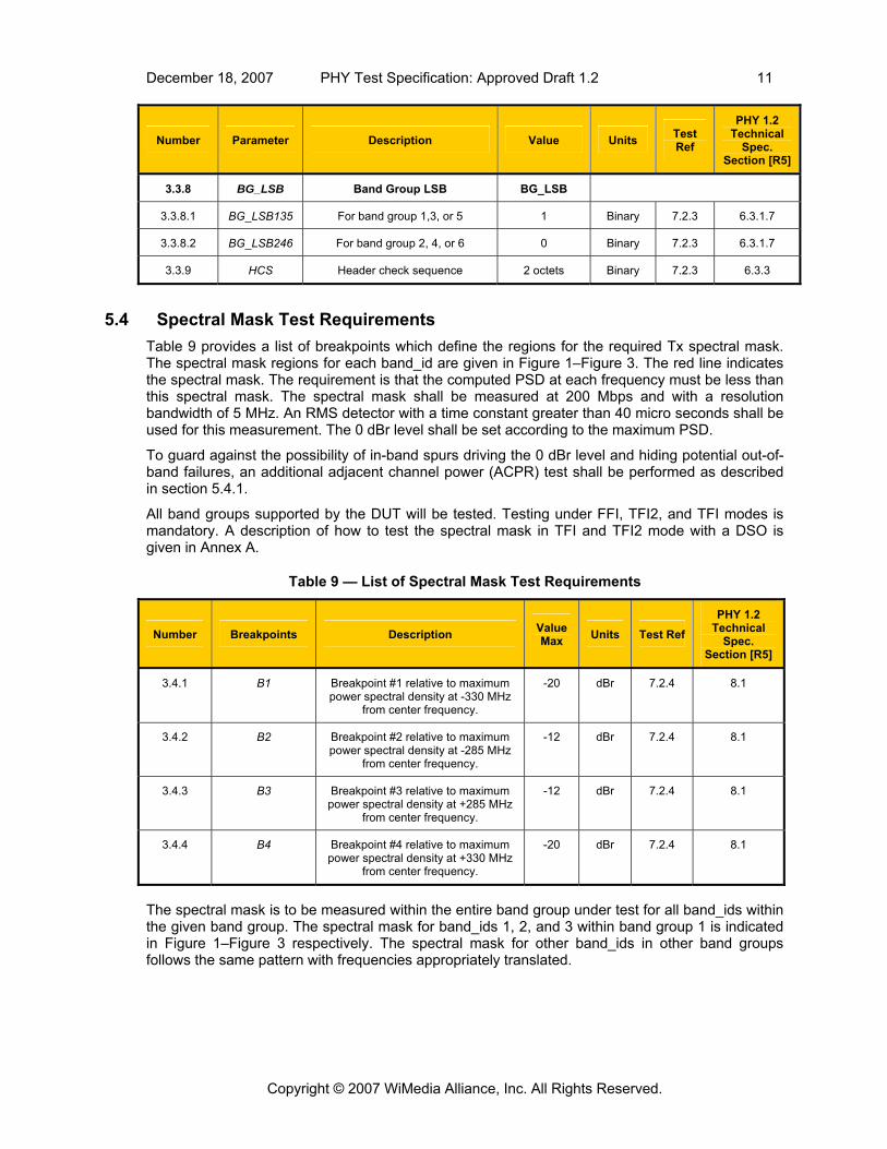
3.3.8 BG_LSB Band Group LSB BG_LSB
3.3.8.1 BG_LSB135 For band group 1,3, or 5 1 Binary 7.2.3 6.3.1.7
3.3.8.2 BG_LSB246 For band group 2, 4, or 6 0 Binary 7.2.3 6.3.1.7
3.3.9 HCS Header check sequence 2 octets Binary 7.2.3 6.3.3
5.4 Spectral Mask Test Requirements Table 9 provides a list of breakpoints which define the regions for the required Tx spectral mask. The spectral mask regions for each band_id are given in Figure 1–Figure 3. The red line indicates the spectral mask. The requirement is that the computed PSD at each frequency must be less than this spectral mask. The spectral mask shall be measured at 200 Mbps and with a resolution bandwidth of 5 MHz. An RMS detector with a time constant greater than 40 micro seconds shall be used for this measurement. The 0 dBr level shall be set according to the maximum PSD.
To guard against the possibility of in-band spurs driving the 0 dBr level and hiding potential out-of-band failures, an additional adjacent channel power (ACPR) test shall be performed as described in section 5.4.1.
All band groups supported by the DUT will be tested. Testing under FFI, TFI2, and TFI modes is mandatory. A description of how to test the spectral mask in TFI and TFI2 mode with a DSO is given in Annex A.
Table 9 — List of Spectral Mask Test Requirements
Number Breakpoints Description Value Max Units Test Ref
PHY 1.2 Technical
Spec. Section [R5]
3.4.1 B1 Breakpoint #1 relative to maximum power spectral density at -330 MHz
from center frequency.
-20 dBr 7.2.4 8.1
3.4.2 B2 Breakpoint #2 relative to maximum power spectral density at -285 MHz
from center frequency.
-12 dBr 7.2.4 8.1
3.4.3 B3 Breakpoint #3 relative to maximum power spectral density at +285 MHz
from center frequency.
-12 dBr 7.2.4 8.1
3.4.4 B4 Breakpoint #4 relative to maximum power spectral density at +330 MHz
from center frequency.
-20 dBr 7.2.4 8.1
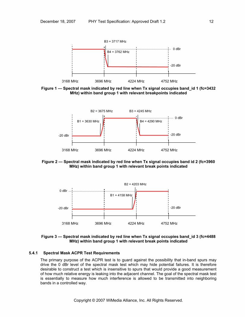
The spectral mask is to be measured within the entire band group under test for all band_ids within the given band group. The spectral mask for band_ids 1, 2, and 3 within band group 1 is indicated in Figure 1–Figure 3 respectively. The spectral mask for other band_ids in other band groups follows the same pattern with frequencies appropriately translated.
Copyright © 2007 WiMedia Alliance, Inc. All Rights Reserved.
December 18, 2007 PHY Test Specification: Approved Draft 1.2 12
Figure 1 — Spectral mask indicated by red line when Tx signal occupies band_id 1 (fc=3432
MHz) within band group 1 with relevant breakpoints indicated
Figure 2 — Spectral mask indicated by red line when Tx signal occupies band id 2 (fc=3960
MHz) within band group 1 with relevant break points indicated
Figure 3 — Spectral mask indicated by red line when Tx signal occupies band_id 3 (fc=4488
MHz) within band group 1 with relevant break points indicated
5.4.1 Spectral Mask ACPR Test Requirements
The primary purpose of the ACPR test is to guard against the possibility that in-band spurs may drive the 0 dBr level of the spectral mask test which may hide potential failures. It is therefore desirable to construct a test which is insensitive to spurs that would provide a good measurement of how much relative energy is leaking into the adjacent channel. The goal of the spectral mask test is essentially to measure how much interference is allowed to be transmitted into neighboring bands in a controlled way.
3168 MHz 3696 MHz 4224 MHz 4752 MHz
-20 dBr
B2 = 4203 MHz
B1 = 4158 MHz
-20 dBr
0 dBr
3168 MHz 3696 MHz 4224 MHz 4752 MHz
-20 dBr
B1 = 3630 MHz
-20 dBr
B2 = 3675 MHz B3 = 4245 MHz
B4 = 4290 MHz 0 dBr
-20 dBr
B3 = 3717 MHz
0 dBr B4 = 3762 MHz
3168 MHz 3696 MHz 4224 MHz 4752 MHz
Copyright © 2007 WiMedia Alliance, Inc. All Rights Reserved.

December 18, 2007 PHY Test Specification: Approved Draft 1.2 13
The ACPR test measures the ratio of the in-band signal power to the out-of-band signal power and ensures that this ratio is at least 20 dB. Specifically, the in-band energy is measured from channel center ±231 MHz (462 MHz). Let this quantity be represented as Pin. The out-of-band power is measured over a 462 MHz bandwidth at offsets which depend on the band_id under test. Let this quantity be represented as Pout. The ACPR test requirement is given below in Table 10. The resolution bandwidth for this measurement shall be 5 MHz.
Table 10 — Spectral Mask ACPR Test Requirement
Number Name Description Value Min Units Test Ref
PHY 1.2 Technical
Spec. Section [R5]
3.4.1.1 ACPR
Power ratio of Pin to Pout outP
inP
20 dB 7.2.4.1 N/A
Figure 4–Figure 6 provide the frequency integration ranges for Pout and Pin for band_ids 1, 2, and 3 respectively. For each band_id, two measurements are to be performed, and each measurement must satisfy the test requirement in Table 10.
Measurement 1
Figure 4 — Integration ranges for Pin and Pout for band_id 1
3168 MHz 3696 MHz 4224 MHz
Pin
3729 MHz
3201 MHz 4191 MHz3663 MHz
Pout
4752 MHz
Measurement 2
3168 MHz 3696 MHz 4224 MHz
3201 MHz 4711 MHz 4249 MHz3663 MHz
Pout Pin
4752 MHz
Copyright © 2007 WiMedia Alliance, Inc. All Rights Reserved.

December 18, 2007 PHY Test Specification: Approved Draft 1.2 14
Measurement 1
3663 MHz
Pin Pout
3201 MHz 4191 MHz3729 MHz
3168 MHz 3696 MHz 4224 MHz 4752 MHz
Measurement 2 4257 MHz
3168 MHz 3696 MHz 4224 MHz
Pin Pout
4719 MHz 4191 MHz
4752 MHz
3729 MHz
Figure 5 — Integration ranges for Pin and Pout for band_id 2
Copyright © 2007 WiMedia Alliance, Inc. All Rights Reserved.

December 18, 2007 PHY Test Specification: Approved Draft 1.2 15
Measurement 1 4191 MHz
4257 MHz 4719 MHz 3729 MHz
Pout Pin
3168 MHz 3696 MHz 4224 MHz 4752 MHz
Measurement 2
3663 MHz 3201 MHz
Pout
4257 MHz 4719 MHz
Pin
3168 MHz 3696 MHz 4224 MHz 4752 MHz Figure 6 — Integration ranges for Pin and Pout for band_id 3
5.5 EVM Test Requirements The EVM shall be computed over the payload portion of the packet only. Table 11 lists the Tx EVM requirements for the mandatory rates listed in Table 2, and also provides the requirement for higher rates up to 480 Mbps if supported by the DUT. The EVM test shall be performed on all channels in each supported band group. The Tx power level for all tests shall be at 0 dB TPC attenuation and at the highest power setting supported by the DUT. Additionally the EVM will be measured at 200 Mbps for a TPC attenuation of 12 dB for TFC 1, 10 dB for TFC 8 and 8 dB for TFC 7 for band groups 1-4, 6, where references are to MAC TFCs for band group 6, and at 200 Mbps for a TPC attenuation of 10 dB for TFC 8 and 8 dB for TFC 5 for band group 5. The EVM Rx shall compute and correct for common phase error (CPE) after a CPE filter has been applied as described in Section 5.5.1. In addition to the EVM test requirements, the absolute steady-state frequency error shall be measured to ensure it is less than 20 ppm. The EVM shall be done in two passes over the payload. The first will estimate equalizer response and frequency offset using the payload. The equalizer will be frozen on the second pass to compensate for channel effects and the frequency offset will be removed. The second pass will take each frequency and channel corrected symbol and apply the CPE filter to the pilot phase error after timing offset compensation is performed. The output of the CPE filter is used to correct the phase of the current symbol. EVM is then computed for this symbol. Functions performed by a typical EVM receiver are given below as an example:
First pass:
Copyright © 2007 WiMedia Alliance, Inc. All Rights Reserved.

December 18, 2007 PHY Test Specification: Approved Draft 1.2 16
1. Detect the start of packet and frame boundary. 2. Implement overlap and add as appropriate followed by an FFT. 3. Calculate the initial Channel Estimates (one for each band), using the CE symbols. 4. Estimate the phase and timing error using the pilots. 5. Correct for the timing and phase errors. 6. Estimate the ideal channel response averaging over the entire packet using pilot and data
tones. 7. Estimate the carrier frequency offset averaged over the payload section and remove from
the time domain signal.
Second pass:
1. Rewind to the start of the payload. 2. Implement overlap and add as appropriate followed by an FFT. 3. Equalize the channel using the fixed equalizer taps obtained from the first pass. 4. Estimate the phase error using the pilots and derive a timing error and the CPE
independently. 5. Correct for timing errors. 6. Feed the CPE into the CPE filter. 7. Use the output of the CPE filter and correct for the phase. 8. Compute EVM.
The Euclidean distance will be calculated to the closest constellation point for each of the data and pilot subcarriers. The RMS error will be calculated using equation 8-1 in the WiMedia PHY 1.2 technical specification [R5] and shall not exceed the max value in Table 11.
Table 11 — List of EVM Test Requirements
Number Parameter Description Value Max Units Test
Ref
PHY 1.2 Technical
Spec. Section [R5]
3.5.1 EVM1 EVM Measurement for mandatory rates 0 dB TPC
-165 dB 7.2.5 8.7
3.5.2 EVM2 EVM Measurement for rates above 200 Mbps up to 480 Mbps 0 dB TPC
-186 dB 7.2.5 8.7
3.5.3 EVM3 EVM Measurement for 200 Mbps with maximum TPC attenuation of 8 dB for TFC 7, 10 dB for TFC 8, and 12 dB for
TFC 1 for Band Groups 1-4, 6 (references are to MAC TFCs for Band
group 6;
EVM Measurement for 200 Mbps with maximum TPC attenuation of 8 dB for TFC 5 and 10 dB for TFC 8, for band
group 5
-13.57 dB 7.2.5 8.7
The EVM shall be computed over 3 packets with a payload of 96 symbols each. If the measured EVM is within 2 dB of the specified EVM maximum in absolute value, abs(measuredEVM –
5 Includes 1 dB of margin over the WiMedia PHY 1.2 technical specification [R5]
6 Includes 1.5 dB of margin over the WiMedia PHY 1.2 technical specification [R5]
7 Includes 2.5 dB of margin over the 0 dB TPC case consistent with the PHY specification
Copyright © 2007 WiMedia Alliance, Inc. All Rights Reserved.

December 18, 2007 PHY Test Specification: Approved Draft 1.2 17
specEVM) < 2 dB, then the EVM should be re-measured over an average of 10 packets to ensure accuracy of the measurement. Table 12 provides payload lengths in bytes at each data rate to produce a payload of 96 symbols.
Table 12 — Number of Bytes for each Rate to Produce a 96 Symbol Payload
Rate Num Payload Bytes
53.3 195
80 295
106.7 395
160 595
200 745
320 1195
400 1495
480 1795
5.5.1 CPE Filter Definition for EVM Measurements
The CPE shall be corrected on a symbol-by-symbol basis in a feed-forward manner as depicted in Figure 1. For the TFI and TFI2 modes, a filter will be applied to each band id separately since there is no requirement that the phase be continuous across frequencies. It is assumed that average frequency error computed over the entire packet has been removed prior to performing this computation. The motivation for CPE filtering is to allow the EVM measurement to see phase noise impairments from a given Tx. A margin of 1 and 1.5 dB was added over the PHY technical specification [R5] for this reason as noted in footnotes 5 and 6.
Frequency Domain
Figure 7 — CPE Correction Block Diagram
The CPE filter shall be a single-pole low-pass filter with the following transfer function:
Compute CPE
CPE Filter
)(⋅− je
Calculate EVM
CPE Filter CPE
Filter
Copyright © 2007 WiMedia Alliance, Inc. All Rights Reserved.

December 18, 2007 PHY Test Specification: Approved Draft 1.2 18
121
11)( −
−
++
=zcc
zzH ,
where
bc /111 += , bc /112 −= , and dB3cos1 ω+dBb 3cos1 ω−
= .
The 3 dB cutoff radian frequency, ω3dB, shall be π/12 (12 time averages) for FFI modes, π/6 (6 time averages) for TFI2 modes and π/4 (4 time averages) for TFI modes. The initial condition of the filter shall be set so that the first output sample, CPEAve(1), is equal to the first input sample CPE(1).
5.6 Tx Power Control (TPC) Test Requirements Table 13 below lists the requirements for TPC and specifies the amount of power reduction or attenuation from maximum Tx power. These power measurements shall be done without measuring EVM. The table provides requirements for TFI, TFI2, and FFI modes. Testing of TPC is optional and only required if the DUT supported TPC.
Table 13 — List of TPC Test Requirements
Number Parameter Description Value Units Test Ref
PHY 1.2 Technical
Spec. Section [R5]
3.6.1 TXPWR TFI Tx power level support in TFI Mode
3.6.1.1 TXPWR_TFI0 Tx power attenuation 0 0 dB 7.2.6 8.6
3.6.1.2 TXPWR_TFI1 Tx power attenuation 1 2 dB 7.2.6 8.6
3.6.1.3 TXPWR_TFI2 Tx power attenuation 2 4 dB 7.2.6 8.6
3.6.1.4 TXPWR_TFI3 Tx power attenuation 3 6 dB 7.2.6 8.6
3.6.1.5 TXPWR_TFI4 Tx power attenuation 4 8 dB 7.2.6 8.6
3.6.1.6 TXPWR_TFI5 Tx power attenuation 5 10 dB 7.2.6 8.6
3.6.1.7 TXPWR_TFI6 Tx power attenuation 6 12 dB 7.2.6 8.6
3.6.2 TXPWR TFI2 Tx power level support in TFI2 mode
3.6.2.1 TXPWR_TFI2_0 Tx power attenuation 0 0 dB 7.2.6 8.6
3.6.2.2 TXPWR_TFI2_1 Tx power attenuation 1 2 dB 7.2.6 8.6
3.6.2.3 TXPWR_TFI2_2 Tx power attenuation 2 4 dB 7.2.6 8.6
3.6.2.4 TXPWR_TFI2_3 Tx power attenuation 3 6 dB 7.2.6 8.6
3.6.2.5 TXPWR_TFI2_4 Tx power attenuation 4 8 dB 7.2.6 8.6
3.6.2.6 TXPWR_TFI2_5 Tx power attenuation 5 10 dB 7.2.6 8.6
Copyright © 2007 WiMedia Alliance, Inc. All Rights Reserved.

December 18, 2007 PHY Test Specification: Approved Draft 1.2 19
PHY 1.2 Test Technical Number Parameter Description Value Units Ref Spec.
Section [R5]
3.6.3 TXPWR FFI Tx power level support in FFI Mode
3.6.3.1 TXPWR_FFI0 Tx power attenuation 0 0 dB 7.2.6 8.6
3.6.3.2 TXPWR_FFI1 Tx power attenuation 1 2 dB 7.2.6 8.6
3.6.3.3 TXPWR_FFI2 Tx power attenuation 2 4 dB 7.2.6 8.6
3.6.3.4 TXPWR_FFI3 Tx power attenuation 3 6 dB 7.2.6 8.6
3.6.3.5 TXPWR_FFI4 Tx power attenuation 4 8 dB 7.2.6 8.6
Each attenuation step shall be accurate to within ±1 dB or ±20%, whichever is greater, as given in Table 14. This level of accuracy shall hold for any change in attenuation level (not just the change from 0dB). This ensures that the actual attenuation is a monotonic function of the commanded attenuation level.
Table 14 — Allowable Power Level Differences
TPC Step |i-j|
Allowable Power Difference |Δi – Δj| (dB)
0
1 [1, 3]
2 [3, 5]
3 [4.8, 7.2]
4 [6.4, 9.6]
5 [8, 12]
6 [9.6, 14.4]
It is possible to have a set of measurements that fall within the values of Table 14 for j=0, for instance, but violate the table for other values of j. Table 15 below provides a non-monotonic example illustrating this type of violation.
Table 15 — Non-Monotonic TPC Example
j=0 Measured
j=1 Calculated
j=2 Calculated
j=3 Calculated
I=1 2
I=2 4 2
I=3 7.2 5.2 3.2
I=4 6.4 4.4 2.4 0.8
The j=0 column represents the measured TPC steps relative to maximum power. The other TPC steps starting from j=1, j=2, and j=3, are computed from the measured values at j=0. Note the
Copyright © 2007 WiMedia Alliance, Inc. All Rights Reserved.
December 18, 2007 PHY Test Specification: Approved Draft 1.2 20
attenuation of step 3 is greater than the attenuation of step 4 which is undesirable. The bolded numbers in this table represent attenuation values which violate the requirements of Table 14.
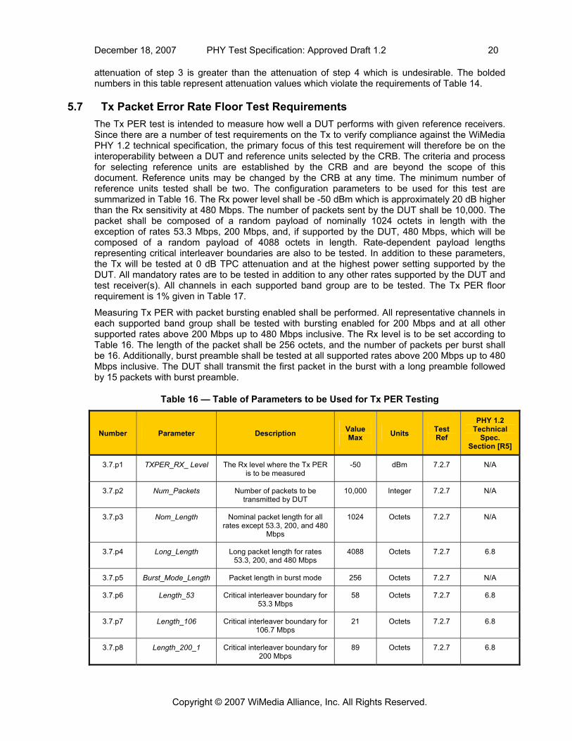
5.7 Tx Packet Error Rate Floor Test Requirements The Tx PER test is intended to measure how well a DUT performs with given reference receivers. Since there are a number of test requirements on the Tx to verify compliance against the WiMedia PHY 1.2 technical specification, the primary focus of this test requirement will therefore be on the interoperability between a DUT and reference units selected by the CRB. The criteria and process for selecting reference units are established by the CRB and are beyond the scope of this document. Reference units may be changed by the CRB at any time. The minimum number of reference units tested shall be two. The configuration parameters to be used for this test are summarized in Table 16. The Rx power level shall be -50 dBm which is approximately 20 dB higher than the Rx sensitivity at 480 Mbps. The number of packets sent by the DUT shall be 10,000. The packet shall be composed of a random payload of nominally 1024 octets in length with the exception of rates 53.3 Mbps, 200 Mbps, and, if supported by the DUT, 480 Mbps, which will be composed of a random payload of 4088 octets in length. Rate-dependent payload lengths representing critical interleaver boundaries are also to be tested. In addition to these parameters, the Tx will be tested at 0 dB TPC attenuation and at the highest power setting supported by the DUT. All mandatory rates are to be tested in addition to any other rates supported by the DUT and test receiver(s). All channels in each supported band group are to be tested. The Tx PER floor requirement is 1% given in Table 17.
Measuring Tx PER with packet bursting enabled shall be performed. All representative channels in each supported band group shall be tested with bursting enabled for 200 Mbps and at all other supported rates above 200 Mbps up to 480 Mbps inclusive. The Rx level is to be set according to Table 16. The length of the packet shall be 256 octets, and the number of packets per burst shall be 16. Additionally, burst preamble shall be tested at all supported rates above 200 Mbps up to 480 Mbps inclusive. The DUT shall transmit the first packet in the burst with a long preamble followed by 15 packets with burst preamble.
Table 16 — Table of Parameters to be Used for Tx PER Testing
Number Parameter Description Value Max Units Test
Ref
PHY 1.2 Technical
Spec. Section [R5]
3.7.p1 TXPER_RX_ Level The Rx level where the Tx PER is to be measured
-50 dBm 7.2.7 N/A
3.7.p2 Num_Packets Number of packets to be transmitted by DUT
10,000 Integer 7.2.7 N/A
3.7.p3 Nom_Length Nominal packet length for all rates except 53.3, 200, and 480
Mbps
1024 Octets 7.2.7 N/A
3.7.p4 Long_Length Long packet length for rates 53.3, 200, and 480 Mbps
4088 Octets 7.2.7 6.8
3.7.p5 Burst_Mode_Length Packet length in burst mode 256 Octets 7.2.7 N/A
3.7.p6 Length_53 Critical interleaver boundary for 53.3 Mbps
58 Octets 7.2.7 6.8
3.7.p7 Length_106 Critical interleaver boundary for 106.7 Mbps
21 Octets 7.2.7 6.8
3.7.p8 Length_200_1 Critical interleaver boundary for 200 Mbps
89 Octets 7.2.7 6.8
Copyright © 2007 WiMedia Alliance, Inc. All Rights Reserved.
December 18, 2007 PHY Test Specification: Approved Draft 1.2 21
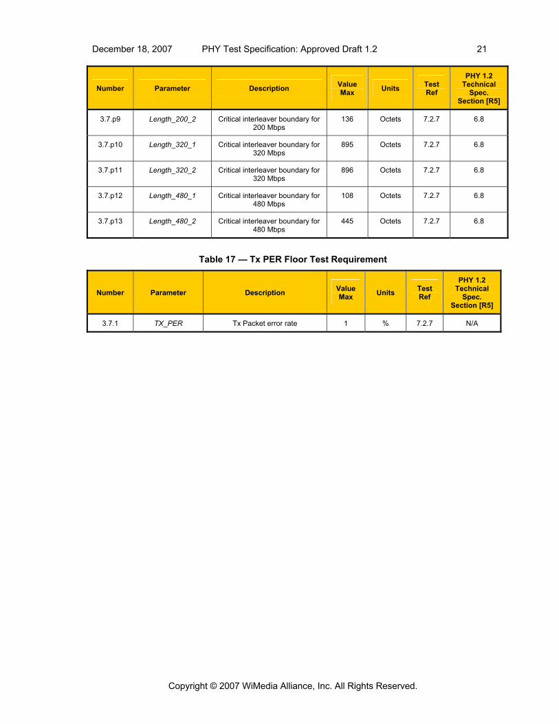
PHY 1.2 Value Test Technical Number Parameter Description Units Max Ref Spec.
Section [R5]
3.7.p9 Length_200_2 Critical interleaver boundary for 200 Mbps
136 Octets 7.2.7 6.8
3.7.p10 Length_320_1 Critical interleaver boundary for 320 Mbps
895 Octets 7.2.7 6.8
3.7.p11 Length_320_2 Critical interleaver boundary for 320 Mbps
896 Octets 7.2.7 6.8
3.7.p12 Length_480_1 Critical interleaver boundary for 480 Mbps
108 Octets 7.2.7 6.8
3.7.p13 Length_480_2 Critical interleaver boundary for 480 Mbps
445 Octets 7.2.7 6.8
Table 17 — Tx PER Floor Test Requirement
Number Parameter Description Value Max Units Test
Ref
PHY 1.2 Technical
Spec. Section [R5]
3.7.1 TX_PER Tx Packet error rate 1 % 7.2.7 N/A
Copyright © 2007 WiMedia Alliance, Inc. All Rights Reserved.

December 18, 2007 PHY Test Specification: Approved Draft 1.2 22
6. Receiver Test Requirements The following section provides the test requirements for the receiver organized in the following logical sub-sections:
1. Timing-Related Test Requirements
2. Rx PER Floor Test Requirements
6.1 Rx Timing-Related Test Requirements Table 18 below lists the Rx timing-related test parameter, pCCADetectTime. The requirement for pCCADetectTime applies only to those DUTs that support this feature.
Table 18 — List of Rx Timing-Related Test Requirements
Number Parameter Description Value Max Units Test
Ref
PHY 1.2 Technical
Spec. Section [R5]
4.1.1 pCCADetectTime Time required to trigger CCA at a Rx level of -77.8 dBm with
a probability of 90%
5.625 μs 7.3.1 9.2
6.2 Rx Packet Error Rate Floor Test Requirements The Rx PER test is intended to measure how well a DUT performs with given reference transmitters. Reference units selected by the CRB shall be used for the purpose of interoperability testing. The minimum number of reference units tested shall be two. All mandatory rates and additionally any rates supported by the DUT are to be tested.
The Rx PER test requirements for 53.3 Mbps are given in Table 19 below. The high Rx range interval was determined based on a 10 cm separation (see footnotes 8 and 9) and a 20 dB backoff from sensitivity as specified in the WiMedia PHY 1.2 technical specification [R5]. The PER measurements shall be computed over 10,000 packets. The lowest Rx level was determined based on a 10 dB backoff from sensitivity given in the WiMedia PHY 1.2 technical specification for Band Group 1. The packets for this test shall be comprised of random data with a payload length of 1024 octets. Only the representative channels in each supported band group are required for the test requirements given in Table 19.
Table 19 — Rx Level and Max PER Requirements for 53.3 Mbps
Band Group Mode High Rx Range
(dBm) Max
PER(%) Low Rx Range
(dBm) Max
PER(%) Step
Size(dB) Test Ref
1 TFI [-338,-61] 1 (-61, -71] 8 2 7.3.2
1 TFI2 [-35,-61] 1 (-61,-71] 8 2 7.3.2
1 FFI [-379,-61] 1 (-61, -71] 8 2 7.3.2
8 High Rx signal power level requirement of -32 dBm corresponds to roughly a 10 cm separation with Tx that is radiating -10 dBm EIRP in TFI mode at 3.69 GHz assuming freespace pathloss.
9 High Rx signal power level requirement of -37 dBm corresponds to roughly a 10 cm separation with Tx that is radiating -15 dBm EIRP in FFI mode at 3.69 GHz assuming freespace pathloss.
Copyright © 2007 WiMedia Alliance, Inc. All Rights Reserved.

December 18, 2007 PHY Test Specification: Approved Draft 1.2 23
Band High Rx Range Max Low Rx Range Max Step Mode Test Ref Group (dBm) PER(%) (dBm) PER(%) Size(dB)
2 TFI [-33,-61] 1 (-61,-71] 8 2 7.3.2
2 TFI2 [-35,-61] 1 (-61,-71] 8 2 7.3.2
2 FFI [-37,-61] 1 (-61,-71] 8 2 7.3.2
3 TFI [-39,-61] 1 (-61,-71] 8 2 7.3.2
3 TFI2 [-41,-61] 1 (-61,-71] 8 2 7.3.2
3 FFI [-43,-61] 1 (-61,-71] 8 2 7.3.2
4 TFI [-41,-61] 1 (-61,-71] 8 2 7.3.2
4 TFI2 [-43,-61] 1 (-61,-71] 8 2 7.3.2
4 FFI [-45,-61] 1 (-61,-71] 8 2 7.3.2
5 TFI [-41,-61] 1 (-61,-71] 8 2 7.3.2
5 TFI2 [-43,-61] 1 (-61,-71] 8 2 7.3.2
5 FFI [-45,-61] 1 (-61,-71] 8 2 7.3.2
6 TFI [-39,-61] 1 (-61,-71] 8 2 7.3.2
6 TFI2 [-41,-61] 1 (-61,-71] 8 2 7.3.2
6 FFI [-43,-61] 1 (-61,-71] 8 2 7.3.2
Fixed level Rx PER test requirements are given in Table 20 below. Note only rates 53.3 Mbps, 106.7 Mbps, and 200 Mbps are mandatory. Requirements for other rates are provided for DUTs that support them. For each rate, only two measurements are required, high Rx level, and low Rx level except where it’s indicated otherwise. The high Rx level was determined based on a 20 dB backoff from sensitivity. The max PER requirement at the high Rx level is 1%. The low Rx level was determined based on a 10 dB backoff from sensitivity. The max PER requirement for the low Rx level is 8%. All mandatory channels shall be measured for the Rx PER requirements listed in Table 20.
Table 20 — Rx Level and Max PER Requirements at Specific Rx Levels and Packet Lengths
Rate (Mbps) High Rx Level (dBm)
Max PER(%)
Low Rx Level (dBm)
Max PER(%)
Payload Length (octets)
Test Ref
PHY 1.2 Technical
Spec. Section [R5]
53.3 -61 1 N/A N/A 4088 7.3.2 9.1
106.7 -58 1 -68 8 1024 7.3.2 9.1
200 -55 1 -65 8 1024 7.3.2 9.1
200 -55 1 N/A N/A 4088 7.3.2 9.1
320 -53 1 -63 8 1024 7.3.2 9.1
400 -52 1 -62 8 1024 7.3.2 9.1
480 -50 1 -60 8 1024 7.3.2 9.1
Copyright © 2007 WiMedia Alliance, Inc. All Rights Reserved.
December 18, 2007 PHY Test Specification: Approved Draft 1.2 24
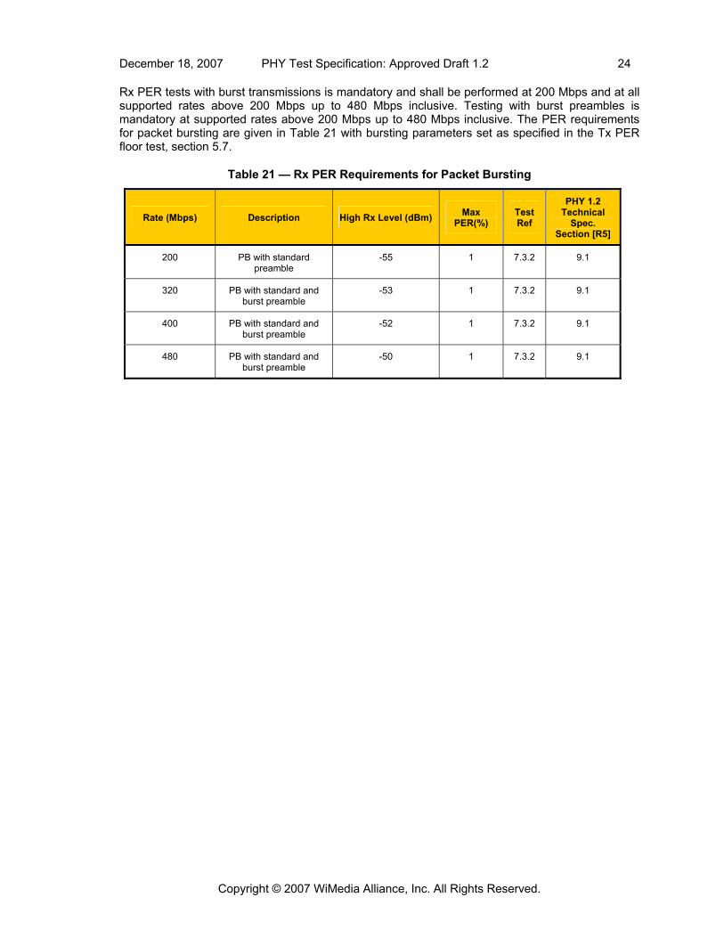
Rx PER tests with burst transmissions is mandatory and shall be performed at 200 Mbps and at all supported rates above 200 Mbps up to 480 Mbps inclusive. Testing with burst preambles is mandatory at supported rates above 200 Mbps up to 480 Mbps inclusive. The PER requirements for packet bursting are given in Table 21 with bursting parameters set as specified in the Tx PER floor test, section 5.7.
Table 21 — Rx PER Requirements for Packet Bursting
Rate (Mbps) Description High Rx Level (dBm) Max PER(%)
Test Ref
PHY 1.2 Technical
Spec. Section [R5]
200 PB with standard preamble
-55 1 7.3.2 9.1
320 PB with standard and burst preamble
-53 1 7.3.2 9.1
400 PB with standard and burst preamble
-52 1 7.3.2 9.1
480 PB with standard and burst preamble
-50 1 7.3.2 9.1
Copyright © 2007 WiMedia Alliance, Inc. All Rights Reserved.

December 18, 2007 PHY Test Specification: Approved Draft 1.2 25
7. PHY Test Descriptions The following sections provide a general description for the tests to be conducted to verify the Tx and Rx requirements in sections 5 and 6 respectively. It is recognized that there may be multiple ways to perform the tests in order to verify these requirements. Therefore, this section does not necessarily dictate the details of the test procedure and test fixtures to be used, but rather provides an outline of the functions that should be performed.
7.1 DUT Requirements to Enable Testing This section describes requirements that must be met by the DUT in order to facilitate testing. These requirements are as follows:
1. The DUT must provide a method to allow testing personnel to select a given channel in both Rx and Tx modes.
2. The DUT must provide method to allow testing personnel to select a given Tx power level. 3. The DUT must provide a method to allow testing personnel to select the Tx data rate. 4. The DUT must provide a Tx mode with maximum SIFS spacing between transmissions at a
configured packet length. 5. If the DUT provides a CCA mechanism, then it must expose the CCA control signal through
a dedicated pin, or through a general purpose I/O (GPIO) pin, or through something similar. 6. The DUT must provide an Rx mode where it reports the following statistics: the number of
total packets received with or without errors, the number of packets received with valid FCS, and the number of packets received with HCS error.
7.2 Tx Test Descriptions
7.2.1 Tx Timing Test Description
The test described in this section measures the Tx MIFS time between packet bursts to verify it satisfies the timing requirements in section 5.1. This timing may also be measured during the Tx PER test.
The following steps are to be performed when measuring the MIFS time:
1. Configure the Tx DUT to desired channel (choose a TFI channel). 2. Configure the Tx DUT to transmit packets in burst mode. 3. Capture the Tx packets with appropriate test equipment. 4. Measure the time between bursts and verify it satisfies the Tx MIFS requirements in Table 4.
7.2.2 Preamble Compliance Test Description
In general, preamble compliance is implicitly checked throughout all of the PHY interoperability tests. The tests described here specifically look at preamble lengths to determine that the proper number of symbols is being used for both standard and burst preambles to verify the DUT satisfies requirements in section 5.2. Note that these tests can likely be performed in combination with other PHY tests.
7.2.2.1 Standard Preamble Mandatory Rates Test Description
This test is to be performed at 53 Mbps with the PHY configured to use a standard preamble. The following steps are to be performed in each supported band group:
1. Configure the DUT to the first representative channel for that band group. 2. Configure the DUT to transmit at 53.3 Mbps. 3. Configure the DUT to transmit packets. 4. Capture the Tx packet with appropriate test equipment. 5. Verify that the preamble is 30 symbols in length (9.375 μs). 6. Repeat steps 2–5 on the other representative channels for that band group.
Copyright © 2007 WiMedia Alliance, Inc. All Rights Reserved.
December 18, 2007 PHY Test Specification: Approved Draft 1.2 26
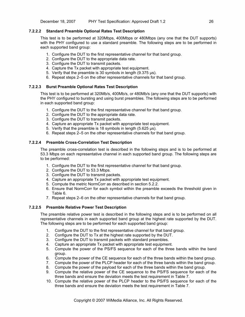
7.2.2.2 Standard Preamble Optional Rates Test Description
This test is to be performed at 320Mbps, 400Mbps or 480Mbps (any one that the DUT supports) with the PHY configured to use a standard preamble. The following steps are to be performed in each supported band group:
1. Configure the DUT to the first representative channel for that band group. 2. Configure the DUT to the appropriate data rate. 3. Configure the DUT to transmit packets. 4. Capture the Tx packet with appropriate test equipment. 5. Verify that the preamble is 30 symbols in length (9.375 μs). 6. Repeat steps 2–5 on the other representative channels for that band group.
7.2.2.3 Burst Preamble Optional Rates Test Description
This test is to be performed at 320Mb/s, 400Mb/s, or 480Mb/s (any one that the DUT supports) with the PHY configured to bursting and using burst preambles. The following steps are to be performed in each supported band group:
1. Configure the DUT to the first representative channel for that band group. 2. Configure the DUT to the appropriate data rate. 3. Configure the DUT to transmit packets. 4. Capture an appropriate Tx packet with appropriate test equipment. 5. Verify that the preamble is 18 symbols in length (5.625 μs). 6. Repeat steps 2–5 on the other representative channels for that band group.
7.2.2.4 Preamble Cross-Correlation Test Description
The preamble cross-correlation test is described in the following steps and is to be performed at 53.3 Mbps on each representative channel in each supported band group. The following steps are to be performed:
1. Configure the DUT to the first representative channel for that band group. 2. Configure the DUT to 53.3 Mbps. 3. Configure the DUT to transmit packets. 4. Capture an appropriate Tx packet with appropriate test equipment. 5. Compute the metric NormCorr as described in section 5.2.2. 6. Ensure that NormCorr for each symbol within the preamble exceeds the threshold given in
Table 6. 7. Repeat steps 2–6 on the other representative channels for that band group.
7.2.2.5 Preamble Relative Power Test Description
The preamble relative power test is described in the following steps and is to be performed on all representative channels in each supported band group at the highest rate supported by the DUT. The following steps are to be performed for each supported band group:
1. Configure the DUT to the first representative channel for that band group. 2. Configure the DUT to Tx at the highest rate supported by the DUT. 3. Configure the DUT to transmit packets with standard preambles. 4. Capture an appropriate Tx packet with appropriate test equipment. 5. Compute the power of the PS/FS sequence for each of the three bands within the band
group. 6. Compute the power of the CE sequence for each of the three bands within the band group. 7. Compute the power of the PLCP header for each of the three bands within the band group. 8. Compute the power of the payload for each of the three bands within the band group. 9. Compute the relative power of the CE sequence to the PS/FS sequence for each of the
three bands and ensure the deviation meets the test requirement in Table 7. 10. Compute the relative power of the PLCP header to the PS/FS sequence for each of the
three bands and ensure the deviation meets the test requirement in Table 7.
Copyright © 2007 WiMedia Alliance, Inc. All Rights Reserved.

December 18, 2007 PHY Test Specification: Approved Draft 1.2 27
11. Compute the relative power of the payload to the PS/FS sequence for each of the three bands and ensure the deviation meets the test requirement in Table 7.
12. Compute the relative power of the PLCP header to the CE sequence for each of the three bands and ensure the deviation meets the test requirement in Table 7.
13. Compute the relative power of the payload to the CE sequence for each of the three bands and ensure the deviation meets the test requirement in Table 7.
14. Compute the relative power of the payload to the PLCP header for each of the three bands and ensure the deviation meets the test requirement in Table 7.
15. Repeat steps 4–14 on the other representative channels for that band group.
7.2.3 PLCP Header Tests Descriptions
The test described in this section verifies compliance to the PLCP header test requirements described in section 5.3. This test is to be performed at all mandatory rates listed in Table 2 and all time frequency codes in each supported band group. The following steps are to be performed when performing PLCP header compliance testing:
1. Configure the Tx DUT to desired channel. 2. Configure the Tx DUT to transmit packets. 3. Capture the Tx packet with appropriate test equipment. 4. Process packet and verify the header parameters in Table 8.
7.2.4 Spectral Mask Test Description
The test described in this section performs a spectral mask measurement of the DUT and verifies it satisfies the requirements in section 5.4. The following steps are to be performed when testing spectral mask compliance:
1. Configure DUT to a desired channel. 2. Configure the DUT to transmit at 200 Mbps. 3. Select the highest transmit power setting supported by the DUT. 4. Configure the DUT to transmit. 5. Use test equipment10 to capture the power spectral density characteristics of the transmitter. 6. Record the maximum power. 7. Measure the PSD at the appropriate frequency offsets and verify it meets the requirements
in section 5.4.
7.2.4.1 Spectral Mask ACPR Test Description
The test described in this section performs the ACPR measurement of the DUT as part of the spectral mask test and verifies it satisfies the test requirement given in Table 7 in section 5.4.1. The following steps are to be performed when testing for ACPR compliance:
1. Configure DUT to a desired channel. 2. Select the highest transmit power setting supported by the DUT. 3. Configure the DUT to transmit. 4. Use method described in Annex A to compute the PSD with resolution bandwidth of 5 MHz. 5. Apply the appropriate integration ranges for each band_id as described in section 5.4.1 and
compute the ratio of Pin/Pout (dB) for each measurement as required. 6. Verify that the ratio Pin/Pout satisfies the requirement given in Table 10.
10 See Annex A for a description of how to use a DSO for this test.
Copyright © 2007 WiMedia Alliance, Inc. All Rights Reserved.

December 18, 2007 PHY Test Specification: Approved Draft 1.2 28
7.2.5 EVM Test Description
The test described in this section performs the EVM measurement of the DUT and verifies it meets the requirements described in section 5.5. The following steps are to be performed when testing EVM compliance:
1. Configure DUT to a test channel. 2. Configure the Tx power to the highest power supported by the DUT. 3. Select the data rate and size of payload consistent with section 5.5. 4. Transmit packets in the transmit mode described in section 7.1. 5. Use test equipment to capture the appropriate number of packets. 6. Process the packets with an Rx compliant with section 5.5. 7. Calculate relative constellation RMS error according to formula 8-1 in the WiMedia PHY 1.2
technical specification [R5] and compare to test specification in Table 11. 8. Record the absolute steady-state frequency error and make sure it is less than 20 ppm.
7.2.6 Tx Power Control Test Description
The test described in this section measures the Tx power control of the DUT and verifies it satisfies the test requirements given in section 5.6. The test equipment used for this test must have the ability to measure signal power in the band group under test with a total occupied bandwidth of 1.6 GHz. FFI, TFI2, and TFI modes are to be tested. The following steps are to be performed in each supported band group when testing TPC:
1. Configure the DUT to the first representative channel for that band group. 2. Select the highest transmit power setting (0 dB attenuation). 3. Use test equipment to measure and record the highest power setting. 4. Lower the transmit power setting per Table 13. 5. Measure and record the power difference relative to the level recorded in step 3. Denote the
difference in power (in dB) as Δi for the ith step. 6. Continue steps 4 through 5 for all other power settings. 7. For all i, j with i ≠ j verify that
min{ (2×|i-j|) - 1, (2×|i-j|)×0.8 } ≤ |Δi – Δj| ≤ max{ (2×|i-j|) + 1, (2×|i-j|)×1.2 } 11. 8. Repeat steps 2–7 for the other representative channels for that band group.
7.2.7 Tx PER Floor Test Description
The test described in this section measures the TxPER floor of a DUT operating with a collection of receivers from an approved testbed and verifies it satisfies the test requirements given in section 5.7. The following test will be performed in a conducted or wired fashion to control the Rx power level precisely. The following steps are to be performed for each channel in each supported band group when measuring the TxPER:
1. Configure the Tx DUT to transmit at the desired rate at the highest power setting. 2. Measure the Tx power of the DUT using the procedure described in the control test in
section 7.2.6. 3. Measure the pathloss of the conducted test fixture. 4. Determine the level of attenuation required to meet an Rx level of -50 dBm as follows:
ATTN (dB) = -50 + Tx Power (step 2) (dBm) + Pathloss (step 3) (dB). 5. Configure the Tx DUT to a desired channel. 6. Configure the Tx packet length according to Table 16. 7. Configure the Tx DUT to transmit 10,000 packets. 8. Transmit and record the Tx PER.
11 Note: Only TPC steps relative to maximum power need to be measured. TPC steps relative to other values may be computed using the measured data relative to maximum power.
Copyright © 2007 WiMedia Alliance, Inc. All Rights Reserved.

December 18, 2007 PHY Test Specification: Approved Draft 1.2 29
9. Repeat steps 1–8 for all data rates to be tested. 10. Repeat steps 1–8 with packet bursting if supported by the DUT at 200 Mbps. 11. Repeat steps 1–9 with packet bursting if supported by the DUT at all supported rates
above 200 Mbps up to 480 Mbps inclusive. 12. Repeat steps 1–9 with burst preamble if supported by the DUT at all supported rates above
200 Mbps up to 480 Mbps inclusive.
7.3 Rx Test Descriptions
7.3.1 Rx Timing Test Description
The test described in this section measures the pCCADetectTime of a DUT and verifies it satisfies the test requirement in section 6.1. The following test applies only to those devices that support PCA operation. The Tx used for this test shall be a Tx from an approved testbed. The hardware setup for this test is depicted below in Figure 8.
Figure 8 — Hardware Setup for CCA Timing Test
7.3.2 Rx PER Floor Test Description
The test described in this section measures the RxPER floor of a DUT operating with a collection of transmitters from an approved testbed for interoperability testing and verifies it satisfies the test requirements given in section 6.2. The following test will be performed in a conducted or wired fashion to control the Rx power level precisely. Given the low Rx signal levels involved in this test, it’s required that, at a minimum, the Rx be placed in an anechoic chamber12 to protect it from potential interference sources that may cause unwanted anomalies in the test results. The PER should be measured in the Rx range specified in Table 19 and in Table 20. The following steps are to be performed when measuring the RxPER:
1. Configure the Tx to the desired channel consistent with the test requirement. 2. Configure the Tx to transmit at the appropriate data rate and at the highest power setting
for the selected channel.
12 A small anechoic chamber of dimensions 3’x3’ is sufficient.
Power divider or directional coupler
DUT UWB Tx
Oscilloscope
CCA Signal
Trigger- Level used to indicate trigger for scope
Copyright © 2007 WiMedia Alliance, Inc. All Rights Reserved.

December 18, 2007 PHY Test Specification: Approved Draft 1.2 30
3. Measure the Tx power using the procedure described in the control test in section 7.2.6. 4. Measure the pathloss of the conducted test fixture. 5. Determine the level of attenuation required to meet a given Rx level depending on data
rate as follows: ATTN (dB) = Rx Level (dBm) + Tx Power (step 2) (dBm) + Pathloss (step 3) (dB).
6. Configure the Tx to transmit the appropriate number of packets. 7. For each Rx power level, transmit packets and record the RxPER. 8. Repeat steps 1–7 for each data rate to be tested. 9. Repeat steps 1–7 with packet bursting at 200 Mbps. 10. Repeat steps 1–8 with packet bursting enabled at all supported rates above 200 Mbps up
to 480 Mbps inclusive with standard preamble. 11. Repeat steps 1–8 with packet bursting enabled at all supported rates above 200 Mbps up
to 480 Mbps inclusive with burst preamble.
Copyright © 2007 WiMedia Alliance, Inc. All Rights Reserved.

December 18, 2007 PHY Test Specification: Approved Draft 1.2 31
Annex A (informative) Spectral Mask Test Fixture Description Using Digital Sampling Scope
The measurement of the PSD in TFI and TFI2 modes may be accomplished with a real-time digital sampling oscilloscope (DSO) or digitizer. A typical procedure is given below for band group 1:
1. Set up oscilloscope or digitizer as follows:
a. Set digitizing rate to 20 Giga-samples per second or higher. Bandwidth of scope/digitizer should be at least 5 GHz for band group #1 measurements. For band groups greater than 1, more bandwidth and sample rate will be needed.
b. In order to maximize vertical ADC resolution, adjust volts-per-division (full-scale range) of oscilloscope so that the largest excursions of the time-domain signal are just within the vertical digitizing window.
c. Set up time-per-division (record length) so that at least one packet is captured. Analysis is done on a packet-by-packet basis.
2. Specify the channel number (or TFC) of packets to be used for test.
3. Using data for the preamble base sequence symbol, corresponding to the desired TFC, create up-sampled and up-converted symbol data sequences for the 3 center frequency cases. The up-sample baseband symbol to sample rate ratio of captured packets is 1250:33 for 20 GSPS digitizing rate. Translate the up-sampled symbol sequence to each of the 3 RF center frequencies.
4. Correlate the first and last of the 24 preamble sync symbols (12 for a burst preamble) in the captured packet with the appropriate up-sampled and up-converted sequence to determine a sync time for each symbol. Using this technique, the measured sync times will have an uncertainty of about 1 sample (50 ps in case of 20 GSPS acquisition). Use these times to determine the frequency offset and phase reference. Use the frequency offset and phase reference to extrapolate the start times for each symbol in the packet.
5. Set the FFT window to start according to the algorithm described in Annex B. The FFT window shall have a duration of 160 bits (303 ns, or 6060 samples @ 20 GSPS). Perform the 6060 point FFT for each symbol in the packet and add the power spectrum from the FFT into the accumulated power spectrum for the appropriate center frequency. Alternately, zero pad the 6060 samples to 8192 samples and apply an FFT of length 8192.
6. Accumulate the 3 power spectra to obtain at least 20 averages for each frequency.
7. Smooth the 3 power spectra using a filter to obtain a resolution bandwidth of 5 MHz.
8. Apply spectral masks as specified in section 5.4.
Copyright © 2007 WiMedia Alliance, Inc. All Rights Reserved.

December 18, 2007 PHY Test Specification: Approved Draft 1.2 32
Annex B (informative) Method for Calculating the Optimal FFT Window for the Spectral Mask Test
The following describes a gating method for optimizing the starting sample of the FFT while performing the spectral mask compliance test as described in Annex A. The following algorithm assumes that the starting sample of the symbol is known and searches for the optimal FFT window using this starting point as a reference. The frequencies F2 and F3 represent the center frequencies of the other band ids within the band group. For example if the signal is using TFC 1 and is centered at 3432 MHz (F1), then F2 = 3960 MHz, and F3 = 4480 MHz. The steps to find the optimal starting point Ks are as follows:
1. Find the first sample of the first symbol using method described in Annex A. 2. Gate the signal using an offset of K=-37 to +0 and calculate the PSD in the center
frequencies F2 and F3 (6060 point DFT on a two frequencies can be used instead of FFT to optimize calculation time).
3. Choose the point Ks which brings max(Leakage on F2, Leakage on F3) to a minimum. 4. If more than one point minimizes the energy select the point that is closer to K=0.
The Matlab code provided on the next page computes the leakage at F2 and F3 based on an example data vector using TFC1 with a known symbol starting point of 74190 and computes the best shift according to the steps above.
Copyright © 2007 WiMedia Alliance, Inc. All Rights Reserved.

December 18, 2007 PHY Test Specification: Approved Draft 1.2 33
Copyright © 2007 WiMedia Alliance, Inc. All Rights Reserved.
% The following Matlab code is provided as an example which finds the
% the shift in the staring point which minimizes the leakage at F2 and F3
% while looking at band 1 for TFC 1, the leakage at F1 and F3 for band 2
% and the leakage at F1 and F2 for band 3.
x = tfc1_data;
Nsymbols = 96;
SampleRate = 20e9;
first_sample = 74190; % First sample of the symbol.
chanBW = 528e6;
UpSample = round(SampleRate/chanBW);
N_samples_sym = round(165 * UpSample); % Samples in each symbol
N_gated_samples = 160 * UpSample; % ...after eliminating guard interval
Fresolution = SampleRate/N_gated_samples; % Frequency resolution per FFT bin.
q = zeros(3,38);
for i=-37:0,
% There are 6250 samples per symbol at 20Gs/s. Shape y into a matrix
% of size 6250 samples x Nsymbols.
y=reshape(x(first_sample+round(i*UpSample)+(1:N_samples_sym*Nsymbols)),...
N_samples_sym,Nsymbols);
for band = 1:3
% Gate out the portion of y corresponding to the guard interval and
% separate out the band.
y1=y(1:N_gated_samples,band:3:end);
% Take FFT of each symbol and compute power of the LOs in the
% adjacent bands.
z = fft(y1);
row1 = round( (6.5+rem(band, 3))*chanBW/Fresolution );
row2 = round( (6.5+rem(band+1,3))*chanBW/Fresolution );
z1 = z(row1,:); % LO at F2.
z2 = z(row2,:); % LO at F3.
% Compute the spurious LO power of each symbol.
w1=sum(z1 * z1');
w2=sum(z2 * z2');
q(band,-i+1) = max(w1,w2); % Worst leakage for this band and shift.
end
end
q = max(q); % What's the worst leakage of the three bands?
[max_LO,idx] = min(q); % find the shift that minmize the spurious LO.
BestShift = idx-1;
Related Documents


![REAMBLE ARC2471C MEDICAIDWAIVERSERVICES - … · MEDICAIDWAIVERSERVICES PREAMBLE ... [ARC2471C,IAB3/30/16,effective5/4/16] DIVISIONI—HCBSHEALTHANDDISABILITYWAIVERSERVICES 441—83.1(249A)](https://static.cupdf.com/doc/110x72/5adb4cd67f8b9a6d318de199/reamble-arc2471c-medicaidwaiverservices-preamble-arc2471ciab33016effective5416.jpg)