May 2010 doc.: IEEE 802.11-10/0433r2 IEEE P802.11 Wireless LANs PHY/MAC Complete Proposal Specification Date: 2010-05-18 Author(s)/Supporter(s): Name Company Addre ss Phon e email Abu-Surra, Shadi Samsung [email protected] Ban, Koichiro Toshiba [email protected] Banerjea, Raja Marvell [email protected] Basson, Gal Wilocity [email protected] Blanksby, Andrew Broadcom [email protected] m Borges, Daniel Apple [email protected] Borison, David Ralink [email protected] m Cariou, Laurent Orange laurent.cariou@orange- ftgroup.com Chamberlin, Philippe Technicolor R&I philippe.chambelin@technico lor.com Chang, Kapseok ETRI [email protected] Chin, Francois I2R [email protected] star.edu.sg Choi, Changsoon IHP GmbH choi@ihp- microelectronics.com Christin, Philippe Orange philippe.christin@orange- ftgroup.com Chu, Liwen STMicroelectro nics [email protected] Chung, Hyun Kyu ETRI [email protected] Coffey, Sean Realtek [email protected] Cordeiro, Carlos Intel [email protected] Derham, Thomas Orange thomas.derham@orange- ftgroup.com Dorsey, John Apple [email protected] Elboim, Yaron Wilocity [email protected] Fischer, Matthew Broadcom [email protected] Giraud, Claude NXP [email protected] Glibbery, Ron Peraso Technologies [email protected] Golan, Ziv Wilocity [email protected] Gong, Michelle Intel [email protected] Submission Page 1 of 494 Carlos Cordeiro, Intel, et al.

60GHz MAC/PHY Specification - IEEE Standards ... · Web viewLynch, Brad Peraso Technologies [email protected] Majkowski, Jakub Nokia [email protected] Marin, Janne Nokia
Jun 11, 2018
Welcome message from author
This document is posted to help you gain knowledge. Please leave a comment to let me know what you think about it! Share it to your friends and learn new things together.
Transcript
May 2010 doc.: IEEE 802.11-10/0433r2
IEEE P802.11Wireless LANs
PHY/MAC Complete Proposal Specification
Date: 2010-05-18
Author(s)/Supporter(s):Name Company Address Phone email
Abu-Surra, Shadi Samsung [email protected], Koichiro Toshiba [email protected], Raja Marvell [email protected]
Basson, Gal Wilocity [email protected], Andrew Broadcom [email protected]
Borges, Daniel Apple [email protected], David Ralink [email protected], Laurent Orange [email protected]
Chamberlin, Philippe Technicolor R&I [email protected], Kapseok ETRI [email protected], Francois I2R [email protected]
Choi, Changsoon IHP GmbH [email protected], Philippe Orange [email protected]
Chu, Liwen STMicroelectronics [email protected], Hyun Kyu ETRI [email protected]
Coffey, Sean Realtek [email protected], Carlos Intel [email protected], Thomas Orange [email protected]
Dorsey, John Apple [email protected], Yaron Wilocity [email protected]
Fischer, Matthew Broadcom [email protected], Claude NXP [email protected], Ron Peraso Technologies [email protected]
Golan, Ziv Wilocity [email protected], Michelle Intel [email protected]
Grandhi, Sudheer InterDigital [email protected], Eckhard IHP GmbH [email protected], David Agilent [email protected]
Grodzinsky, Mark Wilocity [email protected], Christopher Broadcom [email protected]
Hart, Brian Cisco [email protected], Amer Microsoft [email protected]
Hong, Seung Eun ETRI [email protected], Kenichi NEC [email protected], Srinath Texas Instruments [email protected]
Hsu, Alvin MediaTek [email protected], Julan Samsung [email protected]
Hung, Kun-Chien MediaTek [email protected], Avinash Qualcomm [email protected]
Jauh, Alan MediaTek [email protected], Raymond Jararaj s/o I2R [email protected]
Jeon, Paul LGE [email protected], Sunggeun ETRI [email protected]
Jones, VK Qualcomm [email protected], Stacy Beam Networks [email protected]
Submission Page 1 of 339 Carlos Cordeiro, Intel, et al.
May 2010 doc.: IEEE 802.11-10/0433r2
Jun, Haeyoung Samsung [email protected], Harald Nokia [email protected], Padam Nokia [email protected]
Kakani, Naveen Nokia [email protected], Assaf Intel [email protected], Mika Nokia [email protected], Hodong Samsung [email protected], Yongsun ETRI [email protected], Rolf IHP GmbH [email protected]
Kreifeldt, Rick Harman International [email protected]
Kwon, Edwin Samsung [email protected], Hyoungjin ETRI [email protected], Hyukchoon Samsung [email protected]
Laine, Tuomas Nokia [email protected], Ismail Tensorcom [email protected], Hoosung ETRI [email protected]
Lee, Keith AMD [email protected], Wooyong ETRI [email protected]
Liu, Yong Marvell [email protected], Hui-Ling Marvell [email protected], Brad Peraso Technologies [email protected]
Majkowski, Jakub Nokia [email protected], Janne Nokia [email protected]
Maruhashi, Kenichi NEC [email protected], Taisuke Panasonic [email protected]
Meerson, Yury Wilocity [email protected], Murat Broadcom [email protected]
Montag, Bruce Dell [email protected], Andrew Cisco [email protected]
Nandagopalan, Saishankar Broadcom [email protected], Chiu Samsung [email protected]
Nikula, Eero Nokia [email protected], DS Samsung [email protected]
Park, Minyoung Intel [email protected], Xiaoming I2R [email protected]
Pi, Zhouyue Samsung [email protected], Vish MediaTek [email protected]
Prasad, Narayan NEC [email protected], Gideon Intel [email protected], Xuhong I2R [email protected]
Ramachandran, Kishore NEC [email protected], Yu Zhan Panasonic [email protected]
Roblot, Sandrine Orange [email protected], Roee Wilocity [email protected], Ohad Wilocity [email protected]
Sachdev, Devang NVIDIA [email protected], Ali Intel [email protected]
Sampath, Hemanth Qualcomm [email protected], Amichai Wilocity [email protected]
Sankaran, Sundar Atheros [email protected], Vincenzo STMicroelectronics [email protected]
Seok, Yongho LGE [email protected], Huai-Rong Samsung [email protected], Ba-Zhong Broadcom [email protected]
Sim, Michael Panasonic [email protected]
Submission Page 2 of 339 Carlos Cordeiro, Intel, et al.

May 2010 doc.: IEEE 802.11-10/0433r2
Singh, Harkirat Samsung [email protected], Menashe Intel [email protected], Seungho SK Telecom [email protected], Simha Wilocity [email protected], Matt Atheros [email protected]
Stacey, Robert Intel [email protected], Ananth I2R [email protected]
Sutskover, Ilan Intel [email protected], Hossain Qualcomm [email protected]
Takahashi, Kazuaki Panasonic [email protected], Ichihiko NTT [email protected]
Trachewsky, Jason Self [email protected], Solomon Intel [email protected]
Usuki, Naoshi Panasonic [email protected], Prabodh Nokia [email protected]
Vertenten, Bart NXP [email protected], George STMicroelectronics [email protected]
Wang, Chao-Chun MediaTek [email protected], Homber TMC [email protected], James MediaTek [email protected]
Wong, David Tung Chong I2R [email protected], James MediaTek [email protected]
Yucek, Tevfik Atheros [email protected], Su Khiong Marvell [email protected], Hongyuan Marvell [email protected]
AbstractThis document is part and is in support of the complete proposal described in 802.11-10/432r1 (slides) and 802.11-10/433r1 (text).
This document is the technical specification text as required in the TGad selection procedure (802.11-09/935r5).
Submission Page 3 of 339 Carlos Cordeiro, Intel, et al.

May 2010 doc.: IEEE 802.11-10/0433r2
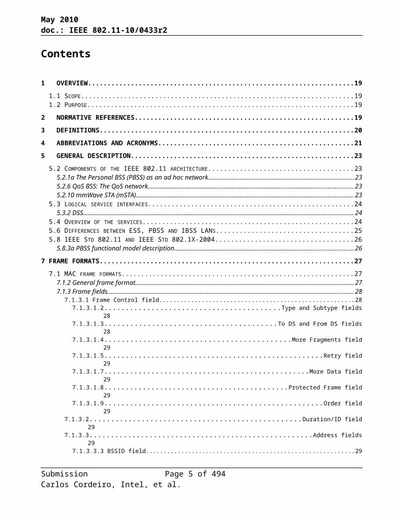
Contents
1 OVERVIEW.................................................................................................................................................................19
1.1 SCOPE............................................................................................................................................................................191.2 PURPOSE........................................................................................................................................................................19
2 NORMATIVE REFERENCES..................................................................................................................................19
3 DEFINITIONS.............................................................................................................................................................20
4 ABBREVIATIONS AND ACRONYMS....................................................................................................................21
5 GENERAL DESCRIPTION.......................................................................................................................................23
5.2 COMPONENTS OF THE IEEE 802.11 ARCHITECTURE.....................................................................................................235.2.1a The Personal BSS (PBSS) as an ad hoc network................................................................................................235.2.6 QoS BSS: The QoS network..................................................................................................................................235.2.10 mmWave STA (mSTA).........................................................................................................................................23
5.3 LOGICAL SERVICE INTERFACES.....................................................................................................................................245.3.2 DSS........................................................................................................................................................................24
5.4 OVERVIEW OF THE SERVICES........................................................................................................................................245.6 DIFFERENCES BETWEEN ESS, PBSS AND IBSS LANS.................................................................................................255.8 IEEE STD 802.11 AND IEEE STD 802.1X-2004...........................................................................................................26
5.8.3a PBSS functional model description.....................................................................................................................26
7 FRAME FORMATS...........................................................................................................................................................27
7.1 MAC FRAME FORMATS.................................................................................................................................................277.1.2 General frame format............................................................................................................................................277.1.3 Frame fields..........................................................................................................................................................28
7.1.3.1 Frame Control field............................................................................................................................................................287.1.3.1.2 Type and Subtype fields......................................................................................................................................287.1.3.1.3 To DS and From DS fields..................................................................................................................................287.1.3.1.4 More Fragments field..........................................................................................................................................297.1.3.1.5 Retry field...........................................................................................................................................................297.1.3.1.7 More Data field...................................................................................................................................................297.1.3.1.8 Protected Frame field..........................................................................................................................................297.1.3.1.9 Order field...........................................................................................................................................................29
7.1.3.2 Duration/ID field...........................................................................................................................................................297.1.3.3 Address fields................................................................................................................................................................29
7.1.3.3.3 BSSID field...............................................................................................................................................................297.1.3.5 QoS Control field...........................................................................................................................................................29
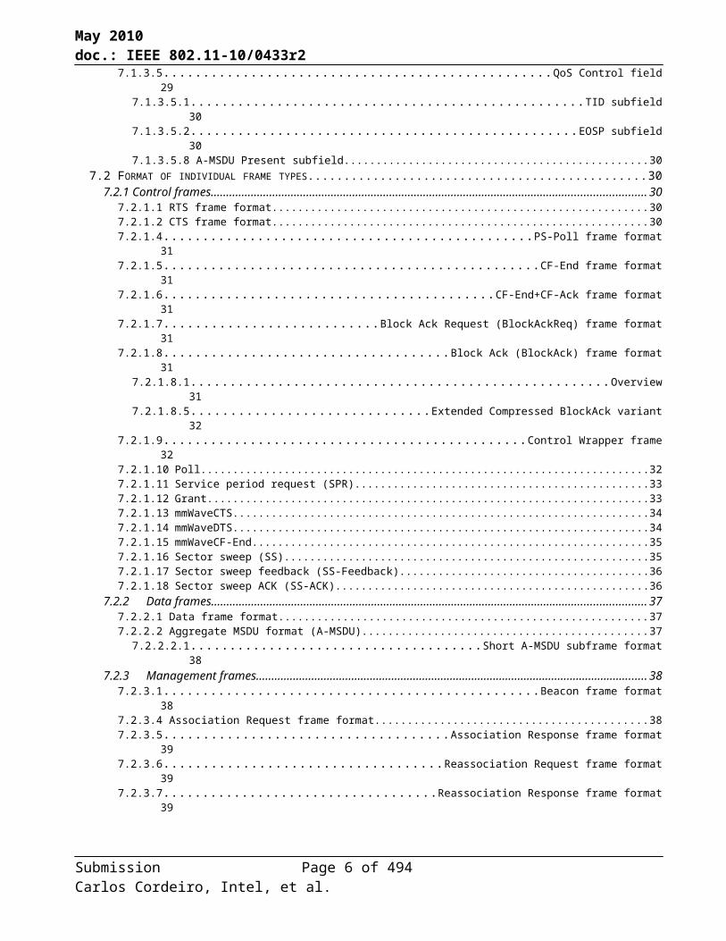
7.1.3.5.1 TID subfield........................................................................................................................................................307.1.3.5.2 EOSP subfield.....................................................................................................................................................307.1.3.5.8 A-MSDU Present subfield.........................................................................................................................................30
7.2 FORMAT OF INDIVIDUAL FRAME TYPES.....................................................................................................................307.2.1 Control frames......................................................................................................................................................30
7.2.1.1 RTS frame format..............................................................................................................................................................307.2.1.2 CTS frame format..............................................................................................................................................................307.2.1.4 PS-Poll frame format.....................................................................................................................................................317.2.1.5 CF-End frame format.....................................................................................................................................................317.2.1.6 CF-End+CF-Ack frame format.....................................................................................................................................317.2.1.7 Block Ack Request (BlockAckReq) frame format........................................................................................................317.2.1.8 Block Ack (BlockAck) frame format............................................................................................................................31
7.2.1.8.1 Overview.............................................................................................................................................................317.2.1.8.5 Extended Compressed BlockAck variant...........................................................................................................32
7.2.1.9 Control Wrapper frame..................................................................................................................................................327.2.1.10 Poll............................................................................................................................................................................327.2.1.11 Service period request (SPR)...................................................................................................................................337.2.1.12 Grant.........................................................................................................................................................................337.2.1.13 mmWaveCTS...........................................................................................................................................................34
Submission Page 4 of 339 Carlos Cordeiro, Intel, et al.
May 2010 doc.: IEEE 802.11-10/0433r2
7.2.1.14 mmWaveDTS...........................................................................................................................................................347.2.1.15 mmWaveCF-End......................................................................................................................................................357.2.1.16 Sector sweep (SS).....................................................................................................................................................357.2.1.17 Sector sweep feedback (SS-Feedback).....................................................................................................................367.2.1.18 Sector sweep ACK (SS-ACK).................................................................................................................................36
7.2.2 Data frames.....................................................................................................................................................377.2.2.1 Data frame format..............................................................................................................................................................377.2.2.2 Aggregate MSDU format (A-MSDU)...............................................................................................................................37
7.2.2.2.1 Short A-MSDU subframe format........................................................................................................................387.2.3 Management frames.........................................................................................................................................38
7.2.3.1 Beacon frame format.....................................................................................................................................................387.2.3.4 Association Request frame format.....................................................................................................................................387.2.3.5 Association Response frame format..............................................................................................................................397.2.3.6 Reassociation Request frame format.............................................................................................................................397.2.3.7 Reassociation Response frame format...........................................................................................................................397.2.3.8 Probe Request frame format..........................................................................................................................................397.2.3.9 Probe Response frame format........................................................................................................................................40
7.2.4 Extension frames...................................................................................................................................................407.2.4.1 mmWave Beacon...............................................................................................................................................................40
7.3 MANAGEMENT AND EXTENSION FRAMES BODY COMPONENTS..................................................................................437.3.1 Fields that are not information elements..............................................................................................................43
7.3.1.8 AID field........................................................................................................................................................................437.3.1.9 Status Code field............................................................................................................................................................437.3.1.11 Action field...............................................................................................................................................................447.3.1.51 Relay capable STA info field..........................................................................................................................................44
7.3.2 Information elements.......................................................................................................................................447.3.2.20 Channel Switch Announcement element.................................................................................................................457.3.2.21 Measurement Request element.................................................................................................................................45
7.3.2.21.12 Directional Channel Quality request.................................................................................................................467.3.2.21.13 Directional Measurement request..........................................................................................................................487.3.2.21.14 Directional Statistics request.................................................................................................................................48
7.3.2.22 Measurement Report element..........................................................................................................................................497.3.2.22.11 Directional Channel Quality report.......................................................................................................................507.3.2.22.12 Directional Measurement report............................................................................................................................517.3.2.22.13 Directional Statistics report...................................................................................................................................52
7.3.2.25 RSN information element................................................................................................................................................537.3.2.25.1 Cipher suites........................................................................................................................................................537.3.2.25.3 RSNA capabilities...............................................................................................................................................54
7.3.2.30 TSPEC element........................................................................................................................................................547.3.2.31 TCLAS element........................................................................................................................................................567.3.2.46 Multiple BSSID element..........................................................................................................................................567.3.2.71 Non-transmitted BSSID Capability element............................................................................................................577.3.2.90 mmWave BSS Parameter Change element..............................................................................................................577.3.2.91 mmWave Capabilities element.................................................................................................................................58
7.3.2.91.1 mmWave STA Capability Information field...........................................................................................................587.3.2.91.2 mmWave PCP/AP Capability Information field.....................................................................................................61
7.3.2.92 mmWave Operation element....................................................................................................................................617.3.2.93 mmWave Beam refinement element........................................................................................................................637.3.2.94 Wakeup Schedule element.......................................................................................................................................657.3.2.95 Extended Schedule element......................................................................................................................................657.3.2.96 STA Availability element.........................................................................................................................................677.3.2.97 Extended mmWave TSPEC element........................................................................................................................677.3.2.98 Next mmWave AT element......................................................................................................................................707.3.2.99 Channel measurement feedback element.................................................................................................................707.3.2.100 Awake Window element..........................................................................................................................................727.3.2.101 Multi-band element..................................................................................................................................................737.3.2.102 ADDBA extension element......................................................................................................................................757.3.2.103 Next PCP List element.............................................................................................................................................757.3.2.104 PCP Handover element............................................................................................................................................767.3.2.105 Link Margin element................................................................................................................................................76
7.3.2.105.1 Action field........................................................................................................................................................777.3.2.106 Switching Stream element........................................................................................................................................777.3.2.107 Session Transition element.......................................................................................................................................787.3.2.108 Dynamic Tone Pairing (DTP) Report element.........................................................................................................79
Submission Page 5 of 339 Carlos Cordeiro, Intel, et al.
May 2010 doc.: IEEE 802.11-10/0433r2
7.3.2.109 Cluster Report element.............................................................................................................................................807.3.2.110 Relay Capabilities element.......................................................................................................................................817.3.2.111 Relay transfer parameter set element.......................................................................................................................82
7.3A FIELDS THAT ARE USED IN MANAGEMENT AND EXTENSION FRAME BODIES AND CONTROL FRAMES.......................837.3a.1 Sector Sweep field...............................................................................................................................................837.3a.2 SP Info field.........................................................................................................................................................847.3a.3 Sector Sweep Feedback field...............................................................................................................................847.3a.4 BRP Request field................................................................................................................................................857.3a.5 Beamforming Control field.................................................................................................................................86
7.4 ACTION FRAME FORMAT DETAILS..............................................................................................................................867.4.2 QoS Action frame details......................................................................................................................................86
7.4.2.1 Basic and Extended mmWave ADDTS Request frame formats...................................................................................877.4.2.1.1 Basic ADDTS Request frame variant.................................................................................................................877.4.2.1.2 Extended mmWave ADDTS Request frame variant..........................................................................................87
7.4.2.2 Basic and Extended mmWave ADDTS Response frame formats.................................................................................887.4.2.2.1 Basic ADDTS Response frame variant...............................................................................................................887.4.2.2.2 Extended mmWave ADDTS Response frame variant........................................................................................88
7.4.2.3 DELTS frame format.....................................................................................................................................................897.4.4 Block Ack Action frame details.............................................................................................................................90
7.4.4.1 ADDBA Request frame format.....................................................................................................................................907.4.4.2 ADDBA Response frame format...................................................................................................................................907.4.4.3 DELBA frame format....................................................................................................................................................90
7.4.13 mmWave Action frame details.............................................................................................................................917.4.13.1 mmWave Action field......................................................................................................................................................917.4.13.2 Announce.........................................................................................................................................................................917.4.13.3 Power Save Configuration Request.................................................................................................................................927.4.13.4 Power Save Configuration Response...............................................................................................................................927.4.13.5 Information Request........................................................................................................................................................937.4.13.6 Information Response......................................................................................................................................................947.4.13.7 Beam Refinement (BRP).................................................................................................................................................957.4.13.8 Handover Request............................................................................................................................................................957.4.13.9 Handover Response.........................................................................................................................................................967.4.13.10 Link Margin Request.....................................................................................................................................................967.4.13.11 Link Margin Response...................................................................................................................................................977.4.13.12 DTP Request..................................................................................................................................................................977.4.13.13 DTP Report....................................................................................................................................................................987.4.13.14 Relay search request......................................................................................................................................................987.4.13.15 Relay search response....................................................................................................................................................997.4.13.16 Multi-relays channel measurement request...................................................................................................................997.4.13.17 Multi-relays channel measurement report...................................................................................................................1007.4.13.18 RLS request.................................................................................................................................................................1017.4.13.19 RLS response...............................................................................................................................................................1027.4.13.20 RLS announcement......................................................................................................................................................1027.4.13.21 RLS teardown..............................................................................................................................................................1037.4.13.22 Relay ACK request......................................................................................................................................................1047.4.13.23 Relay ACK response....................................................................................................................................................1047.4.13.24 TPA request.................................................................................................................................................................1057.4.13.25 TPA response...............................................................................................................................................................1067.4.13.26 TPA report...................................................................................................................................................................1067.4.13.27 ROC request.................................................................................................................................................................1067.4.13.28 ROC response..............................................................................................................................................................107
7.4.14 FST Action frame details...................................................................................................................................1087.4.14.1 FST Action field............................................................................................................................................................1087.4.14.2 FST Setup Request........................................................................................................................................................1087.4.14.3 FST Setup Response......................................................................................................................................................1097.4.14.4 FST Tear down..............................................................................................................................................................1107.4.14.5 FST Ack Request...........................................................................................................................................................1107.4.14.6 FST Ack Response........................................................................................................................................................111
7.4A AGGREGATE MPDU (A-MPDU)..............................................................................................................................1117.4a.1a mmWave A-MPDU format..............................................................................................................................1127.4a.3 A-MPDU contents.............................................................................................................................................112
8 SECURITY.................................................................................................................................................................112
Submission Page 6 of 339 Carlos Cordeiro, Intel, et al.
May 2010 doc.: IEEE 802.11-10/0433r2
8.1 FRAMEWORK...............................................................................................................................................................1128.1.1 Security methods.................................................................................................................................................1128.1.2 RSNA equipment and RSNA capabilities............................................................................................................1138.1.3 RSNA establishment............................................................................................................................................113
8.3 RSNA DATA CONFIDENTIALITY AND INTEGRITY PROTOCOLS.................................................................................1158.3.1 Overview.............................................................................................................................................................1158.3.5 GCM with GMAC Protocol (GCMP)..................................................................................................................115
8.3.5.1 GCMP overview..........................................................................................................................................................1158.3.5.2 GCMP MPDU format..................................................................................................................................................1168.3.5.3 GCMP cryptographic encapsulation............................................................................................................................116
8.3.5.3.1 PN processing...................................................................................................................................................1178.3.5.3.2 Construct AAD.................................................................................................................................................1188.3.5.3.3 Construct GCM nonce......................................................................................................................................1188.3.5.3.4 Construct GCMP header...................................................................................................................................1188.3.5.3.5 GCM originator processing...............................................................................................................................118
8.3.5.4 GCMP decapsulation...................................................................................................................................................1188.3.5.4.1 GCM recipient processing................................................................................................................................1198.3.5.4.2 Decrypted GCMP MPDU.................................................................................................................................1208.3.5.4.3 PN and replay detection....................................................................................................................................120
8.4 RSNA SECURITY ASSOCIATION MANAGEMENT.......................................................................................................1218.4.1 Security associations.....................................................................................................................................121
8.4.1.1 Security association definitions...................................................................................................................................1218.4.1.1.2 PTKSA..............................................................................................................................................................1218.4.1.1.3 GTKSA.............................................................................................................................................................1218.4.1.1.5 STKSA..............................................................................................................................................................121
8.4.1.2 Security association life cycle.....................................................................................................................................1228.4.1.2.0a General...................................................................................................................................................................1228.4.1.2.1 Security association in an ESS/PBSS......................................................................................................................1228.4.1.2.2 Security association in an IBSS/PBSS....................................................................................................................123
8.4.2 RSNA selection...............................................................................................................................................1238.4.3 RSNA policy selection in an ESS/PBSS.........................................................................................................1248.4.4 RSNA policy selection in an IBSS/PBSS........................................................................................................1258.4.5 RSNA management of the IEEE 802.1X Controlled Port..............................................................................1268.4.6 RSNA authentication in an ESS/PBSS...........................................................................................................126
8.4.6.0a General...........................................................................................................................................................................1268.4.6.2 Cached PMKSAs and RSNA key management..............................................................................................................127
8.4.7 RSNA authentication in an IBSS/PBSS..........................................................................................................1278.4.8 RSNA key management in an ESS/PBSS.......................................................................................................1298.4.9 RSNA key management in an IBSS/PBSS......................................................................................................1298.4.10 RSNA security association termination....................................................................................................1308.4.11 RSNA rekeying..........................................................................................................................................1318.4.12 Multi-band RSNA......................................................................................................................................131
8.4.12.1 Non-transparent multi-band RSNA........................................................................................................................1328.4.12.2 Transparent multi-band RSNA...............................................................................................................................133
8.5 KEYS AND KEY DISTRIBUTION.................................................................................................................................1338.5.2 EAPOL-Key frames.......................................................................................................................................1338.5.3 4-Way Handshake..........................................................................................................................................134
8.5.3.2 4-Way Handshake Message 2......................................................................................................................................1348.5.3.3 4-Way Handshake Message 3......................................................................................................................................1348.5.3.4 4-Way Handshake Message 4......................................................................................................................................136
8.7 PER-FRAME PSEUDO CODE...........................................................................................................................................1368.7.2 RSNA frame pseudo-code..............................................................................................................................136
8.7.2.3 Per-MPDU Rx pseudo-code........................................................................................................................................136
9 MAC SUBLAYER FUNCTIONAL DESCRIPTION.............................................................................................137
9.1 MAC ARCHITECTURE..............................................................................................................................................1379.1.3 Hybrid coordination function (HCF)..................................................................................................................137
9.1.3.1 HCF contention-based channel access (EDCA)..............................................................................................................1389.1.5 Fragmentation/defragmentation overview..........................................................................................................138
9.2 DCF.........................................................................................................................................................................1389.2.3 IFS.......................................................................................................................................................................139
Submission Page 7 of 339 Carlos Cordeiro, Intel, et al.
May 2010 doc.: IEEE 802.11-10/0433r2
9.2.3.0b RIFS...............................................................................................................................................................................1399.2.3.1 SIFS.................................................................................................................................................................................1409.2.3.4 AIFS.................................................................................................................................................................................1409.2.3.6 SBIFS...............................................................................................................................................................................1409.2.3.7 BRPIFS............................................................................................................................................................................141
9.2.4 Random backoff time...........................................................................................................................................1419.2.5 DCF access procedure........................................................................................................................................141
9.2.5.1 Basic access.....................................................................................................................................................................1419.2.5.2 Backoff procedure for DCF.............................................................................................................................................1419.2.5.3 Recovery procedures and retransmit limits.....................................................................................................................1439.2.5.4 Setting and resetting the NAV.........................................................................................................................................1439.2.5.7 CTS procedure.................................................................................................................................................................144
9.2.7 Broadcast and multicast MPDU transfer procedure..........................................................................................1449.2.11 NAV distribution...............................................................................................................................................144
9.4 FRAGMENTATION.....................................................................................................................................................1449.6 MULTIRATE SUPPORT...............................................................................................................................................145
9.6.0a Overview...........................................................................................................................................................1459.6.0f Usage of mmWave Control modulation class....................................................................................................1459.6.0g Rate selection rules for control frames transmitted by mSTAs.........................................................................1459.6.0h Rate selection for group addressed data and management frames transmitted by mSTAs..............................1469.6.0i Rate selection for unicast data and management frames transmitted by mSTAs..............................................1469.6.0j Rate selection for BRP packets..........................................................................................................................1479.6.1 Modulation classes..............................................................................................................................................147
9.7C A-MSDU OPERATION...............................................................................................................................................1479.7D A-MPDU OPERATION...............................................................................................................................................148
9.7d.1 A-MPDU contents.............................................................................................................................................1489.7d.2 A-MPDU length limit rules...............................................................................................................................1489.7d.3 Minimum MPDU Start Spacing........................................................................................................................1489.7d.4 A-MPDU aggregation of group addressed data frames...................................................................................148
9.7E PPDU DURATION CONSTRAINT.................................................................................................................................1499.8 OPERATION ACROSS REGULATORY DOMAINS..............................................................................................................1499.9 HCF.............................................................................................................................................................................149
9.9.1 HCF contention-based channel access (EDCA).................................................................................................1499.9.1.1 Reference implementation...............................................................................................................................................1499.9.1.5 EDCA backoff procedure................................................................................................................................................1499.9.1.7 Truncation of TxOP.........................................................................................................................................................149
9.10 BLOCK ACKNOLEDGEMENT (BLOCK ACK)...............................................................................................................1509.10.1 Introduction.......................................................................................................................................................1509.10.7 HT-immediate Block Ack extensions.................................................................................................................150
9.10.7.2 HT-immediate Block Ack architecture..........................................................................................................................1509.10.7.2.1 Data and acknowledgement transfer.....................................................................................................................150
9.15 REVERSE DIRECTION (RD) PROTOCOL...............................................................................................................1519.23 MMWAVE CHANNEL ACCESS..............................................................................................................................151
9.23.1 Beacon interval (BI) structure..................................................................................................................1519.23.2 Interframe space (IFS)..............................................................................................................................1529.23.3 AT transmission rules...............................................................................................................................1529.23.4 DTT transmission rules.............................................................................................................................1549.23.5 Contention-based period (CBP) transmission rules.................................................................................1549.23.6 Time division based channel access in DTT.............................................................................................154
9.23.6.1 Service period (SP) allocation.......................................................................................................................................1559.23.6.2 Contention-based period (CBP) allocation....................................................................................................................1569.23.6.3 Pseudo-static allocations................................................................................................................................................1579.23.6.4 Guard time.....................................................................................................................................................................1579.23.6.5 mmWave Protected Period............................................................................................................................................158
9.23.6.5.1 mmWave Protected Period establishment and maintenance.................................................................................1599.23.6.5.2 NAV Update in mmWave Protected Period..........................................................................................................1609.23.6.5.3 Interference report.................................................................................................................................................160
9.23.6.6 Service period recovery.................................................................................................................................................1619.23.7 Dynamic allocation of service period.......................................................................................................162
9.23.7.1 Polling period (PP)........................................................................................................................................................1639.23.7.2 Grant period (GP)..........................................................................................................................................................164
Submission Page 8 of 339 Carlos Cordeiro, Intel, et al.
May 2010 doc.: IEEE 802.11-10/0433r2
9.23.8 Dynamic truncation of service period.......................................................................................................1659.23.9 Dynamic extension of service period........................................................................................................1669.23.10 NAV update...............................................................................................................................................167
9.24 PCP/AP CLUSTERING.........................................................................................................................................1699.24.1 Cluster formation..............................................................................................................................................1709.24.2 Cluster maintenance.........................................................................................................................................1719.24.3 Cluster report and re-scheduling......................................................................................................................1729.24.4 Cluster request..................................................................................................................................................173
9.25 MMWAVE BEAMFORMING...................................................................................................................................1749.25.1 Sector Level Sweep Phase.................................................................................................................................175
9.25.1.1 Initiator Sector Sweep....................................................................................................................................................1779.25.1.1.1 Initiator TXSS.......................................................................................................................................................1789.25.1.1.2 Initiator RXSS.......................................................................................................................................................179
9.25.1.2 Responder Sector Sweep...............................................................................................................................................1799.25.1.2.1 Responder TXSS...................................................................................................................................................1809.25.1.2.2 Responder RXSS...................................................................................................................................................181
9.25.1.3 Sector Sweep Feedback.................................................................................................................................................1829.25.1.4 Sector Sweep ACK........................................................................................................................................................183
9.25.2 Beam Refinement (BRP) Phase.........................................................................................................................1839.25.2.1 BRP setup sub-phase.....................................................................................................................................................185
9.25.3 Beamforming in BT...........................................................................................................................................1879.25.4 Beamforming in A-BFT.....................................................................................................................................188
9.25.4.1 Allocation of A-BFT..............................................................................................................................................1889.25.4.2 Operation during the A-BFT..................................................................................................................................1889.25.4.3 STA Beamforming after A-BFT............................................................................................................................1919.25.4.4 Beamforming in A-BFT with multiple antennas....................................................................................................192
9.25.5 Beamforming in DTT................................................................................................................................1929.25.5.1 SLS phase execution......................................................................................................................................................1939.25.5.2 MIDC (multiple sector ID capture) phase..............................................................................................................194
9.25.5.2.1 MIDC phase with MID and BC sub-phases......................................................................................................1969.25.5.2.2 MIDC phase with MID sub-phase only............................................................................................................2009.25.5.2.3 MIDC phase with BC sub-phases only.............................................................................................................202
9.25.5.3 BRP phase execution..............................................................................................................................................2039.25.5.3.1 Beam refinement transaction............................................................................................................................2049.25.5.3.2 Beam refinement transaction after SLS............................................................................................................2049.25.5.3.3 Antenna configuration setting during a beam refinement transaction..............................................................206
9.25.6 Beam tracking...........................................................................................................................................2079.25.7 State machines (informative)....................................................................................................................208
9.26 MMWAVE BLOCK ACK WITH FLOW CONTROL...................................................................................................2109.26.1 mmWave Block Ack architecture with Flow Control........................................................................................2109.26.2 Scoreboard context control with Flow Control................................................................................................2119.26.3 Receive Reordering Buffer with Flow Control operation.................................................................................211
9.26.3.1 General...........................................................................................................................................................................2119.26.3.2 Operation for mmWave Block Ack agreement initialization........................................................................................2129.26.3.3 Operation for each received data MPDU.......................................................................................................................2129.26.3.4 Operation for ongoing release of received MPDUs......................................................................................................213
9.26.4 Generation and transmission of BlockAck by a STA with Flow Control..........................................................2139.26.5 Originator’s behavior with flow control support..............................................................................................214
9.27 MMWAVE LINK ADAPTATION.............................................................................................................................2149.28 MMWAVE DYNAMIC TONE PAIRING (DTP)........................................................................................................215
11 MLME.........................................................................................................................................................................216
11.1 SYNCHRONIZATION.............................................................................................................................................21611.1.1 Basic approach.................................................................................................................................................216
11.1.1.1 TSF for infrastructure networks and PBSS networks....................................................................................................21611.1.2 Maintaining synchronization............................................................................................................................217
11.1.2.1 Beacon generation in infrastructure networks in LB and HB........................................................................................21711.1.2.1a Beacon generation in infrastructure BSS and in PBSS in UB.....................................................................................217
11.1.2.1a.1 Beacon generation in a PBSS..............................................................................................................................21911.1.2.1a.2 Beacon generation in infrastructure BSS in UB..................................................................................................219
11.1.2.1b Beacon generation before network initialization.........................................................................................................219
Submission Page 9 of 339 Carlos Cordeiro, Intel, et al.
May 2010 doc.: IEEE 802.11-10/0433r2
11.1.2.2 Beacon generation in an IBSS.......................................................................................................................................22011.1.2.3 Beacon reception...........................................................................................................................................................22011.1.2.3a Multiple BSSID procedures.........................................................................................................................................22111.1.2.4 TSF timer accuracy........................................................................................................................................................221
11.1.3 Acquiring synchronization, scanning................................................................................................................22211.1.3.1 Passive scanning............................................................................................................................................................222
11.1.3.1.1 Passive scanning for mSTAs.................................................................................................................................22211.1.3.2 Active scanning.............................................................................................................................................................223
11.1.3.2.1 Sending a probe response......................................................................................................................................22311.1.3.2.2 Active scanning procedure....................................................................................................................................224
11.1.3.3 Initializing a BSS...........................................................................................................................................................22511.1.3.3.1 Initializing a mmWave BSS..................................................................................................................................225
11.1.3.4 Synchronizing with a BSS.............................................................................................................................................22611.1.4 Adjusting STA timers.........................................................................................................................................22611.1.6 Terminating a network......................................................................................................................................226
11.2 POWER MANAGEMENT........................................................................................................................................22711.2.1 Power management in an infrastructure network in the LB and HB................................................................22711.2.3 Power management in a PBSS and infrastructure BSS in the UB....................................................................227
11.2.3.1 Non-PCP/non-AP STA power management mode........................................................................................................22811.2.3.1.1 Power management mode operation of a non-PCP/non-AP STA with no wakeup schedule...............................22911.2.3.1.2 Power management mode operation of a non-PCP/non-AP STA with a wakeup schedule.................................22911.2.3.1.3 Power management mode operation of a non-PCP/non-AP STA with or without a wakeup schedule................231
11.2.3.2 PCP Power management mode......................................................................................................................................23211.3 STA AUTHENTICATION AND ASSOCIATION........................................................................................................234
11.3.3 mmWave BSS Association, reassociation, and disassociation.........................................................................23411.3.3.1 Non-PCP/non-AP STA Association and RSNA procedures.......................................................................................23811.3.3.2 PCP/AP Association and RSNA procedures.................................................................................................................23811.3.3.3 Non-PCP/non-AP STA Disassociation procedures.......................................................................................................23911.3.3.4 Non-PCP/non-AP STA disassociation receipt procedure..............................................................................................23911.3.3.5 PCP/AP disassociation initiation procedure..................................................................................................................24011.3.3.6 PCP/AP disassociation receipt procedure......................................................................................................................240
11.3.4 Communicating PBSS information...................................................................................................................24011.4 TS OPERATION....................................................................................................................................................241
11.4.1 Introduction.......................................................................................................................................................24111.4.2 TSPEC Construction.........................................................................................................................................24311.4.3 TS Lifecycle.......................................................................................................................................................24311.4.4 TS Setup.............................................................................................................................................................24311.4.5 Failed TS Setup.................................................................................................................................................24511.4.6 Data Transfer....................................................................................................................................................24511.4.7 TS Deletion........................................................................................................................................................24611.4.8 TS Timeout........................................................................................................................................................24611.4.11 mmWave TS Traffic Types........................................................................................................................248
11.4.11.1 Isochronous TS support..........................................................................................................................................24811.4.11.2 Asynchronous TS support......................................................................................................................................248
11.4.12 PTP TS Operation.....................................................................................................................................24811.5 BLOCK ACK OPERATION.....................................................................................................................................24911.8 TPC PROCEDURES...............................................................................................................................................25011.9 DFS PROCEDURES...............................................................................................................................................250
11.9.1 Association based on supported channels................................................................................................25011.9.1.1 Providing supported channels upon association in a mmWave BSS............................................................................250
11.9.2 Quieting channels for testing............................................................................................................................25111.9.6 Requesting and reporting of measurements......................................................................................................25111.9.7 Selecting and advertising a new channel in an infrastructure BSS..................................................................251
11.9.7.3 Selecting and advertising a new channel in a mmWave BSS.......................................................................................25111.10 RADIO MEASUREMENT PROCEDURES..................................................................................................................252
11.10.1 Multiple BSSID set..........................................................................................................................................25211.22 WIRELESS NETWORK MANAGEMENT PROCEDURES.............................................................................................252
11.22.15 DMS Procedures...........................................................................................................................................25211.30 MMWAVE BEAMFORMED LINK AND BSS MAINTENANCE..................................................................................252
11.30.1 Beamformed Link Maintenance......................................................................................................................25211.30.2 PCP Handover................................................................................................................................................253
Submission Page 10 of 339 Carlos Cordeiro, Intel, et al.
May 2010 doc.: IEEE 802.11-10/0433r2
11.30.2.1 Explicit Handover procedure..................................................................................................................................25411.30.2.2 Implicit Handover procedure..................................................................................................................................255
11.31 MMWAVE BSS PEER AND SERVICE DISCOVERY................................................................................................25611.31.1 Information Request and Response.................................................................................................................25611.31.2 Peer Service Discovery...................................................................................................................................257
11.32 CHANGING MMWAVE BSS PARAMETERS...........................................................................................................25711.32.1 Moving the BT.................................................................................................................................................25711.32.2 Changing BI duration.....................................................................................................................................25811.32.3 Maintaining synchronization in a PCP/AP cluster.........................................................................................259
11.33 SPATIAL FREQUENCY SHARING AND INTERFERENCE MITIGATION......................................................................25911.33.1 Spatial sharing and Interference assessment..................................................................................................26011.33.2 Achieving spatial sharing and Interference mitigation...................................................................................26111.33.3 PBSS and infrastructure BSS stability in OBSS scenarios.............................................................................262
11.34 MULTI-BAND OPERATION...................................................................................................................................26311.34.1 FST Setup........................................................................................................................................................264
11.34.1.1 FST TS switching...................................................................................................................................................26911.34.2 FST Teardown...........................................................................................................................................271
11.35 MMWAVE COEXISTENCE WITH OTHER MMWAVE TECHNOLOGIES......................................................................27111.36 MMWAVE MAC SUBLAYER PARAMETERS..........................................................................................................27211.37 MMWAVE RELAY OPERATION.................................................................................................................................273
11.37.1 Common relay setup procedures.....................................................................................................................27411.37.1.1 Relay capabilities and RSUS discovery procedures....................................................................................................27411.37.1.2 RSUS selection procedure...........................................................................................................................................27411.37.1.3 RLS procedure.............................................................................................................................................................275
11.37.2 Link switching type..........................................................................................................................................27611.37.2.1 SP request and allocation.............................................................................................................................................27611.37.2.2 Usage of RSUS............................................................................................................................................................27611.37.2.3 Relay frame exchange rules.........................................................................................................................................277
11.37.2.3.1 Additional frame exchange rules for FD/AF RSUS............................................................................................27711.37.2.3.2 Additional frame exchange rules for HD/DF RSUS...........................................................................................27811.37.2.3.3 Operation of FD/AF RSUS.................................................................................................................................279
11.37.2.4 Link monitoring...........................................................................................................................................................28011.37.3 Link cooperating type......................................................................................................................................280
11.37.3.1 TPA procedure.............................................................................................................................................................28011.37.3.2 Frame exchange operation...........................................................................................................................................281
11.37.3.2.1 Cooperated transmission SP request and allocation............................................................................................28211.37.3.2.2 Data transmission rules.......................................................................................................................................282
11.37.4 Relay operation-type change procedure.........................................................................................................28211.37.5 Relay link adaptation......................................................................................................................................28311.37.6 Relay teardown...............................................................................................................................................284
12 PHY SERVICE SPECIFICATION..............................................................................................................................285
12.3 DETAILED PHY SERVICE SPECIFICATIONS................................................................................................................28512.3.5 PHY-SAP detailed service specification...........................................................................................................285
12.3.5.7a PHY-TXPLCPEND.indication....................................................................................................................................28512.3.5.7a.1 Function...............................................................................................................................................................28512.3.5.7a.2 Semantics of the service primitive.......................................................................................................................28512.3.5.7a.3 When generated...................................................................................................................................................28512.3.5.7a.4 Effect of receipt...................................................................................................................................................285
21 MMWAVE PHY SPECIFICATION.......................................................................................................................286
21.1 MMWAVE PHY INTRODUCTION..........................................................................................................................28621.1.1 Scope.................................................................................................................................................................28621.1.2 mmWave PHY functions....................................................................................................................................286
21.1.2.1 mmWave PLCP sublayer...............................................................................................................................................28621.1.2.2 mmWave PMD sublayer................................................................................................................................................28621.1.2.3 PHY management entity (PLME).................................................................................................................................28621.1.2.4 Service specification method.........................................................................................................................................287
21.2 MMWAVE PHY SERVICE INTERFACE..................................................................................................................28721.2.1 Introduction.......................................................................................................................................................28721.2.2 TXVECTOR and RXVECTOR parameters........................................................................................................287
Submission Page 11 of 339 Carlos Cordeiro, Intel, et al.
May 2010 doc.: IEEE 802.11-10/0433r2
21.2.3 TXSTATUS Parameters.....................................................................................................................................28921.3 COMMON PARAMETERS.......................................................................................................................................289
21.3.1 Channelization..................................................................................................................................................28921.3.2 Transmit Mask...................................................................................................................................................28921.3.3 Common requirements......................................................................................................................................290
21.3.3.1 Tx RF Delay..................................................................................................................................................................29021.3.3.2 Transmit and Receive Operating Temperature Range...................................................................................................29021.3.3.3 Center Frequency Tolerance..........................................................................................................................................29021.3.3.4 Symbol Clock Tolerance...............................................................................................................................................29021.3.3.5 Tx Center Frequency Leakage.......................................................................................................................................29021.3.3.6 Transmit Ramp up and Ramp Down.............................................................................................................................29021.3.3.7 Maximum Input Requirement........................................................................................................................................29121.3.3.8 Receive Sensitivity........................................................................................................................................................291
21.3.4 Timing Related Parameters..............................................................................................................................29221.3.5 Mathematical conventions in the signal description.........................................................................................293
21.3.5.1 The windowing function................................................................................................................................................29421.3.6 A Common Preamble........................................................................................................................................295
21.3.6.1 The Short Training field................................................................................................................................................29521.3.6.2 The Channel Estimation field........................................................................................................................................29521.3.6.3 Transmission of the Preamble in an OFDM packet.......................................................................................................296
21.3.6.3.1 hfilt definition........................................................................................................................................................29721.3.7 HCS calculation for headers of OFDM PHY and SC PHY..............................................................................29721.3.8 Common LDPC parity matrices........................................................................................................................298
21.3.8.1 Rate-1/2 LDPC code matrix H = 336 rows x 672 columns, Z = 42..............................................................................29821.3.8.2 Rate-5/8 LDPC code matrix H = 252 rows x 672 columns, Z = 42..............................................................................29821.3.8.3 Rate-3/4 LDPC code matrix H = 168 rows x 672 columns, Z = 42..............................................................................29921.3.8.4 Rate-13/16 LDPC code matrix H = 126 rows x 672 columns, Z = 42..........................................................................299
21.3.9 Scrambler..........................................................................................................................................................29921.4 MMWAVE CONTROL PHY..................................................................................................................................300
21.4.1 Introduction.......................................................................................................................................................30021.4.2 Frame Format...................................................................................................................................................30021.4.3 Transmission.....................................................................................................................................................300
21.4.3.1 Preamble........................................................................................................................................................................30021.4.3.1.1 Short Training field...............................................................................................................................................30021.4.3.1.2 Channel Estimation field.......................................................................................................................................301
21.4.3.2 Header............................................................................................................................................................................30121.4.3.2.1 Generation of HCS bits.........................................................................................................................................30121.4.3.2.2 Header Encoding and Modulation.........................................................................................................................302
21.4.3.3 Data field.......................................................................................................................................................................30221.4.3.3.1 Scrambler...............................................................................................................................................................30221.4.3.3.2 Encoder..................................................................................................................................................................30221.4.3.3.3 Modulation............................................................................................................................................................30321.4.3.3.4 Spreading...............................................................................................................................................................303
21.4.4 Performance requirements................................................................................................................................30321.4.4.1 Transmit Requirements..................................................................................................................................................303
21.4.4.1.1 Transmit EVM.......................................................................................................................................................30321.4.4.2 Rx Requirements...........................................................................................................................................................304
21.4.4.2.1 CCA.......................................................................................................................................................................30421.5 MMWAVE OFDM PHY......................................................................................................................................305
21.5.1 Introduction.......................................................................................................................................................30521.5.2 Frame Format...................................................................................................................................................30521.5.3 Transmission.....................................................................................................................................................305
21.5.3.1 PLCP Header.................................................................................................................................................................30521.5.3.1.1 Modulation and Coding Scheme...........................................................................................................................30621.5.3.1.2 Generation of the HCS bits...................................................................................................................................30621.5.3.1.3 Header encoding and modulation..........................................................................................................................306
21.5.3.2 The Data field................................................................................................................................................................30721.5.3.2.1 Scrambler...............................................................................................................................................................30721.5.3.2.2 Encoding................................................................................................................................................................30721.5.3.2.3 Modulation Mapping.............................................................................................................................................30821.5.3.2.4 Pilot Sequence.......................................................................................................................................................31121.5.3.2.5 OFDM modulation................................................................................................................................................312
Submission Page 12 of 339 Carlos Cordeiro, Intel, et al.
May 2010 doc.: IEEE 802.11-10/0433r2
21.5.4 Performance requirements................................................................................................................................31221.5.4.1 Transmit Requirements..................................................................................................................................................312
21.5.4.1.1 Transmit EVM.......................................................................................................................................................31321.5.4.1.2 Tx Flatness............................................................................................................................................................31421.5.4.1.3 Time of Departure accuracy..................................................................................................................................314
21.5.4.2 Rx Requirements...........................................................................................................................................................31421.5.4.2.1 CCA.......................................................................................................................................................................314
21.6 MMWAVE SC PHY.............................................................................................................................................31521.6.1 Introduction.......................................................................................................................................................31521.6.2 Frame format....................................................................................................................................................31521.6.3 Transmission.....................................................................................................................................................315
21.6.3.1 Header............................................................................................................................................................................31521.6.3.1.1 Modulation and Coding Scheme...........................................................................................................................31621.6.3.1.2 Generation of the HCS bits...................................................................................................................................31621.6.3.1.3 Header encoding and modulation..........................................................................................................................316
21.6.3.2 The Data field................................................................................................................................................................31721.6.3.2.1 Scrambler...............................................................................................................................................................31721.6.3.2.2 Encoding................................................................................................................................................................31721.6.3.2.3 Modulation Mapping.............................................................................................................................................31921.6.3.2.4 Symbol Blocking and Guard Insertion..................................................................................................................320
21.6.4 Performance requirements................................................................................................................................32121.6.4.1 Transmit Requirements..................................................................................................................................................321
21.6.4.1.1 Transmit EVM.......................................................................................................................................................32121.6.4.1.2 Time of Departure accuracy..................................................................................................................................322
21.6.4.2 Rx Requirements...........................................................................................................................................................32221.6.4.2.1 CCA.......................................................................................................................................................................322
21.7 MMWAVE LOW POWER SC PHY.........................................................................................................................32221.7.1 Transmission.....................................................................................................................................................322
21.7.1.1 Preamble........................................................................................................................................................................32221.7.1.2 Header............................................................................................................................................................................323
21.7.1.2.1 Header encoding and modulation..........................................................................................................................32321.7.1.3 Data field.......................................................................................................................................................................323
21.7.1.3.1 Scrambler...............................................................................................................................................................32321.7.1.3.2 Encoding................................................................................................................................................................32321.7.1.3.3 Modulation............................................................................................................................................................32521.7.1.3.4 Blocking................................................................................................................................................................325
21.8 BEAMFORMING....................................................................................................................................................32621.8.1 Beamforming concept.......................................................................................................................................32621.8.2 Beamforming PHY frame format......................................................................................................................326
21.8.2.1 TX sector sweep............................................................................................................................................................32621.8.2.2 Beam refinement............................................................................................................................................................326
21.8.2.2.1 Beam refinement packet structure.........................................................................................................................32721.8.2.2.2 Beam Refinement packet header fields.................................................................................................................32721.8.2.2.3 Beam Refinement AGC field................................................................................................................................32821.8.2.2.4 Beam Refinement TRN-R field.............................................................................................................................32821.8.2.2.5 Beam Refinement TRN-T field.............................................................................................................................32821.8.2.2.6 Channel Measurement...........................................................................................................................................328
21.9 GOLAY SEQUENCES............................................................................................................................................32921.10 MMWAVE PLME................................................................................................................................................330
21.10.1 PLME_SAP sublayer management primitives................................................................................................33021.10.2 mmWave PHY Management Information Base...............................................................................................33021.10.3 TXTIME calculation........................................................................................................................................33021.10.4 PHY characteristics........................................................................................................................................331
ANNEX A (NORMATIVE) PICS......................................................................................................................................332
A.4 PICS PROFORMA-IEEE STD 802.11-2007..................................................................................................................332A.4.3 IUT configuration...............................................................................................................................................332A.4.21 mmWave features..............................................................................................................................................332
A.4.21.1 mmWave MAC features...............................................................................................................................................332A.4.21.2 mmWave PHY features................................................................................................................................................333
ANNEX D (NORMATIVE) ASN.1 ENCODING OF THE MAC AND PHY MIB.......................................................333
Submission Page 13 of 339 Carlos Cordeiro, Intel, et al.
May 2010 doc.: IEEE 802.11-10/0433r2
ANNEX J (NORMATIVE) COUNTRY INFORMATION ELEMENT AND REGULATORY CLASSES..............334
List of Figures
Figure 1 – Logical architecture of a PBSS..............................................................................................................................25Figure 2 – RSNA setup in PBSS.............................................................................................................................................27Figure 3 – Poll frame...............................................................................................................................................................32Figure 4 – SPR frame..............................................................................................................................................................33Figure 5 – Grant frame............................................................................................................................................................33Figure 6 – mmWaveCTS frame...............................................................................................................................................34Figure 7 – mmWaveDTS frame..............................................................................................................................................34Figure 8 – mmWaveCF-End frame.........................................................................................................................................35Figure 9 – SS frame.................................................................................................................................................................35Figure 10 – SS-Feedback frame..............................................................................................................................................36Figure 11 – SS-ACK frame.....................................................................................................................................................36Figure 12 – Short A-MSDU subframe structure......................................................................................................................38Figure 13 – mmWave Beacon frame format...........................................................................................................................40Figure 14 – Beacon Interval Control.......................................................................................................................................41Figure 15 – mmWave Capability.............................................................................................................................................42Figure 16 – PCP/AP clustering control field format...............................................................................................................43Figure 17 – Relay STA Info field............................................................................................................................................44Figure 18 – Measurement request field format for Directional Channel Quality Request......................................................46Figure 19 – Directional Channel Quality Reporting Information data field format................................................................47Figure 20 – Directional Measurement Request.......................................................................................................................48Figure 21 – Directional Statistics Request...............................................................................................................................49Figure 22 – Directional Statistics Bitmap field format............................................................................................................49Figure 23 – Measurement report field format for Directional Channel Quality Report..........................................................50Figure 24 – Directional Measurement Report.........................................................................................................................51Figure 25 – Measurement Results field format.......................................................................................................................52Figure 26 – Directional Statistics Report.................................................................................................................................52Figure 27 – mmWave BSS Parameter Change element format..............................................................................................57Figure 28 – Change Type Bitmap field format........................................................................................................................57Figure 29 – mmWave Capabilities element format.................................................................................................................58Figure 30 – mmWave STA Capability Information................................................................................................................59Figure 31 – A-MPDU parameters field...................................................................................................................................59Figure 32 – Supported MCS set field......................................................................................................................................60Figure 33 – mmWave PCP/AP Capability Information..........................................................................................................61Figure 34 – mmWave Operation element................................................................................................................................61Figure 35 – mmWave Operation Information.........................................................................................................................62Figure 36 – mmWave BSS Parameter Configuration field.....................................................................................................62Figure 37 – Beam refinement element format.........................................................................................................................63Figure 38 – Wakeup Schedule.................................................................................................................................................65Figure 39 – Extended Schedule element format......................................................................................................................65Figure 40 – Allocation field.....................................................................................................................................................65Figure 41 – Allocation Control field.......................................................................................................................................66Figure 42 – STA availability element format..........................................................................................................................67Figure 43 – STA Info field......................................................................................................................................................67Figure 44 – Extended mmWave TSPEC element format........................................................................................................68Figure 45 – Extended mmWave TS Info field format.............................................................................................................68Figure 46 – TS scheduling constraint field format..................................................................................................................70Figure 47 – Constraint subfield...............................................................................................................................................70Figure 48 – Next mmWave AT...............................................................................................................................................70Figure 49 – Awake Window....................................................................................................................................................73Figure 50 – Multi-band element format...................................................................................................................................73Figure 51 – Multi-band control field format............................................................................................................................73Figure 52 – Multi-band STA capability field format...............................................................................................................74Figure 53 – ADDBA extension...............................................................................................................................................75
Submission Page 14 of 339 Carlos Cordeiro, Intel, et al.
May 2010 doc.: IEEE 802.11-10/0433r2
Figure 54 – ADDBA capabilities............................................................................................................................................75Figure 55 – Next PCP List.......................................................................................................................................................75Figure 56 – PCP Handover......................................................................................................................................................76Figure 57 – Link Margin element............................................................................................................................................76Figure 58 – Switching stream element format.........................................................................................................................77Figure 59 – Switching parameters field format.......................................................................................................................78Figure 60 – Session Transition element format.......................................................................................................................78Figure 61 – Session type field format......................................................................................................................................79Figure 62 – Cluster Report element.........................................................................................................................................80Figure 63 – Cluster report control field...................................................................................................................................80Figure 64 – Relay capabilities element format........................................................................................................................81Figure 65 – Relay capabilities info field..................................................................................................................................81Figure 66 – Relay transfer parameter set element format........................................................................................................82Figure 67 – Relay transfer parameter field..............................................................................................................................82Figure 68 – SS field format.....................................................................................................................................................83Figure 69 – SP Info field format..............................................................................................................................................84Figure 70 – SS Feedback field format.....................................................................................................................................84Figure 71 – BRP Request field format....................................................................................................................................85Figure 72 – BF Control field format........................................................................................................................................86Figure 73 – DTP Request frame format..................................................................................................................................97Figure 74 – DTP Report frame format....................................................................................................................................98Figure 75 – Channel measurement info field........................................................................................................................100Figure 76 – Relay operation type field..................................................................................................................................107Figure 77 – mmWave A-MPDU subframe format................................................................................................................112Figure 78 – Expanded GCMP MPDU...................................................................................................................................116Figure 79 – GCMP encapsulation block diagram..................................................................................................................117Figure 80 – Nonce construction.............................................................................................................................................118Figure 81 – GCMP decapsulation block diagram..................................................................................................................119Figure 82 – Example of a BI structure...................................................................................................................................152Figure 83 – Example of frame exchanges during the AT......................................................................................................153Figure 84 – The guard time...................................................................................................................................................158Figure 85 – Example of dynamic allocation of service period mechanism...........................................................................163Figure 86 – PCP/AP clustering for 3 PCPs/APs....................................................................................................................171Figure 87 – An example of beamforming training................................................................................................................174Figure 88 – An example of sector level sweep......................................................................................................................176Figure 89 – An example of sector level sweep......................................................................................................................177Figure 90 – Initiator TXSS or Initiator RXSS.......................................................................................................................178Figure 91 – Responder TXSS or Responder RXSS...............................................................................................................181Figure 92 – An example of a beam refinement transactions.................................................................................................185Figure 93 – Example of BRP setup sub-phase procedure (SLS in BT and A-BFT).............................................................187Figure 94 – Example of BRP setup sub-phase procedure (SLS in DTT)..............................................................................187Figure 95 – A-BFT structure.................................................................................................................................................189Figure 96 – SS slot (aSSSlotTime) definition.......................................................................................................................189Figure 97 – Example of time allocation for the MIDC phase with MID and BC sub-phases...............................................194Figure 98 – Example of time allocation for the MIDC phase with the MID sub-phase only...............................................195Figure 99 – Example of the use of the BRP setup sub-phase to setup the subsequent MIDC phase in the A-BFT and DTT
......................................................................................................................................................................................195Figure 100 – Example of the use of the BRP setup sub-phase to setup the subsequent MIDC phase in the DTT...............196Figure 101 – Conceptual flow of a sample MIDC phase execution with MID and BC sub-phases for the initiator link.....197Figure 102 – Examples of the use of the MID extension field during the execution of the MID sub-phase........................199Figure 103 – Beam Combining..............................................................................................................................................200Figure 104 – Conceptual flow of a sample MIDC phase execution with only the MID sub-phase for the initiator link.....200Figure 105 – Example of the use of the BRP setup sub-phase to setup the subsequent R-MID sub-phase in the A-BFT and
DTT...............................................................................................................................................................................201Figure 106 – Example of the use of the BRP setup sub-phase to setup the subsequent I-MID sub-phase in the DTT........202Figure 107 – Example beam refinement transaction (receive training)................................................................................206Figure 108 – Example beam refinement transaction (transmit training)...............................................................................206Figure 109 – Example beam refinement transaction (combination of receive and transmit training)..................................207
Submission Page 15 of 339 Carlos Cordeiro, Intel, et al.
May 2010 doc.: IEEE 802.11-10/0433r2
Figure 110 – Example of a beam tracking procedure............................................................................................................208Figure 111 – TXSS phase state machine (initiator)...............................................................................................................209Figure 112 – TXSS phase state machine (responder)............................................................................................................209Figure 113 – mmWave Block Ack architecture....................................................................................................................210Figure 114 – Flow control and its associated parameters as a function of receiver buffer size............................................211Figure 115 – Example of mmWave Beacon transmission by PCP/AP during the BT..........................................................218Figure 116 – Probe request/response in the UB....................................................................................................................225Figure 117 – State Transition Diagram of non-PCP/non-AP STA in Active and Power Save Mode...................................229Figure 118 – State Transition Diagram of PCP Power Management Mode..........................................................................233Figure 119 – Example operation of PPS mode......................................................................................................................234Figure 120 – Relationship between state variables and services...........................................................................................235Figure 121 – Moving the BT position...................................................................................................................................258Figure 122 – Changing BI duration.......................................................................................................................................259Figure 123 – Example of spatial sharing assessment............................................................................................................261Figure 124 – Example of spatial sharing between SP1 and SP2...........................................................................................262Figure 125 – States of the FST setup protocol......................................................................................................................265Figure 126 – Example of Normal mode operation with FD/AF relay...................................................................................278Figure 127 – Example of the operation with HD/DF relay...................................................................................................279Figure 128 – TPA mechanism...............................................................................................................................................280Figure 129 – Example of data transmission in an SP with link cooperating relay................................................................282Figure 130 – Transmit Mask..................................................................................................................................................290Figure 131 – Packet structure................................................................................................................................................293Figure 132 – Illustration of the windowing function.............................................................................................................294Figure 133 – The preamble....................................................................................................................................................295Figure 134 – Channel Estimation field for SC Packets.........................................................................................................296Figure 135 – Channel Estimation field for OFDM Packets..................................................................................................296Figure 136 – Data scrambler..................................................................................................................................................299Figure 137 – Control PHY Frames........................................................................................................................................300Figure 138 – Control PHY Preamble.....................................................................................................................................300Figure 139 – OFDM frame format........................................................................................................................................305Figure 140 – 64-QAM modulation mapping.........................................................................................................................310Figure 141 – SC frame format...............................................................................................................................................315Figure 142 – BPSK constellation bit encoding......................................................................................................................319Figure 143 – QPSK constellation bit encoding.....................................................................................................................320Figure 144 – Block transmission...........................................................................................................................................320Figure 145 – Blocking for low power SC..............................................................................................................................326Figure 146 – Beam refinement packet structure....................................................................................................................327
List of Tables
Table 1 – Control Frame Extension.........................................................................................................................................28Table 2 – QoS Control field for mmWave PHY frames.........................................................................................................30Table 3 – mmWave Beacon frame body.................................................................................................................................40Table 4 – Category Values......................................................................................................................................................44Table 5 – Optional Subelement IDs for Directional Channel Quality Request.......................................................................47Table 6 – Reporting Condition for Directional Channel Quality Report................................................................................47Table 7 – Optional Subelement IDs for Directional Channel Quality Report.........................................................................51Table 8 – Reliability................................................................................................................................................................55Table 9 – mmWave BSS Control field format........................................................................................................................57Table 10 – Subfields of the A-MPDU Parameters field..........................................................................................................59Table 11 – FBCK-REQ fields..................................................................................................................................................63Table 12 – FBCK-TYPE field.................................................................................................................................................64Table 13 – Traffic Type values................................................................................................................................................68Table 14 – Allocation Period values........................................................................................................................................69Table 15 – Channel Measurement Feedback element format.................................................................................................71Table 16 – Channel measurement............................................................................................................................................72
Submission Page 16 of 339 Carlos Cordeiro, Intel, et al.

May 2010 doc.: IEEE 802.11-10/0433r2
Table 17 – STA Role...............................................................................................................................................................73Table 18 – Action field values.................................................................................................................................................77Table 19 – DTP Report element..............................................................................................................................................79Table 20 – Subfields of the relay capabilities info field..........................................................................................................81Table 21 – Encoding of the ADDTS request variant...............................................................................................................86Table 22 – Encoding of the ADDTS response variant............................................................................................................87Table 23 – Extended mmWave ADDTS Request frame variant.............................................................................................87Table 24 – Extended mmWave ADDTS Response frame variant..........................................................................................89Table 25 – mmWave Action field values................................................................................................................................91Table 26 – Announce...............................................................................................................................................................92Table 27 – Power Save Configuration Request.......................................................................................................................92Table 28 – Power Save Configuration Response....................................................................................................................93Table 29 – Information Request frame....................................................................................................................................93Table 30 – Information Response frame.................................................................................................................................94Table 31 – Beam Refinement frame........................................................................................................................................95Table 32 – Handover Request frame.......................................................................................................................................95Table 33 – Handover Response frame.....................................................................................................................................96Table 34 – Link Margin Request frame...................................................................................................................................96Table 35 – Link Margin Response frame................................................................................................................................97Table 36 – Relay search request frame format........................................................................................................................98Table 37 – Relay search response frame body........................................................................................................................99Table 38 – Multi-relays channel measurement request frame body........................................................................................99Table 39 – Multi-relays channel measurement report frame body........................................................................................100Table 40 – RLS request frame body......................................................................................................................................101Table 41 – RLS response frame body....................................................................................................................................102Table 42 – RLS announcement frame body..........................................................................................................................103Table 43 – RLS teardown frame body...................................................................................................................................103Table 44 – Relay ACK request frame body...........................................................................................................................104Table 45 – Relay ACK response frame body........................................................................................................................104Table 46 – TPA request frame body......................................................................................................................................105Table 47 – TPA response frame body...................................................................................................................................106Table 48 – TPA report frame body........................................................................................................................................106Table 49 – ROC request frame body.....................................................................................................................................107Table 50 – ROC response frame body...................................................................................................................................107Table 51 – FST Action field values.......................................................................................................................................108Table 52 – FST Setup Request frame....................................................................................................................................108Table 53 – FST Setup Response frame..................................................................................................................................109Table 54 – FST Tear down frame..........................................................................................................................................110Table 55 – FST Ack Request frame......................................................................................................................................110Table 56 – FST Ack Response frame....................................................................................................................................111Table 57 – MPDU Delimiter fields mmWave A-MPDU......................................................................................................112Table 58 – Beam Refinement packet type following a TXSS...............................................................................................205Table 59 – Beam refinement packet type following an RXSS..............................................................................................205Table 60 – Power management states for an Awake BI........................................................................................................228Table 61 – Exceptions for the initiator..................................................................................................................................266Table 62 – FST status at state transition................................................................................................................................268Table 63 – MAC sublayer parameters...................................................................................................................................272Table 64 – TXVECTOR and RXVECTOR parameters........................................................................................................287Table 65 – TXSTATUS parameters......................................................................................................................................289Table 66 – Receiver Sensitiviy..............................................................................................................................................291Table 67 – Timing Related Parameters.................................................................................................................................292Table 68 – Frequently used parameters.................................................................................................................................292Table 69 – Rate 1/2 LDPC code matrix.................................................................................................................................298Table 70 – Rate 5/8 LDPC code matrix.................................................................................................................................298Table 71 – Rate 3/4 LPDC code matrix.................................................................................................................................299Table 72 – Rate 13/16 LDPC code matrix.............................................................................................................................299Table 73 – Control PHY header fields..................................................................................................................................301Table 74 – EVM requirement for control PHY.....................................................................................................................304
Submission Page 17 of 339 Carlos Cordeiro, Intel, et al.
May 2010 doc.: IEEE 802.11-10/0433r2
Table 75 – Header fields........................................................................................................................................................305Table 76 – Modulation and Coding Scheme for OFDM.......................................................................................................306Table 77 – LDPC code rates..................................................................................................................................................307Table 78 – Header fields........................................................................................................................................................315Table 79 – Modulation and Coding Scheme for SC..............................................................................................................316Table 80 – LDPC code rates..................................................................................................................................................317Table 81 – Values of NCBPB....................................................................................................................................................320Table 82 – Low power SC Modualtion and Coding Schemes...............................................................................................323Table 83 – The sequence Ga128(n)..........................................................................................................................................329Table 84 – The sequence Gb128(n).........................................................................................................................................329Table 85 – The sequence Ga64(n)...........................................................................................................................................329Table 86 – The sequence Gb64(n)..........................................................................................................................................329Table 87 – The sequence Ga32(n)...........................................................................................................................................330Table 88 – The sequence Gb32(n)..........................................................................................................................................330Table 89 – mmWave PHY MIB attribute default values......................................................................................................330Table 90 – mmWave PHY Characteristics............................................................................................................................331
Submission Page 18 of 339 Carlos Cordeiro, Intel, et al.

May 2010 doc.: IEEE 802.11-10/0433r2
1 Overview
1.1 Scope
This amendment defines modifications to both the 802.11 physical layers (PHY) and the 802.11 Medium Access Control Layer (MAC) to enable operation in the 60 GHz frequency band (typically 57-66 GHz) capable of very high throughput.
1.2 Purpose
The purpose of this amendment is to improve the 802.11 user experience by providing significantly higher throughput.
2 Normative references
IEEE 802.11™-2007, IEEE Standard for Information Technology—Telecommunications and information exchange between systems—Local and metropolitan area networks—Specific requirements, Part 11: Wireless LAN Medium Access Control (MAC) and Physical Layer (PHY) Specifications
IEEE 802.11k™-2008, IEEE Standard for Information Technology—Telecommunications and information exchange between systems—Local and metropolitan area networks—Specific requirements, Part 11: Wireless LAN Medium Access Control (MAC) and Physical Layer (PHY) Specifications, Amendment 1: Radio Resource Measurement of Wireless LANs
IEEE 802.11y™-2008, IEEE Standard for Information Technology—Telecommunications and information exchange between systems—Local and metropolitan area networks—Specific requirements, Part 11: Wireless LAN Medium Access Control (MAC) and Physical Layer (PHY) specifications, Amendment 3: 3650–3700 MHz Operation in USA
IEEE 802.11w™-2009, IEEE Standard for Information Technology - Telecommunications and information exchange between systems - Local and metropolitan area networks – Specific Requirements, Part 11: Wireless LAN Medium Access Control (MAC) and Physical Layer (PHY) specifications, Amendment 4: Protected Management Frames
IEEE 802.11nTM-2009, IEEE Standard for Information Technology—Telecommunications and information exchange between systems—Local and metropolitan area networks—Specific requirements, Part 11: Wireless LAN Medium Access Control (MAC) and Physical Layer (PHY) specifications, Amendment 5: Enhancements for Higher Throughput
IEEE P802.11v™/D7.03, Draft Standard for Information technology- Telecommunications and information exchange between systems- Local and metropolitan area networks- Specific requirements- Part 11: Wireless LAN Medium Access Control (MAC) and Physical Layer (PHY) specifications, Amendment 8: Wireless Network Management
Submission Page 19 of 339 Carlos Cordeiro, Intel, et al.
May 2010 doc.: IEEE 802.11-10/0433r2
NIST Special Publication 800-38D, Recommendation for Block Cipher Modes of Operation: Galois/Counter Mode (GCM) and GMAC, Morris Dworkin, November 2007
3 Definitions
3.43 downlink: A unidirectional link from an access point (AP) to one or more non-AP stations (STAs) or a unidirectional link from a Destination STA to a Source STA.
3.167 uplink: A unidirectional link from a non-access point (non-AP) station (STA) to an access point (AP) or a unidirectional link from a Source STA to a Destination STA.
3.193 average noise plus interference power indicator (ANIPI): A MAC indication of the average noise plus interference power measured on a channel that meets the two simultaneous conditions: 1) the STA is not transmitting a frame, and 2) the STA is not receiving a frame addressed to itself.
3.194 beacon time (BT): The time interval between the start of the first mmWave Beacon transmission by an mSTA in a beacon interval to the end of the last mmWave Beacon transmission by the mSTA in the same beacon interval.
3.195 antenna: An antenna is a phased array, a single element antenna, or a set of switched beam antennas covered by a quasi-omni antenna pattern.
3.196 QoS mmWave frame: A QoS frame that is transmitted as a mmWave PPDU.
3.197 quasi-omni antenna pattern: A quasi-omni antenna pattern is defined to be an operating mode with the widest practical beamwidth attainable for a particular antenna. The antenna gain of the main beam with the quasi-omni pattern is at most 15dB lower than the antenna gain in the main beam for a directional pattern.
3.198 mmWave STA (mSTA): A STA whose radio transmitter is operating on a channel that is within the UB.
3.199 mmWave PPDU: A Clause 21 PPDU transmitted or received using the Clause 21 PHY.
3.200 personal basic service set (PBSS): A basic service set (BSS) which forms a self-contained network, includes one PBSS coordination point (PCP), and in which access to a distribution system (DS) is not available. Membership in a PBSS implies that wireless communication with all other members of the PBSS is possible.
3.201 PBSS control point (PCP): Any entity that has station (STA) functionality and has received a START.confirm with a return code of SUCCESS in response to the transmission of a START.request with BSSType parameter set to “PBSS”.
3.202 peer to peer traffic specification (PTP TSPEC): The quality of service (QoS) characteristics of a data flow between non-access point (non-AP) QoS stations (STA).
Submission Page 20 of 339 Carlos Cordeiro, Intel, et al.
May 2010 doc.: IEEE 802.11-10/0433r2
3.203 antenna Weight Vector (AWV): A vector of weights describing the phase-shifting and amplitude-scaling parameters for each element of a phased array antenna. 3.204 sector: A transmit or receive antenna configuration corresponding to a Sector ID. 3.205 spatial frequency sharing: Use of a frequency channel by multiple STAs whose directional transmissions may overlap in time.
3.206 spatial frequency sharing domain: A combination of channels of operation, antenna configurations and MCS choices for a given plurality of pairs of STAs operating in the ultra band such that no pair’s transmissions induce frame errors in the frames exchanged by any other pair.
3.207 space-frequency domain: The set of all combinations of channels of operation, antenna configurations and MCS choices for a given plurality of pairs of STAs operating in the ultra band that are not in the spatial frequency sharing domain.
3.208 low band (LB): 2.4 GHz – 2.4835 GHz frequency band.
3.209 high band (HB): 4.9 GHz – 5.825 GHz frequency band.
3.210 ultra band (UB): 57 – 66 GHz frequency band.
3.211 session: State information kept in a pair of STAs that have an established direct PHY link (i.e., excludes forwarding).
3.212 FST session transfer: The transfer of a session from a channel to another channel when the communicating STAs both have matching radios in the frequency band they wish to communicate.
3.213 sector sweep: Change in antenna configuration performed within SBIFS interval.
3.214 transmit sector sweep (TXSS): transmission of multiple SS or mmWave Beacon frames, in which a sector sweep is performed between consecutive transmissions.
3.215 receive sector sweep (RXSS): reception attempt of SS frames, in which a sector sweep is performed between consecutive reception attempts.
3.216 mmWave BSS: a BSS which operates on a channel that is within the UB.
3.216 mmWave PBSS: a mmWave BSS that is also a PBSS.
4 Abbreviations and acronyms
A-BFTAF
association beamforming trainingamplify-and-forward
AT announcement timeAWV antenna weight vector BF beamformingBI beacon interval
Submission Page 21 of 339 Carlos Cordeiro, Intel, et al.
May 2010 doc.: IEEE 802.11-10/0433r2
BRP beam refinementBT beacon timeCBP contention-based period dBi DF
the dB value to be used with isotropic antennas decode-and-forward
DTTFDFSTGCMGCMP
data transfer timefull-duplexfast session transferGalois/Counter mode Galois/Counter mode protocol
GPHDmmWave
grant periodhalf-duplexmillimeter-wave
MIDC multiple sector ID capturemSTA mmWave STA PBSS personal basic service setPCP PBSS control pointPP polling periodPTP TSPEC peer to peer TSPEC RLSROCRSUSRUSRXSS
relay link setuprelay operation type changerelay-supportable mSTArelay-usable mSTAreceive sector sweep
SBIFSSFDOMSFSSFSDOM
short beamforming inter frame space space-frequency domainspatial frequency sharingspatial frequency sharing domain
SP service periodSPRSSTPA
service period requestsector sweep transmission time-point adjustment
TXSS transmit sector sweep
Submission Page 22 of 339 Carlos Cordeiro, Intel, et al.
May 2010 doc.: IEEE 802.11-10/0433r2
5 General description
5.2 Components of the IEEE 802.11 architecture
.11 Editor Note: change the third paragraph as indicated below:
It is useful to think of the ovals used to depict a BSS as the coverage area within which the member STAs of the BSS may remain in communication. When a STA operates in the UB, however, the oval may not be a good representation of the coverage area of a BSS due to the directional patterns generated by the member STA. (The concept of area, while not precise, is often good enough.) This area is called the Basic Service Area (BSA). If a STA moves out of its BSA, it can no longer directly communicate with other STAs present in the BSA.
.11 Editor Note: Insert the indicated subclause as follows:
5.2.1a The Personal BSS (PBSS) as an ad hoc network
Similar to the IBSS, the PBSS is a type of IEEE 802.11 LAN ad hoc network in which STAs are able to communicate directly with each other.
As opposed to the IBSS, in the PBSS one STA is required to assume the role of the PBSS central point (PCP). The PCP provides the basic timing for the PBSS through mmWave Beacon and Announce frames as well as allocation of service periods and contention-based periods.
5.2.6 QoS BSS: The QoS network
.11 Editor Note: throughout this subclause, replace “QoS access point” by “QoS access point and PCP”
.11 Editor Note: throughout this subclause, replace “AP” by “AP and PCP”
.11 Editor Note: insert the following paragraph after the first paragraph:
Every STA within a PBSS is a QoS STA, and hence every PBSS is a QoS BSS.
.11 Editor Note: Insert the following subclause after 5.2.9:
5.2.10 mmWave STA (mSTA)
The IEEE 802.11 mSTA provides PHY and MAC features that can support a throughput of 1 Gb/s and greater, as measured at the MAC data service access point (SAP). An mSTA supports mmWave features as identified in Clause 9, Clause 11 and Clause 21. An mSTA operates in the mmWave band
Submission Page 23 of 339 Carlos Cordeiro, Intel, et al.

May 2010 doc.: IEEE 802.11-10/0433r2
and supports transmission and reception of frames that are compliant with PHY specifications as defined in Clause 21. An mSTA is also a QoS STA. Certain mmWave features such as service period allocation are only available to mSTAs that are associated with an AP or with a PCP, while other mmWave features such as DCF operation within allocated CBPs do not require association. An mSTA supports beamforming as described in 9.25 and 21.8, and GCM encryption as described in 8.3.5.
An mSTA supports an unified and interoperable PHY as described in 21.4, 21.5, 21.6, and 21.7. At a minimum, an mSTA supports the mandatory modulation and coding scheme (MCS) and PLCP protocol data unit (PPDU) formats described in 21.4 and 21.6. An mSTA has PHY features that include: a common low density parity check (LDPC) encoding; common preamble; the use of Golay sequences; and beamforming. The PPDUs are always transmitted with the same channel bandwidth as described in Annex J for the mmWave band.
An mSTA supports MAC features that provide directional channel access. An mSTA has MAC features that include: frame aggregation; Block Ack features; service periods; contention-based periods; mmWave protected period; PCP/AP clustering; dynamic channel time management; reverse direction; spatial sharing of frequency; beamforming; and multi-band operation.
5.3 Logical service interfaces
.11 Editor Note: Change the last paragraph as follows:
This set of services is divided into two groups: the SS and the DSS. The SS are part of every STA. The DSS are provided by the DS and can also be provided in the PBSS with the exceptions noted in 5.3.2.
5.3.2 DSS
.11 Editor Note: Change the first paragraph as follows:
The service provided by the DS is known as the DSS. In a PBSS, select services of the DSS can be available in addition to the SS.
.11 Editor Note: Change the third paragraph as follows:
The services that comprise the DSS are as follows:a) Associationb) Disassociationc) Distribution (not provided in a PBSS)d) Integration (not provided in a PBSS)e) Reassociationf) QoS traffic scheduling (QoS facility only)
5.4 Overview of the services
.11 Editor Note: Change the fourth paragraph as follows:
Submission Page 24 of 339 Carlos Cordeiro, Intel, et al.
May 2010 doc.: IEEE 802.11-10/0433r2
The IEEE 802.11 MAC sublayer uses three four types of messages—data, management, extension, and control (see Clause 7). The data messages are handled via the MAC data service path.
.11 Editor Note: Insert the following paragraph after the sixth paragraph:
MAC extension messages can be used to support the IEEE 802.11 services that are handled via the MAC management service path.
.11 Editor Note: Modify the seventh (and last) paragraph as follows:
The examples here assume an ESS network environment. The differences between the ESS, the PBSS and the IBSS network environments are discussed separately in 5.6.
.11 Editor Note: Change the indicated subclause as follows:
5.6 Differences between ESS, PBSS and IBSS LANs
In 5.2.1 the concept of the IBSS LAN was introduced and in 5.2.1a the concept of the PBSS LAN was introduced. It was noted that an IBSS and PBSS is often used to support an ad hoc network. In an IBSS and a PBSS network, a STA communicates directly with one or more other STAs.
.11 Editor Note: Insert the following paragraphs after “Figure 5-9 – Logical architecture of an IBSS”:
An important difference between the IBSS and the PBSS is that within the PBSS only a single STA, namely the PCP, is responsible for beacon frame transmission. Within the IBSS, all STAs are responsible for beacon frame transmission. When compared to the infrastructure BSS, the PBSS does not provide certain DSSs as described in 5.3.2.
A PBSS consists of STAs that are logically connected. Thus, as opposed to the IBSS, there can be more than one PBSSs in the same BSA. One of the STAs within each PBSS assumes the role of the PCP. The logical picture of the PBSS reduces to Figure 1 .
Figure 1 – Logical architecture of a PBSS
.11 Editor Note: Change the fourth paragraph as follows:
Only the minimum two STAs are shown in Figure 5-9. An IBSS may have an arbitrary number of members. In an IBSS, only Class 1 and Class 2 frames are allowed because there is no DS in an IBSS.
Submission Page 25 of 339 Carlos Cordeiro, Intel, et al.
May 2010 doc.: IEEE 802.11-10/0433r2
A PBSS can have an arbitrary number of STAs, but there can be no more than 255 STAs associated with a PCP.
.11 Editor Note: Change the fifth and sixth paragraphs as follows:
The services that apply to an IBSS are the SSs. The services that apply to the PBSS are the SSs and, in addition, the DSSs that can apply to the PBSS as described in 5.3.2. A QoS IBSS and PBSS supports operation under the HCF using TXOPs gained through the EDCA mechanism. In a PBSS, the EDCA mechanism is used only within scheduled contention-based periods. The parameters that control differentiation of traffic classes using EDCA are fixed in an IBSS, but can be configured by the PCP in a PBSS. A QoS IBSS has no HC and does not support polled TXOP operation and setting up of TSPEC. The PCP of a PBSS has no HC, but can support TSPEC setup and service periods.
In an IBSS, each STA must enforce its own security policy. In an ESS and PBSS, an AP and PCP can, respectively, enforce a uniform security policy across all STAs.
5.8 IEEE Std 802.11 and IEEE Std 802.1X-2004
.11 Editor Note: Insert the following subclause
5.8.3a PBSS functional model description
This subclause summarizes the system setup and operation of an RSNA in a PBSS.
In a PBSS, if a non-PCP STA chooses to associate with the PCP of the PBSS, it establishes an RSNA with the PCP following the infrastructure functional model as specified in 5.8.2.
If a non-PCP STA wants to establish an RSNA with the PCP without association, or if the non-PCP STA wants to establish an RSNA with another non-PCP STA, it can directly initiate an RSNA authentication with the peer STA, followed by a 4-Way Handshake. One difference between this model and the IBSS functional model is that only one RSNA authentication and one 4-Way Handshake are performed between two STAs. If both STAs initiate an RSNA setup at the same time, the RSNA setup initiated by the STA with the lower MAC address is carried through, while the RSNA setup initiated by the STA with the higher MAC address is terminated.
Figure 2 shows an example of the RSNA setup in a PBSS. An initiator STA discovers a peer STA’s RSNA policies through the mmWave Beacons from the peer STA if the peer STA is the PCP, or through the Probe Response or Information Response frames from the peer STA. The initiator STA does not associate with the peer STA, and directly initiates an RSNA authentication with the peer STA. A 4-Way Handshake is started right after the RSNA authentication to complete the RSNA setup.
Submission Page 26 of 339 Carlos Cordeiro, Intel, et al.
May 2010 doc.: IEEE 802.11-10/0433r2
Figure 2 – RSNA setup in PBSS
When PSK authentication is used in a PBSS, a single PSK is installed in all STAs that join the PBSS. Two STAs that have installed the same PSK can skip pairwise authentication and directly use the PSK as PMK to create the PTKSA.
In the example of Figure 2, PSK authentication is used in a PBSS. Both the initiator STA and the peer STA have installed the same PSK. When the initiator STA wants to establish an RSNA with the peer STA and discovers that the peer STA uses the same PSK, it skips the pairwise authentication and directly initiates a 4-Way Handshake with the peer STA.
7 Frame formats
7.1 MAC frame formats
7.1.2 General frame format
.11 Editor Note: insert the following paragraph as the third paragraph:
The Frame Body of up to 9000 octets plus any overhead from security encapsulation is permitted for frames transmitted using the mmWave PHY (clause 21 ).
.11 Editor Note: In Figure 7-1 MAC frame format, replace the value 7955 by 9000
Submission Page 27 of 339 Carlos Cordeiro, Intel, et al.
May 2010 doc.: IEEE 802.11-10/0433r2
7.1.3 Frame fields
7.1.3.1 Frame Control field
7.1.3.1.2 Type and Subtype fields .11 Editor Note: modify Table 7-1 as follows:
Table 7-1 – Valid type and subtype combinationsType value
b3 b2Type
descriptionSubtype value
b7 b6 b5 b4Subtype description
01 Control 0000-01101 Reserved01 Control 0110 Control frame extension11 Extension 0000 mmWave Beacon 11 Extension 0001-1111 Reserved
.11 Editor Note: add the following text and table at end of the sublcuse
The Control frame extension subtype is used to increase the subtype space by reusing bits b8-b11 in the Frame Control field. These additional Control frames are defined in Table 1 .
Table 1 – Control Frame ExtensionType value
b3 b2Subtype
b7 b6 b5 b4Extended subtype
b11 b10 b9 b8Description
01 0110 0010 Poll01 0110 0011 SPR01 0110 0100 Grant01 0110 0101 mmWaveCTS 01 0110 0110 mmWaveDTS 01 0110 0111 mmWaveCF-End 01 0110 1000 SS01 0110 1001 SS-Feedback01 0110 1010 SS-ACK 01 0110 1011-1111 Reserved
7.1.3.1.3 To DS and From DS fields.11 Editor Note: add at end of the subcluse:
In the Control frames of subtype Control frame extension this field does not exist (see 7.1.3.1.2 , Table 1 ).
.11 Editor Note: In Table 7-2—To/From DS combinations in data frames, add "or the same PBSS" after the word "IBSS" in the first row
Submission Page 28 of 339 Carlos Cordeiro, Intel, et al.

May 2010 doc.: IEEE 802.11-10/0433r2
7.1.3.1.4 More Fragments field.11 Editor Note: insert at end of the subclause
For Control frames this field does not exist, as per the modified frame format for control extended subtype (see 7.1.3.1.2 , Table 1 ).
7.1.3.1.5 Retry field11 Editor Note: insert at end of the subclause.
For Control frames this field does not exist, as per the modified frame format for control extended subtype (see 7.1.3.1.2 , Table 1 ).
7.1.3.1.7 More Data field11 Editor Note: insert at end of the subclause.
For Control frames this field is reserved.
7.1.3.1.8 Protected Frame field11 Editor Note: insert at end of the subclause.
For Control frames this field is reserved.
7.1.3.1.9 Order field11 Editor Note: insert at end of the subclause.
The Order field is always set to 0 for frames transmitted using the mmWave PHY (clause 21 ).
7.1.3.2 Duration/ID field
7.1.3.3 Address fields
7.1.3.3.3 BSSID field11 Editor Note: Insert after the first paragraph
The value of this field in a PBSS is the MAC address currently in use by the STA in the PCP of the PBSS.
7.1.3.5 QoS Control field.11 Editor note: add following text and table at end of the subclause
The format of the QoS Control field for MPDUs transmitted within a mmWave PPDU is provided in Table 2. Subtypes not shown in the table either do not have a QoS Control field or are not permitted to be transmitted within a mmWave PPDU.
Submission Page 29 of 339 Carlos Cordeiro, Intel, et al.
May 2010 doc.: IEEE 802.11-10/0433r2
Table 2 – QoS Control field for mmWave PHY framesApplicable frame
(sub-)typesBits 0-3 Bit 4 Bit 5-6 Bit 7 Bit 8 Bits 9-14 Bit 15
QoS Data TID EOSP Ack Policy
A-MSDUPresent
RDG/More PPDU
Reserved AC Constraint
Qos Null TID EOSP Ack Policy
Reserved RDG/More PPDU
Reserved AC Constraint
7.1.3.5.1 TID subfield.11 Editor note: add following at end of the subclause
When a STA operates in the UB, the TID subfield carries a value in the range 0-7 for a TC and in the range 0-15 for a TS.
7.1.3.5.2 EOSP subfield .11 Editor Note: replace all occurrences of “HC” by “HC/mSTA”
7.1.3.5.8 A-MSDU Present subfield.11 Editor note: add at end of the subclause
NOTE – When the A-MSDU Present subfield is set to 1, one of two A-MSDU formats may be present in the Frame Body. The specific A-MSDU format present is negotiated prior to its first use for each {RA, TID} combination.
7.1.4Duration/ID field (QoS STA)
.11 Editor’s instructions: replace “TXOP” with “TXOP and SP” in subclause 7.1.4
7.2 Format of individual frame types
7.2.1 Control frames
7.2.1.1 RTS frame format.11 Editor Note: Throughout this subclause, replace all occurrences of “CTS” by “CTS or mmWaveCTS (depending on the frequency band of operation)”
7.2.1.2 CTS frame format.11 Editor Note: insert the following as the last paragraph in this subclause: “STAs operating in the UB do not transmit CTS frames.”
Submission Page 30 of 339 Carlos Cordeiro, Intel, et al.

May 2010 doc.: IEEE 802.11-10/0433r2
7.2.1.4 PS-Poll frame format.11 Editor Note: insert the following as the last paragraph in this subclause: “STAs operating in the UB do not transmit PS-Poll frames.”
7.2.1.5 CF-End frame format.11 Editor Note: insert the following as the last paragraph in this subclause: “STAs operating in the UB do not transmit CF-End frames.”
7.2.1.6 CF-End+CF-Ack frame format.11 Editor Note: insert the following as the last paragraph in this subclause: “STAs operating in the UB do not transmit CF-End+CF-Ack frames.”
7.2.1.7 Block Ack Request (BlockAckReq) frame format
.11 Editor Note: insert the following as the last paragraph in this subclause:
STAs operating in the UB use the Compressed BlockAckRequest variant. The other variants are not used in the UB.
7.2.1.8 Block Ack (BlockAck) frame format
7.2.1.8.1 Overview.11 Editor notes: Replace Figure 7-15 with the following figure:
Octets
2 2 6 6 2 Variable 1 4
Frame Control
Duration/ID RA TA BA control
BA Information
RBUFCAP (Receiver Buffer Capacity)
FCS
Figure 7-15—BlockAck frame
.11 Editor notes: modify definition of the reserved field in Table 7-6k as follows:
Multi_TID subfield value Compressed Bitmap subfield value BlockAck frame variant
1 0 Reserved Extended Compressed BlockAck
.11 Editor note: add after last paragraph the following sentence:
The RBUFCAP field is present in the Extended Compressed BlockAck variant only as defined in 7.2.1.8.5.
Submission Page 31 of 339 Carlos Cordeiro, Intel, et al.
MAC Header
May 2010 doc.: IEEE 802.11-10/0433r2
.11 Editor notes: insert the following new subclause after 7.2.1.8.4
7.2.1.8.5 Extended Compressed BlockAck variantThe TID_INFO subfield of the BA Control field of the Compressed BlockAck frame contains the TID for which a BlockAck frame is requested.
The BA Information field of the Compressed BlockAck frame comprises the Block Ack Starting Sequence Control subfield and the Block Ack Bitmap subfield, as shown in Figure 7-16b. The Starting Sequence Number subfield of the Block Ack Starting Sequence Control subfield contains the sequence number of the first MSDU or A-MSDU for which this BlockAck frame is sent. The value of this subfield is defined in 9.10.7.5. The Fragment Number subfield of the Block Ack Starting Sequence Control subfield is set to 0.
The Block Ack Bitmap subfield of the BA Information field of the Compressed BlockAck frame is 8 octets in length and is used to indicate the received status of up to 64 MSDUs and A-MSDUs. Each bit that is set to 1 in the compressed Block Ack bitmap acknowledges the successful reception of a single MSDU or AMSDU in the order of sequence number, with the first bit of the Block Ack bitmap corresponding to the MSDU or A-MSDU with the sequence number that matches the value of the Starting Sequence Number subfield of the Block Ack Starting Sequence Control subfield.
The RBUFCAP field contains an unsigned integer that is the number of MPDU buffers available to store MPDUs at the time of transmission of the Extended Compressed BlockAck frame. Each MPDU buffer is at least equal to the maximum MPDU size.
7.2.1.9 Control Wrapper frame.11 Editor Note: insert the following as the last paragraph in this subclause: “STAs operating in the UB do not transmit Control Wrapper frames.”
.11 Editor Note: insert subclauses 7.2.1.10 till 7.2.1.18 after 7.2.1.9
7.2.1.10 PollThe format of the Poll frame is shown in Figure 3.
Frame Control
Duration RA TA Response Offset
FCS
Octets: 2 2 6 6 2 4
Figure 3 – Poll frame
The Duration field is set to include the duration, in microseconds, of the remaining Poll frame transmissions, plus all appropriate IFSs, plus the duration of the SPR frame transmissions. The RA field contains the address of the STA being polled.
The TA field contains the address of the PCP/AP.
Submission Page 32 of 339 Carlos Cordeiro, Intel, et al.
May 2010 doc.: IEEE 802.11-10/0433r2
The Response Offset indicates the offset in units of 0.25 microseconds beginning SIFS after the end of the Poll frame for when the SPR frame in response to this Poll frame is transmitted.
7.2.1.11 Service period request (SPR)The format of the SPR frame is shown in Figure 4.
Frame Control
Duration RA TA SP Info BF Control
FCS
Octets: 2 2 6 6 5 2 4
Figure 4 – SPR frame
When sent in response to a Poll frame, the Duration field is set to the value of the Duration field contained in the Poll frame, minus the value of the Response Offset field contained in the Poll frame multiplied by its unit as specified in 7.2.1.10, minus SIFS, minus the time taken to transmit the SPR frame. Otherwise, the Duration field is set to zero. The RA field contains the address of the PCP/AP.
The TA field contains the address of the STA transmitting the SP request.
The SP Info field is defined in 7.3a.2 SP Info field.
The BF Control field is defined in 7.3a.5 Beamforming Control field.
7.2.1.12 GrantThe format of the Grant frame is shown in Figure 5.
FrameControl
Duration RA TA SP Info
BF Control
FCS
Octets: 2 2 6 6 5 2 4
Figure 5 – Grant frame
For unicast Grant frames the Duration field in the Grant frame is set to cover the time to transmit the remaining Grant frame if required, the related IFS and the SP Duration carried in the SP Info field. For broadcast Grant frames the Duration field is set to cover for the duration of all remaining Grant frames and the transmission of the following MPDU and its response frame, if required (including appropriate IFS values).
The RA field contains the address of the STA receiving the SP grant.
The TA field contains the address of the STA that has transmitted the Grant frame.
The SP Info field is defined in 7.3a.2 SP Info field.
The BF Control field is defined in 7.3a.5 Beamforming Control field.
Submission Page 33 of 339 Carlos Cordeiro, Intel, et al.
May 2010 doc.: IEEE 802.11-10/0433r2
7.2.1.13 mmWaveCTS The frame format for the mmWaveCTS frame is as defined in Figure 6.
Figure 6 – mmWaveCTS frame
For all mmWaveCTS frames sent in response to RTS frames, the duration value is the value obtained from the Duration field of the immediately previous RTS frame, minus the time, in microseconds, required to transmit the mmWaveCTS frame and its SIFS interval. Otherwise, the Duration field is set to the remaining duration of the TXOP or SP. If the calculated duration includes a fractional microsecond, that value is rounded up to the next higher integer.
The RA field of the frame is copied from the TA field of the immediately previous RTS frame to which the mmWaveCTS is a response.
The TA field is the address of the STA transmitting the mmWaveCTS frame.
7.2.1.14 mmWaveDTSThe frame format for the mmWave Denial to Send (DTS) frame is as defined in Figure 7.
Figure 7 – mmWaveDTS frame
The Duration field is set to the transmitting STA’s NAV-(mmWaveDTS+SIFS).
The RA field of the frame is copied from the TA field of the immediately previous RTS frame to which the mmWaveDTS is a response.
Submission Page 34 of 339 Carlos Cordeiro, Intel, et al.
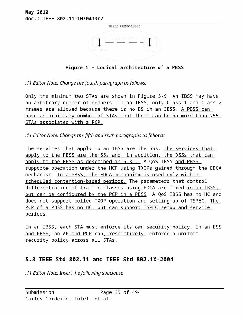
May 2010 doc.: IEEE 802.11-10/0433r2
The NAV-SA and the NAV-DA fields addresses are of the Source STA and the Destination STA, respectively, whose exchange of an RTS and mmWaveCTS caused an update to the NAV at the transmitting STA.
7.2.1.15 mmWaveCF-EndThe frame format for the mmWaveCF-End frame is as defined in Figure 8.
Frame Control
Duration RA TA FCS
Octets: 2 2 6 6 4
Figure 8 – mmWaveCF-End frame
The Duration field in the mmWaveCF-End frame is set to the time required to complete the mmWaveCF-End truncation sequence of which it is part (see 9.23.8): Duration = (i-1)*(mmWaveCF-End + SIFS), where i is in the range [1,3] and indicates the order of the mmWaveCF-End frame in the truncation sequence in the reverse direction (i.e., i=1 corresponds to the last mmWaveCF-End frame in the sequence).
The RA field is the address of the STA that is the intended immediate recipient of the directed data or management frame or the Broadcast Address.
The TA field is the address of the STA transmitting the mmWaveCF-End frame.
7.2.1.16 Sector sweep (SS)
The frame format for the SS frame is as defined in Figure 9.
FrameControl
Duration RA TA SS SS Feedback
FCS
Octets: 2 2 6 6 3 3 4
Figure 9 – SS frame
The Duration field is set to the time until the end of the SS frame transmission with CDOWN subfield within the SS field equal to zero or the end of the current allocation (see 9.25), whichever comes first.
The RA field contains the address of the STA that is the intended receiver of the sector sweep.
The TA field contains the address of the transmitter STA of the sector sweep frame.
The SS field is defined in 7.3a.1 Sector Sweep field.
The SS Feedback field is defined in 7.3a.3 Sector Sweep Feedback field.
Submission Page 35 of 339 Carlos Cordeiro, Intel, et al.
May 2010 doc.: IEEE 802.11-10/0433r2
7.2.1.17 Sector sweep feedback (SS-Feedback)
The format of the SS-Feedback frame is shown in Figure 10.
Frame Control
Duration RA TA SS SS Feedback
BRP Request
FCS
Octets: 2 2 6 6 3 3 3 4
Figure 10 – SS-Feedback frame
The Duration field is set to zero when the SS-Feedback frame is transmitted within an A-BFT. Otherwise, it is set to the time, in microseconds, required to transmit an SS-ACK frame plus SIFS. The RA field contains the address of the STA that is the intended destination of the SS-Feedback frame.
The TA field contains the address of the STA transmitting the SS-Feedback frame.
The SS field is defined in 7.3a.1 Sector Sweep field.
The SS Feedback field is defined in 7.3a.3 Sector Sweep Feedback field.
The BRP Request field is defined in 7.3a.4 BRP Request field.
7.2.1.18 Sector sweep ACK (SS-ACK)
The format of the SS-ACK frame is shown in Figure 11.
Frame Control
Duration RA TA SS SS Feedback
BRP Request
FCS
Octets: 2 2 6 6 3 3 3 4
Figure 11 – SS-ACK frame
The Duration field is set to the value of the Duration within the immediatelly preceding SS-Feedback frame, minus SIFS, minus the time required to transmit the SS-ACK frame. The RA field contains the address of the STA that is the intended destination of the SS-ACK frame.
The TA field contains the address of the STA transmitting the SS-ACK frame.
The SS field is defined in 7.3a.1 Sector Sweep field.
The SS Feedback field is defined in 7.3a.3 Sector Sweep Feedback field.
The BRP Request field is defined in 7.3a.4 BRP Request field.
Submission Page 36 of 339 Carlos Cordeiro, Intel, et al.
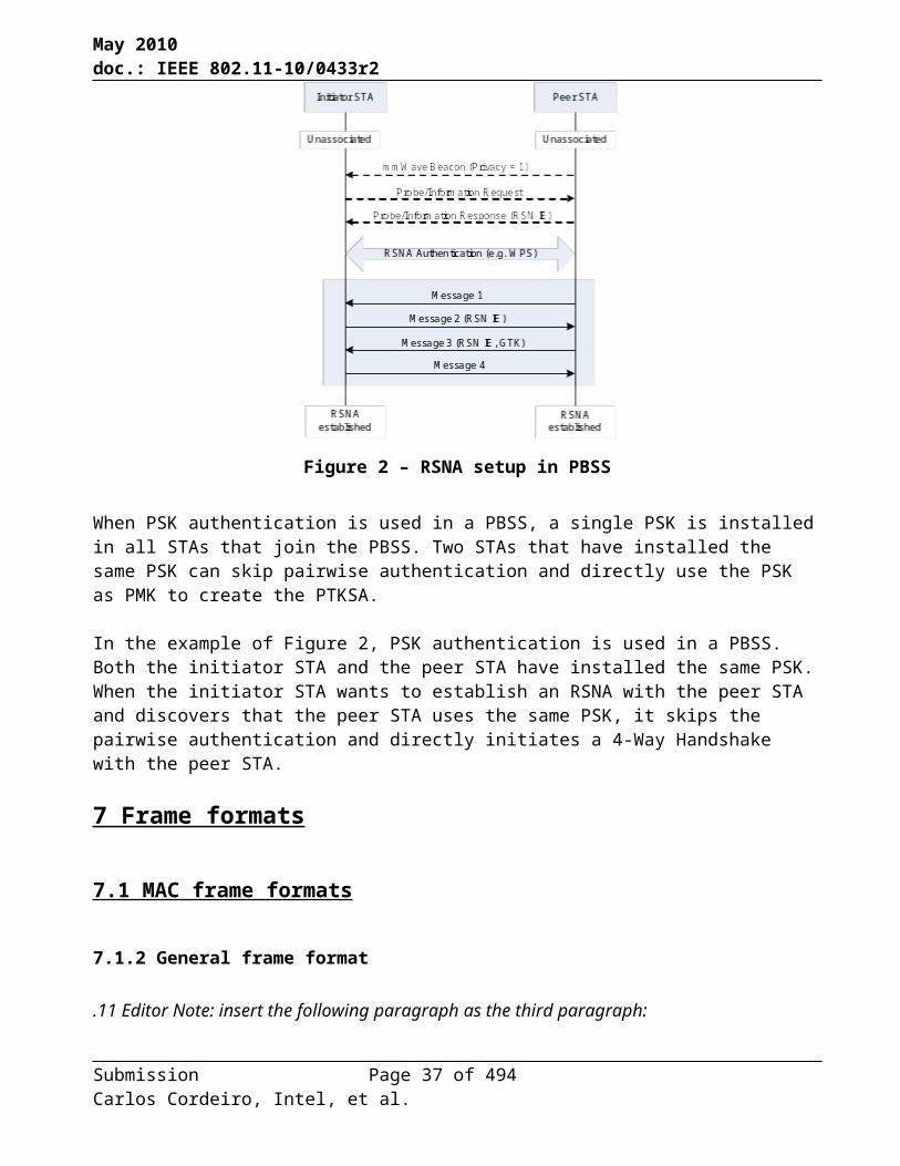
May 2010 doc.: IEEE 802.11-10/0433r2
7.2.2 Data frames
7.2.2.1 Data frame format
.11 Editor Note: modify Table 7-7 as follows:
Table 7-7 – Address field contents
To DS
From DS
Address 1 Address 2 Address 3 Address 4
MSDU and Short
A-MSDU case
A-MSDU case
MSDU and Short A-MSDU
case
A-MSDU case
0 0 RA=DA TA=SA BSSID BSSID NA NA
0 1 RA=DA TA=BSSID SA BSSID NA NA
1 0 RA=BSSID TA=SA DA BSSID NA NA
1 1 RA TA DA BSSID SA BSSID
.11 Editor’s instructions: modify the indicated text as follows:b) If the STA is a member of an IBSS, the BSSID is the BSSID of the IBSS.c) If the STA participates in a PBSS, the BSSID is the address of the STA contained in the PCP of the PBSS.
.11 Editor’s instructions: add at end of the subcaluse:
The QoS Data and QoS Null subtypes are the only Data subtypes transmitted using the mmWave PHY (Clause 21).
The HT Control field is not present in frames transmitted using the mmWave PHY.
7.2.2.2 Aggregate MSDU format (A-MSDU) .11 Editor: change the first paragraph as follows:
An A-MSDU is a sequence of A-MSDU subframes as shown in Figure 7-17a. Each A-MSDU subframe consists of an A-MSDU subframe header followed by an MSDU and 0-3 octets of padding as shown in Figure 7-17b and Figure 12 . Each A-MSDU subframe (except the last) is padded so that its length is a multiple of 4 octets. The last A-MSDU subframe has no padding.
.11 Editor: insert the following text as the new second paragraph:
Two A-MSDU subframe formats are defined: the standard A-MSDU subframe described below and the Short A-MSDU subframe described in 7.2.2.2.1.
Submission Page 37 of 339 Carlos Cordeiro, Intel, et al.
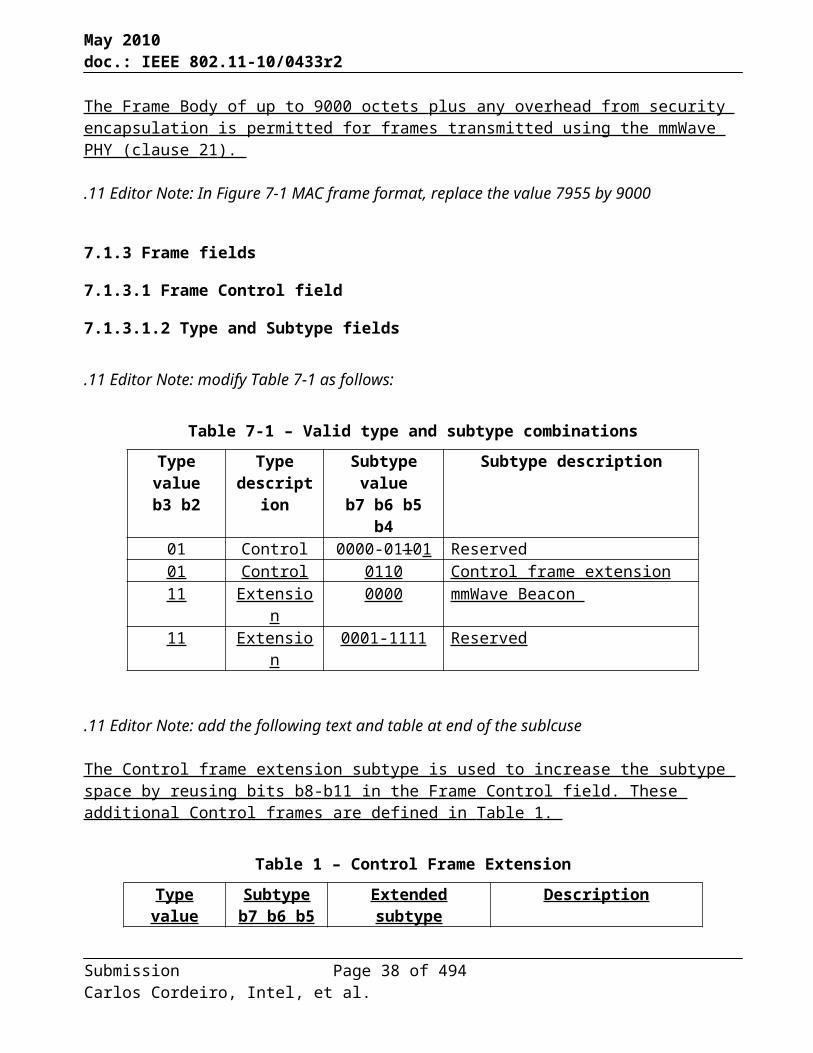
Length
2
MSDU
0-9000Octets:
A-MSDU subframe header
Padding
0-3
May 2010 doc.: IEEE 802.11-10/0433r2
.11 Editor: change the length of the MSDU in (Figure 7-17b - A-MSDU subframe structure) to “0-2304 (non-mSTA) and 0-9000 (mSTA)”
.11 Editor: modify NOTE 3 in this subclause to reflect the 0-9000 MSDU length for mSTAs
7.2.2.2.1 Short A-MSDU subframe formatThe Short A-MSDU subframe is shown in Figure 12.
Figure 12 – Short A-MSDU subframe structure
The Short A-MSDU subframe header consists of a Length field that contains the length in octets of the MSDU.
7.2.3 Management frames.11 Editor note: add at end of the subclause
Within a PBSS, the BSSID field of a management frame is set to the MAC address in use by the STA contained in the PCP of the PBSS.
7.2.3.1 Beacon frame format
.11 editor Note: Insert the following row in Table 7-8 “Beacon Frame Body”, renumbering as appropriate
Order Information Notes<ANA> Multi-band The Multi-band element is optionally present if
dot11MultibandSupportEnabled is true.
7.2.3.4 Association Request frame format
.11 editor Note: Insert the following row in Table 7-10 “Association Request Frame Body”, renumbering as appropriate
Order Information Notes<ANA> Multi-band The Multi-band element is optionally present if
dot11MultibandSupportEnabled is true.
Submission Page 38 of 339 Carlos Cordeiro, Intel, et al.
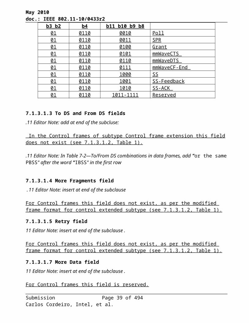
May 2010 doc.: IEEE 802.11-10/0433r2
<ANA> mmWave Capabilities The mmWave Capabilities element is present when dot11MmWaveCapable is set to true.
7.2.3.5 Association Response frame format
.11 editor Note: Insert the following row in Table 7-11 “Association Response Frame Body”, renumbering as appropriate
Order Information Notes<ANA> Multi-band The Multi-band element is optionally present if
dot11MultibandSupportEnabled is true.<ANA> mmWave Capabilities The mmWave Capabilities element is present when
dot11MmWaveCapable is set to TRUE. <ANA> mmWave Operation The mmWave Operation element is present when
dot11MmWaveCapable is set to TRUE.
7.2.3.6 Reassociation Request frame format
.11 editor Note: Insert the following row in Table 7-12 “Reassociation Request Frame Body”, renumbering as appropriate
Order Information Notes<ANA> Multi-band The Multi-band element is optionally present if
dot11MultibandSupportEnabled is true.<ANA> mmWave Capabilities The mmWave Capabilities element is present when
dot11MmWaveCapable is set to TRUE.
7.2.3.7 Reassociation Response frame format.11 editor Note: Insert the following row in Table 7-13 “Reassociation Response Frame Body”, renumbering as appropriate
Order Information Notes<ANA> Multi-band The Multi-band element is optionally present if
dot11MultibandSupportEnabled is true.<ANA> mmWave Capabilities The mmWave Capabilities element is present when
dot11MmWaveCapable is set to TRUE. <ANA> mmWave Operation The mmWave Operation element is present when
dot11MmWaveCapable is set to TRUE.
7.2.3.8 Probe Request frame format.11 editor Note: Insert the following row in Table 7-14 “Probe Request Frame Body”, renumbering as appropriate
Submission Page 39 of 339 Carlos Cordeiro, Intel, et al.
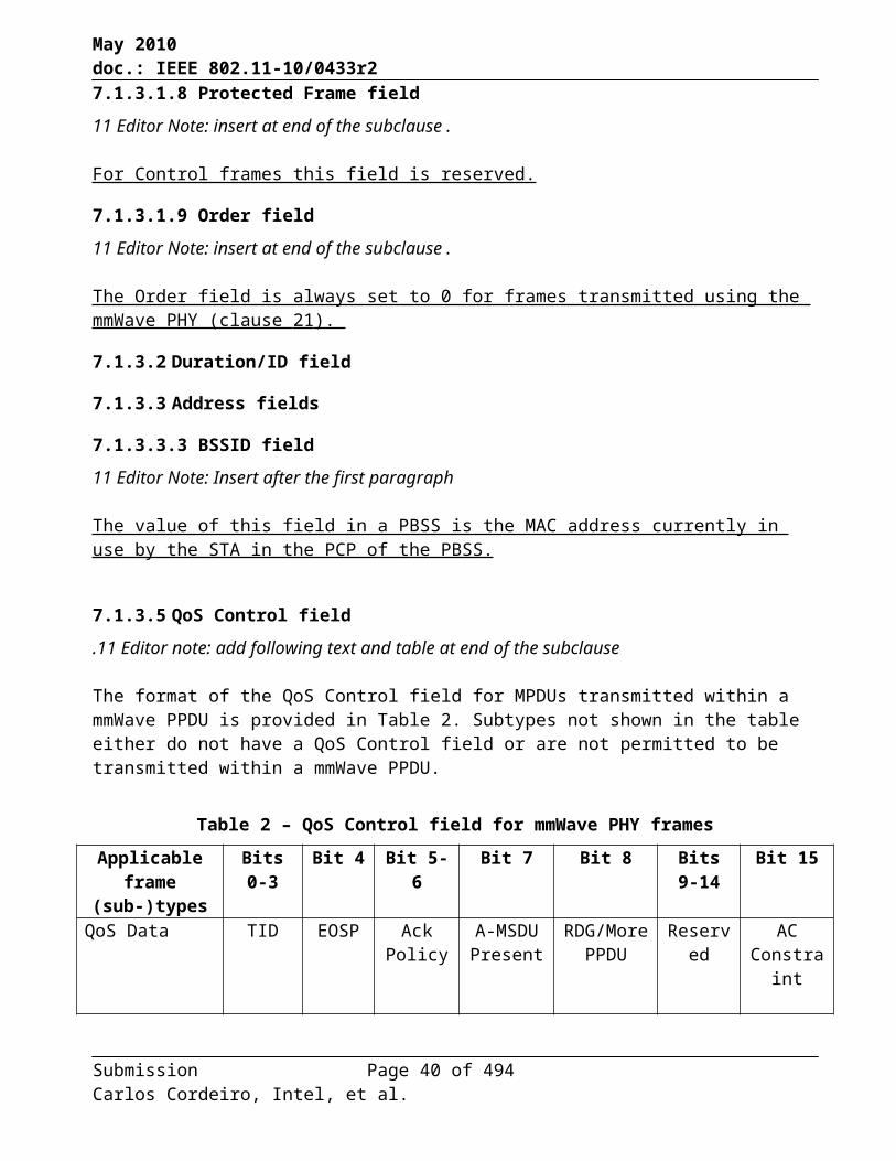
May 2010 doc.: IEEE 802.11-10/0433r2
Order Information Notes<ANA> Multi-band The Multi-band element is optionally present if
dot11MultibandSupportEnabled is true.<ANA> mmWave Capabilities The mmWave Capabilities element is present when
dot11MmWaveCapable is set to TRUE.
7.2.3.9 Probe Response frame format.11 editor Note: Insert the following row in Table 7-15 “Probe Response Frame Body”, renumbering as appropriate
Order Information Notes<ANA> Multi-band The Multi-band element is optionally present if
dot11MultibandSupportEnabled is true.<ANA> mmWave Capabilities The mmWave Capabilities element is present when
dot11MmWaveCapable is set to TRUE. <ANA> mmWave Operation The mmWave Operation element is present when
dot11MmWaveCapable is set to TRUE.
.11 Editor Note: Insert the following after section 7.2.3:
7.2.4 Extension frames
7.2.4.1 mmWave BeaconThe format of the mmWave Beacon is shown in Figure 13.
In addition to its function as a Beacon, the mmWave Beacon frame may also be used as training frame for beamforming (9.25).
Octets: 2 2 6 Variable 4
Frame Control Duration
RA Body FCS
Figure 13 – mmWave Beacon frame format
The Duration field is set to the time remaining until the end of the BT.
The RA field contains the BSSID.
The body of the mmWave Beacon frame contains the elements listed in Table 3.
Table 3 – mmWave Beacon frame bodyOrder Information Notes
1 Sector sweep See 7.3a.1 Sector Sweep field2 Timestamp See 7.3.1.10
Submission Page 40 of 339 Carlos Cordeiro, Intel, et al.

May 2010 doc.: IEEE 802.11-10/0433r2
3 Beacon interval See 7.3.1.3 4 Beacon Interval Control See below5 mmWave Capability See below6 PCP/AP Clustering Control Optional (see below)7 RSN The RSN element is optionally present when
dot11RSNAEnabled is set to TRUE. 8 Multiple BSSID One or more Multiple BSSID elements are
optionally present if dot11MgmtOptionMultiBSSIDEnabled is set to TRUE.
Last - 1
One or more resource and/or capability related information elements may appear in this frame. These information elements follow all other information elements that are not vendor-specific information elements and precede all other information elements that are vendor-specific information elements that are part of the Last field in the frame.
Optional
The format of the Beacon Interval Control field is shown in Figure 14.
CC present
Discovery Mode
Next Beacon
AT Present
A-BFT Length
FSS Responder T/RXSS
Bits: B0 B1 B2-B5 B6 B7-B10 B11-B13
B14
Next A-BFT
Fragment
TXSS Span
N BIs A-BFT
A-BFT count
N A-BFT in Ant
PCP AssocReady
Reserved
Bits:
B15-B20
B21 B22-B28 B29-B31
B32-B37 B38-B43
B44 B45-B47
Figure 14 – Beacon Interval Control
The CC present field is set to one to indicate that the PCP/AP clustering control field is present in the mmWave Beacon. The PCP/AP clustering control field is not present otherwise.
The Discovery Mode field is set to one if the STA is generating the mmWave Beacon following the procedure described in 11.1.2.1b Beacon generation before network initialization. Otherwise, this field is set to zero.
The Next Beacon field indicates the number of beacon intervals following the current beacon interval during which the mmWave Beacon will be not present. The AT present field set to one indicates that the AT period is present in the current beacon interval. The AT period is not present otherwise.
Submission Page 41 of 339 Carlos Cordeiro, Intel, et al.
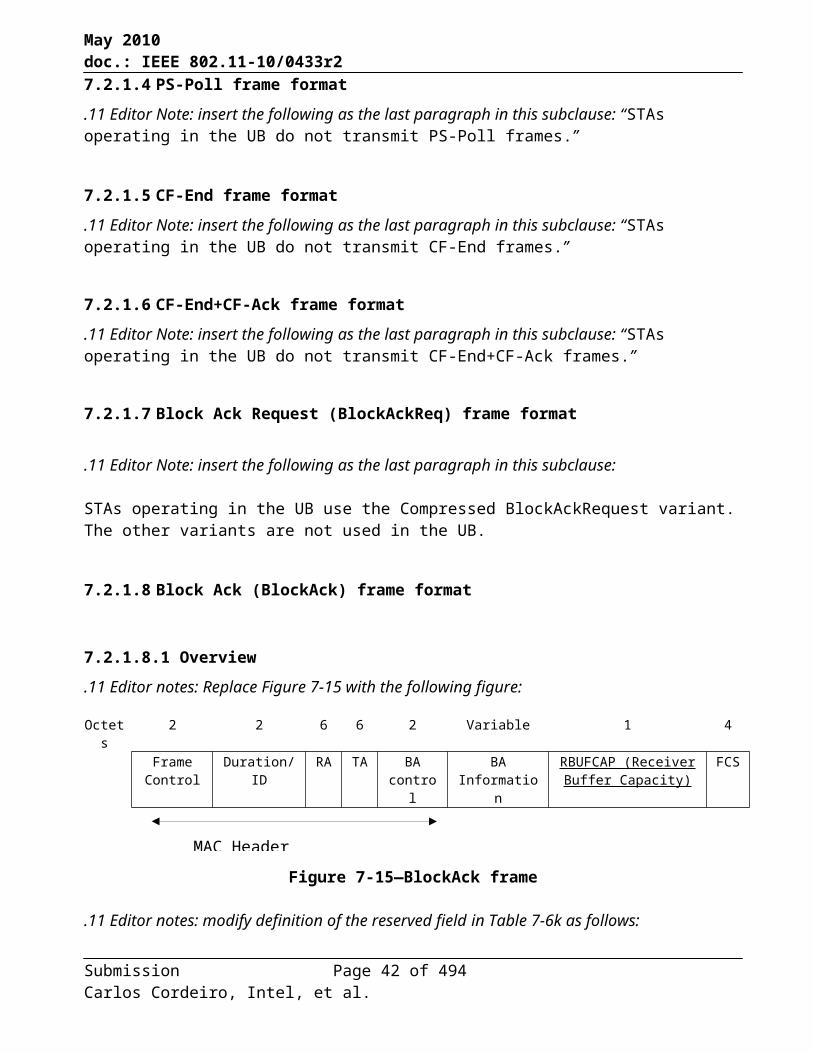
May 2010 doc.: IEEE 802.11-10/0433r2
The A-BFT Length field specifies the size of the A-BFT following the BT, and is defined in units of a sector sweep slot (9.25.4).
The FSS field specifies the number of SS frames allowed per each sector sweep slot (9.25.4).
The Responder T/RXSS field is set to one to indicate the A-BFT following the BT is used for responder TXSS. This field is set to zero to indicate responder RXSS. When this field is set to zero, the FSS field specifies the length of a complete RX sector sweep by the PCP/AP.
The Next A-BFT field indicates the number of beacon intervals during which the A-BFT will be not present. The value of zero in this field indicates that the A-BFT immediately follows this BT.
The Fragment field is set to 1 to indicate the TXSS is a fragmented sweep, and is set to 0 to indicate the TXSS is a complete sweep.
The TXSS Span field indicates the number of BIs it takes for the PCP/AP to complete the TXSS phase.
The N BIs per A-BFT field indicates the frequency, in number of BIs, with which the PCP/AP allocates an A-BFT.
The A-BFT count field indicates the number of A-BFTs since the PCP/AP started transmitting from the current antenna.
The N A-BFT in Ant field indicates how many A-BFTs the PCP/AP receives from each antenna- in the antenna receive rotation.
The PCP AssocReady field is set to 1 to indicate that the PCP is ready to receive Association Request frames from non-PCP STAs, and is set to 0 otherwise. This field is ignored when transmitted by a non-PCP STA. The format of the mmWave Capability field is shown in Figure 15.
BSS type CBP only mmWave Privacy
Reserved
Bits: B0-B1 B2 B3 B4-B7
Figure 15 – mmWave Capability
The BSS type field indicates the type of BSS established by the STA transmitting the mmWave Beacon as follows:
B0 B1 BSS type Transmitted by mSTA
1 1 Infrastructure BSS
AP
1 0 PBSS PCP
Submission Page 42 of 339 Carlos Cordeiro, Intel, et al.

May 2010 doc.: IEEE 802.11-10/0433r2
0 1 IBSS Any non-AP and non-PCP mSTA
0 0 Reserved
The BSS type field is ignored if the the Discovery Mode field is set to one.
The CBP only field indicates the type of link access provided by the PCP/AP in the DTT of the BI. An AP/PCP sets the CBP only bit to 1 when the entirety of the DTT portion of the BI is allocated as a CBP for random access. An AP/PCP sets the CBP only bit to 0 when the allocation of the DTT portion of the BI is provided by the AP/PCP through the Extended Schedule element.
The mmWave Privacy subfield is set to 1 if dot11RSNAEnabled is true. Otherwise, this subfield is set to 0.
The format of the PCP/AP Clustering Control field is shown in Figure 16.
Reserved ClusterMemRole ClusterID ClusterMaxMem ClusterTimeInterv Bits: B0 B1-B2 B3-B50 B51-B53 B54-B63
Figure 16 – PCP/AP clustering control field format The ClusterMemRole field identifies the role that the transmitting STA takes within the cluster. A value of 0 means that the STA is currently not participating in clustering. A value of 1 means that the STA acts as the S-PCP/S-AP of the cluster. A value of 2 means that the STA participates in the cluster, but not as the S-PCP/S-AP. The value of 3 is reserved.
The cluster to which the transmitter of the PCP/AP clustering control field belongs is identified by the ClusterID field. The MAC address of the S-PCP/S-AP is the ClusterID of the cluster.
The ClusterMaxMem field defines maximum number of PCPs and/or APs that participate in the cluster.
The ClusterTimeInterv field defines the time interval, in units of 8 microseconds, between the start of Beacon SPs of PCPs and/or APs participating in the cluster of the transmitting STA.
7.3 Management and extension frames body components
7.3.1 Fields that are not information elements
7.3.1.8 AID field.11 Editor Note: add at end of the subclause
The value assigned for the AID field is in the range 1-254 and the value 0 is reserved as the broadcast AID when the field is transmitted in a frame sent using the mmWave PHY (clause 21). The value 255 corresponds to the PCP/AP.
Submission Page 43 of 339 Carlos Cordeiro, Intel, et al.
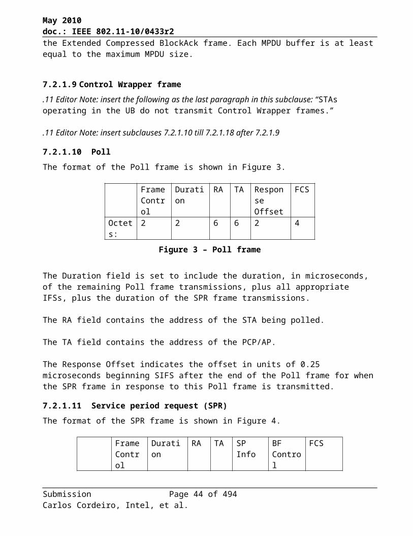
May 2010 doc.: IEEE 802.11-10/0433r2
7.3.1.9 Status Code field
.11 Editor: in Table 7-23 Status codes, replace all occurrences of “AP” by “AP/PCP”, “HC” by “HC/PCP”
.11 Editor: Insert the following rows in Table 7-23 Status codes, and change the last row as follows:
Status Code Meaning52 Reject with recommended schedule53 Reject because no wakeup schedule specified54 Success, the Destination STA is in power save mode55 FST pending, in process of acquiring resources from AP/PCP56 Performing FST now57 FST pending, gap(s) in Block Ack window
5 2 8 – 65 535 Reserved
7.3.1.11 Action field.11 Editor Note: Modify Table 7-24 as it is shown in Table 4.
Table 4 – Category ValuesCode Meaning See subclause Robust
<ANA> mmWave 7.4.13
<ANA> Fast session transfer 7.4.14 Yes
7.3.1.51 Relay capable STA info field
The format of the Relay Capable STA Info field is defined in Figure 17.
AID Relay Capabilities InfoBits:
B0-B7 B8-B15
Figure 17 – Relay STA Info field
The AID field contains the AID of the relay capable STA which is associated with PCP/AP.
The Relay Capabilities Info field is defined in 7.3.2.110.
7.3.2 Information elements
.11 Editor Note: insert the following rows in “Table 7-26 – Element IDs”
Submission Page 44 of 339 Carlos Cordeiro, Intel, et al.
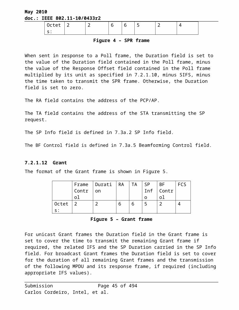
May 2010 doc.: IEEE 802.11-10/0433r2
Table 7-26 – Element IDsInformation element Element ID Length (in octets)Wakeup Schedule <ANA> 6Extended Schedule <ANA> 15 to 255STA Availability <ANA> 2 to 256Extended mmWave TSPEC <ANA> 13Next mmWave AT <ANA> 4mmWave Capabilities <ANA> 17mmWave Operation <ANA> 10mmWave BSS Parameter Change <ANA> 7mmWave Service <ANA> 16 to 256mmWave Beam refinement <ANA> 5Channel measurement feedback <ANA> 4 to 256Awake Window <ANA> 2Multi-band <ANA> 23 to 255ADDBA extension <ANA> 1NextPCP List <ANA> 2 to 256PCP Handover <ANA> 2Link Margin <ANA> 8Switching Stream <ANA> 4 to 256Session Transition <ANA> 11 Dynamic Tone Pairing Report <ANA> 32Cluster report <ANA> 13 to 256Relay capabilities <ANA> 1Relay transfer parameter set <ANA> 8
7.3.2.20 Channel Switch Announcement element.11 Editor Note: Change the first paragraph as follows:
The Channel Switch Announcement element is used by an AP in a BSS or a STA in an IBSS or a PCP in a PBSS to advertise when it is changing to a new channel and the corresponding channel number of the new channel. The format of the Channel Switch Announcement element is shown in Figure 7-57.
7.3.2.21 Measurement Request element
Table 7-29 – Measurement Type definitions for measurement requestsName Measurement Type Measurement Use
Directional Channel Quality request 10 Radio Resource MeasurementDirectional Measurement request 11 Radio Resource Measurement Directional Statistics request 12 Radio Resource Measurement Reserved 13-254 N/A
Table 7-30 – Measurement Type definitions for measurement reports Name Measurement Type Measurement Use
Submission Page 45 of 339 Carlos Cordeiro, Intel, et al.
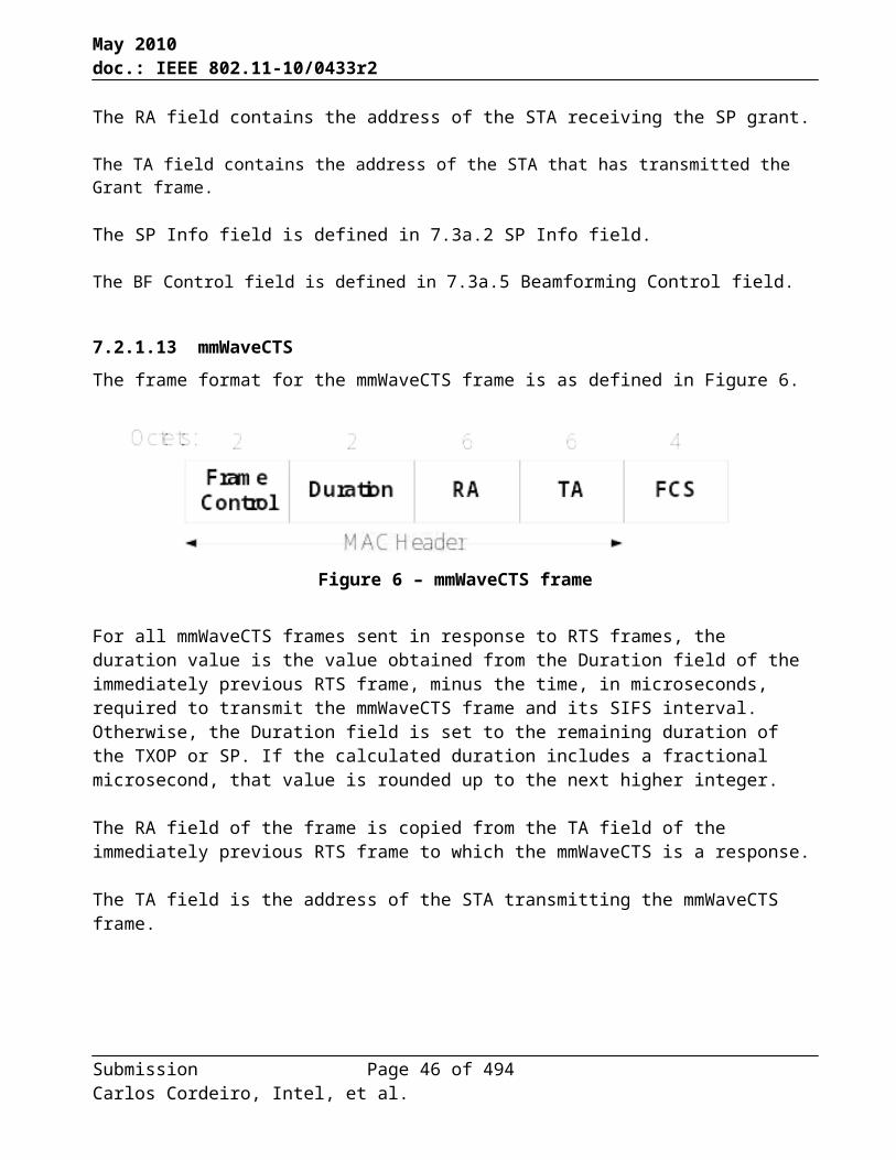
May 2010 doc.: IEEE 802.11-10/0433r2
Directional Channel Quality report 10 Radio Resource MeasurementDirectional Measurement report 11 Radio Resource MeasurementDirectional Statistics report 12 Radio Resource MeasurementReserved 13-254 N/A
.11 Editor Note: insert the following subclauses
7.3.2.21.12 Directional Channel Quality requestThe Measurement Request field corresponding to a Directional Channel Quality request is shown in Figure 18. This Measurement Request is transmitted from a Requesting STA to a Requested STA to perform measurements towards a Target STA.
Regulatory Class Channel Number AID Reserved Measurement Method
Octets: 1 1 1 1 1
Measurement Start Time
Measurement Duration
Number of Time Blocks
Optional Subelements
Octets:
8 2 1 Variable
Figure 18 – Measurement request field format for Directional Channel Quality Request
Regulatory Class indicates the channel set for which the measurement request applies. Country, Regulatory Class, and Channel Number together specify the channel frequency and spacing for which the measurement request applies. Valid values of Regulatory Class are shown in Annex J.
Channel Number indicates the channel number for which the measurement request applies. Channel Number is defined within a Regulatory Class as shown in Annex J.
The AID indicates the Target STA. If the Requested STA is already beamformed with the Target STA, then the measurement shall be carried out employing the same receive antenna configuration as is used when receiving frames from the Target STA. If the AID is set to the BcastID or an unknown AID, then the Requested STA shall perform the measurements using an quasi-omni antenna pattern.
The Measurement Method indicates the method that is to be used by the Requested STA to carry out this measurement request and report back in the measurement report. If this field is set to zero (0) it indicates ANIPI. If this field is set to one (1), it indicates RSNI. Other values are reserved.
The Measurement Start Time field is set to the TSF timer at the time at which the requested measurement shall start. A value of 0 indicates that the measurement starts immediately.
The Measurement Duration field is set to the preferred or mandatory duration of the requested measurement, expressed in units of TUs. See 11.10.3.
Submission Page 46 of 339 Carlos Cordeiro, Intel, et al.
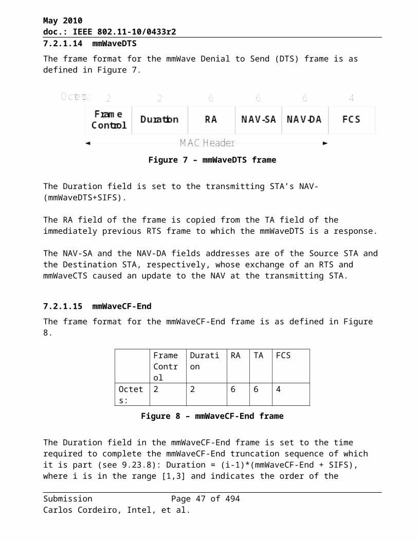
May 2010 doc.: IEEE 802.11-10/0433r2
The Number of Time Blocks indicates the number of time blocks within the Measurement Duration. The ratio (Measurement Duration / Number of Time Blocks) provides the duration of an individual measurement unit.
The Optional Subelements field format contains zero or more Subelements, each consisting of a 1-octet Subelement ID field, a 1-octet Length field, and a variable length Data field, as shown in Figure 7-95p. Any optional subelements are ordered by non-decreasing Subelement ID.
The Subelement ID field values for the defined optional subelements are shown in Table 5. A Yes in the Extensible column of a subelement listed in Table 5. indicates that the Length of the subelement might be extended in future revisions or amendments of this specification. When the Extensible column of an element is set to Subelements, then the subelement might be extended in future revisions or amendments of this specification by defining additional subelements within the subelement. See 9.14.2.
Table 5 – Optional Subelement IDs for Directional Channel Quality Request
Subelement ID
Name Length field (octets) Extensible
0 Reserved
1 Directional Channel Quality Reporting Information
2 Yes
2-220 Reserved
221 Vendor Specific 1 to 244
222-225 Reserved
The Directional Channel Quality Reporting Information subelement indicates the condition for issuing a Directional Channel Quality Report. Directional Channel Quality Reporting Information subelement data field format is shown in Figure 19 and contains a 1-octet Reporting Condition subfield and a 1-octet Directional Channel Quality Reference Value subfield. The Reporting Condition is described in Table 6. The Directional Channel Quality Reference value is a Directional Channel Quality value and is the reference value for the indicated Reporting Condition.
Reporting Condition
Directional Channel Quality Reference Value
Octets: 1 1
Figure 19 – Directional Channel Quality Reporting Information data field format
Table 6 – Reporting Condition for Directional Channel Quality Report
Condition for report to be issued Reporting Condition
Submission Page 47 of 339 Carlos Cordeiro, Intel, et al.
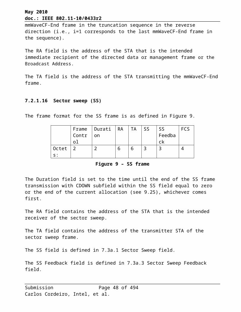
May 2010 doc.: IEEE 802.11-10/0433r2
Report to be issued after each measurement (default, used when Directional Channel Quality Reporting Information subelement is not included in Directional Channel Quality Request).
0
Report to be issued when measured ANIPI or RSNI is equal to or greater than the reference value.
1
Report to be issued when measured ANIPI or RSNI is equal to or less than the reference value.
2
Reserved 3-255
The Vendor Specific subelements have the same format as their corresponding elements (see 7.3.2.26). Multiple Vendor Specific subelements can be included in the list of Optional Subelements.
7.3.2.21.13 Directional Measurement request The Measurement Request field corresponding to a Directional Measurement request is shown in Figure 20. This Measurement Request is transmitted from a Requesting STA to a Requested STA to perform directional channel measurements in all sectored receiving directions.
Regulatory Class
Channel Number
Measurement Start Time
Measurement Duration per Direction
Measurement Method
Optional Subelements
Octets 1 1 8 2 1 Variable
Figure 20 – Directional Measurement RequestRegulatory Class indicates the channel set for which the measurement request applies. Country, Regulatory Class, and Channel Number together specify the channel frequency and spacing for which the measurement request applies. Valid values of Regulatory Class are shown in Annex J.
Channel Number indicates the channel number for which the measurement request applies. Channel Number is defined within a Regulatory Class as shown in Annex J.
The Measurement Start Time field is set to the TSF timer at the time at which the requested measurement shall start. A value of 0 indicates that the measurement starts immediately.
The Measurement Duration per Direction field is set to the preferred or mandatory duration of the requested measurement in each receiving direction, expressed in units of TUs.
The Measurement Method indicates the method that is to be used by the Requested STA to carry out this measurement request and report back in the measurement report. If this field is set to zero (0) it indicates ANIPI. If this field is set to one (1), it indicates RCPI. If the field is set to two (2), it indicates Channel Load. Other values are reserved.
The Optional Subelements field format contains zero or more Subelements, each consisting of a 1-octet Subelement ID field, a 1-octet Length field, and a variable length Data field, as shown in Figure 7-95p. Any optional subelements are ordered by non-decreasing Subelement ID.
Submission Page 48 of 339 Carlos Cordeiro, Intel, et al.
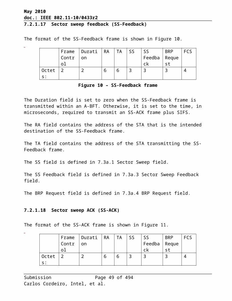
May 2010 doc.: IEEE 802.11-10/0433r2
7.3.2.21.14 Directional Statistics request The Measurement Request field corresponding to a Directional Statistics request is shown in Figure21. This Measurement Request is transmitted from a Requesting STA to a Requested STA to perform directional channel measurements in all sectored receiving directions.
Regulatory class
Channel number
Measurement Start Time
Measurement Duration per Direction
Measurement Method
Directional Statistics Bitmap
Optional Subelements
Octets 1 1 8 2 1 1 Variable
Figure 21 – Directional Statistics Request
Regulatory Class indicates the channel set for which the measurement request applies. Country, Regulatory Class, and Channel Number together specify the channel frequency and spacing for which the measurement request applies. Valid values of Regulatory Class are shown in Annex J.
Channel Number indicates the channel number for which the measurement request applies. Channel Number is defined within a Regulatory Class as shown in Annex J.
The Measurement Start Time field is set to the TSF timer at the time at which the requested measurement shall start. A value of 0 indicates that the measurement starts immediately.
The Measurement Duration per Direction field is set to the preferred or mandatory duration of the requested measurement in each receiving direction, expressed in units of TUs.
The Measurement Method indicates the method that is to be used by the Requested STA to carry out this measurement request and report back in the measurement report. If this field is set to zero (0) it indicates ANIPI. If this field is set to one (1), it indicates RCPI. If the field is set to two (2), it indicates Channel Load. Other values are reserved.
The Directional Statistics Bitmap field format is shown in Figure 22. The Maximum field indicates that the maximum measurement result among all directions is expected in the measurement report. The Minimum field indicates that the minimum measurement result among all directions is expected in the measurement report. The Average field indicates that the average measurement result among all directions is expected in the measurement report. The Variance field indicates that the variance of measurement results among all directions is expected in the measurement report. Others are reserved.
Figure 22 – Directional Statistics Bitmap field format
The Optional Subelements field format contains zero or more Subelements, each consisting of a 1-octet Subelement ID field, a 1-octet Length field, and a variable length Data field, as shown in Figure 7-95p. Any optional subelements are ordered by non-decreasing Subelement ID.
Submission Page 49 of 339 Carlos Cordeiro, Intel, et al.
Maximum Minimum Average Variance ReservedBits: 1 1 1 1 4

May 2010 doc.: IEEE 802.11-10/0433r2
7.3.2.22 Measurement Report element.11 Editor Note: insert the following subclauses
7.3.2.22.11 Directional Channel Quality reportThe format of the Measurement Report field of a Directional Channel Quality Report is shown in Figure 23.
Regulatory Class
Channel Number
AID Reserved
Measurement Method
Measurement Start Time
Octets: 1 1 1 1 1 8
Measurement Duration
Number of Time Blocks (N)
Measurement for Time block 1
… Measurement for Time block N
Optional subelements
Octets: 2 1 1 1 Variable
Figure 23 – Measurement report field format for Directional Channel Quality Report
Regulatory Class indicates the channel set for which the measurement report applies. Country, Regulatory Class, and Channel Number together specify the channel frequency and spacing for which the measurement report applies. Valid values of Regulatory Class are shown in Annex J.
Channel Number indicates the channel number for which the measurement report applies. Channel Number is defined within a Regulatory Class as shown in Annex J.
The AID indicates the Target STA.
The Measurement Method indicates the method used by the STA to carry out this measurement request and the format of the Measurement for Time Block field(s). If this field is set to zero (0) it indicates that the Measurement for Time Block fields are expressed in ANIPI. If this field is set to one (1), it indicates that the Measurement for Time Block fields are expressed in RSNI. Other values are reserved.
Measurement Start Time is set to the value of the measuring STA’s TSF timer at the time the measurement started.
The Measurement Duration field is set to the duration of the measurement, expressed in units of TUs.
The Number of Time Blocks indicates the number of time blocks within the Measurement Duration. The ratio (Measurement Duration / Number of Time Blocks) provides the duration of an individual measurement unit.
Submission Page 50 of 339 Carlos Cordeiro, Intel, et al.
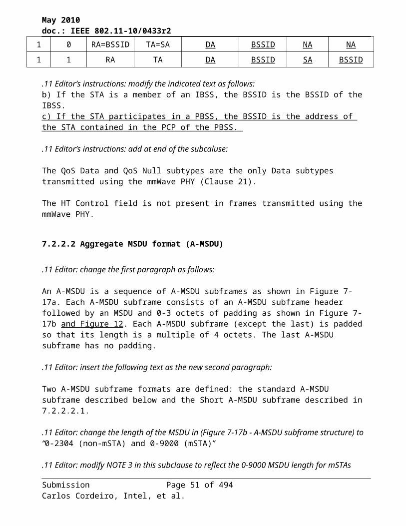
May 2010 doc.: IEEE 802.11-10/0433r2
The Measurement for Time Block fields are set to the ANIPI or average RSNI value measured during each (Measurement Duration / Number of Time Blocks) measurement units. The measurement units are set in the report in increasing order of start times.
The Optional Subelements field format contains zero or more Subelements, each consisting of a 1-octet Subelement ID field, a 1-octet Length field, and a variable length Data field, as shown in Figure 7-95p. Any optional subelements are ordered by non-decreasing Subelement ID.
The Subelement ID field values for the defined optional subelements are shown in Table 7. A Yes in the Extensible column of a subelement listed in Table 7 indicates that the Length of the subelement might be extended in future revisions or amendments of this specification. When the Extensible column of an element is set to Subelements, then the subelement might be extended in future revisions or amendments of this specification by defining additional subelements within the subelement. See 9.14.2.
Table 7 – Optional Subelement IDs for Directional Channel Quality Report
Subelement ID
Name Length field (octets)
Extensible
0-220 Reserved
221 Vendor Specific 1 to 255
222-255 Reserved
The Vendor Specific subelements have the same format as their corresponding elements (see 7.3.2.26). Multiple Vendor Specific subelements can be included in the list of Optional Subelements.
7.3.2.22.12 Directional Measurement reportThe format of the Measurement Report field of a Directional Measurement report is shown in Figure 24.
Regulatory Class
Channel Number
Measurement Start Time
Measurement Duration per Direction
Measurement Method
Measurement Results
Optional Subelements
Octets 1 1 8 2 1 Variable Variable
Figure 24 – Directional Measurement Report
Regulatory Class indicates the channel set for which the measurement report applies. Country, Regulatory Class, and Channel Number together specify the channel frequency and spacing for which the measurement report applies. Valid values of Regulatory Class are shown in Annex J.
Channel Number indicates the channel number for which the measurement report applies. Channel Number is defined within a Regulatory Class as shown in Annex J.
The Measurement Start Time field is set to the value of the measuring STA’s TSF timer at the time the measurement started.
Submission Page 51 of 339 Carlos Cordeiro, Intel, et al.
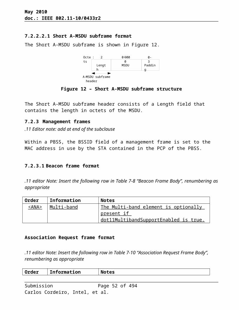
May 2010 doc.: IEEE 802.11-10/0433r2
The Measurement Duration per Direction field is set to the duration of the measurement in each receiving direction, expressed in units of TUs.
The Measurement Method indicates the method used by the STA to carry out the measurement request and the format of values in the Measurement for Direction fields. If this field is set to zero (0) it indicates that the values in the Measurement for Direction fields are expressed in ANIPI. If this field is set to one (1), it indicates that the values in the Measurement for Direction fields are expressed in RCPI. If this field is set to two (2), it indicates that the values in the Measurement for Direction fields are expressed in Channel Load. Other values are reserved.
The format of the Measurement Results field is shown in Figure 25. The Measurement for Direction fields are set to the format of values specified in the Measurement Method field.
Figure 25 – Measurement Results field formatThe Optional Subelements field format contains zero or more Subelements, each consisting of a 1-octet Subelement ID field, a 1-octet Length field, and a variable length Data field, as shown in Figure 7-95p. Any optional subelements are ordered by non-decreasing SubelementID.
7.3.2.22.13 Directional Statistics reportThe format of the Measurement Report field of a Directional Statistics report is shown in Figure 26.
Regulatory class
Channel number
Measure-ment Start Time
Measurement Duration per Direction
Measure-ment Method
Directional Statistics Bitmap
Measure-ment Results
Optional Subelements
Octets 1 1 8 2 1 1 Variable Variable
Figure 26 – Directional Statistics Report
Regulatory Class indicates the channel set for which the measurement report applies. Country, Regulatory Class, and Channel Number together specify the channel frequency and spacing for which the measurement report applies. Valid values of Regulatory Class are shown in Annex J.
Channel Number indicates the channel number for which the measurement report applies. Channel Number is defined within a Regulatory Class as shown in Annex J.
The Measurement Start Time field is set to the value of the measuring STA’s TSF timer at the time the measurement started.
The Measurement Duration per Direction field is set to the duration of the measurement in each receiving direction, expressed in units of TUs.
Submission Page 52 of 339 Carlos Cordeiro, Intel, et al.
Number of Directions
Measurement for Direction 1
Measurement for Direction 2 … Measurement for
Direction NOctets: 1 Variable Variable … Variable
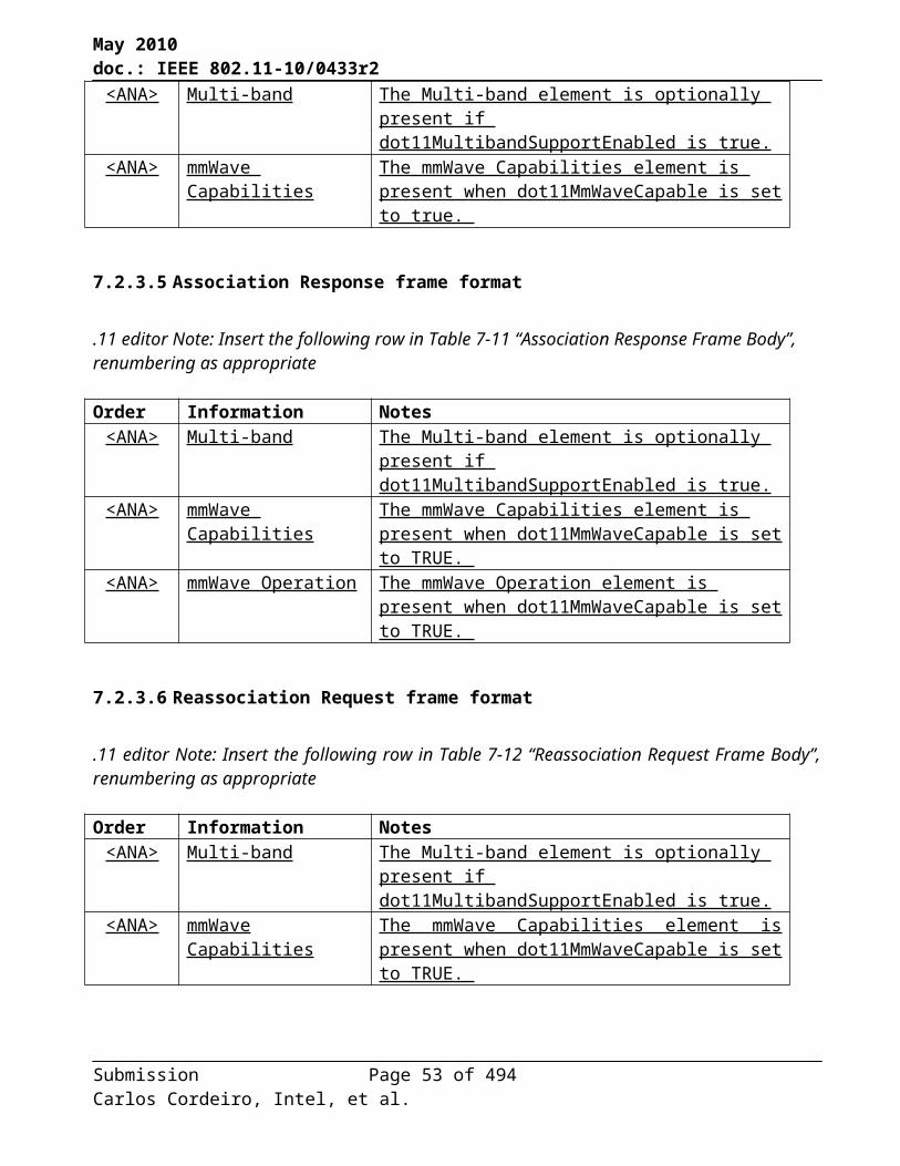
May 2010 doc.: IEEE 802.11-10/0433r2
The Measurement Method indicates the method used by the STA to carry out the measurement request and the format of values in the Measurement Results field. If this field is set to zero (0) it indicates that the values in the Measurement Results field are expressed in ANIPI. If this field is set to one (1), it indicates that the values in the Measurement Results field are expressed in RCPI. If this field is set to two (2), it indicates that the values in the Measurement Results field are expressed in Channel Load. Other values are reserved.
The Directional Statistics Bitmap field format is described in section 7.3.2.21.14. When the Maximum field is set, it indicates that the maximum measurement result among all directions is included in the Measurement Results field. When the Minimum field is set, it indicates that the minimum measurement result among all directions is included in the Measurement Results field. If the Average field is set, it indicates that the average measurement result among all directions is included in the Measurement Results field. If the Variance field is set, it indicates that the variance of measurement results among all directions is included in the Measurement Results field. Others are reserved.
The Measurement Results field is set based on the values in the Measurement Method field and the Directional Statistics Bitmap field. If two or more subfields in the Directional Statistics Bitmap are set to one, the corresponding measurement results should be included in the Measurement Results field in the same sequence as they present in the Directional Statistics Bitmap field.
The Optional Subelements field format contains zero or more Subelements, each consisting of a 1-octet Subelement ID field, a 1-octet Length field, and a variable length Data field, as shown in Figure 7-95p. Any optional subelements are ordered by non-decreasing Subelement ID.
7.3.2.25 RSN information element .11 Editor Note: include a “Joint Multi-band RSNA” subfield with a length of 1 bit in RSN Capabilities field and define it as follows: “A STA sets the Joint Multi-band RSNA subfield to 1 to indicate that it supports the Joint Multi-band RSNA (8.4.12). Otherwise, the subfield is set to 0.”
7.3.2.25.1Cipher suites.11 Editor Note: Edit Table 7-32 to include suite type for GCMP:
Table 7-32 – Cipher suite selectorsOUI Suite type Meaning00-0F-AC <ANA> GCMP – default for an RSNA
when operating in the 60 GHz band
The cipher suite selector 00-0F-AC:<ANA> (GCMP) shall be the only cipher suite value for an mSTA operating in UB .
If a pair of multi-band capable mSTAs support GCMP in a band other than the UB, GCMP shall be the only valid option for the mSTA pair in that band.
Submission Page 53 of 339 Carlos Cordeiro, Intel, et al.
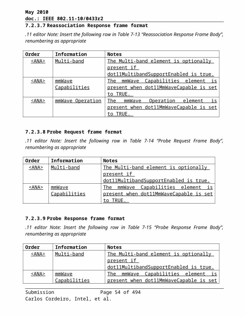
May 2010 doc.: IEEE 802.11-10/0433r2
.11 Editor - Add a row at the end of Table 7-33 for the GCMP cipher suite selector:
Table 7-33 – Cipher suite usageCipher suite selector GTK PTK IGTK
GCMP Yes Yes No
7.3.2.25.3RSNA capabilities .11 Editor – Edit Figure 7-74 to include an “Extended KeyID for Unicast” subfield
Bit 10: Extended Key ID for Unicast. This subfield is set to 1 to indicate that the STA supports Key ID values in the range 0 through 1 for a PTKSA and STKSA when the cipher suite is GCMP. A value of 0 indicates that the STA only supports Key ID 0 for a PTKSA and STKSA.
7.3.2.30 TSPEC element
.11 Editor’s instructions: add the following sentence after “The element information format comprises the items as defined in this subclause, and the structure is defined in Figure 7-82.”
Note that a PTP TSPEC is a TSPEC exchanged between two non-AP STAs in UB. The element format described in this subclause applies to the PTP TSPEC unless stated otherwise.
.11 Editor’s instructions: modify the sentence as follows: The HC/non-AP STA that responds with an ADDTS response frame may change the value of parameters that have been set unspecified by the STA to any value that it deems appropriate, including leaving them unspecified.
.11 Editor’s instructions: modify (Figure 7-83—TS Info field) to replace the reserved subfield (B17-B23) as follows
B17 B18 B19 B20 B23Reliability A-MSDU subframe SP TSID
.11 Editor add the following new paragraph after the paragraph ending with “A bidirectional link request is equivalent to a downlink TS and an uplink TS, each with the same TSID and parameters.”
In a PTP TSPEC the TSID subfield is 4 bits in length and contains a value that is a TSID. The combination of the TSID, Source STA AID, Destination STA AID and Direction subfields identify the TS, in the context of the non-AP STA, to which the TSPEC applies. A non-AP Source STA may use the TSID subfield value for an uplink PTP TSPEC and a non-AP Destination STA may use the same TSID subfield value for a downlink PTP TSPEC at the same time. A bidirectional link request is equivalent to a downlink TS and an uplink TS, each with the same TSID and parameters.
.11 Editor’s instructions: modify Table 7-38—Direction subfield encoding as follows:
Submission Page 54 of 339 Carlos Cordeiro, Intel, et al.
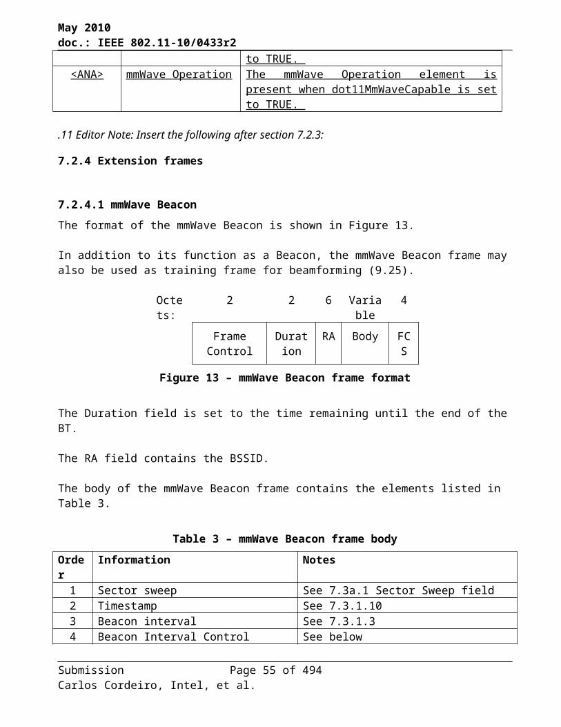
May 2010 doc.: IEEE 802.11-10/0433r2
Bit 5 Bit 6 Usage0 0 Uplink (MSDUs are sent from the non-AP STA to HC) and used
in a PTP TSPEC when the ADDTS request frame is sent by the non-AP Source STA)
1 0 Downlink (MSDUs are sent from the HC to the non-AP STA and used in a PTP TSPEC when the ADDTS request frame is sent by the non-AP Destination STA)
.11 Editor’s instructions: in the Table 7-39—Access Policy subfield replace “Reserved” by “mmWave PBSS”
.11 Editor’s instructions: modify the paragraph as follows
The Aggregation subfield is 1 bit in length. The Aggregation subfield is valid only when access method is HCCA or when the source and destination of the flow are members of a mmWave PBSS/infrastructure BSS or when the access method is EDCA and the Schedule subfield is set to 1. When the access method is HCCA or when the access method is EDCA and the Schedule subfield is set to 1 the Aggregation subfield is set to 1 by a non-AP STA to indicate that an aggregate schedule is required. It is set to 1 by the AP if an aggregate schedule is being provided to the non-AP STA. It is set to 1 if the source and destination of the flow are members of a mmWave PBSS/infrastructure BSS and the non-AP/non-PCP STA transmitting the ADDTS request that contains the PTP TSPEC element requests an aggregation of a new PTP TS to an existing scheduled SP whose SP TSID value matches the SP TSID of the PTP TSPEC in the ADDTS request. It is set to 1 if the source and destination of the flow are members of a mmWave PBSS/infrastructure BSS and the non-AP/non-PCP STA transmitting the ADDTS response that contains the PTP TSPEC element has accepted an aggregation of a new PTP TS to an existing scheduled SP whose SP TSID value matches the SP TSID of the PTP TSPEC in the ADDTS response. It is set to 0 otherwise. In all other cases, the Aggregation subfield is reserved.
.11 Editor’s instructions: add the following text after the sentence “The configuration of APSD=0, Schedule=1 is reserved.” The reliability field is 2 bits in length and contains a PER of the PHY. The encoding of the PER is shown in Table 8 .
Table 8 – ReliabilityReliability index
PER
0 Not specified1 10E-22 10E-43 10E-5
When this field is included in the ADDTS request frame and the direction is set to downlink and when this field is included in the ADDTS response frame and the direction field is set to uplink then value in this field represents the receiver expectation of the PER per specific TSID. This information is
Submission Page 55 of 339 Carlos Cordeiro, Intel, et al.

May 2010 doc.: IEEE 802.11-10/0433r2
provided by the SME using the MLME-ADDTS.request primitive and MLME-ADDTS.response primitives. Together with the Link Margin ( 9.27 ) and other implementation specific information, the value may be used by the transmitter to estimate the MCS to be used for this particular TS.
The A-MSDU subframe field is 1 bit in length and contains a value that is a A-MSDU subframe structure. The A-MSDU subframe field is set to 0 to indicate the A-MSDU subframe structure and set to 1 to indicate the Short A-MSDU subframe structure.
The SP TSID subfield is 4 bits in length and contains a value that is the TSID of the SP for this PTP TSPEC. Different PTP TSPECs that share the same source STA and destination STA can share a single SP TSID through TSPEC aggregation. When the Aggregation subfield is set to 0, the SP TSID subfield is reserved.
7.3.2.31 TCLAS element
.11 Editor’s instructions: modify the paragraph as follows
TCLAS element need not be provided for the uplink or direct-link transmissions. The TCLAS element is provided in the case the PTP TSPEC is transmitted to the peer STA (destination or source respectively) via a PCP/AP.
7.3.2.46 Multiple BSSID element
.11 Editor Instruction: change the 7th paragraph of 802.11-2007+802.11v D6.01 as follows:
When the Multiple BSSID element is transmitted in a Beacon, mmWave Beacon, or Probe Response frame, the reference BSSID is the BSSID of the frame. More than one Multiple BSSID element may be included in a Beacon or mmWave Beacon frames. The AP/mSTA determines the number of Multiple BSSID elements. The AP/mSTA does not fragment a non-transmitted BSSID profile subelement for a single BSSID across two Multiple BSSID elements unless the length of the non-transmitted BSSID profile subelement exceeds 255 octets. When the Multiple BSSID element is transmitted as a subelement in a Neighbor Report element, the reference BSSID is the BSSID field in the Neighbor Report element.
.11 Editor Instruction: change the 10th paragraph of 802.11-2007+802.11v D6.01 as follows:
The Non-Transmitted BSSID Profile subelement contains a list of elements for one or more APs/mSTAs which have non-transmitted BSSIDs, and is defined as follows:
.11 Editor Instruction: change the 12th paragraph of 802.11-2007+802.11v D6.01 as follows:
The Multiple BSSID element is included in Beacon frames, as described in 7.2.3.1, in mmWave Beacon frames, as described in 7.2.4.1 , and Probe Response frames, as described in 7.2.3.9. The use of the Multiple BSSID element is described 11.10.1. Non-transmitted BSSID Advertisement procedures are described in 11.1.2.3a Multiple BSSID procedures.
Submission Page 56 of 339 Carlos Cordeiro, Intel, et al.
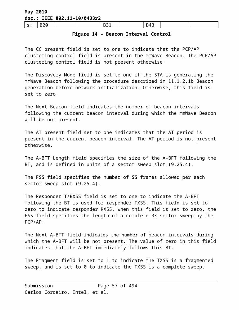
May 2010 doc.: IEEE 802.11-10/0433r2
7.3.2.71 Non-transmitted BSSID Capability element.11 Editor Instruction: change Figure 7-101bp (Non-transmitted BSSID Capability element format) of 802.11-2007+802.11v D6.01 as follows:
Element ID
Length
Non-transmitted BSSID Capability
Non-transmitted BSSID mmWave
Capability element
mmWave BSS Control
Octets: 1 1 2 13 1
.11 Editor Instruction: change the 3rd and 4th paragraphs of 802.11-2007+802.11v D6.01 as follows:
The value of Length field is 216.
The Non-transmitted BSSID Capability field contains the Capability information field of the BSS in the LB or HB, and the mmWave Capabilities element and the mmWave BSS Control field of the mSTA in the UB.
.11 Editor Instruction: insert the following text
The mmWave BSS Control field is defined in Table 9 .
Table 9 – mmWave BSS Control field format
BSS Type ReservedBits: 2 bits 6 bits
The BSS Type field is as defined in 7.2.4.1.
.11 Editor Note: insert the following subclauses
7.3.2.90 mmWave BSS Parameter Change elementThe mmWave BSS Parameter Change element is formatted as illustrated in Figure 27.
Element ID
Length Change type bitmap
Beacon time BI duration
Octets: 1 1 1 4 2
Figure 27 – mmWave BSS Parameter Change element format
The Change Type Bitmap field indicates the type of the parameter change to the BSS. This field is defined in Figure 28.
Move Size ReservedBits: B0 B1 B2-B7
Figure 28 – Change Type Bitmap field format
Submission Page 57 of 339 Carlos Cordeiro, Intel, et al.

May 2010 doc.: IEEE 802.11-10/0433r2
If the Move field is set to one, it indicates a change in the TBTT of the BSS. The TBTT is not changed if the Move field is set to zero. If the Size field is set to one, it indicates a change in the BI duration. The BI duration is not changed if the Size field is set to zero.
The Beacon Time field indicates the anticipated transmission time, expressed in microseconds, of the mmWave Beacon following the indicated mmWave BSS Parameter Change. The value of the Beacon Time field represents the lower order 4 octets of the TSF timer value at the start of the mmWave Beacon transmission.
The BI Duration field indicates the beacon interval duration, expressed in TUs, following the indicated mmWave BSS Parameter Change. The BI Duration field is reserved if the Size bit of the Change Type Bitmap field is set to zero.
7.3.2.91 mmWave Capabilities elementThe mmWave Capabilities element contains a STA identifier and several fields that are used to advertise the support of optional mmWave capabilities of an mSTA. The element is present in Association Request, Association Response, Reassociation Request, Reassociation Response, Probe Request and Probe Response frames and may be present in mmWave Beacon and Information request and response frames. The mmWave Capabilities element is formatted as illustrated in Figure 29.
Element ID
Length STA address
AID mmWave STA Capability Information
mmWave PCP/AP Capability
InformationOctets: 1 1 6 1 8 2
Figure 29 – mmWave Capabilities element format
The STA Address field contains the MAC address of the STA.
The AID field contains the AID assigned to the STA by the PCP/AP.
7.3.2.91.1 mmWave STA Capability Information fieldThe mmWave STA Capability Information field, shown in Figure 30, represents the transmitting STA capabilities irrespective of the role the STA has.
Reverse Direction
Higher Layer Timer Synchronization
TPC SFS and Interference Mitigation
Number of Antennas
Total Number of Sectors
Bit: B0 B1 B2 B3 B4-B5 B6-B13
RXSS Length
Antenna reciprocity
A-MPDU parameters
BA with flow
control
Supported MCS Set
DTP Supported
Reserved
Submission Page 58 of 339 Carlos Cordeiro, Intel, et al.

May 2010 doc.: IEEE 802.11-10/0433r2
Bit: B14-B19 B20 B21-B26 B27 B28-B51 52 B53-B63
Figure 30 – mmWave STA Capability Information The Reverse Direction field is set to 1 if the STA supports RD as defined in 9.15 and is set to 0 otherwise.
The Higher Layer Timer Synchronization field is set to 1 if the STA supports Higher Layer Timer Synchronization as defined in 11.22.5 Timing measurement procedure, and is set to 0 otherwise.
The TPC field is set to 1 if the STA supports the TPC as defined in 11.8 and is set to 0 otherwise.
The SFS and Interference Mitigation field is set to 1 if the STA is capable of performing the function of SFS and Interference Mitigation and is set to 0 otherwise (see 11.33).
The Number of Antennas field indicates the total number of antennas of the STA.
The Total Number of Sectors field indicates the total number of sectors the STA will use in a sector sweep combined over all antennas.
The RXSS Length field specifies the length of a receive sector sweep per each antenna required by the STA, and is defined in units of a SS frame.
The Antenna reciprocity field is set to one to indicate that the best transmit antenna of the STA is the same as the best receive antenna of the STA and vice-versa. This field is set to zero otherwise.
The A-MPDU parameters field is shown in Figure 31.
Maximum A-MPDU Length Exponent Minimum MPDU Start SpacingBits:
B0-B2 B3-B5
Figure 31 – A-MPDU parameters field
The subfields of the A-MPDU parameters field are defined in Table 10.
Table 10 – Subfields of the A-MPDU Parameters fieldSubfield Definition Encoding
Maximum A-MPDU Length Exponent
Indicates the maximum length of A-MPDU that the STA can receive.
This field is an integer in the range 0 to 5.
The length defined by this field is equal to 2(13 + Maximum A-MPDU Length Exponent) – 1 octets.
Minimum MPDU Start Spacing
Determines the minimum time between the start of adjacent MPDUs within an A-MPDU that the STA can receive, measured at the PHY-SAP.
Set to 0 for no restrictionSet to 1 for 16 nsSet to 2 for 32 nsSet to 3 for 64 nsSet to 4 for 128 nsSet to 5 for 256 ns
Submission Page 59 of 339 Carlos Cordeiro, Intel, et al.

May 2010 doc.: IEEE 802.11-10/0433r2
Set to 6 for 512 nsSet to 7 for 1024 ns
The BA with flow control field is set to 1 if the STA supports BA with flow control as defined in 9.26 and is set to 0 otherwise. The Supported MCS Set field indicates which MCSs an mSTA supports. An MCS is identified by an MCS index, which is represented by an integer in the range 0 to 27. The interpretation of the MCS index (i.e., the mapping from MCS to data rate) is PHY dependent. For the mmWave PHY, see clause 21. The structure of the Supported MCS Set field is defined in Figure 32.
Maximum SC Rx MCS
Maximum OFDM Rx MCS
Maximum SC Tx MCS
Maximum OFDM Tx MCS
Low Power SC PHY Supported
Code Rate 13/16
Reserved
Bits: 5 5 5 5 1 1 2
Figure 32 – Supported MCS set field
The Maximum SC Rx MCS subfield contains the value of the maximum MCS index the STA supports for reception of single-carrier frames. The value of this subfield is at least equal to 4. Other possible values for this subfield are shown in Table 79.
The Maximum OFDM Rx MCS subfield contains the value of the maximum MCS index the STA supports for reception of OFDM frames. If this field is set to zero, it indicates that the STA does not support reception of OFDM frames. Otherwise, the value of this field is at least equal to 17 as described in 21.5.3.1.1.
The Maximum SC Tx MCS subfield contains the value of the maximum MCS index the STA supports for transmission of single-carrier frames. The value of this subfield is at least equal to 4. Other possible values for this subfield are shown in Table 79.
The Maximum OFDM Tx MCS subfield contains the value of the maximum MCS index the STA supports for transmission of OFDM frames. If this field is set to zero, it indicates that the STA does not support transmission of OFDM frames. Otherwise, the value of this field is at least equal to 17 as described in 21.5.3.1.1.
The Low Power SC PHY Supported subfield is set to one to indicate that the STA supports the mmWave low power SC PHY mode (21.7). Otherwise it is set to zero. If the STA supports the low power SC PHY, it supports all low power SC PHY MCSs indicated in Table 82. The Code Rate 13/16 subfield specifies whether the STA supports rate 13/16. It is set to one to indicate that the STA supports rate 13/16 and is set to zero otherwise. If this field is zero, MCS sets with 13/16 code rate specified in Table 76 and Table 79 are not supported regardless of the value in Maximum SC/OFDM Tx/Rx MCS subfields.
The DTP Supported field is set to one to indicate that the STA supports DTP as described in 9.28 and 21.5.3.2.3.5.2. Otherwise, it is set to zero.
Submission Page 60 of 339 Carlos Cordeiro, Intel, et al.
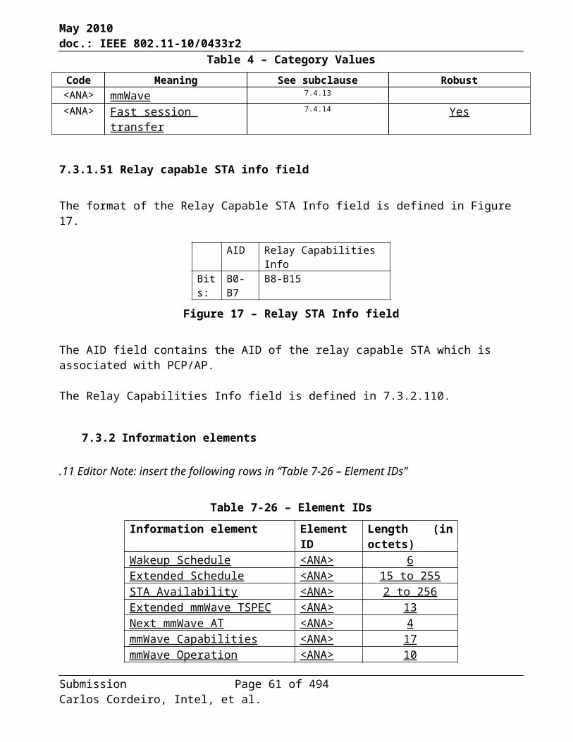
May 2010 doc.: IEEE 802.11-10/0433r2
7.3.2.91.2 mmWave PCP/AP Capability Information field
The mmWave PCP/AP Capability field, illustrated in Figure 33, represents the capabilities when the transmitting STA performs in the role of PCP/AP and that are in addition to the capabilities in the mmWave STA Capability Information field.
TDDTT Pseudo-static allocations
PCP Handover
MAX Associated STA Number
Power source
PCP/AP clustering
Reserved
Bit: B0 B1 B2 B3-B10 B11 B12 B13-B15
Figure 33 – mmWave PCP/AP Capability Information
The TDDTT field is set to 1 if the STA, while operating as a PCP/AP, is capable of providing TDMA access as defined in 9.23.6 and 11.4 and is set to 0 otherwise.
The Pseudo-static allocations field is set to 1 if the STA, while operating as a PCP/AP, is capable of providing pseudo-static allocations as defined in 9.23.6.3 Pseudo-static allocations and is set to 0 otherwise. The Pseudo-static allocations field may be set to 1 only if the TDDTT field in the mmWave PCP/AP Capability Information field is set to 1.
The PCP Handover field is set to 1 if the STA, while operating as a PCP, is capable of performing a PCP Handover as defined in 11.30.2 and is set to 0 if the STA does not support PCP Handover.
The MAX Associated STA Number field indicates the maximum number of STAs that the STA can perform association with if operating as a PCP/AP.
The Power Source field is set to 1 if the STA is battery powered, and is set to 0 otherwise.
The PCP/AP Clustering field is set to 1 if the STA, when operating as a PCP/AP, is capable of performing a PCP/AP clustering and is set to 0 otherwise.
7.3.2.92 mmWave Operation element The operational parameters of a BSS provided by the PCP/AP are determined by the mmWave Operation element defined in Figure 34.
Element ID
Length mmWave Operation Information
mmWave BSS Parameter Configuration
Octets: 1 1 2 8
Figure 34 – mmWave Operation element
The mmWave Operation Information field is shown in Figure 35.
TDDTT Pseudo-static allocations PCP Handover Reserved
Submission Page 61 of 339 Carlos Cordeiro, Intel, et al.
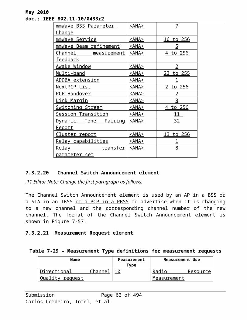
May 2010 doc.: IEEE 802.11-10/0433r2
Bit: B0 B1 B2 B3-B15
Figure 35 – mmWave Operation Information
The TDDTT field is set to 1 if the PCP/AP provides TDMA access as defined in 9.23.6 and is set to 0 otherwise.
The Pseudo-static allocations field is set to 1 if the PCP/AP provides pseudo-static allocations as defined in 9.23.6.3 Pseudo-static allocations and is set to 0 otherwise. The Pseudo-static allocations field may be set to 1 only if the TDDTT field in the mmWave Operation Information field is set to 1.
The PCP Handover field is set to 1 if the PCP provides PCP Handover as defined in 11.30.2 and is set to 0 if the PCP does not provide PCP Handover. The mmWave BSS Parameter Configuration field is defined in Figure 36.
PSRequestSuspensionInterval
MinBIHeaderDuration
BroadcastSTAInfoDuration
AssocRespConfirmTime
MinPPDuration
SPIdleTimeout
MaxLostBeacons
Octets:
1 2 1 1 1 1 1
Figure 36 – mmWave BSS Parameter Configuration field The PSRequestSuspensionInterval subfield indicates the power save suspension interval and is specified in number of BIs. A STA overrides the value of its local dot11PSRequestSuspensionInterval MIB variable with the value of this field when it receives this element from its PCP/AP.
The MinBIHeaderDuration subfield indicates the minimum duration of the BI header, which can include the BT, A-BFT, and AT and is specified in microseconds. A STA overrides the value of its local dot11MinBIHeaderDuration MIB variable with the value of this field when it receives this element from its PCP/AP.
The BroadcastSTAInfoDuration subfield indicates the upper bound on the duration of time that the PCP/AP expects to take to transmit information about associated STAs and is specified in number of BIs. A STA overrides the value of its local dot11BroadcastSTAInfoDuration MIB variable with the value of this field when it receives this element from its PCP/AP.
The AssocRespConfirmTime subfield indicates the upper bound on the duration of time that the PCP/AP expects to take to respond to association requests and is specified in milliseconds. A STA overrides the value of its local dot11AssocRespConfirmTime MIB variable with the value of this field when it receives this element from its PCP/AP.
The MinPPDuration subfield indicates the minimum duration of the PP and/or GP as part of the dynamic allocation of service period mechanism and is specified in microseconds. A STA overrides the value of its local dot11MinPPDuration MIB variable with the value of this field when it receives this element from its PCP/AP.
The SPIdleTimeout subfield indicates time during which a STA expects to receive a frame from its partner STA and is specified in microseconds. A STA overrides the value of its local
Submission Page 62 of 339 Carlos Cordeiro, Intel, et al.
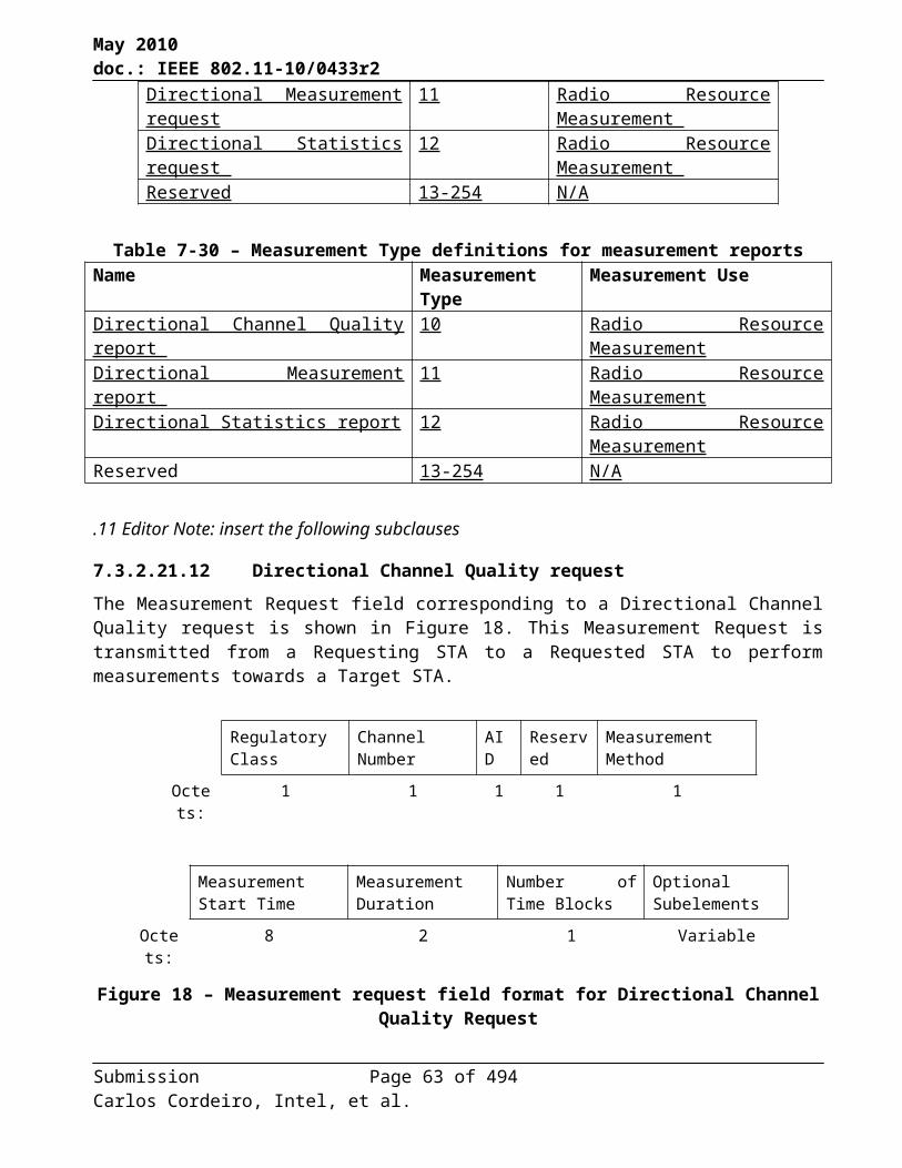
May 2010 doc.: IEEE 802.11-10/0433r2
dot11SPIdleTimeout variable with the value of this field when it receives this element from its PCP/AP.
The MaxLostBeacons field contains the value of the dot11MaxLostBeacons attribute. A STA overrides the value of its local dot11MaxLostBeacons attribute with the value of this field when it receives this element from its PCP/AP.
7.3.2.93 mmWave Beam refinement element
The mmWave Beam Refinement element is defined as shown in Figure 37.
Element ID
Length Initiator TX-train-response
RX-Train-response
TX-TRN-OK
TXSS-FBCK-REQ
Bits:
B0-B7 B8-B15
B16 B17 B18 B19 B20
BS-FBCK FBCK-REQ FBCK-TYPE MID extension
Capability Request
Reserved
Bits: B21-B26 B27-B31 B32-B48 B49 B50 B51-B55
Figure 37 – Beam refinement element formatA value of 1 in the Initiator field indicates that the sender is the beam refinement initiator. Otherwise this field is set to zero.
A value of 1 in the TX-train-response field indicates that this packet is the response to a TX training request. Otherwise this field is set to zero.
A value of 1 in the RX-train-response field indicates that the packet servers as an acknowledgement for a RX training request. Otherwise this field is set to zero.
A value of 1 in the TX-TRN-OK field confirms a previous training request received by a STA. Otherwise this field is set to zero.
A value of 1 in the TXSS-FBCK-REQ indicates a request for transmit sector sweep feedback.
BS-FBCK specifies the best sector. It indicates the index of the antenna configuration that resulted in the best receive quality in the last received BRP-TX packet. If the last received packet was not a BRP-TX packet, this field is set to zero. The determination of the best sector is implementation dependent.
FBCK-REQ field is defined in Table 11.
Table 11 – FBCK-REQ fields Field Size (bits) MeaningSNR requested 1 bit SNR subfield is requested as part of the
Submission Page 63 of 339 Carlos Cordeiro, Intel, et al.
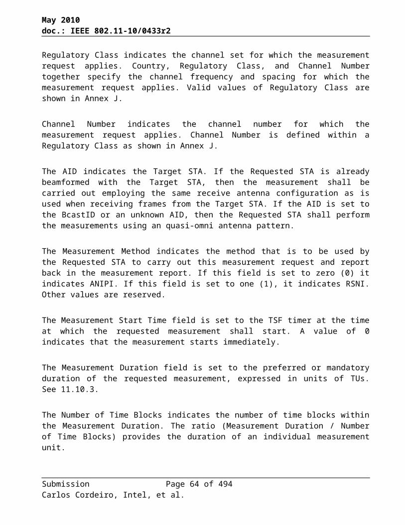
May 2010 doc.: IEEE 802.11-10/0433r2
Field Size (bits) Meaningchannel measurement feedback
Channel Measurement requested
1 bit Channel measurement is requested as part of the channel measurement feedback
Number of taps requested 2 bits Number of taps in each channel measurement:0x0 – 1 tap0x1 – 5 taps0x2 – 17 taps0x3 – 63 taps
Sector ID order requested 1 bit Sector ID order subfield is requested as part of the channel measurement feedback
The FBCK-TYPE field is defined in Table 12. When both Nmeas and Nbeam in this field are zero, the channel measurement feedback element is not present.
Table 12 – FBCK-TYPE field Field Size (bits) MeaningSNR present 1 bit Set to one to indicate that the SNR subfield is present as part
of the channel measurement feedback. Set to zero otherwise.Channel Measurement present
1 bit Set to one to indicate that the channel measurement is present as part of the channel measurement feedback. Set to zero otherwise.
Tap Delay present 1 bit Set to one to indicate that the Tap delays field is present as part of the channel measurement feedback. Set to zero otherwise.
Number of taps present Ntaps
2 bits Number of taps in each channel measurement:0x0 – 1 tap0x1 – 5 taps0x2 – 17 taps0x3 – 63 taps
Number of measurements Nmeas
6 bits Number of measurements in the SNR subfield and the channel measurements subfield. It is equal to the number of TRN-T subfields in the BRP-TX packet on which the measurement is based, or the number of received sectors if TXSS result is reported by setting TXSS-FBCK-REQ to one.
Sector ID order present
1 bit Set to one to indicate that the Sector ID order subfield is present as part of the channel measurement feedback. Set to zero otherwise.
Number of beamsNbeam
5 bits Number of beams in the Sector ID order subfield for the MIDC phase with the direction and the TX/RX antenna identification. The 1st bit shall be set to 0 for the initiator link and 1 for the responder link. The 2nd bit shall be set to 0 for the transmitter antenna and 1 for the receiver antenna. The 3rd
to 5th bits represent the number of beams for beam combining. E.g. “01101” stands for Nbeam
(I, RX) = 5.
Submission Page 64 of 339 Carlos Cordeiro, Intel, et al.

May 2010 doc.: IEEE 802.11-10/0433r2
A value of 1 in the MID extension field indicates the intention to continue transmitting BRP-RX packets during the MID sub-phases. Otherwise, this field is set to zero.
A value of 1 in the capability request field indicates that the transmitter of the packet requests the intended receiver to respond with a BRP packet that includes the BRP request field. Otherwise, this field is set to 0.
7.3.2.94 Wakeup Schedule element The Wakeup Schedule element is defined in Figure 38.
Element ID Length Start Time Sleep Interval
Octets: 1 1 4 2
Figure 38 – Wakeup ScheduleFor non-PCP STA power management, the Start Time field indicates the start time, expressed in microseconds, of the first Awake BI. The value of the Start Time field represents the lower order 4 octets of the TSF timer value at the start of the first Awake BI.
For PCP power management, the Start Time field indicates the start time, expressed in microseconds, of the next doze beacon interval. The value of the Start Time field represents the lower order 4 octets of the TSF timer value at the start of the next doze beacon interval.
The Sleep Interval field is 2 octets. For non-PCP STA power management, the Sleep Interval field indicates the time, expressed in number of TBTTs, between two successive Awake BIs. For PCP power management, the Sleep Interval field indicates the length of the PCP sleep interval, expressed in number of TBTTs.
For non-PCP STA power management, the Sleep Interval field in the Wakeup Schedule element is set to a value that is power of 2.
7.3.2.95 Extended Schedule elementThe Extended Schedule element is formatted as illustrated in Figure 39. Because the length parameter supports only 255 octets of payload in an element, the PCP/AP may split the Schedule information into more than one Schedule element entry in the beacon or AT. The Allocation fields shall be ordered by increasing allocation start time with allocations beginning at the same time arbitrarily ordered.
Element ID Length Allocation 1 Allocation 2 … Allocation nOctets: 1 1 15 15 … 15
Figure 39 – Extended Schedule element format
The Allocation field is formatted as illustrated in Figure 40.
Allocation BF Source Destination Allocation Allocation Allocation Number
Submission Page 65 of 339 Carlos Cordeiro, Intel, et al.
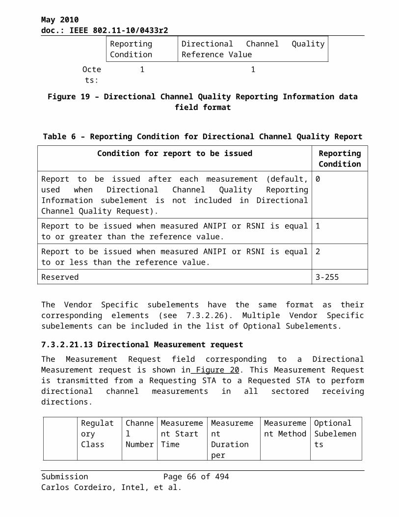
May 2010 doc.: IEEE 802.11-10/0433r2
Control Control
AID AID Start Block Duration
Block Period of Blocks
Octets: 2 2 1 1 4 2 2 1
Figure 40 – Allocation field
The Allocation Control field is defined in Figure 41.
SPType TID Pseudo-static
Truncatable Extendable
PCP Active Reserved
Bits: B0 B1-B4 B5 B6 B7 B8 B9-B15
Figure 41 – Allocation Control field
The SPType field is set to 0 to indicate that the allocation is for an SP and set to 1 to indicate that the allocation is for CBP. If value of this field differs from 0, the Source AID and the Destination AID fields are set to the broadcast AID.
The TID field indicates the TC or TS for which the allocation is made. For a CBP allocation, this field is reserved.
The Pseudo-static field is set to 1 to indicate that this allocation is pseudo-static (9.23.6.3 Pseudo-staticallocations) and set to 0 otherwise.
For an SP allocation, the Truncatable field is set to 1 to indicate that the source and destination STA can request SP truncation and set to 0 otherwise. For a CBP allocation, the Truncatable field is reserved.
For an SP allocation, the Extendable field is set to 1 to indicate that the source and destination STA can request SP extension and set to 0 otherwise. For a CBP allocation, the Extendable field is reserved.
The PCP Active field is set to 1 if the PCP is available to receive transmissions during the CBP or SP allocation and set to 0 otherwise. The PCP Active field is always set to 1 if either or both the Truncatable or Extendable fields are set to 1, and when transmitted by an AP.
The BF Control field is defined in 7.3a.5 Beamforming Control field.
The Source AID field is set to the AID of the STA that initiates channel access during the SP allocation.
The Destination AID field indicates the AID of a STA that is expected to listen for transmissions from the source STA during the SP allocation or broadcast AID if all STAs are expected to listen for transmissions from the source STA during the SP allocation. The broadcast AID asserted in the Source AID and the Destination AID fields for an SP allocation indicates that during the SP a non-AP/non-PCP STA shall not transmit unless it receives a Poll or Grant frame from the PCP/AP. The Allocation Start field contains the lower 4 octets of the TSF at the time the SP or CBP starts. The Allocation Start field can be confined to within a BI, or can go across BI boundaries when the pseudo-static field is set to 1.
Submission Page 66 of 339 Carlos Cordeiro, Intel, et al.
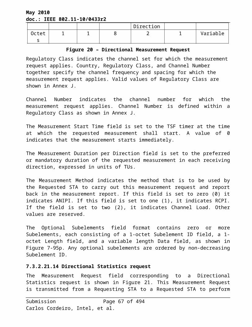
May 2010 doc.: IEEE 802.11-10/0433r2
The Allocation Block Duration field indicates the duration, in microseconds, of a contiguous time block for which the SP or CBP allocation is made and cannot cross BI boundaries.
The Allocation Block Period field contains the time, in microseconds, between the start of two consecutive time blocks belonging to the same allocation. The Allocation Block Period field can be confined to within a BI or can go across BI boundaries. The Allocation Block Period field is reserved when the Number of Blocks field is set to 1. The Number of Blocks field contains the number of time blocks making up the allocation.
7.3.2.96 STA Availability elementThe STA Availability element is used by a non-PCP/non-AP STA to inform a PCP/AP about the STA availability during the subsequent CBPs (9.23.5) and to indicate participation in the Dynamic allocation of service periods (9.23.7). The PCP/AP uses the STA Availability element to inform the non-PCP/non-AP STAs of other STAs availability during subsequent CBPs and participation of other STAs in the Dynamic allocation of service periods.
The format of the STA availability element is illustrated in Figure 42.
Element ID
Length STA Info 1 … STA Info n
Octets: 1 1 2 … 2
Figure 42 – STA availability element format
The format of the STA Info field is shown in Figure 43.
AID CBP Dynamic allocation of service period ReservedBits:
B0-B7 B8 B9 B10-B15
Figure 43 – STA Info field
The AID field contains the AID of the STA for which availability is indicated.
The CBP field is set to 1 to indicate that the STA is available to receive transmissions during CBPs and set to 0 otherwise.
The Dynamic Allocation of Service Period field is set to 1 to indicate that the STA is available for polling during truncatable SPs and set to 0 otherwise.
7.3.2.97 Extended mmWave TSPEC elementThe Extended mmWave TSPEC element is present in the ADDTS Request frame and contains the set of parameters intended to modify the scheduler behavior for the admission of a new TS or updating the scheduler behavior for an existing TS. The Extended mmWave TSPEC element is also present in the
Submission Page 67 of 339 Carlos Cordeiro, Intel, et al.
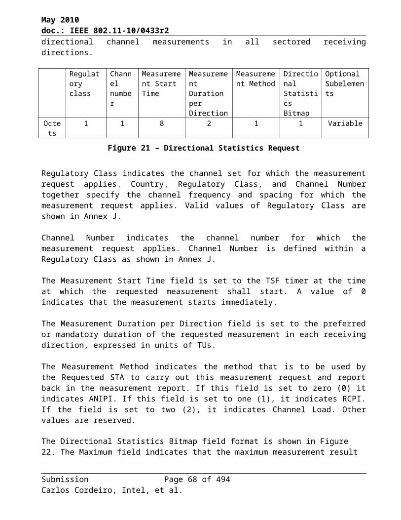
May 2010 doc.: IEEE 802.11-10/0433r2
ADDTS Response and reflects the parameters, possibly modified, by which the TS was admitted. The format of the Extended mmWave TSPEC element is shown in Figure 44.
Element ID Length Extended mmWave TS Info BF ControlOctets:
1 1 3 2
Allocation Period
Minimum Allocation
Maximum Allocation
Minimum SP Duration
TSCONST
Octets:
2 2 2 2 Variable
Figure 44 – Extended mmWave TSPEC element format
The Extended mmWave TS Info field is formatted as shown in Figure 45.
Traffic type
TSID Pseudo-static
Truncatable
Extendable UP Destination STA
Reserved
Bits: B0 B1-B4
B5 B6 B7 B8-B10
B11-B18 B19-B23
Figure 45 – Extended mmWave TS Info field format
The Traffic type field values are listed in Table 13.
Table 13 – Traffic Type valuesTraffic Type value Description
0 Isochronous traffic1 Asynchronous traffic
The TSID field is 4 bits in length and contains a value that is the TSID. The MSB of the TSID is always set to 1. The combination of the destination STA and TSID identify the TS in the context of the non-PCP STA.
The Pseudo-static field is set to 1 for a pseudo-static allocation and set to 0 otherwise. The pseudo-static field shall only be set to 1 for an isochronous traffic type.
The Truncatable field is set to 1 if the STA expects to truncate the SP, as described in 9.23.8. If the STA does not expect to truncate the SP, the Truncatable field is set to 0.
The Extendable field is set to 1 if the STA expects to extend the SP, as described in 9.23.9. If the STA does not expect to extend the SP, the Extendable field is set to 0.
The UP field indicates the actual value of the UP to be used for the transport of MSDUs belonging to this TS in cases where relative prioritization is required. The Destination AID field contains the AID of a STA that the requesting STA wishes to communicate with during the SP allocations.
Submission Page 68 of 339 Carlos Cordeiro, Intel, et al.
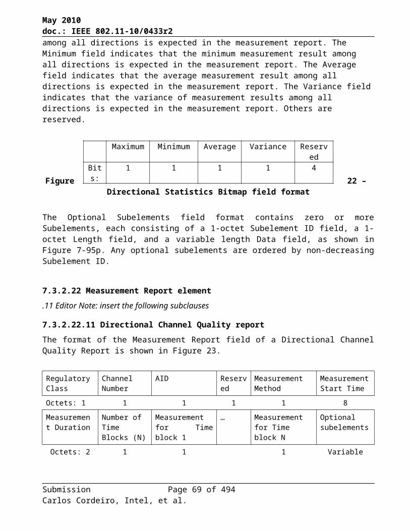
May 2010 doc.: IEEE 802.11-10/0433r2
The BF Control field is defined in 7.3a.5 Beamforming Control field.
The Allocation Period is specified as a fraction or multiple of the Beacon Interval as defined in Table 14.
Table 14 – Allocation Period valuesB0-B14 B15 Meaning0 0-1 Reserved1-32767 0 The allocation period is a multiple of the
BI, i.e., allocation period = n x BI where n is the value represented by B0-B14
1-32767 1 The allocation period is a fraction of the BI, i.e., allocation period = BI/n where n is the value represented by B0-B14.
For isochronous requests, the Allocation Period, Minimum Allocation, Maximum Allocation and Minimum SP Duration fields are set as follows.
The Allocation Period field indicates the period over which the allocation repeats.
The Minimum Allocation field is set to the minimum acceptable allocation in microseconds in each allocation period.
The Maximum Allocation field is set to the desired allocation in microseconds in each allocation period.
The Minimum SP Duration specifies the minimum acceptable SP duration in microseconds making up the allocation.
NOTE – With an isochronous TSPEC, the allocation period defines the period over which the channel time allocation repeats. The scheduler should ensure that at least the minimum allocation is made within each allocation period. The allocation may be composed of multiple SPs. The scheduler will also ensure that each SP making up the allocation is no shorter than the minimum SP duration. The scheduler is free to position the SPs that make up the allocation anywhere in the allocation period. The scheduler may allocate up to the maximum allocation each allocation period if resources permit.
For asynchronous requests, Maximum Allocation field is reserved and the Allocation Period, Minimum Allocation and Minimum SP Duration fields are set as follows.
The Allocation Period field indicates the period over which the minimum allocation applies. The Allocation Period shall be an integral multiple of the Beacon Interval.
The Minimum Allocation field specifies the minimum allocation in microseconds that the STA expects within the allocation period.
The Minimum SP Duration field specifies the minimum acceptable SP duration in microseconds.
NOTE – With an asynchronous TSPEC, the STA registers the minimum allocation it expects within the allocation period while a SP request is in effect that is greater than the minimum allocation specified. In addition, the STA expects that each
Submission Page 69 of 339 Carlos Cordeiro, Intel, et al.
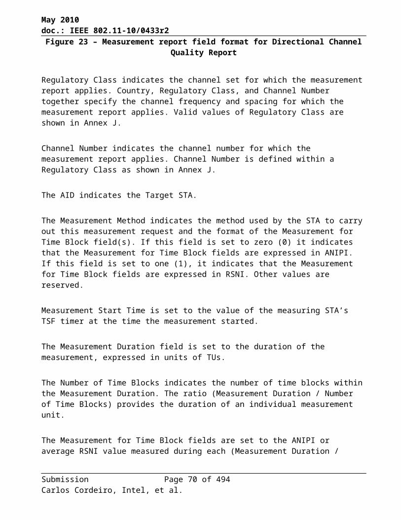
May 2010 doc.: IEEE 802.11-10/0433r2
SP allocation will be at least Minimum SP Duration microseconds in duration provided the outstanding SP request is at least that much. In admitting the TSPEC, the PCP/AP should ensure that there are sufficient resources available to meet the TSPEC requirements.
The TS Scheduling Constraint (TSCONST) field contains one or more constraint subfields as illustrated in Figure 46.
One or more constraint subfieldsOctets:
Variable
Figure 46 – TS scheduling constraint field format
The constraint subfield is defined as illustrated in Figure 47.
TSCONST Start Time TSCONST Duration TSCONST Period Interferer MAC addressOctets:
4 2 2 6
Figure 47 – Constraint subfield
The TSCONST Start Time field contains the lower 4 octets of the TSF at the time the scheduling constraint starts.
The TSCONST Duration field indicates the time, in microseconds, for which the constraint is specified.
The TSCONST Period field contains the time, in microseconds, between the start of two consecutive scheduling constraints.
The Interferer MAC Address field is set to the value of the TA field within a frame received during the interval of time indicated by this TSCONST field. If unknown, the Interferer MAC Address field is set to the broadcast MAC address.
7.3.2.98 Next mmWave AT elementThe Next mmWave AT element indicates earliest start time for the next AT period in a subsequent BI.
Element ID Length
Start Time
Octets:
1 1 4
Figure 48 – Next mmWave AT
The Start Time field contains the low order 4 octets of the TSF for the earliest time at which the next AT period will start.
Submission Page 70 of 339 Carlos Cordeiro, Intel, et al.
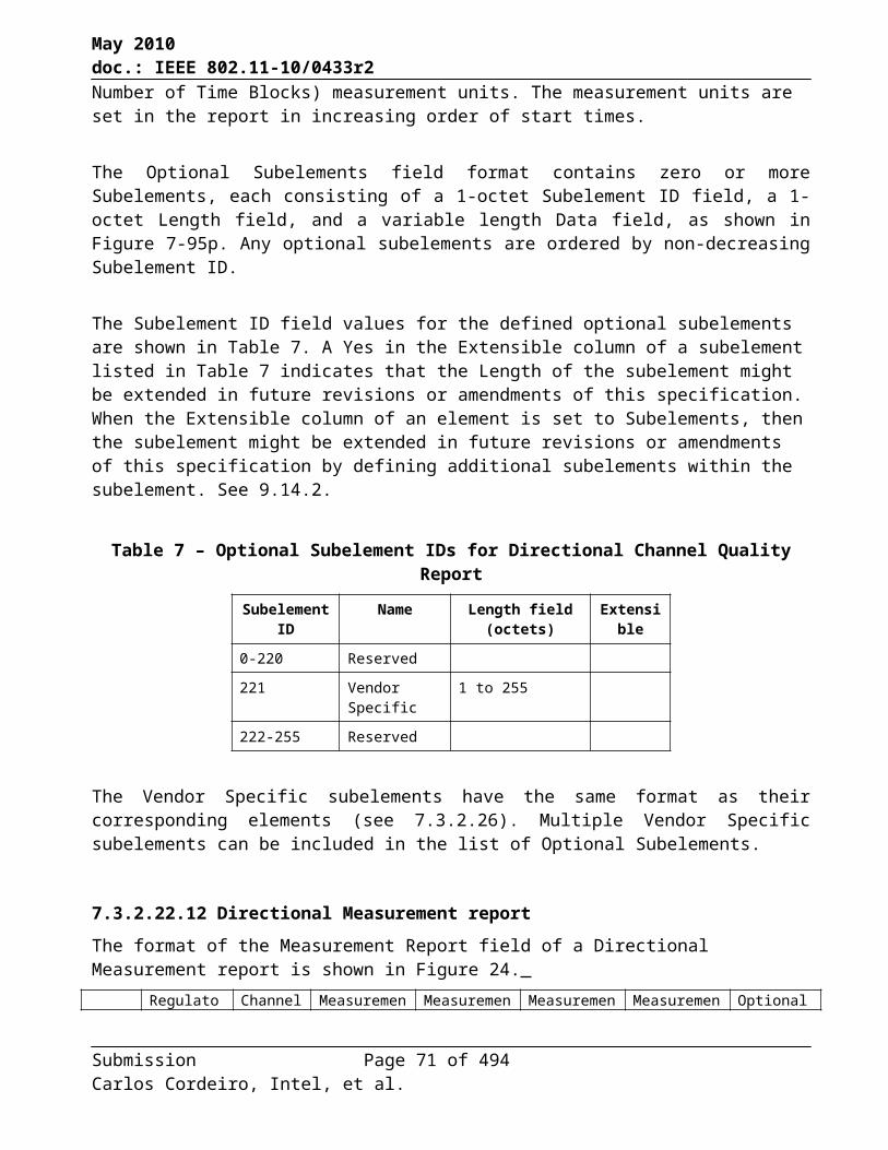
May 2010 doc.: IEEE 802.11-10/0433r2
7.3.2.99 Channel measurement feedback element
The channel measurement feedback element is used to carry the channel measurement feedback data that the STA has measured on the TRN-T fields of the Beam Refinement packet that contained the Channel Measurement request, to provide a list of sectors identified during a sector sweep, or during beam combination (9.25.5.2). The format and size of the channel measurement feedback element are defined by the parameter values specified in the accompanying Beam Refinement element.
The channel measurement feedback element, as shown in Table 15, is composed of 4 subfields: the SNR subfield, the channel measurement subfield, the Tap Delay subfield and the Sector ID order subfield.
Table 15 – Channel Measurement Feedback element format Field Size Meaning
Element ID 8 bitsLength 8 bitsSNR subfield 6 bits SNR as measured in the first TRN-T field or
at the first sector from which SS frame is received.
6 bits SNR as measured in the second TRN-T field or at the second sector from which SS frame is received.
6 bits SNR as measured in the Nmeas TRN-T field or at the Nmeas’th sector from which SS frame is received.
Channel Measurement subfield
Channel Measurement 1
Ntaps×14 bits
Channel measurement for the first TRN-T field
Channel Measurement 2
Ntaps×14 bits
Channel measurement for the second TRN-T field
Channel Measurement Nmeas
Ntaps×14 bits
Channel measurement for the Nmeas TRN-T field
Tap Delay subfield Relative Delay Tap #1
7 bits The delay of Tap #1 in Tc relative to the path with the shortest delay detected.
Relative Delay Tap #2
7 bits The delay of Tap #2 in Tc relative to the path with the shortest delay detected.
Relative Delay Tap #Ntaps
7 bits The delay of Tap #Ntaps in Tc relative to the path with the shortest delay detected.
Sector ID order subfield
Sector ID1 6 bits Sector ID for SNR1 being obtained, or sector ID of the first detected beam.
Sector ID2 6 bits Sector ID for SNR2 being obtained, or sector ID of the second detected beam.
Sector IDNmeas
6 bits Sector ID for SNRNmeas being obtained, or
Submission Page 71 of 339 Carlos Cordeiro, Intel, et al.
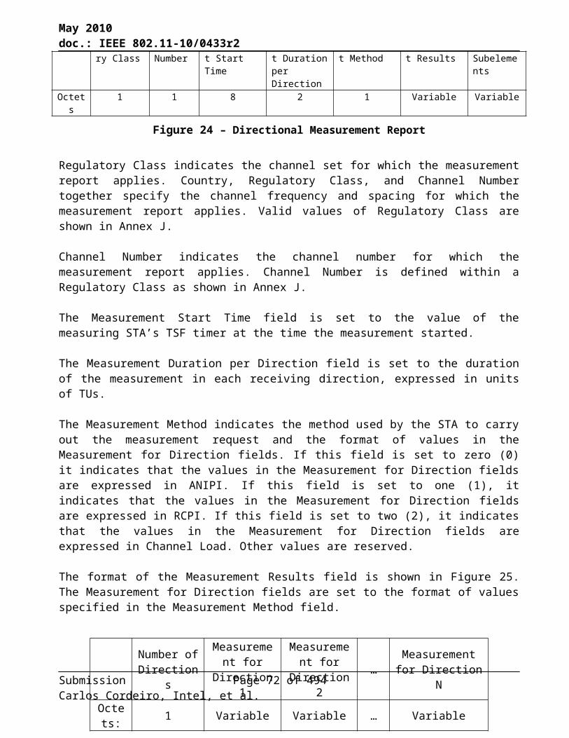
May 2010 doc.: IEEE 802.11-10/0433r2
or Sector IDNbeam sector ID of the Nbeam’th detected beam.Zero pad Zeros Variable
(0-7)Padding to make the Channel Measurement Feedback element length a multiple of 8 bits.
The number of channel/SNR measurements reported, Nmeas, is equal to the number of TRN-T sub-fields that were appended to the packet on which the measurements were performed. If the measurement reports the result of an SLS or of an MID, it is equal to the number of frames received during the sector sweep, or the number of packets used during the MID sub-phase.
The SNR subfield levels are positive numbers (expressed in ones’ complement) referenced to a level of -8dB. Each step is 0.5dB.
The format of each channel measurement is specified in Table 16.
Table 16 – Channel measurementField Size Meaning
Relative I Component Tap #1 7 bits The in-phase component of impulse response for Tap #1, relative to the amplitude of the strongest tap measured.
Relative Q Component Tap #1 7 bits The quadrature component of impulse response for Tap #1, relative to the amplitude of the strongest tap measured.
Relative I Component Tap #2 7 bits The in-phase component of impulse response for Tap #2, relative to the amplitude of the strongest tap measured.
Relative Q Component Tap #2 7 bits The quadrature component of impulse response for Tap #2, relative to the amplitude of the strongest tap measured.
Relative I Component Tap #Ntaps
7 bits The in-phase component of impulse response for Tap #Ntaps, relative to the amplitude of the strongest tap measured.
Relative Q Component Tap #Ntaps
7 bits The quadrature component of impulse response for Tap #Ntaps, relative to the amplitude of the strongest tap measured.
Each channel measurement contains Ntaps channel impulse taps. The channel impulse response reported for all Nmeas measurements correspond to a common set of relative tap delays. If the Tap Delay subfield is not present then the Ntaps channel taps shall be interpreted as contiguous time samples, separated by Tc. The delay values in the Tap Delay subfield, when present, correspond to the strongest taps and are positive numbers, expressed in one’s complement, in increments of Tc, starting from zero. Each channel tap is reported as in-phase and quadrature component pairs, relative to the amplitude of the strongest path detected among all TRN-T fields. The values are represented as two’s complement numbers corresponding to integer valued ratios between -64 and +63. The sector ID order subfield indicates the TX sector IDs corresponding to the SNRs in the SNR subfield when SNR present subfield is set to 1 and sector ID order present subfield is set to 1, in response to a BRP packet with SNR requested subfield set to 1. The sector ID order subfield indicates the TX sector IDs ranked in the decreasing order of link quality, determined in an implementation
Submission Page 72 of 339 Carlos Cordeiro, Intel, et al.
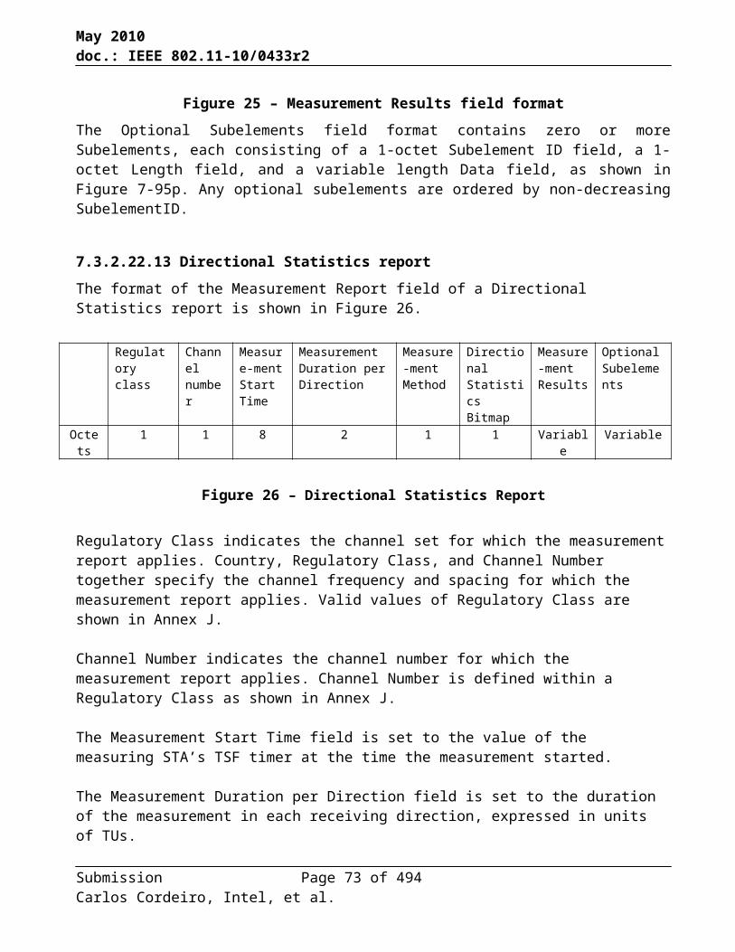
May 2010 doc.: IEEE 802.11-10/0433r2
dependent manner, when SNR present subfield is set to 0 and Sector ID order present subfield is set to 1 in response to setting SNR requested subfield to 0 and Sector ID order requested subfield to 1. The FBCK-REQ field and the FBCK TYPE field in the mmWave Beam refinement element are used by the transmitter and receiver to, respectively, request for and indicate the Sector IDs and their order.
7.3.2.100 Awake Window elementThe Awake Window element is defined as shown in Figure 49.
Element ID Length Awake WindowOctets: 1 1 2
Figure 49 – Awake WindowThe Awake Window field is 2 octets and contains the length of the Awake Window measured in microseconds.
7.3.2.101 Multi-band elementThe Multi-band element indicates that the STA transmitting this element (the transmitting STA) is capable of operating in a frequency band other than the one in which this element is transmitted and that the transmitting STA is able to switch a session from the current channel to a channel in the other band. The format of the Multi-band element is shown Figure 50.
Element ID
Length Multi-band Control Band ID Regulatory Class Channel Number BSSID Beacon Interval
Octets:
1 1 1 1 1 1 6 2
TSF Offset
Multi-band STA Capability
FSTSession
TimeOut
STA MAC Address (optional)
Pairwise Cipher Suite Count (optional)
Pairwise Cipher Suite List (optional)
Octets:
8 2 1 6 2 4*m
Figure 50 – Multi-band element format
The format of the Multi-band Control field is shown in Figure 51.
STA Role STA MAC Address present
Pairwise Cipher Suite Present
Reserved
Bits: 3 1 1 3
Figure 51 – Multi-band control field format
The STA Role field specifies the role the transmitting STA plays on the channel of the regulatory class indicated in this element. The possible values of the STA Role field are indicated in Table 17. If the STA Role field is set to IBSS STA, the BSSID field contains the BSSID of the IBSS.
Table 17 – STA Role
Submission Page 73 of 339 Carlos Cordeiro, Intel, et al.

May 2010 doc.: IEEE 802.11-10/0433r2
STA role ValueNon-AP STA 0
AP 1TDLS STA 2IBSS STA 3
PCP 4Non-PCP Non-AP STA 5
Reserved 6-7
The STA MAC Address Present field indicates whether the STA MAC Address field is present in the Multi-band element. If set to one, the STA MAC Address field is present. If set to zero, the STA MAC Address field is not present.
The Pairwise Cipher Suite Present field indicates whether the Pairwise Cipher Suite Count field and the Pairwise Cipher Suite List field are present in the Multi-band element. If set to one, the Pairwise Cipher Suite Count field and the Pairwise Cipher Suite List field are present. If set to zero, the Pairwise Cipher Suite Count field and the Pairwise Cipher Suite List field are not present.
The Band ID field provides the identification of the frequency band related to the Regulatory Class and Channel number fields. It is set to 1 for LB, 2 for HB, 3 for UB and the value 0 is reserved.
Regulatory Class indicates the channel set for which the Multi-band element applies. Country, Regulatory Class, and Channel Number together specify the channel frequency and spacing for which the Multi-band element applies. Valid values of Regulatory Class are shown in Annex J.
The Channel number field is set to the number of the channel the transmitting STA intends to operate on.
If the transmitting STA is a member of a PBSS or infrastructure BSS on both the channel indicated in this element and the channel on which the element is transmitted, then the TSF Offset field contains the time offset of the TSF of the PBSS or infrastructure BSS of which the transmitting STA is member on the channel indicated in this element relative to the TSF of the PBSS or infrastructure BSS corresponding to the BSSID indicated in the Address 3 field of the MPDU in which this element is transmitted, specified as a two’s complement integer in microsecond units. If the transmitting STA is not a member of an infrastructure BSS or PBSS on both the channel indicated in this element and the channel on which the element is transmitted, then the TSF Offset field contains the value zero.
The Multi-band STA Capability field is defined in Figure 52. The Multi-band STA Capability field indicates the connection capabilities supported by the STA on the channel and band indicated in this element.
AP PCP DLS TDLS IBSS ReservedBits:
1 1 1 1 1 3
Figure 52 – Multi-band STA capability field format
Submission Page 74 of 339 Carlos Cordeiro, Intel, et al.

May 2010 doc.: IEEE 802.11-10/0433r2
The AP field specifies whether the STA can function as an AP on the channel and band indicated in the element. It is set to one when the STA is capable to function as an AP and it is set to zero otherwise.
The PCP field specifies whether the STA can function as a PCP on the channel and band indicated in the element. It is set to one when the STA is capable to function as a PCP and it is set to zero otherwise.
The DLS field is set to one to indicate that the STA can perform a DLS on the channel and band indicated in the element. Otherwise, it is set to zero.
The TDLS field is set to one to indicate that the STA can perform a TDLS on the channel and band indicated in the element. Otherwise, it is set to zero.
The IBSS field is set to one to indicate that the STA is able to support IBSS on the channel and band indicated in the element. Otherwise, it is set to zero.
The FSTSessionTimeOut field is used in the FST Setup Request frame to indicate the timeout value for FST session setup protocol as defined in 11.34.1. The FSTSessionTimeOut field contains the duration, in TUs, after which the FST setup is terminated.
The STA MAC Address field contains the MAC address that the transmitting STA uses while operating on the channel indicated in this element. The STA MAC Address field is not present in this element if the STA MAC Address Present field is set to zero.
The Pairwise Cipher Suite Count field and the Pairwise Cipher Suite List field are defined in 7.3.2.25. These fields are not present in this element if the Pairwise Cipher Suite Present field is set to zero.
7.3.2.102 ADDBA extension element The ADDBA extension element is shown in Figure 53.
Element ID Length ADDBA capabilitiesOctets: 1 1 1
Figure 53 – ADDBA extension
The ADDBA capabilities field is shown in Figure 54.
No-Fragmentation ReservedBit: B0 B1-B7
Figure 54 – ADDBA capabilitiesADDBA extension element may be included in the ADDBA request and response action frames. The ADDBA request or ADDBA response or both may contain the element.
No-Fragmentation field determines whether a fragmented MSDU may be carried in the MPDU sent under the Block Ack agreement. When set to 1 in the ADDBA request frame, it indicates that the
Submission Page 75 of 339 Carlos Cordeiro, Intel, et al.
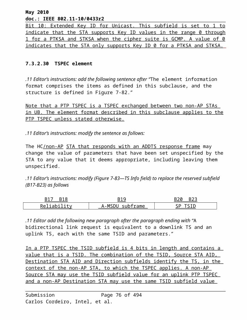
May 2010 doc.: IEEE 802.11-10/0433r2
originator is not fragmenting sent MSDUs. When set to 1 in the ADDBA response frame, it indicates that the recipient is not capable to receive fragmented MSDUs.
7.3.2.103 Next PCP List element The Next PCP List element contains one or more AID of NextPCP i fields as shown in Figure 55.
Element ID Length Token AID of NextPCP 1
… AID of NextPCP n
Octets: 1 1 1 1 … 1
Figure 55 – Next PCP List
The Token field is set to zero when the PBSS is initialized and incremented each time the NextPCP List is updated.
Each AID of NextPCP i field contains the AID value of a STA. The AID values are listed in the order corresponding to the ordered list of STA(s) on the NextPCP List.
7.3.2.104 PCP Handover element The PCP Handover element is used to indicate which STA will become the new PCP following a handover procedure. The PCP Handover element is defined in Figure 56.
Element ID Length New PCP AID Remaining BIsOctets: 1 1 1 1
Figure 56 – PCP Handover
The New PCP AID field indicates the AID of the new PCP following a handover.
The Remaining BIs field indicates the number of BIs, from the BI in which this element is transmitted, remaining until the handover takes effect.
7.3.2.105 Link Margin element The format of the Link Margin element is shown in Figure 57. The Link Margin element is included in a Link Margin Response frame.
Element ID Length Action MCS
Link Margin
SNR Reference Timestamp
Octets: 1 1 1 1 1 1 4
Figure 57 – Link Margin elementThe Action field is set to a preferred action that the STA sending this element recommends that the STA indicated in the RA field of the Link Margin Response frame execute. The method by which the sending STA determines a suitable action for the peer STA is implementation specific. The action field is defined in 7.3.2.105.1.
Submission Page 76 of 339 Carlos Cordeiro, Intel, et al.
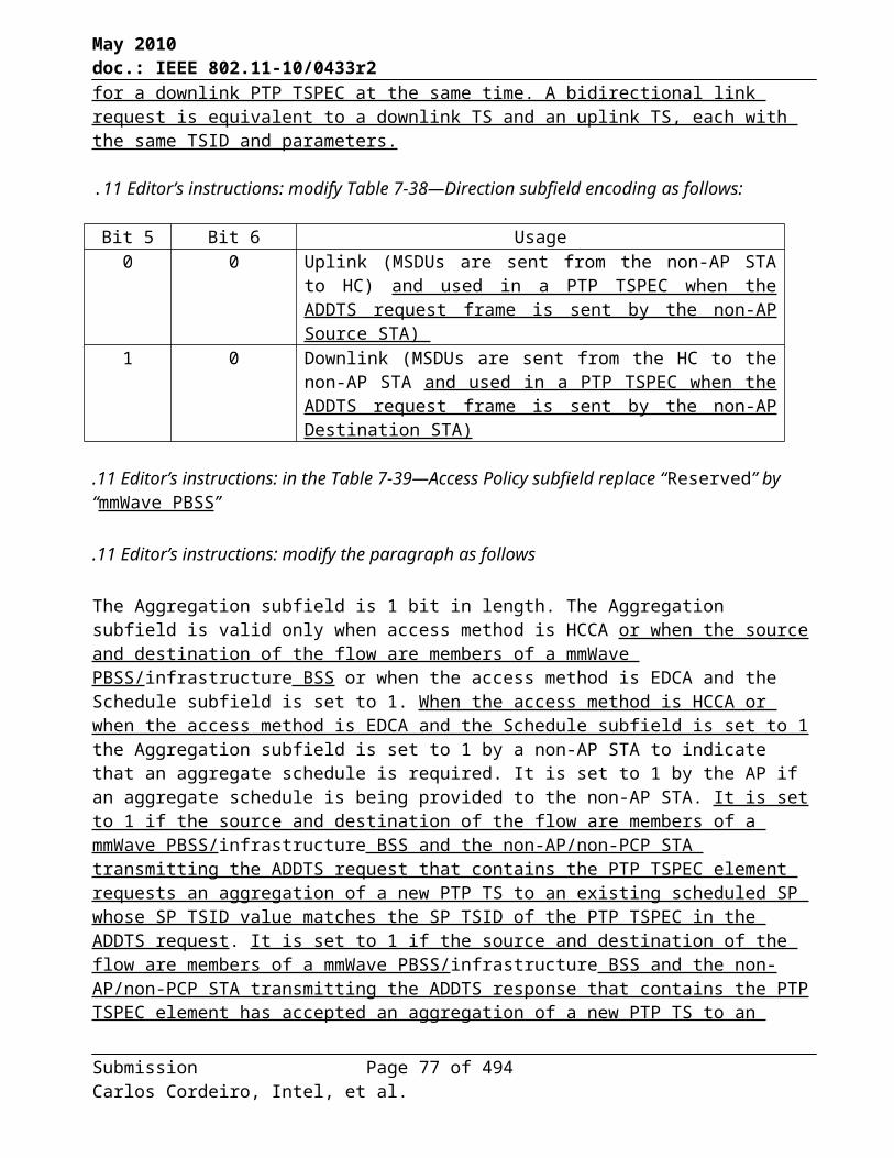
May 2010 doc.: IEEE 802.11-10/0433r2
The MCS field is set to a MCS value that the STA sending this element recommends that the STA indicated in the RA field of the Link Margin Response frame use to transmit frames to this STA. The method by which the sending STA determines a suitable MCS for the peer STA is implementation specific. The MCS field is ignored if the Action field is not set to ‘1’ (change MCS) or ‘4’ (Power conserve mode).
The Link Margin field contains the measured link margin of data frames received from the STA indicated in the RA field of the Link Margin Response frame and is coded as a 2’s complement signed integer in units of decibels. The measurement method of Link Margin is beyond the scope of this specification.
The SNR field indicates the SNR measured during the reception of a PHY packet. Values are -10dB to 53.75dB in 0.25dB steps.
The Reference Timestamp field contains the lower four octets of the TSF timer value sampled at the instant that the MAC received the PHY-CCA.indication(IDLE) signal that corresponds to the end of the reception of the PPDU that was used to generate the feedback information contained in the Link Margin Response frame.
7.3.2.105.1 Action field The Action field values are defined in Table 18.
Table 18 – Action field valuesPreferred Action
Value Meaning
0 No Preference1 Change MCS2 Change Transmit Power3 Fast Session Transfer (FST)4 Power conserve mode
5-7 Reserved
7.3.2.106 Switching Stream element The Switching stream element indicates the streams that the transmitting STA requests to be switched to the new band of operation. The format of the Stream Switching element is shown in Figure 58.
Element ID
Length
Old Band
ID
New Band
ID
Non-QoS frames
Number of Streams
switching
Switching Parameters
Octets: 1 1 1 1 1 1 2 * Number of Streams switching
Figure 58 – Switching stream element format
Submission Page 77 of 339 Carlos Cordeiro, Intel, et al.
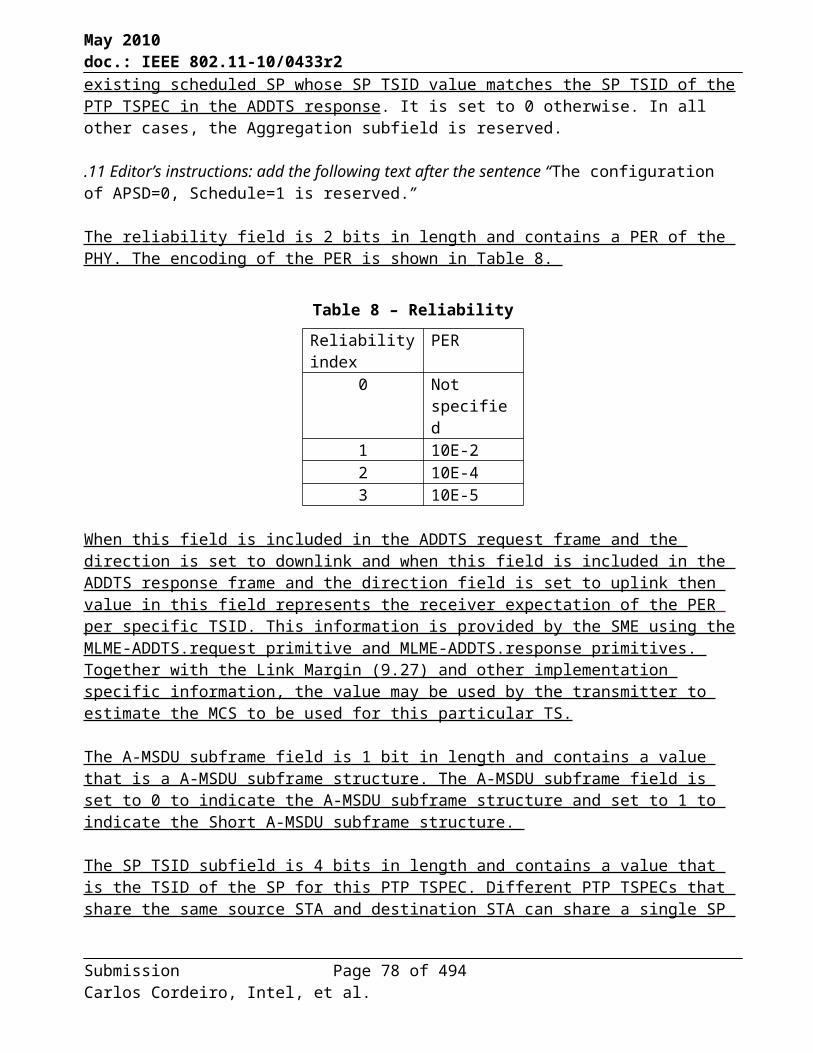
May 2010 doc.: IEEE 802.11-10/0433r2
The Old Band ID field specifies the frequency band to which the information carried in this element is related to. It is set to 1 for LB, 2 for HB, 3 for UB and the value 0 is reserved.
The New Band ID field specifies the frequency band to which the information contained in the Stream ID in New Band subfield of this element is related to. It is set to 1 for LB, 2 for HB, 3 for UB and the value 0 is reserved.
The Non-QoS data frames field specifies whether non-QoS data frames can be transmitted in the frequency band indicated in the New Band ID field. If set to zero, non-QoS data frames cannot be transmitted in the frequency band indicated in the New Band ID field. If set to one, non-QoS data frames can be transmitted in the frequency band indicated in the New Band ID field.
The Number of streams switching field specifies the number of streams to be switched.
The format of Switching Parameters field is shown in Figure 59.
Stream ID in Old Band
Stream ID in New Band
Stream ID in New Band Valid
LLT type
Reserved
TID/TSID Direction TID/TSID DirectionBits
4 1 4 1 1 1 4
Figure 59 – Switching parameters field format
The Stream ID in Old Band and Stream ID in New Band subfields are comprised of the TID/TSID and Direction subfields. The subfields within the Stream ID in New Band subfield are reserved if the Stream ID in New Band Valid subfield is set to zero.
The TID/TSID subfield specifies the stream in the corresponding band.
The Direction field specifies whether the STA transmitting this element is the source or destination of the corresponding TID/TSID. It is set to zero to indicate that the STA transmitting this element is the source of the TID/TSID, and it is set to one otherwise.
Stream ID in New Band Valid subfield is set to 1 if the information contained in the Stream ID in New Band subfield is valid, that is, the TID/TSID specified within the Stream ID in New Band subfield has been established in the band identified in the New Band ID field. The Stream ID in New Band Valid subfield is set to 0 otherwise.
The LLT type field is set one to indicate that the stream-based Link Loss Countdown is used for the stream identified by the Stream ID in Old Band subfield. The LLT type field is set zero to indicate that the STA-based Link Loss Countdown is used for the stream identified by the Stream ID in Old Band subfield. This field is reserved when the LLT field within the FST Setup Request or FST Setup Response frame containing this element is set to zero.
7.3.2.107 Session Transition element The Session Transition Information element is formatted as illustrated in Figure 60.
Submission Page 78 of 339 Carlos Cordeiro, Intel, et al.
May 2010 doc.: IEEE 802.11-10/0433r2
Element ID
Length
FSTS ID
Session
type
New Band Old BandBand ID
Setup
operation
Band ID
setup
operation
Octets:
1 1 4 1 1 1 1 1 1 1
Figure 60 – Session Transition element format
The FSTS ID field contains the identification of the FST session established between a pair of STAs as allocated by the initiator (11.34).
The Session type field is defined as shown in Figure 61 and indicates the type of connection/session that is intended to be set up in the new band for this FST session.
Value
Session type
0 Infrastructure BSS1 IBSS2 DLS3 TDLS4 PBSS
5-255 Reserved
Figure 61 – Session type field formatWhen the Session type field is set to IBSS and the STA Role field within the Multi-band element is set to IBSS STA, BSSID field within the Multi-band element contains the MAC address of the BSSID of the IBSS. It means that the transmitting STA is not associated in AP and it may want to perform IBSS mode with the peer STA.
The New Band and Old Band fields are used for the signaling described in 11.34.1. Each of the New Band and Old Band field contain a Band ID subfield, a Setup subfield and an Operation subfield.
The Band ID subfield is defined in 7.3.2.101. The Setup subfield is set to one to indicate that the STA transmitting this element has an FST Session established with the STA that the frame containing this element is addressed and in the band indicated within the Band ID subfield. Otherwise, it is set to zero. Other values are reserved.
The Operation subfield is set to one to indicate that the STA is operating in the band indicated within the Band ID subfield. Otherwise, it is set to zero. Other values are reserved.
7.3.2.108 Dynamic Tone Pairing (DTP) Report element
The DTP Report element is included in the DTP Response frame. The format of the DTP Report element is shown in Table 19.
Submission Page 79 of 339 Carlos Cordeiro, Intel, et al.

May 2010 doc.: IEEE 802.11-10/0433r2
Table 19 – DTP Report elementElement ID 8 bitsLength 8 bitsGroupPairIndex(0) 6 bits Index of n-th DTP group pair in
the range 0 to NG-1, for n = 0,1,2,…,NG-1 where NG=42
GroupPairIndex(1) 6 bits… …GroupPairIndex(NG-1) 6 bitsZero pad 4 bits Zero padding to make the DTP
Feedback element length a multiple of 8 bits
GroupPairIndex(n) subfields for n=0,1,..,NG-1(where NG=42) indicate DTP groups which in turn determines how pairs of SQPSK symbols are mapped to OFDM tones when DTP is enabled, as described in 21.5.3.2.3.5.2. Valid values of GroupPairIndex(n) are in the range of 0 to NG-1. Furthermore valid values of GroupPairIndex(0), GroupPairIndex(1),…, GroupPairIndex(NG-1) are distinct and therefore represent a permutation of integers 0 to NG-1.
All numeric fields are encoded in unsigned binary, least significant bit first.
7.3.2.109 Cluster Report element
The format of the Cluster Report element is shown in Figure 62. The Cluster Report element is included in management action frames, such as the Announce and the Information Response frames, transmitted to the PCP/AP of the BSS.
Element ID
Length Cluster report control
Reference Timestamp
PCP/AP Clustering Control
Extended Schedule Element
TSCONST
Octets: 1 1 1 4 8 15-255 Variable
Figure 62 – Cluster Report element The Cluster report control field is defined in Figure 63.
Cluster request Cluster report Schedule present
TSCONST present Reserved
Bits:
1 1 1 1 4
Figure 63 – Cluster report control field
The Cluster request subfield is set to one to indicate that the STA is requesting the PCP/AP to start or continue PCP/AP clustering (9.24). This field is ignored when set to zero.
The Cluster report subfield is set to one to indicate that this element contains a cluster report. If this subfield is set to one, the Reference Timestamp and PCP/AP Clustering Control fields are present in
Submission Page 80 of 339 Carlos Cordeiro, Intel, et al.
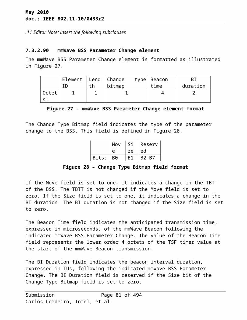
May 2010 doc.: IEEE 802.11-10/0433r2
this element. Otherwise if the Cluster report subfield is set to zero, none of the Reference Timestamp, PCP/AP Clustering Control, Extended Schedule Element and TSCONST fields are present in this element.
The Schedule present subfield is valid only if the Cluster report subfield is set to one, otherwise it is ignored. The Schedule present subfield is set to one to indicate that the Extended Schedule Element field is present in this element. Otherwise, the Extended Schedule Element field is not present in this element.
The TSCONST present subfield is valid only if the Cluster report subfield is set to one, otherwise it is ignored. The TSCONST present subfield is set to one to indicate that the TSCONST field is present in this element. Otherwise, the TSCONST field is not present in this element.
The Reference Timestamp field contains the lower four octets of the TSF timer value sampled at the instant that a STA’s MAC received a mmWave Beacon from a PCP/AP different than the PCP/AP of the BSS the STA participates, for which the PCP/AP Clustering Control field is included in the received mmWave Beacon frame, and for which the value of the Cluster ID field within the PCP/AP Clustering Control field is different than the MAC address of the STA’s PCP/AP.
The PCP/AP Clustering Control is defined in 7.2.4.1, and contains the PCP/AP Clustering Control received in the mmWave Beacon that generated this report.
The Extended Schedule Element field is defined in 7.3.2.95, and contains the Extended Schedule element received in the mmWave Beacon that generated this report. If an Extended Schedule element is not present in the received mmWave Beacon, this field is set to all zeros.
The TS Scheduling Constraint (TSCONST) field is defined in 7.3.2.97 and specifies periods of time with respect to the TBTT of the BI of the BSS the STA participates where the STA experiences poor channel conditions, such as due to interference.
7.3.2.110 Relay Capabilities element
A STA which intends to participate in relay operation advertizes its capabilities through the Relay Capabilities element. The Relay Capabilities element is defined in Figure 64.
Element ID Length Relay Capabilities InfoOctets:1 1 2
Figure 64 – Relay capabilities element format
The Relay Capabilities Info field is defined in Figure 65.
Relay Supportability
Relay Usability
Relay Permission
A/CPower
Mobility
Relay Preference
Duplex Cooperation
Reserved
Bi B0 B1 B2 B3 B4 B5 B6-B7 B8 B9-B15
Submission Page 81 of 339 Carlos Cordeiro, Intel, et al.

May 2010 doc.: IEEE 802.11-10/0433r2
t
Figure 65 – Relay capabilities info field
The subfields of the Relay Capabilities Info field are defined in Table 20.
Table 20 – Subfields of the relay capabilities info fieldSubfield Definition Encoding
Relay Supportability
Indicates that STA is capable of relaying via itself by transmitting and receiving frames between a pair of other STAs. A STA capable of relaying support is named “relay STA”.
Set to 1 if STA is relay supportable. Otherwise set to 0
Relay Usability
Indicates that STA is capable of using frame-relaying through a relay STA.
Set to 1 if STA is relay usable. Otherwise set to 0
Relay Permission
Indicates whether the PCP/AP allows relay operation (11.37) to be used within the PCP/AP’s BSS. This field is ignored when transmitted by a non-PCP/non-AP STA.
Set to 0 if relay operation is not allowed in the BSS. Set to 1 if relay operation is allowed in the BSS.
A/C Power Indicates that relay STA is capable of obtaining A/C power
Set to 1 if relay STA is capable of being supplied by A/C power. Otherwise set to 0.
Mobility Indicates that relay STA is capable of support mobility
Set to 1 if relay STA is capable to support mobility. Otherwise set to 0.
Relay Preference
Indicates that a STA prefers to become RSUS rather than RUS
Set to 1 if a STA prefers to be RSUS. Otherwise set to 0.
Duplex Indicates whether a relay STA is capable of FD/AF or HD/DF.
Set to 01 if relay STA is not capable of HD/DF but only capable of FD/AF. Set to 10 if relay STA is capable of HD/DF but not capable of FD/AF. Set to 11 if relay STA is capable of both HD/DF and FD/AF. The value 00 is reserved.
Cooperation Indicates whether a STA is capable of supporting Link cooperating.
Set to 1 if a STA supports both Link cooperating type and Link switching type. Set to 0 if a STA supports only Link switching or if the Duplex field is set to 01.
7.3.2.111 Relay transfer parameter set element
A source RUS which intends to transfer frames via an RSUS advertizes the parameters for the relay operation with the transmission of a Relay Transfer Parameter Set element. The Relay Transfer Parameter Set element is defined in Figure 66.
Element ID Length Relay Transfer ParameterOctets:1 1 8
Figure 66 – Relay transfer parameter set element format
The Relay Transfer Parameter field is defined in Figure 67.
Duplex-Mode
Cooperation-Mode
Tx-Mode
Reserved
Link Change Interval
Data Sensing Time
First Period
Second Period Reserve
dBit B0 B1 B2 B3-B7 B8-B15 B16-B23 B24- B40- B56-
Submission Page 82 of 339 Carlos Cordeiro, Intel, et al.
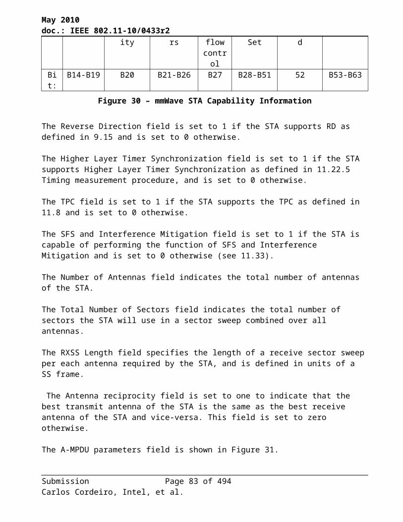
May 2010 doc.: IEEE 802.11-10/0433r2
: B39 B55 B63
Figure 67 – Relay transfer parameter field
The Duplex-Mode subfield indicates that the source RUS set the duplex mode of the RSUS involved in RLS. The Duplex-Mode subfield value is set to 0 if the RSUS operates in HD/DF mode. It is set to 1 if the RSUS operates in FD/AF mode.
The Cooperation-Mode subfield indicates whether the source RUS sets the link cooperating of the RSUS involved in RLS or not. This subfield is valid only when the RSUS is capable of link cooperating type and Duplex-Mode subfield is set to 0. Otherwise this subfield is ignored. The Cooperation-Mode subfield value is set to 0 if the RSUS operates in link switching type. It is set to 1 if the RSUS operates in link cooperation type.
The Tx-Mode subfield indicates that the source RUS sets the transmission mode of the RSUS involved in RLS. This subfield is valid only when the RSUS is capable of link–switching type and Duplex-Mode subfield is set to 1. Otherwise this subfield is ignored. The Tx-Mode subfield value is set to 0 if a group of three STAs involved in the RLS operates in Normal mode, as defined in 11.37.1.3.2. It is set to 1 if the group operates in Alternation mode, as defined in 11.37.1.3.2.
The Link Change Interval subfield indicates when the link of frame transmission between source RUS and destination RUS is changed. From the start position of one reserved contiguous SP, every time instant of Link Change Interval can have an opportunity to change the link. Within one Link Change Interval, only one link is used for frame transfer. The unit of this field is microseconds. This subfield is used only when the group involved in the RLS operates in link switching type.
The Data Sensing Time subfield indicates the defer time offset from the time instant of the next Link Change Interval when the link switching occurs. By default, it is set to SIFS plus SBIFS. This subfield is used only when the STAs involved in the RLS operate in link switching with Tx-Mode that is set to 0.
The First Period subfield indicates the period of the source RUS-RSUS link in which the source RUS and RSUS exchange frames. This subfield is used only when HD/DF RSUS operates in link switching type.
The Second Period subfield indicates the period of the RSUS-destination RUS link in which the RSUS and destination RUS exchange frames and the following period of the RSUS-source RUS link in which the RSUS informs the source RUS of finishing one frame transfer. This subfield is used only when HD/DF RSUS operates in link switching type.
.11 Editor Note: insert the following subclause
7.3a Fields that are used in Management and Extension frame bodies and Control frames
Submission Page 83 of 339 Carlos Cordeiro, Intel, et al.
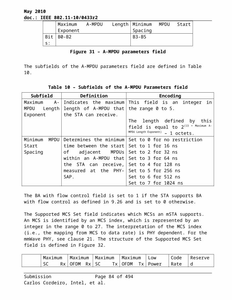
May 2010 doc.: IEEE 802.11-10/0433r2
7.3a.1 Sector Sweep field
The format of the sector sweep (SS) field is shown in Figure 68.
Direction CDOWN
Sector ID Antenna ID RXSS Length
Bits: 1 9 6 2 6
Figure 68 – SS field format The Direction field is set to 0 to indicate that the frame is transmitted by the initiator and set to 1 to indicate that the frame is transmitted by the responder.
The CDOWN field is a down-counter indicating the number of remaining mmWave Beacon frame transmissions in the BT, or the number of remaining SS frame transmissions to the end of the TXSS/RXSS or the allocation, whichever comes first. This field is set to 0 in the last frame mmWave Beacon and SS frame transmission. Possible values range from 0-511.
The Sector ID field is set to indicate the sector number through which the frame containing this SS field is transmitted from.
The Antenna ID field indicates the antenna the transmitter is currently using for this transmission. The RXSS Length field is valid only when transmitted in a CBP and is ignored otherwise. The RXSS Length field specifies the length of a receive sector sweep per antenna required by the transmitting STA, and is defined in units of a SS frame. The RXSS Length field shall be set to the value of the RXSS Length field in the transmitting STA’s mmWave Capabilities element.
7.3a.2 SP Info field
The format of the SP Info field is defined in Figure 69.
TID SPType Source AID Destination AID
SP Duration Reserved
Bits: B0-B3 B4 B5-B12 B13-B20 B21-B36 B37-B39
Figure 69 – SP Info field format
The TID subfield in the SP Info field identifies the TC or TS for the SP request or grant.
The SPType field is defined in the 7.3.2.95.
The Source AID field identifies the STA that is the source of the SP.
The Destination AID field identifies the STA that is the destination of the SP.
Submission Page 84 of 339 Carlos Cordeiro, Intel, et al.
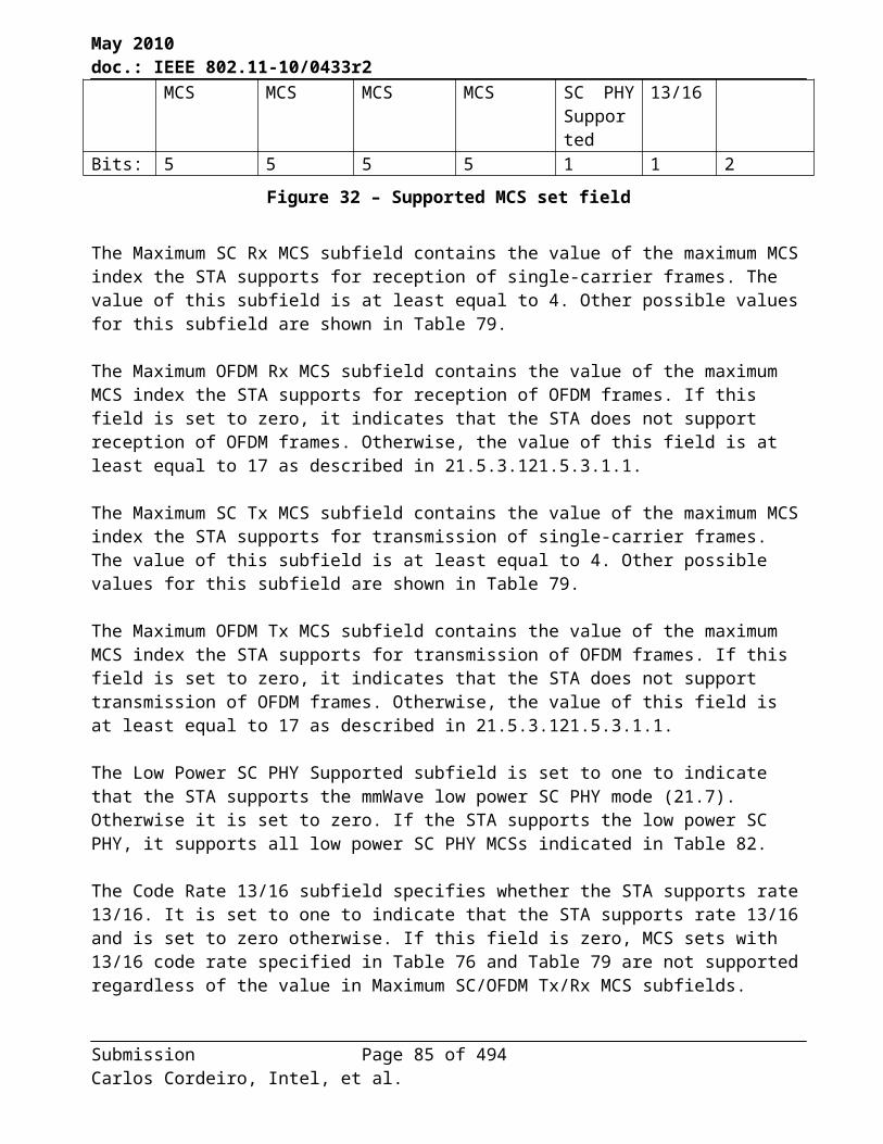
May 2010 doc.: IEEE 802.11-10/0433r2
When the SP Info field is transmitted within an SPR frame, the SP Duration field contains the duration requested in microseconds. When the SP Info field is transmitted within a Grant frame, the SP Duration field contains the remaining time to the end of the SP, CBP or TXOP allocation (see 9.23.7, 9.23.8, 9.23.9).
7.3a.3 Sector Sweep Feedback field
The format of the SS Feedback field is shown in Figure 70.
Sector select Antenna select SNR Report Poll required ReservedBits
:6 2 8 1 7
Figure 70 – SS Feedback field format
The Sector select field is a feedback containing the value of the Sector ID subfield of the SS field within the frame that was received with best quality in the immediately preceding sector sweep. The determination of which packet was received with best quality is implementation dependent. Possible values of this field range from 0-63. The Antenna select field is a feedback indicating the value of the Antenna ID subfield of the SS field within the frame that was received with best quality in the immediately preceding sector sweep. The determination of which frame was received with best quality is implementation dependent.
The SNR Report field is set to the value of the SNR from the frame that was received with best quality during the immediately preceding sector sweep, and which is indicated in the sector select field. This field is encoded as 8-bit two’s complement value of , where SNR is measured in dB. This covers from -10dB to 53.75dB in 0.25dB steps. The Poll required field is set to one by a non-AP/non-PCP STA to indicate that it requires the AP/PCP to initiate communication with the non-AP/non-PCP. This field is set to zero to indicate that the non-AP/non-PCP has no preference whether or not the PCP/AP initiates the communication. This field is ignored when transmitted by an PCP/AP.
7.3a.4 BRP Request field
The BRP Request field is defined in Figure 71.
L-RX TX-TRN-REQ
MID-REQ
BC-REQ
MID-Grant
BC-Grant
Chan-FBCK-CAP
TX Sector ID
Reserved
Bits: 6 1 1 1 1 1 1 6 6
Figure 71 – BRP Request field format
Submission Page 85 of 339 Carlos Cordeiro, Intel, et al.
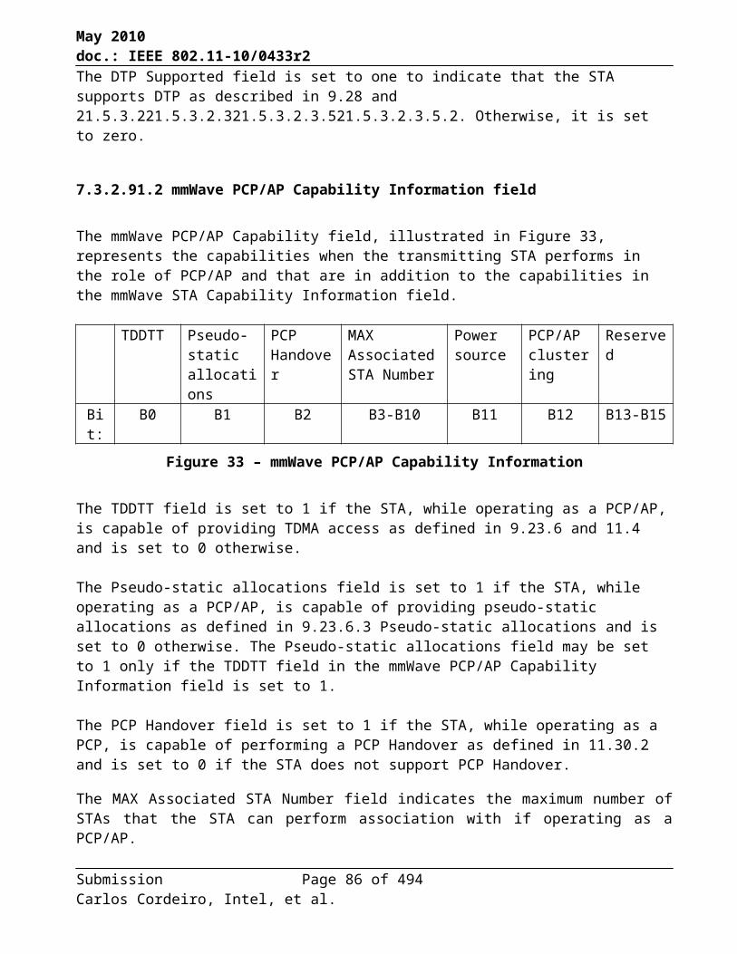
May 2010 doc.: IEEE 802.11-10/0433r2
The L-RX field indicates the compressed number of TRN-R subfields requested by the transmitting STA as part of beam refinement. To obtain the desired number of TRN-R subfieds, the value of the L-RX field is multiplied by 4. Possible values range form 0-16, corresponding to 0-64 TRN-R fields. If the field is set to zero, the transmitting STA does not need receiver training as part of beam refinement.
The TX-TRN-REQ field is set to one to indicate that the STA needs transmit training. It is set to zero otherwise.
A STA sets the MID-REQ field to one in SS-Feedback or BRP frames to indicate a request for an I/R-MID sub-phase. In case an R-MID sub-phase is requested, the STA can include information on the TX sector IDs to be used by the STA receiving this request. The STA receiving this request sets the MID-grant field in SS-ACK or BRP frames to one to grant this request or otherwise sets it to zero.
A STA sets the BC-REQ field to one in SS-Feedback or BRP frames to indicate a request for an I/R-BC sub-phase. In case an R-BC sub-phase is requested, the STA can include information on the TX sector IDs to be used by the STA receiving this request. The STA receiving this request sets the BC-grant field in SS-ACK or BRP to one to grant this request or otherwise sets it to zero.
The Chan-FBCK-CAP field indicates a capability to return channel measurement during beam refinement. If it is set to zero, the STA can only return BS-FBCK during beam refinement.
The TX sector ID field indicates the Sector ID that is used when transmitting the packet. If the packet is transmitted using a pattern that is not a sector that has been used in the sector sweep, the value of this field is set to 0x63.
7.3a.5 Beamforming Control field
The beamforming control field is formatted as shown in Figure 72.
Beamforming Training
Initiator T/RXSS
Responder T/RXSS
RXSS Length
Reserved
Bit: B0 B1 B2 B3-B8 B9-B15
Figure 72 – BF Control field format
The Beamforming Training field is set to 1 to indicate that the source STA intends to initiate beamforming training with the destination STA at the start of the SP and set to 0 otherwise. If the Beamforming Training field is set to 0, the Initiator T/RXSS, Responder T/RXSS, and RXSS Length fields are ignored.
The Initiator T/RXSS field is set to 1 to indicate that the source STA will start the beamforming training with a initiator TXSS. This field is set to 0 to indicate that the source station will start the BF training with a initiator RXSS.
The Responder T/RXSS field is set to 1 to indicate that the destination STA will start the RSS with a responder TXSS. This field is set to 0 to indicate that the destination station is to initiate the RSS with
Submission Page 86 of 339 Carlos Cordeiro, Intel, et al.
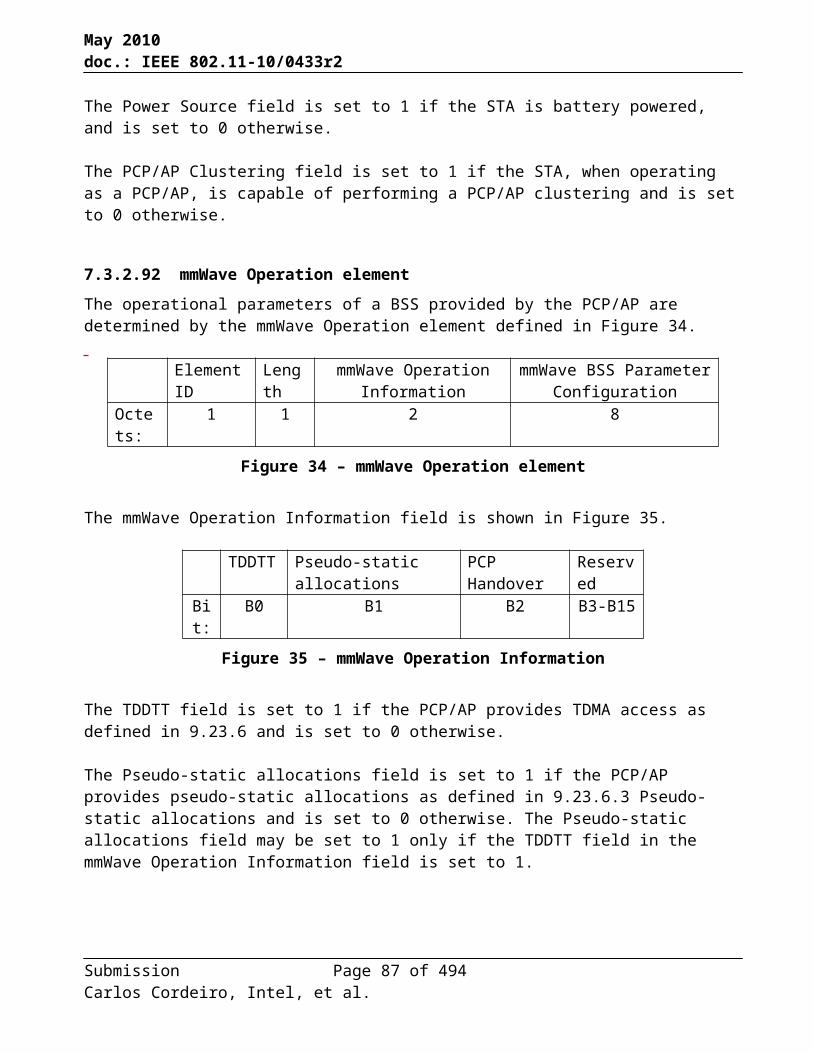
May 2010 doc.: IEEE 802.11-10/0433r2
a responder RXSS. If the initiator T/RXSS field is set to 0, the Responder T/RXSS field is set to one. If the Responder T/RXSS field is set to zero, the Initiator T/RXSS field is set to one. The RXSS Length field is valid only if the initiator T/RXSS or Responder T/RXSS field is set to 0 and is ignored otherwise. RXSS Length field specifes the total number of SS frames that are transmitted as part of an RXSS, from each of the transmitter antennas, and is defined in units of a SS frame. If the RXSS Length field is set with respect to the source STA, it shall be set to the value of the RXSS Length field in the source STA’s mmWave Capabilities element. If the RXSS Length field is set with respect to the destination STA, it shall be set to the value of the RXSS Length field in the destination STA’s mmWave Capabilities element.
7.4 Action frame format details
7.4.2 QoS Action frame details.11 editor note: add following text at end of subclause 7.4.2 QoS Action frame details
Two variants are defined for the ADDTS frames: Basic ADDTS frame variant and Extended mmWave ADDTS frame variant. The basic ADDTS frames contain the TSPEC element as defined in 7.3.2.30. The extended mmWave ADDTS frames contain the extended mmWave TSPEC as defined in 7.3.2.97. The variant of the frame is indicated by the Element ID in the fourth field of the ADDTS request frame body (Table 7-46) and sixth field of the ADDTS response frame body (Table 7-47). The Element ID is the first octet of each of these fields. The encoding of the ADDTS frame variants is shown in Table 21 and Table 22 .
Table 21 – Encoding of the ADDTS request variantElement ID of fourth field of ADDTS request frame
ADDTS request frame variant
13 (TSPEC) Basic ADDTS request frame-ANA- (extended mmWave TSPEC) Extended mmWave ADDTS
request frame
Table 22 – Encoding of the ADDTS response variantElement ID of sixth field of ADDTS response frame
ADDTS response frame variant
13 (TSPEC) Basic ADDTS response frame-ANA- (extended mmWave TSPEC) Extended mmWave ADDTS
request frame
In subsequent sub clauses of this document, the use of the term ADDTS request/response frame without the modifier “Extended mmWave” always refers to the Basic ADDTS request/response frame variant.
.11 editor note: modify subclauses 7.4.2.1 and 7.4.2.2 as follows
Submission Page 87 of 339 Carlos Cordeiro, Intel, et al.
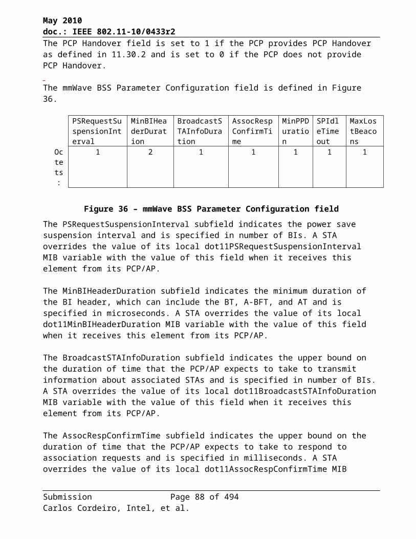
May 2010 doc.: IEEE 802.11-10/0433r2
7.4.2.1 Basic and Extended mmWave ADDTS Request frame formats
7.4.2.1.1 Basic ADDTS Request frame variant
.11 editor note: rename the Table 7-46 —“Basic ADDTS Request frame variant” and add line as follows:
Order Informationn+2 Multi-band (optional)
.11 editor note: add at end of the subcaluse7.4.2.1.1:
When present in an ADDTS Request frame, the Multi-band element indicates to which regulatory class and channel number the ADDTS Request frame applies and contains band specific information.
7.4.2.1.2 Extended mmWave ADDTS Request frame variant
The Extended mmWave ADDTS Request frame is used in a PBSS and in an infrastructure BSS operating in the UB. The frame body of the mmWave ADDTS Request frame contains the information shown in Table 23.
Table 23 – Extended mmWave ADDTS Request frame variantOrder Information
1 Category2 Action3 Dialog token4 Extended mmWave TSPEC
5-n TCLAS (optional)n+1 TCLAS Processing
(optional)n+2 Multi-band (optional)
The Dialog Token, TCLAS, and TCLAS Processing fields of this frame and the Extended mmWave TSPEC parameters are contained in an MLME-ExtADDTS.request primitive that causes the frame to be sent.
The Extended mmWave TSPEC element contains the QoS parameters that define a TS. The TS is identified by the source STA MAC Address, TSID and destination AID within the Extended mmWave TSPEC element.
The TCLAS element is optional and when present it is used by the non-AP/non-PCP mSTA that sends the Extended mmWave ADDTS Request frame to other non-AP/non-PCP mSTA through AP/PCP mSTA to identify the destination non-AP/non-PCP mSTA of the ADDTS request frame. There may be one or more TCLAS elements in the Extended mmWave ADDTS frame. The TCLAS Processing element is present when there is more than one TCLAS elements.
Submission Page 88 of 339 Carlos Cordeiro, Intel, et al.

May 2010 doc.: IEEE 802.11-10/0433r2
When present in an Extended mmWave ADDTS Request frame, the Multi-band element indicates to which regulatory class and channel number the Extended mmWave ADDTS Request frame applies and contains band specific information.
7.4.2.2 Basic and Extended mmWave ADDTS Response frame formats
7.4.2.2.1 Basic ADDTS Response frame variant
.11 editor note: add in the Table 7-47—ADDTS Response frame body line as follows:
Order Informationn+3 Multi-band (optional)
.11 editor note: add at end of the subcaluse 7.4.2.2.2:
When present in an ADDTS Response frame, the Multi-band element indicates to which regulatory class and channel number the ADDTS Request frame applies and contains band specific information.
7.4.2.2.2 Extended mmWave ADDTS Response frame variant
The Extended mmWave ADDTS Response frame is used in a PBSS and in an infrastructure BSS operating in the UB. The frame body of the Extended mmWave ADDTS Response contains the information shown in Table 24.
Table 24 – Extended mmWave ADDTS Response frame variantOrder Information
1 Category2 Action3 Dialog token4 Status code5 TS Delay6 Extended mmWave TSPEC
7-n TCLAS (optional)n+1 TCLAS Processing
(optional)n+2 Multi-band (optional)
The Dialog Token, TS Delay, and Extended mmWave TSPEC in this frame are contained in an MLME-ExtADDTS.response primitive that causes the frame to be sent. The TS Delay information element is present in an Extended mmWave ADDTS Response frame only if the status code is set to 47.
When present in an Extended mmWave ADDTS Response frame, the Multi-band element indicates to which regulatory class and channel number the Extended mmWave ADDTS Response frame applies and contains band specific information.
Submission Page 89 of 339 Carlos Cordeiro, Intel, et al.
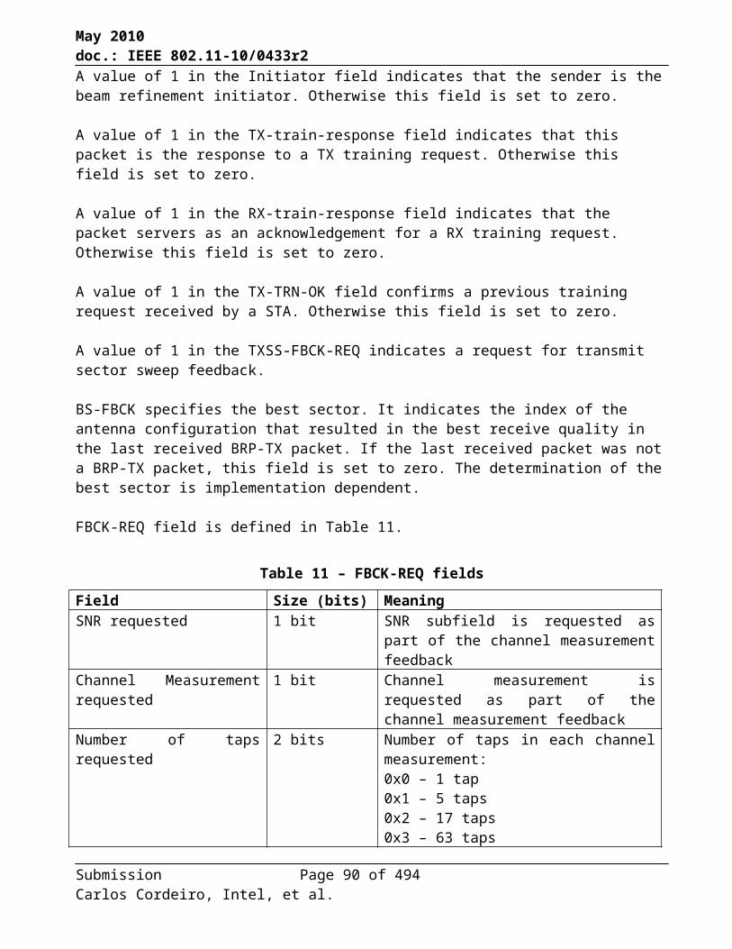
May 2010 doc.: IEEE 802.11-10/0433r2
7.4.2.3 DELTS frame format
.11 Editor Note: change this subclause as indicated below
Table 7-48 – DELTS frame bodyOrder Information
1 Category2 Action3 TS Info4 Reason code5 Extended mmWave TS Info 6 Multi-band (optional)
The TS Info field is present for a TS added with the TSPEC element and is defined in 7.3.2.30 . The Extended mmWave TS Info field is present for a TS added with the Extended mmWave TSPEC element and is defined in 7.3.2.97 .
A DELTS frame is used to delete a TS characterized by the TS Info field or Extended mmWave TS Info field in the frame. A DELTS frame may be sent from the HC or PCP to the source STA of that TS, or vice versa, to indicate an imperative request, to which no response is required from the recipient STA.
When present in an DELTS frame, the Multi-band element indicates to which regulatory class and channel number the DELTS frame applies to.
7.4.4 Block Ack Action frame details
7.4.4.1 ADDBA Request frame format.11 Editor note: insert the following rows in “Table 7-55 ADDBA Request frame body”
7 Multi-band (optional)8 TCLAS (optional)9 ADDBA Extension (optional)
.11 Editor note: insert the following paragraph as the last one: “When present in an ADDBA Request frame, the Multi-band element indicates to which band ID, regulatory class and channel number the ADDBA Request frame applies to and contains band specific information.”
Submission Page 90 of 339 Carlos Cordeiro, Intel, et al.
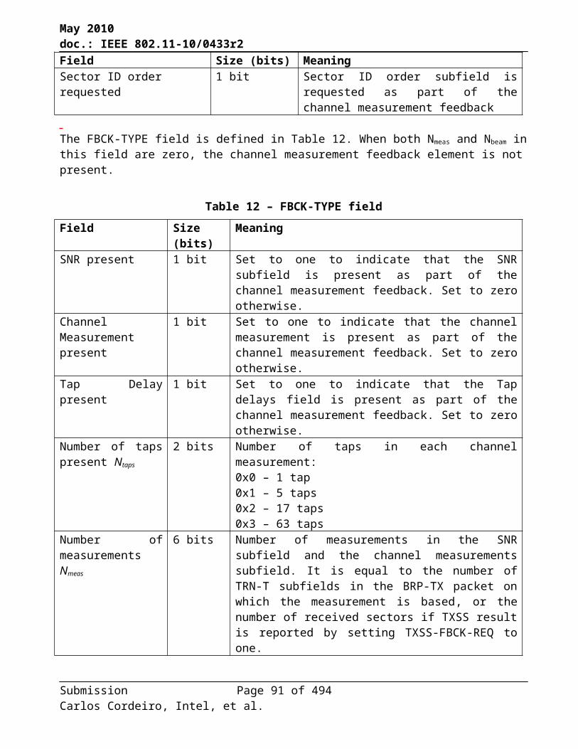
May 2010 doc.: IEEE 802.11-10/0433r2
7.4.4.2 ADDBA Response frame format.11 Editor note: insert the following rows in “Table 7-56 ADDBA Response frame body”
7 Multi-band (optional)8 TCLAS (optional)9 ADDBA Extension (optional)
.11 Editor note: insert the following paragraph as the last one: “When present in an ADDBA Response frame, the Multi-band element indicates to which band ID, regulatory class and channel number the ADDBA Response frame applies to and contains band specific information.”
7.4.4.3 DELBA frame format.11 Editor note: insert the following rows in “Table 7-57 DELBA frame body”
5 Multi-band (optional)6 TCLAS (optional)
.11 Editor note: insert the following paragraph as the last one: “When present in an DELBA frame, the Multi-band element indicates to which band ID, regulatory class and channel number the DELBA Request frame applies to.”
.11 Editor Note: Insert the following subclauses after section 7.4.12 (from P802.11s amendment):
7.4.13 mmWave Action frame details
7.4.13.1 mmWave Action field
The mmWave Action field values are defined in Table 25.
Table 25 – mmWave Action field valuesAction field value
Meaning
1 Announce2 Power Save Configuration Request3 Power Save Configuration Response4 Information Request5 Information Response6 Beam Refinement7 Handover Request 8 Handover Response 9 Link Margin Request10 Link Margin Response11 DTP Request
Submission Page 91 of 339 Carlos Cordeiro, Intel, et al.

May 2010 doc.: IEEE 802.11-10/0433r2
12 DTP Response13 Relay Search Request14 Relay Search Response15 Multi-Relays Channel Measurement Request16 Multi-Relays Channel Measurement Report17 RLS Request 18 RLS Response19 RLS Announcement20 RLS Teardown21 Relay ACK Request22 Relay ACK Response23 TPA Request24 TPA Response25 TPA Report26 ROC Request27 ROC Response
7.4.13.2 AnnounceThe Announce frame is an Action or and Action No Ack frame of category mmWave. The format of the frame body is shown in Table 26.
Announce frames can be transmitted during the AT period of a BI and can perform functions including of a mmWave Beacon frame, but since this frame can be transmitted directionally to a STA it can provide a much more spectrally efficient access than using a mmWave Beacon frame.
Table 26 – AnnounceOrder Information
1 Category2 Action3 Timestamp4 Beacon Interval5 SSID (optional)
Last - 1
One or more resource and/or capability related information elements may appear in this frame. These information elements follow all other information elements that are not vendor-specific information elements and precede all other information elements that are vendor-specific information elements that are part of the Last field in the Action frame.
The Category field is set to the category for mmWave, specified in Table 4.
The Action field is set to the value corresponding to Announce specified in Table 25.
Any number of information elements can be included within an Announce frame, including the Extended Schedule element.
Submission Page 92 of 339 Carlos Cordeiro, Intel, et al.
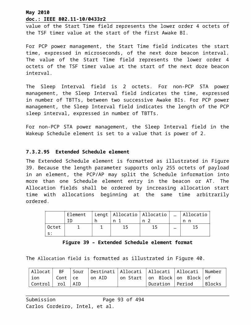
May 2010 doc.: IEEE 802.11-10/0433r2
7.4.13.3 Power Save Configuration RequestThe frame body of the Power Save Configuration Request (PSC-REQ) frame is shown in Table 27.
Table 27 – Power Save Configuration RequestOrder Information
1 Category2 Action3 Power Management4 Wakeup Schedule element (optional)
The Category field is set to the category for mmWave, specified in Table 4.
The Action field is set to the value corresponding to Power Save Configuration Request specified in Table 25.
The length of the Power Management (PM) field is one octet. Setting the PM field to 0 indicates a transition from power save mode to active mode. Setting the PM field to 1 indicates a transition from active mode to power save mode. All other values are reserved.
The Wakeup Schedule is defined in 7.3.2.94 Wakeup Schedule element.
7.4.13.4 Power Save Configuration ResponseThe frame body of the Power Save Configuration Response (PSC-RSP) frame is shown in Table 28.
Table 28 – Power Save Configuration ResponseOrder Information
1 Category2 Action3 Status Code4 Wakeup Schedule element (optional)
The Category field is set to the category for mmWave, specified in Table 4.
The Action field is set to the value corresponding to Power Save Configuration Response specified in Table 25.
The Status Code field is defined in 7.3.1.9.
The Wakeup Schedule is defined in 7.3.2.94 Wakeup Schedule element.
Submission Page 93 of 339 Carlos Cordeiro, Intel, et al.
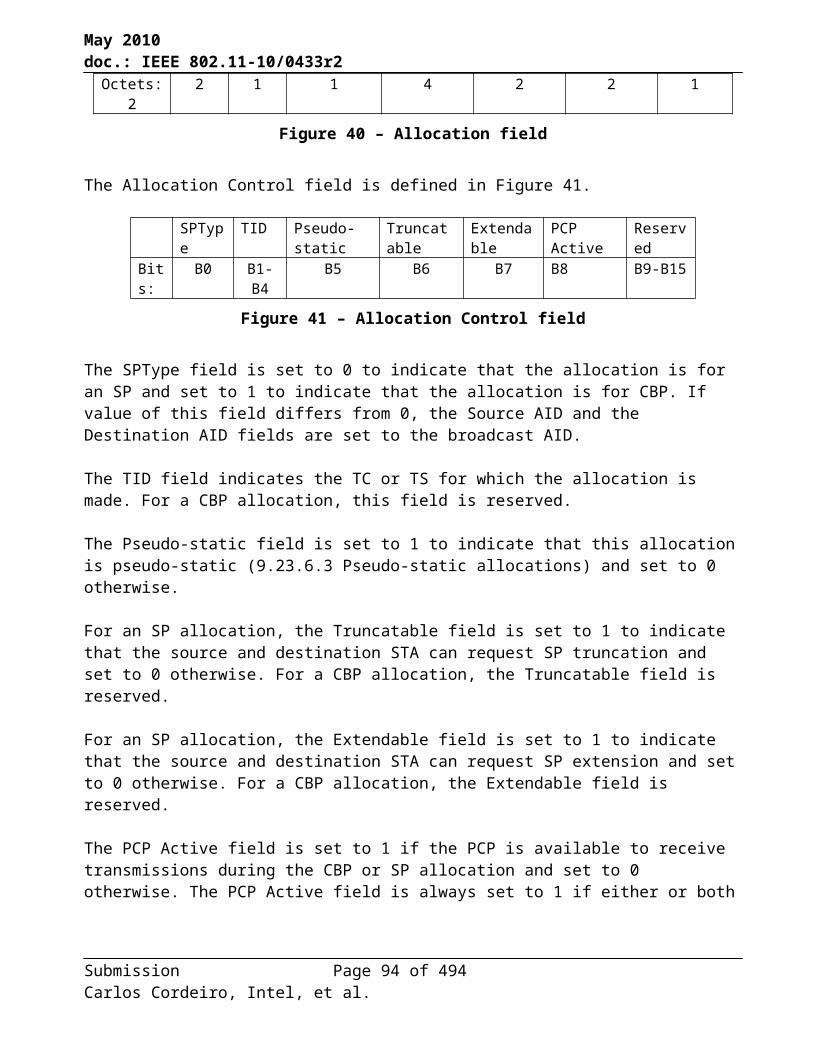
May 2010 doc.: IEEE 802.11-10/0433r2
7.4.13.5 Information RequestThe Information Request frame is an Action frame of category mmWave. The format of the frame body of a Information Request is shown in Table 29.
Table 29 – Information Request frameOrder Information
1 Category2 Action3 Target Address4 Request element5 mmWave Capabilities 1 (optional)… …
N+4 mmWave Capabilities N (optional)N+5 IE Provided 1 (optional)… …
4+N+M IE Provided M (optional)
The Category field is set to the category for mmWave, specified in Table 4.
The Action field is set to the value for Information Request, specified in Table 25.
The Target Address field contains the MAC address of the STA whose information is being requested. If this frame is sent to the PCP and the value of the Target Address field is the broadcast address, then the STA is requesting information regarding all associated STAs.
The Request IE field is described in 7.3.2.12.
The mmWave Capabilities element carries information about the transmitter STA and other STAs known to the transmitter STA. The format of this element is defined in mmWave Capabilities element 7.3.2.91.
Each IE Provided field contains an element as specified in 7.3.2, that the source STA of this frame is providing to the destination STA.
7.4.13.6 Information ResponseThe format of the Information Response frame is shown in Table 30.
This frame is sent unicast to a STA or it is sent unsolicited as a unicast to a STA or broadcast to all STAs in the PBSS/infrastructure BSS. If this frame is sent as a broadcast, then this frame is an Action No Ack frame.
Table 30 – Information Response frameOrder Information
1 Category
Submission Page 94 of 339 Carlos Cordeiro, Intel, et al.
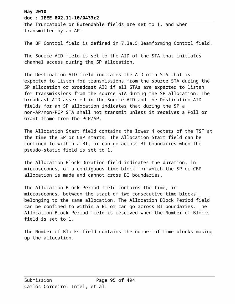
May 2010 doc.: IEEE 802.11-10/0433r2
2 Action3 Target address 4 mmWave Capabilities 1… …
N+3 mmWave Capabilities N (optional)N+4 Request elementN+5 IE Provided 1 (optional)… …
4+N+M IE Provided M (optional)Last Vendor specific
The category field is set to the category for mmWave, specified in Table 4.
The Action field is set to the value for Information Response, specified in Table 25.
The Target Address field contains the MAC address of the STA whose information is being provided. If this field is set to the broadcast address, then the STA is providing information regarding all associated STAs.
The mmWave Capabilities element carries information about the transmitter STA and other STAs known to the transmitter STA. The mmWave Capabilities element is described in 7.3.2.91.
The Request IE field is described in 7.3.2.12.
The IE Provided field contains the element, as described in 7.3.2, that the source STA of this frame is providing to the destination STA.
One or more vendor-specific information elements can appear in this frame. This information element follows all other information elements.
7.4.13.7 Beam Refinement (BRP)The Beam Refinement (BRP) frame includes the Beam Refinement information element and can include the Channel measurement feedback element, and is defined in Table 31.
Table 31 – Beam Refinement frameOrde
r
Information
1 Category2 Action3 Dialog Token4 BRP request field5 mmWave Beam Refinement element6 Channel measurement feedback element (optional)
Submission Page 95 of 339 Carlos Cordeiro, Intel, et al.
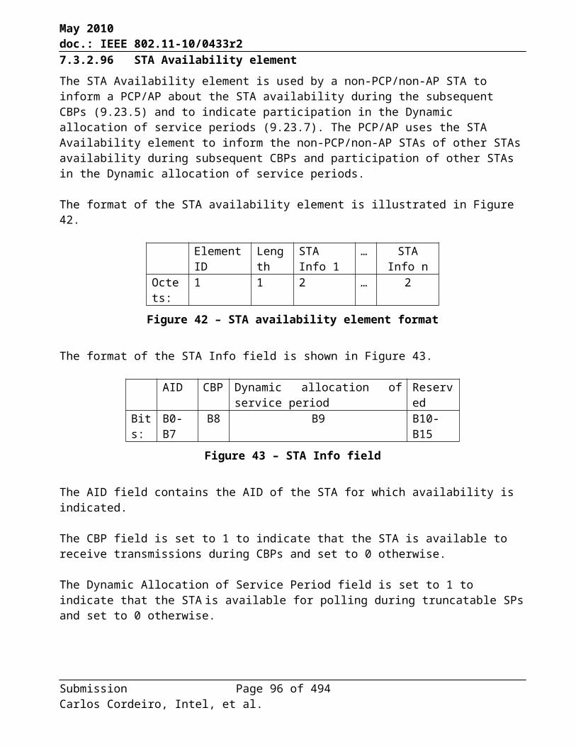
May 2010 doc.: IEEE 802.11-10/0433r2
The Category field is set to the category for mmWave, specified in Table 4.
The Action field is set to the value corresponding to Beam Refinemt, specified in Table 25.
The BRP request field is defined in 7.3a.4 BRP Request field.
The Beam Refinement element is defined in 7.3.2.93.
The Channel measurement feedback element is defined in 7.3.2.99.
The Beam Refinement frame may contain more than one Channel measurement feedback element if the measurement information exceeds 254 bytes. The content of each Channel measurement feedback element that follows the first one in a single Beam Refinement frame is a continuation of the content in the previous element. The Channel measurement subfield and the Sector ID subfield may be split between several elements. Each Channel measurement feedback element that is not the last Channel measurement feedback element in the frame shall be 256 bytes long. Channel measurement information for a single channel measurement is always contained within a single Beam Refinement frame.
7.4.13.8 Handover RequestThe format of the Handover Request frame is shown in Table 32.
Table 32 – Handover Request frameOrde
rInformation
1 Category2 Action3 Handover Reason4 Handover Remaining BI
The category field is set to the category for mmWave, specified in Table 4.
The Action field is set to the value for Handover Request, specified in Table 25.
Handover Reason is 1 octet in length and indicates the reason that the current PCP intends to do the PCP handover. The handover reason field is set to 0 to indicate the PCP is leaving the PBSS, it is set to 1 to indicate low power in the PCP, is set to 2 to indicate that a more qualified PCP handover capable STA is available, and is set to 3 to indicate that the PCP handover capable STA wants to be a PCP. All the other values are reserved. Handover Remaining BI is 1 octet in length and indicates the number of BIs, starting from the BI in which this frame is transmitted, remaining until the handover takes effect.
7.4.13.9 Handover Response
Submission Page 96 of 339 Carlos Cordeiro, Intel, et al.

May 2010 doc.: IEEE 802.11-10/0433r2
The format of the Handover Response frame is shown in Table 33.
Table 33 – Handover Response frameOrde
rInformation
1 Category2 Action3 Handover Result4 Handover Reject Reason
The category field is set to the category for mmWave, specified in Table 4.
The Action field is set to the value for Handover Response, specified in Table 25.
Handover Result is 1 octet in length and indicates whether the destination STA or PCP accepted or not a handover request. A value of 0 indicates that the destination STA or PCP accepts the handover request. A value of 1 indicates that the destination STA or PCP does not accept the handover request.
If the Handover Result field is set to 0, the Handover Reject Reason field is reserved and set to 0. If the Handover Result field is set to 1, the Handover Reject Reason indicates the reason the destination STA or PCP rejected the handover request and can be one of the following: 0 for low power, 1 for handover in progress with another STA, and 2 for unspecified reason. The length of Handover Reject Reason field is 1 octet.
7.4.13.10 Link Margin Request
The format of the Link Margin Request frame is shown in Table 34.
Table 34 – Link Margin Request frameOrde
rInformation
1 Category2 Action3 Dialog Token
The category field is set to the category for mmWave, specified in Table 4.
The Action field is set to the value for Link Margin Request, specified in Table 25.
The Dialog Token field is set to a non-zero value chosen by the STA sending the request to identify the transaction.
7.4.13.11 Link Margin Response
Submission Page 97 of 339 Carlos Cordeiro, Intel, et al.
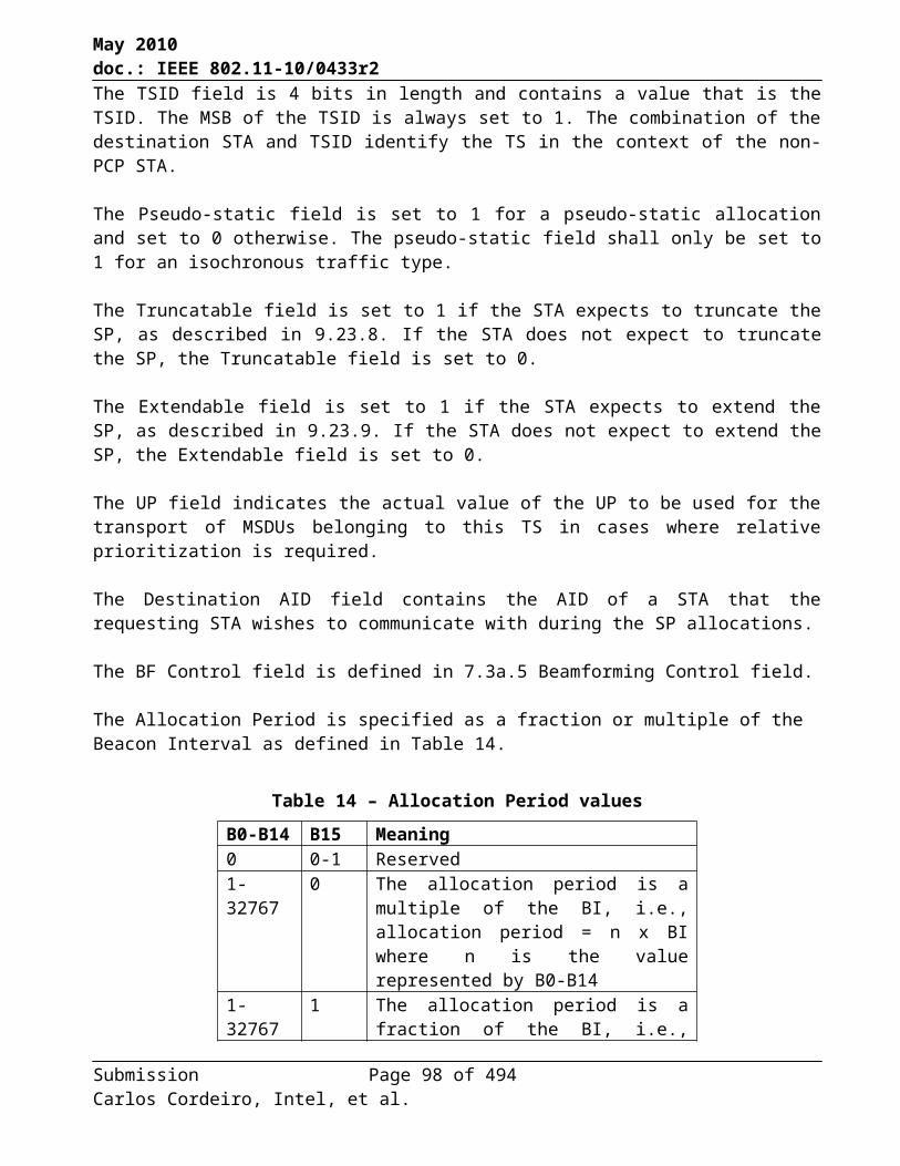
May 2010 doc.: IEEE 802.11-10/0433r2
The Link Margin Response frame is an Action or an Action No Ack frame. The format of the Link Margin Response frame is shown in Table 35.
Table 35 – Link Margin Response frameOrde
rInformation
1 Category2 Action3 Dialog Token4 Link Margin
The category field is set to the category for mmWave, specified in Table 4.
The Action field is set to the value for Link Margin Request, specified in Table 25.
The Dialog Token field is set to the value received in a corresponding Link Margin Request frame. If the Link Margin Response frame is not transmitted in response to a Link Margin Request frame, then the Dialog Token field is set to 0.
The Link Margin element is defined in 7.3.2.105.
7.4.13.12 DTP Request
The DTP Request frame is transmitted by a STA requesting another STA for DTP information. The format of the DTP Request frame body is shown in Figure 73.
Category Action Dialog TokenOctets: 1 1 1
Figure 73 – DTP Request frame format
The Category field is set to the category for mmWave, specified in Table 4.
The Action field is set to the value representing a DTP Request frame, specified in Table 25.
The Dialog Token field is set to a non-zero value chosen by the STA sending the request to identify the transaction.
7.4.13.13 DTP Report
The DTP Report frame is transmitted in response to a DTP Request frame. A DTP Report frame can also be sent unsolicited. The format of the DTP Report frame body is shown in Figure 74.
Category Action Dialog Token DTP
Submission Page 98 of 339 Carlos Cordeiro, Intel, et al.

May 2010 doc.: IEEE 802.11-10/0433r2
ReportOctets: 1 1 1 34
Figure 74 – DTP Report frame format
The Category field is set to the category for mmWave, specified in Table 4.
The Action field is set to the value representing a DTP Report frame, specified in Table 25.
The Dialog Token field is set to the Dialog Token value in the corresponding TPC Request frame. If the DTP Report frame is not being transmitted in response to a DTP Request frame, the Dialog Token is set to zero.
The DTP Report element is defined in 7.3.2.108.
7.4.13.14 Relay search request
The Relay Search Request frame is transmitted by a non-PCP/non-AP STA to the PCP/AP to request a list of RSUSs in the BSS. The frame body of the Relay Search Request frame is shown in Table 36.
Table 36 – Relay search request frame formatOrder Information1 Category2 Action3 Dialog Token4 Destination RUS AID
The Category field is set to the category for mmWave, specified in Table 4.
The Action field is set to the value corresponding to Relay Search Request, specified in Table 25.
The Dialog Token field shall be set to a nonzero value chosen by the STA sending the Relay Search Request frame to identify the request/response transaction.
The Destination RUS AID field is set to the AID of the target destination RUS.
7.4.13.15 Relay search response
The Relay Search Response frame is sent by a PCP/AP in response to a Relay Search Request frame. The frame body of a Relay Search Response frame contains the information shown in Table 37.
Table 37 – Relay search response frame bodyOrder Information1 Category
Submission Page 99 of 339 Carlos Cordeiro, Intel, et al.

May 2010 doc.: IEEE 802.11-10/0433r2
2 Action3 Dialog Token4 Status Code5 Relay Capable STA 1 Info… …N+4 Relay Capable STA N Info
The Category field is set to the category for mmWave, specified in Table 4.
The Action field is set to the value corresponding to Relay Search Response, specified in Table 25.
The Dialog Token field shall be set to the value in the corresponding Relay Search Request frame that generated this response.
The Status Code field is defined in 7.3.1.9.
The Relay Capable STA Info field is defined in 7.3.1.51 Relay capable STA info field. This information is included only if the status code indicates successful.
7.4.13.16 Multi-relays channel measurement request
The Multi-Relays Channel Measurement Request frame is transmitted by a STA initiating relay operation to the recipient STA in order to obtain Channel Measurements between the recipient STA and the other STA participating in the relay operation. The frame body of the Multi-Relays Channel Measurement Request frame contains the information shown in Table 38.
Table 38 – Multi-relays channel measurement request frame bodyOrder Information1 Category2 Action3 Dialog Token
The Category field is set to the category for mmWave, specified in Table 4.
The Action field is set to the value corresponding to Multi-Relays Channel Measurement Request, specified in Table 25.
The Dialog Token field shall be set to a nonzero value chosen by the STA sending the Multi-Relays Channel Measurement Request frame to identify the request/report transaction.
7.4.13.17 Multi-relays channel measurement report
The Multi-Relays Channel Measurement Report frame is sent in response to a Multi-Relays Channel Request. The frame body of the Multi-Relays Channel Measurement Report frame is shown in Table 39.
Submission Page 100 of 339 Carlos Cordeiro, Intel, et al.
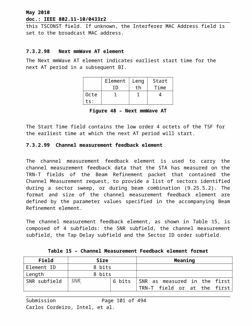
May 2010 doc.: IEEE 802.11-10/0433r2
Table 39 – Multi-relays channel measurement report frame bodyOrder Information1 Category2 Action3 Dialog Token4 Channel Measurement Info 1… …N+3 Channel Measurement Info N
The Category field is set to the category for mmWave, specified in Table 4.
The Action field is set to the value corresponding to Multi-Relays Channel Measurement Report, specified in Table 25.
The Dialog Token field shall be set to the value in any corresponding Multi-Relays Channel Measurement Request frame. If the Multi-Relays Channel Measurement Report frame is not being transmitted in response to a Multi-Relays Channel Measurement Request frame, then the Dialog token shall be set to 0.
The format of the Channel Measurement Info field is defined in Figure 75. Multiple Channel Measurement Info fields can be included in case that the reporting STA measures the channel for multiple RSUSs.
Peer STA AID SNR Internal Angle Recommend ReservedBits: B0-B7 B8-B15 B16-B22 B23 B24-B31
Figure 75 – Channel measurement info field
The Peer STA AID subfield contains the AID of the STA toward which the reporting STA measures link.
The SNR subfield indicates the SNR measured in the link toward the STA corresponding to Peer STA AID. This field is encoded as 8-bit two’s complement value of 4x(SNR-22), where SNR is measured in dB. This covers from -10dB to 53.75dB in 0.25dB steps.
The Internal Angle subfield indicates the angle between directions toward the other STAs involved in the relay operation. This covers from 0 degree to 180 degree in 2 degree steps. This subfield uses the degree of the direction from the sector that was feedbacked with best quality during TXSS if SLS phase of BF is performed and RXSS is not included.
The Recommend subfield indicates whether the responding STA recommends the relay operation based on the channel measurement with the Peer STA. This subfield is set to one when the relay operation is recommended and otherwise is set to zero.
7.4.13.18 RLS request
Submission Page 101 of 339 Carlos Cordeiro, Intel, et al.
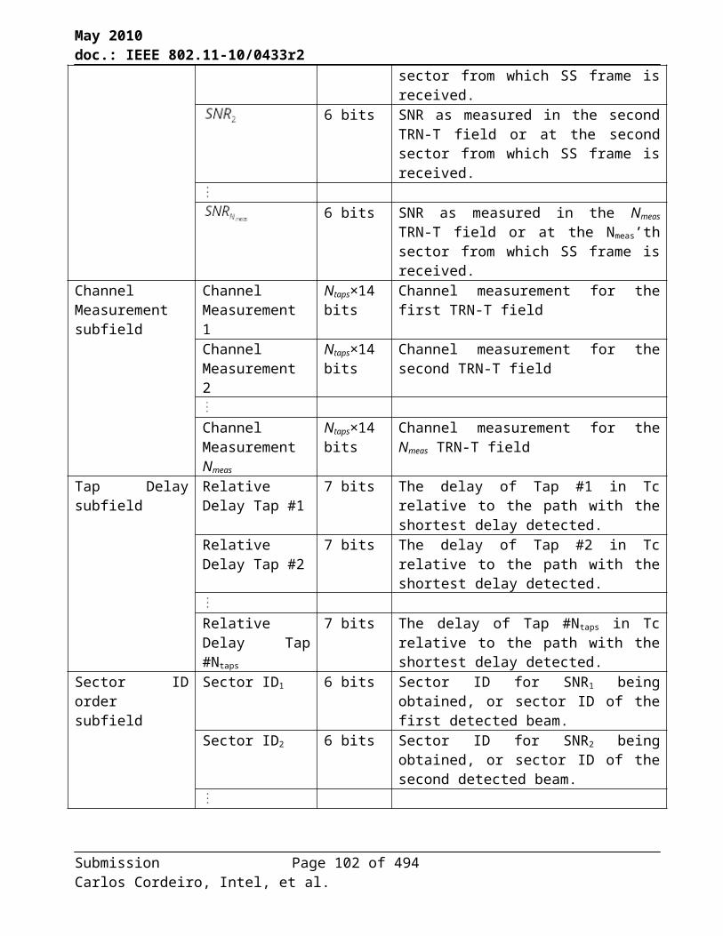
May 2010 doc.: IEEE 802.11-10/0433r2
The RLS Request frame is used to setup a relay link. The frame body of the RLS Request is shown in Table 40.
Table 40 – RLS request frame bodyOrder Information1 Category2 Action3 Dialog Token4 Destination AID5 Relay AID6 Source AID7 Destination Capability
Information8 Relay Capability Information9 Source Capability Information10 Relay Transfer Parameter Set
The Category field is set to the category for mmWave, specified in Table 4.
The Action field is set to the value corresponding to RLS Request, specified in Table 25.
The Dialog Token field shall be set to a nonzero value chosen by the STA sending the RLS Request frame to identify the request/response transaction.
The Destination AID field value is the AID of the target destination.
The Relay AID field value is the AID of the selected RSUS.
The Source AID field value is the AID of the initiating STA.
The Destination Capability Information field value is the capability information of the target destination.
The Relay Capability Information field value is the capability information of the selected RSUS.
The Source Capability Information field value is the capability information of originator of the request.
The Relay Transfer Parameter Set element is defined in 7.3.2.111.
7.4.13.19 RLS response
The RLS Response frame is sent in response to an RLS Request frame. The frame body of an RLS Response frame is shown in Table 41.
Table 41 – RLS response frame body
Submission Page 102 of 339 Carlos Cordeiro, Intel, et al.
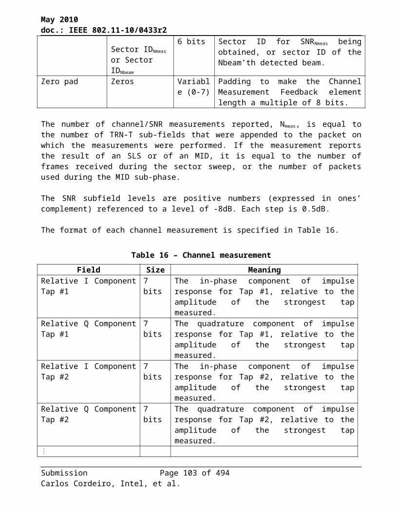
May 2010 doc.: IEEE 802.11-10/0433r2
Order Information1 Category2 Action3 Dialog Token4 Destination AID5 Relay AID6 Source AID7 Destination Capability
Information8 Relay Capability Information 9 Source Capability Information 10 Destination Status Code11 Relay Status Code (optional)
The Category field is set to the category for mmWave, specified in Table 4.
The Action field is set to the value corresponding to RLS Response, specified in Table 25.
The Dialog Token field shall be set to the value in any corresponding RLS Request frame.
The Destination AID, the Relay AID, the Source AID, the Destination Capability Information, the Relay Capability Information, and the Source Capability Information fields are copied from the corresponding fields in the RLS Request frame.
The Destination Status Code field is included when the destination RUS transmits this RLS Response frame as a result of RLS Request. It is defined in 7.3.1.9.
The Relay Status Code field is included when the relay RUS transmits this RLS Response frame as a result of RLS Request. It is defined in 7.3.1.9.
7.4.13.20 RLS announcement
The RLS Announcement frame is sent to announce the successful RLS. The frame body of an RLS Announcement frame is shown in Table 42.
Table 42 – RLS announcement frame bodyOrder Information1 Category2 Action3 Status Code4 Destination AID5 Relay AID6 Source AID
The Category field is set to the category for mmWave, specified in Table 4.
The Action field is set to the value corresponding to RLS Announcement, specified in Table 25.
Submission Page 103 of 339 Carlos Cordeiro, Intel, et al.
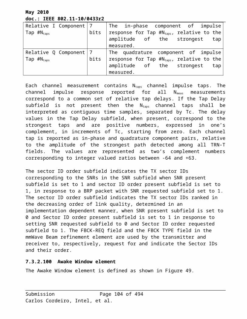
May 2010 doc.: IEEE 802.11-10/0433r2
The Status Code field is defined in 7.3.1.9.
The Destination AID field value is the AID of the target destination.
The Relay AID field value is the AID of the RSUS.
The Source AID field value is the AID of the initiating STA.
7.4.13.21 RLS teardown
The RLS Teardown frame is sent to terminate a relay operation. The frame body of the RLS Teardown frame contains the information shown in Table 43.
Table 43 – RLS teardown frame bodyOrder Information1 Category2 Action3 Destination AID4 Relay AID5 Source AID6 Reason Code
The Category field is set to the category for mmWave, specified in Table 4.
The Action field is set to the value corresponding to RLS Teardown, specified in Table 25.
The Destination AID field value is the AID of the destination RUS.
The Relay AID field value is the AID of the RSUS.
The Source AID field value is the AID of the source RUS.
The Reason Code field is defined in 7.3.1.7.
7.4.13.22 Relay ACK request
The Relay ACK Request frame is sent by an source RUS to an RSUS participating in a relay operation, in order to determine whether all frames forwarded through the RSUS were successfully received by the destination RUS also participating in the relay operation. This frame is used only when the RSUS is operated in HD/DF mode and relay operation is link switching type. The frame body of the Relay ACK Request frame contains the information in Table 44.
Table 44 – Relay ACK request frame body
Submission Page 104 of 339 Carlos Cordeiro, Intel, et al.
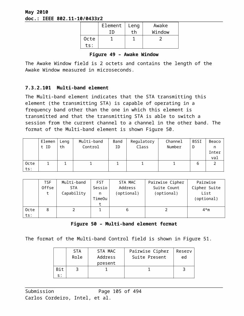
May 2010 doc.: IEEE 802.11-10/0433r2
Order Information1 Category2 Action3 BAR Control 4 BlockAck Starting Sequence Control
The Category field is set to the category for mmWave, specified in Table 4.
The Action field is set to the value corresponding to Relay ACK Request, specified in Table 25.
The BAR Control field and BlockAck Starting Sequence Control fields are defined in 7.2.1.7.
7.4.13.23 Relay ACK response
The Relay ACK Response frame is sent by an RSUS to a source RUS participating in a relay operation, in order to report which frames have been received by the destination RUS also participating in the relay operation. This frame is used only when the RSUS is operated in HD/DF mode and relay operation is link switching type. The frame body of the Relay ACK Response frame contains the information in Table 45.
Table 45 – Relay ACK response frame bodyOrder Information1 Category2 Action3 BA Control 4 BlockAck Starting Sequence Control 5 BlockAck Bitmap
The Category field is set to the category for mmWave, specified in Table 4.
The Action field is set to the value corresponding to Relay ACK Response, specified in Table 25.
The BA Control field is defined in 7.2.1.8.
The BlockAck Starting Sequence Control field is defined in 7.2.1.8 and is set to the corresponding value within the immediately previously received Relay ACK Request frame.
The BlockAck Bitmap field is defined in 7.2.1.8.
7.4.13.24 TPA request
The TPA Request frame is sent by a destination RUS participating in operation based on link cooperating type to both the RSUS and source RUS that belong to the same group as the destination RUS, in order for them to send back their own TPA Response frames at the separately pre-defined
Submission Page 105 of 339 Carlos Cordeiro, Intel, et al.
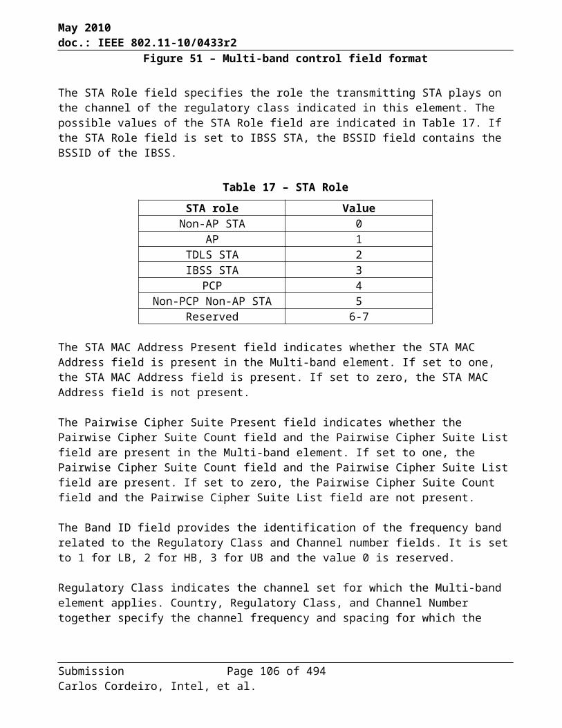
May 2010 doc.: IEEE 802.11-10/0433r2
times. Also, a source RUS sends a TPA Request frame to the RSUS that is selected by the source RUS, in order for the RSUS to feedback its own TPA Response frame at the pre-defined time.
The frame body of the TPA Request frame is formatted as shown in Table 46.
Table 46 – TPA request frame bodyOrder
Information
1 Category2 Action3 Dialog Token4 Timing Offset5 Response Offset6 Sampling Frequency Offset (Optional)
The Category field is set to the category for mmWave, specified in Table 4.
The Action field is set to the value corresponding to TPA Request, specified in Table 25.
The Dialog Token field shall be set to a nonzero value chosen by the STA sending the TPA Request frame to identify the request/response transaction.
The Timing Offset is 2 octets in length and indicates the amount of time, in nanoseconds, that the STA identified in the RA of the frame is required to change the timing offset of its transmissions, so that they arrive at the expected time at the transmitting STA.
The Response Offset field is defined in 7.2.1.10.
The Sampling Frequency Offset is 2 octets in length and indicates the amount by which to change the sampling frequency offset of the burst transmission so that bursts arrive at the destination STA with no sampling frequency offset. The unit is 0.01 ppm.
7.4.13.25 TPA response
The TPA Response frame is sent by an RSUS or a source RUS participating in relay operation in response to a TPA Request frame from a destination RUS or a source RUS. The RSUS or the source RUS that receive a TPA Request frame shall respond to the destination RUS or the source RUS with a TPA Response frame at the time offset from the end of the TPA Request frame indicated in the Response Offset field within the TPA Request frame. The frame body of the TPA Request frame contains the information in Table 47.
Table 47 – TPA response frame bodyOrder Information1 Category2 Action3 Dialog Token
Submission Page 106 of 339 Carlos Cordeiro, Intel, et al.
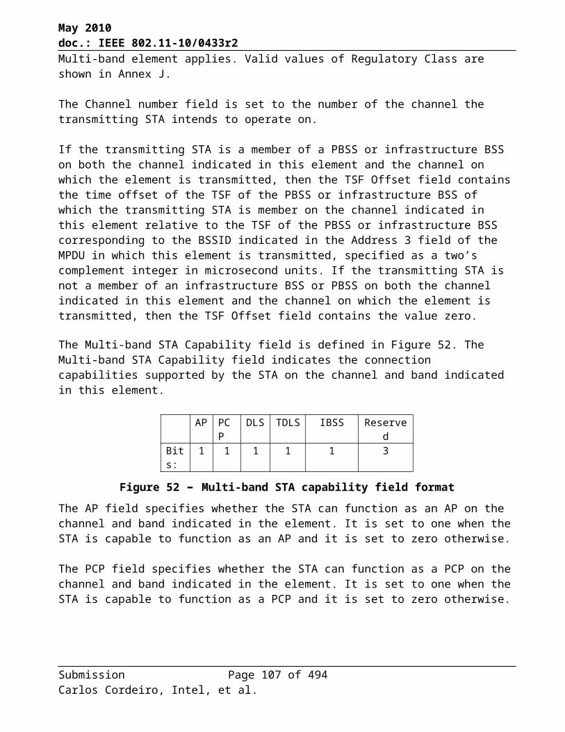
May 2010 doc.: IEEE 802.11-10/0433r2
The Category field is set to the category for mmWave, specified in Table 4.
The Action field is set to the value corresponding to TPA Response, specified in Table 25.
The Dialog Token field is set to the value received in the corresponding TPA Request frame that generated this response.
7.4.13.26 TPA report
The TPA Report frame is sent to announce whether a TPA procedure is successful or not. The frame body of the TPA Report frame contains the information shown in Table 48.
Table 48 – TPA report frame bodyOrder
Information
1 Category2 Action3 Status code
The Category field is set to the category for mmWave, specified in Table 4.
The Action field is set to the value corresponding to TPA Report, specified in Table 25.
If the Status Code field is set to 1, it indicates that current TPA procedure was successful. Otherwise, the TPA procedure is failed.
7.4.13.27 ROC request
The ROC Request frame is sent by the source RUS participating in a relay operation, in order to request a change in the current relay operation type. The frame body of the ROC Request frame contains the information in Table 49.
Table 49 – ROC request frame bodyOrder Information1 Category2 Action3 Dialog Token4 Relay operation type
The Category field is set to the category for mmWave, specified in Table 4.
The Action field is set to the value corresponding to ROC Request, specified in Table 25.
Submission Page 107 of 339 Carlos Cordeiro, Intel, et al.
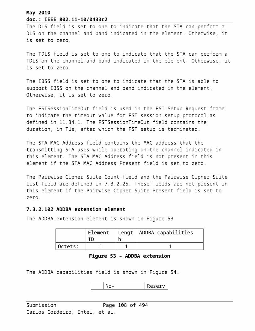
May 2010 doc.: IEEE 802.11-10/0433r2
The Dialog Token field shall be set to a nonzero value chosen by the STA sending the ROC Request frame to identify the request/response transaction.
The format of the Relay operation type field is defined in Figure 76.
Link cooperating Relay-link ReservedBits: B0 B1 B2-B7
Figure 76 – Relay operation type field
The Link cooperating subfield is set to 0 to request the operation to be changed to link switching, and is set to 1 to request the operation to be changed to link cooperating.
The Relay-link subfield is set to 0 to indicate that the link switching operation starts at the direct link between the source RUS and destination RUS and set to 1 to indicate that the link switching operation starts with the RSUS. If the Link cooperating subfield is set to 1, the relay-link subfield is ignored.
7.4.13.28 ROC response
The ROC Response frame is sent by the RSUS or the destination STA participating in a relay operation in response to a ROC Request frame from the source STA. The frame body of the ROC Request frame contains the information in Table 50.
Table 50 – ROC response frame bodyOrder Information1 Category2 Action3 Dialog Token4 Status code5 Relay operation type
The Category field is set to the category for mmWave, specified in Table 4.
The Action field is set to the value corresponding to ROC Response, specified in Table 25.
The Dialog Token field shall be set to the value received in the corresponding ROC Request frame that generated this response.
The Status Code field is defined in 7.3.1.9.
The Relay operation type field is defined in 7.4.13.27. The value of this field is copied from the ROC Request frame that generated this response.
Submission Page 108 of 339 Carlos Cordeiro, Intel, et al.
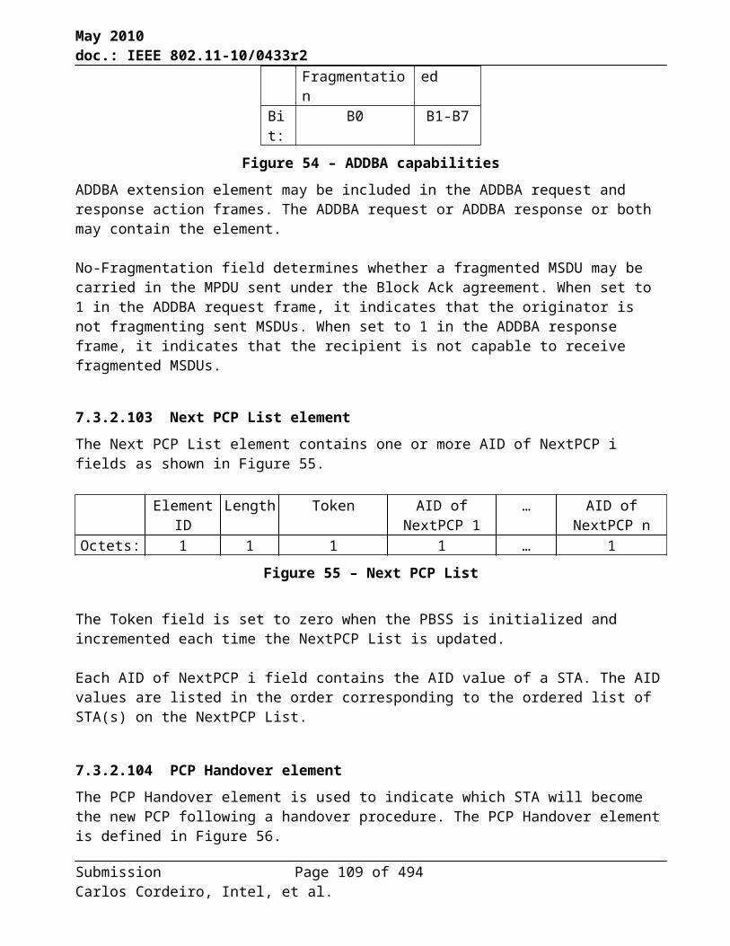
May 2010 doc.: IEEE 802.11-10/0433r2
7.4.14 FST Action frame details
7.4.14.1 FST Action fieldThe FST Action field values are defined in Table 51.
Table 51 – FST Action field valuesAction field value Meaning
1 FST Setup Request2 FST Setup Response3 FST Tear-down4 FST Ack Request 5 FST Ack Response
7.4.14.2 FST Setup Request The FST Setup Request frame is an Action frame of category FST. The FST Setup Request frame allows an initiating STA to announce to other peer STA whether it intends to enable FST for the session between the source STA and the peer STA (11.34). The format of the FST Setup Request is shown in Table 52.
Table 52 – FST Setup Request frameOrder Information
1 Category2 Action3 LLT4 Session Transition5 Multi-band (optional)6 Wakeup Schedule (optional) 7 Awake Window (optional) 8 Switching stream (optional)
Last - 1 One or more resource and/or capability related information elements may appear in this frame. These information elements follow all other information elements that are not vendor-specific information elements and precede all other information elements that are vendor-specific information elements that are part of the Last field in the Action frame.
The Category field is set to the category for FST.
The Action field is set to the value for FST Setup Request.
Submission Page 109 of 339 Carlos Cordeiro, Intel, et al.
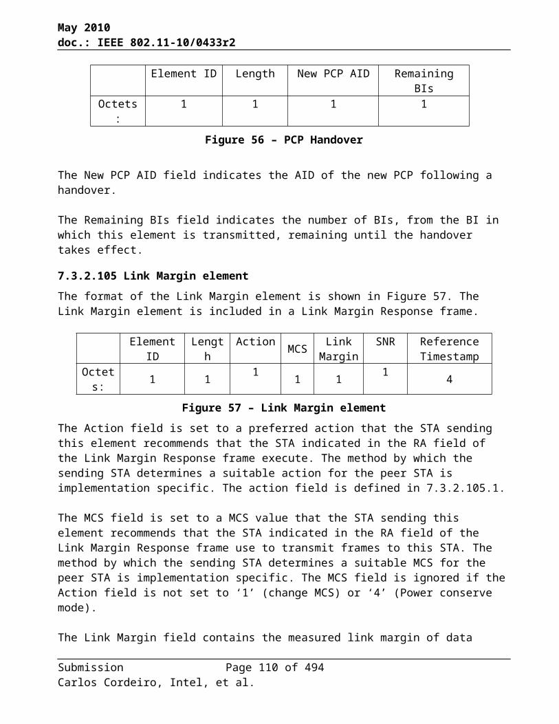
May 2010 doc.: IEEE 802.11-10/0433r2
The Link loss timeout (LLT) field is 32 bits and indicates the maximum duration of time, in microseconds, counted from the last time an MPDU was received by the source STA from the peer STA until the source STA decides to initiate FST. The use of this field is described in 11.34.
The Session Transition field contains the Session Transition element as defined in 7.3.2.107.
The Multi-band field contains the Multi-Band element as defined in 7.3.2.101. The regulatory information contained in the Multi-band element is applicable to all the fields and elements contained in the frame.
The Wakeup Schedule element is defined in 7.3.2.94.
The Awake Window element is defiend in 7.3.2.100.
The Switching Stream element is defined in 7.3.2.106.
7.4.14.3 FST Setup ResponseThe FST Setup Response frame is an Action frame of category FST. This frame is transmitted in response to the reception of a FST Setup Request frame. The format of the frame body is shown in Table 53.
Table 53 – FST Setup Response frameOrder Information Notes
1 Category2 Action3 Status Code The Status Code is defined in 7.3.1.94 Session Transition 5 Multi-band (optional)6 Wakeup Schedule (optional) 7 Awake Window (optional) 8 Switching stream (optional)
Last - 1 One or more resource and/or capability related information elements may appear in this frame. These information elements follow all other information elements that are not vendor-specific information elements and precede all other information elements that are vendor-specific information elements that are part of the Last field in the Action frame.
The Category field is set to the category for FST.
The Action field is set to the value for FST Setup Response.
The Session Transition field contains the Session Transition element as defined in 7.3.2.107.
Submission Page 110 of 339 Carlos Cordeiro, Intel, et al.
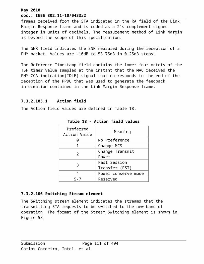
May 2010 doc.: IEEE 802.11-10/0433r2
The Multi-band element is defined in 7.3.2.101.
The Wakeup Schedule element is defined in 7.3.2.94.
The Awake Window element is defiend in 7.3.2.100
The Switching Stream element is defined in 7.3.2.106.
7.4.14.4 FST Tear down The FST Tear-down frame is an Action frame of category FST. This frame is transmitted to delete an established FST session between STAs. The format of the frame body is shown in Table 54.
Table 54 – FST Tear down frameOrder Information
1 Category2 Action3 FSTS ID
The Category field is set to the category for FST.
The Action field is set to the value for FST Tear-down.
The FSTS ID field contains the identification of the FST session established between the STAs identified by the TA and RA fields of this frame (7.3.2.107).
7.4.14.5 FST Ack Request The FST Ack Request frame is an Action frame of category FST. This frame is transmitted in the frequency band an FST session is transferred to and confirms the FST session transfer. The format of the frame body is shown in Table 55.
Table 55 – FST Ack Request frameOrder Information
1 Category2 Action3 Dialog Token4 FSTS ID
The category field is set to the category for FST.
The Action field is set to the value for FST Ack Request.
The Dialog Token field shall be set to a nonzero value chosen by the STA sending the FST ACK request to identify the request/report transaction.
Submission Page 111 of 339 Carlos Cordeiro, Intel, et al.
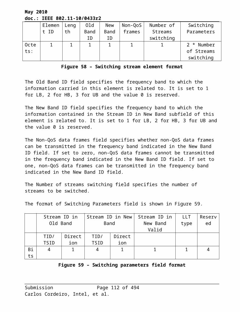
May 2010 doc.: IEEE 802.11-10/0433r2
The FSTS ID field contains the identification of the FST session established between the STAs identified by the TA and RA fields of this frame (7.3.2.107).
7.4.14.6 FST Ack Response The FST Ack Response frame is an Action frame of category FST. This frame is transmitted in response to the reception of an FST Ack Request frame. The format of the frame body is shown in Table 56.
Table 56 – FST Ack Response frameOrder Information
1 Category2 Action3 Dialog Token4 FSTS ID
The category field is set to the category for FST.
The Action field is set to the value for FST Ack Response.
The Dialog Token field shall be set to the value in any corresponding FST Ack Request frame. If the FST Ack Response frame is not being transmitted in response to a FST Ack Request frame, then the Dialog token shall be set to 0.
The FSTS ID field contains the identification of the FST session established between the STAs identified in the TA and RA fields of this frame (7.3.2.107).
7. 4a Aggregate MPDU (A-MPDU)
.11 Editor Note: include the following subclause after 7.4a.1
7.4a.1a mmWave A-MPDU formatThe mmWave A-MPDU subframe format is defined in Figure 77.
The fields of the MPDU Delimiter field are defined in Table 57.
Reserved Delimiter SignatureCRCMPDU Length
B0 B1 B2 B15 B16 B23 B24 B31
MPDU Pad
MPDU DelimiterVariable 0-3
4Octets:
Bits:
Figure 77 – mmWave A-MPDU subframe format
Submission Page 112 of 339 Carlos Cordeiro, Intel, et al.
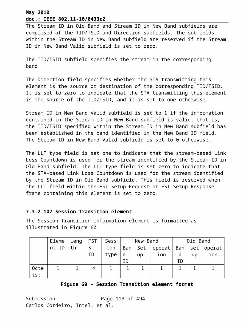
May 2010 doc.: IEEE 802.11-10/0433r2
Table 57 – MPDU Delimiter fields mmWave A-MPDUMPDU Delimiter field Size (bits) DescriptionReserved 2MPDU length 14 Length of MPDU in octetsCRC 8 8-bit CRC on preceding 16-bitsDelimiter signature 8 Pattern that may be used to detect
an MPDU delimiter when scanning for a delimiter.The unique pattern is set to the value 0x4E.
7.4a.3 A-MPDU contents.11 Editor Note: in Table 7-57aa A-MPDU contents MPDUs in a control response context, insert “or Beam refinement management frame” at the end of the sentence ending with “… explicit feedback response” in the 4th row named as Action No Ack.
.11 Editor note: insert the following as the third paragraph:
All protected MPDUs within an A-MPDU shall have the same Key ID.
8 Security
8.1 Framework
8.1.1 Security methods
.11 Editor Note: make the indicated changes in the second paragraph
RSNA security comprises the following algorithms:— TKIP, described in 8.3.2 (Temporal Key Integrity Protocol (TKIP))— CCMP, described in 8.3.3 (CTR with CBC-MAC Protocol (CCMP))— GCMP, described in 8.3. 5 ( GCM with GMAC Protocol (GCMP) ) — BIP, described in 8.3.4 (The Broadcast/Multicast integrity protocol)
8.1.2 RSNA equipment and RSNA capabilities
.11 Editor Note: make the indicated changes in the first paragraph
RSNA-capable equipment can create RSNAs. When dot11RSNAEnabled is true, RSNA-capable equipment shall include the RSN information element in Beacon, Probe Response, Information Response, and (Re)Association Request frames and in Message 2 and Message 3 of the 4-Way
Submission Page 113 of 339 Carlos Cordeiro, Intel, et al.
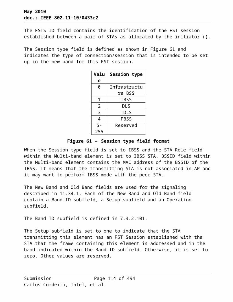
May 2010 doc.: IEEE 802.11-10/0433r2
Handshake, shall set the mmWave Privacy subfield to 1 within transmitted mmWave Beacons, and may include the RSN information element in mmWave Beacon and Announce frames. Pre-RSNA equipment is not capable of creating RSNAs.
8.1.3 RSNA establishment
.11 Editor Note: make the indicated changes in the first paragraph
A STA’s SME establishes an RSNA in one of four ways:a) When using IEEE 802.1X AKM in an ESS/PBSS, an RSNA-capable STA’s SME establishes
an RSNA with the AP/PCP as follows:1) It identifies the AP/PCP as RSNA-capable from the AP’s Beacon, mmWave Beacon or
Probe Response, or from the PCP’s mmWave Beacon, Announce, Probe Response, or Information Response frames.
2) It shall invoke Open System authentication in an ESS.
NOTE―STAs do not invoke Open System authentication in a PBSS.
3) If it chooses to associate with the AP/PCP, It negotiates cipher suites during the association process, as described in 8.4.2 (RSNA selection) and 8.4.3 (RSNA policy selection in an ESS/PBSS).
4) It uses IEEE Std 802.1X-2004 to authenticate, as described in 8.4.6 (RSNA authentication in an ESS/PBSS) and 8.4.7 (RSNA authentication in an IBSS/PBSS).
5) It establishes temporal keys by executing a key management algorithm, using the protocol defined by 8.5 (Keys and key distribution) or 11A (Fast BSS transition).
6) It programs the agreed-upon temporal keys and cipher suites into the MAC and invokes protection. See, for example, 8.3.3 (CTR with CBC-MAC Protocol (CCMP)) or 8.3.5 ( GCM with GMAC Protocol (GCMP) ) for a description of the RSNA data protection mechanisms.
7) If the STAs negotiate Management Frame Protection, the STA programs the TK and pairwise cipher suite into the MAC for protection of unicast Robust Management frames. It also installs the IGTK and IPN for protection of group addressed Robust Management frames.
b) If an RSNA is based on a PSK in an ESS/PBSS, the STA’s SME establishes an RSNA with the AP/PCP as follows:1) It identifies the AP/PCP as RSNA-capable from the AP’s/PCP’s Beacon, mmWave
Beacon or Probe Response, or PCP’s mmWave Beacon, Announce, Probe Response, or Information Response frames.
2) It shall invoke Open System authentication in an ESS.
NOTE―STAs do not invoke Open System authentication in a PBSS.
3) If it chooses to associate with the AP/PCP, It negotiates cipher suites during the association process, as described in 8.4.2 (RSNA selection) and 8.4.3 (RSNA policy selection in an ESS/PBSS).
4) It establishes temporal keys by executing a key management algorithm, using the protocol defined by 8.5 (Keys and key distribution). It uses the PSK as the PMK.
Submission Page 114 of 339 Carlos Cordeiro, Intel, et al.
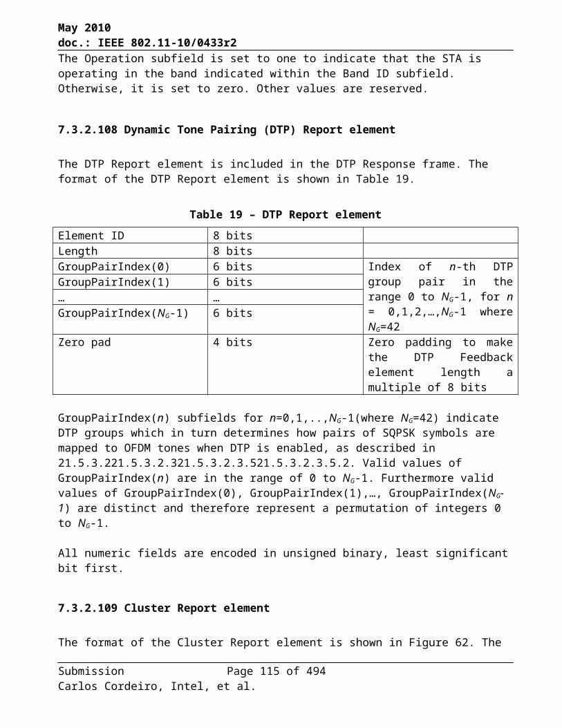
May 2010 doc.: IEEE 802.11-10/0433r2
5) It protects the data link by programming the negotiated cipher suites and the established temporal key into the MAC and then invoking protection.
6) If the STAs negotiate Management Frame Protection, the STA programs the negotiated pairwise cipher suite and established TK, IGTK, and IPN.
c) If an RSNA is based on a PSK in an IBSS/PBSS, the STA’s SME executes the following sequence of procedures to establish an RSNA with a peer STA:1) It identifies the peer as RSNA-capable from the peer’s Beacon, mmWave Beacon,
Announce, Probe Response, or Information Response frames.
NOTE—STAs can respond to a data MPDU from an unrecognized STA by sending a Probe Request or Information request frame to find out whether the unrecognized STA is RSNA-capable.
2) It may optionally invoke Open System authentication in an IBSS.3) In a PBSS, if it chooses not to associate with the peer, it uses the procedures in 8.5 (Keys
and key distribution) to establish temporal keys and to negotiate cipher suites. In an IBSS, Each STA uses the procedures in 8.5 (Keys and key distribution), to establish temporal keys and to negotiate cipher suites. It uses a PSK as the PMK. Note that two peer STAs may follow this procedure simultaneously in an IBSS. See 8.4.9 (RSNA key management in an IBSS/PBSS).
4) It protects the data link by programming the negotiated cipher suites and the established temporal key and then invoking protection.
d) An RSNA-capable STA’s SME using IEEE 802.1X AKM in an IBSS/PBSS establishes an RSNA with a peer STA as follows:1) It identifies the peer as RSNA-capable from the peer’s Beacon, mmWave Beacon,
Announce, Probe Response, or Information Response frames.
NOTE—STAs can respond to a data MPDU from an unrecognized STA by sending a Probe Request or Information Request frame to find out whether the unrecognized STA is RSNA-capable.
2) It may optionally invoke Open System authentication in an IBSS.3) In a PBSS, if it chooses not to associate with the peer, it uses IEEE Std 802.1X-2004 to
authenticate with the AS associated with the peer’s Authenticator, as described in 8.4.6 (RSNA authentication in an ESS/PBSS) and 8.4.7 (RSNA authentication in an IBSS/PBSS). In an IBSS, Each STA uses IEEE Std 802.1X-2004 to authenticate with the AS associated with the other STA’s Authenticator, as described in 8.4.6 (RSNA authentication in an ESS/PBSS) and 8.4.7 (RSNA authentication in an IBSS/PBSS). Hence two authentications are happening at the same time in an IBSS.
4) In a PBSS, it establishes temporal keys by executing a key management algorithm, using the protocol defined in 8.5 (Keys and key distribution). In an IBSS, Each STA’s SME establishes temporal keys by executing a key management algorithm, using the protocol defined in 8.5 (Keys and key distribution). Hence two such key management algorithms are happening in parallel between any two STA’s Supplicants and Authenticators in an IBSS.
5) In a PBSS, it uses the agreed-upon temporal key portion of the PTK and pairwise cipher suite to protect the link. In an IBSS, Both STAs use the agreed-upon temporal key portion of the PTK and pairwise cipher suite from one of the exchanges to protect the link. Each STA uses the GTK established by the exchange it initiated to protect the group addressed frames it transmits.
Submission Page 115 of 339 Carlos Cordeiro, Intel, et al.

May 2010 doc.: IEEE 802.11-10/0433r2
8.3 RSNA data confidentiality and integrity protocols
8.3.1 Overview
.11 Editor Note: Modify the 1st paragraph of 8.3.1 as follows:
This standard defines two three RSNA confidentiality and integrity protocols: TKIP, CCMP, and GCMP. Implementation of CCMP shall be mandatory in all IEEE 802.11 devices operating in LB and HB and claiming RSNA compliance. Implementation of GCMP shall be mandatory for all IEEE 802.11 devices operating in UB and claiming RSNA compliance. This standard defines one integrity protocol: BIP.
.11 Editor Note: Add subclause 8.3.5
8.3.5 GCM with GMAC Protocol (GCMP)
This subclause specifies the GCMP, which provides data confidentiality, authentication, integrity, and replay protection.
8.3.5.1 GCMP overview
GCMP is based on the GCM of the AES encryption algorithm. GCM combines Galois/Counter Mode for data confidentiality and GMAC for authentication and integrity. GCM protects the integrity of both the MPDU Data field and selected portions of the MPDU header.
The AES algorithm is defined in FIPS PUB 197-2001. All AES processing used within GCMP uses AES with a 128-bit key and a 128-bit block size.
GCM is defined in NIST Special Publication 800-38D. GCM is a generic mode that can be used with any block-oriented encryption algorithm.
GCM requires a fresh temporal key for every session. GCM also requires a unique nonce value for each frame protected by a given temporal key, and GCMP uses a 96-bit nonce and a 48-bit packet number (PN) for this purpose. Reuse of a PN with the same temporal key voids all security guarantees. GCMP uses a 128-bit MIC.
8.3.5.2 GCMP MPDU format
Figure 78 shows the MPDU format when using GCMP.
Submission Page 116 of 339 Carlos Cordeiro, Intel, et al.
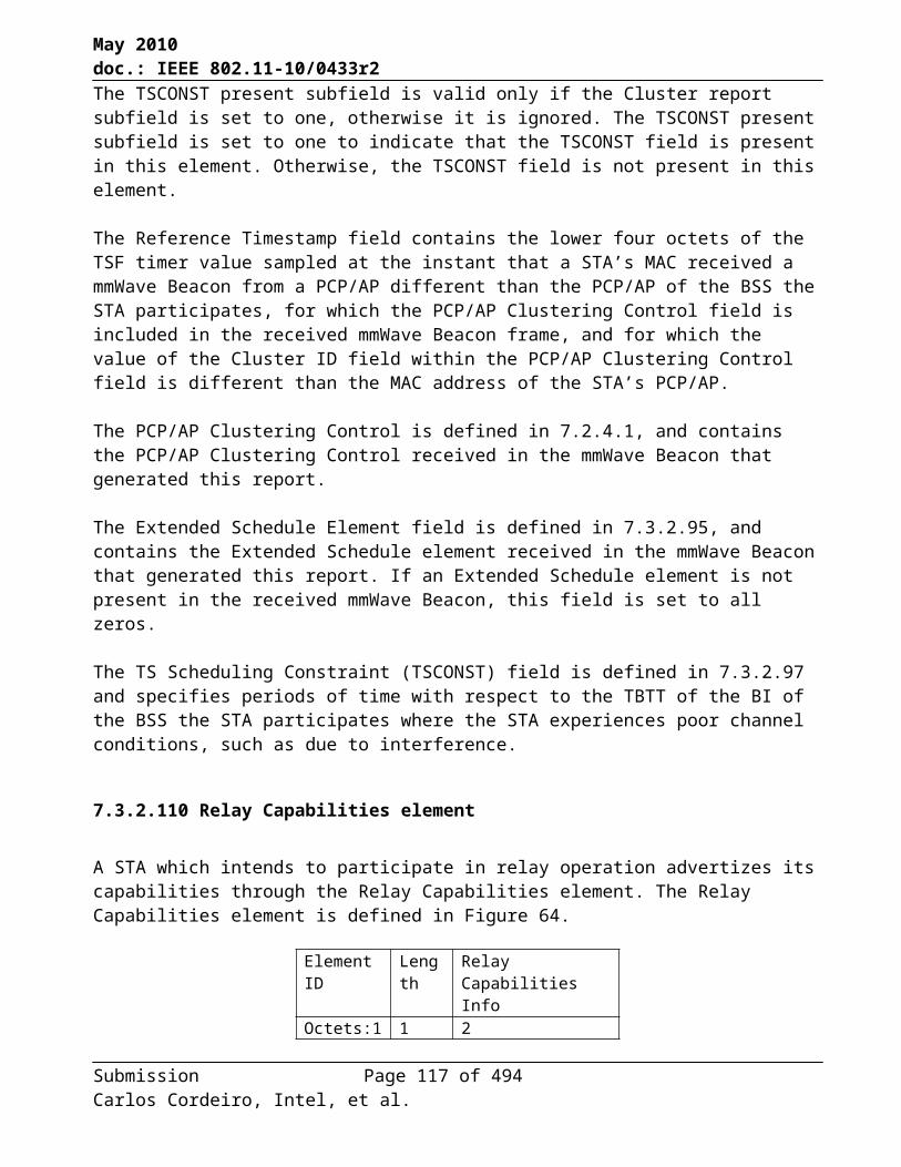
May 2010 doc.: IEEE 802.11-10/0433r2
Figure 78 – Expanded GCMP MPDU
GCMP processing expands the original MPDU size by 24 octets, 8 octets for the GCMP Header field and 16 octets for the MIC field. The GCMP Header field is constructed from the PN and Key ID subfields. The 48-bit PN is represented as an array of 6 octets. PN5 is the most significant octet of the PN, and PN0 is the least significant.
The size of Key ID field is 16 bits. Bits 0-1 of the Key ID field are for the Key ID subfield. The remaining bits of the Key ID field are reserved.
The reserved bits shall be set to 0 and shall be ignored on reception.
8.3.5.3 GCMP cryptographic encapsulation
The GCMP cryptographic encapsulation process is depicted in Figure 79.
Figure 79 – GCMP encapsulation block diagram
GCMP encrypts the payload of a plaintext MPDU and encapsulates the resulting cipher text using the following steps:
a) Increment the PN, to obtain a fresh PN for each MPDU, so that the PN never repeats for the same temporal key. Note that retransmitted MPDUs are not modified on retransmission.
Submission Page 117 of 339 Carlos Cordeiro, Intel, et al.

May 2010 doc.: IEEE 802.11-10/0433r2
b) Use the fields in the MPDU header to construct the additional authentication data (AAD) for GCM. The GCM algorithm provides integrity protection for the fields included in the AAD. MPDU header fields that may change when retransmitted are muted by being masked to 0 when calculating the AAD.
c) Construct the GCM Nonce block from the PN and A2, where A2 is MPDU Address 2.d) Place the new PN and the key identifier into the 8-octet GCMP Header.e) Use the temporal key, AAD, nonce, and MPDU data to form the cipher text and MIC. This step
is known as GCM originator processing.f) Form the encrypted MPDU by combining the original MPDU header, the GCMP header, the
encrypted data and MIC, as described in 8.3.5.2
The GCM reference describes the processing of the key, nonce, AAD, and data to produce the encrypted output. See 8.3.5.3.1 through 8.3.5.3.5 for details of the creation of the AAD and nonce from the MPDU and the associated MPDU-specific processing.
8.3.5.3.1 PN processing
Each transmitter shall maintain a single PN (48-bit counter) for each PTKSA, GTKSA, and STKSA.
The PN shall be implemented as a 48-bit monotonically incrementing non-negative integer, initialized to 1 when the corresponding temporal key is initialized or refreshed.
The PN is incremented by a positive number for each MPDU. The PN shall never repeat for a series of encrypted MPDUs using the same temporal key.
If the PN is larger than the value of dot11PNExhaustionThreshold, an MLME-PN-Exhaustion.indication primitive shall be generated.
8.3.5.3.2 Construct AADThe AAD construction is as defined in section 8.3.3.3.2.
8.3.5.3.3 Construct GCM nonceThe Nonce field occupies 12 octets, and its structure is shown in Figure 80.
Figure 80 – Nonce construction
The Nonce field has an internal structure of A2 || PN (“||” is concatenation), where─ MPDU address A2 field occupies octets 0–5. This shall be encoded with the octets ordered
with A2 octet 0 at octet index 0 and A2 octet 5 at octet index 5.─ The PN field occupies octets 6–11. The octets of PN shall be ordered so that PN0 is at octet
index 11 and PN5 is at octet index 6.
Submission Page 118 of 339 Carlos Cordeiro, Intel, et al.
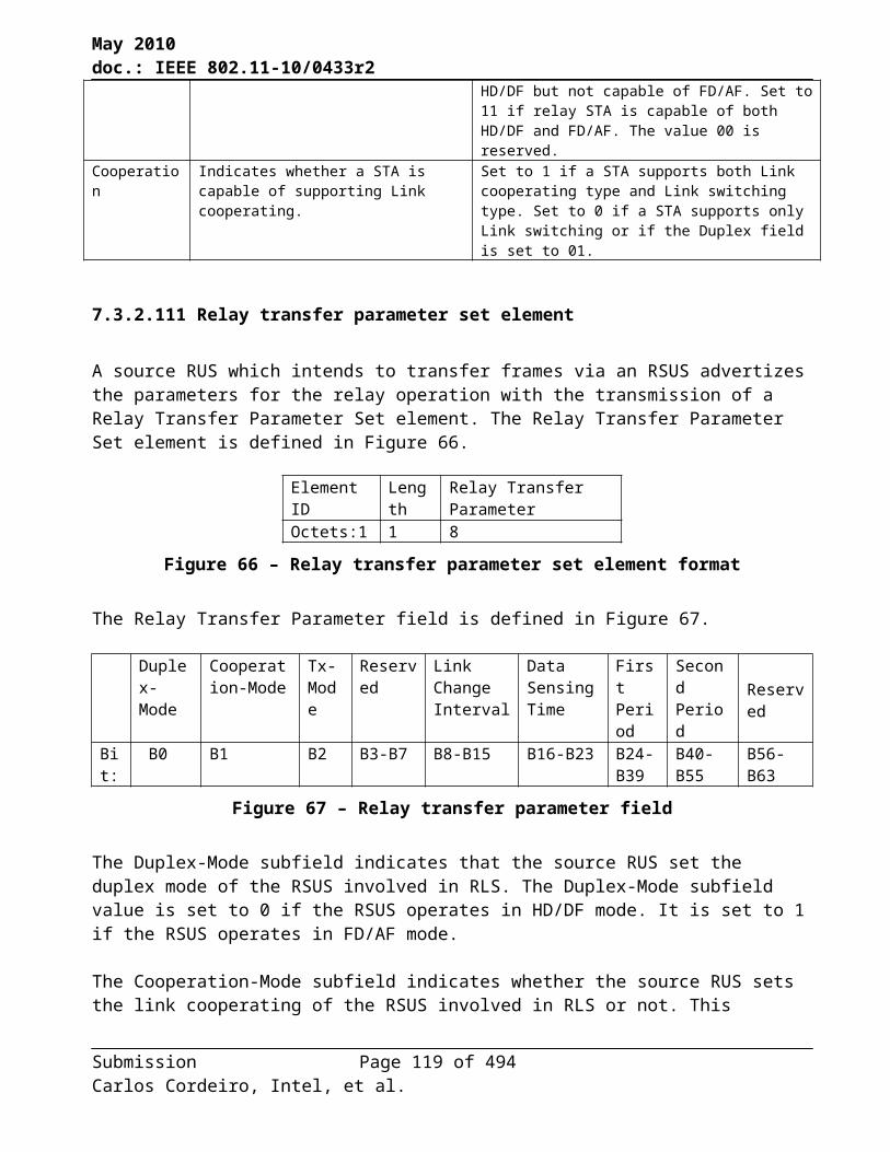
May 2010 doc.: IEEE 802.11-10/0433r2
8.3.5.3.4 Construct GCMP header
The format of the 8-octet GCMP Header is given in 8.3.5.2. The header encodes the PN and Key ID field values used to encrypt the MPDU.
8.3.5.3.5 GCM originator processing
GCM is a generic authenticate-and-encrypt block cipher mode, and in this standard, GCM is used with the AES block cipher.
There are four inputs to GCM originator processing:a) Key: the temporal key (16 octets).b) Nonce: the nonce (12 octets) constructed as described in 8.3.5.3.3.c) Frame body: the frame body of the MPDU.d) AAD: the AAD (22-30 octets) constructed from the MPDU header as described in 8.3.5.3.2.
The GCM originator processing provides authentication and integrity of the frame body and the AAD as well as data confidentiality of the frame body. The output from the GCM originator processing consists of the encrypted data and 16 additional octets of encrypted MIC.
8.3.5.4 GCMP decapsulation
Figure 81 shows the GCMP decapsulation process.
Figure 81 – GCMP decapsulation block diagram
GCMP decrypts the payload of a cipher text MPDU and decapsulates a plaintext MPDU using the following steps:
a) The encrypted MPDU is parsed to construct the AAD and nonce values.b) The AAD is formed from the MPDU header of the encrypted MPDU.c) The Nonce value is constructed from the A2 and PN fields.
Submission Page 119 of 339 Carlos Cordeiro, Intel, et al.
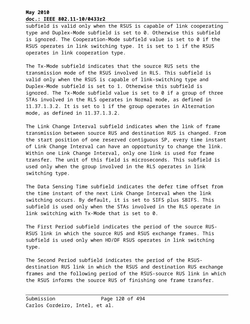
May 2010 doc.: IEEE 802.11-10/0433r2
d) The MIC is extracted for use in the GCM integrity checking.e) The GCM recipient processing uses the temporal key, AAD, nonce, MIC, and MPDU cipher
text data to recover the MPDU plaintext data as well as to check the integrity of the AAD and MPDU plaintext data.
f) The received MPDU header and the MPDU plaintext data from the GCM recipient processing may be concatenated to form a plaintext MPDU.
g) The decryption processing prevents replay of MPDUs by validating that the PN in the MPDU is greater than the replay counter maintained for the session.
See 8.3.5.4.1 through 8.3.5.4.3 for details of this processing.
8.3.5.4.1 GCM recipient processing
GCM recipient processing must use the same parameters as GCM originator processing.
There are four inputs to GCM recipient processing:─ Key: the temporal key (16 octets).─ Nonce: the nonce (12 octets) constructed as described in 8.3.5.3.3.─ Encrypted frame body: the encrypted frame body from the received MPDU. The encrypted
frame body includes a 16-octet MIC.─ AAD: the AAD (22-30 octets) that is the canonical MPDU header as described in 8.3.5.3.2.
The GCM recipient processing checks the authentication and integrity of the frame body and the AAD as well as decrypting the frame body. The plaintext is returned only if the MIC check is successful.
There is one output from error-free GCM recipient processing:— Frame body: the plaintext frame body, which is 16 octets smaller than the encrypted frame
body.
8.3.5.4.2 Decrypted GCMP MPDU
The decapsulation process succeeds when the calculated MIC matches the MIC value obtained from decrypting the received encrypted MPDU. The original MPDU header is concatenated with the plaintext data resulting from the successful GCM recipient processing to create the plaintext MPDU.
8.3.5.4.3 PN and replay detection
To effect replay detection, the receiver extracts the PN from the GCMP header. See 8.3.5.2 for a description of how the PN is encoded in the GCMP header. The following processing rules are used to detect replay:
a) The PN values sequentially number each MPDU.b) A receiver shall maintain a separate set of PN replay counters for each PTKSA, GTKSA, and
STKSA. The receiver initializes these replay counters to 0 when it resets the temporal key for a peer. The replay counter is set to the PN value of accepted GCMP MPDUs.
Submission Page 120 of 339 Carlos Cordeiro, Intel, et al.
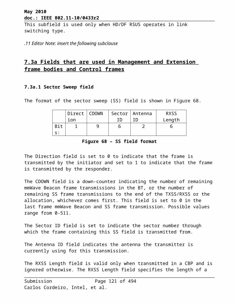
May 2010 doc.: IEEE 802.11-10/0433r2
c) For each PTKSA, GTKSA, and STKSA, the recipient shall maintain a separate replay counter for each possible IEEE 802.11 MSDU or A-MSDU priority and shall use the PN recovered from a received frame to detect replayed frames. A replayed frame occurs when the PN extracted from a received frame is less than or equal to the current replay counter value for the frame’s MSDU or A-MSDU priority and frame type.
For each IGTKSA the recipient shall maintain a single replay counter for protected broadcast/multicast Robust Management frames, and shall compare the IPN recovered from a received, protected broadcast/multicast Robust Management frame to the replay counter to detect replayed frames as described above for data frames.
If dot11RSNAProtectedManagementFramesEnabled is TRUE, the recipient shall maintain a single replay counter for received unicast Robust Management frames and shall use the PN from the received frame to detect replays. A replayed frame occurs when the PN from the frame is less than or equal to the current management frame replay counter value. The transmitter shall preserve the order of protected Robust Management frames sent to the same DA.
d) A receiver shall discard any MPDU that is received with its PN less than or equal to the replay counter. When discarding a frame, the receiver shall increment by 1 the value of dot11RSNAStatsGCMPReplays for data frames or dot11RSNAStatsRobustMgmtGCMPReplays for Robust Management frames.
e) For MSDUs or A-MSDUs sent using the Block Ack feature, reordering of received MSDUs or A-MSDUs according to the Block Ack receiver operation (described in 9.10.4) is performed prior to replay detection.
8.4 RSNA security association management
8.4.1 Security associations
8.4.1.1 Security association definitions
8.4.1.1.2 PTKSA
.11 editor: change the bulleted list in this subclause as indicated and add the following paragraph
The PTKSA consists of the following elements:
PTK Pairwise cipher suite selector Supplicant MAC address or non-AP STA’s MAC address Authenticator MAC address or BSSID Key ID If FT key hierarchy is used,
◦ R1KH-ID
Submission Page 121 of 339 Carlos Cordeiro, Intel, et al.
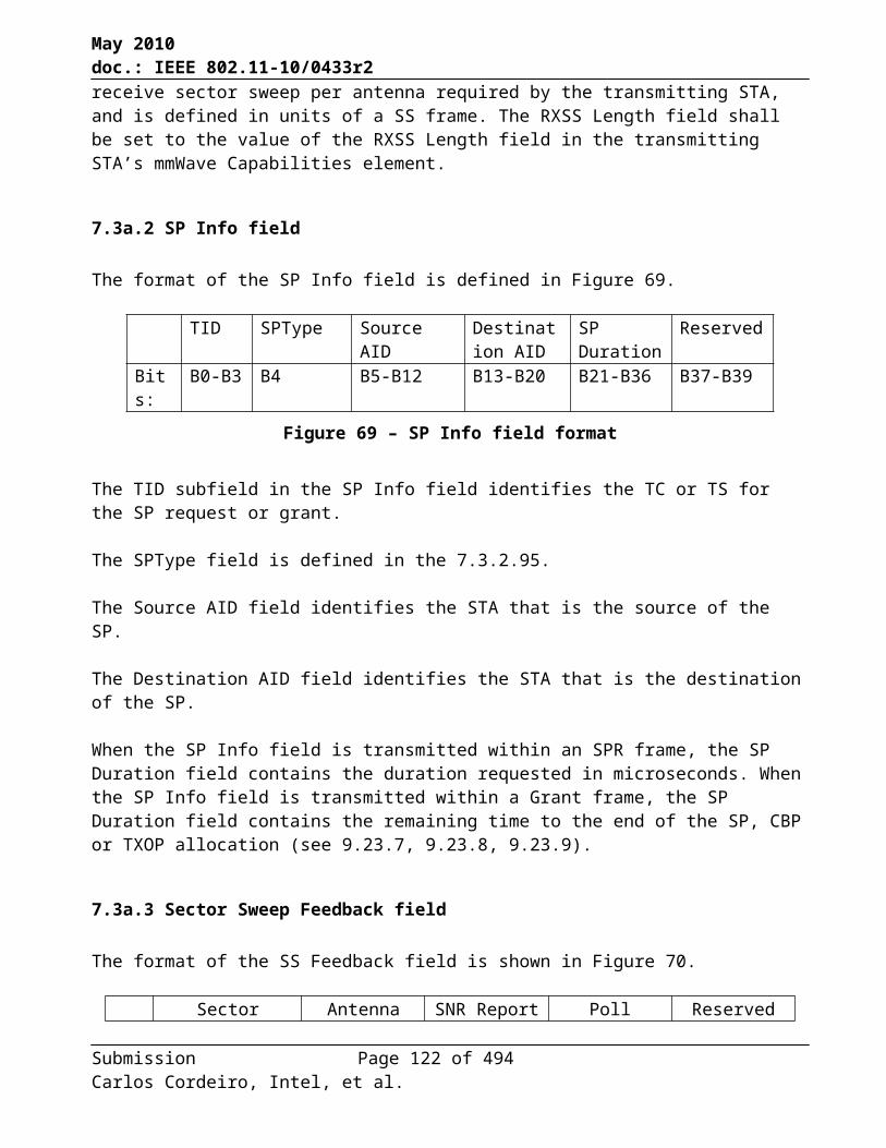
May 2010 doc.: IEEE 802.11-10/0433r2
◦ S1KH-ID◦ PTKName
8.4.1.1.3 GTKSA
.11 editor: change the bulleted list in this subclause as indicated and add the following paragraph
A GTKSA consists of the following elements:
Direction vector (whether the GTK is used for transmit or receive). Group cipher suite selector. GTK. Authenticator MAC address. Key ID All authorization parameters specified by local configuration. This can include parameters such as
the STA’s authorized SSID.
8.4.1.1.5 STKSA.11 editor: change the bulleted list in this subclause as indicated and add the following paragraph
The STKSA consists of the following elements:
STK Pairwise cipher suite selector Initiator MAC address Peer MAC address KeyID
8.4.1.2 Security association life cycle
8.4.1.2.0a General
.11 editor: change the first paragraph in this subclause as indicated
A STA can operate in either an ESS, a PBSS, or in an IBSS, and a security association has a distinct life cycle for each.
.11 editor: change the title of the subclause indicated below as follows
8.4.1.2.1 Security association in an ESS/PBSS
.11 editor: insert the following paragraph as the new second paragraph
Submission Page 122 of 339 Carlos Cordeiro, Intel, et al.
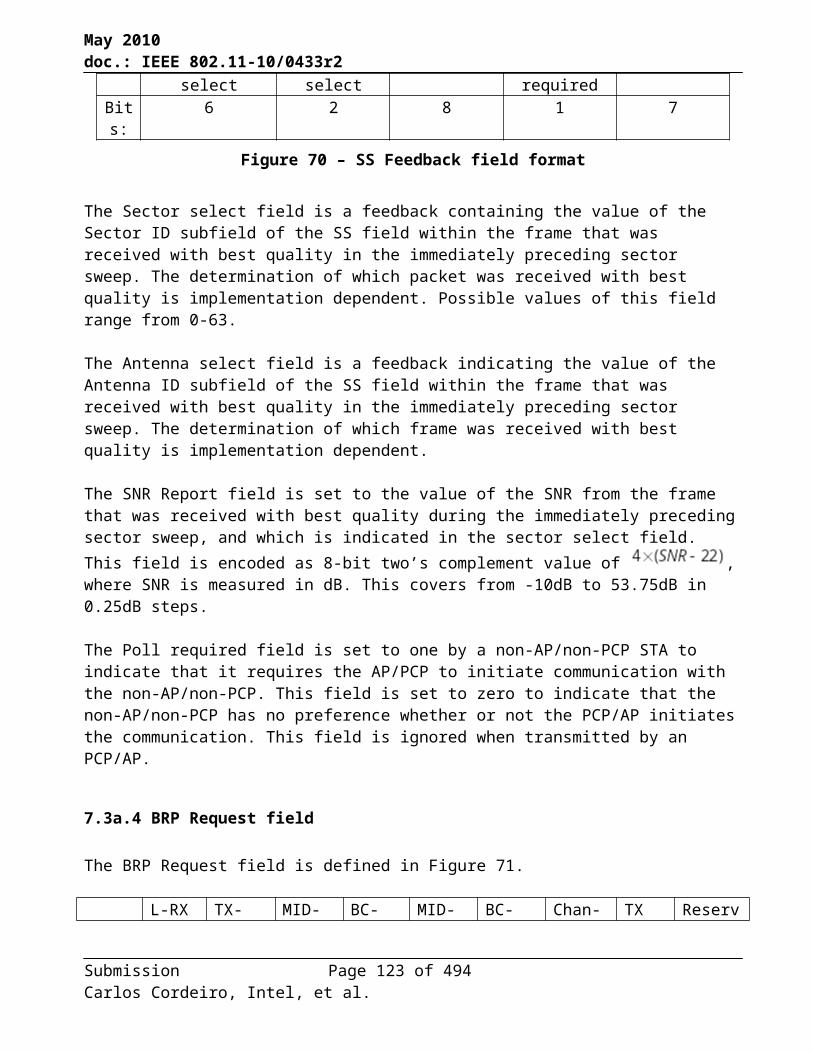
May 2010 doc.: IEEE 802.11-10/0433r2
In a PBSS, a STA can establish initial contact with the PCP or a non-PCP STA.
.11 editor: change the second paragraph as follows
A STA and AP/PCP establish an initial security association via the following steps:a) The STA selects an authorized ESS/PBSS by selecting among APs/PCPs that advertise an
appropriate SSID.b) In an ESS, The STA uses IEEE 802.11 Open System authentication followed by association to
the chosen AP. Negotiation of security parameters takes place during association. In a PBSS, the IEEE 802.11 Open System authentication is not used. If the STA associates with the chosen PCP, the STA and the PCP negotiate the security parameters during association.
NOTE 1—It is possible for more than one PMKSA to exist. As an example, a second PMKSA may come into existence through PMKSA caching. A STA might leave the ESS/PBSS and flush its cache. Before its PMKSA expires in the AP/PCP’s cache, the STA returns to the ESS/PBSS and establishes a second PMKSA from the AP/PCP’s perspective.NOTE 2—An attack altering the security parameters will be detected by the key derivation procedure.NOTE 3—IEEE 802.11 Open System authentication provides no security, but is included to maintain backward compatibility with the IEEE 802.11 state machine (see 11.3 (STA authentication and association)) in an ESS.NOTE 4—In a PBSS, a STA may choose not to associate with the PCP.
c) The AP/PCP’s Authenticator or the STA’s Supplicant initiates IEEE 802.1X authentication or uses PSK. The EAP method used by IEEE Std 802.1X-2004 will support mutual authentication, as the STA needs assurance that the AP/PCP is a legitimate AP/PCP.
NOTE 1—Prior to the completion of IEEE 802.1X authentication and the installation of keys, the IEEE 802.1X Controlled Port in the AP/PCP will block all data frames. The IEEE 802.1X Controlled Port returns to the unauthorized state and blocks all data frames before invocation of an MLME-DELETEKEYS.request primitive. The IEEE 802.1X Uncontrolled Port allows IEEE 802.1X frames to pass between the Supplicant and Authenticator. Although IEEE Std 802.1X-2004 does not require a Supplicant Controlled Port, this standard assumes that the Supplicant has a Controlled Port in order to provide the needed level of security. Supplicants without a Controlled Port compromise RSN security and should not be used.
NOTE 2—Any secure network cannot support promiscuous association, e.g., an unsecured operation of IEEE Std 802.11. A trust relationship must exist between the STA and the AS of the targeted SSID prior to association and secure operation, in order for the association to be trustworthy. The reason is that an attacker can deploy a rogue AP/PCP just as easily as a legitimate network provider can deploy a legitimate AP/PCP, so some sort of prior relationship is necessary to establish credentials between the ESS/PBSS and the STA.
d) The last step is key management. The authentication process creates cryptographic keys shared between the IEEE 802.1X AS and the STA. The AS transfers these keys to the AP/PCP, and the AP/PCP and STA uses one of the key confirmation handshakes, e.g., the 4-Way Handshake or FT 4-Way Handshake, to complete security association establishment. The key confirmation handshake indicates when the link has been secured by the keys and is ready to allow normal data traffic and protected Robust Management frames.
.11 editor: insert the following paragraph after the second paragraph
In a PBSS, a STA may establish a security association with the PCP without association, or it may establish a security association with a non-PCP STA. In either case, the STA initiates IEEE 802.1X authentication or uses PSK, followed by one of the key confirmation handshakes, e.g. the 4-Way Handshake, to establish the security association.
Submission Page 123 of 339 Carlos Cordeiro, Intel, et al.
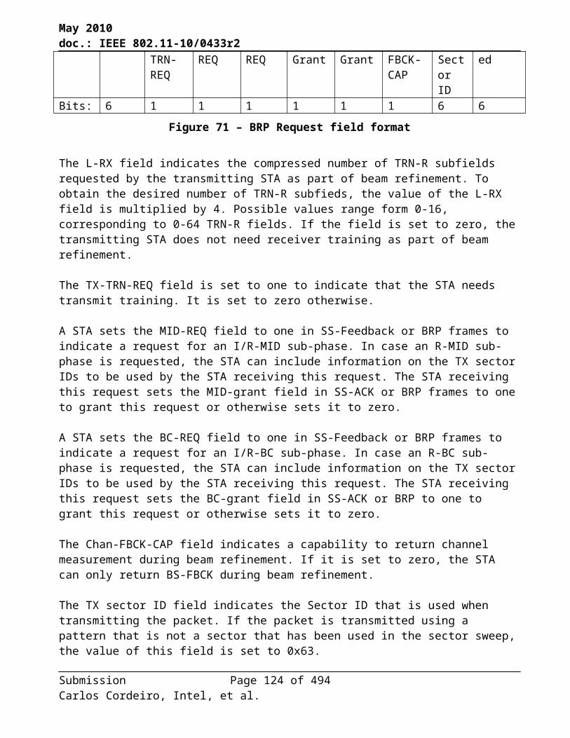
May 2010 doc.: IEEE 802.11-10/0433r2
.11 editor: change the title of the subclause indicated below as follows
8.4.1.2.2 Security association in an IBSS/PBSS
.11 editor: in this subclause, replace all occurrences of “IBSS” with “IBSS/PBSS”
8.4.2 RSNA selection
.11 editor: change the first three paragraphs of this subclause as follows
A STA prepared to establish RSNAs shall advertise its capabilities by including the RSN element in Beacon, Information Response, and Probe Response messages and may also include the RSN element in mmWave Beacon and Announce messages. The included RSN element shall specify all the authentication and cipher suites enabled by the STA’s policy. A STA shall not advertise any authentication or cipher suite that is not enabled.
The STA’s IEEE 802.11 management entity shall utilize the MLME-SCAN.request primitive to identify neighboring STAs that assert robust security and advertise an SSID identifying an authorized ESS, PBSS or IBSS. A STA may decline to communicate with STAs that fail to advertise an RSN element in their Beacon, Information Response, and Probe Response frames or that do not advertise an authorized SSID. A STA may also decline to communicate with other STAs that do not advertise authorized authentication and cipher suites within their RSN elements.
A STA shall advertise the same RSN element in both its Beacon, mmWave Beacon, Announce, Information Response, and Probe Response frames.
.11 editor: change the title of the subclause indicated below as follows
8.4.3 RSNA policy selection in an ESS/PBSS
.11 editor: change the paragraphs indicated below
RSNA policy selection in an ESS utilizes the normal IEEE 802.11 association procedure. RSNA policy selection in a mmWave BSS utilizes the mmWave BSS association procedure ( 11.3.3 ) if the initiating STA chooses to associate. RSNA policy selection is performed by the associating STA. The STA does this by including an RSN element in its (Re)Association Requests.
In an RSN, an AP/PCP shall not associate with pre-RSNA STAs, i.e., with STAs that fail to include the RSN element in the Association or Reassociation Request frame.
The STA’s SME initiating an association shall insert an RSN element into its (Re)Association Request; via the MLME-ASSOCIATE.request primitive, when the targeted AP/PCP indicates RSNA support. The initiating STA’s RSN element shall include one authentication and pairwise cipher suite from among those advertised by the targeted AP/PCP in its Beacon, mmWave Beacon, Annonce,
Submission Page 124 of 339 Carlos Cordeiro, Intel, et al.
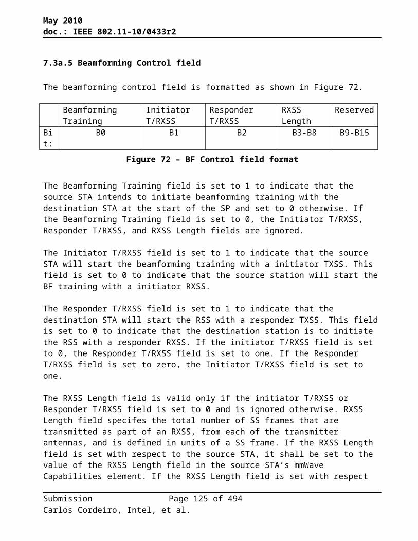
May 2010 doc.: IEEE 802.11-10/0433r2
Information Response, and Probe Response frames. It shall also specify the group cipher suite specified by the targeted AP/PCP. If at least one RSN element field from the AP’s/PCP’s RSN element fails to overlap with any value the STA supports, the STA shall decline to associate with that AP/PCP.
If an RSNA-capable AP/PCP receives a (Re)Association Request including an RSN element and if it chooses to accept the association as a secure association, then it shall use the authentication and pairwise cipher suites in the (Re)Association Request, unless the AP/PCP includes an optional second RSN element in Message 3 of the 4-Way Handshake. If the second RSN element is supplied in Message 3, then the pairwise cipher suite used by the security association, if established, shall be the pairwise cipher from the second RSN element.
In order to accommodate local security policy, a STA may choose not to associate with an AP/PCP that does not support any pairwise cipher suites. An AP/PCP indicates that it does not support any pairwise keys by advertising “Use group key” as the pairwise cipher suite selector.
NOTE—When an ESS/PBSS uses PSKs, STAs negotiate a pairwise cipher. However, any STA in the ESS/PBSS can derive the pairwise keys of any other that uses the same PSK by capturing the first two messages of the 4-Way Handshake. This provides malicious insiders with the ability to eavesdrop as well as the ability to establish a man-in-the-middle attack.
An RSNA-enabled AP/PCP shall use Table 8-1a (Robust Management frame selection in an ESS/PBSS) and the Management Frame Protection Capable (MFPC) and Management Frame Protection Required (MFPR) advertised in the RSN IEs to determine if it may associate with a non-AP/non-PCP STA. An RSNA enabled non-AP/non-PCP STA shall use Table 8-1a (Robust Management frame selection in an ESS/PBSS) and the values of the Management Frame Protection Capable and Management Frame Protection Required bits advertised in the RSN IEs to determine if it may associate with an AP/PCP. Management Frame Protection is enabled when dot11RSNAProtectedManagementFramesActivated is set to 1. Management Frame Protection is negotiated when an AP/PCP and non-AP/non-PCP STA set the Management Frame Protection Capable field to 1 in their respective RSN IEs in the (re)association procedure, and both parties confirm the Management Frame Protection Capable bit set to 1 in the 4-Way Handshake, FT 4-Way Handshake, or the FT Fast BSS Transition protocol.
.11 editor: change the title of the subclause indicated below as follows
8.4.4 RSNA policy selection in an IBSS/PBSS
.11 editor: change the paragraphs indicated below
In an IBSS/PBSS, all STAs must use a single group cipher suite, and all STAs must support a common subset of pairwise cipher suites. However, the SMEs of any pair of STAs may negotiate to use any common pairwise cipher suite they both support. Each STA shall include the group cipher suite and its list of pairwise cipher suites in its Beacon, Information Response, and Probe Response messages, and may include the group cipher suite and its list of pairwise cipher suites in its mmWave Beacon and Announce messages. Two STAs shall not establish a PMKSA unless they have advertised the same group cipher suite. Similarly, the two STAs shall not establish a PMKSA if the STAs have advertised disjoint sets of pairwise cipher suites.
Submission Page 125 of 339 Carlos Cordeiro, Intel, et al.

May 2010 doc.: IEEE 802.11-10/0433r2
In order to set up a security association with a peer STA, the SME of an IBSS/PBSS STA that does not know the peer’s policy must first obtain the peer’s security policy using a Probe Request or Information Request frame. In an IBSS, each STA’s SME initiates the 4-Way Handshake from the Authenticator to the peer STA’s Supplicant (see 8.4.7 (RSNA authentication in an IBSS/PBSS)). Two separate 4-Way Handshakes are conducted. The SME entities of the two STAs select the pairwise cipher suites using one of the 4-Way Handshakes. In a PBSS, one 4-Way Handshake is conducted from the initiating STA to the peer STA. If the initiating STA does not associate with the peer STA, the SME entities of the two STAs select the pairwise cipher suites using the 4-Way Handshake. As specified in 8.5.2 (EAPOL-Key frames), Message 2 and Message 3 of the 4-Way Handshake convey an RSN element. The Message 2 RSN element includes the selected pairwise cipher suite, and Message 3 includes the RSN element that the STA would send in a Probe Response or Information Response frame.
In an IBSS, If the 4-Way Handshake is successfully completed, then the pair of STAs shall use the pairwise cipher suite specified in Message 2 of the 4-Way Handshake initiated by the Authenticator STA with the higher MAC address (see 8.5.1 (Key hierarchy)).
The SME shall check that the group cipher suite and AKMP match those in the Beacon, Information Response, and Probe Response frames for the IBSS/PBSS.NOTE 1—The RSN elements in Message 2 and Message 3 are not the same as in the Beacon frame. The group cipher and AKMP are the same, but the pairwise ciphers may differ because Beacon frames from different STAs may advertise different pairwise ciphers. Thus, STAs in an IBSS use the same AKM suite and group cipher, while different pairwise ciphers can be used between STA pairs.NOTE 2—When an IBSS/PBSS network uses PSKs, STAs can negotiate a pairwise cipher. However, any STA in the IBSS/PBSS can derive the PTKs of any other that uses the same PSK by capturing the first two messages of the 4-Way Handshake. This provides malicious insiders with the ability to eavesdrop as well as the ability to establish a man-in-the-middle attack.
To establish a connection with a peer STA, an RSNA enabled STA that implements Management Frame Protection shall use Table 8-1b (Robust Management frame selection in an IBSS/PBSS) and the MFPC and MFPR values advertised in the RSN IEs exchanged in the 4-Way Handshake to determine if the communication is allowed. In an IBSS, the 4-Way Handshake initiated by the Authenticator of the STA with the larger MAC address is used. Management Frame Protection is enabled when dot11RSNAProtectedManagementFramesActivated is set to 1. The STAs negotiate protection of management frames when the both STAs set the Management Frame Protection Capable subfield to 1 during the 4-Way Handshake.
8.4.5 RSNA management of the IEEE 802.1X Controlled Port
.11 editor: change the paragraphs indicated below
In an ESS/PBSS, if the STA associates with the AP/PCP, the STA indicates the IEEE 802.11 link is available by invoking the MLMEASSOCIATE.confirm or MLME-REASSOCIATE.confirm primitive. This signals the Supplicant that the MAC has transitioned from the disabled to enabled state. At this point, the Supplicant’s Controlled Port is blocked, and communication of all non-IEEE-802.1X MSDUs sent or received via the port is not authorized.
In an ESS/PBSS, if the AP/PCP associates with a STA, the AP/PCP indicates that the IEEE 802.11 link is available by invoking the MLMEASSOCIATE.indication or MLME-
Submission Page 126 of 339 Carlos Cordeiro, Intel, et al.

May 2010 doc.: IEEE 802.11-10/0433r2
REASSOCIATE.indication primitive. At this point the Authenticator’s Controlled Port corresponding to the STA’s association is blocked, and communication of all non-IEEE-802.1X MSDUs sent or received via the Controlled Port is not authorized.
In an IBSS, the STA shall block all IEEE 802.1X ports at initialization. Communication of all non-IEEE-802.1X MSDUs sent or received via the Controlled Port is not authorized.
In a PBSS, if a STA chooses not to associate with the PCP, the STA shall block all IEEE 802.1X ports at initialization. Communication of all non-IEEE-802.1X MSDUs sent or received via the Controlled Port is not authorized.
.11 editor: change the title of the subclause indicated below as follows
8.4.6 RSNA authentication in an ESS/PBSS
8.4.6.0a General
.11 editor: change the paragraphs indicated below
When establishing an RSNA in a non-FT environment or during an FT initial mobility domain association in an ESS, a STA shall use IEEE 802.11 Open System authentication prior to (re)association. IEEE 802.11 Open System authentication is not used in a PBSS.
IEEE 802.1X authentication is initiated by any one of the following mechanisms:— If a STA negotiates to use IEEE 802.1X authentication during (re)association, the STA’s
management entity can respond to the MLME-ASSOCIATE.confirm (or indication) primitive by requesting the STA’s Supplicant (or AP’s/PCP’s Authenticator) to initiate IEEE 802.1X authentication. Thus, in this case, authentication is driven by the STA’s decision to associate and the AP’s/PCP’s decision to accept the association.
— If a STA’s MLME-SCAN.confirm primitive finds another AP within the current ESS, a STA may signal its Supplicant to use IEEE Std 802.1X-2004 to preauthenticate with that AP.
NOTE—A roaming STA’s IEEE 802.1X Supplicant can initiate preauthentication by sending an EAPOL-Start message via its old AP, through the DS, to a new AP.
— If a STA receives an IEEE 802.1X message, it delivers this to its Supplicant or Authenticator, which may initiate a new IEEE 802.1X authentication.
8.4.6.2 Cached PMKSAs and RSNA key management
.11 editor: throughout this subclause, change “ESS” by “ESS/PBSS”, and “AP” by “AP/PCP”
.11 editor: change the title of the subclause indicated below as follows
Submission Page 127 of 339 Carlos Cordeiro, Intel, et al.
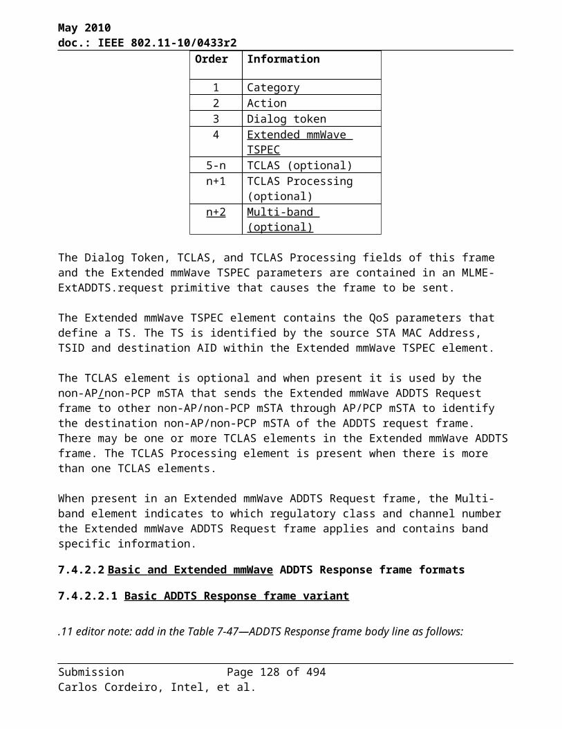
May 2010 doc.: IEEE 802.11-10/0433r2
8.4.7 RSNA authentication in an IBSS/PBSS
.11 editor: change the paragraphs indicated below
When authentication is used in an IBSS/PBSS, it is driven by each STA wishing to establish communications. The management entity of this STA chooses a set of STAs with which it might need to authenticate. In an IBSS, the STA may send an IEEE 802.11 Open System authentication message to each targeted STA. Candidate STAs can be identified from Beacon frames, mmWave Beacon frames, Announce frames, Probe Response frames, Information Response frames, and data frames from the same BSSID. Before communicating with STAs identified from data frames, the security policy of the STAs may be obtained, e.g., by sending a Probe Request or Information Request frame to the STA and obtaining a Probe Response or Information Response frame. In an IBSS, targeted STAs that wish to respond may return an IEEE 802.11 Open System authentication message to the initiating STA.
When IEEE 802.1X authentication is used, the STA management entity will then request its local IEEE 802.1X entity to create a Supplicant PAE for the peer STA. The Supplicant PAE will initiate the authentication to the peer STA by sending an EAPOL-Start message to the peer. The management entity of the peer STA will request its local IEEE 802.1X entity to create an Authenticator PAE for the initiating STA on receipt of the EAPOL-Start message. The Authenticator will initiate authentication to the Supplicant by sending an EAP-Request message. In an IBSS, the management entity of the peer STA will also request its local IEEE 802.1X entity to create a Supplicant PAE for the initiating STA and initiate the authentication to the initiating STA by sending an EAPOL-Start message to the initiating STA. The management entity of the initiating STA will also request its local IEEE 802.1X entity to create an Authenticator PAE for the peer STA on receipt of the EAPOL-Start message. The Authenticator will initiate authentication to the Supplicant by sending an EAP-Request message.
In a PBSS, if an initiating STA receives an EAPOL-Start message from a peer STA after sending an EAPOL-Start message to the same peer STA, and before receiving an EAP-Request message from the peer STA, and the source address of the received EAPOL-Start message is higher than its own MAC address, in which case the initiating STA shall silently discard the received EAPOL-Start message and shall not send an EAP-Request message to the peer STA. If the initiating STA receives an EAPOL-Start message from the peer STA after sending an EAPOL-Start message to the same peer STA, and before receiving an EAP-Request message from the peer STA, and the source address of the received EAPOL-Start message is lower than its own MAC address, in which case the initiating STA shall terminate the authentication it initiates and shall send an EAP-Request message to the peer STA.
Upon initial authentication between any pair of STAs, data frames, other than IEEE 802.1X messages, are not allowed to flow between the pair of STAs until both STAs in each pair of STAs have successfully completed AKM and have provided the supplied encryption keys.
Upon the initiation of an IEEE 802.1X reauthentication by any STA of a pair of STAs, data frames will continue to flow between the STAs while authentication completes. Upon a timeout or failure in the authentication process, the Authenticator of the STA initiating the reauthentication shall cause a Deauthentication message to be sent to the Supplicant of the STA targeted for reauthentication. The Deauthentication message will cause both STAs in the pair of STAs to follow the deauthentication procedure defined in 11.3.1.3 (Deauthentication—originating STA) and 11.3.1.4 (Deauthentication— destination STA).
Submission Page 128 of 339 Carlos Cordeiro, Intel, et al.

May 2010 doc.: IEEE 802.11-10/0433r2
In an IBSS, The IEEE 802.1X reauthentication timers in each STA are independent. If the reauthentication timer of the STA with the higher MAC address (see 8.5.1 (Key hierarchy) for MAC comparison) triggers the reauthentication via its Authenticator, its Supplicant must send an EAPOL-Start message to the authenticator of the STA with the lower MAC address to trigger reauthentication on the other STA. This process keeps the pair of STAs in a consistent state with respect to derivation of fresh temporal keys upon an IEEE 802.1X reauthentication.
In an IBSS, When it receives an MLME-AUTHENTICATE.indication primitive due to an Open System authentication request, the IEEE 802.11 management entity on a targeted STA shall, if it intends to set up a security association with the peer STA, request its Authenticator to begin IEEE 802.1X authentication, i.e., to send an EAP-Request/Identity message or Message 1 of the 4-Way Handshake to the Supplicant.
The EAPOL-Key frame is used to exchange information between the Supplicant and the Authenticator to negotiate a fresh PTK. The 4-Way Handshake produces a single PTK from the PMK. The 4-Way Handshake and Group Key Handshake use the PTK to protect the GTK as it is transferred to the receiving STA.
PSK authentication may also be used in an IBSS/PBSS. When a single PSK is shared among the IBSS STAs, the STA wishing to establish communication sends 4-Way Handshake Message 1 to the target STA(s). The targeted STA responds to Message 1 with Message 2 of the 4-Way Handshake and begins its 4-Way Handshake by sending Message 1 to the initiating STA. The two 4-Way Handshakes establish PTKSAs and GTKSAs to be used between the initiating STA and the targeted STA. PSK PMKIDs may also be used, enabling support for pairwise PSKs in an IBSS/PBSS.
When a single PSK is shared among the PBSS STAs, the STAs that have installed the PSK may include the PSKID for the PSK in the PMKID List field of the RSN element in the Probe Response and Information Response frames. The PCP may also include the PSKID for the PSK in the RSN element in the Beacon, mmWave Beacon, Announce, Probe Response and Information Response frames.
The PSKID is defined as: PSKID = HMAC-SHA1-128(PSK, SSID)
Here, SSID is the SSID of the PBSS.
When PSK authentication is used in a PBSS, a STA wishing to establish communication with a targeted STA can skip pairwise authentication with the targeted STA if both STAs use a same PSK. If the targeted STA is the PCP, and the initiating STA chooses to (re)associate with the PCP, the initiating STA may include the PSKID for the PSK in the RSN element in the (Re)Association Request. Upon receipt of a (Re)Association Request with a PSKID, the PCP checks whether its Authenticator has retained a PSK for the PSKID, and whether the PSK is still valid. If so, it shall assert possession of that PSK by beginning the 4-Way Handshake after association has completed; otherwise it shall begin a full authentication after association has completed. If the initiating STA chooses not to associate with the targeted STA, it may initiate the 4-Way Handshake by sending an EAPOL request message to the targeted STA. Upon receipt of an EAPOL request message, the targeted STA shall begin the 4-Way Handshake by using the PSK as the PMK.
Submission Page 129 of 339 Carlos Cordeiro, Intel, et al.
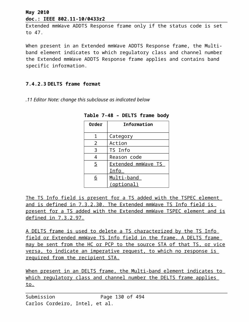
May 2010 doc.: IEEE 802.11-10/0433r2
In a PBSS, if an initiating STA receives an EAPOL request message from a targeted STA after sending an EAPOL request message to the same targeted STA, and before receiving Message 1 of the 4-Way Handshake from the targeted STA, and the source address of the received EAPOL request message is higher than its own MAC address, in which case the initiating STA shall silently discard the received EAPOL request message and shall not send Message 1 of the 4-Way Handshake to the targeted STA. If the initiating STA receives an EAPOL request message from the targeted STA after sending an EAPOL request message to the same targeted STA, and before receiving Message 1 of the 4-Way Handshake from the targeted STA, and the source address of the received EAPOL request message is lower than its own MAC address, in which case the initiating STA shall terminate the 4-Way Handshake it initiates and shall send Message 1 of the 4-Way Handshake to the targeted STA.
.11 editor: change the title of the subclause indicated below as follows
8.4.8 RSNA key management in an ESS/PBSS
.11 editor: throughout this subclause, change “AP” by “AP/PCP”
.11 editor: change the title of the subclause indicated below as follows
8.4.9 RSNA key management in an IBSS/PBSS
.11 editor: change the paragraphs indicated below
To establish a security association between two STAs in an IBSS, each STA’s SME must have an accompanying IEEE 802.1X Authenticator and Supplicant. Each STA’s SME initiates the 4-Way Handshake from the Authenticator to the peer STA’s Supplicant (see 8.4.7 (RSNA authentication in an IBSS/PBSS)). Two separate 4-Way Handshakes are conducted. In a PBSS, one 4-Way Handshake is conducted from an intiating STA to a peer STA (see 8.4.7 (RSNA authentication in an IBSS/PBSS)).
The 4-Way Handshake is used to negotiate the pairwise cipher suites, as described in 8.4.4 (RSNA policy selection in an IBSS/PBSS). The IEEE 802.11 SME configures the temporal key portion of the PTK into the IEEE 802.11 MAC. Each Authenticator uses the KCK and KEK portions of the PTK negotiated by the exchange it initiates to distribute its own GTK and if Management Frame Protection is enabled, its own IGTK. Each Authenticator generates its own GTK and if Management Frame Protection is enabled, its own IGTK, and uses either the 4-Way Handshake or the Group Key Handshake to transfer the GTK and if Management Frame Protection is negotiated, the IGTK, to other STAs with whom it has completed a 4-Way Handshake. In an IBSS, the pairwise key used between any two STAs shall be the pairwise key from the 4-Way Handshake initiated by the STA with the highest MAC address.
A STA joining an IBSS/PBSS is required to adopt the security configuration of the IBSS/PBSS, which includes the group cipher suite, pairwise cipher suite, AKMP, and if Management Frame Protection is enabled, Group Management Cipher Suite (see 8.4.4 (RSNA policy selection in an IBSS/PBSS)). The STA shall not set up a security association with any STA having a different security configuration. The Beacon and Probe Response frames of the various STAs within an IBSS must reflect a consistent security policy, as the beacon initiation rotates among the STAs.
Submission Page 130 of 339 Carlos Cordeiro, Intel, et al.
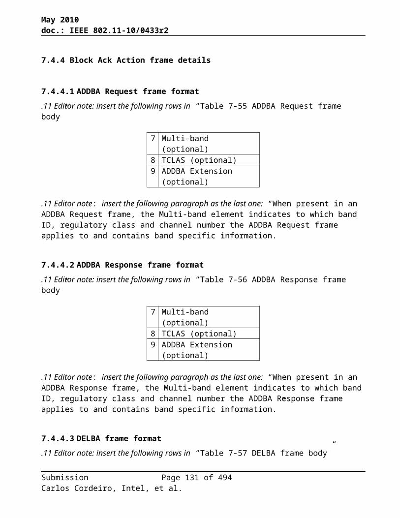
May 2010 doc.: IEEE 802.11-10/0433r2
8.4.10 RSNA security association termination
.11 editor: add the following paragraphs in this subclause as indicated When an STA’s SME receives an MLME-PN-Exhaustion.indication primitive, and the PN is associated with a PTKSA, the STA’s SME shall invoke an MLME Disassociation primitive and delete the PTKSA.
When a STA’s SME receives an MLME-PN-Exhaustion.indication primitive, and the PN is associated with a GTKSA, the STA’s SME shall delete the GTKSA.
When a STA’s SME receives an MLME-PN-Exhaustion.indication primitive, and the PN is associated with a STKSA, the STA’s SME shall invoke a STSL application teardown procedure for the STKSA and delete the STKSA.
Once the security associations have been deleted, the SME then invokes MLME-DELETEKEYS.request primitive to delete all temporal keys associated with the deleted security associations.
.11 editor: add subclause 8.4.11
8.4.11 RSNA rekeying
When a PTKSA is deleted due to PN exhaustion, a non-PCP/AP STA may reassociate with the same PCP/AP and/or establish a new RSNA with the PCP/AP. If the non-PCP/AP STA has cached one or more PMKSAs, it may skip the PMKSA establishment and proceed with the creation of a new PTKSA by using 4-Way Handshake.
When a GTKSA is deleted due to PN exhaustion, an originating STA may create a new GTKSA by using 4-Way Handshake or Group Key Handshake.
When a STKSA is deleted due to PN exhaustion, the STA_I may establish a new STSL with the STA_P. If the SMK between the STA pair has not expired, the STA_I may initiate a 4-Way Handshake and create a new STKSA with STA_P. If the SMK has expired, the STA_I shall create both a new SMKSA and a new STKSA with the STA_P.
An Authenticator / STA_I may initiate a 4-Way Handshake for the purpose of renewing the key associated with a PTKSA or STKSA. A supplicant / STA_P may send an EAPOL request message to the authenticator / STA_I to request rekeying. In addition, if both the Authenticator and the Supplicant support multiple keys for unicast traffic, a smooth switchover to the new key is possible using the following procedure.
The 802.11 MAC shall issue an MLME-PNThresholdReached.indication when the Packet Number assignment for a particular PTKSA, GTKSA or STKSA reaches or exceeds dot11PNThreshold for the first time. The indication shall only be issued once for a given PTKSA, GTKSA or STKSA. The SME
Submission Page 131 of 339 Carlos Cordeiro, Intel, et al.

May 2010 doc.: IEEE 802.11-10/0433r2
may use the indication as a trigger to establish a new PTKSA, GTKSA or STKSA before the Packet Number space is exhausted.
A PTKSA or STKSA has a limited lifetime, either in absolute time or due to exhausting the PN space. A STA that wishes to maintain an uninterrupted security association should establish a new PKTSA or STKSA prior to the expiry of the old PTKSA or STKSA.
When both ends of the link support the expanded Key ID space for unicast traffic, it is possible to install the new PTKSA or STKSA without data loss, provided the new PTKSA or STKSA uses a different Key ID from the old PTKSA or STKSA. Data loss might occur if the same Key ID is used because it is not possible to precisely coordinate (due to software processing delays) when the new key is used for transmit at one end and when it is applied to receive at the other end. If a different Key ID is used for the new PTKSA or STKSA, then provided the new key is installed at the receive side prior to its first use at the transmit side there is no need for precise coordination. During the transition, received packets are unambiguously identified using the Key ID as belonging to either the old or new PTKSA or STKSA.
8.4.12 Multi-band RSNA A STA is Multi-band capable and RSNA-capable if the values of both its local MIB variables dot11MultibandSupportEnabled and dot11RSNAEnabled are true. A STA that is Multi-band capable and RSNA-capable shall set the Pairwise Cipher Suite Present field of the Multi-band element to 1 and shall include the Pairwise Cipher Suite Count field and the Pairwise Cipher Suite List field in the Multi-band element. The STA may include the RSN element and the Multi-band element in the mmWave Beacon and Announce frames, and shall include the RSN element and the Multi-band element in Beacon, Probe Response and Information Response frames. The included RSN element shall specify all the authentication and cipher suites enabled by the STA’s policy for the band where this element is transmitted, and the included Multi-band element shall specify all the pairwise cipher suites enabled by the STA’s policy for the band specified within the Multi-band element. A STA shall not advertise any cipher suite that is not enabled.
A Multi-band capable and RSNA capable STA shall also include the Multi-band element in (Re)Association Request frame and in Message 2 and Message 3 of the 4-Way Handshake.
When a STA’s SME wants to set up an RSNA with a peer STA for a supported band, but does not know the peer STA’s policy for the supported band, it must first obtain the peer STA’s policy for the supported band by using a Probe Request frame or Information Request frame. The STA initiating RSNA establishment for a supported band is called initiator and the targeted STA of the RSNA establishment is called responder.
A multi-band capable STA may create its own group key(s) for one or more supported bands. If the STA uses different MAC addresses in different bands, different GTKSAs are created for different bands. If the STA uses a same MAC address in all supported bands, a single GTKSA is created for all supported bands.
Submission Page 132 of 339 Carlos Cordeiro, Intel, et al.

May 2010 doc.: IEEE 802.11-10/0433r2
8.4.12.1 Non-transparent multi-band RSNA An initiator can establish a non-transparent multi-band RSNA with a responder for a supported band other than the current operating band. The two STAs use a same PMKSA for both the supported band and the current operating band, and creates different PTKSAs for different bands.
If the initiator does not have an existing PMKSA with the responder, it shall first establish a PMKSA with the responder in the current operating band, and then use the PMKSA to create a PTKSA with the responder for the supported band. If the initiator has already established a PMKSA with the responder, the PMKSA shall be used to create a PTKSA between the two STAs for the supported band. With the PMK in place, the STA pair wishing to establish a non-transparent multi-band RSNA for the supported band may start a 4-Way Handshake in the current operating band to negotiate a pairwise cipher suite for the supported band and establish a PTKSA for the supported band. As specified in 8.5.3, Message 2 and Message 3 of the 4-Way Handshake convey the Multi-band element associated with the supported band. The Multi-band element in Message 2 includes the selected pairwise cipher suite for the supported band. Message 3 includes the Multi-band element that the STA would send in a Beacon, mmWave Beacon, Announce, Probe Response or Information Response frame. Message 3 may optionally include a second Multi-band element that indicates the STA’s pairwise cipher suite assignment for the supported band.
If the Joint Multi-band RSNA subfield of the RSN Capabilities field is set to 1 for both STAs of a STA pair and at least one of the STAs uses different MAC addresses for different bands, the STA pair may use a single 4-Way Handshake to negotiate pairwise cipher suites and establish PTKSAs for both the current operating band and the other supported band(s). As specified in 8.5.3, Message 2 and Message 3 of the 4-Way Handshake convey the RSN element and the Multi-band element(s). The RSN element in Message 2 include the selected pairwise cipher suite for the current operating band and the Multi-band element(s) in Message 2 include the selected pairwise cipher suite(s) for the other supported band(s). Message 3 includes the RSN element and the Multi-band elements that the STA would send in a Beacon, mmWave Beacon, Announce, Probe Response or Information Response frame. Message 3 may optionally include a second RSN element and Multi-band element(s) that indicate the STA’s pairwise cipher suite assignments for the current operating band and the other supported band(s). KCK and KEK associated with the current operating band shall be used in the 4-Way Handshake.
8.4.12.2 Transparent multi-band RSNA An initiator can establish a transparent multi-band RSNA with a responder for both the current operating band and the other supported band(s) if
1) Both STAs use the same MAC address in the current operating band and the other supported band(s); and
2) At least one common pairwise cipher suite is supported by both STAs in the current operating band and the other supported band(s).
Two STAs that establish a transparent multi-band RSNA create one PMKSA and one PTKSA for both the current operating band and other supported band(s).
If the initiator does not have an existing PMKSA with the responder, it shall first establish a PMKSA with the responder in the current operating band, and then use the PMKSA to create a PTKSA with the
Submission Page 133 of 339 Carlos Cordeiro, Intel, et al.

May 2010 doc.: IEEE 802.11-10/0433r2
responder for all involved bands. If the initiator has already established a PMKSA with the responder, the PMKSA shall be used to create a PTKSA between the two STAs for all involved bands.
With the PMK in place, the STA pair wishing to establish a transparent multi-band RSNA for both the current operating band and the other supported band(s) may start a 4-Way Handshake in the current operating band to negotiate a pairwise cipher suite for all involved bands, and also establish a single PTKSA for all involved bands. As specified in 8.5.3, Message 2 and Message 3 of the 4-Way Handshake convey the RSN element and the Multi-band element(s). The RSN element and the Multi-band element(s) in Message 2 include one selected pairwise cipher suite for all involved bands. Message 3 includes the RSN element and the Multi-band element(s) that the STA would send in a Beacon, mmWave Beacon, Announce, Probe Response or Information Response frame. Message 3 may optionally include a second RSN element and Multi-band elements that indicate the STA’s pairwise cipher suite assignment for all involved bands.
8.5 Keys and key distribution
8.5.2 EAPOL-Key frames.11 Editor Note: Add the Key ID KDE to Table 8-4 at the appropriate position:
Table 8-4 – KDEOUI Data type Meaning
00-0F-AC <ANA> Key ID KDE
.11 Editor Note: change Figure 8-26 as follows:
KeyID (0, 1, 2, or 3) Tx Reserved (0) Band ID GTK
bits 0-1 bit 2 bits 3-7 1 octet (Length – 6) octetsFigure 8-26 – GTK KDE format
.11 Editor Note: change Figure 8-27 as follows:
MAC Address Band ID
6 octets 1 octetFigure 8-27 – MAC address KDE format
.11 Editor Note: Insert following Table 8-6:
The format of the Key ID KDE is shown in Figure 8-32a.
KeyID Reserved (0) Band IDbits 0-1 bits 2-7 bits 8-15
Figure 8-32a – Key ID KDE
Submission Page 134 of 339 Carlos Cordeiro, Intel, et al.

May 2010 doc.: IEEE 802.11-10/0433r2
The KeyID field contains the Authenticator selected Key ID.
The Band ID field contains the identification of the band.
8.5.3 4-Way Handshake
8.5.3.2 4-Way Handshake Message 2.11 Editor Note: Modify the description of the Key Data field as follows:Key Data = included RSNIE – the sending STA’s RSNIE for PTK generation for the current operating band or peer RSNIE for the current operating band or; if dot11MultibandSupportEnabled is true, the sending STA’s Multi-band element for PTK generation for a supported band other than the current operating band or; if dot11MultibandSupportEnabled is true and both the Authenticator and the Supplicant use the same MAC address in the current operating band and the other supported band(s), the sending STA’s RSN element and Multi-band element(s) for generating a single PTK for all involved bands; or if dot11MultibandSupportEnabled is true and the Joint Multi-band RSNA subfield of the RSN capabilities field is set to 1 for both the Authenticator and the Supplicant, and either the Authenticator or the Supplicant uses different MAC addresses for different bands, the sending STA’s RSN element and Multi-band element(s) for generating a different PTK for each involved band; Lifetime of SMK and SMKID for STK generation.
8.5.3.3 4-Way Handshake Message 3.11 Editor Note: Modify the description of the Key Data field as follows:
Key Data = For PTK generation for the current operating band, the AP’s Beacon/Probe Response frame’s RSN element for the current operating band, and, optionally, a second RSN element that is the Authenticator’s pairwise cipher suite assignment for the current operating band, and, if a group cipher has been negotiated, the encapsulated GTK and the GTK’s key identifier (see 8.5.2) for the current operating band; or if dot11MultibandSupportEnabled is true, for PTK generation for a supported band other than the current operating band, the Authenticator’s Beacon/mmWave Beacon/Announce/Probe Response/Information Response frame’s Multi-band element associated with the supported band, and optionally, a second Multi-band element that is the Authenticator’s pairwise cipher suite assignment for the supported band, and, if group cipher for the supported band is negotiated, the encapsulated GTK and the GTK’s key identifier for the supported band; or if dot11MultibandSupportEnabled is true and both the Authenticator and the Supplicant use the same MAC address in the current operating band and the other supported band(s), for generating a single PTK for all involved bands, the Authenticator’s Beacon/mmWave Beacon/Announce/Probe Response/Information Response frame’s RSN element and Multi-band element(s), and optionally, additional RSN element and Multi-band element(s) that indicate the Authenticator’s assignment of one pairwise cipher suite for all involved bands; if a group cipher for all involved bands is negotiated, the encapsulated GTK and the GTK’s key identifier for all involved bands; or i f dot11MultibandSupportEnabled is true and the Joint Multi-band RSNA subfield is set to 1 for both the Authenticator and Supplicant, and either the Authenticator or the Supplicant uses different MAC addresses for different bands, for generating different PTKs for the current operating band and other supported band(s), the Authenticator’s Beacon/mmWave Beacon/Announce/Probe Response/Information Response frame’s RSN element and Multi-band element(s), and optionally, additional RSN element and Multi-band elements that are the Authenticator’s pairwise cipher suite assignments for one or more involved bands; if group ciphers for
Submission Page 135 of 339 Carlos Cordeiro, Intel, et al.
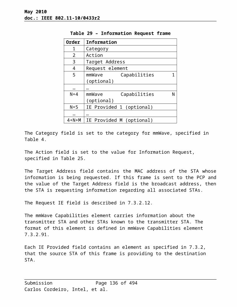
May 2010 doc.: IEEE 802.11-10/0433r2
the involved bands are negotiated, the encapsulated GTKs and the GTK’s key identifiers for the involved bands. For STK generation Initiator RSNIE, Lifetime of SMK is used. If the Extended KeyID for Unicast subfield of the RSN Capabilities field is set to 1 for both the Authenticator/STA_I and Supplicant/STA_P, then the Authenticator/STA includes the Key ID KDE with the assigned key identifier for the current operating band; or if dot11MultibandSupportEnabled is true, the Authenticator includes the Key ID KDE(s) with the assigned key identifier(s) for one or more supported bands.
.11 Editor Note: after the sentence “Processing for PTK generation is as follows:” and before the sentence ” The Authenticator sends Message 3 to the Supplicant.” add the following:
If the Extended Key ID for Unicast subfield of the RSN Capabilities field is set to 1 for both the Authenticator and the Supplicant, then the Authenticator assigns a new Key ID for the PTKSA in the range 0 through 1. Otherwise the Key ID 0 use used. The Authenticator uses the MLME-SETKEYS.request primitive to install the new key in the IEEE 802.11 MAC to receive Class 3 unicast MPDUs protected by the PTK with the assigned Key ID.
NOTE – If an existing PTK is still in effect, the Authenticator IEEE 802.11 MAC continues to transmit Class 3 unicast MPDUs (if any) using the existing key. With the installation of the new key for receive, the Authenticator is able to receive Class 3 unicast MPDUs using either the old key (if present) or the new key.
.11 Editor Note: in the paragraph that starts with “On reception of Message 3, the Supplicant silently…” change as follows:
d) Uses the MLME-SETKEYS.request primitive to configure the IEEE 802.11 MAC to send and receive Class 3 unicast MPDUs protected by the PTK with the assigned Key ID.
de) Constructs Message 4.ef) Sends Message 4 to the Authenticator.f) Uses the MLME-SETKEYS.request primitive to configure the IEEE 802.11 MAC to send and
receive Class 3 unicast MPDUs protected by the PTK. The GTK is also configured by MLMESETKEYS primitive.
.11 Editor Note: before the paragraph that starts with “The STA_I sends Message 3 to the STA_P. On reception of Message 3, the STA_P silently…” add following text:
If the Extended Key ID for Unicast subfield of the RSN Capabilities field is set to 1 for both the STA_I and the STA_P, then the Authenticator assigns a new Key ID for the STKSA in the range 0 through 1. Otherwise the Key ID 0 use used. The STA_I uses the MLME-SETKEYS.request primitive to install the new key in the IEEE 802.11 MAC to receive Class 3 unicast MPDUs protected by the STK with the assigned Key ID. The STA_I sends Message 3 to the STA_P.
NOTE – If an existing STK is still in effect, the STA_I IEEE 802.11 MAC continues to transmit Class 3 unicast MPDUs (if any) using the existing key. With the installation of the new key for receive, the STA_I is able to receive Class 3 unicast MPDUs using both the old key (if present) or the new key.
.11 Editor Note: in the paragraph that starts with “The STA_I sends Message 3 to the STA_P. On reception of Message 3, the STA_P silently…” add after bullet c):
Submission Page 136 of 339 Carlos Cordeiro, Intel, et al.
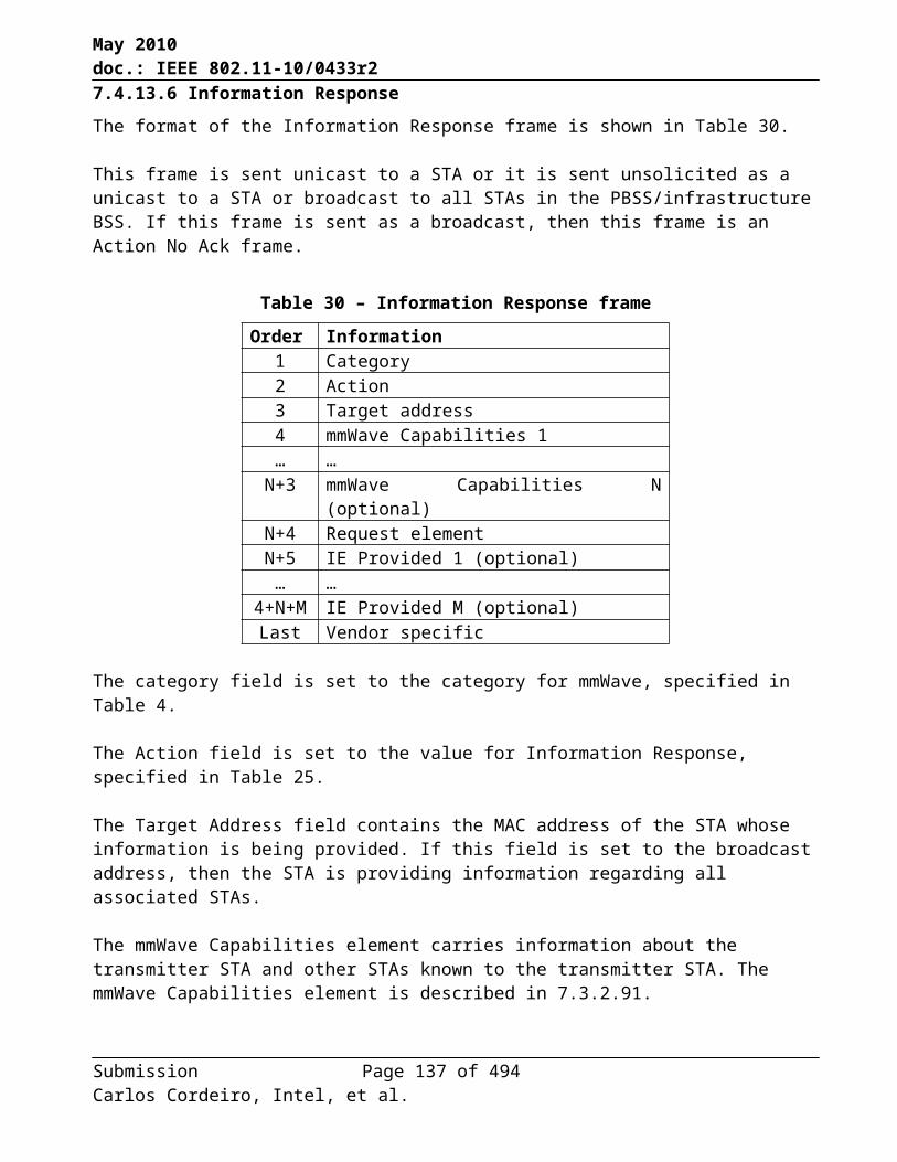
May 2010 doc.: IEEE 802.11-10/0433r2
d) The STA_P uses the MLME-SETKEYS.request primitive to configure the IEEE 802.11 MAC to send and receive Class 3 unicast MPDUs protected by the STK with the assigned Key ID.
8.5.3.4 4-Way Handshake Message 4.11 Editor Note: in the paragraph that starts with “On reception of Message 4, the Authenticator verifies that the Key Replay Counter…” modify as follows:
b) If the MIC is valid, the Authenticator uses the MLME-SETKEYS.request primitive to configure the PTK into the IEEE 802.11 MAC to send Class 3 unicast MPDUs using for the new PTK.
.11 Editor Note: in the paragraph that starts with “The STA_P sends Message 4 to the STA_I. On reception …” modify as follows:
b) If the MIC is valid, the STA_I configures the STK into the IEEE 802.11 MAC uses the MLME-SETKEYS.request primitive to configure the 802.11 MAC to send Class 3 unicast MPDUs using for the new STK.
8.7 Per-frame pseudo code
8.7.2 RSNA frame pseudo-code
8.7.2.3 Per-MPDU Rx pseudo-code.11 Editor Note: in the pseudo-code, insert the following after the sentence “if ((MPDU has individual RA and Pairwise key exists for the MPDU’s TA) or (MPDU has a broadcast/multicast RA and network type is IBSS and IBSS GTK exists for MPDU’s RA)) then”:
MPDU’s RA)) thenif MPDU has individual RA then
lookup pairwise key using Key ID from MPDU else lookup group key using Key ID from MPDU endif
if key is null then
9 MAC sublayer functional description
9.1 MAC Architecture
.11 Editor Note: Replace the first paragraph and Figure 9-1 with the following:
The MAC architecture is shown in Figure 9-1. When operating with any of the Clause 14 through 20 PHYs, the MAC provides the PCF and HCF through the services of the DCF. In a non-mmWave QoS
Submission Page 137 of 339 Carlos Cordeiro, Intel, et al.
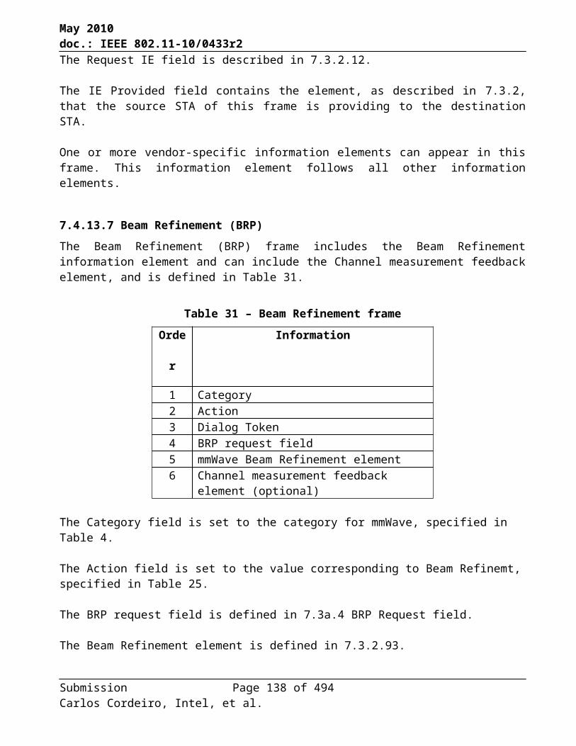
May 2010 doc.: IEEE 802.11-10/0433r2
STA implementation, both DCF and HCF are present. In a non-mmWave non-QoS STA implementation, only DCF is present. PCF is optional in all non-mSTAs.
When operating with a mmWave PHY (Clause 21 ) the MAC provides services using the mmWave Channel Access mechanisms. Specific rules apply for access during scheduled periods, which include the association beamforming training period (A-BFT), announcement time period (AT), contention-based period (CBP), and service period (SP). The DCF is used during contention-based access periods. Polled access is built on service period and contention-based period access.
Figure 9-1 — MAC architecture
9.1.3 Hybrid coordination function (HCF)
9.1.3.1 HCF contention-based channel access (EDCA)
.11 Editor note: change the 4th paragraph as indicated below:
The AP and PCP may use a different set of EDCA parameters than it advertises to the STAs in its BSS.
9.1.5 Fragmentation/defragmentation overview
.11 Editor note: Insert the following after (Figure 9-2 Fragmentation):
MPDUs that are not aggregated in the A-MPDU may be transmitted with regular ACK acknowledgment even under BA agreement.
The MSDU shall not be fragmented if the No-Fragmentation field in the ADDBA extension of the ADDBA frame is set to 1 in the ADDBA response frame of the BA Agreement handshake. If the ADDBA response frame has the No-Fragmentation field in the ADDBA extension of the ADDBA frame set to 0 the originator may send fragmented non-aggregated MSDU with regular ACK
Submission Page 138 of 339 Carlos Cordeiro, Intel, et al.
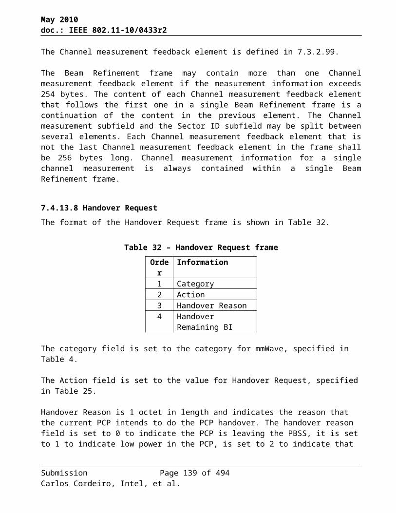
May 2010 doc.: IEEE 802.11-10/0433r2
acknowledgement under BA agreement. The recipient shall not acknowledge the MPDUs of fragmented MSDU with regular ACK if they are received in the A-MPDU.
9.2 DCF
.11 Editor’s instructions: make the following changes in this subclause
The basic medium access protocol is DCF that allows for automatic medium sharing between compatible PHYs through the use of CSMA/CA and a random backoff time following a busy medium condition. In addition, all individually addressed traffic uses immediate positive acknowledgment (ACK frame) where retransmission is scheduled by the sender if no ACK is received.
Due to its specific propagation characteristics, the WM in the UB is a combination of SFSDOM and SFDOM. Any STA in the UB operates in either SFSDOM or SFDOM depending on who are the intended receivers of the STA’s transmissions and which other STAs are simultaneously transmitting. The STA does not have precise knowledge of when it operates in the SFSDOM or in the SFDOM. The DCF is modified to allow sharing of the mmWave specific medium between compatible PHYs.
The CSMA/CA protocol is designed to reduce the collision probability between multiple STAs accessing a medium, at the point where collisions would most likely occur. Just after the medium becomes idle following a busy medium (as indicated by the CS function) is when the highest probability of a collision exists. This is because multiple STAs could have been waiting for the medium to become available again. This is the situation that necessitates a random backoff procedure to resolve medium contention conflicts.
In the UB the CS function may not properly indicate the medium busy condition. In the SFDOM, the transmission of a STA may interfere (collide) with the transmission of another STA even though the CS function at the first STA does not indicate medium busy. The interference (collision) is identified when the expected response frame is not received. SFS is achieved by the proper combination of the STA antenna configuration during the media access and data transfer phases.
.11 Editor’s instructions: fix the references in subclause 9.2 DCF, IEEE P802.11n/D9.0, March 2009 to reflect the rules for the mmWave MCS control frame’s transmission in the paragraph that starts with:“STAs that are members of a BSS are able to receive and transmit at all the data rates in the BSSBasicRateSet parameter of the MLME-START.request or BSSBasicRateSet parameter of the BSSDescription representing the SelectedBSS parameter of the MLME-JOIN.request, see 10.3.3.1.4 (Effect of receipt) and 10.3.10.1.4 (Effect of receipt). …”
.11 Editor’s instructions: add the following new paragraph after the one that starts with: “Data frames sent under the DCF shall use the frame type Data …” While in the WAKE state and operating under DCF but not transmitting, an mSTA configures its receive antenna to a quasi-omni pattern in order to receive frames transmitted by any STA that is covered by this antenna pattern.
9.2.3 IFS
Submission Page 139 of 339 Carlos Cordeiro, Intel, et al.
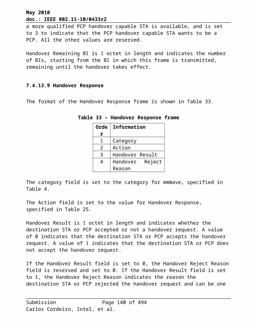
May 2010 doc.: IEEE 802.11-10/0433r2
.11 Editor instructions: please make the following changes to (9.2.3 IFS) of 802.11-2007+amendments
The time interval between frames is called the IFS. A STA shall determine that the medium is idle through the use of the CS function for the interval specified. SixEight different IFSs are defined to provide priority levels for access to the wireless media; Figure 9-3 shows some of these relationships. All timings are referenced from PHY interface signals PHY-TXEND.confirm, PHY-TXSTART.confirm, PHY-RXSTART.indication, and PHY-RXEND.indication.
.11 Editor change the list of items after the first paragraph of 9.2.3 as follows (existing letters are not shown for clarity):
g) SBIFS Short Beamforming Interframe Spacingh) BRPIFS Beam Refinement Protocol Interframe Spacing
9.2.3.0b RIFS
.11 Editor change the first paragraph as follows:
RIFS may be used in place of SIFS to separate multiple transmissions from a single transmitter, when each transmission occurs with the same transmit antenna configuration, except during a receive sector sweep, and no SIFS-separated response transmission is expected. RIFS shall not be used between frames with different RA values. The duration of RIFS is defined by the aRIFS PHY characteristic (see Table 20-24 and Table 74). The RIFS is the time from the end of the last symbol of the previous frame to the beginning of the first symbol of the preamble of the subsequent frame as seen at the air interface. A STA shall not allow the space between frames that are defined to be separated by a RIFS time, as measured on the medium, to vary from the nominal RIFS value (aRIFSTime) by more than ±10% of aRIFSTime. Two frames separated by a RIFS shall both be HT/mmWave PPDUs.
9.2.3.1 SIFS
.11 Editor change the first paragraph as follows:
The SIFS shall be used prior to transmission of an ACK frame, a PPDU containing a BlockAck frame that is an immediate response to either a BlockAckReq frame or an A-MPDU, a mmWaveCTS frame, a mmWaveDTS frame, an SS-ACK frame, a response frame transmitted in the AT, the second or subsequent MPDU of a fragment burst, and by a STA responding to any polling by the PCF. The SIFS may also be used by a PC for any types of frames during the CFP (see 9.3). The SIFS is the time from the end of the last symbol, or signal extension if present, of the previous frame to the beginning of the first symbol of the preamble of the subsequent frame as seen at the air interface.
Submission Page 140 of 339 Carlos Cordeiro, Intel, et al.
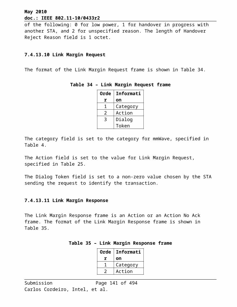
May 2010 doc.: IEEE 802.11-10/0433r2
9.2.3.4 AIFS.11 Editor change the first paragraph as follows: The AIFS shall be used by QoS STAs to transmit all data frames (MPDUs) except during the AT or a SP, all management frames (MMPDUs) except during the AT or a SP, all extension frames except for the mmWave Beacon frame, and the following control frames: PS-Poll, SS (if first transmission by initiator in a CBP), Poll (if first transmission and when in a CBP), Grant ( if first transmission and when in a CBP and not transmitted in response to a SPR), SPR (when in a CBP and not transmitted as a response to a Poll), RTS, mmWaveCTS (when not transmitted as a response to the RTS), BlockAckReq, and BlockAck (when not transmitted as a response to the BlockAckReq). A STA using the EDCA shall obtain a TXOP for an AC if the STA’s CS mechanism (see 9.2.1) determines that the medium is idle at the AIFS[AC] slot boundary (see 9.9.1.3), after a correctly received frame, and the backoff time for that AC has expired.
.11 Editor change the first paragraph as follows:
A non-AP/non-PCP QoS STA computes the time periods for each AIFS[AC] from the dot11EDCATableAIFSN attributes in the MIB. QoS STAs update their dot11EDCATableAIFSN values using information in the most recent EDCA Parameter Set element of Beacon frames received from the AP of the BSS (see 7.3.2.28) when operating in the LB or HB, or the most recent EDCA Parameter Set element of mmWave Beacon and Announce frames received from the AP/PCP of the BSS/PBSS when operating in the UB. A QoS AP/PCP computes the time periods for each AIFS[AC] from the dot11QAPEDCATableAIFSN attributes in its MIB.
.11 Editor Insert the following two subclauses (9.2.3.6 and 9.2.3.7) after 9.2.3.5 EIFS:
9.2.3.6 SBIFSSBIFS (Short Beamforming Interframe Spacing) shall be used to separate multiple transmissions from a single transmitter, during a receive sector sweep or when each transmission occurs with a different transmit antenna configuration and no SIFS-separated response transmission is expected. The duration of SBIFS is determined by the aSBIFS PHY characteristic. The SBIFS is the time from the end of the last symbol of the previous frame to the beginning of the first symbol of the preamble of the subsequent frame as seen at the air interface. A STA shall not allow the space between frames that are defined to be separated by a SBIFS time, as measured on the medium, to vary from the nominal SBIFS value (aSBIFSTime) by more than ±10% of aSBIFSTime. Two frames separated by a SBIFS shall both be mmWave PPDUs.
9.2.3.7 BRPIFSThe BRPIFS (Beam Refinement Protocol Interframe Spacing) shall be used by STAs between any combination of transmissions of BRP-TX and BRP-RX packets.
Submission Page 141 of 339 Carlos Cordeiro, Intel, et al.
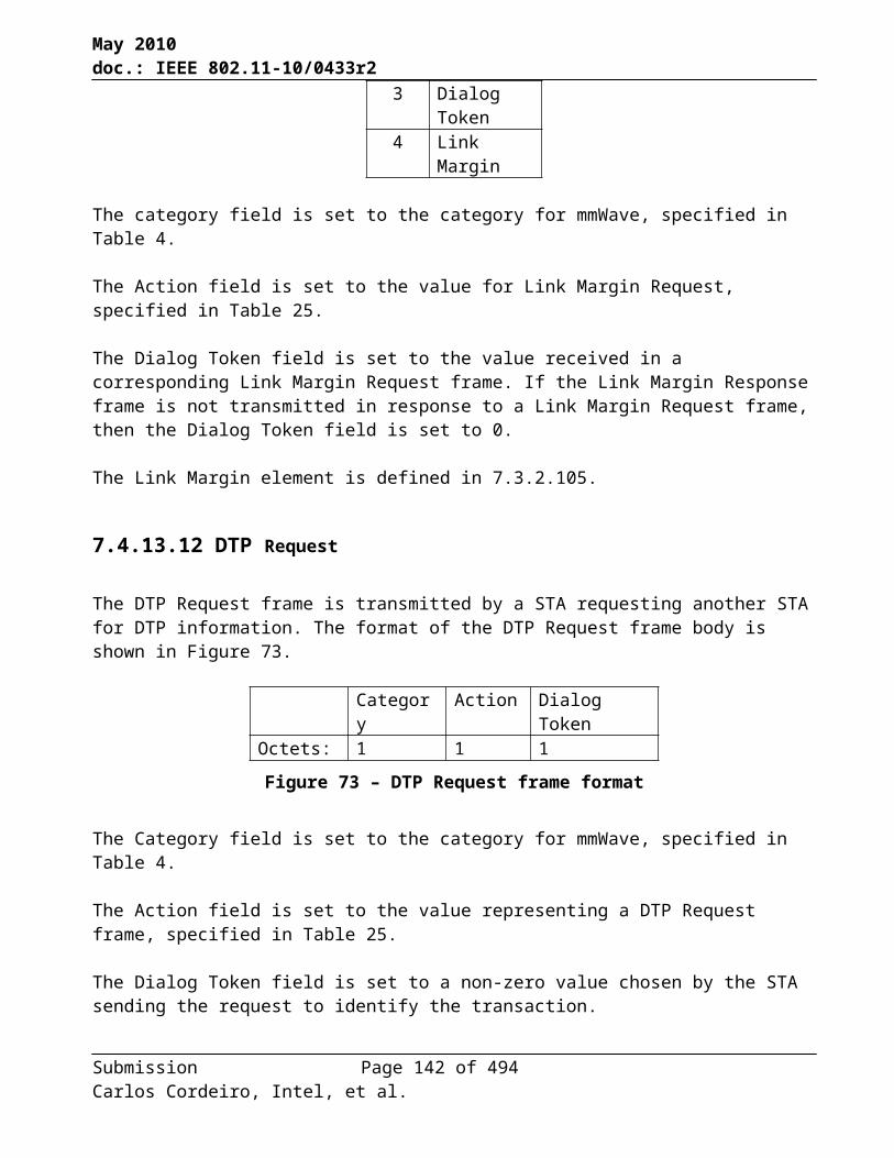
May 2010 doc.: IEEE 802.11-10/0433r2
The BRPIFS is the maximum time from the end of the last symbol of the previous PPDU, or training field if present in the PPDU, to the beginning of the first symbol of the preamble of the subsequent PPDU as seen at the air interface. The corresponding minimum time is SIFS. BRPIFS is defined to be equal to aBRPIFS ± 10%.
9.2.4 Random backoff time.11 Editor’s instructions: change the following sentence: “… that have been deferring to the same event in HB and in LB”
9.2.5 DCF access procedure
9.2.5.1 Basic access
.11 Editor’s instructions: add the following paragraphs after the second paragraph
An mSTA operating under the DCF access method should transmit MPDUs and control frames with its transmit antenna pattern directed towards the intended receiver.
An mSTA operating under the DCF access method that is not participating in a TxOP exchange may configure its receiving antenna array to a quasi-omni antenna pattern so as to be ready to receive frames from any mSTA.
An mSTA operating under the DCF access method that is participating in a TxOP exchange should configure its receiving antenna array to be directed toward the other transmitter involved in the TxOP.
9.2.5.2 Backoff procedure for DCF.11 Editor’s instructions: Modify the third paragraph as shown:
To begin the backoff procedure, the STA shall set its Backoff Timer to a random backoff time using the equation in 9.2.4. All backoff slots occur following a DIFS period during which the medium is determined to be idle for the duration of the DIFS period, or following an EIFS period during which the medium is determined to be idle for the duration of the EIFS period, as appropriate (see 9.2.3), except that no backoff slots for DCF occur during the BT, the A-BFT, the AT and non-CBP portions of the DTT.
.11 Editor’s instructions: replace all appearances of the word “DIFS” by “DIFS (PIFS in the UB)”; insert Figure 9-6a and Figure 9-6b immediately following Figure 9-6.
Submission Page 142 of 339 Carlos Cordeiro, Intel, et al.
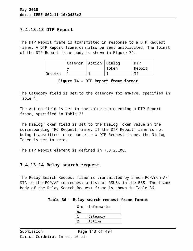
May 2010 doc.: IEEE 802.11-10/0433r2
Figure 9-6a — Example topology of NAV setting in mSTAs
Figure 9-6b — Backoff procedure in the UB
.11 Editor’s instructions: add the following text at end of the subclause
Figure 9-6b describes the backoff procedure in the UB for the example topology shown in Figure 9-6a.
At the time that STA A starts transmitting a frame to STA E and STA E starts receiving the frame, the antennas of both stations are directed to the peer, i.e., the transmitting antennas of STA A are directed to STA E and the receiving antennas of STA E are directed to STA A. At this point, STA B, STA C and STA D are not involved in any frame exchange, so they are in receiving mode with the configuration of their receiving antenna arrays set to a quasi-omni antenna pattern so as to be ready to receive frames from any STA.
STA B receives the frame transmitted by STA A (to STA E) and CS (physical and virtual) in STA B indicates a busy medium during the exchange between STA A and STA E.
STA D is not able to receive the frame transmitted by STA A or the response transmitted by STA E, hence CS in STA D indicates IDLE for the duration of the exchange between STA A and STA E.
Submission Page 143 of 339 Carlos Cordeiro, Intel, et al.
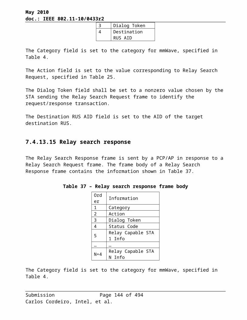
May 2010 doc.: IEEE 802.11-10/0433r2
The physical CS function of STA C indicates a medium busy condition when it receives the response sent by STA E, but indicates an idle medium condition during the transmission from STA A.
STA A and STA E, which are directly involved in the frame exchange, STA B, which received the frame sent by STA A, and STA C, which received the response sent by STA E, are synchronized at point A, where the transaction between STA A and STA E completes.
Since STA D cannot hear the directional transmissions either from STA A or STA C, its physical CS indicates an idle medium condition for the duration of the frame exchange,enabling a frame exchange with STA B at the same time as the frame exchange between STA A and STA E. This is an example of SFS.
Because STA C is unaware of the transmission of the frame from STA A to STA E, STA C transmits an RTS to STA B. But STA C does not receive a mmWaveCTS from STA B since the CS at STA B is busy when STA B receives the RTS from the STA C. This causes STA C to retry the RTS transmission following the expiration of a backoff count which occurs after the completion of the exchange between STA A and STA E.
.11 Editor’s instructions: add the following text after the indicated paragraph:The effect of this procedure is that when multiple STAs are deferring and go into random backoff, then the STA selecting the smallest backoff time using the random function will win the contention (assuming all of the contending STAs detect the same instances of WM activity at their respective receivers, which is not always true, due to hidden node effects and interference events). In the UB, the number of STAs that are able to detect each WM transmission is reduced even further due to a mixture of SFSDOM and SFDOM.
9.2.5.3 Recovery procedures and retransmit limits.11 Editor’s instructions: change the indicated paragraph as follows:Retries for failed transmission attempts shall continue until the SRC for the MPDU of type Data or MMPDU is equal to dot11ShortRetryLimit or until the LRC for the MPDU of type Data or MMPDU is equal to dot11LongRetryLimit. When either of these limits is reached, retry attempts shall cease, and the MPDU of type Data (and any MSDU of which it is a part) or MMPDU shall be discarded. In the UB, in addition to random access within a CBP, retry attempts can use scheduled SP provided scheduled access is supported by the AP or PCP of the BSS that the STA is associated with.
9.2.5.4 Setting and resetting the NAV.11 Editor’s instructions: fix sentence in the last paragraph as follows:In LB and HB a STA that used information from an RTS frame as the most recent basis to update its NAV setting is permitted to reset its NAV.
NOTE – An mSTA operating in the UB is not permitted to use this reset procedure because there might be significant receive sensitivity difference between the RTS and the subsequent data due to the use of receive beamforming.
.11 Editor’s instructions: add after last paragraphSTAs operating in the UB update their NAV timers according to the procedures described in 9.23.10 .
Submission Page 144 of 339 Carlos Cordeiro, Intel, et al.

May 2010 doc.: IEEE 802.11-10/0433r2
9.2.5.7 CTS procedure .11 Editor’s instructions: add the following new paragraph at the end of the subclause:
An mSTA does not transmit CTS frames and uses a mmWaveCTS frame instead of a CTS frame in all instances where a CTS is sent ( 11.3.3 ). A STA operating in the LB or the HB does not transmit mmWaveCTS frames ( 11.3.3 ).
9.2.7 Broadcast and multicast MPDU transfer procedure
.11 Editor Note: make the indicated changes in this subclause:
In the absence of a PCF, when broadcast or multicast MPDUs are transferred from a STA with the To DS field clear, only the basic access procedure shall be used. Regardless of the length of the frame, no RTS/CTS or RTS/mmWaveCTS exchange shall be used. In addition, no ACK shall be transmitted by any of the recipients of the frame. Any broadcast or multicast MPDUs transferred from a STA with a To DS field set shall, in addition to conforming to the basic access procedure of CSMA/CA, obey the rules for RTS/CTS exchange and the ACK procedure because the MPDU is directed to the AP. In addition, in the UB the MPDU transmission shall conform to the access procedures defined in 9.23 . The broadcast/multicast message shall be distributed into the BSS. The STA originating the message shall receive the message as a broadcast/multicast message. Therefore, all STAs shall filter out broadcast/multicast messages that contain their address as the source address. Broadcast and multicast MSDUs shall be propagated throughout the ESS.
There is no MAC-level recovery on broadcast or multicast frames, except for those frames sent with the To DS field set. As a result, the reliability of this traffic is reduced, relative to the reliability of individually addressed traffic, due to the increased probability of lost frames from interference, collisions, or time-varying channel properties.
If multiple copies of broadcast or multicast MPDUs with a To DS field clear are transferred in the UB, the STA shall not transmit a different frame with a consecutive SN before the completion of the transmission of all copies of the broadcast or multicast MPDU.
9.2.11 NAV distribution.11 Editor’s instructions: modify text as follows:
“… the node may first transmit a CTS frame with the RA field equal to its own MAC address (CTS-to-self) if operating in the HB or LB, or a mmWaveCTS with the RA field equal to the TA field and equal to its own MAC address (mmWaveCTS-to-self) if operating in the UB. A duration value in the frame protects the pending transmission, plus possibly an ACK frame.”
9.4 Fragmentation
.11 Editor note: Insert the following paragraph at end of the subclause:
Submission Page 145 of 339 Carlos Cordeiro, Intel, et al.
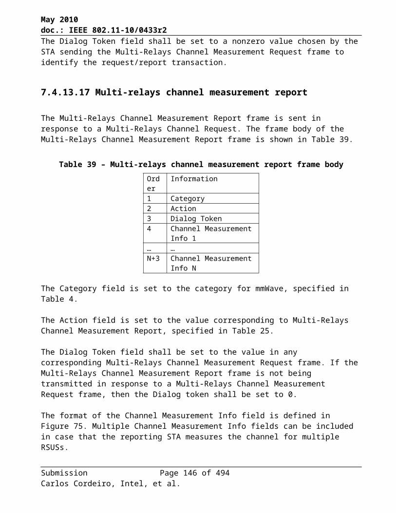
May 2010 doc.: IEEE 802.11-10/0433r2
MAC that supports the mmWave PHY shall complete the transmission of a fragmented MSDU before starting transmission of the following fragmented MSDU.
9.6 Multirate support
9.6.0a Overview
.11 Editor: Change the third paragraph of this subclause as follows:
Otherwise the frame shall be transmitted using a rate that is in accordance with rules defined in 9.6.0d and 9.6.0e when the STA is not an mSTA operating in the UB. For an mSTA operating in the UB, the frame shall be transmitted using a rate that is in accordance with rules defined in 9.6.0f Usage of mmWave Control modulation class through 9.6.0j Rate selection for BRP packets . .11 Editor: insert the following four subclauses:
9.6.0f Usage of mmWave Control modulation class The mmWave Control modulation class has only one MCS, which is mmWave MCS 0 defined in Clause 21. The mmWave Beacon, Sector Sweep frame, SS-Feedback, SS-ACK, and the first BRP packet in beam refinement shall always be transmitted using the mmWave Control modulation class. Other mmWave beamforming training frames may be transmitted using the mmWave Control modulation class or the mmWave SC modulation class. Other mmWave control frames and management frames may be transmitted using the mmWave Control modulation class.
An A-MPDU shall not be transmitted using the mmWave control modulation class.
9.6.0g Rate selection rules for control frames transmitted by mSTAs
This sub-clause describes the rate selection rules for control frames transmitted by mSTAs to other mSTAs while operating in the UB. The rate selection rules shall only apply for MCSs defined in Clause 21.
A control frame that is not BA, nor BAR and that is not a control response frame shall be transmitted by an mSTA using an MCS from the mandatory MCS set of the mmWave SC modulation class. A mmWave control response frame that is not a BA frame shall be transmitted using the same type of PHY of the frame that elicited the response and shall use the highest mandatory MCS that is the same as or lower than the MCS of the frame that elicited the response.
An mSTA transmitting a BAR frame that is not a response transmission may use any MCS supported by the receiver as reported in the Supported MCS set.
Submission Page 146 of 339 Carlos Cordeiro, Intel, et al.

May 2010 doc.: IEEE 802.11-10/0433r2
An mSTA transmitting a BA frame that is a response transmission shall transmit the frame using the same modulation class as the frame that solicited the response and the MCS chosen from the Supported MCS set of the STA that transmitted the frame that solicited the response.
NOTE – A control response frame is a control frame that is transmitted within an MPDU as a response to a reception SIFS time after the PPDU containing the frame that elicits the response, e.g. a mmWaveCTS in response to an RTS reception, an ACK in response to a DATA reception, a BA in response to a BAR reception. In some situations, the transmission of some of these control frames is not a control response transmission, such as when a mmWaveCTS is used to initiate a TXOP.
The rules in this subclause shall not apply to control frames that are contained in A-MPDUs that also include at least one MPDU of type Data or Management.
9.6.0h Rate selection for group addressed data and management frames transmitted by mSTAs
This subclause describes the rate selection rules for group addressed data and management frames as transmitted by mSTAs to other mSTAs while operating in the UB. The rate selection rules shall only apply for MCSs defined in Clause 21.
If a single transmission of a group-addressed frame is intended to reach more than one receiver and the supported MCS set of each of the intended receivers is known to the sender, then the MCS used for the transmission shall be an MCS common to the supported MCS sets of all the intended receivers. If such an MCS is not known, the frame shall be transmitted using a MCS from the mandatory MCS set of the mmWave SC PHY.
If a single transmission of the group-addressed frame is intended to reach only one receiver, the frame shall be transmitted following the rate selection rules of unicast frames as described in section 9.6.0i.
9.6.0i Rate selection for unicast data and management frames transmitted by mSTAs
This subclause describes the rate selection rules for unicast addressed data and management frames as transmitted by mSTAs to other mSTAs while operating in the UB. The rate selection rules shall only apply for MCSs defined in Clause 21.
A unicast data or management frame that shall be sent using any MCS subject to the following constraints:
— A STA shall not transmit a frame using a MCS that is not supported by the receiver STA, as reported in the Supported Receiving MCS field in management frames transmitted by the receiver STA.
— A STA shall not initiate transmission of a frame at a MCS higher than the highest Transmission MCS in the OperationalMCSSet, which is a parameter of the MLME-JOIN.request primitive.
In case when the Supported MCS set of the receiving STA is not known, the transmitting STA shall transmit using a MCS from the mandatory MCS set of the mmWave SC PHY mode.
Submission Page 147 of 339 Carlos Cordeiro, Intel, et al.
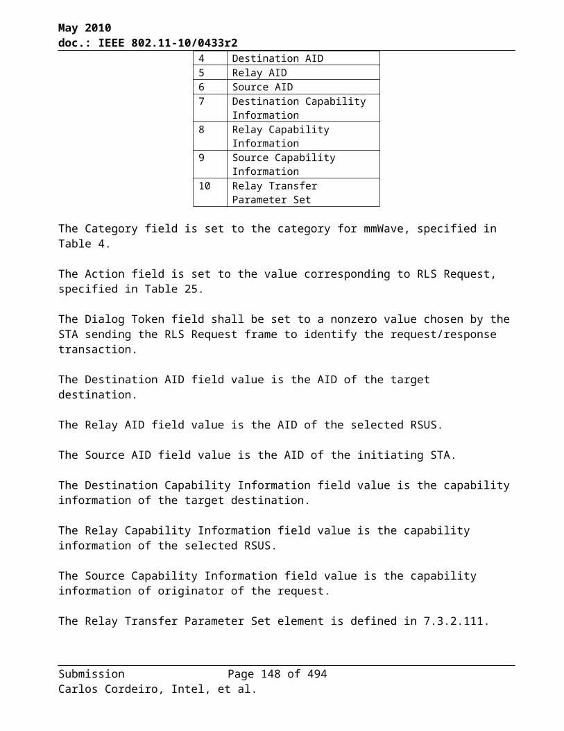
May 2010 doc.: IEEE 802.11-10/0433r2
The rules in this subclause also apply to A-MPDUs that contain at least one control type MPDU and at least one MPDU of type Data or Management.
A STA shall not transmit an A-MPDU that contains at least one frame of type Data with MCS 0.
9.6.0j Rate selection for BRP packets
The first BRP packet transmitted from the initiator to the responder after the SLS phase shall use MCS0.
The first BRP packet transmitted from the responder to the initiator after the SLS phase shall use MCS0.
BRP packets transmitted during beam refinement should use MCS1, and shall use MCS0-MCS12.
BRP packets transmitted during the BRP setup sub-phase, the MID sub-phase and the BC sub-phase shall use MCS0.
BRP packets transmitted during a BC sub-phase, as part of a BC sub-phase only training, may use MCS0-MCS12.
BRP packets transmitted during beam tracking may use any MCS.
9.6.1 Modulation classes
.11 Editor: Add the following rows to (Table 9-2-Modualtion classes):
Modulation Class
Description of modulation
Condition that selects this modulationPHYs defined by Clauses 14, 15, 16,
17, 18, 19 or 21Clause 20 PHY
9 mmWave Control Clause 21.4 transmission NA10 mmWave SC Clause 21.6 transmission NA11 mmWave OFDM Clause 21.5 transmission NA12 mmWave low power SC Clause 21.7 transmission NA
9.7c A-MSDU operation
.11 Editor instructions: Insert at start of the sub clause:
The transmitter of frames for a TID corresponding to a PTP TSPEC shall use format that is the result of the PTP TSPEC negotiation for that TID. The A-MSDU subframe format is negotiated using the PTP TSPEC ( 7.3.2.30 ) : the Short A-MSDU subframe format shall not be used for frames of the corresponding flow if the A-MSDU subframe field of the P2P TSPEC element is set to 0 either in the
Submission Page 148 of 339 Carlos Cordeiro, Intel, et al.

May 2010 doc.: IEEE 802.11-10/0433r2
ADDTS request frame or in the ADDTS response frame. Prior to PTP TSPEC negotiation, a STA shall use the A-MSDU subframe format if the STA employs MSDU aggregation.
9.7d A-MPDU operation
9.7d.1 A-MPDU contents
.11 Editor Note: Add the following paragraphs at end of the sub clause:
An mSTA shall transmit an A-MPDU in either the Data Enabled Immediate Response context or the Control Response context specified in Table 7-57w.
The contents of an A-MPDU transmitted by an mSTA in the data enabled immediate response context shall be the ACK MPDU, or the HT-immediate BlockAck, or the Action No Ack as specified in Table 7-57x.
9.7d.2 A-MPDU length limit rules
.11 Editor Note: change all occurrences of “HT” by “HT/mmWave” and of “Table 7-43l” by “Table 7-43l for an HT STA and in the mmWave Capabilities element for an mSTA”
9.7d.3 Minimum MPDU Start Spacing
.11 Editor Note: change all occurrences of “HT” by “HT/mmWave”, of “Table 7-43l” by “Table 7-43l for an HT STA and in the mmWave Capabilities element for an mSTA”, and of “20.6” by “20.6 for an HT STA and 21 for an mSTA”
9.7d.4 A-MPDU aggregation of group addressed data frames
.11 Editor Note: Insert the following as the new 3rd paragraph: “An mSTA may transmit an A-MPDU containing MPDUs with a group addressed RA.”
.11 Editor Note: change the last paragraph as follows:
When an HT AP or an mSTA transmits an A-MPDU containing MPDUs with a group addressed RA, both of the following shall apply:
— the value of Maximum A-MPDU Length Exponent that applies is the minimum value in the Maximum A-MPDU Length Exponent subfield of the A-MPDU Parameters field of the HT Capabilities element across all HT STAs associated with the AP or of the mmWave Capabilities element across all mSTAs associated with the PCP/AP;— the value of Minimum MPDU Start Spacing that applies is the maximum value in the Minimum MPDU Start Spacing subfield of the A-MPDU Parameters field of the HT
Submission Page 149 of 339 Carlos Cordeiro, Intel, et al.
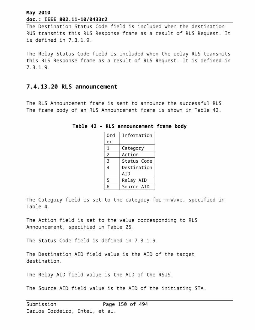
May 2010 doc.: IEEE 802.11-10/0433r2
Capabilities element across all HT STAs associated with the AP or of the mmWave Capabilities element across all mSTAs associated with the PCP/AP.
9.7e PPDU duration constraint
.11 Editor’s instructions: add at end of the subclauseAn mSTA shall not transmit a PPDU that has a duration (as determined by the PHY-TXTIME.confirm primitive defined in 10.4.6) that is greater than aMMWavePPDUMaxTime.
9.8 Operation across regulatory domains
.11 Editor Note: throughout this subclause, replace all occurrences of “Beacon” by “Beacon/mmWave Beacon”
.11 Editor Note: throughout this subclause, replace all occurrences of “AP” by “AP/PCP”
9.9 HCF.11 Editor’s instructions: add at end of the subclause
HCCA is not supported by mSTAs operating in the UB.
9.9.1 HCF contention-based channel access (EDCA)
9.9.1.1 Reference implementation.11 Editor’s instructions: add after the second paragraphAn mSTA may implement a single AC. If the mSTA implements a single AC, all UP and frame types shall be mapped to AC = AC_BE.
9.9.1.5 EDCA backoff procedure.11 Editor’s instructions: Modify the indicated (second to last) paragraph of the subclause as shown:
All backoff slots occur following an AIFS[AC] period during which the medium is determined to be idle for the duration of the AIFS[AC] period, or following an EIFS – DIFS + AIFS[AC] period during which the medium is determined to be idle for the duration of the EIFS – DIFS + AIFS[AC] period, as appropriate (see 9.2.3), except that no backoff slots for EDCA occur during the BT, the A-BFT, the AT and non-CBP portions of the DTT.
9.9.1.7 Truncation of TxOP.11 Editor’s instructions: Append the indicated text to the first paragraph:
Submission Page 150 of 339 Carlos Cordeiro, Intel, et al.
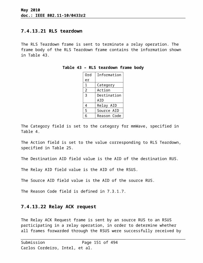
May 2010 doc.: IEEE 802.11-10/0433r2
When a STA gains access to the channel using EDCA and empties its transmission queue, it may transmit a CF-End frame provided that the remaining duration is long enough to transmit this frame. By transmitting the CF-End frame, the STA is explicitly indicating the completion of its TXOP. In UB the STA shall not send a mmWaveCF-End with non zero value in the Duration/ID field if the remaining duration is shorter than 2*mmWaveCF-End duration +2*SIFS.
.11 Editor’s instructions: Modify the text as follows:In LB and HB a STA shall interpret the reception of a CF-End frame as a NAV reset, i.e., it resets its NAV timer to zero at the end of the PPDU containing this frame. After receiving a CF-End frame with a matching BSSID, an AP may respond by transmitting a CF-End frame after SIFS.
In UB a STA that is not in the listening mode ( 9.23.6.5 mmWave Protected Period ) shall interpret the reception of an mmWaveCF-End frame as a NAV reset, i.e., it resets its NAV timer to zero at end of the time interval indicated in the value of the Duration/ID field of the received frame. The interval starts at PHY-RXEND.indication of the frame reception. The STA shall not transmit during the interval if the RA field of the frame is not equal to the STA MAC address. The STA may transmit a mmWaveCF-End frame if the RA field of the received frame is equal to the STA MAC address and value of the Duration/ID field in the received frame is not equal to zero.
.11 Editor’s instructions: Modify the text as follows:In LB and HB, STAs that receive a CF-End frame reset their NAV and can start contending for the medium without further delay. In UB, STAs that receive a mmWaveCF-End frame can start contending for the medium at the end of the time interval equal to the value in Duration/ID field of the frame if none of its NAV timers has a non-zero value.
.11 Editor’s instructions: in other non modified paragraphs replace each appearance of “CF-End frame” by “CF-End frame in LB and HB, and mmWaveCF-End frame in UB”
9.10 Block Acknoledgement (Block Ack)
.11 Editor: throughout subclause 9.10, replace “HT STA” by “HT STA/mSTA”
9.10.1 Introduction
.11 Editor Inserting the following paragraph after the third paragraph:
An mSTA shall support the HT-Immediate Block Ack extension. An mSTA does not support the HT-Delayed Block Ack extension.
9.10.7 HT-immediate Block Ack extensions
9.10.7.2 HT-immediate Block Ack architecture
.11 Editor: insert the following subclause
Submission Page 151 of 339 Carlos Cordeiro, Intel, et al.

May 2010 doc.: IEEE 802.11-10/0433r2
9.10.7.2.1 Data and acknowledgement transfer Under a BA agreement the regular ACK acknowledgement may be used in order to improve efficiency. STAs shall respond with an ACK to the reception of frames that are covered by a BA agreement but that are not part of an A-MPDU and that are received with their Ack Policy subfield in the QoS control field set to Normal Ack.
The Block Ack record shall be updated irrespective of the acknowledgement type (regular or Block ACK) for the TID/TSID with a Block Ack agreement.
The reception of QoS data frames using Normal Ack policy shall not be used by the recipient as an indication to reset the timer employed in detecting a Block Ack timeout (see 11.5). This allows the recipient to delete the Block Ack if the originator does not switch back to using Block Ack.
9.15 Reverse Direction (RD) protocol
.11 Editor Note: Insert the following paragraph at start of the subclause
The RD functionality is provided by the MAC that supports HT PHY (clause 20) and the MAC that supports mmWave PHY (clause 21 ). Normative behavior of the RD defined in this subclause applies to both types of supported PHYs. In the MAC that supports the HT PHY the RDG/More PPDU field and the AC Constraint field are present in the HTC field, and in the MAC that supports the mmWave PHY the RDG/More PPDU field and the AC Constraint field are present in the QoS control field.
.11 Editor Note: replace all occurrences of “+HTC MPDU” by “+HTC/mmWave MPDU”, “+HTC frame” by “+HTC/mmWave frame”, and wherever applicable “HT” by “HT/mmWave”
.11 Editor Note: Insert the following subclause
9.23 mmWave Channel access
Channel access by an mSTA operating in the UB occurs during Beacon Intervals (BI) and is coordinated using a schedule. An mSTA operating as a PCP or AP generates the schedule and communicates it to STAs using mmWave Beacon and Announce frames. A non-PCP STA that is a non-AP STA and that receives scheduling information initiates access to the medium during the scheduled periods using the access rules specific to that period. A non-PCP that is a non-AP STA can access the medium in response to an explicit Poll frame or a Grant frame received from the PCP or AP. A non-PCP STA that is a non-AP STA operating in the UB and that does not receive either scheduling information or a mmWave Beacon frame with the CBP Only field set to one from a PCP or AP is only allowed to transmit mmWave Beacon frames.
9.23.1 Beacon interval (BI) structure
Submission Page 152 of 339 Carlos Cordeiro, Intel, et al.
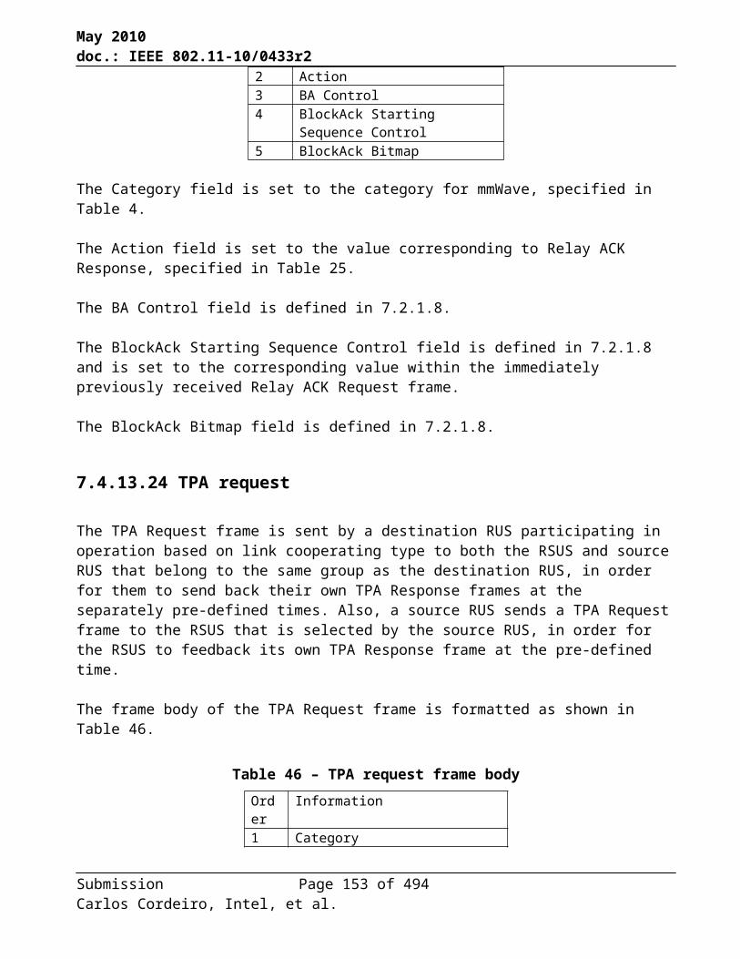
May 2010 doc.: IEEE 802.11-10/0433r2
Medium time within a BSS operating in the UB is divided into Beacon Intervals (BI). Subdivisions within the BI are called access periods. Different access periods within the BI have different access rules. The access periods are described in a schedule that is communicated by the PCP or AP to the non-PCP and non-AP STAs within the BSS. The schedule communicated by the PCP or AP can include the following access periods:
– BT: An access period during which one or more mmWave Beacon frames is transmitted. Not all mmWave Beacon frames are detectable by all non-PCP and non-AP STAs. Not all BIs contain a BT. A non-PCP STA that is a non-AP STA shall not transmit during the BT of the BSS of which it is a member.
– A-BFT: An access period during which beamforming training is performed with a PCP or AP. The presence of the A-BFT is optional and signaled in mmWave Beacon frames.
– AT: A request-response based management access period during which a PCP or AP delivers non-MSDUs and provides access opportunities for STAs to return non-MSDUs. The presence of the AT is optional and signaled in mmWave Beacon frames.
– DTT: An access period during which frame exchanges are performed between STAs.
The DTT, in turn, is comprised of contention-based access periods (CBPs) and service periods (SPs).
Figure 82 illustrates an example of a BI structure comprised of a BT, an A-BFT, an AT, and two CBPs and SPs within the DTT. Any combination in the number of SPs and CBPs can be present in the DTT.
Figure 82 – Example of a BI structure
The details of the access protocol within each of the access periods are described in the remaining subclauses of 9.23 and within subclause 9.25.
9.23.2 Interframe space (IFS)
STAs shall use the interframe spaces defined in 9.2.3 when operating in the UB.
9.23.3 AT transmission rules
The presence of an AT in the current BI is signaled by the AT Present field set to one in the current mmWave Beacon (7.2.4.1). The Next mmWave AT element (7.3.2.98) transmitted in the Announce frame (7.4.13.2) or in the mmWave Beacon frame indicates the earliest start time for the next AT. The AT is a contiguous period of time which ends at the earliest of the following events:
1) the start time of the first SP in this BI;2) the start time of the first CBP in this BI;
Submission Page 153 of 339 Carlos Cordeiro, Intel, et al.
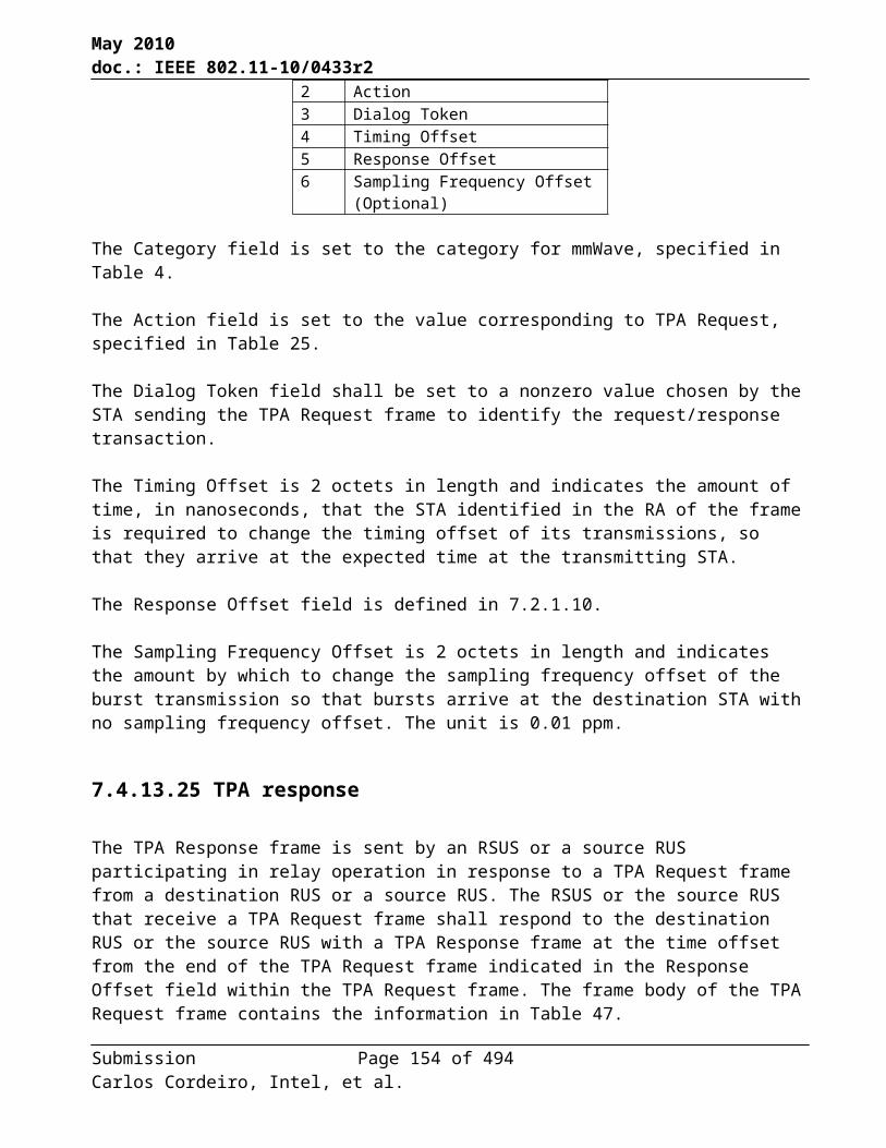
May 2010 doc.: IEEE 802.11-10/0433r2
An example of an AT is shown in Figure 83.
Figure 83 – Example of frame exchanges during the AT
During an AT, request and response frames are exchanged between the PCP/AP and any subset of STAs. The PCP/AP initiates all frame exchanges that occur during the AT. The PCP/AP shall not start transmission of a request frame sooner than a guard time (9.23.6.4 Guard time) following the end of the previous BT or A-BFT when present in the BI. The PCP/AP shall not start transmission of a request frame before TBTT if the AT is the first period in the BI.
A non-PCP/non-AP STA shall not transmit during the AT except in response to a received unicast frame that has the value of the TA field equal to the MAC address of the PCP/AP and that was addressed to the STA.
STAs shall not transmit frames that are not request or response frames during the AT. Request and response frames transmitted during the AT shall be one of the following:
A frame of type Management An ACK frame A Grant, Poll, RTS or mmWaveCTS frame when transmitted as a request frame An SPR or mmWaveCTS frame when transmitted as a response frame A frame of type Data only if part of a secure authentication exchange
Unicast request frames transmitted during the AT shall not be sent using management frames of subtype action no ACK.
A non-PCP/non-AP STA shall transmit a response frame, which may be an ACK frame or an Association Request frame, addressed to the PCP/AP after receiving a unicast request frame addressed to the STA that was transmitted by the PCP/AP during the AT. The response frame shall be transmitted with a spacing of SIFS after the end of the request frame. The PCP/AP shall interpret the receipt of the response frame as an acknowledgement of the request frame. Response frames transmitted by non-PCP/non-AP STAs during the AT shall be transmitted with a unicast address destined to the PCP/AP.
Submission Page 154 of 339 Carlos Cordeiro, Intel, et al.

May 2010 doc.: IEEE 802.11-10/0433r2
NOTE – STAs do not transmit a response frame to the PCP/AP when they receive a request frame from the PCP/AP with the RA equal to the broadcast/multicast address (see 9.2.7 and 9.2.8).
The PCP/AP may repeat transmission of a unicast frame to a STA or send a frame to any other STA if the PCP/AP does not receive a PHY-RXSTART.indication within aSIFSTime + aSlotTime + aPHY-RX-START-Delay starting at the PHY-TXEND.confirm from the end of the transmission and the medium is idle.
Multiple request and response frame exchanges between the PCP/AP and a STA may occur during a single AT. The PCP/AP should complete at least one acknowledged frame exchange with each associated non-PCP/non-AP STA every dot11MaxLostBeacons BIs.
During the AT, the PCP/AP should schedule transmissions to non-PCP/non-AP STAs in power save mode before transmissions to non-PCP/non-AP STAs that are not in power save mode.
9.23.4 DTT transmission rulesDuring the DTT, a STA may transmit frames (following the appropriate access procedures) if any of the following conditions are met:
a) During a CBP (9.23.6.2 Contention-based period (CBP) allocation, 9.23.7 Dynamic allocation of service period and 9.23.8)
b) During a SP for which the STA is identified as source or destination (9.23.6.1 Service period (SP) allocation and 9.23.7 Dynamic allocation of service period)
and shall not transmit if none of these conditions is met. A STA initiating data transfer shall ensure that the transaction, including acknowledgements, completes before the end of the CBP or SP in which it was initiated.
9.23.5 Contention-based period (CBP) transmission rules The definition of contention-based transmission rules used within a CBP is provided in section 9.2 DCF and in section 9.9 HCF.
A BF initiator (9.25) shall not initiate an SLS phase within a CBP if there is not enough time within the CBP to complete the SLS phase. A BF initiator (9.25) shall not initiate a BRP phase within a CBP if there is not enough time within the CBP to complete the BRP phase.
A STA with multiple antennas within CBPs should use only one antenna in its frame transmission, CCA and frame reception. The algorithm to select an antenna and switch active antenna is implementation dependent. Within CBPs, a STA that is changing to a different antenna in order to transmit shall perform CCA on that antenna until a frame sequence is detected by which it can correctly set its NAV, or until a period of time equal to the ProbeDelay has transpired.
Submission Page 155 of 339 Carlos Cordeiro, Intel, et al.
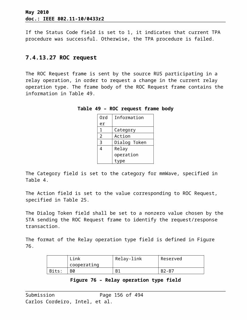
May 2010 doc.: IEEE 802.11-10/0433r2
9.23.6 Time division based channel access in DTTThe PCP/AP schedules each allocation with a specified start time from the TSF and fixed duration. An allocation can be a Service Period (SP), where ownership of channel time is granted to a single STA, or a Contention-Based Period (CBP), where all STAs may compete for channel access. The PCP/AP shall reference the start time of each allocation from the TSF.
The PCP/AP shall only schedule SPs or CBPs during the DTT of a BI following the end of an allocated BT, A-BFT and AT when any one of these periods are present in the BI.
The schedule of the DTT of a BI is communicated through the Extended Schedule element. The PCP/AP shall transmit the Extended Schedule element in the Announce frame or in the mmWave Beacon frame. The Extended Schedule element shall contain the scheduling information of all allocations in the DTT. The PCP/AP should attempt to schedule SPs for a STA such that the scheduled SPs do not overlap in time with the traffic scheduling constraints indicated by this STA in the TSCONST field of the associated Extended mmWave TSPEC element.
An SP or CBP allocation within an Extended Schedule element may be comprised of one or more individual allocations. The start time of the ith individual SP or CBP allocation is given by (A_start + (i-1)*A_period), where A_start is the value of the Allocation start field for the SP or CBP, A_period is the value of the Allocation block period field for the SP or CBP, and i is an integer greater than zero and less than or equal to the value of the Number of blocks field for the SP or CBP. The end of the ith individual SP or CBP allocation is computed by adding the start time of the ith individual allocation to the value of the Allocation block duration field for the corresponding SP or CBP allocation.
If the PCP Active subfield in the Allocation field for an allocation within an Extended Schedule element is set to one, the PCP shall be in the receive state for the duration of that allocation, except when transmitting during that allocation. The AP shall set the PCP Active field to one for every allocation within an Extended Schedule element transmitted by the AP.
Non-PCP/non-AP mSTAs shall be capable of processing the Poll and Grant frames and the SP Info field (7.3a.2 SP Info field) to operate as a destination in an SP and in a CBP. A PCP/AP shall be capable of processing the SPR frame transmitted by a non-PCP/non-AP STA and responding to a SPR frame with a Grant frame. Listening Mode is a mode of operation during which an mSTA is in receiving state and meets at least one of the following conditions:
a) its receiving antennas are in the quasi-omni modeb) its receiving antennas are directed to the peer mSTA for which this mSTA is either the
destination or source mSTA
9.23.6.1 Service period (SP) allocationThe PCP/AP shall set the SPType field to zero in the Extended Schedule element to allocate a SP.
A SP is assigned to the source STA identified in the Source AID field in the Extended Schedule element. The source STA shall initiate the frame exchange sequence that takes place during the SP at the start of the SP. The SP allocation identifies the TC or TS for which the allocation is made, however, the type of traffic transmitted is not restricted to the specified TC or TS.
Submission Page 156 of 339 Carlos Cordeiro, Intel, et al.
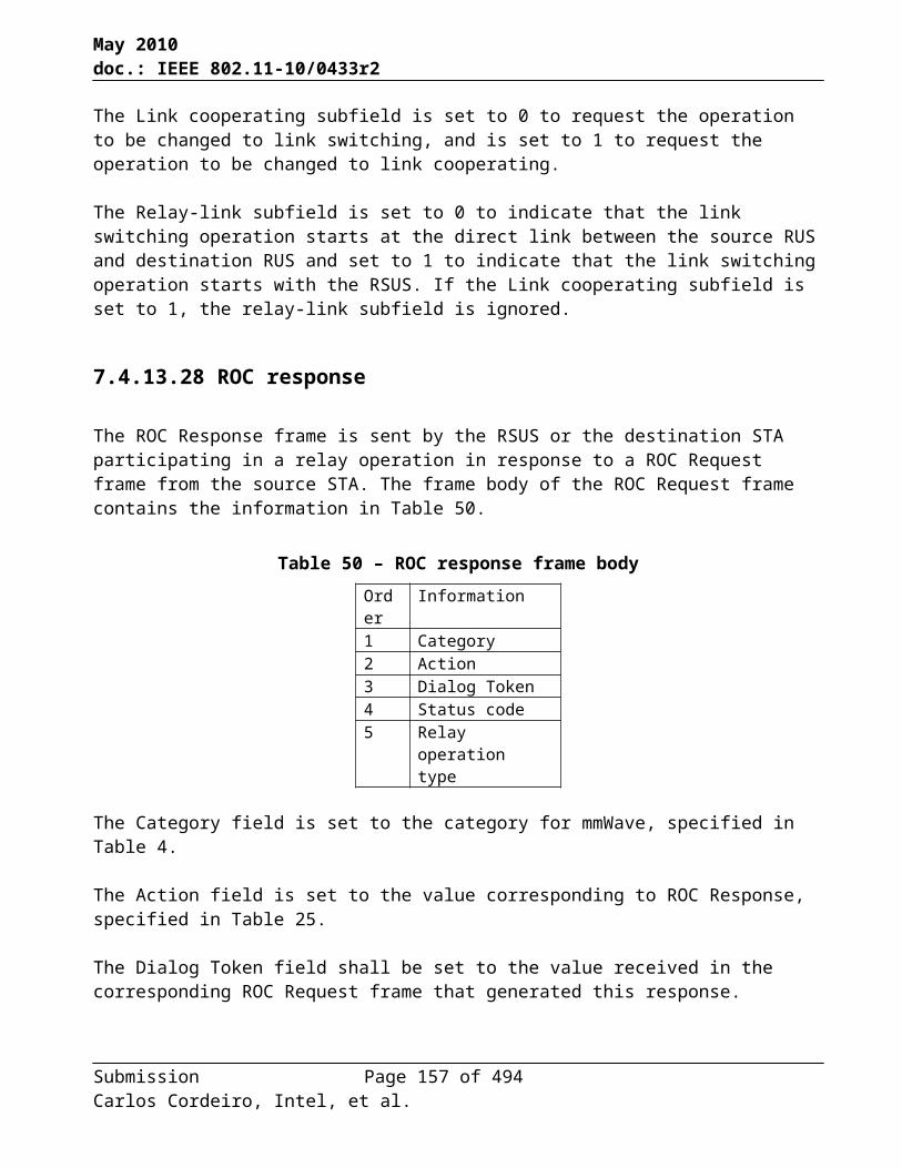
May 2010 doc.: IEEE 802.11-10/0433r2
Except when transmitting a frame as part of the SP recovery procedure (9.23.6.6 Service period recovery) or transmitting a response to the source STA, the STA identified by the Destination AID field in the Extended Schedule element should be in receive state for the duration of the SP in order to receive transmissions from the source STA. If the Destination AID field of the scheduled SP is set to the broadcast AID and the Source AID field of the scheduled SP is not set to the broadcast AID, then all STAs on the PBSS/infrastructure BSS should be in receive state in order to receive transmissions from the source STA for the duration of the SP. Subclause 9.23.7 describes the rules for when the scheduled SP has both the Source and Destination AID fields set to the broadcast AID.
Except when the rules in 9.23.7, 9.23.8, or 9.23.9 are used, only a STA identified as the source STA or destination STA of a SP shall transmit during the SP.
The PCP/AP shall set the Beamforming Training field to one in the Allocation field for an SP within an Extended Schedule element to indicate that the source STA of this SP will initiate beamforming training with the destination STA at the start of that SP.
If the PCP Active field is zero in the Allocation field for an SP within an Extended Schedule element, neither the destination STA of the SP nor the source STA of the SP shall transmit to the PCP during the SP.
In no case shall the source or destination STA extend a transmission frame exchange sequence that started during a SP beyond the end of that SP. A STA that initiates a sequence shall ensure that the frame exchange sequence, including any control frame responses, completes before the end of the SP. If the mSTA participates as source mSTA and/or destination mSTA in two or more SPs, the PCP mSTA and the AP mSTA should not allocate the SPs separated by less than aMinListeningTime microseconds between the end of SP in which the mSTA is either source or destination mSTA and the start of any SP in which the mSTA is either source or destination mSTA.
9.23.6.2 Contention-based period (CBP) allocationThe PCP/AP shall set the SPType field to one, the Source AID field to broadcast AID, and the Destination AID field to broadcast AID in an Allocation field within an Extended Schedule element to allocate a CBP.
All CBPs are initiated and allocated by the PCP/AP, except when allocated by a non-PCP/non-AP STA with the transmission of a Grant frame following a SP truncation (9.23.8). Multiple CBPs may be present in a beacon interval, with the location and duration of each determined by the PCP/AP and announced in the Extended Schedule element. When only one CBP is present and no other allocations exist for the DTT, then the PCP/AP shall announce the presence of the CBP by setting the CBP only field to one in the mmWave Capability field of the mmWave Beacon. If at least one non-CBP allocation is present or more than one CBP is present or no allocations are present within a DTT, then the PCP/AP shall set the CBP only field to zero in the mmWave Capability field in the mmWave Beacon transmitted during the BT. The PCP/AP shall set the CBP only field to zero in the mmWave Capability field within a transmitted mmWave Beacon if the mmWave Beacon contains at least one Extended Schedule element.
Submission Page 157 of 339 Carlos Cordeiro, Intel, et al.
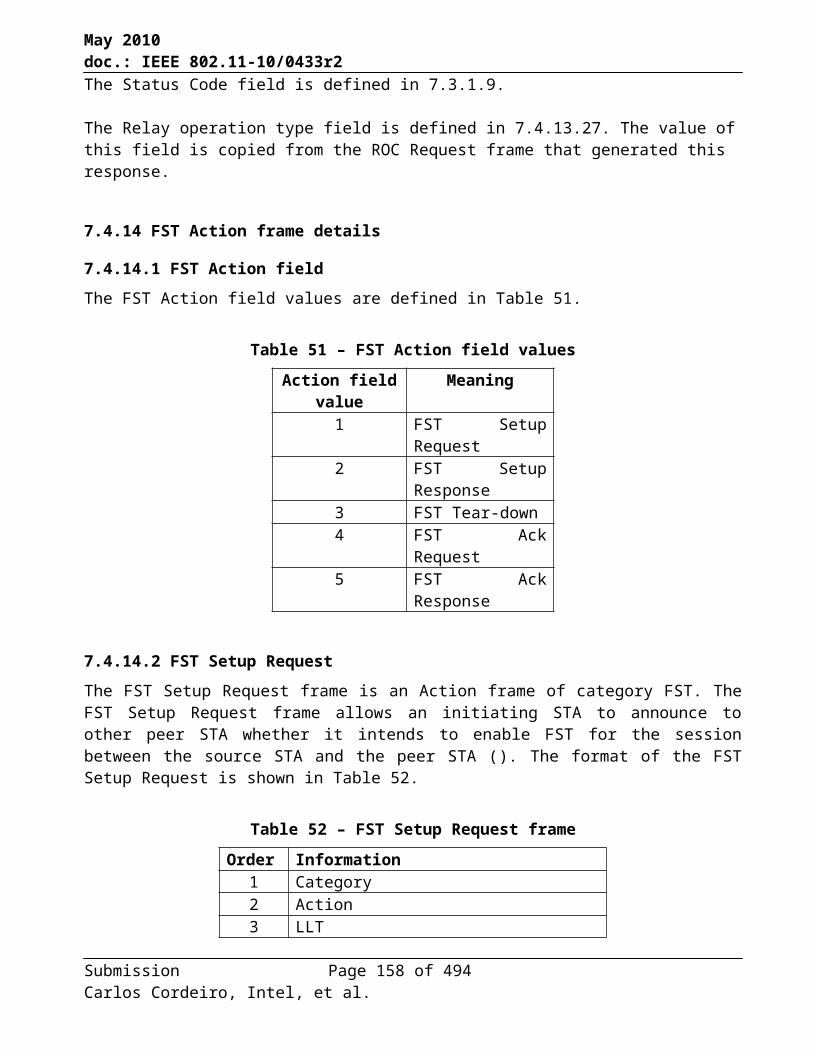
May 2010 doc.: IEEE 802.11-10/0433r2
When the entire DTT is allocated to CBP through the CBP only field in the mmWave Capability field, then that CBP is pseudo-static and exists for dot11MaxLostBeacons BIs following the most recently transmitted mmWave Beacon that contained the indication, except that the CBP is canceled by the transmission by the PCP/AP of an mmWave Beacon with the CBP only field of the mmWave Capability field set to zero or an Announce frame with an Extended Schedule element.
In no case shall a STA extend a transmission frame exchange sequence that started during a CBP beyond the end of that CBP. A STA that initiates a sequence shall ensure that the frame exchange sequence, including any control frame responses, completes before the end of the CBP.
Channel access during a CBP shall follow the rules described in 9.23.5.
9.23.6.3 Pseudo-static allocationsAn SP or CBP allocation is pseudo-static if the Pseudo-static field in the Allocation control field for the SP or CBP is set to one. A pseudo-static SP or CBP recurs at the same relative offset to TBTT and with the same duration in up to dot11MaxLostBeacons BIs following the last received Extended Schedule element containing the pseudo-static allocation. A STA can fail to receive up to dot11MaxLostBeacons -1 Extended Schedule elements in consecutive BIs and still may access the channel during the pseudo-static SP or CBP. The STA shall cease transmission during a pseudo-static SP if it fails to receive an Extended Schedule element for dot11MaxLostBeacons consecutive BIs.
The PCP/AP may change the offset relative to TBTT or the duration of a pseudo-static allocation by transmitting a modified Allocation field in an Extended Schedule element before dot11MaxLostBeacons BIs from the last transmitted Extended Schedule element. The PCP/AP may delete a pseudo-static allocation by transmitting an Extended Schedule element that does not include an allocation field containing that allocation’s TID, source AID and destination AID before the completion of dot11MaxLostBeacons BIs from the last transmitted Extended Schedule element. In either case the PCP/AP should not schedule a new allocation that overlaps with the previous pseudo-static allocation for a minimum of dot11MaxLostBeacons BIs unless both the new and previous allocation are for a CBP or the new allocation identifies the same source STA as the original pseudo-static allocation.
To maintain the same position of the allocation with respect to the start of a BI, the value of the Allocation Block Period subfield within an Allocation field of the Extended Schedule element shall be set to be an integer multiple or submultiple of the BI duration.
If the destination STA of a pseudo-static allocation receives an Extended Schedule element with an Allocation field that indicates a change in the schedule of the pseudo-static allocation, the STA should enter receive state during the new pseudo-static allocation and may enter receive state during the previous allocation.
9.23.6.4 Guard timeAn allocation (SP or CBP) is defined by its start time and duration as specified in the Extended Schedule element. Guard time is the time between the end of one allocation and the start of the following allocation, provided these allocations are not under spatial frequency sharing (11.33). Guard times are used to keep transmissions in adjacent allocations from colliding. Figure 84 shows an
Submission Page 158 of 339 Carlos Cordeiro, Intel, et al.

May 2010 doc.: IEEE 802.11-10/0433r2
example of the insertion of the guard time such that the allocations are separated by at least the guard time, in case the STAs participating in the adjacent allocations drift towards each other’s allocation.
Figure 84 – The guard time
The PCP/AP inserts guard time when it constructs the schedule for a BI. The PCP/AP shall insert sufficient guard time between adjacent allocations to ensure that transmissions in adjacent allocations do not overlap in time.
For each of the adjacent allocations, guard times are calculated based on the worst case drift and the maximum allowed number of lost mmWave Beacons. The PCP/AP shall insert a guard time between adjacent allocations that is not shorter than:
GuardTime = ceiling((MLBAllocation_i + MLBAllocation_i+1 + 2) * ([ClockAccuracy (ppm) / 1e6] * DriftInterval) + SIFS + aAirPropagationTime, aTSFResolution)
The value of MLBAllocation_i for each allocation depends on whether the allocation is pseudo-static or not. MLBAllocation_i is zero for a non pseudo-static allocation and is equal to dot11MaxLostBeacons if the allocation is pseudo-static. ClockAccuracy is equal to aClockAccuracy and DriftInterval is the time elapsed since a synchronizing reference event. The synchronizing event is the reception of the Timestamp field from the AP/PCP. The parameter aAirPropagationTime accounts for the propagation delay between the STAs participating in the adjacent allocations. The parameter aTSFResolution is the resolution of the TSF timer (11.36). The function ceiling(x, y) shall return the value x rounded up, away from zero, to the nearest multiple of y.
9.23.6.5 mmWave Protected PeriodCommunicating STA pairs of neighboring PBSS/infrastructure BSS might be granted SPs that potentially create interference for neighbor PBSS/infrastructure BSS STA pairs. SPs within a PBSS/infrastructure BSS can also experience such interference when spatial diversity conditions change. The intent of mmWave Protected Period is to minimize such interference by allowing any pair of STAs to protect their SP and thereby limit the transmission of frames during the mmWave Protected period to not more than one pair of a set of potentially interfering pairs of communicating stations.
Submission Page 159 of 339 Carlos Cordeiro, Intel, et al.
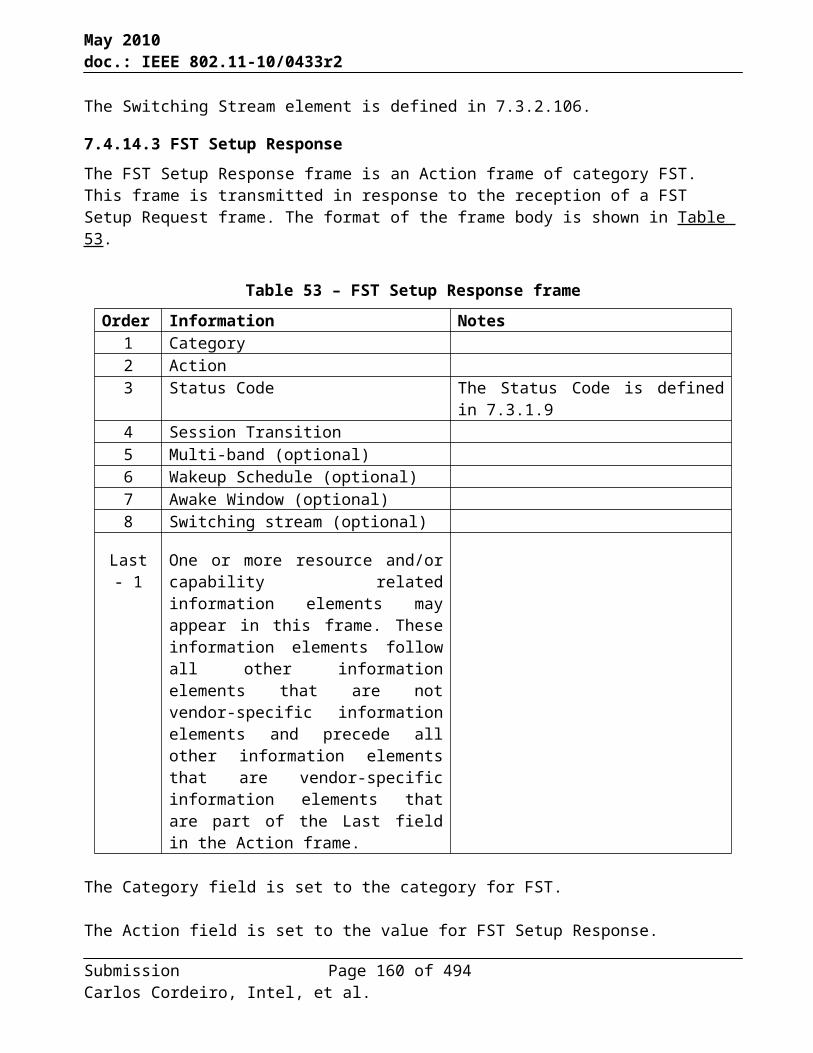
May 2010 doc.: IEEE 802.11-10/0433r2
A mmWave Protected Period can be created by the source STA during an SP. Both the source and destination STAs of an SP are owners of the mmWave Protected Period. During any mmWave Protected Period, both stations can receive frames from the other participant.
A mmWave Protected Period is established through an RTS/mmWaveCTS handshake. To create a mmWave Protected Period, the source STA of an SP sends an RTS and the recipient STA responds with a mmWaveCTS. If the recipient STA responds with a mmWaveCTS, then a mmWave Protected Period is established, otherwise, no mmWave Protected Period has been established. In all cases of mmWave Protected Period establishment, the same antenna configurations that are used by the STAs that establish the mmWave Protected Period are used for the exchange of frames during the mmWave Protected Period.
9.23.6.5.1 mmWave Protected Period establishment and maintenanceAn mSTA that attempts to create a mmWave Protected Period during an SP shall transition to listening mode not less than aMinListeningTime before the attempt and shall remain in listening mode for at least aMinListeningTime before making the attempt. If an attempt is made, the first attempt shall begin at the start of the SP.
A STA shall not issue an RTS to establish a mmWave Protected Period if any of its NAV timers is not equal to zero.
An mSTA that transmits an RTS to establish a mmWave Protected Period during an SP in which it is a source STA shall not transmit the RTS outside of the SP and the value of the Duration field of the RTS shall not exceed the duration of the portion of the SP that remains following the RTS transmission.
In order to accommodate STAs that have begun listening to the medium after the establishment of a mmWave Protected Period, a STA that transmitted an RTS that established a mmWave Protected period should transmit an additional RTS at the end of every consecutive (aMinListeningTime –aRTSTimeoutTime) during the mmWave Protected Period if the duration of the RTS/mmWaveCTS exchange is not less than the time remaining in the SP.
An mSTA that transmitted an RTS that established a mmWave Protected Period shall transmit data frames during the mmWave Protected Period using the same antenna configuration as was used for the transmission of the RTS. An mSTA should transition to listening mode not less than aMinListeningTime before the start of an SP in which it is the destination mSTA.
During an SP in which it is the destination mSTA, an mSTA that receives a valid RTS with the RA equal to the recipient mSTA MAC address and the TA corresponding to the source mSTA of the SP shall respond with a mmWaveCTS if the recipient mSTA has been in listening mode for aMinListeningTime at the start of the reception of the RTS and none of its NAV timers has a non-zero value.
During an SP in which it is the destination mSTA, an mSTA that receives a valid RTS with the RA equal to the recipient mSTA MAC address and the TA corresponding to the source mSTA of the SP
Submission Page 160 of 339 Carlos Cordeiro, Intel, et al.
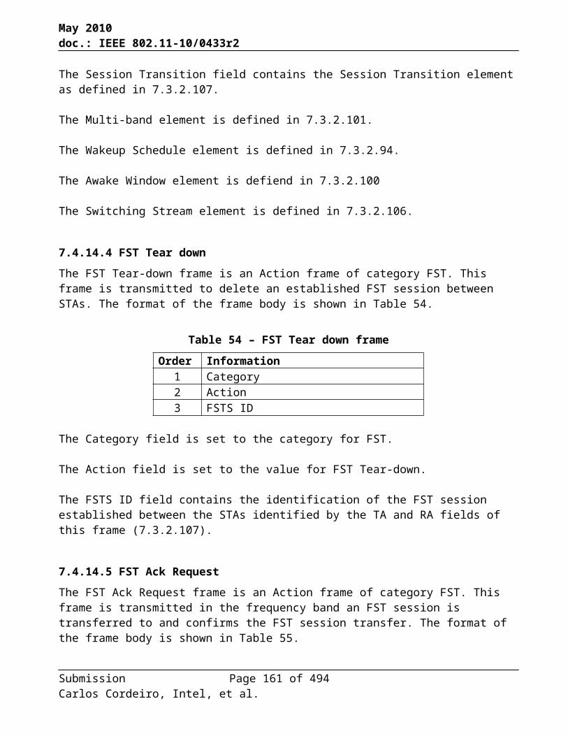
May 2010 doc.: IEEE 802.11-10/0433r2
shall not respond with a mmWaveCTS if at the start of the reception of the RTS the recipient mSTA has a non-zero value in at least one of its NAV timers or the recipient mSTA has not been in listening mode for at least aMinListeningTime.
An mSTA may transmit a mmWaveDTS after expiration of the aRTSTimeoutTime time following the start of an SP in which it is the Destination mSTA, if any of its NAV timers has a non-zero value at that time and no RTS has been received from the Source mSTA of the SP and the mSTA has been in Listening Mode for aMinListeningTime immediately preceding the start of transmission of the mmWaveDTS. The Destination mSTA shall not transmit a mmWaveDTS if any portion of the mmWaveDTS would be transmitted outside of the SP.
The value in the duration field of a mmWaveDTS shall be calculated by subtracting the mmWaveDTS transmission time from the NAV timer in the Destination STA that has the largest value at the time of the start of the transmission of the mmWaveDTS. The NAV-DA and NAV-SA fields shall be set to the MAC addresses that identify the NAV timer in the Destination STA that was used to determine the duration field value of the mmWaveDTS.
A Destination STA that responds to an RTS with a mmWaveCTS or mmWaveDTS shall transmit the response frame SIFS time after the end of the received RTS. A Destination STA that transmits either a mmWaveCTS or a mmWaveDTS shall use the same antenna configuration for the subsequent transmission of ACK frames and data frames within the SP as is used for the transmission of the mmWaveCTS or mmWaveDTS.
The source STA of an SP can send a mmWaveCF-End to the destination STA of the SP to truncate a mmWave Protected Period – see 9.23.8.
9.23.6.5.2 NAV Update in mmWave Protected PeriodSTAs in the listening mode shall update their NAV timers according to the procedures described in 9.23.10.
When an SP terminates, either through time allocation expiration or truncation, then the source STA of that SP may reset any NAV timer to zero which has an associated variable NAV_DTSCANCELABLE with a value of TRUE.
9.23.6.5.3 Interference report A STA that receives a RTS and/or mmWaveCTS frame which updates the NAV and that overlaps in time with an SP where the STA is destination or source, may report the overlap to the PCP/AP by sending an Extended mmWave ADDTS Request frame variant (7.4.2.2.2) and including in the Extended mmWave TSPEC element (7.3.2.97) the indication of interference in the TSCONST field (Figure 46). Transmission of the Extended mmWave ADDTS Request frame variant shall follow the rules defined in 11.4, with the following exceptions.
The TSID field of the Extended mmWave TSPEC element shall be set to the value of the TSID of the SP in which the interference was detected. One ADDTS Request frame is generated and transmitted for each SP in which interference is detected.
Submission Page 161 of 339 Carlos Cordeiro, Intel, et al.
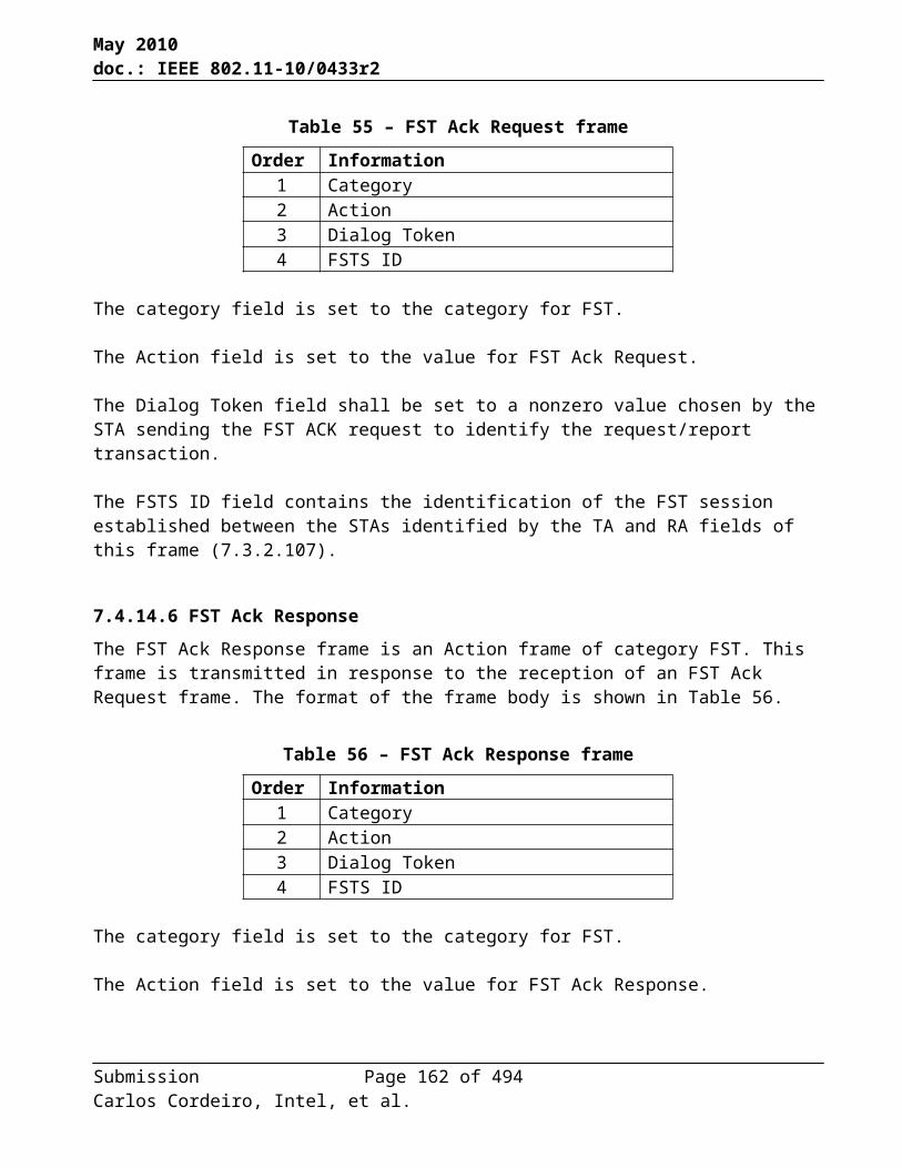
May 2010 doc.: IEEE 802.11-10/0433r2
The TSCONST field of the Extended mmWave TSPEC element may contain one or more TS scheduling constraint fields. Each TS scheduling constrain field provides information separately for each overlapping NAV event. The following NAV events should be reported:
a) non-zero NAV at start of SP b) extension of NAV during the SP, including extension of an initial non-zero NAV and
transitioning of the NAV from zero to non-zero value during the SPc) truncation of the NAV during the SP
The TSCONST Start Time field is set to the time at which the NAV timer value was captured for placement into the TSCONST Duration field. For event a) above, the TSCONST Start Time field shall be set to the start of the SP. For event b) above, the TSCONST Start Time field shall be set to the time the NAV timer was updated or initialized to the value reported in the TSCONST Duration field. For event c) above, the TSCONST Start Time field shall be set to the time the NAV timer was reset.
The TSCONST Duration field shall be set to the NAV timer value at the TSCONST Start Time, which is the value zero for event c).
The TSCONST Period shall be set to zero indicating that the field is not applicable.
The Interferer MAC Address shall be set to the NAVDST of the NAV timer from which the TSCONST Start Time was derived (9.23.10).
All values conveyed in the TSCONST field shall refer to the SP indicated in the TSID field of the TSPEC.
The value of other fields within the Extended mmWave TSPEC element shall conform to the rules specified in 11.4.
Use of the information conveyed in the TCONST field is implementation dependent and not specified in the spec.
9.23.6.6 Service period recoveryWhen a non-PCP/non-AP STA fails to receive the Extended schedule element for a BI, it has no knowledge of the non pseudo-static SPs allocated during the BI that indicate itself as source STA, and it will therefore fail to initiate transmission during those SPs. If the destination of the non pseudo-static SP is a PCP/AP and it does not receive any frames from the source non-PCP/non-AP STA for the dot11SPIdleTimeout interval from the start of the SP, the PCP/AP may truncate the SP and use the mechanism described in 9.23.7 to reallocate the remaining duration of the SP to the source STA of the SP or other STAs provided that it was a truncatable SP. If the SP is not a truncatable SP, the PCP may stay awake or may switch to Doze state. If the non-PCP/non-AP STA failed to receive the Extended schedule element from the PCP/AP for that BI, it may switch to Doze state or may tune its receive antenna towards the PCP/AP to receive a Grant during non pseudo-static SPs or CBPs in the current BI.
A PCP/AP may reclaim the entire time allocated in an SP between two non-PCP/non-AP STAs if the following two conditions are met.
The SP is announced within an Extended Schedule element transmitted during the AT period
Submission Page 162 of 339 Carlos Cordeiro, Intel, et al.
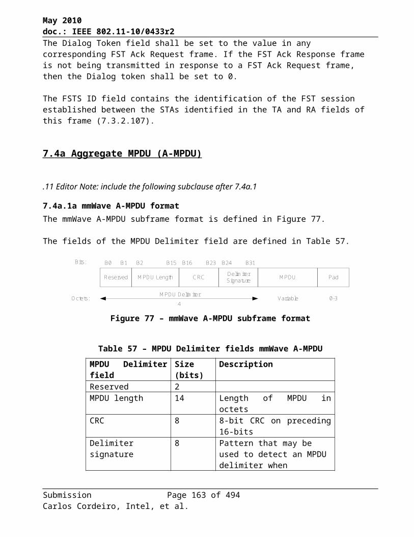
May 2010 doc.: IEEE 802.11-10/0433r2
The PCP/AP does not receive a response frame from either the source or destination non-PCP/non-AP STAs of that SP as part of the AT exchange (9.23.3).
In either case, the PCP/AP may reallocate the reclaimed SP time as a CBP, SP, or take no further actions.
9.23.7 Dynamic allocation of service period
Dynamic allocation of service period is employed to allocate channel time during scheduled SPs and CBPs. The procedure includes an optional Polling Period (PP) phase and a Grant Period (GP) phase.
The Dynamic Allocation of Service Period field in the STA Availability element (7.3.2.96) indicates whether a STA participates in Dynamic Allocation of Service Periods. A STA that participates in Dynamic Allocation of Service Periods responds to Poll frames during the PP. A STA that participates in Dynamic Allocation of Service Periods uses the time allocated through Grant frames during the GP to transmit frames. A STA may set the Dynamic Allocation of Service Period field in a transmitted STA Availability element to zero to indicate that it does not respond to Poll and Grant frames during the PP and the GP.
NOTE – A STA can receive a Grant frame in periods of the BI other than the GP, in which case the STA uses the time allocated through the Grant frame. An example is described in 9.25.4.
The PCP/AP shall not transmit Poll or Grant frames to a STA whose Dynamic allocation of service period field in the STA Availability element is set to zero. The PCP/AP shall not dynamically allocate a service period to a STA that is in a Doze BI. A PCP/AP may transmit Poll or Grant frames to a STA from which it has not received a STA Availability element with the Dynamic allocation of service period field from the STA set to zero.
If a PCP/AP wants to dynamically allocate Service Periods during a scheduled SP for which both the source and destination AID fields are set to the broadcast AID, the PCP/AP shall set the truncatable subfield to one within the Allocation field corresponding to the scheduled SP.
If a non-PCP/non-AP STA is neither source nor unicast destination during a truncatable SP and the non-PCP/non-AP STA participates in Dynamic Allocation of Service Periods and the non-PCP/non-AP STA is in an Awake BI, then it should be in the Awake state for the duration of the truncatable SP.
A non-PCP/non-AP STA that participates in Dynamic Allocation of Service Periods shall be in the Awake state for dot11MinPPDuration from the start of each truncatable SP for which both the source and the destination AID fields are set to the broadcast AID and that occurs within each Awake BI of that STA. Following the expiration of dot11MinPPDuration, the non-PCP/non-AP STA should remain in the Awake state until the end of the truncatable SP.
A STA shall be in the Awake state for dot11MinPPDuration from the start of each scheduled CBP that occurs within each Awake BI of that STA. A STA that enters the Doze state at any time during a CBP and then returns to the Awake state later during that same CBP shall not transmit except in response to a reception or when an explicit Grant frame is received which gives the STA permission to transmit during the CBP.
Submission Page 163 of 339 Carlos Cordeiro, Intel, et al.
May 2010 doc.: IEEE 802.11-10/0433r2
As described in , a STA that participates in Dynamic Allocation of Service Periods and that is neither source nor destination during a truncatable SP can be in receive state with its receive antennas configured in a quasi-omni antenna pattern for the duration of the truncatable SP.
A STA that receives a Grant frame with an SP allocation for which it is either source or destination shall not transmit longer than the time granted to it.
An example of dynamic allocation of service period is shown in Figure 85.
Figure 85 – Example of dynamic allocation of service period mechanism
9.23.7.1 Polling period (PP)
A PCP/AP that uses a PP to dynamically allocate an SP within the DTT shall commence the PP at a time instant indicated by at least one of the following:
anytime during a scheduled SP for which the source AID and destination AID are set to the broadcast AID, excluding any time that has been allocated dynamically
anytime during a TXOP within a scheduled CBP for which the source AID and destination AID are set to the broadcast AID, excluding any time that has been allocated dynamically
anytime during the relinquished channel time following an SP truncation, excluding any time that has been allocated dynamically.
The PCP/AP shall not transmit a frame during a PP if any portion of that frame would extend beyond the end of the originally scheduled SP or CBP.
During the PP, the PCP/AP may transmit unicast Poll frames to STAs to solicit SPR frames from those STAs. The Duration/ID field within each Poll frame shall be set to the duration of all remaining Poll frame transmissions if any, plus the duration of each SPR frame expected to be sent in response to each Poll frame transmission, plus all appropriate IFSs. The PCP/AP shall include a value in the
Submission Page 164 of 339 Carlos Cordeiro, Intel, et al.

May 2010 doc.: IEEE 802.11-10/0433r2
Response Offset field within each Poll frame that ensures that the SPR transmitted in response to the receipt of that Poll frame will be transmitted entirely within the originally scheduled SP or CBP.
A STA that receives a Poll frame shall respond to the PCP/AP with a single directional unicast SPR frame at the time offset from the end of the Poll frame indicated in the Response Offset field within the Poll frame. The Duration/ID field within the SPR frame shall be set to the value of the Duration/ID field contained in the received Poll frame, minus the value of the Response Offset field contained in the received Poll frame, minus SIFS.
The PP ends at a time equal to the end of the last Poll frame transmission plus the value of the Response Offset field in that Poll frame plus the expected duration of the SPR transmission that is expected in response to that Poll frame plus SIFS.
9.23.7.2 Grant period (GP)A PCP/AP that intends to dynamically allocate an SP within the DTT shall commence a GP at a time instant indicated by at least one of the following:
SIFS interval following the end of a PP if the PP is present anytime during a scheduled SP for which the source AID and destination AID are set to the
broadcast AID if a PP does not precede the GP, excluding any time that has been allocated dynamically
anytime during a TXOP within a scheduled CBP for which the source AID and destination AID are set to the broadcast AID, excluding any time that has been allocated dynamically
anytime during the relinquished channel time following an SP truncation if a PP does not precede the GP, excluding any time that has been allocated dynamically.
The PCP/AP shall not transmit a frame during a GP if any portion of that frame would extend beyond the end of the originally scheduled SP or CBP, or beyond the end of an immediately following SP if that SP has the broadcast AID as both source and destination AID, whichever is later.
A non-PCP/non-AP STA may switch to Doze state if it does not receive a Grant frame from the PCP/AP within dot11MinPPDuration from the start of the scheduled SP for which the source AID and destination AID are set to the broadcast AID.
To commence the GP, the PCP/AP shall transmit one or more Grant frames to notify the source and destination STAs about a dynamically allocated service period. In each transmitted Grant frame, the PCP/AP shall set the Duration/ID field within the Grant frame to a time that does not overlap in time with another SP which has either the source AID or destination AID different than the broadcast AID. In addition, the source AID and destination AID fields shall respectively be set to the source and destination of the dynamically allocated SP, the SPType field set to indicate SP or CBP, and the SP Duration field set to a value that is not greater than the result of the subtraction of the duration of all remaining Grant frame transmissions, if any, plus all appropriate IFSs from the value of the Duration/ID field. The SP info field within each Grant frame transmitted as part of the same GP shall be the same.
Submission Page 165 of 339 Carlos Cordeiro, Intel, et al.
May 2010 doc.: IEEE 802.11-10/0433r2
NOTE – Since the SP Info fields in all Grant frames are the same, the PCP/AP can allocate only one SP per GP.
A STA that receives a Grant frame shall not update its NAV if the value of either the source AID or destination AID fields in the Grant frame are equal to the STA’s AID.
The PCP/AP may grant a dynamic allocation of service period to a STA that does not transmit a SPR frame during the PP.
9.23.8 Dynamic truncation of service period
A STA truncates an SP to relinquish the remaining time in the current SP. The STA can use the mmWaveCF-End frame to truncate the SP at the peer STA, to reset NAV in third party STAs and to return to the AP/PCP the time left in the SP, thus allowing the AP/PCP to grant any portion of the relinquished time as part of an SP to any other STA or to allocate any portion of it as CBP. The STA can use the Grant frame to release any part of the time left in the SP as CBP.
If a STA is neither source nor destination during a truncatable SP and the STA’s Dynamic allocation of service period field is not set to zero (7.3.2.96), it should be in receive state with its receive antennas configured in a quasi-omni antenna pattern for the duration of the truncatable SP. If both the source and destination AID fields of a truncatable SP are set to the broadcast AID, except when transmitting a non-PCP/non-AP STA may direct its receive antenna to its PCP/AP for the duration of the truncatable SP that is not dynamically allocated to the non-PCP/non-AP STA.
Only the source STA of an SP may truncate the SP, except that the destination STA may truncate the SP if it does not receive an expected transmission from the source STA at the start of the SP as defined in 9.23.6.6 Service period recovery.
In order to advertise the availability of truncatable SP time for reuse through AP/PCP dynamic allocation, a non-PCP/non-AP STA shall transmit an mmWaveCF-End frame to the PCP/AP. A STA is not required to truncate an SP if a portion of the SP is unused.
In order to enable CBP access during the time released through SP truncation, the STA shall broadcast a Grant frame with the Source AID and Destination AID set to broadcast AID, the SPType field set to indicate CBP and the Duration/ID field set to the time needed to transmit the Grant frame(s) (the Duration/ID field in a Grant frame does not include duration of that frame) plus SIFS and plus the time needed to transmit the following mmWaveCF-End frame and the response mmWaveCF-End frame, if required and appropriate IFS values. The SP Duration field shall be set to a value that is not greater than the result of the subtraction of the value in the Duration/ID field from the time remaining in the SP. The CBP that is indicated in this manner begins at the time that is equal to the PHY-TXEND.indication of the Grant frame plus the value from the Duration/ID field of the Grant frame and continues for the time indicated in the SP Duration field of the Grant frame.
The STA shall not transmit the Grant frame and shall not transmit the mmWaveCF-End frame to the AP/PCP if the SP is not indicated as truncatable.
Submission Page 166 of 339 Carlos Cordeiro, Intel, et al.

May 2010 doc.: IEEE 802.11-10/0433r2
After transmission of the mmWaveCF-End frame to the AP/PCP or after broadcasting a Grant frame, the STA shall transmit a mmWaveCF-End frame to the peer STA of the SP. The mmWaveCF-End frame releases any time remaining in the SP at the recipient and resets the NAV in third party STAs. The NAV is reset only if the RA and TA of the mmWaveCF-End frame match the addresses of the frame that established the NAV (see 9.23.10). The recipient STA may transmit a mmWaveCF-End frame SIFS after the reception if the duration field of the received frame is not equal to zero and the transmission will not extend beyond the end of the originally scheduled SP.
A STA shall not initiate SP truncation if there is not enough time left in the SP to complete the frame exchange required for truncation of the SP.
After the truncation is completed, the PCP/AP may dynamically allocate any portion of the relinquished channel time that has not been allocated to a CBP through a transmitted Grant frame (9.23.7).
9.23.9 Dynamic extension of service period A non-PCP/non-AP STA uses dynamic extension of SP to extend the allocated time in the current SP. Dynamic extension of SP uses the SPR frame. The SPR frame is sent by a non-PCP/non-AP STA to the PCP/AP to request additional SP time in the current beacon interval. Dynamic extension of SP can be used to support variable bit rate traffic, for retransmissions and for other purposes.
Except in response to a Poll frame from the PCP/AP, a non-PCP/non-AP STA shall not transmit an SPR frame within an SP if the current SP is not extendable (see Extended Schedule element 7.3.2.95).
Only the source and destination STAs of an SP can transmit an SPR during that SP.
If the PCP/AP is not the source of an extendable SP, it should be in receive state and with its receive antennas configured in a quasi-omni antenna pattern for the duration of the extendable SP.
To request extension of the current SP, a non-PCP/non-AP STA shall transmit an SPR frame to the PCP/AP. The non-PCP/non-AP STA shall not request extension of the current SP if there is not enough time left in the SP to complete the frame exchange required for the SP extension. In the transmitted SPR frame, the STA shall set the RA field to the address of the PCP/AP, the Duration/ID field to the time left in the SP (not including the SPR transmission time), and the SP Duration field to the additional amount of time requested by the STA following the end of the current SP.
The PCP/AP shall only grant the request for an extension of an SP if the following SP has the broadcast AID as both source and destination AID, and the duration of the following SP is larger than the value of the SP Duration field in the received SPR frame. To grant an extension request, the AP/PCP shall transmit a Grant frame with the RA field set to the value of the TA in the received SPR frame, the Duration/ID field set to the value of the Duration/ID field received in the SPR frame minus SIFS minus the duration of this Grant frame transmission, and the SP Duration field to the amount of additional time granted by the PCP/AP.
To decline a request for an extension of an SP, the PCP/AP shall transmit a Grant frame with the RA field set to the value of the TA in the received SPR frame, the Duration/ID field set to the value of the
Submission Page 167 of 339 Carlos Cordeiro, Intel, et al.

May 2010 doc.: IEEE 802.11-10/0433r2
Duration/ID field received in the SPR frame minus SIFS minus the duration of this Grant frame transmission, and the SP Duration field set to zero.
The non-PCP/non-AP STA considers that its extension request was successful if it receives from the PCP/AP a Grant frame with a non-zero value for the SP Duration field SIFS after the SPR. SIFS after the reception of a Grant frame from the PCP/AP with a non-zero value for the SP Duration field, the non-PCP/non-AP STA shall transmit a Grant frame to the partner STA of the SP with the Duration/ID field set to the value of the Duration/ID field of the Grant frame received from the PCP/AP minus the duration of this Grant frame transmission minus SIFS, and the SP Duration field set to the value of the SP Duration field of the Grant frame received from the PCP/AP.
The PCP/AP shall not transmit an SPR frame if it wants to extend an SP in which it is the source. A PCP/AP that extends an SP for which it is the source STA shall transmit a Grant frame to the destination STA of the SP to indicate the extension of the SP. The Duration/ID field in the transmitted Grant frame shall be set to the remaining time in the SP plus any additional channel time allocated by the PCP/AP following the end of the SP. The SP Duration field of the Grant frame shall be set to the additional channel time allocated by the PCP/AP following the end of the SP.
9.23.10 NAV update There are multiple NAV timers in each STA. The number of available NAV timers within any STA shall be not less than aMinNAVTimersNumber. Each NAV timer is identified by a pair of MAC addresses, NAVSRC and NAVDST and has associated variables NAV_RTSCANCELABLE and NAV_DTSCANCELABLE. Each STA also maintains a variable UPDATE_OPTIONAL. When a STA is enabled for operation, all NAV timers shall have NULL values for their NAVSRC and NAVDST identifiers, the value of NAV_RTSCANCELABLE shall be FALSE, the value of NAV_DTSCANCELABLE shall be FALSE and each NAV timer shall have the value Zero. NAV timer address pairs correspond to the NAV-SA and NAV-DA fields in mmWaveDTS frames and correspond to the RA and TA fields of all other received frames which are used to update the NAV timers. Receipt of any frame can cause an update to the NAV timer whose identifying address pair corresponds to the specified address fields of the received frame according to the rules in this subclause.
STAs receiving any valid frame shall perform the following NAV Timer update operation expressed using pseudocode:
NAV_TIMER_UPDATE(received_frame):
UPDATE_OPTIONAL FALSE
If (received_frame(RA) = STA MAC address&& received_frame = mmWaveDTS&& received_frame(TA) = destination STA MAC address for current SP&& STA MAC address = source STA MAC address for current SP) {
UPDATE_OPTIONAL TRUE}
If (received_frame(RA) STA MAC address || UPDATE_OPTIONAL = TRUE) {
Submission Page 168 of 339 Carlos Cordeiro, Intel, et al.
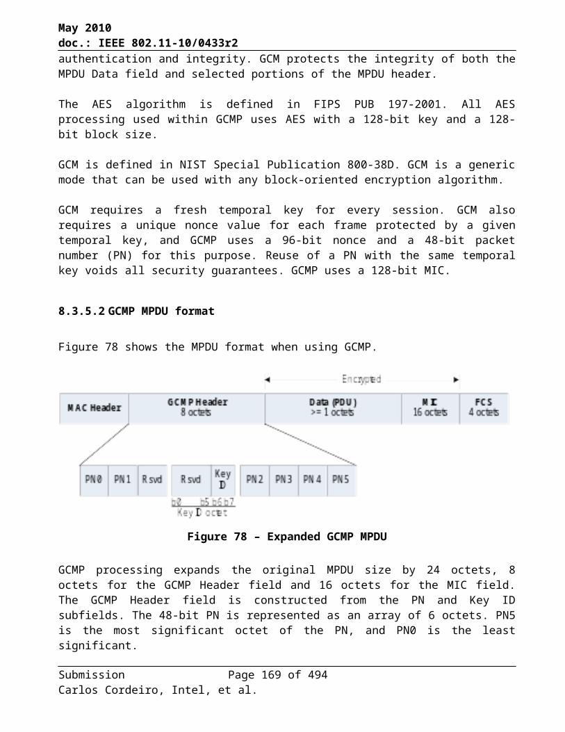
May 2010 doc.: IEEE 802.11-10/0433r2
If (received_frame = mmWaveDTS) {R_DST received_frame(NAV-DA)R_SRC received_frame(NAV-SA)
} else if (received_frame = ACK) {R_DST received_frame(RA)R_SRC 0
} else if (received_frame = mmWaveCTS-To-Self){R_DST 0R_SRC received_frame(TA)
} else {R_DST received_frame(RA)R_SRC received_frame(TA)
}
R_DUR received_frame(DUR)
N_TIMER -1
For (x 0; x < aMinNAVTimersNumber; x++) {If (received_frame = ACK) {
If(NAVDST(x) = R_DST) {N_TIMER xBreak
}} else if (received_frame = mmWaveCTS-To-Self) {
If(NAVSRC(x) = R_SRC) {N_TIMER xBreak
}} else if (NAVSRC(x) = R_SRC && (NAVDST(x) = R_DST || NAVDST(x) = 0)) {
N_TIMER xBreak
}}
If (N_TIMER < 0) {For (x 0; x < aMinNAVTimersNumber; x++) {
If (NAVSRC(x) = NULL && NAVDST(x) = NULL|| NAV(x) = 0) {NAVSRC(x) R_SRCNAVDST(x) R_DSTN_TIMER xBreak
} }
}
Submission Page 169 of 339 Carlos Cordeiro, Intel, et al.
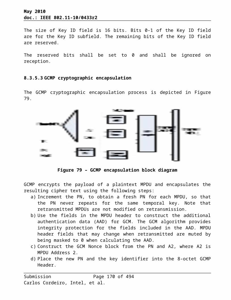
May 2010 doc.: IEEE 802.11-10/0433r2
If (N_TIMER 0) {If (UPDATE_OPTIONAL = FALSE
&& R_DUR > NAV(N_TIMER) ) {NAV(N_TIMER) R_DURIf (received_frame = RTS) {
NAV_RTSCANCELABLE(N_TIMER) TRUE} else {
NAV_RTSCANCELABLE(N_TIMER) FALSE}
} else if (UPDATE_OPTIONAL = TRUE&& R_DUR > NAV(N_TIMER) ) {
If (implementation decision to update = TRUE) {NAV_DTSCANCELABLE(N_TIMER) TRUENAV(N_TIMER) R_DUR
}}
}
} else {No change to NAV timers
}
END OF NAV_TIMER_UPDATE
During a time period beginning with the completion of each NAV Timer update operation and lasting for mmWaveCTS +2SIFS, each STA shall monitor the channel to determine if a preamble or carrier detect event has occurred. If such an event has not occurred during this time period, then the STA may reset to ZERO any NAV Timer that has a value of TRUE for its associated NAV_RTSCANCELABLE variable.
Subsequent to the NAV Timer update operation, each NAV timer counts down until it reaches the value zero or until it reaches zero through a reset operation.
If a STA receives a valid mmWaveCF-End response with RA and TA values that match the NAVSRC and NAVDST values, respectively, for any NAV Timer, then the STA shall set the associated NAV Timer to the value of the duration field in the received mmWaveCF-End frame.
9.24 PCP/AP Clustering
A PCP/AP may use the PCP/AP clustering mechanism described in this subclause to improve spatial frequency sharing and interference mitigation with other co-channel BSSs.
PCP/AP clustering allows a PCP/AP that is a member of a cluster to schedule transmissions in non-overlapping time periods with respect to other members of the same cluster, since the PCP/AP can receive mmWave Beacon and Announce frames containing the Extended Schedule element of other cluster members.
Submission Page 170 of 339 Carlos Cordeiro, Intel, et al.

May 2010 doc.: IEEE 802.11-10/0433r2
The PCP/AP employs the PCP/AP Clustering Control field defined in 7.2.4.1 to configure the use of PCP/AP Clustering in a BSS. A PCP/AP that transmits the Clustering Control field is clustering enabled. A PCP/AP that does not transmit the Clustering Control field is clustering disabled.
Clustering enabled PCP/APs operating on the same channel may form a PCP/AP cluster. A PCP/AP cluster includes one Synchronization PCP/AP (S-PCP/S-AP) and zero or more member PCP/APs. The MAC address of the S-PCP/S-AP shall be the ClusterID of the PCP/AP cluster.
A clustering enabled PCP/AP that is not a member of any cluster shall set the ClusterMemRole to zero in transmitted frames that contain the PCP/AP Clustering Control field.
Each PCP/AP that is a member of a PCP/AP cluster shall include the PCP/AP Clustering Control field in each mmWave Beacon it transmits.
For each cluster, there exists a set of ClusterMaxMem Beacon SPs. The nth Beacon SP, Beacon SPn, begins at ClusterTimeOffsetn usec following the end of each BT of the S-PCP/S-AP, where:
ClusterTimeOffsetn = ClusterTimeInterv*n
and (n=1, 2… ClusterMaxMem-1)
The ClusterTimeOffsetn and Beacon SPn where n equals zero is reserved for the S-PCP/S-AP.
A PCP/AP that is a member of a PCP/AP cluster shall transmit its mmWave Beacon frame during one of the Beacon SPs as specified in 9.24.1.
9.24.1 Cluster formationA clustering enabled PCP/AP starts a cluster by becoming an S-PCP/S-AP. A clustering enabled PCP/AP becomes an S-PCP/S-AP by transmitting a mmWave Beacon at least once every aMinBTPeriod beacon intervals that includes a PCP/AP Clustering Control field with ClusterID set to its MAC address, ClusterMemRole set to the value for an S-PCP/S-AP, ClusterMaxMem set to the value of dot11ClusterMaxMem and ClusterTimeInterv set to the value of dot11ClusterTimeInterv. The duration ((dot11ClusterMaxMem-1) * dot11ClusterTimeInterv) shall not exceed dot11BeaconPeriod of the PCP/AP. A clustering enabled PCP/AP that receives a mmWave Beacon from an S-PCP/S-AP on the channel it selects to establish a BSS shall monitor the channel for mmWave Beacon transmissions during each Beacon SP for an interval of length at least aMinChannelScan. Beacon SPn is empty if no mmWave Beacon frame is received during Beacon SPn over an interval of length aMinChannelScan. The PCP/AP shall not become a member of the cluster if no Beacon SP is determined to be empty during aMinChannelScan, in which case, the PCP/AP may become the S-PCP/S-AP of a new cluster, or may cease its activity on this channel and, if desired, attempt operation on a different channel.
A clustering enabled PCP/AP that operates its BSS on a channel on which it discovered an S-PCP/S-AP and at least one empty Beacon SP, shall transmit its mmWave Beacon during an empty Beacon SP.
Submission Page 171 of 339 Carlos Cordeiro, Intel, et al.

May 2010 doc.: IEEE 802.11-10/0433r2
By transmitting its mmWave Beacon during an empty Beacon SP, the PCP/AP becomes a member PCP/AP.
The member PCP/AP shall select a BI length that is an integer multiple of the BI length of its S-PCP/S-AP.
The member PCP/AP shall transmit its mmWave Beacon with ClusterID set to the MAC address of the S-PCP/S-AP, ClusterMemRole set to the member PCP/AP value, ClusterMaxMem set to the value of the ClusterMaxMem field contained in the S-PCP/S-AP mmWave Beacon and ClusterTimeInterv set to the value of the ClusterTimeInterv field contained in the S-PCP/S-AP mmWave Beacon.
A PCP/AP with a value of ClusterMemRole that is not zero shall schedule a Beacon SP that is allocated for mmWave Beacon transmission of other cluster member PCP/AP at each of ClusterTimeOffsetn, at any time the PCP/AP transmits its own mmWave Beacon. The minimum size of the Beacon SP shall be equal to the maximum mmWave Beacon transmission time.
Figure 86 illustrates, for three PCP/APs, the Beacon SPs of the S-PCP/S-AP and member PCP/APs of a PCP/AP cluster.
Figure 86 – PCP/AP clustering for 3 PCPs/APs
9.24.2 Cluster maintenance
The end of the BT of the S-PCP/S-AP provides a timing reference for the Beacon SPs of the member PCP/APs. Timing synchronization among the member PCP/APs facilitates equitable sharing of the common medium among the member PCP/APs. As long as a member PCP/AP periodically receives mmWave Beacons from the S-PCP/S-AP, the member PCP/AP is able to maintain synchronization with the S-PCP/S-AP and hence, the other member PCP/APs. In the case when the S-PCP/S-AP of a cluster is lost, or appears to a member PCP/AP to have been lost, another PCP/AP needs to become the S-PCP/S-AP in order to allow the remaining member PCP/APs to maintain synchronization with the cluster. The creation of a new S-PCP/S-AP is called S-PCP/S-AP handover. After an S-PCP/S-AP handover, the cluster might continue to function as before, except with altered membership, or the cluster might no longer exist, or there might be one or more new clusters.
A member PCP/AP shall start an S-PCP/S-AP handover if, within a time period of 4*aMinBTPeriod beacon intervals, it does not receive a mmWave Beacon with the value of the ClusterID field equal to the ClusterID of the cluster of which the PCP/AP is a member and with the ClusterMemRole field set to the S-PCP/S-AP value. This is the called the first Cluster Monitoring Period. During the next step in
Submission Page 172 of 339 Carlos Cordeiro, Intel, et al.
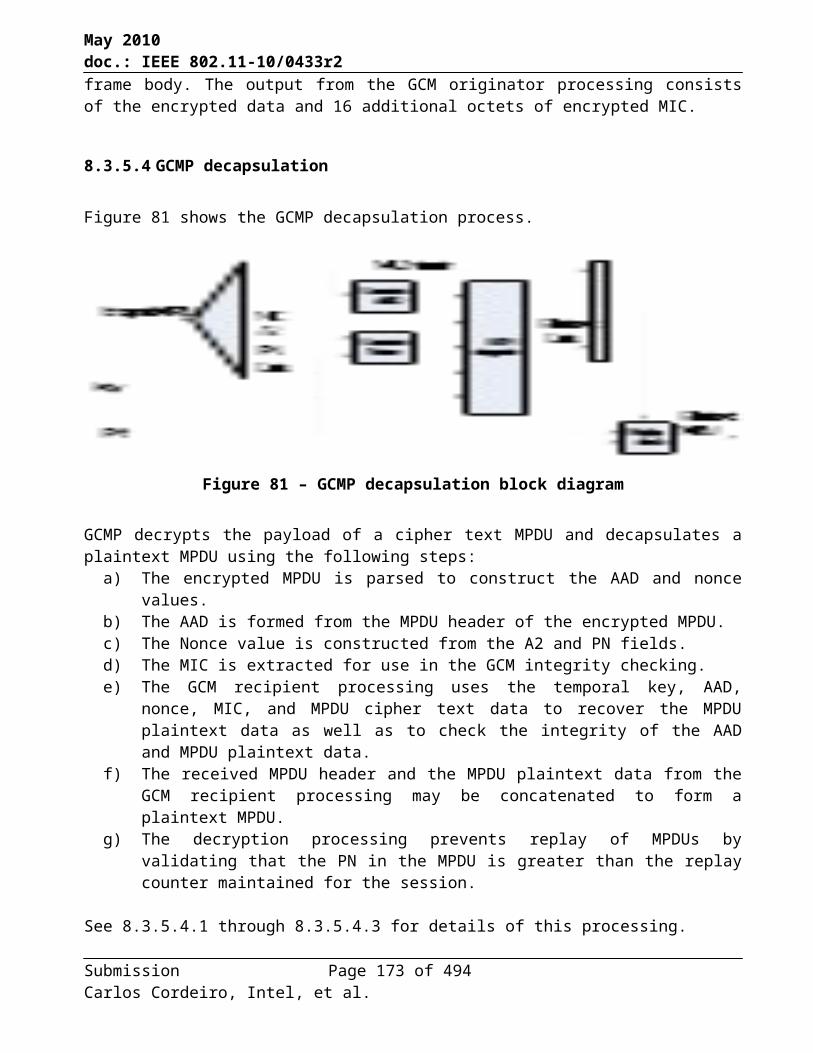
May 2010 doc.: IEEE 802.11-10/0433r2
the S-PCP/S-AP handover, called the Second Cluster Monitoring Period, the member PCP/AP performs a Cluster Monitoring Period. A Third Cluster Monitoring Period, during which the member PCP/AP performs a Cluster Monitoring Period, may also be needed. A Cluster Monitoring Period is a time period of 4*aMinBTPeriod beacon intervals during which the PCP/AP listens for mmWave Beacons while continuing to transmit mmWave Beacons using its current Beacon SPn.
NOTE – A clustering enabled PCP/AP does not cease mmWave Beacon transmission during Cluster Monitoring and S-PCP/S-AP handover. Hence, data communication is unaffected while performing these procedures.
If, during a Cluster Monitoring Period, the member PCP/AP receives a mmWave Beacon with the value of ClusterMemRole set to the S-PCP/S-AP value, the member PCP/AP shall follow the rules in 9.24.1 to become a member PCP/AP of the cluster corresponding to the detected S-PCP/S-AP and the Cluster Monitoring Period is terminated.
If, during a Cluster Monitoring Period, the PCP/AP receives no mmWave Beacons with the value of ClusterMemRole set to the S-PCP/S-AP value and one or more mmWave Beacons with ClusterID equal to the ClusterID of its last S-PCP/S-AP, then at the end of the Cluster Monitoring Period the PCP/AP compares the MAC addresses of all such received mmWave Beacons with its own MAC address. If its MAC address is the lowest, the PCP/AP shall become an S-PCP/S-AP according to the rules in 9.24.1. If its MAC address is not the lowest, the PCP/AP shall perform a new Cluster Monitoring Period. If the number of Cluster Monitoring Period performed by the PCP/AP exceeds dot11MaxNumberOfClusteringMonitoringPeriods, the PCP/AP may cease cluster maintenance and initiate cluster formation as described in 9.24.1.
If, during a Cluster Monitoring Period, the PCP/AP does not receive a mmWave Beacon that contains the value of S-PCP/S-AP in the ClusterMemRole field and does not receive a mmWave Beacon with ClusterID equal to the ClusterID of the cluster of which it is currently a member, then at the end of the Cluster Monitoring Period the PCP/AP may become an S-PCP/S-AP according to the rules of 9.24.1, or it may cease its activity on this channel and, if desired, attempt operation on a different channel.
NOTE – An assumption to allow the establishment of an S-PCP/S-AP in this case is that the PCPs/APs cannot hear each other’s mmWave Beacons. The rule how to decide to switch the channel or to establish an S-PCP/S-AP is implementation dependent.
If, during a Cluster Monitoring Period, the member PCP/AP receives no mmWave Beacons from clustering enabled STAs, then the PCP/AP shall establish it self as an S-PCP/S-AP according to the rules in 9.24.1.
If an S-PCP/S-AP detects the presence of another S-PCP/S-AP on the same channel, it should schedule a Beacon SP for the mmWave Beacon transmission of the other S-PCP/S-AP if the MAC address of the other S-PCP/S-AP is lower than the MAC address of this S-PCP/S-AP. The S-PCP/S-AP with higher MAC address should become a member PCP/AP of the cluster corresponding to the S-PCP/S-AP with the lower MAC address according to the rules in 9.24.1.
9.24.3 Cluster report and re-schedulingA cluster enabled PCP/AP that receives an Extended Schedule element from another cluster enabled PCP/AP may re-schedule SPs and CBPs in its BI, or move the BT, in an attempt to mitigate any interference with the transmissions indicated in the received Extended Schedule element. The PCP/AP
Submission Page 173 of 339 Carlos Cordeiro, Intel, et al.

May 2010 doc.: IEEE 802.11-10/0433r2
may also create SPs in its BI with the source and destination AID set to 255 to prevent transmissions during specific periods in the BI.
A non-PCP/non-AP STA that is a member of a BSS and that receives a mmWave Beacon should send a Cluster Report element to its PCP/AP if the received mmWave Beacon frame meets all of the following conditions:
The mmWave Beacon is not from the STA’s PCP/AP The mmWave Beacon contains the PCP/AP Clustering Control field The value of the Cluster ID field within the PCP/AP Clustering Control field is different than
the MAC address of the STA’s PCP/AP
A Cluster Report element meeting the conditions above shall be transmitted in an Announce or Information Response frame sent to the STA’s PCP/AP. Within the transmitted Cluster Report element, the STA shall set the Cluster report subfield to one. The STA shall set the PCP/AP Clustering Control field within a transmitted Cluster Report element to the corresponding field values within the PCP/AP Clustering Control of the received mmWave Beacon, and shall set the Reference timestamp field to indicate the mmWave Beacon reception time. The STA shall set the Schedule present subfield to one if the Extended Schedule field is present in the transmitted Cluster Report element, otherwise it shall set Schedule present subfield to zero. The STA shall set the TSCONST present subfield to one if the TSCONST field is present in the transmitted Cluster Report element, otherwise it shall set TSCONST subfield to zero. If present, the Extended Schedule Element field within the Cluster Report element shall be set to the corresponding field values within the Extended Schedule element of the received mmWave Beacon. If present, the TSCONST field shall be set to indicate periods of time with respect to the TBTT of the BI of the BSS the STA participates where the transmitting STA experiences poor channel conditions, such as due to interference.
Upon receiving a Cluster Report element from a non-PCP/non-AP STA with the Cluster report field set to one, a clustering enabled PCP/AP may re-schedule SPs and CBPs in its BI, or move the BT, or perform other actions, in an attempt to mitigate any interference with the transmissions indicated in the received Cluster Report element. The cluster enabled PCP/AP may also create SPs in its BI with the source and destination AID set to 255 to prevent transmissions during specific periods in the BI.
9.24.4 Cluster request
A non-PCP/non-AP STA that is a member of a BSS may transmit a Cluster Report element to its PCP/AP to request that PCP/AP clustering be enabled in the BSS. The non-PCP/non-AP STA can make this request if, for example, the non-PCP/non-AP STA intends to initialize another co-channel BSS (11.1) in which it will perform the role of PCP/AP and, when performing this role, it wishes to become a member PCP/AP of the cluster enabled by its current PCP/AP.
To request PCP/AP clustering to be enabled in the BSS, the STA shall transmit a Cluster Report element with the Cluster request subfield set to one to its PCP/AP. Upon receiving a Cluster Report element with the Cluster request subfield set to one, the PCP/AP should form and maintain PCP/AP clustering in the BSS according to the procedures described in 9.24.1 and 9.24.2. In doing that, the PCP/AP should set the minimum duration of the Beacon SP to be equal to dot11MinBIHeaderDuration.
Submission Page 174 of 339 Carlos Cordeiro, Intel, et al.
May 2010 doc.: IEEE 802.11-10/0433r2
If the non-PCP/non-AP does not receive a mmWave Beacon frame from its PCP/AP with PCP/AP clustering enabled after dot11ClusterEnableTime following the transmission to its PCP/AP of a Cluster Report element with the Cluster request subfield set to one, the non-PCP/non-AP STA should not retransmit a Cluster Report element to its PCP/AP to request that PCP/AP clustering be enabled in the BSS.
If a non-PCP/non-AP STA becomes a member PCP/AP of the cluster enabled by its current PCP/AP, the non-PCP/non-AP STA can synchronize scheduled CBP allocations, if any, between the BSS in which it performs the role of PCP/AP and the BSS of its current PCP/AP. The non-PCP/non-AP STA can disallow STAs in the BSS in which it plays the role of PCP/AP from transmitting during the Beacon SPs of the cluster it is a part of, and this can be done by allocating an SP time-overlapping with each Beacon SP such that each allocated SP has both the source AID and destination AID fields within the Extended Schedule element set to the AID of the non-PCP/non-AP STA.
9.25 mmWave Beamforming
Beamforming (BF) is the process that is used by a pair of STAs to achieve the necessary mmWave link budget for subsequent communication. BF is established following the successful completion of BF training. BF training is a bidirectional sequence of BF training frame transmissions that provide the necessary signaling to allow each STA to determine appropriate antenna system settings for both transmission and reception. A BF training frame is an SS frame, a mmWave Beacon frame or a BRP frame. Figure 87 gives an example of the beamforming training procedure.
Figure 87 – An example of beamforming training
In this subclause, the STA that initiates BF training through the transmission of a BF frame is referred to as the initiator, and the recipient STA of the BF frame that continues BF training with the initiator is referred to as the responder. For BF training that occurs within the A-BFT allocation, the PCP/AP is the initiator and a non-PCP/non-AP STA becomes the responder. For BF training that occurs during an SP allocation, the source STA of the SP is the initiator and the destination STA of the SP becomes the
Submission Page 175 of 339 Carlos Cordeiro, Intel, et al.

May 2010 doc.: IEEE 802.11-10/0433r2
responder. For BF training during a TXOP allocation, the TXOP holder is the initiator and the TXOP responder is the responder.
The link from the initiator to the responder is referred to as the initiator link and the link from the responder to the initiator is referred to as the responder link.
BF training starts with a sector level sweep (SLS) from the initiator. A beam refinement procedure (BRP) may follow, if requested by either the initiator or the responder. The purpose of SLS phase is to enable communications between the two participating STAs at least at the control PHY rate. Normally, the SLS phase provides only transmit BF training. If one (and only one) of the participating STAs chooses to use only one transmit antenna pattern, receive training may be performed as part of the SLS. The purpose of the BRP phase is to enable receiver training and enable iterative refinement of the AWV of both transmitter and receiver at both participating STAs.
Any BF information obtained by an initiator or a responder during a BF training attempt shall be considered invalid if either or both of the following conditions are satisfied:
a) The SLS phase was not completed within dot11MaxBFTime BIs from the start of the SLS phase.
b) The BRP phase, if initiated, was not completed within dot11MaxBFTime BIs from the start of the BRP phase.
A STA shall abort an SLS if the SLS is not completed within dot11MaxBFTime BIs from the start of the SLS, and shall abort a BRP if the BRP is not completed within dot11MaxBFTime BIs from the start of the BRP.
A STA shall not initiate the BRP phase with a responder STA unless the initiator and responder have successfully completed the SLS phase.
9.25.1 Sector Level Sweep PhaseThe SLS phase can include as many as four components: an initiator sector sweep (ISS) to train the initiator link as described in 9.25.1.1, a responder sector sweep (RSS) to train the responder link as described in 9.25.1.2, an SS Feedback as described in 9.25.1.3, and an SS ACK as described in 9.25.1.4.
An initiator shall begin the SLS phase with an ISS.
A responder shall not begin an RSS before the ISS is successfully completed, except when the ISS occurs in the BT (9.25.4).
An initiator shall not begin an SS Feedback before the RSS phase is successfully completed, except when the RSS occurs in the A-BFT.
A responder shall not begin an SS ACK to an initiator before the SS Feedback is successfully completed and in the A-BFT.
Submission Page 176 of 339 Carlos Cordeiro, Intel, et al.
May 2010 doc.: IEEE 802.11-10/0433r2
The BF frames which an initiator is allowed to transmit during the SLS phase are the mmWave Beacon frame, the SS frame, and the SS-Feedback frame. The BF frames which a responder is allowed to transmit during the SLS phase are the SS frame and the SS-ACK frame.
At the end of the SLS phase, both the initiator and the responder will know their own best transmit sector. If either the ISS or the RSS employs a receive sector sweep, then the responder or the initiator respectively, will know its own best receive sector. The following rule applies to all channel access in the UB. A STA shall not transmit a unicast frame as part of an ISS and RSS comprised of at least two sectors if a response frame to the unicast frame is expected within SIFS interval from the reception of the unicast frame from the STA identified in the RA field of the unicast frame.
Two examples of the SLS phases are shown in Figure 88 and Figure 89.
Figure 88 – An example of sector level sweep
In Figure 88 the initiator has many sectors, the responder has only one transmit sector and receive sector sweep is used at the responder sector sweep (the responder is transmitting all responder SS frames through the same transmit sector, the initiator is switching receive antennas at the same time).
Submission Page 177 of 339 Carlos Cordeiro, Intel, et al.
May 2010 doc.: IEEE 802.11-10/0433r2
Figure 89 – An example of sector level sweep
In Figure 89 the initiator has many transmit sectors, the responder has one transmit sector. In this case, receive training for the initiator is performed in the BRP phase.
9.25.1.1 Initiator Sector Sweep
An ISS comprises either an initiator TXSS or an initiator RXSS.
An initiator RXSS may be performed in an ISS when the initiator chooses to use only one transmit pattern in the trained antenna.
If the initiator T/RXSS subfield in the BF Control field within a frame transmitted to setup an ISS is set to zero, the responder T/RXSS field shall be set to one.
An initiator may employ either mmWave Beacon frames or SS frames in the ISS. If the initiator begins an ISS with the transmission of a mmWave Beacon frame, it shall use the mmWave Beacon frame for all subsequent transmissions during the ISS. Conversely, if the initiator begins an ISS with the transmission of an SS frame, it shall use the SS frame for all subsequent transmissions during the ISS. A responder never begins an ISS.
The Duration/ID field within each transmitted mmWave Beacon frame is set to the time remaining until the end of the current BT (see 9.25.3). The Duration/ID field of each transmitted SS frame shall be set to the time remaining until the end of the ISS or the end of the current allocation, whichever is earliest.
Submission Page 178 of 339 Carlos Cordeiro, Intel, et al.

May 2010 doc.: IEEE 802.11-10/0433r2
9.25.1.1.1 Initiator TXSSWhen the initiator T/RXSS field for a specific SP is set to one in a received Extended Schedule element (7.3.2.95) or Grant frame (see 7.2.1.12), and the Beamforming Training field of the BF Control field for that SP in the same Extended Schedule element or Grant frame is set to one, then the SP contains an initiator TXSS and the initiator shall start an initiator TXSS at the start of the next SP as described by the received Extended Schedule element or Grant frame. During the BT, the initiator shall always start an initiator TXSS (see also 9.25.3). During a CBP, an initiator may obtain a TXOP with an initiator TXSS if an ISS is required to obtain the TXOP.
The initiator starts an initiator TXSS with the transmission of a mmWave Beacon frame or an SS frame. The initiator shall not transmit a frame other than a mmWave Beacon or an SS frame during an initiator TXSS.
During an initiator TXSS, each BF frame shall have the Direction field set to zero. The Sector ID field in each BF frame shall be set to a value that uniquely identifies the transmit antenna sector (or AWV setting) employed when the BF frame is transmitted. The CDOWN field in each transmitted frame shall contain the total number of transmissions remaining until the end of the initiator TXSS, such that the last BF frame transmission of the initiator TXSS has the CDOWN field set to zero. Each transmitted BF frame shall be separated by a time interval equal to SBIFS, unless the allocation ends as described in 9.25.5. This is indicated in Figure 90.
Figure 90 – Initiator TXSS or Initiator RXSS
If the initiator has more than one antenna, the initiator transmits the BF frame through a number of sectors equal to the value of the Total number of Sectors field. In each transmitted BF frame the initiator shall set the sector ID and antenna ID fields to indicate the sector ID and the antenna ID it is using for the transmission, and shall set the CDOWN field to the total number of transmissions remaining from all of the initiator’s antennas.
If the responder has more than one antenna, the initiator repeats its initiator sector sweep for the number of antennas indicated by the responder in the Number of Antennas field within the responder’s mmWave Capabilities element. In this case CDOWN indicates the number of sectors until the end of transmission from all initiator’s antennas to all responder’s antennas. At the start of an initiator TXSS, the responder should have its receive antenna array configured to a quasi omni pattern in one of its antennas and should not change its receive antenna array configuration for a time corresponding to the value of the Total number of sectors field within the initiator’s mmWave Capabilities element multiplied by the time to transmit a single SS frame, plus appropriate IFSs. After this time, the responder may switch to a quasi omni pattern in another antenna.
Submission Page 179 of 339 Carlos Cordeiro, Intel, et al.

May 2010 doc.: IEEE 802.11-10/0433r2
If unable to receive the last frame in the initiator TXSS, the responder shall assume that the initiator TXSS has completed at the expected or actual, whichever comes first, end time of the SS frame from the initiator with the CDOWN field equal to zero.
9.25.1.1.2 Initiator RXSSAn initiator RXSS shall only be requested when an initiator is aware of the capabilities of a responder, which includes the RXSS Length field. An initiator can obtain the capabilities of a responder using the Information request and Information response procedure as described in 11.31.1. When the initiator T/RXSS field for a specific SP in a received Extended Schedule element or Grant frame is set to zero and the Beamforming Training field of the BF Control field for that SP in the same Extended Schedule element or Grant frame is set to one, then the SP shall contain an initiator RXSS and the initiator shall start an initiator RXSS at the start of the next SP described by the received Extended Schedule element or Grant frame. The initiator never performs an initiator RXSS during the BT. During a CBP, an initiator shall not obtain a TXOP with an initiator RXSS if an ISS is required to obtain the TXOP.
During the initiator RXSS, the initiator shall transmit the number of BF frames indicated by the responder in the RXSS Length field from each of its antennas. Each transmitted BF frame shall have the Direction field set to zero and shall be transmitted with the same fixed antenna sector or pattern. The initiator shall set the Sector ID and Antenna ID fields in each transmitted BF frame to a value that uniquely identifies the single sector through which the BF frame is transmitted. The initiator shall set the CDOWN field in each transmitted BF frame to contain the total number of transmissions remaining to the end of the initiator RXSS, such that the last BF frame transmission of the initiator RXSS has the CDOWN field set to zero. Each transmitted BF frame shall be separated by a time interval equal to SBIFS, except if the allocation ends as described in 9.25.5. This is indicated in Figure90.
During an initiator RXSS, the responder should have its receive antenna array configured to sweep RXSS Length sectors for each of the initiator’s antennas while attempting to receive SS frames from the initiator.
While attempting to receive SS frames from the initiator RXSS, the responder shall consider that the initiator RXSS is completed at the expected or actual, whichever comes first, end time of the SS frame transmission from the initiator with the CDOWN field equal to zero.
9.25.1.2 Responder Sector SweepAn RSS comprises either a responder TXSS or a responder RXSS.
A responder RXSS may be performed as part of a RSS only if the responder has indicated it uses one antenna pattern by setting the total number of sectors field to 1 in the responder’s mmWave Capabilities element. If the responder T/RXSS subfield in the BF Control field within a frame transmitted to setup a RSS is set to zero, the initiator T/RXSS field shall be set to one.
Submission Page 180 of 339 Carlos Cordeiro, Intel, et al.
May 2010 doc.: IEEE 802.11-10/0433r2
The responder initiates an RSS with the transmission of an SS frame, which is the only frame allowed during an RSS.
The Duration/ID field within each transmitted SS frame shall be set to the time remaining until the end of the RSS or the end of the current allocation, whichever comes first.
9.25.1.2.1 Responder TXSSIf the mmWave Beacon immediately preceding an A-BFT contained a value of one in the responder T/RXSS subfield of the beacon interval control field, then the A-BFT is a responder TXSS A-BFT.
When the responder T/RXSS field for a specific SP in a received Extended Schedule element or Grant frame is set to one and the Beamforming Training field of the BF Control field for that SP in the same Extended Schedule element or Grant frame is set to one, then the SP contains a responder TXSS and the responder shall initiate a TXSS following the completion of the ISS in the SP described by the received Extended Schedule element or Grant frame. When the RXSS Length field within an SS frame used to obtain a TXOP during a CBP is set to zero, the responder shall initiate a TXSS following the completion of the ISS in the TXOP described by the received SS frame.
During a responder TXSS, the responder shall transmit an SS frame with the Direction field set to one in each sector available to the responder. The responder shall set the Sector ID and the Antenna ID fields in each transmitted SS frame to a value that uniquely identifies the sector through which the SS frame is transmitted. The initial value of CDOWN is set to the total numbers of sectors in the responder (covering all antennas) multiplied by the number of antennas at the initiator minus one, except when the responder TXSS occurs in the A-BFT (9.25.4). The responder shall set the CDOWN field in each transmitted SS frame to contain the total number of transmissions remaining to the end of the responder TXSS, such that the last SS frame transmission of the responder TXSS has the CDOWN field set to zero. Each transmitted SS frame shall be separated by an interval of time equal to SBIFS, except if the allocation ends as described in 9.25.3 and 9.25.5 or if the end of an SS slot is reached as described in 9.25.4. This is indicated in Figure 91. A responder that has more than one antenna and has set the value of the Antenna reciprocity field in its mmWave Capabilities element to zero transmits through all the sectors of all of its antennas. A responder that has more than one antenna and has set the value of the Antenna reciprocity field in the responder’s mmWave Capabilities element to one transmits through the antenna through which it had the best reception in the initiator sector sweep.
A responder that has only one antenna should transmits through all its sectors, regardless of the setting of the Antenna reciprocity field.
Submission Page 181 of 339 Carlos Cordeiro, Intel, et al.

May 2010 doc.: IEEE 802.11-10/0433r2
Figure 91 – Responder TXSS or Responder RXSSThe responder shall set the Sector Select field and the Antenna select field in each transmitted SS frame to the value of, respectively, the Sector ID field and Antenna ID field of the frame received with the best quality during the ISS. The determination of which frame is received with best quality is implementation dependent and beyond the scope of this specification. The responder shall set the SNR Report field to the SNR measured for the frame received with highest SNR during the ISS.
If the initiator has more than one antenna, the responder repeats its responder sector sweep for the number of antennas indicated by the initiator in the Number of Antennas field within the initiator’s mmWave Capabilities element. At the start of a responder TXSS, the initiator should have its receive antenna array configured to a quasi-omni antenna pattern in one of its antennas for a time corresponding to the value of the Total number of sectors field within the responder’s mmWave Capabilities element multiplied by the time to transmit a single SS frame, plus any appropriate IFSs. After this time, the initiator may switch to a quasi omni pattern in another antenna. It may change its antenna configuration if dot11BFTXSSTime has passed since the last change.
The initiator shall consider that the responder TXSS has completed at the expected or actual, whichever comes first, end time of the SS frame transmission from the responder that includes a value of zero in the CDOWN field.
9.25.1.2.2 Responder RXSSIf the mmWave Beacon immediately preceding an A-BFT contained a value of zero in the Responder T/RXSS subfield of the beacon interval control field within the mmWave Beacon, then the A-BFT is a responder RXSS A-BFT.
When the responder T/RXSS field for a specific SP in a received Extended Schedule element or Grant frame is set to zero and the Beamforming Training field of the BF Control field for that SP in the same Extended Schedule element or Grant frame is set to one, then the SP contains a responder RXSS, and the responder shall initiate an RXSS at the start of the next SP described by the received Extended Schedule element or Grant frame.
When the RXSS Length field within an SS frame used to obtain a TXOP during a CBP is set to a non-zero value, the responder shall initiate a RXSS following the completion of the ISS in the TXOP described by the received SS frame. During the responder RXSS, the responder shall transmit the number of SS frames indicated by the initiator in the RXSS Length field or FSS field from each of its antennas, each time with the same antenna sector or pattern fixed for all SS frames transmission originating from the same antenna. The SS frame shall have the Direction field set to one. The responder shall set the CDOWN field in each transmitted SS frame to contain the total number of transmissions remaining until the end of the
Submission Page 182 of 339 Carlos Cordeiro, Intel, et al.

May 2010 doc.: IEEE 802.11-10/0433r2
responder RXSS, such that the last SS frame transmission of the responder RXSS has the CDOWN field equal to zero. Each transmitted SS frame shall be separated by an interval of time equal to SBIFS, except if the allocation ends as described in 9.25.5 or if the end of an SS slot is reached as described in 9.25.4. This is indicated in Figure 91. The responder shall set the Sector Select field and the Antenna Select field in each transmitted SS frame to the value of, respectively, the Sector ID field and the Antenna ID field of the frame received with the best quality during the ISS. The determination of which frame is received with best quality is implementation dependent and beyond the scope of this specification.
At the start of a responder RXSS, the initiator should have its receive antenna array configured to sweep over RXSS Length sectors for each of the responder antennas when it attempts to receive frames from the responder until the completion of the responder RXSS.
The initiator shall consider that the responder RXSS is completed at the expected or actual, whichever comes first, end time of the SS frame transmission from the responder with the CDOWN field equal to zero.
9.25.1.3 Sector Sweep FeedbackSector Sweep Feedback (SS Feedback) occurs following each RSS.
During SS Feedback, the initiator shall transmit an SS-Feedback frame to the responder.
During SS Feedback, the responder should have its receive antenna array configured to a quasi-omni antenna pattern in the antenna through which it received with the highest quality during the ISS, or to the best antenna configuration it has found during RXSS if RXSS has been performed during the ISS, and should not change its receive antenna array configuration when it communicates with the initiator until the expected end of the SS Feedback.
When responder TXSS was performed during the preceding RSS, the initiator shall set the Sector Select field and the Antenna Select field in the SS-Feedback frame it transmits to the value of, respectively, the Sector ID field and Antenna ID field of the frame received with the best quality during the responder TXSS. The determination of which frame is received with best quality is implementation dependent and beyond the scope of this specification. In addition, the initiator shall set the SNR Report field to the SNR measured on the frame received with highest SNR during the responder TXSS. The SS-Feedback frame shall be transmitted through the sector identified by the value of the Sector Select field and Antenna Select field received from the responder during the preceding responder TXSS.
When responder RXSS was performed during the preceding RSS, the initiator shall set the Sector Select field in the SS-Feedback frame it transmits to zero and the responder shall ignore the value of the Sector Select field transmitted by the initiator in the SS-Feedback frame. The initiator shall set the SNR Report field to zero. The SS-Feedback frame shall be transmitted through the sector identified by the value of the Sector Select field received from the responder during its most recently completed responder T/RXSS with the initiator.
Submission Page 183 of 339 Carlos Cordeiro, Intel, et al.
May 2010 doc.: IEEE 802.11-10/0433r2
In the transmitted SS-Feedback frame, the initiator shall set the TX-TRN-REQ field to one if it desires to have transmitter training as part of the beam refinement phase and shall set the L-RX field to indicate the length of the training sequence it requests the responder to use in the beam refinement phase. If the initiator desires to carry out the MIDC phase as part of the beam refinement process, it shall set the BC-request field to one to request a BC sub-phase and shall set the MID-request field to one to request an MID sub-phase and, in this case, the L-RX field shall be set to indicate the number of receive AWVs the initiator will use during the MID sub-phase. If the initiator desires to carry out the MIDC phase as part of the beam refinement process, it shall set the BC-request field to one to request a sub-BC phase and shall set the MID-request field to one to request an MID sub-phase and, in this case, the L-RX field shall be set to indicate the number of receive AWVs the initiator will use during the MID sub-phase. The initiator shall set the Direction field to zero in the SS-Feedback frame.
If the responder receives an SS-Feedback frame from the initiator before it completes the RSS with the initiator such as is described in 9.25.4, the responder may cease the RSS.
9.25.1.4 Sector Sweep ACKWhen present, the Sector Sweep ACK (SS ACK) occurs SIFS interval following an SS Feedback.
When a responder TXSS is performed during an RSS, the responder shall transmit an SS-ACK frame to the initiator to perform an SS ACK. The SS-ACK frame shall be transmitted through the sector identified by the value of the Sector Select field and the Antenna Select field received from the initiator in the SS Feedback. When an RXSS was performed during the RSS, an SS-ACK frame shall be sent by the responder to the initiator. The SS-ACK should be sent by the same antenna used in the RSS. When the responder has used more than one antenna in the RSS, it should use the antenna indicated in the antenna select field in the SS-Feedback frame.
In the transmitted SS-ACK frame, the responder shall set the TX-TRN-REQ field to one if it requires transmitter training as part of the beam refinement phase and shall set the L-RX field to the length of the training sequence it requests the initiator to use in the beam refinement phase. The responder shall set the Direction field to one in the SS-ACK frame. If the responder desires to carry out an MID sub-phase, it sets the MID-REQ bit to one in the BRP request field of the SS frame. In this case it shall also set the L-RX field to indicate the number of receive AWVs it will use during the MID sub-phase. If it desires to carry out a BC sub-phase, it sets the BC-REQ bit to 1. If the initiator has set either the MID-REQ bit or the BC-REQ fields to one in the SS-Feedback frame, the responder may set the MID-grant or the BC-grant fields to one, or both, to grant the requests.
At the start of an SS ACK, the initiator should have its receive antenna array configured to a quasi-omni antenna pattern using the antenna through which it received with the highest quality during the RSS and should not change its receive antenna array configuration while it attempts to receive from the responder until the expected end of the SS ACK.
9.25.2 Beam Refinement (BRP) PhaseBRP is a process in which a STA trains its RX/TX antenna array and improves its TX antenna array configuration and RX antenna array configuration using an iterative procedure. BRP may be used regardless of the antenna configuration a STA supports.
Submission Page 184 of 339 Carlos Cordeiro, Intel, et al.
May 2010 doc.: IEEE 802.11-10/0433r2
The BRP phase is composed of a BRP setup sub-phase, an MID (Multiple sector ID Detection) sub-phase, a BC (Beam Combining) sub-phase, and one or more beam refinement transactions. The BRP setup sub-phase may be skipped if the BRP follows an SS-ACK frame and no MID or BC were requested during the SLS. MID and BC sub-phases can be skipped if either sides indicate that the sub-phase is not needed by setting the appropriate requests fields or by setting grant fields to zero. The beam refinement phase can be skipped if both sides indicate that the phase is not needed by setting the appropriate requests fields or by setting grant fields to zero.
The MID sub-phase is composed of I-MID sub-phase, which consists of one or more transmissions of BRP-RX packets, an R-MID sub-phase which consists of one or more transmissions of BRP packets, and a feedback.
The BC sub-phase is composed of either I-BC sub-phase or R-BC sub-phase or both. These are composed of transmission of BRP-RX packets to select a beam. A beam refinement transaction is a set of beam refinement frames consisting of beam refinement requests and responses. A beam refinement request can be either a transmit beam refinement request or a receive beam refinement request.
A transmit beam refinement request (TX-TRN-REQ field within the BRP Request field set to one) indicates the need of the TX antenna array training for the transmitting STA. The beam refinement packet that has the TX-TRN-REQ set to one (or the next packet from this STA) shall include transmit training subfields (TRN-T) appended to it. The STA responding to the beam refinement packet shall include feedback based on measurements it performed during the reception of the beam refinement packet. The feedback type is dictated by the FBCK-TYPE field within the mmWave Beam refinement element contained in the beam refinement packet.
A receive beam refinement request (L-RX field within the BRP Request Field greater than zero) indicates the need of the receive antenna array training for the transmitting STA. The responding STA shall respond with a beam refinement packet with receive training subfields (TRN-R) appended to it.
Requests and responses can be combined in the same frame. As an example, the same frame can be both a transmit beam refinement request and a receive beam refinement request. The same frame can also be used as receive beam refinement response and a receive beam refinement request. See the example in Figure 92.
Beam refinement responses are separated from beam refinement requests by at least a SIFS interval and at most a BRPIFS interval provided sufficient time is available for the complete transmission of those frames within the allocation.
When the beam refinement occurs within the same allocation as the SLS, the SLS initiator is the beam refinement initiator. If the beam refinement occurs in a separate allocation, the STA that transmits the first beam refinement request is the beam refinement initiator. The other STA is the beam refinement responder.
Submission Page 185 of 339 Carlos Cordeiro, Intel, et al.
May 2010 doc.: IEEE 802.11-10/0433r2
A beam refinement transaction is complete when the initiator determines that it does not need further training and it has received a beam refinement frame with no training requests from the beam refinement responder.
Figure 92 – An example of a beam refinement transactionsIn Figure 92, the first packet (from the initiator) has TX-TRN-REQ=1, the L-RX field has a value greater than zero and TRN-T subfields are appended to the packet. The second packet (from the responder) has a value greater than zero in the L-RX field, the TX-Train-RESP field is set to one, RX-Train-Resp=1, TX train feedback set to one and TRN-R subfields are appended to the packet. The last packet (form the initiator) has RX-Train-Resp set to one and TRN-R subfields are appended to the packet.
9.25.2.1 BRP setup sub-phase
The BRP setup sub-phase is used to exchange the intent and capabilities to conduct some or all the sub-phases and beam refinement transactions in a subsequent BRP phase. The BRP setup sub-phase is especially useful to setup the MIDC phase, but can also be used to setup beam refinement transactions.
The BRP setup sub-phase shall be used in the following two cases:1) When the RSS part of the SLS phase occurred in an A-BFT, in which case the SS-ACK frame
was not part of the SLS2) When the initiator set the MID-REQ or BC-REQ in the SS-Feedback frame to one, or the
responder set the MID-REQ or the BC-REQ in the SS-ACK frame to one.
The BRP setup sub-phase starts with the initiator sending a BRP packet with the capability request subfield set to 1 and with the remaining subfields within the BRP request field set according to the initiator’s intent. Upon receiving a BRP packet with the capability request field set to one, the responder shall respond with a BRP packet with the subfields within the BRP request field set according to the responder’s intent. This process is repeated until the initiator transmits to the responder a BRP packet with the capability request subfield set to 0 for which it receives as a response
Submission Page 186 of 339 Carlos Cordeiro, Intel, et al.
May 2010 doc.: IEEE 802.11-10/0433r2
a BRP packet with the capability request subfield also set to 0. The BRP packet from the initiator that initiates the termination of the BRP setup sub-phase can be the first BRP packet of the BRP phase, either as part of beam refinement or as part of an MID or BC sub-phase.
An mSTA (either initiator or responder) requests an MID sub-phase by setting the MID-REQ subfield to 1 in the BRP request field of an SS-Feedback, SS-ACK or BRP frame. It shall also set the L-RX subfield in the BRP request field to the number of RX AWV settings it needs in each BRP-RX packet during the MID sub-phase. The peer mSTA (either a responder or initiator) grants the request by setting the MID grant subfield to one in the BRP request field within the next SS-ACK or BRP frame transmitted to the requesting mSTA. The MID sub-phase shall not occur if the peer STA does not grant the request.
An mSTA (either initiator or responder) requests a BC sub-phase by setting the BC-REQ subfield to 1 in the BRP request field of an SS-Feedback, SS-ACK or BRP frame. The peer mSTA (either a responder or initiator) grants the request by setting the BC grant subfield to one in the BRP request field within the next SS-ACK or BRP frame transmitted to the requesting STA. The BC sub-phase shall not occur if the peer STA does not grant the request.
An mSTA indicates that beam refinement transactions (9.25.5.3.1) occur by setting the L-RX field to a value greater than 1 or by setting the value of the TX-TRN-REQ field to 1 or both. The beam refinement transactions shall occur if at least one of these conditions is met.
Beam refinement transactions shall occur following an MID or BC sub-phases when at least one or both of the following conditions are met at the last BRP frame transmitted by either the initiator or responder as part of the MID or BC sub-phases:
a) Either the initiator or the responder set the L-RX field to a value greater than 1.b) Either the initiator or responder has set the value of the TX-TRN-REQ field to 1.
After the BRP setup sub-phase, beamforming training shall immediately continue to the next phase (i.e., either MIDC phase or the beam refinement transactions). Examples of BRP setup sub-phase procedures are illustrated in Figure 93, Figure 94, Figure 98, Figure 99, Figure 105, and Figure 106.
Submission Page 187 of 339 Carlos Cordeiro, Intel, et al.
May 2010 doc.: IEEE 802.11-10/0433r2
Figure 93 – Example of BRP setup sub-phase procedure (SLS in BT and A-BFT)
Figure 94 – Example of BRP setup sub-phase procedure (SLS in DTT)
9.25.3 Beamforming in BTIn the BT, the PCP/AP performs an initiator TXSS as the first part of the SLS with the transmission of at least one mmWave Beacon frame.
The PCP/AP may fragment the initiator TXSS over multiple consecutive BTs by not transmitting a mmWave Beacon frame through all sectors available to the PCP/AP in a single BT. In a BT with a
Submission Page 188 of 339 Carlos Cordeiro, Intel, et al.
PCP/AP
STA
…SS
fram
e
I-TXSS
R-TXSS
SS
fram
e…SS
fr
ame
SS
fram
eSS
fe
edba
ck
BR
P fr
ame
BR
P fr
ame
BR
P fr
ame
BR
P fr
ame
BR
P fr
ame
Direction=0,L-RX>0, TX-TRN-REQ=1
Initiator=1,Capability-request=1
Initiator =0, Capability-request=0, L-RX>0, TX-TRN-REQ=1
SLS (BT+A-BFT)BRP setup (AT+DTT) BRP transactions (DTT)
Time separation between BRP frame exchanges: > SIFS & < BRPIFS
Initiator=1,Capability-request=0
Initiator …
SS
fram
e
I-TXSS
R-TXSS
SS
fram
e
…
SS
fram
eSS
fr
ame
SS
feed
back
BR
P fr
ame
BR
P fr
ame
Initiator =0, L-RX>0, TX-TRN-REQ=1
SLS BRP transactions
SS A
CK
BRP setup sub-phase is skipped in this case
Direction=0,L-RX>0, TX-TRN-REQ=1
Responder
Time separation between BRP frame exchanges: > SIFS & < BRPIFS
May 2010 doc.: IEEE 802.11-10/0433r2
fragmented initiator TXSS, the PCP/AP shall transmit mmWave Beacon frames with the Fragment field set to one. Otherwise, the PCP/AP shall set the Fragment field to zero. The AP/PCP shall not change the duration of the next BT if at least one of the mmWave Beacon frames transmitted in the current BT have the Fragmented field set to one. The CDOWN field shall be set to the total number of transmissions remaining to the end of the initiator TXSS, such that the last mmWave Beacon frame transmission of the initiator TXSS has the CDOWN field set to zero. The TXSS Span field shall be set to the total number of BIs it takes the PCP/AP to complete the entire TXSS phase. The Duration/ID field within each transmitted mmWave Beacon shall be set to the time remaining until the end of the current BT. When a PCP/AP has more than one antenna, the TXSS shall cover all the sectors in all antennas. The TXSS Span field indicates the total number of BIs it takes the PCP/AP to cover all sectors in all antennas. The value of the TXSS span field shall be lower than dot11MaximalSectorScanUsec.
NOTE – If an unassociated responder receives a mmWave Beacon frame in the BT with a fragmented initiator TXSS, the responder may start a responder TXSS in the following A-BFT or it may scan for the number of BIs indicated in a received TXSS Span field in order to cover a complete initiator TXSS and find a suitable TX sector from the PCP/AP.
9.25.4 Beamforming in A-BFT
9.25.4.1 Allocation of A-BFT The PCP/AP shall allocate an A-BFT period SIFS time following the completion of a BT that included a mmWave Beacon frame transmission with A-BFT Length greater than zero and Next A-BFT equal to zero.
Following the end of a BT, the PCP/AP shall decrement the value of the Next A-BFT field by one provided it is not equal to zero, and shall announce this value in the next BT. When the Next A-BFT field in a transmitted mmWave Beacon is equal to zero, the value of the A-BFT Length field is no less than aMinSSSlotsPerABFT as described in 9.25.4.2. The PCP/AP may increase the Next A-BFT field value following a BT in which the Next A-BFT field was equal to zero. A STA shall consider that a BT is completed at the expiration of the value within the Duration field of the last mmWave Beacon frame received in that BT.
All mmWave Beacon frames transmitted within the number of beacon intervals specified within the most recently updated TXSS Span field have the same value for all the subfields within the Beacon Interval Control field (11.1.2.1a Beacon generation in infrastructure BSS and in PBSS in UB).
9.25.4.2 Operation during the A-BFTBeamforming training in the A-BFT consists of the RSS and SS Feedback of the SLS between the PCP/AP and a STA. In the A-BFT, the PCP/AP is the initiator and the STA is the responder in the RSS part of the SLS (9.25.1.2). The BRP phase shall not be performed within the A-BFT. A STA shall not transmit in the A-BFT of a BI if it does not receive at least one mmWave Beacon frame during the BT of that BI. The A-BFT is slotted and the length of the A-BFT is an integral multiple of the sector sweep slot time (aSSSlotTime). The structure of the A-BFT is shown in Figure 95. The PCP/AP shall announce the
Submission Page 189 of 339 Carlos Cordeiro, Intel, et al.
May 2010 doc.: IEEE 802.11-10/0433r2
size of the A-BFT in the A-BFT Length field of the beacon interval control (7.2.4.1), which shall be no less than aMinSSSlotsPerABFT sector sweep (SS) slots. The first SS slot begins at the start of the A-BFT, and the following SS slots are adjacent and non-overlapping. An SS slot (Figure 96) is a period of time within the A-BFT that can be used by a responder to transmit at least one SS frame. An SS slot has a duration of aSSSlotTime. aSSSlotTime is defined to be:
aSSSlotTime = aAirPropagationTime + aSSDuration + SIFS + aSSFBDuration + SIFS
Figure 95 – A-BFT structure
Figure 96 – SS slot (aSSSlotTime) definition
The parameter aAirPropagationTime accounts for the propagation delay between the initiator and the responder. The parameter aSSDuration (11.36) provides time for a responder to transmit up to the number of SS frames announced in the FSS subfield of the Beacon Interval Control field in the mmWave Beacon. The initiator shall set the FSS subfield of the Beacon Interval Control field in the mmWave Beacon to a value that is no less than aSSFramesPerSlot. Finally, the parameter aSSFBDuration provides time for the initiator to perform SS Feedback.
If the responder T/RXSS field of the beacon interval control is equal to one, the A-BFT shall be used to perform a responder TXSS. Otherwise, the A-BFT shall be used to perform a responder RXSS. In the case of a responder RXSS, the same slotted structure described above is used and the responder shall transmit the number of SS frames announced in the FSS field in the mmWave Beacon. The PCP/AP shall allocate the A-BFT as a responder RXSS at least once every dot11ABFTRSSSwitch BIs in which an A-BFT is present and, in this case, it should
Submission Page 190 of 339 Carlos Cordeiro, Intel, et al.
May 2010 doc.: IEEE 802.11-10/0433r2
set the value of the FSS field within the Beacon Interval Control to the number of receive directions supported by the PCP/AP. Similarly, the PCP/AP shall allocate the A-BFT as a responder TXSS at least once every dot11ABFTRSSSwitch BIs in which an A-BFT is present.
At the start of each A-BFT, the responder(s) shall invoke a random backoff procedure to initiate or resume a RSS as follows. The random backoff procedure begins at the start of the A-BFT with the responder selecting a backoff count as a random integer drawn from a uniform distribution [0, A-BFT Length), i.e., 0 inclusive through A-BFT Length exclusive, where A-BFT Length is the value of the A-BFT Length field in the last received mmWave Beacon. The responder shall decrement the backoff count by one at the end of each SS slot, even if the CS function at the responder indicates the medium busy condition for that SS slot. The responder shall only initiate the RSS at the start of the SS slot for which the backoff count is zero at the beginning of the SS slot. The responder shall transmit no more SS frames within an SS slot than indicated in the value of the FSS subfield in the mmWave Beacon. If the responder has more SS frames to transmit as part of the RSS, but is not allowed to send any more SS frames in the current SS slot, then the responder may resume the RSS at the start of the following SS slot provided that the A-BFT has not ended. If the responder cannot complete the RSS before the end of the A-BFT, it may use the same backoff procedure described above to resume the RSS at the next A-BFT for which the value of the responder T/RXSS field is the same as the current A-BFT. The initiator shall initiate an SS Feedback to a responder (9.25.1.3) at a time such that the beginning of the first symbol of the SS-Feedback frame on the air occurs at aSSFBDuration + SIFS before the end of the SS slot. A responder that transmitted at least one SS frame within a SS slot shall be in quasi-omni receive mode for a period of aSSFBDuration commencing SIFS time before the end of the SS slot. The initiator may initiate an SS Feedback to the responder at an SS slot even if the responder did not complete RSS within that SS slot. If the initiator transmits an SS-Feedback under this circumstance, it should transmit an Announce frame to the responder in an AT period. Following the reception of the Announce frame, the responder can respond with an SPR frame requesting time for the responder to continue with the RSS. The information contained in an SS-Feedback frame is based on the SS frames received during the SS slot in which the SS-Feedback frame was transmitted. To communicate with each other following an SLS, an initiator and responder should use the information contained within the SS-Feedback frame with the highest value for the SNR Report field and that was transmitted or received, respectively, as part of the most recent SLS between the initiator and responder.
The responder may attempt to restart the RSS within the same A-BFT if it does not receive a SS-Feedback frame from the initiator by the end of the SS slot in which it completes the RSS. To do this, the responder shall invoke the random backoff procedure beginning at the start of the SS slot following the completion of the RSS. The responder shall select a backoff count as a random integer drawn from a uniform distribution [0, A-BFT Length), i.e., 0 inclusive through A-BFT Length exclusive, where A-BFT Length is the value of the A-BFT Length field in the last received mmWave Beacon. The responder shall decrement the backoff count by one at the end of each SS slot, even if the CS function at the responder indicates the medium busy condition for that SS slot. The responder may restart the RSS at the start of the SS slot for which the backoff count is zero at the beginning of the SS slot provided the A-BFT still has SS slots available.
Submission Page 191 of 339 Carlos Cordeiro, Intel, et al.
May 2010 doc.: IEEE 802.11-10/0433r2
At the end of an A-BFT the responder shall cancel a backoff procedure that was started during the A-BFT, but has not been completed at the end of the A-BFT. As described above, the responder invokes a random backoff procedure at the start of each A-BFT. If the number of times a STA initiates RSS in an A-BFT exceeds dot11RSSRetryLimit, the STA shall select a backoff count as a random integer drawn from a uniform distribution [0, dot11RSSBackoff), i.e., 0 inclusive through dot11RSSBackoff exclusive. The responder shall decrement the backoff count by one at the end of each A-BFT period in the following BIs. The responder shall only re-initiate RSS during an A-BFT when the backoff count becomes zero. In an A-BFT, the responder shall not initiate SS ACK (9.25.1.4) in response to the reception of a SS-Feedback frame from the initiator. The SS ACK only occurs within the DTT of a BI (9.25.5.1). If the PCP/AP receives an SS frame from the responder during the RSS with the Poll required field within the SS frame set to one, the PCP/AP shall allocate time for the responder and the PCP/AP to communicate during the AT or within an SP of the DTT of one of the following aMinBTPeriod BIs. This can be done through the Extended Schedule element or the transmission of a Poll or Grant frame addressed to the responder, and the allocated time can be used for association, authentication, and service period request.
After transmitting an SS-Feedback frame to the responder, the initiator shall send a BRP frame with a capability request field set to one addressed to the responder. The BRP (capability request) frame shall be sent in one of the following aMinBTPeriod BIs beginning with the BI in which the RSS phase with the responder was last completed. The BRP frame shall be transmitted at MCS 0 using the sector identified by the Sector Select field received from the responder during the RSS.
In an AT period after the completion of the SS Feedback, a responder should have its receive antenna configured to a quasi-omni antenna pattern in the antenna in which it received the best sector from the initiator,to receive an Announce or Grant or BRP frame (with capability request set to one) from the initiator, while the initiator should configure its transmit antenna to the value of the Sector Select and the Antenna Select fields received from the responder during the RSS. If the responder does not receive an Announce or Grant frame from the initiator with the RA address equal to the responder’s MAC address until aMinBTPeriod BIs after the BI in which the SLS phase with the initiator was last attempted, it may retry BF with the initiator in the A-BFT.
Due to the multiple access nature of RSS in the A-BFT, the PCP/AP may not receive the best sector for communication with the STA. The PCP/AP may schedule an SP to perform BF again with the STA to find the best sector for communication with the STA.
9.25.4.3 STA Beamforming after A-BFT
The initiator shall either initiate BRP execution with the responder in the next CBP or shall schedule time in the DTT for BRP execution with the responder if it needs BRP training or the responder indicated a need for training (by setting any of the L-RX, TX-TRN-REQ, MID-REQ or BC-REQ
Submission Page 192 of 339 Carlos Cordeiro, Intel, et al.
May 2010 doc.: IEEE 802.11-10/0433r2
fields to a nonzero value) as a response to a SS-Feedback or BRP frame with capability request field set to one.
The responder may initiate BRP in a CBP by sending a BRP frame with any of the training request fields set to 1 (L-RX, TX-TRN-REQ, MID-REQ, BC-REQ).
To schedule time in the DTT for BRP execution with the responder, the initiator shall transmit a Grant frame to the responder in an AT period (9.23.3) of the following aMinBTPeriod BIs beginning with the BI in which the SLS phase with the responder was last completed. In the Grant frame, the initiator shall set the RA field to the MAC address of the responder and the TA field to the MAC address of the initiator. In the SP Info field of the Grant frame, the SPType field shall be set to indicate SP, the source AID field shall be set to the AID of the initiator, the destination AID field shall be set to the broadcast AID and the SP Duration field shall be set to the expected duration of the BRP phase.
If the initiator receives at least one SS frame from a responder within an A-BFT but did not transmit an SS-Feedback frame to the responder within that A-BFT, the initiator may schedule time in the DTT for the responder to complete the RSS. To do that, the initiator shall transmit a Grant frame to the responder in an AT period before the next A-BFT. In the Grant frame, the initiator shall set the RA field to the MAC address of the responder and the TA field to the MAC address of the initiator. In the SP Info field of the Grant frame, the SPType field shall be set to indicate SP, the source AID field shall be set to the broadcast AID, the destination AID field shall be set to the AID of the initiator and the SP Duration field shall be set to cover for at least the remaining duration of the RSS.
The initiator may transmit an Announce frame to the responder during the AT period to announce a CBP allocation in the BI. If the responder receives the Announce frame with a CBP allocation, it may contend for a TXOP during a CBP to perform the BRP execution with the initiator or continue the RSS with the initiator.
Any Announce or Grant frames the initiator sends to a responder after initiating beamforming with the responder in the A-BFT but before beamforming with the responder is completed shall be transmitted at MCS 0 using the sector identified by the Sector Select field received from the responder in the RSS.
The execution of the beamforming procedure in an SP allocated in the DTT is described in 9.25.5.
9.25.4.4 Beamforming in A-BFT with multiple antennasA PCP/AP shall receive through a quasi-omni antenna pattern from a single antenna throughout an A-BFT unless RXSS is used in the A-BFT, in which case it switches through antenna pattern as described in 9.25.4.2. A PCP/AP with multiple antennas has a regular schedule of receiving through each antenna. The PCP/AP with multiple antennas shall have an A-BFT every k BIs, where k is the value indicated by the N-BIs A-BFT subfield in the beacon interval control field. In an A-BFT, the PCP/AP shall receive in a quasi-omni antenna pattern using the antenna indicated by the value of the Antenna ID subfield within the SS field transmitted in the mmWave Beacon. The PCP/AP shall switch RX antenna every N A-BFT in Ant A-BFTs allocations, where N A-BFT in Ant is the value of the N A-BFT in Ant subfield within the beacon interval control field.
Submission Page 193 of 339 Carlos Cordeiro, Intel, et al.
May 2010 doc.: IEEE 802.11-10/0433r2
In each mmWave Beacon, the A-BFT count subfield in the beacon interval control field indicates the number of A-BFTs that have passed since the PCP/AP last switched RX antennas.
9.25.5 Beamforming in DTTAn initiator and responder may perform BF in the DTT within an SP allocation or within a TXOP allocation.
An initiator shall have the capabilities of the responder prior to initiating BF with the responder if the responder is associated. A STA may obtain the capabilities of other STAs through the Information Request and Information Response frames (11.31) or following a STA’s association with the PBSS/infrastructure BSS (11.3.3). The initiator should use its own capabilities and the capabilities of the responder to compute the required allocation size to perform BF and BF related timeouts.
An initiator may request the PCP/AP to schedule a SP to perform BF with a responder by setting the Beamforming Training subfield in the BF Control field of the Extended mmWave TSPEC element or SPR frame to one. The PCP/AP shall set the Beamforming Training subfield to one in the Allocation field of the Extended Schedule element if the Beamforming Training subfield in the BF Control field of the Extended mmWave TSPEC element or SPR frame that generated this Allocation field is set to one.
9.25.5.1 SLS phase executionFor BF in the DTT, both the initiator and responder shall use the SS frame for the ISS and RSS.
The initiator shall begin an ISS (9.25.1.1) at the start of the allocation, except when the allocation is an SP and the initiator T/RXSS field for this SP is set to zero in which case the initiator shall begin an initiator RXSS to attempt to receive frames from the responder. If the end of the allocation is reached and the initiator did not complete the ISS, the initiator shall resume the ISS with the transmission of the subsequent SS frame at the start of the following allocation between the initiator and the responder.
The RSS is a TXSS unless the allocation is an SP and the responder T/RXSS field for this SP is set to zero. The responder shall begin a RSS (9.25.1.2) SIFS time following the completion of an ISS, provided there is sufficient time in the allocation for the responder to transmit an SS frame and the responder received an SS frame from the initiator during the ISS. If the end of the allocation is reached and the responder did not complete the RSS, the responder shall resume the RSS with the transmission of subsequent SS frames at the start of the following allocation between the initiator and the responder.
The initiator may restart the ISS up to dot11BFRetryLimit times if it does not receive an SS frame from the responder in dot11BFTXSSTime time following the end of the ISS. The initiator shall restart the ISS SIFS time following dot11BFTXSSTime time, provided there is sufficient time left in the allocation for the initiator to transmit an SS frame. If there is not sufficient time left in the allocation for the transmission of an SS frame, the initiator shall restart the ISS at the start of the following allocation between the initiator and the responder.
The initiator shall begin an SS Feedback (9.25.1.3) SIFS time following the completion of a RSS, provided the initiator received an SS frame from the responder during the RSS and there is sufficient time left in the allocation to complete the SS Feedback followed by an SS ACK (9.25.1.4) from the responder in SIFS time. If there is not sufficient time left in the allocation for the completion of the SS
Submission Page 194 of 339 Carlos Cordeiro, Intel, et al.
May 2010 doc.: IEEE 802.11-10/0433r2
Feedback and SS ACK, the initiator shall being the SS Feedback at the start of the following allocation between the initiator and the responder.
The responder shall begin an SS ACK (9.25.1.4) to the initiator in SIFS time following the reception of a SS-Feedback frame from the initiator. As described in 9.25.1.4, in the case of responder RXSS during RSS the responder does not perform the SS ACK.
The initiator may restart the SS Feedback up to dot11BFRetryLimit times if it does not receive an SS-ACK frame from the responder in SIFS time following the completion of the SS Feedback. The initiator shall restart the SS Feedback SIFS time following the expected end of the SS ACK by the responder, provided there is sufficient time left in the allocation for the initiator to begin the SS Feedback followed by an SS ACK from the responder in SIFS time. If there is no sufficient time left in the allocation for the completion of the SS Feedback and SS ACK, the initiator shall restart the SS Feedback at the start of the following allocation between the initiator and the responder.
Once started, the initiator and responder shall complete the SLS phase before any additional frame exchange takes place between these STAs.
9.25.5.2 MIDC (multiple sector ID capture) phase In practice, the quasi-omni RX antenna patterns used in the SLS phase may exhibit imperfections that lead to an incorrect choice of the best TX sector and consequently a sub-optimal starting point for beam refinement in the BRP phase. To remedy this, an MIDC (multiple sector ID capture) phase may be carried out before the BRP phase. Instead of selecting the starting point for the BRP phase (i.e., the best TX sector) based on information obtained with quasi-omni RX antenna patterns from the SLS phase, the MIDC phase enables the use of additional information based on the trial of multiple TX and RX sectors.
The MIDC phase can be implemented in two ways. The first option is to conduct a trial (e.g., in a round-robin manner) between a small set of TX and RX AWV settings with wide (e.g., quasi-omni) antenna patterns. The second option is to carry out a trial (e.g., in a round-robin manner) between a small set of TX sectors and the full set of RX AWV settings. The set of TX sectors are chosen from a TX sector sweep with a quasi-omni RX antenna pattern. With either option, the end result from the MIDC phase can be the better starting point TX and RX sector pair for further beam refinement.
For the first option above, the MIDC phase consists of an MID sub-phase and a BC (or beam combining) sub-phase. This is further elaborated upon in section 9.25.5.2.1, and a sample time allocation is illustrated in Figure 97. For the second option, the MIDC phase consists only of an MID sub-phase. This is further elaborated upon in 9.25.5.2.2, and a sample time allocation is illustrated in Figure 98.
Figure 97 – Example of time allocation for the MIDC phase with MID and BC sub-phases
Submission Page 195 of 339 Carlos Cordeiro, Intel, et al.
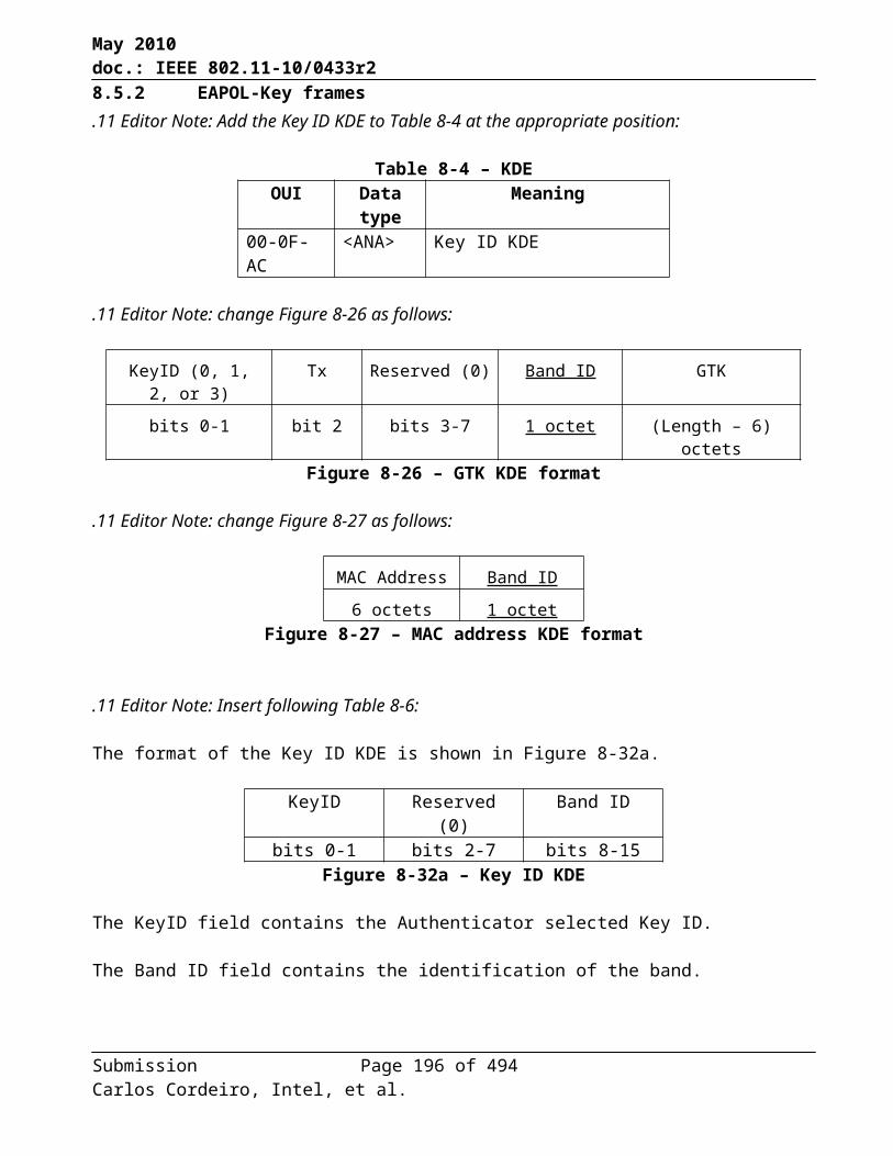
May 2010 doc.: IEEE 802.11-10/0433r2
Figure 98 – Example of time allocation for the MIDC phase with the MID sub-phase only
Prior to the beginning of the MIDC phase, a BRP setup sub-phase will be carried out as specified in . This sub-phase enables the two mSTAs involved to negotiate whether and how the MIDC phase will be carried out. Examples of how the MIDC phase is set up, depending on whether beamforming is initiated in the BT and A-BFT or in the DTT, are illustrated in Figure 99 and Figure 100, respectively. Note that the MIDC phase is only applicable when both the initiator and the responder have the ability to switch amongst their sectors.
Figure 99 – Example of the use of the BRP setup sub-phase to setup the subsequent MIDC phase in the A-BFT and DTT
Submission Page 196 of 339 Carlos Cordeiro, Intel, et al.
PCP/AP
STA
…SS
fram
e
I-TXSS
R-TXSS
SS
fram
e
…SS
fram
eSS
fram
eSS
fe
edba
ck
BR
P fr
ame
BR
P fr
ame
BR
P fr
ame
BR
P fr
ameB
RP
fram
e
BR
P fr
ame(
s)
BR
P fr
ame(
s)
BR
P fr
ame
BR
P fr
ame
…BRP
fram
eBR
P fr
ame
…BRP
fram
eBR
P fr
ame
BR
P fr
ame
BR
P fr
ame
R-MID R-BC
I-BC
Direction=0,MID/BC-REQ=1
Initiator=1,Capability-request=1,MID/BC-REQ=1,L-RX>0
Capability-request=1, MID/BC-Grant=1, TXSS-FBCK-REQ=1, SNR requested=1, MID/BC-REQ=1, L-RX>0
SLS (BT+A-BFT)BRP setup (AT+DTT) MID (DTT) BC (DTT)
I-MID
Capability-request=1,Nmeas, SNR-present=1,Sector-ID-order-present=1, MID/BC-Grant=1, TXSS-FBCK-REQ=1,SNR requested=1
Capability-request=0,Nmeas, SNR-present=1,Sector-ID-order-present=1
Capability-request=0
Nbeam(R, RX )
Nbeam(R, TX),Sector-ID-order present=1
Nbeam(I, TX),Sector-ID-order present=1
Nbeam(I, RX )
Time separation between BRP frame exchanges: ≥ SIFS & < BRPIFS

May 2010 doc.: IEEE 802.11-10/0433r2
Figure 100 – Example of the use of the BRP setup sub-phase to setup the subsequent MIDC phase in the DTT
9.25.5.2.1 MIDC phase with MID and BC sub-phases
The MIDC phase can be implemented such that a small set of TX and RX AWVs are first chosen, followed by a trial (e.g., in a round-robin manner) with this chosen set to determine the optimal starting TX and RX AWV pair. The set of TX sectors is chosen from an a priori TX sector sweep with a quasi-omni RX antenna pattern (in the SLS phase). To enable the selection of the RX sectors, and the subsequent trial between the TX and RX sectors, the MIDC phase consists of an MID sub-phase and a BC (or beam combining) sub-phase. In the MID sub-phase, a wide TX beam (e.g., quasi-omni) is used while the receiver sweeps through its choice of AWV settings to determine the set of RX AWVs with the highest link quality. This is followed by the BC sub-phase, which involves testing the multiple RX AWVs together (e.g., in a round-robin manner) with multiple TX AWVs. This is conceptually illustrated in Figure 101.
Submission Page 197 of 339 Carlos Cordeiro, Intel, et al.
PCP/AP
STA
…SS
fram
e
I-TXSS
R-TXSS
SS
fram
e
…SS
fram
eSS
fram
eSS
fe
edba
ck
BR
P fr
ame
BR
P fr
ame
BR
P fr
ame
BR
P fr
ameB
RP
fram
e
BR
P fr
ame(
s)
BR
P fr
ame(
s)
BR
P fr
ame
BR
P fr
ame
…BRP
fram
eBR
P fr
ame
…BRP
fram
eBR
P fr
ame
BR
P fr
ame
BR
P fr
ame
R-MID R-BC
I-BC
Direction=0,MID/BC-REQ=1
Initiator=1,Capability-request=1,MID/BC-REQ=1,L-RX>0
Capability-request=1, MID/BC-Grant=1, TXSS-FBCK-REQ=1, SNR requested=1, MID/BC-REQ=1, L-RX>0
SLS (BT+A-BFT)BRP setup (AT+DTT) MID (DTT) BC (DTT)
I-MID
Capability-request=1,Nmeas, SNR-present=1,Sector-ID-order-present=1, MID/BC-Grant=1, TXSS-FBCK-REQ=1,SNR requested=1
Capability-request=0,Nmeas, SNR-present=1,Sector-ID-order-present=1
Capability-request=0
Nbeam(R, RX )
Nbeam(R, TX),Sector-ID-order present=1
Nbeam(I, TX),Sector-ID-order present=1
Nbeam(I, RX )
Time separation between BRP frame exchanges: ≥ SIFS & < BRPIFS
May 2010 doc.: IEEE 802.11-10/0433r2
Figure 101 – Conceptual flow of a sample MIDC phase execution with MID and BC sub-phases for the initiator link
Setting up the MID and BC sub-phases: To request an MIDC phase with the MID and the BC sub-phases, the initiator shall transmit an SS-Feedback or BRP frame with the MID-REQ and the BC-REQ fields set to one in the BRP request field. The responder may grant this request by setting the MID grant and the BC grant fields to one in the BRP request field within the next SS-ACK or BRP frame transmitted to the initiator. The R-MID and R-BC sub-phases are performed if the request is granted, and are not performed otherwise.
The responder shall transmit an SS-ACK or BRP frame to request an MIDC phase, with the I-MID and I-BC sub-phases. It shall do so by setting the MID request and the BC request fields to one in the BRP request field within the transmitted frame. The initiator may grant this request by setting the MID grant and the BC grant fields to one in the BRP request field within the next BRP frame transmitted to the responder. The I-MID and I-BC sub-phases are performed if the request is granted, and are not performed otherwise.
If all of R-MID, R-BC, I-MID, and I-BC sub-phases are performed, the MID sub-phases are performed before the BC sub-phases. Within the MID and BC sub-phases, the R-MID/BC is performed before I-MID/BC (see Figure 97 and Figure 98).
Submission Page 198 of 339 Carlos Cordeiro, Intel, et al.
May 2010 doc.: IEEE 802.11-10/0433r2
In addition to the MID, BC request and grant fields, the responder (and/or initiator) needs to obtain the number of RX AWV settings to be appended to BRP-RX packets in the R/I-MID sub-phase. To do this, the initiator (and/or responder) should use the L-RX field in the BRP request field to convey this information. Similarly, the responder (and/or initiator) needs to obtain the IDs and SNRs of the TX sectors received during the SLS phase for use in the R-BC and I-BC sub-phases. To do this, the responder (and/or initiator) shall send a BRP packet with the TXSS-FBCK-REQ subfield and SNR Requested subfield set to one in the FBCK-REQ field of the mmWave beam refinement element. In response, the initiator (and/or responder) should send a BRP frame with both the SNR present subfield and the sector ID order present subfield set to one. The Nmeas field in the FBCK-TYPE is set to indicate the number of sectors received during the last SLS for which an SNR measurement is included. In the channel measurement field, the initiator (or responder) should set the SNR subfield to the SNRs corresponding to the TX sectors trialed during the SLS phase. In the Sector ID subfield, it should list the sector IDs of the received sectors. The responder (and/or initiator) should then use the SNR information, and any additional information such as angular separation between sectors, to determine the TX sectors for use in the BC sub-phase. The responder (or initiator) shall inform the initiator (or responder) of the number of TX sectors using the Nbeam field in the FBCK-TYPE field during the BRP setup sub-phase. After the R/I-MID sub-phases, the same field is used to exchange information about the number of RX AWVs to be trialed during the BC sub-phase.
Executing the MID sub-phase: If R-MID was requested and granted during the SLS and/or subsequent BRP set-phase, after the BRP setup sub-phase, the R-MID shall be initiated by the responder sending a BRP frame with TRN-R fields (as requested in the BRP setup sub-phase). This packet may be transmitted using a wide pattern, approaching an omni transmit pattern, or by a sector. The receiver may use the TRN-R fields for receiver training.
If the MID-extension field in this packet is set to 1, the responder will transmit another BRP-RX packet, possibly transmitted using another transmit pattern. It may continue transmitting BRP-RX packets as long as the MID-extension field in all of them is set to 1. The last BRP-RX packet transmitted by the responder shall have the MID-extension field set to 0.
If the initiator does not receive a BRP-RX packet within BRPIFS after transmitting the first packet, it may retransmit the first packet.
After the initiator receives a BRP-RX packet with the MID-extension field set to 0, it shall respond with a BRP frame with the appropriate feedback. This BRP frame should be sent using the best TX sector as determined in the SLS phase, while the responder should use a quasi-omni pattern to receive this frame. The feedback included in this BRP frame is the number of RX AWVs to be tested in the subsequent R-BC sub-phase using the Nbeam field in the FBCK-TYPE field.
Submission Page 199 of 339 Carlos Cordeiro, Intel, et al.
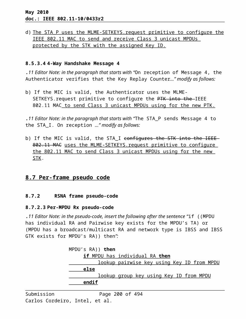
May 2010 doc.: IEEE 802.11-10/0433r2
If I-MID was granted in addition to R-MID, the initiator shall send a BRP frame with TRN-R fields (as requested in the BRP setup sub-phase). The initiator shall continue to send BRP packets if the MID-extension was set to 1 as in the R-MID.
After the responder receives a BRP-RX packet with the MID-extension set to 0. It shall respond by sending a BRP frame with feedback. This BRP frame should be sent using the best TX sector as determined in the SLS phase, while the initiator should use a quasi-omni pattern to receive this frame. The feedback included in this BRP frame is the number of RX AWVs to be tested in the subsequent I-BC sub-phase using the Nbeam field in the FBCK-TYPE field. The initiator shall respond with a BRP-frame with the TX-TRN-OK field set to 1 as an acknowledgement. The R-BC sub-phase then follows.
If I-MID does not follow R-MID, the BC sub-phase follows immediately.
Executing the BC sub-phase: The execution of an I-BC sub-phase is used as an example. In an I-BC sub-phase, the initiator shall transmit Nbeam
(I,TX) BRP-RX frames using the number of TX sectors specified during the BRP setup sub-phase. Each BRP-RX frame shall be appended with Nbeam
(I,RX) TRN-R subfields, and shall include the Sector ID subfield of the TX sector used. While receiving these TRN-R subfields, the responder shall switch through the RX AWVs selected during the prior I-MID sub-phase. To conclude the I-BC sub-phase, the responder shall feed back to the initiator a BRP frame with (a) the BS-FBCK field set to the TX sector ID of the BRP-RX packet received with the highest link quality, and (b) the ordered list of transmit sectors (based on received link quality during the I-BC) using the Sector ID order subfield in the channel measurement feedback element. This BRP frame should be sent using the best TX sector as determined in the SLS phase, while the initiator should use a quasi-omni pattern to receive this frame. The complete procedure is illustrated in Figure 102, while Figure 103 depicts the beam combining sub-phase.
(a) Normal process: one MID and BC for each initiator and responder link (the initiator and responder use a quasi-omni TX pattern)
(b) The MID for both the initiator and responder are repeated twice: each TX beam is wider than a TX sector but narrower than a quasi-omni pattern and covers a different direction
Submission Page 200 of 339 Carlos Cordeiro, Intel, et al.

> SIFS< BRPIFS
BRP withfeedback
BRP
Initiator
BRP-RX BRP-RX BRP-RX
SBIFS
BRP-RX BRP-RX BRP-RX
SBIFS
1 2 Nbeam(R, Tx)
1 2 Nbeam(I, Tx)Nbeam(R,Rx) Rx beams are tested while receiving each BRP-RX packet.
Nbeam(I,Rx) Rx beams are tested while receiving each BRP-RX packet.
> SIFS< BRPIFS
> SIFS< BRPIFS
May 2010 doc.: IEEE 802.11-10/0433r2
(c) The MID for the initiator is repeated twice: each TX beam is wider than a TX sector but narrower than a quasi-omni pattern and covers a different direction
Figure 102 – Examples of the use of the MID extension field during the execution of the MID sub-phase
Figure 103 – Beam Combining
9.25.5.2.2 MIDC phase with MID sub-phase only The MIDC phase may also be implemented such that multiple TX sectors, obtained from the TXSS in the SLS phase, are used instead of wide TX beams. Here, the receiver employs multiple RX AWVs for each TX sector chosen by the transmitter. Based on this joint trial of TX and RX AWVs, the optimal starting TX and RX AWV pair is chosen for further refinement in the BRP phase. In this case, the MIDC phase consists only of the MID sub-phase. This is conceptually illustrated in Figure 104.
Submission Page 201 of 339 Carlos Cordeiro, Intel, et al.
May 2010 doc.: IEEE 802.11-10/0433r2
Figure 104 – Conceptual flow of a sample MIDC phase execution with only the MID sub-phase for the initiator link
Setting up the MID sub-phase: To request an MIDC phase with only the R-MID sub-phase, the initiator shall transmit an SS-Feedback or BRP frame with the MID request subfield set to one and the BC request subfield set to zero in the BRP request field. The responder may grant this request by setting the MID grant subfield to one in the BRP request field transmitted in the next SS-ACK or BRP frame sent to the initiator. The R-MID sub-phase is performed if the request is granted and is not performed otherwise. The responder shall use the SS-ACK or BRP frames to request an MIDC phase, with only the I-MID sub-phase. It shall do so by setting the MID request subfield to one and the BC request subfield to zero in the BRP request field. The initiator may grant this request by setting the MID grant subfield to one in the BRP request field within the next BRP frame transmitted to the responder. The I-MID sub-phase is performed if the request is granted and is not performed otherwise. If both R-MID and I-MID are performed, the R-MID is performed before the I-MID.
In addition to using the MID request and grant fields to setup the MID sub-phase, the responder and initiator need to know the SNRs of the sectors tested during the SLS phase for use in the R-MID and I-MID respectively. To get this information, the responder (or initiator) shall send a BRP packet with the TXSS-FBCK-REQ subfield, and the SNR requested subfield set to one in the FBCK-REQ field of the mmWave beam refinement element. The initiator (or responder) should respond with a BRP frame with the SNR present and sector ID order present subfields set to one, and the Nmeas field in the FBCK-TYPE field indicating the number of SNR measurements from the last SLS phase. In the channel measurement field, the initiator (or responder) should set the SNR subfield to the SNRs corresponding to the TX sectors received during the SLS phase. In the Sector ID subfield, it should list the sector IDs of the received sectors.
Submission Page 202 of 339 Carlos Cordeiro, Intel, et al.
May 2010 doc.: IEEE 802.11-10/0433r2
Figure 105 – Example of the use of the BRP setup sub-phase to setup the subsequent R-MID sub-phase in the A-BFT and DTT
Submission Page 203 of 339 Carlos Cordeiro, Intel, et al.
PCP/AP
STA
…SS
fram
e
I-TXSS
R-TXSS
SS
fram
e
…SS
fram
eSS
fr
ame
SS
feed
bac
k
BR
P fr
ame
BR
P fr
ame
BR
P fr
ame
BR
P fr
ame
BR
P fr
ame
BR
P fr
ame
…BRP
fram
eB
RP
fram
e
R-MID
Direction=0MID/BC-REQ=1
Initiator=1,Capability-request=1,MID/BC-REQ=1,L-RX>0
Capability-request=1, MID-Grant=1, BC-Grant=0,TXSS-FBCK-REQ=1, SNR requested=1, MID/BC-REQ=1, L-RX>0
SLS (BT+A-BFT) BRP setup (AT+DTT) MID (DTT)
Capability-request=1,Nmeas, SNR-present=1,Sector-ID-order-present=1, MID/BC-Grant=0
Capability-request=0
Capability-request=0
Nbeam(R, TX),Sector-ID-order present=1
Time separation between BRP frame exchanges: ≥ SIFS & < BRPIFS
MID extension=1
MID extension=0 for the last BRP frame
May 2010 doc.: IEEE 802.11-10/0433r2
Figure 106 – Example of the use of the BRP setup sub-phase to setup the subsequent I-MID sub-phase in the DTT
Executing the MID sub-phase: The execution of the MID sub-phase for the responder link (i.e., R-MID) is used as an example. Execution of the MID sub-phase for the initiator link (i.e., I-MID) will be similar, except for a change in the direction of the corresponding frames. In an R-MID sub-phase, the responder shall transmit one BRP-RX packet each from one of the chosen TX sectors. In each packet, it shall indicate the sector ID of the TX sector used using the Sector ID field in the BRP request field. Each transmitted BRP-RX packet should be appended with multiple TRN-R subfields such that the initiator can train its receiver antenna during the R-MID sub-phase. The initiator shall train its receiver antenna by cycling through its choice of RX AWVs while receiving the TRN-R subfields. The initiator shall indicate to the responder the number of TRN-R subfields to be appended using the L-RX field in the BRP request field during the SLS phase or the BRP-setup phase (see Figure 105). For all BRP-RX packets except the last one, the responder shall also set the MID extension field to 1.
In the R-MID sub-phase, the initiator shall send a BRP frame with feedback. This BRP frame should be sent using the best TX sector as determined in the SLS phase, while the responder should use a quasi-omni pattern to receive this frame. The feedback included in this BRP frame should be (a) the BS-FBCK field set to the TX sector ID of the BRP-RX packet received with the highest link quality, and (b) the ordered list of
Submission Page 204 of 339 Carlos Cordeiro, Intel, et al.
…SS
fram
e
I-TXSS
R-TXSS
SS
fram
e
…SS
fram
eSS
fr
ame
SS
feed
bac
k
BR
P fr
ame
BR
P fr
ame
BR
P fr
ame
BR
P fr
ame
BR
P fr
ame
Direction=0MID/BC-REQ=1, L-RX>0
Capability-request=1,Nmeas, SNR-present=1,Sector-ID-order-present=1
SLS BRP setup MID
I-MID
Initiator=1,Capability-request=1,MID-Grant=1, BC-Grand=0,TXSS-FBCK-REQ=1,SNR requested=1
Capability-request=0
Capability-request=0
Time separation between BRP frame exchanges: ≥ SIFS & < BRPIFS
SS
AC
K
MID/BC-Grant=0, MID/BC-REQ=1,L-RX>0
…BRP
fram
eB
RP
fram
e
Nbeam(I, TX),Sector-ID-order present=1
MID extension=1 MID
extension=0 for the last BRP frame
Initiator
Responder
May 2010 doc.: IEEE 802.11-10/0433r2
transmit sectors (based on received link quality during the R-MID) using the Sector ID order subfield.
9.25.5.2.3 MIDC phase with BC sub-phases only An MIDC phase with only the BC sub-phase is carried out when the MID and BC sub-phases have been carried out earlier. In this case, the initiator and responder keep track of the TX and RX sectors, for use in the BC sub-phase, from earlier iterations. Since the best TX and RX sectors (in terms of link quality) are kept track of, this information can be used to deal with link blockage events. STAs can utilize only the chosen set of TX sectors in the SLS phase to reduce beamforming training time, and jump to the BC sub-phase directly without executing the MID sub-phase. In this manner, fast recovery is possible when some of backup links are available after partial blockage around the STA.
To carry out the MIDC phase with the BC sub-phase only, the values of the MID request field is set to zero and the value of BC request field is set to one in SS-Feedback or SS-ACK or BRP frames and values of the BC grant field is set to one in the following SS-ACK or BRP frame. The BC sub-phase can include an I-BC and/or an R-BC (9.25.5.2.1).
9.25.5.3 BRP phase execution Beam refinement is a request/response based process. A STA requests receive beam refinement training by sending a beam refinement frame (7.4.13.7) with a non-zero value in the L-RX field. The STA that receives a beam refinement frame shall respond with a beam refinement packet (21.8.2.2) with the appropriate number of appended TRN-R fields and with the RX-train-response field in the PLCP header set to 1.
A STA requests transmit beam refinement training by sending a beam refinement frame as follows. In the mmWave Beam Refinement element, the TX-TRN-REQ is set to one and the FBCK-REQ field to the desired feedback type. In the PLCP header, the packet type and the training length fields are set to indicate the number of AGC and TRN-T fields appended to the packet.
The responding STA shall reply to the transmit beam refinement training with a beam refinement frame containing a mmWave Beam Refinement element with the TX-TRN-OK field set to one and the BS-FBCK field set to indicate the TRN-T field on which it received the best signal (the determination of best signal is implementation dependent). The FBCK-TYPE field shall be set to according to the format of the Channel measurement feedback element, if one is included in the frame. If the SNR present and channel measurement present fields of this FBCK-TYPE field are set to zero, the Channel measurement feedback element shall not be included. The number of taps indicated in the FBCK-TYPE shall less than or equal to the number of taps indicated in the FBCK-REQ field of the request frame.
If a STA requests transmit beam refinement training, but does not send TRN-T fields, the responding STA shall reply with a Beam Refinement frame containing a mmWave Beam refinement element with the TX-TRN-OK field set to one. The requesting STA shall then transmit a beam refinement packet with TRN-T fields. The responding STA shall then respond with a beam refinement frame with the BS-FBCK and channel measurement feedback element as above.
Submission Page 205 of 339 Carlos Cordeiro, Intel, et al.
May 2010 doc.: IEEE 802.11-10/0433r2
Beam refinement can start immediately following SLS (9.25.5.3.2). If the responder receives an SS-Feedback frame from the PCP/AP in an A-BFT, the PCP/AP allocates an SP for the beam refinement if required (see 9.25.4.3). A STA may transmit a beam refinement packet to another STA whenever it transmits a packet to that STA, provided that the transmitting STA knows that the recipient STA’s receive antennas are directed to it or are in a quasi-omni antenna pattern.
A STA shall set the initiator field to one within a mmWave beam refinement element if the previous received frame was not a beam refinement frame, or the last packet it transmitted was a beam refinement frame with the initiator field set to one.
A STA that has transmitted a beam refinement frame with the initiator field set to one and has not received a response BRPIFS after the transmission may retransmit the frame.
A beam refinement frame shall not be both a TX training request packet and RX response packet.
A STA may request a TXSS sector list feedback by sending a beam refinement frame with the TXSS-FBCK-REQ field set to 1 and by setting the FBCK-REQ field to “0b1000” (only SNR is requested). The responding STA shall respond with a beam refinement frame with the FBCK-REQ field set to “0b1000” a list of Sector IDs indicating the sector IDs of the received SS frames or mmWave Beacon frames, and the SNR values in which those frames were received in the last TXSS.
A STA shall not set the TXSS-FBCK-REQ and the TX-TRN-REQ fields to 1 in the same beam refinement frame.
More than one beam refinement packet shall not be aggregated into a single A-MPDU.
NOTE – A beam refinement packet with a combination of TX training response and RX request is not recommended.
9.25.5.3.1Beam refinement transactionA beam refinement transaction is a set of beam refinement frames composed of request and responses.
A beam refinement transaction starts with the beamforming initiator STA sending a beam refinement frame with the initiator field set to 1.
A beam refinement responder is a STA that receives a beam refinement frame (which is directed to it) with the initiator field set to 1.
A beam refinement transaction participant shall respond to a beam refinement frame with a beam refinement frame.
If the beam refinement transaction initiator received a beam refinement frame from the responder with no training requests, it may terminate the transaction by not transmitting any further beam refinement packets.
Figure 107, Figure 108 and Figure 109 show examples of beam refinement transactions.
Submission Page 206 of 339 Carlos Cordeiro, Intel, et al.
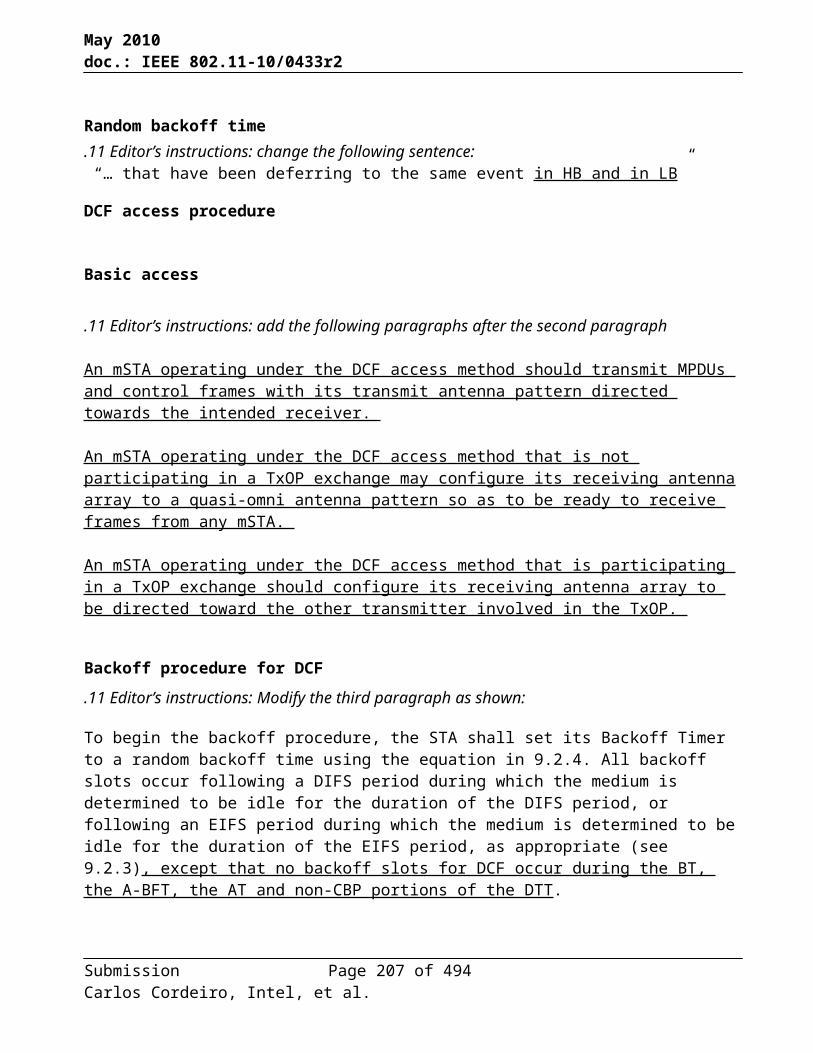
May 2010 doc.: IEEE 802.11-10/0433r2
9.25.5.3.2Beam refinement transaction after SLSIf either L-RX or TX-TRN-REQ are non-zero within the BRP request field in the SS-Feedback or SS-ACK frames of the most recent SLS phase execution and no MID or BC was granted during the BRP setup sub-phase and no beam refinement transaction has been done since the most recent SLS phase execution, the initiator shall initiate the beam refinement transaction with the responder by sending a beam refinement frame to the responder. When the responder phase of the SLS included a TXSS, the type of the first beam refinement frame the initiator transmits is defined in Table 58. When the responder phase of the SLS included an RXSS, the type of the first beam refinement frame the initiator transmits is defined in Table 59.
Table 58 – Beam Refinement packet type following a TXSS values received during the SLS First Beam Refinement packet, the values of L-RX
and TX-TRN-REQ are the ones to be used in the first BRP packetInitiator
L-RX
Initiator TX-
TRN-REQ
Responder L-RX
Responder TX-TRN-
REQ
>0 1 >0 1BRP-RX packet from the initiator, both L-RX and TX-TRN-REQ are >0
>0 1 >0 0BRP-RX packet from the initiator, both L-RX and TX-TRN-REQ are >0
>0 1 0 1BRP-TX packet from the initiator, both L-RX and TX-TRN-REQ are >0
>0 1 0 0BRP-TX packet from the initiator, both L-RX and TX-TRN-REQ are >0
>0 0 >0 1 BRP-RX packet from the initiator, L-RX>0>0 0 >0 0 BRP-RX packet from the initiator, L-RX>0>0 0 0 1 beam refinement packet from the initiator L-RX>0>0 0 0 0 beam refinement packet from the initiator L-RX>0
0 1 >0 1BRP-RX packet from the initiator, both L-RX and TX-TRN-REQ are >0
0 1 >0 0BRP-RX packet from the initiator, both L-RX and TX-TRN-REQ are >0
0 1 0 1BRP-TX packet from the initiator, both L-RX and TX-TRN-REQ are >0
0 1 0 0BRP-TX packet from the initiator, both L-RX and TX-TRN-REQ are >0
0 0 >0 1 BRP-RX packet from the initiator, L-RX>00 0 >0 0 BRP-RX packet from the initiator, L-RX>0
0 0 0 1beam refinement packet from the initiator with L-RX=0 and TX-TRN-REQ=0
0 0 0 0 Beam refinement is not initiated
Table 59 – Beam refinement packet type following an RXSS
Initiator L-RX
Initiator TX-TRN-
REQ First Beam Refinement packet>0 1 BRP-TX packet from the initiator, L-RX>0>0 0 beam refinement frame from the initiator with L-RX>00 1 BRP-TX packet from the initiator, L-RX=00 0 Beam refinement is not initiated
Submission Page 207 of 339 Carlos Cordeiro, Intel, et al.
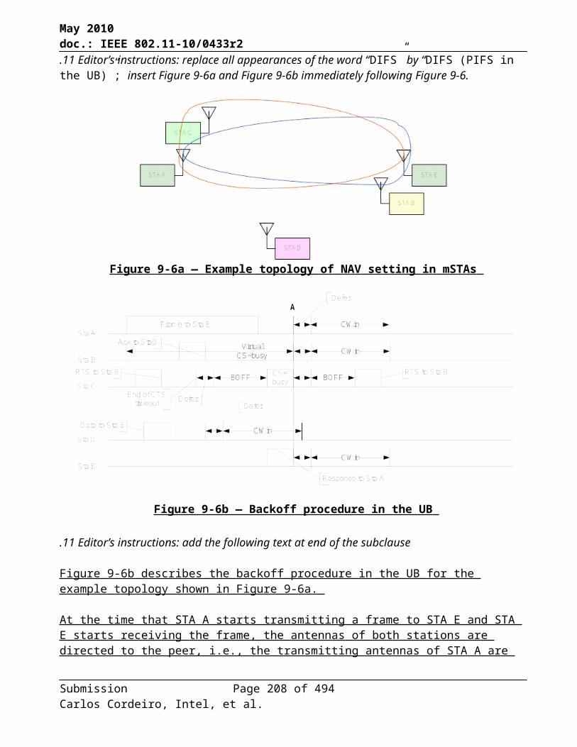
May 2010 doc.: IEEE 802.11-10/0433r2
Submission Page 208 of 339 Carlos Cordeiro, Intel, et al.
May 2010 doc.: IEEE 802.11-10/0433r2
9.25.5.3.3 Antenna configuration setting during a beam refinement transactionA STA that has requested beam refinement receive training shall set its receive antenna configuration to the best known receive antenna configuration based on previous beam refinement receive training or receive sector level training. If the STA has not received a beam refinement receive frame since the last sector level training, and the sector level training did not include a receive sector sweep, it should set its receive antenna configuration to a quasi-omni antenna pattern in the antenna through which it received the best sector during the sector level training.
A STA that has received a beam refinement transmit training request shall send the response frame and then set its antenna configuration to the best known receive antenna configuration based on previous beam refinement receive training or sector level receive training. If it has not received a beam refinement receive frame since the last sector level training and the sector level training did not include a receive sector sweep it should set its antennas to a quasi-omni antenna pattern.
Figure 107 – Example beam refinement transaction (receive
training)
Figure 108 – Example beam refinement transaction (transmit training)
Submission Page 209 of 339 Carlos Cordeiro, Intel, et al.
May 2010 doc.: IEEE 802.11-10/0433r2
Figure 109 – Example beam refinement transaction (combination of receive and transmit training)
9.25.6 Beam trackingA STA (beam tracking initiator) may request a peer STA (beam tracking responder) to perform beam tracking by setting the Beam Tracking Request field to one in the PLCP header of a transmitted packet. Otherwise, the Beam Tracking Request field shall be set to zero. The beam tracking initiator shall also include a beam refinement frame as part of the transmitted packet.
A beam tracking initiator requesting receive beam tracking shall set the L-RX field of the beam refinement frame to the number of training fields it needs from the beam tracking responder.
A beam tracking responder that receives a frame with the Beam Tracking Request field set to one shall follow the rules described in 21.8.2.2 and shall include a beam refinement frame with the Rx-Train-Resp set to one, and beam refinement AGC field and TRN-R fields appended to the following packet transmitted to the initiator. The number of TRN-R subfields appended to the following packet may be lower than the value of the L-RX field specified in the beam refinement frame. If the beam tracking initiator desires further beam tracking training, it may append a beam refinement packet with a new value of L-RX to the next packet addressed to the beam tracking responder and set the Beam Tracking Request within the PLCP header to one.
A beam tracking initiator requesting transmit beam tracking shall set the Beam Tracking Request field in the PLCP header to one and append an AGC field and a TRN-T field to the packet. It shall also include a beam refinement frame in the packet, with the TX-TRN-REQ set to 1 and the FBCK-REQ type set to the desired feedback. The beam tracking responder shall append a beam refinement frame with the TX-TRN-Resp set to 1, and a measurement feedback as specified in the FBCK-REQ. If the beam tracking responder is not ready with the FBCK in the immediately following packet, it shall continue including beam refinement frames in the packet it transmits with the TX-TRN-Resp set to 1 and FBCK-TYPE set to 0 until it is ready with the feedback.
Submission Page 210 of 339 Carlos Cordeiro, Intel, et al.
May 2010 doc.: IEEE 802.11-10/0433r2
The beam tracking initiator shall provide feedback to the beam tracking responder by transmitting a beam refinement frame to the beam tracking responder. The beam refinement frame may be aggregated with other MPDUs sent to the beam tracking responder. When aggregating a beam refinement frame with a Ack MPDU or a BlockAck MPDU, the beam refinement frame shall be considered as a Action No Ack frame. Figure 110 illustrates a beam tracking frame exchange sequence.
Figure 110 – Example of a beam tracking procedure
9.25.7 State machines (informative)Figure 111 depicts the state machine of the TXSS phase for the initiator and Figure 112 illustrates the state machine of the TXSS phase for the responder. These state machines describe the behavior of the initiator and responder during BF and are applicable for any period of the BI where BF is performed.
Submission Page 211 of 339 Carlos Cordeiro, Intel, et al.

May 2010 doc.: IEEE 802.11-10/0433r2
Figure 111 – TXSS phase state machine (initiator)
Figure 112 – TXSS phase state machine (responder)
Submission Page 212 of 339 Carlos Cordeiro, Intel, et al.
May 2010 doc.: IEEE 802.11-10/0433r2
9.26 mmWave Block Ack with Flow Control An mSTA indicates that it is capable to support mmWaveBlock Ack with Flow Control by setting the BA with flow control field to one within the mSTA’s mmWave Capabilities element. Both originator and recipient shall be capable of mmWaveBlockAck with Flow Control to allow a valid engagement.
9.26.1 mmWave Block Ack architecture with Flow ControlThe mmWave Block Ack rules are explained in terms of the architecture shown in Figure 113 and explained in this subclause.
Figure 113 – mmWave Block Ack architecture
The originator contains a Transmit Buffer Control that uses WinStartO BufSizeO and WinLimitO to submit MPDUs for transmission, and releases transmit buffers upon receiving BlockAck frames from the recipient or when it advances the transmit control buffer window.
WinStartO is the starting sequence number of the transmit range, WinLimitO is the last sequence number expected to exhaust the receiver buffer capacity, and BufSizeO is the number of buffers negotiated in the Block Ack agreement.
Figure 114 shows the mmWave Block Ack with flow control and its associated parameters from the Originator perspective.
Submission Page 213 of 339 Carlos Cordeiro, Intel, et al.
May 2010 doc.: IEEE 802.11-10/0433r2
Figure 114 – Flow control and its associated parameters as a function of receiver buffer size
The Aggregation control creates A-MPDUs. It may adjust the Ack Policy field of transmitted data frames according to the rules defined in 9.10.7.7 in order to solicit Block Ack responses.
The recipient contains a Receive Reordering Buffer Control per TA/TID, which contains related control state.
The receive reordering buffer is responsible for reordering MSDUs or A-MSDUs so that MSDUs or A-MSDUs are eventually passed up to the next MAC process in order of received sequence number (SN). It maintains its own state independent of the Scoreboard Context Control to perform this reordering as specified in 9.10.7.6. The delivery of in order MSDUs or A-MSDUs to the next MAC process is implementation dependent. In some cases, the receiver reordering buffer may be forced to hold on MSDUs ready for in order delivery due to deferred reception at the next MAC process. This behavior imposes handling of dynamic capacity. The reordering buffer is required to manage its least and most (in order) SN – deferred-delivery MSDU or A-MSDUs – marked as WinTailB and WinHeadB, respectively.
The scoreboard context control provides the WinCapacityB, actually controlled by the Reordering buffer in addition to the bitmap field and the Starting Sequence Number (SSN) field to be sent in BlockAck responses to the originator.
9.26.2 Scoreboard context control with Flow ControlThe scoreboard context control with Flow Control is defined in 9.10.7.3 and 9.10.7.4.
9.26.3 Receive Reordering Buffer with Flow Control operation
9.26.3.1 GeneralA receive reordering buffer shall be maintained for each mmWave Block Ack agreement. Each receive reordering buffer includes a record comprising:- buffered MSDUs or A-MSDUs that have been received, but not yet passed up to the next MAC
process- a WinStartB parameter, indicating the value of the Sequence Number field (SN) of the first (in
order of ascending sequence number) MSDU or A-MSDU that has not yet been received- a WinEndB parameter, indicating the highest SN expected to be received in the current reception
range
Submission Page 214 of 339 Carlos Cordeiro, Intel, et al.
May 2010 doc.: IEEE 802.11-10/0433r2
- a BuffSizeB parameter, indicating the size of the reception window- a WinTailB parameter, indicating the value of the Sequence Number field (SN) of the first (in order
of ascending sequence number) MSDU or A-MSDU that has not yet been delivered to the next MAC process
- a WinHeadB parameter, indicating the highest SN received in the current reception range
WinStartB is initialized to the Starting Sequence Number field value (SSN) of the ADDBA request frame that elicited the ADDBA response frame that established the mmWave Block Ack agreement.
WinEndB is initialized to WinStartB + BufSizeB - 1, where BufSizeB is set to the value of the Buffer Size field of the ADDBA Response frame that established the Block Ack agreement.
Both WinTailB and WinHeadB are initialized to the preceding Starting Sequence Number field value (SSN-1), to indicate no MPDU was received, within the current reception window.
Any MSDU or A-MSDU that has been passed up to the next MAC process shall be deleted from the receive reordering buffer, advancing the WinTailB.
The recipient shall always pass MSDUs or A-MSDUs up to the next MAC process in order of increasing Sequence Number field value.
9.26.3.2 Operation for mmWave Block Ack agreement initializationa) At mmWave Block Ack agreement establishment:
1) WinStartB SSN from the ADDBA request frame that elicited the ADDBA response frame that established the mmWave Block Ack agreement
2) WinEndB = WinStartB + BufSizeB - 13) WinCapacityB = BufSizeB
4) WinHeadB = SSN-1, where SSN is taken from the ADDBA request, similar to WinStartB
5) WinTailB = SSN-1
9.26.3.3 Operation for each received data MPDUFor each received data MPDU that is related to a specific mmWave Block Ack agreement, the receive reordering buffer record is modified as follows, where SN is the value of the Sequence Number field of the received MPDU:
a) If WinStartB <= SN <= WinEndB
1) Store the received MPDU in the bufferi. If SN > WinHeadB, Set WinHeadB = SN.
ii. if SN > (WinTailB + BufSizeB), 1. all MSDU buffers with sequence numbers from WinTailB to SN-BufSizeB
that were received correctly are passed to the next MAC process. 2. set WinTailB = SN-BufSizeB
iii. set WinCapacityB = WinTailB + BufSizeB - WinHeadB
2) Set WinStartB to the value of the Sequence Number field of the first MSDU or A-MSDU that is missing to allow in-order delivery to the next MAC process
3) Set WinEndB = WinStartB + BufSizeB – 1
b) If WinEndB < SN < WinStartB + 211
Submission Page 215 of 339 Carlos Cordeiro, Intel, et al.

May 2010 doc.: IEEE 802.11-10/0433r2
1) Store the received MPDU in the buffer2) set WinEndB = SN3) set WinStartB = WinEndB - BufSizeB + 14) all MSDU buffers with sequence numbers from WinTailB to SN-BufSizeB that were
received correctly are passed to the next MAC process.5) set WinTailB = SN-BufSizeB
6) set WinHeadB = SN7) set WinCapacityB = WinTailB + BufSizeB - WinHeadB
c) If WinStartB + 211<= SN < WinStartB, discard the MPDU (do not store the MPDU in the buffer, do not pass the MSDU or A-MSDU up to the next MAC process)
d) For each received Block Ack Request frame the block acknowledgement record for that agreement is modified as follows, where SSN is the value from the Starting Sequence Number field of the received Block Ack Request frame:
1) If WinStartB < SSN <= WinEndB
i) set WinStartB = SSNii) set WinEndB = WinStartB + BufSizeB - 1.iii) if SSN > WinHeadB, set WinHeadB = SSN-1 iv) if SSN > (WinTailB + BufSizeB),
i. all MSDU buffers with sequence numbers from WinTailB to SSN-BufSizeB, are discarded from the buffer
ii. set WinTailB = SSN-BufSizeB
v) set WinCapacityB = WinTailB + BufSizeB – WinHeadB
2) If WinEndB < SSN < WinStartB + 211
i) set WinStartB = SSNii) set WinEndB = WinStartB + BufSizeB - 1iii) set WinHeadB = SSN-1iv) if SSN > (WinTailB + BufSizeB),
i. all MSDU buffers with sequence numbers from WinTailB to SSN-BufSizeB, are discarded from the buffer
ii. set WinTailB = SSN-BufSizeB
v) set WinCapacityB = WinTailB + BufSizeB – WinHeadB
3) If WinStartB + 211 <= SSN <= WinStartB, make no changes to the record
9.26.3.4 Operation for ongoing release of received MPDUsThe reordering buffer shall continue to pass MSDUs or A-MSDUs up to the next MAC process that are stored in the buffer in order of increasing value of the Sequence Number field, starting with the MSDU or A-MSDU that has SN=WinTailB and proceeding sequentially until there is no ready in-order MSDU or A-MSDU buffered for the next sequential value of the Sequence Number field.
a) Set WinTailB to the value of the Sequence Number field of the last MSDU or A-MSDU that was passed up to the next MAC process plus one.
9.26.4 Generation and transmission of BlockAck by a STA with Flow Control
Submission Page 216 of 339 Carlos Cordeiro, Intel, et al.
May 2010 doc.: IEEE 802.11-10/0433r2
In addition to the normative behavior specified in subclause 9.10.7.5 when responding with a BlockAck frame, the RBUFCAP field shall be updated with the value of WinCapacityB.
9.26.5 Originator’s behavior with flow control support
If the BA with flow control field within a recipient’s mmWave Capabilities element is set to one, the originator shall defer transmission of MPDU with an SN that is beyond the current recipient’s buffer capacity (WinLimitO).
The BlockAck frame indicates the amount of free buffer slots available at the recipient for reception of additional MPDUs.
The originator shall update a variable WinLimitO to limit the transmission of following MPDUs upon reception of a valid BlockAck:
Set WinCapacityO to the received value of the RBUFCAP field in the BlockAck frame. Set MostSuccSN to the highest SN of positively acknowledged MPDUs Set WinLimitO = MostSuccSN + WinCapacityO
Originator’s support of recipient’s partial state is defined in 9.10.7.9.
9.27 mmWave Link adaptation
A STA may transmit a Link Margin Request frame (7.4.13.10) to request a STA indicated in the RA field of the frame to respond with Link Margin Response frame (7.4.13.11). The Link Margin Response frame contains the values of the MCS, of the SNR and of the Link Margin that the requesting STA may use to transmit frames to the STA indicated in the RA field of the Link Margin Request frame.
The requesting STA may aggregate a Link Margin Request frame in a A-MPDU as defined in Table 7-57y and Table 7-57ab (IEEE Std. 802.11n-2009). If the Dialog Token field in the Link Margin Request frame is set to a non-zero value, the requesting STA shall send a frame to the same responding STA SIFS after receiving the ACK or BA frame corresponding to the Link Margin Request frame.
The responding STA may aggregate a Link Margin Response frame in a A-MPDU as defined in Table 7-57y and Table 7-57ab (IEEE Std. 802.11n-2009).
An mSTA with MAC address that is equal to the value of the Link Margin Request frame RA field should transmit a Link Margin response frame addressed to the requesting STA. The RA field of the Link Margin response frame shall be equal to the TA field of the Link Margin Request frame.
If the Dialog Token field in the Link Margin Response frame is equal to the non-zero Dialog Token field of the Link Margin Request frame, the MCS, SNR and Link Margin fields of the Link Margin Response frame shall be computed using the measurements of the PPDU which is the subsequent frame following the Link Margin Request frame.
Submission Page 217 of 339 Carlos Cordeiro, Intel, et al.

May 2010 doc.: IEEE 802.11-10/0433r2
If the Dialog Token field in the Link Margin Request frame is set to zero, the responding STA may set the MCS field in the Link Margin Response frame to the MCS value computed based on any of the received frames from the requesting STA.
The SNR field and Link Margin field in the Link Margin Response frame shall indicate the corresponding measurements based on the reception of the PPDU that was used to generate the MCS feedback contained in the same Link Margin Response frame.
The Link Margin Request and Response frames may be used to obtain Link Margin information, which can be used to determine appropriate action by the requesting STA (e.g., control transmit power or initiate FST).
A STA may send an unsolicited Link Margin Response frame with the Dialog Token field set to zero.
9.28 mmWave Dynamic Tone Pairing (DTP)
A pair of communicating STAs shall only employ DTP modulation if both STAs support DTP as indicated through the DTP Supported field within the STA’s mmWave Capability element.
A DTP capable STA may use DTP with another DTP capable STA by setting the Tone Pairing Type field within the PLCP header to one, otherwise the Tone Pairing Type field shall be set to zero. The transmitting STA may stop using DTP by setting the Tone Pairing Type field within the PLCP header to zero. A transmitting STA requests a DTP report from a receiving STA by sending a DTP Request frame to that STA. Upon receiving a DTP Request frame, the receiving STA shall respond with a DTP Report frame carrying the DTP configuration. A receiving STA may also send a DTP Report frame unsolicited, that is, without receiving a corresponding DTP Request frame.
The transmitting STA should switch to the updated DTP configuration after a DTP Report frame is received.
If a STA transmits a DTP Report frame in response to the reception of a DTP Request frame, the STA should not send an updated DTP Report frame unless it receives another DTP Request frame.
If a STA transmits an unsolicited DTP Report frame, the STA should not send a new unsolicited updated DTP Report unless the transmitting STA has switched to the DTP configuration last sent.
Both the transmitting and receiving STAs maintain two copies of DTP configurations: the current configuration that is in use for transmission and an updated configuration, if any, received after the current configuration. The transmitting STA determines when to switch from the current to the updated DTP configuration. The transmitting STA shall indicate the switch from the current configuration to the updated configuration by toggling the DTP Indicator bit field in the PLCP header. The value of the DTP Indicator field shall be kept unchanged until the transmitting STA decides to switch DTP configuration.
Submission Page 218 of 339 Carlos Cordeiro, Intel, et al.
May 2010 doc.: IEEE 802.11-10/0433r2
The transmitting STA may send another DTP Request frame to a receiving STA even if it decided not to switch to the DTP configuration indicated by the receiving STA’s last transmitted, if any, DTP Report frame.
11 MLME
11.1 Synchronization
11.1.1 Basic approach
.11 Editor Note: insert the following paragraph at the end of this subclause: A multi-band capable STA (11.34 Multi-band Operation) shall maintain a local TSF timer for each channel that the STA operates.
.11 Editor Note: Please replace section 11.1.1.1 with the following paragraphs:
11.1.1.1 TSF for infrastructure networks and PBSS networks
In an infrastructure BSS or in a PBSS, the AP in the infrastructure BSS or the PCP in the PBSS shall be the timing master for the TSF. The AP and the PCP shall initialize its TSF timer independently of any simultaneously started APs and PCPs in an effort to minimize the synchronization of the TSF timers of multiple APs and PCPs. In the HB and LB, The AP shall periodically transmit special frames called Beacon frames. In the UB, the PCP shall periodically transmit special frames called mmWave Beacon and Announce frames and which provide a similar function to the Beacon frame in the LB and HB. Beacon, mmWave Beacon and Announce frames contain a copy of its the PCP’s or AP’s TSF timer to synchronize the TSF timers of other STAs in a BSS. A receiving STA shall always accept the timing information in Beacon, mmWave Beacon and Announce frames sent from the AP and PCP servicing its BSS. If a STA’s TSF timer is different from the timestamp in the received Beacon, mmWave Beacon or Announce frame, the receiving STA shall set its local TSF timer to the received timestamp value.
In LB and HB, Beacon frames shall be generated for transmission by the AP once every dot11BeaconPeriod TUs. In the UB, at least one mmWave Beacon frame shall be generated for transmission by the AP every dot11BeaconPeriod TUs. The AP shall transmit at least one mmWave Beacon frame through each antenna configuration available to the AP within a time interval that is not longer than dot11BeaconPeriod* dot11MaxLostBeacons TUs . TXSS Span field in the mmWave Beacon shall be set to a value that is less than or equal to the dot11MaxLostBeacons attribute.
In a PBSS, the TSF is advertized by the mmWave Beacon frames generated at each BT. In a PBSS the TSF is delivered to the mSTA by the mmWave beacon frames generated at each BT and by the Announce frames generated at AT. In a PBSS the BT and AT can alternate in different BIs. The time interval in between two consecutive BTs shall be an integer multiple of dot11BeaconPeriod TUs. The
Submission Page 219 of 339 Carlos Cordeiro, Intel, et al.
May 2010 doc.: IEEE 802.11-10/0433r2
PCP shall transmit at least one mmWave Beacon frame to each associated STA within a time interval that is not longer than dot11BeaconPeriod* dot11MaxLostBeacons TUs . dot11MaxLostBeacons .
11.1.2 Maintaining synchronization
.11 Editor Note: modify the first paragraph as indicated below
Each STA shall maintain a TSF timer that increments in microseconds with which is reset every modulus 264 microseconds counting in increments of microseconds. STAs expect to receive Beacon frames at a nominal rate. In an infrastructure network that operates in LB and HB, the interval between Beacon frames is defined by the dot11BeaconPeriod parameter of the STA. In an infrastructure network that operate in UB, the STAs expect to receive at least one mmWave Beacon frame every dot11BeaconPeriod* dot11MaxLostBeacons TUs. In the PBSS the mSTAs expect to receive at least one mmWave Beacon frame or one Announce frame every dot11BeaconPeriod* dot11MaxLostBeacons TUs.
A STA sending a Beacon frame shall set the value of the Beacon frame’s timestamp so that it equals the value of the STA’s TSF timer at the time that the data symbol containing the first bit of the timestamp is transmitted to the PHY plus the transmitting STA’s delays through its local PHY from the MAC-PHY interface to its interface with the WM [e.g., antenna, light-emitting diode (LED) emission surface]. A STA sending a mmWave Beacon or an Announce frame shall set the value of the frame’s timestamp field so that it equals the value of the STA’s TSF timer at the time that the transmission of data symbol containing the first bit of the MPDU is started on the air, which should include any transmitting STA’s delays through its local PHY from the MAC-PHY interface to its interface with the WM.
.11 Editor Note: change the heading of 11.1.2.1 as follows
11.1.2.1 Beacon generation in infrastructure networks in LB and HB
.11 Editor Note: Please insert the following sections after section 11.1.2.1
11.1.2.1a Beacon generation in infrastructure BSS and in PBSS in UB
An mSTA acting as a PCP/AP may access the medium at any time to transmit a mmWave Beacon, except when it overlaps in time with an allocation owned by a non-PCP/non-AP STA.
Each mmWave Beacon frame transmitted by the PCP mSTA and the AP mSTA shall have the discovery mode field within the mmWave Beacon set to zero.
The Duration/ID field of each transmitted mmWave Beacon frame shall be set to the time remaining until the end of the current BT.
Submission Page 220 of 339 Carlos Cordeiro, Intel, et al.
May 2010 doc.: IEEE 802.11-10/0433r2
The PCP mSTA and AP mSTA establishes a series of Target Beacon Transmission Times (TBTTs) spaced dot11BeaconPeriod TUs apart. The period between two TBTTs is referred to as the beacon interval (BI). The BI length shall be no more than aMaxBIDuration. Time value zero of the TSF is defined to be a TBTT with a mmWave Beacon frame transmitted at the beginning of the BI. The length of the beacon interval is included in the mmWave Beacon, Announce and Probe Response frames, and the mSTAs shall adopt that beacon interval when joining the BSS.
A PCP mSTA and an AP mSTA that moves the BT (11.32.1) or changes the BI duration (11.32.2) shall re-establish the TBTT and reset the TSF to zero at the time the BSS parameter change takes effect in the BSS.
Transmission of the mmWave Beacon may comprise transmission of one or more mmWave Beacon frames through different antenna configurations during the BT. The PCP mSTA and the AP mSTA shall not transmit more than one mmWave Beacon frame through the same antenna configuration during the BT of any BI.
At least once every aMinBTPeriod beacon intervals, the PCP/AP shall transmit at least one mmWave Beacon within dot11MinBIHeaderDuration following the start of a BI. The PCP mSTA and the AP mSTA shall transmit at least one mmWave Beacon frame through each possible antenna configuration in a full-coverage set of antenna configurations within the number of beacon intervals specified within the most recently updated TXSS Span field. At each BT, the PCP schedules one or more mmWave Beacon frames for transmission according to the procedure specified in subclause 9.25.3. Subject to this constraint, the PCP mSTA and the AP mSTA may delay the mmWave Beacon transmission if the medium is determined by the carrier-sense mechanism to be busy. When delaying a mmWave beacon transmision, the PCP/AP shall ensure that the BT, A-BFT and AT do not overlap in time with pseudo-static SPs for which the PCP/AP is neither source nor destination.
The PCP/AP may transmit mmWave Beacon frames through different antenna configurations during the BT, but shall not transmit more than one mmWave Beacon frame through the same antenna configuration during the BT of any BI. For any BI that does not include a mmWave Beacon transmission, the PCP/AP shall begin the BI with an AT sequence. All mmWave Beacon frames transmitted within the number of beacon intervals specified within the most recently updated TXSS Span field shall have the same value for all the subfields within the Beacon Interval Control field.
When the mmWave Beacon transmission is performed as multiple directional transmissions, the PCP/AP may change the sequence of directions through which a mmWave Beacon is transmitted after it has transmitted a mmWave Beacon frame through each direction in the current sequence of directions. This is done to randomize and potentially minimize interference to/from the mmWave Beacon. One such example is indicated in Figure 115. The sequence of directions shall be pseudo-randomly chosen from a sequence of directions covering the full set of directions available to a PCP/AP.
Submission Page 221 of 339 Carlos Cordeiro, Intel, et al.
May 2010 doc.: IEEE 802.11-10/0433r2
Figure 115 – Example of mmWave Beacon transmission by PCP/AP during the BT
NOTE – An PCP/AP operating in the UB can transmit Announce frames as request frames during the AT (9.23.3). An Announce frame can perform the function of a mmWave Beacon frame, can be transmitted as a unicast frame directed to a STA, and can provide a much more spectrally efficient access than using a mmWave Beacon frame.
An AP and PCP shall include a mmWave Operation element within a transmitted mmWave Beacon frame if the CBP only field within the mmWave Beacon frame is set to one. An AP and PCP shall include a mmWave Operation element within a transmitted mmWave Beacon frame if the CBP only field within the mmWave Beacon frame is set to zero and the Extended Schedule element is included in the mmWave Beacon frame. An AP and PCP shall include a mmWave Operation element within a transmitted Announce frame if the Extended Schedule element is included in the Announce frame.
11.1.2.1a.1 Beacon generation in a PBSS
At TBTTs that do not start with a BT and when the PCP is not in Doze state, the PCP shall begin a beacon interval with an AT sequence.
11.1.2.1a.2 Beacon generation in infrastructure BSS in UB
In an infrastructure BSS operating in UB, the AP mSTA shall assert the dot11MaxLostBeacons attribute value equal to the aMinBTPeriod parameter value.
11.1.2.1b Beacon generation before network initialization
An mSTA that transmits mmWave Beacon frames before network initialization shall set the discovery mode field in each transmitted mmWave Beacon frame to one. This indicates that the mSTA is not a PCP or an AP, and the network initialization procedure defined in 11.1.3.48 has not been performed.
Before network initialization, the spacing between TBTTs can change and the time to the next TBTT is contained in the last mmWave Beacon transmission. At each TBTT, the mSTA should generate a random value for the beacon interval field within the mmWave Beacon frame from a uniform distribution between [10 TUs, aMaxBIDuration), i.e., 10 TUs inclusive through aMaxBIDuration exclusive. All mmWave Beacon frame transmissions within the same BT shall have the same value for the beacon interval field. The mSTA shall transmit the first mmWave Beacon frame of the next BT at the time indicated by the addition of the TSF value transmitted in the last mmWave Beacon frame transmission within the last BT and the value of the beacon interval field contained in the last mmWave Beacon transmission within the last BT. The TSF shall be set to zero at the first TBTT for which the discovery mode field within the mmWave Beacon frame is set to one.
Submission Page 222 of 339 Carlos Cordeiro, Intel, et al.
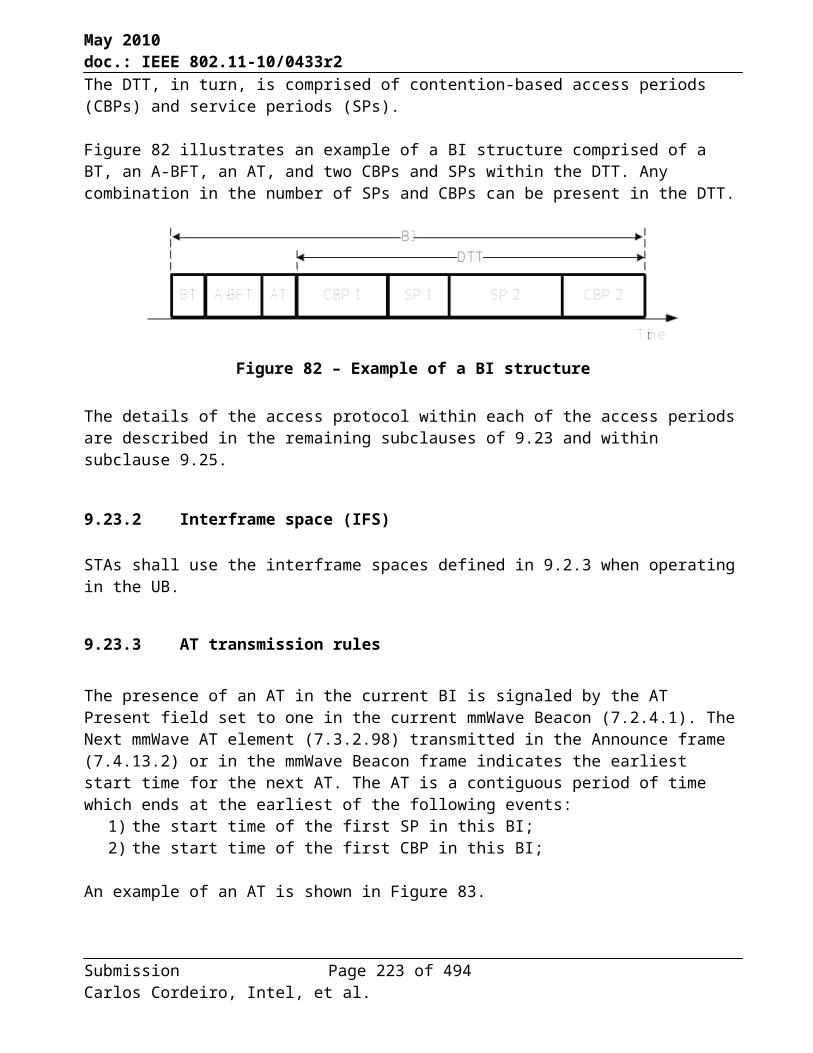
May 2010 doc.: IEEE 802.11-10/0433r2
The procedure of TBTT change described in the preceding paragraph is applicable for mmWave Beacon generation before network initialization, whereas the procedures defined in 11.32.1 and 11.32.2 are used to change the mmWave BSS parameters after the infrastructure BSS and PBBS are initialized in the UB.
The mSTA shall set the Duration/ID field of each transmitted mmWave Beacon frame to the time remaining until the end of the current BT.
11.1.2.2 Beacon generation in an IBSS
.11 Editor Note: Modify the first paragraph as follows
Beacon generation in an IBSS is distributed. The beacon period is included in Beacon, Announce and Probe Response frames, and STAs shall adopt that beacon period when joining the IBSS. All members of the IBSS participate in beacon generation. Each STA shall maintain its own TSF timer that is used for dot11BeaconPeriod timing. The beacon interval within an IBSS is established by the STA at which the MLME-START.request is performed to create the IBSS. This defines a series of TBTTs exactly dot11BeaconPeriod TUs apart. Time zero is defined to be a TBTT. At each TBTT the STA shall
a) Suspend the decrementing of the backoff timer for any pending non-beacon or non-ATIM or non-mmWave Beacon transmission,
b) Calculate a random delay uniformly distributed in the range between zero and twice aCWmin× aSlotTime when operating in the LB and the HB, and between zero and the result of two multiplied by aCWminMMwaveIBSS multiplied by the duration of the STA’s following BT when operating in the UB,
c) Wait for the period of the random delay, decrementing the random delay timer using the same algorithm as for backoff,
d) Cancel the remaining random delay and the pending beacon transmission or BT if operating in the UB, if a Beacon frame arrives from the IBSS of which the STA is a member before the random delay timer has expired, at which time the ATIM backoff timer shall resume decrementing.
e) Send a Beacon frame when operating in the LB or the HB or mmWave Beacon frame(s) when operating in the UB if the random delay has expired and no Beacon frame when operating in the LB or the HB or mmWave Beacon frame when operating in the UB has arrived from the IBSS of which the STA is a member during the delay period.
11.1.2.3 Beacon reception
.11 Editor Note: Modify the following paragraphs as follows
STAs in an infrastructure network and STAs in a PBSS shall only use other information in received Beacon frames or mmWave Beacon frames or Announce frames, if the BSSID field is equal to the MAC address currently in use by the STA contained in the AP of the infrastructure BSS or to the MAC address currently in use by the PCP of the PBSS.
Submission Page 223 of 339 Carlos Cordeiro, Intel, et al.
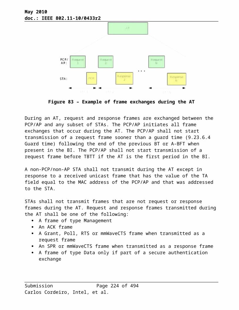
May 2010 doc.: IEEE 802.11-10/0433r2
STAs in an IBSS operating in the LB or in the HB shall use other information in any received Beacon frame for which the IBSS subfield of the Capability field is set to 1, the content of the SSID element is equal to the SSID of the IBSS, and the TSF value is later than the receiving STA’s TSF timer. Use of this information is specified in 11.1.4.
.11 Editor Note: Insert the following paragraphs at the end of the subclause
STAs in an IBSS operating in the UB shall use other information in any received mmWave Beacon and Announce frames for which the BSS Type subfield is set to 1, the content of the SSID element is equal to the SSID of the IBSS, and the TSF value is later than the receiving STA’s TSF timer. Use of this information is specified in 11.1.4 .
A STA shall ignore the BSS Type field contained in a received mmWave Beacon frame if the discovery mode field within the mmWave Beacon is set to one.
An active STA operating in a BSS shall be ready to receive a mmWave Beacon or a frame from the PCP/AP for a period of time of at least dot11MinBIHeaderDuration following the start of a BI or expected AT start time as specified in the last Next mmWave AT element ( 7.3.2.98 ) transmitted by the PCP/AP.
In UB, an active STA that is receive beamforming trained with the AP/PCP should direct its receive antenna pattern toward the AP/PCP during this time.
A non-PCP STA that receives a mmWave Beacon frame from a PCP with the PCP AssocReady field set to 0 shall not transmit an Association Request frame addressed to the PCP that transmitted the received mmWave Beacon. A non-PCP STA that receives a mmWave Beacon frame from a PCP with the PCP AssocReady field set to 1 may transmit an Association Request frame addressed to the PCP that transmitted the received mmWave Beacon.
11.1.2.3a Multiple BSSID procedures.11 Editor Instruction: throughout this subclause in 802.11-2007+amendments, change all occurrences of “non-AP” to “non-AP/non-PCP”
.11 Editor Instruction: throughout this subclause in 802.11-2007+amendments, change all occurrences of “AP” to “AP/mSTA”
.11 Editor Instruction: throughout this subclause in 802.11-2007+amendments, change all occurrences of “Beacon” to “Beacon/mmWave Beacon”
11.1.2.4 TSF timer accuracy
.11 Editor Note: Please Modify the following paragraph as follows
Upon receiving a Beacon or a mmWave Beacon or an Announce frame with a valid FCS and BSSID or SSID, as described in 11.1.2.3, a STA shall update its TSF timer according to the following algorithm:
Submission Page 224 of 339 Carlos Cordeiro, Intel, et al.

May 2010 doc.: IEEE 802.11-10/0433r2
When operating in the LB or the HB, The received timestamp value shall be adjusted by adding an amount equal to the receiving STA’s delay through its local PHY components plus the time since the first bit of the timestamp was received at the MAC/PHY interface.
When operating in the UB, the received timestamp value shall be adjusted by adding an amount equal to the receiving STA’s delay through its local PHY components plus the time since the last data symbol of the PLCP header was received as indicated by PHY_RXSTART.ind.
In the case of an infrastructure BSS or a PBSS, the STA’s TSF timer shall then be set to the adjusted value of the timestamp. In the case of an IBSS, the STA’s TSF timer shall be set to the adjusted value of the received timestamp, if the adjusted value of the timestamp is later than the value of the STA’s TSF timer. The accuracy of the TSF timer shall be no worse than ±0.01%.
11.1.3 Acquiring synchronization, scanning
.11 Editor Note: starting from the 3rd paragraph, change this subclause as follows:
Upon receipt of the MLME-SCAN.request primitive, a STA shall perform scanning. The SSID parameter indicates the SSID for which to scan. To become a member of a particular ESS using passive scanning, a STA shall scan for Beacon and mmWave Beacon frames containing that ESS’s SSID, returning all Beacon and mmWave Beacon frames matching the desired SSID in the BSSDescriptionSet parameter of the corresponding MLME-SCAN.confirm primitive with the appropriate bits in the Capabilities Information field and mmWave Capabilities field indicating whether, respectively, the Beacon frame and the mmWave Beacon frame came from an infrastructure BSS or IBSS or PBSS. To actively scan, the STA shall transmit Probe request frames containing the desired SSID, but may have to transmit mmWave Beacon frames or do beamforming prior to the transmission of Probe request frames if the STA operates in the UB. Upon completion of scanning, an MLME-SCAN.confirm is issued by the MLME indicating all of the BSS information received.
Upon receipt of an MLME-SCAN.request with the SSID parameter set to the wildcard SSID, the STA shall passively scan for any Beacon and mmWave Beacon frames, or actively transmit Probe request or mmWave Beacon frames containing the wildcard SSID, as appropriate depending upon the value of ScanMode. Upon completion of scanning, an MLMESCAN.confirm is issued by the MLME indicating all of the BSS information received.
When a STA starts a BSS, that STA shall determine the BSSID of the BSS. If the BSSType indicates an infrastructure BSS, then the STA shall start an infrastructure BSS and the BSSID shall be equal to the STA’s dot11StationID. If the BSSType indicates a PBSS, then the STA shall start a PBSS and the BSSID shall be equal to the STA’s dot11StationID. For both the infrastructure BSS and the PBSS, The value of the BSSID shall remain unchanged, even if the value of dot11StationID is changed after the completion of the MLME-START.request. If the BSSType indicates an IBSS, the STA shall start an IBSS, and the BSSID shall be an individual locally administered IEEE MAC address as defined in 5.2 of IEEE Std 802-1990. The remaining 46 bits of that MAC address shall be a number selected in a manner that minimizes the probability of STAs generating the same number, even when those STAs are subjected to the same initial conditions. The value SSID parameter shall be used as the SSID of the new BSS. It is important that designers recognize the need for statistical independence among the random number streams among STAs.
Submission Page 225 of 339 Carlos Cordeiro, Intel, et al.
May 2010 doc.: IEEE 802.11-10/0433r2
11.1.3.46 Passive scanning
.11 Editor Note: Add the following subclause:
11.1.3.1.1 Passive scanning for mSTAsUpon receipt of the MLME-SCAN.request primitive with the ScanType parameter set to Passive, an mSTA shall passively scan for transmissions on each channel supported by the mSTA.
That is, the mSTA shall be in receive state for a period of time in a channel no less than MinChannelScan and return information on all mmWave Beacon frames received matching a particular BSSID or SSID parameters specified in the MLME-SCAN.request. If no mmWave Beacon scan parameters are specified in the request, then the mSTA shall return information on all received mmWave Beacon frames.
If at any time during the scan the mSTA detects a non-mmWave Beacon frame, the mSTA shall continue to scan the current channel until the aMaxChannelScan timer expires or until a mmWave Beacon from the new BSS is received, whichever comes first. After scanning one channel, the mSTA may initiate scanning in another channel. The mSTA shall be capable of scanning all channels supported by the mSTA, but the choice of channels scanned and the channel traversal order during passive scanning are implementation specific and may be subject to regulatory requirements.
When the mSTA has completed scanning all indicated channels, it returns the scan results via the MLME-SCAN.confirm primitive. If dot11MultiDomainCapabilityEnabled is true and no regulatory domain is configured at a multi-band capable mSTA, the multi-band capable mSTA may scan for infrastructure networks to get the Country IE and the AP Channel Report IE.
11.1.3.47 Active scanning
11.1.3.2.1 Sending a probe response
.11 Editor Instruction: change the 2nd, 3rd, and 4th paragraph as follows:
Probe Response frames shall be sent as directed frames to the address of the STA that generated the probe request. The probe response shall be sent using normal frame transmission rules. An APs, PCPs, and mSTAs that are not member of a PBSS but that have transmitted at least one mmWave Beacon with the discovery mode field set to one shall respond to all probe requests meeting the above criteria. In an IBSS, the STA that generated the last Beacon/mmWave Beacon frame shall be the STA that responds to a probe request.
Only APs, PCPs, mSTAs that are not member of a PBSS but that have transmitted at least one mmWave Beacon with the discovery mode field set to one and STAs in an IBSS respond to probe requests. The procedures defined in this subclause ensure that in each BSS, except those operating in the UB, there is at least one STA that is awake at any given time to receive and respond to probe
Submission Page 226 of 339 Carlos Cordeiro, Intel, et al.
May 2010 doc.: IEEE 802.11-10/0433r2
requests. A STA that sent a Beacon frame shall remain in the Awake state and shall respond to probe requests, subject to criteria in the next paragraph, until a Beacon frame with the current BSSID is received. If the STA is an AP, it shall always remain in the Awake state and always respond to probe requests, subject to criteria in the next paragraph. There may be more than one STA in an IBSS that responds to any given probe request, particularly in cases where more than one STA transmitted a Beacon/mmWave Beacon frame following the most recent TBTT, either due to not receiving successfully a previous Beacon/mmWave Beacon frame or due to collisions between beacon transmissions.
STAs receiving Probe Request frames shall respond with a probe response when the SSID in the probe request is the wildcard SSID or matches the specific SSID of the STA. Probe Response frames shall be sent as directed frames to the address of the STA that generated the probe request. The probe response shall be sent using normal frame transmission rules. An AP, PCP, and mSTA that is not member of a PBSS but that have transmitted at least one mmWave Beacon with the discovery mode field set to one shall respond to all probe requests meeting the above criteria. In an IBSS, the STA that generated the last Beacon/mmWave Beacon frame shall be the STA that responds to a probe request.
11.1.3.47.2 Active scanning procedure.11 Editor Instruction: insert the following paragraph as the first paragraph in this subclause:
A multi-band capable STA (as defined in 11.34 ) that includes support for the UB and either the LB or the HB is not required to perform active scanning in the UB if the STA intends to perform active scanning by transmitting a mmWave Beacon frame with the discovery mode field set to one. In such case when the multi-band STA did not perform active scanning in the UB, the MLME shall issue an MLME-SCAN.confirm with a ResultCode of NOT_SUPPORTED in response to a MLME-SCAN.request received in the UB, and the STA may then perform active scanning in the LB or HB. In all other cases, the STA proceeds as follows.
.11 Editor Instruction: change the 2nd paragraph as follows:
For each channel to be scanned, including any channel in the UB as permitted within the regulatory domain of operation,
a) Wait until the ProbeDelay time has expired or a PHYRxStart.indication has been received;b) Perform the Basic Access procedure as defined in 9.2.5.1 when operating in the LB or HB;c) Start generation of mmWave Beacon frames according to the rules described in 11.1.2.1b
Beacon generation before network initialization, if the STA operates in the UB and the STA intends to transmit mmWave Beacon frames with the discovery mode field is set to one;
d) Perform beamforming as defined in 9.25 when operating in the UB; e) Perform the Basic Access procedure as defined in 9.2.5.1 within a CBP if the STA operates in
the UB;f) c) Send a probe request to the broadcast destination address, with the SSID and BSSID from
the MLME-SCAN.request primitive;g) d) Clear and start a ProbeTimer;h) e) If PHY-CCA.indication (busy) has not been detected before the ProbeTimer reaches
MinChannelTime, then clear NAV and scan the next channel if operating in the LB or HB, else when ProbeTimer reaches MaxChannelTime, process all received probe responses;
i) f) Clear NAV and scan the next channel.
Submission Page 227 of 339 Carlos Cordeiro, Intel, et al.

May 2010 doc.: IEEE 802.11-10/0433r2
.11 Editor Instruction: change the 3rd paragraph as follows:
See Figure 11-3 when operating in the LB or HB.
.11 Editor Instruction: insert the following after (Figure 11-3 Probe Response):
See Figure 116 when the STAs operate in the UB and generate mmWave Beacon frames with the discovery mode field set to one.
Figure 116 – Probe request/response in the UB
11.1.3.48 Initializing a BSS
.11 Editor Note: Add the following subclause:
11.1.3.48.1 Initializing a mmWave BSS
Prior to choosing a suitable operating channel and starting a BSS, the SME of an mSTA or AP should perform a channel scan to ascertain the quality of each channel the STA supports. The rules for choosing a suitable operating channel are implementation specific and may be subject to regulatory requirements. Upon receipt of a MLME-START.request primitive from the SME, the MAC entity of the mSTA or an AP shall try to start a BSS and shall not associate with an existing BSS. The mSTA or AP may listen for a duration of aMinChannelScan, the listening duration, in the channel specified by the SME in the request. If the mSTA or AP determines the channel is suitable for BSS operation at the end of this listening duration, the AP or the mSTA, which in a PBSS assumes the role of a PCP, initializes the BSS by commencing transmission of mmWave Beacon frames according to 11.1.2.1a Beacon
Submission Page 228 of 339 Carlos Cordeiro, Intel, et al.

May 2010 doc.: IEEE 802.11-10/0433r2
generation in infrastructure BSS and in PBSS in UB.
If the mSTA or AP determines that no channels are suitable or available, it shall respond with an MLME-START.confirm with a ResultCode of INVALID_PARAMETERS. Otherwise the MLME shall respond with an MLME-START.confirm with a ResultCode of SUCCESS.
If PCP/AP clustering is in use on the selected channel, the mmWave Beacon transmission by a PCP/AP shall commence following the additional rules described in 9.24.
11.1.3.49 Synchronizing with a BSS
.11 Editor Note: Insert the following paragraph at the end of this subclause
Every mSTA shall be capable of transmitting mmWave Beacon frames. An mSTA shall adopt the operational parameters transmitted by its PCP/AP within the mmWave Operation Information field of the mmWave Operation element. An mSTA shall update the value of its local MIB variables with the field value transmitted by its PCP/AP within the mmWave BSS Parameter Configuration field of the mmWave Operation element ( 7.3.2.92 ).
11.1.4 Adjusting STA timers
.11 Editor Note: Modify the indicated paragraphs as follows:
In an infrastructure BSS and PBSS, STAs shall always adopt the TSF timer value in a Beacon frame or probe response or mmWave Beacon or Announce coming from the AP/PCP in their BSS by using the algorithm in 11.1.2.4.
In response to an MLME-JOIN.request, a STA joining an IBSS shall initialize its TSF timer to 0 and shall not transmit a Beacon frame or probe response or mmWave Beacon until it hears a Beacon frame or probe response or mmWave Beacon from a member of the IBSS with a matching SSID. This ensures that such a STA will adopt the timer from the next Beacon frame or probe response or mmWave Beacon from its IBSS.
All Beacon, mmWave Beacon, Announce, and Probe Response frames carry a Timestamp field. A STA receiving such a frame from another STA in an IBSS with the same SSID shall compare the Timestamp field with its own TSF time. If the Timestamp field of the received frame is later than its own TSF timer, the STA in the IBSS operating in the LB or HB shall adopt each parameter contained in the Beacon frame according to the rule for that parameter found in the column "IBSS adoption" of the matching row of the BSSDescription table found in 10.3.2.2.2, whereas the STA in the IBSS operating in the UB shall adopt each parameter contained in the mmWave Beacon or Announce frames. Parameters adopted by a STA due to the receipt of a later timestamp shall not be changed by the STA except when adopting parameters due to a subsequently received Beacon, mmWave Beacon, or Announce frame with a later timestamp.
Submission Page 229 of 339 Carlos Cordeiro, Intel, et al.

May 2010 doc.: IEEE 802.11-10/0433r2
11.1.6 Terminating a networkAn infrastructure BSS or a PBSS may be terminated at any time. A STA may cease support for an IBSS that it formed at any time. Upon receipt of an MLME-STOP.request, a STA shall stop transmitting Beacon, mmWave Beacon, Announce and Probe Response frames, and deauthenticate all associated STAs.
If possible, a PCP should announce in the PBSS its intention to stop the PBSS operation. Unexpected departure of a PCP can end the PBSS operation.
A PCP indicating intent to terminate a PBSS shall use the deauthentication procedure (11.3.1.3) to send a Deauthentication frame to all associated STAs. The reason code in the deauthentication frame shall be set to the value 3 (Deauthenticated because sending STA is leaving (or has left) IBSS, or ESS).
11.2 Power management
.11 Editor Note: change the title of subclause 11.2.1 as follows:
11.2.1 Power management in an infrastructure network in the LB and HB
.11 Editor Note: Insert the following subclauses:
11.2.3 Power management in a PBSS and infrastructure BSS in the UBTo enable non-PCP/non-AP STAs and PCPs to sleep for one or more beacon intervals, a non-PCP/non-AP STA power save mechanism and a PCP power save mechanism are defined in this subclause.
Non-PCP/non-AP STA power save mode, as described in section 11.2.3.1, allows a non-PCP/non-AP STA to sleep at intervals negotiated with the PCP/AP. Each non-PCP/non-AP STA can choose an independent wakeup interval that fits its own power consumption and traffic delivery requirements. The PCP/AP keeps track of sleep intervals of all associated non-PCP/non-AP STAs and delivers traffic to each non-PCP/non-AP STA only when it is awake.
PCP Power Save (PPS) mode, as described in section 11.2.3.2, allows a PCP to sleep for one or more consecutive beacon intervals to minimize the energy consumption. The PCP operating in PPS mode may sleep for one or more consecutive beacon intervals and does not transmit mmWave Beacons during this time. Before going into sleep, the PCP announces necessary information, such as sleep duration and scheduling information, to the non-PCP STAs in the PBSS so that they can communicate with each other while the PCP is sleeping.
If a PCP/AP sets the BSS Type field within a transmitted mmWave Beacon frame to PBSS or the PCP/AP includes a Non-transmitted BSSID Capability element in a transmitted mmWave Beacon, Announce, or Probe Response frames and the BSS Type field within the Non-transmitted BSSID Capability element is set to PBSS, then the PCP/AP shall follow the PCP power management rules described in 11.2.3.2.
Submission Page 230 of 339 Carlos Cordeiro, Intel, et al.
May 2010 doc.: IEEE 802.11-10/0433r2
A STA may operate in one of two power states:— Awake: STA is fully powered.— Doze: STA is not able to transmit or receive and consumes little power.
The manner in which a STA transitions between these two power states shall be determined by the STA’s Power Management mode: - Active mode: A STA shall be in the Awake state, except that when in Active mode the STA can
switch to Doze state in an Awake BI at the BT, at the A-BFT, and in the SPs indicated in Table 60. - Power Save (PS) mode: A STA alternates between the Awake and the Doze state, as determined
by the frame transmission and reception rules defined in this subclause.
A non-PCP/non-AP STA may enter the Awake state at any time when it is in a PS mode.
The PCP/AP shall not transmit MSDUs to non-PCP/non-AP STAs operating in a PS mode, but shall buffer MSDUs and only transmit them at designated times.
A BI during which a STA shall be in the Awake state for at least some period of time is called an Awake BI for that STA.
Table 60 lists the power states for a non-PCP/non-AP STA in PS mode and a PCP in PS mode during an Awake BI. Each entry indicates the state, either Awake or Doze, for the non-PCP/non-AP STA or the PCP in PS mode at various times during the Awake BI.
Table 60 – Power management states for an Awake BIBI portion PPS
PCPPS non-PCP/non-AP STA
BT BT Awake AwakeA-BFT
A-BFT Awake Awake orDoze
AT AT Awake Awake
DTT
CBP marked as PCP available in the schedule Awake Awake orDoze
CBP marked as PCP unavailable in the schedule Doze Awake orDoze
SP with broadcast AID as Destination AID Awake AwakeNon-truncatable or non-extensible SP with non-PCP STA as Source AID and Destination AID
Awake orDoze
Awake orDoze
Truncatable SP or extensible SP with non-PCP/non-AP STA (excluding the PS STA) as Source AID and Destination AID
Awake Awake orDoze
SPs allocated to itself Awake AwakeAll other SPs Awake
orDoze
Awake orDoze
Submission Page 231 of 339 Carlos Cordeiro, Intel, et al.

ActiveMode
Power SaveMode
Awake Doze
Start of the first doze BI (or) as per the power management state in Awake BIs
Beginning of the awake BI (or) as per the power management state in awake BIs
PSC-REQ(PM=1, WS) & PSC-RSP(Reject, WS_new)
PSC-REQ(PM=0)
PSC-REQ(PM=1, WS) & PSC-RSP(success)
As per Power management state in an Awake BIs
Awake DozePower Save States
Power Save States
As per Power management state in an Awake BIs
May 2010 doc.: IEEE 802.11-10/0433r2
The source STA and the destination STA of a non-truncatable SP may go to Doze state within the SP after the source STA transmitted a frame to the destination STA of the SP with the EOSP field set to 1 and successfully received the following response frame from the destination STA of the SP.
11.2.3.1 Non-PCP/non-AP STA power management modeThe Power Management mode of a non-PCP/non-AP STA is selected by the PowerManagementMode parameter of the MLME-POWERMGT.request. Once the STA updates its Power Management mode, the MLME shall issue an MLME-POWERMGT.confirm indicating the success of the operation. Figure 117 illustrates a finite state machine that shows the state transition of a STA in active and PS mode, and also the transition between active and Power Save Mode when the non-PCP/non-AP STA has setup a wakeup schedule.
Figure 117 – State Transition Diagram of non-PCP/non-AP STA in Active and Power Save Mode
11.2.3.1.1 Power management mode operation of a non-PCP/non-AP STA with no wakeup scheduleA non-PCP/non-AP STA that has not set up a wakeup schedule with the PCP/AP shall enter PS mode only after a successful frame exchange as described in section 9.12, initiated by the non-PCP/non-AP STA and that includes an acknowledgement from the PCP/AP. The Power Management field in the Frame Control field of the frame sent by the STA (7.1.3.1.6) is used to indicate such a transition.
Submission Page 232 of 339 Carlos Cordeiro, Intel, et al.
May 2010 doc.: IEEE 802.11-10/0433r2
When a non-PCP/non-AP STA that has not set up a wakeup schedule with the PCP/AP enters PS mode, every beacon interval shall be an Awake BI for that STA. A non-PCP/non-AP STA that has not set up a wakeup schedule with the PCP/AP and that is in PS mode shall be awake during any allocated SP for which the STA is either the source STA or destination STA during Awake BI.
11.2.3.1.2 Power management mode operation of a non-PCP/non-AP STA with a wakeup schedule Before transitioning from Active mode to PS mode, a non-PCP/non-AP STA that is associated with a PCP/AP may establish a wakeup schedule with the PCP/AP. A wakeup schedule (WS) is established with the PCP/AP following the successful transmission of a Power Save Configuration Request (PSC-REQ) frame to the PCP/AP with the PM field set to 1 and an acknowledged receipt of the corresponding Power Save Configuration Response (PSC-RSP) from the PCP/AP provided that the PSC-RSP contained a status code indicating success. A non-PCP/non-AP STA that is already in power saving mode but without a WS established with its PCP/AP may transmit a PSC-REQ frame to set up a WS with the PCP/AP. After receiving a PSC-RSP from the PCP/AP with a status code indicating success, the STA shall follow the WS established with the PCP/AP. If a non-PCP/non-AP STA has not established a pseudo-static SP with the PCP/AP, a WS element shall be included in any PSC-REQ frame that the STA transmits to the PCP/AP as an explicit request for a wakeup schedule. If the PCP/AP accepts the proposed WS, it shall reply with a PSC-RSP frame indicating status code 0. Otherwise it shall respond with a PSC-RSP frame with a non-zero status code indicating the reason for rejecting the request. An alternative schedule shall be included in the PSC-RSP frame when the status code is set to “Reject with a recommended schedule.” Providing recommended schedules enables the PCP/AP to align sleep intervals from different non-PCP/non-AP STAs. If the STA accepts the alternative schedule, it shall include this WS in a subsequently transmitted PSC-REQ frame. If the non-PCP/non-AP STA does not accept the alternative schedule, it shall not send a PSC-REQ frame for dot11PSRequestSuspensionInterval BIs following the receipt of the PSC-RSP frame.
If a non-PCP/non-AP STA has established a pseudo-static SP schedule with the PCP/AP, it may omit the WS in the PSC-REQ frames that it sends to the PCP/AP. In this case, all outstanding pseudo-static SPs for the non-PCP/non-AP STA become an implicit WS request. When no WS element is specified in a PSC-REQ, the PCP/AP shall reply with a PSC-RSP frame indicating status code 0 and shall adopt all outstanding pseudo-static service period schedules as the wakeup schedule for that STA.
A non-PCP/non-AP STA may transition to PS mode only after first receiving a PSC-RSP with a status code of 0 and then successfully transmitting a frame that includes a value of one in the PM field, and receiving an acknowledgement for that transmission, as described in subclause 9.12.
If a non-PCP/non-AP STA has explicitly established a WS with the PCP/AP and the non-PCP/non-AP STA is in PS mode, every n-th BI shall be an Awake BI for the non-PCP/non-AP STA, where n is the value from the Sleep Interval field of the WS element contained in the PSC-RSP frame received from the PCP/AP during the frame exchange that established the WS. The non-PCP/non-AP STA shall be awake during allocated SPs in which it is either the source or destination STA during each Awake BI.
If a non-PCP/non-AP STA has implicitly established a WS with the PCP/AP and the non-PCP/non-AP STA is in PS mode, every BI that includes an SP for which the non-PCP/non-AP STA is either the
Submission Page 233 of 339 Carlos Cordeiro, Intel, et al.

May 2010 doc.: IEEE 802.11-10/0433r2
source or the destination shall be an Awake BI for the non-PCP/non-AP STA. The non-PCP/non-AP STA shall be awake during the Awake Window within the CBPs and during allocated SPs in which it is either the source or destination STA during each of its Awake BIs.
The WS established by a non-PCP/non-AP STA may contain one part that is explicitly negotiated with the PCP/AP and another part that is inferred from the non-PCP/non-AP STA’s pseudo-static SPs. The portion of the WS that is explicitly negotiated between the non-PCP/non-AP STA and the PCP/AP remains valid until the non-PCP/non-AP STA updates or deletes the explicit portion of the WS through a successful PSC-REQ/PSC-RSP exchange or until the non-PCP/non-AP STA’s association with the PCP/AP times out. The portion of the WS that is inferred from the non-PCP/non-AP STA’s pseudo-static SPs changes with the changing allocation of the non-PCP/non-AP STA’s pseudo-static SPs and is deleted when the association with the PCP/AP times out or when an explicit deletion request for the SP is successful. A PCP/AP may send an unsolicited PSC-RSP frame with a new WS to a non-PCP/non-AP STA in PS mode. Upon receiving the unsolicited PSC-RSP frame, the non-PCP/non-AP STA should follow the new WS specified by the PCP/AP.
11.2.3.1.3 Power management mode operation of a non-PCP/non-AP STA with or without a wakeup schedule
A non-PCP/non-AP STA in PS mode shall stay awake for dot11MinBIHeaderDuration starting from the beginning of each Awake BI and may switch to the Doze state after the expiration of this time. If a non-PCP/non-AP STA did not transmit all of the buffered traffic at the end of a scheduled SP, it may set the More Data bit to 1 to indicate there is more traffic. Upon receiving a frame with More Data bit set to 1, a STA should stay awake during subsequent CBPs and truncatable SPs in addition to its wakeup periods.
A PCP/AP shall transmit SP allocation announcements for STAs in PS mode during each of the STA’s Awake BIs and may transmit those SP allocation announcements for STAs in PS mode in other BIs. New SPs shall be allocated to begin either within or after the later Awake BI of the source and destination STAs of the SP. Upon receiving the announcement of the new SP, a non-PCP/non-AP STA stays awake for dot11MinBIHeaderDuration starting from the beginning of the BI where the new SP is allocated.
To transition from PS mode to Active mode, a non-PCP/non-AP STA that has an established WS with the PCP/AP shall send a PSC-REQ frame with the PM field set to 0 to the PCP/AP and enter Active mode following the reception of the ACK response. The PCP/AP shall not send a PSC-RSP frame if the PM field is set to 0 in the PSC-REQ frame.
In order for a non-PCP/non-AP STA to learn the WS of other STAs within the BSS, the non-PCP/non-AP STA may send an Information Request frame to the PCP/AP that contains the other STA’s MAC address as the Target Address and a Request element indicating that a Wakeup Schedule element for that STA is requested.
After receiving an Information Request frame that contains a Request element indicating a request for a Wakeup Schedule element, a PCP/AP shall transmit an Information Response frame that contains the Wakeup Schedule element of the STA indicated in the Information Request’s Target Address field. If
Submission Page 234 of 339 Carlos Cordeiro, Intel, et al.
May 2010 doc.: IEEE 802.11-10/0433r2
the STA indicated in the Information Request’s Target Address field is in Active mode, the PCP/AP shall set the length of the Wakeup Schedule element to zero in the Information Response frame. If the STA, indicated in the Information Request’s Target Address field, changes its WS or its PS mode before its original upcoming Awake BI, the PCP/AP may inform the STA that requested the information by transmitting an unsolicited Information Response frame with the updated Wakeup Schedule element.
There may be one or more CBPs in a BI. An Awake window is present within the first CBP within a beacon interval if the Awake Window field in the Awake Window element (7.3.2.100) has a value that is not zero. The PCP/AP may set the Awake Window field in the Awake Window element to a value that is not zero to create an awake window within the first CBP of a beacon interval. The Awake window starts from the beginning of the first CBP and has a duration that is defined by the value of the Awake Window field in the Awake Window element. During the Awake window, a STA shall only transmit ATIM frames. An mSTA in PS mode shall be in the Awake state during each Awake window that lies within each Awake BI for that STA. Multicast MSDUs and MSDUs and MMPDUs that are to be transmitted to a STA that is in PS mode are first announced through ATIM frames during the Awake window. A STA in PS mode that is awake during an Awake window shall listen for these announcements to determine if it needs to remain in the Awake state. If no ATIM frames are received or transmitted by a STA during an Awake window in which the mSTA is awake and the STA participates in CBPs and is in PS mode, then it may enter the Doze state at the end of the Awake window. If a STA receives an ATIM frame during the Awake Window, it shall acknowledge the ATIM frame. Any two STAs that successfully complete an ATIM frame exchange with each other during the Awake Window are defined as peer STAs. A STA that transmits an ATIM, but which does not receive an acknowledgement, includes the STA that is the destination of the ATIM as a peer STA. If a STA receives or transmits an ATIM frame during the Awake Window, it shall be awake during the CBP(s) within the current BI to wait for the announced MSDU(s) and/or MMPDU(s) to be received and/or to transmit announced MSDU(s) and/or MMPDU(s). A STA that receives or transmits an ATIM frame during the Awake Window may enter the Doze state when it has successfully transmitted to and received from all corresponding peer STAs for this BI a frame with the EOSP subfield set to one. ATIM frame transmissions and MSDU transmissions follow the rules defined in subclause 11.2.2.4.
11.2.3.2 PCP Power management modeA PCP in PPS mode (PPS PCP) may enter the Doze state for one or more consecutive BIs in order to minimize its energy consumption. The BI when a PCP is in the Doze state is referred to as a doze BI. Figure 118 illustrates a finite state machine that shows the state transition of the PCP power management mode.
Submission Page 235 of 339 Carlos Cordeiro, Intel, et al.
ActiveMode
PPS Mode
Awake Doze
Start of the first doze BI (or) as per the power management state in an awake BIs
Beginning of the awake BI (or) as per the power management state in awake BIs
Wakeup Schedule IE in mmWave Beacon or Announce frames
No Wakeup Schedule IE in mmWave Beacon or Announce frames
Wakeup Schedule IE in mmWave Beacon or Announce frames & Start of the first doze BI
As per power management state in an Awake BIs
Awake DozePower Save States
Power Save States
As per power management state in an Awake BIs
May 2010 doc.: IEEE 802.11-10/0433r2
Figure 118 – State Transition Diagram of PCP Power Management Mode
To enter PS mode, the PCP shall announce the start of the first PCP doze BI and the length of the PCP sleep interval through the Wakeup schedule element (7.3.2.94) and include this element within mmWave Beacon or Announce frames. It shall be transmitted at least dot11MaxLostBeacons times before the PCP goes into PS mode. The PCP enters PS mode at the start of the first PCP doze BI. Following the transition from PS mode to active mode, the PCP shall stop including Wakeup schedule elements in mmWave Beacon and Announce frames.
The PCP may include in the Extended Schedule element the schedule for the BIs during the PCP doze BIs, which is done through the Allocation Start field in the Extended Schedule element. If the Extended Schedule element is transmitted, the PCP shall transmit it at least dot11MaxLostBeacons times before the PPS PCP enters the Doze state.
The PCP shall ensure that the schedule of pseudo-static allocations transmitted in the last Extended Schedule element before the PCP entered PS mode is valid during the PCP doze BIs. Thus, a STA participating in such pseudo-static allocation shall assume that the allocation is present during PCP doze BIs.
The PCP may enter and remain in the Doze state for any portion of an SP if it is not a source or a destination of the SP. The PCP should enter and remain in the Awake state for any portion of a truncatable or extendable SP (7.3.2.95). The availability of the PCP during a CBP in the Awake BI shall be announced by setting the PCP Active subfield within the Allocation Control field to one for a CBP allocation made through the Extended Schedule element.
Submission Page 236 of 339 Carlos Cordeiro, Intel, et al.

May 2010 doc.: IEEE 802.11-10/0433r2
Figure 119 shows an example of the basic operation of a PCP in PPS mode when the PCP sleep interval equals one BI (i.e., PCP sleeps every other BI) and the PCP sleep interval starts right after the first BI. In this example, the first BI and the second BI have the same schedule, but the third BI and the fourth BI have different schedules. The first BI is the Awake BI in which the PPS PCP is in the Awake state to serve non-PCP STAs. In the first BI, the PCP transmits the Extended Schedule element for the current BI with the pseudo-static subfield set to 1 for all allocations within the Extended Schedule element to indicate that the schedule of the first BI also applies to the second BI, the Wakeup Schedule element with the information of the start time and the length of the PCP sleep interval, and the STA Availability element to indicate the availability of the PCP for the CBP of the Awake BI. Following the CBP of the first BI, the PCP enters the Doze state and sleeps for more than one BI. The PCP switches from the Doze state to the Awake state after sleeping through the remainder of the first BI and through the entire second BI, which is the start of the third BI in Figure 119. Since in this example the schedule of the third BI and the fourth BI are different, the PCP transmits the Extended Schedule element containing the individual allocations for the third BI and fourth BI. The PCP enters the Doze state after it completes all exchanges in the third BI and wakes up at the start of the fifth BI.
Figure 119 – Example operation of PPS mode
11.3 STA Authentication and Association
.11 Editor Note: Insert the following subclauses:
11.3.3 mmWave BSS Association, reassociation, and disassociation
A STA keeps two state variables for each STA with which direct communication via the WM is needed:— Association state: The values are unassociated and associated— RSNA state: The values are un-established and established
These two variables define three local states for each remote STA:— State 1: Initial start state, unassociated, RSNA un-established— State 2: Associated, RSNA un-established — State 3: RSNA established
The relationship between the STA state variables and the services are given in Figure 120.
Submission Page 237 of 339 Carlos Cordeiro, Intel, et al.

May 2010 doc.: IEEE 802.11-10/0433r2
Figure 120 – Relationship between state variables and services
A STA determines which frame transmissions and receptions are permitted between itself and another STA by examining the state between itself and the other STA. If the state that exists between the two STAs is state 1, then only class 1 frames shall be permitted to be transmitted and received. If the state between the two STAs is state 2, then only class 1 and class 2 frames shall be permitted to be transmitted and received. If the state between the two STAs is state 3, then class 1, 2 and 3 frames shall be permitted to be transmitted and received.
In the frame classes definition, the following terms are used: “within an infrastructure BSS” means that both the transmitting STA and the recipient STA
participate in the same infrastructure BSS “within a PBSS” means that both the transmitting STA and the recipient STA participate in
the same PBSS “within an IBSS” means that both the transmitting STA and the recipient STA participate in
the same IBSS “dot11RSNAEnabled” refers to the setting of the dot11RSNAEnabled MIB variable of the
STA determining whether a transmission or reception is permitted.
NOTE – “within a BSS” comprises “within a PBSS”, “within an IBSS”, and “within an infrastructure BSS”
STA A participates in the same infrastructure BSS as STA B if at least one of the following conditions is met:
STA A is associated with STA B and either STA A or STA B is an AP
Submission Page 238 of 339 Carlos Cordeiro, Intel, et al.

May 2010 doc.: IEEE 802.11-10/0433r2
STA A receives a frame with the value of its TA field equal to the MAC address of STA B and with the value of its BSSID field equal to the BSSID of the BSS with which STA A is associated.
STA A receives a frame from the AP with which it is associated containing an explicit indication that STA B is a member of the BSS with which STA A is associated
STA A participates in the same PBSS as STA B if at least one of the following conditions is met: STA A is associated with STA B and either STA A or STA B is a PCP. STA A receives a frame with the value of its TA field equal to the MAC address of STA B and
with the value of its BSSID field equal to the BSSID of the PBSS that STA A has joined or started.
STA A receives a frame from its PCP containing an explicit indication that STA B is a member of the PBSS that STA A has joined.
STA A participates in the same IBSS as STA B if at least one of the following conditions is met: STA A receives a frame with the value of its TA field equal to the MAC address of STA B and
with the value of its BSSID field equal to the BSSID of the IBSS that STA A has joined or started.
The frame classes are defined as follows:
a) Class 1 frames (permitted from within States 1, 2, and 3)1) Control frames
i) Request to send (RTS)ii) mmWave Clear to send (mmWaveCTS) iii) Acknowledgment (ACK)iv) Grantv) SSvi) SS-Feedbackvii)SS-ACKviii) Block Ack (BlockAck) within a PBSS/IBSS when dot11RSNAEnabled is set to FALSEix) Block Ack Request (BlockAckReq) within a PBSS/IBSS when dot11RSNAEnabled is set
to FALSE2) Management frames
i) Probe request/responseii) Announcement traffic indication message (ATIM)iii) Spectrum Management Action: Within an IBSS, action frames are Class 1iv) Public Actionv) Within an IBSS, all Action frames and all Action No Ack framesvi) Announcevii)Association request/response: successful association with an AP/PCP enables a STA to
change to State 2 thus allowing the STA to exchange Class 2 frames. Unsuccessful association leaves the STA in State 1.
viii) Reassociation request/response: Successful reassociation with an AP/PCP enables a STA to change to State 2 thus allowing the STA to exchange Class 2 frames. Unsuccessful reassociation leaves the STA in State 1 (with respect to the STA that was sent the reassociation message). Reassociation frames shall only be sent if the sending STA is already associated in the same ESS.
Submission Page 239 of 339 Carlos Cordeiro, Intel, et al.
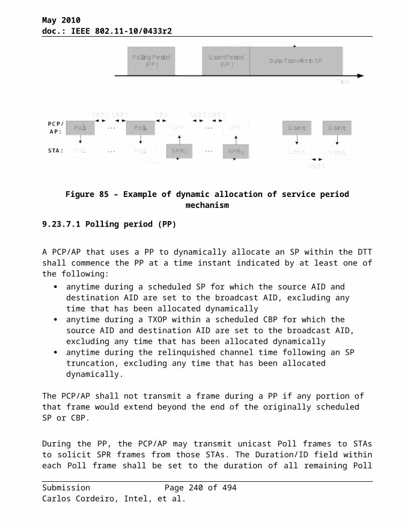
May 2010 doc.: IEEE 802.11-10/0433r2
ix) Disassociation: Disassociation notification when in State 2 or 3 changes a STA’s state to State 1.
x) Within a PBSS when dot11RSNAEnabled is set to FALSE, all Action and Action No Ack frames except the following frames:(1) ADDTS Request and ADDTS Response frames
3) Data framesi) Data frames within an IBSS with frame control (FC) bits “To DS” and “From DS” both
false when dot11RSNAEnabled is set to FALSE.ii) Data frames within a PBSS when dot11RSNAEnabled is set to FALSE.iii) RSNA establishment frames within a PBSS when dot11RSNAEnabled is set to TRUE.
Successful RSNA establishment enables a STA to change to State 3. Unsuccessful RSNA establishment leaves the STA in State 1.
iv) Data frames that are not sent within a BSS and that have the wildcard BSSID value in the BSSID field.
4) Extension framesi) mmWave Beacon
b) Class 2 frames (if and only if associated and RSNA not established; allowed from within States 2 and 3 only)1) Management frames
i) Within an infrastructure BSS when dot11RSNAEnabled is set to FALSE, all Action and Action No Ack frames
2) Control framesi) Pollii) SPRiii) mmWaveDTSiv) mmWaveCF-Endv) Block Ack (BlockAck) within an infrastructure BSS when dot11RSNAEnabled is set to
FALSEvi) Block Ack Request (BlockAckReq) within an infrastructure BSS when
dot11RSNAEnabled is set to FALSE3) Data frames
i) RSNA establishment frames within a BSS when dot11RSNAEnabled is set to TRUE. Successful RSNA establishment enables a STA to change to State 3. Unsuccessful RSNA establishment leaves the STA in State 2.
ii) Data frames within a BSS when dot11RSNAEnabled is set to FALSE.
c) Class 3 frames (if and only if associated and RSNA established or RSNA established; allowed only from within State 3)1) Data frames
i) Data subtypes: Within a BSS that is not an IBSS, Data frames allowed, i.e., either the “To DS” or “From DS” FC bits, but not both, may be set to true to utilize the DSS.
ii) QoS data subtypes allowed to/from non-AP STA(s) that are associated with AP(s), and among STAs within a PBSS.
iii) Data frames within a BSS with FC bits “To DS” and “From DS” both FALSE.2) Management frames
i) Within a PBSS or an infrastructure BSS, all Action and Action No Ack frames except the following frames:
Submission Page 240 of 339 Carlos Cordeiro, Intel, et al.
May 2010 doc.: IEEE 802.11-10/0433r2
(1) Public Action3) Control frames
i) Block Ack (BlockAck)ii) Block Ack Request (BlockAckReq)
If STA A that participates in a PBSS and has dot11RSNAEnabled set to TRUE receives a Class 3 frame with a unicast address in the Address 1 field from STA B that does not have an established RSNA with STA A, STA A shall disallow the received Class 3 frame and send a disassociation frame to STA B.
11.3.3.1 Non-PCP/non-AP STA Association and RSNA proceduresUpon receipt of an MLME-ASSOCIATE.request primitive, a STA shall associate with a PCP/AP via the following procedure:
a) The STA shall transmit an Association Request frame to a PCP/AP. If the MLME-ASSOCIATE.request primitive contained an RSN information element with only one pairwise cipher suite and only one authenticated key suite, this RSN information element shall be included in the Association Request frame.
b) If an Association Response frame is received with a status value of “successful,” the STA is now associated with the PCP/AP. The state variable shall be set to State 2, and the MLME shall issue an MLME-ASSOCIATE.confirm primitive indicating the successful completion of the operation.
c) If an Association Response frame is received with a status value other than “successful” or the AssociateFailureTimeout expires, the STA is not associated with the PCP/AP. The MLME shall issue an MLME-ASSOCIATE.confirm primitive indicating the failure of the operation. The status code returned in the Association Response frame indicates the cause of the failed association attempt. Any misconfiguration or parameter mismatch, e.g., data rates required as basic rates that the STA did not indicate as supported in the STA’s Supported Rates information element, shall be corrected before the SME issues an MLME-ASSOCIATE.request for the same PCP/AP. If the status code indicates the association failed because of a reason that is not related to configuration, e.g., the PCP/AP is unable to support additional associations, the SME shall not issue an MLME-ASSOCIATE.request for the same PCP/AP until a period of at least 2 seconds has elapsed.
Upon receipt of an MLME-SETPROTECTION.request primitive with ProtectType set to “Rx_Tx,” a STA shall establish RSNA. The state variable shall be set to State 3 if the STA successfully establishes RSNA. The State variable shall remain unchanged if the STA does not successfully establish RSNA.
The STA’s SME shall delete any PTKSA and temporal keys held for communication with the indicated STA by using MLME-DELETEKEYS.request primitive (8.4.10) before invoking MLME-ASSOCIATE.request primitive.
11.3.3.2 PCP/AP Association and RSNA proceduresWhen an Association Request frame is received from a STA, the PCP/AP shall associate with the STA using the following procedure:
a) In an RSNA, the PCP/AP shall check the values received in the RSN information element to see whether the values received match the PCP/AP ’s security policy. If not, the association
Submission Page 241 of 339 Carlos Cordeiro, Intel, et al.
May 2010 doc.: IEEE 802.11-10/0433r2
shall not be accepted. Otherwise, the PCP/AP shall transmit an Association Response frame addressed to the STA before dot11AssocRespConfirmTime expires.
b) Upon receipt of an MLME-Associate.response service primitive, the PCP/AP shall transmit an Association Response with a status code as defined in 7.3.1.9 and with AID field in the range 1-254. If the status value is “successful,” the association identifier assigned to the STA shall be included in the response.
c) When the status value of the association is not successful, the PCP/AP shall indicate a specific reason for the failure to associate in the status code of the Association Response frame. If any status code value from Table 7-23 in 7.3.1.9 is an appropriate reason for the failure to associate, the PCP/AP shall indicate that status code value. The use of the unspecified reason value of the status code shall indicate the association failed for a reason that is unrelated to every other defined status code value in Table 7-23.
d) When the Association Response frame with a status value of “successful” is acknowledged by the STA, the STA is considered to be associated with this PCP/AP. The state variable for the STA shall be set to State 2.
Upon receipt of an MLME-SETPROTECTION.request primitive with ProtectType set to “Rx_Tx,” a PCP/AP shall establish RSNA. The state variable shall be set to State 3 if the PCP/STA successfully establishes RSNA. The State variable shall remain unchanged if the PCP/STA does not successfully establish RSNA.
The STA’s SME shall delete any PTKSA and temporal keys held for communication with the indicated STA by using MLME-DELETEKEYS.request primitive (see 8.4.10) upon receiving a MLME-ASSOCIATE.indication primitive.
11.3.3.3 Non-PCP/non-AP STA Disassociation proceduresUpon receipt of an MLME-DISASSOCIATE.request primitive, an associated STA shall disassociate from a PCP/AP using the following procedure:
a) The STA shall transmit a Disassociation frame to the PCP/AP with which that STA is associated.
b) The state variable for the PCP/AP shall be set to State 1.c) The MLME shall issue an MLME-DISASSOCIATE.confirm primitive indicating the
successful completion of the operation.
The STA’s SME shall delete any PTKSA and temporal keys held for communication with the indicated STA by using the MLME-DELETEKEYS.request primitive (see 8.4.10) and by invoking MLME-SETPROTECTION.request(None) before invoking the MLME-DISASSOCIATE.request primitive.
11.3.3.4 Non-PCP/non-AP STA disassociation receipt procedureUpon receipt of a Disassociation frame, a STA shall operate as follows:
a) The MLME shall issue an MLME-DISASSOCIATE.indication with the ReasonCode parameter set to the value of the reason code received in the Disassociation frame.
b) The state variable for the PCP/AP shall be set to State 1.
Submission Page 242 of 339 Carlos Cordeiro, Intel, et al.
May 2010 doc.: IEEE 802.11-10/0433r2
c) If the reason code indicates a configuration or parameter mismatch as the cause of the disassociation, the STA shall not attempt to associate or reassociate with the PCP/AP sending the Disassociation frame until the configuration or parameter mismatch has been corrected.
d) If the reason code indicates the STA was disassociated for a reason other than configuration or parameter mismatch, the STA shall not attempt to associate the PCP/AP sending the Disassociation frame until a period of 2 seconds has elapsed.
The STA’s SME shall delete any PTKSA and temporal keys held for communication with the indicated STA by using the MLME-DELETEKEYS.request primitive (see 8.4.10) and by invoking MLME-SETPROTECTION.request(None) before invoking the MLME-DISASSOCIATE.request primitive.
11.3.3.5 PCP/AP disassociation initiation procedureUpon receipt of an MLME-DISASSOCIATE.request, a PCP/AP shall use the following procedure when disassociating a STA:
a) The PCP/AP shall send a Disassociation frame to the STA being disassociated.b) The PCP/AP shall indicate a specific reason for the disassociation in the Reason Code field of
the Disassociation frame. If any reason code value other than the unspecified reason code from Table 7-22 of 7.3.1.7 is appropriate for indicating the reason for the disassociation, the PCP/AP shall indicate that reason code value. The use of the unspecified reason value shall indicate the STA was disassociated for a reason unrelated to all defined reason code values defined in Table 7-22.
c) The state variable for the STA shall be set to State 1.
The STA’s SME shall delete any PTKSA and temporal keys held for communication with the indicated STA by using the MLME-DELETEKEYS.request primitive (see 8.4.10) and by invoking MLME-SETPROTECTION.request(None) upon receiving a MLME-DISASSOCIATE.indication primitive.
11.3.3.6 PCP/AP disassociation receipt procedureUpon receipt of a Disassociation frame from an associated STA, the PCP/AP shall disassociate the STA via the following procedure:
a) The state variable for the STA shall be set to State 1.b) The MLME shall issue an MLME-DISASSOCIATE.indication primitive to inform the SME of
the disassociation.
The STA’s SME shall delete any PTKSA and temporal keys held for communication with the indicated STA by using the MLME-DELETEKEYS.request primitive (see 8.4.10) and by invoking MLME-SETPROTECTION.request(None) upon receiving a MLME-DISASSOCIATE.indication primitive.
11.3.4 Communicating PBSS informationFollowing the association or security association of a STA with a PCP, the PCP shall distribute the PBSS information using an unsolicited Information Response frame (7.4.13.6). The PCP shall set the
Submission Page 243 of 339 Carlos Cordeiro, Intel, et al.

May 2010 doc.: IEEE 802.11-10/0433r2
target address field of the Information Response frame to the broadcast address and shall include in the Information Response frame an entry for each STA associated with the PBSS including the PCP.
The PCP shall distribute the PBSS information for each of the STAs that are associated with the PBSS, including the PCP, at least once every dot11BroadcastSTAInfoDuration BIs.
11.4 TS operation .11 Editor Notes: Edit the contents of 11.4.1 through 11.4.10 of IEEE 802.11-2007 as follows:
11.4.1 Introduction
.11 editor note: modify the subclause 11.4.1 as follows
There are three types of traffic specifications: The TSPEC, The Extended mmWave TSPEC and the PTP TSPEC.
A TSPEC describes the traffic characteristics and the QoS requirements of TS (7.3.2.30). The main purpose of the TSPEC is to reserve resources within the HC and modify the HC’s scheduling behavior. It also allows other parameters to be specified that are associated with the TS, such as a traffic classifier and acknowledgment policy. The Extended mmWave TSPEC (7.3.2.97) describes the timing and the traffic requirements of a TS that exists within either a PBSS or within an infrastructure BSS operating in the UB. The purpose of the Extended mmWave TSPEC is for the initial creation and modification of service periods and their allocation for the transmission of frames between mSTAs that are members of a PBSS or that are members of a mmWave infrastructure BSS ( 9.23.6 ).
When transmitted between members of a PBSS or members of an infrastructure BSS operating in the UB, the TSPEC defined in 7.3.2.30 is used to modify the traffic parameters of a previously-established TS between non-AP/non-PCP mSTAs in a mmWave infrastructure BSS/PBSS and between a non-AP/non-PCP STA and a PCP in a PBSS. In this case, the TSPEC is referred to as a PTP TSPEC.
The PTP TSPEC is a TSPEC that is exchanged between two non-AP mSTAs. A PTP TSPEC includes parameters that are associated with the TS such as max MSDU size and Delay Bound, and identifies different TSs that can use the same SP for data transfer between non-AP mSTAs. In the case the PTP TSPEC contains the SP and the additional TS to be transferred during the identified SP, the non-AP/non-PCP mSTA should forward ADDTS Request frame to the peer non-AP/non-PCP mSTA through the AP/PCP mSTA. A TS can have one or more TCLAS associated with it. The AP uses the parameters in the TCLAS elements to identify the MSDUs belonging to a TS so that they can be delivered with the QoS parameters that have been set up for that TS.
TSPEC, PTP TSPEC and the optional TCLAS elements are transported over the air within ADDTS frames and across the MLME SAP by the MLME-ADDTS primitives.
Submission Page 244 of 339 Carlos Cordeiro, Intel, et al.

May 2010 doc.: IEEE 802.11-10/0433r2
Extended mmWave TSPEC is transported over the air within the Extended mmWave ADDTS and across the MLME SAP by the MLME-ExtADDTS primitives.
Following a successful negotiation of a TSPEC, a TS is created, and is identified within the non-AP STA by its TSID and direction, and identified within the HC by a combination of TSID, direction, and non-AP STA address.
Following a successful negotiation of an Extended mmWave TSPEC in a PBSS or in a mmWave infrastructure BSS a TS is created and is identified within non-AP/non-PCP mSTA by a combination of TSID, BSSID, and destination AID, and is identified within the PCP mSTA and AP mSTA by a combination of TSID, source mSTA address and destination AID.
Following successful negotiation of a PTP TSPEC, the frames corresponding to the PTP TSPEC are indentified within the mSTA by the combination of TSID, requesting non-AP mSTA address, responding non-AP mSTA address, direction, and SP TSID (7.3.2.30).
It is always the responsibility of the non-AP STA to initiate the creation of a TS regardless of its direction. A STA that is not an mSTA shall not transmit a PTP TSPEC or an Extended mWave TSPEC. The non-AP mSTA that is not the source STA of a specific TS shall not initiate the exchange of an Extended mmWave TSPEC to the AP mSTA or PCP mSTA to create that TS. Any non-AP mSTA can issue a PTP TSPEC to any other non-AP mSTA to create a TS.
In the direct-link case, it is the responsibility of the non-AP STA that is going to send the data to create the TS using a TSPEC. In this case, the non-AP STA negotiates with the HC to gain TXOPs that it uses to send the data. There is no negotiation between the originator and recipient non-AP STAs concerning the TS: the originator can discover the capabilities of the recipient (rates, BlockAck) using the DLS. In the case of traffic relayed by an AP/PCP, the sending and receiving non-AP/non-PCP STAs may both create individual TSs for the traffic. In an infrastructure BSS, any traffic classifier created for the downlink TS applies equally regardless of whether the source is in the same BSS or reached through the DS.
In an infrastructure BSS, a non-AP STA may simultaneously support up to eight TSs from the HC to itself and up to eight TSs from itself to other STAs, including the HC. The actual number it supports may be less due to implementation restrictions.
Within a mmWave BSS may be up to sixteen TSs from a source mSTA to a destination mSTA. An additional sixteen TSs may be created between the two mSTAs by reversing the roles of source and destination. The actual number supported in any direction may be less due to implementation restrictions in either the source or destination mSTA.
The traffic admitted in context of a TSPEC can be sent using EDCA or HCCA or HEMM. This depends on the access policy set in the TS Info field in the TSPEC. A TSPEC request may be set so that both HCCA and EDCA mechanisms (i.e., HEMM) are used. The traffic admitted as a result of an Extended mmWave TSPEC negotiation is sent during a CBP or an SP.
Submission Page 245 of 339 Carlos Cordeiro, Intel, et al.
May 2010 doc.: IEEE 802.11-10/0433r2
11.4.2 TSPEC Construction
Extended mmWave TSPECs and TSPECs are constructed at the SME, from application requirements supplied via the SME, and with information specific to the MAC layer. There are no normative requirements on how any Extended mmWave TSPEC or TSPEC is to be generated. However, in K.3.2, a description is given on how and where certain parameters may be chosen for the TSPEC.
11.4.3 TS Lifecycle
Unless stated otherwise, the owner of an SP is the STA identified by the source AID field contained in a Grant frame or Extended Schedule element transmitted by the PCP/AP for that SP, and the owner of a TXOP is the TXOP holder. A STA that owns an SP or a TXOP is said to have the ownership of the SP or the TXOP, respectively. The rules applicable to a SP or TXOP owner are defined in 9.23 and 11.4.
Following a successful TS setup initiated by the non-AP STA in a BSS in the LB/HB, the TS becomes active, and either the non-AP STA or the HC may transmit QoS data frames using this TSID (according to the Direction field). Following a successful TS setup initiated by a STA in a BSS in the UB, the TS becomes active, and source STA takes ownership of the SP.
While the TS is active, the parameters of the TSPEC or Extended mmWave TSPEC characterizing the TS can be renegotiated, when the renegotiation is initiated by the non-AP STA. This negotiation can succeed, resulting in a change to the TSPEC or Extended mmWave TSPEC, or can fail, resulting in no change to the TSPEC or Extended mmWave TSPEC.
An active TS becomes inactive following a TS deletion process initiated at either non-AP STA or HC It also becomes inactive following a TS timeout detected at the HC. When using the mmWave PHY, a TS timeout is detected at a non-AP STA and causes the TS deletion process to be initiated at the non-AP STA. When an active TS becomes inactive, all the resources allocated for the TS are released.
An active TS may become suspended if no activity is detected for a duration of a suspension interval. Upon detection of activity, the TS may be reinstated. While the TS is in the suspended state, the HC shall not reclaim the resources assigned to the TS. When using the mmWave PHY (clause 21 ), a TS in which both the source and destination are non-AP/non-PCP STAs shall not be suspended.
11.4.4 TS Setup
.11 Editor’s instructions: in Figure11-8, replace “HC” by “HC/non-AP STA”
.11 editor note: modify the first two paragraphs in the subclause 11.4.4 as follows
The non-AP STA SME decides that a TS needs to be created. How it does this, and how it selects the TSPEC or Extended mmWave TSPEC parameters, is beyond the scope of this specification. The SME generates an MLME-ADDTS.request primitive containing a TSPEC or Extended mmWave TSPEC. A TSPEC or Extended mmWave TSPEC may also be generated autonomously by the MAC without any initiation by the SME. However, if a TSPEC or Extended mmWave TSPEC is generated subsequently
Submission Page 246 of 339 Carlos Cordeiro, Intel, et al.
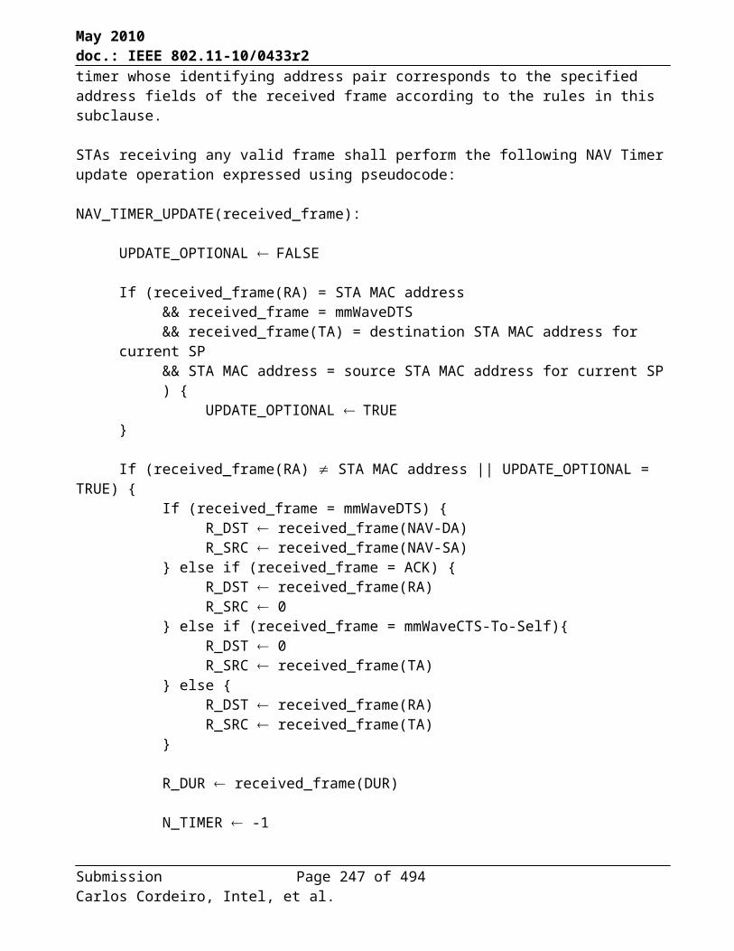
May 2010 doc.: IEEE 802.11-10/0433r2
by the SME and the responding MLME-ADDTS.confirm primitive contains ResultCode=SUCCESS, the TSPEC or Extended mmWave TSPEC containing the same TSID generated autonomously by the MAC shall be overridden. If one or more TSPECs or Extended mmWave TSPEC s are initiated by the SME, the autonomous TSPEC or Extended mmWave TSPEC shall be terminated.
The non-AP STA MAC transmits the TSPEC or Extended mmWave TSPEC in an ADDTS Request frame to the HC/non-AP STA and starts a response timer called ADDTS timer of duration dot11ADDTSResponseTimout. If the non-AP STA expects to enter power save mode, it shall include its Wakeup Schedule IE in the ADDTS Request frame variant and in the Extended mmWave ADDTS frame variant.
The HC/non-AP STA MAC receives this management frame and generates an MLME-ADDTS.indication primitive to its SME containing the TSPEC or Extended mmWave TSPEC.
The SME in the HC/non-AP STA decides whether to admit the TSPEC or Extended mmWave TSPEC as specified, refuse the TSPEC or Extended mmWave TSPEC, or not admit but suggest an alternative TSPEC or Extended mmWave TSPEC. The SME then generates an MLME-ADDTS.response primitive containing the TSPEC or Extended mmWave TSPEC and a ResultCode value. The contents of the TSPEC or Extended mmWave TSPEC and Status fields contain values specified in 10.3.24.4.2.
If the Extended mmWave TSPEC is admitted, the PCP/AP shall set the ResultCode to SUCCESS_STA_IN_DOZE_MODE if the STA identified by destination AID is in power save mode, and shall include in the ADDTS Response frame the Wakeup Schedule element of the destination STA. In this case, the PCP/AP should defer including the TS schedule in the Extended Schedule element until both source and destination STAs are in active mode.
The HC/non-AP STA MAC transmits an ADDTS Response frame containing this TSPEC and status. The encoding of the ResultCode values to Status Code field values is defined in Table 11-2. The PCP/AP shall transmit the ADDTS Response frame to the STAs identified as source and destination AID of the Extended mmWave TSPEC contained in the ADDTS request frame, if the ADDTS request it is sent by a non-PCP/AP STA. If the ResultCode is SUCCESS, the PCP/AP shall announce the creation of the TS by including the TS schedule in the Extended Schedule element transmitted in the mmWave Beacon frame or Announce frame.
.11 Editor note: In Table 11-2, insert the following row:
Table 11-2 – Encoding of ResultCode to Status Code field valueResultCode Status code
SUCCESS_STA_IN_DOZE_MODE 54
The non-AP STA MAC receives this management frame and cancels its ADDTS timer. It generates an MLME-ADDTS.confirm primitive to its SME containing the TSPEC or Extended mmWave TSPEC and status.
The non-AP STA SME decides whether the response meets its needs. How it does this is beyond the scope of this specification. If the result code is SUCCESS, the TS enters into an active state. Otherwise, the whole process can be repeated using the same TSID and direction and a modified TSPEC until the non-AP STA SME decides that the granted TXOP is adequate or inadequate and
Submission Page 247 of 339 Carlos Cordeiro, Intel, et al.
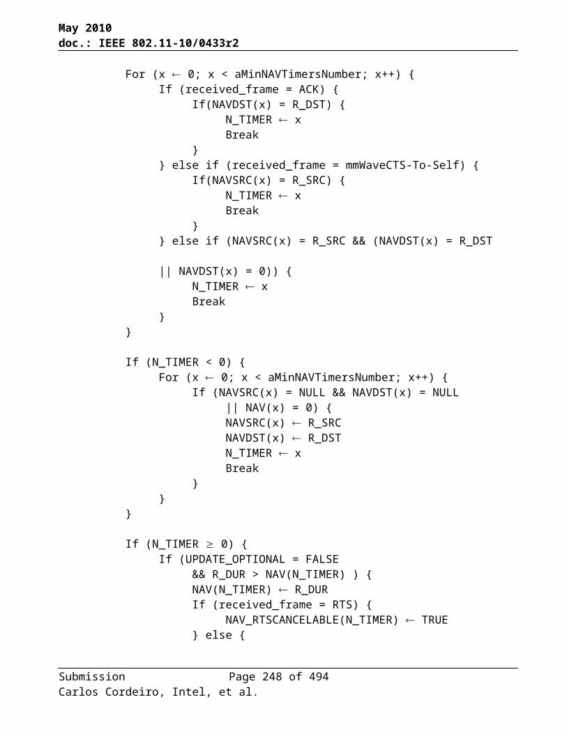
May 2010 doc.: IEEE 802.11-10/0433r2
cannot be improved. The same rule applies to the negotiation of the P2P TSPEC and to negotiation of the Extended mmWave TSPEC.
The parameters that are set for a TS can be renegotiated in a similar manner, when such a request is generated by the SME through ADDTS.request primitive. When a request for the modification of the TS parameters is accepted by the HC it shall reset both the suspension interval and the inactivity interval timers.
When a request for the modification of the TS parameters is accepted by the non-AP STA, it shall reset the inactivity interval timers.
If the AP/HC grants a TXOP for an ADDTS Request frame with the Ack Policy subfield set to Block Ack and the Direction field set to either downlink or bidirectional, then it shall initiate a Block Ack negotiation by sending an ADDBA Request frame to the non-AP STA that originated the ADDTS Request frame. If a non-AP STA in a BSS in the LB/HB is granted a TXOP for an ADDTS Request frame with the Ack Policy subfield set to Block Ack and the Direction field set to other than downlink, then it shall initiate a Block Ack negotiation by sending an ADDBA Request frame to the recipient of the TS.
.11 Editor note: Add after the last paragraph:
The MAC or SME of a mmWave STA may allocate a TSID and use it to identify the frames comprising a flow with a peer STA without using ADDTS Request and Response frames.
11.4.5 Failed TS SetupThere are two possible types of failed TS setup:
a) The transmission of ADDTS Request frame failed.b) No ADDTS Response frame is received from the HC/non-AP STA (e.g., because of delay due to congestion or because the response frame cannot be transmitted).
Figure 11-9 summarizes the remaining two cases. The MLME shall issue an MLME-ADDTS.confirm primitive, with a result code of TRANSMISSION_FAILURE in the former case and TIMEOUT in the latter case. In both cases and for a BSS in the LB/HB, if the request is not for an existing TS, the non-AP STA MAC shall send a DELTS to the HC specifying the TSID and direction of the failed request just in case the HC had received the request and it was the response that was lost. In both cases and for a BSS in the UB, if the request is not for an existing TS, the non-PCP/non-AP STA MAC shall send a DELTS to the non-AP STA specifying the TSID and destination STA of the failed request just in case the PCP/AP had received the request and it was the response that was lost.
.11 Editor note: In Figure 11-9, replace “HC” by “HC/non-AP STA”
.11 editor note: modify the sub clauses 11.4.6 -11.4.8 as follows
11.4.6 Data Transfer
After the setup of a TSPEC, MSDUs are classified above the MAC and are sent to the MAC through the MAC_SAP using the service primitive MA-UNITDATA.request with the priority parameter encoded to the TSID. The MAC delivers the MSDUs based on a schedule using QoS data frames. In
Submission Page 248 of 339 Carlos Cordeiro, Intel, et al.
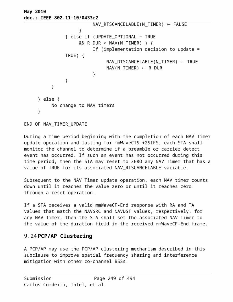
May 2010 doc.: IEEE 802.11-10/0433r2
the case of a non-AP STA, the MSDUs are transmitted using QoS data frames, when the non-AP STA is polled by the HC.
After the setup of a P2P TSPEC, MSDUs are classified above the MAC and are sent to the MAC through the MAC_SAP using the service primitive MA-UNITDATA.request with the priority parameter encoded to the TSID. During the CBP the MAC delivers the MSDUs based on a priority of the transmitted QoS data frames. During SP allocated as defined in 11.4.11.1 and 11.4.11.2.the MSDUs are transmitted using QoS data frames,
After the setup of an Extended mmWave TSPEC, MSDUs are classified above the MAC and are sent to the MAC through the MAC_SAP using the service primitive MA-UNITDATA.request with the priority parameter encoded to the TSID. The MSDUs are transmitted using QoS data frames, during the SP allocated as defined in 11.4.11.1 and 11.4.11.2.
When an MSDU arrives from the MAC_SAP with a TSID for which there is no associated TSPEC or Extended mmWave TSPEC, then the MSDUs shall be sent using EDCA using the access category AC_BE.
11.4.7 TS DeletionThere are two types of TS deletion: non-AP/non-PCP STA-initiated and HC/PCP-initiated. In both cases and when the TS Info is used, the SME entity above the MAC generates an MLME-DELTS.request primitive specifying the TSID and direction of the TS to be deleted and the reason for deleting the TS. In both cases and when the Extended mmWave TS Info is used, the SME entity above the MAC generates an MLME-DELTS.request primitive specifying the TSID and destination STA of the TS to be deleted and the reason for deleting the TS. This causes the MAC to send a DELTS Action frame. The encoding of ReasonCode values to Reason Code field (see 7.3.1.7) values is defined in Table 11-3.
Figure 11-10 shows the case of TS deletion initiated by the non-AP/non-PCP STA and the case of TS deletion initiated by the HC/PCP.
An HC should not delete a TSPEC without a request from the SME except due to inactivity (see 11.4.8).
All TSPECs or Extended mmWave TSPEC s that have been set up shall be deleted upon disassociation and reassociation. Reassociation causes the non-AP/non-PCP STA and AP/PCP to clear their state, and the non-AP/non-PCP STA will have to reinitiate the setup.
A PCP/AP shall remove the scheduling information contained in the Extended Schedule element corresponding to a deleted Extended mmWave TSPEC identified by the TSID and destination STA.
.11 Editor note: In Figure 11-10, replace “HC” by “HC/non-AP STA”
11.4.8 TS TimeoutTS timeout is detected within the HC/non-AP STA STA MAC when no traffic is detected on the TS within the inactivity timeout specified when the TS was created.
Submission Page 249 of 339 Carlos Cordeiro, Intel, et al.
May 2010 doc.: IEEE 802.11-10/0433r2
For an uplink TS in a BSS in the LB/HB or for a TS that has the PCP/AP as the destination STA in a BSS in the UB, the timeout is based on the arrival of correctly received MSDUs that belong to the TS within the MAC after any decryption and reassembly.
For a downlink TS in a BSS in the LB/HB or for a TS that has the PCP/AP as the source STA in a BSS in the UB, the timeout is based on the following:— Arrival of valid MA-UNITDATA.request primitives using this TS at the MAC_SAP when the QoS data frames are sent with the Ack Policy subfield set to No Ack.— Confirmation of correctly sent MSDUs that belong to the TS within the MAC when the QoS data frames are sent with the Ack Policy subfield set other than to No Ack.
When using the mmWave PHY (clause 21 ) and the TS is established between non-AP STA (PTP TPSEC) the timeout of the recipient is based on the arrival of correctly received MSDUs that belong to the TS within the MAC after any decryption and reassembly.
For TS established between non-AP STAs (PTP TSPEC) the timeout of the originator is based on the following:— Arrival of valid MA-UNITDATA.request primitives using this TS at the MAC_SAP when the QoS data frames are sent with the Ack Policy subfield set to No Ack.— Confirmation of correctly sent MSDUs that belong to the TS within the MAC when the QoS data frames are sent with the Ack Policy subfield set other than to No Ack.
For a direct-link TS not employing the mmWave PHY ( clause 21 ) , inactivity is considered to have happened if one of the two following happens:— Returning QoS Null immediately after SIFS interval that contains a zero Queue Size subfield in the QoS Control field in response to a QoS CF-Poll frame.— No QoS Null frame indicating the queue size for related TSID within a TXOP. This is to ensure that the non-AP STA is actually using the assigned TXOP for the given TSID.
When not using the mmWave PHY ( clause 21 ), any other use of a polled TXOP delivered to the non-AP STA is considered to be activity on all direct-link TS associated with that non-AP STA. Detection of inactivity of this type is optional.
In response to an inactivity timeout, the HC/AP/PCP shall send a DELTS frame to the non-AP STA or non-PCP source STA, respectively, with the result code set to TIMEOUT and inform its SME using the MLME-DELTS.indication primitive.
When using the mmWave PHY (clause 21 ) and the TS is established between non-AP STA (PTP TSPEC) then in response to an inactivity timeout, the non-AP STA shall send a DELTS frame to the non-AP STA with the result code set to TIMEOUT and inform its SME using the MLME-DELTS.indication primitive.
The case of uplink TS timeout in a BSS or TS timeout in a PBSS in which the PCP/AP is the destination STA of the TS is shown in Figure 11-11.
.11 Editor note: In Figure 11-11, replace “HC” by “HC/non-AP STA”
Submission Page 250 of 339 Carlos Cordeiro, Intel, et al.

May 2010 doc.: IEEE 802.11-10/0433r2
.11 editor note: add following sub-clauses 11.4.11, 11.4.11.1, 1.4.11.2, 11.4.12 after 11.4.10
11.4.11 mmWave TS Traffic Types
An mSTA supports TS operation as described in sub clauses 11.4.1 through 11.4.11. Using the Extended mmWave TSPEC the mSTA may schedule two types of TS: isochronous and asynchronous. It should establish an isochronous TS if it needs periodic access to the channel and does not expect to change the amount of time allocated frequently. It should establish an asynchronous TS if it expects to make requests for channel time and wishes to reserve a minimum amount of channel time to satisfy for those requests when they occur.
11.4.11.1 Isochronous TS supportA STA shall set the Traffic Type field in the Extended mmWave TSPEC element to zero to request the setup of an isochronous TS.
Following the successful admittance of a isochronous TS, the PCP/AP should allocate time in the BI to meet the periodicity and minimum allocation requirements specified in the Extended mmWave TSPEC.
The PCP/AP should ensure that over each Allocation Period, the sum of the time allocations is at least the Minimum Allocation. In addition, the PCP/AP should ensure that each individual SP allocation has a minimum duration of at least Minimum SP Duration. See subclauses 7.3.2.97, 9.23.6, 9.23.6.3 Pseudo-static allocations.
11.4.11.2 Asynchronous TS supportThe STA uses the SPR frame to request channel time for asynchronous traffic. For each TID, source STA and destination STA tuple, the PCP/AP can maintain the amount of outstanding channel time that needs to be allocated. Each time it receives the SPR frame the amount of outstanding channel time is set to the value received in the SPR frame from the source STA for the identified TID and destination STA. The amount of outstanding channel time is decreased by the amount allocated when channel time is schedule for that TID, source STA and destination STA tuple.
A STA may use the Extended mmWave TSPEC to reserve resources for asynchronous traffic. In this case, the STA shall set the Traffic Type field in the Extended mmWave TSPEC element to one. The PCP/AP should only admit an asynchronous TS if it is able to meet the minimum allocation requirements specified in the Extended mmWave TSPEC.
11.4.12 PTP TS Operation
The ADDTS Request frame containing the PTP TSPEC may be sent to the peer non-AP mSTA directly or through AP/PCP mSTA.
A non-AP mSTA may add TSs to an existing SP. To do this, the non-AP mSTA transmits an ADDTS Request frame to peer non-PCP/non-AP mSTA to include the additional TS. The ADDTS request
Submission Page 251 of 339 Carlos Cordeiro, Intel, et al.
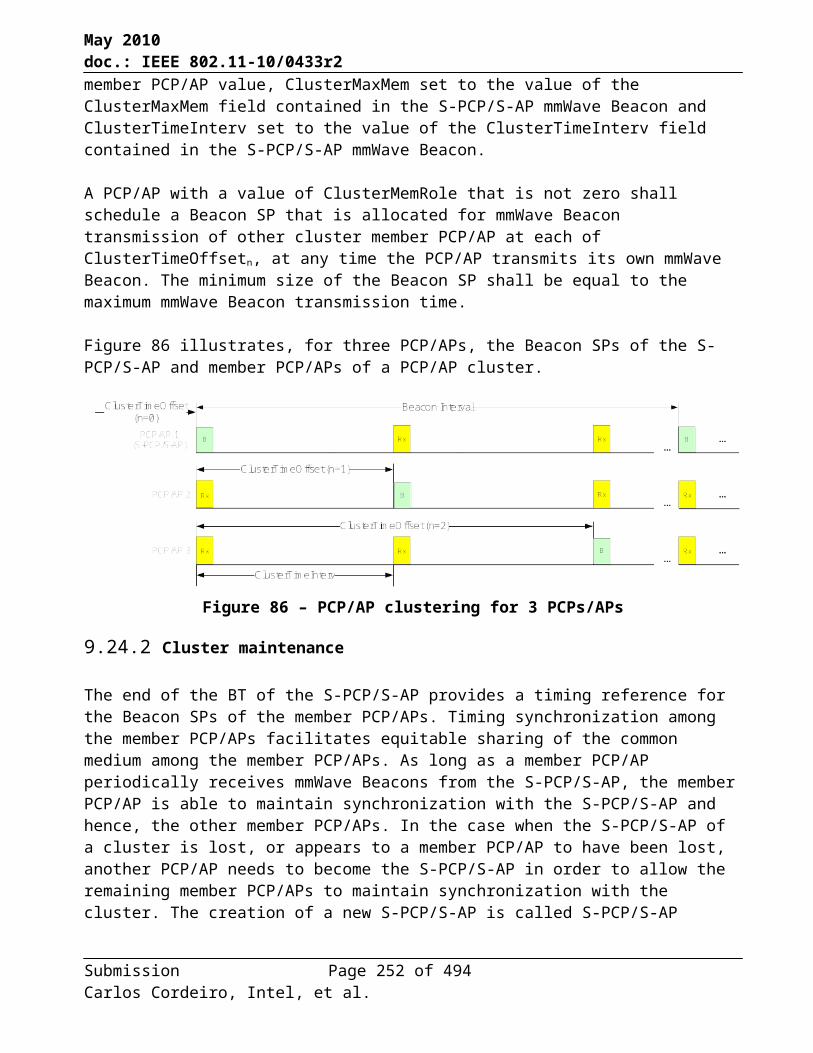
May 2010 doc.: IEEE 802.11-10/0433r2
frame shall contain a PTP TSPEC with aggregation field set to 1, and the SP TSID set to the TSID of the SP to which the mSTA wishes to add the additional TS.
The ADDTS request frame that adds TS to the existing SP should be forwarded to the peer mSTA through the AP/PCP mSTA to provide the information to the SP scheduler. The ADDTS Request frame forwarded through AP/PCP mSTA shall contain a TCLAS element with the classifier type set to Ethernet parameters and the Source Address field shall contain the address of the mSTA that sends the ADDTS Request frame and the Destination Address field shall contain the address of the peer mSTA in the allocated SP.
The non-AP mSTA and the non-PCP mSTA shall not request the inclusion of an additional TS to an SP in which the source mSTA and the destination mSTA differs from the source mSTA and destination mSTA indicated in the ADDTS request frame.
The AP mSTA or PCP mSTA shall forward the received ADDTS Request frame to the mSTA with Address equal to the Destination Address field of the Classifier. If an ADDTS Response frame is received by the AP mSTA or PCP mSTA in response to the forwarded ADDTS Request frame, then the AP mSTA or PCP mSTA shall forward the ADDTS Response frame to the mSTA with Address equal to the Source Address field of the Classifier.
A non-AP mSTA may deliver traffic-specific parameters like A-MSDU subframe and Maximum MSDU Size to other non-AP mSTA with which it is directly communicating. To do this, the non-AP mSTA should directly transmit an ADDTS Request frame to peer non-AP mSTA. The PTP TSPEC shall be used to convey traffic parameters of the TS; the parameters are applicable for SPs and for CBPs the mSTAs that established the TS communicate.
If the mSTA asserts the direction field to the Downlink in the PTP TSPEC included in the ADDTS Request frame, the parameters apply to the mSTA as the receiving station. For example, the Maximum MSDU Size field indicates that the mSTA is not able to receive MSDUs longer then the value presented in the MSDU Size field. If the direction field indicates uplink, the mSTA that issued the ADDTS Request frame will never send MSDUs longer than the value of the Maximum MSDU Size field.
11.5 Block Ack operation
.11 Editor Notes: Insert the following to (Table 11-5a—Types of Block Ack agreement based on capabilities and ADDBA conditions):
Table 11-5a – Types of Block Ack agreement based on capabilities and ADDBA conditions
Capabilities Condition ADDBA condition Type of Block Ack agreementBoth STA supports mmWave PHY Block Ack Policy subfield set to 0 HT-Immediate
Both STA supports Block Ack Policy subfield set to 1 HT-Immediate + Flow Control
Submission Page 252 of 339 Carlos Cordeiro, Intel, et al.

May 2010 doc.: IEEE 802.11-10/0433r2
mmWave PHY
11.8 TPC procedures
.11 Editor’s instructions: through the subclause 11.8 including 11.8.1, 11.8.2, 11.8.3, and 11.8.4 replace any appearance of “BSS” by “Infrastructure BSS, PBSS”
.11 Editor’s instructions: through the subclause 11.8 including 11.8.1, 11.8.2, 11.8.3, and 11.8.4 replace any appearance of “AP” by “AP/PCP”
.11 Editor’s instructions: through the subclause 11.8 including 11.8.1, 11.8.2, 11.8.3, and 11.8.4 replace any appearance of word “beacon” by “beacon, mmWave Beacon and Announce”
11.9 DFS procedures
.11 Editor Note: Insert the following sentence after “The procedures may also satisfy comparable needs in other frequency bands and may be useful for other purposes.”
For example, some of the procedures described in this section may be used for channel selection in the UB.
.11 Editor Note: Insert the following paragraphs before the sentence “For the purposes of DFS, the following statements apply:”
In the UB, the following DFS procedures apply:
— Associating STAs with an AP or a PCP based on the STAs’ supported channels (see 11.9.1).— Quieting the current channel so it can be tested for interference with less interference fromassociated STAs (see 11.9.2).— Requesting and reporting measurements in the current and other channels (see 11.9.6).— Selecting and advertising a new channel to assist the migration of an infrastructure BSS, IBSS or
PBSS (see 11.9.7).
.11 Editor Note: Throughout this subclause, replace all occurrences of “BSS or IBSS” with “infrastructure BSS, IBSS, or PBSS”
11.9.1 Association based on supported channels
.11 Editor Note: Insert the following sub-section
11.9.1.1 Providing supported channels upon association in a mmWave BSS
A PCP/AP may advertise regulatory domain in which it is located via a Country element in the mmWave Beacon or Announce or Information Response frame if dot11MultiDomainCapabilityEnabled is true.
Submission Page 253 of 339 Carlos Cordeiro, Intel, et al.

May 2010 doc.: IEEE 802.11-10/0433r2
A STA shall provide a PCP/AP with a list of the channels in which it can operate when associating or reassociating using a Supported Channels element in Information Request, Association Request frames or Reassociation Request frames. A PCP/AP may use the supported channels list for associated STAs as an input into an algorithm used to select a new channel for the BSS. The specification of the algorithm is beyond the scope of this specification.
PCP/AP may advertise the supported channels of associated STAs via an Information Response frame with Target Address set to the broadcast address and a Supported Channels element with a list of all channels supported in the BSS.
11.9.2 Quieting channels for testing
.11 Editor Note: Insert the following paragraph after the subsection title
A PCP/AP in a BSS may measure one or more channels itself or a PCP/AP may request associated non-PCP/non-AP STAs in the same BSS to measure one or more channels, either in a dedicated measurement interval or during normal operation. A PCP/AP may schedule a service period allocated to itself to quite the associated STAs and use the self-allocated SP for measurement.
11.9.6 Requesting and reporting of measurements
.11 Editor Note: Replace all occurrences of “BSS or IBSS” with “infrastructure BSS, IBSS, or PBSS” in this sub- section.
.11 Editor Note: Replace all occurrences of “AP” with “AP or PCP” in this sub- section.
.11 Editor Note: Append the following rows to Table 11-8—Allowed Measurement Requests.
Service set Source of request Destination of request Type of measurement request allowed
PBSS/BSS PCP/AP STA Individual or groupSTA PCP/AP IndividualSTA STA None
.11 Editor Note: Insert the following sentence at the end of the section 11.9.6
The measurement request and report procedures can follow relevant procedures defined in section 11.10.
11.9.7 Selecting and advertising a new channel in an infrastructure BSS
.11 Editor Note: Insert the following subclause after section 11.9.7.2
Submission Page 254 of 339 Carlos Cordeiro, Intel, et al.
May 2010 doc.: IEEE 802.11-10/0433r2
11.9.7.3 Selecting and advertising a new channel in a mmWave BSS
The decision to switch to a new operating channel in a BSS shall be made only by the PCP/AP. A PCP/AP may make use of the information in Supported Channel elements and the results of measurements undertaken by the PCP/AP and other STAs in the BSS to assist the selection of the new channel. The algorithm to choose a new channel is beyond the scope of this specification, but shall satisfy applicable regulatory requirements.
A PCP/AP shall inform associated STAs that the PCP/AP is moving to a new channel and maintain the association by advertising the switch using the Extended Channel Switch Announcement element in mmWave Beacon frames, Announce frames, Information Response frames, and Channel Switch Announcement frames until the intended channel switch time. The channel switch should be scheduled so that all non-PCP/non-AP STAs in the BSS, including STAs in power save mode, have the opportunity to receive at least one Extended Channel Switch Announcement element before the switch. In a BSS, a STA may ignore the Channel Switch Mode field.
A STA that receives an Extended Channel Switch Announcement element may choose not to perform the specified switch, but to take alternative action. For example, it may choose to move to a different BSS. A non-PCP/non-AP STA in a BSS shall not transmit the Extended Channel Switch Announcement element.
11.10 Radio measurement procedures
11.10.1 Multiple BSSID set
.11 Editor Instruction: throughout this subclause in 802.11-2007+amendments, change all occurrences of “Beacon” to “Beacon/mmWave Beacon”
11.22 Wireless network management procedures
11.22.15 DMS Procedures
.11 Editor Note: replace all occurrences of the word “AP” by “AP or non-AP mSTA”.
.11 Editor Note: Add new paragraph after first paragraph in this subclause as follows:
In the mmWave PBSS operation the Directed Multicast Service (DMS) is a service that may be provided by any STA to other STAs associated in the same PBSS that support the DMS service, where the STA transmits group addressed MSDUs as individually addressed A-MSDUs.
11.30 mmWave Beamformed Link and BSS Maintenance
Submission Page 255 of 339 Carlos Cordeiro, Intel, et al.
May 2010 doc.: IEEE 802.11-10/0433r2
11.30.1 Beamformed Link MaintenanceA pair of STAs that have established a beamformed link may maintain this link. This subclause describes procedures that allow a pair of STAs to maintain a beamformed link that was established between them. The destination STA of an SP waits for aSlotTime + aPHY-RX-START-Delay from the start of the SP for a PHY-RXSTART.indication to occur. If a PHY-RXSTART.indication does not occur during this time, the destination STA of the SP should configure its receive antenna to a quasi-omni antenna pattern following the expiration of this time. If a PHY-RXSTART.indication does occur during this time, the STA should wait for the corresponding PHY-RXEND.indication to determine whether the MPDU transmission was successful. The recognition of anything else other than a valid frame sent by the source STA of the SP and addressed to the destination STA of the SP should be interpreted as beamformed link breakage by the destination STA. Following the determination of the beamformed link, the destination STA of the SP should configure its receive antenna to a quasi-omni antenna pattern.
The destination STA of an SP may transmit a mmWaveDTS frame to the source STA of the SP following the rules in 9.23.6.5 mmWave Protected Period, if the NAV timer at the destination STA has a non-zero value and the destination STA wants to prevent the source STA of the SP to re-start beamforming with the destination STA.
Any time after aSlotTime + aPHY-RX-START-Delay has elapsed from the start of the SP, the source STA of the SP may transmit an RTS frame to restore the beamformed link with the destination STA of the SP and, in this case, the RTS shall be transmitted at MCS 0. The source STA of the SP should restart beamforming with the destination STA after no more than dot11ShortRetryLimit RTS retransmission attempts without a response CTS.
To maintain a beamformed link between a PCP/AP and a non-PCP/non-AP STA, the PCP/AP should send a frame with its antenna pattern directed to the STA at least once every aMinBTPeriod beacon intervals and the STA should send a frame with its antenna pattern directed to the PCP/AP at least once every aMinBTPeriod beacon intervals. If the PCP/AP does not receive a frame with a MCS other than MCS 0 from the STA after dot11ShortRetryLimit transmission attempts, it assumes that the beamformed link with the STA is invalid and should schedule time in the beacon interval for the PCP/AP to initiate beamforming training with the STA whose beamformed link became invalid.
If a STA detects degradation in the link quality between itself and another STA, the STA can use beam tracking or beam refinement to improve the link quality. The STA can request the PCP/AP to schedule an SP to perform BF with the other STA or use a CBP to perform BF. The STA can use the A-BFT to perform BF if the other STA is its PCP/AP. A PCP/AP can perform BF with a non-PCP/non-AP STA during a CBP or by scheduling an SP between the PCP/AP and the non-PCP/non-AP STA through an Extended Schedule element transmitted in a mmWave Beacon or Announce frames.
If the link quality between a PCP/AP and a STA degrades, but the STA can still receive mmWave Beacon frames and the A-BFT present field set to 1, the STA should improve the link quality by performing beamforming during the A-BFT period as described in 9.25.4.
Submission Page 256 of 339 Carlos Cordeiro, Intel, et al.

May 2010 doc.: IEEE 802.11-10/0433r2
11.30.2 PCP Handover
A STA is PCP handover capable if the PCP Handover field within the STA’s mmWave Capabilities element (7.3.2.91) is set to one. The STA is PCP handover incapable otherwise.
The PCP handover process allows the information pertinent to the operation of the PBSS to be distributed to suitable PCP handover capable STA(s) and for a PCP handover capable STA to take over the PCP responsibilities from the PCP explicitly or implicitly.
The information pertinent to the operation of a PBSS includes STA information and pseudo-static scheduling information.
The STA information comprise of AID, MAC address and capability. The PCP may relay the information to all STAs in the PBSS by using the Information Response frame.
The pseudo-static scheduling information include pseudo-static SP and CBP allocations carried in the Extended Schedule element (7.3.2.95).
Two types of PCP Handover may be supported, explicit and implicit. In Explicit PCP Handover, the PCP explicitly selects and schedules the transfer of PCP responsibilities to another PCP handover capable STA as described in 11.30.2.1. In Implicit PCP Handover the PCP distributes the Next PCP List element (7.3.2.103) in its mmWave Beacon or Announce frames and maintains the content of the NextPCP List element to facilitate the implicit handover process described in 11.30.2.2. The PCP may decide the priority of Next PCPs and update the Next PCP List based on information contained within a STA’s mmWave PCP/AP Capability element. The NextPCP List element contains an ordered list of zero or more PCP handover capable STAs that can take over the role of the PCP during implicit handover. The ordering of STAs in the NextPCP List and the criteria for updating the NextPCP List are implementation specific. The PCP shall increment the Token field of the NextPCP List by 1 every time the list is changed or if information pertinent to the operation of the PBSS is changed.
When a PCP handover capable STA takes over the PCP responsibilities of a PBSS, the pseudo-static scheduling information shall remain unchanged. Any outstanding request for resource allocation is lost and STAs that have outstanding requests for allocation may re-request the resource allocation.
In explicit PCP handover, the PCP may use several types of information when selecting the candidate PCP, such as the value of the MAX Associated STA Number field within the STA’s mmWave Capabilities element advertised by candidate PCPs.
Following a PCP handover, non-PCP STAs should transmit a frame to the new PCP within dot11MaxLostBeacons BIs. If the new PCP does not receive at least one frame from an associated non-PCP STA for dot11MaxLostBeacons BIs following a PCP handover, it should remove the STA from the PBSS.
Submission Page 257 of 339 Carlos Cordeiro, Intel, et al.
May 2010 doc.: IEEE 802.11-10/0433r2
11.30.2.1 Explicit Handover procedureThe PCP may transmit a Handover Request frame to a non-PCP STA that is handover capable. Upon receiving a Handover Request, a non-PCP STA becomes the candidate PCP. If the Handover Request is accepted, the candidate PCP shall transmit a Handover Response frame to the PCP with the Handover Result field set to 0. If the Handover Request is rejected, the candidate PCP shall transmit a Handover Response frame to the PCP with the Handover Result field set to 1 or 2 and cease to be the candidate PCP.
A non-PCP STA that is handover capable may transmit a Handover Request frame to a handover capable PCP. Upon transmission of the Handover Request frame, the non-PCP STA becomes the candidate PCP. If the Handover Request is accepted, the PCP shall transmit a Handover Response frame to the candidate PCP with the Handover Result field set to 0. If the Handover Request is rejected, the PCP shall transmit a Handover Response frame to the candidate PCP with the Handover Result field set to 1 or 2 and the candidate PCP shall cease to be a candidate PCP. Following the transmission or reception of a successful Handover Response frame, a candidate PCP should request STA information and pseudo-static scheduling information from the PCP using an Information Request frame within the next dot11NbrOfChangeBeacons BIs. The candidate PCP should also request SPs to perform beamforming and establish security association with other associated STAs prior to the completion of PCP handover.
Following the reception or transmission of a successful Handover Response frame, the PCP shall transmit the PCP Handover element within its mmWave Beacon or Announce frame for each of the next dot11NbrOfChangeBeacons BIs and shall set the Remaining BIs field within the PCP Handover element to the number of BIs remaining until the candidate PCP takes over the role of the PBSS’s PCP. The initial value of the Remaining BIs field shall be equal to the value transmitted by the PCP in the Handover Remaining BI field within the last transmitted Handover Request frame to the candidate PCP, or equal to the value received by the PCP in the Handover Remaining BI field within the last received Handover Request frame from the candidate PCP. A non-PCP STA receiving a mmWave Beacon or Announce frame containing the PCP Handover element shall set the STA’s local countdown counter to the value of the Remaining BIs field contained in the PCP Handover element. The STAs shall then decrease the local countdown counter by one at each TBTT and shall use the candidate PCP’s address as the new beacon filter address once the STA’s local countdown reaches zero. When exiting sleep state, a STA shall decrement the local countdown counter by the number of BI(s) in the sleep state it is exiting from.
11.30.2.2 Implicit Handover procedureUpon receiving the NextPCP List element, a PCP handover capable STA which finds its AID as the ith AID entry in the NextPCP List element received from the PCP becomes the ith Implicit candidate PCP. Upon detecting a Token value contained in the NextPCP List element is different from the value of the last Token received from the PCP, each Implicit candidate PCP should request STA information and pseudo-static scheduling information from the PCP by transmitting an Information Request frame addressed to the PCP (11.31.1).
The implicit handover process is triggered at the ith Implicit candidate PCP when the ith Implicit candidate PCP fails to receive a mmWave Beacon or Announce frames from the PCP for (i * dot11ImplicitHandoverLostBeacons) beacon intervals. When this happens, the ith Implicit candidate
Submission Page 258 of 339 Carlos Cordeiro, Intel, et al.
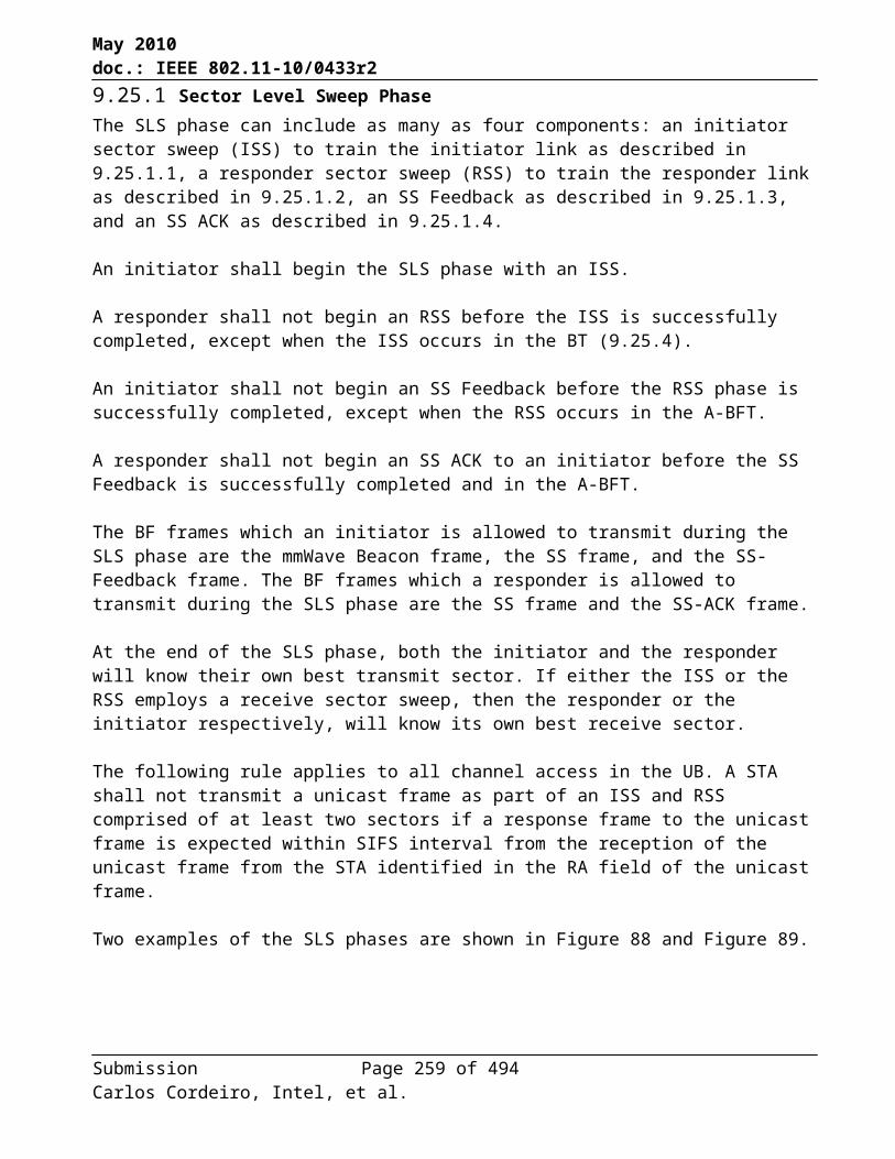
May 2010 doc.: IEEE 802.11-10/0433r2
PCP then sends a mmWave Beacon at the next BI to announce that it is taking over the responsibility as the PCP of the PBSS. The mmWave Beacon sent by ith Implicit candidate PCP repeats all information carried in the last mmWave Beacon sent by the former PCP.
If the first n Implicit candidate PCPs fail to take the role of PCP, it will take at least dot11ImplicitHandoverLostBeacons * (n +1) beacon intervals before the PBSS members receive a mmWave Beacons. The system should make sure that all STAs are capable of maintaining the accuracy of the internal clock to remain synchronized with each other.
To avoid disruptions to pseudo-static SPs due to implicit handover, the value of dot11ImplicitHandoverLostBeacons should be lower than the value of dot11MaxLostBeacons.
11.31 mmWave BSS Peer and Service Discovery
This subclause describes the procedures for peer and service discovery.
11.31.1 Information Request and Response
A STA may request information about either a single STA in the PBSS or about all of the STAs in the PBSS by sending a Information Request frame (7.4.13.5). If the STA is requesting information about only a single STA in the PBSS, it shall set the Target Address in the frame to the MAC address of that STA. If the STA is requesting information about all of the STAs in the PBSS, it shall set the Target Address in the frame to the broadcast address and shall transmit the Information Request frame to the PCP.
A STA may transmit an Information Request frame with the length field of the Request element set to zero to another STA in the PBSS to determine if the destination STA is still present in the PBSS and is within range of the sending STA.
A STA may transmit an Information Request frame with its STA Capability element and other elements. A non-PCP STA shall not include in the Information Request frame the capability information corresponding to another STA.
The STA may transmit an Information Response frame (7.4.13.6) either as a response to an Information Request frame or it may be sent unsolicited. If a STA is providing information about a single STA in the PBSS, it shall set the Target Address in the Information Response frame to the MAC address of that STA. If a STA is providing information about all of the STAs in the PBSS, it shall set the Target Address in the Information Response frame to the broadcast address.
A non-PCP STA shall not include in the Information Response frame the capability information corresponding to another STA.
A STA shall include in the Information Response frame the elements requested by the originator STA.
A STA shall send an Information Response frame with length zero in response to a received Information Request frame for which the requesting STA solicits information about a single STA that
Submission Page 259 of 339 Carlos Cordeiro, Intel, et al.
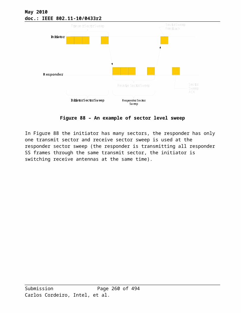
May 2010 doc.: IEEE 802.11-10/0433r2
is not a member of the PBSS and the receiving STA is a non-PCP STA, or that is not the receiving STA itself. Otherwise, the STA shall send the Information Response frame with the information requested by the requesting STA.
11.31.2 Peer Service Discovery
A PCP/AP may provide different types of information to a non-PCP/non-AP STA upon request. To query available services in a BSS, a non-PCP/non-AP STA shall send either an Information Request frame or a Probe Request frame to the PCP/AP (11.31.1). The Information Request and Information Response frames are robust management frames, while the Probe Request and Probe Response frames are not.
Upon receiving the Information Request frame, the PCP/AP, subject to criteria below, shall respond with a Information Response, only if all the following three criteria are true:
a) The SSID in the Information Request is the wildcard SSID or the specific SSID of the PCP/AP,b) The BSSID field in the Information Request is the wildcard BSSID or the BSSID of the PCP/AP, andc) The DA field in the Information Request is the MAC address of the PCP/AP.
The PCP/AP transmits the Information Response frame to the address of the non-PCP/non-AP STA that generated the Information Request.
The Information Response frame can contain service information as vendor-specific information elements.
11.32 Changing mmWave BSS parameters
This subclause describes the methods used by the PCP/AP to change certain key characteristics of the BSS.
The PCP/AP shall deliver the mmWave BSS Parameter Change to STAs holding pseudo-static SPs and STAs in power save mode before a mmWave BSS Parameter Change.
The PCP/AP shall initiate a mmWave BSS Parameter Change by including a mmWave BSS Parameter Change element (7.3.2.90) in its mmWave Beacon or Announce frames. The PCP/AP places the mmWave BSS Parameter Change in every mmWave Beacon or Announce frame after the first one, stopping in the following mmWave Beacon or Announce frame after the mmWave BSS Parameter Change takes effect.
11.32.1 Moving the BT
Submission Page 260 of 339 Carlos Cordeiro, Intel, et al.
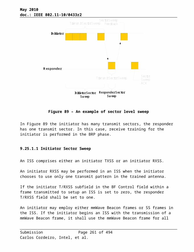
May 2010 doc.: IEEE 802.11-10/0433r2
The PCP/AP may move the relative position, i.e., TBTT of the first mmWave Beacon transmission within a BT, hence moving the entire BT. Moving the BT means that except for the BI in which the change takes effect the BI duration is unchanged while the position of the BT is moved.
If the PCP/AP wishes to move the position of its first mmWave Beacon within a BT, it shall insert the mmWave BSS Parameter Change element into dot11NbrOfChangeBeacons mmWave Beacon or Announce frames with the Move field set as indicated in 7.3.2.90 and the Beacon Time field set to the first mmWave Beacon transmission time following this mmWave BSS Parameter Change. The PCP/AP shall indicate the BT movement through the Move field with every mmWave Beacon or Announce frame transmission until following the mmWave BSS Parameter Change. The PCP/AP shall update the Beacon Time field in the mmWave BSS Parameter Change element with every mmWave Beacon or Announce frame transmission until following the mmWave BSS Parameter Change.
A PCP/AP member of a PCP/AP cluster that wishes to move its BT transmission time shall set the Beacon Time field to an empty Beacon SP allocated by its S-PCP/S-AP as defined in 9.24.
Figure 121 illustrates the process in moving the BT position.
Figure 121 – Moving the BT position
11.32.2 Changing BI duration
The PCP/AP may change the duration of its BI during the BSS operation.
If the PCP/AP wishes to change its BI duration, it shall insert the mmWave BSS Parameter Change element into dot11NbrOfChangeBeacons mmWave Beacon or Announce frames with the Size field set as indicated in 7.3.2.90 and the BI Duration field set to the BI duration following this mmWave BSS Parameter Change. The Beacon Time field shall be set to the time when this mmWave BSS Parameter Change takes effect.
The PCP/AP shall indicate the change in BI duration through the Size field with every mmWave Beacon or Announce frame transmission until following the mmWave BSS Parameter Change. The PCP/AP shall update the Beacon Time field in the mmWave BSS Parameter Change element with every mmWave Beacon or Announce frame transmission until following the mmWave BSS Parameter Change.
Figure 122 illustrates the process in changing the BI duration.
Submission Page 261 of 339 Carlos Cordeiro, Intel, et al.

May 2010 doc.: IEEE 802.11-10/0433r2
Figure 122 – Changing BI duration
11.32.3 Maintaining synchronization in a PCP/AP cluster
A S-PCP/S-AP shall update the PCP/AP clustering fields transmitted in the mmWave Beacon if the mmWave BSS Parameter Change modifies the allocation of the Beacon SPs (9.24). If the PCP/AP clustering fields are modified as a result of a mmWave BSS Parameter Change, the S-PCP/S-AP shall transmit the updated PCP/AP clustering fields in every mmWave Beacon in which the mmWave BSS Parameter Change field is transmitted.
A PCP/AP member of a PCP/AP cluster receiving a S-PCP/S-AP mmWave Beacon with a mmWave BSS Parameter Change element indicating a change in the BI duration or TBTT time shall immediately insert the appropriate mmWave BSS Parameter Change element into its mmWave Beacons if the S-PCP’s/S-AP’s mmWave BSS Parameter Change causes a modification in the allocation of the Beacon SPs.
If a PCP/AP that is a member of a PCP/AP cluster is required to make a mmWave BSS Parameter Change as a result of its S-PCP’s/S-AP’s mmWave BSS Parameter Change, it shall use the value of the Beacon Time field in the mmWave BSS Parameter Change element from the S-PCP’s/S-AP’s mmWave Beacon to calculate the Beacon Time field in the mmWave BSS Parameter Change element of its own mmWave Beacon transmission.
11.33 Spatial frequency sharing and Interference mitigation
This subclause describes mechanisms to enable spatial frequency sharing and interference mitigation within a PBSS/infrastructure BSS and in a uncoordinated OBSS environment. A STA may implement spatial sharing mechanisms which allow SPs in the same vicinity to be scheduled concurrently over the same channel, and for interference mitigation. Alternatively, the PCP/AP can use CBPs to mitigate interference.
The SFS and Interference Mitigation field in the mmWave Capabilities element indicates whether a STA supports spatial sharing.
A STA shall support the Directional Channel Quality measurements described in 7.3.2.21.12 and 7.3.2.22.11 if the STA is spatial sharing capable.
Submission Page 262 of 339 Carlos Cordeiro, Intel, et al.
May 2010 doc.: IEEE 802.11-10/0433r2
11.33.1 Spatial sharing and Interference assessment
The PCP/AP should request STAs to perform and report spectrum and radio resource measurements described in 11.10 and 7.4 to assess the possibility to perform spatial sharing and for interference mitigation.
The PCP/AP should use the Directional Channel Quality described in 7.3.2.21.12, 7.3.2.22.11 to assess the possibility for spatial sharing of SPs.
A SP to be assessed for spatial sharing with other existing and allocated SPs or considered to be reallocated in the BI is hereby termed as a candidate SP. There may be multiple candidate and existing SPs at one time, and a SP may simultaneously assume the role of candidate and existing SP depending upon the context it is used for spatial sharing and interference assessment.
STAs which participate in a SP and which support spatial sharing should perform beamforming with each other before engaging in any communication or performing any measurements.
The PCP/AP should request beamforming-capable STAs involved in a candidate SP to perform measurements for the purpose of spatial sharing with an existing SP only after the STAs have beamformed with each other.
If the PCP/AP transmits a Directional Channel Quality Request to a STA involved in a candidate SP to assess the possibility for spatial sharing with another existing SP, it shall set the Target STA to the corresponding peer STA involved in the candidate SP and shall set the Measurement Method field to indicate ANIPI.
If the candidate SP has already been allocated channel time, the PCP/AP should transmit a Directional Channel Quality Request to the STAs involved in the existing SP to assess the possibility for spatial sharing with the candidate SP. In the Channel Quality Request, the PCP/AP shall set the Target STA to the corresponding peer STA involved in the existing SP and shall set the Measurement Method field to indicate ANIPI. NOTE – When the PCP/AP transmits a directional channel quality request to a STA of an existing SP, it intends to assess the channel quality during transmission by STAs belonging to the candidate SP. Similarly, when the PCP/AP transmits a directional channel quality request to a STA of a candidate SP, it intends to assess the channel quality during transmission by STAs belonging to the existing SP.
Figure 123 illustrates an example of spatial sharing assessment between two SPs. In this example, SP1 is the existing SP and SP2 is the candidate SP. The PCP/AP transmits a Directional Channel Quality Request to STAs C and D to measure over SP1’s channel allocation, and transmits a Directional Channel Quality Request to STAs A and B to measure over SP2’s channel allocation. The relation of the Measurement Start Time and Measurement Duration fields in the Directional Channel Quality Request message is shown in Figure 123, while the field Number of Time Blocks is the ratio (Measurement Duration / Measurement Unit).
Submission Page 263 of 339 Carlos Cordeiro, Intel, et al.
May 2010 doc.: IEEE 802.11-10/0433r2
Figure 123 – Example of spatial sharing assessment
If a non-PCP/non-AP STA receives a Directional Channel Quality Request from its PCP/AP, it should perform the measurements as indicated in the request and shall report back to the PCP/AP using the Directional Channel Quality Report. The report shall be formatted and transmitted as per specified in the Directional Channel Quality Request. The non-PCP/non-AP STA shall set the Report Mode field (7.3.2.22) in the report frame to indicate whether it performed the measurement as requested by the PCP/AP.
11.33.2 Achieving spatial sharing and Interference mitigationA PCP/AP may estimate the channel quality across STAs participating in the PBSS/infrastructure BSS and implement spatial sharing and interference mitigation based on the results of the measurements performed by the STAs associated with the PCP/AP.
A PCP/AP should only schedule a candidate SP time-overlapping with an existing SP in its BI after it receives a Directional Channel Quality Report from the STAs involved in the candidate SP.
If a candidate SP is already allocated channel time, the PCP/AP should only schedule this candidate SP time-overlapping with an existing SP in its BI after it receives a Directional Channel Quality Report from the STAs involved in the existing SP.
The PCP/AP should schedule a candidate SP during a period of time in the BI where the PBSS/infrastructure BSS performance is expected to be maximized. The determination of performance maximization should be based on measurement reports received by the PCP/AP, but is implementation dependent and beyond the scope of this specification.
The decision process at the PCP/AP to perform spatial sharing of a candidate and an existing SP is implementation dependent and beyond the scope of this specification.
Submission Page 264 of 339 Carlos Cordeiro, Intel, et al.
May 2010 doc.: IEEE 802.11-10/0433r2
The candidate SP is referred to as Time-Overlapped SP following the allocation by the PCP/AP of a candidate SP overlapping in time with an existing SP.
Figure 124 illustrates an example of the resulting SP schedule in the BI for the spatial sharing between the two SPs shown in Figure 123.
Figure 124 – Example of spatial sharing between SP1 and SP2
The PCP/AP shall transmit a Directional Channel Quality Request to each spatial sharing capable STA involved in a Time-Overlapped and existing SP scheduled under spatial frequency sharing. In the Directional Channel Quality Request that the PCP/AP transmits to each STA, the PCP/AP shall set the Target STA to the peer STA involved in the same SP and shall set the Measurement Method field to indicate RSNI.
If a spatial sharing capable non-PCP/non-AP STA receives a Directional Channel Quality Request from its PCP/AP, it should perform the measurements as indicated in the request and shall report the results back to the PCP/AP using the Directional Channel Quality Report. The report shall be formatted and transmitted as per specified in the corresponding Directional Channel Quality Request.
The PCP/AP should stop the spatial sharing of two or more SPs if it determines that the link quality of any of the links involved in the spatial sharing has dropped below acceptable levels. This determination should be based on Directional Channel Quality Reports received by the PCP/AP, but is implementation dependent and beyond the scope of this specification.
The STA may include the TSCONST field with the ADDTS request sent to the PCP/AP for the purpose of interference mitigation. The PCP/AP should consider the information in the TSCONST field specified by a STA in its SP schedule.
Specific algorithms to realize spatial sharing and interference mitigation amongst SPs between different STAs is implementation dependent and beyond the scope of this specification.
11.33.3 PBSS and infrastructure BSS stability in OBSS scenarios
The PCP/AP should keep the SP schedule stable across BIs and should minimize schedule changes. This is to allow for STAs to associate or disassociate the PBSS/infrastructure BSS or modify their SP reservations. Stability in BI schedule allows a PBSS/infrastructure BSS to assess the interference pattern produced by OBSSs and adapt to the environment by scheduling SPs over periods of time in the BI when less interference is expected.
Submission Page 265 of 339 Carlos Cordeiro, Intel, et al.
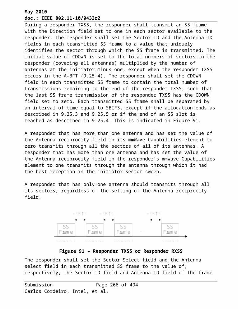
May 2010 doc.: IEEE 802.11-10/0433r2
The PCP/AP shall limit the frequency with which it changes the operating PBSS/infrastructure BSS channel to alleviate the instability and ripple effect that may result from frequent channel changes in OBSS scenarios. Upon a channel switch, the PCP/AP of a PBSS/infrastructure BSS shall select a random number, N, uniformly distributed between [0, SwitchInterval-1] and shall only attempt a new channel switch after N BIs have elapsed since the preceding channel switch. The initial value of SwitchInterval is aMinSwitchInterval and it is doubled upon every new channel switch up to a maximum value of aMaxSwitchInterval. The PCP/AP resets SwtichInterval to aMinSwitchInterval if it remains on the same operating channel for a minimum of aMaxSwitchInterval consecutive BIs.
11.34 Multi-band Operation
A STA is multi-band capable if the value of its local MIB variable dot11MultibandSupportEnabled is true. A STA that is multi-band capable advertizes the capability by including the Multi-band element in Beacon, mmWave Beacon, (Re)Association Request, Association Response, Information Request, Information Response, Probe Response, Announce, FST Setup Request and FST Setup Response frames.
A STA may include more than one Multi-band element in any one of these frames if it supports more than two bands. A multi-band capable STA shall set the Band ID and Regulatory Class fields within a Multi-band element to specify the frequency band it supports. If the multi-band capable STA is or intends to operate in the band indicated within the Multi-band element, it shall set the Channel Number field to indicate the channel of operation within that band. The FST session transition is managed by FST session setup protocol. A multi-band capable STA participates as an initiator or as a responder in the FST session setup. Depending on the STAs behavior during the FST session setup, the FST session may be operational in one band, or may be transferred to another band, or may be operational in multiple bands simultaneously and in this case data transfer can take place in multiple bands any time an MSDU arrives at the MAC SAP. When operational in more than one band simultaneously, an FST session in one of the bands can be transferred back to any other bands of the FST session. An FST session between an initiator and a responder is identified by an FSTS ID. The value of the FSTS ID is allocated by the initiator of an FST session and shall remain unchanged whether the FST session is operational in one band or more than one band simultaneously. The value of the FSTS ID shall be unique for a pair of initiator and responder, and there shall be no more than one FST session between a pair of initiator and responder. The FSTS ID shall be reset by an initiator and responder pair when a different FSTS ID is included in the FST Setup Request frame sent by either the initiator or responder.
A multi-band capable STA may use the same MAC address in both bands or it may use different MAC addresses in each band. When the STA MAC Address Present field is set to one in a Multi-band element, the STA MAC Address field in the Multi-band element specifies the MAC addresses that the STA uses in the band that is indicated in the Multi-band element. If the STA MAC Address Present field is set to zero, the MAC address that the STA uses in the frequency band that is indicated in the Multi-band element is the same as the STA uses in the current operating band.
Submission Page 266 of 339 Carlos Cordeiro, Intel, et al.

May 2010 doc.: IEEE 802.11-10/0433r2
The FST session addressing mode is Transparent if both initiator and responder of the FST session use the same MAC address in the frequency bands involved in the FST session transfer. The FST session addressing mode is Non-Transparent if either the initiator or responder use different MAC addresses in the different frequency bands involved in the FST session. A multi-band capable STA should deliver all fragments, if any, of an MSDU of an FST session before it transfers the FST session.
A multi-band capable STA that is a member of a BSS shall include, in any transmitted FST Setup Request and in any transmitted FST Setup Response, the same capabilities element, supported rates and supported channels that were transmitted during its most recent successful association exchange in the band indicated in its most recently transmitted Multi-band element that was transmitted on the same band on which it is transmitting the FST Setup Request or FST Setup Response frames.
11.34.1 FST Setup
The FST setup protocol defines the transfer of an FST session between initiator and responder to another band. The FST setup protocol comprises four states and rules how to move from one state to the next. The states are: Initial, Setup completion, Transition done and Transition confirmed. In the Initial state, the FST session is operational in one or both bands. In the Setup Completion state, both initiator and responder are ready to change their currently operating band(s). An FST session may be fully or partially transferred to another band or transferred back to one band. The Transition done state enables both initiator and responder to operate in the other band if the value of the LLT was zero. Both initiator and responder have to successfully communicate in the new band to reach the Transition confirmed state. The state transition diagram of the FST setup protocol is shown in Figure 125.
To transfer an FST session from the Initial state to the Setup Completion state of the FST setup protocol (Figure 125), an initiator and responder shall exchange FST Setup Request and FST Setup Response frames. In the Initial and in the Setup Completion states, the Old band represents the frequency band from which the FST session is intending to be transferred from and the New Band represents the frequency band to which the FST session is intending to be transferred to. In the Transition done state, the New Band represents the frequency band the FST Ack Request and FST Ack Response frames, if any, are sent and the Old Band represents the frequency band the FST session is transferring from.
The responder shall set the Status Code field to zero if it accepts the FST Setup Request, shall set the Status Code to 39 to indicate that one or more parameters of the FST Setup Request are invalid and shall suggest alternative parameters, shall set the Status Code to 55 or 57 to indicate that a FST Setup Request is pending, and shall set the Status Code field to 37 to reject a FST Setup Request.
Submission Page 267 of 339 Carlos Cordeiro, Intel, et al.
May 2010 doc.: IEEE 802.11-10/0433r2
Figure 125 – States of the FST setup protocol
A state transition within the FST setup protocol is controlled by the State Transition Timer (STT). Each STA maintains a STT for each FST session. The STAs shall move to the Initial state when the STT moves from one to zero, or upon reception or transmission of an FST Tear down frame.
The initiator shall set the STT to the value of the FSTSessionTimeOut field at successful transmission of a FST Setup Request frame and at each ACK frame sent in response to a received FST Setup Response with the status code field equal to 55 or 57. The initiator shall set the STT to zero at the transmission of an ACK frame sent in response to a received FST Setup Response frame with the value of the status code field equal to 0. The initiator should send a FST Setup Request frame no later than FSTSessionTimeOut after the transmission of an ACK frame in response to a received FST Setup Response with status code field equal to 0.
The responder shall set the STT to the value of the FSTSessionTimeOut field at successful transmission of a FST Setup Response frame. The responder shall set the STT to zero at each transmission of an ACK frame sent in response to the reception of an FST Setup Request. The responder should send an FST Setup Response frame no later than FSTSessionTimeOut after the transmission of an ACK frame sent in response to a received FST Setup Request frame or successful transmission of a FST Setup Response frame with the status code field equal to 55 or 57. In the latter case the responder shall transmit the unsolicited FST Setup Response frame to the initiator.
Submission Page 268 of 339 Carlos Cordeiro, Intel, et al.
May 2010 doc.: IEEE 802.11-10/0433r2
There may be multiple FST Setup Request and FST Setup Response frame transmissions by, respectively, the initiator and the responder until the FST session between these STAs becomes established. At each transition from the Initial state to the Setup completion state, the initiator and responder shall perform the following procedure:
1. The initiator sends an FST Setup Request frame to the responder.2. Upon receipt of a FST Setup Request frame, the responder shall respond with an FST Setup
Response frame unless it has a pending FST Setup Request frame addressed to the initiator and the responder has a numerically larger MAC address than the initiator’s MAC address, in which case, the responder shall delete the received FST Setup Request.
3. If after the reception of the acknowledgement to the initiator’s FST Setup Request frame the initiator receives an FST Setup Request frame from the responder, the initiator shall not respond with an FST Setup Response frame if its MAC address is numerically larger than the responder’s MAC address. Otherwise if its MAC address is numerically smaller than the responder’s MAC address it becomes the responder and respond with the FST Setup Response frame and shall not send the FST Setup Request frame during the current FST session transition.
4. The initiator shall not move to the next state if at least one of the following conditions are met:a. The initiator does not transmit an ACK frame in response to the receipt of a FST Setup
Response frame from the responderb. The value of the status code field in the received FST Setup Response frame from the
responder is different than 0c. If a state specific exception in Table 61 takes place.
5. The initiator shall move to the next state if none of conditions 4(a), 4(b), and 4(c) is met.6. The responder shall not move to the next state if at least one of the following conditions are
met:a. The responder does not receive the acknowledgement to its transmitted FST Setup
Response frameb. The value of the status code field in the FST Setup Response frame it transmitted to the
initiator was different than 0c. The value of the Setup and Operation subfields within the Session Transition element in
the transmitted FST Setup Response frame results in a status different than any of the rows shown in Table 62, in which case the responder shall set the Status Code field with the transmitted FST Setup Response to 37
d. The resulting status of the Operation subfield in the New Band field is 0.7. The responder shall move to the next state if none of conditions 6(a), 6(b), 6(c) and 6(d) is met.
Table 61 – Exceptions for the initiatorState Condition Meaning Next State
Initial FST setup response with Status Code = 55
Pending, no transmission of the FST setup request
Initial
Initial FST setup response with Status Code = 57
Pending, Block Ack window at the responder has gaps
Initial
Initial FST setup response with Status Code = 39
One or more parameters of the FST SetupRequest is invalid and the responder suggests alternative parameters.
Initial
Submission Page 269 of 339 Carlos Cordeiro, Intel, et al.
May 2010 doc.: IEEE 802.11-10/0433r2
Initial FST setup response with Status Code = 37
Responder rejects the request. One particular case is that values of the regulatory class and channel number fields within the Multi-band element, if any, received in the FST Setup Request frame is different than the value of the corresponding fields within the Multi-band element, if any, transmitted in the following FST Setup Response
Initial
Initial Resulting status is different from shown in Table 62
The responder is not able to complete the setup
Initial
Initial Resulting status of the Operational field in the New Band field is 0 in Table 62
The operation in the New band is disabled Initial
Setup completion
FST setup response with Status Code = 0 and value of the LLT field within the FST Setup Request frame is greater than zero
The STA is ready to switch to the New band if the link is lost in the Old band
Setup Completion
Setup Completion
Transmission or reception of FST tear down frame
Termination of FST session Initial
If upon transition to the Setup Completion state the value of the LLT field within the last FST Setup Request frame received was zero, the initiator and responder shall immediately move to the Transition done state. If upon transition to the Setup Completion state the value of the LLT field within the last FST Setup Request frame received was greater than zero, the initiator and responder shall proceed as follows:
If the last FST Setup Request or FST Setup Response frames exchanged between the initiator and responder included a Switching Stream element, then all the streams within the Switching Streams element that have the LLT type field set to one shall be switched using the Stream-based Link Loss Countdown and all the streams within the Switching Streams element that have the LLT type field set to one zero shall be switched using the STA-based Link Loss Countdown.
If the neither the FST Setup Request nor the FST Setup Response frames exchanged between the initiator and responder included a Switching Stream element, then the streams shall be switched using the STA-based Link Loss Countdown.
The FST transition for the STA, if STA-based, or the stream, if stream-based, from the Setup completion state to the Transition done state shall occur immediately after the corresponding Link Loss countdown timer transitions from one to zero within any of the initiator or responder of the FST session.
An initiator and responder shall perform the STA-based and stream-based Link Loss Countdown as follows:
Submission Page 270 of 339 Carlos Cordeiro, Intel, et al.
May 2010 doc.: IEEE 802.11-10/0433r2
STA-based Link Loss Countdown: both initiator and responder shall remain in the Setup completion state and start a Link Loss countdown timer with an initial value of LLT*32 usec. The Link Loss countdown is reloaded with the value of LLT*32 usec every time that a unicast frame is received from the peer STA of the FST session.
Stream-based Link Loss Countdown: both the initiator and responder shall start a Link Loss countdown timer with an initial value of LLT*32 usec for each stream identified within the Switching Stream element. The Link Loss countdown for a stream is reloaded with the value of LLT*32 usec every time that a unicast frame for that stream is received from the peer STA of the FST session.
Table 62 shows the FST session status at each state transition. When the value of a subfield in the FST Setup Request is different from the value of that same subfield in the following FST Setup Response, the resulting status shall be the logical AND of the value of the corresponding subfields in both the FST Setup Request and the FST Setup Response.
Table 62 – FST status at state transitionFrom State Old band resulting
statusNew band resulting
statusTo State Definition
Setup Operation Setup OperationInitial 1 1 0 0 Initial New Band setup
and operation are disabled
Initial 1 1 1 0 Initial New Band operation is disabled, the
setup is kept alive Initial 0 0 Const=1 1 Setup
CompletionFST session is operational in
New BandInitial Const=1 1 Const=1 1 Setup
CompletionFST Session is operational in
both bands Initial 1 0 Const=1 1 Setup
CompletionFST Session is operational in
New Band; FST session in Old
Band is kept alive Setup
CompletionUnchanged Unchanged Unchanged Unchanged Transition
doneNo status changes
Transition done
Unchanged Unchanged Unchanged Unchanged Transition confirmed
No status changes
Upon transition from the Transition done state to the Transition confirmed state, the initiator and responder shall perform the following procedure within the channel number of the regulatory class and band ID specified in the Multi-band element negotiated during the FST session setup:
Submission Page 271 of 339 Carlos Cordeiro, Intel, et al.
May 2010 doc.: IEEE 802.11-10/0433r2
1. The State transition is controlled by the State Transition Timer. Each STA of the FST session has its own STT. The initiator and responder shall move to the Initial state when the STT moves from one to zero.
The initiator shall set the STT to the value of the FSTSessionTimeOut field at successful transmission of an FST Ack Request frame or at transmission of any unicast A-MPDU, MPDU or MMPDU to responder. The initiator shall set the STT to zero at the transmission of an ACK sent in response to a received FST Ack Response from the responder or at reception of an ACK frame received in response to a frame sent to the responder.
The responder shall set the STT to FSTSessionTimeOut at transmission of an FST Ack Response frame or at transmission of any other unicast A-MPDU, MPDU or MMPDU to the initiator. The responder shall set the STT to zero at reception of an ACK frame received in response to a transmitted FST Ack Response frame or at the reception of any unicast frame sent by the initiator. The responder shall transmit an FST Ack Response frame to the initiator no later than FSTSessionTimeOut after the transmission of an ACK frame sent in response to a received FST Ack Request from the initiator.
2. The initiator shall send an FST Ack Request frame or may send any other unicast A-MPDU, MPDU or MMPDU to the responder.
3. Upon receipt of an FST Ack Request frame, the responder shall respond to the initiator with an FST Ack Response frame.
4. The initiator shall move to the Transition Confirmed state upon transmission of an ACK frame sent in response to a FST Ack Response frame or any other unicast frame received from the responder or when it receives an ACK frame from the responder to any non FST Ack Request frame the initiator transmitted to the responder.
5. The responder shall move to the Transition Confirmed state when it receives an ACK frame in response to a FST Ack Response frame or any other unicast frame sent to the initiator or upon transmission of an ACK frame sent in response to any non FST Ack Request unicast frame.
If either the initiator or the responder perform in the role of PCP or AP as indicated through the STA Role field within the Multi-band element for that STA and the STAs use the transparent mode for FST session transfer, the STA performing in the role of PCP or AP should setup a FST session with all STAs in the BSS and transfer all its sessions to the new band before it performs FST to the new band.
Upon entering the Setup Completion state and preceding the actual FST session transfer, the initiator and responder that is performing a full FST session transfer may transmit a FST Setup Response frame in the old band with a status code field set to 56 and with the RA field set to the broadcast address as to notify other STAs in the BSS of this STA’s forthcoming full FST session transfer.
Following the successful FST transition to a new band, the STA of the FST session shall follow the medium access rules applicable on the new band.
11.34.1.1 FST TS switching If a STA transmitting an FST Setup Request or an FST Setup Response does not intend to switch all its streams, then the STA shall include the Switching Stream element in the transmitted frame to indicate which streams are requested to be transferred to the other band. The indication shall cover
Submission Page 272 of 339 Carlos Cordeiro, Intel, et al.
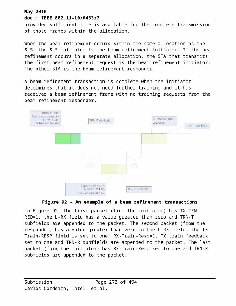
May 2010 doc.: IEEE 802.11-10/0433r2
QoS and non-QoS streams. If the FST Setup Request frame includes a Switching Stream element, the FST Setup Response frame should include a Switching Stream element. If the FST Setup Request frame does not include a Switching Stream element, the FST Setup Response frame may include a Switching Stream element. If the STA transmitting the Switching Stream element has not setup a stream in the band indicated in the New Band ID field within this element, it shall set the Stream ID in New Band Valid field to zero. A STA may setup a stream in any band by transmitting ADDBA Request or ADDTS Request frames that include the Multi-band element.
If a STA transmits an ADDTS Request frame to another STA with which it has an FST session established and the ADDTS Request frame is transmitted in a band or channel different than the band or channel to which the ADDTS Request is intended to apply to, the ADDTS Request frame shall include the Multi-band element with the band ID, regulatory class and channel number fields set to indicate to which channel the ADDTS Request frame applies to. In addition if these STAs use the non-transparent mode for FST session transfer, the STA transmitting the ADDTS Request frame sets the STA MAC Address Present field to one and the STA MAC Address field to the MAC address that the STA uses in the band and channel number that is indicated in the Multi-band element contained in the ADDTS Request frame. Similar to the ADDTS Request frame, the Multi-band element shall be included in the ADDBA Request, ADDTS Response, ADDBA Response, DELTS, and DELBA frames when these frames are transmitted in a band or channel different than the band or channel to which they are intended to apply to.
If any of the ADDTS variants is used to switch the TS, the PTP TSPEC or the Extended mmWave TSPEC shall be used when the TS is being established to operate in UB and the Basic TSPEC shall be used when the TS is being established to operate in LB and HB irrespective of the band and channel used to communicate the ADDTS frames and the Extended mmWave ADDTS frames.
The rules defined below apply when the ADDTS frames or the Extended mmWave ADDTS frames are used to switch TS. When the ADDTS frames and the Extended ADDTS frames are used then the ADDTS requester and the ADDTS responder provide the functions defined for the ADDBA Originator and the ADDBA Recipient respectively.
If the ADDBA Recipient includes the Switching Stream element in any of the FST Setup Request or FST Setup Response frames and if the Stream ID in New Band Valid field within the Switching Stream element is set to zero, the ADDBA Originator should issue the DELBA frame to reject the BA agreements indicated in the Stream ID in Old Band field. If the Originator intends to establish new BA agreements in the band indicated in the Multi-band element sent by the Recipient and with the Recipient MAC address indicated in the Multi-band element sent by the Recipient, the Originator shall transmit an ADDBA Request frame addressed to the Recipient.
The Originator may include the Multi-band element and the Ethernet type TCLAS element in the ADDBA request frame. If the MAC Addresses of the Originator and Recipient to be used in the New Band are different from the MAC addresses used in the Old Band then the ADDBA frame sent in the old band to establish a Block Ack in the New Band shall include the Multi-band and the TCLAS elements. The resulting BA agreement if established applies to the band and channel identified in the Multi-band element included in the ADBBA frame. The BA is identified by the TID/TSID and MAC addresses of the Originator and the Recipient used in the band and channel indicated in the Multi-band element included in the ADDBA frames.
Submission Page 273 of 339 Carlos Cordeiro, Intel, et al.
May 2010 doc.: IEEE 802.11-10/0433r2
The ADDBA request frame may be issued in the old band and channel, the corresponding ADDBA response may be transmitted in the band and channel indicated in the Multi-band element of the ADDBA request frame.
The following rules for the multi-band BA establishment shall apply:
1. If the TA and/or the RA fields of the ADDBA request frame are different from the Originator MAC address and/or the Recipient MAC address, respectively, used in the channel and band where the BA agreement should operate, then the Originator shall set the Source Address field and the Destination Address field of the classifier to, respectively, the Originator MAC Address and to the Recipient MAC address to be used in the band and channel indicated in the Multi-band element included in the ADDBA request frame.
2. If the TA and RA are equal to the Originator MAC address and the Recipient MAC address, respectively, then the Multi-band element, if any, included in the ADDBA request frame shall indicate the band and channel the established BA operates. The TCLAS element shall not be included in this ADDBA request frame.
3. The Multi-band element should not be included in the ADDBA request frame if in the case (2) the ADDBA request frame is issued in the same band and channel the BA shall operate.
4. If the TA and/or the RA fields of the ADDBA response frame are different from the Recipient MAC address and/or the Originator MAC address, respectively, to be used in the channel and band where the BA agreement should operate, then the Recipient shall set the Source Address field and the Destination address field of the classifier to, respectively, the Recipient MAC Address and to the Originator MAC address to be used in the band and channel indicated in the Multi-band element included in the ADDBA response frame. The indicated band and channel shall be equal to the band and channel indicated in the Multi-band element of the ADDBA request frame.
5. If the TA and RA fields are equal to the Recipient MAC address and the Originator MAC address, respectively, then the Multi-band element, if any, included in the ADDBA response frame shall indicate the band and channel the established BA operates. The indicated band and channel shall be equal to the band and channel indicated in the Multi-band element of the ADDBA request frame. The TCLAS element shall not be included in the ADDBA response frame.
6. The Multi-band element should not be included in the ADDBA response frame if in the case (5) the ADDBA response frame is issued in the same band and channel the BA, if established, shall operate.
11.34.2 FST Teardown
At the Setup completion state a STA may transmit an FST Tear-down frame to its peer STA of the FST session in order to tear-down an FST session that was previously setup using the FST Setup Request/Response frame exchange. Upon transmission or reception of a FST tear down frame, the initiator and responder move to the Initial state (11.34.1).
11.35 mmWave coexistence with other mmWave technologies This subclause describes the features available in this specification to improve coexistence with other mmWave technologies, including IEEE 802.15.3c.
Submission Page 274 of 339 Carlos Cordeiro, Intel, et al.
May 2010 doc.: IEEE 802.11-10/0433r2
The same common channelization as what is defined in other mmWave standards and specifications is adopted (21.3.1). In regulatory domains where 2 or more channels are allowed to be used, an mSTA should support at least 2 channels and the channels are used as per regulatory constraints.
An AP should not start an infrastructure BSS on a channel within the UB where the signal level is at or above aMmWaveDetectionThres or upon detecting a valid IEEE 802.15.3c CMS preamble at a receive level equal to or greater than -60 dBm.
If an mSTA is capable of performing directional channel measurements (11.33) to detect the transmission from a device of a mmWave technology on a channel, it can report the results of the measurements to the mSTA’s PCP/AP.
If an mSTA detects a transmission from a device of a mmWave technology or if the PCP/AP receives a report from an mSTA on the transmission from a device of a mmWave technology, they may use mechanisms such as the following to mitigate interference with that device:
Change operating channel (11.9) Beamforming (9.25) Reduce transmit power (11.8) Move the BT (11.32.1), and thus the BI, in case of an AP or PCP Change the schedule of SPs and CBPs in the BI (7.3.2.95) in case of an AP or PCP Defer transmission for a later time For periods of time in the BI where the mSTA experiences poor channel quality, the mSTA can
use the TCONST field within the Extended mmWave TSPEC element (7.3.2.97) to request its PCP/AP to avoid scheduling an SP for that mSTA during those periods of time in the BI
11.36 mmWave MAC sublayer parameters
The parameters that define some of the MAC characteristics are given in Table 63.
Table 63 – MAC sublayer parameters Parameter Value
aMaxBIDuration 1000 TUsaMinChannelScan aMaxBIDurationaMinBTPeriod 4aMinSwitchInterval 2*aMinBTPeriodaMaxSwitchInterval 16*aMinSwitchIntervalaTSFResolution 1 usecaMinListeningTime 150 usecaSSFramesPerSlot 4aSSDuration (FSS – 1) * SBIFS + FSS * ((aPreambleLength +
aPLCPHeaderLength + ((SS frame length) / MCS0 microseconds)))aSSFBDuration aPreambleLength + aPLCPHeaderLength + ((SS-Feedback frame
length) / MCS0 microseconds)aMinSSSlotsPerABFT 4aMMWavePPDUMaxTim 2 ms
Submission Page 275 of 339 Carlos Cordeiro, Intel, et al.

May 2010 doc.: IEEE 802.11-10/0433r2
e aRTSTimeoutTime aPreambleLength + aPLCPHeaderLength + ((RTS frame
length)/MCS0 microseconds) + aAirPropagationTime + aRxRFDelay + aMACProcessingDelay
aClockAccuracy 2 ppm aMinNAVTimersNumber 2aCWminMMwaveIBSS 3
11.37 mmWave Relay operation
Relaying allows a source relay usable mSTA (RUS) to transmit frames to a destination relay usable mSTA (RUS) with the assistance of another mSTA called the relay supportable mSTA (RSUS). Relaying can improve the reliability of communication in the UB, in case the direct link between the source RUS and the destination RUS is disrupted.
A STA is a RUS if the value of its local MIB variable dot11RelayRUSSupportEnabled is true. A RUS shall set the relay usability field within its Relay Capabilities element to one. A STA is an RSUS if the value of its local MIB variable dot11RelayRSUSSupportEnabled is true. An RSUS shall set the relay supportability field within its Relay Capabilities element to one. A STA is relay capable if it is either a RUS or an RSUS or both, and is relay incapable otherwise.
A relay capable STA shall advertize its capability by including the Relay Capabilities element in (Re)Association Request, (Re)Association Response, Probe Request, Probe Response, Information Request and Information Response frames. A relay capable STA that is a PCP/AP may include the Relay Capabilities element in mmWave Beacon frames.
For a STA to operate as a RUS or an RSUS in a BSS, the following conditions shall be met: The STA shall be associated with the BSS. The TDDTT field within the mmWave STA Capabilities element of the PCP/AP of the BSS
shall be set to one. The Relay permission field within the Relay Capabilities element of the PCP/AP of the BSS
shall be set to one.The STA shall not operate as a RUS or an RSUS in the BSS if at least one of these conditions is not met.
A relay capable STA follows the NAV rules described in 9.23.10.
A source RUS, a destination RUS and an RSUS shall establish pair-wise authentication prior to relay setup among these STAs if a common PSK is not used in the BSS and if the dot11RSNAEnabled variable for any of these STAs is set to TRUE.
A source RUS, a destination RUS and an RSUS may establish two types of relay operation: Link switching (11.37.2 Link switching type): if the direct PHY link between the source RUS
and destination RUS is disrupted, the source RUS redirects the transmission of frames addressed to the destination RUS via the RSUS. The RSUS forwards frames received from the source RUS to the destination RUS and from the destination RUS to the source RUS. Direct
Submission Page 276 of 339 Carlos Cordeiro, Intel, et al.
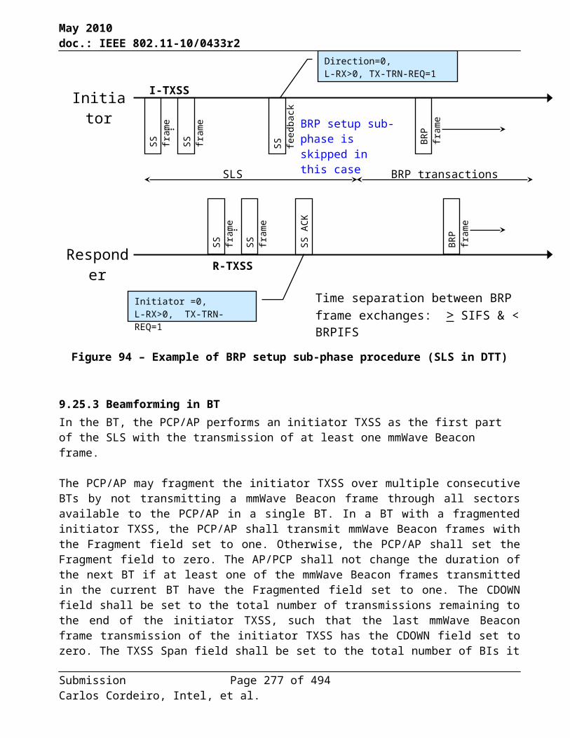
May 2010 doc.: IEEE 802.11-10/0433r2
communication between the source RUS and destination RUS can resume after the direct link between them is recovered.
Link cooperating (11.37.3 Link cooperating type): in this case, the RSUS is actively involved in the direct communication between the source RUS and the destination RUS. A frame transmission from the source RUS to the destination RUS is simultaneously repeated by the RSUS, which can possibly increase the signal quality received at the destination RUS.
As needed, in the following subclauses source RUS, RSUS, and destination RUS are expressed as ‘S’, ‘R’, and ‘D’, respectively. Also, a direct PHY link between STA S and STA D can be simply referred to as ‘S-D’ link.
11.37.1 Common relay setup procedures
This subclause describes the procedures that a source RUS, a destination RUS and an RSUS employ to setup a relay operation among these STAs. These procedures are used for both link switching and link cooperating relays, and shall be performed in the order shown in this subclause.
11.37.1.1 Relay capabilities and RSUS discovery procedures
A source RUS can obtain the capabilities of other STAs in the BSS following the STA’s association with the BSS or with the transmission of an Information Request frame as described in 11.31.1.
A source STA that intends to setup relay operation with a destination STA shall obtain the capabilities of the destination STA prior to initiating the relay setup procedure with the destination STA. The source STA shall only attempt to setup relay operation with the destination STA if both the source and destination STAs are RUS, and there exists at least one RSUS in the BSS.
The source STA can discover a list of RSUSs in the BSS by transmitting a Relay Search Request frame to the PCP/AP with the destination RUS AID field set to the AID of the destination STA. The PCP/AP shall respond to the reception of a Relay Search Request frame with the transmission of a Relay Search Response frame addressed to the requesting STA, and shall include in the transmitted frame a list of RSUSs in the BSS. After the transmission of the Relay Search Response frame to the source STA, the PCP/AP shall transmit an unsolicited Relay Search Response frame to the destination STA with the Relay Capable STA Info field of the source STA and the list of RSUSs that the PCP/AP included in the last Relay Search Response frame transmitted to the source STA.
11.37.1.2 RSUS selection procedure
Following the transmission of a Relay Search Response frame, the PCP/AP should schedule within its Extended Schedule element two SPs for each RSUS included in the transmitted Relay Search Response frame:
An SP having as source STA the source RUS and as destination STA the RSUS, and with the Beamforming Training field set to one. The duration of the SP should be such that the source RUS and RSUS can complete BF as described in 9.25.
Submission Page 277 of 339 Carlos Cordeiro, Intel, et al.
May 2010 doc.: IEEE 802.11-10/0433r2
An SP having as source STA the RSUS and as destination STA the destination RUS, and with the Beamforming Training field set to one. The duration of the SP should be such that the RSUS and the destination RUS can complete BF as described in 9.25.
After the RSUS completes BF with both the source RUS and destination RUS, the source RUS shall send a Multi-Relays Channel Measurement Request frame to the RSUS, which shall respond with the transmission of a Multi-Relays Channel Measurement Report frame back to the source RUS. Following the reception of this frame, the source RUS should perform BF with the destination RUS as described in 9.25, and once BF is completed the source RUS shall transmit a Multi-Relays Channel Measurement Request frame to the destination RUS. In response, the destination RUS shall transmit a Multi-Relays Channel Measurement Report frame to the source RUS including the channel measurement information between the destination RUS and all RSUSs known to the destination RUS. To shorten the time it takes to complete this procedure, STAs can limit BF to the SLS phase only.
Once this procedure is completed, the source RUS becomes aware of all the channel measurement information between the source RUS and zero or more RSUSs, and between the destination RUS and zero or more RSUSs. The source RUS shall then select a single STA to operate as the RSUS between the source RUS and the destination RUS. The selection of the RSUS is implementation-dependent, and it can be based on information contained within an RSUS’ Relay capability element and channel measurements.
11.37.1.3 RLS procedure
Following the selection of the RSUS to be used between the source RUS and the destination RUS, the source RUS initiates the RLS procedure by sending an RLS Request frame to the selected RSUS. The RLS Request frame includes the capabilities and the AIDs of the source RUS, the destination RUS, and the RSUS, and the relay transfer parameter set. Upon receiving the RLS Request frame, the RSUS shall transmit an RLS Request frame to the destination RUS containing the same information as received within the frame body of the source RUS’ RLS Request frame.
Following the reception of an RLS Request frame, the destination RUS shall transmit an RLS Response frame to the RSUS with the destination status code field set to 0 if the destination RUS is willing to participate in the RLS, and set to 37 if the destination RUS is not willing to participate in the RLS. Upon receiving the RLS Response frame, the RSUS shall transmit an RLS Response frame to the source RUS containing the same information as received within the destination RUS’ RLS Response frame, with the exception that the RSUS shall set the relay status code field to 0 if the RSUS is willing to participate in the RLS, and shall set it to 37 if the RSUS is not willing to participate in the RLS.
Upon reception of an RLS Response frame from the RSUS with the destination status code and relay status code fields set to 0, the source STA may transmit an RLS Announcement frame to the PCP/AP to indicate that the RLS procedure was successfully completed. If either or both of the destination status code and relay status code fields are different than zero, the RLS procedure is unsuccessful.
Upon the completion of RLS procedure, the source RUS, the destination RUS, and the RSUS can redo BF amongst them.
Submission Page 278 of 339 Carlos Cordeiro, Intel, et al.
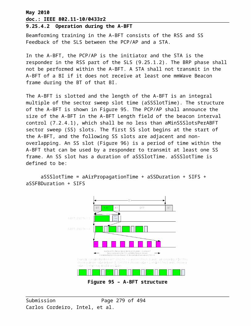
May 2010 doc.: IEEE 802.11-10/0433r2
11.37.2 Link switching type
A source RUS that has successfully completed an RLS procedure with a destination RUS for which the value of the Cooperation-Mode subfield within the negotiated Relay Transfer Parameter Set element is set to 0 may use the selected RSUS between the source RUS and destination RUS for the purpose of link switching. This is described in this subclause.
11.37.2.1 SP request and allocation
The source RUS uses the procedures described in 11.4 to request an SP allocation between itself and the destination RUS.
Upon receiving an ADDTS Request frame for which the source AID and the destination AID fields within the Extended mmWave TSPEC element are equal to, respectively, a source RUS and a destination RUS pair known to the PCP/AP to have successfully completed the RLS procedure, the PCP/AP schedules an SP with the source STA as the source RUS and the destination STA as the destination RUS.
An RSUS shall check the value of the source AID and the destination AID fields of each SP allocation within an Extended Schedule element it receives in a mmWave Beacon or Announce frame from the PCP/AP. If the value of the source AID and the destination AID fields of an SP allocation correspond to a source RUS and a destination RUS which have successfully completed the RLS setup procedure (11.37.1 Common relay setup procedures), the RSUS is allowed to operate as an RSUS during that SP allocation.
11.37.2.2 Usage of RSUS
In link switching type, an RSUS operates either in FD/AF mode or in HD/DF mode. An RSUS capable of FD/AF relaying shall be in one of two frame transmission modes:
Normal mode: a pair of source RUS and destination RUS exchange frames via either the direct link or the relay link until this link is determined to become unavailable due to, for example, blockage or channel degradation.
Alternation mode: a source RUS and a destination RUS exchange frames via two separate links, where the use of each link alternates at each Link Change Interval. The Link Change Interval specifies the time instants at which a source RUS is allowed to change the link used for a frame transmission to the destination RUS as specified in 7.3.2.111.
An RSUS that supports only HD/DF shall operate in the Normal mode.
The frame transmission mode is indicated in the Relay Transfer Parameter Set element exchanged by the source RUS, destination RUS, and RSUS during the RLS procedure. A source RUS or destination RUS may change the transmission mode used in a relay link following a successful exchange of RLS Request and RLS Response frames as described in 11.37.1.3 RLS procedure.
An RSUS shall start to operate as RSUS at the start of an SP for which the value of the source AID and destination AID fields for that SP are equal to, respectively, the source RUS and destination RUS
Submission Page 279 of 339 Carlos Cordeiro, Intel, et al.
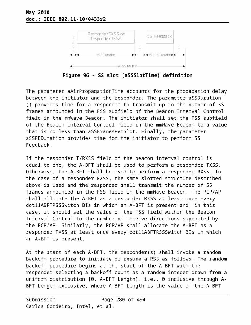
May 2010 doc.: IEEE 802.11-10/0433r2
for which the RSUS has successfully completed the RLS procedure. The RSUS can determine the SPs for which it operates as an RSUS upon the reception of an Extended Schedule element.
11.37.2.3 Relay frame exchange rules
Following the completion of the RLS procedure and SP allocation, each of the source RUS, destination RUS, and RSUS have a direct link with one another.
The values of Link Change Interval and Data Sensing Time are indicated within the Relay Transfer Parameter Set transmitted by the source RUS to the destination RUS during the RLS procedure. Either the Link Change Interval period or the First Period begins at the start of an SP between the source RUS and the destination RUS, and any transmission by the source RUS, destination RUS, and RSUS within a Link Change Interval period shall use the same link that is used at the start of the Link Change Interval period. A new Link Change Interval period starts immediately after another Link Change Interval period, but shall not exceed the end of the SP.
In the normal mode, a source RUS shall use the direct link to initiate frame transmission to the destination RUS at the start of the first SP allocated between the source RUS and destination RUS for a particular TID. At the start of the following SP allocations for that same TID, the source RUS uses the last link in which a frame transmission to the destination RUS via this link was successful. In the alternation mode, the source STA shall alternate the frame transmission to the destination RUS between direct frame transmission to the destination RUS and frame transmission through the RSUS. The source RUS shall alternate the link used for a frame transmission at the start of each Link Change Interval.
If a source RUS transmits a frame to the destination RUS via the direct link but does not receive an expected ACK frame or BA frame from the destination RUS during a Link Change Interval period, the source RUS should change the link used for frame transmission at the start of the following Link Change Interval period and use the RSUS to forward frames to the destination RUS.
If a source RUS transmits a frame to the destination RUS via the RSUS but does not receive an expected ACK frame or BA frame from the RSUS during a Link Change Interval period or a First Period, the source RUS should change the link used for frame transmission at the start of the following Link Change Interval period or the following First Period and transmit frames directly to the destination RUS.
11.37.2.3.1 Additional frame exchange rules for FD/AF RSUSIf the source RUS decides to change the link at the start of the following Link Change Interval period and the Normal mode is used, the source RUS shall start its frame transmission after Data Sensing Time from the start of the following Link Change Interval period. If the Alternation mode is used, the source RUS alternates the link used for frame transmission at the start of each Link Change Interval period and the value of Data Sensing Time is ignored.
In the Normal mode, if the destination RUS does not receive a valid frame from the source RUS within Data Sensing Time after the start of a Link Change Interval, the destination RUS shall immediately change the link to attempt to receive frames from the source RUS through the RSUS. If
Submission Page 280 of 339 Carlos Cordeiro, Intel, et al.

May 2010 doc.: IEEE 802.11-10/0433r2
the More Data field in the last frame received from the source RUS is set to 0, then the destination RUS shall not switch to the link in the next Link Change Interval period even if it does not receive a frame during the Data Sensing Time. An example of frame transfer under Normal mode with FD/AF RSUS is illustrated in Figure 126.
In the Alternation mode, if the destination RUS receives an out of order frame, the destination RUS shall remain at the current link. If the More Data field in the last frame received from the source RUS is set to 0, then the destination RUS shall not switch links in the next Link Change Interval period. If the source RUS uses either the direct or the relacy link and decides to resume alternate frame transmission, the source RUS should transmit a frame to the other link Data Sensing Time after the next Link Change Interval to inform the destination RUS that operation on the other link has been resumed. Note that this is the only situation when Data Sensing Time is used in the Alternation mode.
Figure 126 – Example of Normal mode operation with FD/AF relay
11.37.2.3.2 Additional frame exchange rules for HD/DF RSUS
When the RSUS is operating as a HD/DF RSUS and the RSUS is used in the frame exchange between the source RUS and the destination RUS, the frame exchange is performed in two periods which are repeated for as long as the RSUS is used. In the First Period, the source RUS shall transmit a frame to the RSUS and then the RSUS responds within SIFS if needed. In the Second Period, the RSUS shall forward the frame received from the source RUS to the destination RUS and then the destination RUS responds within SIFS if needed. The duration of the First Period and the Second Period are specified in the last Relay Transfer Parameter Set element transmitted from the source RUS.
The First Period and Second Period are valid only when the source RUS and destination RUS exchange frames via the RSUS. The Link Change Interval is valid only when the source RUS and destination RUS exchange frames via the direct link. The First Period begins at the end of the Link Change Interval when a change to the relay link occurs. The Link Change Interval begins at the end of the Second Period when a change to the direct link occurs.
The source RUS may transmit a Relay ACK Request frame to the RSUS to determine whether all frames forwarded through the RSUS were successfully received by the destination RUS. Upon reception of a Relay ACK Request frame, the RSUS shall respond with a Relay ACK Response frame
Submission Page 281 of 339 Carlos Cordeiro, Intel, et al.
May 2010 doc.: IEEE 802.11-10/0433r2
and set the BlockAck Bitmap field to indicate which frames have been successfully received by the destination RUS.
If the source RUS decides to change to the relay link at the start of the following Link Change Interval period, the source RUS shall start its frame transmission at the start of the following Link Change Interval period. If the current link is the direct link and the destination RUS does not receive a valid frame from the source RUS within Data Sensing Time after the start of each Link Change Interval, the destination RUS shall change the link and consider the First Period to begin at the start of the Link Change Interval.
If a link change to the direct link occurs, the source RUS shall start to transmit a frame using the direct link at the end of the Second Period when the Link Change Interval begins. The destination RUS shall switch to the direct link at each First Period and listen to the medium toward the source RUS. If the destination RUS receives a valid frame from the source RUS, it shall remain on the direct link and consider the Link Change Interval to begin at the start of the First Period. Otherwise, the destination RUS shall change the link at the start of the next Second Period and attempt to receive frames from the source RUS through the RSUS. If the active link is relay link and the More Data field in the last frame received from the RSUS is set to 0, then the destination RUS shall not switch to the direct link even if it does not receive any frame during the Second Period. An example of frame transfer with HD/DF RSUS is illustrated in Figure 127.
Figure 127 – Example of the operation with HD/DF relay
11.37.2.3.3 Operation of FD/AF RSUS
In an SP allocated for relay operation, a FD/AF RSUS operates in an amplify-and-forward manner. This means that for each frame detected at the RF in receive state within an SP in which it operates as a FD/AF RSUS, the RSUS amplifies the received signal and simultaneously retransmits it via the RF in transmit state.
At the start of the SP where it operates as a FD/AF RSUS, the RSUS shall initiate an RF antenna module in receive state directed toward the source RUS and another RF antenna module in transmit state directed toward the destination RUS.
Submission Page 282 of 339 Carlos Cordeiro, Intel, et al.
May 2010 doc.: IEEE 802.11-10/0433r2
For each frame received at the RSUS during the SP, the RSUS shall follow the same rules for frame exchange sequences as described in 9.12 and 9.23. This includes switching the state of each RF available to the RSUS from receive to transmit, and vice-versa, depending upon the frame type and its ACK policy.
11.37.2.4 Link monitoring
After a link change, the source RUS can periodically monitor the quality of the previous link. To do that, the source RUS may use the link change mechanism described in 11.37.2.3 Relay frame exchange rules. If the previous link is the relay link, the source RUS can acquire the channel status by using relay link measurement mechanism as described in 11.37.5 Relay link adaptation. If the previous link is the direct link, the source RUS can acquire the channel status via the link adaptation mechanism defined in 9.27. If the channel quality of the previous link is better than the one on the current link which is an implementation-dependent decision, the source RUS may switch to the previous link.
11.37.3 Link cooperating type
11.37.3.1 TPA procedure
A source RUS, a destination RUS, and an RSUS that wish to setup a link cooperating relay use the common relay setup procedure defined in 11.37.1 Common relay setup procedures. In addition, to establish a link cooperating relay, the source RUS, destination RUS, and RSUS shall perform the TPA procedure described in this subclause and shown in Figure 128.
Figure 128 – TPA mechanism
The TPA procedure is triggered by the destination RUS following the common relay setup procedure with the source RUS and RSUS. First, the destination RUS uses the procedures described in 11.4 to request the allocation of an SP to perform TPA, wherein the source of the SP is the destination RUS and the destination of the SP is the source RUS. If the value of a source AID and the destination AID fields of an SP allocation correspond to a destination RUS and a source RUS which have successfully
Submission Page 283 of 339 Carlos Cordeiro, Intel, et al.

May 2010 doc.: IEEE 802.11-10/0433r2
completed the RLS setup procedure, the mSTA that performs as an RSUS in that SP allocation shall operate during the allocation as a non RSUS capable mSTA.
Within the allocated SP, the destination RUS sends a TPA Request frame to the RSUS and sets the Response Offset field to the time (Dtime, which is pre-defined) when the RSUS shall transmit a TPA Response frame back to the destination RUS, and sets the time offset field to zero (see Figure 128). SBIFS interval following the end of the first TPA Request frame transmission, the destination RUS shall send another TPA Request frame to the source RUS and set the Response Offset field to the Dtime when the source RSUS shall transmit a TPA Response frame back to the destination RUS. Upon receiving the TPA Response frame from the RSUS, the destination RUS shall estimate the TPA value of the RSUS and the time deviation (i.e., 2*dTDR) between the expected Dtime and the actual arrival time of the TPA Response frame. The destination RUS shall repeat the same procedure upon reception of the TPA Response frame received from the source RUS.
SBIFS interval following the end of the transmission of the TPA Response frame to the destination RUS, the source RUS shall send a TPA Request frame to the RSUS and set the Response Offset field to the Dtime when the RSUS shall transmit a TPA Response frame back to the source RUS (see Figure128). Upon reception of the TPA Response frame from the RSUS, the source RUS shall estimate the TPA value of the source RUS and the time deviation (i.e., 2*dTSR) between the expected Dtime and the actual arrival time of the TPA Response frame.
At dot11RelayTPATime from the end of the last TPA Request frame transmitted by the destination RUS to the source RUS, the destination RUS shall send a TPA Request frame to the RSUS and set the Response Offset field to the Dtime when the RSUS shall transmit a TPA Response frame back to the destination RUS, and set the timing offset field to dTDS-dTDR. Upon reception of the TPA Request frame, the RSUS shall transmit a TPA Response frame to the destination RUS at Dtime+dTDR+(dTDS-dTDR) from the end of the TPA Request frame. Upon reception of the TPA Response frame, the destination RUS shall estimate the time deviation (i.e., 2*dTDR+(dTDS-dTDR)) between the expected Dtime and the actual arrival time of the TPA Response frame. If the destination RUS determines that the estimated deviation is equal to 2*dTDR+(dTDS-dTDR), then the TPA procedure is considered successful.
As the last step of the TPA procedure, the destination RUS shall send a TPA Report frame to the source RUS that includes the information whether the last TPA procedure succeeded or not. If it is not successful, the TPA procedure is repeated until it is successful or upon the decision of the destination RUS to stop performing the TPA procedure. The TPA procedure can include the estimation of the sampling frequency-offset (SFO), in order for the source RUS and RSUS to adjust their SFOs.
11.37.3.2 Frame exchange operationA source RUS that has successfully completed an RLS procedure with a destination RUS for which the value of the Cooperation-Mode subfield within the negotiated Relay Transfer Parameter Set element is set to 1 and has successfully completed the TPA procedure, shall use the selected RSUS between the source RUS and destination RUS for the purpose of link cooperation. This is described in this subclause.
Submission Page 284 of 339 Carlos Cordeiro, Intel, et al.

May 2010 doc.: IEEE 802.11-10/0433r2
11.37.3.2.1 Cooperated transmission SP request and allocation
If the source RUS receives a TPA Report frame that indicates the successful completion of the TPA procedure with the RSUS and the destination RUS, the source RUS uses the procedure in 11.4 to request an SP allocation with the destination RUS. The source RUS can use the SP allocation for communication with the destination RUS with the assistance of the RSUS.
11.37.3.2.2 Data transmission rules
As shown in the example of Figure 129, in the allocated SP the first time interval (T1) and the second time interval (T2) for a cooperated data frame transfer are determined by the packet transmission time at each transmission from the source RUS to the destination RUS within the SP.
The data transmission rules are as follows. At the start of each time T1, the source RUS transmits a frame with its transmit antenna pattern directed towards the RSUS and with the TA and the RA fields in the MAC header set to the MAC address of the source RUS and destination RUS, respectively. After Ptime+dTSR from the start of T2, the source RUS retransmits the same frame sent to the RSUS during the previous time T1 but now with its transmit antenna pattern directed towards the destination RUS. Similarly, after Ptime+(dTDS-dTDR) from the start of T2, the RSUS retransmits the same frame it received from the source RUS during the previous time T1. So that the destination RUS can take advantage of the improved received signal level from both of these transmissions, the destination RUS should set its receive antenna pattern during T2 such that it simultaneously covers the links towards both the source RUS and the RSUS.
The Ack policy used during an SP where link cooperation is in use is the same as defined in Clause 9.
Figure 129 – Example of data transmission in an SP with link cooperating relay
11.37.4 Relay operation-type change procedure
The source RUS may change the relay operation type from link switching to link cooperating, and vice-versa, if either one of S-D, or S-R, or R-D links becomes unavailable or for other reasons. Link unavailability can be determined by the source STA not receiving expected frames from the
Submission Page 285 of 339 Carlos Cordeiro, Intel, et al.
May 2010 doc.: IEEE 802.11-10/0433r2
destination RUS. To assist in this decision, the source RUS may use the link adaptation procedure (11.37.5 Relay link adaptation) to obtain the quality of a link.
To change the relay operation type within an SP from link cooperating to link switching in a case that the S-D link becomes unavailable, the source RUS shall transmit a ROC Request frame to the RSUS with the link cooperating subfield set to 0 and the relay-link subfield set to 1. Upon receiving a ROC Request frame, the RSUS shall transmit a ROC Request frame to the destination RUS containing the same information as received within the frame body of the source RUS’ ROC Request frame. Following the reception of a ROC Request frame, the destination RUS shall respond with a ROC Response frame to the RSUS with the status code field set to 0 if the destination RUS accepts to change the operation into link switching, and set to 37 if the destination RUS rejects the request. Upon receiving the ROC Response frame, the RSUS shall transmit a ROC Response to the source RUS with the status code field set to 0 only if the RSUS accepts to change the operation into link switching and the status code field set to 0 in the ROC Response frame received from destination RUS. Otherwise, the RSUS shall set the status code field to 37. Upon reception of a ROC Response from the RSUS with the status code field set to 0, the source RUS immediately starts to transmit frames to the destination RUS via the RSUS relay link.
To change the relay operation type from link cooperating to link switching in other case that the S-R link becomes unavailable, the source RUS shall a ROC Request frame to the destination RUS with the link cooperating subfield set to 0 and the relay-link subfield set to 0. Following the reception of a ROC Request frame, the destination RUS shall respond with a ROC Response frame to the source RUS with the status code field indicating the acceptance or rejection of the request. Upon reception of a ROC Response from the destination RUS with the status code field set to 0, the source RUS immediately starts to transmit frames to the destination RUS via the direct link in link switching mode.
To change the relay operation type within an SP from link switching to link cooperating, the source RUS shall transmit a ROC Request frame to the destination RUS via the RSUS with the link cooperating subfield set to 1. Following the reception of a ROC Request frame from the RSUS, the destination RUS shall respond with a ROC Response frame to the source RUS via the RSUS with the status code field indicating the acceptance or rejection of the request. Upon reception of a ROC Response frame from the RSUS with the status code field set to 0, the source RUS immediately starts to transmit frames to the destination RUS using the RSUS in link cooperating mode. If a TPA procedure was not performed beforehand since the link switching operation has been continued from the start of relay operation, the TPA procedure shall be performed before the commencement of the link cooperating mode.
NOTE – As described in 11.37.3.2.2 Data transmission rules, during the SP in link cooperating operation the destination RUS has its receive antenna pattern such that it simultaneously covers the links towards both the source RUS and the RSUS.
11.37.5 Relay link adaptation
When a relay link is used for communication between a source RUS and a destination RUS, the link qualities of the S-R link, the R-D link, and the S-D link may be required.
The source RUS, destination RUS, and RSUS use the procedure described in 9.27 to request and report the link quality among themselves with the following exception. In the Link Margin Response
Submission Page 286 of 339 Carlos Cordeiro, Intel, et al.

May 2010 doc.: IEEE 802.11-10/0433r2
frame the RSUS transmits to the source RUS, the RSUS shall include two Link Margin elements in this order:
The first Link Margin element shall report the link quality between the source RUS and the RSUS
The second Link Margin element shall report the link quality between the RSUS and the destination RUS
Upon reception of a Link Margin Response frame, the source RUS can take several actions including changing the MCS it uses for frame transmission to the RSUS and destination RUS.
11.37.6 Relay teardown
A source RUS that has successfully completed the RLS procedure with a destination RUS may teardown the relay operation between the source RUS, destination RUS and RSUS. To do that, the source RUS shall transmit an RLS Teardown frame to the RSUS, destination RUS and PCP/AP of the BSS. Within the Relay Teardown frame, the source RUS shall set the source AID field to the AID of the source RUS, the destination AID field to the AID of the destination RUS and the relay AID field to the AID of the RSUS.
A RSUS may teardown the relay operation between the source RUS, destination RUS and RSUS. To do that, the RSUS shall transmit an RLS Teardown frame to the source RUS, destination RUS and PCP/AP of the BSS. Within the Relay Teardown frame, the RSUS shall set the source AID field to the AID of the source RUS, the destination AID field to the AID of the destination RUS and the relay AID field to the AID of the RSUS.
Submission Page 287 of 339 Carlos Cordeiro, Intel, et al.
May 2010 doc.: IEEE 802.11-10/0433r2
12 PHY service specification
12.3 Detailed PHY service specifications
12.3.5 PHY-SAP detailed service specification
.11 Editor note: add new sub clauses 12.3.5.7a, 12.3.5.7a.1, 12.3.5.7a.2, 12.3.5.7a.3, 12.3.5.7a.4 after subcluse 12.3.5.7
12.3.5.7a PHY-TXPLCPEND.indication
12.3.5.7a.1 FunctionThis primitive indicates the transmission completion of the PLCP header to the local MAC entity.
12.3.5.7a.2 Semantics of the service primitiveThe semantics of the primitive are as follows:
PHY-TXPLCPEND.indication
This primitive has no parameters.
12.3.5.7a.3 When generatedThe PHY-TXPLCPEND.indication is generated by a transmitter PHY entity to indicate the
transmission completion of the PLCP header the local MAC entity.
12.3.5.7a.4 Effect of receiptThe receipt of this primitive by the MAC entity will cause the MAC to record the time when this
primitive is received only if TIME_OF_DEPARTURE_REQUESTED is true in the
corresponding PHY_TXSTART.request.
Submission Page 288 of 339 Carlos Cordeiro, Intel, et al.
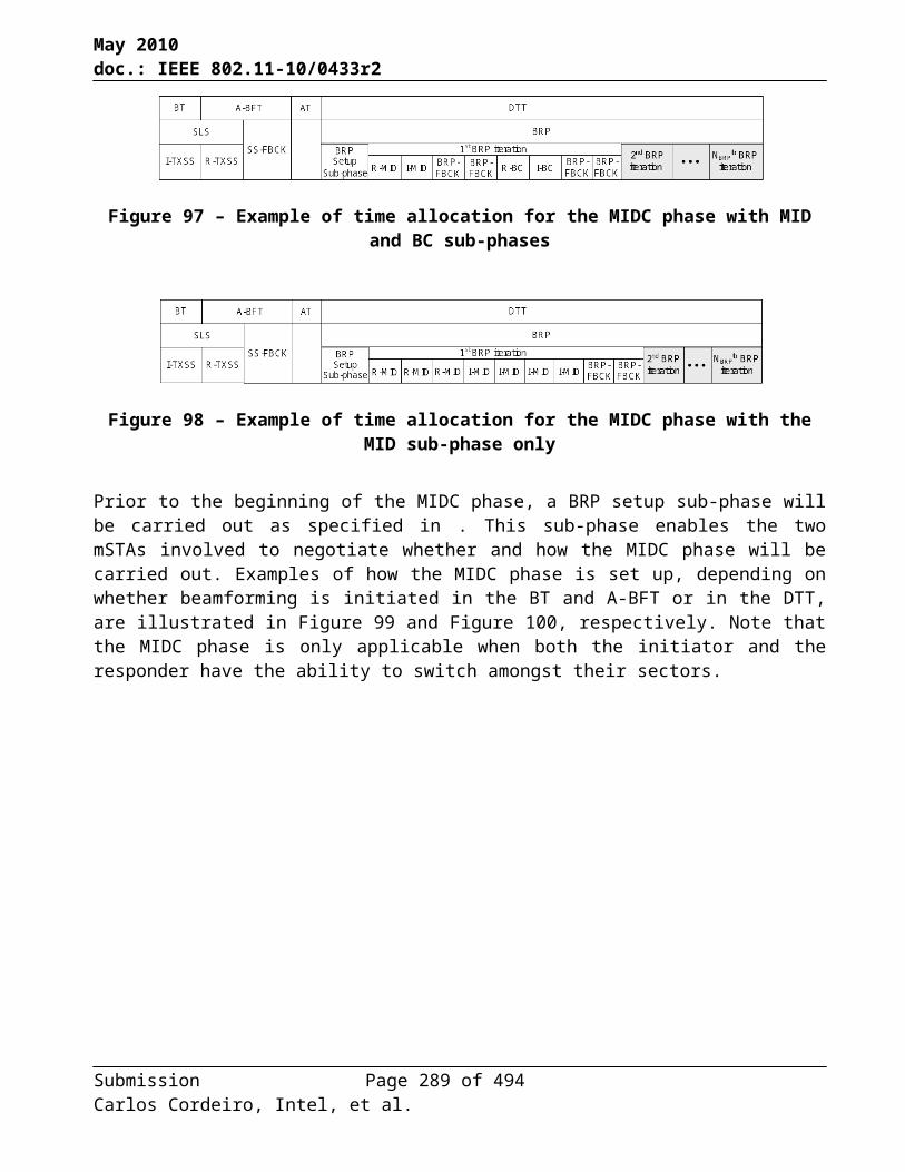
May 2010 doc.: IEEE 802.11-10/0433r2
21 mmWave PHY specification
21.1 mmWave PHY Introduction
21.1.1 ScopeThe services provided to the MAC by the mmWave PHY consist of two protocol functions, defined as follows:
a) A PHY convergence function, which adapts the capabilities of the physical medium dependent (PMD) system to the PHY service. This function is supported by the physical layer convergence procedure (PLCP), which defines a method of mapping the PLCP service data units (PSDU) into a framing format (PPDU) suitable for sending and receiving PSDUs between two or more STAs using the associated PMD systems.
b) A PMD system whose function defines the characteristics and method of transmitting and receiving data through a wireless medium between two or more STAs. Depending on the mmWave MCSs, these STAs support a mixture of mmWave SC PHY, mmWave OFDM PHY, mmWave low power SC PHY, and mmWave Control PHY.
21.1.2 mmWave PHY functions
The mmWave PHY contains three functional entities: the PHY convergence function (PLCP), the layer management function (PLME) and the PMD function. Each of these functions is described in detail in 21.3 to 21.9. The mmWave PHY service is provided to the MAC through the PHY service primitives defined in Clause 12.
21.1.2.1 mmWave PLCP sublayer
In order to allow the MAC to operate with minimum dependence on the PMD sublayer, a PHY convergence sublayer is defined (PLCP). The PLCP sublayer simplifies the PHY service interface to the MAC services.
21.1.2.2 mmWave PMD sublayer
The mmWave PMD sublayer provides a means to send and receive data between two or more STAs. This Clause is concerned with the mmWave band using SC and OFDM modulation.
21.1.2.3 PHY management entity (PLME)
Submission Page 289 of 339 Carlos Cordeiro, Intel, et al.
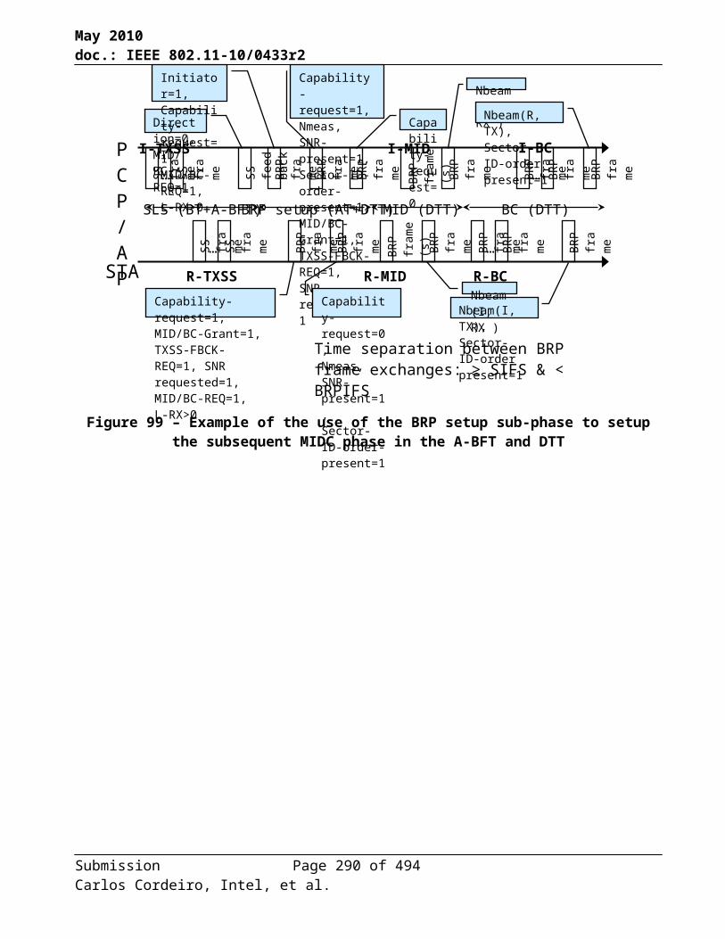
May 2010 doc.: IEEE 802.11-10/0433r2
The PLME performs management of the local PHY functions in conjunction with the MLME.
21.1.2.4 Service specification method
The models represented by figures and state diagrams are intended to be illustrations of the functions provided. It is important to distinguish between a model and a real implementation. The models are optimized for simplicity and clarity of presentation; the actual method of implementation is left to the discretion of the mmWave PHY compliant developer. The service of a layer or sublayer is the set of capabilities that it offers to a user in the next higher layer (or sublayer). Abstract services are specified here by describing the service primitives and parameters that characterize each service. This definition is independent of any particular implementation.
21.2 mmWave PHY service interface
21.2.1 IntroductionThe PHY interfaces to the MAC through the TXVECTOR, RXVECTOR, and the PHYCONFIG_VECTOR. The TXVECTOR supplies the PHY with per packet transmit parameters. Using the RXVECTOR, the PHY informs the MAC of the received packet parameters. Using the PHYCONFIG_VECTOR, the MAC configures the PHY for operation, independent of frame transmission or reception.
This interface is an extension of the generic PHY service interface defined in 12.3.4.
21.2.2 TXVECTOR and RXVECTOR parametersThe parameters in Table 64 are defined as part of the TXVECTOR parameter list in the PHY-TXSTART.request service primitive and/or as part of the RXVECTOR parameter list in the PHY-RXSTART.indication service primitive.
Table 64 – TXVECTOR and RXVECTOR parameters
Parameter Value
TXV
ECTO
R
RX
VEC
TOR
MCS The MCS field indicates the modulation and coding scheme used in the transmission of the packet.Values are integers in the range 0-27. An MCS of zero indicates the use of Control PHY.MCS values of 1-12 indicate use of single carrier modulations. The value is a index to Table 79 Y Y
Submission Page 290 of 339 Carlos Cordeiro, Intel, et al.
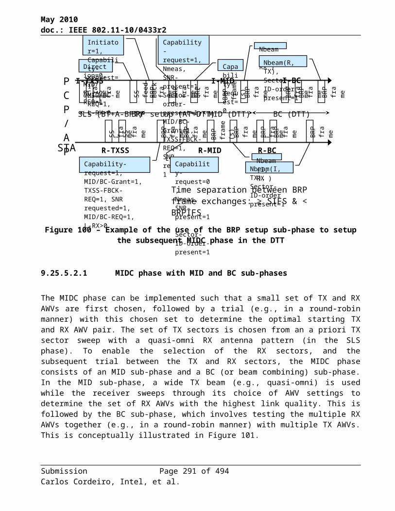
May 2010 doc.: IEEE 802.11-10/0433r2
Parameter Value
TXV
ECTO
R
RX
VEC
TOR
MCS values of 13-24 indicates use of OFDM modulations. The value is an index to Table 76MCS values of 25-27 indicate use of Low Power SC PHY the value is an index to Table 82
LENGTH Indicates the number of octets in the PSDU in the range of 0-262143A value of zero indicates a packet in which no data part follows the header Y Y
ADD-PPDU Enumerated Type:ADD-PPDU indicates that this PPDU is immediately followed by another PPDY with no IFS or preamble on the subsequent PPDU.NO-ADD-PPDU indicates no additional PPDU follows this PPDU. Y Y
PACKET-TYPE Enumerated Type:TRN-R-PACKET indicates a packet in which TRN-R subfields follow the data part.TRN-T-PACKET indicates a packet in which TRN-R subfields follow the data part.This Field is ignored if TRN-LEN is set to 0 Y Y
TRN-LEN TRN-LEN indicates the length of the training field. Values are 0-64 in multiples of 4. Y Y
AGGREGATION Indicates whether the PSDU contains an A-MPDU.Enumerated Type:AGGREGATED indicates this is a packet with A-MPDU NOT_AGGREGATED indicates this is a packet without A-MPDU aggregation Y Y
RSSI The allowed values for the RSSI parameter are in the range from 0 through RSSI maximum. This parameter is a measure by the PHY of the power observed at the antennas used to receive the current PPDU. RSSI shall be measured during the reception of the PLCP preamble. RSSI is intended to be used in a relative manner, and it shall be a monotonically increasing function of the received power. N Y
SNR This parameter indicates the SNR measured during the reception of a control PHY packet. Values are -10dB to 53.73dB in 0.25dB steps N Y
ANT-CONFIG The MAC uses this parameter to instruct the PHY what antenna configuration(s) to use throughout the transmission of the packet, and when to switch between them.Values are implementation dependent. Y N
CHAN-MEASUREMENT Channel as measured during the reception of TRN-T subfields. Each measurement includes 63 complex numbers. N Y
TIME_OF_DEPARTURE_REQUESTED
Enumerated type:true indicates that the MAC entity requests that the PHY PLCP entity measures and reports time of departure parameters corresponding to the time when the first frame energy is sent by the transmitting port. false indicates that the MAC entity requests that the PHY PLCP entity neither measures nor reports time of
O N
Submission Page 291 of 339 Carlos Cordeiro, Intel, et al.

May 2010 doc.: IEEE 802.11-10/0433r2
Parameter Value
TXV
ECTO
R
RX
VEC
TOR
departure parameters.RX_START_OF_FRAME_OFFSET 0 to 232-1. An estimate of the offset (in 10 nanosecond units)
from the point in time at which the start of the preamble corresponding to the incoming frame arrived at the receive antenna port to the point in time at which this primitive is issued to the MAC. N Y
21.2.3 TXSTATUS ParametersThe parameters listed in Table 65 are defined as part of the TXSTATUS parameter list in the PHYTXSTART.confirm(TXSTATUS) service primitive.
Table 65 – TXSTATUS parameters
Parameter ValueTIME_OF_DEPARTURE When the first frame energy is sent by the transmitting
port, in units equal to 1/TIME_OF_DEPARTURE_ClockRate.
This parameter is present only if TIME_OF_DEPARTURE_REQUESTED is true in the corresponding request.
TIME_OF_DEPARTURE_ClockRate 0 to 216-1. The clock rate, in units of MHz, is used to generate the TIME_OF_DEPARTURE value. This parameter is present only if TIME_OF_DEPARTURE_REQUESTED is true in the corresponding request.
TX_START_OF_FRAME_OFFSET 0 to 232-1. An estimate of the offset (in 10 nanosecond units) from the point in time at which
the start of the preamble corresponding to the frame was transmitted at the transmit antenna port to the point in time at which this primitive is issued to the MAC.
21.3 Common parameters
21.3.1 Channelization STAs compliant with the physical layer defined in clause 21 operate in the channels defined in Annex J for the UB, and shall support at least channel number 2.
Submission Page 292 of 339 Carlos Cordeiro, Intel, et al.
May 2010 doc.: IEEE 802.11-10/0433r2
21.3.2 Transmit Mask The transmitted spectrum shall adhere to the transmit spectrum mask shown in the Figure 130.
Figure 130 – Transmit Mask
21.3.3 Common requirements The section below describes the common requirement from all 4 PHYs: CP, SC, OFDM and Low Power SC.
21.3.3.1 Tx RF Delay As defined at 17.3.8.5 and its value is implementation dependent.
21.3.3.2 Transmit and Receive Operating Temperature Range The transmit and receive temperature range shall follow 17.3.8.8.
21.3.3.3 Center Frequency Tolerance The transmitter center frequency tolerance shall be ±20 ppm maximum for the 60 GHz band.
21.3.3.4 Symbol Clock Tolerance The symbol clock frequency tolerance shall be ±20 ppm maximum for the 60 GHz band.
The transmit center frequency and the symbol clock frequency shall be derived from the same reference oscillator.
21.3.3.5 Tx Center Frequency Leakage The transmitter center frequency leakage shall not exceed –23 dB relative to the overall transmitted power, or, equivalently, 2.5 dB relative to the average energy of the rest of the subcarriers (in OFDM).
21.3.3.6 Transmit Ramp up and Ramp Down The transmit power-on ramp is defined as the time it takes for a transmitter to rise from less than 10% to greater than 90% of the average power to be transmitted in the frame.
Submission Page 293 of 339 Carlos Cordeiro, Intel, et al.

May 2010 doc.: IEEE 802.11-10/0433r2
The transmit power-on ramp shall be less than 10 ns.
The transmit power-down ramp is defined as the time it takes the transmitter to fall from greater than 90% to less than 10% of the maximum power to be transmitted in the frame.
The transmit power-down ramp shall be less than 10 ns.
21.3.3.7 Maximum Input RequirementThe receiver maximum input level is the maximum power level at the receive antenna(s) of the incoming signal, in dBm, present at the input of the receiver for which the error rate criterion (defined at the RX Sensitivity subclause) is met. A compliant receiver shall have a receiver maximum input level at the receive antenna(s) of at least -33 dBm for each of the modulation formats that the receiver supports.
21.3.3.8 Receive Sensitivity
The PER shall be less than 1% (5% for MCS 0) for a PSDU length of 4096 octets (256 for MCS 0) with the MCS dependent input levels listed in the Table 66 defined at the antenna port(s).
NOTE – For RF power measurements based on received power density and the input level shall be corrected to compensate for the antenna gain in the implementation. The gain of the antenna is the maximum estimated gain by the manufacturer. In the case of the phased-array antenna, the gain of the phased-array antenna is the maximum sum of estimated element gain minus 3 dB implementation loss.
The table below assumes 5 dB implementation loss and 10 dB noise factor (Noise Figure).
Table 66 – Receiver Sensitiviy
21.3.4 Timing Related Parameters
Submission Page 294 of 339 Carlos Cordeiro, Intel, et al.
MCS Index Receive Sensitivity (dBm)0 -781 -682 -673 -654 -645 -626 -637 -628 -619 -59 10 -5511 -5412 -5313 -6614 -6415 -6316 -6217 -6018 -5819 -5620 -5421 -5322 -5123 -4924 -4725 -6426 -6027 -57
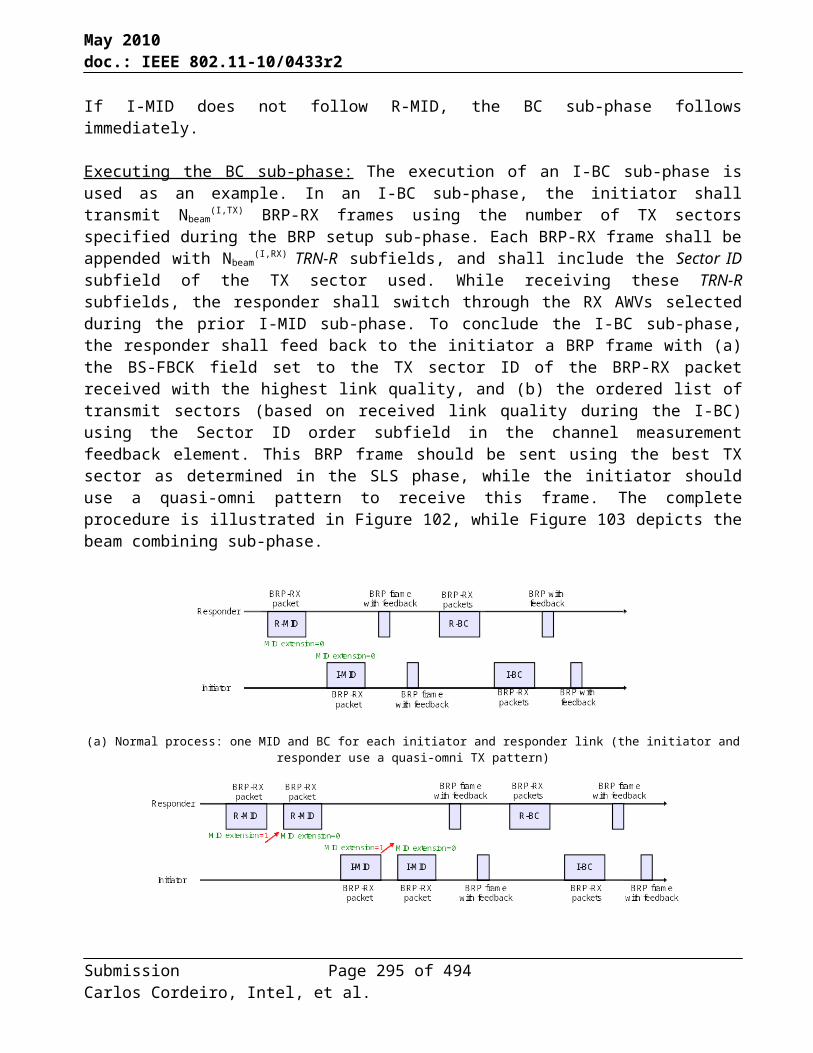
May 2010 doc.: IEEE 802.11-10/0433r2
Table 67 – Timing Related ParametersParameter Value in OFDM
NSD: Number of data subcarriers 336NSP: Number of pilot subcarriers 16NDC: Number of DC subcarriers 3
NST: Total Number of subcarriers 355NSR: Number of subcarriers occupying half of the
overall BW177
ΔF : subcarrier frequency spacing
5.15625MHz(2640MHz/512)
Fs: OFDM sample rate 2640MHzFc: SC chip rate 1760MHz = ⅔ Fs
Ts: OFDM Sample Time 0.38ns=1/Fs
Tc: SC Chip Time 0.57ns=1/Fc
TDFT: IDFT/DFT period 0.194usecTGI: Guard Interval duration 48.4ns= TDFT/4
Tseq 72.7ns=128×Tc
TSTF: Detection sequence duration 1091ns=15× Tseq
TCE: Channel Estimation sequence duration 655ns=9×Tseq
TSYM: Symbol Interval 0.242µs= TDFT+TGI
THEADER: Header Duration 0.242 µs=TSYM (OFDM)
0.582µs =2×512× Tc (SC)FCCP: Control PHY chip rate 1760MHzTCCP: Control PHY chip time 0.57ns = 1/FCP
TSTF-CP: Control PHY short training field duration 2.909µs =40× Tseq
TCE-CP: Control PHY channel estimation field duration
655ns=9× Tseq
TData NSYM×TSYM (OFDM)
NBLKS×512×Tc (SC)1
1 NSYM is defined in 21.5.3.2.2.2 and NBLKS is defiend in 21.6.3.2.2.2
Submission Page 295 of 339 Carlos Cordeiro, Intel, et al.
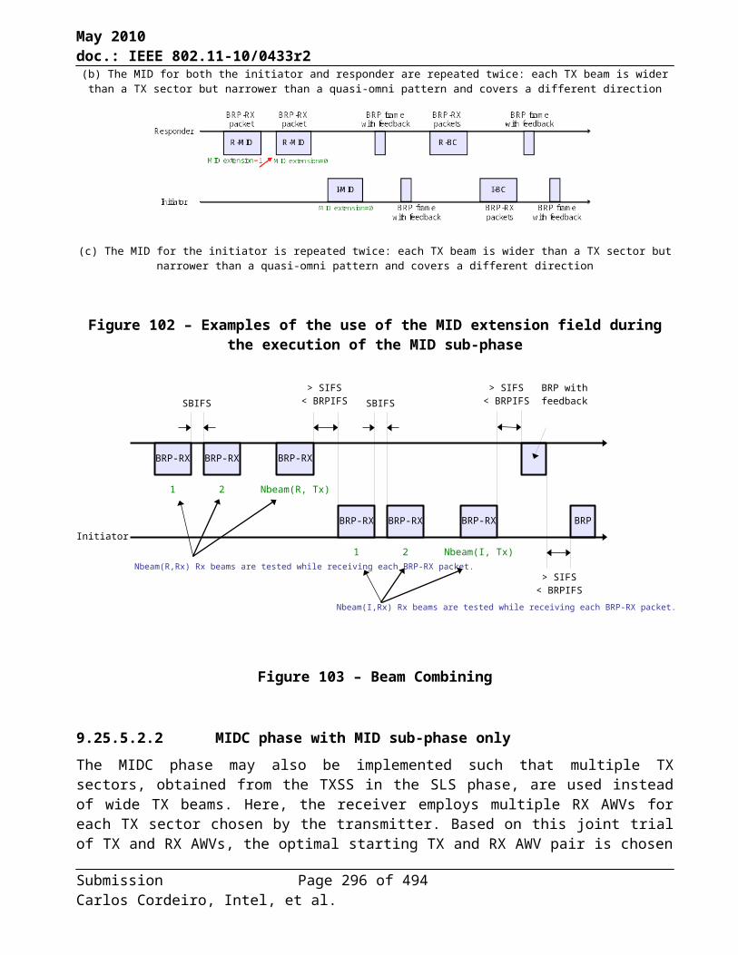
May 2010 doc.: IEEE 802.11-10/0433r2
Table 68 – Frequently used parametersSymbol Explanation
Number of coded bits per symbol
Number of data bits per symbol
Number of coded bits per single carrier
Code rate
21.3.5 Mathematical conventions in the signal descriptionThe transmitted signal is described in complex base-band signal notation. The actual transmitted signal
is related to the complex baseband signal by the following relation:
(20-1)
where
represents the real part of a complex variable;
is the center frequency of the carrier.
The transmitted RF signal is generated by modulating the complex baseband signal, which consists of several fields. The fields and the timing boundaries for the various fields are shown in Figure 131
Figure 131 – Packet structure
The time offset, , determines the starting time of the corresponding field.
Submission Page 296 of 339 Carlos Cordeiro, Intel, et al.
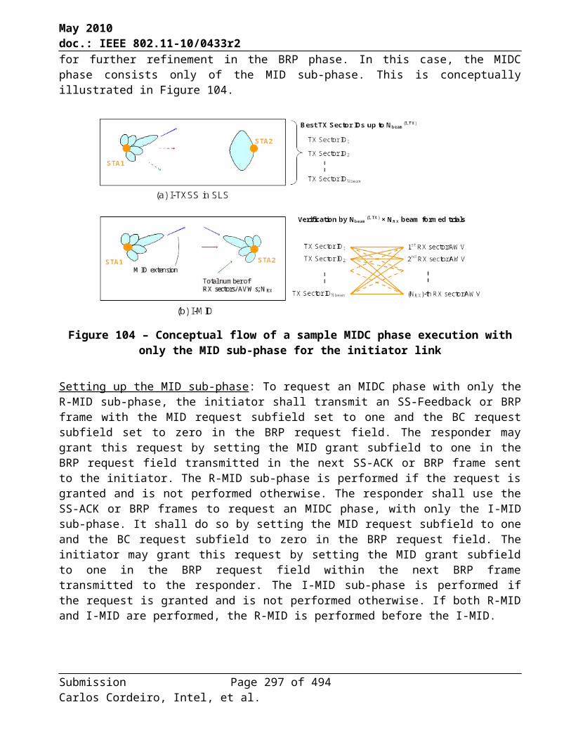
May 2010 doc.: IEEE 802.11-10/0433r2
(20-2)
Where:
Each OFDM base band waveform , for the fields above, is defined via the discrete inverse Fourier transform as
Where is the complex constellation point to be transmitted on subcarrier k. n is the discrete time
index. The window is user defined and is used to smooth the transition between fields.
The base band waveform for fields defined by time domain sequences or for single carrier transmission is:
Where is the n’th constellation point. Conversion from the sampled digital domain to the continuous time domain is beyond the scope of this document. Filtering for pulse shaping such as in GMSK is beyond the scope of this specification.
21.3.5.1 The windowing function
The windowing function is used to smooth the transition between adjacent fields in the packet where OFDM modulation is employed. No windowing is applied to preamble fields or to SC modulated fields. The windowing function is different from being equivalent to “1” only in the transition region.
Submission Page 297 of 339 Carlos Cordeiro, Intel, et al.
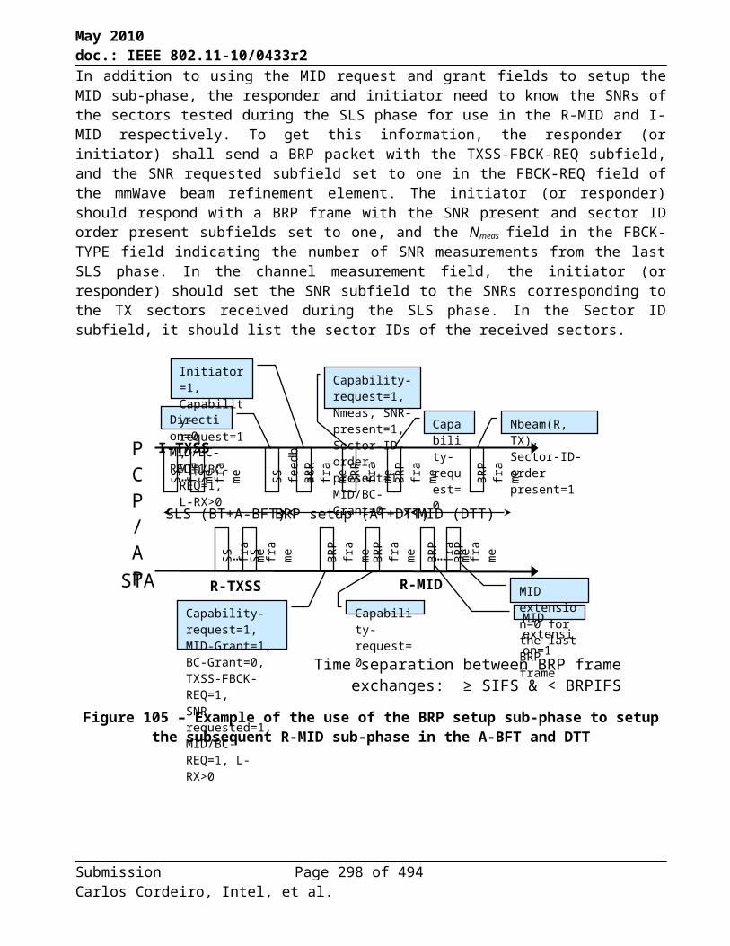
May 2010 doc.: IEEE 802.11-10/0433r2
Figure 132 – Illustration of the windowing function
An example of a windowing function is given by:
The transition region creates an overlap (with length TR) between adjacent fields. The field wave form
is extended cyclically to fill the part of the transition region in which it is undefined. If the transition region vanishes (i.e., TR=0), the windowing function degenerates to a rectangular window.
21.3.6 A Common PreambleThe preamble is the part of the PPDU that is used for packet detection, AGC, frequency offset estimation, synchronization, indication of modulation (SC or OFDM) and channel estimation. The format of the preamble is common to both OFDM packets and SC packets.
The preamble is composed of two parts: the Short Training field and the Channel Estimation field.
Figure 133 – The preamble
21.3.6.1 The Short Training field
The Short Training field is composed of 14 repetitions of sequences Ga128(n) of length 128 defined in 21.9, followed by a single repetition of –Ga128(n).
The waveform for the Short Training field is:
Submission Page 298 of 339 Carlos Cordeiro, Intel, et al.
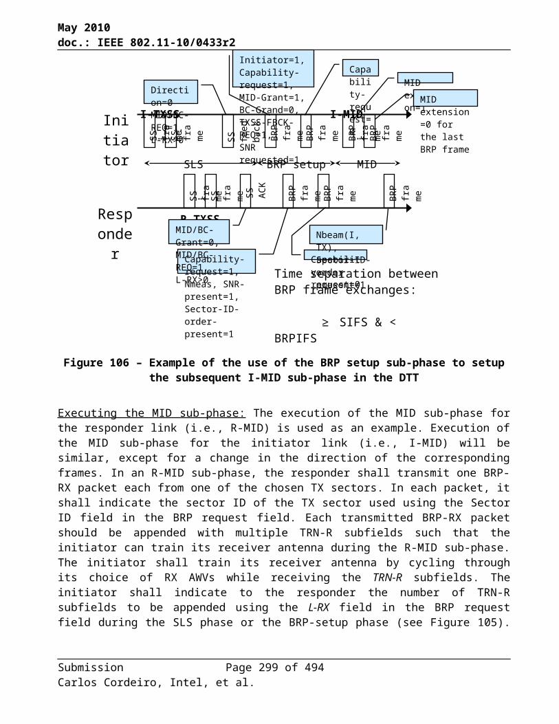
May 2010 doc.: IEEE 802.11-10/0433r2
r STF (nT c )={ (Ga128 (nmod 128 ) )exp( jπ n2 ) n=0,1 ,…, 14×128−1
(−Ga128 (n mod 128 ) )exp( jπ n2 ) n=14×128 ,… ,15×128−1
Where mod is the modulus operation.
21.3.6.2 The Channel Estimation fieldThe Channel Estimation field is used for channel estimation, as well as indication which modulation is going to be used for the packet. The Channel Estimation field is composed of a concatenation of two complementary Golay sequences, Gu512(n) and Gv512(n) where the last 128 samples of Gu512(n) are equal to the last 128 samples used in the Short Training field. They are followed by a 128 samples sequence Gv128(n) equal to the first 128 samples of Gv512(n). The Gu512 and Gv512 Golay sequences are defined as,
where Ga128 and Gb128 are as defined in 21.9. When the data field of the packet is modulated using single carrier, the Gu512 and Gv512 fields are concatenated in the order illustrated in Figure 134. When the data field of the packet is modulated using OFDM, the Gu512 and Gv512 fields are concatenated in the order illustrated in Figure 135.
Figure 134 – Channel Estimation field for SC Packets
Figure 135 – Channel Estimation field for OFDM Packets
The waveform for the channel estimation sequence is:
Submission Page 299 of 339 Carlos Cordeiro, Intel, et al.
May 2010 doc.: IEEE 802.11-10/0433r2
Note that sequences Gu512(n) and Gv512(n) are defined for 0≤n≤511. For other n they are set to zero.
21.3.6.3 Transmission of the Preamble in an OFDM packetThe preamble sequence defined in the above subclauses is specified at the SC chip rate (Tc). For transmission in the OFDM (nominal) sample rate, the signal is resampled with a 3/2 rate change. The
resampling is done by upsampling by a factor of 3, filtering by the filter defined in 21.3.6.3.1, and downsampling by a factor of 2 (see equation below). The resampling is performed using a specific
filter since the OFDM receiver needs to know this filter to correct for its response during channel estimation. To define the transmission of the preamble when the packet is an OFDM packet, the preamble wave form is defined below.
Let Then
r preambleOFDM ( 2 )(n T s
2 )={r preamble(nT c
3 ) n=0,3,6 ,…
0 otherwise
~r preambleOFDM (2 )(n
T s
2 )=∑k=0
K −1
r preambleOFDM (2)((n−k )T s
2 )hFilt (k ) , n=0,1 ,…
r preambleOFDM (nT s)=~r preamble
OFDM ( 2 )(2nT s
2−36T s
2 ) , n=0,1 ,…
K=73.
21.3.6.3.1 hfilt definition
The filter is defined by the following coefficients (from h0 to h72):[3,2,-1,-4,-3,2,5,3,-3,-6,-2,5,7,1,-6,-8,0,9,9,-2,-12,-10,4,16,11,-9,-22,-12,16,32,12,-32,-55, -12, 94,207,256,207,94,-12,-55,-32,12,32,16,-12,-22,-9,11,16,4,-10,-12,-2,9,9,0,-8,-6,1,7,5,-2,-6, -3,3,5,2,-
3,-4,-1,2,3] Normalized to have a norm of so that hFilt (k )= √3 hk
√∑l=0
72
|hl|2 .
21.3.7 HCS calculation for headers of OFDM PHY and SC PHY
The header check sequence (HCS) is a CRC of the header bits. The header is considered to be a stream of bits b0,…,bM-1. The CRC is based on CRC 16-CCITT. The value of the CRC field is the ones complement of
Submission Page 300 of 339 Carlos Cordeiro, Intel, et al.
May 2010 doc.: IEEE 802.11-10/0433r2
where:
is the header bits represented as polynomial (over the binary field) where b0 is bit 0 of the header and bM-1 is bit M-1 of the header.
is an initialization polynomial added to the first 16 bits of the header (setting the
shift register bits to 1)
is the CRC generating polynomial
( 9)
The CRC field is transmitted with x15 first.
For a block diagram and an example of how to calculate the CRC, see subclause 18.2.3.6 of IEEE802-11™-2007.
21.3.8 Common LDPC parity matrices
Four Low-Density Parity-Check (LDPC) codes are specified, each of a different rate but with a common codeword size of 672 bits.
Each of the parity-check matrices H is partitioned into square sub-matrices of size Z x Z. The sub-matrices are either cyclic-permutations of the identity matrix, or null sub-matrices with all zero entries.
A location with integer i denotes the cyclic-permutation sub-matrix Pi obtained from the Z x Z identity matrix by cyclically shifting the columns to the right by i elements. The matrix Po is the Z x Z identity matrix. An empty location denotes a null sub-matrix of size Z x Z.
Examples with Z = 4:
P0=[1 0 0 00 1 0 00 0 1 00 0 0 1 ] , P1=[0 1 0 0
0 0 1 00 0 0 11 0 0 0 ] P3=[0 0 0 1
1 0 0 00 1 0 00 0 1 0 ]
21.3.8.1 Rate-1/2 LDPC code matrix H = 336 rows x 672 columns, Z = 42
Table 69 – Rate 1/2 LDPC code matrix 40 38 13 5 1834 35 27 30 2 1
36 31 7 34 10 4127 18 12 20 15 6
35 41 40 39 28 3 28
Submission Page 301 of 339 Carlos Cordeiro, Intel, et al.

May 2010 doc.: IEEE 802.11-10/0433r2
29 0 22 4 28 27 2331 23 21 20 12 0 1322 34 31 14 4 13 22 24
21.3.8.2 Rate-5/8 LDPC code matrix H = 252 rows x 672 columns, Z = 42
Table 70 – Rate 5/8 LDPC code matrix 20 36 34 31 20 7 41 34 10 4130 27 18 12 20 14 2 25 15 635 41 40 39 28 3 2829 0 22 4 28 27 24 23
31 23 21 20 9 12 0 1322 34 31 14 4 22 24
21.3.8.3 Rate-3/4 LDPC code matrix H = 168 rows x 672 columns, Z = 42
Table 71 – Rate 3/4 LPDC code matrix35 19 41 22 40 41 39 6 28 18 17 3 2829 30 0 8 33 22 17 4 27 28 20 27 24 2337 31 18 23 11 21 6 20 32 9 12 29 0 1325 22 4 34 31 3 14 15 4 14 18 13 13 22 24
21.3.8.4 Rate-13/16 LDPC code matrix H = 126 rows x 672 columns, Z = 42
Table 72 – Rate 13/16 LDPC code matrix29 30 0 8 33 22 17 4 27 28 20 27 24 2337 31 18 23 11 21 6 20 32 9 12 29 10 0 1325 22 4 34 31 3 14 15 4 2 14 18 13 13 22 24
21.3.9 ScramblerThe header and data fields (including data padding bits but excluding the scrambler initialization field), shall be scrambled by XORing each bit in turn with a length 127 periodic sequence generated by the
polynomial . The PLCP header bits (with the exception of the first seven) will be placed one after the other, bit 7 first. The octets of the PSDU and the pad bits shall be placed into a bit stream with bit 0 (LSB) of each octet first and bit 7 of each octet (MSB) last. The generation of the sequence and the XOR operation are defined in Figure 136.
Submission Page 302 of 339 Carlos Cordeiro, Intel, et al.
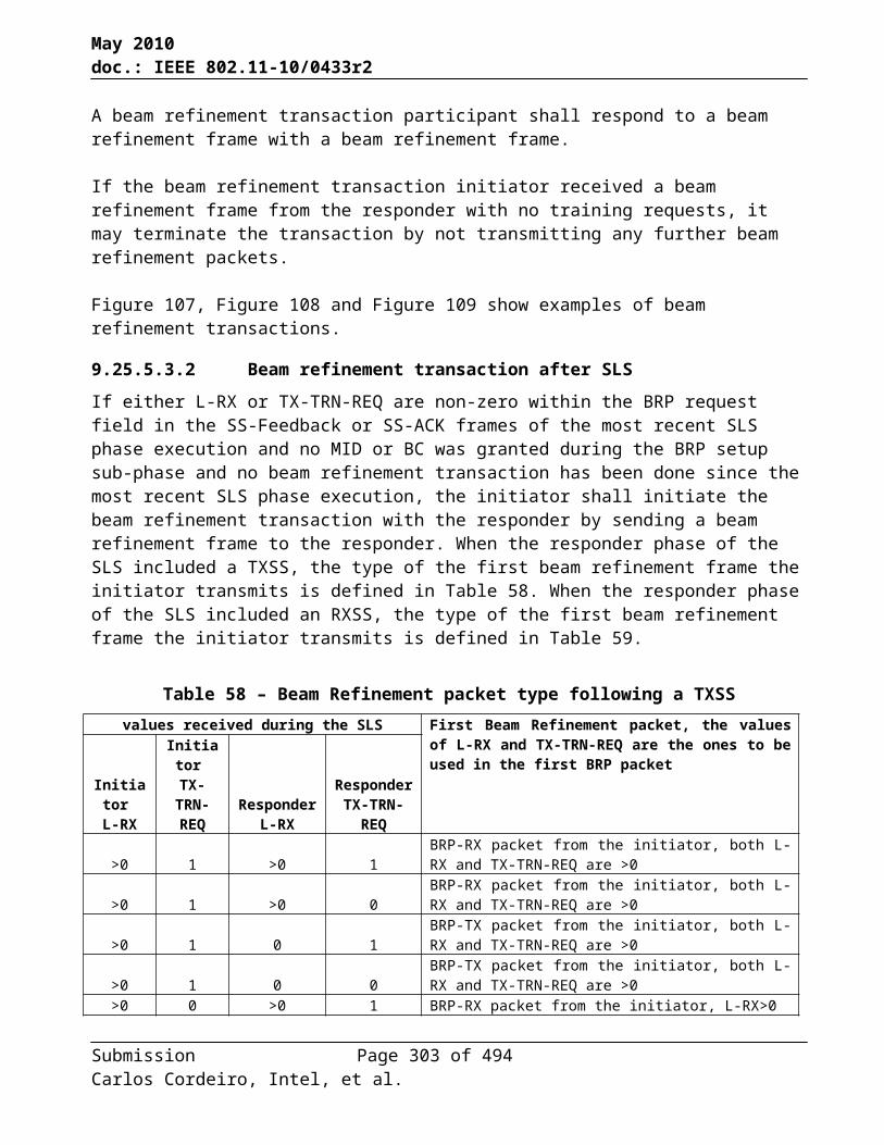
May 2010 doc.: IEEE 802.11-10/0433r2
Figure 136 – Data scrambler
For each PPDU, the transmitter selects values for bits x1 through x7 of the scrambler. The values selected for bits x1 through x7 should be such that a different combination of values is likely should the same PPDU be retransmitted. The values selected are sent in the Scrambler Initialization field. Each data bit in the data field of the PPDU is then XORed with the scrambler output (x4 XOR x7) and the scrambler content shifted once.
21.4 mmWave Control PHY
21.4.1 Introduction
Transmission and reception of Control PHY PPDUs is mandatory. Control PHY uses the same chip rate as the SC PHY.
21.4.2 Frame Format
The Control PHY frame is composed of the Preamble, Header, Data field, and possibly TRN-R/T field. This is shown in Figure 137.
Figure 137 – Control PHY Frames
21.4.3 Transmission
21.4.3.1 PreambleThe preamble is the part of the Control PHY PPDU that is used for packet detection, AGC, frequency offset estimation, synchronization, indication of frame type and channel estimation.
The preamble is composed of two parts as shown in Figure 138: the Short Training field and the Channel Estimation field.
Submission Page 303 of 339 Carlos Cordeiro, Intel, et al.

May 2010 doc.: IEEE 802.11-10/0433r2
Figure 138 – Control PHY Preamble
21.4.3.1.1 Short Training fieldThe Short Training field is composed of 38 repetitions of sequences Gb128(n) of length 128, followed by a single -Gb128(n) sequence (for synchronization) and then a single -Ga128(n) sequence. The sequences Ga128(n) and Gb128(n) are defined in subclause 21.9.
The waveform for the Short Training field is
:
r STF (nT c)={ Gb128 (nmod 128 ) exp( jπ n2 ) n=0,1 , …,37 ×128−1
−G b128 (nmod 128 ) exp( jπ n2 ) n=37 × 128 ,…,38 ×128−1
−G a128 (nmod 128 ) exp( jπ n2 ) n=38 ×128 , …,39 ×128−1
Where mod is the modulus operation. Note that sequences Ga128(n) and Gb128(n) are defined for 0≤n≤127. For other n they are set to zero.
21.4.3.1.2 Channel Estimation fieldThe Channel Estimation field is the same as the Channel Estimation field of the SC PHY, as defined in Figure 134 of subclause 21.3.6.2.
21.4.3.2 HeaderIn the Control PHY, the preamble is followed by the header block. The header consists of several fields which define the details of the PPDU to be transmitted.
The header fields are described in Table 73.
Submission Page 304 of 339 Carlos Cordeiro, Intel, et al.
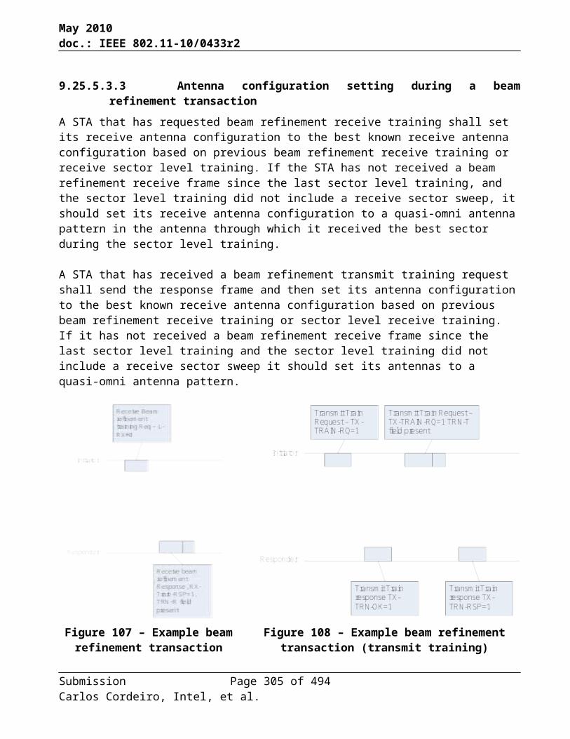
May 2010 doc.: IEEE 802.11-10/0433r2
Table 73 – Control PHY header fields
Field Name Number of bits
Starting bit
Description
Reserved 1 0 Set to zero (differential detector initialization.)
Scrambler Initialization
4 1 bits X1-X4 of the initial scrambler state. The rest of the bits are set to one.
Length 10 5 Number of data octets in the PSDU. Range 14-1023.
Packet type 1 15 TRN packet type:0 - TRN-R packet1 - TRN-T packet
Training Length 5 16 Length of the training field - the use of this field is define in subclause 21.8.2.2.2.
Reserved bits 3 21
HCS 16 24 Header Check sequence. Calculation of the header check sequence is defined in subclause 21.3.7.
All the numeric fields are encoded in unsigned binary, least significant bit first.
21.4.3.2.1 Generation of HCS bits
The header check sequence (HCS) uses CRC 16-CCITT the same as that in SC PHY, as described in subclause 21.6.3.1.2.
21.4.3.2.2 Header Encoding and ModulationThe header bits followed by the HCS bits are prepended to the data field bits and passed into the data field encoder per subclause 21.4.3.3. The minimal payload length is 14 octets.
21.4.3.3 Data fieldThe Data field consists of the payload data of the PSDU. The PSDU is scrambled, encoded, modulated and spread as described in the following subclauses.
21.4.3.3.1 ScramblerThe operation of the scrambler is defined in 21.3.9. Bits x1, x2, x3, x4 of the scrambler shift register are initialized using the bits in the scrambler initialization bits from the header, bits x5, x6, x7 are set to 1. The scrambling of the data field continues the scrambling of the header with no reset.
Submission Page 305 of 339 Carlos Cordeiro, Intel, et al.
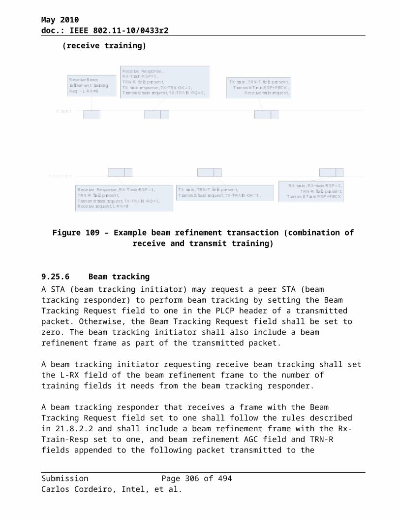
May 2010 doc.: IEEE 802.11-10/0433r2
21.4.3.3.2 Encoder The control PHY header and data should be encoded using an effective LDPC code rate of ½, generated from the data PHY rate ¾ LDPC parity check matrix, with shortening. The following steps are used for the encoding:
1) LCWD=168 is the maximal number of data bits in each LDPC codeword. Define LHDR =5
as the length of the header (including header CRC), and LFDCW is the length of the additional data in the header LDPC codeword in octets. Define the number of header and
data bits in the first LDPC codeword asLDPFCW=( LHDR+LFDCW )×8=88 . The number of
LDPC code words is calculatedNCW=1+⌈
(Length−6 )×8LCWD
⌉.
The number of bits in the second and any subsequent codeword (if present), except the last, is
LDPCW=⌈( Length−6 )×8
NCW −1⌉
2) The number of bits in the last codeword, is defined as LDPLCW=( Length−6 )×8−( NCW −2) ×LDPCW .
3) The output stream of the scrambler is broken into blocks of L = LDPFCW, LDPCW, or LDPLCW
bits (depending on the codeword index) such that the mth data word is (b1(m) , b2
(m ) ,. . ., bL(m )) .
4) Each data word is padded with zeros to create 504 total bits.
5) To each data word, LCWD parity bits ( p1(m) , p2
(m ) , . .. , pLCWD
( m) ) are added to create the
codeword c(m )=(b1
(m) , b2(m ) ,. . ., bL
(m ) , 0 ,. .. ,0 , p1(m ) , p2
(m ) , .. . , pLCWD
(m ) ) such that Hc(m)T
=0 .
6) The output is the stream bits generated from the codewords, with the zero padding removed from all codewords.
Example: If Length=120 , then NCW =1+⌈
(120−6 )×8LCWD
⌉=7,
LDPCW=⌈(120−6 )×8
7−1⌉=152
, and LDPLCW=(120−6 )×8−(7−2)×152=152 . In the first LDPC block the 40 header+HCS bits are encoded along with additional 48 bits of the data.
21.4.3.3.3 ModulationThe scrambled and coded bit stream is converted into a stream of complex constellation points using differential binary phase shift keying (DBPSK) as follows.
Submission Page 306 of 339 Carlos Cordeiro, Intel, et al.

May 2010 doc.: IEEE 802.11-10/0433r2
The encoded bit stream is converted the non-differential stream .
The differential sequence is created by setting d (k )=s ( k )×d (k−1 ) . For the differential encoding
purposes d (−1 ) is defined to be 1. is the first bit of the encoded header bits.
21.4.3.3.4 SpreadingThe constellation points are spread using the sequence Ga32(n) which is defined in 21.9.
The waveform for the modulated and spread data field is
r DATA (n T c) (G a32 (nmod 32 ) ∙ d (⌊ n32
⌋ ))exp( jπ n2 ) , n=0,1,2 ,…
where means the largest integer smaller than a real number x, and is the k-th modulated constellation point.
21.4.4 Performance requirements This section describes the performance requirement of the Control PHY (CP).
21.4.4.1 Transmit Requirements This section describes the transmitter performance requirement of the Control PHY.
21.4.4.1.1 Transmit EVMThe transmit EVM accuracy test shall be performed by instrumentation capable of converting the transmitted signal into a stream of complex samples, with sufficient accuracy in terms of I/Q arm amplitude and phase balance, dc offsets, phase noise, etc.
The sampled signal shall be processed by a receiver that is capable of converting the transmitted signal into a stream of complex samples at sufficient rate or more, with sufficient accuracy in terms of I/Q arm amplitude and phase balance, DC offsets, and phase noise. It shall perform carrier lock, symbol timing recovery and amplitude adjustment while making the measurements. For the CP PHY EVM, measuring Ns samples at the sample rate, the measured chips should not contain the first and the last hundred chips of a given packet (ramp up/down) the EVM will be calculated according to the formula below:
EVM =20 log10(√( 1
N s Pavg∑i=1
N S
[( I i−I i¿ )2−(Qi−Qi
¿)2]))
Submission Page 307 of 339 Carlos Cordeiro, Intel, et al.
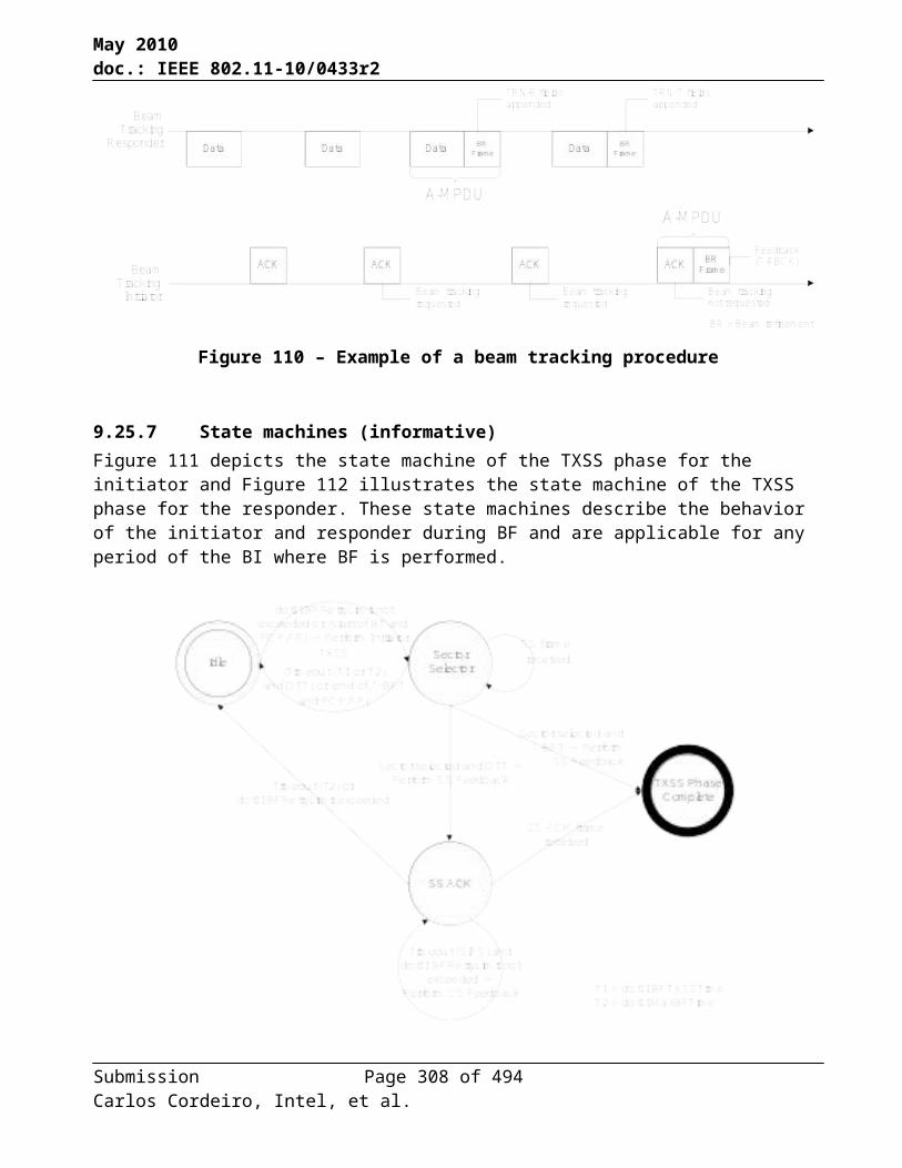
May 2010 doc.: IEEE 802.11-10/0433r2
Where is the number of samples to be measured and Ns should be bigger than 8000, is the
average power of the constellation, is the complex coordinates of the ith measured chip, and
I i , Qiis the complex coordinates of the ideal constellation point for the ith measured chip.
The measuring device should have the accuracy of at least 20 dB better than the EVM value to be measured. The test equipment should use a root-raised cosine filter with roll-off factor of 0.25 for the pulse shaping filter when conducting EVM measurement.The transmit pulse shaping used is left to the implementer.
The EVM shall not exceed a data-rate dependent value according to Table 74.
Table 74 – EVM requirement for control PHYMCS Index Description EVM Value [dB]
0 CP Modulation -6
21.4.4.2 Rx Requirements This section describes the performance requirement from the CP PHY receiver.
21.4.4.2.1 CCA
The start of a valid mmWave Control PHY transmission at a receive level greater than the minimum sensitivity for control PHY (-78dBm), shall cause CCA to indicate busy with a probability > 90% within 3usec.
21.5 mmWave OFDM PHY
21.5.1 Introduction
21.5.2 Frame FormatThe OFDM frame is composed of the Short Training Field (STF), the channel estimation field (CE), the Header, OFDM symbols and optional training fields, as shown in Figure 139.
Figure 139 – OFDM frame format
Submission Page 308 of 339 Carlos Cordeiro, Intel, et al.

May 2010 doc.: IEEE 802.11-10/0433r2
21.5.3 Transmission
21.5.3.1 PLCP HeaderIn the OFDM PHY, the preamble is followed by the PLCP header. The PLCP header consists of several fields which define the details of the PPDU being transmitted. The encoding and modulation of the header is described in subclause 21.5.3.1.3.
The header fields are described in Table 75.
Table 75 – Header fields Field Name Number
of bitsStart Bit
Description
Scrambler Initialization
7 0 bits X1-X7 of the initial scrambler state.
MCS 5 7 Index into the Modulation and Coding Scheme table
Length 18 12 Number of data octets in the PSDU. Range 0-262143.
Additional PPDU
1 30 A value of 1 indicates that this PPDU is immediately followed by another PPDU with no IFS or preamble on the subsequent PPDU. A value of 0 indicates that no additional PPDU follows this PPDU.
Packet type 1 31 packet type: 0 - TRN-R packet1 - TRN-T packet
Training Length 5 32 Indicates the length of the training field. The use of this field is define in subclause 21.8.2.2.2. A value of zero indicates that this packet does not have any training field.
Aggregation 1 37 Set to 1 to indicate that the PPDU in the data portion of the packet contains an A-MPDU; otherwise, set to 0.
Beam Tracking Request
1 38 Set to 1 to indicate the need for beam tracking (9.25.6); otherwise, set to zero.
Tone Pairing Type
1 39 Set to 0 to indicate Static Tone Pairing (21.5.3.2.3.5.1);Set to 1 to indicate Dynamic Tone Pairing (21.5.3.2.3.5.2).
Only valid if MCS field value is in the range of 13-17; otherwise ignored.DTP Indicator 1 40 Bit flip used to indicate DTP update.
Only valid when the Tone Pairing Type field is set to 1 and the MCS field value is in the range of 13-17; otherwise ignored.
Reserved 7 41 Set to 0, ignored by receiverHCS 16 48 Header check sequence. Definition of this field calculation is in the subclause
21.5.3.1.2.
All the numeric fields are encoded in unsigned binary, least significant bit first.
21.5.3.1.1 Modulation and Coding SchemeThe modulation and coding scheme (MCS) field specifies the modulation and code rate used in the PPDU. The modulation and coding schemes for OFDM modulations are defined in Table 76.
Submission Page 309 of 339 Carlos Cordeiro, Intel, et al.
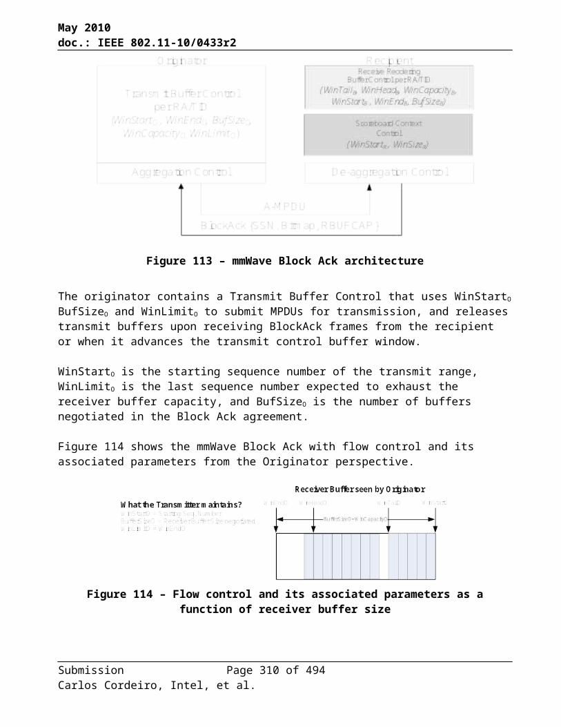
May 2010 doc.: IEEE 802.11-10/0433r2
Table 76 – Modulation and Coding Scheme for OFDM
MCS index Modulation Code Rate NBPSC NCBPS NDBPSData Rate
(Mbps)13 SQPSK 1/2 1 336 168 693.0014 SQPSK 5/8 1 336 210 866.2515 QPSK 1/2 2 672 336 1386.0016 QPSK 5/8 2 672 420 1732.5017 QPSK 3/4 2 672 504 2079.0018 16-QAM 1/2 4 1344 672 2772.0019 16-QAM 5/8 4 1344 840 3465.0020 16-QAM 3/4 4 1344 1008 4158.0021 16-QAM 13/16 4 1344 1092 4504.5022 64-QAM 5/8 6 2016 1260 5197.5023 64-QAM 3/4 6 2016 1512 6237.0024 64-QAM 13/16 6 2016 1638 6756.75
MCS 17 and below are mandatory for each Tx and Rx of a device that supports OFDM.
21.5.3.1.2 Generation of the HCS bitsCalculation of the HCS for bits 0-47 of the header is defined in subclause 21.3.7.
21.5.3.1.3 Header encoding and modulation
The header is encoded using a single OFDM symbol. The bits are scrambled and encoded as follows:
(1) The 64 header bits (b1, b2, …, bLH), where LH = 64, are scrambled as described in 21.3.9, starting from the eighth bit, to create q=(q1,q2,…,qLH).
(2) The sequence q is padded with 440 zeros to obtain a total of 504 bits, (q1,q2,…,qLH,0LH+1,0LH+2,…0504), which are then encoded using the rate-3/4 LDPC code as described in 21.5.3.2.2.2. 168 parity bits, p1,p2,…,p168, are generated.
(3) A sequence c1 is generated as (q1,q2,…,qLH,p9,p10,…p168).(4) A sequence c2 is generated as (q1,q2,…,qLH,p1,p2,…p84, p93,p94,…p168) XORed with the one-time
pad sequence generated using the scrambler defined in 21.3.9, with the shift register is initialized to all ones.
(5) A sequence c3 is generated as (q1,q2,…,qLH,p1,p2,…p160) XORed with the one-time pad sequence, generated using the scrambler defined in 21.3.9, as a continuation to of the sequence used in step (4).
(6) The sequences c1,c2 and c3 are concatenated to form the 672-bit sequence d=(d1,d2,d3,…,d672)=(c1,c2,c3).
(7) The 672-bit sequence, d, is then mapped as QPSK as described in 21.5.3.2.3.2, pilots are inserted as described in 21.5.3.2.4 and the resulting sequence is modulated as an OFDM symbol as described in 21.5.3.2.5.
Submission Page 310 of 339 Carlos Cordeiro, Intel, et al.
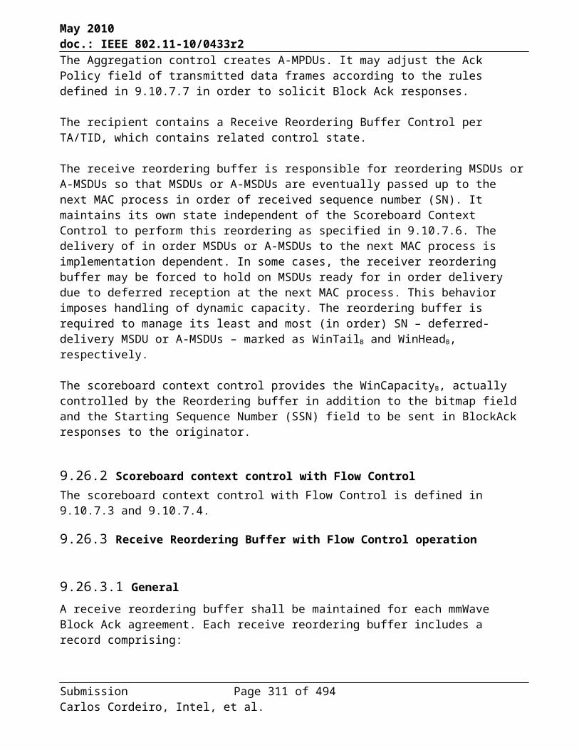
May 2010 doc.: IEEE 802.11-10/0433r2
21.5.3.2 The Data fieldThe data field consists of the payload data of the PSDU and possible padding. The data are padded with zeros, scrambled, encoded and modulated as described in the following subclauses. The amount of padding is defined in subclause 21.5.3.2.2.
21.5.3.2.1 Scrambler
The operation of the scrambler is defined in 21.3.9. The scrambling of the data field continues the scrambling of the header with no reset.
21.5.3.2.2 EncodingThe data are encoded by a systematic LDPC encoder. LDPC (Low Density Parity Check) is a block code. Each block of bits (b1, b2,...,bk) is concatenated with a block of parity bits (p1,p2,….,pn-k) to create a codeword c=( b1, b2,...,bk,p1,p2,….,pn-k) such that HcT=0. H is an (n-k)×n parity check matrix. The block size n is 672 bits. The code rate is R is equal to k/n. The set of code rates is defined in Table 77. The parity check matrices are defined in subclause 21.5.3.2.2.1. The encoding process is defined in subclause 21.5.3.2.2.2.
Table 77 – LDPC code ratesCode Rate Codeword size Number of data bits
1/2 672 3365/8 672 4203/4 672 504
13/16 672 546
21.5.3.2.2.1 Parity Check Matrices
See 21.3.8.
21.5.3.2.2.2 LDPC encoding processThe LDPC encoding process is composed of several steps including determining the number of padding bits, padding with zeros and the coding of every word.
1) First the total number of padding bits NPAD is calculated, using the number of LDPC codeword NCW and the number of OFDM symbols NSYM:
NCW=⌈ Length×8LCW×R
⌉
N SYM=⌈NCW ×LCW
NCBPS⌉
N PAD=R×N SYM×N CBPS−Length×8
Recalculate NCW = N SYM⋅
N CBPS
LCW
Submission Page 311 of 339 Carlos Cordeiro, Intel, et al.
May 2010 doc.: IEEE 802.11-10/0433r2
Where LCW=672 is the LDPC code word length, Length is the length of the PSDU defined in the header field, R is the code rate and NCBPS is the number of code bits per symbol as defined in the MCS table.
2) The PSDU is concatenated with NPAD zeros. They are scrambled using the continuation of the scrambler sequence that scrambled the PSDU.
3) The output stream of the scrambler is broken into blocks of LCWD= R×LCW bits such as the m’th
data word is .
4) To each data word, n-k=LCW-R×LCW parity bits are added to create the code
word such that . 5) The code words are the concatenated one after the other to create the coded bits stream
.
21.5.3.2.3 Modulation MappingThe coded bits are mapped to complex constellation points for the modulation specified in the MCS as described in the following subclauses.
21.5.3.2.3.1 SQPSK ModulationIn SQPSK (Spread QPSK) modulation, the input stream is broken into groups of NCBPS bits -
. Each pair of bits is converted into a complex
constellation point . This generates the constellation points for
half the OFDM subcarriers. For the other subcarriers, d P( k )(q) =conj (dk
(q)) for k=0,1, . .. , NCBPS /2−1where the indices P(k), in the range NCBPS /2 to NCBPS-1, are as defined in 21.5.3.2.5.
21.5.3.2.3.2 QPSK modulation
(a) The input stream is broken into groups of NCBPS bits - . Each group of four bits
is converted into two complex constellation points
. The block
is created.
Submission Page 312 of 339 Carlos Cordeiro, Intel, et al.
May 2010 doc.: IEEE 802.11-10/0433r2
(b) Each pair of constellation points is converted into
[dk(q ) , dP (k )
(q) ]T=Q [ x2k(q ) , x2 k+1
( q) ]T where the matrix and the indices P(k), in the range NSD /2 to NSD-1, are as defined in 21.5.3.2.5.
(c) The output is the stream of blocks .
21.5.3.2.3.3 16-QAM Modulation
The input stream is broken into groups of NCBPS bits . Each group of eight bits
is converted into
two complex constellation points such that
The output is the stream of blocks (x0( q ) , x1
( q ) , x2( q ) ,…, xN SD−1
(q ) , q=0,1,2 ,…N SYM −1.
21.5.3.2.3.4 64-QAM Modulation
The input stream is broken into groups of NCBPS bits . The constellation point for the k’th subcarrier in the q’th symbol is:
NOTE – This mapping provides interleaving between three LDPC codewords on a subcarrier basis.
The mapping is shown in Figure 140.
Submission Page 313 of 339 Carlos Cordeiro, Intel, et al.
May 2010 doc.: IEEE 802.11-10/0433r2
Figure 140 – 64-QAM modulation mapping
21.5.3.2.3.5 Tone Pairing for SQPSK and QPSK
When SQPSK or QPSK modulations are employed in OFDM, bit sequences are mapped to pairs of
symbols (dk(q ) , dP (k )
(q ) ) where k is in the range 0≤k≤
NSD
2−1 and P(k) is in the range of
N SD
2≤P (k )≤NSD−1, in order to exploit frequency diversity. The indices k and P(k) determine
which pair of OFDM subcarriers each pair of symbols are carried on.
All STAs shall support Static Tone Pairing (STP) where a constant mapping between k and P(k) is employed. The PHY header is always encoded using STP.
A STA may employ Dynamic Tone Pairing (DTP) where the mapping between k and P(k) are determined by the receiving STA and fed back to the transmitting STA. An STA may use DTP when transmitting to a DTP-capable STA, from which it has received DTP feedback. A STA is DTP-capable if the DTP Supported field within the STA’s mmWave Capability element is set to one (7.3.2.91). The STA is not DTP-capable otherwise.
Submission Page 314 of 339 Carlos Cordeiro, Intel, et al.
May 2010 doc.: IEEE 802.11-10/0433r2
21.5.3.2.3.5.1 Static Tone Pairing (STP)
When applied to the payload, STP is indicated by the Tone Pairing Type field in the PHY header set to 0. STP is always applied to the PHY header.
When STP is applied, the SQPSK symbol-pair indices k and P(k) are such that
P(k )=k+N SD
2 for k=0,1,2 , .. . ,
NSD
2−1
.
21.5.3.2.3.5.2 Dynamic Tone Pairing (DTP)
When applied, DTP is indicated by the Tone Pairing Type field in the PHY header set to 1. DTP can only be applied to the payload of a PPDU employing MCS 13-17.
When DTP is applied, the SQPSK symbol-pair indices, k and P(k), are such that
P(k )=ToneIndexOffset (⌊ kNTPG ⌋)+mod (k , NTPG ) for k=0,1,2 , . .. ,
N SD
2−1
where NTPG denotes the number of tones per group and ToneIndexOffset(l) denotes the starting index
of the l-th group of tone pairs, for l=0,1,2 , .. . ,
N SD
NTPG−1
.
The values of NTPG and ToneIndexOffset(l) for l=0,1,2 , .. . ,
N SD
NTPG−1
are derived from the DTP Report element (7.3.2.108) included in the last received DTP Report frame (7.4.13.13).
The number of tone-pairs per group, NTPG, is derived as
NTPG=N SD
2NGwhere NG is the number of number of DTP groups, which is equal to 42.
The tone index offsets, ToneIndexOffset(l), are derived asToneIndexOffset ( l)=N TPG×GroupPairIndex ( l)+N SD/2
where GroupPairIndex(l) is the value of the GroupPairIndex(l) subfield of the DTP Report Element.
21.5.3.2.4 Pilot SequencePilot tones are inserted at tones -150, -130, -110, -90, -70, -50, -30, -10, 10, 30, 50, 70, 90, 110, 130,150. The values of the pilots at these tones is [-1, 1, -1, 1, 1, -1, -1, -1, -1, -1, 1, 1, 1, -1, 1, 1] respectively. The pilot sequence P is created by creating a sequence of zeros corresponding to tones –NSR to NSR. The pilots are then inserted at the corresponding tones with the values specified above.
Submission Page 315 of 339 Carlos Cordeiro, Intel, et al.

May 2010 doc.: IEEE 802.11-10/0433r2
At OFDM symbol n the pilot sequence is multiplied by the value 2×pn-1, where pn is the value generated by the shift register defined in subclause 21.5.3.2.1 if x1,x2,…x7 are all set to 1 at the first OFDM symbol.
21.5.3.2.5 OFDM modulationThe stream of complex constellation points dk is broken into groups of NSD points dm,n where m=1,2,…,NSD and n=1,2,…,NSYM. The baseband signal for the data phase is:
r DATA (qT S )= 1√ NTones
∑n=1
N SYM
wT SYM(qT S−nT SYM ) ∑
k=− NSR
NSR
( DM (k ), n+ pn Pk )exp ( j2 πkΔF (qT S−nT SYM −TGI ))
Where pn, P are defined in 21.5.3.2.4, is the number of active subcarriers, and
21.5.4 Performance requirements This subclause describes the performance requirement from the OFDM PHY.
21.5.4.1 Transmit RequirementsThis subclause describes the performance requirement from the OFDM PHY transmitter.
Submission Page 316 of 339 Carlos Cordeiro, Intel, et al.

May 2010 doc.: IEEE 802.11-10/0433r2
21.5.4.1.1 Transmit EVM The transmit EVM accuracy test shall be performed by instrumentation capable of converting the transmitted signal into a stream of complex samples, with sufficient accuracy in terms of I/Q arm amplitude and phase balance, dc offsets, phase noise, etc.
The sampled signal shall be processed in a manner similar to an actual receiver, according to the following steps, or an equivalent procedure:
a) Start of frame shall be detected.b) Transition from short sequences to channel estimation sequences shall be detected, and
fine timing (with one sample resolution) shall be established.c) frequency offsets shall be estimated and corrected.d) The frame shall be de-rotated according to estimated frequency offset.e) The complex channel response coefficients shall be estimated for each of the
subcarriers.f) For each of the data OFDM symbols: transform the symbol into subcarrier received
values, estimate the phase from the pilot subcarriers, derotate the subcarrier values according to estimated phase, and divide each subcarrier value with a complex estimated channel response coefficient.
g) For each data-carrying subcarrier, find the closest constellation point and compute the Euclidean distance from it.
h) Compute the RMS average of all errors in a packet. It is given by:
- Number of framesi-frame indexk-carrier indexj-Symbol index
numer of symbols
Total number of subcarriers. I0,Q0- the ideal constellation point, for I and Q respectively.
The measurements shall occur only on the OFDM symbols, the measurement shall be performed on at least 10 frames with 16 symbols at least in each of them. Random data shall be used.
The EVM RMS error shall not exceed an MCS dependent value as found in the table below:
MCS Index Modulation Coding Rate EVM Value [dB]13 SQPSK ½ -714 SQPSK 5/8 -915 QPSK ½ -1016 QPSK 5/8 -1117 QPSK ¾ -13
Submission Page 317 of 339 Carlos Cordeiro, Intel, et al.

May 2010 doc.: IEEE 802.11-10/0433r2
18 16QAM ½ -1519 16QAM 5/8 -1720 16QAM ¾ -1921 16QAM 13/16 -2022 64QAM 5/8 -2423 64QAM ¾ -2424 64QAM 13/16 -25
21.5.4.1.2 Tx Flatness When using the OFDM PHY and only while transmitting OFDM symbols the average energy of the OFDM Symbols constellations in each of the subcarriers with indices –146 to –2 and +2 to +145 shall deviate no more than ± 2 dB from their average energy. The average energy of the constellations in each of the subcarriers with indices –147 to –177 and +147 to +177 shall deviate no more than +2/–4 dB from the average energy of subcarriers with indices –177 to –2 and +2 to +177.
21.5.4.1.3 Time of Departure accuracyThe Time of Departure accuracy test evaluates TIME_OF_DEPARTURE against aTxPmdTxStartRMS and aTxPmdTxStartRMS against TIME_OF_DEPARTURE_ACCURACY_TEST_THRESH as defined in Annex V with the following test parameters:
― MULTICHANNEL_SAMPLING_RATE is 2640x106 sample/s ― FIRST_TRANSITION_FIELD is Short Training field ― SECOND_TRANSITION_FIELD is Channel Estimation field― TRAINING_FIELD is Channel Estimation field ― TIME_OF_DEPARTURE_ACCURACY_TEST_THRESH is 80 ns
NOTE — The indicated windowing applies to the time of departure accuracy test equipment, and not the transmitter or receiver.
21.5.4.2 Rx Requirements This section describes the performance requirement for an OFDM receiver.
21.5.4.2.1 CCA The start of a valid mmWave OFDM PHY or mmWave SC PHY transmission at a receive level greater than the minimum sensitivity for MCS 13 (-66dBm), shall cause CCA to indicate busy with a probability >90% within 1usec.
Submission Page 318 of 339 Carlos Cordeiro, Intel, et al.

May 2010 doc.: IEEE 802.11-10/0433r2
21.6 mmWave SC PHY
21.6.1 Introduction
21.6.2 Frame formatThe SC frame is composed of the Short Training Field (STF), the channel estimation field (CE), the Header, SC blocks and optional training fields, as shown in Figure 141.
Figure 141 – SC frame format
21.6.3 Transmission
21.6.3.1 HeaderIn the SC PHY, the preamble is followed by the header. The header consists of several fields which define the details of the PPDU to be transmitted. The encoding and modulation of the header is described in subclause 21.6.3.1.3.
The header fields are described in Table 78.
Table 78 – Header fields Field Name Number
of BitsStart Bit
Description
Scrambler Initialization
7 0 Bits X1-X7 of the initial scrambler state.
MCS 5 7 Index into the Modulation and Coding Scheme table
Length 18 12 Number of data octets in the PSDU.Range 0-262143
Additional PPDU
1 30 A value of 1 indicates that this PDDU is immediately followed by another PPDU with no IFS or preamble on the subsequent PPDU. A value of 0 indicates that no additional PPDU follows this PPDU.
Packet Type 1 31 Packet Type : 0 – TRN-R packet1 – TRN-T packet
Training Length
5 32 Length of the training field – the use of this field is defined in subclause 21.6.3.2.2
Aggregation 1 37 Set to 1 to indicate that the PPDU in the data portion of the packet contains an A-MPDU;otherwise, set to 0.
Beam Tracking Request
1 38 Set to 1 to indicate the need for beam tracking (9.25.6); otherwise, set to zero.
Submission Page 319 of 339 Carlos Cordeiro, Intel, et al.

May 2010 doc.: IEEE 802.11-10/0433r2
Reserved 9 39 Set to 0, ignored by the receiver
HCS 16 48 Header check sequence
All the numeric fields are encoded in unsigned binary, least significant bit first.
21.6.3.1.1 Modulation and Coding SchemeThe modulation and coding scheme defines the modulation and code rate that is used in the PPDU. The modulation and coding schemes for SC are defined in Table 79.
Table 79 – Modulation and Coding Scheme for SC
MCS Index Modulation NCBPS Repetition Code RateData Rate
(Mbps)1 π/2-BPSK 1 2 1/2 3852 π/2-BPSK 1 1 1/2 7703 π/2-BPSK 1 1 5/8 962.54 π/2-BPSK 1 1 3/4 11555 π/2-BPSK 1 1 13/16 1251.256 π/2-QPSK 2 1 1/2 15407 π/2-QPSK 2 1 5/8 19258 π/2-QPSK 2 1 3/4 23109 π/2-QPSK 2 1 13/16 2502.510 π/2-16QAM 4 1 1/2 3080 11 π/2-16QAM 4 1 5/8 385012 π/2-16QAM 4 1 3/4 4620
MCS 4 and below are mandatory for each Tx and Rx of a device. MCS 5-12 are optional.
21.6.3.1.2 Generation of the HCS bitsCalculation of the HCS for bits 0-39 of the header is defined in subclause 21.3.7.
21.6.3.1.3 Header encoding and modulation
The header will be encoded using a two SC block of NCBPB (see Table 81) symbols with NGI guard symbols. The bits are scrambled and encoded as follows:
(1) The input header bits (b1, b2, …, bLH), where LH = 64, are scrambled as described in 21.3.9, starting from the eighth bit. to create d1s=(q1,q2,…,qLH)
(2) The LDPC codeword c = (q1,q2,…,qLH,01,02,…,0504-LH,p1,p2,…,p168) is created by concatenating 504-LH zeros to the LH bits of d1s and then generating the parity bits p1,p2,…,p168 such that HcT
= 0, where H is the parity check matrix for the rate 3/4 LDPC code specified in 21.6.3.2.2.1.
Submission Page 320 of 339 Carlos Cordeiro, Intel, et al.
May 2010 doc.: IEEE 802.11-10/0433r2
(3) Remove bits LH+1 through 504 and bits 665 through 672 of the codeword c to create the sequence cs1=(q1,q2,…,qLH,p1,p2,…,p160).
(4) Remove bits LH+1 through 504 and bits 657 through 664 of the codeword c to create the
sequence cs2= (q1 ,q2 ,…,qLH ,p1 ,p2 ,…,p152,p161 ,p162 ,…,p168) and then XOR with a PN sequence which is generated from the LFSR used for data scramblings defined in 21.3.9. The LFSR is initialized to the all ones vector.
(5) cs1 and cs2 are concatenated to form the sequence (cs1, cs2). The resulting 448 bits are then mapped as pi/2-BPSK as described in 21.6.3.2.3.1. The NGI guard symbols are then prepended to the resulting NCBPB symbols as described in subclause 21.6.3.2.4.
The same resulting NCBPB symbols are multiplied by -1 and repeated, and then NGI guard symbols are added as described in subclause 21.6.3.2.4.
21.6.3.2 The Data fieldThe data field consists of the payload data of the PSDU and possible padding. The data are padded with zeros, scrambled, encoded and modulated as described in the following subclauses. The amount of padding is defined in subclause 21.5.3.2.2.
21.6.3.2.1 ScramblerThe operation of the scrambler is defined in 21.3.9. The scrambling of the PSDU continues the scrambling of the header with no reset of the scrambler.
21.6.3.2.2 EncodingThe data are encoded by a systematic Low Density Parity Check (LDPC) encoder. The LDPC is a block code. Each block of information bits (b1, b2,...,bk) is concatenated with a block of parity bits (p1,p2,….,pn-k) to create a codeword c=( b1, b2,...,bk,p1,p2,….,pn-k) such that HcT=0, where H is the (n-k)×n party check matrix. The block size n is 672 bits. The code rate, R, is equal to k/n. The set of code rates is defined in Table 77. The parity check matrices are defined in subclause 21.6.3.2.2.1. The encoding process is defined in subclause 21.5.3.2.2.2.
Table 80 – LDPC code ratesCode Rate Codeword size Number of data bits
1/2 672 3365/8 672 4203/4 672 504
13/16 672 546
21.6.3.2.2.1 Parity Check MatricesSee 21.3.8.
21.6.3.2.2.2 LDPC encoding process The LDPC encoding process is composed of several steps that includes deciding the number of shortening/repetition bits in every code word, the shortening itself, the coding of each word and then any repetition of bits.
Submission Page 321 of 339 Carlos Cordeiro, Intel, et al.
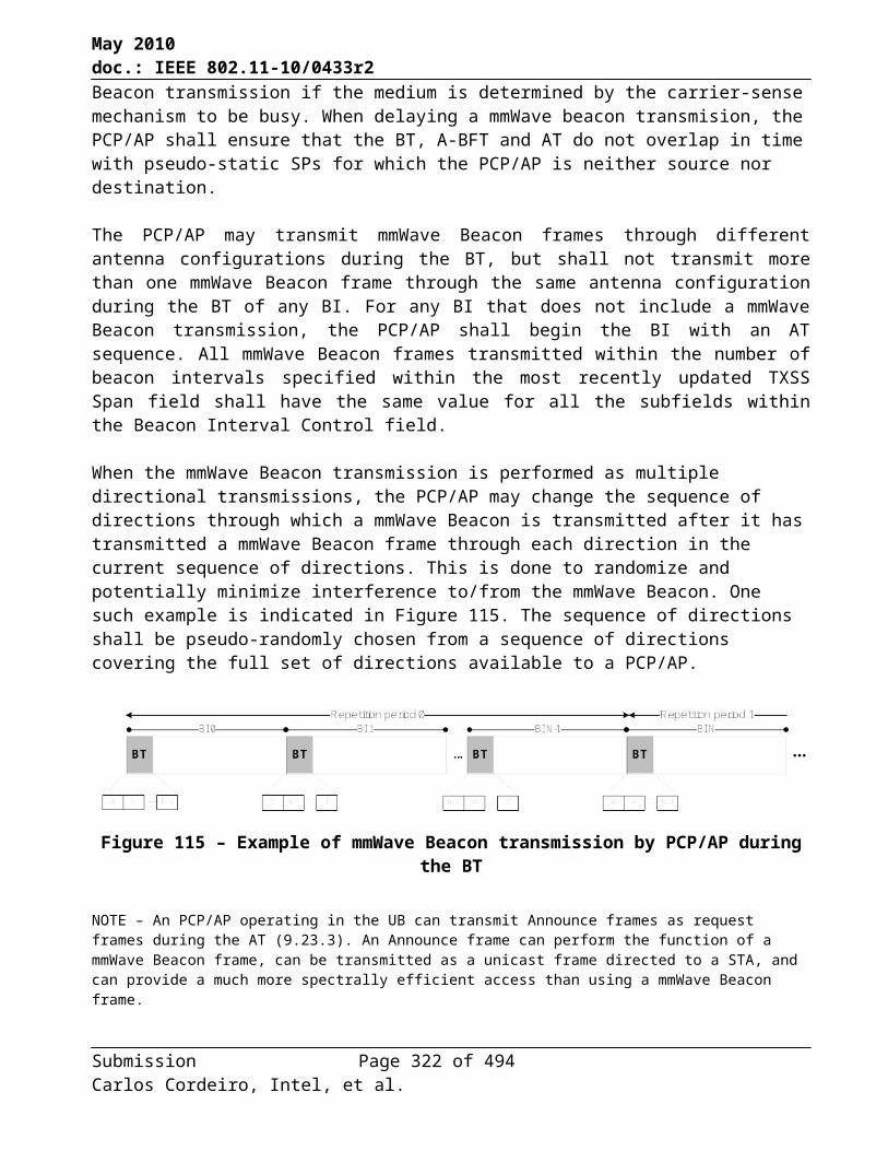
May 2010 doc.: IEEE 802.11-10/0433r2
1) First the total number of data pad bits NDATA_PAD is calculated, using the number of LDPC codewords NCW:
NCW=⌈ Length⋅8LCW
ρ⋅R
⌉
N DATAPAD=NCW⋅
LCW
ρ⋅R−Length⋅8
where LCW=672 is the LDPC code word length, Length is the length of the PSDU defined in the header field (in octets), ρ is the repetition factor (1 or 2), and R is the code rate.The scrambled PSDU is concatenated with NDATA_PAD zeros. They are scrambled using the continuation of the scrambler sequence that scrambled the PSDU input bits.
2) The procedure for converting the scrambled PSDU data to LDPC codewords depends on the repetition factor.
a. If = 1,i. The output stream of the scrambler is broken into blocks of LCWD = LCW ×R bits
such that the mth data word is .
ii. To each data word, n-k=LCW-R×LCW parity bits are added to
create the code word c(m )=(b1
(m) , b2(m ) ,. . ., bLCWD
(m ) , p1( m) , .. . pn−k
( m) ) such that
b. If ρ = 2,
i. The data bits in each codeword where are
concatenated with zeros to produce a sequence in length of
.
ii. The LDPC code word is created
by generating the parity bits such that . Where H is the parity matrix for rate 1/2 LDPC coding specified in 21.3.8.
iii. Replace bits though 336 of the codeword c with bits from the sequence
XOR’ed by a PN sequence which is generated from the LFSR used for data scrambling as defined in 21.3.9. The LFSR is initialized to the all ones vector and reinitialized to the same vector after every codeword.
3) The code words are then concatenated one after the other to create the coded bits stream (c1 , c2 ,. . ., c LCWD⋅NCW ) .
Submission Page 322 of 339 Carlos Cordeiro, Intel, et al.

+1-1
+i
-i
10
May 2010 doc.: IEEE 802.11-10/0433r2
4) The number of symbol blocks, NBLKS, and the number of symbol block padding bits, NBLK_PAD, are calculated:
N BLKS=⌈NCW⋅LCW
NCBPB⌉
N BLKPAD=N BLKS⋅N CBPB−NCW⋅LCW ,
where NCBPB is the number of coded bits per symbol block, per Table 81 in subclause 21.6.3.2.4.
5) The coded bit stream is concatenated with NBLK_PAD zeros. They are scrambled using the continuation of the scrambler sequence that scrambled the PSDU input bits.
21.6.3.2.3 Modulation MappingThe coded and padded bit stream is converted into a stream of complex constellation points according to the modulation specified in the MCS table.
21.6.3.2.3.1 π/2-BPSK ModulationIn π/2-BPSK modulation, the input bit stream is mapped according to the following equation: ~s k=2⋅ck−1 , where ck is the kth input coded (or scrambled pad) bit. Each output symbol is then rotated
according to the following equation: .
Figure 142 – BPSK constellation bit encoding
NOTE – With appropriate choice of transmit filtering, π/2-BPSK is equivalent to a precoded pulse-shaped MSK (e.g.,
GMSK). The precoder is simply bout , k=b in, k⊕b in, k−1 , k=0,1 , .. . , where bin,k is the scrambled input stream, bin,-1 is 0, and bout,k is the input to the (G)MSK modulator.
21.6.3.2.3.2 π/2-QPSK Modulation
In π/2-QPSK modulation, the input bit stream is grouped into sets of 2 bits and mapped according to
the following equation: ~s (k )=( (2⋅c2 k−1)+ j (2c2 k+1−1)) exp(− j π
4 ), where k is the output symbol index, k = 0, 1, …. Each output symbol is then rotated according to the following equation:
.
Submission Page 323 of 339 Carlos Cordeiro, Intel, et al.

448 symbols 448 symbols 448 symbols64 64 64
GI DATA GI DATA GI DATA
64
GI
May 2010 doc.: IEEE 802.11-10/0433r2
Figure 143 – QPSK constellation bit encoding
21.6.3.2.3.3 π/2-16QAM Modulation In π/2-16QAM modulation, the input bit stream is grouped into sets of 4 bits and mapped according to
the following equation: ~s (k )= 1
√10 {( 4C4 k−2 )+ (2C4 k+1−1 )+ j ( 4 C4 k+2−2 )+ j (2C4 k+3−1 ) }where k is the output symbol index, k =0, 1, …. Each output symbol is then rotated according to the
following equation: s (k )=~s (k )⋅e j⋅π⋅k /2.
21.6.3.2.4 Symbol Blocking and Guard InsertionEach group of NCBPB bits is pre-pended by π/2-BPSK symbols generated by the 64 point Golay sequence Ga64 defined in 21.9. NCBPB values are shown in Table 81. The starting index for the first symbol for π/2 rotation is 0.
Table 81 – Values of NCBPB
Symbol Mapping NCBPB
π/2-BPSK 448π/2-QPSK 896
π/2-16QAM 1792
The final block transmitted is followed by the same Golay sequence guard interval.
Figure 144 – Block transmission
Submission Page 324 of 339 Carlos Cordeiro, Intel, et al.
May 2010 doc.: IEEE 802.11-10/0433r2
21.6.4 Performance requirements This subclause describes the performance requirement from the SC PHY.
21.6.4.1 Transmit Requirements
21.6.4.1.1 Transmit EVM The transmit EVM accuracy test shall be performed by instrumentation capable of converting the transmitted signal into a stream of complex samples, with sufficient accuracy in terms of I/Q arm amplitude and phase balance, dc offsets, phase noise, etc.
The sampled signal shall be processed by a receiver that is capable of converting the transmitted signal into a stream of complex samples at sufficient rate or more, with sufficient accuracy in terms of I/Q arm amplitude and phase balance, DC offsets, and phase noise. It shall perform carrier lock, symbol timing recovery and amplitude adjustment while making the measurements. For the SC PHY EVM, measuring Ns samples at the sample rate, the measured chips should not contain the first and the last hundred chips of a given packet (ramp up/down) the EVM will be calculated according to the formula below:
EVM=20 log10(√( 1N s Pavg
∑i=1
N S
[(I i−I i¿ )2−(Qi−Qi
¿)2]))Where Ns is the number of samples to be measured Ns should be bigger than 8000.
where Pavgis the average power of the constellation, is the complex coordinates of the i’th
measured chip, and I i ,Qi is the complex coordinates of the ideal constellation point for the i’th
measured chip.
The measuring device should have the accuracy of at least 20 dB better than the EVM value to be measured. The test equipment should use a root-raised cosine filter with roll-off factor of 0.25 for the pulse shaping filter when conducting EVM measurement.The transmit pulse shaping used is left to the implementer.
The relative constellation error (EVM) shall not exceed a MCS dependent value according to the Table below:
MCS Indexes Modulation Coding Rate EVM Value [dB]1 π/2-BPSK ½ with repetition -62 π/2-BPSK 1/2 -93 π/2-BPSK 5/8 -104 π/2-BPSK 3/4 -115 π/2-BPSK 13/16 -126 π/2-QPSK 1/2 -147 π/2-QPSK 5/8 -158 π/2-QPSK 3/4 -16
Submission Page 325 of 339 Carlos Cordeiro, Intel, et al.
May 2010 doc.: IEEE 802.11-10/0433r2
9 π/2-QPSK 13/16 -1710 π/2-16QAM 1/2 -2011 π/2-16QAM 5/8 -2112 π/2-16QAM 3/4 -22
21.6.4.1.2 Time of Departure accuracyThe Time of Departure accuracy test evaluates TIME_OF_DEPARTURE against aTxPmdTxStartRMS and aTxPmdTxStartRMS against TIME_OF_DEPARTURE_ACCURACY_TEST_THRESH as defined in Annex V with the following test parameters:
— MULTICHANNEL_SAMPLING_RATE is 1760x106 sample/s — FIRST_TRANSITION_FIELD is Short Training field — SECOND_TRANSITION_FIELD is Channel Estimation field— TRAINING_FIELD is Channel Estimation field — TIME_OF_DEPARTURE_ACCURACY_TEST_THRESH is 80 ns
NOTE — The indicated windowing applies to the time of departure accuracy test equipment, and not the transmitter or receiver.
21.6.4.2 Rx Requirements This section describes the performance requirement from the SC PHY receiver.
21.6.4.2.1 CCAThe start of a valid mmWave SC PHY transmission at a receive level greater than the minimum sensitivity for MCS 1 (-68dBm) shall cause CCA to indicate busy with a probability > 90% within 1usec. The receiver shall hold the carrier sense signal busy for any signal 20dB above the minimum sensitivity for MCS 1.
21.7 mmWave low power SC PHY
The mmWave low power SC PHY is an optional SC mode. This mode can provide lower processing power requirements for mmWave tranceivers.
A STA supports the mmWave low power SC PHY if the low power SC PHY supported subfield within its mmWave Capability element is set to one. A STA that supports the mmWave low power SC PHY shall not transmit a PPDU using the mmWave low power SC PHY if the STA identified in the RA field of the PPDU does not support the mmWave low power SC PHY.
21.7.1 Transmission
21.7.1.1 PreambleThe mmWave low power SC PHY uses the same preamble as the mmWave SC PHY.
Submission Page 326 of 339 Carlos Cordeiro, Intel, et al.

May 2010 doc.: IEEE 802.11-10/0433r2
21.7.1.2 HeaderThe mmWave low power SC PHY header fields are the same fields as in the mmWave SC PHY (see Table 78 in 21.6.3.1).
The mmWave low power SC PHY modulation and coding schemes are listed in Table 82.
Table 82 – Low power SC Modualtion and Coding Schemes MCS Modulation Effective Code Rate Coding Scheme NCPB Rate (Mbps)
25 π/2-BPSK 108/224 RS(224,208)+ Block-Code(16,8) 392 62626 π/2-BPSK 208/224 RS(224,208) 392 125127 π/2-QPSK 208/224 RS(224,208) 392 2502
21.7.1.2.1 Header encoding and modulationThe low power SC PHY header is encoded using the following scheme:
1) The header is scrambled as described in 21.3.9.2) The resulting 8 octers are encoded using a RS(24,8) generating 24 octets.3) The resulting 24 octets are encoded in the block code described in 21.7.1.3.2.2 generating 48
octets.4) One zero octet is prepended to the end of the 48 octets generating 49 octets.5) Each set of 7 octets is interleaved using a uniform interleaver of 7 rows and 8 columns. The 7
octets are written row wise and read column wise. 6) The resulting 49 octets are blocked as described in 21.7.1.3.4 and transmitted using π/2-BPSK
as described in 21.6.3.2.3.1.
21.7.1.3 Data fieldThe data field consists of the payload data of the PSDU and possible padding. The data are padded with zeros, scrambled, encoded and modulated as described in the following sub-clauses.
21.7.1.3.1 ScramblerThe operation of the scrambler is defined in 21.3.9. The scrambling of the PSDU continues the scrambling of the header with no reset of the scrambler. The padding bits are also scrambled.
21.7.1.3.2 Encoding Data is encoded by a block code. In MCSs 23,24 the data is encoded by a RS(224,208) block code. In MCS 22 that data is further encoded by a (16,8) block code.
21.7.1.3.2.1 Encoding process: RS(224, 208)The following steps are used for encoding using the RS(224,208) block code:
1) First the number of block padding bits is calculated:
Submission Page 327 of 339 Carlos Cordeiro, Intel, et al.
May 2010 doc.: IEEE 802.11-10/0433r2
a. The total number of Reed Solomon codewords is N RS=⌈Length208
⌉and the total number of RS encoded symbols is given by: NEO= Length + NRS×16
b. The total number of 512 blocks (each containing 392 data sumbols) is NBLKS=⌈
N EO ×8NCBPS ×392
⌉. The total number of zero block paddings bit is NBLK_PAD=NBLKS×NCPBS×392-NEO×8
2) The data is broken into blocks of length 208×8 bits (except for possibly the last block). 3) Each block is encoded using the RS(224,208) block code as described in 21.7.1.3.2.3, except
perhaps the last block which encoded by a shortened version of the code (i.e., if the block length is k the shortened code is an RS(16+k,k))
4) The coded bit stream is concatenated with NBLK_PAD zeros. They are scrambled with the continuation of the scrambler sequence that scrambled the PSDU input bits.
5) The resulting bit stream is modulated and blocked as described in 21.7.3.3 and 21.7.3.4 respectively.
21.7.1.3.2.2 Encoding of RS(224,208)+block codeThe following steps are used for encoding using the RS(224,208) as an outer code and the Blok-code(16,8) as an inner code::1) The number of block padding bits is calculated
a) The total number of Reed Solomon codewords is N RS=⌈Length208
⌉and the total number of RS encoded symbols is given by: Length + NRS16
b) For MCS 22, after Reed Solomon encoding, the data is encoded with Block-Code(16,8) and therefore:i) The total number of encoded octets is: NEO = 2(Length + NRS16)ii) The total number of 512 blocks (each containing 392 data symbols) is
N BLKS=⌈N EO×8
NCBPS×392⌉
. The total number of zero block padding bits is N BLKPAD
=N BLKS×NC BPS×392−N EO×82) The data is broken into blocks of length 208×8 bits (except for possibly the last
block).3) Each block is encoded using the RS(224,208) block code as described in 21.7.1.3.2.3, except
perhaps the last block which is encoded by a shortened version of the code (i.e., if the last block length is k, the shortened block code is RS(16+k,k).
4) The Reed Solomon encoded data stream is further encoded using the Block-code(16,8) as described in 21.7.1.3.2.4.
5) The coded bit stream is concatenated with N BLKPAD zeros. The are scrambled with the continuation of the scrambler sequence that scrambled the PSDU input bits.
6) Each set of 7 octets is interleaved using a uniform interleaver of 7 rows and 8 columns. The 7 octest are written row wise and read column wise, i.e., the index i of a bit after interleaving is realted to the index k of a bit before interleaving by the following rule:
i=8×(k mod 7 )+ floor (k /7 ) , k=0,1, . .. , 55
Submission Page 328 of 339 Carlos Cordeiro, Intel, et al.
May 2010 doc.: IEEE 802.11-10/0433r2
Where the function floor(.) denotes the largest integer not exceeding the function parameter.7) The resulting bit sream is modulated and blocked as described in 21.7.1.3.3 and 21.7.1.3.4.
21.7.1.3.2.3 RS encodingThe RS block code is based on the polynomial
G ( x )=∏k=1
16
( x+αk )
Where α=0 x 02 is a root of the primitive polynomial p ( x )=1+x2+x3+x4+x8. We assume that an octet b0b1b2b3 b4 b5 b6 b7 (b0 is the LSB) represented by the polynomial M=b7 x7+b6 x6+b5 x5+b4 x4+b3 x3+b2 x2+b1 x+b0.
The RS is a systematic block code. Given a block of octets m=( mM−1 ,mM−1 ,…m0) the additional
parity octets r=(r15 , r14 , ,…r0) is calculated by setting r ( x )=x16m ( x ) mod g ( x ), where
r ( x )=∑k=0
15
rk xk
and m (x )= ∑
k=0
M−1
mk xk
and where the calculation is performed over GF (28 ) . The parity octets r are
appended to the uncoded block m to generated the encoded RS block ( mM−1 ,mM−1 ,…m0 ,r15 , r14 ,…, r0 ) .
21.7.1.3.2.4 (16,8) Block-coding
In the Ham-like block code, every octet b=(b0b1b2b3 b4 b5 b6 b7 ) is encoded to a 16-bit code word c=( b0 b1 b2 b3 b4 b5b6b7 c0 c1 c2 c3 c4 c5 c6 c7 ) such that c=bG where:
G=¿ [ 1 0 0 0 0 0 0 0 0 1 1 0 1 0 1 0 ¿ ] [ 0 1 0 0 0 0 0 0 0 0 1 1 0 1 0 1¿ ] [0 0 1 0 0 0 0 0 1 0 0 1 1 0 1 0 ¿ ] [0 0 0 1 0 0 0 0 0 1 0 0 1 1 0 1 ¿ ] [ 0 0 0 0 1 0 0 0 1 0 1 0 0 1 1 0¿ ] [ 0 0 0 0 0 1 0 0 0 1 0 1 0 0 1 1 ¿ ] [0 0 0 0 0 0 1 0 1 0 1 0 1 0 0 1¿ ]¿¿
¿ ¿21.7.1.3.3 Modulation
The same π/2-BPSK described in 21.6.3.2.3.1 and π/2-QPSK described in 21.6.3.2.3.1 are used in the mmWave low power SC PHY.
21.7.1.3.4 Blocking
Submission Page 329 of 339 Carlos Cordeiro, Intel, et al.
May 2010 doc.: IEEE 802.11-10/0433r2
The blocking for the low power SC is illustrated in Figure 145. The data is partitioned into blocks of length 512 wherein each 512-block is constructed from 8 sub-blocks. Each sub-block is of length 64. The first sub-block is a Ga64 (as defined in 21.9) and sub-blocks 2 to 8 are constructed in the same way, i.e., a data portion of 7 octets followed by a guard interval of 1 octet. The last 512-block in the transmission shall be followed by Ga64. Note that each 512-block carries 49 octets of data and 15 octets of guard.
The G8 guard interval is a copy of the last 8 samples of Ga64.
Figure 145 – Blocking for low power SCNOTE – A STA may estimate the channel impulse response from the CEF, and decides whether to equalize using the 512-block or the short 64-sub-block. For example if the channel impulse response energy is almost concentrated in 8 taps, a 64-equalizer can be used, otherwise a 512-equalizer is used.
21.8 Beamforming
21.8.1 Beamforming concept
Beamforming enables a pair of STAs to train their transmit and receive antennas for subsequent communication. BF is established following the successful completion of BF training, which is described in 9.25.
21.8.2 Beamforming PHY frame format
21.8.2.1 TX sector sweepThe packets sent during TX sector sweep are Control PHY packets as defined in 21.4.
21.8.2.2 Beam refinement Beam refinement is a process where a STA can improve its antenna configuration (or antenna weight vectors) both for transmission and reception. If the SLS beamforming training did not include a RSS, as in the case where both devices have more than one transmit sector per antenna, beam refinement can serve as the first receive antenna configuration training. The procedure of beam refinement is described in 9.25.5.3.
In the beam refinement procedure, beam refinement (BRP) packets are used to train the receiver and transmitter antenna. BRP-RX packets are packets that have training sequences appended to them. These packets enable receiver antenna weight vector training. BRP-TX packets are packets that have
Submission Page 330 of 339 Carlos Cordeiro, Intel, et al.

May 2010 doc.: IEEE 802.11-10/0433r2
training sequences appended to them. The transmitting STA may change antenna configuration at the beginning of each sequence. The receiving STA performs measurements on these sequences and sends feedback to the STA that transmits the BRP-TX packet.
21.8.2.2.1 Beam refinement packet structure
Each Beam Refinement packet is composed of an MPDU, A-MPDU or MMPDU followed by a training field containing an AGC training field and a receiver training field.
Figure 146 – Beam refinement packet structure
In the BRP-RX/TX packets in the first beam refinement iteration, the transmitter uses the AWV based on the best sector feedback from the TX sector sweep for transmission of the data. The receiver should receive that data part of the packet using a quasi-omni antenna pattern.
In the BRP-TX/TX packets in the second and further beam refinement iterations, the transmitter uses AWV based on feedback from previous beam refinement iterations. The receiver should use the best AWV based on previous BRP-RX packets.
In the BRP-RX packets in the MID and BC sub-phases, the transmitter uses the AWV based on the best sector feedback from the TX sector sweep or a TX sector where a signal is detected in TX sector sweep for transmission of the data. The receiver should receive that data part of the packet using a quasi-omni antenna pattern.
21.8.2.2.2 Beam Refinement packet header fieldsThe packet type and training length fields present within the SC header and control PHY header are used to indicate, respectively, that a packet is beam refinement packet and the length of the training fields.
A value of 0x0 in the packet type field indicates a BRP-RX packet (TRN-R field is present).
A value of 0x1 in the packet type field indicates a BRP-TX packet (TRN-T field is present).
A value of N in the training length field indicates that the AGC has 4N subfields and that the TRN-R/T field has 5N subfields.
The value N in the training length field of a BRP-RX packet is equal to the value of the L-RX field requested by the intended receiver of the BRP-RX packet at a previously received BRP request field (see 7.3a.4).
Submission Page 331 of 339 Carlos Cordeiro, Intel, et al.
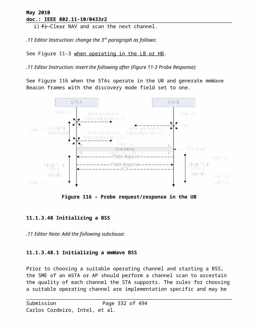
May 2010 doc.: IEEE 802.11-10/0433r2
The value N in the training length field of a BRP-TX packet is equal to number TRN-T subfields that will be added to the packet, divided by 4.
21.8.2.2.3 Beam Refinement AGC field The beam refinement AGC fields are composed of 4N repetitions of the sequence [Ga64 Ga64 Ga64 Ga64
] when the packet is transmitted using the OFDM or SC PHY and [Gb64 Gb64 Gb64 Gb64 ] when the packet is transmitted using the Control PHY. The sequences Ga64 and Gb64 are defined in 21.9. The sequences are transmitted using rotated π/2-BPSK modulation.
In a BRP-TX packet, the transmitter may change the TX AWV configuration at the beginning of each AGC field. In a BRP-RX packet, the transmitter shall use the same TX AWV as in the preamble and data fields of the packet.
21.8.2.2.4 Beam Refinement TRN-R field The TRN-R fields enable receiver AWV training. All TRN-R fields are transmitted using the same TX AWV configuration as the preamble and data fields of the frame. The TRN-R fields will have the form:
CE R1 R2 R3 R4 CE R5 R6 R7 R8 …
Each subfield CE matches the Channel Estimation field that is transmitted in the packet preamble. The 4N fields R1 through R4N each consist of the sequence [Ga128 -Gb128 Ga128 Gb128 Ga128]. The sequences Ga128 and Gb128 are defined in Table 83 and Table 84, respectively, in Section 21.9. The sequences are transmitted using rotated π/2-BPSK modulation.
21.8.2.2.5 Beam Refinement TRN-T field The TRN-T field enables transmitter AWV training. The TRN-T field has the form:
CE T1 T2 T3 T4 CE T5 T6 T7 T8 …
Each subfield CE matches the Channel Estimation field that is transmitted in the packet preamble. The 4N fields T1 through T4N each consist of the sequence [Ga128 -Gb128 Ga128 Gb128 Ga128]. The sequences Ga128 and Gb128 are defined in Table 83 and Table 84, respectively, in subclause 21.9. The sequences are transmitted using rotated π/2-BPSK modulation. When transmitting the CE subfield, the transmitter shall use the same AWV as in the preamble and data fields of the packet.
21.8.2.2.6 Channel MeasurementThe good autocorrelation properties of the Golay sequence enable reconstructing part of the impulse response of the channel between the transmitter and the receiver. The receiver should find the tap with largest amplitude in the channel during the CE field of the BRP-RX. It selects thereafter the set of taps that will be measured around the tap with the largest amplitude, according the number of taps requested in FBCK-REQ field. It can select a contiguous set of taps or select a non-contiguous set of
Submission Page 332 of 339 Carlos Cordeiro, Intel, et al.
May 2010 doc.: IEEE 802.11-10/0433r2
taps, and include the tap delays sub-field as part of the subfield measurement. It will then measure the phase and amplitude of the corresponding channel taps in each of the TRN-T field repetition (except for those using the CE AWV configuration). The beam refinement feedback subfield k-1 is the relative amplitude and phase of this tap in the k’th repetition compared to the first one.
21.9 Golay Sequences The following Golay sequences are used in the preamble, in the single carrier guard interval and in beam refinement TRN-R/T and AGC fields: Ga128(n), Gb128(n), Ga64(n), Gb64(n), Ga32(n), Gb32(n). These are 3 pairs of complementary sequences. The subscript denotes the length of the sequences. These sequences are generated using the following recursive procedure:
A0 (n )=δ (n )B0 (n )=δ (n )Ak (n )=W k Ak−1 (n )+Bk−1 (n−D k )Bk (n )=W k Ak−1 (n )−Bk−1 (n−D k )Note that Ak (n ) , Bk (n ) are zero for n<0and for n≥2k
.Ga128(n)=A7(128-n), Gb128(n)=B7(128-n) when the procedure uses Dk = [64 32 16 1 8 2 4] (k=1,2,…,7) and Wk = [+1 +1 +1 +1 -1 -1 +1].Ga64(n)=A6(64-n), Gb64(n)=B6(64-n) when the procedure uses Dk=[ 32 16 1 8 2 4] and Wk=[ -1 +1 +1 -1 +1 -1].Ga32(n)=A5(32-n), Gb32(n)=B5(32-n) when the procedure uses Dk=[16 1 8 2 4] and Wk=[-1 -1 +1 +1 +1 ].The sequences are defined in Table 83, Table 84, Table 85, Table 86, Table 87 and Table 88. The sequences in the tables are normative, the description above is informative.
Table 83 – The sequence Ga128(n)The Sequence Ga128(n), to be transmitted from left to right, up to down 1 1 -1 -1 -1 -1 -1 -1 -1 1 -1 1 1 -1 -1 1 1 -1 -1 1 -1 1 -1 1 -1 -1 -1 -1 1 1 -1 -1 1 1 -1 -1 -1 -1 -1 -1 -1 1 -1 1 1 -1 -1 1 -1 1 1 -1 1 -1 1 -1 1 1 1 1 -1 -1 1 1 -1 -1 1 1 1 1 1 1 1 -1 1 -1 -1 1 1 -1 -1 1 1 -1 1 -1 1 -1 1 1 1 1 -1 -1 1 1 1 1 -1 -1 -1 -1 -1 -1 -1 1 -1 1 1 -1 -1 1 -1 1 1 -1 1 -1 1 -1 1 1 1 1 -1 -1 1 1
Table 84 – The sequence Gb128(n)The Sequence Gb128(n), to be transmitted from left to right, up to down-1 -1 1 1 -1 -1 -1 -1 1 -1 1 -1 1 -1 -1 1 -1 1 1 -1 -1 1 -1 1 1 1 1 1 1 1 -1 -1 -1 -1 1 1 -1 -1 -1 -1 1 -1 1 -1 1 -1 -1 1 1 -1 -1 1 1 -1 1 -1 -1 -1 -1 -1 -1 -1 1 1 1 1 -1 -1 1 1 1 1 -1 1 -1 1 -1 1 1 -1 1 -1 -1 1 1 -1 1 -1 -1 -1 -1 -1 -1 -1 1 1 -1 -1 1 1 -1 -1 -1 -1 1 -1 1 -1 1 -1 -1 1 1 -1 -1 1 1 -1 1 -1 -1 -1 -1 -1 -1 -1 1 1
Table 85 – The sequence Ga64(n)The Sequence Ga64(n), to be transmitted from left to right, up to down-1 -1 -1 -1 -1 -1 1 1 1 -1 -1 1 1 -1 1 -1 -1 1 -1 1 -1 1 1 -1 1 1 -1 -1 1 1 1 1 -1 -1 -1 -1 -1 -1 1 1 1 -1 -1 1 1 -1 1 -1 1 -1 1 -1 1 -1 -1 1 -1 -1 1 1 -1 -1 -1 -1
Submission Page 333 of 339 Carlos Cordeiro, Intel, et al.

May 2010 doc.: IEEE 802.11-10/0433r2
Table 86 – The sequence Gb64(n)The sequence Gb64(n), to be transmitted from left to right, up to down 1 1 1 1 -1 -1 1 1 -1 1 1 -1 1 -1 1 -1 1 -1 1 -1 -1 1 1 -1 -1 -1 1 1 1 1 1 1 1 1 1 1 -1 -1 1 1 -1 1 1 -1 1 -1 1 -1 -1 1 -1 1 1 -1 -1 1 1 1 -1 -1 -1 -1 -1 -1
Table 87 – The sequence Ga32(n)The Sequence Ga32(n), to be transmitted from left to right1 -1 1 -1 -1 1 1 -1 1 1 -1 -1 -1 -1 -1 -1 1 1 1 1 -1 -1 1 1 1 -1 -1 1 -1 1 -1 1
Table 88 – The sequence Gb32(n)The Sequence Gb32(n), to be transmitted from left to right-1 1 -1 1 -1 1 1 -1 -1 -1 1 1 -1 -1 -1 -1 -1 -1 -1 -1 -1 -1 1 1 -1 1 1 -1 -1 1 -1 1
21.10mmWave PLME
21.10.1 PLME_SAP sublayer management primitivesTable 89 lists the MIB attributes that may be accessed by the PHY entities and the intra-layer of higher level LMEs. These attributes are accessed via the PLME-GET, PLME-SET, PLME-RESET, and PLME-CHARACTERISTICS primitives defined in 10.4.
21.10.2 mmWave PHY Management Information Base All mmWave PHY MIB attributes are defined in Appendix D of IEEE802.11-2007, with specific values defined in Table 89. The column titled “Operational semantics” in Table 89 contains two types: static and dynamic. Static MIB attributes are fixed and cannot be modified for a given PHY implementation. Dynamic MIB attributes can be modified by some management entity.
Table 89 – mmWave PHY MIB attribute default valuesManaged object Default Value/Range Operational Semantics
dot11PHYoperationTabledot11PHYtype mmWave staticdot11FrequencyBand mmWave static
dot11SupportedMCSTxdot11SupportMCSTxValue MCS0-MCS27 static
dot11SupportedMCSRxdot11SupportMCSRxValue MCS0-MCS27 static
21.10.3 TXTIME calculation The value of the TXTIME parameter returned by the PLME-TXTIME.confirm primitive shall be calculated according to the following equations.
For mmWave OFDM PHY, and for mmWave SC PHY (NTRN is training length defined in the header – see, for example, Table 75):
Submission Page 334 of 339 Carlos Cordeiro, Intel, et al.

May 2010 doc.: IEEE 802.11-10/0433r2
TXTIME=T STF+T CE+T header+T Data+NTRN (256×4+640×4 ) TC+NTRN T CE
For mmWave Control PHY:TXTIME=T STF−CP+T CE−CP+(11×8+( Length−6 )×8+NCW ×168 )×TC×32+
NTRN (256×4+640×4 )T C +NTRN T CE−CP
where NCW calculation is defined in 21.4.3.3.2.
21.10.4 PHY characteristicsThe static mmWave PHY characteristics, provided through the PLME-CHARACTERISTICS service primitive, shall be as shown in Table 90. The definitions for these characteristics are given in 10.4.
Table 90 – mmWave PHY Characteristics
PHY Parameter Value
aRIFSTime 1usec
aSIFSTime 3usec
aDataPreambleLength 1745ns
aControlPHYPreambleLength 3564ns
aSBIFSTime 1usec
aAirPropagationTime << 1usec
aMmWaveDetectionThres -48 dBm
aBRPIFS 20usec
aSlotTime 3usec
Submission Page 335 of 339 Carlos Cordeiro, Intel, et al.
May 2010 doc.: IEEE 802.11-10/0433r2
Annex A (normative) PICS
A.4 PICS proforma-IEEE Std 802.11-2007
A.4.3 IUT configuration
.11 Editor note: Modify the table as follows:
Item IUT configuration References Status Support* CF10 Is spectrum management
operation supported?7.3.1.4, 11.6 (CF6 OR
CF16 OR CF17):O
Yes, No
* CF11 Is regulatory classes capability implemented?
7.3.2.12,17.3.8.3.2,17.3.8.6,17.4.2,Annex I,Annex J
(CF6 ORCF16 OR CF17)&CF8&CF10:O
Yes, No, N/A
* CF12 QoS 9.9, 9.10, 5.2.9 OCF16&CF17:M
Yes, No, N/A
* CF17 mmWave features 7.3.2.62 O Yes, No
.11 Editor note: Insert the following subclause:
A.4.21 mmWave features
A.4.21.1 mmWave MAC features
Item Protocol capability References Status SupportAre the following MAC protocol features supported?
mmWaveM1 mmWave capabilities signaling
mmWaveM1.1
mmWave Capabilities element
CF17:M Yes, No, N/A
mmWaveM2 mmWave channel accessmmWaveM2.1
Service period CF17:O
mmWaveM2.2
Contention-based period CF17:M
mmWaveM2. mmWave protected period mmWaveM2.1:
Submission Page 336 of 339 Carlos Cordeiro, Intel, et al.
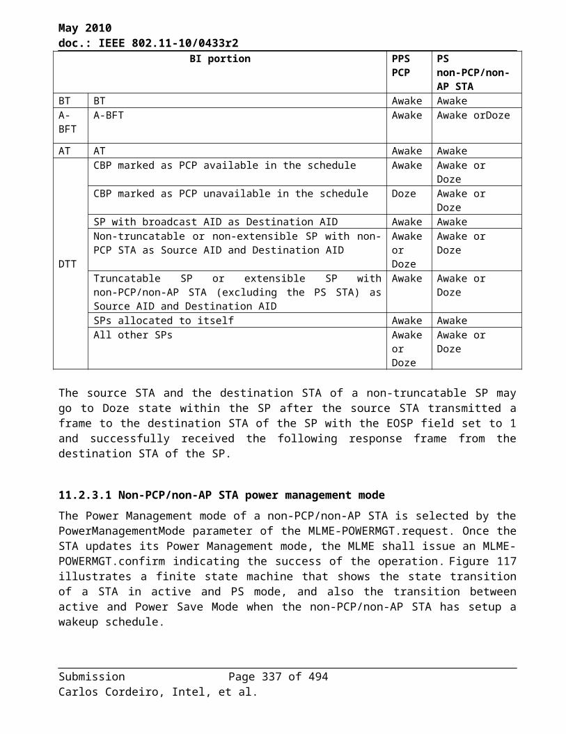
May 2010 doc.: IEEE 802.11-10/0433r2
3 MmmWaveM2.4
Dynamic allocation of service period
mmWaveM2.1:M
mmWaveM2.5
Dynamic truncation of service period
mmWaveM2.1:M
mmWaveM2.6
Dynamic extension of service period
mmWaveM2.1:M
mmWaveM3 PCP/AP clustering CF17:OmmWaveM4 mmWave Beamforming CF17:MmmWaveM5 mmWave broadcast and
multicast MPDU transferCF17:M
mmWaveM6 mmWave multirate support CF17:MmmWaveM7 mmWave A-MPDU
operationCF17:M
mmWaveM8 mmWave block ACK with flow control
CF17:O
mmWaveM9 mmWave reverse direction CF17:OmmWaveM10 Spatial sharing of
frequency and interference mitigation
CF17:O
mmWaveM11 Multi-band operation CF17:OmmWaveM12 mmWave dynamic tone
pairingCF17:O
mmWaveM13 Changing mmWave BSS parameters
CF17:O
A.4.21.2 mmWave PHY features
Item Protocol capability References Status SupportAre the following PHY protocol features supported?
mmWaveP1 PHY operating modesmmWaveP1.1 Operation according to
clause 2121 CF17:M Yes, No, N/A
mmWaveP2 PLCP frame formatmmWaveP2.1 Control PHY PLCP format CF17:MmmWaveP2.2 SC PHY PLCP format CF17:MmmWaveP2.3 OFDM PHY PLCP format CF17:OmmWaveP2.4 Modulation and coding
schemes (MCS)mmWaveP2.4.1 MCS 0 of Control PHY mmWaveP2.1:
MmmWaveP2.4.2 MCS 1-12 of SC PHYmmWaveP2.4.2.1
MCS 1-4 mmWaveP2.2:M
Submission Page 337 of 339 Carlos Cordeiro, Intel, et al.

May 2010 doc.: IEEE 802.11-10/0433r2
mmWaveP2.4.2.2
MCS 5-12 mmWaveP2.2:O
mmWaveP2.4.3 MCS 13-24 of OFDM PHY
mmWaveP2.3:O
mmWaveP2.4.4 MCS 25-27 of Low power SC PHY
mmWaveP2.4:O
Annex D (normative) ASN.1 encoding of the MAC and PHY MIB
.11 Editor Note: Modify as follows:Insert the following in item (1) in dot11EDCATableTXOPLimit: "except for the mmWave PHY (clause 21)" after "0 for all PHYs"3) Insert item (4) as follows: "4) 500 microseconds for Clause 21 PHY if dot11EDCATableIndex is 1 or 2; 100 microseconds for Clause 21 PHY if dot11EDCATableIndex is 4; 4080 microseconds for Clause 21 PHY if dot11EDCATableIndex is 3;"
Annex J (normative) Country information element and regulatory classes
.11 Editor Note: Insert the following row in Table J.1
Table J.1 Regulatory classes in the USARegulatory class
Channel starting frequency (GHz)
Channel spacing (MHz)
Channel set
Transmit power limit (dBm)
Transmit power limit (EIRP)
Emissions limits set
Behavior limits set
34 57.24 2160 1, 2, 3 --- 40dBm average
43dBm peak
0 0
.11 Editor Note: Insert the following row in Table J.2
Table J.2 Regulatory classes in EuropeRegulatory class
Channel starting frequency (GHz)
Channel spacing (MHz)
Channel set
Transmit power limit (dBm)
Transmit power limit (EIRP)
Emissions limits set
Behavior limits set
13 59.4 2160 2, 3, 4 --- 57 dBm 0 0
.11 Editor Note: Insert the following row in Table J.3
Table J.3 Regulatory classes in JapanRegula- Channel Channel Channel Transmit Transmit EIRP Emissions Behavior
Submission Page 338 of 339 Carlos Cordeiro, Intel, et al.
May 2010 doc.: IEEE 802.11-10/0433r2
tory class
starting frequency (GHz)
spacing (MHz)
set power limit (dBm)
power limit (EIRP)
(mW/MHz) limits set limits set
58 59.4 2160 2, 3, 4 --- 57 dBm --- 0 0
.11 Editor Note: Insert the following Table J.4
Table J.4 Regulatory classes in AustraliaRegula-tory class
Channel starting frequency (GHz)
Channel spacing (MHz)
Channel set
Transmit power limit (dBm)
Transmit power limit (EIRP)
EIRP(mW/MHz)
Emissions limits set
Behavior limits set
59 59.4 2160 2 --- 57 dBm --- 0 0
Submission Page 339 of 339 Carlos Cordeiro, Intel, et al.
Related Documents