Wittig RFL Rotary Vane Compressors/Vacuum Pumps for Vacuum Tankers

Welcome message from author
This document is posted to help you gain knowledge. Please leave a comment to let me know what you think about it! Share it to your friends and learn new things together.
Transcript

Wittig RFLRotary Vane Compressors/Vacuum Pumps for Vacuum Tankers
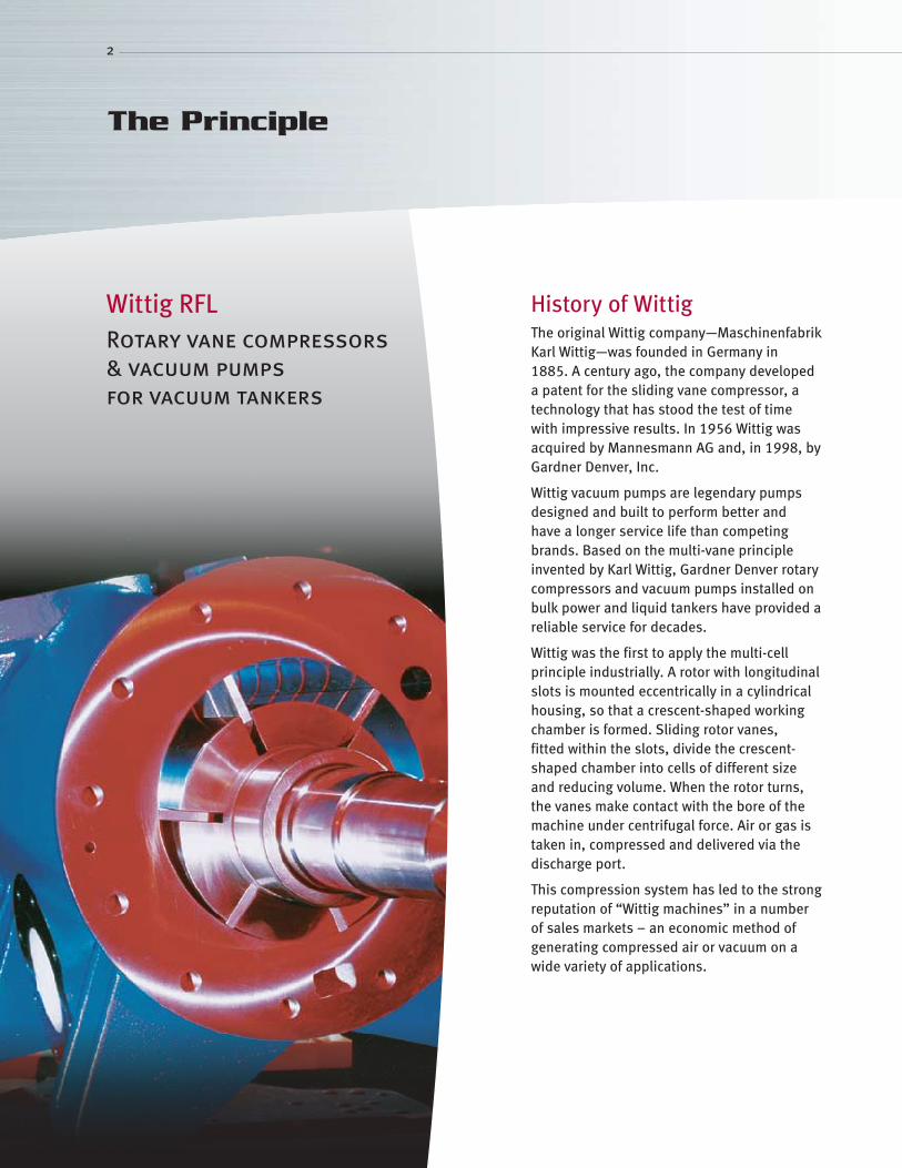
History of WittigThe original Wittig company—Maschinenfabrik Karl Wittig—was founded in Germany in 1885. A century ago, the company developed a patent for the sliding vane compressor, a technology that has stood the test of time with impressive results. In 1956 Wittig was acquired by Mannesmann AG and, in 1998, by Gardner Denver, Inc.
Wittig vacuum pumps are legendary pumps designed and built to perform better and have a longer service life than competing brands. Based on the multi-vane principle invented by Karl Wittig, Gardner Denver rotary compressors and vacuum pumps installed on bulk power and liquid tankers have provided a reliable service for decades.
Wittig was the first to apply the multi-cell principle industrially. A rotor with longitudinal slots is mounted eccentrically in a cylindrical housing, so that a crescent-shaped working chamber is formed. Sliding rotor vanes, fitted within the slots, divide the crescent-shaped chamber into cells of different size and reducing volume. When the rotor turns, the vanes make contact with the bore of the machine under centrifugal force. Air or gas is taken in, compressed and delivered via the discharge port.
This compression system has led to the strong reputation of “Wittig machines” in a number of sales markets – an economic method of generating compressed air or vacuum on a wide variety of applications.
2
The Principle
Wittig RFLRotary vane compressors & vacuum pumps for vacuum tankers

Reliable & Cost-EffectiveAssembled and tested with great care, our rotary vane compressor/vacuum pumps are renowned for their reliability, safety in operation, long life and cost effectiveness. They have few rotating parts, ensuring that maintenance requirements are minimal.
Practically Pulsation-Free Compressed AirA typical feature of our rotary vane compressor/ vacuum pumps is the supply of a nearly pulsation-free and constant gas flow. This is a significant advantage on many applications where compressed air or vacuum is required.
Compact Design Delivered Ready for Connection/InstallationCompact design is a typical characteristic of our machines. For ease of mounting and quick start up, we ship all machines ready for installation and connection.
The Wittig WayGardner Denver Wittig has expertise in both vacuum applications for loading liquids or sludge onto waste tankers and compressor applications for unloading bulk road tankers. We did the pioneering work on rotary vane compressor/vacuum pumps and have maintained a program of development and improvement ever since.
3
The Wittig Advantage

4
Wittig RFL Compressor/Vacuum Pump
Oil TankA generously proportioned oil tank allows extended run periods.
LubricationIntegrated oil pump for continuous and reliable oil supply.
Oil Level IndicationSight glasses on both sides of the machine for ease of oil level checks.
CoolingAn ideal air cooling system, provided by two fans, ensures the best cooling effect, even on extended run times.
MountingMounting feet attached to top or underneath of the machine allows a standing or suspended installation. Machine can be rotated through 1800 to give maximum mounting flexibility.

5
DimensionsShaft ends suitable for alternative V-belt drive.
DriveCentral mounting point for the easy fitting of a hydraulic drive motor if required.
6
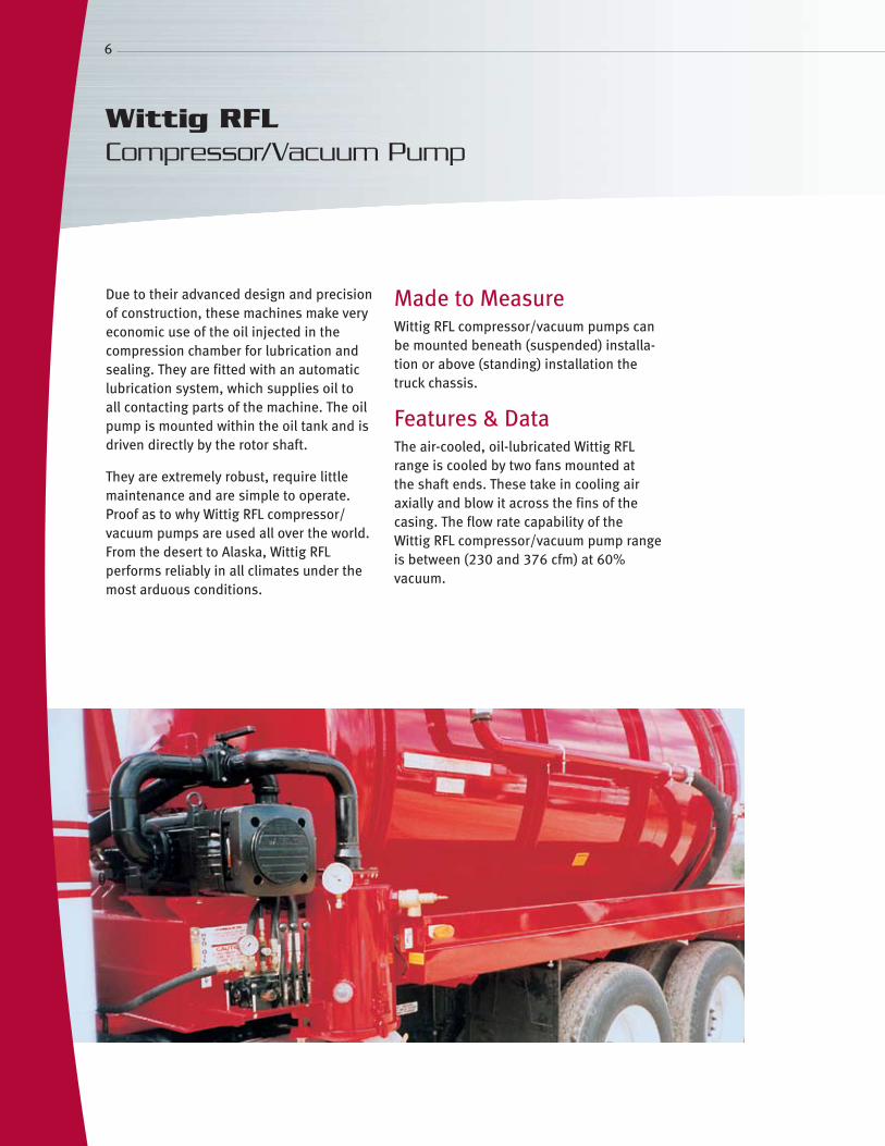
Due to their advanced design and precision of construction, these machines make very economic use of the oil injected in the compression chamber for lubrication and sealing. They are fitted with an automatic lubrication system, which supplies oil to all contacting parts of the machine. The oil pump is mounted within the oil tank and is driven directly by the rotor shaft.
They are extremely robust, require little maintenance and are simple to operate. Proof as to why Wittig RFL compressor/vacuum pumps are used all over the world. From the desert to Alaska, Wittig RFL performs reliably in all climates under the most arduous conditions.
Made to MeasureWittig RFL compressor/vacuum pumps can be mounted beneath (suspended) installa-tion or above (standing) installation the truck chassis.
Features & DataThe air-cooled, oil-lubricated Wittig RFL range is cooled by two fans mounted at the shaft ends. These take in cooling air axially and blow it across the fins of the casing. The flow rate capability of the Wittig RFL compressor/vacuum pump range is between (230 and 376 cfm) at 60% vacuum.
Wittig RFL Compressor/Vacuum Pump

7
Wittig RFL in ServiceMachines of the Wittig RFL range offer the vehicle builder and operator a wide range of installation options. Wittig RFL compressor/vacuum pumps can be mounted within or to the side of the vehicle chassis.
8
Facts, Figures, and Data
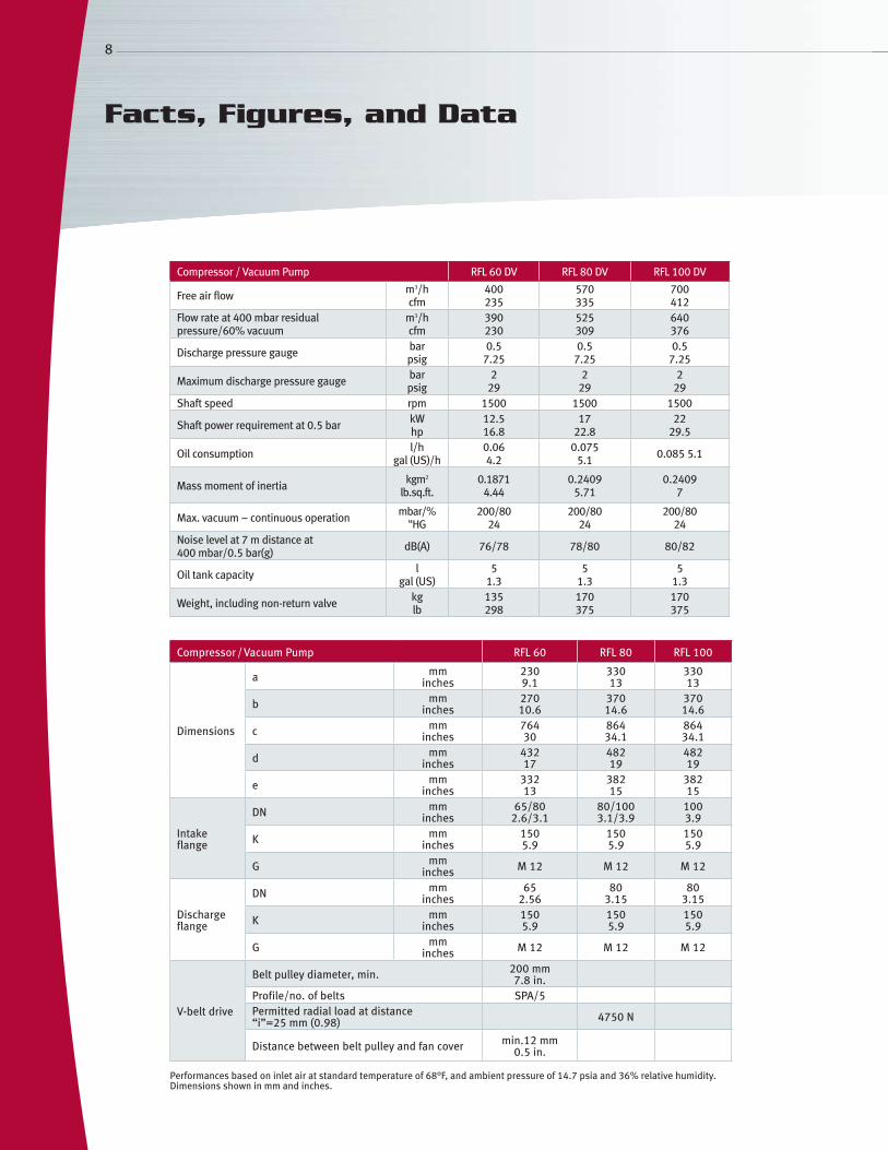
Compressor / Vacuum Pump RFL 60 DV RFL 80 DV RFL 100 DV
Free air flow m3/h cfm
400 235
570 335
700 412
Flow rate at 400 mbar residual pressure/60% vacuum
m3/h cfm
390 230
525 309
640 376
Discharge pressure gauge barpsig
0.5 7.25
0.5 7.25
0.5 7.25
Maximum discharge pressure gauge barpsig
2 29
2 29
2 29
Shaft speed rpm 1500 1500 1500
Shaft power requirement at 0.5 bar kW hp
12.5 16.8
17 22.8
22 29.5
Oil consumption l/h gal (US)/h
0.06 4.2
0.075 5.1 0.085 5.1
Mass moment of inertia kgm2
lb.sq.ft.0.1871
4.440.2409
5.710.2409
7
Max. vacuum – continuous operation mbar/% "HG
200/80 24
200/80 24
200/80 24
Noise level at 7 m distance at 400 mbar/0.5 bar(g) dB(A) 76/78 78/80 80/82
Oil tank capacity l gal (US)
5 1.3
5 1.3
5 1.3
Weight, including non-return valve kg lb
135 298
170 375
170 375
Compressor / Vacuum Pump RFL 60 RFL 80 RFL 100
Dimensions
a mm inches
230 9.1
330 13
330 13
b mm inches
270 10.6
370 14.6
370 14.6
c mm inches
764 30
864 34.1
864 34.1
d mm inches
432 17
482 19
482 19
e mm inches
332 13
382 15
382 15
Intake flange
DN mm inches
65/80 2.6/3.1
80/100 3.1/3.9
100 3.9
K mm inches
150 5.9
150 5.9
150 5.9
G mm inches M 12 M 12 M 12
Discharge flange
DN mm inches
65 2.56
80 3.15
80 3.15
K mm inches
150 5.9
150 5.9
150 5.9
G mm inches M 12 M 12 M 12
V-belt drive
Belt pulley diameter, min. 200 mm 7.8 in.
Profile/no. of belts SPA/5Permitted radial load at distance “i”=25 mm (0.98) 4750 N
Distance between belt pulley and fan cover min.12 mm 0.5 in.
Performances based on inlet air at standard temperature of 68°F, and ambient pressure of 14.7 psia and 36% relative humidity. Dimensions shown in mm and inches.
9
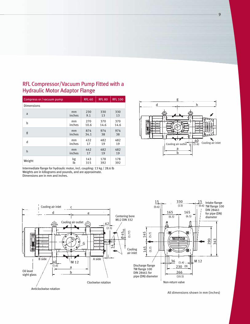
RFL Compressor/Vacuum Pump Fitted with a Hydraulic Motor Adaptor FlangeCompress or / vacuum pump RFL 60 RFL 80 RFL 100
Dimensions
a mminches
2309.1
33013
33013
b mminches
27010.6
37014.6
37014.6
g mminches
87434.1
97438
97438
d mminches
43217
48219
48219
h mminches
44217
48219
48219
Weight kglb
143315
178392
178392
Intermediate flange for hydraulic motor, incl. coupling: 13 kg / 28.6 lb Weights are in killograms and pounds, and are approximate.Dimensions are in mm and inches.
(13.
5)
(11.
4)
ab
40 M 12
k
62
G
i
d
c
e
14
Ø 4
5 k6
145
145
33015
165 165
36 M 12
230
266
290
343
15Cooling air inlet
Cooling air outlet
Centering bore M12 DIN 332
A sideB side
Anticlockwise rotation
Clockwise rotation
Oil level sight glass
Cooling air inlet
(1.6)
(2.5)
(1.7
7)
(0.6)
(6.5)
(5.7
)(5
.7)
(1.4)(9)
(10.5)
Discharge flangeTW flange 100 DIN 28461 for pipe (DN) diameter
(6.5)
(13) (0.6)Intake flange TW flange 100 DIN 28461 for pipe (DN) diameter
Non-return valve
g
d h
t40
ab
Cooling air inletCooling air outlet (1.6)
All dimensions shown in mm (inches)

10
Evacuation TimesThe evacuation times tev are represented as a function of the vacuum and of the vessel volume V. These times are intended for guidance only. The actual times are governed by the condition of the entire system.
Evacuation times RFL 60/80/100
Evac
uati
on ti
me
in s
econ
ds
Vessel volume in m3
RFL 60/200 mbar 24" HG
RFL 80/200 mbar 24" HG
RFL 100/200 mbar 24" HG
RFL 60/400 mbar 18" HG
RFL 80/400 mbar 18" HG
RFL 100/400 mbar 18" HG
ApplicationInstallation on medium-sized vacuum tankers•
For vacuum systems•
For fixed installation sludge handling and waste •disposal systems
DriveFrom the vehicle engine via an auxiliary drive•
Via universal shaft•
By V-belt – a belt pulley is fitted to the free •shaft end
By hydraulic motor•
Via flexible coupling•
By diesel engine or electric motor •with 1500 rpm
CoolingAir cooling is provided by two fans fitted to the shaft ends. These fans take in cooling air axially and blow it across the fins of the casing.
LubricationThe automatic lubrication device supplies oil to all contacting parts of the machine. The oil pump is mounted within the oil tank and is driven directly by the rotor shaft.
InstallationMounting using securing points at the top or bottom of the main casting, combined with optional CW or CCW rotation, gives maximum installation flexibility.
Facts, Figures, and Data

11
Number of holesDN
890L
18
D
Ø 2
05
b R3/8”R3/8”
(35)
(8.0
7)(.07
)
Accessories
All dimensions shown in mm (inches)
80 (3.15)
V-belt pulleyWeight: 12 kg (26.5 lb)
Vacuum relief valveWeight: 6.2 kg (13.7 lb)
Kühlluft Eintritt
Antrieb rechtsdrehend
DruckflanschTW-Flansch 100nach DIN 28461für Rohr DN
g
262
165
165
262
Filterausbaumaß325
13
Ø 1503
90220235
Ø 1503
M12
(10.31)
(10
.31
) (6.5
)
(5.9
)
(12.79)
(5.54) (8.6)(9.25)
(5.9)
(0.51)
Suction filter VFD 3 Weight: 22 kg (48.5 lb)
Discharge silencer
Series Flange measure Weight
DN D L b xkglb
RFL 60 DV65
2.56185 7.28
145 5.71
16 0.63
412
26.5
RFL 80/100 DV80
3.15200 7.87
160 6.3
18 0.71
815
33.1
Weights are in killograms and pounds, and are approximate.
110(4.33)
(1.9
7)50
50
(1.9
)
153
244
(9.6
)
(6.0
2)
(0.5
)14
Clearance for element remove
The following accessories can be supplied as additional equipment. All components involved are of optimum design for use with our compressor / vacuum pump and have proved their efficiency under the most severe operating conditions.
Suction Filter This protects the compressor/vacuum pump against coarse and fine-grained impurities but not against liquids. The VFD 3 filter with an integrated fine filter is fitted directly to the suction flange. VFD 3 filters are particularly necessary on vehicles carrying dangerous goods on public roads. They are designed for 160 psig.
Discharge SilencerFor reduction of air discharge noise during suction operations. This silencer is installed in the line which discharges to atmosphere.
Vacuum Relief ValveThe vacuum relief valve ensures that the permissible or desired operating vacuum is maintained at the correct level by allowing atmospheric air to flow in during suction operations. It is installed in the suction line.
Intermediate Flange for Hydraulic MotorFor direct mounting the hydraulic motor (gauge ring and 4 threaded holes in the casing cover) with flexible coupling. The intermediate flange also serves as a coupling guard.
Further AccessoriesLow oil level warning•
Non-return valve•
Pressure/vacuum gauge•
Flexible drive coupling and •guard
www.GardnerDenverProducts.com [email protected]
Gardner Denver, Inc. 1800 Gardner Expressway, Quincy, IL 62305Telephone: (800) 682-9868 FAX: (217) 221-8780
©2009 Gardner Denver, Inc. Printed in U.S.A. GDT-W-RFL 1st Ed. 9/09
Please recycle after use.
8
ACCREDITED
Gardner Denver ServiceSpeed, reliability and competence are what we understand by providing quality support. Commitment and understanding are both ingredients of quality.
Gardner Denver Installation, Technical Support and TrainingComprehensive technical support before, during and after installation are vital ingredients to provide a long, trouble-free machine life. Please contact your Gardner Denver representative for further details.
Gardner Denver Original PartsFast and skilled service, a comprehensive parts stock and the right accessories for every machine are a "must" for problem-free operation.
Related Documents