1 ENERGY OPTIMISATION IN AIR COMPRESSION THEORETICAL AND EXPERIMENTAL RESEARCH ACTIVITY ON SLIDING VANE ROTARY COMPRESSORS R. Cipollone (*), G. Contaldi (**) D. Di Battista (*), G. Bianchi (*), A. Capoferri (**), S. Murgia (**) (*) Department of Mechanical Engineering, Energy & Management, University of L’Aquila, L’Aquila, Italy (**) Ing. Enea Mattei S.p.A., Vimodrone, Milano, Italy ABSTRACT Energy saving represents one of the most important issues of the European Community to counteract climate change due to global warming. A saving goal of 20 % of the energy consumption by 2020 has been set up and great efforts are to be done in order to reach this figure. All the energy intensive sectors are called to produce actions of that quantitative dimension: the industrial sector accounts for 35 % of the energy consumption and, of that 15 % is due to the compression of air. In absolute quantitative terms, 100 TWh of electric energy are consumed in Europe per year to compress air for industrial purposes. Sliding Vane Rotary Compressors (SVRC) show previously unforeseen potential in terms of energy saving due to some intrinsic features specifically related to the principles of the working conditions of the machine and which do not strictly apply to other types of rotary compressor. As we strive for energy savings and CO 2 reduction the inherent efficiency advantages of these machines increases the importance of developing this SVRC technology. The Authors continue their previous studies concerning this machine type and present here a refinement of a comprehensive mathematical model which was validated by an experimental data set of an existing industrial 22 kW machine. Thanks to a suitable procedure, all the mechanical aspects were investigated as well as the breathing properties of the machine as a function of the main operating conditions which were close to the main industrial applications. The measurements included pressure measurements inside the cells and gave the opportunity to go deeper (than today done) inside the physics of the machine. Forward and backward blade tilting was investigated as design parameter to optimize specific energy consumption. INTRODUCTION Electrical energy in Europe for Compression Air Systems (CAS) in Industry accounts for almost 100 TWh. Including leakage and the incorrect use of compressed air, the potential in terms of energy saving, has been estimated to be 30%. Using optimised compressors, specifically conceived for energy saving could offer potential energy savings estimated at close to 10%, which would represent 50% of the European Energy saving goal by 2020 (“20-20-20” EU Directive) if CAS is considered as a specific sector. Sliding Vane Rotary Compressors (SVRC) show previously unforeseen potential in terms of energy saving due to some intrinsic features specifically related to the principles of the working conditions of the machine and which do not strictly apply to other types of rotary compressor. In this machine, a cylindrical rotor placed eccentrically with respect to a corresponding cylindrical stator, expels a given number of blades arranged inside rotor slots, during rotation. This causes the formation of closed cells having a volume which decreases from the intake to the exhaust ports, and in doing so compresses the trapped air. The most critical aspects of this machine are the contact between blade tip and stator inner wall and lateral blade surface and rotor slots. As the oil is pressurised by the same compressed air, a continuous injection of oil is supplied, avoiding the use of an external oil pump. This lubricating oil creates a film on the internal stator wall on which the blade tip slides, minimising the friction coefficient and, therefore, the power lost. Independently from the working conditions (during transients or at steady state, for a new machine or after a long operating period, low or high speed of revolution, pressure delivered, etc...), the blade rearranges its relative position toward the stator according to the equilibrium between centrifugal force

Welcome message from author
This document is posted to help you gain knowledge. Please leave a comment to let me know what you think about it! Share it to your friends and learn new things together.
Transcript

1
ENERGY OPTIMISATION IN AIR COMPRESSION
THEORETICAL AND EXPERIMENTAL RESEARCH ACTIVITY ON
SLIDING VANE ROTARY COMPRESSORS
R. Cipollone (*), G. Contaldi (**)
D. Di Battista (*), G. Bianchi (*), A. Capoferri (**), S. Murgia (**)
(*) Department of Mechanical Engineering, Energy & Management, University of L’Aquila, L’Aquila, Italy
(**) Ing. Enea Mattei S.p.A., Vimodrone, Milano, Italy
ABSTRACT
Energy saving represents one of the most important issues of the European Community to counteract
climate change due to global warming. A saving goal of 20 % of the energy consumption by 2020 has
been set up and great efforts are to be done in order to reach this figure. All the energy intensive sectors
are called to produce actions of that quantitative dimension: the industrial sector accounts for 35 % of
the energy consumption and, of that 15 % is due to the compression of air. In absolute quantitative
terms, 100 TWh of electric energy are consumed in Europe per year to compress air for industrial
purposes.
Sliding Vane Rotary Compressors (SVRC) show previously unforeseen potential in terms of energy
saving due to some intrinsic features specifically related to the principles of the working conditions of
the machine and which do not strictly apply to other types of rotary compressor.
As we strive for energy savings and CO2 reduction the inherent efficiency advantages of these machines
increases the importance of developing this SVRC technology.
The Authors continue their previous studies concerning this machine type and present here a refinement
of a comprehensive mathematical model which was validated by an experimental data set of an existing
industrial 22 kW machine. Thanks to a suitable procedure, all the mechanical aspects were investigated
as well as the breathing properties of the machine as a function of the main operating conditions which
were close to the main industrial applications. The measurements included pressure measurements
inside the cells and gave the opportunity to go deeper (than today done) inside the physics of the
machine.
Forward and backward blade tilting was investigated as design parameter to optimize specific energy
consumption.
INTRODUCTION
Electrical energy in Europe for Compression Air Systems (CAS) in Industry accounts for almost 100
TWh. Including leakage and the incorrect use of compressed air, the potential in terms of energy saving,
has been estimated to be 30%. Using optimised compressors, specifically conceived for energy saving
could offer potential energy savings estimated at close to 10%, which would represent 50% of the
European Energy saving goal by 2020 (“20-20-20” EU Directive) if CAS is considered as a specific
sector.
Sliding Vane Rotary Compressors (SVRC) show previously unforeseen potential in terms of energy
saving due to some intrinsic features specifically related to the principles of the working conditions of
the machine and which do not strictly apply to other types of rotary compressor.
In this machine, a cylindrical rotor placed eccentrically with respect to a corresponding cylindrical
stator, expels a given number of blades arranged inside rotor slots, during rotation. This causes the
formation of closed cells having a volume which decreases from the intake to the exhaust ports, and in
doing so compresses the trapped air.
The most critical aspects of this machine are the contact between blade tip and stator inner wall and
lateral blade surface and rotor slots. As the oil is pressurised by the same compressed air, a continuous
injection of oil is supplied, avoiding the use of an external oil pump. This lubricating oil creates a film
on the internal stator wall on which the blade tip slides, minimising the friction coefficient and,
therefore, the power lost.
Independently from the working conditions (during transients or at steady state, for a new machine or
after a long operating period, low or high speed of revolution, pressure delivered, etc...), the blade
rearranges its relative position toward the stator according to the equilibrium between centrifugal force

2
and the pressure generated by the hydrodynamic contact between blade tip, oil layer and stator surface,
always ensuring a very reduced dissipative contact. For instance, when the centrifugal force is increased
(increased rpm), the load on the oil film from the blade increases. This results in an increased oil film
pressure which in turn leads to a re-equilibrating of the blade position. When the oil properties
degenerate, due to oil aging, the compressibility of the oil is increased and a different oil film thickness
can result at similar working conditions.
A similar situation occurs at the lateral blade surface which slides on the inner surface rotor slots.
Considering that the blade thickness is smaller than the slot width, during this motion the blade inclines
with respect to the slot axis. As with the blade tip, an oil layer stands between the blade and the slot. The
blade is subjected to a force perpendicular to the centrifugal force which is counteracted by the reaction
force caused by the load acting on the oil film: the more this force increases, the more the oil pressure
increases balancing it out and avoiding any dry contact.
So, if the blade tip is properly designed according to proprietary design rules as well as the blade side
and rotor slot surfaces, there will never be a dry contact. On the other hand if this were to happen, the
very high relative velocity between fixed and moving metallic parts would seriously damage the
machine, compromising the compressor life. As this is an extremely rare occurrence one can deduce that
this compressor is, due to its very nature, intrinsically safe and reliable. Additionally, the sealing caused
by the oil film on every surface which separates high and low pressure zones, ensures minimal air
leakage between adjacent cells ensuring a high volumetric efficiency.
These features do not strictly apply to other types of rotary compressor. Screw compressors are the most
widely used in CAS; they are reliable, universally known, covering a huge market sector. Nevertheless,
it should be emphasized that they make use of a very sophisticated male/female screw geometry the
enhancement of which has represented the main goal of a specifically targeted research for many years.
A male rotor during its rotation drives a female rotor. The relative motion between them causes the
advance of an air volume which is reduced along the rotor axis, so compressing the air trapped at the
intake. It can be easily recognized that the precision of the position of the axes of the two rotors is only
due to the precision of the corresponding main bearings, which inevitably vary during compressor life or
during compressor transients (for instance, at various temperatures). This is efficiently compensated for
with the precise clearance between rotor screws and stator in order to avoid metal to metal contact, but
ensuring a high volumetric efficiency is difficult even in the presence of a continuous oil flow rate from
the intake to the exhaust section. In these machines, dry contacts between the two rotors are difficult to
avoid, due to the fact that one rotor must drive the other and a given torque is required to produce this
action. In any case, it must be remembered that screw compressors represent a standard in CAS.
Unlike with screw compressors, the scientific investigation has been limited and unsatisfactory for
SVRCs: only recently and mainly due to the Authors, have these machines received the attention which
has led to a greater knowledge and understanding of their operating principles than ever before. The
inherent efficiency advantages of these machines increases the importance of developing this
technology, in fact even more so now due to the increasing need for energy saving and CO2 reduction.
Recently, a complex reconstruction of the pressure inside a cell was carried out using a single
piezoelectric pressure transducers positioned at different angular spacing within an existing commercial
SVRC, [1]. The data obtained represented an innovation in the sector. Due to the complexity of the data
matching, some pressure data was lost, mainly during compressor exhaust, however thanks to a
comprehensive mathematical modeling previously developed by the Authors, the theoretical handling of
the pressure measured allowed a detailed even though preliminary examination of the thermodynamic
aspects of the closed volume compression phase and discharge and intake processes.
In this paper the Authors refine the mathematical modeling of a SVRC concentrating the attention on the
most important aspects which are related to energy consumption: integrated with the previous
modeling, the actual software formulation behaves as a virtual platform for compressor design.
Main issues of this theoretical advancement was related to:
a) Geometry of the machine which takes into account blades which moves inside their slots non
radially. Thanks to a suitable representation, this unconventional geometry can be considered as
optimizing parameter for specific energy consumption;
b) The blade dynamics which matches blades which move non radially: the model has been
rewritten and Inertia and Coriolis terms have been included, leading to a much more general
blade dynamic modeling.
3
A more intensive experimental activity has been done, going beyond the previous analysis: four
piezoelectric pressure transducers were used (instead of one) and they allowed a much more detailed
pressure reconstruction during the intake, closed volume and exhaust phases. Data treatment was easier
and errors related to the pressure data matching were negligible. Thanks to this, a consistent
experimental data set was available in order to deal with:
a) The role of the heat transfer between air and external surfaces during compression phase as well
as that related to the oil injection;
b) The friction coefficient and power lost due to it versus operating conditions, i.e. pressure
delivered and speed of rotation;
c) Indicated power Vs calculated, using the pressure data calculated and measured;
d) Tilting of the blade in a forward or in a backward arrangement (blade moving non radially) as
design parameter for specific energy consumption optimization.
MODEL BASED MACHINE OPTIMIZATION
In a previous series of works, the Authors presented a comprehensive mathematical model which
considered all the main issues of the behavior of such machine, [2-5]. A preliminary experimental
validation of the model was done, [1], thanks to a complex reconstruction of the pressure inside the cells
done with only one piezoelectric pressure transducer. The unique sensor, in fact, forced the Authors to a
very time consuming procedure to match pressure data between angular displacements, the piezoelectric
transducers measuring pressure differences and not absolute values.
The results were useful for a preliminary analysis and for the set up of the procedure but not yet
satisfactory for machine optimization and overall comprehension of the most intimate processes of the
machine.
In the followings, a brief outline of a SVRC modeling is reported, focusing the improvement already
cited. For the base modeling, please refer to previous papers.
Vane geometry. The vane geometry of the compressor is calculated when the rotor and stator diameters
are known, and eccentricity too. Knowing the slot depth and width, and the blade height and thickness,
the full geometry of the vane is easily defined.
More complex is the description when the slots on the rotor are not radial, as their inclination can be
both backwards facing or forwards facing.
In this case, which should be investigated in order to optimize the machine performance, a procedure to
represent the geometry is needed also for dealing with an immediate machine construction.
A suitable way to represent this situation is that of fixing a given internal circumference (whose radius
is smaller than the rotor’s radius) and the blade are drawn as tangential to this circumference. In fact, at
a given inner radius a known blade inclination occurs, having to fix only the inclination’s direction
(forward or backward). Figure 1 reports relevant quantities and reference angles and dimensions.
Solving some geometrical complexity, the volume of the cell can be calculated and the variations which
follow hint to equivalent variations into the mass trapped inside. In such a way, backward and forward
tilted SVRC can be easily represented.
On the stator, suitable ports are located, usually frontally (on the covers, with an axial air admission or
delivery) or circumferentially (with a radial air admission or delivery). It is suitable to refer the port
opening and closing to correspondent angular position, as shown in Figure 3. From fluid dynamics
considerations, the section which opens to the fluid passage can be derived as changing during time
(during filling and emptying).
Angular ports position on the stator influences the real compression ratio (not the volumetric one) as
pressure ratio between the cell before it opens toward the exhaust and after it closes toward the inlet.
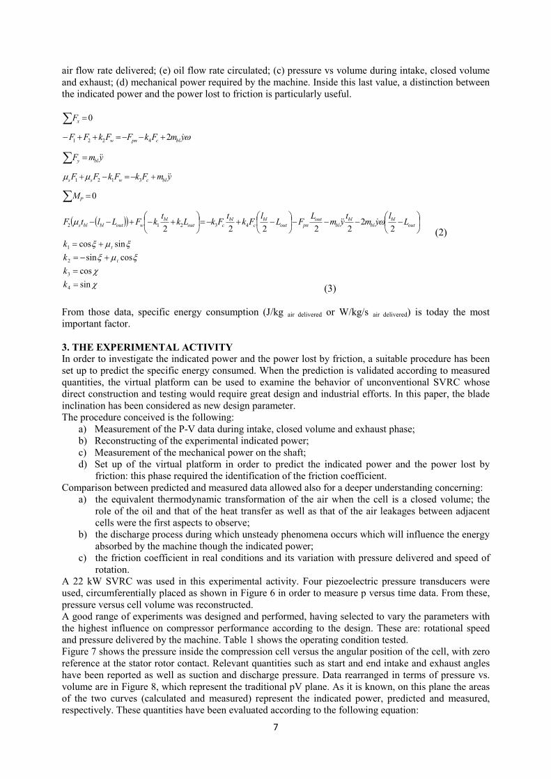
The model can consider intake and exhaust ports located in any manner: usually, intake ports are on the
front cover of the machine having suitable designed shapes while exhaust ports are radial, being usually
rectangular shaped, Figure 3.
Vane filling & emptying.
In order to improve SVRC design the filling and emptying of the cells required a particular care in order
to predict the mass inducted and expelled in or from the vane. While the induction process could be
considered really steady, the exhaust process is fully unsteady considering that the cell pressure when it
4
opens toward the discharge usually does not fit with the line pressure, i.e. the pressure in the discharge
volume.
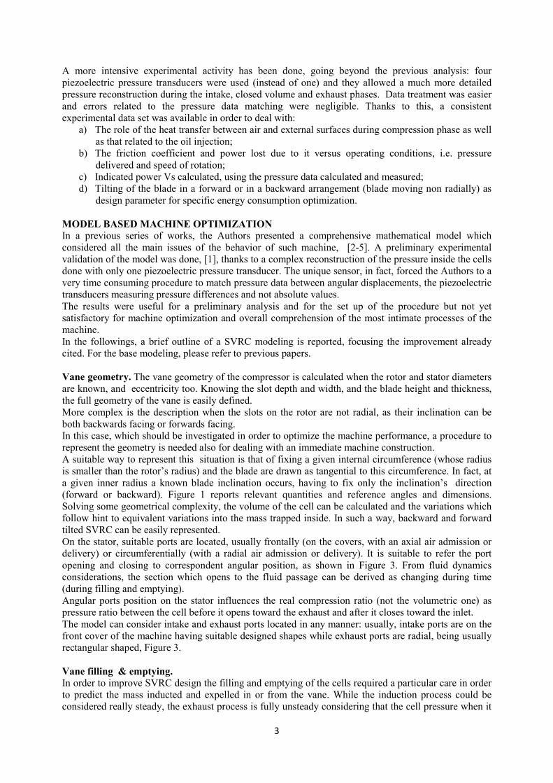
Figure 1 – Geometry of a SVRC with inclined blades: (left)-front view of the machine, relevant
quantities are shown in particular intake (blue) and exhaust (red) ports angularly placed; (right)-two
blades in opposite position with correspondent points.
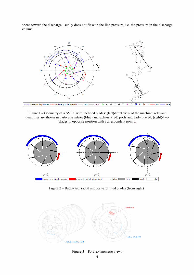
φ<0 φ=0 φ>0
Figure 2 – Backward, radial and forward tilted blades (from right)
AXI AL I NTAKE PORT
RADI AL I NTAKE PORT
EXHAUST PORT
Figure 3 – Ports axonometic views

5
This represent an added value of the rotary volumetric machines with respect to other compressor types
(for instance reciprocating compressors or turbocompressors), but this feature makes the emptying
process more difficult and generally, it is paid in terms of specific compression energy. Considering that
the cell-discharge volume pressure difference could be of the order to 4/5 bar, a strong unsteady process
occurs during the emptying of the cell.
To avoid 1D unsteady fluid dynamic analysis, a quasi propagatory model (QPM) has been used, [6-7]
which very efficiently evaluates the unsteadiness during exhaust. The method makes use of the mass,
momentum and energy unsteady equations and solve them in an analytical form.
109876
54'
32
4"
1
Figure 4 – reference model for vanes filling and emptying
The QPM considers the SVRC as in Figure 4. An inlet plenum (1) having infinite capacity is in
connection with the intake vane (4) though a intake manifold (2) and an intermediate capacity (3) which
is the one in which an inlet valve is mounted, controlling with its opening the flow rate delivered.
Similarly, the exhaust cell (5) discharges toward a capacity (6) represented by the volume which
immediately receives the flow. Through an equivalent duct (7), the compressed air (and oil) fill the oil
separator (8) which behaves as a capacity and, through a pipe (9) having a given designed length, it
reached the working line (10) which behaves as a plenum of a finite capacity at pressure line. The mass
and enthalpy fluxes are calculated in each relevant section (equivalent pipes and capacities) solving an
unsteady 1D model: inlet plenum (1), intermediate inlet volume (3), cell which is emptying and voiding
(4, 5), intermediate capacity (6), oil separator (8) and line (10) behave as time varying boundary
conditions.
Thermo dynamic cell model. The model is based on a lumped parameter assumption having so,
uniform thermodynamic properties (temperature, pressure, composition, etc…). Considering the
quantity of the oil injected, each cell is considered as a mixture of air (inducted) and oil (injected).
Different phase transitions (liquid-vapor) are allowed according to physical tendency of oil evaporation
(comparison between its partial pressure and the saturation pressure which changes with the temperature
inside the cell).
The cell behaves like an open system (with respect to mass and energy); therefore, energy conservation
equation has the form:
( ) ,o vap
LHV
dmdUmh q p V H T
dt dt= + − ⋅ − ⋅
∑ && &
(1)
Eq. (1) requires the knowledge of the input and output terms which derive from the cell voiding and
emptying,
Equation (1) included the heat exchanged by the air during compression: in fact, when it is compressed
the temperature increases and it would be very beneficiary to cool it in order to decrease energy required
for compression. From this point of view, equation (1) considers two terms: (1) forced convection
between air and metallic parts of the machine; (2) the heat subtracted by the air due to oil evaporation.
Another term should be added and it is related to the heat produced by friction which firstly is brought
out by the oil layer in between the tip blade-stator contact and subsequently could be exchanged toward
the air.
The interactions of these two contributions are complicated and they require extensive investigations.
These effects could also have different “exchange directions”, and only the “equivalent” effect would
produce a positive or negative contribution to the energy required to compress the air.

6
If the scope is to understand this “equivalent” contribution, the comparison between the pressure vs
volume calculated (according to a given assumption) and that measured will be enough to understand
the real effect of heat exchanged and/or oil vaporization (due to the temperature increase of the
compressed air and to the droplet size) and re-condensation (due to pressure increase during vane
contraction).
Oil circulation. Oil circulates inside the machine naturally, the driving force of this circulation being
the oil pressure when it is discharged by the vane. The oil separator holds the initial oil volume and from
this the oil moves inside external pipes around the machine untill the injection inside the cells.
Distributed pressure losses as well as concentrated ones (changes in directions and cross sections) are
considered: the last pressure drop is represented by the oil injection rail from which several injections
are made. Injections have been modeled as sudden expansions inside the cells whose pressure changes
during time. Except for the injection rail, all the other section have been represented as stationary
phenomena. During the injections, pressure waves have been taken into account to calculate in a correct
way the upstream injection pressure. The oil flow rate, therefore, is the result of the mass and
momentum conservation equations applied to the rail which sustain the oil injection process.
Friction modeling. The power dissipated by friction is calculated evaluating the forces exchanged
between the blade and the surfaces during their motion inside the slot and during rotor’s rotation.
Contact surfaces are at tip blade (in contact with the stator’s surfaces) and to the lateral surfaces of the
blades, in contact with the slot’s surfaces.
The problem is that the position of the blade inside the slot is unknown, being four states possible: in
fact the blade can arrange itself inside the slot tilted in backward and forward position (with respect to
the rotor motion) and completely leaned on the two slot surfaces (forward and backward lean, according
to the rotor motion).
Blade motion is the result of the force and momentum equilibrium applied to the blade, whose reference
system is in rotation. Figure 5 reports the complete set of forces which are applied in the case of
backward tilted blade inside the slots; equation (2) the force and momentum equilibrium, (symbols are
in Figure 1 and 5). The model considers two contacts between blade and slot and one contact between
blade and stator: three friction coefficients could be specified and properly set up.
Figure 5 – Force acting between blade and slot and blade and stator during rotation. For inertia and
Coriolis forces, the blade is considered entering the a slot and reference rotation as clockwise.
The k coefficients change according to blade inclination: in the case depicted in Figure 5 (φ>0), they are
in equations 3.
All the sections previously considered have been managed inside a virtual platform which gives, once
the geometry is designed and ambient and line pressure are known, the behavior of the SVRC as a
function of the speed of rotation. Principal quantities which receive greatest designer attention’s are: (a)
7
air flow rate delivered; (e) oil flow rate circulated; (c) pressure vs volume during intake, closed volume
and exhaust; (d) mechanical power required by the machine. Inside this last value, a distinction between
the indicated power and the power lost to friction is particularly useful.
( )( )
−−−−
−+−=
+−+−−
=
+−=−+
=
+−−=++−
=
∑
∑
∑
out
bl
bl
bl
bl
out
pnout
bl
c
bl
cout
bl
woutblbls
P
blcwss
bly
blcpnw
x
Ll
ymt
ymL
FLl
Fkt
FkLkt
kFLltF
M
ymFkFkFF
ymF
ymFkFFkFF
F
22
22222
0
2
0
43212
3121
4221
ωµ
µµ
ω
&&&
&&
&&
&
(2)
χχ
ξµξξµξ
sin
cos
cossin
sincos
4
3
2
1
=
=
+−=
+=
k
k
k
k
t
t
(3)
From those data, specific energy consumption (J/kg air delivered or W/kg/s air delivered) is today the most
important factor.
3. THE EXPERIMENTAL ACTIVITY
In order to investigate the indicated power and the power lost by friction, a suitable procedure has been
set up to predict the specific energy consumed. When the prediction is validated according to measured
quantities, the virtual platform can be used to examine the behavior of unconventional SVRC whose
direct construction and testing would require great design and industrial efforts. In this paper, the blade
inclination has been considered as new design parameter.
The procedure conceived is the following:
a) Measurement of the P-V data during intake, closed volume and exhaust phase;
b) Reconstructing of the experimental indicated power;
c) Measurement of the mechanical power on the shaft;
d) Set up of the virtual platform in order to predict the indicated power and the power lost by
friction: this phase required the identification of the friction coefficient.
Comparison between predicted and measured data allowed also for a deeper understanding concerning:
a) the equivalent thermodynamic transformation of the air when the cell is a closed volume; the
role of the oil and that of the heat transfer as well as that of the air leakages between adjacent
cells were the first aspects to observe;
b) the discharge process during which unsteady phenomena occurs which will influence the energy
absorbed by the machine though the indicated power;
c) the friction coefficient in real conditions and its variation with pressure delivered and speed of
rotation.
A 22 kW SVRC was used in this experimental activity. Four piezoelectric pressure transducers were
used, circumferentially placed as shown in Figure 6 in order to measure p versus time data. From these,
pressure versus cell volume was reconstructed.
A good range of experiments was designed and performed, having selected to vary the parameters with
the highest influence on compressor performance according to the design. These are: rotational speed
and pressure delivered by the machine. Table 1 shows the operating condition tested.
Figure 7 shows the pressure inside the compression cell versus the angular position of the cell, with zero
reference at the stator rotor contact. Relevant quantities such as start and end intake and exhaust angles
have been reported as well as suction and discharge pressure. Data rearranged in terms of pressure vs.
volume are in Figure 8, which represent the traditional pV plane. As it is known, on this plane the areas
of the two curves (calculated and measured) represent the indicated power, predicted and measured,
respectively. These quantities have been evaluated according to the following equation:

8
1
2
3
4
5
TEST #
1000RPM@11bar
1500RPM@11bar
1500RPM@13bar
Table 1 – SVRC operating conditions tested
5
36 . 4
81 . 4
126 . 4
EXHAUST PORT
INTAKE PORT
4t h
3r d
2nd
1st
Figure 6 – Pressure transducers positioning (front view).
(4)
where pre pressure values could be both measured or predicted. and a are the number of the cells
of the machine and the time required to make a revolution.
During the compression phase when the cell is represented by a closed volume, the predicted pressure
calculated, considering an adiabatic compression, overlaps with the measured data: this means clearly
that during this period the net heat exchanged between air (during compression) and the surroundings or
with oil is negligible. The cooling feature of the oil is, therefore, meaningless and its main goal is the
sealing function between adjacent cells. This feature is repeated for all the tested points, so it can be
assumed for further model refinement and design aims. Due to these conclusions, the temperature of the
air at the exit of the cell can’t differ too much from that corresponding temperature of an adiabatic
compression, that is to say hundreds of degrees Celsius.
Figure 7 – Pressure versus angle trace, test #1.
cycle
cells
indt
dVpnP
∫ ⋅⋅=
cellsn cyclet
9
Considering that the air delivered by the machine has a temperature close to 90-100 °C, a strong cooling
is done by the oil (which is colder that the compressed air) and forced convection (surface) heat transfer
outside of the cells, when the compressed air travels in the exhaust channel (between the stator and the
external surface of the machine) and inside the oil separator. So, the overall compression could be
considered as equivalent to two transformations: the first adiabatic inside the cell which leads the air to
the final delivery pressure, the second isobaric during which the compressed air is cooled.
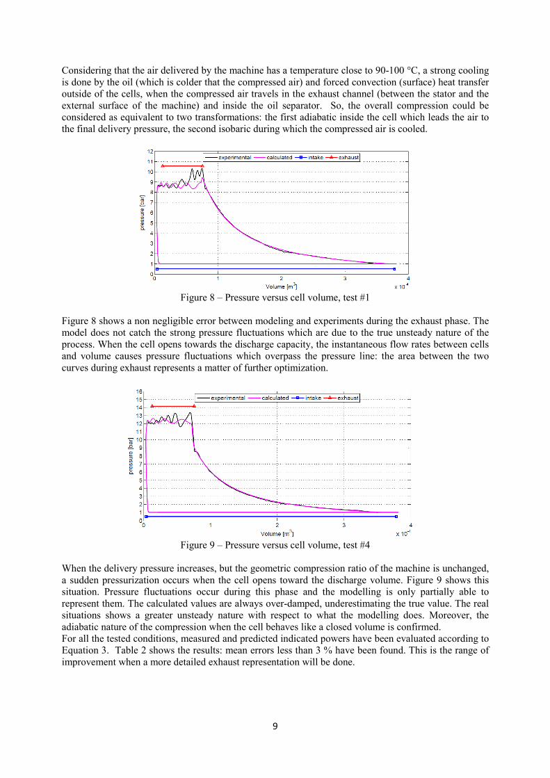
Figure 8 – Pressure versus cell volume, test #1
Figure 8 shows a non negligible error between modeling and experiments during the exhaust phase. The
model does not catch the strong pressure fluctuations which are due to the true unsteady nature of the
process. When the cell opens towards the discharge capacity, the instantaneous flow rates between cells
and volume causes pressure fluctuations which overpass the pressure line: the area between the two
curves during exhaust represents a matter of further optimization.
Figure 9 – Pressure versus cell volume, test #4
When the delivery pressure increases, but the geometric compression ratio of the machine is unchanged,
a sudden pressurization occurs when the cell opens toward the discharge volume. Figure 9 shows this
situation. Pressure fluctuations occur during this phase and the modelling is only partially able to
represent them. The calculated values are always over-damped, underestimating the true value. The real
situations shows a greater unsteady nature with respect to what the modelling does. Moreover, the
adiabatic nature of the compression when the cell behaves like a closed volume is confirmed.
For all the tested conditions, measured and predicted indicated powers have been evaluated according to
Equation 3. Table 2 shows the results: mean errors less than 3 % have been found. This is the range of
improvement when a more detailed exhaust representation will be done.

10
1 2 3 4 5
P ind, exp kW 12,77 15,44 18,26 22,10 24,97
P ind, calc kW 12,47 15,14 18,44 21,97 24,34
Deviation 2,33% 1,92% -0,98% 0,60% 2,51%
TEST #
Table 2 – Comparison between measured and calculated indicated power
The friction coefficient represents an important knowledge in SVRC. According to this modelling. The
power lost by friction can be calculated using an expression in which the only unknown is the
coefficient itself. The solution of the blade dynamics gives, in fact, all the reaction forces where the
blade is in contact with the rotor and the stator (Figure 5). The only term which produces a loss in terms
of mechanical power is that which controls the contact between stator and blade. So, the power can be
calculated when this force is multiplied by the relative speed (which changes during time) at the contact
point.
Moreover, the power lost by friction can be derived from experimental values, so experimentally
identified. In fact, from the shaft power (directly measured), subtracting the measured indicated power
(by the p-V measured data), a value for the power lost due to friction can be derived. This information
can be used in order to identify a value for the friction coefficient which minimizes the root mean square
error between calculated and measured data for the power lost due to friction. Such fine tuning gives as
most suitable identification for friction coefficient the value of 0.055.
Table 3 reports mechanical, indicated and friction power in a comparison between calculated and
measured. The overall mechanical power is estimated with an error less than 5 % in the overall operating
range. This represents a very interesting result considering the high complexity of the phenomena
involved.
A relevant datum is the flow rate produced by the SVRC. The volumetric property, in fact, represent a
high marketing value of the machine. Table 4 shows how the model predicts the real values. An error
less than 4 % characterize the flow rate, which is close to the measurement error in an industrial
environment. Data in tables 2, 3 and 4 therefore show the effectiveness of the virtual platform
represented by the interconnected models. The use as a design tool seems to be strongly recommended.
TEST # 1 2 3 4 5
P mech, exp kW 14,46 16,86 21,68 25,32 27,69
P ind, exp kW 12,77 15,44 18,26 22,10 24,97
P lost, exp kW 1,69 1,42 3,42 3,22 2,72
P mech, calc kW 13,80 16,43 22,62 26,09 28,45
P ind, calc kW 12,47 15,14 18,44 21,97 24,34
P lost, calc kW 1,33 1,29 4,18 4,12 4,11
Deviation in mech. power % 4,51 2,57 4,34 3,01 2,74
Table 3 – Comparison between measured and calculated mechanical,
indicated and friction power.
Table 4 – Comparison between measured and calculated flow rates
Starting from this modelling potentiality, the virtual platform has been used in order to investigate the
effect of the blade inclination on relevant quantities, including specific energy consumption.
TEST # 1 2 3 4 5
Flow rate, exp kg/s 0,0460 0,0460 0,0675 0,0656 0,0637
Flow rate, calc kg/s 0,0475 0,0462 0,0675 0,0658 0,0659
Deviation % 3,26 0,43 0,00 0,30 3,45
11
Blade inclination is an unconventional technological issue and a direct experimental verification will
mean a time consuming and complex (and costly) activity. This environment represents, therefore, the
most suitable use of the virtual platform.
Seven SVRC have been virtually built and tested and relevant operating properties have been evaluated.
For these compressors no other design changes have been done and, in particular, the intake and exhaust
ports remained unchanged: so, blade inclination stand as a minor design change.
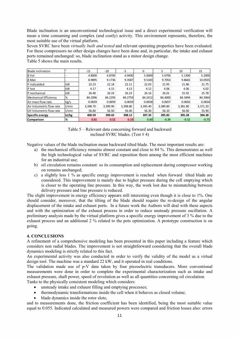
Table 5 shows the main results.
Blade inclination ° -15 -10 -5 0 5 10 15
β Vol - 4.8000 4.8700 4.9400 5.0000 5.0700 5.1300 5.2000
β Man - 8.9895 9.1736 9.3587 9.5183 9.7053 9.8665 10.0555
P indicatded kW 22.23 22.18 22.11 22.03 21.95 21.86 21.75
P lost kW 4.17 4.15 4.13 4.12 4.06 4.06 4.02
P mechanical kW 26.40 26.33 26.23 26.16 26.01 25.92 25.78
Mechanical Efficiency % 84.2096 84.2295 84.2759 84.2412 84.4000 84.3494 84.3964
Air mass flow rate kg/s 0.0659 0.0659 0.0659 0.0658 0.0657 0.0656 0.0654
Air Volumetric flow rate l/min 3,398.70 3,399.90 3,398.80 3,395.40 3,389.80 3,381.80 3,371.20
Oil Volumetric flow rate l/min 56.60 56.50 56.40 56.30 56.10 56.00 55.90
Specific energy kJ/kg 400.59 399.42 398.12 397.35 395.82 395.28 394.38
Comparison % 0.81 0.52 0.19 0.00 -0.39 -0.52 -0.75
Table 5 – Relevant data concerning forward and backward
inclined SVRC blades. (Test # 4)
Negative values of the blade inclination mean backward tilted blade. The most important results are:
a) the mechanical efficiency remains almost constant and close to 84 %. This demonstrates as well
the high technological value of SVRC and reposition them among the most efficient machines
for an industrial use;
b) oil circulation remains constant: so its consumption and replacement during compressor working
on remains unchanged;
c) a slightly less 1 % as specific energy improvement is reached when forward tilted blade are
considered. This improvement is mainly due to higher pressure during the cell emptying which
is closer to the operating line pressure. In this way, the work lost due to mismatching between
delivery pressure and line pressure is reduced.
The slight improvement in energy efficiency appears still interesting even though it is close to 1%. One
should consider, moreover, that the tilting of the blade should require the re-design of the angular
displacement of the intake and exhaust ports. In a future work the Authors will deal with these aspects
and with the optimization of the exhaust process in order to reduce unsteady pressure oscillation. A
preliminary analysis made by the virtual platform gives a specific energy improvement of 3 % due to the
exhaust process and an additional 2 % related to the pots optimization. A prototype construction is on
going.
4. CONCLUSIONS A refinement of a comprehensive modeling has been presented in this paper including a feature which
considers non radial blades. The improvement is not straightforward considering that the overall blade
dynamics modeling is strictly related to this fact.
An experimental activity was also conducted in order to verify the validity of the model as a virtual
design tool. The machine was a standard 22 kW, and it operated in real conditions.
The validation made use of p-V data taken by four piezoelectric transducers. More conventional
measurements were done in order to complete the experimental characterization such as intake and
exhaust pressure, shaft power, speed of revolution as well as all quantities concerning oil circulation.
Tanks to the physically consistent modeling which considers:
• unsteady intake and exhaust filling and emptying processes;
• thermodynamic transformations inside the cell when it behaves as closed volume;
• blade dynamics inside the rotor slots;
and to measurements done, the friction coefficient has been identified, being the most suitable value
equal to 0.055. Indicated calculated and measured powers were compared and friction losses also: errors
12
less than 5 % for those mechanical terms were found. Flow rates were represented, with an error less
than 4 %. Mechanical efficiency of these machines stand for 82-84 % demonstrating a very high
technological level achieved by these machines in recent years: this seriously contends the widespread
concept that these machines are “inefficient” and place them among the most efficient ones in their
compressed air sector.
Thanks to these figures, the model represents a comprehensive virtual platform whose use as design tool
could be recommended.
Seven virtual SVRC were studied considering as design free parameter the inclination of the blade in a
forward or backward direction with respect to rotation: the goal was to gain some additional points in
terms of energy efficiency.
With respect to the actual conventional radial SVRC, the following conclusions apply:
• without changing the intake and exhaust ports, blade inclination (as minor design changes) could
improve the energetic performances of about 1 % forward tilting the blades;
• an interesting room for improvement should include ports optimization according to the blade
inclination; a further efficiency increase of 3 % has been predicted;
• unsteady phenomena during exhaust produce a wasteful situation; 3 % in specific energy can be
saved optimizing this aspect.
Therefore, an overall saving of 5-6 % is predicted by the virtual platform which can be considered fully
validated.
5. REFERENCES
(1) Cipollone R., Contaldi G., Capoferri A., Valente R. Theoretical and experimental study of the p-V
diagram for a sliding vane rotary compressor ImechE International conference on compressors and their
systems 2009.
(2) Cipollone R., Contaldi G., Sciarretta A., Tufano R. A comprehensive model of a sliding vane rotary
compressor system, ImechE International conference on compressors and their systems 2005.
(3) Cipollone R., Contaldi G., Villante C., Tufano R. A theoretical model and experimental validation of
a sliding vane rotary compressor, 18th International Compressor Engineering Conference at Purdue,
July 17-20, 2006.
(4) Cipollone R., Contaldi G., Valente R., Tufano, R. An integrated two stage rotary vane compressor:
theoretical optimization ImechE International conference on compressors and their systems 2007.
(5) Villante C., Valente R. On the optimal design of one rotor two stage rotary vane compressor, 19th
International Compressor Engineering Conference at Purdue, July 14-17, 2008.
(6) Cipollone R. and A. Sciarretta, The Quasi-Propagatory Model: a New Approach for Describing
Transient Phenomena in Engine Manifolds, SAE Technical paper no. 2001-01-0579.
(7) Cipollone R. and A. Sciarretta, A new modeling for air and gas dynamics in ICE manifolds oriented
to Ait-Fuel-Control, ASME Paper 99-ICE-170, 1999
Related Documents