WisDOT Bridge Manual Chapter 24 – Steel Girder Structures January 2018 24-1 Table of Contents 24.1 Introduction ...................................................................................................................... 5 24.1.1 Types of Steel Girder Structures............................................................................... 5 24.1.2 Structural Action of Steel Girder Structures .............................................................. 5 24.1.3 Fundamental Concepts of Steel I-Girders ................................................................. 5 24.2 Materials ........................................................................................................................ 11 24.2.1 Bars and Plates ...................................................................................................... 12 24.2.2 Rolled Sections....................................................................................................... 12 24.2.3 Threaded Fasteners ............................................................................................... 12 24.2.3.1 Bolted Connections ......................................................................................... 13 24.2.4 Quantity Determination ........................................................................................... 14 24.3 Design Specification and Data ....................................................................................... 15 24.3.1 Specifications ......................................................................................................... 15 24.3.2 Resistance.............................................................................................................. 15 24.3.3 References for Horizontally Curved Structures ....................................................... 15 24.3.4 Design Considerations for Skewed Supports .......................................................... 15 24.4 Design Considerations ................................................................................................... 20 24.4.1 Design Loads ......................................................................................................... 20 24.4.1.1 Dead Load ...................................................................................................... 20 24.4.1.2 Traffic Live Load ............................................................................................. 21 24.4.1.3 Pedestrian Live Load ...................................................................................... 21 24.4.1.4 Temperature ................................................................................................... 21 24.4.1.5 Wind ............................................................................................................... 21 24.4.2 Minimum Depth-to-Span Ratio................................................................................ 21 24.4.3 Live Load Deflections ............................................................................................. 22 24.4.4 Uplift and Pouring Diagram ..................................................................................... 22 24.4.5 Bracing ................................................................................................................... 23 24.4.5.1 Intermediate Diaphragms and Cross Frames .................................................. 23 24.4.5.2 End Diaphragms ............................................................................................. 25 24.4.5.3 Lower Lateral Bracing ..................................................................................... 25 24.4.6 Girder Selection ...................................................................................................... 26 24.4.6.1 Rolled Girders ................................................................................................. 26 24.4.6.2 Plate Girders ................................................................................................... 26

Welcome message from author
This document is posted to help you gain knowledge. Please leave a comment to let me know what you think about it! Share it to your friends and learn new things together.
Transcript

WisDOT Bridge Manual Chapter 24 – Steel Girder Structures
January 2018 24-1
Table of Contents
24.1 Introduction ...................................................................................................................... 5
24.1.1 Types of Steel Girder Structures ............................................................................... 5
24.1.2 Structural Action of Steel Girder Structures .............................................................. 5
24.1.3 Fundamental Concepts of Steel I-Girders ................................................................. 5
24.2 Materials ........................................................................................................................ 11
24.2.1 Bars and Plates ...................................................................................................... 12
24.2.2 Rolled Sections ....................................................................................................... 12
24.2.3 Threaded Fasteners ............................................................................................... 12
24.2.3.1 Bolted Connections ......................................................................................... 13
24.2.4 Quantity Determination ........................................................................................... 14
24.3 Design Specification and Data ....................................................................................... 15
24.3.1 Specifications ......................................................................................................... 15
24.3.2 Resistance .............................................................................................................. 15
24.3.3 References for Horizontally Curved Structures ....................................................... 15
24.3.4 Design Considerations for Skewed Supports .......................................................... 15
24.4 Design Considerations ................................................................................................... 20
24.4.1 Design Loads ......................................................................................................... 20
24.4.1.1 Dead Load ...................................................................................................... 20
24.4.1.2 Traffic Live Load ............................................................................................. 21
24.4.1.3 Pedestrian Live Load ...................................................................................... 21
24.4.1.4 Temperature ................................................................................................... 21
24.4.1.5 Wind ............................................................................................................... 21
24.4.2 Minimum Depth-to-Span Ratio ................................................................................ 21
24.4.3 Live Load Deflections ............................................................................................. 22
24.4.4 Uplift and Pouring Diagram ..................................................................................... 22
24.4.5 Bracing ................................................................................................................... 23
24.4.5.1 Intermediate Diaphragms and Cross Frames .................................................. 23
24.4.5.2 End Diaphragms ............................................................................................. 25
24.4.5.3 Lower Lateral Bracing ..................................................................................... 25
24.4.6 Girder Selection ...................................................................................................... 26
24.4.6.1 Rolled Girders ................................................................................................. 26
24.4.6.2 Plate Girders ................................................................................................... 26

WisDOT Bridge Manual Chapter 24 – Steel Girder Structures
January 2018 24-2
24.4.7 Welding .................................................................................................................. 28
24.4.8 Dead Load Deflections, Camber and Blocking ........................................................ 32
24.4.9 Expansion Hinges ................................................................................................... 33
24.5 Repetitive Loading and Toughness Considerations ........................................................ 34
24.5.1 Fatigue Strength ..................................................................................................... 34
24.5.2 Charpy V-Notch Impact Requirements ................................................................... 35
24.5.3 Non-Redundant Type Structures ............................................................................ 35
24.6 Design Approach - Steps in Design ................................................................................ 37
24.6.1 Obtain Design Criteria ............................................................................................ 37
24.6.2 Select Trial Girder Section ...................................................................................... 38
24.6.3 Compute Section Properties ................................................................................... 39
24.6.4 Compute Dead Load Effects ................................................................................... 40
24.6.5 Compute Live Load Effects ..................................................................................... 40
24.6.6 Combine Load Effects ............................................................................................ 41
24.6.7 Check Section Property Limits ................................................................................ 41
24.6.8 Compute Plastic Moment Capacity ......................................................................... 42
24.6.9 Determine If Section is Compact or Non-compact .................................................. 42
24.6.10 Design for Flexure – Strength Limit State ............................................................. 42
24.6.11 Design for Shear ................................................................................................... 42
24.6.12 Design Transverse Intermediate Stiffeners and/or Longitudinal Stiffeners ............ 43
24.6.13 Design for Flexure – Fatigue and Fracture ............................................................ 43
24.6.14 Design for Flexure – Service Limit State ............................................................... 43
24.6.15 Design for Flexure – Constructability Check ......................................................... 43
24.6.16 Check Wind Effects on Girder Flanges ................................................................. 44
24.6.17 Draw Schematic of Final Steel Girder Design ....................................................... 44
24.6.18 Design Bolted Field Splices .................................................................................. 44
24.6.19 Design Shear Connectors ..................................................................................... 44
24.6.20 Design Bearing Stiffeners ..................................................................................... 44
24.6.21 Design Welded Connections ................................................................................. 44
24.6.22 Design Diaphragms, Cross-Frames and Lateral Bracing ...................................... 45
24.6.23 Determine Deflections, Camber, and Elevations ................................................... 45
24.7 Composite Design .......................................................................................................... 46
24.7.1 Composite Action ................................................................................................... 46

WisDOT Bridge Manual Chapter 24 – Steel Girder Structures
January 2018 24-3
24.7.2 Values of n for Composite Design........................................................................... 46
24.7.3 Composite Section Properties ................................................................................ 47
24.7.4 Computation of Stresses ........................................................................................ 47
24.7.4.1 Non-composite Stresses ................................................................................. 47
24.7.4.2 Composite Stresses ........................................................................................ 47
24.7.5 Shear Connectors ................................................................................................... 48
24.7.6 Continuity Reinforcement ....................................................................................... 49
24.8 Field Splices ................................................................................................................... 51
24.8.1 Location of Field Splices ......................................................................................... 51
24.8.2 Splice Material ........................................................................................................ 51
24.8.3 Design .................................................................................................................... 51
24.8.3.1 Obtain Design Criteria ..................................................................................... 51
24.8.3.1.1 Section Properties Used to Compute Stresses ........................................ 51
24.8.3.1.2 Constructability ........................................................................................ 52
24.8.3.2 Compute Flange Splice Design Loads ............................................................ 53
24.8.3.2.1 Factored Loads ....................................................................................... 53
24.8.3.2.2 Section Properties ................................................................................... 53
24.8.3.2.3 Factored Stresses ................................................................................... 53
24.8.3.2.4 Controlling Flange ................................................................................... 54
24.8.3.2.5 Flange Splice Design Forces ................................................................... 54
24.8.3.3 Design Flange Splice Plates ........................................................................... 54
24.8.3.3.1 Yielding and Fracture of Splice Plates ..................................................... 55
24.8.3.3.2 Block Shear ............................................................................................. 56
24.8.3.3.3 Net Section Fracture ................................................................................ 57
24.8.3.3.4 Fatigue of Splice Plates ........................................................................... 57
24.8.3.3.5 Control of Permanent Deformation .......................................................... 57
24.8.3.4 Design Flange Splice Bolts ............................................................................. 58
24.8.3.4.1 Shear Resistance .................................................................................... 58
24.8.3.4.2 Slip Resistance ........................................................................................ 58
24.8.3.4.3 Bolt Spacing ............................................................................................ 58
24.8.3.4.4 Bolt Edge Distance .................................................................................. 59
24.8.3.4.5 Bearing at Bolt Holes ............................................................................... 59
24.8.3.5 Compute Web Splice Design Loads ................................................................ 59

WisDOT Bridge Manual Chapter 24 – Steel Girder Structures
January 2018 24-4
24.8.3.5.1 Girder Shear Forces at the Splice Location ............................................. 60
24.8.3.5.2 Web Moments and Horizontal Force Resultant ........................................ 60
24.8.3.6 Design Web Splice Plates ............................................................................... 60
24.8.3.6.1 Shear Yielding of Splice Plates ................................................................ 61
24.8.3.6.2 Fracture and Block Shear Rupture of the Web Splice Plates ................... 61
24.8.3.6.3 Flexural Yielding of Splice Plates ............................................................. 62
24.8.3.6.4 Fatigue of Splice Plates ........................................................................... 62
24.8.3.7 Design Web Splice Bolts ................................................................................. 63
24.8.3.7.1 Shear in Web Splice Bolts ....................................................................... 63
24.8.3.7.2 Bearing Resistance at Bolt Holes ............................................................ 64
24.8.3.8 Schematic of Final Splice Configuration .......................................................... 65
24.9 Bearing Stiffeners ........................................................................................................... 67
24.9.1 Plate Girders .......................................................................................................... 67
24.9.2 Rolled Beams ......................................................................................................... 67
24.9.3 Design .................................................................................................................... 67
24.9.3.1 Projecting Width .............................................................................................. 67
24.9.3.2 Bearing Resistance ......................................................................................... 68
24.9.3.3 Axial Resistance ............................................................................................. 69
24.9.3.4 Effective Column Section ................................................................................ 69
24.10 Transverse Intermediate Stiffeners ............................................................................... 71
24.10.1 Proportions ........................................................................................................... 72
24.10.2 Moment of Inertia .................................................................................................. 72
24.11 Longitudinal Stiffeners .................................................................................................. 75
24.11.1 Projecting Width ................................................................................................... 76
24.11.2 Moment of Inertia .................................................................................................. 76
24.11.3 Radius of Gyration ................................................................................................ 77
24.12 Construction ................................................................................................................. 79
24.12.1 Web Buckling........................................................................................................ 80
24.12.2 Deck Placement Analysis ..................................................................................... 81
24.13 Painting ........................................................................................................................ 89
24.14 Floor Systems .............................................................................................................. 90
24.15 Box Girders .................................................................................................................. 91
24.16 Design Examples ......................................................................................................... 93

WisDOT Bridge Manual Chapter 24 – Steel Girder Structures
January 2018 24-5
24.1 Introduction
Steel girders are recommended due to depth of section considerations for short span structures and due to their economy in comparison with other materials or structure types for longer span structures.
24.1.1 Types of Steel Girder Structures
This chapter considers the following common types of steel girder structures:
• Plate girder
• Rolled girder
• Box girder
A plate girder structure is selected over a rolled girder structure for longer spans or when greater versatility is required. Generally rolled girders are used for web depths less than 36" on short span structures of 80' or less.
24.1.2 Structural Action of Steel Girder Structures
Box girder, rolled girder and plate girder bridges are primarily flexural structures which carry their loads by bending between the supports. The degree of continuity of the steel girders over their intermediate supports determines the structural action within the steel bridge. The main types of structural action are as follows:
• Simply-supported structures
• Multiple-span continuous structures
• Multiple-span continuous hinged structures
Simply-supported structures are generally used for single, short-span structures. Multiple-span steel girder structures are designed as continuous spans. When the overall length of the continuous structure exceeds approximately 900', a transverse expansion joint is provided by employing girder hinges and a modular watertight expansion device.
The 900’ guideline is based on the abutments having expansion bearings and a pier or piers near the center of the continuous segment having fixed bearings. More than one fixed pier shall be used when four or more piers are utilized or when a steep grade (greater than 3%) exists. When one abutment has fixed bearings, see Chapter 12 – Abutments for the limitation on the length of a continuous segment.
24.1.3 Fundamental Concepts of Steel I-Girders
This section describes basic concepts of I-girder sections to aid in understanding the design provisions for steel I-sections presented in AASHTO LRFD. This section is cursory in nature.

WisDOT Bridge Manual Chapter 24 – Steel Girder Structures
January 2018 24-6
The behavior of non-composite steel I-section members subject to flexure is similar to the behavior of composite I-section members in negative flexure. A qualitative bending moment versus rotation relationship for a homogeneous compact web section is presented Figure 24.1-1.
A homogeneous section is defined as a section in which the flanges and web have the same nominal yield strength.
In AASHTO LRFD, a compact web section is defined as a non-composite section (or a composite section in negative flexure) that has a web with a slenderness at or below which the section can achieve a maximum flexural resistance, Mmax, equal to the plastic moment, Mp, prior to web bend-buckling having a statistically significant influence on the response. In addition, specific steel grade, ductility, flange slenderness and lateral bracing requirements must also be satisfied. Compact web sections are typically shallower sections, with thicker webs, than non-compact sections. Compact web sections are often rolled beams or welded girder sections with proportions similar to rolled beams.
Figure 24.1-1 Bending Moment versus Rotation for Homogeneous Compact Web Section
Proceeding along the actual curve shown in Figure 24.1-1, the initial Stage I behavior represents completely elastic behavior. As the section approaches the theoretical yield moment, My, the presence of residual stresses will result in some inelastic behavior in the outer fibers of the cross section before the calculated My is reached. At Stage II, yielding continues and begins to progress throughout the section as the section approaches the plastic moment, Mp. At Stage III, the entire cross section has yielded; that is, each component of the cross
f
STAGE I
f
STAGE III
f
STAGE II
Bend
ing
Mom
ent
Rotation
MMAX = Mp
My
III
II
I
Unloading
Reloading
Actual Curve
Idealized Curve

WisDOT Bridge Manual Chapter 24 – Steel Girder Structures
January 2018 24-7
section is assumed to be at Fy. The idealized curve shown in Figure 24.1-1 is assumed for design. The dotted line shown in Figure 24.1-1 illustrates the behavior of a member that is loaded with a moment greater than My and then unloaded.
Figure 24.1-2 shows a moment versus rotation relationship for a homogeneous slender web section. In AASHTO LRFD, a slender web section is defined as a non-composite section (or a composite section in negative flexure) that has a web with a slenderness at or above which the theoretical elastic bend-buckling stress in flexure is reached in the web prior to reaching the yield strength of the compression flange. Because web bend-buckling is assumed to occur in such sections, a web load-shedding factor, Rb, must be introduced to account for the effect of the post-bend-buckling resistance or redistribution of the web compressive stresses to the compression flange resulting from the bend-buckling of the web.
The maximum flexural resistance, Mmax, is taken as the smaller of RbMyc and Myt for a homogeneous slender-web section, where Myc and Myt are the yield moments with respect to the compression and tension flanges, respectively. Like a compact web section, residual stresses will contribute to yielding and some inelastic behavior will occur prior to reaching Mmax, as shown in Figure 24.1-2. However, unlike a compact web section, a slender web section has little or no available inelastic rotation capacity after reaching Mmax. Therefore, the flexural resistance drops off quite rapidly after reaching Mmax, and redistribution of moments is not permitted when these sections are used at interior piers.
Figure 24.1-2 Moment versus Curvature for Homogeneous Slender Web Section
Sections with a web slenderness between the slenderness limits for a compact web and a slender web section are termed non-compact web sections. This represents a change from previous AASHTO Specifications, which defined sections as either compact or non-compact and did not distinguish between a non-compact and a slender web.
Bend
ing
Mom
ent
Rotation
MMAX = RbMyc

WisDOT Bridge Manual Chapter 24 – Steel Girder Structures
January 2018 24-8
In AASHTO LRFD, a non-compact web section is defined as a non-composite section (or a composite section in negative flexure) that has a web satisfying steel grade requirements and with a slenderness at or below the limit at which theoretical elastic web bend-buckling does not occur for elastic stress levels, computed according to beam theory, smaller than the limit of the nominal flexural resistance.
Because web bend-buckling is not assumed to occur, Rb is taken equal to 1.0 for these sections. The maximum flexural resistance of a non-compact web section, Mmax, is taken as the smaller of RpcMyc and RptMyt. It falls between Mmax for a compact web and a slender web section as a linear function of the web slenderness ratio. Rpc and Rpt are termed web plastification factors for the compression and tension flange, respectively. The web plastification factors are essentially effective shape factors that define a smooth linear transition in the maximum flexural resistance between My and Mp.
The basic relationship between Mmax and the web slenderness 2Dc/tw given in AASHTO LRFD is presented in Figure 24.1-3. Figure 24.1-3 assumes that yielding with respect to the compression flange controls. The relationship between Mmax and web slenderness is defined in terms of all three types of sections – compact web, non-compact web and slender web.
Figure 24.1-3 Mmax versus Web Slenderness
In AASHTO LRFD, the flexural resistance for slender web sections is expressed in terms of stress. For compact web and non-compact web sections, in which the maximum potential flexural resistance equals or exceeds My, the resistance equations are more conveniently expressed in terms of bending moment.
Lateral torsional buckling can result if the compression flange of an I-section member does not have adequate lateral support. The member deflects laterally in a torsional mode before the
Compact
RpcMyc (Rb = 1,
Rpc > Rh)
Noncompact Slender
lpw(Dc) lrww
c
tD2
RhMyc
Mp
Mmax
RbRhMyc (Rb < 1,
Rpc = Rh)
Rpc = effective shape factor

WisDOT Bridge Manual Chapter 24 – Steel Girder Structures
January 2018 24-9
compressive bending stress reaches the yield stress. Lateral torsional buckling is illustrated in Figure 24.1-4.
Figure 24.1-4 Lateral Torsional Buckling in a Doubly Symmetric I-section Member
As presented in Figure 24.1-5, AASHTO LRFD has adopted a simple linear expression to approximate the lateral-torsional buckling resistance of discretely braced compression flanges in the inelastic range. Figure 24.1-5 also shows the basic form of the flange local buckling equations in AASHTO LRFD, which is similar to the form of the lateral-torsional buckling equations.
Section A-A
McrMcr
A
A
y
y
z
z
x
x
β

WisDOT Bridge Manual Chapter 24 – Steel Girder Structures
January 2018 24-10
Figure 24.1-5 Form of the Compression-Flange Resistance Equations in AASHTO LRFD
Compact Noncompact
Slender
Lp or λpf
RbFyr or RbFyrSxc
Fmax or Mmax
Fnc or Mnc
Lb or bfc / 2tfc
(elastic buckling)
Nonslender
Lr or λrf
(inelastic buckling)
Uni
form
Ben
ding
Cb x
Uni
form
Ben
ding
R
esis
tanc
e
Res
ista
nce
Anchor Point 1
See LRFD [D6.4.1 or D6.4.2] FLB resistance; LTB resistance in uniform bendingLTB resistance under moment gradient
Anchor Point 2

WisDOT Bridge Manual Chapter 24 – Steel Girder Structures
January 2018 24-11
24.2 Materials
Structural steels currently used conform to ASTM A709 Specifications designated Grades 36, 50 and 50W. AASHTO LRFD gives the necessary design information for each grade of steel. Steel girders may utilize High-Performance Steel (HPS); however it may come at a premium price due to the limited number of mills that are rolling HPS. The limited number of mills may also have adverse effects on the delivery schedule.
HPS is currently produced by either quenching and tempering (Q&T) or by thermo-mechanical-controlled-processing (TMCP). TMCP HPS is currently available in plate thicknesses up to 2” and in maximum plate lengths from approximately 50’ to 125’ depending on weights. Q&T HPS is available in plate thicknesses from 2” to 4” (or less for larger plate widths), but because of the furnaces that are used in the tempering process, it is subject to a maximum plate-length limitation of 600” (50’) or less, depending on weights. Therefore, whenever Q&T HPS is used (generally when HPS plates over 2” in thickness are specified), the maximum plate-length limitation should be considered when laying out flange (and web) transitions in a girder.
For fracture toughness, HPS provides significant toughness improvements given, that by default, Charpy V-notch requirements satisfy the more stringent Zone 3 requirements in all temperature zones. For welding, most of the bridge steels specified in the ASTM A709 Specifications can be welded without special precautions or procedures. However, special procedures should be followed to improve weldability and ensure high-quality welds when HPS is used.
Hybrid girder design utilizing HPS Grade 70 steel (Grade 70 is only available in HPS) for the flanges and Grade 50 steel for the web may be considered as a viable alternative. Such an arrangement has recently proven to be a popular option, primarily in regions of negative flexure.
For unpainted structures over stream crossings, Grade 50W weathering steel is recommended throughout.
Cracks have been observed in steel girders due to fabrication, fatigue, brittle fractures and stress corrosion. To insure against structural failure, the material is tested for plane-strain fracture toughness. As a result of past experience, the Charpy V-notch test is currently required on all grades of steel used for girders.
Plate width and length availability is an important consideration when it comes to sizing girder flanges. The availability of plate material varies from mill to mill. Generally, plates are available in minimum widths ranging from 48” to 60” and in maximum widths ranging from 150” to 190”. AASHTO/NSBA Steel Bridge Collaboration, “Guidelines for Design for Constructibility, G12.1” (2003) contains some example plate length and width availability information from a single mill. However, a fabricator and/or mill should be consulted regarding the most up-to-date plate availability information. The maximum available plate length is generally a function of the plate width and thickness, steel grade and production process.
For additional information about plate widths and lengths, including maximum sizes for shipping and erection, see 24.4.6.2.

WisDOT Bridge Manual Chapter 24 – Steel Girder Structures
January 2018 24-12
For additional information about materials, see Chapter 9 – Materials.
24.2.1 Bars and Plates
Bars and plates are grouped under flat rolled steel products that are designated by size as follows:
• Bars – 8" or less in width
• Plates – over 8" in width
WisDOT policy item:
AASHTO LRFD allows a minimum thickness of 5/16” for most structural steel members. Current WisDOT policy is to employ a minimum thickness of 7/16" for primary members and a minimum of 3/8" for secondary structural steel members.
Optional splices are permitted on plates which are detailed over 60' long. Refer to the latest steel product catalogs for steel sections and rolled stock availability.
24.2.2 Rolled Sections
A wide variety of structural steel shapes are produced by steel manufacturers. Design and detail information is available in the AISC Manual of Steel Construction, and information on previously rolled shapes is given in AISC Iron and Steel Beams 1873 to 1952. Refer to the latest steel product catalogs for availability and cost, as some shapes are not readily available and their use could cause costly construction delays.
24.2.3 Threaded Fasteners
The design of bolted connections is covered in LRFD [6.13.2]. As specified in LRFD [6.13.2.1], bolted steel parts must fit solidly together after the bolts are tightened. The bolted parts may be coated or uncoated. It must be specified in the contract documents that all joint surfaces, including surfaces adjacent to the bolt head and nut, be free of scale (except for tight mill scale), dirt or other foreign material. All material within the grip of the bolt must be steel.
High-strength bolts are installed to have a specified initial tension, which results in an initial pre-compression between the joined parts. At service load levels, the transfer of the loads between the joined parts may then occur entirely via friction, with no bearing of the bolt shank against the side of the hole. Until the friction force is overcome, the shear resistance of the bolt and the bearing resistance of the bolt hole will not affect the ability to transfer the load across the shear plane between the joined parts.
In general, high-strength bolted connections designed according to AASHTO LRFD will have a higher reliability than the connected parts because the resistance factors for the design of bolted connections were selected to provide a higher level of reliability than those chosen for member design. Also, the controlling strength limit state in the connected part (for example, yielding or deflection) is typically reached well before the controlling strength limit state in the

WisDOT Bridge Manual Chapter 24 – Steel Girder Structures
January 2018 24-13
connection (for example, the bolt shear resistance or the bearing resistance of the connected material).
AASHTO LRFD recognizes two types of high-strength bolted connections – slip-critical connections and bearing-type connections. The resistance of all high-strength bolted connections in transmitting shear across a shear plane between bolted steel parts is the same whether the connection is a slip-critical or bearing-type connection. The slip-critical connection has an additional requirement that slip must not occur between the joined parts at service load levels.
Slip-critical (or friction) type connections are used on bridges since the connections are subject to stress reversals and bolt slippage is undesirable. High strength bolts in friction type connections are not designed for fatigue. The allowable unit stresses, minimum spacing and edge distance as given in AASHTO LRFD are used in designing and detailing the required number of bolts. A490 bolts shall not be used in tension connections due to their low fatigue strength. Generally, A325 bolts are used for steel connections unless the higher strength A490 bolt is warranted. If at all possible, avoid specifying A490, Type 3 bolts on plans for unpainted structures. All bolt threads should be clean and lubricated with oil or wax prior to tightening.
Steel connections shall be made with high strength bolts conforming to ASTM designations A325 and A490. Galvanized A490 bolts cannot be substituted for A325 bolts; if A490 bolts are galvanized, failure may occur due to hydrogen embrittlement. ASTM specifications limit galvanizing to A325 or lower strength fasteners. All bolts for a given project should be from the same location and manufacturer.
High strength pin bolts may be used as an alternate to A325 bolts. The shank and head of the high strength steel pin bolt and the collar fasteners shall meet the chemical composition and mechanical property requirements of ASTM designation A325, Types 1, 2 or 3.
24.2.3.1 Bolted Connections
Bolted connections shall be designed as follows:
1. All field connections are made with 3/4" high strength bolts unless noted or shown otherwise.
2. Holes for bolted connections shall not be more than 1/16" greater than the nominal bolt diameter.
3. Faying surfaces of friction type connections are blast cleaned and free from all foreign material. Note that AASHTO LRFD allows various design stresses depending on surface condition of bolted parts.
4. Bolts are installed with a flat, smooth, hardened circular washer under the nut or bolt head, whichever element is turned in tightening the connection.
5. A smooth, hardened, bevel washer is used where bolted parts in contact exceed a 1 to 20 maximum slope.

WisDOT Bridge Manual Chapter 24 – Steel Girder Structures
January 2018 24-14
6. Where clearance is required, washers are clipped on one side to a point not closer than seven-eighths of the bolt diameter from the center of the washer.
7. After all bolts in the connections are installed, each fastener shall be tightened equal to the proof load for the given bolt diameter as specified by ASTM A490 bolts and galvanized A325 bolts shall not be reused.
Retightening previously tightened bolts which may have been loosened by tightening of adjacent bolts is not considered a reuse.
24.2.4 Quantity Determination
For information about determining structural steel and bolt weight, see subsection 506.4 of the State of Wisconsin Standard Specification for Highway and Structure Construction.
For new structures, the bolt length is not required on the plans. For rehabilitation plans, when connecting new steel to existing steel, indicate either the required grip or the thickness of the existing material, in addition to the bolt diameter. Bolt weight should be included with the specified structural steel of the lower strength material being joined.

WisDOT Bridge Manual Chapter 24 – Steel Girder Structures
January 2018 24-15
24.3 Design Specification and Data
24.3.1 Specifications
Refer to the design and construction related materials as presented in the following specifications:
1. Bridge Welding Code: AASHTO/AWS-D1.5.
2. American Institute of Steel Construction (AISC) Manual of Steel Construction.
24.3.2 Resistance
Material properties required to compute the nominal and factored resistance values are given in AASHTO LRFD. Information for the more common structural components used on bridges is provided in Chapter 9 - Materials.
24.3.3 References for Horizontally Curved Structures
Standard for Girder Layout on Curve shows the method for laying out kinked steel girders on horizontally curved bridges. For horizontally curved structures, girders can either be kinked at field splice locations or they can be curved throughout. Curved girders are generally preferable because they result in a constant overhang and are generally more aesthetically pleasing. For a kinked girder, lateral bending may be concentrated at the location of the kink.
For horizontally curved steel girders, LRFD [2.5.2.6.3] suggests that the maximum span-to-depth ratio for the steel girder be limited to ArcSpan/25 (or less depending on certain conditions). An increase in the preferred minimum depth for curved steel girders reflects the fact that the outermost curved girder receives a disproportionate share of the load and needs to be stiffer. Increasing the depth and stiffness of all the girders in a curved-bridge system leads to smaller relative deflections between girders and to smaller cross-frame forces as a result. Deeper girders also result in reduced out-of-plane girder rotations, which may make the bridge easier to erect. Similarly, in curved and straight steel bridges with skewed supports, cross-frame forces are directly related to the relative girder deflections, and increasing the girder depth and stiffness can help control the relative deflections. For additional information about cross frames and diaphragms, see 24.4.5.
24.3.4 Design Considerations for Skewed Supports
Modern highway design must recognize vehicle speed and right-of-way cost. These factors have reversed the position of the bridge designer from determining the layout of a bridge, including the approaching roadway and span arrangement, to designing bridges for a predetermined space. This allotted space may limit bridge depth, span arrangement and pier location. Additional constraints on the design include sight distances, setbacks and other constraints such as environmental and aesthetic factors. This plethora of constraining factors makes the design of bridges more challenging rather than limiting. Skewed supports are one of the most common factors introduced in modern bridge design. Spanning streams or

WisDOT Bridge Manual Chapter 24 – Steel Girder Structures
January 2018 24-16
highways not perpendicular to the bridge alignment frequently requires the introduction of skewed supports.
The engineer is best served if the skew of the supports can be reduced. Reduction of the skew often involves increasing the span, which may lead to deeper girders. When girder depth is limited, this may not be a practical solution. However, reduction of skew has the advantage of reducing abutment and/or pier length. This cost reduction should always be balanced against any increase in superstructure cost related to the use of longer spans. Simply minimizing the square footage of the bridge deck is often not the most economical solution.
One of the most problematic skew arrangements is variable skew of adjacent substructure units. This arrangement leads to different length girders with different stiffnesses, and subsequently, different vertical deflections. Hence, reduction of skew on one support while it remains on the other is not a desirable way to address skew, and such a skew arrangement should be used only as a last resort.
Multi-girder bridges are integral structures with transverse elements. Analysis of the structure must acknowledge the restoring forces in the transverse members. In multi-girder bridges with right supports and equal-stiffness girders, the action of these restoring forces is implied within the wheel-load distribution factors that are often employed. Parallel skews have equal length girders with equal stiffnesses. However, when the relative stiffness of points on adjacent girders attached by cross frames or diaphragms is different (for example, when the cross frames or diaphragms are perpendicular to the girders), the design becomes more problematic. The skew affects the analysis of these types of skewed bridges by the difference in stiffness at points connected by perpendicular cross frames.
It should be noted that dead load as well as live load is affected by skew. The specifications address the effect of skew on live load by providing correction factors to account for the effect of skew on the wheel-load distribution factors for bending moment and end support shear in the obtuse corner (see LRFD [Table 4.6.2.2.2e-1] and LRFD [Table 4.6.2.2.3c-1], respectively). There is currently no provision requiring dead load on skewed bridges to be addressed differently than for other bridges. For additional information about the effects of skew on live load distribution factors, see 17.2.8.
The effect of skew is far from constant on all bridges. The significance of skew is increased with increasing skew with respect to the girder line, with increased deflections and in simple spans. Skewed simple spans seem to be more problematic than continuous spans with the same skew.
Arrangement of cross frames and diaphragms is challenging for sharply skewed girder bridges. If the skew is 15 degrees or less and both supports have the same skew, it is usually desirable to skew the cross frames or diaphragms to be parallel with the supports. This arrangement permits the cross frames or diaphragms to be attached to the girders at points of equal stiffness, thus reducing the relative deflection between cross frame and diaphragm ends, and thus, the restoring forces in these members. AASHTO LRFD permits parallel skews up to 20 degrees.

WisDOT Bridge Manual Chapter 24 – Steel Girder Structures
January 2018 24-17
WisDOT policy item:
For skews greater than 15 degrees, the cross frames and diaphragms must be placed perpendicular to the girders.
Typically, the cross frames or diaphragms can be staggered. This arrangement reduces the transverse stiffness because the flanges flex laterally and relieve some of the force in the cross frames or diaphragms. There is a resultant increase in lateral bending moment in the flanges. Often, this lateral bending is not critical and the net result is a desirable reduction in cross-frame forces or diaphragm forces. Smaller cross-frame forces or diaphragm forces permit smaller cross-frame or diaphragm members and smaller, less expensive cross-frame or diaphragm connections. Alternatively, they are placed in a contiguous pattern with the cross frames or diaphragms matched up on both sides of the interior girders, except near the bearings. This arrangement provides the greatest transverse stiffness. Thus, cross-frame forces or diaphragm forces are relatively large, and the largest amount of load possible is transferred across the bridge. This results in the largest reduction of load in the longitudinal members (that is, the girders). The bearings at oblique points receive increased load.
The exterior girders always have cross frames or diaphragms on one side, but since there are no opposing cross frames or diaphragms on the other side, lateral flange bending is usually small in these girders, which often have critical vertical bending moments compared to the interior girders. Interior girders are generally subjected to larger lateral flange bending moments when a staggered cross-frame arrangement is employed.
In lieu of a refined analysis, LRFD [C6.10.1] contains a suggested estimate of 10.0 ksi for the total unfactored lateral flange bending stress, f, due to the use of discontinuous cross-frame or diaphragm lines in conjunction with a skew angle exceeding 15 degrees. It is further suggested that this value be proportioned to dead and live load in the same proportion as the unfactored major-axis dead and live load bending stresses. It is currently presumed that the same value of the flange lateral buckling, f, should be applied to interior and exterior girders, although the suggested value is likely to be conservative for exterior girders for the reason discussed previously. Therefore, lateral flange bending due to discontinuous cross-frame lines in conjunction with skew angles exceeding 15 degrees is best handled by a direct structural analysis of the bridge superstructure.
At piers, it is usually not necessary to use a cross-frame or diaphragm line along the pier. Nor is it necessary to have a cross frame or diaphragm at each bearing. It is necessary to have a perpendicular cross frame or diaphragm at each bearing that is fixed laterally in order to transfer loads into the bearing. Otherwise, lateral bending in the bottom flange is excessive. Some means should be provided to allow for jacking the girder to replace bearings. At abutments and other simple supports, a row of cross frames or diaphragms is always required to support the free edge of the deck. The end rotation of the girders creates forces in these cross frames or diaphragms, which in turn create end moments in the girders. Usually the end moments are negative. Note that the larger the rotation and deflection of the girders, the larger the end moments. In some cases, these end moments are important. Generally, they cannot be avoided. However, by placing the deck at the ends of the bridge last, the tensile stresses in the deck can be minimized.
WisDOT Bridge Manual Chapter 24 – Steel Girder Structures
January 2018 24-18
Differential deflections between the ends of the cross frames in skewed bridges along with differential rotations of the girders (about an axis transverse to the longitudinal axis of the girders) result in twist of the girders, which can make girder erection and fit-up of the cross-frame connections more difficult as the dead load is applied. As discussed in LRFD [C6.7.2], in order for the girder webs of straight skewed I-girder bridges to end up theoretically vertical (or plumb) at the bearings under either the steel or full dead load condition, the cross frames or diaphragms must be detailed for that condition in order to introduce the necessary reverse twist into the girders during the erection so that the girders will rotate back to a theoretically plumb position as the corresponding dead load is applied. The steel dead load condition refers to the condition after the erection of the steel is completed. The full dead load condition refers to the condition after the full non-composite dead load, including the concrete deck, is applied. The cross frames or diaphragms may have to be forced into position in this case, but this can usually be accomplished in straight skewed I-girder bridges without inducing significant locked-in stresses in the girder flanges or the cross frames or diaphragms. The twist, φ, of the girders at the end supports in a straight skewed I-girder bridge can either be determined from a refined analysis, or it can be approximated from the following equation:
( )[ ]α
θ=φ
−
TandTanSin 1
Where:
α = Skew angle of the end support measured with respect to the longitudinal axis of the girder (radians)
θ = Girder end rotation due to the appropriate dead load about an axis transverse to the longitudinal axis of the girder (radians)
d = Girder depth (in.)
Alternatively, the girders may be erected in the no-load condition (that is, the condition where the girders are erected plumb under a theoretically zero-stress condition neglecting any stress due to the weight of the steel acting between points of temporary support), with the cross frames or diaphragms detailed to fit theoretically stress-free. In this case, the girders will rotate out-of-plumb as the corresponding dead load is applied. Therefore, the engineer should consider the effect of any potential errors in the horizontal roadway alignment under the full dead load condition resulting from the girder rotations. Also, it should be ensured that the rotation capacity of the bearings is sufficient to accommodate the twist or that the bearings are installed so that their rotation capacities are not exceeded.
For straight skewed I-girder bridges, LRFD [6.7.2] requires that the contract documents clearly state an intended erected position of the girders (that is, either girder webs theoretically plumb or girder webs out-of-plumb) and the condition under which that position is to be theoretically achieved (that is, either the no-load condition, steel dead load condition or full dead load condition). The provisions of LRFD [2.5.2.6.1] related to bearing rotations for straight skewed I-girder bridges are also to be applied. These provisions are intended to ensure that the computed girder rotations at bearings for the accumulated factored loads corresponding to the

WisDOT Bridge Manual Chapter 24 – Steel Girder Structures
January 2018 24-19
engineer’s assumed construction sequence do not exceed the specified rotational capacity of the bearings.
It should be apparent that all of the issues relating to skewed bridges are related to deflection. The smaller the deflections, both dead load and live load, the less critical are the above issues. Thus, deep girders and low design stresses are beneficial to skewed bridges.
For additional information about bracing, including cross frames and diaphragms, see 24.4.5.

WisDOT Bridge Manual Chapter 24 – Steel Girder Structures
January 2018 24-20
24.4 Design Considerations
Steel girder structures are analyzed and designed using LRFD. AASHTO LRFD provides the details for designing simple and continuous steel girders for various span lengths using LRFD.
WisDOT Policy Item:
Do no utilize optional LRFD (Appendix A6) providing Flexural Resistance of Straight Composite I-Sections in Negative Flexure and Straight Non-composite I-Sections with Compact or Non-compact Webs.
Design considerations common to all superstructure types, including distribution of loads, dead load, traffic live load, pedestrian load and wind load, are presented in Chapter 17 – Superstructures - General.
24.4.1 Design Loads
24.4.1.1 Dead Load
For steel girder structures, dead loads should be computed based on the following:
1. The weight of the concrete haunch is determined by estimating the haunch depth at 2- 1/2" and the width equal to a weighted average of the top flange width.
2. The weight of steel beams and girders is determined from the AISC Manual of Steel Construction. Haunched webs of plate girders are converted to an equivalent uniform partial dead load.
3. The weight of secondary steel members such as bracing, shear studs and stiffeners can be estimated at 30 plf for interior girders and 20 plf for exterior girders.
4. A dead load of 20 psf carried by the composite section is added to account for a future wearing surface.
AASHTO LRFD specifies that the effect of creep is to be considered in the design of composite girders which have dead loads acting on the composite sections. As specified in LRFD [6.10.1.1.1a] and LRFD [6.10.1.1.1b], for the calculation of the stresses in a composite girder, the properties of the steel section alone should be used for permanent loads applied before the concrete deck has hardened or is made composite. The properties of the long-term 3n composite section should be used for permanent loads applied after the concrete deck has hardened or is made composite. The properties of the short-term n composite section should be used for transient loads applied after the concrete deck is made composite. LRFD [6.10.1.1.1d] requires that n be used to compute concrete deck stresses due to all permanent and transient loads.
Information regarding dead load deflections is given in 24.4.8

WisDOT Bridge Manual Chapter 24 – Steel Girder Structures
January 2018 24-21
24.4.1.2 Traffic Live Load
For information about LRFD traffic live load, see 17.2.4.2.
24.4.1.3 Pedestrian Live Load
For information about LRFD pedestrian live load, see 17.2.4.4.
24.4.1.4 Temperature
Steel girder bridges are designed for a coefficient of linear expansion equal to .0000065/°F at a temperature range from -30 to 120°F. Refer to Chapter 28 – Expansion Devices for expansion joint requirements, and refer to Chapter 27 – Bearings for the effect of temperature forces on bearings.
24.4.1.5 Wind
For information about LRFD wind load, see Chapter 17 – Superstructures – General, including the WisDOT Policy item in 17.2.3.1 regarding wind speeds during a deck pour. In addition, see 24.6.16 for wind effects on girder flanges and 24.6.22 for design of bracing.
24.4.2 Minimum Depth-to-Span Ratio
Traditional minimum depths for constant depth superstructures are provided in LRFD [Table 2.5.2.6.3-1]. For steel simple-span superstructures, the minimum overall depth of the composite girder (concrete slab plus steel girder) is 0.040L and the minimum depth of the I-beam portion of the composite girder is 0.033L. For steel continuous-span superstructures, the minimum overall depth of the composite girder (concrete slab plus steel girder) is 0.032L and the minimum depth of the I-beam portion of the composite girder is 0.027L. For trusses, the minimum depth is 0.100L.
For a given span length, a preliminary, approximate steel girder web depth can be determined by referring to Table 24.4-1. This table is based on previous design methods and should therefore be used for preliminary purposes only. However, it remains a useful tool for approximating an estimated range of web depths for a given span length. Recommended web depths are given for parallel flanged steel girders. The girder spacings and web depths were determined from an economic study, deflection criteria and load-carrying capacity of girders for a previous design method.
From a known girder spacing, the effective span is computed as shown in Figure 17.5-1. From the effective span, the slab depth and required slab reinforcement are determined from tables in Chapter 17 – Superstructures - General, as well as the additional slab reinforcement required due to slab overhang.

WisDOT Bridge Manual Chapter 24 – Steel Girder Structures
January 2018 24-22
10’ Girder Spacing, 9” Deck
12’ Girder Spacing, 10” Deck
Span Lengths (Ft.)
Web Depth (In.)
Span Lengths (Ft.)
Web Depth (In.)
90 – 115 48 90 – 103 48 116 – 131 54 104 – 119 54 132 – 140 60 120 – 127 60 141 – 149 66 128 – 135 66 150 – 163 72 136 – 146 72 164 – 171 78 147 – 153 78 172 – 180 84 154 – 163 84 181 – 190 90 164 – 170 90 191 – 199 96 171 – 177 96 200 – 207 102 178 – 184 102 208 – 215 108 185 – 192 108
Table 24.4-1 Parallel Flange Girder Recommended Depths For 2-Span Bridges with Equal Span Lengths)
24.4.3 Live Load Deflections
WisDOT requirements for allowable live load deflection are described in 17.2.12, and the computation of actual live load deflection is explained in 17.2.13.
Limiting the live load deflection ensures a minimum degree of stiffness in the steel girders and helps when constructing the bridge. This is especially important when using higher-strength high-performance steels which can result in shallower and more flexible girders, particularly on curved and/or skewed bridges.
24.4.4 Uplift and Pouring Diagram
Permanent hold-down devices are used to attach the superstructure to the substructure at the bearing when any combination of loading using Strength I loading combination (see LRFD [C3.4.1]) produces uplift. Also, permanent hold-down devices are required on alternate girders that cross over streams with less than 2' clearance for a 100-year flood where expansion bearings are used. These devices are required to prevent the girder from moving off the bearings during extreme flood conditions.
Uplift generally occurs under live loading on continuous spans when the span ratio is greater than 1 to 1.75. However, a span ratio of 1.75 should be avoided. Under extreme span ratios,

WisDOT Bridge Manual Chapter 24 – Steel Girder Structures
January 2018 24-23
the structure may be in uplift for dead load. When this occurs, it is necessary to jack the girders upward at the bearings and insert shim plates to produce a downward dead load reaction. The use of simple spans or hinged continuous spans is also considered for this case.
On two-span bridges of unequal span lengths, the slab is poured in the longer span first. Cracking of the concrete slab in the positive moment region has occurred on bridges with extreme span ratios when the opposite pouring sequence has been followed. When the span exceeds 120', consider some method to control positive cracking such as limited pouring time, the use of retarders and sequence of placing.
On multiple-span structures, determine a pouring sequence that causes the least structure deflections and permits a reasonable construction sequence. Refer to Standard for Slab Pouring Sequence for concrete slab pouring requirements. Temporary hold-down devices are placed at the ends of continuous girders where the slab pour ends if permanent hold-down devices are not required. The temporary hold-down devices prevent uplift and unseating of the girders at the bearings during the pouring sequence. Consideration should be given to including temporary hold-down devices at the end of the bridge where deck removal begins on deck replacement projects.
Standard hold-down devices having a capacity of 20 kips are attached symmetrically to alternate girders or to all the girders as required. Hold-down devices are designed by considering line bearing acting on a pin. Refer to Standard for Hold Down Devices for permanent and temporary hold-down details. To compute uplift, a shear influence line is first obtained. Next the wheel load distribution factor is determined in the same manner as for live load deflection. The number of loaded lanes is based on the width of the bridge between curbs. The live load plus dynamic load allowance is uniformly distributed to all the girders and is adjusted based on the appropriate multiple presence factor (see LRFD [3.6.1.1.2]). The live load is increased 100 percent and applied to the shear influence line to produce maximum uplift. The allowance for future wearing surface should not be included in uplift computations when this additional dead load increases the end reaction.
For additional information about construction and constructability verifications, see 24.12.
24.4.5 Bracing
All bracing systems must be attached to the main girder connection stiffener by bolted connections.
24.4.5.1 Intermediate Diaphragms and Cross Frames
Diaphragms or cross frames are required at each support and at regular intervals throughout the span in all bays. Although not explicitly stated in AASHTO LRFD, a common rule of thumb, based on previous editions of the AASHTO Specifications, is to use a maximum cross-frame spacing of 25 feet. The cross-frame spacing can affect the required flange thicknesses, as well as constructability checks for stability before the deck is cured. Currently, stay-in-place forms should not be considered to provide adequate bracing to the top flange.
The spacing should be adjusted to miss any splice material. The transverse bracing is placed parallel to the skew for angles up to and including 15 degrees. Transverse bracing is placed

WisDOT Bridge Manual Chapter 24 – Steel Girder Structures
January 2018 24-24
normal to the girders for skew angles greater than 15 degrees. When diaphragms are stepped slightly out of straight through alignment, the girder flanges will experience the greatest torsional stress. Larger steps in diaphragm spacing allow the torsional moment to distribute over a longer girder section. On curved girder structures, the diaphragms are placed straight through radial lines to minimize the effects of torsion since the diaphragms or cross frames are analyzed as primary load-carrying members.
Diaphragm details and dimensions are given on Standards for Plate Girder Diaphragms & Cross Frames and Rolled Girder Diaphragms. Diaphragms carry moment and tensile stresses caused by girder deflections. In the composite slab region, the steel section acts similar to the lower chord of a vierendeel truss and is in tension. A rigidly connected diaphragm resists bending due to girder deflection and tends to distribute the load. It is preferable to place diaphragms at the 0.4 point of the end spans on continuous spans and at the center of interior spans when this can be accomplished without an increase in total number. Also, if practical, place diaphragms adjacent to a field splice between the splice and the pier. Bolted diaphragm connections are used in place of welded diaphragm connections. All cross framing is attached to this main girder connection stiffener using bolted gusset plates.
Cross framing is used for web depths over 48". The bracing consists of two diagonal members connected at their intersection and one bottom chord member. The bottom chord is designed as a secondary compression member. The diagonals are designed as secondary tension members. The length of a minimum 1/4" fillet weld size is determined for each member based on a minimum of 75 percent of the member strength.
On spans over 200' in length, the stresses caused by wind load on part of the erected girders without the slab in place may control the size of the members. Construction loads are also considered in determining member size.
On girders where longitudinal stiffeners are used, the relative position of the stiffener to the cross frame is checked. When the longitudinal stiffener interferes with the cross frame, cope the gusset plate attached to the vertical stiffener and attach the cross frame to the gusset plates, as shown in Figure 24.4-1.

WisDOT Bridge Manual Chapter 24 – Steel Girder Structures
January 2018 24-25
Figure 24.4-1 Cross Frame Where Longitudinal Stiffener is Used
24.4.5.2 End Diaphragms
End diaphragms are placed horizontally along the abutment end of beams or girders and at other points of discontinuity in the structure. Channel sections are generally used for end diaphragms, and they are designed as simply-supported edge beams. The live load moment plus dynamic load allowance is determined by placing one wheel load or two wheel loads 4' apart and correcting for the skew angle at the center line of the member. Generally, the dead load moment of the overlying slab and diaphragm is insignificant and as such is neglected. End diaphragm details and dimensions are given on Standard for End Diaphragms.
End diaphragms are either bolted or welded to gussets attached to the girders at points of discontinuity in the superstructure. The gusset plates are bolted to the bearing stiffeners. The same connection detail is used throughout the structure. The connections are designed for shear only where joined at a web since very little moment is transferred without a flange connection. The connection is designed for the shear due to live load plus dynamic load allowance from the wheel loads.
24.4.5.3 Lower Lateral Bracing
Lateral bracing requirements for the bottom flanges are to be investigated. Bureau of Structures (BOS) practice is to eliminate the need for bracing by either increasing flange sizes or reducing the distance between cross frames. The controlling case for this stress is usually at a beam cutoff point. At cutoff points, the condition of maximum stress exists with the smallest flange size, where wind loads have the greatest effect. A case worth examining is the temporary stress that exists in top flanges during construction. Top flange plates, which are often only 12" wide, can be heavily stressed by wind load. A temporary bracing system placed by the contractor may be in order.
On an adjacent span to one requiring lower lateral bracing, the bracing is extended one or two panel lengths into that span. The lower lateral bracing system is placed in the exterior bays of

WisDOT Bridge Manual Chapter 24 – Steel Girder Structures
January 2018 24-26
the bridge and in at least 1/3 of the bays of the bridge. On longer spans, the stresses caused by wind load during construction will generally govern the member size.
Curved girders in Wisconsin generally do not have extremely long span lengths, and the curvature of the girders forms an arch which is usually capable of resisting the wind forces prior to placing the slab.
24.4.6 Girder Selection
The exterior girder section is always designed and detailed such that it is equal to or larger than the interior girder sections. Guidelines for ratios of girder depth to length of span are provided in 24.4.2. The following criteria are used to determine the selection and sizes of girder sections. For additional rules of thumb regarding economical design considerations, see 24.6.2.
24.4.6.1 Rolled Girders
Rolled girders without cover plates are preferred. Cover plates are not recommended due to fatigue considerations and higher fabrication costs.
24.4.6.2 Plate Girders
Basic cross-section proportion limits for flanges of steel I-girders are specified in LRFD [6.10.2.2]. The limits apply to both tension and compression flanges. The minimum width of flanges, bf, is specified as:
6Dbf ≥
Where:
D = Web depth
This limit is a lower limit, and flange widths should not be set based on this limit. Practical size flanges should easily satisfy this limitation based on satisfaction of other design criteria. Fabricators prefer that flange widths never be less than 12” to prevent distortion and cupping of the flanges during welding, which sets a practical lower limit.
Composite design has led to a significant reduction in the size of compression flanges in regions of positive flexure as economical composite girders normally have smaller top flanges than bottom flanges. In regions of positive flexure during deck placement, more than half the web is typically in compression. As a result, maximum moments generated during the deck-casting sequence, coupled with top compression flanges that are too narrow, can lead to out-of-plane distortions of the compression flanges and web during construction. The following relationship from LRFD [C6.10.3.4] is a suggested guideline on the minimum top compression flange width, bfc, that should be provided in these regions to help minimize potential problems in these cases:

WisDOT Bridge Manual Chapter 24 – Steel Girder Structures
January 2018 24-27
85Lbfc ≥
Where:
L = Length of the girder shipping piece
Satisfaction of this simple guideline can also help ensure that individual field sections will be stable for handling both in the fabrication shop and in the field. Adherence to this guideline can also facilitate erection without any required special stiffening trusses or falsework. It is recommended that the above two equations be used to establish a minimum required top-flange width in regions of positive flexure in composite girders.
As a practical matter, fabricators order flange material from wide plate, typically between 72” and 96” wide. They either weld the shop splices in the individual flanges after cutting them to width or they weld the different thickness plates together to form one wide plate and then strip the individual flanges. In the latter case, the individual flange widths must be kept constant within an individual shipping piece, which is preferred. Changing of flange widths at shop splices should be avoided if at all possible. Stripping the individual flanges from a single wide plate allows for fewer weld starts and stops and results in only one set of run-on and run-off tabs. It is estimated that up to 35% of the labor required to join the flanges can be saved by specifying changes in thickness rather than width within a field section.
A fabricator will generally order plate with additional width and length for cutting tolerance, sweep tolerance and waste. Waste is a particular concern when horizontally curved flanges are cut curved. The engineer should give some consideration as to how the material might be ordered and spliced; a fabricator can always be consulted for assistance. Flanges should be sized (including width, thickness and length) so that plates can be ordered and spliced with minimal waste. AASHTO/NSBA Steel Bridge Collaboration, “Guidelines for Design for Constructability, G12.1” (2003) is a free publication available from AASHTO which contains some specific recommendations and illustrative examples related to this issue.
The following additional guidelines are used for plate girder design and detailing:
1. Maximum change in flange plate thickness is 1” and preferably less.
2. The thinner plate is not less than 1/2 the thickness of the thicker flange plate.
3. Plate thicknesses are given in the following increments:
4. 1/16” up to 1”
5. 1/8” between 1” and 2”
6. 1/4” above 2”
7. Minimum plate size on the top flange of a composite section in the positive moment region is variable depending on the depth of web, but not less than 12” x ¾” for web

WisDOT Bridge Manual Chapter 24 – Steel Girder Structures
January 2018 24-28
depths less than or equal to 66” and 14” x ¾” for web depths greater than 66”. Thinner plates become wavy and require extra labor costs to straighten within tolerances.
8. For plate girder flange widths, use 2” increments.
9. For plate girder web depths, use 3” increments.
10. Changes in plate widths or depths are to follow recommended standard transition distances and/or radii. The minimum size flange plates of 16" x 1 1/2" at the point of maximum negative moment and 16" x 1" for the bottom flange at the point of maximum positive moment are recommended for use on plate girders. The use of a minimum flange width on plate girders is necessary to maintain adequate stiffness in the girder so it can be fabricated, transported and erected. Deeper web plates with small flanges may use less steel, but they create problems during fabrication and construction. However, flange sizes on plate girders with web depths 48" or less may be smaller.
11. Flange plate sizes are detailed based on recommended maximum span lengths given in Table 24.4-1 for parallel flanged girders. The most economical girder is generally the one having the least total weight but is determined by comparing material costs and welding costs for added stiffener details. Plates over 60'-90’ (depending on thickness and material) are difficult to obtain, and butt splices are detailed to limit flange plates to these lengths or less. It is better to detail more flange butt splices than required and leave the decision to utilize them up to the fabricator. All butt splices are made optional to the extent of available lengths, and payment is based on the plate sizes shown on the plans. As previously described, detail flange plates to the same width and vary the thicknesses. This allows easier fabrication when cutting plate widths. Change widths, if necessary, only at field splices.
12. Minimum web thickness is 7/16" for girder depths less than or equal to 60". An economical web thickness usually has a few transverse stiffeners. Refer to 24.10 for transverse stiffener requirements. Due to fatigue problems, use of longitudinal stiffeners for plate girders is not encouraged.
24.4.7 Welding
Welding design details shall conform to current requirements of Bridge Welding Code: AASHTO/AWS-D1.5. Weld details are not shown on the plans but are specified by using standard symbols as given on Figure 24.4-2 and Figure 24.4-3. Weld sizes are based on the size required due to stress or the minimum size for plate thicknesses being connected.

WisDOT Bridge Manual Chapter 24 – Steel Girder Structures
January 2018 24-29
Figure 24.4-2 Basic Welding Symbols

WisDOT Bridge Manual Chapter 24 – Steel Girder Structures
January 2018 24-30
Figure 24.4-3 Basic Welding Symbols (Continued)

WisDOT Bridge Manual Chapter 24 – Steel Girder Structures
January 2018 24-31
Fillet welds are the most widely used welds due to their ease of fabrication and overall economy. Fillet welds generally require less precision during fit-up, and the edges of the joined pieces seldom need special preparation such as beveling or squaring. Fillet welds have a triangular cross section and do not fully fuse the cross-sectional area of the parts they join, although full-strength connections can be developed with fillet welds.
The size of a fillet weld is given as the leg size of the fillet. The effective area of a fillet weld is taken equal to the effective length of the weld times the effective throat (LRFD [6.13.3.3]). The effective length is to be taken as the overall length of the full-size fillet. The effective throat dimension of a fillet weld is nominally the shortest distance from the joint root to the weld face, which for a typical fillet weld with equal legs of nominal size, a, is taken equal to 0.707a.
When placing a fillet weld, the welder builds up the weld to the full dimension as near to the beginning of the weld as possible. However, there is always a slight tapering off of the weld where the weld starts and ends. Therefore, a minimum effective length of the weld is required. As specified in LRFD [6.13.3.5], the minimum effective length of a fillet weld is to be taken as four times its leg size, but not less than 1.5 inches.
As specified in LRFD [6.13.3.4], maximum thickness (size) requirements for fillet welds along edges of connected parts depend on the thickness of the parts being connected (unless the weld is specifically designated on the contract documents to be built out to obtain full throat thickness).
The minimum thickness (size) of a fillet weld is based on the thickness of the thicker part joined, as specified on Standard for Plate Girder Details and in Table 24.4-2.
Base Metal Thickness of
Thicker Part Joined Minimum Size of
Fillet Weld Up to ½” 3/16”
Over ½” to ¾” 1/4” Over ¾” to 1½” 5/16”
Over 1½” to 2¼” 3/8” Over 2¼” to 6” 1/2”
Table 24.4-2 Minimum Size of Fillet Welds
The fillet weld size is not required to exceed the thickness of the thinner part joined. Refer to AASHTO LRFD for minimum effective fillet weld length and end return requirements.
According to LRFD [6.13.3.2.4a], the factored resistance, Rr, of fillet-welded connections at the strength limit state subject to tension or compression parallel to the axis of the weld is to be taken as the corresponding factored resistance of the base metal. Note that fillet welds joining component elements of built-up members (such as girder flange-to-web welds) need not be designed for the tensile or compressive stress in those elements parallel to the axis of

WisDOT Bridge Manual Chapter 24 – Steel Girder Structures
January 2018 24-32
the welds. According to LRFD [6.13.3.2.4b], the factored resistance, Rr, of fillet-welded connections at the strength limit state subject to shear on the effective area is to be taken as follows:
exxe F.Rr 260 φ=
Where:
φe2 = Resistance factor for shear on the throat of the weld metal in fillet welds specified in LRFD [6.5.4.2] (= 0.80)
Fexx = Classification strength of the weld metal (ksi) (for example, for E70 weld metal, Fexx = 70 ksi)
If a certain size fillet weld must be used in adjacent areas of a particular joint, it is desirable to use the same size weld to allow the same electrodes and welding equipment to be used for that joint and to simplify the inspection.
24.4.8 Dead Load Deflections, Camber and Blocking
Show the total dead load deflections, including composite dead load (without future wearing surface) acting on the composite section, at tenth points of each span. Distribute the composite dead load evenly to all girders and provide one deflection value for a typical interior girder. Chapter 17 – Superstructure-General illustrates three load cases for exterior girder design with raised sidewalks, cases that provide a conservative envelope to ensure adequate girder capacity. However, the above composite dead load distribution should be used for deflection purposes. Total deflections and deflections for concrete only are computed to the nearest 0.1” and shown on a deflection diagram.
A separate deflection value for interior and exterior girders may be provided if the difference, accounting for load transfer between girders, warrants multiple values. A weighted distribution of composite dead load could be used for deflection purposes only. For example, an extremely large composite load over the exterior girder could be distributed as 40-30-30 percent to the exterior and first two interior girders respectively. Use good engineering judgment whether to provide separate deflection values for individual girder lines. In general, this is not necessary.
When straight girder sections between splice joints are erected, final girder elevations usually vary in height between the girder and roadway elevations due to dead load deflections and vertical curves. Since a constant slab thickness is detailed, a concrete haunch between the girder and slab is used to adjust these variations. If these variations exceed 3/4", the girder is cambered to reduce the variation of thickness in the haunch. This is done for all new girders, including widenings. Straight line chords between splice points are sometimes used to create satisfactory camber. If separate deflections are required for exterior girders, as described in Chapter 6 – Plan Preparation and Chapter 17 – Superstructure-General, provide only one camber value for all girders that is a best fit.
Welded girders are cambered by cutting the web plates to a desired curvature. During fabrication, all web plates are cut to size since rolled plates received from the mill are not

WisDOT Bridge Manual Chapter 24 – Steel Girder Structures
January 2018 24-33
straight. There is a problem in fabricating girders that have specified cambers less than 3/4", so they are not detailed.
Rolled sections are cambered by the application of heat in order that less camber than recommended by AISC specifications may be used. The concrete haunch is used to control the remaining thickness variations.
A blocking diagram is given for all continuous steel girder bridges on a vertical curve. Refer to Standard for Blocking & Slab Haunch Details for blocking and slab haunch details. Blocking heights to the nearest 1/16" are given at all bearings, field splices and shop splice points. The blocking dimensions are from a horizontal base line passing through the lower end of the girder at the centerline of bearing.
The plans should show in a table the top of steel elevations after erection at each field splice and at the centerline of all bearings.
It should be noted that the plans are detailed for horizontal distances. The fabricator must detail all plates to the erected position considering dead loads. Structure erection considerations are three-dimensional, considering slope lengths and member rotation for member end cuts.
24.4.9 Expansion Hinges
The expansion hinge as shown on Standard for Expansion Hinge Joint Details is used where pin and hanger details were previously used. The expansion hinge is more redundant and, if necessary, the bearings can easily be replaced.

WisDOT Bridge Manual Chapter 24 – Steel Girder Structures
January 2018 24-34
24.5 Repetitive Loading and Toughness Considerations
AASHTO LRFD specifies requirements for repetitive loading and toughness considerations. Fatigue design and detail guidelines are provided, and material impact testing for fracture toughness is required. These requirements are based on performance evaluations over the past several decades on existing highways and bridges under the effects of repetitive vehicle loading.
The direct application of fatigue specifications to main load-carrying members has generally been apparent to most bridge designers. Therefore, main members have been designed with the appropriate details. However, fatigue considerations in the design of secondary members and connections have not always been so obvious. Many of these members interact with main members and receive more numerous cycles of load at a higher level of stress range than assumed. As a result, most of the fatigue problems surfacing in recent years have involved cracking initiated by secondary members.
24.5.1 Fatigue Strength
In AASHTO LRFD, fatigue is defined as the initiation and/or propagation of cracks due to repeated variation of normal stress with a tensile component. The fatigue life of a detail is defined as the number of repeated stress cycles that results in fatigue failure of a detail, and the fatigue design life is defined as the number of years that a detail is expected to resist the assumed traffic loads without fatigue cracking. In AASHTO LRFD, the fatigue design life is based on either Fatigue I for infinite load-induced fatigue life or Fatigue II for finite load-induced fatigue life.
WisDOT Policy Item
Only consider the Fatigue I limit state for steel design.
The main factors governing fatigue strength are the applied stress, the number of loading cycles and the type of detail. The designer has the option of either limiting the stress range to acceptable levels or choosing details which limit the severity of the stress concentrations.
Details involving connections that experience fatigue crack growth from weld toes and weld ends where there is high stress concentration provide the lowest allowable stress range. This applies to both fillet and groove welded details. Details which serve the intended function and provide the highest fatigue strength are recommended.
Generally, details involving failure from internal discontinuities such as porosity, slag inclusion, cold laps and other comparable conditions will have a high allowable stress range. This is primarily due to the fact that geometrical stress concentrations at such discontinuities do not exist, other than the effect of the discontinuity itself.
AASHTO LRFD provides the designer with eight basic design range categories for redundant and non-redundant load path structures. The stress range category is selected based on the highway type and the detail employed. The designer may wish to make reference to Bridge Fatigue Guide Design and Details, by John W. Fisher.

WisDOT Bridge Manual Chapter 24 – Steel Girder Structures
January 2018 24-35
24.5.2 Charpy V-Notch Impact Requirements
Recognizing the need to prevent brittle fracture failures of main load-carrying structural components, AASHTO adopted provisions for Charpy V-Notch impact testing in 1974. Impact testing offers an important measure of material quality, particularly in terms of ductility. Brittleness is detected prior to placing the material in service to prevent member service failures. Wisconsin Standard Specifications for Highway and Structure Construction require Charpy V-Notch tests on all girder flange and web plates, flange splice plates, hanger bars, links, rolled beams and flange cover plates. Special provisions require higher Charpy V-Notch values for non-redundant structure types.
For the Charpy V-Notch impact test, small, notched steel specimens are loaded at very high strain rates as the specimen absorbs the impact from a pendulum. The maximum height the pendulum rises after impact measures the amount of energy absorbed in foot-pounds.
The AASHTO fracture control plan uses three different temperature zones (designated Zones 1, 2 and 3) to qualify the fracture toughness of bridge steels. The three zones are differentiated by their minimum operating (or service) temperatures, which are given in LRFD [Table 6.6.2-1]. In Wisconsin, use Zone 2 requirements.
Separate fracture toughness requirements are given in LRFD [Table 6.6.2-2] for non-fracture-critical and fracture-critical members (or components). A fracture-critical member (FCM) is defined as a component in tension whose failure is expected to result in the collapse of the bridge or the inability of the bridge to perform its function. FCMs are subject to more stringent Charpy V-Notch fracture toughness requirements than non-fracture-critical members. For FCMs, High Performance Steel (HPS) shall be used with Zone 2 requirements.
According to LRFD [6.6.2], the engineer has the responsibility to identify all bridge members or components that are fracture critical and clearly delineate their location on the contract plans. Examples of FCMs in bridges include certain truss members in tension, suspension cables, tension components of girders in two-girder systems, pin and link systems in suspended spans, cross girders and welded tie girders in tied-arches. In addition, any attachment having a length in the direction of the tension stress greater than 4 inches and welded to the tension area of a component of a FCM is also to be considered fracture critical.
24.5.3 Non-Redundant Type Structures
Previous AASHTO fatigue and fracture toughness provisions provided satisfactory fracture control for multi-girder structures when employed with good fabrication and inspection practices. However, concern existed that some additional factor of safety against the possibility of brittle fracture should be provided in the design of non-redundant type structures such as single-box and two-box girders, two-plate girders or truss systems where failure of a single element could cause collapse of the structure. A case in point was the collapse of the Point Pleasant Bridge over the Ohio River. HPS shall be used for non-redundant structures.
Primary factors controlling the susceptibility of non-redundant structures to brittle fracture are the material toughness, flaw size and stress level. One of the most effective methods of reducing brittle fracture is lowering the stress range imposed on the member. AASHTO provides an increased safety factor for non-redundant members by requiring a shift of one

WisDOT Bridge Manual Chapter 24 – Steel Girder Structures
January 2018 24-36
range of loading cycles for fatigue design with corresponding reduction of stress range for critical stress categories. The restrictive ranges for certain categories require the designer to investigate the use of details which do not fall in critical stress categories or induce brittle fracture. For non-fracture-critical members including bolted tie girders found in tied arch bridges, multiple box girder structures (3 boxes) and hanger plates, HPS shall also be used.
As per a FHWA directive, two-girder box girder structures are to be considered non-redundant.
For I-girder bridges, other than pedestrian or other unusual structures, four or more girders shall be used.

WisDOT Bridge Manual Chapter 24 – Steel Girder Structures
January 2018 24-37
24.6 Design Approach - Steps in Design
24.6.1 Obtain Design Criteria
The first design step for a steel girder is to choose the correct design criteria. The design criteria include the following:
• Number of spans
• Span lengths
• Skew angles
• Number of girders
• Girder spacing
• Deck overhang
• Cross-frame spacing
• Flange and web yield strengths
• Deck concrete strength
• Deck reinforcement strength
• Deck thickness
• Dead loads
• Roadway geometry
• Haunch depth
For steel girder design, the following load combinations are generally considered:
• Strength I
• Service II
• Fatigue I
The extreme event limit state (including earthquake load) is generally not considered for a steel girder design.
The following steps are taken in determining the girder or beam spacing and the slab thickness:

WisDOT Bridge Manual Chapter 24 – Steel Girder Structures
January 2018 24-38
1. The girder spacing (and the resulting number of girders) for a structure is determined by considering the desirable girder depth and the span lengths. Refer to 24.4.2 for design aids. Where depth or deflection limitations do not control the design, it is usually more economical to use fewer girders with a wider spacing and a thicker slab. Four girders are generally considered to be the minimum, and five girders are desirable to facilitate future redecking.
2. The slab overhang on exterior girders is limited to 3'-7" measured from the girder centerline to the edge of slab. The overhang is limited to prevent rotation and bending of the web during construction caused by the forming brackets. The overhang width is generally determined such that the moments and shears in the exterior girder are similar to those in the interior girder. In addition, the overhang is set such that the positive and negative moments in the deck slab are balanced. A common rule of thumb is to make the overhang approximately 0.28 to 0.5 times the girder spacing.
3. Check if a thinner slab and the same number of members can be used by slightly reducing the spacing.
24.6.2 Select Trial Girder Section
Before the dead load effects can be computed, a trial girder section must be selected. This trial girder section is selected based on previous experience and based on preliminary design. Based on this trial girder section, section properties and dead load effects will be computed. Then specification checks will be performed to determine if the trial girder section successfully resists the applied loads. If the trial girder section does not pass all specification checks or if the girder optimization is not acceptable, then a new trial girder section must be selected and the design process must be repeated.
The following tips are presented to help bridge designers in developing an economical steel girder for most steel girder designs. Other design tips are available in various publications from the American Institute of Steel Construction (AISC) and from steel fabricators.
• Girder depth – The minimum girder depth is specified in LRFD [2.5.2.6.3]. An estimate of the optimum girder depth can be obtained from trial runs using design software. The web depth may be varied by several inches more or less than the optimum without significant cost penalty. Refer to 24.4.2 for recommended girder depths for a given girder spacing and span length.
• Web thickness – A "nominally stiffened" web (approximately 1/16 inch thinner than "unstiffened") will generally provide the least cost alternative or very close to it. However, for web depths of approximately 50” or less, unstiffened webs may be more economical.
• Plate transitions – For rolled sections, a change in section should occur only at field splice locations. For plate girders, include the change in section at butt splices and check the maximum rolling lengths of plates to see if additional butt splices are required. The fabricator may assume the cost of extending the heavier plate and eliminating the butt splice; this option has been used by fabricators on numerous occasions. Shim plates are provided at the bearing to allow for either option. A common

WisDOT Bridge Manual Chapter 24 – Steel Girder Structures
January 2018 24-39
rule of thumb is to use no more than three plates (two shop splices) in the top or bottom flange of field sections up to 130 feet long. In some cases, a single flange plate size can be carried through the full length of the field section. Estimate field splice locations at approximately the 7/10 point of continuous spans.
• Flange widths – Flange widths should remain constant within field sections. The use of constant flange widths simplifies construction of the deck. The unsupported length in compression of the shipping piece divided by the minimum width of the compression flange in that piece should be less than approximately 85. High bearing reactions at the piers of continuous girders may govern the width of the bottom flange.
• Flange transitions – It is good design practice to reduce the flange cross-sectional area by no more than approximately one-half of the area of the heavier flange plate. This reduces the build-up of stress at the transition.
• Haunched girders – On haunched plate girders, the length of the parabolic haunch is approximately 1/4 of the span length. The haunch depth is 1 1/2 times the midspan depth.
It should be noted that during the optimization process, minor adjustments can be made to the plate sizes and transition locations without needing to recompute the analysis results. However, if significant adjustments are made, such that the moments and shears would change significantly, then a revised analysis is required.
24.6.3 Compute Section Properties
See 17.2.11 for determining composite slab width.
For a composite superstructure, several sets of section properties must be computed. The initial dead loads (or the non-composite dead loads) are applied to the girder-only section. The superimposed dead loads are applied to the composite section based on a modular ratio of 3n, as described in LRFD [6.10.1.1.1]. The live loads are applied to the composite section based on a modular ratio of n.
For girders with shear connectors provided throughout their entire length and with slab reinforcement satisfying the provisions of LRFD [6.10.1.7], stresses due to loads applied to the composite section for the Fatigue I and Service II limit states may be computed using the short-term composite section, based on a modular ratio of n, assuming the concrete slab to be fully effective for both positive and negative flexure.
For the strength limit state, since the deck concrete is in tension in the negative moment region, the deck reinforcing steel contributes to the composite section properties and the deck concrete does not.
For LRFD, Wisconsin places shear connectors in both the positive and negative moment regions of continuous steel girder bridges, and both regions are considered composite in analysis and design computations. Negative flexure concrete deck reinforcement is considered in the section property calculations.

WisDOT Bridge Manual Chapter 24 – Steel Girder Structures
January 2018 24-40
24.6.4 Compute Dead Load Effects
The girder must be designed to resist the dead load effects, as well as the other load effects. Various types of dead loads and their corresponding load factors are described in 17.2.4 and 17.2.5.
For the steel girder, the dead load per unit length varies due to the change in plate sizes. The moments and shears due to the weight of the steel girder can be computed using analysis software. Since the actual plate sizes are entered as input, the moments and shears are computed based on the actual, varying plate sizes.
Distribution of dead load to the girders is described in 17.2.8.
The stiffness of the composite section is used for determining live load and composite dead load moments and shears. When computing live load values, the composite section is based on n, and when computing composite dead load values, the composite section is based on 3n. Non-composite dead load moments and shears are computed based on the stiffness of the non-composite steel section.
24.6.5 Compute Live Load Effects
The girder must also be designed to resist the live load effects. The live load consists of an HL-93 loading. Similar to the dead load, the live load moments and shears for an HL-93 loading can be obtained from an analysis computer program.
For all limit states other than fatigue and fracture, the dynamic load allowance, IM, is 0.33. However, it is important to note that the dynamic load allowance is applied only to the design truck or tandem. The dynamic load allowance is not applied to pedestrian loads or to the design lane load.
Live load distribution factors must be computed as specified in LRFD [4.6.2.2], as shown in Table 24.6-1.
WisDOT Policy Item
For beams with variable moment of inertia, the longitudinal stiffness parameter, Kg (LRFD [4.6.2.2.1-1]), shall be based on a weighted average of properties, over the entire length of the bridge.
In addition to computing the live load distribution factors, their ranges of applicability must also be checked. If they are not satisfied, then conservative assumptions must be made based on sound engineering judgment. Additional information about distribution of live load to the girders is presented in 17.2.8.

WisDOT Bridge Manual Chapter 24 – Steel Girder Structures
January 2018 24-41
For skewed bridges, WisDOT does not consider skew correction factors for moment.
Live Load Distribution Factor
AASHTO LRFD Reference
Moments in Interior Beams LRFD [Table 4.6.2.2.2b-1] Moments in Exterior Beams LRFD [C4.6.2.2.2d] and
LRFD [Table 4.6.2.2.2d-1] Moment Reduction for Skew Not Applicable for WisDOT
Shear in Interior Beams LRFD [Table 4.6.2.2.3a-1] Shear in Exterior Beams LRFD [C4.6.2.2.2d] and
LRFD [Table 4.6.2.2.3b-1] Shear Correction for Skew LRFD [Table 4.6.2.2.3c-1]
Table 24.6-1 Live Load Distribution Factors
24.6.6 Combine Load Effects
The next step is to combine the load effects for each of the applicable limit states. Load effects are combined in accordance with LRFD [Table 3.4.1-1] and LRFD [Table 3.4.1-2].
After combining load effects, the next ten design steps consist of verifying the structural adequacy of the steel girder using appropriate sections of AASHTO LRFD. For steel girder designs, specification checks are generally performed at the following locations:
• Span tenth points
• Locations of plate transitions
• Locations of stiffener spacing transitions
However, it should be noted that the maximum moment within a span may not necessarily occur at any of the above locations.
Check the loads of the interior and exterior members to see if one or both members are to be designed.
24.6.7 Check Section Property Limits
Several checks are required to ensure that the proportions of the girder section are within specified limits, as presented in LRFD [6.10.2]. The first section proportion check relates to the web slenderness, and the second set of section proportion checks relate to the general proportions of the section.

WisDOT Bridge Manual Chapter 24 – Steel Girder Structures
January 2018 24-42
24.6.8 Compute Plastic Moment Capacity
For composite sections, the plastic moment, Mp, must be calculated as the first moment of plastic forces about the plastic neutral axis. The methodology for the plastic moment capacity computations is presented in LRFD [Appendix D6.1].
24.6.9 Determine If Section is Compact or Non-compact
The next step in the design process is to determine if the section is compact or non-compact, as described in LRFD [6.10.6.2.2]. This, in turn, will determine which formulae should be used to compute the flexural capacity of the girder.
24.6.10 Design for Flexure – Strength Limit State
The next step is to compute the flexural resistance of the girder at each section. These computations vary, depending on whether the section is composite or non-composite, whether the section is compact or non-compact, and whether the section is in positive flexure or negative flexure. The following sections of AASHTO LRFD can be used:
• Compact, composite section in positive flexure – LRFD [6.10.7.1]
• Non-compact, composite section in positive flexure – LRFD [6.10.7.2]
• Composite sections in negative flexure – LRFD [6.10.8]
• Non-composite sections – LRFD [6.10.8]
WisDOT Policy Item:
Do not utilize optional LRFD [Appendix B6] for Moment Redistribution from Interior-Pier I-Sections in Straight Continuous-Span Bridges.
24.6.11 Design for Shear
Shear must be checked at each section of the girder. However, shear is generally maximum at or near the supports.
The first step in the design for shear is to check if the web must be stiffened. A "nominally stiffened" web (approximately 1/16 inch thinner than "unstiffened") will generally provide the least cost alternative or very close to it. However, for web depths of approximately 50 inches or less, unstiffened webs may be more economical.
It should be noted that in end panels, the shear is limited to either the shear yield or shear buckling in order to provide an anchor for the tension field in adjacent interior panels. Tension field is not allowed in end panels. The design procedure for shear in the end panel is presented in LRFD [6.10.9.3.3].

WisDOT Bridge Manual Chapter 24 – Steel Girder Structures
January 2018 24-43
24.6.12 Design Transverse Intermediate Stiffeners and/or Longitudinal Stiffeners
If transverse intermediate stiffeners and/or longitudinal stiffeners are used, they must be designed. The design of transverse intermediate stiffeners is described in 24.10, and the design of longitudinal stiffeners is described in 24.11.
24.6.13 Design for Flexure – Fatigue and Fracture
Load-induced fatigue must be considered in a steel girder design. Fatigue considerations may include:
• Welds connecting the shear studs to the girder
• Welds connecting the flanges and the web
• Welds connecting stiffeners to the girder
The specific fatigue considerations depend on the unique characteristics of the girder design. Specific fatigue details and detail categories are explained and illustrated in LRFD [Table 6.6.1.2.3-1].
In addition to the nominal fatigue resistance computations, fatigue requirements for webs must also be checked. These checks are required to control out-of-plane flexing of the web due to flexure or shear under repeated live loading.
24.6.14 Design for Flexure – Service Limit State
The girder must be checked for service limit state control of permanent deflection. This check is intended to prevent objectionable permanent deflections due to expected severe traffic loadings that would impair rideability. Service II is used for this check.
In addition to the check for service limit state control of permanent deflection, the girder must also be checked for live load deflection, as described in 24.4.3.
24.6.15 Design for Flexure – Constructability Check
The girder must also be checked for flexure during construction. The girder has already been checked in its final condition when it behaves as a composite section. It is the responsibility of the contractor to ensure that allowable stresses aren’t exceeded during steel erection. The engineer is to make certain allowable stresses aren’t exceeded from the time the steel erection is complete through final service, including during the deck pour. In addition, check the lateral bracing without the deck slab.
Before constructability checks can be performed, the slab pouring sequence must be determined. Refer to Standard for Slab Pouring Sequence. Determine the maximum amount of concrete that can be poured in a day. Determine deflections based on the proposed pouring sequence. The effects of the deck pouring sequence will often control the design of the top flange in the positive moment regions of composite girders.

WisDOT Bridge Manual Chapter 24 – Steel Girder Structures
January 2018 24-44
Lateral torsional buckling can occur when the compression flange is not laterally supported. The laterally unsupported compression flange tends to buckle out-of-plane between the points of lateral support. Because the tension flange is kept in line, the girder section twists when it moves laterally. This behavior is commonly referred to as lateral torsional buckling. Lateral torsional buckling is generally most critical for the moments induced during the deck pouring sequence. If lateral torsional buckling occurs, the plastic moment resistance, Mp, cannot be reached.
In addition to checking the nominal flexural resistance during construction, the nominal shear resistance must also be checked.
24.6.16 Check Wind Effects on Girder Flanges
The next step is to check wind effects on the girder flanges. Wind effects generally do not control a steel girder design, and they are generally considered for the exterior girders only.
24.6.17 Draw Schematic of Final Steel Girder Design
If all of the above specification checks are satisfied, then the trial girder section is acceptable and can be considered the final girder section. It is often useful to draw a schematic summarizing the design of the final girder section.
However, if any of the specification checks are not satisfied or if the design is found to be overly conservative, then the trial girder section must be revised appropriately, and the specification checks must be repeated for the new trial girder section.
24.6.18 Design Bolted Field Splices
If bolted field splices are used, they must be designed, as described in 24.8.
24.6.19 Design Shear Connectors
For a composite steel girder, the shear connectors must be designed, as described in 24.7.5. The shear connector spacing must be computed based on fatigue and strength limit states.
24.6.20 Design Bearing Stiffeners
The next step is to design the bearing stiffeners, as described in 24.9.
24.6.21 Design Welded Connections
Welded connections are required at several locations on the steel superstructure, and all welds must be designed. Base metal, weld metal and welding design details must conform to the requirements of the ANSI/AASHTO/AWS Bridge Welding Code D1.5.
In most cases, the minimum weld thickness provides a welded connection that satisfies all design requirements. Therefore, the minimum weld thickness is generally a good starting point when designing a fillet weld.

WisDOT Bridge Manual Chapter 24 – Steel Girder Structures
January 2018 24-45
Determine the distance from the piers where field welding to the top flange for construction purposes is not permitted (other than for shear studs).
24.6.22 Design Diaphragms, Cross-Frames and Lateral Bracing
Diaphragms and cross-frames must be designed in accordance with LRFD [6.7.4]. Diaphragms and cross-frames may be placed at the following locations along the bridge:
• At the end of the structure
• Across interior supports
• Intermittently along the span
When investigating the need for diaphragms or cross-frames and when designing them, the following must be considered:
• Transfer of lateral wind loads from the bottom of the girder to the deck and from the deck to the bearings
• Stability of the bottom flange for all loads when it is in compression
• Stability of the top flange in compression prior to curing of the deck
• Distribution of vertical dead and live loads applied to the structure
Diaphragms or cross-frames can be specified as either temporary (if they are required only during construction) or permanent (if they are required during construction and in the bridge's final condition).
At a minimum, AASHTO LRFD requires that diaphragms and cross-frames be designed for the following transfer of wind loads based on LRFD [4.6.2.7] and for applicable slenderness requirements in accordance with LRFD [6.8.4] or LRFD [6.9.3]. In addition, connection plates must satisfy the requirements of LRFD [6.6.1.3.1].
Refer to Standards 24.03 through 24.06 for information about the design of lateral bracing and end diaphragms. Consideration must be given to connection details susceptible to fatigue crack growth.
24.6.23 Determine Deflections, Camber, and Elevations
Determine the dead load deflections, blocking, camber, top of steel elevations and top of slab elevations. Camber and blocking are described in 24.4.8.

WisDOT Bridge Manual Chapter 24 – Steel Girder Structures
January 2018 24-46
24.7 Composite Design
24.7.1 Composite Action
Composite action is present in steel girder superstructures when the steel beams or girders feature shear connectors which are embedded within the concrete slab. The shear connectors prevent slip and vertical separation between the bottom of the slab and the top of the steel member. Unless temporary shoring is used, the steel members deflect under the dead load of the wet concrete before the shear connectors become effective. However, since temporary shoring is not used in Wisconsin, composite action applies only to live loads and to portions of dead load placed after the concrete deck has hardened.
In the positive moment region, the concrete deck acts in compression and the composite section includes the slab concrete. However, in the negative moment region, the concrete deck acts in tension and the composite section includes the bar steel reinforcement in the slab.
As previously described, for LRFD, Wisconsin places shear connectors in both the positive and negative moment regions of continuous steel girder bridges, and both regions are considered composite in analysis and design computations. Negative flexure concrete deck reinforcement is considered in the section property calculations.
WisDOT policy item:
For rehabilitation projects, do not add shear studs in the negative moment region if none exist. Likewise, do not add additional studs in the positive moment region if shear connectors are provided and were designed for shear (not slab anchors on approximately 3’-0” to 4’-0” spacing).
If slab anchors are provided, consider as non-composite and add shear connectors if necessary for rating purposes. If adequate shear connector embedment into the deck is not achieved, additional reinforcement should be provided as per Figure 17.5-1.
24.7.2 Values of n for Composite Design
The effective composite concrete slab is converted to an equivalent steel area by dividing by n. For f'c = 4 ksi, use n = 8.
f'c = Minimum ultimate compressive strength of the concrete slab at 28 days
n = Ratio of modulus of elasticity of steel to that of concrete
The actual calculation of creep stresses in composite girders is theoretically complex and not necessary for the design of composite girders. Instead, a simple approach has been adopted for design in which a modular ratio appropriate to the duration of the load is used to compute the corresponding elastic section properties. As specified in LRFD [6.10.1.1.1b], for transient loads applied to the composite section, the so-called ″short-term″ modular ratio, n, is used. However, for permanent loads applied to the composite section, the so-called ″long-term″ modular ratio, 3n, is used. The short-term modular ratio is based on the initial tangent modulus, Ec, of the concrete, while the long-term modular ratio is based on an effective apparent

WisDOT Bridge Manual Chapter 24 – Steel Girder Structures
January 2018 24-47
modulus, Ec/k, to account for the effects of creep. In U.S. practice, a value of k equal to 3 has been accepted as a reasonable value.
24.7.3 Composite Section Properties
The minimum effective slab thickness is equal to the nominal slab thickness minus 1/2" for wearing surface. The maximum effective slab width is defined in LRFD [4.6.2.6].
24.7.4 Computation of Stresses
24.7.4.1 Non-composite Stresses
For non-composite sections, flexural stresses are computed using only non-composite (steel-only) section properties, as follows:
)onlysteel(S)Pedestrian(LLM
)onlysteel(S)Traffic(LLM
)onlysteel(S)DW&DC(DLM
)onlysteel(S)DC(DLMfb +++=
21
24.7.4.2 Composite Stresses
For composite sections, flexural stresses in the steel girder subjected to positive flexure are computed using appropriate non-composite (steel-only) and composite section properties, as follows:
)n,composite(S)Pedestrian(LLM
)n,composite(S)Traffic(LLM
)n,composite(S)DW&DC(DLM
)onlysteel(S)DC(DLMfb +++=
321
For composite sections, flexural stresses in the concrete deck subjected to positive flexure are computed as follows:
)n,Composite(S)Pedestrian(LLM
)n,composite(S)Traffic(LLM
)n,composite(S)DWDC(DLMf b ++
+=
2
Where:
fb = Computed steel flexural stress
DLM = Dead lead moment
LLM = Live load moment
S = Elastic section modulus
DC1 = DC dead load resisted by the steel section only (for example, steel girder, concrete deck, concrete haunch, cross-frames and stiffeners)

WisDOT Bridge Manual Chapter 24 – Steel Girder Structures
January 2018 24-48
DC2 = DC dead load resisted by the composite section (for example, concrete parapets)
DW = Dead load due to future wearing surface and utilities
24.7.5 Shear Connectors
Refer to Standard for Plate Girder Details for shear connector details. Three shop or field welded 7/8" diameter studs at a length of 5" are placed on the top flange. The studs are equally spaced with a minimum clearance of 1 1/2" from the edge of the flange. On girders having thicker haunches where stud embedment is less than 2" into the slab, longer studs should be used to obtain the minimum embedment of 2".
Connectors which fall on the flange field splice plates should be repositioned near the ends of the splice plate. The maximum spacing of shear connectors is 2'. Connector spacings should begin a minimum of 9" from the centerline of abutments.
To determine the locations of shear connectors along the length of the girder, two general requirements must be satisfied:
• Spacing (or pitch) requirements governed by fatigue, as presented in LRFD [6.10.10.1]
• Number of connector requirements governed by strength, as presented in LRFD [6.10.10.4]
For the fatigue limit state, the pitch, p, of the shear connectors must satisfy the following equation:
sr
r
VnZp ≤
Where:
N = Number of shear connectors in a cross section
Vsr = Horizontal fatigue shear range per unit length (kips/in.)
Zr = Shear fatigue resistance of an individual shear connector determined as specified in LRFD [6.10.10.2] (kips)
When computing the value for Vsr, the maximum value of composite moment of inertia in the span can be used.

WisDOT Bridge Manual Chapter 24 – Steel Girder Structures
January 2018 24-49
For the strength limit state, the minimum number of required shear connectors, n, is computed for a given region according to the following equation:
rQPn =
Where:
P = Total nominal shear force determined as specified in LRFD [6.10.10.4.2] (kips)
Qr = Factored shear resistance of one shear connector (kips)
The given regions over which the required number of shear connectors is distributed are defined based on the point of maximum moment due to live load plus dynamic load allowance. This value is used because it applies to the composite section and is easier to locate than a maximum of the sum of all the moments acting on the composite section.
In most cases, the connector spacing (using three connectors per row) based on fatigue requirements is more than adequate for the strength design requirements. However for relatively long spans, additional shear connectors may be required to satisfy the strength design requirements.
In addition to the above general requirements, special shear connector requirements at points of permanent load contraflexure are presented in LRFD [6.10.10.3].
Additional information and equations used for LRFD design of shear connectors are presented in LRFD [6.10.10]. In addition, a design example for shear connectors is also provided in this Bridge Manual.
24.7.6 Continuity Reinforcement
For continuous steel girder bridges, continuity reinforcement in the concrete deck must be considered in regions of negative flexure, as specified in LRFD [6.10.1.7]. Continuity reinforcement consisting of small bars with close spacing is intended to control concrete deck cracking.
If the longitudinal tensile stress in the concrete deck due to either the factored construction loads or the Service II load combination exceeds φfr, then the following continuity reinforcement requirements must be satisfied:
• The total cross-sectional area of the longitudinal reinforcement in the deck shall be greater than or equal to one percent of the total cross-sectional area of the concrete deck.
• The required reinforcement shall be placed in two layers uniformly distributed across the deck width, with two-thirds being in the top layer and one-third in the bottom layer.

WisDOT Bridge Manual Chapter 24 – Steel Girder Structures
January 2018 24-50
• The specified minimum yield strength, fy, of the reinforcing steel shall not be less than 60 ksi.
• The size of the reinforcement bars shall not exceed No. 6 bars.
• The spacing of the reinforcement bars shall not exceed 12 inches.
Tables 17.5-3 and 17.5-4 meet the criteria specified above.
In computing φfr, fr shall be taken as the modulus of rupture of the concrete (see LRFD [5.4.2.6]) and φ shall be taken as 0.90, which is the appropriate resistance factor for concrete in tension (see LRFD [5.5.4.2.1]). The longitudinal stresses in the concrete deck are computed as specified in LRFD [6.10.1.1.1d]. Superimposed dead loads and live loads are considered to be resisted by the composite section using the short-term modular ratio, n. Non-composite dead loads are supported by the girders alone.
Terminate the continuity reinforcement at the point of non-composite dead load contraflexure plus a development length. The bars are lapped to No. 4 bars.
For non-composite slabs in the negative moment region (on rehabilitation projects), extend the longitudinal reinforcement in Tables 17.5-3 and 17.5-4 a development length beyond the first shear connectors.

WisDOT Bridge Manual Chapter 24 – Steel Girder Structures
January 2018 24-51
24.8 Field Splices
24.8.1 Location of Field Splices
Field splices shall be placed at the following locations whenever it is practical:
• At or near a point of dead load contraflexure for continuous spans
• Such that the maximum rolling length of the flange plates is not exceeded, thus eliminating one or more butt splices
• At a point where the fatigue in the net section of the base metal is minimized
• Such that section lengths between splices are limited to 120', unless special conditions govern
24.8.2 Splice Material
For homogeneous girders, the splice material is the same as the members being spliced. Generally, 3/4" diameter high strength A325 bolted friction-type connectors are used unless the proportions of the structure warrant larger diameter bolts.
24.8.3 Design
The following is a general description of the basic steps required for field splice design. These procedures and the accompanying equations are described in greater detail in LRFD [6.13.6].
24.8.3.1 Obtain Design Criteria
The first design step is to identify the appropriate design criteria. This includes defining material properties, identifying relevant superstructure information and determining the splice location based on the criteria presented in 24.8.1.
Resistance factors used for field splice design are as presented in 17.2.6.
When calculating the nominal slip resistance of a bolt in a slip-critical connection, the value of the surface condition factor, Ks, shall be taken as follows:
• For structures that are to be painted, use Ks = 0.33.
• For unpainted, blast-cleaned steel or steel with organic zinc paint, use Ks = 0.50.
Where a section changes at a splice, the smaller of the two connected sections should be used in the design, as specified in LRFD [6.13.6.1.1].
24.8.3.1.1 Section Properties Used to Compute Stresses
The section properties used to compute stresses are described in LRFD [6.10.1.1.1].

WisDOT Bridge Manual Chapter 24 – Steel Girder Structures
January 2018 24-52
For calculating flexural stresses in sections subjected to positive flexure, the composite sections for short-term (transient) and long-term (permanent) moments shall be based on n and 3n, respectively.
For calculating flexural stresses in sections subjected to negative flexure, the composite section for both short-term and long-term moments shall consist of the steel section and the longitudinal reinforcement within the effective width of the concrete deck, except as specified otherwise in LRFD [6.6.1.2.1], LRFD [6.10.1.1.1d] or LRFD [6.10.4.2.1].
WisDOT policy item:
When computing composite section properties based on the steel section and the longitudinal reinforcement within the effective width of the concrete deck, only the top layer of reinforcement shall be considered.
Where moments due to short-term and long-term loads are of opposite sign at the strength limit state, the associated composite section may be used with each of these moments if the resulting net stress in the concrete deck due to the sum of the factored moments is compressive. Otherwise, the provisions of LRFD [6.10.1.1.1c] shall be used to determine the stresses in the steel section. Stresses in the concrete deck shall be determined as specified in LRFD [6.10.1.1.1d].
However, for members with shear connectors provided throughout their entire length that also satisfy the provisions of LRFD [6.10.1.7]:
• Flexural stresses caused by Service II loads applied to the composite section may be computed using the short-term or long-term composite section, as appropriate, assuming the concrete deck is effective for both positive and negative flexure, as described in LRFD [6.10.4.2.1].
• Live load stresses and stress ranges for fatigue design may be computed using the short-term composite section assuming the concrete deck to be effective for both positive and negative flexure, as described in LRFD [6.6.1.2.1].
WisDOT policy item:
When stresses at the top and bottom of the web are required for web splice design, the flange stresses at the mid-thickness of the flanges can be conservatively used. This allows use of the same stress values for both the flange and web splices, which simplifies the calculations.
24.8.3.1.2 Constructability
As described in LRFD [6.13.6.1.4a], splice connections shall be proportioned to prevent slip during the erection of the steel and during the casting of the concrete deck.

WisDOT Bridge Manual Chapter 24 – Steel Girder Structures
January 2018 24-53
24.8.3.2 Compute Flange Splice Design Loads
Commercially available software programs can be used to obtain the design dead loads and live loads at the splice. The live loads should include dynamic load allowance and distribution factors.
Splices are typically designed for the Strength I, Service II and Fatigue I load combinations. The load factors for these load combinations are presented in 17.2.5. The stresses corresponding to these load combinations should be computed at the mid-thickness of the top and bottom flanges.
24.8.3.2.1 Factored Loads
For the Strength I and Service II load combinations, factored loads must be computed for the following two cases:
• Case 1: Dead load + Positive live load
• Case 2: Dead load + Negative live load
For the Fatigue I load combination, the following two load cases are used to compute the factored loads:
• Case 1: Positive live load
• Case 2: Negative live load
Minimum and maximum load factors are applied as appropriate to compute the controlling loading.
24.8.3.2.2 Section Properties
Section properties based on the gross area of the steel girder are used for computation of the maximum flexural stresses due to the factored loads for the Strength I, Service II and Fatigue I load combinations, as described in LRFD [6.13.6.1.4a] and LRFD [C6.13.6.1.4a].
24.8.3.2.3 Factored Stresses
After the factored loads and section properties have been computed, factored stresses must be computed for each of the following cases:
• Strength I load combination – Dead load + Positive live load
• Strength I load combination – Dead load + Negative live load
• Service II load combination – Dead load + Positive live load
• Service II load combination – Dead load + Negative live load

WisDOT Bridge Manual Chapter 24 – Steel Girder Structures
January 2018 24-54
• Fatigue I load combination – Positive live load
• Fatigue I load combination – Negative live load
Factored stresses are computed by dividing the factored moments by the appropriate section moduli.
24.8.3.2.4 Controlling Flange
As described in LRFD [C6.13.6.1.4c], the controlling flange is defined as either the top or bottom flange for the smaller section at the point of splice, whichever flange has the maximum ratio of the elastic flexural stress at its mid-thickness due to the factored loads for the loading condition under investigation to its factored flexural resistance. The other flange is termed the non-controlling flange. In areas of stress reversal, the splice must be checked independently for both positive and negative flexure. For composite sections in positive flexure, the controlling flange is typically the bottom flange. For sections in negative flexure, either flange may qualify as the controlling flange.
24.8.3.2.5 Flange Splice Design Forces
After the factored stresses have been computed, the flange splice design forces can be computed as specified in LRFD [6.13.6.1.4c]. The design forces are computed for both the top and bottom flange for each load case (positive and negative live load). For the Strength I load combination, the design force is computed as the design stress times the smaller effective flange area on either side of the splice. When a flange is in compression, the gross flange area is used.
Service II load combination design forces must also be computed. As specified in LRFD [6.13.6.1.4c], bolted connections for flange splices should be designed as slip-critical connections for the service level flange design force. This design force is computed as the Service II design stress multiplied by the smaller gross flange area on either side of the splice.
The flange slip resistance must exceed the larger of the following:
• Service II flange forces
• Factored flange forces from the moments at the splice due to constructability (erection and/or deck pouring sequence), as described in LRFD [6.13.6.1.4a]
For the Fatigue I load combination, the stress range at the mid-thickness of both flanges must be computed.
24.8.3.3 Design Flange Splice Plates
The next step is to design the flange splice plates. The width of the outside plate should be at least as wide as the width of the narrowest flange at the splice. The width of the inside plate must allow sufficient clearance for the web and for inserting and tightening the web and flange

WisDOT Bridge Manual Chapter 24 – Steel Girder Structures
January 2018 24-55
splice bolts. Fill plates are used when the flange plate thickness changes at the splice location. A typical flange splice configuration is presented in Figure 24.8-1.
Figure 24.8-1 Bottom Flange Splice Configuration
If the combined area of the inside splice plates is within ten percent of the area of the outside splice plate, then both the inside and outside splice plates may be designed for one-half the flange design force, as described in LRFD [C6.13.6.1.4c]. However, if the areas of the inside and outside splice plates differ by more than ten percent, then the flange design force should be proportioned to the inside and outside splice plates. This is calculated by multiplying the flange design force by the ratio of the area of the splice plate under consideration to the total area of the inner and outer splice plates.
24.8.3.3.1 Yielding and Fracture of Splice Plates
The design force in the splice plates at the Strength I load combination shall not exceed the factored resistances for yielding and fracture, as described in LRFD [6.13.5.2] and LRFD [6.8.2].
For a tension member, the net width shall be determined for each chain of holes extending across the member along any transverse, diagonal or zigzag line. This is determined by subtracting from the width of the element the sum of the width of all holes in the chain and adding the quantity s2/4g for each space between consecutive holes in the chain. For non-staggered holes, the minimum net width is the width of the element minus the width of bolt holes in a line straight across the width.
For a compression member, the gross area is used for these design checks.
Girder Web Girder Web
CL Splice
Inside Splice Plates
Flange Plate Flange PlateOutside Splice PlateFill Plate

WisDOT Bridge Manual Chapter 24 – Steel Girder Structures
January 2018 24-56
24.8.3.3.2 Block Shear
All tension connections, including connection plates, splice plates and gusset plates, shall be investigated to ensure that adequate connection material is provided to develop the factored resistance of the connection. Block shear rupture resistance is described in LRFD [6.13.4]. A bolt pattern must be assumed prior to checking an assumed block shear failure mode.
Block shear rupture will usually not govern the design of splice plates of typical proportion.
Figure 24.8-2 Double – L Block Shear Path, Flange and Splice Plates
Centerline of Field Splice
Wid
th o
f Gird
er F
lang
e
Cen
terli
ne o
f Web
Out
side
Pla
te W
idth
(Typ
.)
Line Pitch
Splice End Distance
Bolt
Pitc
h
Out
side
Spl
ice
Edge
Dis
tanc
e

WisDOT Bridge Manual Chapter 24 – Steel Girder Structures
January 2018 24-57
Centerline of Field Splice
Wid
th o
f Gird
er F
lang
e
Cen
terli
ne o
f Web
Out
side
Pla
te W
idth
(Typ
.)
Bol
t Pitc
h
Line Pitch
Splice End Distance
Figure 24.8-3 Double – U Block Shear Path, Flange and Splice Plates
24.8.3.3.3 Net Section Fracture
When checking flexural members at the Strength I load combination or for constructability, all cross sections containing holes in the tension flange must satisfy the fracture requirements of LRFD [6.10.1.8].
24.8.3.3.4 Fatigue of Splice Plates
Check the fatigue stresses in the base metal of the flange splice plates adjacent to the slip-critical connections. Fatigue normally does not govern the design of the splice plates. However, a fatigue check of the splice plates is recommended whenever the area of the flange splice plates is less than the area of the smaller flange to which they are attached.
The fatigue detail category under the condition of Mechanically Fastened Connections for checking the base metal at the gross section of high-strength bolted slip-resistant connections is Category B.
24.8.3.3.5 Control of Permanent Deformation
A check of the flexural stresses in the splice plates at the Service II load combination is not explicitly specified in AASHTO LRFD. However, whenever the combined area of the inside and outside flange splice plates is less than the area of the smaller flange at the splice, such a check is recommended.

WisDOT Bridge Manual Chapter 24 – Steel Girder Structures
January 2018 24-58
24.8.3.4 Design Flange Splice Bolts
After the flange splice plates have been designed, the flange splice bolts must be designed for shear, slip resistance, spacing, edge distance and bearing requirements.
24.8.3.4.1 Shear Resistance
Shear resistance computations for bolted connections are described in LRFD [6.13.2.7]. The first step is to determine the number of bolts for the flange splice plates that are required to develop the Strength I design force in the flange in shear, assuming the bolts in the connection have slipped and gone into bearing. A minimum of two rows of bolts should be provided to ensure proper alignment and stability of the girder during construction.
The factored resistance of the bolts in shear must be determined, assuming the threads are excluded from the shear planes. For the flange splice bolts, the number of bolts required to provide adequate shear strength is determined by assuming the design force acts on two shear planes, known as double shear.
Requirements for filler plates are presented in LRFD [6.13.6.1.5]. When bolts carrying loads pass through fillers 0.25 inches or more in thickness in axially loaded connections, including girder flange splices, either of the following is required:
• The fillers shall be extended beyond the gusset or splice material and shall be secured by enough additional bolts to distribute the total stress in the member uniformly over the combined section of the member and the filler.
• The fillers need not be extended and developed provided that the factored resistance of the bolts in shear at the Strength I load combination is reduced by the factor presented in LRFD [6.13.6.1.5].
24.8.3.4.2 Slip Resistance
As specified in LRFD [6.13.6.1.4c], bolted connections for flange splices shall be designed as slip-critical connections for the Service II flange design force or the flange design force from constructability, whichever governs. Slip resistance computations for bolted connections are described in LRFD [6.13.2.8].
When checking for slip of the bolted connection for a flange splice with inner and outer splice plates, the slip resistance should always be determined by dividing the flange design force equally to the two slip planes, regardless of the ratio of the splice plate areas. Slip of the connection cannot occur unless slip occurs on both planes.
24.8.3.4.3 Bolt Spacing
The minimum spacing between centers of bolts in standard holes shall be no less than three times the diameter of the bolt.

WisDOT Bridge Manual Chapter 24 – Steel Girder Structures
January 2018 24-59
The maximum spacing for sealing must be checked to prevent penetration of moisture in the joints, in accordance with LRFD [6.13.2.6.2]. Sealing must be checked for a single line adjacent to a free edge of an outside plate or shape (for example, when the bolts along the edges of the plate are parallel to the direction of the applied force) and along the free edge at the end of the splice plate.
24.8.3.4.4 Bolt Edge Distance
Edge distance requirements must be checked as specified in LRFD [6.13.2.6.6]. The minimum required edge distance is measured as the distance from the center of any bolt in a standard hole to an edge of the plate.
The maximum edge distance shall not be more than eight times the thickness of the thinnest outside plate or 5.0 inches.
24.8.3.4.5 Bearing at Bolt Holes
Finally, bearing at the bolt holes must be checked, as specified in LRFD [6.13.2.9]. The flange splice bolts are checked for bearing of the bolts on the connected material under the maximum Strength I design force. The design bearing strength of the connected material is calculated as the sum of the bearing strengths of the individual bolt holes parallel to the line of the applied force.
If the bearing resistance is exceeded, it is recommended that the edge distance be increased slightly, in lieu of increasing the number of bolts or thickening the flange splice plates.
24.8.3.5 Compute Web Splice Design Loads
The next step is to compute the web splice design loads for each of the following cases:
• Strength I load combination – Dead load + Positive live load
• Strength I load combination – Dead load + Negative live load
• Service II load combination – Dead load + Positive live load
• Service II load combination – Dead load + Negative live load
• Fatigue I load combination – Positive live load
• Fatigue I load combination – Negative live load
As specified in LRFD [6.13.6.1.4b], web splice plates and their connections shall be designed for the following loads:
• Girder shear forces at the splice location
• Moment due to the eccentricity of the shear at the point of splice

WisDOT Bridge Manual Chapter 24 – Steel Girder Structures
January 2018 24-60
• The portion of the flexural moment assumed to be resisted by the web at the point of the splice
24.8.3.5.1 Girder Shear Forces at the Splice Location
As previously described, any number of commercially available software programs can be used to obtain the design dead loads and live loads at the splice. The live loads must include dynamic load allowance and distribution factors.
24.8.3.5.2 Web Moments and Horizontal Force Resultant
Because the portion of the flexural moment assumed to be resisted by the web is to be applied at the mid-depth of the web, a horizontal design force resultant must also be applied at the mid-depth of the web to maintain equilibrium. The web moment and horizontal force resultant are applied together to yield a combined stress distribution equivalent to the unsymmetrical stress distribution in the web. For sections with equal compressive and tensile stresses at the top and bottom of the web (that is, with the neutral axis located at the mid-depth of the web), the horizontal design force resultant will equal zero.
In the computation of the portion of the flexural moment assumed to be resisted by the web and the horizontal design force resultant in the web, the flange stresses at the midthickness of the flanges can be conservatively used, as described in LRFD [C6.13.6.1.4b]. This allows use of the same stress values for both the flange and web splices, which simplifies the calculations.
The moment due to the eccentricity of the design shear is resisted solely by the web and always acts about the mid-depth of the web (that is, the horizontal force resultant is zero). This moment is computed as the design shear times the distance from the centerline of the splice to the centroid of the connection on the side of the joint under consideration.
The total web moment for each load case is computed as the sum of these two moments.
In general, the web splice is designed under the conservative assumption that the maximum moment and shear at the splice will occur under the same loading condition.
24.8.3.6 Design Web Splice Plates
After the web splice design forces are computed, the web splice must be designed. First, a preliminary web splice bolt pattern is determined. The outermost rows of bolts in the web splice plate must provide sufficient clearance from the flanges to provide clearance for assembly (see the AISC Manual of Steel Construction for required bolt assembly clearances). The web is spliced symmetrically by plates on each side with a thickness not less than one-half the thickness of the web. A typical web splice configuration is presented in Figure 24.8-4.

WisDOT Bridge Manual Chapter 24 – Steel Girder Structures
January 2018 24-61
Figure 24.8-4 Web Splice Configuration
The web splice plates should be extended as near as practical the full depth of the web between flanges without impinging on bolt assembly clearances. Also, at least two vertical rows of bolts in the web on each side of the splice should be used. This may result in an over-designed web splice, but it is considered good engineering practice.
24.8.3.6.1 Shear Yielding of Splice Plates
Shear yielding on the gross section of the web splice plates must be checked under the Strength I design shear force, as specified in LRFD [6.13.6.1.4b].
24.8.3.6.2 Fracture and Block Shear Rupture of the Web Splice Plates
Fracture must be investigated on the net section extending across the full plate width, in accordance with LRFD [6.13.6.1.4b]. In addition, block shear rupture resistance must be checked in accordance with LRFD [6.13.4]. Connection plates, splice plates and gusset plates shall be investigated to ensure that adequate connection material is provided to develop the
CL Splice

WisDOT Bridge Manual Chapter 24 – Steel Girder Structures
January 2018 24-62
factored resistance of the connection. Strength I load combination checks for fracture on the net section of web splice plates and block shear rupture normally do not govern for plates of typical proportion.
CL Field Splice
Splice End Distance
Horizontal Pitch
Splice Edge Distance
Vertical Pitch
Web Edge Distance
Figure 24.8-5 Block Shear Path, Web Splice
24.8.3.6.3 Flexural Yielding of Splice Plates
Flexural yielding on the gross section of the web splice plates must be checked for the Strength I load combination due to the total web moment and the horizontal force resultant. Flexural yielding must be checked for dead load and positive live load, as well as dead load and negative live load. Flexural yielding of splice plates is checked in accordance with LRFD [6.13.6.1.4b].
24.8.3.6.4 Fatigue of Splice Plates
In addition, fatigue of the splice plates must be checked. Fatigue is checked at the edge of the splice plates which is subject to a net tensile stress. The normal stresses at the edge of the splice plates due to the total positive and negative fatigue load web moments and the corresponding horizontal force resultants are computed.

WisDOT Bridge Manual Chapter 24 – Steel Girder Structures
January 2018 24-63
Check the fatigue stresses in the base metal of the web splice plates adjacent to the slip-critical connections. Fatigue normally does not govern the design of the splice plates. However, a fatigue check of the splice plates is recommended whenever the area of the web splice plates is less than the area of the web at the splice.
The fatigue detail category under the condition of Mechanically Fastened Connections for checking the base metal at the gross section of high-strength bolted slip-resistant connections is Category B.
WisDOT policy item:
For the Fatigue I load combination, the stress range at the mid-thickness of both flanges may be used when checking fatigue in the web.
24.8.3.7 Design Web Splice Bolts
Similar to the flange splice bolts, the web splice bolts must be designed for shear, slip resistance, spacing, edge distance and bearing requirements. These bolt requirements are described in 24.8.3.4.
24.8.3.7.1 Shear in Web Splice Bolts
Shear in the web splice bolts is checked in accordance with LRFD [6.13.6.1.4b]. The polar moment of inertia, Ip, of the bolt group on each side of the web centerline with respect to the centroid of the connection is computed as follows:
( ) ( )[ ]1mg1ns12
mnI 2222p −⋅+−⋅⋅
⋅=
Where:
n = Number of bolts in each vertical row
m = Number of vertical rows of bolts
s = Vertical pitch of bolts (inches)
g = Horizontal pitch of bolts (inches)
The polar moment of inertia is required to determine the shear force in a given bolt due to the applied web moments. Shear in the web splice bolts is checked for each of the following cases:
• Strength I load combination – Dead load + Positive live load
• Strength I load combination – Dead load + Negative live load
• Service II load combination – Dead load + Positive live load

WisDOT Bridge Manual Chapter 24 – Steel Girder Structures
January 2018 24-64
• Service II load combination – Dead load + Negative live load
Under the most critical combination of the design shear, moment and horizontal force, it is assumed that the bolts in the web splice have slipped and gone into bearing. The shear strength of the bolts are computed assuming double shear and assuming the threads are excluded from the shear planes.
Since the bolt shear strength for both the flange and web splices is based on the assumption that the threads are excluded from the shear planes, an appropriate note should be placed on the drawings to ensure that the splice is detailed to exclude the bolt threads from the shear planes.
24.8.3.7.2 Bearing Resistance at Bolt Holes
Bearing of the web splice bolts on the connected material must be checked for the Strength I load combination, assuming the bolts have slipped and gone into bearing, as specified in LRFD [6.13.2.9]. The design bearing strength of the girder web at the location of the extreme bolt in the splice is computed as the minimum resistance along the two orthogonal shear failure planes shown in Figure 24.8-6. The maximum force (vector resultant) acting on the extreme bolt is compared to this calculated strength, which is conservative since the components of this force parallel to the failure surfaces are smaller than the maximum force.
Figure 24.8-6 Bearing Resistance at Girder Web Bolt Holes
Lc2
Hole 1
Hole 2Lc1
Bottom Flange
End of Girder
Shear Planes for Bearing (Typ.)

WisDOT Bridge Manual Chapter 24 – Steel Girder Structures
January 2018 24-65
To determine the applicable equation for the calculation of the nominal bearing resistance, the clear distance between holes and the clear end distance must be calculated and compared to the value of two times the nominal diameter of the bolt. If the bearing resistance is exceeded, it is recommended that the edge distance be increased slightly, in lieu of increasing the number of bolts or thickening the web splice plates.
24.8.3.8 Schematic of Final Splice Configuration
After the flange splice plates, flange splice bolts, web splice plates and web splice bolts have been designed and detailed, a schematic of the final splice configuration can be developed. A sample schematic of a final splice configuration is presented in Figure 24.8-7.

WisDOT Bridge Manual Chapter 24 – Steel Girder Structures
January 2018 24-66
Figure 24.8-7 Sample Schematic of Final Splice Configuration
The schematic includes all plates, dimensions, bolt spacings, edge distances and bolt material and diameter.
A design example for field splices is provided in this Bridge Manual.
2 - Web Splice Plates48" x 5/16"
1.50” (Typ.)
3.00" (Typ.)
1.9375" (Typ.)
Fill Plate 14" x ½"
Outside Splice Plate 14" x 7/16"
Flange Plate 14" x 7/8" Flange Plate
14" x 1 3/8"
2 - Inside Splice Plates6" x ½"
15 Spa. @ 3"(32 Bolts Total)
4.50" (Typ.)
All Bolts - 7/8" Diameter ASTM A325
2 Spa. @ 3" 12 Bolts Total
(Typ.)
1.50” (Typ.)
Web Plate 54" x ½" (Typ.)
C Bolted Field SpliceL

WisDOT Bridge Manual Chapter 24 – Steel Girder Structures
January 2018 24-67
24.9 Bearing Stiffeners
For skew angles greater than 15°, bearing stiffeners are placed normal to the web of the girder. However, for skew angles of 15° or less, they may be placed parallel to the skew at the abutments and piers to support the end diaphragms or cross framing.
For structures on grades of 3 percent or greater, the end of the girder section at joints is to be cut vertical. This eliminates the large extension and clearance problems at the abutments.
24.9.1 Plate Girders
As specified in LRFD [6.10.11.2.1], bearing stiffeners must be placed on the webs of built-up sections at all bearing locations. Bearing stiffeners are placed over the end bearings of welded plate girders and over the intermediate bearings of continuous welded plate girders. The bearing stiffeners extend as near as practical to the outer edges of the flange plate. They consist of two or more plates placed on both sides of the web. They are ground to a tight fit and fillet welded at the top flange, welded to the web on both sides with the required fillet weld and attached to the bottom flange with full penetration groove welds.
24.9.2 Rolled Beams
At bearing locations on rolled shapes and at other locations on built-up sections or rolled shapes subjected to concentrated loads, where the loads are not transmitted through a deck or deck system, either bearing stiffeners must be provided or else the web must satisfy the provisions of LRFD [D6.5] (Appendix D to Section 6). According to the provisions of LRFD [D6.5], webs without bearing stiffeners at the indicated locations are to be investigated for the limit states of web local yielding and web crippling. The section must either be modified to comply with these requirements or else bearing stiffeners must be placed on the web at the locations under consideration.
24.9.3 Design
The design of bearing stiffeners is covered in LRFD [6.10.11.2]. Bearing stiffeners, which are aligned vertically on the web, are designed as columns to resist the reactions at bearing locations and at other locations subjected to concentrated loads where the loads are not transmitted through a deck or deck system.
24.9.3.1 Projecting Width
As specified in LRFD [6.10.11.2.2], the projecting width, bt, of each bearing stiffener element must satisfy the following requirement in order to prevent local buckling of the bearing stiffener plates:
yspt F
Et48.0b ≤
Where:

WisDOT Bridge Manual Chapter 24 – Steel Girder Structures
January 2018 24-68
tp = Thickness of the projecting stiffener element (in.)
E = Modulus of elasticity of stiffener (ksi)
Fys = Specified minimum yield strength of the stiffener (ksi)
The projecting width and thickness of the projecting stiffener element are illustrated in Figure 24.9-1.
Figure 24.9-1 Projecting Width of a Bearing Stiffener
24.9.3.2 Bearing Resistance
Bearing stiffeners must be clipped to clear the web-to-flange fillet welds and to bring the stiffener plates tight against the flange through which they receive their load. As a result, the area of the plates in direct bearing on the flange is less than the gross area of the plates. As specified in LRFD [6.10.11.2.3], the factored bearing resistance, (Rsb)r, of the fitted ends of bearing stiffeners is to be taken as:
( ) ( )nsbbrsb RR φ=
Where:
φb = Resistance factor for bearing on milled surfaces specified in LRFD [6.5.4.2] (= 1.0)
(Rsb)n = Nominal bearing resistance for the fitted ends of bearing stiffeners (kips) = 1.4 ApnFys (LRFD [6.10.11.2.3-2])
Apn = Area of the projecting elements of the stiffener outside of the web-to-flange fillet welds but not beyond the edge of the flange (in2)
Fys = Specified minimum yield strength of the stiffener (ksi)
bt
A A
bt
tp
Section A-A

WisDOT Bridge Manual Chapter 24 – Steel Girder Structures
January 2018 24-69
24.9.3.3 Axial Resistance
As previously mentioned, bearing stiffeners are designed as columns. As specified in LRFD [6.10.11.2.4a], the factored axial resistance of the stiffeners, Pr, is to be determined as specified in LRFD [6.9.2.1] using the specified minimum yield strength of the stiffener plates, Fys, in order to account for the effect of any early yielding of lower strength stiffener plates. The factored resistance of components in axial compression is given in LRFD [6.9.2.1] as:
ncr PP φ=
Where:
φc = Resistance factor for axial compression specified in LRFD [6.5.4.2] (= 0.90)
Pn = Nominal compressive resistance specified in LRFD [6.9.4.1] (kips)
For bearing stiffeners, the nominal compressive resistance, Pn, is computed as follows, based on LRFD [6.9.4.1]:
If λ ≤ 2.25, then: sysn AF66.0P λ=
If λ > 2.25, then: λ
= sysn
AF88.0P
Where:
EF
rK ys
s
π
=λ
Fys = Specified minimum yield strength of the stiffener (ksi)
As = Area of effective column section of the bearing stiffeners (see below) (in.2)
K = Effective length of the effective column taken as 0.75D, where D is the web depth (refer to LRFD [6.10.11.2.4a]) (in.)
rs = Radius of gyration of the effective column about the plane of buckling computed about the mid-thickness of the web (refer to LRFD [6.10.11.2.4a]) (in.)
24.9.3.4 Effective Column Section
The effective column section of the bearing stiffeners is defined in LRFD [6.10.11.2.4b]. For stiffeners bolted to the web, the effective column section is to consist of only the stiffener

WisDOT Bridge Manual Chapter 24 – Steel Girder Structures
January 2018 24-70
elements. For stiffeners consisting of two plates welded to the web, the effective column section is to consist of the two stiffener plates, plus a centrally located strip of web extending not more than 9tw on each side of the stiffeners, as illustrated in Figure 24.9-2.
Figure 24.9-2 Effective Column Section for Welded Bearing Stiffener Design (One Pair of Stiffeners)
If more than one pair of stiffeners is used, the effective column section is to consist of all the stiffener plates, plus a centrally located strip of web extending not more than 9tw on each side of the outer projecting elements of the group.
Additional information and equations used for LRFD design of bearing stiffeners are presented in LRFD [6.10.11.2]. In addition, a design example for bearing stiffeners is also provided in this Bridge Manual.

WisDOT Bridge Manual Chapter 24 – Steel Girder Structures
January 2018 24-71
24.10 Transverse Intermediate Stiffeners
The design of transverse web stiffeners is specified in LRFD [6.10.11.1]. Transverse stiffeners are used to increase the shear resistance of a girder and are aligned vertically on the web.
The term connection plate is given to a transverse stiffener to which a cross-frame or diaphragm is connected. A connection plate can serve as a transverse stiffener for shear design calculations.
As specified in LRFD [6.10.11.1.1], stiffeners used as connection plates must be attached to both flanges. According to LRFD [6.6.1.3.1], attachment of the connection plate to the flanges must be made by welding or bolting. When the diaphragms are connected to the transverse intermediate stiffeners, the stiffeners are welded to both the tension and compression flanges. Flange stresses are usually less than the Category C allowable fatigue stresses produced by this detail which the designer should verify.
Stiffeners in straight girders not used as connection plates are to be welded to the compression flange and tight fit to the tension flange. A tight fit can help straighten the flange tilt without the application of heat. According to LRFD [6.10.11.1.1], single-sided stiffeners on horizontally curved girders should be attached to both flanges to help retain the cross-sectional shape of the girder when subjected to torsion and to avoid high localized bending within the web, particularly near the top flange due to the torsional restraint of the concrete deck. For the same reason, it is required that pairs of transverse stiffeners on horizontally curved girders be tight fit or attached to both flanges.
Indicate on the plans the flange to which stiffeners are welded. The stiffeners are attached to the web with a continuous fillet weld. The dead load moment diagram is used to define the compression flange.
In the fabrication of tub sections, webs are often joined to top flanges and the connection plates and transverse stiffeners (not serving as connection plates) are installed, and then these assemblies are attached to a common box flange. The details in this case must allow the welding head to clear the bottom of the connection plates and stiffeners so the webs can be welded continuously to the box flange inside the tub section. A detail must also be provided to permit the subsequent attachment of the connection plates to the box flange (and any other transverse stiffeners that are to be attached to the box flange).
In Wisconsin, if longitudinal stiffeners are required, the transverse stiffeners are placed on one side of the web of the interior member and the longitudinal stiffener on the opposite side of the web. Place intermediate stiffeners on one side of interior members when longitudinal stiffeners are not required. Transverse stiffeners are placed on the inside web face of exterior members. If longitudinal stiffeners are required, they are placed on the outside web face of exterior members as shown on Standard for Plate Girder Details.
Transverse stiffeners can be eliminated by increasing the thickness of the web. On plate girders under 50" in depth, consider thickening the web to eliminate all transverse stiffeners. Within the constant depth portion of haunched plate girders over 50" deep, consider thickening the web to eliminate the longitudinal stiffener and most, but likely not all, of the transverse stiffeners within the span. The minimum size of transverse stiffeners is 5 x ½".

WisDOT Bridge Manual Chapter 24 – Steel Girder Structures
January 2018 24-72
Transverse stiffeners are placed on the inside face of all exterior girders where the slab overhang exceeds 1’-6” as shown on Standard for Plate Girder Details. The stiffeners are to prevent web bending caused by construction of the deck slab where triangular overhang brackets are used to support the falsework.
If slab overhang is allowed to exceed the recommended 3'-7" on exterior girders, the web and stiffeners should be analyzed to resist the additional bending during construction of the deck. Overhang construction brackets may overstress the stiffeners. It may also be necessary to provide longitudinal bracing between stiffeners to prevent localized web deformations which did occur on a structure having 5' overhangs.
24.10.1 Proportions
As specified in LRFD [6.10.11.1.2], the width, bt, of each projecting transverse stiffener element must satisfy requirements related to the web depth, the flange width and the thickness of the projecting stiffener elements. The width, bt, is illustrated in Figure 24.10-1.
Figure 24.10-1 Projecting Width of Transverse Stiffeners
Fabricators generally prefer a ½” minimum thickness for stiffeners and connection plates.
24.10.2 Moment of Inertia
For the web to adequately develop the shear-buckling resistance, or the combined shear-buckling and post-buckling tension-field resistance, the transverse stiffener must have sufficient rigidity to maintain a vertical line of near zero lateral deflection of the web along the line of the stiffener. Therefore, the bending rigidity (or moment of inertia) is the dominant parameter governing the performance of transverse stiffeners.
bffor widest compression
flange
btD
A A
bt
tp
Section A-A

WisDOT Bridge Manual Chapter 24 – Steel Girder Structures
January 2018 24-73
As specified in LRFD [6.10.11.1.3], for transverse stiffeners adjacent to web panels in which neither panel supports shear forces larger than the shear-buckling resistance, the moment of inertia of the transverse stiffener, It, must satisfy the smaller of the following two equations:
JbtI 3wt ≥
and
5.1yw
3.1t
4
t EF
40DI
ρ≥
Where:
It = Moment of inertia of the transverse stiffener taken about the edge in contact with the web for single stiffeners and about the mid-thickness of the web for stiffener pairs (in.4)
B = Smaller of do and D (in.)
do = Smaller of the adjacent panel widths (in.)
D = Web depth (in.)
tw = Web thickness (in.)
J = Stiffener bending rigidity parameter taken as follows:
5002522 ..
Dd
.Jo
≥−
=
ρt = Larger of Fyw/Fcrs and 1.0
Fyw = Specified minimum yield strength of the web (ksi)
Fcrs = Local buckling stress for the stiffener (ksi) taken as follows:
ys
p
t
F
tb
E.Fcrs ≤
= 2
310
Fys = Specified minimum yield strength of the stiffener (ksi)
bt = Projecting width of the stiffener (in.)

WisDOT Bridge Manual Chapter 24 – Steel Girder Structures
January 2018 24-74
tp = Thickness of the projecting stiffener element (in.)
If the shear force in one of both panels is such that the web post-buckling or tension-field resistance is required, the moment of inertia of the transverse stiffener need only satisfy the second equation presented above.
For single-sided stiffeners, a significant portion of the web is implicitly assumed to contribute to the bending rigidity so that the neutral axis of the stiffener is assumed to be located close to the edge in contact with the web. Therefore, for this case, the moment of inertia is taken about this edge and the contribution of the web to the moment of inertia about the neutral axis is neglected for simplicity.
Transverse stiffeners used in panels with longitudinal web stiffeners must also satisfy the following relationship:
IdD
bbI
o
tt
≥
3
Where:
It = Moment of inertia of the transverse web stiffener taken about the edge in contact with the web for single stiffeners and about the mid-thickness of the web for stiffener pairs (in.4)
bt = Projecting width of the transverse stiffener (in.)
b = Projecting width of the longitudinal stiffener (in.)
D = Web depth (in.)
do = Smaller of the adjacent web panel widths (in.)
I = Moment of inertia of the longitudinal stiffener determined as specified in LRFD [6.10.11.3.3] (in.4)
Additional information and equations used for LRFD design of transverse intermediate stiffeners are presented in LRFD [6.10.11.1]. In addition, a design example for transverse intermediate stiffeners is also provided in this Bridge Manual.

WisDOT Bridge Manual Chapter 24 – Steel Girder Structures
January 2018 24-75
24.11 Longitudinal Stiffeners
The design of longitudinal web stiffeners is specified in LRFD [6.10.11.3]. Longitudinal stiffeners are aligned horizontally on the web along the length of the girder and divide the web panel into smaller sub-panels. As specified in LRFD [6.10.2.1], longitudinal stiffeners are required whenever the web slenderness D/tw exceeds 150. They are used to provide additional bend-buckling resistance to the webs of deeper girders. Longitudinal stiffeners, where required, are to consist of a plate welded to one side of the web or a bolted angle.
As specified in LRFD [6.10.11.3.1], longitudinal stiffeners are to be located vertically on the web such that adequate web bend-buckling resistance is provided for constructibility and at the service limit state. It also must be verified that the section has adequate nominal flexural resistance at the strength limit state with the longitudinal stiffener in the selected position.
At composite sections in negative flexure and non-composite sections, it is recommended that the longitudinal stiffener initially be located at 0.4Dc from the inner surface of the compression flange. For composite sections in negative flexure, Dc would be conservatively calculated for the section consisting of the steel girder plus the longitudinal reinforcement. For non-composite sections, Dc would be based on the section consisting of the steel girder alone. As a preliminary approximation, a distance of 1/5 of the depth of the web may be used as the distance from the longitudinal stiffener to the inner surface of the compression flange.
On the exterior members, the longitudinal stiffeners are placed on the outside face of the web as shown on Standard for Plate Girder Details. If the longitudinal stiffener is required throughout the length of span on an interior member, the longitudinal stiffener is placed on one side of the web and the transverse stiffeners on the opposite side of the web. Longitudinal stiffeners are normally used in the haunch area of long spans and on a selected basis in the uniform depth section.
Where longitudinal stiffeners are used, place intermediate transverse stiffeners next to the web splice plates at a field splice. The purpose of these stiffeners is to prevent web buckling before the girders are erected and spliced.
In some cases, particularly in regions of stress reversal, it may be necessary or desirable to use two longitudinal stiffeners on the web. It is possible to have an overlap of longitudinal stiffeners near the top flange and near the bottom flange due to the variation between maximum positive and maximum negative moment.
It is preferred that longitudinal stiffeners be placed on the opposite side of the web from transverse stiffeners. At bearing stiffeners and connection plates where the longitudinal stiffener and transverse web element must intersect, a decision must be made as to which element to interrupt. According to LRFD [6.10.11.3.1], wherever practical, longitudinal stiffeners are to extend uninterrupted over their specified length, unless otherwise permitted in the contract documents, since longitudinal stiffeners are designed as continuous members to improve the web bend buckling resistance. In such cases, the interrupted transverse elements must be fitted and attached to both sides of the longitudinal stiffener with connections sufficient to develop the flexural and axial resistance of the transverse element. If the longitudinal stiffener is interrupted instead, it should be similarly attached to all transverse elements. All interruptions must be carefully designed with respect to fatigue, especially if the longitudinal

WisDOT Bridge Manual Chapter 24 – Steel Girder Structures
January 2018 24-76
stiffener is not attached to the transverse web elements, as a Category E or E′ detail may exist at the termination points of each longitudinal stiffener-to-web weld. Copes should always be provided to avoid intersecting welds.
Longitudinal stiffeners are subject to the same flexural strain as the web at their vertical position on the web. As a result, the stiffeners must have sufficient strength and rigidity to resist bend buckling of the web (at the appropriate limit state) and to transmit the stresses in the stiffener and an effective portion of the web as an equivalent column. Therefore, as specified in LRFD [6.10.11.3.1], the flexural stress in the longitudinal stiffener due to the factored loads, fs, must satisfy the following at the strength limit state and when checking constructability:
yshfs FRf φ≤
Where:
φf = Resistance factor for flexure specified in LRFD [6.5.4.2] (= 1.0)
Rh = Hybrid factor specified in LRFD [6.10.1.10.1]
Fys = Specified minimum yield strength of the longitudinal stiffener (ksi)
24.11.1 Projecting Width
As specified in LRFD [6.10.11.3.2], the projecting width, b, of the longitudinal stiffener must satisfy the following requirement in order to prevent local buckling of the stiffener plate:
yss F
Et48.0b ≤
Where:
ts = Thickness of the longitudinal stiffener (in.)
Fys = Specified minimum yield strength of the stiffener (ksi)
24.11.2 Moment of Inertia
As specified in LRFD [6.10.11.3.3], to ensure that a longitudinal stiffener will have adequate rigidity to maintain a horizontal line of near zero lateral deflection in the web to resist bend buckling of the web (at the appropriate limit state), the moment of inertia of the stiffener acting in combination with an adjacent strip of web must satisfy the following requirement:
β
−
≥ 13042
23 .
Dd.DtI o
w

WisDOT Bridge Manual Chapter 24 – Steel Girder Structures
January 2018 24-77
Where:
I = Moment of inertia of the longitudinal stiffener including an effective width of the web equal to 18tw taken about the neutral axis of the combined section (in.4). If Fyw is smaller than Fys, the strip of web included in the effective section must be reduced by the ratio of Fyw/Fys.
D = Web depth (in.)
tw = Web thickness (in.)
do = Transverse stiffener spacing (in.)
β = Curvature correction factor for longitudinal stiffener rigidity (equal to 1.0 for longitudinal stiffeners on straight webs)
Longitudinal stiffeners on horizontally curved webs require greater rigidity than on straight webs because of the tendency of curved webs to bow. This is reflected by including the factor β in the above equation, which is a simplification of a requirement for longitudinal stiffeners on curved webs. For longitudinal stiffeners on straight webs, β equals 1.0.
The moment of inertia (and radius of gyration) of the longitudinal stiffener is taken about the neutral axis of an equivalent column cross section consisting of the stiffener and an adjacent strip of web with a width of 18tw.
24.11.3 Radius of Gyration
As specified in LRFD [6.10.11.3.3], to ensure that the longitudinal stiffener acting in combination with an adjacent strip of web as an effective column section can withstand the axial compressive stress without lateral buckling, the radius of gyration, r, of the effective column section must satisfy the following requirement:
ysh
yc
yso
FRF
.
EF
d.r
601
160
−
≥
Where:
r = Radius of gyration of the longitudinal stiffener including an effective width of the web equal to 18tw taken about the neutral axis of the combined section (in.)
do = Transverse stiffener spacing (in.)
Fys = Specified minimum yield strength of the longitudinal stiffener (ksi)

WisDOT Bridge Manual Chapter 24 – Steel Girder Structures
January 2018 24-78
Fyc = Specified minimum yield strength of the compression flange (ksi)
Rh = Hybrid factor determined as specified in LRFD [6.10.1.10.1]
Additional information and equations used for LRFD design of longitudinal stiffeners are presented in LRFD [6.10.11.3].

WisDOT Bridge Manual Chapter 24 – Steel Girder Structures
January 2018 24-79
24.12 Construction
When the deck slab is poured, the exterior girder tends to rotate between the diaphragms. This problem may result if the slab overhang is greater than recommended and/or if the girders are relatively shallow in depth. This rotation causes the rail supporting the finishing machine to deflect downward and changes the roadway grade unless the contractor provides adequate lateral timber bracing.
Stay-in-place steel forms are not recommended for use. Steel forms have collected water that permeates through the slab and discharges across the top flanges of the girders. As a result, flanges frequently corrode. Since there are cracks in the slab, this is a continuous problem.
Where built-up box sections are used, full penetration welds provide a stronger joint than fillet welds and give a more aesthetically pleasing appearance. However, they are also more costly.
Figure 24.12-1 Welds for Built-up Box Sections
The primary force of the member is tension or compression along the axis of the member. The secondary force is a torsional force on the member cross section which produces a shearing force across the weld.
During construction, holes may be drilled in the top flanges in the compression zone to facilitate anchorage of posts for safety lines. The maximum hole size is 3/4" diameter, and prior to pouring the concrete deck, a bolt must be placed in each hole.
LRFD [6.10.3] describes the constructability design requirements for a steel girder bridge. Provisions are provided for the following constructability checks:
• Nominal yielding
• Reliance on post-buckling resistance
• Potential uplift at bearings
• Webs without bearings stiffeners
• Holes in tension flanges

WisDOT Bridge Manual Chapter 24 – Steel Girder Structures
January 2018 24-80
• Load-resisting bolted connections
• Flexure in discretely braced flanges
• Flexure in continuously braced flanges
• Shear in interior panels of webs with transverse stiffeners
• Dead load deflections
24.12.1 Web Buckling
The buckling behavior of a slender web plate subject to pure bending is similar to the buckling behavior of a flat plate. Through experimental tests, it has been observed that web bend-buckling behavior is essentially a load-deflection rather than a bifurcation phenomenon; that is, a distinct buckling load is not observed.
Since web plates in bending do not collapse when the theoretical buckling load is reached, the available post-buckling strength can be considered in determining the nominal flexural resistance of sections with slender webs at the strength limit state. However, during the construction condition, it is desirable to limit the bending deformations and transverse displacements of the web.
The advent of composite design has led to a significant reduction in the size of compression flanges in regions of positive flexure. As a result, more than half of the web of the non-composite section will be in compression in these regions during the construction condition before the concrete deck has hardened or is made composite. As a result, the web is more susceptible to bend-buckling in this condition.
To control the web plate bending strains and transverse displacements during construction, AASHTO LRFD uses the theoretical web bend-buckling load as a simple index. The web bend-buckling resistance, Fcrw, is specified in LRFD [6.10.1.9.1] as follows:
2
90
=
wtD
Ek.Fcrw
Where:
E = Modulus of elasticity of the steel (ksi)
K = Bend-buckling coefficient (see below)
D = Depth of web (in.)
tw = Thickness of web (in.)

WisDOT Bridge Manual Chapter 24 – Steel Girder Structures
January 2018 24-81
For webs without longitudinal stiffeners, the bend-buckling coefficient, k, is as follows:
( )2
9DD
kc
=
Where:
Dc = Depth of web in compression in the elastic range (in.)
Fcrw is not to exceed the smaller of RhFyc and Fyw/0.7, where Fyc and Fyw are the specified minimum yield strengths of the compression flange and web, respectively, and Rh is the hybrid factor.
According to LRFD [6.10.3.2], the maximum compression-flange stress in a non-composite I-section due to the factored loads, calculated without consideration of flange lateral bending, must not exceed the resistance factor for flexure, φf, times Fcrw for all critical stages of construction. This requirement also applies at sections where top flanges of tub girders are subject to compression during construction. For closed-box sections, LRFD [6.11.3.2] states that the maximum longitudinal flange stress due to the factored loads, calculated without consideration of longitudinal warping, must not exceed φfFcrw at sections where non-composite box flanges are subject to compression during construction. (A box flange is defined in AASHTO LRFD as a flange connected to two webs.) For tub or closed-box sections with inclined webs, Dc should be taken as the depth of the web in compression measured along the slope (that is, Dc divided by the cosine of the angle of inclination of the web plate with respect to the vertical) when computing Fcrw. Should Fcrw be exceeded for the construction condition, the engineer has several options to consider:
• Provide a larger compression flange or a smaller tension flange to reduce Dc.
• Adjust the deck-placement sequence to reduce the compressive stress in the web.
• Provide a thicker web.
• As a last resort, should the previous options not prove practical or cost-effective, provide a longitudinal web stiffener.
24.12.2 Deck Placement Analysis
Depending on the length of the bridge, the construction of the deck may require placement in sequential stages. Therefore, certain sections of the steel girders will become composite before other sections. If certain placement sequences are followed, temporary moments induced in the girders during the deck placement can be significantly higher than the final non-composite dead load moments after the sequential placement is complete.
Therefore, LRFD [6.10.3.4] requires that sections in positive flexure that are non-composite during construction but composite in the final condition must be investigated for flexure according to the provisions of LRFD [6.10.3.2] during the various stages of the deck

WisDOT Bridge Manual Chapter 24 – Steel Girder Structures
January 2018 24-82
placement. Furthermore, changes in the load, stiffness and bracing during the various stages are to be considered in the analysis.
Example:
Consider the sample deck placement shown in Figure 24.12-2 for a three-span continuous bridge. The deck placement sequence is based on Standard for Slab Pouring Sequence.
1
C.L . Brg. Abutment
C.L . Brg. Abutment
C.L . Pier
End Span End SpanInterior Span
Indicates Deck Placement Sequence
C.L . Pier
1 2 3
. . . . . . . . . .
Figure 24.12-2 Deck Placement Sequence
Figure 24.12-3 through Figure 24.12-6 show elevation views of a girder which will be used to show the results for each stage of the deck placement sequence assumed for this example in Figure 24.12-2. In Figure 24.12-3, the girders are in place but no deck concrete has yet been placed. The entire girder length is non-composite at this stage. Before the deck is placed, the non-composite girder must resist the moments due to the girder self-weight and any additional miscellaneous steel weight. The moments due to these effects are shown at Location A, which is the location of maximum positive moment in the first end span.

WisDOT Bridge Manual Chapter 24 – Steel Girder Structures
January 2018 24-83
Figure 24.12-3 Girder Elevation View
Figure 24.12-4 shows the first deck placement (Cast 1), which is cast in the first portion of the first span. The moment due to the wet concrete load, which consists of the weight of the deck and deck haunches, is added to the moments due to the girder self-weight and miscellaneous steel weight. Since the concrete in this first placement has not yet hardened, the moment due to the first deck placement is resisted by the non-composite girder. The cumulative positive moment in the girder at Location A after the first deck placement is +3,565 kip-ft, which is the maximum positive moment this section will experience during the assumed placement sequence. This moment is larger than the moment of +3,542 kip-ft that would be computed at this location assuming a simultaneous placement of the entire deck (that is, ignoring the sequential stages).
1 2 3
Non-composite
Girder Elevation
Status of Girder
MA = 778K- ft (Girder)
Deck Placement Sequence
+ 340K- ft (Misc. steel)
Status of Deck
1118K- ft (Total before Deck Pour 1)
A
1 2 3
K--
1 2 3
K-
AA
Non-composite
Non-composite

WisDOT Bridge Manual Chapter 24 – Steel Girder Structures
January 2018 24-84
Figure 24.12-4 Deck Placement Analysis 1
The next deck placement (Cast 2) is located immediately adjacent to Cast 1, as shown in Figure 24.12-5. The concrete in the first placement is now assumed to be hardened so that those portions of the girder are now composite. Therefore, as required in LRFD [6.10.3.4], those portions of the girder are assumed composite in the analysis for this particular deck placement. The remainder of the girder is non-composite. Since the deck casts are relatively short-term loadings, the short-term modular ratio, n, is used to compute the composite stiffness. The previous casts are assumed to be fully hardened in this case, but adjustments to the composite stiffness to reflect the actual strength of the concrete in the previous casts at the time of this particular placement could be made, if desired. The cumulative moment at Location A has decreased from +3,565 kip-ft after Cast 1 to +3,449 kip-ft after Cast 2, because the placement in Cast 2 causes a negative moment in the end spans.
1 2 3
Non-composite
Girder Elevation
Status of Girder
MA = 778K- ft (Girder)
Deck Placement Sequence
+ 340K- ft (Misc. steel)
Status of Deck
+ 2447K- ft (Deck Pour 1)3565K- ft (Total after Deck Pour 1)
A
Deck placedbut not yet hardened
1 2 3
K---
1 2 3
K--
AA
Non-composite
Non-composite

WisDOT Bridge Manual Chapter 24 – Steel Girder Structures
January 2018 24-85
Figure 24.12-5 Deck Placement Analysis 2
The last deck placement (Cast 3) is located immediately adjacent to Cast 2, as presented in Figure 24.12-6. Again, the concrete in Casts 1 and 2 is assumed to be fully hardened in the analysis for Cast 3. The cumulative moment at Location A has increased slightly from +3,449 kip-ft to +3,551 kip-ft, which is less than the moment of +3,565 kip-ft experienced at Location A after Cast 1.
1 2 3
Composite Non-composite
Girder Elevation
Status of Girder
MA = 778K- ft (Girder)
Deck Placement Sequence
+ 340K- ft (Misc. steel)
and hardened
Status of Deck
+ 2447K- ft (Deck Pour 1)
3449K- ft (Total after Deck Pour 2)- 116K- ft (Deck Pour 2)
A
Deck placedbut not yet hardened
1 2 3
K-
Deck placed
-
-
1 2 3
K--
K-
AA
Non-composite

WisDOT Bridge Manual Chapter 24 – Steel Girder Structures
January 2018 24-86
Figure 24.12-6 Deck Placement Analysis 3
Table 24.12-1 shows a more complete set of the unfactored dead-load moments in the end span (Span 1) from the abutment to the end of Cast 1 computed from the example deck placement analysis. Data are given at 19.0-foot increments along the span, measured from the abutment. The end of Cast 1 is located 102.5 feet from the abutment, based on the requirements of Standard for Slab Pouring Sequence. Location A is 76.0 feet from the abutment. In addition to the moments due to each of the individual casts, Table 24.12-1 gives the moments due to the steel weight and the additional miscellaneous steel. Also included are the sum of the moments due to the three casts and the moments due to the weight of the concrete deck and haunches assuming that the concrete is placed simultaneously on the non-composite girders instead of in sequential steps. The maximum moment occurs after Cast 1.
1 2 3
Composite Composite Non-composite
Girder Elevation
Status of Girder
MA = 778K- ft (Girder)
Deck Placement Sequence
+ 340K- ft (Misc. steel)
and hardened
Status of Deck
+ 2447K- ft (Deck Pour 1)
3551K- ft (Total after Deck Pour 3)
Deck placedand
hardened
- 116K- ft (Deck Pour 2)
A
Deck placedbut not yet hardened
+ 102K- ft (Deck Pour 3)
1 2 3
K-
Deck placed
-
-
1 2 3
K--
K-
AA

WisDOT Bridge Manual Chapter 24 – Steel Girder Structures
January 2018 24-87
Length (ft) 0.0 19.0 38.0 57.0 76.0 95.0 Steel Weight 0 400 663 789 778 630
Additional Miscellaneous
Steel 0 166 278 336 340 290
Cast 1 0 1190 1994 2413 2447 2096 Cast 2 0 -29 -58 -87 -116 -145 Cast 3 0 25 51 76 102 127
Sum of Casts 0 1186 1987 2402 2433 2078 Deck & Haunches
(Simultaneous Cast)
0 1184 1983 2396 2424 2067
Table 24.12-1 Moments from Deck Placement Analysis (K-ft)
The slight differences in the moments on the last line of Table 24.12-1 (assuming a simultaneous placement of the entire slab) and the sum of the moments due to the three casts are due to the changes in the girder stiffness with each sequential cast. The principle of superposition does not apply directly in the deck-placement analyses, since the girder stiffness changes at each step of the analysis. Although the differences in the moments are small in this example, they can be significantly greater depending on the span configuration. The effects of the deck placement sequence must be considered during design.
In regions of positive flexure, the non-composite girder should be checked for the effect of the maximum accumulated deck-placement moment. This moment at 76 feet from Abutment 1 is computed as:
M = 778 + 340 + 2,447 = 3,565 kip-ft
This value agrees with the moment at this location shown in Figure 24.12-4.
In addition to the dead load moments during the deck placement, unfactored dead load deflections and reactions can also be investigated similarly during the construction condition.
When investigating reactions during the construction condition, if uplift is found to be present during deck placement, the following options can be considered:
• Rearrange the concrete casts.
• Specify a temporary load over that support.
• Specify a tie-down bearing.

WisDOT Bridge Manual Chapter 24 – Steel Girder Structures
January 2018 24-88
• Perform another staging analysis with zero bearing stiffness at the support experiencing lift-off.

WisDOT Bridge Manual Chapter 24 – Steel Girder Structures
January 2018 24-89
24.13 Painting
The final coat of paint on all steel bridges shall be an approved color. Exceptions to this policy may be considered on an individual basis for situations such as scenic river crossings, unique or unusual settings or local community preference. The Region is to submit requests for an exception along with the Structure Survey Report. The colors available for use on steel structures are shown in Chapter 9 - Materials.
Unpainted weathering steel is used on bridges over streams and railroads. All highway grade separation structures require the use of painted steel, since unpainted steel is subject to excessive weathering from salt spray distributed by traffic. On weathering steel bridges, the end 6' of any steel adjacent to either side of an expansion joint and/or hinge is required to have two shop coats of paint. The second coat is to be brown color similar to rusted steel. Do not paint the exterior face of the exterior girders for aesthetic reasons, but paint the hanger bar on the side next to the web. Additional information on painting is presented in Chapter 9 - Materials.
For painted steel plate I-girders utilize a three-coat system defined by the Standard Specification bid item “Painting Epoxy System (Structure)”. For painted tub girders use a two-coat system defined by the STSP “Painting Polysiloxane System (Structure)”, which includes painting of the inside of the tubs.
Paint on bridges affects the slip resistance of bolted connections. Since faying surfaces that are not galvanized are typically blast-cleaned as a minimum, a Class A surface condition should only be used to compute the slip resistance when Class A coatings are applied or when unpainted mill scale is left on the faying surface. Most commercially available primers will qualify as Class B coatings.

WisDOT Bridge Manual Chapter 24 – Steel Girder Structures
January 2018 24-90
24.14 Floor Systems
In the past, floor systems utilizing two main girders were used on long span structures. Current policy is to use multiple plate girder systems for bridges having span lengths up to 400'. Multiple girder systems are preferred since they are redundant; that is, failure of any single member will not cause failure of the structure.
In a two-girder system, the main girders are designed equally to take the dead load and live load unless the roadway cross section is unsymmetrical. The dead load and live load carried by the intermediate stringers is transferred to the floor beams, which transmit the load to the main girders. In designing the main girders, it is an acceptable practice to assume the same load distribution along the stringers as along the girder and ignore the concentrated loads at the floor beam connections.
The design criteria used for such girders is the same as the criteria used for plate girders and rolled sections. Particular attention should be paid to the sufficiency of the girder connection details and to the lateral bracing requirements and connections.

WisDOT Bridge Manual Chapter 24 – Steel Girder Structures
January 2018 24-91
24.15 Box Girders
Box girders present a smooth, uncluttered appearance under the bridge deck due to the lack of transverse bracing and due to their closed section. Enhanced torsional rigidity can make box girders a favorable choice for horizontally curved bridges. However, due to redundancy concerns, use of single-box and two-box girder bridges should be avoided unless absolutely necessary.
In the design of box girders, the concrete slab is designed as a portion of the top flange and also as the support between the two girder webs which satisfies the requirement for being considered a closed box section.
During construction, the box girder requires additional bracing to support the web until the slab is in place. The additional bracing can either be temporary bracing that is removed after the slab is cured or permanent bracing that is left in place. In either case, it is an additional cost item. In addition, temporary bracing is required between the girders to transfer wind loads until the deck slab is poured.
Current experience shows that box girders may require more material than conventional plate girders. On longer spans, additional bracing between girders is required to transfer lateral loads.
Several requirements in AASHTO LRFD are specific to box girders. For box girders, sections in positive flexure shall not have a yield strength in excess of 70 ksi. The following web slenderness requirement from LRFD [6.11.6.2.2] must also be satisfied:
ycw
cp
FE.
tD
7632
≤
Where:
Dcp = Depth of web in compression at plastic moment (in.)
tw = Web thickness (in.)
Fyc = Specified minimum yield strength of the compression flange (ksi)
Other requirements for positive flexure in box girders are presented in LRFD [6.11.6.2.2]. Steel sections in negative flexure must not use the provisions in Appendices A or B of the AASHTO LRFD specifications.
When computing effective flange widths for closed-box sections, the distance between the outside of the webs at the tops is to be used in lieu of the web thickness in the general requirements. For closed box sections, the spacing should be taken as the spacing between the centerlines of the box sections.
When computing section properties for closed-box sections with inclined webs, the moment of inertia of the webs about a horizontal axis at the mid-depth of the web should be adjusted for

WisDOT Bridge Manual Chapter 24 – Steel Girder Structures
January 2018 24-92
the web slope by dividing by the cosine of the angle of inclination of the web plate to the vertical. Also, inspection manholes are often inserted in the bottom flanges of closed-box sections near supports. These manholes should be subtracted from the bottom-flange area when computing the elastic section properties for use in the region of the access hole. If longitudinal flange stiffeners are present on the closed-box section, they are often included when computing the elastic section properties.
When investigating web bend-buckling resistance for closed-box sections, LRFD [6.11.3.2] states that the maximum longitudinal flange stress due to the factored loads, calculated without consideration of longitudinal warping, must not exceed φfFcrw at sections where non-composite box flanges are subject to compression during construction. For more information about the web bend-buckling resistance of box girders, refer to 24.12.1. In AASHTO LRFD, a box flange is defined as a flange connected to two webs.
Torsion in structural members is generally resisted through a combination of St. Venant torsion and warping torsion. For closed cross-sections such as box girders, St. Venant torsion generally dominates. Box girders possess favorable torsional characteristics which make them an attractive choice for horizontally curved bridges. However, due to redundancy concerns, use of single-box and two-box girder bridges should be avoided unless absolutely necessary.
WisDOT policy item:
Rigorous analysis of single-box and two-box girder bridges to eliminate the need for in-depth fracture critical inspections is not allowed.
Full-depth, solid diaphragms between box girders shall be used at the one-third points (min.) in each span.
BOS approval is required for all box girders.

WisDOT Bridge Manual Chapter 24 – Steel Girder Structures
January 2018 24-93
24.16 Design Examples
E24-1 2-Span Continuous Steel Plate Girder Bridge, LRFD
E24-2 Bolted Field Splice, LRFD

WisDOT Bridge Manual
This page intentionally left blank.

Table of ContentsE24-1 2-Span Continous Steel Plate Girder Bridge LRFD...........................................................................
E24-1.1 Obtain Design Criteria ..........................................................................................E24-1.2 Select Trial Girder Section....................................................................................E24-1.3 Compute Section Properties.................................................................................E24-1.4 Compute Dead Load Effects.................................................................................E24-1.5 Compute Live Load Effects...................................................................................E24-1.6 Combine Load Effects ..........................................................................................E24-1.7 Check Section Proportion Limits Positive Moment Region...................................E24-1.8 Compute Plastic Moment Capacity Positive Moment Region...............................E24-1.9 Determine if Section is Compact or Noncompact Positive Moment Region .........E24-1.10 Design for Flexure Strength Limit State Positive Moment Region......................E24-1.11 Design for Shear Positive Moment Region.........................................................E24-1.12 Design Transverse Intermediate Stiffeners Positive Moment Region ................E24-1.13 Design for Flexure Fatigue and Fracture Limit State Positive Moment Region ..E24-1.14 Design for Flexure Service Limit State Positive Moment Region .......................E24-1.15 Design for Flexure Constructibility Check Positive Moment Region...................E24-1.16 Check Wind Effects on Girder Flanges Positive Moment Region.......................E24-1.17 Check Section Proportion Limits Negative Moment Region ...............................E24-1.18 Compute Plastic Moment Capacity Negative Moment Region ...........................E24-1.19 Determine if Section is a Compact-Web, Noncompact-Web, or Slender-WebSection Negative Moment Region......................................................................................E24-1.20 Design for Flexure Strength Limit State Negative Moment Region ....................E24-1.21 Design for Shear Negative Moment Region .......................................................E24-1.22 Design Transverse Intermediate Stiffeners Negative Moment Region...............E24-1.23 Design for Flexure Fatigue and Fracture Limit State Negative MomentRegion ................................................................................................................................E24-1.24 Design for Flexure Service Limit State Negative Moment Region......................E24-1.25 Design for Flexure Constructibility Check Negative Moment Region .................E24-1.26 Check Wind Effects on Girder Flanges Negative Moment Region .....................E24-1.27 Draw Schematic of Final Steel Girder Design ....................................................E24-1.28 Design Shear Connectors...................................................................................E24-1.29 Design Bearing Stiffeners ...................................................................................
2256
111622293133343737373840444445
48495155
58596061656674
WisDOT Bridge Manual Chapter 24 – Steel Girder Structures
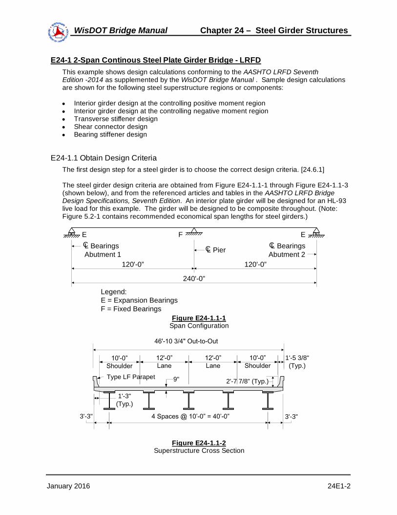
E24-1 2-Span Continous Steel Plate Girder Bridge - LRFDThis example shows design calculations conforming to the AASHTO LRFD SeventhEdition -2014 as supplemented by the WisDOT Bridge Manual . Sample design calculationsare shown for the following steel superstructure regions or components:
Interior girder design at the controlling positive moment regionInterior girder design at the controlling negative moment regionTransverse stiffener designShear connector designBearing stiffener design
E24-1.1 Obtain Design CriteriaThe first design step for a steel girder is to choose the correct design criteria. [24.6.1]
The steel girder design criteria are obtained from Figure E24-1.1-1 through Figure E24-1.1-3(shown below), and from the referenced articles and tables in the AASHTO LRFD BridgeDesign Specifications, Seventh Edition. An interior plate girder will be designed for an HL-93live load for this example. The girder will be designed to be composite throughout. (Note:Figure 5.2-1 contains recommended economical span lengths for steel girders.)
120'-0” 120'-0”
240'-0”
L Bearings Abutment 1
L Bearings Abutment 2L Pier
EFE
Legend:E = Expansion BearingsF = Fixed Bearings
CCC
Figure E24-1.1-1Span Configuration
2'-7 7/8” (Typ.)
3'-3" 3'-3"
1'-5 3/8" (Typ.)
9"Type LF Parapet
1'-3"(Typ.)
Figure E24-1.1-2Superstructure Cross Section
January 2016 24E1-2
WisDOT Bridge Manual Chapter 24 – Steel Girder Structures

L Bearing Abutment L PierC C
6 Spaces at 20'-0" = 120'-0”
Cross Frame (Typ.)
L Girder (Typ.)C
Symmetrical about L PierC
4 Sp
aces
at
10'-0
" = 4
0'-0
"
Figure E24-1.1-3Framing Plan
Design criteria:
Nspans 2 Number of spans
L 120 ft span length
Skew 0 deg skew angle
Nb 5 number of girders
S 10.0 ft girder spacing
Soverhang 3.25 ft deck overhang (Per Chapter 17.6.2, WisDOT practice isto limit the overhang to 3'-7", however, economical overhang range is 0.28S - 0.35S based on parapet weight.)
Lb 240 in cross-frame spacing LRFD [6.7.4]
Fyw 50 ksi web yield strength LRFD [Table 6.4.1-1]
Fyf 50 ksi flange yield strength LRFD [Table 6.4.1-1]
f'c 4.0 ksi concrete 28-day compressive strength LRFD [5.4.2.1 & Table C5.4.2.1-1]
fy 60 ksi reinforcement strength LRFD [5.4.3 & 6.10.1.7]
January 2016 24E1-3
WisDOT Bridge Manual Chapter 24 – Steel Girder Structures

Es 29000 ksi modulus of elasticity LRFD [6.4.1]
tdeck 9.0 in total deck thickness
ts 8.5 in effective deck thickness
toverhang 9.5 in total overhang thickness
teffoverhang 9.0 in effective overhang thickness
Ws 0.490 kcf steel density LRFD [Table 3.5.1-1]
wc 0.150 kcf concrete density LRFD [Table 3.5.1-1 & C3.5.1]
DLmisc 0.030 kip/ft additional miscellaneous dead load (per girder)(Chapter 17.2.4.1)
Wpar 0.464 kip/ft parapet weight (each) (Type 32SS)
Wfws 0.020 ksf future wearing surface (Chapter 17.2.4.1)
wdeck 46.50 ft deck width
wroadway 44.0 ft roadway width
dhaunch 3.75 in haunch depth (from top of web for design)(for construction, the haunch is measured from the top ofthe top flange)
ADTTSL 3000 Average Daily Truck Traffic (Single-Lane)
Design factors from AASHTO LRFD Bridge Design Specifications:
Load factors,, LRFD [Table 3.4.1-1 & Table 3.4.1-2]:
DC DW LL IM WS WL EQStrength I 1.25 1.50 1.75 1.75 - - -Service II 1.00 1.00 1.30 1.30 - - -Fatigue I - - 1.50 1.50 - - -
Load Combinations and Load FactorsLoad FactorsLimit
State
Table E24-1.1-1Load Combinations and Load Factors
The abbreviations used in Table E24-1.1-1 are as defined in LRFD [3.3.2].
The extreme event limit state (including earthquake load) is generally not considered for a
January 2016 24E1-4
WisDOT Bridge Manual Chapter 24 – Steel Girder Structures
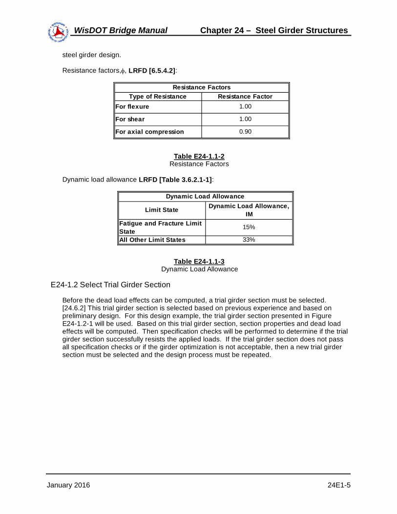
steel girder design.
Resistance factors,, LRFD [6.5.4.2]:
Type of Resistance Resistance FactorFor flexure 1.00
For shear 1.00
For axial compression 0.90
Resistance Factors
Table E24-1.1-2Resistance Factors
Dynamic load allowance LRFD [Table 3.6.2.1-1]:
Fatigue and Fracture Limit State
15%
All Other Limit States 33%
Dynamic Load AllowanceDynamic Load Allowance,
IMLimit State
Table E24-1.1-3Dynamic Load Allowance
E24-1.2 Select Trial Girder Section
Before the dead load effects can be computed, a trial girder section must be selected.[24.6.2] This trial girder section is selected based on previous experience and based onpreliminary design. For this design example, the trial girder section presented in FigureE24-1.2-1 will be used. Based on this trial girder section, section properties and dead loadeffects will be computed. Then specification checks will be performed to determine if the trialgirder section successfully resists the applied loads. If the trial girder section does not passall specification checks or if the girder optimization is not acceptable, then a new trial girdersection must be selected and the design process must be repeated.
January 2016 24E1-5
WisDOT Bridge Manual Chapter 24 – Steel Girder Structures

84'-0” (A)
16'-0”(C)
120'-0”
14” x 7/8” Bottom Flange
14” x 1 1/4” Top Flange
14” x 2 3/4” Bottom Flange
14” x 2 1/2” Top Flange
L Bearing Abutment L Pier
Symmetrical about L Pier
L Bolted Field Splice
54” x 1/2” Web
C
C
C C
8”
20'-0”(B)
14” x 1 3/8” Bottom Flange
14” x 3/4” Top Flange
Length(Region)
Figure E24-1.2-1Plate Girder Elevation
The AASHTO/NSBA Steel Bridge Collaboration Document "Guidelines for Design forConstructibility" recommends a 3/4" minimum flange thickness. Wisconsin requires a 3/4"minimum flange thickness.
E24-1.3 Compute Section Properties
Since the superstructure is composite, several sets of section properties must be computedLRFD [6.10.1.1]. The initial dead loads (or the noncomposite dead loads) are applied to thegirder-only section. For permanent loads assumed to be applied to the long-term compositesection, the long-term modular ratio of 3n is used to transform the concrete deck area LRFD[6.10.1.1.1b]. For transient loads assumed applied to the short-term composite section, theshort-term modular ratio of n is used to transform the concrete deck area.
For girders with shear connectors provided throughout their entire length and with slabreinforcement satisfying the provisions of LRFD [6.10.1.7], stresses due to loads applied tothe composite section for the fatigue limit state may be computed using the short-termcomposite section assuming the concrete slab to be fully effective for both positive andnegative flexure LRFD [6.6.1.2.1 & 6.10.5.1].
For girders with shear connectors provided throughout their entire length that also satisfy theprovisions of LRFD [6.10.1.7], flexural stresses caused by Service II loads applied to thecomposite section may be computed using the short-term or long-term composite section, asappropriate, assuming the concrete deck is effective for both positive and negative flexureLRFD [6.10.4.2.1].
In general, both the exterior and interior girders must be considered, and the controllingdesign is used for all girders, both interior and exterior. However, design computations forthe interior girder only are presented in this example.
The modular ratio, n, is computed as follows:
January 2016 24E1-6
WisDOT Bridge Manual Chapter 24 – Steel Girder Structures

nEs
Ec
Ec
Where:
Es = Modulus of elasticity of steel (ksi)
Ec = Modulus of elasticity of concrete (ksi)
Es 29000 ksi LRFD [6.4.1]
Ec 33000 K1 wc1.5 f'c K1 LRFD [5.4.2.4]
Where:
K1 = Correction factor for source of aggregate to be taken as1.0 unless determined by physical test, and as approvedby the authority of jurisdiction. For WisDOT, K1 = 1.0.
wc = Unit weight of concrete (kcf)
f'c = Specified compressive strength of concrete (ksi)
wc 0.150 kcf LRFD [Table 3.5.1-1 & C3.5.1]
f'c 4.0 ksi LRFD [Table 5.4.2.1-1 & 5.4.2.1]
K1 1 LRFD [5.4.2.4]
Ec 33000 K1 wc1.5 f'c Ec 3834 ksi
nEs
Ec n 7.6 LRFD [6.10.1.1.1b]
Therefore, use: n 8
The effective flange width is computed as follows (Chapter 17.2.11):
For interior beams, the effective flange width is taken as the average spacing of adjacentbeams:
Weffflange S Weffflange 10.00 ft
or
Weffflange 12 120.00 in
Based on Table 17.5-3 of Chapter 17 for a 9" deck and 10'-0" girder spacing, the top mat
January 2016 24E1-7
WisDOT Bridge Manual Chapter 24 – Steel Girder Structures

longitudinal continuity reinforcement bar size and spacing is #6 bars at 7.5" spacing. Thearea of the top mat longitudinal continuity deck reinforcing steel in the negative momentregion is computed below for the effective flange width. For the section properties in TableE24-1.3-3, the location of the centroid of the top mat longitudinal reinforcement isconservatively taken as one-half the structural slab thickness or 8.5" / 2 = 4.25".
Adeckreinf 1 0.44Weffflange 12
7.5 Adeckreinf 7.04 in2
For this design example, the slab haunch is 3.75 inches throughout the length of the bridge.That is, the bottom of the slab is located 3.75 inches above the top of the web (forconstruction, it is measured from the top of the top flange). For this design example, thisdistance is used in computing the location of the centroid of the slab. However, the area ofthe haunch is conservatively not considered in the section properties for this example.
Based on the trial plate sizes shown in Figure E24-1.2-1, the noncomposite and compositesection properties for Region A, B, and C are computed as shown in the following tablesLRFD [6.6.1.2.1, 6.10.5.1, 6.10.4.2.1]. The distance to the centroid is measured from thebottom of the girder.
Top flange 10.500 55.250 580.1 0.5 8441.1 8441.6 Web 27.000 27.875 752.6 6561.0 25.8 6586.8 Bottom flange 12.250 0.438 5.4 0.8 8576.1 8576.9 Total 49.750 26.897 1338.1 6562.3 17043.0 23605.3
Girder 49.750 26.897 1338.1 23605.3 13668.5 37273.7 Slab 42.500 62.875 2672.2 255.9 16000.2 16256.0 Total 92.250 43.472 4010.3 23861.1 29668.6 53529.8
Girder 49.750 26.897 1338.1 23605.3 33321.4 56926.6 Slab 127.500 62.875 8016.6 767.7 13001.9 13769.5 Total 177.250 52.777 9354.7 24372.9 46323.2 70696.2
Girder only 26.897 28.728 --- 877.6 821.7 ---Composite (3n) 43.472 12.153 23.653 1231.4 4404.7 2263.1Composite (n) 52.777 2.848 14.348 1339.5 24820.6 4927.1
Region A Section Properties ( 0 - 84 Feet )
SectionArea, A
(inches2)Centroid, d (inches)
A*d (inches3)
Io
(inches4)A*y2
(inches4)Itotal
(inches4)Girder only:
Composite (3n):
Composite (n):
Section ybotgdr (inches)
ytopgdr (inches)
ytopslab (inches)
Sbotgdr
(inches3)Stopgdr
(inches3)Stopslab
(inches3)
Table E24-1.3-1Region A Section Properties
January 2016 24E1-8
WisDOT Bridge Manual Chapter 24 – Steel Girder Structures
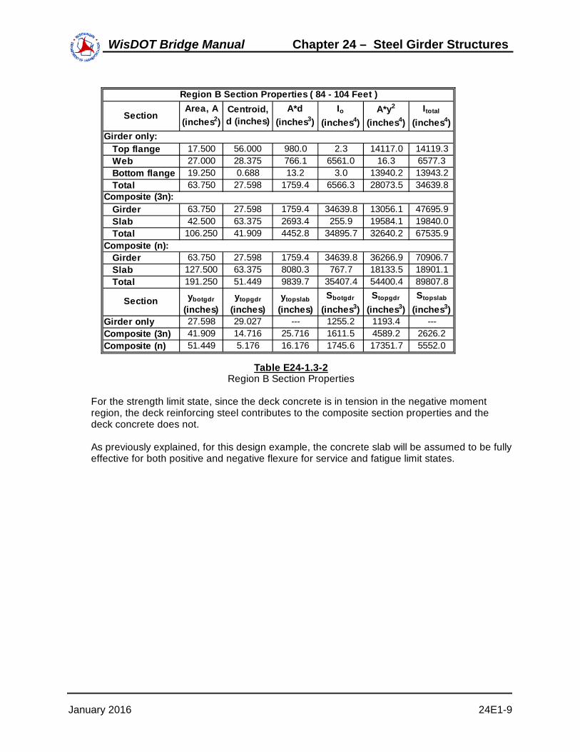
Top flange 17.500 56.000 980.0 2.3 14117.0 14119.3 Web 27.000 28.375 766.1 6561.0 16.3 6577.3 Bottom flange 19.250 0.688 13.2 3.0 13940.2 13943.2 Total 63.750 27.598 1759.4 6566.3 28073.5 34639.8
Girder 63.750 27.598 1759.4 34639.8 13056.1 47695.9 Slab 42.500 63.375 2693.4 255.9 19584.1 19840.0 Total 106.250 41.909 4452.8 34895.7 32640.2 67535.9Composite (n): Girder 63.750 27.598 1759.4 34639.8 36266.9 70906.7 Slab 127.500 63.375 8080.3 767.7 18133.5 18901.1 Total 191.250 51.449 9839.7 35407.4 54400.4 89807.8
Girder only 27.598 29.027 --- 1255.2 1193.4 ---Composite (3n) 41.909 14.716 25.716 1611.5 4589.2 2626.2Composite (n) 51.449 5.176 16.176 1745.6 17351.7 5552.0
Girder only:
Composite (3n):
Section ybotgdr (inches)
ytopgdr (inches)
ytopslab (inches)
Sbotgdr
(inches3)Stopgdr
(inches3)Stopslab
(inches3)
Region B Section Properties ( 84 - 104 Feet )
SectionArea, A
(inches2)Centroid, d (inches)
A*d (inches3)
Io
(inches4)A*y2
(inches4)Itotal
(inches4)
Table E24-1.3-2Region B Section Properties
For the strength limit state, since the deck concrete is in tension in the negative momentregion, the deck reinforcing steel contributes to the composite section properties and thedeck concrete does not.
As previously explained, for this design example, the concrete slab will be assumed to be fullyeffective for both positive and negative flexure for service and fatigue limit states.
January 2016 24E1-9
WisDOT Bridge Manual Chapter 24 – Steel Girder Structures

Top flange 35.000 58.000 2030.0 18.2 30009.7 30027.9 Web 27.000 29.750 803.3 6561.0 28.7 6589.7 Bottom flange 38.500 1.375 52.9 24.3 28784.7 28809.0 Total 100.500 28.718 2886.2 6603.5 58823.1 65426.6
Girder 100.500 28.718 2886.2 65426.6 11525.0 76951.6 Slab 42.500 64.750 2751.9 255.9 27253.3 27509.2 Total 143.000 39.427 5638.1 65682.5 38778.3 104460.8
Girder 100.500 28.718 2886.2 65426.6 40802.5 106229.1 Slab 127.500 64.750 8255.6 767.7 32162.0 32929.6 Total 228.000 48.868 11141.8 66194.3 72964.4 139158.7
Girder 100.500 28.718 2886.2 65426.6 559.2 65985.8 Deck reinf. 7.040 64.750 455.8 0.0 7982.4 7982.4 Total 107.540 31.077 3342.0 65426.6 8541.6 73968.2
Girder only 28.718 30.532 --- 2278.2 2142.9 ---Composite (3n) 39.427 19.823 29.573 2649.5 5269.7 3532.3Composite (n) 48.868 10.382 20.132 2847.7 13403.3 6912.2Composite (rebar 31.077 28.173 33.673 2380.2 2625.5 2196.7
Girder only:
Region C Section Properties ( 104 - 120 Feet )
SectionArea, A
(inches2)Centroid, d (inches)
A*d (inches3)
Io
(inches4)A*y2
(inches4)Itotal
(inches4)
Composite (deck concrete using 3n):
Composite (top longitudinal deck reinforcement only):
Section ybotgdr (inches)
ytopgdr (inches)
ydeck (inches)
Sbotgdr
(inches3)Stopgdr
(inches3)Sdeck
(inches3)
Composite (deck concrete using n):
Table E24-1.3-3Region C Section Properties
The section properties used to compute the unfactored dead and live load moments andshears for each girder region are given in the following table in accordance with therequirements of LRFD [6.10.1.5].
Beam Self Weight, Misc Dead Loads, Concrete Deck &
Haunch (Noncomposite)
Wisconsin Barrier, Future Wearing
Surface (Composite)
Hl-93 Live Load
(Composite)
Region A (0-84) 23605.3 53529.8 70696.2 Region B (84-104) 34639.8 67535.9 89807.8
Region C (104-120) 65426.6 104460.8 139158.7
Girder Region (ft)
Moment of Inertia Used (in4)
Table E24-1.3-4Section Properties Used to Generate Design Moments and Shears
January 2016 24E1-10
WisDOT Bridge Manual Chapter 24 – Steel Girder Structures

E24-1.4 Compute Dead Load EffectsThe girder must be designed to resist the dead load effects, as well as the other load effects.The dead load components consist of some dead loads that are resisted by thenoncomposite section, as well as other dead loads that are resisted by the compositesection. In addition, some dead loads are factored with the DC load factor and other deadloads are factored with the DW load factor. The following table summarizes the various deadload components that must be included in the design of a steel girder.
DC DW Steel girder Concrete deck Concrete haunch Stay-in-place deck forms Miscellaneous dead load (including cross- frames, stiffeners, etc.)
Composite section Concrete parapets Future wearing
''''''' surface & utilities
Dead Load ComponentsType of Load Factor
Noncomposite section
Resisted by
Table E24-1.4-1Dead Load Components
For the steel girder, the dead load per unit length varies due to the change in plate sizes.The moments and shears due to the weight of the steel girder can be computed using readilyavailable analysis software. Since the actual plate sizes are entered as input, the momentsand shears are computed based on the actual, varying plate sizes.
The dead load per unit length for Regions A, B, and C is calculated as follows:
AA 49.75 in2 Region A (0 - 84 feet)(Table E24-1.3-1)
AB 63.75 in2 Region B (84 - 104 feet)(Table E24-1.3-2)
AC 100.50 in2 Region C (104 - 120 feet)(Table E24-1.3-3)
Weight of Girder per region:
DLA WsAA
122 DLA 0.169 klf
DLB WsAB
122 DLB 0.217 klf
January 2016 24E1-11
WisDOT Bridge Manual Chapter 24 – Steel Girder Structures

DLC WsAC
122 DLC 0.342 klf
For the concrete deck, the dead load per unit length for an interior girder is computed asfollows:
wc 0.150 kcf
S 10.00 ft
tdeck 9.00 in
DLdeck wc Stdeck
12 DLdeck 1.125 kip/ft
For the concrete haunch, the dead load per unit length varies due to the change in topflange plate sizes. The moments and shears due to the concrete haunch are computedbased on the actual, varying haunch thickness.
The haunch dead load per unit length for Region A, B, and C is calculated as follows:
widthflange 14 in Top flange width is consistent in all three regions.
tflangeA 0.75 in Top flange thickness in Region A
tflangeB 1.25 in Top flange thickness in Region B
tflangeC 2.5 in Top flange thickness in Region C
dhaunch 3.75 in Distance from top of web to bottom of deck as detailed in E24-1.1
dhA dhaunch tflangeA dhA 3.00 in
dhB dhaunch tflangeB dhB 2.50 in
dhC dhaunch tflangeC dhC 1.25 in
wc 0.150 kcf
DLhAwidthflange dhA
122wc DLhA 0.044 klf
DLhBwidthflange dhB
122wc DLhB 0.036 klf
January 2016 24E1-12
WisDOT Bridge Manual Chapter 24 – Steel Girder Structures

DLhCwidthflange dhC
122wc DLhC 0.018 klf
Total weight of deck and haunch per region:
DLdhA DLdeck DLhA DLdhA 1.169 klf
DLdhB DLdeck DLhB DLdhB 1.161 klf
DLdhC DLdeck DLhC DLdhC 1.143 klf
For the miscellaneous dead load (including cross-frames, stiffeners, and other miscellaneousstructural steel), the dead load per unit length is assumed to be as follows:
DLmisc 0.030 kip/ft See E24-1.1
For the concrete parapets, the dead load per unit length is computed as follows, assumingthat the superimposed dead load of the two parapets is distributed uniformly among all of thegirders LRFD [4.6.2.2.1]:
Wpar 0.464 kip/ft (Type LF)
Nb 5
DLparWpar 2
Nb DLpar 0.186 kip/ft
For the future wearing surface, the dead load per unit length is computed as follows,assuming that the superimposed dead load of the future wearing surface is distributeduniformly among all of the girders LRFD [4.6.2.2.1]:
Wfws 0.020 ksf
wroadway 44.0 ft
Nb 5
DLfwsWfws wroadway
Nb DLfws 0.176 kip/ft
Since the plate girder and its section properties are not uniform over the entire length of thebridge, an analysis software was used to compute the dead load moments and shears.
The following two tables present the unfactored dead load moments and shears, ascomputed by an analysis computer program. Since the bridge is symmetrical, the momentsand shears in Span 2 are symmetrical to those in Span 1.
January 2016 24E1-13
WisDOT Bridge Manual Chapter 24 – Steel Girder Structures

1.0L
-430
.4
-264
7.3
-65.
4
-405
.7
-383
.9
0.9L
-246
.9
-163
0.2
-39.
5
-244
.6
-231
.5
0.8L
-112
.1
-780
.3
-17.
8
-110
.3
-104
.4
0.7L
-9.8
-97.
6
-0.4
-2.8
-2.6
0.6L
64.8
417.
9
12.6
78.0
73.8
0.5L
114.
9
766.
2
21.3
131.
9
124.
8
0.4L
140.
7
947.
3
25.7
159.
1
150.
6
0.3L
142.
1
961.
3
25.7
159.
5
150.
9
0.2L
119.
1
808.
0
21.5
133.
1
126.
0
0.1L
71.7
487.
6
12.9
80.0
75.7
0.0L 0.0
0.0
0.0
0.0
0.0
Dead
Loa
d M
omen
ts (K
ip-fe
et)
Loca
tion
in S
pan
1De
ad L
oad
Com
pone
nt
Stee
l gird
er
Tabl
e 24
E1.4
-2D
ead
Load
Mom
ents
Conc
rete
dec
k &
haun
ches
Oth
er d
ead
load
s ac
ting
on g
irder
alo
ne
Conc
rete
par
apet
s
Futu
re w
earin
g su
rface
January 2016 24E1-14
WisDOT Bridge Manual Chapter 24 – Steel Girder Structures

1.0L
-17.
5
-91.
7
-2.3
-14.
5
-13.
8
0.9L
-13.
1
-77.
8
-2.0
-12.
3
-11.
6
0.8L
-9.8
-63.
9
-1.6
-10.
1
-9.5
0.7L
-7.2
-49.
9
-1.3
-7.8
-7.4
0.6L
-5.2
-36.
0
-0.9
-5.6
-5.3
0.5L
-3.2
-22.
1
-0.5
-3.4
-3.2
0.4L
-1.1
-8.1
-0.2
-1.1
-1.1
0.3L 0.9
5.8
0.2
1.1
1.0
0.2L 2.9
19.7
0.5
3.3
3.1
0.1L 5.0
33.7
0.9
5.5
5.2
0.0L 7.0
47.6
1.3
7.8
7.4
Tabl
e 24
E1.4
-3D
ead
Load
She
ars
Conc
rete
dec
k &
haun
ches
Oth
er d
ead
load
s ac
ting
on g
irder
alo
ne
Conc
rete
par
apet
s
Futu
re w
earin
g su
rface
Dead
Loa
d Sh
ears
(Kip
s)
Loca
tion
in S
pan
1De
ad L
oad
Com
pone
nt
Stee
l gird
er
January 2016 24E1-15
WisDOT Bridge Manual Chapter 24 – Steel Girder Structures

E24-1.5 Compute Live Load Effects
The girder must also be designed to resist the live load effects LRFD [3.6.1.2]. The live loadconsists of an HL-93 loading. Similar to the dead load, the live load moments and shears foran HL-93 loading were obtained from an analysis computer program.
Based on Table E24-1.1-3, for all limit states other than fatigue and fracture, the dynamicload allowance, IM, is as follows LRFD [3.6.2.1]:
IM 0.33
The live load distribution factors for moment for an interior girder are computed as followsLRFD [4.6.2.2.2]:
First, the longitudinal stiffness parameter, Kg, must be computed LRFD [4.6.2.2.1]:
Kg n I A eg2 I
Where:
I = Moment of inertia of beam (in4)
A = Area of stringer, beam, or girder (in2)
eg = Distance between the centers of gravity of the basic beamand deck (in)
Region A Region B Region C Weighted(Pos. Mom.) (Intermediate) (At Pier) Average *
Length (Feet) 84 20 16n 8 8 8I (Inches4) 23,605.3 34,639.8 65,426.6A (Inches2) 49.750 63.750 100.500eg (Inches) 35.978 35.777 36.032Kg (Inches4) 704,020 929,915 1,567,250 856,767
Longitudinal Stiffness Parameter, Kg
Table E24-1.5-1Longitudinal Stiffness Parameter
After the longitudinal stiffness parameter is computed, LRFD [Table 4.6.2.2.1-1] is used tofind the letter corresponding with the superstructure cross section. The letter correspondingwith the superstructure cross section in this design example is "a."
If the superstructure cross section does not correspond with any of the cross sectionsillustrated in LRFD [Table 4.6.2.2.1-1], then the bridge should be analyzed as presented inLRFD [4.6.3].
Based on cross section "a", LRFD [Table 4.6.2.2.2b-1 & Table 4.6.2.2.2.3a-1] are used tocompute the distribution factors for moment and shear, respectively.
January 2016 24E1-16
WisDOT Bridge Manual Chapter 24 – Steel Girder Structures

Check the range of applicability as follows LRFD [Table 4.6.2.2.2b-1]:
3.5 S 16.0
Where:
S = Spacing of beams or webs (ft)
S 10.00 ft OK
4.5 ts 12.0
Where:
ts = Depth of concrete slab (in)
ts 8.5 in OK
20 L 240
Where:
L = Span of beam (ft)
L 120 ft OK
Nb 4
Where:
Nb = Number of beams, stringers, or girders
Nb 5.00 OK
10000 Kg 7000000
Kg 856767 in4 OK
For one design lane loaded, the distribution of live load per lane for moment in interiorbeams is as follows LRFD [4.6.2.2.2b-1]:
gint_moment_1 0.06S14
0.4 SL
0.3 Kg
12.0L ts3
0.1
gint_moment_1 0.473 lanes
For two or more design lanes loaded, the distribution of live load per lane for moment ininterior beams is as follows LRFD [Table 4.6.2.2.2b-1]:
January 2016 24E1-17
WisDOT Bridge Manual Chapter 24 – Steel Girder Structures

gint_moment_2 0.075S
9.5
0.6 SL
0.2 Kg
12.0 L ts3
0.1
gint_moment_2 0.700 lanes
The live load distribution factors for shear for an interior girder are computed in a similarmanner. The range of applicability is similar to that for moment LRFD [Table 4.6.2.2.3a-1].
For one design lane loaded, the distribution of live load per lane for shear in interior beams isas follows:
gint_shear_1 0.36S
25.0 gint_shear_1 0.760 lanes
For two or more design lanes loaded, the distribution of live load per lane for shear in interiorbeams is as follows:
gint_shear_2 0.2S12
S35
2.0 gint_shear_2 0.952 lanes
Since this bridge has no skew, the skew correction factor does not need to be considered forthis design example LRFD [4.6.2.2.2e & 4.6.2.2.3c].
This design example is based on an interior girder. However, for illustrative purposes, the liveload distribution factors for an exterior girder are computed below, as follows LRFD[4.6.2.2.2]:
The distance, de, is defined as the distance between the web centerline of the exterior girderand the interior edge of the curb. For this design example, based on Figure E24-1.1-2:
de Soverhang 1.25 ft
Check the range of applicability as follows LRFD [Table 4.6.2.2.2d-1]:
1.0 de 5.5 de 2.00 ft OK
For one design lane loaded, the distribution of live load per lane for moment in exteriorbeams is computed using the lever rule, as follows:
January 2016 24E1-18
WisDOT Bridge Manual Chapter 24 – Steel Girder Structures

Assumed Hinge
0.5P 0.5P
6'-0"2'-0"
4'-3"
3'-3"
1'-3"
Figure E24-1.5-1Lever Rule
x1 S 6 de 2 x2 S de 2
gext_moment_10.5( ) x1 0.5( ) x2
S gext_moment_1 0.700 lanes
mpf 1.20
gext_moment_1 gext_moment_1 mpf gext_moment_1 0.840
lanes (for strength limit state)
For two or more design lanes loaded, the distribution of live load per lane for moment inexterior beams is as follows LRFD [Table 4.6.2.2.2d-1]:
The correction factor for distribution, e, is computed as follows:
e 0.77de
9.1 e 0.990
gext_moment_2 e gint_moment_2 gext_moment_2 0.693 lanes
The live load distribution factors for shear for an exterior girder are computed in a similarmanner. The range of applicability is similar to that for moment LRFD [Table 4.6.2.2.3.b-1].
For one design lane loaded, the distribution of live load per lane for shear in exterior beamsis computed using the lever rule, as illustrated in Figure E24-1.5-1 and as follows:
gext_shear_10.5( ) x1 0.5( ) x2
S gext_shear_1 0.700 lanes
gext_shear_1 gext_shear_1 mpf gext_shear_1 0.840
lanes (for strength limit state)
January 2016 24E1-19
WisDOT Bridge Manual Chapter 24 – Steel Girder Structures

For two or more design lanes loaded, the distribution of live load per lane for shear in exteriorbeams is as follows LRFD [Table 4.6.2.2.3b-1]:
e 0.6de
10 e 0.800
gext_shear_2 e gint_shear_2 gext_shear_2 0.761 lanes
In beam-slab bridge cross-sections with diaphragms or cross-frames, the distribution factorfor the exterior beam can not be taken to be less than that which would be obtained byassuming that the cross-section deflects and rotates as a rigid cross-section. LRFD[C4.6.2.2.2d] provides one approximate approach to satisfy this requirement. The multiplepresence factor provisions of LRFD [3.6.1.1.2] must be applied when this equation is used.This is not shown here since an interior girder is being designed.
Since this bridge has no skew, the skew correction factor does not need to be considered forthis design example LRFD [4.6.2.2.2e & 4.6.2.2.3c].
The controlling distribution factors for moment and shear for the interior girder are givenbelow.
Moment DF Shear DFOne Lane 0.473 0.760
Two or More Lanes 0.700 0.952
Interior Girder Distribution Factors
Table E24-1.5-2Summary of Interior Girder Distribution Factors
The following table presents the unfactored maximum positive and negative live loadmoments and shears for HL-93 live loading for interior beams, as computed using ananalysis computer program. These values include the controlling live load distribution factorgiven above for two or more lanes, and they also include dynamic load allowance. Since thebridge is symmetrical, the moments and shears in Span 2 are symmetrical to those in Span1.
January 2016 24E1-20
WisDOT Bridge Manual Chapter 24 – Steel Girder Structures
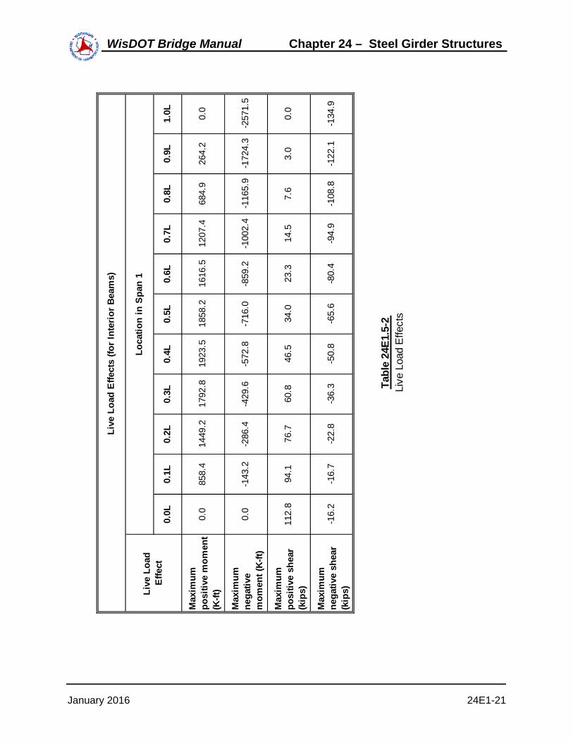
1.0L 0.0
-257
1.5
0.0
-134
.9
0.9L
264.
2
-172
4.3
3.0
-122
.1
0.8L
684.
9
-116
5.9
7.6
-108
.8
0.7L
1207
.4
-100
2.4
14.5
-94.
9
0.6L
1616
.5
-859
.2
23.3
-80.
4
0.5L
1858
.2
-716
.0
34.0
-65.
6
0.4L
1923
.5
-572
.8
46.5
-50.
8
0.3L
1792
.8
-429
.6
60.8
-36.
3
0.2L
1449
.2
-286
.4
76.7
-22.
8
0.1L
858.
4
-143
.2
94.1
-16.
7
0.0L 0.0
0.0
112.
8
-16.
2
Tabl
e 24
E1.5
-2Li
ve L
oad
Effe
cts
Live
Loa
d Ef
fect
s (fo
r Int
erio
r Bea
ms)
Loca
tion
in S
pan
1
Max
imum
ne
gativ
e sh
ear
(kip
s)Live
Loa
d
Effe
ct
Max
imum
po
sitiv
e m
omen
t (K
-ft)
Max
imum
ne
gativ
e m
omen
t (K-
ft)
Max
imum
po
sitiv
e sh
ear
(kip
s)
January 2016 24E1-21
WisDOT Bridge Manual Chapter 24 – Steel Girder Structures

The design live load values for HL-93 loading, as presented in the previous table, arecomputed based on the product of the live load effect per lane and live load distributionfactor. These values also include the effects of dynamic load allowance. However, it isimportant to note that the dynamic load allowance is applied only to the design truck ortandem. The dynamic load allowance is not applied to pedestrian loads or to the design laneload LRFD [3.6.1, 3.6.2, 4.6.2.2].
E24-1.6 Combine Load Effects
After the load factors and load combinations have been established (see E24-1.1), thesection properties have been computed (see E24-1.3), and all of the load effects have beencomputed (see E24-1.4 and E24-1.5), the force effects must be combined for each of theapplicable limit states.
For this design example, equals 1.00 LFRD[1.3]. (For more detailed information about ,refer to E24-1.1.)
The maximum positive moment (located at 0.4L) for the Strength I Limit State is computed asfollows LRFD [3.4.1]:
LFDC 1.25
MDC 140.7 947.3 25.7 159.1 MDC 1272.8 kip-ft
LFDW 1.50
MDW 150.6 kip-ft
LFLL 1.75
MLL 1923.5
Mtotal LFDC MDC LFDW MDW LFLL MLL Mtotal 5183.0 kip-ft
Similarly, the maximum stress in the top of the girder due to positive moment (located at 0.4L)for the Strength I Limit State is computed as follows:
Noncomposite dead load:
MnoncompDL 140.7 947.3 25.7 MnoncompDL 1113.70 kip-ft
Stopgdr 821.7 in3
fnoncompDLMnoncompDL 12( )
Stopgdr fnoncompDL 16.26 ksi
Parapet dead load (composite):
January 2016 24E1-22
WisDOT Bridge Manual Chapter 24 – Steel Girder Structures

Mparapet 159.1 kip-ft
Stopgdr 4404.7 in3
fparapetMparapet 12( )
Stopgdr fparapet 0.43 ksi
Future wearing surface dead load (composite):
Mfws 150.6 kip-ft
Stopgdr 4404.7 in3
ffwsMfws 12( )
Stopgdr ffws 0.41 ksi
Live load (HL-93) and dynamic load allowance:
MLL 1923.50 kip-ft
Stopgdr 24820.6 in3
fLLMLL 12( )
Stopgdr fLL 0.93 ksi
Multiplying the above stresses by their respective load factors and adding the productsresults in the following combined stress for the Strength I Limit State LRFD [3.4.1]:
fStr LFDC fnoncompDL LFDC fparapet LFDW ffws LFLL fLL
fStr 23.12 ksi
Similarly, all of the combined moments, shears, and flexural stresses can be computed at thecontrolling locations. A summary of those combined load effects for an interior beam ispresented in the following three tables, summarizing the results obtained using theprocedures demonstrated in the above computations.
January 2016 24E1-23
WisDOT Bridge Manual Chapter 24 – Steel Girder Structures

Summary of Unfactored Values:
Noncomposite DL 1102.0 15.07 -16.09 0.00Parapet DL 136.9 1.35 -0.41 -0.04FWS DL 155.4 1.53 -0.47 -0.05LL - HL-93 1916.6 17.27 -1.18 -0.62LL - Fatigue Range 871.4 7.85 -0.54 -0.28Summary of Factored Values:
Strength I 5135.8 53.03 -23.40 -1.22Service II 3885.9 40.39 -18.51 -0.91Fatigue I 653.5 5.89 -0.40 -0.21
fbotgdr (ksi)
ftopgdr (ksi)
Combined Effects at Location of Maximum Positive Moment
Loading Moment (K-ft)
fbotgdr (ksi)
ftopgdr (ksi)
ftopslab (ksi)
ftopslab (ksi)
Limit State Moment (K-ft)
Table E24-1.6-1Combined Effects at Location of Maximum Positive Moment
As shown in the above table, the Strength I Limit State elastic stress in the bottom of thegirder exceeds the girder yield stress. However, for this design example, this value is notused because of the local yielding that is permitted to occur at this section at the strengthlimit state.
January 2016 24E1-24
WisDOT Bridge Manual Chapter 24 – Steel Girder Structures

Noncomposite DL -3073.2 -16.19 17.21 0.00Parapet DL -327.5 -1.66 1.52 1.82FWS DL -371.9 -1.88 1.73 2.06LL - HL-93 -2414.2 -12.21 11.23 13.40
Noncomposite DL -3073.2 -16.19 17.21 0.00Parapet DL -327.5 -1.49 0.79 0.08FWS DL -371.9 -1.70 0.90 0.09LL - HL-93 -2414.2 -10.23 2.39 0.56LL - Fatigue Range -481.4 -2.04 0.48 0.11
Strength I * -9033.6 -46.50 45.66 28.82Service II ** -6911.1 -32.67 22.01 0.89Fatigue I ** -361.0 -1.53 0.36 0.08
Legend: * Strength I Limit State stresses are based on section properties assuming the deck concrete is not effective, and fdeck is the stress in the deck reinforcing steel. ** Service II and Fatigue I Limit State stresses are based on section properties assuming the deck concrete is effective, and fdeck is the stress in the deck concrete.
Summary of Unfactored Values (Assuming Concrete Effective):
Loading Moment (K-ft)
fbotgdr (ksi)
ftopgdr (ksi)
fdeck (ksi)
Summary of Factored Values:Moment
(K-ft)fbotgdr (ksi)
ftopgdr (ksi)
fdeck (ksi)
Limit State
Combined Effects at Location of Maximum Negative Moment
Loading Moment (K-ft)
fbotgdr (ksi)
ftopgdr (ksi)
fdeck (ksi)
Summary of Unfactored Values (Assuming Concrete Not Effective):
Table E24-1.6-2Combined Effects at Location of Maximum Negative Moment
January 2016 24E1-25
WisDOT Bridge Manual Chapter 24 – Steel Girder Structures

Summary of Unfactored Values:
Noncomposite DL 108.9Parapet DL 12.0FWS DL 13.7LL - HL-93 132.0LL - Fatigue Range 56.5Summary of Factored Values:
Strength I 402.7Service II 306.2Fatigue I 42.4
Combined Effects at Location of Maximum Shear
Loading
Limit State
Shear (kips)
Shear (kips)
Table E24-1.6-3Combined Effects at Location of Maximum Shear
Envelopes of the factored Strength I moments and shears are presented in the following twofigures. Maximum and minimum values are presented. As mentioned previously, allremaining design computations in this example are based on the interior girder. The basicapproach illustrated in the subsequent design calculations applies equally to the exterior andinterior girders (with some exceptions noted) once the load effects in each girder have beendetermined.
January 2016 24E1-26
WisDOT Bridge Manual Chapter 24 – Steel Girder Structures

January 2016 24E1-27
WisDOT Bridge Manual Chapter 24 – Steel Girder Structures

January 2016 24E1-28
WisDOT Bridge Manual Chapter 24 – Steel Girder Structures

Two design sections will be checked for illustrative purposes. First, all specification checkswill be performed for the location of maximum positive moment, which is at 0.4L in Span 1.Second, all specification checks for these same design steps will be performed for thelocation of maximum negative moment and maximum shear, which is at the pier.
The following specification checks are for the location of maximum positive moment, which isat 0.4L in Span 1, as shown in Figure E24-1.6-3.
0.4L = 48'-0”
L = 120'-0”
L Bearing Abutment L Pier
Location of Maximum Positive Moment
CC
Symmetrical about L PierC
Figure E24-1.6-3Location of Maximum Positive Moment
E24-1.7 Check Section Proportion Limits - Positive Moment RegionSeveral checks are required to ensure that the proportions of the trial girder section arewithin specified limits LRFD [6.10.2].
The first section proportion check relates to the web slenderness LRFD [6.10.2.1]. For asection without longitudinal stiffeners, the web must be proportioned such that:
Dtw
150
Where:
D = Clear distance between flanges (in)
tw = Web thickness (in)
D 54 in
tw 0.50 in
Dtw
108.00 OK
January 2016 24E1-29
WisDOT Bridge Manual Chapter 24 – Steel Girder Structures

The second set of section proportion checks relate to the general proportions of the sectionLRFD [6.10.2.2]. The compression and tension flanges must be proportioned such that:
bf
2 tf12.0
Where:
bf = Full width of the flange (in)
tf = Flange thickness (in)
bf 14 tf 0.75bf
2 tf9.33 OK
bfD6
D6
9.00 in OK
tf 1.1 tw 1.1tw 0.55 in OK
0.1Iyc
Iyt 10
Where:
Iyc = moment of inertia of the compression flange of a steel
section about the vertical axis in the plane of the web (in4)
Iyt = moment of inertia of the tension flange of a steel section
about the vertical axis in the plane of the web (in4)
Iyc0.75 143
12 Iyc 171.50 in4
Iyt0.875 143
12 Iyt 200.08 in4
Iyc
Iyt0.857 OK
January 2016 24E1-30
WisDOT Bridge Manual Chapter 24 – Steel Girder Structures

E24-1.8 Compute Plastic Moment Capacity - Positive Moment Region
For composite sections, the plastic moment, Mp, is calculated as the first moment of plasticforces about the plastic neutral axis LRFD [Appendix D6.1].
bs
ts
tcbc
tw
bt
Dw
tt
Y
Plastic Neutral
Axis
Ps
Pc
Pw
Pt
Figure E24-1.8-1Computation of Plastic Moment Capacity for Positive Bending Sections
For the tension flange:
Pt Fyt bt tt Fyt
Where:
Fyt = Specified minimum yield strength of a tension flange (ksi)
bt = Full width of the tension flange (in)
tt = Thickness of tension flange (in)
Fyt 50 ksi
bt 14 in
tt 0.875 in
Pt Fyt bt tt Pt 613 kips
For the web:
January 2016 24E1-31
WisDOT Bridge Manual Chapter 24 – Steel Girder Structures

Pw Fyw D tw
Where:
Fyw = Specified minimum yield strength of a web (ksi)
Fyw 50 ksi
D 54 in
tw 0.50 in
Pw Fyw D tw Pw 1350 kips
For the compression flange:
Pc Fyc bc tc Fyc
Where:
Fyc = Specified minimum yield strength of a compression flange(ksi)
bc = Full width of the compression flange (in)
tc = Thickness of compression flange (in)
Fyc 50 ksi
bc 14 in
tc 0.75 in
Pc Fyc bc tc Pc 525 kips
For the slab:
Ps 0.85 f'c bs ts bs
Where:
bs = Effective width of concrete deck (in)
ts = Thickness of concrete deck (in)
f'c 4.00 ksi
bs 120 in
ts 8.5 in
Ps 0.85 f'c bs ts Ps 3468 kips
January 2016 24E1-32
WisDOT Bridge Manual Chapter 24 – Steel Girder Structures

The forces in the longitudinal reinforcement may be conservatively neglected in regions ofpositive flexure.
Check the location of the plastic neutral axis, as follows:
Pt Pw 1963 kips Pc Ps 3993 kips
Pt Pw Pc 2488 kips Ps 3468 kips
Since Pt + Pw + Pc < Ps, the plastic neutral axis is located within the slab LRFD [Table D6.1-1].Since the slab reinforcement is being neglected in regions of positive flexure, Case III, V, orVII can be used. All three cases yield the same results with the reinforcement terms Prt andPrb set equal to zero.
Y ts Pc Pw Pt
Ps
Y 6.10 in
Check that the position of the plastic neutral axis, as computed above, results in anequilibrium condition in which there is no net axial force.
Compression 0.85 f'c bs Y Compression 2488 kips
Tension Pt Pw Pc Tension 2488 kips OK
The plastic moment, Mp, is computed as follows, where d is the distance from an elementforce (or element neutral axis) to the plastic neutral axis LRFD [Table D6.1-1]:
dctc
23.75 ts Y dc 5.78 in
dwD2
3.75 ts Y dw 33.15 in
dttt2
D 3.75 ts Y dt 60.59 in
Mp
Y2 Ps
2 tsPc dc Pw dw Pt dt
12 Mp 7707 kip-ft
E24-1.9 Determine if Section is Compact or Noncompact - Positive Moment RegionSince the section is in a straight bridge, the next step in the design process is to determine ifthe section is compact or noncompact. This, in turn, will determine which formulae should beused to compute the flexural capacity of the girder.
If the specified minimum yield strengths of the flanges do not exceed 70.0 ksi and the girderdoes not have longitudinal stiffeners, then the first step is to check the compact-section webslenderness provisions, as follows LRFD [6.10.6.2.2]:
January 2016 24E1-33
WisDOT Bridge Manual Chapter 24 – Steel Girder Structures

2 Dcp
tw3.76
EFyc
Where:
Dcp = Depth of web in compression at the plastic moment (in)
Since the plastic neutral axis is located within the slab,
Dcp 0 in
Therefore the web is deemed compact. Since this is a composite section in positive flexureand there are no holes in the tension flange at this section, the flexural resistance iscomputed as defined by the composite compact-section positive flexural resistanceprovisions of LRFD [6.10.7.1.2].
E24-1.10 Design for Flexure - Strength Limit State - Positive Moment RegionSince the section was determined to be compact, and since it is a composite section in thepositive moment region with no holes in the tension flange, the flexural resistance iscomputed in accordance with LRFD [6.10.7.1.2].
Mn 1.3 Rh My Rh
Where:
Rh = Hybrid factor
My = Yield Moment (kip-in)
All design sections of this girder are homogenous. That is, the same structural steel is usedfor the top flange, the web, and the bottom flange. Therefore, the hybrid factor, Rh, is asfollows LRFD [6.10.1.10.1]:
Rh 1.0
The yield moment, My, is computed as follows LRFD [Appendix D6.2.2]:
FyMD1
SNC
MD2
SLT
MAD
SST
MD1
Where:
MD1 = Bending moment caused by the factored permanent loadapplied before the concrete deck has hardened or ismade composite (kip-in)
SNC = Noncomposite elastic section modulus (in3)
MD2 = Bending moment caused by the factored permanent loadapplied to the long-term composite section (kip-in)
SLT = Long-term composite elastic section modulus (in3)
January 2016 24E1-34
WisDOT Bridge Manual Chapter 24 – Steel Girder Structures

MAD = Additional bending moment that must be applied to theshort-term composite section to cause nominal yielding ineither steel flange (kip-in)
SST = Short-term composite elastic section modulus (in3)
My MD1 MD2 MAD MD1
Fy 50 ksi
MD1 1.25 1113.7( ) MD1 1392 kip-ft
MD2 1.25 159.1( ) 1.50 150.6( ) MD2 425 kip-ft
For the bottom flange:
SNC 877.6 in3
SLT 1231.4 in3
SST 1339.5 in3
MADSST
123Fy 144
MD1
SNC
123
MD2
SLT
123
MAD 2994 kip-ft
Mybot MD1 MD2 MAD Mybot 4811 kip-ft
For the top flange:
SNC 821.7 in3
SLT 4404.7 in3
SST 24820.6 in3
MADSST
123Fy 144
MD1
SNC
123
MD2
SLT
123
MAD 58974 kip-ft
Mytop MD1 MD2 MAD Mytop 60791 kip-ft
The yield moment, My, is the lesser value computed for both flanges. Therefore, My isdetermined as follows LRFD [Appendix D6.2.2]:
My min Mybot Mytop My 4811 kip-ft
January 2016 24E1-35
WisDOT Bridge Manual Chapter 24 – Steel Girder Structures

Therefore, for the positive moment region of this design example, the nominal flexuralresistance is computed as follows LRFD [6.10.7.1.2]:
Dp 0.1Dt
Dp Y Dp 6.10 in
Dt 0.875 54 .75 3 8.5 Dt 67.13 in
0.1 Dt 6.713 in OK
Therefore
Mn Mp Mn 7707 kip-ft
Since this is neither a simple span nor a continuous span where the span and the sections inthe negative-flexure region over the interior supports satisfy the special conditions outlined atthe end of LRFD [6.10.7.1.2], the nominal flexural resistance of the section must not exceedthe following:
Mn 1.3 Rh My Mn 6255 kip-ft
The ductility requirement is checked as follows LRFD [6.10.7.3]:
Dp 0.42Dt
Where:
Dp = Distance from top of the concrete deck to the neutral axisof the composite section at the plastic moment (in)
Dt = Total depth of the composite section (in)
0.42 Dt 28.19 in OK
The factored flexural resistance, Mr, is computed as follows (note that since there is nocurvature, skew and wind load is not considered under the Strength I load combination, theflange lateral bending stress is taken as zero in this case LRFD [6.10.7.1.1]:
Mu13
0( ) ϕf Mn
Where:
Mu = Moment due to the factored loads (kip-in)
Mn = Nominal flexural resistance of a section (kip-in)
ϕf 1.00
Mr ϕf Mn Mr 6255 kip-ft
The positive flexural resistance at this design section is checked as follows:
January 2016 24E1-36
WisDOT Bridge Manual Chapter 24 – Steel Girder Structures

Σηi γi Qi Rr
or in this case:
Ση γ Mu Mr
η 1.00
As computed in E24-1.6,
Σγ Mu 5183Σγ Mu kip-ft
Therefore
Ση γ Mu 5183Ση γ Mu kip-ft
Mr 6255 kip-ft OK
E24-1.11 Design for Shear - Positive Moment RegionShear must be checked at each section of the girder LRFD [6.10.9]. However, shear isminimal at the location of maximum positive moment, and it is maximum at the pier.
Therefore, for this design example, the required shear design computations will be presentedlater for the girder design section at the pier.
It should be noted that in end panels, the shear is limited to either the shear yield or shearbuckling in order to provide an anchor for the tension field in adjacent interior panels.Tension field is not allowed in end panels. The design procedure for shear in the end panelis presented in LRFD [6.10.9.3.3c].
E24-1.12 Design Transverse Intermediate Stiffeners - Positive Moment Region
As stated above, shear is minimal at the location of maximum positive moment but ismaximum at the pier. Therefore, the required design computations for transverseintermediate stiffeners will be presented later for the girder design section at the pier LRFD[6.10.11.1].
E24-1.13 Design for Flexure - Fatigue and Fracture Limit State - Positive MomentRegion
Load-induced fatigue must be considered in a plate girder design LRFD [6.6.1].
For this design example, fatigue will be checked for the fillet-welded connection of atransverse intermediate stiffener serving as a cross-frame connection plate to the girder atthe location of maximum positive moment. This detail corresponds to Description 4.1 inLRFD [Table 6.6.1.2.3-1], and it is classified as Detail Category C'. The fatigue detail at theinner fiber of the tension flange, where the transverse intermediate stiffener is welded to theflange, is subject to a net tensile stress by inspection. However, for simplicity, thecomputations will conservatively compute the fatigue stress at the outer fiber of the tensionflange.
The fatigue detail being investigated in this design example is illustrated in the followingfigure:
January 2016 24E1-37
WisDOT Bridge Manual Chapter 24 – Steel Girder Structures

Transverse Intermediate
Stiffener (Typ.)Fillet Weld
(Typ.)
Figure E24-1.13-1Load-Induced Fatigue Detail
The nominal fatigue resistance is computed as follows LRFD [6.6.1.2.5]:NOTE: WisDOT policy is to design for infinite fatigue life (ADTT not considered) and useFatigue I limit state.
ΔFn ΔFTH TH
Where:
FTH = Constant-amplitude fatigue threshold LRFD [Table 6.6.1.2.5-3] (ksi)
ΔFTH 12.00 ksi
ΔFn 12.00ΔF ksi
The factored fatigue stress range in the outer fiber base metal at the weld at the location ofmaximum positive moment was previously computed in Table E24-1.6-1, as follows:
fbotgdr 9.90 ksi
fbotgdr ΔFn OK
In addition to the above fatigue detail check, a special fatigue requirement for webs must alsobe checked LRFD [6.10.6]. These calculations will be presented later for the girder designsection at the pier [E24-1.23].
E24-1.14 Design for Flexure - Service Limit State - Positive Moment RegionThe girder must be checked for service limit state control of permanent deflection LRFD[6.10.4.2]. This check is intended to prevent objectionable permanent deflections due toexpected severe traffic loadings that would impair rideability. The Service II load combinationis used for this check.
The stresses for steel flanges of composite sections must satisfy the following requirementsLRFD [6.10.4.2.2]:
January 2016 24E1-38
WisDOT Bridge Manual Chapter 24 – Steel Girder Structures

Top flange:
ff 0.95Rh Fyf
Bottom flange
fffl2
0.95Rh Fyf
Since there is no curvature and no discontinuous diaphragm lines in conjunction with skewsexceeding 20 degrees, fl is taken equal to zero at the service limit state in this case. Thefactored Service II flexural stress was previously computed in Table E24-1.6-1 as follows:
fbotgdr 40.65 ksi
ftopgdr 18.32 ksi
0.95 Rh Fyf 47.50 ksi OK
As indicated in LRFD [6.10.4.2.2], the web bend buckling check at the service limit statemust be checked for all sections according to equation 6.10.4.2.2-4 with the execption ofcomposite sections in positive flexure that meet the requirement of LRFD [6.10.2.1.1] (
D/tw 150 ). Since Dtw
108 [E24-1.7], equation 6.10.4.2.2-4 does not need to be
considered for this location.
In addition to the check for service limit state control of permanent deflection, the girder canalso be checked for live load deflection LRFD [2.5.2.6.2]. Although this check is optional fora concrete deck on steel girders, it is included in this design example.
Using an analysis computer program, the maximum live load deflection is computed to bethe following:
Δmax 1.14 in
This maximum live load deflection is computed based on the following:
1. All design lanes are loaded.2. All supporting components are assumed to deflect equally.3. For composite design, the design cross section includes the entire width of the roadway.4. The number and position of loaded lanes is selected to provide the worst effect.5. The live load portion of Service I Limit State is used.6. Dynamic load allowance is included.7. The live load is taken from LRFD [3.6.1.3.2].As recommended in LRFD [2.5.2.6.2] for "vehicular load, general", the deflection limit is asfollows:
Span 120 ft
January 2016 24E1-39
WisDOT Bridge Manual Chapter 24 – Steel Girder Structures

ΔallowableSpan800
12( ) Δallowable 1.80 in OK
E24-1.15 Design for Flexure - Constructibility Check - Positive Moment RegionThe girder must also be checked for flexure during construction LRFD [6.10.3.2]. The girderhas already been checked in its final condition when it behaves as a composite section. Theconstructibility must also be checked for the girder prior to the hardening of the concretedeck when the girder behaves as a noncomposite section.
As previously stated, a deck pouring sequence will not be considered in this design example.However, it is required to consider the effects of the deck pouring sequence in an actualdesign because it will often control the design of the top flange and the cross-frame spacingin the positive moment regions of composite girders. The calculations illustrated below, whichare based on the final noncomposite dead load moments after the sequential placement iscomplete would be employed to check the girder for the critical actions resulting from thedeck pouring sequence. For an exterior girder, deck overhang effects must also beconsidered according to LRFD [6.10.3.4]. Since an interior girder is designed in thisexample, those effects are not considered here.
Based on the flowchart for constructibility checks in LRFD [Appendix C6], nominal yieldingof both flanges must be checked as well as the flexural resistance of the compression flange.For discretely braced flanges (note fl is taken as zero since this is an interior girder and thereare no curvature, skew, deck overhang or wind load effects considered) LRFD [6.10.3.2.1 &6.10.3.2.2]:
fbu fl ϕf Rh Fyf
The flange stress, fbu, is taken from Table E24-1.6-1 for the noncomposite dead load for thetop flange since no deck placement analysis was performed. By inspection, since lateralflange bending is not considered, and no live load effects are considered, Strength IV is thecontrolling limit state and the compression flange is the controlling flange.
fbu 1.5 16.26 ksi fbu 24.39 ksi
ϕf Rh Fyf 50.00 ksi OK
The flexural resistance calculation ensures that the compression flange has sufficientstrength with respect to lateral torsional and flange local buckling based limit states, includingthe consideration of flange lateral bending where these effects are judged to be significant.The equation is in LRFD [6.10.3.2]:
fbu13
fl ϕf Fnc
Where:
Fnc = Nominal flexural resistance of the flange (ksi)
For straight I-girder bridges with compact or noncompact webs, the nominal resistance maybe calculated from LRFD [Appendix A6.3.3] which includes the beneficial contribution of theSt. Venant constant, J, in the calculation of the lateral torsional buckling resistance. This
January 2016 24E1-40
WisDOT Bridge Manual Chapter 24 – Steel Girder Structures

example will not use LRFD [Appendix A6.3.3], but a check of the noncompact slendernesslimit of web using LRFD [6.10.6.2.3] is included for reference.
Dc 28.73 0.75 Dc 27.98 in
2 Dc
tw111.92
λrw 5.7Es
Fyc λrw 137.27
2 Dc
tw5.7
EFyc
OK
Although the noncomposite section has a nonslender web according to equation 1 of LRFD[6.10.6.2.3], for this example, these beneficial effects will conservatively not be utilized.
The nominal flexural resistance of the compression flange is therefore taken as the smallerof the local buckling resistance and the lateral torsional buckling resistance calculatedaccording to LRFD [6.10.8.2].
Local buckling resistance LRFD [6.10.8.2.2]:
λfbfc
2 tfc
bfc
Where:
f = Slenderness ratio for the compression flange
bfc = Full width of the compression flange (in)
tfc = Thickness of the compression flange (in)
bfc 14 in (see Figure E24-1.2-1)
tfc 0.75 in (see Figure E24-1.2-1)
λfbfc
2 tfc λf 9.33
λpf 0.38Es
Fyc
Where:
pf = Limiting slenderness ratio for a compact flange
λpf 9.15
Since f > pf, Fnc must be calculated by the following equation:
January 2016 24E1-41
WisDOT Bridge Manual Chapter 24 – Steel Girder Structures

Fnc 1 1Fyr
Rh Fyc
λf λpf
λrf λpf
Rb Rh FycFyr
Where:
Fyr = Compression-flange stress at the onset of nominalyielding within the cross-section, including residual stresseffects, but not including compression-flange lateralbending, taken as the smaller of 0.7Fyc and Fyw, but notless than 0.5Fyc
rf = Limiting slenderness ratio for a noncompact flange
Rb = Web load-shedding factor LRFD [6.10.1.10.2]
Fyr max min 0.7 Fyc Fyw 0.5 Fyc Fyr 35.00 ksi
λrf 0.56Es
Fyr λrf 16.12
Rb 1.0
Fnc 1 1Fyr
Rh Fyc
λf λpf
λrf λpf
Rb Rh Fyc
Fnc 49.61 ksi
Lateral torsional buckling resistance LRFD [6.10.8.2.3]:
For the noncomposite loads during construction:
Depthcomp 55.625 26.897 (see Figure E24-1.2-1 and Table E24-1.3-1)
Depthcomp 28.73 in
The effective radius of gyration, rt, for lateral torsional buckling is calculated as follows:
rtbfc
12 113
Dc tw
bfc tfc
Where:
Dc = Depth of the web in compression in the elastic range (in).For composite sections see LRFD [Appendix D6.3.1]
ttopfl 0.75 in
Dc Depthcomp ttopfl Dc 27.98 in
January 2016 24E1-42
WisDOT Bridge Manual Chapter 24 – Steel Girder Structures

rtbfc
12 113
Dc tw
bfc tfc
rt 3.36 in
The limiting unbraced length, Lp, to achieve the nominal flexural resistance of RbRhFyc underuniform bending is calculated as follows:
Lp 1.0 rtEs
Fyc Lp 80.99 in
The limiting unbraced length, Lr, to achieve the onset of nominal yielding in either flangeunder uniform bending with consideration of compression-flange residual stress effects iscalculated as follows:
Lr π rtEs
Fyr Lr 304.13 in
Lb 240.00 in
The moment gradient correction factor, Cb, is computed as follows:
Note since fmid is greater than f2 at the location of maximum positive moment (see FigureE24-1.1-3), use Cb = 1.0 according to LRFD [6.10.8.2.3].
Cb 1.00
Therefore:
Fnc Cb 1 1Fyr
Rh Fyc
Lb Lp
Lr Lp
Rb Rh Fyc
Fnc 39.3 ksi
Use
Fnc 39.3 ksi(minimum of local buckling and lateral torsional buckling)
ϕf Fnc 39.30 ksi
fbu13
0( ) 24.39 ksi OK
Web bend-buckling during construction must also be checked according to equation 3 ofLRFD [6.10.3.2.1]. However, since the noncomposite section has previously been shown tohave a nonslender web, web bend-buckling need not be checked in this case according toLRFD [6.10.3.2.1].
In addition to checking the nominal flexural resistance during construction, the nominal shearresistance must also be checked LRFD [6.10.3.2.3]. However, shear is minimal at the
January 2016 24E1-43
WisDOT Bridge Manual Chapter 24 – Steel Girder Structures

location of maximum positive moment, and it is maximum at the pier in this case.
Therefore, for this design example, the nominal shear resistance for constructibility will bepresented later for the girder design section at the pier.
E24-1.16 - Check Wind Effects on Girder Flanges - Positive Moment RegionAs stated in previously, for this design example, the interior girder is being designed.
Wind effects generally do not control a steel girder design, and they are generallyconsidered for the exterior girders only LRFD [6.10.1.6 & C4.6.2.7.1]. However, for thisdesign example, wind effects will be presented later for the girder design section at the pierfor illustration only.
Specification checks have been completed for the location of maximum positive moment,which is at 0.4L in Span 1.
E24-1.17 Check Section Proportion Limits - Negative Moment Region
Now the specification checks are repeated for the location of maximum negative moment,which is at the pier, as shown in Figure E24-1.17-1. This is also the location of maximumshear in this case.
L = 120'-0”
Location of Maximum Negative Moment
Symmetrical about L PierC
L PierCL Bearing AbutmentC
Figure E24-1.17-1Location of Maximum Negative Moment
Several checks are required to ensure that the proportions of the girder section are withinspecified limits LRFD [6.10.2].
The first section proportion check relates to the web slenderness LRFD [6.10.2.1]. For asection without longitudinal stiffeners, the web must be proportioned such that:
Dtw
150Dtw
108.00 OK
The second set of section proportion checks relate to the general proportions of the section
January 2016 24E1-44
WisDOT Bridge Manual Chapter 24 – Steel Girder Structures

LRFD [6.10.2.2]. The compression and tension flanges must be proportioned such that:
bf
2 tf12.0
bf 14
tf 2.50bf
2 tf2.80 OK
bfD6
D6
9.00 in OK
tf 1.1 tw 1.1tw 0.55 in OK
0.1Iyc
Iyt 10
Iyc2.75 143
12 Iyc 628.83 in4
Iyt2.50 143
12 Iyt 571.67 in4
Iyc
Iyt1.100 OK
E24-1.18 Compute Plastic Moment Capacity - Negative Moment RegionFor composite sections, the plastic moment, Mp, is calculated as the first moment of plastic forces aboutthe plastic neutral axis LRFD [Appendix D6.1]. For composite sections in negative flexure, the concretedeck is ignored and the longitudinal deck reinforcement is included in the computation of Mp.
January 2016 24E1-45
WisDOT Bridge Manual Chapter 24 – Steel Girder Structures

ttbt
tw
bc
D
tc
Y
Plastic Neutral
Axis
Prb
Pt
Pw
Pc
Art Arb
Prt
Figure E24-1.18-1Computation of Plastic Moment Capacity for Negative Bending Sections
The plastic force in the tension flange, Pt, is calculated as follows:
tt 2.50 in
Pt Fyt bt tt Pt 1750 kips
The plastic force in the web, Pw, is calculated as follows:
Pw Fyw D tw Pw 1350 kips
The plastic force in the compression flange, Pc, is calculated as follows:
tc 2.75 in
Pc Fyc bc tc Pc 1925 kips
The plastic force in the top layer of longitudinal deck reinforcement, Prt, used to compute theplastic moment is calculated as follows:
Prt Fyrt Art Fyrt
Where:
Fyrt = Specified minimum yield strength of the top layer oflongitudinal concrete deck reinforcement (ksi)
January 2016 24E1-46
WisDOT Bridge Manual Chapter 24 – Steel Girder Structures

Art = Area of the top layer of longitudinal reinforcement within
the effective concrete deck width (in2)
Fyrt 60 ksi
Art 0.44Weffflange 12
7.5
Art 7.04 in2
Prt Fyrt Art Prt 422 kips
This example conservatively ignores the contribution from the bottom layer of longitudinaldeck reinforcement, but the calculation is included for reference. The plastic force in thebottom layer of longitudinal deck reinforcement, Prb, used to compute the plastic moment iscalculated as follows:
Prb Fyrb Arb Fyrb
Where:
Fyrb = Specified minimum yield strength of the bottom layer oflongitudinal concrete deck reinforcement (ksi)
Arb = Area of the bottom layer of longitudinal reinforcement
within the effective concrete deck width (in2)
Fyrb 60 ksi
Arb 0Weffflange 12
1
Arb 0.00 in2
Prb Fyrb Arb Prb 0 kips
Check the location of the plastic neutral axis, as follows:
Pc Pw 3275 kips
Pt Prb Prt 2172 kips
Pc Pw Pt 5025 kips
Prb Prt 422 kips
Therefore the plastic neutral axis is located within the web LRFD [Appendix Table D6.1-2].
YD2
Pc Pt Prt Prb
Pw1
Y 22.05 in
Although it will be shown in the next design step that this section qualifies as a nonslender
January 2016 24E1-47
WisDOT Bridge Manual Chapter 24 – Steel Girder Structures

web section at the strength limit state, the optional provisions of Appendix A to LRFD [6] arenot employed in this example. Thus, the plastic moment is not used to compute the flexuralresistance and therefore does not need to be computed.
E24-1.19 Determine if Section is a Compact-Web, Noncompact-Web, or Slender-WebSection - Negative Moment Region
Since the section is in a straight bridge, the next step in the design process is to determine ifthe section is a compact-web, noncompact-web, or slender-web section. This, in turn, willdetermine which formulae should be used to compute the flexural capacity of the girder.
Where the specified minimum yield strengths of the flanges do not exceed 70.0 ksi and thegirder does not have longitudinal stiffeners, then the first step is to check thenoncompact-web slenderness limit, as follows LRFD [6.10.6.2.3]:
2 Dc
tw5.7
Es
Fyc λrw 5.7
Es
Fyc
At sections in negative flexure, Dc of the composite section consisting of the steel sectionplus the longitudinal reinforcement is to be used at the strength limit state.
Dc 31.077 2.75 (see Figure E24-1.2-1 and Table E24-1.3-3)
Dc 28.33 in
2 Dc
tw113.3
5.7Es
Fyc 137.3
The section is a nonslender web section (i.e. either a compact-web or noncompact-websection). Next, check:
Iyc2.75 143
12 Iyc 628.83 in4
Iyt2.5 143
12 Iyt 571.67 in4
Iyc
Iyt1.10 > 0.3 OK
Therefore, the web qualifies to use the optional provisions of LRFD [Appendix A6] tocompute the flexural resistance. However, since the web slenderness is closer to thenoncompact web slenderness limit than the compact web slenderness limit in this case, thesimpler equations of LRFD [6.10.8], which assume slender-web behavior and limit theresistance to Fyc or below, will conservatively be applied in this example to compute theflexural resistance at the strength limit state. The investigation proceeds by calculating theflexural resistance of the discretely braced compression flange.
January 2016 24E1-48
WisDOT Bridge Manual Chapter 24 – Steel Girder Structures
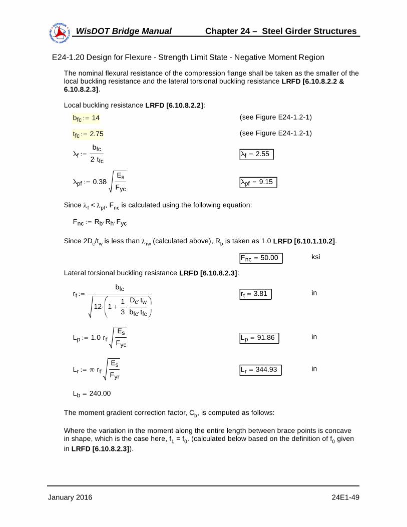
E24-1.20 Design for Flexure - Strength Limit State - Negative Moment Region
The nominal flexural resistance of the compression flange shall be taken as the smaller of thelocal buckling resistance and the lateral torsional buckling resistance LRFD [6.10.8.2.2 &6.10.8.2.3].
Local buckling resistance LRFD [6.10.8.2.2]:
bfc 14 (see Figure E24-1.2-1)
tfc 2.75 (see Figure E24-1.2-1)
λfbfc
2 tfc λf 2.55
λpf 0.38Es
Fyc λpf 9.15
Since f < pf, Fnc is calculated using the following equation:
Fnc Rb Rh Fyc
Since 2Dc/tw is less than rw (calculated above), Rb is taken as 1.0 LRFD [6.10.1.10.2].
Fnc 50.00 ksi
Lateral torsional buckling resistance LRFD [6.10.8.2.3]:
rtbfc
12 113
Dc tw
bfc tfc
rt 3.81 in
Lp 1.0 rtEs
Fyc Lp 91.86 in
Lr π rtEs
Fyr Lr 344.93 in
Lb 240.00
The moment gradient correction factor, Cb, is computed as follows:
Where the variation in the moment along the entire length between brace points is concavein shape, which is the case here, f1 = f0. (calculated below based on the definition of f0 givenin LRFD [6.10.8.2.3]).
January 2016 24E1-49
WisDOT Bridge Manual Chapter 24 – Steel Girder Structures

MNCDC0.8L 112.1 780.3 17.8 MNCDC0.8L 910.20 kip-ft
SNCDC0.8L 2278.2 in3
The section properties specified for the0.8 pt are the properties found at thepier based on LRFD [6.10.8.2.3].
Mpar0.8L 110.3 kip-ft
Mfws0.8L 104.4 kip-ft
MLL0.8L 1165.9 kip-ft
Srebar0.8L 2380.2 in3
f1 1.25MNCDC0.8L 12
SNCDC0.8L 1.25
Mpar0.8L 12
Srebar0.8L 1.50
Mfws0.8L 12
Srebar0.8L 1.75
MLL0.8L 12
Srebar0.8L
f1 17.76 ksi
f2 48.84 ksi (Table E24-1.6-2)
f1f2
0.36
Cb 1.75 1.05f1f2
0.3f1f2
2 < 2.3 Cb 1.41
Therefore:
Fyr max min 0.7 Fyc Fyw 0.5 Fyc Fyr 35.00 ksi
Fnc Cb 1 1Fyr
Rh Fyc
Lb Lp
Lr Lp
Rb Rh Fyc
Fnc 58.03 ksi
Fnc Rb Rh Fyc Rb Rh Fyc 50.00 ksi
Use:
Fnc 50.00 ksi
ϕf Fnc 50.00 ksi
fbu 48.84 ksi (Table E24-1.6-2)
Since there are no curvature or skew effects and wind is not considered under the Strength Iload combination, fl is taken equal to zero. Therefore:
January 2016 24E1-50
WisDOT Bridge Manual Chapter 24 – Steel Girder Structures

fbu13
0( ) 48.84 ksi OK
The investigation proceeds by calculating the flexural resistance of the continuously bracedtension flange LRFD [6.10.8.1.3 & 6.10.8.3].
fbu ϕf Rh Fyf ϕf Rh Fyf 50.00 ksi
(Table E24-1.6-2) fbu 47.52 ksi OK
E24-1.21 - Design for Shear - Negative Moment RegionShear must be checked at each section of the girder. For this design example, shear ismaximum at the pier.
The first step in the design for shear is to check if the web must be stiffened. The nominalshear resistance, Vn, of unstiffened webs of hybrid and homogeneous girders is LRFD[6.10.9.2]:
Vn C Vp Vp
Where:
C = Ratio of the shear-buckling resistance to the shear yieldstrength in accordance with LRFD [6.10.9.3.2], with theshear-buckling coefficient, k, taken equal to 5.0
Vp = Plastic shear force (kips)
k 5.0Dtw
108.00
1.12Es k
Fyw 60.31
1.40Es k
Fyw 75.39
Therefore,
Dtw
1.40E kFyw
C1.57
Dtw
2
Es k
Fyw
C 0.390
The plastic shear force, Vp, is then:
Vp 0.58 Fyw D tw Vp 783.0 kips
January 2016 24E1-51
WisDOT Bridge Manual Chapter 24 – Steel Girder Structures

Vn C Vp Vn 305.6 kips
The factored shear resistance, Vr, is computed as follows LRFD [6.10.9.1]:
ϕv 1.00
Vr ϕv Vn Vr 305.6 kips
The shear resistance at this design section is checked as follows:
Σηi γi Qi Rr
Or in this case:
Σηi γi Vi Vr
ηi 1.00
As computed in E24-1.6, the factored Strength I Limit State shear at the pier is as follows:
Σηi γi Vi 414.3Σηi γi Vi kips
Vr 305.6 kips
Since the shear resistance of an unstiffened web is less than the actual design shear, theweb must be stiffened.
The transverse intermediate stiffener spacing is 120 inches. The spacing of the transverseintermediate stiffeners does not exceed 3D, therefore the design section can be consideredstiffened and the provisions of LRFD [6.10.9.3] apply.
The section must be checked against the web to flange proportion limits for interior webpanels LRFD [6.10.9.3.2].
2 D tw
bfc tfc bft tft2.5
Where:
bft = Full width of tension flange (in)
tft = Thickness of tension flange (in)
bft 14.0
tft 2.50
2 D tw
bfc tfc bft tft0.73 OK
The nominal shear resistance , Vn, of the interior web panel at the pier is then:
January 2016 24E1-52
WisDOT Bridge Manual Chapter 24 – Steel Girder Structures

Vn Vp C0.87 1 C( )
1do
D
2
do
Where:
C = Ratio of the shear-buckling resistance to the shear yieldstrength
d0 = Transverse stiffener spacing (in)
do 120
k 55
do
D
2 k 6.01
Dtw
108.00
1.12Es k
Fyw 66.14
1.40Es k
Fyw 82.67
Dtw
1.40E kFyw
C1.57
Dtw
2
Es k
Fyw
C 0.469
Vp 783.00
Vn Vp C0.87 1 C( )
1do
D
2
Vn 515.86 kips
The factored shear resistance, Vr, is computed as follows:
ϕv 1.00
Vr ϕv Vn Vr 515.86 kips
January 2016 24E1-53
WisDOT Bridge Manual Chapter 24 – Steel Girder Structures

As previously computed, for this design example:
Σηi γi Vi 414.3Σηi γi Vi kips
Vr 515.86 kips OK
Therefore, the girder design section at the pier satisfies the shear resistance requirementsfor the web.
January 2016 24E1-54
WisDOT Bridge Manual Chapter 24 – Steel Girder Structures

E24-1.22 Design Transverse Intermediate Stiffeners - Negative Moment RegionIt is assumed that the transverse intermediate stiffeners consist of plates welded to one sideof the web. The required interface between the transverse intermediate stiffeners and thetop and bottom flanges is described in LRFD [6.10.11.1.1].
The transverse intermediate stiffener configuration is assumed to be as presented in thefollowing figure.
do = 10'-0"
A A
Partial Girder Elevation at Pier
Section A-A
t w =
1/2
"
b t =
5 1
/2"
tp = 1/2"
Transverse Intermediate
Stiffener
Web
(Typ.)
Bearing Stiffener
Transverse Intermediate Stiffener (Typ. Unless Noted Otherwise)
Symmetrical about L PierC
L PierC
Figure E24-1.22-1Transverse Intermediate Stiffener
The first specification check is for the projecting width of the transverse intermediate stiffener.The width, bt, of each projecting stiffener element must satisfy the following LRFD[6.10.11.1.2]:
January 2016 24E1-55
WisDOT Bridge Manual Chapter 24 – Steel Girder Structures

bt 2.0D
30.0 and 16.0 tp bt 0.25bf
Where:
tp = Thickness of the projecting stiffener element (in)
bf = Full width of the widest compression flange within the fieldsection under consideration (in)
bt 5.5 in
D 54 in
tp 0.50 in
bf 14.00 in
2.0D
30.0 3.80 in OK
16.0 tp 8.00 in
0.25 bf 3.50 in OK
The moment of inertia, It, of the transverse stiffener must satisfy the following since eachpanel adjacent to the stiffener supports a shear force larger than the shear bucklingresistance (Vcr = CVp) LRFD [6.10.11.1.3]:
If It2 It1 , then :
It It1 It2 It1 Vu ϕv Vcr
ϕv Vn ϕv Vcr
Otherwise:
It It2
It1 b tw3 J b
Where:
b = The smaller of do and D (in)
J = Stiffener bending rigidity parameter
b min do D b 54.00 in
January 2016 24E1-56
WisDOT Bridge Manual Chapter 24 – Steel Girder Structures
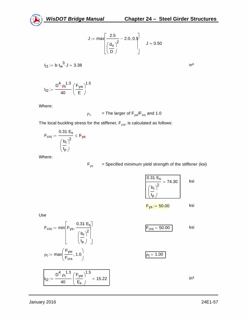
J max2.5
do
D
22.0 0.5
J 0.50
It1 b tw3 J 3.38 in4
It2D4
ρt1.3
40
Fyw
E
1.5
ρt
Where:
t = The larger of Fyw/Fcrs and 1.0
The local buckling stress for the stiffener, Fcrs, is calculated as follows:
Fcrs0.31 Es
bt
tp
2Fys Fys
Where:
Fys = Specified minimum yield strength of the stiffener (ksi)
0.31 Es
bt
tp
274.30 ksi
Fys 50.00 ksi
Use
Fcrs min Fys0.31 Es
bt
tp
2
Fcrs 50.00 ksi
ρt maxFyw
Fcrs1.0
ρt 1.00
It2D4
ρt1.3
40
Fyw
Es
1.5 15.22 in4
January 2016 24E1-57
WisDOT Bridge Manual Chapter 24 – Steel Girder Structures

Since It2 > It1, the moment of inertia, It, of the transverse stiffener must satisfy:
It It1 It2 It1 Vu ϕv Vcr
ϕv Vn ϕv Vcr
Vu 414.3 kip
Vcr C Vp 367.53 kip
Vn 515.86 kip
It1 It2 It1 Vu ϕv Vcr
ϕv Vn ϕv Vcr
7.11 in4
Ittp bt
3
3 It 27.73 in4
Therefore,
It It1 It2 It1 Vu ϕv Vcr
ϕv Vn ϕv Vcr
OK
E24-1.23 Design for Flexure - Fatigue and Fracture Limit State - Negative MomentRegion
For this design example, sample nominal fatigue resistance computations were presentedpreviously (E24-1.13) for the girder section at the location of maximum positive momentLRFD [6.6.1]. Detail categories are explained and illustrated in LRFD [Table 6.6.1.2.3-1].
In addition to the nominal fatigue resistance computations, a special fatigue requirement forwebs must also be checked LRFD [6.10.5.3]. This check is required to control out-of-planeflexing of the web due to shear under repeated live loading.
The check is made using fatigue range live load shear in combination with the shear due tothe unfactored permanent load. This total shear is limited to the shear buckling resistance(Vcr = CVp), as follows:
Vu Vcr
Based on the unfactored shear values in Table E24-1.6-3:
Vu = Vnoncomp + Vpar + Vfws + 1.5VLLfatiguerange
Vu 111.5 14.5 13.8 1.5 47.4( ) Vu 210.90 kips
C 0.469 See E24-1.21
Vp 783.00 kips See E24-1.21
Vcr C Vp Vcr 367.53 kips
January 2016 24E1-58
WisDOT Bridge Manual Chapter 24 – Steel Girder Structures

Vu Vcr OK
Therefore, the special fatigue requirement for webs for shear is satisfied.
Other fatigue resistance calculations in the negative moment region are not shown here, butwould be similar to the sample check illustrated previously for the positive moment region(E24-1.13).
E24-1.24 Design for Flexure - Service Limit State - Negative Moment RegionThe girder must be checked for service limit state control of permanent deflection LRFD[6.10.4]. Service II Limit State is used for this check.
The flange stress checks of LRFD [6.10.4.2.2] will not control for composite sections innegative flexure for which the nominal flexural resistance under the strength loadcombinations given in LRFD [Table 3.4.1-1] is determined according to the slender-webprovision of LRFD [6.10.8], which is the case in this example.
However, for sections in negative flexure, the web must satisfy the web bend buckling checkgiven by equation 4 of LRFD [6.10.4.2.2] at the service limit state, using the appropriatevalue of the depth of the web in compression in the elastic range, Dc.
fc Fcrw
Fcrw0.9 Es k
Dtw
2 (LRFD 6.10.1.9.1-1)
Where:
k = Bend-buckling coefficient = 9/(Dc/D)2
The factored Service II flexural stress was previously computed in Table E24-1.6-2 as follows:
fbotgdr 34.22 ksi
ftopgdr 22.39 ksi
As previously explained, for this design example, the concrete slab is assumed to be fullyeffective for both positive and negative flexure for service limit states. Therefore, when thisassumption is made, Dc must be computed as follows as indicated in LRFD [AppendixD6.3.1]:
Dcfc
fc ft
d tfc 0fc
Depthgdr 59.25 in (see Figure E24-1.2-1)
Depthcompfbotgdr
fbotgdr ftopgdrDepthgdr Depthcomp 35.82 in
January 2016 24E1-59
WisDOT Bridge Manual Chapter 24 – Steel Girder Structures

tbotfl 2.75 in
Dc Depthcomp tbotfl Dc 33.07 in
D 54.0 in
k9.0
Dc
D
2 k 24.00
0.9 Es k
Dtw
253.71 ksi
Fcrw min0.9 Es k
Dtw
2Rh Fyc
Fyw
0.7
Fcrw 50.00 ksi
tbf 2.75 in
fc fbotgdrDc
Dc tbf
fc 31.59 ksi OK
E24-1.25 Design for Flexure - Constructibility Check - Negative Moment RegionThe girder must also be checked for flexure during construction LRFD [6.10.3.2]. The girderhas already been checked in its final condition when it behaves as a composite section. Theconstructibility must also be checked for the girder prior to the hardening of the concretedeck when the girder behaves as a noncomposite section.
For discretely braced flanges in compression with a compact or noncompact web and with flequal to zero (interior girder), equation 2 is used. This check is similar to the checkperformed in E24-1.20 and will not be checked here.
For the interior girder in this case (where fl = 0), the sizes of the flanges at the pier sectionare controlled by the strength limit state flexural resistance checks illustrated previously.Therefore, separate constructibility checks on the flanges need not be made. However, theweb bend buckling resistance of the noncomposite pier section during construction must bechecked according to equation 3 of LRFD [6.10.3.2.1], as follows:
fbu ϕf Fcrw
Check first if the noncomposite section at the pier is a nonslender web section. From TableE24-1.3-3 LRFD [6.10.6.2.3]:
Dc 28.718 2.75 Dc 25.97 in
January 2016 24E1-60
WisDOT Bridge Manual Chapter 24 – Steel Girder Structures

2 Dc
tw103.87
λrw 137.27
2 Dc
twλrw OK
The section is therefore a nonslender web section (i.e. a noncompact web section), webbend buckling need not be checked in this case according to LRFD [6.10.3.2.1].In addition to checking the flexural resistance during construction, the shear resistance in theweb must also be checked prevent shear buckling of the web during construction as followsLRFD [6.10.3.3]:
Vcr C Vp Vcr 367.53 kips
Vr ϕv Vcr Vr 367.53 kips
Vu 1.25 111.5( ) Vu 139.38 kips OK
Therefore, the design section at the pier satisfies the constructibility specification checks.
E24-1.26 Check Wind Effects on Girder Flanges - Negative Moment RegionWind effects generally do not control a steel girder design, and they are generallyconsidered for the exterior girders only LRFD [C6.10.1.6 & C4.6.2.7.1]. However, forillustrative purposes, wind effects are presented below for the girder design section at thepier. A bridge height of greater than 30 feet is used in this design step to illustrate therequired computations LRFD [3.8.1.1].
The stresses in the bottom flange are combined as follows LRFD [6.10.8.1.1]:
fbu13
fl
ϕf Fnc
fl6 Mw
tfb bfb2
Mw (LRFD 6.10.1.6)
Since the deck provides horizontal diaphragm action and since there is wind bracing in thesuperstructure, the maximum wind moment, Mw, on the loaded flange is determined asfollows:
MwW Lb
2
10
W
Lb
1220.00 ft
January 2016 24E1-61
WisDOT Bridge Manual Chapter 24 – Steel Girder Structures

Wη γ PD d
2
PD
η 1.0
γ 0.40 for Strength V Limit State
Assume that the bridge is to be constructed in a city. The design horizontal wind pressure,PD, is computed as follows LRFD [3.8.1.2]:
PD PBVDZ
VB
2 PB
Where:
PB = Base wind pressure LRFD [Table 3.8.1.1-1] (ksf)
VDZ = Design wind velocity at design elevation Z (mph)
VB = Base wind velocity of 100 mph for a 30.0 ft height
PB 0.050 ksf
VB 100 mph
VDZ 2.5 VoV30
VB
lnZZo
Vo
Where:
V30 = Wind velocity at 30.0 feet above low ground or abovedesign water level (mph)
V0 = Friction velocity LRFD [Table 3.8.1.1-1] (mph)
Z = Height of structure at which wind loads are beingcalculated as measured from low ground, or from waterlevel, > 30.0 feet
Z0 = Friction length of upstream fetch LRFD [Table 3.8.1.1-1](ft)
Vo 12.0 MPH for a bridge located in a city
V30 60 MPH assumed wind velocity at 30 feet above low ground orabove design water level at bridge site
VB 100 MPH
Z 35 ft assumed height of structure at which wind loads arebeing calculated as measured from low ground or from
January 2016 24E1-62
WisDOT Bridge Manual Chapter 24 – Steel Girder Structures

water level
Zo 8.20 ft for a bridge located in a city
VDZ 2.5 VoV30
VB
lnZZo
VDZ 26.12 MPH
PD PBVDZ
VB
2 PD 0.0034 ksf
d 8.45 ft from bottom of girder to top of barrier
W PD d W 0.0288 kips/ft
LRFD [3.8.1.2.1] states that the total wind loading, W, must not be taken less than 0.30 klf onbeam or girder spans, therefore use PD as computed below:
W 0.30 kips/ft
PDWd
PD 0.0355 ksf
After the design horizontal wind pressure has been computed, the factored wind force perunit length applied to the flange is computed as follows LRFD [C4.6.2.7.1]:
Wη γ PD d
2 W 0.060 kips/ft
Next, the maximum lateral moment in the flange due to the factored wind loading is computedas follows:
Mw
WLb
12
2
10 Mw 2.40 kip-ft
Finally, the flexural stress at the edges of the bottom flange due to factored wind loading iscomputed as follows LRFD [6.10.8.1.1]:
tfb 2.75 in
bfb 14.0 in
fl6 Mw 12
tfb bfb2
fl 0.321 ksi
The load factor for live load is 1.35 for the Strength V Limit State. However, it is 1.75 for theStrength I Limit State, which we have already investigated. Therefore, it is clear that windeffects will not control the design of this steel girder. Nevertheless, the following
January 2016 24E1-63
WisDOT Bridge Manual Chapter 24 – Steel Girder Structures

computations are presented simply to demonstrate that wind effects do not control thisdesign:
fbu 1.25 16.56( ) 1.25 2.05( )[ ] 1.50 1.94( ) 1.35 12.26( )[ ]
fbu 42.72 ksi
fbu13
fl 42.83 ksi
Fnc 50.00 ksi
fbu13
fl ϕf Fnc OK
January 2016 24E1-64
WisDOT Bridge Manual Chapter 24 – Steel Girder Structures

E24-1.27 Draw Schematic of Final Steel Girder Design
Since all of the specification checks were satisfied, the trial girder section presented inE24-1.2 is acceptable. If any of the specification checks were not satisfied or if the designwere found to be overly conservative, then the trial girder section would need to be revisedappropriately, and the specification checks would need to be repeated for the new trial girdersection.
The following is a schematic of the final steel girder configuration:
84'-0”(A)
16'-0”(C)
120'-0”
14” x 7/8” Bottom Flange
14” x 1 1/4” Top Flange
14” x 2 3/4” Bottom Flange
14” x 2 1/2” Top Flange
L Bearing Abutment L Pier
Symmetrical about L Pier
L Bolted Field Splice
54” x 1/2” Web
C
C
C C
8”
20'-0”(B)
14” x 1 3/8” Bottom Flange
14” x 3/4” Top Flange
10'-0”
5 1/2” x 1/2” Transverse Intermediate Stiffeners (One Side of Web Only - Interior Side of Fascia Girders)(Typ. Unless Noted Otherwise)
Bearing Stiffener(Both Sides of Web)
Bearing Stiffener(Both Sides of Web)
(Typ.)
Length(Region)
Figure E24-1.27-1Final Plate Girder Elevation
For this design example, only the location of maximum positive moment, the location ofmaximum negative moment, and the location of maximum shear were investigated. However,the above schematic shows the plate sizes and stiffener spacing throughout the entire lengthof the girder.
Design computations for shear connectors and bearing stiffeners now follow.
January 2016 24E1-65
WisDOT Bridge Manual Chapter 24 – Steel Girder Structures

E24-1.28 Design Shear ConnectorsFor continuous composite bridges, shear connectors are normally provided throughout thelength of the bridge. In the negative flexure region, since the longitudinal reinforcement isconsidered to be a part of the composite section, shear connectors must be provided LRFD[6.10.10.1].
Studs are used as shear connectors. The shear connectors must permit a thoroughcompaction of the concrete to ensure that their entire surfaces are in contact with theconcrete. In addition, the shear connectors must be capable of resisting both horizontal andvertical movement between the concrete and the steel.
The following figure shows the stud shear connector proportions, as well as the location ofthe stud head within the concrete deck.
7/8"
14"
9"
5"(Typ.)
AB
C
6"
3¾”
Figure E24-1.28-1Stud Shear Connectors
Flexure Region A B CPositive 3.00" 3.00" 6.00"Intermediate 2.50" 3.50" 5.50"Negative 1.25" 4.75" 4.25"
Shear Connector Embedment
Table E24-1.28-1Shear Connector Embedment
The ratio of the height to the diameter of a stud shear connector must not be less than 4.0LRFD [6.10.10.1.1]. For this design example, the ratio is computed based on the dimensionspresented in Figure E24-1.28-1, as follows:
Heightstud 6.0 in
Diameterstud 0.875 inHeightstud
Diameterstud6.86 OK
The pitch of the shear connectors must be determined to satisfy the fatigue limit state asspecified in LRFD [6.10.10.2 & 6.10.10.3], as applicable. The resulting number of shearconnectors must not be less than the number required to satisfy the strength limit states as
January 2016 24E1-66
WisDOT Bridge Manual Chapter 24 – Steel Girder Structures

specified in LRFD [6.10.10.4].
The pitch, p, of the shear connectors must satisfy the following equation LRFD [6.10.10.1.2]:
pn Zr
Vsr
Where:
n = Number of shear connectors in a cross-section
Zr = Shear fatigue resistance of an individual shear connectorLRFD [6.10.10.2] (kip)
Vsr = Horizontal fatigue shear range per unit length (kip-in)
The shear fatigue resistance of an individual shear connector, Zr, is taken as:
ADTTSL 3000 > 960, Therefore, use Fatigue 1 load combinations with fatigue shearresistance for infinite life as follows:
Zr 5.5 d2
Where:
d = Diameter of the stud (in)
The horizontal fatigue shear range per unit length, Vsr, is taken as:
Vsr Vfat2 Ffat
2 Vfat
Where:
Vfat = Longitudinal fatigue shear range per unit length
Ffat = Radial fatigue shear range per unit length (kip-in)
The longitudinal fatigue shear range per unit length, Vfat, is taken as:
VfatVf Q
I
Vf
Where:
Vf = Vertical shear force range under the fatigue loadcombination in LRFD [Table 3.4.1-1] with the fatigue liveload taken as specified in LRFD [3.6.1.4] (kip)
Q = First moment of the transformed short-term area of theconcrete deck about the neutral axis of the short-termcomposite section (in3)
January 2016 24E1-67
WisDOT Bridge Manual Chapter 24 – Steel Girder Structures

I = Moment of inertia of the short-term composite section (in4)
The radial fatigue shear range per unit length, Ffat, is taken as the larger of:
Ffat1Abot σflg l
w R
Abot
Ffat2Frc
w
Frc
Where:
Abot = Area of the bottom flange (in2)
flg = Range of longitudinal fatigue stress in the bottom flangewithout consideration of flange lateral bending (ksi)
l = Distance between brace points (ft)
w = Effective length of deck (in) taken as 48.0 in, except atend supports where w may be taken as 24.0 in
R = Minimum girder radius within the panel (ft)
Frc = Net range of cross-frame or diaphragm force at the topflange (kip)
Since this bridge utilizes straight spans and has no skew, the radial fatigue shear range, Ffatis taken as zero. Therefore:
Vsr Vfat Vfat
In the positive flexure region, the maximum fatigue live load shear range is located at theabutment. For illustration purposes, this example uses the average fatigue live load shearrange in the positive moment region and assumes it acts at 0.4L. In reality, the required pitchshould be calculated throughout the entire length of the girder. The actual pitch should bechosen such that it is less than or equal to the required pitch. The factored average value iscomputed as follows:
Vf 1.5 44.5( ) Vf 66.75 kips
The parameters I and Q are based on the short-term composite section and are determinedusing the deck within the effective flange width. In the positive flexure region:
n 3 (see Figure E24-1.28-1)
I 70696.16 in4 (see Table E24-1.3-1)
Q8.5( ) 120( )
8
62.875 52.777( ) Q 1287.49 in3
VfatVf Q
I Vfat 1.22 kip/in
January 2016 24E1-68
WisDOT Bridge Manual Chapter 24 – Steel Girder Structures

Vsr Vfat Vsr 1.22 kip/in
d 0.875 in
Zr 5.5 d2 Zr 4.21 kips
pn Zr
Vsr p 10.39 in
In the negative flexure region:
n 3 (see Figure E24-1.28-1)
From LRFD [C6.10.10.1.2], in the negative flexure region, the parameters I and Q may bedetermined using the reinforcement within the effective flange width for negative moment,unless the concrete slab is considered to be fully effective for negative moment in computingthe longitudinal range of stress, as permitted in LRFD [6.6.1.2.1]. For this design example, Iand Q are assumed to be computed considering the concrete slab to be fully effective.
I 139158.7 in4 (see Table E24-1.3-3)
Q8.5( ) 120( )
8
64.750 48.868( ) Q 2024.95 in3
Vf 1.5 47.4( ) Vf 71.10 kips
VfatVf Q
I Vfat 1.03 kip/in
Vsr Vfat Vsr 1.03 kip/in
pn Zr
Vsr p 12.21 in
Therefore, based on the above pitch computations to satisfy the fatigue limit state, use thefollowing pitch throughout the entire girder length:
p 10 in
As stated earlier, the shear connector pitch typically is not the same throughout the entirelength of the girder. In reality, most girder designs use a variable pitch, which is beneficialeconomically.
However, for simplicity in this design example, a constant shear connector pitch of 10 incheswill be used.
January 2016 24E1-69
WisDOT Bridge Manual Chapter 24 – Steel Girder Structures

In addition, the shear connectors must satisfy the following pitch requirements LRFD[6.10.10.1.2]:
p 24 in OK
p 6 d 6 d 5.25 in OK
For transverse spacing, the shear connectors must be placed transversely across the topflange of the steel section and may be spaced at regular or variable intervals LRFD[6.10.10.1.3].
Stud shear connectors must not be closer than 4.0 stud diameters center-to-centertransverse to the longitudinal axis of the supporting member.
4 d 3.50 in
Spacingtransverse 5.0 in (see Figure E24-1.28-1) OK
In addition, the clear distance between the edge of the top flange and the edge of thenearest shear connector must not be less than 1.0 inch.
Dclear142
5d2
Dclear 1.56 in OK
The clear depth of concrete cover over the tops of the shear connectors should not be lessthan 2.0 inches, and shear connectors should penetrate at least 2.0 inches into the deckLRFD [6.10.10.1.4]. Based on the shear connector penetration information presented inTable E24-1.28-1, both of these requirements are satisfied.
For the strength limit state, the factored resistance of the shear connectors, Qr, is computedas follows LRFD [6.10.10.4.1]:
Qr ϕsc Qn ϕsc
ϕsc 0.85 (LRFD 6.5.4.2)
The nominal shear resistance of one stud shear connector embedded in a concrete slab, Qn,is computed as follows LRFD [6.10.10.4.3]:
Qn 0.5 Asc f'c Ec Asc Fu Asc
Where:
Asc = Cross-sectional area of a stud shear connector (in2)
Fu = Specified minimum tensile strength of a stud shearconnector from LRFD [6.4.4] (ksi)
Asc πd2
4 Asc 0.601 in2
January 2016 24E1-70
WisDOT Bridge Manual Chapter 24 – Steel Girder Structures

Fu 60.0 ksi
Ec 3834 ksi
Qn min 0.5 Asc f'c Ec Asc Fu Qn 36.08 kips
Qr ϕsc Qn Qr 30.67 kips
The number of shear connectors provided over the section being investigated must not beless than the following LRFD [6.10.10.4.1]:
nPQr
P
For continuous spans that are composite for negative flexure in their final condition, thenominal shear force, P, must be calculated for the following regions LRFD [6.10.10.4.2]:
1. Between points of maximum positive design live load plus impact moments and adjacentends of the member
2. Between points of maximum positive design live load plus impact moment and centerlinesof adjacent interior supports
For Region 1:
P Pp2 Fp
2 Pp
Where:
Pp = Total longitudinal shear force in the concrete deck at thepoint of maximum positive live load plus impact moment(kips)
Fp = Total radial shear force in the concrete deck at the pointof maximum positive live load plus impact moment (kips)
The total longitudinal shear force in the concrete deck at the point of maximum positive liveload plus impact moment, Pp, is taken as the lesser of:
P1p 0.85 f'c bs ts
or
P2p Fyw D tw Fyt bft tft Fyc bfc tfc
tft 0.875 in (see E24-1.27)
tfc 0.75 in (see E24-1.27)
Pp min 0.85 f'c bs ts Fyw D tw Fyt bft tft Fyc bfc tfc
Pp 2488 kips
January 2016 24E1-71
WisDOT Bridge Manual Chapter 24 – Steel Girder Structures

For straight spans or segments, Fp may be taken equal to zero which gives LRFD[6.10.10.4.2]:
P Pp P 2488 kips
Therefore, the number of shear connectors provided between the section of maximumpositive moment and each adjacent end of the member must not be less than the followingLRFD [6.10.10.4.1]:
nPQr
n 81.1
For region 2:
P PT2 FT
2 PT
Where:
PT = Total longitudinal shear force in the concrete deckbetween the point of maximum positive live load plusimpact moment and the centerline of an adjacent interiorsupport (kips)
FT = Total radial shear force in the concrete deck between thepoint of maximum positive live load plus impact momentand the centerline of an adjacent interior support (kips)
The total longitudinal shear force in the concrete deck between the point of maximum positivelive load plus impact moment and the centerline of an adjacent interior support, PT, is takenas:
PT Pp Pn Pn
Where:
Pn = Total longitudinal shear force in the concrete deck over aninterior support (kips)
The total longitudinal shear force in the concrete deck over an interior support, Pn, is takenas the lesser of:
P1n Fyw D tw Fyt bft tft Fyc bfc tfc
or
P2n 0.45 f'c bs ts
tft 2.5 in (see E24-1.27)
tfc 2.75 in (see E24-1.27)
Pn min Fyw D tw Fyt bft tft Fyc bfc tfc 0.45 f'c bs ts
January 2016 24E1-72
WisDOT Bridge Manual Chapter 24 – Steel Girder Structures

Pn 1836 kips
PT Pp Pn PT 4324 kips
For straight spans or segments, FT may be taken equal to zero which gives:
P PT P 4324 kips
Therefore, the number of shear connectors provided between the section of maximumpositive moment and the centerline of the adjacent interior pier must not be less than thefollowing LRFD [6.10.10.4.1]:
nPQr
n 141.0
The distance between the end of the girder and the location of maximum positive moment isapproximately equal to:
L 48.0 ft (see Table E24-1.4-2)
Using a pitch of 10 inches, as previously computed for the fatigue limit state, and using theabove length, the number of shear connectors provided is as follows:
n 3L 12( )
p n 172.8 OK
Similarly the distance between the section of the maximum positive moment and the interiorsupport is equal to:
L 120.0 48.0 L 72.0 ft (see Table E24-1.4-2)
Using a pitch of 10 inches, as previously computed for the fatigue limit state, and using theabove length, the number of shear connectors provided is as follows:
n 3L 12( )
p n 259.2 OK
Therefore, using a pitch of 10 inches for each row, with three stud shear connectors per row,throughout the entire length of the girder satisfies both the fatigue limit state requirements ofLRFD [6.10.10.1.2 & 6.10.10.2] and the strength limit state requirements of LRFD[6.10.10.4].
Use a shear stud spacing as illustrated in the following figure.
January 2016 24E1-73
WisDOT Bridge Manual Chapter 24 – Steel Girder Structures

Bearing stiffeners are required to resist the bearing reactions and other concentrated loads,either in the final state or during construction LRFD [6.10.11.2.1].
For plate girders, bearing stiffeners are required to be placed on the webs at all bearinglocations. At all locations supporting concentrated loads where the loads are not transmittedthrough a deck or deck system, either bearing stiffeners are to be provided or the web mustsatisfy the provisions of LRFD [Appendix D6.5].
Therefore, for this design example, bearing stiffeners are required at both abutments and atthe pier. The following design of the abutment bearing stiffeners illustrates the bearingstiffener design procedure.
The bearing stiffeners in this design example consist of one plate welded to each side of theweb. The connections to the web will be designed to transmit the full bearing force due tofactored loads and is presented in E24-1.30.
The stiffeners extend the full depth of the web and, as closely as practical, to the outer edgesof the flanges.
The following figure illustrates the bearing stiffener layout at the abutments.
Symmetrical about L Pier
144 Spaces @ 10" = 120'-0"(3 Stud Shear Connectors Per Row)
L PierCL Bearing AbutmentC
C
Figure E24-1.28-2Shear Connector Spacing
E24-1.29 Design Bearing Stiffeners
January 2016 24E1-74
WisDOT Bridge Manual Chapter 24 – Steel Girder Structures

L Bearings at Abutment
A A
Partial Girder Elevation at Abutment
Section A-A
t w =
1/2
"
b t =
5 1
/2"
tp = 11/16"
Web
Bearing Stiffener
Bearing Stiffener
(Typ
.)
(Typ.)
C
Figure E24-1.29-1Bearing Stiffeners at Abutments
The projecting width, bt, of each bearing stiffener element must satisfy the following equationLRFD [6.10.11.2.2]. This provision is intended to prevent local buckling of the bearingstiffener plates.
bt 0.48 tpE
Fys
Where:
tp = Tickness of the projecting stiffener element (in)
Fys = Specified minimum yield strength of the stiffener (ksi)
January 2016 24E1-75
WisDOT Bridge Manual Chapter 24 – Steel Girder Structures

bt 5.5 in (see Figure E24-1.29-1)
tp1116
in (see Figure E24-1.29-1)
Fys 50
0.48 tpEs
Fys 7.95 in OK
The bearing resistance must be sufficient to resist the factored reaction acting on the bearingstiffeners LRFD [6.10.11.2.3]. The factored bearing resistance, Rsbr, is computed as follows:
Rsbr ϕb Rsbn ϕb
ϕb 1.00 (LRFD 6.5.4.2)
Rsbn 1.4 Apn Fys Apn
Where:
Apn = Area of the projecting elements of the stiffener outside ofthe web-to-flange fillet welds but not beyond the edge ofthe flange (in2)
Part of the stiffener must be clipped to clear the web-to-flange weld. Thus the area of directbearing is less than the gross area of the stiffener. The bearing area, Apn, is taken as thearea of the projecting elements of the stiffener outside of the web-to-flange fillet welds but notbeyond the edge of the flange. This is illustrated in the following figure:
1"
Bearing Stiffener
(Typ.)
1" x 1" Clip for Fillet Weld (Typ.)
Total Width = 5 1/2"
Bearing Width = 4 1/2"
January 2016 24E1-76
WisDOT Bridge Manual Chapter 24 – Steel Girder Structures

Figure E24-1.29-2Bearing Width
bbrg bt 1.0 bbrg 4.50 in
Apn 2bbrg tp Apn 6.19 in2
Rsbr ϕb 1.4 Apn Fys Rsbr 433.13 kips
The factored bearing reaction at the abutment is computed as follows, using load factors aspresented in LRFD [Table 3.4.1-1 & Table 3.4.1-2] and using reactions obtained from TableE24-1.4-3 and Table E24-1.5-2:
ReactFactored 1.25 63.7( ) 1.50 7.4( ) 1.75 112.8( )
ReactFactored 288.13 kips
Therefore, the bearing stiffener at the abutment satisfies the bearing resistancerequirements.
The final bearing stiffener check relates to the axial resistance of the bearing stiffeners LRFD[6.10.11.2.4]. The factored axial resistance is determined as specified in LRFD [6.9.2.1].The radius of gyration is computed about the midthickness of the web, and the effectivelength is taken as 0.75D, where D is the web depth LRFD [6.10.11.2.4a].
For stiffeners consisting of two plates welded to the web, the effective column sectionconsists of the two stiffener elements, plus a centrally located strip of web extending not morethan 9tw on each side of the stiffeners LRFD [6.10.11.2.4.b]. This is illustrated in thefollowing figure:
t w =
1/2
"
b t =
5 1
/2"
tp = 11/16"
Bearing Stiffener (Typ.)
(Typ
.)
(Typ.)
9tw = 4 1/2" 9tw = 4 1/2"
9"
Midthickness of Web
Figure E24-1.29-3Bearing Stiffener Effective Section
Pr ϕc Pn ϕc (LRFD 6.9.2.1)
January 2016 24E1-77
WisDOT Bridge Manual Chapter 24 – Steel Girder Structures

ϕc 0.90 (LRFD 6.5.4.2)
Bearing stiffeners only need to be designed for Flexural Buckling failure (Torsional Buckling andFlexural Torsional Buckling are not applicable) LRFD [6.9.4.1.1].
First, calculate the elastic critical buckling resistance, Pe, based on LRFD [6.9.4.1.2].
PeAg π
2 Es
klrs
2
Ag
Where:
kl = Taken as 0.75D, where D is the web depth (in)
rs = Radius of gyration about the midthickness of the web (in)
Ag = Cross-sectional area of the effective section (in2)
kl 0.75( ) 54( ) kl 40.50 in
Is0.6875 11.53 8.3125 0.53
12 Is 87.22 in4
Ag 0.6875 11.5( ) 8.3125 0.5( ) Ag 12.06 in2
rsIsAg
rs 2.69 in
PeAg π
2 Es
klrs
2 Pe 15220 kip
Next, calculate the equivalent nominal yield resistance, Po, given as:
Po Q Fy Ag (LRFD 6.9.4.1.1)
Where:
Q = slender element reduction factor, taken as 1.0 for bearing stiffeners
Po 1.0Fy Ag Po 603 kip
January 2016 24E1-78
WisDOT Bridge Manual Chapter 24 – Steel Girder Structures

Pe
Po25.23 Since Pe/Po > 0.44, Use equation 1 from LRFD [6.9.4.1.1].
Pn 0.658
Po
Pe
Po Pn 593.20 kips
Pr ϕc Pn Pr 533.88 kips
ReactFactored 288.13 kips OK
Therefore, the bearing stiffener at the abutment satisfies the axial bearing resistancerequirements.
The bearing stiffener at the abutment satisfies all bearing stiffener requirements. Use thebearing stiffener as presented in Figure E24-1.29-2 and Figure E24-1.29-3.
January 2016 24E1-79
WisDOT Bridge Manual Chapter 24 – Steel Girder Structures

WisDOT Bridge Manual
This page intentionally left blank.

Table of ContentsE24-2 Bolted Field Splice, LRFD .................................................................................................................
E24-2.1 Obtain Design Criteria ..........................................................................................E24-2.2 Select Girder Section as Basis for Field Splice Design ........................................E24-2.3 Compute Flange Splice Design Loads .................................................................E24-2.4 Design Bottom Flange Splice ...............................................................................E24-2.5 Design Top Flange Splice.....................................................................................E24-2.6 Compute Web Splice Design Loads .....................................................................E24-2.7 Design Web Splice ...............................................................................................E24-2.8 Draw Schematic of Final Bolted Field Splice Design............................................
2255
2241415063
WisDOT Bridge Manual Chapter 24 – Steel Girder Structures

E24-2 Bolted Field Splice, LRFD
E24-2.1 Obtain Design Criteria
This splice design example shows design calculations conforming to the AASHTO LRFDBridge Design Specifications (Seventh Edition - 2015 Interims) as supplemented by theWisDOT Bridge Manual (January 2015). Note: This example uses the girder from example E24-1.
Presented in Figure E24-2.1-1 is the steel girder configuration and the bolted field splicelocation. LRFD [6.13.6.1.4a] recommends locating splices near points of dead loadcontraflexure.
84'-0” 16'-0”
120'-0”
14” x 7/8” Bottom Flange
14” x 1 1/4” Top Flange
14” x 2 3/4” Bottom Flange
14” x 2 1/2” Top Flange
L Bearing Abutment L Pier
Symmetrical about L Pier
L Bolted Field Splice
54” x 1/2” Web
C
C
C C
8”
20'-0”
14” x 1 3/8” Bottom Flange
14” x 3/4” Top Flange
Figure E24-2.1-1Plate Girder Elevation
The steel properties of the girder and splice plates are as follows:
Yield strength:
Fy 50 ksi
Tensile strength:
Fu 65 ksi
For specification checks requiring the flange yield strength:
Fyf 50 ksi
January 2016 24E2-2
WisDOT Bridge Manual Chapter 24 – Steel Girder Structures

The plate dimensions of the girder on the left side of the splice from Figure E24-2.1-1 are asfollows:
Web thickness:
tw 0.50 in
Web depth:
D 54 in
Top flange width:
bfltL 14 in
Top flange thickness:
tfltL 0.75 in
Bottom flange width:
bflbL 14 in
Bottom flange thickness:
tflbL 0.875 in
The plate dimensions of the girder on the right side of the splice from Figure E24-2.1-1 areas follows:
Web thickness:
tw 0.50 in
Web depth:
D 54 in
Top flange width:
bfltR 14 in
Top flange thickness:
tfltR 1.25 in
Bottom flange width:
bflbR 14 in
Bottom flange thickness:
tflbR 1.375 in
The properties of the splice bolts are as follows:
Bolt diameter:
dbolt 0.875 in LRFD [6.13.2.5]
January 2016 24E2-3
WisDOT Bridge Manual Chapter 24 – Steel Girder Structures

Bolt hole diameter (for design purposes add 1/16" to standard hole diameter):
dhole 1.0 in LRFD [6.13.2.4.2-1]
Bolt tensile strength:
Fubolt 120 ksi LRFD [6.4.3.1]
The properties of the concrete deck are as follows:
Effective slab thickness:
tseff 8.5 in
Modular ratio:
n 8
Haunch depth (measured from top of web):
dhaunch 3.75 in
Effective flange width:
Weff 120 in
The area of longitudinal deck reinforcing steel in the negative moment region is for the topand bottom mat is given as number 6 bars at 7.5 inch spacing. The area of steel in theeffective flange width is then:
For the top steel:
Adeckreinftop 0.44( )Weff
7.5 Adeckreinftop 7.04 in2
For the bottom steel:
Adeckreinfbot 0.44( )Weff
7.5 Adeckreinfbot 7.04 in2
Resistance factors LRFD [6.5.4.2]:
Flexure: ϕf 1.0
Shear: ϕv 1.0
Axial compression, composite: ϕc 0.90
Tension, fracture in net section: ϕu 0.80
Tension, yielding in gross section: ϕy 0.95
Bolts bearing on material: ϕbb 0.80
A325 and A490 bolts in shear: ϕs 0.80
January 2016 24E2-4
WisDOT Bridge Manual Chapter 24 – Steel Girder Structures

Block shear: ϕbs 0.80
E24-2.2 Select Girder Section as Basis for Field Splice Design
Where a section changes at a splice, the smaller of the two connected sections shall be usedin the design LRFD [6.13.6.1.1]. Therefore, the bolted field splice will be designed based onthe left adjacent girder section properties. This will be referred to as the Left Girderthroughout the calculations. The girder located to the right of the bolted field splice will bedesignated the Right Girder.
E24-2.3 Compute Flange Splice Design Loads
A summary of the unfactored moments at the splice from example 24-1 are listed below. Thelive loads include impact and distribution factors.
Dead load moments:
Noncomposite:
MNDL 98.8 kip-ft
Composite:
MCDL 6.6 kip-ft
Future wearing surface:
MFWS 6.3 kip-ft
Live load moments:
HL-93 positive:
MPLL 1245.7 kip-ft
HL-93 negative:
MNLL 957.7 kip-ft
Fatigue positive:
MPFLL 375.6 kip-ft
Fatigue negative:
MNFLL 285.4 kip-ft
Typically, splices are designed for the Strength I, Service II, and Fatigue I load combinations.The load factors for these load combinations are shown in Table E24.2.3-1 LRFD [Tables3.4.1-1 & 3.4.1-2]:
January 2016 24E2-5
WisDOT Bridge Manual Chapter 24 – Steel Girder Structures

Load max min max min max min
DC 1.25 0.90 1.00 1.00 ‐ ‐
DW 1.50 0.65 1.00 1.00 ‐ ‐
LL 1.75 1.75 1.30 1.30 1.50 1.50
Load Factors
Fatigue IService IIStrength I
Table E24-2.3-1Load Factors
Flange stress computation procedure:
The stresses corresponding to the load combinations described above will be computed atthe midthickness of the top and bottom flanges. The appropriate section properties and loadfactors for use in computing stresses are described below. Where necessary, refer to thesigns of the previously documented design moments.
Strength I load combination:
The flexural stresses due to the factored loads at the strength limit state and for checkingslip of the bolted connections at the point of splice shall be determined using the grosssection properties LRFD [6.13.6.1.4a].Case 1: Dead load + positive live load
For this case, stresses will be computed using the gross section properties. The minimumload factor is used for the DC dead loads (noncomposite and composite) and the maximumload factor is used for the future wearing surface. The composite dead load and futurewearing surface act on the 3n-composite slab section and the live load acts on then-composite slab section LRFD [6.10.1.1.1b].Case 2: Dead load + negative live load
For this case, stresses will be computed using the gross section properties. The futurewearing surface is excluded and the maximum load factor is used for the DC dead loads.The live load acts on the composite steel girder plus longitudinal reinforcement section. Thecomposite dead load is applied to this section as well, as a conservative assumption forsimplicity and convenience, since the net effect of the live load is to induce tension in theslab. LRFD [6.10.1.1.1c].Service II load combination:
Case 1: Dead load + positive live load
For this case, stresses will be computed using the gross steel section. The future wearingsurface is included and acts, along with the composite dead load, on the 3n-composite slabsection. The live load acts on the n-composite slab section.
Case 2: Dead load + negative live load
For this case, stresses will be computed using the gross steel section. The future wearingsurface is excluded. The composite dead load acts on the 3n-composite slab section. Thelive load acts on the n-composite slab section.
January 2016 24E2-6
WisDOT Bridge Manual Chapter 24 – Steel Girder Structures

Fatigue I load combination:
Case 1: Positive live load
For this case, stresses will be computed using the gross steel section. The live load acts onthe n-composite slab section.
Case 2: Negative live load
For this case, stresses will be computed using the gross steel section. The live load acts onthe n-composite slab section.
Section properties:
The effective flange area, Ae, is calculated from LRFD [6.13.6.1.4c]:
Aeϕu Fu
ϕy Fyt
An AgFyt
Where:
u = Resistance factor for fracture of tension membersLRFD [6.5.4.2]
y = Resistance factor for yielding of tension membersLRFD [6.5.4.2]
An = Net area of the tension flange (in2) LRFD [6.8.3]
Ag = Gross area of the tension flange (in2)
Fu = Specified minimum tensile strength of the tension flange(ksi) LRFD [Table 6.4.1-1]
Fyt = Specified minimum yield strength of the tensionflange (ksi)
The gross area of the top and bottom flange of the steel girder is as follows:
Agbot tflbL bflbL Agbot 12.25 in2
Agtop tfltL bfltL Agtop 10.50 in2
The net area of the bottom flange of the steel girder is defined as the product of thethickness of the flange and the smallest net width LRFD [6.8.3]. The net width is determinedby subtracting from the width of the flange the sum of the widths of all holes in the assumedfailure chain, and then adding the quantity s2 /4g for each space between consective holes inthe chain. Since the bolt holes in the flanges are lined up transverse to the loading direction,the governing failure chain is straight across the flange (i.e., s2 /4g is equal to zero).
January 2016 24E2-7
WisDOT Bridge Manual Chapter 24 – Steel Girder Structures

The net area of the bottom and top flanges of the steel girder now follows:
Anbot bflbL 4 dhole tflbL Anbot 8.75 in2
Antop bfltL 4 dhole tfltL Antop 7.50 in2
With the gross and net areas identified, the effective tension area of the bottom and topflanges can now be computed as follows:
Fyt 50 ksi
Aebotϕu Fu
ϕy Fyt
Anbot Aebot 9.58 in2
Aetopϕu Fu
ϕy Fyt
Antop Aetop 8.21 in2
Check:
Aebot 9.58 < Agbot 12.25 OK
Effective bottom flange area:
Aebot 9.58 in2
Effective top flange area:
Aetop 8.21 in2
The transformed effective area of the concrete flange of the steel girder is now determinedas follows:
Ac= Effective Slab Width x tseff Modular Ratio
Weff 120.00 in
n 8 in
tseff 8.50 in
For the n-composite beam:
AcWeff
ntseff Ac 127.50 in2
For the 3n-composite beam:
Ac3nWeff
3ntseff Ac3n 42.50 in2
January 2016 24E2-8
WisDOT Bridge Manual Chapter 24 – Steel Girder Structures

The section properties for the Left Girder are calculated with the aid of Figure E24-2.3-1shown below:
Neutral Axis
Y
1 2
3
4
5
Figure E24-2.3-1Girder, Slab and Longitudinal Reinforcement
The following tables contain the section properties for the left (i.e., smaller) girder section atthe splice location. The properties in Table E24-2.3-2 are based on the gross area of thesteel girder, and these properties are used for computation of stresses for the Service II andFatigue Limit States. The properties in Tables E24-2.3-3 and E24-2.3-4 are based on theeffective top flange and effective bottom flange of the steel girder, respectively, and theseproperties are used for computation of stresses for the Strength I Limit State.
January 2016 24E2-9
WisDOT Bridge Manual Chapter 24 – Steel Girder Structures

Top flange 10.500 55.250 580.1 0.5 8441.1 8441.6
Web 27.000 27.875 752.6 6561.0 25.8 6586.8
Bottom flange 12.250 0.438 5.4 0.8 8576.1 8576.9
Total 49.750 26.897 1338.1 6562.3 17043.0 23605.3
Girder 49.750 26.897 1338.1 23605.3 1066.7 24672.0
Top Steel 7.040 64.250 452.3 0.0 7538.3 7538.3
Total 56.790 31.527 1790.4 23605.3 8605.0 32210.3
Girder 49.750 26.897 1338.1 23605.3 13668.5 37273.7
Slab 42.500 62.875 2672.2 255.9 16000.2 16256.0
Total 92.250 43.472 4010.3 23861.1 29668.6 53529.8
Girder 49.750 26.897 1338.1 23605.3 33321.4 56926.6
Slab 127.500 62.875 8016.6 767.7 13001.9 13769.5
Total 177.250 52.777 9354.7 24372.9 46323.2 70696.2
Girder only 26.459 28.353 907.1 892.1 832.5 843.7
Deck Steel 31.090 23.723 1050.8 1036.0 1357.8 1379.6
Composite (3n) 43.035 11.778 1256.7 1243.9 4544.9 4694.4
Composite (n) 52.339 2.473 1362.1 1350.7 28583.9 33692.3
SectionStopweb
(Inches3)
Stopmid
(Inches3)
Sbotmid
(Inches3)
Sbotweb
(Inches3)
ytopmid
(Inches)
ybotmid
(Inches)
SectionArea, A
(Inches2)
Centroid
, d
(Inches)
A*d
(Inches3)
Io
(Inches4)
A*y2
(Inches4)
Itotal
(Inches4)
Composite (n):
Composite (3n):
Deck Steel:
Girder only:
Section Properties ‐ Effective Top Flange Area
Table E24-2.3-2Section Properties
Note: This example uses only the top layer of deck steel as it is WisDOT's policy to onlyinclude the top layer of bar steel in determining section properties and stresses.
Strength I Limit State stresses - Dead load + positive live load:
The section properties for this case have been calculated in Table E24-2.3-2. The stressesat the midthickness of the flanges are shown in Table E24-2.3-3, which immediately followsthe sample calculation presented below.
January 2016 24E2-10
WisDOT Bridge Manual Chapter 24 – Steel Girder Structures

A typical computation for the stresses occurring at the midthickness of the flanges ispresented in the example below. The stress in the bottom flange of the girder is computedusing the 3n-composite section for the composite dead load and future wearing surface, andthe n-composite section for the live load:
fMS
Noncomposite DL:
Stress at the midthickness:
f fbotgdr1 fbotgdr
Noncomposite DL Moment:
MNDL 98.80 kip-ft
Section modulus (girder only), from Table E24-2.3-2:
Sbotgdr1892.1 in3
Stress due to the noncomposite dead load:
fbotgdr1
MNDL 12
Sbotgdr1 fbotgdr1
1.33 ksi
Composite DL:
Stress at the midthickness:
f fbotgdr2
2
Composite DL moment:
MCDL 6.60 kip-ft
Section modulus (3n-composite), from Table E24-2.3-2:
Sbotgdr21243.9 in3
Stress due to the composite dead load:
fbotgdr2
MCDL 12
Sbotgdr2 fbotgdr2
0.06 ksi
Future wearing surface:
Stress at the midthickness:
f fbotgdr3
3
January 2016 24E2-11
WisDOT Bridge Manual Chapter 24 – Steel Girder Structures

FWS moment:
MFWS 6.30 kip-ft
Section modulus (3n-composite), From Table E24-2.3-2:
Sbotgdr31243.9 in3
Stress due to the composite dead load:
fbotgdr3
MFWS 12
Sbotgdr3 fbotgdr3
0.06 ksi
Positive live load:
Stress at the midthickness:
f fbotgdr4
4
Live load moment:
MPLL 1245.70 kip-ft
Section modulus (n-composite), From Table E24-2.3-2:
Sbotgdr41350.7 in3
Stress due to the positive live load:
fbotgdr4
MPLL 12
Sbotgdr4 fbotgdr4
11.07 ksi
The preceding stresses are now factored by their respective load factors to obtain the finalfactored stress at the midthickness of the bottom flange for this load case. The applicableload factors for this case were discussed previously LRFD [ Table 3.4.1-1 & 3.4.1-2].
fbotgdr 0.90 fbotgdr1 0.90 fbotgdr2
1.50 fbotgdr3 1.75 fbotgdr4
fbotgdr 18.32 ksi
The stresses at the midthickness of the top flange for this load case are computed in asimilar manner. The section properties used to obtain the stresses in the top flange are alsofrom Table E24-2.3-2.
The top and bottom flange midthickness stresses are summarized in Table E24-2.3-3, shownbelow.
January 2016 24E2-12
WisDOT Bridge Manual Chapter 24 – Steel Girder Structures

Noncomposite DL ‐98.80 ‐1.33 1.42
Composite DL 6.60 0.06 ‐0.02
FWS DL 6.30 0.06 ‐0.02
Live Load ‐ HL‐93 1245.70 11.07 ‐0.52
Strength I 2106.45 18.32 0.33
Summary of Factored Values
Limit State
ftopmid
(ksi)
fbotmid
(ksi)
Moment
(K‐ft)Loading
Summary of Unfactored Values
Strength I ‐ Dead Load + Positive Live Load
Table E24-2.3-3Strength I Flange Stresses for Dead + Pos. LL
The computation of the midthickness flange stresses for the remaining load cases arecomputed in a manner similar to what was shown in the sample calculation that precededTable E24-2.3-3.
Strength I Limit State - Dead Load + Negative Live Load:
The computed stresses in the following table require the use of section properties from TableE24-2.3-2.
Noncomposite DL ‐98.80 ‐1.33 1.42
Composite DL 6.60 0.08 ‐0.06
Live Load ‐ HL‐93 ‐957.70 ‐11.09 8.46
Strength I ‐1791.23 ‐20.98 16.52
Summary of Factored Values
Limit State
Summary of Unfactored Values
Strength I ‐ Dead Load + Negative Live Load
ftopmid
(ksi)
fbotmid
(ksi)
Moment
(K‐ft)Loading
Table E24-2.3-4Strength I Flange Stresses for Dead + Neg. LL
Service II Limit State - Dead Load + Positive Live Load:
The computed stresses in the following table require the use of section properties from TableE24-2.3-2.
January 2016 24E2-13
WisDOT Bridge Manual Chapter 24 – Steel Girder Structures

Noncomposite DL ‐98.80 ‐1.33 1.42
Composite DL 6.60 0.06 ‐0.02
FWS 6.30 0.06 ‐0.02
Live Load ‐ HL‐93 1245.70 11.07 ‐0.52
Service II 1533.51 13.18 0.71
fbotmid
(ksi)
ftopmid
(ksi)
Limit State
Summary of Factored Values
Summary of Unfactored Values
Service II ‐ Dead Load + Positive Live Load
LoadingMoment
(K‐ft)
Table E24-2.3-5Service II Flange Stresses for Dead + Pos. LL
Service II Limit State - Dead Load + Negative Live Load:
The computed stresses in the following table require the use of section properties from TableE24-2.3-2.
Noncomposite DL ‐98.80 ‐1.33 1.42
Composite DL 6.60 0.06 0.00
Live Load ‐ HL‐93 ‐957.70 ‐8.51 0.40
Service II ‐1337.21 ‐12.33 1.94
Limit State
Summary of Factored Values
Summary of Unfactored Values
Service II ‐ Dead Load + Negative Live Load
ftopmid
(ksi)
fbotmid
(ksi)
Moment
(K‐ft)Loading
Table E24-2.3-6Service II Flange Stresses for Dead + Neg. LL
Fatigue Limit State - Positive Live Load:
The computed stresses in the following table require the use of section properties from TableE24-2.3-2.
January 2016 24E2-14
WisDOT Bridge Manual Chapter 24 – Steel Girder Structures

Live Load‐Fatigue 375.60 3.34 ‐0.16
Fatigue 563.40 5.01 ‐0.24
Limit State
Summary of Factored Values
Summary of Unfactored Values
Fatigue ‐ Positive Live Load
LoadingMoment
(K‐ft)fbotmid
(ksi)
ftopmid
(ksi)
Table E24-2.3-7Fatigue Flange Stresses for Positive LL
Fatigue Limit State - Negative Live Load:
The computed stresses in the following table require the use of section properties from TableE24-2.3-2.
Live Load‐Fatigue ‐285.40 ‐2.54 0.12
Fatigue ‐428.10 ‐3.80 0.18
LoadingMoment
(K‐ft)fbotmid
(ksi)
ftopmid
(ksi)
Summary of Unfactored Values
Fatigue ‐ Negative Live Load
Limit State
Summary of Factored Values
Table E24-2.3-8Fatigue Flange Stresses for Negative LL
Fatigue Limit State:
The computed stresses in the following table require the use of section properties from TableE24-2.3-2.
Live Load‐Pos 375.60 3.31 ‐0.13
Live Load‐Neg ‐285.40 ‐2.51 0.10
Pos Fatigue 563.40 4.96 ‐0.20
Neg Fatigue ‐428.10 ‐3.77 0.15
Limit State
Summary of Factored Values
Summary of Unfactored Values
Fatigue ‐ Live Load
LoadingMoment
(K‐ft)fbotweb (ksi)
ftopweb (ksi)
Table 42E2.3-9Fatigue Web Stresses for Positive and Negative Live Load
January 2016 24E2-15
WisDOT Bridge Manual Chapter 24 – Steel Girder Structures

A summary of the factored stresses at the midthickness of the top and bottom flanges for theStrength I, Service II, and Fatigue limit states are presented below in Tables E24-2.3-9through E24-2.3-12. Table E24-2.3-12 also contains the top and bottom web fatiguestresses.
Limit State Location Dead + Pos. LL Dead + Neg. LL
Bottom Flange 18.32 ‐20.98
Top Flange 0.33 16.52Strength I
Stress (ksi)
Table E24-2.3-10Strength I Flange Stresses
Limit State Location Dead + Pos. LL Dead + Neg. LL
Bottom Flange 13.18 ‐12.33
Top Flange 0.71 1.94Service II
Stress (ksi)
Table E24-2.3-11Service II Flange Stresses
Limit State Location Positive LL Negative LL
Bottom Flange 5.01 ‐3.80
Top Flange ‐0.24 0.18
Bottom of Web 4.96 ‐3.77
Top of Web ‐0.20 0.15
Fatigue
Stress (ksi)
Table E24-2.3-12Fatigue Flange and Web Stresses
Strength I minimum design force - controlling flange LRFD [6.13.6.1.4c]:
The next step is to determine the minimum design forces for the controlling flange of eachload case (i.e., positive and negative live load). By inspection of Table E24-2.3-10, it isobvious that the bottom flange is the controlling flange for both positive and negative liveload for the Strength I Limit State.
The minimum design force for the controlling flange, Pcu, is taken equal to the design stress,Fcf, times the smaller effective flange area, Ae, on either side of the splice. When a flange isin compression, the effective compression flange area shall be taken as Ae = Ag.
The calculation of the minimum design force is presented below for the load case of deadload with positive live load.
January 2016 24E2-16
WisDOT Bridge Manual Chapter 24 – Steel Girder Structures

The minimum design stress for the controlling (bottom) flange, Fcf, is computed as followsLRFD [6.13.6.1.4c]:
Fcf
fcf
Rh
α ϕf Fyf Rg
20.75 α ϕf Fyf Rg
fcf
Where:
fcf = Maximum flexural stress due to the factored loads at the midthickness of the controlling flange at the point of splice(ksi)
Rg = Flange resistance modification factor LRFD [6.13.6.1.4c-3]
Rh = Hybrid factor LRFD [6.10.1.10.1]. For hybrid sections inwhich Fcf does not exceed the specified minimum yield strength of the web, the hybrid factor shall be taken as 1.0
= 1.0, except that a lower value equal to (Fn/Fyf) may beused for flanges where Fn is less than Fyf
f = Resistance factor for flexure LRFD [6.5.4.2]
Fn = Nominal flexural resistance of the flange (ksi)
Fyf = Specified minimum yield strength of the flange(ksi)
Maximum flexural stress due to the factored loads at the midthickness of the controllingflange at the point of splice (from Table E24-2.3-10):
fcf 18.32 ksi
Rh 1.0
Rg 1.0
α 1.0
Resistance factor for flexure (see E24-2.1.1):
ϕf 1.0
Fyf 50.00 ksi
Fcf1
fcf
Rh
α ϕf Fyf Rg
2 Fcf1
34.16 ksi
January 2016 24E2-17
WisDOT Bridge Manual Chapter 24 – Steel Girder Structures

Compute the minimum required design stress:
Fcf20.75 α ϕf Fyf Rg Fcf2
37.50 ksi
The minimum design stress for the bottom flange for this load case is:
Fcf max Fcf1Fcf2 Fcf 37.50 ksi
The minimum design force now follows:
Pcu Fcf Ae Ae
The gross area of the bottom flange is:
AflbL bflbL tflbL AflbL 12.25 in2
Since the bottom flange force for this load case is a tensile force, the effective area will beused. This value was computed previously to be:
Aebot 9.58 in2
Therefore:
Pcu Fcf Aebot Pcu 359.21 kips
Table E24-2.3-13 presents the minimum design forces for the Strength I Limit State for boththe positive and negative live load cases.
Load Case Location fcf (ksi) Fcf (ksi) Area (in2) Pcu (kips)
Dead + Pos. LL Bot. Flange 18.32 37.50 9.58 359.21
Dead + Neg. LL Bot. Flange ‐20.98 37.50 12.25 459.38
Strength I Limit State
Controlling Flange
Table E24-2.3-13Controlling Flange Forces
In the above table, the design controlling flange force (Pcu) is a compressive force fornegative live load.
Strength I minimum design force - noncontrolling flange LRFD [6.13.6.1.4c]:The next step is to determine the minimum design forces for the noncontrolling flange ofeach load case (i.e., positive and negative live load). By inspection of Table 24E2.3-10, thetop flange is the noncontrolling flange for both positive and negative live load for theStrength I Limit State.
The minimum design force for the noncontrolling flange, Pncu, is taken equal to the designstress, Fncf, times the smaller effective flange area, Ae, on either side of the splice. When aflange is in compression, the effective compression flange area shall be taken as Ae = Ag
January 2016 24E2-18
WisDOT Bridge Manual Chapter 24 – Steel Girder Structures

The calculation of the minimum design force is presented below for the load case of deadload with positive live load.
The minimum design stress for the noncontrolling (top) flange, Fncf, is computed as followsLRFD [6.13.6.1.4c]:
Fncf Rcffncf
Rh 0.75 α ϕf Fyf Rg Rcf
Where:
Rcf = The absolute value of the ratio of Fcf to fcf for the controlling flange
fncf = Flexural stress due to the factored loads at themidthickness of the noncontrolling flange at the point of splice concurrent with fcf (ksi)
Maximum flexural stress due to the factored loads at the midthickness of the noncontrollingflange at the point of splice concurrent with fcf (see Table 24E2.3-10):
fncf 0.33 ksi
Controlling flange design stress:
Fcf 37.50 ksi
Controlling flange actual stress:
fcf 18.32 ksi
Controlling flange stress ratio:
RcfFcf
fcf Rcf 2.05
Rh 1.00
Therefore:
Fncf1Rcf
fncf
Rh Fncf1
0.68 ksi
Compute the minimum required design stress:
Fncf20.75 α ϕf Fyf Rg Fncf2
37.50 ksi
The minimum design stress in the top flange is:
Fncf max Fncf1Fncf2 Fncf 37.50 ksi
The minimum design force now follows:
Pncu Fncf Ae Ae
January 2016 24E2-19
WisDOT Bridge Manual Chapter 24 – Steel Girder Structures
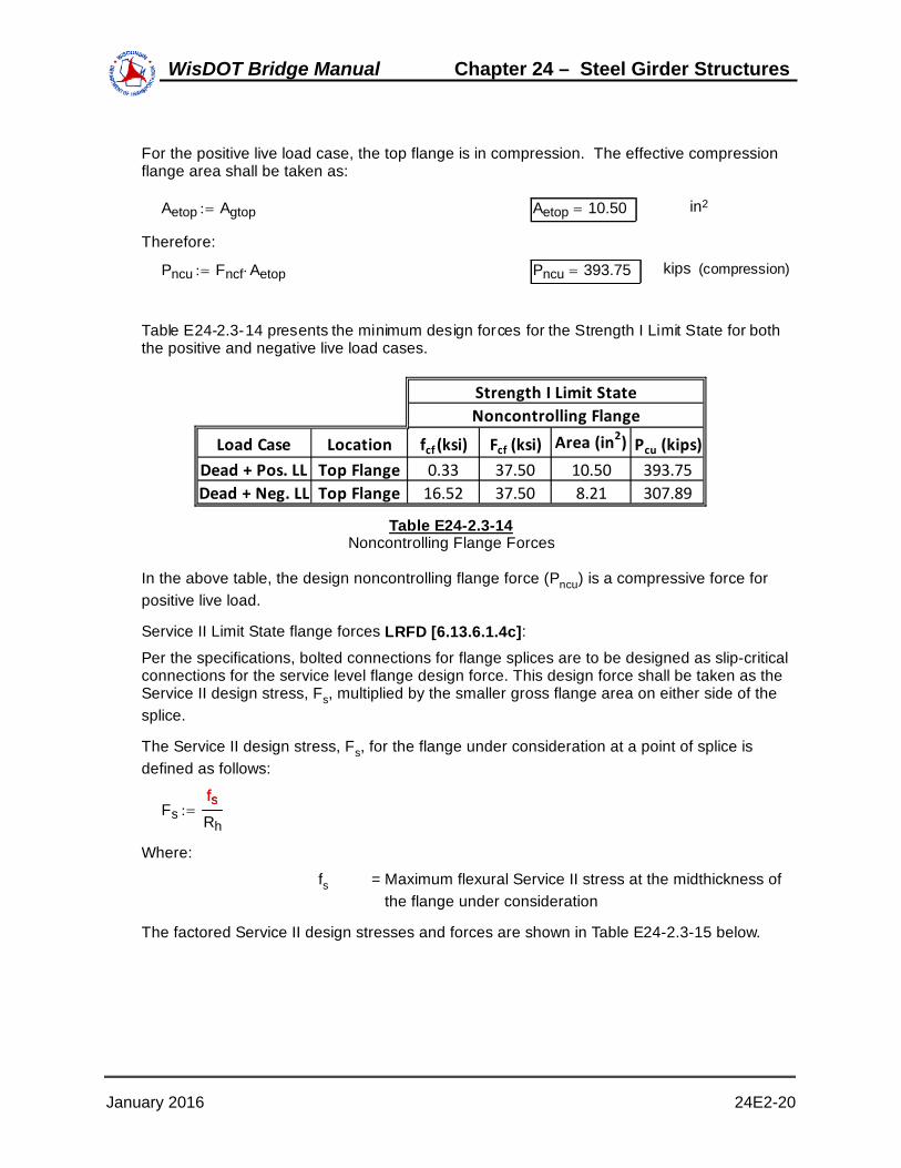
For the positive live load case, the top flange is in compression. The effective compressionflange area shall be taken as:
Aetop Agtop Aetop 10.50 in2
Therefore:
Pncu Fncf Aetop Pncu 393.75 kips (compression)
Table E24-2.3-14 presents the minimum design forces for the Strength I Limit State for boththe positive and negative live load cases.
Load Case Location fcf (ksi) Fcf (ksi) Area (in2) Pcu (kips)
Dead + Pos. LL Top Flange 0.33 37.50 10.50 393.75
Dead + Neg. LL Top Flange 16.52 37.50 8.21 307.89
Strength I Limit State
Noncontrolling Flange
Table E24-2.3-14Noncontrolling Flange Forces
In the above table, the design noncontrolling flange force (Pncu) is a compressive force forpositive live load.
Service II Limit State flange forces LRFD [6.13.6.1.4c]:Per the specifications, bolted connections for flange splices are to be designed as slip-criticalconnections for the service level flange design force. This design force shall be taken as theService II design stress, Fs, multiplied by the smaller gross flange area on either side of thesplice.
The Service II design stress, Fs, for the flange under consideration at a point of splice isdefined as follows:
FsfsRh
fs
Where:
fs = Maximum flexural Service II stress at the midthickness of the flange under consideration
The factored Service II design stresses and forces are shown in Table E24-2.3-15 below.
January 2016 24E2-20
WisDOT Bridge Manual Chapter 24 – Steel Girder Structures

Load Case Location Fs (ksi) Agross (in2) Ps (kips)
Bot. Flange 13.18 12.25 161.49
Top Flange 0.71 10.50 7.46
Bot. Flange ‐12.33 12.25 ‐151.06
Top Flange 1.94 10.50 20.41Dead + Neg. LL
Service II Limit State
Dead + Pos. LL
Table E24-2.3-15Service II Flange Forces
It is important to note here that the flange slip resistance must exceed the larger of: (1) theService II flange forces or (2) the factored flange forces from the moments at the splice dueto constructibility (erection and/or deck pouring sequence) LRFD [6.13.6.1.4a]. However, inthis design example, no special erection procedure is prescribed, therefore, the deck isassumed to be placed in a single pour. The constructibility moment is then equal to thenoncomposite dead load moment shown at the beginning of this design step. By inspection,the Service II Limit State will control for checking of slip-critical connections for the flangesand the web in this example.
Fatigue Limit State stresses:
The final portion of this design step is to determine the range of the stresses at themidthickness of both flanges, and at the top and bottom of the web for the Fatigue LimitState. The ranges are calculated below and presented in Table E24-2.3-16.
A typical calculation of the stress range for the bottom flange is shown below.
From Tables E24-2.3-7 and E24-2.3-8, the factored stresses at the midthickness of thebottom flange are:
Case 1 - Positive Live Load:
fspos 5.01
Case 2 - Negative Live Load:
fsneg 3.8
The stress range is determined by:
Δf fspos fsneg Δf 8.81 ksi
LocationFatigue Limit State
Stress Range (ksi)
Bottom Flange 8.81
Top Flange 0.42
Bottom of Web 8.73
Top of Web 0.35
Table E24-2.3-16Fatigue Stress Ranges
January 2016 24E2-21
WisDOT Bridge Manual Chapter 24 – Steel Girder Structures

E24-2.4 - Design Bottom Flange Splice
Splice plate dimensions:
The width of the outside plate should be at least as wide as the width of the narrowest flangeat the splice. Therefore, try a 7/16" x 14" outside splice plate with two 1/2" x 6" inside spliceplates. Include a 1/2" x 14" fill plate on the outside. Figure E24-2.4-1 illustrates the initialbottom flange splice configuration.
Girder Web
Girder Web
CLSpliceInside Splice Plates 2
Plates - ½" x 6"
Flange 7/8” x 14" Flange
1 3/8" x 14"Outside Splice
Plate 7/16" x 14"
Fill Plate ½" x 14"
Figure E24-2.4-1Bottom Flange Splice
The dimensions of the elements involved in the bottom flange splice from Figure E24-2.4-1are:
Thickness of the inside splice plate:
tin 0.50 in
Width of the inside splice plate:
bin 6 in
Thickness of the outside splice plate:
tout 0.4375 in
Width of the outside splice plate:
bout 14 in
Thickness of the fill plate:
tfill 0.50 in
January 2016 24E2-22
WisDOT Bridge Manual Chapter 24 – Steel Girder Structures

Width of the fill plate:
bfill 14 in
If the combined area of the inside splice plates is within ten percent of the area of the outsidesplice plate, then both the inside and outside splice plates may be designed for one-half theflange design force LRFD [C6.13.6.4.1c]. Gross area of the inside and outside splice plates:
Inside:
Agross_in 2 tin bin Agross_in 6.00 in2
Outside:
Agross_out tout bout Agross_out 6.13 in2
Check:
1Agross_in
Agross_out
100 % 2.04 %
The combined areas are within ten percent.
If the areas of the inside and outside splice plates had differed by more than ten percent, theflange design force would be proportioned to the inside and outside splice plates. This iscalculated by multiplying the flange design force by the ratio of the area of the splice plateunder consideration to the total area of the inner and outer splice plates.
Yielding and fracture of splice plates:
Case 1 - Tension LRFD [6.13.5.2]:At the Strength Limit State, the design force in the splice plates subjected to tension shall notexceed the factored resistances for yielding, fracture, and block shear.
From Table E24-2.3-13, the Strength I bottom flange tension design force is:
Pcu 359.21 kips
The factored tensile resistance for yielding on the gross section, Pr, is taken from LRFD[6.8.2.1]:
Pr ϕy Pny Pny
Where:
Pny = Nominal tensile resistance for yielding in gross section (kips)
= FyAg
Fy = Specified minimum yield strength (ksi)
January 2016 24E2-23
WisDOT Bridge Manual Chapter 24 – Steel Girder Structures

Ag = Gross cross-sectional area of the member (in2)
Pr ϕy Fy Ag Ag
Fy 50.00 ksi SeeE24-2.1
ϕy 0.95 SeeE24-2.1
For yielding of the outside splice plate:
Ag Agross_out Ag 6.13 in2
Pr ϕy Fy Ag Pr 290.94 kips
The outside splice plate takes half of the design load:
Pr 290.94 >Pcu
2179.61 OK
For yielding of the inside splice plates:
Ag Agross_in Ag 6.00 in2
Pr ϕy Fy Ag Pr 285.00 kips
The inside splice plate takes half of the design load:
Pr 285.00 kips >Pcu
2179.61 kips OK
The factored tensile resistance for fracture on the net section, Pr, is calculated by:
Pr ϕu Pnu Pnu
Where:
Pnu = Nominal tensile resistance for fracture in net section (kips)
= FuAnRpU
Fu = Tensile strength (ksi)
Rp = Reduction factor for holes taken equal to 0.90 for boltholes punched full size and 1.0 for bolt holes drilled fullsize or subpunched and reamed to size.
An = Net area of the member (in2) LRFD [6.8.3]
January 2016 24E2-24
WisDOT Bridge Manual Chapter 24 – Steel Girder Structures

U = reduction factor to account for shear lag; 1.0 for components in which force effects are transmitted to all elements, and as specified in LRFD [6.8.2.2] for othercases
Pr ϕu Fu An Rp U An
Fu 65.00 ksi SeeE24-2.1
ϕu 0.80 SeeE24-2.1
U 1.0
Rp 1.0
To compute the net area of the splice plates, assume four 7/8" bolts across the width of thesplice plate.
The net width shall be determined for each chain of holes extending across the memberalong any transverse, diagonal or zigzag line. This is determined by subtracting from thewidth of the element the sum of the width of all holes in the chain and adding the quantitys2/4g for each space between consecutive holes in the chain. For non-staggered holes,such as in this design example, the minimum net width is the width of the element minus thenumber of bolt holes in a line straight across the width LRFD [6.8.3].For fracture of the outside splice plate:
The net width is:
dhole 1.00 in (see E24-2.1)
bn_out bout 4 dhole bn_out 10.00 in
The nominal area is determined to be:
An_out bn_out tout An_out 4.38 in2
The net area of the connecting element is limited to 0.85Ag LRFD [6.13.5.2]:
An 0.85 Ag
Agross_out 6.13 in2
An_out 4.38 in2 < 0.85 Agross_out 5.21 in2 OK
Pr ϕu Fu An_out U Pr 227.50 kips
The outside splice plate takes half of the design flange force:
January 2016 24E2-25
WisDOT Bridge Manual Chapter 24 – Steel Girder Structures

Pr 227.50 kips >Pcu
2179.61 kips OK
For fracture of the inside splice plates:
The net width is:
bn_in bin 2 dhole bn_in 4.00 in
The nominal area is determined to be:
An_in 2 bn_in tin An_in 4.00 in2
The net area of the connecting element is limited to 0.85Ag:
An 0.85 Ag
Agross_in 6.00 in2
An_in 4.00 in2 < 0.85 Agross_in 5.10 in2 OK
Pr ϕu Fu An_in U Pr 208.00 kips
The inside splice plates take half of the design flange force:
Pr 208.00 kips >Pcu
2179.61 kips OK
Case 2 - Compression LRFD [6.13.6.1.4c]:From Table E24-2.3-13, the Strength I bottom flange compression design force is:
Pcu 459.38 kips
This force is distributed equally to the inside and outside splice plates.
The factored resistance of the splice plate, Rr, is calculated from:
Rr ϕc Fy As As
Where:
c = resistance factor for compression LRFD [6.5.4.2]
Fy = Specified minimum yield strength of the splice plate (ksi)
As = Gross area of the splice plate (in2)
ϕc 0.90 (see E24-2.1)
For yielding of the outside splice plate:
As Agross_out As 6.13 in2
Rr_out ϕc Fy As Rr_out 275.63 kips
January 2016 24E2-26
WisDOT Bridge Manual Chapter 24 – Steel Girder Structures

Rr_out 275.63 kips >Pcu
2229.69 kips OK
For yielding of the inside splice plates:
As Agross_in As 6.00 in2
Rr_in ϕc Fy As Rr_in 270.00 kips
Rr_in 270.00 kips >Pcu
2229.69 kips OK
Block shear LRFD [6.13.6.1.4c, 6.13.5.2 & 6.13.4]:
All tension connections, including connection plates, splice plates and gusset plates, shall beinvestigated to ensure that adequate connection material is provided to develop the factoredresistance of the connection. Block shear rupture will usually not govern the design of spliceplates of typical proportion. However, the block shear checks are carried out here forcompleteness.
From Table E24-2.3-13, the Strength I bottom flange tension design force is:
Pcu 359.25 kips
Rr ϕbs Rp 0.58 Fu Avn Ubs Fu Atn ϕbs Rp 0.58 Fy Avg Ubs Fu Atn Avn
Where:
Rp = Reduction factor (1.0)
bs = Resistance factor for block shear LRFD [6.5.4.2]
Fy = Specified minimum yield strength of the connected material (ksi)
Avg = Gross area along the plane resisting shear stress (in2)
Fu = Specified minimum tensile strength of the connected material (ksi) LRFD [Table 6.4.1-1]
Atn = Net area along the plane resising tension stress (in2)
Avn = Net area along the plane resisting shear stress (in2)
Ubs = Reduction factor for block shear rupture resistance takenequal to 0.50 when the tension stress is non-uniform and1.0 when the tension stress is uniform
From E24-2.1:
Fy 50.00 ksi
January 2016 24E2-27
WisDOT Bridge Manual Chapter 24 – Steel Girder Structures

Fu 65.00 ksi
ϕbs 0.80
Outside splice plate:
Failure mode 1:
A bolt pattern must be assumed prior to checking an assumed block shear failure mode. Aninitial bolt pattern for the bottom flange splice, along with the first assumed failure mode, isshown in Figure E24-2.4-2. The outside splice plate will now be checked for block shear.
14.00”
3.00”
1.50”
5.00”
1.50” 3.00” 3.00”
1.9375"
1.00" Ø
Field SpliceCL
Figure E24-2.4-2Outside Splice Plate - Failure Mode 1
Applying the factored resistance equations presented previously to the outside splice platefor failure mode 1:
Gross area along the plane resisting shear stress:
Avg 2 3.00( ) 1.50[ ] tout Avg 3.28 in2
Net area along the plane resisting shear stress:
Avn 2 3.00( ) 1.50 2.5 dhole tout Avn 2.19 in2
Net area along the plane resisting tension stress:
January 2016 24E2-28
WisDOT Bridge Manual Chapter 24 – Steel Girder Structures

Atn 2 3.00( ) 5.00 1.50[ ] 3.5 dhole tout Atn 3.94 in2
Ubs 1.0
Rr1 ϕbs Rp 0.58 Fu Avn Ubs Fu Atn 270.73
Rr2 ϕbs Rp 0.58 Fy Avg Ubs Fu Atn 280.88
Rr min Rr1 Rr2
Rr 270.73 kips
Check:
Rr 270.73 kips >Pcu
2179.63 kips OK
Failure mode 2:
See Figure E24-2.4-3 for failure mode 2:
14.00”
3.00”
1.50”
5.00”
1.50” 3.00” 3.00”
1.9375"
1.00” Ø
Field SpliceCL
Figure E24-2.4-3Outside Splice Plate - Failure Mode 2
The failure mode 2 calculations for the outside splice plates are are not shown since they aresimilar to those shown previously for failure mode 1. The final check for failure mode 2 isshown below.
January 2016 24E2-29
WisDOT Bridge Manual Chapter 24 – Steel Girder Structures

Check:
Rr 268.45 kips >Pcu
2179.63 kips OK
Inside splice plates:
The inside splice plates will now be checked for block shear. See Figure E24-2.4-4 for theassumed failure mode:
6.00"
13.00"
1.50”
3.00”
1.50”
5.00”
1.50" 3.00” 3.00”
1.9375"
1.00” Ø
CL Field Splice
Figure E24-2.4-4Inside Splice Plates - Block Shear Check
The calculations for the inside splice plates are not shown since they are similar to thoseshown previously for failure mode 1 and 2. The final check for the inside splice plates isshown below.
Check:
Rr 306.80 kips >Pcu
2179.63 kips OK
January 2016 24E2-30
WisDOT Bridge Manual Chapter 24 – Steel Girder Structures

Girder bottom flange:
The girder bottom flange will now be checked for block shear. See Figure E24-2.4-5 for theassumed failure mode:
14.00"
3.00”
1.50”
5.00”
3.00” 3.00”1.75"
1.00” Ø
Field Splice
CL
Figure E24-2.4-5Bottom Flange - Block Shear Check
The calculations for the girder bottom flange are not shown since they are similar to thoseshown previously for the inside splice plates. The final check for the girder bottom flange isshown below.
Check:
Rr 736.19 kips > Pcu 359.25 kips OK
It should be noted that although the block shear checks performed in this design exampleindicate an overdesign, the number of bolts cannot be reduced prior to checking shear onthe bolts and bearing at the bolt holes. These checks are performed in what follows.
Net Section Fracture LRFD [6.10.1.8]
When checking flexural members at the strength limit state or for constructibility, the stresson the gross area of the tension flange due to the factored loads calculated withoutconsideration of flange lateral bending, ft, shall be satisfied at all cross-sections containingholes in the tension flange:
January 2016 24E2-31
WisDOT Bridge Manual Chapter 24 – Steel Girder Structures

ft 0.84An
Ag
Fu Fyt
Where:
An = Net area of the tension flange (in2) LRFD[6.8.3]
Ag = Gross area of the tension flange (in2)
Fyt = Specified minimum yield strength of a tension flange (ksi)LRFD [C6.8.2.3]
An bflbL 4 dhole tflbL An 8.75 in2
Ag tflbL bflbL Ag 12.25 in2
Fu 65.00 ksi
0.84An
Ag
Fu 39.00 ksi
Fyt 50 ksi
ft 37.5 ksi (from Table E24-2.3-13)
ft 0.84An
Ag
Fu fyt OK
Flange bolts - shear:
Determine the number of bolts for the bottom flange splice plates that are required todevelop the Strength I design force in the flange in shear assuming the bolts in theconnection have slipped and gone into bearing. A minimum of two rows of bolts should beprovided to ensure proper alignment and stability of the girder during construction.
The Strength I flange design force used in this check was previously computed (referenceTable E24-2.3-13):
Pcu 459.38 kips
The factored resistance of an ASTM A325 7/8" diameter high-strength bolt in shear must bedetermined, assuming the threads are excluded from the shear planes. For this case, thenumber of bolts required to provide adequate shear strength is determined by assuming thedesign force acts on two shear planes, known as double shear.
The nominal shear resistance, Rn, is computed first as follows LRFD [6.13.2.7]:
Rn 0.48 Ab Fub Ns Ab
January 2016 24E2-32
WisDOT Bridge Manual Chapter 24 – Steel Girder Structures
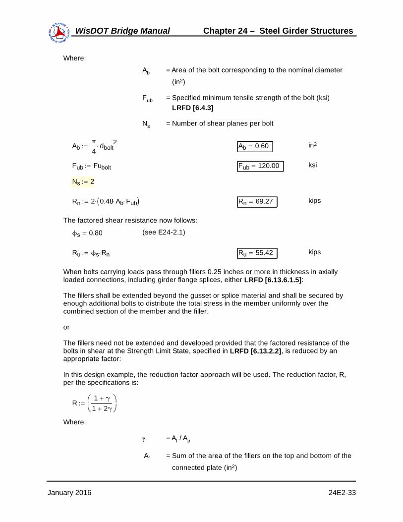
Where:
Ab = Area of the bolt corresponding to the nominal diameter
(in2)
Fub = Specified minimum tensile strength of the bolt (ksi) LRFD [6.4.3]
Ns = Number of shear planes per bolt
Abπ
4dbolt
2 Ab 0.60 in2
Fub Fubolt Fub 120.00 ksi
Ns 2
Rn 2 0.48 Ab Fub Rn 69.27 kips
The factored shear resistance now follows:
ϕs 0.80 (see E24-2.1)
Ru ϕs Rn Ru 55.42 kips
When bolts carrying loads pass through fillers 0.25 inches or more in thickness in axiallyloaded connections, including girder flange splices, either LRFD [6.13.6.1.5]:
The fillers shall be extended beyond the gusset or splice material and shall be secured byenough additional bolts to distribute the total stress in the member uniformly over thecombined section of the member and the filler.
or
The fillers need not be extended and developed provided that the factored resistance of thebolts in shear at the Strength Limit State, specified in LRFD [6.13.2.2], is reduced by anappropriate factor:
In this design example, the reduction factor approach will be used. The reduction factor, R,per the specifications is:
R1 γ
1 2γ
Where:
= Af / Ap
Af = Sum of the area of the fillers on the top and bottom of the
connected plate (in2)
January 2016 24E2-33
WisDOT Bridge Manual Chapter 24 – Steel Girder Structures

Ap = Smaller of either the connected plate area or the sum of the splice plate areas on the top and bottom of theconnected plate (in2)
Sum of the area of the fillers on the top and bottom of the connected plate:
Af bfill tfill Af 7.00 in2
The smaller of either the connected plate area (i.e., girder flange) or the sum of the spliceplate areas on the top and bottom of the connected plate determines Ap.
Bottom flange area:
bflbL 14.00 in
tflbL 0.88 in
Ap1 bflbL tflbL Ap1 12.25 in2
Sum of splice plate areas is equal to the gross areas of the inside and outside splice plates:
Agross_in 6.00 in
Agross_out 6.13 in
Ap2 Agross_in Agross_out Ap2 12.13 in2
The minimum of the areas is:
Ap min Ap1 Ap2 Ap 12.13 in2
Therefore:
γAf
Ap γ 0.58
The reduction factor is determined to be:
Rfill1 γ
1 2γ
Rfill 0.73
To determine the total number of bolts required for the bottom flange splice, divide theapplied Strength I flange design force by the reduced allowable bolt shear strength:
R Ru Rfill R 40.57 kips
The number of bolts required per side is:
NPcu
R N 11.32
January 2016 24E2-34
WisDOT Bridge Manual Chapter 24 – Steel Girder Structures

The minimum number of bolts required on each side of the splice to resist the maximumStrength I flange design force in shear is twelve.
Flange bolts - slip resistance:
Bolted connections for flange splices shall be designed as slip-critical connections for theService II flange design force, or the flange design force from constructibility, whichevergoverns LRFD [6.13.6.1.4a]. In this design example, the Service II flange force controls (seeE24-2.3).
When checking for slip of the bolted connection for a flange splice with inner and outer spliceplates, the slip resistance should always be determined by dividing the flange design forceequally to the two slip planes regardless of the ratio of the splice plate areas LRFD[C6.13.6.1.4c]. Slip of the connection cannot occur unless slip occurs on both planes.
From Table E24-2.3-15, the Service II bottom flange design force is:
Ps 161.49 kips
The factored resistance for slip-critical connections, Rn, is calculated from LRFD [6.13.2.2 &6.13.2.8]:
Rr Rn
Rn Kh Ks Ns Pt Kh
Where:
Kh = Hole size factor LRFD [Table 6.13.2.8-2]
Ks = Surface condition factor LRFD [Table 6.13.2.8-3]
Ns = Number of slip planes per bolt
Pt = Minimum required bolt tension (kips)LRFD [Table 6.13.2.8-1]
Determine the factored resistance per bolt assuming a Class B surface condition for thefaying surface, standard holes (which are required per LRFD [6.13.6.1.4a]) and two slipplanes per bolt:
Class B surfaces are unpainted blast-cleaned surfaces and blast-cleaned surfaces withClass B coatings LRFD [6.13.2.8].
Kh 1.0
Ks 0.50
Ns 2
Pt 39.0 kips
January 2016 24E2-35
WisDOT Bridge Manual Chapter 24 – Steel Girder Structures

Rr Kh Ks Ns Pt Rr 39.00 kips
The minimum number of bolts required to prevent slip is:
NPs
Rr N 4.14
Use:
N 5 bolts < N = 12 bolts determined previously to satisfy the bolt shearrequirements.
Therefore, the number of bolts required for the bottom-flange splice is controlled by the boltshear requirements. Arrange the bolts in three rows of four bolts per line with no stagger.
Flange bolts - minimum spacing LRFD [6.13.2.6.1]:
The minimum spacing between centers of bolts in standard holes shall be no less than threetimes the diameter of the bolt.
dbolt 0.875 in
smin 3 dbolt smin 2.63 in
s 3.00 in (see Figures E24-2.4-2 thruE24-2.4-5)
The minimum spacing requirement is satisfied.
Flange bolts - maximum spacing for sealing LRFD [6.13.2.6.2]:For a single line adjacent to a free edge of an outside plate or shape (for example, the boltsalong the edges of the plate parallel to the direction of the applied force):
s 4.0 4.0 t( ) 7.0
Where:
t = Thickness of the thinner outside plate or shape (in)
tout 0.4375 in
Maximum spacing for sealing:
4.0 4.0 tout 5.75 in
s 5.75 7.00 OK
Next, check for sealing along the free edge at the end of the splice plate. The bolts are notstaggered, therefore the applicable equation is:
s 4.00 4.00 t( ) 7.00
Maximum spacing along the free edge at the end of the splice plate (see Figures E24-2.4-2thru E24-2.4-5):
send 5.00 in
January 2016 24E2-36
WisDOT Bridge Manual Chapter 24 – Steel Girder Structures

Maximum spacing for sealing:
4.0 4.0 tout 5.75 in
send 5.75 7.00 OK
Flange bolts - maximum pitch for stitch bolts LRFD [6.13.2.6.3]:The maximum pitch requirements are applicable only for mechanically fastened built-upmembers and will not be applied in this example.
Flange bolts - edge distance LRFD [6.13.2.6.6]:The minimum required edge distance is measured as the distance from the center of any boltin a standard hole to an edge of the plate. For a 7/8" diameter bolt measured to a shearededge, the minimum edge distance is 1 1/2" LRFD [Table 6.13.2.6.6-1]. Referring to FiguresE24-2.4-2 thru E24-2.4-5, it is clear that the minimum edge distance specified for thisexample is 1 1/2" and thus satisfies the minimum requirement.
The maximum edge distance shall not be more than eight times the thickness of the thinnestoutside plate or five inches.
8 t 5.00 in
t tout tout 0.4375 in
8 tout 3.50 in
The maximum distance from the corner bolts to the corner of the splice plate or girder flangeis equal to (reference Figure E24-2.4-5):
1.502 1.752 2.30 in
2.30 in 3.50 in OK
Flange bolts - bearing at bolt holes LRFD [6.13.2.9]:Check bearing of the bolts on the connected material under the maximum Strength I LimitState design force. The maximum Strength I bottom flange design force from TableE24-2.3-13 is:
Pcu 459.38
The design bearing strength of the connected material is calculated as the sum of thebearing strengths of the individual bolt holes parallel to the line of the applied force.
The element of the bottom flange splice that controls the bearing check in this designexample is the outer splice plate.
To determine the applicable equation for the calculation of the nominal resistance, the cleardistance between holes and the clear end distance must be calculated and compared to thevalue of two times the nominal diameter of the bolt. This check yields:
dbolt 0.875 in 2 dbolt 1.75 in
For the bolts adjacent to the end of the splice plate, the edge distance is 1 1/2". Therefore,the clear end distance between the edge of the hole and the end of the splice plate:
January 2016 24E2-37
WisDOT Bridge Manual Chapter 24 – Steel Girder Structures

dhole 1.00
Lc11.50
dhole
2 Lc1
1.00 in
The center-to-center distance between bolts in the direction of the force is three inches.Therefore, the clear distance between edges of adjacent holes is computed as:
Lc23.00 dhole Lc2
2.00 in
For standard holes, where either the clear distance between holes or the clear end distanceis less than twice the bolt diameter, the nominal resistance, Rn, is taken as:
Rn 1.2 Lc t Fu
Where:
Lc = Clear distance between holes or between the hole and theend of the member in the direction of the applied bearingforce (in)
For the outside splice plate:
tout 0.4375 in
Fu 65.00 in
The nominal resistance for the end row of bolt holes is computed as follows:
Rn14 1.2 Lc1
tout Fu Rn1136.50 kips
The nominal resistance for the remaining bolt holes is computed as follows:
Rn28 1.2 Lc2
tout Fu Rn2546.00 kips
The total nominal resistance of the bolt holes is:
Rn Rn1Rn2
Rn 682.50 kips
ϕbb 0.80
Rr ϕbb Rn Rr 546.00 kips
Check:
Pcu
2229.69 kips < Rr 546.00 kips OK
January 2016 24E2-38
WisDOT Bridge Manual Chapter 24 – Steel Girder Structures

Fatigue of splice plates LRFD [6.6.1]:Check the fatigue stresses in the base metal of the bottom flange splice plates adjacent tothe slip-critical connections. Fatigue normally does not govern the design of the spliceplates, and therefore, an explicit check is not specified. However, a fatigue check of thesplice plates is recommended whenever the combined area of the inside and outside flangesplice plates is less than the area of the smaller flange at the splice.
From Table E24-2.3-16, the factored fatigue stress range at the midthickness of the bottomflange is:
Δffact 8.81 ksi
For load-induced fatigue considerations, each detail shall satisfy:
γ Δf( ) ΔFn
Where:
= Load factor for fatigue I load combination LRFD [Table3.4.1-1]
(f) = Force effect, live load stress range due to the passage ofthe fatigue load (ksi) LRFD [3.6.1.4]
Fn = Nominal fatigue resistance (ksi) LRFD [6.6.1.2.5]
γ 1.50
γ Δf( ) Δffact γ Δf( ) 8.81 ksi
For the fatigue I load combination:
ΔFn ΔFTHΔFn
Where:
FTH = Constant-amplitude fatigue threshold (ksi)LRFD [Table 6.6.1.2.5-3]
ΔFTH 16 ksi
ΔFn ΔFTH ΔFn 16.00 ksi (governs)
Check that the following is satisfied:
Δffact ΔFn Δffact 8.81 ksi < ΔFn 16.00 ksi OK
January 2016 24E2-39
WisDOT Bridge Manual Chapter 24 – Steel Girder Structures

Control of permanent deflection - splice plates LRFD [6.10.4.2]:
A check of the flexural stresses in the splice plates at the Service II Limit State is not explicitlyspecified in the specifications. However, whenever the combined area of the inside andoutside flange splice plates is less than the area of the smaller flange at the splice (which isthe case for the bottom flange splice in this example), such a check is recommended.
The maximum Service II flange force in the bottom flange is taken from Table E24-2.3-15:
Ps 161.49 kips
The following criteria will be used to make this check LRFD [6.10.4.2]. The equationpresented is for both steel flanges of a composite section assuming no lateral flangebending:
ff 0.95 Rh Fyf
Where:
ff = Flange stress at the section under consideration due tothe Service II loads calculated without consideration offlange lateral bending (ksi)
Rh = Hybrid factor LRFD [6.10.1.10.1]
Fyf = Specified minimum yield strength of a flange (ksi)LRFD [6.7.7.3]
Fyf 50.00 ksi
The flange force is equally distributed to the inner and outer splice plates due to the areas ofthe flanges being within 10 percent of each other:
PPs
2 P 80.75 kips
The resulting stress in the outside splice plate is:
f_outP
Agross_out f_out 13.18 ksi
f_out 13.18 ksi < 0.95 Fyf 47.50 ksi OK
The resulting stress in the inside splice plates is:
f_in 13.46 ksi < 0.95 Rh Fyf 47.50 ksi OK
January 2016 24E2-40
WisDOT Bridge Manual Chapter 24 – Steel Girder Structures

E24-2.5 Design Top Flange SpliceThe top flange splice is designed using the same procedures and methods presented in thisdesign example for the bottom flange splice.
E24-2.6 Compute Web Splice Design LoadsWeb splice plates and their connections shall be designed for shear, the moment due to theeccentricity of the shear at the point of splice, and the portion of the flexural momentassumed to be resisted by the web at the point of the splice LRFD [6.13.6.1.4b].Girder shear forces at the splice location:
A summary of the unfactored shears at the splice location from the initial trial of the girderdesign are listed below. The live loads include impact and distribution factors.
Dead load shears:
Noncomposite:
VNDL 58.3 kips
Composite:
VCDL 7.7 kips
Future wearing surface:
VFWS 7.3 kips
Live Load shears:
HL-93 positive:
VPLL 14.7 kips
HL-93 negative:
VNLL 94.0 kips
Fatigue positive:
VPFLL 5.2 kips
Fatigue negative:
VNFLL 34.2 kips
Web moments and horizontal force resultant LRFD [C6.13.6.1.4b]:Because the portion of the flexural moment assumed to be resisted by the web is to beapplied at the mid-depth of the web, a horizontal design force resultant, Huw, must also beapplied at the mid-depth of the web to maintain equilibrium. The web moment and horizontalforce resultant are applied together to yield a combined stress distribution equivalent to theunsymmetrical stress distribution in the web. For sections with equal compressive and tensilestresses at the top and bottom of the web (i.e., with the neutral axis located at the mid-depth
January 2016 24E2-41
WisDOT Bridge Manual Chapter 24 – Steel Girder Structures

of the web), Huw will equal zero.
In the computation of the portion of the flexural moment assumed to be resisted by the web,Muw, and the horizontal design force resultant, Huw, in the web, the flange stresses at themidthickness of the flanges are conservatively used. This allows use of the same stressvalues for both the flange and web splices, which simplifies the calculations. It is important tonote that the flange stresses are taken as signed quantities in determining Muw and Huw(positive for tension; negative for compression).
The moment, Muv, due to the eccentricity of the design shear, Vuw, is resisted solely by theweb and always acts about the mid-depth of the web (i.e., horizontal force resultant is zero).This moment is computed as:
Muv Vuw e Vuw
Where:
e = The distance from the centerline of the splice to thecentroid of the connection on the side of the joint underconsideration (in)
e 1.93753.00
2 (see Figure E24-2.7-1) e 3.4375 in
The total web moment for each load case is computed as follows:
Mtotal Muw Muv Muv
In general, and in this example, the web splice is designed under the conservativeassumption that the maximum moment and shear at the splice will occur under the sameloading condition.
Strength I Limit State:
Design shear LRFD [6.13.6.1.4b]:For the Strength I Limit State, the girder web factored shear resistance is required whendetermining the design shear LRFD [6.10.9.2]. Assume an unstiffened web at the splicelocation. The nominal shear resistance, Vn, is as follows:
Vn C Vp Vp
Where:
C = Ratio of the shear-buckling resistance to the shear yieldstrength in accordance with LRFD [6.10.9.3.2], with theshear-buckling coefficient, k, taken equal to 5.0
Vp = Plastic shear force (kips)= 0.58FywDtw
Fyw = Specified minimum yield strength of a web (ksi)
D = Clear distance between flanges (in)
January 2016 24E2-42
WisDOT Bridge Manual Chapter 24 – Steel Girder Structures

tw = Web thickness (in)
k 5.0
E 29000 ksi
Fyw Fy Fyw 50.00 ksi
D 54.00 in (see Figure E24-2.1-1)
tw 0.50 in (see Figure E24-2.1-1)
Compare:Dtw
108.00
to the values for:
1.12E kFyw
60.31
and
1.40E kFyw
75.39
Based on the computed value of D/tw, use the following equation to determine C LRFD[6.10.9.3.2]:
C1.57
Dtw
2E kFyw
C 0.39
The nominal shear resistance, Vn, is computed as follows:
Vp 0.58 Fyw D tw Vp 783.00 kips
Vn C Vp Vn 305.64 kips
The factored shear resistance, Vr, now follows:
Vr ϕv Vn Vr 305.64 kips
At the strength limit state, the design shear, Vuw, shall be taken as LRFD [6.13.6.1.4b]:
If:
Vu < 0.5 vVn, then:
then:
January 2016 24E2-43
WisDOT Bridge Manual Chapter 24 – Steel Girder Structures

Vuw 1.5 Vu Vu
Otherwise:
VuwVu ϕv Vn
2
Vu
The shear due to the Strength I loading at the point of splice, Vu, is computed from the girdershear forces at the splice location listed at the beginning of this section.
For the Strength I Limit State, the factored shear for the positive live load is:
Vupos 0.90 VNDL VCDL 1.75 VPLL Vupos 33.67 kips
For the Strength I Limit State, the factored shear for the negative live load is:
Vuneg 1.25 VNDL VCDL 1.50 VFWS 1.75 VNLL
Vuneg 257.95 kips (controls)
Therefore:
Vu Vuneg Vu 257.95 kips
Since Vu exceeds one-half of vVn:
VuwVu ϕv Vn
2 Vuw 281.80 kips
Web moments and horizontal force resultants:
Case 1 - Dead load + positive live load:
For the loading condition with positive live load, the controlling flange was previouslydetermined to be the bottom flange. The maximum elastic flexural stress due to the factoredloads at the midthickness of the controlling flange, fcf, and the design stress for thecontrolling flange, Fcf, were previously computed for this loading condition. From TableE24-2.3-13:
fcf 18.32 ksi
Fcf 37.50 ksi
For the same loading condition, the concurrent flexural stress at the midthickness of thenoncontrolling (top) flange, fncu, was previously computed. From Table E24-2.3-14:
fncf 0.33 ksi
Therefore, the portion of the flexural moment, Muw, assumed to be resisted by the web iscomputed as:
Muwtw D2
12Rh Fcf Rcf fncf
January 2016 24E2-44
WisDOT Bridge Manual Chapter 24 – Steel Girder Structures

Where:
Fcf = Design stress for the controlling flange at the point ofsplice specified in LRFD [6.13.6.1.4c]; positive fortension, negative for compression (ksi)
Rcf = The absolute value of the ratio of Fcf to the maximumflexural stress, fcf, due to the factored loads at themidthickness of the controlling flange at the point ofsplice, as defined in LRFD [6.13.6.1.4c]
fncf = Flexural stress due to the factored loads at themidthickness of the noncontrolling flange at the point ofsplice concurrent with fcf; positive for tension, negative forcompression (ksi)
Rh 1.00
RcfFcf
fcf Rcf 2.05
Compute the portion of the flexural moment to be resisted by the web:
Muw_str_postw D2
12Rh Fcf Rcf fncf
112
Muw_str_pos 372.85 kip-ft
The total web moment is:
Mtot_str_pos Muw_str_pos Vuw e 112
Mtot_str_pos 453.57 kip-ft
Compute the horizontal force resultant (the variables included in this equation are as definedfor Mw_str_pos):
Huw_str_postw D
2Rh Fcf Rcf fncf Huw_str_pos 515.37 kips
The above value is a signed quantity, positive for tension and negative for compression.
Case 2 - Dead load + negative live load:
The calculations at the Strength I Limit State for case 2 are not shown since they are similarto those shown previously for case 1. The final web moment and horizontal force resultantfor case 2 are shown below.
The total web moment is:
Mtot_str_neg Muw_str_neg Vuw e 112
Mtot_str_neg 759.38 kip-ft
Compute the horizontal force resultant:
January 2016 24E2-45
WisDOT Bridge Manual Chapter 24 – Steel Girder Structures

Huw_str_negtw D
2Rh Fcf Rcf fncf Huw_str_neg 107.62 kips
The above value is a signed quantity, positive for tension, and negative for compression.
Service II Limit State:
Design shear:
As a minimum, for checking slip of the web splice bolts, the design shear shall be taken asthe shear at the point of splice under the Service II Limit State, or the shear fromconstructibility, whichever governs LRFD [6.13.6.1.4b]. In this design example, the Service IIshear controls (see previous discussion in section E24-2.3).
For the Service II Limit State, the factored shear for the positive live load is (ignore futurewearing surface):
Vser_pos 1.00 VNDL 1.00 VCDL 1.30 VPLL Vser_pos 46.89 kips
For the Service II Limit State, the factored shear for the negative live load is (include futurewearing surface):
Vser_neg 1.00 VNDL 1.00 VCDL 1.00 VFWS 1.30 VNLL
Vser_neg 195.50 kips (governs)
Therefore:
Vw_ser Vser_neg Vw_ser 195.50 kips
Web moments and horizontal force resultants LRFD [C6.13.6.1.4b]:
Muw_sertw D2
12fs fos fs
Huw_sertw D
2fs fos fs
Where:
fs = Maximum Service II midthickness flange stress for the loadcase considered (i.e., positive or negative live load) (ksi)
fos = Service II midthickness flange stress in the other flange,concurrent with fs
Case 1 - Dead load + positive live load:
The maximum midthickness flange flexural stress for the load case with positive live loadmoment for the Service II Limit State occurs in the bottom flange. From Table 2E2.34-11:
fs_bot_pos 13.18 ksi
fos_top_pos 0.71 ksi
January 2016 24E2-46
WisDOT Bridge Manual Chapter 24 – Steel Girder Structures

Therefore, for the load case of positive live load:
Muw_ser_postw D2
12fs_bot_pos fos_top_pos
112
Muw_ser_pos 126.26 kip-ft
Mtot_ser_pos Muw_ser_pos Vw_ser e 112
Mtot_ser_pos 182.26 kip-ft
Compute the horizontal force resultant:
Huw_ser_postw D
2fs_bot_pos fos_top_pos Huw_ser_pos 187.52 kips
The above value is a signed quantity, positive for tension, and negative for compression.
Case 2 - Dead load + negative live load:
The maximum midthickness flange flexural stress for the load case with negative live loadmoment for the Service II Limit State occurs in the bottom flange. From Table E24-2.3-11:
fs_bot_neg 12.33 ksi
fos_top_neg 1.94 ksi
Therefore:
Muw_ser_negtw D2
12fs_bot_neg fos_top_neg
112
Muw_ser_neg 144.48 kip-ft
The total web moment is:
Mtot_ser_neg Muw_ser_neg Vw_ser e 112
Mtot_ser_neg 200.49 kip-ft
Compute the horizontal force resultant:
Huw_ser_negtw D
2fs_bot_neg fos_top_neg Huw_ser_neg 140.27 kips
The above value is a signed quantity, positive for tension, and negative for compression.
January 2016 24E2-47
WisDOT Bridge Manual Chapter 24 – Steel Girder Structures

Fatigue I Limit State:
Fatigue of the base metal adjacent to the slip-critical connections in the splice plates may bechecked as specified in LRFD [Table 6.6.1.2.3-1] using the gross section of the splice platesand member LRFD [C6.13.6.1.4a]. However, the areas of the web splice plates will oftenequal or exceed the area of the web to which it is attached (the case in this design example).Therefore, fatigue will generally not govern the design of the splice plates, but is carried outin this example for completeness.
Design shear:
For the Fatigue I Limit State, the factored shear for the positive live load is:
Vfat_pos 1.50 VPFLL Vfat_pos 7.80 kips
For the Fatigue I Limit State, the factored shear for the negative live load is:
Vfat_neg 1.50 VNFLL Vfat_neg 51.30 kips
Web moments and horizontal force resultants:
The portion of the flexural moment to be resisted by the web and the horizontal forceresultant are computed from equations similar to LRFD [Equations C6.13.6.1.4b-1 &6.13.6.1.4b-2], respectively, with appropriate substitutions of the stresses in the web causedby the fatigue-load moment for the flange stresses in the equations. Also, the absolute valuesigns are removed to keep track of the signs. This yields the following equations:
Muwtw D2
12fbotweb ftopweb fbotweb
Huwtw D
2fbotweb ftopweb fbotweb
Case 1 - Positive live load:
The factored stresses due to the positive live load moment for the Fatigue I Limit State at thetop and bottom of the web, from Table E24-2.3-12, are:
ftopweb_pos 0.20 ksi
fbotweb_pos 4.96 ksi
Therefore:
Muw_fat_postw D2
12fbotweb_pos ftopweb_pos
112
Muw_fat_pos 52.25 kip-ft
January 2016 24E2-48
WisDOT Bridge Manual Chapter 24 – Steel Girder Structures

The total web moment is:
Mtot_fat_pos Muw_fat_pos Vfat_pos e 112
Mtot_fat_pos 54.48 kip-ft
Compute the horizontal force resultant:
Huw_fat_postw D
2fbotweb_pos ftopweb_pos Huw_fat_pos 64.26 kips
The above value is a signed quantity, positive for tension, and negative for compression.
Case 2 - Negative live load:
The factored stresses due to the negative live load moment for the Fatigue I Limit State atthe top and bottom of the web, from Table E24-2.3-12, are:
fbotweb_neg 3.77 ksi
ftopweb_neg 0.15 ksi
Therefore:
Muw_fat_negtw D2
12fbotweb_neg ftopweb_neg
112
Muw_fat_neg 39.69 kip-ft
The total web moment is:
Mtot_fat_neg Muw_fat_neg Vfat_neg e 112
Mtot_fat_neg 54.39 kip-ft
Compute the horizontal force resultant:
Huw_fat_negtw D
2fbotweb_neg ftopweb_neg Huw_fat_neg 48.87 kips
The above value is a signed quantity, positive for tension, and negative for compression.
January 2016 24E2-49
WisDOT Bridge Manual Chapter 24 – Steel Girder Structures

E24-2.7 Design Web Splice
Web splice configuration:
Two vertical rows of bolts with sixteen bolts per row will be investigated. The typical boltspacings, both horizontally and vertically, are as shown in Figure E24-2.7-1. The outermostrows of bolts are located 4 1/2" from the flanges to provide clearance for assembly (see theAISC Manual of Steel Construction for required bolt assembly clearances). The web isspliced symmetrically by plates on each side with a thickness not less than one-half thethickness of the web. Assume 3/8" x 48" splice plates on each side of the web. No web fillplate is necessary for this example.
1.50"
3.00"
3.00"
3.00"
3/8"
1.50"
CL Splice
1.9375"
Figure E24-2.7-1Web Splice
Web bolts - minimum spacing LRFD [6.13.2.6.1]:
This check is only dependent upon the bolt diameter, and is therefore satisfied for a threeinch spacing per the check for the flange bolts from E24-2.4.
Web Bolts - Maximum Spacing for Sealing LRFD [6.13.2.6.2]:
January 2016 24E2-50
WisDOT Bridge Manual Chapter 24 – Steel Girder Structures

The maximum spacing of the bolts is limited to prevent penetration of moisture in the joints.
For a single line adjacent to a free edge of an outside plate or shape (for example, the boltsalong the edges of the plate parallel to the direction of the applied force):
s 4.0 4.0 t( ) 7.0
twp 0.375 in
Maximum spacing for sealing:
4.0 4.0 twp 5.50 in
3.0 5.5 7.00 OK
Web bolts - maximum pitch for stitch bolts LRFD [6.13.2.6.3]:
The maximum pitch requirements are applicable only for mechanically fastened built-upmembers and will not be applied in this example.
Web bolts - edge distance LRFD [6.13.2.6.6]:Referring to Figure E24-2.7-1, it is clear that the minimum edge distance specified for thisexample is 1 1/2" and thus satisfies the minimum requirement LRFD [Table 6.13.2.6.6-1]. The maximum edge distance shall not be more than eight times the thickness of the thinnestoutside plate or five inches.
t twp twp 0.3750 in
The maximum edge distance allowable is:
8 twp 3.00
The maximum distance from the corner bolts to the corner of the splice plate or girder flangeis equal to (reference Figure E24-2.7-1):
1.502 1.502 2.12 in
and satisfies the maximum edge distance requirement.
2.12 in 2.50 in OK
Web bolts - shear:
Calculate the polar moment of inertia, Ip, of the bolt group on each side of the centerline withrespect to the centroid of the connection LRFD [C6.13.6.1.4.b]. This is required fordetermination of the shear force in a given bolt due to the applied web moments.
Ipn m12
s2 n2 1 g2 m2 1 m
Where:
m = number of vertical rows of bolts
n = number of bolts in one vertical row
January 2016 24E2-51
WisDOT Bridge Manual Chapter 24 – Steel Girder Structures

s = vertical pitch (in)
g = horizontal pitch (in)
m 2
n 16
s 3.00 in
g 3.00 in
The polar moment of inertia is:
Ipn m12
s2 n2 1 g2 m2 1 Ip 6192.00 in2
The total number of web bolts on each side of the splice, assuming two vertical rows per sidewith sixteen bolts per row, is:
Nb 32
Strength I Limit State:
Under the most critical combination of the minimum design shear, moment and horizontalforce, it is assumed that the bolts in the web splice have slipped and gone into bearing. Theshear strength of an ASTM A325 7/8" diameter high-strength bolt in double shear, assumingthe threads are excluded from the shear planes, was computed in E24-2.4 for Flange Bolts -Shear:
Ru 55.42 kips
Case 1 - Dead load + positive live load:
The following forces were computed in E24-2.6:
Vuw 281.80 kips
Mtot_str_pos 453.57 kip-ft
Huw_str_pos 515.37 kips
The vertical shear force in the bolts due to the applied shear force:
Pv_strVuw
Nb Pv_str 8.81 kips
The horizontal shear force in the bolts due to the horizontal force resultant:
PH_str_posHuw_str_pos
Nb PH_str_pos 16.11 kips
Determine the horizontal and vertical components of the bolt shear force on the extreme bolt
January 2016 24E2-52
WisDOT Bridge Manual Chapter 24 – Steel Girder Structures

due to the total moment in the web:
PMvMtotal x
Ip
Mtotal
and
PMhMtotal y
Ip
Mtotal
For the vertical component:
xg2
x 1.50 in
For the horizontal component:
y15 s
2 y 22.50 in
Calculating the components:
PMv_str_posMtot_str_pos x( )
Ip12( ) PMv_str_pos 1.32 kips
PMh_str_posMtot_str_pos y( )
Ip12( ) PMh_str_pos 19.78 kips
The resultant bolt force for the extreme bolt is:
Pr_str_pos Pv_str PMv_str_pos 2
PH_str_pos PMh_str_pos 2
Pr_str_pos 37.28 kips
Case 2 - Dead load + negative live load:
The calculations at the Strength I Limit State for case 2 are not shown since they are similarto those shown previously for case 1. The final check for case 2 is shown below.
The following forces were computed in 24E2.6:
Vuw 281.80 kips
Mtot_str_neg 759.38 kip-ft
Huw_str_neg 107.62 kip-ft
The vertical shear force in the bolts due to the applied shear force:
Pv_strVuw
Nb Pv_str 8.81 kips
January 2016 24E2-53
WisDOT Bridge Manual Chapter 24 – Steel Girder Structures

The horizontal shear force in the bolts due to the horizontal force resultant:
PH_str_negHuw_str_neg
Nb PH_str_neg 3.36 kips
Determine the horizontal and vertical components of the bolt shear force on the extreme boltdue to the total moment in the web:
Calculating the components:
PMv_str_negMtot_str_neg x( )
Ip12( ) PMv_str_neg 2.21 kips
PMh_str_negMtot_str_neg y( )
Ip12( ) PMh_str_neg 33.11 kips
The resultant bolt force is:
Pr_str_neg Pv_str PMv_str_neg 2
PH_str_neg PMh_str_neg 2
Pr_str_neg 38.10 kips
The governing resultant bolt force is:
Pr_str max Pr_str_pos Pr_str_neg Pr_str 38.10 kips
Check:
Pr_str 38.10 kips < Ru 55.42 kips OK
Service II Limit State:
The factored slip resistance, Rr, for a 7/8" diameter high-strength bolt in double shear for aClass B surface and standard holes was determined from E24-2.4 to be:
Rr 39.00 kips
Case 1 - Dead load + positive live load:
The following forces were computed in E24-2.6:
Vw_ser 195.50 kips
Mtot_ser_pos 182.26 kip-ft
Huw_ser_pos 187.52 kips
The vertical shear force in the bolts due to the applied shear force:
Ps_serVw_ser
Nb Ps_ser 6.11 kips
January 2016 24E2-54
WisDOT Bridge Manual Chapter 24 – Steel Girder Structures

The horizontal shear force in the bolts due to the horizontal force resultant:
PH_ser_posHuw_ser_pos
Nb PH_ser_pos 5.86 kips
Determine the horizontal and vertical components of the bolt shear force on the extreme boltdue to the total moment in the web:
For the vertical component:
x 1.50 in
PMv_ser_posMtot_ser_pos x( )
Ip12( ) PMv_ser_pos 0.53 kips
For the horizontal component:
y 22.50 in
PMh_ser_posMtot_ser_pos y( )
Ip12( ) PMh_ser_pos 7.95 kips
The resultant bolt force is:
Pr_ser_pos Ps_ser PMv_ser_pos 2
PH_ser_pos PMh_ser_pos 2
Pr_ser_pos 15.32 kips
Case 2 - Dead load + negative live load:
The calculations at the Service II Limit State for case 2 are not shown since they are similarto those shown previously for case 1. The final check for case 2 is shown below.
The following forces were computed in 24E2.6:
Vw_ser 195.50 kips
Mtot_ser_neg 200.49 kip-ft
Huw_ser_neg 140.27 kips
The vertical shear force in the bolts due to the applied shear force:
Ps_serVw_ser
Nb Ps_ser 6.11 kips
The horizontal shear force in the bolts due to the horizontal force resultant:
PH_ser_negHuw_ser_neg
Nb PH_ser_neg 4.38 kips
January 2016 24E2-55
WisDOT Bridge Manual Chapter 24 – Steel Girder Structures

Determine the horizontal and vertical components of the bolt shear force on the extreme boltdue to the total moment in the web:
For the vertical component:
PMv_ser_negMtot_ser_neg x( )
Ip12( ) PMv_ser_neg 0.58 kips
For the horizontal component:
PMh_ser_negMtot_ser_neg y( )
Ip12( ) PMh_ser_neg 8.74 kips
The resultant bolt force is:
Pr_ser_neg Ps_ser PMv_ser_neg 2
PH_ser_neg PMh_ser_neg 2
Pr_ser_neg 14.73 kips
The governing resultant bolt force is:
Pr_ser max Pr_ser_pos Pr_ser_neg Pr_ser 15.32 kips
Check:
Pr_ser 15.32 kips < Rr 39.00 kips OK
Thirty-two 7/8" diameter high-strength bolts in two vertical rows on each side of the spliceprovides sufficient resistance against bolt shear and slip.
Shear yielding of splice plates LRFD [6.13.6.1.4b]:
Check for shear yielding on the gross section of the web splice plates under the Strength Idesign shear force, Vuw:
Vuw 281.80 kips
The factored resistance of the splice plates is taken as LRFD [6.13.5.3]:
Rr ϕv Rn
Rn 0.58 Ag Fy
The gross area of the web splice is calculated as follows:
Number of splice plates:
Nwp 2
Thickness of plate:
January 2016 24E2-56
WisDOT Bridge Manual Chapter 24 – Steel Girder Structures

twp 0.375 in
Depth of splice plate:
dwp 48 in
Agross_wp Nwp twp dwp Agross_wp 36.00 in2
The factored shear resistance is then:
ϕv 1.0
Rr ϕv 0.58( ) Agross_wp Fy Rr 1044.00 kips
Check:
Vuw 281.80 kips < Rr 1044.00 kips OK
Fracture and block shear rupture of the web splice plates LRFD [6.13.6.1.4b]:
Strength I Limit State checks for fracture on the net section of web splice plates and blockshear rupture normally do not govern for plates of typical proportion. These checks areprovided in this example for completeness.
From E24-2.6, the factored design shear for the Strength I Limit State was determined to be:
Vuw 281.80 kips
Fracture on the net section LRFD [C6.13.4]:
Investigation of critical sections and failure modes, other than block shear, is recommended,including the case of a net section extending across the full plate width, and, therefore,having no parallel planes. This may be a more severe requirement for a girder flange orsplice plate than the block shear rupture mode.
For this case, the areas of the plate resisting tension are considered to be zero.
Atn 0.0 in2
Therefore, the factored resistance is:
Rr ϕbs 0.58 Fu Avn Ubs Fy Atn
Number of web plates:
Nwp 2
Depth of the web plate:
dwp 48.00 in
Number of bolts along one plane:
Nfn 16
Thickness of the web plate:
January 2016 24E2-57
WisDOT Bridge Manual Chapter 24 – Steel Girder Structures

twp 0.3750 in
Specified minimum tensile strength of the connected material:
Fu 65 ksi
Diameter of the bolt holes:
dhole 1.00 in
Net area resisting shear:
Avn Nwp dwp Nfn dhole twp Avn 24.00 in2
Avn of the splice plates to be used in calculating the fracture strength of the splice platescannot exceed eighty-five percent of the gross area of the plates LRFD [6.13.5.2]:
A85 0.85 Agross_wp Agross_wp 36.00 in2
A85 30.60 in2 > Avn 24.00 in2 OK
The factored resistance is then:
Rr ϕbs 0.58 Fu Avn Rr 723.84 kips
Rr 723.84 kips > Vuw 281.80 kips OK
Block shear rupture resistance LRFD [6.13.4]:
Connection plates, splice plates and gusset plates shall be investigated to ensure thatadequate connection material is provided to develop the factored resistance of theconnection.
January 2016 24E2-58
WisDOT Bridge Manual Chapter 24 – Steel Girder Structures

3.00"
3.00"
1.50"
CL Splice
1.50"
Figure E24-2.7-2Block Shear Failure Mode - Web Splice Plate
Gross area along the plane resisting shear stress:
Avg Nwp dwp 1.50 twp Avg 34.88 in2
Net area along the plane resisting shear stress:
Avn Nwp dwp 1.50 15.50 dhole twp Avn 23.25 in2
Net area along the plane resisting tension stress:
Atn Nwp 1.50 3.0 1.5 dhole twp Atn 2.25 in2
Ubs 1.0
Rr1 ϕbs Rp 0.58 Fu Avn Ubs Fu Atn 818.22
Rr2 ϕbs Rp 0.58 Fy Avg Ubs Fu Atn 926.10
January 2016 24E2-59
WisDOT Bridge Manual Chapter 24 – Steel Girder Structures

Rr min Rr1 Rr2
Rr 818.22 kips
Check:
Vuw 281.80 kips < Rr 818.22 kips OK
Flexural yielding of splice plates LRFD [6.13.6.1.4b]:
Check for flexural yielding on the gross section of the web splice plates for the Strength ILimit State due to the total web moment and the horizontal force resultant:
fMTotal
Spl
Huw
Agross_wp ϕf Fy
Huw
ϕf 1.0 (see E24-2.1)
Section modulus of the web splice plate:
Spl16
Agross_wp dwp Spl 288.00 in3
Case 1 - Dead load + positive live load:
Mtot_str_pos 453.57 kip-ft
Huw_str_pos 515.37 kips
fstr_posMtot_str_pos
Spl12( )
Huw_str_pos
Agross_wp fstr_pos 33.21 ksi
fstr_pos 33.21 ksi < ϕf Fy 50.00 ksi OK
Case 2 - Dead load + negative live load:
Mtot_str_neg 759.38 kip-ft
Huw_str_neg 107.62 kips
fstr_negMtot_str_neg
Spl12( )
Huw_str_neg
Agross_wp fstr_neg 34.63 ksi
fstr_neg 34.63 ksi < ϕf Fy 50.00 ksi OK
Web bolts - bearing resistance at bolt holes LRFD [6.13.2.9]:
Since the girder web thickness is less than twice the thickness of the web splice plates, thegirder web will control for the bearing check.
January 2016 24E2-60
WisDOT Bridge Manual Chapter 24 – Steel Girder Structures

Check the bearing of the bolts on the connected material for the Strength I Limit Stateassuming the bolts have slipped and gone into bearing. The design bearing strength of thegirder web at the location of the extreme bolt in the splice is computed as the minimumresistance along the two orthogonal shear failure planes shown in Figure E24-2.7-3. Themaximum force (vector resultant) acting on the extreme bolt is compared to this calculatedstrength, which is conservative since the components of this force parallel to the failuresurfaces are smaller than the maximum force.
Lc2
Hole 1
Hole 2 Lc1
Bottom Flange
End of Girder
Shear Planes for Bearing (Typ.)
Figure E24-2.7-3Bearing Resistance - Girder Web
To determine the applicable equation for the calculation of the nominal bearing resistance,the clear distance between holes and the clear end distance must be calculated andcompared to the value of two times the nominal diameter of the bolt. This check yields:
2 dbolt 1.75 in
The edge distance from the center of the hole to the edge of the girder is taken as 1.75".Therefore, the clear distance between the edge of the hole and the edge of the girder iscomputed as follows LRFD [6.13.2.6.6]:
Lc11.75
dhole
2 Lc1
1.25 in
The center-to-center distance between adjacent holes is 3". Therefore, the clear distancebetween holes is:
Lc23.00 dhole Lc2
2.00 in
For standard holes, where either the clear distance between holes is less than 2.0d, or theclear end distance is less than 2.0d LRFD [6.13.2.9]:
The nominal bearing resistance at the extreme bolt hole is as follows:
January 2016 24E2-61
WisDOT Bridge Manual Chapter 24 – Steel Girder Structures

Rn 1.2 Lc1 tw Fu Rn 48.75 kips
The factored bearing resistance is:
Rr ϕbb Rn Rr 39.00 kips
The controlling minimum Strength I resultant bolt force was previously computed:
Pr_str 38.10 kips < Rr 39.00 kips OK
Fatigue of splice plates:
For load-induced fatigue considerations, each detail shall satisfy LRFD [6.6.1.2.2]:
γ Δf( ) ΔFn
Fatigue is checked at the bottom edge of the splice plates, which by inspection are subject toa net tensile stress.
The normal stresses at the bottom edge of the splice plates due to the total positive andnegative fatigue-load web moments and the corresponding horizontal force resultants are asfollows:
fMtotal
Spl
Hw
Agross_wp
Mtotal
From previous calculations:
Spl 288.00 in3
Agross_wp 36.00 in3
Case 1 - Positive live load:
Mtot_fat_pos 54.48 kip-ft (see E24-2.6)
Huw_fat_pos 64.26 kips (see E24-2.6)
ffat_posMtot_fat_pos
Spl12( )
Huw_fat_pos
Agross_wp ffat_pos 4.05 ksi
Case 2 - Negative live load:
Mtot_fat_neg 54.39 kip-ft (see E24-2.6)
Huw_fat_neg 48.87 kips (see E24-2.6)
ffat_negMtot_fat_neg
Spl12( )
Huw_fat_neg
Agross_wp ffat_neg 3.62 ksi
The total fatigue-load stress range at the bottom edge of the web splice plates is therefore:
January 2016 24E2-62
WisDOT Bridge Manual Chapter 24 – Steel Girder Structures

γΔf ffat_pos ffat_neg γΔf 7.68 ksi
From E24-2.4, the fatigue resistance was determined as:
ΔFn 16.00 ksi
γΔf 7.68 ksi < ΔFn 16.00 ksi OK
E24-2.8 Draw Schematic of Final Bolted Field Splice Design
Figure E24-2.8-1 shows the final bolted field splice as determined in this design example.
2 - Web Splice Plates
48" x 3/8"
1.50” (Typ)
3.00" (Typ.)
1.9375" (Typ.)
Fill Plate 14" x ½" Outside
Splice Plate 14" x 7/16"
Flange Plate 14" x 7/8"
Flange Plate 14" x 1 3/8"
2 - Inside Splice Plates
6" x ½"
15 Spa. At 3"(32 Bolts Total)
4.50" (Typ.)
All Bolts - 7/8" Diameter ASTM A325
2 Spa. At 3" 12 Bolts
Total (Typ.)
1.50” (Typ.)
Web Plate 54" x ½" (Typ.)
C Bolted Field Splice
L
Figure E24-2.8-1Final Bolted Field Splice Design
January 2016 24E2-63
WisDOT Bridge Manual Chapter 24 – Steel Girder Structures

WisDOT Bridge Manual
This page intentionally left blank.
Related Documents