Information Brochure Choose controls to match application 1 Application Brochure Design your mechanical applications 2 Rough In Wiring Rough-in wiring instructions 3 Wiring Brochure Wiring and installation of specific control 4 Data Brochure Control settings and sequence of operation 5 Job Record Record settings & wiring details for future reference 6 W 441 12/08 tekmarNet ® 4 Mixing Expansion Module 441 - Wiring Brochure 1 of 8 © 2008 W 441 - 12/08 1 R 2 C 3 tN4 4 Pmp 5 Com 6 Mix + Use at least 194F (90C) conductors ON ON The following wiring brochure describes how to wire the tekmar Mixing Expansion Module 441. The 441 is designed to operate any of the tekmar 3-way and 4-way brass mixing valves from type 710 through to type 724. The 441 can only be used together with tekmarNet ® 4 systems. Definitions ....................................................................... 2 Installation ..................................................................... 3 Electrical Drawings ......................................................3-5 Wiring the Control ........................................................6-7 Troubleshooting the Wiring ............................................. 7 Testing the Control.......................................................... 7 Technical Data ................................................................ 8 Table of Contents tN4 Network 24 V (ac) Power DIP Switch Power tN4 System Pump Mixing Expansion Module 441 Made In Canada Actuating Motor 24 V (ac) 50/60 Hz 4 VA 105 s System Pump: 24 V (ac) 2 A tektra 1010-01 H1212A Mix Sensor System Pump Output Overview

Welcome message from author
This document is posted to help you gain knowledge. Please leave a comment to let me know what you think about it! Share it to your friends and learn new things together.
Transcript
Information Brochure
Choose controlsto match
application
1 Application BrochureDesign your mechanical applications
2 Rough InWiring
Rough-inwiring
instructions
3 WiringBrochureWiring and
installation of specific control
4 DataBrochure
Control settings and sequence of
operation
5 JobRecord
Record settings & wiring details for future reference
6
W 441 12/08tekmarNet®4 Mixing Expansion Module 441
- Wiring Brochure
1 of 8 © 2008 W 441 - 12/08
1R
2C
3tN4
4Pmp
5Com
6Mix+
Use at least194F (90C)conductors
ONON
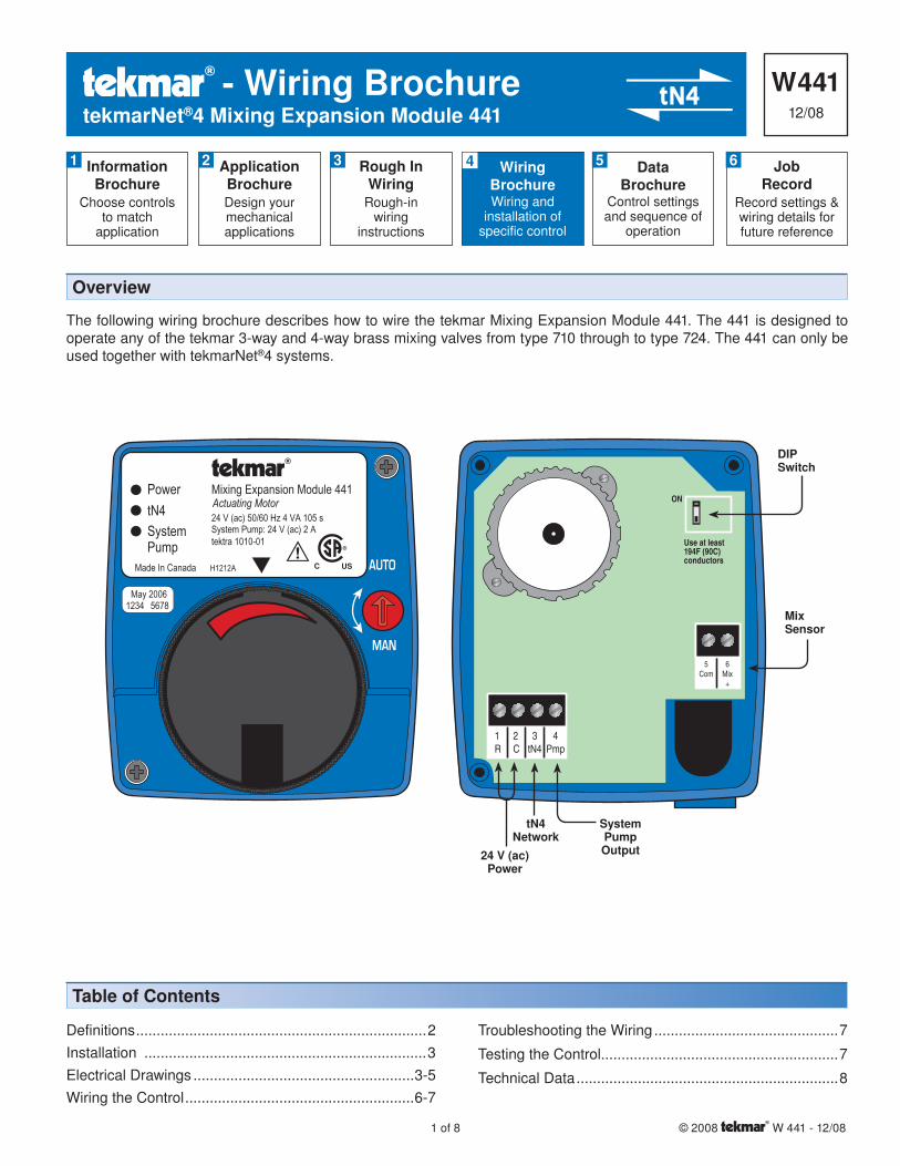
The following wiring brochure describes how to wire the tekmar Mixing Expansion Module 441. The 441 is designed to operate any of the tekmar 3-way and 4-way brass mixing valves from type 710 through to type 724. The 441 can only be used together with tekmarNet®4 systems.
Definitions .......................................................................2Installation .....................................................................3Electrical Drawings ......................................................3-5Wiring the Control ........................................................6-7
Troubleshooting the Wiring .............................................7
Testing the Control ..........................................................7
Technical Data ................................................................8
Table of Contents
tN4Network
24 V (ac)Power
DIPSwitch
PowertN4SystemPump
Mixing Expansion Module 441
Made In Canada
Actuating Motor24 V (ac) 50/60 Hz 4 VA 105 sSystem Pump: 24 V (ac) 2 Atektra 1010-01
H1212A
MixSensor
SystemPumpOutput
Overview
© 2008 W 441 - 12/08 2 of 8
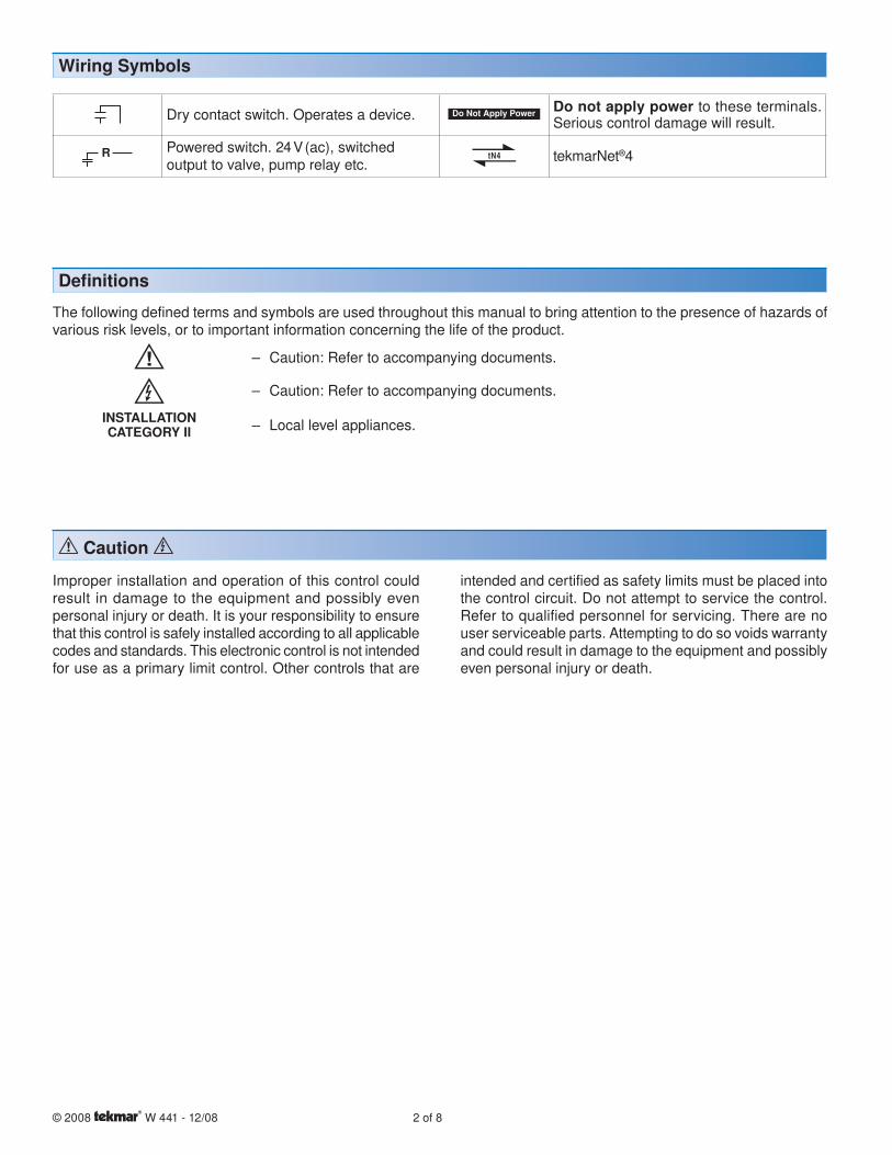
Dry contact switch. Operates a device. Do not apply power to these terminals. Serious control damage will result.
Powered switch. 24 V (ac), switched output to valve, pump relay etc. tekmarNet®4
Wiring Symbols
Defi nitions
The following defined terms and symbols are used throughout this manual to bring attention to the presence of hazards of various risk levels, or to important information concerning the life of the product.
– Caution: Refer to accompanying documents.
– Caution: Refer to accompanying documents.
INSTALLATIONCATEGORY II – Local level appliances.
Caution
Improper installation and operation of this control could result in damage to the equipment and possibly even personal injury or death. It is your responsibility to ensure that this control is safely installed according to all applicable codes and standards. This electronic control is not intended for use as a primary limit control. Other controls that are
intended and certified as safety limits must be placed into the control circuit. Do not attempt to service the control. Refer to qualified personnel for servicing. There are no user serviceable parts. Attempting to do so voids warranty and could result in damage to the equipment and possibly even personal injury or death.
3 of 8 © 2008 W 441 - 12/08
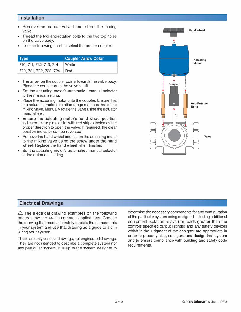
Type Coupler Arrow Color710, 711, 712, 713, 714 White720, 721, 722, 723, 724 Red
Installation
• • Remove the manual valve handle from the mixing valve.
• • Thread the two anti-rotation bolts to the two top holes on the valve body.
• • Use the following chart to select the proper coupler:
• • The arrow on the coupler points towards the valve body. Place the coupler onto the valve shaft.
• • Set the actuating motor’s automatic / manual selector to the manual setting.
• • Place the actuating motor onto the coupler. Ensure that the actuating motor’s rotation range matches that of the mixing valve. Manually rotate the valve using the actuator hand wheel.
• • Ensure the actuating motor’s hand wheel position indicator (clear plastic film with red stripe) indicates the proper direction to open the valve. If required, the clear position indicator can be reversed.
• • Remove the hand wheel and fasten the actuating motor to the mixing valve using the screw under the hand wheel. Replace the hand wheel when finished.
• • Set the actuating motor’s automatic / manual selector to the automatic setting.
ActuatingMotor
Hand Wheel
Coupler
Anti-RotationBolts
Valve
Electrical Drawings
The electrical drawing examples on the following pages show the 441 in common applications. Choose the drawing that most accurately depicts the components in your system and use that drawing as a guide to aid in wiring your system.
These are only concept drawings, not engineered drawings. They are not intended to describe a complete system nor any particular system. It is up to the system designer to
determine the necessary components for and configuration of the particular system being designed including additional equipment isolation relays (for loads greater than the controls specified output ratings) and any safety devices which in the judgment of the designer are appropriate in order to properly size, configure and design that system and to ensure compliance with building and safety code requirements.

© 2008 W 441 - 12/08 4 of 8
Electrical Application 441 E1
Description:The Mixing Expansion Module 441 connects to a Zone Manager 335, 336 or 337 which in turn is connected to a tN4 system control. The 441 controls the supply water temperature of the tN4 bus that it is connected to.
1R
2C
3tN4
4Pmp
5Com
6Mix+
Use at least194F (90C)conductors
ONON
Zone Manager
Universal Sensor 082
441 MixingExpansion Module
C PmpA
tN4tNt
C CR WtN4Zn Gp A Zone A1
Note: The Zone Manager must connect to a tN4 mix temperature bus on a tN4 system control.

5 of 8 © 2008 W 441 - 12/08
Electrical Application 441 E2
1R
2C
3tN4
4Pmp
5Com
6Mix+
Use at least194F (90C)conductors
ONON
Universal Sensor 082
441 MixingExpansion Module
SystemPump
3
4
5
6
2
1
8
7
RC
Relay 003
L
N
To tN4 Mix temperature buson a tN4 system control
ON
Description:The Mixing Expansion Module 441 connects to a tN4 device such as a thermostat which in turn is connected to a tN4 system control. An external transformer provides 24 V (ac) power, and a Relay 003 is used to switch the system pump.
© 2008 W 441 - 12/08 6 of 8
• • Use a Phillips screwdriver to remove the two screws on the top of the actuating motor to remove the wiring cover.• • All electrical wiring enters the actuating motor through the 1/2” (13 mm) conduit hole on the bottom. Standard 18 AWG
solid wire is recommended for all connections to the motor terminals.• • When using conduit, a conduit wye is required to allow the separation of the sensor wires from the R, C, tN4 and Pump
wires.• • Strip all wiring to a length of 3/8 in. or 10 mm for all terminals.• • Refer to the current and voltage ratings at the back of this brochure before connecting devices to this control.
Caution: The mixing expansion module 441 is not suitable for use with rigid conduit.
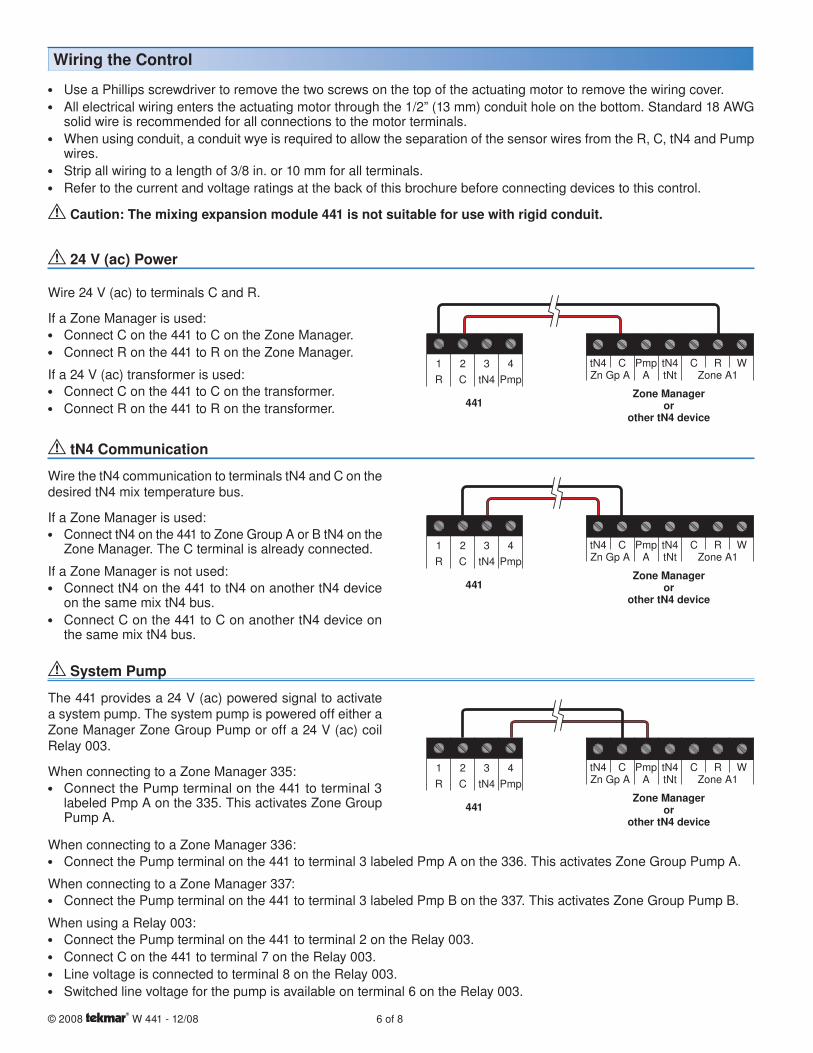
24 V (ac) Power
Wire 24 V (ac) to terminals C and R.
If a Zone Manager is used:• • Connect C on the 441 to C on the Zone Manager.• • Connect R on the 441 to R on the Zone Manager.
If a 24 V (ac) transformer is used:• • Connect C on the 441 to C on the transformer.• • Connect R on the 441 to R on the transformer.
tN4 Communication
Wire the tN4 communication to terminals tN4 and C on the desired tN4 mix temperature bus.
If a Zone Manager is used:• • Connect tN4 on the 441 to Zone Group A or B tN4 on the
Zone Manager. The C terminal is already connected.
If a Zone Manager is not used:• • Connect tN4 on the 441 to tN4 on another tN4 device
on the same mix tN4 bus.• • Connect C on the 441 to C on another tN4 device on
the same mix tN4 bus.
441Zone Manager
orother tN4 device
tN4 C Pmp tN4 C R WZn Gp A A tNt Zone A1
1 2 3 4R C tN4 Pmp
441Zone Manager
orother tN4 device
tN4 C Pmp tN4 C R WZn Gp A A tNt Zone A1
1 2 3 4R C tN4 Pmp
System Pump
441Zone Manager
orother tN4 device
tN4 C Pmp tN4 C R WZn Gp A A tNt Zone A1
1 2 3 4R C tN4 Pmp
The 441 provides a 24 V (ac) powered signal to activate a system pump. The system pump is powered off either a Zone Manager Zone Group Pump or off a 24 V (ac) coil Relay 003.
When connecting to a Zone Manager 335:• • Connect the Pump terminal on the 441 to terminal 3
labeled Pmp A on the 335. This activates Zone Group Pump A.
When connecting to a Zone Manager 336:• • Connect the Pump terminal on the 441 to terminal 3 labeled Pmp A on the 336. This activates Zone Group Pump A.
When connecting to a Zone Manager 337:• • Connect the Pump terminal on the 441 to terminal 3 labeled Pmp B on the 337. This activates Zone Group Pump B.
When using a Relay 003:• • Connect the Pump terminal on the 441 to terminal 2 on the Relay 003. • • Connect C on the 441 to terminal 7 on the Relay 003. • • Line voltage is connected to terminal 8 on the Relay 003. • • Switched line voltage for the pump is available on terminal 6 on the Relay 003.
Wiring the Control

7 of 8 © 2008 W 441 - 12/08
Mix Sensor (tekmar 082)
Connect the two wires from the Mix Supply Sensor to the Com and Mix terminals. The Mix Supply Sensor is used by the control to measure the mix supply temperature.
441
Sensor mounted in Mix Supply pipe
5 6Com Mix
+
1 2 3 4R C tN4 Pmp###
Troubleshooting the Wiring
General
The following tests are to be performed using standard testing practices and procedures and should only be carried out by properly trained and experienced persons.
A good quality electrical test meter, capable of reading from at least 0-300 V (ac), 0-30 V (dc), 0-2,000,000 Ohms, and testing for continuity is essential to properly test the wiring and sensors.
For an explanation on the use of the Test Button, the ‘Test’ sequence or any error messages, refer to the Data Brochure of the tN4 System Control.
Testing the Control
Testing the Power
The Power LED is green when 24 V (ac) is applied to the R and the C terminals. Use a voltmeter to check for 24 V (ac) +/- 10% on terminals R and C.
Testing the tN4 Communication
The tN4 Bus LED is green when the 441 detects communication. If the tN4 Bus LED is off, ensure that the tN4 and C wires are properly terminated on the 441 and at the device on the other end of the wires. The tN4 and C wires are polarity sensitive.
To check the tN4 and C wires, disconnect the wires on one end and connect them together using a wire nut. Then measure the other end of the wires using the continuity check on a digital multimeter.
Testing the System Pump
The System Pump LED is green when the Pump contact is energized. Use a voltmeter to check for 24 V (ac) +/- 10% between the Pump and the C terminal.
Testing tekmar Sensors
To test the sensors, the actual temperature at each sensor location must be measured.• • Use a good quality digital thermometer with a surface temperature probe for ease of use and accuracy. Where a digital
thermometer is not available, strap a spare sensor alongside the one to be tested and compare the readings.• • Disconnect each sensor from the control.• • Test the sensors resistance according to the instructions in the sensor Data Brochure D 082.
Technical Data
tekmar Control Systems Ltd., Canadatekmar Control Systems, Inc., U.S.A.Head Office: 5100 Silver Star RoadVernon, B.C. Canada V1B 3K4(250) 545-7749 Fax. (250) 545-0650Web Site: www.tekmarcontrols.com
Product design, software and literature are Copyright © 2008 by:tekmar Control Systems Ltd. and tekmar Control Systems, Inc. 8 of 8 All specifications are subject to change without notice.
Printed in Canada. W 441 - 12/08.
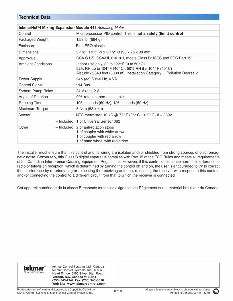
tekmarNet®4 Mixing Expansion Module 441 Actuating Motor
Control Microprocessor PID control; This is not a safety (limit) controlPackaged Weight 1.53 lb. (694 g)
Enclosure Blue PPO plastic
Dimensions 3-1/2” H x 3” W x 3-1/2” D (90 x 75 x 90 mm)Approvals CSA C US, CSA/UL 61010-1, meets Class B: ICES and FCC Part 15Ambient Conditions Indoor use only, 32 to 122°F (0 to 50°C)
92% RH up to 104°F (40°C), 50% RH if > 104°F (40°C)Altitude <9840 feet (3000 m), Installation Category II, Pollution Degree 2
Power Supply 24 V (ac) 50/60 Hz, 4 VAControl Signal tN4 BusSystem Pump Relay 24 V (ac), 2 AAngle of Rotation 90° rotation, non-adjustableRunning Time 105 seconds (60 Hz), 126 seconds (50 Hz)Maximum Torque 6 N•m (53 in•lb)
Sensor NTC thermistor, 10 kΩ @ 77°F (25°C ± 0.2°C) ß = 3892
– Included 1 of Universal Sensor 082Other – Included 2 of anti-rotation stops
1 of coupler with white arrow1 of coupler with red arrow1 of hand wheel with red stripe
The installer must ensure that this control and its wiring are isolated and / or shielded from strong sources of electromag-netic noise. Conversely, this Class B digital apparatus complies with Part 15 of the FCC Rules and meets all requirements of the Canadian Interference-Causing Equipment Regulations. However, if this control does cause harmful interference to radio or television reception, which is determined by turning the control off and on, the user is encouraged to try to correct the interference by re-orientating or relocating the receiving antenna, relocating the receiver with respect to this control, and / or connecting the control to a different circuit from that to which the receiver is connected.
Cet appareil numérique de la classe B respecte toutes les exigences du Règlement sur le matériel brouilleur du Canada.
Related Documents