WinDelsol 1.0 Users Guide 1 WinDelsol 1.0 Users Guide

Welcome message from author
This document is posted to help you gain knowledge. Please leave a comment to let me know what you think about it! Share it to your friends and learn new things together.
Transcript

WinDelsol 1.0 Users Guide 1
WinDelsol 1.0
Users Guide

WinDelsol 1.0 Users Guide 2
1. General Considerations on Delsol3 and WinDelsol 1.0 working__________________________ 3
1.1. General Considerations on Delsol3 working ________________________________________ 3
1.2. General Considerations on WinDelsol working ______________________________________ 3
2. Using WinDelsol 1.0_____________________________________________________________ 7
2.1. Starting WinDelsol, the DOC Problem ____________________________________________ 7
2.2. DOC Normalised Input ________________________________________________________ 8
2.3. Explanation for Magenta Fixed Values in a DOC Normalised Input_____________________ 10
2.4. Using Input Editor Tool_______________________________________________________ 13
2.5. WinDelsol DOC Stage ________________________________________________________ 252.5.1. Delsol3 plays its Role ________________________________________________________________ 25
2.5.2. WinDelsol plays its Role ______________________________________________________________ 27
2.5.3. Basic Parameters Analysis ____________________________________________________________ 29
2.5.4. Energetic Analysis __________________________________________________________________ 29
2.5.5. Receiver Analysis ___________________________________________________________________ 30
2.5.6. Heliostat Field Analysis ______________________________________________________________ 41
2.6. WinDelsol HFA Stage ________________________________________________________ 42
2.7. WinDelsol PFC Stage ________________________________________________________ 49
3. Installation Procedure __________________________________________________________ 57

WinDelsol 1.0 Users Guide 3
1. General Considerations on Delsol3 and WinDelsol 1.0 working
1.1. General Considerations on Delsol3 w orking
There are two types of problems that are run on Delsol3, Design Optimisation Calculations, DOCs, and
Performance of Field Calculations, PFCs.
In a Design Optimisation Calculation, user specifies the heliostat geometry, basic receiver description,
geographical location, and, of course, the range for all the variables to be optimised, and Delsol3searches for the set of optimised variables that minimises the energy cost. The results of a Design
Optimisation Calculation, -DOC process-, are generated in the from now on called Optimisation Area, OP.These results w ill be tested in the same Design Optimisation Calculation DOC process under the execution
of the so called, Performance Rerun Area, PR, just to verify that requested problem resolution, and
calculated optimum solution fit. Notice that working at this DOC stage, even at PR section, Delsol3 w ill
never use defined by coordinates heliostat field layout, but only average values for heliostats densities onfield.
In a Performance of Field Calculation, PFC, the user defines a single system, -included definite by
coordinates positions of every reflective unit, that is, the heliostat field layout-. Delsol3 calculates the
optical/energetic performance for that system, well in a single time, or in an annual basis. This annual
performance is presented by means of the called Annual Performance Matrix. Delsol3 doesn’t calculatethe definite by coordinates heliostat field layout.
More information on the Delsol3 code working way can be found in the Delsol3 Users Guide, Sandia
Nat. Labs .
1.2. General Considerations on WinDelsol w orking
WinDelsol code keeps the same strategy of working as Delsol3, w ith a DOC stage including OP and PRareas, and a PFC stage based on definite by coordinates heliostat field layout.
Additional features of WinDelsol code over Delsol3 are:
a) Use of Windows user-friendly interrelation between human and computer.
b) Inclusion of an Input Editor tool that takes into account all Delsol3 constrains among the about two
hundred variables, that make quite difficult the generation of a free of contradictions Input.txt fileby hand.
c) Self-Extraction of results from the over more than 50 pages Delsol3 Output.txt f ile, andpresentation on screen of a selection of the more important ones. The less relevant data can be also
studied into the frame of WinDelsol by the integrated option of accessing to the edition of
Output.txt .
d) Graphical interpretation of results, especially those that are hard to analyse quickly in Delsol3
Output.txt f ile, as receiver geometry and flux maps. But WinDelsol allows also to make the quickinterpretation through graphics, of the results related to the heliostat field configuration, mean
annual cosine factor distribution on field, shadows and blocks, spillage, air transmittance, etc…
e) Calculation of the definite by coordinates heliostat f ield layout.
f) Automatic generation of the Input.txt file to test the performance of the calculated field, including
the clustering by rows, of the definite by coordinates heliostat field layout. This Input.txt file can begenerated both for PFC in a single time, -Design Point-, or in an annual basis by means of the
-Annual Performance Matrix-. Although it is possible in Delsol3 to do the PFC of a defined single
system in a different single time of the design point, this option has not been considered at
WinDelsol, because of the following two reasons:
• This calculus is included in the Annual Performance Matrix and can be deduced from it.
• WinDelsol is not considered as an accurate energetic performance tool by the authors of thiswork. The main task of WinDelsol code is to generate an optimised heliostats field layout, tower
height calculation and receiver geometry proposal. PFC, Performance of Field Calculation of anoptimised system including the heliostats field coordinates description at design point, can be
only considered as a verif ication for the correct solution proposed by WinDelsol to the analysed
problem. In some way, this Performance of Field Calculation at design point can be compared tothe Performance Rerun that the code makes at Design Optimisation task, including at this time, a
defined by coordinates heliostat field layout.
WinDelsol 1.0 Users Guide 4
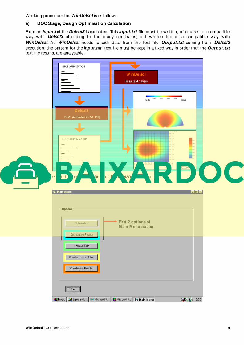
Working procedure for WinDelsol is as follows:
a) DOC Stage, Design Optimisation Calculation
From an Input.txt f ile Delsol3 is executed. This Input.txt file must be written, of course in a compatibleway w ith Delsol3 attending to the many constrains, but written too in a compatible way with
WinDelsol. As WinDelsol needs to pick data from the text file Output.txt coming from Delsol3
execution, the pattern for the Input.txt text file must be kept in a fixed way in order that the Output.txttext f ile results, are analysable.
INPUT OPTIMIZATION
OUTPUT OPTIM IZATION
Delsol3
DOC (includes OP & PR)
WinDelsol
Results Analisis
This stage works on the first two options of WinDelsol main menu screen:
First 2 options ofM ain M enu screen
WinDelsol 1.0 Users Guide 5
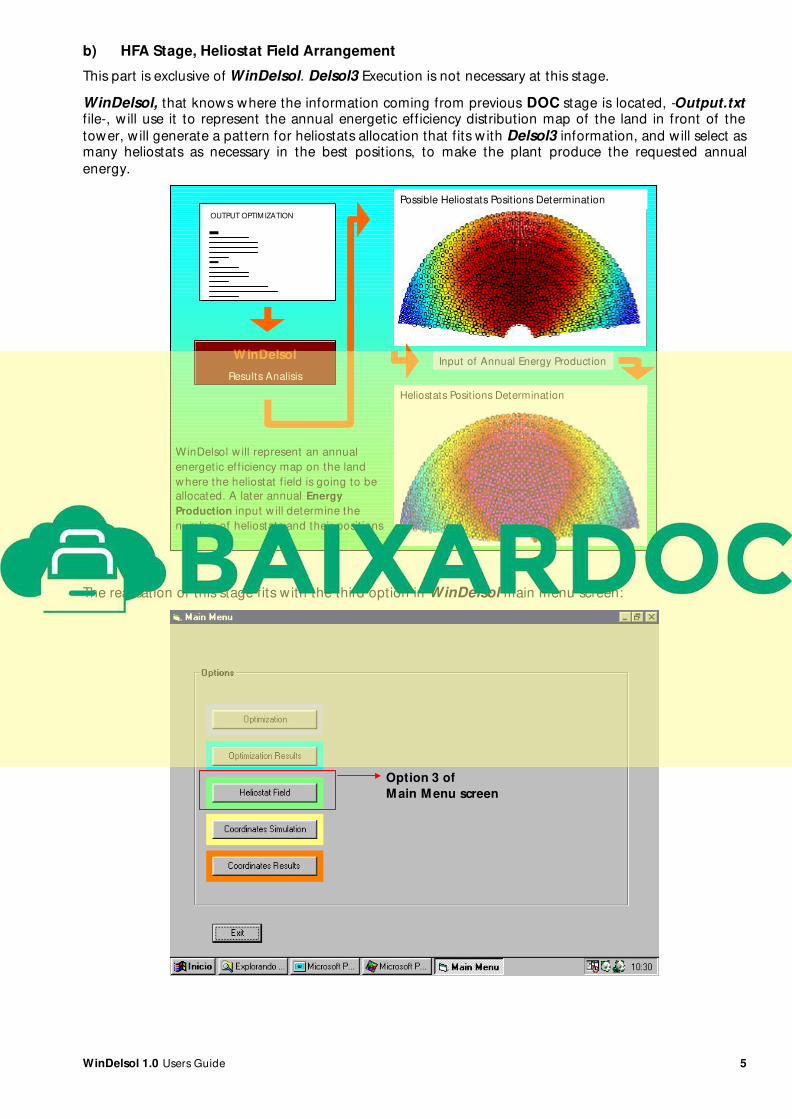
b) HFA Stage, Heliostat Field Arrangement
This part is exclusive of WinDelsol. Delsol3 Execution is not necessary at this stage.
WinDelsol, that knows where the information coming from previous DOC stage is located, -Output.txtf ile-, w ill use it to represent the annual energetic efficiency distribution map of the land in front of the
tower, w ill generate a pattern for heliostats allocation that fits w ith Delsol3 information, and will select asmany heliostats as necessary in the best positions, to make the plant produce the requested annual
energy.
OUTPUT OPTIMIZATION
WinDelsol
Results Analisis
Possible Heliostats Posit ions Determination
Heliostats Posit ions Determination
Input of Annual Energy Production
WinDelsol w ill represent an annual
energetic eff iciency map on the land
where the heliostat f ield is going to be
allocated. A later annual Energy
Production input w ill determine the
number of heliostats and their posit ions
The realisation of this stage fits w ith the third option in WinDelsol main menu screen:
Option 3 of
M ain M enu screen
WinDelsol 1.0 Users Guide 6
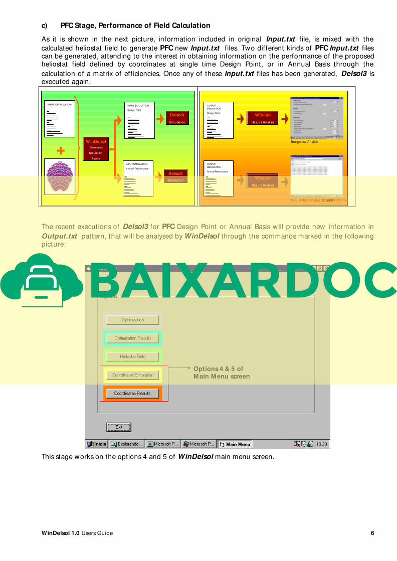
c) PFC Stage, Performance of Field Calculation
As it is shown in the next picture, information included in original Input.txt f ile, is mixed with the
calculated heliostat field to generate PFC new Input.txt f iles. Two different kinds of PFC Input.txt filescan be generated, attending to the interest in obtaining information on the performance of the proposedheliostat field defined by coordinates at single time Design Point, or in Annual Basis through the
calculation of a matrix of efficiencies. Once any of these Input.txt files has been generated, Delsol3 isexecuted again.
INPUT OPTIM IZATION
+
INPUT SIM ULATION
Design Point
W inDelsol
Generates
Simulation
Inputs
INPUT SIM ULATION
Annual Performance
Delsol3
Simulat ion
Delsol3
Simulat ion
OUTPUT
SIMULATION
Design Point
OUTPUT
SIMULATION
Annual Performance
WDelsol
Results Analisis
WDelsol
Results Analisis
Energetical Analisis
Annual Performance SOLERGY M atrix
The recent executions of Delsol3 for PFC Design Point or Annual Basis will provide new information in
Output.txt pattern, that w ill be analysed by WinDelsol through the commands marked in the followingpicture:
Options 4 & 5 ofM ain M enu screen
This stage works on the options 4 and 5 of WinDelsol main menu screen.

WinDelsol 1.0 Users Guide 7
2. Using WinDelsol 1.0
2.1. Starting WinDelsol, the DOC Problem
WinDelsol.exe w ill start the running of WinDelsol1.0.
A click in the Next button of the presentation screen will lead to the code main menu screen.
At this start point of the program execution, the only possibility that is enabled apart from quitting, is to
begin a DOC problem by pressing Optimisation button. This w ill lead to the screen in the picture.
Two possibilit ies are shown, the use of the Input Editor tool, and the direct use of a DOC Input.txt fileprepared w ith any text editor tool, this last option only recomendable if user is sure that it is a normalised
DOC Input.txt file.
A normalised DOC Input.txt file is that one that has gone through the WinDelsol tool called Input
Editor. Only the use of a normalised Input.txt f ile can ensure the correct working of WinDelsol, not onlyin the accuracy of results, but avoiding halts.
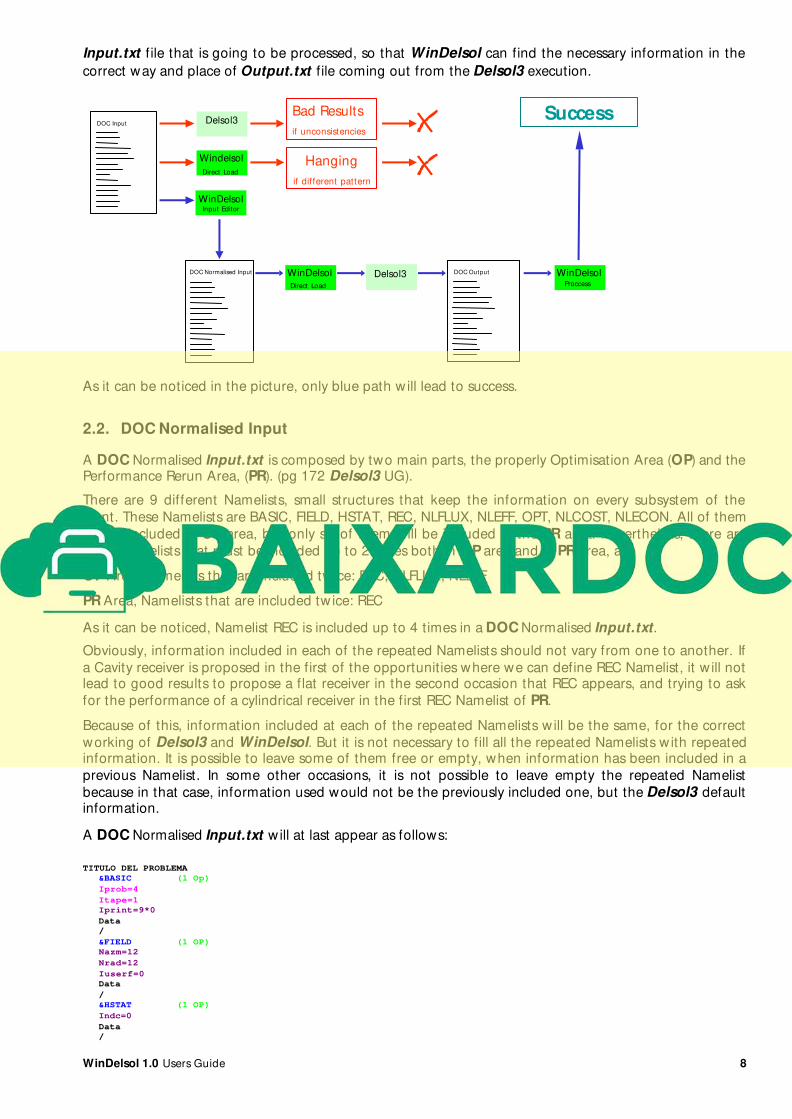
The use of Input Editor allows the loading of a previous Input.txt f ile. Input Editor w ill detectinconsistencies between variables from the point of view of Delsol3 computer code in the loaded
Input.txt f ile, ensuring then correct results. Input Editor w ill also give a fixed common pattern to every
WinDelsol 1.0 Users Guide 8
Input.txt f ile that is going to be processed, so that WinDelsol can find the necessary information in the
correct way and place of Output.txt file coming out from the Delsol3 execution.
Delsol3
Windelsol
Direct Load
DOC Input
DOC Normalised Input DOC Output WinDelsolProccess
WinDelsolInput Editor
Bad Results
if unconsistencies
Hanging
if different pattern
Success
WinDelsol
Direct Load Delsol3
As it can be noticed in the picture, only blue path w ill lead to success.
2.2. DOC Normalised Input
A DOC Normalised Input.txt is composed by two main parts, the properly Optimisation Area (OP) and thePerformance Rerun Area, (PR). (pg 172 Delsol3 UG).
There are 9 different Namelists, small structures that keep the information on every subsystem of the
plant. These Namelists are BASIC, FIELD, HSTAT, REC, NLFLUX, NLEFF, OPT, NLCOST, NLECON. All of them
will be included in OP area, but only six of them will be included in the PR area. Nevertheless, there are
some Namelists that must be included up to 2 times both in OP area and in PR area, as:
OP Area, Namelists that are included tw ice: REC, NLFLUX, NLEFF
PR Area, Namelists that are included tw ice: REC
As it can be noticed, Namelist REC is included up to 4 times in a DOC Normalised Input.txt.
Obviously, information included in each of the repeated Namelists should not vary from one to another. If
a Cavity receiver is proposed in the first of the opportunities where we can define REC Namelist, it w ill notlead to good results to propose a flat receiver in the second occasion that REC appears, and trying to ask
for the performance of a cylindrical receiver in the first REC Namelist of PR.
Because of this, information included at each of the repeated Namelists w ill be the same, for the correct
working of Delsol3 and WinDelsol. But it is not necessary to fill all the repeated Namelists w ith repeatedinformation. It is possible to leave some of them free or empty, when information has been included in a
previous Namelist. In some other occasions, it is not possible to leave empty the repeated Namelist
because in that case, information used would not be the previously included one, but the Delsol3 defaultinformation.
A DOC Normalised Input.txt w ill at last appear as follows:
TITULO DEL PROBLEMA
&BASIC (1 Op)
Iprob=4
Itape=1
Iprint=9*0
Data
/
&FIELD (1 OP)
Nazm=12
Nrad=12
Iuserf=0
Data
/
&HSTAT (1 OP)
Indc=0
Data
/
WinDelsol 1.0 Users Guide 9
&REC (1 OP)
Irec=0,2,4
Numcav=1
Data
/
&NLFLUX (1 OP)
Iflx=1
Nxflx=13
Nyflx=13
Icavf=1
Data
/
&NLEFF (1 OP)
Iradfl=0
Data
/
&REC (2 OP)
/
&OPT (1 OP)
Ihopt=0
Numopt=1
Iotape=1
Irerun=1
Iplfl=1
Ipropt=-1
Ihoptp=0
Data
/
&NLFLUX (2 OP)
Iflx=1
Nxflx=13
Nyflx=13
Icavf=1
Data
/
&NLEFF (2 OP)
Iradfl=0
Data
/
&NLCOST (1 OP)
Data
/
&NLECON (1 OP)
Data
/
PERFORMANCE RERUN
/
&BASIC (1 PR)
Iprob=0
Itape=3
Tdesp
/
&FIELD (1 PR)
/
&HSTAT (1 PR)
/
&REC (1 PR)
/
&NLFLUX (1 PR)
Iflx=1
Ifxout(i,j)=1
Nxflx=13
Nyflx=13
Icavf=1
Data
/
&NLEFF (1 PR)
/
&REC (2 PR)
W=-100.
/
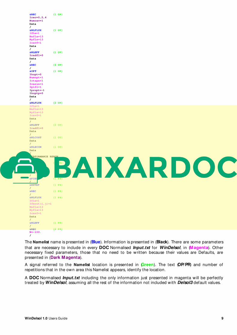
The Namelist name is presented in (Blue). Information is presented in (Black). There are some parameters
that are necessary to include in every DOC Normalised Input.txt for WinDelsol, in (M agenta). Othernecessary fixed parameters, those that no need to be written because their values are Defaults, are
presented in (Dark M agenta).
A signal referred to the Namelist location is presented in (Green). The text (OP/PR) and number of
repetitions that in the own area this Namelist appears, identify the location.
A DOC Normalised Input.txt including the only information just presented in magenta will be perfectlytreated by WinDelsol, assuming all the rest of the information not included with Delsol3 default values.

WinDelsol 1.0 Users Guide 10
2.3. Explanation for M agenta Fixed Values in a DOC Normalised Input
&BASIC (1 OP)Iprob=4 Control parameter specifying Delsol3 working mode as an OP Optimisation at this occasion.
This parameter is fixed because of the general concept of WinDelsol, that works on a DOC initial stage
including both OP and PR steps.
Itape=1 Control parameter that fits perfectly w ith Iprob=4 at DOC working. (Pg 65 Delsol3 UG).
Iprint=9* 0 Control parameter to indicate the printing of a detailed day by day (from 1 to NYEAR), or
time step by time step in the days (from 1 to NYEAR), performance of the zone by zone field. WinDelsolworks on the information of the annual zone by zone performance, and this is always written when
Iprint=0. As a matter of fact, it would be more exquisite to include at DOC Input.txt file the expressionIprint=NYEAR* 0, depending on NYEAR value, but as NYEAR ranges from 1 to 9, and Delsol3 w ill use
always a 9 positions matrix to look for Iprint values, we can fix all positions there equal to 0, the work w illbe perfect. Not necessary to be included because Default.
Data/&FIELD (1 OP)Nazm=12 Number of zone divisions azimuthally around the tower. Maximum value is 12. Computers are
quick enough at present moment to manage with the biggest sizes of matrixes that Delsol3 can handle
without delaying time execution appreciably. For that reason, all variable size matrixes for Delsol3 have
been fixed at their highest values to allow the more accurate information disposal to WinDelsol. Not
necessary to be included because Default.Nrad=12 Number of zone divisions in the radial direction from the tower. Maximum value is 13. Delsol3Default value is 12. For that reason, WinDelsol w ill use this Default value and so, it w ill never more be
necessary to include Nazm nor Nrad in an input file.
Iuserf=0 Parameter specifying field option. It must be Iuserf=0 for a DOC working mode. Not necessaryto be included because Default.
Data/&HSTAT (1 OP)Indc=0 Control parameter for more accurate heliostat images calculation in PFC working mode. It must
be Indc=0 for a DOC working mode. Not necessary to be included because Default.
Data/&REC (1 OP)Irec=0,2,4 Parameter specifying type of receiver. Cavity w ith elliptical aperture (IREC=1) nor elliptical
shape flat plate (Irec=3) are not considered in WinDelsol.Numcav=1 Let’s work receiver by receiver better. Not necessary to be included because Default.
Data/&NLFLUX (1 OP)Iflx=1 Parameter specifying flux calculation. For OP stage, flux calculations are made at the design point
just to verify the values of flux at receiver in order to dimensionate it not overpassing stablished limits.
Nxflx=13 Number of divisions of a grid in the horizontal length of the receiver in order to calculate flux.Maximum value is 13. Computers are quick enough at present moment to manage with the biggest sizes
of matrixes that Delsol3 can handle w ithout delaying time execution appreciably. For that reason, all
variable size matrixes for Delsol3 have been fixed at their highest values to allow the more accurate
information disposal to WinDelsol.Nyflx=13 Number of divisions of a grid in the vertical length of the receiver in order to calculate flux.Maximum value is 13. Computers are quick enough at present moment to manage with the biggest sizes
of matrixes that Delsol3 can handle w ithout delaying time execution appreciably. For that reason, all
variable size matrixes for Delsol3 have been fixed at their highest values to allow the more accurate
information disposal to WinDelsol.Icavf=1 Parameter specifying aperture(s) through which incident light can reach the flux surface under
consideration, =0, no light reaches flux surface from aperture i, <>0 light reaches flux surface fromaperture i.
WinDelsol considers only one aperture or receiver for a plant. So, for WinDelsol the only possibility is
Icavf=1.
Data/
Related Documents