Form MHD56298 • A copy of our “Safe Operating Practices” Manuals are always available free of charge either by downloading it from our Technical Publications website @ www.airwinch.com or by contacting the Factory at (800) 866-5457 for North America and (206) 624-0466 for International. The Safe Operating Practices manual must be read prior to anyone operating a Ingersoll-Rand winch or hoist. The manual form numbers are as follows: “Safe Operating Practices Non-Man Rider™ Winches” Manual, Form No. MHD56250 “Safe Operating Practices for Man Rider™ Winches” Manual, Form No. MHD56251 “Safe Operating Practices for Pneumatic, Hydraulic and Electric Hoists” Manual, Form No. MHD56295 • Available winch options may require additional supplements to the basic winch manual. • For Man Rider™ winches ensure a copy of the Man Rider™ supplement is made available to the operator prior to winch operation. • We strongly recommend that ALL maintenance on Ingersoll-Rand equipment be carried out by personnel certified by Ingersoll-Rand, or by Ingersoll-Rand Authorized Service Centers. • Contact the Factory if in doubt about installation, operation, inspection and maintenance instructions. • Use only Genuine Ingersoll-Rand parts when maintaining or repairing a winch, hoist or any component of a winch or hoist. • ANSI / ASME recommends that a winch or hoist (or any components of a winch or hoist) that has been repaired be tested prior to being placed into service: Winch Man Rider™ Supplements: Model: Publication No. Model: Publication No. FA2, FA2.5, FH2, FH2.5 MHD56046 LS500RLP SAM0011 LS1000RLP SAM0012 FA5 MHD56042 and MHD56220 LS150RLP SAM0082 LS150RLP/500/ 1000 SAM0115 FA10 MHD56252 FA2.5A MHD56236 LS150RLP and LS150PLP-PH SAM0120 FA2B and HU40A MHD56207 LS500RLP-E SAM0122 FH10MR MHD56212 LS150RLP- DP5M-F SAM0184 Fulcrum Electric MHD56277 LS500HLP/ LS1000HLP SAM0004 LS150HLP SAM0222 * Winches - ANSI / ASME B30.7 (BASE MOUNTED DRUM HOISTS) Refer to section 7.2.2 - Testing. * Hoists - ANSI / ASME B30.16 (OVERHEAD HOISTS - UNDERHUNG) Refer to section 16.2.2 - Testing. Form MHD56298 Edition 2 November 2004 71441844 © 2004 Ingersoll-Rand Company IMPORTANT INFORMATION:

WINCHE FA5A-MR Ingersoll Rand
Oct 07, 2014
Welcome message from author
This document is posted to help you gain knowledge. Please leave a comment to let me know what you think about it! Share it to your friends and learn new things together.
Transcript
Form MHD56298
• A copy of our “Safe Operating Practices” Manuals are always available free of charge either by downloading it from our Technical Publications website @ www.airwinch.com or by contacting the Factory at (800) 866-5457 for North America and (206) 624-0466 for International. The Safe Operating Practices manual must be read prior to anyone operating a Ingersoll-Rand winch or hoist. The manual form numbers are as follows:
“Safe Operating Practices Non-Man Rider™ Winches” Manual, Form No. MHD56250 “Safe Operating Practices for Man Rider™ Winches” Manual, Form No. MHD56251 “Safe Operating Practices for Pneumatic, Hydraulic and Electric Hoists” Manual, Form No. MHD56295
• Available winch options may require additional supplements to the basic winch manual.
• For Man Rider™ winches ensure a copy of the Man Rider™ supplement is made available to the operator prior to winch operation.
• We strongly recommend that ALL maintenance on Ingersoll-Rand equipment be carried out by personnel certified by Ingersoll-Rand, or by Ingersoll-Rand Authorized Service Centers.
• Contact the Factory if in doubt about installation, operation, inspection and maintenance instructions.
• Use only Genuine Ingersoll-Rand parts when maintaining or repairing a winch, hoist or any component of a winch or hoist.
• ANSI / ASME recommends that a winch or hoist (or any components of a winch or hoist) that has been repaired be tested prior to being placed into service:
Winch Man Rider™ Supplements:
Model: Publication No. Model: Publication No.
FA2, FA2.5, FH2, FH2.5
MHD56046LS500RLP SAM0011
LS1000RLP SAM0012
FA5 MHD56042 and MHD56220
LS150RLP SAM0082
LS150RLP/500/1000
SAM0115FA10 MHD56252
FA2.5A MHD56236 LS150RLP and LS150PLP-PH
SAM0120FA2B and HU40A
MHD56207LS500RLP-E SAM0122
FH10MR MHD56212 LS150RLP-DP5M-F
SAM0184Fulcrum Electric MHD56277
LS500HLP/LS1000HLP
SAM0004LS150HLP SAM0222
* Winches - ANSI / ASME B30.7 (BASE MOUNTED DRUM HOISTS) Refer to section 7.2.2 - Testing.
* Hoists - ANSI / ASME B30.16 (OVERHEAD HOISTS - UNDERHUNG) Refer to section 16.2.2 - Testing.
Form MHD56298Edition 2November 200471441844© 2004 Ingersoll-Rand Company
IMPORTANT INFORMATION:
Form MHD56115
PARTS, OPERATION AND MAINTENANCE MANUAL
THIRD GENERATION
MODEL FA5A-MRMan Rider
™
AIR WINCHES
READ THIS MANUAL BEFORE USING THESE PRODUCTS. This manualcontains important safety, installation, operation and maintenanceinformation. Make this manual available to all persons responsible for theinstallation, operation and maintenance of these products.
These instructions apply only to winches designed by Ingersoll-Rand that are identifiedfor personnel lifting by a permanent nameplate attached to the winch at the factory.
Always operate, inspect and maintain this winch in accordance with American NationalStandards Institute Safety Code (ASME B30.7) and any other applicable safety codes andregulations.
Form MHD56115Edition 2December 200271300248© 2002 Ingersoll-Rand Company
TM
2 MHD56115 - Edition 2
CONTENTS
Description Page
Safety InformationDanger, Warning, Caution and Notice .................................................................................................................................................................3Safety Summary...................................................................................................................................................................................................3
General InformationTraceability ..........................................................................................................................................................................................................4
Safe Winch Operating InstructionsMan Rider Operating Instructions .......................................................................................................................................................................5General Operating Instructions ............................................................................................................................................................................5
Standards ............................................................................................................................................................................................................6
Warning Tags and Label ...................................................................................................................................................................................7
SpecificationsDescription...........................................................................................................................................................................................................7
InstallationMounting............................................................................................................................................................................................................10Wire Rope ..........................................................................................................................................................................................................10Air Supply..........................................................................................................................................................................................................12Motor .................................................................................................................................................................................................................13Emergency Stop and Overload System..............................................................................................................................................................13Initial Winch Operating Checks.........................................................................................................................................................................14
OperationTraining Program ...............................................................................................................................................................................................15Controls..............................................................................................................................................................................................................15Winch Brakes.....................................................................................................................................................................................................18
InspectionRecords and Reports ..........................................................................................................................................................................................19Frequent Inspection............................................................................................................................................................................................19Periodic Inspection ............................................................................................................................................................................................20Winches Not In Regular Use .............................................................................................................................................................................20
Inspection and Maintenance Report ..............................................................................................................................................................21
Troubleshooting................................................................................................................................................................................................22
LubricationGeneral Lubrication ...........................................................................................................................................................................................23Reduction Gear and Disc Brake Lubrication .....................................................................................................................................................23Motor Assembly ................................................................................................................................................................................................24Wire Rope ..........................................................................................................................................................................................................25Seals and Bearings .............................................................................................................................................................................................25
MaintenanceMaintenance Intervals........................................................................................................................................................................................25Adjustments .......................................................................................................................................................................................................25Disassembly .......................................................................................................................................................................................................26Cleaning, Inspection and Repair ........................................................................................................................................................................30Assembly ...........................................................................................................................................................................................................30Testing................................................................................................................................................................................................................35
Parts SectionWinch Cross Section Drawing...........................................................................................................................................................................36Winch Drawings and Parts Lists Table of Contents ..........................................................................................................................................37Winch Parts Drawings and Parts Lists..........................................................................................................................................................38-59
Parts Ordering Information ...........................................................................................................................................................................60
Warranty...........................................................................................................................................................................................................63
Office Locations ...............................................................................................................................................................................................64
MHD56115 - Edition 2 3
SAFETY INFORMATION
This manual provides important information for all personnelinvolved with the safe installation, operation and propermaintenance of this product. Even if you feel you are familiarwith this or similar equipment, you should read this manualbefore operating the winch.
Danger, Warning, Caution and Notice
Throughout this manual there are steps and procedures which, ifnot followed, may result in a hazard. The following signal words
Danger is used to indicate the presence ofa hazard which will cause severe injury,death, or substantial property damage ifthe warning is ignored.
Warning is used to indicate the presenceof a hazard which can cause severe injury,death, or substantial property damage ifthe warning is ignored.
Caution is used to indicate the presence ofa hazard which will or can cause injury orproperty damage if the warning isignored.
Notice is used to notify people ofinstallation, operation, or maintenanceinformation which is important but nothazard-related.
DANGER
WWAARRNNIINNGG
CCAAUUTTIIOONN
NNOOTTIICCEE
are used to identify the level of potential hazard.
Safety Summary
WARNING• The supporting structures and load-attaching devices used inconjunction with this winch must provide an adequate safetyfactor to handle the rated load, plus the weight of the winchand attached equipment. This is the customer’s responsibility.If in doubt, consult a registered structural engineer.
Ingersoll-Rand winches are manufactured in accordance with thelatest ASME B30.7 standards.
The National Safety Council, Accident Prevention Manual forIndustrial Operations, Eighth Edition and other recognized safetysources make a common point: Employees who work nearsuspended loads or assist in hooking on or arranging a loadshould be instructed to keep out from under the load. From asafety standpoint, one factor is paramount: conduct all lifting orpulling operations in such a manner that if there were anequipment failure, no personnel would be injured. This meanskeep out from under a raised load and keep out of the line of forceof any load.
The Occupational Safety and Health Act of 1970 generally placesthe burden of compliance with the user, not the manufacturer.Many OSHA requirements are not concerned or connected withthe manufactured product but are, rather, associated with the finalinstallation. It is the owner’s and user’s responsibility todetermine the suitability of a product for any particular use. It isrecommended that all applicable industry, trade association,federal, state and local regulations be checked. Read all operatinginstructions and warnings before operation.
Rigging: It is the responsibility of the operator to exercisecaution, use common sense and be familiar with proper riggingtechniques. See ASME B30.9 for rigging information, AmericanNational Standards Institute, 1430 Broadway, New York, NY10018.
This manual has been produced by Ingersoll-Rand to providedealers, mechanics, operators and company personnel with theinformation required to install, operate, maintain and repair theproducts described herein.It is extremely important that mechanics and operators be familiarwith the servicing procedures of these products, or like or similarproducts, and are physically capable of conducting the procedures.These personnel shall have a general working knowledge thatincludes:1. Proper and safe use and application of mechanics common
hand tools as well as special Ingersoll-Rand orrecommended tools.
2. Safety procedures, precautions and work habits establishedby accepted industry standards.
Ingersoll-Rand cannot know of, or provide all the procedures bywhich product operations or repairs may be conducted and thehazards and/or results of each method. If operation ormaintenance procedures not specifically recommended by themanufacturer are conducted, it must be ensured that productsafety is not endangered by the actions taken. If unsure of anoperation or maintenance procedure or step, personnel shouldplace the product in a safe condition and contact supervisorsand/or the factory for technical assistance.
4 MHD56115 - Edition 2
GENERAL INFORMATION
Ingersoll-Rand offers, in its air winch product line, a limitednumber of models referred to as Man Riders which are designedand manufactured to standards and specifications established byvarious regulatory bodies for the purpose of lifting people.
Man Rider winches are type approved and/or certified to meet therequirements of the Offshore Oil Industry by one or more of thefollowing regulatory bodies:American Bureau of Shipping (ABS), Lloyd’s Register ofShipping (LRS) or Det Norske Veritas (DNV) to comply withthe UK Health and Safety Executive (HSE), the UK Departmentof Energy (DEn), the Norwegian Maritime Directorate (NMD) orthe Norwegian Petroleum Directorate (NPD).
In furnishing customers Man Rider winches, Ingersoll-Randdoes not warrant the suitability of these winches for any particularuse. It is the owner and user’s responsibility to determine thesuitability of a Man Rider winch for a particular application.Further, it is the owner and user’s responsibility to check andsatisfy all local, state, federal and country requirements pertainingto the lifting and lowering of persons.
WARNING• Many agencies require additional redundant safety deviceson winches that Ingersoll-Rand does not furnish. Additionaldevices are often required to bring the system up to elevatorcode standards.
Man Rider winches manufactured by Ingersoll-Rand to ABS,LRS and/or DNV requirements are furnished with limitations;approval for use in personnel lifting applications automaticallyterminates for any of the following reasons:
1. Winch does not meet other applicable codes or standards.2. Winch is not part of an approved system.3. Winch is not properly maintained in an “as new” condition
with all parts intact and properly adjusted.4. Winch is used in applications not approved by codes and
regulations, or is used in applications inconsistent withmanufacturer’s operating and maintenance manual.
5. Changes in any of the standards or regulations afterIngersoll-Rand’s initial shipment of the product.
6. More than one winch is used to attach to a common load.
WARNING• Before using a Man Rider winch be sure to check allregulations: local, state, federal and country, that may apply tothe use of a winch or winch system for lifting and loweringpeople.
7. The personnel platform shall be designed by a registeredengineer competent in this area.
NOTICE• Lifting personnel with this winch is STRICTLY LIMITED tooff-shore marine applications specifically approved bymaritime regulatory bodies. Suitable use is determined byregulatory bodies, not the manufacturer. DO NOT USE FORpersonnel lifting applications not specifically approved byregulatory bodies.
Traceability
Load bearing parts are documented to provide traceability.Documentation includes chemical and physical properties of rawmaterial, heat treating, and hardening, tensile and charpy tests asrequired for the part.
Units with M1, M2 or M3 in the model code have traceable load-bearing components.
M1–Material Traceability certificates according to EN 10204 (ExDIN 50049) 2.2 on load bearing parts. Conformity documentsaffirm (by the manufacturer) that parts are in compliance with therequirements of the order based on non-specific inspection andtesting (i.e. results are typical material properties for these parts).
M2–Material Traceability certificates according to EN 10204 (ExDIN 50049) 3.1b on load bearing parts. Conformity documentsaffirm (by a department independent of the manufacturingdepartment) that the actual parts are in compliance with therequirements of the order based on specific inspection and testing(i.e. results are actual material properties for these parts).
M3–Material Traceability certificates according to EN 10204 (ExDIN 50049) 3.1b on load bearing parts. Conformity documentsaffirm (by a department independent of the manufacturingdepartment) that the actual parts used in the product are incompliance with the order based on specific inspection and testing(i.e. results are actual material properties for these parts in afinished, as delivered condition).
Components with part numbers ending in CH or CHA are charpyparts for use under extreme cold conditions. Traceabilityrequirements must be stated when reordering these parts forcontinued certification.
MHD56115 - Edition 2 5
SAFE WINCH OPERATING INSTRUCTIONS
Man Rider Operating Instructions
WARNING• Failure to follow these instructions may result in terminationof all applicable warranties. Ingersoll-Rand assumes noliability for any loss or damage resulting from operation ofMan Rider winches if these operating instructions are notfollowed.
1. Winch operator must maintain visual or audio contact withpersonnel being lifted or lowered from transfer point tolanding area.
2. Personnel operating the winch or being transferred are tohave sufficient instruction/training concerning that operationbefore any movement takes place.
3. The winch installation must be specially arranged andaccepted for personnel handling.
4. Prior to any personnel movement, the entire system shouldbe inspected by the person in charge. It is that individual’sresponsibility to instruct and appoint the winch operator.
5. The lifting apparatus (basket, etc.) shall be inspected andcertified for personnel lifting prior to use.
6. Do not operate without a surveyor’s site approval.7. Do not overload.8. Do not operate without testing. (Refer to “Inspection and
Testing” procedures)9. Do not operate winch in a damaged condition.10. Do not operate winch that has not been properly maintained
or equipped.11. Do not attach winch to unsafe foundation. Refer to
“INSTALLATION” section for winch mounting instructions.12. Do not operate winch with any personnel near the line of
force or capable of coming into contact with moving parts.13. All signs and warning notices must be posted permanently
on the winch.14. Always maintain three or more wraps of wire rope on the
drum.15. Never leave a suspended load unattended.16. Wire rope must spool off drum from the top away from the
operator.
General Operating Instructions
The following warnings and operating instructions have beenadapted in part from American National (Safety) StandardASME B30.7 and are intended to avoid unsafe operatingpractices which might lead to injury or property damage.
Ingersoll-Rand recognizes that most companies who use wincheshave a safety program in force at their facility. In the event thatsome conflict exists between a rule set forth in this publicationand a similar rule already set by an individual company, the morestringent of the two should take precedence.
Safe Operating Instructions are provided to make an operatoraware of dangerous practices to avoid and are not necessarilylimited to the following list. Refer to specific sections in themanual for additional safety information.
1. Only allow people, trained in safety and operation of thisproduct, to operate and maintain this winch.
2. Only operate a winch if you are physically fit to do so.3. When a “DO NOT OPERATE” sign is placed on the winch,
or controls, do not operate the winch until the sign has beenremoved by designated personnel.
4. Before each shift, the operator should inspect the winch forwear and damage. Never use a winch that inspectionindicates is worn or damaged.
5. Never lift a load greater than the rated capacity of the winch.See nameplate attached to winch or refer to“SPECIFICATIONS” section.
6. Keep hands, clothing, etc., clear of moving parts.7. Never place your hand in the throat area of a hook or near
wire rope spooling onto or off of the winch drum.8. Always rig loads properly and carefully.9. Be certain the load is properly seated in the saddle of the
hook. Do not support the load on the tip of the hook.10. Do not “side pull” or “yard”.11. Always ensure that you, and all other people, are clear of the
path of the load. Do not lift a load over people.12. Ease the slack out of the wire rope when starting a lift or
pull. Do not jerk the load.13. Do not swing a suspended load.14. Do not leave a suspended load unattended.15. Never operate a winch with twisted, kinked or damaged wire
rope.16. Pay attention to the load at all times when operating the
winch.17. Never use the wire rope as a sling.18. After use, or when in a non-operational mode, the winch
should be secured against unauthorized and unwarranted use.
6 MHD56115 - Edition 2
STANDARDS
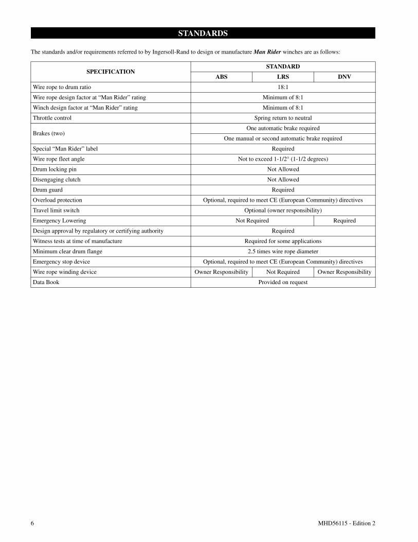
The standards and/or requirements referred to by Ingersoll-Rand to design or manufacture Man Rider winches are as follows:
SPECIFICATIONSTANDARD
ABS LRS DNV
Wire rope to drum ratio 18:1
Wire rope design factor at “Man Rider” rating Minimum of 8:1
Winch design factor at “Man Rider” rating Minimum of 8:1
Throttle control Spring return to neutral
Brakes (two)One automatic brake required
One manual or second automatic brake required
Special “Man Rider” label Required
Wire rope fleet angle Not to exceed 1-1/2° (1-1/2 degrees)
Drum locking pin Not Allowed
Disengaging clutch Not Allowed
Drum guard Required
Overload protection Optional, required to meet CE (European Community) directives
Travel limit switch Optional (owner responsibility)
Emergency Lowering Not Required Required
Design approval by regulatory or certifying authority Required
Witness tests at time of manufacture Required for some applications
Minimum clear drum flange 2.5 times wire rope diameter
Emergency stop device Optional, required to meet CE (European Community) directives
Wire rope winding device Owner Responsibility Not Required Owner Responsibility
Data Book Provided on request
MHD56115 - Edition 2 7
WARNING TAGS AND LABEL
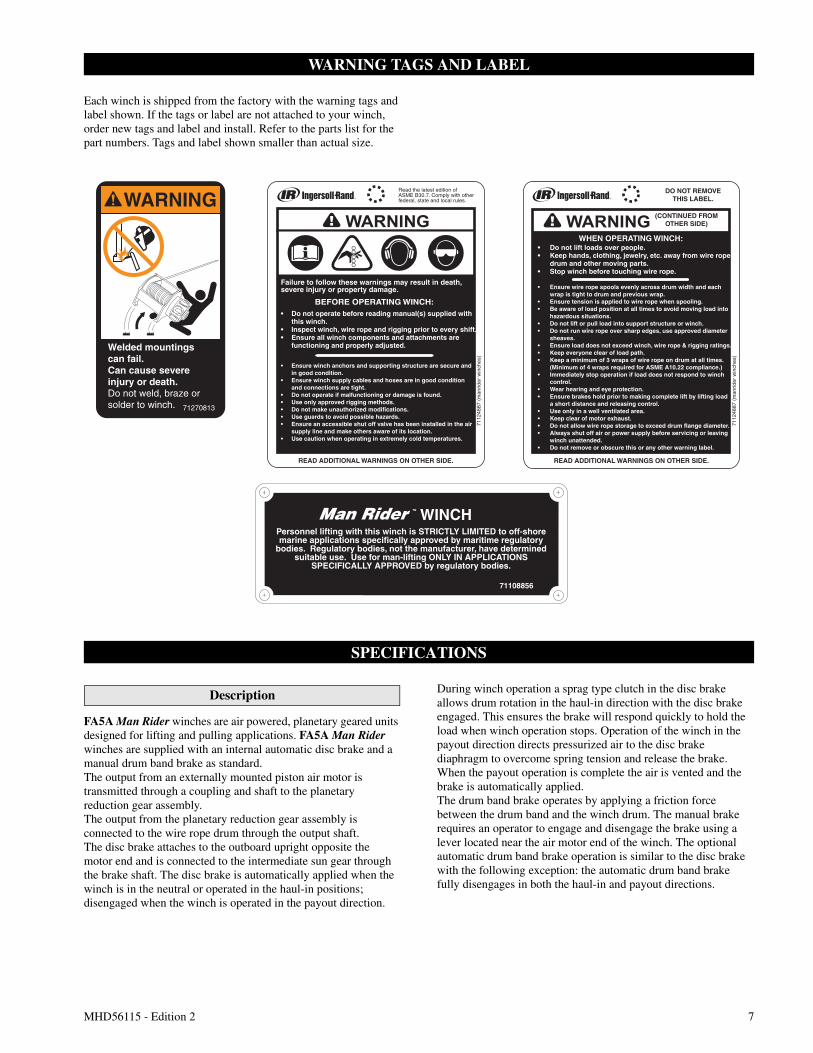
Each winch is shipped from the factory with the warning tags andlabel shown. If the tags or label are not attached to your winch,order new tags and label and install. Refer to the parts list for thepart numbers. Tags and label shown smaller than actual size.
SPECIFICATIONS
Description
FA5A Man Rider winches are air powered, planetary geared unitsdesigned for lifting and pulling applications. FA5A Man Riderwinches are supplied with an internal automatic disc brake and amanual drum band brake as standard.The output from an externally mounted piston air motor istransmitted through a coupling and shaft to the planetaryreduction gear assembly.The output from the planetary reduction gear assembly isconnected to the wire rope drum through the output shaft.The disc brake attaches to the outboard upright opposite themotor end and is connected to the intermediate sun gear throughthe brake shaft. The disc brake is automatically applied when thewinch is in the neutral or operated in the haul-in positions;disengaged when the winch is operated in the payout direction.
During winch operation a sprag type clutch in the disc brakeallows drum rotation in the haul-in direction with the disc brakeengaged. This ensures the brake will respond quickly to hold theload when winch operation stops. Operation of the winch in thepayout direction directs pressurized air to the disc brakediaphragm to overcome spring tension and release the brake.When the payout operation is complete the air is vented and thebrake is automatically applied.The drum band brake operates by applying a friction forcebetween the drum band and the winch drum. The manual brakerequires an operator to engage and disengage the brake using alever located near the air motor end of the winch. The optionalautomatic drum band brake operation is similar to the disc brakewith the following exception: the automatic drum band brakefully disengages in both the haul-in and payout directions.
WARNING
Welded mountingscan fail.Can cause severeinjury or death.Do not weld, braze or
solder to winch. 71270813
Read the latest edition ofASME B30.7. Comply with other federal, state and local rules.
READ ADDITIONAL WARNINGS ON OTHER SIDE. READ ADDITIONAL WARNINGS ON OTHER SIDE.
7112
4887
(m
anrid
er w
inch
es)
DO NOT REMOVETHIS LABEL.
(CONTINUED FROMOTHER SIDE)
7112
4887
(m
anrid
er w
inch
es)
Failure to follow these warnings may result in death, severe injury or property damage.
• Do not operate before reading manual(s) supplied with this winch.• Inspect winch, wire rope and rigging prior to every shift.• Ensure all winch components and attachments are functioning and properly adjusted.
• Ensure winch anchors and supporting structure are secure and in good condition.• Ensure winch supply cables and hoses are in good condition and connections are tight.• Do not operate if malfunctioning or damage is found.• Use only approved rigging methods.• Do not make unauthorized modifications.• Use guards to avoid possible hazards.• Ensure an accessible shut off valve has been installed in the air supply line and make others aware of its location.• Use caution when operating in extremely cold temperatures.
BEFORE OPERATING WINCH:
WHEN OPERATING WINCH:• Do not lift loads over people.• Keep hands, clothing, jewelry, etc. away from wire rope, drum and other moving parts.• Stop winch before touching wire rope.
• Ensure wire rope spools evenly across drum width and each wrap is tight to drum and previous wrap.• Ensure tension is applied to wire rope when spooling.• Be aware of load position at all times to avoid moving load into hazardous situations.• Do not lift or pull load into support structure or winch.• Do not run wire rope over sharp edges, use approved diameter sheaves.• Ensure load does not exceed winch, wire rope & rigging ratings.• Keep everyone clear of load path.• Keep a minimum of 3 wraps of wire rope on drum at all times. (Minimum of 4 wraps required for ASME A10.22 compliance.)• Immediately stop operation if load does not respond to winch control.• Wear hearing and eye protection.• Ensure brakes hold prior to making complete lift by lifting load a short distance and releasing control.• Use only in a well ventilated area.• Keep clear of motor exhaust.• Do not allow wire rope storage to exceed drum flange diameter.• Always shut off air or power supply before servicing or leaving winch unattended.• Do not remove or obscure this or any other warning label.
WINCHTM
Personnel lifting with this winch is STRICTLY LIMITED to off-shoremarine applications specifically approved by maritime regulatory
bodies. Regulatory bodies, not the manufacturer, have determinedsuitable use. Use for man-lifting ONLY IN APPLICATIONS
SPECIFICALLY APPROVED by regulatory bodies.
71108856
8 MHD56115 - Edition 2
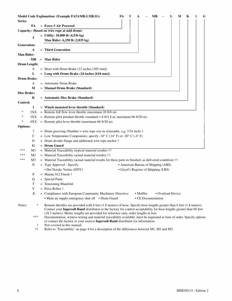
Model Code Explanation: (Example FA5AMR-LMK1G) FA 5 A - MR - L M K 1 GSeries
FA = Force 5 Air PoweredCapacity: (Based on wire rope at mid drum)
5= Utility: 10,000 lb (4,536 kg)
Man Rider: 6,250 lb (2,835 kg)Generation:
A = Third GenerationMan Rider:
MR = Man RiderDrum Length:
S = Short with Drum Brake (12 inches [305 mm])
L = Long with Drum Brake (24 inches [610 mm])Drum Brake:
A = Automatic Drum Brake
M = Manual Drum Brake (Standard)Disc Brake:
K = Automatic Disc Brake (Standard)Control:
1 = Winch mounted lever throttle (Standard)* 2XX = Remote full flow lever throttle (maximum 20 ft/6 m)
* 3XX = Remote pilot pendant throttle (standard = 6 ft/1.8 m; maximum 66 ft/20 m)
* 4XX = Remote pilot lever throttle (maximum 66 ft/20 m)
Options:7 = Drum grooving (Number = wire rope size in sixteenths, e.g. 7/16 inch) †
C = Low Temperature Components; specify -10° C (14° F) or -20° C (-4° F)
D = Drum divider flange and additional wire rope anchor †
G = Drum Guard*** M1 = Material Traceability (typical material results) ††
*** M2 = Material Traceability (actual material results) ††
*** M3 = Material Traceability (actual material results for these parts in finished, as-delivered condition) ††
N = Type Approval - Specify: • American Bureau of Shipping (ABS)
• Det Norske Veritas (DNV) • Lloyd’s Register of Shipping (LRS)
P = Marine 812 Finish †
Q = Special Paint
T = Tensioning Manifold
V = Press Roller †
-E = Compliance with European Community Machinery Directive: • Muffler • Overload Device
• Main air supply emergency shut off • Drum Guard • CE Documentation
Notes: *
***
†††
Remote throttles are provided with 6 feet (1.8 metres) of hose. Specify hose lengths greater than 6 feet (1.8 metres).Contact your Ingersoll-Rand distributor or the factory for control acceptability for hose lengths greater than 60 feet(18.3 metres). Metric lengths are provided for reference only, order lengths in feet.Documentation, witness testing and material traceability available; must be requested at time of order. Specify optionsor contact the factory or your nearest Ingersoll-Rand distributor for information.Not covered in this manual.Refer to ‘Traceability’ on page 4 for a description of the differences between M1, M2 and M3.
MHD56115 - Edition 2 9
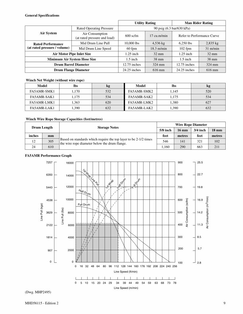
General Specifications
FA5AMR Performance Graph
(Dwg. MHP2495)
Utility Rating Man Rider Rating
Air SystemRated Operating Pressure 90 psig (6.3 bar/630 kPa)
Air Consumption(at rated pressure and load)
600 scfm 17 cu.m/min Refer to Performance Curve
Rated Performance(at rated pressure / volume)
Mid Drum Line Pull 10,000 lbs 4,536 kg 6,250 lbs 2,835 kg
Mid Drum Line Speed 60 fpm 18.3 m/min 102 fpm 31 m/min
Air Motor Pipe Inlet Size 1.25 inch 32 mm 1.25 inch 32 mm
Minimum Air System Hose Size 1.5 inch 38 mm 1.5 inch 38 mm
Drum Barrel Diameter 12.75 inches 324 mm 12.75 inches 324 mm
Drum Flange Diameter 24.25 inches 616 mm 24.25 inches 616 mm
Winch Net Weight (without wire rope)
Model lbs kg Model lbs kg
FA5AMR-SMK1 1,170 532 FA5AMR-SMK2 1,145 520
FA5AMR-SAK1 1,175 534 FA5AMR-SAK2 1,175 534
FA5AMR-LMK1 1,363 620 FA5AMR-LMK2 1,380 627
FA5AMR-LAK1 1,390 632 FA5AMR-LAK2 1,390 632
Winch Wire Rope Storage Capacities (feet/metres)
Drum Length Storage NotesWire Rope Diameter
5/8 inch 16 mm 3/4 inch 18 mm
inches mmBased on standards which require the top layer to be 2-1/2 timesthe wire rope diameter below the drum flange.
feet metres feet metres
12 305 546 141 321 102
24 610 1,160 290 663 211
2000
6000
4000
8000
10000
12000
14000
160001st W
rap Line Pull
1st W
rap
Half D
rum
Full D
rum
0
300
500
400
600
700
800
900
200
100
8.5
14.2
11.3
16.9
19.8
22.7
25.5
5.7
2.8
907
2122
1814
3629
4536
5443
6350
7257
0
0 16 32 48 64 80 96 112 128 144 160 176 192 208 224 240
5 10 15 20 24 29 34 39 44 49 54 59 63 68 73 780
256
Line
Pul
l (lb
s)
Line
Pul
l (kg
s)
Line Speed (ft/min)
Line Speed (m/min)
Air
Con
sum
ptio
n (s
cfm
)
Air
Con
sum
ptio
n (m
/m
in)
3
Half Drum
Full Drum
10 MHD56115 - Edition 2
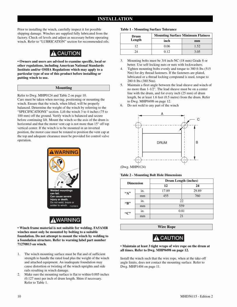
INSTALLATION
Prior to installing the winch, carefully inspect it for possibleshipping damage. Winches are supplied fully lubricated from thefactory. Check oil levels and adjust as necessary before operatingwinch. Refer to “LUBRICATION” section for recommended oils.
CAUTION
• Owners and users are advised to examine specific, local orother regulations, including American National StandardsInstitute and/or OSHA Regulations which may apply to aparticular type of use of this product before installing orputting winch to use.
Mounting
Refer to Dwg. MHP0124 and Table 2 on page 10.Care must be taken when moving, positioning or mounting thewinch. Ensure that the winch, when lifted, will be properlybalanced. Determine the weight of the winch by referring to the“SPECIFICATIONS” section. Lift the winch 3 to 4 inches (75 to100 mm) off the ground. Verify winch is balanced and securebefore continuing lift. Mount the winch so the axis of the drum ishorizontal and that the motor vent cap is not more than 15° off topvertical center. If the winch is to be mounted in an invertedposition, the motor case must be rotated to position the vent cap atthe top and adequate clearance must be provided for control valveoperation.
WARNING• Winch frame material is not suitable for welding. FA5AMRwinches must only be mounted by bolting to a suitablefoundation. Do not attempt to mount the winch by welding toa foundation structure. Refer to warning label part number71270813 on winch.
1. The winch mounting surface must be flat and of sufficientstrength to handle the rated load plus the weight of the winchand attached equipment. An inadequate foundation maycause distortion or twisting of the winch uprights and siderails resulting in winch damage.
2. Make sure the mounting surface is flat to within 0.005 inches(0.127 mm) per inch of drum length. Shim if necessary.Refer to Table 1.
Table 1 - Mounting Surface Tolerance
3. Mounting bolts must be 3/4 inch-NC (18 mm) Grade 8 orbetter. Use self-locking nuts or nuts with lockwashers.
4. Tighten mounting bolts evenly and torque to 380 ft lbs (515Nm) for dry thread fasteners. If the fasteners are plated,lubricated or a thread locking compound is used, torque to280 ft lbs (380 Nm).
5. Maintain a fleet angle between the lead sheave and winch ofno more than 1-1/2°. The lead sheave must be on a centerline with the drum, and for every inch (25 mm) of drumlength, be at least 1.6 feet (0.5 metre) from the drum. Referto Dwg. MHP0498 on page 12.
6. Do not weld to any part of the winch
(Dwg. MHP0124)
Table 2 - Mounting Bolt Hole Dimensions
Wire Rope
CAUTION
• Maintain at least 3 tight wraps of wire rope on the drum atall times. Refer to Dwg. MHP0498 on page 12.
Install the winch such that the wire rope, when at the take-offangle limits, does not contact the mounting surface. Refer toDwg. MHP1404 on page 11.
WARNING
Welded mountingscan fail.Can cause severeinjury or death.Do not weld, braze orsolder to winch. 71270813
DrumLength
Mounting Surface Minimum Flatness
inch mm
12 0.06 1.52
24 0.12 3.05
DimensionDrum Length (inches)
12 24
“A”in. 17.89 29.89
mm 455 760
“B”in. 22
mm 559
“C”in. 0.81
mm 21
MHD56115 - Edition 2 11
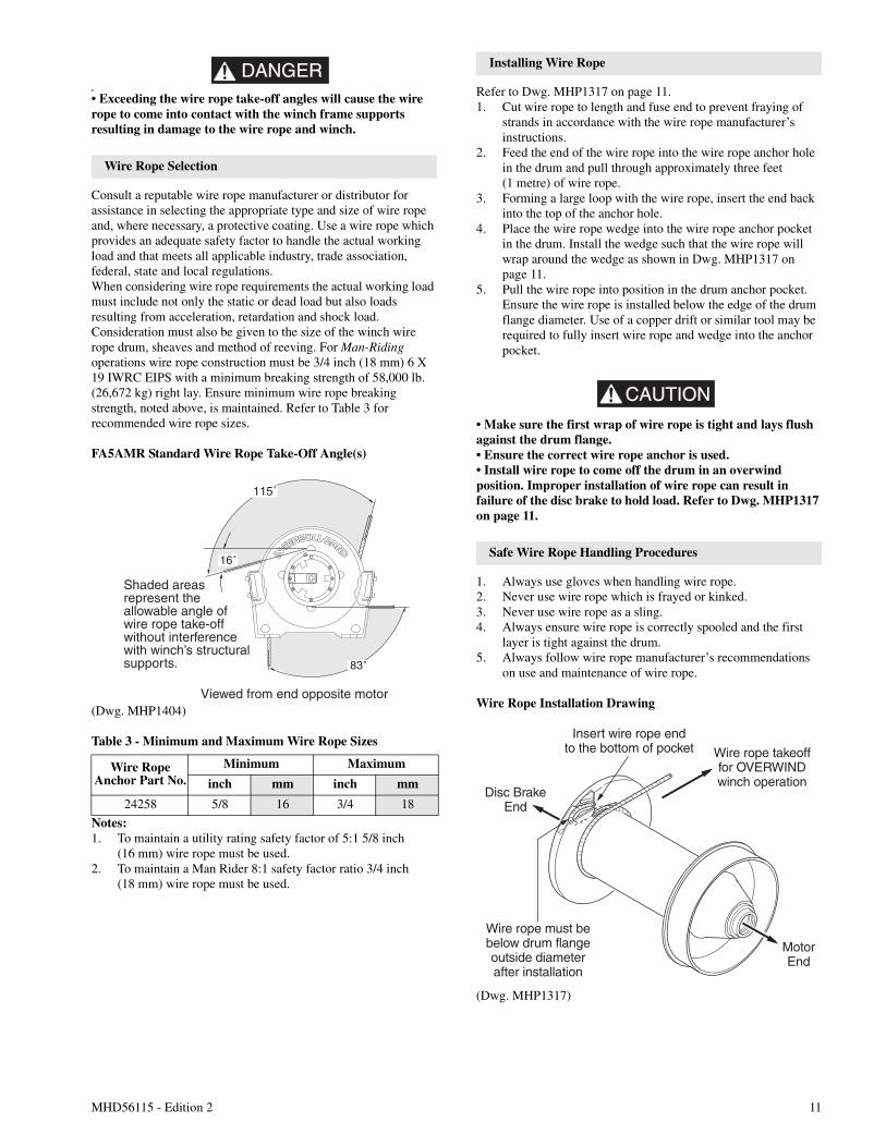
DANGER•
• Exceeding the wire rope take-off angles will cause the wirerope to come into contact with the winch frame supportsresulting in damage to the wire rope and winch.
Wire Rope Selection
Consult a reputable wire rope manufacturer or distributor forassistance in selecting the appropriate type and size of wire ropeand, where necessary, a protective coating. Use a wire rope whichprovides an adequate safety factor to handle the actual workingload and that meets all applicable industry, trade association,federal, state and local regulations.When considering wire rope requirements the actual working loadmust include not only the static or dead load but also loadsresulting from acceleration, retardation and shock load.Consideration must also be given to the size of the winch wirerope drum, sheaves and method of reeving. For Man-Ridingoperations wire rope construction must be 3/4 inch (18 mm) 6 X19 IWRC EIPS with a minimum breaking strength of 58,000 lb.(26,672 kg) right lay. Ensure minimum wire rope breakingstrength, noted above, is maintained. Refer to Table 3 forrecommended wire rope sizes.
FA5AMR Standard Wire Rope Take-Off Angle(s)
(Dwg. MHP1404)
Table 3 - Minimum and Maximum Wire Rope Sizes
Notes:1. To maintain a utility rating safety factor of 5:1 5/8 inch
(16 mm) wire rope must be used.2. To maintain a Man Rider 8:1 safety factor ratio 3/4 inch
(18 mm) wire rope must be used.
Installing Wire Rope
Refer to Dwg. MHP1317 on page 11.1. Cut wire rope to length and fuse end to prevent fraying of
strands in accordance with the wire rope manufacturer’sinstructions.
2. Feed the end of the wire rope into the wire rope anchor holein the drum and pull through approximately three feet(1 metre) of wire rope.
3. Forming a large loop with the wire rope, insert the end backinto the top of the anchor hole.
4. Place the wire rope wedge into the wire rope anchor pocketin the drum. Install the wedge such that the wire rope willwrap around the wedge as shown in Dwg. MHP1317 onpage 11.
5. Pull the wire rope into position in the drum anchor pocket.Ensure the wire rope is installed below the edge of the drumflange diameter. Use of a copper drift or similar tool may berequired to fully insert wire rope and wedge into the anchorpocket.
CAUTION
• Make sure the first wrap of wire rope is tight and lays flushagainst the drum flange.• Ensure the correct wire rope anchor is used.• Install wire rope to come off the drum in an overwindposition. Improper installation of wire rope can result infailure of the disc brake to hold load. Refer to Dwg. MHP1317on page 11.
Safe Wire Rope Handling Procedures
1. Always use gloves when handling wire rope.2. Never use wire rope which is frayed or kinked.3. Never use wire rope as a sling.4. Always ensure wire rope is correctly spooled and the first
layer is tight against the drum.5. Always follow wire rope manufacturer’s recommendations
on use and maintenance of wire rope.
Wire Rope Installation Drawing
(Dwg. MHP1317)
Wire RopeAnchor Part No.
Minimum Maximum
inch mm inch mm
24258 5/8 16 3/4 18
115˚
83˚
16˚
Shaded areasrepresent theallowable angle ofwire rope take-offwithout interferencewith winch’s structuralsupports.
Viewed from end opposite motor
Disc BrakeEnd
MotorEnd
Wire rope must bebelow drum flangeoutside diameterafter installation
Insert wire rope endto the bottom of pocket Wire rope takeoff
for OVERWINDwinch operation
12 MHD56115 - Edition 2
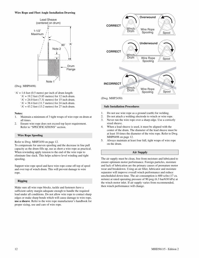
Wire Rope and Fleet Angle Installation Drawing
(Dwg. MHP0498)
‘A’ = 1.6 feet (0.5 metre) per inch of drum length:‘A’ = 19.2 feet (5.85 metres) for 12 inch drum.‘A’ = 24.0 feet (7.31 metres) for 15 inch drum.‘A’ = 38.4 feet (11.7 metres) for 24 inch drum.‘A’ = 43.2 feet (13.2 metres) for 27 inch drum.
Notes:1. Maintain a minimum of 3 tight wraps of wire rope on drum at
all times.2. Ensure wire rope does not exceed top layer requirement.
Refer to “SPECIFICATIONS” section.
Wire Rope Spooling
Refer to Dwg. MHP2450 on page 12.To compensate for uneven spooling and the decrease in line pullcapacity as the drum fills up, use as short a wire rope as practical.When rewinding apply tension to the end of the wire rope toeliminate line slack. This helps achieve level winding and tightspooling.
Support wire rope spool and have wire rope come off top of spooland over top of winch drum. This will prevent damage to wirerope.
Rigging
Make sure all wire rope blocks, tackle and fasteners have asufficient safety margin adequate enough to handle the requiredload under all conditions. Do not allow wire rope to contact sharpedges or make sharp bends which will cause damage to wire rope,use a sheave. Refer to the wire rope manufacturer’s handbook forproper sizing, use and care of wire rope.
(Dwg. MHP2450)
Safe Installation Procedures
1. Do not use wire rope as a ground (earth) for welding.2. Do not attach a welding electrode to winch or wire rope.3. Never run the wire rope over a sharp edge. Use a correctly
sized sheave.4. When a lead sheave is used, it must be aligned with the
center of the drum. The diameter of the lead sheave must beat least 18 times the diameter of the wire rope. Refer to Dwg.MHP0498 on page 12.
5. Always maintain at least four full, tight wraps of wire ropeon the drum.
Air Supply
The air supply must be clean, free from moisture and lubricated toensure optimum motor performance. Foreign particles, moistureand lack of lubrication are the primary causes of premature motorwear and breakdown. Using an air filter, lubricator and moistureseparator will improve overall winch performance and reduceunscheduled down time. The air consumption is 600 scfm (17 cu.m/min) at rated operating pressure of 90 psig (6.3 bar/630 kPa) atthe winch motor inlet. If air supply varies from recommended,then winch performance will change.
Lead Sheave(centered on drum)
1-1/2˚Maximum
Note 2
Note 1
‘A’
DrumFlange
90˚
CORRECT
Wire RopeSpooling
Wire RopeSpooling
Wire RopeSpooling
Spool
INCORRECTWinchDrum
SpoolWinchDrum
CORRECT
Underwound
Overwound
SpoolWinchDrum
MHD56115 - Edition 2 13
Air Lines
The inside diameter of the winch air supply lines must be at least1-1/2 inch (38 mm). Before making final connections, all airsupply lines should be purged with clean, moisture free air ornitrogen before connecting to winch inlet. Supply lines should beas short and straight as installation conditions will permit. Longtransmission lines and excessive use of fittings, elbows, tees,globe valves etc. cause a reduction in pressure due to restrictionsand surface friction in the lines.
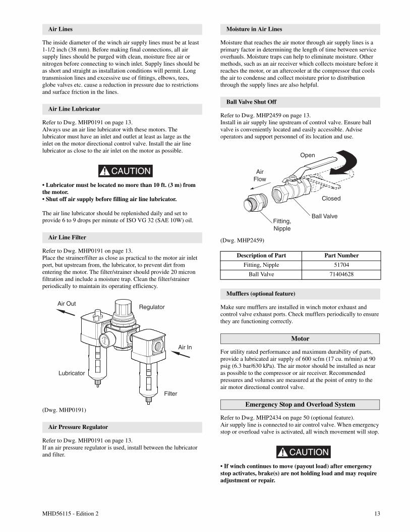
Air Line Lubricator
Refer to Dwg. MHP0191 on page 13.Always use an air line lubricator with these motors. Thelubricator must have an inlet and outlet at least as large as theinlet on the motor directional control valve. Install the air linelubricator as close to the air inlet on the motor as possible.
CAUTION
• Lubricator must be located no more than 10 ft. (3 m) fromthe motor.• Shut off air supply before filling air line lubricator.
The air line lubricator should be replenished daily and set toprovide 6 to 9 drops per minute of ISO VG 32 (SAE 10W) oil.
Air Line Filter
Refer to Dwg. MHP0191 on page 13.Place the strainer/filter as close as practical to the motor air inletport, but upstream from, the lubricator, to prevent dirt fromentering the motor. The filter/strainer should provide 20 micronfiltration and include a moisture trap. Clean the filter/strainerperiodically to maintain its operating efficiency.
(Dwg. MHP0191)
Air Pressure Regulator
Refer to Dwg. MHP0191 on page 13.If an air pressure regulator is used, install between the lubricatorand filter.
Moisture in Air Lines
Moisture that reaches the air motor through air supply lines is aprimary factor in determining the length of time between serviceoverhauls. Moisture traps can help to eliminate moisture. Othermethods, such as an air receiver which collects moisture before itreaches the motor, or an aftercooler at the compressor that coolsthe air to condense and collect moisture prior to distributionthrough the supply lines are also helpful.
Ball Valve Shut Off
Refer to Dwg. MHP2459 on page 13.Install in air supply line upstream of control valve. Ensure ballvalve is conveniently located and easily accessible. Adviseoperators and support personnel of its location and use.
(Dwg. MHP2459)
Mufflers (optional feature)
Make sure mufflers are installed in winch motor exhaust andcontrol valve exhaust ports. Check mufflers periodically to ensurethey are functioning correctly.
Motor
For utility rated performance and maximum durability of parts,provide a lubricated air supply of 600 scfm (17 cu. m/min) at 90psig (6.3 bar/630 kPa). The air motor should be installed as nearas possible to the compressor or air receiver. Recommendedpressures and volumes are measured at the point of entry to theair motor directional control valve.
Emergency Stop and Overload System
Refer to Dwg. MHP2434 on page 50 (optional feature).Air supply line is connected to air control valve. When emergencystop or overload valve is activated, all winch movement will stop.
CAUTION
• If winch continues to move (payout load) after emergencystop activates, brake(s) are not holding load and may requireadjustment or repair.
Lubricator
Air Out Regulator
Air In
Filter
Description of Part Part Number
Fitting, Nipple 51704
Ball Valve 71404628
Open
Closed
Ball Valve
AirFlow
Fitting,Nipple
14 MHD56115 - Edition 2
When control valve senses a preset pressure difference betweenports, a pilot signal is sent to stop flow of air, all winch movementwill stop.
Initial Winch Operating Checks
Winches are tested for proper operation prior to leaving thefactory. Before the winch is placed into service the followinginitial operating checks should be performed.1. When first running the motor inject some light oil into the
inlet connection to provide initial lubrication.2. When first operating the winch it is recommended that the
motor be driven slowly in both directions for a few minutes.
For winches that have been in storage the following start-upprocedures are required.1. Give the winch an inspection conforming to the requirements
of “Winches Not in Regular Use” in the “INSPECTION”section.
2. Pour a small amount of ISO VG 32 (SAE 10W) oil in themotor inlet port.
3. Operate the motor for 10 seconds in both directions to flushout any impurities.
4. Check to ensure oil levels are “full”.5. The winch is now ready for normal use.
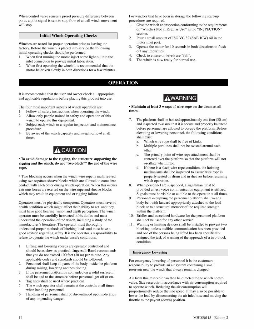
OPERATION
It is recommended that the user and owner check all appropriateand applicable regulations before placing this product into use.
The four most important aspects of winch operation are:1. Follow all safety instructions when operating the winch.2. Allow only people trained in safety and operation of this
winch to operate this equipment.3. Subject each winch to a regular inspection and maintenance
procedure.4. Be aware of the winch capacity and weight of load at all
times.
CAUTION
• To avoid damage to the rigging, the structure supporting therigging and the winch, do not “two-block*” the end of the wirerope.
* Two blocking occurs when the winch wire rope is multi reevedusing two separate sheave blocks which are allowed to come intocontact with each other during winch operation. When this occursextreme forces are exerted on the wire rope and sheave blockswhich may result in equipment and or rigging failure.
Operators must be physically competent. Operators must have nohealth condition which might affect their ability to act, and theymust have good hearing, vision and depth perception. The winchoperator must be carefully instructed in his duties and mustunderstand the operation of the winch, including a study of themanufacturer’s literature. The operator must thoroughlyunderstand proper methods of hitching loads and must have agood attitude regarding safety. It is the operator’s responsibility torefuse to operate the winch under unsafe conditions.
1. Lifting and lowering speeds are operator controlled andshould be as slow as practical. Ingersoll-Rand recommendsthat you do not exceed 100 feet (30 m) per minute. Anyapplicable codes and standards should be followed.
2. Personnel shall keep all parts of the body inside the platformduring raising, lowering and positioning.
3. If the personnel platform is not landed on a solid surface, itshall be tied to the structure before personnel get off or on.
4. Tag lines shall be used where practical.5. The winch operator shall remain at the controls at all times
when handling personnel.6. Handling of personnel shall be discontinued upon indication
of any impending danger.
WARNING• Maintain at least 3 wraps of wire rope on the drum at alltimes.
7. The platform shall be hoisted approximately one foot (30 cm)and inspected to assure that it is secure and properly balancedbefore personnel are allowed to occupy the platform. Beforeelevating or lowering personnel, the following conditionsshall exist:a. Winch wire rope shall be free of kinks.b. Multiple part lines shall not be twisted around each
other.c. The primary point of wire rope attachment shall be
centered over the platform so that the platform will notoscillate when lifted.
d. If there is a slack wire rope condition, the hoistingmechanisms shall be inspected to assure wire rope isproperly seated on drum and in sheaves before resumingwinch operation.
8. When personnel are suspended, a signalman must beprovided unless voice communication equipment is utilized.Signals must be visible or audible to the operator at all times.
9. Personnel occupying the personnel platform shall wear abody belt with lanyard appropriately attached to the loadblock or to a structural member of the required strengthwithin the platform.
10. Bridles and associated hardware for the personnel platformshall not be used for any other service.
11. Warning or limiting devices shall be installed to prevent twoblocking, unless audible communication has been providedand one of the persons being lifted has been specificallyassigned the task of warning of the approach of a two-blockcondition.
Emergency Lowering
For emergency lowering of personnel it is the customersresponsibility to provide an air system containing a smallreservoir near the winch that always remains charged.
Air from this reservoir can then be directed to the winch controlvalve. Size reservoir in accordance with air consumption requiredto operate winch. Reducing the air consumption willproportionately reduce the line speed. It may also be possible tolower the load by disconnecting the air inlet hose and moving thethrottle to the payout (down) position.
MHD56115 - Edition 2 15
Contact the factory for minimum load requirements. Using thismethod a lowering speed of approximately 3 ft/min (1 m/min) canbe accomplished.
Training Program
The employer shall provide and implement a training program forall supervisors and employees engaged in the operation of raising,lowering or suspending personnel platforms from a winch loadline so that they are familiar with the requirements of the hoistingsystem and are able to recognize the associated hazards and takeappropriate measures. Records of training programs shall bemaintained.
Planning Meeting
A meeting attended by the winch operator, signalman, persons tobe lifted and the person in charge of the task to be performed isrequired to be held to plan and review the procedures to befollowed, including procedures for entering and leaving thepersonnel platform, the points at which personnel will enter andleave the platform, the use of safety equipment, signals, and thelift chart information.
NOTICE• This meeting shall be held prior to the beginning ofpersonnel hoisting operations at each new work location andthereafter for any new employees assigned to the operation.
Controls
A spring loaded, motor mounted, live air manual throttle controlvalve is supplied as a standard feature on this winch. Optionalremote throttle controls are available. Reference model code onthe winch nameplate and compare it to the “SPECIFICATIONS”section on page 7 to determine your configuration. The throttlecontrol provides operator control of the motor speed and directionof drum rotation. Operate winch throttle control using smooth,even movements. Do not slam or jerk throttle controls duringoperation.
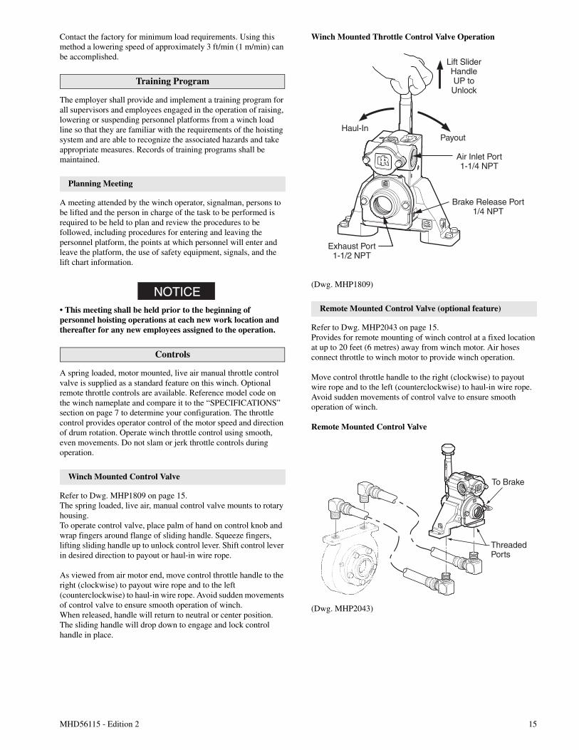
Winch Mounted Control Valve
Refer to Dwg. MHP1809 on page 15.The spring loaded, live air, manual control valve mounts to rotaryhousing.To operate control valve, place palm of hand on control knob andwrap fingers around flange of sliding handle. Squeeze fingers,lifting sliding handle up to unlock control lever. Shift control leverin desired direction to payout or haul-in wire rope.
As viewed from air motor end, move control throttle handle to theright (clockwise) to payout wire rope and to the left(counterclockwise) to haul-in wire rope. Avoid sudden movementsof control valve to ensure smooth operation of winch.When released, handle will return to neutral or center position.The sliding handle will drop down to engage and lock controlhandle in place.
Winch Mounted Throttle Control Valve Operation
(Dwg. MHP1809)
Remote Mounted Control Valve (optional feature)
Refer to Dwg. MHP2043 on page 15.Provides for remote mounting of winch control at a fixed locationat up to 20 feet (6 metres) away from winch motor. Air hosesconnect throttle to winch motor to provide winch operation.
Move control throttle handle to the right (clockwise) to payoutwire rope and to the left (counterclockwise) to haul-in wire rope.Avoid sudden movements of control valve to ensure smoothoperation of winch.
Remote Mounted Control Valve
(Dwg. MHP2043)
Haul-In
Brake Release Port1/4 NPT
Air Inlet Port1-1/4 NPT
Payout
Lift SliderHandleUP toUnlock
Exhaust Port1-1/2 NPT
To Brake
ThreadedPorts
16 MHD56115 - Edition 2
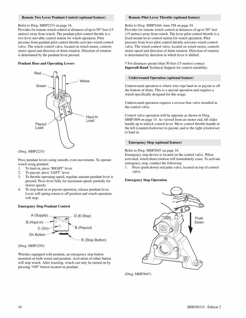
Remote Two Lever Pendant Control (optional feature)
Refer to Dwg. MHP2233 on page 16.Provides for remote winch control at distances of up to 50* feet (15metres) away from winch. The pendant pilot control throttle is atwo lever movable control station for winch operation. Pilotpressure from pendant pilot control throttle activates winch controlvalve. The winch control valve, located on winch motor, controlsmotor speed and direction of drum rotation. Direction of rotationis determined by the pendant lever pressed.
Pendant Hose and Operating Levers
(Dwg. MHP2233)
Press pendant levers using smooth, even movements. To operatewinch using pendant:1. To haul-in, press ‘RIGHT’ lever.2. To payout, press ‘LEFT’ lever.3. To throttle operating speed, regulate amount pendant lever is
pressed. Press lever fully for maximum speed; partially forslower speeds.
4. To stop haul-in or payout operation, release pendant lever.Lever will spring return to off position and winch operationwill stop.
Emergency Stop Pendant Control
(Dwg. MHP2295)
Winches equipped with pendant, an emergency stop buttonmounted on both winch and pendant. Activation of either buttonwill stop winch. After resetting, winch can only be turned on bypressing “ON” button located on pendant.
Remote Pilot Lever Throttle (optional feature)
Refer to Dwg. MHP2444, item 358 on page 54.Provides for remote winch control at distances of up to 50* feet(15 metres) away from winch. The lever pilot control throttle is afixed mount lever control station for winch operation. Pilotpressure from lever pilot control throttle activates winch controlvalve. The winch control valve, located on winch motor, controlsmotor speed and direction of drum rotation. Direction of rotationis determined by direction in which lever is shifted.
* For distances greater than 50 feet (15 metres) contactIngersoll-Rand Technical Support for control suitability.
Underwound Operation (optional feature)
Underwound operation is where wire rope haul-in or payout is offthe bottom of drum. This is a special operation and requires awinch specifically designed for this usage.
Underwound operation requires a reverse bias valve installed inthe control valve.
Control valve operation will be opposite as shown in Dwg.MHP1809 on page 15. As viewed from air motor end, lift sliderhandle up to unlock control lever. Move control throttle handle tothe left (counterclockwise) to payout, and to the right (clockwise)to haul-in.
Emergency Stop (optional feature)
Refer to Dwg. MHP2047 on page 16.Emergency stop device is located on the control valve. Whenactivated, winch drum rotation will immediately cease. To activateemergency stop, conduct the following:1. Press (push down) red palm valve, located on top of control
valve.
Emergency Stop Operation
(Dwg. MHP2047)
PayoutLoad
Haul-InLoad
Red
GreenYellow
A (Supply)
B (Payout)
E (Stop Button)
B (Haul-in)
C (On)
On Button
D (E-Stop)PushDown
MHD56115 - Edition 2 17
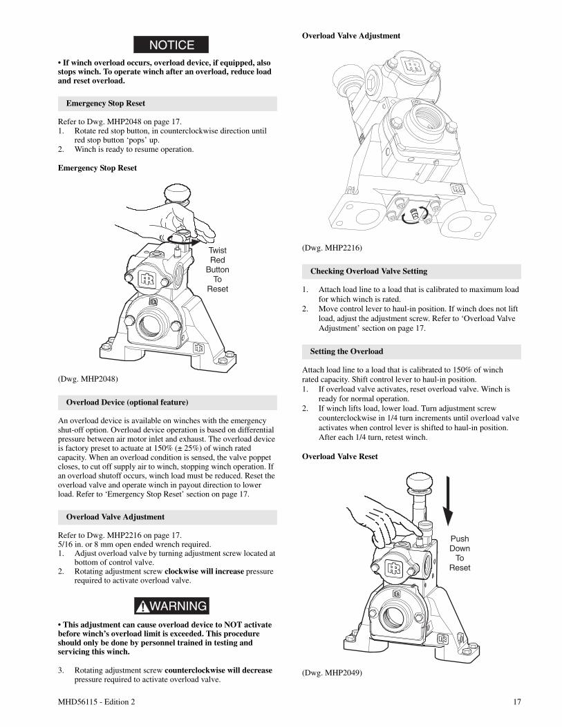
NOTICE• If winch overload occurs, overload device, if equipped, alsostops winch. To operate winch after an overload, reduce loadand reset overload.
Emergency Stop Reset
Refer to Dwg. MHP2048 on page 17.1. Rotate red stop button, in counterclockwise direction until
red stop button ‘pops’ up.2. Winch is ready to resume operation.
Emergency Stop Reset
(Dwg. MHP2048)
Overload Device (optional feature)
An overload device is available on winches with the emergencyshut-off option. Overload device operation is based on differentialpressure between air motor inlet and exhaust. The overload deviceis factory preset to actuate at 150% (± 25%) of winch ratedcapacity. When an overload condition is sensed, the valve poppetcloses, to cut off supply air to winch, stopping winch operation. Ifan overload shutoff occurs, winch load must be reduced. Reset theoverload valve and operate winch in payout direction to lowerload. Refer to ‘Emergency Stop Reset’ section on page 17.
Overload Valve Adjustment
Refer to Dwg. MHP2216 on page 17.5/16 in. or 8 mm open ended wrench required.1. Adjust overload valve by turning adjustment screw located at
bottom of control valve.2. Rotating adjustment screw clockwise will increase pressure
required to activate overload valve.
WARNING• This adjustment can cause overload device to NOT activatebefore winch’s overload limit is exceeded. This procedureshould only be done by personnel trained in testing andservicing this winch.
3. Rotating adjustment screw counterclockwise will decreasepressure required to activate overload valve.
Overload Valve Adjustment
(Dwg. MHP2216)
Checking Overload Valve Setting
1. Attach load line to a load that is calibrated to maximum loadfor which winch is rated.
2. Move control lever to haul-in position. If winch does not liftload, adjust the adjustment screw. Refer to ‘Overload ValveAdjustment’ section on page 17.
Setting the Overload
Attach load line to a load that is calibrated to 150% of winchrated capacity. Shift control lever to haul-in position.1. If overload valve activates, reset overload valve. Winch is
ready for normal operation.2. If winch lifts load, lower load. Turn adjustment screw
counterclockwise in 1/4 turn increments until overload valveactivates when control lever is shifted to haul-in position.After each 1/4 turn, retest winch.
Overload Valve Reset
(Dwg. MHP2049)
TwistRed
ButtonTo
Reset
PushDown
ToReset
18 MHD56115 - Edition 2
Winch Brakes
Automatic Disc Brake
The automatic disc brake is spring applied, air released. When thewinch is operated in payout direction, air pressure acting on thediaphragm overcomes spring pressure and releases brake. Thebrake automatically engages when winch operation is returnedfrom payout direction to neutral or when shifted to haul-indirection. When winch is in neutral or haul-in positions the brakeair is vented and brake springs apply the brake. The springs, actingon the pressure plate, compress brake friction and separator platesand engage brake to prevent drum rotation in payout direction.
The cam type sprag clutch assembly allows drum rotation in haul-in direction with brake plates engaged, but prevents drum fromrotating in payout direction.A minimum air pressure of 25 psi (1.72 bar/172.4 kPa) is requiredto release brake.
Disc brake adjustment is not required. If disc brake does notoperate properly it must be disassembled, inspected and repaired.
WARNING• If the brake is disassembled, the friction and separator platesmust be correctly installed as described in the“MAINTENANCE” section of this manual. Failure tocorrectly install the friction and separator plates can causeinjury and/or property damage.
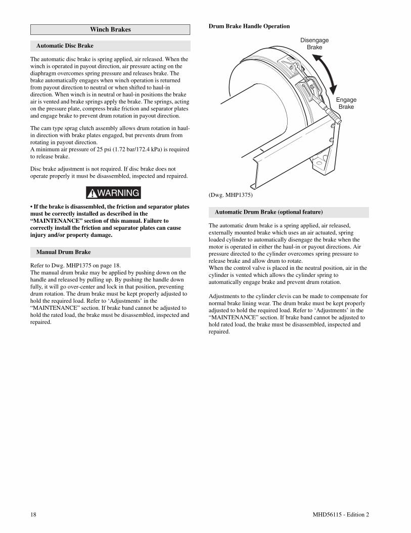
Manual Drum Brake
Refer to Dwg. MHP1375 on page 18.The manual drum brake may be applied by pushing down on thehandle and released by pulling up. By pushing the handle downfully, it will go over-center and lock in that position, preventingdrum rotation. The drum brake must be kept properly adjusted tohold the required load. Refer to ‘Adjustments’ in the“MAINTENANCE” section. If brake band cannot be adjusted tohold the rated load, the brake must be disassembled, inspected andrepaired.
Drum Brake Handle Operation
(Dwg. MHP1375)
Automatic Drum Brake (optional feature)
The automatic drum brake is a spring applied, air released,externally mounted brake which uses an air actuated, springloaded cylinder to automatically disengage the brake when themotor is operated in either the haul-in or payout directions. Airpressure directed to the cylinder overcomes spring pressure torelease brake and allow drum to rotate.When the control valve is placed in the neutral position, air in thecylinder is vented which allows the cylinder spring toautomatically engage brake and prevent drum rotation.
Adjustments to the cylinder clevis can be made to compensate fornormal brake lining wear. The drum brake must be kept properlyadjusted to hold the required load. Refer to ‘Adjustments’ in the“MAINTENANCE” section. If brake band cannot be adjusted tohold rated load, the brake must be disassembled, inspected andrepaired.
DisengageBrake
EngageBrake
MHD56115 - Edition 2 19
INSPECTION
Inspection information is based in part on American NationalStandards Institute Safety Codes (ASME B30.7).
WARNING• All new, altered or modified equipment should be inspectedand tested by personnel instructed in safety, operation andmaintenance of this equipment to ensure safe operation atrated specifications before placing equipment in service.• Never use a winch that inspection indicates is damaged.
Frequent and periodic inspections should be performed onequipment in regular service. Frequent inspections are visualexaminations performed by operators or personnel trained insafety and operation of this equipment and include observationsmade during routine equipment operation. Periodic inspectionsare thorough inspections conducted by personnel trained in thesafety, operation and maintenance of this equipment.ASME B30.7 states inspection intervals depend upon the nature ofthe critical components of the equipment and the severity of usage.The inspection intervals recommended in this manual are based onintermittent operation of the winch eight hours each day, five daysper week, in an environment relatively free of dust, moisture, andcorrosive fumes. If the winch is operated almost continuously ormore than the eight hours each day, more frequent inspectionswill be required.Careful inspection on a regular basis will reveal potentiallydangerous conditions while still in the early stages, allowingcorrective action to be taken before the condition becomesdangerous.Deficiencies revealed through inspection, or noted duringoperation, must be reported to designated personnel instructed insafety, operation and maintenance of this equipment. Adetermination as to whether a condition constitutes a safety hazardmust be decided, and the correction of noted safety hazardsaccomplished and documented by written report before placingthe equipment in service.
Records and Reports
An approved test and inspection record should be maintained foreach winch, listing all points requiring test and inspection. Thesereports should be dated, signed by the person who performed thetest or inspection, and kept on file where they are readily availableto authorized personnel.1. Winches which are used to raise, lower or suspend personnel
platforms shall be inspected by a qualified person, at thebeginning of each shift and prior to hoisting employee’s onthe personnel platform after the winch has been used for anymaterial handling operation.
2. A test lift shall be made for each work location and at thebeginning of each shift to insure that all systems and controlsare functioning properly.
3. The winch shall not be used for hoisting personnel if the testresults in instability or causes permanent deformation of anycomponent.
4. A visual inspection of the winch, personnel platform andrigging shall be conducted immediately after the test lift.
Wire Rope Reports
Records should be maintained as part of a long-range wire ropeinspection program. Records should include the condition of wirerope removed from service. Accurate records will establish arelationship between visual observations noted during frequentinspections and the actual condition of wire rope as determinedby periodic inspections.
Frequent Inspection
On equipment in continuous service, frequent inspection shouldbe made by operators at the beginning of each shift. In addition,visual inspections should be conducted during regular operationfor indications of damage or evidence of malfunction (such asabnormal noises).1. WINCH. Prior to operation, visually inspect winch housings,
controls, brakes, sideframes, uprights and drum for indicationsof damage. Any discrepancies noted must be reviewed andinspected further by authorized personnel instructed in theoperation, safety and maintenance of this winch.
2. WIRE ROPE. Visually inspect all wire rope which can beexpected to be in use during the day’s operations. Inspect forwear and damage indicated by distortion of wire rope suchas kinking, “birdcaging,” core protrusion, main stranddisplacement, corrosion, broken or cut strands. If damage isevident, do not operate winch until the discrepancies havebeen reviewed and inspected further by personnelknowledgeable on wire rope safety and maintenanceprocedures.
NOTICE• The full extent of wire rope wear cannot be determined byvisual inspection. At any indication of wear inspect the wirerope in accordance with instructions in “Periodic Inspection.”
3. AIR SYSTEM. Visually inspect all connections, fittings,hoses and components for indication of air leaks. Repair anyleaks or damage.
4. CONTROLS. During operation of winch, verify response tocontrol is quick and smooth. If winch responds or controlsstick, do not operate winch until all problems have beencorrected.
5. BRAKES. During winch operation test brakes. Brakes musthold load without slipping. Automatic brakes must releasewhen winch motor throttle or pendant is operated. If brakesdo not hold load, or do not release properly, the brakes mustbe adjusted or repaired.
6. WIRE ROPE REEVING. Check reeving and ensure wirerope is properly secured to the drum. Do not operate thewinch unless the wire rope feeds onto the drum smoothly.
7. LUBRICATION. Refer to the “LUBRICATION” section forrecommended procedures and lubricants.
8. PENDANT (optional feature). Ensure operation of pendantbuttons is smooth and that winch is responsive to pendantcontrol. Pendant buttons must spring return to a positionflush with the pendant housing when released.
9. MANUAL THROTTLE LEVER. Ensure operation ofmanual throttle lever is smooth and winch is responsive tolever movement. Lever must return to neutral and lock inplace when released. If winch responds slowly or controlsstick, do not operate winch until all problems have beencorrected.
20 MHD56115 - Edition 2
10. MOTOR. Check oil level. Place a suitable container belowthe motor and carefully open drain plug to remove anyaccumulated water. Check oil level in motor and add oil asnecessary to maintain correct level. Ensure lubricated airsupply provides 6 to 9 drops of ISO VG 32 (10W) lubricant.Operate motor slowly in both directions.
Periodic Inspection
Periodic inspection intervals for winch use under variousconditions is listed below:
Disassembly may be required as a result of frequent inspectionfindings or in order to properly inspect the individualcomponents. Disassembly steps are described in the“MAINTENANCE” section. Maintain written records of periodicinspections to provide an accumulative basis for continuingevaluation. Inspect all items listed in ‘Frequent Inspection.’ Alsoinspect the following:1. FRAMES and UPRIGHTS. Check for deformed, cracked or
corroded main components. Replace damaged parts.2. FASTENERS. Check retainer rings, split pins, capscrews,
nuts, and other fasteners on winch, including mounting bolts.Replace if missing or damaged and tighten if loose.
3. DRUM and SHEAVES. Check for cracks, wear or damage.Replace if necessary.
4. WIRE ROPE. In addition to Frequent Inspectionrequirements, also inspect for the following:a. Buildup of dirt and corrosion. Clean with steam or a stiff
wire brush to remove dirt and corrosion if necessary.b. Loose or damaged end connection. Replace if loose or
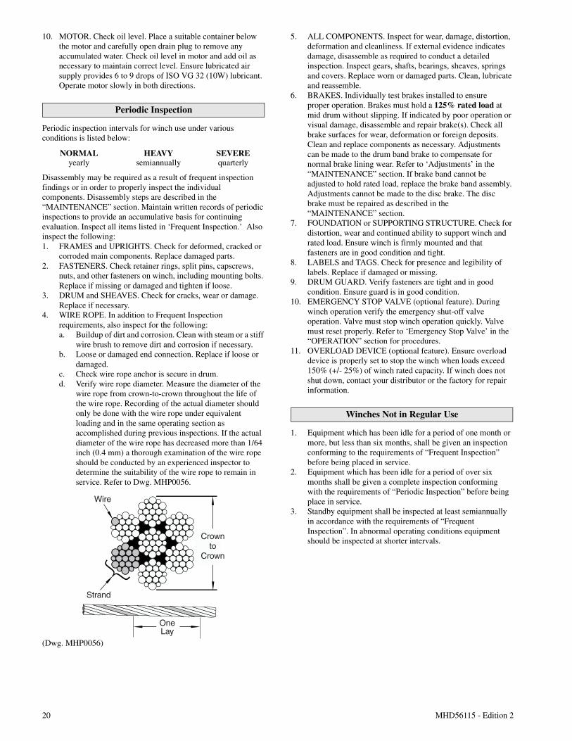
damaged.c. Check wire rope anchor is secure in drum.d. Verify wire rope diameter. Measure the diameter of the
wire rope from crown-to-crown throughout the life ofthe wire rope. Recording of the actual diameter shouldonly be done with the wire rope under equivalentloading and in the same operating section asaccomplished during previous inspections. If the actualdiameter of the wire rope has decreased more than 1/64inch (0.4 mm) a thorough examination of the wire ropeshould be conducted by an experienced inspector todetermine the suitability of the wire rope to remain inservice. Refer to Dwg. MHP0056.
(Dwg. MHP0056)
5. ALL COMPONENTS. Inspect for wear, damage, distortion,deformation and cleanliness. If external evidence indicatesdamage, disassemble as required to conduct a detailedinspection. Inspect gears, shafts, bearings, sheaves, springsand covers. Replace worn or damaged parts. Clean, lubricateand reassemble.
6. BRAKES. Individually test brakes installed to ensureproper operation. Brakes must hold a 125% rated load atmid drum without slipping. If indicated by poor operation orvisual damage, disassemble and repair brake(s). Check allbrake surfaces for wear, deformation or foreign deposits.Clean and replace components as necessary. Adjustmentscan be made to the drum band brake to compensate fornormal brake lining wear. Refer to ‘Adjustments’ in the“MAINTENANCE” section. If brake band cannot beadjusted to hold rated load, replace the brake band assembly.Adjustments cannot be made to the disc brake. The discbrake must be repaired as described in the“MAINTENANCE” section.
7. FOUNDATION or SUPPORTING STRUCTURE. Check fordistortion, wear and continued ability to support winch andrated load. Ensure winch is firmly mounted and thatfasteners are in good condition and tight.
8. LABELS and TAGS. Check for presence and legibility oflabels. Replace if damaged or missing.
9. DRUM GUARD. Verify fasteners are tight and in goodcondition. Ensure guard is in good condition.
10. EMERGENCY STOP VALVE (optional feature). Duringwinch operation verify the emergency shut-off valveoperation. Valve must stop winch operation quickly. Valvemust reset properly. Refer to ‘Emergency Stop Valve’ in the“OPERATION” section for procedures.
11. OVERLOAD DEVICE (optional feature). Ensure overloaddevice is properly set to stop the winch when loads exceed150% (+/- 25%) of winch rated capacity. If winch does notshut down, contact your distributor or the factory for repairinformation.
Winches Not in Regular Use
1. Equipment which has been idle for a period of one month ormore, but less than six months, shall be given an inspectionconforming to the requirements of “Frequent Inspection”before being placed in service.
2. Equipment which has been idle for a period of over sixmonths shall be given a complete inspection conformingwith the requirements of “Periodic Inspection” before beingplace in service.
3. Standby equipment shall be inspected at least semiannuallyin accordance with the requirements of “FrequentInspection”. In abnormal operating conditions equipmentshould be inspected at shorter intervals.
NORMAL HEAVY SEVEREyearly semiannually quarterly
Wire
Strand
Crownto
Crown
OneLay
MHD56115 - Edition 2 21
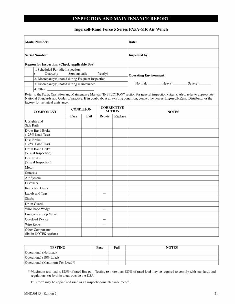
INSPECTION AND MAINTENANCE REPORT
Ingersoll-Rand Force 5 Series FA5A-MR Air Winch
Model Number: Date:
Serial Number: Inspected by:
Reason for Inspection: (Check Applicable Box)
1. Scheduled Periodic Inspection:(_____ Quarterly _____ Semiannually _____ Yearly) Operating Environment:
Normal: ________ Heavy: ________ Severe: _______2. Discrepancy(s) noted during Frequent Inspection
3. Discrepancy(s) noted during maintenance
4. Other: ___________________________
Refer to the Parts, Operation and Maintenance Manual “INSPECTION” section for general inspection criteria. Also, refer to appropriateNational Standards and Codes of practice. If in doubt about an existing condition, contact the nearest Ingersoll-Rand Distributor or thefactory for technical assistance.
COMPONENTCONDITION CORRECTIVE
ACTION NOTESPass Fail Repair Replace
Uprights andSide Rails
Drum Band Brake(125% Load Test)
Disc Brake(125% Load Test)
Drum Band Brake(Visual Inspection)
Disc Brake(Visual Inspection)
Motor
Controls
Air System
Fasteners
Reduction Gears
Labels and Tags ---
Shafts
Drum Guard
Wire Rope Wedge ---
Emergency Stop Valve
Overload Device ---
Wire Rope ---
Other Components(list in NOTES section)
TESTING Pass Fail NOTESOperational (No Load)
Operational (10% Load)
Operational (Maximum Test Load*)
* Maximum test load is 125% of rated line pull. Testing to more than 125% of rated load may be required to comply with standards andregulations set forth in areas outside the USA.
This form may be copied and used as an inspection/maintenance record.
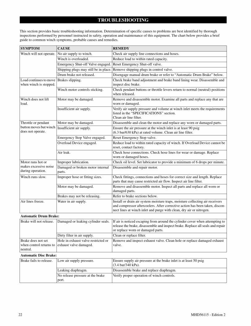
22 MHD56115 - Edition 2
TROUBLESHOOTING
This section provides basic troubleshooting information. Determination of specific causes to problems are best identified by thoroughinspections performed by personnel instructed in safety, operation and maintenance of this equipment. The chart below provides a briefguide to common winch symptoms, probable causes and remedies.
SYMPTOM CAUSE REMEDYWinch will not operate. No air supply to winch. Check air supply line connections and hoses.
Winch is overloaded. Reduce load to within rated capacity.
Emergency Shut-off Valve engaged. Reset Emergency Shut-off valve.
Shipping plugs may still be in place. Remove shipping plugs in control valve.
Drum brake not released. Disengage manual drum brake or refer to “Automatic Drum Brake” below.
Load continues to movewhen winch is stopped.
Brakes slipping. Check brake band adjustment and brake band lining wear. Disassemble andinspect disc brake.
Winch motor controls sticking. Check pendant buttons or throttle levers return to normal (neutral) positionswhen released.
Winch does not liftload.
Motor may be damaged. Remove and disassemble motor. Examine all parts and replace any that areworn or damaged.
Insufficient air supply. Verify air supply pressure and volume at winch inlet meets the requirementslisted in the “SPECIFICATIONS” section.Clean air line filter.
Throttle or pendantbutton moves but winchdoes not operate.
Motor may be damaged. Disassemble and clean the motor and replace any worn or damaged parts.
Insufficient air supply. Ensure the air pressure at the winch inlet is at least 90 psig(6.3 bar/630 kPa) at rated volume. Clean air line filter.
Emergency Stop Valve engaged. Reset Emergency Stop valve.
Overload Device engaged. Reduce load to within rated capacity of winch. If Overload Device cannot bereset, contact factory.
Air leak. Check hose connections. Check hose lines for wear or damage. Replaceworn or damaged hoses.
Motor runs hot ormakes excessive noiseduring operation.
Improper lubrication. Check oil level. Set lubricator to provide a minimum of 6 drops per minute.
Damaged or broken motor internalparts.
Disassemble and repair motor.
Winch runs slow. Improper hose or fitting sizes. Check fittings, connections and hoses for correct size and length. Replaceparts that may cause restricted air flow. Inspect air line filter.
Motor may be damaged. Remove and disassemble motor. Inspect all parts and replace all worn ordamaged parts.
Brakes may not be releasing. Refer to brake sections below.
Air lines freeze. Water in air supply. Install or drain air system moisture traps, moisture collecting air receiversand compressor aftercoolers. After corrective action has been taken, discon-nect lines at winch inlet and purge with clean, dry air or nitrogen.
Automatic Drum Brake:Brake will not release. Damaged or leaking cylinder seals. If air is noticed escaping from around the cylinder cover when attempting to
release the brake, disassemble and inspect brake. Replace all seals and repairor replace worn or damaged parts.
Dirty filter in air supply. Clean or replace filter.
Brake does not setwhen control returns toneutral.
Hole in exhaust valve restricted orexhaust valve damaged.
Remove and inspect exhaust valve. Clean hole or replace damaged exhaustvalve.
Automatic Disc Brake:Brake fails to release. Low air supply pressure. Ensure supply air pressure at the brake inlet is at least 50 psig
(3.4 bar/340 kPa).
Leaking diaphragm. Disassemble brake and replace diaphragm.
No release pressure at the brakeport.
Verify proper operation of winch controls.
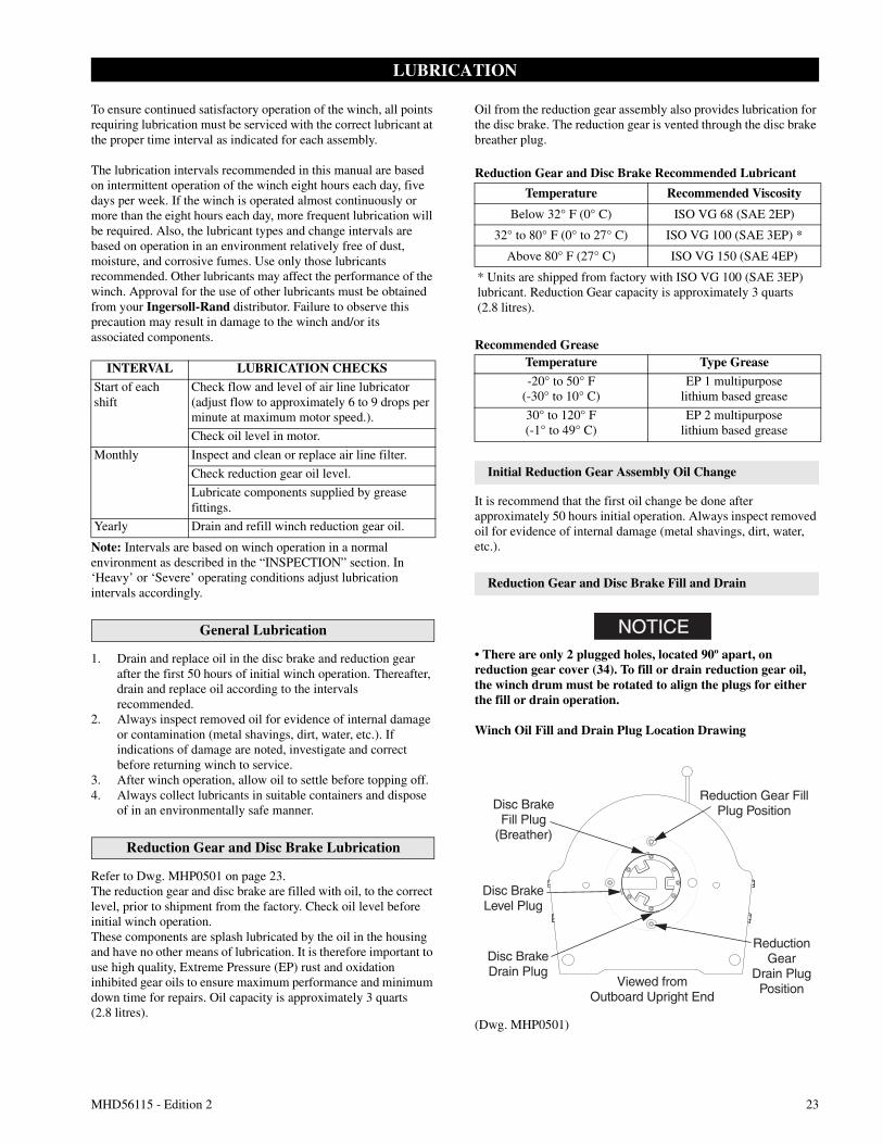
MHD56115 - Edition 2 23
LUBRICATION
To ensure continued satisfactory operation of the winch, all pointsrequiring lubrication must be serviced with the correct lubricant atthe proper time interval as indicated for each assembly.
The lubrication intervals recommended in this manual are basedon intermittent operation of the winch eight hours each day, fivedays per week. If the winch is operated almost continuously ormore than the eight hours each day, more frequent lubrication willbe required. Also, the lubricant types and change intervals arebased on operation in an environment relatively free of dust,moisture, and corrosive fumes. Use only those lubricantsrecommended. Other lubricants may affect the performance of thewinch. Approval for the use of other lubricants must be obtainedfrom your Ingersoll-Rand distributor. Failure to observe thisprecaution may result in damage to the winch and/or itsassociated components.
Note: Intervals are based on winch operation in a normalenvironment as described in the “INSPECTION” section. In‘Heavy’ or ‘Severe’ operating conditions adjust lubricationintervals accordingly.
General Lubrication
1. Drain and replace oil in the disc brake and reduction gearafter the first 50 hours of initial winch operation. Thereafter,drain and replace oil according to the intervalsrecommended.
2. Always inspect removed oil for evidence of internal damageor contamination (metal shavings, dirt, water, etc.). Ifindications of damage are noted, investigate and correctbefore returning winch to service.
3. After winch operation, allow oil to settle before topping off.4. Always collect lubricants in suitable containers and dispose
of in an environmentally safe manner.
Reduction Gear and Disc Brake Lubrication
Refer to Dwg. MHP0501 on page 23.The reduction gear and disc brake are filled with oil, to the correctlevel, prior to shipment from the factory. Check oil level beforeinitial winch operation.These components are splash lubricated by the oil in the housingand have no other means of lubrication. It is therefore important touse high quality, Extreme Pressure (EP) rust and oxidationinhibited gear oils to ensure maximum performance and minimumdown time for repairs. Oil capacity is approximately 3 quarts(2.8 litres).
Oil from the reduction gear assembly also provides lubrication forthe disc brake. The reduction gear is vented through the disc brakebreather plug.
Reduction Gear and Disc Brake Recommended Lubricant
Recommended Grease
Initial Reduction Gear Assembly Oil Change
It is recommend that the first oil change be done afterapproximately 50 hours initial operation. Always inspect removedoil for evidence of internal damage (metal shavings, dirt, water,etc.).
Reduction Gear and Disc Brake Fill and Drain
NOTICE• There are only 2 plugged holes, located 90º apart, onreduction gear cover (34). To fill or drain reduction gear oil,the winch drum must be rotated to align the plugs for eitherthe fill or drain operation.
Winch Oil Fill and Drain Plug Location Drawing
(Dwg. MHP0501)
INTERVAL LUBRICATION CHECKSStart of eachshift
Check flow and level of air line lubricator(adjust flow to approximately 6 to 9 drops perminute at maximum motor speed.).
Check oil level in motor.
Monthly Inspect and clean or replace air line filter.
Check reduction gear oil level.
Lubricate components supplied by greasefittings.
Yearly Drain and refill winch reduction gear oil.
Temperature Recommended Viscosity
Below 32° F (0° C) ISO VG 68 (SAE 2EP)
32° to 80° F (0° to 27° C) ISO VG 100 (SAE 3EP) *
Above 80° F (27° C) ISO VG 150 (SAE 4EP)
* Units are shipped from factory with ISO VG 100 (SAE 3EP)lubricant. Reduction Gear capacity is approximately 3 quarts(2.8 litres).
Temperature Type Grease
-20° to 50° F(-30° to 10° C)
EP 1 multipurposelithium based grease
30° to 120° F(-1° to 49° C)
EP 2 multipurposelithium based grease
Disc BrakeFill Plug
(Breather)
Disc BrakeLevel Plug
Disc BrakeDrain Plug
Viewed fromOutboard Upright End
Reduction Gear FillPlug Position
ReductionGear
Drain PlugPosition
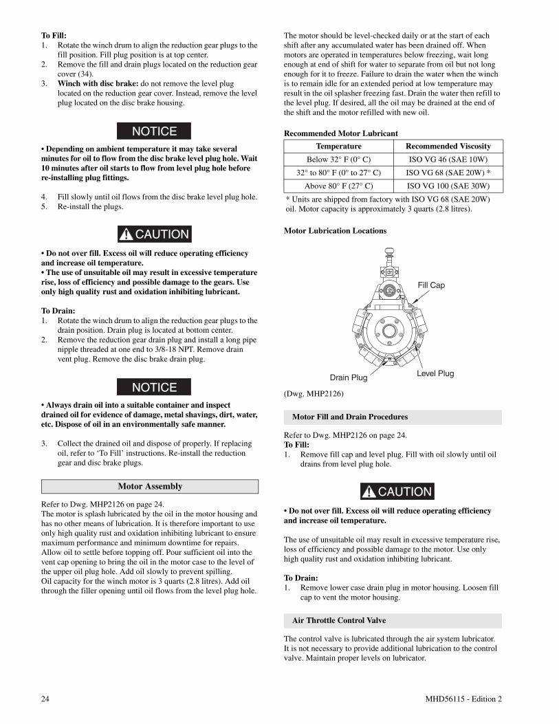
24 MHD56115 - Edition 2
To Fill:1. Rotate the winch drum to align the reduction gear plugs to the
fill position. Fill plug position is at top center.2. Remove the fill and drain plugs located on the reduction gear
cover (34).3. Winch with disc brake: do not remove the level plug
located on the reduction gear cover. Instead, remove the levelplug located on the disc brake housing.
NOTICE• Depending on ambient temperature it may take severalminutes for oil to flow from the disc brake level plug hole. Wait10 minutes after oil starts to flow from level plug hole beforere-installing plug fittings.
4. Fill slowly until oil flows from the disc brake level plug hole.5. Re-install the plugs.
CAUTION
• Do not over fill. Excess oil will reduce operating efficiencyand increase oil temperature.• The use of unsuitable oil may result in excessive temperaturerise, loss of efficiency and possible damage to the gears. Useonly high quality rust and oxidation inhibiting lubricant.
To Drain:1. Rotate the winch drum to align the reduction gear plugs to the
drain position. Drain plug is located at bottom center.2. Remove the reduction gear drain plug and install a long pipe
nipple threaded at one end to 3/8-18 NPT. Remove drainvent plug. Remove the disc brake drain plug.
NOTICE• Always drain oil into a suitable container and inspectdrained oil for evidence of damage, metal shavings, dirt, water,etc. Dispose of oil in an environmentally safe manner.
3. Collect the drained oil and dispose of properly. If replacingoil, refer to ‘To Fill’ instructions. Re-install the reductiongear and disc brake plugs.
Motor Assembly
Refer to Dwg. MHP2126 on page 24.The motor is splash lubricated by the oil in the motor housing andhas no other means of lubrication. It is therefore important to useonly high quality rust and oxidation inhibiting lubricant to ensuremaximum performance and minimum downtime for repairs.Allow oil to settle before topping off. Pour sufficient oil into thevent cap opening to bring the oil in the motor case to the level ofthe upper oil plug hole. Add oil slowly to prevent spilling.Oil capacity for the winch motor is 3 quarts (2.8 litres). Add oilthrough the filler opening until oil flows from the level plug hole.
The motor should be level-checked daily or at the start of eachshift after any accumulated water has been drained off. Whenmotors are operated in temperatures below freezing, wait longenough at end of shift for water to separate from oil but not longenough for it to freeze. Failure to drain the water when the winchis to remain idle for an extended period at low temperature mayresult in the oil splasher freezing fast. Drain the water then refill tothe level plug. If desired, all the oil may be drained at the end ofthe shift and the motor refilled with new oil.
Recommended Motor Lubricant
Motor Lubrication Locations
(Dwg. MHP2126)
Motor Fill and Drain Procedures
Refer to Dwg. MHP2126 on page 24.To Fill:1. Remove fill cap and level plug. Fill with oil slowly until oil
drains from level plug hole.
CAUTION
• Do not over fill. Excess oil will reduce operating efficiencyand increase oil temperature.
The use of unsuitable oil may result in excessive temperature rise,loss of efficiency and possible damage to the motor. Use onlyhigh quality rust and oxidation inhibiting lubricant.
To Drain:1. Remove lower case drain plug in motor housing. Loosen fill
cap to vent the motor housing.
Air Throttle Control Valve
The control valve is lubricated through the air system lubricator.It is not necessary to provide additional lubrication to the controlvalve. Maintain proper levels on lubricator.
Temperature Recommended Viscosity
Below 32° F (0° C) ISO VG 46 (SAE 10W)
32° to 80° F (0° to 27° C) ISO VG 68 (SAE 20W) *
Above 80° F (27° C) ISO VG 100 (SAE 30W)
* Units are shipped from factory with ISO VG 68 (SAE 20W)oil. Motor capacity is approximately 3 quarts (2.8 litres).
Fill Cap
Level PlugDrain Plug
MHD56115 - Edition 2 25
Wire Rope
Follow the wire rope manufacturer's instructions. At a minimum,observe the following guidelines.1. Clean with a brush or steam to remove dirt, rock dust or other
foreign material on the surface of the wire rope.
CAUTION
• Do not use an acid-based solvent. Only use cleaning fluidsspecified by the wire rope manufacturer.
2. Apply a wire rope lubricant, Ingersoll-Rand LUBRI-LINK-GREEN or ISO VG 100 (SAE 30W) lubricant.
3. Brush, drip or spray lubricant weekly, or more frequently,depending on severity of service.
Seals and Bearings
If winch is disassembled, clean all parts thoroughly and coatbearings and seals with clean grease. Refer to the ‘RecommendedLubricants’ section. Use sufficient grease to provide a goodprotective coat.
MAINTENANCE
WARNING• Never perform maintenance on the winch while it issupporting a load.• Before performing maintenance, tag controls:
WARNING - DO NOT OPERATE -EQUIPMENT BEING REPAIRED.
• Only allow personnel trained in safety and service on thiswinch to perform maintenance.• After performing any maintenance on the winch, test winchto 125% of its rated line pull at mid drum before returning toservice. (Testing to more than 125% of rated line pull may berequired to comply with standards and regulations set forth inareas outside the USA.)• Shut off air system and depressurize air lines beforeperforming any maintenance.
Maintenance Intervals
The Maintenance Interval chart is based on intermittent operationof winch eight hours each day, five days per week. If winchoperation exceeds eight hours per day, or use is under HEAVY orSEVERE conditions, more frequent maintenance should beperformed. Refer to ‘Periodic Inspection’ on page 20 in“INSPECTION” section for interval guidance.
Reduction Gear Assembly
It is recommended that the first oil change be done afterapproximately 50 hours initial operation. Always inspect removedoil for evidence of internal damage (metal shavings, dirt, water,etc.). Refer to the “LUBRICATION” section for recommendedlubricants.
Adjustments
Disc Brake
Brake adjustment is not required. If the disc brake does not hold100% of rated load at mid drum, disassemble and repair.
NOTICE• Winches are provided with a breather plug located at the topof the disc brake housing. If the brake assembly is removed orrepaired ensure the breather is installed and located at the topof the brake housing during reassembly.
Manual Drum Band Brake
Optional feature. Refer to Dwg. MHP1448 on page 44.1. Release wire rope tension on the drum.2. Raise handle (135) to free brake bands (136) and (137).3. Remove cotter pin (139) and pin (138).4. Rotate brake link stud (141) clockwise to increase brake
torque.5. Install pin (138) and check adjustment.
NOTICE• If brake band cannot be adjusted to hold the rated load,replace the brake band assembly.
6. Adjust brake so when brake handle locks (goes over-center),brake will hold rated load.
7. Install cotter pin (139) when adjustment is complete.
Automatic Drum Band Brake (optional feature)
Refer to Dwg. MHP2433 on page 45.For adjustments, references to “clockwise” and“counterclockwise” directions, in the text, refer to directions asviewed from the head end of capscrew (120).
INTERVAL MAINTENANCE CHECK
Start of each shift(Operator orMaintenancePersonnel)
Make a thorough visual inspection of thewinch for damage. Do not operate thewinch if damaged.
Operate the winch at low RPM in bothdirections. Winch must operate smoothlywithout sticking, binding or abnormalnoises. Check operation of the brake(s).
3 Months(MaintenancePersonnel)
Inspect the drum brake friction linings.Clean or replace parts as required. Adjustdrum brake as necessary.
Yearly(MaintenancePersonnel)
Inspect the winch gearing, shafts andbearings for wear and damage. Repair orreplace as necessary.
Check all the supporting members,including foundations, fasteners, nuts,sheaves and rigging, etc. for indications ofdamage or wear. Repair or replace asrequired.
26 MHD56115 - Edition 2
NOTICE• If brake band cannot be adjusted to hold rated load, replacethe brake band assembly.
1. Loosen jam nut (117) closest to plunger (114).2. Adjust band assembly using capscrew (120).
a. To loosen band brake, turn capscrew (120) in thecounterclockwise direction.
b. To tighten band brake, turn capscrew (120) in theclockwise direction.
NOTICE• If the capscrew (120) is not accessible, the jam nut (117)[located closest to the head of capscrew (120)] may be used toadjust the band brake. Ensure capscrew turns with nut.
3. When adjustments are complete tighten jam nut (117) closestto plunger (114).
Pilot Air Control Valve Adjustment (optional feature)
Refer to Dwg. MHP2416 on page 48.If winch operating speeds differ from performance specificationspilot air control valve may require adjustment.1. Loosen nut (264) and adjust adjusting screw (270), located in
valve cap end (268), until drum speed for no-load haul-inequals drum speed for full load payout.
2. Rotate adjusting screw (270) ‘out’ to increase drum speedand ‘in’ to decrease drum speed. It is suggested that a chalkmark be placed on drum flange so that drum rpm can beaccurately counted.
Disassembly
General Disassembly Instructions
The following instructions provide the necessary information todisassemble, inspect, repair, and assemble the winch. Partsdrawings are provided in the Parts Section.If a winch is being completely disassembled for any reason,follow the order of the topics as they are presented.It is recommended that all maintenance work on the winch beperformed in a clean dust free work area.In the process of disassembling the winch, observe the following:1. Never disassemble the winch any further than is necessary to
accomplish the needed repair. A good part can be damagedduring the course of disassembly.
2. Never use excessive force when removing parts. Tappinggently around the perimeter of a cover or housing with a softhammer, for example, is sufficient to break the seal.
3. Do not heat a part with a flame to free it for removal, unlessthe part being heated is already worn or damaged beyondrepair and no additional damage will occur to other parts.
In general, the winch is designed to permit easy disassembly andassembly. The use of heat or excessive force should not berequired.
4. Keep the work area as clean as practical, to prevent dirt andother foreign matter from getting into bearings or othermoving parts.
5. All seals, gaskets and ‘O’ rings should be discarded oncethey have been removed. New seals, gaskets and ‘O’ ringsshould be used when assembling the winch.
6. When grasping a part in a vise, always use leather-covered orcopper-covered vise jaws to protect the surface of the partand help prevent distortion. This is particularly true ofthreaded members, machined surfaces and housings.
7. Do not remove any part which is a press fit in or on asubassembly unless the removal of that part is necessary forrepairs or replacement.
8. When removing ball bearings from shafts, it is best to use abearing puller. When removing bearings from housings,drive out the bearing with a sleeve slightly smaller than theoutside diameter of the bearing. The end of the sleeve or pipewhich contacts the bearing must be square. Protect bearingsfrom dirt by keeping them wrapped in clean cloths.
Drum Guard Disassembly
Refer to Dwg. MHP1450 on page 57.1. Separate capscrew (597), washer (74) and nut (598).2. Pull bracket (595) straight away from drum guard (590).
Note how many washers (593) there are for assembly.3. Pull drum guard (590) away from bracket (591). By design
the drum guard attaches to the side rail by tabs. The smaller,upper tabs are visible on the top of the side rail. The longer,lower tab is located under the side rail. During removal takecare not to bend the tabs. Push the drum guard away fromthe side rail, towards the drum. Do not pull ‘up’ or ‘down’ asthe tabs may become deformed.
4. Note how many washers (593) there are on bracket (591) forassembly.
NOTICE• Washers should be distributed equally on both sides of drumguard (590).
Winch Disassembly
Refer to Dwg. MHP1410 on page 38.1. Remove the wire rope from the drum. Remove wire rope
anchor (63) and store for reassembly.2. Relieve pressure in the air lines and winch air components
by operating the winch control several times after the airsupply has been turned off.
WARNING• Shut off, bleed down and disconnect the air supply linebefore performing any disassembly procedures.
3. Disconnect and tag the air lines.4. To drain oil refer to “LUBRICATION” section.5. Remove the capscrews and nuts securing winch to its
foundation and move to a suitable work area beforebeginning disassembly.
WARNING• The air motor weighs approximately 260 lbs. (118 kg).Adequately support the air motor before removing the motormounting capscrews.
MHD56115 - Edition 2 27
6. Remove the ten capscrews (197), lockwashers (196) securingthe motor assembly to the motor adapter (71). Using a hoistto support the motor, pull the motor straight away from thewinch. Refer to the ‘Motor Disassembly’ section if motordisassembly is required.
7. Remove drive shaft (61) and coupling (60).8. Disconnect the drum band brake.
Manual Drum Brake:Refer to Dwg. MHP1448 on page 44.a. Remove cotter pin (139) and pin (138).b. To disassemble further, refer to ‘Manual Band Brake
Disassembly’ section.Automatic Drum Brake:Refer to Dwg. MHP2433 on page 45.a. Remove capscrews (101), spacers (102) and (103).b. Remove and save spacer (105).c. Loosen jam nut (117) that is locking plunger (114).d. Rotate capscrew (120) until free from plunger (114).
NOTICE• Lower jam nut (117) is bonded to capscrew (120) and shouldnot be removed.
9. Remove drum guard and any other externally mounted winchattachments. Refer to applicable sections for disassemblyinstructions.
CAUTION
• There are a total of eight capscrews securing the disc brakecover to the brake housing. Two of these capscrews (41) holdthe disc brake assembly together, but do not attach to theoutboard upright. One capscrew attaching the brake assemblyis located directly beneath the brake air line fitting connection;the other is located 180 degrees from the air fitting. The headsof these two capscrews sit deeper into the counterbores of thebrake cover. Do not remove these two capscrews (41) until thebrake has been separated as an assembly from the winch andthe directions in the ‘Disc Brake Disassembly’ section havebeen reviewed.
10. Disconnect and remove brake hose (75). Remove sixcapscrews (1) attaching disc brake assembly to outboardupright (26). Remove disc brake assembly by tapping aroundhousing with a soft hammer or mallet while pulling out andaway from upright in a horizontal direction. Remove dowelpin (20) and store until reinstallation. To further disassemblethe disc brake assembly, refer to Dwg. MHP1230 on page 42and the ‘Disc Brake Disassembly’ section.
11. Using a hoist to support the drum, remove side rails (65),one at a time, by removing four capscrews (66) and washers(74) attaching each side rail to uprights (26) and (68).
12. Remove the inboard (motor end) upright (68) by pullingstraight away from drum (62) in a horizontal direction.Remove oil seal (29) and bearing (30) from upright. Discardoil seal. Discard bearing if inspection indicates replacement.
13. Remove the drum band brake assembly (104) by sliding overthe end of the drum (62) flange.
14. To remove outboard upright (26) pull upright away fromdrum (62) in a straight horizontal direction. Remove outputshaft (28), oil seal (29) and bearing (30) from upright.Discard oil seal. Discard bearing if inspection indicatesreplacement.
CAUTION
• Ensure the reduction gear oil is drained before disassemblyand that the drain and fill plugs are removed. When usingjacking bolts, ensure the cover lifts evenly by turning bolt onefull turn and then repeating on the other bolt. If cover jams,remove jacking bolts and gently tap around the cover to reseatit before starting over. Careful prying of the cover along itsdiameter during jacking, using a soft material wedge, to guidethe cover is acceptable. Care must be taken not to scar, gougeor damage the machined finishes on the cover and the reducerhousing mating surfaces during parts separation.
15. Stand drum on end with reduction gear on top. Removereduction gear assembly from drum (62) by removingcapscrews (33) attaching end cover (34) to drum. Screw two7/16 - 20 UNF x 1-1/2 inch capscrews into the threaded holesin cover (34). Turn both screws evenly until cover isseparated from housing. Remove cover.
16. Screw two 1/2 - 13 UNC x 1-1/2 inch capscrews into thethreaded holes in the reducer housing (48). Turn both screwsevenly until housing is separated from drum. Attach suitablelifting eyes to the capscrews and remove housing from drum.
17. To further disassemble reduction gear refer to ‘ReductionGear Disassembly’ section.
K5C2-X Control Valve Disassembly
Refer to Dwg. MHP2427 on page 46.
Handle Removal
If handle is not damaged it is not necessary to disassemblecompletely.1. Carefully pry off plug (935).2. Remove capscrew (901) and tab lock washer (909).
NOTICE• Observe spring (937) connection during disassembly. Thisspring is under tension and is required to return handle toneutral position.
3. Carefully pull handle assembly (930) from reverse valve(943). Remove spring (937).
Reverse Valve Removal
1. Remove capscrews (938), (925) and washers (924) from sealbracket (939). Remove seal bracket from housing. Removeand discard ‘O’ rings (941) and (942).
2. Remove capscrews (901) and washers (902) from exhaustflange (955). Remove flange from housing. Remove anddiscard ‘O’ ring (942).
3. Move reverse valve (943) out exhaust flange side of housinguntil ball (916) is visible on reverse valve. Allow ball (916)to drop out of bushing (944) and remove ball (916).
4. Remove bushing (944) out exhaust flange side of housing.
28 MHD56115 - Edition 2
NOTICE• Dowel pin (945) allows the bushing to be removed only fromthe exhaust flange side of housing. Ball (916) retains reversevalve (943) in bushing (944).• Do not remove reverse valve (943), bushing (944) and ball(916) at the same time, damage may occur to bushing.• Take care to not allow ball (916) to drop in motor. If thisoccurs it may be necessary to disassemble motor to retrieveball (916).
Piston Removal
1. Remove capscrews (901) and washers (902) from pistoncover (919). Remove cover and discard gasket (918).
2. Remove capscrews (901) and washers (902) from poppetcover (903). Remove cover and discard gasket (904).
3. Remove the following items from housing poppet bore:spring (905), poppet cap (906) and poppet seal (907).
4. From poppet side, push piston (922) out of housing. Remove‘O’ rings (921) and (923) and discard.
Pilot Valve Removal
NOTICE• For easier removal it is recommended to use I-R pilot seattool (920). This must be purchased separately. Operation ofthis tool (920) is similar to an allen wrench or screwdriver.
If pilot valve is not damaged it is not necessary to disassemblecompletely.1. Remove plug (912).2. Remove pilot valve assembly (910) as an assembly.3. Discard and replace pilot valve assembly (910) if necessary.
K5C2-EX Control Valve Disassembly
Refer to Dwg. MHP2434 on page 50.
Handle Removal
Follow disassembly instructions for K5C2-X Control Valve.
Reverse Valve Removal
1. Remove capscrews (938), (925) and washers (924) from sealbracket (939). Remove seal bracket from housing. Removeand discard ‘O’ rings (941) and (942).
2. Remove capscrews (721) and washers (902) from exhaustflange (955) and exhaust adapter (723). Remove and discard‘O’ rings (942) and (722).
3. Move reverse valve (943) out exhaust flange side of housinguntil ball (916) is visible on reverse valve. Allow ball (916)to drop out of bushing (944) and remove ball (916).
4. Remove bushing (944) out exhaust flange side of housing.
NOTICE• Dowel pin (945) allows the bushing to be removed only fromthe exhaust flange side of housing. Ball (916) retains reversevalve (943) in bushing (944).• Do not remove reverse valve (943), bushing (944) and ball(916) at the same time, damage may occur to bushing.
Piston Removal
Follow disassembly instructions for K5C2-X Control Valve.
Pilot Valve Removal
Follow disassembly instructions for K5C2-X Control Valve.
Emergency Stop Removal
1. Remove adapter (706) and E-Stop button (705).2. Remove plunger (707). Remove and discard ‘O’ rings (703).3. Pull spring (711) out of valve housing and discard.
Overload Valve Removal
1. Remove cap (700). Remove and discard grommet (701).2. Pull out plunger (702), remove and discard ‘O’ rings (703).3. Remove capscrews (901) and washers (902) from cover
(719) underneath valve housing.
NOTICE• Cover (719) retains spring (718). To remove capscrews (901)and washer (902) unscrew in a crisscross pattern.
4. Remove adjusting screw (720).5. Remove and discard ‘O’ ring (716), gasket (714) and ‘O’
ring (713) from piston.6. Do not remove seal from piston, if piston appears damaged
or worn replace.
Motor Disassembly
Refer to Dwg. MHP0690 on page 40.1. Remove the five capscrews (255) from the exhaust flange
(254).2. Remove the rotary valve housing (247) by pulling it out of
the motor housing (217) as an assembly with the exhaustflange (254).
3. Remove rotary valve (250) by pulling it out from theassembly through the motor end of the rotary valve housing(247).
4. Remove exhaust flange (254) from rotary valve housing(247) by gently tapping edges of flange with a soft hammeruntil seal is loosened.
5. Remove each cylinder head (201) by removing the fourcapscrews (200). Remove head gaskets (209) and discard.
6. Remove mounting flange (216) from motor by pullingstraight away from motor.
7. Pull the cylinder liner (208) straight out.
MHD56115 - Edition 2 29
8. Position the piston (204) at the top of its stroke. In thisposition, with the cylinder liner pulled out in step 7, the wristpin (203) can be removed. Remove one retainer ring (205)from either side of piston (204). Push the wrist pin (203) outby hand from one side. If the wrist pin is too tight it isacceptable to carefully heat the piston to 200° F (93° C) orless and then push the wrist pin out.
NOTICE• If original piston, wrist pin, connecting rod or cylinder linerare to be reassembled, number each set. Also add radialalignment marks for each piston and cylinder liner to themotor housing.
9. Remove the remaining cylinder liners and pistons asdescribed in steps 7 and 8. To remove the crank assembly, allpistons and cylinder liners must be removed.
10. Crank assembly (231) can now be removed with the oilslinger (230) by pulling straight out from the motor housing(217). Use care while guiding the connecting rods (206)through the inside of the motor housing.
Crankshaft Disassembly
1. Remove cotter pin (236) and the pin nut (237).2. Remove lock pin (235) by carefully driving it out of its
location. Use care not to damage the threads.3. Pull the crankshaft valve end (231) off the crankshaft.4. Remove connecting rod rings (234), connecting rod bushing
(233), sleeve (232) and connecting rods (206). Record thefive connecting rod (206) numbers and foot directions sothey can be reinstalled in the same order.
5. Oil slinger (230) does not have to be removed unlessdamaged. If removal is required, heating of the five screws(229) may be necessary to loosen the Loctite® connection.
Disc Brake Disassembly
Refer to Dwg. MHP1230 on page 42.
NOTICE• Prior to disassembly, matchmark the cover (2), housing (6)and support plate (19) to assist in proper alignment of partsduring reassembly.
1. Remove capscrews (1) securing brake to upright (26).2. Remove brake shaft (25) and retainer ring (23). Place brake
assembly on a flat surface with cover (2) on top. Removeelbow fitting (80) and brake valve (79). Alternately andevenly loosen the two capscrews (41) until the brake spring(17) compression has been relaxed. Remove capscrews.
3. Remove cover (2) and diaphragm (3).4. Using a small tipped screwdriver or similar tool, remove ring
(4). Remove diaphragm support (5).5. Remove housing (6) by lifting straight away from brake
parts. Collect the three dowel pins (9) and store untilreinstallation. Inspect pins for deformation, wear anddamage. Replace if parts fail inspection.
6. Alternately remove the six separator plates (14) and fivefriction plates (13).
7. Remove the pressure plate (15) and springs (17).
8. Grasp the outer race (12) and remove the sprag clutch as anassembly. Remove the spacer (11) between the sprag clutchassembly and support plate (19).
9. Remove gasket (18) from support plate (19). Discard gasket.10. To remove the bearing (21) from the support plate (19) first
remove the retainer ring (22) and then press the bearing outof the support plate recess.
NOTICE• To prevent accidental damage, remove the bearing (21) onlyif it requires replacement.
11. Separate the sprag clutch assembly into its component parts.The sprag clutch assembly consists of the inner race (10), twospacers (11), the outer race (12) and the sprag clutch (16).The sprag clutch can be further disassembled into twowearing plates and the sprag cage.
Manual Drum Band Brake Disassembly
Refer to Dwg. MHP1448 on page 44.The winch does not have to be removed or disassembled todisassemble the manual band brake.
CAUTION
• Release wire rope tension on the drum and disconnect mainair supply line.
1. Raise handle (135) to free brake bands (136) and (137).2. Remove cotter pin (139) and pin (138).3. Rotate brake link stud (141) counterclockwise until free
from brake handle.4. Remove grip from brake handle (135). Loosen screws in
brake handle until handle can be freed from brake bandbracket, remove brake handle. Remove pivot nut (134).
5. Remove cotter pin (144) and washer (142).6. Loosen capscrews (112).7. Spread brake band (137) apart slightly and slide out over
drum flange. Rotate brake band around drum and remove.8. Repeat this procedure for brake band (136).9. Remove capscrews (132), washers (131), and adapter plate
(145).10. Press bushings (143) out of brake band pivot brackets.
Automatic Drum Band Brake Disassembly(optional feature)
Refer to Dwg. MHP2433 on page 45.1. Loosen jam nut (117) closest to plunger (114). Turn capscrew
(120) counterclockwise until disconnected from plunger.2. Disconnect air line from brake cylinder (121). With the aid
of a strap wrench, remove brake cylinder (121) andcomponents as an assembly by turning brake cylindercounterclockwise until disconnected from brake bracket(106).
3. Disconnect brake bracket (106) from band assembly byremoving three capscrews (101), spacers (102) and spacertubes (103). Remove spacer plate (105).
4. Disconnect brake bracket from motor end upright (68) byremoving two capscrews (107) and two capscrews (112).
30 MHD56115 - Edition 2
DANGER•
• Springs (124) and (127) exert a considerable force on cover(125). Extreme care must be taken when disassembling thecylinder assembly and removing cover (125).
5. To disassemble the cylinder (121) assembly into itscomponent parts conduct the following:a. Use a press to compress the cover (125) enough to
remove retainer ring (126). Slowly, and carefully, relaxthe load exerted on cover (125) by the springs (124) and(127). Remove cover and springs.
b. Remove washer (128).c. Remove piston (123) assembly.d. Disassemble piston assembly into component parts by
removing retainer ring (111) and separating cylinder rod(108) from piston (123). Remove ‘O’ rings (122), (109)and (110). Discard ‘O’ rings.
6. Remove plunger (114) assembly and spring (113) from brakebracket (106).
Reduction Gear Disassembly
NOTICE• It is not recommended to disassemble reduction gear.
Refer to Dwg. MHP1410 on page 38.1. Place the reduction gear assembly on a clean work bench
such that reducer housing (48) with oil seal (58) is down.2. Remove capscrews (33) and cover (34) from housing (38).3. Remove thrust washer (35) and output carrier assembly (36).4. Remove the input carrier assembly (42) by grasping the
intermediate sun gear (39) and removing as an assembly.This also removes the input sun gear (43). Ensure that thrustbearing (45) and thrust washers (44), located on the end ofthe input sun gear (43), are removed.
NOTICE• Do not disassemble carrier assemblies (36) and (42). Replaceif damaged or worn.
5. Remove the oil seal (58) and discard. Remove the cagedneedle bearing (46) only if replacing. To remove pressbearing out of housing.
Two Lever Pendant Disassembly
Refer to Dwg. MHP2346 or MHP1677 on page 52.1. Remove fittings (455) and lifting eye (440).2. Unscrew plugs (444). Remove springs (445) and balls (446).3. Tap out pin (447) and remove levers (453).4. Remove setscrew (450) from pendant handle (454).5. Remove valve assemblies (452). Remove ‘O’ rings (443) and
(449). Discard ‘O’ rings.6. Remove plug (470) or emergency stop valve (441) from
pendant handle.7. Remove retainer ring (458) and exhaust washer (457).
Cleaning, Inspection and Repair
Cleaning
Clean all winch component parts in solvent (except the drumbrake bands and disc brake friction plates). The use of a stiffbristle brush will facilitate the removal of accumulated dirt andsediments on the housings, frame and drum. If bushings havebeen removed it may be necessary to carefully remove oldLoctite® from the bushing bores. Dry each part using lowpressure, filtered compressed air. Clean the drum brake bandusing a wire brush or emery cloth. Do not wash the drum brakeband in solvent. If the drum brake band lining is oil soaked, itmust be replaced.
Inspection
All disassembled parts should be inspected to determine theirfitness for continued use. Pay particular attention to the following:1. Inspect all gears for worn, cracked, or broken teeth.2. Inspect all bushings for wear, scoring, or galling.3. Inspect shafts for ridges caused by wear. If ridges caused by
wear are apparent on shafts, replace the shaft.4. Inspect all threaded items and replace those having
damaged threads.5. Inspect the drum band brake lining for oil, grease and
glazing. If the drum band brake lining is oil-soaked,excessively greasy or overly glazed replace the brake band.Remove small glazed areas of band brake lining by sandinglightly with a fine grit emery cloth.
6. Measure the thickness of the drum band brake lining. If thedrum brake band lining is less than 0.062 in. (2 mm) thickanywhere along the edges replace the brake band assembly(104).
Repair
Actual repairs are limited to the removal of small burrs and otherminor surface imperfections from gears, shafts, housings andmachined surfaces. Use a fine stone or emery cloth for this work.1. Worn or damaged parts must be replaced. Refer to the
applicable parts listing for specific replacement partsinformation.
2. Inspect all remaining parts for evidence of damage. Replaceor repair any part which is in questionable condition. Thecost of the part is often minor in comparison with the cost ofredoing the job.
3. Smooth out all nicks, burrs, or galled spots on shafts, bores,pins, or bushings.
4. Examine all gear teeth carefully, and remove nicks or burrs.5. Polish the edges of all shaft shoulders to remove small nicks
which may have been caused during handling.6. Remove all nicks and burrs caused by lockwashers.
Assembly
General instructions• use all new gaskets and seals.• replace worn parts.• assemble parts using match marks applied during
disassembly. Compare replacement parts with originalsto identify installation alignments.
• lubricate all internal parts with rust and oxidationinhibiting lubricant, ISO VG 100 (SAE 30W).
MHD56115 - Edition 2 31
Motor Assembly
Refer to Dwg. MHP0690 on page 40.1. Install two seal rings (251) on each end of rotary valve (250).
Place bearing (252) onto the rear of rotary valve (250) andpress into position. Press only on the bearing inner race. Withthe rotary valve housing (247) exhaust flange side down,install rotary valve into housing.
2. Install ‘O’ ring (244) into motor housing (217).3. Install the rotary valve housing gasket (243) onto rotary
valve housing (247). With the exhaust flange down on thebench, install motor housing (217) onto rotary valve housing(247). Check for any evidence of damage to ‘O’ ring (244)when the rotary valve housing is fully engaged. Installexhaust flange (254) and tighten capscrews (255) to 50 ft lbs(68 Nm).
4. If removed, press crank bearing (228) on crank assembly(231). Press only on the inner race of the bearing.
5. Place crank assembly (231) on a work bench with the oilslinger (230) down and slide the sleeve (232), with tang up,on the crankpin.
6. Slide connecting rod bushing (233) over the sleeve (232) andfirst connecting rod ring (234) with the chamfer up.
7. Install the connecting rods (206) in the same order asremoved, with all feet pointing in the same direction, usingthe first connecting rod ring (234) to hold one side of theconnecting rod feet.
8. Slide the second connecting rod ring (234) over the otherside of the connecting rod feet with the chamfer on the ringfacing down (toward the stem of the connecting rod).
9. Slide the crank shaft valve end over the crank pin whilesimultaneously aligning the tang on the sleeve (232) with theslot in the crank shaft.
10. Rotate and position the crank shaft valve end relative to thecrank pin to allow installation of the lock pin (235).
11. Tap the lock pin (235) into place and install the pin nut(237). Torque nut to 60 ft lbs (81 Nm).
12. Install cotter pin (236).13. Install roll pin (240) and bearing (228) into the valve end of
the crank shaft.14. Check that all connecting rods move freely around the crank.
Position the crank assembly (231) into the motor housing(217). Ensure the bearing (228) is seated and connectingrods (206) are centered in the cylinder holes.
NOTICE• Make certain that the roll pin (240) and the three lugs on therotary valve (250) line up with the corresponding hole andlugs on the crank shaft.• Do not allow the rotary valve (250) to slide back in rotaryvalve housing (247). If the rotary valve slides in too far, therotary valve and crankshaft will not align properly and willrestrict further assembly.
15. Rotate the crank assembly until one connecting rod (206) isat the top of its stroke. Install a piston (204) with its rings(202) and (207) to the connecting rod (206) with wrist pin(203) and retainer rings (205).
16. Install a new cylinder head gasket (209) before installing thecylinder liner (208).
17. Install the cylinder liner (208) over the piston (204) bycompressing both piston rings (202) and (207) with a singleband ring compressor.
18. Install cylinder head (201) over the cylinder and securecylinder head to motor housing (217) with four capscrews(200). Torque capscrews to 60 ft lbs (81 Nm).
19. Repeat Steps 15 through 18 with the remaining cylinders.
NOTICE• When installing the two lowest cylinder heads (201), use sealwashers on capscrews (200).
20. Rotate motor by hand. Motor should rotate without binding.21. Install mounting flange (216) and gasket (226) on the front
of the motor housing (217). Make sure notches on both partsare aligned.
22. Lightly lubricate ‘O’ ring (70) and install in groove on motoradapter (71).
23. Install eye bolts (213), vent cap assembly (210) and pipeplug (218) in the motor housing (217). From the rotary valvehousing end of the motor, ensure plug (218) is installed inthe left oil fill hole of the motor.
24. Install motor on winch at motor adapter (71) usingcapscrews (197), lockwashers (196) and washers (198).
25. Ensure oil drain (225) and level plug (225) are installed.
K5C2-X Control Valve Assembly
Refer to Dwg. MHP2427 on page 46.
Reverse Valve Assembly
1. Insert reverse valve (943) into bushing (944) with ball slotoriented UP, approximately 2-1/2 in. (64 mm).
2. Insert bushing (944) and reverse valve (943) into valvehousing (917) from exhaust flange side, ensuring that groovein bushing is aligned with pin (945).
3. Insert ball (916) onto reverse valve platform. With finger,push ball (916) in housing until ball hits end of reverse valve.
4. Holding ball (916) in position on reverse valve platform,rotate reverse valve from neutral position to approximately45 degrees in either direction. Ball will ‘walk’ up side ofreverse valve platform and move in ball hole in bushing.
NOTICE• Do not rotate reverse valve past a 90 degree position, it mayresult in the ball (916) falling in motor.
5. Slowly push reverse valve, while still in the 45 degreeposition, the rest of the way in housing until flush withsurface. From other side of valve rotate reverse valve back toneutral position, ball should be seated in ball slot at that time.
6. Lubricate ‘O’ ring (942) and place in groove on exhaustflange (955).
7. Secure exhaust flange (955) to valve housing with capscrews(901) and washers (902).
8. Insert ‘O’ ring (941) into seal bracket (939). Lubricate ‘O’ring (942) and place in groove on seal bracket.
9. Place seal bracket over end of reverse valve. Using fingerpressure, press until seal is seated on reverse valve and sealbracket is seated on valve housing. Secure with washers(924) and capscrews (925) and (938).
32 MHD56115 - Edition 2
Pilot Valve Assembly
NOTICE• For easier installation it is recommended to use I-R pilot seattool (920). This must be purchased separately. Operation ofthis tool (920) is similar to an allen wrench or screwdriver.
1. Install pilot valve assembly (910).2. Apply thread sealant Loctite® 567 to pilot seat (914), place
pilot valve assembly into valve housing. Use a large flattipped screw driver to engage slots in pilot seat and tightenuntil pilot assembly is 1/8 in. (3.175 mm) from housing bore.
3. Insert plug (912) and tighten.
Piston Assembly
1. Lubricate and install ‘O’ rings (921) and (923) on piston(922).
2. Insert assembled piston into valve housing (917) fromhandle side.
3. Secure with gasket (918), piston cover (919), washers (902)and capscrews (901).
4. Place poppet seal (907) into poppet cap (906). Place thisassembly into valve housing and seat on piston (922).
5. Place spring (905) over this assembly.6. Secure with gasket (904), poppet cover (903), washers (902)
and capscrews (901).
Handle Assembly
1. Place spring (937) over reverse valve handle end in sealbracket.
NOTICE• Spring (937) will have to be ‘cocked’ over stud in sealbracket. This will ensure handle returns to neutral.
2. Place handle assembly (930) over reverse valve end. Slidehandle will have to be lifted slightly to allow pin to fit intoslot in seal bracket.
3. Secure handle assembly (930) to reverse valve with tab lockwasher (909) and capscrew (901), torque to 15 ft. lbs. (21Nm). Washer (909) has small tab on side, engage with smallhole in handle.
4. Bend tabs of washer (909) over flats of capscrew.5. Press plug (935) into handle assembly to cover capscrew.
Check control handle movement. Correct any discrepancies.
K5C2-EX Control Valve Assembly
Refer to Dwg. MHP2434 on page 50.
Reverse Valve Assembly
1. Insert reverse valve (943) into bushing (944) with ball slotoriented UP. Apply grease to ball (916) and insert into ballslot of reverse valve (943) through bushing (944).
2. Insert bushing (944), reverse valve (943) and ball (916) intovalve housing (917) from exhaust flange side, ensuring thatgroove in bushing is aligned with pin (945).
3. Lubricate ‘O’ rings (942) and (722), and place in grooves onexhaust adapter (723).
4. Lubricate ‘O’ rings (942) and place in grooves on exhaustflange (955).
5. Secure exhaust adapter with exhaust flange to valve housingwith capscrews (721) and washers (902).
6. Insert ‘O’ ring (941) into seal bracket (939). Lubricate ‘O’ring (942) and place in groove on seal bracket.
7. Place seal bracket over end of reverse valve. Using fingerpressure, press until seal is seated on reverse valve and sealbracket is seated on valve housing. Secure with washers(924) and capscrews (925) and (938).
Pilot Valve Assembly
Follow assembly instructions for K5C2-X Control Valve.
Piston Assembly
Follow assembly instructions for K5C2-X Control Valve.
Handle Assembly
Follow assembly instructions for K5C2-X Control Valve.
Emergency Stop Assembly
1. Insert spring (711) into valve housing (917).2. Place ‘O’ rings (703) on plunger (707).3. Insert plunger into valve housing.4. Screw adapter (706) and E-Stop button (705) into valve
housing.5. Tighten adapter until snug, do not over tighten.
Overload Valve Assembly
1. Replace ‘O’ rings (703) on plunger (702).2. Insert plunger (702) with ‘O’ rings in valve housing (917).3. Replace grommet (701) in cap (700).4. Install and tighten cap (700) flush to valve housing.5. Replace piston (712) if appears damaged or worn.6. Insert ‘O’ ring (713) on piston (712).7. Replace gasket (714).
NOTICE• Cover (719) retains springs (718), adjustment nut (717) andplate (715). Insert capscrews (902) and washers (901) in acrisscross patter until tightened evenly.
8. Insert adjusting screw (720), refer to ‘OPERATION’ sectionfor overload valve adjustment.
Reduction Gear Assembly
Refer to Dwg. MHP1410 on page 38.1. Install oil seal (58) in housing (48).2. Install needle bearing (46) if removed during disassembly.3. Install thrust washers (44) on input sun gear (43).4. Install input sun gear assembly (43) in housing (48).5. Install (40) on either side of input gear carrier (42).6. Install input gear carrier (42) on input sun gear (43).7. Align intermediate sun gear (39) with input gear carrier (42)
and install in gear carrier (42). Take care not to damage teethon either part while installing.
MHD56115 - Edition 2 33
8. Install thrust washer (35) and output gear carrier (36) inhousing (48). Align with intermediate sun gear (39). Takecare not to damage teeth on either part while installing.
9. Align holes in cover (34) with housing (48) and secure withcapscrews (33). Torque to 60 ft lbs (81 Nm).
10. With drum standing on end, place reduction gear assemblyinto drum. Place Loctite® 515 on mating surfaces of housing(87) and end cover. Align the 3/8 inch NPT holes in the endcover with counterbore marks on the housing mating flange.Secure in place by evenly installing sixteen capscrews (33).Torque capscrews to 60 ft lbs (81 Nm).
11. Cover the reduction gear to prevent dirt and contaminantsfrom entering assembly and place in a safe place until readyfor assembly to winch uprights.
Winch Assembly
Refer to Dwg. MHP1410 on page 38.
NOTICE• Unless otherwise stated capscrew torque values listed are forlubricated or plated threads. This assembly uses “blue bolts”in numerous locations. These are plated and should not belubricated.
1. Using a hoist, support the drum.2. Install bearing (30) in inboard (motor end) upright (68). With
oil seal (29) lip facing towards drum, install oil seal ininboard upright.
3. Install output shaft (28), bearing (30) and oil seal (29) inoutboard upright (26). Install the outboard upright onto drumby aligning splines of output shaft to reduction gear outputcarrier assembly splines. Install disc brake, refer to the ‘DiscBrake Assembly’ section.
4. Install the drum band brake bracket and piston assemblies.Do not attach the brake band assembly (104). Refer to the‘Drum Band Brake’ section for instructions.
5. Install coupling (60) on shaft (61) and install on end of theinput sun gear (43), located in the reduction gear assembly.
6. Place brake band assembly (104) onto drum brake flange.Place inboard (motor end) upright (68) on drum.
7. Loosely attach the side rails (65) to the uprights (26) and(68) using four capscrews (66) and washers (74) for eachside rail. Tighten capscrews and torque to 75 ft lbs (102 Nm)for dry threads, or 55 ft lbs (75 Nm) if thread lubrication isused.
8. Align holes in motor adapter (71) and install on upright.Secure with six capscrews (73). Torque capscrews to 125 ftlbs (170 Nm) for dry threads, or 95 ft lbs (129 Nm) if threadlubrication is used.
9. Attach band brake assembly (104) as described in the ‘DrumBand Brake Assembly’ section.
Manual Drum Band Brake Assembly
Refer to Dwg. MHP1448 on page 44.1. Press bushings (143) into brake band pivot brackets. Bushing
flanges must be to the motor upright side.2. Attach adapter plate (145) to upright (68) loosely with
capscrews (132) (apply Loctite® 242 to threads) andwashers (131).
3. Place brake band (136) onto drum and rotate around drum(close to mounting position). Spread brake band (136) apartslightly and slide in over drum flange. Place brake bandpivot bracket over pin in adapter plate (145).
4. Repeat this procedure for brake band (137).
5. Place washer (142) over pin in adapter plate (145) and securewith cotter pin (144).
6. Insert pivot nut (134) into brake handle (135).7. Place brake handle (135) into bracket in brake band (136)
and tighten screws in handle. Slide grip over brake handle.8. Place brake link stud (141) into pivot nut (134) and rotate
clockwise until approximately 1 in. (25 mm) of threads areexposed.
NOTICE• Refer to ‘ADJUSTMENT’ section for adjusting brake.
9. Lift up brake handle (135) until hole in brake link stud (141)and bracket in brake band (137) are aligned. Insert pin (138)and secure with cotter pin (139).
10. Push brake handle (135) down to the lock position.11. Tighten capscrews (132).
Automatic Drum Band Brake Assembly (optional feature)
Refer to Dwg. MHP2433 on page 45.For ease of assembly install bracket (106), cylinder (121)assembly to motor end upright (68) prior to assembling upright todrum.1. Assemble the brake cylinder (121) as follows:
a. Install ‘O’ ring (122) on piston (123).b. Heavily coat the piston and cylinder rod with
“LubriPlate” MO-LITH No. 2 or equivalent lubricant.Install ‘O’ rings (109) and (110) on cylinder rod (108).Place cylinder rod (108) into piston (123) and secure inplace using retainer ring (111).
c. Install piston assembly in brake cylinder (121).d. Install washer (128) and springs (124) and (127).
DANGER•
• Springs (124) and (127) exert a considerable force on cover(125) when assembled . Extreme care must be taken whenassembling and installing cover (125) and retainer ring (126).
e. Using a press, slowly compress cover (125) and springsuntil the retainer ring groove is accessible. Installretainer ring (126). To ensure that retainer ring isproperly installed, tap the end of the retainer ring with apunch until the entire retainer ring rotates in brakecylinder groove. Slowly release press and ensureretainer ring securely holds cover in place.
2. If not accomplished during ‘Winch Assembly’ steps, installbracket (106) to inside of motor end upright (68) and securein place using capscrews (107) and (112). Torque capscrewsto 85 ft lbs (115 Nm).
3. Assemble roller (116) in plunger (114) and secure usingdowel pin (115). Heavily coat the plunger assembly with“LubriPlate” MO-LITH No. 2 or equivalent lubricant. Installspring (113) and plunger assembly in brake bracket (106).Align groove in plunger towards hole in motor end (68)upright.
4. Align cylinder rod roller surface to groove in plunger. Turncylinder (121) clockwise until snug. Adjust cylinder (121)such that the air hose connection port is horizontal andtowards the motor.
Conduct the following when the winch is assembled, but prior tomounting to the foundation. The motor end of the winch shouldbe raised enough to allow access to the brake components locatedon the inside surface of the inboard (motor end) upright (68).
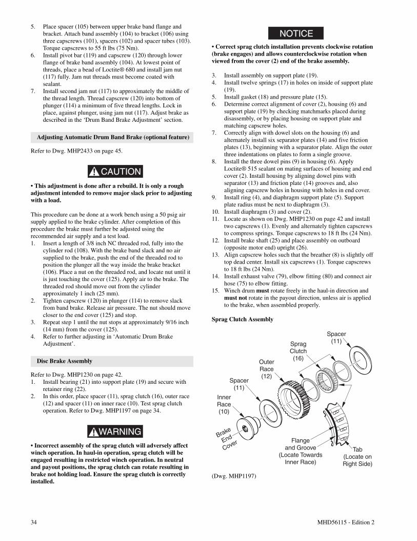
34 MHD56115 - Edition 2
5. Place spacer (105) between upper brake band flange andbracket. Attach band assembly (104) to bracket (106) usingthree capscrews (101), spacers (102) and spacer tubes (103).Torque capscrews to 55 ft lbs (75 Nm).
6. Install pivot bar (119) and capscrew (120) through lowerflange of brake band assembly (104). At lowest point ofthreads, place a bead of Loctite® 680 and install jam nut(117) fully. Jam nut threads must become coated withsealant.
7. Install second jam nut (117) to approximately the middle ofthe thread length. Thread capscrew (120) into bottom ofplunger (114) a minimum of five thread lengths. Lock inplace, against plunger, using jam nut (117). Adjust brake asdescribed in the ‘Drum Band Brake Adjustment’ section.
Adjusting Automatic Drum Band Brake (optional feature)
Refer to Dwg. MHP2433 on page 45.
CAUTION
• This adjustment is done after a rebuild. It is only a roughadjustment intended to remove major slack prior to adjustingwith a load.
This procedure can be done at a work bench using a 50 psig airsupply applied to the brake cylinder. After completion of thisprocedure the brake must further be adjusted using therecommended air supply and a test load.1. Insert a length of 3/8 inch NC threaded rod, fully into the
cylinder rod (108). With the brake band slack and no airsupplied to the brake, push the end of the threaded rod toposition the plunger all the way inside the brake bracket(106). Place a nut on the threaded rod, and locate nut until itis just touching the cover (125). Apply air to the brake. Thethreaded rod should move out from the cylinderapproximately 1 inch (25 mm).
2. Tighten capscrew (120) in plunger (114) to remove slackfrom band brake. Release air pressure. The nut should movecloser to the end cover (125) and stop.
3. Repeat step 1 until the nut stops at approximately 9/16 inch(14 mm) from the cover (125).
4. Refer to further adjusting in ‘Automatic Drum BrakeAdjustment’.
Disc Brake Assembly
Refer to Dwg. MHP1230 on page 42.1. Install bearing (21) into support plate (19) and secure with
retainer ring (22).2. In this order, place spacer (11), sprag clutch (16), outer race
(12) and spacer (11) on inner race (10). Test sprag clutchoperation. Refer to Dwg. MHP1197 on page 34.
WARNING• Incorrect assembly of the sprag clutch will adversely affectwinch operation. In haul-in operation, sprag clutch will beengaged resulting in restricted winch operation. In neutraland payout positions, the sprag clutch can rotate resulting inbrake not holding load. Ensure the sprag clutch is correctlyinstalled.
NOTICE• Correct sprag clutch installation prevents clockwise rotation(brake engages) and allows counterclockwise rotation whenviewed from the cover (2) end of the brake assembly.
3. Install assembly on support plate (19).4. Install twelve springs (17) in holes on inside of support plate
(19).5. Install gasket (18) and pressure plate (15).6. Determine correct alignment of cover (2), housing (6) and
support plate (19) by checking matchmarks placed duringdisassembly, or by placing housing on support plate andmatching capscrew holes.
7. Correctly align with dowel slots on the housing (6) andalternately install six separator plates (14) and five frictionplates (13), beginning with a separator plate. Align the outerthree indentations on plates to form a single groove.
8. Install the three dowel pins (9) in housing (6). ApplyLoctite® 515 sealant on mating surfaces of housing and endcover (2). Install housing by aligning dowel pins withseparator (13) and friction plate (14) grooves and, alsoaligning capscrew holes in housing with holes in end cover.
9. Install ring (4), and diaphragm support plate (5). Supportplate radius must be next to diaphragm (3).
10. Install diaphragm (3) and cover (2).11. Locate as shown on Dwg. MHP1230 on page 42 and install
two capscrews (1). Evenly and alternately tighten capscrewsto compress springs. Torque capscrews to 18 ft lbs (24 Nm).
12. Install brake shaft (25) and place assembly on outboard(opposite motor end) upright (26).
13. Align capscrew holes such that the breather (8) is slightly offtop dead center. Install six capscrews (1). Torque capscrewsto 18 ft lbs (24 Nm).
14. Install exhaust valve (79), elbow fitting (80) and connect airhose (75) to elbow fitting.
15. Winch drum must rotate freely in the haul-in direction andmust not rotate in the payout direction, unless air is appliedto the brake, when assembled properly.
Sprag Clutch Assembly
(Dwg. MHP1197)
Spacer(11)
Flangeand Groove
(Locate TowardsInner Race)
Brake
End
Cover
InnerRace(10)
OuterRace(12)
SpragClutch(16)
Spacer(11)
Tab(Locate onRight Side)
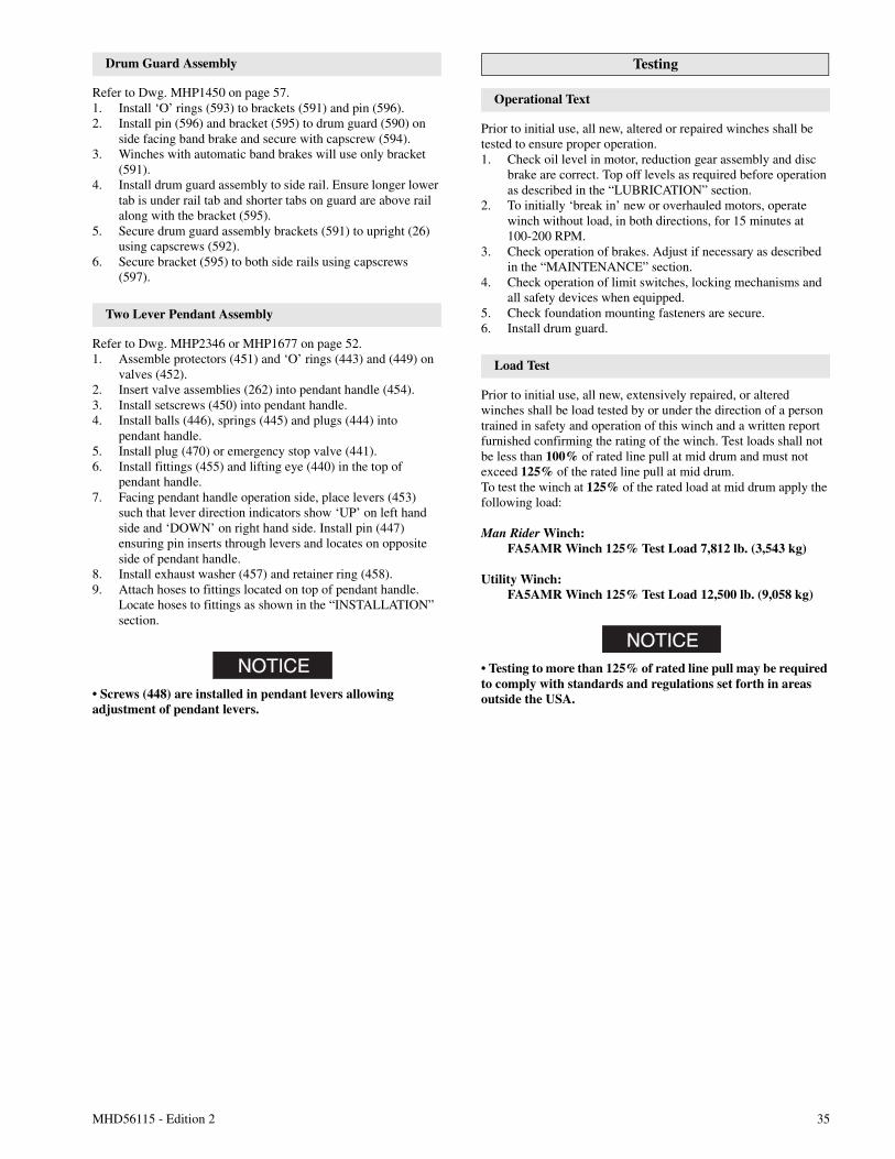
MHD56115 - Edition 2 35
Drum Guard Assembly
Refer to Dwg. MHP1450 on page 57.1. Install ‘O’ rings (593) to brackets (591) and pin (596).2. Install pin (596) and bracket (595) to drum guard (590) on
side facing band brake and secure with capscrew (594).3. Winches with automatic band brakes will use only bracket
(591).4. Install drum guard assembly to side rail. Ensure longer lower
tab is under rail tab and shorter tabs on guard are above railalong with the bracket (595).
5. Secure drum guard assembly brackets (591) to upright (26)using capscrews (592).
6. Secure bracket (595) to both side rails using capscrews(597).
Two Lever Pendant Assembly
Refer to Dwg. MHP2346 or MHP1677 on page 52.1. Assemble protectors (451) and ‘O’ rings (443) and (449) on
valves (452).2. Insert valve assemblies (262) into pendant handle (454).3. Install setscrews (450) into pendant handle.4. Install balls (446), springs (445) and plugs (444) into
pendant handle.5. Install plug (470) or emergency stop valve (441).6. Install fittings (455) and lifting eye (440) in the top of
pendant handle.7. Facing pendant handle operation side, place levers (453)
such that lever direction indicators show ‘UP’ on left handside and ‘DOWN’ on right hand side. Install pin (447)ensuring pin inserts through levers and locates on oppositeside of pendant handle.
8. Install exhaust washer (457) and retainer ring (458).9. Attach hoses to fittings located on top of pendant handle.
Locate hoses to fittings as shown in the “INSTALLATION”section.
NOTICE• Screws (448) are installed in pendant levers allowingadjustment of pendant levers.
Testing
Operational Text
Prior to initial use, all new, altered or repaired winches shall betested to ensure proper operation.1. Check oil level in motor, reduction gear assembly and disc
brake are correct. Top off levels as required before operationas described in the “LUBRICATION” section.
2. To initially ‘break in’ new or overhauled motors, operatewinch without load, in both directions, for 15 minutes at100-200 RPM.
3. Check operation of brakes. Adjust if necessary as describedin the “MAINTENANCE” section.
4. Check operation of limit switches, locking mechanisms andall safety devices when equipped.
5. Check foundation mounting fasteners are secure.6. Install drum guard.
Load Test
Prior to initial use, all new, extensively repaired, or alteredwinches shall be load tested by or under the direction of a persontrained in safety and operation of this winch and a written reportfurnished confirming the rating of the winch. Test loads shall notbe less than 100% of rated line pull at mid drum and must notexceed 125% of the rated line pull at mid drum.To test the winch at 125% of the rated load at mid drum apply thefollowing load:
Man Rider Winch:FA5AMR Winch 125% Test Load 7,812 lb. (3,543 kg)
Utility Winch:FA5AMR Winch 125% Test Load 12,500 lb. (9,058 kg)
NOTICE• Testing to more than 125% of rated line pull may be requiredto comply with standards and regulations set forth in areasoutside the USA.
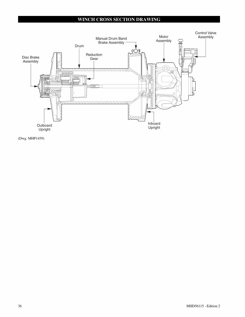
36 MHD56115 - Edition 2
WINCH CROSS SECTION DRAWING
(Dwg. MHP1459)
ReductionGear
Drum
MotorAssembly
Control ValveAssembly
Disc BrakeAssembly
OutboardUpright
Manual Drum BandBrake Assembly
InboardUpright
MHD56115 - Edition 2 37
WINCH DRAWINGS AND PARTS LISTS TABLE OF CONTENTS
Description Page
Winch Cross Section Drawing (MHP1459) ......................................................................................................................................................36Winch Assembly Parts Drawing (MHP1410) ...................................................................................................................................................38Winch Assembly Parts List................................................................................................................................................................................39Motor Assembly Parts Drawing (MHP0690) ...................................................................................................................................................40Motor Assembly Parts List ................................................................................................................................................................................41Disc Brake Assembly Parts Drawing (MHP1230)............................................................................................................................................42Disc Brake Assembly Parts List ........................................................................................................................................................................43Manual Drum Band Brake Assembly Drawing (MHP1448) and Parts List .....................................................................................................44Automatic Drum Band Brake Assembly Drawing (MHP2433) and Parts List ................................................................................................45K5C2-X Control Valve Assembly Drawing (MHP2427) .................................................................................................................................46K5C2-X Control Valve Assembly Parts List .....................................................................................................................................................47Pilot Air Control Valve (Optional) Assembly Drawing (MHP2416) and Parts List.........................................................................................48Full Flow Remote Control Valve Assembly Drawing (MHP2432) and Parts List ...........................................................................................49Emergency Stop and Overload K5C2-EX Valve Assembly Drawing (MHP2434) ..........................................................................................50Emergency Stop and Overload K5C2-EX Valve Parts List ...............................................................................................................................51Remote Two Lever Pendant Assembly Drawings (MHP2346 and MHP1677) ..............................................................................................52Remote Two Lever Pendant Assembly Parts List..............................................................................................................................................53Remote Pilot Air Control (Optional) Parts Drawing (MHP2444) ....................................................................................................................54Remote Pilot Air Control (Optional) Parts List .................................................................................................................................................55Muffler Assembly Drawing (MHP1189) and Parts List ...................................................................................................................................56Drum Guard Assembly Parts Drawing (MHP1450) and Parts List ..................................................................................................................57Air Preparation Assembly Drawing (MHP0223) and Parts List.......................................................................................................................58Accessories and Kits Parts List..........................................................................................................................................................................58Winch Label/Tag Location and Part Number Reference Drawing (MHP1460) ...............................................................................................59
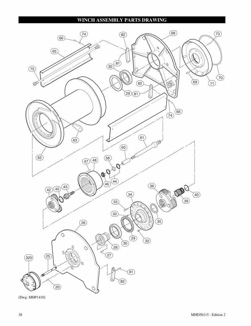
38 MHD56115 - Edition 2
WINCH ASSEMBLY PARTS DRAWING
(Dwg. MHP1410)
7368
70
7169
6674
61
60
82
8130
7466
65
75
29
63
62
81
82
58
4644
4847
434042
29
27
82
81
26
25
20
2830
32
35
32
39
36
40
320
34
33
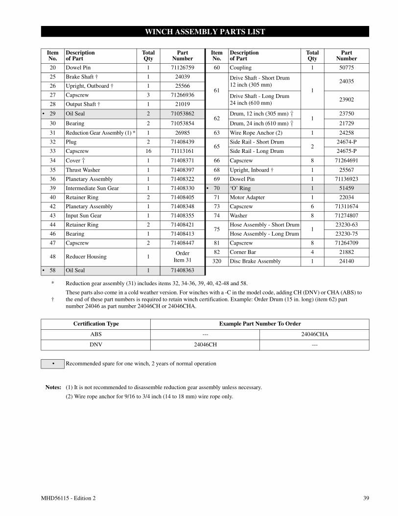
MHD56115 - Edition 2 39
WINCH ASSEMBLY PARTS LIST
ItemNo.
Descriptionof Part
TotalQty
PartNumber
ItemNo.
Descriptionof Part
TotalQty
PartNumber
20 Dowel Pin 1 71126759 60 Coupling 1 50775
25 Brake Shaft † 1 24039
61
Drive Shaft - Short Drum12 inch (305 mm)
1
2403526 Upright, Outboard † 1 25566
27 Capscrew 3 71266936 Drive Shaft - Long Drum24 inch (610 mm)
2390228 Output Shaft † 1 21019
• 29 Oil Seal 2 7105386262
Drum, 12 inch (305 mm) u1
23750
30 Bearing 2 71053854 Drum, 24 inch (610 mm) u 21729
31 Reduction Gear Assembly (1) * 1 26985 63 Wire Rope Anchor (2) 1 24258
32 Plug 2 7140843965
Side Rail - Short Drum2
24674-P
33 Capscrew 16 71113161 Side Rail - Long Drum 24675-P
34 Cover u 1 71408371 66 Capscrew 8 71264691
35 Thrust Washer 1 71408397 68 Upright, Inboard † 1 25567
36 Planetary Assembly 1 71408322 69 Dowel Pin 1 71136923
39 Intermediate Sun Gear 1 71408330 • 70 ‘O’ Ring 1 51459
40 Retainer Ring 2 71408405 71 Motor Adapter 1 22034
42 Planetary Assembly 1 71408348 73 Capscrew 6 71311674
43 Input Sun Gear 1 71408355 74 Washer 8 71274807
44 Retainer Ring 2 7140842175
Hose Assembly - Short Drum1
23230-63
46 Bearing 1 71408413 Hose Assembly - Long Drum 23230-75
47 Capscrew 2 71408447 81 Capscrew 8 71264709
48 Reducer Housing 1Order
Item 3182 Corner Bar 4 21882
320 Disc Brake Assembly 1 24140
• 58 Oil Seal 1 71408363
* Reduction gear assembly (31) includes items 32, 34-36, 39, 40, 42-48 and 58.
†These parts also come in a cold weather version. For winches with a -C in the model code, adding CH (DNV) or CHA (ABS) tothe end of these part numbers is required to retain winch certification. Example: Order Drum (15 in. long) (item 62) partnumber 24046 as part number 24046CH or 24046CHA.
Certification Type Example Part Number To Order
ABS --- 24046CHA
DNV 24046CH ---
• Recommended spare for one winch, 2 years of normal operation
Notes: (1) It is not recommended to disassemble reduction gear assembly unless necessary.
(2) Wire rope anchor for 9/16 to 3/4 inch (14 to 18 mm) wire rope only.
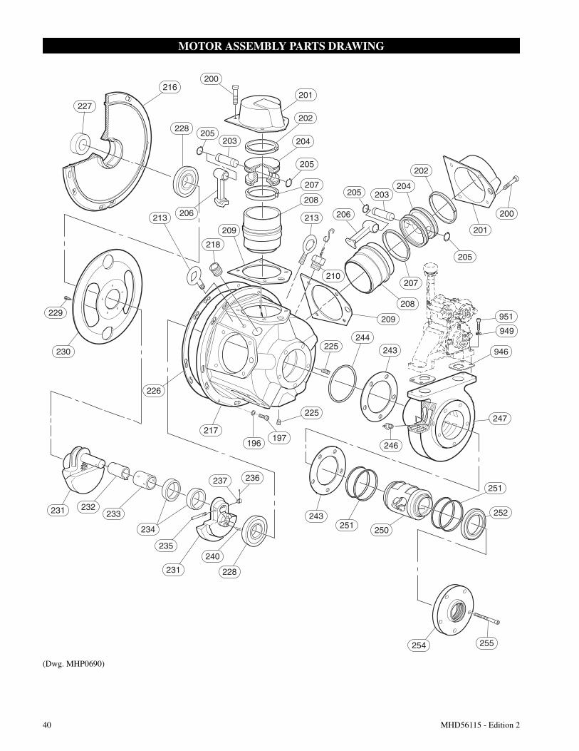
40 MHD56115 - Edition 2
MOTOR ASSEMBLY PARTS DRAWING
(Dwg. MHP0690)
216
227
228
213
210
206213
230
226
217
196197
225
243
250
251
251
252
254 255
218
205 203
201
200
205
209
225244
243 946
247
246
208
207
204
202
231 232233
234
237 236
235
231
240
228
200
205203
201
202
204
205
208
207
209
206
951
949
229
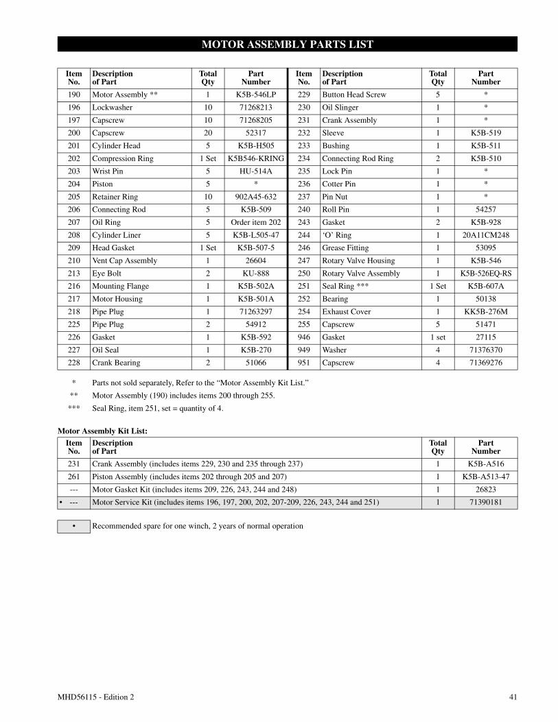
MHD56115 - Edition 2 41
MOTOR ASSEMBLY PARTS LIST
Motor Assembly Kit List:
ItemNo.
Descriptionof Part
TotalQty
PartNumber
ItemNo.
Descriptionof Part
TotalQty
PartNumber
190 Motor Assembly ** 1 K5B-546LP 229 Button Head Screw 5 *
196 Lockwasher 10 71268213 230 Oil Slinger 1 *
197 Capscrew 10 71268205 231 Crank Assembly 1 *
200 Capscrew 20 52317 232 Sleeve 1 K5B-519
201 Cylinder Head 5 K5B-H505 233 Bushing 1 K5B-511
202 Compression Ring 1 Set K5B546-KRING 234 Connecting Rod Ring 2 K5B-510
203 Wrist Pin 5 HU-514A 235 Lock Pin 1 *
204 Piston 5 * 236 Cotter Pin 1 *
205 Retainer Ring 10 902A45-632 237 Pin Nut 1 *
206 Connecting Rod 5 K5B-509 240 Roll Pin 1 54257
207 Oil Ring 5 Order item 202 243 Gasket 2 K5B-928
208 Cylinder Liner 5 K5B-L505-47 244 ‘O’ Ring 1 20A11CM248
209 Head Gasket 1 Set K5B-507-5 246 Grease Fitting 1 53095
210 Vent Cap Assembly 1 26604 247 Rotary Valve Housing 1 K5B-546
213 Eye Bolt 2 KU-888 250 Rotary Valve Assembly 1 K5B-526EQ-RS
216 Mounting Flange 1 K5B-502A 251 Seal Ring *** 1 Set K5B-607A
217 Motor Housing 1 K5B-501A 252 Bearing 1 50138
218 Pipe Plug 1 71263297 254 Exhaust Cover 1 KK5B-276M
225 Pipe Plug 2 54912 255 Capscrew 5 51471
226 Gasket 1 K5B-592 946 Gasket 1 set 27115
227 Oil Seal 1 K5B-270 949 Washer 4 71376370
228 Crank Bearing 2 51066 951 Capscrew 4 71369276
* Parts not sold separately, Refer to the “Motor Assembly Kit List.”
** Motor Assembly (190) includes items 200 through 255.
*** Seal Ring, item 251, set = quantity of 4.
ItemNo.
Descriptionof Part
TotalQty
PartNumber
231 Crank Assembly (includes items 229, 230 and 235 through 237) 1 K5B-A516
261 Piston Assembly (includes items 202 through 205 and 207) 1 K5B-A513-47
--- Motor Gasket Kit (includes items 209, 226, 243, 244 and 248) 1 26823
• --- Motor Service Kit (includes items 196, 197, 200, 202, 207-209, 226, 243, 244 and 251) 1 71390181
• Recommended spare for one winch, 2 years of normal operation
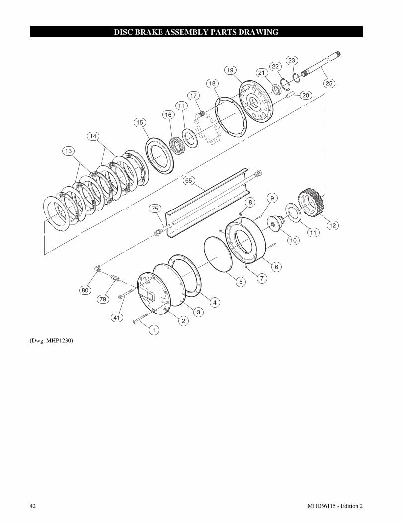
42 MHD56115 - Edition 2
DISC BRAKE ASSEMBLY PARTS DRAWING
(Dwg. MHP1230)
13
14
1516
11
17
18
19 2122
23
25
20
65
75
1211
10
80
79
41
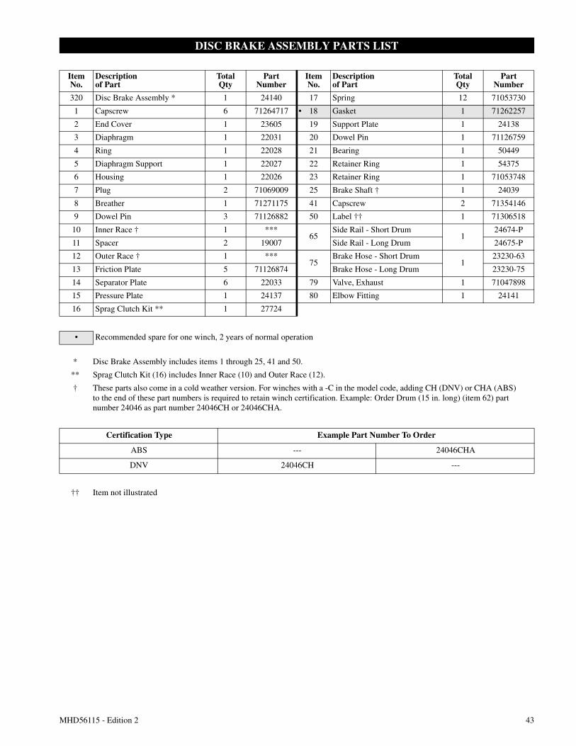
MHD56115 - Edition 2 43
DISC BRAKE ASSEMBLY PARTS LIST
ItemNo.
Descriptionof Part
TotalQty
PartNumber
ItemNo.
Descriptionof Part
TotalQty
PartNumber
320 Disc Brake Assembly * 1 24140 17 Spring 12 71053730
1 Capscrew 6 71264717 • 18 Gasket 1 71262257
2 End Cover 1 23605 19 Support Plate 1 24138
3 Diaphragm 1 22031 20 Dowel Pin 1 71126759
4 Ring 1 22028 21 Bearing 1 50449
5 Diaphragm Support 1 22027 22 Retainer Ring 1 54375
6 Housing 1 22026 23 Retainer Ring 1 71053748
7 Plug 2 71069009 25 Brake Shaft † 1 24039
8 Breather 1 71271175 41 Capscrew 2 71354146
9 Dowel Pin 3 71126882 50 Label †† 1 71306518
10 Inner Race † 1 ***65
Side Rail - Short Drum1
24674-P
11 Spacer 2 19007 Side Rail - Long Drum 24675-P
12 Outer Race † 1 ***75
Brake Hose - Short Drum1
23230-63
13 Friction Plate 5 71126874 Brake Hose - Long Drum 23230-75
14 Separator Plate 6 22033 79 Valve, Exhaust 1 71047898
15 Pressure Plate 1 24137 80 Elbow Fitting 1 24141
16 Sprag Clutch Kit ** 1 27724
• Recommended spare for one winch, 2 years of normal operation
* Disc Brake Assembly includes items 1 through 25, 41 and 50.
** Sprag Clutch Kit (16) includes Inner Race (10) and Outer Race (12).
† These parts also come in a cold weather version. For winches with a -C in the model code, adding CH (DNV) or CHA (ABS)to the end of these part numbers is required to retain winch certification. Example: Order Drum (15 in. long) (item 62) partnumber 24046 as part number 24046CH or 24046CHA.
Certification Type Example Part Number To Order
ABS --- 24046CHA
DNV 24046CH ---
†† Item not illustrated
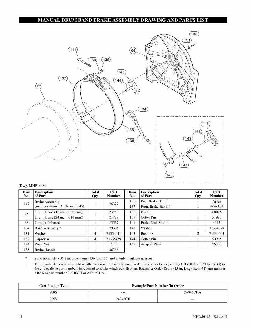
44 MHD56115 - Edition 2
MANUAL DRUM BAND BRAKE ASSEMBLY DRAWING AND PARTS LIST
(Dwg. MHP1448)
142
143
143
144
145
135
136
134
68
132
131
141
139 138
145
144
62
137
ItemNo.
Descriptionof Part
TotalQty
PartNumber
ItemNo.
Descriptionof Part
TotalQty
PartNumber
147Brake Assembly(includes items 131 through 145)
1 26377136 Rear Brake Band † 1 Order
item 104137 Front Brake Band † 1
62Drum, Short (12 inch (305 mm))
123750 138 Pin † 1 4308-S
Drum, Long (24 inch (610 mm)) 21729 139 Cotter Pin 1 51996
68 Upright, Inboard 1 25567 141 Brake Link Stud † 1 4115
104 Band Assembly * 1 29305 142 Washer 1 71334379
131 Washer 4 71334411 143 Bushing 2 71334403
132 Capscrew 4 71335459 144 Cotter Pin 1 50965
134 Pivot Nut 1 2445 145 Adapter Plate 1 26350
135 Brake Handle 1 26388
* Band assembly (104) includes items 136 and 137, and is only available as a set.
† These parts also come in a cold weather version. For winches with a -C in the model code, adding CH (DNV) or CHA (ABS) tothe end of these part numbers is required to retain winch certification. Example: Order Drum (15 in. long) (item 62) part number24046 as part number 24046CH or 24046CHA.
Certification Type Example Part Number To Order
ABS --- 24046CHA
DNV 24046CH ---

MHD56115 - Edition 2 45
AUTOMATIC DRUM BAND BRAKE ASSEMBLY DRAWING AND PARTS LIST
(Dwg. MHP2433)
Note: Refer to certification type cold weather chart on page 46 for example of part number to order.
104
119120
101
102
103
105
107
106
110
79
111
109
113112108
116
114
115
117
149
126
125127
124128
123
76122
121
ItemNo.
Descriptionof Part
TotalQty
PartNumber
ItemNo.
Descriptionof Part
TotalQty
PartNumber
130 Brake Assembly * 1 23890 114 Plunger † 1 23886
76 Hose Assembly 1 24403-39 115 Dowel Pin 1 71415368
79 Valve, Exhaust 1 71047898 116 Roller † 1 23883
101 Capscrew 3 71264808 117 Jam Nut 2 71267413
102 Spacer 3 21899 119 Pivot Bar 1 23755
103 Spacer Tube 3 21891 120 Capscrew 1 71267405
• 104 Band Assembly † 1 24367 121 Cylinder 1 23889
105 Spacer 1 23029 • 122 ‘O’ Ring 1 52536
106 Brake Bracket † 1 22984 123 Piston 1 23884
107 Capscrew 2 71264832 124 Spring 1 71144943
108 Cylinder Rod 1 23885 125 Cover 1 23887
• 109 ‘O’ Ring 1 71049423 126 Retainer Ring 1 71126668
• 110 ‘O’ Ring 1 52662 127 Spring 1 71144935
111 Retainer Ring 1 54136 128 Washer 1 71145080
112 Capscrew 2 71264824 149 Fitting, Nipple 1 52092
113 Spring 1 71126643
* Automatic Drum Brake Assembly (130), includes items 101-128.
• Recommended spare for one winch, 2 years of normal operation
† These parts also come in a cold weather version. For winches with a -C in the model code, adding CH (DNV) or CHA (ABS) tothe end of these part numbers is required to retain winch certification. Example: Order Drum (15 in. long) (item 62) part number24046 as part number 24046CH or 24046CHA.
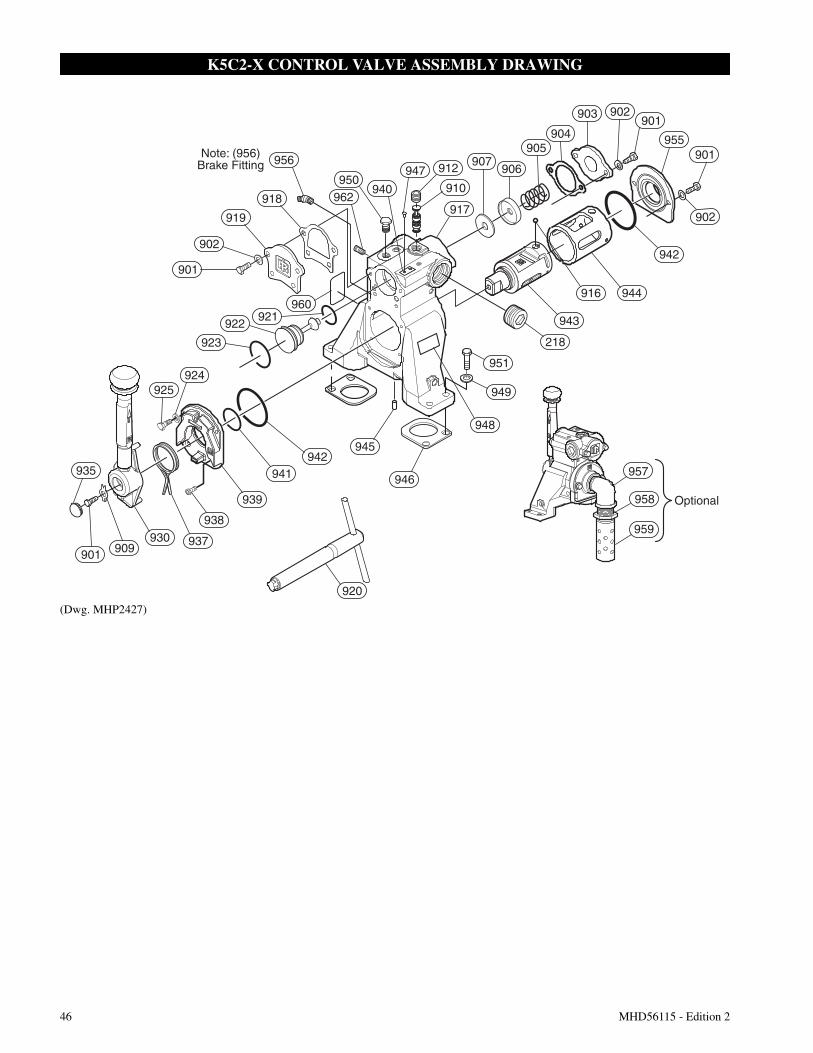
46 MHD56115 - Edition 2
K5C2-X CONTROL VALVE ASSEMBLY DRAWING
(Dwg. MHP2427)
Note: (956)Brake Fitting
909
Optional
948
949
902903901
955
951
218
942
943
944
912 907906
904905
917
916
918
956
919
921922
902
901
945
946935
901930 937
939
941
938
925924
942
923
962950
960
957
958
959
940
947
910
920
901
902
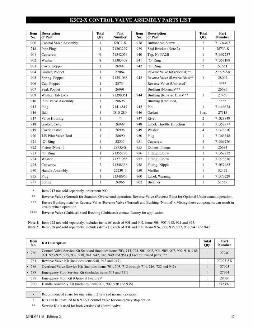
MHD56115 - Edition 2 47
K5C2-X CONTROL VALVE ASSEMBLY PARTS LIST
ItemNo.
Descriptionof Part
TotalQty
PartNumber
ItemNo.
Descriptionof Part
TotalQty
PartNumber
900 Control Valve Assembly 1 K5C2-X 938 Buttonhead Screw 2 71394407
218 Pipe Plug 1 71263297 939 Seal Bracket (Note 2) 1 28733-S
901 Capscrew 9 71342034 940 Tag, No FA2B 1 71392757
902 Washer 8 71303408 941 ‘O’ Ring 1 71357198
903 Cover, Poppet 1 26997 942 ‘O’ Ring 2 51651
904 Gasket, Poppet 1 27064
943
Reverse Valve Kit (Normal)**
1
27925-SX
905 Spring, Poppet 1 71351068 Reverse Valve (Reverse Bias)** 28002
906 Cap, Poppet 1 28734 Reverse Valve (Unbiased) ****
907 Seal, Poppet 1 26991
944
Bushing (Normal)***
1
26686
909 Washer, Tab Lock 1 71398051 Bushing (Reverse Bias)*** 27450
910 Pilot Valve Assembly 1 28696 Bushing (Unbiased) ****
912 Plug 1 71414817 945 Pin 1 71146674
916 Ball 1 D10-280 946 Gasket 1 set 27115
917 Valve Housing 1 * 947 Rivet 2 71028849
918 Gasket, Cover 1 26999 948 Label, Throttle Direction 1 71352777
919 Cover, Piston 1 26998 949 Washer 4 71376370
920 I-R Pilot Valve Tool 1 28690 950 Plug 1 71366348
921 ‘O’ Ring 1 52537 951 Capscrew 4 71369276
922 Piston (Note 1) 1 28735-S 955 Exhaust Flange 1 26691
923 ‘O’ Ring 1 71355796 956 Fitting, Elbow 1 71367932
924 Washer 2 71271985 957 Fitting, Elbow 1 71273676
925 Capscrew 2 71348338 958 Fitting, Nipple 1 71057483
930 Handle Assembly 1 27239-1 959 Muffler 1 52472
935 Plug 1 71348965 960 Label, Warning 1 71373229
937 Spring 1 26966 962 Breather 1 51559
* Item 917 not sold separately, order item 900.
** Reverse Valve (Normal) for Standard Overwound operation. Reverse Valve (Reverse Bias) for Optional Underwound operation.
*** Ensure Bushing matches Reverse Valve (Reverse Valve (Normal) and Bushing (Normal)). Mixing these components can result inerratic winch operation.
**** Reverse Valve (Unbiased) and Bushing (Unbiased) contact factory for application.
Note 1: Item 922 not sold separately, includes items (6) each of 901 and 902, items 904-907, 918, 921 and 923.Note 2: Item 939 not sold separately, includes items (1) each of 901 and 909, items 924, 925, 935, 937, 938, 941 and 942.
ItemNo. Kit Description Total
QtyPart
Number
• 780Control Valve Service Kit Standard (includes items 703, 713, 721, 901, 902, 904, 905, 907, 909, 916, 918,921, 923-925, 935, 937, 938, 941, 942, 946, 949 and 951) (Discard unused parts) **
1 27240
781 Reverse Valve Kit (includes items 940, 943 and 947) 1 27925-SX
• 786 Overload Valve Service Kit (includes items 701, 703, 712 through 714, 716, 722 and 942) 1 27995
• 788 Emergency Stop Service Kit (includes items 703 and 711) 1 27994
789 Emergency Stop Kit (Optional Feature)* 1 28026
930 Handle Assembly Kit (includes items 901, 909, 930 and 935) 1 27239-1
• Recommended spare for one winch, 2 years of normal operation
* Kits can be installed to K5C2-X control valve for emergency stop option.
** Service Kit is used for both versions of control valve.
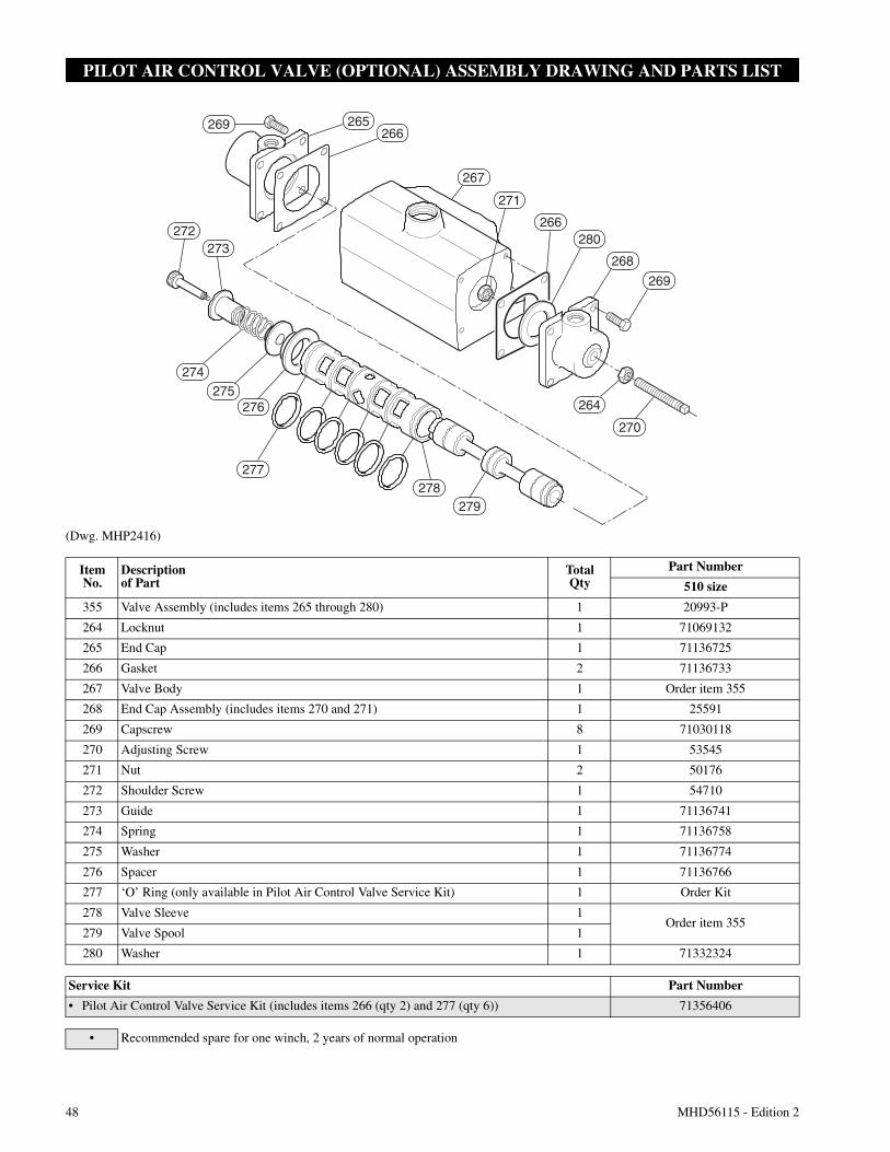
48 MHD56115 - Edition 2
PILOT AIR CONTROL VALVE (OPTIONAL) ASSEMBLY DRAWING AND PARTS LIST
(Dwg. MHP2416)
276
277278
279
272273
269 265266
267
271
266280
268
269
264
270
274275
ItemNo.
Descriptionof Part
TotalQty
Part Number
510 size
355 Valve Assembly (includes items 265 through 280) 1 20993-P
264 Locknut 1 71069132
265 End Cap 1 71136725
266 Gasket 2 71136733
267 Valve Body 1 Order item 355
268 End Cap Assembly (includes items 270 and 271) 1 25591
269 Capscrew 8 71030118
270 Adjusting Screw 1 53545
271 Nut 2 50176
272 Shoulder Screw 1 54710
273 Guide 1 71136741
274 Spring 1 71136758
275 Washer 1 71136774
276 Spacer 1 71136766
277 ‘O’ Ring (only available in Pilot Air Control Valve Service Kit) 1 Order Kit
278 Valve Sleeve 1Order item 355
279 Valve Spool 1
280 Washer 1 71332324
Service Kit Part Number
• Pilot Air Control Valve Service Kit (includes items 266 (qty 2) and 277 (qty 6)) 71356406
• Recommended spare for one winch, 2 years of normal operation
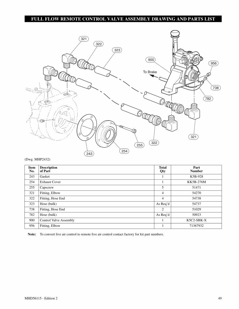
MHD56115 - Edition 2 49
FULL FLOW REMOTE CONTROL VALVE ASSEMBLY DRAWING AND PARTS LIST
(Dwg. MHP2432)
321
322
323
900
738
956
782
To Brake
321
322255
254243
ItemNo.
Descriptionof Part
TotalQty
PartNumber
243 Gasket 1 K5B-928
254 Exhaust Cover 1 KK5B-276M
255 Capscrew 5 51471
321 Fitting, Elbow 4 54270
322 Fitting, Hose End 4 54738
323 Hose (bulk) As Req’d 54737
738 Fitting, Hose End 2 51029
782 Hose (bulk) As Req’d 50923
900 Control Valve Assembly 1 K5C2-SBK-X
956 Fitting, Elbow 1 71367932
Note: To convert live air control to remote live air control contact factory for kit part numbers.
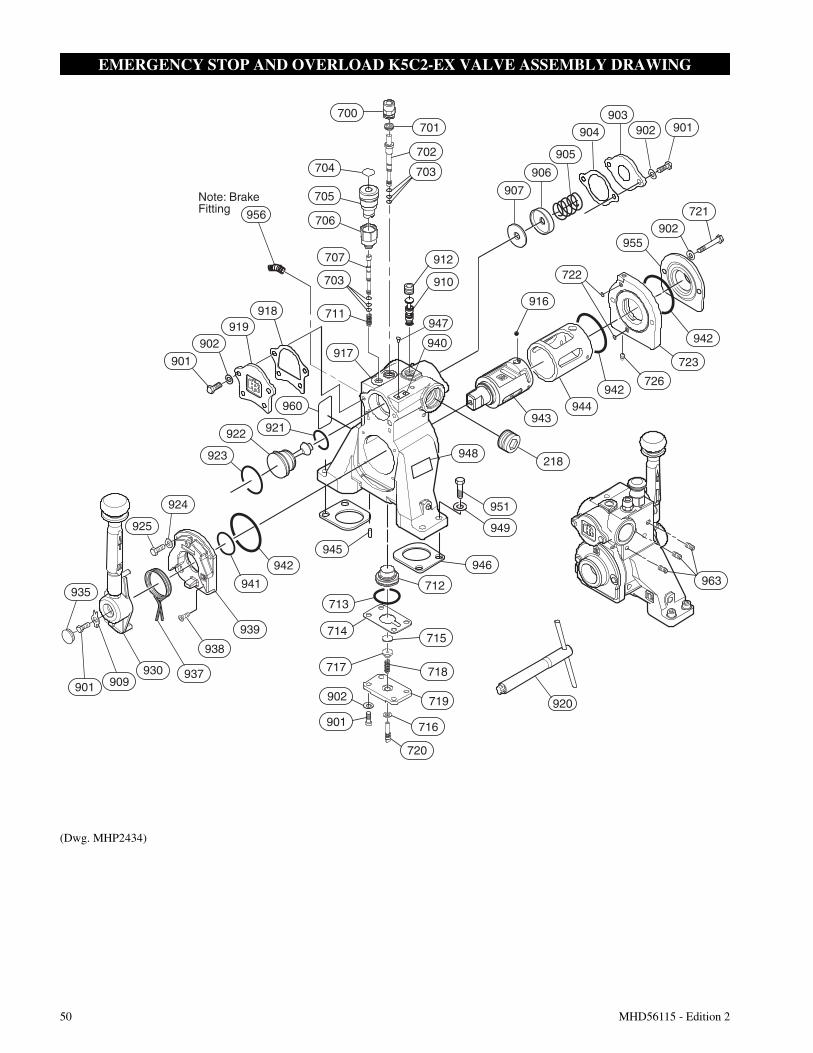
50 MHD56115 - Edition 2
EMERGENCY STOP AND OVERLOAD K5C2-EX VALVE ASSEMBLY DRAWING
(Dwg. MHP2434)
Note: Brake Fitting
948
920
906
956
912
910
917
711
703
707
706
705
918919
902
704 703
702
701700
940
947
901
922
923
921
960
901 909930 937
938
939
941
942
925
924
935963
944
955902
942
721
722
942
723
726
943
716
719
718
715
916
946
949
951
218
901
902
720
717
714
712
713
945
901902903
904
905
907
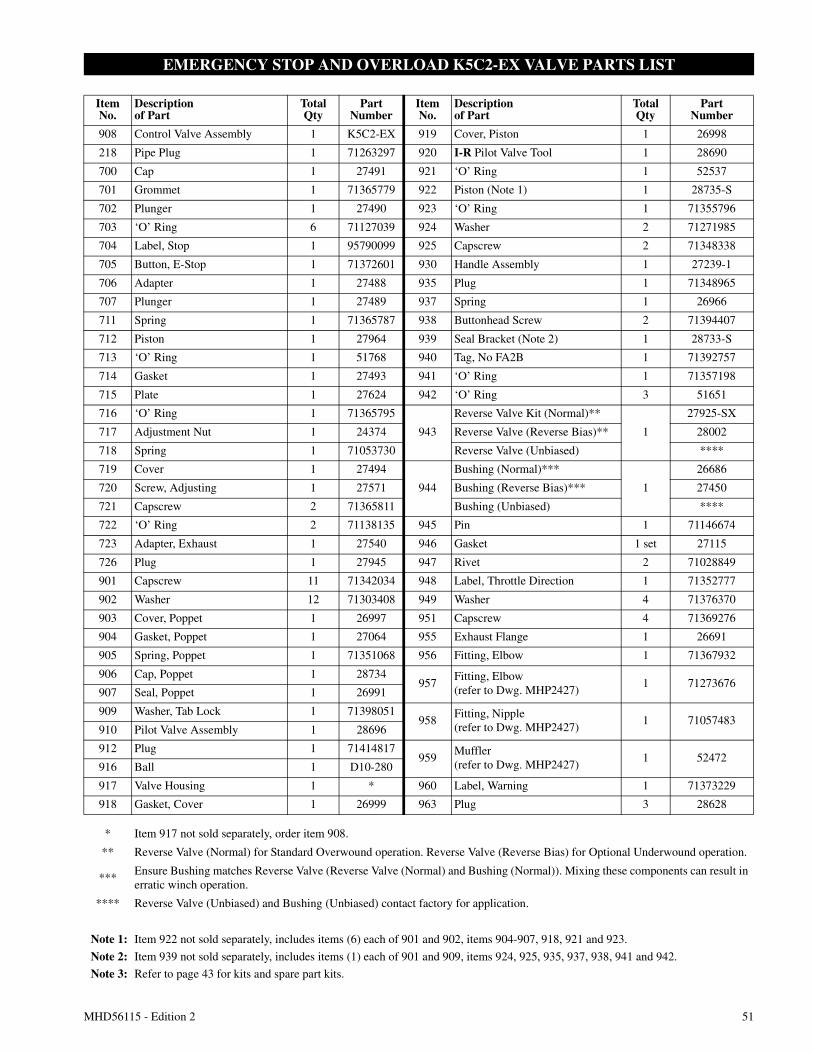
MHD56115 - Edition 2 51
EMERGENCY STOP AND OVERLOAD K5C2-EX VALVE PARTS LIST
ItemNo.
Descriptionof Part
TotalQty
PartNumber
ItemNo.
Descriptionof Part
TotalQty
PartNumber
908 Control Valve Assembly 1 K5C2-EX 919 Cover, Piston 1 26998
218 Pipe Plug 1 71263297 920 I-R Pilot Valve Tool 1 28690
700 Cap 1 27491 921 ‘O’ Ring 1 52537
701 Grommet 1 71365779 922 Piston (Note 1) 1 28735-S
702 Plunger 1 27490 923 ‘O’ Ring 1 71355796
703 ‘O’ Ring 6 71127039 924 Washer 2 71271985
704 Label, Stop 1 95790099 925 Capscrew 2 71348338
705 Button, E-Stop 1 71372601 930 Handle Assembly 1 27239-1
706 Adapter 1 27488 935 Plug 1 71348965
707 Plunger 1 27489 937 Spring 1 26966
711 Spring 1 71365787 938 Buttonhead Screw 2 71394407
712 Piston 1 27964 939 Seal Bracket (Note 2) 1 28733-S
713 ‘O’ Ring 1 51768 940 Tag, No FA2B 1 71392757
714 Gasket 1 27493 941 ‘O’ Ring 1 71357198
715 Plate 1 27624 942 ‘O’ Ring 3 51651
716 ‘O’ Ring 1 71365795
943
Reverse Valve Kit (Normal)**
1
27925-SX
717 Adjustment Nut 1 24374 Reverse Valve (Reverse Bias)** 28002
718 Spring 1 71053730 Reverse Valve (Unbiased) ****
719 Cover 1 27494
944
Bushing (Normal)***
1
26686
720 Screw, Adjusting 1 27571 Bushing (Reverse Bias)*** 27450
721 Capscrew 2 71365811 Bushing (Unbiased) ****
722 ‘O’ Ring 2 71138135 945 Pin 1 71146674
723 Adapter, Exhaust 1 27540 946 Gasket 1 set 27115
726 Plug 1 27945 947 Rivet 2 71028849
901 Capscrew 11 71342034 948 Label, Throttle Direction 1 71352777
902 Washer 12 71303408 949 Washer 4 71376370
903 Cover, Poppet 1 26997 951 Capscrew 4 71369276
904 Gasket, Poppet 1 27064 955 Exhaust Flange 1 26691
905 Spring, Poppet 1 71351068 956 Fitting, Elbow 1 71367932
906 Cap, Poppet 1 28734957
Fitting, Elbow(refer to Dwg. MHP2427)
1 71273676907 Seal, Poppet 1 26991
909 Washer, Tab Lock 1 71398051958
Fitting, Nipple(refer to Dwg. MHP2427)
1 71057483910 Pilot Valve Assembly 1 28696
912 Plug 1 71414817959
Muffler(refer to Dwg. MHP2427)
1 52472916 Ball 1 D10-280
917 Valve Housing 1 * 960 Label, Warning 1 71373229
918 Gasket, Cover 1 26999 963 Plug 3 28628
* Item 917 not sold separately, order item 908.
** Reverse Valve (Normal) for Standard Overwound operation. Reverse Valve (Reverse Bias) for Optional Underwound operation.
***Ensure Bushing matches Reverse Valve (Reverse Valve (Normal) and Bushing (Normal)). Mixing these components can result inerratic winch operation.
**** Reverse Valve (Unbiased) and Bushing (Unbiased) contact factory for application.
Note 1: Item 922 not sold separately, includes items (6) each of 901 and 902, items 904-907, 918, 921 and 923.
Note 2: Item 939 not sold separately, includes items (1) each of 901 and 909, items 924, 925, 935, 937, 938, 941 and 942.
Note 3: Refer to page 43 for kits and spare part kits.
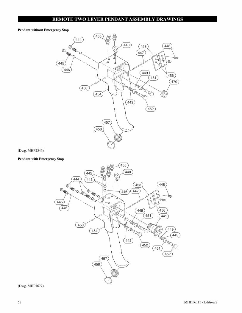
52 MHD56115 - Edition 2
REMOTE TWO LEVER PENDANT ASSEMBLY DRAWINGS
Pendant without Emergency Stop
(Dwg. MHP2346)
Pendant with Emergency Stop
(Dwg. MHP1677)
445
446
444455
440
456
447
453 448
449451
470
452
443
450
454
457
458
445
446
444
442
443
455
440
446 447
453 448
456449451 441
454
457
458
443452
451
452
449
443
450
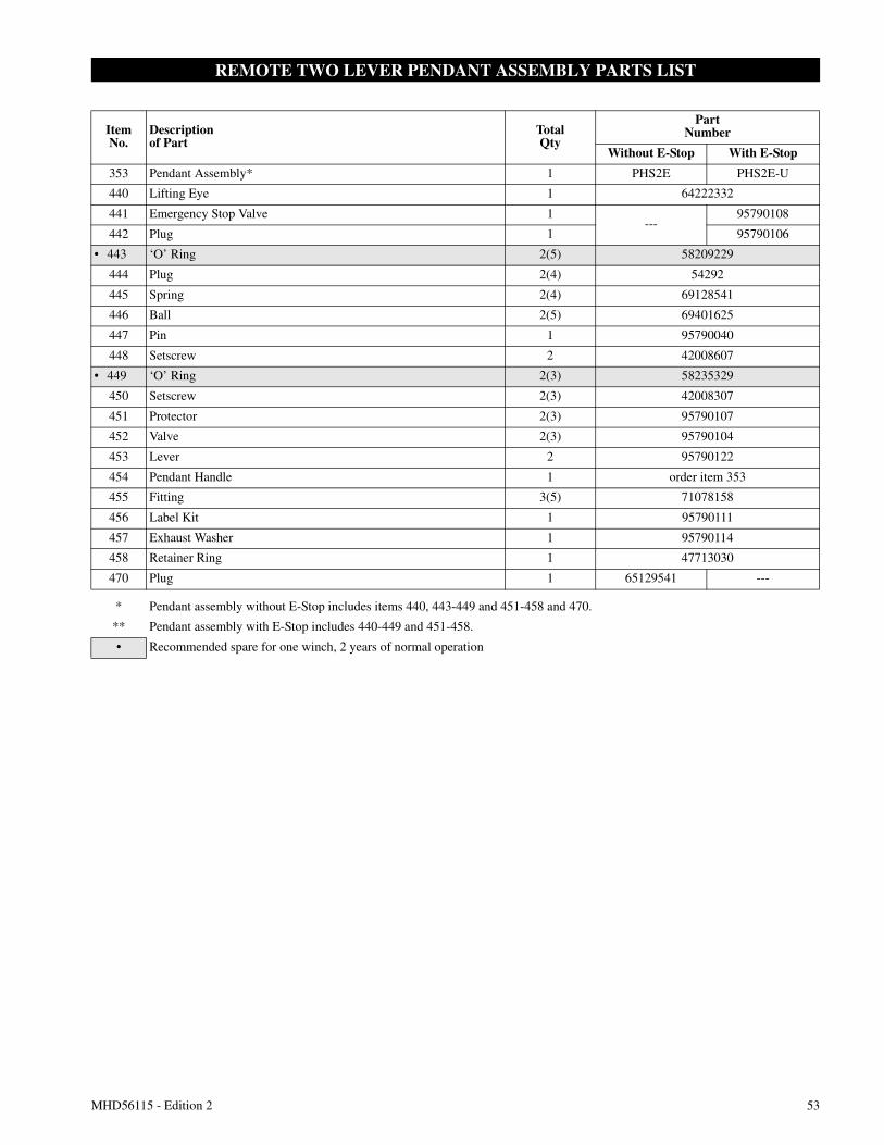
MHD56115 - Edition 2 53
REMOTE TWO LEVER PENDANT ASSEMBLY PARTS LIST
ItemNo.
Descriptionof Part
TotalQty
PartNumber
Without E-Stop With E-Stop
353 Pendant Assembly* 1 PHS2E PHS2E-U
440 Lifting Eye 1 64222332
441 Emergency Stop Valve 1---
95790108
442 Plug 1 95790106
• 443 ‘O’ Ring 2(5) 58209229
444 Plug 2(4) 54292
445 Spring 2(4) 69128541
446 Ball 2(5) 69401625
447 Pin 1 95790040
448 Setscrew 2 42008607
• 449 ‘O’ Ring 2(3) 58235329
450 Setscrew 2(3) 42008307
451 Protector 2(3) 95790107
452 Valve 2(3) 95790104
453 Lever 2 95790122
454 Pendant Handle 1 order item 353
455 Fitting 3(5) 71078158
456 Label Kit 1 95790111
457 Exhaust Washer 1 95790114
458 Retainer Ring 1 47713030
470 Plug 1 65129541 ---
* Pendant assembly without E-Stop includes items 440, 443-449 and 451-458 and 470.
** Pendant assembly with E-Stop includes 440-449 and 451-458.
• Recommended spare for one winch, 2 years of normal operation
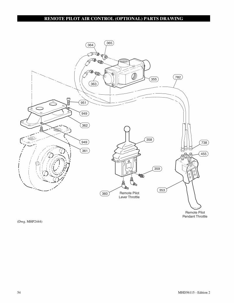
54 MHD56115 - Edition 2
REMOTE PILOT AIR CONTROL (OPTIONAL) PARTS DRAWING
(Dwg. MHP2444)
Remote PilotLever Throttle
Remote PilotPendant Throttle
951
364365
355782
363
949
362
949
361
360
738
455
353
359
358
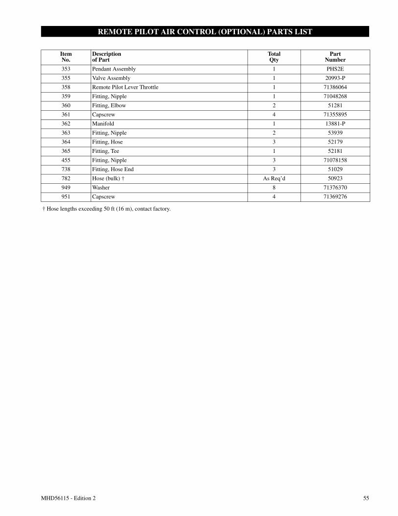
MHD56115 - Edition 2 55
REMOTE PILOT AIR CONTROL (OPTIONAL) PARTS LIST
ItemNo.
Descriptionof Part
TotalQty
PartNumber
353 Pendant Assembly 1 PHS2E
355 Valve Assembly 1 20993-P
358 Remote Pilot Lever Throttle 1 71386064
359 Fitting, Nipple 1 71048268
360 Fitting, Elbow 2 51281
361 Capscrew 4 71355895
362 Manifold 1 13881-P
363 Fitting, Nipple 2 53939
364 Fitting, Hose 3 52179
365 Fitting, Tee 1 52181
455 Fitting, Nipple 3 71078158
738 Fitting, Hose End 3 51029
782 Hose (bulk) † As Req’d 50923
949 Washer 8 71376370
951 Capscrew 4 71369276
† Hose lengths exceeding 50 ft (16 m), contact factory.
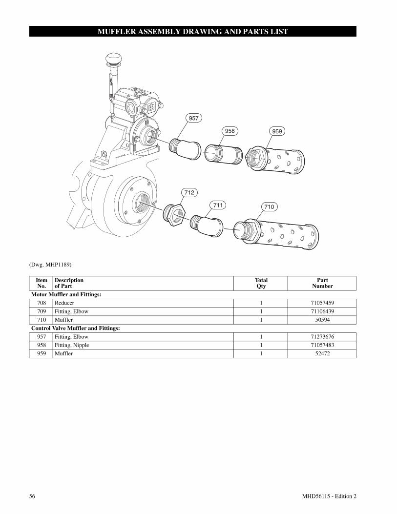
56 MHD56115 - Edition 2
MUFFLER ASSEMBLY DRAWING AND PARTS LIST
(Dwg. MHP1189)
957
959
710711
712
958
ItemNo.
Descriptionof Part
TotalQty
PartNumber
Motor Muffler and Fittings:708 Reducer 1 71057459
709 Fitting, Elbow 1 71106439
710 Muffler 1 50594
Control Valve Muffler and Fittings:
957 Fitting, Elbow 1 71273676
958 Fitting, Nipple 1 71057483
959 Muffler 1 52472
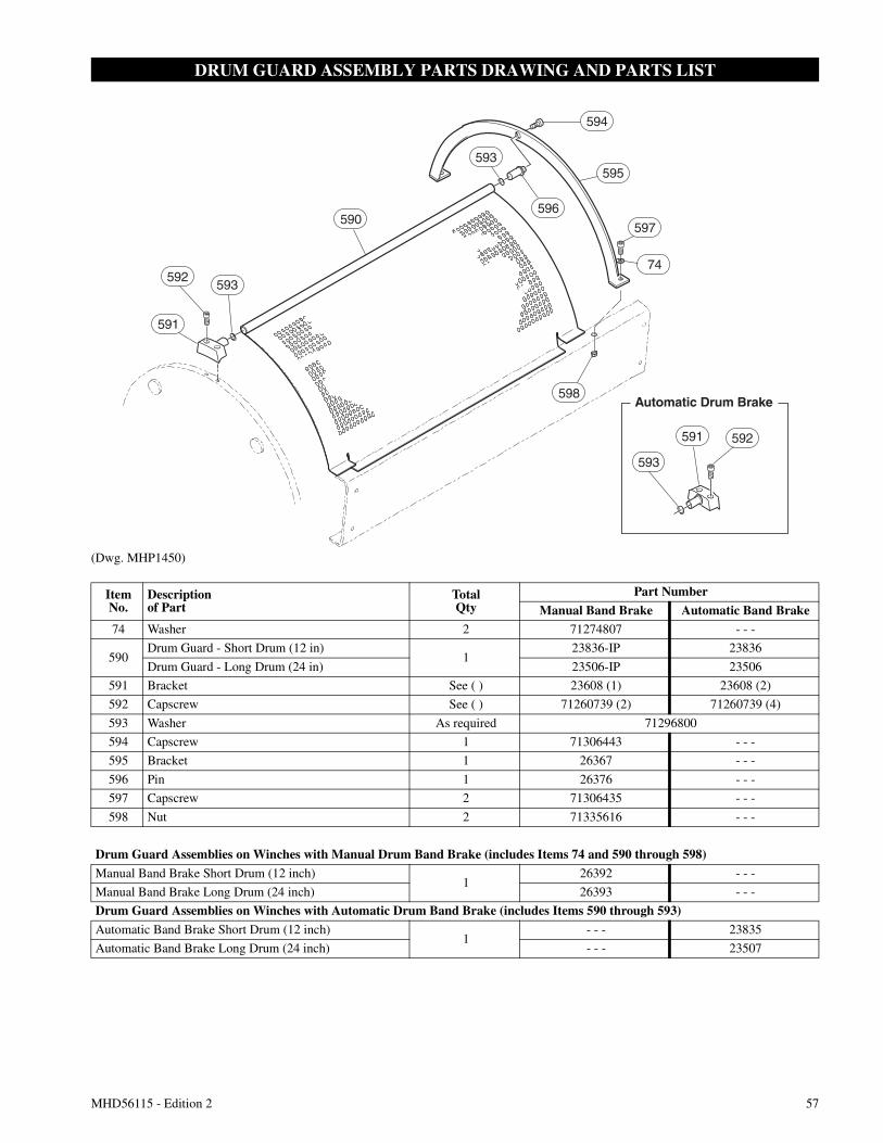
MHD56115 - Edition 2 57
DRUM GUARD ASSEMBLY PARTS DRAWING AND PARTS LIST
(Dwg. MHP1450)
591
592593
590
593
594
595
597
598
591 592
593
74
596
Automatic Drum Brake
ItemNo.
Descriptionof Part
TotalQty
Part Number
Manual Band Brake Automatic Band Brake74 Washer 2 71274807 - - -
590Drum Guard - Short Drum (12 in)
123836-IP 23836
Drum Guard - Long Drum (24 in) 23506-IP 23506
591 Bracket See ( ) 23608 (1) 23608 (2)
592 Capscrew See ( ) 71260739 (2) 71260739 (4)
593 Washer As required 71296800
594 Capscrew 1 71306443 - - -
595 Bracket 1 26367 - - -
596 Pin 1 26376 - - -
597 Capscrew 2 71306435 - - -
598 Nut 2 71335616 - - -
Drum Guard Assemblies on Winches with Manual Drum Band Brake (includes Items 74 and 590 through 598)
Manual Band Brake Short Drum (12 inch)1
26392 - - -
Manual Band Brake Long Drum (24 inch) 26393 - - -
Drum Guard Assemblies on Winches with Automatic Drum Band Brake (includes Items 590 through 593)
Automatic Band Brake Short Drum (12 inch)1
- - - 23835
Automatic Band Brake Long Drum (24 inch) - - - 23507
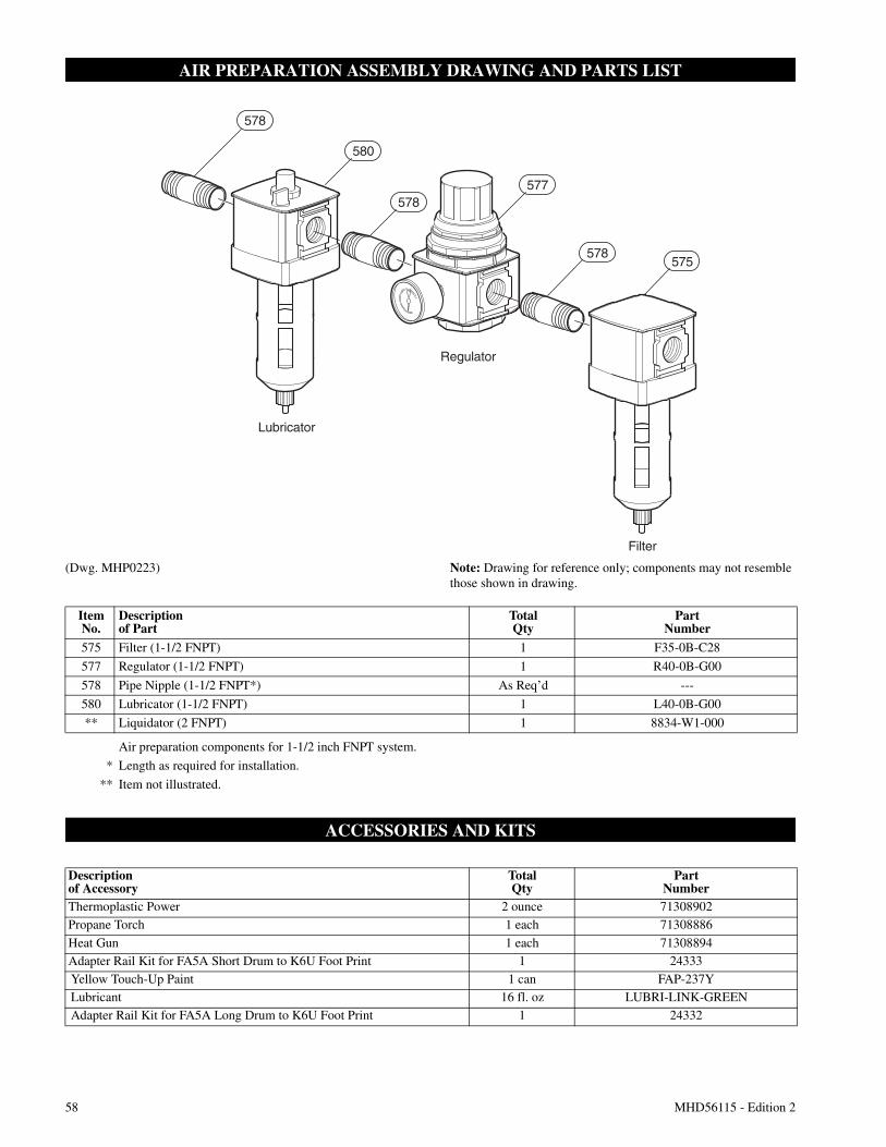
58 MHD56115 - Edition 2
AIR PREPARATION ASSEMBLY DRAWING AND PARTS LIST
(Dwg. MHP0223) Note: Drawing for reference only; components may not resemblethose shown in drawing.
ACCESSORIES AND KITS
580
578577
578575
Filter
Regulator
Lubricator
578
ItemNo.
Descriptionof Part
TotalQty
PartNumber
575 Filter (1-1/2 FNPT) 1 F35-0B-C28
577 Regulator (1-1/2 FNPT) 1 R40-0B-G00
578 Pipe Nipple (1-1/2 FNPT*) As Req’d ---
580 Lubricator (1-1/2 FNPT) 1 L40-0B-G00
** Liquidator (2 FNPT) 1 8834-W1-000
Air preparation components for 1-1/2 inch FNPT system.
* Length as required for installation.
** Item not illustrated.
Descriptionof Accessory
TotalQty
PartNumber
Thermoplastic Power 2 ounce 71308902Propane Torch 1 each 71308886
Heat Gun 1 each 71308894Adapter Rail Kit for FA5A Short Drum to K6U Foot Print 1 24333Yellow Touch-Up Paint 1 can FAP-237YLubricant 16 fl. oz LUBRI-LINK-GREENAdapter Rail Kit for FA5A Long Drum to K6U Foot Print 1 24332
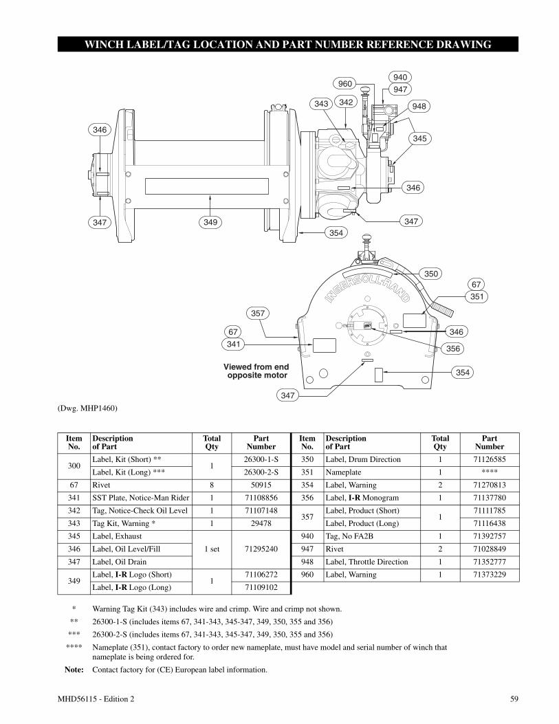
MHD56115 - Edition 2 59
WINCH LABEL/TAG LOCATION AND PART NUMBER REFERENCE DRAWING
(Dwg. MHP1460)
342343
947
948
960
345
346
347
Viewed from end opposite motor
67350
347
356
346
351
346
347 349
357
67
341
354
940
354
ItemNo.
Descriptionof Part
TotalQty
PartNumber
ItemNo.
Descriptionof Part
TotalQty
PartNumber
300Label, Kit (Short) **
126300-1-S 350 Label, Drum Direction 1 71126585
Label, Kit (Long) *** 26300-2-S 351 Nameplate 1 ****
67 Rivet 8 50915 354 Label, Warning 2 71270813
341 SST Plate, Notice-Man Rider 1 71108856 356 Label, I-R Monogram 1 71137780
342 Tag, Notice-Check Oil Level 1 71107148357
Label, Product (Short)1
71111785
343 Tag Kit, Warning * 1 29478 Label, Product (Long) 71116438
345 Label, Exhaust
1 set 71295240
940 Tag, No FA2B 1 71392757
346 Label, Oil Level/Fill 947 Rivet 2 71028849
347 Label, Oil Drain 948 Label, Throttle Direction 1 71352777
349Label, I-R Logo (Short)
171106272 960 Label, Warning 1 71373229
Label, I-R Logo (Long) 71109102
* Warning Tag Kit (343) includes wire and crimp. Wire and crimp not shown.
** 26300-1-S (includes items 67, 341-343, 345-347, 349, 350, 355 and 356)
*** 26300-2-S (includes items 67, 341-343, 345-347, 349, 350, 355 and 356)
**** Nameplate (351), contact factory to order new nameplate, must have model and serial number of winch thatnameplate is being ordered for.
Note: Contact factory for (CE) European label information.
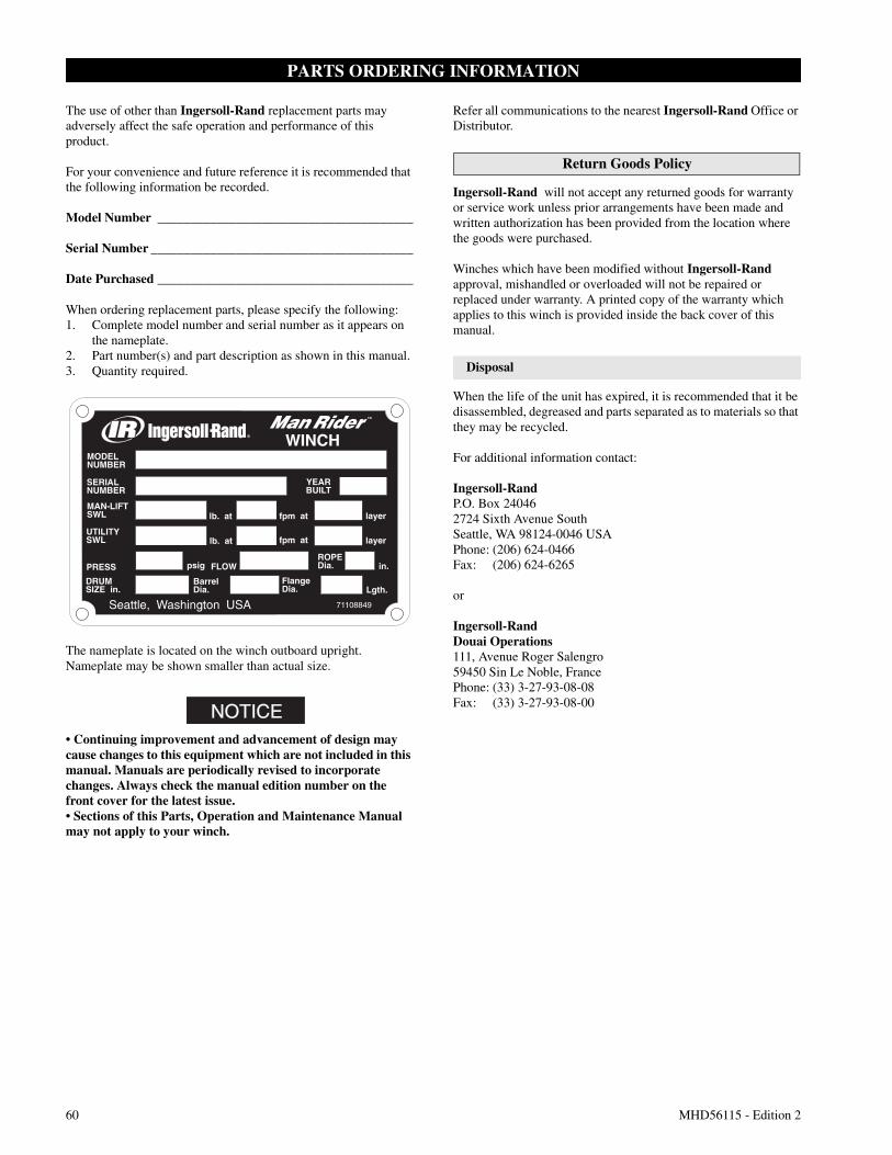
60 MHD56115 - Edition 2
PARTS ORDERING INFORMATION
The use of other than Ingersoll-Rand replacement parts mayadversely affect the safe operation and performance of thisproduct.
For your convenience and future reference it is recommended thatthe following information be recorded.
Model Number _______________________________________
Serial Number ________________________________________
Date Purchased _______________________________________
When ordering replacement parts, please specify the following:1. Complete model number and serial number as it appears on
the nameplate.2. Part number(s) and part description as shown in this manual.3. Quantity required.
The nameplate is located on the winch outboard upright.Nameplate may be shown smaller than actual size.
NOTICE• Continuing improvement and advancement of design maycause changes to this equipment which are not included in thismanual. Manuals are periodically revised to incorporatechanges. Always check the manual edition number on thefront cover for the latest issue.• Sections of this Parts, Operation and Maintenance Manualmay not apply to your winch.
Refer all communications to the nearest Ingersoll-Rand Office orDistributor.
Return Goods Policy
Ingersoll-Rand will not accept any returned goods for warrantyor service work unless prior arrangements have been made andwritten authorization has been provided from the location wherethe goods were purchased.
Winches which have been modified without Ingersoll-Randapproval, mishandled or overloaded will not be repaired orreplaced under warranty. A printed copy of the warranty whichapplies to this winch is provided inside the back cover of thismanual.
Disposal
When the life of the unit has expired, it is recommended that it bedisassembled, degreased and parts separated as to materials so thatthey may be recycled.
For additional information contact:
Ingersoll-RandP.O. Box 240462724 Sixth Avenue SouthSeattle, WA 98124-0046 USAPhone: (206) 624-0466Fax: (206) 624-6265
or
Ingersoll-RandDouai Operations111, Avenue Roger Salengro59450 Sin Le Noble, FrancePhone: (33) 3-27-93-08-08Fax: (33) 3-27-93-08-00

MHD56115 - Edition 2 61
SERVICE NOTES

62 MHD56115 - Edition 2
SERVICE NOTES
MHD56115 - Edition 2 63
SERVICE NOTESWARRANTY
LIMITED WARRANTY
Ingersoll-Rand Company (I-R) warrants to the original user itsHoists and Winches (Products) to be free of defects in materialand workmanship for a period of one year from the date ofpurchase. I-R will repair, without cost, any Product found to bedefective, including parts and labor charges, or at its option, willreplace such Products or refund the purchase price less areasonable allowance for depreciation, in exchange for theProduct. Repairs or replacements are warranted for the remainderof the original warranty period.
If any Product proves defective within its original one yearwarranty period, it should be returned to any Authorized Hoistand Winch Service Distributor, transportation prepaid with proofof purchase or warranty card.
This warranty does not apply to Products which I-R hasdetermined to have been misused or abused, improperlymaintained by the user, or where the malfunction or defect can beattributed to the use of non-genuine I-R parts.
I-R makes no other warranty, and all implied warrantiesincluding any warranty of merchantability or fitness for aparticular purpose are limited to the duration of theexpressed warranty period as set forth above. I-R’s maximumliability is limited to the purchase price of the Product and inno event shall I-R be liable for any consequential, indirect,incidental, or special damages of any nature rising from thesale or use of the Product, whether based on contract, tort, orotherwise.
Note: Some states do not allow limitations on incidental orconsequential damages or how long an implied warranty lasts sothat the above limitations may not apply to you.
This warranty gives you specific legal rights and you may alsohave other rights which may vary from state to state.
IMPORTANT NOTICE
It is our policy to promote safe delivery of all orders.
This shipment has been thoroughly checked, packed andinspected before leaving our plant and receipt for it in goodcondition has been received from the carrier. Any loss or damagewhich occurs to this shipment while enroute is not due to anyaction or conduct of the manufacturer.
Visible Loss or DamageIf any of the goods called for on the bill of lading or expressreceipt are damaged or the quantity is short, do not accept themuntil the freight or express agent makes an appropriate notation onyour freight bill or express receipt.
Concealed Loss or DamageWhen a shipment has been delivered to you in apparent goodcondition, but upon opening the crate or container, loss or damagehas taken place while in transit, notify the carrier’s agentimmediately.
Damage ClaimsYou must file claims for damage with the carrier. It is thetransportation company’s responsibility to reimburse you forrepair or replacement of goods damaged in shipment. Claims forloss or damage in shipment must not be deducted from theIngersoll-Rand invoice, nor should payment of Ingersoll-Randinvoice be withheld awaiting adjustment of such claims as thecarrier guarantees safe delivery.
You may return products damaged in shipment to us for repair,which services will be for your account and form your basis forclaim against the carrier.
Printed in USA
United States Office Locations International Office Locations
For Order Entry andOrder Status
Ingersoll-RandGlobal LogisticsP.O. Box 618510 Hester DriveWhite House, TN 37188Phone: (615) 474-8665Fax: (615) 672-0854
For Technical Support
Ingersoll-RandP.O. Box 240462724 Sixth Avenue SouthSeattle, WA 98124-0046Phone: (206) 624-0466 or
(866) 273-FAST (3278)Fax: (206) 624-6265
Web Site:www.airwinch.com
Regional Sales Offices
Annandale, NJP.O. Box 9701467 Route 31 SouthAnnandale, NJ 08801Phone: (908) 238-7000Fax: (908) 238-7048
Detroit, MI1872 Enterprise DriveRochester, MI 48309Phone: (248) 293-5700Fax: (248) 293-5800
Offices and distributors inprincipal cities throughout theworld. Contact the nearestIngersoll-Rand office for thename and address of thedistributor in your country orwrite/fax to:
CanadaNational Sales OfficeRegional WarehouseToronto, Ontario51 Worcester RoadRexdale, OntarioM9W 4K2Phone: (416) 213-4500Fax: (416) 213-4510Order DeskFax: (416) 213-4506
Latin America OperationsIngersoll-Rand730 N.W. 107 AvenueSuite 300, Miami, FL33172-3107 USAPhone: (305) 559-0500Fax: (305) 222-0864
Europe, Middle East andAfricaIngersoll-RandDouai Operations111, avenue Roger Salengro59450 Sin Le Noble, FrancePhone: (33) 3-27-93-08-08Fax: (33) 3-27-93-08-00
Asia Pacific OperationsIngersoll-Rand Ltd.42 Benoi RoadJurong, Singapore 629903Phone: 65-861-1555Fax: 65-862-1373
RussiaIngersoll-RandPresnensky Val19, Moscow, Russia 123557Phone: (7) 095-933-03-24Fax: (7) 095-737-01-48
AustraliaIngersoll-Rand Ltd.Landmark Corporate CenterLevel 2454-472 Nepean HighwayFrankston, Vic 3199AustraliaPhone: 61 3 8781 1600Fax: 61 3 8781 1611
Related Documents