MX Driver Reference Manual William M. Lavender June 2, 2011

Welcome message from author
This document is posted to help you gain knowledge. Please leave a comment to let me know what you think about it! Share it to your friends and learn new things together.
Transcript

MX Driver Reference Manual
William M. Lavender
June 2, 2011

2
MX has been developed by the Illinois Institute of Technology and is available under the following MIT X11 stylelicense.
Copyright 1999 Illinois Institute of Technology
Permission is hereby granted, free of charge, to any person obtaininga copy of this software and associated documentation files (the"Software"), to deal in the Software without restriction, includingwithout limitation the rights to use, copy, modify, merge, publish,distribute, sublicense, and/or sell copies of the Software, and topermit persons to whom the Software is furnished to do so, subject tothe following conditions:
The above copyright notice and this permission notice shall beincluded in all copies or substantial portions of the Software.
THE SOFTWARE IS PROVIDED "AS IS", WITHOUT WARRANTY OF ANY KIND,EXPRESS OR IMPLIED, INCLUDING BUT NOT LIMITED TO THE WARRANTIES OFMERCHANTABILITY, FITNESS FOR A PARTICULAR PURPOSE AND NONINFRINGEMENT.IN NO EVENT SHALL ILLINOIS INSTITUTE OF TECHNOLOGY BE LIABLE FOR ANYCLAIM, DAMAGES OR OTHER LIABILITY, WHETHER IN AN ACTION OF CONTRACT,TORT OR OTHERWISE, ARISING FROM, OUT OF OR IN CONNECTION WITH THESOFTWARE OR THE USE OR OTHER DEALINGS IN THE SOFTWARE.
Except as contained in this notice, the name of Illinois Instituteof Technology shall not be used in advertising or otherwise to promotethe sale, use or other dealings in this Software without prior writtenauthorization from Illinois Institute of Technology.

Contents
1 Introduction 111.1 mxserver.acl . . . . . . . . . . . . . . . . . . . . . . . . . . . . . . . . . . . . . . . . . . . . . . . . 111.2 mxupdate.dat . . . . . . . . . . . . . . . . . . . . . . . . . . . . . . . . . . . . . . . . . . . . . . . 121.3 The MX Record Database Files motor.dat and mxserver.dat . . . . . . . . . . . . . . . . . . . . . . . 121.4 Records and Record Fields . . . . . . . . . . . . . . . . . . . . . . . . . . . . . . . . . . . . . . . . 14
2 Amplifiers 172.1 APS ADCMOD2 . . . . . . . . . . . . . . . . . . . . . . . . . . . . . . . . . . . . . . . . . . . . . 172.2 APS QuadEM . . . . . . . . . . . . . . . . . . . . . . . . . . . . . . . . . . . . . . . . . . . . . . . 172.3 Keithley 428 . . . . . . . . . . . . . . . . . . . . . . . . . . . . . . . . . . . . . . . . . . . . . . . . 172.4 Keithley 2000 . . . . . . . . . . . . . . . . . . . . . . . . . . . . . . . . . . . . . . . . . . . . . . . 172.5 Keithley 2400 . . . . . . . . . . . . . . . . . . . . . . . . . . . . . . . . . . . . . . . . . . . . . . . 172.6 Keithley 2700 . . . . . . . . . . . . . . . . . . . . . . . . . . . . . . . . . . . . . . . . . . . . . . . 172.7 Network Amplifier . . . . . . . . . . . . . . . . . . . . . . . . . . . . . . . . . . . . . . . . . . . . 172.8 Oxford Danfysik IC PLUS . . . . . . . . . . . . . . . . . . . . . . . . . . . . . . . . . . . . . . . . 172.9 SCIPE Amplifier . . . . . . . . . . . . . . . . . . . . . . . . . . . . . . . . . . . . . . . . . . . . . 172.10 Soft Amplifier . . . . . . . . . . . . . . . . . . . . . . . . . . . . . . . . . . . . . . . . . . . . . . . 172.11 SRS SR-570 . . . . . . . . . . . . . . . . . . . . . . . . . . . . . . . . . . . . . . . . . . . . . . . . 172.12 UDT Tramp . . . . . . . . . . . . . . . . . . . . . . . . . . . . . . . . . . . . . . . . . . . . . . . . 17
3 Analog I/O 193.1 APS ADCMOD2 Analog I/O . . . . . . . . . . . . . . . . . . . . . . . . . . . . . . . . . . . . . . . 193.2 Data Track Tracker Analog I/O . . . . . . . . . . . . . . . . . . . . . . . . . . . . . . . . . . . . . . 193.3 Kinetic Systems 3112 Analog Output . . . . . . . . . . . . . . . . . . . . . . . . . . . . . . . . . . 193.4 Kinetic Systems 3512 Analog Input . . . . . . . . . . . . . . . . . . . . . . . . . . . . . . . . . . . 193.5 MODBUS Analog I/O . . . . . . . . . . . . . . . . . . . . . . . . . . . . . . . . . . . . . . . . . . 193.6 Multichannel Analog Input Function . . . . . . . . . . . . . . . . . . . . . . . . . . . . . . . . . . . 193.7 Network Analog I/O . . . . . . . . . . . . . . . . . . . . . . . . . . . . . . . . . . . . . . . . . . . 193.8 Newport Electronics Iseries Analog I/O . . . . . . . . . . . . . . . . . . . . . . . . . . . . . . . . . 193.9 Prairie Digital Model 45 Analog I/O . . . . . . . . . . . . . . . . . . . . . . . . . . . . . . . . . . . 193.10 Soft Analog I/O . . . . . . . . . . . . . . . . . . . . . . . . . . . . . . . . . . . . . . . . . . . . . . 193.11 Spellman DF3/FF3 Series High Voltage Power Supplies . . . . . . . . . . . . . . . . . . . . . . . . . 193.12 Stanford Research Systems SR-630 . . . . . . . . . . . . . . . . . . . . . . . . . . . . . . . . . . . 223.13 Wago 750 Series MODBUS Analog Output . . . . . . . . . . . . . . . . . . . . . . . . . . . . . . . 23
3

4 CONTENTS
3.14 Motor Controller Analog I/O . . . . . . . . . . . . . . . . . . . . . . . . . . . . . . . . . . . . . . . 233.15 Other Controller Type Analog I/O . . . . . . . . . . . . . . . . . . . . . . . . . . . . . . . . . . . . 23
4 Area Detector 254.1 Aviex PCCD-170170 . . . . . . . . . . . . . . . . . . . . . . . . . . . . . . . . . . . . . . . . . . . 254.2 Network Area Detector . . . . . . . . . . . . . . . . . . . . . . . . . . . . . . . . . . . . . . . . . . 254.3 Soft Area Detector . . . . . . . . . . . . . . . . . . . . . . . . . . . . . . . . . . . . . . . . . . . . 25
5 Autoscale Devices 275.1 Autoscale Amplifier . . . . . . . . . . . . . . . . . . . . . . . . . . . . . . . . . . . . . . . . . . . . 275.2 Autoscale Filter . . . . . . . . . . . . . . . . . . . . . . . . . . . . . . . . . . . . . . . . . . . . . . 275.3 Autoscale Filter and Amplifier . . . . . . . . . . . . . . . . . . . . . . . . . . . . . . . . . . . . . . 275.4 Related Devices . . . . . . . . . . . . . . . . . . . . . . . . . . . . . . . . . . . . . . . . . . . . . . 27
5.4.1 Autoscale Scaler . . . . . . . . . . . . . . . . . . . . . . . . . . . . . . . . . . . . . . . . . 275.4.2 Gain Tracking Scaler . . . . . . . . . . . . . . . . . . . . . . . . . . . . . . . . . . . . . . . 27
6 Counter/Timers 296.1 Am9513 . . . . . . . . . . . . . . . . . . . . . . . . . . . . . . . . . . . . . . . . . . . . . . . . . . 296.2 Black Cat Systems GM-xx . . . . . . . . . . . . . . . . . . . . . . . . . . . . . . . . . . . . . . . . 316.3 Blu-Ice Timer . . . . . . . . . . . . . . . . . . . . . . . . . . . . . . . . . . . . . . . . . . . . . . . 316.4 DSP QS450 or Kinetic Systems 3610 . . . . . . . . . . . . . . . . . . . . . . . . . . . . . . . . . . 316.5 EPICS Scaler . . . . . . . . . . . . . . . . . . . . . . . . . . . . . . . . . . . . . . . . . . . . . . . 316.6 EPICS Timer . . . . . . . . . . . . . . . . . . . . . . . . . . . . . . . . . . . . . . . . . . . . . . . 326.7 Interval Timer . . . . . . . . . . . . . . . . . . . . . . . . . . . . . . . . . . . . . . . . . . . . . . . 326.8 Joerger VSC8/16 . . . . . . . . . . . . . . . . . . . . . . . . . . . . . . . . . . . . . . . . . . . . . 326.9 MCA Timer . . . . . . . . . . . . . . . . . . . . . . . . . . . . . . . . . . . . . . . . . . . . . . . . 326.10 MCS Timer . . . . . . . . . . . . . . . . . . . . . . . . . . . . . . . . . . . . . . . . . . . . . . . . 326.11 Network Scaler . . . . . . . . . . . . . . . . . . . . . . . . . . . . . . . . . . . . . . . . . . . . . . 326.12 Network Timer . . . . . . . . . . . . . . . . . . . . . . . . . . . . . . . . . . . . . . . . . . . . . . 326.13 Ortec 974 . . . . . . . . . . . . . . . . . . . . . . . . . . . . . . . . . . . . . . . . . . . . . . . . . 326.14 Prairie Digital Model 45 . . . . . . . . . . . . . . . . . . . . . . . . . . . . . . . . . . . . . . . . . 326.15 PFCU Shutter Timer . . . . . . . . . . . . . . . . . . . . . . . . . . . . . . . . . . . . . . . . . . . 326.16 Radix Databox Scaler/Timer . . . . . . . . . . . . . . . . . . . . . . . . . . . . . . . . . . . . . . . 326.17 RTC-018 . . . . . . . . . . . . . . . . . . . . . . . . . . . . . . . . . . . . . . . . . . . . . . . . . 326.18 SCIPE Scaler . . . . . . . . . . . . . . . . . . . . . . . . . . . . . . . . . . . . . . . . . . . . . . . 326.19 SCIPE Timer . . . . . . . . . . . . . . . . . . . . . . . . . . . . . . . . . . . . . . . . . . . . . . . 326.20 Soft Scaler . . . . . . . . . . . . . . . . . . . . . . . . . . . . . . . . . . . . . . . . . . . . . . . . . 326.21 Soft Timer . . . . . . . . . . . . . . . . . . . . . . . . . . . . . . . . . . . . . . . . . . . . . . . . . 326.22 Spec Scaler . . . . . . . . . . . . . . . . . . . . . . . . . . . . . . . . . . . . . . . . . . . . . . . . 326.23 Spec Timer . . . . . . . . . . . . . . . . . . . . . . . . . . . . . . . . . . . . . . . . . . . . . . . . 326.24 XIA DXP Timer . . . . . . . . . . . . . . . . . . . . . . . . . . . . . . . . . . . . . . . . . . . . . . 326.25 XIA Handel Timer . . . . . . . . . . . . . . . . . . . . . . . . . . . . . . . . . . . . . . . . . . . . 326.26 Pseudoscalers . . . . . . . . . . . . . . . . . . . . . . . . . . . . . . . . . . . . . . . . . . . . . . . 32
6.26.1 Autoscale Related Pseudoscalers . . . . . . . . . . . . . . . . . . . . . . . . . . . . . . . . . 326.26.2 MCA Related Pseudoscalers . . . . . . . . . . . . . . . . . . . . . . . . . . . . . . . . . . . 326.26.3 MCS Scaler . . . . . . . . . . . . . . . . . . . . . . . . . . . . . . . . . . . . . . . . . . . . 32

CONTENTS 5
6.26.4 Scaler Function . . . . . . . . . . . . . . . . . . . . . . . . . . . . . . . . . . . . . . . . . . 326.27 Pseudotimers . . . . . . . . . . . . . . . . . . . . . . . . . . . . . . . . . . . . . . . . . . . . . . . 32
7 Digital I/O 357.1 Bit I/O . . . . . . . . . . . . . . . . . . . . . . . . . . . . . . . . . . . . . . . . . . . . . . . . . . . 367.2 Data Track Tracker Digital I/O . . . . . . . . . . . . . . . . . . . . . . . . . . . . . . . . . . . . . . 367.3 Intel 8255 . . . . . . . . . . . . . . . . . . . . . . . . . . . . . . . . . . . . . . . . . . . . . . . . . 367.4 Kinetic Systems 3063 . . . . . . . . . . . . . . . . . . . . . . . . . . . . . . . . . . . . . . . . . . . 367.5 Linux Parport . . . . . . . . . . . . . . . . . . . . . . . . . . . . . . . . . . . . . . . . . . . . . . . 367.6 MODBUS Digital I/O . . . . . . . . . . . . . . . . . . . . . . . . . . . . . . . . . . . . . . . . . . . 367.7 Motorola MC6821 . . . . . . . . . . . . . . . . . . . . . . . . . . . . . . . . . . . . . . . . . . . . 367.8 Network Digital I/O . . . . . . . . . . . . . . . . . . . . . . . . . . . . . . . . . . . . . . . . . . . . 367.9 PC Parallel Port . . . . . . . . . . . . . . . . . . . . . . . . . . . . . . . . . . . . . . . . . . . . . . 367.10 PFCU Filter Summary Digital Output . . . . . . . . . . . . . . . . . . . . . . . . . . . . . . . . . . 367.11 Port I/O Digital I/O . . . . . . . . . . . . . . . . . . . . . . . . . . . . . . . . . . . . . . . . . . . . 367.12 Prairie Digital Model 45 Digital I/O . . . . . . . . . . . . . . . . . . . . . . . . . . . . . . . . . . . 367.13 SCIPE Digital I/O . . . . . . . . . . . . . . . . . . . . . . . . . . . . . . . . . . . . . . . . . . . . . 367.14 Soft Digital I/O . . . . . . . . . . . . . . . . . . . . . . . . . . . . . . . . . . . . . . . . . . . . . . 367.15 VME Digital I/O . . . . . . . . . . . . . . . . . . . . . . . . . . . . . . . . . . . . . . . . . . . . . 367.16 Wago 750 Series MODBUS Digital Output . . . . . . . . . . . . . . . . . . . . . . . . . . . . . . . 367.17 Motor Controller Digital I/O . . . . . . . . . . . . . . . . . . . . . . . . . . . . . . . . . . . . . . . 367.18 Other Controller Type Digital I/O . . . . . . . . . . . . . . . . . . . . . . . . . . . . . . . . . . . . 36
8 Encoder 378.1 Kinetic Systems 3640 . . . . . . . . . . . . . . . . . . . . . . . . . . . . . . . . . . . . . . . . . . . 37
9 Goniostat/Diffractometer Tables 399.1 IMCA-CAT ADC Table at APS Sector 17 . . . . . . . . . . . . . . . . . . . . . . . . . . . . . . . . 39
9.1.1 Record Fields in the Record Description . . . . . . . . . . . . . . . . . . . . . . . . . . . . . 41
10 Motors 4310.1 Record Fields in the Record Description . . . . . . . . . . . . . . . . . . . . . . . . . . . . . . . . . 4310.2 Motor Controllers . . . . . . . . . . . . . . . . . . . . . . . . . . . . . . . . . . . . . . . . . . . . . 45
10.2.1 Advanced Control Systems MCU-2 . . . . . . . . . . . . . . . . . . . . . . . . . . . . . . . 4510.2.2 Aerotech Unidex 500 . . . . . . . . . . . . . . . . . . . . . . . . . . . . . . . . . . . . . . . 4510.2.3 Am9513-based Motor . . . . . . . . . . . . . . . . . . . . . . . . . . . . . . . . . . . . . . 4610.2.4 Animatics SmartMotor . . . . . . . . . . . . . . . . . . . . . . . . . . . . . . . . . . . . . . 4610.2.5 APS Insertion Device . . . . . . . . . . . . . . . . . . . . . . . . . . . . . . . . . . . . . . . 4810.2.6 Blu-Ice Motor . . . . . . . . . . . . . . . . . . . . . . . . . . . . . . . . . . . . . . . . . . . 4910.2.7 Bruker D8 . . . . . . . . . . . . . . . . . . . . . . . . . . . . . . . . . . . . . . . . . . . . . 4910.2.8 Compumotor 6K and 6000 Series Motor Controllers . . . . . . . . . . . . . . . . . . . . . . 4910.2.9 DAC Motor . . . . . . . . . . . . . . . . . . . . . . . . . . . . . . . . . . . . . . . . . . . . 5510.2.10 Delta Tau PMAC . . . . . . . . . . . . . . . . . . . . . . . . . . . . . . . . . . . . . . . . . 5510.2.11 Delta Tau Power PMAC . . . . . . . . . . . . . . . . . . . . . . . . . . . . . . . . . . . . . 6210.2.12 Disabled Motor . . . . . . . . . . . . . . . . . . . . . . . . . . . . . . . . . . . . . . . . . . 6410.2.13 DSP E500 . . . . . . . . . . . . . . . . . . . . . . . . . . . . . . . . . . . . . . . . . . . . . 6410.2.14 EPICS Motor . . . . . . . . . . . . . . . . . . . . . . . . . . . . . . . . . . . . . . . . . . . 64

6 CONTENTS
10.2.15 IMS MDrive . . . . . . . . . . . . . . . . . . . . . . . . . . . . . . . . . . . . . . . . . . . 6510.2.16 IMS Panther and IM483 . . . . . . . . . . . . . . . . . . . . . . . . . . . . . . . . . . . . . 6610.2.17 Joerger SMC24 . . . . . . . . . . . . . . . . . . . . . . . . . . . . . . . . . . . . . . . . . . 6710.2.18 Kohzu SC-200, SC-400, and SC-800 . . . . . . . . . . . . . . . . . . . . . . . . . . . . . . . 6810.2.19 Lakeshore 330 Temperature Controller . . . . . . . . . . . . . . . . . . . . . . . . . . . . . 6910.2.20 Mar Desktop Beamline . . . . . . . . . . . . . . . . . . . . . . . . . . . . . . . . . . . . . . 7010.2.21 Mclennan . . . . . . . . . . . . . . . . . . . . . . . . . . . . . . . . . . . . . . . . . . . . . 7210.2.22 Mclennan PM-304 . . . . . . . . . . . . . . . . . . . . . . . . . . . . . . . . . . . . . . . . 7410.2.23 National Instruments PC-STEP . . . . . . . . . . . . . . . . . . . . . . . . . . . . . . . . . 7510.2.24 National Instruments ValueMotion . . . . . . . . . . . . . . . . . . . . . . . . . . . . . . . . 7610.2.25 Network Motor . . . . . . . . . . . . . . . . . . . . . . . . . . . . . . . . . . . . . . . . . . 7610.2.26 Newport MM3000 . . . . . . . . . . . . . . . . . . . . . . . . . . . . . . . . . . . . . . . . 7710.2.27 Newport MM4000 . . . . . . . . . . . . . . . . . . . . . . . . . . . . . . . . . . . . . . . . 7710.2.28 Newport ESP series . . . . . . . . . . . . . . . . . . . . . . . . . . . . . . . . . . . . . . . . 7810.2.29 Newport Picomotor . . . . . . . . . . . . . . . . . . . . . . . . . . . . . . . . . . . . . . . . 7810.2.30 NSLS MMC32 . . . . . . . . . . . . . . . . . . . . . . . . . . . . . . . . . . . . . . . . . . 8010.2.31 OSS µ-GLIDE . . . . . . . . . . . . . . . . . . . . . . . . . . . . . . . . . . . . . . . . . . 8010.2.32 Oxford Cryosystems Cryostream 600 Temperature Controller . . . . . . . . . . . . . . . . . 8110.2.33 Oxford Instruments ITC503 Temperature Controller . . . . . . . . . . . . . . . . . . . . . . 8210.2.34 Pan-Tilt-Zoom Motor . . . . . . . . . . . . . . . . . . . . . . . . . . . . . . . . . . . . . . . 8310.2.35 Phidget Stepper (old version) . . . . . . . . . . . . . . . . . . . . . . . . . . . . . . . . . . . 8310.2.36 Physik Instrumente E662 Piezo Controller . . . . . . . . . . . . . . . . . . . . . . . . . . . . 8310.2.37 Pontech STP100 . . . . . . . . . . . . . . . . . . . . . . . . . . . . . . . . . . . . . . . . . 8310.2.38 Prairie Digital Model 40 . . . . . . . . . . . . . . . . . . . . . . . . . . . . . . . . . . . . . 8310.2.39 Precision MicroControl MCAPI-based Motor Controllers . . . . . . . . . . . . . . . . . . . . 8310.2.40 Pro-Dex VME58 . . . . . . . . . . . . . . . . . . . . . . . . . . . . . . . . . . . . . . . . . 8310.2.41 Radix Databox . . . . . . . . . . . . . . . . . . . . . . . . . . . . . . . . . . . . . . . . . . 8410.2.42 Scientific Instruments 9650 Temperature Controller . . . . . . . . . . . . . . . . . . . . . . . 8410.2.43 SCIPE Motor . . . . . . . . . . . . . . . . . . . . . . . . . . . . . . . . . . . . . . . . . . . 8410.2.44 Soft Motor . . . . . . . . . . . . . . . . . . . . . . . . . . . . . . . . . . . . . . . . . . . . 8410.2.45 Spec Motor . . . . . . . . . . . . . . . . . . . . . . . . . . . . . . . . . . . . . . . . . . . . 8410.2.46 SRC Monochromator . . . . . . . . . . . . . . . . . . . . . . . . . . . . . . . . . . . . . . . 8410.2.47 Velmex VP9000 . . . . . . . . . . . . . . . . . . . . . . . . . . . . . . . . . . . . . . . . . 8510.2.48 XIA HSC-1 Huber Slit Controller . . . . . . . . . . . . . . . . . . . . . . . . . . . . . . . . 85
10.3 Pseudomotors . . . . . . . . . . . . . . . . . . . . . . . . . . . . . . . . . . . . . . . . . . . . . . . 8610.3.1 ADSC Two Theta . . . . . . . . . . . . . . . . . . . . . . . . . . . . . . . . . . . . . . . . . 8610.3.2 A-Frame Detector Motor . . . . . . . . . . . . . . . . . . . . . . . . . . . . . . . . . . . . . 8610.3.3 ALS Dewar Positioner . . . . . . . . . . . . . . . . . . . . . . . . . . . . . . . . . . . . . . 8810.3.4 APS 18-ID . . . . . . . . . . . . . . . . . . . . . . . . . . . . . . . . . . . . . . . . . . . . 8810.3.5 Delta . . . . . . . . . . . . . . . . . . . . . . . . . . . . . . . . . . . . . . . . . . . . . . . 8810.3.6 Elapsed Time . . . . . . . . . . . . . . . . . . . . . . . . . . . . . . . . . . . . . . . . . . . 8810.3.7 Energy . . . . . . . . . . . . . . . . . . . . . . . . . . . . . . . . . . . . . . . . . . . . . . 8810.3.8 Linear Function . . . . . . . . . . . . . . . . . . . . . . . . . . . . . . . . . . . . . . . . . . 8810.3.9 Monochromator . . . . . . . . . . . . . . . . . . . . . . . . . . . . . . . . . . . . . . . . . . 8810.3.10 Q Motor . . . . . . . . . . . . . . . . . . . . . . . . . . . . . . . . . . . . . . . . . . . . . . 9710.3.11 Record Field Motor . . . . . . . . . . . . . . . . . . . . . . . . . . . . . . . . . . . . . . . . 97

CONTENTS 7
10.3.12 Segmented Move . . . . . . . . . . . . . . . . . . . . . . . . . . . . . . . . . . . . . . . . . 9710.3.13 Slit Motor . . . . . . . . . . . . . . . . . . . . . . . . . . . . . . . . . . . . . . . . . . . . . 9710.3.14 Table Motor . . . . . . . . . . . . . . . . . . . . . . . . . . . . . . . . . . . . . . . . . . . . 9810.3.15 Tangent Arm/Sine Arm . . . . . . . . . . . . . . . . . . . . . . . . . . . . . . . . . . . . . . 9810.3.16 Theta-Two Theta . . . . . . . . . . . . . . . . . . . . . . . . . . . . . . . . . . . . . . . . . 9910.3.17 Translation . . . . . . . . . . . . . . . . . . . . . . . . . . . . . . . . . . . . . . . . . . . . 9910.3.18 Wavelength . . . . . . . . . . . . . . . . . . . . . . . . . . . . . . . . . . . . . . . . . . . . 9910.3.19 Wavenumber . . . . . . . . . . . . . . . . . . . . . . . . . . . . . . . . . . . . . . . . . . . 9910.3.20 XAFS Wavenumber . . . . . . . . . . . . . . . . . . . . . . . . . . . . . . . . . . . . . . . 99
11 Multichannel Analog Input 10111.1 Keithley 2700 . . . . . . . . . . . . . . . . . . . . . . . . . . . . . . . . . . . . . . . . . . . . . . . 10111.2 Oxford Danfysik QBPM . . . . . . . . . . . . . . . . . . . . . . . . . . . . . . . . . . . . . . . . . 101
12 Multichannel Analyzers 10312.1 EPICS MCA . . . . . . . . . . . . . . . . . . . . . . . . . . . . . . . . . . . . . . . . . . . . . . . 10312.2 Network MCA . . . . . . . . . . . . . . . . . . . . . . . . . . . . . . . . . . . . . . . . . . . . . . 10312.3 Ortec UMCBI (Trump) . . . . . . . . . . . . . . . . . . . . . . . . . . . . . . . . . . . . . . . . . . 10312.4 Rontec RCL-22 MCA . . . . . . . . . . . . . . . . . . . . . . . . . . . . . . . . . . . . . . . . . . . 10312.5 Soft MCA . . . . . . . . . . . . . . . . . . . . . . . . . . . . . . . . . . . . . . . . . . . . . . . . . 10312.6 X-Ray Instrumentation Associates (XIA) . . . . . . . . . . . . . . . . . . . . . . . . . . . . . . . . 10312.7 MCA Associated Records . . . . . . . . . . . . . . . . . . . . . . . . . . . . . . . . . . . . . . . . . 103
12.7.1 MCA Alternate Time . . . . . . . . . . . . . . . . . . . . . . . . . . . . . . . . . . . . . . . 10312.7.2 MCA Channel . . . . . . . . . . . . . . . . . . . . . . . . . . . . . . . . . . . . . . . . . . 10312.7.3 MCA Region of Interest Integral . . . . . . . . . . . . . . . . . . . . . . . . . . . . . . . . . 10312.7.4 MCA Value . . . . . . . . . . . . . . . . . . . . . . . . . . . . . . . . . . . . . . . . . . . . 103
13 Multichannel Encoders 10513.1 MCS Elapsed Time Multichannel Encoder . . . . . . . . . . . . . . . . . . . . . . . . . . . . . . . . 10513.2 MCS Multichannel Encoder . . . . . . . . . . . . . . . . . . . . . . . . . . . . . . . . . . . . . . . 10513.3 Network Multichannel Encoder . . . . . . . . . . . . . . . . . . . . . . . . . . . . . . . . . . . . . . 10513.4 PMAC Multichannel Encoder . . . . . . . . . . . . . . . . . . . . . . . . . . . . . . . . . . . . . . 10513.5 Radix Databox Multichannel Encoder . . . . . . . . . . . . . . . . . . . . . . . . . . . . . . . . . . 105
14 Multichannel Scalers 10714.1 EPICS MCS . . . . . . . . . . . . . . . . . . . . . . . . . . . . . . . . . . . . . . . . . . . . . . . . 10714.2 Network MCS . . . . . . . . . . . . . . . . . . . . . . . . . . . . . . . . . . . . . . . . . . . . . . . 10814.3 Radix Databox MCS . . . . . . . . . . . . . . . . . . . . . . . . . . . . . . . . . . . . . . . . . . . 10814.4 Scaler Function MCS . . . . . . . . . . . . . . . . . . . . . . . . . . . . . . . . . . . . . . . . . . . 10814.5 SIS3801 . . . . . . . . . . . . . . . . . . . . . . . . . . . . . . . . . . . . . . . . . . . . . . . . . . 10814.6 Soft MCS . . . . . . . . . . . . . . . . . . . . . . . . . . . . . . . . . . . . . . . . . . . . . . . . . 10814.7 X-ray Instrumentation Associates MCS . . . . . . . . . . . . . . . . . . . . . . . . . . . . . . . . . 108

8 CONTENTS
15 Pan-Tilt-Zoom Controllers 10915.1 Hitachi KP-D20A/B . . . . . . . . . . . . . . . . . . . . . . . . . . . . . . . . . . . . . . . . . . . . 10915.2 Network PTZ . . . . . . . . . . . . . . . . . . . . . . . . . . . . . . . . . . . . . . . . . . . . . . . 10915.3 Panasonic KX-DP702 . . . . . . . . . . . . . . . . . . . . . . . . . . . . . . . . . . . . . . . . . . . 10915.4 Sony VISCA . . . . . . . . . . . . . . . . . . . . . . . . . . . . . . . . . . . . . . . . . . . . . . . 109
16 Pulse Generator 11116.1 Network Pulse Generator . . . . . . . . . . . . . . . . . . . . . . . . . . . . . . . . . . . . . . . . . 11116.2 Prairie Digital Model 45 Pulse Generator . . . . . . . . . . . . . . . . . . . . . . . . . . . . . . . . 11116.3 Struck SIS3801 . . . . . . . . . . . . . . . . . . . . . . . . . . . . . . . . . . . . . . . . . . . . . . 11116.4 Struck SIS3807 . . . . . . . . . . . . . . . . . . . . . . . . . . . . . . . . . . . . . . . . . . . . . . 111
17 Relays 11317.1 Binary Relay . . . . . . . . . . . . . . . . . . . . . . . . . . . . . . . . . . . . . . . . . . . . . . . 11317.2 Blind Relay . . . . . . . . . . . . . . . . . . . . . . . . . . . . . . . . . . . . . . . . . . . . . . . . 11317.3 Blu-Ice Shutter . . . . . . . . . . . . . . . . . . . . . . . . . . . . . . . . . . . . . . . . . . . . . . 11317.4 Generic Relay . . . . . . . . . . . . . . . . . . . . . . . . . . . . . . . . . . . . . . . . . . . . . . . 11317.5 MarCCD Relay . . . . . . . . . . . . . . . . . . . . . . . . . . . . . . . . . . . . . . . . . . . . . . 11317.6 MarDTB Shutter . . . . . . . . . . . . . . . . . . . . . . . . . . . . . . . . . . . . . . . . . . . . . 11317.7 Network Relay . . . . . . . . . . . . . . . . . . . . . . . . . . . . . . . . . . . . . . . . . . . . . . 11317.8 PFCU Filter and Shutter . . . . . . . . . . . . . . . . . . . . . . . . . . . . . . . . . . . . . . . . . 11317.9 Pulsed Relay . . . . . . . . . . . . . . . . . . . . . . . . . . . . . . . . . . . . . . . . . . . . . . . 113
18 Sample Changers 11518.1 Network . . . . . . . . . . . . . . . . . . . . . . . . . . . . . . . . . . . . . . . . . . . . . . . . . . 11518.2 Sercat ALS Robot . . . . . . . . . . . . . . . . . . . . . . . . . . . . . . . . . . . . . . . . . . . . . 115
19 Single Channel Analyzers 11719.1 Network SCA . . . . . . . . . . . . . . . . . . . . . . . . . . . . . . . . . . . . . . . . . . . . . . . 11719.2 Oxford Danfysik Cyberstar X1000 . . . . . . . . . . . . . . . . . . . . . . . . . . . . . . . . . . . . 11719.3 Soft SCA . . . . . . . . . . . . . . . . . . . . . . . . . . . . . . . . . . . . . . . . . . . . . . . . . 117
20 Video Input Devices 11920.1 EPIX XCLIB . . . . . . . . . . . . . . . . . . . . . . . . . . . . . . . . . . . . . . . . . . . . . . . 11920.2 Network Video Input . . . . . . . . . . . . . . . . . . . . . . . . . . . . . . . . . . . . . . . . . . . 11920.3 Soft Video Input . . . . . . . . . . . . . . . . . . . . . . . . . . . . . . . . . . . . . . . . . . . . . . 11920.4 Video4Linux 2 . . . . . . . . . . . . . . . . . . . . . . . . . . . . . . . . . . . . . . . . . . . . . . 119
21 CAMAC 12121.1 DSP6001 . . . . . . . . . . . . . . . . . . . . . . . . . . . . . . . . . . . . . . . . . . . . . . . . . 12121.2 ESONE . . . . . . . . . . . . . . . . . . . . . . . . . . . . . . . . . . . . . . . . . . . . . . . . . . 12121.3 Soft CAMAC . . . . . . . . . . . . . . . . . . . . . . . . . . . . . . . . . . . . . . . . . . . . . . . 121
22 Camera Link 12322.1 Camera Link API . . . . . . . . . . . . . . . . . . . . . . . . . . . . . . . . . . . . . . . . . . . . . 12322.2 EPIX Camera Link . . . . . . . . . . . . . . . . . . . . . . . . . . . . . . . . . . . . . . . . . . . . 12322.3 Soft Camera Link . . . . . . . . . . . . . . . . . . . . . . . . . . . . . . . . . . . . . . . . . . . . . 123

CONTENTS 9
23 GPIB 12523.1 EPICS GPIB . . . . . . . . . . . . . . . . . . . . . . . . . . . . . . . . . . . . . . . . . . . . . . . 12523.2 Iotech Micro488EX GPIB . . . . . . . . . . . . . . . . . . . . . . . . . . . . . . . . . . . . . . . . 12523.3 Keithley 500-SERIAL . . . . . . . . . . . . . . . . . . . . . . . . . . . . . . . . . . . . . . . . . . 12523.4 Linux GPIB . . . . . . . . . . . . . . . . . . . . . . . . . . . . . . . . . . . . . . . . . . . . . . . . 12523.5 Linux Lab Project GPIB . . . . . . . . . . . . . . . . . . . . . . . . . . . . . . . . . . . . . . . . . 12523.6 National Instruments GPIB . . . . . . . . . . . . . . . . . . . . . . . . . . . . . . . . . . . . . . . . 12523.7 Network GPIB . . . . . . . . . . . . . . . . . . . . . . . . . . . . . . . . . . . . . . . . . . . . . . 125
24 MODBUS 12724.1 MODBUS Serial RTU . . . . . . . . . . . . . . . . . . . . . . . . . . . . . . . . . . . . . . . . . . 12724.2 MODBUS/TCP . . . . . . . . . . . . . . . . . . . . . . . . . . . . . . . . . . . . . . . . . . . . . . 127
25 Port I/O 12925.1 DriverLINX Port I/O . . . . . . . . . . . . . . . . . . . . . . . . . . . . . . . . . . . . . . . . . . . 12925.2 MSDOS Port I/O . . . . . . . . . . . . . . . . . . . . . . . . . . . . . . . . . . . . . . . . . . . . . 12925.3 Linux iopl() and ioperm() drivers . . . . . . . . . . . . . . . . . . . . . . . . . . . . . . . . . . . . . 12925.4 Linux portio driver . . . . . . . . . . . . . . . . . . . . . . . . . . . . . . . . . . . . . . . . . . . . 12925.5 VxWorks Port I/O . . . . . . . . . . . . . . . . . . . . . . . . . . . . . . . . . . . . . . . . . . . . . 129
26 RS-232 13126.1 Camera Link . . . . . . . . . . . . . . . . . . . . . . . . . . . . . . . . . . . . . . . . . . . . . . . 13126.2 EPICS RS-232 . . . . . . . . . . . . . . . . . . . . . . . . . . . . . . . . . . . . . . . . . . . . . . 13126.3 MSDOS COM . . . . . . . . . . . . . . . . . . . . . . . . . . . . . . . . . . . . . . . . . . . . . . 13126.4 Fossil . . . . . . . . . . . . . . . . . . . . . . . . . . . . . . . . . . . . . . . . . . . . . . . . . . . 13126.5 Kinetic Systems KS3344 . . . . . . . . . . . . . . . . . . . . . . . . . . . . . . . . . . . . . . . . . 13126.6 Network RS-232 . . . . . . . . . . . . . . . . . . . . . . . . . . . . . . . . . . . . . . . . . . . . . 13126.7 Spec Command . . . . . . . . . . . . . . . . . . . . . . . . . . . . . . . . . . . . . . . . . . . . . . 13126.8 TCP Socket . . . . . . . . . . . . . . . . . . . . . . . . . . . . . . . . . . . . . . . . . . . . . . . . 13126.9 Unix TTY . . . . . . . . . . . . . . . . . . . . . . . . . . . . . . . . . . . . . . . . . . . . . . . . . 13126.10VMS Terminal . . . . . . . . . . . . . . . . . . . . . . . . . . . . . . . . . . . . . . . . . . . . . . 13126.11VxWorks RS-232 . . . . . . . . . . . . . . . . . . . . . . . . . . . . . . . . . . . . . . . . . . . . . 13126.12Wago 750 Serial Port . . . . . . . . . . . . . . . . . . . . . . . . . . . . . . . . . . . . . . . . . . . 13126.13Win32 COM Port . . . . . . . . . . . . . . . . . . . . . . . . . . . . . . . . . . . . . . . . . . . . . 131
27 USB 13327.1 Libusb . . . . . . . . . . . . . . . . . . . . . . . . . . . . . . . . . . . . . . . . . . . . . . . . . . . 133
28 VME 13528.1 EPICS VME . . . . . . . . . . . . . . . . . . . . . . . . . . . . . . . . . . . . . . . . . . . . . . . . 13528.2 Mmap VME . . . . . . . . . . . . . . . . . . . . . . . . . . . . . . . . . . . . . . . . . . . . . . . . 13528.3 National Instruments VXI Memacc . . . . . . . . . . . . . . . . . . . . . . . . . . . . . . . . . . . . 13528.4 RTEMS VME . . . . . . . . . . . . . . . . . . . . . . . . . . . . . . . . . . . . . . . . . . . . . . . 13528.5 Struck SIS-1100 and SIS-3100 . . . . . . . . . . . . . . . . . . . . . . . . . . . . . . . . . . . . . . 13528.6 VxWorks VME . . . . . . . . . . . . . . . . . . . . . . . . . . . . . . . . . . . . . . . . . . . . . . 135

10 CONTENTS
29 Variables 13729.1 EPICS Variables . . . . . . . . . . . . . . . . . . . . . . . . . . . . . . . . . . . . . . . . . . . . . . 13729.2 Inline Variables . . . . . . . . . . . . . . . . . . . . . . . . . . . . . . . . . . . . . . . . . . . . . . 13729.3 Network Variables . . . . . . . . . . . . . . . . . . . . . . . . . . . . . . . . . . . . . . . . . . . . 13729.4 PMAC Variables . . . . . . . . . . . . . . . . . . . . . . . . . . . . . . . . . . . . . . . . . . . . . 13729.5 Spec Variables . . . . . . . . . . . . . . . . . . . . . . . . . . . . . . . . . . . . . . . . . . . . . . . 13729.6 Calculation Variables . . . . . . . . . . . . . . . . . . . . . . . . . . . . . . . . . . . . . . . . . . . 137
29.6.1 APS Topup Time to Inject . . . . . . . . . . . . . . . . . . . . . . . . . . . . . . . . . . . . 13729.6.2 APS Topup Interlock . . . . . . . . . . . . . . . . . . . . . . . . . . . . . . . . . . . . . . . 13729.6.3 Mathop Variables . . . . . . . . . . . . . . . . . . . . . . . . . . . . . . . . . . . . . . . . . 13729.6.4 Polynomial . . . . . . . . . . . . . . . . . . . . . . . . . . . . . . . . . . . . . . . . . . . . 13729.6.5 Position Select . . . . . . . . . . . . . . . . . . . . . . . . . . . . . . . . . . . . . . . . . . 137
30 Servers 13930.1 TCP/IP Servers . . . . . . . . . . . . . . . . . . . . . . . . . . . . . . . . . . . . . . . . . . . . . . 13930.2 Unix Domain Socket Servers . . . . . . . . . . . . . . . . . . . . . . . . . . . . . . . . . . . . . . . 139
31 Scans 14131.1 Linear Scans . . . . . . . . . . . . . . . . . . . . . . . . . . . . . . . . . . . . . . . . . . . . . . . . 141
31.1.1 Input Scans . . . . . . . . . . . . . . . . . . . . . . . . . . . . . . . . . . . . . . . . . . . . 14131.1.2 Motor Scans . . . . . . . . . . . . . . . . . . . . . . . . . . . . . . . . . . . . . . . . . . . 14131.1.3 Pseudomotor Scans . . . . . . . . . . . . . . . . . . . . . . . . . . . . . . . . . . . . . . . . 14131.1.4 Slit Scans . . . . . . . . . . . . . . . . . . . . . . . . . . . . . . . . . . . . . . . . . . . . . 14131.1.5 Theta-Two Theta Scans . . . . . . . . . . . . . . . . . . . . . . . . . . . . . . . . . . . . . . 141
31.2 List Scans . . . . . . . . . . . . . . . . . . . . . . . . . . . . . . . . . . . . . . . . . . . . . . . . . 14131.2.1 File List Scans . . . . . . . . . . . . . . . . . . . . . . . . . . . . . . . . . . . . . . . . . . 141
31.3 XAFS Scans . . . . . . . . . . . . . . . . . . . . . . . . . . . . . . . . . . . . . . . . . . . . . . . . 14131.4 Quick Scans (also known as Fast or Slew Scans) . . . . . . . . . . . . . . . . . . . . . . . . . . . . . 141
31.4.1 Joerger Quick Scans . . . . . . . . . . . . . . . . . . . . . . . . . . . . . . . . . . . . . . . 14131.4.2 MCS Quick Scans . . . . . . . . . . . . . . . . . . . . . . . . . . . . . . . . . . . . . . . . 141
32 Interfaces to Other Control Systems 14332.1 Blu-Ice . . . . . . . . . . . . . . . . . . . . . . . . . . . . . . . . . . . . . . . . . . . . . . . . . . 14332.2 EPICS . . . . . . . . . . . . . . . . . . . . . . . . . . . . . . . . . . . . . . . . . . . . . . . . . . . 14332.3 SCIPE . . . . . . . . . . . . . . . . . . . . . . . . . . . . . . . . . . . . . . . . . . . . . . . . . . . 14332.4 Spec . . . . . . . . . . . . . . . . . . . . . . . . . . . . . . . . . . . . . . . . . . . . . . . . . . . . 143

Chapter 1
Introduction
MX is a portable beamline control and data acquisition toolkit currently in use at a number of synchrotron beamlinesand laboratory X-ray generator systems. The purpose of this manual is to explain how to set up the configuration filesthat control how MX works.
The most important step in configuring a new MX system is the building of the MX configuration files which aregenerally found in the directory $MXDIR/etc where MXDIR is an environment variable that points to the top of theMX directory tree. If you use the standard definition that MXDIR = /opt/mx, then the configuration files will be foundin /opt/mx/etc. The most important configuration files are:
/opt/mx/etc/motor.dat - The primary MX client-side database file./opt/mx/etc/mxserver.acl - An access control list for the MX server./opt/mx/etc/mxserver.dat - The MX server-side database file./opt/mx/etc/mxupdate.dat - The mxupdate process’s configuration file.
We will cover mxserver.acl and mxupdate.dat first since they are simple and relatively easy to explain.
1.1 mxserver.aclmxserver.acl is an access control list file that describes what computers are allowed to connect to the local MX server.It is a simple text file with one entry per line. The entries are either IP addresses or Internet domain names. Irecommend the use of IP addresses since then the MX server does not need to perform potentially time consumingDNS lookups to find the IP address from the domain name, but it is your choice. Here is an example mxserver.aclfile:
127.0.0.1192.168.17.5192.168.17.27192.168.22.*myhost.example.com
*.example.net
This configuration files says that the individual IP addresses 127.0.0.1, 192.168.17.5 and 192.168.17.27 are al-lowed, that any host on the subnet 192.168.22.* is allowed, that myhost.example.com is allowed, and that any host in
11

12 CHAPTER 1. INTRODUCTION
the domain *.example.net is allowed. You will note that * wildcards are allowed. In addition, the ? wildcard, whichstands for a single character, is also allowed although it is not as easy to use.
At present, MX only does access control on a host level basis and allows any username from a given machine toconnect. Although MX clients do transmit their username to the remote MX server, this information is not used foraccess control since it is trivially spoofed. Support for user level access control will be added once something alongthe lines of an SSL/TLS certificate infrastructure has been added to MX.
1.2 mxupdate.datThe mxupdate process exists to save and restore MX database variables so that their values can be preserved when theMX server is stopped and restarted. It is another simple text file that contains the name of one record field per line.An example mxupdate.dat file looks like:
edge_energy.value 1 0d_spacing.value 1 0beam_offset.value 1 0shutter_policy.value 1 0xafs_header1.value 1 0xafs_header2.value 1 0xafs_header3.value 1 0sff_header1.value 1 0sff_header2.value 1 0sff_header_fmt.value 1 0theta_enabled.value 1 0momega_enabled.value 1 0normpoly_enable.value 1 0normal_enabled.value 1 0id_ev_enabled.value 1 0momega_params.value 1 0normpoly_params.value 1 0id_ev_harmonic.value 1 0id_ev_offset.value 1 0id_ev_params.value 1 0
The first field on each line is the name of an MX record field. For example, edge energy.value refers to the recordcalled edge energy and the field within it called value. Any record field listed here will have its value saved twicea minute and will have its value restored the next time the MX server is started from the mxupdate state files called/opt/mx/state/mxsave.1 and /opt/mx/state/mxsave.2. When mxupdate restores the values the next time the MX serveris started, mxupdate will choose whichever of the two state files which is both complete and most recent.
For the present, you should set the second and third fields on each line above to 1 and 0 respectively. These fieldsare not currently documented, since they are scheduled to be changed in the future.
1.3 The MX Record Database Files motor.dat and mxserver.datThe most important configuration files in MX are the client-side motor.dat file and the server-side mxserver.dat file.These files describe the set of objects called MX records which are used to represent the motors, counter, MCAs,serial ports, and so forth that an MX client or server will manage.

1.3. THE MX RECORD DATABASE FILES MOTOR.DAT AND MXSERVER.DAT 13
The first thing you will note if you compare motor.dat and mxserver.dat is that they have exactly the same format.This is due to the fact that MX servers and clients actually use exactly the same set of device drivers. In fact, the onlything that marks a process as being an MX client is the use of one of the device drivers that send command requestsacross the network to a remote server rather than to a device directly attached to the client process.
For example, suppose you have a Compumotor 6K motor controller that is managed by an MX server and aremote MX client wants to move a motor belonging to the 6K. The MX server will have in its database a record forthe motor of type compumotor which communicates via a directly attached RS-232 port, while the MX client willhave a record of type network motor which sends the request across the network via a socket. But other than the factthat the server or client are using different low level drivers, they treat the motor moves the same.
To make the example more concrete, let us display some example MX configuration files. First, here is anmxserver.dat file for an MX server managing a 4-axis Compumotor 6K motor controller:
6k_rs232 interface rs232 tty "" "" 9600 8 N 1 S 0x0d0a 0x0d0a /dev/ttyS16k interface controller compumotor_int "" "" 6k_rs232 0x0 1 1 4m1 device motor compumotor "" "" 0 0 -1000000 1000000 0 -1 -1 0.04 0 urad 6k 1 1 1m2 device motor compumotor "" "" 0 0 -1000000 1000000 0 -1 -1 0.04 0 urad 6k 1 2 1m3 device motor compumotor "" "" 0 0 -1000000 1000000 0 -1 -1 .0188 0 um 6k 1 3 1m4 device motor compumotor "" "" 0 0 -200000 200000 0 -1 -1 0.25 0 urad 6k 1 4 1
For the moment, we will not go too deeply into the details of the format of the lines. The first thing to note here isthat each line of the database file corresponds to one MX record, whose name is the first item on the line. Thus, thereare six MX records in this database named 6k rs232, 6k, m1, m2, m3, m4. There is nothing special about these recordnames. All that MX expects is that they be unique, be ordinary printing ASCII characters, and be 15 characters longor less.
Going to a little lower level of detail, the second, third, and fourth fields on each line describe the MX devicedriver that will be used to control the underlying hardware. The second field is called the mx superclass field, thethird field is the mx class field, and the fourth field is the mx type field. Typically the MX driver as a whole will bereferred to by the name of the mx type field. For the example database above, this breaks down as follows:
Record Name Superclass Class Type Explanation6k rs232 interface rs232 tty This record uses the tty driver for Posix serial ports.
6k interface controller compumotor int This record manages the 6K controller as a whole.m1 device motor compumotor This record manages axis 1 of the 6K controller.m2 device motor compumotor This record manages axis 2 of the 6K controller.m3 device motor compumotor This record manages axis 3 of the 6K controller.m4 device motor compumotor This record manages axis 4 of the 6K controller.
To finish the example, we now show the client side motor.dat file that matches the MX server database shownabove:
serv server network tcpip_server "" "" 0x0 192.168.17.10 9727m1 device motor network_motor "" "" 0 0 -1e+06 1e+06 0 -1 -1 1 0 urad serv m1m2 device motor network_motor "" "" 0 0 -1e+06 1e+06 0 -1 -1 1 0 urad serv m2omega device motor network_motor "" "" 0 0 -1e+06 1e+06 0 -1 -1 1 0 urad serv m3chi device motor network_motor "" "" 0 0 -1e+06 1e+06 0 -1 -1 1 0 urad serv m4

14 CHAPTER 1. INTRODUCTION
In more verbose language, this breaks down as:
Record Name Superclass Class Type Explanationserv server network tcpip server This record manages the connection to an MX
server running on port 9727 of host 192.168.17.10.m1 device motor network motor This record requests server serv to perform actions
on its behalf on the server’s record m1.m2 device motor network motor This record requests server serv to perform actions
on its behalf on the server’s record m2.omega device motor network motor This record requests server serv to perform actions
on its behalf on the server’s record m3.chi device motor network motor This record requests server serv to perform actions
on its behalf on the server’s record m4.
An important detail to notice here is that the name of the client’s record does not have to be the same as the namethe server knows it by. For example, client record omega sends requests to the server for server record m3. However,it is common and convenient to give the records the same name in the clients and in the servers.
One last detail to note is that an MX client is not restricted to only one server connection. If you had an MX clientdatabase that started with the following
serv1 server network tcpip_server "" "" 0x0 192.168.17.11 9727serv2 server network tcpip_server "" "" 0x0 192.168.17.12 9727serv3 server network tcpip_server "" "" 0x0 192.168.17.13 9727
then the client would have three simultaneous connections to three different MX servers.
1.4 Records and Record FieldsSo what is a record, actually? On a technical level, it is a C data structure of type MX RECORD that is declared inthe MX source code in the header file mx/libMx/mx record.h. But most of you probably did not want to know that.
On a more practical level, it is a repository for most of the information that MX program needs to know about agiven object. The reason I say “most” is that MX records often have pointers to other MX records in the database.Thus, the 6k record from the example in the previous section does not itself contain the information about the RS-232settings of the port used to communicate with the Compumotor controller. Instead it uses the pointer 6k rs232 in itsown record description so that it can find that information in the record 6k rs232.
MX records are the primary “objects” of MX. They encapsulate both data values such as motor position, scalercounts, etc. and tables of functions (“methods”) that operate on that data. Many of the data fields will be the samefor all records of a given class. For example, all motor drivers need to have a place to store the current position ofthe motor. However, each record type will have type specific information in it. For example, a Pontech stp100 recordcontains a field for the digital I/O pin number used to implement a home switch, a concept which many motor driverswould have no need for.
Internally, the data belonging to a record is contained in a variety of C data structures with names like MX MOTOR,MX COMPUMOTOR, MX PMAC MOTOR, and so forth. However, when it comes time to read data from a disk fileor send it across the network, we can’t really use the binary C structures or pointers to them for this. Theoreticallyyou could, but it would be a really bad idea to do so. Instead, we use the concept of a record field.
An MX record field contains a pointer to a piece of data and also a description of its datatype and size. The recordfield also has a name that we can use to refer to it by. For example, if we look at an MX motor record called theta,

1.4. RECORDS AND RECORD FIELDS 15
its position will be found in the record field theta.position. Thus, the record field name has two parts, namely, therecord name theta and the field name position. Information read from MX database files and sent across MX networkconnections is identified by it record field name.
We said earlier in this chapter that each horizontal line in an MX database corresponds to one MX record. Withina given database line, the data is organized by field name. As we saw earlier, the first four fields are called name,mx superclass, mx class, and mx type. These four fields are always found at the start of an MX database line. Theyare followed by two more fields called label and acl description which are also common to all record types. Theserecord fields can be summarized by the following table:
Field Name FieldType
Number ofDimensions
Sizes Description
name string 1 16 The name of the recordmx superclass recordtype 0 0 The string “device”
mx class recordtype 0 0 The string “motor”mx type recordtype 0 0 The name of the motor driver for this
motor.label string 1 40 A verbose description of the record.
acl description string 1 40 Placeholder for an access control list(not yet implemented).
You will see tables like the above throughout the rest of this manual, so we will try to explain it further here.
First of all, the Field Name column is just what it says, the name of the field. The Field Type column tells youwhat datatype the field contains. At present, MX supports the following datatypes, which are mostly modeled on theC datatypes:

16 CHAPTER 1. INTRODUCTION
Internal Name Common Name DescriptionMXFT STRING string Null terminated C stringMXFT CHAR char C char
MXFT UCHAR uchar C unsigned charMXFT SHORT short C short
MXFT USHORT ushort C unsigned shortMXFT INT int C int
MXFT UINT uint C unsigned intMXFT LONG long C long
MXFT ULONG ulong C unsigned longMXFT FLOAT float C float
MXFT DOUBLE double C doubleMXFT HEX hex A C unsigned long, usually represented in hexadecimal notation,
such as 0x27a5.MXFT RECORD record A pointer to another MX record, represented by the name of the
record in the database file.MXFT RECORDTYPE recordtype Used to point to device driver structures. Represented by the
name of the driver type.MXFT INTERFACE interface A generalization of the MX RECORD type which includes an
optional address field. Typically used for devices that can becontrolled by both RS-232 and GPIB. An example would begpib0:4 which refers to GPIB address 4 for GPIB interfacerecord gpib0.
The Number of Dimensions column refers, of course, to the dimensions of the array containing the data. Thecase “0” stands for a single scalar value. The Sizes column contains a list of the sizes of each dimension.

Chapter 2
Amplifiers
2.1 APS ADCMOD2
2.2 APS QuadEM
2.3 Keithley 428
2.4 Keithley 2000
2.5 Keithley 2400
2.6 Keithley 2700
2.7 Network Amplifier
2.8 Oxford Danfysik IC PLUS
2.9 SCIPE Amplifier
2.10 Soft Amplifier
2.11 SRS SR-570
2.12 UDT Tramp
17

18 CHAPTER 2. AMPLIFIERS

Chapter 3
Analog I/O
3.1 APS ADCMOD2 Analog I/O
3.2 Data Track Tracker Analog I/O
3.3 Kinetic Systems 3112 Analog Output
3.4 Kinetic Systems 3512 Analog Input
3.5 MODBUS Analog I/O
3.6 Multichannel Analog Input Function
3.7 Network Analog I/O
3.8 Newport Electronics Iseries Analog I/O
3.9 Prairie Digital Model 45 Analog I/O
3.10 Soft Analog I/O
3.11 Spellman DF3/FF3 Series High Voltage Power Supplies
The Spellman DF3/FF3 series (http://www.spellmanhv.com/tech/pdf/DF3FF3MAN.pdf) of high voltage power sup-plies for X-ray generator systems. MX communicates with the power supply via an RS-232 link.
The available drivers include:
19

20 CHAPTER 3. ANALOG I/O
spellman df3 - Communicates with the power supply via RS-232.spellman df3 ain - Reports the value of the voltage, current, or filament current.spellman df3 aout - Controls the setpoint for the voltage, current, power limit, or filament current limit.spellman df3 din - Turns the X-ray generator on/off or resets a power supply fault.spellman df3 dout - Reports the X-ray on status or any of the fault conditions.
The record fields for the spellman df3 driver are:
Field Name FieldType
Number ofDimensions
Sizes Description
See Common record field definitionsrs232 record string 1 0 Name of the RS-232 port used to commu-
nicate with the Spellman power supply.query interval double 0 0 Minimum time interval between hardware
queries.default power limit hex 0 0 Default value for the power limit specified
as a hexadecimal integer.default filament current limit hex 0 0 Default value for the filament current limit
specified as a hexadecimal integer.
The RS-232 command language for the Spellman power supply only supports a single ‘Q’ command that reportsall of the analog and digital input values at once. Since there are 12 of these values, reading out all of them can lead toa lot of redundant polling. The purpose of the query interval field is to specify a minimum time in seconds between‘Q’ commands. If a client asks for an input value before the minimum time has elapsed, the values cached from aprevious call to ‘Q’ are returned instead.
The record fields for the spellman df3 ain driver are:
Field Name FieldType
Number ofDimensions
Sizes Description
See Common analog input field definitionsspellman df3 record record 0 0 The Spellman power supply record.
input type double 0 0 The type of input used for this record.
The input type field can have any of the following values:
0 - Voltage ( 0 to 0x3FF, 60 kV max )
1 - Current ( 0 to 0x3FF, 80 mA max )
2 - Filament current ( 0 to 0x3FF, 5 amps max )
The record fields for the spellman df3 aout driver are:

3.11. SPELLMAN DF3/FF3 SERIES HIGH VOLTAGE POWER SUPPLIES 21
Field Name FieldType
Number ofDimensions
Sizes Description
See Common analog output field definitionsspellman df3 record record 0 0 The Spellman power supply record.
output type double 0 0 The type of output used for this record.
The output type field can have any of the following values:
0 - Voltage setpoint ( 0 to 0xFFF, 60 kV max )
1 - Current setpoint ( 0 to 0xFFF, 80 mA max )
2 - Power limit ( 0 to 0xFFF, 4 kW max )
3 - Filament current limit ( 0 to 0xFFF, 5 amps max )
The record fields for the spellman df3 din driver are:
Field Name FieldType
Number ofDimensions
Sizes Description
See Common digital input field definitionsspellman df3 record record 0 0 The Spellman power supply record.
input type unsigned long 0 0 The type of input used for this record.
The input type field can have any of the following values:
0 - kV minimum fault
1 - overcurrent fault
2 - overpower fault
3 - overvoltage fault
4 - filament current limit fault
5 - power supply fault
6 - X-ray on indicator
7 - interlock status
8 - control mode indicator
The record fields for the spellman df3 dout driver are:

22 CHAPTER 3. ANALOG I/O
Field Name FieldType
Number ofDimensions
Sizes Description
See Common digital output field definitionsspellman df3 record record 0 0 The Spellman power supply record.
output type unsigned long 0 0 The type of output used for this record.
The output type field can have any of the following values:
0 - X-rays on (Writing 1 turns them on; 0 turns them off)
1 - X-rays off (Writing 1 turns them off; 0 turns them on)
1 - Power supply reset
The following is an example database for the Spellman DF3/FF3 power supply:
spellman_rs232 interface rs232 tty "" "" 9600 8 N 1 N 0x0d 0x0d 1 0x0 /dev/ttyS0spellman interface controller spellman_df3 "" "" spellman_rs232 1 0x1ff 0x1ff#voltage_cmd device analog_output spellman_df3_aout "" "" 0 0.0146520 0 kV 0x0 spellman 0current_cmd device analog_output spellman_df3_aout "" "" 0 0.0195360 0 mA 0x0 spellman 1#xrayson_cmd device digital_output spellman_df3_dout "" "" 0 spellman 0xraysoff_cmd device digital_output spellman_df3_dout "" "" 0 spellman 1power_reset device digital_output spellman_df3_dout "" "" 0 spellman 2#voltage device analog_input spellman_df3_ain "" "" 0 0.0586510 0 kV 0x0 0 "" spellman 0current device analog_input spellman_df3_ain "" "" 0 0.0782014 0 mA 0x0 0 "" spellman 1filament device analog_input spellman_df3_ain "" "" 0 0.0782014 0 A 0x0 0 "" spellman 2#kv_min_fault device digital_input spellman_df3_din "" "" 0 spellman 0ovcurrent_fault device digital_input spellman_df3_din "" "" 0 spellman 1ovpower_fault device digital_input spellman_df3_din "" "" 0 spellman 2ovvoltage_fault device digital_input spellman_df3_din "" "" 0 spellman 3fil_curr_fault device digital_input spellman_df3_din "" "" 0 spellman 4power_sup_fault device digital_input spellman_df3_din "" "" 0 spellman 5xrays_on device digital_input spellman_df3_din "" "" 0 spellman 6interlock_state device digital_input spellman_df3_din "" "" 0 spellman 7remote_mode device digital_input spellman_df3_din "" "" 0 spellman 8
3.12 Stanford Research Systems SR-630The SR-630 is a 16-channel thermocouple readout controller.
An example database for the SR-630 looks like:
sr630_rs232 interface rs232 tty "" "" 9600 8 N 1 N 0x0a 0x0a 10 0x0 /dev/ttyS7sr630 interface controller sr630 "" "" sr630_rs232

3.13. WAGO 750 SERIES MODBUS ANALOG OUTPUT 23
temp1 device analog_input sr630_ainput "" "" 0 1 0 C 0x0 0 "" sr630 1temp2 device analog_input sr630_ainput "" "" 0 1 0 C 0x0 0 "" sr630 2temp3 device analog_input sr630_ainput "" "" 0 1 0 C 0x0 0 "" sr630 3temp4 device analog_input sr630_ainput "" "" 0 1 0 C 0x0 0 "" sr630 4temp5 device analog_input sr630_ainput "" "" 0 1 0 C 0x0 0 "" sr630 5temp6 device analog_input sr630_ainput "" "" 0 1 0 C 0x0 0 "" sr630 6temp7 device analog_input sr630_ainput "" "" 0 1 0 C 0x0 0 "" sr630 7temp8 device analog_input sr630_ainput "" "" 0 1 0 C 0x0 0 "" sr630 8temp9 device analog_input sr630_ainput "" "" 0 1 0 C 0x0 0 "" sr630 9temp10 device analog_input sr630_ainput "" "" 0 1 0 C 0x0 0 "" sr630 10temp11 device analog_input sr630_ainput "" "" 0 1 0 C 0x0 0 "" sr630 11temp12 device analog_input sr630_ainput "" "" 0 1 0 C 0x0 0 "" sr630 12temp13 device analog_input sr630_ainput "" "" 0 1 0 C 0x0 0 "" sr630 13temp14 device analog_input sr630_ainput "" "" 0 1 0 C 0x0 0 "" sr630 14temp15 device analog_input sr630_ainput "" "" 0 1 0 C 0x0 0 "" sr630 15temp16 device analog_input sr630_ainput "" "" 0 1 0 C 0x0 0 "" sr630 16
3.13 Wago 750 Series MODBUS Analog Output
3.14 Motor Controller Analog I/O
3.15 Other Controller Type Analog I/O

24 CHAPTER 3. ANALOG I/O

Chapter 4
Area Detector
4.1 Aviex PCCD-170170
4.2 Network Area Detector
4.3 Soft Area Detector
25

26 CHAPTER 4. AREA DETECTOR

Chapter 5
Autoscale Devices
5.1 Autoscale Amplifier
5.2 Autoscale Filter
5.3 Autoscale Filter and Amplifier
5.4 Related Devices
5.4.1 Autoscale Scaler
5.4.2 Gain Tracking ScalerMX scaler driver to control MX gain tracking scalers. Gain tracking scalers are pseudoscalers that rescale theirreported number of counts to go up and down when an associated amplifier changes its gain.
For example, suppose that the real scaler was reading 1745 counts, the amplifier was set to 108 gain and the gaintracking scale factor was 1010. Then, the gain tracking scaler would report a value of 174500 counts. If the amplifiergain was changed to 109, then the gain tracking scaler would report a value of 17450 counts.
Gain tracking scalers are intended to be used in combination with autoscaling scalers, so that when the autoscalingscaler changes the gain of the amplifier, the values reported by gain tracking scalers will change to match.
27

28 CHAPTER 5. AUTOSCALE DEVICES

Chapter 6
Counter/Timers
6.1 Am9513The following is an example database for the IIT BCPS setup for Am9513 boards:
ports interface portio linux_portio "" "" /dev/portioam9513 interface controller am9513 "" "" ports 0x284 0x1b0i8255 interface controller i8255 "" "" ports 0x280## Motor 1 uses Am9513 counters 1 & 2 to generate the motor step pulses while# 8255 output bit 2 of port C is used to generate the direction signal.#motor1 device motor am9513_motor "" "" 0 0 -1000000 1000000 0 -1 -1 0.005 0 um 2 am9513:1 am9513:2 portc 2 5000000 1000 0portc device digital_output i8255_out "" "" 0 i8255 C## Scaler 1 is a 32 bit scaler created using Am9513 counters 4 & 5. The# counter is gated by the gate input for its low order counter (GATE4),# while external pulses to be counted are fed to the source input for# its low order counter (SRC4).#scaler1 device scaler am9513_scaler "" "" 0 0 0 2 am9513:4 am9513:5 0x4 0x4## Timer 1 is a 16 bit timer created using Am9513 counter 3. It is using# a 5 MHz clock signal.#timer1 device timer am9513_timer "" "" 1 am9513:3 5000000
Warning: The am9513 interface driver has only been fully implemented and tested for Am9513-based systemsusing 8-bit bus access.
At present, MX Am9513 timers can only use one 16-bit counter. Also note that the timer driver relies on theoutput for the timer’s counter being connected to its own gate input. That is, OUT(n) must be connected to GATE(n)for the timer to work. Of course, OUT(n) is also connected to the GATE inputs of the scalers that this timer is gating.
29

30 CHAPTER 6. COUNTER/TIMERS
Figure 6.1: Wiring diagram used by the IIT BCPS department

6.2. BLACK CAT SYSTEMS GM-XX 31
6.2 Black Cat Systems GM-xx
6.3 Blu-Ice Timer
6.4 DSP QS450 or Kinetic Systems 3610
6.5 EPICS Scaler
The MX EPICS scaler support optionally can make use of globally visible dark current values. This is done byloading an additional EPICS database file in “st.cmd” that can be found in the MX base distribution in the filemx/driver info/epics scaler/Jscaler dark.db. This EPICS database implements two additional records per EPICSscaler channel. For example, for scaler channel 2 the records are
• $(P)$(S) Dark2.VAL - Dark current per second for scaler channel 2.
• $(P)$(S) SD2.VAL - The dark current subtracted value for scaler 2.
where $(P) and $(S) are defined to have the same values as in the standard Jscaler.db database. The database is loadedinto the EPICS VME crate by adding a line to the ’st.cmd’ startup script that looks like
dbLoadRecords("iocBoot/ioc1/Jscaler_dark.db","P=s10id:,S=scaler1,C=0", top)
Please note that this database contains a definition for the scaler record $(P) and $(S) itself and thus is not immedi-ately compatible with the standard Jscaler.db database. This is due to the fact that EPICS does not supply any way foran add-on database to add forward links to existing records. If you wish to combine Jscaler.db and Jscaler dark.db,the simplest way is to merely move the FLNK field whose value is “$(P)$(S) cts1.PROC” in Jscaler.db to the LNK4field of Fanout record “$(P)$(S) fan0” defined in Jscaler dark.db.
Hopefully, something equivalent to the dark current fields in Jscaler dark.db will be added to some future versionof Jscaler.db.

32 CHAPTER 6. COUNTER/TIMERS
6.6 EPICS Timer
6.7 Interval Timer
6.8 Joerger VSC8/16
6.9 MCA Timer
6.10 MCS Timer
6.11 Network Scaler
6.12 Network Timer
6.13 Ortec 974
6.14 Prairie Digital Model 45
6.15 PFCU Shutter Timer
6.16 Radix Databox Scaler/Timer
6.17 RTC-018
6.18 SCIPE Scaler
6.19 SCIPE Timer
6.20 Soft Scaler
6.21 Soft Timer
6.22 Spec Scaler
6.23 Spec Timer
6.24 XIA DXP Timer
6.25 XIA Handel Timer
6.26 Pseudoscalers
6.26.1 Autoscale Related Pseudoscalers
6.26.2 MCA Related Pseudoscalers
6.26.3 MCS Scaler
6.26.4 Scaler Function
6.27 PseudotimersTimer Fanout
The MX timer fanout driver is used to control multiple MX timers in software as if they were one timer.

6.27. PSEUDOTIMERS 33
WARNING WARNING WARNING WARNING WARNING WARNING WARNING WARNING WARN-ING
This driver does NOT attempt to ensure that all of the timers start at exactly the same time. This means thatdevices gated by different timers may not be gated on for exactly the same timer interval, although the lengths of timethey are gated on for should be the same. The result is that you may get SYSTEMATIC ERRORS if you do notuse this driver intelligently. It is up to you to decide whether or not this makes a difference to the experiment youare performing. The best solution is to make sure that all of your measuring devices are gated by the same hardwaretimer, but if that is not possible, then this driver may be useful as a stopgap.
Caveat emptor.

34 CHAPTER 6. COUNTER/TIMERS

35

36 CHAPTER 7. DIGITAL I/O
Chapter 7
Digital I/O
7.1 Bit I/O
7.2 Data Track Tracker Digital I/O
7.3 Intel 8255
7.4 Kinetic Systems 3063
7.5 Linux Parport
7.6 MODBUS Digital I/O
7.7 Motorola MC6821
7.8 Network Digital I/O
7.9 PC Parallel Port
7.10 PFCU Filter Summary Digital Output
7.11 Port I/O Digital I/O
7.12 Prairie Digital Model 45 Digital I/O
7.13 SCIPE Digital I/O
7.14 Soft Digital I/O
7.15 VME Digital I/O
7.16 Wago 750 Series MODBUS Digital Output
7.17 Motor Controller Digital I/O
7.18 Other Controller Type Digital I/O

Chapter 8
Encoder
8.1 Kinetic Systems 3640
37

38 CHAPTER 8. ENCODER

Chapter 9
Goniostat/Diffractometer Tables
9.1 IMCA-CAT ADC Table at APS Sector 17
The ADC table is designed to support a standard crystallography goniostat. At present, it is the support for an ADSCQuantum 105 detector system. The geometry of the table is shown by the figure below: The geometry is describedfurther in a technical note in PDF format. The note is also available in Postscript if you prefer.
The MX table support for ADC tables uses two different kinds of records, namely, an ADC specific table recorddescribed here and the generic table motor record described in the motor section.
39

40 CHAPTER 9. GONIOSTAT/DIFFRACTOMETER TABLES
Figure 9.1: IMCA-CAT ADC table geometry

9.1. IMCA-CAT ADC TABLE AT APS SECTOR 17 41
9.1.1 Record Fields in the Record Description
Field Name FieldType
Number ofDimensions
Sizes Description
name string 1 16 The name of the recordmx superclass recordtype 0 0 The string “device”
mx class recordtype 0 0 The string “table”mx type recordtype 0 0 The string “adc table”
label string 1 40 A verbose description of the record.acl description string 1 40 Placeholder for an access control list (not yet im-
plemented).motor record array record 1 6 The names of the raw motor records used by this
table record listed in the order X1, Y1, Y2, Z1,Z2, and Z3.
m1 double 0 0 Distance from the table zero point to the Z1 pivotpoint.
m2 double 0 0 Distance from the table zero point to the Z2 pivotpoint.
m3 double 0 0 Distance from the table zero point to the Z3 pivotpoint.
rx double 0 0 X component of the distance from the table zeropoint to the rotation center.
ry double 0 0 Y component of the distance from the table zeropoint to the rotation center.
rz double 0 0 Z component of the distance from the table zeropoint to the rotation center.
An example database for this table type would look like:
adsc_table device table adc_table "" "" x1 y1 y2 z1 z2 z3 0.4 0.6 0.75 0.25 0.25 0.5x1 device motor soft_motor "" "" 0 0 -20000000 20000000 0 -1 -1 0.001 0 umy1 device motor soft_motor "" "" 0 0 -20000000 20000000 0 -1 -1 0.001 0 umy2 device motor soft_motor "" "" 0 0 -20000000 20000000 0 -1 -1 0.001 0 umz1 device motor soft_motor "" "" 0 0 -20000000 20000000 0 -1 -1 0.001 0 umz2 device motor soft_motor "" "" 0 0 -20000000 20000000 0 -1 -1 0.001 0 umz3 device motor soft_motor "" "" 0 0 -20000000 20000000 0 -1 -1 0.001 0 umtx device motor table_motor "" "" 0 0 -20000000 20000000 0 -1 -1 1 0 um adsc_table 1ty device motor table_motor "" "" 0 0 -20000000 20000000 0 -1 -1 1 0 um adsc_table 2tz device motor table_motor "" "" 0 0 -20000000 20000000 0 -1 -1 1 0 um adsc_table 3troll device motor table_motor "" "" 0 0 -20000000 20000000 0 -1 -1 1 0 urad adsc_table 4tpitch device motor table_motor "" "" 0 0 -20000000 20000000 0 -1 -1 1 0 urad adsc_table 5tyaw device motor table_motor "" "" 0 0 -20000000 20000000 0 -1 -1 1 0 urad adsc_table 6
In this example, the adsc table record is the actual table record itself. It is configured to use soft motors x1, y1,y2, z1, z2, and z3 as the raw motors. The table parameters for the example are set to m1 = 0.4, m2 = 0.6, m3 = 0.75,rx = 0.25, ry = 0.25, and rz = 0.5.

42 CHAPTER 9. GONIOSTAT/DIFFRACTOMETER TABLES

Chapter 10
Motors
All motor records in MX support a common set of operations that are described in this chapter. We describe first theset of record fields found in the record description string in an MX database file for a motor.
Motor records are divided into two subclasses, namely, stepper and analog motors. The two classes are distin-guished by the format of the numbers used to communicate with the underlying controller. Motor controllers forwhich positions, speeds, etc. are specified in integer units (steps or encoder ticks) are called stepper motors by MXmotor support. Motor controllers for which positions, speeds, etc. are specified in floating point units are calledanalog motors by MX motor support.
10.1 Record Fields in the Record Description
The following fields must be included in the record description for a record in an MX database file. They must appearin the order presented below.
43

44 CHAPTER 10. MOTORS
Field Name FieldType
Number ofDimensions
Sizes Description
name string 1 16 The name of the recordmx superclass recordtype 0 0 The string “device”
mx class recordtype 0 0 The string “motor”mx type recordtype 0 0 The name of the motor driver for this
motor.label string 1 40 A verbose description of the record.
acl description string 1 40 Placeholder for an access control list(not yet implemented).
raw positionlong for stepper,double for analog 0 0 The motor position in raw units. Gen-
erally this value will be overwritten bythe position read from the motor con-troller.
raw backlash correctionlong for stepper,double for analog 0 0 The MX backlash correction in raw
units.
raw negative limitlong for stepper,double for analog 0 0 The software negative limit in raw
units.
raw positive limitlong for stepper,double for analog 0 0 The software positive limit in raw
units.
raw move deadbandlong for stepper,double for analog 0 0 The motion deadband in raw units.
A requested move is not performedunless the difference between the re-quested and the current positions isbigger than the deadband distance.
raw minimum speed limitlong for stepper,double for analog 0 0 The slowest raw speed that can be re-
quested for this motor. Negative valueshave special meanings. -1 means thereare no restrictions on the requested rawspeed. -2 means that the speed cannotbe changed.
raw maximum speed limitlong for stepper,double for analog 0 0 The fastest raw speed that can be re-
quested for this motor. Negative val-ues have the same meaning as for“raw minimum speed limit”.
scale double 0 0 The “scale” field is used together withthe “offset” field to compute posi-tions in user units using the formula:user units = scale * raw units + off-set.
offset double 0 0 See the description of the “scale” field.units string 1 16 User units for the motor, such as um,
or deg.

10.2. MOTOR CONTROLLERS 45
An example motor record description for a “disabled motor” is shown below.
theta device motor disabled_motor "" "" 0 0 -20000000 20000000 0 -1 -1 5e-05 0 deg
The disabled motor record was chosen for this example since it has no type-specific fields.
10.2 Motor ControllersMX currently supports a wide variety of motor controllers. Motor controllers typically have a lot of additional I/Odevices that are associated with the controller, such as digital and analog I/O. For convenience, we describe all of theMX drivers for a given motor controller here in one place.
10.2.1 Advanced Control Systems MCU-2Platforms: All
The mcu2 driver is for the MCU-2 stepping motor driver/controller from Advanced Control Systems. Vendor infor-mation for the MCU-2 can be found at http://www.acsmotion.com/ACS MCU-2 Product Page.htm
The individual axes for this controller can be accessed independently of each other, so this motor driver directlyspeaks to the serial port, instead of going through an intermediate interface record.
Field Name FieldType
Number ofDimensions
Sizes Description
See Common Motor Field Definitions
rs232 record record 0 0 Name of the serial port record that is connected to the MCS2unit.
axis address long 0 0 Axis number of this particular MCU2 controlled motor.mcu2 flags hex 0 0 Flag bits used to modify the behavior of the mcu2 driver.
The valid flag bits for the mcu2 flags field are as follows:
0x1 - This bit tells the driver that home searches should home to a limit switch rather thanlooking for a home switch.
0x2 - If this bit is set, commands to the MCU-2 will not be prefixed with a ’#’ character.
10.2.2 Aerotech Unidex 500Platforms: Win32
This set of drivers is for the Unidex 500 family of motor controllers from Aerotech. The Unidex 500 is no longer forsale.
The available drivers include:u500 Interface driver for controlling one or more Unidex 500 motor con-
trollers.u500 motor Motor driver for an individual axis of a Unidex 500 motor controller.
The MX drivers are only supported on Microsoft Windows since they depend on the binary WAPI Windows DLLsdistributed by Aerotech.

46 CHAPTER 10. MOTORS
u500 Record Fields
Field Name FieldType
Number ofDimensions
Sizes Description
See Common record field definitionsnum boards long 0 0 The number of Unidex 500 boards at-
tached to the computer.firmware filename string 2 ( num boards,
mxu filename length )An array of firmware file names.
parameter filename string 2 ( num boards,mxu filename length )
An array of parameter file names.
calibration filename string 2 ( num boards,mxu filename length )
An array of calibration file names.This field is optional. Set it to anempty string "" if not needed.
pso firmware filename string 2 ( num boards,mxu filename length )
An array of PSO firmware file names.This field is optional. Set it to anempty string "" if not needed.
In the table above, mxu filename length is a platform specific maximum filename length.
u500 motor Record Fields
Field Name FieldType
Number ofDimensions
Sizes Description
See Common motor field definitionsu500 record record 0 0 The name of the U500 controller record for this motor.
board number int 0 0 The number of the U500 board used to control this motor.axis name char 0 0 The single character U500 axis name for this motor.
default speed double 0 0 The default speed for the motor.
10.2.3 Am9513-based MotorPlatforms: All
It is possible to configure an Am9513 chip to act as a very basic motor controller which only knows how to run at thebase speed. See the Am9513 subsection in the Counter/Timer section.
10.2.4 Animatics SmartMotorPlatforms: All
This set of drivers is for the SmartMotor integrated motor/controller units from Animatics (http://www.animatics.com/).

10.2. MOTOR CONTROLLERS 47
Vendor information about the SmartMotor can be found here http://www.animatics.com/web/motors.html
The available drivers for this type of controller include:smartmotor - A motor driver for the Animatics SmartMotor.smartmotor ain - An analog input driver for the Animatics SmartMotor.smartmotor aout - An analog output driver for the Animatics SmartMotor.smartmotor din - An digital input driver for the Animatics SmartMotor.smartmotor dout - An digital output driver for the Animatics SmartMotor.
smartmotor record fields
Field Name FieldType
Number ofDimensions
Sizes Description
See Common Motor Field Definitions
rs232 record record 0 0 Name of the serial port record used to communicate with adaisy chained set of SmartMotors.
motor address long 0 0 The numerical address of the SmartMotor on the daisychain.
smartmotor flags hex 0 0 Flag bits used to modify the behavior of the smartmotordriver.
The valid flag bits for the smartmotor flags field are as follows:
0x1 -This tells the MX driver to command a daisy chained set of SmartMotors to automaticallyassign addresses to themselves at startup time.
0x2 - This tells the MX driver to assume that the SmartMotors echo all commands sent to them.0x1000 - This enables limit switches during home searches.
smartmotor ain record fields
Field Name FieldType
Number ofDimensions
Sizes Description
See Common Analog Input Field Definitionssmartmotor record record 0 0 Name of the SmartMotor record that this port belongs to.
port name string 1 5 Smartmotor port name. See below for a list.
smartmotor aout record fields
Field Name FieldType
Number ofDimensions
Sizes Description
See Common Analog Output Field Definitionssmartmotor record record 0 0 Name of the SmartMotor record that this port belongs to.
port name string 1 5 Smartmotor port name. See below for a list.
smartmotor din record fields

48 CHAPTER 10. MOTORS
Field Name FieldType
Number ofDimensions
Sizes Description
See Common Digital Input Field Definitionssmartmotor record record 0 0 Name of the SmartMotor record that this port belongs to.
port name string 1 5 Smartmotor port name. See below for a list.
smartmotor dout record fields
Field Name FieldType
Number ofDimensions
Sizes Description
See Common Digital Output Field Definitionssmartmotor record record 0 0 Name of the SmartMotor record that this port belongs to.
port name string 1 5 Smartmotor port name. See below for a list.
Allowed Port Names The allowed port names for SmartMotor I/O ports fall into several categories:
• Onboard I/O ports - The allowed names for onboard I/O ports are UA, UB, UC, UD, UE, UF, UG, UI, and UJ.
• Anilink analog input ports - Analog input port names are two characters long. The first character is a letter inthe range from A to H. The second character is a number in the range from 1 to 4. Some examples are: A3, D1,and G4.
• Anilink analog output ports - Analog output port names are one character long in the range from A to H.
• Anilink digital I/O ports - These are either two or three characters long. The first character is a letter in therange from A to H. The remaining characters are a number in the range from 0 to 63.
• Temperature - The name of the temperature sensor port is TEMP.
10.2.5 APS Insertion Device
Platforms: Requires EPICS 3.14 support.
This driver is used to control either the gap or the harmonic energy of an undulator/wiggler insertion device at theAdvanced Photon Source (http://www.aps.anl.gov/). These driver make use of the information found at the APS IDControls Information (http://www.aps.anl.gov/aod/blops/IDINFO/ID Controls.html) web page.
The only driver supported is:aps gap - Controls either the gap or energy of the insertion device.
The record fields for this driver are:

10.2. MOTOR CONTROLLERS 49
Field Name FieldType
Number ofDimensions
Sizes Description
See Common Motor Field Definitions
sector number long 0 0The number of the APS sector that the insertion devicebelongs to. For example, at APS Sector 10-ID, the sectornumber would be 10.
motor subtype long 0 0
This field has four possible values:1 - for gap control in millimeters.2 - for ID energy control in keV.3 - for taper control in millimeters.4 - for taper control in keV.
10.2.6 Blu-Ice Motor
Platforms: All
This driver controls a motor controlled by a Blu-Ice DHS or DCSS. See the Blu-Ice section for more information.
10.2.7 Bruker D8
Platforms: All
This driver is for the D8 motor controller made by Bruker AXS and distributed with goniostat systems from them.Warning: This driver was only tested with a prerelease version of the D8.
d8 record fields
Field Name FieldType
Number ofDimensions
Sizes Description
See Common Record Field Definitions
rs232 record record 0 0 Record name of the serial port that is connected to this D8controller.
d8 motor record fields
Field Name FieldType
Number ofDimensions
Sizes Description
See Common Motor Field Definitionsd8 record record 0 0 Record name of the D8 controller that this motor belongs to.
drive number long 0 0 Drive number of this axis.d8 speed double 0 0 Initial speed of this D8 motor.
10.2.8 Compumotor 6K and 6000 Series Motor Controllers
Platforms: All
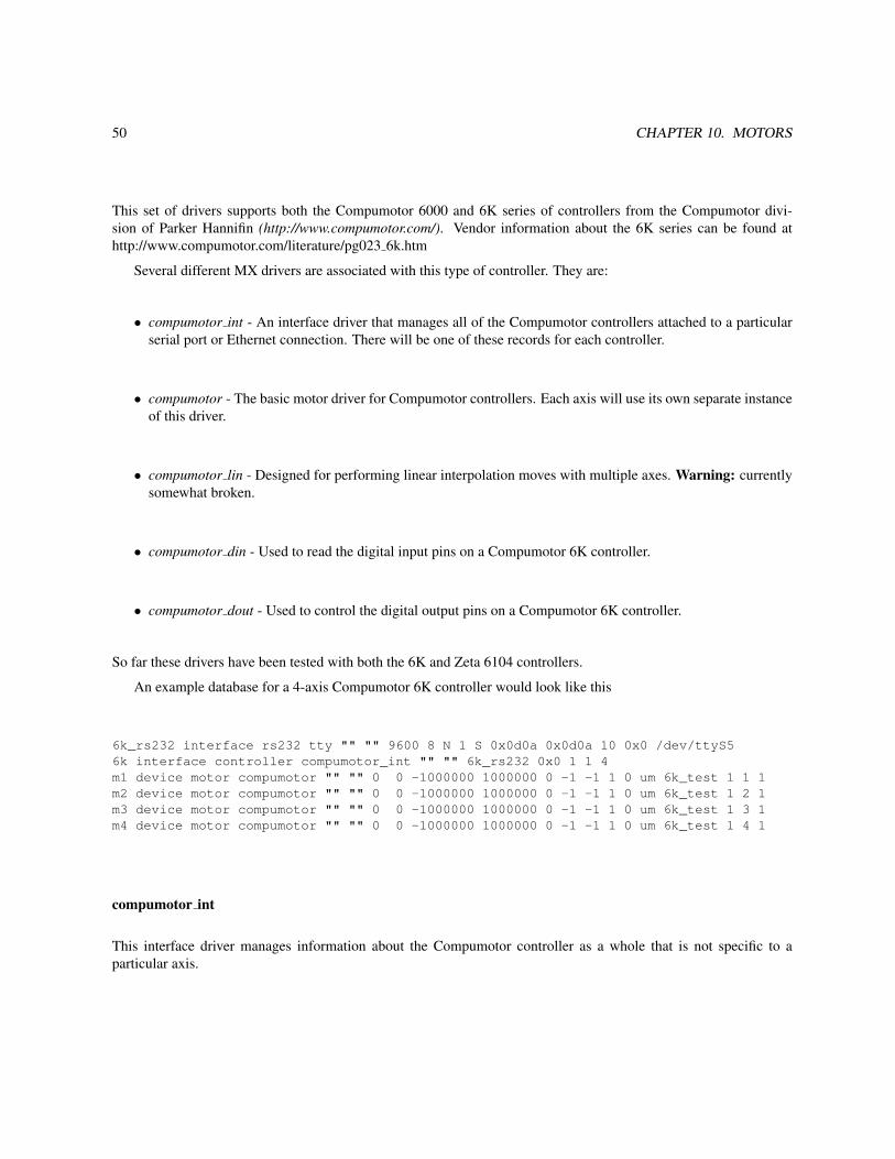
50 CHAPTER 10. MOTORS
This set of drivers supports both the Compumotor 6000 and 6K series of controllers from the Compumotor divi-sion of Parker Hannifin (http://www.compumotor.com/). Vendor information about the 6K series can be found athttp://www.compumotor.com/literature/pg023 6k.htm
Several different MX drivers are associated with this type of controller. They are:
• compumotor int - An interface driver that manages all of the Compumotor controllers attached to a particularserial port or Ethernet connection. There will be one of these records for each controller.
• compumotor - The basic motor driver for Compumotor controllers. Each axis will use its own separate instanceof this driver.
• compumotor lin - Designed for performing linear interpolation moves with multiple axes. Warning: currentlysomewhat broken.
• compumotor din - Used to read the digital input pins on a Compumotor 6K controller.
• compumotor dout - Used to control the digital output pins on a Compumotor 6K controller.
So far these drivers have been tested with both the 6K and Zeta 6104 controllers.
An example database for a 4-axis Compumotor 6K controller would look like this
6k_rs232 interface rs232 tty "" "" 9600 8 N 1 S 0x0d0a 0x0d0a 10 0x0 /dev/ttyS56k interface controller compumotor_int "" "" 6k_rs232 0x0 1 1 4m1 device motor compumotor "" "" 0 0 -1000000 1000000 0 -1 -1 1 0 um 6k_test 1 1 1m2 device motor compumotor "" "" 0 0 -1000000 1000000 0 -1 -1 1 0 um 6k_test 1 2 1m3 device motor compumotor "" "" 0 0 -1000000 1000000 0 -1 -1 1 0 um 6k_test 1 3 1m4 device motor compumotor "" "" 0 0 -1000000 1000000 0 -1 -1 1 0 um 6k_test 1 4 1
compumotor int
This interface driver manages information about the Compumotor controller as a whole that is not specific to aparticular axis.

10.2. MOTOR CONTROLLERS 51
Field Name FieldType
Number ofDimensions
Sizes Description
See Common Record Field Definitions
rs232 record record 0 0
The name of the rs232 record interface thatthe controller is plugged into. In general, thers232 record can either correspond to a realRS-232 device such as the tty or win32 comdriver or to a device connected via Ethernet,which will use the tcp232 driver.
interface flags hex 0 0 Flags to select optional features. They aredescribed in more detail below.
num controllers long 0 0
For a multidrop system such as the Zeta 6104,this record will control all of the realcontrollers attached to the multidrop cable.You must specify the number of controllershere. For a 6K controller, this value willalways be 1.
controller number long 1 num controllers
This varying length array lists the controlleraddress for each controller as set by theCompumotor ADDR command. For a 6Kcontroller, there will only be one value here.
num axes long 1 num controllers
This varying length array lists the maximumnumber of motor axes for each controller onthe multidrop cable. For a 6K controller, therewill only be one value here. The allowed rangeof values for this field are from 1 to 8.
The interface flags field will be the logical OR of the option bits selected from the following list:
0x1 - If this flag is selected, the MX driver will send a Compumotor ADDR command at startup,which will cause the controllers on a multidrop to automatically configure their addressesfrom 1 to N. In general, we recommend not use this option. Instead, you should configurethe address in the startup program of each controller.
0x2 - If this flag is selected, the MX driver expects the Compumotor controller to echo all com-mands sent to it. This option is not normally recommended since it adds extra RS-232 I/Ofor reading and discarding the echoed command strings. It is just here in case you are al-ternating operation of the controller between MX and some other package that expects thecommands to be echoed.
compumotor
The compumotor driver handles one particular axis in a Compumotor controller. Since Compumotor interface recordssupport multiple controllers and axes, both the controller number and the axis number must be specified.
Go to the MX Motor Driver Support page for the common motor record description fields. For the compumotordriver, the following driver specific fields are present:

52 CHAPTER 10. MOTORS
Field Name FieldType
Number ofDimensions
Sizes Description
See Common Motor Field Definitions
compumotor interface record record 0 0 The name of the Compumotor controllerrecord for this motor.
controller number long 0 0 The controller number for this particularmotor.
axis number long 0 0 The axis number for this particular motor inthe specified controller.
flags hex 0 0Setting particular bits in the flags variable canmodify the behavior of the driver. Theindividual bit values are specified below.
Flag bits for the flags field:0x1 - This flag tells the driver to get the motor position using the TPE (Transfer Position of Encoder)
command rather than the TPM (Transfer Position of Motor) command.0x2 - This flag tells the driver to round raw motor positions to the nearest integer when setting motor
destinations using the D command or redefining the position using the PSET command.0x1000 - This flag tells the driver to disable hardware limits for this axis using the LH0 command.
compumotor din
Field Name FieldType
Number ofDimensions
Sizes Description
See Common Digital Input Field Definitions
compumotor interface record record 0 0 The name of the Compumotor controllerrecord for this motor.
controller number long 0 0 The controller number for this particulardevice.
brick number long 0 0 The brick number for this particular device.
first bit long 0 0 The bit number of the first bit controlled bythis record.
num bits long 0 0 The number of bits controlled by this record.
compumotor dout
Field Name FieldType
Number ofDimensions
Sizes Description
See Common Digital Output Field Definitions
compumotor interface record record 0 0 The name of the Compumotor controllerrecord for this motor.
controller number long 0 0 The controller number for this particulardevice.
brick number long 0 0 The brick number for this particular device.
first bit long 0 0 The bit number of the first bit controlled bythis record.
num bits long 0 0 The number of bits controlled by this record.

10.2. MOTOR CONTROLLERS 53
compumotor lin
Warning: The compumotor lin driver is partially obsolete and partially broken. If you merely want to have the motorperform a simultaneous start, then you should use the linear function pseudomotor instead. If you want blendedmoves, then you will need to fix the part of the driver that is supposed to do that.
Field Name FieldType
Number ofDimensions
Sizes Description
See Common Motor Field Definitions
flags hex 0 0Setting particular bits in the flags variable canmodify the behavior of this pseudomotor. Theindividual bit values are specified below.
num motors long 0 0 The number of motors used by thispseudomotor.
motor record array record 1 num motors This array lists all of the motor records used bythis pseudomotor.
real motor scale double 1 num motorsThe real motor position is multiplied by thisscale when computing the raw pseudomotorposition.
real motor offset double 1 num motorsThis offset is added to the scaled real motorposition when computing the raw pseudomotorposition.
motor move fraction double 1 num motors
When a move is commanded, this valuespecifies what fraction of the total rawpseudomotor move is to be performed by thismotor.
The interface flags field will be the logical OR of the option bits selected from the following list:
0x1 - If this flag is selected, the pseudomotor will perform a simultaneous start rather than ablended move. Warning: If you do not set this bit, the driver attempts to perform a blendedmove. However, the driver currently does not correctly implement the blended move.
General Notes
• The MX drivers assume that daisy-chained controllers are numbered from 1 to N where N is the number ofcontrollers. This may be done via the ADDR command as described in the 6000 and 6K Command Referencemanuals. For more information look at the sections named RS-232C Daisy-Chaining and RS-485 Multi-Dropin the Compumotor 6000 or 6K Programmer’s Guide.
• If you use the ethernet port on a 6K controller, you will need to use the ’tcp232’ RS-232 interface type andspecify the port number to connect to as 5002.
Warning: Very old 6K controllers used port 502. If there is a problem, using a packet sniffer while the vendorsupplied code for Windows is running should be able to determine the correct port number.
• The MX Compumotor drivers make certain assumptions about the internal configuration of Compumotor con-trollers. Figure 10.1 shows an example startup script for Compmotor controllers that is compatible with MX.The MX drivers will not operate correctly if the variables ERRLVL, EOT, and MA are not set as shown. Also

54 CHAPTER 10. MOTORS
; This command script is to be downloaded into a Compumotor 6000 or 6K; controller in order to set up the controller to be compatible with MX.; The script sets up a startup command program to be executed by the; Compumotor controller at power-on. The commands for ERRLVL, EOT, and MA; _must_ be set as shown below or else the MX driver will not work.; If you need other commands to set motor parameters, network addresses,; and so forth, add them to the commands listed below.;; Please note that if you use ECHO1, you must add the 0x2 echo on flag to; the compumotor_int record that defines the connection to the interface.; This lets the driver know that it needs to discard echoed characters.;; For a single controller, it is better to set ECHO0 since that will; eliminate the overhead of discarding the characters. However, in a; multidrop daisy chain configuration, ECHO1 _must_ _be_ _set_ since the; controllers rely on the echoing to send the command on to the next; controller in the daisy chain. If ECHO0 is set in a daisy chain; configuration, the configuration will mostly work but will randomly; lock up from time to time, so don’t do it.;; William Lavender -- Last modified April 27, 2002;DEF mstartERRLVL1 ; Have the controller generate a minimum amount of output.EOT13,10,0 ; Want all output lines to have the same line terminators.MA1 ; Use absolute mode for positioning.LH0 ; Disable limits (for testing only!)ENC0 ; Use motor step mode ( or set ENC1 for encoder step mode ).ECHO1 ; Enable command echoing.END
Figure 10.1: Recommended STARTP program for MX controlled Compumotor motors.

10.2. MOTOR CONTROLLERS 55
note that the setting shown for EOT means that the ’rs232’ driver must be configured with the read and writeterminators set to 0x0d0a. In addition, the setting ECHO1 is required in order for multi-drop installations tofunction correctly. For a single controller, you may use ECHO0 which will reduce the amount of serial I/Orequired.
Bugs
At present, Zeta 6104s occasionally stop communicating with the MX driver. The exact circumstances under whichthis occurs is not entirely clear. However, since most of our Compumotor usage is migrating towards the 6K series,the need to fix this issue may become less important.
10.2.9 DAC Motor
Platforms: All
This driver is used to control an MX analog output device as if it were a motor. The type of control supported hereis fairly basic. When a move is commanded, all that happens is that the DAC output voltage is changed to the valuecorresponding to the new position.
There is only one driver specific specific field for the dac motor driver. Here is the description of it:
Field Name FieldType
Number ofDimensions
Sizes Description
See Common Motor Field Definitions
dac record record 0 0 The name of the MX analog output record used by this motorrecord.
10.2.10 Delta Tau PMAC
Platform: All
The PMAC series of motor controllers is manufactured by Delta Tau Data Systems of Chatsworth, CA. PMACmotor controllers are definitely the most powerful motor controllers supported by MX. However, they are also themost complicated to setup and program of all the controllers supported by MX, so they may not be the best choicefor simple applications.
The MX PMAC drivers are designed to be easily adaptable to any model of PMAC motor controller. However,the drivers have been tested mainly with the Turbo PMAC series of controllers. There is also limited support for thePower PMAC series and lightly tested support for the original legacy PMAC 1 series.
Note: If you are using a Power PMAC controller, you will be better off using the MX powerpmac series ofdrivers described in the next section of this manual. The powerpmac drivers support a much larger amount of the totalfunctionality of a Power PMAC.
The drivers listed below currently all operate via PMAC ASCII communication interfaces of various types.MX has a large number of drivers for interacting with PMAC motor controllers:

56 CHAPTER 10. MOTORS
pmac Interface driver for controlling one or more PMAC motor controllersconnected to an ASCII serial interface.
pmac motor Motor driver for controlling a single motor of a PMAC controller.pmac cs axis Motor driver for controlling a coordinate system axis belonging to a
PMAC motor controller.pmac mce Multichannel encoder (MCE) driver for reading out any motor be-
longing to a given PMAC motor controller.pmac ainput Analog input driver for reading a floating point value from a PMAC
variable.pmac aoutput Analog output driver for writing a floating point value to a PMAC
variable.pmac dinput Digital input driver for reading an integer value from a PMAC vari-
able.pmac doutput Digital output driver for writing an integer value to a PMAC vari-
able.pmac long Variable driver for reading and writing signed integer values to and
from a PMAC variable.pmac ulong Variable driver for reading and writing unsigned integer values to
and from a PMAC variable.pmac double Variable driver for reading and writing floating point values to and
from a PMAC variable.
MX PMAC drivers
pmac driverPmac interface records are used to control one or more PMAC motor controllers attached to a given external
interface. An example pmac record looks like
pmac1 interface controller pmac "" "" rs232 pmac1_rs232 1
which describes a single PMAC motor controller attached to MX RS-232 record pmac1 rs232.The driver-specific record fields are
Field Name FieldType
Number ofDimensions
Sizes Description
See Common Record Field Definitions
port type name string 1 32 A string such as rs232 that describes the type of PMACinterface this is. See below for more information.
port args string 1 80 This contains port type specific information such as the nameof an RS-232 port record. See below for more information.
num cards long 0 0
The number of individual PMAC controllers attached to thisinterface. In most cases this will be 1. However, for acontroller attached to a multidrop connection such as RS-485,this will be the number of controllers attached to themultidrop.
PMAC ASCII command interfaces are accessible via a variety of different mechanisms such as RS-422, Ethernet,USB, VME, etc. Since the information needed to describe the interface can vary widely from interface type to

10.2. MOTOR CONTROLLERS 57
interface type, the information needed to the interface is specified in a string called port args. The currently definedport types are:
port type name port argsrs232 The name of the MX RS-232/422/485 record that this PMAC interface is attached to,
such as pmac1 rs232 in the example below.tcp The network hostname of the PMAC.
The network protocol for this port type is described in the “PMAC ETHERNET PRO-TOCOL” section of the manual for the Delta Tau Acc-54E UMAC board. The TCP portnumber is not specified since the protocol requires it to always be 1025.Note: Only TCP connections are supported. Currently USB and UDP connections arenot supported.
gpascii This case is for a Power PMAC that is being controlled over a Telnet connection usingDelta Tau’s gpascii command.The port args string for this case looks like "pmac1 socket root deltatau".The first field in this string is the name of the MX RS-232 record used to communicatewith the Power PMAC. This record must be of type telnet, since the Power PMAC willperform Telnet negotiation with the MX client. Records of type tcp232 will not worksince the tcp232 driver does not know how to handle Telnet negotiation.The second field is the name of the account used to login to the Power PMAC. Thedefault is root. The gpascii interface has not been tested with non-root accounts.The third field is the password of the account used to login to the Power PMAC. Thedefault is deltatau.
gplib This is for the special case of an MX server that is running on the Power PMAC it-self with the MX library linked to the Delta Tau provided libraries. For this case, theport args string is empty.Warning: It is strongly recommended that you use the MX powerpmac series ofdrivers rather than the MX pmac drivers, since the powerpmac drivers exports a muchlarger fraction of the total functionality of a Power PMAC.
epics ect This port type uses the string command and response interfaces provided with theEPICS PMAC software written by Tom Coleman of the Argonne National LaboratoryECT group. This port type uses EPICS process variable names that are constructed byappending “StrCmd” or “StrRsp” to the names. Thus, if the port args were “S18ID”,then the EPICS process variables used by this interface would be S18IDStrCmd.VALand S18IDStrRsp.VAL.Note: There is an alternate set of MX EPICS drivers called pmac tc motor andpmac bio motor that is described elsewhere in this manual.
Here are some examples of MX database records for each port type:
Port type rs232:
Via a Linux tty port:
pmac1_rs232 interface rs232 tty "" "" 38400 8 N 1 H 0xd 0xd -1 0x0 /dev/ttyS5pmac1 interface controller pmac "" "" rs232 pmac1_rs232 1
Via a network socket:

58 CHAPTER 10. MOTORS
pmac1_rs232 interface rs232 tcp232 "" "" 38400 8 N 1 H 0xd 0xd -1 0x0 w11 3001 0x0pmac1 interface controller pmac "" "" rs232 pmac1_rs232 1
Port type tcp:
pmac1 interface controller pmac "" "" tcp 192.168.0.1 1
Port type gpascii:
pmac1_socket interface rs232 telnet "" "" 38400 8 N 1 H 0x0d0a 0x0d0a -1 0x0 powerpmac 23 0x0pmac1 interface controller pmac "" "" gpascii "pmac1_socket root deltatau" 1
Port type gplib:
pmac1 interface controller pmac "" "" gplib "" 1
pmac motor driverA pmac motor record refers to one particular motor in a PMAC motor controller. The motor is controlled mostly
via PMAC “jog” mode commands except for certain features not available via jog commands.An example pmac motor record looks like
x1 device motor pmac_motor "" "" 0 0 -10000000 10000000 0 -1 -1 0.05 0 um pmac1 0 4
which describes a motor called x1 which belongs to controller 0, axis 4 of PMAC interface pmac1. The examplemotor uses a scale factor of 0.05 µ-meters per step and raw motion limits of ± 10000000 steps.
Field Name FieldType
Number ofDimensions
Sizes Description
See Common Motor Field Definitionspmac record record 0 0 Name of the PMAC interface record that controls this motor.
card number long 0 0Card number of the PMAC card that controls this motor. ForPMACs that are not in a multi-drop configuration, the cardnumber will normally be 0.
motor number long 0 0 The PMAC motor number for this specific motor.
pmac cs axis driverNote: This driver does not support Power PMAC controllers at all. For Power PMAC controllers, use the
powerpmac cs axis driver instead.A pmac cs axis record makes use of a specified coordinate system axis for a coordinate system defined in a
PMAC controller. PMAC coordinate systems can be thought of as a way of defining “pseudomotors” inside a PMACcontroller in a manner that is analogous to the way MX defines pseudomotors. However, PMAC coordinate systemaxes are more powerful than MX pseudomotors, since for a coordinate system, the PMAC controller is able to ensurethat all of the raw motors are able to maintain their correct relative relationship even while the motors are moving.Ordinary MX pseudomotors make sure that the real motors are at the correct positions at the beginning and end ofmotor moves, but they cannot do this while a move is in progress.
Pmac cs axis motor records require that some preliminary setup be done in the PMAC before they may be used.There are three primary steps in this process:
• The coordinate system that this axis is to be part of must be set up before this record may be used.

10.2. MOTOR CONTROLLERS 59
• You must write a motion program that will be run every time a move of this axis is commanded. The motionprogram must define the move destination, the feedrate (reciprocal of the speed), the acceleration time, and theS curve acceleration times in terms of PMAC motion variables so that the pmac cs axis driver can set them.I recommend that you use Q-variables so that variables used by this coordinate system will not interfer withother coordinate systems used by your PMAC.
• You must arrange for the current position of the coordinate system axis to be continuously updated to a PMACvariable that you specify. The most obvious way to do this is with a constantly running PMAC PLC programwhich is set up to calculate the coordinate system axis position from the real motor positions at all times. Iwould recommend that you use a Q-variable for this too. Of course, the kinematic calculation logic of the PLCprogram must match the logic of the PMAC motion program mentioned above.
An example pmac cs axis record looks like
det_distance motor pmac_cs_axis "" "" 0 0 200 1000 0 -1 -1 1 0 mm pmac1 0 2 Z 3 Q50 Q51 Q52 Q53 Q54
This describes a motor called det distance which corresponds to axis Z of coordinate system 2 running in card 0of PMAC interface pmac1. The axis performs moves using motion program 3 with position, destination, feedrate,acceleration time, and S-curve acceleration time managed by PMAC coordinate system variables Q50 through Q54.
Field Name FieldType
Number ofDimensions
Sizes Description
See Common Motor Field Definitions
pmac record record 0 0 Name of the interface record for the PMACthat runs this coordinate system.
card number long 0 0
Card number of the PMAC card that controlsthis axis. For PMACs that are not in amulti-drop configuration, the card numberwill normally be 0.
coordinate system long 0 0 The PMAC coordinate system number.
axis name char 0 0The name of the coordinate system axis usedby this motor. The possible names are X, Y,Z, A, B, and C.
move program number long 0 0The number of the motion program that isused to move this axis as part of thecoordinate system.
position variable string 1 8Name of the PMAC variable that the MXdriver uses to read the current position of theaxis from.
destination variable string 1 8The MX driver writes the new axis destinationto this PMAC variable before starting themotion program to perform the move.
feedrate variable string 1 8 The MX driver sets the axis speed by writingto the specified PMAC feedrate variable.
acceleration time variable string 1 8 The MX driver sets the axis acceleration timeby writing to this variable.
s curve acceleration time var string 1 8 The MX driver sets the axis acceleration timeby writing to this variable.

60 CHAPTER 10. MOTORS
Note: If all you want is basic control of the individual motors belonging to a PMAC controller, then it is notnecessary to create MX pmac cs axis motor records or coordinate systems in the PMAC. You can get basic controlof the motors with just the pmac motor records, with much less setup required. You only need pmac cs axis recordsif you want to make use of the special abilities of PMAC coordinate systems.
pmac mce driverA pmac mce record is used to save the positions of the moving PMAC motor during an MX quick scan, so that theycan be read out at the end of the scan. MCE stands for multichannel encoder; a term that is thought to have beenoriginated by the author. This feature is implemented by permanently assigning one of the motors in the PMAC to bea slave motor, not connected to a real motor axis. Instead, it is slaved at run time to the primary real motor axis of themove. The slave motor is programmed to always generate step and direction output, which is converted by a smallamount of electronic login into clockwise (CW) and counterclockwise (CCW) pulse trains which can be fed into twochannels of a multichannel scaler.
*** A figure here might help. ***
For more information, read the section on Multichannel encoders further on in this document and also read thechapter about MX scans.
Field Name FieldType
Number ofDimensions
Sizes Description
See Common MCE Field Definitions
pmac record record 0 0 This field specifies the name of the PMAC controllerthat contains the slave axis for this particular PMAC.
card number long 0 0 Card number of the PMAC controller that contains theslave axis for this particular PMAC.
mcs record record 0 0Name of the multichannel scaler (MCS) record that theclockwise (CW) and counterclockwise (CCW) pulsetrains are sent to.
down channel ulong 0 0 Number of the MCS channel that receives thecounterclockwise pulses.
up channel ulong 0 0 Number of the MCS channel that receives theclockwise pulses.
plc program number long 0 0
Number of the PMAC PLC program that is run whenthe assignment of the slave axis to a master is changed.If you specify a negative number for this field, thedriver uses the absolute value of it as the slave motoraxis number and does not use a PLC program.
PMAC Analog and Digital I/O Drivers
pmac ainput driver
This is an MX analog input driver that reads a floating point value from a PMAC variable.

10.2. MOTOR CONTROLLERS 61
Field Name FieldType
Number ofDimensions
Sizes Description
See Common Analog Input Field Definitions
pmac record record 0 0 The name of the PMAC that contains this PMACvariable.
card number long 0 0 The card number of the PMAC that contains thisPMAC variable.
pmac variable name string 1 8 The name of the PMAC variable.
pmac aoutput driverThis is an MX analog output driver that writes a floating point value to a PMAC variable.
Field Name FieldType
Number ofDimensions
Sizes Description
See Common Analog Output Field Definitions
pmac record record 0 0 The name of the PMAC that contains this PMACvariable.
card number long 0 0 The card number of the PMAC that contains thisPMAC variable.
pmac variable name string 1 8 The name of the PMAC variable.
pmac dinput driverThis is an MX digital input driver that reads an integer value from a PMAC variable.
Field Name FieldType
Number ofDimensions
Sizes Description
See Common Digital Input Field Definitions
pmac record record 0 0 The name of the PMAC that contains this PMACvariable.
card number long 0 0 The card number of the PMAC that contains thisPMAC variable.
pmac variable name string 1 8 The name of the PMAC variable.
pmac doutput driverThis is an MX analog output driver that writes an integer value to a PMAC variable.
Field Name FieldType
Number ofDimensions
Sizes Description
See Common Digital Output Field Definitions
pmac record record 0 0 The name of the PMAC that contains this PMACvariable.
card number long 0 0 The card number of the PMAC that contains thisPMAC variable.
pmac variable name string 1 8 The name of the PMAC variable.
PMAC Variable Drivers
pmac long driverThis is an MX variable driver for reading and writing signed integer values to and from a PMAC variable.

62 CHAPTER 10. MOTORS
Field Name FieldType
Number ofDimensions
Sizes Description
See Common PMAC Variable Field Definitions
pmac record record 0 0 The name of the PMAC that contains this PMACvariable.
card number long 0 0 The card number of the PMAC that contains thisPMAC variable.
pmac variable name string 1 8 The name of the PMAC variable.
pmac ulong driverThis is an MX variable driver for reading and writing unsigned integer values to and from a PMAC variable.
Field Name FieldType
Number ofDimensions
Sizes Description
See Common PMAC Variable Field Definitions
pmac record record 0 0 The name of the PMAC that contains this PMACvariable.
card number long 0 0 The card number of the PMAC that contains thisPMAC variable.
pmac variable name string 1 8 The name of the PMAC variable.
pmac double driverThis is an MX variable driver for reading and writing unsigned integer values to and from a PMAC variable.
Field Name FieldType
Number ofDimensions
Sizes Description
See Common PMAC Variable Field Definitions
pmac record record 0 0 The name of the PMAC that contains this PMACvariable.
card number long 0 0 The card number of the PMAC that contains thisPMAC variable.
pmac variable name string 1 8 The name of the PMAC variable.
10.2.11 Delta Tau Power PMAC
Platform: Power PMAC controllers running PowerPC Linux
The Power PMAC series of motor controllers from Delta Tau Data Systems of Chatsworth, California is theirnewest series of motor controllers. The special feature of this series of controllers is that they are implemented usinga PowerPC based system using Linux together with Xenomai extensions for real-time control. Fortunately, they areusing a fairly standard version of the Debian 5.0 (Lenny) distribution for powerpc. Although they provide a Cygwin-based cross compiler system for Windows, the Debian Linux installation on the Power PMAC itself comes completewith development tools like GCC, GDB, and Make. Thus, it is possible to do Power PMAC software developmentdirectly on the Power PMAC itself.
The MX powerpmac series of drivers is designed to run under Linux on the Power PMAC’s CPU. Insteadof using gpascii, the MX drivers use the Delta Tau-provided gplib.h include file and directly link to Delta Tau’s/opt/ppmac/libppmac.so library. This provides direct access to features like the Power PMAC shared memory inter-face.

10.2. MOTOR CONTROLLERS 63
So far all of the software development has been done directly on the Power PMAC itself. However, we do all ofour work on an SD card installed in the Power PMAC’s SD slot to avoid unnecessary changes to the Power PMACroot partition and to avoid unnecessary wear on the Power PMAC’s flash memory.
At present, the following MX drivers are available:
powerpmac Interface driver for controlling the Power PMAC controller.powerpmac motor Motor driver for controlling a single motor of a Power PMAC controller.
Analog and digital I/O drivers, coordinate system drivers, multichannel encoder drivers, multichannel scaler drivers,and variable drivers are planned but not yet implemented.
MX Power PMAC drivers
powerpmac driverPowerpmac interface records are used to control one or more PMAC motor controllers attached to a given external
interface. An example powerpmac record looks like
ppmac1 interface controller powerpmac "" ""
Note that the powerpmac does not have any driver specific fields. This is because the driver is able to autoconfigureitself by directly querying the Power PMAC libraries.
powerpmac motor driverA pmac motor record refers to one particular motor in a PMAC motor controller. The motor is controlled mostly
via PMAC “jog” mode commands except for certain features not available via jog commands.An example pmac motor record looks like
x1 device motor powerpmac_motor "" "" 0 0 -10000000 10000000 0 -1 -1 0.05 0 um ppmac1 4
which describes a motor called x1 which belongs to controller 0, axis 4 of PMAC interface pmac1. The examplemotor uses a scale factor of 0.05 µ-meters per step and raw motion limits of ± 10000000 steps.
Field Name FieldType
Number ofDimensions
Sizes Description
See Common Motor Field Definitions
powerpmac record record 0 0 Name of the Power PMAC interface record that controlsthis motor.
motor number long 0 0 The Power PMAC motor number for this specific motor.
Here is an example database for the Power PMAC:
ppmac1 interface controller powerpmac "" ""m1 device motor powerpmac_motor "" "" 0 0 -10000000 10000000 0 -1 -1 0.0001 0 um ppmac1 1m2 device motor powerpmac_motor "" "" 0 0 -10000000 10000000 0 -1 -1 0.0001 0 um ppmac1 2m3 device motor powerpmac_motor "" "" 0 0 -10000000 10000000 0 -1 -1 0.0001 0 um ppmac1 3m4 device motor powerpmac_motor "" "" 0 0 -10000000 10000000 0 -1 -1 0.0001 0 um ppmac1 4

64 CHAPTER 10. MOTORS
10.2.12 Disabled MotorPlatforms: All
This driver type was added to make it easier to quickly disable a particular motor in the MX database. The dis-abled motor driver has no extra fields beyond the default motor fields. This makes it easy to just change the mx typefield in the record description to disabled motor and have the record description still be a valid record description,albeit with ignored, trailing text.
The disabled motor driver makes no attempt to accurately simulate the behavior of a real motor. If you want amore accurate simulation, select the soft motor driver described further on in this chapter.
10.2.13 DSP E500Platforms: All
The DSP E500 was a CAMAC-based stepper motor controller from DSP Technology, Inc. that is no longer available.In the 1980’s, this controller was one of the most popular motor controllers in use in the synchrotron radiation field,and there are still many in use at installations around the world.
e500 driver
Field Name FieldType
Number ofDimensions
Sizes Description
See Common Motor Field Definitions
camac record record 0 0 The MX record for the CAMAC crate that the E500controller is installed in.
slot long 0 0 The CAMAC slot number that the E500 controller isinstalled in.
subaddress long 0 0 The CAMAC subaddress for the motor channel used bythis motor.
e500 base speed ushort 0 0 The initial base speed for this motor.e500 slew speed ulong 0 0 The initial slew speed for this motor.acceleration time ushort 0 0 The initial acceleration time for this motor.correction limit ushort 0 0 The initial correction limit for this motor.
lam mask long 0 0 The initial LAM mask for this motor.Notes:
• The E500 does not have any non-volatile memory, so all of its parameters must be programmed from scratcheach time the MX driver starts.
• This driver dates from the mid-1990s and should not be regarded as a good example of how to write an MXmotor driver.
10.2.14 EPICS MotorPlatforms: Requires EPICS 3.14 support.
The MX epics motor driver uses EPICS Channel Access to communicate as an EPICS client with the AdvancedPhoton Source’s EPICS motor driver (http://www.aps.anl.gov/upd/people/sluiter/epics/motor/) in an EPICS IOC.

10.2. MOTOR CONTROLLERS 65
There is only one driver specific specific field for the epics motor driver. Here it is:
Field Name FieldType
Number ofDimensions
Sizes Description
See Common Motor Field Definitions
epics record name string 1 100 The name of the EPICS motor record used by this MXrecord.
10.2.15 IMS MDrive
Platforms: All
The IMS MDrive is an integrated motor/controller combination with microstepping that is housed as one unit. TheMDrive is produced by Intelligent Motion Systems (http://www.imshome.com/).
mdrive record
Field Name FieldType
Number ofDimensions
Sizes Description
See Common Motor Field Definitions
rs232 record record 0 0 The name of the RS-232 record that this MDrive is connectedto.
axis name char 0 0 The MDrive axis name
The MDrive also has a few analog input and digital I/O ports as part of the module.
mdrive ain recordThere is only one analog input port.
Field Name FieldType
Number ofDimensions
Sizes Description
See Common Analog Input Field Definitions
mdrive record record 0 0 The record name of the MDrive that this I/O port is connectedto.
mdrive din record
Field Name FieldType
Number ofDimensions
Sizes Description
See Common Digital Input Field Definitions
mdrive record record 0 0 The record name of the MDrive that this I/O port is connectedto.
port number long 0 0
mdrive dout record

66 CHAPTER 10. MOTORS
Field Name FieldType
Number ofDimensions
Sizes Description
See Common Digital Output Field Definitions
mdrive record record 0 0 The record name of the MDrive that this I/O port is connectedto.
port number long 0 0
10.2.16 IMS Panther and IM483
Platforms: All
This driver is for the Panther HI/HE microstepping driver/controllers as well as the IM483I and IM483IE controllers aswell. These controllers are manufactured by Intelligent Motion Systems (http://www.imshome.com/). The controllersall support multi-drop serial connections which are called “Party Line” mode by the manual. This driver probablyalso works for the Panther LI, Panther LE, IM1007I, and IM1007IE controllers, but this has not been tested.
Warning: The IM483I and IM483IE are both motor controllers. However, the similar sounding IM483 is not amotor controller. Instead the IM483 is only a microstepping driver. Don’t get them confused.
These controllers do not have any non-volatile storage, so all of their parameters must be reprogrammed fromscratch each time that the MX driver starts. The axis name parameter can be any ASCII upper case or lower caseletter as well as a subset of ASCII punctuation marks. Read the manual for more information.
panther hi driverThe Panther HI does not have any support for encoders.
Field Name FieldType
Number ofDimensions
Sizes Description
See Common Motor Field Definitionsrs232 record record 0 0 The RS-232 record name for this motor.
axis name char 0 0 The axis name for this motor.default speed long 0 0 This value is used at startup by the V command.
default base speed long 0 0 This value is used at startup by the I command.
acceleration slope long 0 0 This value, together with the deceleration slope isused at startup by the K command.
deceleration slope long 0 0 This value, together with the acceleration slope isused at startup by the K command.
microstep divide factor long 0 0 This value is used at startup by the D command.step resolution mode char 0 0 This value is used at startup by the H command.
hold current long 0 0 This value, together with the run current is used atstartup by the Y command.
run current long 0 0 This value, together with the hold current is used atstartup by the Y command.
settling time delay long 0 0 This value is used at startup by the E command.
limit polarity long 0 0 This value is used at startup by the l command.Please note that the character is a lower-case L.
panther he driver

10.2. MOTOR CONTROLLERS 67
The Panther HE does have support for encoders.
Field Name FieldType
Number ofDimensions
Sizes Description
See Common Motor Field Definitionsrs232 record record 0 0 The RS-232 record name for this motor.
axis name char 0 0 The axis name for this motor.default speed long 0 0 This value is used at startup by the V command.
default base speed long 0 0 This value is used at startup by the I command.
acceleration slope long 0 0 This value, together with the deceleration slope isused at startup by the K command.
deceleration slope long 0 0 This value, together with the acceleration slope isused at startup by the K command.
microstep divide factor long 0 0 This value is used at startup by the D command.step resolution mode char 0 0 This value is used at startup by the H command.
hold current long 0 0 This value, together with the run current is used atstartup by the Y command.
run current long 0 0 This value, together with the hold current is used atstartup by the Y command.
settling time delay long 0 0 This value is used at startup by the E command.
limit polarity long 0 0 This value is used at startup by the l command.Please note that the character is a lower-case L.
encoder resolution long 0 0 This value is used at startup by the e command.deadband size long 0 0 This value is used at startup by the d command.hunt velocity long 0 0 This value is used at startup by the v command.
hunt resolution long 0 0 This value is used at startup by the h command.stall factor long 0 0 This value is used at startup by the s command.
stall sample rate long 0 0 This value is used at startup by the t command.max stall retries long 0 0 This value is used at startup by the r command.
10.2.17 Joerger SMC24
Platforms: All
This is an MX motor driver for the Joerger SMC24 CAMAC stepping motor controller from Joerger Enterprises, Inc.As of June 2011, this controller is still available as a “legacy” product.

68 CHAPTER 10. MOTORS
Field Name FieldType
Number ofDimensions
Sizes Description
See Common Motor Field Definitionscrate record record 0 0 The MX record name for the CAMAC crate.
slot long 0 0 The CAMAC slot number ‘N’.
encoder record record 0 0 The MX record name for the encoder used tostore motor positions.
motor steps per encoder tick double 0 0It means what it says. The motor steps toencoder ticks ratio may be a non-integernumber.
flags hex 0 0 These flags can change the behavior of thedriver and are described below.
The allowed values for the flags field are:0x1 - The driver assumes that the encoder uses a 32-bit counter.0x2 - Clockwise and counterclockwise encoder pulses will be used.
Warning: As far as I know, this driver has not been tested in a long time. However, if broken, I expect that it wouldtake less than a day to get the MX driver working again.
The Joerger SMC24 controller does not have an internal register to record its current position, so it needs theassistance of an external device to keep track of the motor’s absolute position. Traditionally, a Kinetic Systems 3640CAMAC up/down counter is used as the external device, but any device capable of acting as an encoder-like devicemay be used as long as there is an MX encoder driver for it.
Also, traditionally the Kinetic Systems 3640 up/down counter was modified in the field to connect pairs of 16-bitup/down counters to form 32-bit up/down counters. However, if this has not been done, the driver can also emulatein software a 32-bit step counter using a 16-bit hardware encoder by setting the bit in the ”flags” variable calledMXF SMC24 USE 32BIT SOFTWARE COUNTER (0x1) .
10.2.18 Kohzu SC-200, SC-400, and SC-800
Platforms: All
This driver is for the SC series of stepping motor controllers from Kohzu (http://www.kohzu.com/). Both RS-232and GPIB support has been implemented in the MX drivers, but only the RS-232 support has actually been tested.
The MX drivers for this controller arekohzu sc Interface driver for controlling the Kohzu SC controller.kohzu sc motor Motor driver for controlling a single motor of the controller.
kohzu sc driver

10.2. MOTOR CONTROLLERS 69
Field Name FieldType
Number ofDimensions
Sizes Description
See Common Record Field Definitions
port interface interface 0 0
For RS-232 connections, this will be the name of the MXRS-232 record, such as kohzu com1.For GPIB connections, this will be the name of the MXGPIB record together with the GPIB address of the Kohzucontroller, such as kohzu gpib:4 for a controller at GPIBaddress 4.
kohzu sc motor driver
Field Name FieldType
Number ofDimensions
Sizes Description
See Common Motor Field Definitionskohzu sc record record 0 0 The name of the MX record for the Kohzu controller above.
axis number long 0 0 The number of the motor axis.
kohzu sc flags hex 0 0 Flag bits described below that affect the behavior of thedriver.
The valid flag bits for the kohzu sc flags field are:
0x1 - This tells the controller to report the position for this motor returned by an attached encoder ratherthan the commanded step position.
0x1000 - This tells the controller to ignore hardware limits for this motor.Here is an example MX database for the Kohzu SC series:
kohzu_com1 interface rs232 win32_com "" "" 38400 8 N 1 N 0x0d0a 0x0d0a -1 0x0 com1kohzu_sc interface controller kohzu_sc "" "" kohzu_com1k1 device motor kohzu_sc_motor "" "" 0 0 -10000000 10000000 0 -1 -1 1.0 0 steps kohzu_sc 1 0x0k2 device motor kohzu_sc_motor "" "" 0 0 -10000000 10000000 0 -1 -1 1.0 0 steps kohzu_sc 2 0x0
10.2.19 Lakeshore 330 Temperature Controller
Platforms: All
The ls330 motor driver is for the LakeShore 330 temperature controller from LakeShore Cryotronics, Inc.(http://www.lakeshore.com/). Since temperature controllers generally have PID loops, MX usually treats temperaturecontrollers as if they were motor controllers. This allows the temperature setpoint to be step scanned. Both RS-232and GPIB support has been implemented in the MX driver.
The fields for the ls330 motor driver are:

70 CHAPTER 10. MOTORS
Field Name FieldType
Number ofDimensions
Sizes Description
See Common Motor Field Definitions
port interface interface 0 0
For RS-232 connections, this will be the name of the MXRS-232 record, such as lakeshore tty1.For GPIB connections, this will be the name of the MXGPIB record together with the GPIB address of the Kohzucontroller, such as k500s:12 for a controller at GPIBaddress 12.
busy deadband double 0 0
The LakeShore controller does not provide a command toask for whether or not the setpoint has been reached.Instead, we must decide that for ourselves by computingthe difference between the current temperature and thetemperature setpoint. If the absolute value of thedifference is less than the busy deadband value set by thisfield, then the “motor” move is declared to be complete.
Here is an example MX database for the Lakeshore 330:
keithley_rs232 interface rs232 tty "" "" 9600 8 N 1 N 0xd 0xd -1 0x0 /dev/ttyak500s interface gpib k500serial "" "" 13 0 0xa 0xa 0x0 keithley_rs232lakeshore device motor ls330_motor "" "" 296.1 0 0 1000000 0 -1 -1 1 0 K k500s:12 0
The above example uses a Keithley 500-SERIAL module as an RS-232 to GPIB converter.
10.2.20 Mar Desktop BeamlinePlatforms: All
The MarDTB DeskTop Beamline is an advanced goniostat for computer-controlled data collection from Rayonix(formerly MarUSA). Their web site can be found at http://www.rayonix.com/.
The MarDTB system contains a variety of computer-controlled motors, ion chamber readouts, and a shutter.They are intended to be used only by Rayonix-supplied software, so the interfaces for talking to them are almostcompletely undocumented. However, by leveraging what limited documentation exists and by reverse engineeringsome information, I have been able to figure out how to talk to them anyway.
Before continuing, I want to say one thing:
DO NOT ASK RAYONIX ANY QUESTIONS ABOUT THESE MX DRIVERS.
If you have questions, contact the author (William Lavender) for help.Since these interfaces are undocumented, it is possible that changes to the Rayonix software can break these
MX drivers. In fact, there have been occasions in the past where Rayonix changes have broken these MX drivers.Furthermore, I have not had a chance to test the correctness of these drivers since 2007, so it is quite possible, indeedlikely, that the drivers do not work correctly with current versions of Rayonix firmware. In fact, it is possible thatusing these drivers can break your MarDTB system. If it does, then I doubt that Rayonix will regard this ascovered by their warranty. So, if you have any qualms or doubts, do not use these drivers.

10.2. MOTOR CONTROLLERS 71
Having said all of that, here are the drivers that are available.
mardtb An interface driver for the MarDTB controller as a whole.mardtb motor A motor driver for controlling individual MarDTB motors.mardtb status Used for reading out various bits of status information from the MarDTB.mardtb shutter Controls the MarDTB shutter.
mardtb driverThe mardtb driver communicates with the MarDTB control computer via a TCP socket using the tcp232 driver.
Although the port number is the Telnet port number (23), it appears that the MarDTB operating system does not sendany Telnet negotiation sequences, so using the tcp232 driver worked. If this no longer works, then using the telnetMX driver may help.
The driver specific fields are
Field Name FieldType
Number ofDimensions
Sizes Description
See Common Record Field Definitions
rs232 record record 0 0 This is the name of the tcp232 record used to communicatewith the MarDTB.
username string 1 8 This is the username used to login to the MarDTB. As far as Iknow, this must always be esd.
mardtb flags hex 0 0 The flag values are described below.
Flag values for the mardtb flags field.0x1000 - Three parameter status dump. Needed by very old MarDTB systems, as in, long before 2005.
Probably you will not need this.Other flag values exist, but are not documented since they do not work! Don’t try them.
mardtb motor driverThe mardtb motor driver moves one of the motors on the MarDTB system. It may not be safe to move some of
these motors, so be really careful with this one!The driver specific fields are
Field Name FieldType
Number ofDimensions
Sizes Description
See Common Motor Field Definitions
mardtb record record 0 0 This is the name of the controller record for theMarDTB.
motor number long 0 0 The MarDTB motor number for this motor.
default speed ulong 0 0 The default speed for this motor. Reasonable values forthis speed are not documented by Rayonix.
default acceleration ulong 0 0The default acceleration for this motor. Reasonablevalues for this acceleration are not documented byRayonix.
mardtb status driverThis driver reads one of the internal status values from the MarDTB.

72 CHAPTER 10. MOTORS
The driver specific fields are:
Field Name FieldType
Number ofDimensions
Sizes Description
See Common Analog Input Field Definitionsmardtb record record 0 0 This is the name of the controller record for the MarDTB.
parameter number long 0 0 The MarDTB parameter number for this status variable.The meaning of most of the status values is unknown. However, it is known that 136 and 137 return the values
from the two ion chambers of the MarDTB, while 138 returns the value from an internal MarDTB clock.
mardtb shutter driver
This driver controls the MarDTB shutter.
The driver specific fields are:
Field Name FieldType
Number ofDimensions
Sizes Description
See Common Relay Field Definitionsmardtb record record 0 0 This is the name of the controller record for the MarDTB.
Here is an example database for the MarDTB:
mardtb_rs232 interface rs232 tcp232 "" "" 38400 8 N 1 H 0x0d0a 0x0d0a -1 0x0 192.0.2.3 23 0x0mardtb interface controller mardtb "" "" mardtb_rs232 esd 0x0phi device motor mardtb_motor "" "" 0 0 -1000000 1000000 0 -1 -1 -0.00125 0 deg mardtb 6 10000 1000p136 device analog_input mardtb_status "" "" 0 1 0 units 0x0 0 "" mardtb 136p137 device analog_input mardtb_status "" "" 0 1 0 units 0x0 0 "" mardtb 137clock device analog_input mardtb_status "" "" 0 1 0 units 0x0 0 "" mardtb 138shutter device relay mardtb_shutter "" "" mardtb
10.2.21 Mclennan
Platforms: All
This set of drivers is for the Mclennan PM-600 from Mclennan Servo Supplies (http://www.mclennan.co.uk/). Itcontains code for several other models of Mclennan controller, but it has only actually been tested with the PM-600.
The MX drivers and their fields include
mclennan driver

10.2. MOTOR CONTROLLERS 73
Field Name FieldType
Number ofDimensions
Sizes Description
See Common Motor Field Definitions
rs232 record record 0 0 The name of the MX record for the RS-232 port thatthe controller is plugged into.
axis number long 0 0 The axis number for this encoder.
axis encoder number long 0 0If a PM368 encoder display is installed, specify theaxis encoder number for it here. If a PM368 is notinstalled, then specify -1 here.
mclennan ain driver
Field Name FieldType
Number ofDimensions
Sizes Description
See Common Analog Input Field Definitions
mclennan record record 0 0 The name of the MX motor record that this analog inputbelongs to.
port number long 0 0 The port number for this analog input.
mclennan aout driver
Field Name FieldType
Number ofDimensions
Sizes Description
See Common Analog Output Field Definitions
mclennan record record 0 0 The name of the MX motor record that this analog outputbelongs to.
port number long 0 0 The port number for this analog output.
mclennan din driver
Field Name FieldType
Number ofDimensions
Sizes Description
See Common Digital Input Field Definitions
mclennan record record 0 0 The name of the MX motor record that this digital inputbelongs to.
port number long 0 0 The port number for this digital input.
mclennan dout driver

74 CHAPTER 10. MOTORS
Field Name FieldType
Number ofDimensions
Sizes Description
See Common Digital Output Field Definitions
mclennan record record 0 0 The name of the MX motor record that this digital outputbelongs to.
port number long 0 0 The port number for this digital output.
Here is an example database for the mclennan driver:
mr interface rs232 tty "" "" 9600 7 E 1 N 0x0d0a 0x0d -1 0x0 /dev/ttyS0m1 device motor mclennan "" "" 0 0 -1000000000 1000000000 0 -1 -1 1 0 steps mr 1 -1din1 device digital_input mclennan_din "" "" 0 m1 1dout1 device digital_output mclennan_dout "" "" 0 m1 1ain1 device analog_input mclennan_ain "" "" 0 1 0 units 0x0 0 "" m1 1aout3 device analog_output mclennan_aout "" "" 0 1 0 units 0x0 m1 3
10.2.22 Mclennan PM-304Platforms: All
The Mclennan PM-304 controller is a single-axis servo controller from Mclennan (www.mclennan.co.uk) that is nolonger manufactured.
Field Name FieldType
Number ofDimensions
Sizes Description
See Common Motor Field Definitions
rs232 record record 0 0 The name of the MX record for the RS-232 portthat this controller is plugged into.
axis number long 0 0 The axis number for this encoder.
axis encoder number long 0 0If a PM368 encoder display is installed, specify theaxis encoder number for it here. If a PM368 is notinstalled, then specify -1 here.
minimum event interval double 0 0
It is possible for MX to send commands faster thanthe PM-304 can cope with. This field sets aminimum time in seconds between commands sentto the PM-304. A typical value for this field is 0.1seconds.
An example database for the PM-304 looks like this:
theta_rs232 interface rs232 tty "" "" 9600 7 E 1 N 0xd0a 0xd0a 1 0 /dev/ttyS3theta device motor pm304 "" "" 0 0 -5400000 200000 0 0 20000 -5e-05 0 deg theta_rs232 1 201 0.1
The MX driver for the PM304 requires that responses from the controller include an address prefix. By default,the PM304 has this feature turned off. You may turn it on by sending the string
1AD

10.2. MOTOR CONTROLLERS 75
to the PM304, assuming that it is configured for address 1. Please note that the AD command is a toggle, so if addressprefixes are already turned on, the AD command will turn them off.
10.2.23 National Instruments PC-STEPPlatform: Linux or Windows
National Instruments PC-STEP cards were ISA-bus motion controllers originally made by nuLogic. This is anMX port I/O driver for communicating with a PC-STEP card. If you are running on Windows, then you may havebetter luck using the MX drivers for the National Instruments ValueMotion series of motor controllers, since they arecurrently supported by National Instruments.
The PC-STEP family of drivers has two drivers:
pcstep driver
Field Name FieldType
Number ofDimensions
Sizes Description
See Common Record Field Definitions
portio record record 0 0 This is the name of the MX port I/O record used tocommunicate with the PC-STEP card.
base address hex 0 0 The hexadecimal base address of the I/O ports used bythe card.
limit switch polarity hex 0 0 This sets the polarity of the limit switches used by allof the motors.
enable limit switches hex 0 0 If this is set to 1, the limit switches are enabled. If it isset to 0, then the limit switches are not enabled.
pcstep motor driverThe PC-STEP card does not have non-volatile memory for storing motor parameters, so they must be set directly inthe MX database.
Field Name FieldType
Number ofDimensions
Sizes Description
See Common Motor Field Definitions
controller record record 0 0 The name of the MX record that controls thisPC-STEP card.
axis id long 0 0 The axis number for this motor.default speed ulong 0 0 The default speed for the motor.
default base speed ulong 0 0 The default base speed for the motor.default acceleration ulong 0 0 The default acceleration for the motor.
default acceleration factor ulong 0 0 The default acceleration factor for the motor.lines per revolution ushort 0 0 Specifies the resolution of the encoder readout.
steps per revolution ushort 0 0 Specifies the number of steps per revolution forthe motor.
Here is an example database for the PC-STEP:

76 CHAPTER 10. MOTORS
portio interface portio linux_portio "" "" /dev/portionulogic interface generic pcstep "" "" portio 0x210 0xc0 0xc0m1 device motor pcstep_motor "" "" 0 0 -20000000 20000000 0 -1 -1 0.0001 0 um nulogic 1 20000 500 10000 1 0 0m2 device motor pcstep_motor "" "" 0 0 -20000000 20000000 0 -1 -1 0.0001 0 um nulogic 2 20000 500 10000 1 0 0
10.2.24 National Instruments ValueMotion
Platform: Windows
The National Instruments ValueMotion series of motor controllers uses the MX pcmotion32 series of drivers. Thepcmotion32 family of MX drivers has two drivers:
pcmotion32 driver
This driver communicates with the PCMOTION32.DLL library provided by National Instruments.
pcmotion32 motor driver
Here is an example database for the pcmotion32 family of MX drivers.
nulogic interface controller pcmotion32 "" "" 1 0 0m1 device motor pcmotion32_motor "" "" 0 0 -20000000 20000000 0 -1 -1 0.0001 0 um nulogic 1 20000 500 10000 1 0 0m2 device motor pcmotion32_motor "" "" 0 0 -20000000 20000000 0 -1 -1 0.0001 0 um nulogic 2 2000 500 10000 1 0 0
10.2.25 Network Motor
Platform: All
The network motor driver is used by MX clients to communicate with motors controlled by a remote MX server.Here are the fields used by that driver.
Field Name FieldType
Number ofDimensions
Sizes Description
See Common Motor Field Definitionsserver record record 0 0 The name of the MX server record used by this motor.
remote record name string 1 16 The name of the matching motor record in the MXserver’s own database.
Here is an example database for the network motor driver.
10id server network tcpip_server "" "" 0x20000000 127.0.0.1 9827theta device motor network_motor "" "" 10 0 -100000 100000 0 -1 -1 1 0 deg 10id thetaomega device motor network_motor "" "" 0 0 -50000 50000 0 -1 -1 1 0 um 10id omegachi device motor network_motor "" "" 0 -20 -50000 50000 0 -1 -1 1 0 um 10id chipivot device motor network_motor "" "" 0 -20 -50000 50000 0 -1 -1 1 0 um 10id pivot

10.2. MOTOR CONTROLLERS 77
10.2.26 Newport MM3000Platforms: All
The MM3000 is an old motor controller formerly available from Newport Corporation (http://www.newport.com/).It has not been for sale since sometime in the early 1990s.mm3000 driver
Field Name FieldType
Number ofDimensions
Sizes Description
See Common Record Field Definitions
controller interface interface 0 0 The interface description for the MM3000 controller.See below for more information.
The controller interface field works as follows. For RS-232, the name of the MX RS-232 record used to commu-nicate with the controller. For GPIB, the name of the MX GPIB record followed by a colon ‘:’ and then the GPIBaddress. For example, mono gpib:4 would be found at GPIB address 4 on the GPIB bus reached through MX recordmono gpib.
mm3000 motor driver
Field Name FieldType
Number ofDimensions
Sizes Description
See Common Motor Field Definitionsnewport record record 0 0 The name of the MX record for the Newport controller.
axis number long 0 0 The axis number for this motor axis. The allowed values are1 through 4.
10.2.27 Newport MM4000Platforms: All
These drivers are for the MM4000 series of motion controllers from Newport Corporation (http://www.newport.com/).The drivers have been tested with the MM4000 and MM4005 controllers, but not the MM4006 controller. None ofthese controllers are still available for sale.
Note: If you are using an MM4000 series controller with RS-232, the driver requires that you go into the frontpanel setup menus and change the value of the field “Terminator” under “General Setup” for the controller to CR/LF.For GPIB connections, this should not matter.mm4000 driver
Field Name FieldType
Number ofDimensions
Sizes Description
See Common Record Field Definitions
controller interface interface 0 0 The interface description for the MM4000 controller.See below for more information.
The controller interface field works as follows. For RS-232, the name of the MX RS-232 record used to commu-nicate with the controller. For GPIB, the name of the MX GPIB record followed by a colon ‘:’ and then the GPIBaddress. For example, mono gpib:4 would be found at GPIB address 4 on the GPIB bus reached through MX recordmono gpib.

78 CHAPTER 10. MOTORS
mm4000 motor driver
Field Name FieldType
Number ofDimensions
Sizes Description
See Common Motor Field Definitionsnewport record record 0 0 The name of the MX record for the Newport controller.
axis number long 0 0 The axis number for this motor axis. The allowed values are1 through 4.
10.2.28 Newport ESP series
Platforms: AllThese drivers are for the ESP series of motion controllers from Newport Corporation (http://www.newport.com/).
The drivers have been tested with the ESP300 and ESP301 controllers. The drivers may work with the ESP100 or theESP7000, but this has not been tested. The drivers will not work with the ESP6000 since that is a PC ISA bus cardwhich uses a completely different software architecture.
Only the ESP301 controller is currently available for sale (June 2011).
esp driver
Field Name FieldType
Number ofDimensions
Sizes Description
See Common Record Field Definitions
controller interface interface 0 0 The interface description for the ESP controller. Seebelow for more information.
The controller interface field works as follows. For RS-232, the name of the MX RS-232 record used to commu-nicate with the controller. For GPIB, the name of the MX GPIB record followed by a colon ‘:’ and then the GPIBaddress. For example, mono gpib:4 would be found at GPIB address 4 on the GPIB bus reached through MX recordmono gpib.
esp motor driver
Field Name FieldType
Number ofDimensions
Sizes Description
See Common Motor Field Definitionsnewport record record 0 0 The name of the MX record for the Newport controller.
axis number long 0 0 The axis number for this motor axis. The allowed values are1 through 3 for the ESP300 and ESP301.
10.2.29 Newport Picomotor
Platforms: All

10.2. MOTOR CONTROLLERS 79
The Picomotor 875x series of actuators from Newport (formerly New Focus) are used for fine positioning of motorsand stages in cold or vacuum environments.
picomotor controller driver
Field Name FieldType
Number ofDimensions
Sizes Description
See Common Record Field Definitions
rs232 record record 0 0 The name of the MX RS-232 record used to communicate withthe controller.
picomotor ainput driver
Field Name FieldType
Number ofDimensions
Sizes Description
See Common Analog Input Field Definitionspicomotor controller record record 0 0 MX record name for the Picomotor controller.
driver name string 1 4 A1 to A31 for 8751-C drivers; I0 to I31 for I/Odevices; 0 for joystick
channel number long 0 0 0, 1, or 2.
picomotor dinput driver
Field Name FieldType
Number ofDimensions
Sizes Description
See Common Digital Input Field Definitionspicomotor controller record record 0 0 MX record name for the Picomotor controller.
driver name string 1 4 I0 to I31channel number long 0 0 0 to 9 for I/O module; 8 to 11 for joystick.
picomotor doutput driver
Field Name FieldType
Number ofDimensions
Sizes Description
See Common Digital Output Field Definitionspicomotor controller record record 0 0 MX record name for the Picomotor controller.
driver name string 1 4 I0 to I31channel number long 0 0 0 to 6 for I/O module; 0 to 7 for joystick.
picomotor motor driver
Field Name FieldType
Number ofDimensions
Sizes Description
See Common Motor Field Definitionspicomotor controller record record 0 0 MX record name for the Picomotor controller.
driver name string 1 4 Allowed driver names run from A1 to A31.motor number long 0 0 For the 8753, the valid values are 0, 1, or 2.
flags hex 0 0 Option flag bits for the picomotor driver.
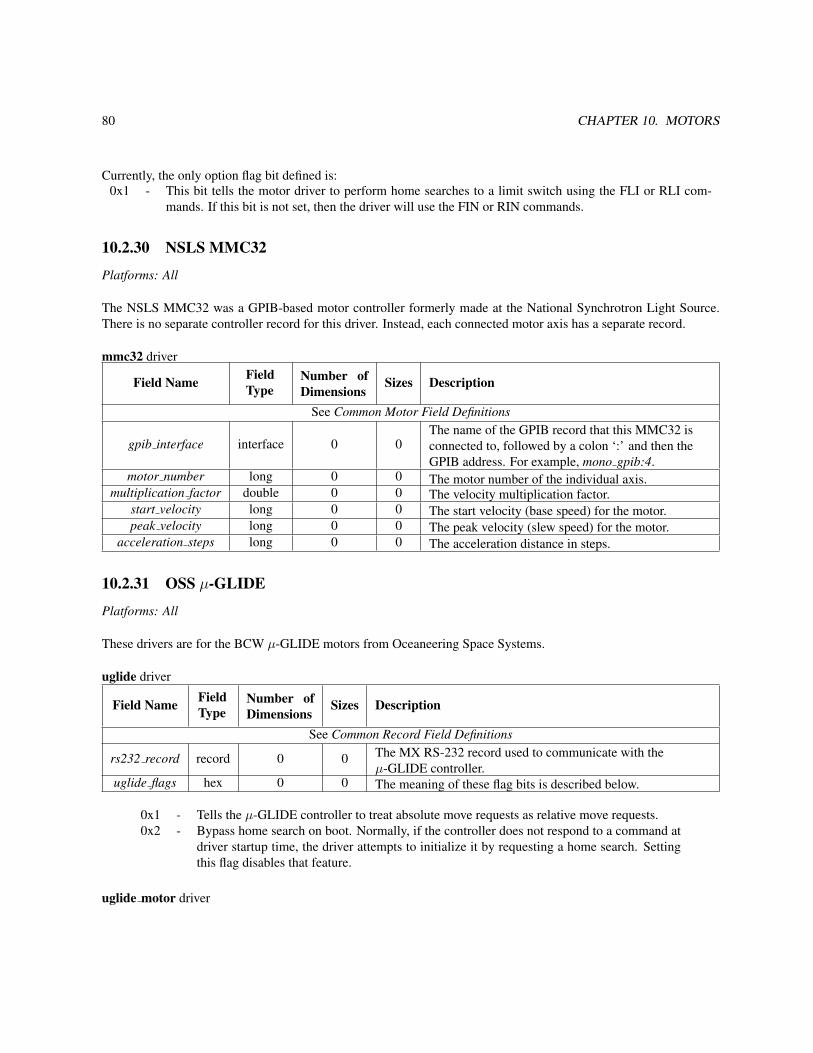
80 CHAPTER 10. MOTORS
Currently, the only option flag bit defined is:0x1 - This bit tells the motor driver to perform home searches to a limit switch using the FLI or RLI com-
mands. If this bit is not set, then the driver will use the FIN or RIN commands.
10.2.30 NSLS MMC32
Platforms: All
The NSLS MMC32 was a GPIB-based motor controller formerly made at the National Synchrotron Light Source.There is no separate controller record for this driver. Instead, each connected motor axis has a separate record.
mmc32 driver
Field Name FieldType
Number ofDimensions
Sizes Description
See Common Motor Field Definitions
gpib interface interface 0 0The name of the GPIB record that this MMC32 isconnected to, followed by a colon ‘:’ and then theGPIB address. For example, mono gpib:4.
motor number long 0 0 The motor number of the individual axis.multiplication factor double 0 0 The velocity multiplication factor.
start velocity long 0 0 The start velocity (base speed) for the motor.peak velocity long 0 0 The peak velocity (slew speed) for the motor.
acceleration steps long 0 0 The acceleration distance in steps.
10.2.31 OSS µ-GLIDE
Platforms: All
These drivers are for the BCW µ-GLIDE motors from Oceaneering Space Systems.
uglide driver
Field Name FieldType
Number ofDimensions
Sizes Description
See Common Record Field Definitions
rs232 record record 0 0 The MX RS-232 record used to communicate with theµ-GLIDE controller.
uglide flags hex 0 0 The meaning of these flag bits is described below.
0x1 - Tells the µ-GLIDE controller to treat absolute move requests as relative move requests.0x2 - Bypass home search on boot. Normally, if the controller does not respond to a command at
driver startup time, the driver attempts to initialize it by requesting a home search. Settingthis flag disables that feature.
uglide motor driver

10.2. MOTOR CONTROLLERS 81
Field Name FieldType
Number ofDimensions
Sizes Description
See Common Motor Field Definitionsuglide record record 0 0 The MX controller record for the µ-GLIDE controller.
axis name char 0 0 The name of this motor axis.
10.2.32 Oxford Cryosystems Cryostream 600 Temperature Controller
Platforms: All
These drivers are for the Cryostream 600 temperature controller from Oxford Cryosystems.
cryostream600 motor driverThis driver allows you to control the temperature setpoint as if it were a motor position.
Field Name FieldType
Number ofDimensions
Sizes Description
See Common Motor Field Definitions
rs232 record record 0 0 The MX RS-232 record used to communicate with thecontroller.
ramp rate double 0 0 The initial ramp rate (speed) in Kelvin per hour.busy deadband double 0 0 The busy deadband in Kelvin.
The Cryostream 600 controller does not provide a direct way to determine that a “move” is complete. Insteadthe MX driver checks to see if the difference between the measured temperature and the setpoint is less than thebusy deadband value defined above. If it is, the driver declares the “move” to be complete and tells the controller tohold at the current temperature.
cryostream600 status driverThis driver can be used to report various pieces of the internal status of the controller.
Field Name FieldType
Number ofDimensions
Sizes Description
See Common Analog Input Field Definitionscryostream600 motor record record 0 0 The MX motor record for this controller.
parameter type long 0 0 The parameter type for this record as describedbelow.
The possible values for parameter type are:1 - Current measured temperature in Kelvin.2 - Temperature setpoint in Kelvin.3 - The difference between the measured temperature and the temperature setpoint in Kelvin.4 - Final temperature in Kelvin.5 - The current ramp rate in Kelvin per hour.6 - Evaporator temperature in Kelvin.7 - Ice block detection. If this field is non-zero, the controller thinks that an ice block is present

82 CHAPTER 10. MOTORS
10.2.33 Oxford Instruments ITC503 Temperature Controlleritc503 control
The value of ’parameter type’ is the letter that starts the ITC503 command that will be sent. The currently supportedvalues are:
• A - Set auto/manual for heater and gas
• C - Set local/remote/lock status
• G - Set gas flow ( in manual only )
• O - Set heater output volts ( in manual only )
There are several other ITC503 control commands, but only the ones likely to be used in routine operation aresupported.
itc503 motor
The two lowest order bits in ’itc503 motor flags’ are used to construct a ’Cn’ control command. The ’Cn’ determineswhether or not the controller is in LOCAL or REMOTE mode and also whether or not the LOC/REM button is lockedor active. The possible values for the ’Cn’ command are:
• C0 - Local and locked (default state)
• C1 - Remote and locked (front panel disabled)
• C2 - Local and unlocked
• C3 - Remote and unlocked (front panel disabled)
itc503 status
The value of ’parameter type’ is used to construct an ITC503 ’R’ command. Thus, the values of the parameters areas listed in the Oxford manual:
• 0 - Set temperature
• 1 - Sensor 1 temperature
• 2 - Sensor 2 temperature
• 3 - Sensor 3 temperature
• 4 - Temperature error
• 5 - Heater O/P (as
• 6 - Heater O/P (as Volts, approx.)
• 7 - Gas flow O/P (arbitrary units)
• 8 - Proportional band

10.2. MOTOR CONTROLLERS 83
• 9 - Integral action time
• 10 - Derivative action time
• 11 - Channel 1 freq/4
• 12 - Channel 2 freq/4
• 13 - Channel 3 freq/4
10.2.34 Pan-Tilt-Zoom Motor
10.2.35 Phidget Stepper (old version)
10.2.36 Physik Instrumente E662 Piezo Controller
10.2.37 Pontech STP100The permitted board numbers are from 1 to 255.
The permitted values for digital I/O pins are:0 - Disable the pin.3, 5, 6, 8 - The pin is active closed.-3, -5, -6, -8 - The pin is active open.
Pins 5 and 6 are normally used for limit switches while either pin 3 or pin 8 is used for the home switch. This isbecause pins 5 and 6 already have pullup resistors.
The output of the RP command is 0 = closed and 1 = open.
10.2.38 Prairie Digital Model 40
10.2.39 Precision MicroControl MCAPI-based Motor Controllers
10.2.40 Pro-Dex VME58Platforms: All
The VME58 motor controller from Pro-Dex (formerly Oregon Microsystems) is a 4 or 8 axis motor controllercapable of supporting both servo and stepper applications. It is no longer for sale.
This set of drivers controls the VME58 by sending raw ASCII commands to the controller through an MX VMErecord.
vme58 driver
Field Name FieldType
Number ofDimensions
Sizes Description
See Common Record Field Definitions
vme record record 0 0 The name of the MX VME record used to communicate withthe VME58.
crate number ulong 0 0 The VME crate number for this motor controller.base address hex 0 0 The base address in hexadecimal of the motor controller.
vme58 motor driver

84 CHAPTER 10. MOTORS
Field Name FieldType
Number ofDimensions
Sizes Description
See Common Motor Field Definitionsvme58 record record 0 0 The MX controller record for this motor axis.
axis number long 0 0The axis number for this motor axis. This can rangefrom 1 to 4 for models with encoder feedback and from1 to 8 for models with no encoder feedback.
flags hex 0 0 The meaning of the flag bits in this field are describedbelow.
default speed long 0 0 The initial slew speed for the axis.
default base speed long 0 0 The initial base speed for the axis. This is not used forservo axes.
default acceleration long 0 0 The initial acceleration for this axis.The meaning of the bits in the flags field above are as follows:
0x1 - Ignore database settings. This option tells the driver not to reprogram the speeds andaccelerations for the axis at startup time.
0x2 - Use encoder. Not actually implemented in the driver at this time.0x10 - Disable hardware limits for this axis.0x20 - Set the home switch to active high. This allows the use of normally closed home switches.
10.2.41 Radix Databox
10.2.42 Scientific Instruments 9650 Temperature Controller
10.2.43 SCIPE Motor
10.2.44 Soft Motor
10.2.45 Spec Motor
10.2.46 SRC MonochromatorThis driver is used to change the energy of a monochromator at the Aladdin storage ring of the Synchrotron RadiationCenter (SRC) (http://www.src.wisc.edu/) at the University of Wisconsin-Madison. MX communicates over an RS-232link with the SRC computer that actually controls the monochromator.
The supported driver is:
src mono - Changes the monochromator energy for the beamline.
The record fields for this driver are:
Field Name FieldType
Number ofDimensions
Sizes Description
See Common motor field definitionsrs232 record string 1 0 The name of the RS-232 port used to communicate with the SRC
control computer.

10.2. MOTOR CONTROLLERS 85
The following is an example database for the SRC monochromator:
src_computer interface rs232 tty "" "" 9600 8 N 1 N 0x0d0a 0x0d 1 0x0 /dev/ttyS0energy device motor src_mono "" "" 0 0 210 800 0 -2 -2 1 0 eV src_computer
10.2.47 Velmex VP9000
10.2.48 XIA HSC-1 Huber Slit ControllerBy default, the HSC-1 Huber Slit Controllers are delivered with default values that do not allow the slit blades to bemoved to anywhere the blades can physically reach. The default values for parameters 1 and 2 are:
Parameter Name Default Value Default in um1 Outer Motion Limit 4400 11000 um2 Origin Position 400 1000 um
The MX drivers for the HSC-1 assume that these two parameters have been redefined to have the following values:Parameter Name Default Value Default in um
1 Outer Motion Limit 10400 26000 um2 Origin Position 5200 13000 um
The reprogramming must be done using a terminal program like Kermit or Minicom. Suppose you have an HSC-1controller with a serial number of XIAHSC-B-0001. Then the appropriate commands to send to the HSC-1 would be:
!XIAHSC-B-0001 W 1 10400!XIAHSC-B-0001 W 2 5200
Next, in the MX config file, specify the limits, scales and offsets of the various axes as follows:XIA motor name negative limit (raw units) positive limit (raw units) scale offset
A -65535 65535 2.5 -13000B -65535 65535 2.5 -13000C -65535 65535 2.5 0S 0 131071 2.5 -26000
Then, you will be able to move the A, B, and C motors from -13000 um to +13000 um and the S motor from 0um to 26000 um.
Please note that the HSC-1 motor positions can only be set to the value 0. A “set motor ... position” command toany other value than zero will fail. The “set motor ... position 0” command itself will cause the HSC-1 to execute an“Immediate Calibration” or “0 I” command. Also note that the slit size motor S cannot be moved to a negative value,so if S is at zero and there is a visible gap between the blades, then you will have to manually close the slit by hand.
Here is an example database for two HSC-1 controllers attached to the same serial port:
hsc1_rs232 interface rs232 tty "" "" 9600 8 N 1 N 0xd0a 0xd /dev/ttyS0hsc1_1 interface controller hsc1 "" "" hsc1_rs232 2 XIAHSC-B-0067 XIAHSC-B-0069hsc67a device motor hsc1_motor "" "" 0 0 -65535 65535 0 -1 -1 2.5 -13000 um hsc1_1 0 Ahsc67b device motor hsc1_motor "" "" 0 0 -65535 65535 0 -1 -1 2.5 -13000 um hsc1_1 0 Bhsc67c device motor hsc1_motor "" "" 0 0 -65535 65535 0 -1 -1 2.5 0 um hsc1_1 0 Chsc67s device motor hsc1_motor "" "" 0 0 0 131071 0 -1 -1 2.5 -26000 um hsc1_1 0 S

86 CHAPTER 10. MOTORS
hsc69a device motor hsc1_motor "" "" 0 0 -65535 65535 0 -1 -1 2.5 -13000 um hsc1_1 1 Ahsc69b device motor hsc1_motor "" "" 0 0 -65535 65535 0 -1 -1 2.5 -13000 um hsc1_1 1 Bhsc69c device motor hsc1_motor "" "" 0 0 -65535 65535 0 -1 -1 2.5 0 um hsc1_1 1 Chsc69s device motor hsc1_motor "" "" 0 0 0 131071 0 -1 -1 2.5 -26000 um hsc1_1 1 S
10.3 PseudomotorsPseudomotor support goes here.
10.3.1 ADSC Two Theta
10.3.2 A-Frame Detector MotorThis is an MX motor driver for the pseudomotors used by Gerd Rosenbaum’s A-frame CCD detector mount. Thegeometry of this detector mount is shown in the following figure:
The pseudomotors available are:
• detector distance - This is the length of the line perpendicular to the plane containing the front face of thedetector which passed through the center of rotation of the goniometer head.
• detector horizontal angle - This is the angle between the line used by the detector distance and the horizonalplane.
• detector offset - This is the distance between the centerline of the detector and the line used to define thedetector distance above.
There are three constants that describe the system:
• A - This is the perpendicular distance between the two vertical supports that hold up the detector.
• B - This is the distance along the centerline of the detector from the front face of the detector to the point wherea perpendicular from the downstream detector pivot intersects this line.
• C - This is the separation between the centerline of the detector and the line defining the detector distanceabove.
The pseudomotors depend on the positions of three real motors. These are:
• dv upstream - This motor controls the height of the upstream vertical detector support.
• dv downstream - This motor controls the height of the downstream vertical detector support.
• dh - This motor controls the horizontal position of the vertical detector supports.
Confused? I am planning to write a short document that describes the definitions of these parameters in moredetail and derives the formulas describing them. If you are reading this text and I have not yet written that document,then pester me until I do write it.
Warning: The detector horizonal angle is expressed internally in radians. If you want to display the angle indegrees, use the scale field of the angle pseudomotor to do the conversion.

10.3. PSEUDOMOTORS 87
Figure 10.2: A-frame CCD detector mount designed by Gerd Rosenbaum

88 CHAPTER 10. MOTORS
10.3.3 ALS Dewar Positioner
10.3.4 APS 18-ID
10.3.5 Delta
10.3.6 Elapsed Time
10.3.7 Energy
10.3.8 Linear FunctionAn example database for the linear function pseudomotor looks like:
cmirror_us device motor compumotor "" "" 0 0 -1000000 1000000 0 -1 -1 1 0 um 6k_coll 1 3 1cmirror_ds device motor compumotor "" "" 0 0 -1000000 1000000 0 -1 -1 1 0 um 6k_coll 1 2 1cmirror_bend device motor linear_function "" "" 0 0 -1000000 1000000 0 -1 -11 0 um 0x1 2 cmirror_us cmirror_ds 0.5 0.5 0 0 0.5 0.5
10.3.9 MonochromatorThe monochromator pseudomotor is implemented using a large collection of MX records. These records can becategorized into several groups:
• The monochromator record with N dependencies.
• N dependency list records.
• N dependency enable records.
• N dependency parameter records.
• N dependency record list records.
• N dependency type records.
where the value of N above is set by the value of the num dependencies field in the monochromator record.
Monochromator Record
The MX Motor Driver Support page describes the common motor record description fields. For the monochromatordriver, the following driver specific fields are present:
Field Name FieldType
Number ofDimensions
Sizes Description
See Common motor field definitionsnum dependencies long 0 0 The number of dependencies for
this monochromator pseudomotor.list array record 1 num dependencies The list of depencency list records.
Example:
theta device motor monochromator "" "" 0 0 -10 270 0 -1 -1 1 0 deg 4 theta_list momega_list id_ev_list normal_list

10.3. PSEUDOMOTORS 89
The monochromator record is a pseudomotor record which contains a list of the dependencies used by the pseu-domotor. In general, one of the dependencies will be a primary dependency which describes the primary axis usedby the monochromator pseudomotor (usually theta). The rest of the dependencies will be secondary dependenciesthat describe motors that are to be moved to positions that depend on the position of the primary dependency motor.There should only be one primary dependency.
In the example above, the dependencies specified are:
• theta list - This is the primary dependency and describes the dependence of the monochromator pseudomotoron the real theta axis of the monochromator.
• momega list - A secondary dependency that controls the angle between the first and second monochromatorcrystal.
• id ev list - A secondary dependency that controls the energy of the peak of the undulator spectrum for thisbeamline.
• normal list - A secondary dependency that controls the perpendicular spacing between the first and secondmonochromator crystals.
This example does not include all of the available dependency types which are described in more detail below. Inaddition, the primary dependency does not have to be the first record listed, but it is customary to do so.
Dependency List Records
An example dependency list record looks like
momega_list variable inline record "" "" 1 4 momega_enabled momega_type momega_params momega_records
Dependency list records must be four element 1-dimensional arrays of type MXFT RECORD. The individual ele-ments of this array must be in the following order:
• Dependency enable record - used to enable or disable the dependency. (momega enabled in the example above.)
• Dependency type record - describes what type of dependency this is. (momega type in the example above.)
• Dependency parameters record - describes the parameters used by this dependency. (momega params in theexample above.)
• Dependency record list - describes the records used by this dependency. (momega records in the exampleabove.)
The individual elements of the array are described in more detail below.
Dependency Enable Records
An example dependency enable record looks like
momega_enabled variable net_variable net_int "" "" localhost momega_enabled.value 1 1 0
The dependency enable record must be a variable record of type MXFT INT. It has two legal values:
• 1 - The dependency is enabled and the dependent motor(s) will be moved to positions that correspond to theposition of the primary dependency.
• 0 - The dependency is disabled and the dependent motor(s) will not be moved.

90 CHAPTER 10. MOTORS
Dependency Parameter Records
An example dependency parameters record looks like
momega_params variable net_variable net_double "" "" localhost momega_params.value 1 4 0 0 0 0
The dependency parameters record will be a 1-dimensional variable record of some kind. The particular variabletype used will depend on the dependency type as described below. In the example above, the parameters record is a1-dimensional array of integers that are all initialized to 0.
Dependency Record List Records
An example dependency record list looks like
momega_records variable inline record "" "" 1 1 momega
The dependency record list record will be a 1-dimensional variable record of type MXFT RECORD. The numberand identity of the listed records will depend on the dependency type as described below. In the example above, therecord list array contains only the record momega.
Dependency Type Records
An example dependency type record looks like
momega_type variable inline int "" "" 1 1 2
The dependency type record will be 1-dimensional variable record of type MXFT INT with only one element, namely,the dependency type. In the example above, the dependency type is 2.
At present, nine different dependency types are available. Dependency types 0 and 1 are primary dependencytypes, while types 2 through 8 are secondary dependency types.
Type 0 - Theta dependency
The theta dependency is used to control the position of the primary theta axis. This dependency is normally theprimary dependency for the monochromator pseudomotor. If this dependency does not exist or is disabled, the realtheta axis will not be moved at all.
• Record list record - This is a 1-dimensional array with only one element, specifically, the name of the realtheta motor record.
• Parameters record - This record must be present, but its contents are not used by this dependency. Typically,a dummy variable will be used here as in the example below.
An example set of records for the theta dependency looks like
theta_list variable inline record "" "" 1 4 theta_enabled theta_type dummy_params theta_recordstheta_type variable inline int "" "" 1 1 0theta_enabled variable inline int "" "" 1 1 1theta_records variable inline record "" "" 1 1 theta_realdummy_params variable inline double "" "" 1 1 0
Normally, there is no reason for the users to disable this dependency, so it is standard to hard code it to 1 as in theexample above.

10.3. PSEUDOMOTORS 91
Type 1 - Energy dependency
The energy dependency is a primary dependency that computes the monochromator theta angle from a monochroma-tor energy provided by a foreign beamline control system. Use of this dependency is not recommended, unless theunderlying beamline control software/hardware does not provide a direct way of querying and controlling the thetaangle. Use of this dependency is incompatible with the type 0 theta dependency specified above. Do not specify bothof them in the same MX database.
If you are looking for a way to control a dependent motor as a polynomial function of energy, you should be usingthe type 8 energy polynomial dependency described below.
• Record list record - This is a 1-dimensional array of type MXFT RECORD containing two elements:
– energy record - This motor record queries and controls the monochromator energy.
– monochromator d spacing record - This is a variable record that contains the d spacing of the monochro-mator crystal in angstroms.
• Parameters record - This record must be present, but its contents are not used by this dependency. Typically,a dummy variable will be used here as in the example below.
An example set of records for the energy dependency looks like
energy_list variable inline record "" "" 1 4 energy_enabled energy_type dummy_params energy_recordsenergy_type variable inline int "" "" 1 1 1energy_enabled variable net_variable net_int "" "" 1 1 1energy_records variable inline record "" "" 1 2 energy d_spacingdummy_params variable inline double "" "" 1 1 0
A corresponding d spacing variable would look like
d_spacing variable net_variable net_double "" "" localhost d_spacing.value 1 1 3.1355
The monochromator theta angle is computed using the standard Bragg equationtheta = asin( 12398.5 / ( 2.0 * d spacing * energy ) )Normally, there is no reason for the users to disable this dependency, so it is standard to hard code it to 1 as in the
example above.
Type 2 - Polynomial dependency
This dependency type is a secondary dependency that allows a dependent motor to be moved to positions that are apolynomial function of the theta position of the monochromator. The computed position will be of the form
dependent position = c0 + c1 * theta + c2 * (theta**2) + c3 * (theta**3) + ...Beamline staff may configure this polynomial to have as few or as many terms in it as they want by changing
the number of elements in the parameters array below. For example, a parameters array record with only two arrayelements will describe a dependent position that has a linear dependence on theta, while a parameters array recordwith four array elements describes a cubic dependence on theta. It is generally not useful to use a polynomial ofhigher order than cubic, although there is no limit in the record as to how high the order may be.
• Record list record - This is a 1-dimensional array with only one element, specifically, the name of the depen-dent motor record.

92 CHAPTER 10. MOTORS
• Parameters record - This is a 1-dimensional array of type MXFT DOUBLE which contains the coefficientsof the polynomial. The coefficients are specified in order starting with the constant term and continuing up tothe coefficient of the highest order term.
An example set of records for the polynomial dependency looks like
momega_list variable inline record "" "" 1 4 momega_enabled momega_type momega_params momega_recordsmomega_type variable inline int "" "" 1 1 2momega_enabled variable net_variable net_int "" "" localhost momega_enabled.value 1 1 0momega_records variable inline record "" "" 1 1 momegamomega_params variable net_variable net_double "" "" localhost momega_params.value 1 4 0 0 0 0
In the example above, momega params is a cubic polynomial. If the value of momega params at some particular timewas set to something like ( 0.32, 0.41, -0.02, 0.015 ), the computed polynomial would have the form
momega = 0.32 + 0.41 * theta - 0.02 * (theta**2) + 0.015 * (theta**3)Typically, the values of these coefficients will be determined by measuring the location of the peak X-ray in-
tensity as a function of the dependent motor position for several values of theta Then a curve will be fitted to themeasurements.
Type 3 - Insertion device energy dependency
This dependency type is a secondary dependency that changes the energy of the undulator peak such that the maxi-mum of the undulator spectrum is at the same energy as the monochromator.
• Record list record - This is a 1-dimensional array of type MXFT RECORD containing two elements:
– insertion device motor record - This is a motor record that controls the position of the undulator peak inunits of eV.
– monochromator d spacing record - This is a variable record that contains the d spacing of the monochro-mator crystal in angstroms.
• Parameters record - This is a 1-dimensional array of type MXFT DOUBLE which contains two elements:
– gap harmonic - This is the requested undulator harmonic number and should be a positive odd integersuch as 1, 3, 5, etc. This is usually set to 1.
– gap offset - This is an offset to be added to the computed gap energy.
For a given monochromator theta position in degrees, the undulator energy is computed as follows:mono energy = 12398.5 / ( 2.0 * d spacing * sin( theta ) )undulator energy = ( mono energy + gap offset ) / gap harmonicPlease note that if the undulator controls provided by your storage ring also have a way of setting the gap harmonic
in addition to the method provided by MX, then you should only set one of them to the harmonic number and set theother to 1. For example, at the APS, if you set both EPICS’s variable for the gap harmonic to 3 and MX’s variablefor the gap harmonic to 3, you would actually end up with the ninth harmonic.
An example set of records for the insertion device energy dependency looks like
id_ev_list variable inline record "" "" 1 4 id_ev_enabled id_ev_type id_ev_params id_ev_recordsid_ev_type variable inline int "" "" 1 1 3id_ev_enabled variable net_variable net_int "" "" localhost id_ev_enabled.value 1 1 0id_ev_records variable inline record "" "" 1 2 id_ev d_spacingid_ev_params variable net_variable net_double "" "" localhost id_ev_params.value 1 2 1 100

10.3. PSEUDOMOTORS 93
Type 4 - Constant exit Bragg normal dependency
This dependency type is a secondary dependency that changes the perpendicular spacing between the first and secondmonochromator crystals so that the X-ray beam exiting the monochromator stays at a constant height.
• Record list record - This is a 1-dimensional array of type MXFT RECORD containing two elements:
– normal record - This motor record controls the perpendicular spacing between the two monochromatorscrystals.
– beam offset record - This is a variable record of type MXFT DOUBLE that contains the desired fixedoffset distance of the beam expressed in the same units as the normal motor.
• Parameters record - This record must be present, but its contents are not used by this dependency. Typically,a dummy variable will be used here as in the example below.
An example set of records for the Bragg normal dependency looks like
normal_list variable inline record "" "" 1 4 normal_enabled normal_type dummy_params normal_recordsnormal_type variable inline int "" "" 1 1 4normal_enabled variable net_variable net_int "" "" localhost normal_enabled.value 1 1 0normal_records variable inline record "" "" 1 2 normal beam_offsetdummy_params variable inline double "" "" 1 1 0
A corresponding beam offset variable would look like
beam_offset variable net_variable net_double "" "" localhost beam_offset.value 1 1 -35000
The Bragg normal position is computed from the beam offset and the monochromator theta angle via the equationbragg normal = beam offset / ( 2.0 * cos( theta ) )If a positive move of the normal motor at theta = 0 is in the opposite direction from the desired beam offset, then
the value of the beam offset must be set to a negative number. For example, this is true of the MX installations at APSsectors 10 and 17 where beam offset = -35000 um.
Type 5 - Constant exit Bragg parallel dependency dependency
This dependency type is a secondary dependency that translates the second crystal parallel to its surface. This depen-dency should normally be used in combination with the Bragg normal dependency listed above. It is used to ensurethat the X-ray beam does not fall off the end of the second crystal.
• Record list record - This is a 1-dimensional array of type MXFT RECORD containing two elements:
– parallel record - This motor record controls the translated position of the second crystal.
– beam offset record - This is a variable record of type MXFT DOUBLE that contains the desired fixedoffset distance of the beam expressed in the same units as the normal motor.
• Parameters record - This record must be present, but its contents are not used by this dependency. Typically,a dummy variable will be used here as in the example below.
An example set of records for the Bragg parallel dependency looks like

94 CHAPTER 10. MOTORS
parallel_list variable inline record "" "" 1 4 parallel_enabled parallel_type dummy_params parallel_recordsparallel_type variable inline int "" "" 1 1 5parallel_enabled variable net_variable net_int "" "" localhost parallel_enabled.value 1 1 0parallel_records variable inline record "" "" 1 2 parallel beam_offsetdummy_params variable inline double "" "" 1 1 0
A corresponding beam offset variable would look like
beam_offset variable net_variable net_double "" "" localhost beam_offset.value 1 1 -35000
If used in combination with a Bragg normal dependency, the two dependencies should use the same MX variable tocontrol the beam offset.
The Bragg parallel position is computed from the beam offset and the monochromator theta angle via the equationbragg parallel = beam offset / ( 2.0 * sin( theta ) )
Type 6 - Experiment table height dependency
If a given monochromator does not support fixed exit beam operation, an alternate way to ensure that the X-ray beamhits the desired target is to put the experiment on a table that can be vertically translated to track the beam.
• Record list record - This is a 1-dimensional array of type MXFT RECORD containing three elements:
– table height record - This motor record controls the vertical height of the experiment table.
– table offset record - This is a variable record of type MXFT DOUBLE that provides a way of adding aconstant offset to the computed table height.
– crystal separation record - This is a variable record of type MXFT DOUBLE that contains the perpen-dicular crystal separation distance expressed in the same units as the table height motor.
• Parameters record - This record must be present, but its contents are not used by this dependency. Typically,a dummy variable will be used here as in the example below.
An example set of records for the experiment table height dependency looks like
theight_list variable inline record "" "" 1 4 theight_enabled theight_type dummy_params theight_recordstheight_type variable inline int "" "" 1 1 6theight_enabled variable net_variable net_int "" "" localhost theight_enabled.value 1 1 0theight_records variable inline record "" "" 1 3 theight toffset crystal_sepdummy_params variable inline double "" "" 1 1 0
A corresponding pair of variables would look like
toffset variable net_variable net_double "" "" localhost toffset.value 1 1 0crystal_sep variable net_variable net_double "" "" localhost crystal_sep.value 1 1 5000
The experiment table height position is computed via the equationtable height = table offset + 2.0 * crystal separation * cos( theta )

10.3. PSEUDOMOTORS 95
Type 7 - Diffractometer theta dependency
The diffractometer theta dependency is used to control the Bragg angle of a diffractometer or goniostat in the exper-imental hutch so that it is set to the correct angle to diffract the X-ray beam coming from the monochromator. Thisdependency assumes that, in general, the crystal on the diffractometer will have a different d spacing than that of themonochromator crystal.
If the diffractometer angle is called htheta and the diffractometer d spacing is called hd spacing, the diffractometerangle is computed by the equation
sin(htheta) = d spacing * sin(theta) / hd spacingThe raw value of htheta is adjusted using a linear equation of the formhtheta adjusted = diffractometer scale * htheta + diffractometer offset
• Record list record - This is a 1-dimensional array of type MXFT RECORD containing three elements:
– diffractometer theta motor record - This the a motor record that controls the diffractometer theta angle.
– monochromator d spacing record - This is a variable record that contains the d spacing of the monochro-mator crystal in angstroms.
– diffractometer d spacing record - This is a variable record that contains the d spacing of the diffractometercrystal in angstroms.
• Parameters record - This is a 1-dimensional array of type MXFT DOUBLE which contains two elementswhich are used to compute the adjusted diffractometer angle:
– diffractometer scale
– diffractometer offset
An example set of records for the diffractometer theta dependency looks like
htheta_list variable inline record "" "" 1 4 htheta_enabled htheta_type htheta_params htheta_recordshtheta_type variable inline int "" "" 1 1 7htheta_enabled variable net_variable net_int "" "" localhost htheta_enabled.value 1 1 0htheta_records variable inline record "" "" 1 3 htheta d_spacing hd_spacinghtheta_params variable net_variable net_double "" "" localhost htheta_params.value 1 2 0 0
Type 8 - Energy polynomial dependency
The energy polynomial dependency is similar to the type 2 polynomial dependency described above, except thedependent motor position is a polynomial function of the monochromator X-ray energy. Thus, the dependent positionwill have the form
dependent position = c0 + c1 * energy + c2 * (energy**2) + c3 * (energy**3) + ...This dependency assumes that the energy is expressed in eV.
• Record list record - This is a 1-dimensional array containing two elements:
– dependent motor record - This motor record controls the dependent motor whose position is determinedby the energy polynomial.
– monochromator d spacing record - This is a variable record that contains the d spacing of the monochro-mator crystal in angstroms. This record is used to convert the theta angle in degrees to energy in eV.

96 CHAPTER 10. MOTORS
• Parameters record - This is a 1-dimensional array of type MXFT DOUBLE which contains the coefficientsof the polynomial. The coefficients are specified in order starting with the constant term and continuing up tothe coefficient of the highest order term.
An example set of records for the energy polynomial dependency looks like
focus_list variable inline record "" "" 1 4 focus_enabled focus_type focus_params focus_recordsfocus_type variable inline int "" "" 1 1 8focus_enabled variable net_variable net_int "" "" localhost focus_enabled.value 1 1 0focus_records variable inline record "" "" 1 2 focus d_spacingfocus_params variable net_variable net_double "" "" localhost focus_params.value 1 4 0 0 0 0
Type 9 - Option selector dependency
The option selector dependency is used together with a “position select” calculation record to switch an external valuebetween multiple settings depending on the current value of the monochromator theta position. The “position select”variable has an integer value from 1 to N. For example, this could be used to automatically switch between mirrorstripes at certain X-ray energies.
• Record list record - This is a 1-dimensional array of type MXFT RECORD containing two elements:
– option selector record - This should be a calculation variable record of type “position select” that controlsthe external value and contains a list of allowed values for the external value.
– option range record - This is the name of the parameters record below.
• Parameters record - This is a 2-dimensional Nx2 array of type MXFT DOUBLE which contains pairs ofelements that describe the limits for each allowed theta range. The two values for each theta range are
– theta range lower limit
– theta range upper limit
The number N is the number of theta ranges.
An example set of records for the option selector dependency looks like
stripe_list variable inline record "" "" 1 4 stripe_enabled stripe_type dummy_params stripe_recordsstripe_type variable inline int "" "" 1 1 9stripe_enabled variable inline int "" "" 1 1 1stripe_records variable inline record "" "" 1 2 stripe_select stripe_paramsstripe_params variable inline double "" "" 2 4 2 0 5 4.5 8.5 8 11 10.5 15stripe_select variable calc position_select "" "" stripe 4 300 600 900 1200 1 1 -1stripe device motor soft_motor "" "" 0 0 -1000000000 1000000000 0 -1 -1 0.01 0 um 100000 0 50000
The example above is for an X-ray mirror whose transverse position is determined by a motor record called stripe.There are 4 allowed positions for stripe, namely, 300, 600, 900, and 1200. The allowed theta ranges correspondingto the allowed positions are 0 to 5 degrees, 4.5 to 8.5 degrees, 8 to 11 degrees, and 10.5 to 15 degrees. The stripeposition to be selected is determined by comparing the current position of theta to the parameter ranges in the variablestripe params. According to stripe params, the stripe motor is allowed to be at 300 if theta is between 0 and 5, orit is allowed to be at 600 if theta is between 4.5 and 8.5, and so forth. If theta moves outside the allowed range ofpositions for the current selection, the option selector will switch to the next selection.

10.3. PSEUDOMOTORS 97
Notice that the allowed ranges for theta overlap. This is to provide a deadband for switches between optionselector ranges. As an example, suppose theta is currently at 7 degrees. This means that theta is within the secondoption selector range of 4.5 to 8.5 degrees and that the stripe motor should currently be at 600. However, if thetais moved to 9 degrees, this is outside the current option selector range, so stripe will be moved to the next allowedposition of 900. However, the lower end of the new range, namely, 8 degrees, is below the upper end of the originalrange, namely, 8.5 degrees. This means that theta must be moved below 8 degrees before the stripe position will bemoved back to the previous value of 600.
Note that if theta is below 0 degrees, the stripe motor will be sent to 300, while if theta is above 15 degrees, thestripe motor will be moved to 1200.
Bugs
The MX database for the monochromator pseudomotor system has turned out to be much more complex to set upthan I had originally wanted. It is my intention to revise this pseudomotor to be easier to configure, but I have no timeestimate as to when that will happen.
Some of the dependencies are user configurable via the parameters record while others are configured via addi-tional records added to the record list.
10.3.10 Q Motor
This is an MX pseudomotor driver for the momentum transfer parameter q, which is defined as
q =4π sin(θ)
λ=
2π
d
where λ is the wavelength of the incident X-ray, θ is the Bragg angle for the analyzer arm and d is the effective crystald-spacing that is currently being probed.
Warning: θ above must not be set to the angle of the analyzer arm. Instead, it must be set to half of that anglewhich is the nominal Bragg angle.
10.3.11 Record Field Motor
10.3.12 Segmented Move
10.3.13 Slit Motor
slit type field - This integer field select the type of slit pseudomotor that this record represents. There are four possiblevalues for the slit type field, which come in two groups of two, namely, the SAME case and the OPPOSITE case. Theallowed values are:
• 1 - (MXF SLIT CENTER SAME)
• 2 - (MXF SLIT WIDTH SAME)
• 3 - (MXF SLIT CENTER OPPOSITE)
• 4 - (MXF SLIT WIDTH OPPOSITE)

98 CHAPTER 10. MOTORS
The SAME cases above are for slit blade pairs that move in the same physical direction when they are bothcommanded to perform moves of the same sign. The OPPOSITE cases are for slit blade pairs that move in theopposite direction from each other when they are both commanded to perform moves of the same sign.
As an example, for a top and bottom slit blade pair, if a positive move of each causes both blades to go up, youuse the SAME case. On the other hand, if a positive move of each causes the top slit blade to go up and the bottomslit blade to go down, you use the OPPOSITE case.
10.3.14 Table Motor
10.3.15 Tangent Arm/Sine ArmThis is an MX motor driver to move a tangent arm or sine arm pseudomotor.
IMPORTANT: The moving motor position and the arm length must both be specified using the same user units,while the angle offset must be specified in radians. Thus, if the moving motor position is specified in micrometers,then the arm length must be specified in micrometers as well.
If you want to specify the angle offset in degrees rather than in radians, the simplest way is to create a ’transla-tion mtr’ record containing only the raw angle offset motor. Then, set a scale factor in the translation motor recordthat converts from radians to degrees.
A tangent arm consists of two arms that are connected at a pivot point as follows:
*B **
* |
* |
* |
* | m
* |
* |
* \ theta |
*-----------------------+------ˆ a A||
pivot point
A linear motor is attached to the fixed arm at point A and then moves a push rod that pushes the moving arm atpoint B. In this geometry, the position of the moving motor, m, is related to the angle theta by the relationship
tan(θ) =m
a
where a is the distance of the motor on the arm it is attached to from the pivot point. The important considerationhere is that the linear motion is perpendicular to the fixed arm.
A sine arm is similar except that the linear motion is now perpendicular to the moving arm:
**

10.3. PSEUDOMOTORS 99
*B **
* \
* \
* \ m
* \
* \ theta \
*-----------------------+------ˆ a A||
pivot point
This changes the equation to the formsin(θ) =
m
a
hence the name “sine arm”.Note: The ’tangent arm’ and ’sine arm’ drivers share the same code and distinguished in the driver code by their
different driver types, namely, MXT MTR TANGENT ARM and MXT MTR SINE ARM.
10.3.16 Theta-Two Theta
10.3.17 Translation
10.3.18 Wavelength
10.3.19 Wavenumber
10.3.20 XAFS WavenumberThis MX pseudomotor driver controls another MX motor in units of XAFS electron wavenumber.
The XAFS electron wavenumber k is computed using the equation:
Ephoton = Eedge +h2k2
2melectron

100 CHAPTER 10. MOTORS

Chapter 11
Multichannel Analog Input
11.1 Keithley 2700
11.2 Oxford Danfysik QBPM
101

102 CHAPTER 11. MULTICHANNEL ANALOG INPUT

Chapter 12
Multichannel Analyzers
12.1 EPICS MCA
12.2 Network MCA
12.3 Ortec UMCBI (Trump)
12.4 Rontec RCL-22 MCA
12.5 Soft MCA
12.6 X-Ray Instrumentation Associates (XIA)
12.7 MCA Associated Records
12.7.1 MCA Alternate Time
12.7.2 MCA Channel
12.7.3 MCA Region of Interest Integral
12.7.4 MCA Value
103

104 CHAPTER 12. MULTICHANNEL ANALYZERS

Chapter 13
Multichannel Encoders
13.1 MCS Elapsed Time Multichannel Encoder
13.2 MCS Multichannel Encoder
13.3 Network Multichannel Encoder
13.4 PMAC Multichannel Encoder
13.5 Radix Databox Multichannel Encoder
105

106 CHAPTER 13. MULTICHANNEL ENCODERS

Chapter 14
Multichannel Scalers
14.1 EPICS MCS
The MX EPICS MCS support optionally can make use of globally visible dark current values. This is done by loadingan additional EPICS analog output record per MCS channel which is used to store the dark current value. This ismost easily described by giving an example.
Suppose you have a set of MCS records loaded in the EPICS “st.cmd” script that look like
dbLoadRecords("mcaApp/Db/mca.db","P=s10id:,M=mcs1,CARD=0,SIGNAL=0,DTYPE=Struck STR7201 MCS,NCHAN=2000", share)dbLoadRecords("mcaApp/Db/mca.db","P=s10id:,M=mcs2,CARD=0,SIGNAL=1,DTYPE=Struck STR7201 MCS,NCHAN=2000", share)dbLoadRecords("mcaApp/Db/mca.db","P=s10id:,M=mcs3,CARD=0,SIGNAL=2,DTYPE=Struck STR7201 MCS,NCHAN=2000", share)dbLoadRecords("mcaApp/Db/mca.db","P=s10id:,M=mcs4,CARD=0,SIGNAL=3,DTYPE=Struck STR7201 MCS,NCHAN=2000", share)
Then, all that you need to add to support dark currents for these channels is to add something like the followinglines to “st.cmd”.
dbLoadRecords("iocBoot/ioc1/mcs_dark.db","P=s10id:,M=mcs1", top)dbLoadRecords("iocBoot/ioc1/mcs_dark.db","P=s10id:,M=mcs2", top)dbLoadRecords("iocBoot/ioc1/mcs_dark.db","P=s10id:,M=mcs3", top)dbLoadRecords("iocBoot/ioc1/mcs_dark.db","P=s10id:,M=mcs4", top)
The mcs dark.db database file is extremely simple. The entire contents of the file is:
grecord(ao,"$(P)$(M)_Dark") {field(PREC,"3")
}
A copy of this file may be found in the MX base source distribution in the file mx/driver info/epics mcs/mcs dark.db.
107

108 CHAPTER 14. MULTICHANNEL SCALERS
14.2 Network MCS
14.3 Radix Databox MCS
14.4 Scaler Function MCS
14.5 SIS3801
14.6 Soft MCS
14.7 X-ray Instrumentation Associates MCS

Chapter 15
Pan-Tilt-Zoom Controllers
15.1 Hitachi KP-D20A/B
15.2 Network PTZ
15.3 Panasonic KX-DP702
15.4 Sony VISCA
109

110 CHAPTER 15. PAN-TILT-ZOOM CONTROLLERS

Chapter 16
Pulse Generator
16.1 Network Pulse Generator
16.2 Prairie Digital Model 45 Pulse Generator
16.3 Struck SIS3801
16.4 Struck SIS3807
111

112 CHAPTER 16. PULSE GENERATOR

Chapter 17
Relays
17.1 Binary Relay
17.2 Blind Relay
17.3 Blu-Ice Shutter
17.4 Generic Relay
17.5 MarCCD Relay
17.6 MarDTB Shutter
17.7 Network Relay
17.8 PFCU Filter and Shutter
17.9 Pulsed Relay
113

114 CHAPTER 17. RELAYS

Chapter 18
Sample Changers
18.1 Network
18.2 Sercat ALS Robot
115

116 CHAPTER 18. SAMPLE CHANGERS

Chapter 19
Single Channel Analyzers
19.1 Network SCA
19.2 Oxford Danfysik Cyberstar X1000
19.3 Soft SCA
117

118 CHAPTER 19. SINGLE CHANNEL ANALYZERS

Chapter 20
Video Input Devices
20.1 EPIX XCLIB
20.2 Network Video Input
20.3 Soft Video Input
20.4 Video4Linux 2
119

120 CHAPTER 20. VIDEO INPUT DEVICES

Chapter 21
CAMAC
21.1 DSP6001
21.2 ESONE
21.3 Soft CAMAC
121

122 CHAPTER 21. CAMAC

Chapter 22
Camera Link
22.1 Camera Link API
22.2 EPIX Camera Link
22.3 Soft Camera Link
123

124 CHAPTER 22. CAMERA LINK

Chapter 23
GPIB
23.1 EPICS GPIB
23.2 Iotech Micro488EX GPIB
23.3 Keithley 500-SERIAL
23.4 Linux GPIB
23.5 Linux Lab Project GPIBWarning: This MX driver was originally developed for the Linux 2.0.x device driver provided by the Linux LabProject, but that project seems to have stalled. Fortunately, the code seems to have been picked up by the Linux GPIBPackage Homepage (http://linux-gpib.sourceforge.net/) which supports Linux 2.4.x. However, this MX driver has notyet been tested with the new Linux 2.4.x version of the device driver.
The Linux Lab Project GPIB driver does not provide an equivalent to the ibdev() function that finds a GPIBdevice by address. That makes the Linux Lab Project driver the only one that does not provide such an inter-face, so it is easier just to provide one for it. This is handled by adding to /etc/gpib.conf the contents of the filemx/driver info/llp gpib/gpib.conf addon from the MX base source distribution, so that there is a way to find a givenGPIB device by its primary address. The contents of the file gpib.conf addon is shown in the following figure:
23.6 National Instruments GPIB
23.7 Network GPIB
125

126 CHAPTER 23. GPIB
/* Devices for use with the MX Linux GPIB driver. */
device { name = gpib0.1 pad=1 sad=0 }device { name = gpib0.2 pad=2 sad=0 }device { name = gpib0.3 pad=3 sad=0 }device { name = gpib0.4 pad=4 sad=0 }device { name = gpib0.5 pad=5 sad=0 }device { name = gpib0.6 pad=6 sad=0 }device { name = gpib0.7 pad=7 sad=0 }device { name = gpib0.8 pad=8 sad=0 }device { name = gpib0.9 pad=9 sad=0 }device { name = gpib0.10 pad=10 sad=0 }device { name = gpib0.11 pad=11 sad=0 }device { name = gpib0.12 pad=12 sad=0 }device { name = gpib0.13 pad=13 sad=0 }device { name = gpib0.14 pad=14 sad=0 }device { name = gpib0.15 pad=15 sad=0 }device { name = gpib0.16 pad=16 sad=0 }device { name = gpib0.17 pad=17 sad=0 }device { name = gpib0.18 pad=18 sad=0 }device { name = gpib0.19 pad=19 sad=0 }device { name = gpib0.20 pad=20 sad=0 }device { name = gpib0.21 pad=21 sad=0 }device { name = gpib0.22 pad=22 sad=0 }device { name = gpib0.23 pad=23 sad=0 }device { name = gpib0.24 pad=24 sad=0 }device { name = gpib0.25 pad=25 sad=0 }device { name = gpib0.26 pad=26 sad=0 }device { name = gpib0.27 pad=27 sad=0 }device { name = gpib0.28 pad=28 sad=0 }device { name = gpib0.29 pad=29 sad=0 }device { name = gpib0.30 pad=30 sad=0 }device { name = gpib0.31 pad=31 sad=0 }
Figure 23.1: gpib.conf addon for the MX Linux Lab Project GPIB driver

Chapter 24
MODBUS
24.1 MODBUS Serial RTU
24.2 MODBUS/TCP
127

128 CHAPTER 24. MODBUS

Chapter 25
Port I/O
25.1 DriverLINX Port I/OThis MX driver is an interface to the DriverLINX port I/O driver for Windows NT/98/95 written by Scientific SoftwareTools, Inc. The DriverLINX package may be downloaded from http://www.sstnet.com/dnload/dnload.htm. Thisdriver is primarily intended for use under Windows NT, since the ’dos portio’ driver already handles Windows 98/95,but it should work on all three operating systems.
Warning: These drivers have not yet been tested with Windows 2000 or Windows XP.
25.2 MSDOS Port I/O
25.3 Linux iopl() and ioperm() drivers
25.4 Linux portio driver
25.5 VxWorks Port I/O
129

130 CHAPTER 25. PORT I/O

Chapter 26
RS-232
26.1 Camera Link
26.2 EPICS RS-232
26.3 MSDOS COM
26.4 Fossil
26.5 Kinetic Systems KS3344
26.6 Network RS-232
26.7 Spec Command
26.8 TCP Socket
26.9 Unix TTY
26.10 VMS Terminal
26.11 VxWorks RS-232
26.12 Wago 750 Serial Port
26.13 Win32 COM Port
131

132 CHAPTER 26. RS-232

Chapter 27
USB
27.1 Libusb
133

134 CHAPTER 27. USB

Chapter 28
VME
28.1 EPICS VME
28.2 Mmap VME
28.3 National Instruments VXI Memacc
28.4 RTEMS VME
28.5 Struck SIS-1100 and SIS-3100
28.6 VxWorks VME
135

136 CHAPTER 28. VME

Chapter 29
Variables
29.1 EPICS Variables
29.2 Inline Variables
29.3 Network Variables
29.4 PMAC Variables
29.5 Spec Variables
29.6 Calculation Variables
29.6.1 APS Topup Time to Inject
29.6.2 APS Topup Interlock
29.6.3 Mathop Variables
29.6.4 Polynomial
29.6.5 Position Select
137

138 CHAPTER 29. VARIABLES

Chapter 30
Servers
30.1 TCP/IP Servers
30.2 Unix Domain Socket Servers
139

140 CHAPTER 30. SERVERS

Chapter 31
Scans
31.1 Linear Scans
31.1.1 Input Scans
31.1.2 Motor Scans
31.1.3 Pseudomotor Scans
31.1.4 Slit Scans
31.1.5 Theta-Two Theta Scans
31.2 List Scans
31.2.1 File List Scans
31.3 XAFS Scans
31.4 Quick Scans (also known as Fast or Slew Scans)
31.4.1 Joerger Quick Scans
31.4.2 MCS Quick Scans
141

142 CHAPTER 31. SCANS

Chapter 32
Interfaces to Other Control Systems
32.1 Blu-Ice
32.2 EPICS
32.3 SCIPE
32.4 Spec
143
Related Documents