1 SWRA591 – April 2019 Submit Documentation Feedback Copyright © 2019, Texas Instruments Incorporated Wide-Band DSSS Mode for FCC Digital Transmission Systems Using CC13x0 Application Report SWRA591 – April 2019 Wide-Band DSSS Mode for FCC Digital Transmission Systems Using CC13x0 Farrukh Inam, Srividya Sundar, Trond Rognerud ABSTRACT This application report describes a wide-band modulation scheme to comply with the requirements of FCC section 15.247 for non-frequency hopping digital modulation systems utlizing datarates below 500kbps. The scheme is implemented with an MCE patch, which is a standalone program that implements the various options of the Wide-Band Direct Sequence Spread Spectrum (WB-DSSS) scheme. The patch is included in the CC1310 SDK and can be setup to be imported in the final application by Code Export option of SmartRF™ studio. This SDK can be downloaded from: http://www.ti.com/tool/SIMPLELINK- CC13X0-SDK. The implementations and summary of performances measured on CC13x0EM [5] are provided in this document. Contents 1 Introduction ................................................................................................................... 3 2 DSSS Encoding Scheme ................................................................................................... 3 3 Packet Format ................................................................................................................ 5 4 Setting Up WB-DSSS in SmartRF Studio ................................................................................ 6 5 Setting Up WB-DSSS in Code Composer Studio™ ................................................................... 10 6 Measured Results .......................................................................................................... 13 7 References .................................................................................................................. 22 List of Figures 1 WB-DSSS Coding Scheme (the modulator is 2-GFSK) ................................................................ 3 2 K=4, Rate = ½, Convolutional Encoder for WB-DSSS Modes......................................................... 4 3 WB-DSSS Packet Structure ................................................................................................ 5 4 SmartRF GUI Showing Two CC1310 in List of Connected Devices .................................................. 6 5 SmartRF Studio Showing WB-DSSS Setup in Transmit Mode ........................................................ 7 6 SmartRF Studio Showing WB-DSSS Setup in Receive Mode ........................................................ 7 7 SmartRF Studio TX Setup Showing Configurable Sync Word ........................................................ 8 8 SmartRF Studio RX Setup Showing Configurable Sync Word ........................................................ 9 9 CCS Project Import Showing rfPakdetRX and rfPacketTX Examples .............................................. 10 10 Shows Code Export Feature of SmartRF Studio (the exported smartrf_settings.c/.h are used in CCS projects) ..................................................................................................................... 11 11 WB-DSSS Modes in SmartRF Studio ................................................................................... 12 12 Sensitivity K = 4, DSSS = 1, 240 kbps .................................................................................. 13 13 PER vs. Input Signal Level K = 4, DSSS = 1, 240 kbps .............................................................. 13 14 Blocking Performance K = 4, DSSS = 1, 240 kbps .................................................................... 13 15 RSSI K = 4, DSSS = 1, 240 kbps ........................................................................................ 13 16 Sensitivity K = 4, DSSS = 2, 120 kbps .................................................................................. 14 17 PER vs. Input Signal Level K = 4, DSSS = 2, 120 kbps .............................................................. 14 18 Blocking Performance K = 4, DSSS = 2, 120 kbps .................................................................... 14

Welcome message from author
This document is posted to help you gain knowledge. Please leave a comment to let me know what you think about it! Share it to your friends and learn new things together.
Transcript
1SWRA591–April 2019Submit Documentation Feedback
Copyright © 2019, Texas Instruments Incorporated
Wide-Band DSSS Mode for FCC Digital Transmission Systems UsingCC13x0
Application ReportSWRA591–April 2019
Wide-Band DSSS Mode for FCC Digital TransmissionSystems Using CC13x0
Farrukh Inam, Srividya Sundar, Trond Rognerud
ABSTRACTThis application report describes a wide-band modulation scheme to comply with the requirements of FCCsection 15.247 for non-frequency hopping digital modulation systems utlizing datarates below 500kbps.The scheme is implemented with an MCE patch, which is a standalone program that implements thevarious options of the Wide-Band Direct Sequence Spread Spectrum (WB-DSSS) scheme. The patch isincluded in the CC1310 SDK and can be setup to be imported in the final application by Code Exportoption of SmartRF™ studio. This SDK can be downloaded from: http://www.ti.com/tool/SIMPLELINK-CC13X0-SDK.
The implementations and summary of performances measured on CC13x0EM [5] are provided in thisdocument.
Contents1 Introduction ................................................................................................................... 32 DSSS Encoding Scheme ................................................................................................... 33 Packet Format................................................................................................................ 54 Setting Up WB-DSSS in SmartRF Studio ................................................................................ 65 Setting Up WB-DSSS in Code Composer Studio™ ................................................................... 106 Measured Results .......................................................................................................... 137 References .................................................................................................................. 22
List of Figures
1 WB-DSSS Coding Scheme (the modulator is 2-GFSK) ................................................................ 32 K=4, Rate = ½, Convolutional Encoder for WB-DSSS Modes......................................................... 43 WB-DSSS Packet Structure................................................................................................ 54 SmartRF GUI Showing Two CC1310 in List of Connected Devices.................................................. 65 SmartRF Studio Showing WB-DSSS Setup in Transmit Mode........................................................ 76 SmartRF Studio Showing WB-DSSS Setup in Receive Mode ........................................................ 77 SmartRF Studio TX Setup Showing Configurable Sync Word ........................................................ 88 SmartRF Studio RX Setup Showing Configurable Sync Word ........................................................ 99 CCS Project Import Showing rfPakdetRX and rfPacketTX Examples .............................................. 1010 Shows Code Export Feature of SmartRF Studio (the exported smartrf_settings.c/.h are used in CCS
projects) ..................................................................................................................... 1111 WB-DSSS Modes in SmartRF Studio ................................................................................... 1212 Sensitivity K = 4, DSSS = 1, 240 kbps .................................................................................. 1313 PER vs. Input Signal Level K = 4, DSSS = 1, 240 kbps .............................................................. 1314 Blocking Performance K = 4, DSSS = 1, 240 kbps.................................................................... 1315 RSSI K = 4, DSSS = 1, 240 kbps ........................................................................................ 1316 Sensitivity K = 4, DSSS = 2, 120 kbps .................................................................................. 1417 PER vs. Input Signal Level K = 4, DSSS = 2, 120 kbps .............................................................. 1418 Blocking Performance K = 4, DSSS = 2, 120 kbps.................................................................... 14
www.ti.com
2 SWRA591–April 2019Submit Documentation Feedback
Copyright © 2019, Texas Instruments Incorporated
Wide-Band DSSS Mode for FCC Digital Transmission Systems UsingCC13x0
19 RSSI K = 4, DSSS = 2, 120 kbps ........................................................................................ 1420 TC430 Sensitivity K = 4, DSSS = 4, 60 kbps........................................................................... 1521 PER vs. Input Signal Level K = 4, DSSS = 4, 60 kbps................................................................ 1522 Blocking Performance K = DSSS = 4, 60 kbps ........................................................................ 1523 RSSI K = 4, DSSS = 4, 60 kbps ......................................................................................... 1524 Sensitivity K = 4, DSSS = 8, 30 kbps.................................................................................... 1625 PER vs. Input Signal Level K = 4, DSSS = 8, 30 kbps................................................................ 1626 Blocking Performance K = 4, DSSS = 8, 30 kbps ..................................................................... 1627 RSSI K = 4, DSSS = 8, 30 kbps ......................................................................................... 1628 SimpleLink Long Range Frequency Offset Performance (915 MHz, K = 4, DSSS = 1, 240 kbps) ............. 1729 SimpleLink Long Range Frequency Offset Performance (915 MHz, K = 4, DSSS = 8, 30 kbps) ............... 1730 Explanation of 6 dB Bandwidth Figures ................................................................................. 1831 Transmit Spectrum PSD 8 dBm in any 3 kHz Bandwidth............................................................. 1932 Transmit Spectrum 6 dB Occupied Bandwidth......................................................................... 1933 Max Output Power at 915 MHz .......................................................................................... 1934 Transmit Spectrum PSD 8 dBm in any 3 kHz Bandwidth............................................................. 2035 Transmit Spectrum 6 dB Occupied Bandwidth......................................................................... 2036 Max Output Power at 915 MHz .......................................................................................... 2037 Transmit Spectrum PSD 8 dBm in any 3 kHz Bandwidth............................................................. 2138 Transmit Spectrum 6dB Occupied Bandwidth.......................................................................... 2139 Max Output Power at 915 MHz .......................................................................................... 2140 Transmit Spectrum PSD 8 dBm in any 3 kHz Bandwidth............................................................. 2241 Transmit Spectrum 6 dB Occupied Bandwidth......................................................................... 2242 Max Output Power at 915 MHz........................................................................................... 22
List of Tables
1 Acronyms and Descriptions ................................................................................................ 32 DSSS Spreading Codes .................................................................................................... 53 WB-DSSS Modes in SmartRF Studio ................................................................................... 124 FCC 15.247 Digital Modulation Requirements ........................................................................ 175 FCC 15.247 Digital Modulation Requirements [ref].................................................................... 17
TrademarksSmartRF, Code Composer Studio are trademarks of Texas Instruments.All other trademarks are the property of their respective owners.
ConvolutionalEncoder
Direct SequenceSpreader
Data Bits Encoded Bits Spread Bits GFSK SignalGFSKModulator
www.ti.com Introduction
3SWRA591–April 2019Submit Documentation Feedback
Copyright © 2019, Texas Instruments Incorporated
Wide-Band DSSS Mode for FCC Digital Transmission Systems UsingCC13x0
1 IntroductionWB-DSSS uses a well-known method to obtain sensitivity gains by means of coding and spreading theinformation bits into a series of transmitted symbols.
The transmit spectrum requirements of FCC Section 15.247 for digital transmission systems operating inthe 902 MHz - 928 MHz band are as follows:• The minimum 6 dB emission bandwidth of the signal shall be at least 500 KHz.• The maximum peak conducted output power for transmitter is +30 dBm (1 Watt).• The maximum power spectral density is limited to 8 dBm in any 3 KHz band segment within the
emission bandwidth during any interval of continuous transmission.
1.1 Acronyms Used in This Document
Table 1. Acronyms and Descriptions
Acronym Description(G)FSK (Gaussian) Frequency shift keyingAWGN Additive White Gaussian NoiseSNR Signal to Noise RatioBW BandwidthDSSS Direct Sequence Spread SpectrumPER Packet Error RateBER Bit Error RateCRC Cyclic Redundancy CheckFEC Forward Error CorrectionMCE Modem Control EngineXOR Exclusive OR
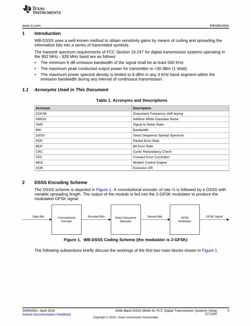
2 DSSS Encoding SchemeThe DSSS scheme is depicted in Figure 1. A convolutional encoder of rate ½ is followed by a DSSS withvariable spreading length. The output of the module is fed into the 2-GFSK modulator to produce themodulated GFSK signal.
Figure 1. WB-DSSS Coding Scheme (the modulator is 2-GFSK)
The following subsections briefly discuss the workings of the first two main blocks shown in Figure 1.
3 2 1 0K=4
a0
a1
DSSS Encoding Scheme www.ti.com
4 SWRA591–April 2019Submit Documentation Feedback
Copyright © 2019, Texas Instruments Incorporated
Wide-Band DSSS Mode for FCC Digital Transmission Systems UsingCC13x0
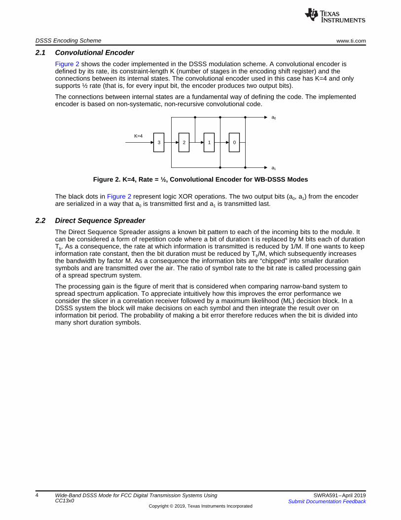
2.1 Convolutional EncoderFigure 2 shows the coder implemented in the DSSS modulation scheme. A convolutional encoder isdefined by its rate, its constraint-length K (number of stages in the encoding shift register) and theconnections between its internal states. The convolutional encoder used in this case has K=4 and onlysupports ½ rate (that is, for every input bit, the encoder produces two output bits).
The connections between internal states are a fundamental way of defining the code. The implementedencoder is based on non-systematic, non-recursive convolutional code.
Figure 2. K=4, Rate = ½, Convolutional Encoder for WB-DSSS Modes
The black dots in Figure 2 represent logic XOR operations. The two output bits (a0, a1) from the encoderare serialized in a way that a0 is transmitted first and a1 is transmitted last.
2.2 Direct Sequence SpreaderThe Direct Sequence Spreader assigns a known bit pattern to each of the incoming bits to the module. Itcan be considered a form of repetition code where a bit of duration t is replaced by M bits each of durationTb. As a consequence, the rate at which information is transmitted is reduced by 1/M. If one wants to keepinformation rate constant, then the bit duration must be reduced by Tb/M, which subsequently increasesthe bandwidth by factor M. As a consequence the information bits are “chipped” into smaller durationsymbols and are transmitted over the air. The ratio of symbol rate to the bit rate is called processing gainof a spread spectrum system.
The processing gain is the figure of merit that is considered when comparing narrow-band system tospread spectrum application. To appreciate intuitively how this improves the error performance weconsider the slicer in a correlation receiver followed by a maximum likelihood (ML) decision block. In aDSSS system the block will make decisions on each symbol and then integrate the result over oninformation bit period. The probability of making a bit error therefore reduces when the bit is divided intomany short duration symbols.
Symbol RateData Rate
2 * DSSS
Preamble Sync Word Payload Termination
Variable 32 bits or 64 bits N*8*2*DSSS bits 4*2*DSSS bits
www.ti.com Packet Format
5SWRA591–April 2019Submit Documentation Feedback
Copyright © 2019, Texas Instruments Incorporated
Wide-Band DSSS Mode for FCC Digital Transmission Systems UsingCC13x0
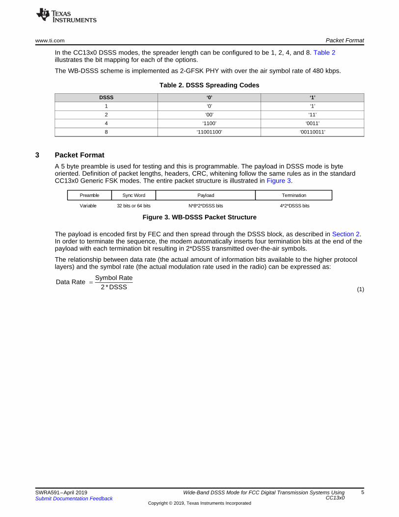
In the CC13x0 DSSS modes, the spreader length can be configured to be 1, 2, 4, and 8. Table 2illustrates the bit mapping for each of the options.
The WB-DSSS scheme is implemented as 2-GFSK PHY with over the air symbol rate of 480 kbps.
Table 2. DSSS Spreading Codes
DSSS ‘0’ ‘1’1 ‘0’ ‘1’2 ‘00’ ‘11’4 ‘1100’ ‘0011’8 ‘11001100’ ‘00110011’
3 Packet FormatA 5 byte preamble is used for testing and this is programmable. The payload in DSSS mode is byteoriented. Definition of packet lengths, headers, CRC, whitening follow the same rules as in the standardCC13x0 Generic FSK modes. The entire packet structure is illustrated in Figure 3.
Figure 3. WB-DSSS Packet Structure
The payload is encoded first by FEC and then spread through the DSSS block, as described in Section 2.In order to terminate the sequence, the modem automatically inserts four termination bits at the end of thepayload with each termination bit resulting in 2*DSSS transmitted over-the-air symbols.
The relationship between data rate (the actual amount of information bits available to the higher protocollayers) and the symbol rate (the actual modulation rate used in the radio) can be expressed as:
(1)
Setting Up WB-DSSS in SmartRF Studio www.ti.com
6 SWRA591–April 2019Submit Documentation Feedback
Copyright © 2019, Texas Instruments Incorporated
Wide-Band DSSS Mode for FCC Digital Transmission Systems UsingCC13x0
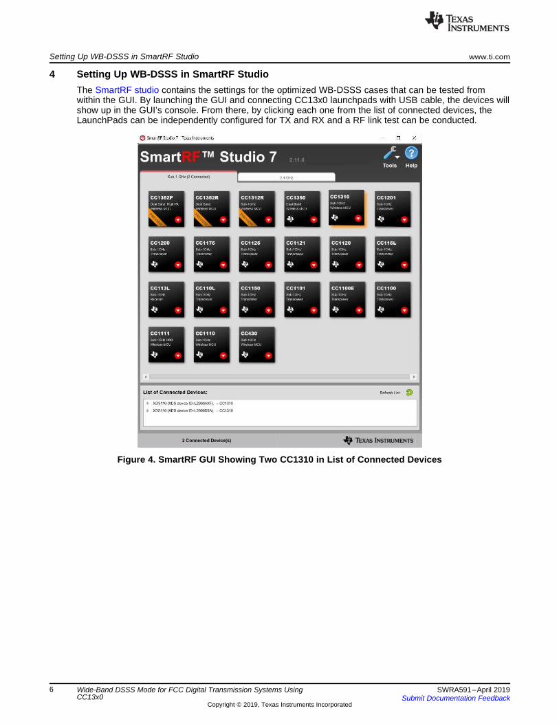
4 Setting Up WB-DSSS in SmartRF StudioThe SmartRF studio contains the settings for the optimized WB-DSSS cases that can be tested fromwithin the GUI. By launching the GUI and connecting CC13x0 launchpads with USB cable, the devices willshow up in the GUI’s console. From there, by clicking each one from the list of connected devices, theLaunchPads can be independently configured for TX and RX and a RF link test can be conducted.
Figure 4. SmartRF GUI Showing Two CC1310 in List of Connected Devices
www.ti.com Setting Up WB-DSSS in SmartRF Studio
7SWRA591–April 2019Submit Documentation Feedback
Copyright © 2019, Texas Instruments Incorporated
Wide-Band DSSS Mode for FCC Digital Transmission Systems UsingCC13x0
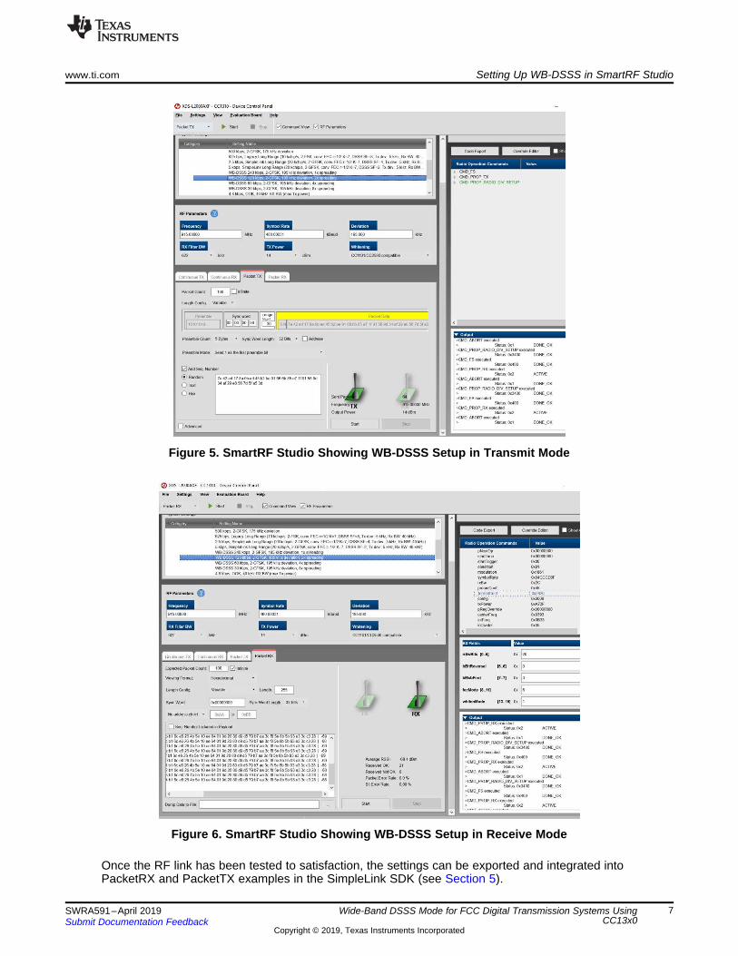
Figure 5. SmartRF Studio Showing WB-DSSS Setup in Transmit Mode
Figure 6. SmartRF Studio Showing WB-DSSS Setup in Receive Mode
Once the RF link has been tested to satisfaction, the settings can be exported and integrated intoPacketRX and PacketTX examples in the SimpleLink SDK (see Section 5).
Setting Up WB-DSSS in SmartRF Studio www.ti.com
8 SWRA591–April 2019Submit Documentation Feedback
Copyright © 2019, Texas Instruments Incorporated
Wide-Band DSSS Mode for FCC Digital Transmission Systems UsingCC13x0
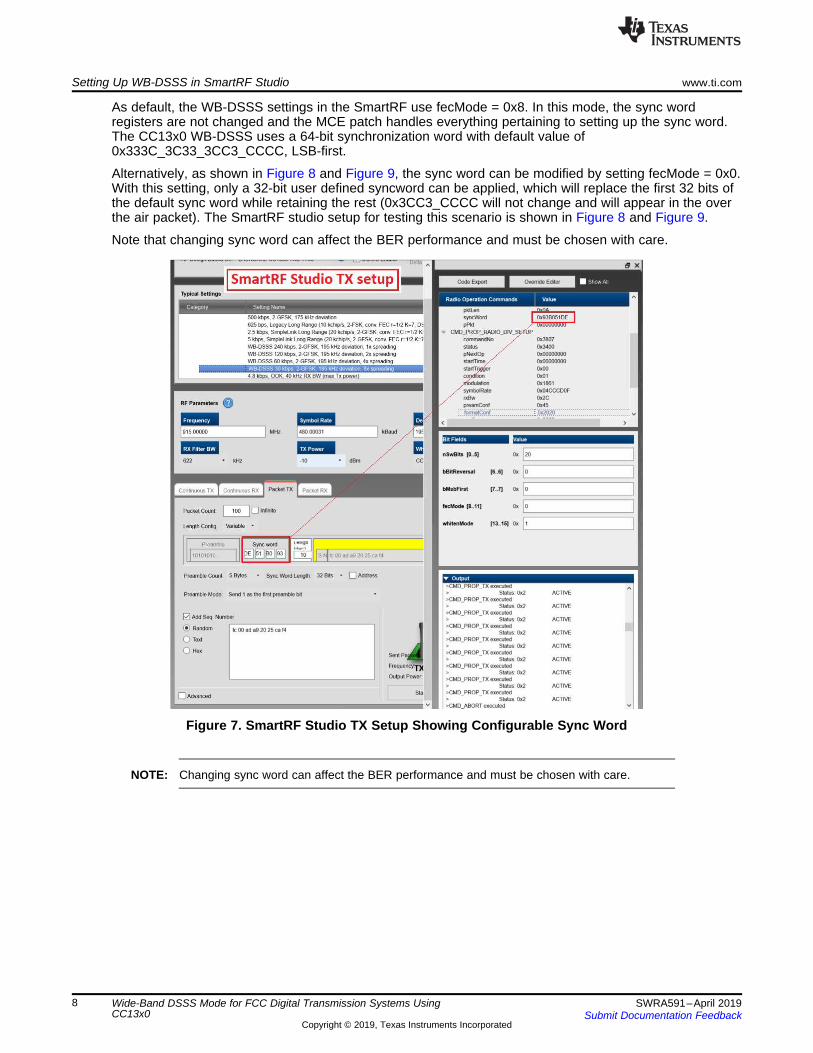
As default, the WB-DSSS settings in the SmartRF use fecMode = 0x8. In this mode, the sync wordregisters are not changed and the MCE patch handles everything pertaining to setting up the sync word.The CC13x0 WB-DSSS uses a 64-bit synchronization word with default value of0x333C_3C33_3CC3_CCCC, LSB-first.
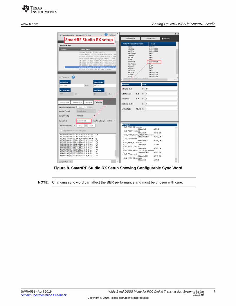
Alternatively, as shown in Figure 8 and Figure 9, the sync word can be modified by setting fecMode = 0x0.With this setting, only a 32-bit user defined syncword can be applied, which will replace the first 32 bits ofthe default sync word while retaining the rest (0x3CC3_CCCC will not change and will appear in the overthe air packet). The SmartRF studio setup for testing this scenario is shown in Figure 8 and Figure 9.
Note that changing sync word can affect the BER performance and must be chosen with care.
Figure 7. SmartRF Studio TX Setup Showing Configurable Sync Word
NOTE: Changing sync word can affect the BER performance and must be chosen with care.
www.ti.com Setting Up WB-DSSS in SmartRF Studio
9SWRA591–April 2019Submit Documentation Feedback
Copyright © 2019, Texas Instruments Incorporated
Wide-Band DSSS Mode for FCC Digital Transmission Systems UsingCC13x0
Figure 8. SmartRF Studio RX Setup Showing Configurable Sync Word
NOTE: Changing sync word can affect the BER performance and must be chosen with care.
Setting Up WB-DSSS in Code Composer Studio™ www.ti.com
10 SWRA591–April 2019Submit Documentation Feedback
Copyright © 2019, Texas Instruments Incorporated
Wide-Band DSSS Mode for FCC Digital Transmission Systems UsingCC13x0
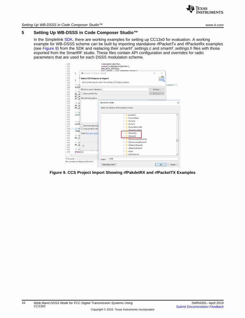
5 Setting Up WB-DSSS in Code Composer Studio™In the Simplelink SDK, there are working examples for setting up CC13x0 for evaluation. A workingexample for WB-DSSS scheme can be built by importing standalone rfPacketTx and rfPacketRx examples(see Figure 9) from the SDK and replacing their smartrf_settings.c and smartrf_settings.h files with thoseexported from the SmartRF studio. These files contain API configuration and overrides for radioparameters that are used for each DSSS modulation scheme.
Figure 9. CCS Project Import Showing rfPakdetRX and rfPacketTX Examples
www.ti.com Setting Up WB-DSSS in Code Composer Studio™
11SWRA591–April 2019Submit Documentation Feedback
Copyright © 2019, Texas Instruments Incorporated
Wide-Band DSSS Mode for FCC Digital Transmission Systems UsingCC13x0
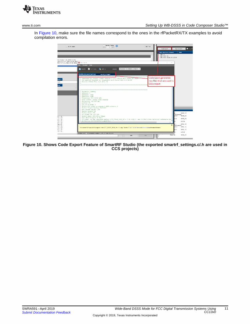
In Figure 10, make sure the file names correspond to the ones in the rfPacketRX/TX examples to avoidcompilation errors.
Figure 10. Shows Code Export Feature of SmartRF Studio (the exported smartrf_settings.c/.h are used inCCS projects)
Setting Up WB-DSSS in Code Composer Studio™ www.ti.com
12 SWRA591–April 2019Submit Documentation Feedback
Copyright © 2019, Texas Instruments Incorporated
Wide-Band DSSS Mode for FCC Digital Transmission Systems UsingCC13x0
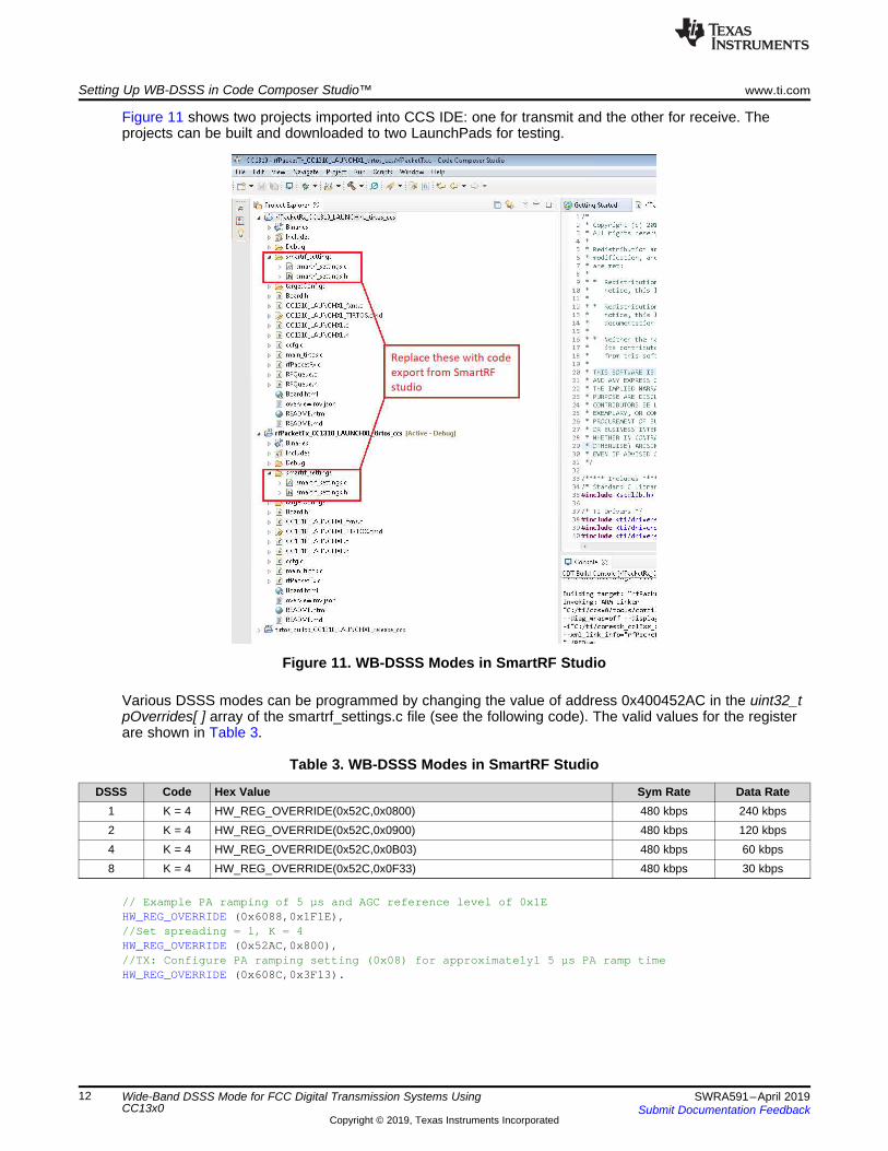
Figure 11 shows two projects imported into CCS IDE: one for transmit and the other for receive. Theprojects can be built and downloaded to two LaunchPads for testing.
Figure 11. WB-DSSS Modes in SmartRF Studio
Various DSSS modes can be programmed by changing the value of address 0x400452AC in the uint32_tpOverrides[ ] array of the smartrf_settings.c file (see the following code). The valid values for the registerare shown in Table 3.
Table 3. WB-DSSS Modes in SmartRF Studio
DSSS Code Hex Value Sym Rate Data Rate1 K = 4 HW_REG_OVERRIDE(0x52C,0x0800) 480 kbps 240 kbps2 K = 4 HW_REG_OVERRIDE(0x52C,0x0900) 480 kbps 120 kbps4 K = 4 HW_REG_OVERRIDE(0x52C,0x0B03) 480 kbps 60 kbps8 K = 4 HW_REG_OVERRIDE(0x52C,0x0F33) 480 kbps 30 kbps
// Example PA ramping of 5 µs and AGC reference level of 0x1EHW_REG_OVERRIDE (0x6088,0x1F1E),//Set spreading = 1, K = 4HW_REG_OVERRIDE (0x52AC,0x800),//TX: Configure PA ramping setting (0x08) for approximatelyl 5 µs PA ramp timeHW_REG_OVERRIDE (0x608C,0x3F13).
www.ti.com Measured Results
13SWRA591–April 2019Submit Documentation Feedback
Copyright © 2019, Texas Instruments Incorporated
Wide-Band DSSS Mode for FCC Digital Transmission Systems UsingCC13x0
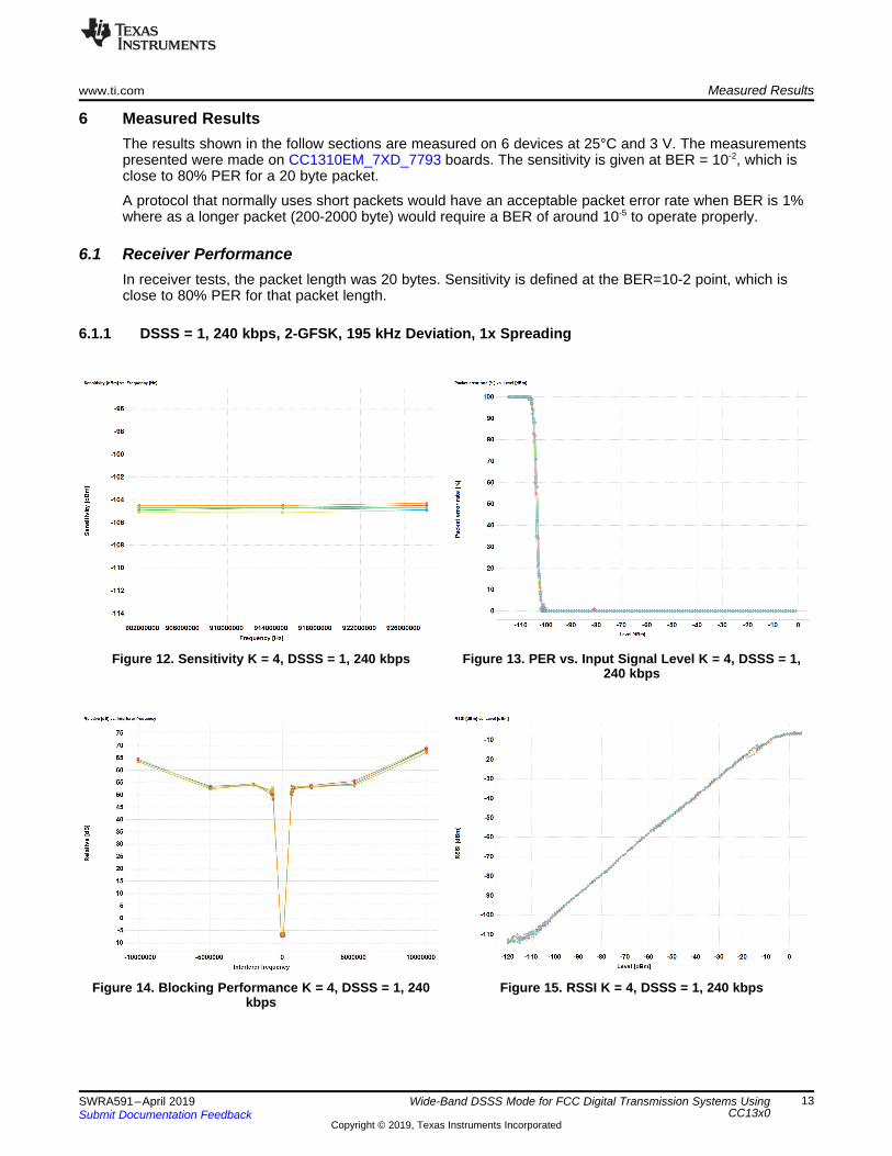
6 Measured ResultsThe results shown in the follow sections are measured on 6 devices at 25°C and 3 V. The measurementspresented were made on CC1310EM_7XD_7793 boards. The sensitivity is given at BER = 10-2, which isclose to 80% PER for a 20 byte packet.
A protocol that normally uses short packets would have an acceptable packet error rate when BER is 1%where as a longer packet (200-2000 byte) would require a BER of around 10-5 to operate properly.
6.1 Receiver PerformanceIn receiver tests, the packet length was 20 bytes. Sensitivity is defined at the BER=10-2 point, which isclose to 80% PER for that packet length.
6.1.1 DSSS = 1, 240 kbps, 2-GFSK, 195 kHz Deviation, 1x Spreading
Figure 12. Sensitivity K = 4, DSSS = 1, 240 kbps Figure 13. PER vs. Input Signal Level K = 4, DSSS = 1,240 kbps
Figure 14. Blocking Performance K = 4, DSSS = 1, 240kbps
Figure 15. RSSI K = 4, DSSS = 1, 240 kbps
Measured Results www.ti.com
14 SWRA591–April 2019Submit Documentation Feedback
Copyright © 2019, Texas Instruments Incorporated
Wide-Band DSSS Mode for FCC Digital Transmission Systems UsingCC13x0
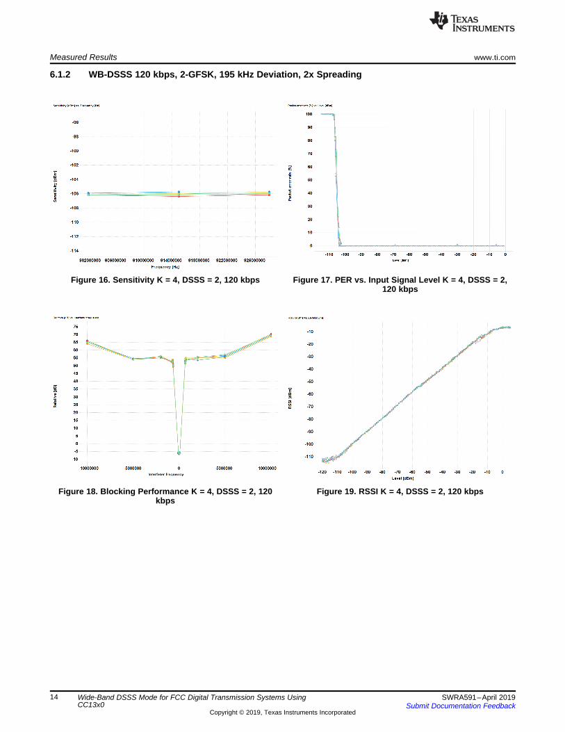
6.1.2 WB-DSSS 120 kbps, 2-GFSK, 195 kHz Deviation, 2x Spreading
Figure 16. Sensitivity K = 4, DSSS = 2, 120 kbps Figure 17. PER vs. Input Signal Level K = 4, DSSS = 2,120 kbps
Figure 18. Blocking Performance K = 4, DSSS = 2, 120kbps
Figure 19. RSSI K = 4, DSSS = 2, 120 kbps
www.ti.com Measured Results
15SWRA591–April 2019Submit Documentation Feedback
Copyright © 2019, Texas Instruments Incorporated
Wide-Band DSSS Mode for FCC Digital Transmission Systems UsingCC13x0
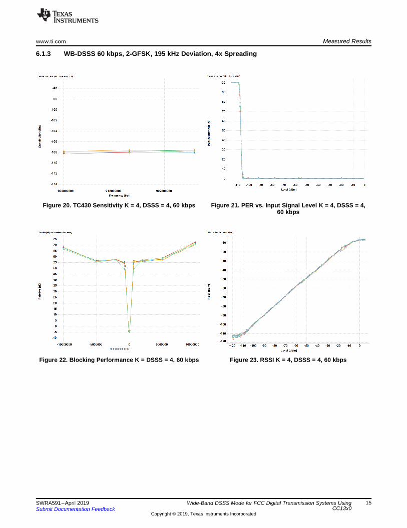
6.1.3 WB-DSSS 60 kbps, 2-GFSK, 195 kHz Deviation, 4x Spreading
Figure 20. TC430 Sensitivity K = 4, DSSS = 4, 60 kbps Figure 21. PER vs. Input Signal Level K = 4, DSSS = 4,60 kbps
Figure 22. Blocking Performance K = DSSS = 4, 60 kbps Figure 23. RSSI K = 4, DSSS = 4, 60 kbps
Measured Results www.ti.com
16 SWRA591–April 2019Submit Documentation Feedback
Copyright © 2019, Texas Instruments Incorporated
Wide-Band DSSS Mode for FCC Digital Transmission Systems UsingCC13x0
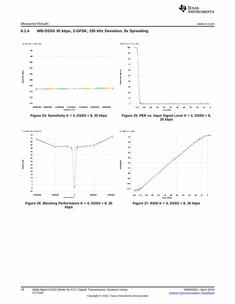
6.1.4 WB-DSSS 30 kbps, 2-GFSK, 195 kHz Deviation, 8x Spreading
Figure 24. Sensitivity K = 4, DSSS = 8, 30 kbps Figure 25. PER vs. Input Signal Level K = 4, DSSS = 8,30 kbps
Figure 26. Blocking Performance K = 4, DSSS = 8, 30kbps
Figure 27. RSSI K = 4, DSSS = 8, 30 kbps
www.ti.com Measured Results
17SWRA591–April 2019Submit Documentation Feedback
Copyright © 2019, Texas Instruments Incorporated
Wide-Band DSSS Mode for FCC Digital Transmission Systems UsingCC13x0
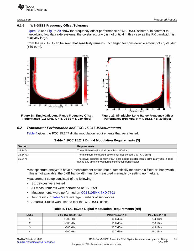
6.1.5 WB-DSSS Frequency Offset ToleranceFigure 28 and Figure 29 show the frequency offset performance of WB-DSSS scheme. In contrast tonarrowband low data rate systems, the crystal accuracy is not critical in this case as the RX bandwidth isrelatively large.
From the results, it can be seen that sensitivity remains unchanged for considerable amount of crystal drift(±50 ppm).
Figure 28. SimpleLink Long Range Frequency OffsetPerformance (915 MHz, K = 4, DSSS = 1, 240 kbps)
Figure 29. SimpleLink Long Range Frequency OffsetPerformance (915 MHz, K = 4, DSSS = 8, 30 kbps)
6.2 Transmitter Performance and FCC 15.247 MeasurementsTable 4 gives the FCC 15.247 digital modulation requirements that were tested.
Table 4. FCC 15.247 Digital Modulation Requirements [3]
Section Requirements15.247a2 The 6 dB bandwidth shall be at least 500 kHz15.247b3 The maximum conducted power shall not exceed 1 W (+30 dBm)15.247e The power spectral density (PSD) shall not be greater than 8 dBm in any 3 kHz band
during any time interval during continuous transmission
Most spectrum analyzers have a measurement option that automatically measures a fixed dB bandwidth.If this is not available, the 6 dB bandwidth must be measured manually by setting up markers.
Measurement setup consisted of the following:• Six devices were tested• All measurements were performed at 3 V, 25°C• Measurements were performed on CC1310EMK-7XD-7793• Test results in Table 5 are average numbers of six devices• SmartRF Studio was used to test the WB-DSSS cases
Table 5. FCC 15.247 Digital Modulation Requirements [ref]
DSSS 6 dB BW (15.247 a2) Power (15.247 b) PSD (15.247 d)1 >500 kHz 13.6 dBm 1.4 dBm2 >500 kHz 13.6 dBm 2.8 dBm3 >500 kHz 13.7 dBm 4.8 dBm4 >500 kHz 13.7 dBm 5.1 dBm
Measured Results www.ti.com
18 SWRA591–April 2019Submit Documentation Feedback
Copyright © 2019, Texas Instruments Incorporated
Wide-Band DSSS Mode for FCC Digital Transmission Systems UsingCC13x0
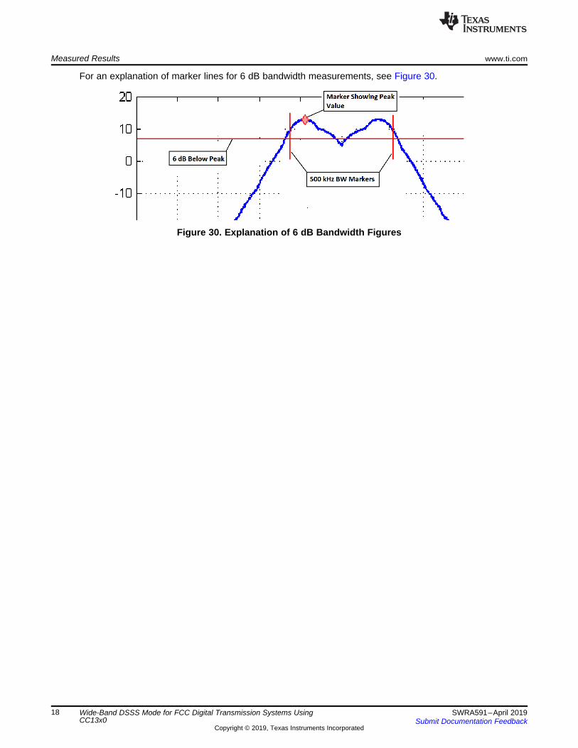
For an explanation of marker lines for 6 dB bandwidth measurements, see Figure 30.
Figure 30. Explanation of 6 dB Bandwidth Figures
www.ti.com Measured Results
19SWRA591–April 2019Submit Documentation Feedback
Copyright © 2019, Texas Instruments Incorporated
Wide-Band DSSS Mode for FCC Digital Transmission Systems UsingCC13x0
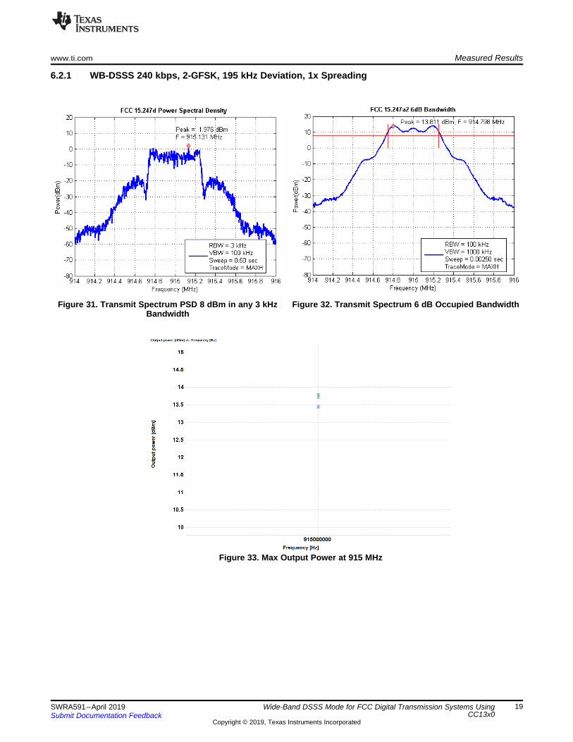
6.2.1 WB-DSSS 240 kbps, 2-GFSK, 195 kHz Deviation, 1x Spreading
Figure 31. Transmit Spectrum PSD 8 dBm in any 3 kHzBandwidth
Figure 32. Transmit Spectrum 6 dB Occupied Bandwidth
Figure 33. Max Output Power at 915 MHz
Measured Results www.ti.com
20 SWRA591–April 2019Submit Documentation Feedback
Copyright © 2019, Texas Instruments Incorporated
Wide-Band DSSS Mode for FCC Digital Transmission Systems UsingCC13x0
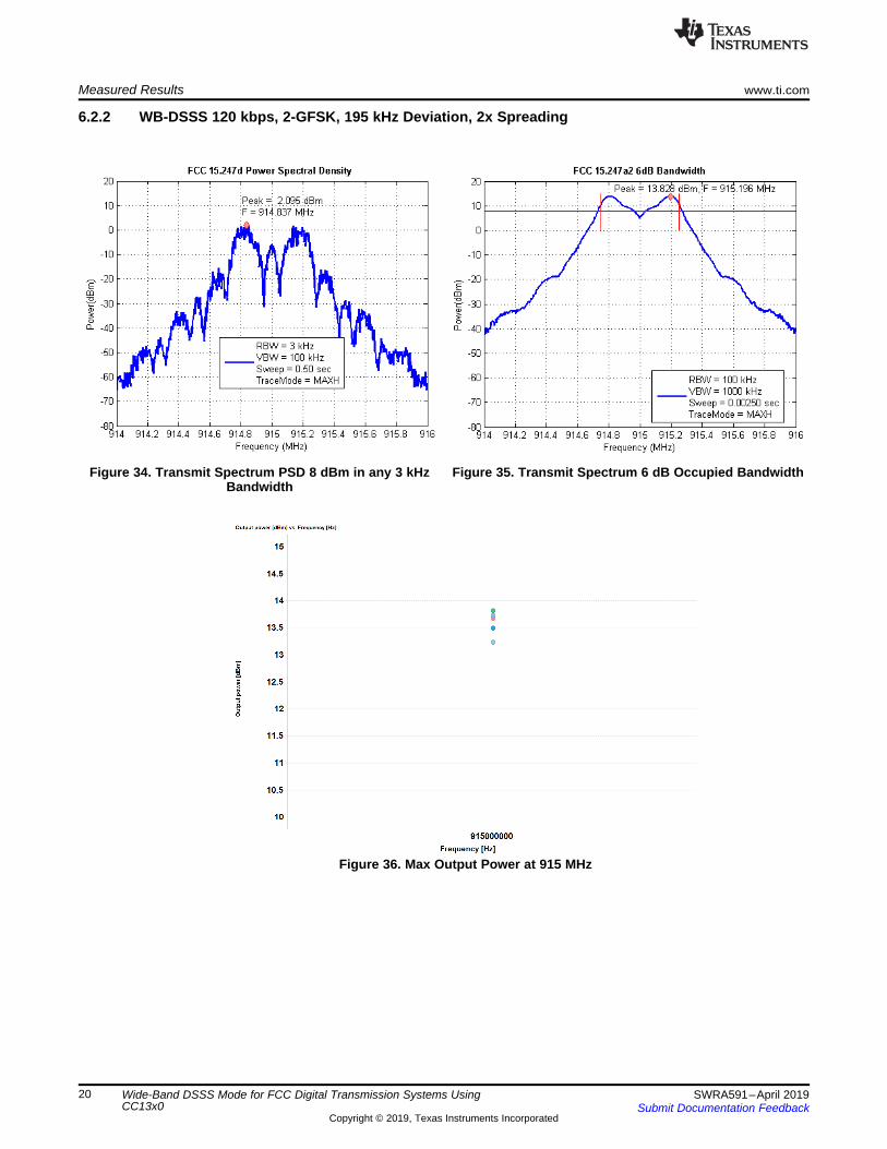
6.2.2 WB-DSSS 120 kbps, 2-GFSK, 195 kHz Deviation, 2x Spreading
Figure 34. Transmit Spectrum PSD 8 dBm in any 3 kHzBandwidth
Figure 35. Transmit Spectrum 6 dB Occupied Bandwidth
Figure 36. Max Output Power at 915 MHz
www.ti.com Measured Results
21SWRA591–April 2019Submit Documentation Feedback
Copyright © 2019, Texas Instruments Incorporated
Wide-Band DSSS Mode for FCC Digital Transmission Systems UsingCC13x0
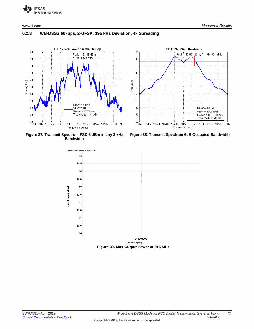
6.2.3 WB-DSSS 60kbps, 2-GFSK, 195 kHz Deviation, 4x Spreading
Figure 37. Transmit Spectrum PSD 8 dBm in any 3 kHzBandwidth
Figure 38. Transmit Spectrum 6dB Occupied Bandwidth
Figure 39. Max Output Power at 915 MHz
References www.ti.com
22 SWRA591–April 2019Submit Documentation Feedback
Copyright © 2019, Texas Instruments Incorporated
Wide-Band DSSS Mode for FCC Digital Transmission Systems UsingCC13x0
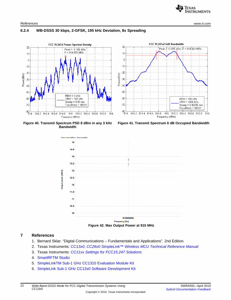
6.2.4 WB-DSSS 30 kbps, 2-GFSK, 195 kHz Deviation, 8x Spreading
Figure 40. Transmit Spectrum PSD 8 dBm in any 3 kHzBandwidth
Figure 41. Transmit Spectrum 6 dB Occupied Bandwidth
Figure 42. Max Output Power at 915 MHz
7 References1. Bernard Sklar. “Digital Communications – Fundamentals and Applications”. 2nd Edition.2. Texas Instruments: CC13x0, CC26x0 SimpleLink™ Wireless MCU Technical Reference Manual3. Texas Instruments: CC11xx Settings for FCC15.247 Solutions4. SmartRFTM Studio5. SimpleLinkTM Sub-1 GHz CC1310 Evaluation Module Kit6. SimpleLink Sub-1 GHz CC13x0 Software Development Kit
IMPORTANT NOTICE AND DISCLAIMER
TI PROVIDES TECHNICAL AND RELIABILITY DATA (INCLUDING DATASHEETS), DESIGN RESOURCES (INCLUDING REFERENCEDESIGNS), APPLICATION OR OTHER DESIGN ADVICE, WEB TOOLS, SAFETY INFORMATION, AND OTHER RESOURCES “AS IS”AND WITH ALL FAULTS, AND DISCLAIMS ALL WARRANTIES, EXPRESS AND IMPLIED, INCLUDING WITHOUT LIMITATION ANYIMPLIED WARRANTIES OF MERCHANTABILITY, FITNESS FOR A PARTICULAR PURPOSE OR NON-INFRINGEMENT OF THIRDPARTY INTELLECTUAL PROPERTY RIGHTS.These resources are intended for skilled developers designing with TI products. You are solely responsible for (1) selecting the appropriateTI products for your application, (2) designing, validating and testing your application, and (3) ensuring your application meets applicablestandards, and any other safety, security, or other requirements. These resources are subject to change without notice. TI grants youpermission to use these resources only for development of an application that uses the TI products described in the resource. Otherreproduction and display of these resources is prohibited. No license is granted to any other TI intellectual property right or to any thirdparty intellectual property right. TI disclaims responsibility for, and you will fully indemnify TI and its representatives against, any claims,damages, costs, losses, and liabilities arising out of your use of these resources.TI’s products are provided subject to TI’s Terms of Sale (www.ti.com/legal/termsofsale.html) or other applicable terms available either onti.com or provided in conjunction with such TI products. TI’s provision of these resources does not expand or otherwise alter TI’s applicablewarranties or warranty disclaimers for TI products.
Mailing Address: Texas Instruments, Post Office Box 655303, Dallas, Texas 75265Copyright © 2019, Texas Instruments Incorporated
Related Documents