Introduction to Radiation Detectors and Electronics Copyright 1998 by Helmuth Spieler X. Why Things Don’t Work 1 X. Why Things Don’t Work or Why S/N Theory Often Seems to be Irrelevant Throughout the previous lectures it was assumed that the only sources of noise were • random • known • in the detector, preamplifier, or associated components In practice, the detector system will pick up spurious signals that are • not random, • but not correlated with the signal, so with reference to the signal they are quasi-random. ⇒ Baseline fluctuations superimposed on the desired signal ⇒ Increased detection threshold, Degradation of resolution

Welcome message from author
This document is posted to help you gain knowledge. Please leave a comment to let me know what you think about it! Share it to your friends and learn new things together.
Transcript

Introduction to Radiation Detectors and Electronics Copyright 1998 by Helmuth SpielerX. Why Things Don’t Work
1
X. Why Things Don’t Work
or
Why S/N Theory Often Seems to be Irrelevant
Throughout the previous lectures it was assumed that the onlysources of noise were
• random
• known
• in the detector, preamplifier, or associated components
In practice, the detector system will pick up spurious signals that are
• not random,
• but not correlated with the signal,
so with reference to the signal they are quasi-random.
⇒ Baseline fluctuations superimposed on the desired signal
⇒ Increased detection threshold,Degradation of resolution

Introduction to Radiation Detectors and Electronics Copyright 1998 by Helmuth SpielerX. Why Things Don’t Work
2
Common Types of Interference
1. Light Pick-Up
Critical systems:
• Photomultiplier tubes
• Semiconductor detectors(all semiconductor detectors are photodiodes)
Sources
• Room lighting (Light Leaks)
• Vacuum gauges
Interference is correlated with the power line frequency(60 Hz here, 50 Hz in Europe, Japan)
Pickup from incandescent lamps has twice the line frequency(light intensity ∝ voltage squared)
Diagnostics:
a) inspect signal output with oscilloscope set to triggermode “line”. Look for stationary structure on baseline
Analog oscilloscope better than digital.
b) switch off light
c) cover system with black cloth (preferably felt, or verydensely woven – check if you can see through it)

Introduction to Radiation Detectors and Electronics Copyright 1998 by Helmuth SpielerX. Why Things Don’t Work
3
2. Microphonics
If the electrode at potential VB vibrates with respect to the enclosure,the stray capacitance C is modulated by ∆C(t), inducing a charge
in the detector signal circuit.
Typically, vibrations are excited by motors (vacuum pumps, blowers),so the interference tends to be correlated with the line frequency.
Check with
a) oscilloscope on line trigger
b) hand to feel vibrations
This type of pickup only occurs between conductors at differentpotentials, so it can be reduced by shielding the relevant electrode.
a) additional shield at electrode potential
b) in coaxial detectors, keep outer electrode at 0 V.
)()( tCVtQ B∆=∆

Introduction to Radiation Detectors and Electronics Copyright 1998 by Helmuth SpielerX. Why Things Don’t Work
4
3. RF Pickup
All detector electronics are sensitive to RF signals.
The critical frequency range depends on the shaping time. The gainof the system peaks at
and high-gain systems will be sensitive over a wide range offrequencies around the peaking frequency.
Typical sources
• Radio and TV stations
AM broadcast stations: 0.5 – 1.7 MHz
FM broadcast stations: ~ 100 MHz
TV stations: 50 – 800 MHz
• Induction furnaces (13.6, 27, 40 MHz)
• Accelerators
⇒ sine waves
• Computers (10’s to 100’s MHz)
• Video Displays (10 – 100 kHz)
• Radar (GHz)
• Internal clock pulses (e.g. digital control, data readout)
⇒ Pulses (or recurring damped oscillations)
Pulsed UHF or microwave emissions can affect low-frequencycircuitry by driving it beyond linearity (the bandwidth of thepreamplifier can be much greater than of the subsequent shaper).
πτ21≈f

Introduction to Radiation Detectors and Electronics Copyright 1998 by Helmuth SpielerX. Why Things Don’t Work
5
Diagnostic Techniques
a) Inspect analog output on an oscilloscope.
Check with different trigger levels and deflection times and lookfor periodic structure on the baseline.
Pickup levels as low as 10% of the noise level can be serious,so careful adjustment of the trigger and judicious squinting ofthe eye is necessary to see periodic structure superimposed onthe random noise.
Again, an “old fashioned” analog oscilloscope is best.
b) Inspect output with a spectrum analyzer
This is a very sensitive technique.
Indeed, for some it may be too sensitive, as it tends to showsignals that are so small that they are irrelevant.
Ascertain quantitatively what levels of interfering signals vs.frequency are important.

Introduction to Radiation Detectors and Electronics Copyright 1998 by Helmuth SpielerX. Why Things Don’t Work
6
Remedial Techniques
a) Shielding
↑contiguous shield
Conducting shield attenuates an incident electromagnetic wavebecause of
a) reflection of the incident wave
where
is the impedance of free space.
The impedance of the conductor is very low, so most of theincident wave is reflected.
−=
000 1
Z
ZEE shield
r
Ω== 3770 εµ
Z

Introduction to Radiation Detectors and Electronics Copyright 1998 by Helmuth SpielerX. Why Things Don’t Work
7
b) attenuation of the absorbed wave
The absorbed wave gives rise to a local current, whose fieldcounteracts the primary field.
The net current decreases as the wave penetrates deeperinto the medium
where i0 is the current at the surface of the conductor and
is the penetration depth or “skin depth”. µ and σ are the
permeability and conductivity of the conductor and ω is thefrequency of the incident wave.
For an alternating current flowing in a conductor the currentflow is confined to a surface layer of order δ. The resistancepresented to the alternating current by a conductor of widthw and length l is
i.e. the resistance is not determined by the geometricthickness of the conductor, but by the penetration depth.
In a round conductor, the resistance is determined by the outer cylindrical “skin” of thickness δ.
The skin depth decreases with the square root of thefrequency and the conductivity.
δ/0)( xeixi −=
πµσωδ
2
c=
σδ lw
RAC
=
Introduction to Radiation Detectors and Electronics Copyright 1998 by Helmuth SpielerX. Why Things Don’t Work
8
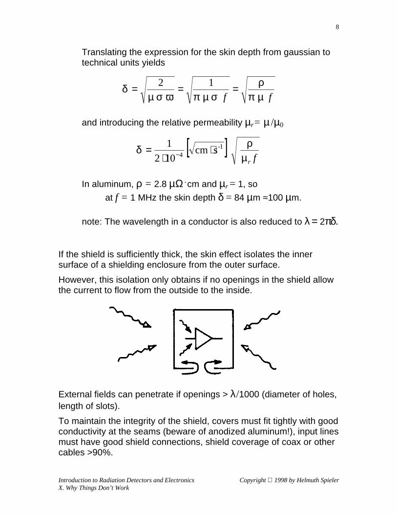
Translating the expression for the skin depth from gaussian totechnical units yields
and introducing the relative permeability µr= µ /µ0
In aluminum, ρ = 2.8 µΩ . cm and µr = 1, so
at f = 1 MHz the skin depth δ = 84 µm ≈100 µm.
note: The wavelength in a conductor is also reduced to λ = 2πδ.
If the shield is sufficiently thick, the skin effect isolates the innersurface of a shielding enclosure from the outer surface.
However, this isolation only obtains if no openings in the shield allowthe current to flow from the outside to the inside.
External fields can penetrate if openings > λ/1000 (diameter of holes,length of slots).
To maintain the integrity of the shield, covers must fit tightly with goodconductivity at the seams (beware of anodized aluminum!), input linesmust have good shield connections, shield coverage of coax or othercables >90%.
ff µπρ
σµπωσµδ === 12
[ ]frµ
ρδ scm 102
1 1-4 ⋅
⋅= −

Introduction to Radiation Detectors and Electronics Copyright 1998 by Helmuth SpielerX. Why Things Don’t Work
9
b) “Field Line Pinning”
Full shielding is not always practical, nor is it always necessary.
Rather than preventing interference currents from entering thedetector system, it is often more practical to reduce the coupling ofthe interference to the critical nodes.
Consider a conductor carrying an undesired signal current, with acorresponding signal voltage.
Capacitive coupling will transfer interference to another circuit node.
If an intermediate conductor is introduced with a large capacitance tothe interference source and to ground compared to the critical node, itwill “capture” the field lines and effectively “shield” the critical node.
“Field line pinning” is the operative mechanism of “Faraday shields”.
C
C
C C
C 01
02
2 1
12
C
C
02
2
Er

Introduction to Radiation Detectors and Electronics Copyright 1998 by Helmuth SpielerX. Why Things Don’t Work
10
“Self-Shielding” Structures
The magnitude of capacitive coupling depends on the dielectricconstant of the intermediate medium.
Ensemble of electrodes: εr = 1 in volume between set 2 to set 1 andεr > 1 between sets 2 and 3.
The capacitance between electrode sets 2 and 3 is εr times largerthan between sets 1 and 2.
Example: Si, εr = 11.9
⇒ 92.2% of the field lines originating from electrode set 2 terminate on set 3,
i.e. are confined to the Si bulk7.8% terminate on set 1.
For comparison, with εr = 1, 50% of the field lines originating from electrode set 2 terminate on set 1.
⇒ high dielectric constant reduces coupling of electrode sets 2 and 3 to external sources.
If the interference source is represented by electrode set 1 and sets 2 and 3 represent a detector
⇒ Si detector is 6.5 times less sensitive to capacitive pickup then a detector with εr = 1(e.g. a gas chamber with the same geometry)
r
r
1
2
3
ε = 1
ε > 1

Introduction to Radiation Detectors and Electronics Copyright 1998 by Helmuth SpielerX. Why Things Don’t Work
11
4. Shared Current Paths (“ground loops”)
Although capacitive or inductive coupling cannot be ignored, the mostprevalent mechanism of undesired signal transfer is the existence ofshared signal paths.
Mechanism:
A large alternating current I1 is coupled into the common ground bus.
Although the circuit associated with generator V1 has a dedicatedcurrent return, the current seeks the past of least resistance, whichis the massive ground bus.
The lower circuit is a sensitive signal transmission path. Following thecommon lore, it is connected to ground at both the source andreceiver.
The large current flowing through the ground bus causes a voltagedrop ∆V, which is superimposed on the low-level signal loopassociated with V2 and appears as an additional signal component.
Cross-coupling has nothing to do with grounding per se, but is due tothe common return path.However, the common ground caused the problem by establishingthe shared path.
∆V
V
V
1
2
I1
CommonGround Bus

Introduction to Radiation Detectors and Electronics Copyright 1998 by Helmuth SpielerX. Why Things Don’t Work
12
In systems that respond to transients (i.e. time-varying signals) ratherthan DC signals, secondary loops can be closed by capacitance.A DC path is not necessary.
The loops in this figure are the same as shown before, but the loopsare closed by the capacitances Cs1 and Cs2. Frequently, thesecapacitances are not formed explicitly by capacitors, but are the straycapacitance formed by a power supply to ground, a detector to itssupport structure (as represented by Cs2), etc. For AC signals theinductance of the common current path can increase the impedancesubstantially beyond the DC resistance, especially at highfrequencies.
This mode of interference occurs whenever spurious voltages areintroduced into the signal path and superimpose on the desiredsignal.
∆V
V
V
1
2
I1
C
Cs2
s1
CommonGround Bus

Introduction to Radiation Detectors and Electronics Copyright 1998 by Helmuth SpielerX. Why Things Don’t Work
13
Interference does not cross-couple by voltage alone, but also viacurrent injection.
Current spikes originating in logic circuitry, for example, propagatethrough the bussing system as in a transmission line.
Individual connection points will absorb some fraction of the currentsignal, depending on the relative impedance of the node.
Current spike originatesin switching circuit andpropagates primarilytowards power supply
↓
↑Current also flows intolow impedance node A(common base stage),which closes thesecondary loop,
↑but not into high impedance node B
i(t)
A B
Introduction to Radiation Detectors and Electronics Copyright 1998 by Helmuth SpielerX. Why Things Don’t Work
14
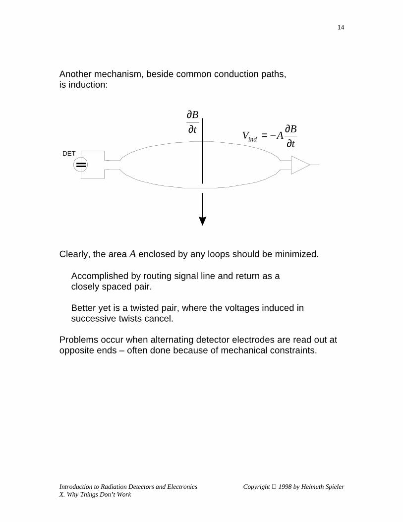
Another mechanism, beside common conduction paths,is induction:
Clearly, the area A enclosed by any loops should be minimized.
Accomplished by routing signal line and return as aclosely spaced pair.
Better yet is a twisted pair, where the voltages induced insuccessive twists cancel.
Problems occur when alternating detector electrodes are read out atopposite ends – often done because of mechanical constraints.
DET
t
B
∂∂
t
BAVind ∂
∂−=

Introduction to Radiation Detectors and Electronics Copyright 1998 by Helmuth SpielerX. Why Things Don’t Work
15
Remedial Techniques
1. Reduce impedance of the common path
⇒ Copper Braid Syndrome
Colloquially called “improving ground”.
(sometimes fortuitously introduces an out-of-phase component of the original interference, leading to cancellation)
Rather haphazard, poorly controlled ⇒ continual surprises
2. Avoid Grounds
Circuits rely on current return paths, not a ground connection!
In transferring from stage to stage the signal current flows throughlocal return loops.
1. At the input the detector signal is applied between the gate andsource of Q1
2. At the output of Q1 the signal is developed across the loadresistor in the drain of Q1 and applied between the gate andsource of Q2.
3. The output of Q2 is developed across the load resistor in itsdrain and applied across the gate and source resistor and load.
Note that – disregarding the input voltage divider that biases Q1 –varying either +V or –V does not affect the local signals.
OUTPUT
DAQ SYSTEM
+V
+V
- V- V
DET
DET
DETQ1
Q2Q3

Introduction to Radiation Detectors and Electronics Copyright 1998 by Helmuth SpielerX. Why Things Don’t Work
16
Breaking parasitic signal paths
Example:
Main Amp.
Bias Supply
Preamp Insulated Feed-Through
Det. Box
Detector
The configuration at the left has a loop that includes the mostsensitive part of the system – the detector and preamplifier input.
By introducing insulated feed-throughs, the input loop is broken.
Note that a new loop is shown, introduced by the common detectorbias supply. This loop is restricted to the output circuit of thepreamplifier, where the signal has been amplified, so it is lesssensitive to interference.
• Note that the problem is not caused by loops per se, i.e.enclosed areas, but by the multiple connections that provideentry paths for interference.
• Although not shown in the schematic illustrations above, boththe “detector box” (e.g. a scattering chamber) and the mainamplifiers (e.g. in a NIM bin or VME crate) are connected topotential interference sources, so currents can flow throughparts of the input signal path.

Introduction to Radiation Detectors and Electronics Copyright 1998 by Helmuth SpielerX. Why Things Don’t Work
17
Breaking shared signal paths, cont’d
1. Differential Receivers
Besides providing common mode noise rejection, differentialreceivers also allow “ground free” connections.
Ideal configuration using differential drivers and receivers
Technique also usable with single-ended drivers
SIGNAL TERMINATION
HIGH-VALUE RESISTORSFOR DC REFERENCING

Introduction to Radiation Detectors and Electronics Copyright 1998 by Helmuth SpielerX. Why Things Don’t Work
18
2. Insert high impedances
Ferrite sleeves block common mode currents.
Signal current in coax line flows on
• outer surface of inner conductor• inner surface of shield.
Net field at outer surface of shield is zero.
⇒ Ferrite sleeve does not affect signal transmission.
Common mode currents in the coax line (current flow in same direction on inner and outer conductor) orcurrent components flowing only on the outside surface of the shield (“ground loops”)will couple to the ferrite and be suppressed.
Ferrite material must be selected to present high impedance atrelevant frequencies.
Technique can also be applied to twisted-pair ribbon cables.Series resistors isolate parasitic ground connections.
FERRITE SLEEVE

Introduction to Radiation Detectors and Electronics Copyright 1998 by Helmuth SpielerX. Why Things Don’t Work
19
Example: detector bias voltage connection
Isolation resistors can also be mounted in an external box that islooped into the bias cable. Either use an insulated box or be sure toisolate the shells of the input and output connectors from another.
A simple check for noise introduced through the detector biasconnection is to use a battery.
“Ground loops” are often formed by the third wire in the AC powerconnection. Avoid voltage differences in the “ground” connection byconnecting all power cords associated with low-level circuitry into thesame outlet strip.
DETECTORBIASSUPPLY
SHAPER
COAX SHIELD INSULATEDFROM LOCAL GROUND
ISOLATIONRESISTORS
DETECTOR PREAMPLIFIER

Introduction to Radiation Detectors and Electronics Copyright 1998 by Helmuth SpielerX. Why Things Don’t Work
20
3. Direct the current flow away from sensitive nodes
A timing discriminator was built on a PC board and mounted in a NIMmodule with multiple channels.
All inputs and outputs were mounted on the front panel. The outputsdrove about 20 mA into 50 Ω cables.
Whenever an output fired, the unit broke into oscillation.
A portion of the output current flowed through the input groundconnection. The voltage drop ∆V was sufficient to fire the comparator.
Breaking the loop by insulating the output connector from the frontpanel fixed the problem.
50
THRESHOLDCOMPARATOR
OUTPUT DRIVER
VTH
∆V
50LOAD
Ω
INPUT
50
THRESHOLDCOMPARATOR
OUTPUT DRIVER
VTH
50LOAD
Ω
INSULATED BUSHING
INPUT

Introduction to Radiation Detectors and Electronics Copyright 1998 by Helmuth SpielerX. Why Things Don’t Work
21
Often it is convenient to replace the coax cable at the output by astrip line integrated on the PC board.
Strip Line:
Current paths can be controlled by patterning the ground plane.
50
THRESHOLDCOMPARATOR
OUTPUT DRIVER
VTH
50LOAD
Ω
INSULATED BUSHING
INPUT
Signal Trace
Ground Plane

Introduction to Radiation Detectors and Electronics Copyright 1998 by Helmuth SpielerX. Why Things Don’t Work
22
Ground returns are also critical at the circuit level.
Although the desired signal currents circulate as shown on p. 15,there are additional currents flowing in the circuit.
In addition to the signal currents Iin and Iout, the drain current is alsochanging with the signal and must return to the source. Since thereturn through the power supply can be remote and circuitous, a well-defined AC return path is provided by the bypass capacitor.
Since the input and output signal voltages are usually referenced tothe negative supply rail, circuits commonly configure it as a commonlarge area bus, the “ground”, and all nodes are referenced to it.
Since the “ground” is a large area conducting surface – often achassis or a ground plane – with a “low” impedance, it is consideredto be an equipotential surface.
BypassCapacitor
LOADI
I
Iinout
out
+V
- V
Bypass Capacitor
LOADI
I
Iinout
out
Introduction to Radiation Detectors and Electronics Copyright 1998 by Helmuth SpielerX. Why Things Don’t Work
23
The assumption that “ground” is an equipotential surface is notalways justified.
At high frequencies current flows only in a thin surface layer(“skin effect”).
The skin depth in aluminum is ~100 µm at 1 MHz. A pulse with a 3 ns rise-time will have substantial Fourier components beyond 100 MHz, where the skin depth is 10 µm.
⇒ Even large area conductors can have substantial resistance!
Example: a strip of aluminum, 1 cm wide and 5 cm longhas a resistance of ~20 mΩ at 100 MHz(single surface, typical Al alloy)
100 mA ⇒ 2 mV voltage drop,
which can be much larger than the signal.
The resistance is determined by the ratio of lengthto width, i.e. a strip 1 mm wide and 5 mm long willshow the same behavior.
Inductance can increase impedances much beyond this value!
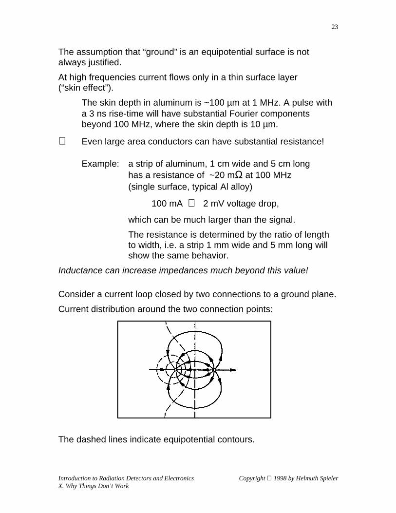
Consider a current loop closed by two connections to a ground plane.
Current distribution around the two connection points:
The dashed lines indicate equipotential contours.

Introduction to Radiation Detectors and Electronics Copyright 1998 by Helmuth SpielerX. Why Things Don’t Work
24
Assume a total drop of 100 mV. The resulting potential distribution is
Mounting a circuit block (an IC, for example) with ground and bypassconnections as shown below
introduces a 50 mV voltage drop in the “ground” path.
Direct connection of the bypass capacitor between the V+ and GNDpads avoids pickup of the voltage drop on the ground plane.
10080
70
605040
30
200
10080
70
6040
30
200
GNDV+
10080
40
30
200
GND
V+

Introduction to Radiation Detectors and Electronics Copyright 1998 by Helmuth SpielerX. Why Things Don’t Work
25
“Ground” Connections in Multi-Stage Circuits
IC comprising a preamplifier, gain stages and an output driver:
The output current is typically orders of magnitude greater than theinput current (due to amplifier gain, load impedance).
Combining all ground returns in one bond pad creates a sharedimpedance (inductance of bond wire). This also illustrates the use ofa popular technique – the “star” ground – and its pitfalls.
Separating the “ground” connections by current return paths routescurrents away from the common impedance and constrains theextent of the output loop, which tends to carry the highest current.
LOAD
SIGNAL
V+
V-
LOADSIGNAL
V+

Introduction to Radiation Detectors and Electronics Copyright 1998 by Helmuth SpielerX. Why Things Don’t Work
26
The Folded Cascode
The folded cascode is frequently used in preamplifiers optimized forlow power.
Standard cascode with representative transistor sizes:
The cascode combines two transistors to obtain
• the high transconductance and low noise of a wide transistor
• the high output resistance (increased by local feedback)and small output capacitance of a narrow transistor
• reduced capacitance between output and input
Since the input transistor determines the noise level, its currentrequirement tends to dominate.
In a conventional cascode the current required for the input transistormust flow through the whole chain.
OUT OUT
VGS VGS
+V +V
WL
WL
WL
WL
WL
= 25= 1
= 25= 1
= 25= 8
= 250= 1
= 250= 1
V
V
1
2

Introduction to Radiation Detectors and Electronics Copyright 1998 by Helmuth SpielerX. Why Things Don’t Work
27
The folded cascode allows the (second) cascode transistor to operateat a lower current and, as a result, higher output resistance.
Since PMOS transistors tend to have lower “1/ f ” noise than NMOSdevices, the following adaptation is often used:
The problem with this configuration is that the supply V1 becomespart of the input signal path. Unless the V1 supply bus is verycarefully configured and kept free of other signals, interference will becoupled into the input.
OUT
VGS
+V
OUTVGS
1
2
+V
+V

Introduction to Radiation Detectors and Electronics Copyright 1998 by Helmuth SpielerX. Why Things Don’t Work
28
Consider the circuit connected to a strip detector:
Unless the connection points of the bypass capacitors from the FETsource and the detector backplane are chosen carefully, interferencewill be introduced into the input signal loop.
It is much better to “ground” the FET source to a local signalreference and use a negative second supply.
OUTVGS
V 1
2
-
+V
OUT
1 2+V +V
?
?
VDET

Introduction to Radiation Detectors and Electronics Copyright 1998 by Helmuth SpielerX. Why Things Don’t Work
29
Connected to a strip detector (and redrawn slightly), this configurationprovides a direct input return loop.
For some (mythical?) reason positive supplies are more popular.Proper connection of the detector can stillprovide a direct input path.
In most implementations supply lines are more susceptible to pickup,so the +V1 line must be properly filtered to prevent current injection.
OUT
V 1
2
-
+V
VDET
OUT
V 1
2+V
VDET
+

Introduction to Radiation Detectors and Electronics Copyright 1998 by Helmuth SpielerX. Why Things Don’t Work
30
System Considerations
1. Choice of Shaper
Although a bipolar shaper has slightly inferior noise performancethan a unipolar shaper, it may provide better results in the presenceof significant low-frequency noise.
Minimum Noise
CR-RC
(CR)2-RC
In the frequency domain the additional CR-stage (low-pass filter)provides substantial attenuation of low-frequency interference.
Frequency Response of CR-RC and (CR)2-RC Shapers
1.0E-09
1.0E-08
1.0E-07
1.0E-06
1.0E-05
1.0E-04
1.0E-03
1.0E-02
1.0E-01
1.0E+00
1.0E+02 1.0E+03 1.0E+04 1.0E+05 1.0E+06 1.0E+07 1.0E+08
Frequency [Hz]
Rel
ativ
e V
olt
age
Gai
n
(CR)2-RC
CR-RC
CviQ nnoptn 355.1, =
CviQ nnoptn 406.1, =

Introduction to Radiation Detectors and Electronics Copyright 1998 by Helmuth SpielerX. Why Things Don’t Work
31
2. Connections in Multi-Channel Systems
Example: Strip Detector Readout
A single channel of a readout system for strip detectors includes
• low noise preamplification
• additional gain stages
• a comparator for hit recognition
• a clocked pipeline or storage array
• additional multiplexing circuitry to feed the hit flag and possiblyanalog output signal to the output.
Especially comparators and switching stages inject current spikesinto the voltage busses, but even low-level analog stages rely oncurrent changes.
Voltage bussing circuitry on integrated circuitry often has significantresistance, since the lines are narrow and thin, so the currenttransients cause local voltage changes that can couple into the input.
Voltage Drop due to transient currents In series with V(det)!
The transient voltage drop dV is superimposed on the detector biasand injects a charge dQ = dV Cdet into the input.
V(elec) V(det)
dV
dQ= dV Cdet
DET
Introduction to Radiation Detectors and Electronics Copyright 1998 by Helmuth SpielerX. Why Things Don’t Work
32
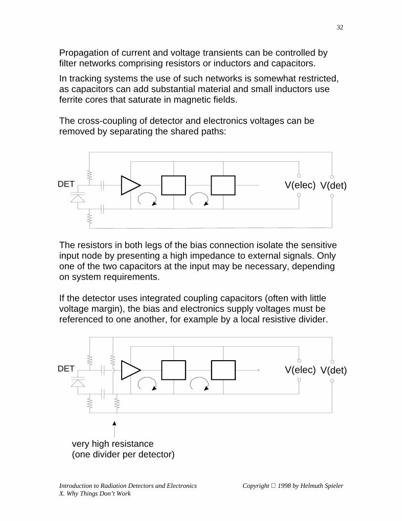
Propagation of current and voltage transients can be controlled byfilter networks comprising resistors or inductors and capacitors.
In tracking systems the use of such networks is somewhat restricted,as capacitors can add substantial material and small inductors useferrite cores that saturate in magnetic fields.
The cross-coupling of detector and electronics voltages can beremoved by separating the shared paths:
The resistors in both legs of the bias connection isolate the sensitiveinput node by presenting a high impedance to external signals. Onlyone of the two capacitors at the input may be necessary, dependingon system requirements.
If the detector uses integrated coupling capacitors (often with littlevoltage margin), the bias and electronics supply voltages must bereferenced to one another, for example by a local resistive divider.
very high resistance (one divider per detector)
V(elec) V(det)DET
V(elec) V(det)DET

Introduction to Radiation Detectors and Electronics Copyright 1998 by Helmuth SpielerX. Why Things Don’t Work
33
Ideally, multiple channels are configured so that only local signalloops exist.
Since the path of least resistance is provided by the cabling andconnections to the power supplies and data acquisition system,current transients originating in the front-end circuitry do not flowtowards the input.
V(elec)
V(det)
V(elec)
V(det) CABLEANALOG IC DIGITAL IC

Introduction to Radiation Detectors and Electronics Copyright 1998 by Helmuth SpielerX. Why Things Don’t Work
34
In reality, the inputs of adjacent channels and chips are coupled bythe strip-to-strip capacitance and the common detector substrate.
The loop formed by common connections at both the input and theoutput allows current transients to propagate to the input.
This is also applies to channels on the same side of the detector.
Consider current spikes originating in the digital circuitry:
Since the cross-connection at the input is formed by the connection ofmultiple chips to the detector, it is unavoidable.
Breaking the cross-connection at the output is impractical (commondata line for multiple chips on a hybrid).
What can be done to break the secondary current path?
V(elec) V(det)
V(elec) V(det)
CABLEANALOG IC DIGITAL IC

Introduction to Radiation Detectors and Electronics Copyright 1998 by Helmuth SpielerX. Why Things Don’t Work
35
Since the most serious current spikes originate in the digital circuitry,it should be isolated from the analog section.
Commonly, the analog and digital supply voltages are fed separately,but this doesn’t address the main problem, which is the commonreturn connection (typically the “ground”).
The only necessary connection between the analog and digitalcircuitry is the data path.
By implementing this in a manner that
• provides a signal path from the analog to the digital circuitry,
but
• presents a high impedance from the digital to the analog section,i.e. in the opposite direction, the input loop can be broken.
L: Local signal loopOne connection per channel,but one return per chip (tolimit number of wire bonds).
CABLEANALOG IC DIGITAL IC
V(analog)V(dig) V(det)
L
V(analog)V(dig) V(det)
L

Introduction to Radiation Detectors and Electronics Copyright 1998 by Helmuth SpielerX. Why Things Don’t Work
36
Double-sided detectors pose similar problems.
The figure below represents a double-sided strip detector readout,where the upper electronics chain connects to one side (A) of thedetector and the lower chain to the opposite side (B).
Since the signal return path includes
a) the adjacent channels
b) strips on the opposite side
the system must be designed carefully to avoid loops that introduceinterference currents into the input circuit.
Typical configuration:side A
side B
In this arrangement voltage transients formed on the busses of bothreadout sides couple into the input circuit.
Not recommended!
V(elec)
V(elec)
V(det)CABLEANALOG IC DIGITAL ICDET

Introduction to Radiation Detectors and Electronics Copyright 1998 by Helmuth SpielerX. Why Things Don’t Work
37
The technique of using a unidirectional driver with local return loop toisolate the digital from the analog circuitry can also be applied todouble-sided detectors.
The double-sided detector is AC-coupled, i.e. it has integratedcoupling capacitors and bias resistors per strip. A resistive divider isincluded for voltage referencing.
side A
side B
Local signal loopon detector
Note that the input signal return path is well-defined by incorporatinga direct connection between the reference (“ground”) connections ofthe input stages on both sides.
In the schemes described above it is critical that• all of the above circuits rely on local signal referencing, rather than
“system grounds”.• the power supply lines are balanced, i.e. both the positive and
negative legs present the same (preferably high) impedance to theremote system ground.
V(det)CABLEANALOG IC DIGITAL IC
V(analog)V(dig)
L
V(analog)V(dig)L
+ +
+ +
DET

Introduction to Radiation Detectors and Electronics Copyright 1998 by Helmuth SpielerX. Why Things Don’t Work
38
Reducing Sensitivity to External Pickup
The most critical node is the input, and the most vulnerableconnection is the one to the backplane, i.e. the detector bias line.
The separate detector bias connection should be implemented as abalanced, differential supply (shown below for the CAFE chip).
⇒ Pickup on the detector bias line couples equally to both legs, sothe difference is unaffected.
This requires a “groundless” system, i.e. the impedance Z presentedby both the +VCC and –VCC lines to the remote system ground mustbe much greater than the input impedance of the amplifier.The isolation impedance Z can be provided by the inductance of longconnecting cables, depending on the critical frequency range.
Any differential pickup on the bias line is attenuated by the filternetwork. Connecting the capacitor between the lines rather than toground keeps interference currents from flowing to the front-end.
The isolation resistors introduce a high impedance into the biassupply line to avoid formation of a parasitic signal path.
The capacitor connecting the detector backplane to CAFE “DETGND”is usually called a bypass capacitor, but it really is a couplingcapacitor that closes the input signal return path.
CAFE "DETGND"
CAFE "GND”
DETECTORSTRIP
BACKPLANE
+VCC
−VCC
+VDET
−VDETISOLATIONRESISTORS FILTER NETWORK
Z
Z

Introduction to Radiation Detectors and Electronics Copyright 1998 by Helmuth SpielerX. Why Things Don’t Work
39
“Bypass” implies that interference is being shunted to ground,which is the opposite of what is intended here. Since the inputcommon connection is not a zero impedance point, we don’t wantto inject any interference into this node.
Differential bias feed applied to a double-sided detector formed bygluing two single-sided detectors back-to-back:
CAFE "GND"
CAFE "DETGND"
CAFE "DETGND"
CAFE "GND"

Introduction to Radiation Detectors and Electronics Copyright 1998 by Helmuth SpielerX. Why Things Don’t Work
40
Interference can also be coupled into the front-end throughmechanical mounting systems.
Maximum noise immunity obtains when coupling from the coolingstave to the backplane is a common mode effect, i.e. both the inputand the reference node change by the same amount. This requires• a balanced power bus, such that both +VCC and –VCC lines
present the same impedance to the remote system ground,• that the impedance presented by the +VCC and –VCC lines to the
remote system ground is much greater than the input impedanceof the amplifier,
• that the two coupling capacitors are much greater than thedetector capacitance (strip to backplane).
CAFE "DETGND"
CAFE "DETGND"
CAFE "GND"
CAFE "GND"

Introduction to Radiation Detectors and Electronics Copyright 1998 by Helmuth SpielerX. Why Things Don’t Work
41
“Self-Shielding” Cables
In mixed analog-digital systems, radiation from cables, especiallydigital signal cables, is a concern.
By utilizing broadside-coupled differential lines with a thinintermediate dielectric, the field is confined to the region between theconductors. The extent of the fringing field beyond the conductoredge is about equal to the thickness of the dielectric.
Example:
Conductors: 50 µm thick, 150 µm wide
Dielectric: 50 µm thick
Gap between pairs: 150 µm
Cross-coupling between adjacent pairs:< 2% at 60 MHz for 1 m length
Power connections are made substantially wider (1 – 5 mm), forminga low impedance transmission line with high distributed capacitance.
The geometry shown above is for short runs in the inner region of atracker, where reduction of material is crucial. Dimensions can bescaled proportionally to achieve lower resistance and signaldispersion in longer cable runs at larger radii.
ANALOG LINESDATA BUS(PARTIAL)
THRESHOLD
ANALOG POWER CURRENT SET

Introduction to Radiation Detectors and Electronics Copyright 1998 by Helmuth SpielerX. Why Things Don’t Work
42
Summary of Considerations in Detector Design
1. Maximize the signal
If the detector medium provides an acceptable combination ofenergy loss and charge yield, direct detection is feasible.
In many situations the required absorber properties dictatehybrid systems, e.g.
scintillator – PMT or scintillator – photodiode combinations.
Maximizing the signal also implies reducing the capacitance atthe electronic input node. Although we want to measure charge,the primary electric signal is either voltage or current, both ofwhich increase with decreasing capacitance.
2. Choose the input transistor to match the application.
At long shaping times FETs (JFETs or MOSFETs) are best.At short shaping times, bipolar transistors tend to prevail.
3. Select the appropriate shaper and shaping time
In general, short shaping times will require higher powerdissipation for a given noise level than long times.
The shaper can be optimized with respect to either current orvoltage noise (important in systems subject to radiationdamage)
4. Position-sensitive detectors can be implemented using eitherinterpolation techniques or direct readout. Interpolating systemsreduce the number of electronic channels but require morecomplex and sophisticated electronics. Direct readout allowsthe greatest simplicity per channel, but requires many channels,often at high density (good match for monolithically integratedcircuits).

Introduction to Radiation Detectors and Electronics Copyright 1998 by Helmuth SpielerX. Why Things Don’t Work
43
5. Segmentation improves both rate capability and noise (lowcapacitance). It also increases radiation resistance.
6. Timing systems need to optimize both rise-time andcapacitance.
Relatively long rise-times can still provide good timingresolution (<< rise-time) if the signal-to-noise ratio is high.
7. From the outset, systems must consider sensitivity to spurioussignals. Poor system design can render the best low-noisefront-end useless.
8. Although making detectors “work” in an experiment has reliedextensively on tinkering and “cut-and-try”, understanding thecritical elements that determine detector performance makes itmuch easier to navigate the maze of a large system.
It is more efficient to avoid problems than to fix them.
A little understanding can go a long way.
Related Documents


