Chapter 1 Introduction Introduction 1-1 What’s the Internet: a service view communication infrastructure enables distributed applications: ❍ Web, VoIP, email, games, e-commerce, file sharing communication services Introduction 1-2 communication services provided to apps: ❍ reliable data delivery from source to destination ❍ “best effort” (unreliable) data delivery What’s the Internet: “nuts and bolts” view millions of connected computing devices: hosts = end systems ❍ running network apps Home network Mobile network Global ISP Regional ISP PC server wireless laptop cellular handheld communication links Introduction 1-3 Institutional network Regional ISP router wired links access points communication links fiber, copper, radio, satellite transmission rate = bandwidth routers: forward packets (chunks of data) What’s the Internet: “nuts and bolts” view protocols control sending, receiving of msgs ❍ e.g., TCP, IP, HTTP, Skype, Ethernet Internet: “network of networks” Home network Mobile network Global ISP Regional ISP Introduction 1-4 networks” ❍ loosely hierarchical ❍ public Internet versus private intranet Internet standards ❍ RFC: Request for comments ❍ IETF: Internet Engineering Task Force Institutional network Regional ISP

Welcome message from author
This document is posted to help you gain knowledge. Please leave a comment to let me know what you think about it! Share it to your friends and learn new things together.
Transcript
Chapter 1Introduction
Introduction 1-1
What’s the Internet: a service view
� communication infrastructure enables distributed applications:
❍ Web, VoIP, email, games, e-commerce, file sharing
� communication services
Introduction 1-2
� communication services provided to apps:
❍ reliable data delivery from source to destination
❍ “best effort” (unreliable) data delivery
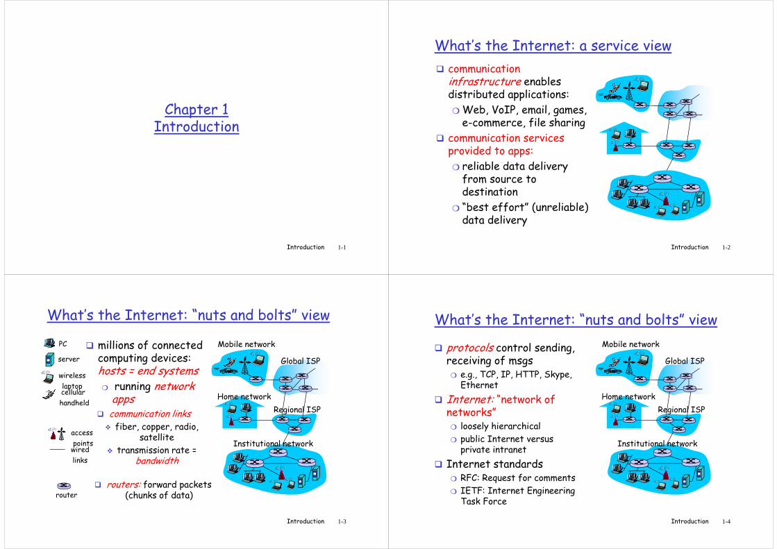
What’s the Internet: “nuts and bolts” view
� millions of connected computing devices: hosts = end systems
❍ running network apps Home network
Mobile network
Global ISP
Regional ISP
PC
server
wireless
laptopcellular
handheld
� communication links
Introduction 1-3
Institutional network
Regional ISP
router
wired
links
access
points
� communication links� fiber, copper, radio,
satellite
� transmission rate = bandwidth
� routers: forward packets (chunks of data)
What’s the Internet: “nuts and bolts” view
� protocols control sending, receiving of msgs
❍ e.g., TCP, IP, HTTP, Skype, Ethernet
� Internet: “network of networks”
Home network
Mobile network
Global ISP
Regional ISP
Introduction 1-4
networks”❍ loosely hierarchical
❍ public Internet versus private intranet
� Internet standards❍ RFC: Request for comments
❍ IETF: Internet Engineering Task Force
Institutional network
Regional ISP
What’s a protocol?
human protocols:
� “what’s the time?”
� “I have a question”
� introductions
network protocols:
� machines rather than humans
� all communication activity in Internet governed by protocols
Introduction 1-5
… specific msgs sent
… specific actions taken when msgs received, or other events
governed by protocols
protocols define format, order of msgs sent and received among network entities, and actions
taken on msg transmission, receipt
What’s a protocol?
a human protocol and a computer network protocol:
Hi
Hi
TCP connectionreq
TCP connection
Introduction 1-6
Hi
Got thetime?
2:00
TCP connectionresponse
Get http://www.awl.com/kurose-ross
<file>
time
A closer look at network structure:
� network edge:applications and hosts� access networks,
physical media:
Introduction 1-7
physical media:wired, wireless
communication links
� network core:� interconnected routers
� network of networks
The network edge:
� end systems (hosts):❍ run application programs
❍ e.g. Web, email
❍ at “edge of network” peer-peer
� client/server model
Introduction 1-8
client/server
client/server model� client host requests, receives service from always-on server
� e.g. Web browser/server; email client/server
� peer-peer model:� minimal (or no) use of
dedicated servers
� e.g. Skype, BitTorrent
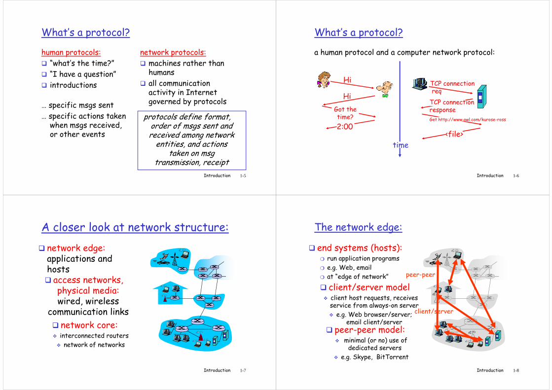
Transmission across a physical link: point-to-point networks
� Bits: propagate between transmitter and receiver
physical link: what lies between transmitter &
TXTXRX
RX
Physical link
Introduction 1-9
� physical link: what lies between transmitter & receiver
� guided media:❍ signals propagate in solid media: copper, fiber, coax
� unguided media:❍ signals propagate freely, e.g., radio
Transmission across a physical link
� Bit sequence modulates a suitable waveform which is sent across the link
TXTXRX
RX
100011 110011
Introduction 1-10
sent across the link
� As the signal travels it experiences❍ Attenuation (absorption)
❍ Distortion (limited bandwidth (frequency))
❍ Noise (interference, thermal noise)
❍ Influenced by medium, bit rate and distance
� Received sequence may be incorrect!!!
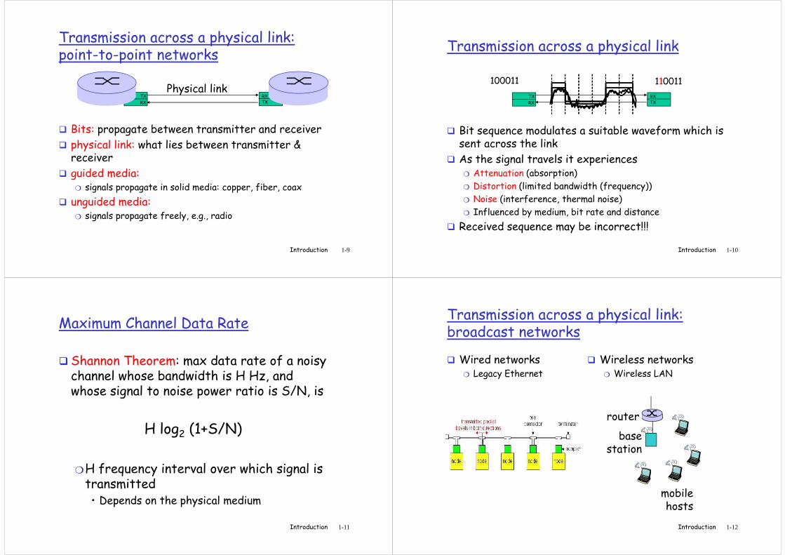
Maximum Channel Data Rate
� Shannon Theorem: max data rate of a noisy channel whose bandwidth is H Hz, and whose signal to noise power ratio is S/N, is
Introduction 1-11
H log2 (1+S/N)
❍H frequency interval over which signal is transmitted• Depends on the physical medium
Transmission across a physical link: broadcast networks
� Wired networks❍ Legacy Ethernet
� Wireless networks❍ Wireless LAN
router
Introduction 1-12
basestation
mobilehosts
router
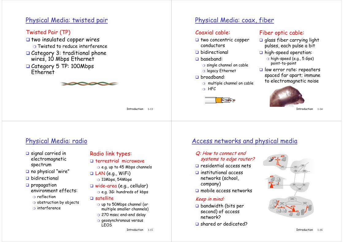
Physical Media: twisted pair
Twisted Pair (TP)� two insulated copper wires
❍ Twisted to reduce interference
� Category 3: traditional phone wires, 10 Mbps Ethernet
Introduction 1-13
wires, 10 Mbps Ethernet� Category 5 TP: 100Mbps Ethernet
Physical Media: coax, fiber
Coaxial cable:� two concentric copper
conductors
� bidirectional
� baseband:
Fiber optic cable:� glass fiber carrying light
pulses, each pulse a bit
� high-speed operation:❍ high-speed (e.g., 5 Gps)
point-to-point
Introduction 1-14
� baseband:❍ single channel on cable
❍ legacy Ethernet
� broadband:❍ multiple channel on cable
❍ HFC
high-speed (e.g., 5 Gps) point-to-point
� low error rate: repeaters spaced far apart; immune to electromagnetic noise
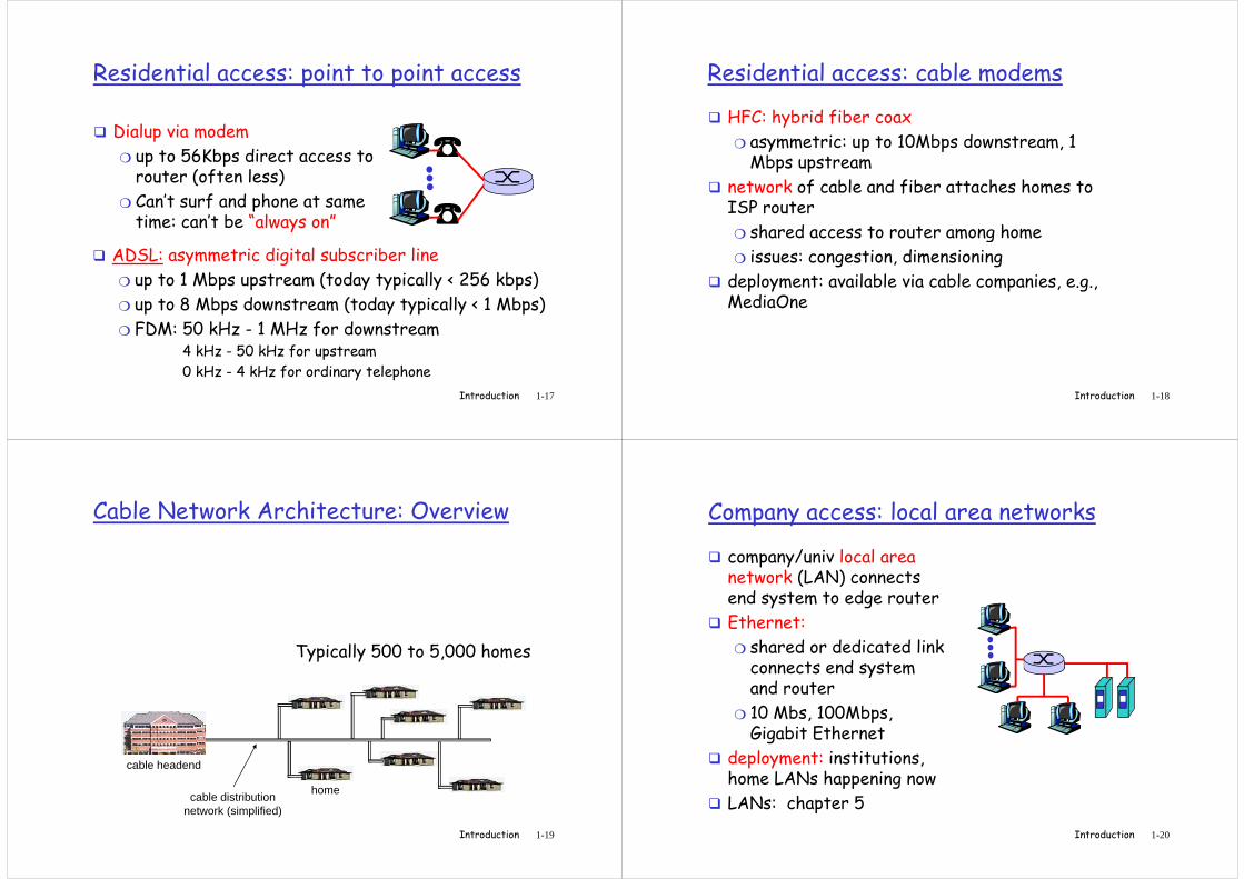
Physical Media: radio
� signal carried in electromagnetic spectrum
� no physical “wire”
� bidirectional
propagation
Radio link types:� terrestrial microwave
❍ e.g. up to 45 Mbps channels
� LAN (e.g., WiFi)❍ 11Mbps, 54Mbps
Introduction 1-15
� propagation environment effects:
❍ reflection
❍ obstruction by objects
❍ interference
11Mbps, 54Mbps
� wide-area (e.g., cellular)❍ e.g. 3G: hundreds of kbps
� satellite❍ up to 50Mbps channel (or
multiple smaller channels)
❍ 270 msec end-end delay
❍ geosynchronous versus LEOS
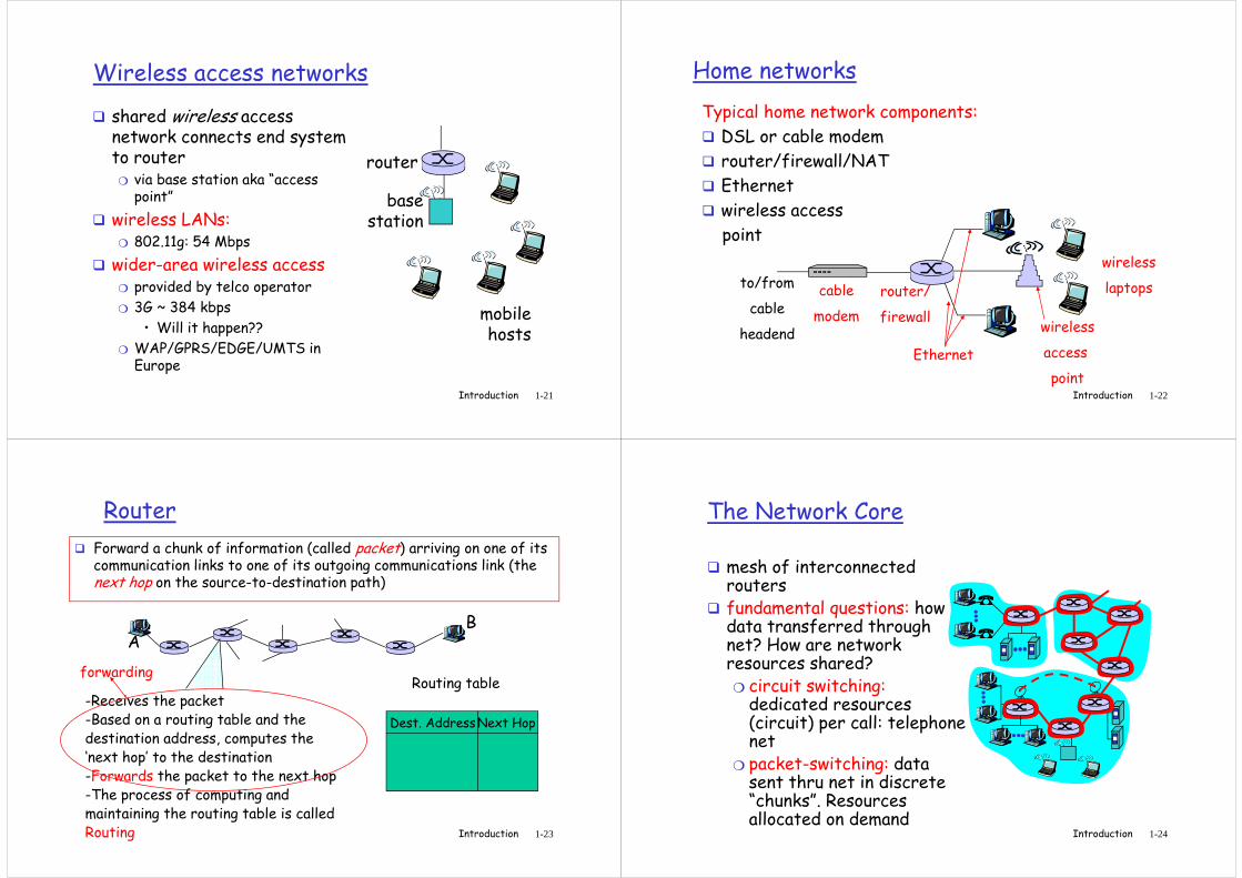
Access networks and physical media
Q: How to connect end systems to edge router?
� residential access nets
� institutional access networks (school, company)
Introduction 1-16
company)
� mobile access networks
Keep in mind: � bandwidth (bits per
second) of access network?
� shared or dedicated?
Residential access: point to point access
� Dialup via modem
❍ up to 56Kbps direct access to router (often less)
❍ Can’t surf and phone at same time: can’t be “always on”
Introduction 1-17
time: can’t be “always on”
� ADSL: asymmetric digital subscriber line
❍ up to 1 Mbps upstream (today typically < 256 kbps)
❍ up to 8 Mbps downstream (today typically < 1 Mbps)
❍ FDM: 50 kHz - 1 MHz for downstream4 kHz - 50 kHz for upstream
0 kHz - 4 kHz for ordinary telephone
Residential access: cable modems
� HFC: hybrid fiber coax
❍ asymmetric: up to 10Mbps downstream, 1 Mbps upstream
� network of cable and fiber attaches homes to ISP router
shared access to router among home
Introduction 1-18
❍ shared access to router among home
❍ issues: congestion, dimensioning
� deployment: available via cable companies, e.g., MediaOne
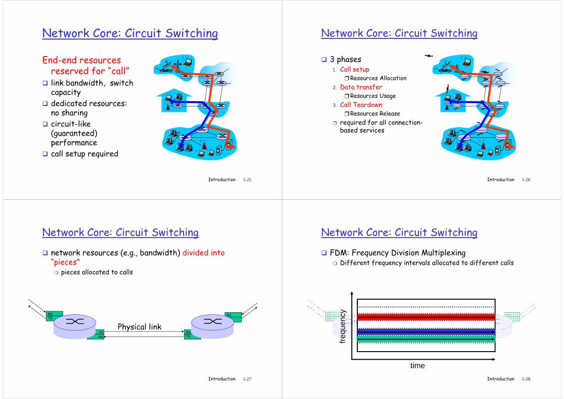
Cable Network Architecture: Overview
Typically 500 to 5,000 homes
Introduction 1-19
home
cable headend
cable distributionnetwork (simplified)
Typically 500 to 5,000 homes
Company access: local area networks
� company/univ local area network (LAN) connects end system to edge router
� Ethernet:
❍ shared or dedicated link connects end system
Introduction 1-20
connects end system and router
❍ 10 Mbs, 100Mbps, Gigabit Ethernet
� deployment: institutions, home LANs happening now
� LANs: chapter 5
Wireless access networks
� shared wireless access network connects end system to router
❍ via base station aka “access point”
� wireless LANs:base
station
router
Introduction 1-21
� wireless LANs:❍ 802.11g: 54 Mbps
� wider-area wireless access❍ provided by telco operator
❍ 3G ~ 384 kbps
• Will it happen??
❍ WAP/GPRS/EDGE/UMTS in Europe
station
mobilehosts
Home networks
Typical home network components:
� DSL or cable modem
� router/firewall/NAT
� Ethernet
� wireless access
Introduction 1-22
wireless access
point
wireless
access
point
wireless
laptopsrouter/
firewall
cable
modem
to/from
cable
headend
Ethernet
Router
� Forward a chunk of information (called packet) arriving on one of its communication links to one of its outgoing communications link (the next hop on the source-to-destination path)
AB
Introduction 1-23
-Receives the packet-Based on a routing table and the destination address, computes the ‘next hop’ to the destination-Forwards the packet to the next hop-The process of computing and maintaining the routing table is called Routing
-Receives the packet-Based on a routing table and the destination address, computes the ‘next hop’ to the destination-Forwards the packet to the next hop-The process of computing and maintaining the routing table is called Routing
forwardingRouting table
Dest. AddressNext Hop
The Network Core
� mesh of interconnected routers
� fundamental questions: how is data transferred through net? How are network resources shared?
Introduction 1-24
resources shared?❍ circuit switching:dedicated resources (circuit) per call: telephone net
❍ packet-switching: data sent thru net in discrete “chunks”. Resources allocated on demand
Network Core: Circuit Switching
End-end resources reserved for “call”
� link bandwidth, switch capacity
dedicated resources:
Introduction 1-25
� dedicated resources: no sharing
� circuit-like (guaranteed) performance
� call setup required
Network Core: Circuit Switching
� 3 phases1. Call setup
❒ Resources Allocation
2. Data transfer❒ Resources Usage
Call Teardown
Introduction 1-26
3. Call Teardown❒ Resources Release
❒ required for all connection-based services
Network Core: Circuit Switching
� network resources (e.g., bandwidth) divided into “pieces”
❍ pieces allocated to calls
Introduction 1-27
TXRX
TXTXRX
RX
Physical linkTXRX
Network Core: Circuit Switching
� FDM: Frequency Division Multiplexing❍ Different frequency intervals allocated to different calls
Introduction 1-28
TXRX
TXTXRX
RX
Physical linkTXRX
time
freq
uenc
y
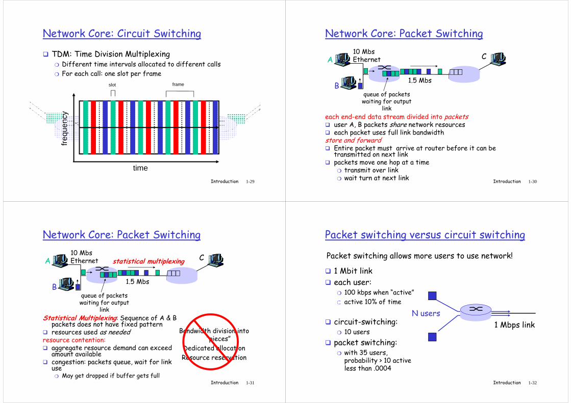
Network Core: Circuit Switching
� TDM: Time Division Multiplexing❍ Different time intervals allocated to different calls
❍ For each call: one slot per frame
slot frame
Introduction 1-29
TXRX
TXTXRX
RX
Physical linkTXRX
time
freq
uenc
y
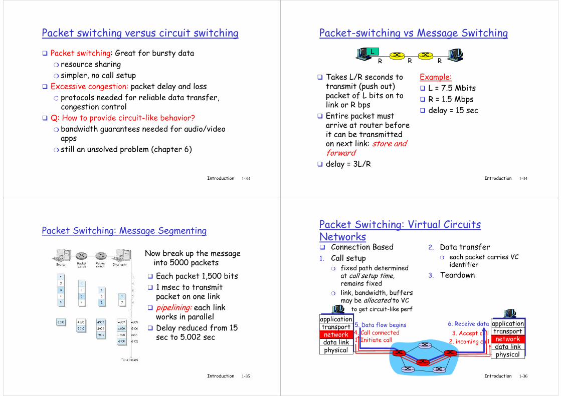
Network Core: Packet Switching
A
B
C10 MbsEthernet
1.5 Mbs
queue of packetswaiting for output
Introduction 1-30
each end-end data stream divided into packets� user A, B packets share network resources� each packet uses full link bandwidth store and forward� Entire packet must arrive at router before it can be
transmitted on next link� packets move one hop at a time
❍ transmit over link❍ wait turn at next link
waiting for outputlink
Network Core: Packet Switching
A
B
C10 MbsEthernet
1.5 Mbs
queue of packetswaiting for output
statistical multiplexing
Introduction 1-31
Statistical Multiplexing: Sequence of A & B packets does not have fixed pattern
� resources used as neededresource contention:� aggregate resource demand can exceed
amount available� congestion: packets queue, wait for link
use❍ May get dropped if buffer gets full
waiting for outputlink
Bandwidth division into “pieces”
Dedicated allocation
Resource reservation
Packet switching versus circuit switching
� 1 Mbit link
� each user: ❍ 100 kbps when “active”
❍ active 10% of time
Packet switching allows more users to use network!
Introduction 1-32
❍ active 10% of time
� circuit-switching: ❍ 10 users
� packet switching: ❍ with 35 users,
probability > 10 active less than .0004
N users
1 Mbps link
Packet switching versus circuit switching
� Packet switching: Great for bursty data
❍ resource sharing
❍ simpler, no call setup
� Excessive congestion: packet delay and loss
❍ protocols needed for reliable data transfer,
Introduction 1-33
❍ protocols needed for reliable data transfer, congestion control
� Q: How to provide circuit-like behavior?
❍ bandwidth guarantees needed for audio/video apps
❍ still an unsolved problem (chapter 6)
Packet-switching vs Message Switching
� Takes L/R seconds to transmit (push out) packet of L bits on to link or R bps
Example:
� L = 7.5 Mbits
� R = 1.5 Mbps
R R R
L
Introduction 1-34
packet of L bits on to link or R bps
� Entire packet must arrive at router before it can be transmitted on next link: store and forward
� delay = 3L/R
� R = 1.5 Mbps
� delay = 15 sec
Packet Switching: Message Segmenting
Now break up the message into 5000 packets
� Each packet 1,500 bits
� 1 msec to transmit packet on one link
Introduction 1-35
packet on one link
� pipelining: each link works in parallel
� Delay reduced from 15 sec to 5.002 sec
Packet Switching: Virtual Circuits Networks� Connection Based
1. Call setup❍ fixed path determined
at call setup time, remains fixed
❍ link, bandwidth, buffers may be allocated to VC
2. Data transfer❍ each packet carries VC
identifier
3. Teardown
Introduction 1-36
applicationtransportnetworkdata linkphysical
applicationtransportnetworkdata linkphysical
1. Initiate call 2. incoming call
3. Accept call4. Call connected5. Data flow begins 6. Receive data
may be allocated to VC• to get circuit-like perf
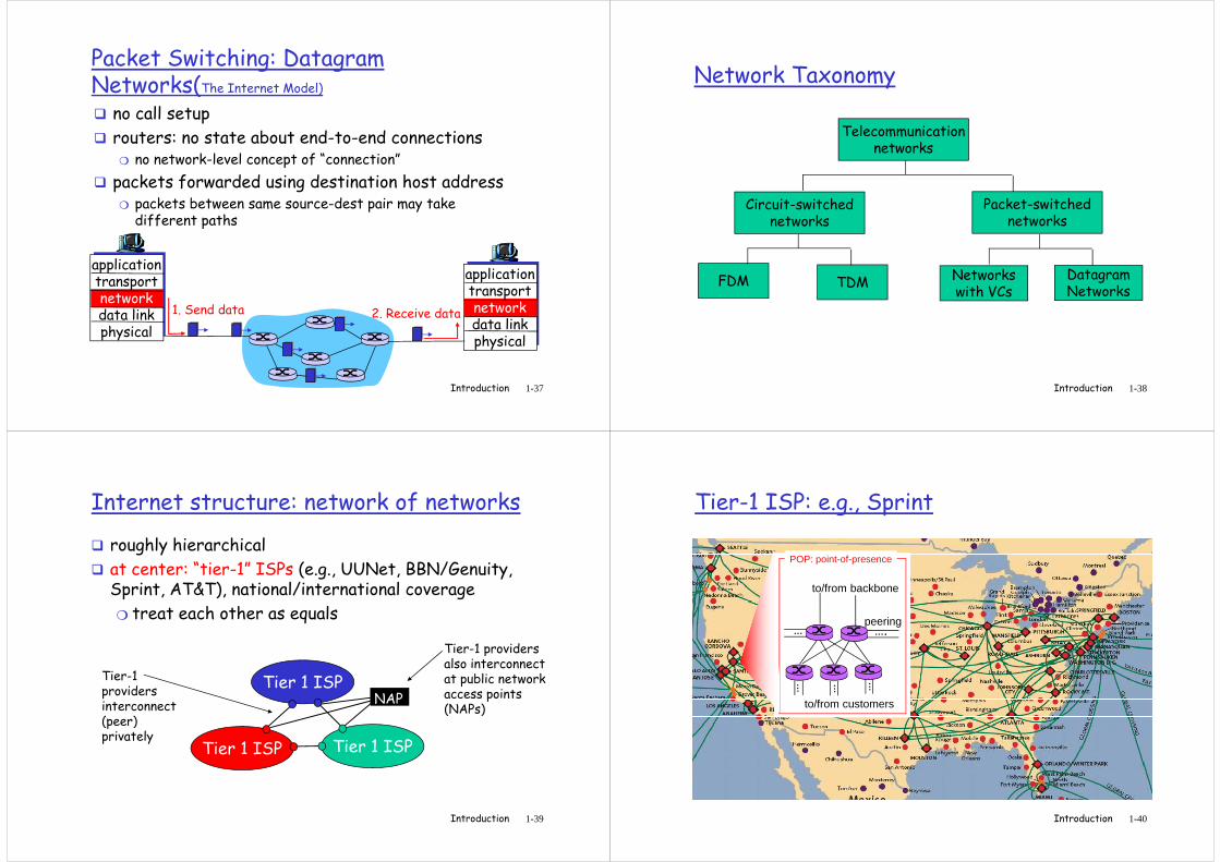
Packet Switching: Datagram Networks(The Internet Model)
� no call setup
� routers: no state about end-to-end connections❍ no network-level concept of “connection”
� packets forwarded using destination host address❍ packets between same source-dest pair may take
different paths
Introduction 1-37
different paths
applicationtransportnetworkdata linkphysical
applicationtransportnetworkdata linkphysical
1. Send data 2. Receive data
Network Taxonomy
Telecommunicationnetworks
Circuit-switchednetworks
Packet-switchednetworks
Introduction 1-38
networks
FDM TDM
networks
Networkswith VCs
DatagramNetworks
Internet structure: network of networks
� roughly hierarchical
� at center: “tier-1” ISPs (e.g., UUNet, BBN/Genuity, Sprint, AT&T), national/international coverage
❍ treat each other as equals
Tier-1 providers
Introduction 1-39
Tier 1 ISP
Tier 1 ISP
Tier 1 ISP
Tier-1 providers interconnect (peer) privately
NAP
Tier-1 providers also interconnect at public network access points (NAPs)
Tier-1 ISP: e.g., Sprint
…peering
to/from backbone
….
POP: point-of-presence
Introduction 1-40
to/from customers
………
Internet structure: network of networks
� “Tier-2” ISPs: smaller (often regional) ISPs❍ Connect to one or more tier-1 ISPs, possibly other tier-2
ISPs
Tier-2 ISPTier-2 ISP pays
Tier-2 ISPs also peer
Introduction 1-41
Tier 1 ISP
Tier 1 ISP
Tier 1 ISP
NAP
Tier-2 ISPTier-2 ISP
Tier-2 ISP Tier-2 ISP
Tier-2 ISP
Tier-2 ISP pays tier-1 ISP for connectivity to rest of Internet� tier-2 ISP is customer oftier-1 provider
also peer privately with each other, interconnect at NAP
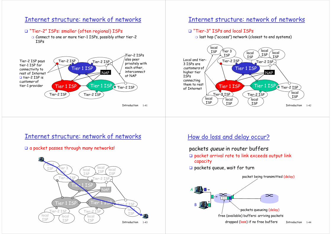
Internet structure: network of networks
� “Tier-3” ISPs and local ISPs ❍ last hop (“access”) network (closest to end systems)
Tier-2 ISP
localISPlocal
ISPlocalISP
localISP Tier 3
ISPLocal and tier-
Introduction 1-42
Tier 1 ISP
Tier 1 ISP
Tier 1 ISP
NAP
Tier-2 ISPTier-2 ISP
Tier-2 ISP Tier-2 ISP
Tier-2 ISP
ISP ISP
localISP
localISP
localISP
localISP
Local and tier-3 ISPs are customers ofhigher tier ISPsconnecting them to rest of Internet
Internet structure: network of networks
� a packet passes through many networks!
Tier-2 ISP
localISPlocal
ISPlocalISP
localISP Tier 3
ISP
Introduction 1-43
Tier 1 ISP
Tier 1 ISP
Tier 1 ISP
NAP
Tier-2 ISPTier-2 ISP
Tier-2 ISP Tier-2 ISP
Tier-2 ISP
ISP ISP
localISP
localISP
localISP
localISP
How do loss and delay occur?
packets queue in router buffers� packet arrival rate to link exceeds output link
capacity
� packets queue, wait for turn
packet being transmitted (delay)
Introduction 1-44
A
B
packet being transmitted (delay)
packets queueing (delay)
free (available) buffers: arriving packets
dropped (loss) if no free buffers
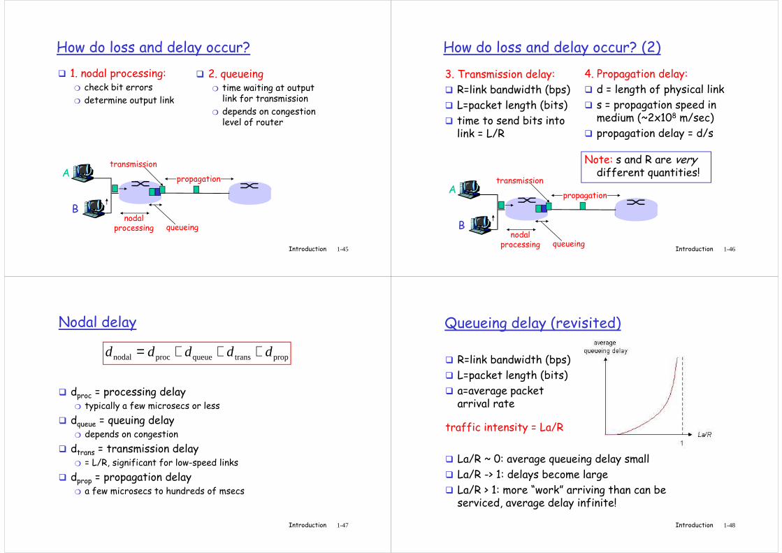
How do loss and delay occur?
� 1. nodal processing:❍ check bit errors
❍ determine output link
� 2. queueing❍ time waiting at output
link for transmission
❍ depends on congestion level of router
Introduction 1-45
A
B
propagation
transmission
nodalprocessing queueing
How do loss and delay occur? (2)
3. Transmission delay:
� R=link bandwidth (bps)
� L=packet length (bits)
� time to send bits into link = L/R
4. Propagation delay:
� d = length of physical link
� s = propagation speed in medium (~2x10⁸ m/sec)
� propagation delay = d/s
Introduction 1-46
link = L/R � propagation delay = d/s
A
B
propagation
transmission
nodalprocessing queueing
Note: s and R are very different quantities!
Nodal delay
� dproc = processing delay❍ typically a few microsecs or less
d = queuing delay
proptransqueueprocnodal ddddd +++=
Introduction 1-47
� dqueue = queuing delay❍ depends on congestion
� dtrans = transmission delay❍ = L/R, significant for low-speed links
� dprop = propagation delay❍ a few microsecs to hundreds of msecs
Queueing delay (revisited)
� R=link bandwidth (bps)
� L=packet length (bits)
� a=average packet arrival rate
Introduction 1-48
traffic intensity = La/R
� La/R ~ 0: average queueing delay small
� La/R -> 1: delays become large
� La/R > 1: more “work” arriving than can be serviced, average delay infinite!
Packet loss
� queue (aka buffer) preceding link in buffer has finite capacity
� when packet arrives to full queue, packet is dropped (aka lost)
� lost packet may be retransmitted by
Introduction 1-49
� lost packet may be retransmitted by previous node, by source end system, or not retransmitted at all
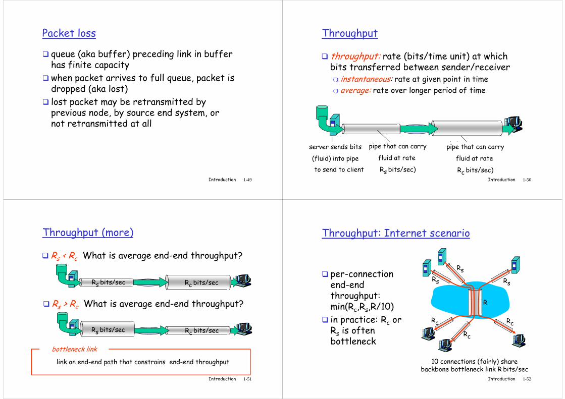
Throughput
� throughput: rate (bits/time unit) at which bits transferred between sender/receiver❍ instantaneous: rate at given point in time❍ average: rate over longer period of time
Introduction 1-50
server, with
file of F bits
to send to client
link capacity
Rs bits/sec
link capacity
Rc bits/sec
pipe that can carry
fluid at rate
Rs bits/sec)
pipe that can carry
fluid at rate
Rc bits/sec)
server sends bits
(fluid) into pipe
Throughput (more)
� Rs < Rc What is average end-end throughput?
Rs bits/sec Rc bits/sec
R > R What is average end-end throughput?
Introduction 1-51
� Rs > Rc What is average end-end throughput?
Rs bits/sec Rc bits/sec
link on end-end path that constrains end-end throughput
bottleneck link
Throughput: Internet scenario
Rs
Rs
Rs
R
� per-connection end-end throughput:
Introduction 1-52
10 connections (fairly) share backbone bottleneck link R bits/sec
Rc
Rc
Rc
Rthroughput: min(Rc,Rs,R/10)
� in practice: Rc or Rs is often bottleneck
Protocol “Layers”
Networks are complex!
� many “pieces”:
❍ hosts
❍ routers
❍ links of various
Question:Is there any hope of organizing structure of
Introduction 1-53
❍ links of various media
❍ applications
❍ protocols
❍ hardware, software
organizing structure of network?
Or at least our discussion of networks?
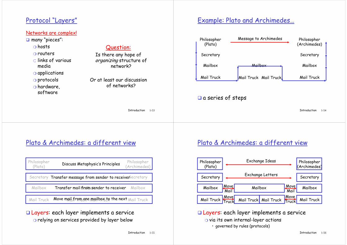
Example: Plato and Archimedes…
Philosopher (Plato)
Secretary
Philosopher (Archimedes)
Secretary
Message to Archimedes
Introduction 1-54
� a series of steps
Mailbox
Mail Truck
Mailbox
Mail TruckMail Truck
Mailbox
Mail Truck
Plato & Archimedes: a different view
Philosopher (Plato)
Secretary
Philosopher (Archimedes)
SecretaryTransfer message from sender to receiver
Discuss Metaphysic’s Principles
Introduction 1-55
Mailbox
Mail Truck
Mailbox
Mail TruckMail Truck
Mailbox
Mail Truck
� Layers: each layer implements a service❍ relying on services provided by layer below
Move mail from one mailbox to the next
Transfer mail from sender to receiver
Plato & Archimedes: a different view
Philosopher (Plato)
Secretary
Philosopher (Archimedes)
Secretary
Exchange Ideas
Exchange Letters
Move Move
Introduction 1-56
Mailbox
Mail Truck
Mailbox
Mail TruckMail Truck
Mailbox
Mail Truck
� Layers: each layer implements a service❍ via its own internal-layer actions
• governed by rules (protocols)
Move Mail
Move Mail
Move Truck
Move Truck
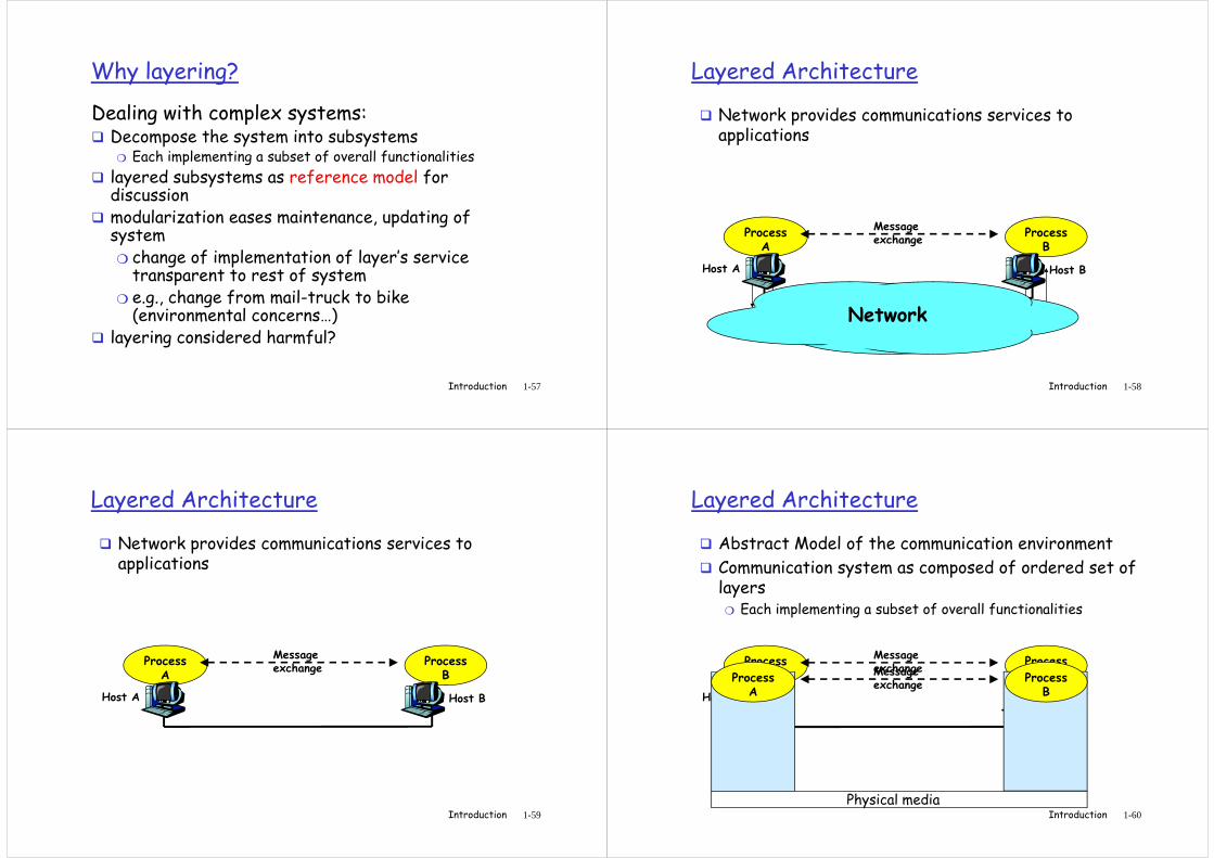
Why layering?
Dealing with complex systems:� Decompose the system into subsystems
❍ Each implementing a subset of overall functionalities
� layered subsystems as reference model for discussion
� modularization eases maintenance, updating of
Introduction 1-57
� modularization eases maintenance, updating of system❍ change of implementation of layer’s service transparent to rest of system
❍ e.g., change from mail-truck to bike (environmental concerns…)
� layering considered harmful?
Layered Architecture
� Network provides communications services to applications
Introduction 1-58
Process A
ProcessB
Message exchange
Host A Host B
Network
Layered Architecture
� Network provides communications services to applications
Introduction 1-59
Process A
ProcessB
Message exchange
Host A Host B
Layered Architecture
� Abstract Model of the communication environment
� Communication system as composed of ordered set of layers
❍ Each implementing a subset of overall functionalities
Introduction 1-60
Process A
ProcessB
Message exchange
Host A Host B
Physical media
Process A
ProcessB
Message exchange
Layered Architecture
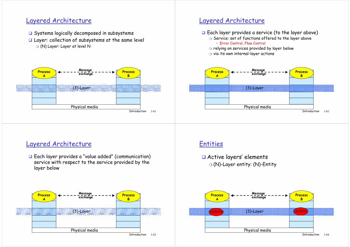
� Systems logically decomposed in subsystems
� Layer: collection of subsystems at the same level❍ (N) Layer: Layer at level N
Introduction 1-61
Physical media
(3)-Layer
Process A
ProcessB
Message exchange
Layered Architecture
� Each layer provides a service (to the layer above)❍ Service: set of functions offered to the layer above
• Error Control, Flow Control
❍ relying on services provided by layer below❍ via its own internal-layer actions
Introduction 1-62
Physical media
(3)-Layer
Process A
ProcessB
Message exchange
Layered Architecture
� Each layer provides a “value added” (communication) service with respect to the service provided by the layer below
Introduction 1-63
Physical media
(3)-Layer
Process A
ProcessB
Message exchange
Entities
�Active layers’ elements❍ (N)-Layer entity: (N)-Entity
Introduction 1-64
Physical media
(3)-Layer(3)-Entity (3)-Entity
Process A
ProcessB
Message exchange
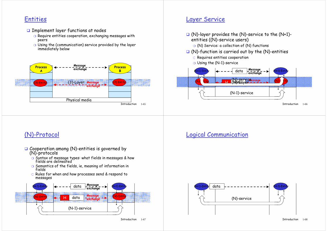
Entities
� Implement layer functions at nodes❍ Require entities cooperation, exchanging messages with
peers❍ Using the (communication) service provided by the layer
immediately below
Introduction 1-65
Physical media
Process A
ProcessB
Message exchange
(3)-Layer(3)-Entity (3)-EntityMessage exchange
Layer Service
� (N)-layer provides the (N)-service to the (N+1)-entities ((N)-service users)
❍ (N) Service: a collection of (N) functions
� (N)-function is carried out by the (N)-entities❍ Requires entities cooperation
Introduction 1-66
❍ Requires entities cooperation
❍ Using the (N-1)-service
(N)-Entity (N)-Entity
(N+1)-Entity (N+1)-EntityMessage exchange
data
Message exchangedataH
(N-1)-service
(N)-service(N)-Layer
(N)-Protocol
� Cooperation among (N)-entities is governed by (N)-protocols
❍ Syntax of message types: what fields in messages & how fields are delineated
❍ Semantics of the fields, ie, meaning of information in fields
❍ Rules for when and how processes send & respond to
Introduction 1-67
❍ Rules for when and how processes send & respond to messages
(N)-Entity (N)-Entity
(N+1)-Entity (N+1)-EntityMessage exchange
data
Message exchangedataH
(N-1)-service
Logical Communication
Introduction 1-68
(N+1)-Entity (N+1)-Entitydata
(N)-service
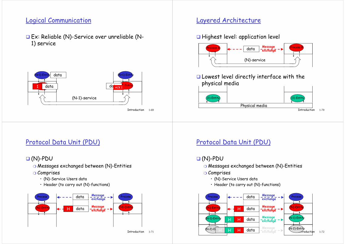
Logical Communication
� Ex: Reliable (N)-Service over unreliable (N-1) service
Introduction 1-69
(N)-Entity (N)-Entity
(N+1)-Entity (N+1)-Entitydata
data1
(N-1)-service
dataACK 1
Layered Architecture
�Highest level: application level
Process A Process BMessage exchangedata
(N)-service
Introduction 1-70
� Lowest level directly interface with the physical media
(N)-service
Physical media
(1)-Entity (1)-Entity
Protocol Data Unit (PDU)
� (N)-PDU❍ Messages exchanged between (N)-Entities
❍ Comprises• (N)-Service Users data
• Header (to carry out (N)-functions)
Introduction 1-71
• Header (to carry out (N)-functions)
(N)-Entity (N)-Entity
Process ProcessMessage exchange
data
Message exchangedataH
Protocol Data Unit (PDU)
� (N)-PDU❍ Messages exchanged between (N)-Entities
❍ Comprises• (N)-Service Users data
• Header (to carry out (N)-functions)
Introduction 1-72
• Header (to carry out (N)-functions)
(N)-Entity (N)-Entity
Process ProcessMessage exchange
data
Message exchangedataH
(N-1)-Entity (N-1)-EntityMessage exchangedataH
(N-2)-Entity (N-2)-EntityMessage exchangedataH
H
HH
Connection oriented and Connectionless Service
� Connection Oriented (N)-Service❍ E.g. telephone call
❍ To communicate, (N)-users • Setup Connection
• Transfer Data
• Tear-down Connection
Introduction 1-73
• Tear-down Connection
� Connectionless (N)-service❍ E,g,Postal service
❍ Trasfer Data
Layered Architecture: Models
�OSI (Open System Interconnection)❍ ’70 Standard de iure
❍ 7 levels
❍ Architecture first
Protocols later…if any
Introduction 1-74
❍ Protocols later…if any
� TCP/IP Model❍ ’80… Standard de facto
❍ 5 levels
❍ Protocols first
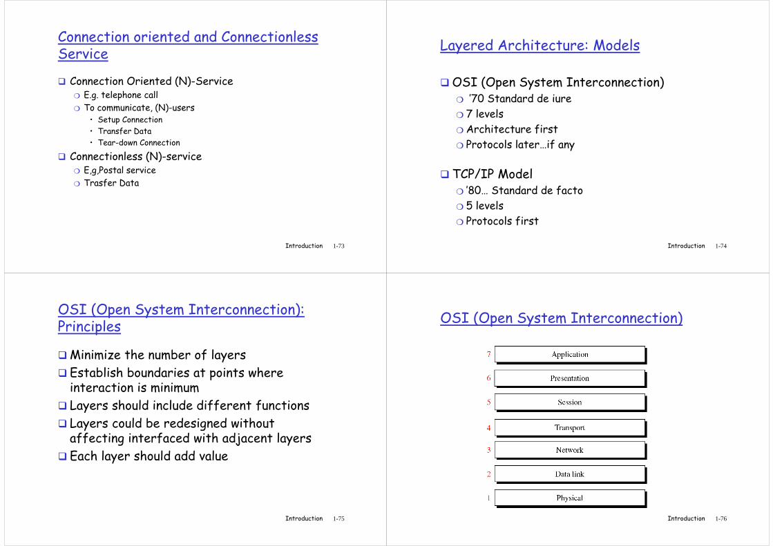
OSI (Open System Interconnection): Principles
�Minimize the number of layers
� Establish boundaries at points where interaction is minimum
� Layers should include different functions
Introduction 1-75
� Layers should include different functions
� Layers could be redesigned without affecting interfaced with adjacent layers
� Each layer should add value
OSI (Open System Interconnection)
Introduction 1-76
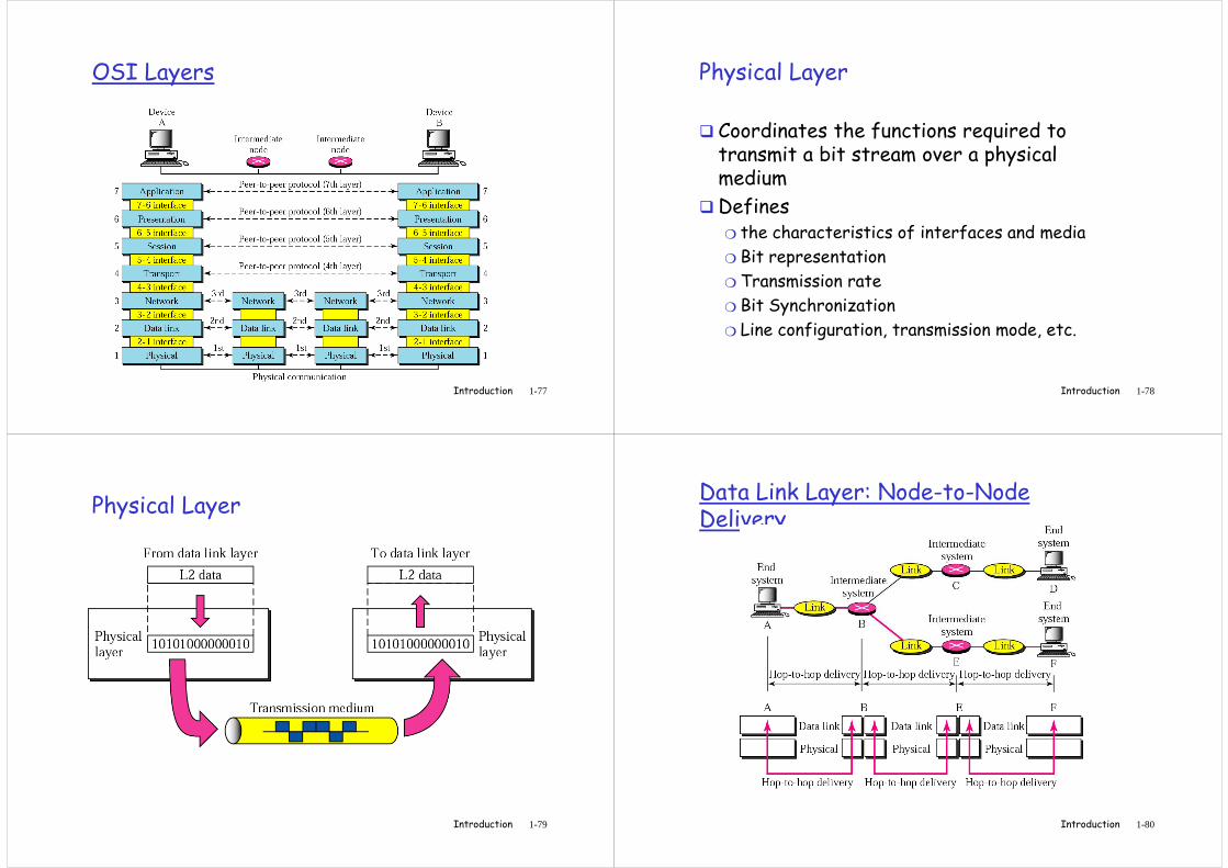
OSI Layers
Introduction 1-77
Physical Layer
� Coordinates the functions required to transmit a bit stream over a physical medium
�Defines
Introduction 1-78
Defines ❍ the characteristics of interfaces and media
❍ Bit representation
❍ Transmission rate
❍ Bit Synchronization
❍ Line configuration, transmission mode, etc.
Physical Layer
Introduction 1-79
Data Link Layer: Node-to-Node Delivery
Introduction 1-80
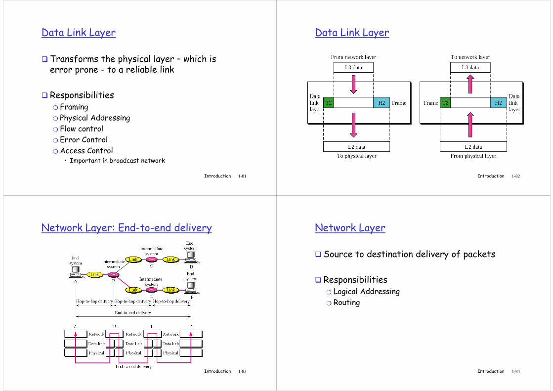
Data Link Layer
� Transforms the physical layer – which is error prone - to a reliable link
� Responsibilities
Introduction 1-81
� Responsibilities❍ Framing
❍ Physical Addressing
❍ Flow control
❍ Error Control
❍ Access Control• Important in broadcast network
Data Link Layer
Introduction 1-82
Network Layer: End-to-end delivery
Introduction 1-83
Network Layer
� Source to destination delivery of packets
� Responsibilities❍ Logical Addressing
Introduction 1-84
❍ Logical Addressing
❍ Routing
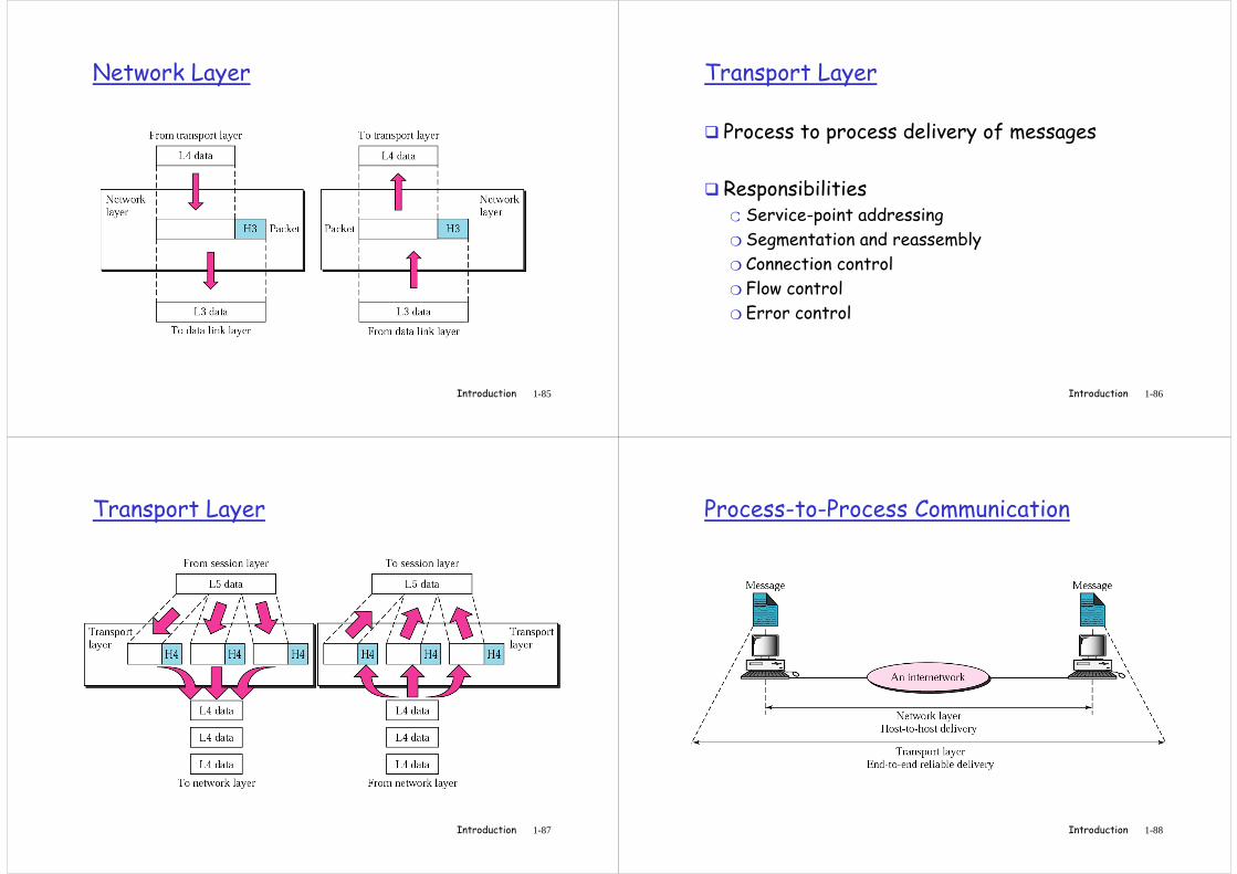
Network Layer
Introduction 1-85
Transport Layer
� Process to process delivery of messages
� Responsibilities❍ Service-point addressing
Introduction 1-86
❍ Service-point addressing
❍ Segmentation and reassembly
❍ Connection control
❍ Flow control
❍ Error control
Transport Layer
Introduction 1-87
Process-to-Process Communication
Introduction 1-88
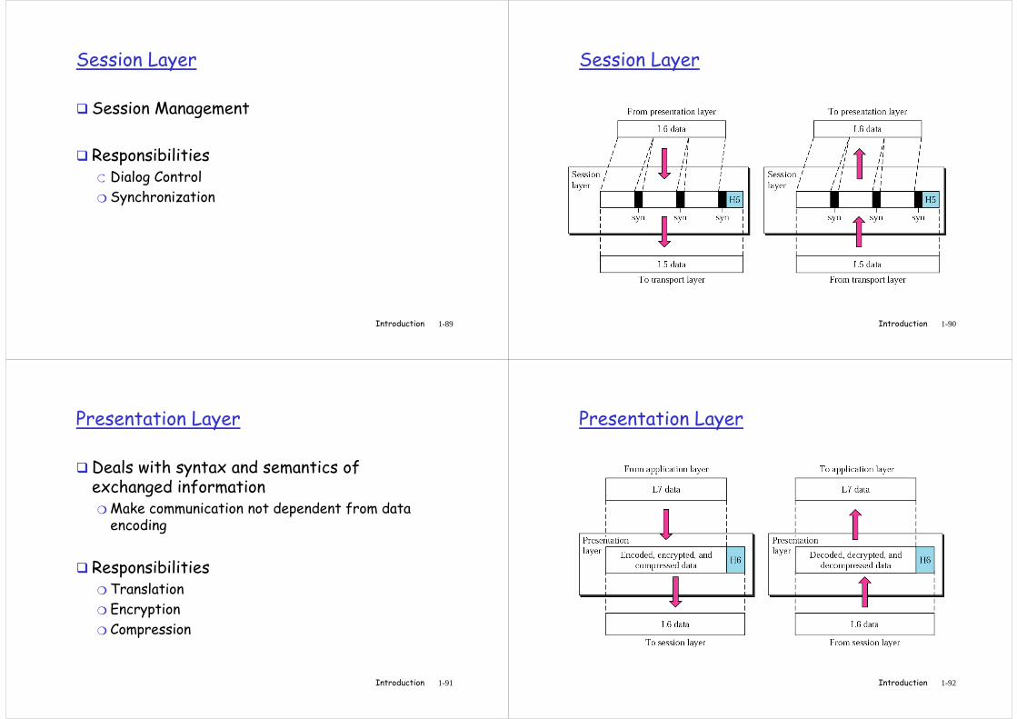
Session Layer
� Session Management
� Responsibilities❍ Dialog Control
Introduction 1-89
❍ Dialog Control
❍ Synchronization
Session Layer
Introduction 1-90
Presentation Layer
�Deals with syntax and semantics of exchanged information❍ Make communication not dependent from data encoding
Introduction 1-91
� Responsibilities❍ Translation
❍ Encryption
❍ Compression
Presentation Layer
Introduction 1-92
Application Layer
� Enables users to access the network ❍ Providing user interfaces and support for services
Specific services:
Introduction 1-93
� Specific services:❍ Network virtual terminal
❍ File transfer, access and management
❍ Mail services
❍ Directory services
Application Layer
Introduction 1-94
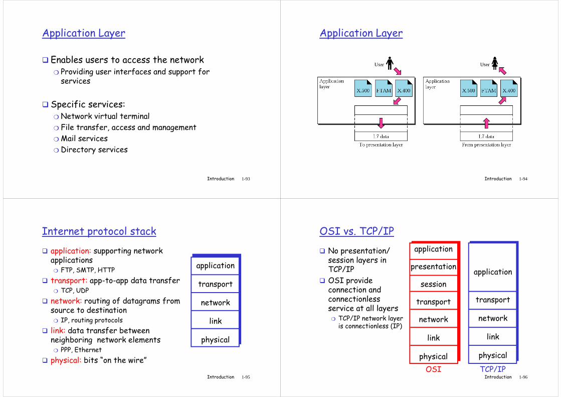
Internet protocol stack
� application: supporting network applications
❍ FTP, SMTP, HTTP
� transport: app-to-app data transfer❍ TCP, UDP
� network: routing of datagrams from
application
transport
network
Introduction 1-95
� network: routing of datagrams from source to destination
❍ IP, routing protocols
� link: data transfer between neighboring network elements
❍ PPP, Ethernet
� physical: bits “on the wire”
network
link
physical
OSI vs. TCP/IP
� No presentation/ session layers in TCP/IP
� OSI provide connection and connectionless
application
transport
application
presentation
session
transport
Introduction 1-96
connectionless service at all layers
❍ TCP/IP network layer is connectionless (IP)
transport
network
link
physical
transport
network
link
physical
OSI TCP/IP
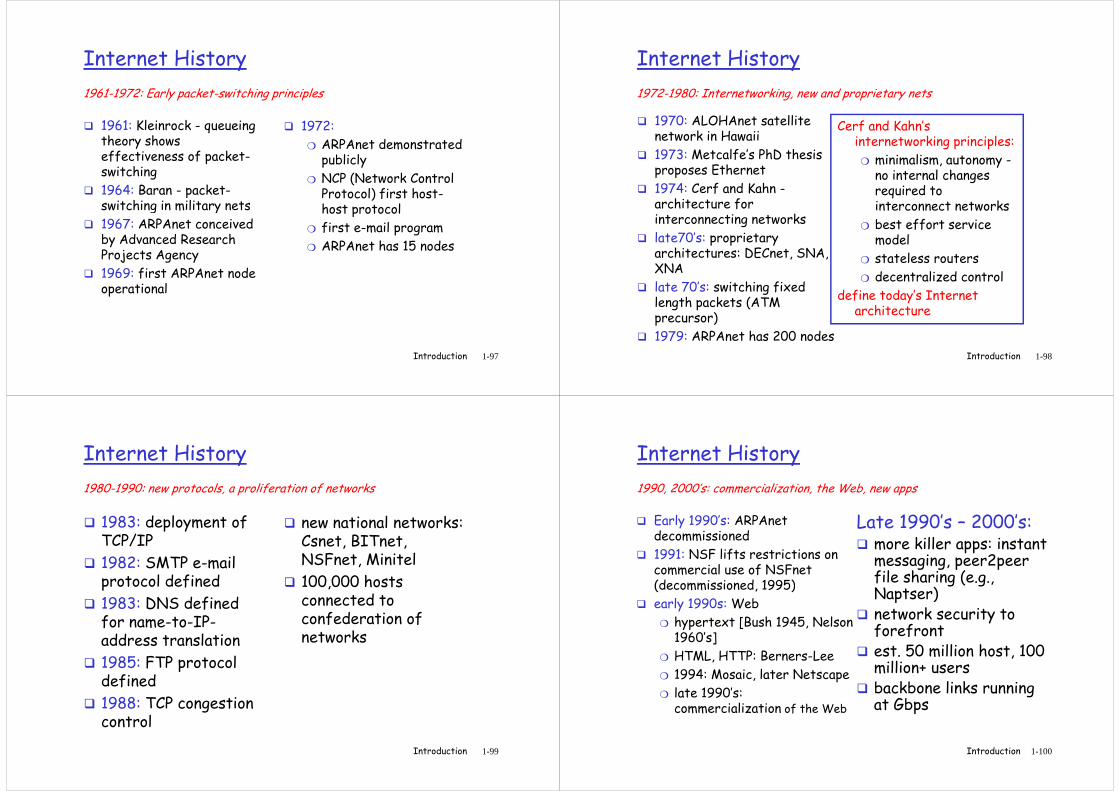
Internet History
� 1961: Kleinrock - queueing theory shows effectiveness of packet-switching
� 1964: Baran - packet-switching in military nets
� 1972:
❍ ARPAnet demonstrated publicly
❍ NCP (Network Control Protocol) first host-
1961-1972: Early packet-switching principles
Introduction 1-97
1964: Baran - packet-switching in military nets
� 1967: ARPAnet conceived by Advanced Research Projects Agency
� 1969: first ARPAnet node operational
Protocol) first host-host protocol
❍ first e-mail program
❍ ARPAnet has 15 nodes
Internet History
� 1970: ALOHAnet satellite network in Hawaii
� 1973: Metcalfe’s PhD thesis proposes Ethernet
� 1974: Cerf and Kahn -architecture for
Cerf and Kahn’s internetworking principles:
❍ minimalism, autonomy -no internal changes required to interconnect networks
1972-1980: Internetworking, new and proprietary nets
Introduction 1-98
architecture for interconnecting networks
� late70’s: proprietary architectures: DECnet, SNA, XNA
� late 70’s: switching fixed length packets (ATM precursor)
� 1979: ARPAnet has 200 nodes
required to interconnect networks
❍ best effort service model
❍ stateless routers
❍ decentralized control
define today’s Internet architecture
Internet History
� 1983: deployment of TCP/IP
� 1982: SMTP e-mail protocol defined
1983: DNS defined
� new national networks: Csnet, BITnet, NSFnet, Minitel
� 100,000 hosts connected to
1980-1990: new protocols, a proliferation of networks
Introduction 1-99
� 1983: DNS defined for name-to-IP-address translation
� 1985: FTP protocol defined
� 1988: TCP congestion control
connected to confederation of networks
Internet History
� Early 1990’s: ARPAnet decommissioned
� 1991: NSF lifts restrictions on commercial use of NSFnet (decommissioned, 1995)
Late 1990’s – 2000’s:� more killer apps: instant
messaging, peer2peer file sharing (e.g., Naptser)
1990, 2000’s: commercialization, the Web, new apps
Introduction 1-100
(decommissioned, 1995)
� early 1990s: Web
❍ hypertext [Bush 1945, Nelson 1960’s]
❍ HTML, HTTP: Berners-Lee
❍ 1994: Mosaic, later Netscape
❍ late 1990’s: commercialization of the Web
Naptser)� network security to
forefront� est. 50 million host, 100
million+ users� backbone links running
at Gbps
Related Documents