1 Basic Arduino Manual What’s inside the kit 1 set Jumper Wires 5 pcs Tact Switch 1 pc Photoresistor 1 pc 400 Points Breadboard 1 pc Potentiometer 1 pc LCD 5 pcs 5mm Red LED 5 pcs 5mm Green LED 5 pcs 5mm Yellow LED 30 pcs Resistors 1 pc 4-Digit 7-Segment Display 1 pc RGB LED 1 pc Buzzer

Welcome message from author
This document is posted to help you gain knowledge. Please leave a comment to let me know what you think about it! Share it to your friends and learn new things together.
Transcript

1Basic Arduino Manual
What’s inside the kit
1 set Jumper Wires 5 pcs Tact Switch 1 pc Photoresistor
1 pc 400 Points Breadboard 1 pc Potentiometer 1 pc LCD
5 pcs 5mm Red LED5 pcs 5mm Green LED5 pcs 5mm Yellow LED
30 pcs Resistors1 pc 4-Digit 7-Segment Display
1 pc RGB LED 1 pc Buzzer

2Basic Arduino Manual
What’s inside the kitJumper WiresA short length of conductor used to link two cross-connect termination points of a circuit.
Tact SwitchAn on/off electronic switch that is only on when the button is pressed. Another way to consider it, as momentary make or brake switch. As soon as a tactile switches button is released, the connection is broken.
BreadboardUsed to build and test circuits quickly before finalizing any circuitdesign. It contains holes into which circuit com-ponents like ICs and resistors can be inserted.
PotentiometerA simple knob that provides a variable resis-tance.
LEDA semiconductor diode that emits light when a voltage is applied to it and that is used especially in electronic devices (as for an indicator light).
RGB LEDThe “R” stands for red, the “G” stands for green and the “B” stands for blue. These three colors combined, when varied in intensity, have the ability to produce over 16.7 million different colors.

3Basic Arduino Manual
What’s inside the kit
PhotoresistorA resistor whose resistance varies as a function of the intensity of light it is exposed to.
LCDA 16x2 LCD means it can display 16 characters per line and there are 2 such lines.
ResistorsA device that has electrical resistance and that is used in an electric circuit for protection, operation, or current control.
4-Digit 7-Segment DisplayA set of seven bar-shaped LED (light-emitting diode) or LCD (liquid crystal display) elements, arranged to form a squared-off figure 8.
BuzzerAn electric component that comes in different shapes and sizes, which can be used to create sound waves after providing electrical signal.

4Basic Arduino Manual
What is Arduino?
Arduino by definition is an open-source proto-typing platform based on easy-to-use hardware and software. Arduino boards are able to read inputs - light on a sensor, a finger on a button - and turn it into an output - activating a motor, turning on an LED.
You can tell your board what to do by sending a set of instructions to the microcontroller on the board. To do so you use the Arduino program-ming language (based on Wiring), and the Ar-duino Software (IDE), based on Processing.
It’s applications range from simple LED projects to products for IoT applications, wearable, and 3D printing. All Arduino boards are completely open-source, empowering users to build them independently and eventually adapt them to their particular needs. The software, too, is open-source, and it is growing through the contribu-tions of users worldwide.www.arduino.cc
images from google.com

5Basic Arduino Manual
Hardware There are a couple of parts on the board:
Power The Uno board can be powered via the USB connection or with an external power supply. 5V.This pin outputs a regulated 5V from the regulator on the board. GND. Ground pins.
Input and Output The Uno has 6 analog inputs, labeled A0 through A5. Each of the 14 digital pins, labeled 0 through 13 on the Uno can be used as an input or output, using pinMode(), digitalWrite(), and digialRead() functions.
In addition, some pins have specialized functions: PWM: 3, 5, 6, 9, 10, and 11. Provide 8-bit PWM output with the analogWrite() function.
LED: 13. There is a built-in LED driven by digital pin 13. When the pin is HIGH value, the LED is on, when the pin is LOW, it’s off.
Reset. Bring this line LOW to reset the microcontroller.

6Basic Arduino Manual
SoftwareThe Arduino Integrated Development Envi-ronment - or Arduino Software (IDE) - con-tains a text editor for writing code, a mes-sage area, a text console, a toolbar with buttons for common functions and a series of menus.
It connects to the Arduino and Genuino hardware to upload programs and commu-nicate with them.
Writing SketchesPrograms written using Arduino Software (IDE) are called sketches. These sketches are written in the text editor and are saved with the file extension .ino.
The toolbar buttons allow you to verify and upload programs, create, open, and save sketches, and open the serial monitor.
Verify Checks your code for errors compiling it.
Upload Compiles your code and uploads it to the configured board.
New Creates a new sketch.
Open Presents a menu of all the sketches in your sketchbook. Clicking one will open it within the current window overwriting its content.
Save Saves your sketch.
Serial Monitor Opens the serial monitor.
Additional commands are found within the five menus: File, Edit, Sketch, Tools, Help.

7Basic Arduino Manual
Commonly used functionssetup() called when a sketch starts. Use it to initialize variables, pin modes, start us-ing libraries, etc. The setup function will only run once, after each powerup or reset of the Arduino board.
loop() does precisely what its name suggests, and loops consecutively, allowing your program to change and respond. Use it to actively control the Arduino board.
for()Loop. Used to repeat a block of statements enclosed in curly braces. for (initialization; condition; increment) { //statement(s); }Example: for (i=0;i<3;i++) Do the instructions enclosed by {} three times
if (expr) {} Conditional branch. If expr true, do instructions enclosed by {}
if / elseExample: if (pinFiveInput < 500) { // do Thing A }
; (semicolon) Used to end a statement.
{} (Curly Braces)An opening curly brace “{“ must always be followed by a closing curly brace “}”. This is a condition that is often referred to as the braces being balanced.
CommentsLines in the program that are used to inform yourself or others about the way the program works. Anything after the slashes is a comment.// to the end of the line/* */ this is multiline comment - use it to comment out whole blocks of code
#includeused to include outside libraries in your sketch.
8Basic Arduino Manual
Commonly used functions
voidused only in function declarations. It indicates that the function is expected to return no information to the function from which it was called.
intIntegers are your primary data-type for number storage.
pinMode (n,INPUT) Set pin n to act as an input. One-time command at top of program.
pinMode (n,OUTPUT) Set pin n to act as an output
digitalWrite (n,HIGH) Set pin n to 5V
digitalWrite (n,LOW) Set pin n to 0V
delay(x) Pause program for x millisec, x = 0 to 65,535
digitalRead(pin) Reads the value from a specified digital pin, either HIGH or LOW.
analogRead()Reads the value from the specified analog pin.
analogWrite(pin, value)Writes an analog value (PWM wave) to a pin. Can be used to light a LED at varying brightnesses or drive a motor at various speeds.
delay(ms)Pauses the program for the amount of time (in miliseconds) specified as pa-rameter. (There are 1000 milliseconds in a second.)
For more references visit https://www.arduino.cc/en/Reference/HomePage

9Basic Arduino Manual
Let’s get startedWhat you will need
1. Download Basic Arduino Kit.rarExtract it in your computer. This contains all the sketches and circuit that we will be using through out the lessons.
2. Download and install the Arduino IDE (Integrated Development Envi-ronment)
3. A well lighted table or any workspace where you will be placing your components next to your desktop or laptop PC to enable you to upload the code to the Arduino.
4. A notepad and pen will also come in handy for drawing out rough sche-matics, working out concepts and designs, etc.
5. And most importantly, the enthusiasm and willingness to learn!

10Basic Arduino Manual
Lesson 1: Built-in LED blinkOverview: In this first lesson we will be introduced to arduino programming.
We will be able to learn how con-trol the blinking of the Built-in LED in the Arduino board.
Materials: Arduino UnoUSB cable
Instructions: 1. Connect the arduino to the computer using the USB cable2. Open the file lesson_no._1_built_in_LED_blink.ino 3. The Arduino IDE will open 4. Click Upload

11Basic Arduino Manual
Lesson 1: Discussion of codesint led = 13; // we assigned pin 13 as “led” which we will use through out the sketch/*variable is a way of naming and storing a value for later use by the program,
digital pin 13 drives the built-in led on the board.*/
void setup() /* setup() preparation, always top of program, set pinModes, initializeserial communictions, etc.*/
{
pinMode(led, OUTPUT); // initialize the digital pin labeled as “led” an output. /* pinMode: This command, which goes in the setup() function, is used to set the direction of a digital I/O pin.Set the pin to OUTPUT if the pin is driving and LED, motor or other device. Set the pin to INPUT if the pin is reading a switch or other sensor. On power up or reset, all pins default to inputs. */
}
void loop() /* loop() execution, reading inputs, triggering outputs */{ digitalWrite(led, HIGH); // turn the LED on (HIGH is the voltage level) /* digitalWrite: This command sets an I/O pin high (+5V) or low (0V) and is the workhorse for commanding the outside world of lights, motors, and anything else interfaced to your board.*/ delay(1000); // wait for a second /* Delay pauses the program for a specified number of milliseconds. Since most interactions with the world involve timing, this is an essential instruction. */ digitalWrite(led, LOW); // turn the LED off by making the voltage LOW delay(1000); // wait for a second}

12Basic Arduino Manual
Lesson 2: LED Blink (Breadboard)Overview:In this lesson we will be introduced to circuit wiring and our goal is to make the LED on the breadboard blink ac-cording to the delay to be set. We will also learn how to assign a digital pin as an output.
Materials: 1pc LED 1pc 220ohm resistor BreadboardJumper wires
Instructions: 1. Connect the arduino to the computer2. Open the file lesson_no._2_LED_blink.ino3. The Arduino IDE will open 4. Click Upload5. Construct the circuit as shown in the figure. You can check the larger version of the picture which is located in the folder lesson_no._2_LED_blink

13Basic Arduino Manual
Lesson 2: Discussion of codesint led = 12; // we labeled pin 12 as “led” /*variable is a way of naming and storing a value for later use by the program */
void setup() /* setup() preparation, always top of program, set pinModes, initializeserial communictions, etc.*/
{
pinMode(led, OUTPUT); // initialize the digital pin labeled as “led” an output. /* pinMode: This command, which goes in the setup() function, is used to set the direction of a digital I/O pin.Set the pin to OUTPUT if the pin is driving and LED, motor or other device. Set the pin to INPUT if the pin is reading a switch or other sensor. On power up or reset, all pins default to inputs. */
}
void loop() /* loop() execution, reading inputs, triggering outputs */{ digitalWrite(led, HIGH); // turn the LED on (HIGH is the voltage level) /* digitalWrite: This command sets an I/O pin high (+5V) or low (0V) and is the workhorse for commanding the outside world of lights, motors, and anything else interfaced to your board.*/ delay(1000); // wait for a second /* Delay pauses the program for a specified number of milliseconds. Since most interactions with the world involve timing, this is an essential instruction. */ digitalWrite(led, LOW); // turn the LED off by making the voltage LOW delay(1000); // wait for a second}

14Basic Arduino Manual
Lesson 3: LED controlOverview:In this lesson we will be using a tact switch to control the LED whether it will be turned on or off. We will be able to learn how to read an input(switch) and make the corresponding output(LED).
Materials: 1pc LED 1pc 220ohm resistor1pc 10kohm resistor1 pc tact switch Breadboard Jumper wires
Instructions: 1. Connect the arduino to the computer2. Open the file lesson_no._3_LED_control.ino 3. The Arduino IDE will open 4. Click Upload5. Construct the circuit as shown in the figure. You can check the larger version of the picture which is located in the folder lesson_no._3_LED_control

15Basic Arduino Manual
Lesson 3: Discussion of codesint ledpin=11; //label pin 11 as “ledpin”int inpin=7; //label pin 7 as “inpin”int val; //define the variable val, we well be using later/*variable is a way of naming and storing a value for later use by the program, such as data from a analog pin set to input.*/
void setup()
{ pinMode(ledpin,OUTPUT); //define the “ledpin” as OUTPUT, we will be connecting the LED here pinMode(inpin,INPUT); //define the “inpin” as INPUT, we will be connecting the switch here /* pinMode: This command, which goes in the setup() function, is used to set the direction of a digital I/O pin. Set the pin to OUTPUT if the pin is driving and LED, motor or other device. Set the pin to INPUT if the pin is reading a switch or other sensor. On power up or reset, all pins default to inputs. */
}void loop(){ val=digitalRead(inpin); //read the value of “inpin” then save it to variable “val“ /* digitalRead: Reads the value from a specified pin, it will be either HIGH or LOW.*/ if(val==LOW) //if the button pressed; /*If the condition is true, the program will execute the commands between the braces. If the condition is not true, the program will skip to the statement following the braces.*/ { digitalWrite(ledpin,LOW);} //turn off the LED else { digitalWrite(ledpin,HIGH);} //if not pressed, turn on the LED /*digitalWrite: This command sets an I/O pin high (+5V) or low (0V) and is the workhorse for commanding the outside world of lights, motors, and anything else interfaced to your board.*/}

16Basic Arduino Manual
Lesson 4: 3 LED blink Overview:In this lesson we will learn on how to make 3 LED blink alternately. We will learn how to use multiple pins and assign delays for us to achieve the desired out-put.
Materials: 3 pcs LED (1 green, 1 yellow, 1 red)3pcs 220ohm resistorBreadboardJumper wires
Instructions: 1. Connect the arduino to the computer2. Open the file lesson_no._4_3_LED_blink.ino3. The Arduino IDE will open4. Click Upload5. Construct the circuit as shown in the figure. You can check the larger version of the picture which is located in the folder lesson_no._4_3_LED_blink

17Basic Arduino Manual
Lesson 4: Discussion of codesint greenled = 8; //we labeled pin 8 as ”greenled”int yellowled = 9; //we labeled pin 9 as ”yellowled”int redled = 10; //we labeled pin 10 as ”redled”
void setup(){pinMode(greenled, OUTPUT); //we set “greenled“ as outputpinMode(yellowled, OUTPUT); //we set “yellowled“ as outputpinMode(redled, OUTPUT); //we set “redled“ as output}
void loop(){digitalWrite(greenled, HIGH); //Green on for 1 seconddelay(1000);digitalWrite(greenled, LOW); //Green off, yellow on for 1 seconddigitalWrite(yellowled, HIGH);delay(1000);digitalWrite(yellowled, LOW); //yellow off, red on for 1 seconddigitalWrite(redled, HIGH);delay(1000);digitalWrite(redled, LOW); //Red and Yellow off}
18Basic Arduino Manual
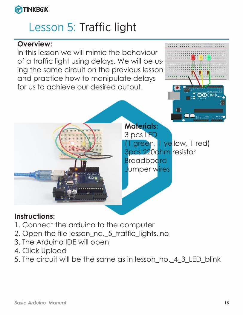
Lesson 5: Traffic light Overview:In this lesson we will mimic the behaviour of a traffic light using delays. We will be us-ing the same circuit on the previous lesson and practice how to manipulate delays for us to achieve our desired output.
Materials: 3 pcs LED (1 green, 1 yellow, 1 red)3pcs 220ohm resistorBreadboardJumper wires
Instructions: 1. Connect the arduino to the computer2. Open the file lesson_no._5_traffic_lights.ino3. The Arduino IDE will open 4. Click Upload5. The circuit will be the same as in lesson_no._4_3_LED_blink

19Basic Arduino Manual
Lesson 5: Discussion of codesint greenled = 8; //we labeled pin 8 as ”greenled”int yellowled = 9; //we labeled pin 9 as ”yellowled”int redled = 10; //we labeled pin 10 as ”redled”
void setup(){pinMode(greenled, OUTPUT); //we set “greenled“ as outputpinMode(yellowled, OUTPUT); //we set “yellowled“ as outputpinMode(redled, OUTPUT); //we set “redled“ as output}
void loop(){digitalWrite(greenled, HIGH); //Green on for 1 seconddelay(5000);digitalWrite(greenled, LOW); //Green off, yellow on for 1 seconddigitalWrite(yellowled, HIGH);delay(2000);digitalWrite(yellowled, LOW); //yellow off, red on for 1 seconddigitalWrite(redled, HIGH);delay(5000);digitalWrite(redled, LOW); //Red and Yellow off}

20Basic Arduino Manual
Lesson 6: LED bar graphOverview:In this lesson we will be using the com-ponent called the potentiometer. As we turn the knob of the potentiome-ter, the number of LEDs turned on will also vary. The codes we used in this les-son can also be found in Files->Exam-ples->Display->barGraph
Materials: 10pcs LED (3 green, 4 yellow, 3 red) , 10pcs 220ohm resistor, Potentiometer Breadboard Jumper wires
Instructions: 1. Connect the arduino to the computer2. Open the file lesson_no._6_LED_bar_graph.ino3. The Arduino IDE will open4. Click Upload5. Construct the circuit as shown in the figure. You can check the larger version of the picture which is located in the folder lesson_no._6_LED_bar_graph

21Basic Arduino Manual
Lesson 6: Discussion of codes/* LED bar graph
Turns on a series of LEDs based on the value of an analog sensor. This is a simple way to make a bar graph display. Though this graph uses 10 LEDs, you can use any number by changing the LED count and the pins in the array.
This method can be used to control any series of digital outputs that depends on an analog input.
The circuit: * LEDs from pins 2 through 11 to ground
created 4 Sep 2010 by Tom Igoe
This example code is in the public domain.
http://www.arduino.cc/en/Tutorial/BarGraph */
// these constants won’t change:const int analogPin = A0; // the pin that the potenti-ometer is attached toconst int ledCount = 10; // the number of LEDs in the bar graph
int ledPins[] = { 2, 3, 4, 5, 6, 7, 8, 9, 10, 11}; // an array of pin numbers to which LEDs are at-tached
void setup() { // loop over the pin array and set them all to output: for (int thisLed = 0; thisLed < ledCount; thisLed++) { pinMode(ledPins[thisLed], OUTPUT); }}
void loop() { // read the potentiometer: int sensorReading = analogRead(analogPin); // map the result to a range from 0 to the number of LEDs: int ledLevel = map(sensorReading, 0, 1023, 0, led-Count);
// loop over the LED array: for (int thisLed = 0; thisLed < ledCount; thisLed++) { // if the array element’s index is less than ledLevel, // turn the pin for this element on: if (thisLed < ledLevel) { digitalWrite(ledPins[thisLed], HIGH); } // turn off all pins higher than the ledLevel: else { digitalWrite(ledPins[thisLed], LOW); } }}

22Basic Arduino Manual
Lesson 7: RGB LED (changing colors)Overview:In this lesson we will be using the com-ponent called the RGB LED. We will learn to to make the RGB LED change its color from red to green and to blue and try some other combinations to achieve more variations of colors.
Materials: 1pc RGB LED 3pcs 220ohm resistorBreadboard Jumper wires
Instructions: 1. Connect the arduino to the computer2. Open the file lesson_no._7_RGB_LED3. The Arduino IDE will open4. Click Upload5. Construct the circuit as shown in the figure. You can check the larger version of the picture which is located in the folder lesson_no._7_RGB_LED

23Basic Arduino Manual
Lesson 7: Discussion of codesint redPin = 11;int greenPin = 10;int bluePin = 9;
void setup(){ pinMode(redPin, OUTPUT); pinMode(greenPin, OUTPUT); pinMode(bluePin, OUTPUT); } void loop(){ setColor(255, 0, 0); // red delay(1000); setColor(0, 255, 0); // green delay(1000); setColor(0, 0, 255); // blue delay(1000); setColor(255, 255, 0); // yellow delay(1000); setColor(80, 0, 80); // purple delay(1000); setColor(0, 255, 255); // aqua delay(1000);}

24Basic Arduino Manual
Lesson 8: RGB LED and tact switchOverview:In this lesson we will make the RGB LED change its color to red, green and blue as we push a certain tact switch that corresponds to each color.
Materials: 1pc RGB LED 3pcs 220ohm resistor 3pcs 10kohm resistor3pcs tact switchBreadboard Jumper wires
Instructions: 1. Connect the arduino to the computer2. Open the file lesson_no._8_RGB_switch.ino3. The Arduino IDE will open3. Click Upload4. Construct the circuit as shown in the figure. You can check the larger version of the picture which is located in the folder esson_no._8_RGB_switch

25Basic Arduino Manual
Lesson 8: Discussion of codesint redLEDPin = 11; // label pin 11 as redLEDPinint greenLEDPin = 10; // label pin 10 as greenLEDPinint blueLEDPin = 9; // label pin 9 as blueLEDPin int redSwitchPin = 7; // label pin 7 as redSwitchPinint greenSwitchPin = 6; // label pin 6 as greenSwitchPinint blueSwitchPin = 5; // label pin 5 as blueSwitchPin void setup(){ pinMode(redLEDPin, OUTPUT); pinMode(greenLEDPin, OUTPUT); pinMode(blueLEDPin, OUTPUT); pinMode(redSwitchPin, INPUT); pinMode(greenSwitchPin, INPUT); pinMode(blueSwitchPin, INPUT);} void loop(){ if (digitalRead(redSwitchPin) == HIGH && dig-italRead(greenSwitchPin) == LOW && digi-talRead(blueSwitchPin) == LOW) { digitalWrite(redLEDPin,HIGH); digitalWrite(greenLEDPin,LOW); digitalWrite(blueLEDPin,LOW); }else{} if (digitalRead(greenSwitchPin) == HIGH && digitalRead(redSwitchPin) == LOW && digi-talRead(blueSwitchPin) == LOW) { digitalWrite(redLEDPin,LOW); digitalWrite(greenLEDPin,HIGH); digitalWrite(blueLEDPin,LOW); }else{}
if (digitalRead(blueSwitchPin) == HIGH && digi-talRead(greenSwitchPin) == LOW && digitalRead(red-SwitchPin) == LOW) { digitalWrite(redLEDPin,LOW); digitalWrite(greenLEDPin,LOW); digitalWrite(blueLEDPin,HIGH); }else{}
delay(10); }

26Basic Arduino Manual
Lesson 9: Photoresistor
Overview:In this lesson we will be using the component called the photo-resistor. It acts like an automatic switch where in whenever it de-tects presence of light it will turn the LED off, otherwise if detects the absence of light it will turn the LED on. Materials:
1pc LDR 1pc LED 1pc 220ohm resistor 1pc 10kohm resistor BreadboardJumper wires
Instructions: 1. Connect the arduino to the computer2. Open the file lesson_no._9_photoresistor.ino3. The Arduino IDE will open4. Click Upload5. Construct the circuit as shown in the figure. You can check the larger version of the picture which is located in the folder lesson_no._9_photoresistor

27Basic Arduino Manual
Lesson 9: Discussion of codesint photocellpin = 2; //label pin 2 as “photocellpin”int val =0; //assign variable “val”, you will be using it later, and set its initial value to 0
void setup(){ pinMode(ledPin,OUTPUT); //set the ledPin to output; Serial.begin(9600);}
void loop(){ val = analogRead(photocellPin); Serial.println("current light is"); Serial.println(val);
/* Serial.print: lets you see what's going on inside the Arduino from your computer. For example, you can see the result of a math operation to determine if you are getting the right number. Or, you can see the state of a digital input pin to see if the Arduino is a sensor or switch properly.
There are two forms of the print command. Serial.print() prints on the same line while Serial.println() starts the print on a new line.*/
if (val<350) { //512 =2.5V, you can modify this to adjust the sensitivty; digitalWrite(ledPin,HIGH); } else { digitalWrite(ledPin,LOW); } delay(1000);}

28Basic Arduino Manual
Lesson 10: Buzzer
Overview:In this lesson we will be using the component called the buzzer. The circuit may seem so simple because the buzzer has only two terminals. Always make sure that the + ter-minal of the buzzer is the one con-nected to the output pin.
Materials: BuzzerBreadboardJumper wires
Instructions: 1. Connect the arduino to the computer2. Open the file lesson_no._10_buzzer.ino3. The Arduino IDE will open3. Click Upload4. Construct the circuit as shown in the figure. You can check the larger version of the picture which is located in the folder lesson_no._10_buzzer5. This time upload lesson_no._10_buzzer_super_mario.ino your buzzer will play on the tune of super mario

29Basic Arduino Manual
Lesson 10: Discussion of codes
int buzzer=7;void setup(){ pinMode(buzzer,OUTPUT);}void loop(){ unsigned char i,j; while(1) { for(i=0;i<80;i++) { digitalWrite(buzzer,HIGH); delay(1); digitalWrite(buzzer,LOW); delay(1); } for(i=0;i<100;i++) { digitalWrite(buzzer,HIGH); delay(2); digitalWrite(buzzer,LOW); delay(2); } }}

30Basic Arduino Manual
Lesson 11: 7 Segment Display
Overview:In this lesson we will be using the component called the 4-digit 7 seg-ment display as a counter.
Materials: 4-digit 7 segment display8pcs 220ohm resistorBreadboardJumper wires
Instructions: 1. Connect the arduino to the computer2. Open the file lesson_no._11_7segment.ino3. The Ardiuno IDE will open4. Click Upload5. Construct the circuit as shown in the figure. You can check the larger version of the picture which is located in the folder lesson_no._11_7segment

31Basic Arduino Manual
Lesson 12: LCD
Overview:In this lesson we will be using a compo-nent called the LCD. We will learn how to make a text appear on the display. The codes we used in this lesson can also be found in Files->Examples->Liq-uidCrystal->HelloWorld
Materials: LCDPotentiometerBreadboard Jumper wires
Instructions: 1. Connect the arduino to the computer2. Open the file lesson_no._12_LCD_hello_world.ino3. The Arduino IDE will open4. Click Upload5. Construct the circuit as shown in the figure. You can check the larger version of the picture which is located in the folder lesson_no._12_LCD_hello_world

32Basic Arduino Manual
Lesson 12: Discussion of codes/* LiquidCrystal Library - Hello World
Demonstrates the use a 16x2 LCD display. The LiquidCrystal library works with all LCD displays that are com-patible with the Hitachi HD44780 driver. There are many of them out there, and you can usually tell them by the 16-pin interface.
This sketch prints "Hello World!" to the LCD and shows the time.
The circuit: * LCD RS pin to digital pin 12 * LCD Enable pin to digital pin 11 * LCD D4 pin to digital pin 5 * LCD D5 pin to digital pin 4 * LCD D6 pin to digital pin 3 * LCD D7 pin to digital pin 2 * LCD R/W pin to ground * LCD VSS pin to ground * LCD VCC pin to 5V * 10K resistor: * ends to +5V and ground * wiper to LCD VO pin (pin 3)
Library originally added 18 Apr 2008 by David A. Mellis library modified 5 Jul 2009 by Limor Fried (http://www.ladyada.net) example added 9 Jul 2009 by Tom Igoe modified 22 Nov 2010 by Tom Igoe
This example code is in the public domain.
http://www.arduino.cc/en/Tutorial/LiquidCrystal */
// include the library code:#include <LiquidCrystal.h>
// initialize the library with the numbers of the interface pinsLiquidCrystal lcd(12, 11, 5, 4, 3, 2);
void setup() { // set up the LCD's number of columns and rows: lcd.begin(16, 2);
// Print a message to the LCD. lcd.print("hello, world!");}
void loop() { // set the cursor to column 0, line 1 // (note: line 1 is the second row, since counting begins with 0): lcd.setCursor(0, 1); // print the number of seconds since reset: lcd.print(millis() / 1000);}
Related Documents