1/27 WEST BENGAL STATE ELECTRICITY DISTRIBUTION COMPANY LIMITED . TECHNICAL SPECIFICATION FOR DISTRIBUTION TRANSFORMERS . PART-A (630KVA & 315 KVA OIL TYPE DISTRIBUTION TRANSFORMERS) 1. SCOPE : This specification covers design, manufacture, testing and supply of 11/0.415KV, 630KVA Outdoor type with cable termination arrangement & 11/0.433KV, 315 KVA , Outdoor & Indoor type ONAN Distribution Transformers as per details furnished. 2. LOCATION : The transformers may be installed outdoor/Indoor anywhere in West Bengal. The elevations of the sites above mean sea level shall not exceed 1000 metres. 3. SYSTEM DETAILS : The 11 kV & 415/433 V systems are effectively earthed at the neutral points of the star connected windings of the transformers. 4. WEATHER CONDITIONS : 1. Elevation at mean sea level : 1000M 2. Maximum ambient Air temperature (°C) : 50 3. Maximum daily average ambient (°C) : 40 4. Minimum Ambient air temperature (°C) : (-)5 Deg C 5. Relative humidity : 100% 6. Pollution level : Heavily polluted. 7. Maximum Wind Pressure : 250 kg/sq.mtr. 8. Annual average rain fall : 3000 mm 9. Average No. of thunder storm day per annum: 100 10. Number of thunder storm day per annum : 100 5. STANDARDS : 01. Transformers covered by this specification shall, unless otherwise specified be built to conform to the latest Indian Electricity Rules, wherever applicable and the requirements of latest issue of ISS:1180 and ISS 2026, CBIP Standards and other ISS(all as per latest issues) 02. In the event of a conflict between the above standard and the specification the latter shall govern. 6. RATING AND GENERAL DATA FOR DISTRIBUTION TRANSFORMERS : 01. Core Type, three phase oil immersed step down two winding distribution transformers for outdoor installation with weather condition as stated above. 02. Rating: please refer to Annexure- “B”. 03. Number of phase : three 04. Frequency: Transformer shall be suitable for continuous operation with a frequency variation of + 3% from normal 50 c/s without exceeding the specified temperature rise. 05. Type of cooling : ONAN 06. Voltage Ratio : refer to Annexure –“B” 07. Vector group reference : Dyn.11, unless otherwise stated. 08. 7. CONNECTIONS : The primary (HV) winding shall be connected in delta and the secondary (L.V) winding in star with vector group Dyn,11.The neutral of the secondary (LV) winding shall be brought out to a separate insulated terminal. The size (Cross section) of the neutral connection conductors and jumpers must be of same size as that of the phase connecting conductors and jumpers which shall be properly supported and insulated.

Welcome message from author
This document is posted to help you gain knowledge. Please leave a comment to let me know what you think about it! Share it to your friends and learn new things together.
Transcript
1/27
WEST BENGAL STATE ELECTRICITY DISTRIBUTION COMPANY LIMITED. TECHNICAL SPECIFICATION FOR DISTRIBUTION TRANSFORMERS.
PART-A
( 630KVA & 315 KVA OIL TYPE DISTRIBUTION TRANSFORMERS)
1 . SCOPE : Th i s s pec i f i c a t i on cove r s des i gn , manu f ac tu r e , t e s t i ng and supp l y o f 11/0.415KV, 630KVA Ou tdoo r t ype w i t h c ab l e t e rm ina t ion a r rangemen t & 11/0.433KV, 315 KVA , Ou tdoo r & Indoor t ype ONAN D i s t r i bu t ion T r ans fo rmers a s pe r de t a i l s f u rn i s hed .
2 . LOCATION : The t r an s f o rmers may be i n s t a l l ed ou tdoo r / Indoor anywhere i n Wes t Benga l . The e l eva t i on s o f the s i t e s above mean s ea l eve l s ha l l no t exceed 1000 met r es .
3 . SYSTEM DETA ILS : The 11 kV & 415 /433 V s ys t ems ar e e f f ec t i ve l y ea r t hed a t the neu t r a l po in t s o f t he s t a r c onnec t ed w ind ings o f the t r ans fo rmer s .
4 . WEATHER CONDITIONS : 1. Elevation at mean sea level : 1000M
2. Maximum ambient Air temperature (°C) : 50
3. Maximum daily average ambient (°C) : 40
4. Minimum Ambient air temperature (°C) : (-)5 Deg C
5. Relative humidity : 100%
6. Pollution level : Heavily polluted.
7. Maximum Wind Pressure : 250 kg/sq.mtr.
8. Annual average rain fall : 3000 mm
9. Average No. of thunder storm day per annum: 100
10. Number of thunder storm day per annum : 100
5 . STANDARDS : 01 . Trans fo rmer s cove r ed by t h i s s pec i f i c a t i on sha l l , un l e ss o t herw i s e spec i f i ed
be bu i l t to con f o rm to the l a t e s t Ind i an E l ec t r i c i t y Ru l e s , whereve r app l i c ab l e and t he r equ i r emen ts o f l a t e s t i s s ue o f ISS :1180 and ISS 2026 , CB IP S t anda rds and o ther ISS (a l l a s pe r l a t e s t i s s ues )
02 . In t he even t o f a con f l i c t be tween the above s t anda rd and the spec i f i c a t i on t he l a t t e r sha l l gove rn .
6 . RATING AND GENERAL DATA FOR DISTRIBUTION TRANSFORMERS : 01 . Co re Type , t h r ee phase o i l immer sed s t ep down two w ind ing d i s t r i bu t ion
t r an s f o rmer s fo r ou tdoo r i ns t a l l a t i on w i t h wea the r cond i t i on as s t a t ed above .
02 . Rat i ng : p l ease r e f e r t o Annexure - “B ” . 03 . Number o f phase : t h r ee 04 . F r equency : T r an s f o rmer sha l l be su i t ab l e f o r con t inuous ope r a t i on w i th a
f r equency va r i a t ion o f +3% f r om no rma l 50 c / s w i thou t exceed ing t he spec i f i ed t empera tu r e r i s e .
05 . Type o f c oo l i ng : ONAN 06 . Vo l t age Ra t i o : r e f e r t o Annexu re – “B ” 07 . Vec to r g roup r e f e r ence : Dyn .11 , un l e s s o t he rw i se s t a t ed . 08 .
7 . CONNECTIONS : The p r imar y (HV) w ind ing sha l l be connec t ed i n de l t a and the s econda r y ( L .V ) w ind ing i n s t a r w i t h vec t o r gr oup Dyn ,11 .The neu t r a l o f the s econda r y ( LV) w ind ing sha l l be b r ough t ou t to a s epa r a t e i n su l a t ed t e rm ina l . The s i z e (C ro s s s ec t i on ) o f the neu t r a l c onnec t i on conduc to r s and j umper s mus t be o f s ame s i z e a s t ha t o f t he phase connec t ing conduc to r s and j umper s wh i ch sha l l be p r ope r l y s uppo r t ed and i n su l a t ed .
2/27
8 . TEMPERATURE R ISE : For wind ing 40 0 C (measu r ed by r e s i s t ance ) and fo r top o i l 35 0 C (measu r ed by t he rmomete r ) when t es ted i n ac co rdance w i t h c lau se 4 .0 o f I .S .2026 -1977 ( l a t e s t ) P t -I I . Tempera tu r e R i s e Tes t f o r T r an s f o rmer s w i l l be conduc t ed a t t he l owes t t ap po s i t i on co r r espond ing to l o sses a t t ha t t ap .
9 . Sho r t C i r cu i t Impedance : A s pe r Annexure – “A ”
10 . TERMINAL ARRANGEMENT : i ) 315 KVA Outdoor Type Trans formers - Bare on ou tdoo r po r ce l a i n bu sh ings w i th a r c i ng ho rn fo r ou tdoo r t ype t r ans fo rmer s a s pe r ISS /CB IP spec i f i c a t i on and o the r r e l evan t s pec i f i c a t i on . The i nne r end o f t he bu sh ing sha l l be comp le t e l y immer sed i n t he o i l . The bu sh ings r ods shou ld be l o c ked i n po s i t i o n s o t ha t tw i s t ing o f l eads i s avo ided du r i ng t i gh t en ing o f nu t s o f bush ing r ods . H .T . & L .T . s t uds a r e to be made o f b r as s f o r t e rm ina l c onnec t ion s a s pe r IS 1180 (Pa r t - I ) o f 1989 . i i )315 KVA Indoor type t rans formers - Su i t ab l e s i z e c ab l e end box w i th Non magne t i c g l and p l a t e sha l l h a ve t o be p r ov ided a t bo th HV & LV s i de o f t r an s fo rmer . Fo r 11 KV s i de , 3C x95 sq .mm XLPE cab l e and f o r LT s i de o f 315 KVA T r . - 1 .1 KV g r ade 2 x 3½C 300 Sq .mm XLPE /PVC cab l e . i i i ) 6 30 KVA Outdoor Type Trans formers but wi th cab le terminat ion a r rangement
(as ment ioned under s l . No .2 above) at both end . Fo r 11 KV s i de , 3Cx 95 sq .mm XLPE cab le & Fo r LT s i de o f 630KVA T r . - 1 .1 KV g r ade 2x1c 630 Sq .mm XLPE cab l e pe r phase & 1x1c 630 Sq .mm XLPE cab l e f o r LT neu t r a l c onnec t i on . OR 3 x 3½C 300 Sq .mm XLPE cab l e may be u sed .
And i v ) The above t e rm ina l a r r angemen t may change du r i ng de t a i l ed eng inee r i ng wh i l e app rova l o f d r aw ing .
11 . TAP CHANGING SWITCH Tapp ing - + 5% to - 7 .5% in s t eps o f 2 .5%.P rov i s i on sha l l be made f o r lo c k ing the t app ing sw i t ch hand le i n po s i t i o n . Su i t ab l e a l um in ium anod i z ed p l a t e sha l l be f i x ed f o r t ap -chang ing sw i t ch t o know the po s i t i on no o f t ap . OFF C i r cu i t t ap chang ing sw i t ch shou ld be p r ov ided on HV s i de . Sw i t ch po s i t i on no .1 sha l l c o r r espond t o the max imum p lu s t app ing . The t ap po s i t i o n no . s hou ld be i n i n c r eas ing o r de r i n c l oc k -w i s e d i rec t i on . The t ap mar k ings shou ld be o f eng r aved i n na tu r e . P r o v i s i on sha l l be made f o r l oc k ing t he t ap sw i t ch hand le a t each po s i t i o n . The l o c k ing a r r angement sha l l be su ch t ha t pad lo c k c anno t be i n se r t ed un l e ss r equ i r ed con t ac t s c o r r espond ing to t he tap po s i t i o n ar e co r r ec t l y c onnec t ed w i t h f u l l c on t ac t p r essu r e . Mechan i c a l back s toppe r shou ld be p r ov ided a t t he l im i t i ng t ap pos i t i o n s . The t ap chang ing sha l l be a f f ec t ed by an ex t e r na l t h r ee phase gang ope r a ted sw i t ch . The ope r a t i ng sha f t sha l l be eas i l y a c ces s i b l e .
The t ap - change r sw i t ches u sed i n the t r ans fo rmer sha l l be o f robus t des i gn . The s t a t i one r y b r as s con t ac t sha l l be s o r i g i d l y f i x ed t o ma in t a i n r i g i d i t y and co - ax i a l i t y w i t h ope r a t i on sha f t t h roughout i t s l i f e . The ope r a t i ng hand le sha l l no t have app r ec i ab l e p l ay i f any po s i t i o n o f t ap w i t hou t d i s t u r b ing t he engagemen t o f mov ing and f i xed es t ab l i s hed by t u r n ing the hand l e i n s t ap l e . The supp l i e r may be r equ i r ed t o g i ve t he r e su l t s o f e l e c t r i c a l and mechan i c a l t e s t s i n c l ud ing endu rance t e s t s c a r r i ed ou t t o en sur e i t s l i f e w i t h r e f e r ence t o any r e l evan t ISS o r any o the r ac cep t ab l e s t anda rd in the t r an s f o rmer w i t h s ec t i ona l d r aw ings show ing the s i z e , a r r angemen t and func t i on ing o f t he con t ac t s o f the t ap sw i t ch , i f r equ i r ed .
The s amp le o f the t ap sw i t ch used fo r d i f f e r en t s i z e s o f t r an s f o r mer s and vo l t age g r ades sha l l h ave t o be app roved be f o r e u s i ng t hem in t r an s f o rmer i f c a l l ed f o r .
12 . LEADS : A l l l eads o f t he w ind ings , c onnec t ion o f t he w ind ings o r t he i r w i r e s t o one ano the r to t e rm ina l bu sh ing o r t o a t ap change r sha l l be p r o pe r l y i n su l a t ed and cove r ed w i th i n su l a t i on s l eeves . The so lde r i ng mate r i a l s sha l l h ave h ighe r me l t i ng tempera tu r e above 300 0 C and p r e f e r ab l y above 400 0 C fo r be t t e r the rma l endu rance and mechan i c a l s t r ength . The t ende r e r sha l l s pec i f i c a l l y ment i on t he method and mate r ia l s t o be used by t hem fo r l ead connec t ion . HV lead termination to the stud should be made either by method of brazing or the free end of the lead wire having considerable length should be bent to form a ring and the ring should be fixed to the bushing stud with suitable nut, bolt and washer.
13 . 01 Tank : 01 . Tank wa l l mus t be f ab r i c a t ed f r om qua l i t y m i l d s t ee l s hee t s o f th i c kness 4 mm. Top and
bo t tom p l a t e o f t he t ank mus t be o f 5 mm th ic k . I t s hou ld be shaped so as to make
3/27
we ld ing t o a m in imum. A l l we ld i ng sha l l be done e l e c t r i c a l l y and r e l i eved o f we ld i ng s t r e sses . S eams sha l l be doub le we lded where p r ac t i c ab l e and f ound neces sa r y by t he manuf ac tu r e r / f ab r i c a to r f o r p rope r o i l t i gh tness . The t ank wa l l sha l l be p r ov ided w i t h s t i f f n e r o f s t r uc tu r a l s t ee l f o r gene r a l r i g i d i t y and to dampen t r an s fo rmer no i s e . I t s ha l l a l s o w i t h s t and pa r t i a l vacuum as pe r l a t e s t CBIP manua l aga in s t s t anda rd a tmosphe r i c p r es su r e . Max imum to l e rance on t he nega t i ve s i de o f t he s t ee l s hee t s sha l l be 0 .35 mm as pe r c l . 8 .2 .2 o f IS - 1052 - 1995 (Spec i f i c a t i on f o r Ro l l i n g and cu t t i ng to l e r ances f o r ho t r o l l ed s t ee l p r oduc t s ) . Tank des i gn sha l l be such tha t t he co r e and w ind ing as semb ly c an be t anked o r de - t anked f r ee l y and eas i l y . In s i de wa l l o f t he t ank and t he M .S . Co r e Channe l s ha l l be pa in t ed w i th va rn i s h o r w i th ho t o i l r e s i s t an ce pa in t . S t i f f n e r sha l l be con t inuous l y we lded on the t ank wa l l .
02 . The t ank cove r sha l l be bo l t ed on to f l anged r im o f the t ank w i t h a wea the r p r oo f , ho t / co ld o i l r e s i s tan t , r e s i l i en t gas ke t i n be tween fo r o i l t i gh tness . I f the gaske t i s c ompress i b l e , me ta l l i c s t r aps may be p r ov ided t o pr even t o ver c ompres s ion o f t he gaske t . A c ces s and i n spec t i on ho l e b l anked w i t h o i l t i gh t gas ke t and s ea l ed cove r p l a t e sha l l be p r ov ided f o r wor k ing on t he connec t i on o f t he l eads o f w ind ing , t he bo t t om t erm ina l s o f bu sh ing a nd o f f lo ad t ap sw i t ch . Bu sh ing t u r r e t s , c o ve r o f a c cess ho l e , co ve r s f o r po cke t s o f the rmomete r s and o ther dev i c es sha l l be des i gned t o p r even t any i ng r es s o f r a in wa te r . The t ank cove r a s a who le sha l l s hed o f a l l r a i n wa te r . The t ank cove r shou ld have downward 90° ben t edges on a l l s i des s o t ha t t he gaske t unde r t he t op cove r i s p r o t ec t ed f r om d i r ec t expo sur e t o wea the r . Gaske t u sed be tween t op cove r and t ank f l ange sha l l be o f r ubbe r i z ed co r k shee t o f 5 mm th i c k and sha l l be p r ov ided w i t h wa te r t i gh t compound be tween t he t ank f l ange and t he gaske t .
a ) G . I . nu t s , bo l t s , f l a t washe rs , s p r ing washe rs sha l l be u sed and su i t ab l y s paced t o pr es s t he t ank cove r . The S l . No . , P .O . No , Ye a r o f manuf ac tu r e & p r ope r t y o f WBSEDCL e tc . s ha l l be eng r aved on t he t ank body i n add i t i on to t hose p r ov ided i n t he Name & Ra t i ng p l a t e . Adequa te c a r e sha l l be t aken so t ha t t ank does no t ge t damaged du r i ng su ch engr av ing .
The conser va t o r s ha l l be l i be r a l l y d imens ioned su ch t ha t w i t h the l owes t
t empera tu r e and no l o ad on the t r an s f o rmer the o i l l e ve l s ha l l no t r each t he l owes t l eve l and w i t h t he h ighes t amb ien t t empera tu r e and pe rm i s s i b l e o ve r l o ad on t he t r an s f o rmer , t he o i l w i l l n o t s p i l l i n to the b r ea t he r p i pe o r t o t he ex t e r i o r to was t e . The conser va t o r s ha l l be p r ov ided w i t h o i l l e ve l i n d i c a t o r w i t h l eve l mar k ing as pe r ISS . The i n s i de d i amete r o f the p i pe connec t i ng t he conse r va t o r to the ma in t ank sha l l be w i t h i n 20 to 50 mm and i t s ha l l be p r o j ec t ed i n to t he conse r va t o r so t ha t i t s and i s app rox . 20 mm above t he bo t tom o f t he conse r va to r . Conse r va t o r s ha l l be p r ov ided w i t h d r a in p l ugs . F i l i n g ho ld w i t h cove r sha l l be p r ov ided as u sua l . Conse r va t o r p i pe sha l l be we lded on t he t op cover . E xp lo s i on ven t s sha l l be we ld ed on t he t op cove r . A i r r e l ease p lug shou ld be p r ov ided i n t he exp lo s i on ven t . De t achab le t ype conse r va t o r and exp lo s i on ven t w i l l a l s o be ac cep t ab l e . The conse r va t o r p i pe ho l e f i t t ed t o t ank cover shou ld be p r ov ided w i t h a su i t ab l e s l an t ed p l a t e , s o t ha t wh i l e pou r ing o i l in t o the t r ans fo rmer th rough t he conse r va to r o i l does no t f a l l d i r e c t l y on t he w ind ing . Ca r e shou ld be t aken so t ha t f r ee o i l f l ow i s no t impeded
03 . PRESSURE TEST :
The t ank sha l l be f i x ed w i t h a dummy cove r w i th a l l f i t t i ngs i n c lud ing bu sh ings i n po s i t io n and sha l l be sub j ec t t o a i r p r es su r e o f 35 Kpa above a tmosphe re f o r 30 m inu t es . The pe rmanen t de f l e c t ion o f f l a t p l a t e a f t e r p r es su r e has been r e l eased sha l l no t exceed t he va lues g i ven be low : -
Leng th o f p l a t e De f l e c t i on Up to 750 mm 5 mm 751 to 1250 mm & 6 mm f o r o the r s i z es A s pe r CB IP manua l
I f r equ i r ed , t he manufac tu r er s shou ld subm i t p r es su r e t e s t c e r t i f i c a t e f o r the t r an s f o rmer s t anks a t l eas t f o r one t ank f o r each ba t ch e i t he r c onduc t ed by t he i r f ab r i c a t o r s o r themse l ves . T r an s fo rmer t anks shou ld be doub le we lded e l e c t r i c a l l y a s pe r t he spec i f i c a t i on .
4/27
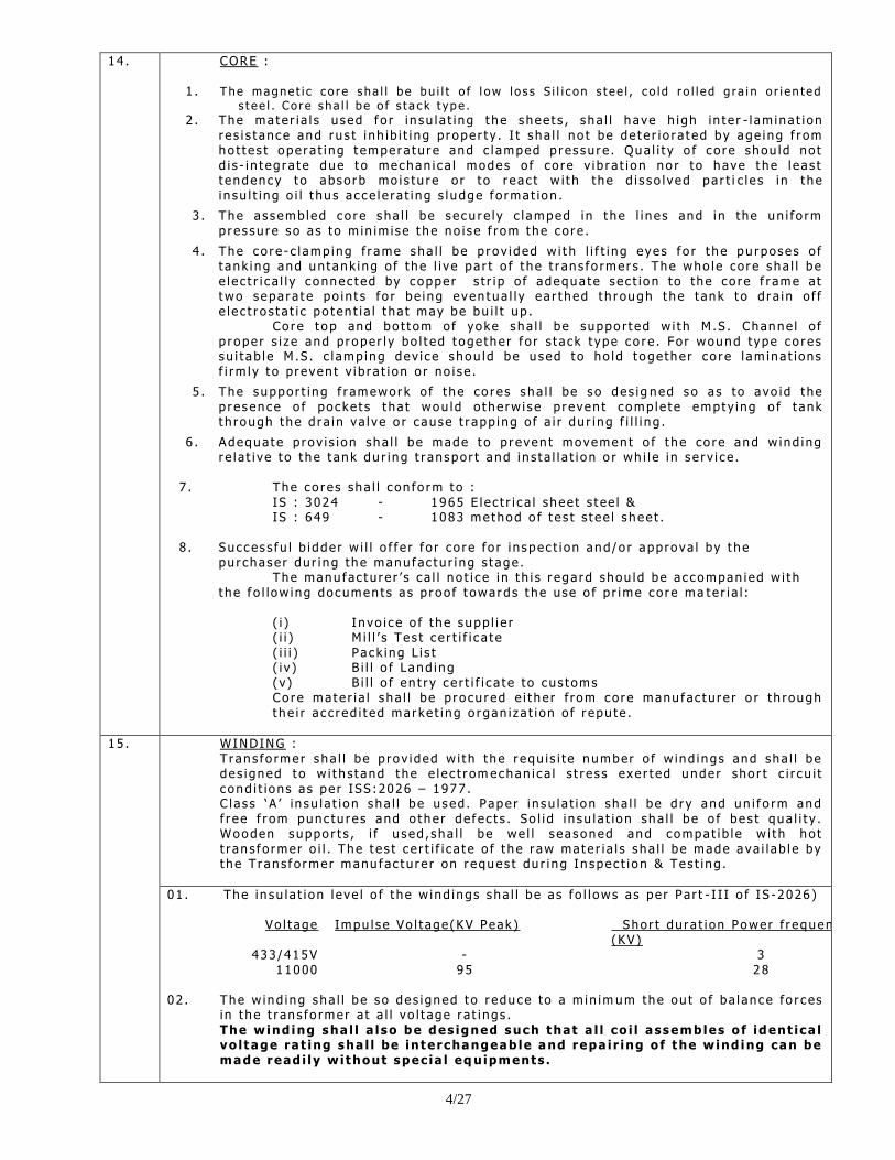
14 . CORE :
1 . The magne t i c c o r e s ha l l b e bu i l t o f l ow l o s s S i l i c on s t ee l , c o l d r o l l e d g r a i n o r i en t ed
s t ee l . Co r e s ha l l b e o f s t a c k t ype . 2 . The mate r i a l s used f o r i n su l a t ing t he shee t s , s ha l l h ave h igh in t e r - l am ina t i on
r es i s t ance and r u s t i nh ib i t i ng p r ope r t y . I t s ha l l no t be de t e r i o r a t ed by age ing f r om ho t t es t ope r a t i ng t empera tu r e and c l amped p r es su r e . Qua l i t y o f c o r e shou ld no t d i s - i n t eg r a t e due t o mechan i c a l modes o f c o re v i b r a t i on no r to have t he l eas t t endency t o abso rb mo i s tu r e o r to r eac t w i t h the d i s s o l ved pa r t i c l e s i n t he i n su l t ing o i l t hu s ac ce l e ra t i ng s l udge f o rmat ion .
3 . The as semb led co r e sha l l be s ecu r e l y c l amped i n t he l i n es and i n the un i fo rm p r es su r e s o as to m in im is e t he no is e f rom the co r e .
4 . The co r e - c l amp ing f r ame sha l l be p r ov ided w i t h l i f t i ng eyes f o r t he pu rposes o f t ank ing and un t ank ing o f the l i ve pa r t o f t he t r an s fo rmer s . The who le co r e sha l l be e l e c t r i c a l l y c onnec t ed by coppe r s t r i p o f adequa te s ec t ion to the co re f r ame at two s epa r a t e po in t s fo r be ing even tua l l y ea r t hed t h r ough t he t ank t o d r a in o f f e l e c t r o s t a t i c po t en t i a l t ha t may be bu i l t up .
Co r e t op and bo t t om o f yoke sha l l be suppo r t ed w i t h M .S . Channe l o f p r ope r s i z e and pr ope r l y bo l t ed t oge the r f o r s t ack t ype co r e . Fo r wound type co r es su i t ab l e M .S . c l amp ing dev i c e shou ld be u sed t o ho ld t oge the r co r e l am ina t ions f i rm l y t o pr even t v i b r a t i on o r no i s e .
5 . The suppor t i ng f r amework o f the co r es sha l l be s o des i g ned so as to avo id t he p r esence o f pocke t s t ha t wou ld o t he rw i s e p r even t c omp le t e empty ing o f t ank t h rough t he d r a in va l ve o r c ause t r app ing o f a i r du r i ng f i l l i n g .
6 . Adequa te p r ov i s i on sha l l be made t o p r even t movemen t o f t he co r e and w ind ing r e l a t i ve t o t he t ank du r ing t r anspor t and i n s t a l l a t i on o r wh i l e i n s e r v i c e .
7 . The co r es sha l l c on fo rm t o : IS : 3024 - 1965 E l ec t r i c a l shee t s t ee l & IS : 649 - 1083 method o f t e s t s t ee l s hee t .
8 . Succes s f u l b i dde r w i l l o f f e r f o r co r e fo r i n spec t i on and/o r app rova l by t he
pu r chase r du r i ng the manu f ac tu r i ng s t age . The manu f ac tu r e r ‟ s c a l l no t i c e i n t h i s r ega rd shou ld be ac compan ied w i t h
t he f o l low ing documen ts a s p r oo f t owards t he use o f p r ime co r e ma te r i a l : ( i ) In vo i c e o f the supp l i e r ( i i ) Mi l l ‟ s Tes t c e r t i f i c a t e ( i i i ) Pack ing L i s t ( i v ) B i l l o f Land ing ( v ) B i l l o f en t r y c e r t i f i c a t e to cus t oms Co r e ma te r i a l s ha l l be p r o cu r ed e i t her f rom co r e manu f ac tu r e r o r th rough t he i r a c c r ed i t ed mar ke t i ng o r gan iz a t i on o f r epu te .
15 . WINDING : T r an s fo rmer sha l l be p rov ided w i t h the r equ is i t e number o f w ind ings and sha l l be des i gned t o w i t h s t and t he e l e c t r om echan i c a l s t r e s s exe r t ed unde r sho r t c i r c u i t c ond i t ions a s pe r ISS :2026 – 1977 . C las s „ A ‟ in su l a t ion sha l l be u sed . Pape r i n su l a t i on sha l l be d r y and un i f o rm and f r ee f r om punc tu r es and o the r de f ec t s . So l i d i n su l a t ion sha l l be o f be s t qua l i t y . Wooden suppo r t s , i f u s ed , sha l l be we l l s easoned and compa t i b l e w i t h ho t t r an s f o rmer o i l . The t e s t c e r t i f i c a t e o f t he r aw mate r i a l s s ha l l be made a va i l ab l e by t he T r an s f o rmer manu f ac tu r e r on r eques t du r i ng In spec t i on & Tes t ing .
01 . The i n su l a t i on l eve l o f t he w ind ings sha l l be a s f o l l ows as pe r Pa r t - I I I o f IS - 2026 )
Vo l t age Impu l s e Vo l t age (KV Peak )
Shor t du r a t i on Power f r equency vo l t age (KV)
433 /415V - 3 11000 95 28
02 . The w ind ing sha l l be s o des i gned t o r educe to a m in im um the ou t o f ba l an ce fo r c es
i n t he t r an s fo rmer a t a l l vo l t age r a t i ngs . The wind i ng sha l l a lso be des igned such that a l l co i l assembles o f ident ica l vo l tage ra t ing sha l l be interchangeab le and repa i r ing o f the wind i ng can be made read i ly wi thout spec ia l eq uipments .
5/27
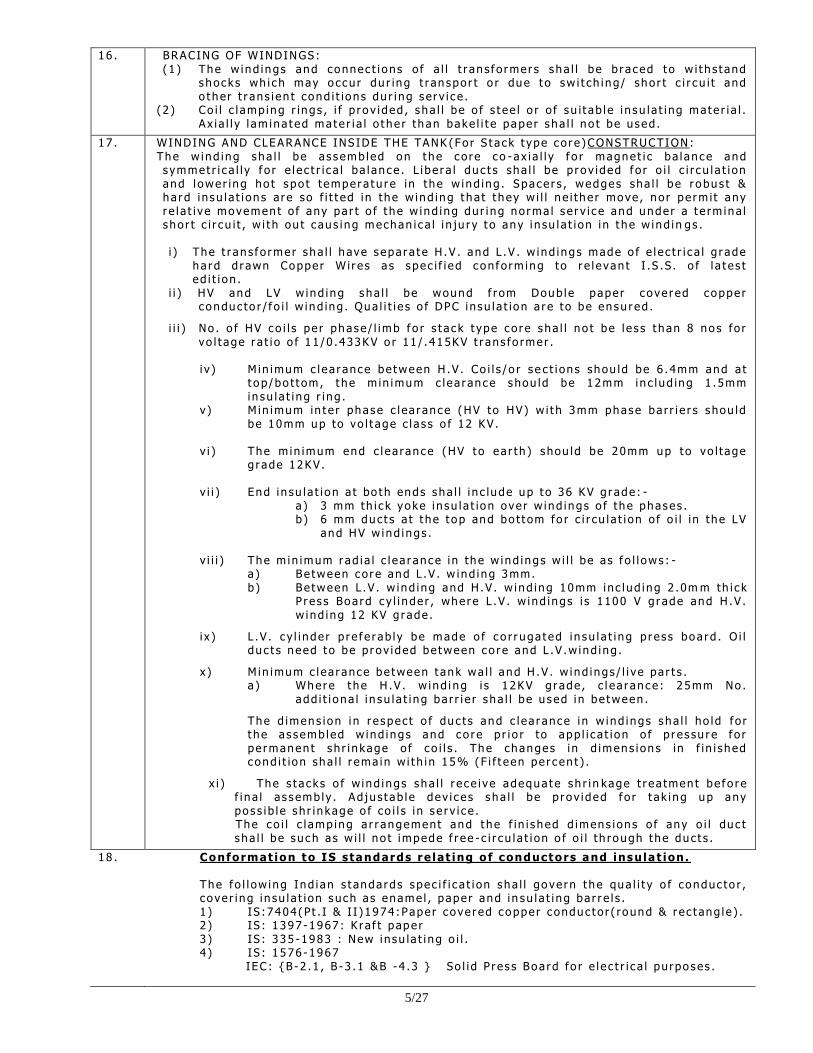
16 . BRAC ING OF WINDINGS : (1 ) The w ind ings and connec t i ons o f a l l t r an s f o rmer s sha l l be b r aced t o w i t h s t and
shocks wh i ch may o ccu r du r ing t r an spor t o r due t o sw i t ch ing / sho r t c i r c u i t and o ther t r ans i en t cond i t ions du r i ng s er v i c e .
( 2 ) Co i l c l amp ing r ings , i f p r o v ided , s ha l l be o f s t ee l o r o f s u i t ab l e i n su l a t i ng mate r i a l . A x i a l l y l am ina t ed mate r i a l o t he r than bake l i t e pape r sha l l no t be used .
17 . WINDING AND CLEARANCE INS IDE THE TANK (For S t ac k t ype co r e ) CONSTRUCTION : The w ind ing sha l l be a s semb led on t he co re co - ax i a l l y f o r magne t i c ba l an ce and s ymmet r i c a l l y f o r e l e c t r i c a l ba l an ce . L i be r a l du c t s sha l l be p r ov ided f o r o i l c i r c u l a t i on and l ower ing ho t s po t tempera tu r e in the w ind ing . Space r s , wedges sha l l be r obus t & ha r d i nsu l a t i on s ar e so f i t t ed i n the w ind ing t ha t t hey w i l l n e i the r move , no r pe rm i t any r e l a t i ve movemen t o f any pa r t o f t he w ind ing dur i ng no rma l s e r v i c e and unde r a t e rm ina l s ho r t c i r c u i t , w i t h ou t c au s ing mechan i c a l i n ju r y t o any i n su l a t i on i n t he w ind in gs .
i ) The t r an s f o rmer sha l l h ave s epa r a t e H .V . and L .V . w ind ings made o f e l e c t r i c a l g r ade
ha rd d r awn Coppe r W i r es a s spec i f i ed con f o rm ing to r e l evan t I .S .S . o f l a t e s t ed i t i on .
i i ) HV and LV w ind ing sha l l be wound f rom Doub le pape r cove r ed coppe r c onduc to r / f o i l w ind ing . Qua l i t i e s o f DPC i nsu l a t ion a r e to be en su r ed .
i i i ) No . o f HV co i l s pe r phase / l imb f o r s t ac k t ype co r e sha l l no t be l e s s t han 8 no s fo r vo l t age r a t i o o f 11 /0 .433KV o r 11 / .415KV t r ans fo rmer .
i v ) M in imum c l ea r ance be tween H .V . Co i l s /o r s e c t i on s shou ld be 6 .4mm and a t
t o p /bo t t om , t he m in imum c l ea r ance shou ld be 12mm in c l ud ing 1 .5mm in su l a t i ng r i ng .
v ) Min imum in t e r phase c l ea r ance (HV to HV) w i t h 3mm phase ba r r i e r s s hou ld be 10mm up to vo l t age c l a s s o f 12 KV .
v i ) The m in imum end c l ea rance (HV t o ea r th ) s hou ld be 20mm up t o vo l tage
g r ade 12KV . v i i ) End i n su l a t i on a t bo th ends sha l l i n c lude up t o 36 KV g r ade : -
a ) 3 mm th i c k yoke i n su l a t ion o ve r w ind ings o f the phases . b ) 6 mm duc t s a t t he t op and bo t t om fo r c i r cu l a t i on o f o i l in the LV
and HV w ind ings .
v i i i ) The m in imum r ad i a l c l ea r ance i n the w ind ings w i l l be a s f o l l ows : - a ) Be tween co r e and L .V . w ind ing 3mm. b ) Be tween L .V . w ind ing and H .V . w ind ing 10mm inc l ud ing 2 .0m m th i c k
P r es s Boa rd c y l i nde r , whe re L .V . w ind ings i s 1100 V g r ade and H .V . w ind ing 12 KV g r ade .
i x ) L .V . c y l i nde r p r e f e r ab l y be made o f c o r r uga t ed i n su l a t i ng p r ess boa rd . O i l du c t s need t o be p r ov ided be tween co r e and L .V .w ind ing .
x ) Min imum c l ea r ance be tween t ank wa l l and H .V . w ind ings / l i ve pa r t s . a ) Where t he H .V . w ind i ng i s 12KV g r ade , c l ea r ance : 25mm No .
add i t i ona l i n su l a t i ng ba r r i e r s ha l l be u sed i n be tween .
The d imens ion i n r e spec t o f du c t s and c l ea r ance i n w ind ings sha l l ho ld fo r t he as semb led w ind ings and co r e p r i o r to app l i c a t i on o f p r es su r e f o r pe rmanen t sh r i n kage o f c o i l s . The changes i n d imens ion s in f in i shed cond i t ion sha l l r ema in w i t h i n 15% (F i f t een pe r cen t ) .
x i ) The s t ac ks o f w ind ings sha l l r e ce i ve adequa te sh r i n kage t r ea tmen t be f o r e f i n a l a s semb ly . Ad ju s t ab l e dev i c es sha l l be p r ov ided f o r t ak i ng up any po s s i b l e sh r i n kage o f co i l s i n s e r v i c e .
The co i l c l amp ing a r r angement and t he f in i s hed d imens ion s o f any o i l du c t s ha l l be su ch as w i l l no t impede f r ee - c i r cu l a t i on o f o i l th rough t he duc t s .
18 . Conformat ion to IS standards re lat ing o f conductors and insu la t ion . The f o l l ow ing Ind i an s t anda rds spec i f i c a t i on sha l l gove rn t he qua l i t y o f conduc to r , c o ve r i ng i n su l a t i on such as ename l , pape r and i n su l a t i ng ba r r e l s . 1 ) IS :7404 (Pt . I & I I )1974 :Pape r cove r ed coppe r conduc to r ( round & r ec t ang l e ) . 2 ) IS : 1397 -1967 : K r a f t pape r 3 ) IS : 335 -1983 : New insu la t i ng o i l . 4 ) IS : 1576 -1967 IEC : {B -2 .1 , B -3 .1 &B - 4 .3 } So l i d P r es s Boa rd fo r e l e c t r i c a l pu rpo ses .
6/27
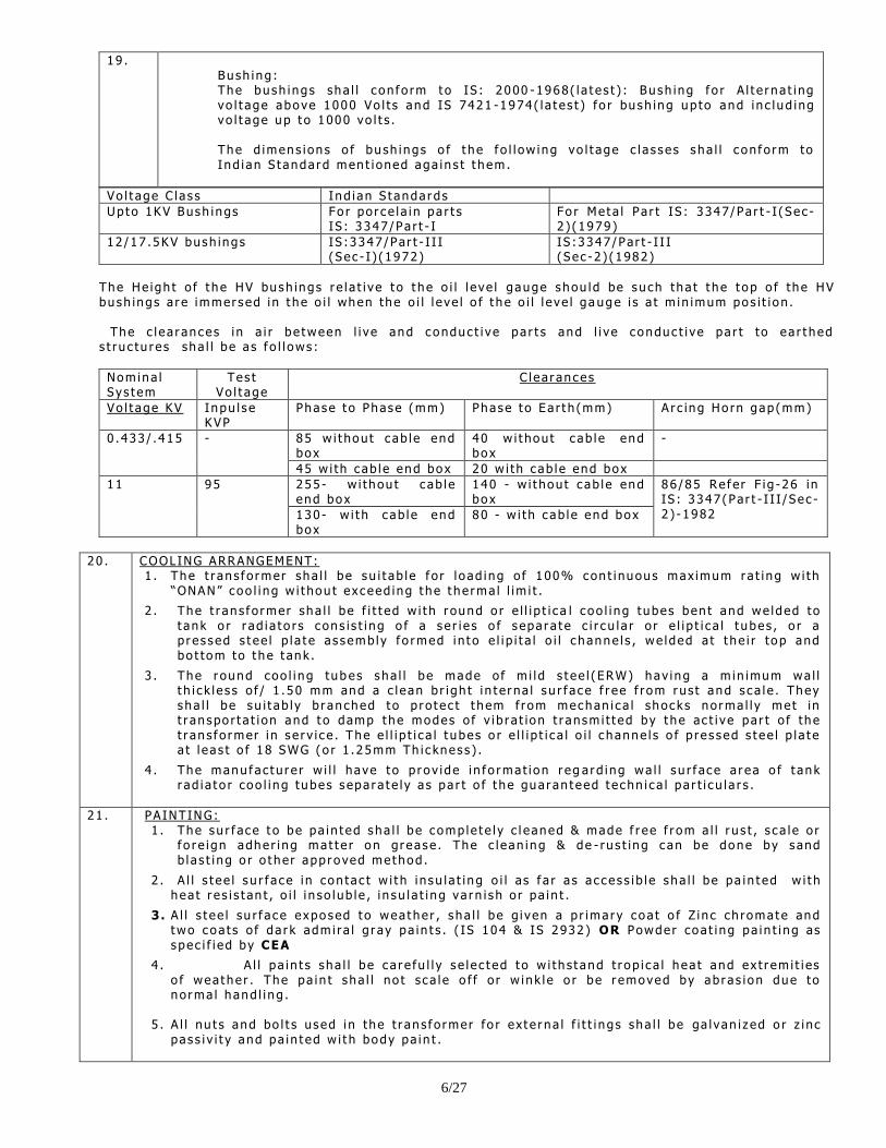
19 . Bu sh ing : The bush ings sha l l c on f o rm t o IS : 2000 -1968( l a t es t ) : Bu sh ing f o r A l t e r na t i ng vo l t age above 1000 Vo l t s and IS 7421 -1974 ( l a t es t ) f o r bu sh ing up to and i n c l ud ing vo l t age up t o 1000 vo l t s . The d imens ion s o f bu sh ings o f t he f o l l ow ing vo l t age c l a s ses sha l l c on f o rm to Ind i an S t anda rd men t i oned aga in s t t hem.
Vo l t age C l a s s Ind i an S t anda rds
Up to 1KV Bush ings Fo r po r ce l a i n pa r t s IS : 3347 /Pa r t - I
Fo r Me ta l Pa r t IS : 3347/Pa r t - I (Sec -2 ) (1979 )
12 /17 .5KV bush ings IS :3347 /Par t - I I I ( Sec - I ) (1972 )
IS :3347 /Par t - I I I ( Sec -2 ) (1982 )
The He igh t o f t he HV bush ings r e l a t i ve t o t he o i l l e ve l gauge shou ld be su ch tha t t he t op o f the HV bush ings a r e immer sed i n t he o i l when the o i l l e ve l o f t he o i l l e ve l ga uge i s a t m in imum pos i t i on .
The c l ea r ances i n a i r be tween l i ve and conduc t i ve pa r t s and l i ve conduc t i ve pa r t to ea r t hed s t ru c tu r es sha l l be a s f o l l ows :
Nom ina l S ys t em
Tes t Vo l t age
C l ea r ances
Vo l t age KV Inpu l s e KVP
Phase t o Phase (mm) Phase t o Ea r t h (mm)
A r c ing Ho rn gap (mm)
0 .433 / .415 - 85 w i t hou t c ab l e end box
40 w i t hou t c ab l e end box
-
45 w i th c ab l e end box 20 w i th c ab l e end box
11 95 255 - w i thou t c ab l e end box
140 - w i t hou t c ab l e end box
86 /85 Re f er F i g - 26 in IS : 3347 (Par t - I I I /Sec -2 ) - 1982 130 - w i t h c ab l e end
box 80 - w i th c ab l e end box
20 . COOLING ARRANGEMENT: 1 . The t r an s f o rmer sha l l be su i t ab l e f o r l o ad ing o f 100% con t i nuous max imum r a t i ng w i th
“ONAN” c oo l i ng w i t hou t exceed ing t he t he rma l l im i t .
2 . The t r an s f o rmer sha l l be f i t t ed w i t h r ound o r e l l i p t i c a l c oo l i ng tubes ben t and we lded to t ank o r r ad i a t o r s c on s i s t i ng o f a s e r i e s o f s epa r a t e c i r cu l a r o r e l i p t i c a l t ubes , o r a p r es sed s t ee l p l a t e a s semb ly f o rmed i n t o e l i p i t a l o i l c hanne l s , we lded a t t he i r top and bo t tom to t he t ank .
3 . The r ound coo l i ng tub es sha l l be made o f m i l d s t ee l (ERW) hav ing a m in imum wa l l t h i c k l e s s o f / 1 .50 mm and a c l ean b r i gh t i n t er na l s u r f ace f r ee f rom rus t and s ca l e . They sha l l be su i t ab l y b r anched t o p r o t ec t t hem f rom mechan i c a l shocks no rma l l y me t in t r an spo r t a t i on and t o damp t he modes o f v i b r a t ion t r ansm i t t ed by t he ac t i ve pa r t o f the t r an s f o rmer i n s e r v i c e . The e l l i p t i c a l t ubes o r e l l i p t i c a l o i l c hanne l s o f p res sed s t ee l p l a t e a t l eas t o f 18 SWG (o r 1 .25mm Th i c knes s ) .
4 . The manu f ac tu r e r w i l l have t o p r ov ide i n f o rmat i on r eg a rd ing wa l l s u r f ace a r ea o f t ank r ad i a t o r coo l i ng tubes s epa r a t e l y a s pa r t o f t he gua r an t eed t echn i c a l pa r t i c u l a r s .
21 . PA INTING: 1 . The su r f ace t o be pa in t ed sha l l be comp le t e l y c l eaned & made f r ee f r om a l l r u s t , s c a l e o r
f o r e i gn adhe r i ng mat t e r on gr ease . The c l ean ing & de - ru s t ing c an be done by s and b l a s t i ng o r o t her app roved method .
2 . A l l s t ee l s u r f ace i n con tac t w i t h i nsu l a t i ng o i l as f a r a s ac ces s i b l e sha l l be pa in t ed w i t h hea t r e s i s t an t , o i l i n so lub l e , i n su l a t i ng va rn i s h o r pa in t .
3. A l l s t ee l su r f ace exposed t o wea the r , s ha l l be g i ven a p r imar y coa t o f Z i n c ch romate and two coa ts o f da r k adm i ra l g r ay pa in t s . ( IS 104 & IS 2932 ) OR Powder coa t i ng pa in t i ng as spec i f i ed by CEA
4 . A l l pa in t s sha l l be c a r e fu l l y s e l e c t ed t o w i th s t and t r op i c a l hea t and ex t r em i t i es o f wea the r . The pa in t s ha l l no t s c a l e o f f o r w ink l e o r be r emoved by ab r as i on due to no rma l hand l i ng .
5 . A l l nu t s and bo l t s used i n the t r an s f o rmer fo r ex t e r na l f i t t i ngs sha l l be ga l van i z ed o r z i nc
pas s i v i t y and pa in t ed w i t h body pa in t .
7/27
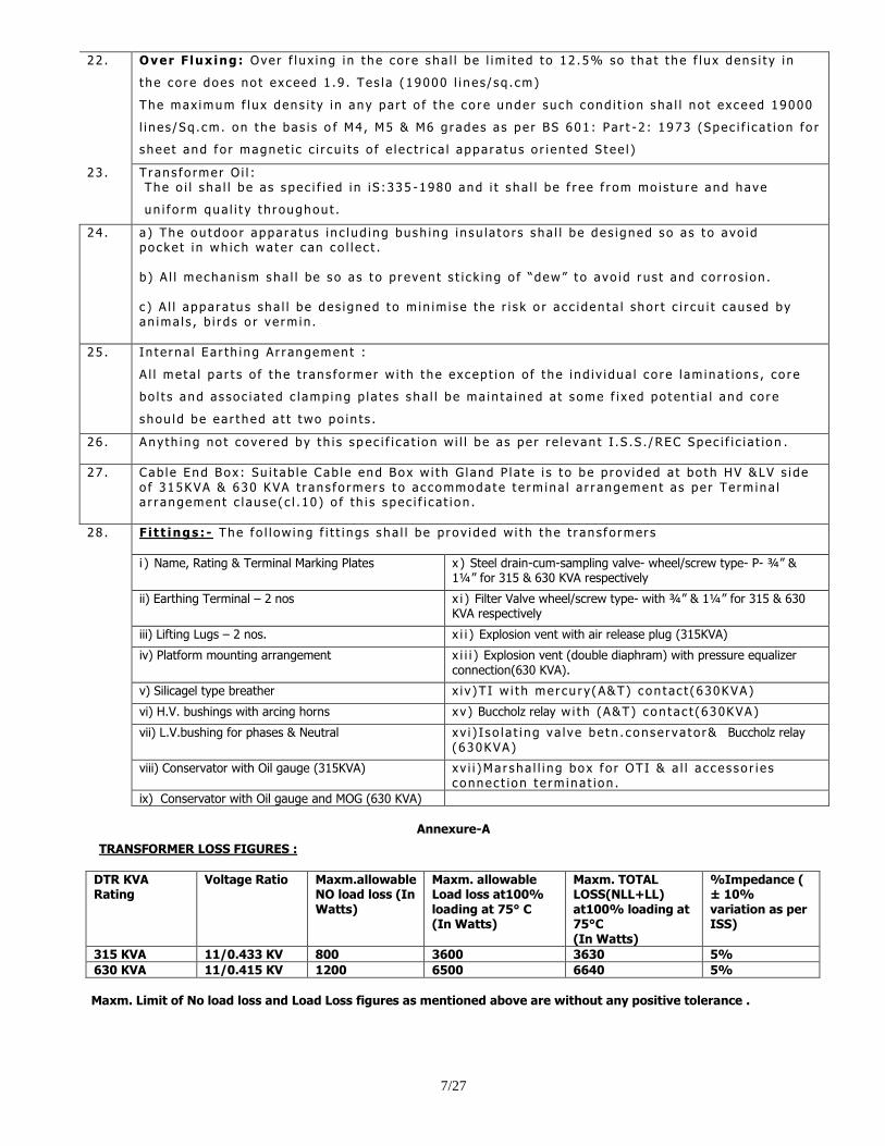
22 . Over F lux ing : Ove r f l u x i ng i n t he co r e sha l l be l im i t ed t o 12 .5% so t ha t t he f l u x dens i t y i n
t he co r e does no t exceed 1 .9 . Tes l a (19000 l i n es / sq . cm)
The max imum f l u x dens i t y i n any pa r t o f the co r e unde r su ch cond i t i on sha l l no t exceed 19000
l i n es /Sq . cm . on t he bas i s o f M4 , M5 & M6 g r ades as pe r BS 601 : Par t - 2 : 1973 (Spec i f i c a t i on fo r
s hee t and f o r magnet i c c i r c u i t s o f e l e c t r i c a l appa r a tu s o r i en t ed S t ee l )
23 . T r an s fo rmer O i l : The o i l s ha l l be a s spec i f i ed i n i S :335 -1980 and i t s ha l l be f r ee f r om mo i s t u r e and have
un i f o rm qua l i t y t h r oughou t .
24 . a ) The ou tdoo r appa r a tus i n c l ud ing bush ing i n su la t o r s s ha l l be des i gned so as t o avo id po cke t i n wh ich wa ter c an co l l e c t .
b) A l l mechan i sm sha l l be s o as t o p r even t s t i c k ing o f “dew” t o avo id r us t and co r ro s i on .
c ) A l l appa r a tu s sha l l be des i gned t o m in im i s e the r i s k o r a c c i den t a l sho r t c i r cu i t c aused by an ima l s , b i r d s o r ve rm in .
25 . In t e r na l Ea r th ing A r r angemen t :
A l l me ta l pa r t s o f t he t ran s fo rmer w i th t he excep t i on o f the i nd i v i dua l c o r e l am ina t i on s , co r e
bo l t s and as so c i a t ed c l amp ing p l a t es sha l l be ma in t a i ned a t s ome f i xed po t en t i a l and co r e
shou ld be ea r t hed a t t two po in t s .
26 . Any th ing no t cove r ed by t h i s s p ec i f i c a t ion w i l l be a s pe r r e l evan t I .S .S . / REC Spec i f i c i a t ion .
27 . Cab l e End Box : Su i t ab l e Cab l e end Box w i t h G l and P l a t e i s t o be p r ov ided a t bo th HV &LV s i de o f 315KVA & 630 KVA t r an s fo rmer s t o ac commoda te t e rm ina l a r r angemen t a s pe r Te rm ina l a r r angement c l au se ( c l . 10 ) o f th i s s pec i f i c a t i on .
28 . F i t t ings : - The f o l l ow ing f i t t i ngs sha l l be p r ov ided w i t h t he t r an s f o rmer s
i ) Name, Rating & Terminal Marking Plates x ) Steel drain-cum-sampling valve- wheel/screw type- P- ¾” & 1¼” for 315 & 630 KVA respectively
ii) Earthing Terminal – 2 nos x i ) Filter Valve wheel/screw type- with ¾” & 1¼” for 315 & 630 KVA respectively
iii) Lifting Lugs – 2 nos. x i i ) Explosion vent with air release plug (315KVA)
iv) Platform mounting arrangement x i i i ) Explosion vent (double diaphram) with pressure equalizer connection(630 KVA).
v) Silicagel type breather x i v )T I w i t h mer cu r y (A&T) con t ac t (630KVA)
vi) H.V. bushings with arcing horns xv ) Buccholz relay w i t h (A&T) con t ac t (630KVA)
vii) L.V.bushing for phases & Neutral x v i ) I s o l a t i ng va l ve be tn . conse r va t o r& Buccholz relay (630KVA)
viii) Conservator with Oil gauge (315KVA) xv i i )Ma r sha l l i n g box f o r OTI & a l l a c ces so r i e s connec t ion t e rm ina t ion .
ix) Conservator with Oil gauge and MOG (630 KVA)
Annexure-A
TRANSFORMER LOSS FIGURES :
DTR KVA Rating
Voltage Ratio Maxm.allowable NO load loss (In Watts)
Maxm. allowable Load loss at100% loading at 75° C (In Watts)
Maxm. TOTAL LOSS(NLL+LL) at100% loading at 75°C (In Watts)
%Impedance ( ± 10% variation as per ISS)
315 KVA 11/0.433 KV 800 3600 3630 5%
630 KVA 11/0.415 KV 1200 6500 6640 5%
Maxm. Limit of No load loss and Load Loss figures as mentioned above are without any positive tolerance .
8/27
PART-B
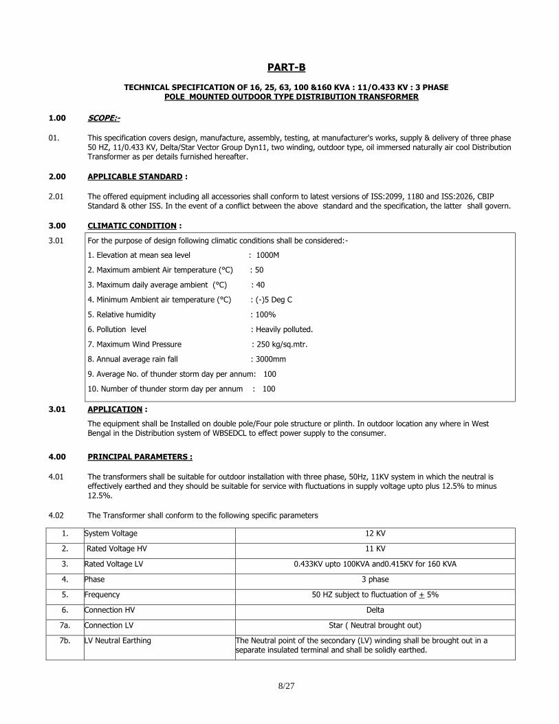
TECHNICAL SPECIFICATION OF 16, 25, 63, 100 &160 KVA : 11/O.433 KV : 3 PHASE POLE MOUNTED OUTDOOR TYPE DISTRIBUTION TRANSFORMER
1.00 SCOPE:-
01. This specification covers design, manufacture, assembly, testing, at manufacturer's works, supply & delivery of three phase 50 HZ, 11/0.433 KV, Delta/Star Vector Group Dyn11, two winding, outdoor type, oil immersed naturally air cool Distribution Transformer as per details furnished hereafter.
2.00 APPLICABLE STANDARD :
2.01 The offered equipment including all accessories shall conform to latest versions of ISS:2099, 1180 and ISS:2026, CBIP Standard & other ISS. In the event of a conflict between the above standard and the specification, the latter shall govern.
3.00 CLIMATIC CONDITION :
3.01 For the purpose of design following climatic conditions shall be considered:-
1. Elevation at mean sea level : 1000M
2. Maximum ambient Air temperature (°C) : 50
3. Maximum daily average ambient (°C) : 40
4. Minimum Ambient air temperature (°C) : (-)5 Deg C
5. Relative humidity : 100%
6. Pollution level : Heavily polluted.
7. Maximum Wind Pressure : 250 kg/sq.mtr.
8. Annual average rain fall : 3000mm
9. Average No. of thunder storm day per annum: 100
10. Number of thunder storm day per annum : 100
3.01 APPLICATION :
The equipment shall be Installed on double pole/Four pole structure or plinth. In outdoor location any where in West Bengal in the Distribution system of WBSEDCL to effect power supply to the consumer.
4.00 PRINCIPAL PARAMETERS :
4.01 The transformers shall be suitable for outdoor installation with three phase, 50Hz, 11KV system in which the neutral is effectively earthed and they should be suitable for service with fluctuations in supply voltage upto plus 12.5% to minus 12.5%.
4.02 The Transformer shall conform to the following specific parameters
1. System Voltage 12 KV
2. Rated Voltage HV 11 KV
3. Rated Voltage LV 0.433KV upto 100KVA and0.415KV for 160 KVA
4. Phase 3 phase
5. Frequency 50 HZ subject to fluctuation of + 5%
6. Connection HV Delta
7a. Connection LV Star ( Neutral brought out)
7b. LV Neutral Earthing The Neutral point of the secondary (LV) winding shall be brought out in a separate insulated terminal and shall be solidly earthed.
9/27
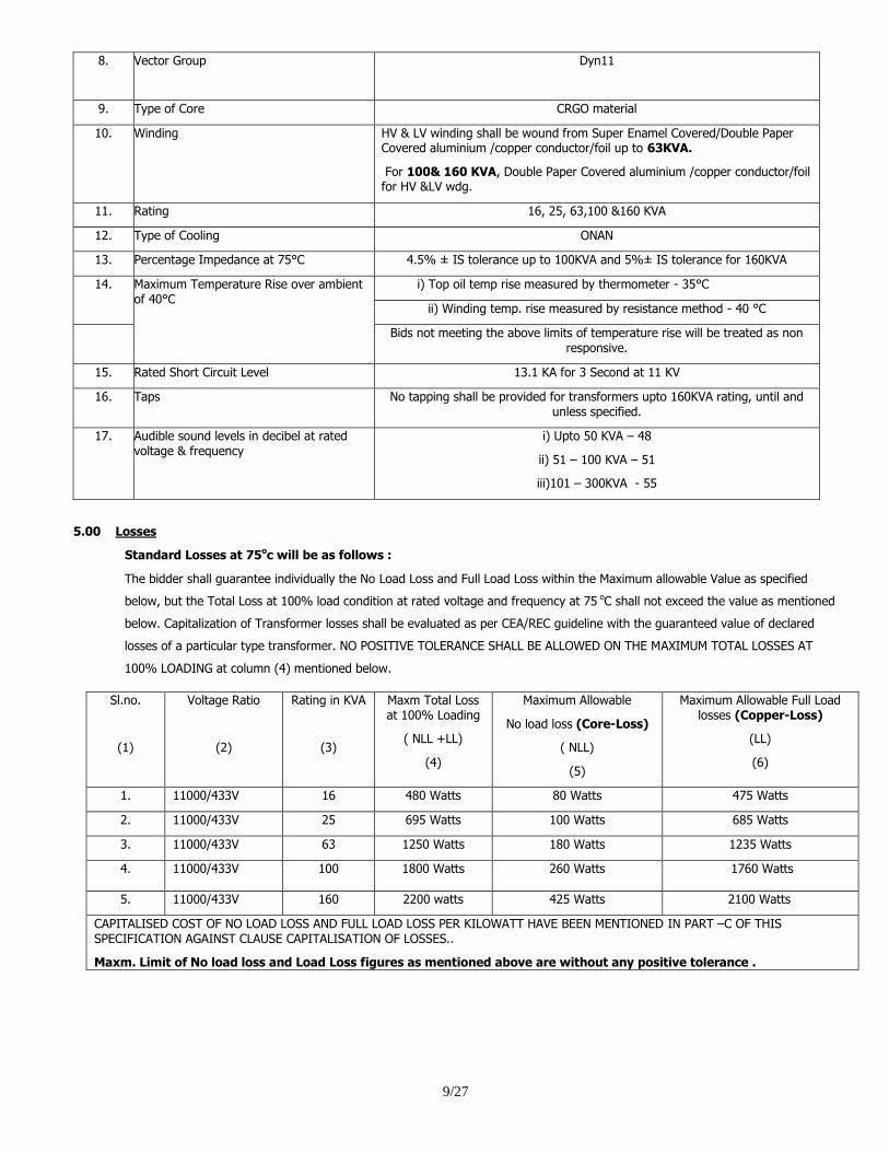
8. Vector Group Dyn11
9. Type of Core CRGO material
10. Winding HV & LV winding shall be wound from Super Enamel Covered/Double Paper Covered aluminium /copper conductor/foil up to 63KVA.
For 100& 160 KVA, Double Paper Covered aluminium /copper conductor/foil for HV &LV wdg.
11. Rating 16, 25, 63,100 &160 KVA
12. Type of Cooling ONAN
13. Percentage Impedance at 75°C 4.5% ± IS tolerance up to 100KVA and 5%± IS tolerance for 160KVA
14. Maximum Temperature Rise over ambient of 40°C
i) Top oil temp rise measured by thermometer - 35°C
ii) Winding temp. rise measured by resistance method - 40 °C
Bids not meeting the above limits of temperature rise will be treated as non responsive.
15. Rated Short Circuit Level 13.1 KA for 3 Second at 11 KV
16. Taps No tapping shall be provided for transformers upto 160KVA rating, until and unless specified.
17. Audible sound levels in decibel at rated voltage & frequency
i) Upto 50 KVA – 48
ii) 51 – 100 KVA – 51
iii)101 – 300KVA - 55
5.00 Losses
Standard Losses at 75oc will be as follows :
The bidder shall guarantee individually the No Load Loss and Full Load Loss within the Maximum allowable Value as specified
below, but the Total Loss at 100% load condition at rated voltage and frequency at 75 oC shall not exceed the value as mentioned
below. Capitalization of Transformer losses shall be evaluated as per CEA/REC guideline with the guaranteed value of declared
losses of a particular type transformer. NO POSITIVE TOLERANCE SHALL BE ALLOWED ON THE MAXIMUM TOTAL LOSSES AT
100% LOADING at column (4) mentioned below.
Sl.no.
(1)
Voltage Ratio
(2)
Rating in KVA
(3)
Maxm Total Loss at 100% Loading
( NLL +LL)
(4)
Maximum Allowable
No load loss (Core-Loss)
( NLL)
(5)
Maximum Allowable Full Load losses (Copper-Loss)
(LL)
(6)
1. 11000/433V 16 480 Watts 80 Watts 475 Watts
2. 11000/433V 25 695 Watts 100 Watts 685 Watts
3. 11000/433V 63 1250 Watts 180 Watts 1235 Watts
4. 11000/433V 100 1800 Watts 260 Watts 1760 Watts
5. 11000/433V 160 2200 watts 425 Watts 2100 Watts
CAPITALISED COST OF NO LOAD LOSS AND FULL LOAD LOSS PER KILOWATT HAVE BEEN MENTIONED IN PART –C OF THIS SPECIFICATION AGAINST CLAUSE CAPITALISATION OF LOSSES..
Maxm. Limit of No load loss and Load Loss figures as mentioned above are without any positive tolerance .
10/27
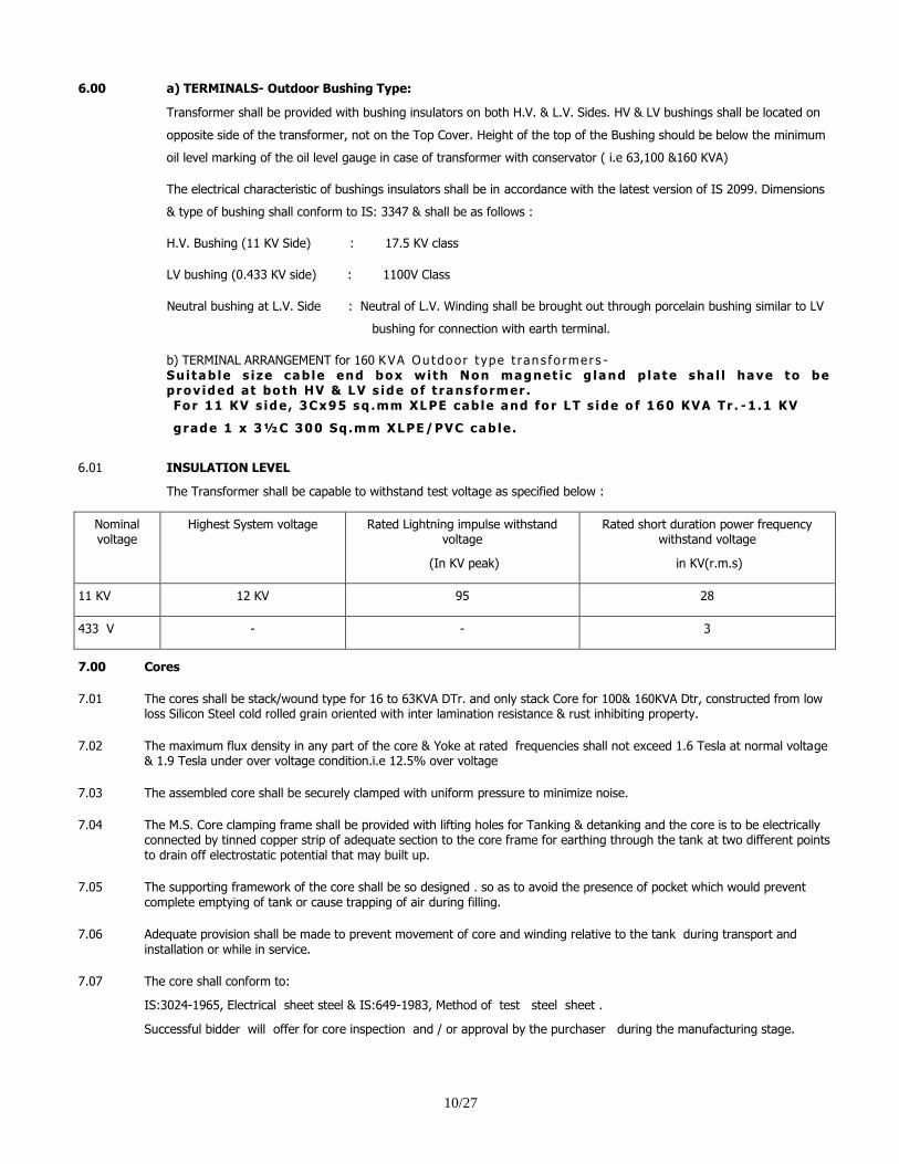
6.00
a) TERMINALS- Outdoor Bushing Type:
Transformer shall be provided with bushing insulators on both H.V. & L.V. Sides. HV & LV bushings shall be located on
opposite side of the transformer, not on the Top Cover. Height of the top of the Bushing should be below the minimum
oil level marking of the oil level gauge in case of transformer with conservator ( i.e 63,100 &160 KVA)
The electrical characteristic of bushings insulators shall be in accordance with the latest version of IS 2099. Dimensions
& type of bushing shall conform to IS: 3347 & shall be as follows :
H.V. Bushing (11 KV Side) : 17.5 KV class
LV bushing (0.433 KV side) : 1100V Class
Neutral bushing at L.V. Side : Neutral of L.V. Winding shall be brought out through porcelain bushing similar to LV
bushing for connection with earth terminal.
b) TERMINAL ARRANGEMENT for 160 KVA Ou tdoor t ype t ran s fo rmer s - Sui tab le s ize cab le end box with Non magnet ic g land p late sha l l have to be p rov ided at both HV & LV s ide o f t rans former . For 11 KV s ide , 3Cx95 sq .mm XLPE cab le and fo r LT s ide o f 160 KVA Tr . -1 .1 KV
grade 1 x 3½C 300 Sq.mm XLPE/PVC cab le .
6.01 INSULATION LEVEL
The Transformer shall be capable to withstand test voltage as specified below :
Nominal voltage
Highest System voltage Rated Lightning impulse withstand voltage
(In KV peak)
Rated short duration power frequency withstand voltage
in KV(r.m.s)
11 KV 12 KV 95 28
433 V - - 3
7.00 Cores
7.01 The cores shall be stack/wound type for 16 to 63KVA DTr. and only stack Core for 100& 160KVA Dtr, constructed from low loss Silicon Steel cold rolled grain oriented with inter lamination resistance & rust inhibiting property.
7.02 The maximum flux density in any part of the core & Yoke at rated frequencies shall not exceed 1.6 Tesla at normal voltage & 1.9 Tesla under over voltage condition.i.e 12.5% over voltage
7.03 The assembled core shall be securely clamped with uniform pressure to minimize noise.
7.04
The M.S. Core clamping frame shall be provided with lifting holes for Tanking & detanking and the core is to be electrically connected by tinned copper strip of adequate section to the core frame for earthing through the tank at two different points to drain off electrostatic potential that may built up.
7.05
The supporting framework of the core shall be so designed . so as to avoid the presence of pocket which would prevent complete emptying of tank or cause trapping of air during filling.
7.06
Adequate provision shall be made to prevent movement of core and winding relative to the tank during transport and installation or while in service.
7.07 The core shall conform to:
IS:3024-1965, Electrical sheet steel & IS:649-1983, Method of test steel sheet .
Successful bidder will offer for core inspection and / or approval by the purchaser during the manufacturing stage.
11/27
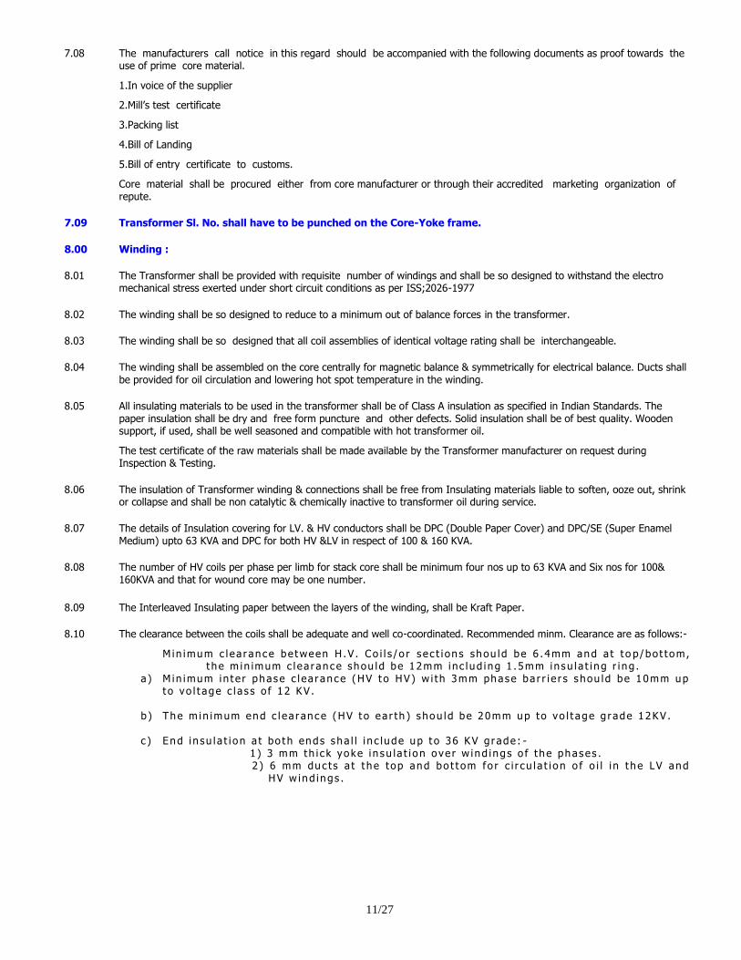
7.08 The manufacturers call notice in this regard should be accompanied with the following documents as proof towards the use of prime core material.
1.In voice of the supplier
2.Mill‟s test certificate
3.Packing list
4.Bill of Landing
5.Bill of entry certificate to customs.
Core material shall be procured either from core manufacturer or through their accredited marketing organization of repute.
7.09 Transformer Sl. No. shall have to be punched on the Core-Yoke frame.
8.00 Winding :
8.01 The Transformer shall be provided with requisite number of windings and shall be so designed to withstand the electro mechanical stress exerted under short circuit conditions as per ISS;2026-1977
8.02 The winding shall be so designed to reduce to a minimum out of balance forces in the transformer.
8.03 The winding shall be so designed that all coil assemblies of identical voltage rating shall be interchangeable.
8.04 The winding shall be assembled on the core centrally for magnetic balance & symmetrically for electrical balance. Ducts shall be provided for oil circulation and lowering hot spot temperature in the winding.
8.05 All insulating materials to be used in the transformer shall be of Class A insulation as specified in Indian Standards. The paper insulation shall be dry and free form puncture and other defects. Solid insulation shall be of best quality. Wooden support, if used, shall be well seasoned and compatible with hot transformer oil.
The test certificate of the raw materials shall be made available by the Transformer manufacturer on request during Inspection & Testing.
8.06 The insulation of Transformer winding & connections shall be free from Insulating materials liable to soften, ooze out, shrink or collapse and shall be non catalytic & chemically inactive to transformer oil during service.
8.07 The details of Insulation covering for LV. & HV conductors shall be DPC (Double Paper Cover) and DPC/SE (Super Enamel Medium) upto 63 KVA and DPC for both HV &LV in respect of 100 & 160 KVA.
8.08 The number of HV coils per phase per limb for stack core shall be minimum four nos up to 63 KVA and Six nos for 100& 160KVA and that for wound core may be one number.
8.09 The Interleaved Insulating paper between the layers of the winding, shall be Kraft Paper.
8.10 The clearance between the coils shall be adequate and well co-coordinated. Recommended minm. Clearance are as follows:-
M in imum c l ea r ance be tween H .V . Co i l s /o r s ec t i on s shou ld be 6 .4mm and a t t o p /bo t tom, t he m in imum c l ea r ance shou ld be 12mm inc l ud ing 1 .5mm insu l a t i ng r i ng .
a ) Min imum in t e r phase c l ea r ance (HV t o HV) w i th 3mm phase ba r r i e r s s hou ld be 10mm up t o vo l t age c l a s s o f 12 KV .
b ) The m in imum end c l ea r ance (HV t o ea r th ) s hou ld be 20mm up to vo l t age g r ade 12KV .
c ) End i n su l a t i on a t bo th ends sha l l i n c lude up t o 36 KV g r ade : - 1 ) 3 mm th i c k yoke i n su la t i on o ve r w ind ings o f the phases . 2 ) 6 mm duc t s a t t he top and bo t t om fo r c i r cu l a t i on o f o i l i n t he LV and
HV w ind ings .
12/27
d ) The m in imum r ad i a l c l ea r ance i n the w ind ings w i l l be a s f o l l ows : -
1 ) Be tween co r e and L .V . w ind ing 3mm. 2 ) Be tween L .V . w ind ing and H .V . w ind ing 10mm inc l ud ing 2 .0mm th ic k P r es s Boa rd
c y l i nde r , whe re L .V . w in d ings i s 1100 V g r ade and H .V . w ind ing 12 KV g r ade .
e) L .V . c y l i nde r p r e f e r ab l y be made o f c o r ruga t ed in su l a t ing p r ess board . O i l du c t s need to be p r ov ided be tween co r e an d L .V .w ind ing .
f ) Min imum c l ea r ance be tween t ank wa l l and H .V . w ind ings / l i ve pa r t s . g ) Where the H .V . w ind ing i s 12KV gr ade , c l ea r ance : 25mm No . add i t i ona l i n su l a t i ng
ba r r i e r s ha l l be u sed i n be tween .
8.11 The stacks of windings shall receive adequate pre shrinkage treatment before assembly. No tapping are to be provided on the winding.
8.12 Lead: HV lead termination to the stud should be made either by method of brazing or the free end of the lead wire having considerable length should be bent to form a ring and the ring should be fixed to the bushing stud with suitable nut, bolt and washer. HV lead termination to the stud should be made either by method of brazing or the free end of the lead wire having considerable length should be bent to form a ring and the ring should be fixed to the bushing stud with suitable nut, bolt and washer.
9.00 TANK :
9.01 Conventional tank shall be constructed. The Transformer tank and cover shall be fabricated from good commercial grade low Carbon Steel suitable for welding & of adequate thickness. The tank wall should be of thickness 3.15mm. Top and bottom plate should be of 5.0 mm thickness. Tolerance as per IS: 1852 shall be applicable.
9.02 Tank design shall be such that core & winding assembly can be tanked or detanked easily.
9.03 The main tank body shall be capable of withstanding vacuum gauge pressure 68 KN per sq.m (500 mm of HG)
9.04 The under carriage of the tank shall be made of channel of suitable slze & design.
9.05 The base of each tank shall be so designed that it shall be possible to move the complete transformer unit by skidding in any direction without injury when using plates or rails.
9.06 Tank shall be designed to prevent retention of water. Tank cover shall be of adequate strength. It shall be bolted on to flanged rim of the tank with weather proof hot oil resistant resilient gasket of 5 mm thickness. Tank cover should have 90° downward bent edges on all sides to protect the gasket under the top cover from direct exposure to weather.
The rating, sl.no, P.O No, year of manufacture & property of WBSEDCL etc. and Asset Codification no. shall be engraved/ Embossed distinctly on the tank body in addition to those provided in the name & rating plate. Adequate care shall be taken so that tank does not get damaged during such engraving.
GI. Nuts & Bolts and washers are to be provided for outside use on tank cover & accessories.
9.07 In s i de wa l l o f the t ank and the M .S .Channe l sha l l be pa in t ed w i t h va rn i sh o r w i t h ho t o i l r e s i s t ance pa in t . Stiffener shall be continuously welded on the tank wall.
9.08 The t ank cove r sha l l be bo l t ed on t o f l anged r im o f t he t ank w i th a wea the r p roo f , ho t , / c o ld o i l r e s i s t ance , r e s i l i en t gas ke t i n be tween f o r o i l t i gh tness . I f t he gaske t i s c ompress i b l e , me ta l l i c s t r i p s sha l l be p r ov ided t o p r even t o ve r compress i on o f t he gaske t . Bush ing t u r r e t s , co ve r s fo r po cke t s o f t he rmomete r s and o ther dev i c es sha l l be des i gned t o p r even t any ing r es s o f r a in wa te r i n t o t he t ank and t he t ank cove r a s a who le sha l l s hed o f a l l r a i n wa te r . The t ank cove r shou ld have downward 90 deg r ee ben t edges on a l l s i des so tha t t he gaske t unde r the top cover i s p r o t ec t ed f r om d i r ec t expo su r e to wea ther . Gaske t u sed be tween t op cove r and t ank f l ange sha l l be o f neoprene rubber ized c o r k shee t o f 5 mm th i c k and sha l l be p r ov ided w i t h wa te r t i gh t c ompou nd be tween t he t ank f l ange and t he gaske t .
9.09 G . I . nu t s , bo l t s , f l a t washe r s , s p r i ng washe r s sha l l be u sed and su i t ab l y s pace t o p r ess the t ank cove r . The S l . No . , P .O . No , Yea r o f manu f ac tu r e & p rope r t y o f WBSEDCL e t c . sha l l be eng r aved on t he t ank bod y i n add i t i on t o t hose p r ov ided i n t he Name & Ra t i ng p l a t e . Adequa te c a r e sha l l be t aken so t ha t t ank does no t ge t damaged du r i ng su ch eng r av ing . Fo l l ow ing m in imum c l ea r ance be tween t op yoke and t ank cove r a r e t o be ma in t a i ned .
13/27
9.10 a ) 16&25 KVA T r ans fo rmer
O i l l e v e l f r om top cove r sha l l no t be l e s s than25 mm and he igh t o f o i l l e ve l f r om top yoke
o r top o f co r e sha l l no t be l e s s t han 50 mm (a t co l d cond i t ion ) .
b ) 63 /100 /160 KVA (w i thou t t ap change r ) : T r an s f o rmer ( the c l ea r ance be tween t op yoke o r
t op o f c o r e and t ank cove r ) s ha l l no t be l e s s than 125 mm.
9.11 S i l i c age l b r ea the r s a r e to be p rov ided o n t r ans fo rmer s o f a l l r a t i ngs , C onser va t o r s a r e t o be
p r ov ided on t r an s f o rmer s o f r a t ings 63 KVA , 100 and 160 KVA . The conse r va to r sha l l be
l i be r a l l y d imens ioned su ch t ha t w i th the l owes t amb ien t t empera tu r e and no l o ad on t he
t r an s f o rmer , t he o i l l e ve l s ha l l no t r ecede t oo l ow and w i th t he h ighes t amb ien t t empera tu r e
and pe rm i s s i b l e o ve r l o ad on t he t r an s f o rmer , the o i l w i l l n o t s p i l l i n t o the b r ea the r p i pe o r t o
t he ex t e r i o r t o was t e . The conse r va t o r sha l l be p r ov ided w i t h o i l l e ve l i nd i c a t o r w i th M in imum,
No rma l & Max imum t empera tu r e Mar k ings . The i n s i de d i amete r o f the p i pe connec t i ng the
conse r va t o r to t he ma in t ank sha l l be w i t h i n 20 t o 50 mm and i t s hou ld be p r o j ec t ed i n t o t he
conse r va t o r i n s uch a way t ha t i t s end i s app rox ima te l y 20 mm above t he bo t tom o f t he
conse r va t o r .
Conse r va t o r s sha l l no t be p r ov ided w i t h d r a in p l ug f o r t r an s f o rmer o f 63KVA ,100KVA and
160KVA r a t ings . F i l l i n g ho l e w i th cove r sha l l be p r ov ided as u sua l . Conse r va t o r p i pe f o r 63
KVA ,100KVA and 160 KVA t r ans fo rmer s sha l l be we lded on t he t op cove r . The conse r va to r p i pe
ho l e f i t t ed t o the t ank cove r shou ld be p r ov ided w i t h a su i t ab l e s l an t ed p l a t e , i f r equ i r ed so
t ha t wh i l e pou r i ng o i l i n t o the t r an s f o rmer th rough the conse r va t o r , o i l does no t f a l l d i r e c t l y
on t he w ind ing . Ca r e shou ld be t aken so t ha t f r ee o i l f l ow i s no t impeded . Exp lo s i on ven t s f o r
100 /160 KVA t r ans fo rmer s sha l l a l s o be we lded on t h e cove r . A i r r e l ease p lug shou ld be
p r ov ided i n t he exp lo s i on ven t , and i n t ank cover t o r e l ease any en t r apped a i r .
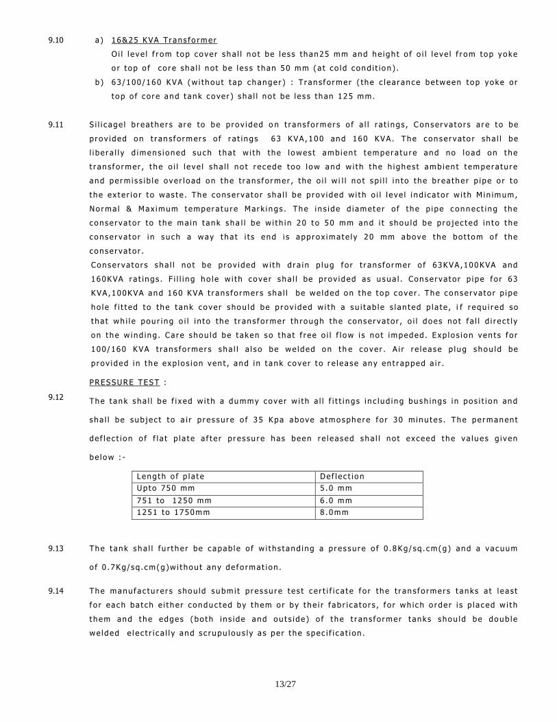
9.12
PRESSURE TEST :
The t ank sha l l be f i x ed w i t h a dummy cove r w i th a l l f i t t i ngs i n c lud ing bu sh ings i n pos i t i o n and
sha l l be sub j ec t t o a i r p r es su r e o f 35 Kpa above a tmosphe re f o r 30 m inu t es . The pe rmanent
de f l e c t i on o f f l a t p l a t e a f t e r pr es su r e has been r e l eased sha l l no t exceed t he va lues g i ven
be low : -
Leng th o f p l a t e De f l e c t i on
Up to 750 mm 5 .0 mm
751 to 1250 mm 6 .0 mm
1251 to 1750mm 8 .0mm
9.13 The t ank sha l l f u r t he r be c apab le o f w i t hs t and ing a p r es su r e o f 0 .8Kg/ sq . cm(g) and a vacuum
o f 0 .7Kg/sq . cm(g)w i t hou t any de f o rmat i on .
9.14 The manuf ac tu r er s shou ld subm i t p r es su r e t e s t c e r t i f i c a t e f o r the t r an s f o rmers t anks a t l eas t
f o r each ba t ch e i t he r c onduc t ed by t hem o r by t he i r f ab r i c a t o r s , f o r wh ich o r de r i s p l a ced w i t h
t hem and t he edges (bo th i ns i de and ou t s i de ) o f t he t r an s f o rmer t anks shou ld be doub le
we lded e l e c t r i c a l l y and s c rupu lou s l y a s pe r t he spec i f i c a t i on .
14/27
10.00 PAINTINGS :
10.01
10.02
Before painting or filling with oil, all un galvanized parts shall be completely cleaned & free from rust, scale & grease and all
external surface on castings shall be filled by metal deposition.
The interior of all transformer tank and Internal structural steel work shall be thoroughly cleaned of all scale & rust by sand
blasting or other approved method. This surface shall be painted with hot oil resisting varnish or paint.
10.03 Except for nuts, bolts and washers, all external surfaces shall receive adequate nos. of coating of weather resisting paint.
All steel surfaces exposed to weather, shall be given a primary coat of Zinc chromate and at least two coat of final paint.i.e
dark admiral gray paints. (IS 104 & IS: 2932) OR Powder Coating Painting as Specified by CEA.
All nuts & bolts used in the transformer for external fillings shall be galvanized or zinc passivity and painted with body
paints.
11.00 EARTHING TERMINALS :
Two earthing terminals capable of carrying the full amount of lower voltage, short circuit current of transformer continuously
for a period of 5 Sec. shall be provided.
12.00 RATING & DIAGRAM PLATE :
12.01
12.02 12.03 12.04
A rating plate bearing the data specified in the relevant clauses of IS:2026 including connection diagram ,Vector Group,
Voltages LV & HV,LV & HV current ,Percentage Impedance ,loss figure, makers name , serial no. are to be provided along
with the transformer.
The weight of core & winding is to be mentioned.
Guaranteed maximum Temp rise in oil & winding should be mentioned.
No-load & load loss (at 75oc) is to be mentioned.
13.00 DUTY UNDER FAULT CONDITION :
13.01 It is to be assumed that normal voltage will be maintained on one side of the transformer when there is a short circuit
between phases or to earth on the other side.
13.02 The transformer may be directly connected to an underground or overhead line and may be switched into and out of service
together with or without its associated incoming/outgoing line.
13.03 The thermal ability to withstand short circuit shall be three seconds without injury for 3 phase dead short circuit at the
terminals. The related calculation is to be submitted.
13.04 Ove r Load Capac i t y : Each t r an s f o rmer sha l l be c apab le o f c a r r y i ng sus t a i ned ove r l o ad as s t a ted i n ISS .
15/27
14.00
FITTINGS:-
14.01 The following fittings shall be provided with the Transformers.
i) Name, rating & terminal marking plates
ii) Two nos. earthing terminals
iii) Two lifting Lugs
iv) Pole mounting arrangement
v) Silica gel breather
vi) H.V. Bushing with arcing horn
vii) L.V. Bushing for phases & neutrals.
viii) Two nos. oil filling hole with cover for only 16KVA but for other rating one no. oil filling hole with cover.
ix) One oil level guage with Min ,Normal & Max Temperature Markings.
x) Conservator (for 63,100 &160KVA)
xi) Drain Valve (for25, 63,100 &160KVA) [ Rec type with ¾” plug]
xii) Filter Valve (for 63,100 &160KVA) [ wheel/screwed valve- ¾” size]
xiii) Explosion Vent (for 100& 160KVA)
15.00 Lifting and Haulage facilities
15.01 Each transformer tank shall be provided with lifting lugs suitable for lifting of transformer complete with oil. Suitable holes
shall be provided in the base channel of the transformer tank for fixing in the D.P. Structure/4-pole structure above ground
level of height 4.5 meter approx.
16.00
16.01
Insulating Oil
The transformer shall be supplied filled with oil maintaining the minimum oil level as mentioned in clause 9.10. The insulating
oil shall conform to the requirement of IS:335.
16.02 Use of re-cycled oil is not acceptable.
The specific resistance of the oil shall not be less than 2.5x 10¹² ohm-cm at 27 oC when tested at IS6103.
16.03 Oil shall be filtered and tested for BDV and moisture content before filling. The Oil shall be filled under Vacuum.
16.04 The design and all materials and processes used in the manufacture of the transformer, shall be such as to reduce a
minimum the risk of the development of acidity in the oil.
17.00 Internal Earthing Arrangement:-
17.01 All metal parts of the transformer with the exception of the individual core lamination, core bolts and associated clamping plates shall be maintained at same fixed potential & core should be earthed at two points.
16/27
PART-C
ROUTINE & TYPE TEST AND OTHER COMMON DETAILS FOR 16-160 KVA AND 315 - 630KVA DISTRIBUTION TRANSFORMER
1.00 Test & Inspection:-
1.01 Routine Test :
All transformers shall be subjected to routine tests at the manufactures works. The following tests are to be carried out :
a) Measurement of winding resistance.
b) Ratio, polarity and phase relationship
c) Impedances voltage
d) Load losses
e) No load loss and no load current.
f) Insulation resistance.
g) Induced over voltage withstand.
h) Separate source voltage withstand.
i) Characteristic requirement of oil sample will be as per IS:1866-1983 amended upto 1987.
j) Unbalance current : The maximum value of unbalance current in transformer shall not exceed 2% of full load current as per CBIP for transformer.
k) Magnetizing current at rated voltage & frequency & 112.5% of rated voltage & frequency should not exceed the limit as per IS:1180 (Part-I) 1989 cl.22.6 up to 100 KVA and magnetizing current at rated voltage & frequency & 112.5% of rated voltage in respect of 160 KVA DTR should not exceed 2.25% & 4.5% respectively of full load current.
l) Magnetizing current at rated voltage & frequency and 110 % & 112.5% of rated voltage i.r.o 315KVA & 630 KVA shall be as per declared value in GTP.
1.02 Type Tests:-
In addition to the routine tests, the following type tests are to be made by the manufacturer, who does not have type tests report witnessed by WBSEDCL and prototype sample of identically designed transformers.
a)Dynamic short circuit withstand test to be conducted as per cl.16.11 & 16.11.4.4.of IS:2026 (Part-I) 1977.
b) Impulse voltage withstand test to be conducted as per cl.13 of relevant IS.
c) Temperature rise test – is mandatory and will be conducted on one transformer for every lot offered for inspection. [The temperature rise test for transformers having tap-changers shall be done at lowest tap at appropriate current related to the said tap position with losses fed corresponding to minimum voltage tapping. This is as per amendment no. 2, 19 & 4 to
IS- 2026 , (part-2) – 1977 ]
Note:- To facilitate testing, arrangement should be made for carrying out Heat run test of two transformers simultaneously.
d) Pressure test - Pressure test on tank as mentioned in the clause at 9.12 (Part-B) and clause13.03 (Part-A) of this specification WBSEDCL's testing wing may witness the said test, at the shop, if required.
1.03 The manu f ac tu r e w i l l h ave t o subm i t t he rma l c a l cu l a t i on o f s ho r t c i r cu i t w i t h s t and ab i l i t y f o r 2 s econds and 3 s econds .
1.04 Performance under external short Circuit condition and limit of temperature rise.
1.05 A l l t r an s f o rmer s sha l l be c apab le o f w i t h s t and ing, w i t hou t damage t he t he rma l and mechan i c a l e f f e c t s o f a sho r t c i r c u i t a t t he t e rm ina l s o f any o f w ind ings fo r 2 s ecs . T he t empera tu r e i n t he w ind ings a f t e r 2 s ec s . o f o ve r cu r r en t mus t no t exceed 200 0 C fo r A l and 250 0 C f o r Cu w ind ings .
17/27
1.06 A f t e r t he above t e s t s , the t r an s f o rmer sha l l be sub j ec t ed t o a l l o r a pa r t o f the r ou t i ne t e s t . The c r i t e r i a f o r eva lua t i on o f t e s t r e su l t s sha l l be t he s ame as t ha t f o r the t e s t t o de t e rm ine t he dynam ic ab i l i t y t o w i t h s t and sho r t c i r cu i t i n ac co rdance w i th ISS 2026 .
1.07 WBSEDCL may a l s o make a t e s t i ng a r r angemen t f o r c a r r y i ng ou t sho r t c i r cu i t t e s t s w i t h du r a t i on no t exceed ing 2 s ecs . Fo r d i s t r i bu t i on t r an s f o rmer upto 100 kVA i n a NABL/Govt app roved Labo r a t o r y . The t r an s f o rmer sub j ec t ed t o su ch t e s t s ha l l be ex am ined f o r t empera tu r e r i s e w i t h i n spec i f i ed l im i t f o r any damage o r d i s p l a cement o f any pa r t s w i t h in the t r an s f o rmer .
1.08 Va r i a t i on % r eac t ance The t r an s fo rmer so t e s t ed sha l l no t exh ib i t more t han 2 pe r cen t va r i a t i on i n pe r cen t age r eac t ance fo r s t ac k co r e and 4% fo r wound co r e a f t e r the sho r t c i r c u i t t e s t f o rm the o r i g i na l measu r ed va lue be fo r e te s t i ng ac co rd ing t o c l ause 16 .11 .5 .4 o f IS 2026 (Pa r t - I ) , 1977 ,however wound co r e i s a c cep t ed up to 100KVA DTR , beyond t ha t s t ac k co r e i s app l i c ab l e
1.09 The s e l ec t i on o f t r an s f o rmer f o r s uch t e s t sha l l be c a r r i ed ou t a t t he d i s c r e t i on o f t he Company f r om any l o t o f t r an s fo rmers o f s ame capac i t i e s o f f e r ed fo r i n spec t i on and t e s t i ng be f o r e de l i ve r y .
1.10 If records of type tests carried out in presence of WBSEDCL’s Representative, along with proto type sample of
a particular transformer with identical design with essential details, is representative of the one being
purchased, are produced, the purchaser may accept these as evidence of actual test.
1.11 The bidder should submit Type Test Report of Short circuit Test and Lightning Impulse voltage test along
with drawing from CPRI, NABL/Govt. approved laboratories carried out within Five years along with their
offer having identical rating and type as that of the tendered item as pre-requisites, mentioned in GCC,
failing which their offer may not be technically accepted.
1.12 However, if it is found that the bidder has submitted Tests Report of identical rating and type but not
conducted on identical design of equipment/material as per specification of WBSEDCL, may be accepted for
technical qualification, but after placement of order, the manufacturer has to arrange for Dynamic Short
Circuit & Impulse tests at CPRI, NABL/Govt. approved Laboratories on a sample chosen at random during
routine test by our representative, as per WBSEDCL's design in presence of the Engineers of WBSEDCL
before mass production is undertaken.
However routine test and temperature rise test shall be done on a sample/ samples chosen (at random upto 100KVA DTr but for higher KVA rating DTR, 100% routine tests shall have to be done) during routine test of transformer in presence of Engineers of WBSEDCL. Routine Test and Temperature rise test shall have to be carried out at the premises of the manufacturer/supplier before aforesaid Type test.
All charges for carrying out such tests, have to be borne by the manufacturer.
2.00 Inspection & Testing:-
2.01 Inspection & Testing as already mentioned the equipment shall be subjected to routine & other acceptance test as per
provisions in the relevant I.S.
2.02 WBSEDCL reserves the right to send its Engineers if so, desires to witness manufacturing process and to reject either raw
materials or finished products found to be not complying with requirement of the specification and also shall have the right
to select any/all equipments from the lot offered for tests.
2.03 The manufacturer shall give at least fifteen (15) days advance notice regarding readiness of such Inspection and testing and
shall submit the sets of work test certificates of the materials/ equipment offered for Inspection and testing indicating
probable date of Inspection and testing.
18/27
2.04 The supplier shall arrange all possible facilities for such Inspection and testing at any time during the course of
manufacturing, free of cost.
2.05 The transformer may be stage inspected at the factory of the manufacturer. The manufacturer shall intimate
in advance in writing to the purchaser about the stages of manufacture & subsequent readiness of the
transformers to enable him to carry out stage inspection & final inspection and testing of the finished
transformers.
2.06 The stage inspection will be carried out at the discretion of the purchaser during the process of manufacturing
of the transformers. The manufacturer need not stop the process of production because of the programme for
stage inspection of the Purchaser.
2.07 Whi le o f fer fo r f ina l inspect ion the fo l lowing po int should invar iably be taken care o f . i ) Name p l a t es shou ld be we lded on t he t anks o f t he t r an s f o rmer .
i i ) The bo l t s c onnec t i ng t he t op cove r o f t he t r an s f o rmer w i th t he t ank a t t he two oppos i t e
comer s a r e t o be p r ov ided w i t h ho l e s a t t he i r l ower po r t ion s wh i ch wou ld go beyond
nu ts s o t ha t the t r an s fo rmer s may be s ea l ed by i n se r t ing s ea l i ng w i r e i n t hese ho l e s .
3.00 Test Certificates:-
Seven Copies of Test Certificates as mentioned above are to be furnished to WBSEDCL for acceptance before issuance of
instruction for dispatch of the equipment.
4.00 Drawings & Manuals :-
4.01 The following drawings and manuals shall be furnished in triplicate along with tender.
i) General Arrangement outline drawing with plan, elevation and end view showing various dimension of transformer and its
vital equipment including height of the bottom most portion of bushing from the bottom of base channel and also indicating
thereon physical center line & position of center of gravity.
ii)Cross sectional drawing showing various parts, including Core- coil assembly.
iii) Sketches for rating plate, complete list of fittings, Net weight of core, winding, tank, oil, total weight, fixing arrangement
of transformer in structures.
4.02 The following drawings in six sets shall be submitted for approval within fifteen (15) days from the date of placement of L.O.I./Order.
1. As stated in clause 4.01 above
2. Cross sectional details with Plan, Elevation, End view showing all internal clearance.
3. Drawing of Name & rating plates.
5.00 Guaranteed Technical Particulars:-
Tenders shall be furnished with guaranteed technical particulars of equipment offered as per Schedule-A. Performance
guarantee shall be based on guaranteed technical particulars.
6.00 Performance Certificate as pre-requisites :-
Copies of performance certificates of similar equipment supplied to various organization shall have to be furnished in
triplicate along with the tender.
19/27
7.00 Credentials as pre-requisites:-
Tenderer shall furnish document along with bid, in support of supply, delivery at consignee stores(e .g copy o f
PO ,SRV , Cha l l an e t c ) , of identical type & rating transformer and also higher capacity with same voltage Ratio and
type, to the Govt. & Power Utility, indicating thereon names of the Organization, quantity ordered, quantity supplied
along with the tender. Credentials for Purchase orders shall be within last 3(three) financial years from the date of
opening of bid ( If opening date extended, the 1st mentioned date for opening, shall be considered for submission of
credential).
8.00 Type Test Report as pre-requisites
i) The bidder should submit Type Test Report of Short circuit Test and Lightning Impulse voltage test along with drawing
from CPRI, NABL/Govt. approved laboratories carried out within Five years from the date of NIT publication, along
with their offer having identical rating and type as that of the tendered item as pre-requisites mentioned in GCC,
failing which their offer may not be technically accepted.
ii) For the transformers, not usually used/procured (say 160 KVA Dtr), in WBSEDCL system, Type Test Report of
transformers with higher rating but same type and with same voltage ratio shall be submitted along with drawing
from CPRI, NABL/Govt. approved laboratories carried out within five years from the date of NIT publication. The same
may be accepted as pre-requisites at the discretion tendering authority of WBSEDCL.
iii) In addition to the routine tests, Type tests are to be arranged by the manufacturer, who does not have type tests
report from CPRI/NABL accredited//Govt. approved laboratories witnessed by WBSEDCL and also prototype sample of
identically designed transformers.
9.00 Deviations :- All deviations from the specification, shall be recorded in the „Deviation Sheet‟ with reference to respective
clauses of the specification by drawing specification for the same. Unless deviations are recorded in the deviation sheet and
submitted with the offer, it will be taken for granted that the offer is made in conformity with specification.
10.00 Validity Period :-
10.01 Validity period of the offer shall be reckoned from the next date of opening of tender provided it is technically and
commercially complete one. Otherwise, it will be counted from the date of receipt of complete information.
10.02 Anything not covering by this specification, will be as per relevant CEA/ REC specification & ISS/CBIP manual.
11.00 Capitalisation of Losses :-
11.01 Bidder shall state the transformer losses viz. a) Iron loss b) Copper loss separately. Transformer losses will be taken into
account during bid evaluation. The losses at rated load, rated voltage & frequency shall be guaranteed.
i) Capitalised value of iron loss (No load loss) per KW= Rs.3,19,218 /-
ii) Capitalised value of copper loss (Load loss) per KW=Rs.95,754 /-
If any losses after Routine Tests are found beyond guaranteed value declared inthe bid offered, penalty will be imposed for
the excess loss over the corresponding guaranteed value by applying the above stated values. For fraction of a KW, penalty
shall be applied pro-rata, but no bonus will be applied on vice-versa. The result of routine test on the sample selected from a
lot would be applied to the specific lot. No changes in guaranteed figures will be allowed after bid opening.
20/27
12.00
Store Testing :-
The materials/equipment delivered to consignee stores will be subjected to inspection/ testing in presence of your authorized representative for which due notice in advance will be furnished by the CE/Addl. C.E. (DTD). If any discrepancy/dispute in quality arises in any sample selected from a lot, the supplier shall have to replace that specific lot at the Supplier’s cost and WBSEDCL reserves the right to take any penal action whatsoever without any further reference. For higher loss values obtained during above tests, ‘Capitalisation of losses’ Clause of this specification will be applicable on you . Loss values whichever is higher as obtained during factory test and store test, shall be considered for LOSS CAPITILASATION. However for 160KVA and above rating transformers, covered by 100% quantity checking by routine test, store testing shall have to be done at the discretion of CE/Addl.CE testing if necessary.
13.00 Asset Codification no. –
Asset codification no. for the ordered quantity shall be communicated to the supplier after placement of order. Necessary Engrave/Embossing (cold punch) shall be done on the main tank with 28 no font size and DTR name and diagram plate with font size not less than that used for marking KVA rating of the DTR.
If cold punch on the tank is not possible then separate property plate(details marking of the plate shall be submitted with the transformer drawing for approval) shall be welded to the tank with the following details:- 1. Ratings : 2. Manufacturer’s Sl.No. : 3. Manufacturer’s Name : 4. P.O. No. : 5. Year of Manufacturing: 6. Property of : WBSEDCL 7. Asset Code Number : ( 10 digit alpha numeric numbers as allotted by the purchaser) Again the following points shall have to be noted
a) Front Size of letter shall be 28 i.e. 7 mm x 5.5 mm b) Letters shall be distinctly engraved by cold Punch c) Plate size shall be minm 125mm X 170mm and shall be electrical run Welded be throughout
its perimeter d) Material of Plate shall be Mild Steel and not less than 3mm thick.
e) Plate shall be welded on the transformer tank at visible position and height.
14.00 TESTING EQUIPMENTS
i ) KV Meter (0 - 30KV) for 11KV sys tem i i ) Vo l t Meter (0 - 1000V) i i i ) Mil l iammeter fo r leakage cur rent (0 -100ma) iv) Power Ana lyzer o f reputed Make( should d isp lay 3 -Ph cur rent , vo ltage ,wat t
and ∑3ΦPower v ) Megger – 2 .5KV v i ) Thermometer (p referab ly D ig i ta l ) -0 -100°C v i i ) TTR Meter v i i i ) Wind ing Res istance measurement ( Preferab ly ELTEL or reputed make) ix ) Dig i ta l Mul t imeter to measure magnet iz ing cur rent & core ba lance o f 11KV
system. x) Clamp on Ammeter ( 0 - 300A) ALL THE ABOVE TESTING EQUIPMENTS SHALL BE AVAILABLE IN THE TESTING LAB AND SHOULD BE CALIBRATED FROM NABL ACCRIDIATED LABORATORY. COPY OF CALIBRATION CERTIFICATES AS PER GCC CLAUSENO. 8 SHALL BE AVAILABLE WITH THE BIDDER AS AND WHEN REQUIRED.
……………….≈………………
21/27
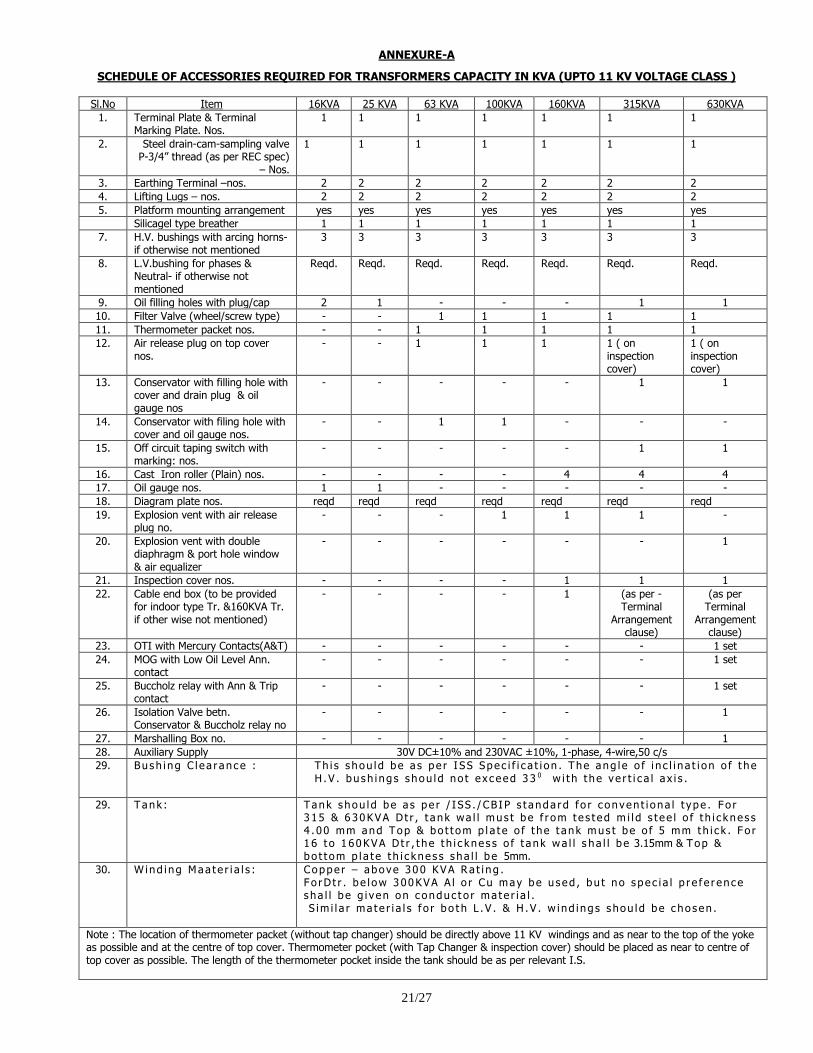
ANNEXURE-A
SCHEDULE OF ACCESSORIES REQUIRED FOR TRANSFORMERS CAPACITY IN KVA (UPTO 11 KV VOLTAGE CLASS )
Sl.No Item 16KVA 25 KVA 63 KVA 100KVA 160KVA 315KVA 630KVA
1. Terminal Plate & Terminal Marking Plate. Nos.
1 1 1 1 1 1 1
2. Steel drain-cam-sampling valve P-3/4” thread (as per REC spec)
– Nos.
1 1 1 1 1 1 1
3. Earthing Terminal –nos. 2 2 2 2 2 2 2
4. Lifting Lugs – nos. 2 2 2 2 2 2 2
5. Platform mounting arrangement yes yes yes yes yes yes yes
Silicagel type breather 1 1 1 1 1 1 1
7. H.V. bushings with arcing horns- if otherwise not mentioned
3 3 3 3 3 3 3
8. L.V.bushing for phases & Neutral- if otherwise not mentioned
Reqd. Reqd. Reqd. Reqd. Reqd. Reqd. Reqd.
9. Oil filling holes with plug/cap 2 1 - - - 1 1
10. Filter Valve (wheel/screw type) - - 1 1 1 1 1
11. Thermometer packet nos. - - 1 1 1 1 1
12. Air release plug on top cover nos.
- - 1 1 1 1 ( on inspection cover)
1 ( on inspection cover)
13. Conservator with filling hole with cover and drain plug & oil gauge nos
- - - - - 1 1
14. Conservator with filing hole with cover and oil gauge nos.
- - 1 1 - - -
15. Off circuit taping switch with marking: nos.
- - - - - 1 1
16. Cast Iron roller (Plain) nos. - - - - 4 4 4
17. Oil gauge nos. 1 1 - - - - -
18. Diagram plate nos. reqd reqd reqd reqd reqd reqd reqd
19. Explosion vent with air release plug no.
- - - 1 1 1 -
20. Explosion vent with double diaphragm & port hole window & air equalizer
- - - - - - 1
21. Inspection cover nos. - - - - 1 1 1
22. Cable end box (to be provided for indoor type Tr. &160KVA Tr. if other wise not mentioned)
- - - - 1 (as per - Terminal
Arrangement clause)
(as per Terminal
Arrangement clause)
23. OTI with Mercury Contacts(A&T) - - - - - - 1 set
24. MOG with Low Oil Level Ann. contact
- - - - - - 1 set
25. Buccholz relay with Ann & Trip contact
- - - - - - 1 set
26. Isolation Valve betn. Conservator & Buccholz relay no
- - - - - - 1
27. Marshalling Box no. - - - - - - 1
28. Auxiliary Supply 30V DC±10% and 230VAC ±10%, 1-phase, 4-wire,50 c/s
29. Bush i ng C l ea r ance :
Th i s s hou l d be a s pe r I SS Spec i f i c a t i on . The ang l e o f i n c l i n a t i on o f t he H .V . bush i ng s s hou l d no t e x c eed 33 0 w i t h t he ve r t i c a l a x i s .
29. Tank : Tank s hou l d be a s pe r / I SS . / CB IP s t anda rd f o r c onven t i ona l t ype . F o r 3 15 & 630KVA D t r , t ank wa l l mus t be f r om t e s t ed m i l d s t ee l o f t h i c k ne s s 4 . 00 mm and Top & bo t t om p l a t e o f t he t ank m us t be o f 5 mm th i c k . F o r 1 6 t o 1 60KVA D t r , t he t h i c kne s s o f t ank wa l l s ha l l b e 3.15mm & Top & bo t t om p l a t e t h i c kne s s s ha l l b e 5mm.
30. W ind i ng Maa te r i a l s :
Coppe r – a bove 300 KVA Ra t i ng . F o rD t r . b e l ow 300KVA A l o r Cu may be u s ed , bu t no s pec i a l p r e f e r ence s ha l l b e g i v en on c onduc t o r ma te r i a l . S im i l a r ma te r i a l s f o r bo t h L .V . & H .V . w i nd i ng s s hou l d be c hosen .
Note : The location of thermometer packet (without tap changer) should be directly above 11 KV windings and as near to the top of the yoke as possible and at the centre of top cover. Thermometer pocket (with Tap Changer & inspection cover) should be placed as near to centre of top cover as possible. The length of the thermometer pocket inside the tank should be as per relevant I.S.
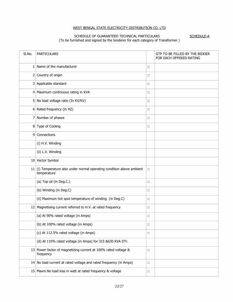
22/27
WEST BENGAL STATE ELECTRICITY DISTRIBUTION CO. LTD
SCHEDULE OF GUARANTEED TECHNICAL PARTICULARS SCHEDULE-A
(To be furnished and signed by the tenderer for each category of Transformer )
Sl.No. PARTICULARS GTP TO BE FILLED BY THE BIDDER FOR EACH OFFERED RATING
1 Name of the manufacturer ::
2 Country of origin ::
3 Applicable standard ::
4 Maximum continuous rating in KVA ::
5 No load voltage ratio (In KV/KV) ::
6 Rated frequency (in HZ) ::
7 Number of phases ::
8 Type of Cooling ::
9 Connections
(i) H.V. Winding
(ii) L.V. Winding
10 Vector Symbol
11 (i) Temperature also under normal operating condition above ambient temperature
::
(a) Top oil (in Deg.C.) ::
(b) Winding (in Deg.C) ::
(ii) Maximum hot spot temperature of winding (in Deg.C) ::
12 Magnetising current referred to H.V. at rated frequency ::
(a) At 90% rated voltage (in Amps) ::
(b) At 100% rated voltage (in Amps) ::
(c) At 112.5% rated voltage (in Amps) ::
(d) At 110% rated voltage (in Amps) for 315 &630 KVA DTr.
13 Power factor of magnetizing current at 100% rated voltage & frequency
::
14 No load current at rated voltage and rated frequency (in Amps) ::
15 Maxm.No load loss in watt at rated frequency & voltage ::
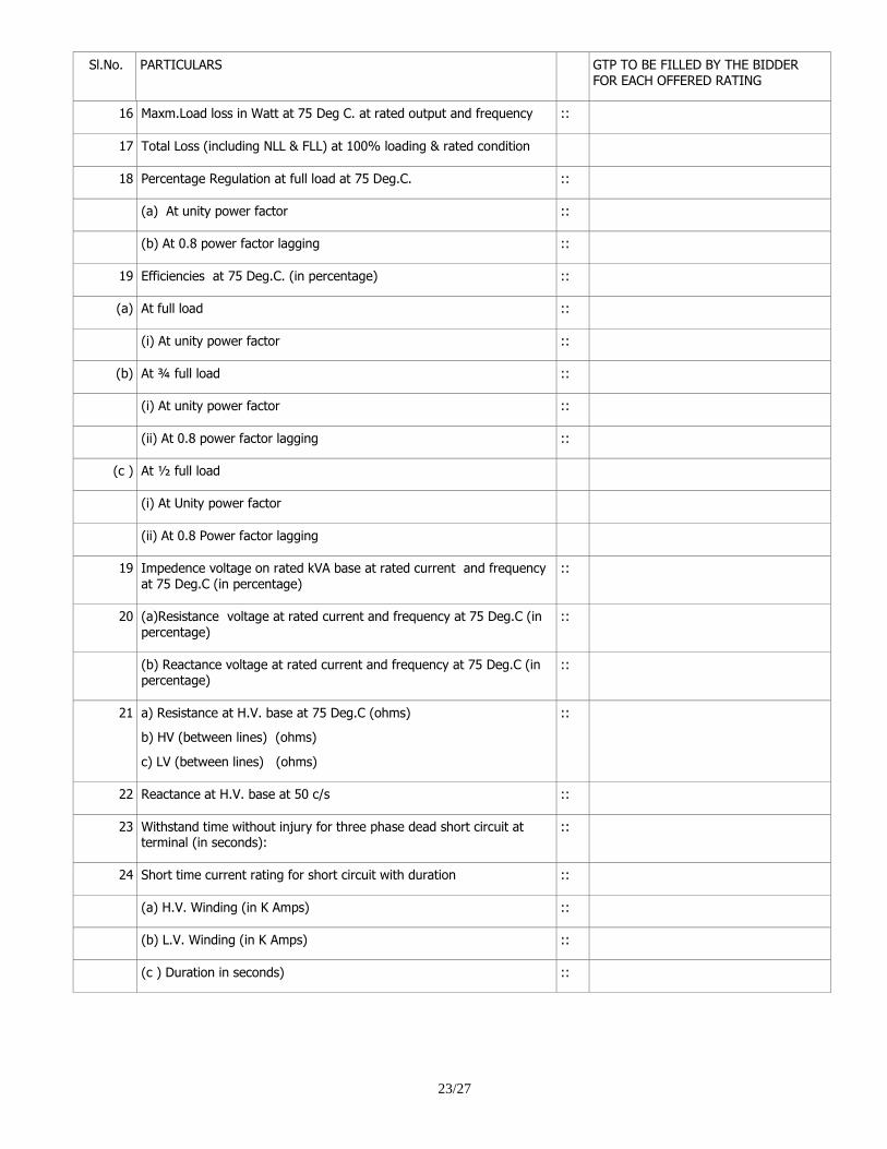
23/27
Sl.No. PARTICULARS GTP TO BE FILLED BY THE BIDDER FOR EACH OFFERED RATING
16 Maxm.Load loss in Watt at 75 Deg C. at rated output and frequency ::
17 Total Loss (including NLL & FLL) at 100% loading & rated condition
18 Percentage Regulation at full load at 75 Deg.C. ::
(a) At unity power factor ::
(b) At 0.8 power factor lagging ::
19 Efficiencies at 75 Deg.C. (in percentage) ::
(a) At full load ::
(i) At unity power factor ::
(b) At ¾ full load ::
(i) At unity power factor ::
(ii) At 0.8 power factor lagging ::
(c ) At ½ full load
(i) At Unity power factor
(ii) At 0.8 Power factor lagging
19 Impedence voltage on rated kVA base at rated current and frequency at 75 Deg.C (in percentage)
::
20 (a)Resistance voltage at rated current and frequency at 75 Deg.C (in
percentage)
::
(b) Reactance voltage at rated current and frequency at 75 Deg.C (in percentage)
::
21 a) Resistance at H.V. base at 75 Deg.C (ohms)
b) HV (between lines) (ohms)
c) LV (between lines) (ohms)
::
22 Reactance at H.V. base at 50 c/s ::
23 Withstand time without injury for three phase dead short circuit at terminal (in seconds):
::
24 Short time current rating for short circuit with duration ::
(a) H.V. Winding (in K Amps) ::
(b) L.V. Winding (in K Amps) ::
(c ) Duration in seconds) ::
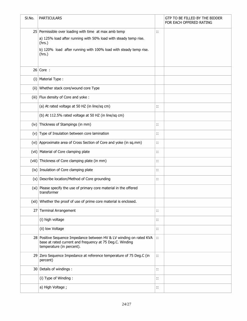
24/27
Sl.No. PARTICULARS GTP TO BE FILLED BY THE BIDDER FOR EACH OFFERED RATING
25 Permissible over loading with time at max amb temp
a) 125% load after running with 50% load with steady temp rise. (hrs.)
b) 120% load after running with 100% load with steady temp rise. (hrs.)
::
26 Core :
(i) Material Type :
(ii) Whether stack core/wound core Type
(iii) Flux density of Core and yoke :
(a) At rated voltage at 50 HZ (in line/sq cm) ::
(b) At 112.5% rated voltage at 50 HZ (in line/sq cm)
(iv) Thickness of Stampings (in mm) ::
(v) Type of Insulation between core lamination ::
(vi) Approximate area of Cross Section of Core and yoke (in sq.mm) ::
(vii) Material of Core clamping plate ::
(viii) Thickness of Core clamping plate (in mm) ::
(ix) Insulation of Core clamping plate ::
(x) Describe location/Method of Core grounding ::
(xi) Please specify the use of primary core material in the offered transformer
(xii) Whether the proof of use of prime core material is enclosed.
27 Terminal Arrangement ::
(i) high voltage ::
(ii) low Voltage ::
28 Positive Sequence Impedance between HV & LV winding on rated KVA base at rated current and frequency at 75 Deg.C. Winding temperature (in percent).
::
29 Zero Sequence Impedance at reference temperature of 75 Deg.C (in percent)
::
30 Details of windings : ::
(i) Type of Winding : ::
a) High Voltage ; ::
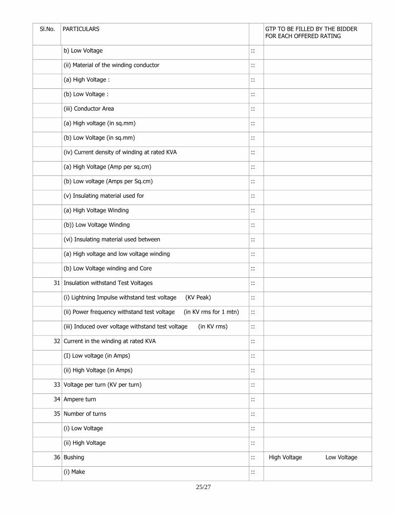
25/27
Sl.No. PARTICULARS GTP TO BE FILLED BY THE BIDDER FOR EACH OFFERED RATING
b) Low Voltage ::
(ii) Material of the winding conductor ::
(a) High Voltage : ::
(b) Low Voltage : ::
(iii) Conductor Area ::
(a) High voltage (in sq.mm) ::
(b) Low Voltage (in sq.mm) ::
(iv) Current density of winding at rated KVA ::
(a) High Voltage (Amp per sq.cm) ::
(b) Low voltage (Amps per Sq.cm) ::
(v) Insulating material used for ::
(a) High Voltage Winding ::
(b)) Low Voltage Winding ::
(vi) Insulating material used between ::
(a) High voltage and low voltage winding ::
(b) Low Voltage winding and Core ::
31 Insulation withstand Test Voltages ::
(i) Lightning Impulse withstand test voltage (KV Peak) ::
(ii) Power frequency withstand test voltage (in KV rms for 1 mtn) ::
(iii) Induced over voltage withstand test voltage (in KV rms) ::
32 Current in the winding at rated KVA ::
(I) Low voltage (in Amps) ::
(ii) High Voltage (in Amps) ::
33 Voltage per turn (KV per turn) ::
34 Ampere turn ::
35 Number of turns ::
(i) Low Voltage ::
(ii) High Voltage ::
36 Bushing :: High Voltage Low Voltage
(i) Make ::
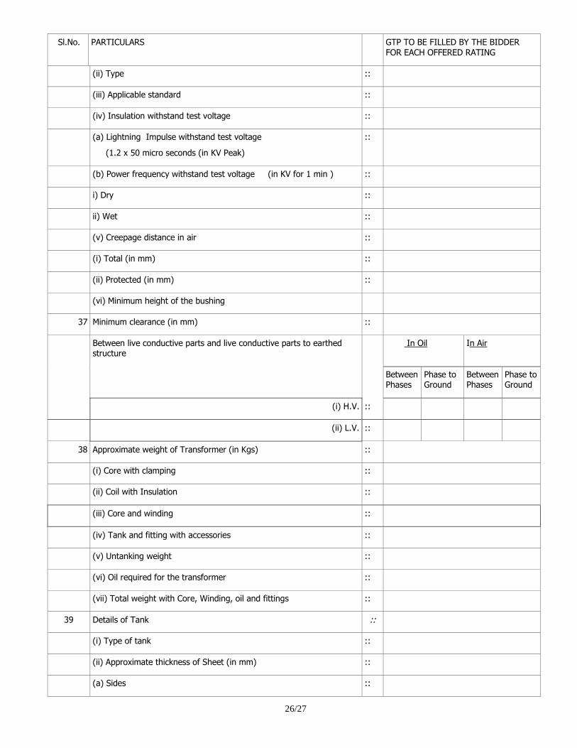
26/27
Sl.No. PARTICULARS GTP TO BE FILLED BY THE BIDDER FOR EACH OFFERED RATING
(ii) Type ::
(iii) Applicable standard ::
(iv) Insulation withstand test voltage ::
(a) Lightning Impulse withstand test voltage
(1.2 x 50 micro seconds (in KV Peak)
::
(b) Power frequency withstand test voltage (in KV for 1 min ) ::
i) Dry ::
ii) Wet ::
(v) Creepage distance in air ::
(i) Total (in mm) ::
(ii) Protected (in mm) ::
(vi) Minimum height of the bushing
37 Minimum clearance (in mm) ::
Between live conductive parts and live conductive parts to earthed structure
In Oil In Air
Between Phases
Phase to Ground
Between Phases
Phase to Ground
(i) H.V. ::
(ii) L.V. ::
38 Approximate weight of Transformer (in Kgs) ::
(i) Core with clamping ::
(ii) Coil with Insulation ::
(iii) Core and winding ::
(iv) Tank and fitting with accessories ::
(v) Untanking weight ::
(vi) Oil required for the transformer ::
(vii) Total weight with Core, Winding, oil and fittings ::
39 Details of Tank ::
(i) Type of tank ::
(ii) Approximate thickness of Sheet (in mm) ::
(a) Sides ::
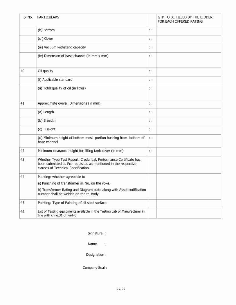
27/27
Sl.No. PARTICULARS GTP TO BE FILLED BY THE BIDDER FOR EACH OFFERED RATING
(b) Bottom ::
(c ) Cover ::
(iii) Vacuum withstand capacity ::
(iv) Dimension of base channel (in mm x mm)
::
40 Oil quality ::
(i) Applicable standard ::
(ii) Total quality of oil (in litres)
::
41 Approximate overall Dimensions (in mm) ::
(a) Length ::
(b) Breadth ::
(c) Height ::
(d) Minimum height of bottom most portion bushing from bottom of base channel
::
42 Minimum clearance height for lifting tank cover (in mm) ::
43 Whether Type Test Report, Credential, Performance Certificate has been submitted as Pre-requisites as mentioned in the respective
clauses of Technical Specification.
44 Marking: whether agreeable to
a) Punching of transformer sl. No. on the yoke.
b) Transformer Rating and Diagram plate along with Asset codification number shall be welded on the tr. Body.
45 Painting: Type of Painting of all steel surface.
46. List of Testing equipments available in the Testing Lab of Manufacturer in line with cl.no.31 of Part-C
Signature :
Name :
Designation :
Company Seal :
Related Documents


![WEST BENGAL STATE ELECTRICITY TRANSMISSI[]N C ...wbsetcl.in/CircularNotice/CIRCULAR-NOTICE (POLICY OF...(v) "Company" means West Bengal State Electricity Transmission Company Ltd.](https://static.cupdf.com/doc/110x72/6079ec9f8eebc249fc44d3df/west-bengal-state-electricity-transmissin-c-policy-of-v-company.jpg)