Temperature, Process, Proportional, PID, Fuzzy Logic, On/Off, Reverse Acting Panel, Switchboard, Bargraph, Power, Energy, Process, Multi-function, Counters. ... Switchboard, Edgewise, Panel, AC, DC, Power, Synchroscope, Meter Relays Transmitters, Isolators, Loop Splitters, Alarms, Programmable, Universal... Shunts, CTs, PTs, Temperature, Power, Pressure, Speed, Flow, Level, Humidity... Chart, Paper, Paperless, Process, Multi-channel, Temperature, Power Clocks, Timers, Switches, Displays, Enclosures, Power Supplies Multimeters, Power Analyzers, Electrical Testers, Thermometers, Calibrators... Application Notes, Tables, Formulas, Conversion Factors, Glossary... Products by Manufacturer, Products by Type, General Information... CONTROLLERS 4 - 10 DIGITAL METERS 11 - 42 ANALOG METERS 43 - 79 SIGNAL CONDITIONERS 80 - 88 TRANSDUCERS / SENSORS 89 - 118 RECORDERS / DATA LOGGERS 119 - 126 MISCELLANEOUS 127 - 138 TEST EQUIPMENT 139 - 175 TECHNICAL REFERENCE - see website INDEX 187 - 191 ANALOG METERS DIGITAL METERS CONTROLLERS TRANSDUCERS/ SENSORS SIGNAL CONDITIONERS RECORDERS / DATA LOGGERS TECHNICAL REFERENCE TEST EQUIPMENT MISC. INDEX TABLE OF CONTENTS Here we present a selection of the more popular meters, sensors and test equipment available from our Measurement Specialists. This edition features many new products, as well as 'industry standard' models that have been used for many years. This catalog also includes condensed information on the Weschler brand products manufactured at our Florida facility. Full specifications and application information for these products can be found on our website www.weschler.com. Also see our website for additional products, new products and reference information. Weschler Instruments distributes over 50 of the leading equipment brands. This catalog shows only a small portion of our total offering. Call, fax or email us for information on any models you don't see here. Our experienced sales team will be happy to assist you in selecting the best products for your application. Years of Power and Process Measurements © 2020 Weschler Instruments 79 Welcome to the Weschler Instruments Product Catalog.

Welcome message from author
This document is posted to help you gain knowledge. Please leave a comment to let me know what you think about it! Share it to your friends and learn new things together.
Transcript
Temperature, Process, Proportional, PID, Fuzzy Logic, On/Off, Reverse Acting
Panel, Switchboard, Bargraph, Power, Energy, Process, Multi-function, Counters. ...
Switchboard, Edgewise, Panel, AC, DC, Power, Synchroscope, Meter Relays
Transmitters, Isolators, Loop Splitters, Alarms, Programmable, Universal...
Shunts, CTs, PTs, Temperature, Power, Pressure, Speed, Flow, Level, Humidity...
Chart, Paper, Paperless, Process, Multi-channel, Temperature, Power
Clocks, Timers, Switches, Displays, Enclosures, Power Supplies
Multimeters, Power Analyzers, Electrical Testers, Thermometers, Calibrators...
Application Notes, Tables, Formulas, Conversion Factors, Glossary...
Products by Manufacturer, Products by Type, General Information...
CONTROLLERS 4 - 10
DIGITAL METERS 11 - 42
ANALOG METERS 43 - 79
SIGNAL CONDITIONERS 80 - 88
TRANSDUCERS / SENSORS 89 - 118
RECORDERS / DATA LOGGERS 119 - 126
MISCELLANEOUS 127 - 138
TEST EQUIPMENT 139 - 175
TECHNICAL REFERENCE - see website
INDEX 187 - 191
AN
ALOG
M
ETERS
DIG
ITAL M
ETERS
CO
NTR
OLLER
S TR
ANSD
UCERS/
SEN
SOR
SS
IGN
ALC
ON
DITIO
NER
S R
ECOR
DER
S/
DATA
LOG
GER
S TECH
NICAL
REFER
ENCE
TESTE
QU
IPMEN
TM
ISC.IN
DEX
TABLE OF CONTENTS
Here we present a selection of the more popular meters, sensors and test equipment available from our Measurement Specialists. This edition features many new products, as well as 'industry standard' models that have been used for many years.
This catalog also includes condensed information on the Weschler brand products manufactured at our Florida facility. Full specifications and application information for these products can be found on our website www.weschler.com. Also see our website for additional products, new products and reference information.
Weschler Instruments distributes over 50 of the leading equipment brands. This catalog shows only a small portion of our total offering. Call, fax or email us for information on any models you don't see here. Our experienced sales team will be happy to assist you in selecting the best products for your application.
Years of Power and
Process Measurements
© 2020 Weschler Instruments
79
Welcome to the Weschler Instruments Product Catalog.
A Control0 Standard type1 Position proportional type2 Heating / cooling type
B Functions0 None1 2 additional DIs and 2 additional DOs2 5 additional DIs and 5 additional DOs
C Network Communications0 None1 RS-485 (Max.38.4 kbps, 2/4-wire)2 Ethernet (with serial gateway function)
D Case Color10 Light Gray11 Dark Gray
E Options/LP 24 V DC loop power supply /HA Heater break alarm /DC Power supply 24 V AC / DC/CT Coating
A Control0 Standard type1 Position proportional type2 Heating / cooling type
B Functions00 None10 RS-485 comm (Max.38 kbps, 2/4-wire) 20 2 additional DIs & 2 additional DOs
C Case Color10 Light Gray11 Dark Gray
D Options/LP 24 V DC loop power supply /HA Heater break alarm/DC Power supply 24 V AC / DC/CT Coating
A Control0 Standard type
B Functions00 None10 1 additional DO (form C relay) + RS-485
comm (Max. 38.4kbps, 2/4-wire)20 1 additional DO (form C relay)30 6 additional DOs (form C relay; 1 point
& open collector; 5 points)C Case Color
10 Light Gray11 Dark Gray
D Options/LP 24 V DC loop power supply /DC Power supply 24 V AC/DC/CT Coating
CO
NTR
OLLER
S
55bb
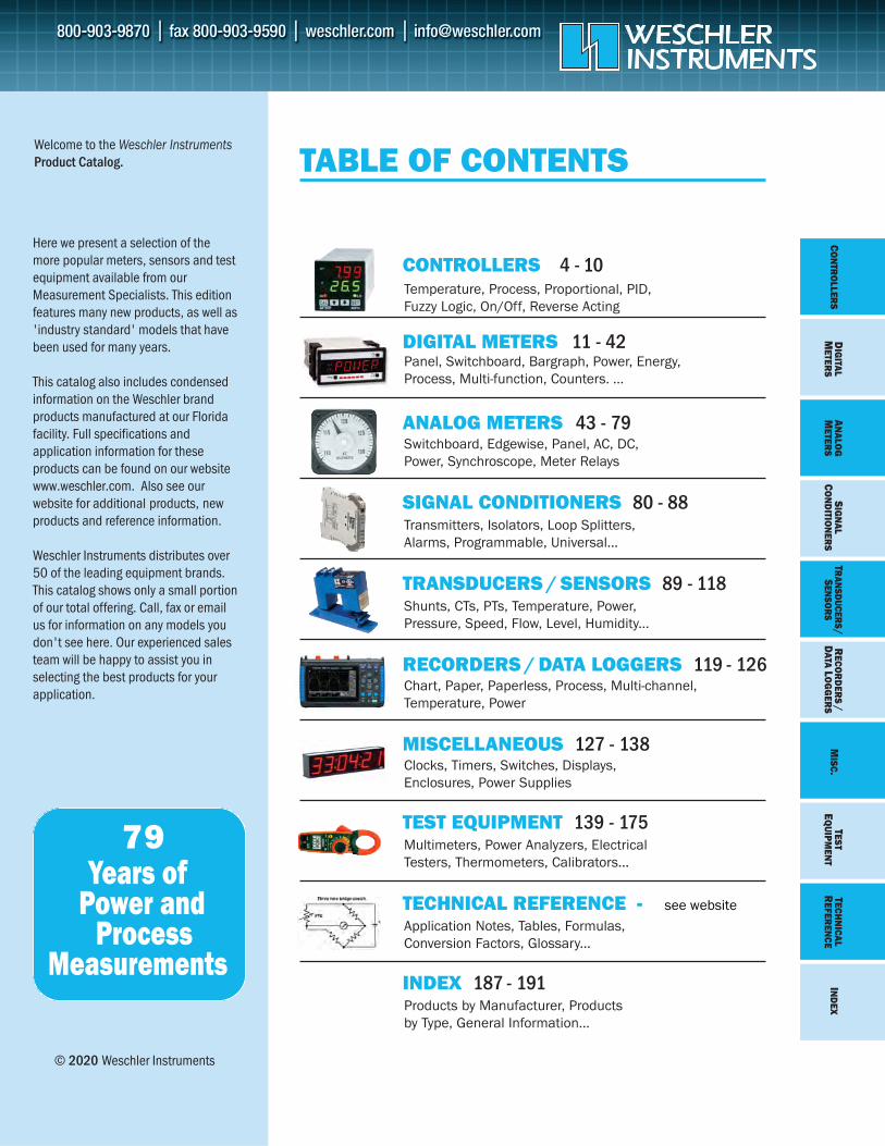
Yokogawa Advanced Controllers
•8 built-in PID control modes•8 built-in PID control types•Ladder sequence control•Fuzzy logic control •Active color LCD display
•Scrolling text•Programmable function keys•RS-485 (Modbus) & Ethernet
communications•3 year warranty
UM33A
ORDERING INFORMATION
With built-in LLaaddddeerr SSeeqquueennccee CCoonnttrrooll, the UTAdvanced controllers can replace a small PLC to: • Monitor and control external machinery• Implement digital input/output logicfunctions.
Sequence control and PID control can be performed simultaneously.
The FFuuzzzzyy LLooggiicc CCoonnttrrooll functions deliver finecontrol and reduce overshoot or hunting.
To Order—Insert Code for Each Letter toSelect Catalog Number.
88 BBuuiilltt--iinn CCoonnttrrooll MMooddeess• Single-loop control• Cascade primary-loop control• Cascade secondary-loop control• Cascade control• Loop control for backup• Loop control with PV switching• Loop control with PV auto-selector• Control with PV-hold
88 BBuuiilltt--iinn CCoonnttrrooll TTyyppeess• PID control• ON/OFF control (1 point hysteresis)• ON/OFF control (2 point hysteresis)• Two-position, two-level control• Heating/cooling control• Sample PI control• Batch PID control• Feedforward control
UT35AUT32A
NEW
UUnniivveerrssaall IInnppuutt::Thermocouple: Type K, J, T, B, S, R, N, E, L, U, W,
PL-2, PR20-40, W97Re3, W75Re25RTD: Pt100, JPt100 (3-wire except 3/4-
wire on 55A) DC Voltage: 0.4 to 2V, 1 to 5V, 0 to 2V, 0 to 10V,
-10 to 20mV, 0 to 100mVDC Current: 4 to 20mA, 0 to 20mASSttaannddaarrdd PPoowweerr SSuuppppllyy: 100-240 V ACPPVV DDiissppllaayy:: 5 digits, 0.1% of FS accuracy
UP55A MMooddeell UUTT5555AA UUTT5522AA UUTT3355AA UUTT3322AA UUPP5555AA UUPP3355AA UUMM3333AASize 1/4 DIN 1/8 DIN 1/4 DIN 1/8 DIN 1/4 DIN 1/4 DIN 1/8 DIN# of Analog Inputs Std (Max) 1 (4) 1 (2) 1 1 1 (4) 1 1# of SPs (PIDs) Max 8 8 4 4 8 4 —# of Control Modes Max 8 8 1 1 5 1 —# of Control Types Max 8 8 5 5 4 4 —Relay, Pulse, Current Output —# of Analog Outputs Std (Max) 2 (3) 2 (3) 2 2 2 (3) 2 1# of Digital Inputs Std (Max) 3 (9) 3 (5) 2 (7) 2 (4) 3 (9) 3 (8) 2 # of Alarms Max 8 8 4 4 8 2 8# of Digital Outputs Std (Max) 3 (18) 3 (5) 3 (8) 3 (5) 8 (18) 3 (8) 3 (9)RS-485 communication (Max) (2) (1) (1) (1) (2) (1) (1)Ethernet communication — — —Split Computation Output — — — Ratio & Square Root Extraction — — — Remote SP Function — — — Heater Break Alarm Function Std type Std type Std or Heat/cool Std type Std type —Ladder Sequence (max. steps) (500) (500) (300) (300) (500) (300) —Control Scan Period (msec) 50/100/200 200 200 100/200 200 50/100/200Bar graph display (Number) (2) (2) (1) (1) (2) (1) —
DDiiggiittaall IInnddiiccaattiinngg CCoonnttrroolllleerrss:: UUTT5555AA,, UUTT5522AA,, UUTT3355AA,, UUTT3322AAPPrrooggrraamm CCoonnttrroolllleerrss:: UUPP5555AA,, UUPP3355AADDiiggiittaall IInnddiiccaattoorr wwiitthh AAllaarrmmss:: UUMM3333AA
See complete ddaattaa sshheeeett for additional options and orderinginformation for UT55A, UT52A, UP35A models.
A B C D EUT35A— — 00
— 00
__ //
A B C DUM33A— __ //
A B C DUT32A— __ //
A B C D EUP55A— — 00__ //A Control
0 Standard type1 Position proportional type2 Heating/cooling type
B Functions 0 None1 Remote (1 additional aux. analog) input,
1 additional DI2 RS-485 (Max.19.2 kpbs, 2/4-wire)3 10 additional DOs4 3 additional aux. analog inputs, 2 DIs &
5 DOs to be deletedC Network Communications
0 None1 RS-485(Max.38.4 kbps, 2/4-wire)2 Ethernet (with serial gateway function)
D Case Color10 Light Gray11 Dark Gray
E Options/DR Additional direct input (TC & 3/4-wire
RTD), current input to Remote (1 additionalaux. analog) input, 1 DI to be deleted
/HA Heater break alarm /DC Power supply 24 V AC/DC/CT Coating
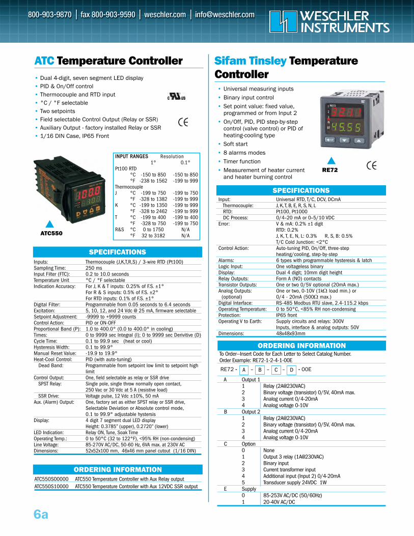
To Order—Insert Code for Each Letter to Select Catalog Number.Order Example: RE92-1-2-0-1-1-00E
A Input 3 (for remote setpoint value)0 None1 0-20 or 4-20 mA2 0-5 or 0-10 V3 Pot transmitter 100 or 1000 ohm
B Output 1 & 21 2 relays2 2 binary (transistor) outputs 0-5V, isolated
C Analog Outputs0 None1 Two 0/4-20 mA or 0-10 V, isolated
D Ethernet0 None1 Ethernet Modbus TCP Slave
E Transducer Supply0 None1 24 VDC @ 30 mA
CO
NTR
OLLER
S
6
Sifam Tinsley Dual LoopController
RE92
SPECIFICATIONSInputs 1 & 2: Universal RTD, T/C, DCV, DCmA
Thermocouple: J, K, T, B, E, R, S, NRTD: Pt100, Pt500, Pt1000, Cu100, Ni100DC Process: 0/4–20 mA or 0–5/10 VDC
Error: V & mA: 0.2% ±1 digitRTD: 0.2%J, K, T, E, N: 0.3% R, S, B: 0.5%T/C Cold Junction: <2°C
Control Source: Input 1, Input 2, sum or difference Control Action: Auto-tuning PID, On/Off, three-step
heating/cooling, step-by-step Alarms: 6 types with programmable hysteresis & latchLogic Inputs: Three voltageless binary Display: 3.5" TFT color, 320x240 pixelsRelay Outputs: Six Form A (2A@230VAC) standardTransistor Outputs: Two 0-5V optional (20mA max.) Replaces 2
relay outputsAnalog Outputs: Two, 0-10V (1kΩ load min.) or
(optional) 0/4 - 20mA (500Ω max.)Digital Interface: RS-485 Modbus RTU slave, 2.4-115.2 kbpsPower: 85 to 253 VDC/AC (40-440 Hz)Operating Temperature: 0 to 50°C, <85% RH non-condensing Protection: IP65 frontOperating V to Earth: Supply circuits and relays: 300V
Inputs, interface & analog outputs: 50VDimensions: 96x96x100mm; 92.5x92.5 panel cutout
ORDERING INFORMATION
ORDERING INFORMATION
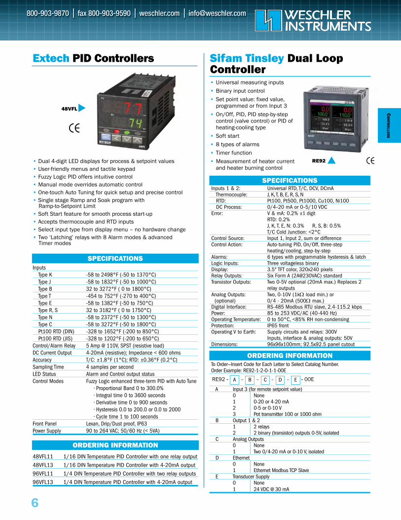
Extech PID Controllers
Inputs Type K -58 to 2498°F (-50 to 1370°C)Type J -58 to 1832°F (-50 to 1000°C)Type B 32 to 3272°F ( 0 to 1800°C)Type T -454 to 752°F (-270 to 400°C)Type E -58 to 1382°F (-50 to 750°C)Type R, S 32 to 3182°F ( 0 to 1750°C)Type N -58 to 2372°F (-50 to 1300°C)Type C -58 to 3272°F (-50 to 1800°C)Pt100 RTD (DIN) -328 to 1652°F (-200 to 850°C)Pt100 RTD (JIS) -328 to 1202°F (-200 to 650°C)
Control/Alarm Relay 5 Amp @ 110V, SPST (resistive load)DC Current Output 4-20mA (resistive); Impedance < 600 ohmsAccuracy T/C: ±1.8°F (1°C); RTD: ±0.36°F (0.2°C)Sampling Time 4 samples per secondLED Status Alarm and Control output statusControl Modes Fuzzy Logic enhanced three-term PID with Auto Tune
• Proportional Band 0 to 300.0%• Integral time 0 to 3600 seconds• Derivative time 0 to 900 seconds• Hysteresis 0.0 to 200.0 or 0.0 to 2000• Cycle time 1 to 100 seconds
Front Panel Lexan, Drip/Dust proof, IP63Power Supply 90 to 264 VAC; 50/60 Hz (< 5VA)
SPECIFICATIONS
48VFL11 1/16 DIN Temperature PID Controller with one relay output
48VFL13 1/16 DIN Temperature PID Controller with 4-20mA output
96VFL11 1/4 DIN Temperature PID Controller with two relay outputs
96VFL13 1/4 DIN Temperature PID Controller with 4-20mA output
48VFL
• Dual 4-digit LED displays for process & setpoint values• User-friendly menus and tactile keypad• Fuzzy Logic PID offers intuitive control • Manual mode overrides automatic control • One-touch Auto Tuning for quick setup and precise control• Single stage Ramp and Soak program with
Ramp-to-Setpoint Limit • Soft Start feature for smooth process start-up• Accepts thermocouple and RTD inputs• Select input type from display menu – no hardware change• Two ‘Latching’ relays with 8 Alarm modes & advanced
Timer modes
A – B – C – D – ERE92 -- -- 00E
• Universal measuring inputs• Binary input control• Set point value: fixed value,
programmed or from Input 3 • On/Off, PID, PID step-by-step
control (valve control) or PID of heating-cooling type
• Soft start• 8 types of alarms• Timer function• Measurement of heater current
and heater burning control
To Order—Insert Code for Each Letter to Select Catalog Number.Order Example: RE72-1-2-4-1-00E
A Output 1 1 Relay (2A@230VAC)2 Binary voltage (transistor) 0/5V, 40mA max.3 Analog current 0/4-20mA4 Analog voltage 0-10V
B Output 21 Relay (2A@230VAC)2 Binary voltage (transistor) 0/5V, 40mA max.3 Analog current 0/4-20mA4 Analog voltage 0-10V
C Option0 None1 Output 3 relay (1A@230VAC)2 Binary input3 Current transformer input4 Additional input (Input 2) 0/4-20mA5 Transducer supply 24VDC 1W
E Supply0 85-253V AC/DC (50/60Hz)1 20-40V AC/DC
RE72 -- -- 00E
Sifam Tinsley TemperatureController
SPECIFICATIONS
6a
ATC550S00000 ATC550 Temperature Controller with Aux Relay outputATC550S10000 ATC550 Temperature Controller with Aux 12VDC SSR output
• Dual 4-digit, seven segment LED display• PID & On/Off control • Thermocouple and RTD input • °C / °F selectable• Two setpoints• Field selectable Control Output (Relay or SSR)• Auxiliary Output - factory installed Relay or SSR• 1/16 DIN Case, IP65 Front
ATC Temperature Controller
SPECIFICATIONS
ORDERING INFORMATION
ATC550
RE72
Inputs: Thermocouple (J,K,T,R,S) / 3-wire RTD (Pt100)Sampling Time: 250 msInput Filter (FTC): 0.2 to 10.0 secondsTemperature Unit °C / °F selectableIndication Accuracy: For J, K & T inputs: 0.25% of F.S. ±1°
For R & S inputs: 0.5% of F.S. ±2°For RTD inputs: 0.1% of F.S. ±1°
Digital Filter: Programmable from 0.05 seconds to 6.4 secondsExcitation: 5, 10, 12, and 24 Vdc @ 25 mA, firmware selectableSetpoint Adjustment: -9999 to +9999 countsControl Action: PID or ON-OFFProportional Band (P): 1.0 to 400.0° (0.0 to 400.0° in cooling)Times: 0 to 9999 sec Integral (I); 0 to 9999 sec Derivitive (D)Cycle Time: 0.1 to 99.9 sec (heat or cool)Hysteresis Width: 0.1 to 99.9°Manual Reset Value: -19.9 to 19.9°Heat-Cool Control: PID (with auto-tuning)
Dead Band: Programmable from setpoint low limit to setpoint high limit
Control Output: One, field selectable as relay or SSR drive SPST Relay: Single pole, single throw normally open contact,
250 Vac or 30 Vdc at 5 A (resistive load)SSR Drive: Voltage pulse, 12 Vdc ±10%, 50 mA
Aux. (Alarm) Output: One, factory set as either SPST relay or SSR drive,Selectable Deviation or Absolute control mode,0.1 to 99.9° adjustable hystersis
Display: 4 digit 7 segment dual LED displayHeight: 0.3785” (upper), 0.2720” (lower)
LED Indication: Relay ON, Tune, Soak TimeOperating Temp.: 0 to 50°C (32 to 122°F), <95% RH (non-condensing) Line Voltage: 85-270V AC/DC, 50-60 Hz, 6VA max. at 230V ACDimensions: 52x52x100 mm, 46x46 mm panel cutout (1/16 DIN)
IINNPPUUTT RRAANNGGEESS Resolution1° 0.1°
Pt100 RTD°C -150 to 850 -150 to 850°F -238 to 1562 -199 to 999
ThermocoupleJ °C -199 to 750 -199 to 750
°F -328 to 1382 -199 to 999K °C -199 to 1350 -199 to 999
°F -328 to 2462 -199 to 999T °C -199 to 400 -199 to 400
°F -328 to 750 -199 to 750R&S °C 0 to 1750 N/A
°F 32 to 3182 N/A
• Universal measuring inputs• Binary input control• Set point value: fixed value,
programmed or from Input 2 • On/Off, PID, PID step-by-step
control (valve control) or PID of heating-cooling type
• Soft start• 8 alarms modes• Timer function• Measurement of heater current
and heater burning control
ORDERING INFORMATION
A – B – C – D
Input: Universal RTD, T/C, DCV, DCmAThermocouple: J, K, T, B, E, R, S, N, LRTD: Pt100, Pt1000DC Process: 0/4–20 mA or 0–5/10 VDC
Error: V & mA: 0.2% ±1 digitRTD: 0.2%J, K, T, E, N, L: 0.3% R, S, B: 0.5%T/C Cold Junction: <2°C
Control Action: Auto-tuning PID, On/Off, three-step heating/cooling, step-by-step
Alarms: 6 types with programmable hysteresis & latchLogic Input: One voltageless binary Display: Dual 4 digit; 10mm digit heightRelay Outputs: Form A (NO) contactsTransistor Outputs: One or two 0/5V optional (20mA max.) Analog Outputs: One or two, 0-10V (1kΩ load min.) or
(optional) 0/4 - 20mA (500Ω max.)Digital Interface: RS-485 Modbus RTU slave, 2.4-115.2 kbpsOperating Temperature: 0 to 50°C, <85% RH non-condensing Protection: IP65 frontOperating V to Earth: Supply circuits and relays: 300V
Inputs, interface & analog outputs: 50VDimensions: 48x48x93mm

CON
TRO
LLER
S
6b
ORDERING INFORMATION
West Temperature Controllers• 1/32 & 1/16 DIN sizes• Thermocouple, Pt100 & mV input• Simple menu setup • Relay & SS drive outputs• Single ramp/soak (dwell) program• Heat/cool operation• Auto-tuning PID• RS-232 or RS-485 Modbus option• CE, UL, cUL, CSA & FM
Input: Thermocouple: B, E, J, K, L, N, R, S, T;Pt100: 2 wire; Linear: 0 to 50mV
Output Function: Heat, Cool, AlarmOutput Type: Relay (rly1 2A, rly2 1A resistive);
SSD (5Vdc +0/-15%, 15mA non-isolated)Control Type: PID heat only, PID heat cool , ON/OFFPower Supply: 100–240Vac, 50–60Hz ±10%
12-24V (AC/DC) ±20%, 4.5VAPanel Sealing: IP66Certifications: CE, UL, CSAOther Functions: Auto-tuning PID;
Single ramp soak program;dAC (derivative Approach Control) to minimize overshoot
Dimensions: 24 x 48 x 107mm (HxWxD), 1/32 DIN48 x 48 x 107mm (HxWxD), 1/16 DIN
Software Tools: CALgrafix for configuration & datalogging
SPECIFICATIONS
CAL3300
CCoommmm PPoowweerr OOuuttppuutt 11//3322 DDIINN 11//1166 DDIINN 11//1166 DDIINN DDuuaall DDiissppllaayyNone 100-240V SSD/Relay CAL330000000 CAL930000000 CAL940000000None 100-240V SSD/SSD CAL332200000 CAL932200000 CAL942200000None 100-240V Relay/Relay CAL331100000 CAL931100000 CAL941100000RS-232 100-240V SSD/Relay CAL330000200 CAL930000200 CAL940000200RS-232 100-240V SSD/SSD CAL332200200 CAL932200200 CAL942200200RS-232 100-240V Relay/Relay CAL331100200 CAL931100200 CAL941100200RS-485 100-240V SSD/Relay CAL330000400 CAL930000400 CAL940000400RS-485 100-240V SSD/SSD CAL332200400 CAL932200400 CAL942200400RS-485 100-240V Relay/Relay CAL331100400 CAL931100400 CAL941100400None 12-24V SSD/Relay CAL330000030 CAL930000030 ---None 12-24V SSD/SSD CAL332200030 CAL932200030 ---RS-232 12-24V SSD/Relay CAL330000230 CAL930000230 ---RS-232 12-24V SSD/SSD CAL332200230 CAL932200230 ---RS-485 12-24V SSD/Relay CAL330000430 CAL930000430 ---RS-485 12-24V SSD/SSD CAL332200430 CAL932200430 ---
CAL9300
CAL9400
CON
TRO
LLER
S
7
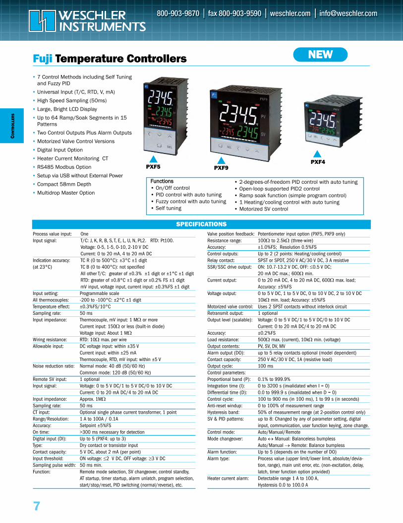
Fuji Temperature Controllers• 7 Control Methods including Self Tuning
and Fuzzy PID
• Universal Input (T/C, RTD, V, mA)
• High Speed Sampling (50ms)
• Large, Bright LCD Display
• Up to 64 Ramp/Soak Segments in 15Patterns
• Two Control Outputs Plus Alarm Outputs
• Motorized Valve Control Versions
• Digital Input Option
• Heater Current Monitoring CT
• RS485 Modbus Option
• Setup via USB without External Power
• Compact 58mm Depth
• Multidrop Master Option
Process value input: OneInput signal: T/C: J, K, R, B, S, T, E, L, U, N, PL2. RTD: Pt100.
Voltage: 0-5, 1-5, 0-10, 2-10 V DCCurrent: 0 to 20 mA, 4 to 20 mA DC
Indication accuracy: TC R (0 to 500°C): ±3°C ±1 digit (at 23°C) TC B (0 to 400°C): not specified
All other T/C: greater of ±0.3% ±1 digit or ±1°C ±1 digitRTD: greater of ±0.8°C ±1 digit or ±0.2% FS ±1 digitmV input, voltage input, current input: ±0.3%FS ±1 digit
Input setting: Programmable scaleAll thermocouples: -200 to -100°C: ±2°C ±1 digitTemperature effect: ±0.3%FS/10°CSampling rate: 50 msInput impedance: Thermocouple, mV input: 1 MΩ or more
Current input: 150Ω or less (built-in diode)Voltage input: About 1 MΩ
Wiring resistance: RTD: 10Ω max. per wireAllowable input: DC voltage input: within ±35 V
Current input: within ±25 mAThermocouple, RTD, mV input: within ±5 V
Noise reduction ratio: Normal mode: 40 dB (50/60 Hz)Common mode: 120 dB (50/60 Hz)
Remote SV input: 1 optionalInput signal: Voltage: 0 to 5 V DC/1 to 5 V DC/0 to 10 V DC
Current: 0 to 20 mA DC/4 to 20 mA DCInput impedance: Approx. 1MΩSampling rate: 50 msCT input: Optional single phase current transformer, 1 pointRange/Resolution: 1 A to 100A / 0.1AAccuracy: Setpoint ±5%FSOn time: >300 ms necessary for detectionDigital input (DI): Up to 5 (PXF4: up to 3)Type: Dry contact or transistor inputContact capacity: 5 V DC, about 2 mA (per point)Input threshold: ON voltage: ≤2 V DC, OFF voltage: ≥3 V DC Sampling pulse width: 50 ms min.Function: Remote mode selection, SV changeover, control standby,
AT startup, timer startup, alarm unlatch, program selection,start/stop/reset, PID switching (normal/reverse), etc.
Valve position feedback: Potentiometer input option (PXF5, PXF9 only)Resistance range: 100Ω to 2.5kΩ (three-wire)Accuracy: ±1.0%FS; Resolution 0.5%FSControl outputs: Up to 2 (2 points: Heating/cooling control)Relay contact: SPST or SPDT, 250 V AC/30 V DC, 3 A resistiveSSR/SSC drive output: ON: 10.7-13.2 V DC, OFF: ≤0.5 V DC;
20 mA DC max.; 600Ω min.Current output: 0 to 20 mA DC, 4 to 20 mA DC, 600Ω max. load;
Accuracy: ±5%FSVoltage output: 0 to 5 V DC, 1 to 5 V DC, 0 to 10 V DC, 2 to 10 V DC
10kΩ min. load; Accuracy: ±5%FSMotorized valve control: Uses 2 SPST contacts without interlock circuitRetransmit output: 1 optionalOutput level (scalable): Voltage: 0 to 5 V DC/1 to 5 V DC/0 to 10 V DC
Current: 0 to 20 mA DC/4 to 20 mA DCAccuracy: ±0.2%FSLoad resistance: 500Ω max. (current), 10kΩ min. (voltage)Output contents: PV, SV, DV, MVAlarm output (DO): up to 5 relay contacts optional (model dependent) Contact capacity: 250 V AC/30 V DC, 1A (resistive load)Output cycle: 100 msControl parameters:Proportional band (P): 0.1% to 999.9%Integration time (I): 0 to 3200 s (invalidated when I = 0)Differential time (D): 0.0 to 999.9 s (invalidated when D = 0)Control cycle: 100 to 900 ms (in 100 ms), 1 to 99 s (in seconds)Anti-reset windup: 0 to 100% of measurement rangeHysteresis band: 50% of measurement range (at 2-position control only)SV & PID patterns: up to 8: Changed by any of parameter setting, digital
input, communication, user function keying, zone change.Control mode: Auto/Manual/RemoteMode changeover: Auto ↔ Manual: Balanceless bumpless
Auto/Manual → Remote: Balance bumplessAlarm function: Up to 5 (depends on the number of DO)Alarm type: Process value (upper limit/lower limit, absolute/devia-
tion, range), main unit error, etc. (non-excitation, delay,latch, timer function option provided)
Heater current alarm: Detectable range 1 A to 100 A,Hysteresis 0.0 to 100.0 A
SPECIFICATIONS
PXF5
NEW
PXF9
FFuunnccttiioonnss• On/Off control• PID control with auto tuning• Fuzzy control with auto tuning• Self tuning
• 2-degrees-of-freedom PID control with auto tuning• Open-loop supported PID2 control• Ramp soak function (simple program control)• 1 Heating/cooling control with auto tuning• Motorized SV control
PXF4
CO
NTR
OLLER
S
8
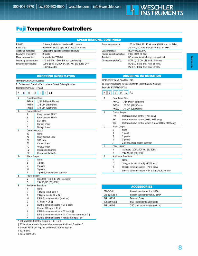
MOTORIZED VALVE CONTROLLERSTo order–Insert Code for Each Letter to Select Catalog Number.Example: PXF4ATY2-1VYA1
- A1
A Front Panel SizePXF4A 1/16 DIN (48x48mm) PXF5A 1/8 DIN (48x96mm)PXF9A 1/4 DIN (96x96mm)
B Control Output 1TY2 Motorized valve control (PXF4 only)SY2 Motorized valve control (PXF5, PXF9 only)VY2 Motorized valve control with FEB input (PFX5, PXF9 only)
C Alarm Output0 None1 1 point2 2 pointsM 3 pointsJ 2 points, independent common
D Power SupplyV Standard (100-240V AC, 50/60Hz)B 24V AC/DC (50/60Hz)
E Additional FunctionsY NoneD 3 Digital inputs (DI x 3) (PXF4 only)V RS485 communications (PXF4 only)U RS485 communications + DI x 3 (PXF5, PXF9 only)
EDCBA
ORDERING INFORMATION
Fuji Temperature Controllers
TEMPERATURE CONTROLLERSTo Order–Insert Code for Each Letter to Select Catalog Number.Example: PX4AAA2 - 1VMA1
- A1
A Front Panel SizePXF4A 1/16 DIN (48x48mm) PXF5A 1/8 DIN (48x96mm)PXF9A 1/4 DIN (96x96mm)
B Control Output 1A Relay contact SPST*B Relay contact SPDT*C SSR driveE Current linearP Voltage linear
C Control Output 2Y2 NoneA2 Relay contact SPSTC2 SSR driveE2 Current linearP2 Voltage linearR2 Retransmit (current)S2 Retransmit (voltage)
D Alarm Output0 None1 1 point2 2 pointsM 3 pointsJ 2 points, independent common
E Power SupplyV Standard (100-240 VAC, 50/60Hz)B 24V AC/DC (50/60Hz)
F Additional FunctionsY NoneS 1 Digital input (DI) †T 2 Digital inputs (DI x 2) ‡M RS485 communication (Modbus)G CT input + DI §‡V RS485 communications + DI 1 pointH Remote SV input + DI #‡J RS485 communications + CT input §†C RS485 communications + DI x 3 + aux alarm out x 2 ‡K RS485 communications + remote SV input #†
* not available if Control Output 2 = C, E or P§ CT input as a heater burnout alarm requires Additional Function C.# Current RSV input requires additional 250ohm resistor.† PXF4 only.‡ PXF5, PXF9 only.
FEDCBA
CTL-6-S-H Current transformer for 1-30ACTL-12-S36-8 Current transformer for 20-100APXR1-A230 Terminal CoverTQ501923C3 USB Parameter Loader CablePXR1-A190 250 ohm shunt resistor (±0.1%)
ACCESSORIES
ORDERING INFORMATION
RS-485: Optional, half-duplex, Modbus-RTU protocolBaud rate: 9600 bps, 19200 bps, 38.4 kbps, 115.2 kbpsAdditional functions: Cooperative operation (master or slave)Password protection: 3 levelsMemory protection: Non-volatile EEPROMOperating temperature: -10 to 50°C, <90% RH non condensingPower supply voltage: 100 (-15%) to 240V (+10%) AC, 50/60Hz; 24V
(±10%) AC/DC
Power consumption: 100 to 240 V AC: 13 VA max. (10VA max. on PXF4),24 V DC/AC: 8 VA max. (3VA max. on PXF4)
Case material: UL94V-0 ABS, PPOEnvironmental protection: IP66, NEMA 4X frontTerminals: M3 screws, terminal strip cover optional Dimensions (HxWxD): PXF4: 1/16 DIN (48 x 48 x 58 mm).
PXF5: 1/8 DIN (96 x 48 x 58 mm).PXF9: 1/4 DIN (96 x 96 x 58 mm)
SPECIFICATIONS, CONTINUED
To Order—Insert Code for Each Letter to Select Catalog Number.Order Example: KE/MB2C34
A Operating VoltageA 110 VAC ±15% or 12-15 VDCB 220 VAC ±15% or 12-15 VDCC 24 VAC ±15% or 12-15 VDC
B Count Inputs3 4-30 VDC or 0-1VDC pulse, 10kHz max.3M 30mV mag. pickup, 5kHz max.
C Options1 RS232 Comm., KEP protocol2 RS422 Comm., KEP protocol3 RS232, Modbus RTU4 RS422/RS485, Modbus RTUA Analog Output (4-20/0-20 mA)
CON
TRO
LLER
S
9
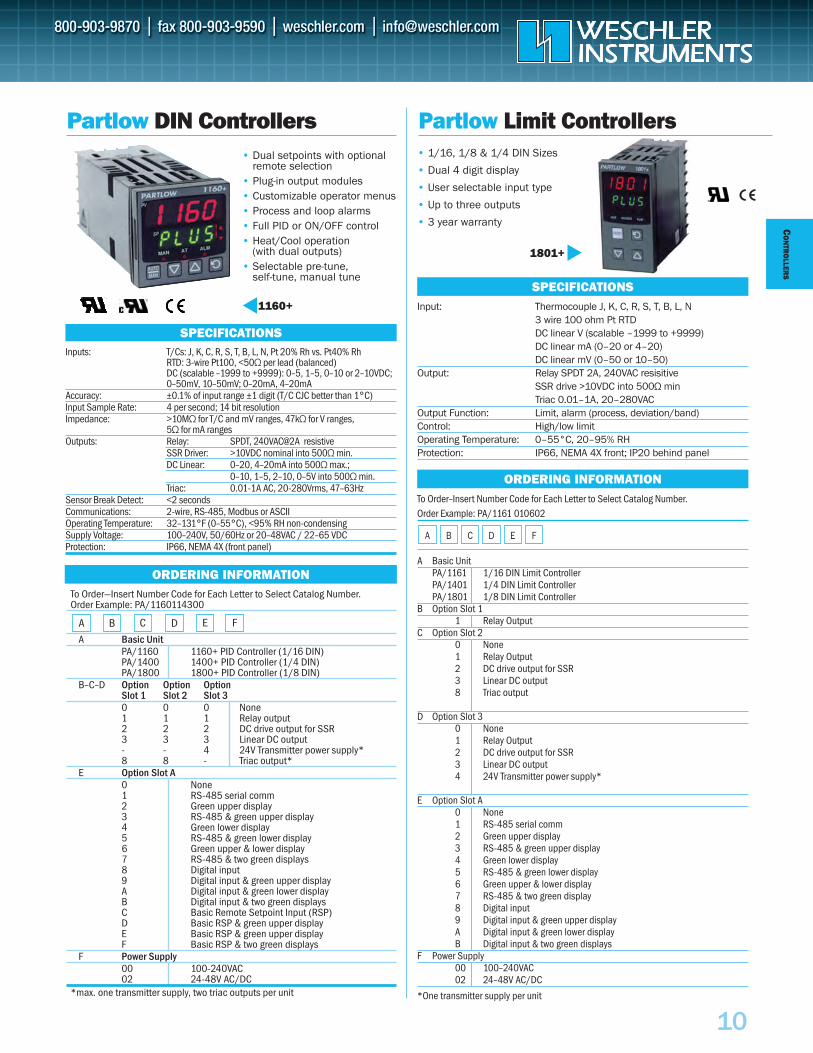
KEP Batch Controller• Display Rate, Batch Size
and Number of Batches or Grand Total
• 5 Digit Scaling Factor • Pulse Input• 2 Relay Outputs• Analog Output or
Serial/Modbus Options• NEMA 4X / IP65
Front PanelMB2
Display: 6 digit, 0.55" high LEDInput: Pulse, 50VDC max, 10kΩ resistanceRatemeter Display: Units per second, minute or hour Accuracy: 0.01% FS (±1 digit)Sampling Rate: 2 to 24 seconds
Scaling Factor: 0.0001 to 99999 (converts input pulses to engineering units)
Presets: Two, 5 digits eachFront Panel Lockout: Complete locked out (except Start/Stop) or the presets
can remain accessibleRelays: Two N.O. 5A, 120/240VAC or 28VDC. (N.C. contacts and
NPN transistor output available with solder jumpers)Relay B On Time: 0.01 to 99.99 sec. or latched (0.00 setting) Power Consumption: 6.5VA AC or 250mA DC max.Output Power: +12VDC @ 50mA, unregulated -10 + 50%
(AC powered units only)Operating Temperature: 0-54°C (32-130°F), <90% RH, non-condensingMemory: EEPROM stores data for 10 years if power is lostDimensions: 4.44"W x 2.63"H x 4.25"D (113 x 67 x 108mm)Cutout: 3.622" x 1.772" (92 x 45mm)
SPECIFICATIONS
The Mini-Batcher is a 6 digit totalizer and 4.5 digit ratemeter with two relay outputs. One output is dedicated to the batch amount (Preset A), the other canbe activated for Prewarn or Batch/Grand Total. The unit can count up to the preset (reset to 0) or down from the preset (set to preset). Start, Stop and Resetfunctions can be activated from the front panel or remote inputs.
Up to 247 units can communicate to a host computer using Modbus RTU protocol. Alternately, an analog output (assignable for Rate or Batch Amount)can be ordered for data logging.
ORDERING INFORMATION
A B CKE/MB2
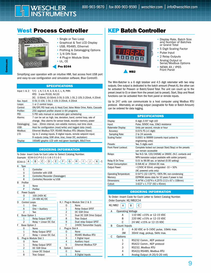
West Process Controller• Single or Two Loop• Graphical & Text LCD Display• USB, RS485, Ethernet• Profiling & Datalogging Options • 1/4 DIN Size• 4 Plug-in Module Slots• UL, CE
Input 1 & 2: T/C: J, K, T, E, R, S, D, B, C, L, N, PtRhRTD: 3-wire Pt100, Ni120DC: 0-50mV, 10-50mV, 0-5V, 0-10V, 1-5V, 2-10V, 0-20mA, 4-20mA
Aux. Input: 0-5V, 0-10V, 1-5V, 2-10V, 0-20mA, 4-20mALoops: 1 or 2 control loopsControl: ON/OFF, PID heat only & Heat/Cool, Valve Motor Drive, Ratio, CascadeProfiler: 255 segment profiler shared in 64 programsPID: 5 PID sets manual or automatic gain schedulingAlarms: 7 can be set as high, low, deviation, band, control loop, rate of
change. Also alarms for sensor break, recorder memory, powerDatalogging: 1sec - 30min interval, non-volatile memory, real time clockUSB: Host for configuration (read/write) and logged data (read)Modbus: Ethernet Modbus TCP; RS485 Modbus RTU (Master/Slave)I/O: Up to 2 analog inputs, 9 digital inputs, remote setpoint input;
9 outputs (relay, SSR drive, triac, linear DC, excitation)Display: 160x80 graphic LCD with red/green backlight, 66x37mm
SPECIFICATIONS
ORDERING INFORMATIONTo Order- Insert Code for Each Letter to Select Catalog Number.Example: EC44-0-C-P-0-2-1-1-8-1-T-1-0-1
EC44-0-
A TypeC ControllerU Controller with USBD Controller/Recorder (Datalogger)R Controller/Recorder w/USB
B ProfilerO NoneP Profiler
C Power Supply O 100-240V AC2 24-48V AC/DC
D Control Loops1 OneA One + Auxiliary2 Two
E Base Option 11 Relay Output SPST2 Relay + Linear DC Out
F Base Option 20 None1 Relay Output SPST2 Relay + Linear DC Out
G Plug-in Module Slot 1 H, I Plug-in Module Slot 2 & 3O None O None1 Relay Output SPDT 1 Relay Output SPDT2 DC SSR Drive 2 DC SSR DriveL Linear DC Output Y Dual DC SSR Drive Output8 Triac Output
A – B – C – D – E – F – G – H – I – J – K
Pro EC44
–1
Simplifying user operation with an intuitive HMI, fast access front USB portand easy-to-use configuration and simulation software, Blue Control©.
H, I Plug-in Module Slot 2 & 3O None1 Relay Output SPDT2 DC SSR DriveY Dual DC SSR Drive Output8 Triac Output9 Dual relay Output SPSTT 24VDC Transmitter Supply
J Plug-in Slot AO None1 RS485 Modbus RTU3 1 Digital Input4 Auxiliary Input5 Ethernet Modbus TCP
K Option C0 None1 8 Digital Inputs
CO
NTR
OLLER
S
10
Partlow DIN Controllers• Dual setpoints with optional
remote selection• Plug-in output modules • Customizable operator menus• Process and loop alarms• Full PID or ON/OFF control• Heat/Cool operation
(with dual outputs)• Selectable pre-tune,
self-tune, manual tune
1160+
Inputs: T/Cs: J, K, C, R, S, T, B, L, N, Pt 20% Rh vs. Pt40% RhRTD: 3-wire Pt100, <50Ω per lead (balanced)DC (scalable –1999 to +9999): 0–5, 1–5, 0–10 or 2–10VDC;0–50mV, 10–50mV; 0–20mA, 4–20mA
Accuracy: ±0.1% of input range ±1 digit (T/C CJC better than 1°C)Input Sample Rate: 4 per second; 14 bit resolutionImpedance: >10MΩ for T/C and mV ranges, 47kΩ for V ranges,
5Ω for mA rangesOutputs: Relay: SPDT, 240VAC@2A resistive
SSR Driver: >10VDC nominal into 500Ω min.DC Linear: 0–20, 4–20mA into 500Ω max.;
0–10, 1–5, 2–10, 0–5V into 500Ω min.Triac: 0.01-1A AC, 20-280Vrms, 47–63Hz
Sensor Break Detect: <2 seconds Communications: 2-wire, RS-485, Modbus or ASCIIOperating Temperature: 32–131°F (0–55°C), <95% RH non-condensing Supply Voltage: 100–240V, 50/60Hz or 20–48VAC / 22–65 VDCProtection: IP66, NEMA 4X (front panel)
SPECIFICATIONS
ORDERING INFORMATIONTo Order—Insert Number Code for Each Letter to Select Catalog Number.Order Example: PA/1160114300
A Basic UnitPA/1160 1160+ PID Controller (1/16 DIN)PA/1400 1400+ PID Controller (1/4 DIN)PA/1800 1800+ PID Controller (1/8 DIN)
B–C–D Option Option OptionSlot 1 Slot 2 Slot 30 0 0 None1 1 1 Relay output2 2 2 DC drive output for SSR3 3 3 Linear DC output- - 4 24V Transmitter power supply*8 8 - Triac output*
E Option Slot A0 None1 RS-485 serial comm2 Green upper display3 RS-485 & green upper display4 Green lower display5 RS-485 & green lower display6 Green upper & lower display7 RS-485 & two green displays8 Digital input9 Digital input & green upper displayA Digital input & green lower displayB Digital input & two green displaysC Basic Remote Setpoint Input (RSP)D Basic RSP & green upper displayE Basic RSP & green upper displayF Basic RSP & two green displays
F Power Supply00 100-240VAC02 24-48V AC/DC
*max. one transmitter supply, two triac outputs per unit
A B C D E F
To Order–Insert Number Code for Each Letter to Select Catalog Number.Order Example: PA/1161 010602
FEDCBA
A Basic UnitPA/1161 1/16 DIN Limit ControllerPA/1401 1/4 DIN Limit ControllerPA/1801 1/8 DIN Limit Controller
B Option Slot 11 Relay Output
C Option Slot 20 None1 Relay Output2 DC drive output for SSR3 Linear DC output8 Triac output
D Option Slot 30 None1 Relay Output2 DC drive output for SSR3 Linear DC output4 24V Transmitter power supply*
E Option Slot A0 None1 RS-485 serial comm2 Green upper display3 RS-485 & green upper display4 Green lower display5 RS-485 & green lower display6 Green upper & lower display7 RS-485 & two green display8 Digital input9 Digital input & green upper displayA Digital input & green lower displayB Digital input & two green displays
F Power Supply00 100–240VAC02 24–48V AC/DC
*One transmitter supply per unit
ORDERING INFORMATION
Partlow Limit Controllers• 1/16, 1/8 & 1/4 DIN Sizes
• Dual 4 digit display
• User selectable input type
• Up to three outputs
• 3 year warranty
Input: Thermocouple J, K, C, R, S, T, B, L, N 3 wire 100 ohm Pt RTDDC linear V (scalable –1999 to +9999)DC linear mA (0–20 or 4–20)DC linear mV (0–50 or 10–50)
Output: Relay SPDT 2A, 240VAC resisitiveSSR drive >10VDC into 500Ω minTriac 0.01–1A, 20–280VAC
Output Function: Limit, alarm (process, deviation/band)Control: High/low limitOperating Temperature: 0–55°C, 20–95% RHProtection: IP66, NEMA 4X front; IP20 behind panel
SPECIFICATIONS
1801+
DIG
ITALM
ETERS
12
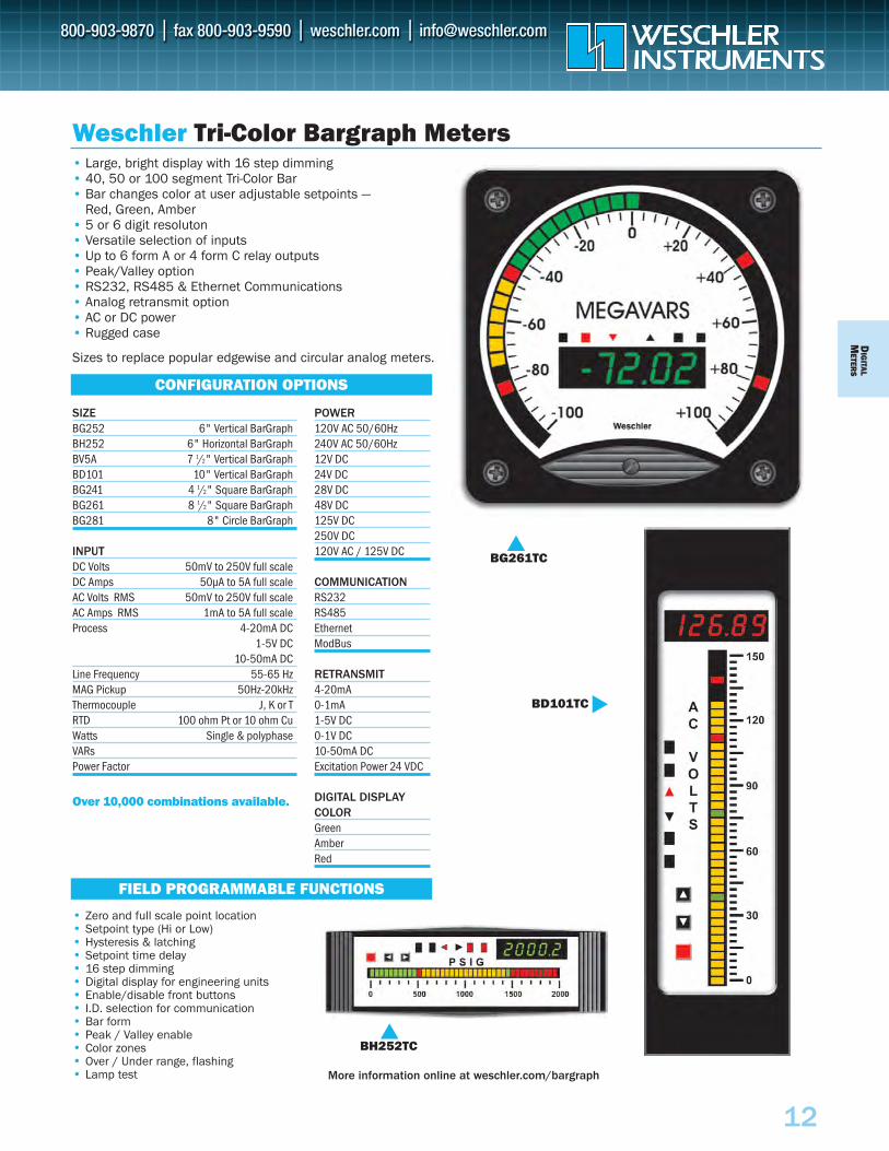
Weschler Tri-Color Bargraph Meters
• Zero and full scale point location• Setpoint type (Hi or Low)• Hysteresis & latching• Setpoint time delay• 16 step dimming• Digital display for engineering units• Enable/disable front buttons• I.D. selection for communication• Bar form• Peak / Valley enable• Color zones• Over / Under range, flashing• Lamp test
CONFIGURATION OPTIONS
• Large, bright display with 16 step dimming• 40, 50 or 100 segment Tri-Color Bar • Bar changes color at user adjustable setpoints —
Red, Green, Amber• 5 or 6 digit resoluton• Versatile selection of inputs• Up to 6 form A or 4 form C relay outputs• Peak/Valley option• RS232, RS485 & Ethernet Communications• Analog retransmit option• AC or DC power• Rugged case
Sizes to replace popular edgewise and circular analog meters.
SIZEBG252 6" Vertical BarGraphBH252 6" Horizontal BarGraphBV5A 7 1/2" Vertical BarGraphBD101 10" Vertical BarGraphBG241 4 1/2" Square BarGraphBG261 8 1/2" Square BarGraphBG281 8" Circle BarGraph
INPUTDC Volts 50mV to 250V full scaleDC Amps 50µA to 5A full scaleAC Volts RMS 50mV to 250V full scaleAC Amps RMS 1mA to 5A full scaleProcess 4-20mA DC
1-5V DC 10-50mA DC
Line Frequency 55-65 HzMAG Pickup 50Hz-20kHzThermocouple J, K or TRTD 100 ohm Pt or 10 ohm CuWatts Single & polyphaseVARsPower Factor
POWER120V AC 50/60Hz240V AC 50/60Hz12V DC24V DC28V DC48V DC125V DC250V DC120V AC / 125V DC
COMMUNICATIONRS232RS485Ethernet ModBus
RETRANSMIT4-20mA 0-1mA1-5V DC0-1V DC10-50mA DC Excitation Power 24 VDC
DIGITAL DISPLAYCOLORGreen Amber Red
BD101TC
BG261TC
BH252TC
FIELD PROGRAMMABLE FUNCTIONS
Over 10,000 combinations available.
More information online at weschler.com/bargraph
DIG
ITAL
MET
ERS
13
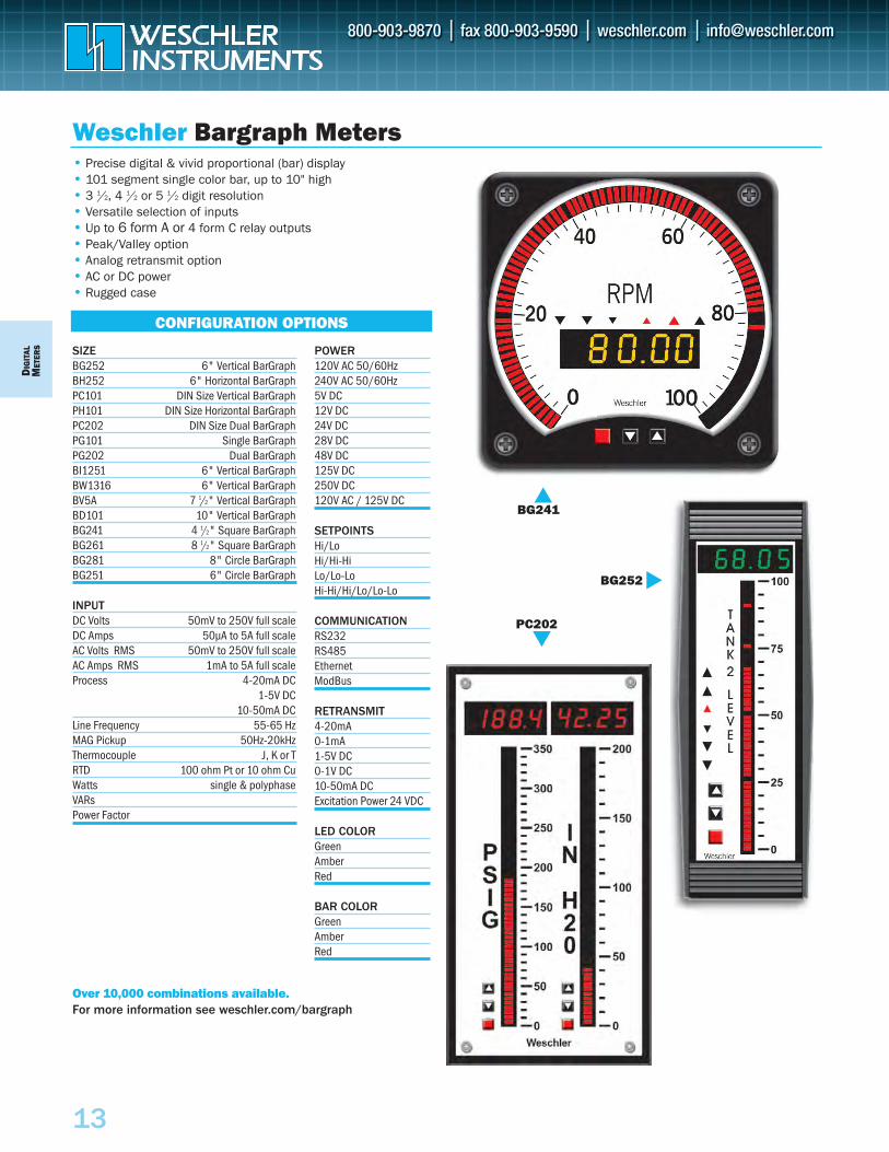
Weschler Bargraph Meters
CONFIGURATION OPTIONS
• Precise digital & vivid proportional (bar) display• 101 segment single color bar, up to 10" high• 3 1/2, 4 1/2 or 5 1/2 digit resolution• Versatile selection of inputs• Up to 6 form A or 4 form C relay outputs• Peak/Valley option• Analog retransmit option• AC or DC power• Rugged case
Over 10,000 combinations available.For more information see weschler.com/bargraph
SIZEBG252 6" Vertical BarGraphBH252 6" Horizontal BarGraphPC101 DIN Size Vertical BarGraphPH101 DIN Size Horizontal BarGraphPC202 DIN Size Dual BarGraphPG101 Single BarGraphPG202 Dual BarGraphBI1251 6" Vertical BarGraphBW1316 6" Vertical BarGraphBV5A 7 1/2" Vertical BarGraphBD101 10" Vertical BarGraphBG241 4 1/2" Square BarGraphBG261 8 1/2" Square BarGraphBG281 8" Circle BarGraphBG251 6" Circle BarGraph
INPUTDC Volts 50mV to 250V full scaleDC Amps 50µA to 5A full scaleAC Volts RMS 50mV to 250V full scaleAC Amps RMS 1mA to 5A full scaleProcess 4-20mA DC
1-5V DC 10-50mA DC
Line Frequency 55-65 HzMAG Pickup 50Hz-20kHzThermocouple J, K or TRTD 100 ohm Pt or 10 ohm CuWatts single & polyphaseVARsPower Factor
BG241
POWER120V AC 50/60Hz240V AC 50/60Hz5V DC12V DC24V DC28V DC48V DC125V DC250V DC120V AC / 125V DC
SETPOINTSHi/LoHi/Hi-HiLo/Lo-LoHi-Hi/Hi/Lo/Lo-Lo
COMMUNICATIONRS232RS485Ethernet ModBus
RETRANSMIT4-20mA 0-1mA1-5V DC0-1V DC10-50mA DC Excitation Power 24 VDC
LED COLORGreen Amber Red
BAR COLORGreen Amber Red
BG252
PC202
DIG
ITALM
ETERS
14
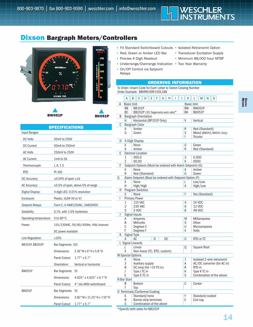
To Order—Insert Code for Each Letter to Select Catalog Number Order Example: BBVRR1RAY1VDL1BX
A Basic Unit Basic UnitBB BB101P BW BW051P BC BB202P (101 Segements each side)* BK BK051P
B Bargraph OrientationH Horizontal (BP101P Only) V Vertical
C Bargraph ColorA Amber R Red (Standard)G Green S Mixed (BW051/BK051 Only)
T TricolorD 4-Digit Display
X None G GreenA Amber R Red (Standard)
E Decimal Location1 000.0 3 0.0002 00.00 X 0000
F Setpoint Options (Must be ordered with Alarm Setpoint) (G)X None A Amber R Red (Standard) G Green
G Alarm Setpoint (Must be ordered with Setpoint Option (F)X None L Low/Low H High/High A High/Low
H Program SwitchesX None Y Yes (Standard)
I Primary Power1 115 VAC 4 24 VDC2 230 VAC 6 12 VDC5 5 VDC 8 48 VDC
J Signal InputsA Amperes M MilliamperesB Millivolts O OtherC Degrees C U MicroamperesF Degrees F V Volts
K Signal TypeA AC D DC O RTD or TC
L Signal LinearityL Linear Q Square RootX Non-linear (TC, RTD, custom)
M Special OptionsX None 1 Isolated 2-wire retransmit3 Auxiliary supply A AC/DC converter (for AC in)B DC amp (for <1V FS in) R RTD inJ Type J TC in K Type K TC inE Type E TC in S Combination of the above
N Bar StartB Bottom C CenterT Top
O Terminals/Conformal CoatingX Standard/none Y Standard/coatedB Barrier strip terminals E End capS Combination of the above
*Specify both sides for BB202P
L M
• Fit Standard Switchboard Cutouts
• Red, Green or Amber LED Bar
• Precise 4 Digit Readout
• Underrange/Overrange Indication
• On/Off Control via SetpointRelays
• Isolated Retransmit Option
• Transducer Excitation Supply
• Minimum 88,000 hour MTBF
• Two Year Warranty
Dixson Bargraph Meters/Controllers
SPECIFICATIONSInput Ranges:
DC Volts 50mV to 250V
DC Current 50mA to 250mA
AC Volts 250mV to 250V
AC Current 1mA to 5A
Thermocouple J, K, T, E
RTD Pt 100
DC Accuracy: ±0.04% of span ±1d
AC Accuracy: ±0.5% of span, above 5% of range
Digital Display: 4 digit LED, 0.01% resolution
Enclosure: Plastic, UL94 V0 or V1
Setpoint Relays: Form C, 0.4A@125VAC, 2A@30VDC
Setability: 0.1%, with 1.0% hysteresis
Operating temperature: 0 to 60°C
Power: 115/230VAC, 50/60/400Hz, 4VA/channel
DC power available
Line Regulation: ±10%
BB101P, BB202P Bar Segments: 101
Dimensions: 2.16"W x 6"H x 5.8"D
Panel Cutout: 1.77" x 5.7"
Orientation: Vertical or horizontal
BW051P Bar Segments: 51
Dimensions: 4.625" x 4.625" x 6.7"D
Panel Cutout: 4" dia ANSI switchboard
BK051P Bar Segments: 51
Dimensions: 3.82"W x 11.25"H x 7.10"D
Panel Cutout: 1.77" x 5.7"
BK051P
BW051P
ORDERING INFORMATION
A B C D E F J KG H I N O
DIG
ITAL
MET
ERS
15
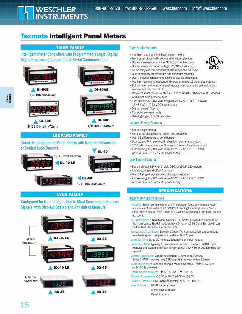
Texmate Intelligent Panel Meters
TIGER FAMILY
LEOPARD FAMILY
LYNX FAMILYSPECIFICATIONS
Intelligent Meter Controllers with Programmable Logic, DigitalSignal Processing Capabilities & Serial Communication
DI-50E
1/8 DIN 96X48mm
DI-60E
1/8 DIN 96X48mm
DL-40
GI-50E
9/32 DIN 144x72mm
DL-40 LR
1/8 DIN 96X48mm
1/16 DIN 96X24mm
1/8 DIN 96X48mm
1/16 DIN96X24mm
BL-40
DX-35DX-35 LR
DX-45DX-40 LR
BX-45BX-35
DI-60AE
Smart, Programmable Meter Relays with Isolated Retransmitor Control Loop Outputs
Configured for Direct Connection to Most Sensors and ProcessSignals, with Displays Scalable to Any Unit of Measure
Tiger Family Features
• Intelligent and super-intelligent digital meters• Front-panel digital calibration and function selection• Built-in linearization function, 32 to 125 flexible points• Built-in sensor excitation voltage 5 V /10 V / 24 V DC• Six 5A relays or combinations of 10A relays and 5A relays• Built-in memory for maximum and minimum readings• Over 75 signal conditioners, single as well as dual inputs• Two high-resolution, independently programmable 16-bit analog outputs• Built-in timer and totalizer (signal integration) inputs, plus user-definable
macros and real time clock• Choice of serial communications – RS232, RS485, Ethernet, ASCII, Modbus
and direct drive printer output• Auto-sensing AC / DC, wide range 85-265 V AC / 95-370 V DC or
15-48 V AC / 10-72 V DC power supply• Digital “smart” filtering• Computer programmable• Data logging up to 7000 samples
Leopard Family Features
• Smart 4-digit meters• Front-panel digital scaling, offset, and setpoints• Over 38 different signal conditioners• Dual 10 and 5-amp relays, 4 relays total plus analog output• 1/16 DIN meters have 2 or 3 relays or 1 relay plus analog output• Auto-sensing AC / DC, wide range 85-265 V AC / 95-370 V DC,
or 15-48 V AC / 10-72 V DC power supply
Lynx Family Features
• Basic indicator 3.5, 4 or 5 digit, 0.56” and 0.8” LED meters • Analog scaling and offset from rear• Over 24 single-input signal conditioners available• Auto-sensing AC / DC, wide range 85-265 V AC / 95-370 V DC,
or 15-48 V AC / 10-72 V DC power supply
Tiger Meter Specifications
Accuracy: Built-in compensation and linearization functions enable systemaccuracies of the order of ±0.0001% of reading for analog inputs. Stop -Start time resolution from ±1sec to ±0.7nsec. Digital input and pulse counts±1 count.
A/D Convertors: A Dual Slope, bipolar 17 bit A/D is provided as standard onthe main board. SMART modules have 24 bit or 16 bit Delta-Sigma A/D con-vertors that utilize the internal I2C BUS.
Temperature Coefficient: Typically 30ppm/˚C. Compensation can be utilizedto achieve system temperature coefficients of 1ppm.
Warm Up Time: Up to 10 minutes, depending on input module.Conversion Rate: Typically 10 samples per second. However, SMART input
modules are available that can convert at 60, 240, 480 or 960 samples persecond.
Control Output Rate: Can be selected for 100msec or 10msec. Some SMART modules have SSR outputs that react within 1.2msec.
Excitation Voltage: Depends on input module selected. Typically, 5V, 10V or 24VDC is provided.
Operating Temperature: 0 to 50 ˚C (32 ˚F to 122 ˚F).Storage Temperature: -20 ˚C to 70 ˚C (-4 ˚F to 158 ˚F).Relative Humidity: <95% (non-condensing) at 40 ˚C (104 ˚F).Case Options: NEMA 4X Lens cover
Metal case surroundPanel Adapters
DMIG
ITALETER
S
16
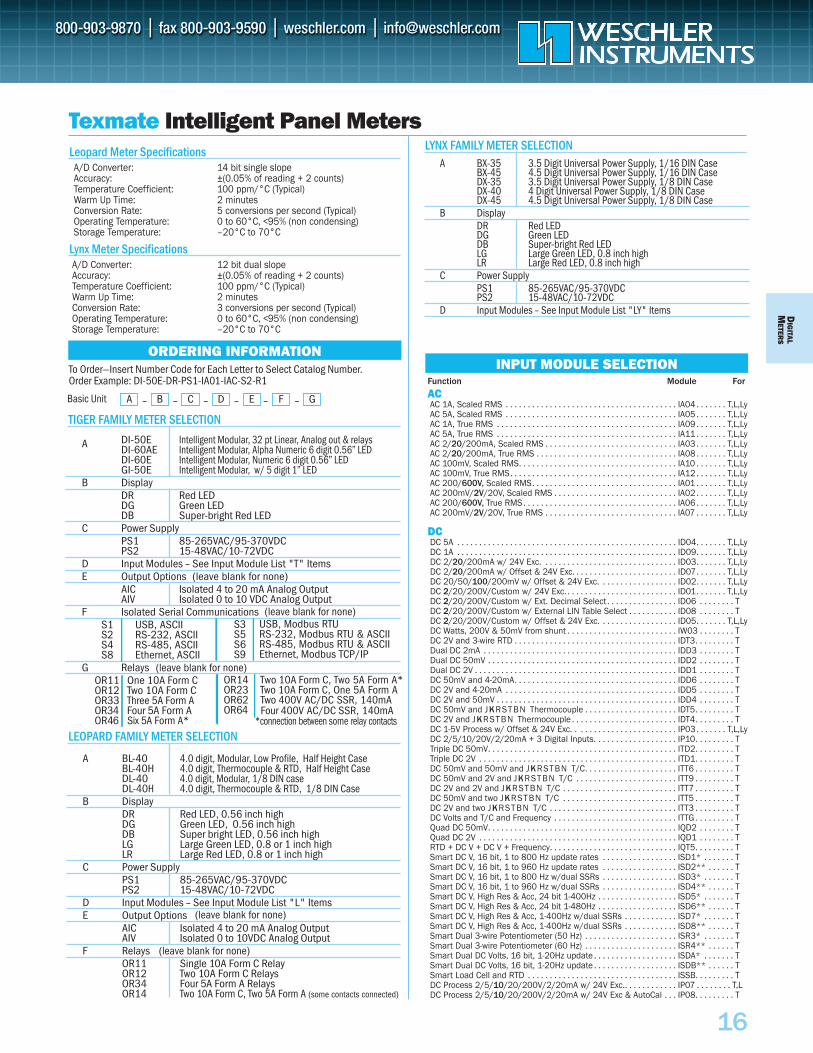
Texmate Intelligent Panel Meters
ORDERING INFORMATIONINPUT MODULE SELECTION
Leopard Meter SpecificationsA/D Converter: 14 bit single slopeAccuracy: ±(0.05% of reading + 2 counts)Temperature Coefficient: 100 ppm/°C (Typical)Warm Up Time: 2 minutesConversion Rate: 5 conversions per second (Typical)Operating Temperature: 0 to 60°C, <95% (non condensing)Storage Temperature: –20°C to 70°C
Lynx Meter SpecificationsA/D Converter: 12 bit dual slopeAccuracy: ±(0.05% of reading + 2 counts)Temperature Coefficient: 100 ppm/°C (Typical)Warm Up Time: 2 minutesConversion Rate: 3 conversions per second (Typical)Operating Temperature: 0 to 60°C, <95% (non condensing)Storage Temperature: –20°C to 70°C
TIGER FAMILY METER SELECTION
LEOPARD FAMILY METER SELECTION
LYNX FAMILY METER SELECTION
To Order—Insert Number Code for Each Letter to Select Catalog Number.Order Example: DI-50E-DR-PS1-IA01-IAC-S2-R1
A DI-50E Intelligent Modular, 32 pt Linear, Analog out & relaysDI-60AE Intelligent Modular, Alpha Numeric 6 digit 0.56” LEDDI-60E Intelligent Modular, Numeric 6 digit 0.56” LEDGI-50E Intelligent Modular, w/ 5 digit 1” LED
B DisplayDR Red LEDDG Green LEDDB Super-bright Red LED
C Power SupplyPS1 85-265VAC/95-370VDCPS2 15-48VAC/10-72VDC
D Input Modules – See Input Module List "T" ItemsE Output Options (leave blank for none)
AIC Isolated 4 to 20 mA Analog OutputAIV Isolated 0 to 10 VDC Analog Output
F Isolated Serial CommunicationsS1S2S4S8
G RelaysOR11OR12OR33OR34OR46
A – B – C – D – E – F – GBasic Unit
A BL-40 4.0 digit, Modular, Low Profile, Half Height CaseBL-40H 4.0 digit, Thermocouple & RTD, Half Height CaseDL-40 4.0 digit, Modular, 1/8 DIN caseDL-40H 4.0 digit, Thermocouple & RTD, 1/8 DIN Case
B DisplayDR Red LED, 0.56 inch highDG Green LED, 0.56 inch highDB Super bright LED, 0.56 inch highLG Large Green LED, 0.8 or 1 inch highLR Large Red LED, 0.8 or 1 inch high
C Power SupplyPS1 85-265VAC/95-370VDCPS2 15-48VAC/10-72VDC
D Input Modules – See Input Module List "L" ItemsE Output Options
AIC Isolated 4 to 20 mA Analog OutputAIV Isolated 0 to 10VDC Analog Output
F RelaysOR11 Single 10A Form C RelayOR12 Two 10A Form C RelaysOR34 Four 5A Form A RelaysOR14 Two 10A Form C, Two 5A Form A (some contacts connected)
A BX-35 3.5 Digit Universal Power Supply, 1/16 DIN Case BX-45 4.5 Digit Universal Power Supply, 1/16 DIN CaseDX-35 3.5 Digit Universal Power Supply, 1/8 DIN CaseDX-40 4 Digit Universal Power Supply, 1/8 DIN CaseDX-45 4.5 Digit Universal Power Supply, 1/8 DIN Case
B DisplayDR Red LEDDG Green LEDDB Super-bright Red LEDLG Large Green LED, 0.8 inch highLR Large Red LED, 0.8 inch high
C Power SupplyPS1 85-265VAC/95-370VDCPS2 15-48VAC/10-72VDC
D Input Modules – See Input Module List "LY" Items
Function Module For
ACAC 1A, Scaled RMS . . . . . . . . . . . . . . . . . . . . . . . . . . . . . . . . . . . . . . . IA04 . . . . . . . T,L,LyAC 5A, Scaled RMS . . . . . . . . . . . . . . . . . . . . . . . . . . . . . . . . . . . . . . . IA05 . . . . . . . T,L,LyAC 1A, True RMS . . . . . . . . . . . . . . . . . . . . . . . . . . . . . . . . . . . . . . . . . IA09 . . . . . . . T,L,LyAC 5A, True RMS . . . . . . . . . . . . . . . . . . . . . . . . . . . . . . . . . . . . . . . . . IA11 . . . . . . . T,L,LyAC 2/20/200mA, Scaled RMS . . . . . . . . . . . . . . . . . . . . . . . . . . . . . . IA03 . . . . . . . T,L,LyAC 2/20/200mA, True RMS . . . . . . . . . . . . . . . . . . . . . . . . . . . . . . . . IA08 . . . . . . . T,L,LyAC 100mV, Scaled RMS. . . . . . . . . . . . . . . . . . . . . . . . . . . . . . . . . . . . IA10 . . . . . . . T,L,LyAC 100mV, True RMS. . . . . . . . . . . . . . . . . . . . . . . . . . . . . . . . . . . . . . IA12 . . . . . . . T,L,LyAC 200/600V, Scaled RMS. . . . . . . . . . . . . . . . . . . . . . . . . . . . . . . . . IA01 . . . . . . . T,L,LyAC 200mV/2V/20V, Scaled RMS . . . . . . . . . . . . . . . . . . . . . . . . . . . . IA02 . . . . . . . T,L,LyAC 200/600V, True RMS . . . . . . . . . . . . . . . . . . . . . . . . . . . . . . . . . . . IA06 . . . . . . . T,L,LyAC 200mV/2V/20V, True RMS . . . . . . . . . . . . . . . . . . . . . . . . . . . . . . IA07 . . . . . . . T,L,Ly
DCDC 5A . . . . . . . . . . . . . . . . . . . . . . . . . . . . . . . . . . . . . . . . . . . . . . . . . . ID04. . . . . . . T,L,LyDC 1A . . . . . . . . . . . . . . . . . . . . . . . . . . . . . . . . . . . . . . . . . . . . . . . . . . ID09. . . . . . . T,L,LyDC 2/20/200mA w/ 24V Exc. . . . . . . . . . . . . . . . . . . . . . . . . . . . . . . ID03. . . . . . . T,L,LyDC 2/20/200mA w/ Offset & 24V Exc. . . . . . . . . . . . . . . . . . . . . . . . ID07. . . . . . . T,L,LyDC 20/50/100/200mV w/ Offset & 24V Exc. . . . . . . . . . . . . . . . . . ID02. . . . . . . T,L,LyDC 2/20/200V/Custom w/ 24V Exc. . . . . . . . . . . . . . . . . . . . . . . . . . ID01. . . . . . . T,L,LyDC 2/20/200V/Custom w/ Ext. Decimal Select . . . . . . . . . . . . . . . . ID06 . . . . . . . . TDC 2/20/200V/Custom w/ External LIN Table Select . . . . . . . . . . . ID08 . . . . . . . . TDC 2/20/200V/Custom w/ Offset & 24V Exc. . . . . . . . . . . . . . . . . . ID05. . . . . . . T,L,LyDC Watts, 200V & 50mV from shunt . . . . . . . . . . . . . . . . . . . . . . . . . IW03 . . . . . . . . TDC 2V and 3-wire RTD . . . . . . . . . . . . . . . . . . . . . . . . . . . . . . . . . . . . . IDT3. . . . . . . . . TDual DC 2mA . . . . . . . . . . . . . . . . . . . . . . . . . . . . . . . . . . . . . . . . . . . . IDD3 . . . . . . . . TDual DC 50mV . . . . . . . . . . . . . . . . . . . . . . . . . . . . . . . . . . . . . . . . . . . IDD2 . . . . . . . . TDual DC 2V . . . . . . . . . . . . . . . . . . . . . . . . . . . . . . . . . . . . . . . . . . . . . . IDD1 . . . . . . . . TDC 50mV and 4-20mA. . . . . . . . . . . . . . . . . . . . . . . . . . . . . . . . . . . . . IDD6 . . . . . . . . TDC 2V and 4-20mA . . . . . . . . . . . . . . . . . . . . . . . . . . . . . . . . . . . . . . . IDD5 . . . . . . . . TDC 2V and 50mV . . . . . . . . . . . . . . . . . . . . . . . . . . . . . . . . . . . . . . . . . IDD4 . . . . . . . . TDC 50mV and JKRSTBN Thermocouple . . . . . . . . . . . . . . . . . . . . . IDT5. . . . . . . . . TDC 2V and JKRSTBN Thermocouple . . . . . . . . . . . . . . . . . . . . . . . . IDT4. . . . . . . . . TDC 1-5V Process w/ Offset & 24V Exc. . . . . . . . . . . . . . . . . . . . . . . . IP03. . . . . . . T,L,LyDC 2/5/10/20V/2/20mA + 3 Digital Inputs. . . . . . . . . . . . . . . . . . . IP10. . . . . . . . . TTriple DC 50mV. . . . . . . . . . . . . . . . . . . . . . . . . . . . . . . . . . . . . . . . . . . ITD2. . . . . . . . . TTriple DC 2V . . . . . . . . . . . . . . . . . . . . . . . . . . . . . . . . . . . . . . . . . . . . . ITD1. . . . . . . . . TDC 50mV and 50mV and JKRSTBN T/C. . . . . . . . . . . . . . . . . . . . . ITT6 . . . . . . . . . TDC 50mV and 2V and JKRSTBN T/C . . . . . . . . . . . . . . . . . . . . . . . ITT9 . . . . . . . . . TDC 2V and 2V and JKRSTBN T/C . . . . . . . . . . . . . . . . . . . . . . . . . . ITT7 . . . . . . . . . TDC 50mV and two JKRSTBN T/C . . . . . . . . . . . . . . . . . . . . . . . . . . ITT5 . . . . . . . . . TDC 2V and two JKRSTBN T/C . . . . . . . . . . . . . . . . . . . . . . . . . . . . . ITT3 . . . . . . . . . TDC Volts and T/C and Frequency . . . . . . . . . . . . . . . . . . . . . . . . . . . . ITTG . . . . . . . . . TQuad DC 50mV. . . . . . . . . . . . . . . . . . . . . . . . . . . . . . . . . . . . . . . . . . . IQD2 . . . . . . . . TQuad DC 2V . . . . . . . . . . . . . . . . . . . . . . . . . . . . . . . . . . . . . . . . . . . . . IQD1 . . . . . . . . TRTD + DC V + DC V + Frequency. . . . . . . . . . . . . . . . . . . . . . . . . . . . . IQT5. . . . . . . . . TSmart DC V, 16 bit, 1 to 800 Hz update rates . . . . . . . . . . . . . . . . . ISD1* . . . . . . . TSmart DC V, 16 bit, 1 to 960 Hz update rates . . . . . . . . . . . . . . . . . ISD2** . . . . . . TSmart DC V, 16 bit, 1 to 800 Hz w/dual SSRs . . . . . . . . . . . . . . . . . ISD3* . . . . . . . TSmart DC V, 16 bit, 1 to 960 Hz w/dual SSRs . . . . . . . . . . . . . . . . . ISD4** . . . . . . TSmart DC V, High Res & Acc, 24 bit 1-400Hz . . . . . . . . . . . . . . . . . . ISD5* . . . . . . . TSmart DC V, High Res & Acc, 24 bit 1-480Hz . . . . . . . . . . . . . . . . . . ISD6** . . . . . . TSmart DC V, High Res & Acc, 1-400Hz w/dual SSRs . . . . . . . . . . . . ISD7* . . . . . . . TSmart DC V, High Res & Acc, 1-400Hz w/dual SSRs . . . . . . . . . . . . ISD8** . . . . . . TSmart Dual 3-wire Potentiometer (50 Hz) . . . . . . . . . . . . . . . . . . . . . ISR3* . . . . . . . TSmart Dual 3-wire Potentiometer (60 Hz) . . . . . . . . . . . . . . . . . . . . . ISR4** . . . . . . TSmart Dual DC Volts, 16 bit, 1-20Hz update . . . . . . . . . . . . . . . . . . . ISDA* . . . . . . . TSmart Dual DC Volts, 16 bit, 1-20Hz update . . . . . . . . . . . . . . . . . . . ISDB** . . . . . . TSmart Load Cell and RTD . . . . . . . . . . . . . . . . . . . . . . . . . . . . . . . . . . ISSB. . . . . . . . . TDC Process 2/5/10/20/200V/2/20mA w/ 24V Exc.. . . . . . . . . . . . IP07 . . . . . . . . T,LDC Process 2/5/10/20/200V/2/20mA w/ 24V Exc & AutoCal . . . IP08. . . . . . . . . T
USB, Modbus RTURS-232, Modbus RTU & ASCIIRS-485, Modbus RTU & ASCIIEthernet, Modbus TCP/IP
USB, ASCIIRS-232, ASCIIRS-485, ASCIIEthernet, ASCII
S3S5S6S9
One 10A Form C Two 10A Form C Three 5A Form A Four 5A Form A Six 5A Form A*
OR14OR23OR62OR64
*connection between some relay contacts
Two 10A Form C, Two 5A Form A* Two 10A Form C, One 5A Form A Two 400V AC/DC SSR, 140mA Four 400V AC/DC SSR, 140mA
(leave blank for none)
(leave blank for none)
(leave blank for none)
(leave blank for none)
DIG
ITAL
MET
ERS
17
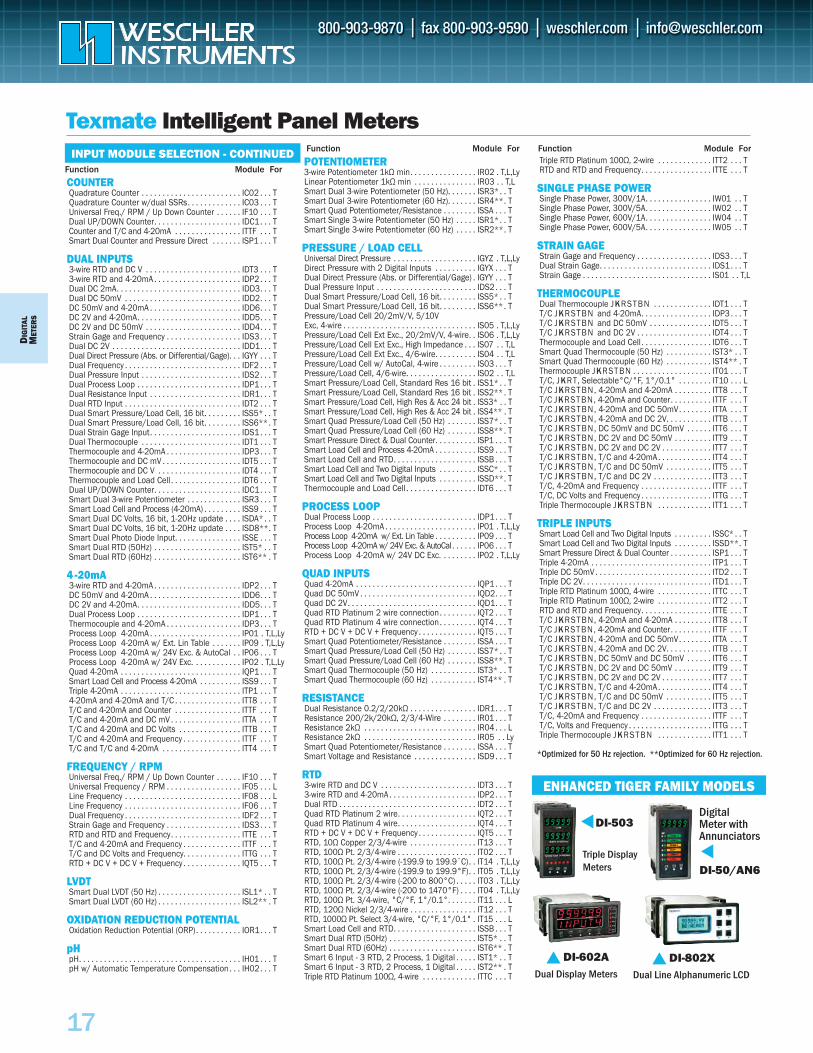
COUNTERQuadrature Counter . . . . . . . . . . . . . . . . . . . . . . . . IC02 . . . TQuadrature Counter w/dual SSRs. . . . . . . . . . . . . IC03 . . . TUniversal Freq./ RPM / Up Down Counter . . . . . . IF10 . . . TDual UP/DOWN Counter. . . . . . . . . . . . . . . . . . . . . IDC1. . . TCounter and T/C and 4-20mA . . . . . . . . . . . . . . . . ITTF . . . TSmart Dual Counter and Pressure Direct . . . . . . . ISP1 . . . T
DUAL INPUTS3-wire RTD and DC V . . . . . . . . . . . . . . . . . . . . . . . IDT3 . . . T3-wire RTD and 4-20mA . . . . . . . . . . . . . . . . . . . . . IDP2 . . . TDual DC 2mA. . . . . . . . . . . . . . . . . . . . . . . . . . . . . . IDD3. . . TDual DC 50mV . . . . . . . . . . . . . . . . . . . . . . . . . . . . IDD2. . . TDC 50mV and 4-20mA . . . . . . . . . . . . . . . . . . . . . . IDD6. . . TDC 2V and 4-20mA. . . . . . . . . . . . . . . . . . . . . . . . . IDD5. . . TDC 2V and DC 50mV . . . . . . . . . . . . . . . . . . . . . . . IDD4. . . TStrain Gage and Frequency . . . . . . . . . . . . . . . . . . IDS3 . . . TDual DC 2V . . . . . . . . . . . . . . . . . . . . . . . . . . . . . . . IDD1. . . TDual Direct Pressure (Abs. or Differential/Gage). . . IGYY . . . TDual Frequency . . . . . . . . . . . . . . . . . . . . . . . . . . . . IDF2 . . . TDual Pressure Input . . . . . . . . . . . . . . . . . . . . . . . . IDS2 . . . TDual Process Loop . . . . . . . . . . . . . . . . . . . . . . . . . IDP1 . . . TDual Resistance Input . . . . . . . . . . . . . . . . . . . . . . IDR1. . . TDual RTD Input . . . . . . . . . . . . . . . . . . . . . . . . . . . . IDT2 . . . TDual Smart Pressure/Load Cell, 16 bit. . . . . . . . . ISS5* . . TDual Smart Pressure/Load Cell, 16 bit. . . . . . . . . ISS6**. TDual Strain Gage Input. . . . . . . . . . . . . . . . . . . . . . IDS1 . . . TDual Thermocouple . . . . . . . . . . . . . . . . . . . . . . . . IDT1 . . . TThermocouple and 4-20mA . . . . . . . . . . . . . . . . . . IDP3 . . . TThermocouple and DC mV . . . . . . . . . . . . . . . . . . . IDT5 . . . TThermocouple and DC V . . . . . . . . . . . . . . . . . . . . IDT4 . . . TThermocouple and Load Cell . . . . . . . . . . . . . . . . . IDT6 . . . TDual UP/DOWN Counter. . . . . . . . . . . . . . . . . . . . . IDC1. . . TSmart Dual 3-wire Potentiometer . . . . . . . . . . . . . ISR3 . . . TSmart Load Cell and Process (4-20mA) . . . . . . . . . ISS9 . . . TSmart Dual DC Volts, 16 bit, 1-20Hz update . . . . ISDA* . . TSmart Dual DC Volts, 16 bit, 1-20Hz update . . . . ISD8**. TSmart Dual Photo Diode Input. . . . . . . . . . . . . . . . ISSE . . . TSmart Dual RTD (50Hz) . . . . . . . . . . . . . . . . . . . . . IST5* . . TSmart Dual RTD (60Hz) . . . . . . . . . . . . . . . . . . . . . IST6** . T
4 - 20mA3-wire RTD and 4-20mA . . . . . . . . . . . . . . . . . . . . . IDP2 . . . TDC 50mV and 4-20mA . . . . . . . . . . . . . . . . . . . . . . IDD6. . . TDC 2V and 4-20mA. . . . . . . . . . . . . . . . . . . . . . . . . IDD5. . . TDual Process Loop . . . . . . . . . . . . . . . . . . . . . . . . . IDP1 . . . TThermocouple and 4-20mA . . . . . . . . . . . . . . . . . . IDP3 . . . TProcess Loop 4-20mA . . . . . . . . . . . . . . . . . . . . . . IP01 . T,L,LyProcess Loop 4-20mA w/ Ext. Lin Table . . . . . . . IP09 . T,L,LyProcess Loop 4-20mA w/ 24V Exc. & AutoCal . . IP06 . . . TProcess Loop 4-20mA w/ 24V Exc. . . . . . . . . . . . IP02 . T,L,LyQuad 4-20mA . . . . . . . . . . . . . . . . . . . . . . . . . . . . . IQP1 . . . TSmart Load Cell and Process 4-20mA . . . . . . . . . . ISS9 . . . TTriple 4-20mA . . . . . . . . . . . . . . . . . . . . . . . . . . . . . ITP1 . . . T4-20mA and 4-20mA and T/C . . . . . . . . . . . . . . . . ITT8 . . . TT/C and 4-20mA and Counter . . . . . . . . . . . . . . . . ITTF . . . TT/C and 4-20mA and DC mV . . . . . . . . . . . . . . . . . ITTA . . . TT/C and 4-20mA and DC Volts . . . . . . . . . . . . . . . ITTB . . . TT/C and 4-20mA and Frequency . . . . . . . . . . . . . . ITTF . . . TT/C and T/C and 4-20mA . . . . . . . . . . . . . . . . . . . ITT4 . . . T
FREQUENCY / RPMUniversal Freq./ RPM / Up Down Counter . . . . . . IF10 . . . TUniversal Frequency / RPM . . . . . . . . . . . . . . . . . . IF05 . . . LLine Frequency . . . . . . . . . . . . . . . . . . . . . . . . . . . . IF08 . . . LLine Frequency . . . . . . . . . . . . . . . . . . . . . . . . . . . . IF06 . . . TDual Frequency . . . . . . . . . . . . . . . . . . . . . . . . . . . . IDF2 . . . TStrain Gage and Frequency . . . . . . . . . . . . . . . . . . IDS3 . . . TRTD and RTD and Frequency. . . . . . . . . . . . . . . . . ITTE . . . TT/C and 4-20mA and Frequency . . . . . . . . . . . . . . ITTF . . . TT/C and DC Volts and Frequency. . . . . . . . . . . . . . ITTG . . . TRTD + DC V + DC V + Frequency . . . . . . . . . . . . . . IQT5 . . . T
LVDTSmart Dual LVDT (50 Hz) . . . . . . . . . . . . . . . . . . . . ISL1* . . TSmart Dual LVDT (60 Hz) . . . . . . . . . . . . . . . . . . . . ISL2** . T
OXIDATION REDUCTION POTENTIALOxidation Reduction Potential (ORP). . . . . . . . . . . IOR1. . . T
pHpH. . . . . . . . . . . . . . . . . . . . . . . . . . . . . . . . . . . . . . . IH01 . . . TpH w/ Automatic Temperature Compensation . . . IH02. . . T
POTENTIOMETER3-wire Potentiometer 1kΩ min. . . . . . . . . . . . . . . . IR02 . T,L,LyLinear Potentiometer 1kΩ min . . . . . . . . . . . . . . . IR03 . . T,LSmart Dual 3-wire Potentiometer (50 Hz). . . . . . . ISR3*. . TSmart Dual 3-wire Potentiometer (60 Hz). . . . . . . ISR4**. TSmart Quad Potentiometer/Resistance . . . . . . . . ISSA . . . TSmart Single 3-wire Potentiometer (50 Hz) . . . . . ISR1*. . TSmart Single 3-wire Potentiometer (60 Hz) . . . . . ISR2**. T
PRESSURE / LOAD CELLUniversal Direct Pressure . . . . . . . . . . . . . . . . . . . . IGYZ . T,L,LyDirect Pressure with 2 Digital Inputs . . . . . . . . . . IGYX . . . TDual Direct Pressure (Abs. or Differential/Gage) . IGYY . . . TDual Pressure Input . . . . . . . . . . . . . . . . . . . . . . . . IDS2 . . . TDual Smart Pressure/Load Cell, 16 bit. . . . . . . . . ISS5* . . TDual Smart Pressure/Load Cell, 16 bit. . . . . . . . . ISS6**. TPressure/Load Cell 20/2mV/V, 5/10V Exc, 4-wire . . . . . . . . . . . . . . . . . . . . . . . . . . . . . . . . IS05 . T,L,LyPressure/Load Cell Ext Exc., 20/2mV/V, 4-wire. . IS06 . T,L,LyPressure/Load Cell Ext Exc., High Impedance . . . IS07 . . T,LPressure/Load Cell Ext Exc., 4/6-wire. . . . . . . . . . IS04 . . T,LPressure/Load Cell w/ AutoCal, 4-wire . . . . . . . . . IS03 . . . TPressure/Load Cell, 4/6-wire. . . . . . . . . . . . . . . . . IS02 . . T,LSmart Pressure/Load Cell, Standard Res 16 bit . ISS1* . . TSmart Pressure/Load Cell, Standard Res 16 bit . ISS2**. TSmart Pressure/Load Cell, High Res & Acc 24 bit . ISS3* . . TSmart Pressure/Load Cell, High Res & Acc 24 bit . ISS4** . TSmart Quad Pressure/Load Cell (50 Hz) . . . . . . . ISS7* . . TSmart Quad Pressure/Load Cell (60 Hz) . . . . . . . ISS8**. TSmart Pressure Direct & Dual Counter. . . . . . . . . . ISP1 . . . TSmart Load Cell and Process 4-20mA . . . . . . . . . . ISS9 . . . TSmart Load Cell and RTD. . . . . . . . . . . . . . . . . . . . ISSB . . . TSmart Load Cell and Two Digital Inputs . . . . . . . . . ISSC* . . TSmart Load Cell and Two Digital Inputs . . . . . . . . . ISSD**. TThermocouple and Load Cell . . . . . . . . . . . . . . . . . IDT6 . . . T
PROCESS LOOPDual Process Loop . . . . . . . . . . . . . . . . . . . . . . . . . IDP1 . . . TProcess Loop 4-20mA . . . . . . . . . . . . . . . . . . . . . . IP01 . T,L,LyProcess Loop 4-20mA w/ Ext. Lin Table . . . . . . . . . . IP09 . . . TProcess Loop 4-20mA w/ 24V Exc. & AutoCal. . . . . . IP06 . . . TProcess Loop 4-20mA w/ 24V DC Exc. . . . . . . . . IP02 . T,L,Ly
QUAD INPUTSQuad 4-20mA . . . . . . . . . . . . . . . . . . . . . . . . . . . . . IQP1 . . . TQuad DC 50mV . . . . . . . . . . . . . . . . . . . . . . . . . . . . IQD2. . . TQuad DC 2V. . . . . . . . . . . . . . . . . . . . . . . . . . . . . . . IQD1. . . TQuad RTD Platinum 2 wire connection. . . . . . . . . IQT2 . . . TQuad RTD Platinum 4 wire connection. . . . . . . . . IQT4 . . . TRTD + DC V + DC V + Frequency . . . . . . . . . . . . . . IQT5 . . . TSmart Quad Potentiometer/Resistance . . . . . . . . ISSA . . . TSmart Quad Pressure/Load Cell (50 Hz) . . . . . . . ISS7* . . TSmart Quad Pressure/Load Cell (60 Hz) . . . . . . . ISS8**. TSmart Quad Thermocouple (50 Hz) . . . . . . . . . . . IST3* . . TSmart Quad Thermocouple (60 Hz) . . . . . . . . . . . IST4** . T
RESISTANCEDual Resistance 0.2/2/20kΩ . . . . . . . . . . . . . . . . IDR1. . . TResistance 200/2k/20kΩ, 2/3/4-Wire . . . . . . . . IR01 . . . TResistance 2kΩ . . . . . . . . . . . . . . . . . . . . . . . . . . . IR04 . . . LResistance 2kΩ . . . . . . . . . . . . . . . . . . . . . . . . . . . IR05 . . LySmart Quad Potentiometer/Resistance . . . . . . . . ISSA . . . TSmart Voltage and Resistance . . . . . . . . . . . . . . . ISD9 . . . T
RTD3-wire RTD and DC V . . . . . . . . . . . . . . . . . . . . . . . IDT3 . . . T3-wire RTD and 4-20mA . . . . . . . . . . . . . . . . . . . . . IDP2 . . . TDual RTD . . . . . . . . . . . . . . . . . . . . . . . . . . . . . . . . . IDT2 . . . TQuad RTD Platinum 2 wire. . . . . . . . . . . . . . . . . . . IQT2 . . . TQuad RTD Platinum 4 wire. . . . . . . . . . . . . . . . . . . IQT4 . . . TRTD + DC V + DC V + Frequency . . . . . . . . . . . . . . IQT5 . . . TRTD, 10Ω Copper 2/3/4-wire . . . . . . . . . . . . . . . . IT13 . . . TRTD, 100Ω Pt. 2/3/4-wire . . . . . . . . . . . . . . . . . . . IT02 . . . TRTD, 100Ω Pt. 2/3/4-wire (-199.9 to 199.9˚C). . IT14 . T,L,LyRTD, 100Ω Pt. 2/3/4-wire (-199.9 to 199.9°F). . IT05 . T,L,LyRTD, 100Ω Pt. 2/3/4-wire (-200 to 800°C) . . . . . IT03 . T,L,LyRTD, 100Ω Pt. 2/3/4-wire (-200 to 1470°F) . . . . IT04 . T,L,LyRTD, 100Ω Pt. 3/4-wire, °C/°F, 1°/0.1°. . . . . . . IT11 . . . LRTD, 120Ω Nickel 2/3/4-wire . . . . . . . . . . . . . . . . IT12 . . . TRTD, 1000Ω Pt. Select 3/4-wire, °C/°F, 1°/0.1° . IT15 . . . LSmart Load Cell and RTD. . . . . . . . . . . . . . . . . . . . ISSB . . . TSmart Dual RTD (50Hz) . . . . . . . . . . . . . . . . . . . . . IST5* . . TSmart Dual RTD (60Hz) . . . . . . . . . . . . . . . . . . . . . IST6** . TSmart 6 Input - 3 RTD, 2 Process, 1 Digital . . . . . IST1* . . TSmart 6 Input - 3 RTD, 2 Process, 1 Digital . . . . . IST2** . TTriple RTD Platinum 100Ω, 4-wire . . . . . . . . . . . . . ITTC . . . T
Triple RTD Platinum 100Ω, 2-wire . . . . . . . . . . . . . ITT2 . . . TRTD and RTD and Frequency. . . . . . . . . . . . . . . . . ITTE . . . T
SINGLE PHASE POWERSingle Phase Power, 300V/1A. . . . . . . . . . . . . . . . IW01 . . TSingle Phase Power, 300V/5A. . . . . . . . . . . . . . . . IW02 . . TSingle Phase Power, 600V/1A. . . . . . . . . . . . . . . . IW04 . . TSingle Phase Power, 600V/5A. . . . . . . . . . . . . . . . IW05 . . T
STRAIN GAGEStrain Gage and Frequency . . . . . . . . . . . . . . . . . . IDS3 . . . TDual Strain Gage. . . . . . . . . . . . . . . . . . . . . . . . . . . IDS1 . . . TStrain Gage . . . . . . . . . . . . . . . . . . . . . . . . . . . . . . . IS01 . . T,L
THERMOCOUPLEDual Thermocouple JKRSTBN . . . . . . . . . . . . . . IDT1 . . . TT/C JKRSTBN and 4-20mA. . . . . . . . . . . . . . . . . IDP3 . . . TT/C JKRSTBN and DC 50mV . . . . . . . . . . . . . . . IDT5 . . . TT/C JKRSTBN and DC 2V . . . . . . . . . . . . . . . . . . IDT4 . . . TThermocouple and Load Cell . . . . . . . . . . . . . . . . . IDT6 . . . TSmart Quad Thermocouple (50 Hz) . . . . . . . . . . . IST3* . . TSmart Quad Thermocouple (60 Hz) . . . . . . . . . . . IST4** . TThermocouple JKRSTBN . . . . . . . . . . . . . . . . . . . IT01 . . . TT/C, JKRT, Selectable°C/°F, 1°/0.1° . . . . . . . . IT10 . . . LT/C JKRSTBN, 4-20mA and 4-20mA . . . . . . . . . ITT8 . . . TT/C JKRSTBN, 4-20mA and Counter. . . . . . . . . . ITTF . . . TT/C JKRSTBN, 4-20mA and DC 50mV. . . . . . . . ITTA . . . TT/C JKRSTBN, 4-20mA and DC 2V. . . . . . . . . . . ITTB . . . TT/C JKRSTBN, DC 50mV and DC 50mV . . . . . . ITT6 . . . TT/C JKRSTBN, DC 2V and DC 50mV . . . . . . . . . ITT9 . . . TT/C JKRSTBN, DC 2V and DC 2V . . . . . . . . . . . . ITT7 . . . TT/C JKRSTBN, T/C and 4-20mA. . . . . . . . . . . . . ITT4 . . . TT/C JKRSTBN, T/C and DC 50mV . . . . . . . . . . . ITT5 . . . TT/C JKRSTBN, T/C and DC 2V . . . . . . . . . . . . . . ITT3 . . . TT/C, 4-20mA and Frequency . . . . . . . . . . . . . . . . . ITTF . . . TT/C, DC Volts and Frequency . . . . . . . . . . . . . . . . . ITTG . . . TTriple Thermocouple JKRSTBN . . . . . . . . . . . . . ITT1 . . . T
TRIPLE INPUTSSmart Load Cell and Two Digital Inputs . . . . . . . . . ISSC* . . TSmart Load Cell and Two Digital Inputs . . . . . . . . . ISSD**. TSmart Pressure Direct & Dual Counter . . . . . . . . . . ISP1 . . . TTriple 4-20mA . . . . . . . . . . . . . . . . . . . . . . . . . . . . . ITP1 . . . TTriple DC 50mV . . . . . . . . . . . . . . . . . . . . . . . . . . . . ITD2 . . . TTriple DC 2V. . . . . . . . . . . . . . . . . . . . . . . . . . . . . . . ITD1 . . . TTriple RTD Platinum 100Ω, 4-wire . . . . . . . . . . . . . ITTC . . . TTriple RTD Platinum 100Ω, 2-wire . . . . . . . . . . . . . ITT2 . . . TRTD and RTD and Frequency. . . . . . . . . . . . . . . . . ITTE . . . TT/C JKRSTBN, 4-20mA and 4-20mA . . . . . . . . . ITT8 . . . TT/C JKRSTBN, 4-20mA and Counter. . . . . . . . . . ITTF . . . TT/C JKRSTBN, 4-20mA and DC 50mV. . . . . . . . ITTA . . . TT/C JKRSTBN, 4-20mA and DC 2V. . . . . . . . . . . ITTB . . . TT/C JKRSTBN, DC 50mV and DC 50mV . . . . . . ITT6 . . . TT/C JKRSTBN, DC 2V and DC 50mV . . . . . . . . . ITT9 . . . TT/C JKRSTBN, DC 2V and DC 2V . . . . . . . . . . . . ITT7 . . . TT/C JKRSTBN, T/C and 4-20mA. . . . . . . . . . . . . ITT4 . . . TT/C JKRSTBN, T/C and DC 50mV . . . . . . . . . . . ITT5 . . . TT/C JKRSTBN, T/C and DC 2V . . . . . . . . . . . . . . ITT3 . . . TT/C, 4-20mA and Frequency . . . . . . . . . . . . . . . . . ITTF . . . TT/C, Volts and Frequency . . . . . . . . . . . . . . . . . . . . ITTG . . . TTriple Thermocouple JKRSTBN . . . . . . . . . . . . . ITT1 . . . T
*Optimized for 50 Hz rejection. **Optimized for 60 Hz rejection.
Texmate Intelligent Panel Meters
ENHANCED TIGER FAMILY MODELS
DI-602ADual Display Meters
DI-802XDual Line Alphanumeric LCD
DI-503
Triple DisplayMeters
DI-50/AN6
Digital Meter withAnnunciators
Function Module For Function Module ForINPUT MODULE SELECTION - CONTINUEDFunction Module For
DMIG
ITALETER
S
18
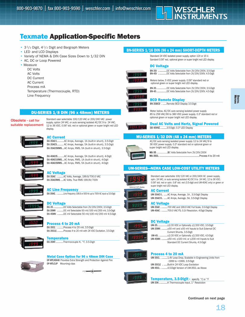
Standard user selectable 100/120 VAC or 200/240 VAC powersupply, option 24 VAC, or auto sensing isolated AC/DC 9 to 24 VAC,12 to 36 VDC. 0.56" std. red or optional green or super bright red LEDdisplay.
AC CurrentDU-35AC1….……..AC Amps, Average, 1A (built-in shunt), 3.5-DigitDU-35AC5……….. AC Amps, Average, 5A (built-in shunt), 3.5-DigitDU-35ACI5RMS….AC Amps, RMS, 5A (built-in shunt), 3.5-Digit
DU-40ACI5………..AC Amps, Average, 5A (built-in shunt), 4-DigitDU-40ACI1RMS….AC Amps, RMS, 1A (built-in shunt), 4-DigitDU-40ACI5RMS….AC Amps, RMS, 5A (built-in shunt), 4-Digit
AC VoltageDU-35AC . ......AC Volts, Average, 199.9/700.0 VACDU-35ACRMS. ....AC Volts, True RMS 199.9V/700V
AC Line FrequencyDU-35HZ . .......Line Frequency 199.9 or 500 Hz up to 700V AC input w/3.5-Digit
DC VoltageDU-35 ...........DC Volts Selectable from 2V/20V/200V, 3.5-DigitDU-35MV .......DC mV Selectable 50 mV/100 mV/200 mV, 3.5-DigitDU-45MV . ......DC mV Selectable 50 mV/100 mV/200 mV 4.5-Digit
Process 4 to 20 mADU-35CL . ......Process 4 to 20 mA, 3.5-DigitDU-35CLE. ......Process 4 to 20 mA with 24 VDC Excitation, 3.5-Digit
TemperatureDU-35KF……….…Thermocouple K, °F, 3.5-Digit
Metal Case Option for 96 x 48mm DIN CaseOP-MTL96X48 Provides Extra Strength and Protection Against FireOP-MTLCLIP Mounting clips
Standard user selectable 100/120 VAC or 200/240V AC power supply,optn. 24 VAC, or auto sensing isolated AC/DC 9 to 24 VAC, 12 to 36 VDC.0.56" std. red or optn. 0.8" std. red (3.5-digit and UM-40AC only) or green orsuper bright red LED display.
AC CurrentUM-35ACI1. ....AC Amps, Average, 1A , 3.5-Digit DisplayUM-35ACI5. ....AC Amps, Average, 5A, 3.5-Digit Display
AC VoltageUM-35AC . ......700 VAC and 199.9 VAC Full Scale, 3.5-Digit DisplayUM-40AC . ......700.0 VAC FS, 0.1V Resolution, 4-Digit Display
DC VoltageUM-35. ..........±2/20 VDC or Optionally ±2/200 VDC, 3.5-DigitUM-35MV . ......±50 mV and ±00 mV Inputs to Suit External DC
Current Shunts, 3.5-DigitUM-45. .........±2/20 VDC or Optionally ±2/200 VDC, 4.5-DigitUM-45MV . ......±50 mV, ±100 mV, or ±200 mV Inputs to Suit
Standard DC Current Shunts, 4.5-Digit
Process 4 to 20 mAUM-35CL . ......1.4V Loop Drop, Scalable in Engineering Units from
-1999 to +1999, 3.5-DigitUM-35CLE . ....Built-In 24 VDC Loop ExcitationUM-45CL . ......4.5-Digit Version of UM-35CL as Above
Temperature, 3.5-Digit - specify °C or °FUM-35K . ........K Thermocouple Input, 1° Resolution
Standard 24 VDC isolated power supply, option 12V or 15 V. Sandard 0.56" red, optional green or super bright red LED display.
DC VoltageBN-35I . ........DC Volts Selectable from 2V/20V/200V, 3.5-DigitBN-45I . ........DC Volts Selectable from 2V/20V/200V, 4.5-Digit
Meters below, 5 VDC power supply. 0.56" standard red or optional green or super bright red LED display.
BN-35 ...........DC Volts Selectable from 2V/20V/200V, 3.5-DigitBN-45 ...........DC Volts Selectable from 2V/20V/200V, 4.5-Digit
BCD Remote DisplayBN-35BCD . ....Remote BCD Display 3.5-Digit
Meter below, AC/DC auto sensing isolated power supply 85 to 256 VAC/90 to 380 VDC power supply. 0.3" standard red oroptional green or super bright red LED display.
Dual AC Volts and Hertz, Signal PoweredDD-40VHZ. ......3.5-Digit, 0.3" LED Display
AC/DC auto sensing isolated power supply 12 to 24 VAC/9 to 36 VDC power supply. 0.3" standard red or optional green orsuper bright red LED display.
MU-35 .MU-35CL. ..................................................................Process 4 to 20 mA
Texmate Application-Specific Meters
DU-SERIES 1/8 DIN (96 x 48mm) METERS
UM-SERIES—NEMA CASE LOW-COST UTILITY METERS
BN-SERIES 1/16 DIN (96 x 24 mm) SHORT-DEPTH METERS
MU-SERIES 1/32 DIN (48 x 24 mm) METERS
Optional 0.8" display
• 3 1/2 Digit, 4 1/2 Digit and Bargraph Meters• LED and LCD Displays• Variety of NEMA & DIN Case Sizes Down to 1/32 DIN• AC, DC or Loop Powered• Measure
DC VoltsAC VoltsDC CurrentAC CurrentProcess mATemperature (Thermocouple, RTD)Line Frequency
Continued on next page
................DC Volts Selectable from 2V/20V/200V
Obsolete - call forsuitable replacement
DIG
ITAL
MET
ERS
19
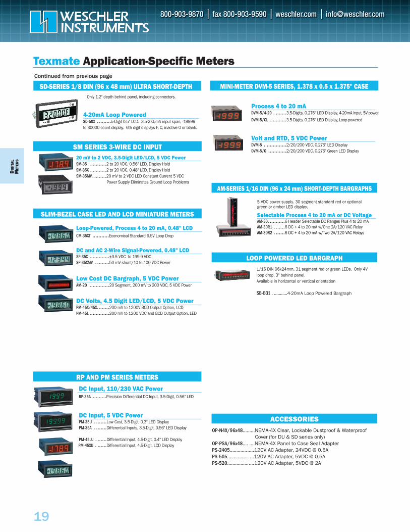
DC Input, 110/230 VAC PowerRP-35A ..........Precision Differential DC Input, 3.5-Digit, 0.56" LED
DC Input, 5 VDC PowerPM-35U . .......Low Cost, 3.5-Digit, 0.3" LED DisplayPM-35A . .......Differential Inputs, 3.5-Digit, 0.56" LED Display PM-45LU . ......Differential Input, 4.5-Digit, 0.4" LED DisplayPM-45XU . ......Differential Input, 4.5-Digit, LCD Display
Texmate Application-Specific Meters
MINI-METER DVM-5 SERIES, 1.378 x 0.5 x 1.375" CASE
RP AND PM SERIES METERS
SM SERIES 3-WIRE DC INPUT20 mV to 2 VDC, 3.5-Digit LED/LCD, 5 VDC PowerSM-35 ...........2 to 20 VDC, 0.56" LED, Display HoldSM-35X ...........2 to 20 VDC, 0.48" LCD, Display HoldSM-35MV. ........20 mV to 2 VDC LED Constant Current 5 VDC
Power Supply Eliminates Ground Loop Problems
SLIM-BEZEL CASE LED AND LCD MINIATURE METERS
Loop-Powered, Process 4 to 20 mA, 0.48" LCDCM-35XT ...........Economical Standard 6.5V Loop Drop
DC and AC 2-Wire Signal-Powered, 0.48" LCDSP-35X .............±3.5 VDC to 199.9 VDC SP-35XMV . ........50 mV shunt/10 to 100 VDC Power
Low Cost DC Bargraph, 5 VDC PowerAM-20 .............20 Segment, 200 mV to 200 VDC, 5 VDC Power
DC Volts, 4.5 Digit LED/LCD, 5 VDC PowerPM-45X/45X........200 mV to 1200V BCD Output Option, LCDPM-45L .............200 mV to 1200 VDC and BCD Output Option, LED
Process 4 to 20 mA DVM-5/4-20 . .......3.5-Digits, 0.276" LED Display, 4-20mA input, 5V power
DVM-5/CL ...........3.5-Digits, 0.276" LED Display, Loop powered
Volt and RTD, 5 VDC Power DVM-5 . .............2/20/200 VDC, 0.276" LED DisplayDVM-5/G ............2/20/200 VDC, 0.276" Green LED Display
LOOP POWERED LED BARGRAPH1/16 DIN 96x24mm, 31 segment red or green LEDs. Only 4V loop drop, 3" behind panel. Available in horizontal or vertical orientation
SB-B31 . ...........4-20mA Loop Powered Bargraph
5 VDC power supply. 30 segment standard red or optional green or amber LED display.
Selectable Process 4 to 20 mA or DC Voltage AM-30...........6 Header Selectable DC Ranges Plus 4 to 20 mAAM-30R1 . ......6 DC + 4 to 20 mA w/One 2A/120 VAC RelayAM-30R2 . ......6 DC + 4 to 20 mA w/Two 2A/120 VAC Relays
AM-SERIES 1/16 DIN (96 x 24 mm) SHORT-DEPTH BARGRAPHS
OP-N4X/96x48…......NEMA-4X Clear, Lockable Dustproof & Waterproof Cover (for DU & SD series only)
OP-PSA/96x48…. ....NEMA-4X Panel to Case Seal Adapter PS-2405…………......120V AC Adapter, 24VDC @ 0.5APS-505……………. ...120V AC Adapter, 5VDC @ 0.5APS-520…………….....120V AC Adapter, 5VDC @ 2A
ACCESSORIES
SD-SERIES 1/8 DIN (96 x 48 mm) ULTRA SHORT-DEPTHOnly 1.2" depth behind panel, including connectors.
4-20mA Loop PoweredSD-50X . ........5-Digit 0.5" LCD. 3.5-27.5mA input span, -19999 to 30000 count display. 6th digit displays F, C, inactive 0 or blank.
Continued from previous page
DIG
ITALM
ETERS
20
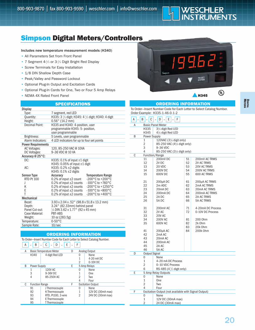
To Order—Insert Number Code for Each Letter to Select Catalog Number. Order Example: H335-1-46-0-1-2
A Basic Panel MeterH335 31/2 digit Red LEDH345 41/2 digit Red LED
B Power Supply1 120VAC (31/2 digit only)2 85-250 VAC (41/2 digit only)3 9–36 VDC4 85-250 VAC (31/2 digit only)
C Function/Range11 200mV DC 51 200mV AC TRMS12 2V DC 52 2V AC TRMS13 20 VDC 53 20V AC TRMS14 200V DC 54 200V AC TRMS15 600V DC 55 600 AC TRMS
21 200µA DC 61 200µA AC TRMS22 2m ADC 62 2mA AC TRMS23 20mA DC 63 20mA AC TRMS24 200mA DC 64 200mA AC TRMS25 2A DC 65 2A AC TRMS26 5A DC 66 5A AC TRMS
31 200mV AC 71 4-20mA DC Process32 2V AC 72 0-10V DC Process33 20V AC34 200V AC 81 200 Ohm35 600V AC 82 2k Ohm
83 20k Ohm41 200µA AC 84 200k Ohm42 2mA AC43 20mA AC44 200mA AC45 2A AC46 5A AC
D Output Signal0 None1 4–20 mA DC Process2 0–10 VDC Process6 RS-485 (4 1 /2 digit only)
E 5 Amp Relay Outputs0 None1 One2 Two4 Four
F Excitation Output (not available with Signal Output)0 None1 12V DC (30mA max)2 24 DC (30mA max)
SPECIFICATIONSDisplay
Type: 7 segment, red LEDQuantity: H335: 3 1/2 digit; H345: 4 1/2 digit; H340: 4 digitHeight: 0.56" (14.2 mm)Decimal Point: H335 and H340: 4-position, user
programmable H345: 5- position, user programmable
Brightness: 5 Levels, user programmableAlarm Indicators: 4 LED indicators for up to four set points
Power RequirementsAC Voltages: 120, 85-250 VAC @ 10VADC Voltages: 9–36 VDC @ 10 VA
Accuracy @ 25°C:DC: H335: 0.1% of input ±1 digit
H345: 0.05% of input ±1 digitAC: H335: 0.2% ±2 digits
H345: 0.1% ±2 digitsSensor Type Accuracy Temperature Range
RTD Pt 100 0.2% of input ±2 count -200°C to +200°CJ 0.2% of input ±2 counts -100°C to +760°CK 0.2% of input ±2 counts -200°C to +1250°CE 0.2% of input ±2 counts -100°C to +800°CT 0.2% of input ±2 counts -200°C to +400°C
MechanicalBezel: 3.93 x 2.04 x .52" (98.8 x 51.8 x 13.2 mm)Depth: 3.24" (82.33mm) behind panelPanel Cut-out: 1/8 DIN 3.62 x 1.77" (92 x 45 mm)Case Material: PBT-ABSWeight: 10 oz (283.5g)
Temperature: 0-50°CSample Rate: 10/sec
Simpson Digital Meters/Controllers
ORDERING INFORMATION
A – B – C – D – E – F
Includes new temperature measurement models (H340)
• All Parameters Set from Front Panel
• 7 Segment 4-1/2 or 3-1/2 Digit Bright Red Display
• Screw Terminals for Easy Installation
• 1/8 DIN Shallow Depth Case
• Peak/Valley and Password Lockout
• Optional Plug-In Output and Excitation Cards
• Optional Plug-In Cards for One, Two or Four 5 Amp Relays
• NEMA 4X Rated Front Panel
To Order—Insert Number Code for Each Letter to Select Catalog Number.
A Basic Temperature Meter D Analog OutputH340 4 digit Red LED 0 None
1 4-20 mA DC2 0-10V DC
B Power Supply E 5 Amp Relays1 120V AC 0 None3 9-36V DC 1 One4 85-250V AC 2 Two
4 FourC Function Range F Excitation Output
91 J Thermocouple 0 None92 K Thermocouple 1 12V DC (30mA max)93 RTD, Pt100, 3-wire 2 24V DC (30mA max)94 E Thermocouple95 T Thermocouple
ORDERING INFORMATION
A – B – C – D – E – F
H345
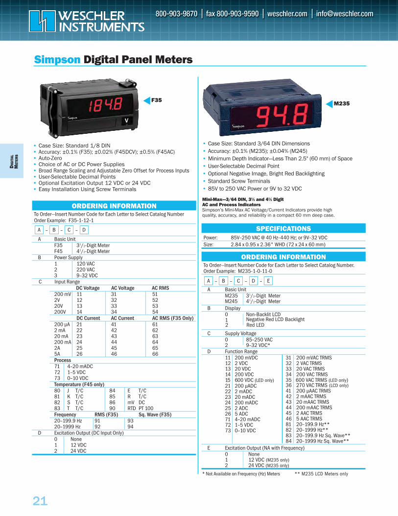
D IG
ITAL
M
ETER
S
21
To Order—Insert Number Code for Each Letter to Select Catalog Number Order Example: F35-1-12-1
A Basic Unit F35 31/2-Digit Meter F45 41/2-Digit Meter
B Power Supply1 120 VAC 2 220 VAC 3 9–32 VDC
DC Voltage AC Voltage AC RMS200 mV 11 31 512V 12 32 5220V 13 33 53200V 14 34 54
DC Current AC Current AC RMS (F35 Only)200 µA 21 41 612 mA 22 42 6220 mA 23 43 63200 mA 24 44 642A 25 45 655A 26 46 66Process 71 4–20 mADC 72 1–5 VDC 73 0–10 VDC Temperature (F45 only) 80 J T/C 84 E T/C81 K T/C 85 R T/C82 S T/C 86 mV DC83 T T/C 90 RTD PT 100Frequency RMS (F35) Sq. Wave (F35) 20–199.9 Hz 91 93 20–1999 Hz 92 94
D Excitation Output (DC Input Only)0 None1 12 VDC2 24 VDC
ORDERING INFORMATION
A – B – C – D
Simpson Digital Panel Meters
F35• Case Size: Standard 1/8 DIN• Accuracy: ±0.1% (F35); ±0.02% (F45DCV); ±0.5% (F45AC)• Auto-Zero• Choice of AC or DC Power Supplies• Broad Range Scaling and Adjustable Zero Offset for Process Inputs • User-Selectable Decimal Points• Optional Excitation Output 12 VDC or 24 VDC• Easy Installation Using Screw Terminals
To Order—Insert Number Code for Each Letter to Select Catalog Number. Order Example: M235-1-0-11-0
A Basic Unit M235 31/2-Digit Meter M245 41/2-Digit Meter
B Display0 Non-Backlit LCD1 Negative Red LCD Backlight
C Supply Voltage0 85–250 VAC 2 9–32 VDC*
D Function Range11 200 mVDC 31 200 mVAC TRMS 12 2 VDC 32 2 VAC TRMS 13 20 VDC 33 20 VAC TRMS 14 200 VDC 34 200 VAC TRMS
21 200 µADC 36 270 VAC TRMS (LCD only)22 2 mADC 41 200 µAAC TRMS23 20 mADC 42 2 mAAC TRMS 24 200 mADC 43 20 mAAC TRMS 25 2 ADC 44 200 mAAC TRMS 26 5 ADC 45 2 AAC TRMS 71 4–20 mADC 46 5 AAC TRMS72 1–5 VDC 81 20–199.9 Hz**73 0–10 VDC 82 20–1999 Hz**
15 600 VDC (LED only)
83 20–199.9 Hz Sq. Wave** 84 20–1999 Hz Sq. Wave**
E Excitation Output (NA with Frequency)0 None1 12 VDC (M235 only)2 24 VDC (M235 only)
• Case Size: Standard 3/64 DIN Dimensions• Accuracy: ±0.1% (M235); ±0.04% (M245)• Minimum Depth Indicator—Less Than 2.5" (60 mm) of Space• User-Selectable Decimal Point• Optional Negative Image, Bright Red Backlighting• Standard Screw Terminals• 85V to 250 VAC Power or 9V to 32 VDC
Mini-Max—3/64 DIN, 31⁄2 and 41⁄2 Digit AC and Process Indicators Simpson’s Mini-Max AC Voltage/Current Indicators provide high quality, accuracy, and reliability in a compact 60 mm deep case.
Power: 85V–250 VAC @ 40 Hz–440 Hz; or 9V–32 VDC Size: 2.84 x 0.95 x 2.36" WHD (72 x 24 x 60 mm)
SPECIFICATIONS
M235
ORDERING INFORMATION
A – B – C – D – E
* Not Available on Frequency (Hz) Meters ** M235 LCD Meters only
C Input Range
Red LED 2
35 600 VAC TRMS (LED only)
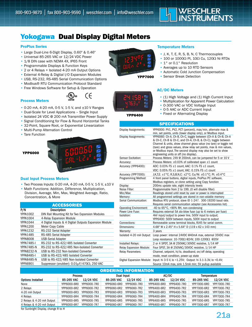
Yokogawa Dual Display Digital Meters
• (1) High Voltage and (1) High Current Input• Multiplication for Apparent Power Calculation• 0-300 VAC or VDC Voltage Input• 0-5 AAC or ADC Current Input• Fixed or Alternating Display
P DP//NN DeessccrriippttiioonnYPPA1002 DIN Rail Mounting Kit for Two Expansion ModulesYPPA1004 4-Relay Expansion Module YPPA1044 4 Digital Inputs & 4 Digital Outputs Expansion Module YPPA1200 Meter Copy CableYPPA1232 RS-232 Serial AdapterYPPA1485 RS-485 Serial AdapterYPPA8008 USB-Serial AdapterYPPA7485-I RS-232 to RS-422/485 Isolated ConverterYPPA7485-N RS-232 to RS-422/485 Non-Isolated ConverterYPPA8232-N USB to RS-232 Non-Isolated ConverterYPPA8485-I USB to RS-422/485 Isolated ConverterYPPA8485-N USB to RS-422/485 Non-Isolated ConverterYPPX6901 Suppressor (snubber): 0.01μF/470Ω, 250 VAC
YPP6000
ACCESSORIES
PPrroocceessss DDuuaall IInnppuutt AACC//DDCC TTeemmppeerraattuurreeOOppttiioonnss IInnssttaalllleedd 8855--226655 VVAACC 1122//2244 VVDDCC 8855--226655 VVAACC 1122//2244 VVDDCC 8855--226655 VVAACC 1122//2244 VVDDCC 8855--226655 VVAACC 1122//2244 VVDDCCNone YPP6000-6R0 YPP6000-7R0 YPP6060-6R0 YPP6060-7R0 YPP6400-6R0 YPP6400-7R0 YPP7000-6R0 YPP7000-7R02 Relays YPP6000-6R2 YPP6000-7R2 YPP6060-6R2 YPP6060-7R2 YPP6400-6R2 YPP6400-7R2 YPP7000-6R2 YPP7000-7R24-20 mA Output YPP6000-6R3 YPP6000-7R3 YPP6060-6R3 YPP6060-7R3 YPP6400-6R3 YPP6400-7R3 YPP7000-6R3 YPP7000-7R34 Relays YPP6000-6R4 YPP6000-7R4 YPP6060-6R4 YPP6060-7R4 YPP6400-6R4 YPP6400-7R4 YPP7000-6R4 YPP7000-7R42 Relays & 4-20 mA Output YPP6000-6R5 YPP6000-7R5 YPP6060-6R5 YPP6060-7R5 YPP6400-6R5 YPP6400-7R5 YPP7000-6R5 YPP7000-7R54 Relays & 4-20 mA Output YPP6000-6R7 YPP6000-7R7 YPP6060-6R7 YPP6060-7R7 YPP6400-6R7 YPP6400-7R7 YPP7000-6R7 YPP7000-7R7 for Sunbright Display, change R to H
Process Meters
Temperature Meters
Dual Input Process Meters
AC/DC Meters
ProPlus Series
SPECIFICATIONSDisplay Assignments: YPP6000: PV1, PV2, PCT (percent), max/min, alternate max &
min, set points, units (lower display only), or Modbus input.Display Assignments: YPP6060: Ch-A, Ch-B, Ch-C, toggle between (Ch-A & Ch-B, Ch-A
& Ch-C, Ch-B & Ch-C, and Ch-A, Ch-B, & Ch-C), toggle between Channel & units, show channel gross value (no tare) or toggle net(tare) and gross values, show relay set points, max & min values,or Modbus input. The second display may also be set to showengineering units or off (no display).
Sensor Excitation: Process Meters: 24V @ 200mA, can be jumpered for 5 or 10 VAccuracy: Process Meters: ±0.03% of calibrated span ±1 countAccuracy (YPP6400): ADC: 0.03% FS ±1 count, AAC: 0.1% FS ±1 count,
VDC: 0.05% FS ±1 count, VAC: 0.15% FS ±1 countAccuracy (YPP7000): J,K,T,E: ±1°C; R,S,B,N,C: ±2°C; Cu/Ni: ±0.1°C; Pt: ±0.4°C Programming Method: 4 front panel buttons, digital inputs, ProPlus PC software,
Modbus registers, or clone setting using Copy functionDisplay: 200ms update rate, eight intensity levelsNoise Filter: Programmable from 2 to 199, (0 will disable filter)Min/Max: Readings stored until reset by user or power is interruptedMemory: All programmed settings are stored in non-volatile memorySerial Communication: Modbus RTU protocol, slave ID 1-247. 300-19200 baud rate.
Requires serial communication adapter (see Accessories list)Operating Environment: -40 to 65°C, <90% RH, non-condensingPower Line Fuse: Requires external 5A slo-blow fuse (up to 6 meters per fuse)Isolation: 4kV input/output to power line, 500V input to output;
YPP6400: 500V between inputs, 500V input to outputConnections: Removeable screw terminal blocks, RJ45 for serial comm.Dimensions: 4.68" W x 2.45" H x 5.64" D (119 x 62 x 143 mm) Warranty: 3 yearsIsolated 4-20 mA Output: Loop power: internal 24VDC @40mA max, external 35VDC max
Loop resistance: 10-700Ω @24V, 100-1200Ω @35VInstalled Relays: 2 or 4 SPDT, 3A @ 250VAC/30VDC resistive, 1/14 HPRelay Expansion Module: Four SPST, 3A @ 250VAC/30VDC resistive, 1/14 HPRelay Parameters: Channel, setpoint, hi/lo, deadband, on/off delay, operating
mode, reset condition, power-up state Digital Expansion Module: Input: hi 3-5 V, lo <1.25V; Output: hi 3.1-3.3V, lo <0.4V;
Source 10mA max, sink 1.5mA min; 5V pullup available
ORDERING INFORMATION
• Large Dual-Line 6-Digit Display, 0.60" & 0.46"• Universal 85-265 VAC or 12/24 VDC Power• 1/8 DIN case with NEMA 4X, IP65 Front • Programmable Displays & Function Keys• 2 or 4 Relays + Isolated 4-20 mA Output Options• External 4-Relay & Digital I/O Expansion Modules• USB, RS-232, RS-485 Serial Communication Options• Modbus® RTU Communication Protocol Standard• Free Windows Software for Setup & Operation
• J, K, T, E, R, S, B, N, C Thermocouples• 100 or 1000Ω Pt, 10Ω Cu, 120Ω Ni RTDs• 1° or 0.1° Resolution• Averages up to 10 RTD Sensors• Automatic Cold Junction Compensation• Sensor Break DetectionYPP7000
• 0-20 mA, 4-20 mA, 0-5 V, 1-5 V, and ±10 V Ranges• Dual-Scale for Level Applications – Single Input• Isolated 24 VDC @ 200 mA Transmitter Power Supply• Signal Conditioning for Flow & Round Horizontal Tanks• 32-Point, Square Root, or Exponential Linearization• Multi-Pump Alternation Control• Tare Function
• Two Process Inputs: 0-20 mA, 4-20 mA, 0-5 V, 1-5 V, ±10 V• Math Functions: Addition, Difference, Multiplication,
Division, Average, Min, Max, Weighted Average, Ratio, Concentration, & More
YPP6400
222111aaa
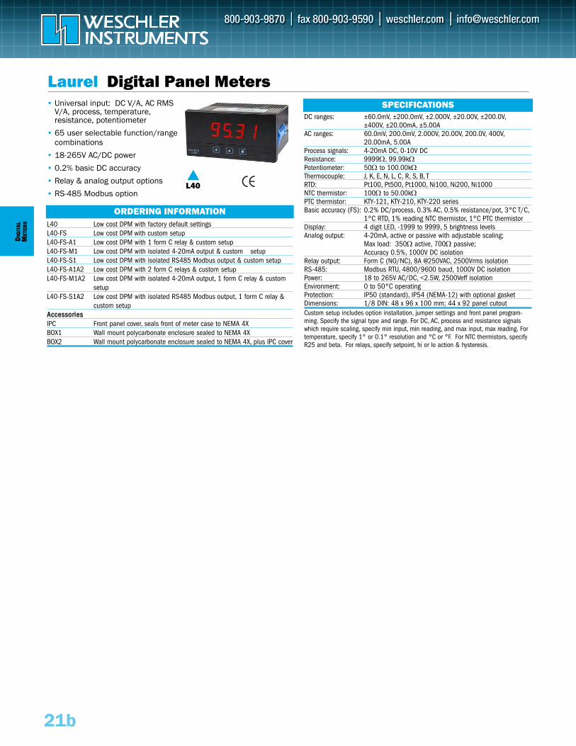
L40
L40 Low cost DPM with factory default settings L40-FS Low cost DPM with custom setup L40-FS-A1 Low cost DPM with 1 form C relay & custom setupL40-FS-M1 Low cost DPM with isolated 4-20mA output & custom setup L40-FS-S1 Low cost DPM with isolated RS485 Modbus output & custom setup L40-FS-A1A2 Low cost DPM with 2 form C relays & custom setup L40-FS-M1A2 Low cost DPM with isolated 4-20mA output, 1 form C relay & custom
setup L40-FS-S1A2 Low cost DPM with isolated RS485 Modbus output, 1 form C relay &
custom setup AAcccceessssoorriieessIPC Front panel cover, seals front of meter case to NEMA 4XBOX1 Wall mount polycarbonate enclosure sealed to NEMA 4XBOX2 Wall mount polycarbonate enclosure sealed to NEMA 4X, plus IPC cover
DIG
ITAL
MET
ERS
21b
Laurel Digital Panel Meters• Universal input: DC V/A, AC RMS
V/A, process, temperature, resistance, potentiometer
• 65 user selectable function/rangecombinations
• 18-265V AC/DC power
• 0.2% basic DC accuracy
• Relay & analog output options
• RS-485 Modbus option
DC ranges: ±60.0mV, ±200.0mV, ±2.000V, ±20.00V, ±200.0V,±400V, ±20.00mA, ±5.00A
AC ranges: 60.0mV, 200.0mV, 2.000V, 20.00V, 200.0V, 400V,20.00mA, 5.00A
Process signals: 4-20mA DC, 0-10V DCResistance: 9999Ω, 99.99kΩPotentiometer: 50Ω to 100.00kΩThermocouple: J, K, E, N, L, C, R, S, B, TRTD: Pt100, Pt500, Pt1000, Ni100, Ni200, Ni1000NTC thermistor: 100Ω to 50.00kΩPTC thermistor: KTY-121, KTY-210, KTY-220 seriesBasic accuracy (FS): 0.2% DC/process, 0.3% AC, 0.5% resistance/pot, 3°C T/C,
1°C RTD, 1% reading NTC thermistor, 1°C PTC thermistorDisplay: 4 digit LED, -1999 to 9999, 5 brightness levelsAnalog output: 4-20mA, active or passive with adjustable scaling;
Max load: 350Ω active, 700Ω passive; Accuracy 0.5%, 1000V DC isolation
Relay output: Form C (NO/NC), 8A @250VAC, 2500Vrms isolationRS-485: Modbus RTU, 4800/9600 baud, 1000V DC isolationPower: 18 to 265V AC/DC, <2.5W, 2500Veff isolationEnvironment: 0 to 50°C operatingProtection: IP50 (standard), IP54 (NEMA-12) with optional gasket Dimensions: 1/8 DIN: 48 x 96 x 100 mm; 44 x 92 panel cutoutCustom setup includes option installation, jumper settings and front panel program-ming. Specify the signal type and range. For DC, AC, process and resistance signalswhich require scaling, specify min input, min reading, and max input, max reading. Fortemperature, specify 1° or 0.1° resolution and °C or °F. For NTC thermistors, specifyR25 and beta. For relays, specify setpoint, hi or lo action & hysteresis.
SPECIFICATIONS
ORDERING INFORMATION
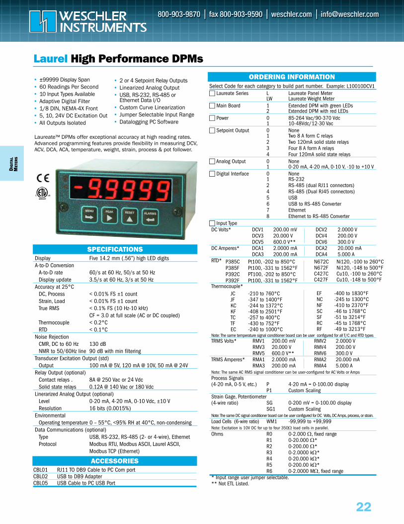
DIG
ITAL
MET
ERS
Select Code for each category to build part number. Example: L10010DCV1 Laureate Series L Laureate Panel Meter
LW Laureate Weight Meter Main Board 1 Extended DPM with green LEDs
2 Extended DPM with red LEDs Power 0 85-264 Vac/90-370 Vdc
1 10-48Vdc/12-30 Vac Setpoint Output 0 None
1 Two 8 A form C relays2 Two 120mA solid state relays3 Four 8 A form A relays4 Four 120mA solid state relays
Analog Output 0 None1 0-20 mA, 4-20 mA, 0-10 V, -10 to +10 V
Digital Interface 0 None1 RS-2322 RS-485 (dual RJ11 connectors)4 RS-485 (Dual RJ45 connectors)5 USB6 USB to RS-485 Converter7 Ethernet8 Ethernet to RS-485 Converter
Input TypeDC Volts* DCV1 200.00 mV DCV2 2.0000 V
DCV3 20.000 V DCV4 200.00 VDCV5 600.0 V** DCV6 300.0 V
DC Amperes* DCA1 2.0000 mA DCA2 20.000 mADCA3 200.00 mA DCA4 5.000 A
RTD*
Thermocouple*
Note: The same temperature signal conditioner board can be user configured for all T/C and RTD typesTRMS Volts* RMV1 200.00 mV RMV2 2.0000 V
RMV3 20.000 V RMV4 200.00 VRMV5 600.0 V** RMV6 300.0 V
TRMS Amperes* RMA1 2.0000 mA RMA2 20.000 mARMA3 200.00 mA RMA4 5.000 A
Note: The same AC RMS signal conditioner can be user-configured for AC Volts or AmpsProcess Signals (4-20 mA, 0-5 V, etc.) P 4-20 mA = 0-100.00 display
P1 Custom ScalingStrain Gage, Potentiometer(4-wire ratio) SG 0-200 mV = 0-100.00 display
SG1 Custom ScalingNote: The same DC signal conditioner board can be user configured for DC Volts,DC Amps,process, or strain.Load Cells (6-wire ratio) WM1 -99,999 to +99,999Note: Excitation is 10V DC for up to four 350Ω load cells in parallel.Ohms R0 0-2.000 Ω, fixed range
R1 0-20.000 Ω*R2 0-200.00 Ω*R3 0-2.0000 kΩ*R4 0-20.000 kΩ*R5 0-200.00 kΩ*R6 0-2.0000 MΩ, fixed range
* Input range user jumper selectable.** Not ETL Listed.
22
Laureate™ DPMs offer exceptional accuracy at high reading rates. Advanced programming features provide flexibility in measuring DCV,ACV, DCA, ACA, temperature, weight, strain, process & pot follower.
Laurel High Performance DPMs
• ±99999 Display Span• 60 Readings Per Second• 10 Input Types Available• Adaptive Digital Filter• 1/8 DIN, NEMA-4X Front• 5, 10, 24V DC Excitation Out• All Outputs Isolated
Display Five 14.2 mm (.56”) high LED digitsA-to-D Conversion
A-to-D rate 60/s at 60 Hz, 50/s at 50 HzDisplay update 3.5/s at 60 Hz, 3/s at 50 Hz
Accuracy at 25°CDC, Process < 0.01% FS ±1 countStrain, Load < 0.01% FS ±1 countTrue RMS < 0.1% FS (10 Hz-10 kHz)
CF = 3.0 at full scale (AC or DC coupled)Thermocouple < 0.2°CRTD < 0.1°C
Noise RejectionCMR, DC to 60 Hz 130 dBNMR to 50/60Hz line 90 dB with min filtering
Transducer Excitation Output (std)Output 100 mA @ 5V, 120 mA @ 10V, 50 mA @ 24V
Relay Output (optional)Contact relays . 8A @ 250 Vac or 24 Vdc Solid state relays 0.12A @ 140 Vac or 180 Vdc
Linerarized Analog Output (optional)Level 0-20 mA, 4-20 mA, 0-10 Vdc, ±10 VResolution 16 bits (0.0015%)
EnvironmentalOperating temperature 0 – 55°C, <95% RH at 40°C, non-condensing
Data Communications (optional)Type USB, RS-232, RS-485 (2- or 4-wire), EthernetProtocol Modbus RTU, Modbus ASCII, Laurel ASCII,
Modbus TCP (Ethernet) (Ethernet),
SPECIFICATIONS
ORDERING INFORMATION
JC -210 to 760°CJF -347 to 1400°FKC -244 to 1372°CKF -408 to 2501°FTC -257 to 400°CTF -430 to 752°FEC -240 to 1000°C
EF -400 to 1830°FNC -245 to 1300°CNF -410 to 2370°FSC -46 to 1768°CSF -51 to 3214°FRC -45 to 1768°CRF -49 to 3213°F
P385C Pt100, -202 to 850°CP385F Pt100, -331 to 1562°FP392C PT100, -202 to 850°CP392F Pt100, -331 to 1562°F
N672C Ni120, -100 to 260°CN672F Ni120, -148 to 500°FC427C Cu10, -100 to 260°CC427F Cu10, -148 to 500°F
ACCESSORIESCBL01 RJ11 TO DB9 Cable to PC Com portCBL02 USB to DB9 AdapterCBL05 USB Cable to PC USB Port
• 2 or 4 Setpoint Relay Outputs• Linearized Analog Output• USB, RS-232, RS-485 or
Ethernet Data I/O• Custom Curve Linearization• Jumper Selectable Input Range• Datalogging PC Software
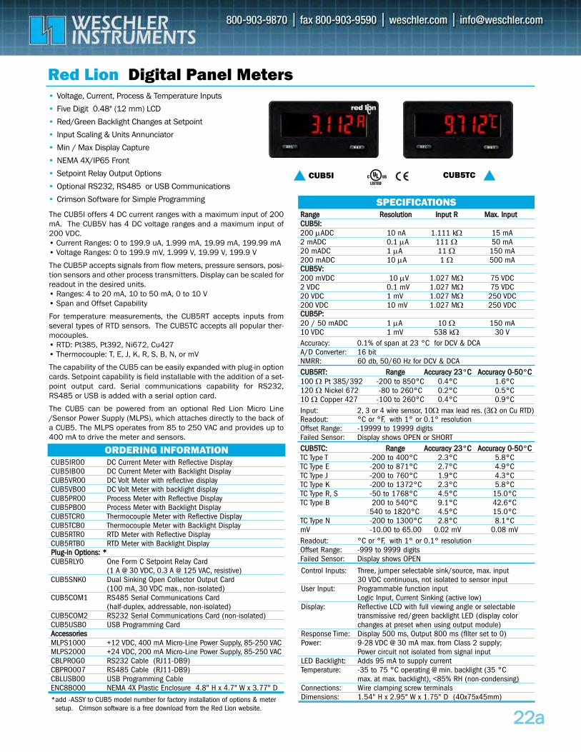
2222aa
CUB5IR00 DC Current Meter with Reflective Display CUB5IB00 DC Current Meter with Backlight Display CUB5VR00 DC Volt Meter with reflective display CUB5VB00 DC Volt Meter with backlight display CUB5PR00 Process Meter with Reflective Display CUB5PB00 Process Meter with Backlight Display CUB5TCR0 Thermocouple Meter with Reflective Display CUB5TCB0 Thermocouple Meter with Backlight Display CUB5RTR0 RTD Meter with Reflective Display CUB5RTB0 RTD Meter with Backlight Display PPlluugg--iinn OOppttiioonnss:: **CUB5RLY0 One Form C Setpoint Relay Card
(1 A @ 30 VDC, 0.3 A @ 125 VAC, resistive) CUB5SNK0 Dual Sinking Open Collector Output Card
(100 mA, 30 VDC max., non-isolated) CUB5COM1 RS485 Serial Communications Card
(half-duplex, addressable, non-isolated)CUB5COM2 RS232 Serial Communications Card (non-isolated)CUB5USB0 USB Programming Card AAcccceessssoorriieessMLPS1000 +12 VDC, 400 mA Micro-Line Power Supply, 85-250 VACMLPS2000 +24 VDC, 200 mA Micro-Line Power Supply, 85-250 VACCBLPROG0 RS232 Cable (RJ11-DB9) CBPRO007 RS485 Cable (RJ11-DB9) CBLUSB00 USB Programming Cable ENC8B000 NEMA 4X Plastic Enclosure 4.8" H x 4.7" W x 3.77" D
Red Lion Digital Panel Meters• Voltage, Current, Process & Temperature Inputs
• Five Digit 0.48" (12 mm) LCD
• Red/Green Backlight Changes at Setpoint
• Input Scaling & Units Annunciator
• Min / Max Display Capture
• NEMA 4X/IP65 Front
• Setpoint Relay Output Options
• Optional RS232, RS485 or USB Communications
• Crimson Software for Simple Programming
ORDERING INFORMATION
RRaannggee RReessoolluuttiioonn IInnppuutt RR MMaaxx.. IInnppuuttCCUUBB55II::200 μADC 10 nA 1.111 kΩ 15 mA 2 mADC 0.1 μA 111 Ω 50 mA 20 mADC 1 μA 11 Ω 150 mA 200 mADC 10 μA 1 Ω 500 mA CCUUBB55VV::200 mVDC 10 μV 1.027 MΩ 75 VDC 2 VDC 0.1 mV 1.027 MΩ 75 VDC 20 VDC 1 mV 1.027 MΩ 250 VDC200 VDC 10 mV 1.027 MΩ 250 VDC CCUUBB55PP::20 / 50 mADC 1 μA 10 Ω 150 mA 10 VDC 1 mV 538 kΩ 30 VAccuracy: 0.1% of span at 23 °C for DCV & DCAA/D Converter: 16 bitNMRR: 60 db, 50/60 Hz for DCV & DCA CCUUBB55RRTT:: RRaannggee AAccccuurraaccyy 2233°CC AAccccuurraaccyy 00--5500°CC100 Ω Pt 385/392 -200 to 850°C 0.4°C 1.6°C120 Ω Nickel 672 -80 to 260°C 0.2°C 0.5°C 10 Ω Copper 427 -100 to 260°C 0.4°C 0.9°CInput: 2, 3 or 4 wire sensor, 10Ω max lead res. (3Ω on Cu RTD)Readout: °C or °F, with 1° or 0.1° resolutionOffset Range: -19999 to 19999 digitsFailed Sensor: Display shows OPEN or SHORT CCUUBB55TTCC:: RRaannggee AAccccuurraaccyy 2233°CC AAccccuurraaccyy 00--5500°CCTC Type T -200 to 400°C 2.3°C 5.8°CTC Type E -200 to 871°C 2.7°C 4.9°CTC Type J -200 to 760°C 1.9°C 4.3°CTC Type K -200 to 1372°C 2.3°C 5.8°CTC Type R, S -50 to 1768°C 4.5°C 15.0°CTC Type B 200 to 540°C 9.1°C 42.6°C
540 to 1820°C 4.5°C 15.0°CTC Type N -200 to 1300°C 2.8°C 8.1°CmV -10.00 to 65.00 0.02 mV 0.08 mVReadout: °C or °F, with 1° or 0.1° resolutionOffset Range: -999 to 9999 digitsFailed Sensor: Display shows OPEN
SPECIFICATIONS
Control Inputs: Three, jumper selectable sink/source, max. input30 VDC continuous, not isolated to sensor input
User Input: Programmable function inputLogic Input, Current Sinking (active low)
Display: Reflective LCD with full viewing angle or selectable transmissive red/green backlight LED (display color changes at preset when using output module)
Response Time: Display 500 ms, Output 800 ms (fIlter set to 0)Power: 9-28 VDC @ 30 mA max. from Class 2 supply;
Power circuit not isolated from signal inputLED Backlight: Adds 95 mA to supply currentTemperature: -35 to 75 °C operating @ min. backlight (35 °C
max. at max. backlight), <85% RH (non-condensing)Connections: Wire clamping screw terminalsDimensions: 1.54" H x 2.95" W x 1.75" D (40x75x45mm)
CUB5I CUB5TC
*add -ASSY to CUB5 model number for factory installation of options & meter setup. Crimson software is a free download from the Red Lion website.
The CUB5I offers 4 DC current ranges with a maximum input of 200mA. The CUB5V has 4 DC voltage ranges and a maximum input of200 VDC. • Current Ranges: 0 to 199.9 uA, 1.999 mA, 19.99 mA, 199.99 mA • Voltage Ranges: 0 to 199.9 mV, 1.999 V, 19.99 V, 199.9 V
The CUB5P accepts signals from flow meters, pressure sensors, posi-tion sensors and other process transmitters. Display can be scaled forreadout in the desired units.• Ranges: 4 to 20 mA, 10 to 50 mA, 0 to 10 V• Span and Offset Capability
For temperature measurements, the CUB5RT accepts inputs fromseveral types of RTD sensors. The CUB5TC accepts all popular ther-mocouples.• RTD: Pt385, Pt392, Ni672, Cu427• Thermocouple: T, E, J, K, R, S, B, N, or mV
The capability of the CUB5 can be easily expanded with plug-in optioncards. Setpoint capability is field installable with the addition of a set-point output card. Serial communications capability for RS232,RS485 or USB is added with a serial option card.
The CUB5 can be powered from an optional Red Lion Micro Line/Sensor Power Supply (MLPS), which attaches directly to the back ofa CUB5. The MLPS operates from 85 to 250 VAC and provides up to400 mA to drive the meter and sensors.
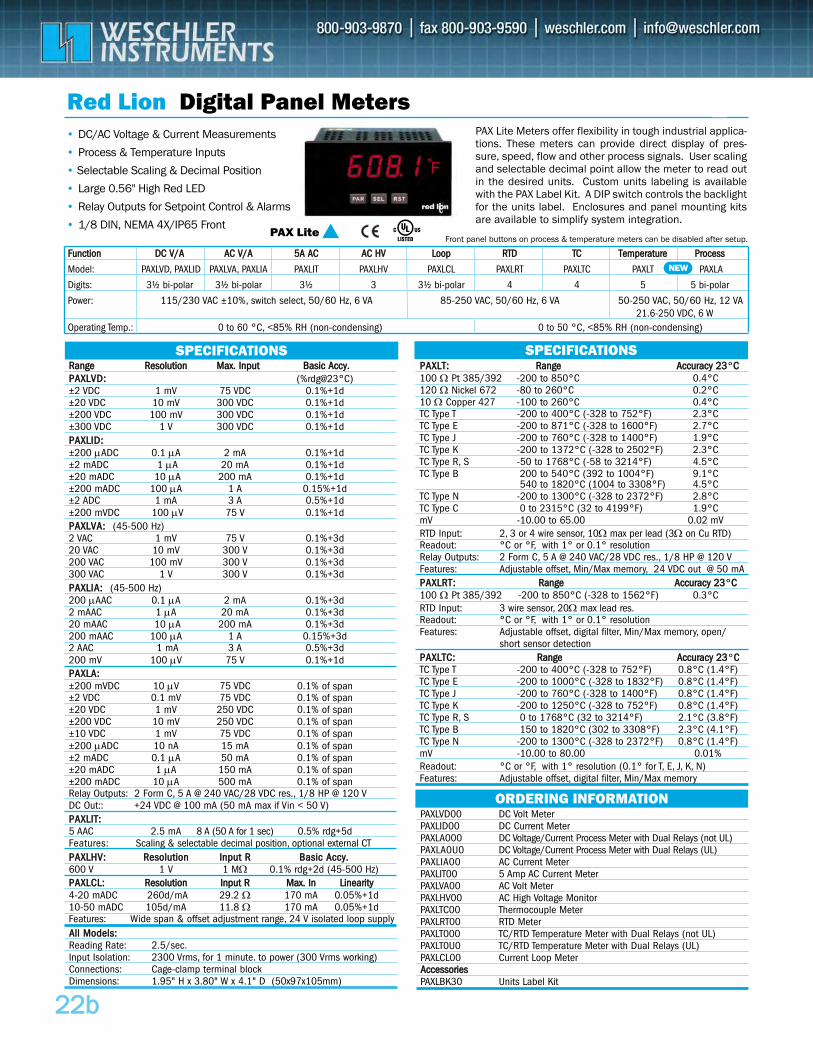
RRaannggee RReessoolluuttiioonn MMaaxx.. IInnppuutt BBaassiicc AAccccyy..PPAAXXLLVVDD:: (%rdg@23°C)±2 VDC 1 mV 75 VDC 0.1%+1d±20 VDC 10 mV 300 VDC 0.1%+1d±200 VDC 100 mV 300 VDC 0.1%+1d±300 VDC 1 V 300 VDC 0.1%+1dPPAAXXLLIIDD::±200 μADC 0.1 μA 2 mA 0.1%+1d±2 mADC 1 μA 20 mA 0.1%+1d±20 mADC 10 μA 200 mA 0.1%+1d±200 mADC 100 μA 1 A 0.15%+1d±2 ADC 1 mA 3 A 0.5%+1d±200 mVDC 100 μV 75 V 0.1%+1dPPAAXXLLVVAA:: (45-500 Hz)2 VAC 1 mV 75 V 0.1%+3d 20 VAC 10 mV 300 V 0.1%+3d200 VAC 100 mV 300 V 0.1%+3d300 VAC 1 V 300 V 0.1%+3dPPAAXXLLIIAA:: (45-500 Hz)200 μAAC 0.1 μA 2 mA 0.1%+3d2 mAAC 1 μA 20 mA 0.1%+3d20 mAAC 10 μA 200 mA 0.1%+3d200 mAAC 100 μA 1 A 0.15%+3d2 AAC 1 mA 3 A 0.5%+3d200 mV 100 μV 75 V 0.1%+1dPPAAXXLLAA::±200 mVDC 10 μV 75 VDC 0.1% of span±2 VDC 0.1 mV 75 VDC 0.1% of span±20 VDC 1 mV 250 VDC 0.1% of span±200 VDC 10 mV 250 VDC 0.1% of span±10 VDC 1 mV 75 VDC 0.1% of span±200 μADC 10 nA 15 mA 0.1% of span±2 mADC 0.1 μA 50 mA 0.1% of span±20 mADC 1 μA 150 mA 0.1% of span±200 mADC 10 μA 500 mA 0.1% of spanRelay Outputs: 2 Form C, 5 A @ 240 VAC/28 VDC res., 1/8 HP @ 120 VDC Out:: +24 VDC @ 100 mA (50 mA max if Vin < 50 V)PPAAXXLLIITT::5 AAC 2.5 mA 8 A (50 A for 1 sec) 0.5% rdg+5dFeatures: Scaling & selectable decimal position, optional external CTPPAAXXLLHHVV:: RReessoolluuttiioonn IInnppuutt RR BBaassiicc AAccccyy..600 V 1 V 1 MΩ 0.1% rdg+2d (45-500 Hz)PPAAXXLLCCLL:: RReessoolluuttiioonn IInnppuutt RR MMaaxx.. IInn LLiinneeaarriittyy4-20 mADC 260d/mA 29.2 Ω 170 mA 0.05%+1d10-50 mADC 105d/mA 11.8 Ω 170 mA 0.05%+1dFeatures: Wide span & offset adjustment range, 24 V isolated loop supply
FFuunnccttiioonn DDCC VV//AA AACC VV//AA 55AA AACC AACC HHVV LLoooopp RRTTDD TTCC TTeemmppeerraattuurree PPrroocceessss
Model: PAXLVD, PAXLID PAXLVA, PAXLIA PAXLIT PAXLHV PAXLCL PAXLRT PAXLTC PAXLT PAXLA
Digits: 3½ bi-polar 3½ bi-polar 3½ 3 3½ bi-polar 4 4 5 5 bi-polar
Power: 115/230 VAC ±10%, switch select, 50/60 Hz, 6 VA 85-250 VAC, 50/60 Hz, 6 VA 50-250 VAC, 50/60 Hz, 12 VA21.6-250 VDC, 6 W
Operating Temp.: 0 to 60 °C, <85% RH (non-condensing) 0 to 50 °C, <85% RH (non-condensing)
2222bb
PAXLVD00 DC Volt MeterPAXLID00 DC Current MeterPAXLA000 DC Voltage/Current Process Meter with Dual Relays (not UL)PAXLA0U0 DC Voltage/Current Process Meter with Dual Relays (UL)PAXLIA00 AC Current Meter PAXLIT00 5 Amp AC Current Meter PAXLVA00 AC Volt Meter PAXLHV00 AC High Voltage Monitor PAXLTC00 Thermocouple Meter PAXLRT00 RTD Meter PAXLT000 TC/RTD Temperature Meter with Dual Relays (not UL)PAXLT0U0 TC/RTD Temperature Meter with Dual Relays (UL)PAXLCL00 Current Loop MeterAAcccceessssoorriieessPAXLBK30 Units Label Kit
Red Lion Digital Panel Meters• DC/AC Voltage & Current Measurements
• Process & Temperature Inputs
• Selectable Scaling & Decimal Position
• Large 0.56" High Red LED
• Relay Outputs for Setpoint Control & Alarms
• 1/8 DIN, NEMA 4X/IP65 Front
ORDERING INFORMATION
AAllll MMooddeellss::Reading Rate: 2.5/sec.Input Isolation: 2300 Vrms, for 1 minute. to power (300 Vrms working) Connections: Cage-clamp terminal blockDimensions: 1.95" H x 3.80" W x 4.1" D (50x97x105mm)
PAX Lite
PAX Lite Meters offer flexibility in tough industrial applica-tions. These meters can provide direct display of pres-sure, speed, flow and other process signals. User scalingand selectable decimal point allow the meter to read outin the desired units. Custom units labeling is availablewith the PAX Label Kit. A DIP switch controls the backlightfor the units label. Enclosures and panel mounting kitsare available to simplify system integration.
SPECIFICATIONS SPECIFICATIONSPPAAXXLLTT:: RRaannggee AAccccuurraaccyy 2233°CC 100 Ω Pt 385/392 -200 to 850°C 0.4°C 120 Ω Nickel 672 -80 to 260°C 0.2°C10 Ω Copper 427 -100 to 260°C 0.4°C TC Type T -200 to 400°C (-328 to 752°F) 2.3°C TC Type E -200 to 871°C (-328 to 1600°F) 2.7°C TC Type J -200 to 760°C (-328 to 1400°F) 1.9°C TC Type K -200 to 1372°C (-328 to 2502°F) 2.3°C TC Type R, S -50 to 1768°C (-58 to 3214°F) 4.5°C TC Type B 200 to 540°C (392 to 1004°F) 9.1°C
540 to 1820°C (1004 to 3308°F) 4.5°C TC Type N -200 to 1300°C (-328 to 2372°F) 2.8°C TC Type C 0 to 2315°C (32 to 4199°F) 1.9°CmV -10.00 to 65.00 0.02 mVRTD Input: 2, 3 or 4 wire sensor, 10Ω max per lead (3Ω on Cu RTD)Readout: °C or °F, with 1° or 0.1° resolutionRelay Outputs: 2 Form C, 5 A @ 240 VAC/28 VDC res., 1/8 HP @ 120 VFeatures: Adjustable offset, Min/Max memory, 24 VDC out @ 50 mA PPAAXXLLRRTT:: RRaannggee AAccccuurraaccyy 2233°CC 100 Ω Pt 385/392 -200 to 850°C (-328 to 1562°F) 0.3°C RTD Input: 3 wire sensor, 20Ω max lead res.Readout: °C or °F, with 1° or 0.1° resolutionFeatures: Adjustable offset, digital filter, Min/Max memory, open/
short sensor detectionPPAAXXLLTTCC:: RRaannggee AAccccuurraaccyy 2233°CC TC Type T -200 to 400°C (-328 to 752°F) 0.8°C (1.4°F)TC Type E -200 to 1000°C (-328 to 1832°F) 0.8°C (1.4°F)TC Type J -200 to 760°C (-328 to 1400°F) 0.8°C (1.4°F)TC Type K -200 to 1250°C (-328 to 752°F) 0.8°C (1.4°F)TC Type R, S 0 to 1768°C (32 to 3214°F) 2.1°C (3.8°F)TC Type B 150 to 1820°C (302 to 3308°F) 2.3°C (4.1°F)TC Type N -200 to 1300°C (-328 to 2372°F) 0.8°C (1.4°F)mV -10.00 to 80.00 0.01%Readout: °C or °F, with 1° resolution (0.1° for T, E, J, K, N)Features: Adjustable offset, digital filter, Min/Max memory
NEW
Front panel buttons on process & temperature meters can be disabled after setup.
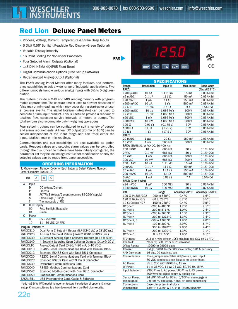
To Order—Insert Number Code for Each Letter to Select Catalog Number.Order Example: PAXD0100
A InputD DC Voltage/Current P ProcessH AC TRMS Voltage/Current (requires 85-250V supply)S Strain Gage / BridgeT Thermocouple / RTD
B LED Display00 Red, Sunlight Readable01 Green
C Power00 85 - 250 VAC10 11 - 36 VDC, 24 VAC
PPlluugg--IInn OOppttiioonnss:: **PAXCDS10 Dual Form C Setpoint Relays (5 A @ 240 VAC or 28 VDC res.) PAXCDS20 4 Form A Setpoint Relays (3 A @ 250 VAC or 30 VDC res.)PAXCDS30 4 Setpoint Sinking Open Collector Outputs (0.1 A @ 50 V) PAXCDS40 4 Setpoint Sourcing Open Collector Outputs (0.1 A @ 30 V)PAXCDL10 Analog Output Card (0-20/4-20 mA, 0-10 VDC) PAXCDC10 RS485 Serial Communications Card with Terminal Block PAXCDC1C Extended RS485 Card with Dual RJ11 Connector PAXCDC20 RS232 Serial Communications Card with Terminal Block PAXCDC2C Extended RS232 Card with 9 Pin D Connector PAXCDC30 DeviceNet Communications Card PAXCDC40 RS485 Modbus Communications Card PAXCDC4C Extended Modbus Card with Dual RJ11 Connector PAXCDC50 Profibus-DP Communications Card SFCRUSB1 USB Programming Card, Cable & Software
ORDERING INFORMATION
BA CPAX
2222cc
Red Lion Deluxe Panel Meters• Process, Voltage, Current, Temperature & Strain Gage Inputs
• 5 Digit 0.56" Sunlight Readable Red Display (Green Optional)
• Variable Display Intensity
• 16 Point Scaling for Non-linear Processes
• Four Setpoint Alarm Outputs (Optional)
• 1/8 DIN, NEMA 4X/IP65 Front Bezel
• Digital Communication Options (Free Setup Software)
• Retransmitted Analog Output (Optional)
PAX
SPECIFICATIONSRRaannggee RReessoolluuttiioonn IInnppuutt RR MMaaxx.. IInnppuutt BBaassiicc AAccccyy..PPAAXXDD:: (%rdg@23°C)±200 μADC 10 nA 1.111 kΩ 15 mA 0.03%+3d±2 mADC 0.1 μA 111 Ω 50 mA 0.03%+3d±20 mADC 1 μA 11 Ω 150 mA 0.03%+3d±200 mADC 10 μA 1 Ω 500 mA 0.05%+3d±2 ADC 0.1 mA 0.1 Ω 3 A 0.5%+3d±200 mVDC 10 μV 1.066 MΩ 100 V 0.03%+3d±2 VDC 0.1 mV 1.066 MΩ 300 V 0.03%+3d±20 VDC 1 mV 1.066 MΩ 300 V 0.03%+3d±300 VDC 10 mV 1.066 MΩ 300 V 0.05%+3d100 Ω 0.01 Ω (0.175 V) 30V 0.05%+3d1000 Ω 0.1 Ω (1.75 V) 30V 0.05%+3d10 kΩ 1 Ω (17.5 V) 30V 0.05%+3dPPAAXXPP::20 mADC 1 μA 20 Ω 150 mA 0.03%+2d10 VDC 1 mV 500 kΩ 300 V 0.03%+2dPPAAXXHH:: (TRMS AC or AC+DC, 50-400 Hz)200 mVAC 10 μV 686 kΩ 30 V 0.1%+40d2 VAC 0.1 mV 686 kΩ 30 V 0.1%+20d20 VAC 1 mV 686 kΩ 300 V 0.1%+20d300 VAC 10 mV 686 kΩ 300 V 0.1%+30d200 μAAC 10 nA 1.11 kΩ 15 mA 0.1%+40d2 mAAC 0.1 μA 111 Ω 50 mA 0.1%+20d20 mAAC 1 μA 11.1 Ω 150 mA 0.1%+20d200 mAAC 10 μA 1.1 Ω 500 mA 0.1%+20d5 AAC 1 mA 0.02 Ω 7 A 0.5%+5dPPAAXXSS:: ((22 oorr 44 wwiirree))±24 mVDC 1 μV 100 MΩ 30 V 0.02%+3d±240 mVDC 10 μV 100 MΩ 30 V 0.02%+3dPPAAXXTT:: RRaannggee AAccccuurraaccyy 2233°CC AAccccuurraaccyy 00--5500°CC100 Ω Pt 385/392 -200 to 850°C 0.4°C 1.6°C120 Ω Nickel 672 -80 to 260°C 0.2°C 0.5°C 10 Ω Copper 427 -100 to 260°C 0.4°C 0.9°CTC Type T -200 to 400°C 1.2°C 2.1°CTC Type E -200 to 871°C 1.0°C 2.4°CTC Type J -200 to 760°C 1.1°C 2.3°CTC Type K -200 to 1372°C 1.3°C 3.4°CTC Type R, S -50 to 1768°C 1.9°C 4.0°CTC Type B 100 to 300°C 3.9°C 5.7°C
300 to 1820°C 2.8°C 4.4°CTC Type N -200 to 1300°C 1.3°C 3.1°CTC Type C 0 to 2315°C 1.9°C 6.1°CRTD Input: 2, 3 or 4 wire sensor, 10Ω max lead res. (3Ω on Cu RTD)Readout: °C or °F, with 1° or 0.1° resolutionOffset Range: -19999 to 99999 digits Totalizer: 9 digit, 0.001 to 65.000 scale factor, 0.01% accuracy A/D Converter: 16 bits, 20 readings/sec.Control Inputs: Three, jumper selectable sink/source, max. input
30 VDC continuous, not isolated to sensor input AC Power: 85 to 250 VAC 50/60 Hz, 15 VA.LV Power: 11 to 36 VDC, 11 W; 24 VAC, 50/60 Hz, 15 VA Input Isolation: 2300 Vrms to AC power, 500 Vrms to LV power,
500 Vrms to digital comm & analog outSensor Power: 24 VDC, 50 mA for DC in, 5/10V on strain gage inTemperature: 0 to 50 °C operating, <85% RH (non-condensing)Connections: Cage-clamp terminal blockDimensions: 1.95" H x 3.80" W x 4.1" D (50x97x105mm)
The PAX® Analog Panel Meters offer many features and perform-ance capabilities to suit a wide range of industrial applications. Fivedifferent models handle various analog inputs with 3½ to 5 digit res-olution.
The meters provide a MAX and MIN reading memory with program-mable capture time. The capture time is used to prevent detection offalse max or min readings which may occur during start-up or unusu-al process events. The signal totalizer (integrator) can be used tocompute a time-input product. This is useful to provide a readout oftotalized flow, calculate service intervals of motors or pumps. Thetotalizer can also accumulate batch weighing operations.
Four setpoint output can be configured to suit a variety of controland alarm requirements. A linear DC output (20 mA or 10 V) can bescaled independent of the input range and can track either theinput, totalizer, max or min readings.
Communication and bus capabilities are also available as optioncards. Readout values and setpoint alarm values can be controlledthrough the bus. Once the meters have been initially configured, theparameter list may be locked against further modification or only thesetpoint values can be made front panel accessible.
*add -ASSY to PAX model number for factory installation of options & metersetup. Crimson software is a free download from the Red Lion website.
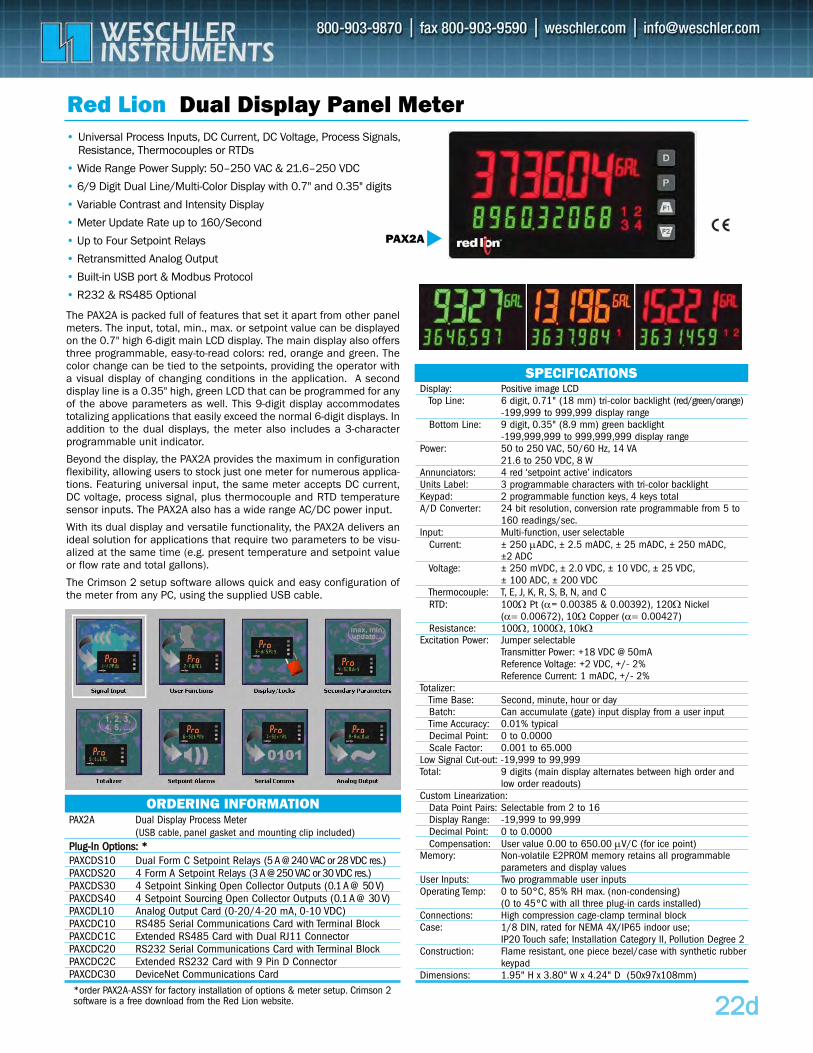
PAX2A Dual Display Process Meter(USB cable, panel gasket and mounting clip included)
PPlluugg--IInn OOppttiioonnss:: **PAXCDS10 Dual Form C Setpoint Relays (5 A @ 240 VAC or 28 VDC res.) PAXCDS20 4 Form A Setpoint Relays (3 A @ 250 VAC or 30 VDC res.)PAXCDS30 4 Setpoint Sinking Open Collector Outputs (0.1 A @ 50 V) PAXCDS40 4 Setpoint Sourcing Open Collector Outputs (0.1 A @ 30 V)PAXCDL10 Analog Output Card (0-20/4-20 mA, 0-10 VDC) PAXCDC10 RS485 Serial Communications Card with Terminal Block PAXCDC1C Extended RS485 Card with Dual RJ11 Connector PAXCDC20 RS232 Serial Communications Card with Terminal Block PAXCDC2C Extended RS232 Card with 9 Pin D Connector PAXCDC30 DeviceNet Communications Card
ORDERING INFORMATION
2222dd
Red Lion Dual Display Panel Meter• Universal Process Inputs, DC Current, DC Voltage, Process Signals,
Resistance, Thermocouples or RTDs
• Wide Range Power Supply: 50–250 VAC & 21.6–250 VDC
• 6/9 Digit Dual Line/Multi-Color Display with 0.7" and 0.35" digits
• Variable Contrast and Intensity Display
• Meter Update Rate up to 160/Second
• Up to Four Setpoint Relays
• Retransmitted Analog Output
• Built-in USB port & Modbus Protocol
• R232 & RS485 Optional
PAX2A
SPECIFICATIONSDisplay: Positive image LCD
Top Line: 6 digit, 0.71" (18 mm) tri-color backlight (red/green/orange)-199,999 to 999,999 display range
Bottom Line: 9 digit, 0.35" (8.9 mm) green backlight-199,999,999 to 999,999,999 display range
Power: 50 to 250 VAC, 50/60 Hz, 14 VA21.6 to 250 VDC, 8 W
Annunciators: 4 red ‘setpoint active’ indicators Units Label: 3 programmable characters with tri-color backlight Keypad: 2 programmable function keys, 4 keys totalA/D Converter: 24 bit resolution, conversion rate programmable from 5 to
160 readings/sec.Input: Multi-function, user selectable
Current: ± 250 μADC, ± 2.5 mADC, ± 25 mADC, ± 250 mADC,±2 ADC
Voltage: ± 250 mVDC, ± 2.0 VDC, ± 10 VDC, ± 25 VDC,± 100 ADC, ± 200 VDC
Thermocouple: T, E, J, K, R, S, B, N, and CRTD: 100Ω Pt (α= 0.00385 & 0.00392), 120Ω Nickel
(α= 0.00672), 10Ω Copper (α= 0.00427)Resistance: 100Ω, 1000Ω, 10kΩ
Excitation Power: Jumper selectableTransmitter Power: +18 VDC @ 50mAReference Voltage: +2 VDC, +/- 2%Reference Current: 1 mADC, +/- 2%
Totalizer:Time Base: Second, minute, hour or dayBatch: Can accumulate (gate) input display from a user inputTime Accuracy: 0.01% typicalDecimal Point: 0 to 0.0000Scale Factor: 0.001 to 65.000
Low Signal Cut-out: -19,999 to 99,999Total: 9 digits (main display alternates between high order and
low order readouts)Custom Linearization:
Data Point Pairs: Selectable from 2 to 16Display Range: -19,999 to 99,999Decimal Point: 0 to 0.0000Compensation: User value 0.00 to 650.00 μV/C (for ice point)
Memory: Non-volatile E2PROM memory retains all programmable parameters and display values
User Inputs: Two programmable user inputsOperating Temp: 0 to 50°C, 85% RH max. (non-condensing)
(0 to 45°C with all three plug-in cards installed)Connections: High compression cage-clamp terminal blockCase: 1/8 DIN, rated for NEMA 4X/IP65 indoor use;
IP20 Touch safe; Installation Category II, Pollution Degree 2Construction: Flame resistant, one piece bezel/case with synthetic rubber
keypadDimensions: 1.95" H x 3.80" W x 4.24" D (50x97x108mm)
The PAX2A is packed full of features that set it apart from other panelmeters. The input, total, min., max. or setpoint value can be displayedon the 0.7" high 6-digit main LCD display. The main display also offersthree programmable, easy-to-read colors: red, orange and green. Thecolor change can be tied to the setpoints, providing the operator witha visual display of changing conditions in the application. A seconddisplay line is a 0.35" high, green LCD that can be programmed for anyof the above parameters as well. This 9-digit display accommodatestotalizing applications that easily exceed the normal 6-digit displays. Inaddition to the dual displays, the meter also includes a 3-characterprogrammable unit indicator.
Beyond the display, the PAX2A provides the maximum in configurationflexibility, allowing users to stock just one meter for numerous applica-tions. Featuring universal input, the same meter accepts DC current,DC voltage, process signal, plus thermocouple and RTD temperaturesensor inputs. The PAX2A also has a wide range AC/DC power input.
With its dual display and versatile functionality, the PAX2A delivers anideal solution for applications that require two parameters to be visu-alized at the same time (e.g. present temperature and setpoint valueor flow rate and total gallons).
The Crimson 2 setup software allows quick and easy configuration ofthe meter from any PC, using the supplied USB cable.
*order PAX2A-ASSY for factory installation of options & meter setup. Crimson 2software is a free download from the Red Lion website.
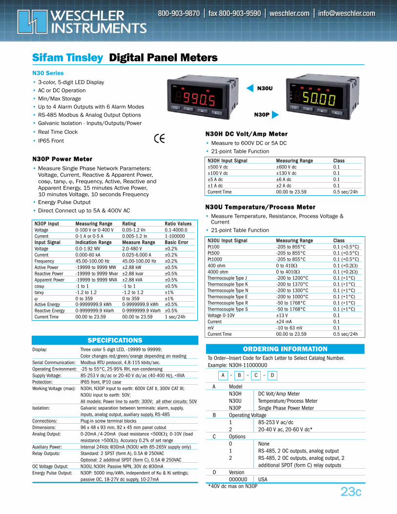
Sifam Tinsley Digital Panel Meters
• Measure Single Phase Network Parameters: Voltage, Current, Reactive & Apparent Power, cosϕ, tanϕ, ϕ, Frequency, Active, Reactive and Apparent Energy, 15 minutes Active Power, 10 minutes Voltage, 10 seconds Frequency
• Energy Pulse Output• Direct Connect up to 5A & 400V AC
N30P
NN3300UU TTeemmppeerraattuurree//PPrroocceessss MMeetteerr
NN3300PP PPoowweerr MMeetteerr
N30 Series
SPECIFICATIONSDisplay: Three color 5 digit LED, -19999 to 99999;
Color changes red/green/orange depending on readingSerial Communication: Modbus RTU protocol, 4.8-115 kbits/sec.Operating Environment: -25 to 55°C, 25-95% RH, non-condensingSupply Voltage: 85-253 V dc/ac or 20-40 V dc/ac (40-400 Hz), <6VA Protection: IP65 front, IP10 caseWorking Voltage (max): N30H, N30P input to earth: 600V CAT II, 300V CAT III;
N30U input to earth: 50V;All models: Power line to earth: 300V; all other circuits: 50V
Isolation: Galvanic separation between terminals: alarm, supply,inputs, analog output, auxiliary supply, RS-485
Connections: Plug-in screw terminal blocksDimensions: 96 x 48 x 93 mm, 92 x 45 mm panel cutout Analog Output: 0-20mA /4-20mA (load resistance <500Ω); 0-10V (load
resistance >500Ω); Accuracy 0.2% of set rangeAuxiliary Power: Internal 24Vdc @30mA (N30U with 85-265V supply only)Relay Outputs: Standard: 2 SPST (form A), 0.5A @ 250VAC
Optional: 2 additinal SPDT (form C), 0.5A @ 250VACOC Voltage Output: N30U, N30H: Passive NPN, 30V dc @30mA Energy Pulse Output: N30P: 5000 imp/kWh, independent of Ku & Ki settings;
passive OC, 18-27V dc supply, 10-27mA
2233cc
• 3-color, 5-digit LED Display• AC or DC Operation• Min/Max Storage• Up to 4 Alarm Outputs with 6 Alarm Modes• RS-485 Modbus & Analog Output Options• Galvanic Isolation - Inputs/Outputs/Power
• Real Time Clock
• IP65 Front
• Measure Temperature, Resistance, Process Voltage & Current
• 21-point Table Function
To Order—Insert Code for Each Letter to Select Catalog Number.Example: N30H-110000U0
A Model N30H DC Volt/Amp MeterN30U Temperature/Process MeterN30P Single Phase Power Meter
B Operating Voltage1 85-253 V ac/dc 2 20-40 V ac, 20-60 V dc*
C Options0 None1 RS-485, 2 OC outputs, analog output2 RS-485, 2 OC outputs, analog output, 2
additional SPDT (form C) relay outputsD Version
0000U0 USA *40V dc max on N30P
ORDERING INFORMATION
A – B – C – D
NN3300HH DDCC VVoolltt//AAmmpp MMeetteerr• Measure to 600V DC or 5A DC• 21-point Table Function
N30U
NN3300HH IInnppuutt SSiiggnnaall MMeeaassuurriinngg RRaannggee CCllaassss±500 V dc ±600 V dc 0.1±100 V dc ±130 V dc 0.1±5 A dc ±6 A dc 0.1±1 A dc ±2 A dc 0.1Current Time 00.00 to 23.59 0.5 sec/24h
NN3300PP IInnppuutt MMeeaassuurriinngg RRaannggee RRaattiinngg RRaattiioo VVaalluueessVoltage 0-100 V or 0-400 V 0.05-1.2 Vn 0.1-4000.0Current 0-1 A or 0-5 A 0.005-1.2 In 1-100000IInnppuutt SSiiggnnaall IInnddiiccaattiioonn RRaannggee MMeeaassuurree RRaannggee BBaassiicc EErrrroorrVoltage 0.0-1.92 MV 2.0-480 V ±0.2%Current 0.000-60 kA 0.025-6.000 A ±0.2%Frequency 45.00-100.00 Hz 45.00-100.00 Hz ±0.2%Active Power -19999 to 9999 MW ±2.88 kW ±0.5%Reactive Power -19999 to 9999 Mvar ±2.88 kvar ±0.5%Apparent Power -19999 to 9999 MVA ±2.88 kVA ±0.5%cosϕ -1 to 1 -1 to 1 ±0.5%tanϕ -1.2 to 1.2 -1.2 to 1.2 ±1%ϕ 0 to 359 0 to 359 ±1%Active Energy 0-9999999.9 kWh 0-9999999.9 kWh ±0.5%Reactive Energy 0-9999999.9 kVarh 0-9999999.9 kVarh ±0.5%Current Time 00.00 to 23.59 00.00 to 23.59 1 sec/24h
NN3300UU IInnppuutt SSiiggnnaall MMeeaassuurriinngg RRaannggee CCllaassssPt100 -205 to 855°C 0.1 (+0.5°C)Pt500 -205 to 855°C 0.1 (+0.5°C)Pt1000 -205 to 855°C 0.1 (+0.5°C)400 ohm 0 to 410Ω 0.1 (+0.2Ω)4000 ohm 0 to 4010Ω 0.1 (+0.2Ω)Thermocouple Type J -200 to 1200°C 0.1 (+1°C)Thermocouple Type K -200 to 1370°C 0.1 (+1°C)Thermocouple Type N -200 to 1300°C 0.1 (+1°C)Thermocouple Type E -200 to 1000°C 0.1 (+1°C)Thermocouple Type R -50 to 1768°C 0.1 (+1°C)Thermocouple Type S -50 to 1768°C 0.1 (+1°C)Voltage 0-10V ±13 V 0.1Current ±24 mA 0.1mV -10 to 63 mV 0.1Current Time 00.00 to 23.59 0.5 sec/24h
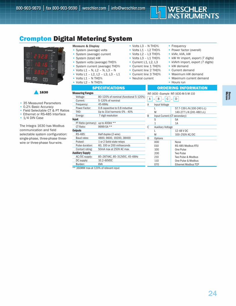
DIG
ITALM
ETERS
A Input VoltageL 57.7-139 L-N (100-240 L-L)M 140-277 L-N (241-480 L-L)
B Input Current (CT secondary)5 5A1 1A
C Auxiliary VoltageL 12-48 V DCM 100–250V AC/DC
D Options000 None010 RS-485 Modbus RTU100 One Pulse200 Two Pulse210 Two Pulse & Modbus110 One Pulse & Modbus070 Ethernet Modbus TCP
• 35 Measured Parameters• 0.2% Basic Accuracy• Field Selectable CT & PT Ratios• Ethernet or RS-485 Interface• 1/4 DIN Case
The Integra 1630 has Modbuscommunication and field selectable system configuration: single-phase, three-phase three-wire or three-phase four-wire.
••••••••••
• Frequency• Power factor (overall)• kVAr, kVA, kW• kW Hr import, export (7 digits)• kVArh import, export (7 digits)• kW demand• Current demand• Maximum kW demand • Maximum current demand• Hours run
Crompton Digital Metering System
SPECIFICATIONS ORDERING INFORMATION1630
•••••••••
Measure & Display• System (average) volts• System (average) current• System (total) kW• System volts (average) THD%• System current (average) THD%• Volts L1 – N, L2 – N, L3 – N• Volts L1 – L2, L2 – L3, L3 – L1• Volts L1 – N THD%• Volts L2 – N THD%
•••••••••
• Volts L3 – N THD%• Volts L1 – L2 THD%• Volts L2 – L3 THD%• Volts L3 – L1 THD%• Current L1, L2, L3• Current line 1 THD%• Current line 2 THD%• Current line 3 THD%• Neutral current
MMeeaassuurriinngg RRaannggeessVoltage: 80-120% of nominal (functional 5-120%)Current: 5-120% of nominal Frequency: 45-66HzPower Factor: 0.8 capacitive to 0.8 inductiveTHD: Up to 31st harmonic 0% - 40%Energy: 7 digit resolution
IInnppuuttPT Ratio (primary): up to 400kV **CT Ratio:
O9999:5A **
OuuttppuuttssRS-485: Half duplex (2-wire)Baud rates: 4800, 9600, 19200, 38400Pulsed: 1 or 2 Solid state relaysPulse duration: 60, 100 or 200 millisecondsContact rating:
A50mA max at 250V AC max.
Auuxxiilliiaarryy SSuuppppllyyAC/DC supply: 85–287VAC, 85–312VDC, 45–66HzDC supply: 10.2–60VDCBurden: 6VA
** 360MW max at 120% of relevant input
INT-1630 –Example INT-1630-M-5-M-110
A – B – C – D
24
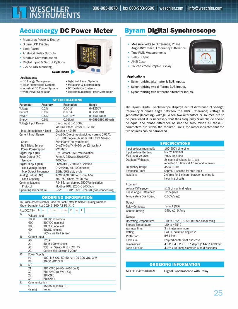
2255
Accuenergy DC Power Meter• Measures Power & Energy• 3 Line LCD Display • Limit Alarm• Analog & Relay Outputs • Modbus Communication• Digital Input & Output Options • 72x72 DIN Mounting
AcuDC243
Byram Digital Synchroscope
ORDERING INFORMATION
Input Voltage (nominal): 100-500V Line-LineInput Voltage Burden: 0.2 VA nominalMax Input Voltage:Overload Withstand: 2x nominal voltage for 1 sec.,
repeated 10 times at 10 second intervalsFrequency Range:
IP54 frontCAT III, pollution degree 2
Response Time: Approx. 1 second for step input
AccuracyVoltage Difference: ±1% of nominal valuePhase Angle Difference: ±2 degrees
Operating Temperature: -10 to +55°C, <95% RH non-condensingStorage Temperature: -20 to +65°CWarmup Time: 3 minutes minimum
Dimensions: 4.31" x 4.31" x 1.55" depth (114x114x39mm)Panel Cut Out: 4.06" (103mm) diameter, 4 stud positions
SPECIFICATIONS
PPaarraammeetteerr AAccccuurraaccyy RReessoolluuttiioonn RRaannggeeVoltage 0.2% 0.001V 0~1200VCurrent 0.2% 0.005A 0~±50000APower 0.5% 0.001kW 0~±60000kWEnergy 0.5% 0.01kWh 0~9999999.99kWhVoltage Input Range Direct Input 0~1000V;
Via Hall Effect Sensor 0~1200VInput Impedence / Load 2Mohm / <0.6W
Current Input Range 0~±20A(Direct Input, pick up current 0.02A);0~±50000A(Via Shunt or Hall Effect Sensor)
Shunt 50~100mV(programmable)Hall Effect Sensor 0~±5V/0-±4V, 4~20mA/12mA±8mAPower Consumption 2W(Max)
Digital Input (DI) Dry Contact, 2500Vac isolationRelay Output (RO) Form A, 250Vac/30Vdc@3A
Isolation 4000VacDigital Output (DO) PhotoMOS, 2500Vac isolation
Load Voltage Range 0~250Vac/dc, 100mA(max)Max Output Frequency 25Hz, 50% duty cycle
Analog Output (AO) 4-20mA/0~20mA; 0~5V/1-5VLoad Capacity mA: 750 Ohm; V: 20 mA
Communications RS485, half duplex, 2500Vac isolationProtocol Modbus-RTU, 1200~38400bps
Operating Temperature -25°C ~ +70°C 5%~95% RH (non-condensing)
SPECIFICATIONS
• Measure Voltage Difference, Phase Angle Difference, Frequency Difference
• True RMS Measurements• Relay Output• ANSI Case• Touch Screen Graphic Display
The Byram Digital Synchroscope displays actual difference of voltage,frequency & phase angle between the BUS (Reference) voltage & generator (Incoming) voltage. When two alternators or sources are to be parallelled it is necessary that their frequency & amplitude should be equal and phase difference be near to zero. When all these 3 parameters are within the required limits, the meter indicates that the two sources can be parallelled.
To Order—Insert Number Code for Each Letter to Select Catalog Number.Order Example: AcuDC243-300-A2-P1-X1-C
AVoltage Input1000 1000VDC nominal600 600VDC nominal300 300VDC nominal60 60VDC nominal5 5V/4V via Hall sensor
B Current InputA0 ±20AA1 50 or 100mV shuntA2 Volt Hall Sensor 0 to ±5V/±4VA3 Current Hall Sensor 4-20mA
C Power SupplyP1 100-415 VAC, 50-60 Hz; 100-300 VDC, 3 WP2 20-60 VDC, 3 W
D I/OX1 2D1+2AO (4-20mA/0-20mA)X2 2D1+2AO (0-5V/1-5V)X3 2DI+2ROX4 2DI+2DO
E CommunicationC RS485, Modbus RTU(blank) None
ORDERING INFORMATION
BA C D EAcuDC243— — — — —
AApppplliiccaattiioonnss:: DC Energy Management Solar Photovoltaic Systems Industrial DC Control Systems Wind Power Generation
Light Rail Transit Systems Metallurgy & Electroplating DC Excitation Systems Telecommunication Power Distribution
AAAppppppllliiicccaaatttiiiooonnnsss
• Synchronizing alternator & BUS inputs.
• Synchronizing two different BUS inputs.
• Synchronizing two different alternator inputs.
Temperature Coefficient: 0.05%/degC
Enclosure: Polycarbonate front and case
600V Line-Line
45 to 66 Hz
Isolation: 2kV rms for 1 minute, between running &incoming circuits
Rating:Protection:
MCS106452-DIGITAL Digital Synchroscope with Relay
Form A (NO)Relay Contacts:240V AC, 5 AmpContact Rating:
General
Output
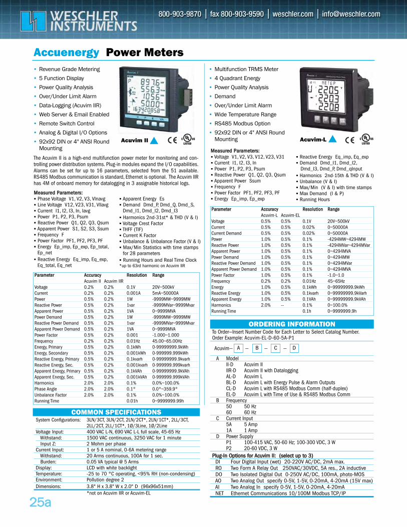
To Order—Insert Number Code for Each Letter to Select Catalog Number.Order Example: Acuvim-EL-D-60-5A-P1
A ModelII-D Acuvim II IIR-D Acuvim II with DataloggingAL-D Acuvim LBL-D Acuvim L with Energy Pulse & Alarm OutputsCL-D Acuvim L with RS485 Modbus Comm (half-duplex)EL-D Acuvim L with Time of Use & RS485 Modbus Comm
B Frequency50 50 Hz60 60 Hz
C Current Input5A 5 Amp1A 1 Amp
D Power SupplyP1 100-415 VAC, 50-60 Hz; 100-300 VDC, 3 WP2 20-60 VDC, 3 W
PPlluugg--IInn OOppttiioonnss ffoorr AAccuuvviimm IIII:: ((sseelleecctt uupp ttoo 33))DI Four Digital Input (wet) 20-220V AC/DC, 2mA max.RO Two Form A Relay Out 250VAC/30VDC, 5A res., 2A inductive DO Two Isolated Digital Out 0-250V AC/DC, 100mA, photo-MOS AO Two Analog Out specify 0-5V, 1-5V, 0-20mA, 4-20mA (15V max)AI Two Analog In specify 0-5V, 1-5V, 0-20mA, 4-20mANET Ethernet Communications 10/100M Modbus TCP/IP
ORDERING INFORMATION
BA C DAcuvim— — — —
2255aa
Accuenergy Power Meters• Revenue Grade Metering
• 5 Function Display
• Power Quality Analysis
• Over/Under Limit Alarm
• Data-Logging (Acuvim IIR)
• Web Server & Email Enabled
• Remote Switch Control
• Analog & Digital I/O Options
• 92x92 DIN or 4" ANSI RoundMounting
• Multifunction TRMS Meter
• 4 Quadrant Energy
• Power Quality Analysis
• Demand
• Over/Under Limit Alarm
• Wide Temperature Range
• RS485 Modbus Option
• 92x92 DIN or 4" ANSI Round Mounting Acuvim-L Acuvim II
COMMON SPECIFICATIONSSystem Configurations: 3LN/3CT, 3LN/2CT, 2LN/2CT*, 2LN/1CT*, 2LL/3CT,
2LL/2CT, 2LL/1CT*, 1Ø/3Line, 1Ø/2Line Voltage Input: 400 VAC L-N, 690 VAC L-L full scale, 45-65 Hz
Withstand: 1500 VAC continuous, 3250 VAC for 1 minuteInput Z: 2 Mohm per phase
Current Input: 1 or 5 A nominal, 0-6A metering rangeWithstand: 20 Arms continuous, 100A for 1 sec.Burden: 0.05 VA typical @ 5 Arms
Display: LCD with white backlightTemperature: -25 to 70 °C operating, <95% RH (non-condensing)Environment: Pollution degree 2Dimensions: 3.8" H x 3.8" W x 2.0" D (96x96x51mm)
*not on Acuvim IIR or Acuvim-EL
The Acuvim II is a high-end multifunction power meter for monitoring and con-trolling power distribution systems. Plug-in modules expand the I/O capabilities.Alarms can be set for up to 16 parameters, selected from the 51 available.RS485 Modbus communication is standard, Ethernet is optional. The Acuvim IIRhas 4M of onboard memory for datalogging in 3 assignable historical logs.
PPaarraammeetteerr AAccccuurraaccyy RReessoolluuttiioonn RRaannggeeAcuvim-L Acuvim-EL
Voltage 0.5% 0.5% 0.1V 20V~500kVCurrent 0.5% 0.5% 0.02% 0~50000ACurrent Demand 0.5% 0.5% 0.02% 0~50000APower 1.0% 0.5% 0.1% -4294MW~4294MWReactive Power 1.0% 0.5% 0.1% -4294MVar~4294MVarApparent Power 1.0% 0.5% 0.1% 0~4294MVAPower Demand 1.0% 0.5% 0.1% 0~4294MWReactive Power Demand 1.0% 0.5% 0.1% 0~4294MVarApparent Power Demand 1.0% 0.5% 0.1% 0~4294MVAPower Factor 1.0% 0.5% 0.1% -1.0~1.0Frequency 0.2% 0.2% 0.01Hz 45~65HzEnergy 1.0% 0.5% 0.1kWh 0~99999999.9kWhReactive Energy 1.0% 0.5% 0.1kvarh 0~99999999.9kVarhApparent Energy 1.0% 0.5% 0.1VAh 0~99999999.9kVAhHarmonics 2.0% -- 0.1% 0~100.0%Running Time 0.1h 0~9999999.9h
PPaarraammeetteerr AAccccuurraaccyy RReessoolluuttiioonn RRaannggeeAcuvim II Acuvim IIR
Voltage 0.2% 0.2% 0.1V 20V~500kVCurrent 0.2% 0.2% 0.001A 5mA~50000APower 0.5% 0.2% 1W -9999MW~9999MWReactive Power 0.5% 0.2% 1var -9999MVar~9999MvarApparent Power 0.5% 0.2% 1VA 0~9999MVAPower Demand 0.5% 0.2% 1W -9999MW~9999MWReactive Power Demand 0.5% 0.2% 1var -9999MVar~9999MvarApparent Power Demand 0.5% 0.2% 1VA 0~9999MVAPower Factor 0.5% 0.2% 0.001 -1.000~1.000Frequency 0.2% 0.2% 0.01Hz 45.00~65.00HzEnergy, Primary 0.5% 0.2% 0.1kWh 0-99999999.9kWhEnergy, Secondary 0.5% 0.2% 0.001kWh 0-999999.999kWhReactive Energy, Primary 0.5% 0.2% 0.1kvarh 0-99999999.9kvarhReactive Energy, Sec. 0.5% 0.2% 0.001kvarh 0-999999.999kvarhApparent Energy, Primary 0.5% 0.2% 0.1kVAh 0-99999999.9kVAhApparent Energy, Sec. 0.5% 0.2% 0.001kVAh 0-999999.999kVAhHarmonics 2.0% 2.0% 0.1% 0.0%~100.0%Phase Angle 2.0% 2.0% 0.1° 0.0°~359.9°Unbalance Factor 2.0% 2.0% 0.1% 0.0%~100.0%Running Time 0.01h 0~9999999.99h
MMeeaassuurreedd PPaarraammeetteerrss:: Voltage V1, V2, V3, V12, V23, V31 Current I1, I2, I3, In Power P1, P2, P3, Psum Reactive Power Q1, Q2, Q3, Qsum Apparent Power Ssum Frequency F Power Factor PF1, PF2, PF3, PF Energy Ep_imp, Ep_exp
Reactive Energy Eq_imp, Eq_exp Demand Dmd_I1, Dmd_I2,
Dmd_I3, Dmd_P, Dmd_qInput Harmonics 2nd-15th & THD (V & I) Unbalance (V & I) Max/Min (V & I) with time stamps Max Demand (I & P) Running Hours
MMeeaassuurreedd PPaarraammeetteerrss:: Phase Voltage V1, V2, V3, Vlnavg Line Voltage V12, V23, V31, Vllavg Current I1, I2, I3, In, Iavg Power P1, P2, P3, Psum Reactive Power Q1, Q2, Q3, Qsum Apparent Power S1, S2, S3, Ssum Frequency F Power Factor PF1, PF2, PF3, PF Energy Ep_imp, Ep_exp, Ep_total,
Ep_net Reactive Energy Eq_imp, Eq_exp,
Eq_total, Eq_net
Apparent Energy Es Demand Dmd_P, Dmd_Q, Dmd_S,
Dmd_I1, Dmd_I2, Dmd_I3 Harmonics 2nd-31st* & THD (V & I) Voltage Crest Factor THFF (TIF) Current K Factor Unbalance & Unbalance Factor (V & I) Max/Min Statistics with time stamps
for 28 parameters Running Hours and Real Time Clock*up to 63rd harmonic on Acuvim IIR
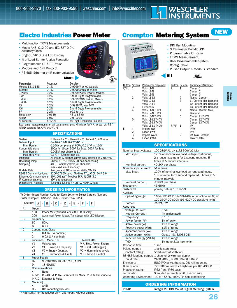
To Order—Insert Number Code for Each Letter to Select Catalog Number.Order Example: EI/Shark100-60-10-V2-D2-485P-X
A Model*100 Power Meter/Transducer with LED Display200 Advanced Power Meter/Transducer with LED Display
B Frequency50 50Hz60 60Hz
C Current Input Class10 0-11A (5A nominal)2 0-2A (1A nominal)
D Functions Model 100 Model 200V1 Volts/Amps V, A, Freq, Power, EnergyV2 V1 + Power & Frequency V1 + 2M DataloggingV3 V2 + Energy Counters V2 + Harmonic AnalysisV4 V3 + Harmonics & Limits V3 + Limit & Control
E Power SupplyD2 90-264VAC/100-370VDC, 10VAD 18-60VDC
F CommunicationsX None 485P RS-485 & Pulse (standard on Model 200 & Transducers)INP10 Ethernet & Pulse
G Mounting X ANSIDIN DIN mounting brackets
* Add suffix T for Transducer only (DIN mount) without display
DIG
ITALM
ETERS
26
Electro Industries Power Meter • Multifunction TRMS Measurements • Meets ANSI C12.20 and IEC 687 0.2%
Accuracy Class• Bright 0.56" 3 Line LED Display• % of Load Bar for Analog Perception• Programmable CT & PT Ratios• Modbus and DNP Protocol • RS-485, Ethernet or IR communication
Shark
PPaarraammeetteerr AAccccuurraaccyy DDiissppllaayyVoltage L-L & L-N: 0.1% 0-9999 V or kV, scalableCurrent: 0.1% 0-9999 Amps or kAmps± Watts 0.2% 0-9999 Watts, kWatts, MWatts±Wh 0.2% 5 to 8 Digits Programmable±VARs 0.2% 0-9999 VARs, kVARs, MVARs±VARh 0.2% 5 to 8 Digits ProgrammableVA 0.2% 0-9999 VA, kVA, MVAVAh 0.2% 5 to 8 Digits ProgrammablePF 0.2% ±0.5 to 1.0Frequency 0.01 Hz 45 to 65 Hz%THD 1.0% 0 to 100%% Load Bar 1-120% 10 Digit Resolution ScalableReal time measurements for all parameters; plus Min/Max for V, A, W, VAr, VA, PF, f,%THD: Average for A, W, VAr, VA, PF
System: 3 Element Y, 2.5 Element Y, 2 Element Δ, 4 Wire ΔVoltage Input: 0-416VAC L-N, 0-721VAC L-L
Max. Burden: 0.36VA per phase at 600V, 0.014VA at 120VCurrent Withstand: 100A for 10sec, 300A for 3sec, 500A for 1sec
Max. Burden: 0.005VA per phase at 11APass-thru Wire: 0.177" (4.5mm) max dia.
Isolation: All Inputs & outputs galvanically isolated to 2500VACOperating Temp: -30 to +70°C, <95% RH non-condensingSampling: 400+ Samples/Cycle, all channels
measured simultaneouslyUpdate Rate: 1sec, except 100msec on Watts, VAr, VARS485 Communications: 1200-57600 baud: Modbus RTU, ASCII, DNP 3.0Ethernet Communications: 10/100BaseT: Modbus TCP/IP, DNP 3.0 IR Communications: IrDA thru faceplate Dimensions, Ratings: 4.85"H x 4.82"W x 4.25"D, NEMA12 face
SPECIFICATIONS
ORDERING INFORMATION
A – B – C – D – E – –F FEI/SHARK
• DIN Rail Mounting• 3 Parameter Backlit LCD • Programmable CT Ratio• TRMS Measurement• User Programmable System
Configuration• Pulsed Output & Modbus Standard
Button Screen Parameter DisplayedV/Hz 1 Volts L1-N
Volts L2-NVolts L3-N
2 Volts L1-L2Volts L2-L3Volts L3-L1
3 Frequency4 Volts L1-N THD%
Volts L2-N THD%Volts L3-N THD%
5 Volts L1-L2 THD%Volts L2-L3 THD%Volts L3-L1 THD%
E 1 Import kWh2 Export kWh3 Import kVArh4 Export kVArh
Nominal input voltage: 100-289V AC L-N (173-500V AC L-L)Max. input: 120% of nominal overload voltage continuous,
2 x range maximum for 1 second repeated 5 times at 5 minute intervals
Nominal burden: <0.2VA per phaseNominal input current: 5A AC rms
Max. input: 120% of nominal overload current continuous,10 x nominal for 1 second repeated 5 times at 5 minute intervals
Nominal burden: <0.6VA per phaseFrequency: 45-66HzSystem CT: primary values 1 to 9999Auxiliary
Operating range: 110-400V AC ±10% (99-440V AC absolute limits) or 120-350V DC ±20% (96-420V DC absolute limits)
Burden: <10VA/5WAAccccuurraaccyy
Voltage, Current: 0.5%Neutral Current: 4% (calculated)Frequency: 0.1HzPower factor (PF) 1% of unityActive power (W) ±1% of rangeReactive power (Var): ±1% of rangeApparent power (VA): ±1% of rangeActive energy (kWh): Class1 (IEC 62053-21)Reactive energy (kVArh): ±1% of rangeTHD: 1% up to 31st harmonic
Response time: 1 secPulsed output: 1 solid state relay
Contact rating: 50mA max at 250V ACRS-485 Modbus output: 1 channel, 2-wire half duplex
Baud rate: 2400, 4800, 9600, 19200, 38400Enclosure: ULk94VO polycarbonate, DIN-rail mountingDimensions: 72 x 90mm (width x height) as per DIN 43880Protection rating: IP52 front, IP30 caseTerminals: Shrouded screw-clamp 0.05-4mm wireOperating environment: -10 to +55°C, <90% RH non-condensing
SPECIFICATIONS
Crompton Metering System
Ri3
Ri3-01 Integra Ri3 DIN Mount Digital Metering SystemORDERING INFORMATION
NEW
Button Screen Parameter DisplayedA 1 Current 1
Current 2Current 3
2 Neutral Current3 L1 Current Max Demand
L2 Current Max DemandL3 Current Max Demand
4 Neutral Current MaxDemand
5 Current L1 THD%Current L2 THD%Current L3 THD%
P/PF 1 kWkVArkVA
2 kW Max Demand3 Power Factor
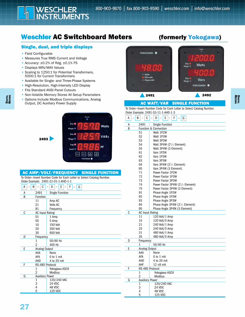
To Order—Insert Number Code for Each Letter to Select Catalog Number.Order Example: 2491-21-01-1-AHD-1-1
A 2491 Single FunctionB Function
11 Amp AC21 Volts AC81 Frequency
C AC Input Rating01 1 Amp05 5 Amp10 150 Volt20 300 Volt30 600 Volt
D Frequency1 50/60 Hz2 400 Hz
E Analog OutputAAA NoneAFA 0 to 1 mAAHD 4 to 20 mA
F RS-485 Protocol1 Yokogawa ASCII2 Modbus
G Auxiliary Power1 120/240 VAC3 24 VDC4 48 VDC5 125 VDC
To Order—Insert Number Code for Each Letter to Select Catalog Number.Order Example: 2491-53-11-1-AHD-1-3
A 2491 Single FunctionB Function & Connection
51 Watt 1P2W52 Watt 1P3W53 Watt 3P3W54 Watt 3P4W (21/2 Element)55 Watt 3P4W (3 Element)61 Vars 1P2W62 Vars 1P3W63 Vars 3P3W64 Vars 3P4W (21/2 Element)65 Vars 3P4W (3 Element)71 Power Factor 1P2W72 Power Factor 1P3W73 Power Factor 3P3W74 Power Factor 3P4W (21/2 Element)75 Power Factor 3P4W (3 Element)91 Phase Angle 1P2W92 Phase Angle 1P3W93 Phase Angle 3P3W94 Phase Angle 3P4W (21/2 Element)95 Phase Angle 3P4W (3 Element)
C AC Input Rating11 120 Volt/1 Amp15 120 Volt/5 Amp21 240 Volt/1 Amp25 240 Volt/5 Amp31 480 Volt/1 Amp35 480 Volt/5 Amp
D Frequency1 50/60 Hz
E Analog OutputAAA NoneAFA 0 to 1 mA AHD 4 to 20 mAAHF 12 ±8 mA
F RS-485 Protocol1 Yokogawa ASCII2 Modbus
G Auxiliary Power1 120/240 VAC3 24 VDC4 48 VDC5 125 VDC
Weschler AC Switchboard Meters (formerly Yokogawa)
• Field Configurable• Measures True RMS Current and Voltage• Accuracy: ±0.2% of Rdg. ±0.1% FS• Displays MIN/MAX Values• Scaling to 1250:1 for Potential Transformers,
5000:1 for Current Transformers• Available for Single- and Three-Phase Systems• High-Resolution, High-Intensity LED Display• Fits Standard ANSI Panel Cutouts• Non-Volatile Memory Stores All Setup Parameters• Options Include Modbus Communications, Analog
Output, DC Auxiliary Power Supply
Single, dual, and triple displays
2493
AC AMP/VOLT/FREQUENCY SINGLE FUNCTION
2492
AC WATT/VAR SINGLE FUNCTION DIG
ITAL
MET
ERS
27
A – B – C – D – E – F – G
A – B – C – D – E – F – G
DIG
ITALM
ETERS
2491
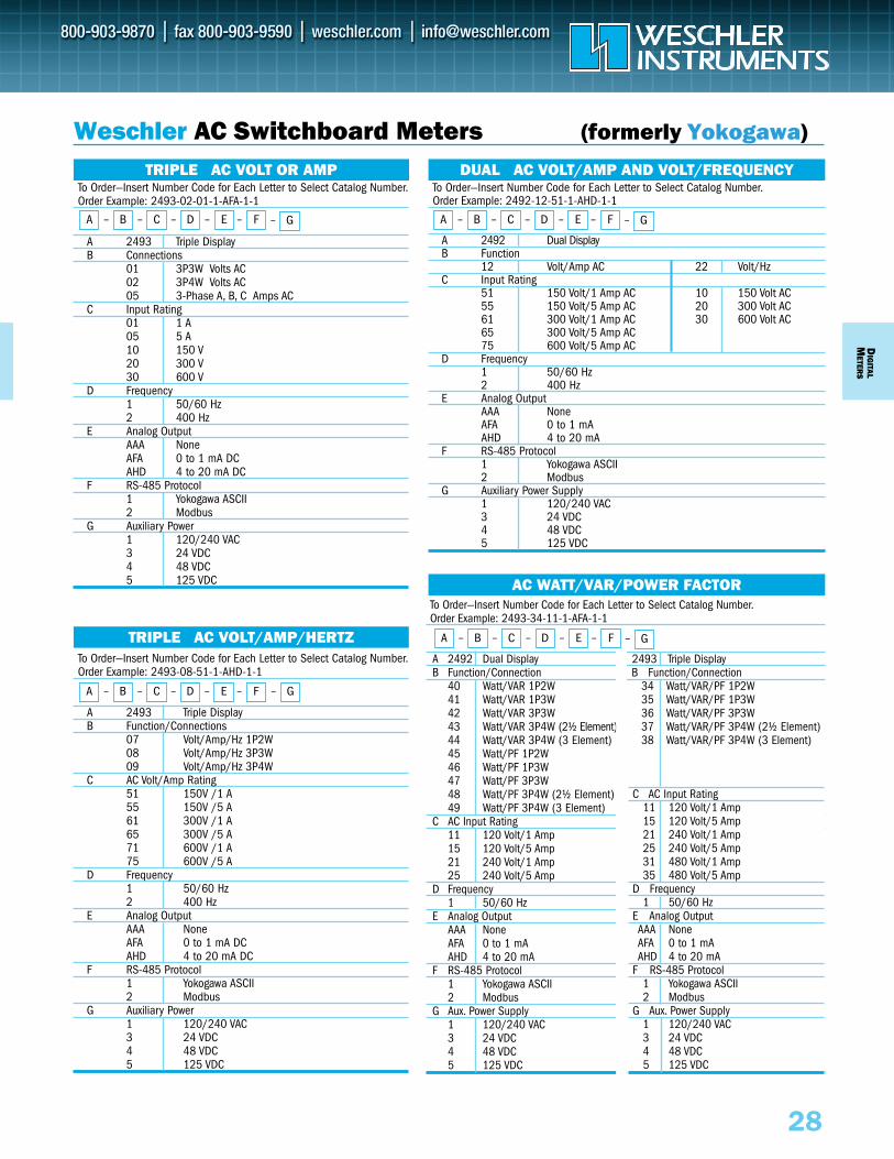
To Order—Insert Number Code for Each Letter to Select Catalog Number.Order Example: 2493-34-11-1-AFA-1-1
A 2492 Dual Display 2493 Triple DisplayB Function/Connection B Function/Connection
40 Watt/VAR 1P2W 34 Watt/VAR/PF 1P2W41 Watt/VAR 1P3W 35 Watt/VAR/PF 1P3W42 Watt/VAR 3P3W 36 Watt/VAR/PF 3P3W43 Watt/VAR 3P4W (2½ Element) 37 Watt/VAR/PF 3P4W (2½ Element)44 Watt/VAR 3P4W (3 Element) 38 Watt/VAR/PF 3P4W (3 Element)45 Watt/PF 1P2W46 Watt/PF 1P3W47 Watt/PF 3P3W48 Watt/PF 3P4W (2½ Element)49 Watt/PF 3P4W (3 Element)
C AC Input Rating C AC Input Rating11 120 Volt/1 Amp 11 120 Volt/1 Amp15 120 Volt/5 Amp 15 120 Volt/5 Amp21 240 Volt/1 Amp 21 240 Volt/1 Amp25 240 Volt/5 Amp 25 240 Volt/5 Amp
D Frequency D Frequency1 50/60 Hz 1 50/60Hz
E Analog Output E Analog OutputAAA None AAA NoneAFA 0 to 1 mA AFA 0 to 1 mAAHD 4 to 20 mA AHD 4 to 20 mA
F RS-485 Protocol F RS-485 Protocol1 Yokogawa ASCII 1 Yokogawa ASCII2 Modbus 2 Modbus
G Aux. Power Supply G Aux. Power Supply1 120/240 VAC 1 120/240 VAC 3 24 VDC 3 24 VDC4 48 VDC 4 48 VDC5 125 VDC 5 125 VDC
C AC Input Rating11 120 Volt/1 Amp15 120 Volt/5 Amp21 240 Volt/1 Amp 25 240 Volt/5 Amp31 480 Volt/1 Amp35 480 Volt/5 Amp
D Frequency1 50/60 Hz
E Analog OutputAAA NoneAFA 0 to 1 mAAHD 4 to 20 mA
F RS-485 Protocol1 Yokogawa ASCII2 Modbus
G Aux. Power Supply1 120/240 VAC3 24 VDC4 48 VDC5 125 VDC
To Order—Insert Number Code for Each Letter to Select Catalog Number.Order Example: 2493-08-51-1-AHD-1-1
A 2493 Triple DisplayB Function/Connections
07 Volt/Amp/Hz 1P2W08 Volt/Amp/Hz 3P3W09 Volt/Amp/Hz 3P4W
C AC Volt/Amp Rating51 150V /1 A 55 150V /5 A 61 300V /1 A 65 300V /5 A 71 600V /1 A 75 600V /5 A
D Frequency1 50/60 Hz2 400 Hz
E Analog OutputAAA NoneAFA 0 to 1 mA DCAHD 4 to 20 mA DC
F RS-485 Protocol1 Yokogawa ASCII2 Modbus
G Auxiliary Power1 120/240 VAC3 24 VDC4 48 VDC5 125 VDC
TRIPLE AC VOLT/AMP/HERTZ
A – B – C – D – E – F – G
DIG
ITALM
ETERS
To Order—Insert Number Code for Each Letter to Select Catalog Number.Order Example: 2492-12-51-1-AHD-1-1
A 2492 Dual DisplayB Function
12 Volt/Amp AC 22 Volt/Hz C Input Rating
51 150 Volt/1 Amp AC 10 150 Volt AC55 150 Volt/5 Amp AC 20 300 Volt AC61 300 Volt/1 Amp AC 30 600 Volt AC65 300 Volt/5 Amp AC 75 600 Volt/5 Amp AC
D Frequency1 50/60 Hz2 400 Hz
E Analog OutputAAA NoneAFA 0 to 1 mAAHD 4 to 20 mA
F RS-485 Protocol1 Yokogawa ASCII2 Modbus
G Auxiliary Power Supply1 120/240 VAC3 24 VDC4 48 VDC5 125 VDC
To Order—Insert Number Code for Each Letter to Select Catalog Number.Order Example: 2493-02-01-1-AFA-1-1
A 2493 Triple DisplayB Connections
01 3P3W Volts AC02 3P4W Volts AC05 3-Phase A, B, C Amps AC
C Input Rating01 1 A05 5 A10 150 V20 300 V30 600 V
D Frequency1 50/60 Hz2 400 Hz
E Analog OutputAAA NoneAFA 0 to 1 mA DCAHD 4 to 20 mA DC
F RS-485 Protocol1 Yokogawa ASCII2 Modbus
G Auxiliary Power1 120/240 VAC3 24 VDC4 48 VDC5 125 VDC
Weschler AC Switchboard Meters (formerly Yokogawa)
TRIPLE AC VOLT OR AMP DUAL AC VOLT/AMP AND VOLT/FREQUENCY
AC WATT/VAR/POWER FACTOR
A – B – C – D – E – F – G
A – B – C – D – E – F – GA – B – C – D – E – F – G
28
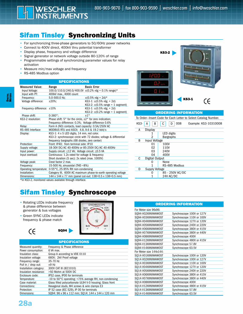
SQ94
For Meter size 96x96:SQ94-V02XXNXWAW0ST Synchroscope 100V or 127V SQ94-V03XXNXWAW0ST Synchroscope 110V or 100V SQ94-V04XXNXWAW0ST Synchroscope 127V or 120V SQ94-V05XXNXWAW0ST Synchroscope 240V or 220V SQ94-V06XXNXWAW0ST Synchroscope 380V or 415V SQ94-V07XXNXWAW0ST Synchroscope 380V or 440V SQ94-V08XXNXWAW0ST Synchroscope 400V SQ94-V12XXNXWAW0ST Synchroscope 480V or 415V SQ94-V13XXNXWAW0ST Synchroscope 57.8V SQ94-V14XXNXWAW0ST Synchroscope 63.5V For Meter size 144x144:SQ14-V01XXNXWAW0ST Synchroscope 100V or 120V SQ14-V02XXNXWAW0ST Synchroscope 100V or 127V SQ14-V03XXNXWAW0ST Synchroscope 110V or 100V SQ14-V04XXNXWAW0ST Synchroscope 127V or 120V SQ14-V05XXNXWAW0ST Synchroscope 240V or 220V SQ14-V06XXNXWAW0ST Synchroscope 380V or 415V SQ14-V07XXNXWAW0ST Synchroscope 380V or 440V SQ14-V08XXNXWAW0ST Synchroscope 400V SQ14-V12XXNXWAW0ST Synchroscope 480V or 415V SQ14-V13XXNXWAW0ST Synchroscope 57.8V SQ14-V14XXNXWAW0ST Synchroscope 63.5V
To Order—Insert Code for Each Letter to Select Catalog Number.
A Display1 LED digits2 Bargraphs
B Input Voltage 01 100V 02 110V03 240V04 400V
C Digital Output 0 None1 RS-485 Modbus
D Supply Voltage0 85 - 250V AC/DC1 24V AC/DC
DIG
ITAL
MET
ERS
28a
Sifam Tinsley Synchroscope
ORDERING INFORMATION
A B C DKS3- 008
Sifam Tinsley Synchronizing Units• For synchronizing three-phase generators to 50/60Hz power networks • Connect to 400V direct, 400kV thru potential transformer• Display phase, frequency and voltage difference• Signal generator or network voltage outside 80-120% of range• Programmable settings of synchronizing parameter values for relay
activation • Measure min/max voltage and frequency• RS-485 Modbus option
• Rotating LEDs indicate frequency & phase difference between generator & bus voltages
• Green SYNC LEDs indicate frequency & phase match
Measured quantity: Frequency & Phase differencePower consumption: 6 VA max.Insulation class: Group A according to VDE 0110Insulation voltage: 660V; 2kV Proof voltageFrequency range: 35-70 HzPull in / drop out: ±9 HzInstallation catogory: 300V CAT III (IEC1010)Insulation resistance: >50 Mohm at 500V DCEnclosure code: IP52 case, IP00 for terminalsTemperature: -10 to 50°C operating; <75% average RH, non-condensingCase material: Glass filled polycarbonate UL94 V-0 housing; Glass frontConnections: Hexagonal studs, M4 screws & wire clamps E3 Protection: IP 52 case (IEC 529), IP 00 for terminalsDimensions: SQ94: 96 x 96 x 112 mm; SQ14: 144 x 144 x 120 mm
MMeeaassuurreedd VVaalluuee:: RRaannggee BBaassiicc EErrrroorrInput Voltage: 100.0/110.0/240.0/400.0V ±(0.2% rdg + 0.1% range)* Input with PT: 400kV max., 4000 count Frequency: 5.0-500.0 Hz; ±(0.5% rdg + 2d)*Voltage difference: ±20%; KS3-1: ±(0.5% rdg. + 2d)
KS3-2: ±(0.5% range + 1 segment) Frequency difference: ±10% KS3-1: ±(0.5% rdg. + 2d)
KS3-2: ±(0.2% range + 1 segment) Phase shift: 0-360°; ±1°
KS3-2 resolution: Phase shift: 5° for the circle, ±2° for zero indication;Frequency difference: 0.3%; Voltage difference 0.6%
Relay: Form A (NO) contacts, load capacity: 0.5A/250V ACRS-485 Interface: MODBUS RTU and ASCII; 4.8, 9.6 & 19.2 kbit/sDisplay: KS3-1: 4 x 5 LED digits, 14 mm, red color.
KS3-2: synchroscope circle with 72 diodes; voltage & differential frequency bargraphs (68 diodes, zero center)
Protection: Front: IP40; from terminal side: IP10Supply voltage: 18-30V DC/AC 40-400Hz or 85-250V DC/AC 40-400HzInput power: Supply circuit: <12 VA; Voltage circuit: <0.5 VAInput overload: Continuous: 1.2x rated for voltage & frequency
Short duration (5 sec): 2x rated (max. 1000V)Voltage peak: Crest factor 2 max.Frequency: 15-500 Hz, sinusoidal (THD <8%)Operating temperature: 0-55°C, 25-95% RH non-condensingInstallation: Category III, 600V AC maximum phase-to-earth operating voltage Dimensions: 144 x 144 x 77 mm (panel cut-out: 138+0.5 x 138+0.5 mm)*in KS3-2, monitored values available through interface.
SPECIFICATIONS
SPECIFICATIONS
ORDERING INFORMATION
KS3-2
KS3-1
Example: KS3-10310008
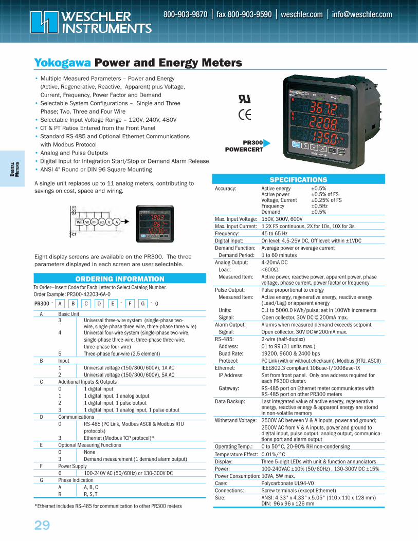
DIG
ITAL
MET
ERS
29
A single unit replaces up to 11 analog meters, contributing tosavings on cost, space and wiring.
Yokogawa Power and Energy Meters
To Order—Insert Code for Each Letter to Select Catalog Number. Order Example: PR300-42203-6A-0
A Basic Unit3 Universal three-wire system (single-phase two-
wire, single-phase three-wire, three-phase three wire)4 Universal four-wire system (single-phase two-wire,
single-phase three-wire, three-phase three-wire, three-phase four-wire)
5 Three-phase four-wire (2.5 element)B Input
1 Universal voltage (150/300/600V), 1A AC2 Universal voltage (150/300/600V), 5A AC
C Additional Inputs & Outputs0 1 digital input1 1 digital input, 1 analog output2 1 digital input, 1 pulse output3 1 digital input, 1 analog input, 1 pulse output
D Communications0 RS-485 (PC Link, Modbus ASCII & Modbus RTU
protocols)3 Ethernet (Modbus TCP protocol)*
E Optional Measuring Functions0 None3 Demand measurement (1 demand alarm output)
F Power Supply6 100-240V AC (50/60Hz) or 130-300V DC
G Phase Indication A A, B, CR R, S, T
SPECIFICATIONS
ORDERING INFORMATION
• Multiple Measured Parameters – Power and Energy (Active, Regenerative, Reactive, Apparent) plus Voltage,Current, Frequency, Power Factor and Demand
• Selectable System Configurations – Single and ThreePhase; Two, Three and Four Wire
• Selectable Input Voltage Range – 120V, 240V, 480V• CT & PT Ratios Entered from the Front Panel• Standard RS-485 and Optional Ethernet Communications
with Modbus Protocol• Analog and Pulse Outputs• Digital Input for Integration Start/Stop or Demand Alarm Release • ANSI 4" Round or DIN 96 Square Mounting
*Ethernet includes RS-485 for communication to other PR300 meters
Eight display screens are available on the PR300. The threeparameters displayed in each screen are user selectable.
BA C D E F GPR300 0
Accuracy: Active energy ±0.5%Active power ±0.5% of FSVoltage, Current ±0.25% of FSFrequency ±0.5HzDemand ±0.5%
Max. Input Voltage: 150V, 300V, 600VMax. Input Current: 1.2X FS continuous, 2X for 10s, 10X for 3sFrequency: 45 to 65 HzDigital Input: On level: 4.5-25V DC, Off level: within ±1VDCDemand Function: Average power or average current
Demand Period: 1 to 60 minutesAnalog Output: 4-20mA DC
Load: <600ΩMeasured Item: Active power, reactive power, apparent power, phase
voltage, phase current, power factor or frequencyPulse Output: Pulse proportional to energy
Measured Item: Active energy, regenerative energy, reactive energy (Lead/Lag) or apparent energy
Units: 0.1 to 5000.0 kWh/pulse; set in 100Wh incrementsSignal: Open collector, 30V DC @ 200mA max.
Alarm Output: Alarms when measured demand exceeds setpointSignal: Open collector, 30V DC @ 200mA max.
RS-485: 2-wire (half-duplex)Address: 01 to 99 (31 units max.)Buad Rate: 19200, 9600 & 2400 bpsProtocol: PC Link (with or without checksum), Modbus (RTU, ASCII)
Ethernet: IEEE802.3 compliant 10Base-T/100Base-TXIP Address: Set from front panel. Only one address required for
each PR300 cluster.Gateway: RS-485 port on Ethernet meter communicates with
RS-485 port on other PR300 meters Data Backup: Last integrated value of active energy, regenerative
energy, reactive energy & apparent energy are stored in non-volatile memory
Withstand Voltage: 2500V AC between V & A inputs, power and ground;2500V AC from V & A inputs, power and ground to digital input, pulse output, analog output, communica-tions port and alarm output
Operating Temp.: 0 to 50°C, 20-90% RH non-condensingTemperature Effect: 0.01%/°C Display: Three 5-digit LEDs with unit & function annunciatorsPower: 100-240VAC ±10% (50/60Hz) , 130-300V DC ±15% Power Consumption: 10VA, 5W max.Case: Polycarbonate UL94-V0Connections: Screw terminals (except Ethernet)Size: ANSI: 4.33" x 4.33" x 5.05" (110 x 110 x 128 mm)
DIN: 96 x 96 x 126 mm
PR300POWERCERT
- - -
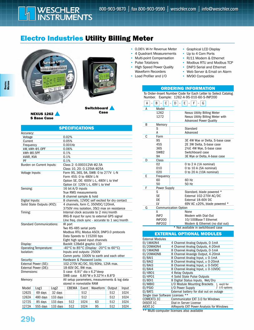
29b
DIG
ITA
LM
ETER
S
Electro Industries Utility Billing Meter• Graphical LCD Display• Up to 4 Com Ports• RJ11 Modem & Ethernet • Modbus RTU and Modbus TCP • DNP3 Serial and Ethernet• Web Server & Email on Alarm• MV90 Compatible
To Order–Insert Number Code for Each Letter to Select CatalogNumber. Example: 1262-A-9S-010-60-S-INP200
A Model1262 Nexus Utility Billing Meter 1272 Nexus Utility Billing Meter with
Advanced Power QualityB Memory
S StandardA Advanced
C Form9S 3E 4W Wye or Delta, S-base case 45S 2E 3W Delta, S-base case 36S 2½E 4W Wye, S-base caseSWB2 Switchboard case9A 3E Wye or Delta, A-base case
D Class 02 0 to 2 A (1A nominal)010 0 to 10 A (5A nominal)020 0 to 20 A (10A nominal)
E Frequency60 60 Hz50 50 Hz
F Power SupplyS Standard, blade powered *SE External 102-270V AC/DCDE External 18-60V DCLV 69V AC ±20%, blade powered *
G Communication OptionX NoneINP2 Modem with Dial-OutINP200 10/100Base T EthernetINP202 Modem & Ethernet (no dial out)
* Not available in switchboard case
ORDERING INFORMATION
A – B – C – D – E – F – G
SPECIFICATIONSAccuracy:
Voltage 0.02%Current 0.05%Frequency 0.001HzkW, kWh @1.0PF 0.06%kWh @0.5PF 0.1%kVAR, KVA 0.1%PF 0.1%
Burden on Current Inputs: Class 2: 0.000312VA @2.5AClass 10, 20: 0.125VA @25A
Voltage Inputs: Form 9S, 36S, 9A, SWB: 0 to 277V L-NForm 45S: 0 to 480V L-NOption SE, DE: 600V L-L, 480V L to VrefOption LV: 120V L-L, 69V L to Vref
Sensing: 16 bit A/D inputsTrue RMS measurements8 channel sample & hold
Digital Inputs: 8 channels, 12VDC self excited for dry contactSolid State Outputs (KYZ): 4 channels, form C, 350VDC/120mA,
3750V rms isolation, 35Ω max on resistanceTiming: Internal clock accurate to 2 min/month
IRIG-B input for sync to external GPS signalLIne freq. clock sync - accurate to 1 sec/month
Standard Communications: IR portTwo RS-485 serial portsModbus RTU, Modus ASCII, DNP3.0 protocolsData Speeds to 115200 bpsEight high speed input channels
Display: Backlit 128x64 graphic LCDOperating Temperature: -40°C to 85°C (Display: -20°C to 60°C)Isolation: Inputs and outputs: 2500V
Comm ports: 1000V to earth and each otherSecurity: Hardware & Password LocksExternal Power (SE): 102-270V AC/DC, 50/60Hz, 12VA max.External Power (DE): 18-60V DC, 9W max.Dimensions: S case 6.91" dia x 6.2"deep
SWB case 6.85"W x 9.32"H x 8.8"DMemory: All setup parameters, measurements & log data
stored in nonvolatile RAMModel Log1 Log2 CBEMA Event Waveform Output Input 1262S 69 days 32 days 512 512 10241262A 480 days 133 days 512 512 10241272S 85 days 133 days 512 1024 63 512 10241272A 555 days 133 days 512 1024 95 512 1024
External ModulesEI/1MAON4 4 Channel Analog Outputs, 0-1mAEI/20MAON4 4 Channel Analog Outputs, 4-20mAEI/1MAON8 8 Channel Analog Outputs, 0-1mAEI/20MAON8 8 Channel Anaolgo Output, 4-20mAEI/8AI1 8 Channel Analog Input, ± 0-1mAEI/8AI2 8 Channel Analog Input, ± 0-20mAEI/8AI3 8 Channel Analog Input, ± 0-5VDCEI/8AI4 8 Channel Analog Input, ± 0-10VDCEI/4RO1 4 Relay OutputsEI/4PO1 4 Solid State Pulse OutputsEI/8DI1 8 Digital Status Inputs, Wet/DryEI/MBIO I/O Module Mounting BracketsEI/PSIO I/O Power SupplyEI/BAT1 External battery for dial out on outageSingle User Software Licenses **COMEXT3.1C Communicator EXT 3.0 for Windows DISEXT.1C Dial-in Server LicenseAIEXT.1C AiReports EXT Power Analysis for Windows ** Multi-computer licenses also available
EXTERNAL OPTIONAL MODULES
NEXUS 1262S Base Case
Switchboard
Case
req’d for I/O options
• 0.06% W-hr Revenue Meter• 4 Quadrant Measurements• Multi-point Compensation • Pulse Totalizers• HIgh Speed Power Quality
Waveform Recorders• Load Profiler and I/O
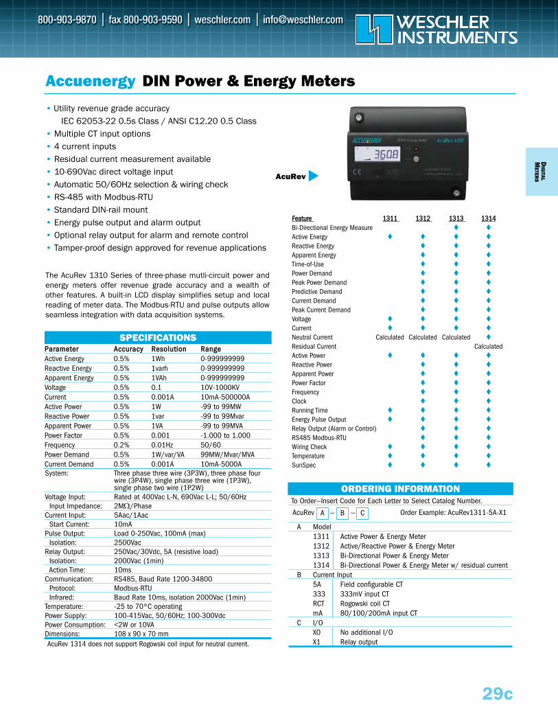
To Order—Insert Code for Each Letter to Select Catalog Number.
A Model1311 Active Power & Energy Meter1312 Active/Reactive Power & Energy Meter1313 Bi-Directional Power & Energy Meter1314 Bi-Directional Power & Energy Meter w/ residual current
B Current Input5A Field configurable CT333 333mV input CTRCT Rogowski coil CTmA 80/100/200mA input CT
C I/OX0 No additional I/OX1 Relay output
• Utility revenue grade accuracy IEC 62053-22 0.5s Class / ANSI C12.20 0.5 Class
• Multiple CT input options • 4 current inputs • Residual current measurement available• 10-690Vac direct voltage input• Automatic 50/60Hz selection & wiring check• RS-485 with Modbus-RTU• Standard DIN-rail mount• Energy pulse output and alarm output• Optional relay output for alarm and remote control• Tamper-proof design approved for revenue applications
AcuRev — — Order Example: AcuRev1311-5A-X1A B C
SPECIFICATIONS
Accuenergy DIN Power & Energy Meters
ORDERING INFORMATION
PPaarraammeetteerr AAccccuurraaccyy RReessoolluuttiioonn RRaannggeeActive Energy 0.5% 1Wh 0-999999999Reactive Energy 0.5% 1varh 0-999999999Apparent Energy 0.5% 1VAh 0-999999999Voltage 0.5% 0.1 10V-1000KVCurrent 0.5% 0.001A 10mA-500000AActive Power 0.5% 1W -99 to 99MWReactive Power 0.5% 1var -99 to 99MvarApparent Power 0.5% 1VA -99 to 99MVAPower Factor 0.5% 0.001 -1.000 to 1.000Frequency 0.2% 0.01Hz 50/60Power Demand 0.5% 1W/var/VA 99MW/Mvar/MVACurrent Demand 0.5% 0.001A 10mA-5000ASystem: Three phase three wire (3P3W), three phase four
wire (3P4W), single phase three wire (1P3W),single phase two wire (1P2W)
Voltage Input: Rated at 400Vac L-N, 690Vac L-L; 50/60HzInput Impedance: 2MΩ/Phase
Current Input: 5Aac/1AacStart Current: 10mA
Pulse Output: Load 0-250Vac, 100mA (max)Isolation: 2500Vac
Relay Output: 250Vac/30Vdc, 5A (resistive load)Isolation: 2000Vac (1min)Action Time: 10ms
Communication: RS485, Baud Rate 1200-34800Protocol: Modbus-RTUInfrared: Baud Rate 10ms, isolation 2000Vac (1min)
Temperature: -25 to 70ºC operatingPower Supply: 100-415Vac, 50/60Hz; 100-300VdcPower Consumption: <2W or 10VADimensions: 108 x 90 x 70 mmAcuRev 1314 does not support Rogowski coil input for neutral current.
AcuRev
DIG
ITALM
ETERS
29c
FFeeaattuurree 11331111 11331122 11331133 11331144Bi-Directional Energy Measure Active Energy Reactive Energy Apparent Energy Time-of-Use Power Demand Peak Power Demand Predictive Demand Current Demand Peak Current Demand Voltage Current Neutral Current Calculated Calculated Calculated Residual Current CalculatedActive Power Reactive Power Apparent Power Power Factor Frequency Clock Running Time Energy Pulse Output Relay Output (Alarm or Control) RS485 Modbus-RTU Wiring Check Temperature SunSpec
The AcuRev 1310 Series of three-phase mutli-circuit power andenergy meters offer revenue grade accuracy and a wealth ofother features. A built-in LCD display simplifies setup and localreading of meter data. The Modbus-RTU and pulse outputs allowseamless integration with data acquisition systems.
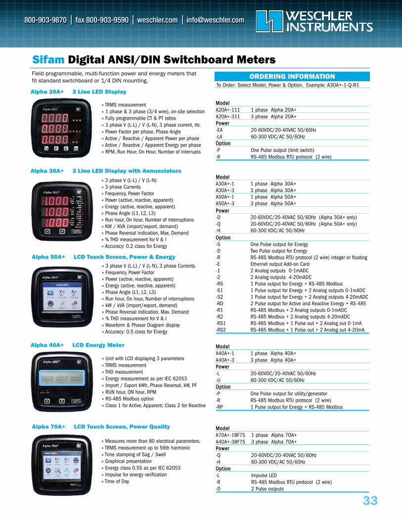
Alpha 20A+ 3 Line LED Display
Alpha 30A+ 3 Line LED Display with Annunciators
Alpha 70A+ LCD Touch Screen, Power Quality
33
Sifam Digital ANSI/DIN Switchboard MetersORDERING INFORMATION
To Order: Select Model, Power & Option. Example: A30A+-1-Q-R1
» TRMS measurement » 1 phase & 3 phase (3/4 wire), on-site selection » Fully programmable CT & PT ratios » 3 phase V (L-L) / V (L-N), 3 phase current, Hz.» Power Factor per phase, Phase Angle» Active / Reactive / Apparent Power per phase» Active / Reactive / Apparent Energy per phase » RPM, Run Hour, On Hour, Number of interrupts
MMooddeellA30A+-1 1 phase Alpha 30A+A30A+-3 3 phase Alpha 30A+A50A+-1 1 phase Alpha 50A+A50A+-3 3 phase Alpha 50A+PPoowweerr-D 20-60VDC/20-40VAC 50/60Hz (Alpha 30A+ only)-Q 20-60VDC/20-40VAC 50/60Hz (Alpha 50A+ only)-H 60-300 VDC/AC 50/60HzOOppttiioonn-S One Pulse output for Energy-D Two Pulse output for Energy-R RS-485 Modbus RTU protocol (2 wire) integer or floating-E Ethernet output Add-on Card-1 2 Analog outputs 0-1mADC -2 2 Analog outputs 4-20mADC-RS 1 Pulse output for Energy + RS-485 Modbus -S1 1 Pulse output for Energy + 2 Analog outputs 0-1mADC-S2 1 Pulse output for Energy + 2 Analog outputs 4-20mADC-RD 2 Pulse output for Active and Reactive Energy + RS-485 -R1 RS-485 Modbus + 2 Analog outputs 0-1mADC -R2 RS-485 Modbus + 2 Analog outputs 4-20mADC-RS1 RS-485 Modbus + 1 Pulse out + 2 Analog out 0-1mA-RS2 RS-485 Modbus + 1 Pulse out + 2 Analog out 4-20mA
MMooddeellA40A+-1 1 phase Alpha 40A+A40A+-3 3 phase Alpha 40A+PPoowweerr-L 20-60VDC/20-40VAC 50/60Hz-U 60-300 VDC/AC 50/60HzOOppttiioonn-P One Pulse output for utility/generator-R RS-485 Modbus RTU protocol (2 wire)-RP 1 Pulse output for Energy + RS-485 Modbus
MMooddeellA70A+-18F75 1 phase Alpha 70A+A40A+-38F75 3 phase Alpha 70A+PPoowweerr-Q 20-60VDC/20-40VAC 50/60Hz-H 60-300 VDC/AC 50/60HzOOppttiioonn-L Impulse LED-R RS-485 Modbus RTU protocol (2 wire)-D 2 Pulse outputs
MMooddeellA20A+-111 1 phase Alpha 20A+ A20A+-311 3 phase Alpha 20A+PPoowweerr-EA 20-60VDC/20-40VAC 50/60Hz-LA 60-300 VDC/AC 50/60HzOOppttiioonn-P One Pulse output (limit switch)-R RS-485 Modbus RTU protocol (2 wire)
» 3 phase V (L-L) / V (L-N)» 3 phase Currents » Frequency, Power Factor» Power (active, reactive, apparent) » Energy (active, reactive, apparent) » Phase Angle (L1, L2, L3) » Run hour, On hour, Number of interruptions» KW / KVA (import/export, demand)» Phase Reversal indication, Max. Demand» % THD measurement for V & I» Accuracy: 0.2 class for Energy
» Measures more than 80 electrical parameters.» TRMS measurement up to 56th harmonic» Time stamping of Sag / Swell» Graphical presentation» Energy class 0.5S as per IEC 62053» Impulse for energy verification» Time of Day
Field programmable, multi-function power and energy meters thatfit standard switchboard or 1/4 DIN mounting.
Alpha 50A+ LCD Touch Screen, Power & Energy
» 3 phase V (L-L) / V (L-N), 3 phase Currents » Frequency, Power Factor » Power (active, reactive, apparent) » Energy (active, reactive, apparent) » Phase Angle (L1, L2, L3)» Run hour, On hour, Number of interruptions» kW / kVA (import/export, demand)» Phase Reversal indication, Max. Demand » % THD measurement for V & I » Waveform & Phasor Diagram display » Accuracy: 0.5 class for Energy
Alpha 40A+ LCD Energy Meter
» Unit with LCD displaying 3 parameters» TRMS measurement» THD measurement» Energy measurement as per IEC 62053» Import / Export kWh, Phase Reversal, kW, PF » RUN hour, ON hour, RPM» RS-485 Modbus option» Class 1 for Active, Apparent; Class 2 for Reactive
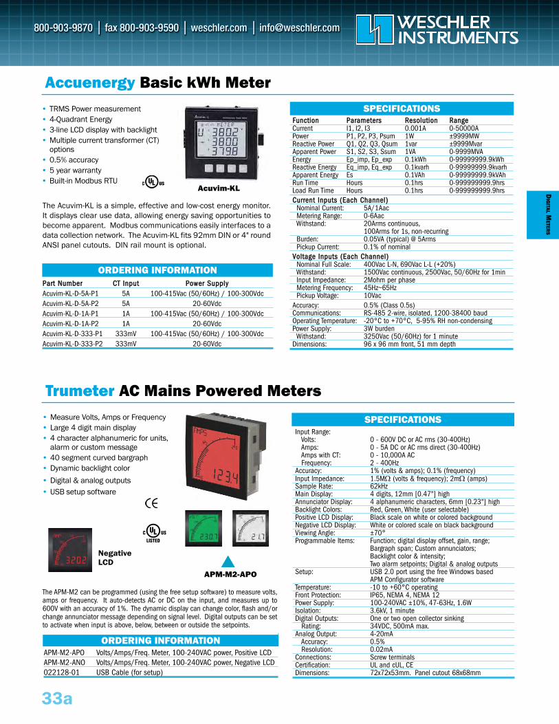
33a
DIG
ITALM
ETERS
Accuenergy Basic kWh Meter• TRMS Power measurement• 4-Quadrant Energy • 3-line LCD display with backlight• Multiple current transformer (CT)
options• 0.5% accuracy• 5 year warranty• Built-in Modbus RTU
Acuvim-KL
FFuunnccttiioonn PPaarraammeetteerrss RReessoolluuttiioonn RRaannggeeCurrent I1, I2, I3 0.001A 0-50000APower P1, P2, P3, Psum 1W ±9999MWReactive Power Q1, Q2, Q3, Qsum 1var ±9999MvarApparent Power S1, S2, S3, Ssum 1VA 0-9999MVAEnergy Ep_imp, Ep_exp 0.1kWh 0-99999999.9kWhReactive Energy Eq_imp, Eq_exp 0.1kvarh 0-99999999.9kvarhApparent Energy Es 0.1VAh 0-99999999.9kVAhRun Time Hours 0.1hrs 0-999999999.9hrsLoad Run Time Hours 0.1hrs 0-999999999.9hrsCCuurrrreenntt IInnppuuttss ((EEaacchh CChhaannnneell))
Nominal Current: 5A/1AacMetering Range: 0-6AacWithstand: 20Arms continuous,
100Arms for 1s, non-recurringBurden: 0.05VA (typical) @ 5ArmsPickup Current: 0.1% of nominal
VVoollttaaggee IInnppuuttss ((EEaacchh CChhaannnneell))Nominal Full Scale: 400Vac L-N, 690Vac L-L (+20%)Withstand: 1500Vac continuous, 2500Vac, 50/60Hz for 1minInput Impedance: 2Mohm per phaseMetering Frequency: 45Hz~65HzPickup Voltage: 10Vac
Accuracy: 0.5% (Class 0.5s)Communications: RS-485 2-wire, isolated, 1200-38400 baudOperating Temperature: -20°C to +70°C, 5-95% RH non-condensingPower Supply: 3W burden
Withstand: 3250Vac (50/60Hz) for 1 minuteDimensions: 96 x 96 mm front, 51 mm depth
ORDERING INFORMATION
SPECIFICATIONS
PPaarrtt NNuummbbeerr CCTT IInnppuutt PPoowweerr SSuuppppllyyAcuvim-KL-D-5A-P1 5A 100-415Vac (50/60Hz) / 100-300Vdc Acuvim-KL-D-5A-P2 5A 20-60VdcAcuvim-KL-D-1A-P1 1A 100-415Vac (50/60Hz) / 100-300Vdc Acuvim-KL-D-1A-P2 1A 20-60VdcAcuvim-KL-D-333-P1 333mV 100-415Vac (50/60Hz) / 100-300Vdc Acuvim-KL-D-333-P2 333mV 20-60Vdc
The Acuvim-KL is a simple, effective and low-cost energy monitor.It displays clear use data, allowing energy saving opportunities tobecome apparent. Modbus communications easily interfaces to adata collection network. The Acuvim-KL fits 92mm DIN or 4" roundANSI panel cutouts. DIN rail mount is optional.
Trumeter AC Mains Powered Meters• Measure Volts, Amps or Frequency• Large 4 digit main display• 4 character alphanumeric for units,
alarm or custom message• 40 segment curved bargraph • Dynamic backlight color
• Digital & analog outputs• USB setup software
APM-M2-APO
NegativeLCD
Input Range: Volts: 0 - 600V DC or AC rms (30-400Hz)Amps: 0 - 5A DC or AC rms direct (30-400Hz)Amps with CT: 0 - 10,000A ACFrequency: 2 - 400Hz
Accuracy: 1% (volts & amps); 0.1% (frequency)Input Impedance: 1.5MΩ (volts & frequency); 2mΩ (amps)Sample Rate: 62kHzMain Display: 4 digits, 12mm [0.47"] highAnnunciator Display: 4 alphanumeric characters, 6mm [0.23"] highBacklight Colors: Red, Green, White (user selectable)Positive LCD Display: Black scale on white or colored backgroundNegative LCD Display: White or colored scale on black backgroundViewing Angle: ±70°Programmable Items: Function; digital display offset, gain, range;
Bargraph span; Custom annunciators; Backlight color & intensity;Two alarm setpoints; Digital & analog outputs
Setup: USB 2.0 port using the free Windows basedAPM Configurator software
Temperature: -10 to +60°C operatingFront Protection: IP65, NEMA 4, NEMA 12Power Supply: 100-240VAC ±10%, 47-63Hz, 1.6WIsolation: 3.6kV, 1 minuteDigital Outputs: One or two open collector sinking
Rating: 34VDC, 500mA max.Analog Output: 4-20mA
Accuracy: 0.5%Resolution: 0.02mA
Connections: Screw terminalsCertification: UL and cUL, CEDimensions: 72x72x53mm. Panel cutout 68x68mm
SPECIFICATIONS
ORDERING INFORMATIONAPM-M2-APO Volts/Amps/Freq. Meter, 100-240VAC power, Positive LCDAPM-M2-ANO Volts/Amps/Freq. Meter, 100-240VAC power, Negative LCD022128-01 USB Cable (for setup)
The APM-M2 can be programmed (using the free setup software) to measure volts,amps or frequency. It auto-detects AC or DC on the input, and measures up to600V with an accuracy of 1%. The dynamic display can change color, flash and/orchange annunciator message depending on signal level. Digital outputs can be setto activate when input is above, below, between or outside the setpoints.
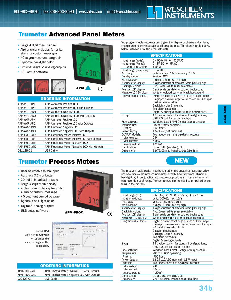
DIG
ITALM
ETERS
34b
Trumeter Advanced Panel Meters• Large 4 digit main display• Alphanumeric display for units,
alarm or custom message• 40 segment curved bargraph • Dynamic backlight color
• Optional digital & analog outputs• USB setup software
• User selectable V/mA input• Accuracy 0.1% or better• 20 point linearization table • Large 4 digit main display• Alphanumeric display for units,
alarm or custom message• 40 segment curved bargraph • Dynamic backlight color
• Digital & analog outputs• USB setup software
APM
Input range (DC): 0 to 10V; ±10V; 0 to 50mA; 4 to 20 mA Input impedance: Volts: 100kΩ; mA: 15ΩAccuracy: Volts: 0.1%; mA: 0.01%Main Display: 4 digits, 12mm [0.47"] highAnnunciator Display: 4 alphanumeric characters, 6mm [0.23"] highBacklight colors: Red, Green, White (user selectable)Positive LCD display: Black scale on white or colored backgroundNegative LCD Display: White or colored scale on black backgroundProgrammable items: Digital display: offset & gain; auto or fixed range
Bargraph: positive, negative or center bar; bar span 20 point linearization tableCustom annunciatorsBacklight color & intensityTwo alarm setpointsDigital & analog outputs
Setup: 16 position switch for standard configurations,USB 2.0 port for custom settings
Free software: Windows based APM Configurator applicationTemperature: -10 to +60°C operatingIP rating: IP65 frontPower Supply: 12-24 VAC/VDC nominal (1.6W max.)Outputs: Two independent analog/digital outputs
Max voltage: 24VMax current: 50mAAnalog output: 4-20mA
Certification: UL and cUL (Pending), CEDimensions: 72x72x53mm. Panel cutout 68x68mm
Input range (Volts): 0 - 600V DC; 0 - 528V ACInput range (Amps): 0 - 5A DC; 0 - 5A AC,
with CT or Shunt: 1000AInput range (Frequency) 0 - 400HzAccuracy: Volts or Amps: 1%; Frequency: 0.1%Display modes: Peak or RMSMain Display: 4 digits, 12mm [0.47"] highAnnunciator Display: 4 alphanumeric characters, 6mm [0.23"] highBacklight colors: Red, Green, White (user selectable)Positive LCD display: Black scale on white or colored backgroundNegative LCD Display: White or colored scale on black backgroundProgrammable items: Digital display: offset & gain; auto or fixed range
Bargraph: positive, negative or center bar; bar span Custom annunciatorsBacklight color & intensityTwo alarm setpointsDigital & analog outputs (Output models only)
Setup: 16 position switch for standard configurations,USB 2.0 port for custom settings
Free software: Windows based APM Configurator applicationTemperature: -10 to +60°C operatingIP rating: IP65 frontPower Supply: 12-24 VAC/VDC nominalOUTPUT Models: Two independent analog/digital outputs
Max voltage: 24VMax current: 50mAAnalog output: 4-20mA
Certification: UL and cUL (Pending), CEDimensions: 72x72x53mm. Panel cutout 68x68mm
SPECIFICATIONS
SPECIFICATIONS
ORDERING INFORMATION
ORDERING INFORMATION
APM-VOLT-APN APM Voltmeter, Positive LCD APM-VOLT-APO APM Voltmeter, Positive LCD with OutputsAPM-VOLT-ANN APM Voltmeter, Negative LCD APM-VOLT-ANO APM Voltmeter, Negative LCD with Outputs APM-AMP-APN APM Ammeter, Positive LCD APM-AMP-APO APM Ammeter, Positive LCD with Outputs APM-AMP-ANN APM Ammeter, Negative LCDAPM-AMP-ANO APM Ammeter, Negative LCD with OutputsAPM-FREQ-APN APM Frequency Meter, Positive LCDAPM-FREQ-APO APM Frequency Meter, Positive LCD with OutputsAPM-FREQ-ANN APM Frequency Meter, Negative LCDAPM-FREQ-ANO APM Frequency Meter, Negative LCD with Outputs022128-01 USB Cable
APM-PROC-APO APM Process Meter, Positive LCD with Outputs APM-PROC-ANO APM Process Meter, Negative LCD with Outputs 022128-01 USB Cable
Two programmable setpoints can trigger the display to change color, flash,change annunciator message or all three at once. Trip when input is above,below, between or outside the setpoints.
The programmable scale, linearization table and custom annunciator allowusers to display the process parameter exactly how they want. Dynamicbacklighting, in conjunction with setpoints, provides a visual alert when aparameter is out of range. The two outputs can be used to control other sys-tems in the process.
Trumeter Process Meters NEW
APM-PROC
Use the APMConfigurator Software
to customize themeter settings for the
application.
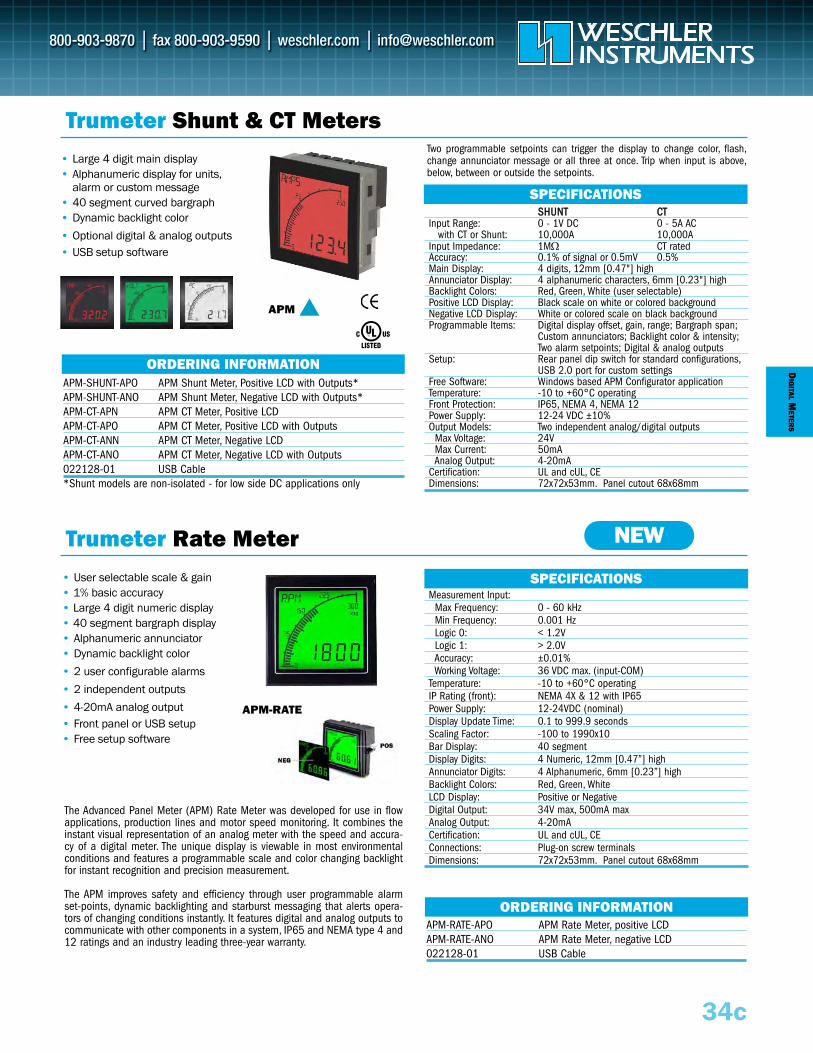
DIG
ITALM
ETERS
34c
Trumeter Shunt & CT Meters• Large 4 digit main display• Alphanumeric display for units,
alarm or custom message• 40 segment curved bargraph • Dynamic backlight color
• Optional digital & analog outputs• USB setup software
• User selectable scale & gain• 1% basic accuracy• Large 4 digit numeric display• 40 segment bargraph display • Alphanumeric annunciator• Dynamic backlight color
• 2 user configurable alarms
• 2 independent outputs
• 4-20mA analog output• Front panel or USB setup• Free setup software
APM
Measurement Input:Max Frequency: 0 - 60 kHzMin Frequency: 0.001 HzLogic 0: < 1.2VLogic 1: > 2.0VAccuracy: ±0.01%Working Voltage: 36 VDC max. (input-COM)
Temperature: -10 to +60°C operatingIP Rating (front): NEMA 4X & 12 with IP65Power Supply: 12-24VDC (nominal)Display Update Time: 0.1 to 999.9 secondsScaling Factor: -100 to 1990x10Bar Display: 40 segmentDisplay Digits: 4 Numeric, 12mm [0.47”] highAnnunciator Digits: 4 Alphanumeric, 6mm [0.23”] highBacklight Colors: Red, Green, WhiteLCD Display: Positive or NegativeDigital Output: 34V max, 500mA maxAnalog Output: 4-20mACertification: UL and cUL, CEConnections: Plug-on screw terminalsDimensions: 72x72x53mm. Panel cutout 68x68mm
SSHHUUNNTT CCTTInput Range: 0 - 1V DC 0 - 5A AC
with CT or Shunt: 10,000A 10,000AInput Impedance: 1MΩ CT ratedAccuracy: 0.1% of signal or 0.5mV 0.5%Main Display: 4 digits, 12mm [0.47"] highAnnunciator Display: 4 alphanumeric characters, 6mm [0.23"] highBacklight Colors: Red, Green, White (user selectable)Positive LCD Display: Black scale on white or colored backgroundNegative LCD Display: White or colored scale on black backgroundProgrammable Items: Digital display offset, gain, range; Bargraph span;
Custom annunciators; Backlight color & intensity;Two alarm setpoints; Digital & analog outputs
Setup: Rear panel dip switch for standard configurations,USB 2.0 port for custom settings
Free Software: Windows based APM Configurator applicationTemperature: -10 to +60°C operatingFront Protection: IP65, NEMA 4, NEMA 12Power Supply: 12-24 VDC ±10%Output Models: Two independent analog/digital outputs
Max Voltage: 24VMax Current: 50mAAnalog Output: 4-20mA
Certification: UL and cUL, CEDimensions: 72x72x53mm. Panel cutout 68x68mm
SPECIFICATIONS
SPECIFICATIONS
ORDERING INFORMATION
ORDERING INFORMATION
APM-SHUNT-APO APM Shunt Meter, Positive LCD with Outputs*APM-SHUNT-ANO APM Shunt Meter, Negative LCD with Outputs*APM-CT-APN APM CT Meter, Positive LCDAPM-CT-APO APM CT Meter, Positive LCD with OutputsAPM-CT-ANN APM CT Meter, Negative LCD APM-CT-ANO APM CT Meter, Negative LCD with Outputs 022128-01 USB Cable*Shunt models are non-isolated - for low side DC applications only
APM-RATE-APO APM Rate Meter, positive LCDAPM-RATE-ANO APM Rate Meter, negative LCD 022128-01 USB Cable
Two programmable setpoints can trigger the display to change color, flash,change annunciator message or all three at once. Trip when input is above,below, between or outside the setpoints.
The Advanced Panel Meter (APM) Rate Meter was developed for use in flowapplications, production lines and motor speed monitoring. It combines theinstant visual representation of an analog meter with the speed and accura-cy of a digital meter. The unique display is viewable in most environmentalconditions and features a programmable scale and color changing backlightfor instant recognition and precision measurement.
The APM improves safety and efficiency through user programmable alarmset-points, dynamic backlighting and starburst messaging that alerts opera-tors of changing conditions instantly. It features digital and analog outputs tocommunicate with other components in a system, IP65 and NEMA type 4 and12 ratings and an industry leading three-year warranty.
Trumeter Rate Meter NEW
APM-RATE
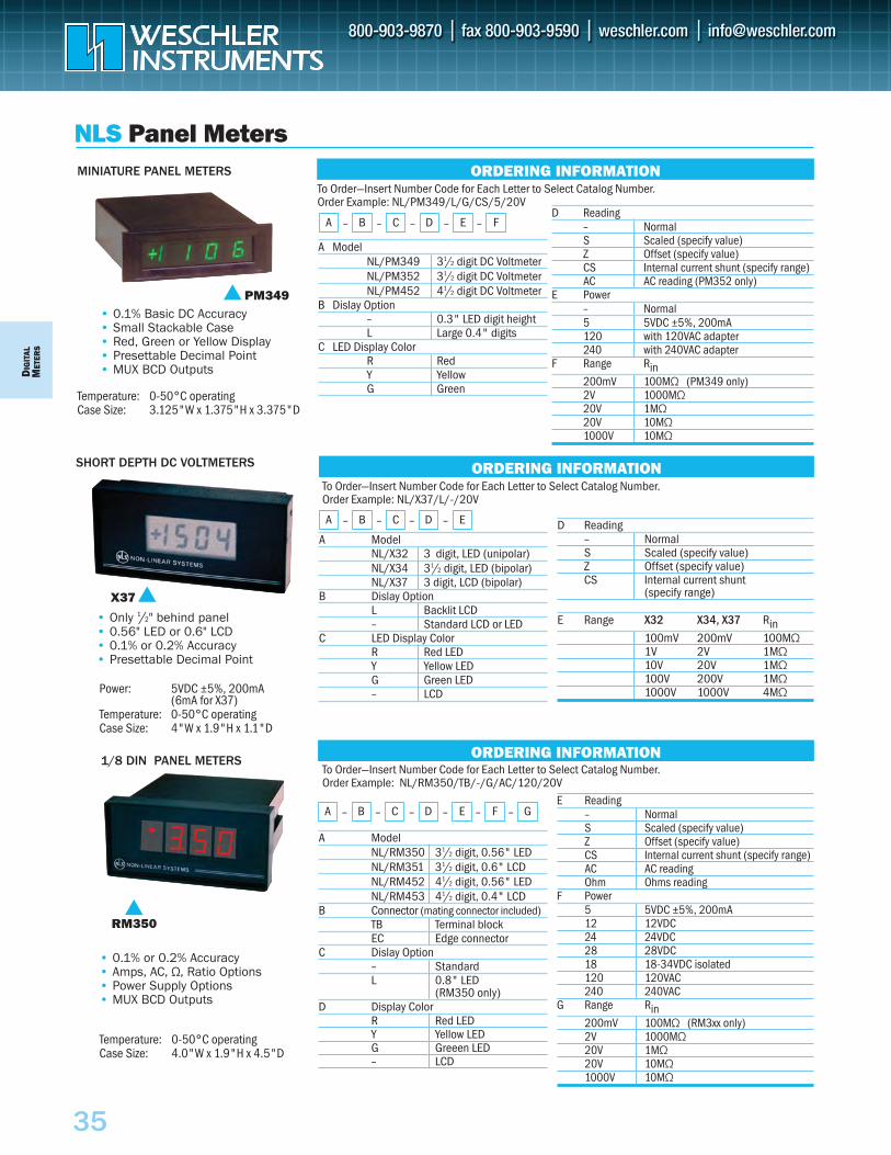
DIG
ITAL
MET
ERS
35
To Order—Insert Number Code for Each Letter to Select Catalog Number. Order Example: NL/PM349/L/G/CS/5/20V
A ModelNL/PM349 31/2 digit DC VoltmeterNL/PM352 31/2 digit DC VoltmeterNL/PM452 41/2 digit DC Voltmeter
B Dislay Option– 0.3" LED digit heightL Large 0.4" digits
C LED Display ColorR RedY YellowG Green
• 0.1% Basic DC Accuracy• Small Stackable Case• Red, Green or Yellow Display• Presettable Decimal Point• MUX BCD Outputs
Temperature: 0-50°C operatingCase Size: 3.125"W x 1.375"H x 3.375"D
MINIATURE PANEL METERS
NLS Panel MetersORDERING INFORMATION
A – B – C – D – E – F
• Only 1/2" behind panel• 0.56" LED or 0.6" LCD• 0.1% or 0.2% Accuracy• Presettable Decimal Point
Power: 5VDC ±5%, 200mA(6mA for X37)
Temperature: 0-50°C operatingCase Size: 4"W x 1.9"H x 1.1"D
SHORT DEPTH DC VOLTMETERS
X37
PM349
ORDERING INFORMATIONTo Order—Insert Number Code for Each Letter to Select Catalog Number. Order Example: NL/RM350/TB/-/G/AC/120/20V
A ModelNL/X32 3 digit, LED (unipolar)NL/X34 31/2 digit, LED (bipolar)NL/X37 3 digit, LCD (bipolar)
B Dislay OptionL Backlit LCD – Standard LCD or LED
C LED Display ColorR Red LEDY Yellow LEDG Green LED– LCD
ORDERING INFORMATION
A – B – C – D – E
To Order—Insert Number Code for Each Letter to Select Catalog Number. Order Example: NL/X37/L/-/20V
A ModelNL/RM350 31/2 digit, 0.56" LEDNL/RM351 31/2 digit, 0.6" LCDNL/RM452 41/2 digit, 0.56" LEDNL/RM453 41/2 digit, 0.4" LCD
B Connector (mating connector included)TB Terminal blockEC Edge connector
C Dislay Option– StandardL 0.8" LED
(RM350 only)D Display Color
R Red LEDY Yellow LEDG Greeen LED– LCD
A – B – C – D – E – F – GE Reading
– NormalS Scaled (specify value)Z Offset (specify value)CS Internal current shunt (specify range)AC AC reading Ohm Ohms reading
F Power5 5VDC ±5%, 200mA12 12VDC24 24VDC28 28VDC18 18-34VDC isolated120 120VAC 240 240VAC
G Range Rin200mV 100MΩ (RM3xx only)2V 1000MΩ 20V 1MΩ 20V 10MΩ 1000V 10MΩ
1/8 DIN PANEL METERS
RM350
• 0.1% or 0.2% Accuracy• Amps, AC, Ω, Ratio Options • Power Supply Options• MUX BCD Outputs
D Reading– NormalS Scaled (specify value)Z Offset (specify value)CS Internal current shunt (specify range)AC AC reading (PM352 only)
E Power– Normal5 5VDC ±5%, 200mA120 with 120VAC adapter240 with 240VAC adapter
F Range Rin200mV 100MΩ (PM349 only)2V 1000MΩ 20V 1MΩ 20V 10MΩ 1000V 10MΩ
Temperature: 0-50°C operatingCase Size: 4.0"W x 1.9"H x 4.5"D
D Reading– NormalS Scaled (specify value)Z Offset (specify value)CS Internal current shunt
(specify range)
E Range X32 X34, X37 Rin100mV 200mV 100MΩ 1V 2V 1MΩ 10V 20V 1MΩ 100V 200V 1MΩ 1000V 1000V 4MΩ
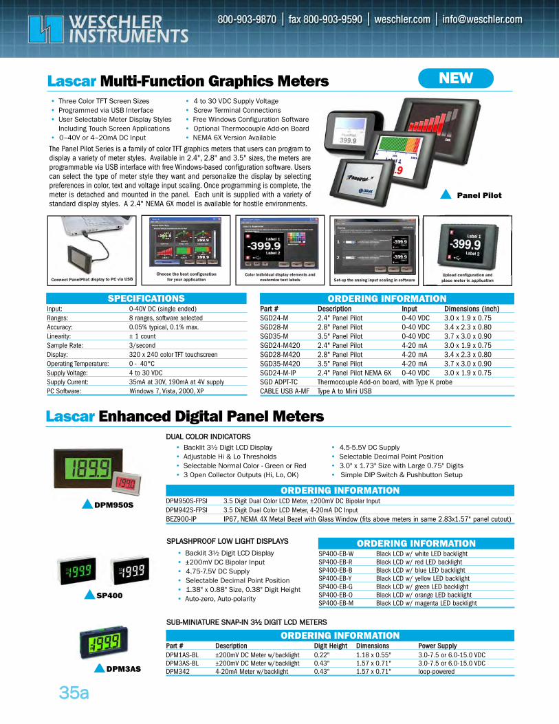
3355aa
Lascar Multi-Function Graphics Meters
The Panel Pilot Series is a family of color TFT graphics meters that users can program todisplay a variety of meter styles. Available in 2.4", 2.8" and 3.5" sizes, the meters areprogrammable via USB interface with free Windows-based configuration software. Userscan select the type of meter style they want and personalize the display by selectingpreferences in color, text and voltage input scaling. Once programming is complete, themeter is detached and mounted in the panel. Each unit is supplied with a variety ofstandard display styles. A 2.4" NEMA 6X model is available for hostile environments.
Input: 0-40V DC (single ended)Ranges: 8 ranges, software selectedAccuracy: 0.05% typical, 0.1% max.Linearity: ± 1 countSample Rate: 3/secondDisplay: 320 x 240 color TFT touchscreenOperating Temperature: 0 - 40°CSupply Voltage: 4 to 30 VDCSupply Current: 35mA at 30V, 190mA at 4V supplyPC Software: Windows 7, Vista, 2000, XP
SPECIFICATIONSPPaarrtt ## DDeessccrriippttiioonn IInnppuutt DDiimmeennssiioonnss ((iinncchh))SGD24-M 2.4" Panel Pilot 0-40 VDC 3.0 x 1.9 x 0.75SGD28-M 2.8" Panel Pilot 0-40 VDC 3.4 x 2.3 x 0.80SGD35-M 3.5" Panel Pilot 0-40 VDC 3.7 x 3.0 x 0.90SGD24-M420 2.4" Panel Pilot 4-20 mA 3.0 x 1.9 x 0.75SGD28-M420 2.8" Panel Pilot 4-20 mA 3.4 x 2.3 x 0.80SGD35-M420 3.5" Panel Pilot 4-20 mA 3.7 x 3.0 x 0.90SGD24-M-IP 2.4" Panel Pilot NEMA 6X 0-40 VDC 3.0 x 1.9 x 0.75SGD ADPT-TC Thermocouple Add-on board, with Type K probeCABLE USB A-MF Type A to Mini USB
DPM950S-FPSI 3.5 Digit Dual Color LCD Meter, ±200mV DC Bipolar InputDPM942S-FPSI 3.5 Digit Dual Color LCD Meter, 4-20mA DC InputBEZ900-IP IP67, NEMA 4X Metal Bezel with Glass Window (fits above meters in same 2.83x1.57" panel cutout)
SP400-EB-W Black LCD w/ white LED backlightSP400-EB-R Black LCD w/ red LED backlightSP400-EB-B Black LCD w/ blue LED backlightSP400-EB-Y Black LCD w/ yellow LED backlightSP400-EB-G Black LCD w/ green LED backlightSP400-EB-O Black LCD w/ orange LED backlightSP400-EB-M Black LCD w/ magenta LED backlight
ORDERING INFORMATION
Panel Pilot
Lascar Enhanced Digital Panel Meters
DPM950SORDERING INFORMATION
ORDERING INFORMATION
PPaarrtt ## DDeessccrriippttiioonn DDiiggiitt HHeeiigghhtt DDiimmeennssiioonnss PPoowweerr SSuuppppllyyDPM1AS-BL ±200mV DC Meter w/backlight 0.22" 1.18 x 0.55" 3.0-7.5 or 6.0-15.0 VDCDPM3AS-BL ±200mV DC Meter w/backlight 0.43" 1.57 x 0.71" 3.0-7.5 or 6.0-15.0 VDCDPM342 4-20mA Meter w/backlight 0.43" 1.57 x 0.71" loop-powered
ORDERING INFORMATION
NEW• Three Color TFT Screen Sizes• Programmed via USB Interface• User Selectable Meter Display Styles
Including Touch Screen Applications• 0–40V or 4–20mA DC Input
• 4 to 30 VDC Supply Voltage• Screw Terminal Connections• Free Windows Configuration Software• Optional Thermocouple Add-on Board• NEMA 6X Version Available
• Backlit 3½ Digit LCD Display• ±200mV DC Bipolar Input • 4.75-7.5V DC Supply • Selectable Decimal Point Position• 1.38" x 0.88" Size, 0.38" Digit Height• Auto-zero, Auto-polarity
• Backlit 3½ Digit LCD Display• Adjustable Hi & Lo Thresholds • Selectable Normal Color - Green or Red• 3 Open Collector Outputs (Hi, Lo, OK)
Choose the best configuration for your application Set-up the analog input scaling in software
Upload configuration and place meter in applicationUpload configuration and place meter in applic ti
Color individual display elements and customize text labelsConnect PanelPilot display to PC via USB
DDUUAALL CCOOLLOORR IINNDDIICCAATTOORRSS
SSPPLLAASSHHPPRROOOOFF LLOOWW LLIIGGHHTT DDIISSPPLLAAYYSS
SSUUBB--MMIINNIIAATTUURREE SSNNAAPP--IINN 33½½ DDIIGGIITT LLCCDD MMEETTEERRSS
SP400
DPM3AS
• 4.5-5.5V DC Supply • Selectable Decimal Point Position• 3.0" x 1.73" Size with Large 0.75" Digits• Simple DIP Switch & Pushbutton Setup
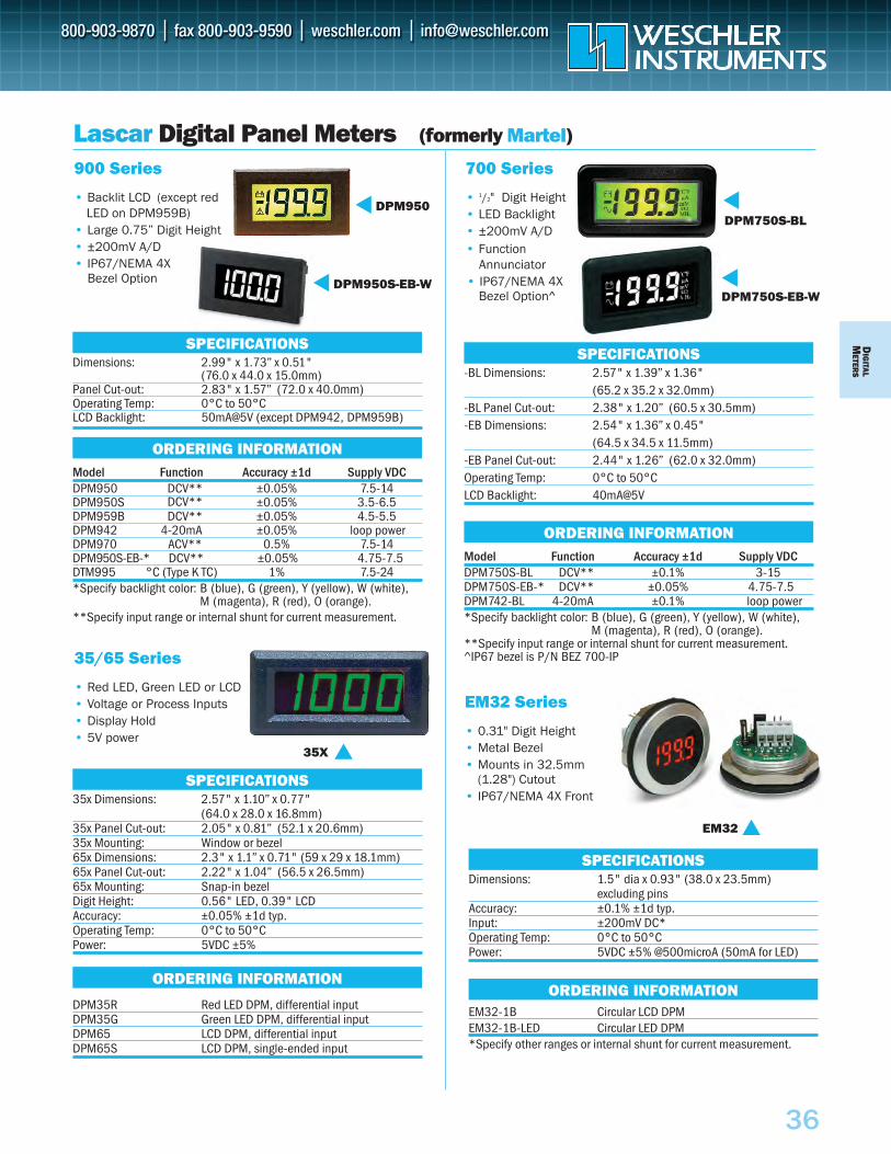
DIG
ITALM
ETERS
36
Lascar Digital Panel Meters (formerly Martel)
900 Series
• Backlit LCD (except redLED on DPM959B)
• Large 0.75” Digit Height• ±200mV A/D• IP67/NEMA 4X
Bezel Option
DPM950
DPM950S-EB-W
Dimensions: 2.99" x 1.73” x 0.51" (76.0 x 44.0 x 15.0mm)
Panel Cut-out: 2.83" x 1.57” (72.0 x 40.0mm) Operating Temp: 0°C to 50°CLCD Backlight: 50mA@5V (except DPM942, DPM959B)
Model Function Accuracy ±1d Supply VDCDPM950 DCV** ±0.05% 7.5-14DPM950S DCV** ±0.05% 3.5-6.5DPM959B DCV** ±0.05% 4.5-5.5DPM942 4-20mA ±0.05% loop powerDPM970 ACV** 0.5% 7.5-14 DPM950S-EB-* DCV** ±0.05% 4.75-7.5DTM995 °C (Type K TC) 1% 7.5-24 *Specify backlight color: B (blue), G (green), Y (yellow), W (white),
M (magenta), R (red), O (orange).**Specify input range or internal shunt for current measurement.
SPECIFICATIONS
ORDERING INFORMATION
700 Series
• 1/2" Digit Height• LED Backlight • ±200mV A/D• Function
Annunciator• IP67/NEMA 4X
Bezel Option^
DPM750S-BL
DPM750S-EB-W
-BL Dimensions: 2.57" x 1.39” x 1.36" (65.2 x 35.2 x 32.0mm)
-BL Panel Cut-out: 2.38" x 1.20” (60.5 x 30.5mm) -EB Dimensions: 2.54" x 1.36” x 0.45"
(64.5 x 34.5 x 11.5mm) -EB Panel Cut-out: 2.44" x 1.26” (62.0 x 32.0mm) Operating Temp: 0°C to 50°CLCD Backlight: 40mA@5V
Model Function Accuracy ±1d Supply VDCDPM750S-BL DCV** ±0.1% 3-15DPM750S-EB-* DCV** ±0.05% 4.75-7.5DPM742-BL 4-20mA ±0.1% loop power *Specify backlight color: B (blue), G (green), Y (yellow), W (white),
M (magenta), R (red), O (orange).**Specify input range or internal shunt for current measurement.^IP67 bezel is P/N BEZ 700-IP
SPECIFICATIONS
ORDERING INFORMATION
35/65 Series
• Red LED, Green LED or LCD• Voltage or Process Inputs• Display Hold • 5V power
35x Dimensions: 2.57" x 1.10” x 0.77" (64.0 x 28.0 x 16.8mm)
35x Panel Cut-out: 2.05" x 0.81” (52.1 x 20.6mm) 35x Mounting: Window or bezel65x Dimensions: 2.3" x 1.1” x 0.71" (59 x 29 x 18.1mm) 65x Panel Cut-out: 2.22" x 1.04” (56.5 x 26.5mm) 65x Mounting: Snap-in bezel Digit Height: 0.56" LED, 0.39" LCD Accuracy: ±0.05% ±1d typ.Operating Temp: 0°C to 50°C Power: 5VDC ±5%
DPM35R Red LED DPM, differential input DPM35G Green LED DPM, differential input DPM65 LCD DPM, differential input DPM65S LCD DPM, single-ended input
SPECIFICATIONS
ORDERING INFORMATION
Dimensions: 1.5" dia x 0.93" (38.0 x 23.5mm)excluding pins
Accuracy: ±0.1% ±1d typ.Input: ±200mV DC*Operating Temp: 0°C to 50°C Power: 5VDC ±5% @500microA (50mA for LED)
EM32-1B Circular LCD DPMEM32-1B-LED Circular LED DPM *Specify other ranges or internal shunt for current measurement.
SPECIFICATIONS
ORDERING INFORMATION
EM32 Series
• 0.31" Digit Height• Metal Bezel• Mounts in 32.5mm
(1.28") Cutout• IP67/NEMA 4X Front
EM32
35X
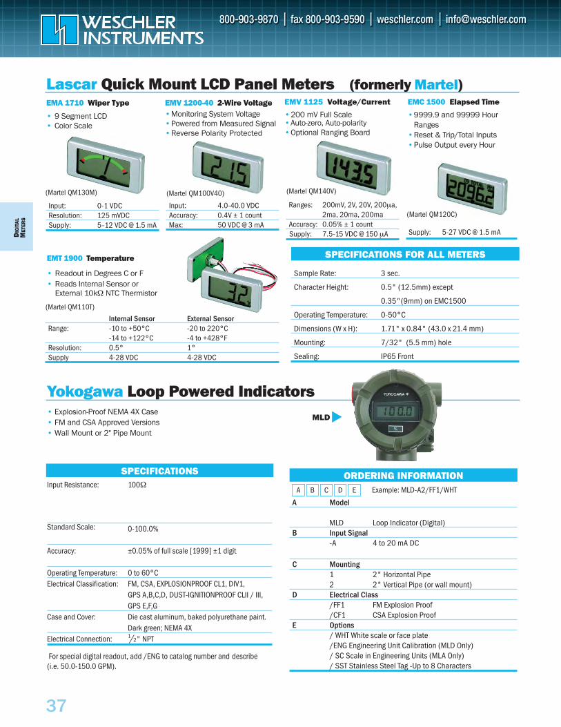
DIG
ITAL
MET
ERS
37
EMA 1710 Wiper Type
• 9 Segment LCD• Color Scale
Input: 0-1 VDCResolution: 125 mVDCSupply: 5–12 VDC @ 1.5 mA
EMV 1125 Voltage/Current
•200 mV Full Scale •Auto-zero, Auto-polarity•Optional Ranging Board
EMC 1500 Elapsed Time
•9999.9 and 99999 Hour Ranges
•Reset & Trip/Total Inputs•Pulse Output every Hour
EMT 1900 Temperature
• Readout in Degrees C or F• Reads Internal Sensor or
External 10kΩ NTC Thermistor
Lascar Quick Mount LCD Panel Meters (formerly Martel)
SPECIFICATIONS FOR ALL METERS
Sample Rate: 3 sec.
Character Height: 0.5" (12.5mm) except
0.35"(9mm) on EMC1500
Operating Temperature: 0-50°C
Dimensions (W x H): 1.71" x 0.84" (43.0 x 21.4 mm)
Mounting: 7/32" (5.5 mm) hole
Sealing: IP65 Front
EMV 1200-40 2-Wire Voltage•Monitoring System Voltage•Powered from Measured Signal•Reverse Polarity Protected
Input: 4.0-40.0 VDCAccuracy: 0.4V ± 1 countMax: 50 VDC @ 3 mA
Ranges: 200mV, 2V, 20V, 200µa,2ma, 20ma, 200ma
Accuracy: 0.05% ± 1 countSupply: 7.5-15 VDC @ 150 µA
Internal Sensor External SensorRange: -10 to +50°C -20 to 220°C
-14 to +122°C -4 to +428°FResolution: 0.5° 1°Supply 4-28 VDC 4-28 VDC
• Explosion-Proof NEMA 4X Case • FM and CSA Approved Versions • Wall Mount or 2" Pipe Mount
A Model
MLD Loop Indicator (Digital)B Input Signal
-A 4 to 20 mA DC
C Mounting 1 2" Horizontal Pipe2 2" Vertical Pipe (or wall mount)
D Electrical Class/FF1 FM Explosion Proof/CF1 CSA Explosion Proof
E Options / WHT White scale or face plate/ENG Engineering Unit Calibration (MLD Only)/ SC Scale in Engineering Units (MLA Only)/ SST Stainless Steel Tag -Up to 8 Characters
ORDERING INFORMATION
Yokogawa Loop Powered IndicatorsMLD
SPECIFICATIONSInput Resistance: 100Ω
Standard Scale: 0-100.0%
Accuracy: ±0.05% of full scale [1999] ±1 digit
Operating Temperature: 0 to 60°C Electrical Classification: FM, CSA, EXPLOSIONPROOF CL1, DIV1,
GPS A,B,C,D, DUST-IGNITIONPROOF CLII / III,GPS E,F,G
Case and Cover: Die cast aluminum, baked polyurethane paint.Dark green; NEMA 4X
Electrical Connection: 1/2" NPT
For special digital readout, add /ENG to catalog number and describe (i.e. 50.0-150.0 GPM).
A B C D E Example: MLD-A2/FF1/WHT
Supply: 5-27 VDC @ 1.5 mA
(Martel QM120C)
(Martel QM100V40)(Martel QM130M) (Martel QM140V)
(Martel QM110T)
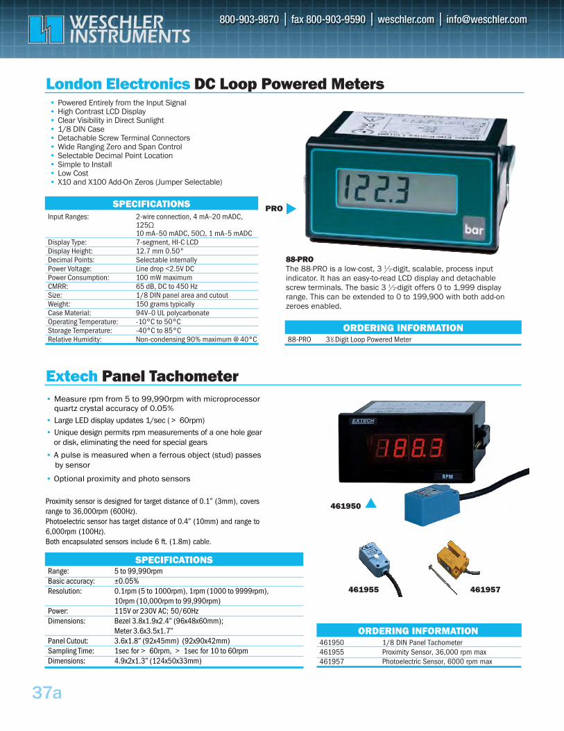
37a
Input Ranges: 2-wire connection, 4 mA–20 mADC, 125Ω 10 mA–50 mADC, 50Ω, 1 mA–5 mADC
Display Type: 7-segment, HI-C LCD Display Height: 12.7 mm 0.50"Decimal Points: Selectable internally Power Voltage: Line drop <2.5V DC Power Consumption: 100 mW maximum CMRR: 65 dB, DC to 450 HzSize: 1/8 DIN panel area and cutout Weight: 150 grams typically Case Material: 94V–0 UL polycarbonate Operating Temperature: -10°C to 50°C Storage Temperature: -40°C to 85°C Relative Humidity: Non-condensing 90% maximum @ 40°C
SPECIFICATIONS
• Powered Entirely from the Input Signal• High Contrast LCD Display• Clear Visibility in Direct Sunlight• 1/8 DIN Case• Detachable Screw Terminal Connectors• Wide Ranging Zero and Span Control• Selectable Decimal Point Location• Simple to Install• Low Cost• X10 and X100 Add-On Zeros (Jumper Selectable)
London Electronics DC Loop Powered Meters
PRO
88-PRO 31⁄2-Digit Loop Powered MeterORDERING INFORMATION
88-PRO The 88-PRO is a low-cost, 3 1/2-digit, scalable, process input indicator. It has an easy-to-read LCD display and detachable screw terminals. The basic 3 1/2-digit offers 0 to 1,999 display range. This can be extended to 0 to 199,900 with both add-on zeroes enabled.
461950 1/8 DIN Panel Tachometer 461955 461957
Proximity Sensor, 36,000 rpm maxPhotoelectric Sensor, 6000 rpm max
SPECIFICATIONS
Extech Panel Tachometer
ORDERING INFORMATION
• Measure rpm from 5 to 99,990rpm with microprocessor quartz crystal accuracy of 0.05%
• Large LED display updates 1/sec ( >60rpm)
• Unique design permits rpm measurements of a one hole gear or disk, eliminating the need for special gears
• A pulse is measured when a ferrous object (stud) passesby sensor
• Optional proximity and photo sensors
Range: 5 to 99,990rpmBasic accuracy: ±0.05%Resolution: 0.1rpm (5 to 1000rpm), 1rpm (1000 to 9999rpm),
10rpm (10,000rpm to 99,990rpm)Power: 115V or 230V AC; 50/60HzDimensions: Bezel 3.8x1.9x2.4” (96x48x60mm);
Meter 3.6x3.5x1.7”Panel Cutout: 3.6x1.8” (92x45mm) (92x90x42mm)Sampling Time: 1sec for >60rpm, >1sec for 10 to 60rpmDimensions: 4.9x2x1.3” (124x50x33mm)
461950
461955 461957
Proximity sensor is designed for target distance of 0.1” (3mm), coversrange to 36,000rpm (600Hz).Photoelectric sensor has target distance of 0.4” (10mm) and range to6,000rpm (100Hz).Both encapsulated sensors include 6 ft. (1.8m) cable.
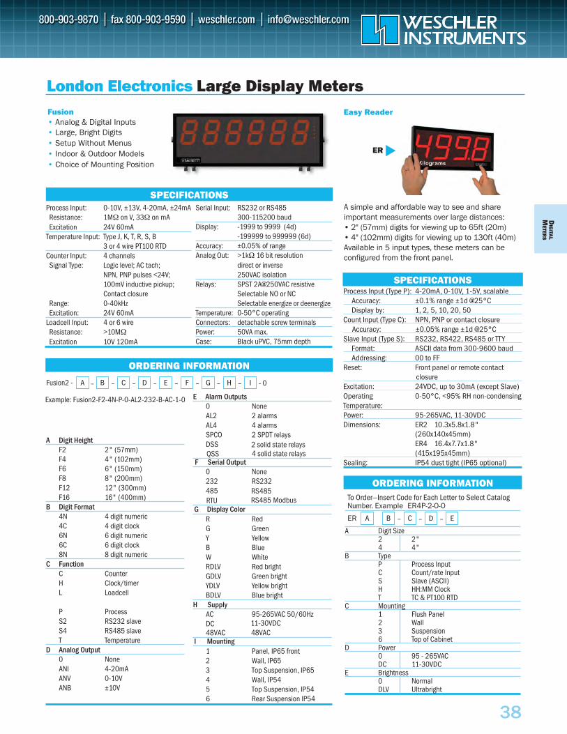
Example: Fusion2-F2-4N-P-0-AL2-232-B-AC-1-0
- 0
DIG
ITALM
ETERS
38
Process Input (Type P): 4-20mA, 0-10V, 1-5V, scalableAccuracy: ±0.1% range ±1d @25°C Display by: 1, 2, 5, 10, 20, 50
Count Input (Type C): NPN, PNP or contact closureAccuracy: ±0.05% range ±1d @25°C
Slave Input (Type S): RS232, RS422, RS485 or TTYFormat: ASCII data from 300-9600 baud Addressing: 00 to FF
Reset: Front panel or remote contact closureExcitation: 24VDC, up to 30mA (except Slave) Operating 0-50°C, <95% RH non-condensing Temperature: Power: 95-265VAC, 11-30VDC Dimensions: ER2 10.3x5.8x1.8"
(260x140x45mm) ER4 16.4x7.7x1.8" (415x195x45mm)
Sealing: IP54 dust tight (IP65 optional)
Fusion• Analog & Digital Inputs• Large, Bright Digits• Setup Without Menus• Indoor & Outdoor Models• Choice of Mounting Position
A simple and affordable way to see and share important measurements over large distances:• 2" (57mm) digits for viewing up to 65ft (20m)• 4" (102mm) digits for viewing up to 130ft (40m) Available in 5 input types, these meters can be configured from the front panel.
SPECIFICATIONS
London Electronics Large Display MetersEasy Reader
ORDERING INFORMATION
SPECIFICATIONS
ORDERING INFORMATIONTo Order—Insert Code for Each Letter to Select Catalog Number. Example ER4P-2-O-O
A Digit Size2 2" 4 4"
B Type P Process Input C Count/rate Input S Slave (ASCII)H HH:MM Clock T TC & PT100 RTD
C Mounting1 Flush Panel2 Wall3 Suspension6 Top of Cabinet
D Power0 95 - 265VAC DC 11-30VDC
E Brightness0 Normal DLV Ultrabright
A B – CER
ER
Process Input: 0-10V, ±13V, 4-20mA, ±24mAResistance: 1MΩ on V, 33Ω on mA Excitation 24V 60mA
Temperature Input: Type J, K, T, R, S, B3 or 4 wire PT100 RTD
Counter Input: 4 channels Signal Type: Logic level; AC tach;
NPN, PNP pulses <24V; 100mV inductive pickup; Contact closure
Range: 0-40kHz Excitation: 24V 60mA
Loadcell Input: 4 or 6 wireResistance: >10MΩExcitation 10V 120mA
– D – E
Serial Input: RS232 or RS485300-115200 baud
Display: -1999 to 9999 (4d)-199999 to 999999 (6d)
Accuracy: ±0.05% of range Analog Out: >1kΩ 16 bit resolution
direct or inverse 250VAC isolation
Relays: SPST 2A@250VAC resistiveSelectable NO or NC Selectable energize or deenergize
Temperature: 0-50°C operating Connectors: detachable screw terminals Power: 50VA max.Case: Black uPVC, 75mm depth
A Digit HeightF2 2" (57mm) F4 4" (102mm) F6 6" (150mm) F8 8" (200mm) F12 12" (300mm) F16 16" (400mm)
B Digit Format4N 4 digit numeric 4C 4 digit clock 6N 6 digit numeric 6C 6 digit clock 8N 8 digit numeric
C FunctionC Counter H Clock/timer L Loadcell
P Process S2 RS232 slave S4 RS485 slave T Temperature
D Analog Output0 None ANI 4-20mA ANV 0-10V ANB ±10V
E Alarm Outputs0 None AL2 2 alarms AL4 4 alarms SPCO 2 SPDT relays DSS
F Serial Output0 None 232 RS232 485
G Display ColorR Red G Green Y Yellow B Blue W White RDLV Red bright GDLV Green bright YDLV Yellow bright BDLV Blue bright
H SupplyAC 95-265VAC 50/60Hz DC
I Mounting1 Panel, IP65 front2 Wall, IP653 Top Suspension, IP654 Wall, IP545 Top Suspension, IP546 Rear Suspension IP54
B – C – D – E – F – G – H – IFusion2 - A –
2 solid state relays4 solid state relaysQSS
RS485RS485 ModbusRTU
11-30VDC48VAC48VAC
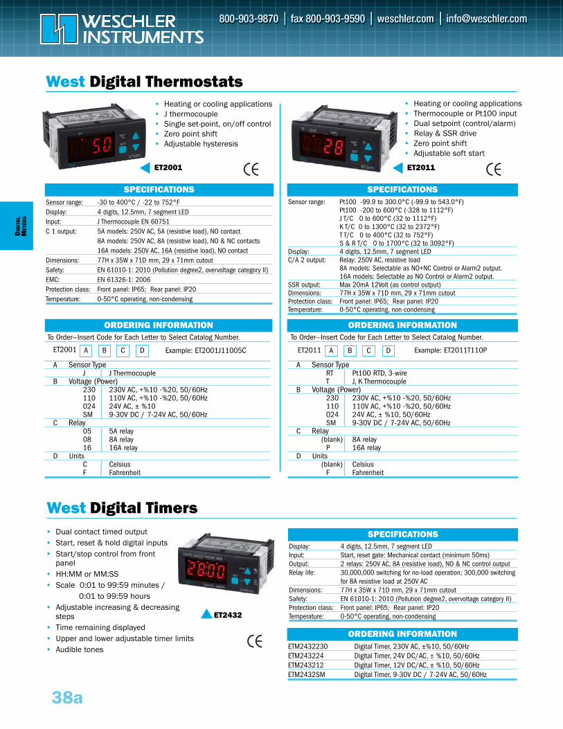
To Order—Insert Code for Each Letter to Select Catalog Number.
A Sensor TypeRT Pt100 RTD, 3-wireT J, K Thermocouple
B Voltage (Power)230 230V AC, +%10 -%20, 50/60Hz 110 110V AC, +%10 -%20, 50/60Hz024 24V AC, ± %10, 50/60HzSM 9-30V DC / 7-24V AC, 50/60Hz
C Relay (blank) 8A relay
P 16A relayD Units
(blank) CelsiusF Fahrenheit
To Order—Insert Code for Each Letter to Select Catalog Number.
A Sensor TypeJ J Thermocouple
B Voltage (Power)230 230V AC, +%10 -%20, 50/60Hz 110 110V AC, +%10 -%20, 50/60Hz024 24V AC, ± %10SM 9-30V DC / 7-24V AC, 50/60Hz
C Relay 05 5A relay08 8A relay16 16A relay
D UnitsC CelsiusF Fahrenheit
DIG
ITAL
MET
ERS
38a
West Digital Timers
ORDERING INFORMATION
A B C DET2011A B C DET2001
West Digital Thermostats• Heating or cooling applications• J thermocouple• Single set-point, on/off control• Zero point shift• Adjustable hysteresis
• Dual contact timed output• Start, reset & hold digital inputs• Start/stop control from front
panel• HH:MM or MM:SS• Scale 0:01 to 99:59 minutes /
0:01 to 99:59 hours• Adjustable increasing & decreasing
steps• Time remaining displayed• Upper and lower adjustable timer limits• Audible tones
• Heating or cooling applications• Thermocouple or Pt100 input• Dual setpoint (control/alarm) • Relay & SSR drive• Zero point shift • Adjustable soft start
Sensor range: -30 to 400°C / -22 to 752°FDisplay: 4 digits, 12.5mm, 7 segment LEDInput: J Thermocouple EN 60751C 1 output: 5A models: 250V AC, 5A (resistive load), NO contact
8A models: 250V AC, 8A (resistive load), NO & NC contacts16A models: 250V AC, 16A (resistive load), NO contact
Dimensions: 77H x 35W x 71D mm, 29 x 71mm cutoutSafety: EN 61010-1: 2010 (Pollution degree2, overvoltage category II)EMC: EN 61326-1: 2006Protection class: Front panel: IP65; Rear panel: IP20Temperature: 0-50°C operating, non-condensing
Display: 4 digits, 12.5mm, 7 segment LEDInput: Start, reset gate: Mechanical contact (minimum 50ms)Output: 2 relays: 250V AC, 8A (resistive load), NO & NC control outputRelay life: 30,000,000 switching for no-load operation; 300,000 switching
for 8A resistive load at 250V ACDimensions: 77H x 35W x 71D mm, 29 x 71mm cutoutSafety: EN 61010-1: 2010 (Pollution degree2, overvoltage category II)Protection class: Front panel: IP65; Rear panel: IP20Temperature: 0-50°C operating, non-condensing
SPECIFICATIONSSensor range: Pt100 -99.9 to 300.0°C (-99.9 to 543.0°F)
Pt100 -200 to 600°C (-328 to 1112°F)J T/C 0 to 600°C (32 to 1112°F)K T/C 0 to 1300°C (32 to 2372°F)T T/C 0 to 400°C (32 to 752°F)S & R T/C 0 to 1700°C (32 to 3092°F)
Display: 4 digits, 12.5mm, 7 segment LEDC/A 2 output: Relay: 250V AC, resistive load
8A models: Selectable as NO+NC Control or Alarm2 output.16A models: Selectable as NO Control or Alarm2 output.
SSR output: Max 20mA 12Volt (as control output)Dimensions: 77H x 35W x 71D mm, 29 x 71mm cutoutProtection class: Front panel: IP65; Rear panel: IP20Temperature: 0-50°C operating, non-condensing
SPECIFICATIONS
SPECIFICATIONS
ORDERING INFORMATION
ORDERING INFORMATION
ET2001 ET2011
ET2432
Example: ET2001J11005C Example: ET2011T110P
ETM2432230 Digital Timer, 230V AC, ±%10, 50/60Hz ETM243224 Digital Timer, 24V DC/AC, ± %10, 50/60HzETM243212 Digital Timer, 12V DC/AC, ± %10, 50/60HzETM2432SM Digital Timer, 9-30V DC / 7-24V AC, 50/60Hz
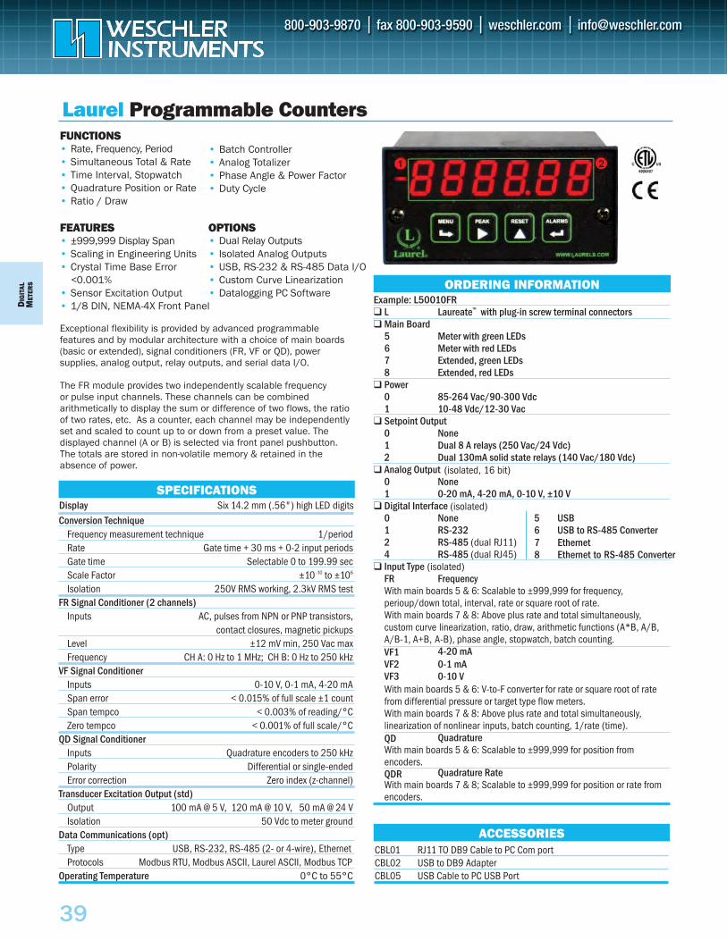
CBL01 RJ11 TO DB9 Cable to PC Com portCBL02 USB to DB9 AdapterCBL05 USB Cable to PC USB Port
DIG
ITAL
MET
ERS
39
FUNCTIONS• Rate, Frequency, Period• Simultaneous Total & Rate• Time Interval, Stopwatch• Quadrature Position or Rate• Ratio / Draw
FEATURES• ±999,999 Display Span• Scaling in Engineering Units• Crystal Time Base Error
<0.001%• Sensor Excitation Output• 1/8 DIN, NEMA-4X Front Panel
Exceptional flexibility is provided by advanced programmablefeatures and by modular architecture with a choice of main boards(basic or extended), signal conditioners (FR, VF or QD), powersupplies, analog output, relay outputs, and serial data I/O.
The FR module provides two independently scalable frequencyor pulse input channels. These channels can be combinedarithmetically to display the sum or difference of two flows, the ratioof two rates, etc. As a counter, each channel may be independentlyset and scaled to count up to or down from a preset value. Thedisplayed channel (A or B) is selected via front panel pushbutton.The totals are stored in non-volatile memory & retained in theabsence of power.
Conversion TechniqueFrequency measurement technique 1/periodRate Gate time + 30 ms + 0-2 input periodsGate time Selectable 0 to 199.99 secScale Factor ±10 -10 to ±106
Isolation 250V RMS working, 2.3kV RMS testFR Signal Conditioner (2 channels)
Inputs AC, pulses from NPN or PNP transistors,contact closures, magnetic pickups
Level ±12 mV min, 250 Vac maxFrequency CH A: 0 Hz to 1 MHz; CH B: 0 Hz to 250 kHz
VF Signal ConditionerInputs 0-10 V, 0-1 mA, 4-20 mASpan error < 0.015% of full scale ±1 countSpan tempco < 0.003% of reading/°CZero tempco < 0.001% of full scale/°C
QD Signal ConditionerInputs Quadrature encoders to 250 kHzPolarity Differential or single-endedError correction Zero index (z-channel)
Transducer Excitation Output (std)Output 100 mA @ 5 V, 120 mA @ 10 V, 50 mA @ 24 VIsolation 50 Vdc to meter ground
Data Communications (opt)Type USB, RS-232, RS-485 (2- or 4-wire), EthernetProtocols Modbus RTU, Modbus ASCII, Laurel ASCII, Modbus TCP
Operating Temperature 0°C to 55°C
SPECIFICATIONS
Example: L50010FR L Laureate™ with plug-in screw terminal connectors Main Board
5 Meter with green LEDs6 Meter with red LEDs7 Extended, green LEDs8 Extended, red LEDs
Power0 85-264 Vac/90-300 Vdc1 10-48 Vdc/12-30 Vac
Setpoint Output0 None1 Dual 8 A relays (250 Vac/24 Vdc)2 Dual 130mA solid state relays (140 Vac/180 Vdc)
Analog Output0 None1 0-20 mA, 4-20 mA, 0-10 V, ±10 V
Digital Interface0 None 5 USB1 RS-232 6 USB to RS-485 Converter2 RS-485 (dual RJ11)4 RS-485 (dual RJ45)
Input TypeFR FrequencyWith main boards 5 & 6: Scalable to ±999,999 for frequency, perioup/down total, interval, rate or square root of rate. With main boards 7 & 8: Above plus rate and total simultaneously, custom curve linearization, ratio, draw, arithmetic functions (A*B, A/B, A/B-1, A+B, A-B), phase angle, stopwatch, batch counting.VF1 4-20 mAVF2 0-1 mAVF3 0-10 VWith main boards 5 & 6: V-to-F converter for rate or square root of ratefrom differential pressure or target type flow meters. With main boards 7 & 8: Above plus rate and total simultaneously, linearization of nonlinear inputs, batch counting, 1/rate (time).QD QuadratureWith main boards 5 & 6: Scalable to ±999,999 for position from encoders. QDR Quadrature RateWith main boards 7 & 8; Scalable to ±999,999 for position or rate fromencoders.
ORDERING INFORMATION
Laurel Programmable Counters
OPTIONS• Dual Relay Outputs• Isolated Analog Outputs• USB, RS-232 & RS-485 Data I/O• Custom Curve Linearization• Datalogging PC Software
• Batch Controller• Analog Totalizer• Phase Angle & Power Factor• Duty Cycle
ACCESSORIES
(isolated)
(isolated, 16 bit)
7 Ethernet8 Ethernet to RS-485 Converter
(isolated)
Display Six 14.2 mm (.56") high LED digits
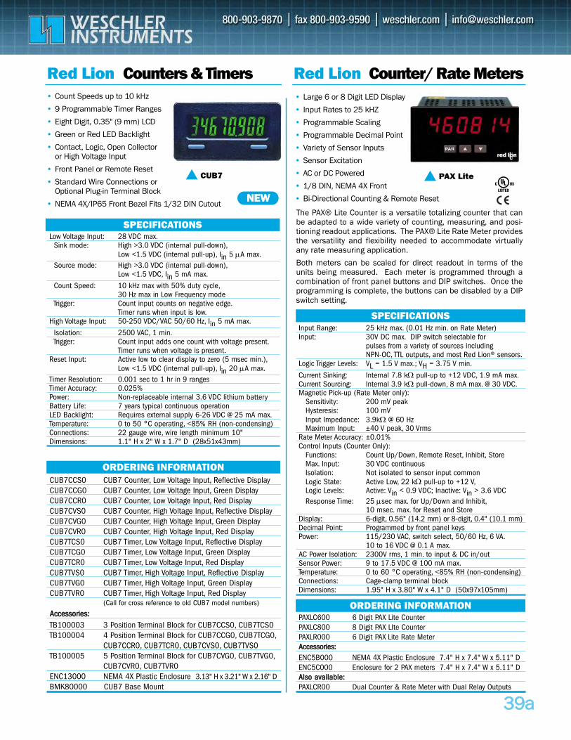
3399aa
CUB7CCS0 CUB7 Counter, Low Voltage Input, Reflective Display CUB7CCG0 CUB7 Counter, Low Voltage Input, Green Display CUB7CCR0 CUB7 Counter, Low Voltage Input, Red DisplayCUB7CVS0 CUB7 Counter, High Voltage Input, Reflective Display CUB7CVG0 CUB7 Counter, High Voltage Input, Green Display CUB7CVR0 CUB7 Counter, High Voltage Input, Red Display CUB7TCS0 CUB7 Timer, Low Voltage Input, Reflective Display CUB7TCG0 CUB7 Timer, Low Voltage Input, Green Display CUB7TCR0 CUB7 Timer, Low Voltage Input, Red Display CUB7TVS0 CUB7 Timer, High Voltage Input, Reflective Display CUB7TVG0 CUB7 Timer, High Voltage Input, Green Display CUB7TVR0 CUB7 Timer, High Voltage Input, Red Display
(Call for cross reference to old CUB7 model numbers)
AAcccceessssoorriieess::TB100003 3 Position Terminal Block for CUB7CCS0, CUB7TCS0TB100004 4 Position Terminal Block for CUB7CCG0, CUB7TCG0,
CUB7CCR0, CUB7TCR0, CUB7CVS0, CUB7TVS0TB100005 5 Position Terminal Block for CUB7CVG0, CUB7TVG0,
CUB7CVR0, CUB7TVR0ENC13000 NEMA 4X Plastic Enclosure 3.13" H x 3.21" W x 2.16" DBMK80000 CUB7 Base Mount
Red Lion Counters & Timers Red Lion Counter/ Rate Meters• Count Speeds up to 10 kHz
• 9 Programmable Timer Ranges
• Eight Digit, 0.35" (9 mm) LCD
• Green or Red LED Backlight
• Contact, Logic, Open Collector or High Voltage Input
• Front Panel or Remote Reset
• Standard Wire Connections or Optional Plug-in Terminal Block
• NEMA 4X/IP65 Front Bezel Fits 1/32 DIN Cutout
• Large 6 or 8 Digit LED Display
• Input Rates to 25 kHZ
• Programmable Scaling
• Programmable Decimal Point
• Variety of Sensor Inputs
• Sensor Excitation
• AC or DC Powered
• 1/8 DIN, NEMA 4X Front
• Bi-Directional Counting & Remote Reset
ORDERING INFORMATION
PAXLC600 6 Digit PAX Lite Counter PAXLC800 8 Digit PAX LIte Counter PAXLR000 6 Digit PAX Lite Rate MeterAAcccceessssoorriieess::ENC5B000 NEMA 4X Plastic Enclosure 7.4" H x 7.4" W x 5.11" DENC5C000 Enclosure for 2 PAX meters 7.4" H x 7.4" W x 5.11" DAAllssoo aavvaaiillaabbllee::PAXLCR00 Dual Counter & Rate Meter with Dual Relay Outputs
ORDERING INFORMATION
PAX Lite
NEW
SPECIFICATIONSLow Voltage Input: 28 VDC max.
Sink mode: High >3.0 VDC (internal pull-down),Low <1.5 VDC (internal pull-up), Iin 5 μA max.
Source mode: High >3.0 VDC (internal pull-down),Low <1.5 VDC, Iin 5 mA max.
Count Speed: 10 kHz max with 50% duty cycle,30 Hz max in Low Frequency mode
Trigger: Count input counts on negative edge.Timer runs when input is low.
High Voltage Input: 50-250 VDC/VAC 50/60 Hz, Iin 5 mA max.
Isolation: 2500 VAC, 1 min.Trigger: Count input adds one count with voltage present.
Timer runs when voltage is present.Reset Input: Active low to clear display to zero (5 msec min.),
Low <1.5 VDC (internal pull-up), Iin 20 μA max.Timer Resolution: 0.001 sec to 1 hr in 9 rangesTimer Accuracy: 0.025%Power: Non-replaceable internal 3.6 VDC lithium battery Battery Life: 7 years typical continuous operationLED Backlight: Requires external supply 6-26 VDC @ 25 mA max.Temperature: 0 to 50 °C operating, <85% RH (non-condensing)Connections: 22 gauge wire, wire length minimum 10"Dimensions: 1.1" H x 2" W x 1.7" D (28x51x43mm)
SPECIFICATIONSInput Range: 25 kHz max. (0.01 Hz min. on Rate Meter)Input: 30V DC max. DIP switch selectable for
pulses from a variety of sources including NPN-OC, TTL outputs, and most Red Lion® sensors.
Logic Trigger Levels: VL = 1.5 V max.; VH = 3.75 V min.
Current Sinking: Internal 7.8 kΩ pull-up to +12 VDC, 1.9 mA max.Current Sourcing: Internal 3.9 kΩ pull-down, 8 mA max. @ 30 VDC.Magnetic Pick-up (Rate Meter only):
Sensitivity: 200 mV peakHysteresis: 100 mVInput Impedance: 3.9kΩ @ 60 HzMaximum Input: ±40 V peak, 30 Vrms
Rate Meter Accuracy: ±0.01%Control Inputs (Counter Only):
Functions: Count Up/Down, Remote Reset, Inhibit, StoreMax. Input: 30 VDC continuousIsolation: Not isolated to sensor input common Logic State: Active Low, 22 kΩ pull-up to +12 V,Logic Levels: Active: Vin < 0.9 VDC; Inactive: Vin > 3.6 VDCResponse Time: 25 μsec max. for Up/Down and Inhibit,
10 msec. max. for Reset and StoreDisplay: 6-digit, 0.56" (14.2 mm) or 8-digit, 0.4" (10.1 mm)Decimal Point: Programmed by front panel keysPower: 115/230 VAC, switch select, 50/60 Hz, 6 VA.
10 to 16 VDC @ 0.1 A max.AC Power Isolation: 2300V rms, 1 min. to input & DC in/outSensor Power: 9 to 17.5 VDC @ 100 mA max.Temperature: 0 to 60 °C operating, <85% RH (non-condensing)Connections: Cage-clamp terminal blockDimensions: 1.95" H x 3.80" W x 4.1" D (50x97x105mm)
The PAX® Lite Counter is a versatile totalizing counter that canbe adapted to a wide variety of counting, measuring, and posi-tioning readout applications. The PAX® Lite Rate Meter providesthe versatility and flexibility needed to accommodate virtuallyany rate measuring application.
Both meters can be scaled for direct readout in terms of theunits being measured. Each meter is programmed through acombination of front panel buttons and DIP switches. Once theprogramming is complete, the buttons can be disabled by a DIPswitch setting.
CUB7
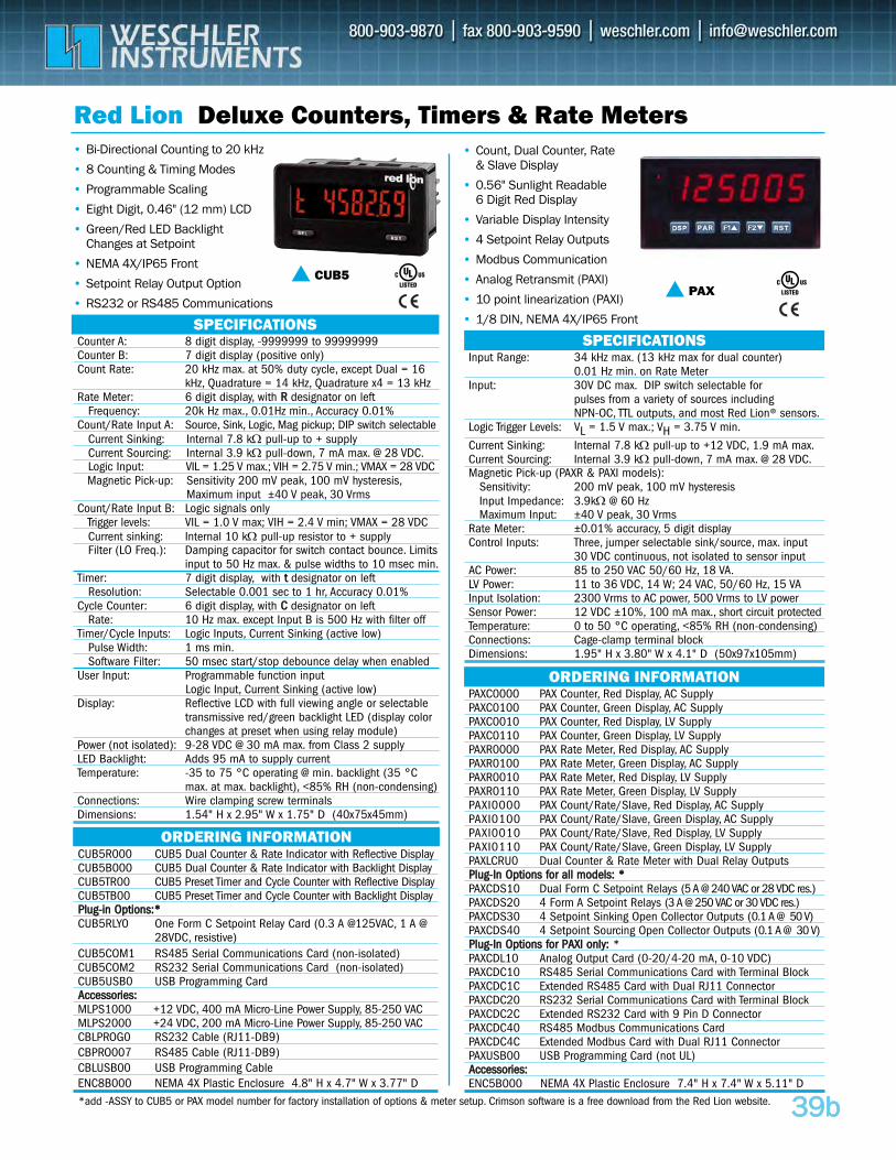
3399bb
CUB5R000 CUB5 Dual Counter & Rate Indicator with Reflective DisplayCUB5B000 CUB5 Dual Counter & Rate Indicator with Backlight Display CUB5TR00 CUB5 Preset Timer and Cycle Counter with Reflective DisplayCUB5TB00 CUB5 Preset Timer and Cycle Counter with Backlight DisplayPPlluugg--iinn OOppttiioonnss::**CUB5RLY0 One Form C Setpoint Relay Card (0.3 A @125VAC, 1 A @
28VDC, resistive)CUB5COM1 RS485 Serial Communications Card (non-isolated)CUB5COM2 RS232 Serial Communications Card (non-isolated)CUB5USB0 USB Programming Card AAcccceessssoorriieess::MLPS1000 +12 VDC, 400 mA Micro-Line Power Supply, 85-250 VACMLPS2000 +24 VDC, 200 mA Micro-Line Power Supply, 85-250 VACCBLPROG0 RS232 Cable (RJ11-DB9)CBPRO007 RS485 Cable (RJ11-DB9)CBLUSB00 USB Programming Cable ENC8B000 NEMA 4X Plastic Enclosure 4.8" H x 4.7" W x 3.77" D
Red Lion Deluxe Counters, Timers & Rate Meters• Bi-Directional Counting to 20 kHz
• 8 Counting & Timing Modes
• Programmable Scaling
• Eight Digit, 0.46" (12 mm) LCD
• Green/Red LED Backlight Changes at Setpoint
• NEMA 4X/IP65 Front
• Setpoint Relay Output Option
• RS232 or RS485 Communications
• Count, Dual Counter, Rate& Slave Display
• 0.56" Sunlight Readable 6 Digit Red Display
• Variable Display Intensity
• 4 Setpoint Relay Outputs
• Modbus Communication
• Analog Retransmit (PAXI)
• 10 point linearization (PAXI)
• 1/8 DIN, NEMA 4X/IP65 Front
ORDERING INFORMATION
PAXC0000 PAX Counter, Red Display, AC SupplyPAXC0100 PAX Counter, Green Display, AC SupplyPAXC0010 PAX Counter, Red Display, LV SupplyPAXC0110 PAX Counter, Green Display, LV SupplyPAXR0000 PAX Rate Meter, Red Display, AC SupplyPAXR0100 PAX Rate Meter, Green Display, AC SupplyPAXR0010 PAX Rate Meter, Red Display, LV SupplyPAXR0110 PAX Rate Meter, Green Display, LV Supply PAXI0000 PAX Count/Rate/Slave, Red Display, AC SupplyPAXI0100 PAX Count/Rate/Slave, Green Display, AC SupplyPAXI0010 PAX Count/Rate/Slave, Red Display, LV SupplyPAXI0110 PAX Count/Rate/Slave, Green Display, LV SupplyPAXLCRU0 Dual Counter & Rate Meter with Dual Relay Outputs PPlluugg--IInn OOppttiioonnss ffoorr aallll mmooddeellss:: **PAXCDS10 Dual Form C Setpoint Relays (5 A @ 240 VAC or 28 VDC res.) PAXCDS20 4 Form A Setpoint Relays (3 A @ 250 VAC or 30 VDC res.)PAXCDS30 4 Setpoint Sinking Open Collector Outputs (0.1 A @ 50 V) PAXCDS40 4 Setpoint Sourcing Open Collector Outputs (0.1 A @ 30 V)PPlluugg--IInn OOppttiioonnss ffoorr PPAAXXII oonnllyy:: *PAXCDL10 Analog Output Card (0-20/4-20 mA, 0-10 VDC) PAXCDC10 RS485 Serial Communications Card with Terminal Block PAXCDC1C Extended RS485 Card with Dual RJ11 Connector PAXCDC20 RS232 Serial Communications Card with Terminal Block PAXCDC2C Extended RS232 Card with 9 Pin D Connector PAXCDC40 RS485 Modbus Communications Card PAXCDC4C Extended Modbus Card with Dual RJ11 Connector PAXUSB00 USB Programming Card (not UL)AAcccceessssoorriieess::ENC5B000 NEMA 4X Plastic Enclosure 7.4" H x 7.4" W x 5.11" D
ORDERING INFORMATION
PAX
SPECIFICATIONSCounter A: 8 digit display, -9999999 to 99999999Counter B: 7 digit display (positive only)Count Rate: 20 kHz max. at 50% duty cycle, except Dual = 16
kHz, Quadrature = 14 kHz, Quadrature x4 = 13 kHz Rate Meter: 6 digit display, with RR designator on left
Frequency: 20k Hz max., 0.01Hz min., Accuracy 0.01%Count/Rate Input A: Source, Sink, Logic, Mag pickup; DIP switch selectable
Current Sinking: Internal 7.8 kΩ pull-up to + supply Current Sourcing: Internal 3.9 kΩ pull-down, 7 mA max. @ 28 VDC.Logic Input: VIL = 1.25 V max.; VIH = 2.75 V min.; VMAX = 28 VDC Magnetic Pick-up: Sensitivity 200 mV peak, 100 mV hysteresis,
Maximum input ±40 V peak, 30 VrmsCount/Rate Input B: Logic signals only
Trigger levels: VIL = 1.0 V max; VIH = 2.4 V min; VMAX = 28 VDCCurrent sinking: Internal 10 kΩ pull-up resistor to + supplyFilter (LO Freq.): Damping capacitor for switch contact bounce. Limits
input to 50 Hz max. & pulse widths to 10 msec min.Timer: 7 digit display, with tt designator on left
Resolution: Selectable 0.001 sec to 1 hr, Accuracy 0.01%Cycle Counter: 6 digit display, with CC designator on left
Rate: 10 Hz max. except Input B is 500 Hz with filter offTimer/Cycle Inputs: Logic Inputs, Current Sinking (active low)
Pulse Width: 1 ms min.Software Filter: 50 msec start/stop debounce delay when enabled
User Input: Programmable function inputLogic Input, Current Sinking (active low)
Display: Reflective LCD with full viewing angle or selectable transmissive red/green backlight LED (display color changes at preset when using relay module)
Power (not isolated): 9-28 VDC @ 30 mA max. from Class 2 supplyLED Backlight: Adds 95 mA to supply currentTemperature: -35 to 75 °C operating @ min. backlight (35 °C
max. at max. backlight), <85% RH (non-condensing)Connections: Wire clamping screw terminalsDimensions: 1.54" H x 2.95" W x 1.75" D (40x75x45mm)
SPECIFICATIONSInput Range: 34 kHz max. (13 kHz max for dual counter)
0.01 Hz min. on Rate MeterInput: 30V DC max. DIP switch selectable for
pulses from a variety of sources including NPN-OC, TTL outputs, and most Red Lion® sensors.
Logic Trigger Levels: VL = 1.5 V max.; VH = 3.75 V min.
Current Sinking: Internal 7.8 kΩ pull-up to +12 VDC, 1.9 mA max.Current Sourcing: Internal 3.9 kΩ pull-down, 7 mA max. @ 28 VDC.Magnetic Pick-up (PAXR & PAXI models):
Sensitivity: 200 mV peak, 100 mV hysteresisInput Impedance: 3.9kΩ @ 60 HzMaximum Input: ±40 V peak, 30 Vrms
Rate Meter: ±0.01% accuracy, 5 digit displayControl Inputs: Three, jumper selectable sink/source, max. input
30 VDC continuous, not isolated to sensor input AC Power: 85 to 250 VAC 50/60 Hz, 18 VA.LV Power: 11 to 36 VDC, 14 W; 24 VAC, 50/60 Hz, 15 VA Input Isolation: 2300 Vrms to AC power, 500 Vrms to LV power Sensor Power: 12 VDC ±10%, 100 mA max., short circuit protectedTemperature: 0 to 50 °C operating, <85% RH (non-condensing)Connections: Cage-clamp terminal blockDimensions: 1.95" H x 3.80" W x 4.1" D (50x97x105mm)
CUB5
*add -ASSY to CUB5 or PAX model number for factory installation of options & meter setup. Crimson software is a free download from the Red Lion website.
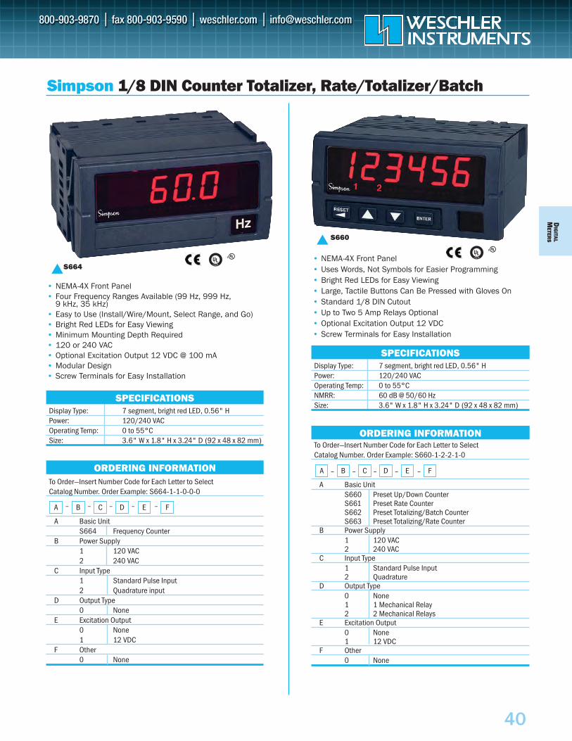
DIG
ITALM
ETERS
40
To Order—Insert Number Code for Each Letter to SelectCatalog Number. Order Example: S660-1-2-2-1-0
A Basic UnitS660 Preset Up/Down CounterS661 Preset Rate CounterS662 Preset Totalizing/Batch CounterS663 Preset Totalizing/Rate Counter
B Power Supply1 120 VAC2 240 VAC
C Input Type1 Standard Pulse Input2 Quadrature
D Output Type0 None1 1 Mechanical Relay2 2 Mechanical Relays
E Excitation Output0 None1 12 VDC
F Other0 None
To Order—Insert Number Code for Each Letter to SelectCatalog Number. Order Example: S664-1-1-0-0-0
A Basic UnitS664 Frequency Counter
B Power Supply1 120 VAC2 240 VAC
C Input Type1 Standard Pulse Input2 Quadrature input
D Output Type0 None
E Excitation Output0 None1 12 VDC
F Other0 None
SPECIFICATIONS
S664
• NEMA-4X Front Panel• Four Frequency Ranges Available (99 Hz, 999 Hz,
9 kHz, 35 kHz)• Easy to Use (Install/Wire/Mount, Select Range, and Go)• Bright Red LEDs for Easy Viewing• Minimum Mounting Depth Required• 120 or 240 VAC • Optional Excitation Output 12 VDC @ 100 mA• Modular Design• Screw Terminals for Easy Installation
Display Type: 7 segment, bright red LED, 0.56" HPower: 120/240 VACOperating Temp: 0 to 55°CSize: 3.6" W x 1.8" H x 3.24" D (92 x 48 x 82 mm)
Simpson 1/8 DIN Counter Totalizer, Rate/Totalizer/Batch
• NEMA-4X Front Panel• Uses Words, Not Symbols for Easier Programming• Bright Red LEDs for Easy Viewing• Large, Tactile Buttons Can Be Pressed with Gloves On• Standard 1/8 DIN Cutout• Up to Two 5 Amp Relays Optional• Optional Excitation Output 12 VDC• Screw Terminals for Easy Installation
S660
SPECIFICATIONSDisplay Type: 7 segment, bright red LED, 0.56" HPower: 120/240 VACOperating Temp: 0 to 55°CNMRR: 60 dB @ 50/60 HzSize: 3.6" W x 1.8" H x 3.24" D (92 x 48 x 82 mm)
ORDERING INFORMATION
A – B – C – D – E – F
ORDERING INFORMATION
A – B – C – D – E – F
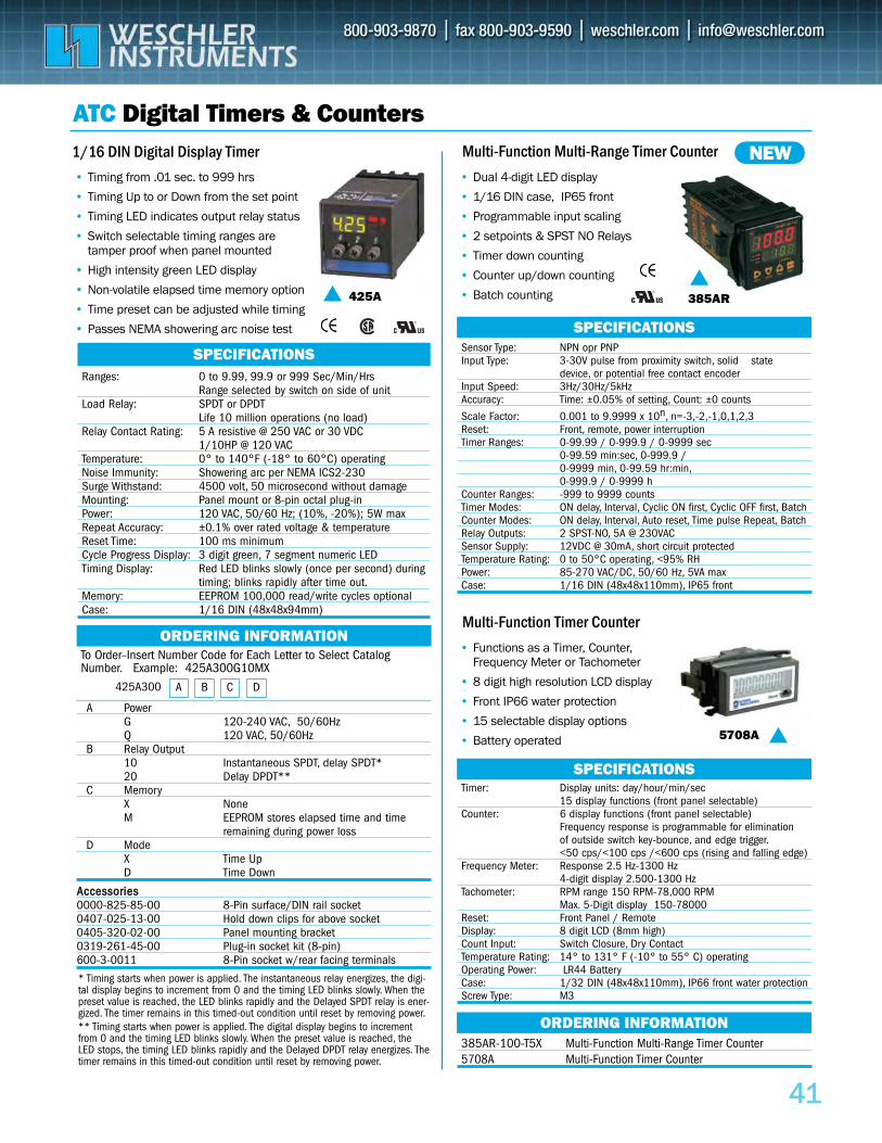
4411
To Order–Insert Number Code for Each Letter to Select CatalogNumber. Example: 425A300G10MX
A PowerG 120-240 VAC, 50/60Hz Q 120 VAC, 50/60Hz
B Relay Output10 Instantaneous SPDT, delay SPDT*20 Delay DPDT**
C MemoryX None M EEPROM stores elapsed time and time
remaining during power lossD Mode
X Time Up D Time Down
AAcccceessssoorriieess0000-825-85-00 8-Pin surface/DIN rail socket 0407-025-13-00 Hold down clips for above socket 0405-320-02-00 Panel mounting bracket 0319-261-45-00 Plug-in socket kit (8-pin) 600-3-0011 8-Pin socket w/rear facing terminals
ATC Digital Timers & Counters1/16 DIN Digital Display Timer Multi-Function Multi-Range Timer Counter
• Dual 4-digit LED display
• 1/16 DIN case, IP65 front
• Programmable input scaling
• 2 setpoints & SPST NO Relays
• Timer down counting
• Counter up/down counting
• Batch counting
ORDERING INFORMATION
385AR-100-T5X Multi-Function Multi-Range Timer Counter 5708A Multi-Function Timer Counter
ORDERING INFORMATION
385AR
NEW
SPECIFICATIONSRanges: 0 to 9.99, 99.9 or 999 Sec/Min/Hrs
Range selected by switch on side of unit Load Relay: SPDT or DPDT
Life 10 million operations (no load)Relay Contact Rating: 5 A resistive @ 250 VAC or 30 VDC
1/10HP @ 120 VACTemperature: 0° to 140°F (-18° to 60°C) operatingNoise Immunity: Showering arc per NEMA ICS2-230Surge Withstand: 4500 volt, 50 microsecond without damageMounting: Panel mount or 8-pin octal plug-inPower: 120 VAC, 50/60 Hz; (10%, -20%); 5W maxRepeat Accuracy: ±0.1% over rated voltage & temperatureReset Time: 100 ms minimumCycle Progress Display: 3 digit green, 7 segment numeric LED Timing Display: Red LED blinks slowly (once per second) during
timing; blinks rapidly after time out.Memory: EEPROM 100,000 read/write cycles optionalCase: 1/16 DIN (48x48x94mm)
SPECIFICATIONSSensor Type: NPN opr PNPInput Type: 3-30V pulse from proximity switch, solid state
device, or potential free contact encoderInput Speed: 3Hz/30Hz/5kHzAccuracy: Time: ±0.05% of setting, Count: ±0 counts
Scale Factor: 0.001 to 9.9999 x 10n, n=-3,-2,-1,0,1,2,3Reset: Front, remote, power interruptionTimer Ranges: 0-99.99 / 0-999.9 / 0-9999 sec
0-99.59 min:sec, 0-999.9 /0-9999 min, 0-99.59 hr:min,0-999.9 / 0-9999 h
Counter Ranges: -999 to 9999 countsTimer Modes: ON delay, Interval, Cyclic ON first, Cyclic OFF first, BatchCounter Modes: ON delay, Interval, Auto reset, Time pulse Repeat, BatchRelay Outputs: 2 SPST-NO, 5A @ 230VACSensor Supply: 12VDC @ 30mA, short circuit protectedTemperature Rating: 0 to 50°C operating, <95% RHPower: 85-270 VAC/DC, 50/60 Hz, 5VA maxCase: 1/16 DIN (48x48x110mm), IP65 front
Multi-Function Timer Counter • Functions as a Timer, Counter,
Frequency Meter or Tachometer
• 8 digit high resolution LCD display
• Front IP66 water protection
• 15 selectable display options
• Battery operated 5708A SPECIFICATIONS
Timer: Display units: day/hour/min/sec15 display functions (front panel selectable)
Counter: 6 display functions (front panel selectable)Frequency response is programmable for eliminationof outside switch key-bounce, and edge trigger.<50 cps/<100 cps /<600 cps (rising and falling edge)
Frequency Meter: Response 2.5 Hz-1300 Hz4-digit display 2.500-1300 Hz
Tachometer: RPM range 150 RPM-78,000 RPMMax. 5-Digit display 150-78000
Reset: Front Panel / RemoteDisplay: 8 digit LCD (8mm high)Count Input: Switch Closure, Dry ContactTemperature Rating: 14° to 131° F (-10° to 55° C) operatingOperating Power: LR44 BatteryCase: 1/32 DIN (48x48x110mm), IP66 front water protection Screw Type: M3
425A
• Timing from .01 sec. to 999 hrs
• Timing Up to or Down from the set point
• Timing LED indicates output relay status
• Switch selectable timing ranges are tamper proof when panel mounted
• High intensity green LED display
• Non-volatile elapsed time memory option
• Time preset can be adjusted while timing
• Passes NEMA showering arc noise test
A B C D425A300
* Timing starts when power is applied. The instantaneous relay energizes, the digi-tal display begins to increment from 0 and the timing LED blinks slowly. When thepreset value is reached, the LED blinks rapidly and the Delayed SPDT relay is ener-gized. The timer remains in this timed-out condition until reset by removing power.** Timing starts when power is applied. The digital display begins to incrementfrom 0 and the timing LED blinks slowly. When the preset value is reached, theLED stops, the timing LED blinks rapidly and the Delayed DPDT relay energizes. Thetimer remains in this timed-out condition until reset by removing power.
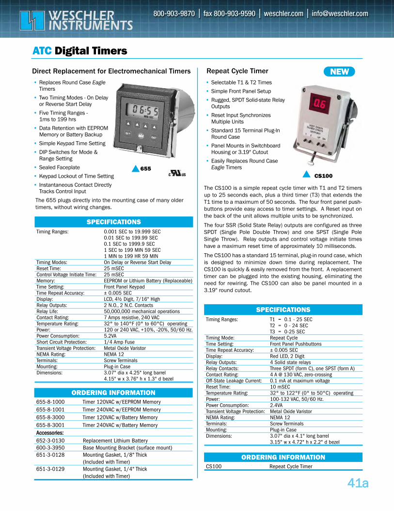
4411aa
655-8-1000 Timer 120VAC w/EEPROM Memory 655-8-1001 Timer 240VAC w/EEPROM Memory 655-8-3000 Timer 120VAC w/Battery Memory 655-8-3001 Timer 240VAC w/Battery Memory AAcccceessssoorriieess::652-3-0130 Replacement Lithium Battery 600-3-3950 Base Mounting Bracket (surface mount) 651-3-0128 Mounting Gasket, 1/8" Thick
(Included with Timer) 651-3-0129 Mounting Gasket, 1/4" Thick
(Included with Timer)
ATC Digital Timers
Direct Replacement for Electromechanical Timers Repeat Cycle Timer
• Replaces Round Case EagleTimers
• Two Timing Modes - On Delay or Reverse Start Delay
• Five Timing Ranges -1ms to 199 hrs
• Data Retention with EEPROMMemory or Battery Backup
• Simple Keypad Time Setting
• DIP Switches for Mode & Range Setting
• Sealed Faceplate
• Keypad Lockout of Time Setting
• Instantaneous Contact Directly Tracks Control Input
• Selectable T1 & T2 Times
• Simple Front Panel Setup
• Rugged, SPDT Solid-state RelayOutputs
• Reset Input Synchronizes Multiple Units
• Standard 15 Terminal Plug-In Round Case
• Panel Mounts in Switchboard Housing or 3.19" Cutout
• Easily Replaces Round Case Eagle Timers655
ORDERING INFORMATION
CS100 Repeat Cycle Timer
ORDERING INFORMATION
CS100
NEW
SPECIFICATIONSTiming Ranges: 0.001 SEC to 19.999 SEC
0.01 SEC to 199.99 SEC0.1 SEC to 1999.9 SEC1 SEC to 199 MIN 59 SEC1 MIN to 199 HR 59 MIN
Timing Modes: On Delay or Reverse Start DelayReset Time: 25 mSECControl Voltage Initiate Time: 25 mSECMemory: EEPROM or Lithium Battery (Replaceable)Time Setting: Front Panel KeypadTime Repeat Accuracy: ± 0.005 SECDisplay: LCD, 4½ Digit, 7/16" HighRelay Outputs: 2 N.O., 2 N.C. ContactsRelay Life: 50,000,000 mechanical operationsContact Rating: 7 Amps resistive, 240 VACTemperature Rating: 32° to 140°F (0° to 60°C) operatingPower: 120 or 240 VAC, +10%, -20%, 50/60 Hz.Power Consumption: 5.2VAShort Circuit Protection: 1/4 Amp FuseTransient Voltage Protection: Metal Oxide VaristorNEMA Rating: NEMA 12Terminals: Screw TerminalsMounting: Plug-in CaseDimensions: 3.07" dia x 4.25" long barrel
4.15" w x 3.76" h x 1.3" d bezel
SPECIFICATIONSTiming Ranges: T1 = 0.1 - 25 SEC
T2 = 0 - 24 SECT3 = 0-25 SEC
Timing Mode: Repeat CycleTime Setting: Front Panel PushbuttonsTime Repeat Accuracy: ± 0.005 SECDisplay: Red LED, 2 Digit Relay Outputs: 4 Solid state relaysRelay Contacts: Three SPDT (form C), one SPST (form A)Contact Rating: 4 A @ 130 VAC, zero-crossing Off-State Leakage Current: 0.1 mA at maximum voltageReset Time: 10 mSECTemperature Rating: 32° to 122°F (0° to 50°C) operatingPower: 100-132 VAC, 50/60 Hz.Power Consumption: 2.4VATransient Voltage Protection: Metal Oxide VaristorNEMA Rating: NEMA 12Terminals: Screw TerminalsMounting: Plug-in CaseDimensions: 3.07" dia x 4.1" long barrel
3.15" w x 4.72" h x 2.2" d bezel
The 655 plugs directly into the mounting case of many oldertimers, without wiring changes.
The CS100 is a simple repeat cycle timer with T1 and T2 timersup to 25 seconds each, plus a third timer (T3) that extends theT1 time to a maximum of 50 seconds. The four front panel push-buttons provide easy access to timer settings. A Reset input onthe back of the unit allows multiple units to be synchronized.
The four SSR (Solid State Relay) outputs are configured as threeSPDT (Single Pole Double Throw) and one SPST (Single PoleSingle Throw). Relay outputs and control voltage initiate timeshave a maximum reset time of approximately 10 milliseconds.
The CS100 has a standard 15 terminal, plug-in round case, whichis designed to minimize down time during replacement. TheCS100 is quickly & easily removed from the front. A replacementtimer can be plugged into the existing housing, eliminating theneed for rewiring. The CS100 can also be panel mounted in a3.19" round cutout.
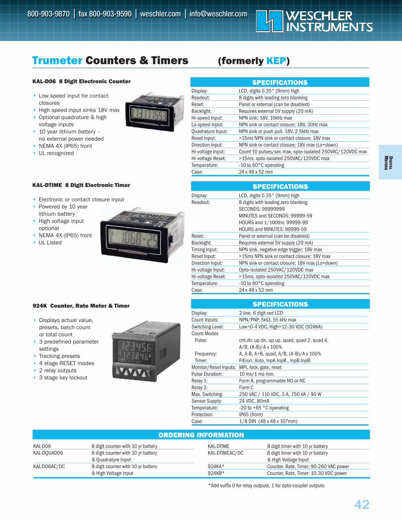
DIG
ITALM
ETERS
42
Trumeter Counters & Timers (formerly KEP)
KAL-D06 8 Digit Electronic Counter
• Low speed input for contact closures
• High speed input sinks 18V max• Optional quadrature & high
voltage inputs• 10 year lithium battery –
no external power needed• NEMA 4X (IP65) front• UL recognized
Display: LCD, digits 0.35" (9mm) highReadout: 8 digits with leading zero blanking Reset: Panel or external (can be disabled)Backlight: Requires external 5V supply (20 mA) Hi-speed Input: NPN sink; 18V, 10kHz max Lo-speed Input: NPN sink or contact closure; 18V, 30Hz maxQuadrature Input: NPN sink or push pull, 18V, 2.5kHz maxReset Input: >15ms NPN sink or contact closure; 18V maxDirection Input: NPN sink or contact closure; 18V max (Lo=down)Hi-voltage Input: Count 10 pulses/sec max; opto-isolated 250VAC/120VDC max Hi-voltage Reset: >15ms, opto-isolated 250VAC/120VDC max Temperature: -10 to 60°C operatingCase: 24 x 48 x 52 mm
SPECIFICATIONS
KAL-DTIME 8 Digit Electronic Timer
• Electronic or contact closure input• Powered by 10 year
lithium battery• High voltage input
optional• NEMA 4X (IP65) front• UL Listed
Display: LCD, digits 0.35" (9mm) highReadout: 8 digits with leading zero blanking
SECONDS: 99999999MINUTES and SECONDS: 99999-59HOURS and 1/100ths: 99999-99HOURS and MINUTES: 99999-59
Reset: Panel or external (can be disabled)Backlight: Requires external 5V supply (20 mA)Timing Input: NPN sink, negative edge trigger; 18V max Reset Input: >15ms NPN sink or contact closure; 18V maxDirection Input: NPN sink or contact closure; 18V max (Lo=down)Hi-voltage Input: Opto-isolated 250VAC/120VDC max Hi-voltage Reset: >15ms, opto-isolated 250VAC/120VDC max Temperature: -10 to 60°C operatingCase: 24 x 48 x 52 mm
924K Counter, Rate Meter & Timer
• Displays actual value, presets, batch count or total count
• 3 predefined parameter settings
• Tracking presets • 4 stage RESET modes • 2 relay outputs • 3 stage key lockout
Display: 2 line, 6 digit red LCD Count Inputs: NPN/PNP, 5kΩ, 55 kHz maxSwitching Level: Low=0-4 VDC, High=12-30 VDC (924KA)Count Modes
Pulse: cnt.dir, up.dn, up.up, quad, quad 2, quad 4, A/B, (A-B)/A x 100%
Frequency: A, A-B, A+B, quad, A/B, (A-B)/A x 100%Timer: FrErun, Auto, InpA.InpB., InpB.InpB.
Monitor/Reset Inputs: MPI, lock, gate, resetPulse Duration: 10 ms/1 ms min.Relay 1: Form A, programmable NO or NCRelay 2: Form CMax. Switching: 250 VAC / 110 VDC, 3 A, 750 VA / 90 WSensor Supply: 24 VDC, 80mATemperature: -20 to +65 °C operatingProtection: IP65 (front)Case: 1/8 DIN (48 x 48 x 107mm)
ORDERING INFORMATION
SPECIFICATIONS
SPECIFICATIONS
KAL-D06 8 digit counter with 10 yr batteryKAL-DQUAD06 8 digit counter with 10 yr battery
& Quadrature InputKAL-D06AC/DC 8 digit counter with 10 yr battery
& High Voltage Input
KAL-DTIME 8 digit timer with 10 yr batteryKAL-DTIMEAC/DC 8 digit timer with 10 yr battery
& High Voltage Input924KA* Counter, Rate, Timer; 90-260 VAC power924KB* Counter, Rate, Timer; 10-30 VDC power
*Add suffix 0 for relay outputs, 1 for opto-coupler outputs
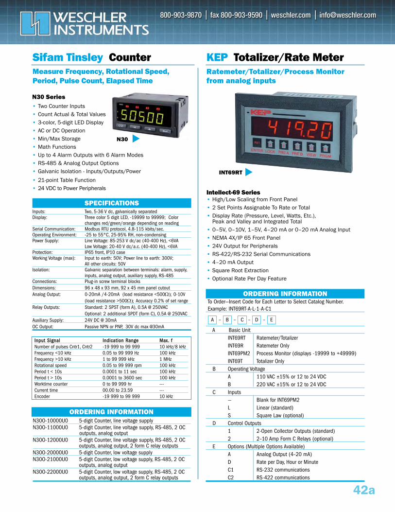
42a
Sifam Tinsley CounterMeasure Frequency, Rotational Speed,Period, Pulse Count, Elapsed Time
N30 Series• Two Counter Inputs• Count Actual & Total Values• 3-color, 5-digit LED Display• AC or DC Operation• Min/Max Storage• Math Functions• Up to 4 Alarm Outputs with 6 Alarm Modes• RS-485 & Analog Output Options• Galvanic Isolation - Inputs/Outputs/Power
• 21-point Table Function• 24 VDC to Power Peripherals
N30
SPECIFICATIONSInputs: Two, 5-36 V dc, galvanically separatedDisplay: Three color 5 digit LED, -19999 to 99999; Color
changes red/green/orange depending on readingSerial Communication: Modbus RTU protocol, 4.8-115 kbits/sec.Operating Environment: -25 to 55°C, 25-95% RH, non-condensingPower Supply: Line Voltage: 85-253 V dc/ac (40-400 Hz), <6VA
Low Voltage: 20-40 V dc/a.c. (40-400 Hz), <6VA Protection: IP65 front, IP10 caseWorking Voltage (max): Input to earth: 50V; Power line to earth: 300V;
All other circuits: 50VIsolation: Galvanic separation between terminals: alarm, supply,
inputs, analog output, auxiliary supply, RS-485 Connections: Plug-in screw terminal blocksDimensions: 96 x 48 x 93 mm, 92 x 45 mm panel cutout Analog Output: 0-20mA /4-20mA (load resistance <500Ω); 0-10V
(load resistance >500Ω); Accuracy 0.2% of set rangeRelay Outputs: Standard: 2 SPST (form A), 0.5A @ 250VAC
Optional: 2 additional SPDT (form C), 0.5A @ 250VACAuxiliary Supply: 24V DC @ 30mAOC Output: Passive NPN or PNP, 30V dc max @30mA
ORDERING INFORMATION
To Order—Insert Code for Each Letter to Select Catalog Number.Example: INT69RT-A-L-1-A-C1
A Basic Unit INT69RT Ratemeter/TotalizerINT69R Ratemeter OnlyINT69PM2 Process Monitor (displays -19999 to +49999)INT69T Totalizer Only
B Operating VoltageA 110 VAC ±15% or 12 to 24 VDCB 220 VAC ±15% or 12 to 24 VDC
C Inputs— Blank for INT69PM2L Linear (standard)S Square Law (optional)
D Control Outputs1 2-Open Collector Outputs (standard)2 2–10 Amp Form C Relays (optional)
E Options (Multiple Options Available)A Analog Output (4–20 mA)D Rate per Day, Hour or MinuteC1 RS-232 communicationsC2 RS-422 communications
Intellect-69 Series• High/Low Scaling from Front Panel• 2 Set Points Assignable To Rate or Total• Display Rate (Pressure, Level, Watts, Etc.),
Peak and Valley and Integrated Total• 0–5V, 0–10V, 1–5V, 4–20 mA or 0–20 mA Analog Input • NEMA 4X/IP 65 Front Panel• 24V Output for Peripherals• RS-422/RS-232 Serial Communications• 4–20 mA Output• Square Root Extraction• Optional Rate Per Day Feature
KEP Totalizer/Rate MeterRatemeter/Totalizer/Process Monitorfrom analog inputs
INT69RT
ORDERING INFORMATION
A – B – C – D – E
N30O-10000U0 5-digit Counter, line voltage supply N30O-11000U0 5-digit Counter, line voltage supply, RS-485, 2 OC
outputs, analog outputN30O-12000U0 5-digit Counter, line voltage supply, RS-485, 2 OC
outputs, analog output, 2 form C relay outputsN30O-20000U0 5-digit Counter, low voltage supplyN30O-21000U0 5-digit Counter, low voltage supply, RS-485, 2 OC
outputs, analog outputN30O-22000U0 5-digit Counter, low voltage supply, RS-485, 2 OC
outputs, analog output, 2 form C relay outputs
IInnppuutt SSiiggnnaall IInnddiiccaattiioonn RRaannggee MMaaxx.. ffNumber of pulses Cntr1, Cntr2 -19 999 to 99 999 10 kHz/8 kHzFrequency <10 kHz 0.05 to 99 999 Hz 100 kHzFrequency >10 kHz 1 to 99 999 kHz 1 MHzRotational speed 0.05 to 99 999 rpm 100 kHzPeriod t < 10s 0.0001 to 11 sec 100 kHzPeriod t > 10s 0.0001 to 3600 sec 100 kHzWorktime counter 0 to 99 999 hr ---Current time 00.00 to 23.59 ---Encoder -19 999 to 99 999 10 kHz
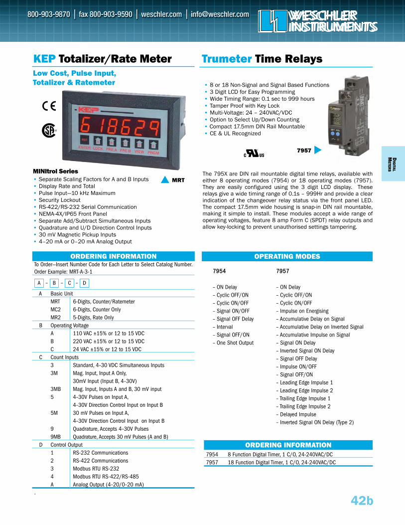
The 795X are DIN rail mountable digital time relays, available witheither 8 operating modes (7954) or 18 operating modes (7957).They are easily configured using the 3 digit LCD display. Theserelays give a wide timing range of 0.1s – 999Hr and provide a clearindication of the changeover relay status via the front panel LED.The compact 17.5mm wide housing is snap-in DIN rail mountable,making it simple to install. These modules accept a wide range ofoperating voltages, feature 8 amp Form C (SPDT) relay outputs andallow key-locking to prevent unauthorised settings tampering.
To Order—Insert Number Code for Each Letter to Select Catalog Number.Order Example: MRT-A-3-1
A Basic UnitMRT 6-Digits, Counter/RatemeterMC2 6-Digits, Counter Only MR2 5-Digits, Rate Only
B Operating VoltageA 110 VAC ±15% or 12 to 15 VDCB 220 VAC ±15% or 12 to 15 VDCC 24 VAC ±15% or 12 to 15 VDC
C Count Inputs3 Standard, 4–30 VDC Simultaneous Inputs3M Mag. Input, Input A Only,
30mV Input (Input B, 4–30V)3MB Mag. Input, Inputs A and B, 30 mV input5 4–30V Pulses on Input A,
4–30V Direction Control Input on Input B5M 30 mV Pulses on Input A,
4–30V Direction Control Input on Input B9 Quadrature, Accepts 4–30V Pulses9MB Quadrature, Accepts 30 mV Pulses (A and B)
D Control Output1 RS-232 Communications2 RS-422 Communications3 Modbus RTU RS-232 4 Modbus RTU RS-422/RS-485 A Analog Output (4–20/0–20 mA)
.
MINItrol Series• Separate Scaling Factors for A and B Inputs• Display Rate and Total• Pulse Input—10 kHz Maximum• Security Lockout• RS-422/RS-232 Serial Communication • NEMA-4X/IP65 Front Panel• Separate Add/Subtract Simultaneous Inputs• Quadrature and U/D Direction Control Inputs• 30 mV Magnetic Pickup Inputs• 4–20 mA or 0–20 mA Analog Output
KEP Totalizer/Rate MeterLow Cost, Pulse Input,Totalizer & Ratemeter
MRT
ORDERING INFORMATION
A – B – C – D
Trumeter Time Relays
OPERATING MODES
77995544
– ON Delay– Cyclic OFF/ON– Cyclic ON/OFF– Signal ON/OFF– Signal OFF Delay– Interval– Signal OFF/ON– One Shot Output
7954 8 Function Digital Timer, 1 C/O, 24-240VAC/DC7957 18 Function Digital Timer, 1 C/O, 24-240VAC/DC
ORDERING INFORMATION
7957
DIG
ITALM
ETERS
42b
77995577
– ON Delay– Cyclic OFF/ON– Cyclic ON/OFF– Impulse on Energising– Accumulative Delay on Signal– Accumulative Delay on Inverted Signal– Accumulative Impulse on Signal– Signal ON Delay– Inverted Signal ON Delay– Signal OFF Delay– Impulse ON/OFF– Signal OFF/ON– Leading Edge Impulse 1– Leading Edge Impulse 2– Trailing Edge Impulse 1– Trailing Edge Impulse 2– Delayed Impulse– Inverted Signal ON Delay (Type 2)
• 8 or 18 Non-Signal and Signal Based Functions• 3 Digit LCD for Easy Programming• Wide Timing Range: 0.1 sec to 999 hours• Tamper Proof with Key Lock • Multi-Voltage: 24 – 240VAC/VDC• Option to Select Up/Down Counting• Compact 17.5mm DIN Rail Mountable• CE & UL Recognized
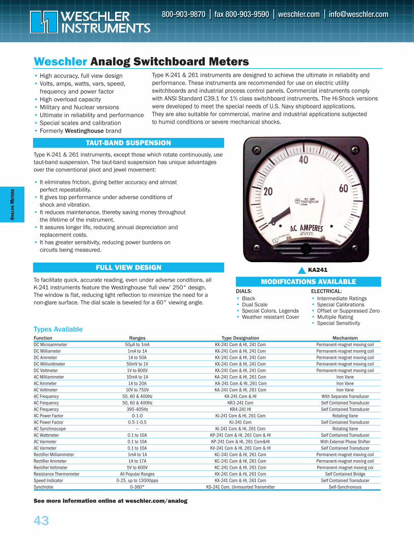
ANAL
OG
MET
ERS
43
Weschler Analog Switchboard MetersType K-241 & 261 instruments are designed to achieve the ultimate in reliability and performance. These instruments are recommended for use on electric utility switchboards and industrial process control panels. Commercial instruments complywith ANSI Standard C39.1 for 1% class switchboard instruments. The Hi-Shock versionswere developed to meet the special needs of U.S. Navy shipboard applications. They are also suitable for commercial, marine and industrial applications subjected to humid conditions or severe mechanical shocks.
Function Ranges Type Designation MechanismDC Microammeter 50µA to 1mA KX-241 Com & HI, 241 Com Permanent-magnet moving coilDC Milliameter 1mA to 1A KX-241 Com & HI, 241 Com Permanent-magnet moving coilDC Ammeter 1A to 50A KX-241 Com & HI, 241 Com Permanent-magnet moving coilDC Millivoltmeter 50mV to 1V KX-241 Com & HI, 241 Com Permanent-magnet moving coilDC Voltmeter 1V to 800V KX-241 Com & HI, 241 Com Permanent-magnet moving coilAC Milliammeter 10mA to 1A KA-241 Com & HI, 261 Com Iron VaneAC Ammeter 1A to 20A KA-241 Com & HI, 261 Com Iron VaneAC Voltmeter 10V to 750V KA-241 Com & HI, 261 Com Iron VaneAC Frequency 50, 60 & 400Hz KX-241 Com & HI With Separate TransducerAC Frequency 50, 60 & 400Hz KR3-241 Com Self Contained TransducerAC Frequency 395-405Hz KR4-241 HI Self Contained TransducerAC Power Factor 0-1-0 KI-241 Com & HI, 261 Com Rotating VaneAC Power Factor 0.5-1-0.5 KJ-241 Com Self Contained TransducerAC Synchroscope -- KI-241 Com & HI, 261 Com Rotating VaneAC Wattmeter 0.1 to 10A KP-241 Com & HI, 261 Com & HI Self Contained TransducerAC Varmeter 0.1 to 10A KP-241 Com & HI, 261 Com&HI With External Phase ShifterAC Varmeter 0.1 to 10A KV-241 Com & HI, 261 Com & HI Self Contained TransducerRectifier Milliammeter 1mA to 1A KC-241 Com & HI, 261 Com Permanent-magnet moving coilRectifier Ammeter 1A to 17A KC-241 Com & HI, 261 Com Permanent-magnet moving coilRectifier Voltmeter 5V to 600V KC-241 Com & HI, 261 Com Permanent-magnet moving coiResistance Thermometer All Popular Ranges KX-241 Com & HI, 261 Com Self Contained BridgeSpeed Indicator 0-25, up to 13000pps KX-241 Com & HI, 261 Com Self Contained TransducerSynchrotie 0-360° KS-241 Com, Unmounted Transmitter Self-Synchronous
Types Available
Type K-241 & 261 instruments, except those which rotate continuously, usetaut-band suspension. The taut-band suspension has unique advantagesover the conventional pivot and jewel movement:
• It eliminates friction, giving better accuracy and almost perfect repeatability.
• It gives top performance under adverse conditions of shock and vibration.
• It reduces maintenance, thereby saving money throughout the lifetime of the instrument.
• It assures longer life, reducing annual depreciation and replacement costs.
• It has greater sensitivity, reducing power burdens on circuits being measured.
To facilitate quick, accurate reading, even under adverse conditions, all K-241 instruments feature the Westinghouse ‘full view’ 250° design. The window is flat, reducing light reflection to minimize the need for a non-glare surface. The dial scale is beveled for a 60° viewing angle.
• High accuracy, full view design• Volts, amps, watts, vars, speed,
frequency and power factor• High overload capacity• Military and Nuclear versions• Ultimate in reliability and performance• Special scales and calibration• Formerly Westinghouse brand
KA241MODIFICATIONS AVAILABLE
TAUT-BAND SUSPENSION
DIALS: • Black• Dual Scale • Special Colors, Legends• Weather resistant Cover
ELECTRICAL:• Intermediate Ratings • Special Calibrations • Offset or Suppressed Zero • Multiple Rating• Special Sensitivity
FULL VIEW DESIGN
See more information online at weschler.com/analog
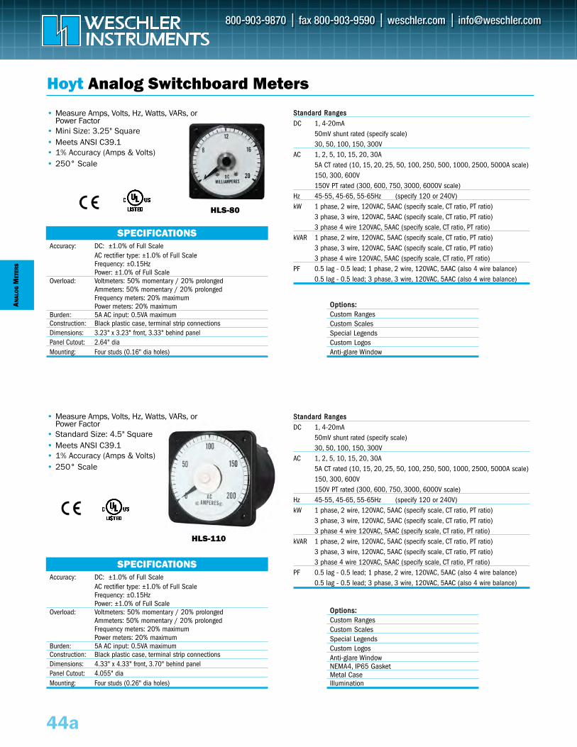
ANAL
OG
MET
ERS
44a
Hoyt Analog Switchboard Meters
HLS-80
HLS-110
SPECIFICATIONSAccuracy: DC: ±1.0% of Full Scale
AC rectifier type: ±1.0% of Full ScaleFrequency: ±0.15HzPower: ±1.0% of Full Scale
Overload: Voltmeters: 50% momentary / 20% prolongedAmmeters: 50% momentary / 20% prolongedFrequency meters: 20% maximumPower meters: 20% maximum
Burden: 5A AC input: 0.5VA maximumConstruction: Black plastic case, terminal strip connectionsDimensions: 3.23" x 3.23" front, 3.33" behind panelPanel Cutout: 2.64" diaMounting: Four studs (0.16" dia holes)
SPECIFICATIONSAccuracy: DC: ±1.0% of Full Scale
AC rectifier type: ±1.0% of Full ScaleFrequency: ±0.15HzPower: ±1.0% of Full Scale
Overload: Voltmeters: 50% momentary / 20% prolongedAmmeters: 50% momentary / 20% prolongedFrequency meters: 20% maximumPower meters: 20% maximum
Burden: 5A AC input: 0.5VA maximumConstruction: Black plastic case, terminal strip connectionsDimensions: 4.33" x 4.33" front, 3.70" behind panelPanel Cutout: 4.055" diaMounting: Four studs (0.26" dia holes)
SSttaannddaarrdd RRaannggeessDC 1, 4-20mA
50mV shunt rated (specify scale)30, 50, 100, 150, 300V
AC 1, 2, 5, 10, 15, 20, 30A5A CT rated (10, 15, 20, 25, 50, 100, 250, 500, 1000, 2500, 5000A scale)150, 300, 600V 150V PT rated (300, 600, 750, 3000, 6000V scale)
Hz 45-55, 45-65, 55-65Hz (specify 120 or 240V)kW 1 phase, 2 wire, 120VAC, 5AAC (specify scale, CT ratio, PT ratio)
3 phase, 3 wire, 120VAC, 5AAC (specify scale, CT ratio, PT ratio)3 phase 4 wire 120VAC, 5AAC (specify scale, CT ratio, PT ratio)
kVAR 1 phase, 2 wire, 120VAC, 5AAC (specify scale, CT ratio, PT ratio)3 phase, 3 wire, 120VAC, 5AAC (specify scale, CT ratio, PT ratio)3 phase 4 wire 120VAC, 5AAC (specify scale, CT ratio, PT ratio)
PF 0.5 lag - 0.5 lead; 1 phase, 2 wire, 120VAC, 5AAC (also 4 wire balance)0.5 lag - 0.5 lead; 3 phase, 3 wire, 120VAC, 5AAC (also 4 wire balance)
• Measure Amps, Volts, Hz, Watts, VARs, orPower Factor
• Mini Size: 3.25" Square• Meets ANSI C39.1• 1% Accuracy (Amps & Volts)• 250° Scale
OOppttiioonnss::Custom RangesCustom ScalesSpecial Legends Custom LogosAnti-glare Window
OOppttiioonnss::Custom RangesCustom ScalesSpecial Legends Custom LogosAnti-glare WindowNEMA4, IP65 GasketMetal CaseIllumination
• Measure Amps, Volts, Hz, Watts, VARs, orPower Factor
• Standard Size: 4.5" Square• Meets ANSI C39.1• 1% Accuracy (Amps & Volts)• 250° Scale
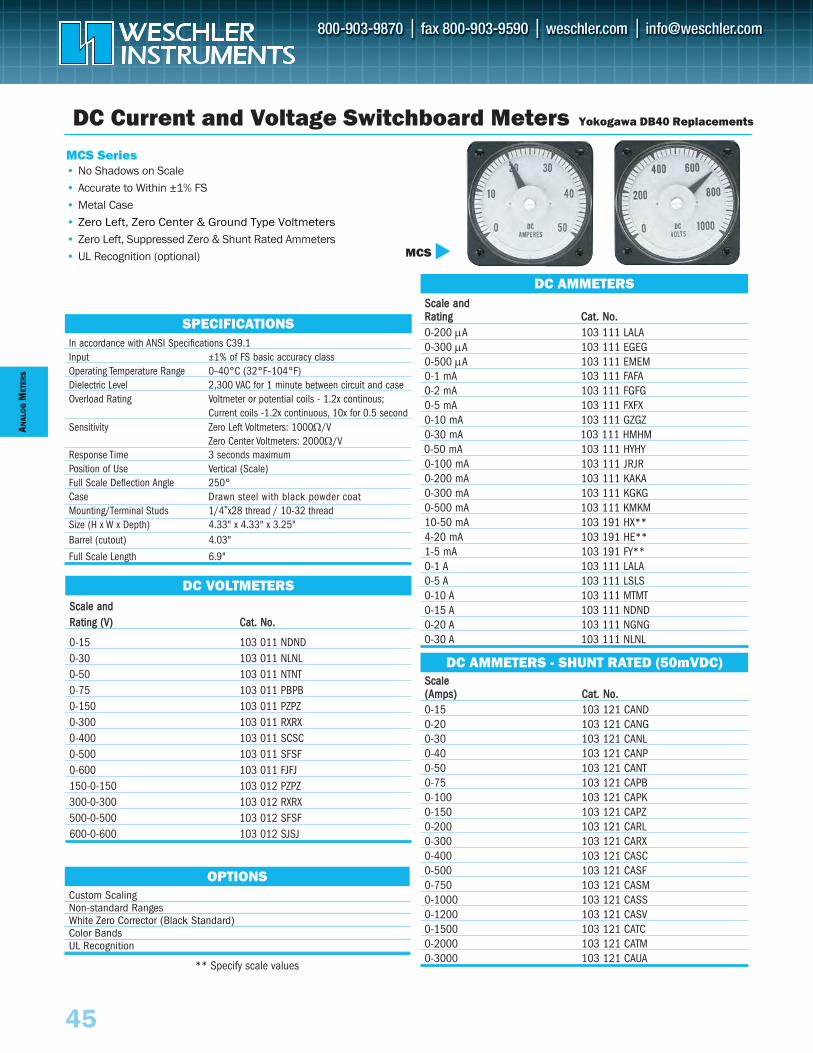
ANAL
OG
MET
ERS
45
In accordance with ANSI Specifications C39.1Input ±1% of FS basic accuracy classOperating Temperature Range 0–40°C (32°F–104°F)Dielectric Level 2,300 VAC for 1 minute between circuit and caseOverload Rating Voltmeter or potential coils - 1.2x continous;
Current coils -1.2x continuous, 10x for 0.5 secondSensitivity Zero Left Voltmeters: 1000Ω/V
Zero Center Voltmeters: 2000Ω/VResponse Time 3 seconds maximumPosition of Use Vertical (Scale)Full Scale Deflection Angle 250°Case Drawn steel with black powder coatMounting/Terminal Studs 1/4”x28 thread / 10-32 threadSize (H x W x Depth) 4.33" x 4.33" x 3.25"Barrel (cutout) 4.03"
Full Scale Length 6.9"
SPECIFICATIONS
SccaalleeS((AAmmppss)) CCaatt.. NNoo.. 0-15 103 121 CAND0-20 103 121 CANG0-30 103 121 CANL0-40 103 121 CANP0-50 103 121 CANT0-75 103 121 CAPB0-100 103 121 CAPK0-150 103 121 CAPZ0-200 103 121 CARL0-300 103 121 CARX0-400 103 121 CASC0-500 103 121 CASF0-750 103 121 CASM0-1000 103 121 CASS0-1200 103 121 CASV0-1500 103 121 CATC0-2000 103 121 CATM0-3000 103 121 CAUA
Sccaallee aannddSRRaattiinngg CCaatt.. NNoo.. 0-200 μA 103 111 LALA0-300 μA 103 111 EGEG0-500 μA 103 111 EMEM0-1 mA 103 111 FAFA0-2 mA 103 111 FGFG0-5 mA 103 111 FXFX0-10 mA 103 111 GZGZ0-30 mA 103 111 HMHM0-50 mA 103 111 HYHY0-100 mA 103 111 JRJR0-200 mA 103 111 KAKA0-300 mA 103 111 KGKG0-500 mA 103 111 KMKM10-50 mA 103 191 HX**4-20 mA 103 191 HE**1-5 mA 103 191 FY**0-1 A 103 111 LALA0-5 A 103 111 LSLS0-10 A 103 111 MTMT0-15 A 103 111 NDND0-20 A 103 111 NGNG0-30 A 103 111 NLNL
MCS Series• No Shadows on Scale• Accurate to Within ±1% FS • Metal Case• Zero Left, Zero Center & Ground Type Voltmeters
• Zero Left, Suppressed Zero & Shunt Rated Ammeters
• UL Recognition (optional)
DC Current and Voltage Switchboard Meters Yokogawa DB40 Replacements
MCS
DC AMMETERS - SHUNT RATED (50mVDC)
DC AMMETERS
Sccaallee aannddSRRaattiinngg ((VV)) CCaatt.. NNoo..
0-15 103 011 NDND0-30 103 011 NLNL0-50 103 011 NTNT0-75 103 011 PBPB0-150 103 011 PZPZ0-300 103 011 RXRX0-400 103 011 SCSC0-500 103 011 SFSF0-600 103 011 FJFJ150-0-150 103 012 PZPZ300-0-300 103 012 RXRX500-0-500 103 012 SFSF600-0-600 103 012 SJSJ
DC VOLTMETERS
Custom ScalingNon-standard RangesWhite Zero Corrector (Black Standard)Color BandsUL Recognition
OPTIONS
** Specify scale values
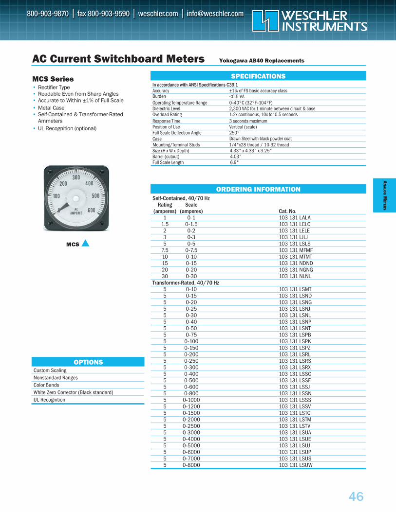
AN
ALOG
METER
S
46
In accordance with ANSI Specifications C39.1Accuracy ±1% of FS basic accuracy class
Operating Temperature Range 0–40°C (32°F–104°F)Dielectric Level 2,300 VAC for 1 minute between circuit & caseOverload Rating 1.2x continuous, 10x for 0.5 secondsResponse Time 3 seconds maximumPosition of Use Vertical (scale)Full Scale Deflection Angle 250°Case Drawn Steel with black powder coatMounting/Terminal Studs 1/4"x28 thread / 10-32 threadSize (H x W x Depth) 4.33" x 4.33" x 3.25"Barrel (cutout) 4.03"Full Scale Length 6.9"
AC Current Switchboard Meters Yokogawa AB40 Replacements
MCS Series• Rectifier Type• Readable Even from Sharp Angles• Accurate to Within ±1% of Full Scale• Metal Case• Self-Contained & Transformer-Rated
Ammeters• UL Recognition (optional)
SPECIFICATIONS
MCS
ORDERING INFORMATION
Custom ScalingNonstandard RangesColor BandsWhite Zero Corrector (Black standard)UL Recognition
OPTIONS
Self-Contained, 40/70 HzRating Scale
(amperes) (amperes) Cat. No.1 0-1 103 131 LALA
1.5 0-1.5 103 131 LCLC2 0-2 103 131 LELE3 0-3 103 131 LJLJ5 0-5 103 131 LSLS
7.5 0-7.5 103 131 MFMF10 0-10 103 131 MTMT15 0-15 103 131 NDND20 0-20 103 131 NGNG30 0-30 103 131 NLNL
Transformer-Rated, 40/70 Hz5 0-10 103 131 LSMT5 0-15 103 131 LSND5 0-20 103 131 LSNG5 0-25 103 131 LSNJ5 0-30 103 131 LSNL5 0-40 103 131 LSNP5 0-50 103 131 LSNT5 0-75 103 131 LSPB5 0-100 103 131 LSPK5 0-150 103 131 LSPZ5 0-200 103 131 LSRL5 0-250 103 131 LSRS5 0-300 103 131 LSRX5 0-400 103 131 LSSC5 0-500 103 131 LSSF5 0-600 103 131 LSSJ5 0-800 103 131 LSSN5 0-1000 103 131 LSSS5 0-1200 103 131 LSSV5 0-1500 103 131 LSTC5 0-2000 103 131 LSTM5 0-2500 103 131 LSTV5 0-3000 103 131 LSUA5 0-4000 103 131 LSUE5 0-5000 103 131 LSUJ5 0-6000 103 131 LSUP5 0-7000 103 131 LSUS5 0-8000 103 131 LSUW
Burden <0.5 VA
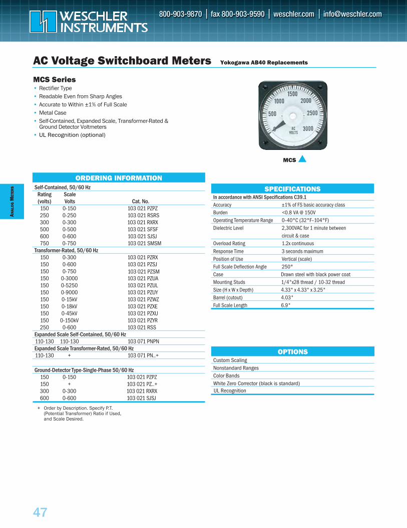
ANAL
OG
MET
ERS
47
Self-Contained, 50/60 HzRating Scale(volts) Volts Cat. No.
150 0-150 103 021 PZPZ250 0-250 103 021 RSRS300 0-300 103 021 RXRX500 0-500 103 021 SFSF600 0-600 103 021 SJSJ750 0-750 103 021 SMSM
Transformer-Rated, 50/60 Hz150 0-300 103 021 PZRX150 0-600 103 021 PZSJ150 0-750150 0-3000 103 021 PZUA150 0-5250 103 021 PZUL150 0-9000 103 021 PZUY150 0-15kV 103 021 PZWZ 150 0-18kV 103 021 PZXE150 0-45kV 103 021 PZXU150 0-150kV 103 021 PZYR250 0-600 103 021 RSS
Expanded Scale Self-Contained, 50/60 Hz110-130 110-130 103 071 PNPNExpanded Scale Transformer-Rated, 50/60 Hz110-130 + 103 071 PN..+
Ground-Detector Type-Single-Phase 50/60 Hz150 0-150 103 021 PZPZ150 + 103 021 PZ..+300 0-300 103 021 RXRX600 0-600 103 021 SJSJ
SPECIFICATIONS
AC Voltage Switchboard Meters Yokogawa AB40 Replacements
MCS Series• Rectifier Type• Readable Even from Sharp Angles• Accurate to Within ±1% of Full Scale• Metal Case• Self-Contained, Expanded Scale, Transformer-Rated &
• UL Recognition (optional)
+ Order by Description. Specify P.T.(Potential Transformer) Ratio if Used,and Scale Desired.
MCS
Custom ScalingNonstandard RangesColor BandsWhite Zero Corrector (black is standard)
OPTIONS
ORDERING INFORMATION
In accordance with ANSI Specifications C39.1Accuracy ±1% of FS basic accuracy classBurden <0.8 VA @ 150VOperating Temperature Range 0–40°C (32°F–104°F)Dielectric Level 2,300VAC for 1 minute between
circuit & caseOverload Rating 1.2x continuousResponse Time 3 seconds maximumPosition of Use Vertical (scale)Full Scale Deflection Angle 250°Case Drawn steel with black power coatMounting Studs 1/4"x28 thread / 10-32 threadSize (H x W x Depth) 4.33" x 4.33" x 3.25"Barrel (cutout) 4.03"Full Scale Length 6.9"
UL Recognition
103 021 PZSM
Ground Detector Voltmeters
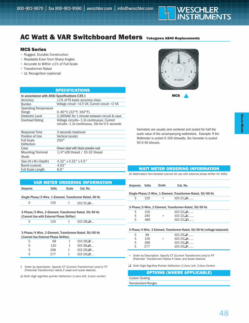
±1% of FS basic accuracy classBurden
AN
ALOG
METER
S
48
+ Order by Description. Specify CT (Current Transformer) and/or PT(Potential Transformer) Ratios if Used, and Scale Desired.
Sixth Digit Signifies Pointer Deflection (1-Zero Left, 2-Zero Center)
AC Wattmeters Non-Isolated (cannot be use with external phase shifter for VARs)
Scale Amperes Volts Cat. No.
Single-Phase/2-Wire, 1-Element, Transformer-Rated, 50/60 Hz5 120 + 103 21A……
3-Phase/3-Wire, 2-Element, Transformer-Rated, 50/60 Hz5 120 103 22A…… 5 240 + 103 22C…… 5 480 103 22D……
5 277 103 25Y……
3-Phase/4-Wire, 3-Element, Transformer-Rated, 50/60 Hz (voltage balanced)
5 69 103 25F…… 5 120 + 103 25A…… 5 208 103 25R……
In accordance with ANSI Specifications C39.1Accuracy
Operating Temperature Range 0–40°C (32°F–104°F)Dielectric Level 2,300VAC for 1 minute between circuit & caseOverload Rating Voltage circuits—1.2x continuous; Current
circuits—1.2x continuous, 10x for 0.5 seconds
Response Time 3 seconds maximum Position of Use Vertical (scale)Full Scale 250° Deflection Case Drawn steel with black powder coatMounting/TerminalStuds
1/4"x28 thread / 10-32 thread
Size (H x W x Depth) 4.33" x 4.33" x 4.5" Barrel (cutout) 4.03"Full Scale Length 6.9"
AC Watt & VAR Switchboard Meters Yokogawa AB40 Replacements
MCS Series• Rugged, Durable Construction• Readable Even from Sharp Angles• Accurate to Within ±1% of Full Scale• Transformer Rated• UL Recognition (optional)
SPECIFICATIONSMCS
† Order by description. Specify CT (Current Transformer) and/or PT (Potential Transformer) ratios if used and scale desired.
Sixth digit signifies pointer deflection (1-zero left, 2-zero center).Custom Scaling
Nonstandard Ranges
OPTIONS (WHERE APPLICABLE)
WATT METER ORDERING INFORMATION
Amperes Volts Scale Cat. No.
Single Phase/2-Wire, 1-Element, Transformer Rated, 60 Hz
5 120 † 103 31A…
3-Phase/3-Wire, 2-Element, Transformer Rated, 50/60 Hz (Cannot Use with External Phase Shifter)
5 120 † 103 28A…
3-Phase/4-Wire, 3-Element, Transformer-Rated, 50/60 Hz (Cannot Use External Phase Shifter)
5 69 † 103 29F… 5 120 † 103 29A…5 208 † 103 29R… 5 277 † 103 29Y…
VAR METER ORDERING INFORMATION
Voltage circuit: <4.5 VA; Current circuit: <2 VA
Varmeters are usually zero-centered and scaled for half thescale value of the accompanying wattmeters. Example: If theWattmeter is scaled 0-100 kilowatts, the Varmeter is scaled50-0-50 kilovars.
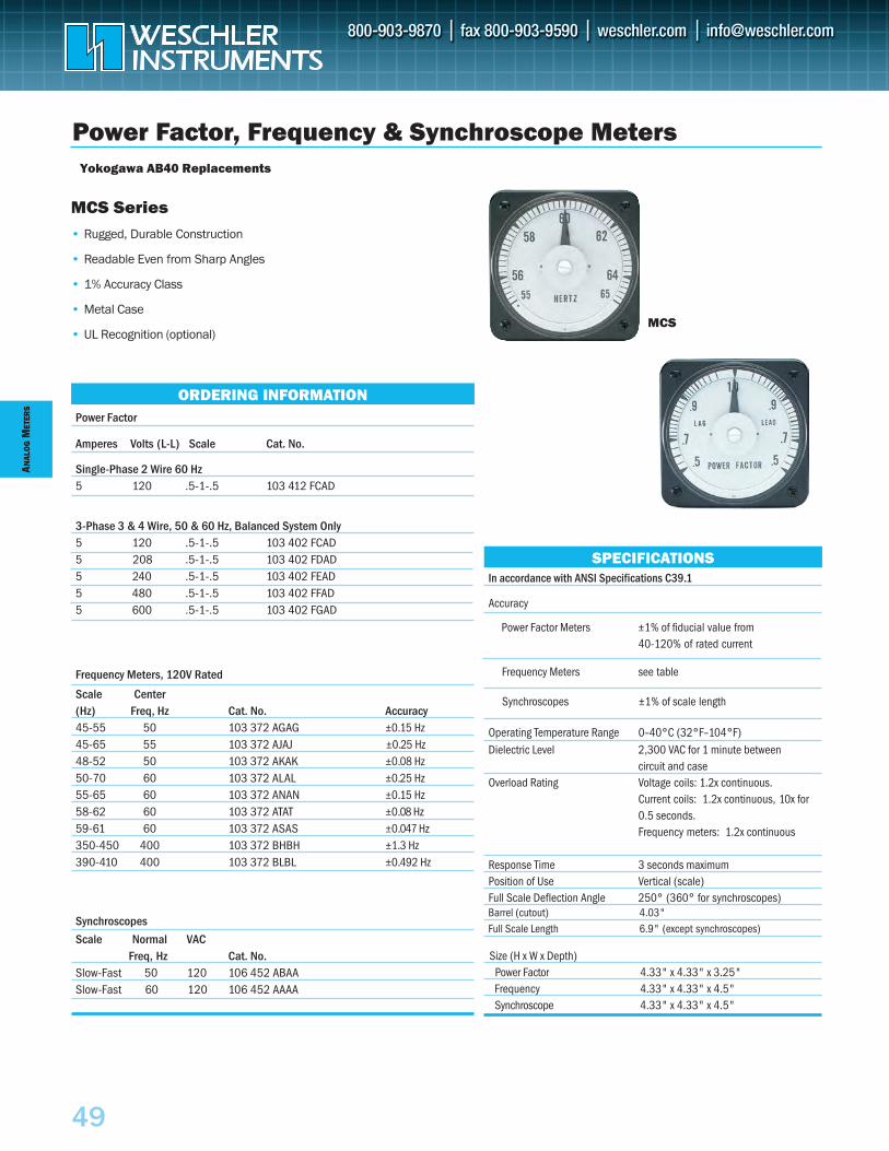
A NAL
OG
M ET
ERS
49
In accordance with ANSI Specifications C39.1
Accuracy
Power Factor Meters ±1% of fiducial value from40-120% of rated current
Frequency Meters see table
Operating Temperature Range 0–40°C (32°F–104°F)Dielectric Level 2,300 VAC for 1 minute between
circuit and caseOverload Rating Voltage coils: 1.2x continuous.
Current coils: 1.2x continuous, 10x for 0.5 seconds. Frequency meters: 1.2x continuous
Response Time 3 seconds maximumPosition of Use Vertical (scale)Full Scale Deflection Angle 250° (360° for synchroscopes)
Size (H x W x Depth)Power Factor 4.33" x 4.33" x 3.25"Frequency 4.33" x 4.33" x 4.5"Synchroscope 4.33" x 4.33" x 4.5"
Power Factor
Amperes Volts (L-L) Scale Cat. No.
Single-Phase 2 Wire 60 Hz5 120 .5-1-.5 103 412 FCAD
3-Phase 3 & 4 Wire, 50 & 60 Hz, Balanced System Only5 120 .5-1-.5 103 402 FCAD 5 208 .5-1-.5 103 402 FDAD 5 240 .5-1-.5 103 402 FEAD 5 480 .5-1-.5 103 402 FFAD 5 600 .5-1-.5 103 402 FGAD
Frequency Meters, 120V Rated
Scale Center (Hz) Freq, Hz Cat. No. Accuracy45-55 50 103 372 AGAG ±0.15 Hz45-65 55 103 372 AJAJ ±0.25 Hz48-52 50 103 372 AKAK ±0.08 Hz50-70 60 103 372 ALAL ±0.25 Hz55-65 60 103 372 ANAN ±0.15 Hz 58-62 60 103 372 ATAT ±0.08 Hz59-61 60 103 372 ASAS ±0.047 Hz350-450 400 103 372 BHBH ±1.3 Hz390-410 400 103 372 BLBL ±0.492 Hz
Synchroscopes
Scale Normal VAC Freq, Hz Cat. No.
Slow-Fast 50 120 106 452 ABAA Slow-Fast 60 120 106 452 AAAA
Power Factor, Frequency & Synchroscope Meters
MCS Series• Rugged, Durable Construction
• Readable Even from Sharp Angles
• 1% Accuracy Class
• Metal Case
• UL Recognition (optional)MCS
SPECIFICATIONS
ORDERING INFORMATION
Synchroscopes ±1% of scale length
Barrel (cutout) 4.03"Full Scale Length 6.9" (except synchroscopes)
Yokogawa AB40 Replacements
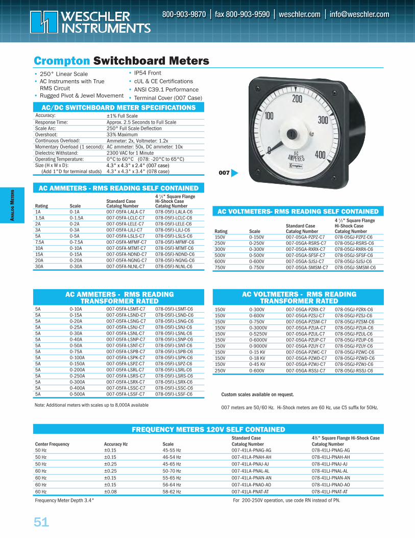
ANAL
OG
MET
ERS
51
Crompton Switchboard Meters• 250° Linear Scale• AC Instruments with True
• Rugged Pivot & Jewel Movement
Accuracy:±1% Full Scale
Response Time: Approx. 2.5 Seconds to Full ScaleScale Arc: 250° Full Scale Deflection
Momentary Overload (1 second): AC ammeter: 50x, DC ammeter: 10x
Overshoot: 33% Maximum
Dielectric Withstand: 2300 VAC for 1 MinuteOperating Temperature: 0°C to 60°C (078: -20°C to 65°C)Size (H x W x D):
4.3" x 4.3" x 3.4" (078 case)
AC/DC SWITCHBOARD METER SPECIFICATIONS
4 1/2" Square FlangeStandard Case Hi-Shock Case
Rating Scale Catalog Number Catalog Number1A 0-1A 007-05FA-LALA-C7 078-05FJ-LALA-C61.5A 0-1.5A 007-05FA-LCLC-C7 078-05FJ-LCLC-C62A 0-2A 007-05FA-LELE-C7 078-05FJ-LELE-C63A 0-3A 007-05FA-LJLJ-C7 078-05FJ-LJLJ-C65A 0-5A 007-05FA-LSLS-C7 078-05FJ-LSLS-C67.5A 0-7.5A 007-05FA-MFMF-C7 078-05FJ-MFMF-C610A 0-10A 007-05FA-MTMT-C7 078-05FJ-MTMT-C615A 0-15A 007-05FA-NDND-C7 078-05FJ-NDND-C620A 0-20A 007-05FA-NGNG-C7 078-05FJ-NGNG-C630A 0-30A 007-05FA-NLNL-C7 078-05FJ-NLNL-C6
AC AMMETERS - RMS READING SELF CONTAINED
4 1/2" Square FlangeStandard Case Hi-Shock Case
Rating Scale Catalog Number Catalog Number150V 0-150V 007-05GA-PZPZ-C7 078-05GJ-PZPZ-C6250V 0-250V 007-05GA-RSRS-C7 078-05GJ-RSRS-C6300V 0-300V 007-05GA-RXRX-C7 078-05GJ-RXRX-C6500V 0-500V 007-05GA-SFSF-C7 078-05GJ-SFSF-C6600V 0-600V 007-05GA-SJSJ-C7 078-05GJ-SJSJ-C6750V 0-750V 007-05GA-SMSM-C7 078-05GJ-SMSM-C6
AC VOLTMETERS- RMS READING SELF CONTAINED
5A 0-10A 007-05FA-LSMT-C7 078-05FJ-LSMT-C65A 0-15A 007-05FA-LSND-C7 078-05FJ-LSND-C65A 0-20A 007-05FA-LSNG-C7 078-05FJ-LSNG-C65A 0-25A 007-05FA-LSNJ-C7 078-05FJ-LSNJ-C65A 0-30A 007-05FA-LSNL-C7 078-05FJ-LSNL-C65A 0-40A 007-05FA-LSNP-C7 078-05FJ-LSNP-C65A 0-50A 007-05FA-LSNT-C7 078-05FJ-LSNT-C65A 0-75A 007-05FA-LSPB-C7 078-05FJ-LSPB-C65A 0-100A 007-05FA-LSPK-C7 078-05FJ-LSPK-C65A 0-150A 007-05FA-LSPZ-C7 078-05FJ-LSPZ-C65A 0-200A 007-05FA-LSRL-C7 078-05FJ-LSRL-C65A 0-250A 007-05FA-LSRS-C7 078-05FJ-LSRS-C65A 0-300A 007-05FA-LSRX-C7 078-05FJ-LSRX-C65A 0-400A 007-05FA-LSSC-C7 078-05FJ-LSSC-C65A 0-500A 007-05FA-LSSF-C7 078-05FJ-LSSF-C6
AC AMMETERS - RMS READING TRANSFORMER RATED
150V 0-300V 007-05GA-PZRX-C7 078-05GJ-PZRX-C6150V 0-600V 007-05GA-PZSJ-C7 078-05GJ-PZSJ-C6150V 0-750V 007-05GA-PZSM-C7 078-05GJ-PZSM-C6150V 0-3000V 007-05GA-PZUA-C7 078-05GJ-PZUA-C6150V 0-5250V 007-05GA-PZUL-C7 078-05GJ-PZUL-C6150V 0-6000V 007-05GA-PZUP-C7 078-05GJ-PZUP-C6150V 0-9000V 007-05GA-PZUY-C7 078-05GJ-PZUY-C6150V 0-15 KV 007-05GA-PZWC-C7 078-05GJ-PZWC-C6150V 0-18 KV 007-05GA-PZWD-C7 078-05GJ-PZWD-C6150V 0-45 KV 007-05GA-PZWJ-C7 078-05GJ-PZWJ-C6250V 0-600V 007-05GA-RSSJ-C7 078-05GJ-RSSJ-C6
AC VOLTMETERS - RMS READING TRANSFORMER RATED
Standard Case 41⁄2" Square Flange Hi-Shock CaseCenter Frequency Accuracy Hz Scale Catalog Number Catalog Number50 Hz ±0.15 45-55 Hz 007-41LA-PNAG-AG 078-41LJ-PNAG-AG50 Hz ±0.15 46-54 Hz 007-41LA-PNAH-AH 078-41LJ-PNAH-AH50 Hz ±0.25 45-65 Hz 007-41LA-PNAJ-AJ 078-41LJ-PNAJ-AJ60 Hz ±0.25 50-70 Hz 007-41LA-PNAL-AL 078-41LJ-PNAL-AL60 Hz ±0.15 55-65 Hz 007-41LA-PNAN-AN 078-41LJ-PNAN-AN60 Hz ±0.15 56-64 Hz 007-41LA-PNAO-AO 078-41LJ-PNAO-AO60 Hz ±0.08 58-62 Hz 007-41LA-PNAT-AT 078-41LJ-PNAT-AT
FREQUENCY METERS 120V SELF CONTAINED
• IP54 Front• cUL & CE Certifications• ANSI C39.1 Performance • Terminal Cover (007 Case)
007
Continuous Overload: Ammeter: 2x, Voltmeter: 1.2x
Custom scales available on request.
007 meters are 50/60 Hz. Hi-Shock meters are 60 Hz, use C5 suffix for 50Hz.Note: Additional meters with scales up to 8,000A available
Frequency Meter Depth 3.4"
Accuracy:
(Add 1"D for terminal studs)4.3" x 4.3" x 2.4" (007 case)
RMS Circuit
For 200-250V operation, use code RN instead of PN.
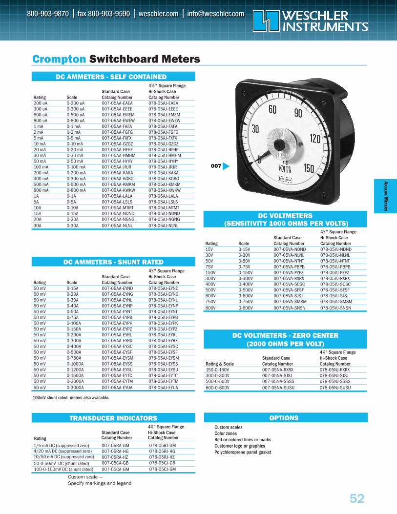
AN
ALOG
METER
S
52
Crompton Switchboard Meters
41⁄2" Square FlangeStandard Case Hi-Shock Case
Rating Scale Catalog Number Catalog Number200 uA 0-200 uA 007-05AA-EAEA 078-05AJ-EAEA300 uA 0-300 uA 007-05AA-EEEE 078-05AJ-EEEE500 uA 0-500 uA 007-05AA-EMEM 078-05AJ-EMEM800 uA 0-800 uA 007-05AA-EWEW 078-05AJ-EWEW1 mA 0-1 mA 007-05AA-FAFA 078-05AJ-FAFA2 mA 0-2 mA 007-05AA-FGFG 078-05AJ-FGFG5 mA 0-5 mA 007-05AA-FXFX 078-05AJ-FXFX10 mA 0-10 mA 007-05AA-GZGZ 078-05AJ-GZGZ20 mA 0-20 mA 007-05AA-HFHF 078-05AJ-HFHF30 mA 0-30 mA 007-05AA-HMHM 078-05AJ-HMHM50 mA 0-50 mA 007-05AA-HYHY 078-05AJ-HYHY100 mA 0-100 mA 007-05AA-JRJR 078-05AJ-JRJR200 mA 0-200 mA 007-05AA-KAKA 078-05AJ-KAKA300 mA 0-300 mA 007-05AA-KGKG 078-05AJ-KGKG500 mA 0-500 mA 007-05AA-KMKM 078-05AJ-KMKM800 mA 0-800 mA 007-05AA-KWKW 078-05AJ-KWKW1A 0-1A 007-05AA-LALA 078-05AJ-LALA5A 0-5A 007-05AA-LSLS 078-05AJ-LSLS10A 0-10A 007-05AA-MTMT 078-05AJ-MTMT15A 0-15A 007-05AA-NDND 078-05AJ-NDND20A 0-20A 007-05AA-NGNG 078-05AJ-NGNG30A 0-30A 007-05AA-NLNL 078-05AJ-NLNL
DC AMMETERS - SELF CONTAINED
41⁄2" Square FlangeStandard Case Hi-Shock Case
Rating Scale Catalog Number Catalog Number50 mV 0-15A 007-05AA-EYND 078-05AJ-EYND50 mV 0-20A 007-05AA-EYNG 078-05AJ-EYNG50 mV 0-30A 007-05AA-EYNL 078-05AJ-EYNL50 mV 0-40A 007-05AA-EYNP 078-05AJ-EYNP50 mV 0-50A 007-05AA-EYNT 078-05AJ-EYNT50 mV 0-75A 007-05AA-EYPB 078-05AJ-EYPB50 mV 0-100A 007-05AA-EYPK 078-05AJ-EYPK50 mV 0-150A 007-05AA-EYPZ 078-05AJ-EYPZ50 mV 0-200A 007-05AA-EYRL 078-05AJ-EYRL50 mV 0-300A 007-05AA-EYRX 078-05AJ-EYRX50 mV 0-400A 007-05AA-EYSC 078-05AJ-EYSC50 mV 0-500A 007-05AA-EYSF 078-05AJ-EYSF50 mV 0-750A 007-05AA-EYSM 078-05AJ-EYSM50 mV 0-1000A 007-05AA-EYSS 078-05AJ-EYSS50 mV 0-1200A 007-05AA-EYSU 078-05AJ-EYSU50 mV 0-1500A 007-05AA-EYTC 078-05AJ-EYTC50 mV 0-2000A 007-05AA-EYTM 078-05AJ-EYTM50 mV 0-3000A 007-05AA-EYUA 078-05AJ-EYUA
DC AMMETERS - SHUNT RATED
41⁄2" Square FlangeStandard Case Hi-Shock Case
Rating Scale Catalog Number Catalog Number15V 0-15V 007-05VA-NDND 078-05VJ-NDND30V 0-30V 007-05VA-NLNL 078-05VJ-NLNL50V 0-50V 007-05VA-NTNT 078-05VJ-NTNT75V 0-75V 007-05VA-PBPB 078-05VJ-PBPB150V 0-150V 007-05VA-PZPZ 078-05VJ-PZPZ300V 0-300V 007-05VA-RXRX 078-05VJ-RXRX400V 0-400V 007-05VA-SCSC 078-05VJ-SCSC500V 0-500V 007-05VA-SFSF 078-05VJ-SFSF600V 0-600V 007-05VA-SJSJ 078-05VJ-SJSJ750V 0-750V 007-05VA-SMSM 078-05VJ-SMSM800V 0-800V 007-05VA-SNSN 078-05VJ-SNSN
DC VOLTMETERS(SENSITIVITY 1000 OHMS PER VOLTS)
41⁄2" Square FlangeStandard Case Hi-Shock Case
Rating & Scale Catalog Number Catalog Number150-0-150V 007-05NA-RXRX 078-05NJ-RXRX300-0-300V 007-05NA-SJSJ 078-05NJ-SJSJ500-0-500V 007-05NA-SSSS 078-05NJ-SSSS600-0-600V 007-05NA-SUSU 078-05NJ-SUSU
DC VOLTMETERS - ZERO CENTER (2000 OHMS PER VOLT)
1/5 mA DC (suppressed zero)4/20 mA DC (suppressed zero)10/50 mA DC (suppressed zero)
TRANSDUCER INDICATORS
007
Custom scale —Specify markings and legend
Custom scalesColor zonesRed or colored lines or marksCustomer logo or graphicsPolychloroprene panel gasket
50-0-50mV DC (shunt rated)100-0-100mV DC (shunt rated)
007-05RA-GM007-05RA-HG007-05RA-HZ007-05CA-GB007-05CA-GM
078-05RJ-GM078-05RJ-HG078-05RJ-HZ078-05CJ-GB078-05CJ-GM
100mV shunt rated meters also available.
41⁄2" Square FlangeStandard Case Hi-Shock Case
Rating Catalog Number Catalog Number
OPTIONS
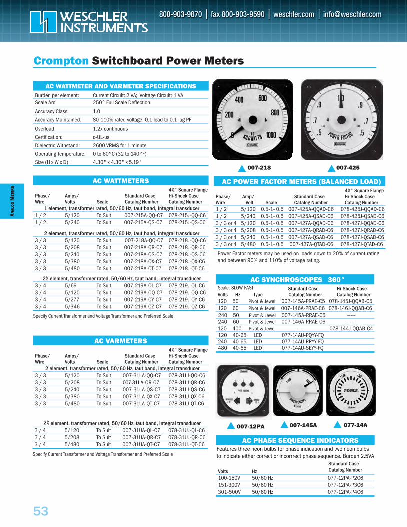
ANAL
OG
MET
ERS
53
41⁄2" Square FlangePhase/ Amps/ Standard Case Hi-Shock CaseWire Volts Scale Catalog Number Catalog Number
2 element, transformer rated, 50/60 Hz, taut band, integral transducer3 / 3 5/120 To Suit 007-31LA-QQ-C7 078-31LJ-QQ-C63 / 3 5/208 To Suit 007-31LA-QR-C7 078-31LJ-QR-C63 / 3 5/240 To Suit 007-31LA-QS-C7 078-31LJ-QS-C63 / 3 5/380 To Suit 007-31LA-QX-C7 078-31LJ-QX-C63 / 3 5/480 To Suit 007-31LA-QT-C7 078-31LJ-QT-C6
21⁄2 element, transformer rated, 50/60 Hz, taut band, integral transducer3 / 4 5/120 To Suit 007-31UA-QL-C7 078-31UJ-QL-C63 / 4 5/208 To Suit 007-31UA-QR-C7 078-31UJ-QR-C63 / 4 5/480 To Suit 007-31UA-QT-C7 078-31UJ-QT-C6
Specify Current Transformer and Voltage Transformer and Preferred Scale
AC VARMETERS
AC SYNCHROSCOPES - PIVOT AND JE°
AC PHASE SEQUENCE INDICATORS
Volts Hz Catalog Number
100-150V 50/60 Hz 077-12PA-P2C6151-300V 50/60 Hz 077-12PA-P3C6301-500V 50/60 Hz 077-12PA-P4C6
Standard Case
41⁄2" Square FlangePhase/ Amps/ Standard Case Hi-Shock CaseWire Volts Scale Catalog Number Catalog Number
1 element, transformer rated, 50/60 Hz, taut band, integral transducer1 / 2 5/120 To Suit 007-215A-QQ-C7 078-215J-QQ-C61 / 2 5/240 To Suit 007-215A-QS-C7 078-215J-QS-C6
2 element, transformer rated, 50/60 Hz, taut band, integral transducer3 / 3 5/120 To Suit 007-218A-QQ-C7 078-218J-QQ-C63 / 3 5/208 To Suit 007-218A-QR-C7 078-218J-QR-C63 / 3 5/240 To Suit 007-218A-QS-C7 078-218J-QS-C63 / 3 5/380 To Suit 007-218A-QX-C7 078-218J-QX-C63 / 3 5/480 To Suit 007-218A-QT-C7 078-218J-QT-C6
21⁄2 element, transformer rated, 50/60 Hz, taut band, integral transducer3 / 4 5/69 To Suit 007-219A-QL-C7 078-219J-QL-C63 / 4 5/120 To Suit 007-219A-QQ-C7 078-219J-QQ-C63 / 4 5/277 To Suit 007-219A-QY-C7 078-219J-QY-C63 / 4 5/346 To Suit 007-219A-QZ-C7 078-219J-QZ-C6
Specify Current Transformer and Voltage Transformer and Preferred Scale
Burden per element: Current Circuit: 2 VA; Voltage Circuit: 1 VA
Accuracy Class: 1.0
Scale Arc: 250° Full Scale Deflection
Overload: 1.2x continuous
Certification: c-UL-us
Dielectric Withstand: 2600 VRMS for 1 minute
Operating Temperature: 0 to 60°C (32 to 140°F)
Size (H x W x D): 4.30" x 4.30" x 5.19"
Crompton Switchboard Power Meters
AC WATTMETERS
AC WATTMETER AND VARMETER SPECIFICATIONS
007-425007-218
Accuracy Maintained: 80-110% rated voltage, 0.1 lead to 0.1 lag PF
AC POWER FACTOR METERS (BALANCED LOAD)41⁄2" Square Flange
Phase/ Amp/ Standard Case Hi-Shock CaseWire Volt Scale Catalog Number Catalog Number1 / 2 5/120 0.5-1- 0.5 007-425A-QQAD-C6 078-425J-QQAD-C61 / 2 5/240 0.5-1- 0.5 007-425A-QSAD-C6 078-425J-QSAD-C63 / 3 or 4 5/120 0.5-1- 0.5 007-427A-QQAD-C6 078-427J-QQAD-C63 / 3 or 4 5/208 0.5-1- 0.5 007-427A-QRAD-C6 078-427J-QRAD-C63 / 3 or 4 5/240 0.5-1- 0.5 007-427A-QSAD-C6 078-427J-QSAD-C63 / 3 or 4 5/480 0.5-1- 0.5 007-427A-QTAD-C6 078-427J-QTAD-C6
Features three neon bulbs for phase indication and two neon bulbs to indicate either correct or incorrrect phase sequence. Burden 2.5VA
007-12PA
Power Factor meters may be used on loads down to 20% of current ratingand between 90% and 110% of voltage rating.
AC SYNCHROSCOPES 360°
120 40-65 LED 077-14AU-PQYY-FQ240 40-65 LED 077-14AU-RRYY-FQ480 40-65 LED 077-14AU-SEYY-FQ
Standard Case Hi-Shock CaseVolts Hz Type Catalog Number Catalog Number120 50 Pivot & Jewel 007-145A-PRAE-C5 078-145J-QQAB-C5120 60 Pivot & Jewel 007-146A-PRAE-C6 078-146J-QQAB-C6240 50 Pivot & Jewel 007-145A-RRAE-C5 -----
Scale: SLOW FAST
120 400 Pivot & Jewel +------ 078-144J-QQAB-C4240 60 Pivot & Jewel 007-146A-RRAE-C6 -----
007-145A 077-14A
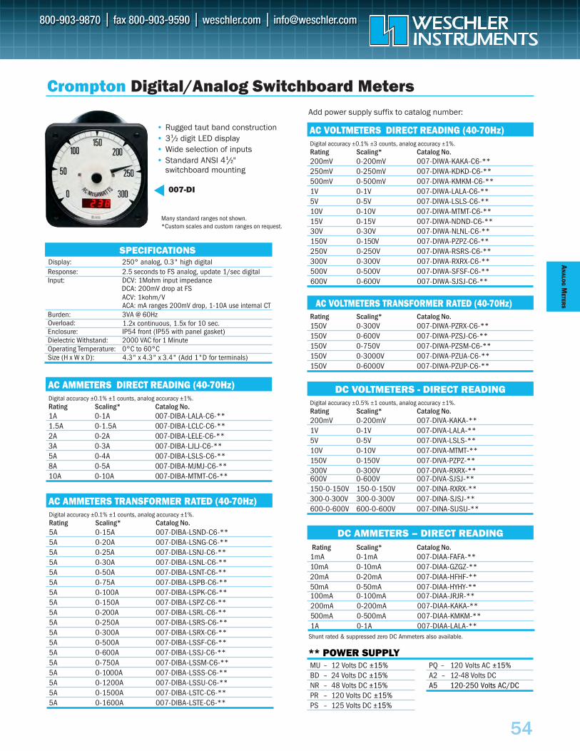
AN
ALOG
METER
S
54
AC VOLTMETERS DIRECT READING (40-70Hz)Digital accuracy ±0.1% ±3 counts, analog accuracy ±1%.Rating Scaling* Catalog No.200mV 0-200mV 007-DIWA-KAKA-C6-**250mV 0-250mV 007-DIWA-KDKD-C6-**500mV 0-500mV 007-DIWA-KMKM-C6-**1V 0-1V 007-DIWA-LALA-C6-**5V 0-5V 007-DIWA-LSLS-C6-**10V 0-10V 007-DIWA-MTMT-C6-**15V 0-15V 007-DIWA-NDND-C6-**
AC VOLTMETERS TRANSFORMER RATED (40-70Hz)Rating Scaling* Catalog No.150V 0-300V 007-DIWA-PZRX-C6-**150V 0-600V 007-DIWA-PZSJ-C6-**150V 0-750V 007-DIWA-PZSM-C6-**150V 0-3000V 007-DIWA-PZUA-C6-**150V 0-6000V 007-DIWA-PZUP-C6-**
DC VOLTMETERS - DIRECT READINGDigital accuracy ±0.5% ±1 counts, analog accuracy ±1%.Rating Scaling* Catalog No.200mV 0-200mV 007-DIVA-KAKA-**1V 0-1V 007-DIVA-LALA-**5V 0-5V 007-DIVA-LSLS-**10V 0-10V 007-DIVA-MTMT-**150V 0-150V 007-DIVA-PZPZ-**300V 0-300V 007-DIVA-RXRX-**
DC AMMETERS – DIRECT READINGRating Scaling* Catalog No.
1mA 0-1mA 007-DIAA-FAFA-**10mA 0-10mA 007-DIAA-GZGZ-**20mA 0-20mA 007-DIAA-HFHF-**50mA 0-50mA 007-DIAA-HYHY-**100mA 0-100mA 007-DIAA-JRJR-**
** POWER SUPPLYMU – 12 Volts DC ±15%BD – 24 Volts DC ±15%NR – 48 Volts DC ±15%PR – 120 Volts DC ±15%PS – 125 Volts DC ±15%
PQ – 120 Volts AC ±15%A2 – 12-48 Volts DCA5 120-250 Volts AC/DC
• Rugged taut band construction• 31/2 digit LED display• Wide selection of inputs• Standard ANSI 41/2"
switchboard mounting
007-DI
Crompton Digital/Analog Switchboard Meters
250° analog, 0.3" high digitalResponse: 2.5 seconds to FS analog, update 1/sec digitalInput: DCV: 1Mohm input impedance
Enclosure: IP54 front (IP55 with panel gasket)
Burden: 3VA @ 60Hz
Dielectric Withstand: 2000 VAC for 1 MinuteOperating Temperature: 0°C to 60°CSize (H x W x D): 4.3" x 4.3" x 3.4" (Add 1"D for terminals)
SPECIFICATIONS
Overload: 1.2x continuous, 1.5x for 10 sec.
Display:
Add power supply suffix to catalog number:
Many standard ranges not shown. *Custom scales and custom ranges on request.
AC AMMETERS DIRECT READING (40-70Hz)Digital accuracy ±0.1% ±1 counts, analog accuracy ±1%.Rating Scaling* Catalog No.1A 0-1A 007-DIBA-LALA-C6-**1.5A 0-1.5A 007-DIBA-LCLC-C6-**2A 0-2A 007-DIBA-LELE-C6-**3A 0-3A 007-DIBA-LJLJ-C6-**5A 0-4A 007-DIBA-LSLS-C6-**8A 0-5A 007-DIBA-MJMJ-C6-**10A 0-10A 007-DIBA-MTMT-C6-**
AC AMMETERS TRANSFORMER RATED (40-70Hz)Digital accuracy ±0.1% ±1 counts, analog accuracy ±1%.Rating Scaling* Catalog No.5A 0-15A 007-DIBA-LSND-C6-**5A 0-20A 007-DIBA-LSNG-C6-**5A 0-25A 007-DIBA-LSNJ-C6-**5A 0-30A 007-DIBA-LSNL-C6-**5A 0-50A 007-DIBA-LSNT-C6-**5A 0-75A 007-DIBA-LSPB-C6-**5A 0-100A 007-DIBA-LSPK-C6-**5A 0-150A 007-DIBA-LSPZ-C6-**5A 0-200A 007-DIBA-LSRL-C6-**5A 0-250A 007-DIBA-LSRS-C6-**5A 0-300A 007-DIBA-LSRX-C6-**5A 0-500A 007-DIBA-LSSF-C6-**5A 0-600A 007-DIBA-LSSJ-C6-**5A 0-750A 007-DIBA-LSSM-C6-**5A 0-1000A 007-DIBA-LSSS-C6-**5A 0-1200A 007-DIBA-LSSU-C6-**5A 0-1500A 007-DIBA-LSTC-C6-**5A 0-1600A 007-DIBA-LSTE-C6-**
5A 0-1500A 007-DIBA-LSTC-C6-**
30V 0-30V 007-DIWA-NLNL-C6-**150V 0-150V 007-DIWA-PZPZ-C6-**250V 0-250V 007-DIWA-RSRS-C6-**300V 0-300V 007-DIWA-RXRX-C6-**500V 0-500V 007-DIWA-SFSF-C6-**600V 0-600V 007-DIWA-SJSJ-C6-**
600V 0-600V 007-DIVA-SJSJ-**150-0-150V 150-0-150V 007-DINA-RXRX-**300-0-300V 300-0-300V 007-DINA-SJSJ-**600-0-600V 600-0-600V 007-DINA-SUSU-**
Shunt rated & suppressed zero DC Ammeters also available.
200mA 0-200mA 007-DIAA-KAKA-**500mA 0-500mA 007-DIAA-KMKM-**1A 0-1A 007-DIAA-LALA-**
ACA: mA ranges 200mV drop, 1-10A use internal CT
DCA: 200mV drop at FSACV: 1kohm/V
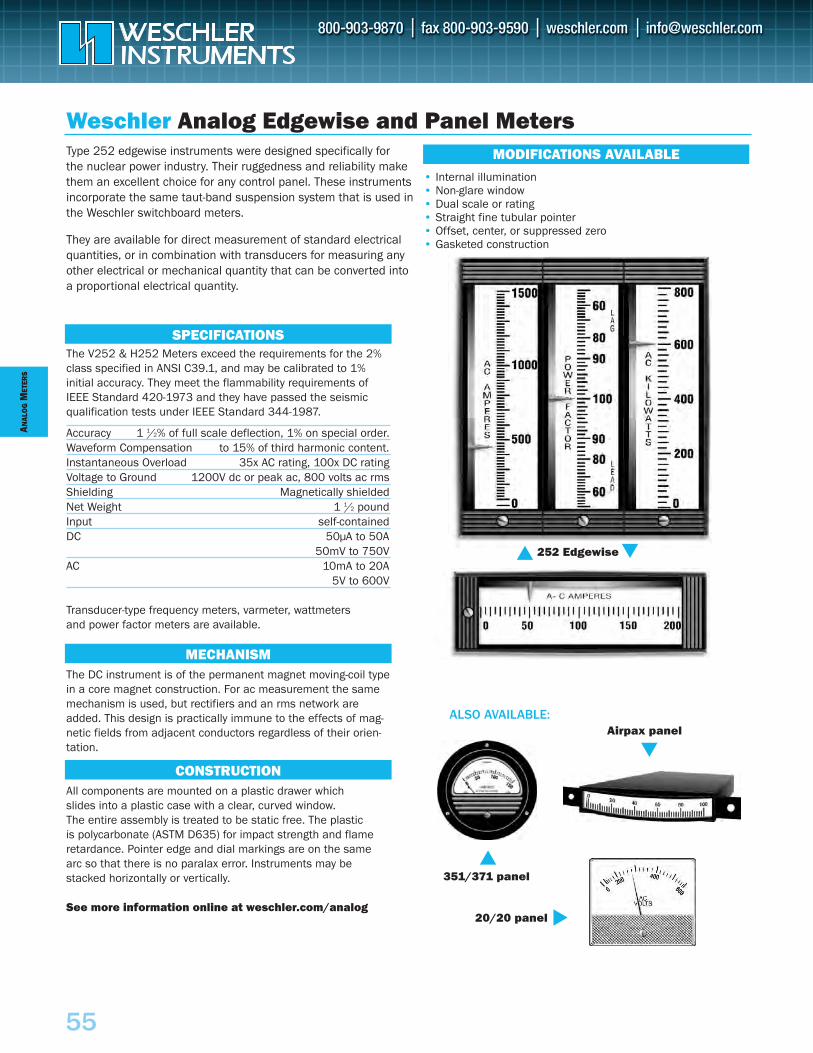
ANAL
OG
MET
ERS
55
The DC instrument is of the permanent magnet moving-coil typein a core magnet construction. For ac measurement the samemechanism is used, but rectifiers and an rms network areadded. This design is practically immune to the effects of mag-netic fields from adjacent conductors regardless of their orien-tation.
All components are mounted on a plastic drawer which slides into a plastic case with a clear, curved window. The entire assembly is treated to be static free. The plastic is polycarbonate (ASTM D635) for impact strength and flameretardance. Pointer edge and dial markings are on the same arc so that there is no paralax error. Instruments may bestacked horizontally or vertically.
See more information online at weschler.com/analog
Weschler Analog Edgewise and Panel Meters
The V252 & H252 Meters exceed the requirements for the 2%class specified in ANSI C39.1, and may be calibrated to 1% initial accuracy. They meet the flammability requirements ofIEEE Standard 420-1973 and they have passed the seismicqualification tests under IEEE Standard 344-1987.
Accuracy 1 1/2% of full scale deflection, 1% on special order.Waveform Compensation to 15% of third harmonic content.Instantaneous Overload 35x AC rating, 100x DC ratingVoltage to Ground 1200V dc or peak ac, 800 volts ac rmsShielding Magnetically shieldedNet Weight 1 1/2 pound Input self-containedDC 50µA to 50A
50mV to 750VAC 10mA to 20A
5V to 600V
Transducer-type frequency meters, varmeter, wattmeters and power factor meters are available.
Type 252 edgewise instruments were designed specifically for the nuclear power industry. Their ruggedness and reliability makethem an excellent choice for any control panel. These instrumentsincorporate the same taut-band suspension system that is used inthe Weschler switchboard meters.
They are available for direct measurement of standard electricalquantities, or in combination with transducers for measuring anyother electrical or mechanical quantity that can be converted intoa proportional electrical quantity.
SPECIFICATIONS
ALSO AVAILABLE:
252 Edgewise
MECHANISM
CONSTRUCTION
MODIFICATIONS AVAILABLE
20/20 panel
Airpax panel
351/371 panel
• Internal illumination• Non-glare window• Dual scale or rating• Straight fine tubular pointer• Offset, center, or suppressed zero• Gasketed construction
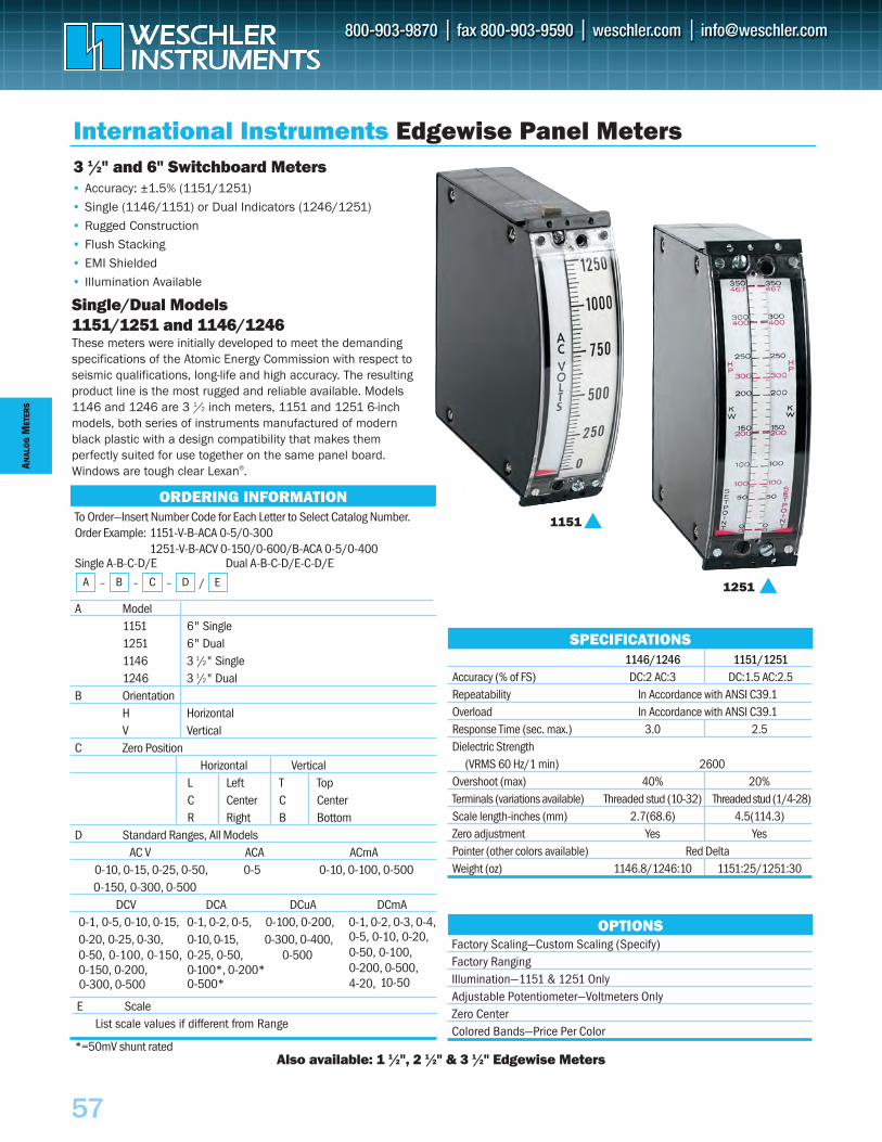
ANAL
OG
MET
ERS
57
To Order—Insert Number Code for Each Letter to Select Catalog Number.Order Example: 1151-V-B-ACA 0-5/0-300
1251-V-B-ACV 0-150/0-600/B-ACA 0-5/0-400Single A-B-C-D/E Dual A-B-C-D/E-C-D/E
A Model1151 6" Single1251 6" Dual1146 3 1/2" Single1246 3 1/2" Dual
B OrientationH HorizontalV Vertical
C Zero PositionHorizontal Vertical
L Left T TopC Center C CenterR Right B Bottom
D Standard Ranges, All ModelsAC V ACA ACmA
0-10, 0-15, 0-25, 0-50, 0-5 0-10, 0-100, 0-5000-150, 0-300, 0-500
DCV DCA DCuA DCmA0-1, 0-5, 0-10, 0-15, 0-1, 0-2, 0-5, 0-100, 0-200, 0-1, 0-2, 0-3, 0-4,0-20, 0-25, 0-30,0-50, 0-100, 0-150,
0-10, 0-15, 0-25, 0-50,
0-300, 0-400, 0-500
0-150, 0-200, 0-100*, 0-200*0-500*
0-5, 0-10, 0-20,0-50, 0-100,0-200, 0-500, 4-20,0-300, 0-500 10-50
*=50mV shunt rated
International Instruments Edgewise Panel Meters
• Accuracy: ±1.5% (1151/1251)
• Single (1146/1151) or Dual Indicators (1246/1251)
• Rugged Construction
• Flush Stacking
• EMI Shielded
• Illumination Available
Single/Dual Models1151/1251 and 1146/1246These meters were initially developed to meet the demandingspecifications of the Atomic Energy Commission with respect toseismic qualifications, long-life and high accuracy. The resultingproduct line is the most rugged and reliable available. Models1146 and 1246 are 3 1/2 inch meters, 1151 and 1251 6-inchmodels, both series of instruments manufactured of modernblack plastic with a design compatibility that makes them perfectly suited for use together on the same panel board.Windows are tough clear Lexan®.
3 1/2" and 6" Switchboard Meters
Factory Scaling—Custom Scaling (Specify)Factory RangingIllumination—1151 & 1251 OnlyAdjustable Potentiometer—Voltmeters OnlyZero CenterColored Bands—Price Per Color
OPTIONS
1151
1251
SPECIFICATIONS
ORDERING INFORMATION
A – B – C – D
1146/1246 1151/1251Accuracy (% of FS) DC:2 AC:3 DC:1.5 AC:2.5Repeatability In Accordance with ANSI C39.1Overload In Accordance with ANSI C39.1Response Time (sec. max.) 3.0 2.5Dielectric Strength
(VRMS 60 Hz/1 min) 2600Overshoot (max) 40% 20%Terminals (variations available) Threaded stud (10-32) Threaded stud (1/4-28)Scale length-inches (mm) 2.7(68.6) 4.5(114.3)Zero adjustment Yes YesPointer (other colors available) Red DeltaWeight (oz) 1146.8/1246:10 1151:25/1251:30
Also available: 1 1/2", 2 1/2" & 3 1/2" Edgewise Meters
/ E
E ScaleList scale values if different from Range
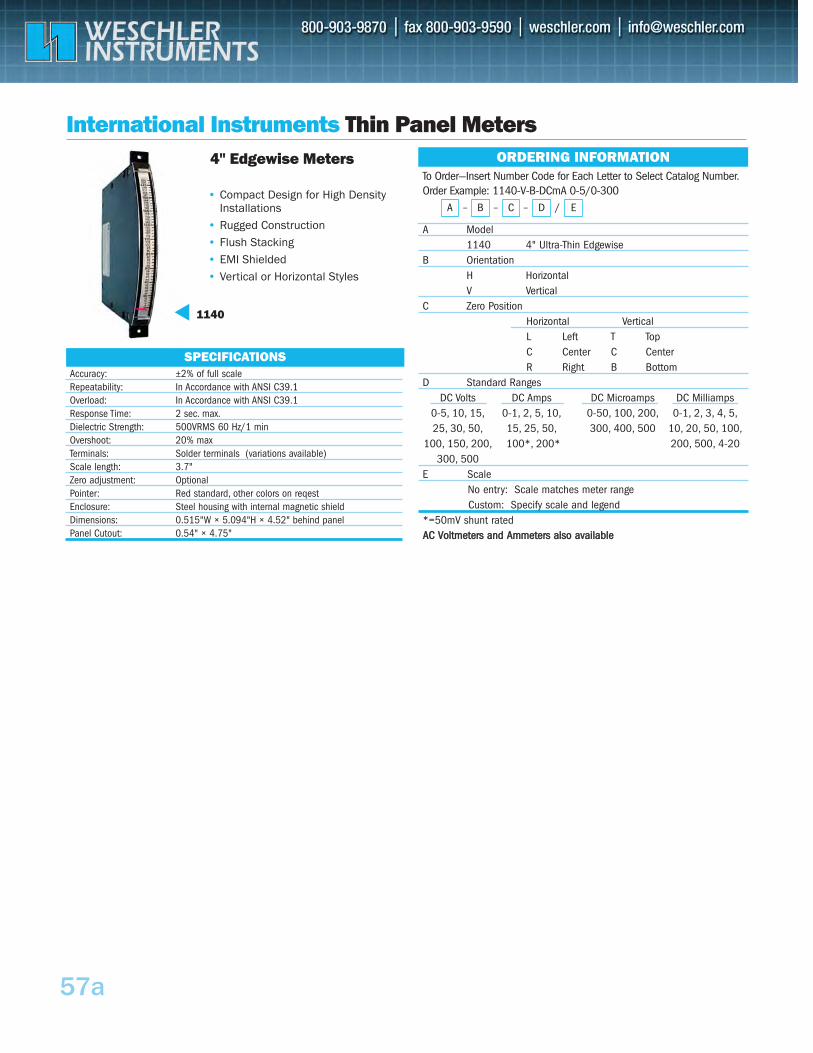
International Instruments Thin Panel Meters
SPECIFICATIONS
To Order—Insert Number Code for Each Letter to Select Catalog Number. Order Example: 1140-V-B-DCmA 0-5/0-300
A Model1140 4" Ultra-Thin Edgewise
B OrientationH Horizontal V Vertical
C Zero PositionHorizontal Vertical L Left T TopC Center C CenterR Right B Bottom
D Standard Ranges DC Volts DC Amps DC Microamps DC Milliamps
0-5, 10, 15, 0-1, 2, 5, 10, 0-50, 100, 200, 0-1, 2, 3, 4, 5,25, 30, 50, 15, 25, 50, 300, 400, 500 10, 20, 50, 100,
100, 150, 200, 100*, 200* 200, 500, 4-20300, 500
E ScaleNo entry: Scale matches meter range Custom: Specify scale and legend
*=50mV shunt rated AACC VVoollttmmeetteerrss aanndd AAmmmmeetteerrss aallssoo aavvaaiillaabbllee
ORDERING INFORMATION
A – B – C – /D E• Compact Design for High Density
Installations• Rugged Construction• Flush Stacking• EMI Shielded• Vertical or Horizontal Styles
4" Edgewise Meters
Accuracy: ±2% of full scale Repeatability: In Accordance with ANSI C39.1Overload: In Accordance with ANSI C39.1 Response Time: 2 sec. max.Dielectric Strength: 500VRMS 60 Hz/1 min Overshoot: 20% max Terminals: Solder terminals (variations available) Scale length: 3.7"Zero adjustment: Optional Pointer: Red standard, other colors on reqest Enclosure: Steel housing with internal magnetic shield Dimensions: 0.515"W × 5.094"H × 4.52" behind panel Panel Cutout: 0.54" × 4.75"
57a
1140
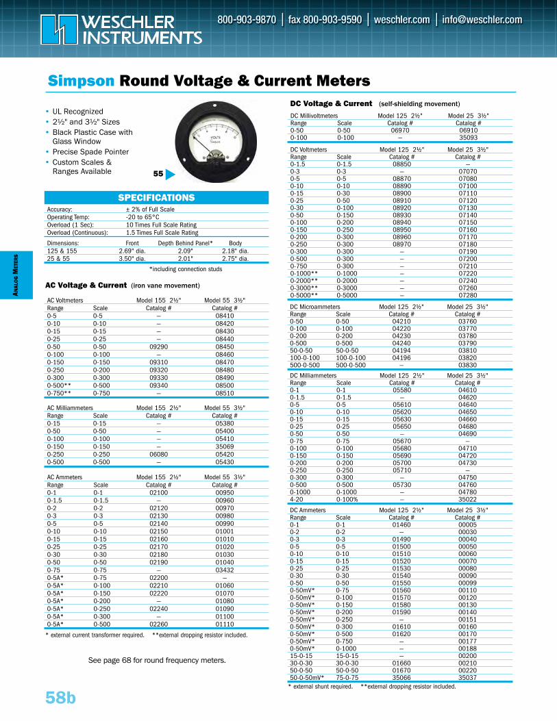
ANAL
OG
MET
ERS
58b
DC Microammeters Model 125 2½" Model 25 3½"Range Scale Catalog # Catalog # 0-50 0-50 04210 037600-100 0-100 04220 037700-200 0-200 04230 037800-500 0-500 04240 0379050-0-50 50-0-50 04194 03810100-0-100 100-0-100 04196 03820500-0-500 500-0-500 — 03830
AC Milliammeters Model 155 2½" Model 55 3½"Range Scale Catalog # Catalog # 0-15 0-15 — 053800-50 0-50 — 054000-100 0-100 — 054100-150 0-150 — 350690-250 0-250 06080 054200-500 0-500 — 05430
DC Ammeters Model 125 2½" Model 25 3½"Range Scale Catalog # Catalog # 0-1 0-1 01460 000050-2 0-2 — 000300-3 0-3 01490 000400-5 0-5 01500 000500-10 0-10 01510 000600-15 0-15 01520 000700-25 0-25 01530 000800-30 0-30 01540 000900-50 0-50 01550 000990-50mV* 0-75 01560 001100-50mV* 0-100 01570 001200-50mV* 0-150 01580 001300-50mV* 0-200 01590 001400-50mV* 0-250 — 001510-50mV* 0-300 01610 001600-50mV* 0-500 01620 001700-50mV* 0-750 — 001770-50mV* 0-1000 — 0018815-0-15 15-0-15 — 0020030-0-30 30-0-30 01660 0021050-0-50 50-0-50 01670 0022050-0-50mV* 75-0-75 35066 35037
DC Voltmeters Model 125 2½" Model 25 3½"Range Scale Catalog # Catalog # 0-1.5 0-1.5 08850 —0-3 0-3 — 070700-5 0-5 08870 070800-10 0-10 08890 071000-15 0-30 08900 071100-25 0-50 08910 071200-30 0-100 08920 071300-50 0-150 08930 071400-100 0-200 08940 071500-150 0-250 08950 071600-200 0-300 08960 071700-250 0-300 08970 071800-300 0-300 — 071900-500 0-300 — 072000-750 0-300 — 072100-1000** 0-1000 — 072200-2000** 0-2000 — 072400-3000** 0-3000 — 072600-5000** 0-5000 — 07280
DC Millivoltmeters Model 125 2½" Model 25 3½"Range Scale Catalog # Catalog #0-50 0-50 06970 069100-100 0-100 — 35093
Dimensions: Front Depth Behind Panel* Body125 & 155 2.69" dia. 2.09" 2.18" dia.25 & 55 3.50" dia. 2.01" 2.75" dia.
*including connection studs
AC Voltmeters Model 155 2½" Model 55 3½"Range Scale Catalog # Catalog #0-5 0-5 — 084100-10 0-10 — 084200-15 0-15 — 084300-25 0-25 — 084400-50 0-50 09290 084500-100 0-100 — 084600-150 0-150 09310 084700-250 0-200 09320 084800-300 0-300 09330 084900-500** 0-500 09340 085000-750** 0-750 — 08510
Simpson Round Voltage & Current Meters
• UL Recognized• 2½" and 3½" Sizes• Black Plastic Case with
Glass Window• Precise Spade Pointer• Custom Scales &
Ranges Available
* external shunt required. **external dropping resistor included.
* external current transformer required. **external dropping resistor included.
55
Accuracy: ± 2% of Full ScaleOperating Temp: -20 to 65°COverload (1 Sec): 10 Times Full Scale RatingOverload (Continuous): 1.5 Times Full Scale Rating
SPECIFICATIONS
AC Ammeters Model 155 2½" Model 55 3½"Range Scale Catalog # Catalog #0-1 0-1 02100 009500-1.5 0-1.5 — 009600-2 0-2 02120 009700-3 0-3 02130 009800-5 0-5 02140 009900-10 0-10 02150 010010-15 0-15 02160 010100-25 0-25 02170 010200-30 0-30 02180 010300-50 0-50 02190 010400-75 0-75 — 034320-5A* 0-75 02200 —0-5A* 0-100 02210 010600-5A* 0-150 02220 010700-5A* 0-200 — 010800-5A* 0-250 02240 010900-5A* 0-300 — 011000-5A* 0-500 02260 01110
DC Milliammeters Model 125 2½" Model 25 3½"Range Scale Catalog # Catalog # 0-1 0-1 05580 046100-1.5 0-1.5 — 046200-5 0-5 05610 046400-10 0-10 05620 046500-15 0-15 05630 046600-25 0-25 05650 046800-50 0-50 — 046900-75 0-75 05670 —0-100 0-100 05680 047100-150 0-150 05690 047200-200 0-200 05700 047300-250 0-250 05710 —0-300 0-300 — 047500-500 0-500 05730 047600-1000 0-1000 — 047804-20 0-100% — 35022
See page 68 for round frequency meters.
DC Voltage & Current (self-shielding movement)
AC Voltage & Current (iron vane movement)
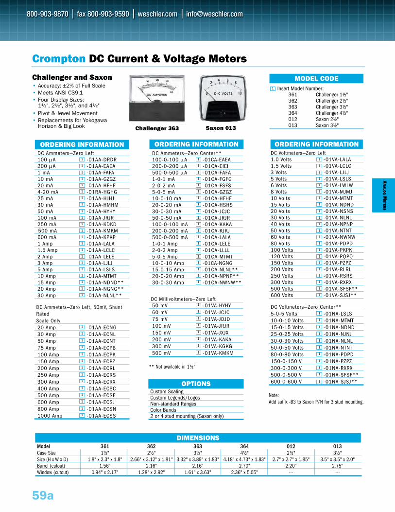
MMooddeell 336611 336622 336633 336644 001122 001133Case Size 1½" 2½" 3½" 4½" 2½" 3½"Size (H x W x D) 1.8" x 2.3" x 1.8" 2.66" x 3.12" x 1.81" 3.32" x 3.89" x 1.83" 4.18" x 4.73" x 1.83" 2.7" x 2.7" x 1.85" 3.5" x 3.5" x 2.0"Barrel (cutout) 1.56" 2.16" 2.16" 2.70" 2.20" 2.75"Window (cutout) 0.94" x 2.17" 1.28" x 2.92" 1.61" x 3.63" 2.36" x 5.05" --- ---
DIMENSIONS
DC Voltmeters—Zero Left1.0 Volts -01VA-LALA1.5 Volts -01VA-LCLC3 Volts -01VA-LJLJ5 Volts -01VA-LSLS6 Volts -01VA-LWLW8 Volts -01VA-MJMJ10 Volts -01VA-MTMT15 Volts -01VA-NDND20 Volts -01VA-NSNS30 Volts -01VA-NLNL40 Volts -01VA-NPNP50 Volts -01VA-NTNT60 Volts -01VA-NWNW80 Volts -01VA-PDPD100 Volts -01VA-PKPK120 Volts -01VA-PQPQ150 Volts -01VA-PZPZ200 Volts -01VA-RLRL250 Volts -01VA-RSRS300 Volts -01VA-RXRX500 Volts -01VA-SFSF**600 Volts -01VA-SJSJ**
DC Voltmeters—Zero Center**5-0-5 Volts -01NA-LSLS10-0-10 Volts -01NA-MTMT15-0-15 Volts -01NA-NDND25-0-25 Volts -01NA-NJNJ30-0-30 Volts -01NA-NLNL50-0-50 Volts -01NA-NTNT80-0-80 Volts -01NA-PDPD150-0-150 V -01NA-PZPZ300-0-300 V -01NA-RXRX500-0-500 V -01NA-SFSF**600-0-600 V -01NA-SJSJ**
Note: Add suffix -B3 to Saxon P/N for 3 stud mounting.
DC Ammeters—Zero Center**100-0-100 μA -01CA-EAEA200-0-200 μA -01CA-EIEI500-0-500 μA -01CA-FAFA1-0-1 mA -01CA-FGFG2-0-2 mA -01CA-FSFS5-0-5 mA -01CA-GZGZ10-0-10 mA -01CA-HFHF20-0-20 mA -01CA-HSHS30-0-30 mA -01CA-JCJC50-0-50 mA -01CA-JRJR100-0-100 mA -01CA-KAKA200-0-200 mA -01CA-KJKJ500-0-500 mA -01CA-LALA1-0-1 Amp -01CA-LELE2-0-2 Amp -01CA-LLLL5-0-5 Amp -01CA-MTMT10-0-10 Amp -01CA-NGNG15-0-15 Amp -01CA-NLNL**20-0-20 Amp -01CA-NPNP**30-0-30 Amp -01CA-NWNW**
DC Millivoltmeters—Zero Left50 mV -01VA-HYHY60 mV -01VA-JCJC75 mV -01VA-JDJD100 mV -01VA-JRJR150 mV -01VA-JXJX200 mV -01VA-KAKA300 mV -01VA-KGKG500 mV -01VA-KMKM
** Not available in 1½"
DC Ammeters—Zero Left100 μA -01AA-DRDR200 μA -01AA-EAEA1 mA -01AA-FAFA10 mA -01AA-GZGZ20 mA -01AA-HFHF4-20 mA -01RA-HGHG25 mA -01AA-HJHJ30 mA -01AA-HMHM50 mA -01AA-HYHY100 mA -01AA-JRJR250 mA -01AA-KDKD500 mA -01AA-KMKM600 mA -01AA-KPKP1 Amp -01AA-LALA1.5 Amp -01AA-LCLC2 Amp -01AA-LELE3 Amp -01AA-LJLJ5 Amp -01AA-LSLS10 Amp -01AA-MTMT15 Amp -01AA-NDND**20 Amp -01AA-NGNG**30 Amp -01AA-NLNL**
DC Ammeters—Zero Left, 50mV, ShuntRated Scale Only20 Amp -01AA-ECNG30 Amp -01AA-ECNL50 Amp -01AA-ECNT75 Amp -01AA-ECPB100 Amp -01AA-ECPK150 Amp -01AA-ECPZ200 Amp -01AA-ECRL250 Amp -01AA-ECRS300 Amp -01AA-ECRX400 Amp -01AA-ECSC500 Amp -01AA-ECSF600 Amp -01AA-ECSJ800 Amp -01AA-ECSN1000 Amp -01AA-ECSS
AN
ALOG
METER
S
1
1
1
1
1
1
1
1
1
1
1
1
1
1
1
1
1
1
1
1
1
1
1
1
1
1
1
1
1
1
1
1
1
1
1
1
1
1
1
1
1
1
1
1
1
1
1
1
1
1
1
1
1
1
1
1
1
1
1
1
1
1
1
1
1
1
1
1
1
1
1
1
1
1
1
1
1
1
1
1
1
1
1
1
1
1
59a
Crompton DC Current & Voltage Meters
Custom ScalingCustom Legends/LogosNon-standard RangesColor Bands2 or 4 stud mounting (Saxon only)
OPTIONS
Insert Model Number:361 Challenger 1½"362 Challenger 2½"363 Challenger 3½"364 Challenger 4½"012 Saxon 2½"013 Saxon 3½"
MODEL CODE
Challenger 363 Saxon 013
ORDERING INFORMATION ORDERING INFORMATION
1
ORDERING INFORMATION
Challenger and Saxon • Accuracy: ±2% of Full Scale• Meets ANSI C39.1• Four Display Sizes:
1½", 2½", 3½", and 4½"• Pivot & Jewel Movement• Replacements for Yokogawa
Horizon & Big Look
1
1
1
1
1
1
1
1
1
1
1
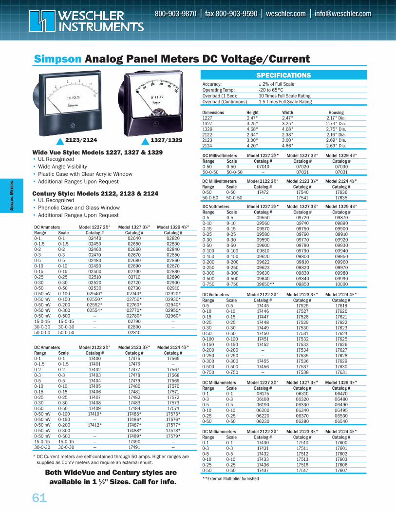
ANAL
OG
MET
ERS
61
DC Milliammeters Model 1227 21⁄2" Model 1327 31⁄2" Model 1329 41⁄2"Range Scale Catalog # Catalog # Catalog #0-1 0-1 06175 06310 064700-3 0-3 06180 06320 064800-5 0-5 06190 06330 064900-10 0-10 06200 06340 064950-25 0-25 06220 06370 065300-50 0-50 06230 06380 06540
DC Voltmeters Model 2122 21⁄2" Model 2123 31⁄2" Model 2124 41⁄2"Range Scale Catalog # Catalog # Catalog #0-5 0-5 17445 17525 176180-10 0-10 17446 17527 176200-15 0-15 17447 17528 176210-25 0-25 17448 17529 176220-30 0-30 17449 17530 176230-50 0-50 17450 17531 176240-100 0-100 17451 17532 176250-150 0-150 17452 17533 176260-200 0-200 — 17534 176270-250 0-250 — 17535 176280-300 0-300 17455 17536 176290-500 0-500 17456 17537 176300-750 0-750 — 17538 17631
DC Voltmeters Model 1227 21⁄2" Model 1327 31⁄2" Model 1329 41⁄2"Range Scale Catalog # Catalog # Catalog #0-5 0-5 09550 09720 098700-10 0-10 09560 09740 098900-15 0-15 09570 09750 099000-25 0-25 09580 09760 099100-30 0-30 09590 09770 099200-50 0-50 09600 09780 099300-100 0-100 09610 09790 099400-150 0-150 09620 09800 099500-200 0-200 09622 09810 099600-250 0-250 09623 09820 099700-300 0-300 09630 09830 099800-500 0-500 09640 09840 099900-750 0-750 09650** 09850 10000
DC Millivoltmeters Model 2122 21⁄2" Model 2123 31⁄2" Model 2124 41⁄2"Range Scale Catalog # Catalog # Catalog #0-50 0-50 17472 17540 1763650-0-50 50-0-50 — 17541 17635
DC Millivoltmeters Model 1227 21⁄2" Model 1327 31⁄2" Model 1329 41⁄2"Range Scale Catalog # Catalog # Catalog #0-50 0-50 07010 07020 0703050-0-50 50-0-50 — 07021 07031
Dimensions Height Width Housing1227 2.47" 2.47" 2.17" Dia.1327 3.25" 3.25" 2.73" Dia.1329 4.68" 4.68" 2.75" Dia.2122 2.34" 2.38" 2.16" Dia.2123 3.00" 3.00" 2.69" Dia.2124 4.20" 4.66" 2.69" Dia.
DC Ammeters Model 1227 21⁄2" Model 1327 31⁄2" Model 1329 41⁄2"Range Scale Catalog # Catalog # Catalog #0-1 0-1 02440 02640 028200-1.5 0-1.5 02450 02650 028300-2 0-2 02460 02660 028400-3 0-3 02470 02670 028500-5 0-5 02480 02680 028600-10 0-10 02490 02690 028700-15 0-15 02500 02700 028800-25 0-25 02510 02710 028900-30 0-30 02520 02720 029000-50 0-50 02530 02730 029100-50 mV 0-100 02540* 02740* 02920*0-50 mV 0-150 02550* 02750* 02930*0-50 mV 0-200 02552* 02760* 02940*0-50 mV 0-300 02554* 02770* 02950*0-50 mV 0-500 — 02780* 02960*15-0-15 15-0-15 — 02790 —30-0-30 30-0-30 — 02800 —50-0-50 50-0-50 — 02810 —
Simpson Analog Panel Meters DC Voltage/Current
Wide Vue Style: Models 1227, 1327 & 1329• UL Recognized• Wide Angle Visibility• Plastic Case with Clear Acrylic Window• Additional Ranges Upon Request
Century Style: Models 2122, 2123 & 2124• UL Recognized• Phenolic Case and Glass Window• Additional Ranges Upon Request
* DC Current meters are self-contained through 50 amps. Higher ranges aresupplied as 50mV meters and require an external shunt.
1327/13292123/2124
Accuracy: ± 2% of Full ScaleOperating Temp: -20 to 65°COverload (1 Sec): 10 Times Full Scale RatingOverload (Continuous): 1.5 Times Full Scale Rating
SPECIFICATIONS
DC Ammeters Model 2122 21⁄2" Model 2123 31⁄2" Model 2124 41⁄2"Range Scale Catalog # Catalog # Catalog #0-1 0-1 17400 17475 175650-1.5 0-1.5 17401 17476 —0-2 0-2 17402 17477 175670-3 0-3 17403 17478 175680-5 0-5 17404 17479 175690-10 0-10 17405 17480 175700-15 0-15 17406 17481 175710-25 0-25 17407 17482 175720-30 0-30 17408 17483 175730-50 0-50 17409 17484 175740-50 mV 0-100 17410* 17485* 17575*0-50 mV 0-150 — 17486* 17576*0-50 mV 0-200 17412* 17487* 17577*0-50 mV 0-300 — 17488* 17578*0-50 mV 0-500 — 17489* 17579*15-0-15 15-0-15 — 17490 —30-0-30 30-0-30 — 17491 —
DC Milliammeters Model 2122 21⁄2" Model 2123 31⁄2" Model 2124 41⁄2"Range Scale Catalog # Catalog # Catalog #0-1 0-1 17430 17510 176000-3 0-3 17431 17511 176010-5 0-5 17432 17512 176020-10 0-10 17433 17513 176030-25 0-25 17436 17516 176060-50 0-50 17437 17517 17607
**External Multiplier furnishedBoth WideVue and Century styles are
available in 1 1/2" Sizes. Call for info.
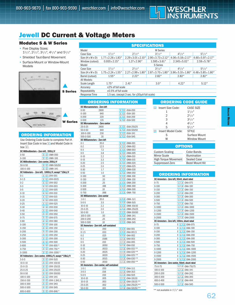
AN
ALOG
METER
S
62
Insert Size Code: CASE SIZE1 11/2"2 21/2"3 31/2"4 41/2"5 51/2"
Insert Model Code: STYLES Surface MountW Window Mount
DDCC MMiilllliivvoollttmmeetteerrss –– ZZeerroo lleefftt,, 220000ΩΩ//VV0-50 -DMV-0500-100 -DMV-100DDCC MMiilllliivvoollttmmeetteerrss –– ZZeerroo cceenntteerr,, 220000ΩΩ//VV50-0-50 -DMV-50U50100-0-100 -DMV-1H1DDCC VVoollttmmeetteerrss –– ZZeerroo lleefftt,, 11000000ΩΩ//VV,, eexxcceepptt **1100kkΩΩ//VV0-1 -DVV-0010-1.5 -DVV-00150-2 -DVV-0020-3 -DVV-0030-5 -DVV-0050-10 -DVV-0100-15 -DVV-0150-20 -DVV-0200-25 -DVV-0250-30 -DVV-0300-40 -DVV-0400-50 -DVV-0500-75 -DVV-0750-80 -DVV-0800-100 -DVV-1000-150 -DVV-1500-200 -DVV-2000-250 -DVV-2500-300 -DVV-3000-500 -DVV-5000-600 -DVV-600 *0-750 -DVV-750 *0-1000 -DVV-1000 *DDCC VVoollttmmeetteerrss –– ZZeerroo cceenntteerr,, 11000000ΩΩ//VV,, eexxcceepptt **1100kkΩΩ//VV5-0-5 -DVV-5U510-0-10 -DVV-10U1015-0-15 -DVV-15U1525-0-25 -DVV-25U2550-0-50 -DVV-50U50100-0-100 -DVV-1H1150-0-150 -DVV-1.5H1.5300-0-300 -DVV-3H3500-0-500 -DVV-5H5
600-0-600 -DVV-6H6 *
DDCC AAmmmmeetteerrss -- ZZeerroo lleefftt,, 5500mmVV,, sshhuunntt rraatteedd0-75 -DAA-0750-100 -DAA-1000-150 -DAA-1500-200 -DAA-2000-300 -DAA-3000-500 -DAA-5000-750 -DAA-7500-1000 -DAA-10000-1200 -DAA-12000-1500 -DAA-15000-2000 -DAA-2000DDCC AAmmmmeetteerrss -- ZZeerroo lleefftt,, 110000mmvv,, sshhuunntt rraatteedd0-75 E -DAA-0750-100 E -DAA-1000-150 E -DAA-1500-200 E -DAA-2000-300 E -DAA-3000-500 E -DAA-5000-750 E -DAA-7500-1000 E -DAA-10000-1200 E -DAA-12000-1500 E -DAA-15000-2000 E -DAA-2000DDCC AAmmmmeetteerrss -- ZZeerroo cceenntteerr,, 5500mmVV,, sshhuunntt rraatteedd75-0-75 -DAA-75U75100-0-100 -DAA-1H1200-0-200 -DAA-2H2300-0-300 -DAA-3H3400-0-400 -DAA-4H4
500-0-500 -DAA-5H5
Jewell DC Current & Voltage Meters
Custom ScalingMirror ScaleHigh Torque MovementSuppressed Zero
Color BandsIlluminationSealed CaseBezel Mount Kit
OPTIONS
ORDERING CODE GUIDE
S Series
W Series
Use Ordering Code Guide to complete Part #.Insert Size Code in box and Model Code inbox .
ORDERING INFORMATION
ORDERING INFORMATION
1
2
ORDERING INFORMATION
Modutec S & W Series• Five Display Sizes:
11/2", 21/2", 31/2", 41/2" and 51/2"
• Shielded Taut-Band Movement
• Surface-Mount or Window-MountModels
Model W SeriesCase Size 11/2" 21/2" 31/2" 41/2" 51/2"Size (H x W x D) 1.77 x 2.26 x 1.83" 2.29 x 3.01 x 2.10" 2.90 x 3.73 x 2.12" 4.06 x 5.18 x 2.17" 4.60 x 5.97 x 2.17"Window (cutout) 0.935 x 2.15" 1.27 x 2.90" 1.595 x 3.61" 2.345 x 5.02" 2.59 x 5.78"Model S SeriesCase Size 11/2" 21/2" 31/2" 41/2" 51/2"Size (H x W x D) 1.75 x 2.24 x 1.55" 2.27 x 2.99 x 1.80" 2.87 x 3.70 x 1.80" 3.96 x 5.10 x 1.80" 4.48 x 5.85 x 1.80"Barrel (cutout) 1.55" 2.22" 2.82" 2.82" 2.82"All Models:Scale Length 1.75" 2.41" 3.0" 4.22" 5.12"Accuracy ±2% of full scaleRepeatability ±0.5% of full scaleResponse Time 1.5 sec. (except 3 sec. for <50µA full scale)
SPECIFICATIONS
** not available in 11/2" size
DDCC MMiiccrrooaammmmeetteerrss -- ZZeerroo lleefftt0-50 2600 -DUA-0500-100 640 -DUA-1000-200 220 -DUA-2000-500 135 -DUA-500DDCC MMiiccrrooaammmmeetteerrss -- ZZeerroo cceenntteerr25-0-25 2600 -DUA-25U2550-0-50 640 -DUA-50U50100-0-100 230 -DUA-1H1500-0-500 35 -DUA-5H5DDCC MMiilllliiaammmmeetteerrss –– ZZeerroo lleefftt0-1 35.0 -DMA-0010-2 12.5 -DMA-0020-3 7.2 -DMA-0030-5 3.8 -DMA-0050-10 2.2 -DMA-0100-15 3.3 -DMA-0150-20 2.5 -DMA-0200-25 2.0 -DMA-0250-30 1.7 -DMA-0300-50 1.0 -DMA-0500-100 .50 -DMA-1000-150 .33 -DMA-1500-200 .25 -DMA-2000-300 .166 -DMA-3000-500 .10 -DMA-5000-750 .066 -DMA-750DDCC MMiilllliiaammmmeetteerrss -- ZZeerroo cceenntteerr1-0-1 35.0 -DMA-1U15-0-5 3.5 -DMA-5U510-0-10 2.2 -DMA-10U1025-0-25 2.0 -DMA-25U2550-0-50 1.0 -DMA-50U50100-0-100 .50 -DMA-1H1200-0-200 .25 -DMA-2H2500-0-500 .10 -DMA-5H5DDCC AAmmmmeetteerrss -- ZZeerroo lleefftt,, sseellff--ccoonnttaaiinneedd0-1 .050 -DAA-0010-1.5 .033 -DAA-001.50-2 .025 -DAA-0020-3 .0166 -DAA-0030-5 .010 -DAA-0050-10 .0050 -DAA-0100-15 .0033 -DAA-015 **0-20 .0025 -DAA-020 **0-25 .0020 -DAA-025 **0-30 .0015 -DAA-030 **0-50 .0010 -DAA-050 **DDCC AAmmmmeetteerrss -- ZZeerroo cceenntteerr,, sseellff ccoonnttaaiinneedd1-0-1 .050 -DAA-1U13-0-3 .016 -DAA-3U35-0-5 .010 -DAA-5U510-0-10 .005 -DAA-10U10 15-0-15 .003 -DAA-15U15 **25-0-25 .002 -DAA-25U25 **50-0-50 .001 -DAA-50U50 **
1 2
1 2
1 2
1 2
1 2
1 2
1 2
1 2
1 2
1 2
1 2
1 2
1 2
1 2
1 2
1 2
1 2
1 2
1 2
1 2
1 2
1 2
1 2
1 2
1 2
1 2
1 2
1 2
1 2
1 2
1 2
1 2
1 2
1 2
1 2
1 2
1 2
1 2
1 2
1 2
1 2
1 2
1 2
1 2
1 2
1 2
1 2
1 2
1 2
1 2
1 2
1 2
1 2
1 2
1 2
1 2
1 2
1 2
1 2
1 2
1 2
1 2
1 2
1 2
1 2
1 2
1 2
1 2
1 2
1 2
1 2
1 2
1 2
1 2
1 2
1 2
1 2
1 2
1 2
1 2
1 2
1 2
1 2
1 2
1 2
1 2
1 2
1 2
1 2
1 2
1 2
1 2
1 2
1 2
1 2
1 2
1 2
1 2
1 2
1 2
1 2
1 2
1 2
1 2
1 2
1 2
1 2
1 2
1 2
1 2
1 2
1 2
1 2
1 2
1 2
1
2
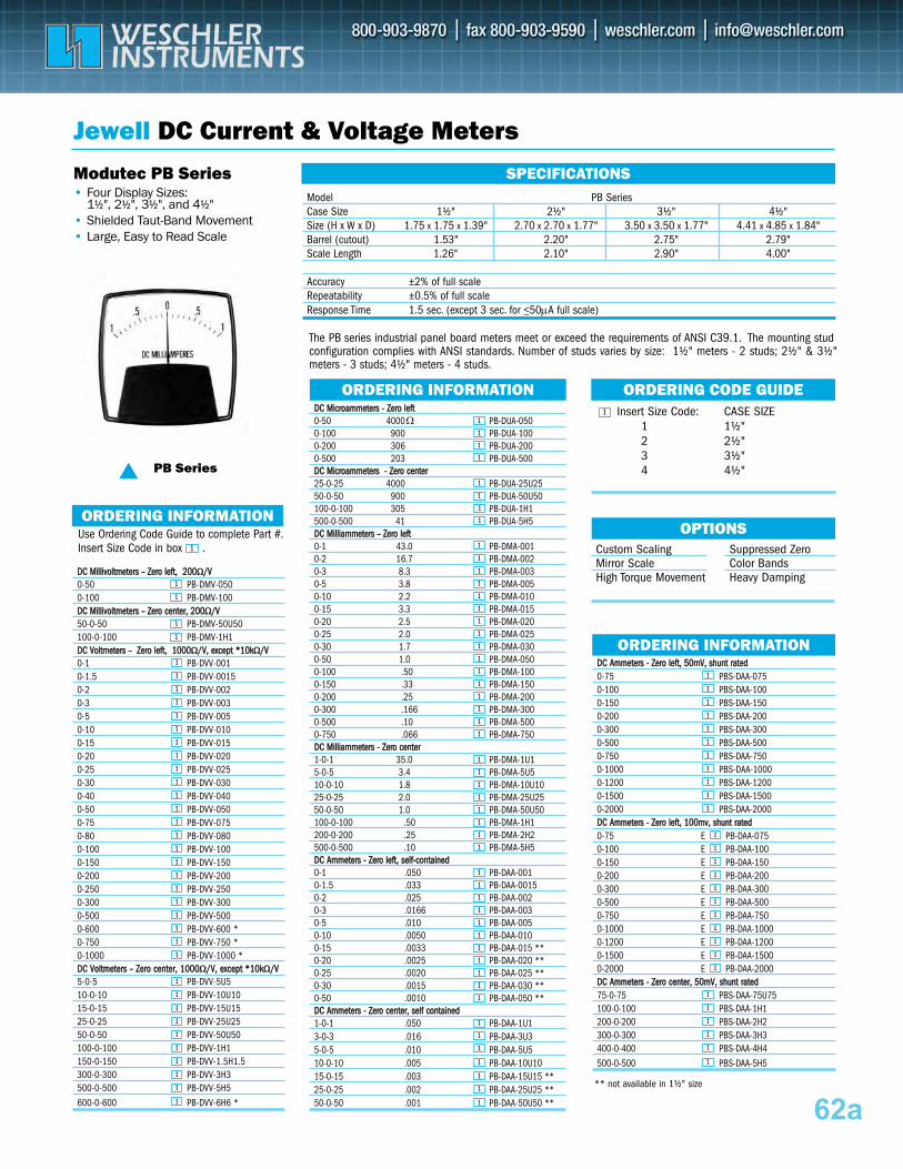
Insert Size Code: CASE SIZE 1 1½"2 2½"3 3½"4 4½"
62a
DDCC MMiilllliivvoollttmmeetteerrss –– ZZeerroo lleefftt,, 220000ΩΩ//VV0-50 PB-DMV-050 0-100 PB-DMV-100 DDCC MMiilllliivvoollttmmeetteerrss –– ZZeerroo cceenntteerr,, 220000ΩΩ//VV50-0-50 PB-DMV-50U50 100-0-100 PB-DMV-1H1 DDCC VVoollttmmeetteerrss –– ZZeerroo lleefftt,, 11000000ΩΩ//VV,, eexxcceepptt **1100kkΩΩ//VV0-1 PB-DVV-001 0-1.5 PB-DVV-0015 0-2 PB-DVV-002 0-3 PB-DVV-003 0-5 PB-DVV-005 0-10 PB-DVV-010 0-15 PB-DVV-015 0-20 PB-DVV-020 0-25 PB-DVV-025 0-30 PB-DVV-030 0-40 PB-DVV-040 0-50 PB-DVV-050 0-75 PB-DVV-075 0-80 PB-DVV-080 0-100 PB-DVV-100 0-150 PB-DVV-150 0-200 PB-DVV-200 0-250 PB-DVV-250 0-300 PB-DVV-300 0-500 PB-DVV-500 0-600 PB-DVV-600 * 0-750 PB-DVV-750 * 0-1000 PB-DVV-1000 * DDCC VVoollttmmeetteerrss –– ZZeerroo cceenntteerr,, 11000000ΩΩ//VV,, eexxcceepptt **1100kkΩΩ//VV5-0-5 PB-DVV-5U5 10-0-10 PB-DVV-10U10 15-0-15 PB-DVV-15U15 25-0-25 PB-DVV-25U25 50-0-50 PB-DVV-50U50 100-0-100 PB-DVV-1H1 150-0-150 PB-DVV-1.5H1.5 300-0-300 PB-DVV-3H3 500-0-500 PB-DVV-5H5 600-0-600 PB-DVV-6H6 *
DDCC AAmmmmeetteerrss -- ZZeerroo lleefftt,, 5500mmVV,, sshhuunntt rraatteedd 0-75 PBS-DAA-075 0-100 PBS-DAA-100 0-150 PBS-DAA-150 0-200 PBS-DAA-200 0-300 PBS-DAA-300 0-500 PBS-DAA-500 0-750 PBS-DAA-750 0-1000 PBS-DAA-1000 0-1200 PBS-DAA-1200 0-1500 PBS-DAA-1500 0-2000 PBS-DAA-2000 DDCC AAmmmmeetteerrss -- ZZeerroo lleefftt,, 110000mmvv,, sshhuunntt rraatteedd 0-75 E PB-DAA-075 0-100 E PB-DAA-100 0-150 E PB-DAA-150 0-200 E PB-DAA-200 0-300 E PB-DAA-300 0-500 E PB-DAA-500 0-750 E PB-DAA-750 0-1000 E PB-DAA-1000 0-1200 E PB-DAA-1200 0-1500 E PB-DAA-1500 0-2000 E PB-DAA-2000 DDCC AAmmmmeetteerrss -- ZZeerroo cceenntteerr,, 5500mmVV,, sshhuunntt rraatteedd 75-0-75 PBS-DAA-75U75 100-0-100 PBS-DAA-1H1 200-0-200 PBS-DAA-2H2 300-0-300 PBS-DAA-3H3 400-0-400 PBS-DAA-4H4 500-0-500 PBS-DAA-5H5
Jewell DC Current & Voltage Meters
Custom Scaling Mirror Scale High Torque Movement
Suppressed Zero Color Bands Heavy Damping
OPTIONS
ORDERING CODE GUIDE
PB Series
1
Use Ordering Code Guide to complete Part #. Insert Size Code in box .
ORDERING INFORMATION
ORDERING INFORMATION
1
ORDERING INFORMATION
Modutec PB Series• Four Display Sizes:
1½", 2½", 3½", and 4½"• Shielded Taut-Band Movement• Large, Easy to Read Scale
Model PB SeriesCase Size 1½" 2½" 3½" 4½"Size (H x W x D) 1.75 x 1.75 x 1.39" 2.70 x 2.70 x 1.77" 3.50 x 3.50 x 1.77" 4.41 x 4.85 x 1.84"Barrel (cutout) 1.53" 2.20" 2.75" 2.79"Scale Length 1.26" 2.10" 2.90" 4.00"
Accuracy ±2% of full scale Repeatability ±0.5% of full scale Response Time 1.5 sec. (except 3 sec. for <50μA full scale)
SPECIFICATIONS
** not available in 1½" size
DDCC MMiiccrrooaammmmeetteerrss -- ZZeerroo lleefftt 0-50 4000 PB-DUA-050 0-100 900 PB-DUA-100 0-200 306 PB-DUA-200 0-500 203 PB-DUA-500 DDCC MMiiccrrooaammmmeetteerrss -- ZZeerroo cceenntteerr 25-0-25 4000 PB-DUA-25U2550-0-50 900 PB-DUA-50U50 100-0-100 305 PB-DUA-1H1 500-0-500 41 PB-DUA-5H5 DDCC MMiilllliiaammmmeetteerrss –– ZZeerroo lleefftt 0-1 43.0 PB-DMA-0010-2 16.7 PB-DMA-0020-3 8.3 PB-DMA-0030-5 3.8 PB-DMA-0050-10 2.2 PB-DMA-0100-15 3.3 PB-DMA-0150-20 2.5 PB-DMA-0200-25 2.0 PB-DMA-0250-30 1.7 PB-DMA-0300-50 1.0 PB-DMA-050 0-100 .50 PB-DMA-1000-150 .33 PB-DMA-1500-200 .25 PB-DMA-2000-300 .166 PB-DMA-3000-500 .10 PB-DMA-5000-750 .066 PB-DMA-750 DDCC MMiilllliiaammmmeetteerrss -- ZZeerroo cceenntteerr 1-0-1 35.0 PB-DMA-1U1 5-0-5 3.4 PB-DMA-5U5 10-0-10 1.8 PB-DMA-10U1025-0-25 2.0 PB-DMA-25U25 50-0-50 1.0 PB-DMA-50U50 100-0-100 .50 PB-DMA-1H1 200-0-200 .25 PB-DMA-2H2 500-0-500 .10 PB-DMA-5H5 DDCC AAmmmmeetteerrss -- ZZeerroo lleefftt,, sseellff--ccoonnttaaiinneedd 0-1 .050 PB-DAA-0010-1.5 .033 PB-DAA-00150-2 .025 PB-DAA-0020-3 .0166 PB-DAA-0030-5 .010 PB-DAA-0050-10 .0050 PB-DAA-0100-15 .0033 PB-DAA-015 **0-20 .0025 PB-DAA-020 **0-25 .0020 PB-DAA-025 **0-30 .0015 PB-DAA-030 **0-50 .0010 PB-DAA-050 ** DDCC AAmmmmeetteerrss -- ZZeerroo cceenntteerr,, sseellff ccoonnttaaiinneedd 1-0-1 .050 PB-DAA-1U13-0-3 .016 PB-DAA-3U35-0-5 .010 PB-DAA-5U5 10-0-10 .005 PB-DAA-10U10 15-0-15 .003 PB-DAA-15U15 ** 25-0-25 .002 PB-DAA-25U25 ** 50-0-50 .001 PB-DAA-50U50 **
1
1
1
1
1
1
1
1
1
1
1
1
1
1
1
1
1
1
1
1
1
1
1
1
1
1
1
1
1
1
1
1
1
1
1
1
1
1
1
1
1
1
1
1
1
1
1
1
1
1
1
1
1
1
1
1
1
1
1
1
1
1
1
1
1
1
1
1
1
1
1
1
1
1
1
1
1
1
1
1
1
1
1
1
1
1
1
1
1
1
1
1
1
1
1
1
1
1
1
1
1
1
1
1
1
1
1
1
1
1
1
1
1
1
1
Ω
The PB series industrial panel board meters meet or exceed the requirements of ANSI C39.1. The mounting stud configuration complies with ANSI standards. Number of studs varies by size: 1½" meters - 2 studs; 2½" & 3½" meters - 3 studs; 4½" meters - 4 studs.
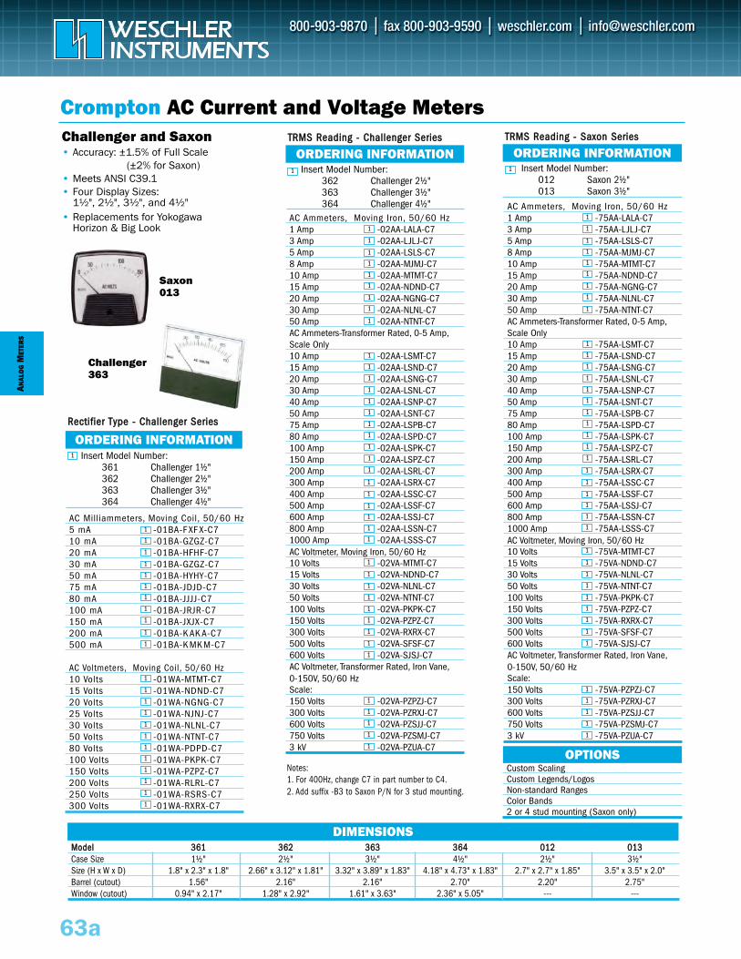
MMooddeell 336611 336622 336633 336644 001122 001133Case Size 1½" 2½" 3½" 4½" 2½" 3½"Size (H x W x D) 1.8" x 2.3" x 1.8" 2.66" x 3.12" x 1.81" 3.32" x 3.89" x 1.83" 4.18" x 4.73" x 1.83" 2.7" x 2.7" x 1.85" 3.5" x 3.5" x 2.0"Barrel (cutout) 1.56" 2.16" 2.16" 2.70" 2.20" 2.75"Window (cutout) 0.94" x 2.17" 1.28" x 2.92" 1.61" x 3.63" 2.36" x 5.05" --- ---
DIMENSIONS
AC Ammeters, Moving Iron, 50/60 Hz1 Amp -75AA-LALA-C73 Amp -75AA-LJL J-C75 Amp -75AA-LSLS-C78 Amp -75AA-MJMJ-C710 Amp -75AA-MTMT-C715 Amp -75AA-NDND-C720 Amp -75AA-NGNG-C730 Amp -75AA-NLNL-C750 Amp -75AA-NTNT-C7AC Ammeters-Transformer Rated, 0-5 Amp,Scale Only10 Amp -75AA-LSMT-C715 Amp -75AA-LSND-C720 Amp -75AA-LSNG-C730 Amp -75AA-LSNL-C740 Amp -75AA-LSNP-C750 Amp -75AA-LSNT-C775 Amp -75AA-LSPB-C780 Amp -75AA-LSPD-C7100 Amp -75AA-LSPK-C7150 Amp -75AA-LSPZ-C7200 Amp -75AA-LSRL-C7300 Amp -75AA-LSRX-C7400 Amp -75AA-LSSC-C7500 Amp -75AA-LSSF-C7600 Amp -75AA-LSSJ-C7800 Amp -75AA-LSSN-C71000 Amp -75AA-LSSS-C7AC Voltmeter, Moving Iron, 50/60 Hz10 Volts -75VA-MTMT-C715 Volts -75VA-NDND-C730 Volts -75VA-NLNL-C750 Volts -75VA-NTNT-C7100 Volts -75VA-PKPK-C7150 Volts -75VA-PZPZ-C7300 Volts -75VA-RXRX-C7500 Volts -75VA-SFSF-C7600 Volts -75VA-SJSJ-C7AC Voltmeter, Transformer Rated, Iron Vane,0-150V, 50/60 HzScale:150 Volts -75VA-PZPZJ-C7300 Volts -75VA-PZRXJ-C7600 Volts -75VA-PZSJJ-C7750 Volts -75VA-PZSMJ-C73 kV -75VA-PZUA-C7
AC Ammeters, Moving Iron, 50/60 Hz1 Amp -02AA-LALA-C73 Amp -02AA-LJL J-C75 Amp -02AA-LSLS-C78 Amp -02AA-MJMJ-C710 Amp -02AA-MTMT-C715 Amp -02AA-NDND-C720 Amp -02AA-NGNG-C730 Amp -02AA-NLNL-C750 Amp -02AA-NTNT-C7AC Ammeters-Transformer Rated, 0-5 Amp,Scale Only10 Amp -02AA-LSMT-C715 Amp -02AA-LSND-C720 Amp -02AA-LSNG-C730 Amp -02AA-LSNL-C740 Amp -02AA-LSNP-C750 Amp -02AA-LSNT-C775 Amp -02AA-LSPB-C780 Amp -02AA-LSPD-C7100 Amp -02AA-LSPK-C7150 Amp -02AA-LSPZ-C7200 Amp -02AA-LSRL-C7300 Amp -02AA-LSRX-C7400 Amp -02AA-LSSC-C7500 Amp -02AA-LSSF-C7600 Amp -02AA-LSSJ-C7800 Amp -02AA-LSSN-C71000 Amp -02AA-LSSS-C7AC Voltmeter, Moving Iron, 50/60 Hz10 Volts -02VA-MTMT-C715 Volts -02VA-NDND-C730 Volts -02VA-NLNL-C750 Volts -02VA-NTNT-C7100 Volts -02VA-PKPK-C7150 Volts -02VA-PZPZ-C7300 Volts -02VA-RXRX-C7500 Volts -02VA-SFSF-C7600 Volts -02VA-SJSJ-C7AC Voltmeter, Transformer Rated, Iron Vane,0-150V, 50/60 HzScale:150 Volts -02VA-PZPZJ-C7300 Volts -02VA-PZRXJ-C7600 Volts -02VA-PZSJJ-C7750 Volts -02VA-PZSMJ-C73 kV -02VA-PZUA-C7
AC Milliammeters, Moving Coil, 50/60 Hz 5 mA -01BA-F XF X-C710 mA -01BA-GZGZ-C720 mA -01BA-HFHF-C730 mA -01BA-GZGZ-C750 mA -01BA-HYHY-C775 mA -01BA-JDJD-C780 mA -01BA-JJJJ-C7100 mA -01BA-JRJR-C7150 mA -01BA-JXJX-C7200 mA -01BA-K AK A-C7500 mA -01BA-K MK M-C7
AC Voltmeters, Moving Coil, 50/60 Hz10 Volts -01WA-MTMT-C715 Volts -01WA-NDND-C720 Volts -01WA-NGNG-C725 Volts -01WA-NJNJ-C730 Volts -01WA-NLNL-C750 Volts -01WA-NTNT-C780 Volts -01WA-PDPD-C7100 Volts -01WA-PKPK-C7150 Volts -01WA-PZPZ-C7200 Volts -01WA-RLRL-C7250 Volts -01WA-RSRS-C7300 Volts -01WA-RXRX-C7
Crompton AC Current and Voltage Meters
ANAL
OG
MET
ERS
63a
Insert Model Number:012 Saxon 2½"013 Saxon 3½"
Challenger363
Saxon013
Challenger and Saxon • Accuracy: ±1.5% of Full Scale
(±2% for Saxon)• Meets ANSI C39.1• Four Display Sizes:
1½", 2½", 3½", and 4½"• Replacements for Yokogawa
Horizon & Big Look
1
Insert Model Number:361 Challenger 1½"362 Challenger 2½"363 Challenger 3½"364 Challenger 4½"
Insert Model Number:362 Challenger 2½"363 Challenger 3½"364 Challenger 4½"
1
1
Custom ScalingCustom Legends/LogosNon-standard RangesColor Bands2 or 4 stud mounting (Saxon only)
OPTIONS Notes: 1. For 400Hz, change C7 in part number to C4.2. Add suffix -B3 to Saxon P/N for 3 stud mounting.
ORDERING INFORMATION ORDERING INFORMATION
ORDERING INFORMATIONRReeccttiiffiieerr TTyyppee -- CChhaalllleennggeerr SSeerriieess
TTRRMMSS RReeaaddiinngg -- SSaaxxoonn SSeerriieessTTRRMMSS RReeaaddiinngg -- CChhaalllleennggeerr SSeerriieess
1
1
1
1
1
1
1
1
1
1
1
1
1
1
1
1
1
1
1
1
1
1
1
1
1
1
1
1
1
1
1
1
1
1
1
1
1
1
1
1
1
1
1
1
1
1
1
1
1
1
1
1
1
1
1
1
1
1
1
1
1
1
1
1
1
1
1
1
1
1
1
1
1
1
1
1
1
1
1
1
1
1
1
1
1
1
1
1
1
1
1
1
1
1
1
1
1
1
1
1
1
1
1
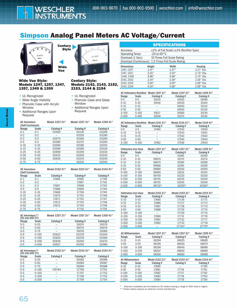
ANAL
OG
MET
ERS
65
AC Ammeters** Model 1257 21⁄2" Model 1357 31⁄2" Model 1359 41⁄2"(for use with CT)Range Scale Catalog # Catalog # Catalog #0-5 0-25 — 35074 350780-5 0-50 — 35075 350790-5 0-75 — 35076 350800-5 0-100 02622 03220 033500-5 0-150 02624 03230 033600-5 0-200 02626 03240 033700-5 0-300 02627 03250 03380
AC Ammeters Model 2152 21⁄2" Model 2153 31⁄2" Model 2154 41⁄2"(Self-Contained)Range Scale Catalog # Catalog # Catalog #0-1 0-1 17665 17695 177400-2 0-2 — 17697 177420-3 0-3 17667 17698 177430-5 0-5 17668 17699 177440-10 0-10 17669 17700 177450-15 0-15 17670 17701 177460-25 0-25 17671 17702 177470-30 0-30 17672 17703 177480-50 0-50 17673 17704 177490-75 0-75 — 17710 17755
AC Milliammeters Model 1257 21⁄2" Model 1357 31⁄2" Model 1359 41⁄2"Range Scale Catalog # Catalog # Catalog #0-10 0-10 06294 06625 066650-50 0-50 06295 06630 066700-100 0-100 06296 06640 066800-250 0-250 06297 06650 066900-500 0-500 06300 06660 06699
Voltmeters-Iron Vane Model 2152 21⁄2" Model 2153 31⁄2" Model 2154 41⁄2"Range Scale Catalog # Catalog # Catalog #0-10 0-10 17685 17726 177710-15 0-15 17686 17727 177720-25 0-25 17687 17728 177730-50 0-50 17688 17729 177740-100 0-100 — 17730 177750-150 0-150 17690 17731 177760-250 0-250 17691 17732 177770-300 0-300 17692 17733 177780-500 0-500 — 17734* 17779*
Voltmeters-Iron Vane Model 1257 21⁄2" Model 1357 31⁄2" Model 1359 41⁄2"Range Scale Catalog # Catalog # Catalog #0-5 0-5 — 10160 102600-10 0-10 09670 10170 102700-15 0-15 09675 10180 102800-25 0-25 09680 10190 102900-50 0-50 09690 10200 103000-100 0-100 09695 10210 103100-150 0-150 09700 10220 103200-250 0-250 09705 10230 103300-300 0-300 09710 10240 103400-500 0-500 09715* 10250* 10350*
AC Voltmeters-Rectified Model 2142 21⁄2" Model 2143 31⁄2"- Model 2144 41⁄2"Range Scale Catalog # Catalog # Catalog #0-5 0-5 17460 17542 176400-10 0-10 — 17543 176410-15 0-15 — 17544 176420-50 0-50 — 17545 176430-150 0-150 17462 17546 17644
AC Voltmeters-Rectified Model 1247 21⁄2" Model 1347 31⁄2" Model 1349 41⁄2"Range Scale Catalog # Catalog # Catalog #0-5 0-5 10015 10020 100900-10 0-10 10016 10030 101000-15 0-15 — 10040 101100-50 0-50 — 10050 101200-150 0-150 10017 10060 101300-300 0-300 10018 10070 10140
Dimensions Height Width Housing1247, 1257 2.47" 2.47" 2.17" Dia.1347, 1357 3.25" 3.25" 2.73" Dia.1349, 1359 4.68" 4.68" 2.75" Dia.2142, 2152 2.34" 2.38" 2.16" Dia.2143, 2153 3.00" 3.00" 2.69" Dia.2144, 2154 4.20" 4.66" 2.69" Dia.
Simpson Analog Panel Meters AC Voltage/Current
Wide Vue Style:Models 1247, 1257, 1347,1357, 1349 & 1359
• UL Recognized• Wide Angle Visibility• Phenolic Case with Acrylic
Window• Additional Ranges Upon
Request
Century Style:Models 2142, 2143, 2152,2153, 2144 & 2154
• UL Recognized• Phenolic Case and Glass
Window• Additional Ranges Upon
Request
WideVue
CenturyStyle
* External multipliers are furnished on AC meters having a range of 500 volts or higher.** These meters require an external current transformer.
Accuracy: ±2% of Full Scale (±3% Rectifier Type)Operating Temp: -20 to 65°COverload (1 Sec): 10 Times Full Scale RatingOverload (Continuous): 1.5 Times Full Scale Rating
SPECIFICATIONS
AC Millammeters Model 2152 21⁄2" Model 2153 31⁄2" Model 2154 41⁄2"Range Scale Catalog # Catalog # Catalog #0-10 0-10 17680 — 177600-50 0-50 17681 17716 177610-100 0-100 17682 17717 177620-250 0-250 17683 17718 177630-500 0-500 17684 17719 17764
AC Ammeters Model 1257 21⁄2" Model 1357 31⁄2" Model 1359 41⁄2"(Self-Contained)Range Scale Catalog # Catalog # Catalog #0-1 0-1 02560 03130 032600-2 0-2 — 03150 032800-3 0-3 02575 03160 032900-5 0-5 02580 03170 033000-10 0-10 02590 03180 033100-15 0-15 02599 03190 033200-25 0-25 02609 03200 033300-30 0-30 02615 03205 033350-50 0-50 02619 03210 033400-75 0-75 — 03215 03345
AC Ammeters** Model 2152 21⁄2" Model 2153 31⁄2" Model 2154 41⁄2"(for use with CT)Range Scale Catalog # Catalog # Catalog #0-5 0-25 — 35082 350860-5 0-50 — 35083 350870-5 0-75 — 35084 350880-5 0-100 176744 17706 177510-5 0-150 — 17707 177520-5 0-200 — 17708 177530-5 0-300 — 17709 17754
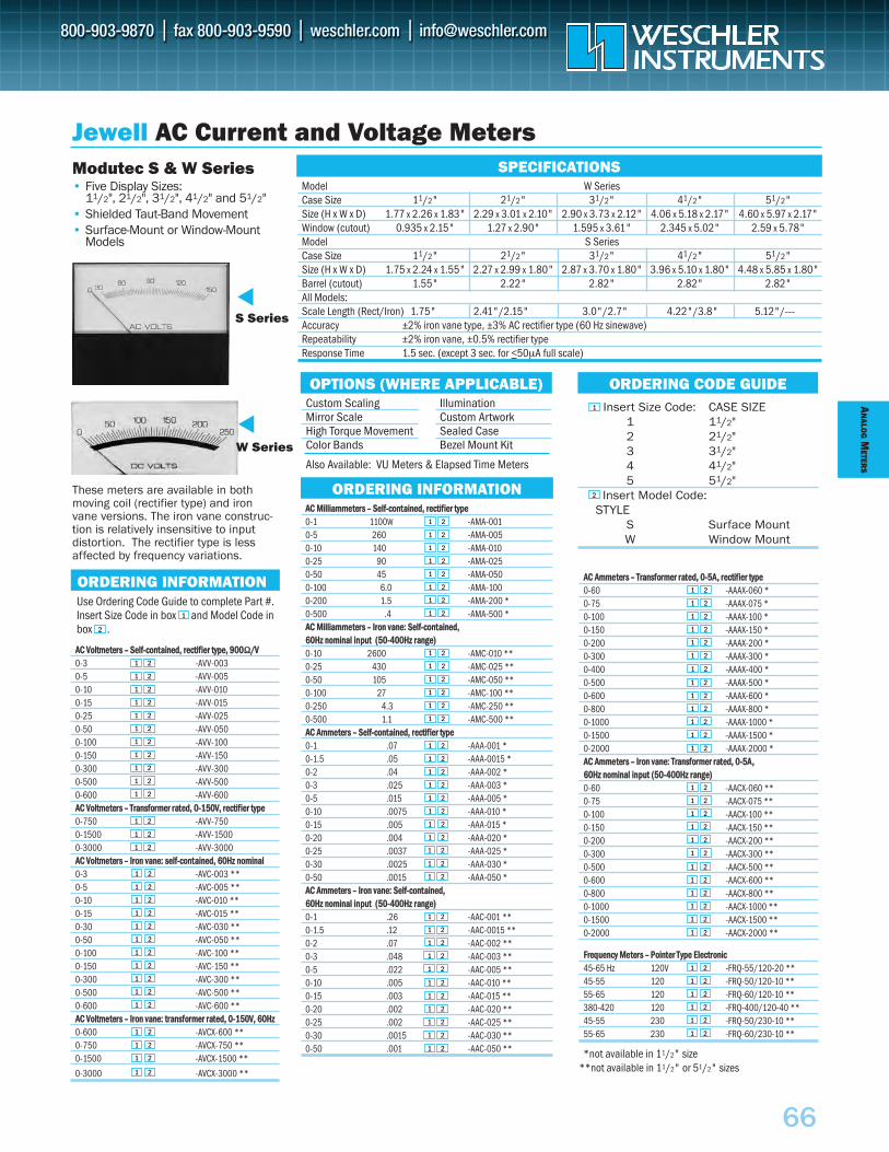
AACC VVoollttmmeetteerrss –– SSeellff--ccoonnttaaiinneedd,, rreeccttiiffiieerr ttyyppee,, 990000ΩΩ//VV0-3 -AVV-0030-5 -AVV-0050-10 -AVV-0100-15 -AVV-0150-25 -AVV-0250-50 -AVV-0500-100 -AVV-1000-150 -AVV-1500-300 -AVV-3000-500 -AVV-5000-600 -AVV-600AACC VVoollttmmeetteerrss –– TTrraannssffoorrmmeerr rraatteedd,, 00--115500VV,, rreeccttiiffiieerr ttyyppee0-750 -AVV-7500-1500 -AVV-15000-3000 -AVV-3000AACC VVoollttmmeetteerrss –– IIrroonn vvaannee:: sseellff--ccoonnttaaiinneedd,, 6600HHzz nnoommiinnaall0-3 -AVC-003 **0-5 -AVC-005 **0-10 -AVC-010 **0-15 -AVC-015 **0-30 -AVC-030 **0-50 -AVC-050 **0-100 -AVC-100 **0-150 -AVC-150 **0-300 -AVC-300 **0-500 -AVC-500 **0-600 -AVC-600 **AACC VVoollttmmeetteerrss –– IIrroonn vvaannee:: ttrraannssffoorrmmeerr rraatteedd,, 00--115500VV,, 6600HHzz 0-600 -AVCX-600 **0-750 -AVCX-750 **0-1500 -AVCX-1500 **
0-3000 -AVCX-3000 **
AN
ALOG
METER
S
66
Insert Size Code: CASE SIZE1 11/2"2 21/2"3 31/2"4 41/2"5 51/2"
Insert Model Code: STYLE
S Surface MountW Window Mount
These meters are available in bothmoving coil (rectifier type) and ironvane versions. The iron vane construc-tion is relatively insensitive to input distortion. The rectifier type is lessaffected by frequency variations.
AACC AAmmmmeetteerrss –– TTrraannssffoorrmmeerr rraatteedd,, 00--55AA,, rreeccttiiffiieerr ttyyppee0-60 -AAAX-060 *0-75 -AAAX-075 *0-100 -AAAX-100 *0-150 -AAAX-150 *0-200 -AAAX-200 *0-300 -AAAX-300 *0-400 -AAAX-400 *0-500 -AAAX-500 *0-600 -AAAX-600 *0-800 -AAAX-800 *0-1000 -AAAX-1000 *0-1500 -AAAX-1500 *0-2000 -AAAX-2000 *AACC AAmmmmeetteerrss –– IIrroonn vvaannee:: TTrraannssffoorrmmeerr rraatteedd,, 00--55AA,, 6600HHzz nnoommiinnaall iinnppuutt ((5500--440000HHzz rraannggee))0-60 -AACX-060 **0-75 -AACX-075 **0-100 -AACX-100 **0-150 -AACX-150 **0-200 -AACX-200 **0-300 -AACX-300 **0-500 -AACX-500 **0-600 -AACX-600 **0-800 -AACX-800 **0-1000 -AACX-1000 **0-1500 -AACX-1500 **0-2000 -AACX-2000 **
FFrreeqquueennccyy MMeetteerrss –– PPooiinntteerr TTyyppee EElleeccttrroonniicc45-65 Hz 120V -FRQ-55/120-20 **45-55 120 -FRQ-50/120-10 **55-65 120 -FRQ-60/120-10 **380-420 120 -FRQ-400/120-40 **45-55 230 -FRQ-50/230-10 **55-65 230 -FRQ-60/230-10 **
*not available in 11/2" size**not available in 11/2" or 51/2" sizes
AACC MMiilllliiaammmmeetteerrss –– SSeellff--ccoonnttaaiinneedd,, rreeccttiiffiieerr ttyyppee0-1 1100W -AMA-0010-5 260 -AMA-0050-10 140 -AMA-0100-25 90 -AMA-0250-50 45 -AMA-0500-100 6.0 -AMA-1000-200 1.5 -AMA-200 * 0-500 .4 -AMA-500 *AACC MMiilllliiaammmmeetteerrss –– IIrroonn vvaannee:: SSeellff--ccoonnttaaiinneedd,, 6600HHzz nnoommiinnaall iinnppuutt ((5500--440000HHzz rraannggee))0-10 2600 -AMC-010 **0-25 430 -AMC-025 **0-50 105 -AMC-050 **0-100 27 -AMC-100 **0-250 4.3 -AMC-250 **0-500 1.1 -AMC-500 **AACC AAmmmmeetteerrss –– SSeellff--ccoonnttaaiinneedd,, rreeccttiiffiieerr ttyyppee0-1 .07 -AAA-001 * 0-1.5 .05 -AAA-0015 *0-2 .04 -AAA-002 *0-3 .025 -AAA-003 *0-5 .015 -AAA-005 *0-10 .0075 -AAA-010 *0-15 .005 -AAA-015 *0-20 .004 -AAA-020 *0-25 .0037 -AAA-025 *0-30 .0025 -AAA-030 *0-50 .0015 -AAA-050 *AACC AAmmmmeetteerrss –– IIrroonn vvaannee:: SSeellff--ccoonnttaaiinneedd,, 6600HHzz nnoommiinnaall iinnppuutt ((5500--440000HHzz rraannggee))0-1 .26 -AAC-001 **0-1.5 .12 -AAC-0015 **0-2 .07 -AAC-002 **0-3 .048 -AAC-003 **0-5 .022 -AAC-005 **0-10 .005 -AAC-010 **0-15 .003 -AAC-015 **0-20 .002 -AAC-020 **0-25 .002 -AAC-025 **0-30 .0015 -AAC-030 **0-50 .001 -AAC-050 **
Model W SeriesCase Size 11/2" 21/2" 31/2" 41/2" 51/2"Size (H x W x D) 1.77 x 2.26 x 1.83" 2.29 x 3.01 x 2.10" 2.90 x 3.73 x 2.12" 4.06 x 5.18 x 2.17" 4.60 x 5.97 x 2.17"Window (cutout) 0.935 x 2.15" 1.27 x 2.90" 1.595 x 3.61" 2.345 x 5.02" 2.59 x 5.78"Model S SeriesCase Size 11/2" 21/2" 31/2" 41/2" 51/2"Size (H x W x D) 1.75 x 2.24 x 1.55" 2.27 x 2.99 x 1.80" 2.87 x 3.70 x 1.80" 3.96 x 5.10 x 1.80" 4.48 x 5.85 x 1.80"Barrel (cutout) 1.55" 2.22" 2.82" 2.82" 2.82"All Models:Scale Length (Rect/Iron) 1.75" 2.41"/2.15" 3.0"/2.7" 4.22"/3.8" 5.12"/---Accuracy ±2% iron vane type, ±3% AC rectifier type (60 Hz sinewave)Repeatability ±2% iron vane, ±0.5% rectifier typeResponse Time 1.5 sec. (except 3 sec. for <50µA full scale)
SPECIFICATIONS
Jewell AC Current and Voltage MetersModutec S & W Series• Five Display Sizes:
11/2", 21/2", 31/2", 41/2" and 51/2"• Shielded Taut-Band Movement• Surface-Mount or Window-Mount
Models
OPTIONS (WHERE APPLICABLE)
S Series
W Series
Use Ordering Code Guide to complete Part #.Insert Size Code in box and Model Code inbox .
ORDERING INFORMATION
ORDERING INFORMATION
ORDERING CODE GUIDECustom ScalingMirror ScaleHigh Torque MovementColor Bands
IlluminationCustom ArtworkSealed CaseBezel Mount Kit
Also Available: VU Meters & Elapsed Time Meters
1 2
1 2
1 2
1 2
1 2
1 2
1
2
1 2
1 2
1 2
1 2
1 2
1 2
1 2
1 2
1 2
1 2
1 2
1 2
1 2
1 2
1 2
1 2
1 2
1 2
1 2
1 2
1 2
1 2
1 2
1
2
1 2
1 2
1 2
1 2
1 2
1 2
1 2
1 2
1 2
1 2
1 2
1 2
1 2
1 2
1 2
1 2
1 2
1 2
1 2
1 2
1 2
1 2
1 2
1 2
1 2
1 2
1 2
1 2
1 2
1 2
1 2
1 2
1 2
1 2
1 2
1 2
1 2
1 2
1 2
1 2
1 2
1 2
1 2
1 2
1 2
1 2
1 2
1 2
1 2
1 2
1 2
1 2
1 2
1 2
1 2
1 2
1 2
1 2
1 2
1 2
1 2
1 2
1 2
1 2
1 2
1 2
1 2
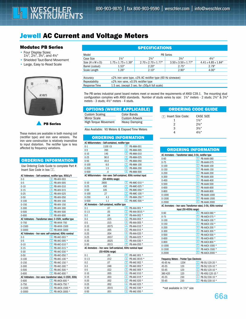
AACC AAmmmmeetteerrss –– TTrraannssffoorrmmeerr rraatteedd,, 00--55AA,, rreeccttiiffiieerr ttyyppee 0-60 PB-AAAX-0600-75 PB-AAAX-0750-100 PB-AAAX-1000-150 PB-AAAX-1500-200 PB-AAAX-2000-300 PB-AAAX-3000-400 PB-AAAX-4000-500 PB-AAAX-5000-600 PB-AAAX-6000-800 PB-AAAX-8000-1000 PB-AAAX-10000-1500 PB-AAAX-15000-2000 PB-AAAX-2000 AA CC AAmmmmeetteerrss –– IIrroonn vvaannee:: TTrraannssffoorrmmeerr rraatteedd,, 00--55AA,, 6600HHzz nnoommiinnaall
iinnppuutt ((5500--440000HHzz rraannggee)) 0-60 PB-AACX-060 *0-75 PB-AACX-075 *0-100 PB-AACX-100 *0-150 PB-AACX-150 *0-200 PB-AACX-200 *0-300 PB-AACX-300 *0-500 PB-AACX-500 *0-600 PB-AACX-600 *0-800 PB-AACX-800 *0-1000 PB-AACX-1000 *0-1500 PB-AACX-1500 *0-2000 PB-AACX-2000 *
FFrreeqquueennccyy MMeetteerrss –– PPooiinntteerr TTyyppee EElleeccttrroonniicc 45-65 Hz 120V PB-55/120-20 * 45-55 120 PB-50/120-10 * 55-65 120 PB-60/120-10 * 380-420 120 PB-400/120-10 * 45-55 230 PB-50/230-10 * 55-65 230 PB-60/230-10 *
*not available in 1½" size
AACC MMiilllliiaammmmeetteerrss –– SSeellff--ccoonnttaaiinneedd,, rreeccttiiffiieerr ttyyppee 0-1 1100 PB-AMA-001 0-5 260 PB-AMA-005 0-10 140 PB-AMA-010 0-25 90.0 PB-AMA-025 0-50 45.0 PB-AMA-050 0-100 6.0 PB-AMA-100 0-200 1.5 PB-AMA-200 0-500 .4 PB-AMA-500 AA CC MMiilllliiaammmmeetteerrss –– IIrroonn vvaannee:: SSeellff--ccoonnttaaiinneedd,, 6600HHzz nnoommiinnaall iinnppuutt
((5500--440000HHzz rraannggee)) 0-10 2600 PB-AMC-010 * 0-25 430 PB-AMC-025 * 0-50 105 PB-AMC-050 * 0-100 27 PB-AMC-100 * 0-250 4.3 PB-AMA-250 * 0-500 1.1 PB-AMC-500 * AACC AAmmmmeetteerrss –– SSeellff--ccoonnttaaiinneedd,, rreeccttiiffiieerr ttyyppee 0-1 .07 PB-AAA-001 * 0-1.5 .05 PB-AAA-0015 *0-2 .04 PB-AAA-002 *0-3 .025 PB-AAA-003 *0-5 .015 PB-AAA-005 *0-10 .0075 PB-AAA-010 *0-15 .005 PB-AAA-015 *0-20 .004 PB-AAA-020 *0-25 .0037 PB-AAA-025 *0-30 .0025 PB-AAA-030 *0-50 .0015 PB-AAA-050 * AACC AAmmmmeetteerrss –– IIrroonn vvaannee:: SSeellff--ccoonnttaaiinneedd,, 6600HHzz nnoommiinnaall iinnppuutt
((5500--440000HHzz rraannggee)) 0-1 .20 PB-AAC-001 * 0-1.5 .012 PB-AAC-0015 *0-2 .07 PB-AAC-002 *0-3 .048 PB-AAC-003 *0-5 .022 PB-AAC-005 *0-10 .005 PB-AAC-010 *0-15 .003 PB-AAC-015 *0-20 .002 PB-AAC-020 *0-25 .002 PB-AAC-025 *0-30 .0015 PB-AAC-030 *0-50 .001 PB-AAC-050 *
AACC VVoollttmmeetteerrss –– SSeellff--ccoonnttaaiinneedd,, rreeccttiiffiieerr ttyyppee,, 990000ΩΩ//VV0-3 PB-AVV-0030-5 PB-AVV-005 0-10 PB-AVV-010 0-15 PB-AVV-015 0-25 PB-AVV-025 0-50 PB-AVV-050 0-100 PB-AVV-100 0-150 PB-AVV-150 0-300 PB-AVV-300 0-500 PB-AVV-500 0-600 PB-AVV-600 AACC VVoollttmmeetteerrss –– TTrraannssffoorrmmeerr rraatteedd,, 00--115500VV,, rreeccttiiffiieerr ttyyppee 0-750 PB-AVVX-750 0-1500 PB-AVVX-1500 0-3000 PB-AVVX-3000 AACC VVoollttmmeetteerrss –– IIrroonn vvaannee:: sseellff--ccoonnttaaiinneedd,, 6600HHzz nnoommiinnaall 0-3 PB-AVC-003 *0-5 PB-AVC-005 * 0-10 PB-AVC-010 * 0-15 PB-AVC-015 * 0-30 PB-AVC-030 * 0-50 PB-AVC-050 * 0-100 PB-AVC-100 * 0-150 PB-AVC-150 * 0-300 PB-AVC-300 * 0-500 PB-AVC-500 * 0-600 PB-AVC-600 * AACC VVoollttmmeetteerrss –– IIrroonn vvaannee:: ttrraannssffoorrmmeerr rraatteedd,, 00--115500VV,, 6600HHzz 0-600 PB-AVCX-600 * 0-750 PB-AVCX-750 * 0-1500 PB-AVCX-1500 * 0-3000 PB-AVCX-3000 *
66a
SPECIFICATIONS
Jewell AC Current and Voltage Meters
Modutec PB Series• Four Display Sizes:
1½", 2½", 3½", and 4½"• Shielded Taut-Band Movement• Large, Easy to Read Scale
OPTIONS (WHERE APPLICABLE)
PB Series
Use Ordering Code Guide to complete Part #. Insert Size Code in box .
ORDERING INFORMATION
1
ORDERING INFORMATION
ORDERING CODE GUIDE1
ORDERING INFORMATION
Custom Scaling Mirror Scale High Torque Movement
Color Bands Custom Artwork Heavy Damping
Also Available: VU Meters & Elapsed Time Meters
Model PB SeriesCase Size 1½" 2½" 3½" 4½"Size (H x W x D) 1.75 x 1.75 x 1.39" 2.70 x 2.70 x 1.77" 3.50 x 3.50 x 1.77" 4.41 x 4.85 x 1.84"Barrel (cutout) 1.53" 2.20" 2.75" 2.79"Scale Length 1.26" 2.10" 2.90" 4.00"
Accuracy ±2% iron vane type, ±3% AC rectifier type (60 Hz sinewave)Repeatability ±2% iron vane, ±0.5% rectifier type Response Time 1.5 sec. (except 3 sec. for <50μA full scale)
The PB series industrial panel board meters meet or exceed the requirements of ANSI C39.1. The mounting stud configuration complies with ANSI standards. Number of studs varies by size: 1½" meters - 2 studs; 2½" & 3½" meters - 3 studs; 4½" meters - 4 studs.
Insert Size Code: CASE SIZE 1 1½"2 2½"3 3½"4 4½"These meters are available in both moving coil
(rectifier type) and iron vane versions. The iron vane construction is relatively insensitive to input distortion. The rectifier type is less affected by frequency variations.
1
1
1
1
1
1
1
1
1
1
1
1
1
1
1
1
1
1
1
1
1
1
1
1
1
1
1
1
1
1
1
1
1
1
1
1
1
1
1
1
1
1
1
1
1
1
1
1
1
1
1
1
1
1
1
1
1
1
1
1
Ω 1
1
1
1
1
1
1
1
1
1
1
1
1
1
1
1
1
1
1
1
1
1
1
1
1
1
1
1
1
1
1
1
1
1
1
1
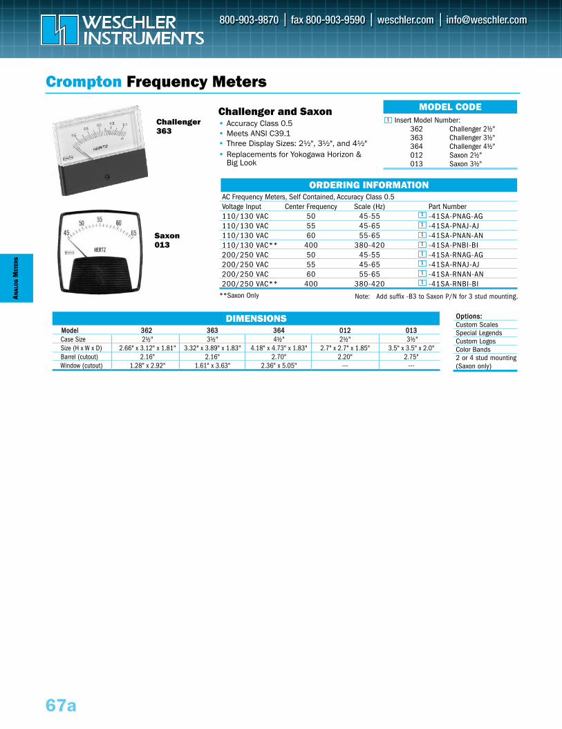
MMooddeell 336622 336633 336644 001122 001133Case Size 2½" 3½" 4½" 2½" 3½"Size (H x W x D) 2.66" x 3.12" x 1.81" 3.32" x 3.89" x 1.83" 4.18" x 4.73" x 1.83" 2.7" x 2.7" x 1.85" 3.5" x 3.5" x 2.0"Barrel (cutout) 2.16" 2.16" 2.70" 2.20" 2.75"Window (cutout) 1.28" x 2.92" 1.61" x 3.63" 2.36" x 5.05" --- ---
DIMENSIONS
ANAL
OG
MET
ERS
67a
AC Frequency Meters, Self Contained, Accuracy Class 0.5Voltage Input Center Frequency Scale (Hz) Part Number110/130 VAC 50 45-55 -41SA-PNAG-AG110/130 VAC 55 45-65 -41SA-PNAJ-AJ110/130 VAC 60 55-65 -41SA-PNAN-AN110/130 VAC** 400 380-420 -41SA-PNBI-BI200/250 VAC 50 45-55 -41SA-RNAG-AG200/250 VAC 55 45-65 -41SA-RNAJ-AJ200/250 VAC 60 55-65 -41SA-RNAN-AN200/250 VAC** 400 380-420 -41SA-RNBI-BI
**Saxon Only
Crompton Frequency Meters
ORDERING INFORMATION
Challenger and Saxon • Accuracy Class 0.5• Meets ANSI C39.1• Three Display Sizes: 2½", 3½", and 4½"• Replacements for Yokogawa Horizon &
Big Look
Challenger363
Saxon013
Insert Model Number:362 Challenger 2½"363 Challenger 3½"364 Challenger 4½"012 Saxon 2½"013 Saxon 3½"
MODEL CODE1
Note: Add suffix -B3 to Saxon P/N for 3 stud mounting.
OOppttiioonnss::Custom ScalesSpecial Legends Custom LogosColor Bands2 or 4 stud mounting(Saxon only)
1
1
1
1
1
1
1
1
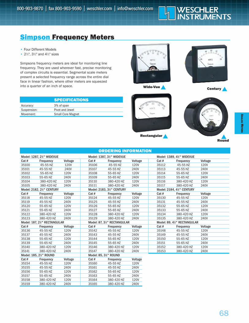
AN
ALOG
METER
S
68
Model: 1287, 21⁄2" WIDEVUE Model: 1387, 31⁄2" WIDEVUE Model: 1389, 41⁄2" WIDEVUECat # Frequency Voltage Cat # Frequency Voltage Cat # Frequency Voltage35100 45-55 HZ 120V 35106 45-55 HZ 120V 35112 45-55 HZ 120V35101 45-55 HZ 240V 35107 45-55 HZ 240V 35113 45-55 HZ 240V35102 55-65 HZ 120V 35108 55-65 HZ 120V 35114 55-65 HZ 120V 35103 55-65 HZ 240V 35109 55-65 HZ 240V 35115 55-65 HZ 240V35104 380-420 HZ 120V 35110 380-420 HZ 120V 35116 380-420 HZ 120V 35105 380-420 HZ 240V 35111 380-420 HZ 240V 35117 380-420 HZ 240VModel: 2182, 21⁄2" CENTURY Model: 2183, 31⁄2" CENTURY Model: 2184, 41⁄2" CENTURYCat # Frequency Voltage Cat # Frequency Voltage Cat # Frequency Voltage35118 45-55 HZ 120V 35124 45-55 HZ 120V 35130 45-55 HZ 120V35119 45-55 HZ 240V 35125 45-55 HZ 240V 35131 45-55 HZ 240V35120 55-65 HZ 120V 35126 55-65 HZ 120V 35132 55-65 HZ 120V 35121 55-65 HZ 240V 35127 55-65 HZ 240V 35133 55-65 HZ 240V35122 380-420 HZ 120V 35128 380-420 HZ 120V 35134 380-420 HZ 120V 35123 380-420 HZ 240V 35129 380-420 HZ 240V 35135 380-420 HZ 240VModel: 187, 21⁄2" RECTANGULAR Model: 87, 31⁄2" RECTANGULAR Model: 89, 41⁄2" RECTANGULARCat # Frequency Voltage Cat # Frequency Voltage Cat # Frequency Voltage35136 45-55 HZ 120V 35142 45-55 HZ 120V 35148 45-55 HZ 120V35137 45-55 HZ 240V 35143 45-55 HZ 240V 35149 45-55 HZ 240V35138 55-65 HZ 120V 35144 55-65 HZ 120V 35150 55-65 HZ 120V 35139 55-65 HZ 240V 35145 55-65 HZ 240V 35151 55-65 HZ 240V35140 380-420 HZ 120V 35146 380-420 HZ 120V 35152 380-420 HZ 120V 35141 380-420 HZ 240V 35147 380-420 HZ 240V 35153 380-420 HZ 240VModel: 185, 21⁄2" ROUND Model: 85, 31⁄2" ROUNDCat # Frequency Voltage Cat # Frequency Voltage35154 45-55 HZ 120V 35160 45-55 HZ 120V35155 45-55 HZ 240V 35161 45-55 HZ 240V35156 55-65 HZ 120V 35162 55-65 HZ 120V 35157 55-65 HZ 240V 35163 55-65 HZ 240V35158 380-420 HZ 120V 35164 380-420 HZ 120V 35159 380-420 HZ 240V 35165 380-420 HZ 240V
Simpson Frequency Meters
• Four Different Models• 21⁄2", 31⁄2" and 41⁄2" sizes
Simpsons frequency meters are ideal for monitoring line frequency. They are used wherever fast, precise monitoring of complex circuits is essential. Segmental scale meters present a selected frequency range across the entire dial face in linear fashion, where other meters are squeezed into a quarter of an inch of space.
Accuracy: 3% of spanSuspension: Pivot and JewelMovement: Small Core Magnet
SPECIFICATIONS
ORDERING INFORMATION
Rectangular
Wide-Vue Century
Round
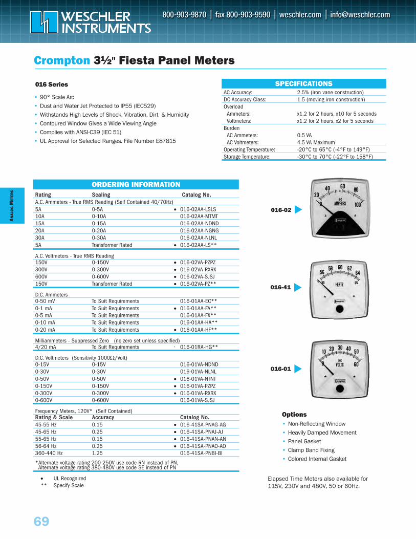
ANAL
OG
MET
ERS
69
016 Series
RRaattiinngg SSccaalliinngg CCaattaalloogg NNoo..A.C. Ammeters - True RMS Reading (Self Contained 40/70Hz)5A 0-5A • 016-02AA-LSLS10A 0-10A 016-02AA-MTMT15A 0-15A 016-02AA-NDND20A 0-20A 016-02AA-NGNG30A 0-30A 016-02AA-NLNL5A Transformer Rated • 016-02AA-LS**
A.C. Voltmeters - True RMS Reading150V 0-150V • 016-02VA-PZPZ300V 0-300V • 016-02VA-RXRX600V 0-600V • 016-02VA-SJSJ150V Transformer Rated • 016-02VA-PZ**
D.C. Ammeters0-50 mV To Suit Requirements 016-01AA-EC**0-1 mA To Suit Requirements • 016-01AA-FA**0-5 mA To Suit Requirements 016-01AA-FX**0-10 mA To Suit Requirements 016-01AA-HA**0-20 mA To Suit Requirements • 016-01AA-HF**
Milliammeters - Suppressed Zero (no zero set unless specified)4/20 mA To Suit Requirements • 016-01RA-HG**
D.C. Voltmeters (Sensitivity 1000Ω/Volt)0-15V 0-15V 016-01VA-NDND0-30V 0-30V 016-01VA-NLNL0-50V 0-50V • 016-01VA-NTNT0-150V 0-150V • 016-01VA-PZPZ0-300V 0-300V • 016-01VA-RXRX0-600V 0-600V 016-01VA-SJSJ
Frequency Meters, 120V* (Self Contained)RRaattiinngg && SSccaallee AAccccuurraaccyy CCaattaalloogg NNoo..45-55 Hz 0.15 • 016-41SA-PNAG-AG45-65 Hz 0.25 • 016-41SA-PNAJ-AJ55-65 Hz 0.15 • 016-41SA-PNAN-AN56-64 Hz 0.25 • 016-41SA-PNAO-AO360-440 Hz 1.25 016-41SA-PNBI-BI
*Alternate voltage rating 200-250V use code RN instead of PN,Alternate voltage rating 380-480V use code SE instead of PN
• UL Recognized** Specify Scale
Crompton 3½" Fiesta Panel Meters
• 90° Scale Arc
• Dust and Water Jet Protected to IP55 (IEC529)• Withstands High Levels of Shock, Vibration, Dirt & Humidity• Contoured Window Gives a Wide Viewing Angle• Complies with ANSI-C39 (IEC 51)• UL Approval for Selected Ranges. File Number E87815
AC Accuracy: 2.5% (iron vane construction)DC Accuracy Class: 1.5 (moving iron construction)Overload
Ammeters: x1.2 for 2 hours, x10 for 5 secondsVoltmeters: x1.2 for 2 hours, x2 for 5 seconds
BurdenAC Ammeters: 0.5 VAAC Voltmeters: 4.5 VA Maximum
Operating Temperature: -20°C to 65°C (-4°F to 149°F)Storage Temperature: -30°C to 70°C (-22°F to 158°F)
SPECIFICATIONS
016-02
016-41
016-01
Options• Non-Reflecting Window• Heavily Damped Movement• Panel Gasket• Clamp Band Fixing• Colored Internal Gasket
ORDERING INFORMATION
Elapsed Time Meters also available for115V, 230V and 480V, 50 or 60Hz.
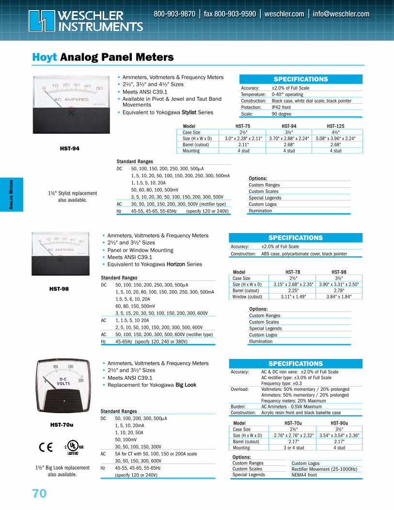
MMooddeell HHSSTT--7755 HHSSTT--9944 HHSSTT--112255Case Size 2½" 3½" 4½"Size (H x W x D) 3.0" x 2.28" x 2.11" 3.70" x 2.88" x 2.24" 5.08" x 3.96" x 2.24"Barrel (cutout) 2.11" 2.68" 2.68"Mounting 4 stud 4 stud 4 stud
MMooddeell HHSSTT--7700uu HHSSTT--9900uuCase Size 2½" 3½"Size (H x W x D) 2.76" x 2.76" x 2.32" 3.54" x 3.54" x 2.36"Barrel (cutout) 2.17" 2.17"Mounting 3 or 4 stud 4 stud
ANAL
OG
MET
ERS
70
SPECIFICATIONSAccuracy: AC & DC iron vane: ±2.0% of Full Scale
AC rectifier type: ±3.0% of Full ScaleFrequency type: ±0.3
Overload: Voltmeters: 50% momentary / 20% prolongedAmmeters: 50% momentary / 20% prolongedFrequency meters: 20% Maximum
Burden: AC Ammeters - 0.5VA MaximumConstruction: Acrylic resin front and black bakelite case
Hoyt Analog Panel Meters
HST-94
HST-70u
OOppttiioonnss::Custom RangesCustom ScalesSpecial Legends
SSttaannddaarrdd RRaannggeessDC 50, 100, 200, 300, 500μA
1, 5, 10, 20mA1, 10, 20, 50A50, 100mV30, 50, 100, 150, 300V
AC 5A for CT with 50, 100, 150 or 200A scale30, 50, 150, 300, 600V
Hz 45-55, 45-65, 55-65Hz (specify 120 or 240V)
• Ammeters, Voltmeters & Frequency Meters• 2½" and 3½" Sizes• Meets ANSI C39.1• Replacement for Yokogawa BBiigg LLooookk
MMooddeell HHSSTT--7788 HHSSTT--9988Case Size 2½" 3½"Size (H x W x D) 3.15" x 2.68" x 2.35" 3.90" x 3.31" x 2.50"Barrel (cutout) 2.25" 2.78"Window (cutout) 3.11" x 1.49" 3.84" x 1.84"
SPECIFICATIONSAccuracy: ±2.0% of Full ScaleConstruction: ABS case, polycarbonate cover, black pointer
SPECIFICATIONSAccuracy: ±2.0% of Full ScaleTemperature: 0-40° operatingConstruction: Black case, white dial scale, black pointerProtection: IP42 frontScale: 90 degree
HST-98
SSttaannddaarrdd RRaannggeessDC 50, 100, 150, 200, 250, 300, 500μA
1, 5, 10, 20, 80, 100, 150, 200, 250, 300, 500mA1.5, 5, 6, 10, 20A60, 80, 150, 500mV3, 5, 15, 20, 30, 50, 100, 150, 200, 300, 600V
AC 1, 1.5, 5, 10 20A2, 5, 10, 50, 100, 150, 200, 300, 500, 600V
AC 50, 100, 150, 200, 300, 500, 600V (rectifier type)Hz 45-65Hz (specify 120, 240 or 380V)
SSttaannddaarrdd RRaannggeessDC 50, 100, 150, 200, 250, 300, 500μA
1, 5, 10, 20, 50, 100, 150, 200, 250, 300, 500mA1, 1.5, 5, 10, 20A50, 60, 80, 100, 500mV3, 5, 10, 20, 30, 50, 100, 150, 200, 300, 500V
AC 30, 50, 100, 150, 200, 300, 500V (rectifier type)Hz 45-55, 45-65, 55-65Hz (specify 120 or 240V)
• Ammeters, Voltmeters & Frequency Meters • 2½" and 3½" Sizes• Panel or Window Mounting• Meets ANSI C39.1• Equivalent to Yokogawa HHoorriizzoonn Series
• Ammeters, Voltmeters & Frequency Meters • 2½", 3½" and 4½" Sizes• Meets ANSI C39.1• Available in Pivot & Jewel and Taut Band
Movements• Equivalent to Yokogawa SSttyylliisstt Series
OOppttiioonnss::Custom RangesCustom ScalesSpecial Legends Custom LogosIllumination
OOppttiioonnss::Custom RangesCustom ScalesSpecial Legends Custom LogosIllumination
Custom LogosRectifier Movement (25-1000Hz)NEMA4 front
1½" Stylist replacementalso available.
1½" Big Look replacementalso available.
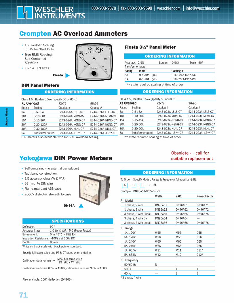
Class 1.5, Burden 0.5VA (specify 50 or 60Hz)72x72 96x96
Rating Scaling Catalog # Catalog #5A 0-5-15A E243-023A-LSLS-C7 E244-023A-LSLS-C7 10A 0-10-30A E243-023A-MTMT-C7 E244-023A-MTMT-C715A 0-15-45A E243-023A-NDND-C7 E244-023A-NDND-C720A 0-20-60A E243-023A-NGNG-C7 E244-023A-NGNG-C730A 0-30-90A E243-023A-NLNL-C7 E244-023A-NLNL-C75A Transformer rated E243-023A -LS**-C7 E244-023A -LS**-C7
ORDERING INFORMATION
• Self-contained (no external transducer)
• Taut band construction
• 1.5 accuracy class (W & VAR)
• 96mm, ¼ DIN size
• Flame retardant ABS case
• 2600V dielectric strength to case
ANAL
OG
MET
ERS
To Order: Specify Model, Range & Frequency followed by -L-BL
Example: DN96A51-W55-N-L-BL
WWaattttss VVAARR PPoowweerr FFaaccttoorrAA MMooddeell
1 phase, 2 wire DN96A51 DN96A61 DN96A711 phase, 3 wire DN96A52 DN96A62 DN96A723 phase, 3 wire unbal DN96A55 DN96A65 DN96A753 phase, 4 wire bal DN96A54 DN96A64 ---3 phase, 4 wire unbal DN96A56 DN96A66 DN96A76
BB RRaannggee 1A, 120V W55 M55 C555A, 120V W56 M56 C561A, 240V W65 M65 C655A, 240V W66 M66 C661A, 63.5V W11 M11 C11*5A, 63.5V W12 M12 C12*
CC FFrreeqquueennccyy50/60 Hz N --- ---50 Hz --- A A60 Hz --- B B
*3 phase, 4 wire
Crompton AC Overload Ammeters
Fiesta 3½" Panel Meter
Accuracy: 2.5% Burden: 0.5VA Scale: 90°
RRRaaatttiiinnnggg IIInnnpppuuuttt CCCaaatttaaallloooggg ###5A 0-5-30A (x6) 016-026A-LS**-C6 5A 0-5-10A (x2) 016-022A-LS**-C6
Transformer rated
Fiesta
ORDERING INFORMATION
DIN Panel Meters
Class 1.5, Burden 0.5VA (specify 50 or 60Hz)72x72 96x96
Rating Scaling Catalog # Catalog #5A 0-5-30A E243-026A-LSLS-C7 E244-026A-LSLS-C7 10A 0-10-60A E243-026A-MTMT-C7 E244-026A-MTMT-C715A 0-15-90A E243-026A-NDND-C7 E244-026A-NDND-C720A 0-20-120A E243-026A-NGNG-C7 E244-026A-NGNG-C730A 0-30-180A E243-026A-NLNL-C7 E244-026A-NLNL-C75A Transformer rated E243-026A -LS**-C7 E244-026A -LS**-C7 DIN meters also available with X2 & X5 overload scaling
ORDERING INFORMATION
Yokogawa DIN Power Meters
SPECIFICATIONS
ORDERING INFORMATION
71
• X6 Overload Scaling for Motor Start Duty
• True RMS Reading, Self Contained 50/60Hz
• 3½" & DIN sizes
DN96A
Deflection: 90°Accuracy Class 1.0 (W & VAR), 5.0 (Power Factor)Environment: 0 to 45°C, <75% RHInsulation Resistance: >10MΩ at 500V DC Depth: 83mmWhite on black scale with black pointer standard.
A – B – C – L – BL
Specify full scale value and PT & CT ratios when ordering.
Calibration watts or vars =
Calibration watts are 65% to 150%, calibration vars are 33% to 150%.
MAX. full scale value PT ratio x CT ratio
Also available: 250° deflection (DN96B).
** state required scaling at time of order
** state required scaling at time of order
XXX666 OOOvvveeerrrllloooaaaddd XXX333 OOOvvveeerrrllloooaaaddd
Obsolete - call for suitable replacement
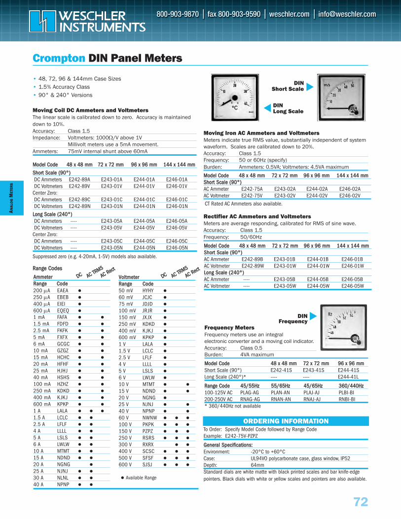
ANAL
OG
MET
ERS
72
• 48, 72, 96 & 144mm Case Sizes• 1.5% Accuracy Class• 90° & 240° Versions
Moving Coil DC Ammeters and VoltmetersThe linear scale is calibrated down to zero. Accuracy is maintaineddown to 10%. Accuracy: Class 1.5Impedance: Voltmeters: 1000Ω/V above 1V
Millivolt meters use a 5mA movement. Ammeters: 75mV internal shunt above 60mA
Frequency MetersFrequency meters use an integral electronic converter and a moving coil indicator. Accuracy: Class 0.5 Burden: 4VA maximum
MMooddeell CCooddee 4488 xx 4488 mmmm 7722 xx 7722 mmmm 9966 xx 9966 mmmmShort Scale (90°) E242-41S E243-41S E244-41SLong Scale (240°)* ---- ---- E244-41L
RRaannggee CCooddee 4455//5555HHzz 5555//6655HHzz 4455//6655HHzz 336600//444400HHzz100-125V AC PLAG-AG PLAN-AN PLAJ-AJ PLBI-BI200-250V AC RNAG-AG RNAN-AN RNAJ-AJ RNBI-BI* 360/440Hz not available
AAmmmmeetteerrRRaannggee CCooddee 200 μA EAEA
250 μA EBEB
400 μA EIEI
600 μA EQEQ
1 mA FAFA
1.5 mA FDFD
2.5 mA FKFK
5 mA FXFX
6 mA GCGC
10 mA GZGZ
15 mA HCHC
20 mA HFHF
25 mA HJHJ
40 mA HSHS
100 mA HZHZ
250 mA KDKD
400 mA K JK J
600 mA KPKP
1 A LALA
1.5 A LCLC
2.5 A LFLF
4 A LLLL
5 A LSLS
6 A LWLW
10 A MTMT
15 A NDND
20 A NGNG
25 A NJNJ
30 A NLNL
40 A NPNP
VVoollttmmeetteerrRRaannggee CCooddee50 mV HYHY
60 mV JCJC
75 mV JDJD
100 mV JRJR
150 mV JX JX
250 mV KDKD
400 mV K JK J
600 mV KPKP
1 V LALA
1.5 V LCLC
2.5 V LFLF
4 V LLLL
5 V LSLS
6 V LWLW
10 V MTMT
15 V NDND
20 V NGNG
25 V NJNJ
40 V NPNP
60 V NWNW
100 V PKPK
150 V PZPZ
250 V RSRS
300 V RXRX
400 V SCSC
500 V SFSF
600 V SJSJ
Crompton DIN Panel Meters
MMooddeell CCooddee 4488 xx 4488 mmmm 7722 xx 7722 mmmm 9966 xx 9966 mmmm 114444 xx 114444 mmmm
SShhoorrtt SSccaallee ((9900°°))DC Ammeters E242-89A E243-01A E244-01A E246-01ADC Voltmeters E242-89V E243-01V E244-01V E246-01V
Center Zero: DC Ammeters E242-89C E243-01C E244-01C E246-01CDC Voltmeters E242-89N E243-01N E244-01N E246-01N
LLoonngg SSccaallee ((224400°°))DC Ammeters ---- E243-05A E244-05A E246-05ADC Voltmeters ---- E243-05V E244-05V E246-05V
Center Zero:DC Ammeters ---- E243-05C E244-05C E246-05CDC Voltmeters ---- E243-05N E244-05N E246-05N
Suppressed zero (e.g. 4-20mA, 1-5V) models also available.
Moving Iron AC Ammeters and VoltmetersMeters indicate true RMS value, substantially independent of systemwaveform. Scales are calibrated down to 20%.Accuracy: Class 1.5Frequency: 50 or 60Hz (specify) Burden: Ammeters: 0.5VA; Voltmeters: 4.5VA maximum
Rectifier AC Ammeters and VoltmetersMeters are average responding, calibrated for RMS of sine wave.Accuracy: Class 1.5Frequency: 50/60Hz
MMooddeell CCooddee 4488 xx 4488 mmmm 7722 xx 7722 mmmm 9966 xx 9966 mmmm 114444 xx 114444 mmmmSShhoorrtt SSccaallee ((9900°°))AC Ammeter E242-75A E243-02A E244-02A E246-02AAC Voltmeter E242-75V E243-02V E244-02V E246-02V
ORDERING INFORMATIONTo Order: Specify Model Code followed by Range CodeExample: E242-75V-PZPZ
GGeenneerraall SSppeecciiffiiccaattiioonnss::Environment: -20°C to +60°CCase: UL94VO polycarbonate case, glass window, IP52 Depth: 64mmStandard dials are white matte with black printed scales and bar knife-edgepointers. Black dials with white or yellow scales and pointers are also available.
DINShort Scale
DINLong Scale
DINFrequency
Available Range
MMooddeell CCooddee 4488 xx 4488 mmmm 7722 xx 7722 mmmm 9966 xx 9966 mmmm 114444 xx 114444 mmmmSShhoorrtt SSccaallee ((9900°°))AC Ammeter E242-89B E243-01B E244-01B E246-01BAC Voltmeter E242-89W E243-01W E244-01W E246-01WLLoonngg SSccaallee ((224400°°)) AC Ammeter ---- E243-05B E244-05B E246-05BAC Voltmeter ---- E243-05W E244-05W E246-05W
CT Rated AC Ammeters also available.
DDCC AACC TTRRMMSSAACC RReecctt
DDCC AACC TTRRMMSSAACC RReeccttRRaannggee CCooddeess
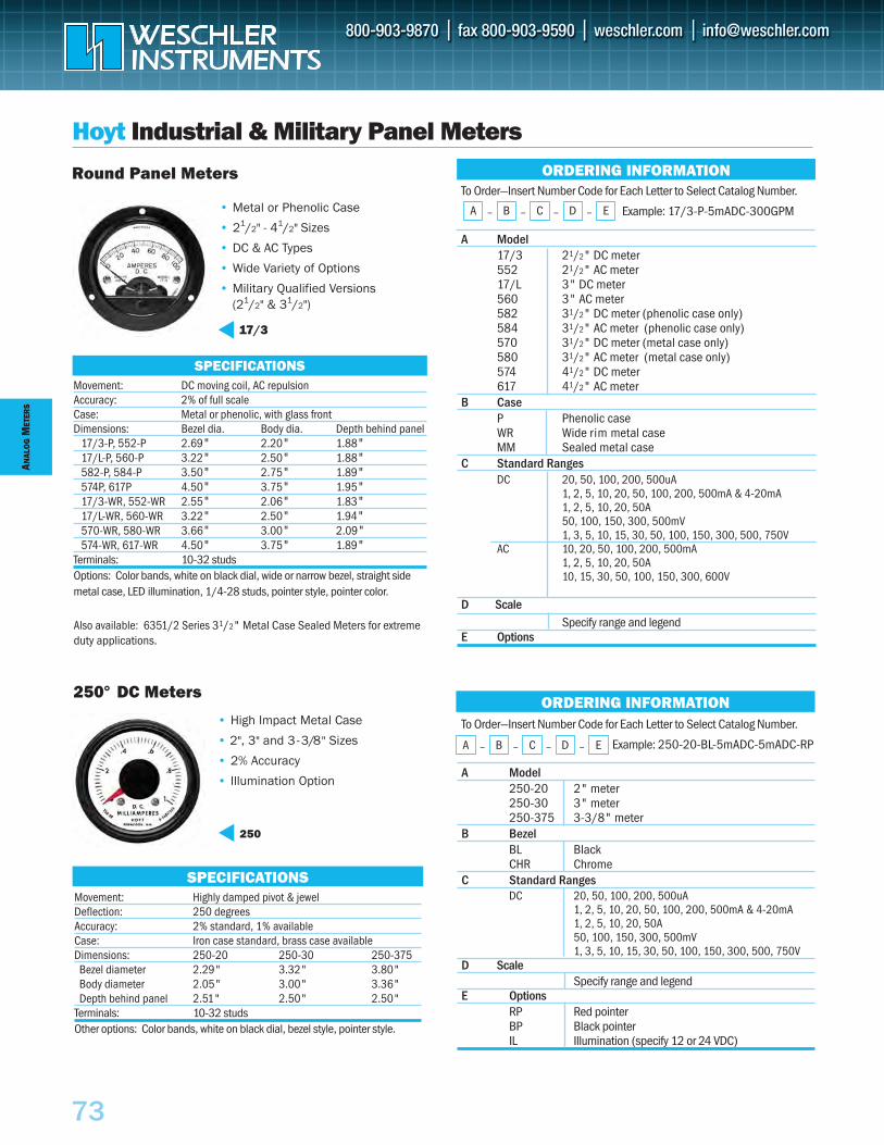
ANAL
OG
MET
ERS
73
Hoyt Industrial & Military Panel Meters
SPECIFICATIONS
SPECIFICATIONS
• High Impact Metal Case
• 2", 3" and 3 -3/8" Sizes
• 2% Accuracy
• Illumination Option
250
Movement: Highly damped pivot & jewelDeflection: 250 degreesAccuracy: 2% standard, 1% availableCase: Iron case standard, brass case availableDimensions: 250-20 250-30 250-375
Bezel diameter 2.29" 3.32" 3.80"Body diameter 2.05" 3.00" 3.36"Depth behind panel 2.51" 2.50" 2.50"
Terminals: 10-32 studsOther options: Color bands, white on black dial, bezel style, pointer style.
Movement: DC moving coil, AC repulsionAccuracy: 2% of full scaleCase: Metal or phenolic, with glass frontDimensions: Bezel dia. Body dia. Depth behind panel
17/3-P, 552-P 2.69" 2.20" 1.88"17/L-P, 560-P 3.22" 2.50" 1.88"582-P, 584-P 3.50" 2.75" 1.89"574P, 617P 4.50" 3.75" 1.95"17/3-WR, 552-WR 2.55" 2.06" 1.83"17/L-WR, 560-WR 3.22" 2.50" 1.94"570-WR, 580-WR 3.66" 3.00" 2.09"574-WR, 617-WR 4.50" 3.75" 1.89"
Terminals: 10-32 studsOptions: Color bands, white on black dial, wide or narrow bezel, straight sidemetal case, LED illumination, 1/4-28 studs, pointer style, pointer color.
ORDERING INFORMATION
• Metal or Phenolic Case
• 21/2" - 41/2" Sizes
• DC & AC Types
• Wide Variety of Options
• Military Qualified Versions(21/2" & 31/2")
Round Panel Meters
250° DC Meters
To Order—Insert Number Code for Each Letter to Select Catalog Number.
Example: 250-20-BL-5mADC-5mADC-RP
A Model250-20 2" meter250-30 3" meter250-375 3-3/8" meter
B BezelBL BlackCHR Chrome
C Standard Ranges DC 20, 50, 100, 200, 500uA
1, 2, 5, 10, 20, 50, 100, 200, 500mA & 4-20mA1, 2, 5, 10, 20, 50A 50, 100, 150, 300, 500mV1, 3, 5, 10, 15, 30, 50, 100, 150, 300, 500, 750V
D ScaleSpecify range and legend
E OptionsRP Red pointerBP Black pointerIL Illumination (specify 12 or 24 VDC)
ORDERING INFORMATION
To Order—Insert Number Code for Each Letter to Select Catalog Number.
Example: 17/3-P-5mADC-300GPM
A Model17/3 21/2" DC meter552 21/2" AC meter17/L 3" DC meter560 3" AC meter582 31/2" DC meter (phenolic case only)584 31/2" AC meter (phenolic case only)570 31/2" DC meter (metal case only)580 31/2" AC meter (metal case only)574 41/2" DC meter617 41/2" AC meter
B CaseP Phenolic caseWR Wide rim metal caseMM Sealed metal case
C Standard Ranges DC 20, 50, 100, 200, 500uA
1, 2, 5, 10, 20, 50, 100, 200, 500mA & 4-20mA1, 2, 5, 10, 20, 50A 50, 100, 150, 300, 500mV1, 3, 5, 10, 15, 30, 50, 100, 150, 300, 500, 750V
AC 10, 20, 50, 100, 200, 500mA1, 2, 5, 10, 20, 50A10, 15, 30, 50, 100, 150, 300, 600V
D ScaleSpecify range and legend
E OptionsAlso available: 6351/2 Series 31/2" Metal Case Sealed Meters for extremeduty applications.
A – B – C – D – E
A – B – C – D – E
17/3
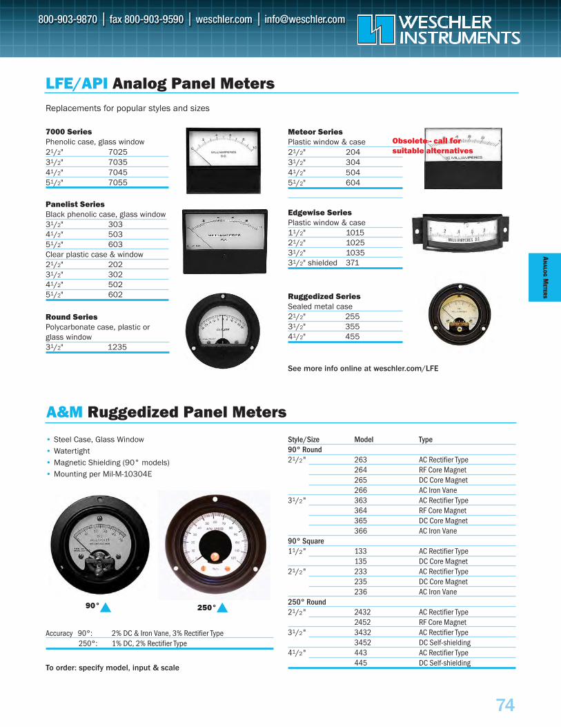
AN
ALOG
METER
S
74
Panelist SeriesBlack phenolic case, glass window 31/2" 30341/2" 50351/2" 603Clear plastic case & window21/2" 20231/2" 30241/2" 50251/2" 602
7000 SeriesPhenolic case, glass window 21/2" 702531/2" 7035 41/2" 7045 51/2" 7055
Replacements for popular styles and sizes
Meteor SeriesPlastic window & case21/2" 20431/2" 30441/2" 504 51/2" 604
Edgewise SeriesPlastic window & case11/2" 101521/2" 102531/2" 103531/2" shielded 371
Round SeriesPolycarbonate case, plastic or glass window31/2" 1235
Ruggedized SeriesSealed metal case21/2" 25531/2" 35541/2" 455
See more info online at weschler.com/LFE
Style/Size Model Type 90° Round21/2" 263 AC Rectifier Type
264 RF Core Magnet 265 DC Core Magnet266 AC Iron Vane
31/2" 363 AC Rectifier Type364 RF Core Magnet365 DC Core Magnet366 AC Iron Vane
90° Square11/2" 133 AC Rectifier Type
135 DC Core Magnet21/2" 233 AC Rectifier Type
235 DC Core Magnet236 AC Iron Vane
250° Round21/2" 2432 AC Rectifier Type
2452 RF Core Magnet31/2" 3432 AC Rectifier Type
3452 DC Self-shielding41/2" 443 AC Rectifier Type
445 DC Self-shielding
LFE/API Analog Panel Meters
A&M Ruggedized Panel Meters
90° 250°
• Steel Case, Glass Window• Watertight• Magnetic Shielding (90° models)• Mounting per Mil-M-10304E
Accuracy 90°: 2% DC & Iron Vane, 3% Rectifier Type250°: 1% DC, 2% Rectifier Type
To order: specify model, input & scale
Obsolete - call forsuitable alternatives
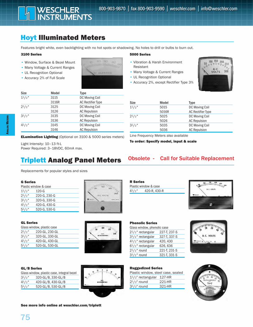
Hoyt Illuminated Meters
Triplett Analog Panel Meters
Size Model Type 11/2" 5015 DC Moving Coil
5016R AC Rectifier Type21/2" 5025 DC Moving Coil
5026 AC Repulsion31/2" 5035 DC Moving Coil
5036 AC Repulsion
Line Frequency Meters also available
To order: Specify model, input & scale
Replacements for popular styles and sizes
G SeriesPlastic window & case11/2" 120-G21/2" 220-G, 230-G31/2" 320-G, 330-G 41/2" 420-G, 430-G 51/2" 520-G, 530-G
R SeriesPlastic window & case41/2" 420-R, 430-R
GL Series Glass window, plastic case21/2" 220-GL, 230-GL31/2" 320-GL, 330-GL41/2" 420-GL, 430-GL51/2" 520-GL, 530-GL
Phenolic SeriesGlass window, phenolic case21/2" rectangular 227-T, 237-S31/2" rectangular 327-T, 337-S41/2" rectangular 420, 43061/2" rectangular 626, 63621/2" round 221-T, 231-S31/2" round 321-T, 331-S
GL/B SeriesGlass window, plastic case, integral bezel31/2" 320-GL/B, 330-GL/B41/2" 420-GL/B, 430-GL/B 51/2" 520-GL/B, 530-GL/B
Ruggedized SeriesPlastic window, steel case, sealed11/2" rectangular 127-HR21/2" round 221-HR31/2" round 321-HR
See more info online at weschler.com/triplett
• Window, Surface & Bezel Mount• Many Voltage & Current Ranges• UL Recognition Optional• Accuracy 2% of Full Scale
Size Model Type 11/2" 3115 DC Moving Coil
3116R AC Rectifier Type21/2" 3125 DC Moving Coil
3126 AC Repulsion31/2" 3135 DC Moving Coil
3136 AC Repulsion41/2" 3145 DC Moving Coil
3146 AC Repulsion
• Vibration & Harsh Environment Resistant
• Many Voltage & Current Ranges• UL Recognition Optional• Accuracy 2%, except Rectifier Type 3%
5000 Series3100 Series
Features bright white, even backlighting with no hot spots or shadowing. No holes to drill or bulbs to burn out.
Light Intensity: 10–13 ft-L Power Required: 3–18VDC, 60mA max.
ELumination Lighting (Optional on 3100 & 5000 series meters)
ANAL
OG
MET
ERS
75
Obsolete - Call for Suitable Replacement
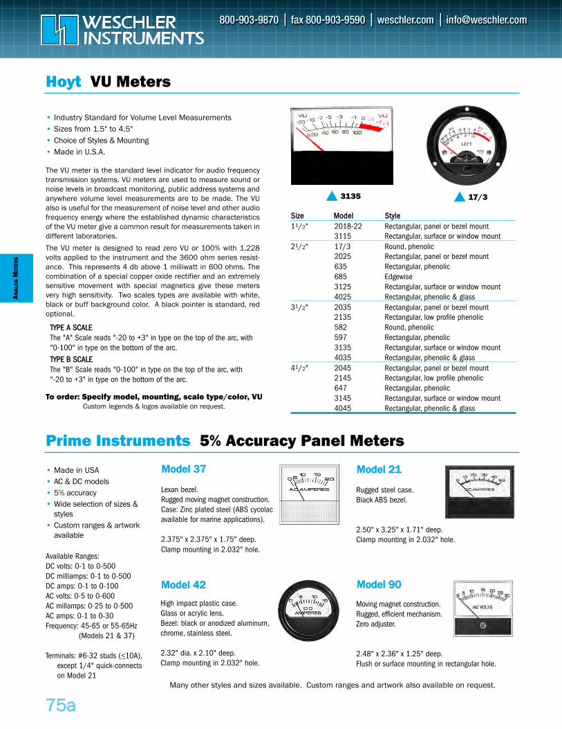
Hoyt VU Meters
Prime Instruments 5% Accuracy Panel Meters
To order: Specify model, mounting, scale type/color, VUCustom legends & logos available on request.
SSiizzee MMooddeell SSttyyllee11/2" 2018-22 Rectangular, panel or bezel mount
3115 Rectangular, surface or window mount21/2" 17/3 Round, phenolic
2025 Rectangular, panel or bezel mount635 Rectangular, phenolic685 Edgewise3125 Rectangular, surface or window mount4025 Rectangular, phenolic & glass
31/2" 2035 Rectangular, panel or bezel mount2135 Rectangular, low profile phenolic582 Round, phenolic597 Rectangular, phenolic3135 Rectangular, surface or window mount4035 Rectangular, phenolic & glass
41/2" 2045 Rectangular, panel or bezel mount2145 Rectangular, low profile phenolic647 Rectangular, phenolic3145 Rectangular, surface or window mount4045 Rectangular, phenolic & glass
• Industry Standard for Volume Level Measurements• Sizes from 1.5" to 4.5" • Choice of Styles & Mounting • Made in U.S.A.
The VU meter is the standard level indicator for audio frequencytransmission systems. VU meters are used to measure sound ornoise levels in broadcast monitoring, public address systems andanywhere volume level measurements are to be made. The VUalso is useful for the measurement of noise level and other audiofrequency energy where the established dynamic characteristicsof the VU meter give a common result for measurements taken indifferent laboratories.
The VU meter is designed to read zero VU or 100% with 1.228volts applied to the instrument and the 3600 ohm series resist-ance. This represents 4 db above 1 milliwatt in 600 ohms. Thecombination of a special copper oxide rectifier and an extremelysensitive movement with special magnetics give these metersvery high sensitivity. Two scales types are available with white,black or buff background color. A black pointer is standard, redoptional.
ANAL
OG
MET
ERS
7755aa
3135 17/3
TTYYPPEE AA SSCCAALLEEThe "A" Scale reads "-20 to +3" in type on the top of the arc, with"0-100" in type on the bottom of the arc.TTYYPPEE BB SSCCAALLEEThe "B" Scale reads "0-100" in type on the top of the arc, with"-20 to +3" in type on the bottom of the arc.
High impact plastic case.Glass or acrylic lens.Bezel: black or anodized aluminum,chrome, stainless steel.
2.32" dia. x 2.10" deep.Clamp mounting in 2.032" hole.
• Made in USA• AC & DC models• 5% accuracy• Wide selection of sizes &
styles• Custom ranges & artwork
available
Available Ranges:DC volts: 0-1 to 0-500DC milliamps: 0-1 to 0-500DC amps: 0-1 to 0-100AC volts: 0-5 to 0-600AC millamps: 0-25 to 0-500AC amps: 0-1 to 0-30Frequency: 45-65 or 55-65Hz
(Models 21 & 37)
Terminals: #6-32 studs (<10A),except 1/4" quick-connects on Model 21
MMooddeell 4422
Lexan bezel.Rugged moving magnet construction.Case: Zinc plated steel (ABS cycolacavailable for marine applications).
2.375" x 2.375" x 1.75" deep.Clamp mounting in 2.032" hole.
MMooddeell 3377
Rugged steel case.Black ABS bezel.
2.50" x 3.25" x 1.71" deep.Clamp mounting in 2.032" hole.
MMooddeell 2211
Moving magnet construction.Rugged, efficient mechanism.Zero adjuster.
2.48" x 2.36" x 1.25" deep.Flush or surface mounting in rectangular hole.
MMooddeell 9900
Many other styles and sizes available. Custom ranges and artwork also available on request.
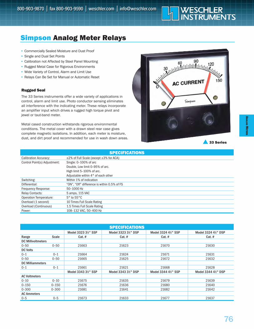
AN
ALOG
METER
S
76
SPECIFICATIONS
Calibration Accuracy: ±2% of Full Scale (except ±3% for ACA)Control Point(s) Adjustment: Single: 0–100% of arc
Double, Low limit 0–95% of arc.High limit 5–100% of arc. Adjustable within 4° of each other
Switching: Within 1% of indicationDifferential: “ON”, “Off” difference is within 0.5% of FSFrequency Response: 50–1000 HzRelay Contacts: 5 amps, 115 VACOperation Temperature: 5° to 55°COverload (1 second) 10 Times Full Scale RatingOverload (Continuous) 1.5 Times Full Scale RatingPower: 108–132 VAC, 50–400 Hz
Simpson Analog Meter Relays
Rugged Seal
• Commercially Sealed Moisture and Dust Proof• Single and Dual Set Points• Calibration not Affected by Steel Panel Mounting• Rugged Metal Case for Rigorous Environments• Wide Variety of Control, Alarm and Limit Use• Relays Can Be Set for Manual or Automatic Reset
The 33 Series instruments offer a wide variety of applications in control, alarm and limit use. Photo conductor sensing eliminates all interference with the indicating meter. These relays incorporate an amplifier input which drives a rugged high torque pivot and jewel or taut-band meter.
Metal cased construction withstands rigorous environmental conditions. The metal cover with a drawn steel rear case gives complete magnetic isolations. In addition, each meter is moisture,dust, and dirt proof and recommended for use in wash down areas.
SPECIFICATIONS
33 Series
Model 3323 31⁄2" SSP Model 3323 31⁄2" DSP Model 3324 41⁄2" SSP Model 3324 41⁄2" DSPRange Scale Cat. # Cat. # Cat. # Cat. #DC Millivoltmeters0–50 0–50 21663 21623 21670 21630DC Volts0–1 0–1 21664 21624 21671 216310–50 0–50 21665 21625 21672 21632DC Milliammeters0–1 0–1 21661 21621 21668 21628
Model 3343 31⁄2" SSP Model 3343 31⁄2" DSP Model 3344 41⁄2" SSP Model 3344 41⁄2" DSPAC Voltmeters0–10 0–10 21675 21635 21679 216390–150 0–150 21676 21636 21680 216400–300 0–300 21681 21641 21682 21642AC Ammeters0–5 0–5 21673 21633 21677 21637
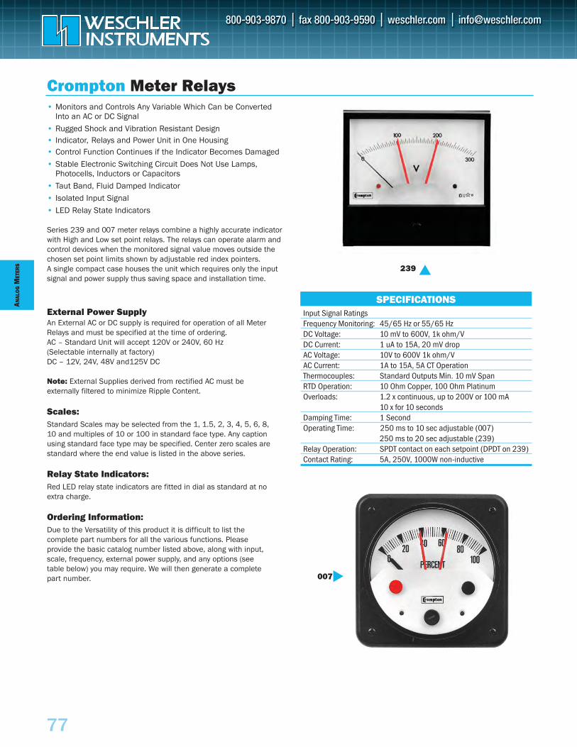
ANAL
OG
MET
ERS
77
Crompton Meter Relays
Input Signal RatingsFrequency Monitoring: 45/65 Hz or 55/65 HzDC Voltage: 10 mV to 600V, 1k ohm/VDC Current: 1 uA to 15A, 20 mV dropAC Voltage: 10V to 600V 1k ohm/VAC Current: 1A to 15A, 5A CT OperationThermocouples: Standard Outputs Min. 10 mV SpanRTD Operation: 10 Ohm Copper, 100 Ohm PlatinumOverloads: 1.2 x continuous, up to 200V or 100 mA
10 x for 10 secondsDamping Time: 1 SecondOperating Time: 250 ms to 10 sec adjustable (007)
250 ms to 20 sec adjustable (239)Relay Operation: SPDT contact on each setpoint (DPDT on 239)Contact Rating: 5A, 250V, 1000W non-inductive
SPECIFICATIONS
• Monitors and Controls Any Variable Which Can be ConvertedInto an AC or DC Signal
• Rugged Shock and Vibration Resistant Design• Indicator, Relays and Power Unit in One Housing• Control Function Continues if the Indicator Becomes Damaged
• Stable Electronic Switching Circuit Does Not Use Lamps,Photocells, Inductors or Capacitors
• Taut Band, Fluid Damped Indicator
• Isolated Input Signal
• LED Relay State Indicators
Series 239 and 007 meter relays combine a highly accurate indicatorwith High and Low set point relays. The relays can operate alarm andcontrol devices when the monitored signal value moves outside thechosen set point limits shown by adjustable red index pointers. A single compact case houses the unit which requires only the inputsignal and power supply thus saving space and installation time.
External Power SupplyAn External AC or DC supply is required for operation of all MeterRelays and must be specified at the time of ordering.AC – Standard Unit will accept 120V or 240V, 60 Hz (Selectable internally at factory)DC – 12V, 24V, 48V and125V DC
Note: External Supplies derived from rectified AC must be externally filtered to minimize Ripple Content.
Scales:Standard Scales may be selected from the 1, 1.5, 2, 3, 4, 5, 6, 8,10 and multiples of 10 or 100 in standard face type. Any captionusing standard face type may be specified. Center zero scales arestandard where the end value is listed in the above series.
Relay State Indicators:Red LED relay state indicators are fitted in dial as standard at noextra charge.
Ordering Information:Due to the Versatility of this product it is difficult to list the complete part numbers for all the various functions. Please provide the basic catalog number listed above, along with input,scale, frequency, external power supply, and any options (see table below) you may require. We will then generate a completepart number.
239
007
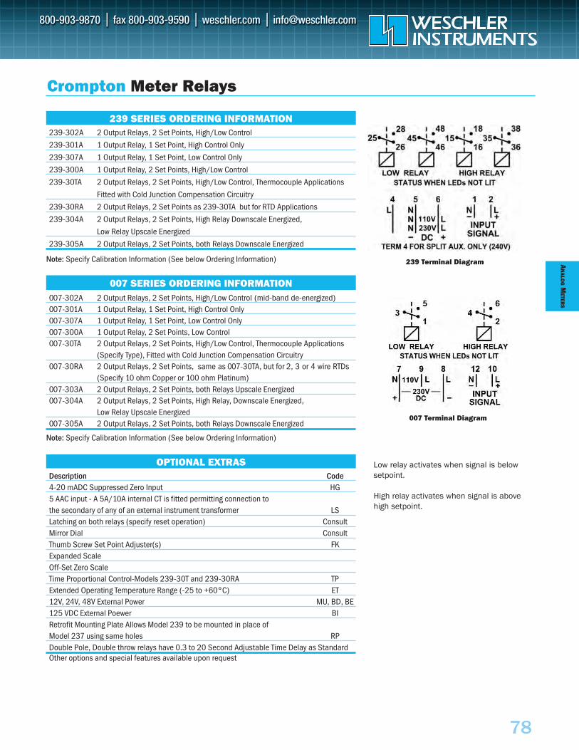
AN
ALOG
METER
S
78
Crompton Meter Relays
OPTIONAL EXTRASDescription Code4-20 mADC Suppressed Zero Input HG5 AAC input - A 5A/10A internal CT is fitted permitting connection to the secondary of any of an external instrument transformer LSLatching on both relays (specify reset operation) ConsultMirror Dial ConsultThumb Screw Set Point Adjuster(s) FKExpanded ScaleOff-Set Zero ScaleTime Proportional Control-Models 239-30T and 239-30RA TPExtended Operating Temperature Range (-25 to +60°C) ET12V, 24V, 48V External Power MU, BD, BE125 VDC External Poewer BIRetrofit Mounting Plate Allows Model 239 to be mounted in place of Model 237 using same holes RPDouble Pole, Double throw relays have 0.3 to 20 Second Adjustable Time Delay as StandardOther options and special features available upon request
239 SERIES ORDERING INFORMATION239-302A 2 Output Relays, 2 Set Points, High/Low Control
239-301A 1 Output Relay, 1 Set Point, High Control Only
239-307A 1 Output Relay, 1 Set Point, Low Control Only
239-300A 1 Output Relay, 2 Set Points, High/Low Control
239-30TA 2 Output Relays, 2 Set Points, High/Low Control, Thermocouple Applications
Fitted with Cold Junction Compensation Circuitry
239-30RA 2 Output Relays, 2 Set Points as 239-30TA but for RTD Applications
239-304A 2 Output Relays, 2 Set Points, High Relay Downscale Energized,
Low Relay Upscale Energized
239-305A 2 Output Relays, 2 Set Points, both Relays Downscale Energized
Note: Specify Calibration Information (See below Ordering Information)
007 SERIES ORDERING INFORMATION007-302A 2 Output Relays, 2 Set Points, High/Low Control (mid-band de-energized)007-301A 1 Output Relay, 1 Set Point, High Control Only007-307A 1 Output Relay, 1 Set Point, Low Control Only007-300A 1 Output Relay, 2 Set Points, Low Control007-30TA 2 Output Relays, 2 Set Points, High/Low Control, Thermocouple Applications
(Specify Type), Fitted with Cold Junction Compensation Circuitry007-30RA 2 Output Relays, 2 Set Points, same as 007-30TA, but for 2, 3 or 4 wire RTDs
(Specify 10 ohm Copper or 100 ohm Platinum)007-303A 2 Output Relays, 2 Set Points, both Relays Upscale Energized007-304A 2 Output Relays, 2 Set Points, High Relay, Downscale Energized,
Low Relay Upscale Energized007-305A 2 Output Relays, 2 Set Points, both Relays Downscale Energized
Note: Specify Calibration Information (See below Ordering Information)
Low relay activates when signal is belowsetpoint.
High relay activates when signal is abovehigh setpoint.
239 Terminal Diagram
007 Terminal Diagram
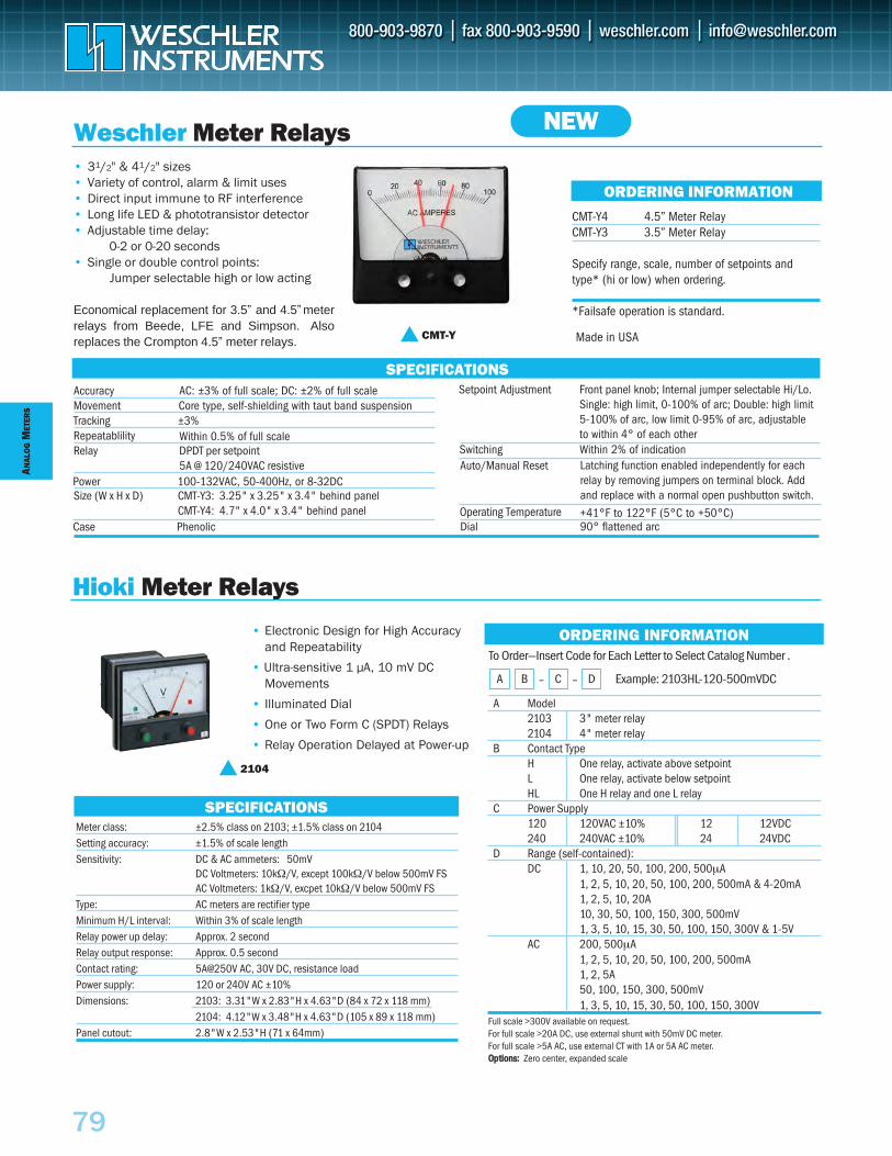
ANAL
OG
MET
ERS
79
A Model2103 3" meter relay2104 4" meter relay
B Contact TypeH One relay, activate above setpointL One relay, activate below setpointHL One H relay and one L relay
C Power Supply 120 120VAC ±10% 12 12VDC240 240VAC ±10% 24 24VDC
D Range (self-contained):DC 1, 10, 20, 50, 100, 200, 500µA
1, 2, 5, 10, 20, 50, 100, 200, 500mA & 4-20mA1, 2, 5, 10, 20A 10, 30, 50, 100, 150, 300, 500mV1, 3, 5, 10, 15, 30, 50, 100, 150, 300V & 1-5V
AC 200, 500µA1, 2, 5, 10, 20, 50, 100, 200, 500mA1, 2, 5A50, 100, 150, 300, 500mV1, 3, 5, 10, 15, 30, 50, 100, 150, 300V
Hioki Meter Relays
SPECIFICATIONS
• Electronic Design for High Accuracy and Repeatability
• Ultra-sensitive 1 µA, 10 mV DC Movements
• Illuminated Dial
• One or Two Form C (SPDT) Relays
• Relay Operation Delayed at Power-up
ORDERING INFORMATION
2104
Meter class: ±2.5% class on 2103; ±1.5% class on 2104Setting accuracy: ±1.5% of scale length Sensitivity: DC & AC ammeters: 50mV
DC Voltmeters: 10kΩ/V, except 100kΩ/V below 500mV FSAC Voltmeters: 1kΩ/V, excpet 10kΩ/V below 500mV FS
Type: AC meters are rectifier typeMinimum H/L interval: Within 3% of scale length Relay power up delay: Approx. 2 second Relay output response: Approx. 0.5 second Contact rating: 5A@250V AC, 30V DC, resistance loadPower supply: 120 or 240V AC ±10% Dimensions: 2103: 3.31"W x 2.83"H x 4.63"D (84 x 72 x 118 mm)
2104: 4.12"W x 3.48"H x 4.63"D (105 x 89 x 118 mm) Panel cutout: 2.8"W x 2.53"H (71 x 64mm)
Full scale >300V available on request. For full scale >20A DC, use external shunt with 50mV DC meter. For full scale >5A AC, use external CT with 1A or 5A AC meter. OOppttiioonnss:: Zero center, expanded scale
To Order—Insert Code for Each Letter to Select Catalog Number .
Example: 2103HL-120-500mVDC
A B – C – D
• 31/2" & 41/2" sizes• Variety of control, alarm & limit uses• Direct input immune to RF interference• Long life LED & phototransistor detector• Adjustable time delay:
0-2 or 0-20 seconds• Single or double control points:
Jumper selectable high or low acting
Economical replacement for 3.5” and 4.5” meterrelays from Beede, LFE and Simpson. Alsoreplaces the Crompton 4.5” meter relays.
Weschler Meter Relays
Accuracy AC: ±3% of full scale; DC: ±2% of full scale Movement Core type, self-shielding with taut band suspensionTracking ±3%Repeatablility Within 0.5% of full scaleRelay DPDT per setpoint
5A @ 120/240VAC resistive
Size (W x H x D) CMT-Y3: 3.25" x 3.25" x 3.4" behind panelCMT-Y4: 4.7" x 4.0" x 3.4" behind panel
CMT-Y4 4.5” Meter RelayCMT-Y3 3.5” Meter Relay
Specify range, scale, number of setpoints andtype* (hi or low) when ordering.
*Failsafe operation is standard.
Switching Within 2% of indication
Case PhenolicOperating Temperature +41°F to 122°F (5°C to +50°C)
SPECIFICATIONS
CMT-Y
NEW
ORDERING INFORMATION
Power 100-132VAC, 50-400Hz, or 8-32DC
Setpoint Adjustment Front panel knob; Internal jumper selectable Hi/Lo.Single: high limit, 0-100% of arc; Double: high limit5-100% of arc, low limit 0-95% of arc, adjustableto within 4° of each other
Auto/Manual Reset Latching function enabled independently for eachrelay by removing jumpers on terminal block. Addand replace with a normal open pushbutton switch.
Dial 90° flattened arc
Made in USA
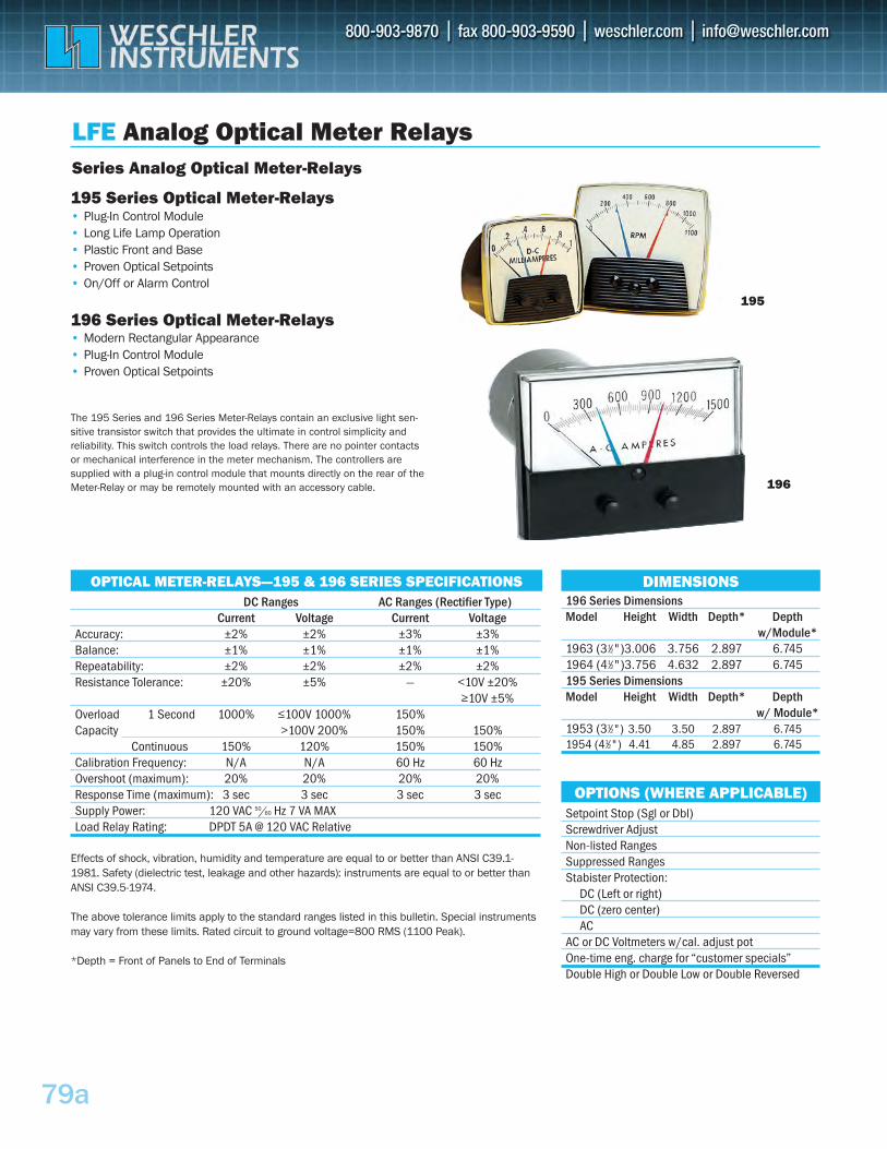
79a
196 Series Dimensions Model Height Width Depth* Depth
w/Module*1963 (31⁄2")3.006 3.756 2.897 6.7451964 (41⁄2")3.756 4.632 2.897 6.745195 Series Dimensions Model Height Width Depth* Depth
w/ Module*1953 (31⁄2") 3.50 3.50 2.897 6.7451954 (41⁄2") 4.41 4.85 2.897 6.745
DC Ranges AC Ranges (Rectifier Type) Current Voltage Current Voltage
Accuracy: ±2% ±2% ±3% ±3%Balance: ±1% ±1% ±1% ±1%Repeatability: ±2% ±2% ±2% ±2%Resistance Tolerance: ±20% ±5% — <10V ±20%
≥10V ±5%Overload 1 Second 1000% ≤100V 1000% 150%Capacity >100V 200% 150% 150%
Continuous 150% 120% 150% 150%Calibration Frequency: N/A N/A 60 Hz 60 HzOvershoot (maximum): 20% 20% 20% 20%Response Time (maximum): 3 sec 3 sec 3 sec 3 secSupply Power: 120 VAC 50/60 Hz 7 VA MAX Load Relay Rating: DPDT 5A @ 120 VAC Relative
Effects of shock, vibration, humidity and temperature are equal to or better than ANSI C39.1-1981. Safety (dielectric test, leakage and other hazards): instruments are equal to or better than ANSI C39.5-1974.
The above tolerance limits apply to the standard ranges listed in this bulletin. Special instruments may vary from these limits. Rated circuit to ground voltage=800 RMS (1100 Peak).
*Depth = Front of Panels to End of Terminals
OPTICAL METER-RELAYS—195 & 196 SERIES SPECIFICATIONS
LFE Analog Optical Meter Relays
195 Series Optical Meter-Relays• Plug-In Control Module• Long Life Lamp Operation• Plastic Front and Base• Proven Optical Setpoints• On/Off or Alarm Control
196 Series Optical Meter-Relays• Modern Rectangular Appearance• Plug-In Control Module• Proven Optical Setpoints
The 195 Series and 196 Series Meter-Relays contain an exclusive light sen-sitive transistor switch that provides the ultimate in control simplicity and reliability. This switch controls the load relays. There are no pointer contacts or mechanical interference in the meter mechanism. The controllers are supplied with a plug-in control module that mounts directly on the rear of the Meter-Relay or may be remotely mounted with an accessory cable.
Series Analog Optical Meter-Relays
196
Setpoint Stop (Sgl or Dbl)Screwdriver Adjust Non-listed Ranges Suppressed Ranges Stabister Protection:
DC (Left or right)DC (zero center)AC
AC or DC Voltmeters w/cal. adjust pot One-time eng. charge for “customer specials” Double High or Double Low or Double Reversed
OPTIONS (WHERE APPLICABLE)
DIMENSIONS
195
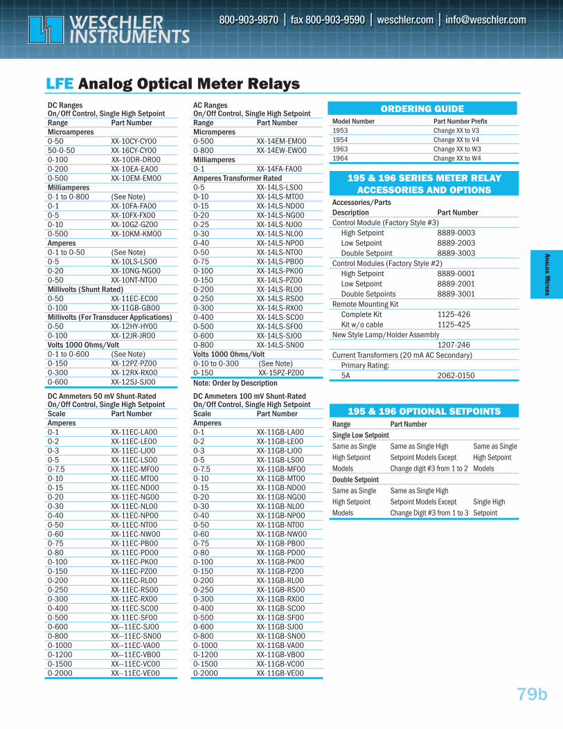
79b
Range Part Number Single Low Setpoint Same as Single Same as Single High Same as Single High Setpoint Setpoint Models Except High Setpoint Models Change digit #3 from 1 to 2 Models Double Setpoint Same as Single Same as Single High High Setpoint Setpoint Models Except Single High Models Change Digit #3 from 1 to 3 Setpoint
Accessories/Parts Description Part NumberControl Module (Factory Style #3)
High Setpoint 8889-0003 Low Setpoint 8889-2003 Double Setpoint 8889-3003
Control Modules (Factory Style #2)High Setpoint 8889-0001 Low Setpoint 8889-2001 Double Setpoints 8889-3001
Remote Mounting KitComplete Kit 1125-426 Kit w/o cable 1125-425
New Style Lamp/Holder Assembly1207-246
Current Transformers (20 mA AC Secondary)Primary Rating: 5A 2062-0150
AC Ranges On/Off Control, Single High Setpoint Range Part Number Micromperes 0-500 XX-14EM-EM00 0-800 XX-14EW-EW00 Milliamperes 0-1 XX-14FA-FA00 Amperes Transformer Rated 0-5 XX-14LS-LS00 0-10 XX-14LS-MT00 0-15 XX-14LS-ND00 0-20 XX-14LS-NG00 0-25 XX-14LS-NJ00 0-30 XX-14LS-NL00 0-40 XX-14LS-NP00 0-50 XX-14LS-NT00 0-75 XX-14LS-PB00 0-100 XX-14LS-PK00 0-150 XX-14LS-PZ00 0-200 XX-14LS-RL00 0-250 XX-14LS-RS00 0-300 XX-14LS-RX00 0-400 XX-14LS-SC00 0-500 XX-14LS-SF00 0-600 XX-14LS-SJ00 0-800 XX-14LS-SN00 Volts 1000 Ohms/Volt 0-10 to 0-300 (See Note) 0-150 XX-15PZ-PZ00 Note: Order by Description
DC Ranges On/Off Control, Single High Setpoint Range Part Number Microamperes 0-50 XX-10CY-CY00 50-0-50 XX-16CY-CY00 0-100 XX-10DR-DR00 0-200 XX-10EA-EA00 0-500 XX-10EM-EM00 Milliamperes 0-1 to 0-800 (See Note) 0-1 XX-10FA-FA00 0-5 XX-10FX-FX00 0-10 XX-10GZ-GZ00 0-500 XX-10KM-KM00 Amperes 0-1 to 0-50 (See Note) 0-5 XX-10LS-LS00 0-20 XX-10NG-NG00 0-50 XX-10NT-NT00 Millivolts (Shunt Rated) 0-50 XX-11EC-EC00 0-100 XX-11GB-GB00 Millivolts (For Transducer Applications) 0-50 XX-12HY-HY00 0-100 XX-12JR-JR00 Volts 1000 Ohms/Volt 0-1 to 0-600 (See Note) 0-150 XX-12PZ-PZ00 0-300 XX-12RX-RX00 0-600 XX-12SJ-SJ00
LFE Analog Optical Meter Relays
Model Number Part Number Prefix1953 Change XX to V31954 Change XX to V41963 Change XX to W31964 Change XX to W4
ORDERING GUIDE
195 & 196 SERIES METER RELAY ACCESSORIES AND OPTIONS
195 & 196 OPTIONAL SETPOINTS
DC Ammeters 50 mV Shunt-Rated On/Off Control, Single High Setpoint Scale Part Number Amperes 0-1 XX-11EC-LA00 0-2 XX-11EC-LE00 0-3 XX-11EC-LJ00 0-5 XX-11EC-LS00 0-7.5 XX-11EC-MF00 0-10 XX-11EC-MT00 0-15 XX-11EC-ND00 0-20 XX-11EC-NG00 0-30 XX-11EC-NL00 0-40 XX-11EC-NP00 0-50 XX-11EC-NT00 0-60 XX-11EC-NW00 0-75 XX-11EC-PB00 0-80 XX-11EC-PD00 0-100 XX-11EC-PK00 0-150 XX-11EC-PZ00 0-200 XX-11EC-RL00 0-250 XX-11EC-RS00 0-300 XX-11EC-RX00 0-400 XX-11EC-SC00 0-500 XX-11EC-SF00 0-600 XX--11EC-SJ00 0-800 XX--11EC-SN00 0-1000 XX--11EC-VA00 0-1200 XX--11EC-VB00 0-1500 XX--11EC-VC00 0-2000 XX--11EC-VE00
DC Ammeters 100 mV Shunt-Rated On/Off Control, Single High Setpoint Scale Part Number Amperes 0-1 XX-11GB-LA00 0-2 XX-11GB-LE00 0-3 XX-11GB-LJ00 0-5 XX-11GB-LS00 0-7.5 XX-11GB-MF00 0-10 XX-11GB-MT00 0-15 XX-11GB-ND00 0-20 XX-11GB-NG00 0-30 XX-11GB-NL00 0-40 XX-11GB-NP00 0-50 XX-11GB-NT00 0-60 XX-11GB-NW00 0-75 XX-11GB-PB00 0-80 XX-11GB-PD00 0-100 XX-11GB-PK00 0-150 XX-11GB-PZ00 0-200 XX-11GB-RL00 0-250 XX-11GB-RS00 0-300 XX-11GB-RX00 0-400 XX-11GB-SC00 0-500 XX-11GB-SF00 0-600 XX-11GB-SJ00 0-800 XX-11GB-SN00 0-1000 XX-11GB-VA00 0-1200 XX-11GB-VB00 0-1500 XX-11GB-VC00 0-2000 XX-11GB-VE00
AN
ALOG
METER
S
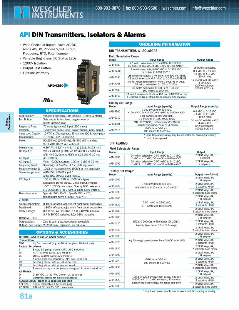
MMooddeell IInnppuutt RRaannggee OOuuttppuutt
APD 1080
APD 1090
MMooddeell IInnppuutt RRaannggee ((ssppeecciiffyy)) OOuuttppuutt
APD 1000
APD 1020
APD 1030
APD 1600
APD 1620
APD 1630
APD 1400
APD 1420
APD 1430
APD 1800
APD 1820
APD 1830
APD 1700
APD 1720
APD 1730
APD 1500
APD 1520
APD 1530
SIG
NAL
CON
DIT
ION
ERS
8811aa
API DIN Transmitters, Isolators & Alarms
LoopTracker®: Variable brightness LEDs indicate I/O level & status Test Button: Sets output to test level, toggles relay or
resets latching relay Response Time: 70 msec typical (AC input: 200 msec)Isolation: 1200 Vrms power/input, power/output, input/outputInput Loop Supply: 15 VDC ±10%, regulated, 25 mA max. (DC & freq inputs)Temperature: -10°C to +60°C operatingPower: 80-265 VAC (50/60 Hz), 48-300 VDC standard;
9-30 VDC,10-32 VAC optionalDimensions: 0.89" W x 4.62" H x 4.81" D (22.5x117x122 mm) DC Input Z: Volts: >200kΩ (>1MΩ on APD4380, >2.5MΩ on
APD HV-DC), Current: 50Ω or 1.25 VDC @ 20 mA AC Input: 40-1000 Hz,AC Input Z: Volts: >220kΩ, Current: 10Ω or 1 VDC @ 20 mAFrequency Input: Sensitivity ±2.5 mV to ±2.5 V , field adjustable Frequency Input Z: 10kΩ at max sensitivity, 100kΩ at min sensitivityStrain Gauge Input: APD4059: 200kΩ input Z
APD1500/20/30: 1MΩ input Z RTD Input: 100 Pt, 10 Cu, 120 Ni, 1000 NiFe types.
Excitation: 10 ma @10Ω, 2 mA @100Ω typical,100°F (55°C) min. span. Specify 0°C resistance (10-2000Ω), 2- or 3-wire, & alpha (385 typical).
Thermistor Input: Typically 2kΩ-20kΩ. Specify PTC or NTC,temperature curve & range (°C or °F)
ALARMS:Alarm Setpoint(s): 0-100% of span, adjustment front panel accessible Deadband: 1-100% of span, adjustment front panel accessible Relay Ratings: 8 A @ 240 VAC resistive, 5 A @ 240 VAC inductive,
8 A @ 30 VDC resistive, 3.5A @30V inductive.TRANSMITTERS:Output Adjust: Zero & span pots, front panel accessibleOutput Loop Supply: 20 VDC nom., regulated, 25 mA max.
SPECIFICATIONS
• Wide Choice of Inputs: Volts AC/DC,Amps AC/DC, Process V/mA, Strain,Frequency, RTD, Potentiometer
• Variable Brightness I/O Status LEDs• 1200V Isolation• Output Test Button• Lifetime Warranty
APD4380
ORDERING INFORMATION
OOPPTTIIOONNSS——aadddd ttoo eenndd ooff mmooddeell nnuummbbeerr TTrraannssmmiitttteerrssMO1 In/Out reversal (e.g. 4-20mA in gives 20-4mA out)FFaaccttoorryy SSeett AAllaarrmmssL Single LO going alarms (APD1x00 models)HH HI/HI alarms (APD1x20 models)LL LO/LO alarms (APD1x20 models)IB Alarms between setpoints (APD1x30 models)HT Latching alarm with pushbutton resetHP Latching alarm with power off resetR Reverse acting alarms (relays energized in alarm conditon)AAllll MMooddeellssD 9-30 VDC,10-32 VAC power (UL pending)U Conformal coating for moisture resistance AACCCCEESSSSOORRIIEESS——oorrddeerr aass aa sseeppaarraattee lliinnee iitteemm API BP4 Spare removable 4 terminal plugAPI TK36 DIN rail, 35 mm W x 39" L, aluminum
OPTIONS & ACCESSORIES
MMooddeell IInnppuutt RRaannggee OOuuttppuutt RRaannggee
APD 4380
APD HV-DC
APD 6380
APD 4008
APD 7580
APD 4059
47 switch selectable, 0-10 mVDC to 0-130 VDC,±5 mVDC to ±65 VDC, 0-200 μADC to 0-50 mADC*
13 switch selectable: 5 mV to 400 mV; 1-10 VDC exc. for1-4 350Ω bridge or strain gauge sensors, 120 mA max.
30 switch selectable, 0-100 Hz to 0-30 kHz,100 mVrms to 150Vrms
Any full-range potentiometer from 0-100Ω to 0-1MΩ,55 switch selectable, 0-10% to 0-100%
28 switch selectable: 0-40 mVAC to 0-300 VAC TRMS,22 switch selectable: 0-4 mAAC to 0-200 mAAC TRMS
8 switch selectable, 0-100 VDC to 0-1200 VDCor custom to 2000 VDC**
2 DPST relays, 8A,1 HI setpoint
2 DPST relays, 8A,2 setpoints HI/LO2 DPST relays, 8A,
2 setpoints, band alarm2 DPST relays, 8A,
1 HI setpoint2 DPST relays, 8A,2 setpoints HI/LO2 DPST relays, 8A,
2 setpoints, band alarm2 DPST relays, 8A,
1 HI setpoint2 DPST relays, 8A,2 setpoints HI/LO2 DPST relays, 8A,
2 setpoints, band alarm2 DPST relays, 8A,
1 HI setpoint2 DPST relays, 8A,2 setpoints HI/LO2 DPST relays, 8A,
2 setpoints, band alarm2 DPST relays, 8A,
1 HI setpoint2 DPST relays, 8A,2 setpoints HI/LO2 DPST relays, 8A,
2 setpoints, band alarm2 DPST relays, 8A,
1 HI setpoint2 DPST relays, 8A,2 setpoints HI/LO2 DPST relays, 8A,
2 setpoints, band alarm
2 DPST relays, 8A,1 setpoint
2 DPST relays, 8A,2 setpoints
FFiieelldd SSeelleeccttaabbllee RRaannggee::
MMooddeell IInnppuutt RRaannggee ((ssppeecciiffyy)) OOuuttppuutt RRaannggee ((ssppeecciiffyy))
APD 4300
APD 6010
APD 4001
APD 7010
0-100 mVDC to 0-300 VDC,±100 mVDC to ±10 VDC, 0-1 mADC to 0-900 mADC*
RTD (10-2000Ω), or Thermistor (2k-20kΩ),(specify type, curve, °C or °F & range)
0-25 Hz to 0-20 kHz,100 mVrms to 150Vrms
Any full-range potentiometer from 0-100Ω to 0-1MΩ
0-40 mVAC to 0-300 VAC TRMS,0-1 mAAC to 0-1000 mAAC TRMS
FFaaccttoorryy SSeett RRaannggee::
DDIINN AALLAARRMMSS
DDIINN TTRRAANNSSMMIITTTTEERRSS && IISSOOLLAATTOORRSS
* input loop power supply may be connected for sourcing or sinking.** not UL recognized.
18 switch selectable,0-1 VDC to 0-10 VDC±5 VDC to ±10 VDC
(10mA max),0-2 mADC to 0-20 mADC,
4-20 mADC(20V compliance,1000Ω @ 20 mA)
0-1 VDC to 0-10 VDC±1 VDC to ±10 VDC
(10mA max),0-1 mADC to 0-20 mADC,
4-20 mADC(20V compliance,1000Ω @ 20 mA)
24 switch selectable, 0-50 mVDC to 0-10 VDC,±5 VDC to ±10 VDC, 0-1 mADC to 0-20 mADC*24 switch selectable, 0-50 mVDC to 0-10 VDC,±5 VDC to ±10 VDC, 0-1 mADC to 0-20 mADC*
FFiieelldd SSeelleeccttaabbllee RRaannggee::
0-100 mVDC to 0-300 VDC,0-1 mADC to 0-20 mADC, 4-20 mADC*
RTD (10-2000Ω), or Thermistor (2k-20kΩ),(specify type, curve, °C or °F & range)
0-10 Hz to 0-20 kHz,100 mVrms to 150Vrms
100Ω to 10kΩ bridge, strain gauge, load cell;5-2000 mV; 1-10 VDC excitation, 30 mA max.Specify excitation voltage, mV range and mV/V
0-50 mVAC to 0-300 VAC,0-1 mAAC to 0-1000 mAAC
FFaaccttoorryy SSeett RRaannggee::
* input loop power supply may be connected for sourcing or sinking.
(see Options)
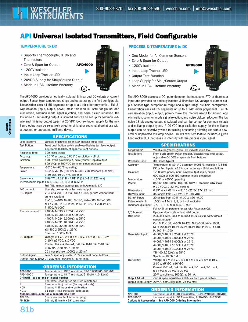
API Universal Isolated Transmitters, Field Configurable
The APD 8000 accepts a DC, potentiometer, thermocouple, RTD or thermistorinput and provides an optically isolated & linearized DC voltage or current out-put. Sensor type, temperature range and output range are field configurable.Linearization uses 41-55 segments or up to a 14th order polynomial. Full 3-way isolation (input, output, power) make this module useful for ground loopelimination, common mode signal rejection, and noise pickup reduction. The lownoise 18 bit analog output is isolated and can be set up for common voltageand milliamp output types. A 20 VDC loop excitation supply for the milliampoutput can be selectively wired for sinking or sourcing allowing use with a pow-ered or unpowered milliamp device. An API exclusive feature includes a greenLoopTracker LED that varies in intensity with the process input signal.
SIG
NAL
CON
DIT
ION
ERS
8811bb
LoopTracker®: Variable brightness green LED indicate input level Test Button: Front push button switch enables/disables test level output.
Adjustable 0-100% of span via front buttonsResponse Time: 300 msec typicalAccuracy: ±0.1°C accuracy; 0.001°C resolution (18 bit)Isolation: 1200 Vrms power/input, power/output, input/output
600 VACp or 600 VDC common mode protectionTemperature: -10°C to +60°C operatingPower: 85-265 VAC (50/60 Hz), 60-300 VDC standard (3W max);
9-30 VDC,10-32 VAC optionalDimensions: 0.89" W x 4.62" H x 4.81" D (22.5x117x122 mm)Thermocouple Input: J, K, T, E, R, S, N, B, C, D, G, M, P
Full ANSI temperature ranges with Automatic CJCT/C burnout: Upscale, downscale or last valid outputRTD Input: 2, 3, or 4 wire, 10Ω to 8000Ω RTDs, (4 wire with/without
current rotation)Cu-10, Cu-100, Ni-100, Ni-120, Ni-Fe-500, Ni-Fe-1000,Ni-Fe-2000, Pt-10, Pt-25, Pt-50, Pt-100, Pt-200, Pt-470,Pt-500, Pt-1000
Thermistor Input: 44004/44033 2.252kΩ at 25°C44005/44030 3.000kΩ at 25°C44007/44034 5.000kΩ at 25°C44006/44031 10.00kΩ at 25°C44008/44032 30.00kΩ at 25°CYSI 400 2.252kΩ at 25°CSpectrum 1003k 1kΩ
DC Output: Voltage: 0-1 V, 0-2 V, 0-4 V, 0-5 V, 1-5 V, 0-8 V, 0-10 V,2-10 V, ±5 VDC, ±10 VDCCurrent: 0-2 mA, 0-4 mA, 0-8 mA, 0-10 mA, 2-10 mA,0-16 mA, 0-20 mA, 4-20 mA20 V compliance, 1000Ω at 20 mA
Output Adjust: Zero & span adjustable ±10% via front panel buttonsOutput Loop Supply: 20 VDC nom., regulated, 25 mA max.
SPECIFICATIONS
LoopTracker®: Variable brightness green LED indicate input level Test Button: Front push button switch enables/disables test level output.
Adjustable 0-100% of span via front buttonsResponse Time: 300 msec typicalAccuracy: Temperature In: ±0.1°C accuracy; 0.001°C resolution (18 bit)
DC or Pot. Inputs: ±0.1% span accuracy (18 bit resolution)Isolation: 1200 Vrms power/input, power/output, input/output
600 VACp or 600 VDC common mode protectionTemperature: -10°C to +60°C operatingPower: 85-265 VAC (50/60 Hz), 60-300 VDC standard (3W max);
9-30 VDC,10-32 VAC optionalDimensions: 0.89" W x 4.62" H x 4.81" D (22.5x117x122 mm)DC Volts Input: 35 ranges from ±25 mVDC to ±10 VDCDC mA Input: 20 ranges from ±0.5 mADC to ±20 mADCPotentiometer In: 100Ω to 1 MΩ; 1, 2, or 4 volt excitationThermocouple Input: J, K, T, E, R, S, N, B, C, D, G, M, P
Full ANSI temperature ranges with Automatic CJCT/C burnout: Upscale, downscale or last valid outputRTD Input: 2, 3, or 4 wire, 10Ω to 8000Ω RTDs, (4 wire with/without
current rotation)Cu-10, Cu-100, Ni-100, Ni-120, Ni-Fe-500, Ni-Fe-1000,Ni-Fe-2000, Pt-10, Pt-25, Pt-50, Pt-100, Pt-200, Pt-470,Pt-500, Pt-1000
Thermistor Input: 44004/44033 2.252kΩ at 25°C44005/44030 3.000kΩ at 25°C44007/44034 5.000kΩ at 25°C44006/44031 10.00kΩ at 25°C44008/44032 30.00kΩ at 25°CYSI 400 2.252kΩ at 25°CSpectrum 1003k 1kΩ
DC Output: Voltage: 0-1 V, 0-2 V, 0-4 V, 0-5 V, 1-5 V, 0-8 V, 0-10 V,2-10 V, ±5 VDC, ±10 VDCCurrent: 0-2 mA, 0-4 mA, 0-8 mA, 0-10 mA, 2-10 mA,0-16 mA, 0-20 mA, 4-20 mA20 V compliance, 1000Ω at 20 mA
Output Adjust: Zero & span adjustable ±10% via front panel buttonsOutput Loop Supply: 20 VDC nom., regulated, 25 mA max.
SPECIFICATIONS
• Suports Thermocouple, RTDs and Thermistors
• Zero & Span for Output• 1200V Isolation• Input Loop Tracker LED• 20VDC Supply for Sink/Source Output• Made in USA, Lifetime Warranty
• One Model for All Common Sensors• Zero & Span for Output• 1200V Isolation• Input Loop Tracker LED• Output Test Function• Loop Supply for Sink/Source Output• Made in USA, Lifetime Warranty
APD4000 APD8000
ORDERING INFORMATIONAPD4000 Temperature to DC Transmitter, 85-265VAC/60-300VDCAPD4000D Temeprature to DC Transmitter, 9-30VDC/10-32VACOOPPTTIIOONNSS——aadddd ttoo eenndd ooff mmooddeell nnuummbbeerr U Conformal coating for moisture resistanceR Reverse acting output (factory set only)NC5 5 point NIST traceable calibrationNC11 11 point NIST traceable calibrationAACCCCEESSSSOORRIIEESS——oorrddeerr aass aa sseeppaarraattee lliinnee iitteemm API BP4 Spare removable 4 terminal plugAPI TK36 DIN rail, 35 mm W x 39" L, aluminum
ORDERING INFORMATIONAPD8000 Universal Input to DC Transmitter, 85-265VAC/60-300VDCAPD8000D Universal Input to DC Transmitter, 9-30VDC/10-32VACOOppttiioonnss && AAcccceessssoorriieess -- SSeeee AAPPII44000000 OOrrddeerriinngg IInnffoorrmmaattiioonn
TTEEMMPPEERRAATTUURREE ttoo DDCC PPRROOCCEESSSS && TTEEMMPPEERRAATTUURREE ttoo DDCC
The APD4000 provides an optically isolated & linearized DC voltage or currentoutput. Sensor type, temperature range and output range are field configurable.Linearization uses 41-55 segments or up to a 14th order polynomial. Full 3-way isolation (input, output, power) make this module useful for ground loopelimination, common mode signal rejection, and noise pickup reduction. Thelow noise 18 bit analog output is isolated and can be set up for common volt-age and milliamp output types. A 20 VDC loop excitation supply for the mil-liamp output can be selectively wired for sinking or sourcing allowing use witha powered or unpowered milliamp device.
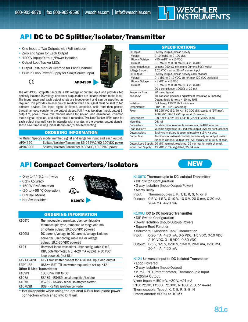
81c
API DC to DC Splitter/Isolator/Transmitter• One Input to Two Outputs with Full Isolation• Zero and Span for Each Output• 1200V Input/Output /Power Isolation • Output LoopTracker LEDs
• Output Test/Manual Override for Each Channel• Built-In Loop Power Supply for Sink/Source Input
• Only 1/4" (6.2mm) wide• 0.1% Accuracy• 1500V RMS Isolation• -20 to +65°C Operation• DIN Rail Mount • Hot Swappable*
APD4930
DC Input: Factory ranged, please specifyVoltage: 0-10 mVDC to 0-100 VDCBipolar Volatge: ±50 mVDC to ±10 VDCCurrent: 0-1 mADC to 0-50 mADC, 4-20 mADC
Input Impedance: Voltage: 200 kΩ minimum; Current: 50Ω typicalVoltage Burden: 1.25 VDC max. at 20 mA current inputDC Output: Factory ranged, please specify each channel
Voltage: 0-1 VDC to 0-10 VDC, 10 mA max (20 VDC available)Bipolar Voltage: ±1 VDC to ±10 VDCCurrent: 0-1 mADC to 0-20 mADC, 4-20 mADC
20 V compliance, 1000Ω at 20 mAResponse Time: 70 msec typicalAccuracy: ±0.1of span (includes adjustment resolution & linearity).
Output ripple & noise < 10 mV RMSIsolation: Full 4-way, 1200V RMS minimumTemperature: -10°C to +60°C operatingPower: 85-265 VAC (50/60 Hz), 60-300 VDC standard (6W max);
9-30 VDC,10-32 VAC optional (D version)Dimensions: 0.89" W x 4.62" H x 4.81" D (22.5x117x122 mm)Mounting: DIN railConnectors: For 4-terminal removable connectors, 14AWG wire max.LoopTracker®: Variable brightness LED indicate output level for each channelOutput Adjust: Each channel zero & span adjustable ±15% via pots Output Test: Terminals for external contacts to manually set output levels
for each channel. Output test level factory set at 50% of span.Output Loop Supply: 20 VDC nominal, regulated, 25 mA max for each channel.Input Loop Supply: 15 VDC ±10%, regulated, 25 mA max.
SPECIFICATIONS
ORDERING INFORMATION
ORDERING INFORMATION
To Order: Specify model number, signal and range for input and each output.APD4390 Splitter/Isolator/Transmitter 85-265VAC/60-300VDC powerAPD4390D Splitter/Isolator/Transmitter 9-30VDC/10-32VAC power
K109TC Thermocouple transmitter. User configurablethermocouple type, temperature range and mAor voltage output. 19.2-30 VDC powered
K109UI DC current/voltage to DC current/voltage isolator/converter. User configurable mA or voltageoutput. 19.2-30 VDC powered
K121 Universal input transmitter. User configurable V, mA,RTD, potentiometer, T/C. 4-20 mA output. 7-30 VDC loop powered. (not UL)
K121-C-420 K121 transmitter pre-set for 4-20 mA input and outputEASY USB USB UART TTL converter required to set up K121 OOtthheerr KK LLiinnee TTrraannssmmiitttteerrssK109PT 100 Ohm RTD to DCK107A RS485 - RS485 serial amplifier/isolatorK107B RS232 - RS485 serial isolator/converterK107USB USB - RS485 isolator/converter* Hot swappable when using the optional K-Bus backplane power
connectors which snap into DIN rail.
The APD4930 IsoSplitter accepts a DC voltage or current input and provides twooptically isolated DC voltage or current outputs that are linearly related to the input.The input range and each output range are independent and can be specified asrequired. This provides an economical solution when one signal must be sent to twodifferent devices. The input signal is filtered, amplified, split, and then passedthrough an opto-coupler to the output stages. Full 4-way isolation (input, output 1,output 2, power) make this module useful for ground loop elimination, commonmode signal rejection, and noise pickup reduction. Two LoopTracker LEDs (one foreach output channel) vary in intensity with changes in the process output signals.These save time during initial startup and/or troubleshooting.
API Compact Converters/Isolators NEW
K109TC
KK110099TTCC TThheerrmmooccoouuppllee ttoo DDCC IIssoollaatteedd TTrraannssmmiitttteerr•DIP Switch Configuration•3-way Isolation (Input/Output/Power)•Alarm RelayInput: Thermocouples J, K, T, E, R, S, N, or BOutput: 0-5 V, 1-5 V, 0-10 V, 10-0 V, 20-0 mA, 0-20 mA,
20-4 mA, 4-20 mA
KK110099UUII DDCC ttoo DDCC IIssoollaatteedd TTrraannssmmiitttteerr•DIP Switch Configuration•3-way Isolation (Input/Output/Power)•Square Root Function•Horizontal Cylindrical Tank LinearizationInput: 0-20 mA, 4-20 mA, 0-5 VDC, 1-5 VDC, 0-10 VDC,
2-10 VDC, 0-15 VDC, 0-30 VDCOutput: 0-5 V, 1-5 V, 0-10 V, 10-0 V, 20-0 mA, 0-20 mA,
20-4 mA, 4-20 mA
KK112211 UUnniivveerrssaall IInnppuutt ttoo DDCC IIssoollaatteedd TTrraannssmmiitttteerr•Loop Powered•2-way Isolation (Input/Output)•V, mA, RTD, Potentiometer, Thermocouple Input•4-20mA OutputV/mA Input: ±150 mV, ±30 V, ±24 mARTD: Pt100, Pt500, Pt1000, Ni100; 2, 3, or 4-wireThermocouple: Type J, K, T, E, R, S, B, NPotentiometer: 500 Ω to 10 kΩ
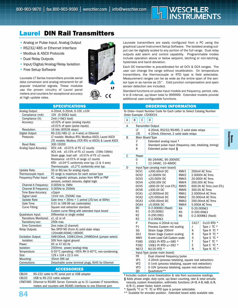
To Order—Insert Number Code for Each Letter to Select Catalog Number Order Example: LT20DCV1
A Transmitter OutputLT 4-20mA, RS232/RS485, 2 solid state relaysLTE 4-20mA, Ethernet, 2 solid state relays
B Main Board Type2 Extended analog input ¹¹6 Standard pulse input (frequency, rate, totalizing, timing)8 Extended pulse input §§
C Power0 85-264VAC, 95-300VDC1 12-34VAC, 10-48VDC
D Input Type (analog main board)
D Input Type (pulse main board)FR Dual channel frequency/pulse VF1 4-20mA (process totalizing, square root extraction)VF2 0-1mA (process totalizing, square root extraction)VF3 0-10V (process totalizing, square root extraction)QD Quadrature**
¹§¹ Includes custom curve linearization & rate from successive readings.§ Adds phase angle, duty cycle, up/down counting, rate & total simulta
neously, custom linearization, arithmetic functions (A+B, A-B, AxB, A/B,A/B-1), power factor, batch control.
* Specify °C or °F. TC or RTD type is jumper selectable.** Scalable for encoder position. Extended board adds scalable rate.
SIG
NAL
CO
ND
ITION
ERS
84
P Process 4-20mA in/outP1 Process Custom mA scaling SG Strain Gage 200mV SG1 Strain Gage Custom scalingWM1 6-wire Load Cell Custom scale P385 100Ω Pt RTD α=385 *P392 100Ω Pt RTD α=392 *N672 Ni120 RTD *
• Analog or Pulse Input, Analog Output• RS232/485 or Ethernet Interface• Modbus & ASCII Protocols• Dual Relay Outputs• Input/Digital/Analog/Relay Isolation• Free Setup Software
ORDERING INFORMATION
Laurel DIN Rail Transmitters
Analog Output: 4-20mA, 0-20mA, 0-10V, ±10VCompliance (mA): 10V (0-500Ω load)Compliance (V): 2mA (>5kΩ load)Accuracy: ±0.02% of span (analog inputs)
±0.01% of span (pulse inputs) Resolution: 16 bits (65536 steps)
Digital Output: RS-232/485 (2- or 4-wire) or EthernetProtocols: LT models: Modbus RTU, Modbus ASCII, Laurel ASCII
LTE models: Modbus (TCP, RTU or ASCII) & Laurel ASCIIBaud Rate: 300-19200
Analog Input Accuracy: DCV, mA: ±0.01% of FS ±2 countsACV, mA: ±0.15% of FS ±2 counts (10Hz-10kHz)Strain gage, load cell: ±0.01% of FS ±2 countsResistance: ±0.01% of range ±2 counts RTD: ±0.04°C conformity error typ. (3 & 4 wire)Thermocouple: ±0.2°C conformity error typ.
Update Rate: 50 or 60/sec for analog inputsThermocouple Input: FS range is maximum for each sensor typeFrequency/Pulse Input: AC, magnetic pickups, pulses from NPN or PNP
sensors, contact closures, digital logicChannel A Frequency: 0.005Hz to 1MHzChannel B Frequency: 0.005Hz to 250kHzTime Base Accuracy: ±2ppmSignal Level: 12mV min, 250VAC maxUpdate Rate: Gate time + 30ms + 1 period (20/sec at 60Hz)Gate Time: 0.01 to 199.99 sec (selectable)Curve Fitting: Square root extraction standard,
Custom curve fitting with extended input boardQuadrature Input: Differential or single ended
Transitions Monitored: x1, x2 or x4Transitions/sec: 250k max.Error Correction: Zero index (Z-channel)
Relay Outputs: Two SPST-NO (Form A) solid-state relays120mA@140VAC/180VDC
Excitation Output: 5V@100mA, 10V@120mA, 24V@50mA (jumper select) Isolation: 50V from signal ground
Power: DC or 47-63 HzIsolation: 250Vrms power/analog/relayTemperature: 0-55°C operating; <95% RH 0-40°C, non-condensingSize: 129 x 104 x 22.5 mmMounting: 35mm DIN railConnections: Detachable screw terminal plugs, RJ45 for Ethernet
SPECIFICATIONS
ACCESSORIES
DCV1 ±200.00mV DCDCV2 ±2.0000V DCDCV3 ±20.000V DCDCV4 ±200.00V DCDCV5 ±600.0V DC (not ETL)DCV6 ±300.0V DCDCA1 ±2.0000mA DCDCA2 ±20.000mA DCDCA3 ±200.00mA DCDCA4 ±5.000A DC
R1 0-20.000ΩR2 0-200.00ΩR3 0-2.000kΩ
RMV1 200mV AC TrmsRMV2 2.0000V AC TrmsRMV3 20.000V AC TrmsRMV4 200.00V AC TrmsRMV5 600.0V AC Trms (not ETL)RMV6 300.0V AC TrmsRMA1 2.0000mA AC TrmsRMA2 20.000mA AC TrmsRMA3 200.00mA AC TrmsRMA4 5.000A AC TrmsR4 0-20.000kΩR5 0-200.00kΩR6 0-2.000MΩ (fixed)
A B C D
CBL04 RS-232 cable to PC serial port or USB adapterCBL02 USB to RS-232 cable adapterLTNET485 Ethernet to RS485 Server. Connects up to 31 Laureate LT transmitters,
meters and counters with RS485 interfaces to one Ethernet port.
Laureate transmitters are easily configured from a PC using thegraphical Laurel Instrument Setup Software. The isolated analog out-put can be digitally scaled to any portion of the full range. Dual relayoutputs add alarm and control capability. Programmable modesinclude operation above or below setpoint, latching or non-latching,hysteresis and band deviation.Each DC transmitter is precalibrated for all DCV & DCA ranges. Theuser can change the range without recalibration. On temperaturetransmitters, the thermocouple or RTD type is field selectable.Measurement ranges can be as wide as the entire span of the sen-sor type or as narrow as 15°. Cold junction compensation and opensensor detection are included. Standard functions on pulse input models are frequency, period, rate,A to B interval, up/down total to 999999. Extended models provideadditional user-configurable functions.
Laureate LT Series transmitters provide serialdata conversion and analog retransmit for allpopular industrial signals. These modulesuse the proven circuitry of Laurel panelmeters and counters for exceptional accuracyat high update rates.
LT
C427 Cu10 RTD *J Type J TC *K Type K TC *R Type R TC *S Type S TC *T Type T TC *E Type E TC *N Type N TC *
R0 0-2.0000Ω (fixed)
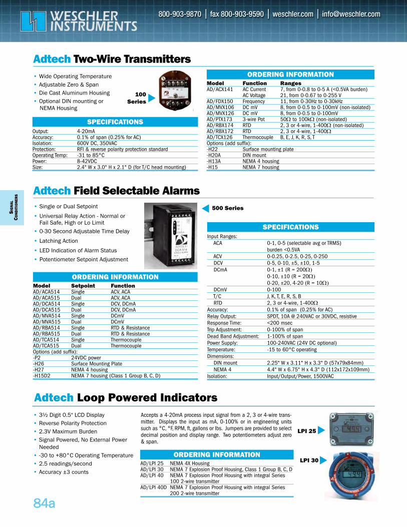
SIG
NAL
CON
DIT
ION
ERS
8844aa
Adtech Two-Wire Transmitters
Adtech Field Selectable Alarms• Single or Dual Setpoint
• Universal Relay Action - Normal or Fail Safe, High or Lo Limit
• 0-30 Second Adjustable Time Delay
• Latching Action
• LED Indication of Alarm Status
• Potentiometer Setpoint Adjustment
500 Series
AD/LPI 25 NEMA 4X Housing AD/LPI 30 NEMA 7 Explosion Proof Housing, Class 1 Group B, C, DAD/LPI 40 NEMA 7 Explosion Proof Housing with integral Series
100 2-wire transmitterAD/LPI 40D NEMA 7 Explosion Proof Housing with integral Series
200 2-wire transmitter
ORDERING INFORMATION
Input Ranges:ACA 0-1, 0-5 (selectable avg or TRMS)
burden <0.5VA ACV 0-0.25, 0-2.5, 0-25, 0-250DCV 0-5, 0-10, ±5, ±10, 1-5DCmA 0-1, ±1 (R = 200Ω)
0-10, ±10 (R = 20Ω)0-20, ±20, 4-20 (R = 10Ω)
DCmV 0-100 T/C J, K, T, E, R, S, B RTD 2, 3 or 4-wire, 1-400Ω
Accuracy: 0.1% of span (0.25% for AC) Relay Output: SPDT, 10A @ 240VAC or 30VDC, resistiveResponse Time: <200 msecTrip Adjustment: 0-100% of spanDead Band Adjustment: 1-100% of spanPower Supply: 100-240VAC (24V DC optional)Temperature: -15 to 60°C operatingDimensions:
DIN mount 2.25" W x 3.11" H x 3.3" D (57x79x84mm)NEMA 4 4.4" W x 6.75" H x 4.3" D (112x172x109mm)
Isolation: Input/Output/Power, 1500VAC
SPECIFICATIONS
• 3½ Digit 0.5" LCD Display • Reverse Polarity Protection• 2.3V Maximum Burden • Signal Powered, No External Power
Needed• -30 to +80°C Operating Temperature• 2.5 readings/second• Accuracy ±3 counts
LPI 25
Adtech Loop Powered Indicators
LPI 30
• Wide Operating Temperature• Adjustable Zero & Span• Die Cast Aluminum Housing• Optional DIN mounting or
NEMA Housing
100 Series
Output: 4-20mAAccuracy: 0.1% of span (0.25% for AC)Isolation: 600V DC, 350VACProtection: RFI & reverse polarity protection standardOperating Temp: -31 to 85°C Power: 8-42VDC Size: 2.4" W x 3.0" H x 2.1" D (for T/C head mounting)
SPECIFICATIONS
Model Function RangesAD/ACX141 AC Current 7, from 0-0.8 to 0-5 A (<0.5VA burden)
AC Voltage 21, from 0-0.67 to 0-255 V AD/FDX150 Frequency 11, from 0-30Hz to 0-30kHz AD/MVX106 DC mV 8, from 0-0.5 to 0-100mV (non-isolated)AD/MVX126 DC mV 8, from 0-0.5 to 0-100mVAD/PTX173 3-wire Pot 50Ω to 100kΩ (non-isolated) AD/RBX174 RTD 2, 3 or 4-wire, 1-400Ω (non-isolated)AD/RBX172 RTD 2, 3 or 4-wire, 1-400ΩAD/TCX126 Thermocouple B, E, J, K, R, S, T Options (add suffix):-H22 Surface mounting plate-H20A DIN mount-H13A NEMA 4 housing-H15 NEMA 7 housing
ORDERING INFORMATION
Accepts a 4-20mA process input signal from a 2, 3 or 4-wire trans-mitter. Displays the input as mA, 0-100% or in engineering unitssuch as °C, °F, RPM, ft, gallons or lbs. Jumpers are provided to selectdecimal position and display range. Two potentiometers adjust zero& span.
Model Setpoint FunctionAD/ACA514 Single ACV, ACAAD/ACA515 Dual ACV, ACAAD/DCA514 Single DCV, DCmAAD/DCA515 Dual DCV, DCmAAD/MVA514 Single DCmV AD/MVA515 Dual DCmVAD/RBA514 Single RTD & ResistanceAD/RBA515 Dual RTD & Resistance AD/TCA514 Single ThermocoupleAD/TCA515 Dual ThermocoupleOptions (add suffix):-P2 24VDC power-H26 Surface Mounting Plate-H27 NEMA 4 housing-H15D2 NEMA 7 housing (Class 1 Group B, C, D)
ORDERING INFORMATION
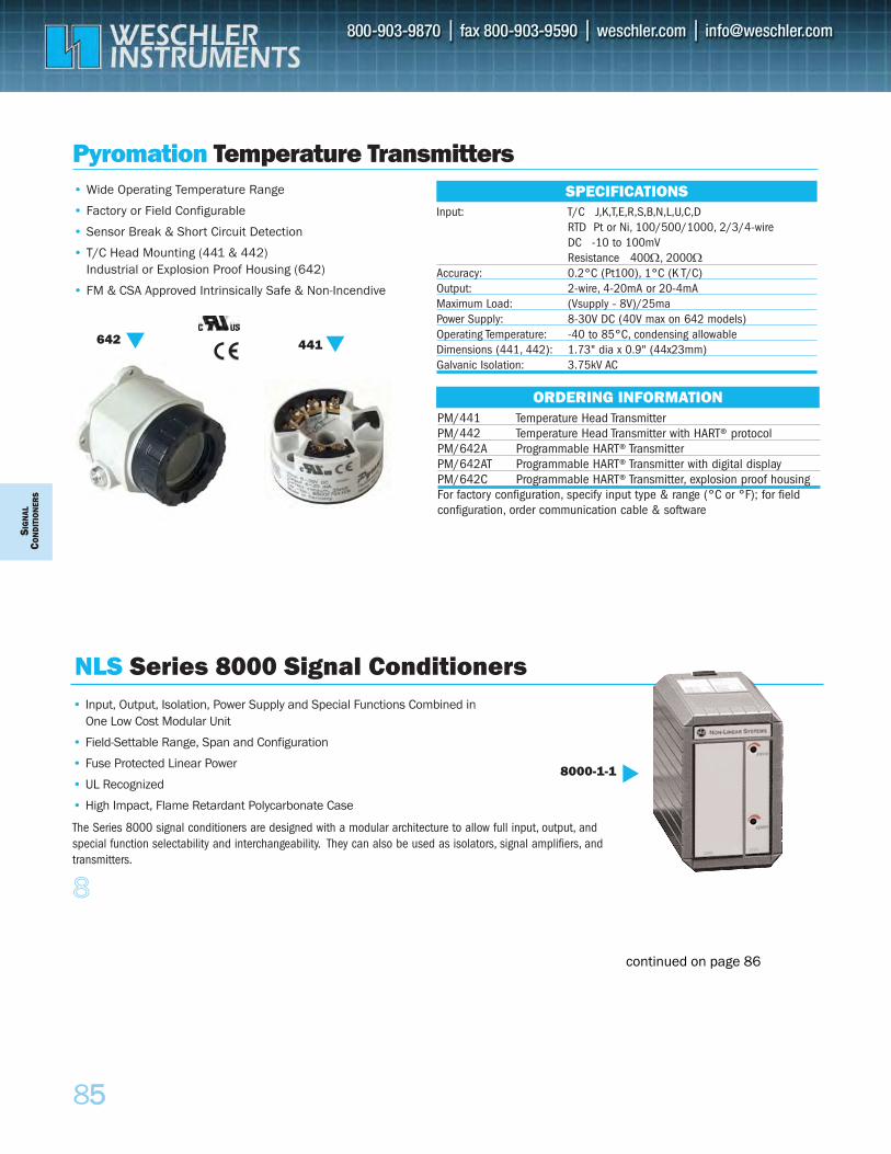
SIG
NAL
CON
DIT
ION
ERS
8
855
Pyromation Temperature Transmitters• Wide Operating Temperature Range
• Factory or Field Configurable
• Sensor Break & Short Circuit Detection
• T/C Head Mounting (441 & 442) Industrial or Explosion Proof Housing (642)
• FM & CSA Approved Intrinsically Safe & Non-Incendive
441
642
PM/441 Temperature Head Transmitter PM/442 Temperature Head Transmitter with HART® protocolPM/642A Programmable HART® Transmitter PM/642AT Programmable HART® Transmitter with digital displayPM/642C Programmable HART® Transmitter, explosion proof housingFor factory configuration, specify input type & range (°C or °F); for fieldconfiguration, order communication cable & software
ORDERING INFORMATION
Input: T/C J,K,T,E,R,S,B,N,L,U,C,DRTD Pt or Ni, 100/500/1000, 2/3/4-wire DC -10 to 100mVResistance 400Ω, 2000Ω
Accuracy: 0.2°C (Pt100), 1°C (K T/C)Output: 2-wire, 4-20mA or 20-4mAMaximum Load: (Vsupply - 8V)/25maPower Supply: 8-30V DC (40V max on 642 models)Operating Temperature: -40 to 85°C, condensing allowableDimensions (441, 442): 1.73" dia x 0.9" (44x23mm)Galvanic Isolation: 3.75kV AC
SPECIFICATIONS
• Input, Output, Isolation, Power Supply and Special Functions Combined in One Low Cost Modular Unit
• Field-Settable Range, Span and Configuration
• Fuse Protected Linear Power
• UL Recognized
• High Impact, Flame Retardant Polycarbonate Case
The Series 8000 signal conditioners are designed with a modular architecture to allow full input, output, andspecial function selectability and interchangeability. They can also be used as isolators, signal amplifiers, andtransmitters.
8000-1-1
NLS Series 8000 Signal Conditioners
continued on page 86
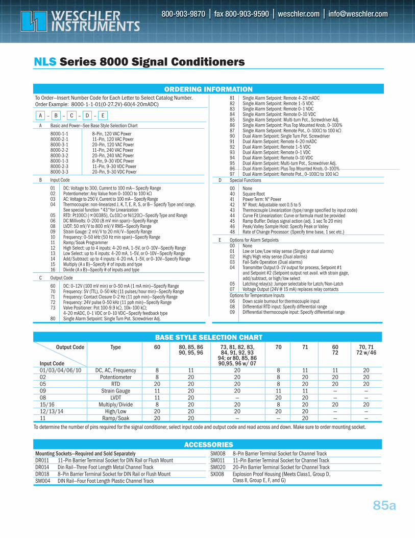
85a
A Basic and Power—See Base Style Selection Chart
8000-1-1 8–Pin, 120 VAC Power 8000-2-1 11–Pin, 120 VAC Power 8000-3-1 20–Pin, 120 VAC Power 8000-2-2 11–Pin, 240 VAC Power 8000-3-2 20–Pin, 240 VAC Power 8000-1-3 8–Pin, 9–30 VDC Power 8000-2-3 11–Pin, 9–30 VDC Power 8000-3-3 20–Pin, 9–30 VDC Power
B Input Code
01 DC: Voltage to 300, Current to 100 mA— Specify Range 02 Potentiometer: Any Value from 0–100Ω to 100 kΩ 03 AC: Voltage to 250 V, Current to 100 mA— Specify Range 04 Thermocouple: non-linearized J, K, T, E, R, S, or B— Specify Type and range.
See special function "43"for Linearization 05 RTD: Pt100Ω (∝00385), Cu10Ω or Ni120Ω—Specify Type and Range 06 DC Millivolts: 0–200 (8 mV min span)—Specify Range 08 LVDT: 50 mV/V to 800 mV/V RMS—Specify Range 09 Strain Gauge: 2 mV/V to 20 mV/V—Specify Range 10 Frequency: 0–50 kHz (50 Hz min span)—Specify Range 11 Ramp/Soak Programmer 12 High Select: up to 4 inputs: 4–20 mA, 1–5V, or 0–10V—Specify Range 13 Low Select: up to 4 inputs: 4–20 mA, 1–5V, or 0–10V—Specify Range 14 Add/Subtract: up to 4 inputs: 4–20 mA, 1–5V, or 0–10V—Specify Range 15 Multiply (A x B)—Specify # of inputs and type 16 Divide (A x B)—Specify # of inputs and type
C Output Code
60 DC: 0–12V (100 mV min) or 0–50 mA (1 mA min)—Specify Range 70 Frequency: 5V (TTL), 0–50 kHz (11 pulses/hour min)—Specify Range 71 Frequency: Contact Closure 0–2 Hz (11 pph min)—Specify Range 72 Frequency: 24V pulse 0–50 kHz (11 pph min)—Specify Range 73 Valve Positioner: Pot 100-9.9 kΩ, 10k–100 kΩ;
4–20 mADC, 0–1 VDC or 0–10 VDC—Specify feedback type 80 Single Alarm Setpoint: Single Turn Pot. Screwdriver Adj.
81 Single Alarm Setpoint: Remote 4–20 mADC 82 Single Alarm Setpoint: Remote 1–5 VDC 83 Single Alarm Setpoint: Remote 0–1 VDC 84 Single Alarm Setpoint: Remote 0–10 VDC 85 Single Alarm Setpoint: Multi-turn Pot., Screwdriver Adj. 86 Single Alarm Setpoint: Plus Top Mounted Knob, 0–100% 87 Single Alarm Setpoint: Remote Pot., 0–100Ω to 100 kΩ 90 Dual Alarm Setpoint: Single Turn Pot. Screwdriver 91 Dual Alarm Setpoint: Remote 4–20 mADC 92 Dual Alarm Setpoint: Remote 1–5 VDC 93 Dual Alarm Setpoint: Remote 0–1 VDC 94 Dual Alarm Setpoint: Remote 0–10 VDC 95 Dual Alarm Setpoint: Multi-turn Pot., Screwdriver Adj. 96 Dual Alarm Setpoint: Plus Top Mounted Knob, 0–100% 97 Dual Alarm Setpoint: Remote Pot., 0–100Ω to 100 kΩ
D Special Functions
00 None 40 Square Root 41 Power Term: Nth Power 42 Nth Root: Adjustable root 0.5 to 5 43 Thermocouple Linearization (type/range specified by input code) 44 Curve Fit Linearization: Curve or formula must be provided 45 Ramp Buffer: Delays signal action (adj. 1 sec To 20 min) 46 Peak/Valley Sample Hold: Specify Peak or Valley 48 Rate of Change Processor: (Specify time base, 1 sec etc.)
E Options for Alarm Setpoints00 None 01 Low or Low/Low relay sense (Single or dual alarms) 02 High/High relay sense (Dual alarms) 03 Fail-Safe Operation (Dual alarms) 04 Transmitter Output 0–1V output for process, Setpoint #1
and Setpoint #2 (Setpoint output not avail. with strain gage, add/subtract, or high/low select
05 Latching relay(s): Jumper selectable for Latch/Non-Latch 07 Voltage Output (24V @ 15 mA) replaces relay contacts Options for Temperature Inputs 06 Down scale burnout for thermocouple input 08 Differential RTD input: Specify differential range 09 Differential thermocouple input: Specify differential range
To Order—Insert Number Code for Each Letter to Select Catalog Number. Order Example: 8000-1-1-01(0-27.2V)-60(4-20mADC)
NLS Series 8000 Signal Conditioners
– D – EA – B – C
ORDERING INFORMATION
Mounting Sockets—Required and Sold SeparatelyDR011 11–Pin Barrier Terminal Socket for DIN Rail or Flush Mount DR014 Din Rail—Three Foot Length Metal Channel Track DR018 8–Pin Barrier Terminal Socket for DIN Rail or Flush Mount SM004 DIN Rail—Four Foot Length Plastic Channel Track
SM008 8–Pin Barrier Terminal Socket for Channel Track SM011 11–Pin Barrier Terminal Socket for Channel Track SM020 20–Pin Barrier Terminal Socket for Channel Track SX008 Explosion Proof Housing (Meets Class1, Group D,
Class II, Group E, F, and G)
ACCESSORIES
To determine the number of pins required for the signal conditioner, select input code and output code and read across and down. Make sure to order mounting socket.
BASE STYLE SELECTION CHARTOutput Code Type 60 80, 85, 86 73, 81, 82, 83, 70 71 60 70, 71
90, 95, 96 84, 91, 92, 93 72 72 w/4694; or 80, 85, 86
Input Code 90,95, 96 w/ 0701/03/04/06/10 DC, AC, Frequency 8 11 20 8 11 11 2002 Potentiometer 8 20 20 8 20 20 2005 RTD 20 20 20 8 20 20 2009 Strain Gauge 11 20 20 11 11 — —08 LVDT 11 20 — 20 20 — —15/16 Multiply/Divide 8 20 20 8 20 20 2012/13/14 High/Low 20 20 20 20 20 — —11 Ramp/Soak 20 20 — — 20 — —
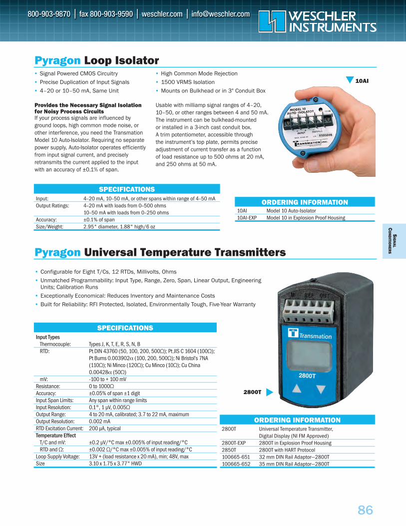
SIG
NAL
CO
ND
ITION
ERS
86
10AI Model 10 Auto-Isolator10AI-EXP Model 10 in Explosion Proof Housing
SPECIFICATIONS
ORDERING INFORMATION
Pyragon Loop Isolator• Signal Powered CMOS Circuitry
• Precise Duplication of Input Signals
• 4–20 or 10–50 mA, Same Unit
• High Common Mode Rejection
• 1500 VRMS Isolation
• Mounts on Bulkhead or in 3" Conduit Box
Provides the Necessary Signal Isolationfor Noisy Process CircuitsIf your process signals are influenced byground loops, high common mode noise, orother interference, you need the TransmationModel 10 Auto-Isolator. Requiring no separatepower supply, Auto-Isolator operates efficientlyfrom input signal current, and preciselyretransmits the current applied to the inputwith an accuracy of ±0.1% of span.
Usable with milliamp signal ranges of 4–20,10–50, or other ranges between 4 and 50 mA. The instrument can be bulkhead-mounted or installed in a 3-inch cast conduit box. A trim potentiometer, accessible through the instrument’s top plate, permits preciseadjustment of current transfer as a function of load resistance up to 500 ohms at 20 mA,and 250 ohms at 50 mA.
Input: 4–20 mA, 10–50 mA, or other spans within range of 4–50 mAOutput Ratings: 4–20 mA with loads from 0–500 ohms
10–50 mA with loads from 0–250 ohmsAccuracy: ±0.1% of spanSize/Weight: 2.95" diameter, 1.88" high/6 oz
10AI
2800T Universal Temperature Transmitter, Digital Display (NI FM Approved)
2800T-EXP 2800T in Explosion Proof Housing2850T 2800T with HART Protocol100665-651 32 mm DIN Rail Adaptor—2800T100665-652 35 mm DIN Rail Adaptor—2800T
ORDERING INFORMATION
• Configurable for Eight T/Cs, 12 RTDs, Millivolts, Ohms
• Unmatched Programmability: Input Type, Range, Zero, Span, Linear Output, EngineeringUnits; Calibration Runs
• Exceptionally Economical: Reduces Inventory and Maintenance Costs
• Built for Reliability: RFI Protected, Isolated, Environmentally Tough, Five-Year Warranty
SPECIFICATIONSInput Types
Thermocouple: Types J, K, T, E, R, S, N, BRTD: Pt DIN 43760 (50, 100, 200, 500Ω); Pt JIS C 1604 (100Ω);
Pt Burns 0.003902α (100, 200, 500Ω); Ni Bristol’s 7NA(110Ω); Ni Minco (120Ω); Cu Minco (10Ω); Cu China0.00428α (50Ω)
mV: -100 to + 100 mVResistance: 0 to 1000Ω Accuracy: ±0.05% of span ±1 digitInput Span Limits: Any span within range limitsInput Resolution: 0.1°, 1 µV, 0.005ΩOutput Range: 4 to 20 mA, calibrated; 3.7 to 22 mA, maximumOutput Resolution: 0.002 mARTD Excitation Current: 200 µA, typicalTemperature Effect
T/C and mV: ±0.2 µV/°C max ±0.005% of input reading/°CRTD and Ω: ±0.002 Ω/°C max ±0.005% of input reading/°C
Loop Supply Voltage: 13V + (load resistance x 20 mA), min; 48V, maxSize 3.10 x 1.75 x 3.77" HWD
Pyragon Universal Temperature Transmitters
2800T
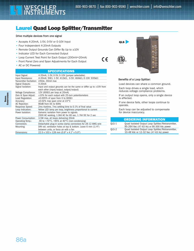
SIG
NAL
CON
DIT
ION
ERS
8866aa
Laurel Quad Loop Splitter/Transmitter
• Accepts 4-20mA, 1-5V, 0-5V or 0-10V Input • Four Independent 4-20mA Outputs• Remote Output Grounds Can Differ By Up to ±10V • Indicator LED for Each Connected Output• Loop Current Test Point for Each Output (200mV=20mA)• Front Panel Zero and Span Adjustments for Each Output • AC or DC Powered
QLS
Input Signal: 4-20mA, 1-5V, 0-5V, 0-10V (jumper selectable)Input Resistance: 4-20mA: 50Ω, 1-5V: 412kΩ, 0-5V: 464kΩ, 0-10V: 935kΩTransmitter Excitation: 24Vdc, 30mA maxSignal Outputs: 4-20mASignal Isolation: Input and output grounds can be the same or differ up to ±10V from
each other (input/output, output/output)Voltage Compliance: 12V (600Ω per loop at 20mA)Zero & Span Adjust: ±10% for each output with 25-turn potentiometersLoad Regulation: ±0.005% of span from 0 to 600ΩAccuracy: ±0.02% max span error at 23°CAC Rejection: 90dB from DC to 60HzResponse Speed: 2ms risetime, 7ms settling time to 0.1% of final valueLoop Indication: Yellow LED lamp per loop, brightness proportional to currentPower Isolation: Galvanic isolation from power to signals.
250V AC working, 1.0kV AC for 60 sec, 1.7kV DC for 2 secPower Consumption: 3.5W max, all loops delivering 20mAOperating Temp.: -40 to +70°C, <95% at 40°C (non-condensing)Connectors: Detachable plug-in screw-clamp connectors for 28-12 AWG wireMounting: DIN rail, ventilaton holes at top & bottom. Leave 6 mm (1/4")
between units, or force air with a fanDimensions: 22.5 x 103 x 128 mm (0.9" x 4.1" x 5.0")
SPECIFICATIONS
QLS-1 Quad Isolated Output Loop Splitter/Retransmitter,95-264 Vac (47-63 Hz) or 90-300 Vdc power
QLS-2 Quad Isolated Output Loop Splitter/Retransmitter,10-48 Vdc or 12-32 Vac (47-63 Hz) power
ORDERING INFORMATION
DDrriivvee mmuullttiippllee ddeevviicceess ffrroomm oonnee ssiiggnnaall
Load devices can share a common ground.
Each loop drives a single load, whichreduces voltage compliance problems.
If an output loop opens, only a single deviceis affected.
If one device fails, other loops continue tooperate.
Each loop can be adjusted to compensatefor device inaccuracy.
BBeenneeffiittss ooff aa LLoooopp SSpplliitttteerr::
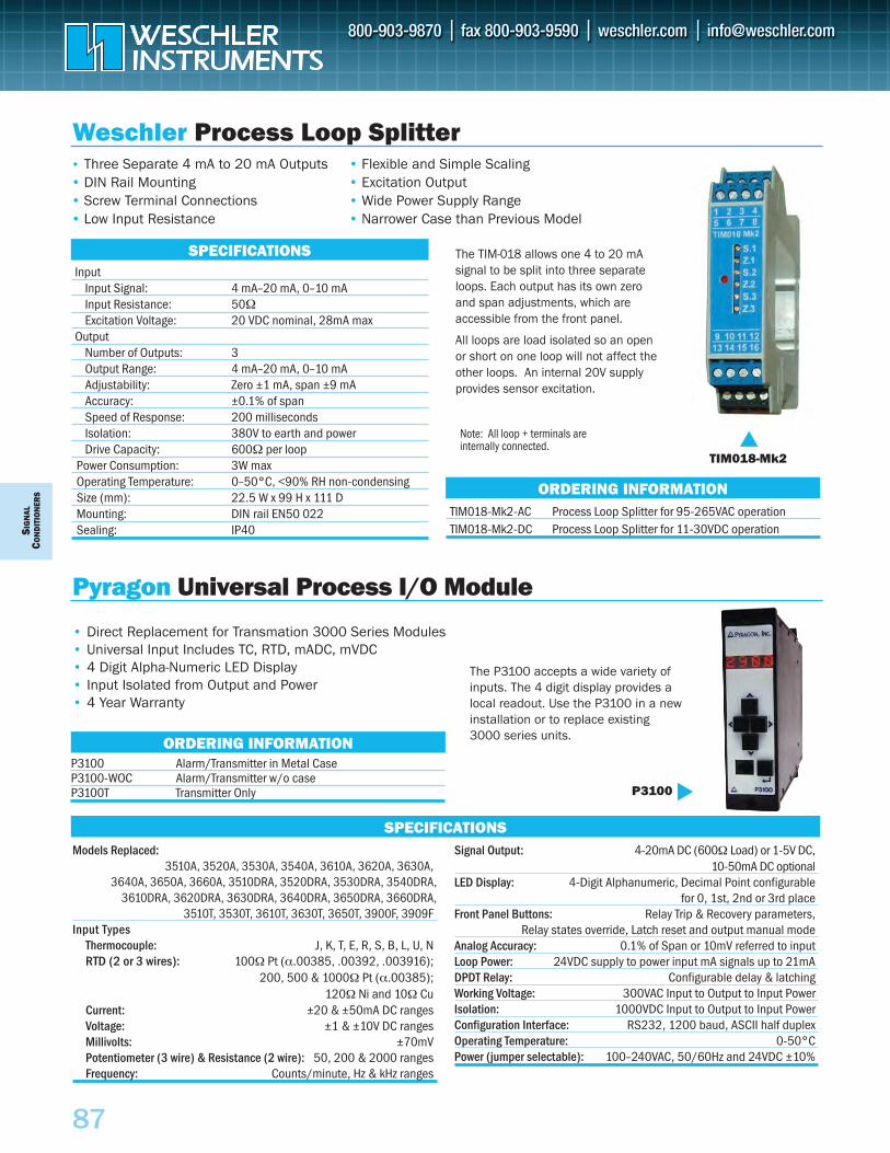
SIG
NAL
CON
DIT
ION
ERS
87
TIM018-Mk2-AC Process Loop Splitter for 95-265VAC operationTIM018-Mk2-DC Process Loop Splitter for 11-30VDC operation
SPECIFICATIONS
Weschler Process Loop Splitter• Three Separate 4 mA to 20 mA Outputs• DIN Rail Mounting• Screw Terminal Connections• Low Input Resistance
• Flexible and Simple Scaling• Excitation Output• Wide Power Supply Range• Narrower Case than Previous Model
TIM018-Mk2
InputInput Signal: 4 mA–20 mA, 0–10 mAInput Resistance: 50ΩExcitation Voltage: 20 VDC nominal, 28mA max
OutputNumber of Outputs: 3Output Range: 4 mA–20 mA, 0–10 mAAdjustability: Zero ±1 mA, span ±9 mAAccuracy: ±0.1% of spanSpeed of Response: 200 millisecondsIsolation: 380V to earth and powerDrive Capacity: 600Ω per loop
Power Consumption: 3W maxOperating Temperature: 0–50°C, <90% RH non-condensingSize (mm): 22.5 W x 99 H x 111 D Mounting: DIN rail EN50 022Sealing: IP40
The TIM-018 allows one 4 to 20 mAsignal to be split into three separateloops. Each output has its own zeroand span adjustments, which areaccessible from the front panel.
All loops are load isolated so an openor short on one loop will not affect theother loops. An internal 20V supplyprovides sensor excitation.
ORDERING INFORMATION
Models Replaced: 3510A, 3520A, 3530A, 3540A, 3610A, 3620A, 3630A,
3640A, 3650A, 3660A, 3510DRA, 3520DRA, 3530DRA, 3540DRA,3610DRA, 3620DRA, 3630DRA, 3640DRA, 3650DRA, 3660DRA,
3510T, 3530T, 3610T, 3630T, 3650T, 3900F, 3909FInput Types
Thermocouple: J, K, T, E, R, S, B, L, U, N RTD (2 or 3 wires): 100Ω Pt (α.00385, .00392, .003916);
200, 500 & 1000Ω Pt (α.00385); 120Ω Ni and 10Ω Cu
Current: ±20 & ±50mA DC rangesVoltage: ±1 & ±10V DC rangesMillivolts: ±70mVPotentiometer (3 wire) & Resistance (2 wire): 50, 200 & 2000 rangesFrequency: Counts/minute, Hz & kHz ranges
Signal Output: 4-20mA DC (600Ω Load) or 1-5V DC, 10-50mA DC optional
LED Display: 4-Digit Alphanumeric, Decimal Point configurable for 0, 1st, 2nd or 3rd place
Front Panel Buttons: Relay Trip & Recovery parameters, Relay states override, Latch reset and output manual mode
Analog Accuracy: 0.1% of Span or 10mV referred to input Loop Power: 24VDC supply to power input mA signals up to 21mADPDT Relay: Configurable delay & latchingWorking Voltage: 300VAC Input to Output to Input PowerIsolation: 1000VDC Input to Output to Input PowerConfiguration Interface: RS232, 1200 baud, ASCII half duplexOperating Temperature: 0-50°C Power (jumper selectable): 100–240VAC, 50/60Hz and 24VDC ±10%
• Direct Replacement for Transmation 3000 Series Modules• Universal Input Includes TC, RTD, mADC, mVDC• 4 Digit Alpha-Numeric LED Display• Input Isolated from Output and Power• 4 Year Warranty
SPECIFICATIONS
P3100 Alarm/Transmitter in Metal CaseP3100-WOC Alarm/Transmitter w/o caseP3100T Transmitter Only
ORDERING INFORMATION
The P3100 accepts a wide variety ofinputs. The 4 digit display provides alocal readout. Use the P3100 in a newinstallation or to replace existing3000 series units.
P3100
Pyragon Universal Process I/O Module
Note: All loop + terminals areinternally connected.
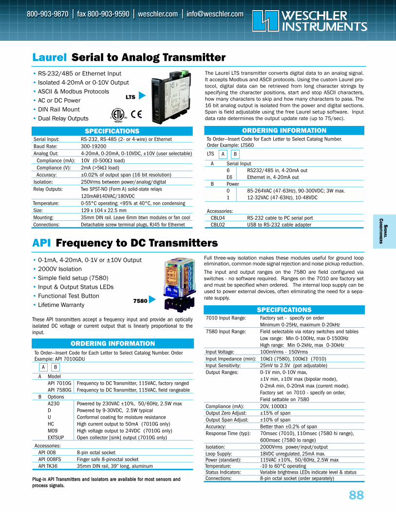
To Order—Insert Code for Each Letter to Select Catalog Number.Order Example: LTS60
A Serial Input6 RS232/485 in, 4-20mA outE6 Ethernet in, 4-20mA out
B Power0 85-264VAC (47-63Hz), 90-300VDC; 3W max.1 12-32VAC (47-63Hz), 10-48VDC
Accessories:CBL04 RS-232 cable to PC serial port CBL02 USB to RS-232 cable adapter
To Order—Insert Code for Each Letter to Select Catalog Number. Order Example: API 7010GDU
A ModelAPI 7010G Frequency to DC Transmitter, 115VAC, factory rangedAPI 7580G Frequency to DC Transmitter, 115VAC, field rangeable
B OptionsA230 Powered by 230VAC ±10%, 50/60Hz, 2.5W maxD Powered by 9-30VDC, 2.5W typicalU Conformal coating for moisture resistanceHC High current output to 50mA (7010G only) M09 High voltage output to 24VDC (7010G only)EXTSUP Open collector [sink] output (7010G only)
Accessories:API 008 8-pin octal socketAPI 008FS Finger safe 8-pinoctal socketAPI TK36 35mm DIN rail, 39” long, aluminum
• RS-232/485 or Ethernet Input• Isolated 4-20mA or 0-10V Output• ASCII & Modbus Protocols• AC or DC Power• DIN Rail Mount• Dual Relay Outputs
LTS A B
SPECIFICATIONS
• 0-1mA, 4-20mA, 0-1V or ±10V Output• 2000V Isolation • Simple field setup (7580)• Input & Output Status LEDs• Functional Test Button• Lifetime Warranty
Laurel Serial to Analog Transmitter
ORDERING INFORMATION
API Frequency to DC Transmitters
Serial Input: RS-232, RS-485 (2- or 4-wire) or Ethernet Baud Rate: 300-19200Analog Out: 4-20mA, 0-20mA, 0-10VDC, ±10V (user selectable)
Compliance (mA): 10V (0-500Ω load)Compliance (V): 2mA (>5kΩ load)Accuracy: ±0.02% of output span (16 bit resolution)
Isolation: 250Vrms between power/analog/digitalRelay Outputs: Two SPST-NO (Form A) solid-state relays
120mA@140VAC/180VDCTemperature: 0-55°C operating; <95% at 40°C, non condensingSize: 129 x 104 x 22.5 mmMounting: 35mm DIN rail. Leave 6mm btwn modules or fan coolConnections: Detachable screw terminal plugs, RJ45 for Ethernet
SPECIFICATIONS7010 Input Range: Factory set - specify on order
Minimum 0-25Hz, maximum 0-20kHz7580 Input Range: Field selectable via rotary switches and tables
Low range: Min 0-100Hz, max 0-1500HzHigh range: Min 0-2kHz, max 0-30kHz
Input Voltage: 100mVrms - 150VrmsInput Impedance (min): 10kΩ (7580), 100kΩ (7010)Input Sensitivity: 25mV to 2.5V (pot adjustable)Output Ranges: 0-1V min, 0-10V max,
±1V min, ±10V max (bipolar mode),0-2mA min, 0-20mA max (current mode).Factory set on 7010 - specify on order,Field settable on 7580
Compliance (mA): 20V, 1000ΩOutput Zero Adjust: ±15% of spanOutput Span Adjust: ±10% of spanAccuracy: Better than ±0.2% of spanResponse Time (typ): 70msec (7010), 110msec (7580 hi range),
600msec (7580 lo range)Isolation: 2000Vrms power/input/outputLoop Supply: 18VDC unregulated, 25mA max.Power (standard): 115VAC ±10%, 50/60Hz, 2.5W maxTemperature: -10 to 60°C operatingStatus Indicators: Variable brightness LEDs indicate level & statusConnections: 8-pin octal socket (order separately)
LTS
7580
The Laurel LTS transmitter converts digital data to an analog signal.It accepts Modbus and ASCII protocols. Using the custom Laurel pro-tocol, digital data can be retrieved from long character strings byspecifying the character positions, start and stop ASCII characters,how many characters to skip and how many characters to pass. The16 bit analog output is isolated from the power and digital sections.Span is field adjustable using the free Laurel setup software. Inputdata rate determines the output update rate (up to 75/sec).
ORDERING INFORMATION
Full three-way isolation makes these modules useful for ground loopelimination, common mode signal rejection and noise pickup reduction.
The input and output ranges on the 7580 are field configured viaswitches - no software required. Ranges on the 7010 are factory setand must be specified when ordered. The internal loop supply can beused to power external devices, often eliminating the need for a sepa-rate supply.
A B
These API transmitters accept a frequency input and provide an opticallyisolated DC voltage or current output that is linearly proportional to theinput.
PpPlluugg--iinn AAPPII TTrraannssmmiitttteerrss aanndd IIssoollaattoorrss aarree aavvaaiillaabbllee ffoorr mmoosstt sseennssoorrss aannddprroocceessss ssiiggnnaallss..
SIG
NAL
CO
ND
ITION
ERS
88
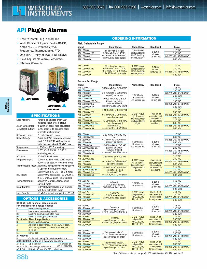
MMooddeell IInnppuutt RRaannggee AAllaarrmm RReellaayy DDeeaaddbbaanndd PPoowweerrAPI 1000 G 115 VACAPI 1000 G A230 230 VACAPI 1000 G P 80-265 VAC, 48-300 VDCAPI 1000 G D 9-30 VDCAPI 1000 G 5A 115 VACAPI 1000 G A230 5A 230 VACAPI 1000 G P 5A 80-265 VAC, 48-300 VDCAPI 1000 G D 5A 9-30 VDCAPI 1020 G 115 VACAPI 1020 G A230 230 VACAPI 1020 G P 80-265 VAC, 48-300 VDCAPI 1020 G D 9-30 VDCAPI 1020 G 5A 115 VACAPI 1020 G A230 5A 230 VACAPI 1020 G P 5A 80-265 VAC, 48-300 VDCAPI 1020 G D 5A 9-30 VDC
SIG
NAL
CON
DIT
ION
ERS
8888bb
API Plug-In Alarms
API1600
LoopTracker®: Variable brightness green LED indicates input level & status
Alarm Setpoint(s): 0-100% of span, field adjustable Test/Reset Button: Toggle relay(s) to opposite state
or resets latching relay Response Time: 70 milliseconds typicalRelay Ratings: 7 A @ 240 VAC maximum resistive
load, 3.5 A @ 240 VAC maximum inductive load, 8 A @ 30 VDC max.
Temperature: -10°C to +60°C operatingDimensions: 1.75" W x 2.75" H x 2.38" D
(excluding socket)AC Input: 40-1000 Hz sinusoidFrequency Input: 100 mV to 150 Vrms, 10kΩ input Z,
600V DC or peak AC common modeThermocouple Input: Automatic cold junction compensation
& upscale burnout protection.Specify Type J, K, T, E, R or S & range
RTD Input: Specify 0°C resistance (10-2000Ω),2- or 3-wire, & alpha (385 typical).
Thermistor Input: Specify PTC or NTC, temperature curve & range
Input Burden: 1.0 VDC typical @20mA on models with field selectable range
Loop Supply: 18 VDC nominal, unregulated, 25 mA
SPECIFICATIONS
• Easy-to-install Plug-in Modules• Wide Choice of Inputs: Volts AC/DC,
Amps AC/DC, Process V/mA, Frequency, Thermocouple, RTD
• One DPDT Relay or Two SPDT Relays• Field Adjustable Alarm Setpoint(s)• Lifetime Warranty
API1080with API011
ORDERING INFORMATION
OFOPPTTIIOONNSS——aadddd ttoo eenndd ooff mmooddeell nnuummbbeerr Foorr UUnnsshhaaddeedd FFiixxeedd RRaannggee MMooddeellss::R Reverse-acting alarmsL Low trip (on decreasing signal) HT Latching alarm, push button reset HP Latching alarm, power-off resetFFoorr SShhaaddeedd FFiixxeedd RRaannggee MMooddeellss:: R Reverse-acting alarmsA Adjustable deadbands, 1% to 100% of span,
adjusted symmetrically about each setpointHH HI/HI trip LL LO/LO tripAAllll MMooddeellss::U A
Conformal coating for moisture resistance ACCCCEESSSSOORRIIEESS——oorrddeerr aass aa sseeppaarraattee lliinnee iitteemm API 011 11-pin socket API 011 FS 11-pin finger safe socket API TK36 DIN rail, 35 mm W x 39" L, aluminum
OPTIONS & ACCESSORIES
Fixed 1% of span, standard.
See optionsfor adjustable
deadband>0-900 mADC to 0-5 ADC
(specify on order)Includes API 011
socket w/0.1Ω 25W shunt
1 DPDT relayHI alarm std.
See options list.
1-100%of span,
12 turn pot
0-100 mVDC to 0-300 VDCor
0-1 mADC to 0-900 mADC(specify on order)
0-100 mVDC to 0-300 VDCor
0-1 mADC to 0-900 mADC(specify on order)
2 SPDT relaysHI/LO alarms,internal jumperconfigurable for
LO/HI.
>0-900 mADC to 0-5 ADC(specify on order)Includes API 011
socket w/0.1Ω 25W shunt
MMooddeell IInnppuutt RRaannggee AAllaarrmm RReellaayy DDeeaaddbbaanndd PPoowweerrAPI 1080 G 115 VACAPI 1080 G A230 230 VACAPI 1080 G P 80-265 VAC, 48-300 VDCAPI 1080 G D 9-30 VDC
API 1090 G 115 VACAPI 1090 G A230 230 VACAPI 1090 G P 80-265 VAC, 48-300 VDCAPI 1090 G D 9-30 VDC
1-100%of span,
12 turn pots
1 DPDT relayconfigurable forHI/LO, latching,normal/reverse
1-100%of span,
12 turn pot
24 selectable ranges,0-50 mVDC to ±10 VDC,
0-1 mADC to 4-20 mADC,18V @25mA loop supply
26 selectable ranges,0-50 mVDC to ±10 VDC,
0-1 mADC to 4-20 mADC,18V @25mA loop supply
2 SPDT relaysconfigurable forHI/LO, latching,normal/reverse
API 1600 G 115 VACAPI 1600 G A230 230 VACAPI 1600 G P 80-265 VAC, 48-300 VDCAPI 1600 G D 9-30 VDCAPI 1600 G 5A 115 VACAPI 1600 G A230 5A 230 VACAPI 1600 G P 5A 80-265 VAC, 48-300 VDCAPI 1600 G D 5A 9-30 VDCAPI 1620 G 115 VACAPI 1620 G A230 230 VACAPI 1620 G P 80-265 VAC, 48-300 VDCAPI 1620 G D 9-30 VDCAPI 1620 G 5A 115 VACAPI 1620 G A230 5A 230 VACAPI 1620 G P 5A 80-265 VAC, 48-300 VDCAPI 1620 G D 5A 9-30 VDC
Fixed 1% of span, standard.
See optionsfor adjustable
deadband>0-900 mAAC to 0-5 AAC
(specify on order)Includes API 011
socket w/0.1Ω 25W shunt
1 DPDT relayHI alarm std.
See options list.
1-100%of span,
12 turn pot
0-50 mVAC to 0-300 VACor
0-1 mAAC to 0-900 mAAC(specify on order)
0-50 mVAC to 0-300 VACor
0-1 mAAC to 0-900 mAAC(specify on order)
2 SPDT relaysHI/LO alarms,internal jumperconfigurable for
LO/HI.
>0-900 mAAC to 0-5 AAC(specify on order)Includes API 011
socket w/0.1Ω 25W shunt
API 1200 G 115 VACAPI 1200 G A230 230 VACAPI 1200 G P 80-265 VAC, 48-300 VDCAPI 1200 G D 9-30 VDCAPI 1220 G 115 VACAPI 1220 G A230 230 VACAPI 1220 G P 80-265 VAC, 48-300 VDCAPI 1220 G D 9-30 VDC
Fixed 1% of span, standard.
See optionsfor adjustable.
1 DPDT relayHI alarm std.
1-100%of span,
12 turn pot
Thermocouple type*,°C or °F temperature range
(specify range on order)
Thermocouple type*,°C or °F temperature range
(specify range on order)
2 SPDT relaysconfigurable forHI/LO, LO/HI,LO/LO, HI/HI
API 1700 G 115 VACAPI 1700 G A230 230 VACAPI 1700 G P 80-265 VAC, 48-300 VDCAPI 1700 G D 9-30 VDCAPI 1720 G 115 VACAPI 1720 G A230 230 VACAPI 1720 G P 80-265 VAC, 48-300 VDCAPI 1720 G D 9-30 VDC
Fixed 1% of span, standard.
See optionsfor adjustable.
1 DPDT relayHI alarm std.
1-100%of span,
12 turn pot
Frequency,(specify range on order)
Min: 0-10Hz, Max: 0-20kHz
Frequency,(specify range on order)
Min: 0-10Hz, Max: 0-20kHz
2 SPDT relaysconfigurable forHI/LO, LO/HI,LO/LO, HI/HI
API 1005 G 115 VACAPI 1005 G A230 230 VACAPI 1005 G P 80-265 VAC, 48-300 VDCAPI 1005 G D 9-30 VDCAPI 1025 G 115 VACAPI 1025 G A230 230 VACAPI 1025 G P 80-265 VAC, 48-300 VDCAPI 1025 G D 9-30 VDC
Fixed 1% of span, standard.
See optionsfor adjustable.
1 DPDT relayHI alarm std.
1-100%of span,
12 turn pot
4-20 mA,1.25VDC max burden,
18V @25mA loop supply
4-20 mA,1.25VDC max burden,
18V @25mA loop supply
2 SPDT relaysconfigurable forHI/LO, LO/HI,LO/LO, HI/HI
*For RTD/thermistor input, change API1200 to API1400 or API1220 to API1420
FFiieelldd SSeelleeccttaabbllee RRaannggee::
FFaaccttoorryy SSeett RRaannggee::
For chassis or DIN rail mounting
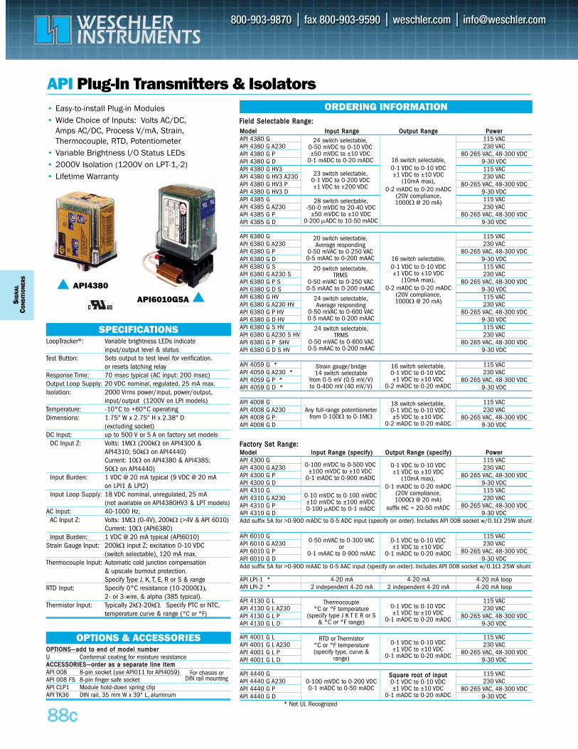
MMooddeell IInnppuutt RRaannggee ((ssppeecciiffyy)) OOuuttppuutt RRaannggee ((ssppeecciiffyy)) PPoowweerrAPI 4300 G 115 VACAPI 4300 G A230 230 VACAPI 4300 G P 80-265 VAC, 48-300 VDCAPI 4300 G D 9-30 VDCAPI 4310 G 115 VACAPI 4310 G A230 230 VACAPI 4310 G P 80-265 VAC, 48-300 VDCAPI 4310 G D 9-30 VDCAdd suffix 5A for >0-900 mADC to 0-5 ADC input (specify on order). Includes API 008 socket w/0.1Ω 25W shunt
SIG
NAL
CON
DIT
ION
ERS
8888cc
API Plug-In Transmitters & Isolators
API4380
LoopTracker®: Variable brightness LEDs indicateinput/output level & status
Test Button: Sets output to test level for verification.or resets latching relay
Response Time: 70 msec typical (AC input: 200 msec)Output Loop Supply: 20 VDC nominal, regulated, 25 mA max.Isolation: 2000 Vrms power/input, power/output,
input/output (1200V on LPI models)Temperature: -10°C to +60°C operatingDimensions: 1.75" W x 2.75" H x 2.38" D
(excluding socket)DC Input: up to 500 V or 5 A on factory set models
DC Input Z: Volts: 1MΩ (200kΩ on API4300 & API4310; 50kΩ on API4440)Current: 10Ω on API4380 & API4385; 50Ω on API4440)
Input Burden: 1 VDC @ 20 mA typical (9 VDC @ 20 mAon LPI1 & LPI2)
Input Loop Supply: 18 VDC nominal, unregulated, 25 mA(not available on API4380HV3 & LPT models)
AC Input: 40-1000 Hz,AC Input Z: Volts: 1MΩ (0-4V), 200kΩ (>4V & API 6010)
Current: 10Ω (API6380) Input Burden: 1 VDC @ 20 mA typical (API6010)
Strain Gauge Input: 200kΩ input Z; excitation 0-10 VDC (switch selectable), 120 mA max.
Thermocouple Input: Automatic cold junction compensation & upscale burnout protection.Specify Type J, K, T, E, R or S & range
RTD Input: Specify 0°C resistance (10-2000Ω),2- or 3-wire, & alpha (385 typical).
Thermistor Input: Typically 2kΩ-20kΩ. Specify PTC or NTC,temperature curve & range (°C or °F)
SPECIFICATIONS
• Easy-to-install Plug-in Modules• Wide Choice of Inputs: Volts AC/DC,
Amps AC/DC, Process V/mA, Strain,Thermocouple, RTD, Potentiometer
• Variable Brightness I/O Status LEDs• 2000V Isolation (1200V on LPT-1,-2)• Lifetime Warranty
ORDERING INFORMATION
OOPPTTIIOONNSS——aadddd ttoo eenndd ooff mmooddeell nnuummbbeerr U Conformal coating for moisture resistance AACCCCEESSSSOORRIIEESS——oorrddeerr aass aa sseeppaarraattee lliinnee iitteemm API 008 8-pin socket (use API011 for API4059)API 008 FS 8-pin finger safe socketAPI CLP1 Module hold-down spring clip API TK36 DIN rail, 35 mm W x 39" L, aluminum
OPTIONS & ACCESSORIES
0-100 mVDC to 0-500 VDC±100 mVDC to ±10 VDC
0-1 mADC to 0-900 mADC
0-10 mVDC to 0-100 mVDC±10 mVDC to ±100 mVDC0-100 μADC to 0-1 mADC
0-1 VDC to 0-10 VDC±1 VDC to ±10 VDC
(10mA max),0-1 mADC to 0-20 mADC
(20V compliance,1000Ω @ 20 mA)
suffix HC = 20-50 mADC
MMooddeell IInnppuutt RRaannggee OOuuttppuutt RRaannggee PPoowweerrAPI 4380 G 115 VACAPI 4380 G A230 230 VACAPI 4380 G P 80-265 VAC, 48-300 VDCAPI 4380 G D 9-30 VDCAPI 4380 G HV3 115 VACAPI 4380 G HV3 A230 230 VACAPI 4380 G HV3 P 80-265 VAC, 48-300 VDCAPI 4380 G HV3 D 9-30 VDCAPI 4385 G 115 VACAPI 4385 G A230 230 VACAPI 4385 G P 80-265 VAC, 48-300 VDCAPI 4385 G D 9-30 VDC
24 switch selectable,0-50 mVDC to 0-10 VDC±50 mVDC to ±10 VDC
0-1 mADC to 0-20 mADC
23 switch selectable,0-1 VDC to 0-200 VDC±1 VDC to ±200 VDC
16 switch selectable,0-1 VDC to 0-10 VDC±1 VDC to ±10 VDC
(10mA max),0-2 mADC to 0-20 mADC
(20V compliance,1000Ω @ 20 mA)
API 6010 G 115 VACAPI 6010 G A230 230 VACAPI 6010 G P 80-265 VAC, 48-300 VDCAPI 6010 G D 9-30 VDCAdd suffix 5A for >0-900 mAAC to 0-5 AAC input (specify on order). Includes API 008 socket w/0.1Ω 25W shunt
0-1 VDC to 0-10 VDC±1 VDC to ±10 VDC
0-1 mADC to 0-20 mADC
0-50 mVAC to 0-300 VACor
0-1 mAAC to 0-900 mAAC
API 4130 G L 115 VACAPI 4130 G L A230 230 VACAPI 4130 G L P 80-265 VAC, 48-300 VDCAPI 4130 G L D 9-30 VDC
0-1 VDC to 0-10 VDC±1 VDC to ±10 VDC
0-1 mADC to 0-20 mADC
Thermocouple °C or °F temperature
(specify type J K T E R or S& °C or °F range)
API 4001 G L 115 VACAPI 4001 G L A230 230 VACAPI 4001 G L P 80-265 VAC, 48-300 VDCAPI 4001 G L D 9-30 VDC
0-1 VDC to 0-10 VDC±1 VDC to ±10 VDC
0-1 mADC to 0-20 mADC
RTD or Thermistor°C or °F temperature (specify type, curve &
range)
API 4440 G 115 VACAPI 4440 G A230 230 VACAPI 4440 G P 80-265 VAC, 48-300 VDCAPI 4440 G D 9-30 VDC
* Not UL Recognized
SSqquuaarree rroooott ooff iinnppuutt0-1 VDC to 0-10 VDC±1 VDC to ±10 VDC
0-1 mADC to 0-20 mADC
0-100 mVDC to 0-200 VDC0-1 mADC to 0-50 mADC
API 4008 G 115 VACAPI 4008 G A230 230 VACAPI 4008 G P 80-265 VAC, 48-300 VDCAPI 4008 G D 9-30 VDC
18 switch selectable,0-1 VDC to 0-10 VDC±5 VDC to ±10 VDC
0-2 mADC to 0-20 mADC
Any full-range potentiometerfrom 0-100Ω to 0-1MΩ
API 4059 G * 115 VACAPI 4059 G A230 * 230 VACAPI 4059 G P * 80-265 VAC, 48-300 VDCAPI 4059 G D * 9-30 VDC
16 switch selectable,0-1 VDC to 0-10 VDC±1 VDC to ±10 VDC
0-2 mADC to 0-20 mADC
Strain gauge/bridge14 switch selectable
from 0-5 mV (0.5 mV/V)to 0-400 mV (40 mV/V)
API LPI-1 * 4-20 mA 4-20 mA 4-20 mA loopAPI LPI-2 * 2 independent 4-20 mA 2 independent 4-20 mA 4-20 mA loop
FFiieelldd SSeelleeccttaabbllee RRaannggee::
FFaaccttoorryy SSeett RRaannggee::
28 switch selectable,-50-0 mVDC to 20-40 VDC
±50 mVDC to ±10 VDC0-200 μADC to 10-50 mADC
API 6380 G 115 VACAPI 6380 G A230 230 VACAPI 6380 G P 80-265 VAC, 48-300 VDCAPI 6380 G D 9-30 VDCAPI 6380 G S 115 VACAPI 6380 G A230 S 230 VACAPI 6380 G P S 80-265 VAC, 48-300 VDCAPI 6380 G D S 9-30 VDCAPI 6380 G HV 115 VACAPI 6380 G A230 HV 230 VACAPI 6380 G P HV 80-265 VAC, 48-300 VDCAPI 6380 G D HV 9-30 VDCAPI 6380 G S HV 115 VACAPI 6380 G A230 S HV 230 VACAPI 6380 G P SHV 80-265 VAC, 48-300 VDCAPI 6380 G D S HV 9-30 VDC
20 switch selectable,Average responding
0-50 mVAC to 0-250 VAC0-5 mAAC to 0-200 mAAC
20 switch selectable,TRMS
0-50 mVAC to 0-250 VAC0-5 mAAC to 0-200 mAAC
16 switch selectable,0-1 VDC to 0-10 VDC±1 VDC to ±10 VDC
(10mA max),0-2 mADC to 0-20 mADC
(20V compliance,1000Ω @ 20 mA)24 switch selectable,
Average responding 0-50 mVAC to 0-600 VAC0-5 mAAC to 0-200 mAAC
24 switch selectable,TRMS
0-50 mVAC to 0-600 VAC0-5 mAAC to 0-200 mAAC
For chassis or DIN rail mounting
API6010G5A
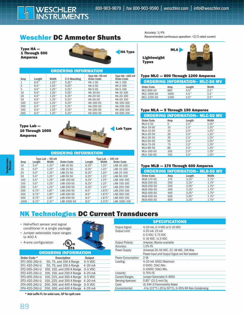
• Hall-effect sensor and signal conditioner in a single package
• Jumper selectable input ranges to 400 A
• 4-wire configuration
DT4
89
Order Code Amp Length Width MLA-5-50 5 2.0" 1.25"MLA-10-50 10 2.0" 1.25"MLA-15-50 15 2.0" 1.25"MLA-20-50 20 2.0" 1.25"MLA-30-50 30 2.0" 1.25"MLA-50-50 50 2.0" 1.25"MLA-75-50 75 2.0" 1.25"MLA-80-50 80 2.0" 1.25"MLA-100-50 100 2.0" 1.25"MLA-150-50 150 2.0" 1.25"
Order Code Amp Length WidthMLB-170-50 170 3.25" 1.75"MLB-200-50 200 3.25" 1.75"MLB-250-50 250 3.25" 1.75"MLB-300-50 300 3.25" 1.75"MLB-400-50 400 3.25" 1.75"MLB-500-50 500 3.25" 1.75"MLB-600-50 600 3.25" 1.75"
Weschler DC Ammeter ShuntsType HA — 1 Through 500 Amperes Lightweight
Types
Type Lab —10 Through 1000 Amperes
Type MLC — 800 Through 1200 Amperes
Type MLB — 170 Through 600 Amperes
Type MLA — 5 Through 150 Amperes
ORDERING INFORMATION
ORDERING INFORMATION– MLC-50 MV
ORDERING INFORMATION– MLC-50 MV
ORDERING INFORMATION
ORDERING INFORMATION– MLB-50 MV
HA Type
MLA
Lab Type
Order Code Amp Length WidthMLC-800-50 800 4.5" 2.5"MLC-1000-50 1000 4.5" 2.5"MLC-1200-50 1200 4.5" 2.5"
Type HA—50 mV Type HA—100 mVAmp Length Width C-C Mounting Order Code Order Code1 6.0" 1.25" 5.25" HA-1-50 HA-1-1002 6.0" 1.25" 5.25" HA-2-50 HA-2-1005 6.0" 1.25" 5.25" HA-5-50 HA-5-10010 6.0" 1.25" 5.25" HA-10-50 HA-10-10020 6.0" 1.25" 5.25" HA-20-50 HA-20-10050 6.0" 1.25" 5.25" HA-50-50 HA-50-100100 6.0" 1.25" 5.25" HA-100-50 HA-100-100200 6.0" 1.25" 5.25" HA-200-50 HA-200-100300 6.0" 1.25" 5.25" HA-300-50 HA-300-100500 6.0" 1.25" 5.25" HA-500-50 HA-500-100
NK Technologies DC Current TransducersSPECIFICATIONS
ORDERING INFORMATION
Output Signal: 4–20 mA, 0–5 VDC or 0–10 VDC Output Limit: 4-20 mA: 23 mA
0–5 VDC: 5.75 VDC 0–10 VDC: 11.5 VDC
Output Polarity: Unipolar, Bipolar available Accuracy: 1.0% FS Power Supply: Universal 20–50 VDC, 22–38 VAC, 2VA Max.
Power Input and Output Signal are Not Isolated Power Consumption: 2 VA Loading: 4–20 mA: 650Ω Maximum
0-5VDC: 25kΩ Min. 0-10VDC: 50kΩ Min.
Linearity: 0.75% FS Current Ranges: Jumper Selectable 0–400A Sensing Aperture: 0.85" (21.5 mm) Sq Case: UL 94V–0 Flammability Rated Environmental: -4 to 122°F (-20 to 50°C), 0–95% RH Non-Condensing
Order Code * Description OutputDT1-005-24U-U 50, 75, and 100 A Range 0–5 VDC DT1-420-24U-U 50, 75, and 100 A Range 4–20 mA DT2-005-24U-U 100, 150, and 200 A Range 0–5 VDC DT2-420-24U-U 100, 150, and 200 A Range 4–20 mA DT3-005-24U-U 150, 225, and 300 A Range 0–5 VDC DT3-420-24U-U 150, 225, and 300 A Range 4–20 mA DT4-005-24U-U 200, 300, and 400 A Range 0–5 VDC DT4-420-24U-U 200, 300, and 400 A Range 4–20 mA
T RAN
SDUC
ERS
/S E
NSO
RS
Type Lab — 50 mV Type Lab — 100 mVAmp Length Width Order Code Length Width Order Code10 5.0" 1.25" LAB-10-50 6.25" 1.25" LAB-10-10015 5.0" 1.25" LAB-15-50 6.25" 1.25" LAB-15-10025 5.0" 1.25" LAB-25-50 6.25" 1.25" LAB-25-10050 5.0" 1.25" LAB-50-50 6.25" 1.25" LAB-50-100100 5.0" 1.25" LAB-100-50 6.25" 1.25" LAB-100-100150 5.0" 1.25" LAB-150-50 6.25" 1.25" LAB-150-100200 5.0" 1.25" LAB-200-50 6.25" 1.25" LAB-200-100250 6.75" 1.87" LAB-250-50 8.0" 1.875" LAB-250-100300 6.75" 1.87" LAB-300-50 8.0" 1.875" LAB-300-100400 6.75" 1.87" LAB-400-50 8.0" 1.875" LAB-400-1001000 6.75" 2.37" LAB-1000-50 8.0" 2.375" LAB-1000-100
* Add suffix FL for solid core, SP for split core
Accuracy: 1/4%Recommended continuous operation: <2/3 rated current
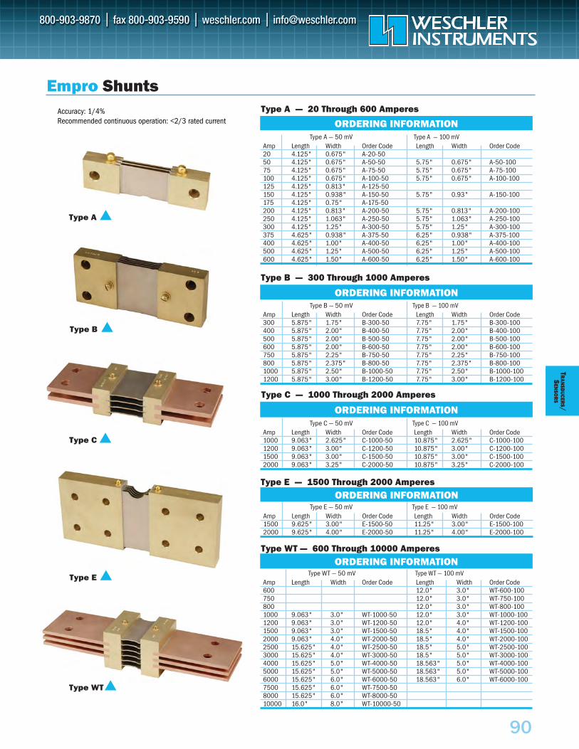
90
TRAN
SDUCER
S/S
ENSO
RS
Empro ShuntsType A — 20 Through 600 Amperes
Type WT — 600 Through 10000 Amperes
Type B — 300 Through 1000 Amperes
ORDERING INFORMATION
Type C — 1000 Through 2000 Amperes
ORDERING INFORMATION
Type E — 1500 Through 2000 AmperesORDERING INFORMATION
Type B
Type WT
Type C
Type A
Type E
Type B — 50 mV Type B — 100 mVAmp Length Width Order Code Length Width Order Code300 5.875" 1.75" B-300-50 7.75" 1.75" B-300-100400 5.875" 2.00" B-400-50 7.75" 2.00" B-400-100500 5.875" 2.00" B-500-50 7.75" 2.00" B-500-100600 5.875" 2.00" B-600-50 7.75" 2.00" B-600-100750 5.875" 2.25" B-750-50 7.75" 2.25" B-750-100800 5.875" 2.375" B-800-50 7.75" 2.375" B-800-1001000 5.875" 2.50" B-1000-50 7.75" 2.50" B-1000-1001200 5.875" 3.00" B-1200-50 7.75" 3.00" B-1200-100
Type WT — 50 mV Type WT — 100 mVAmp Length Width Order Code Length Width Order Code600 12.0" 3.0" WT-600-100750 12.0" 3.0" WT-750-100800 12.0" 3.0" WT-800-1001000 9.063" 3.0" WT-1000-50 12.0" 3.0" WT-1000-1001200 9.063" 3.0" WT-1200-50 12.0" 4.0" WT-1200-1001500 9.063" 3.0" WT-1500-50 18.5" 4.0" WT-1500-1002000 9.063" 4.0" WT-2000-50 18.5" 4.0" WT-2000-1002500 15.625" 4.0" WT-2500-50 18.5" 5.0" WT-2500-1003000 15.625" 4.0" WT-3000-50 18.5" 5.0" WT-3000-1004000 15.625" 5.0" WT-4000-50 18.563" 5.0" WT-4000-1005000 15.625" 5.0" WT-5000-50 18.563" 5.0" WT-5000-1006000 15.625" 6.0" WT-6000-50 18.563" 6.0" WT-6000-1007500 15.625" 6.0" WT-7500-508000 15.625" 6.0" WT-8000-5010000 16.0" 8.0" WT-10000-50
ORDERING INFORMATION
Type C — 50 mV Type C — 100 mVAmp Length Width Order Code Length Width Order Code1000 9.063" 2.625" C-1000-50 10.875" 2.625" C-1000-1001200 9.063" 3.00" C-1200-50 10.875" 3.00" C-1200-1001500 9.063" 3.00" C-1500-50 10.875" 3.00" C-1500-1002000 9.063" 3.25" C-2000-50 10.875" 3.25" C-2000-100
Type E — 50 mV Type E — 100 mVAmp Length Width Order Code Length Width Order Code1500 9.625" 3.00" E-1500-50 11.25" 3.00" E-1500-1002000 9.625" 4.00" E-2000-50 11.25" 4.00" E-2000-100
Type A — 50 mV Type A — 100 mVAmp Length Width Order Code Length Width Order Code20 4.125" 0.675" A-20-5050 4.125" 0.675" A-50-50 5.75" 0.675" A-50-10075 4.125" 0.675" A-75-50 5.75" 0.675" A-75-100100 4.125" 0.675" A-100-50 5.75" 0.675" A-100-100125 4.125" 0.813" A-125-50150 4.125" 0.938" A-150-50 5.75" 0.93" A-150-100175 4.125" 0.75" A-175-50200 4.125" 0.813" A-200-50 5.75" 0.813" A-200-100250 4.125" 1.063" A-250-50 5.75" 1.063" A-250-100300 4.125" 1.25" A-300-50 5.75" 1.25" A-300-100375 4.625" 0.938" A-375-50 6.25" 0.938" A-375-100400 4.625" 1.00" A-400-50 6.25" 1.00" A-400-100500 4.625" 1.25" A-500-50 6.25" 1.25" A-500-100600 4.625" 1.50" A-600-50 6.25" 1.50" A-600-100
ORDERING INFORMATIONAccuracy: 1/4%Recommended continuous operation: <2/3 rated current
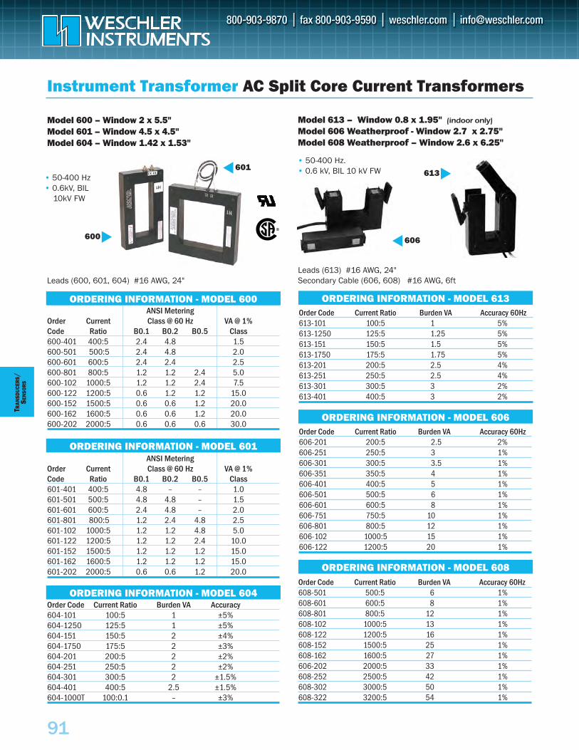
Order Code Current Ratio Burden VA Accuracy 60Hz613-101 100:5 1 5%613-1250 125:5 1.25 5%613-151 150:5 1.5 5%613-1750 175:5 1.75 5%613-201 200:5 2.5 4%613-251 250:5 2.5 4%613-301 300:5 3 2%613-401 400:5 3 2%
ORDERING INFORMATION - MODEL 613
Instrument Transformer AC Split Core Current Transformers
ORDERING INFORMATION – MODEL 600ANSI Metering
Order Current Class @ 60 Hz VA @ 1%Code Ratio B0.1 B0.2 B0.5 Class600-401 400:5 2.4 4.8 1.5600-501 500:5 2.4 4.8 2.0600-601 600:5 2.4 2.4 2.5600-801 800:5 1.2 1.2 2.4 5.0600-102 1000:5 1.2 1.2 2.4 7.5600-122 1200:5 0.6 1.2 1.2 15.0600-152 1500:5 0.6 0.6 1.2 20.0600-162 1600:5 0.6 0.6 1.2 20.0600-202 2000:5 0.6 0.6 0.6 30.0
Model 600 – Window 2 x 5.5"Model 601 – Window 4.5 x 4.5"Model 604 – Window 1.42 x 1.53"
Order Code Current Ratio Burden VA Accuracy604-101 100:5 1 ±5%604-1250 125:5 1 ±5%604-151 150:5 2 ±4%604-1750 175:5 2 ±3%604-201 200:5 2 ±2%604-251 250:5 2 ±2%604-301 300:5 2 ±1.5%604-401 400:5 2.5 ±1.5%604-1000T 100:0.1 – ±3%
ORDERING INFORMATION - MODEL 601
ORDERING INFORMATION - MODEL 604
ORDERING INFORMATION - MODEL 600
ANSI MeteringOrder Current Class @ 60 Hz VA @ 1%Code Ratio B0.1 B0.2 B0.5 Class601-401 400:5 4.8 – – 1.0601-501 500:5 4.8 4.8 – 1.5601-601 600:5 2.4 4.8 – 2.0601-801 800:5 1.2 2.4 4.8 2.5601-102 1000:5 1.2 1.2 4.8 5.0601-122 1200:5 1.2 1.2 2.4 10.0601-152 1500:5 1.2 1.2 1.2 15.0601-162 1600:5 1.2 1.2 1.2 15.0601-202 2000:5 0.6 0.6 1.2 20.0
601600
TRAN
SDUC
ERS
/SE
NSO
RS
• 50-400 Hz• 0.6kV, BIL
10kV FW
91
Order Code Current Ratio Burden VA Accuracy 60Hz 606-201 200:5 2.5 2%606-251 250:5 3 1%606-301 300:5 3.5 1%606-351 350:5 4 1%606-401 400:5 5 1%606-501 500:5 6 1%606-601 600:5 8 1%606-751 750:5 10 1%606-801 800:5 12 1%606-102 1000:5 15 1%606-122 1200:5 20 1%
Model 613 – Window 0.8 x 1.95" (indoor only)Model 606 Weatherproof - Window 2.7 x 2.75"Model 608 Weatherproof – Window 2.6 x 6.25"
ORDERING INFORMATION - MODEL 606
Order Code Current Ratio Burden VA Accuracy 60Hz 608-501 500:5 6 1%608-601 600:5 8 1%608-801 800:5 12 1%608-102 1000:5 13 1%608-122 1200:5 16 1%608-152 1500:5 25 1%608-162 1600:5 27 1%606-202 2000:5 33 1%608-252 2500:5 42 1%608-302 3000:5 50 1%608-322 3200:5 54 1%
ORDERING INFORMATION - MODEL 608
Leads (613) #16 AWG, 24" Secondary Cable (606, 608) #16 AWG, 6ft
• 50-400 Hz.• 0.6 kV, BIL 10 kV FW 613
606
Leads (600, 601, 604) #16 AWG, 24"
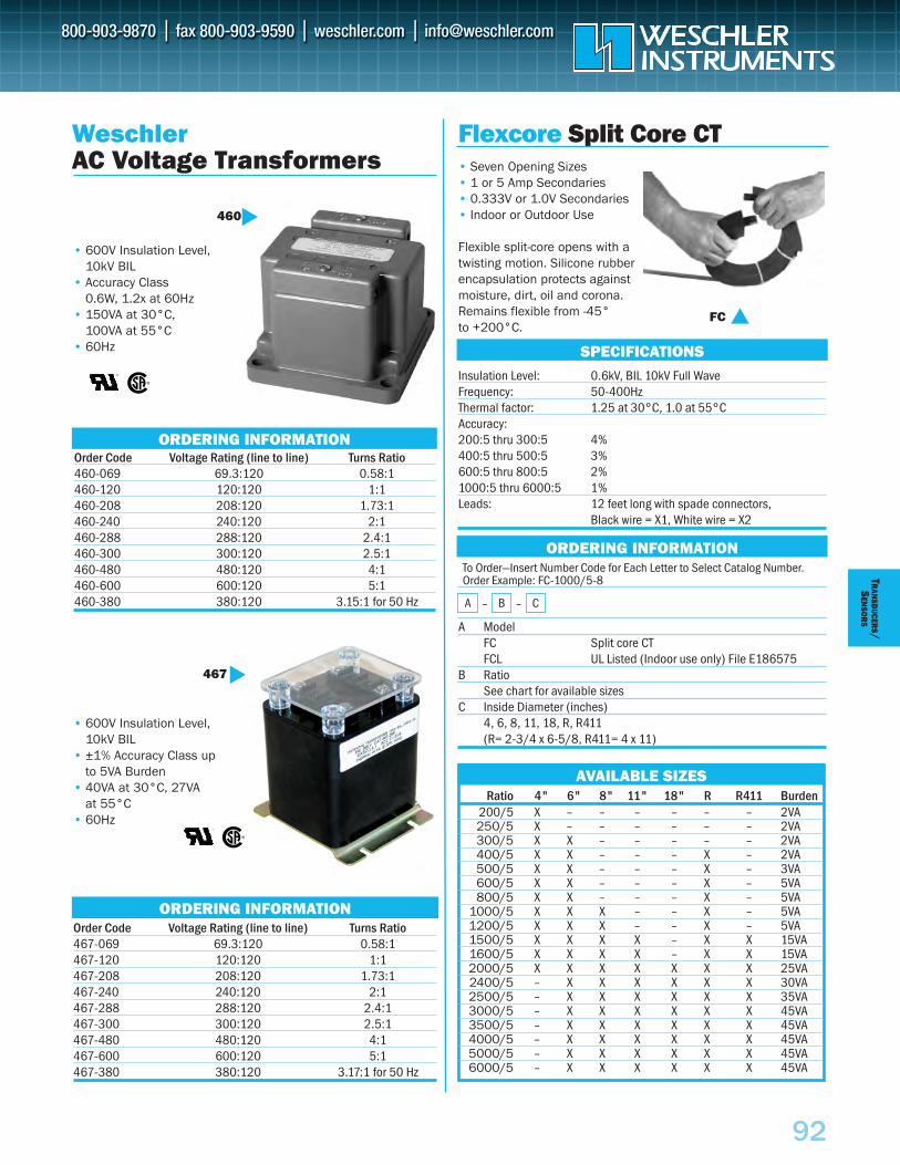
92
TRAN
SDUCER
S/S
ENSO
RS
Flexcore Split Core CT• Seven Opening Sizes • 1 or 5 Amp Secondaries• 0.333V or 1.0V Secondaries• Indoor or Outdoor Use
Flexible split-core opens with atwisting motion. Silicone rubberencapsulation protects againstmoisture, dirt, oil and corona.Remains flexible from -45° to +200°C.
Insulation Level: 0.6kV, BIL 10kV Full Wave Frequency: 50-400HzThermal factor: 1.25 at 30°C, 1.0 at 55°CAccuracy:200:5 thru 300:5 4%400:5 thru 500:5 3%600:5 thru 800:5 2%1000:5 thru 6000:5 1%Leads: 12 feet long with spade connectors,
Black wire = X1, White wire = X2
To Order—Insert Number Code for Each Letter to Select Catalog Number. Order Example: FC-1000/5-8
A ModelFC Split core CTFCL UL Listed (Indoor use only) File E186575
B RatioSee chart for available sizes
C Inside Diameter (inches)4, 6, 8, 11, 18, R, R411(R= 2-3/4 x 6-5/8, R411= 4 x 11)
SPECIFICATIONS
ORDERING INFORMATION
AVAILABLE SIZESRatio 4" 6" 8" 11" 18" R R411 Burden
200/5 X – – – – – – 2VA250/5 X – – – – – – 2VA300/5 X X – – – – – 2VA400/5 X X – – – X – 2VA500/5 X X – – – X – 3VA600/5 X X – – – X – 5VA800/5 X X – – – X – 5VA
1000/5 X X X – – X – 5VA1200/5 X X X – – X – 5VA1500/5 X X X X – X X 15VA1600/5 X X X X – X X 15VA2000/5 X X X X X X X 25VA2400/5 – X X X X X X 30VA2500/5 – X X X X X X 35VA3000/5 – X X X X X X 45VA3500/5 – X X X X X X 45VA4000/5 – X X X X X X 45VA5000/5 – X X X X X X 45VA6000/5 – X X X X X X 45VA
FC
A – B – C
WeschlerAC Voltage Transformers
Order Code Voltage Rating (line to line) Turns Ratio460-069 69.3:120 0.58:1460-120 120:120 1:1460-208 208:120 1.73:1460-240 240:120 2:1460-288 288:120 2.4:1460-300 300:120 2.5:1460-480 480:120 4:1460-600 600:120 5:1460-380 380:120 3.15:1 for 50 Hz
ORDERING INFORMATION
ORDERING INFORMATION
Order Code Voltage Rating (line to line) Turns Ratio467-069 69.3:120 0.58:1467-120 120:120 1:1467-208 208:120 1.73:1467-240 240:120 2:1467-288 288:120 2.4:1467-300 300:120 2.5:1467-480 480:120 4:1467-600 600:120 5:1467-380 380:120 3.17:1 for 50 Hz
467
• 600V Insulation Level, 10kV BIL
• ±1% Accuracy Class up to 5VA Burden
• 40VA at 30°C, 27VA at 55°C
• 60Hz
• 600V Insulation Level, 10kV BIL
• Accuracy Class 0.6W, 1.2x at 60Hz
• 150VA at 30°C, 100VA at 55°C
• 60Hz
460
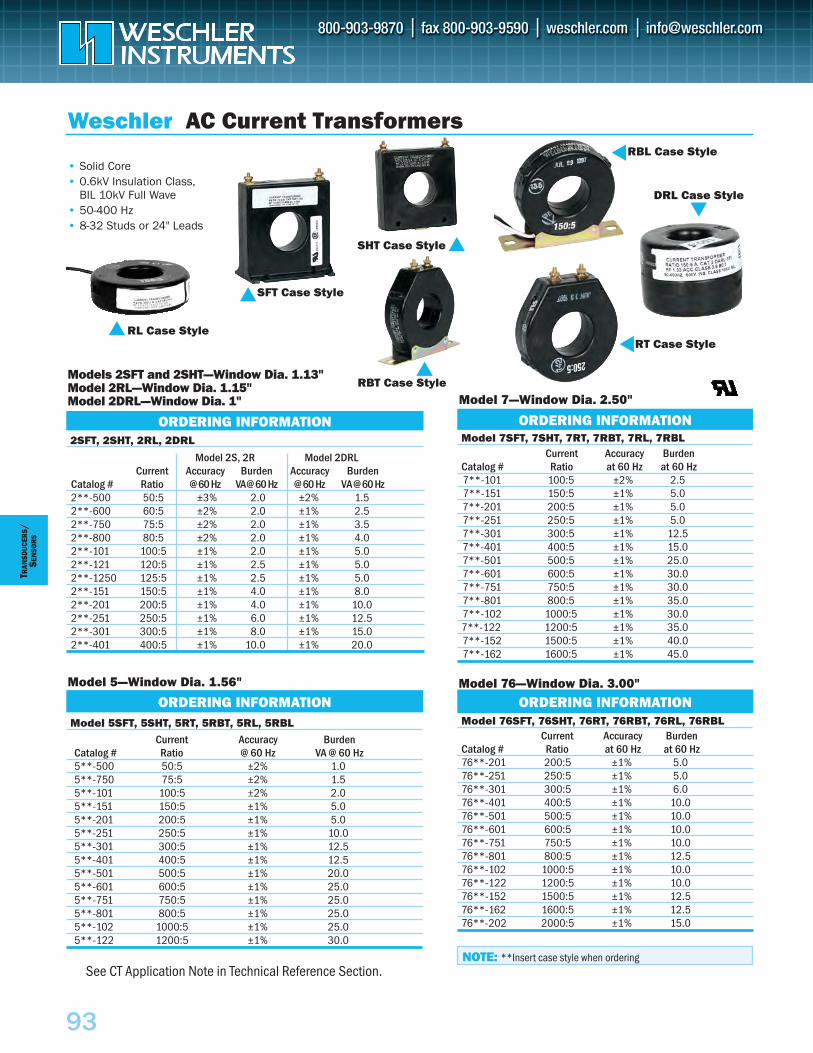
Current Accuracy BurdenCatalog # Ratio @ 60 Hz VA @ 60 Hz5**-500 50:5 ±2% 1.05**-750 75:5 ±2% 1.55**-101 100:5 ±2% 2.05**-151 150:5 ±1% 5.05**-201 200:5 ±1% 5.05**-251 250:5 ±1% 10.05**-301 300:5 ±1% 12.55**-401 400:5 ±1% 12.55**-501 500:5 ±1% 20.05**-601 600:5 ±1% 25.05**-751 750:5 ±1% 25.05**-801 800:5 ±1% 25.05**-102 1000:5 ±1% 25.05**-122 1200:5 ±1% 30.0
Current Accuracy BurdenCatalog # Ratio at 60 Hz at 60 Hz7**-101 100:5 ±2% 2.57**-151 150:5 ±1% 5.07**-201 200:5 ±1% 5.07**-251 250:5 ±1% 5.07**-301 300:5 ±1% 12.57**-401 400:5 ±1% 15.07**-501 500:5 ±1% 25.07**-601 600:5 ±1% 30.07**-751 750:5 ±1% 30.07**-801 800:5 ±1% 35.07**-102 1000:5 ±1% 30.07**-122 1200:5 ±1% 35.07**-152 1500:5 ±1% 40.07**-162 1600:5 ±1% 45.0
Model 76SFT, 76SHT, 76RT, 76RBT, 76RL, 76RBL
Model 7SFT, 7SHT, 7RT, 7RBT, 7RL, 7RBL
Current Accuracy BurdenCatalog # Ratio at 60 Hz at 60 Hz76**-201 200:5 ±1% 5.076**-251 250:5 ±1% 5.076**-301 300:5 ±1% 6.076**-401 400:5 ±1% 10.076**-501 500:5 ±1% 10.076**-601 600:5 ±1% 10.076**-751 750:5 ±1% 10.076**-801 800:5 ±1% 12.576**-102 1000:5 ±1% 10.076**-122 1200:5 ±1% 10.076**-152 1500:5 ±1% 12.576**-162 1600:5 ±1% 12.576**-202 2000:5 ±1% 15.0
2SFT, 2SHT, 2RL, 2DRL
ORDERING INFORMATION
Model 7—Window Dia. 2.50"
Model 76—Window Dia. 3.00"Model 5—Window Dia. 1.56"
Models 2SFT and 2SHT—Window Dia. 1.13"Model 2RL—Window Dia. 1.15" Model 2DRL—Window Dia. 1"
Weschler AC Current Transformers
ORDERING INFORMATION
ORDERING INFORMATIONModel 5SFT, 5SHT, 5RT, 5RBT, 5RL, 5RBL
ORDERING INFORMATION
SHT Case Style
SFT Case Style
NOTE: **Insert case style when ordering
RL Case Style
RBL Case Style
DRL Case Style
RT Case Style
RBT Case Style
Model 2S, 2R Model 2DRLCurrent Accuracy Burden Accuracy Burden
Catalog # Ratio @ 60 Hz VA@ 60 Hz @ 60 Hz VA @ 60 Hz2**-500 50:5 ±3% 2.0 ±2% 1.52**-600 60:5 ±2% 2.0 ±1% 2.52**-750 75:5 ±2% 2.0 ±1% 3.52**-800 80:5 ±2% 2.0 ±1% 4.02**-101 100:5 ±1% 2.0 ±1% 5.02**-121 120:5 ±1% 2.5 ±1% 5.02**-1250 125:5 ±1% 2.5 ±1% 5.02**-151 150:5 ±1% 4.0 ±1% 8.02**-201 200:5 ±1% 4.0 ±1% 10.02**-251 250:5 ±1% 6.0 ±1% 12.52**-301 300:5 ±1% 8.0 ±1% 15.02**-401 400:5 ±1% 10.0 ±1% 20.0
• Solid Core• 0.6kV Insulation Class,
BIL 10kV Full Wave• 50-400 Hz• 8-32 Studs or 24" Leads
See CT Application Note in Technical Reference Section.
93
TRAN
SDUC
ERS
/SE
NSO
RS
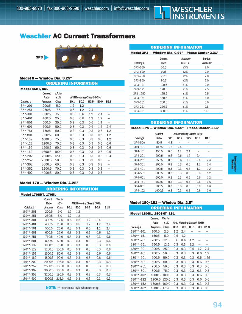
94
TRAN
SDUCER
S/S
ENSO
RS
Model 180RL, 180SHT, 181Current V.A. for
Ratio ±1% ANSI Metering Class @ 60 HzCatalog # Amperes Class B0.1 B0.2 B0.5 B0.9 B1.8180**-101 100:5 2.5 1.2 2.4 — — —180**-151 150:5 5.0 0.6 1.2 — — —180**-201 200:5 12.5 0.6 0.6 1.2 — —180**-251 250:5 12.5 0.3 0.3 1.2 — —180**-301 300:5 25.0 0.3 0.3 0.6 1.2 2.4180**-401 400:5 50.0 0.3 0.3 0.3 0.6 1.2180**-501 500:5 50.0 0.3 0.3 0.3 0.6 1.29180**-601 600:5 50.0 0.3 0.3 0.3 0.6 0.6180**-751 750:5 50.0 0.3 0.3 0.3 0.3 0.6180**-801 800:5 75.0 0.3 0.3 0.3 0.3 0.3180**-102 1000:5 100.0 0.3 0.3 0.3 0.6 0.6180**-122 1200:5 125.0 0.3 0.3 0.3 0.6 0.6180**-152 1500:5 160.0 0.3 0.3 0.3 0.3 0.3180**-162 1600:5 175.0 0.3 0.3 0.3 0.3 0.3
Current V.A. forRatio ±1% ANSI Metering Class @ 60 Hz
Catalog # Amperes Class B0.1 B0.2 B0.5 B0.9 B1.88**-201 200:5 5.0 1.2 1.2 — — —8**-251 250:5 7.5 0.6 1.2 2.4 — —8**-301 300:5 15.0 0.6 0.6 1.2 2.4 —8**-401 400:5 25.0 0.3 0.6 1.2 1.2 —8**-501 500:5 35.0 0.3 0.3 0.6 1.2 —8**-601 600:5 50.0 0.3 0.3 0.6 1.2 2.48**-751 750:5 50.0 0.3 0.3 0.3 0.6 1.28**-801 800:5 60.0 0.3 0.3 0.3 0.6 1.28**-102 1000:5 75.0 0.3 0.3 0.3 0.6 1.28**-122 1200:5 75.0 0.3 0.3 0.3 0.6 0.68**-152 1500:5 90.0 0.3 0.3 0.3 0.6 0.68**-162 1600:5 100.0 0.3 0.3 0.3 0.6 0.68**-202 2000:5 120.0 0.3 0.3 0.3 0.3 0.38**-252 2500:5 50.0 0.3 0.3 0.3 0.3 —8**-302 3000:5 60.0 0.3 0.3 0.3 0.3 —8**-352 3200:5 70.0 0.3 0.3 0.3 0.3 —8**-402 4000:5 80.0 0.3 0.3 0.3 0.3 —
Model 8SHT, 8RL
Model 170SHT, 170RL
ORDERING INFORMATIONModel 170 — Window Dia. 4.25"
Model 8 — Window Dia. 3.25"
Weschler AC Current Transformers
Model 180/181 — Window Dia. 2.5"
ORDERING INFORMATION
ORDERING INFORMATION
NOTE: **Insert case style when ordering
3P3
Current V.A. for
Ratio ±1% ANSI Metering Class @ 60 HzCatalog # Amperes Class B0.1 B0.2 B0.5 B0.9 B1.8
170**-201 200:5 5.0 1.2 1.2 — — —170**-251 250:5 5.0 1.2 1.2 — — —170**-301 300:5 12.5 0.6 0.6 1.2 2.4 —170**-401 400:5 25.0 0.6 0.6 1.2 1.2 2.4170**-501 500:5 25.0 0.3 0.3 0.6 1.2 2.4170**-601 600:5 25.0 0.3 0.3 0.6 0.6 1.2170**-751 750:5 40.0 0.3 0.3 0.3 0.3 0.6170**-801 800:5 50.0 0.3 0.3 0.3 0.3 0.6170**-102 1000:5 75.0 0.3 0.3 0.3 0.3 0.6170**-122 1200:5 100.0 0.3 0.3 0.3 0.3 0.6170**-152 1500:5 80.0 0.3 0.3 0.3 0.6 0.6170**-162 1600:5 90.0 0.3 0.3 0.3 0.6 0.6170**-202 2000:5 105.0 0.3 0.3 0.3 0.3 0.3170**-252 2500:5 130.0 0.3 0.3 0.3 0.3 0.3170**-302 3000:5 165.0 0.3 0.3 0.3 0.3 0.3170**-352 3200:5 190.0 0.3 0.3 0.3 0.3 0.3170**-402 4000:5 215.0 0.3 0.3 0.3 0.3 0.3
Model 3P4 — Window Dia. 1.56" Phase Center 3.56"
ORDERING INFORMATION
Current ANSI Metering Class @ 60 HzCatalog # Ratio B0.1 B0.2 B0.5 B0.9 B1.83P4–500 50:5 4.8 – – – –3P4–101 100:5 1.2 2.4 – – –3P4–151 150:5 0.6 1.2 2.4 – –3P4–201 200:5 0.6 0.6 1.2 2.4 –3P4–251 250:5 0.6 0.6 1.2 2.4 2.43P4–301 300:5 0.3 0.3 0.6 1.2 2.43P4–401 400:5 0.3 0.3 0.6 1.2 1.23P4–501 500:5 0.3 0.3 0.6 0.6 1.23P4–601 600:5 0.3 0.3 0.6 0.6 1.23P4–751 750:5 0.3 0.3 0.6 0.6 0.63P4–801 800:5 0.3 0.3 0.6 0.6 0.63P4–102 1000:5 0.3 0.3 0.3 0.6 0.6
Model 3P3 — Window Dia. 0.97" Phase Center 2.31"
ORDERING INFORMATION
Current Accuracy BurdenCatalog # Ratio @ 60 Hz VA@60Hz3P3–500 50:5 ±3% 2.03P3–600 60:5 ±2% 2.03P3–750 75:5 ±2% 2.03P3–800 80:5 ±2% 2.03P3–101 100:5 ±1% 2.03P3–121 120:5 ±1% 2.5
3P3–1250 125:5 ±1% 2.53P3–151 150:5 ±1% 4.03P3–201 200:5 ±1% 5.03P3–251 250:5 ±1% 7.53P3–301 300:5 ±1% 10.0
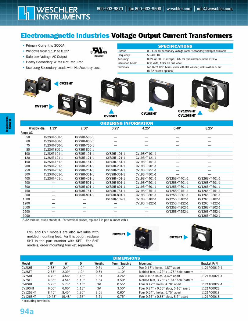
TRAN
SDUC
ERS/
SEN
SOR
S
Electromagnetic Industries Voltage Output Current Transformers SPECIFICATIONS
94a
• Primary Current to 3000A
• Windows from 1.13"" to 8.25""
• Safe Low Voltage AC Output• Heavy Secondary Wires Not Required
• Use Long Secondary Leads with No Accuracy Loss
Output: 0 - 1.0V AC secondary voltage (other secondary voltages available)Frequency: 50-400 HzAccuracy: 0.3% at 60 Hz, except 0.6% for transformers rated <100A Insulation Level: 600 Volts, 10kV BIL full waveTerminals: Two 8-32 UNC brass studs with flat washer, lock washer & nut
(8-32 screws optional)
CV2SHT
CV19SHT
CV7SHT
CV125SHTCV126SHT
ORDERING INFORMATION
DIMENSIONS
WWiinnddooww ddiiaa.. 11..1133"" 22..5500"" 33..2255"" 44..2255"" 66..4400"" 88..2255""AAmmppss AACC
50 CV2SHT-500-1 CV7SHT-500-1 --- --- --- ---60 CV2SHT-600-1 CV7SHT-600-1 --- --- --- ---75 CV2SHT-750-1 CV7SHT-750-1 --- --- --- ---80 CV2SHT-800-1 CV7SHT-800-1 --- --- --- ---
100 CV2SHT-101-1 CV7SHT-101-1 CV8SHT-101-1 CV19SHT-101-1 --- ---120 CV2SHT-121-1 CV7SHT-121-1 CV8SHT-121-1 CV19SHT-121-1 --- ---150 CV2SHT-151-1 CV7SHT-151-1 CV8SHT-151-1 CV19SHT-151-1 --- ---200 CV2SHT-201-1 CV7SHT-201-1 CV8SHT-201-1 CV19SHT-201-1 --- ---250 CV2SHT-251-1 CV7SHT-251-1 CV8SHT-251-1 CV19SHT-251-1 --- ---300 CV2SHT-301-1 CV7SHT-301-1 CV8SHT-301-1 CV19SHT-301-1 --- ---400 CV2SHT-401-1 CV7SHT-401-1 CV8SHT-401-1 CV19SHT-401-1 CV125SHT-401-1 CV126SHT-401-1500 --- CV7SHT-501-1 CV8SHT-501-1 CV19SHT-501-1 CV125SHT-501-1 CV126SHT-501-1600 --- CV7SHT-601-1 CV8SHT-601-1 CV19SHT-601-1 CV125SHT-601-1 CV126SHT-601-1750 --- CV7SHT-751-1 CV8SHT-751-1 CV19SHT-751-1 CV125SHT-751-1 CV126SHT-751-1800 --- CV7SHT-801-1 CV8SHT-801-1 CV19SHT-801-1 CV125SHT-801-1 CV126SHT-801-1
1000 --- --- CV8SHT-102-1 CV19SHT-102-1 CV125SHT-102-1 CV126SHT-102-11200 --- --- --- CV19SHT-122-1 CV125SHT-122-1 CV126SHT-122-12000 --- --- --- --- CV125SHT-202-1 CV126SHT-202-12500 --- --- --- --- CV125SHT-252-1 CV126SHT-252-13000 --- --- --- --- --- CV126SHT-302-18-32 terminal studs standard. For terminal screws, replace T in part number with Y
MMooddeell HH** WW DD WWeeiigghhtt TTeerrmm.. SSppaacciinngg MMoouunnttiinngg BBrraacckkeett PP//NNCV2SHT 2.68" 2.4" 1.0" 0.5# 1.10" Two 0.17"d holes, 1.87" apart 1121A00019-1CV2SFT 2.67" 2.39" 1.0" 0.5# 1.10" Molded feet, 1.73" x 1.75" hole pattern ---CV7SHT 4.70" 4.56" 1.13" 1.5# 3.26" Two 0.40"d holes, 3.42" apart 1121A00021-1CV7SFT 4.85" 4.54" 1.10" 1.5# 3.50" Molded feet, 3.76" x 1.84" hole pattern ---CV8SHT 5.73" 5.73" 1.15" 3# 0.55" Four 0.42"d holes, 4.70" apart 1121A00022-1CV19SHT 6.00" 6.00" 1.18" 3# 3.50" Four 0.24" x 0.56" slots, 5.16" apart 1121A00022CV125SHT 8.45" 8.45" 1.30" 3.5# 0.60" Four 0.54"d holes, 6.75" apart 1121A00018CV126SHT 10.48" 10.48" 1.53" 3.5# 0.75" Four 0.56" x 0.88" slots, 8.5" apart 1121A00018*excluding terminals
CV7SFTCV2SFTCV2 and CV7 models are also available with
molded mounting feet. For this option, replaceSHT in the part number with SFT. For SHTmodels, order mounting bracket separately.
CV8SHT
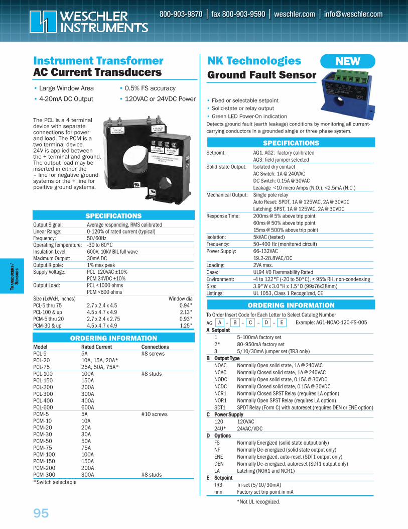
95
TRAN
SDUC
ERS
/SE
NSO
RS
Model Rated Current ConnectionsPCL-5 5A #8 screwsPCL-20 10A, 15A, 20A*PCL-75 25A, 50A, 75A*PCL-100 100A #8 studsPCL-150 150APCL-200 200APCL-300 300APCL-400 400APCL-600 600APCM-5 5A #10 screwsPCM-10 10APCM-20 20APCM-30 30APCM-50 50APCM-75 75APCM-100 100APCM-150 150APCM-200 200APCM-300 300A #8 studs*Switch selectable
Instrument TransformerAC Current Transducers• Large Window Area
• 4-20mA DC Output
• 0.5% FS accuracy
• 120VAC or 24VDC Power
The PCL is a 4 terminaldevice with separate connections for power and load. The PCM is atwo terminal device. 24V is applied betweenthe + terminal and ground.The output load may beinserted in either the – line for negative ground systems or the + line forpositive ground systems.
SPECIFICATIONSOutput Signal: Average responding, RMS calibratedLinear Range: 0-120% of rated current (typical)Frequency: 50/60HzOperating Temperature: -30 to 60°CInsulation Level: 600V, 10kV BIL full waveMaximum Output: 30mA DCOutput Ripple: 1% max peakSupply Voltage: PCL 120VAC ±10%
PCM 24VDC ±10%Output Load: PCL <1000 ohms
PCM <600 ohmsSize (LxWxH, inches) Window diaPCL-5 thru 75 2.7 x 2.4 x 4.5 0.94"PCL-100 & up 4.5 x 4.7 x 4.9 2.13"PCM-5 thru 20 2.7 x 2.4 x 2.75 0.93"PCM-30 & up 4.5 x 4.7 x 4.9 1.25"
ORDERING INFORMATION
NK TechnologiesGround Fault Sensor
SPECIFICATIONS
ORDERING INFORMATION
A B C D –– E––
• Fixed or selectable setpoint• Solid-state or relay output• Green LED Power-On indicationDetects ground fault (earth leakage) conditions by monitoring all current-carrying conductors in a grounded single or three phase system.
Setpoint: AG1, AG2: factory calibratedAG3: field jumper selected
Solid-state Output: Isolated dry contactAC Switch: 1A @ 240VACDC Switch: 0.15A @ 30VACLeakage <10 micro Amps (N.O.), <2.5mA (N.C.)
Mechanical Output: Single pole relayAuto Reset: SPDT, 1A @ 125VAC, 2A @ 30VDCLatching: SPST, 1A @ 125VAC, 2A @ 30VDC
Response Time: 200ms @ 5% above trip point60ms @ 50% above trip point15ms @ 500% above trip point
Isolation: 5kVAC (tested)Frequency: 50–400 Hz (monitored circuit)Power Supply: 66-132VAC
19.2-28.8VAC/DCLoading: 2VA max.Case: UL94 V0 Flammability RatedEnvironment: -4 to 122°F (-20 to 50°C), < 95% RH, non-condensingSize: 3.9"W x 3.0"H x 1.5"D (99x76x38mm)Listings: UL 1053, Class 1 Recognized, CE
To Order Insert Code for Each Letter to Select Catalog Number
AG AA SSeettppooiinntt
1 5–100mA factory set2* 80–950mA factory set3 5/10/30mA jumper set (TR3 only)
BB OOuuttppuutt TTyyppeeNOAC Normally Open solid state, 1A @ 240VACNCAC Normally Closed solid state, 1A @ 240VACNODC Normally Open solid state, 0.15A @ 30VDCNCDC Normally Closed solid state, 0.15A @ 30VDCNCR1 Normally Closed SPST Relay (requires LA option)NOR1 Normally Open SPST Relay (requires LA option)SDT1 SPDT Relay (Form C) with autoreset (requires DEN or ENE option)
CC PPoowweerr SSuuppppllyy120 120VAC24U* 24VAC/VDC
DD OOppttiioonnssFS Normally Energized (solid state output only)NF Normally De-energized (solid state output only)ENE Normally Energized, auto-reset (SDT1 output only)DEN Normally De-energized, autoreset (SDT1 output only)LA Latching (NOR1 and NCR1)
EE SSeettppooiinnttTR3 Tri-set (5/10/30mA)nnn Factory set trip point in mA
*Not UL recognized.
Example: AG1-NOAC-120-FS-005
NEW
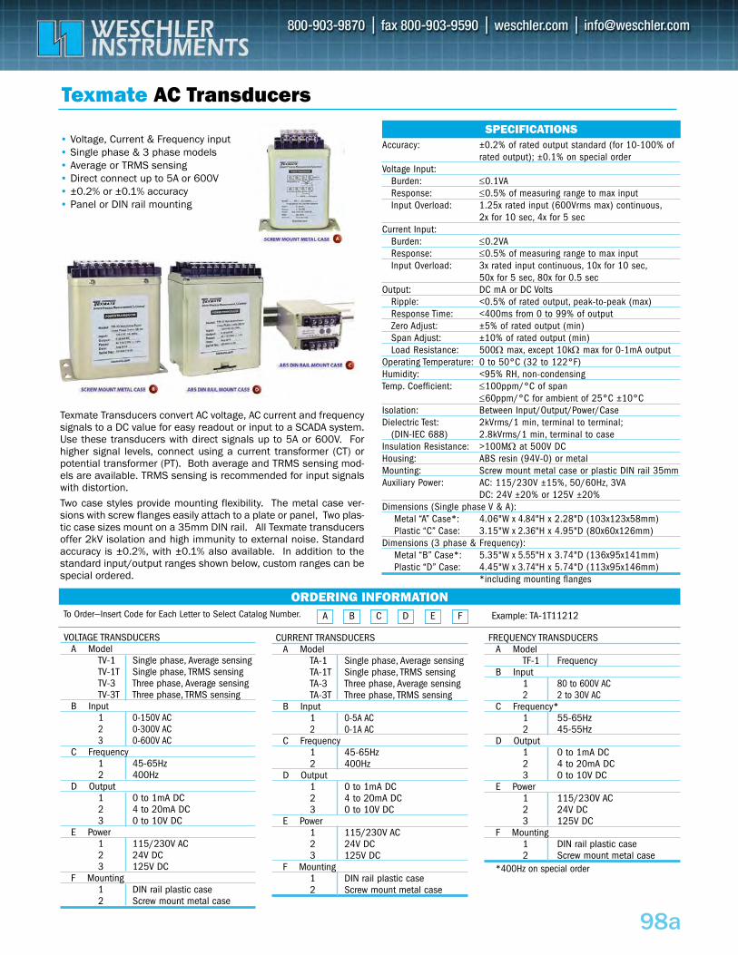
98a
Texmate AC Transducers
Accuracy: ±0.2% of rated output standard (for 10-100% of rated output); ±0.1% on special order
Voltage Input:Burden: ≤0.1VAResponse: ≤0.5% of measuring range to max input Input Overload: 1.25x rated input (600Vrms max) continuous,
2x for 10 sec, 4x for 5 sec Current Input:
Burden: ≤0.2VAResponse: ≤0.5% of measuring range to max input Input Overload: 3x rated input continuous, 10x for 10 sec,
50x for 5 sec, 80x for 0.5 secOutput: DC mA or DC Volts
Ripple: <0.5% of rated output, peak-to-peak (max)Response Time: <400ms from 0 to 99% of outputZero Adjust: ±5% of rated output (min)Span Adjust: ±10% of rated output (min)Load Resistance: 500Ω max, except 10kΩ max for 0-1mA output
Operating Temperature: 0 to 50°C (32 to 122°F)Humidity: <95% RH, non-condensingTemp. Coefficient: ≤100ppm/°C of span
≤60ppm/°C for ambient of 25°C ±10°CIsolation: Between Input/Output/Power/CaseDielectric Test: 2kVrms/1 min, terminal to terminal;
(DIN-IEC 688) 2.8kVrms/1 min, terminal to caseInsulation Resistance: >100MΩ at 500V DCHousing: ABS resin (94V-0) or metalMounting: Screw mount metal case or plastic DIN rail 35mmAuxiliary Power: AC: 115/230V ±15%, 50/60Hz, 3VA
DC: 24V ±20% or 125V ±20%Dimensions (Single phase V & A):
Metal “A” Case*: 4.06"W x 4.84"H x 2.28"D (103x123x58mm)Plastic “C” Case: 3.15"W x 2.36"H x 4.95"D (80x60x126mm)
Dimensions (3 phase & Frequency):Metal “B” Case*: 5.35"W x 5.55"H x 3.74"D (136x95x141mm)Plastic “D” Case: 4.45"W x 3.74"H x 5.74"D (113x95x146mm)
*including mounting flanges
SPECIFICATIONS• Voltage, Current & Frequency input• Single phase & 3 phase models • Average or TRMS sensing• Direct connect up to 5A or 600V• ±0.2% or ±0.1% accuracy • Panel or DIN rail mounting
ORDERING INFORMATION
CURRENT TRANSDUCERSA Model
TA-1 Single phase, Average sensing TA-1T Single phase, TRMS sensingTA-3 Three phase, Average sensingTA-3T Three phase, TRMS sensing
B Input1 0-5A AC2 0-1A AC
C Frequency1 45-65Hz2 400Hz
D Output1 0 to 1mA DC2 4 to 20mA DC3 0 to 10V DC
E Power1 115/230V AC2 24V DC 3 125V DC
F Mounting1 DIN rail plastic case2 Screw mount metal case
VOLTAGE TRANSDUCERSA Model
TV-1 Single phase, Average sensing TV-1T Single phase, TRMS sensingTV-3 Three phase, Average sensingTV-3T Three phase, TRMS sensing
B Input1 0-150V AC2 0-300V AC3 0-600V AC
C Frequency1 45-65Hz2 400Hz
D Output1 0 to 1mA DC2 4 to 20mA DC3 0 to 10V DC
E Power1 115/230V AC2 24V DC 3 125V DC
F Mounting1 DIN rail plastic case2 Screw mount metal case
FREQUENCY TRANSDUCERSA Model
TF-1 FrequencyB Input
1 80 to 600V AC2 2 to 30V AC
C Frequency*1 55-65Hz2 45-55Hz
D Output1 0 to 1mA DC2 4 to 20mA DC3 0 to 10V DC
E Power1 115/230V AC2 24V DC 3 125V DC
F Mounting1 DIN rail plastic case2 Screw mount metal case
*400Hz on special order
A B C D E F Example: TA-1T11212
Texmate Transducers convert AC voltage, AC current and frequencysignals to a DC value for easy readout or input to a SCADA system.Use these transducers with direct signals up to 5A or 600V. Forhigher signal levels, connect using a current transformer (CT) orpotential transformer (PT). Both average and TRMS sensing mod-els are available. TRMS sensing is recommended for input signalswith distortion. Two case styles provide mounting flexibility. The metal case ver-sions with screw flanges easily attach to a plate or panel, Two plas-tic case sizes mount on a 35mm DIN rail. All Texmate transducersoffer 2kV isolation and high immunity to external noise. Standardaccuracy is ±0.2%, with ±0.1% also available. In addition to thestandard input/output ranges shown below, custom ranges can bespecial ordered.
To Order—Insert Code for Each Letter to Select Catalog Number.
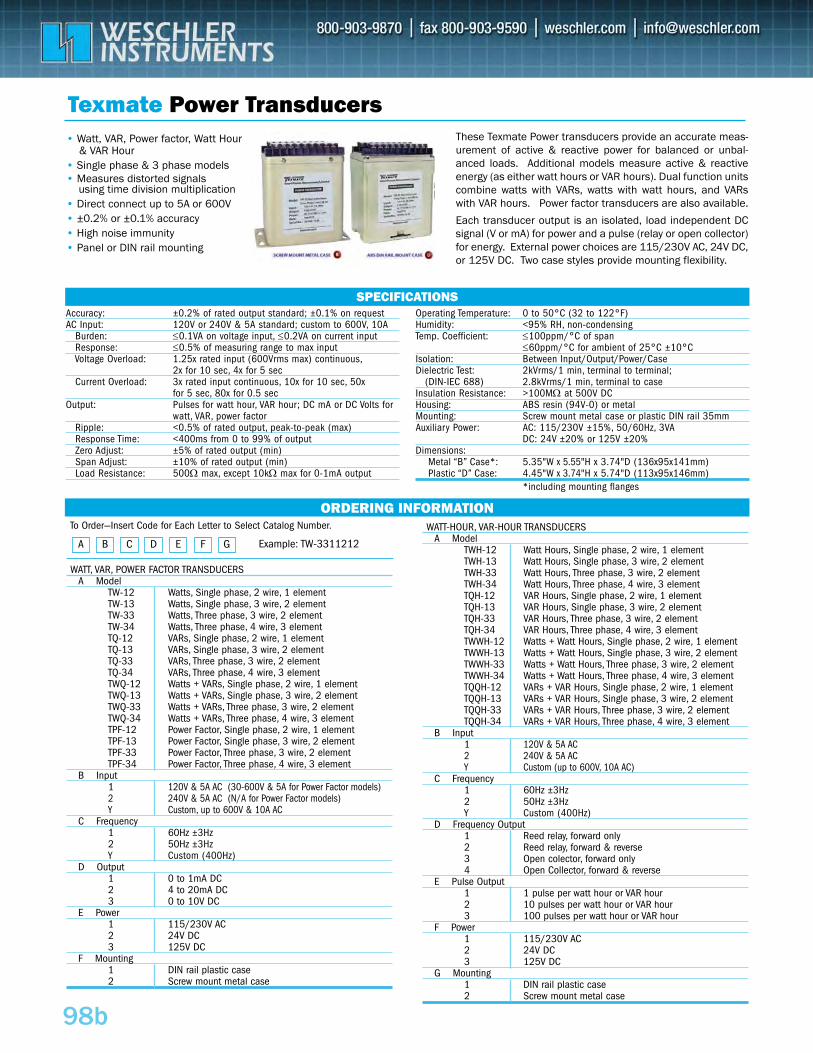
98b
Texmate Power Transducers
Accuracy: ±0.2% of rated output standard; ±0.1% on requestAC Input: 120V or 240V & 5A standard; custom to 600V, 10A
Burden: ≤0.1VA on voltage input, ≤0.2VA on current inputResponse: ≤0.5% of measuring range to max input Voltage Overload: 1.25x rated input (600Vrms max) continuous,
2x for 10 sec, 4x for 5 sec Current Overload: 3x rated input continuous, 10x for 10 sec, 50x
for 5 sec, 80x for 0.5 secOutput: Pulses for watt hour, VAR hour; DC mA or DC Volts for
watt, VAR, power factorRipple: <0.5% of rated output, peak-to-peak (max)Response Time: <400ms from 0 to 99% of outputZero Adjust: ±5% of rated output (min)Span Adjust: ±10% of rated output (min)Load Resistance: 500Ω max, except 10kΩ max for 0-1mA output
Operating Temperature: 0 to 50°C (32 to 122°F)Humidity: <95% RH, non-condensingTemp. Coefficient: ≤100ppm/°C of span
≤60ppm/°C for ambient of 25°C ±10°CIsolation: Between Input/Output/Power/CaseDielectric Test: 2kVrms/1 min, terminal to terminal;
(DIN-IEC 688) 2.8kVrms/1 min, terminal to caseInsulation Resistance: >100MΩ at 500V DCHousing: ABS resin (94V-0) or metalMounting: Screw mount metal case or plastic DIN rail 35mmAuxiliary Power: AC: 115/230V ±15%, 50/60Hz, 3VA
DC: 24V ±20% or 125V ±20%Dimensions:
Metal “B” Case*: 5.35"W x 5.55"H x 3.74"D (136x95x141mm)Plastic “D” Case: 4.45"W x 3.74"H x 5.74"D (113x95x146mm)
*including mounting flanges
SPECIFICATIONS
• Watt, VAR, Power factor, Watt Hour& VAR Hour
• Single phase & 3 phase models • Measures distorted signals
using time division multiplication• Direct connect up to 5A or 600V• ±0.2% or ±0.1% accuracy • High noise immunity • Panel or DIN rail mounting
ORDERING INFORMATION
WATT, VAR, POWER FACTOR TRANSDUCERSA Model
TW-12 Watts, Single phase, 2 wire, 1 element TW-13 Watts, Single phase, 3 wire, 2 elementTW-33 Watts, Three phase, 3 wire, 2 elementTW-34 Watts, Three phase, 4 wire, 3 elementTQ-12 VARs, Single phase, 2 wire, 1 element TQ-13 VARs, Single phase, 3 wire, 2 elementTQ-33 VARs, Three phase, 3 wire, 2 elementTQ-34 VARs, Three phase, 4 wire, 3 elementTWQ-12 Watts + VARs, Single phase, 2 wire, 1 element TWQ-13 Watts + VARs, Single phase, 3 wire, 2 elementTWQ-33 Watts + VARs, Three phase, 3 wire, 2 elementTWQ-34 Watts + VARs, Three phase, 4 wire, 3 elementTPF-12 Power Factor, Single phase, 2 wire, 1 element TPF-13 Power Factor, Single phase, 3 wire, 2 elementTPF-33 Power Factor, Three phase, 3 wire, 2 elementTPF-34 Power Factor, Three phase, 4 wire, 3 element
B Input1 120V & 5A AC (30-600V & 5A for Power Factor models)2 240V & 5A AC (N/A for Power Factor models)Y Custom, up to 600V & 10A AC
C Frequency1 60Hz ±3Hz2 50Hz ±3HzY Custom (400Hz)
D Output1 0 to 1mA DC2 4 to 20mA DC3 0 to 10V DC
E Power1 115/230V AC2 24V DC 3 125V DC
F Mounting1 DIN rail plastic case2 Screw mount metal case
WATT-HOUR, VAR-HOUR TRANSDUCERSA Model
TWH-12 Watt Hours, Single phase, 2 wire, 1 element TWH-13 Watt Hours, Single phase, 3 wire, 2 elementTWH-33 Watt Hours, Three phase, 3 wire, 2 elementTWH-34 Watt Hours, Three phase, 4 wire, 3 elementTQH-12 VAR Hours, Single phase, 2 wire, 1 element TQH-13 VAR Hours, Single phase, 3 wire, 2 elementTQH-33 VAR Hours, Three phase, 3 wire, 2 elementTQH-34 VAR Hours, Three phase, 4 wire, 3 elementTWWH-12 Watts + Watt Hours, Single phase, 2 wire, 1 element TWWH-13 Watts + Watt Hours, Single phase, 3 wire, 2 elementTWWH-33 Watts + Watt Hours, Three phase, 3 wire, 2 elementTWWH-34 Watts + Watt Hours, Three phase, 4 wire, 3 elementTQQH-12 VARs + VAR Hours, Single phase, 2 wire, 1 element TQQH-13 VARs + VAR Hours, Single phase, 3 wire, 2 elementTQQH-33 VARs + VAR Hours, Three phase, 3 wire, 2 elementTQQH-34 VARs + VAR Hours, Three phase, 4 wire, 3 element
B Input1 120V & 5A AC2 240V & 5A ACY Custom (up to 600V, 10A AC)
C Frequency1 60Hz ±3Hz2 50Hz ±3HzY Custom (400Hz)
D Frequency Output1 Reed relay, forward only2 Reed relay, forward & reverse3 Open colector, forward only4 Open Collector, forward & reverse
E Pulse Output1 1 pulse per watt hour or VAR hour2 10 pulses per watt hour or VAR hour3 100 pulses per watt hour or VAR hour
F Power1 115/230V AC2 24V DC 3 125V DC
G Mounting1 DIN rail plastic case2 Screw mount metal case
A B C D E F G Example: TW-3311212
These Texmate Power transducers provide an accurate meas-urement of active & reactive power for balanced or unbal-anced loads. Additional models measure active & reactiveenergy (as either watt hours or VAR hours). Dual function unitscombine watts with VARs, watts with watt hours, and VARswith VAR hours. Power factor transducers are also available.
Each transducer output is an isolated, load independent DCsignal (V or mA) for power and a pulse (relay or open collector)for energy. External power choices are 115/230V AC, 24V DC,or 125V DC. Two case styles provide mounting flexibility.
To Order—Insert Code for Each Letter to Select Catalog Number.
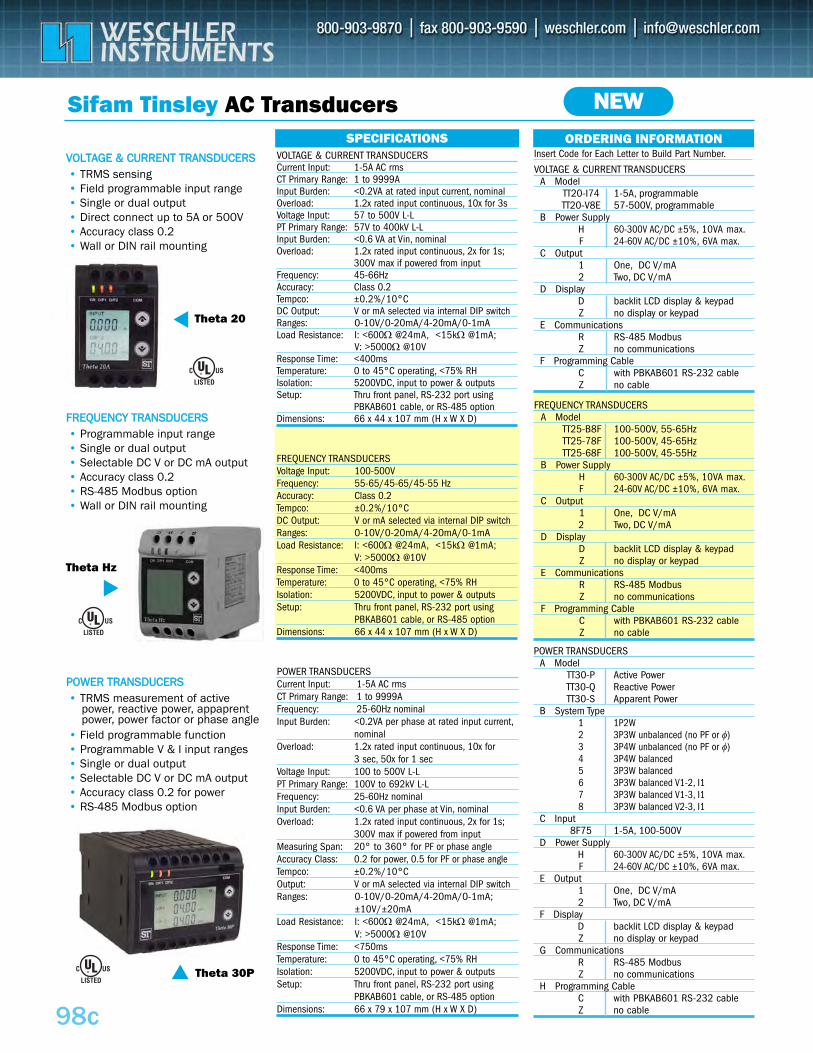
FREQUENCY TRANSDUCERSVoltage Input: 100-500V Frequency: 55-65/45-65/45-55 HzAccuracy: Class 0.2Tempco: ±0.2%/10°CDC Output: V or mA selected via internal DIP switchRanges: 0-10V/0-20mA/4-20mA/0-1mALoad Resistance: I: <600Ω @24mA, <15kΩ @1mA;
V: >5000Ω @10VResponse Time: <400msTemperature: 0 to 45°C operating, <75% RH Isolation: 5200VDC, input to power & outputsSetup: Thru front panel, RS-232 port using
PBKAB601 cable, or RS-485 option Dimensions: 66 x 44 x 107 mm (H x W X D)
FREQUENCY TRANSDUCERS A Model
TT25-B8F 100-500V, 55-65HzTT25-78F 100-500V, 45-65HzTT25-68F 100-500V, 45-55Hz
B Power SupplyH 60-300V AC/DC ±5%, 10VA max.F 24-60V AC/DC ±10%, 6VA max.
C Output1 One, DC V/mA2 Two, DC V/mA
D DisplayD backlit LCD display & keypadZ no display or keypad
E CommunicationsR RS-485 ModbusZ no communications
F Programming CableC with PBKAB601 RS-232 cableZ no cable
98c
Sifam Tinsley AC Transducers
Theta 20
Theta Hz
Theta 30P
SPECIFICATIONS
• TRMS sensing• Field programmable input range• Single or dual output • Direct connect up to 5A or 500V• Accuracy class 0.2 • Wall or DIN rail mounting
ORDERING INFORMATION
POWER TRANSDUCERS A Model
TT30-P Active Power TT30-Q Reactive PowerTT30-S Apparent Power
B System Type1 1P2W2 3P3W unbalanced (no PF or φ)3 3P4W unbalanced (no PF or φ)4 3P4W balanced5 3P3W balanced6 3P3W balanced V1-2, I17 3P3W balanced V1-3, I18 3P3W balanced V2-3, I1
C Input8F75 1-5A, 100-500V
D Power SupplyH 60-300V AC/DC ±5%, 10VA max.F 24-60V AC/DC ±10%, 6VA max.
E Output1 One, DC V/mA2 Two, DC V/mA
F DisplayD backlit LCD display & keypadZ no display or keypad
G CommunicationsR RS-485 ModbusZ no communications
H Programming CableC with PBKAB601 RS-232 cableZ no cable
VOLTAGE & CURRENT TRANSDUCERSA Model
TT20-I74 1-5A, programmable TT20-V8E 57-500V, programmable
B Power SupplyH 60-300V AC/DC ±5%, 10VA max.F 24-60V AC/DC ±10%, 6VA max.
C Output1 One, DC V/mA2 Two, DC V/mA
D DisplayD backlit LCD display & keypadZ no display or keypad
E CommunicationsR RS-485 ModbusZ no communications
F Programming CableC with PBKAB601 RS-232 cableZ no cable
NEW
VVOOLLTTAAGGEE && CCUURRRREENNTT TTRRAANNSSDDUUCCEERRSS
• Programmable input range• Single or dual output• Selectable DC V or DC mA output• Accuracy class 0.2• RS-485 Modbus option • Wall or DIN rail mounting
FFRREEQQUUEENNCCYY TTRRAANNSSDDUUCCEERRSS
• TRMS measurement of active power, reactive power, appaprent power, power factor or phase angle
• Field programmable function• Programmable V & I input ranges • Single or dual output• Selectable DC V or DC mA output• Accuracy class 0.2 for power • RS-485 Modbus option
PPOOWWEERR TTRRAANNSSDDUUCCEERRSS
VOLTAGE & CURRENT TRANSDUCERSCurrent Input: 1-5A AC rmsCT Primary Range: 1 to 9999AInput Burden: <0.2VA at rated input current, nominalOverload: 1.2x rated input continuous, 10x for 3sVoltage Input: 57 to 500V L-LPT Primary Range: 57V to 400kV L-LInput Burden: <0.6 VA at Vin, nominalOverload: 1.2x rated input continuous, 2x for 1s;
300V max if powered from inputFrequency: 45-66HzAccuracy: Class 0.2Tempco: ±0.2%/10°CDC Output: V or mA selected via internal DIP switchRanges: 0-10V/0-20mA/4-20mA/0-1mALoad Resistance: I: <600Ω @24mA, <15kΩ @1mA;
V: >5000Ω @10VResponse Time: <400msTemperature: 0 to 45°C operating, <75% RH Isolation: 5200VDC, input to power & outputsSetup: Thru front panel, RS-232 port using
PBKAB601 cable, or RS-485 option Dimensions: 66 x 44 x 107 mm (H x W X D)
POWER TRANSDUCERSCurrent Input: 1-5A AC rmsCT Primary Range: 1 to 9999AFrequency: 25-60Hz nominalInput Burden: <0.2VA per phase at rated input current,
nominalOverload: 1.2x rated input continuous, 10x for
3 sec, 50x for 1 secVoltage Input: 100 to 500V L-LPT Primary Range: 100V to 692kV L-LFrequency: 25-60Hz nominalInput Burden: <0.6 VA per phase at Vin, nominalOverload: 1.2x rated input continuous, 2x for 1s;
300V max if powered from inputMeasuring Span: 20° to 360° for PF or phase angleAccuracy Class: 0.2 for power, 0.5 for PF or phase angleTempco: ±0.2%/10°COutput: V or mA selected via internal DIP switchRanges: 0-10V/0-20mA/4-20mA/0-1mA;
±10V/±20mALoad Resistance: I: <600Ω @24mA, <15kΩ @1mA;
V: >5000Ω @10VResponse Time: <750msTemperature: 0 to 45°C operating, <75% RH Isolation: 5200VDC, input to power & outputsSetup: Thru front panel, RS-232 port using
PBKAB601 cable, or RS-485 option Dimensions: 66 x 79 x 107 mm (H x W X D)
®
®
®
Insert Code for Each Letter to Build Part Number.
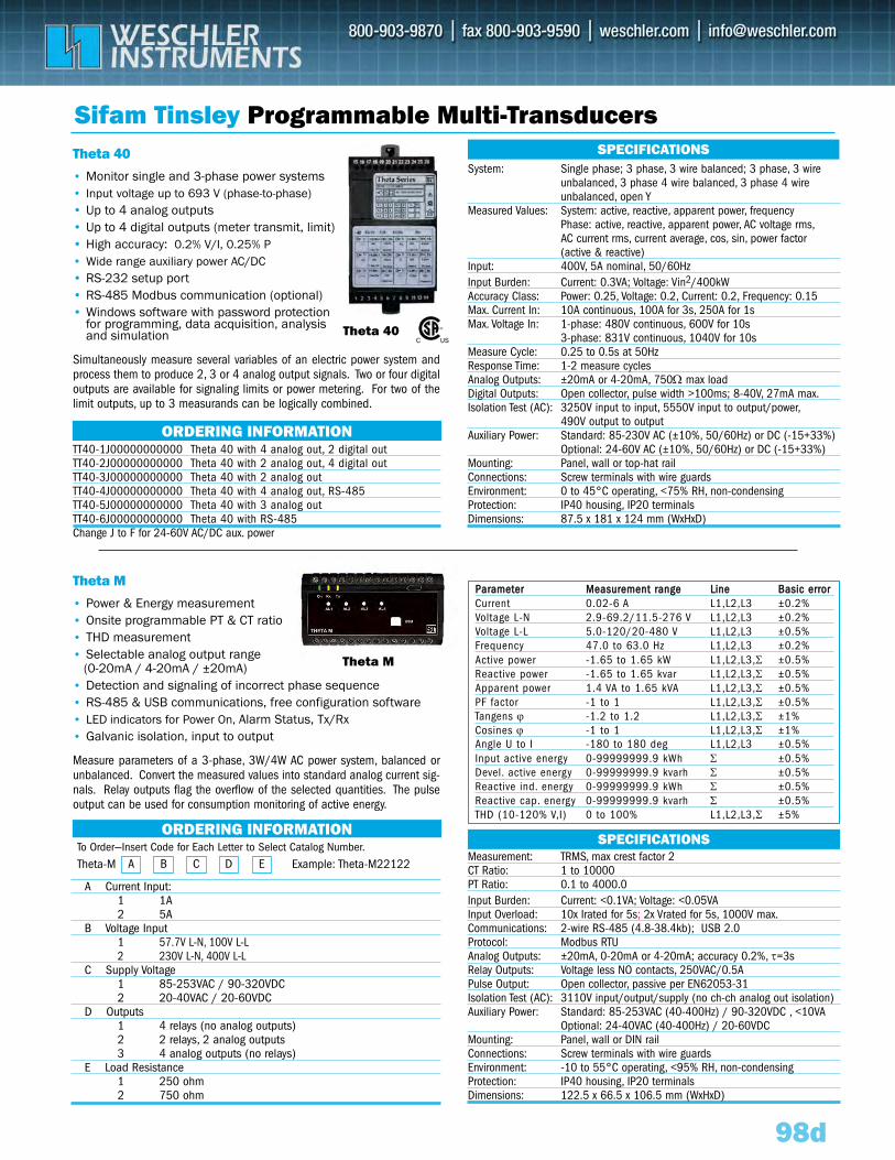
ORDERING INFORMATION
98d
Sifam Tinsley Programmable Multi-Transducers
• Power & Energy measurement• Onsite programmable PT & CT ratio • THD measurement• Selectable analog output range
(0-20mA / 4-20mA / ±20mA)• Detection and signaling of incorrect phase sequence• RS-485 & USB communications, free configuration software• LED indicators for Power On, Alarm Status, Tx/Rx • Galvanic isolation, input to output
• Monitor single and 3-phase power systems• Input voltage up to 693 V (phase-to-phase)• Up to 4 analog outputs • Up to 4 digital outputs (meter transmit, limit)• High accuracy: 0.2% V/I, 0.25% P • Wide range auxiliary power AC/DC• RS-232 setup port• RS-485 Modbus communication (optional)• Windows software with password protection
for programming, data acquisition, analysis and simulation
Theta M
System: Single phase; 3 phase, 3 wire balanced; 3 phase, 3 wire unbalanced, 3 phase 4 wire balanced, 3 phase 4 wire unbalanced, open Y
Measured Values: System: active, reactive, apparent power, frequencyPhase: active, reactive, apparent power, AC voltage rms,AC current rms, current average, cos, sin, power factor (active & reactive)
Input: 400V, 5A nominal, 50/60HzInput Burden: Current: 0.3VA; Voltage: Vin2/400kWAccuracy Class: Power: 0.25, Voltage: 0.2, Current: 0.2, Frequency: 0.15Max. Current In: 10A continuous, 100A for 3s, 250A for 1s Max. Voltage In: 1-phase: 480V continuous, 600V for 10s
3-phase: 831V continuous, 1040V for 10sMeasure Cycle: 0.25 to 0.5s at 50HzResponse Time: 1-2 measure cyclesAnalog Outputs: ±20mA or 4-20mA, 750Ω max loadDigital Outputs: Open collector, pulse width >100ms; 8-40V, 27mA max.Isolation Test (AC): 3250V input to input, 5550V input to output/power,
490V output to outputAuxiliary Power: Standard: 85-230V AC (±10%, 50/60Hz) or DC (-15+33%)
Optional: 24-60V AC (±10%, 50/60Hz) or DC (-15+33%)Mounting: Panel, wall or top-hat rail Connections: Screw terminals with wire guardsEnvironment: 0 to 45°C operating, <75% RH, non-condensingProtection: IP40 housing, IP20 terminalsDimensions: 87.5 x 181 x 124 mm (WxHxD)
SPECIFICATIONS
Theta 40
Theta M
Theta 40
Simultaneously measure several variables of an electric power system andprocess them to produce 2, 3 or 4 analog output signals. Two or four digitaloutputs are available for signaling limits or power metering. For two of thelimit outputs, up to 3 measurands can be logically combined.
A Current Input:1 1A2 5A
B Voltage Input 1 57.7V L-N, 100V L-L2 230V L-N, 400V L-L
C Supply Voltage1 85-253VAC / 90-320VDC2 20-40VAC / 20-60VDC
D Outputs1 4 relays (no analog outputs)2 2 relays, 2 analog outputs3 4 analog outputs (no relays)
E Load Resistance1 250 ohm2 750 ohm
ORDERING INFORMATIONTT40-1J00000000000 Theta 40 with 4 analog out, 2 digital out TT40-2J00000000000 Theta 40 with 2 analog out, 4 digital outTT40-3J00000000000 Theta 40 with 2 analog outTT40-4J00000000000 Theta 40 with 4 analog out, RS-485TT40-5J00000000000 Theta 40 with 3 analog outTT40-6J00000000000 Theta 40 with RS-485Change J to F for 24-60V AC/DC aux. power
To Order—Insert Code for Each Letter to Select Catalog Number.
A B C D ETheta-M Example: Theta-M22122
Measure parameters of a 3-phase, 3W/4W AC power system, balanced orunbalanced. Convert the measured values into standard analog current sig-nals. Relay outputs flag the overflow of the selected quantities. The pulseoutput can be used for consumption monitoring of active energy.
PPaarraammeetteerr MMeeaassuurreemmeenntt rraannggee LLiinnee BBaassiicc eerrrroorrCurrent 0.02-6 A L1,L2,L3 ±0.2%Voltage L-N 2.9-69.2/11.5-276 V L1,L2,L3 ±0.2%Voltage L-L 5.0-120/20-480 V L1,L2,L3 ±0.5%Frequency 47.0 to 63.0 Hz L1,L2,L3 ±0.2%Active power -1.65 to 1.65 kW L1,L2,L3,Σ ±0.5%Reactive power -1.65 to 1.65 kvar L1,L2,L3,Σ ±0.5%Apparent power 1.4 VA to 1.65 kVA L1,L2,L3,Σ ±0.5%PF factor -1 to 1 L1,L2,L3,Σ ±0.5%Tangens ϕ -1.2 to 1.2 L1,L2,L3,Σ ±1%Cosines ϕ -1 to 1 L1,L2,L3,Σ ±1%Angle U to I -180 to 180 deg L1,L2,L3 ±0.5%Input active energy 0-99999999.9 kWh Σ ±0.5%Devel. active energy 0-99999999.9 kvarh Σ ±0.5%Reactive ind. energy 0-99999999.9 kWh Σ ±0.5%Reactive cap. energy 0-99999999.9 kvarh Σ ±0.5%THD (10-120% V,I) 0 to 100% L1,L2,L3,Σ ±5%
Measurement: TRMS, max crest factor 2CT Ratio: 1 to 10000PT Ratio: 0.1 to 4000.0Input Burden: Current: <0.1VA; Voltage: <0.05VAInput Overload: 10x Irated for 5s; 2x Vrated for 5s, 1000V max.Communications: 2-wire RS-485 (4.8-38.4kb); USB 2.0 Protocol: Modbus RTUAnalog Outputs: ±20mA, 0-20mA or 4-20mA; accuracy 0.2%, τ=3s Relay Outputs: Voltage less NO contacts, 250VAC/0.5APulse Output: Open collector, passive per EN62053-31 Isolation Test (AC): 3110V input/output/supply (no ch-ch analog out isolation)Auxiliary Power: Standard: 85-253VAC (40-400Hz) / 90-320VDC , <10VA
Optional: 24-40VAC (40-400Hz) / 20-60VDCMounting: Panel, wall or DIN rail Connections: Screw terminals with wire guardsEnvironment: -10 to 55°C operating, <95% RH, non-condensingProtection: IP40 housing, IP20 terminalsDimensions: 122.5 x 66.5 x 106.5 mm (WxHxD)
SPECIFICATIONS
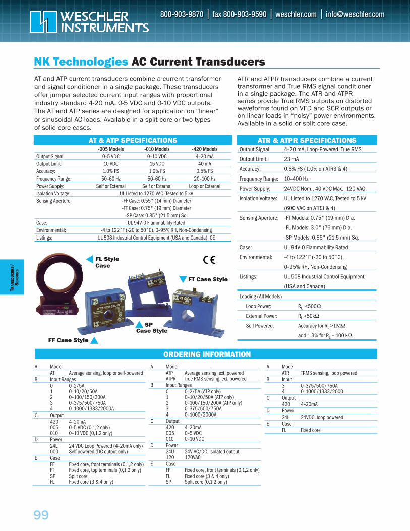
99
Output Signal: 4–20 mA, Loop-Powered, True RMS
Output Limit: 23 mA
Accuracy: 0.8% FS (1.0% on ATR3 & 4)
Frequency Range: 10–400 Hz
Power Supply: 24VDC Nom., 40 VDC Max., 120 VAC
Isolation Voltage: UL Listed to 1270 VAC, Tested to 5 kV
(600 VAC on ATR3 & 4)
Sensing Aperture: -FT Models: 0.75" (19 mm) Dia.
-FL Models: 3.0" (76 mm) Dia.
-SP Models: 0.85" (21.5 mm) Sq.
Case: UL 94V-0 Flammability Rated
Environmental: -4 to 122˚F (-20 to 50˚C),
0–95% RH, Non-Condensing
Listings: UL 508 Industrial Control Equipment
(USA and Canada)
Loading (All Models)
Loop Power: RL <500Ω
External Power: RL >50kΩ
Self Powered: Accuracy for RL >1ΜΩ,
add 1.3% for RL = 100 kΩ
-005 Models -010 Models -420 ModelsOutput Signal: 0–5 VDC 0–10 VDC 4–20 mAOutput Limit: 10 VDC 15 VDC 40 mAAccuracy: 1.0% FS 1.0% FS 0.5% FSFrequency Range: 50–60 Hz 50–60 Hz 20–100 HzPower Supply: Self or External Self or External Loop or ExternalIsolation Voltage: UL Listed to 1270 VAC, Tested to 5 kVSensing Aperture: -FF Case: 0.55" (14 mm) Diameter
-FT Case: 0.75" (19 mm) Diameter-SP Case: 0.85" (21.5 mm) Sq.
Case: UL 94V-0 Flammability RatedEnvironmental: -4 to 122˚F (-20 to 50˚C), 0–95% RH, Non-CondensingListings: UL 508 Industrial Control Equipment (USA and Canada), CE
AT & ATP SPECIFICATIONS
NK Technologies AC Current Transducers
FL Style Case
AT and ATP current transducers combine a current transformerand signal conditioner in a single package. These transducersoffer jumper selected current input ranges with proportionalindustry standard 4-20 mA, 0-5 VDC and 0-10 VDC outputs.The AT and ATP series are designed for application on “linear”or sinusoidal AC loads. Available in a split core or two types of solid core cases.
ATR and ATPR transducers combine a currenttransformer and True RMS signal conditioner in a single package. The ATR and ATPR series provide True RMS outputs on distortedwaveforms found on VFD and SCR outputs or on linear loads in “noisy” power environments.Available in a solid or split core case.
ATR & ATPR SPECIFICATIONS
FT Case Style
SP Case Style
FF Case Style
A ModelAT Average sensing, loop or self-powered
B Input Ranges0 0–2/5A1 0–10/20/50A2 0–100/150/200A3 0–375/500/750A4 0–1000/1333/2000A
C Output420 4–20mA005 0–5 VDC (0,1,2 only)010 0–10 VDC (0,1,2 only)
D Power24L 24 VDC Loop Powered (4–20mA only)000 Self powered (DC output only)
E CaseFF Fixed core, front terminals (0,1,2 only)FT Fixed core, top terminals (0,1,2 only)SP Split coreFL Fixed core (3 & 4 only)
A ModelATP Average sensing, ext. poweredATPR True RMS sensing, ext. powered
B Input Ranges0 0–2/5A (ATP only)1 0–10/20/50A (ATP only)2 0–100/150/200A (ATP only)3 0–375/500/750A4 0–1000/2000A
C Output420 4–20mA005 0–5 VDC010 0–10 VDC
D Power24U 24V AC/DC, isolated output120 120VAC
E CaseFF Fixed core, front terminals (0,1,2 only)FL Fixed core (3 & 4 only)SP Split core (0,1,2 only)
A ModelATR TRMS sensing, loop powered
B Input3 0–375/500/750A4 0–1000/1333/2000
C Output420 4–20mA
D Power24L 24VDC, loop powered
E CaseFL Fixed core
ORDERING INFORMATION
TRAN
SDUC
ERS
/SE
NSO
RS
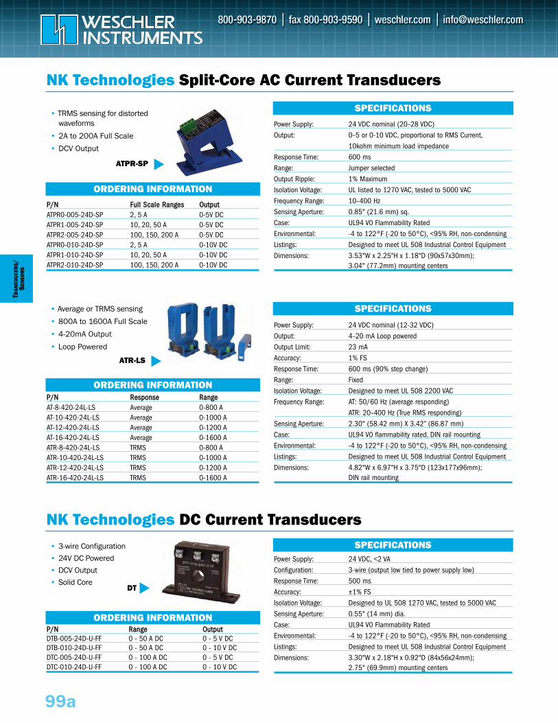
• 3-wire Configuration
• 24V DC Powered
• DCV Output
• Solid Core
TRAN
SDUC
ERS/
SEN
SOR
S
PP//NN RRaannggee OOuuttppuuttDTB-005-24D-U-FF 0 - 50 A DC 0 - 5 V DCDTB-010-24D-U-FF 0 - 50 A DC 0 - 10 V DCDTC-005-24D-U-FF 0 - 100 A DC 0 - 5 V DCDTC-010-24D-U-FF 0 - 100 A DC 0 - 10 V DC
NK Technologies Split-Core AC Current Transducers
ORDERING INFORMATION
ORDERING INFORMATION
PP//NN FFuullll SSccaallee RRaannggeess OOuuttppuuttATPR0-005-24D-SP 2, 5 A 0-5V DC ATPR1-005-24D-SP 10, 20, 50 A 0-5V DC ATPR2-005-24D-SP 100, 150, 200 A 0-5V DC ATPR0-010-24D-SP 2, 5 A 0-10V DC ATPR1-010-24D-SP 10, 20, 50 A 0-10V DC ATPR2-010-24D-SP 100, 150, 200 A 0-10V DC
PP//NN RReessppoonnssee RRaannggeeAT-8-420-24L-LS Average 0-800 AAT-10-420-24L-LS Average 0-1000 A AT-12-420-24L-LS Average 0-1200 A AT-16-420-24L-LS Average 0-1600 A ATR-8-420-24L-LS TRMS 0-800 AATR-10-420-24L-LS TRMS 0-1000 A ATR-12-420-24L-LS TRMS 0-1200 A ATR-16-420-24L-LS TRMS 0-1600 A
SPECIFICATIONS
SPECIFICATIONS
NK Technologies DC Current TransducersSPECIFICATIONS
ORDERING INFORMATION
99a
• TRMS sensing for distortedwaveforms
• 2A to 200A Full Scale
• DCV Output
• Average or TRMS sensing
• 800A to 1600A Full Scale
• 4-20mA Output
• Loop Powered
DT
Power Supply: 24 VDC, <2 VAConfiguration: 3-wire (output low tied to power supply low)Response Time: 500 msAccuracy: ±1% FSIsolation Voltage: Designed to UL 508 1270 VAC, tested to 5000 VACSensing Aperture: 0.55" (14 mm) dia.Case: UL94 V0 Flammability RatedEnvironmental: -4 to 122°F (-20 to 50°C), <95% RH, non-condensingListings: Designed to meet UL 508 Industrial Control EquipmentDimensions: 3.30"W x 2.18"H x 0.92"D (84x56x24mm);
2.75" (69.9mm) mounting centers
Power Supply: 24 VDC nominal (12-32 VDC)Output: 4–20 mA Loop poweredOutput Limit: 23 mAAccuracy: 1% FSResponse Time: 600 ms (90% step change)Range: FixedIsolation Voltage: Designed to meet UL 508 2200 VACFrequency Range: AT: 50/60 Hz (average responding)
ATR: 20–400 Hz (True RMS responding)Sensing Aperture: 2.30" (58.42 mm) X 3.42” (86.87 mm)Case: UL94 V0 flammability rated, DIN rail mountingEnvironmental: -4 to 122°F (-20 to 50°C), <95% RH, non-condensingListings: Designed to meet UL 508 Industrial Control EquipmentDimensions: 4.82"W x 6.97"H x 3.75"D (123x177x96mm);
DIN rail mounting
Power Supply: 24 VDC nominal (20–28 VDC)Output: 0–5 or 0-10 VDC, proportional to RMS Current,
10kohm minimum load impedanceResponse Time: 600 msRange: Jumper selectedOutput Ripple: 1% MaximumIsolation Voltage: UL listed to 1270 VAC, tested to 5000 VACFrequency Range: 10–400 HzSensing Aperture: 0.85" (21.6 mm) sq.Case: UL94 V0 Flammability RatedEnvironmental: -4 to 122°F (-20 to 50°C), <95% RH, non-condensingListings: Designed to meet UL 508 Industrial Control EquipmentDimensions: 3.53"W x 2.25"H x 1.18"D (90x57x30mm);
3.04" (77.2mm) mounting centers
ATPR-SP
ATR-LS
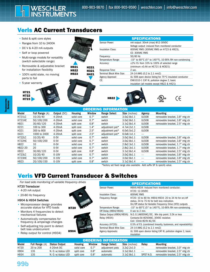
TRAN
SDUC
ERS/
SEN
SOR
S
Veris AC Current Transducers
Veris VFD Current Transducer & Switches
SPECIFICATIONS
99b
• Solid & split core styles
• Ranges from 10 to 2400A
• DC V & 4-20 mA outputs
• Self or loop powered
• Multi-range models for versatility(switch selectable range)
• Removable & adjustable bracketfor installation flexibility
• 100% solid state, no movingparts to fail
• 5-year warranty
HH772200 TTrraannssdduucceerr• 4-20 mA output
• 20-80 Hz frequency
HH990044 && HH993344 SSwwiittcchheess• Microprocessor design provides
accurate status for VFD loads• Monitors 4 frequencies to detect
mechanical failures• Automatically compensates for
frequency & amperage changes • Self-adjusting trip point to detect
belt loss undercurrent• Relay output for control (H934)
Sensor Power: mA output: 30mA (max) @12-30VDCVoltage output: induced from monitored conductor
Insulation Class: 600VAC RMS (300VAC RMS on H723 & H923),CE: 300VAC RMS
Frequency: 50/60 HzTemperature Range: -15° to 60°C (5° to 140°F), 10-90% RH non-condensingAccuracy: ±2% F.S. from 10% to 100% of selected range
(minimum ±0.4A on HC721 & HC921)Response Time: 2 sec.Terminal Block Wire Size: 24-14 AWG (0.2 to 2.1 mm2)Agency Approval: UL 508 open device listing for 75°C insulated conductorCE: EN61010-1 CAT III, pollution degree 2, basic
insulation (all models except H822 & H421)
SPECIFICATIONSSensor Power: H904/H934: Induced from monitored conductor;
H720: 12-30VDCInsulation Class: 600VAC RMSFrequency Range: H720: 10 to 80 Hz; H904/H934: 20 to 34 Hz for on/off
status, 34 to 75 Hz for belt loss indication.On/Off status for Variable Frequency Drive (VFD) outputs
Temperature Range: -15° to 60°C (5° to 140°F), 10-90% RH non-condensingOff Delay (H904/H934): 0 sec to 2 min.Status Output (H904/H934): N.O. 0.1A@30VAC/DC; Min trip point: 3.5A or lessRelay (H934): Contacts:5A @250VAC, 30VDC resistive;
Coil: 10mA @24V AC/DCAccuracy (H720): 0.5% of F.S. (combined linearity, hysteresis, and repeatability)Terminal Block Wire Size: 24-14 AWG (0.2 to 2.1 mm2)Agency Approvals: UL 508 open device listing CAT III, pollution degree 2, basic
insulation
H721H722H723
H921H922H923
H221H321H421
H822
ORDERING INFORMATION
ORDERING INFORMATION
MMooddeell FFuullll RRaannggee (A) OOuuttppuutt (DC) HHoouussiinngg WWiinnddooww RRaannggee SSeelleecctt SSiizzee (inches) AAggeennccyy MMoouunnttiinnggH721LC 10/20/40 4-20mA solid core 0.7" switch 3.0x2.8x1.1 UL508 removable bracket, 3.8" mtg ctrH721HC 50/100/200 4-20mA solid core 0.7" switch 3.0x2.8x1.1 UL508 removable bracket, 3.8" mtg ctrH921 30/60/120 4-20mA split core 0.8" switch 3.1x2.8x1.4 UL508 removable bracket, 2.5" mtg ctrH221 100 to 300 4-20mA split core 1.4" adjustment pot* 4.7x4.2x1.1 UL508H321 300 to 800 4-20mA split core 2.5" adjustment pot* 6.0x5.5x1.2 UL508H421 1000 to 2400 4-20mA split core 2.5" adjustment pot* 6.0x8.1x1.1 ---H722LC 10/20/40 0-5V solid core 0.7" switch 3.0x2.8x1.1 UL508 removable bracket, 3.8" mtg ctrH722HC 50/100/200 0-5V solid core 0.7" switch 3.0x2.8x1.1 UL508 removable bracket, 3.8" mtg ctrH822 10 0-5V solid core 0.7" switch 2.8x2.3x1.1 UL508 removable bracket, 1.7" mtg ctrH822-20 20 0-5V solid core 0.7" switch 2.8x2.3x1.1 UL508 removable bracket, 1.7" mtg ctrH922 30/60/120 0-5V split core 0.8" switch 3.1x2.8x1.4 UL508 removable bracket, 2.5" mtg ctrH723LC 10/20/40 0-10V solid core 0.7" switch 3.0x2.8x1.1 --- removable bracket, 3.8" mtg ctrH723HC 50/100/200 0-10V solid core 0.7" switch 3.0x2.8x1.1 --- removable bracket, 3.8" mtg ctrH923 20/100/150 0-10V split core 0.8" switch 3.1x2.8x1.4 --- removable bracket, 2.5" mtg ctr
MMooddeell FFuullll RRaannggee (A) SSttaattuuss OOuuttppuutt HHoouussiinngg WWiinnddooww RRaannggee SSeelleecctt SSiizzee (inches) RReellaayy MMoouunnttiinnggH720 20 to 200 4-20mA DC solid core 0.7" adjustment pots 3.2x2.2x1.0 --- removable bracket, 3.0" mtg ctrH904 135 N. O. w/status LED split core 0.8" automatic 3.1x2.8x1.1 --- removable bracket, 2.5" mtg ctrH934 135 N. O. w/status LED split core 0.8" automatic 3.1x2.8x1.1 SPST N.O. removable bracket, 2.5" mtg ctr
*factory set fixed range also available. Add suffix SP & specify value.
H720
H904
For load side monitoring of variable frequency drives
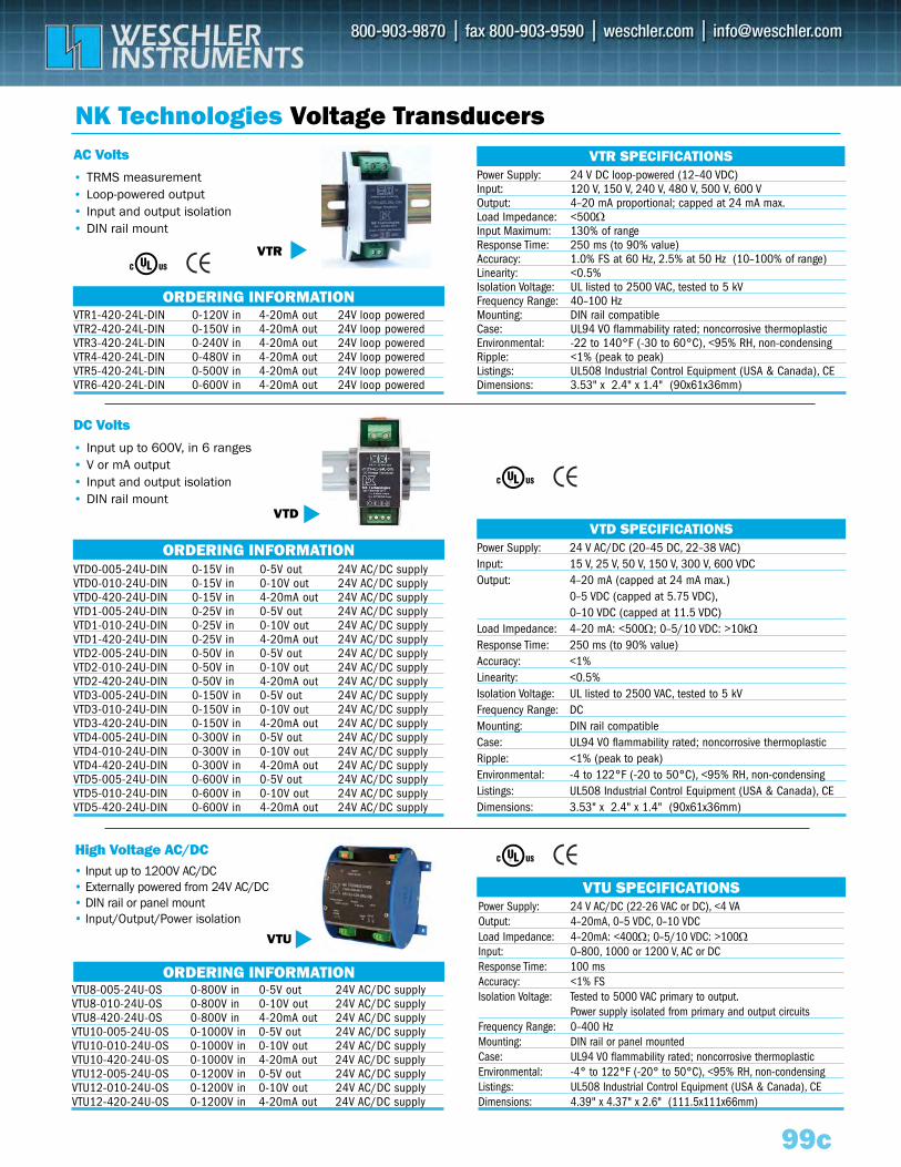
Power Supply: 24 V AC/DC (22-26 VAC or DC), <4 VA Output: 4–20mA, 0–5 VDC, 0–10 VDCLoad Impedance: 4–20mA: <400Ω; 0–5/10 VDC: >100ΩInput: 0–800, 1000 or 1200 V, AC or DCResponse Time: 100 msAccuracy: <1% FSIsolation Voltage: Tested to 5000 VAC primary to output.
Power supply isolated from primary and output circuitsFrequency Range: 0–400 HzMounting: DIN rail or panel mountedCase: UL94 V0 flammability rated; noncorrosive thermoplasticEnvironmental: -4° to 122°F (-20° to 50°C), <95% RH, non-condensingListings: UL508 Industrial Control Equipment (USA & Canada), CE Dimensions: 4.39" x 4.37" x 2.6" (111.5x111x66mm)
VTU SPECIFICATIONS
ORDERING INFORMATION
ORDERING INFORMATION
ORDERING INFORMATION
99c
NK Technologies Voltage Transducers
• Input up to 600V, in 6 ranges• V or mA output• Input and output isolation• DIN rail mount
• TRMS measurement• Loop-powered output• Input and output isolation• DIN rail mount
VTU
VTD
Power Supply: 24 V AC/DC (20–45 DC, 22–38 VAC)Input: 15 V, 25 V, 50 V, 150 V, 300 V, 600 VDCOutput: 4–20 mA (capped at 24 mA max.)
0–5 VDC (capped at 5.75 VDC),0–10 VDC (capped at 11.5 VDC)
Load Impedance: 4–20 mA: <500Ω; 0–5/10 VDC: >10kΩResponse Time: 250 ms (to 90% value)Accuracy: <1%Linearity: <0.5%Isolation Voltage: UL listed to 2500 VAC, tested to 5 kVFrequency Range: DCMounting: DIN rail compatibleCase: UL94 V0 flammability rated; noncorrosive thermoplasticRipple: <1% (peak to peak)Environmental: -4 to 122°F (-20 to 50°C), <95% RH, non-condensingListings: UL508 Industrial Control Equipment (USA & Canada), CEDimensions: 3.53" x 2.4" x 1.4" (90x61x36mm)
Power Supply: 24 V DC loop-powered (12–40 VDC)Input: 120 V, 150 V, 240 V, 480 V, 500 V, 600 VOutput: 4–20 mA proportional; capped at 24 mA max.Load Impedance: <500ΩInput Maximum: 130% of rangeResponse Time: 250 ms (to 90% value)Accuracy: 1.0% FS at 60 Hz, 2.5% at 50 Hz (10–100% of range)Linearity: <0.5%Isolation Voltage: UL listed to 2500 VAC, tested to 5 kVFrequency Range: 40–100 HzMounting: DIN rail compatibleCase: UL94 V0 flammability rated; noncorrosive thermoplasticEnvironmental: -22 to 140°F (-30 to 60°C), <95% RH, non-condensingRipple: <1% (peak to peak)Listings: UL508 Industrial Control Equipment (USA & Canada), CEDimensions: 3.53" x 2.4" x 1.4" (90x61x36mm)
VTR1-420-24L-DIN 0-120V in 4-20mA out 24V loop poweredVTR2-420-24L-DIN 0-150V in 4-20mA out 24V loop poweredVTR3-420-24L-DIN 0-240V in 4-20mA out 24V loop poweredVTR4-420-24L-DIN 0-480V in 4-20mA out 24V loop poweredVTR5-420-24L-DIN 0-500V in 4-20mA out 24V loop poweredVTR6-420-24L-DIN 0-600V in 4-20mA out 24V loop powered
VTU8-005-24U-OS 0-800V in 0-5V out 24V AC/DC supplyVTU8-010-24U-OS 0-800V in 0-10V out 24V AC/DC supplyVTU8-420-24U-OS 0-800V in 4-20mA out 24V AC/DC supplyVTU10-005-24U-OS 0-1000V in 0-5V out 24V AC/DC supplyVTU10-010-24U-OS 0-1000V in 0-10V out 24V AC/DC supplyVTU10-420-24U-OS 0-1000V in 4-20mA out 24V AC/DC supplyVTU12-005-24U-OS 0-1200V in 0-5V out 24V AC/DC supplyVTU12-010-24U-OS 0-1200V in 0-10V out 24V AC/DC supplyVTU12-420-24U-OS 0-1200V in 4-20mA out 24V AC/DC supply
VTD0-005-24U-DIN 0-15V in 0-5V out 24V AC/DC supplyVTD0-010-24U-DIN 0-15V in 0-10V out 24V AC/DC supplyVTD0-420-24U-DIN 0-15V in 4-20mA out 24V AC/DC supplyVTD1-005-24U-DIN 0-25V in 0-5V out 24V AC/DC supplyVTD1-010-24U-DIN 0-25V in 0-10V out 24V AC/DC supplyVTD1-420-24U-DIN 0-25V in 4-20mA out 24V AC/DC supplyVTD2-005-24U-DIN 0-50V in 0-5V out 24V AC/DC supplyVTD2-010-24U-DIN 0-50V in 0-10V out 24V AC/DC supplyVTD2-420-24U-DIN 0-50V in 4-20mA out 24V AC/DC supplyVTD3-005-24U-DIN 0-150V in 0-5V out 24V AC/DC supplyVTD3-010-24U-DIN 0-150V in 0-10V out 24V AC/DC supplyVTD3-420-24U-DIN 0-150V in 4-20mA out 24V AC/DC supplyVTD4-005-24U-DIN 0-300V in 0-5V out 24V AC/DC supplyVTD4-010-24U-DIN 0-300V in 0-10V out 24V AC/DC supplyVTD4-420-24U-DIN 0-300V in 4-20mA out 24V AC/DC supplyVTD5-005-24U-DIN 0-600V in 0-5V out 24V AC/DC supplyVTD5-010-24U-DIN 0-600V in 0-10V out 24V AC/DC supplyVTD5-420-24U-DIN 0-600V in 4-20mA out 24V AC/DC supply
VTD SPECIFICATIONS
VTR SPECIFICATIONS
VTR
DC Volts
AC Volts
High Voltage AC/DC• Input up to 1200V AC/DC• Externally powered from 24V AC/DC • DIN rail or panel mount• Input/Output/Power isolation
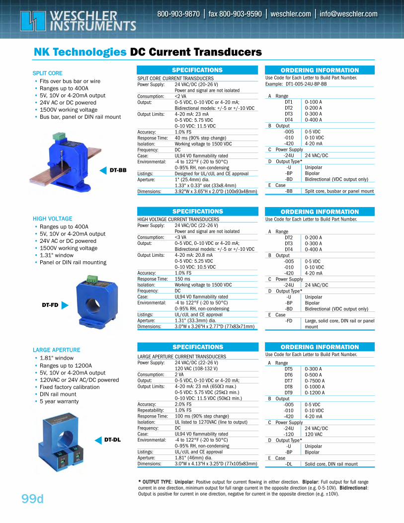
HIGH VOLTAGE CURRENT TRANSDUCERSPower Supply: 24 VAC/DC (22–26 V)
Power and signal are not isolatedConsumption: <3 VAOutput: 0–5 VDC, 0–10 VDC or 4–20 mA;
Bidirectional models: +/-5 or +/-10 VDCOutput Limits: 4–20 mA: 20.8 mA
0–5 VDC: 5.25 VDC0–10 VDC: 10.5 VDC
Accuracy: 1.0% FSResponse Time: 150 ms Isolation: Working voltage to 1500 VDCFrequency: DCCase: UL94 V0 flammability ratedEnvironmental: -4 to 122°F (-20 to 50°C)
0–95% RH, non-condensingListings: UL/cUL and CE approvalAperture: 1.31" (33.3mm) dia.Dimensions: 3.0"W x 3.26"H x 2.77"D (77x83x71mm)
A RangeDT2 0-200 ADT3 0-300 A DT4 0-400 A
B Output-005 0-5 VDC-010 0-10 VDC-420 4-20 mA
C Power Supply-24U 24 VAC/DC
D Output Type*-U Unipolar-BP Bipolar-BD Bidirectional (VDC output only)
E Case-FD Large, solid core, DIN rail or panel
mount
99d
NK Technologies DC Current Transducers
DT-FD
DT-DL
SPECIFICATIONS
SPECIFICATIONS
SPECIFICATIONS
• Fits over bus bar or wire• Ranges up to 400A• 5V, 10V or 4-20mA output • 24V AC or DC powered• 1500V working voltage • Bus bar, panel or DIN rail mount
ORDERING INFORMATION
A RangeDT5 0-300 A DT6 0-500 ADT7 0-7500 A DT8 0-1000 ADT9 0-1200 A
B Output-005 0-5 VDC-010 0-10 VDC-420 4-20 mA
C Power Supply-24U 24 VAC/DC-120 120 VAC
D Output Type*-U Unipolar-BP Bipolar
E Case-DL Solid core, DIN rail mount
A RangeDT1 0-100 A DT2 0-200 ADT3 0-300 A DT4 0-400 A
B Output-005 0-5 VDC-010 0-10 VDC-420 4-20 mA
C Power Supply-24U 24 VAC/DC
D Output Type*-U Unipolar-BP Bipolar-BD Bidirectional (VDC output only)
E Case-BB Split core, busbar or panel mount
SSPPLLIITT CCOORREE
• Ranges up to 400A• 5V, 10V or 4-20mA output• 24V AC or DC powered• 1500V working voltage• 1.31" window • Panel or DIN rail mounting
HHIIGGHH VVOOLLTTAAGGEE
• 1.81" window • Ranges up to 1200A• 5V, 10V or 4-20mA output • 120VAC or 24V AC/DC powered• Fixed factory calibration• DIN rail mount • 5 year warranty
LLAARRGGEE AAPPEERRTTUURREE
SPLIT CORE CURRENT TRANSDUCERSPower Supply: 24 VAC/DC (20–26 V)
Power and signal are not isolatedConsumption: <2 VAOutput: 0–5 VDC, 0–10 VDC or 4–20 mA;
Bidirectional models: +/-5 or +/-10 VDCOutput Limits: 4–20 mA: 23 mA
0–5 VDC: 5.75 VDC0–10 VDC: 11.5 VDC
Accuracy: 1.0% FSResponse Time: 40 ms (90% step change)Isolation: Working voltage to 1500 VDCFrequency: DCCase: UL94 V0 flammability ratedEnvironmental: -4 to 122°F (-20 to 50°C)
0–95% RH, non-condensingListings: Designed for UL/cUL and CE approvalAperture: 1" (25.4mm) dia.
1.33" x 0.33" slot (33x8.4mm)Dimensions: 3.92"W x 3.65"H x 2.0"D (100x93x48mm)
LARGE APERTURE CURRENT TRANSDUCERSPower Supply: 24 VAC/DC (22–26 V)
120 VAC (108-132 V)Consumption: 2 VAOutput: 0–5 VDC, 0–10 VDC or 4–20 mA;Output Limits: 4–20 mA: 23 mA (650Ω max.)
0–5 VDC: 5.75 VDC (25kΩ min.)0–10 VDC: 11.5 VDC (50kΩ min.)
Accuracy: 2.0% FSRepeatability: 1.0% FSResponse Time: 100 ms (90% step change)Isolation: UL listed to 1270VAC (line to output)Frequency: DCCase: UL94 V0 flammability ratedEnvironmental: -4 to 122°F (-20 to 50°C)
0–95% RH, non-condensingListings: UL/cUL and CE approvalAperture: 1.81" (46mm) dia.Dimensions: 3.0"W x 4.13"H x 3.25"D (77x105x83mm)
Use Code for Each Letter to Build Part Number.Example: DT1-005-24U-BP-BB
ORDERING INFORMATIONUse Code for Each Letter to Build Part Number.
ORDERING INFORMATIONUse Code for Each Letter to Build Part Number.
DT-BB
** OOUUTTPPUUTT TTYYPPEE: UUnniippoollaarr: Positive output for current flowing in either direction. BBiippoollaarr: Full output for full rangecurrent in one direction, minimum output for full range current in the opposite direction (e.g. 0-5-10V). BBiiddiirreeccttiioonnaall:Output is positive for current in one direction, negative for current in the opposite direction (e.g. ±10V).
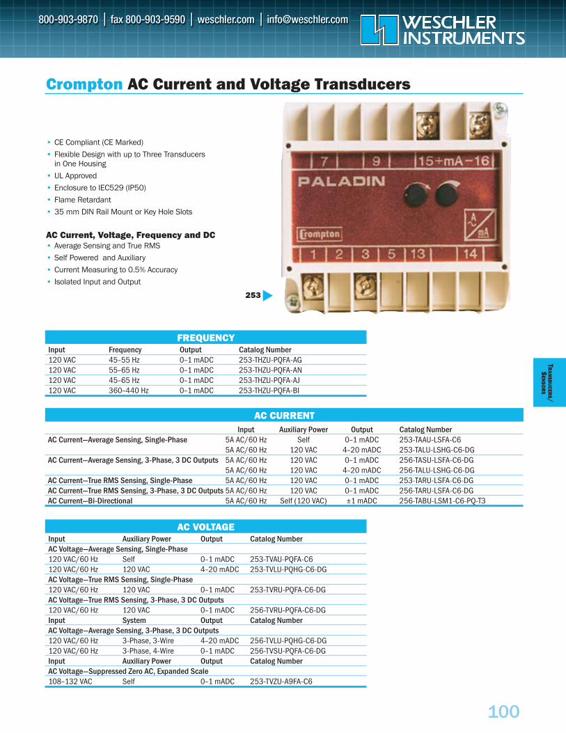
100
TRAN
SDUCER
S/S
ENSO
RS
Input Frequency Output Catalog Number120 VAC 45–55 Hz 0–1 mADC 253-THZU-PQFA-AG120 VAC 55–65 Hz 0–1 mADC 253-THZU-PQFA-AN120 VAC 45–65 Hz 0–1 mADC 253-THZU-PQFA-AJ120 VAC 360–440 Hz 0–1 mADC 253-THZU-PQFA-BI
Input Auxiliary Power Output Catalog Number AC Voltage—Average Sensing, Single-Phase120 VAC/60 Hz Self 0–1 mADC 253-TVAU-PQFA-C6120 VAC/60 Hz 120 VAC 4–20 mADC 253-TVLU-PQHG-C6-DGAC Voltage—True RMS Sensing, Single-Phase 120 VAC/60 Hz 120 VAC 0–1 mADC 253-TVRU-PQFA-C6-DGAC Voltage—True RMS Sensing, 3-Phase, 3 DC Outputs120 VAC/60 Hz 120 VAC 0–1 mADC 256-TVRU-PQFA-C6-DGInput System Output Catalog NumberAC Voltage—Average Sensing, 3-Phase, 3 DC Outputs120 VAC/60 Hz 3-Phase, 3-Wire 4–20 mADC 256-TVLU-PQHG-C6-DG120 VAC/60 Hz 3-Phase, 4-Wire 0–1 mADC 256-TVSU-PQFA-C6-DGInput Auxiliary Power Output Catalog NumberAC Voltage—Suppressed Zero AC, Expanded Scale 108–132 VAC Self 0–1 mADC 253-TVZU-A9FA-C6
Input Auxiliary Power Output Catalog Number AC Current—Average Sensing, Single-Phase 5A AC/60 Hz Self 0–1 mADC 253-TAAU-LSFA-C6
5A AC/60 Hz 120 VAC 4–20 mADC 253-TALU-LSHG-C6-DG AC Current—Average Sensing, 3-Phase, 3 DC Outputs 5A AC/60 Hz 120 VAC 0–1 mADC 256-TASU-LSFA-C6-DG
5A AC/60 Hz 120 VAC 4–20 mADC 256-TALU-LSHG-C6-DG AC Current—True RMS Sensing, Single-Phase 5A AC/60 Hz 120 VAC 0–1 mADC 253-TARU-LSFA-C6-DGAC Current—True RMS Sensing, 3-Phase, 3 DC Outputs 5A AC/60 Hz 120 VAC 0–1 mADC 256-TARU-LSFA-C6-DG AC Current—Bi-Directional 5A AC/60 Hz Self (120 VAC) ±1 mADC 256-TABU-LSM1-C6-PQ-T3
AC CURRENT
Crompton AC Current and Voltage Transducers
• CE Compliant (CE Marked)
• Flexible Design with up to Three Transducers in One Housing
• UL Approved
• Enclosure to IEC529 (IP50)
• Flame Retardant
• 35 mm DIN Rail Mount or Key Hole Slots
AC Current, Voltage, Frequency and DC• Average Sensing and True RMS
• Self Powered and Auxiliary
• Current Measuring to 0.5% Accuracy
• Isolated Input and Output
253
AC VOLTAGE
FREQUENCY
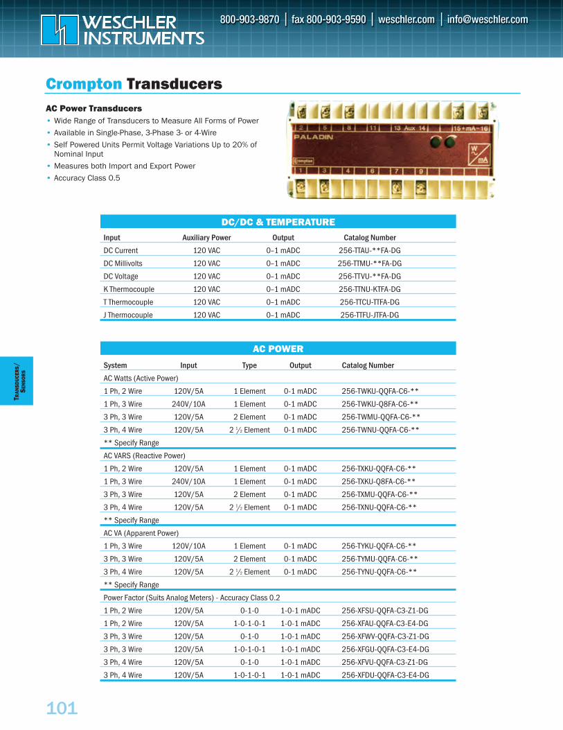
101
TRAN
SDUC
ERS
/SE
NSO
RS
Input Auxiliary Power Output Catalog Number
DC Current 120 VAC 0–1 mADC 256-TTAU-**FA-DG
DC Millivolts 120 VAC 0–1 mADC 256-TTMU-**FA-DG
DC Voltage 120 VAC 0–1 mADC 256-TTVU-**FA-DG
K Thermocouple 120 VAC 0–1 mADC 256-TTNU-KTFA-DG
T Thermocouple 120 VAC 0–1 mADC 256-TTCU-TTFA-DG
J Thermocouple 120 VAC 0–1 mADC 256-TTFU-JTFA-DG
Crompton Transducers
DC/DC & TEMPERATURE
AC POWER
AC Power Transducers• Wide Range of Transducers to Measure All Forms of Power
• Available in Single-Phase, 3-Phase 3- or 4-Wire
• Self Powered Units Permit Voltage Variations Up to 20% of Nominal Input
• Measures both Import and Export Power
• Accuracy Class 0.5
System Input Type Output Catalog Number
AC Watts (Active Power)
1 Ph, 2 Wire 120V/5A 1 Element 0-1 mADC 256-TWKU-QQFA-C6-**
1 Ph, 3 Wire 240V/10A 1 Element 0-1 mADC 256-TWKU-Q8FA-C6-**
3 Ph, 3 Wire 120V/5A 2 Element 0-1 mADC 256-TWMU-QQFA-C6-**
3 Ph, 4 Wire 120V/5A 2 1/2 Element 0-1 mADC 256-TWNU-QQFA-C6-**
** Specify Range
AC VARS (Reactive Power)
1 Ph, 2 Wire 120V/5A 1 Element 0-1 mADC 256-TXKU-QQFA-C6-**
1 Ph, 3 Wire 240V/10A 1 Element 0-1 mADC 256-TXKU-Q8FA-C6-**
3 Ph, 3 Wire 120V/5A 2 Element 0-1 mADC 256-TXMU-QQFA-C6-**
3 Ph, 4 Wire 120V/5A 2 1/2 Element 0-1 mADC 256-TXNU-QQFA-C6-**
** Specify Range
AC VA (Apparent Power)
1 Ph, 3 Wire 120V/10A 1 Element 0-1 mADC 256-TYKU-QQFA-C6-**
3 Ph, 3 Wire 120V/5A 2 Element 0-1 mADC 256-TYMU-QQFA-C6-**
3 Ph, 4 Wire 120V/5A 2 1/2 Element 0-1 mADC 256-TYNU-QQFA-C6-**
** Specify Range
Power Factor (Suits Analog Meters) - Accuracy Class 0.2
1 Ph, 2 Wire 120V/5A 0-1-0 1-0-1 mADC 256-XFSU-QQFA-C3-Z1-DG
1 Ph, 2 Wire 120V/5A 1-0-1-0-1 1-0-1 mADC 256-XFAU-QQFA-C3-E4-DG
3 Ph, 3 Wire 120V/5A 0-1-0 1-0-1 mADC 256-XFWV-QQFA-C3-Z1-DG
3 Ph, 3 Wire 120V/5A 1-0-1-0-1 1-0-1 mADC 256-XFGU-QQFA-C3-E4-DG
3 Ph, 4 Wire 120V/5A 0-1-0 1-0-1 mADC 256-XFVU-QQFA-C3-Z1-DG
3 Ph, 4 Wire 120V/5A 1-0-1-0-1 1-0-1 mADC 256-XFDU-QQFA-C3-E4-DG
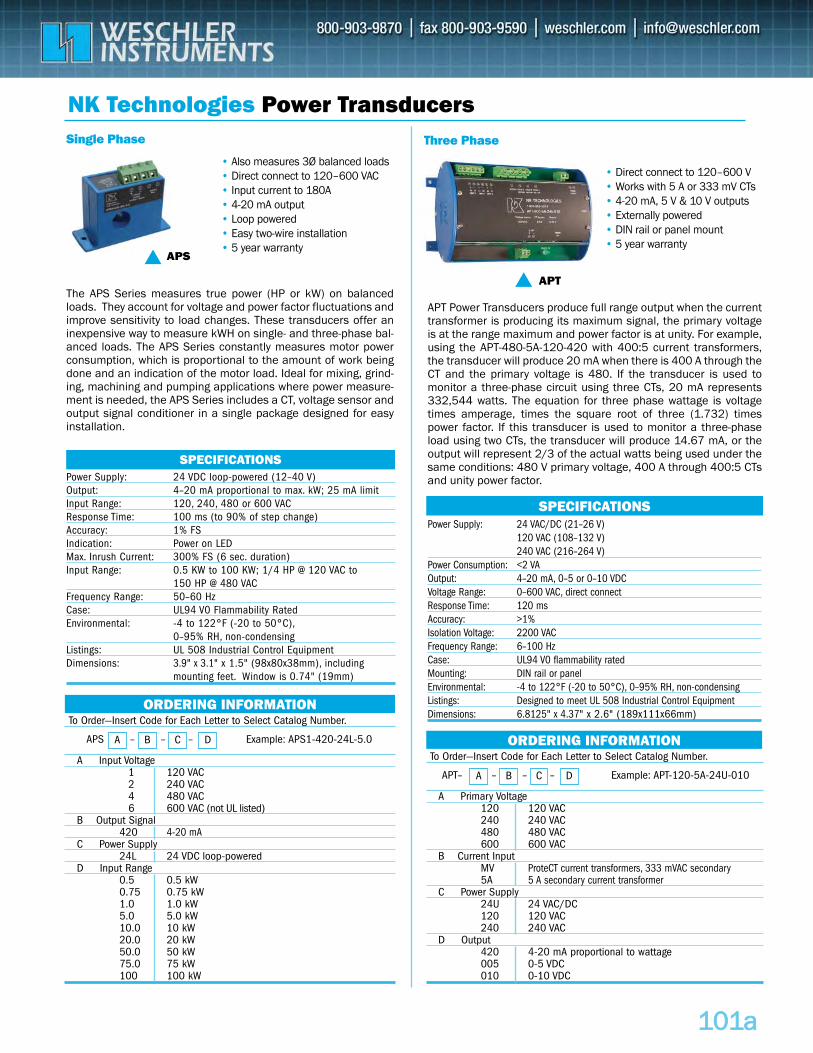
Power Supply: 24 VAC/DC (21–26 V)120 VAC (108–132 V)240 VAC (216–264 V)
Power Consumption: <2 VAOutput: 4–20 mA, 0–5 or 0–10 VDCVoltage Range: 0–600 VAC, direct connectResponse Time: 120 msAccuracy: >1%Isolation Voltage: 2200 VACFrequency Range: 6–100 HzCase: UL94 V0 flammability ratedMounting: DIN rail or panel Environmental: -4 to 122°F (-20 to 50°C), 0–95% RH, non-condensingListings: Designed to meet UL 508 Industrial Control Equipment Dimensions: 6.8125" x 4.37" x 2.6" (189x111x66mm)
SPECIFICATIONS
ORDERING INFORMATION
110011aa
NK Technologies Power Transducers
APS
APT
Power Supply: 24 VDC loop-powered (12–40 V)Output: 4–20 mA proportional to max. kW; 25 mA limitInput Range: 120, 240, 480 or 600 VACResponse Time: 100 ms (to 90% of step change)Accuracy: 1% FSIndication: Power on LEDMax. Inrush Current: 300% FS (6 sec. duration)Input Range: 0.5 KW to 100 KW; 1/4 HP @ 120 VAC to
150 HP @ 480 VACFrequency Range: 50–60 HzCase: UL94 V0 Flammability RatedEnvironmental: -4 to 122°F (-20 to 50°C),
0–95% RH, non-condensingListings: UL 508 Industrial Control EquipmentDimensions: 3.9" x 3.1" x 1.5" (98x80x38mm), including
mounting feet. Window is 0.74" (19mm)
SPECIFICATIONS
Single Phase Three Phase
• Direct connect to 120–600 V• Works with 5 A or 333 mV CTs • 4-20 mA, 5 V & 10 V outputs• Externally powered • DIN rail or panel mount• 5 year warranty
• Also measures 3Ø balanced loads • Direct connect to 120–600 VAC• Input current to 180A• 4-20 mA output • Loop powered• Easy two-wire installation• 5 year warranty
To Order—Insert Code for Each Letter to Select Catalog Number.
A Primary Voltage120 120 VAC240 240 VAC480 480 VAC600 600 VAC
B Current InputMV ProteCT current transformers, 333 mVAC secondary 5A 5 A secondary current transformer
C Power Supply24U 24 VAC/DC 120 120 VAC240 240 VAC
D Output420 4-20 mA proportional to wattage005 0-5 VDC010 0-10 VDC
A B C DAPT– – – – Example: APT-120-5A-24U-010
ORDERING INFORMATIONTo Order—Insert Code for Each Letter to Select Catalog Number.
A Input Voltage1 120 VAC2 240 VAC4 480 VAC6 600 VAC (not UL listed)
B Output Signal420 4-20 mA
C Power Supply24L 24 VDC loop-powered
D Input Range0.5 0.5 kW0.75 0.75 kW1.0 1.0 kW5.0 5.0 kW10.0 10 kW20.0 20 kW50.0 50 kW75.0 75 kW100 100 kW
A B C DAPS – – – Example: APS1-420-24L-5.0
APT Power Transducers produce full range output when the currenttransformer is producing its maximum signal, the primary voltageis at the range maximum and power factor is at unity. For example,using the APT-480-5A-120-420 with 400:5 current transformers,the transducer will produce 20 mA when there is 400 A through theCT and the primary voltage is 480. If the transducer is used tomonitor a three-phase circuit using three CTs, 20 mA represents332,544 watts. The equation for three phase wattage is voltagetimes amperage, times the square root of three (1.732) timespower factor. If this transducer is used to monitor a three-phaseload using two CTs, the transducer will produce 14.67 mA, or theoutput will represent 2/3 of the actual watts being used under thesame conditions: 480 V primary voltage, 400 A through 400:5 CTsand unity power factor.
The APS Series measures true power (HP or kW) on balancedloads. They account for voltage and power factor fluctuations andimprove sensitivity to load changes. These transducers offer aninexpensive way to measure kWH on single- and three-phase bal-anced loads. The APS Series constantly measures motor powerconsumption, which is proportional to the amount of work beingdone and an indication of the motor load. Ideal for mixing, grind-ing, machining and pumping applications where power measure-ment is needed, the APS Series includes a CT, voltage sensor andoutput signal conditioner in a single package designed for easyinstallation.
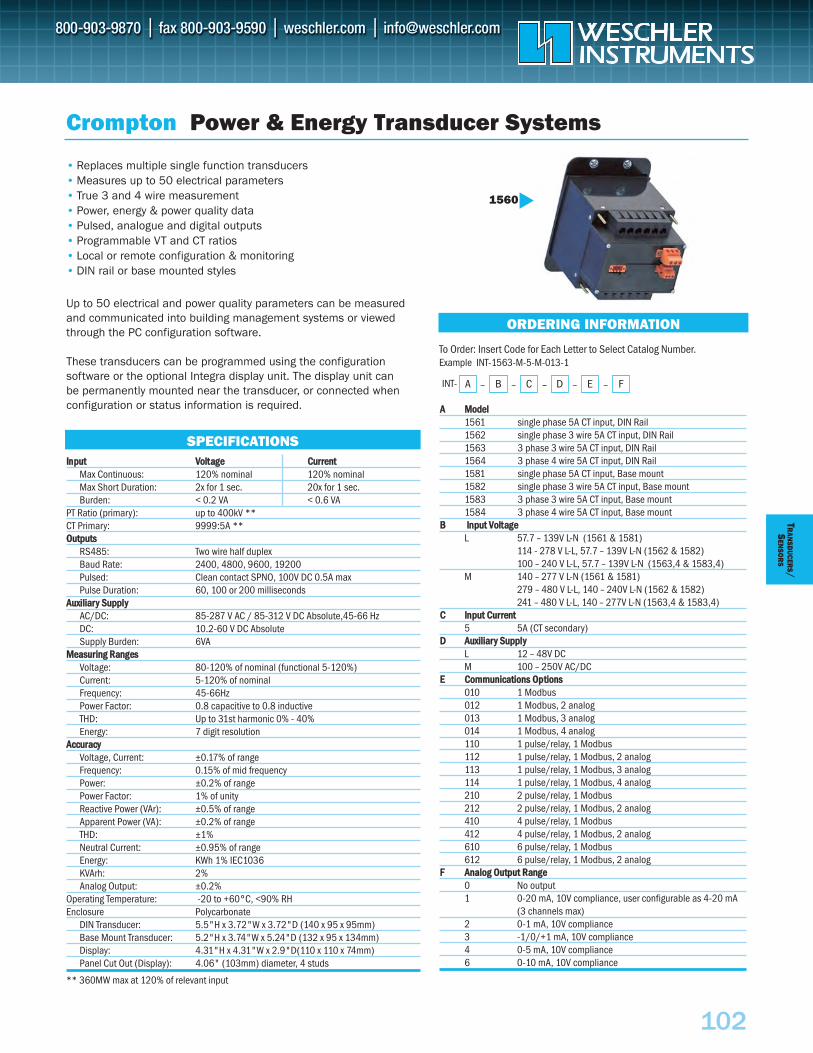
102
TRAN
SDUCER
S/S
ENSO
RS
IInnppuutt VVoollttaaggee CCuurrrreennttMax Continuous: 120% nominal 120% nominalMax Short Duration: 2x for 1 sec. 20x for 1 sec.Burden: < 0.2 VA < 0.6 VA
PT Ratio (primary): up to 400kV **CT Primary: 9999:5A **OOuuttppuuttss
RS485: Two wire half duplexBaud Rate: 2400, 4800, 9600, 19200Pulsed: Clean contact SPNO, 100V DC 0.5A maxPulse Duration: 60, 100 or 200 milliseconds
AAuuxxiilliiaarryy SSuuppppllyyAC/DC: 85-287 V AC / 85-312 V DC Absolute,45-66 HzDC: 10.2-60 V DC AbsoluteSupply Burden: 6VA
MMeeaassuurriinngg RRaannggeessVoltage: 80-120% of nominal (functional 5-120%)Current: 5-120% of nominal Frequency: 45-66HzPower Factor: 0.8 capacitive to 0.8 inductiveTHD: Up to 31st harmonic 0% - 40%Energy: 7 digit resolution
AAccccuurraaccyyVoltage, Current: ±0.17% of rangeFrequency: 0.15% of mid frequencyPower: ±0.2% of rangePower Factor: 1% of unityReactive Power (VAr): ±0.5% of rangeApparent Power (VA): ±0.2% of rangeTHD: ±1%Neutral Current: ±0.95% of rangeEnergy: KWh 1% IEC1036KVArh: 2%Analog Output: ±0.2%
Operating Temperature: -20 to +60°C, <90% RHEnclosure Polycarbonate
DIN Transducer: 5.5"H x 3.72"W x 3.72"D (140 x 95 x 95mm)Base Mount Transducer: 5.2"H x 3.74"W x 5.24"D (132 x 95 x 134mm)Display: 4.31"H x 4.31"W x 2.9"D(110 x 110 x 74mm)Panel Cut Out (Display): 4.06" (103mm) diameter, 4 studs
** 360MW max at 120% of relevant input
INT-
AA MMooddeell1561 single phase 5A CT input, DIN Rail1562 single phase 3 wire 5A CT input, DIN Rail1563 3 phase 3 wire 5A CT input, DIN Rail1564 3 phase 4 wire 5A CT input, DIN Rail1581 single phase 5A CT input, Base mount1582 single phase 3 wire 5A CT input, Base mount1583 3 phase 3 wire 5A CT input, Base mount1584 3 phase 4 wire 5A CT input, Base mount
BB IInnppuutt VVoollttaaggee L 57.7 – 139V L-N (1561 & 1581)
114 - 278 V L-L, 57.7 – 139V L-N (1562 & 1582)100 – 240 V L-L, 57.7 – 139V L-N (1563,4 & 1583,4)
M 140 – 277 V L-N (1561 & 1581)279 – 480 V L-L, 140 – 240V L-N (1562 & 1582)241 – 480 V L-L, 140 – 277V L-N (1563,4 & 1583,4)
CC IInnppuutt CCuurrrreenntt5 5A (CT secondary)
DD AAuuxxiilliiaarryy SSuuppppllyy L 12 – 48V DCM 100 – 250V AC/DC
EE CCoommmmuunniiccaattiioonnss OOppttiioonnss010 1 Modbus012 1 Modbus, 2 analog013 1 Modbus, 3 analog014 1 Modbus, 4 analog110 1 pulse/relay, 1 Modbus112 1 pulse/relay, 1 Modbus, 2 analog113 1 pulse/relay, 1 Modbus, 3 analog114 1 pulse/relay, 1 Modbus, 4 analog210 2 pulse/relay, 1 Modbus212 2 pulse/relay, 1 Modbus, 2 analog410 4 pulse/relay, 1 Modbus 412 4 pulse/relay, 1 Modbus, 2 analog610 6 pulse/relay, 1 Modbus612 6 pulse/relay, 1 Modbus, 2 analog
FF AAnnaalloogg OOuuttppuutt RRaannggee 0 No output1 0-20 mA, 10V compliance, user configurable as 4-20 mA
(3 channels max)2 0-1 mA, 10V compliance3 -1/0/+1 mA, 10V compliance4 0-5 mA, 10V compliance6 0-10 mA, 10V compliance
• Replaces multiple single function transducers• Measures up to 50 electrical parameters• True 3 and 4 wire measurement• Power, energy & power quality data• Pulsed, analogue and digital outputs• Programmable VT and CT ratios• Local or remote configuration & monitoring• DIN rail or base mounted styles
Up to 50 electrical and power quality parameters can be measuredand communicated into building management systems or viewedthrough the PC configuration software.
These transducers can be programmed using the configuration software or the optional Integra display unit. The display unit can be permanently mounted near the transducer, or connected whenconfiguration or status information is required.
Crompton Power & Energy Transducer Systems
ORDERING INFORMATION
SPECIFICATIONS
A B C D–– – E– F–
To Order: Insert Code for Each Letter to Select Catalog Number.Example INT-1563-M-5-M-013-1
1560
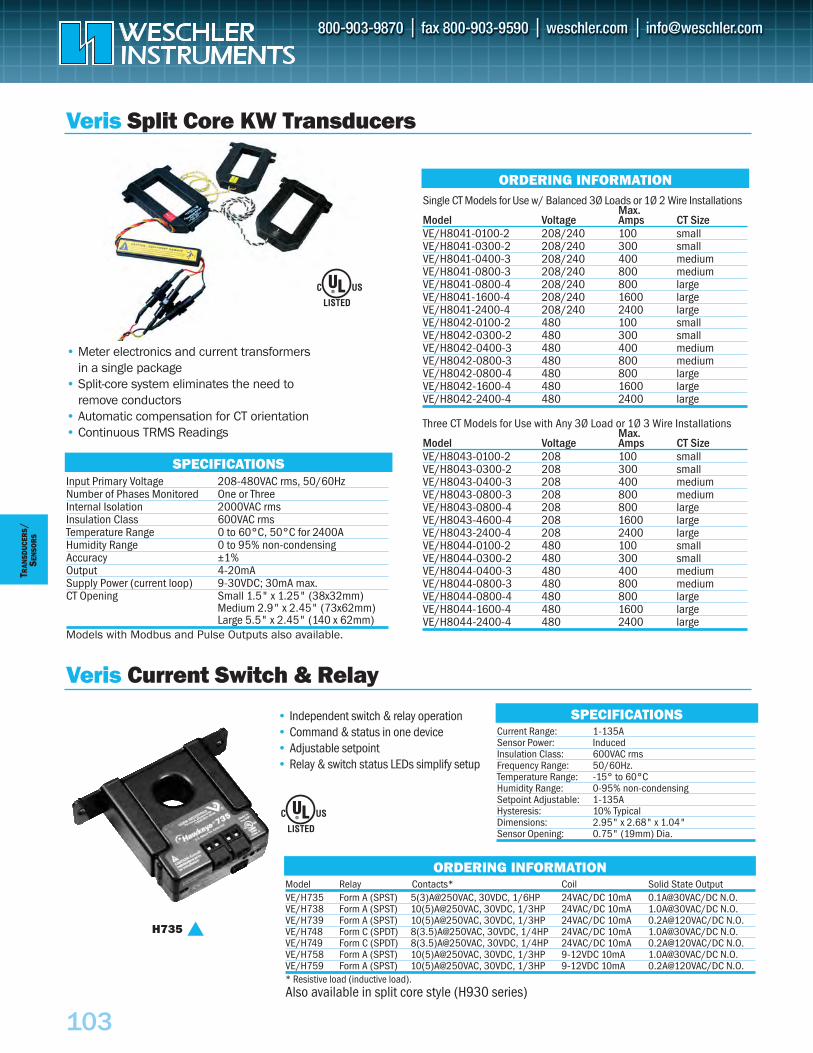
103
TRAN
SDUC
ERS
/SE
NSO
RS
Veris Split Core KW Transducers
Input Primary Voltage 208-480VAC rms, 50/60HzNumber of Phases Monitored One or ThreeInternal Isolation 2000VAC rmsInsulation Class 600VAC rmsTemperature Range 0 to 60°C, 50°C for 2400AHumidity Range 0 to 95% non-condensingAccuracy ±1%Output 4-20mASupply Power (current loop) 9-30VDC; 30mA max.CT Opening Small 1.5" x 1.25" (38x32mm)
Medium 2.9" x 2.45" (73x62mm)Large 5.5" x 2.45" (140 x 62mm)
Models with Modbus and Pulse Outputs also available.
Single CT Models for Use w/ Balanced 3Ø Loads or 1Ø 2 Wire InstallationsMax.
Model Voltage Amps CT SizeVE/H8041-0100-2 208/240 100 smallVE/H8041-0300-2 208/240 300 smallVE/H8041-0400-3 208/240 400 mediumVE/H8041-0800-3 208/240 800 mediumVE/H8041-0800-4 208/240 800 largeVE/H8041-1600-4 208/240 1600 largeVE/H8041-2400-4 208/240 2400 largeVE/H8042-0100-2 480 100 smallVE/H8042-0300-2 480 300 smallVE/H8042-0400-3 480 400 mediumVE/H8042-0800-3 480 800 mediumVE/H8042-0800-4 480 800 largeVE/H8042-1600-4 480 1600 largeVE/H8042-2400-4 480 2400 large
Three CT Models for Use with Any 3Ø Load or 1Ø 3 Wire InstallationsMax.
Model Voltage Amps CT SizeVE/H8043-0100-2 208 100 smallVE/H8043-0300-2 208 300 smallVE/H8043-0400-3 208 400 mediumVE/H8043-0800-3 208 800 mediumVE/H8043-0800-4 208 800 largeVE/H8043-4600-4 208 1600 largeVE/H8043-2400-4 208 2400 largeVE/H8044-0100-2 480 100 smallVE/H8044-0300-2 480 300 smallVE/H8044-0400-3 480 400 mediumVE/H8044-0800-3 480 800 mediumVE/H8044-0800-4 480 800 largeVE/H8044-1600-4 480 1600 largeVE/H8044-2400-4 480 2400 large
ORDERING INFORMATION
SPECIFICATIONS
Current Range: 1-135ASensor Power: InducedInsulation Class: 600VAC rmsFrequency Range: 50/60Hz.Temperature Range: -15° to 60°CHumidity Range: 0-95% non-condensingSetpoint Adjustable: 1-135AHysteresis: 10% TypicalDimensions: 2.95" x 2.68" x 1.04"Sensor Opening: 0.75" (19mm) Dia.
SPECIFICATIONS
Model Relay Contacts* Coil Solid State OutputVE/H735 Form A (SPST) 5(3)A@250VAC, 30VDC, 1/6HP 24VAC/DC 10mA 0.1A@30VAC/DC N.O. VE/H738 Form A (SPST) 10(5)A@250VAC, 30VDC, 1/3HP 24VAC/DC 10mA 1.0A@30VAC/DC N.O. VE/H739 Form A (SPST) 10(5)A@250VAC, 30VDC, 1/3HP 24VAC/DC 10mA 0.2A@120VAC/DC N.O. VE/H748 Form C (SPDT) 8(3.5)A@250VAC, 30VDC, 1/4HP 24VAC/DC 10mA 1.0A@30VAC/DC N.O. VE/H749 Form C (SPDT) 8(3.5)A@250VAC, 30VDC, 1/4HP 24VAC/DC 10mA 0.2A@120VAC/DC N.O. VE/H758 Form A (SPST) 10(5)A@250VAC, 30VDC, 1/3HP 9-12VDC 10mA 1.0A@30VAC/DC N.O. VE/H759 Form A (SPST) 10(5)A@250VAC, 30VDC, 1/3HP 9-12VDC 10mA 0.2A@120VAC/DC N.O. * Resistive load (inductive load). Also available in split core style (H930 series)
ORDERING INFORMATION
®
• Meter electronics and current transformers in a single package
• Split-core system eliminates the need to remove conductors
• Automatic compensation for CT orientation• Continuous TRMS Readings
Veris Current Switch & Relay
• Independent switch & relay operation• Command & status in one device• Adjustable setpoint• Relay & switch status LEDs simplify setup
H735
®
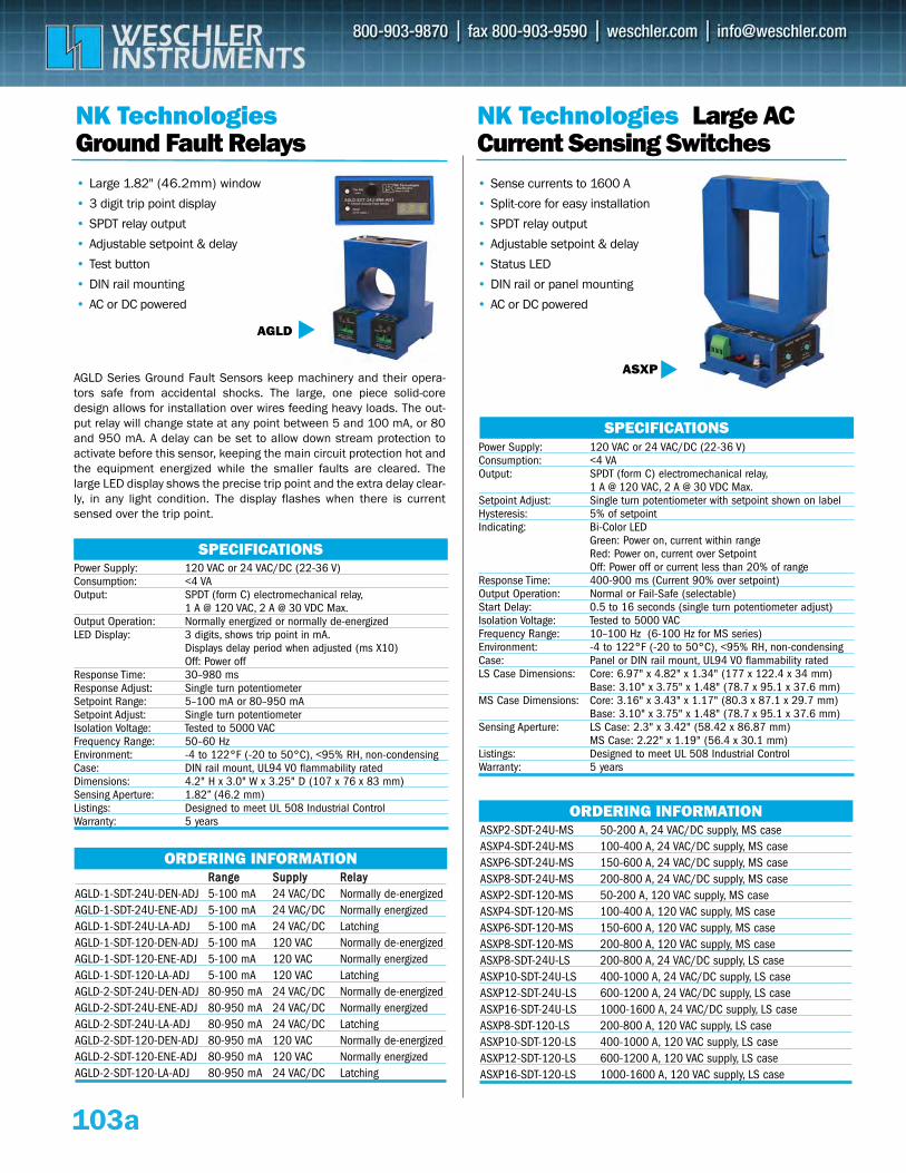
NK Technologies Ground Fault Relays
• Sense currents to 1600 A
• Split-core for easy installation
• SPDT relay output
• Adjustable setpoint & delay
• Status LED
• DIN rail or panel mounting
• AC or DC powered
ORDERING INFORMATION
NK Technologies Large AC Current Sensing Switches
SPECIFICATIONSPower Supply: 120 VAC or 24 VAC/DC (22-36 V)Consumption: <4 VAOutput: SPDT (form C) electromechanical relay,
1 A @ 120 VAC, 2 A @ 30 VDC Max.Output Operation: Normally energized or normally de-energizedLED Display: 3 digits, shows trip point in mA.
Displays delay period when adjusted (ms X10)Off: Power off
Response Time: 30–980 msResponse Adjust: Single turn potentiometer Setpoint Range: 5–100 mA or 80–950 mASetpoint Adjust: Single turn potentiometer Isolation Voltage: Tested to 5000 VACFrequency Range: 50–60 HzEnvironment: -4 to 122°F (-20 to 50°C), <95% RH, non-condensingCase: DIN rail mount, UL94 V0 flammability ratedDimensions: 4.2" H x 3.0" W x 3.25" D (107 x 76 x 83 mm)Sensing Aperture: 1.82” (46.2 mm)Listings: Designed to meet UL 508 Industrial ControlWarranty: 5 years
SPECIFICATIONSPower Supply: 120 VAC or 24 VAC/DC (22-36 V)Consumption: <4 VAOutput: SPDT (form C) electromechanical relay,
1 A @ 120 VAC, 2 A @ 30 VDC Max.Setpoint Adjust: Single turn potentiometer with setpoint shown on labelHysteresis: 5% of setpointIndicating: Bi-Color LED
Green: Power on, current within rangeRed: Power on, current over SetpointOff: Power off or current less than 20% of range
Response Time: 400-900 ms (Current 90% over setpoint)Output Operation: Normal or Fail-Safe (selectable)Start Delay: 0.5 to 16 seconds (single turn potentiometer adjust)Isolation Voltage: Tested to 5000 VACFrequency Range: 10–100 Hz (6-100 Hz for MS series)Environment: -4 to 122°F (-20 to 50°C), <95% RH, non-condensingCase: Panel or DIN rail mount, UL94 V0 flammability ratedLS Case Dimensions: Core: 6.97" x 4.82" x 1.34" (177 x 122.4 x 34 mm)
Base: 3.10" x 3.75" x 1.48" (78.7 x 95.1 x 37.6 mm)MS Case Dimensions: Core: 3.16" x 3.43" x 1.17" (80.3 x 87.1 x 29.7 mm)
Base: 3.10" x 3.75" x 1.48" (78.7 x 95.1 x 37.6 mm)Sensing Aperture: LS Case: 2.3" x 3.42" (58.42 x 86.87 mm)
MS Case: 2.22" x 1.19" (56.4 x 30.1 mm)Listings: Designed to meet UL 508 Industrial ControlWarranty: 5 years
ASXP
• Large 1.82" (46.2mm) window
• 3 digit trip point display
• SPDT relay output
• Adjustable setpoint & delay
• Test button
• DIN rail mounting
• AC or DC powered
ORDERING INFORMATIONASXP2-SDT-24U-MS 50-200 A, 24 VAC/DC supply, MS caseASXP4-SDT-24U-MS 100-400 A, 24 VAC/DC supply, MS caseASXP6-SDT-24U-MS 150-600 A, 24 VAC/DC supply, MS caseASXP8-SDT-24U-MS 200-800 A, 24 VAC/DC supply, MS caseASXP2-SDT-120-MS 50-200 A, 120 VAC supply, MS caseASXP4-SDT-120-MS 100-400 A, 120 VAC supply, MS caseASXP6-SDT-120-MS 150-600 A, 120 VAC supply, MS caseASXP8-SDT-120-MS 200-800 A, 120 VAC supply, MS caseASXP8-SDT-24U-LS 200-800 A, 24 VAC/DC supply, LS caseASXP10-SDT-24U-LS 400-1000 A, 24 VAC/DC supply, LS caseASXP12-SDT-24U-LS 600-1200 A, 24 VAC/DC supply, LS caseASXP16-SDT-24U-LS 1000-1600 A, 24 VAC/DC supply, LS caseASXP8-SDT-120-LS 200-800 A, 120 VAC supply, LS caseASXP10-SDT-120-LS 400-1000 A, 120 VAC supply, LS caseASXP12-SDT-120-LS 600-1200 A, 120 VAC supply, LS caseASXP16-SDT-120-LS 1000-1600 A, 120 VAC supply, LS case
RRaannggee SSuuppppllyy RReellaayyAGLD-1-SDT-24U-DEN-ADJ 5-100 mA 24 VAC/DC Normally de-energizedAGLD-1-SDT-24U-ENE-ADJ 5-100 mA 24 VAC/DC Normally energizedAGLD-1-SDT-24U-LA-ADJ 5-100 mA 24 VAC/DC LatchingAGLD-1-SDT-120-DEN-ADJ 5-100 mA 120 VAC Normally de-energizedAGLD-1-SDT-120-ENE-ADJ 5-100 mA 120 VAC Normally energizedAGLD-1-SDT-120-LA-ADJ 5-100 mA 120 VAC LatchingAGLD-2-SDT-24U-DEN-ADJ 80-950 mA 24 VAC/DC Normally de-energizedAGLD-2-SDT-24U-ENE-ADJ 80-950 mA 24 VAC/DC Normally energizedAGLD-2-SDT-24U-LA-ADJ 80-950 mA 24 VAC/DC LatchingAGLD-2-SDT-120-DEN-ADJ 80-950 mA 120 VAC Normally de-energizedAGLD-2-SDT-120-ENE-ADJ 80-950 mA 120 VAC Normally energizedAGLD-2-SDT-120-LA-ADJ 80-950 mA 24 VAC/DC Latching
103a
AGLD
AGLD Series Ground Fault Sensors keep machinery and their opera-tors safe from accidental shocks. The large, one piece solid-coredesign allows for installation over wires feeding heavy loads. The out-put relay will change state at any point between 5 and 100 mA, or 80and 950 mA. A delay can be set to allow down stream protection toactivate before this sensor, keeping the main circuit protection hot andthe equipment energized while the smaller faults are cleared. Thelarge LED display shows the precise trip point and the extra delay clear-ly, in any light condition. The display flashes when there is currentsensed over the trip point.
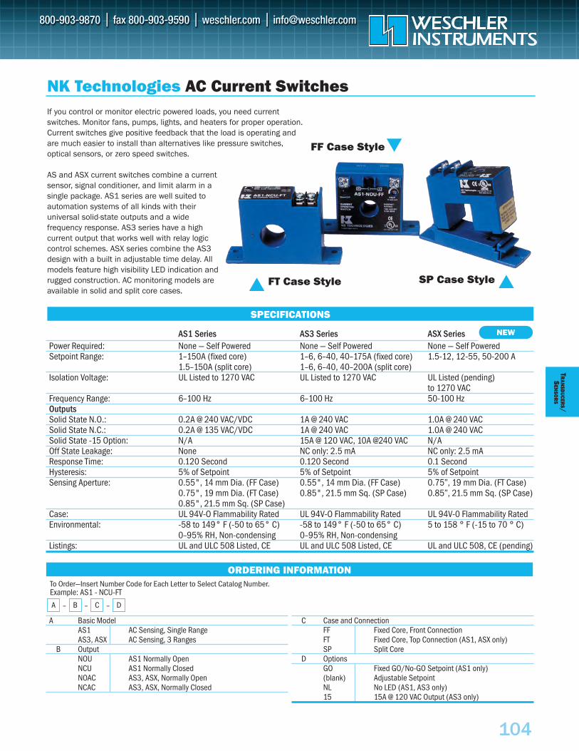
104
TRAN
SDUCER
S/S
ENSO
RS
If you control or monitor electric powered loads, you need currentswitches. Monitor fans, pumps, lights, and heaters for proper operation.Current switches give positive feedback that the load is operating andare much easier to install than alternatives like pressure switches, optical sensors, or zero speed switches.
AS and ASX current switches combine a currentsensor, signal conditioner, and limit alarm in asingle package. AS1 series are well suited toautomation systems of all kinds with their universal solid-state outputs and a wide frequency response. AS3 series have a high current output that works well with relay logiccontrol schemes. ASX series combine the AS3design with a built in adjustable time delay. Allmodels feature high visibility LED indication andrugged construction. AC monitoring models areavailable in solid and split core cases.
AS1 Series AS3 Series ASX SeriesPower Required: None — Self Powered None — Self Powered None — Self PoweredSetpoint Range: 1–150A (fixed core) 1–6, 6–40, 40–175A (fixed core) 1.5-12, 12-55, 50-200 A
1.5–150A (split core) 1–6, 6–40, 40–200A (split core)Isolation Voltage: UL Listed to 1270 VAC UL Listed to 1270 VAC UL Listed (pending)
to 1270 VACFrequency Range: 6–100 Hz 6–100 Hz 50-100 HzOutputsSolid State N.O.: 0.2A @ 240 VAC/VDC 1A @ 240 VAC 1.0A @ 240 VACSolid State N.C.: 0.2A @ 135 VAC/VDC 1A @ 240 VAC 1.0A @ 240 VACSolid State -15 Option: N/A 15A @ 120 VAC, 10A @240 VAC N/AOff State Leakage: None NC only: 2.5 mA NC only: 2.5 mAResponse Time: 0.120 Second 0.120 Second 0.1 SecondHysteresis: 5% of Setpoint 5% of Setpoint 5% of SetpointSensing Aperture: 0.55", 14 mm Dia. (FF Case) 0.55", 14 mm Dia. (FF Case) 0.75”, 19 mm Dia. (FT Case)
0.75", 19 mm Dia. (FT Case) 0.85", 21.5 mm Sq. (SP Case) 0.85”, 21.5 mm Sq. (SP Case)0.85", 21.5 mm Sq. (SP Case)
Case: UL 94V-O Flammability Rated UL 94V-O Flammability Rated UL 94V-0 Flammability RatedEnvironmental: -58 to 149° F (-50 to 65° C) -58 to 149° F (-50 to 65° C) 5 to 158 ° F (-15 to 70 ° C)
0–95% RH, Non-condensing 0–95% RH, Non-condensingListings: UL and ULC 508 Listed, CE UL and ULC 508 Listed, CE UL and ULC 508, CE (pending)
SPECIFICATIONS
NK Technologies AC Current Switches
FT Case Style
FF Case Style
SP Case Style
A Basic ModelAS1 AC Sensing, Single RangeAS3, ASX AC Sensing, 3 Ranges
B OutputNOU AS1 Normally OpenNCU AS1 Normally ClosedNOAC AS3, ASX, Normally OpenNCAC AS3, ASX, Normally Closed
ORDERING INFORMATION
NEW
To Order—Insert Number Code for Each Letter to Select Catalog Number. Example: AS1 - NCU-FT
A – B – C – D
C Case and ConnectionFF Fixed Core, Front ConnectionFT Fixed Core, Top Connection (AS1, ASX only)SP Split Core
D OptionsGO Fixed GO/No-GO Setpoint (AS1 only)(blank) Adjustable SetpointNL No LED (AS1, AS3 only)15 15A @ 120 VAC Output (AS3 only)
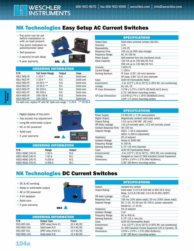
• DC & AC sensing
• Relay or solid-state output
• AC or DC powered
• 3 kV isolation
• Solid core
• 5 year warranty
TRAN
SDUC
ERS/
SEN
SOR
S
PP//NN OOuuttppuutt TTyyppee PPoowweerrDS3-SDT-24U SPDT relay (Form C) 24 V AC/DCDS3-NOU-24U Solid-state N.O. 24 V AC/DCDS3-SDT-12U SPDT relay (Form C) 12 V AC/DCDS3-NOU-12U Solid-state N.O. 12 V AC/DC
NK Technologies Easy Setup AC Current Switches
ORDERING INFORMATION
ORDERING INFORMATION
PP//NN FFuullll SSccaallee RRaannggee OOuuttppuutt CCaasseeASL1-NOU-FF 1-10 A * N.O. Solid-coreASL1-NCU-FF 1-10 A * N.C. Solid-coreASL2-NOU-FF 10-50 A ** N.O. Solid-coreASL2-NCU-FF 10-50 A ** N.C. Solid-core ASL3-NOU-FF 50-100 A N.O. Solid-coreASL3-NCU-FF 50-100 A N.C. Solid-core ASL4-NOU-FF 100-150 A N.O. Solid-coreASL4-NCU-FF 100-150 A N.C. Solid-coreFor split-core, replace FF with SP. Split-core range: * 2-20 A ** 20-50 A
PP//NN RRaannggee OOuuttppuuttASD1-NOAC-24U-FL 1-50 A N.O.ASD1-NCAC-24U-FL 1-50 A N.C.ASD2-NOAC-24U-FL 4-200 A N.O.ASD2-NCAC-24U-FL 4-200 A N.C.
SPECIFICATIONS
SPECIFICATIONS
NK Technologies DC Current SwitchesSPECIFICATIONS
ORDERING INFORMATION
104a
• Trip point can be setbefore installation orwith no load present
• Trip point indicated onpotentiometer label
• Self-powered
• 2 second inrush delay
• 5 year warranty
• Digital display of trip point
• Top access trip adjustment
• Long life solid-state output
• AC or DC powered
• Solid core
• 5 year warranty
DS3
Output: Isolated dry contactOutput Rating: Solid-state: 0.15 A @ 240 VAC or VDC (N.O. Only)
Relay: 5.0 A @ 240 VAC, 5.0 A @ 30 VDC (SPDT)Off-state Leakage: <10 μAResponse Time: 100 ms (10% above setpt), 20 ms (100% above setpt)Setpoint Range: DC: 2–20, 10–50 and 20–100 A, jumper selectable;
Derate by √ 2 for ACHysteresis: 5% of setpointIsolation Voltage: 3 kVFrequency Range: DC to 400 HzSensing Aperture: 0.75" (19.1 mm) dia.Case: UL94 V0 Flammability RatedEnvironment: -4 to 122°F (-20 to 50°C) 0–95% RH, non-condensingListings: UL 508 Industrial Control Equipment (US & Canada), CEDimensions: 3.9"W x 2.9"H x 1.5"D (99x74x38mm);
3.38" (85.8mm) mounting centers
Power Supply: 24 VAC/DC (< 2 VA consumption)Digital Output: Magnetically isolated solid-state switchOutput Rating: 1.0 A up to 240 VAC (AC only)Off-State Leakage: <10 μA normally open, <2.5 mA normally closedContact Response Time: 40–120 msSetpoint Range: ASD1: 1–50 A (adjustable)
ASD2: 4–200 A (adjustable)Hysteresis: 5% of setpointIsolation Voltage: Tested to 5000 VACFrequency Range: 6–100 HzSensing Aperture: 0.74" (19 mm) diameterCase: UL94 V0 Flammability RatedEnvironmental: -4 to 122°F (-20 to 50°C), <95% RH, non-condensingListings: Designed to meet UL 508 Industrial Control EquipmentDimensions: 3.9"W x 2.9"H x 1.5"D (99x74x38mm);
3.38" (85.8mm) mounting centers
Output Type: Solid-state universal contact (AC/DC)Accuracy: ±1%Repeatability: 1.0% FSResponse Time: 100 ms (to 90% step change)Frequency Range: AC 10–100 HzPower Supply: Self-powered from the monitored circuitRelay Capacity: 150 mA up to 240 VAC/DC N.O.
200 mA up to 135 VAC/DC N.C.Linearity: 1.00% FSCurrent Range: 1–150 ASensing Aperture: FF Case: 0.55" (19 mm) diameter
SP Case: 0.85" (21.6 mm) diameterCase: UL94 V0 Flammability RatedEnvironment: -4 to 122°F (-20 to 50°C) 0–95% RH, non-condensingListings: UL/cUL, CEFF Case Dimensions: 3.3"W x 2.2"H x 0.92"D (83.8x55.4x23.2mm);
2.75" (69.9mm) mounting centersSP Case Dimensions: 3.53"W x2.7"H x 1.19"D (90x69x30.2mm);
3.04" (77.2mm) mounting centers
ASL
ASD
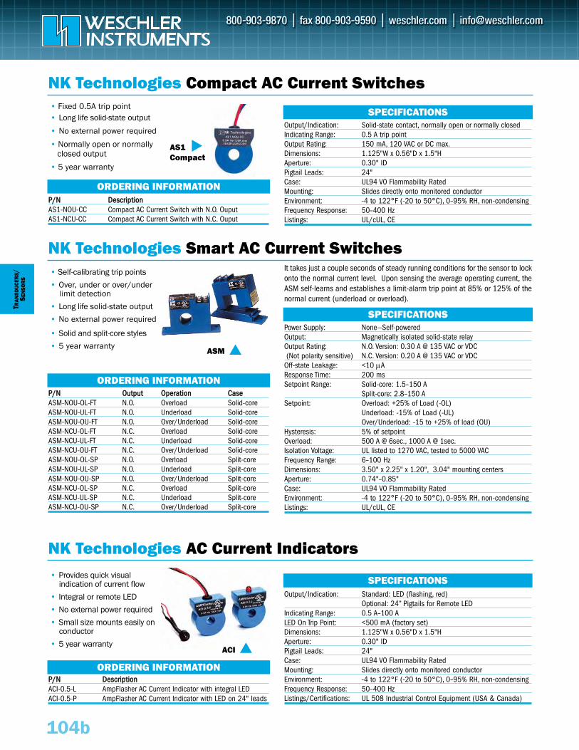
• Provides quick visual indication of current flow
• Integral or remote LED
• No external power required
• Small size mounts easily on conductor
• 5 year warranty
TRAN
SDUC
ERS/
SEN
SOR
S
PP//NN DDeessccrriippttiioonnACI-0.5-L AmpFlasher AC Current Indicator with integral LEDACI-0.5-P AmpFlasher AC Current Indicator with LED on 24" leads
NK Technologies Compact AC Current Switches
ORDERING INFORMATION
ORDERING INFORMATION
PP//NN DDeessccrriippttiioonnAS1-NOU-CC Compact AC Current Switch with N.O. OuputAS1-NCU-CC Compact AC Current Switch with N.C. Ouput
PP//NN OOuuttppuutt OOppeerraattiioonn CCaasseeASM-NOU-OL-FT N.O. Overload Solid-coreASM-NOU-UL-FT N.O. Underload Solid-coreASM-NOU-OU-FT N.O. Over/Underload Solid-coreASM-NCU-OL-FT N.C. Overload Solid-coreASM-NCU-UL-FT N.C. Underload Solid-coreASM-NCU-OU-FT N.C. Over/Underload Solid-coreASM-NOU-OL-SP N.O. Overload Split-coreASM-NOU-UL-SP N.O. Underload Split-coreASM-NOU-OU-SP N.O. Over/Underload Split-coreASM-NCU-OL-SP N.C. Overload Split-coreASM-NCU-UL-SP N.C. Underload Split-coreASM-NCU-OU-SP N.C. Over/Underload Split-core
SPECIFICATIONS
SPECIFICATIONS
NK Technologies AC Current Indicators
NK Technologies Smart AC Current Switches
SPECIFICATIONS
ORDERING INFORMATION
104b
• Fixed 0.5A trip point • Long life solid-state output
• No external power required
• Normally open or normallyclosed output
• 5 year warranty
• Self-calibrating trip points
• Over, under or over/underlimit detection
• Long life solid-state output
• No external power required
• Solid and split-core styles
• 5 year warranty
ACI
Output/Indication: Standard: LED (flashing, red)Optional: 24” Pigtails for Remote LED
Indicating Range: 0.5 A–100 ALED On Trip Point: <500 mA (factory set)Dimensions: 1.125"W x 0.56"D x 1.5"HAperture: 0.30" IDPigtail Leads: 24"Case: UL94 V0 Flammability RatedMounting: Slides directly onto monitored conductorEnvironment: -4 to 122°F (-20 to 50°C), 0–95% RH, non-condensingFrequency Response: 50–400 HzListings/Certifications: UL 508 Industrial Control Equipment (USA & Canada)
Power Supply: None—Self-poweredOutput: Magnetically isolated solid-state relayOutput Rating: N.O. Version: 0.30 A @ 135 VAC or VDC(Not polarity sensitive) N.C. Version: 0.20 A @ 135 VAC or VDC
Off-state Leakage: <10 μAResponse Time: 200 msSetpoint Range: Solid-core: 1.5–150 A
Split-core: 2.8–150 ASetpoint: Overload: +25% of Load (-OL)
Underload: -15% of Load (-UL)Over/Underload: -15 to +25% of load (OU)
Hysteresis: 5% of setpointOverload: 500 A @ 6sec., 1000 A @ 1sec.Isolation Voltage: UL listed to 1270 VAC, tested to 5000 VACFrequency Range: 6–100 HzDimensions: 3.50" x 2.25" x 1.20", 3.04" mounting centersAperture: 0.74"–0.85"Case: UL94 V0 Flammability RatedEnvironment: -4 to 122°F (-20 to 50°C), 0–95% RH, non-condensingListings: UL/cUL, CE
Output/Indication: Solid-state contact, normally open or normally closedIndicating Range: 0.5 A trip pointOutput Rating: 150 mA, 120 VAC or DC max.Dimensions: 1.125"W x 0.56"D x 1.5"HAperture: 0.30" IDPigtail Leads: 24"Case: UL94 V0 Flammability RatedMounting: Slides directly onto monitored conductorEnvironment: -4 to 122°F (-20 to 50°C), 0–95% RH, non-condensingFrequency Response: 50–400 HzListings: UL/cUL, CE
AS1 Compact
ASM
It takes just a couple seconds of steady running conditions for the sensor to lockonto the normal current level. Upon sensing the average operating current, theASM self-learns and establishes a limit-alarm trip point at 85% or 125% of thenormal current (underload or overload).
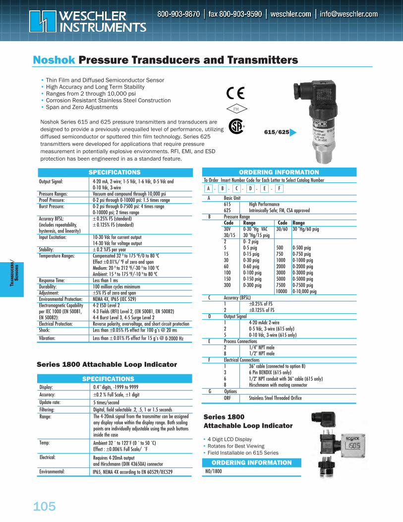
105
T RAN
SDUC
ERS
/S E
NSO
RS
Noshok Pressure Transducers and Transmitters
615/625
Series 1800 Attachable Loop Indicator
FM
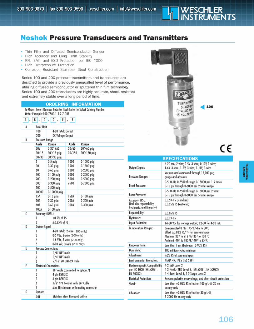
106
TRAN
SDUCER
S/S
ENSO
RS
Noshok Pressure Transducers and Transmitters
100
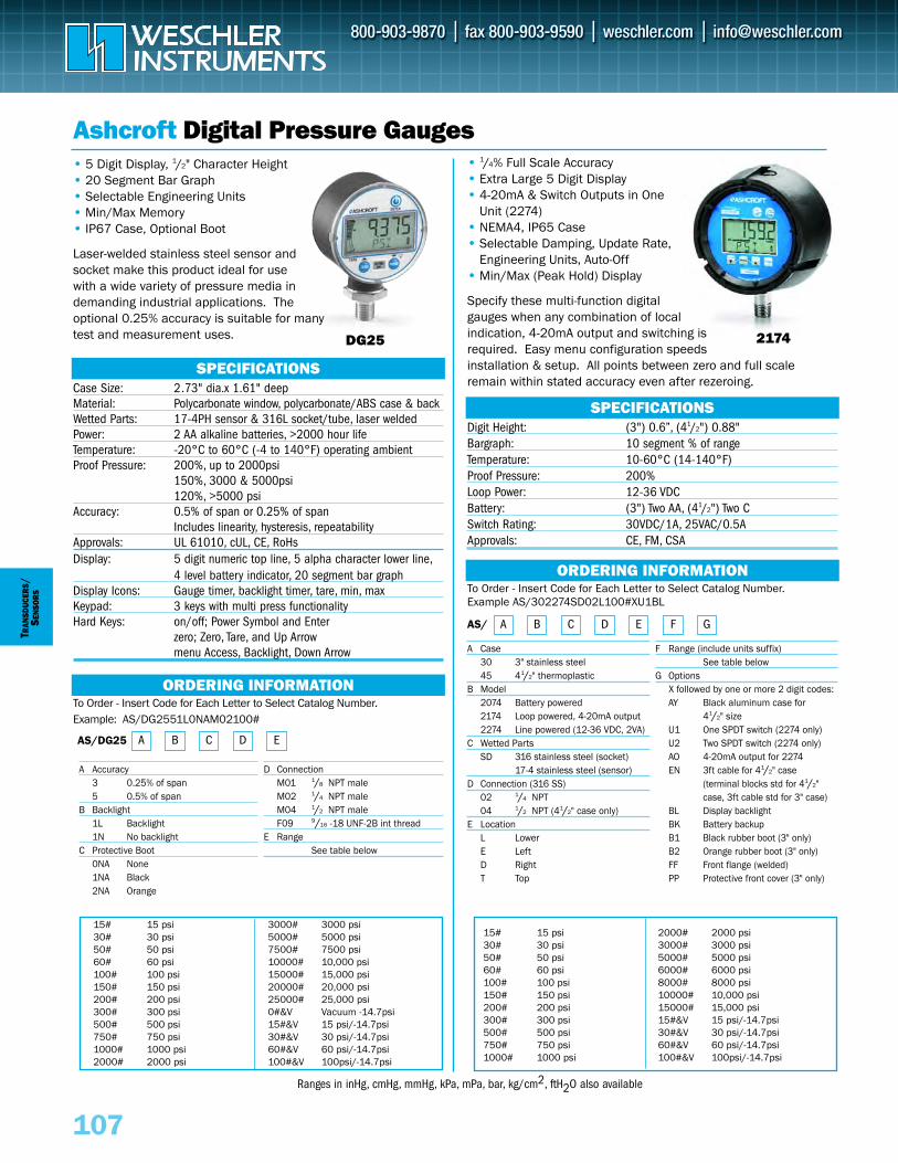
107
TRAN
SDUC
ERS
/SE
NSO
RS
ORDERING INFORMATION
Ashcroft Digital Pressure Gauges•• 5 Digit Display, 1/2" Character Height•• 20 Segment Bar Graph•• Selectable Engineering Units•• Min/Max Memory•• IP67 Case, Optional Boot
Laser-welded stainless steel sensor andsocket make this product ideal for usewith a wide variety of pressure media indemanding industrial applications. Theoptional 0.25% accuracy is suitable for manytest and measurement uses.
To Order - Insert Code for Each Letter to Select Catalog Number.Example: AS/DG2551L0NAM02100#
Case Size: 2.73" dia.x 1.61" deepMaterial: Polycarbonate window, polycarbonate/ABS case & back Wetted Parts: 17-4PH sensor & 316L socket/tube, laser weldedPower: 2 AA alkaline batteries, >2000 hour lifeTemperature: -20°C to 60°C (-4 to 140°F) operating ambientProof Pressure: 200%, up to 2000psi
150%, 3000 & 5000psi 120%, >5000 psi
Accuracy: 0.5% of span or 0.25% of spanIncludes linearity, hysteresis, repeatability
Approvals: UL 61010, cUL, CE, RoHsDisplay: 5 digit numeric top line, 5 alpha character lower line,
4 level battery indicator, 20 segment bar graphDisplay Icons: Gauge timer, backlight timer, tare, min, maxKeypad: 3 keys with multi press functionalityHard Keys: on/off; Power Symbol and Enter
zero; Zero, Tare, and Up Arrowmenu Access, Backlight, Down Arrow
SPECIFICATIONS
•• 1/4% Full Scale Accuracy•• Extra Large 5 Digit Display•• 4-20mA & Switch Outputs in One
Unit (2274)•• NEMA4, IP65 Case•• Selectable Damping, Update Rate,
Engineering Units, Auto-Off•• Min/Max (Peak Hold) Display
Specify these multi-function digitalgauges when any combination of localindication, 4-20mA output and switching isrequired. Easy menu configuration speedsinstallation & setup. All points between zero and full scaleremain within stated accuracy even after rezeroing.
Digit Height: (3") 0.6”, (41/2") 0.88"Bargraph: 10 segment % of rangeTemperature: 10-60°C (14-140°F)Proof Pressure: 200%Loop Power: 12-36 VDCBattery: (3") Two AA, (41/2") Two CSwitch Rating: 30VDC/1A, 25VAC/0.5AApprovals: CE, FM, CSA
ORDERING INFORMATIONTo Order - Insert Code for Each Letter to Select Catalog Number.Example AS/302274SD02L100#XU1BL
AS/
A Case 30 3" stainless steel45 41/2" thermoplastic
B Model2074 Battery powered2174 Loop powered, 4-20mA output2274 Line powered (12-36 VDC, 2VA)
C Wetted PartsSD 316 stainless steel (socket)
17-4 stainless steel (sensor)D Connection (316 SS)
02 1/4 NPT04 1/2 NPT (41/2" case only)
E LocationL LowerE LeftD RightT Top
F Range (include units suffix)See table below
G Options X followed by one or more 2 digit codes:AY Black aluminum case for
41/2" sizeU1 One SPDT switch (2274 only)U2 Two SPDT switch (2274 only)AO 4-20mA output for 2274EN 3ft cable for 41/2" case
(terminal blocks std for 41/2" case, 3ft cable std for 3" case)
BL Display backlightBK Battery backup B1 Black rubber boot (3" only)B2 Orange rubber boot (3" only)FF Front flange (welded)PP Protective front cover (3" only)
A Accuracy 3 0.25% of span 5 0.5% of span
B Backlight1L Backlight1N No backlight
C Protective Boot0NA None1NA Black2NA Orange
D ConnectionM01 1/8 NPT maleM02 1/4 NPT maleM04 1/2 NPT maleF09 9/16 -18 UNF-2B int thread
E RangeSee table below
15# 15 psi 30# 30 psi50# 50 psi60# 60 psi100# 100 psi150# 150 psi200# 200 psi300# 300 psi500# 500 psi750# 750 psi1000# 1000 psi2000# 2000 psi
3000# 3000 psi5000# 5000 psi7500# 7500 psi10000# 10,000 psi15000# 15,000 psi20000# 20,000 psi25000# 25,000 psi0#&V Vacuum -14.7psi15#&V 15 psi/-14.7psi30#&V 30 psi/-14.7psi60#&V 60 psi/-14.7psi100#&V 100psi/-14.7psi
15# 15 psi 30# 30 psi50# 50 psi60# 60 psi100# 100 psi150# 150 psi200# 200 psi300# 300 psi500# 500 psi750# 750 psi1000# 1000 psi
2000# 2000 psi3000# 3000 psi5000# 5000 psi6000# 6000 psi8000# 8000 psi10000# 10,000 psi15000# 15,000 psi15#&V 15 psi/-14.7psi30#&V 30 psi/-14.7psi60#&V 60 psi/-14.7psi100#&V 100psi/-14.7psi
DG25 2174
A B C D E F G
A B C D EAS/DG25
SPECIFICATIONS
Ranges in inHg, cmHg, mmHg, kPa, mPa, bar, kg/cm2, ftH2O also available
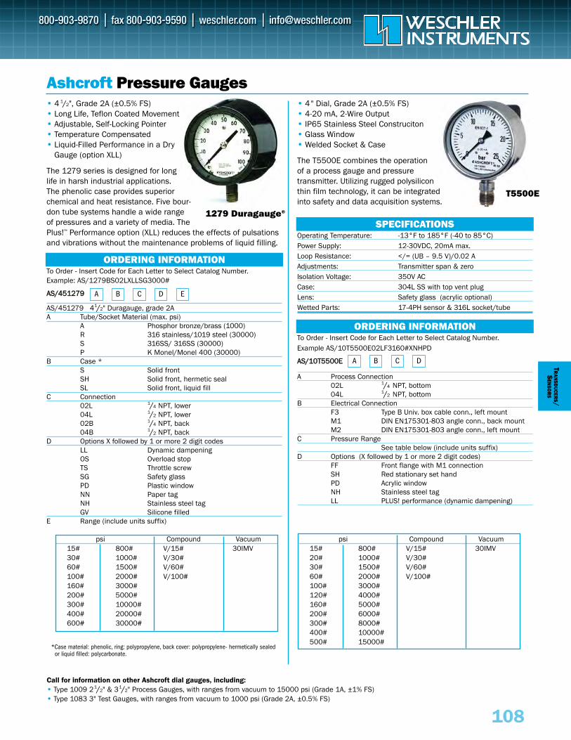
To Order - Insert Code for Each Letter to Select Catalog Number.Example: AS/1279BS02LXLLSG3000#
AASS//445511227799
AS/451279 41/2" Duragauge, grade 2AA Tube/Socket Material (max. psi)
A Phosphor bronze/brass (1000)R 316 stainless/1019 steel (30000)S 316SS/ 316SS (30000)P K Monel/Monel 400 (30000)
B Case *S Solid frontSH Solid front, hermetic sealSL Solid front, liquid fill
C Connection02L 1/4 NPT, lower04L 1/2 NPT, lower02B 1/4 NPT, back04B 1/2 NPT, back
D Options X followed by 1 or more 2 digit codesLL Dynamic dampeningOS Overload stopTS Throttle screwSG Safety glassPD Plastic windowNN Paper tagNH Stainless steel tagGV Silicone filled
E Range (include units suffix)
psi Compound Vacuum15# 800# V/15# 30IMV30# 1000# V/30#60# 1500# V/60#100# 2000# V/100#160# 3000#200# 5000#300# 10000#400# 20000#600# 30000#
108
TRAN
SDUCER
S/S
ENSO
RS
ORDERING INFORMATION
Ashcroft Pressure Gauges•• 4 1/2", Grade 2A (±0.5% FS)•• Long Life, Teflon Coated Movement•• Adjustable, Self-Locking Pointer•• Temperature Compensated•• Liquid-Filled Performance in a Dry
Gauge (option XLL)
The 1279 series is designed for longlife in harsh industrial applications.The phenolic case provides superiorchemical and heat resistance. Five bour-don tube systems handle a wide range of pressures and a variety of media. ThePlus!™ Performance option (XLL) reduces the effects of pulsationsand vibrations without the maintenance problems of liquid filling.
SPECIFICATIONS
•• 4" Dial, Grade 2A (±0.5% FS)•• 4-20 mA, 2-Wire Output•• IP65 Stainless Steel Construciton•• Glass Window•• Welded Socket & Case
The T5500E combines the operationof a process gauge and pressuretransmitter. Utilizing rugged polysiliconthin film technology, it can be integratedinto safety and data acquisition systems.
Operating Temperature: -13°F to 185°F (-40 to 85°C)Power Supply: 12-30VDC, 20mA max.Loop Resistance: </= (UB – 9.5 V)/0.02 AAdjustments: Transmitter span & zero Isolation Voltage: 350V ACCase: 304L SS with top vent plugLens: Safety glass (acrylic optional)Wetted Parts: 17-4PH sensor & 316L socket/tube
ORDERING INFORMATIONTo Order - Insert Code for Each Letter to Select Catalog Number.Example AS/10T5500E02LF3160#XNHPD
AASS//1100TT55550000EE
A Process Connection02L 1/4 NPT, bottom04L 1/2 NPT, bottom
B Electrical Connection F3 Type B Univ. box cable conn., left mountM1 DIN EN175301-803 angle conn., back mountM2 DIN EN175301-803 angle conn., left mount
C Pressure RangeSee table below (include units suffix)
D Options (X followed by 1 or more 2 digit codes)FF Front flange with M1 connectionSH Red stationary set handPD Acrylic windowNH Stainless steel tagLL PLUS! performance (dynamic dampening)
A B C D E
A B C D
psi Compound Vacuum15# 800# V/15# 30IMV20# 1000# V/30#30# 1500# V/60#60# 2000# V/100#100# 3000#120# 4000#160# 5000#200# 6000#300# 8000#400# 10000#500# 15000#
Call for information on other Ashcroft dial gauges, including:•• Type 1009 21/2" & 31/2" Process Gauges, with ranges from vacuum to 15000 psi (Grade 1A, ±1% FS)•• Type 1083 3" Test Gauges, with ranges from vacuum to 1000 psi (Grade 2A, ±0.5% FS)
1279 Duragauge®
T5500E
*Case material: phenolic, ring: polypropylene, back cover: polypropylene- hermetically sealed or liquid filled: polycarbonate.
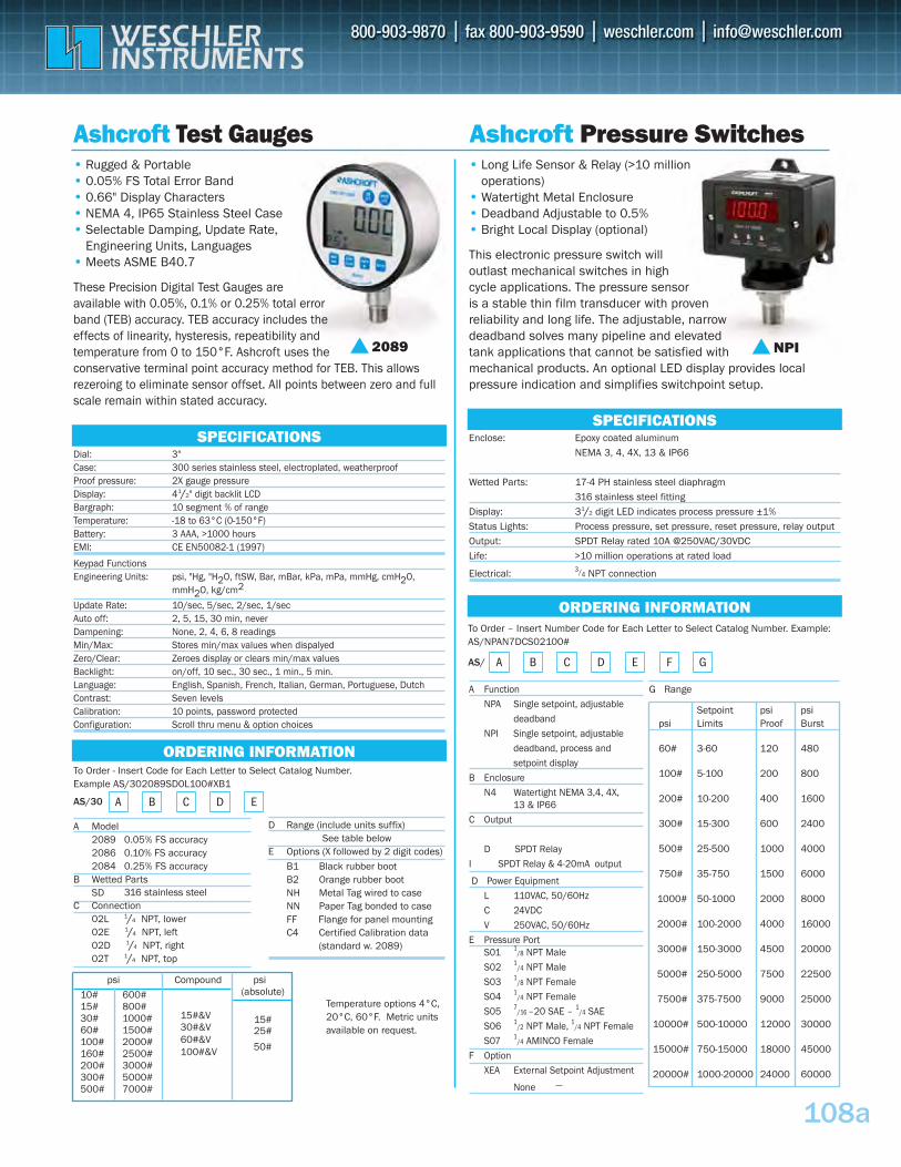
To Order - Insert Code for Each Letter to Select Catalog Number. Example AS/302089SD0L100#XB1
AS/30
A Model2089 0.05% FS accuracy 2086 0.10% FS accuracy 2084 0.25% FS accuracy
B Wetted PartsSD
108a
Ashcroft Test Gauges Ashcroft Pressure Switches•• Rugged & Portable •• 0.05% FS Total Error Band •• 0.66" Display Characters•• NEMA 4, IP65 Stainless Steel Case•• Selectable Damping, Update Rate,
Engineering Units, Languages•• Meets ASME B40.7
These Precision Digital Test Gauges are available with 0.05%, 0.1% or 0.25% total error band (TEB) accuracy. TEB accuracy includes the effects of linearity, hysteresis, repeatibility and temperature from 0 to 150°F. Ashcroft uses the conservative terminal point accuracy method for TEB. This allows rezeroing to eliminate sensor offset. All points between zero and full scale remain within stated accuracy.
SPECIFICATIONSDial: 3"Case: 300 series stainless steel, electroplated, weatherproof Proof pressure: 2X gauge pressure Display: 41/2" digit backlit LCD Bargraph: 10 segment % of range Temperature: -18 to 63°C (0-150°F) Battery: 3 AAA, >1000 hours EMI: CE EN50082-1 (1997)
Keypad Functions Engineering Units: psi, "Hg, "H2O, ftSW, Bar, mBar, kPa, mPa, mmHg, cmH2O,
mmH2O, kg/cm2
Update Rate: 10/sec, 5/sec, 2/sec, 1/sec Auto off: 2, 5, 15, 30 min, never Dampening: None, 2, 4, 6, 8 readings Min/Max: Stores min/max values when dispalyed Zero/Clear: Zeroes display or clears min/max values Backlight: on/off, 10 sec., 30 sec., 1 min., 5 min.Language: English, Spanish, French, Italian, German, Portuguese, Dutch Contrast: Seven levels Calibration: 10 points, password protected Configuration: Scroll thru menu & option choices
SPECIFICATIONS
•• Long Life Sensor & Relay (>10 million operations)
•• Watertight Metal Enclosure•• Deadband Adjustable to 0.5%•• Bright Local Display (optional)
This electronic pressure switch will outlast mechanical switches in high cycle applications. The pressure sensor is a stable thin film transducer with proven reliability and long life. The adjustable, narrow deadband solves many pipeline and elevated tank applications that cannot be satisfied with mechanical products. An optional LED display provides local pressure indication and simplifies switchpoint setup.
Enclose: Epoxy coated aluminum
NEMA 3, 4, 4X, 13 & IP66
Wetted Parts: 17-4 PH stainless steel diaphragm
316 stainless steel fitting
Display: 31/2 digit LED indicates process pressure ±1%
Status Lights: Process pressure, set pressure, reset pressure, relay output
Output: SPDT Relay rated 10A @250VAC/30VDC
Life: >10 million operations at rated load
Electrical: 3/4 NPT connection
ORDERING INFORMATION
A Function
NPA Single setpoint, adjustable
deadband
NPI Single setpoint, adjustable
deadband, process and
setpoint display
B Enclosure
N4 Watertight NEMA 3,4, 4X, 13 & IP66
C Output
D SPDT Relay
I SPDT Relay & 4-20mA output
D Power Equipment
L 110VAC, 50/60Hz
C 24VDC
V 250VAC, 50/60Hz
E Pressure PortS01 1
/8 NPT Male
S02 1/4 NPT Male
S03 1/8 NPT Female
S04 1/4 NPT Female
S05 7/16 –20 SAE – 1
/4 SAE
S06 1/2 NPT Male, 1
/4 NPT Female
S07 1/4 AMINCO Female
F Option
XEA External Setpoint Adjustment
— None
G Range
Setpoint psi psipsi Limits Proof Burst
60# 3-60 120 480
100# 5-100 200 800
200# 10-200 400 1600
300# 15-300 600 2400
500# 25-500 1000 4000
750# 35-750 1500 6000
1000# 50-1000 2000 8000
2000# 100-2000 4000 16000
3000# 150-3000 4500 20000
5000# 250-5000 7500 22500
7500# 375-7500 9000 25000
10000# 500-10000 12000 30000
15000# 750-15000 18000 45000
20000# 1000-20000 24000 60000
To Order – Insert Number Code for Each Letter to Select Catalog Number. Example: AS/NPAN7DCS02100#
AS/
ORDERING INFORMATION
316 stainless steel C Connection
02L 1/4 NPT, lower02E 1/4 NPT, left02D 1/4 NPT, right02T 1/4 NPT, top
D Range (include units suffix)See table below
E Options (X followed by 2 digit codes)
B1 Black rubber boot B2 Orange rubber boot NH Metal Tag wired to caseNN Paper Tag bonded to case FF Flange for panel mountingC4 Certified Calibration data
(standard w. 2089)
2089 NPI
A B C D E
A B C D E F G
Temperature options 4°C, 20°C, 60°F. Metric units available on request.
psi Compound
10# 600#
15#&V 15# 800#
30#&V60#&V100#&V
30# 1000# 60# 1500# 100# 2000#160# 2500#200# 3000#300# 5000# 500# 7000#
psi (absolute)
15#25#
50#
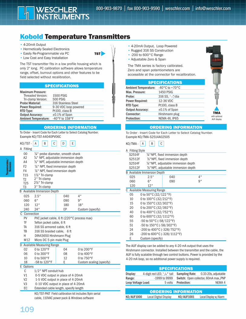
109
TRAN
SDUC
ERS
/SE
NSO
RS
Kobold Temperature Transmitters
To Order - Insert Code for Each Letter to Select Catalog Number.Example KO/TMA-S2514A02505
KO/TMA -
A Fitting Style
B Available Immersion Depth025 2.5" 040 4"060 6" 090 9"120 12"
C Available Measuring Range05 0 to 50°C (32/122 °F) 10 0 to 100°C (32/212°F) 15 0 to 150°C (32/302°F) 20 0 to 200°C (32/392°F) 40 0 to 400°C (32/752°F) 60 0 to 600°C (32/1112°F) 55 -50 to 50°C (-58/122°F) 51 -50 to 150°C (-58/302°F) 24 -200 to 400°C (-328/752°F) 26 -200 to 600°C (-328/1112°F) E Custom (specify)
The AUF display can be added to any 4-20 mA output that uses theHirshmann connector. Installed between the transmitter and the cable, theAUF is fully scalable through two control buttons. Power is provided by the 4-20 mA loop, so no additional power supply is required.
• 4-20mA Output• Hermetically Sealed Electronics • Easily Re-Programmable via PC • Low Cost and Easy Installation
The TST transmitter fits in a low profile housing which isonly 2" long. PC calibration software allows temperaturerange, offset, burnout options and other features to befield selected without recalibration.
Maximum Pressure: Threaded Version: 1500 PSIGTri-clamp Version: 500 PSIG
Probe Material: 316 Stainless Steel Power Required: 9-30 VDC loop powered RTD Type: Pt100, class BOutput Accuracy: ±0.1% of Span Ambient Temperature: -40°F to 158°F
To Order - Insert Code for Each Letter to Select Catalog Number.Example KO/TST-A4040PV06C
KO/TST -
025 2.5" 040 4"060 6" 090 9"120 12" 180 18"240 24" EP Custom (specify)
C ConnectionPV PVC jacket cable, 6 ft (220°C process max)TF Teflon jacket cable, 6 ftTA 316 SS armored cable, 6 ftTB 316 SS braided cable, 6 ftH DIN43650 Hirshmann Plug
D Available Measuring Range02 0 to 120°F 04 0 to 200°F06 0 to 300°F 08 0 to 400°F10 0 to 500°F 12 0 to 750°F18 -58 to 120°F E Custom scaling (specify)
E OptionsC 1/2" NPT conduit hubV1 0-5 VDC output in place of 4-20mA
EC Extended cable length, specify length
KO/TST-PKIT Field calibration kit includes 9pin serial cable, 110VAC power pack & Windows software
SPECIFICATIONS
ORDERING INFORMATION ORDERING INFORMATION
SPECIFICATIONS
ORDERING INFORMATION
Ambient Temperature: -40°C to +70°CMax. Pressure: 1450 PSIG Probe: 316 SS, 1 /4" diaPower Required: 12-36 VDC RTD Type: Pt100, class BOutput Accuracy: ±0.1% of Span Connector: Hirshmann plugProtection: NEMA 4X, IP65
SPECIFICATIONS
• 4-20mA Output, Loop Powered • Rugged 316 SS Construction • -200 to 600°C Range • Adjustable Zero & Span
The TMA series is factory calibrated. Zero and span potentiometers are accessible at the connector for recalibration.
Display: 4-digit red LED, 5 /16" tall Range: -1999 to 9999 Loop Voltage Load: 5 volts
Sampling Rate: 0.33-20s, adjustable Switch: Open collector, 60mA max.,PNPProtection: NEMA 4
KO/AUF1000 Local Digital Display KO/AUF1001 Local Display w/Alarm
TMAwith optionalAUF display
TST
A B C D E A B C
A Fitting Style
M12 Micro DC 5 pin male Plug
V2 1-5 VDC output in place of 4-20mAV3 0-10 VDC output in place of 4-20mA
A2 ¼" NPT, adjustable immersion depth
3" Tri-clampB Available Immersion Depth
S2514F ¼"NPT, fixed immersion depthS2512F ½"NPT, fixed immersion depthS2514F ¼"NPT, adjustable immersion depthS2512F ½"NPT, adjustable immersion depth
1½" Tri-clampT2
2½" Tri-clampT3
2" Tri-clampT25
00 ¼" probe diameter, smooth shank
A4 ½" NPT, adjustable immersion depthF2 ¼" NPT, fixed immersion depthF4 ½" NPT, fixed immersion depthT15
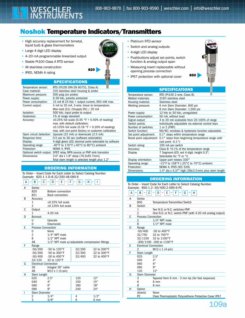
110099aa
To Order – Insert Code for Each Letter to Select Catalog Number.Example: 820-1-1-D-8-32/200-48-090-6
A Series820 Bottom connection 821 Back connection
B Accuracy1 ±0.25% full scale2 ±0.125% full scale
C Output1 4-20 mA
D Burnout U Upscale D Downscale
E Process Connection0 None 2 1/4" NPT male8 1/2" NPT male48 1/2" NPT male w/adjustable compression fittings
F Range-50/200 -50 to 120°F 32/200 32 to 200°F-50/300 -50 to 300°F 32/300 32 to 300°F-50/400 -50 to 400°F 32/400 32 to 400°F32/120 32 to 120°F
G Electrical Connection36 Integral 36" cable 48 M12 x 1 (5-pin)
H Stem Length 025 2.5" 120 12"040 4" 150 15"060 6" 180 18"090 9" 240 24"
I Stem Diameter2 1/4" 4 1/2"3 3/8" 6 6 mm
Noshok Temperature Indicators/Transmitters• Platinum RTD sensor
• Switch and analog outputs
• 4-digit LED display
• Pushbuttons adjust set points, switch function & analog output span
• Measuring insert replaceable without opening process connection
• IP67 protection with optional cover
ORDERING INFORMATION
SPECIFICATIONSTemperature sensor: RTD (Pt100 DIN EN 60751, Class A)Case material: 316 stainless steel housing & probeMaximum pressure: 500 psig (on probe)Power supply: 9-36 Vdc, polarity protectedPower consumption: 15 mA @ 24 Vdc + output current, 950 mW max.Current output: 4 mA to 20 mA, 3-wire, linear to temperature;
Max load (Ω): (Vsupply-9V) / 20 mAIsolation: 500 Vdc, input probe to output Hysteresis: 1% of range standardAccuracy: ±0.25% full scale (0.45 ºF + 0.40% of reading)
max. with default calibration;±0.125% full scale (0.18 ºF + 0.20% of reading) max. with one-point factory or customer calibration
Open circuit detection: Upscale (22 mA) or downscale (2.5 mA) Response time: 0.5 sec to 30 sec (software selectable)Display: 4-digit green LED, decimal point selectable by softwareOperating range: -40ºF to 176ºF (-40ºC to 80ºC) ambientProtection: NEMA 4, IP65Optional switch output: SPDT relay, NPN source or PNP sink transistorDimensions: 3.0" dia x 1.8" deep (76.2x45.7mm);
Total stem length is selected length plus 1.2"
SPECIFICATIONSTemperature sensor: RTD (Pt100 2-wire, Class B)Wetted materials: 316Ti stainless steelHousing material: Stainless steelWorking pressure: 6 mm Stem Diameter: 600 psi
8 mm Stem Diameter: 1,500 psiPower supply: 12 Vdc to 30 Vdc, unregulatedPower consumption: 50 mA, without loadSignal output: 4 to 20 mA scaleable from 20-100% of rangeSwitch points: Individually adjustable via external control keysNumber of switches: 1 or 2 (PNP)Switch function: NO/NC; windows & hysteresis function adjustableSet point adjustment: 0.1° steps within temperature rangeReset point adjustment: 0.1° steps from beginning temperature range until
(set point -0.1°)Switch rating: 100 mA per switchAccuracy: Class B +0.1% of the temperature rangeDisplay 7 Segment-LED, red 4-digit, height 0.3";
Selectable for °F or °CDisplay orientation: Upper part rotates 330°Operating range: -13°F to 158°F (-25°C to 70°C) ambientProtection: NEMA 4, IP65 (IEC 529)Dimensions: 1.4" dia x 4.37" high (36x111mm) plus stem length
820850
• High accuracy replacement for bimetal, liquid bulb & glass thermometers
• Large 4 digit LED display
• 4–20 mA programmable linearized output
• Stable Pt100 Class A RTD sensor
• All stainless construction
• IP65, NEMA 4 rating
A B C D E F G H I– – – – – – – –To Order – Insert Code for Each Letter to Select Catalog Number.Example: 850-1-2--50/400-2-090-6-PC
A Series850 Temperature Transmitter/Switch
B Switch1 Two N.O. or N.C. switches-PNP2 One N.O. or N.C. switch-PNP (with 4-20 mA analog output)
C Process Connection2 1/4" NPT male8 1/2" NPT male
D Range -50/400 -50 to 400°F32/750 32 to 750°F32/1100 32 to 1100°F-300/1100 -300 to 1100°F
E Electrical Connection2 M12 x 1 (4-pin)
F Stem Length 025 2.5" 040 4"060 6"090 9"120 12"
G Stem Diameter3 Tapered from 6 mm - 3 mm tip (for fast response)6 6 mm8 8 mm
H Option(blank) NonePC Clear Thermoplastic Polyurethane Protective Cover IP67
ORDERING INFORMATION
A B C D E F G H– – – – – – –
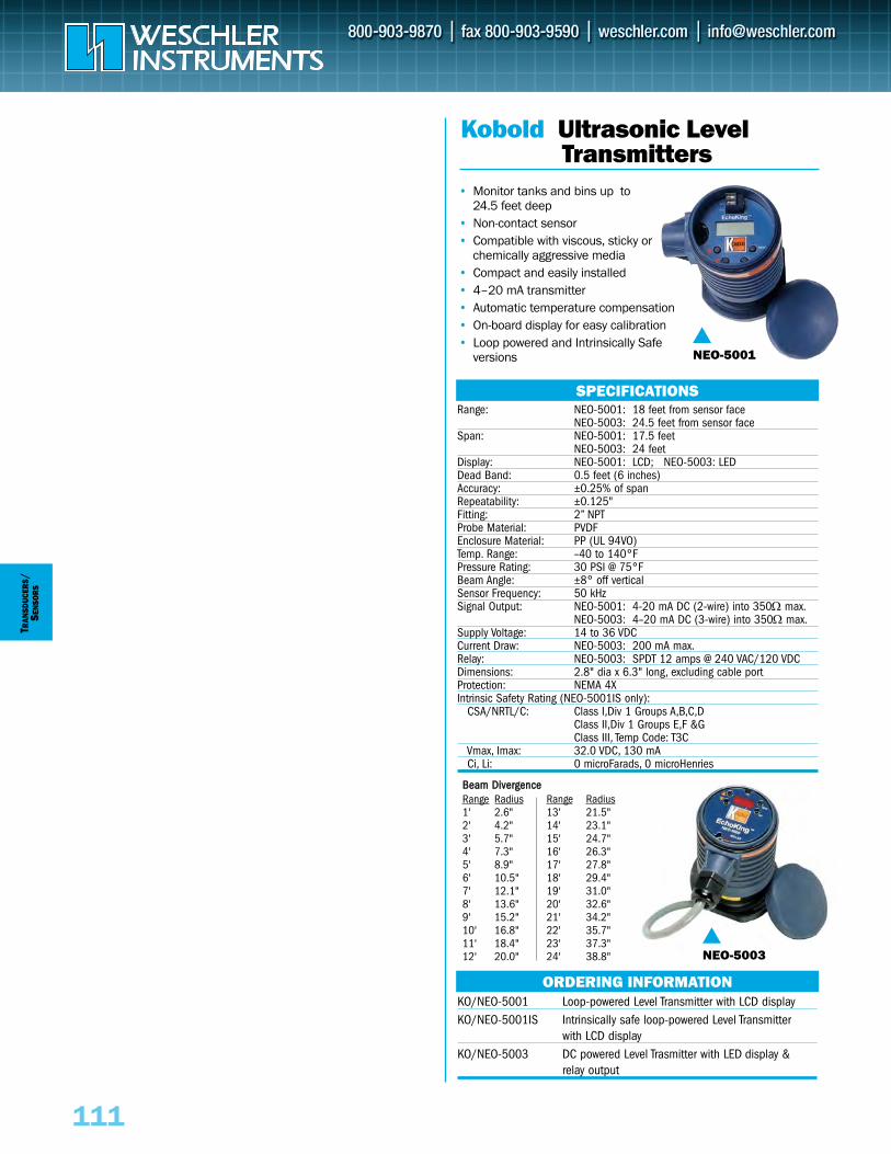
111
TRAN
SDUC
ERS
/SE
NSO
RS
• Monitor tanks and bins up to 24.5 feet deep
• Non-contact sensor• Compatible with viscous, sticky or
chemically aggressive media• Compact and easily installed• 4–20 mA transmitter• Automatic temperature compensation• On-board display for easy calibration• Loop powered and Intrinsically Safe
versions
Range: NEO-5001: 18 feet from sensor faceNEO-5003: 24.5 feet from sensor face
Span: NEO-5001: 17.5 feet NEO-5003: 24 feet
Display: NEO-5001: LCD; NEO-5003: LEDDead Band: 0.5 feet (6 inches)Accuracy: ±0.25% of spanRepeatability: ±0.125"Fitting: 2” NPTProbe Material: PVDFEnclosure Material: PP (UL 94VO)Temp. Range: –40 to 140°FPressure Rating: 30 PSI @ 75°FBeam Angle: ±8° off verticalSensor Frequency: 50 kHzSignal Output: NEO-5001: 4-20 mA DC (2-wire) into 350Ω max.
NEO-5003: 4–20 mA DC (3-wire) into 350Ω max.Supply Voltage: 14 to 36 VDCCurrent Draw: NEO-5003: 200 mA max.Relay: NEO-5003: SPDT 12 amps @ 240 VAC/120 VDCDimensions: 2.8" dia x 6.3" long, excluding cable portProtection: NEMA 4XIntrinsic Safety Rating (NEO-5001IS only):
CSA/NRTL/C: Class I,Div 1 Groups A,B,C,DClass II,Div 1 Groups E,F &GClass III, Temp Code: T3C
Vmax, Imax: 32.0 VDC, 130 mACi, Li: 0 microFarads, 0 microHenries
Kobold Ultrasonic Level Transmitters
SPECIFICATIONS
ORDERING INFORMATION
NEO-5001
NEO-5003
KO/NEO-5001 Loop-powered Level Transmitter with LCD displayKO/NEO-5001IS Intrinsically safe loop-powered Level Transmitter
with LCD displayKO/NEO-5003 DC powered Level Trasmitter with LED display &
relay output
BBeeaamm DDiivveerrggeenncceeRange Radius Range Radius1' 2.6" 13' 21.5"2' 4.2" 14' 23.1"3' 5.7" 15' 24.7"4' 7.3" 16' 26.3"5' 8.9" 17' 27.8"6' 10.5" 18' 29.4"7' 12.1" 19' 31.0"8' 13.6" 20' 32.6"9' 15.2" 21' 34.2"10' 16.8" 22' 35.7"11' 18.4" 23' 37.3"12' 20.0" 24' 38.8"
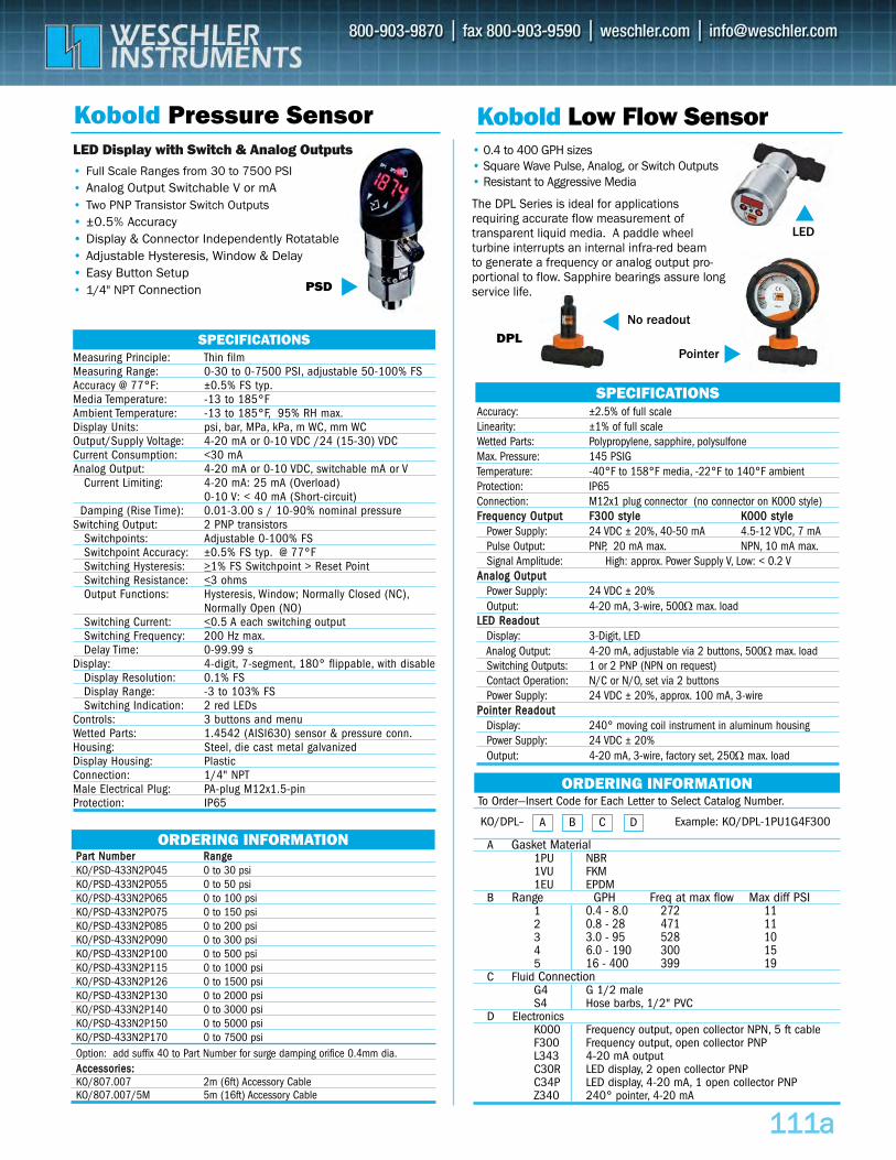
Accuracy: ±2.5% of full scaleLinearity: ±1% of full scaleWetted Parts: Polypropylene, sapphire, polysulfone Max. Pressure: 145 PSIGTemperature: -40°F to 158°F media, -22°F to 140°F ambientProtection: IP65Connection: M12x1 plug connector (no connector on K000 style)FFrreeqquueennccyy OOuuttppuutt FF330000 ssttyyllee KK000000 ssttyyllee
Power Supply: 24 VDC ± 20%, 40-50 mA 4.5-12 VDC, 7 mAPulse Output: PNP, 20 mA max. NPN, 10 mA max.Signal Amplitude: High: approx. Power Supply V, Low: < 0.2 V
AAnnaalloogg OOuuttppuuttPower Supply: 24 VDC ± 20%Output: 4-20 mA, 3-wire, 500Ω max. load
LLEEDD RReeaaddoouuttDisplay: 3-Digit, LEDAnalog Output: 4-20 mA, adjustable via 2 buttons, 500Ω max. loadSwitching Outputs: 1 or 2 PNP (NPN on request)Contact Operation: N/C or N/O, set via 2 buttonsPower Supply: 24 VDC ± 20%, approx. 100 mA, 3-wire
PPooiinntteerr RReeaaddoouuttDisplay: 240° moving coil instrument in aluminum housing Power Supply: 24 VDC ± 20%Output: 4-20 mA, 3-wire, factory set, 250Ω max. load
Kobold Low Flow Sensor
SPECIFICATIONS
ORDERING INFORMATION
111111aa
Kobold Pressure Sensor
• Full Scale Ranges from 30 to 7500 PSI • Analog Output Switchable V or mA• Two PNP Transistor Switch Outputs• ±0.5% Accuracy • Display & Connector Independently Rotatable • Adjustable Hysteresis, Window & Delay• Easy Button Setup• 1/4" NPT Connection PSD
DPL Measuring Principle: Thin filmMeasuring Range: 0-30 to 0-7500 PSI, adjustable 50-100% FSAccuracy @ 77°F: ±0.5% FS typ.Media Temperature: -13 to 185°FAmbient Temperature: -13 to 185°F, 95% RH max.Display Units: psi, bar, MPa, kPa, m WC, mm WCOutput/Supply Voltage: 4-20 mA or 0-10 VDC /24 (15-30) VDCCurrent Consumption: <30 mAAnalog Output: 4-20 mA or 0-10 VDC, switchable mA or V
Current Limiting: 4-20 mA: 25 mA (Overload)0-10 V: < 40 mA (Short-circuit)
Damping (Rise Time): 0.01-3.00 s / 10-90% nominal pressure Switching Output: 2 PNP transistors
Switchpoints: Adjustable 0-100% FSSwitchpoint Accuracy: ±0.5% FS typ. @ 77°FSwitching Hysteresis: >1% FS Switchpoint > Reset PointSwitching Resistance: <3 ohmsOutput Functions: Hysteresis, Window; Normally Closed (NC),
Normally Open (NO)Switching Current: <0.5 A each switching outputSwitching Frequency: 200 Hz max.Delay Time: 0-99.99 s
Display: 4-digit, 7-segment, 180° flippable, with disableDisplay Resolution: 0.1% FSDisplay Range: -3 to 103% FS Switching Indication: 2 red LEDs
Controls: 3 buttons and menuWetted Parts: 1.4542 (AISI630) sensor & pressure conn.Housing: Steel, die cast metal galvanizedDisplay Housing: PlasticConnection: 1/4" NPTMale Electrical Plug: PA-plug M12x1.5-pinProtection: IP65
SPECIFICATIONS
PPaarrtt NNuummbbeerr RRaannggeeKO/PSD-433N2P045 0 to 30 psiKO/PSD-433N2P055 0 to 50 psiKO/PSD-433N2P065 0 to 100 psiKO/PSD-433N2P075 0 to 150 psiKO/PSD-433N2P085 0 to 200 psiKO/PSD-433N2P090 0 to 300 psiKO/PSD-433N2P100 0 to 500 psiKO/PSD-433N2P115 0 to 1000 psiKO/PSD-433N2P126 0 to 1500 psiKO/PSD-433N2P130 0 to 2000 psiKO/PSD-433N2P140 0 to 3000 psiKO/PSD-433N2P150 0 to 5000 psiKO/PSD-433N2P170 0 to 7500 psiOption: add suffix 40 to Part Number for surge damping orifice 0.4mm dia.AAcccceessssoorriieess::KO/807.007 2m (6ft) Accessory CableKO/807.007/5M 5m (16ft) Accessory Cable
ORDERING INFORMATION
LED Display with Switch & Analog Outputs • 0.4 to 400 GPH sizes• Square Wave Pulse, Analog, or Switch Outputs • Resistant to Aggressive Media
The DPL Series is ideal for applications requiring accurate flow measurement of transparent liquid media. A paddle wheel turbine interrupts an internal infra-red beam to generate a frequency or analog output pro-portional to flow. Sapphire bearings assure longservice life.
To Order—Insert Code for Each Letter to Select Catalog Number.
A Gasket Material1PU NBR1VU FKM1EU EPDM
B Range GPH Freq at max flow Max diff PSI1 0.4 - 8.0 272 112 0.8 - 28 471 113 3.0 - 95 528 104 6.0 - 190 300 155 16 - 400 399 19
C Fluid Connection G4 G 1/2 male S4 Hose barbs, 1/2" PVC
D ElectronicsK000 Frequency output, open collector NPN, 5 ft cableF300 Frequency output, open collector PNP L343 4-20 mA outputC30R LED display, 2 open collector PNPC34P LED display, 4-20 mA, 1 open collector PNPZ340 240° pointer, 4-20 mA
A B C DKO/DPL– Example: KO/DPL-1PU1G4F300
Pointer
No readout
LED
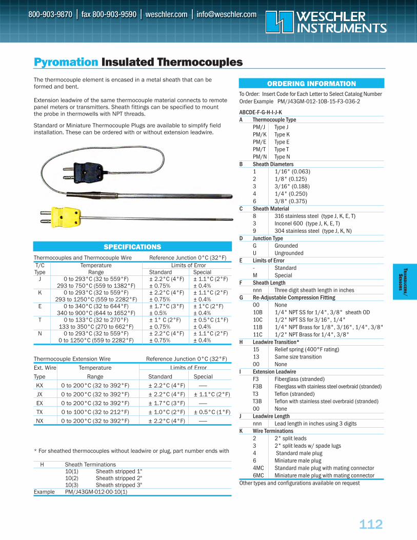
112
TRAN
SDUCER
S/S
ENSO
RS
Pyromation Insulated Thermocouples
Thermocouples and Thermocouple Wire Reference Junction 0°C (32°F)T/C Temperature Limits of ErrorType Range Standard Special
J 0 to 293°C (32 to 559°F) ± 2.2°C (4°F) ± 1.1°C (2°F)293 to 750°C (559 to 1382°F) ± 0.75% ± 0.4%
K 0 to 293°C (32 to 559°F) ± 2.2°C (4°F) ± 1.1°C (2°F)293 to 1250°C (559 to 2282°F) ± 0.75% ± 0.4%
E 0 to 340°C (32 to 644°F) ± 1.7°C (3°F) ± 1°C (2°F)340 to 900°C (644 to 1652°F) ± 0.5% ± 0.4%
T 0 to 133°C (32 to 270°F) ± 1° C (2°F) ± 0.5°C (1°F)133 to 350°C (270 to 662°F) ± 0.75% ± 0.4%
N 0 to 293°C (32 to 559°F) ± 2.2°C (4°F) ± 1.1°C (2°F)0 to 1250°C (559 to 2282°F) ± 0.75% ± 0.4%
* For sheathed thermocouples without leadwire or plug, part number ends with
H Sheath Terminations10(1) Sheath stripped 1"10(2) Sheath stripped 2"10(3) Sheath stripped 3"
Example PM/J43GM-012-00-10(1)
SPECIFICATIONS
The thermocouple element is encased in a metal sheath that can beformed and bent.
Extension leadwire of the same thermocouple material connects to remotepanel meters or transmitters. Sheath fittings can be specified to mountthe probe in thermowells with NPT threads.
Standard or Miniature Thermocouple Plugs are available to simplify fieldinstallation. These can be ordered with or without extension leadwire.
Thermocouple Extension Wire Reference Junction 0°C (32°F)
Ext. Wire Temperature Limits of Error
Type Range Standard Special
KX 0 to 200°C (32 to 392°F) ± 2.2°C (4°F) ------
JX 0 to 200°C (32 to 392°F) ± 2.2°C (4°F) ± 1.1°C (2°F)
EX 0 to 200°C (32 to 392°F) ± 1.7°C (3°F) ------
TX 0 to 100°C (32 to 212°F) ± 1.0°C (2°F) ± 0.5°C (1°F)
NX 0 to 200°C (32 to 392°F) ± 2.2°C (4°F) ------
To Order: Insert Code for Each Letter to Select Catalog NumberOrder Example PM/J43GM-012-10B-15-F3-036-2
ABCDE-F-G-H-I-J-KA Thermocouple Type
PM/J Type JPM/K Type KPM/E Type EPM/T Type TPM/N Type N
B Sheath Diameters 1 1/16" (0.063)2 1/8" (0.125)3 3/16" (0.188)4 1/4" (0.250)6 3/8" (0.375)
C Sheath Material8 316 stainless steel (type J, K, E, T)3 Inconel 600 (type J, K, E, T)9 304 stainless steel (type J, K, N)
D Junction TypeG GroundedU Ungrounded
E Limits of Error- StandardM Special
F Sheath Lengthnnn Three digit sheath length in inches
G Re-Adjustable Compression Fitting00 None10B 1/4" NPT SS for 1/4", 3/8" sheath OD10C 1/2" NPT SS for 3/16", 1/4" 11B 1/4" NPT Brass for 1/8", 3/16", 1/4", 3/8"11C 1/2" NPT Brass for 1/4", 3/8"
H Leadwire Transition*15 Relief spring (400°F rating)13 Same size transition00 None
I Extension LeadwireF3 Fiberglass (stranded)F3B Fiberglass with stainless steel overbraid (stranded)T3 Teflon (stranded)T3B Teflon with stainless steel overbraid (stranded)00 None
J Leadwire Length nnn Lead length in inches using 3 digits
K Wire Terminations2 2" split leads3 2" split leads w/ spade lugs4 Standard male plug6 Miniature male plug4MC Standard male plug with mating connector6MC Miniature male plug with mating connector
Other types and configurations available on request
ORDERING INFORMATION
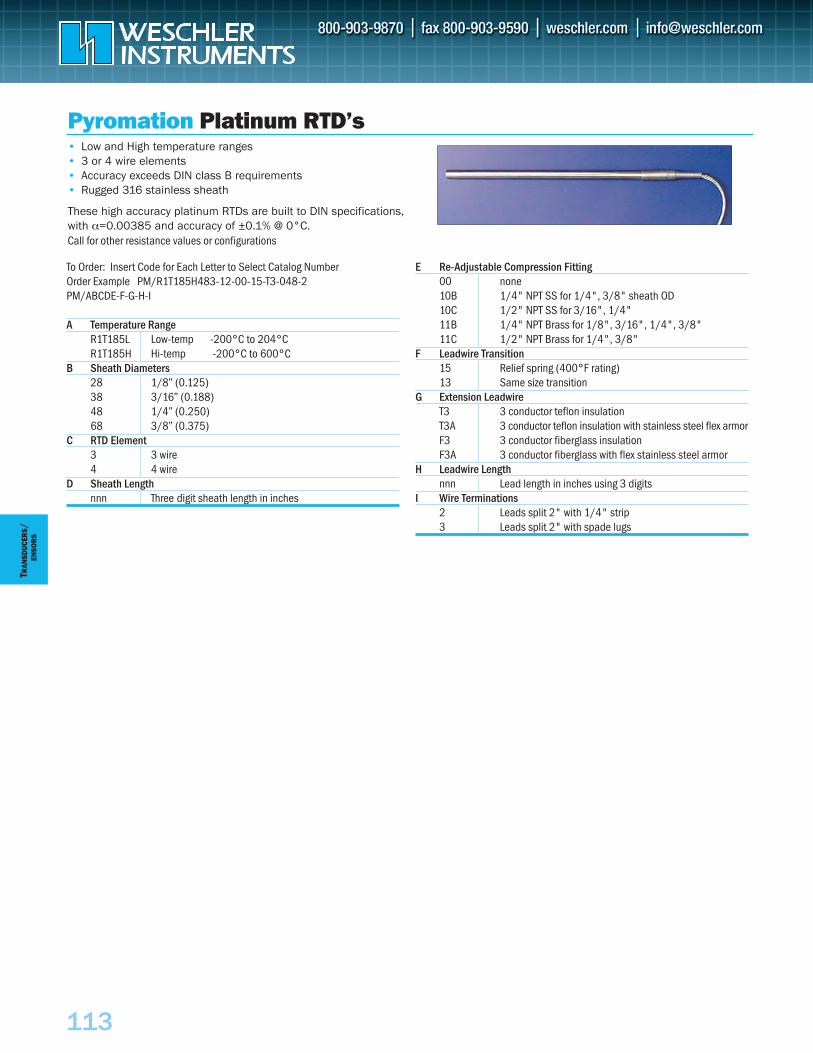
113
TRAN
SDUC
ERS
/EN
SOR
S
• Low and High temperature ranges• 3 or 4 wire elements• Accuracy exceeds DIN class B requirements• Rugged 316 stainless sheath
These high accuracy platinum RTDs are built to DIN specifications, with α=0.00385 and accuracy of ±0.1% @ 0°C. Call for other resistance values or configurations
Pyromation Platinum RTD’s
To Order: Insert Code for Each Letter to Select Catalog NumberOrder Example PM/R1T185H483-12-00-15-T3-048-2PM/ABCDE-F-G-H-I
A Temperature RangeR1T185L Low-temp -200°C to 204°CR1T185H Hi-temp -200°C to 600°C
B Sheath Diameters 28 1/8” (0.125)38 3/16” (0.188)48 1/4” (0.250)68 3/8” (0.375)
C RTD Element3 3 wire4 4 wire
D Sheath Lengthnnn Three digit sheath length in inches
E Re-Adjustable Compression Fitting00 none10B 1/4" NPT SS for 1/4", 3/8" sheath OD10C 1/2" NPT SS for 3/16", 1/4" 11B 1/4" NPT Brass for 1/8", 3/16", 1/4", 3/8"11C 1/2" NPT Brass for 1/4", 3/8"
F Leadwire Transition15 Relief spring (400°F rating)13 Same size transition
G Extension LeadwireT3 3 conductor teflon insulationT3A 3 conductor teflon insulation with stainless steel flex armorF3 3 conductor fiberglass insulationF3A 3 conductor fiberglass with flex stainless steel armor
H Leadwire Length nnn Lead length in inches using 3 digits
I Wire Terminations2 Leads split 2" with 1/4" strip3 Leads split 2" with spade lugs
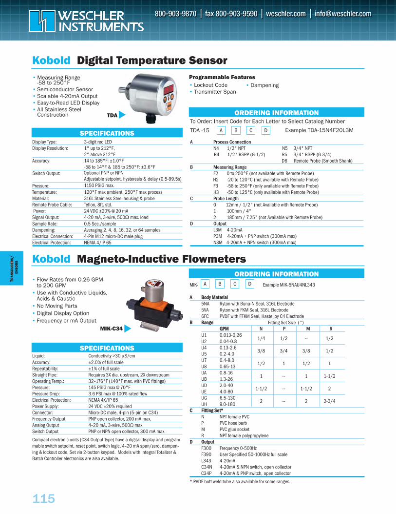
115
TRAN
SDUC
ERS
/
SENSO
RS
MIK- Example MIK-5NAU4NL343
AA BBooddyy MMaatteerriiaall5NA Ryton with Buna-N Seal, 316L Electrode5VA Ryton with FKM Seal, 316L Electrode6FC PVDF with FFKM Seal, Hastelloy C4 Electrode
BB RRaannggee Fitting Set Size (") GGPPMM N P M R
U1 0.013-0.261/4 1/2 -- 1/2
U2 0.04-0.8U4 0.13-2.6
3/8 3/4 3/8 1/2 U5 0.2-4.0U7 0.4-8.0
1/2 1 1/2 1U8 0.65-13UA 0.8-16
1 -- 1 1-1/2 UB 1.3-26UD 2.0-40
1-1/2 -- 1-1/2 2UE 4.0-80UG 6.5-130
2 -- 2 2-3/4UH 9.0-180
CC FFiittttiinngg SSeett**N NPT female PVCP PVC hose barbM PVC glue socketR NPT female polypropylene
DD OOuuttppuuttF300 Frequency 0-500HzF390 User Specified 50-1000Hz full scaleL343 4-20mA C34N 4-20mA & NPN switch, open collectorC34P 4-20mA & PNP switch, open collector
* PVDF butt weld tube also available for some ranges.
Liquid: Conductivity >30 µS/cmAccuracy: ±2.0% of full scaleRepeatability: ±1% of full scaleStraight Pipe: Requires 3X dia. upstream, 2X downstreamOperating Temp.: 32–176°F (140°F max. with PVC fittings)Pressure: 145 PSIG max @ 70°FPressure Drop: 3.6 PSI max @ 100% rated flowElectrical Protection: NEMA 4X/IP 65Power Supply: 24 VDC ±20% requiredConnector: Micro-DC male, 4-pin (5-pin on C34)Frequency Output PNP open collector, 200 mA max.Analog Output 4–20 mA, 3-wire, 500Ω max.Switch Output PNP or NPN open collector, 300 mA max.
Compact electronic units (C34 Output Type) have a digital display and program-mable switch setpoint, reset point, switch logic, 4–20 mA span/zero, dampen-ing & lockout code. Set via 2-button keypad. Models with Integral Totalizer &Batch Controller electronics are also available.
Kobold Magneto-Inductive Flowmeters
MIK-C34
SPECIFICATIONS
ORDERING INFORMATIONA B C D
Display Type: 3-digit red LEDDisplay Resolution: 1° up to 212°F,
2° above 212°F Accuracy: 14 to 185°F: ±1.0°F
-58 to 14°F & 185 to 250°F: ±3.6°F
Adjustable setpoint, hysteresis & delay (0.5-99.5s) 1150 PSIG max.Pressure:
Temperature: 120°F max ambient, 250°F max processMaterial: 316L Stainless Steel housing & probeRemote Probe Cable: Teflon, 8ft. std.Power: 24 VDC ±20% @ 20 mA
Signal Output: 4-20 mA, 3-wire, 500Ω max. loadSample Rate: 0.5 Sec./sampleDampening: Averaging 2, 4, 8, 16, 32, or 64 samplesElectrical Connection: 4-Pin M12 micro-DC male plug Electrical Protection: NEMA 4/IP 65
Kobold Digital Temperature Sensor
SPECIFICATIONS
• Measuring Range -58 to 250°F
• Semiconductor Sensor• Scalable 4-20mA Output• Easy-to-Read LED Display• All Stainless Steel
Construction TDA ORDERING INFORMATIONTo Order: Insert Code for Each Letter to Select Catalog Number
TDA -15 A B C D
A Process ConnectionN4 1/2" NPT N5 3/4" NPTR4 1/2" BSPP (G 1/2) R5 3/4" BSPP (G 3/4)
D6 Remote Probe (Smooth Shank)B Measuring Range
F2 0 to 250°F (not available with Remote Probe)H2 -20 to 120°C (not available with Remote Probe)F3 -58 to 250°F (only available with Remote Probe)H3 -50 to 125°C (only available with Remote Probe)
C Probe Length 0 12mm / 1/2" (not Available with Remote Probe) 1 100mm / 4"2 185mm / 7.25" (not Available with Remote Probe)
D OutputL3M 4-20mAP3M 4-20mA + PNP switch (300mA max)N3M 4-20mA + NPN switch (300mA max)
• Flow Rates from 0.26 GPM to 200 GPM
• Use with Conductive Liquids,Acids & Caustic
• No Moving Parts• Digital Display Option • Frequency or mA Output
Programmable Features• Lockout Code• Transmitter Span
• Dampening
Example TDA-15N4F20L3M
Switch Output: Optional PNP or NPN
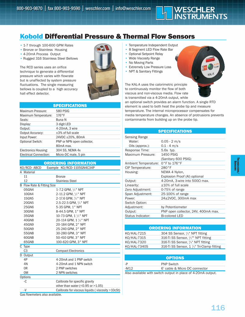
116
TRAN
SDUCER
S/S
ENSO
RS
• Temperature Independent Output • 8 Segment LED Flow Rate Bar• Optional Setpoint Relay • Wide Viscosity Range • No Moving Parts • Extremely Low Pressure Loss • NPT & Sanitary Fittings
The KAL-A uses the calorimetric principle to continuously monitor the flow of both viscous and non-viscous media. Flow rate is transmitted via a 4-20mA output, while an optional switch provides an alarm function. A single RTD element is used to both heat the probe tip and measure temperature. The internal microprocessor compensates for media temperature changes. An absence of protrusions preventscontaminants from building up on the probe tip.
Sensing Range Water: 0.05 - 2 m/s Oils (approx.): 0.1 - 4 m/s
Response Time: 5.6s typ. Maximum Pressure: 1450 PSIG
(Sanitary 600 PSIG)Ambient Temperature: 0°F to 176°F CIP Temperature: 280°F Housing: NEMA 4 Nylon,
Explosion Proof (Al) optional Output: 4-20mA, 3-wire into 500Ω max. Linearity: ±10% of full scale Zero Adjustment: 0-75% of range Span Adjustment: 25-100% of range Power: 24±2VDC, 300mA max Switch Option:Adjustment: by Potentiometer Output: PNP open collector, 24V, 400mA max.Status Indicator: Bi-colored LED
KO/KAL-7215 304 SS Sensor, 1/2" NPT fittingKO/KAL-7315 316-Ti SS Sensor, 1/2"" NPT fittingKO/KAL-7320 316-Ti SS Sensor, 3/4" NPT fittingKO/KAL-7340S 316-Ti SS Sensor, 1 1/2" Tri-Clamp fitting
-P PNP Switch-M12 6’ cable & Micro DC connector Also available with switch output in place of 4-20mA output.
• 1-7 through 100-600 GPM Rates • Bronze or Stainless Housing• 4-20mA Process Output• Rugged 316 Stainless Steel Bellows
The RCD series uses an orifice technique to generate a differential pressure which varies with flowrate but is unaffected by system pressure fluctuations. The single measuring bellows is coupled to a high accuracy hall effect detector.
Maximum Pressure: 580 PSIG Maximum Temperature: 176°F Seals: Buna-NDisplay: 3 digit LEDOutput: 4-20mA, 3 wireOutput Accuracy: ±3% of full scale Input Power: 24VDC ±20%, 80mA Optional Switch: PNP or NPN open collector,
80mA max.Electronics Housing: 304 SS, NEMA 4xElectrical Connection: Micro-DC male, 5 pin
KO/RCD- ABCD Example KO/RCD-1105GN4C34PA Material
11 Bronze12 Stainless Steel
B Flow Rate & Fitting Size05GN4 1-7.2 GPM, 1/2" NPT10GN4 2-11.2 GPM, 1/2" NPT15GN5 2-17.6 GPM, 3/4" NPT20GN5 2.5-22.5 GPM, 3/4" NPT25GN6 5-35 GPM, 1" NPT30GN6 8-44.5 GPM, 1" NPT35GN8 10-73 GPM, 1 1/2" NPT40GN8 20-114 GPM, 1 1/2" NPT45GN9 20-184 GPM, 2" NPT50GN9 25-240 GPM, 2" NPT55GNB 30-280 GPM, 3" NPT60GNB 50-410 GPM, 3" NPT65GNB 100-620 GPM, 3" NPT
C TypeC3 Compact Electronics
D Output4P 4-20mA and 1 PNP switch4N 4-20mA and 1 NPN switch0R 2 PNP switches0M 2 NPN switches
Options-C Calibrate for specific gravity
other than water (<0.95 or >1.05)-V Calibrate for viscous liquids ( viscosity >10cSt)
Gas flowmeters also available.
SPECIFICATIONS
ORDERING INFORMATION
ORDERING INFORMATION
OPTIONS
SPECIFICATIONS
Kobold Differential Pressure & Thermal Flow Sensors
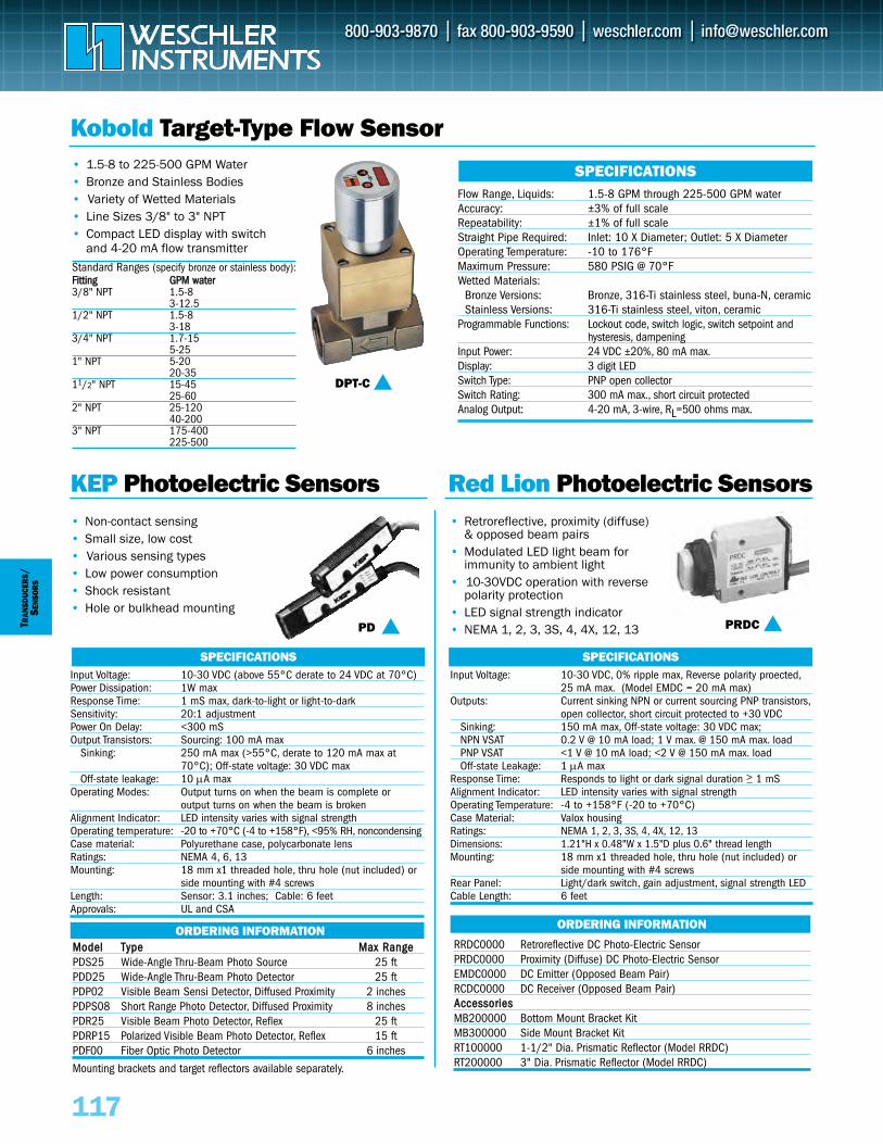
117
TRAN
SDUC
ERS
/SE
NSO
RS
SPECIFICATIONS SPECIFICATIONS
ORDERING INFORMATION ORDERING INFORMATION
KEP Photoelectric Sensors Red Lion Photoelectric Sensors
Flow Range, Liquids: 1.5-8 GPM through 225-500 GPM waterAccuracy: ±3% of full scaleRepeatability: ±1% of full scaleStraight Pipe Required: Inlet: 10 X Diameter; Outlet: 5 X DiameterOperating Temperature: -10 to 176°FMaximum Pressure: 580 PSIG @ 70°FWetted Materials:
Bronze Versions: Bronze, 316-Ti stainless steel, buna-N, ceramicStainless Versions: 316-Ti stainless steel, viton, ceramic
Programmable Functions: Lockout code, switch logic, switch setpoint and hysteresis, dampening
Input Power: 24 VDC ±20%, 80 mA max.Display: 3 digit LEDSwitch Type: PNP open collectorSwitch Rating: 300 mA max., short circuit protectedAnalog Output: 4-20 mA, 3-wire, RL=500 ohms max.
Input Voltage: 10-30 VDC (above 55°C derate to 24 VDC at 70°C)Power Dissipation: 1W maxResponse Time: 1 mS max, dark-to-light or light-to-darkSensitivity: 20:1 adjustmentPower On Delay: <300 mSOutput Transistors: Sourcing: 100 mA max
Sinking: 250 mA max (>55°C, derate to 120 mA max at 70°C); Off-state voltage: 30 VDC max
Off-state leakage: 10 μA maxOperating Modes: Output turns on when the beam is complete or
output turns on when the beam is brokenAlignment Indicator: LED intensity varies with signal strength Operating temperature: -20 to +70°C (-4 to +158°F), <95% RH, noncondensingCase material: Polyurethane case, polycarbonate lensRatings: NEMA 4, 6, 13Mounting: 18 mm x1 threaded hole, thru hole (nut included) or
side mounting with #4 screwsLength: Sensor: 3.1 inches; Cable: 6 feetApprovals: UL and CSA
Input Voltage: 10-30 VDC, 0% ripple max, Reverse polarity proected,25 mA max. (Model EMDC = 20 mA max)
Outputs: Current sinking NPN or current sourcing PNP transistors,open collector, short circuit protected to +30 VDC
Sinking: 150 mA max, Off-state voltage: 30 VDC max;NPN VSAT 0.2 V @ 10 mA load; 1 V max. @ 150 mA max. loadPNP VSAT <1 V @ 10 mA load; <2 V @ 150 mA max. loadOff-state Leakage: 1 μA max
Response Time: Responds to light or dark signal duration > 1 mSAlignment Indicator: LED intensity varies with signal strength Operating Temperature: -4 to +158°F (-20 to +70°C)Case Material: Valox housingRatings: NEMA 1, 2, 3, 3S, 4, 4X, 12, 13Dimensions: 1.21"H x 0.48"W x 1.5"D plus 0.6" thread lengthMounting: 18 mm x1 threaded hole, thru hole (nut included) or
side mounting with #4 screwsRear Panel: Light/dark switch, gain adjustment, signal strength LED Cable Length: 6 feet
SPECIFICATIONS
Kobold Target-Type Flow Sensor
DPT-C
PD PRDC
Standard Ranges (specify bronze or stainless body):FFiittttiinngg GGPPMM wwaatteerr3/8" NPT 1.5-8
3-12.51/2" NPT 1.5-8
3-183/4" NPT 1.7-15
5-251" NPT 5-20
20-3511/2" NPT 15-45
25-602" NPT 25-120
40-2003" NPT 175-400
225-500
• 1.5-8 to 225-500 GPM Water • Bronze and Stainless Bodies• Variety of Wetted Materials• Line Sizes 3/8" to 3" NPT• Compact LED display with switch
and 4-20 mA flow transmitter
• Non-contact sensing • Small size, low cost• Various sensing types• Low power consumption• Shock resistant• Hole or bulkhead mounting
• Retroreflective, proximity (diffuse)& opposed beam pairs
• Modulated LED light beam for immunity to ambient light
• 10-30VDC operation with reverse polarity protection
• LED signal strength indicator • NEMA 1, 2, 3, 3S, 4, 4X, 12, 13
RRDC0000 Retroreflective DC Photo-Electric SensorPRDC0000 Proximity (Diffuse) DC Photo-Electric SensorEMDC0000 DC Emitter (Opposed Beam Pair)RCDC0000 DC Receiver (Opposed Beam Pair)AAcccceessssoorriieessMB200000 Bottom Mount Bracket KitMB300000 Side Mount Bracket KitRT100000 1-1/2" Dia. Prismatic Reflector (Model RRDC)RT200000 3" Dia. Prismatic Reflector (Model RRDC)
MMooddeell TTyyppee MMaaxx RRaannggeePDS25 Wide-Angle Thru-Beam Photo Source 25 ftPDD25 Wide-Angle Thru-Beam Photo Detector 25 ftPDP02 Visible Beam Sensi Detector, Diffused Proximity 2 inchesPDPS08 Short Range Photo Detector, Diffused Proximity 8 inchesPDR25 Visible Beam Photo Detector, Reflex 25 ftPDRP15 Polarized Visible Beam Photo Detector, Reflex 15 ftPDF00 Fiber Optic Photo Detector 6 inches
Mounting brackets and target reflectors available separately.
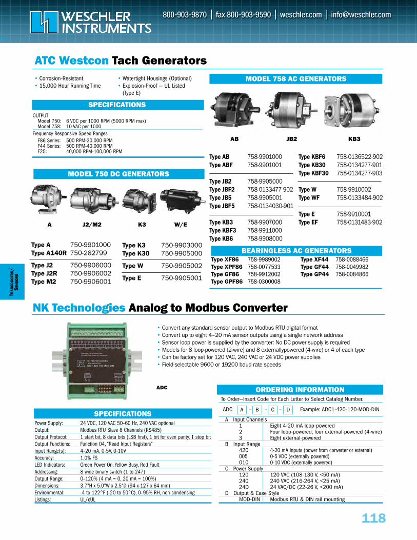
118
TRAN
SDUC
ERS
/SE
NSO
RS
ORDERING INFORMATION
NK Technologies Analog to Modbus Converter
Type A 750-9901000Type A140R 750-282799
Type J2 750-9906000Type J2R 750-9906002Type M2 750-9906001
Type K3 750-9903000Type K30 750-9905000
Type W 750-9905002
Type E 750-9905001
A J2/M2 K3 W/E
MODEL 750 DC GENERATORS
• Corrosion-Resistant• 15,000 Hour Running Time
• Watertight Housings (Optional)• Explosion-Proof — UL Listed
(Type E)
OUTPUTModel 750: 6 VDC per 1000 RPM (5000 RPM max)Model 758: 10 VAC per 1000
Frequency Responsive Speed RangesF86 Series: 500 RPM-20,000 RPMF44 Series: 500 RPM-40,000 RPMF25: 40,000 RPM-100,000 RPM
SPECIFICATIONS
ATC Westcon Tach Generators
AB JB2 KB3
Type AB 758-9901000Type ABF 758-9901001
Type JB2 758-9905000Type JBF2 758-0133477-902Type JB5 758-9905001Type JBF5 758-0134030-901
Type KB3 758-9907000Type KBF3 758-9911000Type KB6 758-9908000
Type KBF6 758-0136522-902Type KB30 758-0134277-901Type KBF30 758-0134277-903
Type W 758-9910002Type WF 758-0133484-902
Type E 758-9910001Type EF 758-0131483-902
Type XF86 758-9989002Type XPF86 758-0077533Type GF86 758-9912002Type GPF86 758-0300008
Type XF44 758-0088466Type GF44 758-0049982Type GP44 758-0084866
BEARINGLESS AC GENERATORS
MODEL 758 AC GENERATORS
To Order—Insert Code for Each Letter to Select Catalog Number.
A Input Channels1 Eight 4-20 mA loop-powered 2 Four loop-powered, four external-powered (4-wire)3 Eight external-powered
B Input Range420 4-20 mA inputs (power from converter or external)005 0-5 VDC (externally powered)010 0-10 VDC (externally powered)
C Power Supply120 120 VAC (108-130 V, <50 mA) 240 240 VAC (216-264 V, <25 mA)24D 24 VAC/DC (22-26 V, <200 mA)
D Output & Case StyleMOD-DIN Modbus RTU & DIN rail mounting
A B C DADC – – – Example: ADC1-420-120-MOD-DIN
ADC
• Convert any standard sensor output to Modbus RTU digital format• Convert up to eight 4–20 mA sensor outputs using a single network address• Sensor loop power is supplied by the converter: No DC power supply is required • Models for 8 loop-powered (2-wire) and 8 externallypowered (4-wire) or 4 of each type• Can be factory set for 120 VAC, 240 VAC or 24 VDC power supplies• Field-selectable 9600 or 19200 baud rate speeds
Power Supply: 24 VDC, 120 VAC 50–60 Hz, 240 VAC optionalOutput: Modbus RTU Slave 8 Channels (RS485)Output Protocol: 1 start bit, 8 data bits (LSB first), 1 bit for even parity, 1 stop bitOutput Functions: Function 04, “Read Input Registers”Input Range(s): 4–20 mA, 0-5V, 0-10VAccuracy: 1.0% FSLED Indicators: Green Power On, Yellow Busy, Red Fault Addressing: 8 wide binary switch (1 to 247)Output Range: 0–120% (4 mA = 0, 20 mA = 100%)Dimensions: 3.7"H x 5.0"W x 2.5"D (94 x 127 x 64 mm)Environmental: -4 to 122°F (-20 to 50°C), 0–95% RH, non-condensingListings: UL/cUL
SPECIFICATIONS
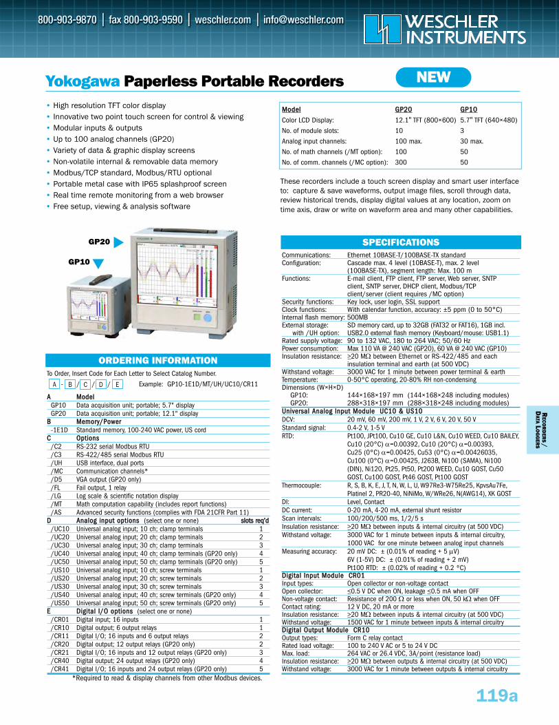
To Order, Insert Code for Each Letter to Select Catalog Number.
- / / / Example: GP10-1E1D/MT/UH/UC10/CR11
AA MMooddeellGP10 Data acquisition unit; portable; 5.7" displayGP20 Data acquisition unit; portable; 12.1" display
BB MMeemmoorryy//PPoowweerr-1E1D Standard memory, 100-240 VAC power, US cord
CC OOppttiioonnss/C2 RS-232 serial Modbus RTU /C3 RS-422/485 serial Modbus RTU /UH USB interface, dual ports /MC Communication channels*/D5 VGA output (GP20 only)/FL Fail output, 1 relay /LG Log scale & scientific notation display /MT Math computation capability (includes report functions) /AS Advanced security functions (complies with FDA 21CFR Part 11)
DD AAnnaalloogg iinnppuutt ooppttiioonnss (select one or none) sslloottss rreeqq’’dd/UC10 Universal analog input; 10 ch; clamp terminals 1/UC20 Universal analog input; 20 ch; clamp terminals 2/UC30 Universal analog input; 30 ch; clamp terminals 3/UC40 Universal analog input; 40 ch; clamp terminals (GP20 only) 4/UC50 Universal analog input; 50 ch; clamp terminals (GP20 only) 5/US10 Universal analog input; 10 ch; screw terminals 1/US20 Universal analog input; 20 ch; screw terminals 2/US30 Universal analog input; 30 ch; screw terminals 3/US40 Universal analog input; 40 ch; screw terminals (GP20 only) 4/US50 Universal analog input; 50 ch; screw terminals (GP20 only) 5
EE DDiiggiittaall II//OO ooppttiioonnss (select one or none) /CR01 Digital input; 16 inputs 1/CR10 Digital output; 6 output relays 1/CR11 Digital I/O; 16 inputs and 6 output relays 2/CR20 Digital output; 12 output relays (GP20 only) 2/CR21 Digital I/O; 16 inputs and 12 output relays (GP20 only) 3/CR40 Digital output; 24 output relays (GP20 only) 4/CR41 Digital I/O; 16 inputs and 24 output relays (GP20 only) 5
*Required to read & display channels from other Modbus devices.
C
• High resolution TFT color display• Innovative two point touch screen for control & viewing • Modular inputs & outputs • Up to 100 analog channels (GP20) • Variety of data & graphic display screens• Non-volatile internal & removable data memory• Modbus/TCP standard, Modbus/RTU optional• Portable metal case with IP65 splashproof screen • Real time remote monitoring from a web browser• Free setup, viewing & analysis software
Yokogawa Paperless Portable Recorders
MMooddeell GGPP2200 GGPP1100
Color LCD Display: 12.1" TFT (800×600) 5.7" TFT (640×480)
No. of module slots: 10 3
Analog input channels: 100 max. 30 max.
No. of math channels (/MT option): 100 50
No. of comm. channels (/MC option): 300 50
SPECIFICATIONS
ORDERING INFORMATION
A B D E
NEW
RECO
RD
ERS/
DATA
LO
GG
ERS
GP10
GP20
Communications: Ethernet 10BASE-T/100BASE-TX standardConfiguration: Cascade max. 4 level (10BASE-T), max. 2 level
(100BASE-TX), segment length: Max. 100 mFunctions: E-mail client, FTP client, FTP server, Web server, SNTP
client, SNTP server, DHCP client, Modbus/TCP client/server (client requires /MC option)
Security functions: Key lock, user login, SSL supportClock functions: With calendar function, accuracy: ±5 ppm (0 to 50°C) Internal flash memory: 500MBExternal storage: SD memory card, up to 32GB (FAT32 or FAT16), 1GB incl.
with /UH option: USB2.0 external flash memory (Keyboard/mouse: USB1.1)Rated supply voltage: 90 to 132 VAC, 180 to 264 VAC; 50/60 HzPower consumption: Max 110 VA @ 240 VAC (GP20), 60 VA @ 240 VAC (GP10)Insulation resistance: >20 MΩ between Ethernet or RS-422/485 and each
insulation terminal and earth (at 500 VDC)Withstand voltage: 3000 VAC for 1 minute between power terminal & earthTemperature: 0-50°C operating, 20-80% RH non-condensingDimensions (W×H×D)
GP10: 144×168×197 mm (144×168×248 including modules)GP20: 288×318×197 mm (288×318×248 including modules)
UUnniivveerrssaall AAnnaalloogg IInnppuutt MMoodduullee UUCC1100 && UUSS1100DCV: 20 mV, 60 mV, 200 mV, 1 V, 2 V, 6 V, 20 V, 50 VStandard signal: 0.4-2 V, 1-5 VRTD: Pt100, JPt100, Cu10 GE, Cu10 L&N, Cu10 WEED, Cu10 BAILEY,
Cu10 (20°C) α=0.00392, Cu10 (20°C) α=0.00393,Cu25 (0°C) α=0.00425, Cu53 (0°C) α=0.00426035,Cu100 (0°C) α=0.00425, J263B, Ni100 (SAMA), Ni100 (DIN), Ni120, Pt25, Pt50, Pt200 WEED, Cu10 GOST, Cu50 GOST, Cu100 GOST, Pt46 GOST, Pt100 GOST
Thermocouple: R, S, B, K, E, J, T, N, W, L, U, W97Re3-W75Re25, KpvsAu7Fe,Platinel 2, PR20-40, NiNiMo, W/WRe26, N(AWG14), XK GOST
DI: Level, ContactDC current: 0-20 mA, 4-20 mA, external shunt resistor Scan intervals: 100/200/500 ms, 1/2/5 sInsulation resistance: >20 MΩ between inputs & internal circuitry (at 500 VDC)Withstand voltage: 3000 VAC for 1 minute between inputs & internal circuitry,
1000 VAC for one minute between analog input channelsMeasuring accuracy: 20 mV DC: ± (0.01% of reading + 5 μV)
6V (1-5V) DC: ± (0.01% of reading + 2 mV)Pt100 RTD: ± (0.02% of reading + 0.2 ºC)
DDiiggiittaall IInnppuutt MMoodduullee CCRR0011Input types: Open collector or non-voltage contactOpen collector: <0.5 V DC when ON, leakage <0.5 mA when OFFNon-voltage contact: Resistance of 200 Ω or less when ON, 50 kΩ when OFFContact rating: 12 V DC, 20 mA or moreInsulation resistance: >20 MΩ between inputs & internal circuitry (at 500 VDC)Withstand voltage: 1500 VAC for 1 minute between inputs & internal circuitryDDiiggiittaall OOuuttppuutt MMoodduullee CCRR1100Output types: Form C relay contactRated load voltage: 100 to 240 V AC or 5 to 24 V DCMax. load: 264 VAC or 26.4 VDC, 3A/point (resistance load)Insulation resistance: >20 MΩ between outputs & internal circuitry (at 500 VDC)Withstand voltage: 3000 VAC for 1 minute between outputs & internal circuitry
These recorders include a touch screen display and smart user interfaceto: capture & save waveforms, output image files, scroll through data,review historical trends, display digital values at any location, zoom ontime axis, draw or write on waveform area and many other capabilities.
119a
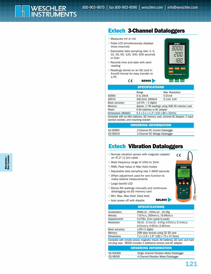
121
REC
OR
DER
S/
DAT
ALO
GG
ERS
EX/SD900 3-Channel DC Current Datalogger EX/SD910 3-Channel DC Voltage Datalogger
ORDERING INFORMATION
Extech 3-Channel Dataloggers• Measures mV or mA
• Triple LCD simultaneously displays three channels
• Selectable data sampling rate: 2, 5,10, 30, 60, 120, 300, 600 secondsor Auto
• Records time and date with each reading
• Readings stored on an SD card in Excel® format for easy transfer to a PC
Range Max. ResolutionSD900 0 to 20mA 0.01mA SD910 300.0mV, 3000mV 0.1mV, 1mVBasic accuracy: ±(0.5% + 2 digits)Memory: Approx. 2.7M readings using 4GB SD memory cardPower: 6 AA batteries or AC adapter Dimensions (WxHxD): 5.2 x 3.1 x 1.3" (132 x 80 x 32mm)Complete with six AAA batteries, SD memory card, Univeral AC Adaptor, 3 inputconnect sockets, and mounting bracket.
SPECIFICATIONS
SD900
EX/SDL800 Single Channel Vibration Meter/Datalogger EX/VB500 4-Channel Vibration Meter/Datalogger
ORDERING INFORMATION
Extech Vibration Dataloggers• Remote vibration sensor with magnetic adapter
on 47.2" (1.2m) cable
• Wide frequency range of 10Hz to 1kHz
• RMS, Peak Value or Max Hold modes
• Adjustable data sampling rate 1-3600 seconds
• Offset adjustment used for zero function to make relative measurements
• Large backlit LCD
• Stores 99 readings manually and continuous datalogging via SD memory card
• Min, Max, Max Hold, Data Hold
• Auto power off with disable
Acceleration: 656ft/s2 , 200m/s2 , 20.39gVelocity: 7.87in/s, 200mm/s, 19.99cm/sDisplacement: 0.078in, 2mm (peak-to-peak)Resolution: 1ft/s2 , 0.1m/s2 , 0.01g; 0.01in/s, 0.1mm/s,
0.01cm/s; 0.001in, 0.001mmBasic accuracy: ±(5%+2 digits)Memory: 20M data records using 2G SD cardDimensions 7.2 x 2.9 x 1.9" (182 x 73 x 47.5mm)Complete with remote sensor, magnetic mount, AA batteries, SD card, and hardcarrying case. VB500 includes 3 additional sensors and AC adapter.
SPECIFICATIONS
SDL800
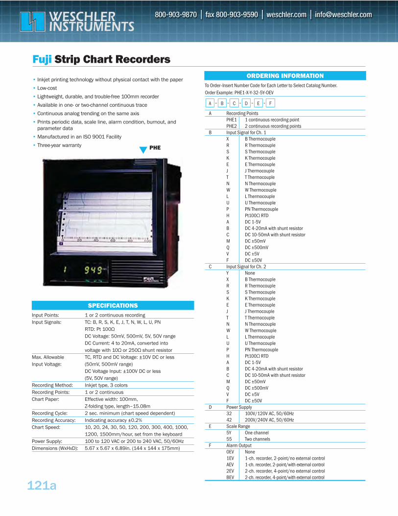
121a
To Order–Insert Number Code for Each Letter to Select Catalog Number. Order Example: PHE1-X-Y-32-5Y-OEV
- - - - -
A Recording PointsPHE1 1 continuous recording point PHE2 2 continuous recording points
B Input Signal for Ch. 1X B Thermocouple R R Thermocouple S S Thermocouple K K Thermocouple E E Thermocouple J J Thermocouple T T Thermocouple N N Thermocouple W W Thermocouple L L Thermocouple U U Thermocouple P PN Thermocouple H Pt100Ω RTD A DC 1-5V B DC 4-20mA with shunt resistor C DC 10-50mA with shunt resistor M DC ±50mV Q DC ±500mV V DC ±5V F DC ±50V
C Input Signal for Ch. 2Y None X B Thermocouple R R Thermocouple S S Thermocouple K K Thermocouple E E Thermocouple J J Thermocouple T T Thermocouple N N Thermocouple W W Thermocouple L L Thermocouple U U Thermocouple P PN Thermocouple H Pt100Ω RTD A DC 1-5V B DC 4-20mA with shunt resistor C DC 10-50mA with shunt resistor M DC ±50mV Q DC ±500mV V DC ±5V F DC ±50V
D Power Supply32 100V/120V AC, 50/60Hz 42 200V/240V AC, 50/60Hz
E Scale Range5Y One channel55 Two channels
F Alarm Output0EV None 1EV 1-ch. recorder, 2-point/no external control AEV 1-ch. recorder, 2-point/with external control 2EV 2-ch. recorder, 4-point/no external control BEV 2-ch. recorder, 4-point/with external control
FEDCBA
Input Points: 1 or 2 continuous recording Input Signals: TC: B, R, S, K, E, J, T, N, W, L, U, PN
RTD: Pt 100ΩDC Voltage: 50mV, 500mV, 5V, 50V range DC Current: 4 to 20mA, converted into voltage with 10Ω or 250Ω shunt resistor
Max. Allowable TC, RTD and DC Voltage: ±10V DC or less Input Voltage: (50mV, 500mV range)
DC Voltage Input: ±100V DC or less (5V, 50V range)
Recording Method: Inkjet type, 3 colors Recording Points: 1 or 2 continuous Chart Paper: Effective width: 100mm,
Z-folding type, length–15.08m Recording Cycle: 2 sec. minimum (chart speed dependent) Recording Accuracy: Indicating accuracy ±0.2%Chart Speed: 10, 20, 24, 30, 50, 120, 200, 300, 400, 1000,
1200, 1500mm/hour, set from the keyboard Power Supply: 100 to 120 VAC or 200 to 240 VAC, 50/60Hz Dimensions (WxHxD): 5.67 x 5.67 x 6.89in. (144 x 144 x 175mm)
SPECIFICATIONS
Fuji Strip Chart Recorders
• Inkjet printing technology without physical contact with the paper
• Low-cost
• Lightweight, durable, and trouble-free 100mm recorder
• Available in one- or two-channel continuous trace
• Continuous analog trending on the same axis
• Prints periodic data, scale line, alarm condition, burnout, and parameter data
• Manufactured in an ISO 9001 Facility
• Three-year warranty
ORDERING INFORMATION
PHE
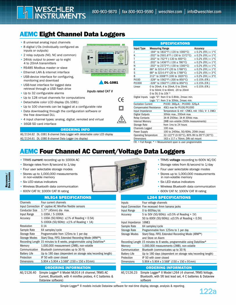
AEMC Four Channel AC Current/Voltage Data Loggers
Inputs Four voltage channelsInput Connection Five recessed 4mm banana jacksInput Range 0 to 600Vac/dcAccuracy 5 to 50V (50/60Hz): ±(0.5% of Reading + 1V)
50 to 600V (50/60Hz): ±(0.5% of Reading + 0.5V)Input Impedance 16MΩSample Rate 64 samples/cycleStorage Rate Programmable from 125ms to 1 per dayStorage Modes Start/Stop, FIFO, Extended Recording Mode (XRM™)
and Store on AlarmRecording Length 15 minutes to 8 weeks, programmable using DataView®Memory 1,000,000 measurements (2MB), non-volatileCommunication Bluetooth (communicates up to 30 ft)Battery Life Up to 180 days (dependent on storage rate/recording length)Protection IP 50 with cover closedDimensions 5.904 x 5.904 x 3.568" (150 x 150 x 91mm)
L264 SPECIFICATIONSChannels Four current channels Input Connection 6" captive AC MiniFlex flexible sensorsConductor Size 1.77" (45mm) dia max.Input Range 1-100A / 5-1000AAccuracy 1-100A (50/60Hz): ±(1% of Reading + 0.5A)
5-1000A (50/60Hz): ±(1% of Reading + 1A)Resolution 0.1ASample Rate 64 samples/cycleStorage Rate Programmable from 125ms to 1 per dayStorage Modes Start/Stop, FIFO, Extended Recording Mode (XRM™) Recording Length 15 minutes to 8 weeks, programmable using DataView®Memory 1,000,000 measurement (2MB), non-volatile Communication Bluetooth (communicates up to 30 ft)Battery Life Up to 180 days (dependent on storage rate/recording length)Protection IP 50 with cover closedDimensions 5.904 x 5.904 x 3.568" (150 x 150 x 91mm)
ML914 SPECIFICATIONS
• TRMS vvoollttaaggee recording to 600V AC/DC• Storage rates from 8/second to 1/day• Four user selectable storage modes• Stores up to 1,000,000 measurements
in non-volatile memory• Six LED status indicators • Wireless Bluetooth data communication • 600V CAT IV; 1000V CAT III rating
• TRMS ccuurrrreenntt recording up to 1000A AC• Storage rates from 8/second to 1/day• Four user selectable storage modes• Stores up to 1,000,000 measurements
in non-volatile memory• Six LED status indicators • Wireless Bluetooth data communication • 600V CAT IV; 1000V CAT III rating
AEMC Eight Channel Data Loggers• 8 universal analog input channels• 8 digital I/Os (individually configured as
inputs or outputs)• 2 relay outputs (NO, NC and common)• 24Vdc output to power up to eight
4 to 20mA transmitters• RS485 Modbus master or slave• Ethernet LAN & internet interface • USB-device interface for configuring,
monitoring and download• USB-host interface for logged data
retrieval through a USB flash drive• Up to 32 configurable alarms• Up to 128 virtual channels for computations• Detachable color LCD display (DL-1081)• Up to 100 channels can be logged at a configurable rate• Data downloading through the configuration software or
the free download DLL• 4 input channel types: analog, digital, remoted and virtual• 16GB SD card interface
IInnppuutt TTyyppee MMeeaassuurriinngg RRaannggee AAccccuurraaccyyJ -184º to 1832ºF (-120 to 1000ºC) ± 0.2% (F.R.) ± 1ºCK -202º to 2501.6ºF (-130 to 1372ºC) ± 0.2% (F.R.) ± 1ºCT -202º to 752ºF (-130 to 400ºC) ± 0.2% (F.R.) ± 1ºCE -202º to 1436ºF (-130 a 780ºC) ± 0.2% (F.R.) ± 1ºCN -202º to 2372ºF (-130 to 1300ºC) ± 0.2% (F.R.) ± 1ºCR 68º to 3214.4ºF (20 to 1768ºC) ± 0.2% (F.R.) ± 1ºCS 68º to 3214.4ºF (20 to 1768ºC) ± 0.2% (F.R.) ± 3ºCB 212º to 3308°F (100 to 1820ºC) ± 0.2% (F.R.) ± 3ºCPt100 -328º to 1562ºF (-200 to 850ºC) ± 0.15% (F.R.) Pt1000 -328º to 1562ºF (-200 to 850ºC) ± 0.15% (F.R.)Linear 0 to 20mA, 4 to 20mA, 0 to 20mV, ± 0.15% (F.R.)
0 to 50mV, 0 to 60mV, -20 to 20mV0 to 5V, 0 to 10V *
Digital Inputs Logic “0”: from 0 to 0.8Vdc, 2msec min.Logic “1”: from 3 to 30Vdc, 2msec min.
Excitation Current Pt100: 360μA; ; Pt1000: 320μACompensated Resistance 40Ω max for Pt100/Pt1000Input Impedance Temperature & mV: >2MΩ, mA: 15Ω, V: 1.1MΩDigital Outputs 30Vdc max., 200mA max.Relay Contacts 3A @ 250Vac; 3A @ 30Vdc max.Internal Memory 2MB non-volatile (500k measurements)Storage Rate from 1ms to 24 hoursChannels Logged 100 max.Power Supply 100 to 240Vac, 50/60Hz. 20VA (max)Operating Temperature 32-122°F (0-50°C), 80% RH to 85°F (30°C)Dimensions 163 x 117 x 76mm, DIN rail mountF.R. = Full Range; * = Measurement span is user programmable
SPECIFICATIONS
AE/2134.62 DL-1081 8-channel Data Logger with detachable color LCD display AE/2134.61 DL-1080 8-channel Data Logger (no display)
ORDERING INFO
112222aa
REC
OR
DER
S/
DAT
ALO
GG
ERS
AE/2126.23 Simple Logger® II Model L264 (4 channel, TRMS Voltage,Bluetooth, with 5ft test lead set, 4 C batteries & Dataview software
ORDERING INFORMATIONAE/2126.40 Simple Logger® II Model ML914 (4 channel, TRMS AC
Current, Bluetooth, with 4 miniflex probes, 4 C batteries & Dataview software)
ORDERING INFORMATION
DL-1081
IInnppuuttss rraatteedd CCAATT IIII
Simple Logger® II models include Dataview software for real-time display, storage, analysis & reporting.
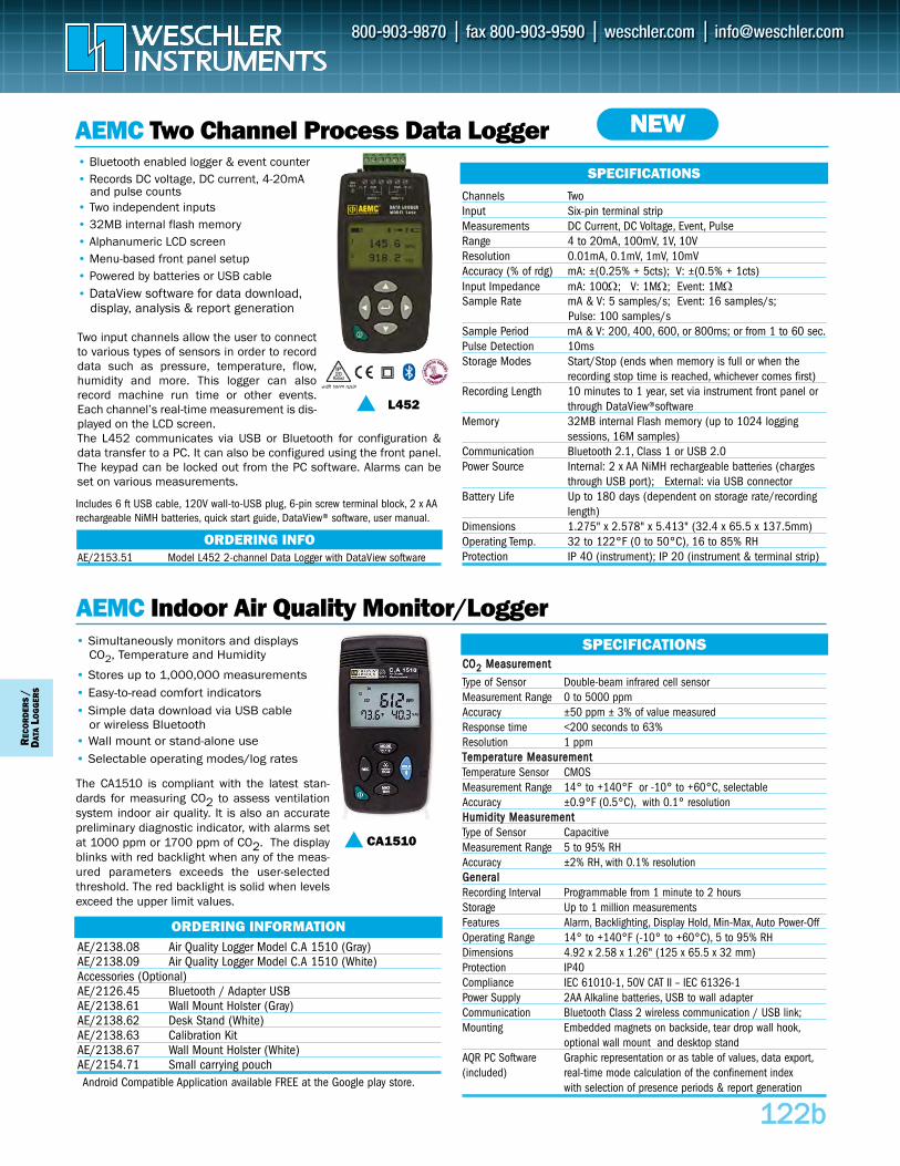
Two input channels allow the user to connectto various types of sensors in order to recorddata such as pressure, temperature, flow,humidity and more. This logger can alsorecord machine run time or other events.Each channel’s real-time measurement is dis-played on the LCD screen.The L452 communicates via USB or Bluetooth for configuration &data transfer to a PC. It can also be configured using the front panel.The keypad can be locked out from the PC software. Alarms can beset on various measurements.
AEMC Indoor Air Quality Monitor/Logger
CCOO22 MMeeaassuurreemmeenntt
Type of Sensor Double-beam infrared cell sensorMeasurement Range 0 to 5000 ppmAccuracy ±50 ppm ± 3% of value measuredResponse time <200 seconds to 63% Resolution 1 ppmTTeemmppeerraattuurree MMeeaassuurreemmeennttTemperature Sensor CMOSMeasurement Range 14° to +140°F or -10° to +60°C, selectableAccuracy ±0.9°F (0.5°C), with 0.1° resolutionHHuummiiddiittyy MMeeaassuurreemmeennttType of Sensor CapacitiveMeasurement Range 5 to 95% RHAccuracy ±2% RH, with 0.1% resolutionGGeenneerraallRecording Interval Programmable from 1 minute to 2 hoursStorage Up to 1 million measurementsFeatures Alarm, Backlighting, Display Hold, Min-Max, Auto Power-OffOperating Range 14° to +140°F (-10° to +60°C), 5 to 95% RHDimensions 4.92 x 2.58 x 1.26" (125 x 65.5 x 32 mm)Protection IP40Compliance IEC 61010-1, 50V CAT II – IEC 61326-1Power Supply 2AA Alkaline batteries, USB to wall adapterCommunication Bluetooth Class 2 wireless communication / USB link;Mounting Embedded magnets on backside, tear drop wall hook,
optional wall mount and desktop standAQR PC Software Graphic representation or as table of values, data export,(included) real-time mode calculation of the confinement index
with selection of presence periods & report generation
SPECIFICATIONS• Simultaneously monitors and displays CO2, Temperature and Humidity
• Stores up to 1,000,000 measurements• Easy-to-read comfort indicators• Simple data download via USB cable
or wireless Bluetooth• Wall mount or stand-alone use • Selectable operating modes/log rates
AEMC Two Channel Process Data Logger• Bluetooth enabled logger & event counter• Records DC voltage, DC current, 4-20mA
and pulse counts• Two independent inputs• 32MB internal flash memory• Alphanumeric LCD screen • Menu-based front panel setup• Powered by batteries or USB cable• DataView software for data download,
display, analysis & report generation
Channels TwoInput Six-pin terminal stripMeasurements DC Current, DC Voltage, Event, PulseRange 4 to 20mA, 100mV, 1V, 10VResolution 0.01mA, 0.1mV, 1mV, 10mVAccuracy (% of rdg) mA: ±(0.25% + 5cts); V: ±(0.5% + 1cts)Input Impedance mA: 100Ω; V: 1MΩ; Event: 1MΩSample Rate mA & V: 5 samples/s; Event: 16 samples/s;
Pulse: 100 samples/sSample Period mA & V: 200, 400, 600, or 800ms; or from 1 to 60 sec.Pulse Detection 10msStorage Modes Start/Stop (ends when memory is full or when the
recording stop time is reached, whichever comes first)Recording Length 10 minutes to 1 year, set via instrument front panel or
through DataView®softwareMemory 32MB internal Flash memory (up to 1024 logging
sessions, 16M samples)Communication Bluetooth 2.1, Class 1 or USB 2.0Power Source Internal: 2 x AA NiMH rechargeable batteries (charges
through USB port); External: via USB connectorBattery Life Up to 180 days (dependent on storage rate/recording
length)Dimensions 1.275" x 2.578" x 5.413" (32.4 x 65.5 x 137.5mm)Operating Temp. 32 to 122°F (0 to 50°C), 16 to 85% RHProtection IP 40 (instrument); IP 20 (instrument & terminal strip)
SPECIFICATIONS
112222bb
REC
OR
DER
S/
DAT
ALO
GG
ERS
AE/2138.08 Air Quality Logger Model C.A 1510 (Gray)AE/2138.09 Air Quality Logger Model C.A 1510 (White)Accessories (Optional)AE/2126.45 Bluetooth / Adapter USBAE/2138.61 Wall Mount Holster (Gray)AE/2138.62 Desk Stand (White)AE/2138.63 Calibration KitAE/2138.67 Wall Mount Holster (White)AE/2154.71 Small carrying pouch
ORDERING INFORMATION
NEW
L452
Android Compatible Application available FREE at the Google play store.
CA1510
The CA1510 is compliant with the latest stan-dards for measuring CO2 to assess ventilationsystem indoor air quality. It is also an accuratepreliminary diagnostic indicator, with alarms setat 1000 ppm or 1700 ppm of CO2. The displayblinks with red backlight when any of the meas-ured parameters exceeds the user-selectedthreshold. The red backlight is solid when levelsexceed the upper limit values.
Includes 6 ft USB cable, 120V wall-to-USB plug, 6-pin screw terminal block, 2 x AArechargeable NiMH batteries, quick start guide, DataView® software, user manual.
AE/2153.51 Model L452 2-channel Data Logger with DataView softwareORDERING INFO
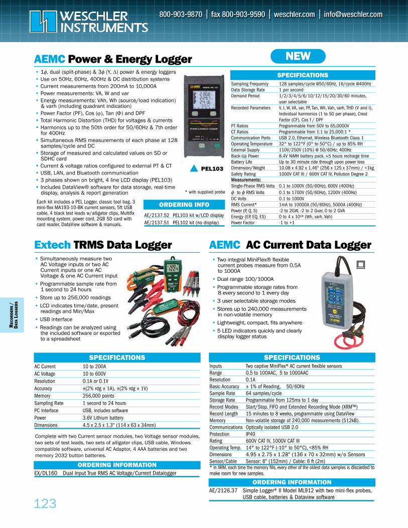
Extech TRMS Data Logger AEMC AC Current Data Logger
Inputs Two captive MiniFlex® AC current flexible sensorsRange 0.5 to 100AAC, 5 to 1000AACResolution 0.1ABasic Accuracy ± 1% of Reading, 50/60HzSample Rate 64 samples/cycleStorage Rate Programmable from 125ms to 1 dayRecord Modes Start/Stop, FIFO and Extended Recording Mode (XRM™)Record Length 15 minutes to 8 weeks, programmable using DataViewMemory Non-volatile storage of 240,000 measurements (512kB).Communications Optically isolated USB 2.0Protection IP40Rating 600V CAT IV, 1000V CAT IIIOperating Temp. 14° to 122°F (-10° to 50°C), <85% RHDimensions 4.95 x 2.75 x 1.28" (136 x 70 x 32mm) w/o SensorsSensor/Cable Sensor: 6" (152mm) / Cable: 6 ft (2m)* In XRM, each time the memory fills, every other of the oldest data samples is discarded tomake room for new samples.
SPECIFICATIONSSPECIFICATIONS
• Simultaneously measure two AC Voltage inputs or two AC Current inputs or one AC Voltage & one AC Current input
• Programmable sample rate from 1 second to 24 hours
• Store up to 256,000 readings• LCD indicates time/date, present
readings and Min/Max• USB interface • Readings can be analyzed using
the included software or exported to a spreadsheet
• Two integral MiniFlex® flexible current probes measure from 0.5A to 1000A
• Dual range 100/1000A• Programmable storage rates from
8 every second to 1 every day• 3 user selectable storage modes• Stores up to 240,000 measurements
in non-volatile memory• Lightweight, compact, fits anywhere• 5 LED indicators quickly and clearly
display logger status
AEMC Power & Energy Logger• 1φ, dual (split-phase) & 3φ (Y, Δ) power & energy loggers• Use on 50Hz, 60Hz, 400Hz & DC distribution systems• Current measurements from 200mA to 10,000A • Power measurements: VA, W and var• Energy measurements: VAh, Wh (source/load indication)
& varh (including quadrant indication)• Power Factor (PF), Cos (ϕ), Tan (Φ) and DPF•• Total Harmonic Distortion (THD) for voltages & currents•• Harmonics up to the 50th order for 50/60Hz & 7th order
for 400Hz•• Simultaneous RMS measurements of each phase at 128
samples/cycle and DC•• Storage of measured and calculated values on SD or
SDHC card•• Current & voltage ratios configured to external PT & CT •• USB, LAN, and Bluetooth communication•• 3 phases shown on bright, 4 line LCD display (PEL103)•• Includes DataView® software for data storage, real-time
display, analysis & report generation
Sampling Frequency 128 samples/cycle @50/60Hz, 16/cycle @400Hz Data Storage Rate 1 per secondDemand Period 1/2/3/4/5/6/10/12/15/20/30/60 minutes,
user selectableRecorded Parameters V, I, W, VA, var, PF, Tan, Wh, Vah, varh, THD (V and I),
Individual harmonics (1 to 50 per phase), Crest Factor (CF), Cos f / DPF
PT Ratios Programmable from 50V to 65,0000VCT Ratios Programmable from 1:1 to 25,000:1 *Communication Ports USB 2.0, Ethernet, Wireless Bluetooth Class 1Operating Temperature 32° to 122°F (0° to 50°C) / up to 85% RHExternal Supply 110V/250V (10%) @ 50/60Hz; 400HzBack-Up Power 8.4V NiMH battery pack, ≈5 hours recharge timeBattery Life Up to 30 minute ride through upon power lossDimension/Weight 10.08 x 4.92 x 1.46" (256 x 125 x 37mm) / <1kgSafety Rating 1000V CAT III / 600V CAT IV, Pollution Degree 2MMeeaassuurreemmeennttss::Single-Phase RMS Volts 0.1 to 1000V (50/60Hz), 600V (400Hz) φ to φ RMS Volts 0.1 to 1700V (50/60Hz), 1200V (400Hz)DC Volts 0.1 to 1000VRMS Current* 1mA to 10000A (50/60Hz), 5000A (400Hz) Power (P, Q, S) -2 to 2GW, -2 to 2 Gvar, 0 to 2 GVA Energy (EP, EQ, ES) 0 to 4 x 10¹⁸ (Wh, varh, Vah)Power Factor -1 to +1
Each kit includes a PEL Logger, classic tool bag, 3mini-flex MA193-10-BK current sensors, 5ft USBcable, 4 black test leads w/alligator clips, Multifixmounting system, power cord, 2GB SD card withcard reader, DataView software & manuals.
SPECIFICATIONS
AE/2137.52 PEL103 kit w/LCD display AE/2137.51 PEL102 kit (no display)
EX/DL160 Dual Input True RMS AC Voltage/Current Datalogger
ORDERING INFO
123
REC
OR
DER
S/
DAT
ALO
GG
ERS
ORDERING INFORMATION
AE/2126.37 Simple Logger® II Model ML912 with two mini-flex probes,USB cable, batteries & Dataview software
ORDERING INFORMATION
AC Current 10 to 200A AC Voltage 10 to 600V Resolution 0.1A or 0.1VAccuracy ±(2% rdg ± 1A), ±(2% rdg ± 1V)Memory 256,000 pointsSampling Rate 1 second to 24 hoursPC Interface USB, includes softwarePower 3.6V Lithium batteryDimensions 4.5 x 2.5 x 1.3" (114 x 63 x 34mm)
Complete with two Current sensor modules, two Voltage sensor modules,two sets of test leads, two sets of alligator clips, USB cable, Windowscompatible software, universal AC Adaptor, 4 AAA batteries and twomemory 2032 button batteries.
NEW
PEL103
* with supplied probe
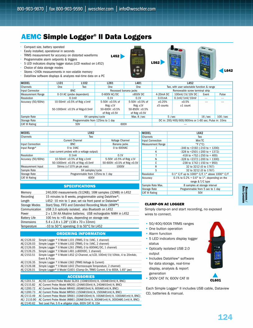
124
RECO
RD
ERS/
DATA
LO
GG
ERS
MMOODDEELL LL110011 LL110022 LL226611 LL448811 LL445522Channels One Two One One Two, with user selectable function & rangeInput Connector BNC Recessed banana jacks Removeable screw terminal stripMeasurement Range 0-1V AC (probe dependent) 0-600V AC/DC ±850V DC 4-20mA DC 100mV/1V/10V DC Event PulseResolution 0.1mV 0.1V 0.1V 0.01mA 0.1mV/1mV/10mV --- ---Accuracy (50/60Hz) 10-50mV: ±0.5% of Rdg ±1mV 5-50V: ±0.5% of 5-50V: ±0.5% of ±0.25% ±0.5% --- ---
Rdg ±1V Rdg ±1V ±5 counts ±1 count50-1000mV: ±0.5% of Rdg±0.5mV 50-600V: ±0.5% 50-850V: ±0.5%
of Rdg ±0.5V of Rdg ±0.5VSample Rate 64 samples/cycle Max. 8 /sec 5 /sec 16 /sec 100 /secStorage Rate Programmable from 125ms to 1 day DC in: 200/400/600/800ms or 1-60 sec; Pulse in: 10msCAT III Rating 50V 600V ---
Memory 240,000 measurements (512KB); 16M samples (32MB) in L452Recording 15 minutes to 8 weeks, programmable using DataView®; Length L452: 10 min to 1 year, set via front panel or Dataview® Storage Modes Start/Stop, FIFO and Extended Recording Mode (XRM™)Communication USB 2.0 optically isolated; also Bluetooth on L452Power 2 x 1.5V AA Alkaline batteries; USB rechargeable NiMH in L452 Battery Life 100 hrs to >45 days, depending on storage rateDimensions 5.4 x 2.8 x 1.28" (138 x 70 x 33mm)Temperature -10 to 50°C operating; 0 to 50°C for L452
SPECIFICATIONS
AEMC Simple Logger® ll Data Loggers•• Compact size, battery operated•• Easily installed, operational in seconds•• TRMS measurement for accuracy on distorted waveforms•• Programmable alarm setpoints & triggers•• 5 LED indicators display logger status (LCD readout on L452)•• Choice of data storage modes•• Stores >240k measurements in non-volatile memory•• DataView software displays & analyzes real-time data on a PC
AE/2126.02 Simple Logger ® II Model L101 (TRMS, 0 to 1VAC, 1 channel)AE/2126.03 Simple Logger ® II Model L102 (TRMS, 0 to 1VAC, 2 channel)AE/2126.05 Simple Logger ® II Model L261 (TRMS, 0 to 600VAC/DC, 1 channel)AE/2126.25 Simple Logger ® II Model L481 (±800VDC, 1 channel)AE/2153.51 Simple Logger ® II Model L452 (2-Channel, w/LCD, 100mV/1V/10Vdc, 4 to 20mAdc,
Event & PulseAE/2126.35 Simple Logger ® II Model L562 (TRMS Voltage & Current)AE/2126.08 Simple Logger ® II Model L642 (Thermocouple Temperature, 2 channel)AE/2126.01 Simple Logger® II Model CL601 (Clamp-On, TRMS Current, 0 to 600A, 1.65" jaw)
AE/1201.51 AC/DC Current Probe Model SL261 (10A@100mV/A, 100A@10mV/A, BNC)AE/2115.82 AC Current Probe Model MN261 (24A@100mV/A, 240A@10mV/A, BNC)AE/1200.72 AC Current Probe Model MR461 (60A@10mV/A, 600A@1mV/A, BNC)AE/1200.73 AC Current Probe Model MR561 (150A@10mV/A, 1500A@1mV/A, BNC)AE/2113.49 AC Current Probe Model SR661 (10A@100mV/A, 100A@10mV/A, 1000A@1mV/A, BNC)AE/ 2110.90 AC Current Probe Model JM861 (30A@10mV/A, 300A@1mV/A, [email protected]/A, BNC)AE/2140.62 Test Lead Pair, 5 ft w alligator clips, 600V CAT IV, 15A
• 50/400/600A TRMS ranges • One button operation• Alarm function• 5 LED indicators display logger
status• Optically isolated USB 2.0
output • Includes DataView® software
for data storage, real-time display, analysis & report generation
• 300V CAT IV, 600V CAT III CL601
ACCESSORIES
ORDERING INFORMATION
MMOODDEELL LL556622Channels Two
Current Channel Voltage ChannelInput Connection BNC Banana jacksInput Range* 0 to 1VAC 0 to 600VAC
(use current probes with a voltage output) Resolution 0.1mA 0.1VAccuracy (50/60Hz) 10-50mV: ±0.5% of Rdg ±1mV 5-50V: ±0.5% of Rdg ±1V
50-1000mV: ±0.5% of Rdg ±0.5mV 50-600V: ±0.5% of Rdg ±0.5VMeasurement Input 5Vrms (±7.07V pk-pk max) 1000VSample Rate 64 samples/cycleStorage Rate Programmable from 125ms to 1 dayCAT III Rating 600V
MMOODDEELL LL664422Channels TwoInput Connection Mini TCMeasurement Range °F (°C)
J -346 to +2192 (-210 to + 1200)K -328 to +2501 (-200 to + 1372)T -418 to +752 (-250 to + 400)N -328 to +2372 (-200 to + 1300)E -238 to 1742 (-150 to + 950)R 32 to 3212 (0 to 1767)S 32 to 3212 (0 to 1767)
Resolution 0.1° C/F up to 1000° C/F, 1° above 1000° C/FAccuracy 0.1% to 0.2% + 0.6° to 1°, depending on the
range & T/C typeSample Rate Max. 8 samples at storage intervalStorage Rate Programmable from 5 sec to 1 dayCAT III Rating 50V
L642
L452
CLAMP-ON AC LOGGER Simply clamp-on and start recording, no exposedwires to connect.
Each Simple Logger® II includes USB cable, DataviewCD, batteries & manual.
L562
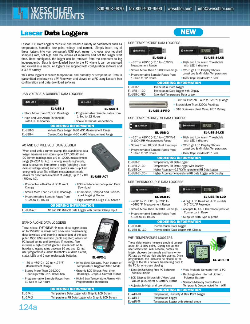
EL-USB-2 Temperature/RH Data Logger EL-USB-2-LCD Temperature/RH Data Logger with DisplayEL-USB-2+ Higher Accuracy (0.3°C) Temperature/RH Data LoggerEL-USB-2-LCD+ Higher Accuracy Temperature/RH Data Logger with Display
112244aa
Lascar Data Loggers
EL-USB-1 Temperature Data LoggerEL-USB-1-LCD Temperature Data Logger with DisplayEL-USB-1-PRO Extended Temperature Data Logger
ORDERING INFORMATION
USB TEMPERATURE DATA LOGGERS
EL-USB-1 EL-USB-1-LCD• –35° to +80°C (–31° to +176°F)
Measurement Range
• Stores More Than 16,000 Readings
• Programmable Sample Rates from10 Sec to 12 Hours
• High and Low Alarm Thresholds with LED Indicators
• 2½ Digit LCD Display Shows . Latest Log & Min/Max Temperatures
• Clear Cap Provides IP67 Seal
Lascar USB Data Loggers measure and record a variety of parameters such astemperature, humidity, dew point, voltage and current. Simply insert any ofthese loggers into your computer’s USB port, name it, choose your requiredsampling rate, set high and low alarms (if required) and set the logger starttime. Once configured, the logger can be removed from the computer to logindependently. Data is downloaded back to the PC where it can be analyzedand viewed as a graph. All loggers are supplied with configuration software anda 3.6 V battery.
WiFi data loggers measure temperature and humidity or temperature. Data istransmitted wirelessly via a WiFi network and viewed on a PC using Lascar’s freeconfiguration and data download software.
EL-USB-3 Voltage Data Logger, 0-30 VDC Measurement RangeEL-USB-4 Current Data Logger, 4-20 mADC Measurement Range
ORDERING INFORMATION
USB VOLTAGE & CURRENT DATA LOGGERS
EL-USB-3 EL-USB-4• Store More than 32,000 Readings
• High and Low Alarm Thresholds with LED Indicators
• Programmable Sample Rates from 1 Sec to 12 Hours
• Screw Terminal Connections
ORDERING INFORMATION
USB TEMPERATURE/RH DATA LOGGERS
• –35° to +80°C (–31° to +176°F) &0-100% RH Measurement Range
• Stores Than 16,000 Dual Readings
• Programmable Sample Rates from10 Sec to 12 Hours
• High and Low Alarm Thresholds with LED Indicators
• 2½ Digit LCD Display Shows . Latest Log & Min/Max Temperatures
• Clear Cap Provides IP67 Seal
EL-USB-2-LCDEL-USB-2
EL-USB-ACT
EL-USB-TC Thermocouple Data LoggerEL-USB-TC-LCD Thermocouple Data Logger with Display
ORDERING INFORMATION
USB THERMOCOUPLE DATA LOGGERS
• –200° to +1350°C (–328° to+2462°F) Measurement Range
• Stores More Than 32,000 Readings
• Programmable Sample Rates from1 Sec to 12 Hours
• 4 Digit LCD Readout (-LCD model) 0.5°C/1°F Resolution
• Accepts K, J & T Thermocouples viaConnector in Base
• Supplied with Type K probe
EL-WIFI-TH Temperature, Humidity & Dew Point LoggerEL-WIFI-T Temperature Logger EL-WIFI-TP Temperature Logger with external probe
ORDERING INFORMATION
WIFI TEMPERATURE LOGGERS
• Easy Set-Up Using Free PC Software and USB Cable
• LCD Display Shows Min/Max/Last Values plus Alarm & Battery Status
• Adjustable High and Low Alarms
• View Multiple Sensors from 1 PC
• Rechargeable Internal Lithium Polymer Battery
• Sensor’s Memory Stores Data ifTemporarily Disconnected from WiFi
EL-USB-TC-LCDEL-USB-TC
EL-WIFI-TH
EL-USB-1-PRO
• –40° to +125°C (–40° to +257°F) Range
• Stores More Than 32000 Readings
• 316 Stainless Steel Case, IP67 Rating
NEW
These data loggers measure ambient temper-ature, RH & dew point. During set-up, theuser selects the WiFi network, names thelogger, chooses the sample and transfer-to-PC rate as well as high and low alarms. Onceprogrammed, the units can be placed in therange of the WiFi network, transferring data tothe PC for on-screen viewing.
EL-USB-ACT AC and DC Millivolt Data Logger with Current Clamp InputORDERING INFORMATION
AC AND DC MILLIVOLT DATA LOGGER
• Compatible with AC and DC CurrentClamps
• Stores More Than 127,000 Readings
• Programmable Sample Rates from1 Sec to 12 Hours
• USB Interface for Set-up and Data Download
• Immediate, Delayed and Push-to-start Logging Modes
• High Contrast 4 Digit LCD Screen
When used with a current clamp, this standalone datalogger measures and stores up to 127,000 AC andDC current readings over a 0 to 1000A measurementrange (0-723A for AC). In ‘energy monitoring’ mode,data is converted into power, energy (applying a userdefined voltage value) and cost (with a user suppliedenergy unit cost). The millivolt measurement modeallows for direct measurement of voltage, up to 1V DC(700mV AC).
EL-GFX-1
EL-GFX-1 Temperature Data Logger with Graphic LCD ScreenEL-GFX-2 Temperature/RH Data Logger with Graphic LCD Screen
ORDERING INFORMATION
STAND-ALONE DATA LOGGERS
• –30 to +80°C (–22 to +176°F) Measurement Range
• Stores More Than 256,000 Readings with 0.1ºC Resolution
• Programmable Sample Rates from10 Sec to 12 Hours
• Immediate, Delayed, Push-button or Temperature Triggered Start Mode
• Graphic LCD Shows Real-time Readings, Graph & Current Status
• High & Low Temperature Alarms withProgrammable Thresholds
These robust, IP67/NEMA 4X rated data logger storesup to 256,000 readings with on-screen programming,data download and graphing independent of the com-puter. Micro USB interface (cable supplied) allows forPC based set-up and download if required. Alsoincludes a high contrast graphic screen with whitebacklight, logging rates between 10 sec and 12 hrs,user programmable alarm thresholds, audible alarms,status LEDs and 2 user replaceable batteries.
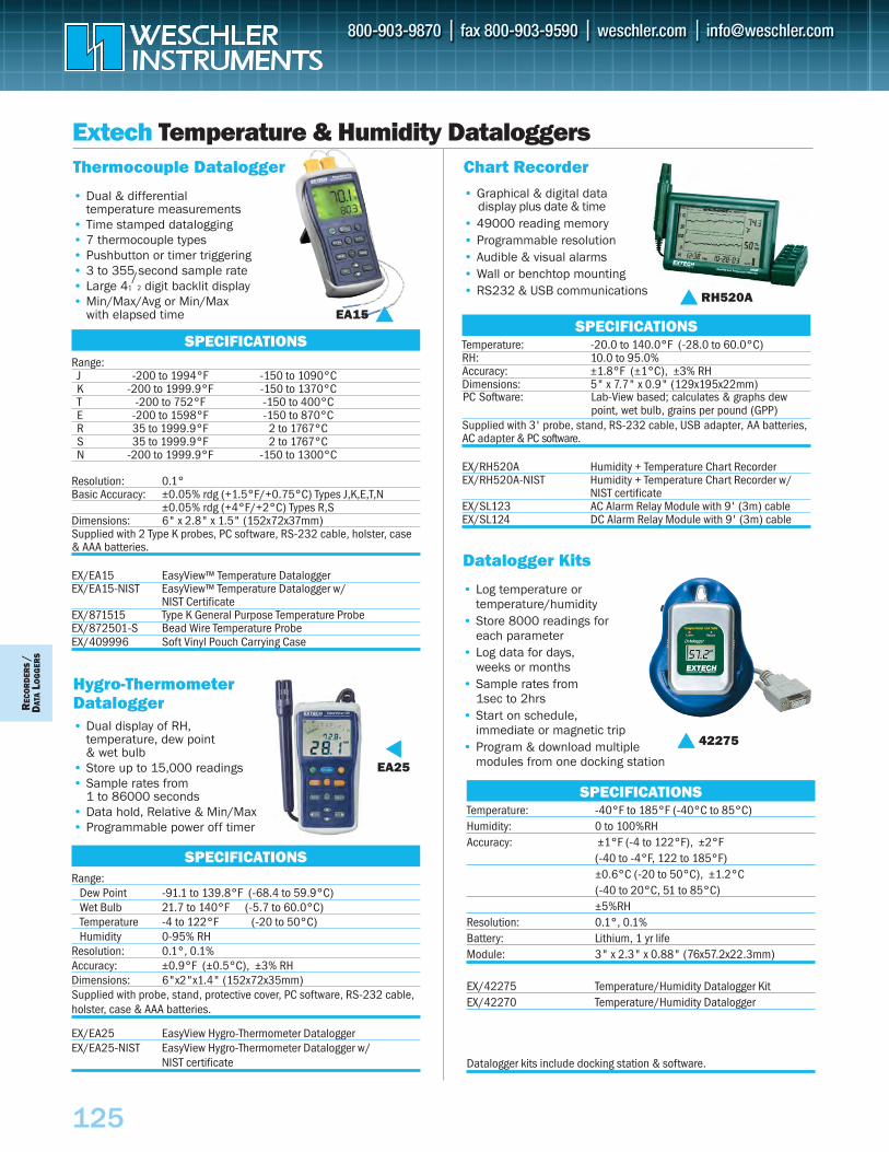
Extech Temperature & Humidity DataloggersThermocouple Datalogger
• Dual & differential temperature measurements
• Time stamped datalogging• 7 thermocouple types• Pushbutton or timer triggering• 3 to 355 second sample rate • Large 41
/2 digit backlit display
• Min/Max/Avg or Min/Max with elapsed time EA15
Range:J -200 to 1994°F -150 to 1090°CK -200 to 1999.9°F -150 to 1370°CT -200 to 752°F -150 to 400°CE -200 to 1598°F -150 to 870°CR 35 to 1999.9°F 2 to 1767°CS 35 to 1999.9°F 2 to 1767°CN -200 to 1999.9°F -150 to 1300°C
Resolution: 0.1°Basic Accuracy: ±0.05% rdg (+1.5°F/+0.75°C) Types J,K,E,T,N
±0.05% rdg (+4°F/+2°C) Types R,SDimensions: 6" x 2.8" x 1.5" (152x72x37mm)Supplied with 2 Type K probes, PC software, RS-232 cable, holster, case& AAA batteries.
EX/EA15 EasyView™ Temperature DataloggerEX/EA15-NIST EasyView™ Temperature Datalogger w/
NIST CertificateEX/871515 Type K General Purpose Temperature ProbeEX/872501-S Bead Wire Temperature ProbeEX/409996 Soft Vinyl Pouch Carrying Case
SPECIFICATIONS
Chart Recorder• Graphical & digital data
display plus date & time• 49000 reading memory• Programmable resolution• Audible & visual alarms• Wall or benchtop mounting• RS232 & USB communications RH520A
Temperature: -20.0 to 140.0°F (-28.0 to 60.0°C)RH: 10.0 to 95.0% Accuracy: ±1.8°F (±1°C), ±3% RHDimensions: 5" x 7.7" x 0.9" (129x195x22mm)
Supplied with 3' probe, stand, RS-232 cable, USB adapter, AA batteries,AC adapter & PC software.
EX/RH520A Humidity + Temperature Chart RecorderEX/RH520A-NIST Humidity + Temperature Chart Recorder w/
NIST certificateEX/SL123 AC Alarm Relay Module with 9' (3m) cableEX/SL124 DC Alarm Relay Module with 9' (3m) cable
SPECIFICATIONS
Temperature: -40°F to 185°F (-40°C to 85°C)Humidity: 0 to 100%RH Accuracy: ±1°F (-4 to 122°F), ±2°F
(-40 to -4°F, 122 to 185°F)±0.6°C (-20 to 50°C), ±1.2°C (-40 to 20°C, 51 to 85°C)±5%RH
Resolution: 0.1°, 0.1%Battery: Lithium, 1 yr lifeModule: 3" x 2.3" x 0.88" (76x57.2x22.3mm)
EX/42275 Temperature/Humidity Datalogger KitEX/42270 Temperature/Humidity Datalogger
Datalogger kits include docking station & software.
SPECIFICATIONS
Datalogger Kits
• Log temperature or temperature/humidity
• Store 8000 readings for each parameter
• Log data for days, weeks or months
• Sample rates from 1sec to 2hrs
• Start on schedule, immediate or magnetic trip
• Program & download multiple modules from one docking station
42275
Hygro-ThermometerDatalogger• Dual display of RH,
temperature, dew point & wet bulb
• Store up to 15,000 readings• Sample rates from
1 to 86000 seconds• Data hold, Relative & Min/Max• Programmable power off timer
EA25
Range:Dew Point -91.1 to 139.8°F (-68.4 to 59.9°C)Wet Bulb 21.7 to 140°F (-5.7 to 60.0°C)Temperature -4 to 122°F (-20 to 50°C)Humidity 0-95% RH
Resolution: 0.1°, 0.1%Accuracy: ±0.9°F (±0.5°C), ±3% RHDimensions: 6"x2"x1.4" (152x72x35mm)Supplied with probe, stand, protective cover, PC software, RS-232 cable,holster, case & AAA batteries.
EX/EA25 EasyView Hygro-Thermometer DataloggerEX/EA25-NIST EasyView Hygro-Thermometer Datalogger w/
NIST certificate
SPECIFICATIONS
REC
OR
DER
S/
DAT
ALO
GG
ERS
125
PC Software: Lab-View based; calculates & graphs dewpoint, wet bulb, grains per pound (GPP)
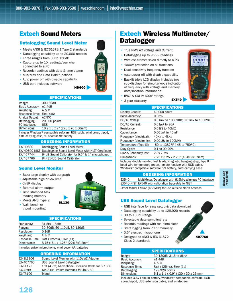
RECO
RD
ERS/
DATA
LO
GG
ERS
126
EX540 MultiMeter/Datalogger with 915MHz Wireless PC InterfaceEX540-NIST EX540 with calibration traceable to NISTOrder Model EX542 (433MHz) for use outside North America
ORDERING INFORMATION
SPECIFICATIONSDisplay Counts: 40,000 countBasic Accuracy: 0.06%DC/AC Voltage: 0.01mV to 1000VDC; 0.01mV to 1000VACDC/AC Current: 0.01μA to 20AResistance: 0.01Ω to 40MΩCapacitance: 0.001nF to 40mFFrequency (electrical): 40Hz to 4kHzFrequency (electronic): 0.001Hz to 100MHzTemperature (Type K): -50 to 1382°F (-45 to 750°C)Duty Cycle: 0.1 to 99.90%Diode/Continuity Test: 2.8V / YesDimensions: 7.25 x 3.25 x 2.25" (184x83x57mm)Includes double molded test leads, magnetic hanging strap, Type Kbead wire temperature probe, remote receiver with USB cable,Windows® compatible software, 9V battery, hard carrying case
Extech Wireless Multimeter/Datalogger
Extech Sound MetersDatalogging Sound Level Meter• Meets ANSI & IEC61672-1 Type 2 standards• Datalogging capability up to 20,000 records• Three ranges from 30 to 130dB• Capture up to 10 readings/sec when
connected to a PC• Records readings with date & time stamp• Min/Max and Data Hold functions• Auto power off with disable capability• USB port includes software
HD600
Range: 30-130dBBasic Accuracy: ±1.4dBWeighting: A & CResponse Time: Fast, slowAnalog Output: AC/DCDatalogging: 20,000 pointsPC Interface: USBDimensions: 10.9 x 3 x 2" (278 x 76 x 50mm)Includes Windows® compatible software, USB cable, wind cover, tripod,hard carrying case, AC adaptor, 9V battery
EX/HD600 Datalogging Sound Level MeterEX/HD600-NIST Datalogging Sound Level Meter with NIST CertificateEX/407744 94dB Sound Calibrator for 0.5" & 1" microphones EX/407766 94/114dB Sound Calibrator
Range: 30-130dB, 31.5 to 8kHzBasic Accuracy: ±1.4dBWeighting: A & CResponse Time: Fast (125ms), Slow (1s)Datalogging: 129,920 pointsDimensions: 5.1 x 1.1 x 0.9" (130 x 30 x 25mm)Includes 3.6V Lithium battery, Windows® compatible software, USBcover, tripod, USB extension cable, and windscreen
SPECIFICATIONS
SPECIFICATIONS
Sound Level Monitor• Extra large display with bargraph• Adjustable high or low limit • OVER display• External alarm output• Time stamped Max
reading memory• Meets ANSI Type 2• Wall, bench or
tripod mounting
USB Sound Level Datalogger• USB interface for easy setup & data download• Datalogging capability up to 129,920 records• 30 to 130dB range• Selectable data sampling rate• Records readings with real time clock• Start logging from PC or manually• 0.5" electret microphone• Designed to ANSI & IEC 61672
Class 2 standards
SL130
407760
Frequency: 31.5Hz – 8kHzRanges: 30-80dB, 60-110dB, 80-130dBResolution: 0.1dBWeighting: A & CResponse Time: Fast (125ms), Slow (1s)Dimensions: 8.75 x 7.1 x 1.25" (22x18x3.2mm)Includes swivel microphone, wind cover, AA batteries
EX/SL130G Sound Level Monitor with 110V AC AdapterEX/407760 USB Sound Level DataloggerEX/SL125 15ft (4.7m) Microphone Extension Cable for SL130GEX/4299 Two 3.6V Lithium Batteries for 407760EX/TR100 Tripod
SPECIFICATIONS
ORDERING INFORMATION
ORDERING INFORMATION
• True RMS AC Voltage and Current• Datalogging up to 9,999 readings• Wireless transmission directly to a PC• 1000V protection on all functions• Dual sensitivity frequency function• Auto power off with disable capability• Backlit triple LCD display includes two
sub-displays for simultaneous indication of frequency with voltage and memory data/location information
• IP67 & CAT IV-600V ratings • 3 year warranty EX540
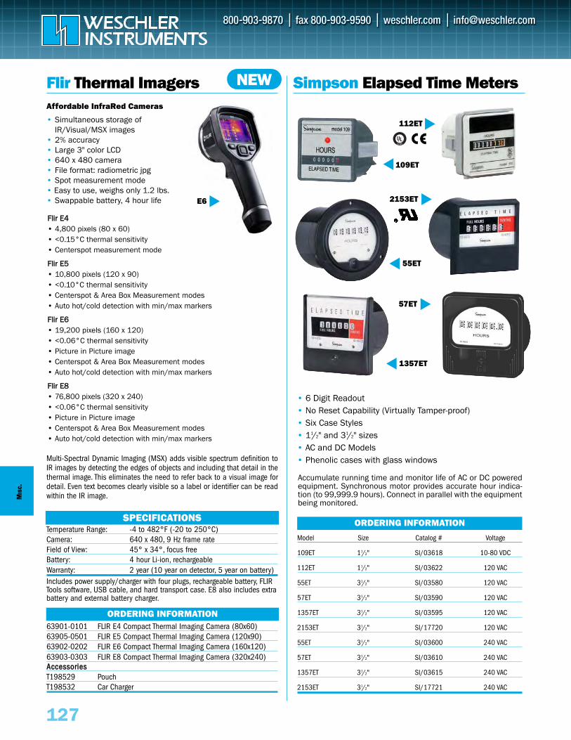
FFlliirr EE44
F
F
F
• 4,800 pixels (80 x 60)• <0.15°C thermal sensitivity• Centerspot measurement mode
Flliirr EE55• 10,800 pixels (120 x 90)• <0.10°C thermal sensitivity• Centerspot & Area Box Measurement modes• Auto hot/cold detection with min/max markers
Flliirr EE66• 19,200 pixels (160 x 120)• <0.06°C thermal sensitivity• Picture in Picture image• Centerspot & Area Box Measurement modes• Auto hot/cold detection with min/max markers
Flliirr EE88• 76,800 pixels (320 x 240)• <0.06°C thermal sensitivity• Picture in Picture image• Centerspot & Area Box Measurement modes• Auto hot/cold detection with min/max markers
127
Simpson Elapsed Time Meters
• 6 Digit Readout• No Reset Capability (Virtually Tamper-proof)• Six Case Styles• 11/2" and 31/2" sizes• AC and DC Models• Phenolic cases with glass windows
Accumulate running time and monitor life of AC or DC powered equipment. Synchronous motor provides accurate hour indica-tion (to 99,999.9 hours). Connect in parallel with the equipmentbeing monitored.
112ET
2153ET
57ET
109ET
1357ET
55ET
Model Size Catalog # Voltage
109ET 11/2" SI/03618 10-80 VDC
112ET 11/2" SI/03622 120 VAC
55ET 31/2" SI/03580 120 VAC
57ET 31/2" SI/03590 120 VAC
1357ET 31/2" SI/03595 120 VAC
2153ET 31/2" SI/17720 120 VAC
55ET 31/2" SI/03600 240 VAC
57ET 31/2" SI/03610 240 VAC
1357ET 31/2" SI/03615 240 VAC
2153ET 31/2" SI/17721 240 VAC
ORDERING INFORMATIONTemperature Range: -4 to 482°F (-20 to 250°C)Camera: 640 x 480, 9 Hz frame rateField of View: 45° x 34°, focus freeBattery: 4 hour Li-ion, rechargeable Warranty: 2 year (10 year on detector, 5 year on battery) Includes power supply/charger with four plugs, rechargeable battery, FLIRTools software, USB cable, and hard transport case. E8 also includes extrabattery and external battery charger.
Flir Thermal Imagers
ORDERING INFORMATION
SPECIFICATIONS
NEW
A
63901-0101 FLIR E4 Compact Thermal Imaging Camera (80x60)63905-0501 FLIR E5 Compact Thermal Imaging Camera (120x90)63902-0202 FLIR E6 Compact Thermal Imaging Camera (160x120)63903-0303 FLIR E8 Compact Thermal Imaging Camera (320x240) AcccceessssoorriieessT198529 PouchT198532 Car Charger
E6
Affordable InfraRed Cameras
• Simultaneous storage of IR/Visual/MSX images
• 2% accuracy• Large 3" color LCD• 640 x 480 camera • File format: radiometric jpg• Spot measurement mode• Easy to use, weighs only 1.2 lbs.• Swappable battery, 4 hour life
MIS
C.
Multi-Spectral Dynamic Imaging (MSX) adds visible spectrum definition toIR images by detecting the edges of objects and including that detail in thethermal image. This eliminates the need to refer back to a visual image fordetail. Even text becomes clearly visible so a label or identifier can be readwithin the IR image.
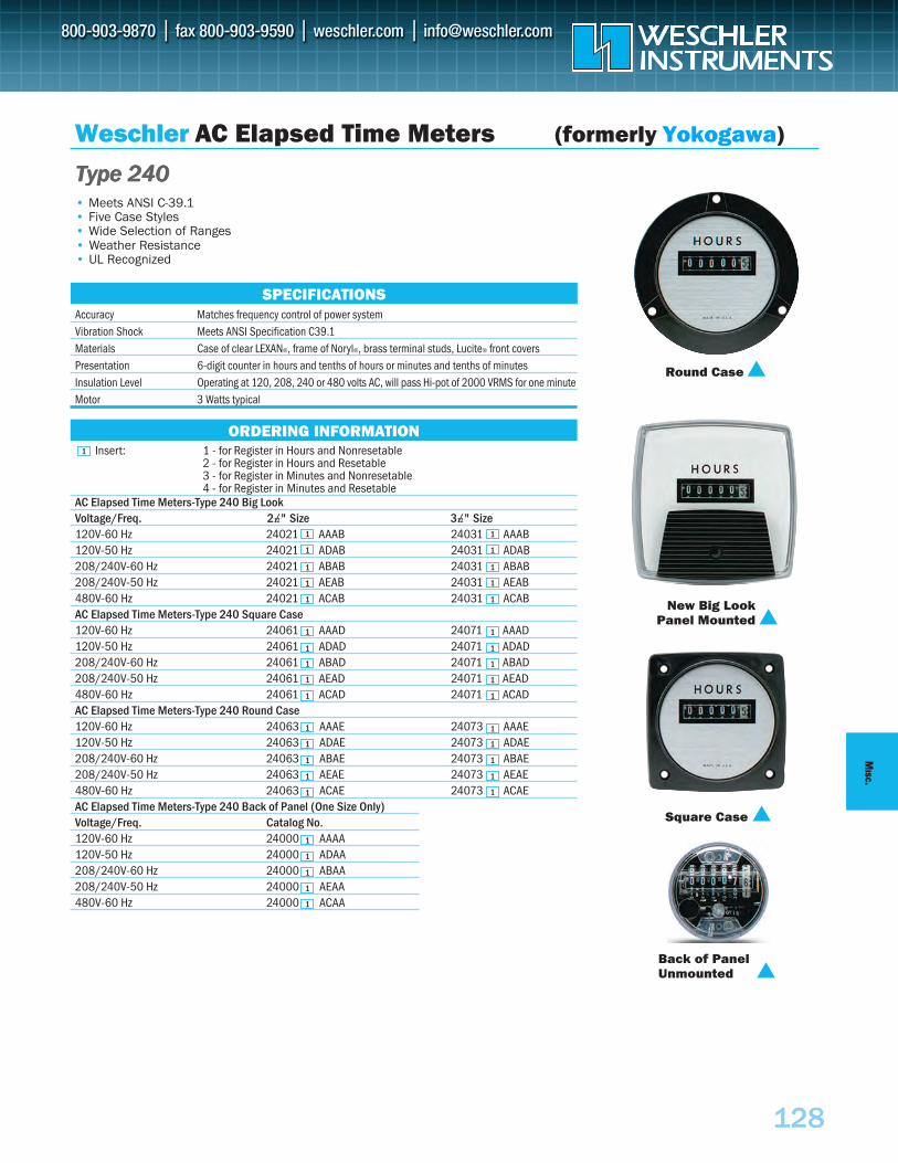
128
MISC.
Insert: 1 - for Register in Hours and Nonresetable2 - for Register in Hours and Resetable3 - for Register in Minutes and Nonresetable4 - for Register in Minutes and Resetable
AC Elapsed Time Meters-Type 240 Big LookVoltage/Freq. 21⁄2" Size 31⁄2" Size120V-60 Hz 24021 AAAB 24031 AAAB120V-50 Hz 24021 ADAB 24031 ADAB208/240V-60 Hz 24021 ABAB 24031 ABAB208/240V-50 Hz 24021 AEAB 24031 AEAB480V-60 Hz 24021 ACAB 24031 ACABAC Elapsed Time Meters-Type 240 Square Case120V-60 Hz 24061 AAAD 24071 AAAD120V-50 Hz 24061 ADAD 24071 ADAD208/240V-60 Hz 24061 ABAD 24071 ABAD208/240V-50 Hz 24061 AEAD 24071 AEAD480V-60 Hz 24061 ACAD 24071 ACADAC Elapsed Time Meters-Type 240 Round Case120V-60 Hz 24063 AAAE 24073 AAAE120V-50 Hz 24063 ADAE 24073 ADAE208/240V-60 Hz 24063 ABAE 24073 ABAE208/240V-50 Hz 24063 AEAE 24073 AEAE480V-60 Hz 24063 ACAE 24073 ACAEAC Elapsed Time Meters-Type 240 Back of Panel (One Size Only)Voltage/Freq. Catalog No.120V-60 Hz 24000 AAAA120V-50 Hz 24000 ADAA208/240V-60 Hz 24000 ABAA208/240V-50 Hz 24000 AEAA480V-60 Hz 24000 ACAA
Accuracy Matches frequency control of power systemVibration Shock Meets ANSI Specification C39.1Materials Case of clear LEXAN®, frame of Noryl®, brass terminal studs, Lucite® front coversPresentation 6-digit counter in hours and tenths of hours or minutes and tenths of minutesInsulation Level Operating at 120, 208, 240 or 480 volts AC, will pass Hi-pot of 2000 VRMS for one minuteMotor 3 Watts typical
Weschler AC Elapsed Time Meters (formerly Yokogawa)
• Meets ANSI C-39.1• Five Case Styles• Wide Selection of Ranges• Weather Resistance• UL Recognized
Round Case
New Big LookPanel Mounted
Square Case
Back of PanelUnmounted
ORDERING INFORMATION1
1 1
1
1
1
1
1
1
1
1
1
1
1
1
1
1
1
1
1
1
1
1
1
1
1
1
1
1
1
1
1
1
1
1
1
SPECIFICATIONS
TTTyyypppeee 222444000
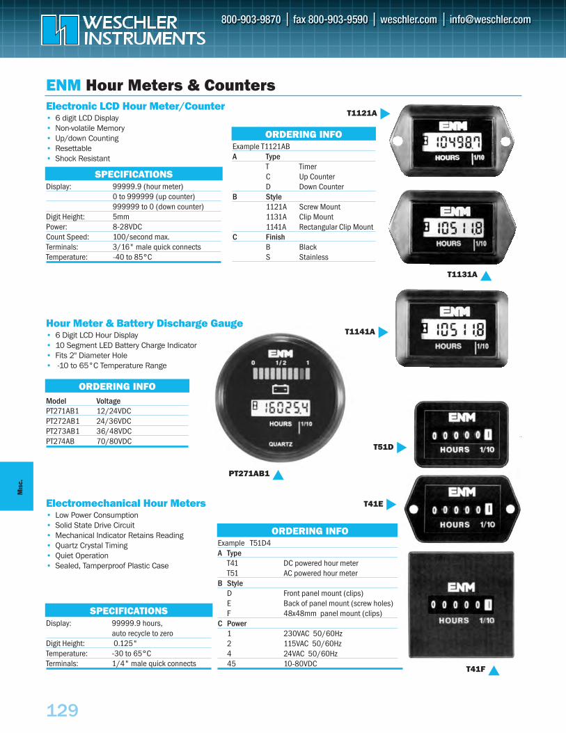
Electromechanical Hour Meters• Low Power Consumption• Solid State Drive Circuit• Mechanical Indicator Retains Reading• Quartz Crystal Timing• Quiet Operation• Sealed, Tamperproof Plastic Case
129
MIS
C.
ORDERING INFO
ORDERING INFO
ORDERING INFO
SPECIFICATIONS
SPECIFICATIONS
Example T1121ABA Type
T TimerC Up CounterD Down Counter
B Style1121A Screw Mount 1131A Clip Mount1141A Rectangular Clip Mount
C FinishB BlackS Stainless
Display: 99999.9 (hour meter)0 to 999999 (up counter)999999 to 0 (down counter)
Digit Height: 5mmPower: 8-28VDCCount Speed: 100/second max.Terminals: 3/16" male quick connectsTemperature: -40 to 85°C
Electronic LCD Hour Meter/Counter• 6 digit LCD Display• Non-volatile Memory• Up/down Counting• Resettable• Shock Resistant
Hour Meter & Battery Discharge Gauge• 6 Digit LCD Hour Display• 10 Segment LED Battery Charge Indicator• Fits 2" Diameter Hole• -10 to 65°C Temperature Range
Model VoltagePT271AB1 12/24VDCPT272AB1 24/36VDCPT273AB1 36/48VDCPT274AB 70/80VDC
Example T51D4A Type
T41 DC powered hour meterT51 AC powered hour meter
B StyleD Front panel mount (clips) E Back of panel mount (screw holes)F 48x48mm panel mount (clips)
C Power 1 230VAC 50/60Hz2 115VAC 50/60Hz4 24VAC 50/60Hz45 10-80VDC
Display: 99999.9 hours,auto recycle to zero
Digit Height: 0.125"Temperature: -30 to 65°CTerminals: 1/4" male quick connects
T41F
PT271AB1
T51D
T1141A
T1121A
T41E
T1131A
ENM Hour Meters & Counters
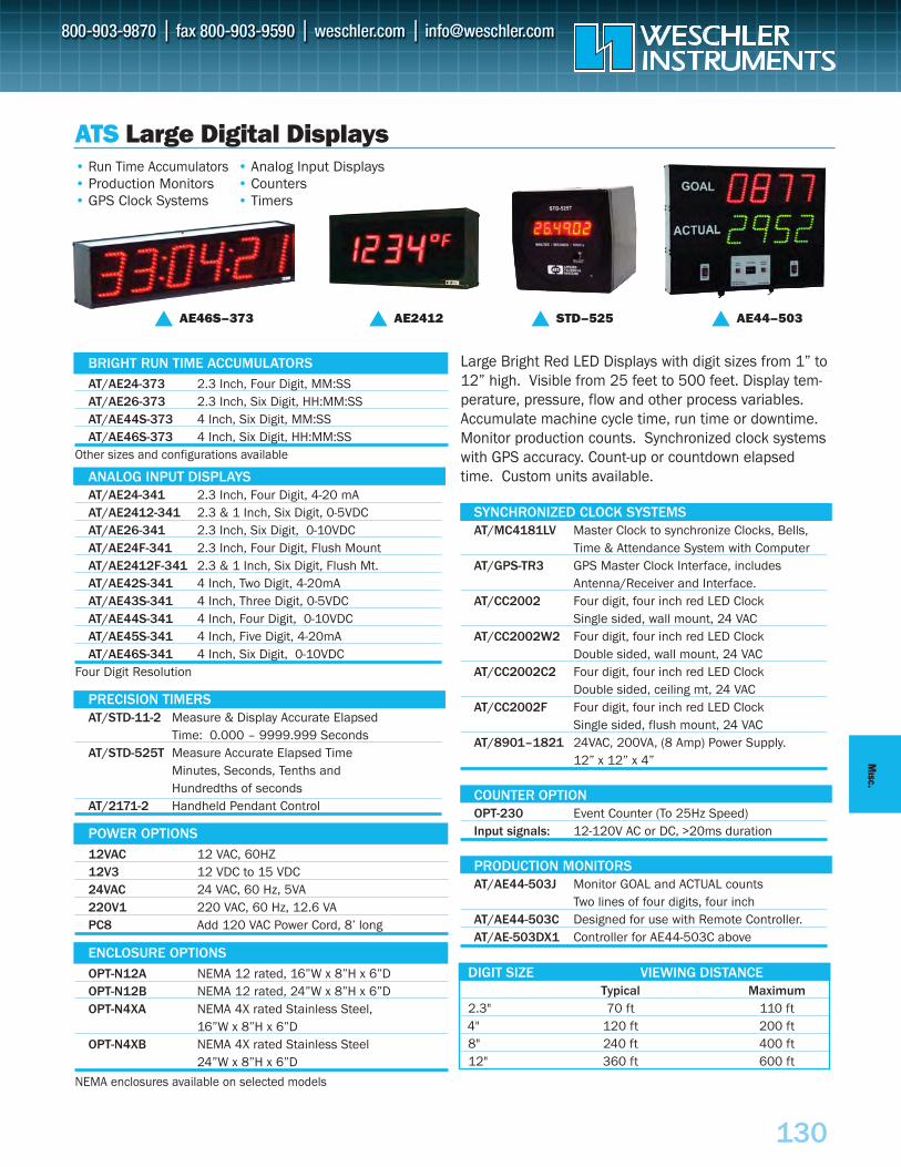
130
MISC.
• Run Time Accumulators• Production Monitors• GPS Clock Systems
• Analog Input Displays• Counters• Timers
DIGIT SIZE VIEWING DISTANCETypical Maximum
2.3" 70 ft 110 ft4" 120 ft 200 ft8" 240 ft 400 ft12" 360 ft 600 ft
ANALOG INPUT DISPLAYSAT/AE24-341 2.3 Inch, Four Digit, 4-20 mAAT/AE2412-341 2.3 & 1 Inch, Six Digit, 0-5VDC AT/AE26-341 2.3 Inch, Six Digit, 0-10VDCAT/AE24F-341 2.3 Inch, Four Digit, Flush MountAT/AE2412F-341 2.3 & 1 Inch, Six Digit, Flush Mt.AT/AE42S-341 4 Inch, Two Digit, 4-20mAAT/AE43S-341 4 Inch, Three Digit, 0-5VDC AT/AE44S-341 4 Inch, Four Digit, 0-10VDCAT/AE45S-341 4 Inch, Five Digit, 4-20mAAT/AE46S-341 4 Inch, Six Digit, 0-10VDC
Four Digit Resolution
PRECISION TIMERSAT/STD-11-2 Measure & Display Accurate Elapsed
Time: 0.000 – 9999.999 SecondsAT/STD-525T Measure Accurate Elapsed Time
Minutes, Seconds, Tenths and Hundredths of seconds
AT/2171-2 Handheld Pendant Control
AT/AE24-373 2.3 Inch, Four Digit, MM:SSAT/AE26-373 2.3 Inch, Six Digit, HH:MM:SSAT/AE44S-373 4 Inch, Six Digit, MM:SSAT/AE46S-373 4 Inch, Six Digit, HH:MM:SS
SYNCHRONIZED CLOCK SYSTEMSAT/MC4181LV Master Clock to synchronize Clocks, Bells,
Time & Attendance System with ComputerAT/GPS-TR3 GPS Master Clock Interface, includes
Antenna/Receiver and Interface.AT/CC2002 Four digit, four inch red LED Clock
Single sided, wall mount, 24 VACAT/CC2002W2 Four digit, four inch red LED Clock
Double sided, wall mount, 24 VACAT/CC2002C2 Four digit, four inch red LED Clock
Double sided, ceiling mt, 24 VACAT/CC2002F Four digit, four inch red LED Clock
Single sided, flush mount, 24 VACAT/8901–1821 24VAC, 200VA, (8 Amp) Power Supply.
12” x 12” x 4”
COUNTER OPTIONOPT-230 Event Counter (To 25Hz Speed)Input signals: 12-120V AC or DC, >20ms duration
PRODUCTION MONITORSAT/AE44-503J Monitor GOAL and ACTUAL counts
Two lines of four digits, four inchAT/AE44-503C Designed for use with Remote Controller.AT/AE-503DX1 Controller for AE44-503C above
Large Bright Red LED Displays with digit sizes from 1” to12” high. Visible from 25 feet to 500 feet. Display tem-perature, pressure, flow and other process variables.Accumulate machine cycle time, run time or downtime.Monitor production counts. Synchronized clock systemswith GPS accuracy. Count-up or countdown elapsedtime. Custom units available.
Other sizes and configurations available
BRIGHT RUN TIME ACCUMULATORS
12VAC 12 VAC, 60HZ12V3 12 VDC to 15 VDC24VAC 24 VAC, 60 Hz, 5VA220V1 220 VAC, 60 Hz, 12.6 VAPC8 Add 120 VAC Power Cord, 8’ long
POWER OPTIONS
OPT-N12A NEMA 12 rated, 16”W x 8”H x 6”DOPT-N12B NEMA 12 rated, 24”W x 8”H x 6”DOPT-N4XA NEMA 4X rated Stainless Steel,
16”W x 8”H x 6”DOPT-N4XB NEMA 4X rated Stainless Steel
24”W x 8”H x 6”D
ENCLOSURE OPTIONS
NEMA enclosures available on selected models
ATS Large Digital Displays
AE46S–373 AE2412 STD–525 AE44–503
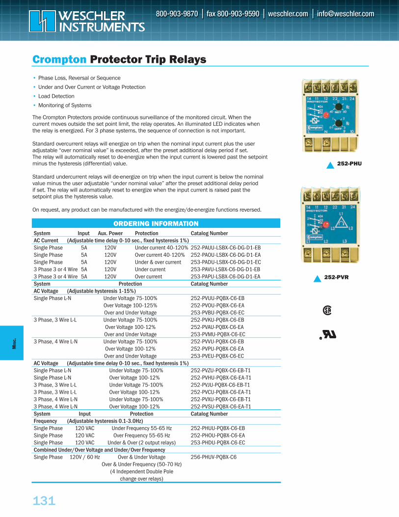
131
MIS
C.
System Input Aux. Power Protection Catalog NumberAC Current (Adjustable time delay 0-10 sec., fixed hysteresis 1%)Single Phase 5A 120V Under current 40-120% 252-PAUU-LSBX-C6-DG-D1-EBSingle Phase 5A 120V Over current 40-120% 252-PAOU-LSBX-C6-DG-D1-EASingle Phase 5A 120V Under & over current 253-PADU-LSBX-C6-DG-D1-EC3 Phase 3 or 4 Wire 5A 120V Under current 253-PAVU-LSBX-C6-DG-D1-EB3 Phase 3 or 4 Wire 5A 120V Over current 253-PAPU-LSBX-C6-DG-D1-EASystem Protection Catalog NumberAC Voltage (Adjustable hysteresis 1-15%)Single Phase L-N Under Voltage 75-100% 252-PVUU-PQBX-C6-EB
Over Voltage 100-125% 252-PVOU-PQBX-C6-EAOver and Under Voltage 253-PVBU-PQBX-C6-EC
3 Phase, 3 Wire L-L Under Voltage 75-100% 252-PVKU-PQBX-C6-EBOver Voltage 100-12% 252-PVAU-PQBX-C6-EAOver and Under Voltage 253-PVMU-PQBX-C6-EC
3 Phase, 4 Wire L-N Under Voltage 75-100% 252-PVVU-PQBX-C6-EBOver Voltage 100-12% 252-PVPU-PQBX-C6-EAOver and Under Voltage 253-PVEU-PQBX-C6-EC
AC Voltage (Adjustable time delay 0-10 sec., fixed hysteresis 1%)Single Phase L-N Under Voltage 75-100% 252-PVZU-PQBX-C6-EB-T1Single Phase L-N Over Voltage 100-12% 252-PVHU-PQBX-C6-EA-T13 Phase, 3 Wire L-L Under Voltage 75-100% 252-PVJU-PQBX-C6-EB-T13 Phase, 3 Wire L-L Over Voltage 100-12% 252-PVCU-PQBX-C6-EA-T13 Phase, 4 Wire L-N Under Voltage 75-100% 252-PVXU-PQBX-C6-EB-T13 Phase, 4 Wire L-N Over Voltage 100-12% 252-PVSU-PQBX-C6-EA-T1System Input Protection Catalog NumberFrequency (Adjustable hysteresis 0.1-3.0Hz)Single Phase 120 VAC Under Frequency 55-65 Hz 252-PHUU-PQBX-C6-EBSingle Phase 120 VAC Over Frequency 55-65 Hz 252-PHOU-PQBX-C6-EASingle Phase 120 VAC Under & Over (2 output relays) 253-PHDU-PQBX-C6-ECCombined Under/Over Voltage and Under/Over FrequencySingle Phase 120V / 60 Hz Over & Under Voltage 256-PHUV-PQBX-C6
Over & Under Frequency (50-70 Hz)(4 Independent Double Pole
change over relays)
Crompton Protector Trip Relays• Phase Loss, Reversal or Sequence
• Under and Over Current or Voltage Protection
• Load Detection
• Monitoring of Systems
252-PHU
252-PVR
The Crompton Protectors provide continuous surveillance of the monitored circuit. When the current moves outside the set point limit, the relay operates. An illuminated LED indicates when the relay is energized. For 3 phase systems, the sequence of connection is not important.
Standard overcurrent relays will energize on trip when the nominal input current plus the user adjustable “over nominal value” is exceeded, after the preset additional delay period if set. The relay will automatically reset to de-energize when the input current is lowered past the setpoint minus the hysteresis (differential) value.
Standard undercurrent relays will de-energize on trip when the input current is below the nominal value minus the user adjustable “under nominal value” after the preset additional delay period if set. The relay will automatically reset to energize when the input current is raised past the setpoint plus the hysteresis value.
On request, any product can be manufactured with the energize/de-energize functions reversed.
ORDERING INFORMATION
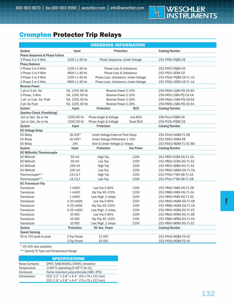
MISC.
System Input Protection Catalog NumberPhase Sequence & Phase Failure3 Phase 3 or 4 Wire 120V L-L 60 Hz Phase Sequence, Under Voltage 252-PVRU-PQBX-C6Phase Balance3 Phase 3 or 4 Wire 120V L-L 60 Hz Phase Loss & Unbalance 252-PSFU-PQBX-C63 Phase 3 or 4 Wire 480V L-L 60 Hz Phase Loss & Unbalance 252-PSFU-SEBX-C63 Phase 3 or 4 Wire 120V L-L 60 Hz Phase Loss, Unbalance, Under Voltage 252-PSGU-PQBX-C6-T1-1A3 Phase 3 or 4 Wire 480V L-L 60 Hz Phase Loss, Unbalance, Under Voltage 252-PSGU-SEBX-C6-T1-1AReverse Power1 ph or 3 ph, 4w 5A, 120V, 60 Hz Reverse Power 2-20% 256-PASU-LSBX-PQ-C6-EA3 Phase, 3 Wire 5A, 120V, 60 Hz Reverse Power 2-20% 256-PATU-LSBX-PQ-C6-EA1 ph or 3 ph, 4w, Push 5A, 120V, 60 Hz Reverse Power 2-20% 256-PAQU-LSBX-PQ-C6-EA3 ph 3w Push 5A, 120V, 60 Hz Reverse Power 2-20% 256-PARU-LSBX-PQ-C6-EASystem Input Protection BUS Catalog NumberSynchro-Check (Paralleling)1ph or 3ph, 3w or 4w 120V/60 Hz Phase Angle & Voltage Live BUS 256-PLLU-PQBX-C61ph or 3ph, 3w or 4w 120V/60 Hz Phase Angle & Voltage Dead BUS 256-PLDU-PQBX-C6System Input Protection Catalog NumberDC Voltage RelayDC Relay 18-20V* Under Voltage External Time Delay 252-PDUU-NABX-T1-EBDC Relay 18-20V* Under Voltage Differential 1-15% 252-PDEU-NABX-EBDC Relay 24V Over & Under Voltage (2 relays) 253-PDCU-BDBX-T1-EC-BDSystem Input Protection Aux Power Catalog NumberDC Millivolts/ThermocoupleDC Millivolt 50 mV High Trip 120V 252-PBTU-ECBX-DG-T1-EADC Millivolt 50 mV Low Trip 120V 252-PBSU-ECBX-DG-T1-EADC Millivolt 100 mV High Trip 120V 252-PBTU-GBBX-DG-T1-EADC Millivolt 100 mV Low Trip 120V 252-PBSU-GBBX-DG-T1-EAThermocouple** J,K,T,S,T High Trip 120V 252-PTOU-T*BX-DB-T1-EAThermocouple** J,K,T,S,T Low Trip 120V 252-PTUU-T*BX-DB-T1-EBDC Transducer TripTransducer 1 mADC Low Trip 0-80% 120V 252-PBAU-FABX-DG-T1-EBTransducer 1 mADC Hip Trip 40-120% 120V 252-PBBU-FABX-DG-T1-EATransducer 1 mADC Low/High, 2 relays 120V 252-PBVU-FABX-DG-T1-ECTransducer 4-20 mADC Low Trip 0-80% 120V 252-PBAU-HGBX-DG-T1-EBTransducer 4-20 mADC Hip Trip 40-120% 120V 252-PBBU-HGBX-DG-T1-EATransducer 4-20 mADC Low/High, 2 relays 120V 252-PBVU-HGBX-DG-T1-ECTransducer 10 VDC Low Trip 0-80% 120V 252-PBAU-MTBX-DG-T1-EBTransducer 10 VDC Hip Trip 40-120% 120V 252-PBBU-MTBX-DG-T1-EATransducer 10 VDC Low/High, 2 relays 120V 252-PBVU-MTBX-DG-T1-ECSystem Protection DC Aux. Power Catalog NumberSpeed Sensing5V to 75V peak to peak 3 Trip Points 12 VDC 253-PH3U-BGBX-FS-V2
3 Trip Points 24 VDC 253-PH3U-BGBX-FS-V4
* 20-30V also available** Specify TC Type and Temperature Range
ORDERING INFORMATION
Crompton Protector Trip Relays
132
SPECIFICATIONSRelay Contacts: DPDT, 5A@240VAC/24VDC (resistive)Temperature: 0-60°C operating (0-40°C for UL)Enclosure: Flame retardant polycarbonate/ABS, IP50Dimensions: 252: 2.2" x 2.8" x 4.4" (55 x 70 x 112 mm)
253: 2.9" x 2.8" x 4.4" (75 x 70 x 112 mm)
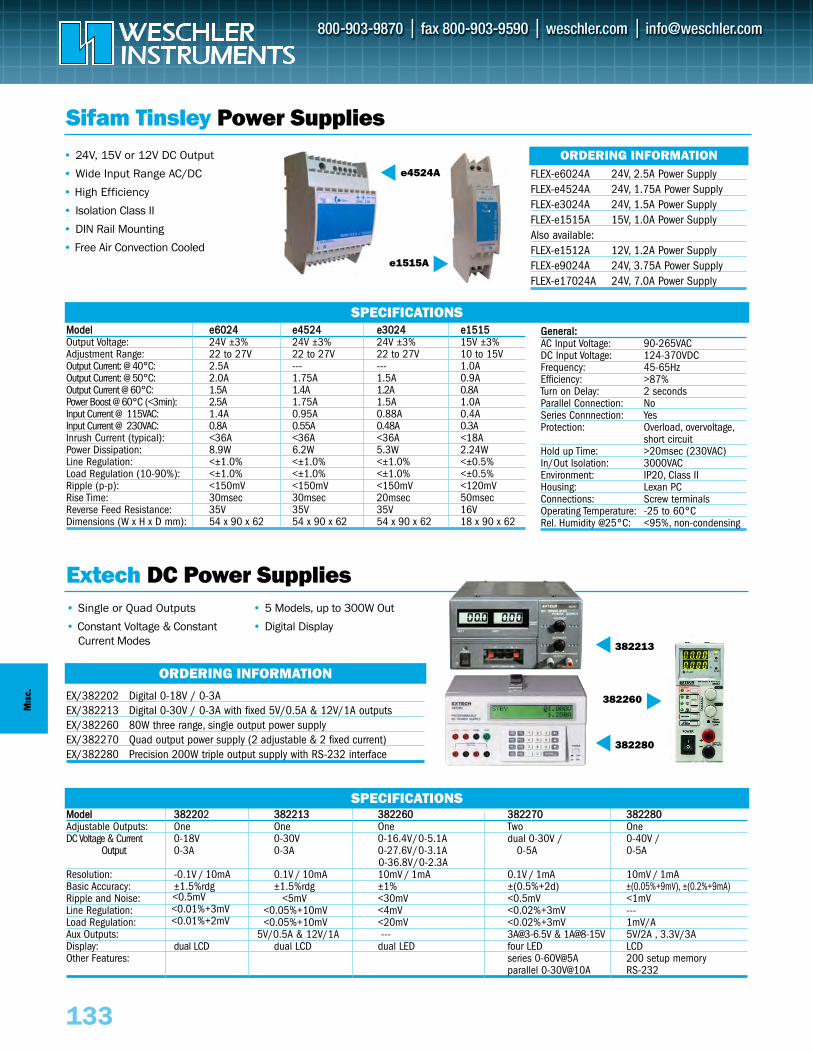
MIS
C.
MMooddeell 33882222002 338822221133 338822226600 338822227700 338822228800Adjustable Outputs: One One One Two OneDC Voltage & Current 0-18V 0-30V 0-16.4V/0-5.1A dual 0-30V / 0-40V /
Output 0-3A 0-3A 0-27.6V/0-3.1A 0-5A 0-5A 0-36.8V/0-2.3A
Resolution: -0.1V / 10mA 0.1V / 10mA 10mV / 1mA 0.1V / 1mA 10mV / 1mABasic Accuracy: ±1.5%rdg ±1.5%rdg ±1% ±(0.5%+2d) ±(0.05%+9mV), ±(0.2%+9mA)Ripple and Noise: <5mV <30mV <0.5mV <1mVLine Regulation: <0.05%+10mV <4mV <0.02%+3mV ---Load Regulation: <0.05%+10mV <20mV <0.02%+3mV 1mV/AAux Outputs: 5V/0.5A & 12V/1A --- [email protected] & 1A@8-15V 5V/2A , 3.3V/3ADisplay: dual LCD dual LCD dual LED four LED LCDOther Features: series 0-60V@5A 200 setup memory
parallel 0-30V@10A RS-232
Extech DC Power Supplies
SPECIFICATIONS
MMooddeell ee66002244 ee44552244 ee33002244 ee11551155Output Voltage: 24V ±3% 24V ±3% 24V ±3% 15V ±3%Adjustment Range: 22 to 27V 22 to 27V 22 to 27V 10 to 15VOutput Current: @ 40°C: 2.5A --- --- 1.0AOutput Current: @ 50°C: 2.0A 1.75A 1.5A 0.9AOutput Current @ 60°C: 1.5A 1.4A 1.2A 0.8APower Boost @ 60°C (<3min): 2.5A 1.75A 1.5A 1.0AInput Current @ 115VAC: 1.4A 0.95A 0.88A 0.4A Input Current @ 230VAC: 0.8A 0.55A 0.48A 0.3AInrush Current (typical): <36A <36A <36A <18APower Dissipation: 8.9W 6.2W 5.3W 2.24W Line Regulation: <±1.0% <±1.0% <±1.0% <±0.5%Load Regulation (10-90%): <±1.0% <±1.0% <±1.0% <±0.5%Ripple (p-p): <150mV <150mV <150mV <120mVRise Time: 30msec 30msec 20msec 50msecReverse Feed Resistance: 35V 35V 35V 16VDimensions (W x H x D mm): 54 x 90 x 62 54 x 90 x 62 54 x 90 x 62 18 x 90 x 62
SPECIFICATIONS
• 24V, 15V or 12V DC Output
• Wide Input Range AC/DC
• High Efficiency
• Isolation Class II
• DIN Rail Mounting
• Free Air Convection Cooled
• Single or Quad Outputs
• Constant Voltage & Constant Current Modes
• 5 Models, up to 300W Out
• Digital Display
382260
382213
382280
EX/382202 Digital 0-18V / 0-3A EX/382213 Digital 0-30V / 0-3A with fixed 5V/0.5A & 12V/1A outputsEX/382260 80W three range, single output power supplyEX/382270 Quad output power supply (2 adjustable & 2 fixed current)EX/382280 Precision 200W triple output supply with RS-232 interface
ORDERING INFORMATION
Sifam Tinsley Power SuppliesORDERING INFORMATION
FLEX-e6024A 24V, 2.5A Power Supply FLEX-e4524A 24V, 1.75A Power SupplyFLEX-e3024A 24V, 1.5A Power SupplyFLEX-e1515A 15V, 1.0A Power Supply Also available:FLEX-e1512A 12V, 1.2A Power SupplyFLEX-e9024A 24V, 3.75A Power Supply FLEX-e17024A 24V, 7.0A Power Supply
e1515A
e4524A
133
GGeenneerraall::AC Input Voltage: 90-265VAC DC Input Voltage: 124-370VDCFrequency: 45-65HzEfficiency: >87%Turn on Delay: 2 secondsParallel Connection: NoSeries Connnection: YesProtection: Overload, overvoltage,
short circuitHold up Time: >20msec (230VAC)In/Out Isolation: 3000VACEnvironment: IP20, Class IIHousing: Lexan PC Connections: Screw terminalsOperating Temperature: -25 to 60°CRel. Humidity @25°C: <95%, non-condensing
<0.5mV<0.01%+3mV<0.01%+2mV
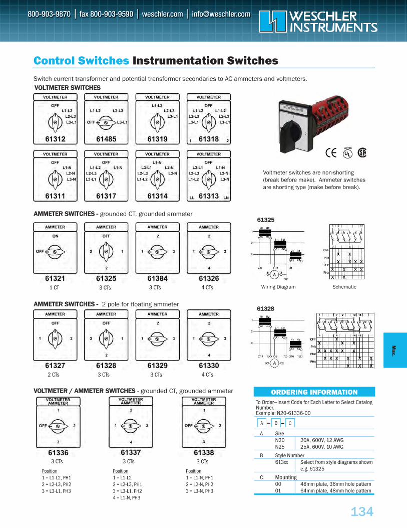
134
MISC.
To Order—Insert Code for Each Letter to Select CatalogNumber.Example: N20-61336-00
A SizeN20 20A, 600V, 12 AWGN25 25A, 600V, 10 AWG
B Style Number613xx Select from style diagrams shown
e.g. 61325
C Mounting00 48mm plate, 36mm hole pattern01 64mm plate, 48mm hole pattern
__A B __ C
6611332288
VVOOLLTTMMEETTEERR SSWWIITTCCHHEESS
ORDERING INFORMATION
Control Switches Instrumentation SwitchesSwitch current transformer and potential transformer secondaries to AC ammeters and voltmeters.
AAMMMMEETTEERR SSWWIITTCCHHEESS -- grounded CT, grounded ammeter
AAMMMMEETTEERR SSWWIITTCCHHEESS -- 2 pole for floating ammeter
VVOOLLTTMMEETTEERR // AAMMMMEETTEERR SSWWIITTCCHHEESS - grounded CT, grounded ammeter
1 CT 3 CTs 3 CTs
3 CTs
3 CTs 3 CTs3 CTs
3 CTs2 CTs
4 CTs
4 CTs
Voltmeter switches are non-shorting(break before make). Ammeter switchesare shorting type (make before break).
Position1 = L1-L2, PH12 = L2-L3, PH23 = L3-L1, PH3
Position1 = L1-L22 = L2-L3, PH13 = L3-L1, PH24 = L1-N, PH3
Position1 = L1-N, PH12 = L2-N, PH23 = L3-N, PH3
6611332255
Wiring Diagram Schematic
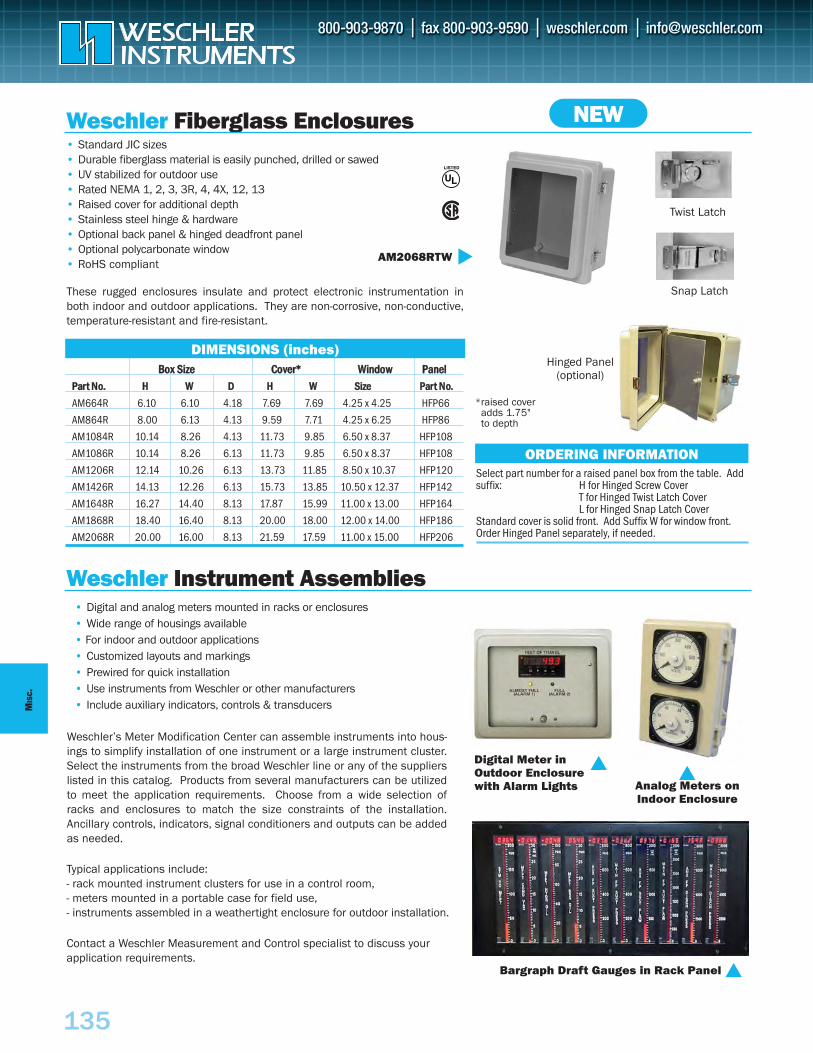
MIS
C.
135
BBooxx SSiizzee CCoovveerr** WWiinnddooww PPaanneellPPaarrtt NNoo.. HH WW DD HH WW SSiizzee PPaarrtt NNoo..
AM664R 6.10 6.10 4.18 7.69 7.69 4.25 x 4.25 HFP66
AM864R 8.00 6.13 4.13 9.59 7.71 4.25 x 6.25 HFP86
AM1084R 10.14 8.26 4.13 11.73 9.85 6.50 x 8.37 HFP108
AM1086R 10.14 8.26 6.13 11.73 9.85 6.50 x 8.37 HFP108
AM1206R 12.14 10.26 6.13 13.73 11.85 8.50 x 10.37 HFP120
AM1426R 14.13 12.26 6.13 15.73 13.85 10.50 x 12.37 HFP142
AM1648R 16.27 14.40 8.13 17.87 15.99 11.00 x 13.00 HFP164
AM1868R 18.40 16.40 8.13 20.00 18.00 12.00 x 14.00 HFP186
AM2068R 20.00 16.00 8.13 21.59 17.59 11.00 x 15.00 HFP206
Weschler Fiberglass Enclosures
Weschler Instrument Assemblies
• Standard JIC sizes• Durable fiberglass material is easily punched, drilled or sawed • UV stabilized for outdoor use • Rated NEMA 1, 2, 3, 3R, 4, 4X, 12, 13• Raised cover for additional depth • Stainless steel hinge & hardware • Optional back panel & hinged deadfront panel • Optional polycarbonate window• RoHS compliant
• Digital and analog meters mounted in racks or enclosures• Wide range of housings available • For indoor and outdoor applications• Customized layouts and markings • Prewired for quick installation• Use instruments from Weschler or other manufacturers• Include auxiliary indicators, controls & transducers
DIMENSIONS (inches)
ORDERING INFORMATION
AM2068RTW
Bargraph Draft Gauges in Rack Panel
Digital Meter inOutdoor Enclosurewith Alarm Lights Analog Meters on
Indoor Enclosure
These rugged enclosures insulate and protect electronic instrumentation inboth indoor and outdoor applications. They are non-corrosive, non-conductive,temperature-resistant and fire-resistant.
*raised coveradds 1.75" to depth
Snap Latch
Twist Latch
Hinged Panel(optional)
Select part number for a raised panel box from the table. Addsuffix: H for Hinged Screw Cover
T for Hinged Twist Latch CoverL for Hinged Snap Latch Cover
Standard cover is solid front. Add Suffix W for window front.Order Hinged Panel separately, if needed.
Weschler’s Meter Modification Center can assemble instruments into hous-ings to simplify installation of one instrument or a large instrument cluster.Select the instruments from the broad Weschler line or any of the supplierslisted in this catalog. Products from several manufacturers can be utilizedto meet the application requirements. Choose from a wide selection ofracks and enclosures to match the size constraints of the installation.Ancillary controls, indicators, signal conditioners and outputs can be addedas needed.
Typical applications include:- rack mounted instrument clusters for use in a control room, - meters mounted in a portable case for field use, - instruments assembled in a weathertight enclosure for outdoor installation.
Contact a Weschler Measurement and Control specialist to discuss yourapplication requirements.
NEW
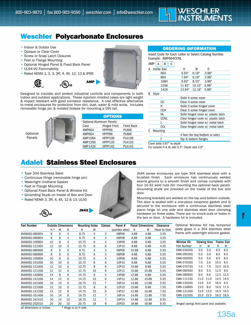
113355aa
MISC .
AMP
OptionalPanels
Weschler Polycarbonate Enclosures • Indoor & Outdor Use• Opaque or Clear Cover• Screw or Snap Latch Closures• Feet or Flange Mounting• Optional Hinged Panel & Fixed Back Panel• UL94-V0 Flammability • Rated NEMA 1, 2, 3, 3R, 4, 4X, 12, 13 & IP66
Insert Code for Each Letter to Select Catalog Number.Example: AMP664CCNL
AMPA Inside Size H W D
664 5.93" 6.16" 3.98"864 7.94" 6.16" 3.98"1084 9.93" 8.15" 3.98"1206 11.92" 10.15" 5.98"1426 13.94" 12.16" 5.98"
B Style-- Solid 4-screw coverCC Clear 4-screw coverH Solid 2-screw hinged coverCCH Clear 2-screw hinged coverNL Solid hinged cover w/ plastic latchCCNL Clear hinged cover w/ plastic latchL Solid hinged cover w/ metal latchCCL Clear hinged cover w/ metal latch
C Mounting-- 4 feet (for top/bottom or side)F Top & bottom flanges
ORDERING INFORMATION
OPTIONS
A B C
Optional Aluminum Panels:Case Hinged Front Fixed BackAMP664 HFPP66 PLA66AMP864 HFPP86 PLA86AMP1084 HFPP108 PLA108AMP1206 HFPP120 PLA120AMP1426 HFPP142 PLA142
Cover adds 0.87" to depthFor outside H & W, add 0.3"; Depth add 0.9"
Designed to insulate and protect industrial controls and components in bothindoor and outdoor applications. These injection molded cases are light weight& impact resistant with good corrosion resistance. A cost effective alternativeto metal enclosures for protection from dirt, dust, water & mild acids. Includesremovable hinge pin & molded bosses for mounting a DIN rail.
JN4X
Adalet Stainless Steel Enclosures • Type 304 Stainless Steel• Continuous Hinge (removable hinge pin)• Watertight Urethane Gasket• Feet or Flange Mounting• Optional Fixed Back Panel & Window Kit• Grounding Studs on Inside of Box and Door • Rated NEMA 3, 3R, 4, 4X, 12 & 13; UL50
JN4X series enclosures are type 304 stainless steel with abrushed finish. Each enclosure has continuously weldedseams ground to a smooth finish and comes complete withfour 10-32 weld nuts (for mounting the optional back panel).Grounding studs are provided on the inside of the box anddoor.
Mounting brackets are welded on the top and bottom outside.The door is sealed with a one-piece neoprene gasket and issecured to the enclosure with a continuous stainless steelpiano hinge on one side and stainless steel door clampinghardware on three sides. There are no knock-outs or holes inthe box or door. A hardware kit is included.
PPaarrtt NNuummbbeerr OOuuttssiiddee DDiimmeennssiioonnss MMoouunnttiinngg HHoolleess CCllaammppss PPaanneell ## PPaanneell DDiimmeennssiioonnss CClleeaarraanncceeH * W D H W (painted steel) H W Panel to Door
JN4XHSS-080604 8 6 4 8.75 4 3 08P06 4.88 4.88 3.55JN4XHSS-080804 8 8 4 8.75 6 3 08P08 6.88 6.88 3.55JN4XHSS-100804 10 8 4 10.75 6 4 10P08 6.88 6.88 3.55JN4XHSS-121005 12 10 5 12.75 8 6 12P10 8.88 6.88 4.55JN4XHSS-080606 8 6 6 8.75 4 3 08P06 10.88 8.88 5.55JN4XHSS-080806 8 8 6 8.75 6 3 08P08 6.88 6.88 5.55JN4XHSS-100806 10 8 6 10.75 6 4 10P08 8.88 6.88 5.55JN4XHSS-101006 10 10 6 10.75 8 6 10P10 8.88 8.88 5.55JN4XHSS-121006 12 10 6 12.75 8 6 12P10 10.88 8.88 5.55JN4XHSS-121206 12 12 6 12.75 10 6 12P12 10.88 10.88 5.55JN4XHSS-140806 14 8 6 14.75 6 4 14P08 12.88 6.88 5.55JN4XHSS-141206 14 12 6 14.75 10 6 14P12 12.88 10.88 5.55JN4XHSS-161406 16 14 6 16.75 12 7 16P14 14.88 12.88 5.55JN4XHSS-121008 12 10 8 12.75 8 6 12P10 10.88 8.88 7.55JN4XHSS-141208 14 12 8 14.75 10 6 14P12 12.88 10.88 7.55JN4XHSS-161408 16 14 8 16.75 12 7 16P14 14.88 12.88 7.55JN4XHSS-161410 16 14 10 16.75 12 7 16P14 14.88 12.88 9.55JN4XHSS-202010 20 20 10 20.75 18 9 20P20 18.88 18.88 9.55all dimensions in inches. * Hinge is on H side.
Optional Window Kit has temperedplate glass in a 304 stainless steelframe with watertight silicone gasket.
WWiinnddooww KKiitt VViieewwiinngg AArreeaa FFrraammee SSiizzeePart Number H W H WEWK-0303SS 3.0 3.0 6.5 6.5EWK-0503SS 5.0 3.0 8.5 6.5EWK-0505SS 5.0 5.0 8.5 8.5EWK-0703SS 7.0 3.0 10.5 6.5EWK-0707SS 7.0 7.0 10.5 10.5EWK-0905SS 9.0 5.5 12.5 9.0EWK-0909SS 9.0 9.0 12.5 12.5EWK-1111SS 11.0 11.0 14.5 14.5EWK-1303SS 13.0 3.0 16.5 6.5EWK-1308SS 13.0 8.0 16.5 11.5EWK-1313SS 13.0 13.0 16.5 16.5EWK-1515SS 15.0 15.0 18.5 18.5
Hinged (swing) front panel also available.
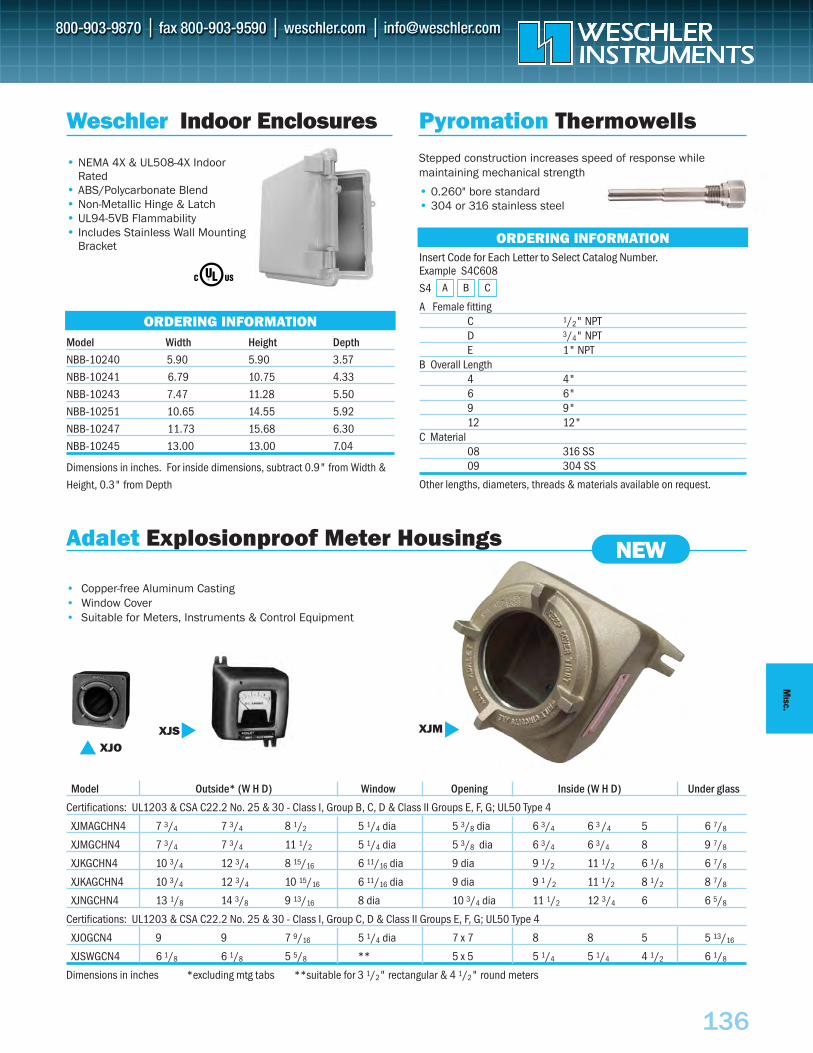
136
MISC.
Model Outside* (W H D) Window Opening Inside (W H D) Under glass
Certifications: UL1203 & CSA C22.2 No. 25 & 30 - Class I, Group B, C, D & Class II Groups E, F, G; UL50 Type 4
XJMAGCHN4 7 3/4 7 3/4 8 1/2 5 1/4 dia 5 3/8 dia 6 3/4 6 3 /4 5 6 7/8
XJMGCHN4 7 3/4 7 3/4 11 1/2 5 1/4 dia 5 3/8 dia 6 3/4 6 3/4 8 9 7/8
XJKGCHN4 10 3/4 12 3/4 8 15/16 6 11/16 dia 9 dia 9 1/2 11 1/2 6 1/8 6 7/8
XJKAGCHN4 10 3/4 12 3/4 10 15/16 6 11/16 dia 9 dia 9 1 /2 11 1/2 8 1/2 8 7/8
XJNGCHN4 13 1/8 14 3/8 9 13/16 8 dia 10 3/4 dia 11 1/2 12 3/4 6 6 5/8
Certifications: UL1203 & CSA C22.2 No. 25 & 30 - Class I, Group C, D & Class II Groups E, F, G; UL50 Type 4
XJOGCN4 9 9 7 9/16 5 1/4 dia 7 x 7 8 8 5 5 13/16
XJSWGCN4 6 1/8 6 1/8 5 5/8 ** 5 x 5 5 1/4 5 1/4 4 1/2 6 1/8
Dimensions in inches *excluding mtg tabs **suitable for 3 1/2" rectangular & 4 1/2" round meters
Weschler Indoor Enclosures
• NEMA 4X & UL508-4X Indoor Rated
• ABS/Polycarbonate Blend • Non-Metallic Hinge & Latch• UL94-5VB Flammability • Includes Stainless Wall Mounting
Bracket
Model Width Height Depth
NBB-10240 5.90 5.90 3.57
NBB-10241 6.79 10.75 4.33
NBB-10243 7.47 11.28 5.50
NBB-10251 10.65 14.55 5.92
NBB-10247 11.73 15.68 6.30
NBB-10245 13.00 13.00 7.04
Dimensions in inches. For inside dimensions, subtract 0.9" from Width &
Height, 0.3" from Depth
ORDERING INFORMATION
XJS
XJOXJM
Pyromation ThermowellsStepped construction increases speed of response while maintaining mechanical strength
• 0.260" bore standard • 304 or 316 stainless steel
Insert Code for Each Letter to Select Catalog Number. Example S4C608
S4
A Female fittingC 1/2" NPT D 3/4" NPT E 1" NPT
B Overall Length4 4" 6 6" 9 9" 12 12"
C Material08 316 SS 09 304 SS
Other lengths, diameters, threads & materials available on request.
ORDERING INFORMATION
A B C
Adalet Explosionproof Meter Housings
• Copper-free Aluminum Casting• Window Cover• Suitable for Meters, Instruments & Control Equipment
NEW
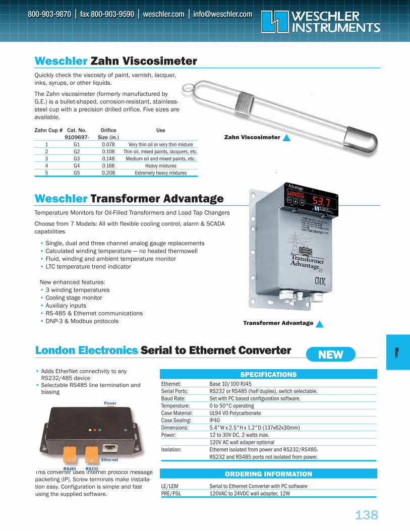
MISC.
138
Zahn Cup # Cat. No. Orifice Use9109697- Size (in.)
1 G1 0.078 Very thin oil or very thin mixture2 G2 0.108 Thin oil, mixed paints, lacquers, etc.3 G3 0.148 Medium oil and mixed paints, etc.4 G4 0.168 Heavy mixtures5 G5 0.208 Extremely heavy mixtures
Weschler Zahn ViscosimeterQuickly check the viscosity of paint, varnish, lacquer,inks, syrups, or other liquids.
The Zahn viscosimeter (formerly manufactured byG.E.) is a bullet-shaped, corrosion-resistant, stainless-steel cup with a precision drilled orifice. Five sizes areavailable.
Zahn Viscosimeter
Weschler Transformer AdvantageTemperature Monitors for Oil-Filled Transformers and Load Tap Changers
Choose from 7 Models: All with flexible cooling control, alarm & SCADAcapabilities
• Single, dual and three channel analog gauge replacements• Calculated winding temperature — no heated thermowell• Fluid, winding and ambient temperature monitor• LTC temperature trend indicator
New enhanced features:• 3 winding temperatures• Cooling stage monitor• Auxiliary inputs• RS-485 & Ethernet communications• DNP-3 & Modbus protocols Transformer Advantage
Ethernet: Base 10/100 RJ45Serial Ports: RS232 or RS485 (half duplex), switch selectable.Baud Rate: Set with PC based configuration software.Temperature: 0 to 50°C operatingCase Material: UL94 V0 PolycarbonateCase Sealing: IP40Dimensions: 5.4"W x 2.5"H x 1.2"D (137x62x30mm)Power: 12 to 30V DC, 2 watts max.
120V AC wall adaper optionalIsolation: Ethernet isolated from power and RS232/RS485.
RS232 and RS485 ports not isolated from power.
LE/LEM Serial to Ethernet Converter with PC softwarePRE/PSL 120VAC to 24VDC wall adapter, 12W
SPECIFICATIONS
ORDERING INFORMATION
London Electronics Serial to Ethernet Converter
• Adds EtherNet connectivity to anyRS232/485 device
• Selectable RS485 line termination and biasing
This converter uses internet protocol messagepacketing (IP). Screw terminals make installa-tion easy. Configuration is simple and fastusing the supplied software.
NEW
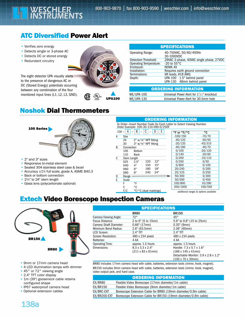
To Order—Insert Number Code for Each Letter to Select Catalog Number.Order Example: 100-30-110-090-0/250F
A Size20 2" w/¼" NPT fitting30 3" w/½" NPT fitting
B Connection100 Bottom110 Back
C Stem Length025 2.5"040 4"060 6"090 9"
D RangeE Scale
F °FC °CF/C °F/°C (dual markings)
100 – –
113388aa
ATC Diversified Power Alert• Verifies zero energy• Detects single or 3-phase AC• Detects DC or stored energy• Redundant circuitry
The eight detector UPA visually alerts to the presence of dangerous AC or DC (Stored Energy) potentials occurringbetween any combination of the four monitored input lines (L1, L2, L3, GND).
Operating Range: 40-750VAC, 50/60/400Hz30-1000VDC
Detection Threshold: 29VAC 3-phase, 40VAC single phase, 27VDCOperating Temperature: -20 to 55°CEnclosure: NEMA 4XInstallation: Requires earth ground connectionTerminations: 6ft leads, #18 AWGDepth: UPA-100 1.5" behind panel
UPA-130 48mm behind panel
SPECIFICATIONS
WE/UPA-100 Universal Power Alert for 11/4" knockoutWE/UPA-130 Universal Power Alert for 30.5mm hole
ORDERING INFORMATION
® UPA100
• 2" and 3" sizes• Responsive bi-metal element• Sealed 304 stainless steel case & bezel • Accuracy ±1% full scale, grade A, ASME B40.3• Back or bottom connection • 2½" to 24" stem length • Glass lens (polycarbonate optional)
Noshok Dial Thermometers
Extech Video Borescope Inspection Cameras
• 9mm or 17mm camera head• 4 LED illumination lamps with dimmer • 45° or 72° viewing angle• 2.4" TFT color display• 1m (39") gooseneck cable retains
configured shape• IP67 waterproof camera head• Optional extension cables
BR150
BR80
BBRR8800 BBRR115500Camera Viewing Angle: 72° 45° Focus Distance: 2 to 6" (5 to 15cm) 5.9" to 9.8" (15 to 25cm)Camera Shaft Diameter: 0.66" (17mm) 0.35" (9mm) Minimum Bend Radius: 2.6" (63.5mm) 2.36" (60mm)LCD Screen: 2.4" TFT 2.4" TFTScreen Resolution: 480 x 234 pixels 480 x 234 pixelsBatteries: 4 AA 4 AA Operating Time: approx. 1.5 hours approx. 1.5 hoursDimensions: 8.3 x 3.3 x 2.4" Handle: 7.3 x 5.7 x 1.6"
(211 x 83 x 61mm) (186 x 145 x 41mm)Detachable Monitor: 3.9 x 2.8 x 1.2" (100 x 70 x 30mm)
BR80 includes 17mm camera head with cable, batteries, extension tools (mirror, hook, magnet).BR150 includes 9mm camera head with cable, batteries, extension tools (mirror, hook, magnet),video output jack, and hard case.
SPECIFICATIONS
EX/BR80 Flexible Video Borescope (17mm diameter/1m cable)EX/BR150 Flexible Video Borescope (9mm diameter/1m cable)EX/BRC-EXT Borescope Extension Cable for BR80 (19mm diameter/0.9m cable)EX/BR200-EXT Borescope Extension Cable for BR150 (19mm diameter/0.9m cable)
ORDERING INFORMATION
ORDERING INFORMATION
100 Series
A – B – C D E °°FF oorr °°FF//°°CC °°CC-100/150 -70/70-40/120 -50/50-20/120 -45/315-40/160 -40/700/100 -20/1200/140 -20/600/200 -10/1100/250 0/500/600 0/100
20/240 0/20025/125 0/25050/300 0/30050/500 0/450
100/800 10/290200/1000 100/550
120 12"150 15"180 18"240 24"
additional ranges & options available
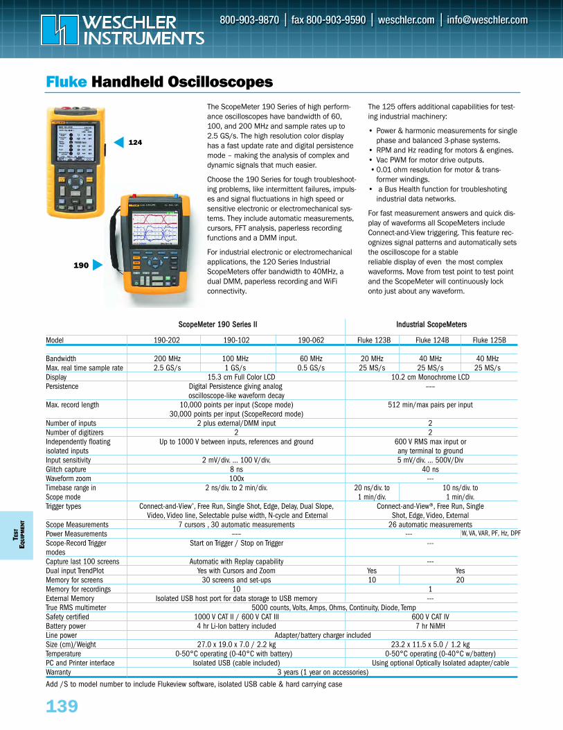
TEST
EQUI
PMEN
T
139
Fluke Handheld Oscilloscopes
SSccooppeeMMeetteerr 119900 SSeerriieess IIII IInndduussttrriiaall SSccooppeeMMeetteerrss
Model 190-202 190-102 190-062 Fluke 123B Fluke 124B Fluke 125B
Bandwidth 200 MHz 100 MHz 60 MHz 20 MHz 40 MHz 40 MHzMax. real time sample rate 2.5 GS/s 1 GS/s 0.5 GS/s 25 MS/s 25 MS/s 25 MS/sDisplay 15.3 cm Full Color LCD 10.2 cm Monochrome LCDPersistence Digital Persistence giving analog –––
oscilloscope-like waveform decayMax. record length 10,000 points per input (Scope mode) 512 min/max pairs per input
30,000 points per input (ScopeRecord mode)Number of inputs 2 plus external/DMM input 2Number of digitizers 2 2Independently floating Up to 1000 V between inputs, references and ground 600 V RMS max input orisolated inputs any terminal to groundInput sensitivity 2 mV/div. … 100 V/div. 5 mV/div. … 500V/DivGlitch capture 8 ns 40 nsWaveform zoom 100x ---Timebase range in 2 ns/div. to 2 min/div. 20 ns/div. to 10 ns/div. toScope mode 1 min/div. 1 min/div.Trigger types Connect-and-View®, Free Run, Single Shot, Edge, Delay, Dual Slope, Connect-and-View®, Free Run, Single
Video, Video line, Selectable pulse width, N-cycle and External Shot, Edge, Video, ExternalScope Measurements 7 cursors , 30 automatic measurements 26 automatic measurementsPower Measurements ––– --- W, VA, VAR, PF, Hz, DPFScope-Record Trigger Start on Trigger / Stop on Trigger ---modesCapture last 100 screens Automatic with Replay capability ---Dual input TrendPlot Yes with Cursors and Zoom Yes Yes Memory for screens 30 screens and set-ups 10 20Memory for recordings 10 1External Memory Isolated USB host port for data storage to USB memory ---True RMS multimeter 5000 counts, Volts, Amps, Ohms, Continuity, Diode, TempSafety certified 1000 V CAT II / 600 V CAT III 600 V CAT IVBattery power 4 hr Li-Ion battery included 7 hr NiMHLine power Adapter/battery charger includedSize (cm)/Weight 27.0 x 19.0 x 7.0 / 2.2 kg 23.2 x 11.5 x 5.0 / 1.2 kgTemperature 0-50°C operating (0-40°C with battery) 0-50°C operating (0-40°C w/battery)PC and Printer interface Isolated USB (cable included) Using optional Optically Isolated adapter/cableWarranty 3 years (1 year on accessories)
Add /S to model number to include Flukeview software, isolated USB cable & hard carrying case
The ScopeMeter 190 Series of high perform-ance oscilloscopes have bandwidth of 60,100, and 200 MHz and sample rates up to2.5 GS/s. The high resolution color displayhas a fast update rate and digital persistencemode – making the analysis of complex anddynamic signals that much easier.
Choose the 190 Series for tough troubleshoot-ing problems, like intermittent failures, impuls-es and signal fluctuations in high speed orsensitive electronic or electromechanical sys-tems. They include automatic measurements,cursors, FFT analysis, paperless recordingfunctions and a DMM input.
For industrial electronic or electromechanicalapplications, the 120 Series IndustrialScopeMeters offer bandwidth to 40MHz, adual DMM, paperless recording and WiFi connectivity.
The 125 offers additional capabilities for test-ing industrial machinery:
• Power & harmonic measurements for singlephase and balanced 3-phase systems.
• RPM and Hz reading for motors & engines. • Vac PWM for motor drive outputs. • 0.01 ohm resolution for motor & trans-
former windings. • a Bus Health function for troubleshoting
industrial data networks.
For fast measurement answers and quick dis-play of waveforms all ScopeMeters includeConnect-and-View triggering. This feature rec-ognizes signal patterns and automatically setsthe oscilloscope for a stable reliable display of even the most complexwaveforms. Move from test point to test pointand the ScopeMeter will continuously lockonto just about any waveform.
190
NEW
124
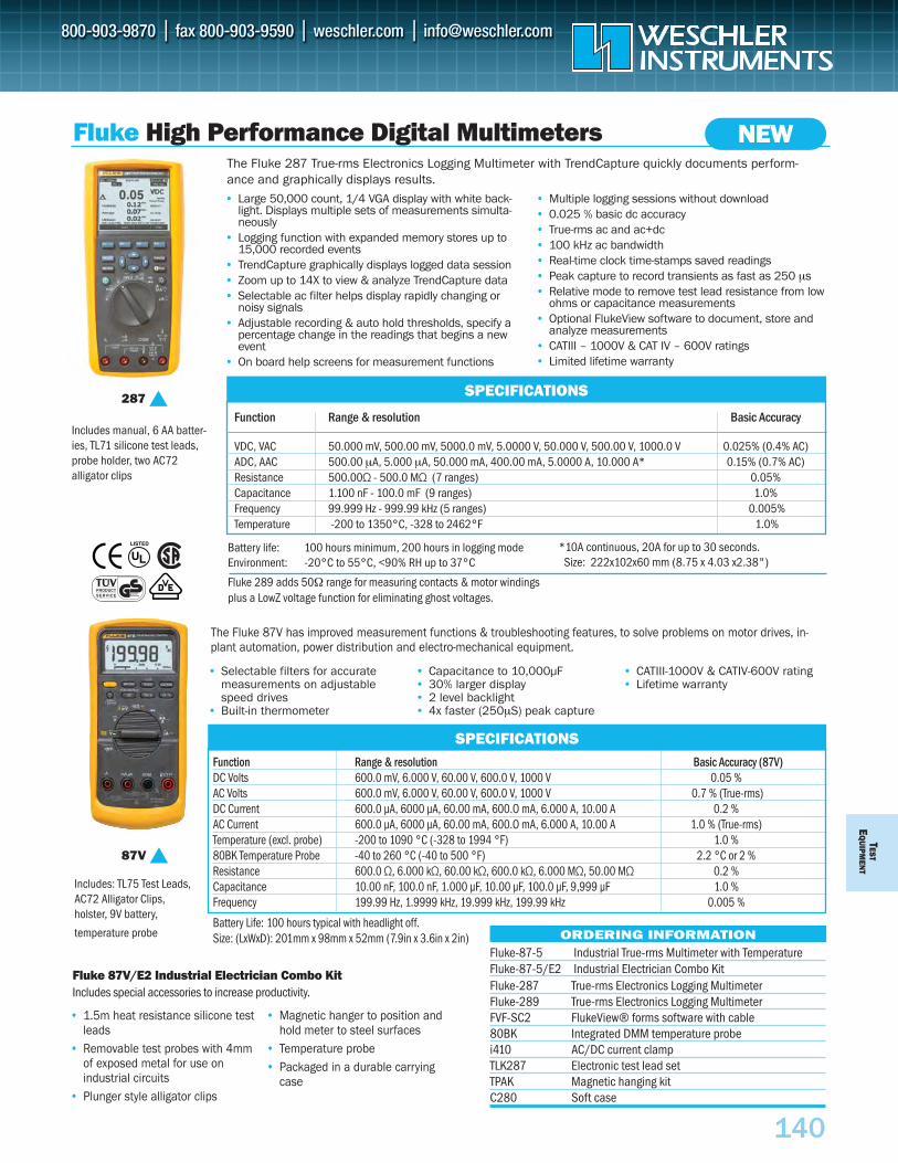
Function Range & resolution Basic Accuracy
VDC, VAC 50.000 mV, 500.00 mV, 5000.0 mV, 5.0000 V, 50.000 V, 500.00 V, 1000.0 V 0.025% (0.4% AC)ADC, AAC 500.00 µA, 5.000 µA, 50.000 mA, 400.00 mA, 5.0000 A, 10.000 A* 0.15% (0.7% AC)Resistance 500.00Ω - 500.0 MΩ (7 ranges) 0.05%Capacitance 1.100 nF - 100.0 mF (9 ranges) 1.0%Frequency 99.999 Hz - 999.99 kHz (5 ranges) 0.005%Temperature -200 to 1350°C, -328 to 2462°F 1.0%
TESTE
QU
IPMEN
T
140
SPECIFICATIONS
Fluke High Performance Digital Multimeters
• Large 50,000 count, 1/4 VGA display with white back-light. Displays multiple sets of measurements simulta-neously
• Logging function with expanded memory stores up to15,000 recorded events
• TrendCapture graphically displays logged data session• Zoom up to 14X to view & analyze TrendCapture data• Selectable ac filter helps display rapidly changing or
noisy signals • Adjustable recording & auto hold thresholds, specify a
percentage change in the readings that begins a newevent
• On board help screens for measurement functions
• Multiple logging sessions without download• 0.025 % basic dc accuracy• True-rms ac and ac+dc • 100 kHz ac bandwidth• Real-time clock time-stamps saved readings• Peak capture to record transients as fast as 250 µs• Relative mode to remove test lead resistance from low
ohms or capacitance measurements• Optional FlukeView software to document, store and
analyze measurements • CATIII – 1000V & CAT IV – 600V ratings• Limited lifetime warranty
Fluke-87-5 Industrial True-rms Multimeter with TemperatureFluke-87-5/E2 Industrial Electrician Combo Kit
ORDERING INFORMATION
287
87V
The Fluke 87V has improved measurement functions & troubleshooting features, to solve problems on motor drives, in-plant automation, power distribution and electro-mechanical equipment.
• Selectable filters for accurate measurements on adjustable speed drives
• Built-in thermometer
• Capacitance to 10,000µF• 30% larger display• 2 level backlight• 4x faster (250µS) peak capture
• CATIII-1000V & CATIV-600V rating• Lifetime warranty
Fluke 87V/E2 Industrial Electrician Combo KitIncludes special accessories to increase productivity.
Includes: TL75 Test Leads,AC72 Alligator Clips, holster, 9V battery,
temperature probe
• 1.5m heat resistance silicone testleads
• Removable test probes with 4mmof exposed metal for use on industrial circuits
• Plunger style alligator clips
• Magnetic hanger to position andhold meter to steel surfaces
• Temperature probe• Packaged in a durable carrying
case
NEW
Fluke-287 True-rms Electronics Logging Multimeter Fluke-289 True-rms Electronics Logging MultimeterFVF-SC2 FlukeView® forms software with cable80BK Integrated DMM temperature probei410 AC/DC current clampTLK287 Electronic test lead setTPAK Magnetic hanging kitC280 Soft case
Includes manual, 6 AA batter-ies, TL71 silicone test leads,probe holder, two AC72 alligator clips
The Fluke 287 True-rms Electronics Logging Multimeter with TrendCapture quickly documents perform-ance and graphically displays results.
Battery life: 100 hours minimum, 200 hours in logging modeEnvironment: -20°C to 55°C, <90% RH up to 37°C
Fluke 289 adds 50Ω range for measuring contacts & motor windings plus a LowZ voltage function for eliminating ghost voltages.
*10A continuous, 20A for up to 30 seconds.Size: 222x102x60 mm (8.75 x 4.03 x2.38")
Function Range & resolution Basic Accuracy (87V)DC Volts 600.0 mV, 6.000 V, 60.00 V, 600.0 V, 1000 V 0.05 %AC Volts 600.0 mV, 6.000 V, 60.00 V, 600.0 V, 1000 V 0.7 % (True-rms)DC Current 600.0 µA, 6000 µA, 60.00 mA, 600.O mA, 6.000 A, 10.00 A 0.2 %AC Current 600.0 µA, 6000 µA, 60.00 mA, 600.O mA, 6.000 A, 10.00 A 1.0 % (True-rms)Temperature (excl. probe) -200 to 1090 °C (-328 to 1994 °F) 1.0 %80BK Temperature Probe -40 to 260 °C (-40 to 500 °F) 2.2 °C or 2 %Resistance 600.0 Ω, 6.000 kΩ, 60.00 kΩ, 600.0 kΩ, 6.000 MΩ, 50.00 MΩ 0.2 %Capacitance 10.00 nF, 100.0 nF, 1.000 µF, 10.00 µF, 100.0 µF, 9,999 µF 1.0 %Frequency 199.99 Hz, 1.9999 kHz, 19.999 kHz, 199.99 kHz 0.005 %
Battery Life: 100 hours typical with headlight off. Size: (LxWxD): 201mm x 98mm x 52mm (7.9in x 3.6in x 2in)
SPECIFICATIONS
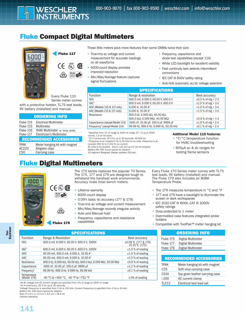
TEST
EQU
IPM
ENT
141
Fluke Compact Digital Multimeters
Function Range & Resolution Best accuracyVDC 600.0 mV, 6.000 V, 60.00 V, 600.0 V, 1000V ±0.09 % (177 & 179)
±0.15 % (175)VAC1 600.0 mV, 6.000 V, 60.00 V, 600.0 V, 1000V ±1.0 % of readingADC 60.00 mA, 400.0 mA, 6.000 A, 10.00 A2 ±1.0 % of readingAAC 60.00 mA, 400.0 mA, 6.000 A, 10.00 A2 ±1.5 % of readingResistance 600.0 Ω, 6.000 kΩ, 60.00 kΩ, 600.0 kΩ, 6.000 MΩ, 50.00 MΩ ±0.9 % of readingCapacitance 1000 nF, 10.00 µF, 100.0 µF, 9999 µF ±1.2 % of readingFrequency3 99.99 Hz, 999.9 Hz, 9.999 Hz, 99.99 kHz ±0.1 % of readingTemperature (Model 179) -40 °C to +400 °C, -40 °F to +752 °F 1.0% of reading
• Lifetime warranty • 6000 count display• 0.09% basic dc accuracy (177 & 179)• True-rms ac voltage and current measurement• Min/Max/Average records irregular activity• Auto and Manual hold • Frequency, capacitance and resistance
capabilities
• The 179 measures temperature in °C and °F • 177 and 179 have a backlight to illuminate the
screen in dark workspaces• IEC 1010 CAT IV 600V, CAT III 1000V
safety ratings• Drop protected to 1 meter• Overmolded case features integrated probe
holders• Compatible with ToolPak™ meter hanging kit
Fluke-175 Digital MultimeterFluke-177 Digital MultimeterFluke-179 Digital Multimeter
1All AC voltage and AC current ranges are specified from 5% of range to 100% of range.210 A continuous, 20 A for up to 30 seconds.3Voltage Frequency is specified from 2 Hz to 100 kHz. Current Frequency is specified from 2 Hz to 30 kHz.Battery life: 200 hours typical for alkalineSize: (H x W x L): 4.3 cm x 9.0 cm x 18.5 cmLifetime Warranty
• True-rms ac voltage and current measurement for accurate readings on all waveforms
• 6000-count display provides improved resolution
• Min/Max/Average feature captures signal fluctuations
• Frequency, capacitance and diode test capabilities (except 114)
• White LED backlight for excellent visibility
• Fast continuity test detects intermittentconnections
• IEC CAT III 600V safety rating
• Auto-Volt automatic ac/dc voltage selection
1 Specified from 1% of range to 100% of range; CF < 3 up to 4000counts, 1.5 at full scale.2 10 A continuous, 20 A for up to 30 seconds, 45-500 Hz.3 Frequency is ac coupled 5 Hz to 50 kHz for ac volts. Frequency is dccoupled 445 Hz to 5 kHz for ac current.AC volts is ac-coupled. Auto-V, LoZ and ac mV are dc-coupled.Battery life: 400 hours typical for alkaline.33 segment Bargraph display updates 32x/sec.
Fluke Digital Multimeters
ORDERING INFOSPECIFICATIONS
SPECIFICATIONS
Fluke-114 Electrical MultimeterFluke-115 MultimeterFluke-116 HVAC Multimeter w/ temp. probeFluke-117 Electrician’s Multimeter
ORDERING INFO
These little meters pack more features than some DMMs twice their size:
Function Range & resolution Best accuracyVDC 600.0 mV, 6.000 V, 60.00 V, 600.0 V ±0.5 % of rdg + 2 dVAC1 600.0 mV, 6.000 V, 60.00 V, 600.0 V ±1.0 % of rdg + 3 dADC (Models 115 & 117 only) 6.000 A, 10.00 A2 ±1.0 % of rdg + 3 dAAC (Models 115 & 117 only) 6.000 A, 10.00 A2 ±1.5 % of rdg + 3 dResistance 600.0 Ω, 6.000 kΩ, 60.00 kΩ,
600.0 kΩ, 6.000 MΩ, 40.00 MΩ ±0.9 % of rdg + 1 dCapacitance (except Model 114) 1000 nF, 10.00 µF, 100.0 µF, 9999 µF ±1.9 % of rdg + 2 dFrequency3 (except Model 114) 99.99 Hz, 999.9 Hz, 9.999 Hz, 50.00 kHz ±0.1 % of rdg + 2 d
RECOMMENDED ACCESSORIESTPAK Meter hanging kit with magnetC25 Soft vinyl carrying caseC510 Top grain leather carrying casei 200 AC current clampTL223 Electrical test lead set
Fluke 117
Fluke 179
TPAK Meter hanging kit with magnetAC220 Alligator clipsC50 Carrying case
Every Fluke 110Series meter comes
with a protective holster, TL75 test leads,9V battery (installed) and manual.
AAddddiittiioonnaall MMooddeell 111166 ffeeaattuurreess::• °F/°C temperature function
for HVAC troubleshooting
• 600µA ac & dc ranges fortesting flame sensors
RECOMMENDED ACCESSORIES
The 170 series replaces the popular 70 Series.The 175, 177 and 179 are designed tough towithstand the harshest work environments.Accuracy rivals most bench meters.
Every Fluke 170 Series meter comes with TL75test leads, 9V battery (installed) and manual.The Fluke 179 also includes an 80BKTemperature Probe.
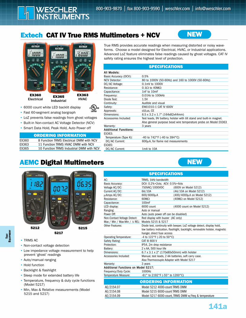
TEST
EQUI
PMEN
T
Extech CAT IV True RMS Multimeters + NCV
• 6000 count white LED backlit display• Fast 60-segment analog bargraph • LoZ prevents false readings from ghost voltages• Built-in Non-contact AC Voltage Detector (NCV)• Smart Data Hold, Peak Hold, Auto Power off
AAllll MMooddeellss::Basic Accuracy (DCV): 0.5% NCV Detector: 80 to 1000V (50-60Hz) and 160 to 1000V (50-60Hz)DC/AC Voltage: 0.1mV to 1000V Resistance: 0.1Ω to 40MΩCapacitance: 1nF to 10mF Frequency: 0.01Hz to 100kHz Diode Test: 1.5V Continuity: Audible and visual Safety: EN61010-1 CAT IV 600VApprovals: cULus, CEDimensions: 6.5 x 3.2 x 1.7" (164x82x44mm) Accessories Included: Test leads, 9V battery, holster with tilt stand and built-in magnet.
Also general purpose bead wire temperature probe on Model EX363 Warranty: 3 yearsAAddddiittiioonnaall FFuunnccttiioonnss::EX363:
Temperature (Type K): -40 to 742°F (-40 to 394°C) DC/AC Current: 600μA, for flame rod measurements
EX365:DC/AC Current: 1mA to 10A
SPECIFICATIONS
EX360 8 Function TRMS Electrical DMM with NCVEX363 11 Function TRMS HVAC DMM with NCVEX365 10 Function TRMS Industrial DMM with NCV
ORDERING INFORMATION
AEMC Digital Multimeters
• TRMS AC • Non-contact voltage detection • Low impedance voltage measurement to help
prevent ‘ghost’ readings• Auto/manual ranging• Hold function• Backlight & flashlight• Sleep mode for extended battery life • Temperature, frequency & duty cycle functions
(Model 5217)• Min, Max & Relative measurements (Model
5215 and 5217)
SPECIFICATIONSAC: TRMS, 1kHz bandwidthBasic Accuracy: DCV: 0.2%+2cts; ACV: 0.5%+4ctsVoltage AC/DC: 750VAC/1000VDC (600V on Model 5212)Current AC/DC: 6A/10A (4A/10A on Model 5212)μAmps AC/DC: 600/6000μA (400/4000μA on Model 5212)Resistance: 60MΩ (40MΩ on Model 5212)Capacitance: 100mF LCD display: 6000 count (4000 count on Model 5212)Ranging: Auto or manualPower Off: Auto (auto power off can be disabled)Non-Contact Voltage Detect: Red display with buzzer (AC only)Max / Min / Max-Min / Δ REL: Models 5215 & 5217Other Features: Diode test, continuity with beeper, LoZ voltage detect, display hold,
low battery indication, flashlight, backlight, removable holster, magnetic hanger, direct fuse access
Operating Temperature: -4 to 122°F (-20 to 50°C) Safety Rating: CAT III 600 VProtection: IP54, 2m drop resistanceBattery: 2 x AA, 500 hour life Dimensions: 6.7 x 3.1 x 2" (170x80x50mm) with holsterAccessories Included: Manual, test leads, 2 AA batteries, soft carry case.
Also Thermocouple Adapter with Model 5217Warranty: 3 yearsAAddddiittiioonnaall FFuunnccttiioonnss oonn MMooddeell 55221177::Frequency/Duty Cycle: 1000Hz Temperature Measure: -61° to 2192°F (-55° to 1200°C)
141a
NEW
NEW
EX363HVAC
EX360Electrical
EX365Industrial
5212 52155217
True RMS provides accurate readings when measuring distorted or noisy wave-forms. Choose a model designed for Electrical, HVAC, or Industrial applications.Advanced LoZ feature eliminates false readings caused by ghost voltages. CAT IVsafety rating ensures the highest level of protection.
AE/2154.07 Model 5212 4000-count TRMS DMMAE/2154.08 Model 5215 6000-count TRMS DMMAE/2154.09 Model 5217 6000-count, TRMS DMM w/freq & temperature
ORDERING INFORMATION
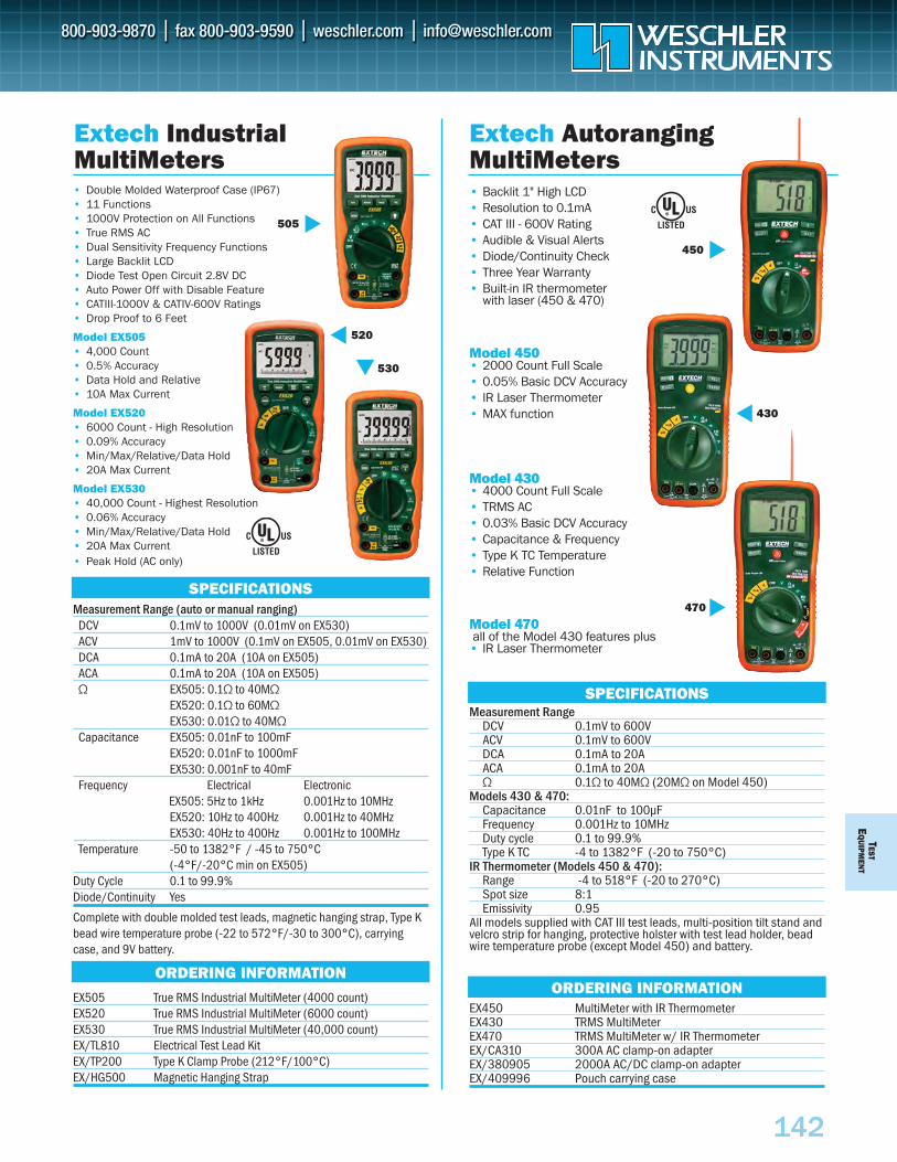
• Double Molded Waterproof Case (IP67)• 11 Functions• 1000V Protection on All Functions• True RMS AC• Dual Sensitivity Frequency Functions• Large Backlit LCD• Diode Test Open Circuit 2.8V DC• Auto Power Off with Disable Feature• CATIII-1000V & CATIV-600V Ratings• Drop Proof to 6 Feet
Model EX505 • 4,000 Count• 0.5% Accuracy• Data Hold and Relative• 10A Max Current
Model EX520 • 6000 Count - High Resolution• 0.09% Accuracy• Min/Max/Relative/Data Hold• 20A Max Current
Model EX530• 40,000 Count - Highest Resolution• 0.06% Accuracy• Min/Max/Relative/Data Hold• 20A Max Current• Peak Hold (AC only)
Measurement Range (auto or manual ranging)DCV 0.1mV to 1000V (0.01mV on EX530)ACV 1mV to 1000V (0.1mV on EX505, 0.01mV on EX530)DCA 0.1mA to 20A (10A on EX505)ACA 0.1mA to 20A (10A on EX505)Ω EX505: 0.1Ω to 40MΩ
EX520: 0.1Ω to 60MΩEX530: 0.01Ω to 40MΩ
Capacitance EX505: 0.01nF to 100mF EX520: 0.01nF to 1000mFEX530: 0.001nF to 40mF
Frequency Electrical ElectronicEX505: 5Hz to 1kHz 0.001Hz to 10MHz EX520: 10Hz to 400Hz 0.001Hz to 40MHz EX530: 40Hz to 400Hz 0.001Hz to 100MHz
Temperature -50 to 1382°F / -45 to 750°C (-4°F/-20°C min on EX505)
Duty Cycle 0.1 to 99.9% Diode/Continuity Yes
Complete with double molded test leads, magnetic hanging strap, Type Kbead wire temperature probe (-22 to 572°F/-30 to 300°C), carryingcase, and 9V battery.
EX505 True RMS Industrial MultiMeter (4000 count)EX520 True RMS Industrial MultiMeter (6000 count)EX530 True RMS Industrial MultiMeter (40,000 count)EX/TL810 Electrical Test Lead KitEX/TP200 Type K Clamp Probe (212°F/100°C)EX/HG500 Magnetic Hanging Strap
TESTE
QU
IPMEN
T
142
• Backlit 1" High LCD• Resolution to 0.1mA• CAT III - 600V Rating• Audible & Visual Alerts• Diode/Continuity Check• Three Year Warranty• Built-in IR thermometer
with laser (450 & 470)
Model 450• 2000 Count Full Scale• 0.05% Basic DCV Accuracy• IR Laser Thermometer• MAX function
Model 430• 4000 Count Full Scale• TRMS AC• 0.03% Basic DCV Accuracy• Capacitance & Frequency• Type K TC Temperature • Relative Function
Model 470all of the Model 430 features plus
• IR Laser Thermometer
Measurement RangeDCV 0.1mV to 600VACV 0.1mV to 600VDCA 0.1mA to 20AACA 0.1mA to 20AΩ 0.1Ω to 40MΩ (20MΩ on Model 450)
Models 430 & 470:Capacitance 0.01nF to 100µFFrequency 0.001Hz to 10MHzDuty cycle 0.1 to 99.9%Type K TC -4 to 1382°F (-20 to 750°C)
IR Thermometer (Models 450 & 470):Range -4 to 518°F (-20 to 270°C)Spot size 8:1Emissivity 0.95
All models supplied with CAT III test leads, multi-position tilt stand andvelcro strip for hanging, protective holster with test lead holder, beadwire temperature probe (except Model 450) and battery.
EX450 MultiMeter with IR ThermometerEX430 TRMS MultiMeter EX470 TRMS MultiMeter w/ IR ThermometerEX/CA310 300A AC clamp-on adapterEX/380905 2000A AC/DC clamp-on adapterEX/409996 Pouch carrying case
Extech AutorangingMultiMeters
ORDERING INFORMATION
SPECIFICATIONS
450
430
470
®
Extech IndustrialMultiMeters
ORDERING INFORMATION
SPECIFICATIONS
®
505
520530
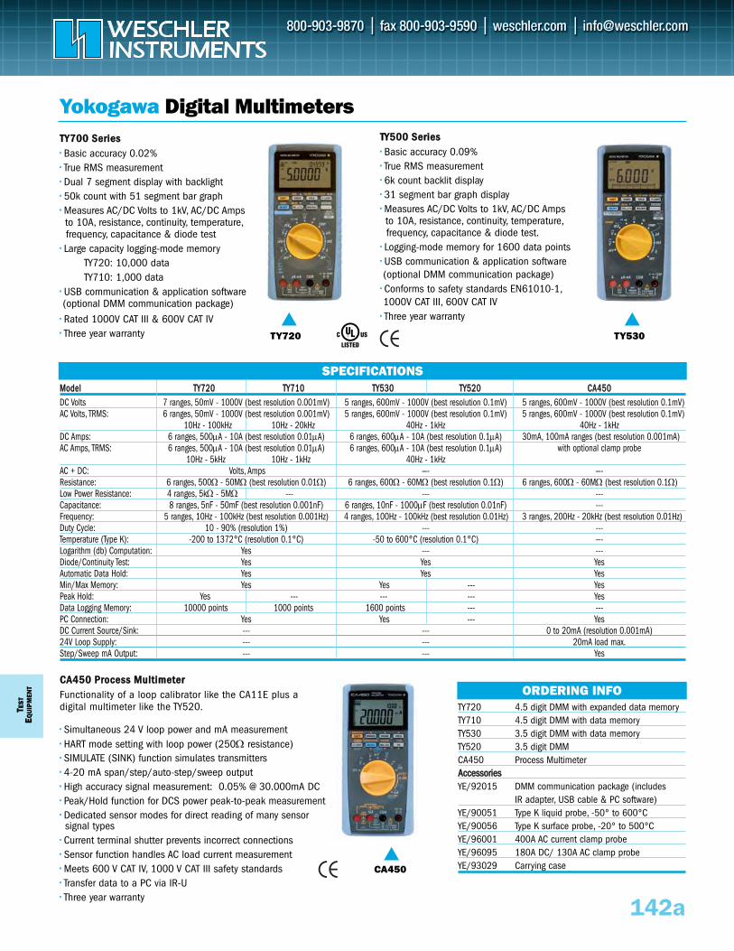
T EST
EQUI
PMEN
T
142a
MMooddeell TTYY772200 TTYY771100 TTYY553300 TTYY552200 CCAA445500DC Volts 7 ranges, 50mV - 1000V (best resolution 0.001mV) 5 ranges, 600mV - 1000V (best resolution 0.1mV) 5 ranges, 600mV - 1000V (best resolution 0.1mV)AC Volts, TRMS: 6 ranges, 50mV - 1000V (best resolution 0.001mV) 5 ranges, 600mV - 1000V (best resolution 0.1mV) 5 ranges, 600mV - 1000V (best resolution 0.1mV)
10Hz - 100kHz 10Hz - 20kHz 40Hz - 1kHz 40Hz - 1kHzDC Amps: 6 ranges, 500μA - 10A (best resolution 0.01μA) 6 ranges, 600μA - 10A (best resolution 0.1μA) 30mA, 100mA ranges (best resolution 0.001mA)AC Amps, TRMS: 6 ranges, 500μA - 10A (best resolution 0.01μA) 6 ranges, 600μA - 10A (best resolution 0.1μA) with optional clamp probe
10Hz - 5kHz 10Hz - 1kHz 40Hz - 1kHzAC + DC: Volts, Amps —- —-Resistance: 6 ranges, 500Ω - 50MΩ (best resolution 0.01Ω) 6 ranges, 600Ω - 60MΩ (best resolution 0.1Ω) 6 ranges, 600Ω - 60MΩ (best resolution 0.1Ω)Low Power Resistance: 4 ranges, 5kΩ - 5MΩ --- --- ---Capacitance: 8 ranges, 5nF - 50mF (best resolution 0.001nF) 6 ranges, 10nF - 1000μF (best resolution 0.01nF) ---Frequency: 5 ranges, 10Hz - 100kHz (best resolution 0.001Hz) 4 ranges, 100Hz - 100kHz (best resolution 0.01Hz) 3 ranges, 200Hz - 20kHz (best resolution 0.01Hz)Duty Cycle: 10 - 90% (resolution 1%) --- ---Temperature (Type K): -200 to 1372°C (resolution 0.1°C) -50 to 600°C (resolution 0.1°C) —-Logarithm (db) Computation: Yes --- ---Diode/Continuity Test: Yes Yes YesAutomatic Data Hold: Yes Yes YesMin/Max Memory: Yes Yes --- YesPeak Hold: Yes --- --- --- YesData Logging Memory: 10000 points 1000 points 1600 points --- ---PC Connection: Yes Yes --- YesDC Current Source/Sink: --- --- 0 to 20mA (resolution 0.001mA)24V Loop Supply: --- --- 20mA load max.Step/Sweep mA Output: --- --- Yes
TTYY770000 SSeerriieess•• Basic accuracy 0.02%•• True RMS measurement•• Dual 7 segment display with backlight•• 50k count with 51 segment bar graph•• Measures AC/DC Volts to 1kV, AC/DC Amps to 10A, resistance, continuity, temperature,frequency, capacitance & diode test
•• Large capacity logging-mode memoryTY720: 10,000 dataTY710: 1,000 data
•• USB communication & application software(optional DMM communication package)
•• Rated 1000V CAT III & 600V CAT IV•• Three year warranty
TTYY550000 SSeerriieess•• Basic accuracy 0.09%•• True RMS measurement•• 6k count backlit display•• 31 segment bar graph display•• Measures AC/DC Volts to 1kV, AC/DC Amps to 10A, resistance, continuity, temperature,frequency, capacitance & diode test.
•• Logging-mode memory for 1600 data points•• USB communication & application software(optional DMM communication package)
•• Conforms to safety standards EN61010-1,1000V CAT III, 600V CAT IV
•• Three year warranty
Yokogawa Digital Multimeters
SPECIFICATIONS
ORDERING INFO
TY720
CA450
TY530
CCAA445500 PPrroocceessss MMuullttiimmeetteerrFunctionality of a loop calibrator like the CA11E plus adigital multimeter like the TY520.
•• Simultaneous 24 V loop power and mA measurement•• HART mode setting with loop power (250Ω resistance)•• SIMULATE (SINK) function simulates transmitters•• 4-20 mA span/step/auto-step/sweep output•• High accuracy signal measurement: 0.05% @ 30.000mA DC•• Peak/Hold function for DCS power peak-to-peak measurement•• Dedicated sensor modes for direct reading of many sensor signal types
•• Current terminal shutter prevents incorrect connections•• Sensor function handles AC load current measurement•• Meets 600 V CAT IV, 1000 V CAT III safety standards•• Transfer data to a PC via IR-U•• Three year warranty
TY720 4.5 digit DMM with expanded data memoryTY710 4.5 digit DMM with data memoryTY530 3.5 digit DMM with data memoryTY520 3.5 digit DMMCA450 Process MultimeterAAcccceessssoorriieessYE/92015 DMM communication package (includes
IR adapter, USB cable & PC software)YE/90051 Type K liquid probe, -50° to 600°CYE/90056 Type K surface probe, -20° to 500°CYE/96001 400A AC current clamp probeYE/96095 180A DC/ 130A AC clamp probe YE/93029 Carrying case
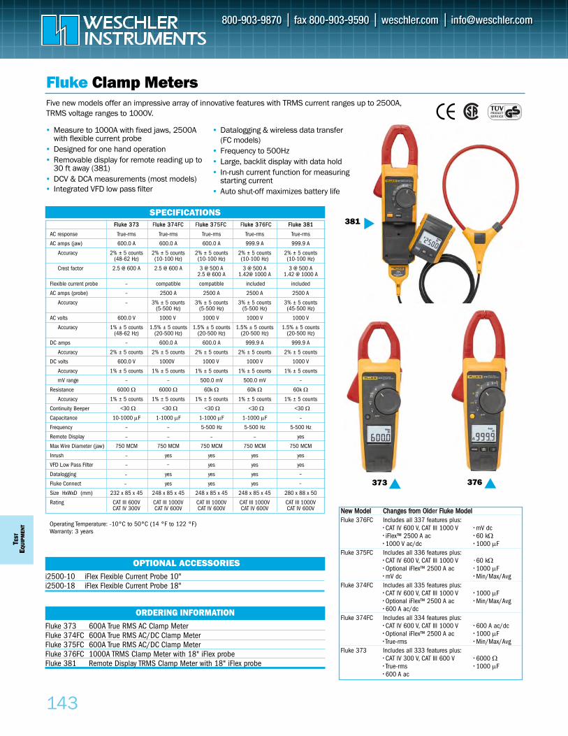
FFlluukkee 337733 Flluukkee 33774FC Flluukkee 3375FC Flluukkee 33776FC FFlluukkee 338811
AC response True-rms True-rms True-rms True-rms True-rms
AC amps (jaw) 600.0 A 600.0 A 600.0 A 999.9 A 999.9 A
Accuracy 2% ± 5 counts 2% ± 5 counts 2% ± 5 counts 2% ± 5 counts 2% ± 5 counts(48-62 Hz) (10-100 Hz) (10-100 Hz) (10-100 Hz) (10-100 Hz)
Crest factor 2.5 @ 600 A 2.5 @ 600 A 3 @ 500 A 3 @ 500 A 3 @ 500 A2.5 @ 600 A 1.42@ 1000 A 1.42 @ 1000 A
Flexible current probe – compatible compatible included included
AC amps (probe) – 2500 A 2500 A 2500 A 2500 A
Accuracy – 3% ± 5 counts 3% ± 5 counts 3% ± 5 counts 3% ± 5 counts(5-500 Hz) (5-500 Hz) (5-500 Hz) (45-500 Hz)
AC volts 600.0 V 1000 V 1000 V 1000 V 1000 V
Accuracy 1% ± 5 counts 1.5% ± 5 counts 1.5% ± 5 counts 1.5% ± 5 counts 1.5% ± 5 counts(48-62 Hz) (20-500 Hz) (20-500 Hz) (20-500 Hz) (20-500 Hz)
DC amps – 600.0 A 600.0 A 999.9 A 999.9 A
Accuracy 2% ± 5 counts 2% ± 5 counts 2% ± 5 counts 2% ± 5 counts 2% ± 5 counts
DC volts 600.0 V 1000V 1000 V 1000 V 1000 V
Accuracy 1% ± 5 counts 1% ± 5 counts 1% ± 5 counts 1% ± 5 counts 1% ± 5 counts
mV range – – 500.0 mV 500.0 mV –
Resistance 6000 Ω 6000 Ω 60k Ω 60k Ω 60k Ω
Accuracy 1% ± 5 counts 1% ± 5 counts 1% ± 5 counts 1% ± 5 counts 1% ± 5 counts
Continuity Beeper <30 Ω <30 Ω <30 Ω <30 Ω <30 Ω
Capacitance 10-1000 μF 1-1000 μF 1-1000 μF 1-1000 μF –
Frequency – – 5-500 Hz 5-500 Hz 5-500 Hz
Remote Display – – – – yes
Max Wire Diameter (jaw) 750 MCM 750 MCM 750 MCM 750 MCM 750 MCM
Inrush – yes yes yes yes
VFD Low Pass Filter – yes yes yes
Datalogging yes yes yes
Fluke Connect yes yes yes
Size HxWxD (mm) 232 x 85 x 45 248 x 85 x 45 248 x 85 x 45 248 x 85 x 45 280 x 88 x 50
Rating CAT III 600V CAT III 1000V CAT III 1000V CAT III 1000V CAT III 1000VCAT IV 300V CAT IV 600V CAT IV 600V CAT IV 600V CAT IV 600V
TEST
EQUI
PMEN
T
143
Fluke Clamp Meters
• Measure to 1000A with fixed jaws, 2500A with flexible current probe
• Designed for one hand operation• Removable display for remote reading up to
30 ft away (381)• DCV & DCA measurements (most models)• Integrated VFD low pass filter
• Datalogging & wireless data transfer (FC models)
• Frequency to 500Hz • Large, backlit display with data hold • In-rush current function for measuring
starting current • Auto shut-off maximizes battery life
Operating Temperature: -10°C to 50°C (14 °F to 122 °F)Warranty: 3 years
Five new models offer an impressive array of innovative features with TRMS current ranges up to 2500A,TRMS voltage ranges to 1000V.
SPECIFICATIONS
376
i2500-10 iFlex Flexible Current Probe 10"i2500-18 iFlex Flexible Current Probe 18"
Fluke 373 600A True RMS AC Clamp MeterFluke 374FC 600A True RMS AC/DC Clamp MeterFluke 375FC 600A True RMS AC/DC Clamp MeterFluke 376FC 1000A TRMS Clamp Meter with 18" iFlex probeFluke 381 Remote Display TRMS Clamp Meter with 18" iFlex probe
OPTIONAL ACCESSORIES
ORDERING INFORMATION
NNeeww MMooddeell CChhaannggeess ffrroomm OOlldder FFlluukkee MMooddeellFluke 376FC Includes all 337 features plus:
• CAT IV 600 V, CAT III 1000 V •• mV dc••• iFlex™ 2500 A ac •• 60 kΩ•• 1000 V ac/dc •• 1000 μF
Fluke 375FC Includes all 336 features plus:• CAT IV 600 V, CAT III 1000 V • 60 kΩ• Optional iFlex™ 2500 A ac •• 1000 μF•••• mV dc •• Min/Max/Avg
Fluke 374FC Includes all 335 features plus:• CAT IV 600 V, CAT III 1000 V •• 1000 μF• Optional iFlex™ 2500 A ac •• Min/Max/Avg•••• 600 A ac/dc
Fluke 374FC Includes all 334 features plus:• CAT IV 600 V, CAT III 1000 V •• 600 A ac/dc• Optional iFlex™ 2500 A ac •• 1000 μF•••• True-rms •• Min/Max/Avg
Fluke 373 Includes all 333 features plus:• CAT IV 300 V, CAT III 600 V •• 6000 Ω••• True-rms •• 1000 μF•• 600 A ac
373
381
–
–
–
–
–
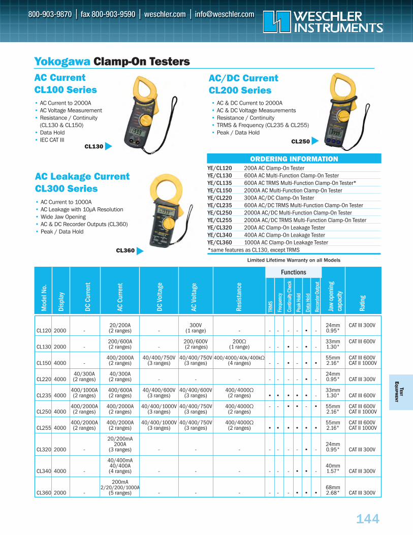
TESTE
QU
IPMEN
T
144
Yokogawa Clamp-On Testers
• AC Current to 2000A• AC Voltage Measurement• Resistance / Continuity
(CL130 & CL150)• Data Hold• IEC CAT III
AC Current CL100 Series
• AC Current to 1000A• AC Leakage with 10µA Resolution • Wide Jaw Opening• AC & DC Recorder Outputs (CL360)• Peak / Data Hold
AC Leakage Current CL300 Series
• AC & DC Current to 2000A• AC & DC Voltage Measurements• Resistance / Continuity• TRMS & Frequency (CL235 & CL255)• Peak / Data Hold
AC/DC Current CL200 Series
20/200A 300V 24mm CAT III 300VCL120 2000 - (2 ranges) - (1 range) - - - - - • - 0.95"
200/600A 200/600V 200Ω 33mm CAT III 600VCL130 2000 - (2 ranges) - (2 ranges) (1 range) - - • - • - 1.30"
400/2000A 40/400/750V 40/400/750V 400/4000/40k/400kΩ 55mm CAT III 600VCL150 4000 - (2 ranges) (3 ranges) (3 ranges) (4 ranges) - - • - • • 2.16" CAT II 1000V
40/300A 40/300A 24mmCL220 4000 (2 ranges) (2 ranges) - - - - - - - • - 0.95" CAT III 300V
400/1000A 400/600A 40/400/600V 40/400/600V 400/4000Ω 33mmCL235 4000 (2 ranges) (2 ranges) (3 ranges) (3 ranges) (2 ranges) • • • • • - 1.30" CAT III 600V
400/2000A 400/2000A 40/400/1000V 40/400/750V 400/4000Ω - - • • - • 55mm CAT III 600VCL250 4000 (2 ranges) (2 ranges) (3 ranges) (3 ranges) (2 ranges) 2.16" CAT II 1000V
400/2000A 400/2000A 40/400/1000V 40/400/750V 400/4000Ω 55mm CAT III 600VCL255 4000 (2 ranges) (2 ranges) (3 ranges) (3 ranges) (2 ranges) • • • • • • 2.16" CAT II 1000V
20/200mA 200A 24mm
CL320 2000 - (3 ranges) - - - - - - - • - 0.95" CAT III 300V
40/400mA 40/400A 40mm
CL340 4000 - (4 ranges) - - - - - - • • - 1.57" CAT III 300V
200mA 2/20/200/1000A 68mm
CL360 2000 - (5 ranges) - - - - - - • • • 2.68" CAT III 300V
Mod
el N
o.
DC C
urre
nt
AC C
urre
nt
DC V
olta
ge
AC V
olta
ge
Resi
stan
ce
Jaw
open
ing
capa
city
Ratin
g
TRM
S
Freq
uenc
y
Cont
inui
ty Ch
eck
Peak
Hol
d
Data
Hol
d
Reco
rder
Out
put
Disp
lay
Functions
YE/CL120 200A AC Clamp-On Tester YE/CL130 600A AC Multi-Function Clamp-On Tester YE/CL135 600A AC TRMS Multi-Function Clamp-On Tester* YE/CL150 2000A AC Multi-Function Clamp-On Tester YE/CL220 300A AC/DC Clamp-On Tester YE/CL235 600A AC/DC TRMS Multi-Function Clamp-On Tester YE/CL250 2000A AC/DC Multi-Function Clamp-On Tester YE/CL255 2000A AC/DC TRMS Multi-Function Clamp-On Tester YE/CL320 200A AC Clamp-On Leakage Tester YE/CL340 400A AC Clamp-On Leakage Tester YE/CL360 1000A AC Clamp-On Leakage Tester *same features as CL130, except TRMS
ORDERING INFORMATION
CL250
CL360
CL130
Limited Lifetime Warranty on all Models
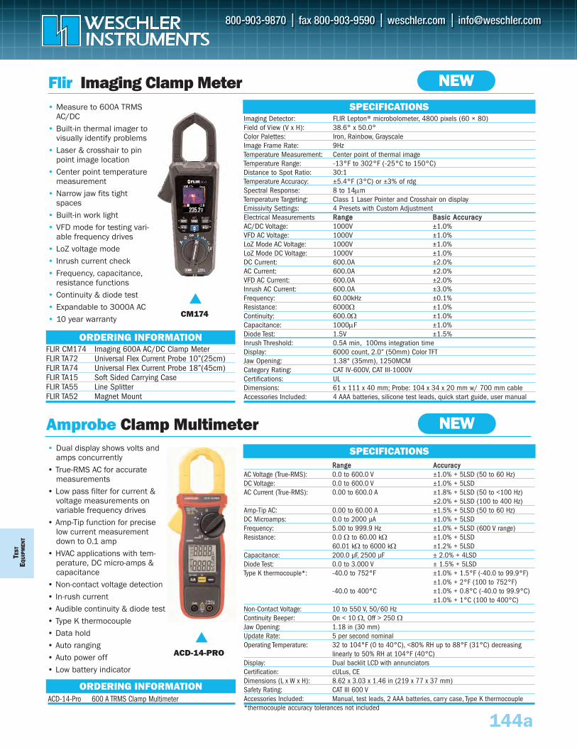
TEST
EQUI
PMEN
T
Flir Imaging Clamp Meter• Measure to 600A TRMS
AC/DC• Built-in thermal imager to
visually identify problems• Laser & crosshair to pin
point image location• Center point temperature
measurement• Narrow jaw fits tight
spaces• Built-in work light• VFD mode for testing vari-
able frequency drives• LoZ voltage mode• Inrush current check• Frequency, capacitance,
resistance functions• Continuity & diode test• Expandable to 3000A AC• 10 year warranty
CM174
Imaging Detector: FLIR Lepton® microbolometer, 4800 pixels (60 × 80)Field of View (V x H): 38.6° x 50.0°Color Palettes: Iron, Rainbow, GrayscaleImage Frame Rate: 9HzTemperature Measurement: Center point of thermal imageTemperature Range: -13°F to 302°F (-25°C to 150°C)Distance to Spot Ratio: 30:1Temperature Accuracy: ±5.4°F (3°C) or ±3% of rdgSpectral Response: 8 to 14μmTemperature Targeting: Class 1 Laser Pointer and Crosshair on displayEmissivity Settings: 4 Presets with Custom AdjustmentElectrical Measurements RRaannggee BBaassiicc AAccccuurraaccyyAC/DC Voltage: 1000V ±1.0%VFD AC Voltage: 1000V ±1.0%LoZ Mode AC Voltage: 1000V ±1.0%LoZ Mode DC Voltage: 1000V ±1.0%DC Current: 600.0A ±2.0%AC Current: 600.0A ±2.0%VFD AC Current: 600.0A ±2.0%Inrush AC Current: 600.0A ±3.0%Frequency: 60.00kHz ±0.1%Resistance: 6000Ω ±1.0%Continuity: 600.0Ω ±1.0%Capacitance: 1000μF ±1.0%Diode Test: 1.5V ±1.5%Inrush Threshold: 0.5A min, 100ms integration time Display: 6000 count, 2.0” (50mm) Color TFTJaw Opening: 1.38" (35mm), 1250MCMCategory Rating: CAT IV-600V, CAT III-1000VCertifications: ULDimensions: 61 x 111 x 40 mm; Probe: 104 x 34 x 20 mm w/ 700 mm cableAccessories Included: 4 AAA batteries, silicone test leads, quick start guide, user manual
SPECIFICATIONS
FLIR CM174 Imaging 600A AC/DC Clamp Meter FLIR TA72 Universal Flex Current Probe 10”(25cm)FLIR TA74 Universal Flex Current Probe 18”(45cm)FLIR TA15 Soft Sided Carrying CaseFLIR TA55 Line SplitterFLIR TA52 Magnet Mount
ORDERING INFORMATION
Amprobe Clamp Multimeter• Dual display shows volts and
amps concurrently• True-RMS AC for accurate
measurements • Low pass filter for current &
voltage measurements on variable frequency drives
• Amp-Tip function for precise low current measurement down to 0.1 amp
• HVAC applications with tem-perature, DC micro-amps & capacitance
• Non-contact voltage detection • In-rush current • Audible continuity & diode test• Type K thermocouple• Data hold • Auto ranging• Auto power off• Low battery indicator
SPECIFICATIONS
ACD-14-Pro 600 A TRMS Clamp MultimeterORDERING INFORMATION
ACD-14-PRO
RRaannggee AAccccuurraaccyyAC Voltage (True-RMS): 0.0 to 600.0 V ±1.0% + 5LSD (50 to 60 Hz)DC Voltage: 0.0 to 600.0 V ±1.0% + 5LSDAC Current (True-RMS): 0.00 to 600.0 A ±1.8% + 5LSD (50 to <100 Hz)
±2.0% + 5LSD (100 to 400 Hz)Amp-Tip AC: 0.00 to 60.00 A ±1.5% + 5LSD (50 to 60 Hz)DC Microamps: 0.0 to 2000 μA ±1.0% + 5LSDFrequency: 5.00 to 999.9 Hz ±1.0% + 5LSD (600 V range)Resistance: 0.0 Ω to 60.00 kΩ ±1.0% + 5LSD
60.01 kΩ to 6000 kΩ ±1.2% + 5LSDCapacitance: 200.0 μF, 2500 μF ± 2.0% + 4LSDDiode Test: 0.0 to 3.000 V ± 1.5% + 5LSDType K thermocouple*: -40.0 to 752°F ±1.0% + 1.5°F (-40.0 to 99.9°F)
±1.0% + 2°F (100 to 752°F)-40.0 to 400°C ±1.0% + 0.8°C (-40.0 to 99.9°C)
±1.0% + 1°C (100 to 400°C)Non-Contact Voltage: 10 to 550 V, 50/60 HzContinuity Beeper: On < 10 Ω, Off > 250 ΩJaw Opening: 1.18 in (30 mm)Update Rate: 5 per second nominalOperating Temperature: 32 to 104°F (0 to 40°C), <80% RH up to 88°F (31°C) decreasing
linearly to 50% RH at 104°F (40°C)Display: Dual backlit LCD with annunciatorsCertification: cULus, CE Dimensions (L x W x H): 8.62 x 3.03 x 1.46 in (219 x 77 x 37 mm)Safety Rating: CAT III 600 VAccessories Included: Manual, test leads, 2 AAA batteries, carry case, Type K thermocouple*thermocouple accuracy tolerances not included
144a
NEW
NEW
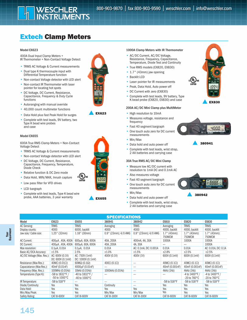
TEST
EQU
IPM
ENT
145
Model EX623 EX655 380941 380942 EX810 EX820 EX830AC Sensing: TRMS TRMS Averaging TRMS Averaging TRMS TRMSDisplay counts: 4000 6000, backlit 4000 4000 4000, backlit 4000, backlit 4000, backlitJaw size/ Cable size: 1.25" (32mm) 1.18" (30mm) 0.9" (23mm); 4/0 AWG 0.9" (23mm); 4/0 AWG 1.7" (43mm): 1.7" (43mm): 1.7" (43mm):
750MCM 750MCM 750MCMAC Current: 400µA , 40A, 400A 600µA, 60A, 600A 40A, 200A 400mA, 4A, 30A 1000A 1000A 1000ADC Current: 400µA , 40A, 400A 600µA, 60A, 600A 40A, 200A 4A, 30A —- —- 1000AMax resolution: 0.1µA, 0.01A 0.1µA, 0.01A 0.01A AC: 0.1mA, DC: 0.001A 0.01A 0.01A AC: 0.01A, DC: 0.1ABasic AC/DCA Accuracy: ±1.5% ±1.0% ±1.5% ±2.8% ±2.5% ±2.5%AC/DC Voltage (Max. Res.): AC: 600V (0.1V) AC: 750V (1mV) 400V (0.1V) 400V (1V) 600V (0.1mV) 600V (0.1mV) 600V (0.1mV)
DC: 600V (0.1mV) DC: 1000V (0.1mV)Resistance (Max Res.): 40MΩ (0.01Ω) 60MΩ (0.1Ω) 400Ω (0.1Ω) —- 40MΩ (0.1Ω) 40MΩ (0.1Ω) 40MΩ (0.1Ω)Capaciatance (Max Res.): 40mF (0.01nF) 4000µF (0.01nF) —- —- 40mF (0.001nF) 40mF (0.001nF) 40mF (0.001nF)Frequency (Max. Res.): 100MHz (0.01Hz) 10kHz (0.01Hz) 1000kHz (0.01Hz) —- 4kHz (1Hz) 4kHz (1Hz) 4kHz (1Hz)Temperatures (Type K): -58 to 1832°F / -40 to 1832°F / —- —- —- -4 to 1400°F / -4 to 1400°F /
-20 to 760°C -20 to 760°CIR Temperature: -58 to 518°F —- —- —-Diode/Continuity: Yes Yes Continuity —- Yes Yes YesData Hold: Yes Yes Yes Yes Yes Yes YesMin/Max/Peak: Yes Yes Min/Max Min/MaxSafety Rating: CAT III-600V CAT III-600V CAT III-300V CAT III-300V CAT III-600V CAT III-600V CAT III-600V
Model EX623
400A Dual Input Clamp Meters +IR Thermometer + Non-Contact Voltage Detect
• TRMS AC Voltage & Current measurements • Dual type K thermocouple input with
Differential Temperature function• Non-contact Voltage detector with LED alert• Non-contact IR Thermometer with laser
pointer for locating hot spots• DC Voltage, DC Current, Resistance,
Capacitance, Frequency & Duty Cycle functions
• Autoranging with manual override• 40,000 count multimeter functions
• Data Hold plus fast Peak Hold for surges • Complete with test leads, 9V battery, two
Type K bead wire probes and case
Model EX655
600A True RMS Clamp Meters + Non-ContactVoltage Detect• TRMS AC Voltage & Current measurements • Non-contact Voltage detector with LED alert • DC Voltage, DC Current, Resistance,
Capacitance, Frequency, Temperature, Diode Check
• Relative function & DC Zero mode• Data Hold, MIN/MAX, Inrush capture
• Low pass filter for VFD drives
• LCD bargraph• Complete with test leads, Type K bead wire
probe, AAA batteries, 3 year warranty
1000A Clamp Meters with IR Thermometer
• AC/DC Current, AC/DC Voltage,Resistance, Frequency, Capacitance,Temperature, Diode Test and Continuity
• True RMS models (EX820, EX830)• 1.7" (43mm) jaw opening • Backlit LCD• Laser pointer for IR measurements• Peak, Data Hold, Auto power off• DC Current with zero (EX830) • Complete with test leads, 9V battery, Type
K bead probe (EX820, EX830) and case
200A AC/DC Mini Clamp plus MultiMeter
• High resolution to 10mA• Measures voltage, resistance and
frequency• Fast 40 segment bargraph• One touch auto zero for DC current
measurements• Min/Max• Data hold and auto power off• Complete with test leads, wrist strap,
2 AA batteries and carrying case
30A True RMS AC/DC Mini Clamp
• Measure low AC/DC current with resolution to 1mA DC and 0.1mA AC
• Also measures voltage• Fast 40 segment bargraph• One touch auto zero for DC current
measurements• Min/Max• Data hold and auto power off• Complete with test leads, wrist strap,
2 AA batteries and carrying case
Extech Clamp Meters
SPECIFICATIONS
EX623
EX830
380941
380942
NEW
EX655
2.5%
-58 to 518°F -58 to 518°F -58 to 518°F
Yes Yes Yes
-50 to 1000°C -40 to 1000°C
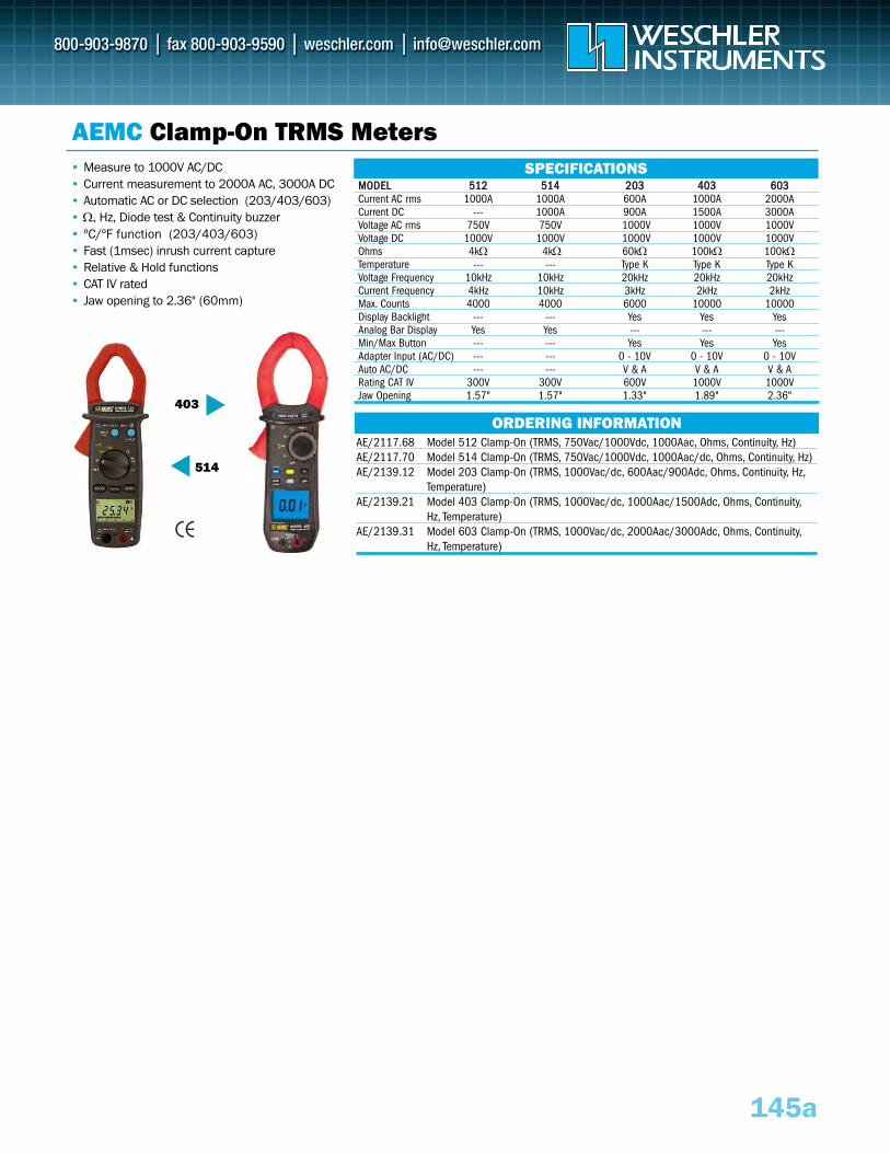
403
514
145a
AEMC Clamp-On TRMS Meters• Measure to 1000V AC/DC • Current measurement to 2000A AC, 3000A DC• Automatic AC or DC selection (203/403/603)• Ω, Hz, Diode test & Continuity buzzer• ºC/ºF function (203/403/603) • Fast (1msec) inrush current capture• Relative & Hold functions• CAT IV rated • Jaw opening to 2.36" (60mm)
MMOODDEELL 551122 551144 220033 440033 660033Current AC rms 1000A 1000A 600A 1000A 2000ACurrent DC --- 1000A 900A 1500A 3000AVoltage AC rms 750V 750V 1000V 1000V 1000VVoltage DC 1000V 1000V 1000V 1000V 1000VOhms 4kΩ 4kΩ 60kΩ 100kΩ 100kΩTemperature --- --- Type K Type K Type KVoltage Frequency 10kHz 10kHz 20kHz 20kHz 20kHzCurrent Frequency 4kHz 10kHz 3kHz 2kHz 2kHzMax. Counts 4000 4000 6000 10000 10000Display Backlight --- --- Yes Yes YesAnalog Bar Display Yes Yes --- --- ---Min/Max Button --- --- Yes Yes YesAdapter Input (AC/DC) --- --- 0 - 10V 0 - 10V 0 - 10V Auto AC/DC --- --- V & A V & A V & ARating CAT IV 300V 300V 600V 1000V 1000VJaw Opening 1.57" 1.57" 1.33" 1.89" 2.36"
ORDERING INFORMATION
SPECIFICATIONS
AE/2117.68 Model 512 Clamp-On (TRMS, 750Vac/1000Vdc, 1000Aac, Ohms, Continuity, Hz)AE/2117.70 Model 514 Clamp-On (TRMS, 750Vac/1000Vdc, 1000Aac/dc, Ohms, Continuity, Hz)AE/2139.12 Model 203 Clamp-On (TRMS, 1000Vac/dc, 600Aac/900Adc, Ohms, Continuity, Hz,
Temperature)AE/2139.21 Model 403 Clamp-On (TRMS, 1000Vac/dc, 1000Aac/1500Adc, Ohms, Continuity,
Hz, Temperature)AE/2139.31 Model 603 Clamp-On (TRMS, 1000Vac/dc, 2000Aac/3000Adc, Ohms, Continuity,
Hz, Temperature)
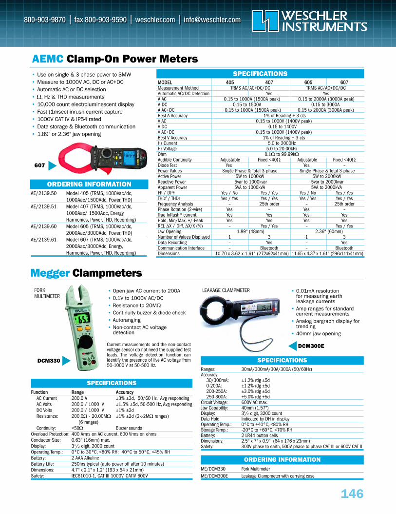
607
146
AEMC Clamp-On Power Meters• Use on single & 3-phase power to 3MW• Measure to 1000V AC, DC or AC+DC• Automatic AC or DC selection• Ω, Hz & THD measurements• 10,000 count electroluminescent display• Fast (1msec) inrush current capture• 1000V CAT IV & IP54 rated • Data storage & Bluetooth communication• 1.89" or 2.36" jaw opening
MMOODDEELL 440055 440077 660055 660077Measurement Method TRMS AC/AC+DC/DC TRMS AC/AC+DC/DC Automatic AC/DC Detection – Yes Yes A AC 0.15 to 1000A (1500A peak) 0.15 to 2000A (3000A peak)A DC 0.15 to 1500A 0.15 to 3000AA AC+DC 0.15 to 1000A (1500A peak) 0.15 to 2000A (3000A peak)Best A Accuracy 1% of Reading + 3 ctsV AC 0.15 to 1000V (1400V peak)V DC 0.15 to 1400VV AC+DC 0.15 to 1000V (1400V peak)Best V Accuracy 1% of Reading + 3 ctsHz Current 5.0 to 2000HzHz Voltage 5.0 to 20.00kHzOhm 0.1Ω to 99.99kΩAudible Continuity Adjustable Fixed <40Ω Adjustable Fixed <40ΩDiode Test Yes – Yes –Power Values Single Phase & Total 3-phase Single Phase & Total 3-phaseActive Power 5W to 1000kW 5W to 2000kWReactive Power 5var to 1000kvar 5var to 2000kvarApparent Power 5VA to 1000kVA 5VA to 2000kVAFP / DPF Yes / No Yes / Yes Yes / No Yes / YesTHDf / THDr Yes / Yes Yes / Yes Yes / Yes Yes / YesFrequency Analysis – 25th order – 25th orderPhase Rotation (2-wire) Yes – Yes –True InRush® current Yes Yes Yes YesHold, Min/Max, +/-Peak Yes Yes Yes YesREL ΔX / Diff. ΔX/X (%) – Yes / Yes – Yes / YesJaw Opening 1.89" (48mm) 2.36" (60mm)Number of Values Displayed 1 3 1 3Data Recording – Yes – YesCommunication Interface – Bluetooth – Bluetooth Dimensions 10.70 x 3.62 x 1.61" (272x92x41mm) 11.65 x 4.37 x 1.61" (296x111x41mm)
ORDERING INFORMATION
SPECIFICATIONS
AE/2139.50 Model 405 (TRMS, 1000Vac/dc,1000Aac/1500Adc, Power, THD)
AE/2139.51 Model 407 (TRMS, 1000Vac/dc,1000Aac/ 1500Adc, Energy,Harmonics, Power, THD, Recording)
AE/2139.60 Model 605 (TRMS, 1000Vac/dc,2000Aac/3000Adc, Power, THD)
AE/2139.61 Model 607 (TRMS, 1000Vac/dc,2000Aac/3000Adc, Energy,Harmonics, Power, THD, Recording)
Megger Clampmeters• Open jaw AC current to 200A• 0.1V to 1000V AC/DC• Resistance to 20MΩ• Continuity buzzer & diode check• Autoranging• Non-contact AC voltage
detection
DCM330
FFuunnccttiioonn RRaannggee AAccccuurraaccyyAC Current 200.0 A ±3% ±3d, 50/60 Hz, Avg respondingAC Volts 200.0 / 1000 V ±1.5% ±5d, 50-500 Hz, Avg respondingDC Volts 200.0 / 1000 V ±1% ±2dResistance: 200.0Ω - 20.00MΩ ±1% ±2d (2k-2MΩ ranges)
(6 ranges)Continuity: <50Ω Buzzer sounds
Overload Protection: 400 Arms on AC current, 600 Vrms on ohmsConductor Size: 0.63" (16mm) max.Display: 31/2 digit, 2000 countOperating Temp.: 0ºC to 30ºC, <80% RH; 40ºC to 50ºC, <45% RHBattery: 2 AAA AlkalineBattery Life: 250hrs typical (auto power off after 10 minutes)Dimensions: 4.7" x 2.1" x 1.2" (193 x 54 x 21mm)Safety: IEC61010-1, CAT III 1000V, CATIV 600V
SPECIFICATIONS
FORK MULTIMETER
• 0.01mA resolution for measuring earth leakage currents
• Amp ranges for standardcurrent measurements
• Analog bargraph display fortrending
• 40mm jaw opening
DCM300E
Ranges: 30mA/300mA/30A/300A (50/60Hz)Accuracy:
30/300mA: ±1.2% rdg ±5d0-200A: ±1.2% rdg ±5d200-250A: ±3.0% rdg ±5d250-300A: ±5.0% rdg ±5d
Circuit Voltage: 600V AC max.Jaw Capability: 40mm (1.57")Display: 31/2 digit, 3200 countData Hold: Indicated by DH in displayOperating Temp.: 0ºC to +40ºC, <80% RHStorage Temp.: -20ºC to +60ºC, <70% RHBattery: 2 LR44 button cellsDimensions: 2.5" x 7" x 0.9" (64 x 176 x 23mm)Safety: 300V phase to earth, 500V phase to phase CAT III or 600V CAT II
SPECIFICATIONS
ME/DCM330 Fork Multimeter ME/DCM300E Leakage Clampmeter with carrying case
ORDERING INFORMATION
LEAKAGE CLAMPMETER
Current measurements and the non-contactvoltage sensor do not need the supplied testleads. The voltage detection function canidentify the presence of live AC voltage from50-1000 V at 50-500 Hz.
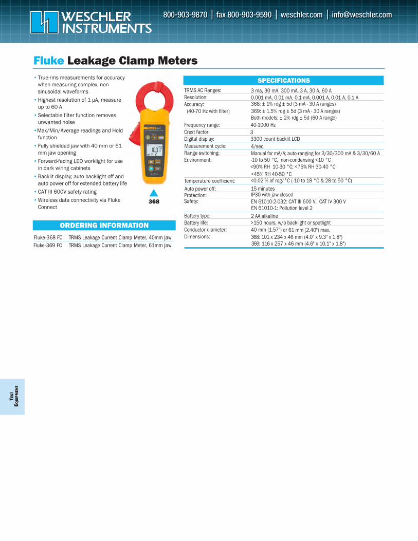
TEST
EQUI
PMEN
T
TRMS AC Ranges: 3 ma, 30 mA, 300 mA, 3 A, 30 A, 60 AResolution: 0.001 mA, 0.01 mA, 0.1 mA, 0.001 A, 0.01 A, 0.1 A Accuracy: 368: ± 1% rdg ± 5d (3 mA - 30 A ranges)
(40-70 Hz with filter)Both models: ± 2% rdg ± 5d (60 A range)
Frequency range: 40-1000 HzCrest factor: 3Digital display: 3300 count backlit LCD Measurement cycle: 4/sec.Range switching: Manual for mA/A; auto-ranging for 3/30/300 mA & 3/30/60 AEnvironment: -10 to 50 °C, non-condensing <10 °C
Temperature coefficient: <0.02 % of rdg/°C (-10 to 18 °C & 28 to 50 °C)
<90% RH 10-30 °C; <75% RH 30-40 °C
Protection: IP30 with jaw closedSafety: EN 61010-2-032: CAT III 600 V, CAT IV 300 V
Battery type: 2 AA alkaline Battery life: >150 hours, w/o backlight or spotlightConductor diameter: 40 mm (1.57") or 61 mm (2.40") max.Dimensions: 368: 101 x 234 x 46 mm (4.0" x 9.3" x 1.8")
Fluke Leakage Clamp Meters
ORDERING INFORMATION
368
SPECIFICATIONS
Fluke-369 FC TRMS Leakage Current Clamp Meter, 61mm jaw
• True-rms measurements for accuracywhen measuring complex, non-sinusoidal waveforms
• Highest resolution of 1 μA, measure up to 60 A
• Selectable filter function removesunwanted noise
•Max/Min/Average readings and Holdfunction
• Fully shielded jaw with 40 mm or 61mm jaw opening
• Forward-facing LED worklight for usein dark wiring cabinets
• Backlit display; auto backlight off and auto power off for extended battery life
• CAT III 600V safety rating• Wireless data connectivity via Fluke
Connect
Fluke-368 FC TRMS Leakage Current Clamp Meter, 40mm jaw369: 116 x 257 x 46 mm (4.6" x 10.1" x 1.8")
Auto power off: 15 minutes
<45% RH 40-50 °C
EN 61010-1: Pollution level 2
369: ± 1.5% rdg ± 5d (3 mA - 30 A ranges)
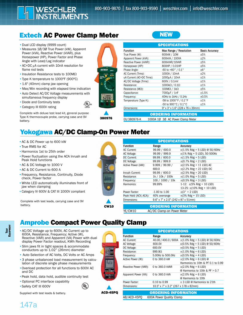
TEST
EQUI
PMEN
T
147a
FFuunnccttiioonn MMaaxx RRaannggee // RReessoolluuttiioonn BBaassiicc AAccccuurraaccyyTrue Power (W): 600kW / 10W ±5%Apparent Power (kVA): 600kVA / 100VA ±2%Reactive Power (kVAR): 600kVAR/10VAR ±5%Horsepower (HP): 800HP / 0.01HP ±5%Phase Angle: -60 to +60° / 0.1° ±6°AC Current (Trms): 1000A / 10mA ±2%uA Current (AC+DC Trms): 1000μA / 10nA ±1%AC/DC Voltage (Trms): 600V / 0.1mV ±1%Resistance: 1000kΩ / 0.1Ω ±1%Resistance (MΩ): 100MΩ / 1kΩ ±5%Capacitance: 7000μF / 1nF ±1.5%Frequency: 40Hz to 1kHz / 0.1Hz ±0.5%Temperature (Type K): -58 to 1000°F / 0.1°F ±1%
-50 to 900°C / 0.1°C ±1%Dimensions: 9" x 3" x 1.6" (228 x 76 x 39mm)
Extech AC Power Clamp Meter•Dual LCD display (9999 count)•Measures 1Ø/3Ø True Power (kW), Apparent
Power (kVA), Reactive Power (kVAR), plusHorsepower (HP), Power Factor and PhaseAngle with Lead/Lag indicator
•AC+DC μA current with 10nA resolution forflame rod tests
•Insulation Resistance tests to 100MΩ•Type K temperature to 1000ºF (900ºC)•1.6" (40mm) clamp jaw opening•Max/Min recording with elapsed time indication•Auto Detect AC/DC Voltage measurements with
simultaneous frequency display•Diode and Continuity tests•Category III 600V rating
ORDERING INFORMATION
Yokogawa AC/DC Clamp-On Power Meter
Amprobe Compact Power Quality Clamp
•AC & DC Power up to 600 kW•True RMS for AC •Harmonics 1st to 25th order•Power fluctuation using the ACA Inrush and
Peak Hold functions•AC & DC Voltage to 1000 V•AC & DC Current to 600 A•Frequency, Resistance, Continuity, Diode
check, Power factor •White LED automatically illuminates front of
jaw when clamping•Category IV 600V & CAT III 1000V compliant
CW10
ACD-45PQ
SPECIFICATIONS
SPECIFICATIONSFFuunnccttiioonn RRaannggee AAccccuurraaccyyAC Current: 40.00 / 400.0 / 600A ±(1.0% Rdg + 5 LSD) @ 50/60HzAC Voltage: 600.0V ±(0.5% Rdg + 5 LSD) @ 50/60HzDC Voltage: 600.0V ±(0.5% Rdg + 5 LSD)Resistance: 999.9Ω ±(1.0% Rdg + 6 LSD)Frequency: 5.00Hz to 500.0Hz ±(0.5% Rdg + 4 LSD)Active Power (W): 0 to 360.0 kW ±(2.0% Rdg + 6 LSD) @
Harmonics to 10th & PF 0.1 to 0.99Reactive Power (VAR): 0 to 360.0 kVAR ±(2.0% Rdg + 6 LSD)
@ Harmonics to 10th & PF > 0.7Apparent Power (VA): 0 to 360.0 kVA ±(2.0% Rdg + 6 LSD)
@ Harmonics to 10thPower Factor: 0.10 to 0.99 ± 3 LSD @ Harmonics to 21thDimensions: 10.5" x 7" x 3.2" (267 x 178 x 82mm)
FFuunnccttiioonn RRaannggee AAccccuurraaccyyAC Current: 99.99 / 600.0 ±(1.5% Rdg + 5 LSD) @ 50/60HzAC Voltage: 99.99 / 999.9 ±(1% Rdg + 5 LSD), 50-500HzDC Current: 99.99 / 600.0 ±(1.5% Rdg + 5 LSD)DC Voltage: 99.99 / 999.9 ±(0.7% Rdg + 2 LSD)Active Power (kW): 9.999 / 99.99 / ±(2.5% Rdg + 11 LSD) AC
600.0 ±(2.2% Rdg + 22 LSD) DCInrush Current: 99.99 / 600.0 ±(2.5% Rdg + 20 LSD)Resistance: 1k / 10k / 100k ±(1.0% Rdg + 5 LSD)Frequency: 100 / 1000 / 10k ±(0.5% Rdg + 3 LSD)Harmonics: 99.99% 1-12: ±(5% Rdg + 10 LSD)
13-25: ±(10% Rdg + 10 LSD)Power Factor: -1.00 to 1.00 ±(3° + 2 LSD)Peak Hold (ACV, ACA): 40% overrange ±(3% Rdg + 15 LSD) Dimensions: 9.6" x 7" x 2.0" (242 x 87 x 51mm)
AB/ACD-45PQ 600A Power Quality Clamp
•AC/DC Voltage up to 600V, AC Current up to600A, Resistance, Frequency; Active (W),Reactive (VAR) and Apparent (VA) Power with dualdisplay Power Factor readout, KWh Recording
•Slim jaws fit in tight spaces & accommodateconductors up to 1.02” (26mm) diameter
• Auto Selection of AC Volts, DC Volts or AC Amps•3 phase unbalanced load measurement by calcu-
lation of discrete single phase measurements•Overload protection for all functions to 600V AC
and DC•Peak hold, data hold, audible continuity test•Optional PC interface capability•Safety CAT III 600V
ORDERING INFORMATION
YE/CW10 AC/DC Clamp-on Power Meter ORDERING INFORMATION
380976
SPECIFICATIONS
EX/380976-K 1000A 1Ø 3Ø AC Power Clamp Meter
NEW
Complete with deluxe test lead kit, general purposeType K thermocouple probe, carrying case and 9Vbattery.
Complete with test leads, carrying case and 9Vbattery.
Supplied with test leads & battery.
®
®
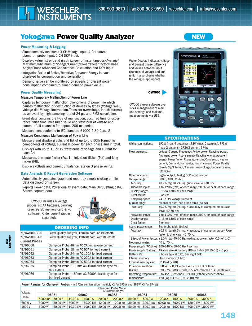
SPECIFICATIONSWiring connections: 1P2W (max. 4 systems), 1P3W (max. 2 systems), 3P3W
(max. 2 systems), 3P3W3 current, 3P4WMeasurements: Voltage, Current, Frequency, Active power, Reactive power,
Apparent power, Active energy, Reactive energy, Apparent energy, Power factor, Phase Advancing Condensor, Neutral current, Demand, Harmonics, Inrush current, Power Quality(Swell/Dip/Interrupt/Transient overvoltage, Unbalance rate,IEC flicker
Other functions: Digital output, Analog DCV input functionVoltage range: 600.0/1000 V RMS
Accuracy: ±0.2% rdg ±0.2% rng. (sine wave, 40-70 Hz)Allowable input: 1 to 120% (rms) of each range, 200% for peak of each rangeDisplay range: 0.15 to 130% of each rangeCrest factor: 3 or lessSampling speed 24 μs for voltage transient
Current range: manual or auto, see probe table (below)Accuracy: ±0.2% rdg ±0.2% rng. + accuracy of clamp-on probe (sine
wave, 40-70 Hz)Allowable input: 1 to 110% (rms) of each range, 200% for peak of each rangeDisplay range: 0.15 to 130% of each rangeCrest factor: 3 or less
Active power range: See probe table (below)Accuracy: ±0.3% rdg ±0.2% rng. + accuracy of clamp-on probe (Power
factor 1, sine wave, 40-70 Hz)Effect of Power Factor: ±1.0% rdg (40-70 Hz, reading at power factor 0.5 ref. 1.0)
Frequency meter: 40 to 70 HzPower supply (AC Line): 100-240 V/50-60 Hz/7 VA max.Power supply (Battery): Alkaline size AA battery LR6 or Ni-Mh (HR15-51) × 6 pcsBattery life: 3 hours typical (LR6, Backlight OFF)Internal memory: Flash memory (4 MB)External memory card: SD Card (2 GB)PC communication: USB Ver. 2.0, Bluetooth Ver. 2.1 + EDR Class2Display: 320 × 240 (RGB) Pixel, 3.5 inch color TFT, 1 s update rateOperating temperature: 0 to 45°C, less than 85% RH (without condensation)Dimensions: 120 (W) × 175 (H) × 68 (D) mm
T EST
EQUI
PMEN
T
148
PPoowweerr MMeeaassuurriinngg && LLooggggiinngg•• Simultaneously measures 3 CH Voltage input, 4 CH current clamp-on probe input, 2 CH DCV input.
•• Displays value list or trend graph screen of Instantaneous/Average/ Maximum/Minimum of Voltage/Current/Power/Power factor/Phase Angle/Phase Advanced Capacitance Calculation and DCV input.
•• Integration Value of Active/Reactive/Apparent Energy is each displayed by consumption and generation.
•• Demand value can be monitored by screens of present power consumption compared to aimed demand power value.
PPoowweerr QQuuaalliittyy MMeeaassuurriinnggMMeeaassuurree TTeemmppoorraarryy MMaallffuunnccttiioonn ooff PPoowweerr LLiinnee•• Captures temporary malfunction phenomena of power line which causes malfunction or destruction of devices by types (Voltage swell,Voltage dip, Voltage interruption, Transient overvoltage, Inrush current) as an event by high sampling rate of 24 μs and RMS calculation.
•• Event data contains the type of malfunction, occurred time or occur-rence finish time, measured value and waveform of voltage and current of all channels for approx. 200 ms period.
•• Measurement conforms to IEC standard 61000-4-30 Class SMMeeaassuurree CCoonnttiinnuuoouuss MMaallffuunnccttiioonn ooff PPoowweerr LLiinnee•• Measure and display graphs and list of up to the 50th Harmonic components of voltage, current & power for each phase and in total.
•• Displays with up to 10 or 12 waveforms of voltage and current for each CH.
•• Measures, 1 minute flicker (Pst, 1 min), short flicker (Pst) and long flicker (Plt).
•• Displays voltage and current unbalance rate on 3 phase wiring.
DDaattaa AAnnaallyyssiiss && RReeppoorrtt GGeenneerraattiioonn SSooffttwwaarree•• Automatically generates graph and report by simply clicking on file data displayed on screen.
•• Reports Power data, Power quality event data, Main Unit Setting data,Screen capture data.
Yokogawa Power Quality Analyzer
ORDERING INFO
CW500
NEW
YE/CW500-B0-D Power Quality Analyzer, 120VAC cord, no BluetoothYE/CW500-B1-D Power Quality Analyzer, 120VAC cord, with BluetoothCCuurrrreenntt PPrroobbeessYE/96060 Clamp-on Probe 40mm AC 2A for leakage current YE/96061 Clamp-on Probe 18mm AC 50A for load current YE/96062 Clamp-on Probe 24mm AC 100A for load current YE/96063 Clamp-on Probe 30mm AC 200A for load current YE/96064 Clamp-on Probe 40mm AC 500A for load current YE/96065 Clamp-on Probe ~110mm AC 1000A flexible type for
load currentYE/96066 Clamp-on Probe ~150mm AC 3000A flexible type for
3ch load current
CW500 includes 4 voltageprobes, six AA batteries, carryingcase, 2G SD memory card & PCsoftware. Order current probes
separately.
PPoowweerr RRaannggeess ffoorr CCllaammpp--oonn PPrroobbeess - in 1P2W configuration (multiply x2 for 1P3W and 3P3W, x3 for 3P4W)Clamp-on Probe Model
& Current ranges9966006611 9966006622 9966006633 9966006644 9966006655 9966006666
5000 mA 50.00 A 10.00 A 100.0 A 20.00 A 200.0 A 50.00 A 500.0 A 100.0 A 1000 A 300.0 A 3000 A600.0 V 3000 W 30.00 kW 6000 W 60.00 kW 12.00 kW 120.0 kW 30.00 kW 300.0 kW 60.00 kW 600.0 kW 180.0 kW 1800 kW1000 V 5000 W 50.00 kW 10.00 kW 100.0 kW 20.00 kW 200.0 kW 50.00 kW 500.0 kW 100.0 kW 1000 kW 300.0 kW 3000 kW
Voltagerange:
Vector Display indicates voltageand current phase differenceand values between inputchannels of voltage and cur-rent. It also checks whetherthe wiring is appropriate.
CW500 Viewer software pro-vides management of mainunit settings and realtimemeasurements via USB.
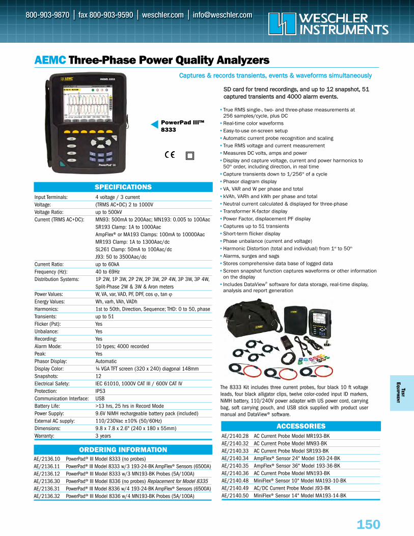
Input Terminals: 4 voltage / 3 currentVoltage: (TRMS AC+DC) 2 to 1000VVoltage Ratio: up to 500kVCurrent (TRMS AC+DC): MN93: 500mA to 200Aac; MN193: 0.005 to 100Aac
SR193 Clamp: 1A to 1000AacAmpFlex® or MA193 Clamps: 100mA to 10000AacMR193 Clamp: 1A to 1300Aac/dcSL261 Clamp: 50mA to 100Aac/dcJ93: 50 to 3500Aac/dc
Current Ratio: up to 60kAFrequency (Hz): 40 to 69HzDistribution Systems: 1P 2W, 1P 3W, 2P 2W, 2P 3W, 2P 4W, 3P 3W, 3P 4W,
Split-Phase 2W & 3W & Aron metersPower Values: W, VA, var, VAD, PF, DPF, cos ϕ, tan ϕEnergy Values: Wh, varh, VAh, VADhHarmonics: 1st to 50th, Direction, Sequence; THD: 0 to 50, phaseTransients: up to 51Flicker (Pst): YesUnbalance: YesRecording: YesAlarm Mode: 10 types; 4000 recordedPeak: YesPhasor Display: AutomaticDisplay Color: ¼ VGA TFT screen (320 x 240) diagonal 148mmSnapshots: 12Electrical Safety: IEC 61010, 1000V CAT III / 600V CAT IVProtection: IP53Communication Interface: USBBattery Life: >13 hrs, 25 hrs in Record ModePower Supply: 9.6V NiMH rechargeable battery pack (included)External AC supply: 110/230Vac ±10% (50/60Hz)Dimensions: 9.8 x 7.8 x 2.6" (240 x 180 x 55mm) Warranty: 3 years
TESTE
QUIPM
ENT
150
AEMC Three-Phase Power Quality Analyzers
PowerPad III™8333
ORDERING INFORMATION
ACCESSORIES
AE/2136.10 PowerPad® III Model 8333 (no probes)AE/2136.11 PowerPad® III Model 8333 w/3 193-24-BK AmpFlex® Sensors (6500A)AE/2136.12 PowerPad® III Model 8333 w/3 MN193-BK Probes (5A/100A)AE/2136.30 PowerPad® III Model 8336 (no probes) Replacement for Model 8335AE/2136.31 PowerPad® III Model 8336 w/4 193-24-BK AmpFlex® Sensors (6500A)AE/2136.32 PowerPad® III Model 8336 w/4 MN193-BK Probes (5A/100A)
•True RMS single-, two- and three-phase measurements at 256 samples/cycle, plus DC
•Real-time color waveforms•Easy-to-use on-screen setup•Automatic current probe recognition and scaling•True RMS voltage and current measurement•Measures DC volts, amps and power•Display and capture voltage, current and power harmonics to
50th order, including direction, in real time•Capture transients down to 1/256th of a cycle•Phasor diagram display•VA, VAR and W per phase and total•kVAh, VARh and kWh per phase and total•Neutral current calculated & displayed for three-phase•Transformer K-factor display•Power Factor, displacement PF display•Captures up to 51 transients•Short-term flicker display•Phase unbalance (current and voltage)•Harmonic Distortion (total and individual) from 1st to 50th
•Alarms, surges and sags•Stores comprehensive data base of logged data •Screen snapshot function captures waveforms or other information
on the display•Includes DataView® software for data storage, real-time display,
analysis and report generation
The 8333 Kit includes three current probes, four black 10 ft voltageleads, four black alligator clips, twelve color-coded input ID markers,NiMH battery, 110/240V power adapter with US power cord, carryingbag, soft carrying pouch, and USB stick supplied with product usermanual and DataView® software.
SPECIFICATIONS
AE/2140.28 AC Current Probe Model MR193-BKAE/2140.32 AC Current Probe Model MN93-BKAE/2140.33 AC Current Probe Model SR193-BKAE/2140.34 AmpFlex® Sensor 24" Model 193-24-BKAE/2140.35 AmpFlex® Sensor 36" Model 193-36-BKAE/2140.36 AC Current Probe Model MN193-BKAE/2140.48 MiniFlex® Sensor 10" Model MA193-10-BKAE/2140.49 AC/DC Current Probe Model J93-BKAE/2140.50 MiniFlex® Sensor 14" Model MA193-14-BK
CCaappttuurreess && rreeccoorrddss ttrraannssiieennttss,, eevveennttss && wwaavveeffoorrmmss ssiimmuullttaanneeoouussllyy
SSDD ccaarrdd ffoorr ttrreenndd rreeccoorrddiinnggss,, aanndd uupp ttoo 1122 ssnnaappsshhoott,, 5511ccaappttuurreedd ttrraannssiieennttss aanndd 44000000 aallaarrmm eevveennttss..
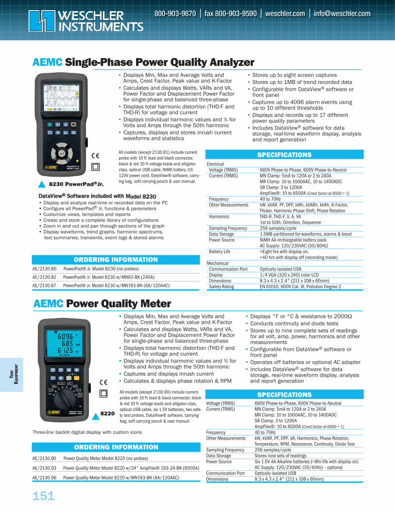
TEST
EQU
IPM
ENT
151
AEMC Single-Phase Power Quality Analyzer
AEMC Power Quality Meter
8230 PowerPad®Jr.
ORDERING INFORMATION
ORDERING INFORMATION
AE/2130.80 PowerPad® Jr. Model 8230 (no probes)
AE/2130.82 PowerPad® Jr. Model 8230 w/MN93-BK (240A)
AE/2130.87 PowerPad® Jr. Model 8230 w/MN193-BK (6A/120AAC)
AE/2130.90 Power Quality Meter Model 8220 (no probes)
AE/2130.93 Power Quality Meter Model 8220 w/24" AmpFlex® 193-24-BK (6500A)
AE/2130.96 Power Quality Meter Model 8220 w/MN193-BK (6A/120AAC)
ElectricalVoltage (TRMS) 660V Phase-to-Phase, 600V Phase-to-NeutralCurrent (TRMS) MN Clamp: 5mA to 120A or 2 to 240A
MR Clamp: 10 to 1000AAC, 10 to 1400ADCSR Clamp: 3 to 1200AAmpFlex®: 10 to 6500A (Crest factor at 6500 = 1)
Frequency 40 to 70HzOther Measurements kW, kVAR, PF, DPF, kWh, kVARh, kVAh, K-Factor,
Flicker, Harmonic Phase Shift, Phase RotationHarmonics THD-R, THD-F, V, A, VA
1st to 50th, Direction, SequenceSampling Frequency 256 samples/cycleData Storage 1.5MB partitioned for waveforms, alarms & trend Power Source NiMH AA rechargeable battery pack
AC Supply: 120/230VAC (50/60Hz)Battery Life >Eight hrs with display on,
>40 hrs with display off (recording mode)Mechanical
Communication Port Optically isolated USBDisplay 1/4 VGA (320 x 240) color LCDDimensions 8.3 x 4.3 x 2.4" (211 x 108 x 60mm)Safety Rating EN 61010, 600V Cat. III, Pollution Degree 2
Voltage (TRMS) 660V Phase-to-Phase, 600V Phase-to-NeutralCurrent (TRMS) MN Clamp: 5mA to 120A or 2 to 240A
MR Clamp: 10 to 1000AAC, 10 to 1400ADCSR Clamp: 3 to 1200AAmpFlex®: 10 to 6500A (Crest factor at 6500 = 1)
Frequency 40 to 70HzOther Measurements kW, kVAR, PF, DPF, VA, Harmonics, Phase Rotation,
Temperature, RPM, Resistance, Continuity, Diode TestSampling Frequency 256 samples/cycleData Storage Stores nine sets of readings Power Source Six 1.5V AA Alkaline batteries (>8hr life with display on)
AC Supply: 120/230VAC (50/60Hz) – optionalCommunication Port Optically isolated USB Dimensions 8.3 x 4.3 x 2.4" (211 x 108 x 60mm)
• Displays Min, Max and Average Volts andAmps, Crest Factor, Peak value and K-Factor
• Calculates and displays Watts, VARs and VA,Power Factor and Displacement Power Factorfor single-phase and balanced three-phase
• Displays total harmonic distortion (THD-F andTHD-R) for voltage and current
• Displays individual harmonic values and % forVolts and Amps through the 50th harmonic
• Captures, displays and stores inrush currentwaveforms and statistics
• Stores up to eight screen captures• Stores up to 1MB of trend recorded data• Configurable from DataView® software or
front panel• Captures up to 4096 alarm events using
up to 10 different thresholds• Displays and records up to 17 different
power quality parameters• Includes DataView® software for data
storage, real-time waveform display, analysis and report generation
• Displays Min, Max and Average Volts andAmps, Crest Factor, Peak value and K-Factor
• Calculates and displays Watts, VARs and VA,Power Factor and Displacement Power Factorfor single-phase and balanced three-phase
• Displays total harmonic distortion (THD-F andTHD-R) for voltage and current
• Displays individual harmonic values and % forVolts and Amps through the 50th harmonic
• Captures and displays inrush current• Calculates & displays phase rotation & RPM
• Displays °F or °C & resistance to 2000Ω• Conducts continuity and diode tests• Stores up to nine complete sets of readings
for all volt, amp, power, harmonics and othermeasurements
• Configurable from DataView® software orfront panel
• Operates off batteries or optional AC adapter • Includes DataView® software for data
storage, real-time waveform display, analysis and report generation
8220
All models (except 2130.81) include current probe with 10 ft lead and black connector, black & red 10 ft voltage leads and alligator clips, optical USB cable, NiMH battery, US 120V power cord, DataView® software, carry-ing bag, soft carrying pouch & user manual.
All models (except 2130.90) include current probe with 10 ft lead & black connector, black & red 10 ft voltage leads and alligator clips, optical USB cable, six 1.5V batteries, two safe-ty test probes, DataView® software, carryingbag, soft carrying pouch & user manual.
SPECIFICATIONS
SPECIFICATIONS
DDaattaaVViieeww®® SSooffttwwaarree iinncclluuddeedd wwiitthh MMooddeell 88223300• Display and analyze real-time or recorded data on the PC• Configure all PowerPad® Jr. functions & parameters• Customize views, templates and reports• Create and store a complete library of configurations • Zoom in and out and pan through sections of the graph• Display waveforms, trend graphs, harmonic spectrums,
text summaries, transients, event logs & stored alarms
Three-line backlit digital display with custom icons
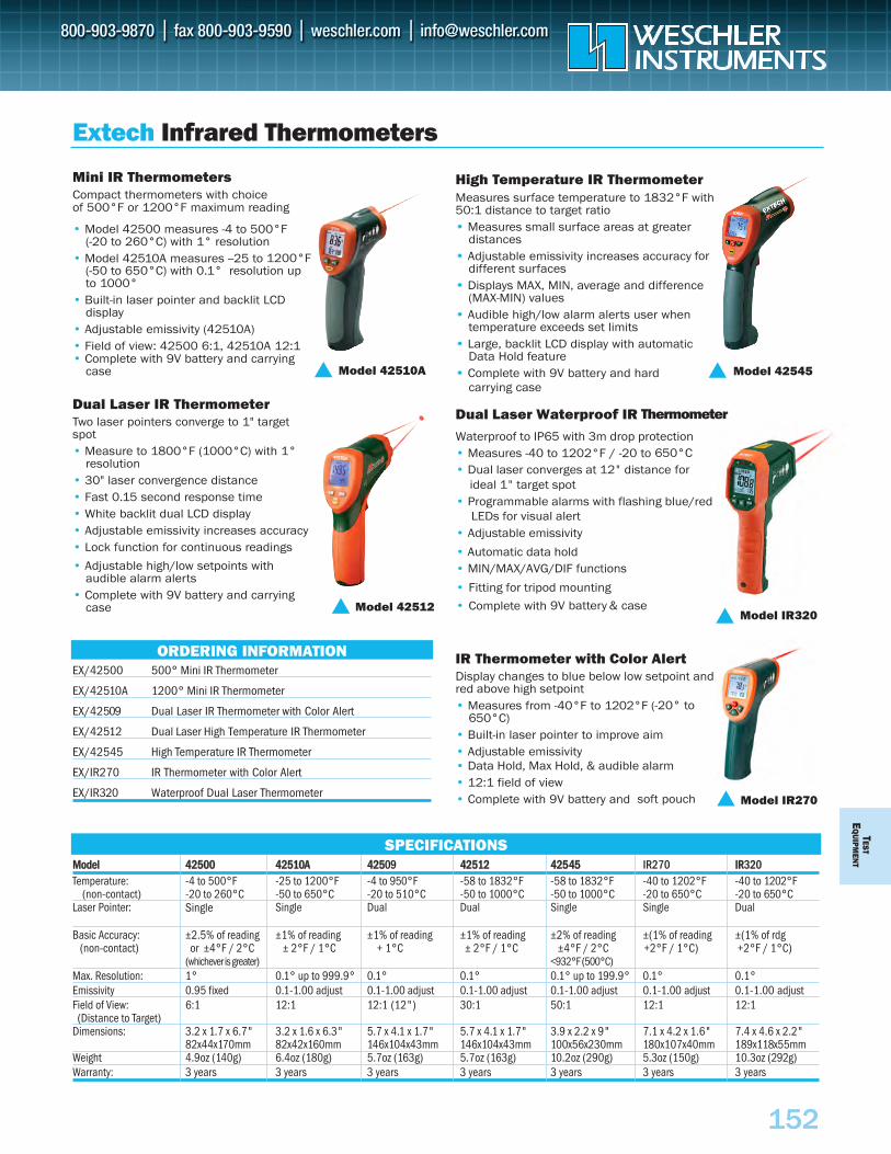
TESTE
QU
IPMEN
T
152
MMooddeell 4422550000 4422551100AA 44225509 4422551122 4422554455 IR270 IIRR320Temperature: -4 to 500°F -25 to 1200°F -4 to 950°F -58 to 1832°F -58 to 1832°F -40 to 1202°F -40 to 1202°F
(non-contact) -20 to 260°C -50 to 650°C -20 to 510°C -50 to 1000°C -50 to 1000°C -20 to 650°C -20 to 650°CLaser Pointer: Single Dual Dual Single Single Dual
Basic Accuracy: ±2.5% of reading ±1% of reading ±1% of reading ±1% of reading ±2% of reading ±(1% of reading ±(1% of rdg(non-contact) or ±4°F / 2°C ± 2°F / 1°C + 1°C ± 2°F / 1°C ±4°F / 2°C +2°F / 1°C) +2°F / 1°C)
(whichever is greater) <932°F (500°C)Max. Resolution: 1° 0.1° up to 999.9° 0.1° 0.1° 0.1° up to 199.9° 0.1° 0.1°Emissivity 0.95 fixed 0.1-1.00 adjust 0.1-1.00 adjust 0.1-1.00 adjust 0.1-1.00 adjust 0.1-1.00 adjust 0.1-1.00 adjustField of View: 6:1 12:1 12:1 (12") 30:1 50:1 12:1 12:1
(Distance to Target)Dimensions: 3.2 x 1.7 x 6.7" 3.2 x 1.6 x 6.3" 5.7 x 4.1 x 1.7" 5.7 x 4.1 x 1.7" 3.9 x 2.2 x 9" 7.1 x 4.2 x 1.6" 7.4 x 4.6 x 2.2"
82x44x170mm 82x42x160mm 146x104x43mm 146x104x43mm 100x56x230mm 180x107x40mm 189x118x55mmWeight 4.9oz (140g) 6.4oz (180g) 5.7oz (163g) 5.7oz (163g) 10.2oz (290g) 5.3oz (150g) 10.3oz (292g)Warranty: 3 years 3 years 3 years 3 years 3 years 3 years 3 years
Mini IR ThermometersCompact thermometers with choice of 500°F or 1200°F maximum reading
• Model 42500 measures -4 to 500°F(-20 to 260°C) with 1° resolution
• Model 42510A measures --25 to 1200°F (-50 to 650°C) with 0.1° resolution up to 1000°
• Built-in laser pointer and backlit LCDdisplay
• Adjustable emissivity (42510A)• Field of view: 42500 6:1, 42510A 12:1• Complete with 9V battery and carrying
case
Dual Laser IR ThermometerTwo laser pointers converge to 1" targetspot• Measure to 1800°F (1000°C) with 1°
resolution• 30" laser convergence distance• Fast 0.15 second response time• White backlit dual LCD display• Adjustable emissivity increases accuracy• Lock function for continuous readings
• Adjustable high/low setpoints withaudible alarm alerts
• Complete with 9V battery and carryingcase
•
•
•
•
•
•
High Temperature IR ThermometerMeasures surface temperature to 1832°F with 50:1 distance to target ratio• Measures small surface areas at greater
distances• Adjustable emissivity increases accuracy for
different surfaces• Displays MAX, MIN, average and difference
(MAX-MIN) values • Audible high/low alarm alerts user when
temperature exceeds set limits• Large, backlit LCD display with automatic
Data Hold feature• Complete with 9V battery and hard
carrying case
Dual Laser Waterproof IR
Waterproof to IP65 with 3m drop protection• Measures -40 to 1202°F / -20 to 650°C• Dual laser converges at 12" distance for
ideal 1" target spot• Programmable alarms with flashing blue/red
LEDs for visual alert• Adjustable emissivity
• Automatic data hold• MIN/MAX/AVG/DIF functions
• Fitting for tripod mounting
• Complete with 9V battery & case
IR Thermometer with Color AlertDisplay changes to blue below low setpoint andred above high setpoint• Measures from -40°F to 1202°F (-20° to
650°C)• Built-in laser pointer to improve aim• Adjustable emissivity • Data Hold, Max Hold, & audible alarm• 12:1 field of view• Complete with 9V battery and soft pouch
Extech Infrared Thermometers
ORDERING INFORMATION
SPECIFICATIONS
EX/42500 500° Mini IR Thermometer
EX/42510A 1200° Mini IR Thermometer
EX/42509 Dual Laser IR Thermometer with Color Alert
EX/42512 Dual Laser High Temperature IR Thermometer
EX/42545 High Temperature IR Thermometer
EX/IR270 IR Thermometer with Color Alert
EX/IR320 Waterproof Dual Laser Thermometer
Model 42510A
Model 42512
Model 42545
Model IR270
Model IR320
Single
Thermometer
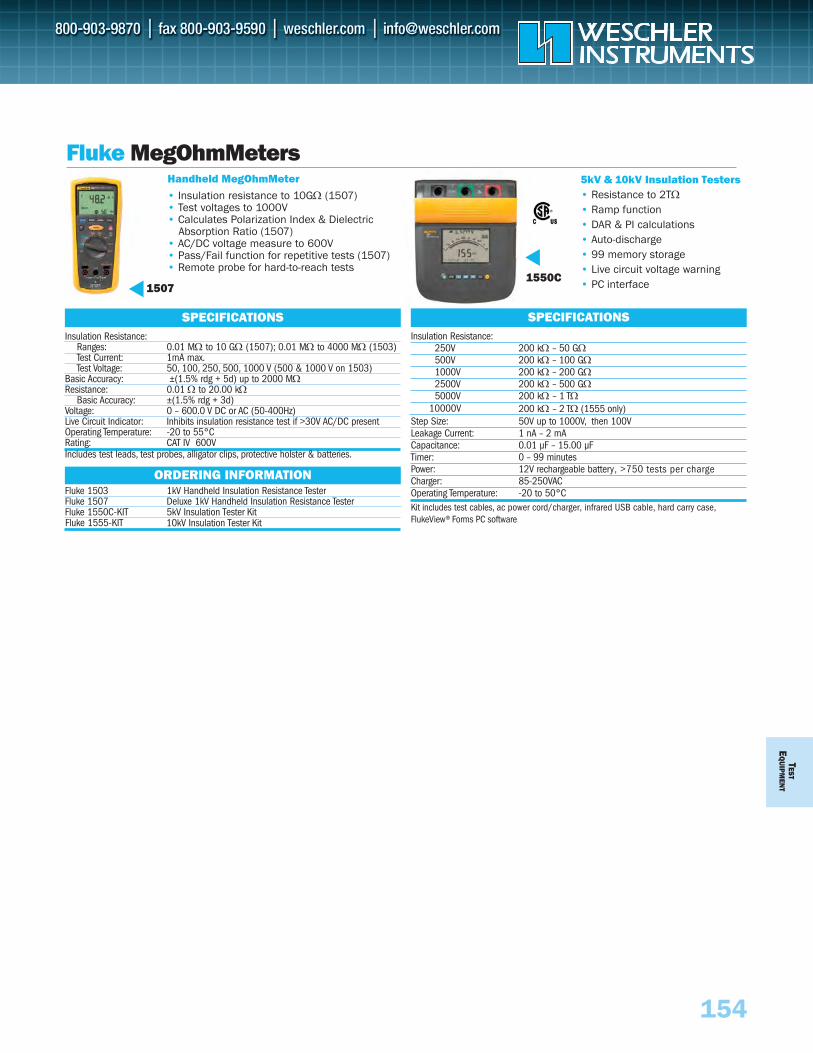
TESTE
QUIPM
ENT
154
Fluke MegOhmMeters
Insulation Resistance:250V 200 kΩ – 50 GΩ500V 200 kΩ – 100 GΩ1000V 200 kΩ – 200 GΩ2500V 200 kΩ – 500 GΩ5000V 200 kΩ – 1 TΩ
200 kΩ – 2 TΩ (1555 only) Step Size: 50V up to 1000V, then 100VLeakage Current: 1 nA – 2 mACapacitance: 0.01 μF – 15.00 μFTimer: 0 – 99 minutesPower: 12V rechargeable battery, >750 tests per chargeCharger: 85-250VACOperating Temperature: -20 to 50°CKit includes test cables, ac power cord/charger, infrared USB cable, hard carry case,FlukeView® Forms PC software
Handheld MegOhmMeter
1507
Insulation Resistance:Ranges: 0.01 MΩ to 10 GΩ (1507); 0.01 MΩ to 4000 MΩ (1503)Test Current: 1mA max.Test Voltage: 50, 100, 250, 500, 1000 V (500 & 1000 V on 1503)
Basic Accuracy: ±(1.5% rdg + 5d) up to 2000 MΩResistance: 0.01 Ω to 20.00 kΩ
Basic Accuracy: ±(1.5% rdg + 3d)Voltage: 0 – 600.0 V DC or AC (50-400Hz)Live Circuit Indicator: Inhibits insulation resistance test if >30V AC/DC presentOperating Temperature: -20 to 55°CRating: CAT IV 600VIncludes test leads, test probes, alligator clips, protective holster & batteries.
SPECIFICATIONS
Fluke 1503 1kV Handheld Insulation Resistance TesterFluke 1507 Deluxe 1kV Handheld Insulation Resistance TesterFluke 1550C-KIT 5kV Insulation Tester Kit
ORDERING INFORMATION
5kV & 10kV Insulation Testers• Resistance to 2TΩ• Ramp function• DAR & PI calculations• Auto-discharge• 99 memory storage• Live circuit voltage warning• PC interface
• Insulation resistance to 10GΩ (1507)• Test voltages to 1000V• Calculates Polarization Index & Dielectric
Absorption Ratio (1507)• AC/DC voltage measure to 600V• Pass/Fail function for repetitive tests (1507)• Remote probe for hard-to-reach tests
1550C
10000V
SPECIFICATIONS
10kV Insulation Tester KitFluke 1555-KIT
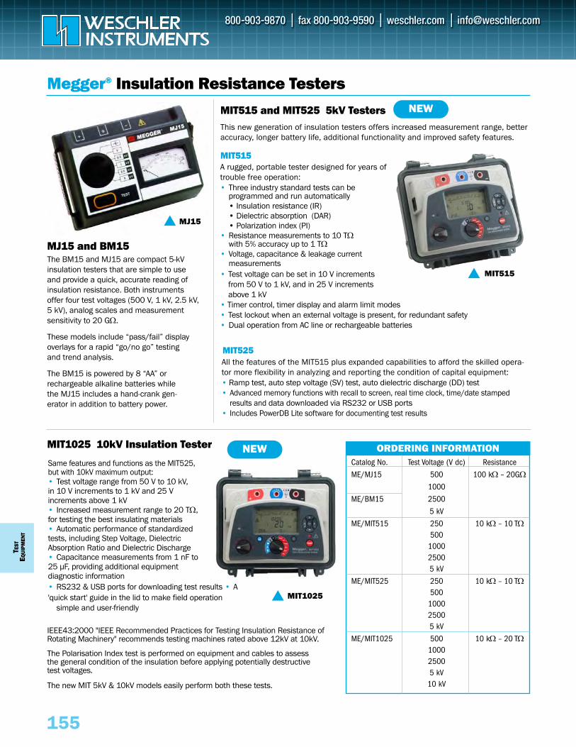
TEST
EQUI
PMEN
T
155
This new generation of insulation testers offers increased measurement range, betteraccuracy, longer battery life, additional functionality and improved safety features.
MIT515 and MIT525 5kV Testers
MIT515
Megger® Insulation Resistance Testers
MJ15 and BM15The BM15 and MJ15 are compact 5-kV insulation testers that are simple to useand provide a quick, accurate reading ofinsulation resistance. Both instrumentsoffer four test voltages (500 V, 1 kV, 2.5 kV,5 kV), analog scales and measurementsensitivity to 20 GΩ.
These models include “pass/fail” display overlays for a rapid “go/no go” testing and trend analysis.
The BM15 is powered by 8 “AA” or rechargeable alkaline batteries while the MJ15 includes a hand-crank gen-erator in addition to battery power.
MJ15
MIT1025
Catalog No. Test Voltage (V dc) Resistance
ME/MJ15 500 100 kΩ – 20GΩ1000
ME/BM15 2500
5 kV
ME/MIT515 250 10 kΩ – 10 TΩ500
100025005 kV
ME/MIT525 250 10 kΩ – 10 TΩ500
100025005 kV
ME/MIT1025 500 10 kΩ – 20 TΩ100025005 kV
10 kV
ORDERING INFORMATION
A rugged, portable tester designed for years oftrouble free operation:• Three industry standard tests can be
programmed and run automatically• Insulation resistance (IR)• Dielectric absorption (DAR)• Polarization index (PI)
• Resistance measurements to 10 TΩwith 5% accuracy up to 1 TΩ
• Voltage, capacitance & leakage currentmeasurements
• Test voltage can be set in 10 V incrementsfrom 50 V to 1 kV, and in 25 V incrementsabove 1 kV
• Timer control, timer display and alarm limit modes• Test lockout when an external voltage is present, for redundant safety• Dual operation from AC line or rechargeable batteries
MIT1025 10kV Insulation Tester NEW
IEEE43:2000 "IEEE Recommended Practices for Testing Insulation Resistance of Rotating Machinery" recommends testing machines rated above 12kV at 10kV.
The Polarisation Index test is performed on equipment and cables to assess the general condition of the insulation before applying potentially destructive test voltages.
The new MIT 5kV & 10kV models easily perform both these tests.
MIT525All the features of the MIT515 plus expanded capabilities to afford the skilled opera-tor more flexibility in analyzing and reporting the condition of capital equipment:• Ramp test, auto step voltage (SV) test, auto dielectric discharge (DD) test • Advanced memory functions with recall to screen, real time clock, time/date stamped
results and data downloaded via RS232 or USB ports• Includes PowerDB Lite software for documenting test results
MIT515
Same features and functions as the MIT525, but with 10kV maximum output:• Test voltage range from 50 V to 10 kV, in 10 V increments to 1 kV and 25 V increments above 1 kV• Increased measurement range to 20 TΩ, for testing the best insulating materials• Automatic performance of standardized tests, including Step Voltage, Dielectric Absorption Ratio and Dielectric Discharge• Capacitance measurements from 1 nF to 25 μF, providing additional equipment diagnostic information• RS232 & USB ports for downloading test results • A 'quick start' guide in the lid to make field operation
simple and user-friendly
NEW
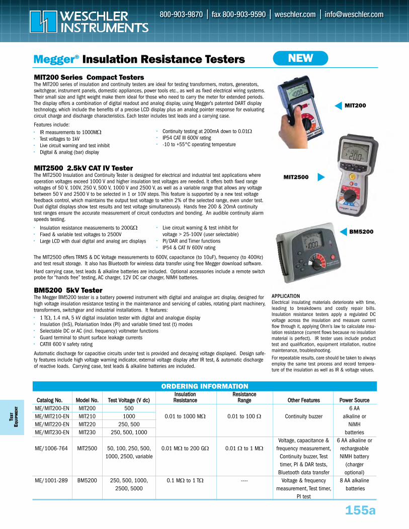
TEST
EQUI
PMEN
T
IInnssuullaattiioonn RReessiissttaanncceeCCaattaalloogg NNoo.. MMooddeell NNoo.. TTeesstt VVoollttaaggee ((VV ddcc)) RReessiissttaannccee RRaannggee OOtthheerr FFeeaattuurreess PPoowweerr SSoouurrccee
ME/MIT200-EN MIT200 500 6 AA ME/MIT210-EN MIT210 1000 0.01 to 1000 MΩ 0.01 to 100 Ω Continuity buzzer alkaline or ME/MIT220-EN MIT220 250, 500 NiMH ME/MIT230-EN MIT230 250, 500, 1000 batteries
Voltage, capacitance & 6 AA alkaline orME/1006-764 MIT2500 50, 100, 250, 500, 0.01 MΩ to 200 GΩ 0.01 Ω to 1 MΩ frequency measurement, rechargeable
1000, 2500, variable Continuity buzzer, Test NIMH batterytimer, PI & DAR tests, (charger
Bluetooth data transfer optional)ME/1001-289 BM5200 250, 500, 1000, 0.1 MΩ to 1 TΩ ---- Voltage & frequency 8 AA alkaline
2500, 5000 measurement, Test timer, batteriesPI test
MIT200 Series Compact TestersThe MIT200 series of insulation and continuity testers are ideal for testing transformers, motors, generators,switchgear, instrument panels, domestic appliances, power tools etc., as well as fixed electrical wiring systems.Their small size and light weight make them ideal for those who need to carry the meter for extended periods.The display offers a combination of digital readout and analog display, using Megger’s patented DART displaytechnology, which include the benefits of a precise LCD display plus an analog pointer response for evaluatingcircuit charge and discharge characteristics. Each tester includes test leads and a carrying case.
Features include:•• IR measurements to 1000MΩ•• Test voltages to 1kV •• Live circuit warning and test inhibit•• Digital & analog (bar) display
MIT2500 2.5kV CAT IV Tester The MIT2500 Insulation and Continuity Tester is designed for electrical and industrial test applications whereoperation voltages exceed 1000 V and higher insulation test voltages are needed. It offers both fixed rangevoltages of 50 V, 100V, 250 V, 500 V, 1000 V and 2500 V, as well as a variable range that allows any voltagebetween 50 V and 2500 V to be selected in 1 or 10V steps. This feature is supported by a new test voltagefeedback control, which maintains the output test voltage to within 2% of the selected range, even under test.Dual digital displays show test results and test voltage simultaneously. Hands free 200 & 20mA continuitytest ranges ensure the accurate measurement of circuit conductors and bonding. An audible continuity alarmspeeds testing.
•• Insulation resistance measurements to 200GΩ•• Fixed & variable test voltages to 2500V•• Large LCD with dual digital and analog arc displays
The MIT2500 offers TRMS & DC Voltage measurements to 600V, capacitance (to 10uF), frequency (to 400Hz)and test result storage. It also has Bluetooth for wireless data transfer using free Megger download software.Hard carrying case, test leads & alkaline batteries are included. Optional accessories include a remote switchprobe for “hands free” testing, AC charger, 12V DC car charger, NIMH batteries.
BM5200 5kV TesterThe Megger BM5200 tester is a battery powered instrument with digital and analogue arc display, designed forhigh voltage insulation resistance testing in the maintenance and servicing of cables, rotating plant machinery,transformers, switchgear and industrial installations. It features:•• 1 TΩ, 1.4 mA, 5 kV digital insulation tester with digital and analogue display•• Insulation (InS), Polarisation Index (PI) and variable timed test (t) modes•• Selectable DC or AC (incl. frequency) voltmeter functions•• Guard terminal to shunt surface leakage currents•• CATIII 600 V safety rating
Automatic discharge for capacitive circuits under test is provided and decaying voltage displayed. Design safe-ty features include high voltage warning indicator, external voltage display after IR test, & automatic dischargeof reactive loads. Carrying case, test leads & alkaline batteries are included.
155a
ORDERING INFORMATION
Megger® Insulation Resistance Testers
MIT200
BM5200
MIT2500
AAPPPPLLIICCAATTIIOONNElectrical insulating materials deteriorate with time,leading to breakdowns and costly repair bills.Insulation resistance testers apply a regulated DCvoltage across the insulation and measure currentflow through it, applying Ohm’s law to calculate insu-lation resistance (current flows because no insulationmaterial is perfect). IR tester uses include producttest and qualification, equipment intallation, routinemaintenance, troubleshooting.For repeatable results, care should be taken to alwaysemploy the same test process and record tempera-ture of the insulation as well as IR & voltage values.
NEW
•• Continuity testing at 200mA down to 0.01Ω•• IP54 CAT III 600V rating•• -10 to +55°C operating temperature
•• Live circuit warning & test inhibit for voltage > 25-100V (user selectable)
•• PI/DAR and Timer functions •• IP54 & CAT IV 600V rating
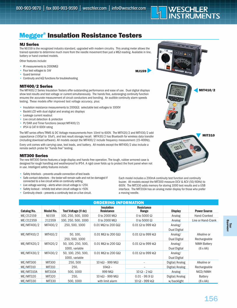
IInnssuullaattiioonn RReessiissttaanncceeCCaattaalloogg NNoo.. MMooddeell NNoo.. TTeesstt VVoollttaaggee ((VV ddcc)) RReessiissttaannccee RRaannggee DDiissppllaayy PPoowweerr SSoouurrcceeME/212159 MJ159 100, 250, 500, 1000 0 to 2000 MΩ 0 to 5000 Ω Analog Hand-CrankedME/212359 212359 100, 250, 500, 1000 0 to 2000 MΩ 0 to 5000 Ω Analog Line or Hand-CrankME/MIT400/2 MIT400/2 250, 500, 1000 0.01 MΩ to 200 GΩ 0.01 Ω to 999 kΩ Analog/
Dual DigitalME/MIT410/2 MIT410/2 50, 100, 0.01 MΩ to 200 GΩ 0.01 Ω to 999 kΩ Analog/ Alkaline or
250, 500, 1000 Dual Digital RechargeableME/MIT420/2 MIT420/2 50, 100, 250, 500, 0.01 MΩ to 200 GΩ 0.01 Ω to 999 kΩ Analog/ NIMH Battery
1000, variable Dual Digital (6 x AA)ME/MIT430/2 MIT430/2 50, 100, 250, 500, 0.01 MΩ to 200 GΩ 0.01 Ω to 999 kΩ Analog/
1000, variable Dual DigitalME/MIT300 MIT300 250, 500 10 kΩ – 999 MΩ – Digital/Analog Alkaline orME/MIT310 MIT310 250, 10kΩ – – Digital/Analog RechargeableME/MIT310A MIT310A 500, 1000 999 MΩ 10 Ω – 2 kΩ Analog NICD/NIMHME/MIT320 MIT320 250, 10 kΩ – 999 MΩ 0.01 – 99.9 Ω Digital/Analog BatteryME/MIT330 MIT330 500, 1000 with limit alarm 10 Ω – 999 kΩ w/backlight (8 x AA)
MJ SeriesThe MJ159 is the recognized industry standard, upgraded with modern circuitry. This analog meter allows thetrained operator to determine much more from the needle movement than just a MΩ reading. Available in line,battery or hand cranked models.
Other features include:
• IR measurements to 2000MΩ• Four test voltages to 1kV • Guard terminal• Continuity and kΩ functions for troubleshooting
MIT400/2 SeriesThe MIT400/2 Series Insulation Testers offer outstanding performance and ease of use. Dual digital displaysshow test results and test voltage or current simultaneously. The hands free, autoranging continuity functionensures the accurate measurement of circuit conductors and bonding. An audible continuity alarm speeds testing. These models offer improved test voltage accuracy, plus:
• Insulation resistance measurements to 200GΩ; selectable test voltages to 1000V• Backlit LCD with dual digital and analog arc displays• Leakage current readout • Live circuit detection & protecton• PI/DAR and Timer functions (except MIT400/2)• IP54 & CAT IV 600V rating
The MIT series offers TRMS & DC Voltage measurements from 10mV to 600V. The MIT420/2 and MIT430/2 add capacitance (100pf to 10uF), and test result storage/recall. MIT430/2 has Bluetooth for wireless data transfer (including download software). All models except the MIT400/2 include frequency measurement (15-400Hz).Every unit comes with carrying case, test leads, and battery. All models except the MIT400/2 also include a remote switch probe for “hands free” testing.
MIT300 SeriesThe new MIT300 Series features a large display and hands-free operation. The tough, rubber armored case isdesigned for rough handling and weatherproof to IP54. A rigid cover folds up to protect the front panel when notin use. Intelligent safety features include:
TESTE
QU
IPMEN
T
156
ORDERING INFORMATION
• Safety Interlock – prevents unsafe connection of test leads• Safe contact detectors – the tester will remain safe and not be damaged if
connected to a live circuit while on continuity setting.• Live voltage warning – alerts when circuit voltage is >25V.• Safety lockout – inhibits test when circuit voltage is >50V.• Continuity check – prevents a continuity test on a live circuit.
Megger® Insulation Resistance Testers
MJ159
MIT310
MIT410/2
Each model includes a 200mA continuity test function and continuitybuzzer. All models except the MIT300 measure DCV & ACV (50/60Hz) to600V. The MIT330 adds memory for storing 1000 test results and a USBinterface. The MIT310A has an analog meter display for those who prefera moving needle.
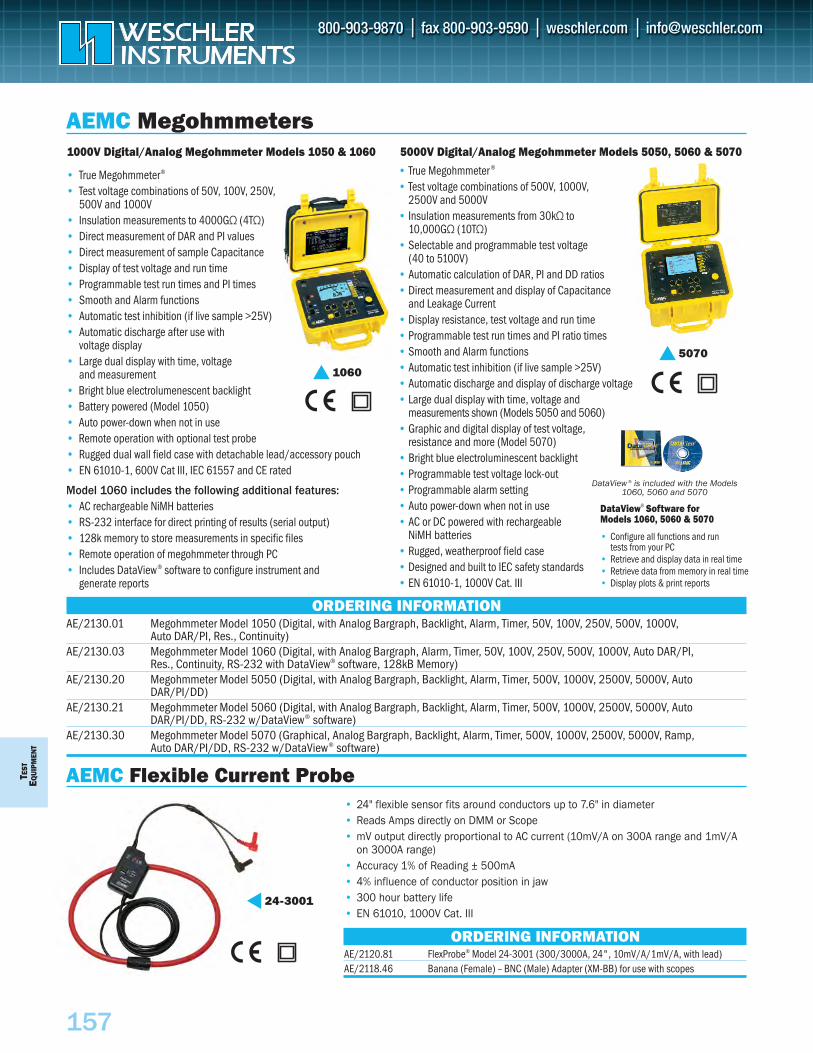
T EST
E Q
UIP
MEN
T
157
• 24" flexible sensor fits around conductors up to 7.6" in diameter• Reads Amps directly on DMM or Scope• mV output directly proportional to AC current (10mV/A on 300A range and 1mV/A
on 3000A range)• Accuracy 1% of Reading ± 500mA• 4% influence of conductor position in jaw• 300 hour battery life• EN 61010, 1000V Cat. III
AEMC Flexible Current Probe
ORDERING INFORMATIONAE/2120.81 FlexProbe® Model 24-3001 (300/3000A, 24", 10mV/A/1mV/A, with lead) AE/2118.46 Banana (Female) – BNC (Male) Adapter (XM-BB) for use with scopes
24-3001
• True Megohmmeter ®
• Test voltage combinations of 500V, 1000V, 2500V and 5000V
• Insulation measurements from 30kΩ to 10,000GΩ (10TΩ)
• Selectable and programmable test voltage (40 to 5100V)
• Automatic calculation of DAR, PI and DD ratios• Direct measurement and display of Capacitance
and Leakage Current• Display resistance, test voltage and run time• Programmable test run times and PI ratio times• Smooth and Alarm functions• Automatic test inhibition (if live sample >25V)• Automatic discharge and display of discharge voltage• Large dual display with time, voltage and
measurements shown (Models 5050 and 5060)• Graphic and digital display of test voltage,
resistance and more (Model 5070)• Bright blue electroluminescent backlight• Programmable test voltage lock-out• Programmable alarm setting• Auto power-down when not in use• AC or DC powered with rechargeable
NiMH batteries• Rugged, weatherproof field case• Designed and built to IEC safety standards• EN 61010-1, 1000V Cat. III
• True Megohmmeter®
• Test voltage combinations of 50V, 100V, 250V, 500V and 1000V
• Insulation measurements to 4000GΩ (4TΩ)• Direct measurement of DAR and PI values• Direct measurement of sample Capacitance• Display of test voltage and run time• Programmable test run times and PI times• Smooth and Alarm functions• Automatic test inhibition (if live sample >25V)• Automatic discharge after use with
voltage display• Large dual display with time, voltage
and measurement• Bright blue electrolumenescent backlight• Battery powered (Model 1050)• Auto power-down when not in use• Remote operation with optional test probe• Rugged dual wall field case with detachable lead/accessory pouch• EN 61010-1, 600V Cat III, IEC 61557 and CE rated
Model 1060 includes the following additional features:• AC rechargeable NiMH batteries• RS-232 interface for direct printing of results (serial output)• 128k memory to store measurements in specific files• Remote operation of megohmmeter through PC• Includes DataView® software to configure instrument and
generate reports
1000V Digital/Analog Megohmmeter Models 1050 & 1060
DataView ® is included with the Models 1060, 5060 and 5070
ORDERING INFORMATIONAE/2130.01 Megohmmeter Model 1050 (Digital, with Analog Bargraph, Backlight, Alarm, Timer, 50V, 100V, 250V, 500V, 1000V,
Auto DAR/PI, Res., Continuity)AE/2130.03 Megohmmeter Model 1060 (Digital, with Analog Bargraph, Alarm, Timer, 50V, 100V, 250V, 500V, 1000V, Auto DAR/PI,
Res., Continuity, RS-232 with DataView® software, 128kB Memory)AE/2130.20 Megohmmeter Model 5050 (Digital, with Analog Bargraph, Backlight, Alarm, Timer, 500V, 1000V, 2500V, 5000V, Auto
DAR/PI/DD)AE/2130.21 Megohmmeter Model 5060 (Digital, with Analog Bargraph, Backlight, Alarm, Timer, 500V, 1000V, 2500V, 5000V, Auto
DAR/PI/DD, RS-232 w/DataView® software)AE/2130.30 Megohmmeter Model 5070 (Graphical, Analog Bargraph, Backlight, Alarm, Timer, 500V, 1000V, 2500V, 5000V, Ramp,
Auto DAR/PI/DD, RS-232 w/DataView® software)
AEMC Megohmmeters
10605070
DataView® Software for Models 1060, 5060 & 5070
• Configure all functions and run tests from your PC
• Retrieve and display data in real time• Retrieve data from memory in real time• Display plots & print reports
5000V Digital/Analog Megohmmeter Models 5050, 5060 & 5070
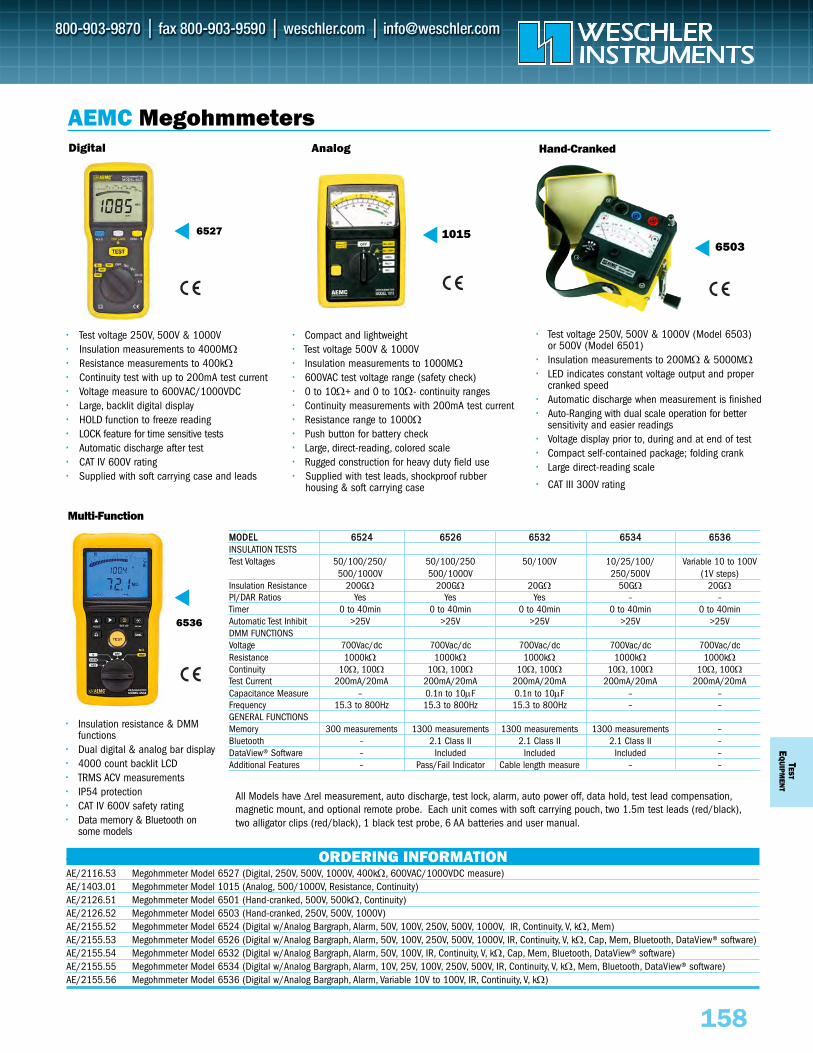
TESTE
QUIPM
ENT
158
•• Compact and lightweight•• Test voltage 500V & 1000V•• Insulation measurements to 1000MΩ•• 600VAC test voltage range (safety check)•• 0 to 10Ω+ and 0 to 10Ω- continuity ranges•• Continuity measurements with 200mA test current•• Resistance range to 1000Ω•• Push button for battery check•• Large, direct-reading, colored scale•• Rugged construction for heavy duty field use•• Supplied with test leads, shockproof rubber
housing & soft carrying case
•• Insulation resistance & DMMfunctions
•• Dual digital & analog bar display•• 4000 count backlit LCD•• TRMS ACV measurements•• IP54 protection•• CAT IV 600V safety rating•• Data memory & Bluetooth on
some models
••
Hand-Cranked Digital
AEMC Megohmmeters
•• Test voltage 250V, 500V & 1000V (Model 6503) or 500V (Model 6501)
•• Insulation measurements to 200MΩ & 5000MΩ•• LED indicates constant voltage output and proper
cranked speed•• Automatic discharge when measurement is finished•• Auto-Ranging with dual scale operation for better
sensitivity and easier readings•• Voltage display prior to, during and at end of test•• Compact self-contained package; folding crank•• Large direct-reading scale
•• CAT III 300V rating
Multi-Function
•• Test voltage 250V, 500V & 1000V•• Insulation measurements to 4000MΩ•• Resistance measurements to 400kΩ•• Continuity test with up to 200mA test current•• Voltage measure to 600VAC/1000VDC•• Large, backlit digital display•• HOLD function to freeze reading•• LOCK feature for time sensitive tests•• Automatic discharge after test•• CAT IV 600V rating•• Supplied with soft carrying case and leads
ORDERING INFORMATIONAE/2116.53 Megohmmeter Model 6527 (Digital, 250V, 500V, 1000V, 400kΩ, 600VAC/1000VDC measure)AE/1403.01 Megohmmeter Model 1015 (Analog, 500/1000V, Resistance, Continuity)AE/2126.51 Megohmmeter Model 6501 (Hand-cranked, 500V, 500kΩ, Continuity)AE/2126.52 Megohmmeter Model 6503 (Hand-cranked, 250V, 500V, 1000V)AE/2155.52 Megohmmeter Model 6524 (Digital w/Analog Bargraph, Alarm, 50V, 100V, 250V, 500V, 1000V, IR, Continuity, V, kΩ, Mem)AE/2155.53 Megohmmeter Model 6526 (Digital w/Analog Bargraph, Alarm, 50V, 100V, 250V, 500V, 1000V, IR, Continuity, V, kΩ, Cap, Mem, Bluetooth, DataView® software)AE/2155.54 Megohmmeter Model 6532 (Digital w/Analog Bargraph, Alarm, 50V, 100V, IR, Continuity, V, kΩ, Cap, Mem, Bluetooth, DataView® software)AE/2155.55 Megohmmeter Model 6534 (Digital w/Analog Bargraph, Alarm, 10V, 25V, 100V, 250V, 500V, IR, Continuity, V, kΩ, Mem, Bluetooth, DataView® software)AE/2155.56 Megohmmeter Model 6536 (Digital w/Analog Bargraph, Alarm, Variable 10V to 100V, IR, Continuity, V, kΩ)
6527
6536
6503
Analog
1015
MMOODDEELL 66552244 66552266 66553322 66553344 66553366INSULATION TESTSTest Voltages 50/100/250/ 50/100/250 50/100V 10/25/100/ Variable 10 to 100V
500/1000V 500/1000V 250/500V (1V steps)Insulation Resistance 200GΩ 200GΩ 20GΩ 50GΩ 20GΩPI/DAR Ratios Yes Yes Yes – –Timer 0 to 40min 0 to 40min 0 to 40min 0 to 40min 0 to 40minAutomatic Test Inhibit >25V >25V >25V >25V >25VDMM FUNCTIONSVoltage 700Vac/dc 700Vac/dc 700Vac/dc 700Vac/dc 700Vac/dcResistance 1000kΩ 1000kΩ 1000kΩ 1000kΩ 1000kΩContinuity 10Ω, 100Ω 10Ω, 100Ω 10Ω, 100Ω 10Ω, 100Ω 10Ω, 100ΩTest Current 200mA/20mA 200mA/20mA 200mA/20mA 200mA/20mA 200mA/20mACapacitance Measure – 0.1n to 10μF 0.1n to 10μF – –Frequency 15.3 to 800Hz 15.3 to 800Hz 15.3 to 800Hz – –GENERAL FUNCTIONSMemory 300 measurements 1300 measurements 1300 measurements 1300 measurements –Bluetooth – 2.1 Class II 2.1 Class II 2.1 Class II –DataView® Software – Included Included Included –Additional Features – Pass/Fail Indicator Cable length measure – –
All Models have Δrel measurement, auto discharge, test lock, alarm, auto power off, data hold, test lead compensation,magnetic mount, and optional remote probe. Each unit comes with soft carrying pouch, two 1.5m test leads (red/black),two alligator clips (red/black), 1 black test probe, 6 AA batteries and user manual.
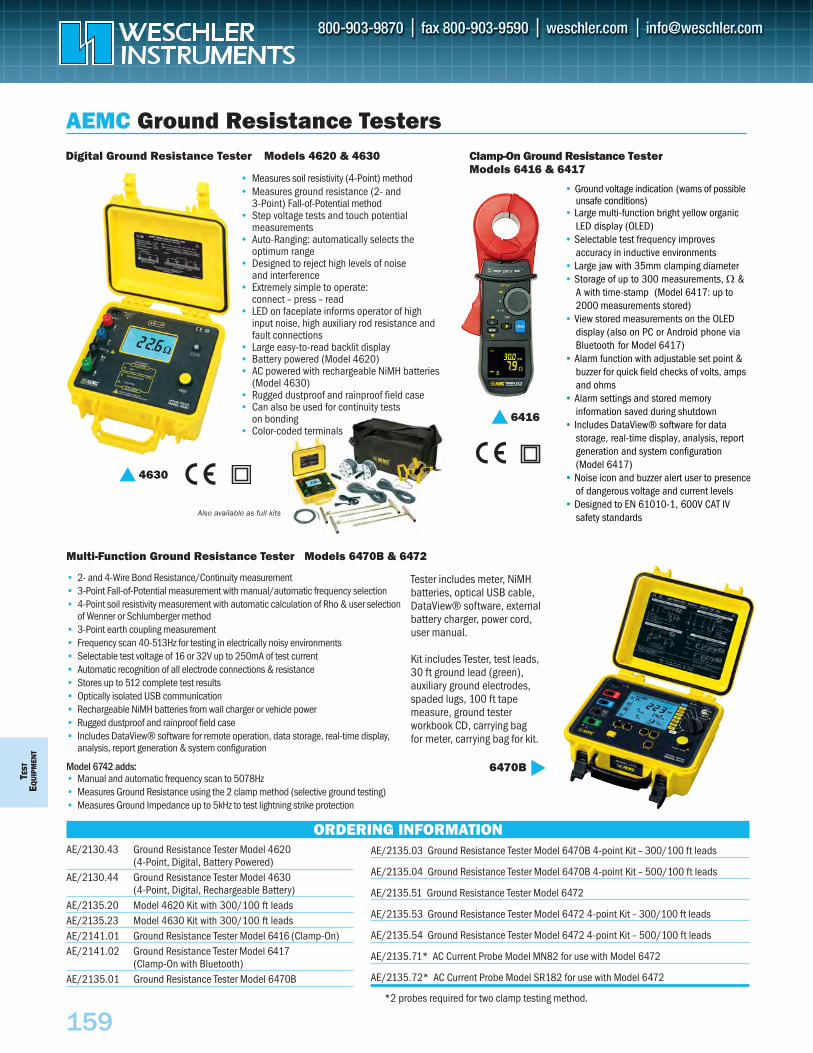
TEST
EQU
IPM
ENT
159
Also available as full kits
Clamp-On Ground Resistance Tester Models 6416 & 6417
Digital Ground Resistance Tester Models 4620 & 4630
AEMC Ground Resistance Testers
• Measures soil resistivity (4-Point) method• Measures ground resistance (2- and
3-Point) Fall-of-Potential method• Step voltage tests and touch potential
measurements• Auto-Ranging: automatically selects the
optimum range• Designed to reject high levels of noise
and interference• Extremely simple to operate:
connect – press – read• LED on faceplate informs operator of high
input noise, high auxiliary rod resistance andfault connections
• Large easy-to-read backlit display• Battery powered (Model 4620)• AC powered with rechargeable NiMH batteries
(Model 4630)• Rugged dustproof and rainproof field case• Can also be used for continuity tests
on bonding• Color-coded terminals
• Ground voltage indication (warns of possible unsafe conditions)
• Large multi-function bright yellow organic LED display (OLED)
• Selectable test frequency improves accuracy in inductive environments
• Large jaw with 35mm clamping diameter • Storage of up to 300 measurements, W &
A with time-stamp (Model 6417: up to 2000 measurements stored)
• View stored measurements on the OLED display (also on PC or Android phone via Bluetooth for Model 6417)
• Alarm function with adjustable set point &buzzer for quick field checks of volts, ampsand ohms
• Alarm settings and stored memory information saved during shutdown
• Includes DataView® software for data storage, real-time display, analysis, report generation and system configuration (Model 6417)
• Noise icon and buzzer alert user to presence of dangerous voltage and current levels
• Designed to EN 61010-1, 600V CAT IV safety standards
4630
6416
AE/2135.03 Ground Resistance Tester Model 6470B 4-point Kit – 300/100 ft leads
AE/2135.04 Ground Resistance Tester Model 6470B 4-point Kit – 500/100 ft leads
AE/2135.51 Ground Resistance Tester Model 6472
AE/2135.53 Ground Resistance Tester Model 6472 4-point Kit – 300/100 ft leads
AE/2135.54 Ground Resistance Tester Model 6472 4-point Kit – 500/100 ft leads
AE/2135.71* AC Current Probe Model MN82 for use with Model 6472
AE/2135.72* AC Current Probe Model SR182 for use with Model 6472
ORDERING INFORMATION
• 2- and 4-Wire Bond Resistance/Continuity measurement • 3-Point Fall-of-Potential measurement with manual/automatic frequency selection• 4-Point soil resistivity measurement with automatic calculation of Rho & user selection
of Wenner or Schlumberger method• 3-Point earth coupling measurement• Frequency scan 40-513Hz for testing in electrically noisy environments• Selectable test voltage of 16 or 32V up to 250mA of test current• Automatic recognition of all electrode connections & resistance• Stores up to 512 complete test results• Optically isolated USB communication• Rechargeable NiMH batteries from wall charger or vehicle power• Rugged dustproof and rainproof field case• Includes DataView® software for remote operation, data storage, real-time display,
analysis, report generation & system configuration
Model 6742 adds:• Manual and automatic frequency scan to 5078Hz• Measures Ground Resistance using the 2 clamp method (selective ground testing)• Measures Ground Impedance up to 5kHz to test lightning strike protection
Tester includes meter, NiMHbatteries, optical USB cable,DataView® software, externalbattery charger, power cord,user manual.
Kit includes Tester, test leads,30 ft ground lead (green), auxiliary ground electrodes,spaded lugs, 100 ft tapemeasure, ground tester workbook CD, carrying bag for meter, carrying bag for kit.
6470B
Multi-Function Ground Resistance Tester Models 6470B & 6472
AE/2130.43 Ground Resistance Tester Model 4620 (4-Point, Digital, Battery Powered)
AE/2130.44 Ground Resistance Tester Model 4630 (4-Point, Digital, Rechargeable Battery)
AE/2135.20 Model 4620 Kit with 300/100 ft leads
300’/100’ leads
AE/2135.23 Model 4630 Kit with 300/100 ft leadsAE/2141.01 Ground Resistance Tester Model 6416 (Clamp-On)AE/2141.02 Ground Resistance Tester Model 6417
(Clamp-On with Bluetooth)AE/2135.01 Ground Resistance Tester Model 6470B
*2 probes required for two clamp testing method.
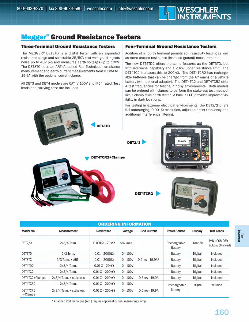
MMooddeell NNoo.. MMeeaassuurreemmeenntt RReessiissttaannccee VVoollttaaggee GGnndd CCuurrrreenntt PPoowweerr SSoouurrccee DDiissppllaayy TTeesstt LLeeaaddss
DET2/3 2/3/4 Term. 0.001Ω - 20kΩ Rechargeable GraphicP/N 1008-969includes 50m leads
Battery
DET3TD 2/3 Term. 0.01 - 2000Ω 0 - 100V Battery Digital included
DET3TC 2/3 Term. + ART* 0.01 - 2000Ω 0 - 100V 0.5mA - 19.9A* Battery Digital included
DET4TD2 2/3/4 Term. 0.01Ω - 20kΩ 0 - 100V Battery Digital included
DET4TC2 2/3/4 Term. 0.01Ω - 200kΩ 0 - 100V Battery Digital included
DET4TC2+Clamps 2/3/4 Term. + stakeless 0.01Ω - 200kΩ 0 - 100V 0.5mA - 19.9A Battery Digital included
DET4TCR2 2/3/4 Term. 0.01Ω - 200kΩ 0 - 100V
DET4TCR2 2/3/4 Term. + stakeless 0.01Ω - 200kΩ 0 - 100V 0.5mA - 19.9A+Clamps
TESTE
QU
IPMEN
T
160
Megger® Ground Resistance TestersThree-Terminal Ground Resistance TestersThe MEGGER® DET3TD is a digital tester with an expandedresistance range and selectable 25/50V test voltage. It rejectsnoise up to 40V p-p and measures earth voltages up to 100V.The DET3TC adds an ART (Attached Rod Technique) resistancemeasurement and earth current measurements from 0.5mA to19.9A with the optional current clamp.
All DET3 and DET4 models are CAT IV 100V and IP54 rated. Testleads and carrying case are included.
Four-Terminal Ground Resistance TestersAddition of a fourth terminal permits soil resistivity testing as wellas more precise resistance (installed ground) measurements.
The new DET4TD2 offers the same features as the DET3TD, butwith 4-terminal capability and a 20kΩ upper resistance limit. TheDET4TC2 increases this to 200kΩ. The DET4TCR2 has recharge-able batteries that can be charged from the AC mains or a vehiclebattery (with optional adapter). The DET4TC2 and DET4TCR2 offer4 test frequencies for testing in noisy environments. Both modelscan be ordered with clamps to perform the stakeless test method,like a clamp style earth tester. A backlit LCD provides improved vis-ibility in dark locations.
For testing in extreme electrical environments, the DET2/2 offersfull autoranging, 0.001Ω resolution, adjustable test frequency andadditional interference filtering.
ORDERING INFORMATION
DET3TC
DET2/3
* Attached Rod Technique (ART) requires optional current measuring clamp.
Rechargeable Digital includedBattery
DET4TCR2+Clamps
DET4TCR2
50V max.
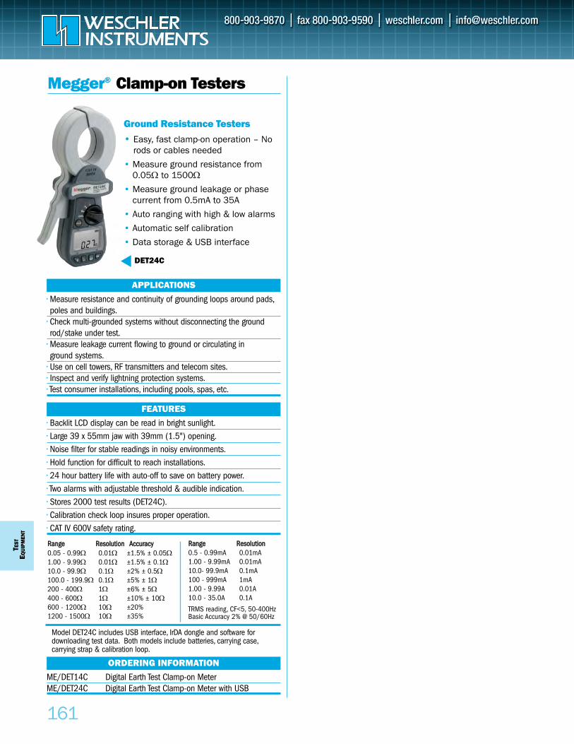
TEST
EQUI
PMEN
T
161
Megger® Clamp-on Testers
• Easy, fast clamp-on operation – Norods or cables needed
• Measure ground resistance from0.05Ω to 1500Ω
• Measure ground leakage or phasecurrent from 0.5mA to 35A
• Auto ranging with high & low alarms
• Automatic self calibration
• Data storage & USB interface
DET24C
• Measure resistance and continuity of grounding loops around pads,poles and buildings.
• Check multi-grounded systems without disconnecting the groundrod/stake under test.
• Measure leakage current flowing to ground or circulating in ground systems.
• Use on cell towers, RF transmitters and telecom sites.• Inspect and verify lightning protection systems.• Test consumer installations, including pools, spas, etc.
APPLICATIONS
ME/DET14C Digital Earth Test Clamp-on MeterME/DET24C Digital Earth Test Clamp-on Meter with USB
ORDERING INFORMATION
• Backlit LCD display can be read in bright sunlight.• Large 39 x 55mm jaw with 39mm (1.5") opening.• Noise filter for stable readings in noisy environments.• Hold function for difficult to reach installations.• 24 hour battery life with auto-off to save on battery power.• Two alarms with adjustable threshold & audible indication.• Stores 2000 test results (DET24C).• Calibration check loop insures proper operation.• CAT IV 600V safety rating.
FEATURES
Ground Resistance Testers
RRaannggee RReessoolluuttiioonn AAccccuurraaccyy0.05 - 0.99Ω 0.01Ω ±1.5% ± 0.05Ω1.00 - 9.99Ω 0.01Ω ±1.5% ± 0.1Ω10.0 - 99.9Ω 0.1Ω ±2% ± 0.5Ω100.0 - 199.9Ω 0.1Ω ±5% ± 1Ω200 - 400Ω 1Ω ±6% ± 5Ω400 - 600Ω 1Ω ±10% ± 10Ω600 - 1200Ω 10Ω ±20%1200 - 1500Ω 10Ω ±35%
RRaannggee RReessoolluuttiioonn 0.5 - 0.99mA 0.01mA 1.00 - 9.99mA 0.01mA 10.0- 99.9mA 0.1mA 100 - 999mA 1mA 1.00 - 9.99A 0.01A 10.0 - 35.0A 0.1A
TRMS reading, CF<5, 50-400HzBasic Accuracy 2% @ 50/60Hz
Model DET24C includes USB interface, IrDA dongle and software for downloading test data. Both models include batteries, carrying case,carrying strap & calibration loop.
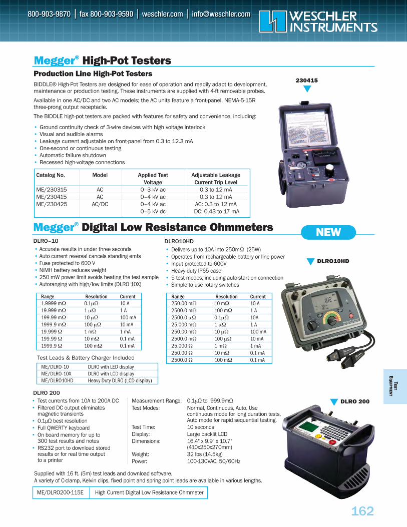
Range Resolution Current250.00 mΩ 10 mΩ 10 A2500.0 mΩ 100 mΩ 1 A 2500.0 µΩ 0.1µΩ 10A25.000 mΩ 1 µΩ 1 A250.00 mΩ 10 µΩ 100 mA2500.0 mΩ 100 µΩ 10 mA25.000 Ω 1 mΩ 1 mA250.00 Ω 10 mΩ 0.1 mA 2500.0 Ω 100 mΩ 0.1 mA
Range Resolution Current1.9999 mΩ 0.1µΩ 10 A19.999 mΩ 1 µΩ 1 A199.99 mΩ 10 µΩ 100 mA1999.9 mΩ 100 µΩ 10 mA19.999 Ω 1 mΩ 1 mA199.99 Ω 10 mΩ 0.1 mA 1999.9 Ω 100 mΩ 0.1 mA
ME/DLRO-10 DLRO with LED displayME/DLRO-10X DLRO with LCD displayME/DLRO10HD Heavy Duty DLRO (LCD display) TEST
EQ
UIPM
ENT
162
Megger® High-Pot Testers
• Accurate results in under three seconds • Auto current reversal cancels standing emfs • Fuse protected to 600 V • NiMH battery reduces weight • 250 mW power limit avoids heating the test sample • Autoranging with high/low limits (DLRO 10X)
• Test currents from 10A to 200A DC• Filtered DC output eliminates
magnetic transients• 0.1µΩ best resolution• Full QWERTY keyboard • On board memory for up to
300 test results and notes• RS232 port to download stored
results or for real time output to a printer
Supplied with 16 ft. (5m) test leads and download software.A variety of C-clamp, Kelvin clips, fixed point and spring point leads are available in various lengths.
Measurement Range: 0.1µΩ to 999.9mΩTest Modes: Normal, Continuous, Auto. Use
continuous mode for long duration tests,Auto mode for rapid sequential testing.
Test Time: 10 secondsDisplay: Large backlit LCDDimensions: 16.4" x 9.9" x 10.7"
(410x250x270mm)Weight: 32 lbs (14.5kg)Power: 100-130VAC, 50/60Hz
Test Leads & Battery Charger Included
DLRO–10
DLRO 200
Megger® Digital Low Resistance Ohmmeters
Catalog No. Model Applied Test Adjustable Leakage Voltage Current Trip Level
ME/230315 AC 0–3 kV ac 0.3 to 12 mAME/230415 AC 0–4 kV ac 0.3 to 12 mAME/230425 AC/DC 0–4 kV ac AC: 0.3 to 12 mA
0–5 kV dc DC: 0.43 to 17 mA
Production Line High-Pot TestersBIDDLE® High-Pot Testers are designed for ease of operation and readily adapt to development, maintenance or production testing. These instruments are supplied with 4-ft removable probes.
Available in one AC/DC and two AC models; the AC units feature a front-panel, NEMA-5-15R three-prong output receptacle.
The BIDDLE high-pot testers are packed with features for safety and convenience, including:
• Ground continuity check of 3-wire devices with high voltage interlock• Visual and audible alarms• Leakage current adjustable on front-panel from 0.3 to 12.3 mA• One-second or continuous testing• Automatic failure shutdown• Recessed high-voltage connections
230415
DLRO10HD
DLRO 200
ME/DLRO200-115E High Current Digital Low Resistance Ohmmeter
• Delivers up to 10A into 250mΩ (25W)• Operates from rechargeable battery or line power• Input protected to 600V• Heavy duty IP65 case• 5 test modes, including auto-start on connection• Simple to use rotary switches
DLRO10HDNEW
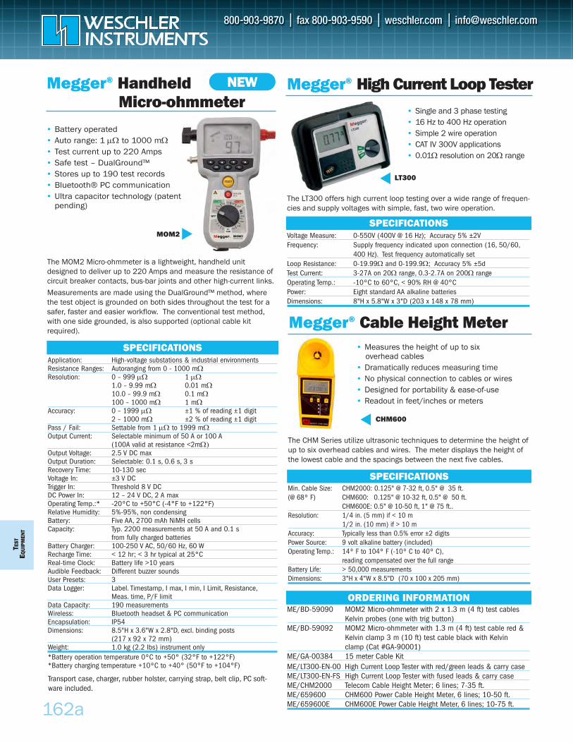
SPECIFICATIONS
Megger® Cable Height Meter• Measures the height of up to six
overhead cables • Dramatically reduces measuring time • No physical connection to cables or wires• Designed for portability & ease-of-use• Readout in feet/inches or meters
CHM600
The CHM Series utilize ultrasonic techniques to determine the height ofup to six overhead cables and wires. The meter displays the height ofthe lowest cable and the spacings between the next five cables.
Min. Cable Size: CHM2000: 0.125" @ 7-32 ft, 0.5" @ 35 ft.(@ 68º F) CHM600: 0.125" @ 10-32 ft, 0.5" @ 50 ft.
CHM600E: 0.5" @ 10-50 ft, 1" @ 75 ft..Resolution: 1/4 in. (5 mm) if < 10 m
1/2 in. (10 mm) if > 10 mAccuracy: Typically less than 0.5% error ±2 digitsPower Source: 9 volt alkaline battery (included)Operating Temp.: 14º F to 104º F (-10º C to 40º C),
reading compensated over the full rangeBattery Life: > 50,000 measurementsDimensions: 3"H x 4"W x 8.5"D (70 x 100 x 205 mm)
TEST
EQUI
PMEN
T
Megger® Handheld Micro-ohmmeter
• Battery operated• Auto range: 1 μΩ to 1000 mΩ• Test current up to 220 Amps• Safe test – DualGround™• Stores up to 190 test records• Bluetooth® PC communication• Ultra capacitor technology (patent
pending)
SPECIFICATIONSApplication: High-voltage substations & industrial environmentsResistance Ranges: Autoranging from 0 - 1000 mΩResolution: 0 – 999 μΩ 1 μΩ
1.0 – 9.99 mΩ 0.01 mΩ10.0 – 99.9 mΩ 0.1 mΩ100 – 1000 mΩ 1 mΩ
Accuracy: 0 – 1999 μΩ ±1 % of reading ±1 digit2 – 1000 mΩ ±2 % of reading ±1 digit
Pass / Fail: Settable from 1 μΩ to 1999 mΩOutput Current: Selectable minimum of 50 A or 100 A
(100A valid at resistance <2mΩ) Output Voltage: 2.5 V DC maxOutput Duration: Selectable: 0.1 s, 0.6 s, 3 sRecovery Time: 10-130 secVoltage In: ±3 V DCTrigger In: Threshold 8 V DCDC Power In: 12 – 24 V DC, 2 A maxOperating Temp.:* -20ºC to +50°C (-4°F to +122°F)Relative Humidity: 5%-95%, non condensingBattery: Five AA, 2700 mAh NiMH cellsCapacity: Typ. 2200 measurements at 50 A and 0.1 s
from fully charged batteriesBattery Charger: 100-250 V AC, 50/60 Hz, 60 WRecharge Time: < 12 hr; < 3 hr typical at 25°CReal-time Clock: Battery life >10 yearsAudible Feedback: Different buzzer soundsUser Presets: 3Data Logger: Label. Timestamp, I max, I min, I Limit, Resistance,
Meas. time, P/F limitData Capacity: 190 measurementsWireless: Bluetooth headset & PC communicationEncapsulation: IP54Dimensions: 8.5"H x 3.6"W x 2.8"D, excl. binding posts
(217 x 92 x 72 mm)Weight: 1.0 kg (2.2 lbs) instrument only*Battery operation temperature 0ºC to +50° (32°F to +122°F)*Battery charging temperature +10ºC to +40° (50°F to +104°F)
MOM2
Megger® High Current Loop Tester• Single and 3 phase testing • 16 Hz to 400 Hz operation• Simple 2 wire operation• CAT IV 300V applications• 0.01Ω resolution on 20Ω range
SPECIFICATIONSVoltage Measure: 0-550V (400V @ 16 Hz); Accuracy 5% ±2V Frequency: Supply frequency indicated upon connection (16, 50/60,
400 Hz). Test frequency automatically set Loop Resistance: 0-19.99Ω and 0-199.9Ω; Accuracy 5% ±5dTest Current: 3-27A on 20Ω range, 0.3-2.7A on 200Ω rangeOperating Temp.: -10ºC to 60°C, < 90% RH @ 40°CPower: Eight standard AA alkaline batteriesDimensions: 8"H x 5.8"W x 3"D (203 x 148 x 78 mm)
ORDERING INFORMATIONME/BD-59090 MOM2 Micro-ohmmeter with 2 x 1.3 m (4 ft) test cables
Kelvin probes (one with trig button)ME/BD-59092 MOM2 Micro-ohmmeter with 1.3 m (4 ft) test cable red &
Kelvin clamp 3 m (10 ft) test cable black with Kelvin clamp (Cat #GA-90001)
ME/GA-00384 15 meter Cable Kit ME/LT300-EN-00 High Current Loop Tester with red/green leads & carry caseME/LT300-EN-FS High Current Loop Tester with fused leads & carry caseME/CHM2000 Telecom Cable Height Meter; 6 lines; 7-35 ft.ME/659600 CHM600 Power Cable Height Meter, 6 lines; 10-50 ft.ME/659600E CHM600E Power Cable Height Meter, 6 lines; 10-75 ft.
LT300
Transport case, charger, rubber holster, carrying strap, belt clip, PC soft-ware included.
162a
NEW
The LT300 offers high current loop testing over a wide range of frequen-cies and supply voltages with simple, fast, two wire operation.
The MOM2 Micro-ohmmeter is a lightweight, handheld unitdesigned to deliver up to 220 Amps and measure the resistance ofcircuit breaker contacts, bus-bar joints and other high-current links.Measurements are made using the DualGround™ method, wherethe test object is grounded on both sides throughout the test for asafer, faster and easier workflow. The conventional test method,with one side grounded, is also supported (optional cable kitrequired).
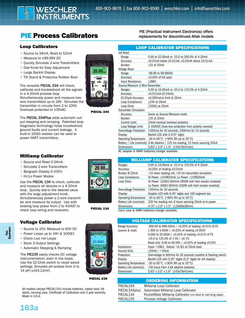
• Source and Read 0-24mA• Simulate 2-wire Transmitters• Bargraph Display 0-100%• Hi/Lo Power Modes
TEST
EQUI
PMEN
T
163a
PIE Process Calibrators
Milliamp Calibrator
Use the PPIIEECCAALL 113344 to check, calibrateand measure all devices in a 4-20mAloop. Quickly dial-in the desired valuewith the large adjustment knob.Simultaneously power a 2-wire transmit-ter and measure its output. Use withexisting loop power from 2 to 42VDC tocheck loop wiring and receivers.
MILLIAMP CALIBRATOR SPECIFICATIONSRanges: 0.00 to 24.00mA or -25.0 to 125.0% of 4-20mAAccuracy: ±0.05% of reading ±0.01mABurden @ 20mA: <1V when reading mA; <2V for transmitter simulationLoop Compliance: Hi Power; >24V@20mA, Lo Power: >15V@20mALoop Drive: Hi Power: 1200Ω @20mA (950W with Hart resistor enabled)
Lo Power: 600Ω @20mA (350W with Hart resistor enabled)Overvoltage Protection: 135Vrms for 30 secondsDisplay: Graphic LCD with 0.45" digits and 100 segment barOperating Temperature: -20 to 60°C (<90% RH up to 35°C)Battery Life (nominal): 220 hrs reading mA, 8 hours sourcing 20mA at hi powerDimensions: 4.75" x 2.6" x 1.5" (120x66x38mm)Carry case & NiMH batteries/charger available.
ORDERING INFORMATIONPIECAL334 Milliamp Loop Calibrator PIECAL334plus Automated Milliamp Loop CalibratorPIECAL134 PocketMate Milliamp Calibrator (no boot or carrying case)PIECAL235 Process Voltage Calibrator
PIECAL 134
Loop Calibrators LOOP CALIBRATOR SPECIFICATIONSmA Read
Range: 0.00 to 52.00mA or -25.0 to 300.0% of 4-20mAAccuracy: ±0.01mA below 24.01mA; ±0.03mA above 24.01mABurden: <2V at 50mA
Voltage ReadRange: -99.99 to 99.99VDCAccuracy: ±0.05% of full spanInput Resistance: >2MΩ
Source/Measure 2-Wire Transmitter Ranges: 0.00 to 24.00mA or -25.0 to 125.0% of 4-20mAAccuracy: ±0.012mA (0-24mA)EZ-Check Accuracy: ±0.005mA at 4mA & 20mALoop Compliance: >24V at 20mALoop Drive: 1200Ω at 20mA
Transmitter SimulationAccuracy: Same as Source/Measure modeBurden: <2V at 20mACurrent Limit: 24mA nominal overload protetionLoop Voltage Limit: 2-100VDC (fuse-less protection from polarity reversal)
Overvoltage Protection: 135Vrms for 30 seconds; 240Vrms for 15 secondsDisplay: Backlit LCD with 0.315" digits Operating Temperature: -20 to 60°C (<90% RH up to 35°C)Battery / Life (nominal): 4 AA alkaline / 125 hrs reading, 15 hours sourcing 20mA Dimensions: 5.63" x 3.0" x 1.6" (143x76x41mm)AC adapter & NiMH batteries/charger available.
• Source to 24mA, Read to 52mA• Measure to ±99.99V DC• Quickly Simulate 2-wire Transmitters• Dial Knob for Easy Adjustment• Large Backlit Display• Tilt Stand & Protective Rubber Boot
The versatile PPIIEECCAALL 333344 will check, calibrate and troubleshoot all the signalsin a 4-20mA process loop.Simultaneously power and measure two-wire transmitters up to 24V. Simulate thetransmitter in circuits from 2 to 100V.Overload protected to 135VAC.
The PPIIEECCAALL 333344PPlluuss adds automatic out-put stepping and ramping. Patented loopdiagnostic technology helps troubleshootground faults and current leakage. Abuilt-in 250Ω resistor can be used topower HART transmitters.
PIECAL 334
PIECAL 235
Voltage Calibrator VOLTAGE CALIBRATOR SPECIFICATIONSRange/Accuracy: -500.00 to 999.00mV / ±0.02% of reading ±0.01% of FS(source & read) 1.000 to 5.000V / ±0.02% of reading ±0.002V
0.000 to 20.000V / ±0.02% of reading ±0.01% of FS-25.0 to 125.0% of 1-5V / ±0.1%Read only: 0.00 to 60.00V / ±0.02% of reading ±0.02V
Impedance: Input: >1MΩ; Output: <0.3Ω at 20mA loadSource/Sink: >20mA / >16mA Protection: Overvoltage to 60Vrms for 30 seconds (audible & flashing alarm)Display: Backlit LCD with 0.35" digits (0.2" digits for mA display)Operating Temperature: -20 to 60°C (<90% RH up to 35°C)Battery Life (nominal): >50 hours from 4 AA alkaline batteriesDimensions: 5.63" x 3.0" x 1.6" (143x76x41mm)
• Source to 20V, Measure to 60V DC• Power Loops up to 24V & 1000Ω• Check Live mA Loops• Store 3 Output Settings• Automatic Stepping & Ramping
The PPIIEE223355 easily checks DC voltageinstrumentation, even in live loops.Use the EZ-Chek switch to recall savedsettings. Simulate pH probes from 0 to14 pH (±414.12mV).
PPIIEE ((PPrraaccttiiccaall IInnssttrruummeenntt EElleeccttrroonniiccss)) ooffffeerrssrreeppllaacceemmeennttss ffoorr ddiissccoonnttiinnuueedd AAlltteekk mmooddeellss
All models (except PIECAL134) include batteries, rubber boot, tiltstand, carrying case, Certificate of Calibration and 3 year warranty.Made in U.S.A.
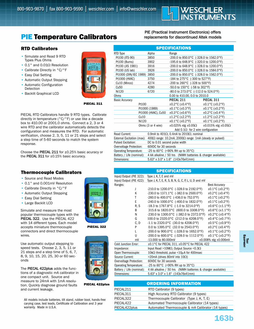
TESTE
QUIPM
ENT
163b
PIE Temperature Calibrators
RTD Type Alpha RangePt100 (ITS-90) 3850 -200.0 to 850.0°C (-328.0 to 1562.0°F)Pt100 (Burns) 3902 -195.6 to 648.9°C (-320.0 to 1200.0°F)Pt100 (JIS 1981) 3916 -200.0 to 648.9°C (-328.0 to 1200.0°F)Pt100 (US lab) 3926 -200.0 to 850.0°C (-328.0 to 1584.0°F)Pt1000 (DIN/IEC 1989) 3850 -200.0 to 850.0°C (-328.0 to 1562.0°F)Pt1000 (HVAC) 3750 -184 to 275°C (-300 to 527°F)Cu10 (Minco) 4274 -200 to 260°C (-328 to 500°F)Cu50 4280 -50.0 to 150°C (-58 to 302°F)Ni120 6720 -80.0 to 273.0°C (-112.0 to 524.0°F)
Ohms 0.00 to 410.00, 0.0 to 2010.0 Basic Accuracy PPIIEECCAALL 221111 PPIIEECCAALL 331111
Pt100 ±0.2°C (±0.4°F) ±0.1°C (±0.2°F)Pt1000 (1989) ±0.1°C (±0.3°F) ±0.1°C (±0.2°F)Pt1000 (HVAC), Cu50 ±0.3°C (±0.6°F) ±0.2°C (±0.4°F)Cu10 ±1.2°C (±2.2°F) ±1.2°C (±2.2°F)Ni120 ±0.1°C (±0.2°F) ±0.1°C (±0.2°F)Ohms (3 or 4 wire) ±0.025% rdg ±0.05Ω ±0.015% rdg ±0.05Ω
Add 0.1Ω for 2 wire configurationRead Current: 0.9mA to 401Ω, 0.4mA to 2010Ω. nominalExternal Excitation (max): 400Ω range: 10.2mA, 2000Ω range: 1mA (steady or pulsed)Pulsed Excitation: DC to 0.01 second pulse widthOvervoltage Protection: 60VDC for 30 secondsOperating Temperature: -25 to 60°C (<90% RH up to 35°C)Battery / Life (nominal): 4 AA alkaline / 50 hrs (NiMH batteries & charger available)Dimensions: 5.63" x 3.0" x 1.6" (143x76x41mm)
SPECIFICATIONS
• Simulate and Read 9 RTD Types Plus Ohms
• 0.1° and 0.01Ω Resolution• Calibrate Directly in °C/°F • Easy Dial Setting• Automatic Output Stepping• Automatic Configuration
Detection• Backlit Graphical LCD
RTD Calibrators
PIECAL RTD Calibrators handle 9 RTD types. Calibratedirectly in temperature (°C/°F) or use like a decadebox to 410.00 or 2001.0 ohms. Connect a 2, 3 or 4wire RTD and the calibrator automatically detects theconfiguration and measures the RTD. For automaticverification, choose 2, 3, 5, 11 or 21 steps and selecta step time of 5-60 seconds to match the systemresponse.
Choose the PPIIEECCAALL 221111 for ±0.25% basic acuracy orthe PPIIEECCAALL 331111 for ±0.15% basic accuracy.
PIECAL 311
Input/Output (PIE 322): Type J, K, T, E and mVInput/Output (PIE 422): Type J, K, T, E, R, S, B, N, G, C, P, L, U, D and mVRanges: Best Accuracy
J -210.0 to 1200.0°C (-328.0 to 2192.0°F) ±0.1°C (±0.2°F)K -230.0 to 1371.1°C (-382.0 to 2500.0°F) ±0.2°C (±0.4°F)T -260.0 to 400.0°C (-436.0 to 752.0°F) ±0.1°C (±0.2°F)E -240.0 to 1000.0°C (-400.0 to 1832.0°F) ±0.1°C (±0.2°F)R, S -18.3 to 1767.8°C (-1.0 to 3214.0°F) ±0.6°C (±1.1°F)B 315.6 to 1820.0°C (600.0 to 3308.0°F) ±0.6°C (±1.1°F)N -230.0 to 1300.0°C (-382.0 to 2372.0°F) ±0.2°C (±0.4°F)G 100.0 to 2320.0°C (212.0 to 4208.0°F) ±0.4°C (±0.7°F)C, D -1.1 to 2320.0°C (30.0 to 4208.0°F) ±0.5°C (±0.9°F)P 0.0 to 1395.0°C (32.0 to 2543.0°F) ±0.2°C (±0.4°F)L -200.0 to 900.0°C (-328.0 to 1652.0°F) ±0.1°C (±0.2°F)U -200.0 to 600.0°C (-328.0 to 1112.0°F) ±0.1°C (±0.2°F)mV -13.000 to 80.000mV ±0.008% rdg ±0.006mV
Cold Junction Error: ±0.1°C for PIECAL 311, ±0.05°C for PIECAL 422Impedance: Input Read >10MΩ, Output Source <0.3ΩOpen Thermocouple: 10kΩ threshold, pulse <10μA for 400msecSource Current: >20mA (drives 80mV into 10Ω)Overvoltage Protection: 60VDC for 30 secondsOperating Temperature: -25 to 60°C (<90% RH up to 35°C)Battery / Life (nominal): 4 AA alkaline / 50 hrs (NiMH batteries & charger available)Dimensions: 5.63" x 3.0" x 1.6" (143x76x41mm)
SPECIFICATIONS
• Source and Read Modes• 0.1° and 0.001mV Resolution• Calibrate Directly in °C/°F• Automatic Output Stepping• Easy Dial Setting• Large Backlit LCD
Thermocouple Calibrators
Simulate and measure the mostpopular thermocouple types with thePPIIEECCAALL 332222. Use the PIECAL 422with 14 different types. Each modelaccepts miniature thermocoupleconnectors and direct thermocouplewires.
Use automatic output stepping tospeed tests. Choose 2, 3, 5, 11 or21 steps and a step time of 5, 6, 7,8, 9, 10, 15, 20, 25, 30 or 60 sec-onds
The PPIIEECCAALL 442222pplluuss adds the func-tions of a diagnostic mA calibrator inone compact unit. Source andmeasure to 24mA with 1mA resolu-tion. Quickly diagnose ground faultsand current leakage.
PIECAL 322
PIECAL 422plus ORDERING INFORMATIONPIECAL211 RTD Calibrator (9 types)PIECAL311 High Accuracy RTD Calibrator (9 types)PIECAL322 Thermocouple Calibrator (Type J, K, T, E)PIECAL422 Automated Thermocouple Calibrator (14 types)PIECAL422plus Automated Thermocouple & mA Calibrator (14 types)
PPIIEE ((PPrraaccttiiccaall IInnssttrruummeenntt EElleeccttrroonniiccss)) ooffffeerrssrreeppllaacceemmeennttss ffoorr ddiissccoonnttiinnuueedd AAlltteekk mmooddeellss
All models include batteries, tilt stand, rubber boot, hands-freecarying case, test leads, Certificate of Calibration and 3 yearwarranty. Made in U.S.A.
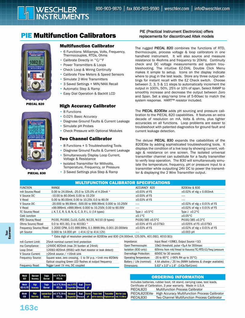
TEST
EQUI
PMEN
T
163c
PIE Multifunction CalibratorsPPIIEE ((PPrraaccttiiccaall IInnssttrruummeenntt EElleeccttrroonniiccss)) ooffffeerrssrreeppllaacceemmeennttss ffoorr ddiissccoonnttiinnuueedd AAlltteekk mmooddeellss
ORDERING INFORMATIONIncludes batteries, rubber boot, tilt stand, carrying case, test leads,Certificate of Calibration, 3 year warranty. Made in U.S.A. PIECAL820 Multifunction Process CalibratorPIECAL820Elite High Accuracy Multifunction Process Calibrator PIECAL830 Two Channel Multifunction Process Calibrator
MULTIFUNCTION CALIBRATOR SPECIFICATIONSFUNCTION RANGE ACCURACY 820 820Elite & 830mA Source/Read 0.00 to 24.00mA, -25.0 to 125.0% of 4-20mA * ±0.03% of FS ±0.02% of rdg ± 0.003mAV Source DC -10.00 to 80.00mV, 0.00 to 10.25V ±0.03% of FS ----V Read 0.00 to 80.00mV, 0.00 to 10.25V, 0.0 to 60.0V ±0.03% of FS ----V Source DC -20.000 to 99.99mV, -500.00 to 999.99mV, 0.000 to 10.250V ---- ±0.02% of rdg ± 0.01% of FSV Read ±99.999mV, ±999.99mV, 0.000 to 10.250V, 0.00 to 60.00V ---- ±0.02% of rdg ± 0.01% of FSTC Source/Read J, K, T, E, R, S, B, N, G, C, D, P, L, U (14 types) Type J ±0.5°C Type J ±0.2°CCold Junction ±0.1°C ±0.05°CRTD Source/Read Pt100, Pt1000, Cu10, Cu50, Ni120, Ni110 (9 types) Pt100/385 ±0.5°C Pt100/385 ±0.3°COhms Source/Read 0.0 to 401.0Ω, 0 to 4010Ω * ±0.03% of FS ±0.075Ω ±0.025% of FS ±0.075ΩFrequency Source/Read 1-2000 CPM, 0.01-999.99Hz, 0.1-9999.9Hz, 0.001-20.000kHz ±0.03% of FS ±0.02% of rdg ± 0.01% of FSpH Source 0.000 to 14.000 pH (-414.12 to 414.12V) ---- ±0.003 pH
* Extra digit of resolution provided on 820Elite and 830 (24.000mA, 125.00%, 401.00Ω, 4010.0Ω)
Multifunction Calibrator• 6 Functions: Milliamps, Volts, Frequency,
Thermocouples, RTDs, Ohms• Calibrate Directly in °C/°F • Power Transmitters & Loops • Check Loop & Wiring Continuity • Calibrate Flow Meters & Speed Sensors• Simulate 2-Wire Transmitters• 3 Saved Settings + MIN/MAX Recall • Automatic Step & Ramp• Easy Dial Operation & Backlit LCD
The rugged PPIIEECCAALL 882200 combines the functions of RTD,thermocouple, process voltage & loop calibrators in onehandheld instrument. It will also source and measureresistance to 4kohms and frequency to 20kHz. Continuitycheck and DC voltage measurements aid system trou-bleshooting. The intuitive EZ-DIAL Double Click Menumakes it simple to setup. Icons on the display indicatewhere to plug in the test leads. Store any three output set-tings for instant recall with the EZ Check switch. Choosebetween 2, 3, 5 & 11 steps to automatically increment theoutput in 100%, 50%, 25% or 10% of span. Select RAMP tosmoothly increase and decrease the output between Zeroand Span. Set a step/ramp time of 5-60sec to match thesystem response. HART™ resistor included.
PIECAL 820
PIECAL 830
High Accuracy Calibrator
Two Channel Calibrator
• 8 Functions • 0.02% Basic Accuracy • Diagnose Ground Faults & Current Leakage• Simulate pH Probes• Check Pressure with Optional Modules
The PPIIEECCAALL 882200EElliittee adds pH sourcing and pressure cali-bration to the PIECAL 820 capabilities. It features an extradecade of resolution on mA, Volts & ohms, plus tighteraccuracies on all functions. Loop problems are easier totroubleshoot with patented diagnostics for ground fault andcurrent leakage detection.
• 8 Functions + 5 Troubleshooting Tools• Diagnose Ground Faults & Current Leakage• Simultaneously Display Loop Current,
Voltage & Resistance• Isolated Transmitter for Millivolts,
Temperature, Frequency, or Pressure• 3 Saved Settings plus Step & Ramp
The deluxe PPIIEECCAALL 883300 expands the cababilities of the820Elite by adding sophisticated troubleshooting tools. Itdisplays the condition of a live loop by showing current, volt-age & resistance on one screen. The isolated universaltransmitter channel can substitute for a faulty transmitterto verify loop operation. The 830 will simultaneously simu-late the temperature, frequency, pH or pressure input to atransmitter while outputting 24V DC to power the transmit-ter & displaying the 2 Wire Transmitter output.
Impedance: Input Read >10MΩ, Output Source <1ΩOpen Thermocouple: 10kΩ threshold, pulse <5μA for 300msecIsolation (830 only): 60Vrms from mA/Vread to Vsource/TC/RTD/Ω/freq/pressureOvervoltage Protection: 60VDC for 30 secondsOperating Temperature: -20 to 60°C (<90% RH up to 35°C)Battery / Life (nominal): 4 AA alkaline / 20 hrs (NiMH batteries & charger available)Dimensions: 5.63" x 3.0" x 1.6" (143x76x41mm)
mA Current Limit: 25mA nominal current limit protectionma Compliance: >24VDC @20mA (max 2V burden at 24mA)Loop Drive: 1200Ω @20mA (950Ω with Hart resistor or leak detect)V Source Current: >20mA source / >16mA sinkFrequency Source: Square wave, zero crossing, -1 to 5V p-p, >1mA rms @20kHz
Optical coupling Green LED flashes at output frequencyFrequency Read: Trigger Level 1V rms, DC coupled
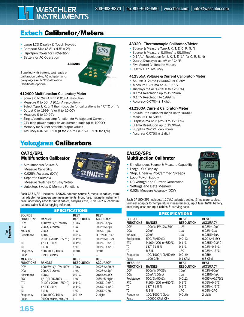
TEST
EQUI
PMEN
T
165
Yokogawa Calibrators
Extech Calibrator/Meters
412300A Current Calibrator/Meter• Source 0 to 24mA for loads up to 1000Ω• Measure 0 to 50mA • Displays mA or % (-25.0 to 125.0%)• 0.1mA Resolution up to 19.99mA• Supplies 24VDC Loop Power• Accuracy 0.075% ± 1 digit
433201 Thermocouple Calibrator/Meter• Source & Measure Type J, K, T, E, C, R, S, N • Source & Measure -5.00mV to 55.00mV• 0.1°/1° Resolution for J, K, T, E (1° for C, R, S, N)• Output Displayed as mV or °C/°F• Five Stored Calibration Values• 0.15% + 1° Accuracy
412400 Multifunction Calibrator/Meter• Source 0 to 24mA with 0.01mA resolution• Measure 0 to 50mA (0.1mA resolution)• Select Type J, K, or T thermocouple for calibrations in °F/°C or mV• Output 0 to 1999mV or 0 to 10.00V• Measure 0 to 19.99V• Single/continuous step function for Voltage and Current• 24V loop power supply drives current loads up to 1000Ω• Memory for 5 user settable output values• Accuracy 0.075% ± 1 digit for V & mA (0.15% + 1°C for T/C)
412355A Voltage & Current Calibrator/Meter• Source 0–24mA (<1000Ω) or 0-20V • Measure 0–50mA or 0–19.99V • Displays mA or % (-25.0 to 125.0%)• 0.1mA Resolution up to 19.99mA• 0.1mV Resolution to 1999mV• Accuracy 0.075% ± 1 digit
SSOOUURRCCEE BBEESSTT BBEESSTTFFUUNNCCTTIIOONNSS RRAANNGGEESS RREESSOOLLUUTTIIOONN AACCCCUURRAACCYYDCV 100mV/1V/10V/30V 10mV 0.02%+15μVDCA 20mA/4-20mA 1μA 0.025%+3μAmA sink 20mA 1μA 0.05%+3μAResistance 400Ω 0.01Ω 0.02%+0.1ΩRTD Pt100 (-200 to +850°C) 0.1°C 0.025%+0.3°CTC J K T E L U N 0.1°C 0.02%+0.5°CTC R S B 1°C 0.02%+1.5°CFrequency 500/1000/10kHz 0.2Hz 0.2HzPulse 99999 cycles 1 --MMEEAASSUURREE BBEESSTT BBEESSTTFFUUNNCCTTIIOONNSS RRAANNGGEESS RREESSOOLLUUTTIIOONN AACCCCUURRAACCYYDCV 100mV/1V/10V/100V 10mV 0.025%+20μVDCA 20mA/4-20mA 1mA 0.025%+4μAResistance 400Ω 0.01Ω 0.05%+0.1ΩACV 1/10/100/300V 1mV 0.5%+5 digitsRTD Pt100 (-200 to +850°C) 0.1°C 0.05%+0.6°CTC J K T E L U N 0.1°C 0.05%+1.5°CTC R S B 1°C 0.05%+2°CFrequency 100/1000/10kHz 0.01Hz 2 digitsPulse 99999 counts/min, /hr 1 --
SSOOUURRCCEE BBEESSTT BBEESSTTFFUUNNCCTTIIOONNSS RRAANNGGEESS RREESSOOLLUUTTIIOONN AACCCCUURRAACCYYDCV 100mV/1V/10V/30V 1μV 0.02%+10μVDCA 20mA 1μA 0.02%+3μAmA sink 20mA 1μA 0.025%+6μAResistance 500/5k/50kΩ 0.01Ω 0.02%+1.5ΩRTD Pt100 (-200 to +850°C) 0.1°C 0.025%+0.3°CTC J K T E L U N 0.1°C 0.02%+0.4°CTC R S B 1°C 0.02%+1.2°CFrequency 100/1000/10k/50kHz 0.01Hz 0.05HzPulse 1100 CPM 0.1 CPM 0.5 CPMMMEEAASSUURREE BBEESSTT BBEESSTTFFUUNNCCTTIIOONNSS RRAANNGGEESS RREESSOOLLUUTTIIOONN AACCCCUURRAACCYYDCV 500mV/5V/35V 10μV 0.02%+50μVDCA 20mA/100mA 1μA 0.025%+4μAResistance 500/5k/50kΩ 0.01Ω 0.055%+0.075ΩRTD Pt100 (-200 to +850°C) 0.1°C 0.05%+0.6°CTC J K T E L U N 0.1°C 0.05%+1.5°CTC R S B 1°C 0.05%+2°CFrequency 100/1000/10kHz 0.01Hz 2 digitsPulse 100000 CPM, CPH 1 --
SPECIFICATIONSSPECIFICATIONS
CCAA115500//SSPP11 MMuullttiiffuunnccttiioonn CCaalliibbrraattoorr• Simultaneous Source & Measure Capability• Large LCD Display• Step, Linear & Programmed Sweeps• Loop Power Supply• DC Voltage and Current Generation• Settings and Data Memory• 0.02% Measure Accuracy (DCV)
CCAA7711//SSPP11 MMuullttiiffuunnccttiioonn CCaalliibbrraattoorr• Simultaneous Source &
Measure Capability• 0.025% Accuracy (DCV)• Separate Source &
Measure Switches for Easy Setup• Autostep, Sweep & Memory Functions
Each CA71/SP1 includes: 120VAC adapter, source & measure cables, termi-nal adaptor for temperature measurements, input fuse, magnetic instrumentcase, accessory case for input cables, carrying case, 9 pin RS232 communi-cations cable & data logging software.
Each CA150/SP1 includes: 120VAC adapter, source & measure cables,terminal adaptor for temperature measurements, input fuse, NiMH battery,accessory case for input cables & carrying case.
433201
Supplied with battery, test leads orcalibration cable, AC adapter, andcarrying case. NIST CalibrationCertificate optional.
• Large LCD Display & Touch Keypad• Compact Size (3.8" x 4.5" x 2")• Flip-Open Cover for Protection• Battery or AC Operation

Pt100 (3851) -200.0 to 800.0°C Pt100 (3850) -200.0 to 630.0°C Pt100 (3916) -200.0 to 510.0°C Pt100 (3926) -200.0 to 630.0°CPt200 (3851) -200.0 to 630.0°C Pt500 (3851) -200.0 to 630.0°CPt1000 (3851) -200.0 to 630.0°CCu10 (427) -100.0 to 260.0°CNi120 (627) -80.0 to 260.0°CPt50 (3851) -200.0 to 630.0°CPt50G -200.0 to 800.0°CPt100G -200.0 to 630.0°CCu50M -180.0 to 200.0°CCu100M -180.0 to 200.0°C500Ω 0.00 to 550.00Ω3000Ω 0.0 to 3300.0ΩAccuracy: Pt100, Pt200: 0.033% +0.3°C
Ω: 0.025% +0.5ΩDimensions: 7.5" x 3.6" x 1.65" (192 x 90 x 42mm)Includes test leads, binding posts, batteries & carryingcase. AC adapter sold separately (P/N 94013).
165a
Yokogawa Process Calibrators
ORDERING INFORMATIONYE/CA310 Volts & mA CalibratorYE/CA320 Thermocouple CalibratorYE/CA330 RTD Calibrator
Extech Process Calibrators
• Source to 24mA, 20V • Measure to 50mA, 20V• 5 user adjustable presets• Banana connections• Battery or AC power
PRC15
Source: 0 to 24mA (-25% to 125%), <1kΩ load 0 to 20V
Measure: 0 to 50mA (-25 to 230%); 0 to 19.99V
Input/Output: Range Resolution0 to 19.99mA 0.01mA0 to 24.0mA 0.1mA0 to 1999mV 1mV0 to 20.00V 10mV
Accuracy: 0.01% +1 digitDimensions: 6.3" x 3.2" x 1.7" (159 x 80 x 44mm)Includes test leads, AC power adapter, batteries & hardcarrying case
DC Source:Current 0 to 24mA (-25% to 125%), <1kΩ loadVoltage 0 to 2000mV, 0 to 20V mV/Temp -5 to 55mV
DC Measure:Current 0 to 50mA, -25% to +230% Voltage 0 to 1999mV / 2 to 20V mV/Temp -10 to 60mV
Thermocouple Source/Measure:Type J -58 to 1832°F (-50 to 1000°C) Type K -58 to 2498°F (-50 to 1370°C) Type T -184 to 752°F (-120 to 400°C) Type E -58 to 1382°F (-50 to 750°C) Type C, R, S 32 to 3182°F (0 to 1750°C) Type N -58 to 2372°F (-50 to 1300°C)
Accuracy: V/I/mV: 0.01% + 1 digit T/C: 0.05% + 2°F or 1°C
Loop Power: 24VDimensions: 6.3" x 3.2" x 1.7" (159 x 80 x 44mm)Includes test leads, calibration cables, AC poweradapter, batteries & hard carrying case
SPECIFICATIONS SPECIFICATIONS SPECIFICATIONS
VOLTAGE/CURRENT
PRC30
MULTIFUNCTION
• Source/Measure Voltage, Current, mV & Thermocouples
• Combines functions ofthe PRC15 & PRC20
• 24V loop power source
• Measure & source (simu-late) 8 T/C types
• Display ºC, ºF or mV• 5 user adjustable presets• Miniature thermocouple
connector• Battery or AC power
PRC20
Type J -58 to 1832°F (-50 to 1000°C) Type K -58 to 2498°F (-50 to 1370°C) Type T -184 to 752°F (-120 to 400°C) Type E -58 to 1382°F (-50 to 750°C) Type C 32 to 3182°F (0 to 1750°C) Type R/S 32 to 3182°F (0 to 1750°C) Type N -58 to 2372°F (-50 to 1300°C) Voltage: -10.00mV to +60.00mV Resolution: 0.1° (up to 999.9) or 1° (over 999.9°)
for J, K, T, E ; 1° for R, N; 0.5° for C, SAccuracy: 0.05% rdg +1° 0.015% ±3 digitor 10μV+1dInput Z: 10 MΩDimensions: 6.3" x 3.2" x 1.7" (159 x 80 x 44mm)Includes calibration cables, AC power adapter, batteries
EX/PRC15 Voltage/Current CalibratorEX/PRC20 Thermocouple Calibrator with Cold Junction CompensationEX/PRC30 Multifunction Calibrator with Cold Junction Compensation
ORDERING INFORMATION
THERMOCOUPLE
add -NIST to P/N for NIST traceable Certificate
of Calibration
• Source to 24mA, ±33V • Measure to ±60mA, ±55V• Step, ramp & sweep• 24V loop power supply• Simulate (sink) function
CA310
Source: 0 to 24.000mA, <1kΩ load 0 to 550.00mV/5.5000V/±33.000V
Measure: 0 to ±24.000mA/±60.000mA; 0 to ±550.00mV/±5.5000V/
±33.000V/±55.000VSimulate: 0 to 24.000mA, 5-28V external supplyInput R: mA source: <10Ω
V measure: >1MΩLoop Supply: 24V ±1V (@24mA, comm R OFF)
24V ±6V (@20mA, comm R ON)Accuracy: 0.015% +3 digit (+5 digits on volts)Dimensions: 7.5" x 3.6" x 1.65" (192 x 90 x 42mm)Includes test leads, batteries & carrying case. ACadapter sold separately (P/N 94013).
SPECIFICATIONS SPECIFICATIONS SPECIFICATIONS
VOLTAGE/CURRENT
CA330
RTD
• Source/Measure 16 RTD types
• 0.3°C basic accuracy• 2/3/4-wire• Step, ramp & sweep• Dual display (° & Ω or %)
• Measure & source(simulate) 16 T/C types
• 0.5°C basic accuracy, including internal reference junction
• Step, ramp & sweep• Dual display (° & mV or %)
CA320
Type K -200.0 to 1372.0°C Type E -250.0 to 1000.0°CType J -210.0 to 1200.0°C Type T -250.0 to 400.0°CType N -200.0 to 1300.0°CType L -200 to 900.0°CType U -200.0 to 600.0°CType R, S -20.0 to 1767.0°CType B 600.0 to 1820.0°CType C 0.0 to 2315.0°CType XK -200.0 to 800.0°CType A 0.0 to 2500.0°CVoltage: -11.000 to ±99.999.mV Accuracy: Type K, E, T, L, U: 0.5°C for 0<t<500°
mV: 0.015% +10μV (max 10mA out)Dimensions: 7.5" x 3.6" x 1.65" (192 x 90 x 42mm)Includes test leads, batteries & carrying case. ACadapter sold separately (P/N 94013).
THERMOCOUPLE
NEW
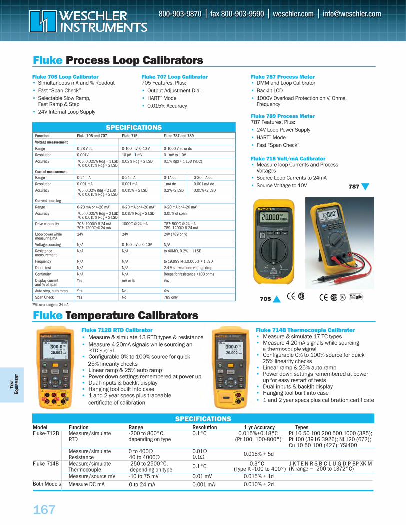
TEST
EQU
IPM
ENT
167
Fluke 705 Loop Calibrator• Simultaneous mA and % Readout• Fast “Span Check”• Selectable Slow Ramp,
Fast Ramp & Step• 24V Internal Loop Supply
Fluke 707 Loop Calibrator705 Features, Plus:• Output Adjustment Dial• HART™ Mode• 0.015% Accuracy
Fluke 787 Process Meter• DMM and Loop Calibrator• Backlit LCD• 1000V Overload Protection on V, Ohms,
Frequency
Fluke 789 Process Meter787 Features, Plus:• 24V Loop Power Supply• HART™ Mode• Fast “Span Check”
Fluke 715 Volt/mA Calibrator• Measure loop Currents and Process
Voltages• Source Loop Currents to 24mA• Source Voltage to 10V
Fluke Process Loop Calibrators
Fluke Temperature Calibrators
Functions Fluke 705 and 707 Fluke 715 Fluke 787 and 789
Voltage measurement
Range 0-28 V dc 0-100 mV 0-10 V 0-1000 V ac or dc
Resolution 0.001V 10 µV 1 mV 0.1mV to 1.0V
Accuracy 705: 0.025% Rdg + 1 LSD 0.02% Rdg + 2 LSD 0.1% Rgd + 1 LSD (VDC)707: 0.015% Rdg + 2 LSD
Current measurement
Range 0-24 mA 0-24 mA 0-1A dc 0-30 mA dc
Resolution 0.001 mA 0.001 mA 1mA dc 0.001 mA dc
Accuracy 705: 0.02% Rdg + 2 LSD 0.015% + 2 LSD 0.2%+2 LSD 0.05%+2 LSD707: 0.015% Rdg + 2 LSD
Current sourcing
Range 0-20 mA or 4-20 mA1 0-20 mA or 4-20 mA1 0-20 mA or 4-20 mA1
Accuracy 705: 0.025% Rdg + 2 LSD 0.015% Rdg + 2 LSD 0.05% of span707: 0.015% Rdg + 2 LSD
Drive capability 705: 1000Ω @ 24 mA 1000Ω @ 24 mA 787: 500Ω @ 24 mA707: 1200Ω @ 24 mA 789: 1200Ω @ 24 mA
Loop power while 24V 24V 24V (789 only)measuring mA
Voltage sourcing N/A 0-100 mV or 0-10V N/A
Resistance N/A N/A to 40MΩ, 0.2% + 1 LSDmeasurement
Frequency N/A N/A to 19.999 kHz,0.005% + 1 LSD
Diode test N/A N/A 2.4 V shows diode voltage drop
Continuity N/A N/A Beeps for resistance <100 ohms
Display current Yes mA or % Yesand % of span
Auto step, auto ramp Yes No Yes
Span Check Yes No 789 only1Will over-range to 24 mA
SPECIFICATIONS
Fluke 712B RTD Calibrator• Measure & simulate 13 RTD types & resistance• Measure 4-20mA signals while sourcing an` RTD signal• Configurable 0% to 100% source for quick` 25% linearity checks• Linear ramp & 25% auto ramp• Power down settings remembered at power up• Dual inputs & backlit display• Hanging tool built into case• 1 and 2 year specs plus traceable` certificate of calibration ` `
Fluke 714B Thermocouple Calibrator• Measure & simulate 17 TC types• Measure 4-20mA signals while sourcing
a thermocouple signal• Configurable 0% to 100% source for quick` 25% linearity checks• Linear ramp & 25% auto ramp• Power down settings remembered at power
up for easy restart of tests• Dual inputs & backlit display• Hanging tool built into case• 1 and 2 year specs plus calibration certificate
SPECIFICATIONSModel Function Range Resolution 1 yr Accuracy TypesFluke-712B Measure/simulate -200 to 800°C, 0.1°C 0.015%+0.18°C Pt 10 50 100 200 500 1000 (385);
RTD (Pt 100, 100-800°) Pt 100 (3916 3926); Ni 120 (672);Cu 10 50 100 (427); YSI400
Measure/simulate 0 to 400Ω 0.01Ω 0.015% + 5d ResistanceFluke-714B Measure/simulate -250 to 2500°C, 0.1°C 0.3°C J K T E N R S B C L U G D P BP XK M
Thermocouple depending on type (K range = -200 to 1372°C)Measure/source mV -10 to 75 mV 0.01 mV 0.015% + 1d
787
705
40 to 4000Ω 0.1Ω
depending on type
(Type K -100 to 400°)
Both Models Measure DC mA 0 to 24 mA 0.001 mA 0.010% + 2d
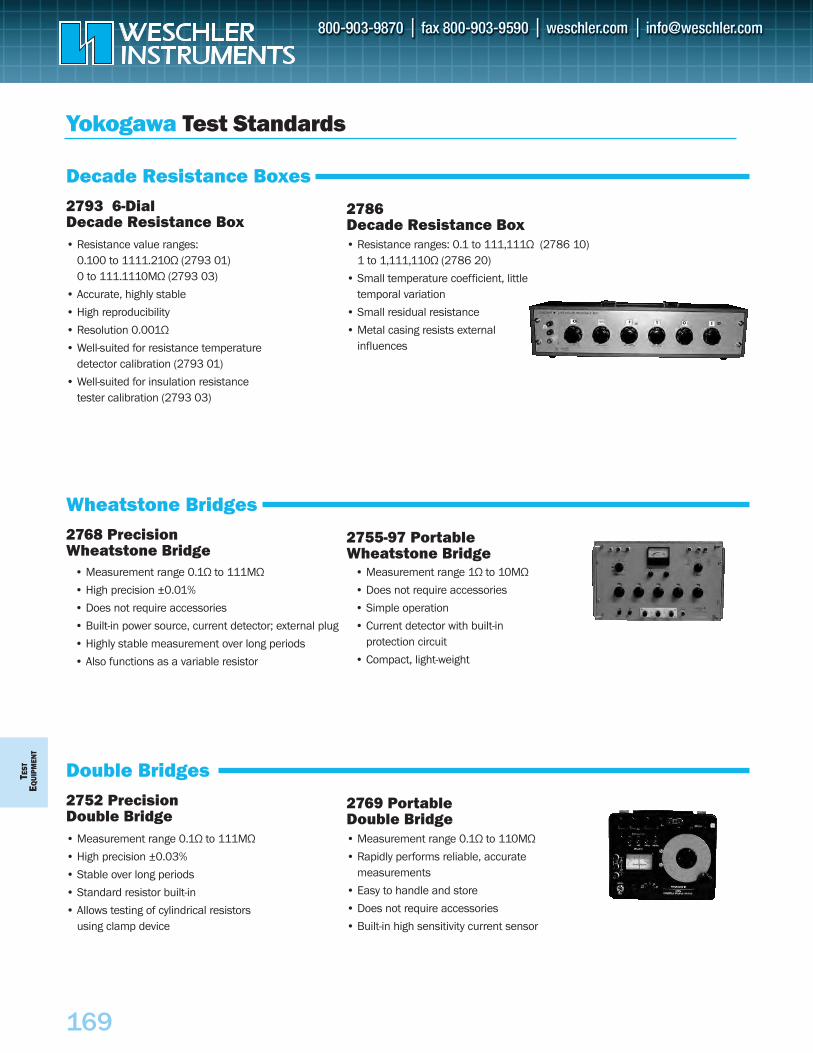
TEST
EQU
IPM
ENT
169
Yokogawa Test Standards
Decade Resistance Boxes2793 6-DialDecade Resistance Box
2786Decade Resistance Box
• Resistance value ranges: 0.100 to 1111.210Ω (2793 01)0 to 111.1110MΩ (2793 03)
• Accurate, highly stable
• High reproducibility
• Resolution 0.001Ω
• Well-suited for resistance temperature detector calibration (2793 01)
• Well-suited for insulation resistance tester calibration (2793 03)
• Resistance ranges: 0.1 to 111,111Ω (2786 10)1 to 1,111,110Ω (2786 20)
• Small temperature coefficient, little temporal variation
• Small residual resistance
• Metal casing resists external influences
Wheatstone Bridges2768 PrecisionWheatstone Bridge
2755-97 PortableWheatstone Bridge
• Measurement range 0.1Ω to 111MΩ
• High precision ±0.01%
• Does not require accessories
• Built-in power source, current detector; external plug
• Highly stable measurement over long periods
• Also functions as a variable resistor
• Measurement range 1Ω to 10MΩ
• Does not require accessories
• Simple operation
• Current detector with built-in protection circuit
• Compact, light-weight
Double Bridges2752 PrecisionDouble Bridge
2769 PortableDouble Bridge
• Measurement range 0.1Ω to 111MΩ
• High precision ±0.03%
• Stable over long periods
• Standard resistor built-in
• Allows testing of cylindrical resistors using clamp device
• Measurement range 0.1Ω to 110MΩ
• Rapidly performs reliable, accurate measurements
• Easy to handle and store
• Does not require accessories
• Built-in high sensitivity current sensor
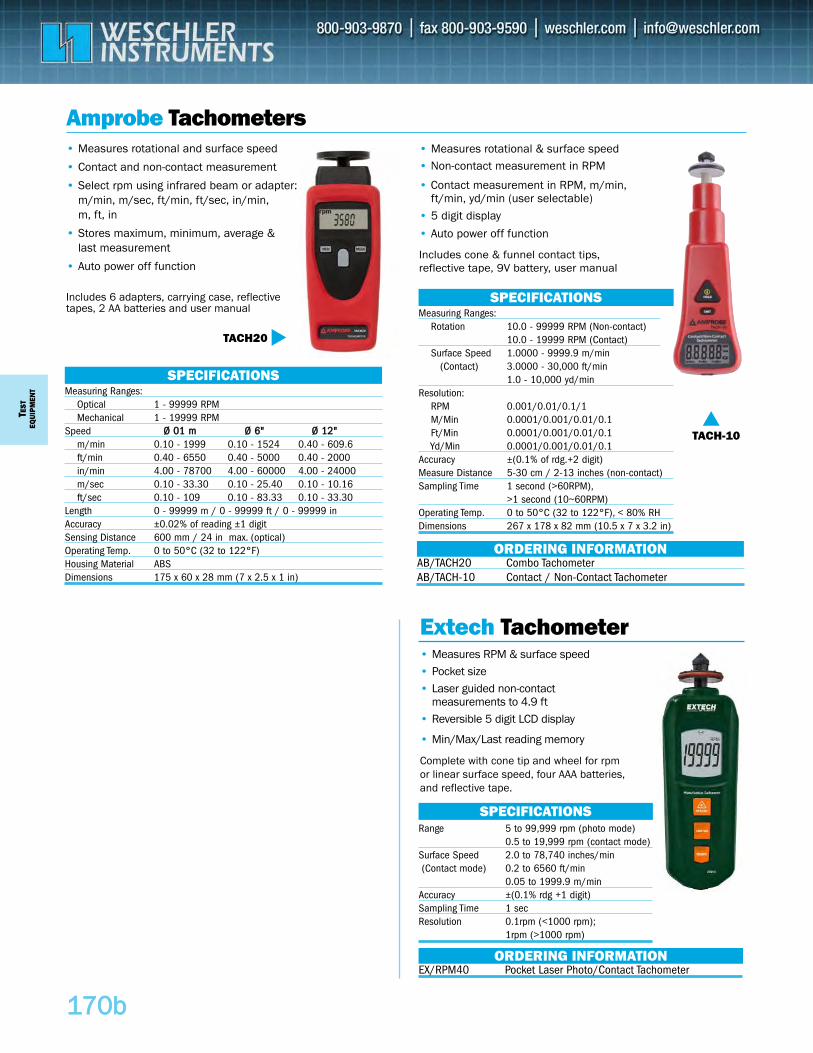
Measuring Ranges:Optical 1 - 99999 RPMMechanical 1 - 19999 RPM
Speed ØØ 0011 mm ØØ 66"" ØØ 1122""m/min 0.10 - 1999 0.10 - 1524 0.40 - 609.6ft/min 0.40 - 6550 0.40 - 5000 0.40 - 2000in/min 4.00 - 78700 4.00 - 60000 4.00 - 24000m/sec 0.10 - 33.30 0.10 - 25.40 0.10 - 10.16ft/sec 0.10 - 109 0.10 - 83.33 0.10 - 33.30
Length 0 - 99999 m / 0 - 99999 ft / 0 - 99999 inAccuracy ±0.02% of reading ±1 digitSensing Distance 600 mm / 24 in max. (optical)Operating Temp. 0 to 50°C (32 to 122°F)Housing Material ABSDimensions 175 x 60 x 28 mm (7 x 2.5 x 1 in)
Range 5 to 99,999 rpm (photo mode)0.5 to 19,999 rpm (contact mode)
Surface Speed 2.0 to 78,740 inches/min(Contact mode) 0.2 to 6560 ft/min
0.05 to 1999.9 m/minAccuracy ±(0.1% rdg +1 digit) Sampling Time 1 secResolution 0.1rpm (<1000 rpm);
1rpm (>1000 rpm)
SPECIFICATIONS
Measuring Ranges:Rotation 10.0 - 99999 RPM (Non-contact)
10.0 - 19999 RPM (Contact) Surface Speed 1.0000 - 9999.9 m/min
(Contact) 3.0000 - 30,000 ft/min1.0 - 10,000 yd/min
Resolution:RPM 0.001/0.01/0.1/1M/Min 0.0001/0.001/0.01/0.1Ft/Min 0.0001/0.001/0.01/0.1Yd/Min 0.0001/0.001/0.01/0.1
Accuracy ±(0.1% of rdg.+2 digit)Measure Distance 5-30 cm / 2-13 inches (non-contact)Sampling Time 1 second (>60RPM),
>1 second (10~60RPM)Operating Temp. 0 to 50°C (32 to 122°F), < 80% RHDimensions 267 x 178 x 82 mm (10.5 x 7 x 3.2 in)
SPECIFICATIONS
TEST
EQUI
PMEN
T
117700bb
Amprobe Tachometers• Measures rotational & surface speed• Non-contact measurement in RPM
• Contact measurement in RPM, m/min, ft/min, yd/min (user selectable)
• 5 digit display
• Auto power off function
Includes cone & funnel contact tips, reflective tape, 9V battery, user manual
• Measures rotational and surface speed
• Contact and non-contact measurement
• Select rpm using infrared beam or adapter:m/min, m/sec, ft/min, ft/sec, in/min, m, ft, in
• Stores maximum, minimum, average & last measurement
• Auto power off function
Includes 6 adapters, carrying case, reflectivetapes, 2 AA batteries and user manual
TACH20
TACH-10
SPECIFICATIONS
AB/TACH20 Combo TachometerAB/TACH-10 Contact / Non-Contact Tachometer
ORDERING INFORMATION
• Measures RPM & surface speed• Pocket size• Laser guided non-contact
measurements to 4.9 ft• Reversible 5 digit LCD display
• Min/Max/Last reading memory
Complete with cone tip and wheel for rpmor linear surface speed, four AAA batteries,and reflective tape.
Extech Tachometer
EX/RPM40 Pocket Laser Photo/Contact TachometerORDERING INFORMATION
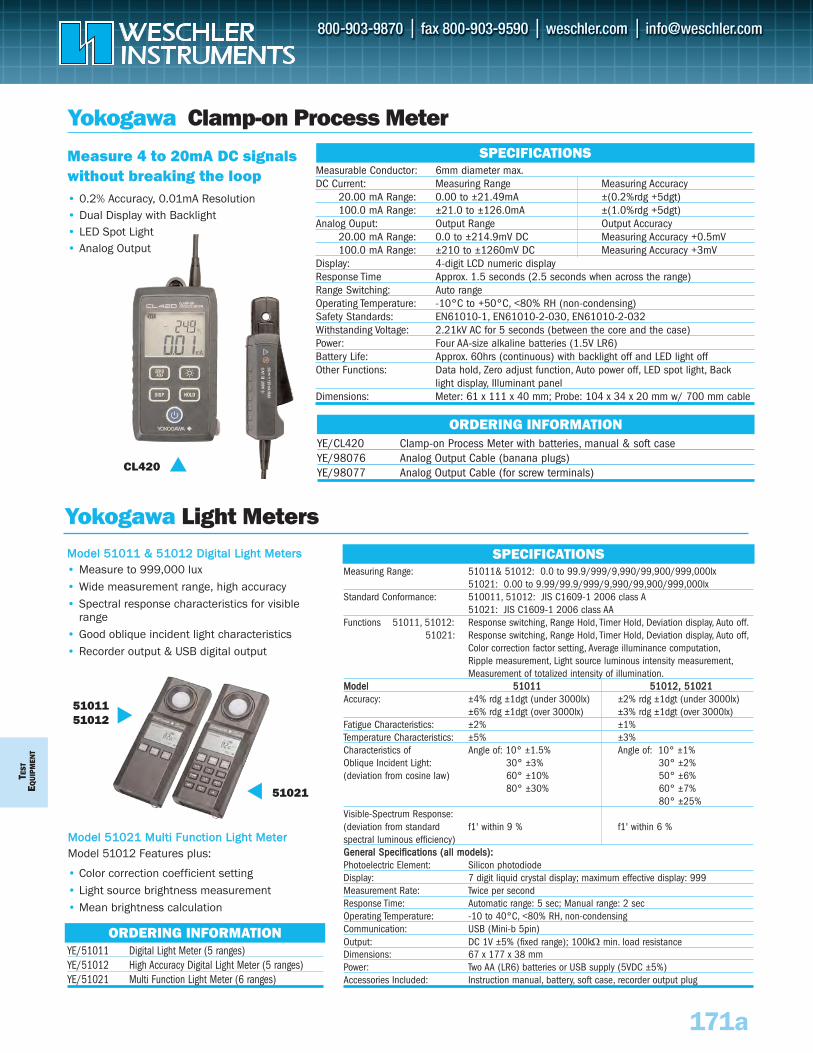
TEST
EQUI
PMEN
T
171a
Yokogawa Clamp-on Process Meter
Measure 4 to 20mA DC signalswithout breaking the loop• 0.2% Accuracy, 0.01mA Resolution• Dual Display with Backlight• LED Spot Light • Analog Output
CL420
Measurable Conductor: 6mm diameter max.DC Current: Measuring Range Measuring Accuracy
20.00 mA Range: 0.00 to ±21.49mA ±(0.2%rdg +5dgt)100.0 mA Range: ±21.0 to ±126.0mA ±(1.0%rdg +5dgt)
Analog Ouput: Output Range Output Accuracy20.00 mA Range: 0.0 to ±214.9mV DC Measuring Accuracy +0.5mV100.0 mA Range: ±210 to ±1260mV DC Measuring Accuracy +3mV
Display: 4-digit LCD numeric displayResponse Time Approx. 1.5 seconds (2.5 seconds when across the range)Range Switching: Auto rangeOperating Temperature: -10°C to +50°C, <80% RH (non-condensing)Safety Standards: EN61010-1, EN61010-2-030, EN61010-2-032Withstanding Voltage: 2.21kV AC for 5 seconds (between the core and the case)Power: Four AA-size alkaline batteries (1.5V LR6)Battery Life: Approx. 60hrs (continuous) with backlight off and LED light offOther Functions: Data hold, Zero adjust function, Auto power off, LED spot light, Back
light display, Illuminant panelDimensions: Meter: 61 x 111 x 40 mm; Probe: 104 x 34 x 20 mm w/ 700 mm cable
SPECIFICATIONS
YE/CL420 Clamp-on Process Meter with batteries, manual & soft caseYE/98076 Analog Output Cable (banana plugs)YE/98077 Analog Output Cable (for screw terminals)
ORDERING INFORMATION
Yokogawa Light MetersMMooddeell 5511001111 && 5511001122 DDiiggiittaall LLiigghhtt MMeetteerrss• Measure to 999,000 lux• Wide measurement range, high accuracy• Spectral response characteristics for visible
range• Good oblique incident light characteristics• Recorder output & USB digital output
MMooddeell 5511002211 MMuullttii FFuunnccttiioonn LLiigghhtt MMeetteerrModel 51012 Features plus:
• Color correction coefficient setting• Light source brightness measurement• Mean brightness calculation
SPECIFICATIONS
YE/51011 Digital Light Meter (5 ranges)YE/51012 High Accuracy Digital Light Meter (5 ranges)YE/51021 Multi Function Light Meter (6 ranges)
ORDERING INFORMATION
51021
5101151012
Measuring Range: 51011& 51012: 0.0 to 99.9/999/9,990/99,900/999,000lx 51021: 0.00 to 9.99/99.9/999/9,990/99,900/999,000lx
Standard Conformance: 510011, 51012: JIS C1609-1 2006 class A 51021: JIS C1609-1 2006 class AA
Functions 51011, 51012: Response switching, Range Hold, Timer Hold, Deviation display, Auto off.51021: Response switching, Range Hold, Timer Hold, Deviation display, Auto off,
Color correction factor setting, Average illuminance computation,Ripple measurement, Light source luminous intensity measurement,Measurement of totalized intensity of illumination.
MMooddeell 5511001111 5511001122,, 5511002211Accuracy: ±4% rdg ±1dgt (under 3000lx) ±2% rdg ±1dgt (under 3000lx)
±6% rdg ±1dgt (over 3000lx) ±3% rdg ±1dgt (over 3000lx)Fatigue Characteristics: ±2% ±1%Temperature Characteristics: ±5% ±3%Characteristics of Angle of: 10° ±1.5% Angle of: 10° ±1%Oblique Incident Light: 30° ±3% 30° ±2%(deviation from cosine law) 60° ±10% 50° ±6%
80° ±30% 60° ±7%80° ±25%
Visible-Spectrum Response: (deviation from standard f1' within 9 % f1' within 6 %spectral luminous efficiency)GGeenneerraall SSppeecciiffiiccaattiioonnss ((aallll mmooddeellss))::Photoelectric Element: Silicon photodiodeDisplay: 7 digit liquid crystal display; maximum effective display: 999 Measurement Rate: Twice per secondResponse Time: Automatic range: 5 sec; Manual range: 2 secOperating Temperature: -10 to 40°C, <80% RH, non-condensingCommunication: USB (Mini-b 5pin)Output: DC 1V ±5% (fixed range); 100kΩ min. load resistance Dimensions: 67 x 177 x 38 mmPower: Two AA (LR6) batteries or USB supply (5VDC ±5%)Accessories Included: Instruction manual, battery, soft case, recorder output plug
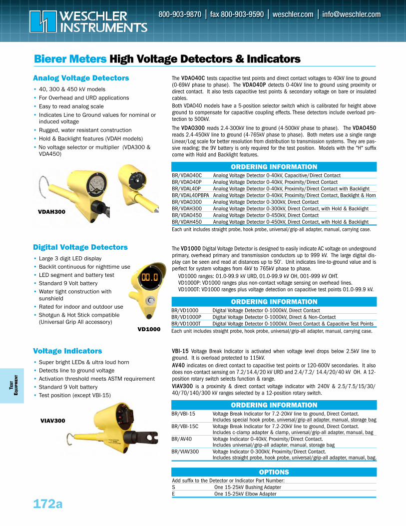
TEST
EQUI
PMEN
T
172a
Bierer Meters High Voltage Detectors & Indicators
Digital Voltage Detectors• Large 3 digit LED display• Backlit continuous for nighttime use• LED segment and battery test • Standard 9 Volt battery• Water tight construction with
sunshield • Rated for indoor and outdoor use• Shotgun & Hot Stick compatible
(Universal Grip All accessory)
Voltage Indicators• Super bright LEDs & ultra loud horn• Detects line to ground voltage• Activation threshold meets ASTM requirement• Standard 9 Volt battery• Test position (except VBI-15)
VDAH300
BR/VDAO40C Analog Voltage Detector 0-40kV, Capacitive/Direct ContactBR/VDAO40P Analog Voltage Detector 0-40kV, Proximity/Direct ContactBR/VDAL40P Analog Voltage Detector 0-40kV, Proximity/Direct Contact with BacklightBR/VDAL40PBPA Analog Voltage Detector 0-40kV, Proximity/Direct Contact, Backlight & HornBR/VDAO300 Analog Voltage Detector 0-300kV, Direct ContactBR/VDAH300 Analog Voltage Detector 0-300kV, Direct Contact, with Hold & BacklightBR/VDAO450 Analog Voltage Detector 0-450kV, Direct ContactBR/VDAH450 Analog Voltage Detector 0-450kV, Direct Contact, with Hold & BacklightEach unit includes straight probe, hook probe, universal/grip-all adapter, manual, carrying case.
ORDERING INFORMATION
BR/VD1000 Digital Voltage Detector 0-1000kV, Direct ContactBR/VD1000P Digital Voltage Detector 0-1000kV, Direct & Non-Contact BR/VD1000T Digital Voltage Detector 0-1000kV, Direct Contact & Capacitive Test PointsEach unit includes straight probe, hook probe, universal/grip-all adapter, manual, carrying case.
ORDERING INFORMATION
BR/VBI-15 Voltage Break Indicator for 7.2-20kV line to ground, Direct Contact.Includes special hook probe, universal/grip-all adapter, manual, storage bag
BR/VBI-15C Voltage Break Indicator for 7.2-20kV line to ground, Direct Contact.Includes c-clamp adapter & clamp, universal/grip-all adapter, manual, bag
BR/AV40 Voltage Indicator 0-40kV, Proximity/Direct Contact.Includes universal/grip-all adapter, manual, storage bag
BR/VIAV300 Voltage Indicator 0-300kV, Proximity/Direct Contact.Includes straight probe, hook probe, universal/grip-all adapter, manual, bag.
ORDERING INFORMATION
Analog Voltage Detectors• 40, 300 & 450 kV models• For Overhead and URD applications• Easy to read analog scale• Indicates Line to Ground values for nominal or
induced voltage• Rugged, water resistant construction• Hold & Backlight features (VDAH models)• No voltage selector or multiplier (VDA300 &
VDA450)
Add suffix to the Detector or Indicator Part Number: S One 15-25kV Bushing AdapterE One 15-25kV Elbow Adapter
OPTIONS
VIAV300
VD1000
The VVDD11000000 Digital Voltage Detector is designed to easily indicate AC voltage on undergroundprimary, overhead primary and transmission conductors up to 999 kV. The large digital dis-play can be seen and read at distances up to 50’. Unit indicates line-to-ground value and isperfect for system voltages from 4kV to 765kV phase to phase.
VD1000 ranges: 01.0-99.9 kV URD, 01.0-99.9 kV OH, 001-999 kV OHT.VD1000P: VD1000 ranges plus non-contact voltage sensing on overhead lines.VD1000T: VD1000 ranges plus voltage detection on capacitive test points 01.0-99.9 kV.
The VVDDAAOO4400CC tests capacitive test points and direct contact voltages to 40kV line to ground(0-69kV phase to phase). The VVDDAAOO4400PP detects 0-40kV line to ground using proximity ordirect contact. It also tests capacitive test points & secondary voltage on bare or insulatedcables.Both VDAO40 models have a 5-position selector switch which is calibrated for height aboveground to compensate for capacitive coupling effects. These detectors include overload pro-tection to 500kV.
The VVDDAAOO330000 reads 2.4-300kV line to ground (4-500kV phase to phase). The VVDDAAOO445500reads 2.4-450kV line to ground (4-765kV phase to phase). Both meters use a single rangeLinear/Log scale for better resolution from distribution to transmission systems. They are pas-sive reading; the 9V battery is only required for the test position. Models with the "H" suffixcome with Hold and Backlight features.
VVBBII--1155 Voltage Break Indicator is activated when voltage level drops below 2.5kV line toground. It is overload protected to 115kV.AAVV4400 indicates on direct contact to capacitive test points or 120-600V secondaries. It alsodoes non-contact sensing on 7.2/14.4/20 kV URD and 2.4/7.2/ 14.4/20/40 kV OH. A 12-position rotary switch selects function & range.VVIIAAVV330000 is a proximity & direct contact voltage indicator with 240V & 2.5/7.5/15/30/40/70/140/300 kV ranges selected by a 12-position rotary switch.
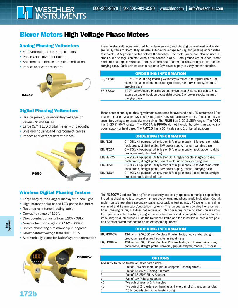
TEST
EQUI
PMEN
T
172b
Bierer Meters High Voltage Phase Meters
Digital Phasing Voltmeters• Use on primary or secondary voltages or
capacitive test points• Large (3/4") LCD digital meter with backlight• Shielded housing and interconnect cables• Impact and water resistant probes
Wireless Digital Phasing Testers• Large easy-to-read digital display with backlight• High intensity color coded LED phase indicators• Requires no interconnecting cable• Operating range of 100ft• Direct contact phasing from 120V - 69kV•Non-contact phasing from 69kV - 800kV
• Shows phase angle relationship in degrees• Direct contact voltage from 4kV - 69kV• Automatically alerts for Delta/Wye transformation
83280
Analog Phasing Voltmeters • For Overhead and URD applications• Phase Capacitive Test Points• Shielded to minimize stray field indications• Impact and water resistant
PD800W
Bierer analog voltmeters are used for voltage sensing and phasing on overhead and under-ground systems to 35kV. They are also suitable for voltage sensing and phasing at capacitivetest points. A 5-position switch selects the function. The meter probe can also be used asstand-alone voltage detector without the second probe. Both probes are shielded, waterresistant and impact resistant. Probes, cables and adapters fit conveniently in the paddedcarrying case. Each unit includes a separate 3kV power supply to verify meter operation.
BR/81280 300V – 25kV Analog Phasing Voltmeter/Detector, 8 ft. regular cable, 8 ft.extension cable, hook probe, straight probe, 3kV power supply, manual,carrying case
BR/83280 300V– 35kV Analog Phasing Voltmeter/Detector, 8 ft. regular cable, 8 ft.extension cable, hook probe, straight probe, 3kV power supply, manual,carrying case
ORDERING INFORMATION
BR/PD25 0 – 25kV All-purpose Utility Meter, 8 ft. regular cable, 8 ft. extension cable,hook probe, straight probe, 3kV power supply, manual, carrying case
BR/PD25A 0 – 25kV All-purpose Utility Meter, 8 ft. regular cable, hook probe, straight probe, manual, standard bag
BR/RMV25 0 – 25kV All-purpose Utility Meter, 30 ft. regular cable, magnetic base,hook probe, straight probe, pair of metal universals, carrying case
BR/PD50 0 – 50kV All-purpose Utility Meter, 8 ft. regular cable, 8 ft. extension cable,hook probe, straight probe, 3kV power supply, manual, carrying case
BR/PD50A 0 – 50kV All-purpose Utility Meter, 8 ft. regular cable, hook probe, straight probe, manual, standard bag
ORDERING INFORMATION
BR/PD800W 120 volt – 800,000 volt Cordless Phasing Tester, hook probe, straight probe, universal/grip-all adapter, manual, case
BR/PD8H2W 120 volt – 800,000 volt Cordless Phasing Tester, 2ft. transmission hook,hook probe, straight probe, universal/grip-all adapter, manual, 26" case
ORDERING INFORMATION
Add suffix to the Voltmeter or Tester part number: U Pair of Universal metal or grip-all adapters (specify which)S Pair of 15-25kV Bushing AdaptersE Pair of 15-25kV Elbow AdaptersV Pair of Low Voltage AdaptersH2 Two pair of regular 2 ft. handlesH6 Two pair of 2 ft. extension handles and one pair of 2 ft. regular handlesD DC hi-pot adapter (for voltmeters only)
OPTIONS
These conventional type phasing voltmeters are rated for overhead and URD systems to 50kVphase to phase. Measure DC or AC voltage to 400Hz with accuracy to 1%. Check primary orsecondary voltages or capacitive test points. The PPDD2255 has 2, 20 & 25kV ranges. The PPDD5500has 2, 20 & 50kV ranges. The PPDD2255AA & PPDD5500AA do not include the extension cable, 3kVpower supply or hard case. The RRMMVV2255 has a 30 ft cable and 2 universal adapters.
The PPDD880000WW Cordless Phasing Tester accurately and easily operates in multiple applicationsincluding phasing, voltage detection, phase sequencing and phase angle indication. One kitrapidly tests three-phase secondary systems, capacitive test points, URD systems as well asoverhead and transmission/substation systems. This unique tester operates like a conven-tional phasing tester, but does not require an interconnecting cable or extension resistors.Each probe is water resistant, designed to withstand wear and is completely shielded to min-imize stray field interference. Both the Reference Probe and the Meter Probe have a five-posi-tion selector switch that controls different operating modes.
PD50
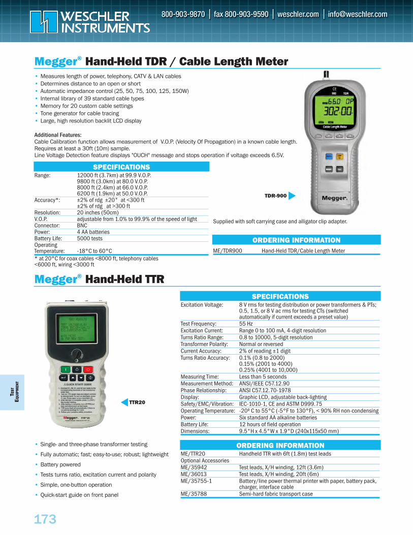
TEST
EQU
IPM
ENT
173
Megger® Hand-Held TDR / Cable Length Meter• Measures length of power, telephony, CATV & LAN cables• Determines distance to an open or short• Automatic impedance control (25, 50, 75, 100, 125, 150W)• Internal library of 39 standard cable types• Memory for 20 custom cable settings• Tone generator for cable tracing• Large, high resolution backlit LCD display
Additional Features:Cable Calibration function allows measurement of V.O.P. (Velocity Of Propagation) in a known cable length.Requires at least a 30ft (10m) sample. Line Voltage Detection feature displays "OUCH" message and stops operation if voltage exceeds 6.5V.
SPECIFICATIONSRange: 12000 ft (3.7km) at 99.9 V.O.P.
9800 ft (3.0km) at 80.0 V.O.P.8000 ft (2.4km) at 66.0 V.O.P.6200 ft (1.9km) at 50.0 V.O.P.
Accuracy*: ±2% of rdg ±20" at <300 ft±2% of rdg at >300 ft
Resolution: 20 inches (50cm)V.O.P. adjustable from 1.0% to 99.9% of the speed of lightConnector: BNCPower: 4 AA batteriesBattery Life: 5000 testsOperating Temperature: -18°C to 60°C* at 20°C for coax cables <8000 ft, telephony cables <6000 ft, wiring <3000 ft
TDR-900
Supplied with soft carrying case and alligator clip adapter.
ME/TDR900 Hand-Held TDR/Cable Length Meter
ORDERING INFORMATION
Megger® Hand-Held TTR
• Single- and three-phase transformer testing
• Fully automatic; fast; easy-to-use; robust; lightweight
• Battery powered
• Tests turns ratio, excitation current and polarity
• Simple, one-button operation
• Quick-start guide on front panel
SPECIFICATIONSExcitation Voltage: 8 V rms for testing distribution or power transformers & PTs;
0.5, 1.5, or 8 V ac rms for testing CTs (switched automatically if current exceeds a preset value)
Test Frequency: 55 Hz Excitation Current: Range 0 to 100 mA, 4-digit resolutionTurns Ratio Range: 0.8 to 10000, 5-digit resolutionTransformer Polarity: Normal or reversedCurrent Accuracy: 2% of reading ±1 digitTurns Ratio Accuracy: 0.1% (0.8 to 2000)
0.15% (2001 to 4000)0.25% (4001 to 10,000)
Measuring Time: Less than 5 secondsMeasurement Method: ANSI/IEEE C57.12.90Phase Relationship: ANSI C57.12.70-1978Display: Graphic LCD, adjustable back-lightingSafety/EMC/Vibration: IEC-1010-1, CE and ASTM D999.75Operating Temperature: -20º C to 55°C (-5°F to 130°F), < 90% RH non-condensingPower: Six standard AA alkaline batteriesBattery Life: 12 hours of field operationDimensions: 9.5"H x 4.5"W x 1.9"D (240x115x50 mm)
ORDERING INFORMATIONME/TTR20 Handheld TTR with 6ft (1.8m) test leadsOptional AccessoriesME/35942 Test leads, X/H winding, 12ft (3.6m) ME/36013 Test leads, X/H winding, 20ft (6m) ME/35755-1 Battery/line power thermal printer with paper, battery pack,
charger, interface cable ME/35788 Semi-hard fabric transport case
TTR20
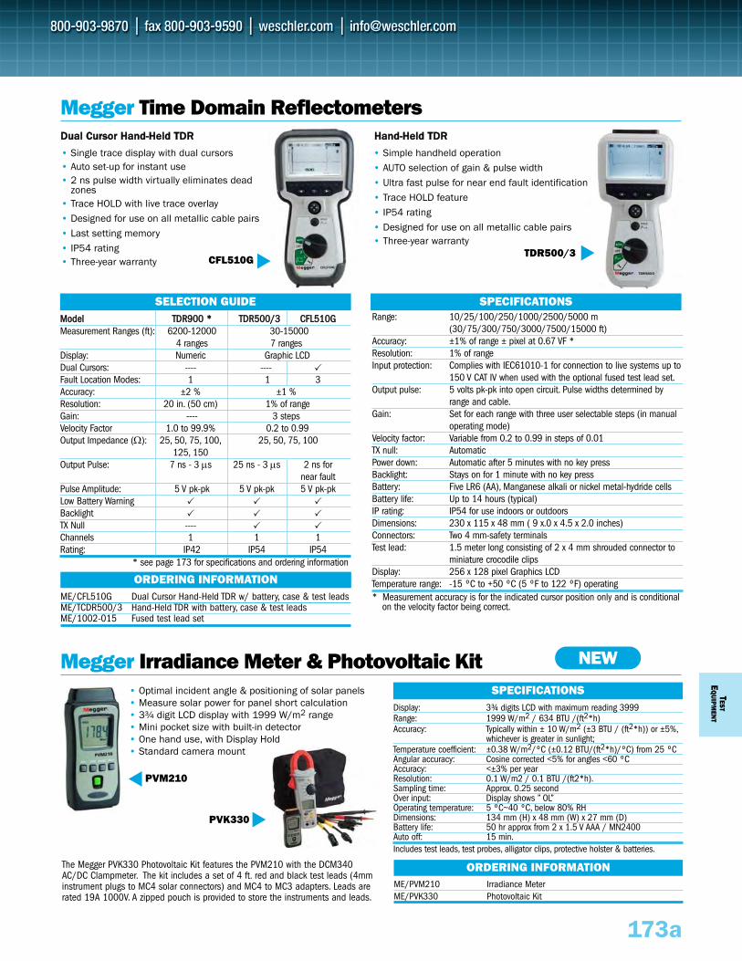
TESTE
QUIPM
ENT
173a
Megger Irradiance Meter & Photovoltaic Kit
PVK330
PVM210
Display: 3¾ digits LCD with maximum reading 3999Range: 1999 W/m2 / 634 BTU /(ft2*h)Accuracy: Typically within ± 10 W/m2 (±3 BTU / (ft2*h)) or ±5%,
whichever is greater in sunlight; Temperature coefficient: ±0.38 W/m2/ºC (±0.12 BTU/(ft2*h)/ºC) from 25 ºCAngular accuracy: Cosine corrected <5% for angles <60 ºCAccuracy: <±3% per yearResolution: 0.1 W/m2 / 0.1 BTU /(ft2*h).Sampling time: Approx. 0.25 secondOver input: Display shows ” OL”Operating temperature: 5 ºC~40 ºC, below 80% RHDimensions: 134 mm (H) x 48 mm (W) x 27 mm (D)Battery life: 50 hr approx from 2 x 1.5 V AAA / MN2400Auto off: 15 min.Includes test leads, test probes, alligator clips, protective holster & batteries.
SPECIFICATIONS
ME/PVM210 Irradiance MeterME/PVK330 Photovoltaic Kit
ORDERING INFORMATION
ME/CFL510G Dual Cursor Hand-Held TDR w/ battery, case & test leadsME/TCDR500/3 Hand-Held TDR with battery, case & test leadsME/1002-015 Fused test lead set
ORDERING INFORMATION
Megger Time Domain Reflectometers
• Single trace display with dual cursors• Auto set-up for instant use• 2 ns pulse width virtually eliminates dead
zones• Trace HOLD with live trace overlay• Designed for use on all metallic cable pairs• Last setting memory• IP54 rating• Three-year warranty CFL510G
MMooddeell TTDDRR990000 ** TTDDRR550000//33 CCFFLL551100GG Measurement Ranges (ft): 6200-12000 30-15000
4 ranges 7 rangesDisplay: Numeric Graphic LCD Dual Cursors: ---- ---- Fault Location Modes: 1 1 3 Accuracy: ±2 % ±1 % Resolution: 20 in. (50 cm) 1% of range Gain: ---- 3 steps Velocity Factor 1.0 to 99.9% 0.2 to 0.99 Output Impedance (Ω): 25, 50, 75, 100, 25, 50, 75, 100
125, 150Output Pulse: 7 ns - 3 μs 25 ns - 3 μs 2 ns for
near faultPulse Amplitude: 5 V pk-pk 5 V pk-pk 5 V pk-pk Low Battery Warning Backlight TX Null ---- Channels 1 1 1 Rating: IP42 IP54 IP54
* see page 173 for specifications and ordering information
SELECTION GUIDE
TDR500/3
Range: 10/25/100/250/1000/2500/5000 m(30/75/300/750/3000/7500/15000 ft)
Accuracy: ±1% of range ± pixel at 0.67 VF *Resolution: 1% of rangeInput protection: Complies with IEC61010-1 for connection to live systems up to
150 V CAT IV when used with the optional fused test lead set.Output pulse: 5 volts pk-pk into open circuit. Pulse widths determined by
range and cable.Gain: Set for each range with three user selectable steps (in manual
operating mode)Velocity factor: Variable from 0.2 to 0.99 in steps of 0.01TX null: AutomaticPower down: Automatic after 5 minutes with no key pressBacklight: Stays on for 1 minute with no key pressBattery: Five LR6 (AA), Manganese alkali or nickel metal-hydride cellsBattery life: Up to 14 hours (typical)IP rating: IP54 for use indoors or outdoorsDimensions: 230 x 115 x 48 mm ( 9 x.0 x 4.5 x 2.0 inches)Connectors: Two 4 mm-safety terminalsTest lead: 1.5 meter long consisting of 2 x 4 mm shrouded connector to
miniature crocodile clipsDisplay: 256 x 128 pixel Graphics LCDTemperature range: -15 ºC to +50 ºC (5 ºF to 122 ºF) operating* Measurement accuracy is for the indicated cursor position only and is conditional
on the velocity factor being correct.
SPECIFICATIONS
• Simple handheld operation• AUTO selection of gain & pulse width• Ultra fast pulse for near end fault identification• Trace HOLD feature• IP54 rating• Designed for use on all metallic cable pairs• Three-year warranty
• Optimal incident angle & positioning of solar panels• Measure solar power for panel short calculation• 3¾ digit LCD display with 1999 W/m2 range • Mini pocket size with built-in detector • One hand use, with Display Hold• Standard camera mount
NEW
The Megger PVK330 Photovoltaic Kit features the PVM210 with the DCM340AC/DC Clampmeter. The kit includes a set of 4 ft. red and black test leads (4mminstrument plugs to MC4 solar connectors) and MC4 to MC3 adapters. Leads arerated 19A 1000V. A zipped pouch is provided to store the instruments and leads.
DDuuaall CCuurrssoorr HHaanndd--HHeelldd TTDDRR HHaanndd--HHeelldd TTDDRR
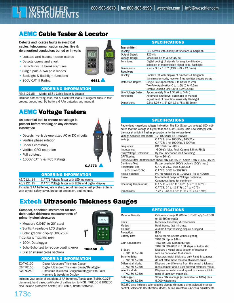
Extech Ultrasonic Thickness Gauges
117733cc
AEMC Cable Tester & Locator
AEMC Voltage Testers
• Detects live & de-energized AC or DC circuits• Verifies phase rotation• Checks continuity• Verifies GFCI operation • Full autotest• 1000V CAT IV & IP65 Ratings
C.A773
EX/TKG100 Digital Ultrasonic Thickness GaugeEX/TKG150 Digital Ultrasonic Thickness Gauge/DataloggerEX/TKG250 Ultrasonic Thickness Gauge/Datalogger with Color
Numeric & Waveform Displayincludes 2oz bottle of couplant, 2 AA batteries, Transducer (5MHz, 0.375"diameter), hard case, certificate of calibration to NIST. TKG150 & TKG250also include protective holster, USB cable, XPorter software.
ORDERING INFORMATION
Redundant Hazardous Voltage Indication: The ELV (Extra-Low Voltage) LED indi-cates that the voltage is higher than the SELV (Safety Extra-Low Voltage) withthe rate at which it flashes proportional to the voltage levelVoltage Absence Test (VAT): 12-1000Vac; 12-1400VdcVoltage: C.A771: 8 to 1000Vac/1400Vdc
C.A773: 1 to 1000Vac/1400VdcFrequency: DC, 16.67 to 800HzImpedance: >500kΩ (Max. Peak Current 3.5mA RMS)Stray Voltage Detection: By low-impedance load switchingGFI Tripping: Up to 30mΩPhase/Neutral Identification: Above 50V (45-65Hz); Above 150V (16.67-45Hz)Continuity Test: Buzzer threshold 100Ω typical (150Ω max.)Resistance Test: C.A771: 2kΩ, 60kΩ, 300kΩ
(<0.1mA/<3.3V) C.A773: 0.5Ω to 2999kΩPhase Rotation: Ph/Ph Voltage 50 to 1000Vac (45 to 400Hz)Buzzer: Intermittent beep for Voltage Detection;
Continuous beep for continuityOperating Temperature: C.A771: -25.6° to 140°F (-30° to 60°C)
C.A773: 5° to 113°F(-15° to 45°C) Dimensions: 7.72 x 3.54 x 1.85" (196 x 90 x 47.1mm)
SPECIFICATIONS
Material Velocity: Calibration range 0.200 to 0.7362 in/μS (0.508 to 18.699mm/μS)
Units: Inches/Millimeters/MicrosecondsModes: Hold, freeze, fast min/maxAlarms: Audible beep; flashing display & keypad Protection: IP54Battery Life: Up to 50 hrs (20hrs w/backlighting)
TKG250: Up to 14hrsGain Adjustment: TKG150: Low, Standard, High
TKG250: 20-90dB in 1dB steps or AutomaticB-Scan: Displays a visual cross section of inspection
(TKG150 &250) with no correlation to distance.Echo to Echo: Measures metal thickness only. Paint & coatings
(TKG150 &250) do not affect base material thickness value.Differential Mode: Displays the difference from the actual thickness
(TKG150 &250) measurement and a user entered reference value.Velocity Mode: Displays acoustic sound speed to measure thick-
(TKG150 &250) ness of unknown materials.Datalogger: Stores 50k readings (expandable to 100k) plus
(TKG150 &250) 5,000 waveformsTKG250 also includes color graphic display, vibrating alarm, adjustable rangecontrol, selectable Rectification Modes, & Live Waveform (A-Scan) adjustments.
SPECIFICATIONS
• Measure 0.040" to 20" steel • Sunlight readable LCD display• Color graphic display (TKG250)TKG150 & TKG250 add:• 100k Datalogger• Echo-Echo test to reduce coating error• B-scan (visual cross section)
TKG150
• Locates and traces hidden cables• Detects opens and short• Detects circuit breakers/fuses• Single pole & two pole modes• Backlight & flashlight functions• 300V CAT III Rating 6681
TTrraannssmmiitttteerr::Display: LCD screen with display of functions & bargraphOutput Signal: 125kHzVoltage Range: Measures 12 to 300V ac/dcFunctions: Digital coding of signals for easy identification,
selection of transmission signal code, flashlightDimensions: 7.48 x 3.5 x 1.67" (190 x 89 x 42.5mm)RReecceeiivveerr::Display: Backlit LCD with display of functions & bargraph,
transmission code, receiver & transmitter battery statusDetection Depth: Single-Pole Application 0 to 6ft (0 to 2m)
Two-Pole Application 0 to 1.6ft (0 to 0.5m)Simple Looping Line Up to 8.2ft (2.5m)
Line Voltage Detect: Approximately 0 to 1.3ft (0 to 0.4m)Functions: Automatic shutdown, automatic or manual
adjustment of reception sensitivity, flashlightDimensions: 9.5 x 3.07 x 1.5" (241.5 x 78 x 38.5mm)
SPECIFICATIONS
AE/2127.85 Model 6681 Cable Tester & Locator Includes soft carrying case, red & black test leads, 2 alligator clips, 2 testprobes, ground rod, 9V battery, 6 AAA batteries and manual.
ORDERING INFORMATION
CCoommppaacctt,, hhaannddhheelldd iinnssttrruummeenntt ffoorr nnoonn--ddeessttrruuccttiivvee tthhiicckknneessss mmeeaassuurreemmeennttss ooffpprriimmaarriillyy sstteeeell ssttrruuccttuurreess
AE/2121.14 C.A771 Voltage Tester with LED indicatorsAE/2121.15 C.A773 Voltage Tester with LEDs and digital displayIncludes 2 AA batteries, velcro strap, set of removable test probes Ø 2mmwith crystal safety cover, probe-tip protection, and manual.
ORDERING INFORMATION
DDeetteeccttss aanndd llooccaatteess ffaauullttss iinn eelleeccttrriiccaallccaabblleess,, tteelleeccoommmmuunniiccaattiioonn ccaabblleess,, lliivvee &&ddee--eenneerrggiizzeedd ccoonndduuccttoorrss bbuurriieedd oorr iinn wwaallllss
AAnn eesssseennttiiaall ttooooll ttoo eennssuurree nnoo vvoollttaaggee iisspprreesseenntt bbeeffoorree wwoorrkkiinngg oonn aannyy eelleeccttrriiccaalliinnssttaallllaattiioonn
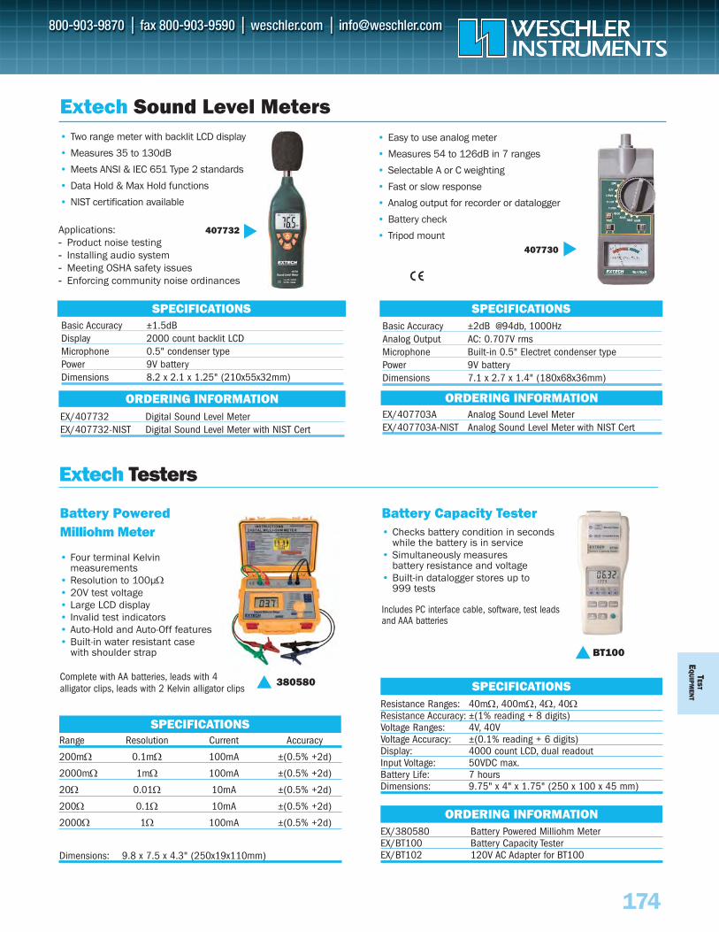
TESTE
QUIPM
ENT
174
Battery PoweredMilliohm Meter
• Four terminal Kelvin measurements
• Resolution to 100μΩ• 20V test voltage• Large LCD display• Invalid test indicators• Auto-Hold and Auto-Off features• Built-in water resistant case
with shoulder strap
Complete with AA batteries, leads with 4 alligator clips, leads with 2 Kelvin alligator clips
380580
Range Resolution Current Accuracy
200mΩ 0.1mΩ 100mA ±(0.5% +2d)
2000mΩ 1mΩ 100mA ±(0.5% +2d)
20Ω 0.01Ω 10mA ±(0.5% +2d)
200Ω 0.1Ω 10mA ±(0.5% +2d)
2000Ω 1Ω 100mA ±(0.5% +2d)
Dimensions: 9.8 x 7.5 x 4.3" (250x19x110mm)
SPECIFICATIONS
SPECIFICATIONS SPECIFICATIONS
Battery Capacity Tester • Checks battery condition in seconds
while the battery is in service• Simultaneously measures
battery resistance and voltage • Built-in datalogger stores up to
999 tests
Includes PC interface cable, software, test leads and AAA batteries
BT100
Resistance Ranges: 40mΩ, 400mΩ, 4Ω, 40ΩResistance Accuracy: ±(1% reading + 8 digits)Voltage Ranges: 4V, 40VVoltage Accuracy: ±(0.1% reading + 6 digits)Display: 4000 count LCD, dual readoutInput Voltage: 50VDC max.Battery Life: 7 hoursDimensions: 9.75" x 4" x 1.75" (250 x 100 x 45 mm)
SPECIFICATIONS
EX/380580 Battery Powered Milliohm MeterEX/BT100 Battery Capacity TesterEX/BT102 120V AC Adapter for BT100
ORDERING INFORMATION
Extech Sound Level Meters• Two range meter with backlit LCD display
• Measures 35 to 130dB
• Meets ANSI & IEC 651 Type 2 standards
• Data Hold & Max Hold functions
• NIST certification available
• Easy to use analog meter
• Measures 54 to 126dB in 7 ranges
• Selectable A or C weighting
• Fast or slow response
• Analog output for recorder or datalogger
• Battery check
• Tripod mount----
Applications:- Product noise testing- Installing audio system - Meeting OSHA safety issues- Enforcing community noise ordinances
EX/407732 Digital Sound Level MeterEX/407732-NIST Digital Sound Level Meter with NIST Cert
Basic Accuracy ±1.5dBDisplay 2000 count backlit LCDMicrophone 0.5" condenser typePower 9V batteryDimensions 8.2 x 2.1 x 1.25" (210x55x32mm)
Basic Accuracy ±2dB @94db, 1000HzAnalog Output AC: 0.707V rmsMicrophone Built-in 0.5" Electret condenser typePower 9V batteryDimensions 7.1 x 2.7 x 1.4" (180x68x36mm)
407732
407730
ORDERING INFORMATIONEX/407703A Analog Sound Level MeterEX/407703A-NIST Analog Sound Level Meter with NIST Cert
ORDERING INFORMATION
Extech Testers
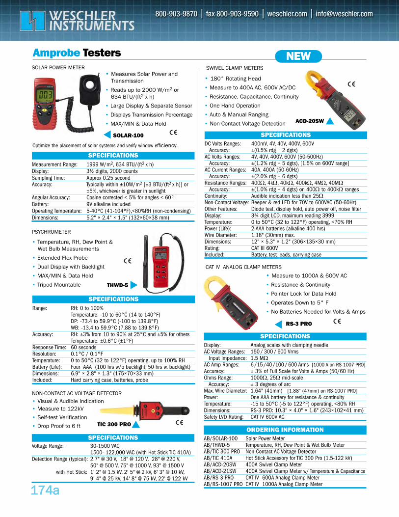
117744aa
AB/SOLAR-100 Solar Power Meter AB/THWD-5 Temperature, RH, Dew Point & Wet Bulb MeterAB/TIC 300 PRO Non-Contact AC Voltage DetectorAB/TIC 410A Hot Stick Accessory for TIC 300 Pro (1.5-122 kV)AB/ACD-20SW 400A Swivel Clamp Meter AB/ACD-21SW 400A Swivel Clamp Meter w/ Temperature & CapacitanceAB/RS-3 PRO CAT IV 600A Analog Clamp Meter AB/RS-1007 PRO CAT IV 1000A Analog Clamp Meter
ORDERING INFORMATION
Amprobe TestersSWIVEL CLAMP METERS
DC Volts Ranges: 400mV, 4V, 40V, 400V, 600VAccuracy: ±(0.5% rdg + 2 dgts)
AC Volts Ranges: 4V, 40V, 400V, 600V (50-500Hz)Accuracy: ±(1.2% rdg + 5 dgts), [1.5% on 600V range]
AC Current Ranges: 40A, 400A (50-60Hz)Accuracy: ±(2.0% rdg + 6 dgts)
Resistance Ranges: 400Ω, 4kΩ, 40kΩ, 400kΩ, 4MΩ, 40MΩAccuracy: ±(1.0% rdg + 4 dgts) on 400Ω to 400kΩ ranges
Continuity: Audible indication less than 25ΩNon-Contact Voltage: Beeper & red LED for 70V to 600VAC (50-60Hz) Other Features: Diode test, display hold, auto power off, noise filterDisplay: 3¾ digit LCD, maximum reading 3999 Temperature: 0 to 50°C (32 to 122°F) operating, <70% RHPower (Life): 2 AAA batteries (alkaline 400 hrs)Wire Diameter: 1.18" (30mm) max.Dimensions: 12" × 5.3" × 1.2" (306×135×30 mm) Rating: CAT III 600V Included: Battery, test leads, carrying case
SPECIFICATIONS
Range: RH: 0 to 100%Temperature: -10 to 60°C (14 to 140°F)DP: -73.4 to 59.9°C (-100 to 139.8°F)WB: -13.4 to 59.9°C (7.88 to 139.8°F)
Accuracy: RH: ±3% from 10 to 90% at 25°C and ±5% for othersTemperature: ±0.6°C (±1°F)
Response Time: 60 secondsResolution: 0.1°C / 0.1°FTemperature: 0 to 50°C (32 to 122°F) operating, up to 100% RHBattery (Life): Four AAA (100 hrs w/o backlight, 50 hrs w. backlight) Dimensions: 6.9" × 2.8" × 1.3" (175×70×33 mm)Included: Hard carrying case, batteries, probe
SPECIFICATIONS
PSYCHROMETER
• 180° Rotating Head
• Measure to 400A AC, 600V AC/DC
• Resistance, Capacitance, Continuity
• One Hand Operation
• Auto & Manual Ranging
• Non-Contact Voltage Detection
Measurement Range: 1999 W/m2, 634 BTU/(ft2 x h)Display: 3½ digits, 2000 countsSampling Time: Approx 0.25 secondAccuracy: Typically within ±10W/m2 [±3 BTU/(ft2 x h)] or
±5%, whichever is greater in sunlightAngular Accuracy: Cosine corrected < 5% for angles < 60ºBattery: 9V alkaline includedOperating Temperature: 5-40ºC (41-104ºF),<80%RH (non-condensing)Dimensions: 5.2" × 2.4" × 1.5" (132×60×38 mm)
SPECIFICATIONS
SOLAR POWER METER
SOLAR-100
• Measures Solar Power andTransmission
• Reads up to 2000 W/m2 or 634 BTU/(ft2 x h)
• Large Display & Separate Sensor
• Displays Transmission Percentage
• MAX/MIN & Data Hold ACD-20SW
• Temperature, RH, Dew Point & Wet Bulb Measurements
• Extended Flex Probe
• Dual Display with Backlight
• MAX/MIN & Data Hold
• Tripod Mountable THWD-5
Display: Analog scales with clamping needleAC Voltage Ranges: 150 / 300 / 600 Vrms
Input Impedance: 1.5 MΩAC Amp Ranges: 6 /15 /40 /100 / 600 Arms [1000 A on RS-1007 PRO]Accuracy: ± 3% of Full Scale for Volts & Amps (50/60 Hz)Ohms Range: 1000Ω, 25Ω mid-scale
Accuracy: ± 3 degrees of arcMax. Wire Diameter: 1.64" (41mm) [1.88" (47mm) on RS-1007 PRO]Power: One AAA battery for resistance & continuityTemperature: -15 to 50°C (-5 to 122°F) operating, <80% RHDimensions: RS-3 PRO: 10.3" × 4.0" × 1.6" (243×102×41 mm) Safety LVD Rating: CAT IV 600V AC
SPECIFICATIONS
CAT IV ANALOG CLAMP METERS
• Measure to 1000A & 600V AC
• Resistance & Continuity
• Pointer Lock for Data Hold
• Operates Down to 5° F
• No Batteries Needed for Volts & Amps
RS-3 PRO
NEW
Voltage Range: 30-1500 VAC1500- 122,000 VAC (with Hot Stick TIC 410A)
Detection Range (typical): 2.7" @ 30 V, 18" @ 120 V, 28" @ 220 V,50" @ 500 V, 75" @ 1000 V, 93" @ 1500 V
with Hot Stick: 1' 2" @ 1.5 kV, 2' 5" @ 2 kV, 6' 3" @ 10 kV,9' 4" @ 25 kV, 14' 8" @ 75 kV, 22' @ 122 kV
SPECIFICATIONS
NON-CONTACT AC VOLTAGE DETECTOR
TIC 300 PRO
• Measure to 122kV
• Self-test Verification
• Drop Proof to 6 ft
Optimize the placement of solar systems and verify window efficiency.
• Visual & Audible Indication
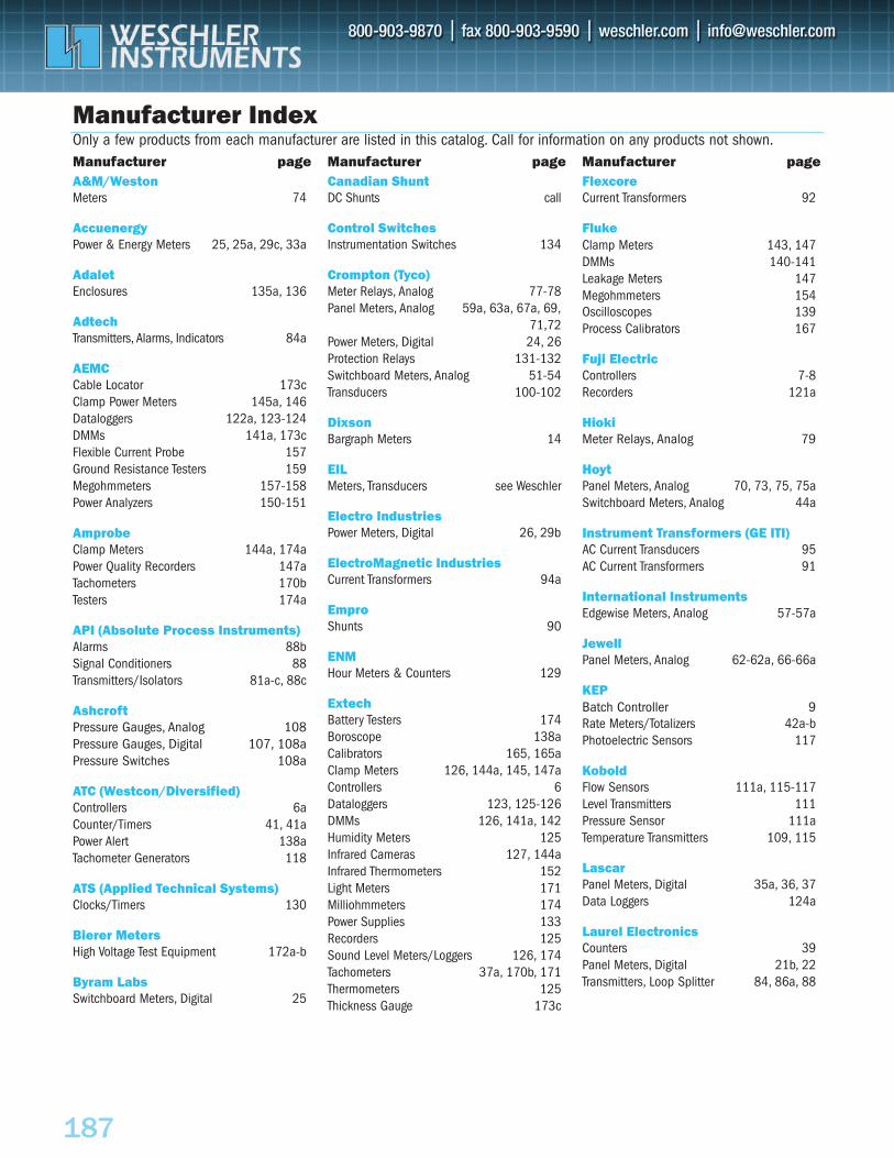
WESCHLER INSTRUMENTS
187
Manufacturer Index
A&M/WestonMeters 74
AccuenergyPower & Energy Meters 25, 25a, 29c, 33a
AdaletEnclosures 135a, 136
AdtechTransmitters, Alarms, Indicators 84a
AEMCCable Locator 173cClamp Power Meters 145a, 146Dataloggers 122a, 123-124DMMs 141a, 173cFlexible Current Probe 157Ground Resistance Testers 159Megohmmeters 157-158Power Analyzers 150-151
AmprobeClamp Meters 144a, 174aPower Quality Recorders 147aTachometers 170bTesters 174a
API (Absolute Process Instruments)Alarms 88bSignal Conditioners 88Transmitters/Isolators 81a-c, 88c
AshcroftPressure Gauges, Analog 108Pressure Gauges, Digital 107, 108aPressure Switches 108a
ATC (Westcon/Diversified)Controllers 6aCounter/Timers 41, 41aPower Alert 138aTachometer Generators 118
ATS (Applied Technical Systems)Clocks/Timers 130
Bierer MetersHigh Voltage Test Equipment 172a-b
Byram LabsSwitchboard Meters, Digital 25
Canadian ShuntDC Shunts call
Control SwitchesInstrumentation Switches 134
Crompton (Tyco)Meter Relays, Analog 77-78Panel Meters, Analog 59a, 63a, 67a, 69,
71,72Power Meters, Digital 24, 26Protection Relays 131-132Switchboard Meters, Analog 51-54Transducers 100-102
DixsonBargraph Meters 14
EILMeters, Transducers see Weschler
Electro IndustriesPower Meters, Digital 26, 29b
ElectroMagnetic IndustriesCurrent Transformers 94a
EmproShunts 90
ENMHour Meters & Counters 129
ExtechBattery Testers 174Boroscope 138aCalibrators 165, 165aClamp Meters 126, 144a, 145, 147aControllers 6Dataloggers 123, 125-126DMMs 126, 141a, 142Humidity Meters 125Infrared Cameras 127, 144aInfrared Thermometers 152Light Meters 171Milliohmmeters 174Power Supplies 133Recorders 125Sound Level Meters/Loggers 126, 174Tachometers 37a, 170b, 171Thermometers 125Thickness Gauge 173c
FlexcoreCurrent Transformers 92
FlukeClamp Meters 143, 147DMMs 140-141Leakage Meters 147Megohmmeters 154Oscilloscopes 139Process Calibrators 167
Fuji ElectricControllers 7-8Recorders 121a
HiokiMeter Relays, Analog 79
HoytPanel Meters, Analog 70, 73, 75, 75aSwitchboard Meters, Analog 44a
Instrument Transformers (GE ITI)AC Current Transducers 95AC Current Transformers 91
International InstrumentsEdgewise Meters, Analog 57-57a
JewellPanel Meters, Analog 62-62a, 66-66a
KEPBatch Controller 9Rate Meters/Totalizers 42a-bPhotoelectric Sensors 117
KoboldFlow Sensors 111a, 115-117Level Transmitters 111Pressure Sensor 111aTemperature Transmitters 109, 115
LascarPanel Meters, Digital 35a, 36, 37Data Loggers 124a
Laurel ElectronicsCounters 39Panel Meters, Digital 21b, 22Transmitters, Loop Splitter 84, 86a, 88
Only a few products from each manufacturer are listed in this catalog. Call for information on any products not shown.Manufacturer page Manufacturer page Manufacturer page
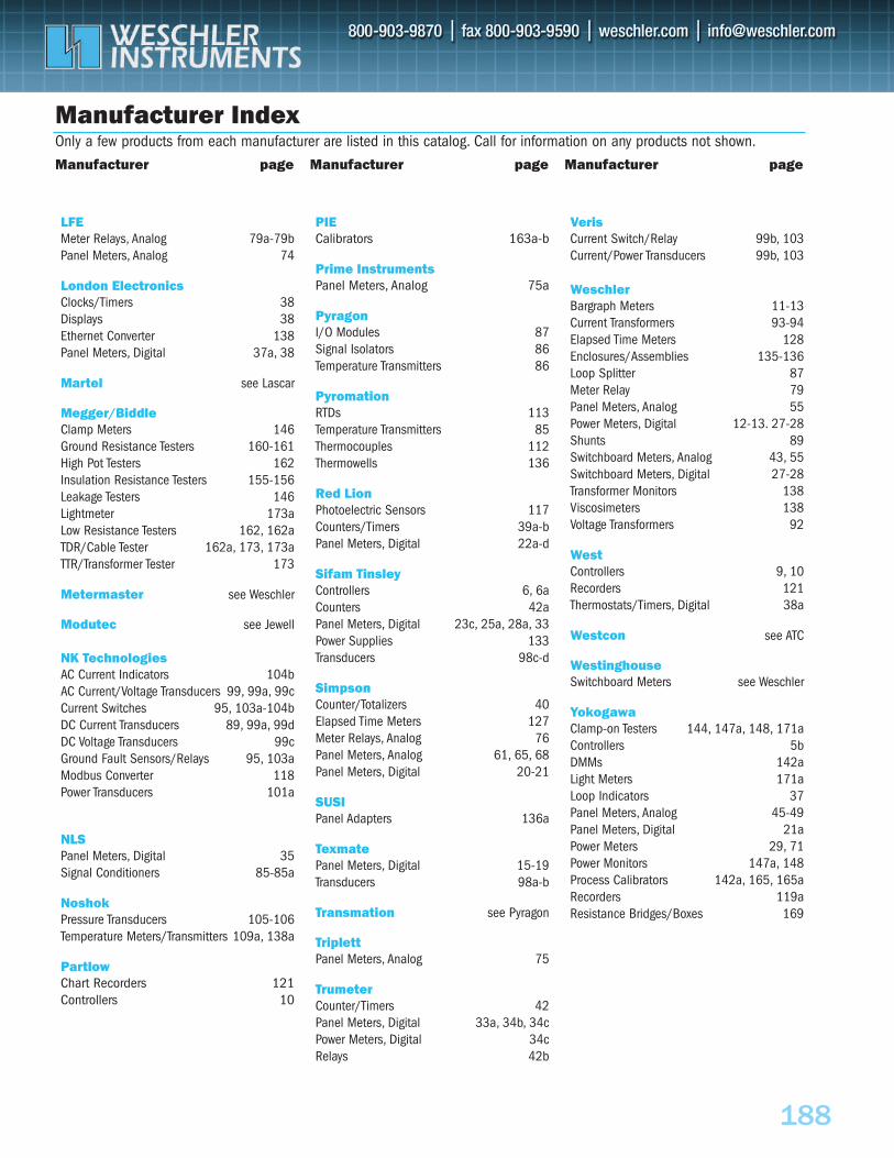
WESCHLER INSTRUMENTS
188
Manufacturer Index
LFEMeter Relays, Analog 79a-79bPanel Meters, Analog 74
London ElectronicsClocks/Timers 38Displays 38Ethernet Converter 138Panel Meters, Digital 37a, 38
Martel see Lascar
Megger/BiddleClamp Meters 146Ground Resistance Testers 160-161High Pot Testers 162Insulation Resistance Testers 155-156Leakage Testers 146Lightmeter 173aLow Resistance Testers 162, 162aTDR/Cable Tester 162a, 173, 173aTTR/Transformer Tester 173
Metermaster see Weschler
Modutec see Jewell
NK TechnologiesAC Current Indicators 104bAC Current/Voltage Transducers 99, 99a, 99cCurrent Switches 95, 103a-104bDC Current Transducers 89, 99a, 99dDC Voltage Transducers 99cGround Fault Sensors/Relays 95, 103aModbus Converter 118Power Transducers 101a
NLSPanel Meters, Digital 35Signal Conditioners 85-85a
NoshokPressure Transducers 105-106Temperature Meters/Transmitters 109a, 138a
PartlowChart Recorders 121Controllers 10
PIECalibrators 163a-b
Prime InstrumentsPanel Meters, Analog 75a
PyragonI/O Modules 87Signal Isolators 86Temperature Transmitters 86
PyromationRTDs 113Temperature Transmitters 85Thermocouples 112Thermowells 136
Red LionPhotoelectric Sensors 117Counters/Timers 39a-bPanel Meters, Digital 22a-d
Sifam TinsleyControllers 6, 6aCounters 42aPanel Meters, Digital 23c, 25a, 28a, 33Power Supplies 133Transducers 98c-d
SimpsonCounter/Totalizers 40Elapsed Time Meters 127Meter Relays, Analog 76Panel Meters, Analog 61, 65, 68Panel Meters, Digital 20-21
SUSIPanel Adapters 136a
TexmatePanel Meters, Digital 15-19Transducers 98a-b
Transmation see Pyragon
TriplettPanel Meters, Analog 75
TrumeterCounter/Timers 42Panel Meters, Digital 33a, 34b, 34cPower Meters, Digital 34cRelays 42b
VerisCurrent Switch/Relay 99b, 103Current/Power Transducers 99b, 103
WeschlerBargraph Meters 11-13Current Transformers 93-94Elapsed Time Meters 128Enclosures/Assemblies 135-136Loop Splitter 87Meter Relay 79Panel Meters, Analog 55Power Meters, Digital 12-13. 27-28Shunts 89Switchboard Meters, Analog 43, 55Switchboard Meters, Digital 27-28Transformer Monitors 138Viscosimeters 138Voltage Transformers 92
West Controllers 9, 10Recorders 121Thermostats/Timers, Digital 38a
Westcon see ATC
WestinghouseSwitchboard Meters see Weschler
YokogawaClamp-on Testers 144, 147a, 148, 171aControllers 5bDMMs 142aLight Meters 171aLoop Indicators 37Panel Meters, Analog 45-49Panel Meters, Digital 21aPower Meters 29, 71Power Monitors 147a, 148Process Calibrators 142a, 165, 165aRecorders 119aResistance Bridges/Boxes 169
Only a few products from each manufacturer are listed in this catalog. Call for information on any products not shown.
Manufacturer page Manufacturer page Manufacturer page
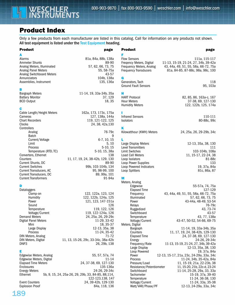
189
Product Index
AAlarms 81a, 84a, 88b, 138aAmmeter Shunts 89-90Analog Meters, Illuminated 57, 62, 66, 73, 75 Analog Panel Meters 55, 58-75aAnalog Switchboard Meters 43-57Annunciators 104b, 138aAssemblies, Instrument 135, 136a
BBargraph Meters 11-14, 19, 33a-34b, 35aBattery Monitor 37, 129BCD Output 18, 35
CCable Length/Height Meters 162a, 173, 173c, 175aCameras 127, 138a, 144aChart Recorders 119, 121-122, 125Clocks 24, 38, 42a,130Controllers
Analog 76-79cBatch 9Current/Voltage 6-7, 10, 15Limit 5, 10Process 5-10, 15Temperature (RTD, TC) 5-10, 15, 38a
Converters, Ethernet 138Counters 11, 17, 19, 24, 38-42b, 129, 130Current Shunts, DC 89-90Current Switches 99b, 103-104b, 134Current Transducers, AC 95, 98-99, 100Current Transducers, DC 89, 99a, 101Current Transformers 91-94a
DDataloggers
Clamp-on 122, 122a, 123, 124Humidity 122, 122b, 124a, 125Power 121, 123, 147-151aSound 126Temperature 119, 122, 126Voltage/Current 119, 122-124a, 126
Demand Meters 24, 25a, 26, 29-29cDigital Panel Meters 11-29, 33-42
Mini 18, 35-37Large Display 12-13, 35a, 38Process 11-24, 35-42
DIN Meters, Analog 71-72DIN Meters, Digital 11, 13, 15-26, 29c, 33-34c, 38a-42bDNP3 26, 29b, 138
EEdgewise Meters, Analog 55, 57, 57a, 74Edgewise Meters, Digital 11-14Elapsed Time Meters 24, 37-38, 69, 127-130 Enclosures 135-136aEnergy Meters 24-26, 29-34cEthernet 5b, 9, 15, 24, 25a-26, 29, 29b, 33, 84-85, 88,114,
122-123,138, 147Event Counters 24, 39-42b, 129-130Explosion Proof 84a, 118, 136
FFlow Sensors 111a, 115-117Freqency Meters, Digital 11-13, 15-19, 21-24, 27, 34b, 39-42aFrequency Meters, Analog 43, 44a, 49, 51, 55, 58a, 66-72, 75aFrequency Transducers 81a, 84-85, 87-88c, 98a, 98c, 100
GGenerators, Tach 118Ground Fault Sensors 95, 103a
HHART Protocol 82, 85, 86, 163a-c, 167Hour Meters 37-38, 69, 127-130Humidity Meters 122, 122b, 125, 174a
IInfrared Sensors 110-111Isolators 80-88c, 99c
KKilowatthour (KWH) Meters 24, 25a, 26, 29-29b, 34c
LLarge Display Meters 12-13, 35a, 38, 130Level Transmitters 111Limit Switches 103-104b, 108aLoad Cell Meters 11, 15-17, 22-24, 38Loop Isolators 81-88cLoop Power Supplies 133Loop Powered Indicators 19, 37a, 84aLoop Splitters 81c, 86a, 87
MMeters, Analog
Edgewise 55-57a, 74, 75aElapsed Time 127-129Frequency 43, 44a, 49, 51, 55, 58a, 66-72, 75aIlluminated 57, 62, 66, 73, 75Power 43-44a, 48-49, 53-54Relays 76-79cRuggedized 43, 73-74Switchboard 43-57Temperature 43, 77, 138aVoltage/Current 43-47, 50-52, 54-66, 69-75
Meters, DigitalBargraph 11-14, 19, 33a-34b, 35aCounters 11, 17, 19, 24, 38-42b, 129-130Elapsed Time 24, 37-38, 69, 127-130Energy 24-26, 29-34cFrequency/Rate 11-13, 15-19, 21-24, 27, 34b, 39-42aLarge Display 12-13, 35a, 38, 130Loop Powered 19, 37a, 84aPower 12-13, 15-17, 21a, 23c, 24-29a, 33a, 34cProcess 11-24, 34b, 35-42a, 84aPressure/Load 11, 15-19, 21a, 22-23b, 38Resistance/Potentiometer 11, 15-20, 21b, 22c-d, 23-24Switchboard 11-14, 25-28, 29a, 33, 33aTachometer 15-19, 37a, 39-40Temperature 11-24, 36-38, 130Voltage/Current 11-24, 33a, 35-38Watt/VAR/Phase/PF 12-13, 24-29a, 33a, 34c
Only a few products from each manufacturer are listed in this catalog. Call for information on any products not shown.All test equipment is listed under the Test Equipment heading.Product page Product page
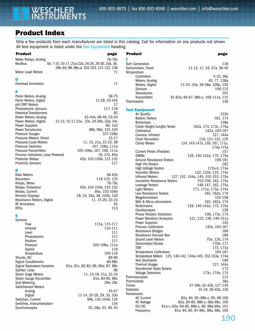
WESCHLER INSTRUMENTS
190
Product Index
Meter Relays, Analog 76-79cModbus 5b, 7-10, 15-17, 21a-22d, 24-26, 29-30, 33a, 39,
39b, 84, 88, 98c-d, 102-103, 121-122, 138Motor Load Meters 71
OOverload Ammeters 71
PPanel Meters, Analog 58-75Panel Meters, Digital 11-29, 33-42bpH/ORP Meters 17Photoelectric Sensors 117, 118Potential Transformers 92Power Meters, Analog 43-44a, 48-49, 53-54Power Meters, Digital 12-13, 15-17,21a, 23c, 24-29a, 33a, 34cPower Supplies 85, 133Power Transducers 98b, 98d, 101-103Pressure Gauges 107-108aPressure Meters, Direct 15-17Pressure/Load Meters 11, 15, 21a, 22-23, 38Pressure Switches 107, 108a, 111aPressure Transmitters 105-106a, 107, 108, 111aProcess Indicators, Loop Powered 19, 37a, 84aProtector Relays 42b, 103-104b, 131-132Proximity Sensors 117
RRate Meters 38-42bRecorders 119-123, 125Relays, Meter 76-79cRelays, Protection 42b, 103-104b, 131-132Relays, Current 84a, 103-104bRemote Displays 18, 24, 35a, 38, 104b, 130Resistance Meters, Digital 11, 15-20, 23-24RF Ammeters 55RTDs 113
SSensors
Flow 111a, 115-117Infrared 110-111Level 111Photoelectric 117Position 117Pressure 105-108a, 111aSpeed 118Temperature 109-115
Shunts, DC 89-80Signal Conditioners 80-88cSignal Repeaters/Isolators 81a, 81c, 82-83, 86, 86a, 87, 88cSplitter, Loop 86Strain Gage Meters 11, 15-18, 21a, 22-24Strain Gauge Transmitter 81a, 84-85, 88cSub-Metering 29b, 29cSwitchboard Meters
Analog 43-57Digital 11-14, 25-28, 29, 33, 33a
Switches, Current 99b, 103-104b, 134Switches, Instrumentation 134Synchroscopes 25, 28a, 43, 49, 53
TTach Generators 118Tachometers, Panel 11-13, 17, 24, 37a, 39-40Temperature
Controllers 5-10, 38aMeters, Analog 43, 77, 138aMeters, Digital 11-24, 33a, 36-38a, 109a, 130Sensors 109-115Transducers 101Transmitters 81-82a, 84-87, 88b-c, 109-111a, 115
Thermowells 136
Test EquipmentAir Quality 122bBattery Testers 161, 174Borescope 138aCable Height/Length/Tester 162a, 173, 173c, 175aCalibrators 142a, 163-167Camera, Infrared 127, 144aChart Recorders 119, 121-122, 125Clamp Meters 124, 143-147a, 159, 161, 171a,
174a-175aCurrent Probe (Flexible) 157DMMs 126, 140-142a, 175, 175aGround Resistance Testers 159-161High Pot Testers 162High Voltage Testers 172a-b, 174aHumidity Meters 122, 122b, 125, 174aInfrared Meters 127, 142, 144a, 145, 152-153, 175aInsulation Resistance Testers 153-158, 162, 175aLeakage Testers 146-147, 162, 175aLight Meters 171, 171a, 173a, 174aLow Resistance Testers 162, 162a, 174Megohmmeters 153-158Milli & Micro-ohmmeters 162, 162a, 174Multimeters 126, 140-142a, 175, 175aOscilloscopes 139Phase Rotaton Detectors 146, 173c, 175Power Monitors/Analyzers 121, 123, 139, 146-151aPower Supplies 125Process Calibrators 142a, 163-167Resistance Bridges 169Resistance Decade Box 169Sound Level Meters 75a, 126, 174Tachometer/Strobe 170b, 171TDR 173, 173aTemperature Calibrators 163-167Temperature Meters 125, 140-142, 144a-145, 152-153a, 174aTest Standards 169Thermal Imager 127, 144aTransformer Ratio Testers 173Voltage Detectors 173c, 174a, 175
Thermocouples 112Thermostats 38aTimers 37-39b, 42-42b, 127-130Totalizers 15-19, 39-42b, 130Transducers
AC Current 82a, 84, 85, 88b-c, 95, 98-100AC Voltage 82a, 84-85, 88b-c, 98a-98c, 100DC/DC 81a-c, 82a, 84-85, 88b-c, 89, 98a-99a, 101Frequency 81a, 84, 85, 87-88c, 98a, 98c, 100
Only a few products from each manufacturer are listed in this catalog. Call for information on any products not shown.All test equipment is listed under the Test Equipment heading.
Product page Product page
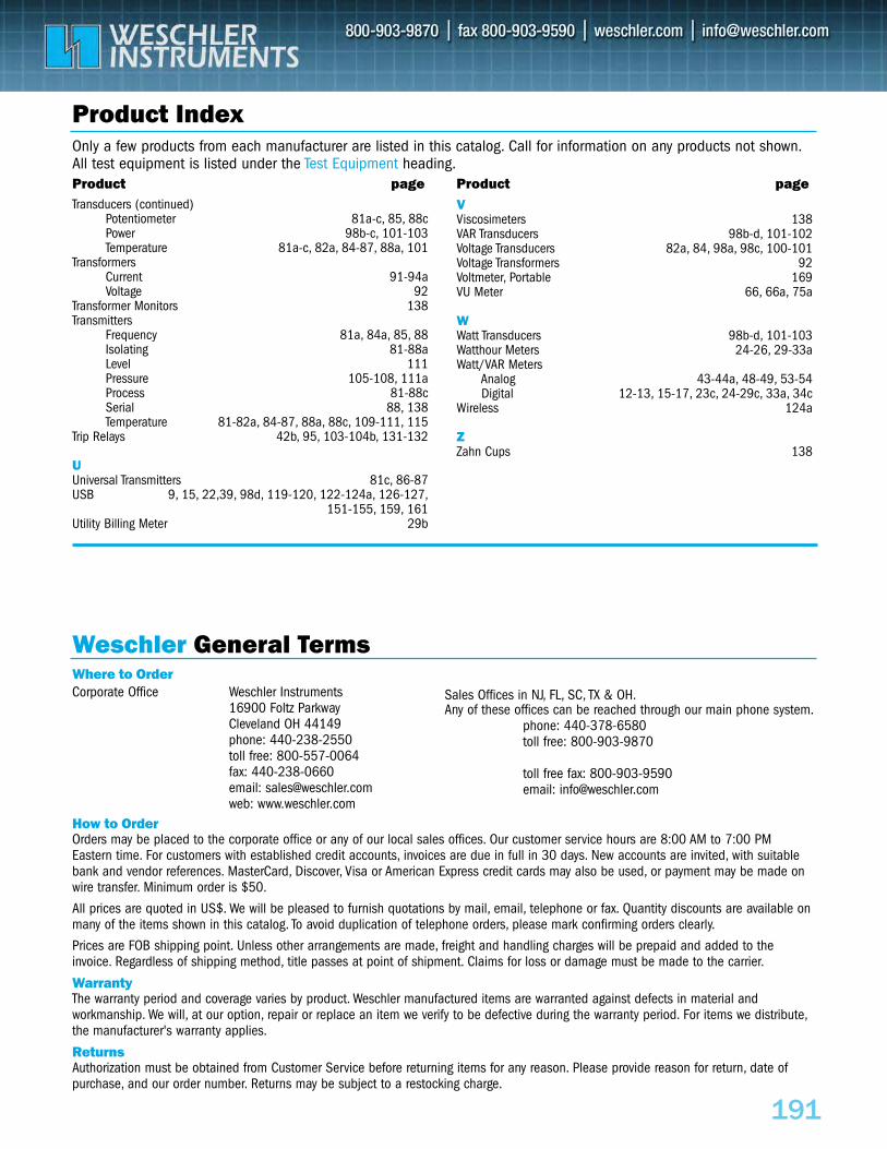
191
Product Index
Where to Order
How to OrderOrders may be placed to the corporate office or any of our local sales offices. Our customer service hours are 8:00 AM to 7:00 PMEastern time. For customers with established credit accounts, invoices are due in full in 30 days. New accounts are invited, with suitablebank and vendor references. MasterCard, Discover, Visa or American Express credit cards may also be used, or payment may be made onwire transfer. Minimum order is $50.
All prices are quoted in US$. We will be pleased to furnish quotations by mail, email, telephone or fax. Quantity discounts are available onmany of the items shown in this catalog. To avoid duplication of telephone orders, please mark confirming orders clearly.
Prices are FOB shipping point. Unless other arrangements are made, freight and handling charges will be prepaid and added to theinvoice. Regardless of shipping method, title passes at point of shipment. Claims for loss or damage must be made to the carrier.
WarrantyThe warranty period and coverage varies by product. Weschler manufactured items are warranted against defects in material andworkmanship. We will, at our option, repair or replace an item we verify to be defective during the warranty period. For items we distribute,the manufacturer's warranty applies.
ReturnsAuthorization must be obtained from Customer Service before returning items for any reason. Please provide reason for return, date ofpurchase, and our order number. Returns may be subject to a restocking charge.
Weschler General Terms
Transducers (continued)Potentiometer 81a-c, 85, 88cPower 98b-c, 101-103Temperature 81a-c, 82a, 84-87, 88a, 101
TransformersCurrent 91-94aVoltage 92
Transformer Monitors 138Transmitters
Frequency 81a, 84a, 85, 88Isolating 81-88aLevel 111Pressure 105-108, 111aProcess 81-88cSerial 88, 138Temperature 81-82a, 84-87, 88a, 88c, 109-111, 115
Trip Relays 42b, 95, 103-104b, 131-132
UUniversal Transmitters 81c, 86-87USB 9, 15, 22,39, 98d, 119-120, 122-124a, 126-127,
151-155, 159, 161Utility Billing Meter 29b
VViscosimeters 138VAR Transducers 98b-d, 101-102Voltage Transducers 82a, 84, 98a, 98c, 100-101Voltage Transformers 92Voltmeter, Portable 169VU Meter 66, 66a, 75a
WWatt Transducers 98b-d, 101-103Watthour Meters 24-26, 29-33aWatt/VAR Meters
Analog 43-44a, 48-49, 53-54Digital 12-13, 15-17, 23c, 24-29c, 33a, 34c
Wireless 124a
ZZahn Cups 138
Only a few products from each manufacturer are listed in this catalog. Call for information on any products not shown.All test equipment is listed under the Test Equipment heading.Product page Product page
Corporate Office Weschler Instruments16900 Foltz ParkwayCleveland OH 44149phone: 440-238-2550toll free: 800-557-0064fax: 440-238-0660email: [email protected]: www.weschler.com
Sales Offices in NJ, FL, SC, TX & OH.Any of these offices can be reached through our main phone system.
phone: 440-378-6580toll free: 800-903-9870
toll free fax: 800-903-9590email: [email protected]
Related Documents