Overload Relays RW overload relays are important equipment within WEG Controls’ range of products. As usual for WEG products, an extended operational service life is one of the main features found in RW overload relays. WEG’s RW Class 10 Thermal Overload Relays are designed to be used with compact contactors and contactors. Effectively, RW overload relays can be mounted directly to WEG compact contactors and contactors, assuring electrical and mechanical operation as an open across-the-line starter. Accessories are also available for separate mounting. RW overload relays are fitted with fixed bimetallic parts, which eliminate any need for heater elements for field installation or future upgrading to a more efficient motor. All sizes provide complete motor protection by offering: J Ambient temperature compensation J Phase failure sensitivity protection Certifications Buy: www.ValinOnline.com | Phone 844-385-3099 | Email: [email protected]

Welcome message from author
This document is posted to help you gain knowledge. Please leave a comment to let me know what you think about it! Share it to your friends and learn new things together.
Transcript
Overload Relays
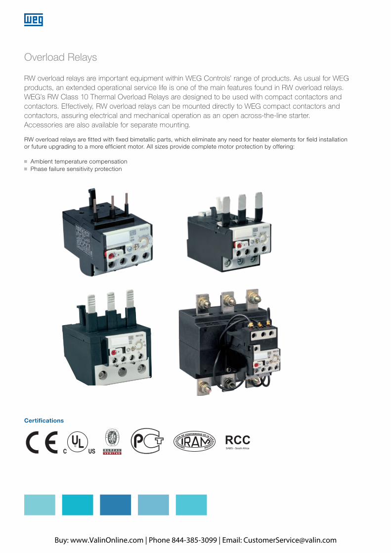
RW overload relays are important equipment within WEG Controls’ range of products. As usual for WEG products, an extended operational service life is one of the main features found in RW overload relays. WEG’s RW Class 10 Thermal Overload Relays are designed to be used with compact contactors and contactors. Effectively, RW overload relays can be mounted directly to WEG compact contactors and contactors, assuring electrical and mechanical operation as an open across-the-line starter. Accessories are also available for separate mounting.
RW overload relays are fitted with fixed bimetallic parts, which eliminate any need for heater elements for field installation or future upgrading to a more efficient motor. All sizes provide complete motor protection by offering:
J Ambient temperature compensationJ Phase failure sensitivity protection
Certifications
Buy: www.ValinOnline.com | Phone 844-385-3099 | Email: [email protected]
A
B
C
D
E
F
G
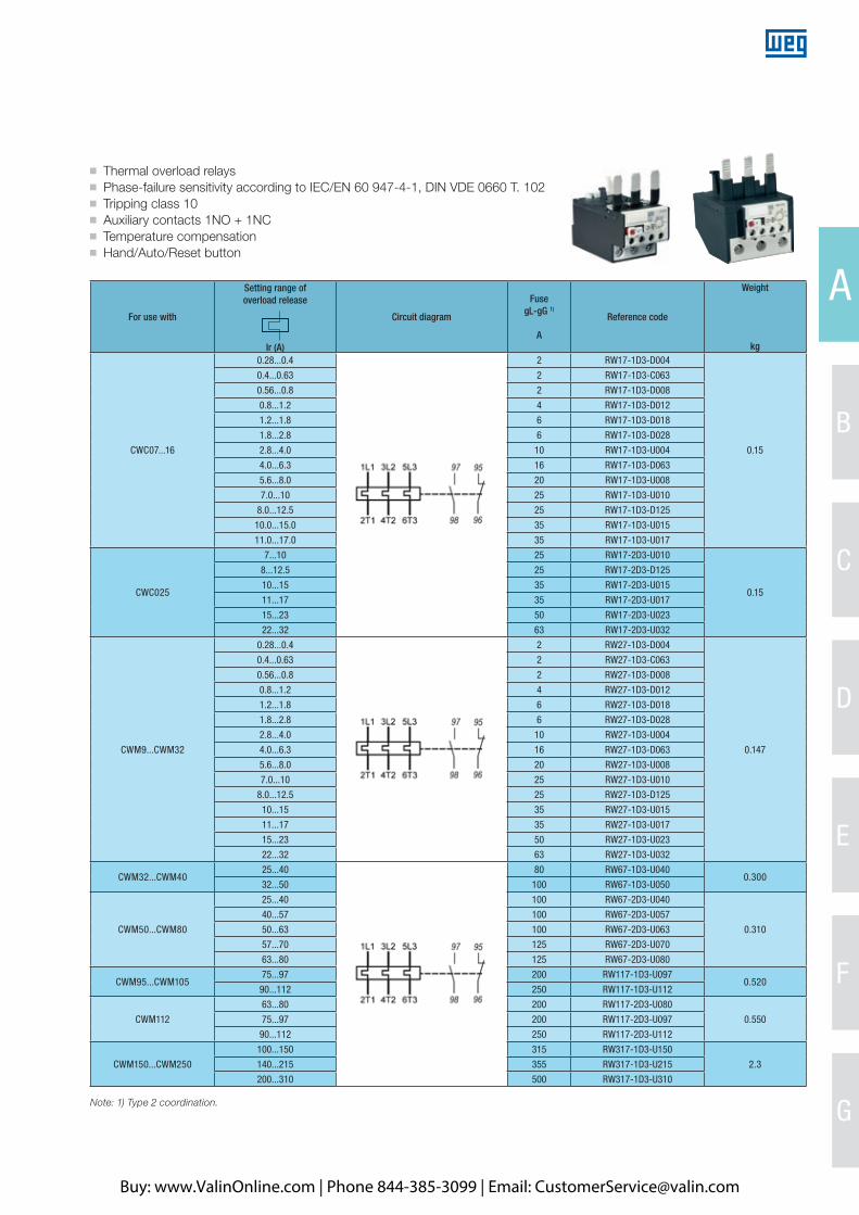
J Thermal overload relays J Phase-failure sensitivity according to IEC/EN 60 947-4-1, DIN VDE 0660 T. 102J Tripping class 10 J Auxiliary contacts 1NO + 1NCJ Temperature compensation J Hand/Auto/Reset button
For use with
Setting range of overload release
Ir (A)
Circuit diagram
FusegL-gG 1)
A
Reference code
Weight
kg
CWC07...16
0.28...0.4 2 RW17-1D3-D004
0.15
0.4...0.63 2 RW17-1D3-C063
0.56...0.8 2 RW17-1D3-D008
0.8...1.2 4 RW17-1D3-D012
1.2...1.8 6 RW17-1D3-D018
1.8...2.8 6 RW17-1D3-D028
2.8...4.0 10 RW17-1D3-U004
4.0...6.3 16 RW17-1D3-D063
5.6...8.0 20 RW17-1D3-U008
7.0...10 25 RW17-1D3-U010
8.0...12.5 25 RW17-1D3-D125
10.0...15.0 35 RW17-1D3-U015
11.0...17.0 35 RW17-1D3-U017
CWC025
7...10 25 RW17-2D3-U010
0.15
8...12.5 25 RW17-2D3-D125
10...15 35 RW17-2D3-U015
11...17 35 RW17-2D3-U017
15...23 50 RW17-2D3-U023
22...32 63 RW17-2D3-U032
CWM9...CWM32
0.28...0.4 2 RW27-1D3-D004
0.147
0.4...0.63 2 RW27-1D3-C063
0.56...0.8 2 RW27-1D3-D008
0.8...1.2 4 RW27-1D3-D012
1.2...1.8 6 RW27-1D3-D018
1.8...2.8 6 RW27-1D3-D028
2.8...4.0 10 RW27-1D3-U004
4.0...6.3 16 RW27-1D3-D063
5.6...8.0 20 RW27-1D3-U008
7.0...10 25 RW27-1D3-U010
8.0...12.5 25 RW27-1D3-D125
10...15 35 RW27-1D3-U015
11...17 35 RW27-1D3-U017
15...23 50 RW27-1D3-U023
22...32 63 RW27-1D3-U032
CWM32...CWM4025...40 80 RW67-1D3-U040
0.30032...50 100 RW67-1D3-U050
CWM50...CWM80
25...40 100 RW67-2D3-U040
0.310
40...57 100 RW67-2D3-U057
50...63 100 RW67-2D3-U063
57...70 125 RW67-2D3-U070
63...80 125 RW67-2D3-U080
CWM95...CWM10575...97 200 RW117-1D3-U097
0.52090...112 250 RW117-1D3-U112
CWM112
63...80 200 RW117-2D3-U080
0.55075...97 200 RW117-2D3-U097
90...112 250 RW117-2D3-U112
CWM150...CWM250
100...150 315 RW317-1D3-U150
2.3140...215 355 RW317-1D3-U215
200...310 500 RW317-1D3-U310
Note: 1) Type 2 coordination.
Buy: www.ValinOnline.com | Phone 844-385-3099 | Email: [email protected]
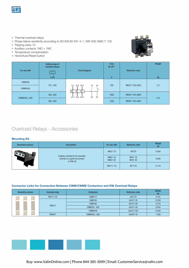
J Thermal overload relays J Phase-failure sensitivity according to IEC/EN 60 947-4-1, DIN VDE 0660 T. 102J Tripping class 10 J Auxiliary contacts 1NO + 1NCJ Temperature compensation J Hand/Auto/Reset button
For use with
Setting range of overload release
Ir (A)
Circuit diagram
FusegL-gG 1)
A
Reference code
Weight
kg
CWM300275...420 700 RW317-1D3-U420 2.3
CWME400
CWME400...800400...600 1000 RW407-1D3-U600
3.12560...840 1250 RW407-1D3-U840
Mounting Kit
Illustrative picture Description For use with Reference codeWeight
kg
Enables overload to be mounteddirectly to a panel via screws
or DIN rail
RW27-1D BF27D 0.050
RW67-1DRW67-2D
BF67-1DBF67-2D
0.095
RW117-1D BF117D 0.110
Illustrative picture Overload relay Contactors Reference codeWeight
kg
RW117-2D CWM112 GA117D 0.135
RW317
CWM150 GA317-1D 0.250
CWM180 GA317-2D 0.270
CWM250...300 GA317-3D 0.630
CWME400 GA317-10D 0.500
RW407 CWME630...800 GA407-1D 1.580
Connector Links for Connection Between CWM/CWME Contactors and RW Overload Relays
Overload Relays - Accessories
Buy: www.ValinOnline.com | Phone 844-385-3099 | Email: [email protected]

A
B
C
D
E
F
G
Overload Relays - Technical Data
Reference code RW17 RW27 RW67 RW117 RW317 RW407
Standards IEC/EN 60 947. DIN VDE 0660. UL. CSA IEC/EN 60 947. DIN VDE 0660
Setting current (A) 0.28...17 0.28...32 25...80 75...112 100...420 400...840
Tripping class 10
Temperature compensation Continuous
Rated insulation voltage Ui
IEC/EN 60 947/DIN VDE 0660UL/CSA
(V)690 1000
(V) 600
Rated impulse withstand voltage Uimp (kV) 6 8
Rated operational frequency (Hz) 0...400
Degree of protectionProtection against direct contact from the front when actuated by a perpendicular test finger (IEC 536)
IP 20Finger and back-of-hand proof
Ambient temperatureOperating temperatureStorage temperature
-25 oC to +60 oC-40 oC to +70 oC
Climating proofIEC 60 068-2-3IEC 60 068-2-30
Damp heat. constantDamp heat. constant
Current heat lossLower value of setting rangeHigher value of setting range
(W)(W)
0.91.4
0.91.7
1.54.7
2.34.7
11.9
Terminal capacitySolidFlexible (stranded) without cable lugFlexible with cable lugSolid and strandedBarTightening torque Main circuitAuxiliary and control circuits
mm2
mm2
mm2
AWG mm
NmNm
2x 1.5 ... 62x 1.5 ... 102x 1.5 ... 6
14 ... 6-
2.31.5
1x 6 ...351x 6 ...351x 6 ...3518 ... 2
-
41.5
1x 25 ... 351x 25 ... 351x 25 ... 35
8 ... 1/0-
61.5
--
8...1/02x (25x5)
16/26 1)
1.5
--
8...1/02x (60x10)
261.5
Reference code RW17 RW27 RW67 RW117 RW317 RW407
Rated insulation voltage Ui
IEC/EN 60 947/DIN VDE 0660 (V)UL/CSA (V)
690600
Rated operational current Ie
AC-15
120 V (A)240 V (A)415 V (A)500 V (A)
32
1.50.5
UL/CSA C600
DC-13
24 V dc (A)60 V dc (A)110 V dc (A)220 V dc (A)
10.50.250.1
UL/CSA R300
Auxiliary Contacts
Note: 1) For RW317-1D3-U150 and RW317-1D3-U215, (ranges 100...150 A and 140...215 A, respectively) the value is 16 N.m. For RW317-1D3-U310 and RW317-1D3-U420, (ranges 200...310 A and 275...420 A, respectively) the value is 26 N.m.
Applications RW thermal overload relays have been designed to protect three-phase and single-phase AC motors and direct current motors. When the RW thermal overload relays are intended to protect single-phase AC loads or DC loads, the connection should be made as shown in the diagrams on page A-78.
RW Thermal Overload Relays in Contactor Assemblies for Wye-Delta Delta StartersWhen using thermal overload relays in conjunction with contactor assemblies for wye-delta starters, it should be taken into consideration that only 0.58 (√3 / 3) x the motor current flows through the main contactor. An overload relay mounted on the main contactor must be set to the same multiple of the motor current.A second overload relay may be mounted on the wye contactor if it is desired the load to be optimally protected in wye operation. The wye current is 1/3 of the rated motor current. The relay must then be set to this current.
Buy: www.ValinOnline.com | Phone 844-385-3099 | Email: [email protected]
Protection Against Short-Circuit The RW thermal overload relays must be protected against short-circuits by fuses or circuit breakers.
Ambient Air Temperature Compensation RW thermal overload relays are temperature compensated. Its trip point is not affected by temperature, and it performs consistently at the same value of current. The time-current characteristics of RWs refer to a stated value of ambient air temperature within the range of -20 °C to +60 °C and are based on no previous loading of the overload relay (i.e. from an initial cold state). For ambient air temperature within the range of +60 °C up +80 °C (maximum ambient air temperature), the current correction factor shown in the table below should be applied:
Site Altitude CompensationThe site altitude and hence the air density play a role with respect to the cooling conditions and dielectric withstand voltage. A site altitude of up to 2000 m is considered as normal in accordance with IEC 60947. For higher altitudes, the current settings on the thermal overload relay should be higher than the motor rated current. On the other hand, the operational voltage must be reduced. For site altitudes higher than 2000 m, the values for the current and voltage shown in the table below should be applied:
Phase Failure SensitivityIn order to ensure fast tripping in case of phase loss, protecting the motor and avoiding expensive repairs / corrective maintenance services, RW thermal overload relays include phase failure sensitivity protection as standard.For this purpose, they have a differential release mechanism that, in the case of phase failure, ensures the de-energized cooled down bimetal strip to generate an additional tripping displacement (simulating an overcurrent that actually doesn’t exist). This way, in the event of phase failure, the differential release ensures tripping at a lower current than with a three-phase load.However, for more effective protection against phase failure, specific protective products should be evaluated ensuring that such failure is detected much faster.
Ambient air temperature Current correction factor
65 °C 0.94
70 °C 0.87
75 °C 0.81
80 °C 0.73
Altitude above sea level (m) Adjustment factor on the current setting Maximum operational voltage Ue (V)
2000 1.00 x In 690
3000 1.05 x In 550
4000 1.08 x In 480
5000 1.12 x In 420
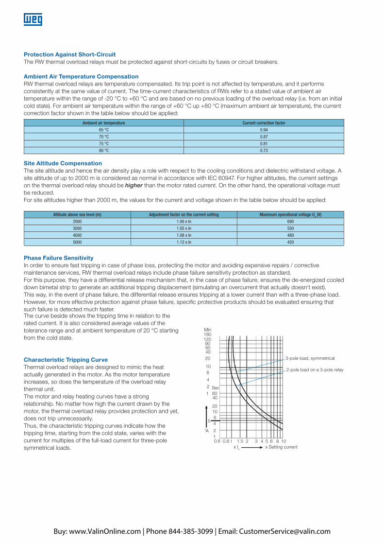
The curve beside shows the tripping time in relation to the rated current. It is also considered average values of the tolerance range and at ambient temperature of 20 °C starting from the cold state.
Characteristic Tripping Curve Thermal overload relays are designed to mimic the heat actually generated in the motor. As the motor temperature increases, so does the temperature of the overload relay thermal unit.The motor and relay heating curves have a strong relationship. No matter how high the current drawn by the motor, the thermal overload relay provides protection and yet, does not trip unnecessarily.Thus, the characteristic tripping curves indicate how the tripping time, starting from the cold state, varies with the current for multiples of the full-load current for three-pole symmetrical loads.
3-pole load, symmetrical
2-pole load on a 3-pole relay
Min18012090604020
106
4
2
2
2 3
Sec
40
20
tA
10
10
6
6 8
5
5
4
4
601
110.6 0.8 1.5
x In x Setting current
Buy: www.ValinOnline.com | Phone 844-385-3099 | Email: [email protected]
A
B
C
D
E
F
G
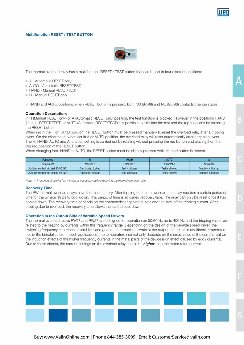
Multifunction RESET / TEST BUTTON
The thermal overload relay has a multifunction RESET / TEST button that can be set in four different positions:
J A - Automatic RESET only; J AUTO - Automatic RESET/TEST; J HAND - Manual RESET/TEST; J H - Manual RESET only.
In HAND and AUTO positions, when RESET button is pressed, both NO (97-98) and NC (95-96) contacts change states.
Operation Description: In H (Manual RESET only) or A (Automatic RESET only) position, the test function is blocked. However in the positions HAND (manual RESET/TEST) or AUTO (Automatic RESET/TEST) it is possible to simulate the test and the trip functions by pressing the RESET button. When set in the H or HAND position the RESET button must be pressed manually to reset the overload relay after a tripping event. On the other hand, when set in A or AUTO position, the overload relay will reset automatically after a tripping event. The H, HAND, AUTO and A function setting is carried out by rotating without pressing the red button and placing it on the desired position of the RESET button. When changing from HAND to AUTO, the RESET button must be slightly pressed while the red button is rotated.
Functions H HAND AUTO A
Relay reset Manual 1) Manual 1) Automatic Automatic
Auxiliary contact trip test 95-96 (NC) Function is blocked Test is allowed Test is allowed Function is blocked
Auxiliary contact trip test 97-98 (NO) Function is blocked Test is allowed Test is allowed Function is blocked
Note: 1) A recovery time of a few minutes is necessary before resetting the thermal overload relay.
Recovery Time The RW thermal overload relays have thermal memory. After tripping due to an overload, the relay requires a certain period of time for the bimetal strips to cool down. This period of time is so-called recovery time. The relay can only be reset once it has cooled down. The recovery time depends on the characteristic tripping curves and the level of the tripping current. After tripping due to overload, the recovery time allows the load to cool down.
Operation in the Output Side of Variable Speed Drivers The thermal overload relays RW17 and RW27 are designed for operation on 50/60 Hz up to 400 Hz and the tripping values are related to the heating by currents within this frequency range. Depending on the design of the variable speed driver, the switching frequency can reach several kHz and generate harmonic currents at the output that result in additional temperature rise in the bimetal strips. In such applications, the temperature rise not only depends on the r.m.s. value of the current, but on the induction effects of the higher frequency currents in the metal parts of the device (skin effect caused by eddy currents).Due to these effects, the current settings on the overload relay should be higher than the motor rated current.
Buy: www.ValinOnline.com | Phone 844-385-3099 | Email: [email protected]
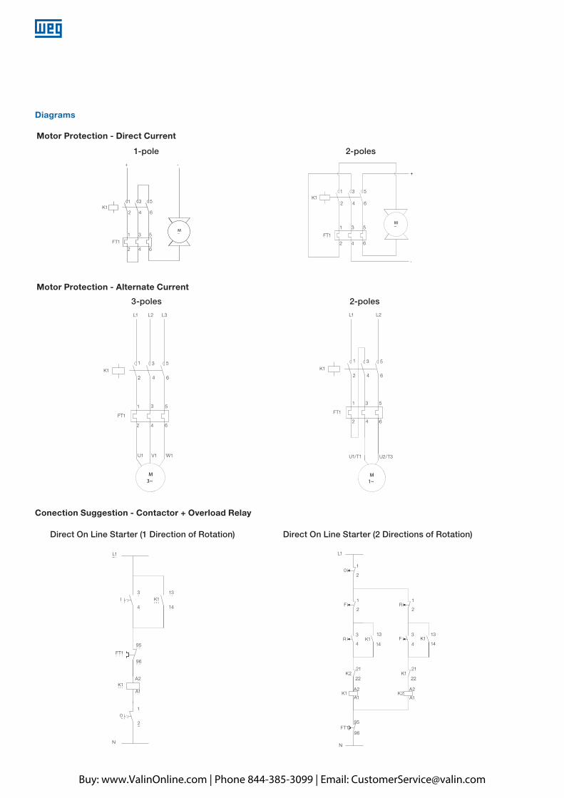
Diagrams
Motor Protection - Direct Current
Motor Protection - Alternate Current
Conection Suggestion - Contactor + Overload Relay
Direct On Line Starter (1 Direction of Rotation) Direct On Line Starter (2 Directions of Rotation)
A2
4
3
A1
L1
N
4
3
2
1
A2
A1
2
1
2
1
95
9696
95
14
13
14
13
22
21
22
21
K1
R
F
K2
K1
0
FT1
F
R
K2
K2 K1
L1
K2 K1
K2
21 21
A2
22 22
A1
A2K1
FT1
N
95
96
A1
K113
14
1
1
3 13
14
1
2
2
4
2
0
F R
F3
4R K1
K1
K1I
FT1
0
A2
95
4
3 13
14
A1
9696
95
2
1
L1
N
L1
K1
FT1
95
96
A2
A1
1
2
K1
0
N
I3 13
4 14
2-poles
L1 L2
2
1
4 6
3 5
42 6
1 3 5
U1/T1 U2/T3
M1~
FT1
K13
3
4
4
5
5
6
6
2
2
U1/T1
FT1
K1
U2/T3
1
1
L1 L2
+
2
1
4 6
3 5
42 6
1 3 5
M_
-
FT1
K1
1-pole
3
3
4
4
5
5
6
6
2
2
K1
FT1
1
1
3-poles
L1 L2 L3
2
1
4 6
3 5
U1
42 6
1 3 5
M3~
V1 W1
FT1
K13
3
4
4
5
5
6
6
2
2
U1 V1 W1
K1
FT1
1
L1 L2 L3
1
+
2
1
4 6
3 5
42 6
1 3 5
M_
-
FT1
K1
2-poles
3
3
4
4
5
5
6
6
2
2
K1
FT1
1
1
Buy: www.ValinOnline.com | Phone 844-385-3099 | Email: [email protected]
A
B
C
D
E
F
G
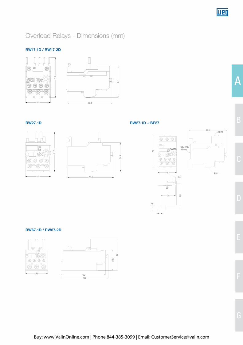
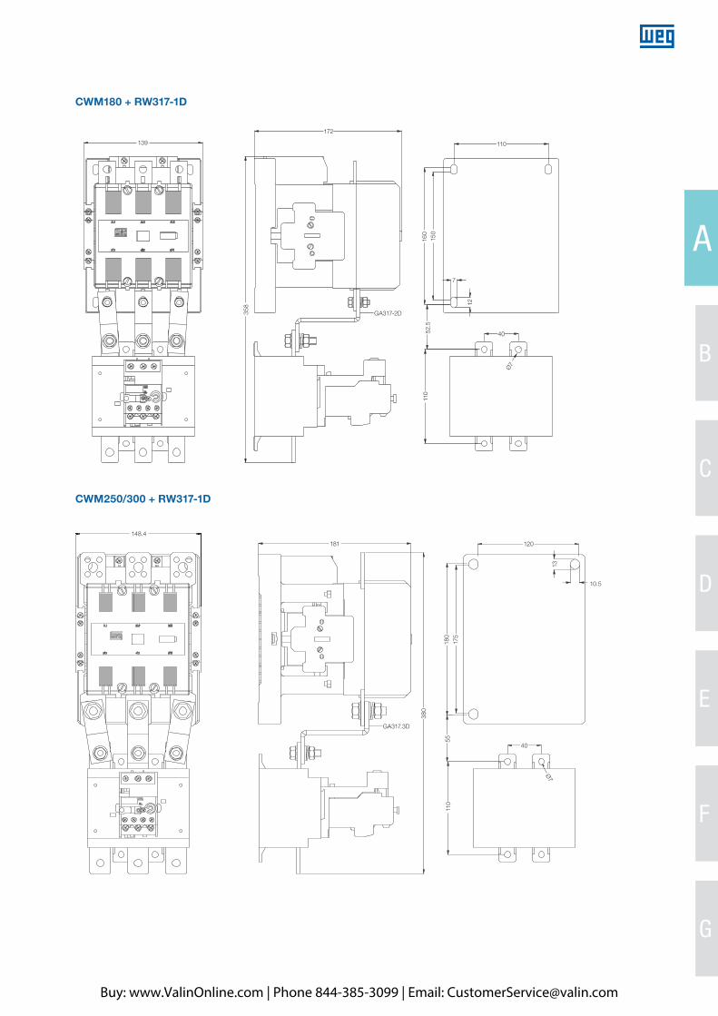
Overload Relays - Dimensions (mm)
RW17-1D / RW17-2D
RW27-1D RW27-1D + BF27
DIN RAIL35mm2A RW27D
DIN RAIL35 mm
2A
RW67-1D / RW67-2D
4
71.5
45
45
71.5
82.5
51.5
79
45
6.8
RW27
BF27D92.5
4.5
4.5
35 60
82.5
5776
50.4
100
106
50
Buy: www.ValinOnline.com | Phone 844-385-3099 | Email: [email protected]
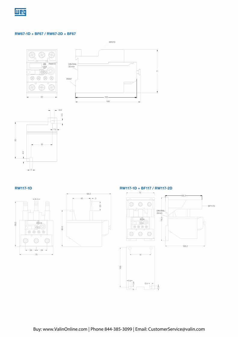
RW117-1D RW117-1D + BF117 / RW117-2D
RW67-1D + BF67 / RW67-2D + BF67
RW67
DIN RAIL35mm
RW67D DIN RAIL35 mm
RW67
100
106
BF67D
125A
50
6.8
4.5
71
60
4.5
7.5
35
5
DIN RAIL35mm
200A
8.4
98.5 7598.3
BF117D
106.2
106
7.4
7.4
5.4
5.4
116.
4
40 3
24 24
75
99.5
80.5
20
200 A
Buy: www.ValinOnline.com | Phone 844-385-3099 | Email: [email protected]
A
B
C
D
E
F
G
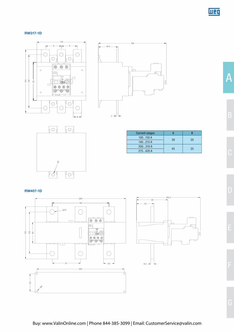
RW317-1D
Current ranges A B100...150 A
39 20140...215 A200...310 A
45 25275...420 A
RW407-1D
120166
48.5
4B
260
50
90182.5
150
50
Ø5
81 32 9.5
250
119
60
162
Ø13
Ø7
A A
155
130
93
Buy: www.ValinOnline.com | Phone 844-385-3099 | Email: [email protected]
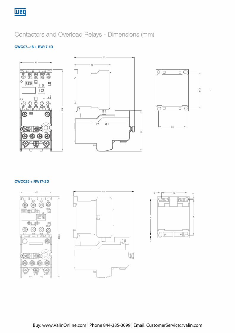
CWC07...16 + RW17-1D
Contactors and Overload Relays - Dimensions (mm)
CWC025 + RW17-2D
45
45 85
114.
3
2 36 1
51 51
1
114
57
85
38
52
51.5
Buy: www.ValinOnline.com | Phone 844-385-3099 | Email: [email protected]
A
B
C
D
E
F
G
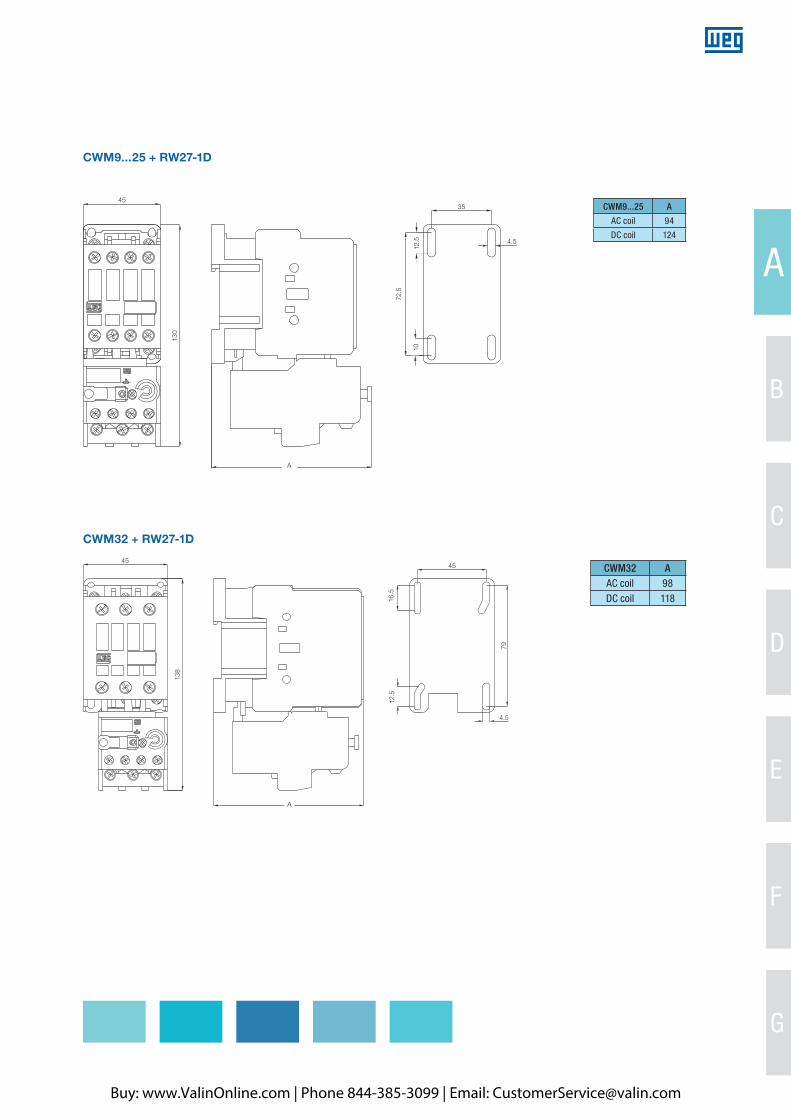
CWM9...25 + RW27-1D
CWM32 + RW27-1D
CWM9...25 A
AC coil 94
DC coil 124
A
45
130
72.5
1012
.5
35
4.5
CWM32 AAC coil 98DC coil 118
4545
16.5
79
4.5
12.5
138
A
Buy: www.ValinOnline.com | Phone 844-385-3099 | Email: [email protected]

CWM32/40 + RW67-1D
CWM50...80 + RW67-2D
CWM50...80 A
AC coil 116
DC coil 116
CWM32/40 A
AC coil 106.5
DC coil 126.5
55
66
167.
5
A
7.5
60
70
56
90
5.5
6
4.5
143.
5
12.5
16.5
45
79
4.5
Buy: www.ValinOnline.com | Phone 844-385-3099 | Email: [email protected]
A
B
C
D
E
F
G
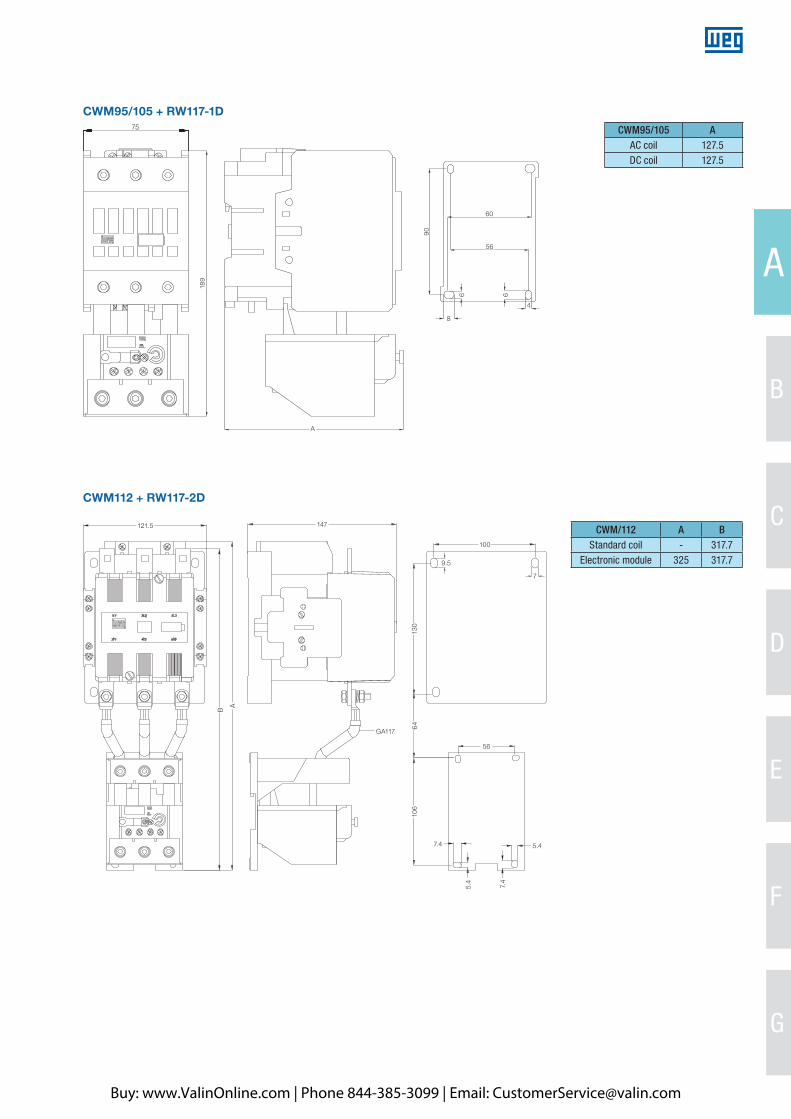
CWM112 + RW117-2D
CWM95/105 + RW117-1D
CWM95/105 AAC coil 127.5DC coil 127.5
CWM/112 A BStandard coil - 317.7
Electronic module 325 317.7
75
189
90
60
56
6 6
4
8
A
100
56
106
7.4
7.4
5.4
5.4
130
64
9.5
7
121.5
B
A
GA117
147
Buy: www.ValinOnline.com | Phone 844-385-3099 | Email: [email protected]
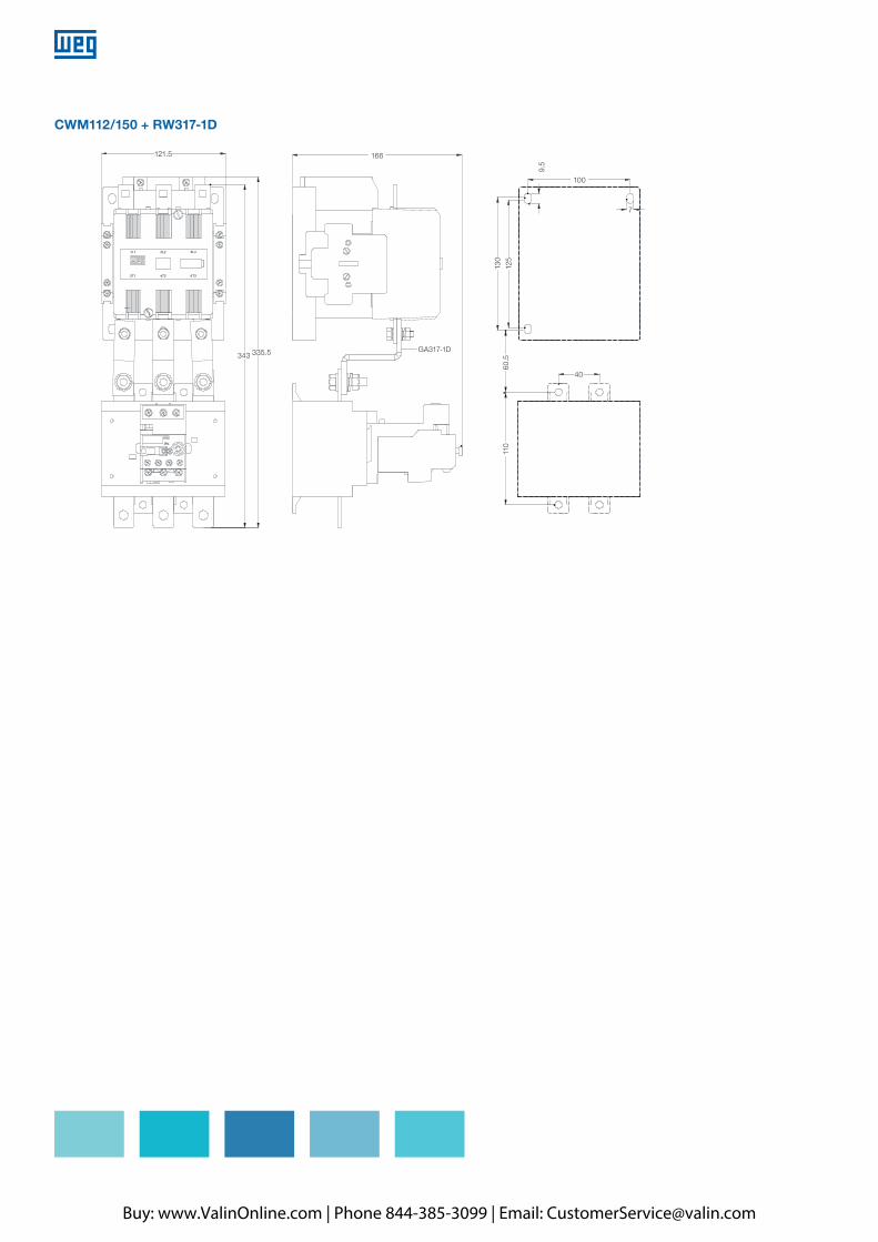
CWM112/150 + RW317-1D
121.5 166
100
7
9.5
130
125
343 335.5 GA317-1D
60.5
110
40
Buy: www.ValinOnline.com | Phone 844-385-3099 | Email: [email protected]
A
B
C
D
E
F
G
CWM180 + RW317-1D
CWM250/300 + RW317-1D
139
172
110
160
358
150
7
GA317-2D
148.4
181
GA317.3D
120
180
380
5511
0
Ø7
40
175
13
10.5
52.5
110
40
Ø7
12
Buy: www.ValinOnline.com | Phone 844-385-3099 | Email: [email protected]
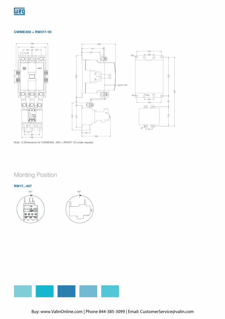
CWME400 + RW317-1D
Monting Position
RW17...407360° 360°
12090
45
72
30
54
188 198
145
R5 R5
58
40Ø7
145
222
394
6211
0
58Ø9
50
168
127
107
240
GA317-10D
4412
7
155
16354
6
Note: 1) Dimensions for CWME400...800 + RW407-1D under request.
Buy: www.ValinOnline.com | Phone 844-385-3099 | Email: [email protected]
Related Documents