33 Bimetal Overload Relays 3UA and 3UC The 3UA / 3UC thermal overload relays are suitable for customers from all industries, who want guaranteed optimum inverse time delayed protection of their electrical loads. The relays meet the requirements of IS/IEC 60947-4-1. Application 3UA overload relay: 3UA5/6 are 3 pole adjustable bi-metal overload relays mainly suitable for normal starting applications. They provide accurate and reliable protection to motors against overload as per CLASS 10A. They also offer protection against single phasing and unbalanced voltages. 3UC overload relay: 3UC5/6 are 3 pole adjustable, saturable CT operated bi-metal overload relays mainly suitable for heavy starting applications (i.e. when heavy masses are to be put in motion resulting in larger starting period). They provide accurate and reliable protection to motors against overload as per CLASS 30. They also offer protection against single phasing and unbalanced voltages. If single-phase AC or DC loads are to be protected by the 3UA / 3UC thermal overload relays, all three bimetal strips must be heated. For this purpose, all main current paths of the relay must be connected in series. Standards Bimetal relays conform to IS/IEC 60947-4-1. They also carry the CE mark. Range 3UA5: 0.1 to 120A, (Class 10A, without CT) 3UA6: 85 to 630A, (Class 10A, CT operated) 3UC5/6: 2.4 to 400A (Class 30, CT operated) Relay overview Overload relay operates on the bi-metallic principle. The heater winding wound on the bimetal strips carry the current flowing through the motor. In case of overload, the current carried through the heater winding is more than the rated current. This heats up the bimetals. Due to this bi-metal strips bend and open the NC contact of the relay, which is connected in the control circuit of the contactor, thus disconnects the motor from the supply. The tripping time is inversely proportional to the current flowing through the bi-metal strips. Bi-relays are therefore, referred to as “current dependent” and inverse-time delayed relays. 1. Connection for mounting onto contactors: Optimally adapted in electrical, mechanical and design terms to the contactors, these connecting pins can be used for direct mounting of the overload relays. Stand-alone installation is possible as an alternative (in some cases in conjunction with a stand-alone installation module). 2. Selector switch for manual/automatic RESET (blue): With this switch you can choose between manual and automatic RESET. A device set to manual RESET can be reset locally by pressing the RESET button. A remote RESET is possible using the RESET modules (accessories), which are independent of size. 3. TEST button (red): Trip circuit can be manually checked by using this button. During this simulation the NC contact (95-96) is opened and the NO contact (97-98) is closed. This tests whether the auxiliary circuit has been correctly connected to the overload relay. The relay must be reset with the RESET button if it has been set to manual RESET. If the thermal overload relay has been set to automatic RESET, then the overload relay is automatically reset when the TEST button is released. 4. Motor current setting dial: Setting the device to the rated motor current is easy with the large rotary knob. (Recessed dial, hence no possibility of accidently change in current setting.) 5. Trip indicator (Green): A separate mechanical Green Trip Indicator is provided on the front cover of the relay to indicate the tripped state of the ‘manual reset’ relay. 1 2 5 3 4

Welcome message from author
This document is posted to help you gain knowledge. Please leave a comment to let me know what you think about it! Share it to your friends and learn new things together.
Transcript
33
Bimetal Overload Relays 3UA and 3UC
The 3UA / 3UC thermal overload relays are suitable for customers from all industries, who want
guaranteed optimum inverse time delayed protection of their electrical loads. The relays meet the
requirements of IS/IEC 60947-4-1.
Application
3UA overload relay: 3UA5/6 are 3 pole adjustable bi-metal
overload relays mainly suitable for normal starting applications.
They provide accurate and reliable protection to motors against
overload as per CLASS 10A. They also offer protection against
single phasing and unbalanced voltages.
3UC overload relay: 3UC5/6 are 3 pole adjustable, saturable CT
operated bi-metal overload relays mainly suitable for heavy
starting applications (i.e. when heavy masses are to be put in
motion resulting in larger starting period). They provide accurate
and reliable protection to motors against overload as per CLASS
30. They also offer protection against single phasing and
unbalanced voltages.
If single-phase AC or DC loads are to be protected by the 3UA /
3UC thermal overload relays, all three bimetal strips must be
heated. For this purpose, all main current paths of the relay must
be connected in series.
Standards
Bimetal relays conform to IS/IEC 60947-4-1. They also carry the CE
mark.
Range
3UA5: 0.1 to 120A, (Class 10A, without CT)
3UA6: 85 to 630A, (Class 10A, CT operated)
3UC5/6: 2.4 to 400A (Class 30, CT operated)
Relay overview
Overload relay operates on the bi-metallic principle. The heater
winding wound on the bimetal strips carry the current flowing
through the motor. In case of overload, the current carried
through the heater winding is more than the rated current. This
heats up the bimetals. Due to this bi-metal strips bend and open
the NC contact of the relay, which is connected in the control
circuit of the contactor, thus disconnects the motor from the
supply. The tripping time is inversely proportional to the current
flowing through the bi-metal strips. Bi-relays are therefore,
referred to as “current dependent” and inverse-time delayed
relays.
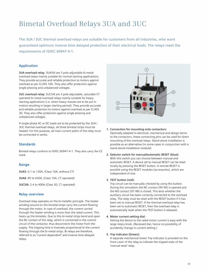
1. Connection for mounting onto contactors:
Optimally adapted in electrical, mechanical and design terms
to the contactors, these connecting pins can be used for direct
mounting of the overload relays. Stand-alone installation is
possible as an alternative (in some cases in conjunction with a
stand-alone installation module).
2. Selector switch for manual/automatic RESET (blue):
With this switch you can choose between manual and
automatic RESET. A device set to manual RESET can be reset
locally by pressing the RESET button. A remote RESET is
possible using the RESET modules (accessories), which are
independent of size.
3. TEST button (red):
Trip circuit can be manually checked by using this button.
During this simulation the NC contact (95-96) is opened and
the NO contact (97-98) is closed. This tests whether the
auxiliary circuit has been correctly connected to the overload
relay. The relay must be reset with the RESET button if it has
been set to manual RESET. If the thermal overload relay has
been set to automatic RESET, then the overload relay is
automatically reset when the TEST button is released.
4. Motor current setting dial:
Setting the device to the rated motor current is easy with the
large rotary knob. (Recessed dial, hence no possibility of
accidently change in current setting.)
5. Trip indicator (Green):
A separate mechanical Green Trip Indicator is provided on the
front cover of the relay to indicate the tripped state of the
‘manual reset’ relay.
1
2
53
4
34
Recovery time
After tripping due to overload, the thermal overload relays require
some time until the bimetal strips have cooled down. The device
can only be reset after the bimetal strips have cooled down. This
time (recovery time) depends on the tripping characteristics and
strength of the tripping current. The recovery time allows the load
to cool down after tripping due to overload.
Benefits and features
High performance
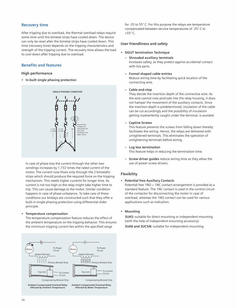
• In-built single phasing protection
In case of phase loss the current through the other two
windings increases by 1.732 times the rated current of the
motor. The current now flows only through the 2 bimetallic
strips which should produce the required force on the tripping
mechanism. This needs higher currents for longer time. As
current is not too high so the relay might take higher time to
trip. This can cause damage to the motor. Similar condition
happens in case of phase unbalance. To take care of these
conditions our birelays are constructed such that they offer a
built-in single phasing protection using differential slider
principle.
• Temperature compensation
The temperature compensation feature reduces the effect of
the ambient temperature on the tripping behavior. This ensures
the minimum tripping current lies within the specified range
for -25 to 55° C. For this purpose the relays are temperature
compensated between service temperatures of -25° C to
+55° C.
User friendliness and safety
• SIGUT termination Technique
– Shrouded auxiliary terminals
Increases safety, as they protect against accidental contact
with live parts.
– Funnel shaped cable entries
Reduce wiring time by facilitating quick location of the
connecting wire.
– Cable end-stop
They decide the insertion depth of the connective wire. As
the wire cannot now protrude into the relay housing, it does
not hamper the movement of the auxiliary contacts. Since
the insertion depth is predetermined, insulation of the cable
can be cut accordingly and the possibility of insulation
getting inadvertently caught under the terminal, is avoided.
– Captive Screws
This feature prevents the screws from falling down thereby
facilitates the wiring. Hence, the relays are delivered with
untightened terminals. This eliminates the operation of
untightening terminals before wiring.
– Lug less termination
This feature helps in reducing the termination time.
– Screw-driver guides reduce wiring time as they allow the
use of power screw-drivers.
Flexibility
• Potential free Auxiliary Contacts
Potential free 1NO + 1NC contact arrangement is provided as a
standard feature. The 1NC contact is used in the control circuit
of the contactor for disconnecting the motor in case of
overload, whereas the 1NO contact can be used for various
applications such as indication.
• Mounting
3UA5: suitable for direct mounting or independent mounting
(with the help of independent mounting accessory)
3UA6 and 3UC5/6: suitable for Independent mounting.
35
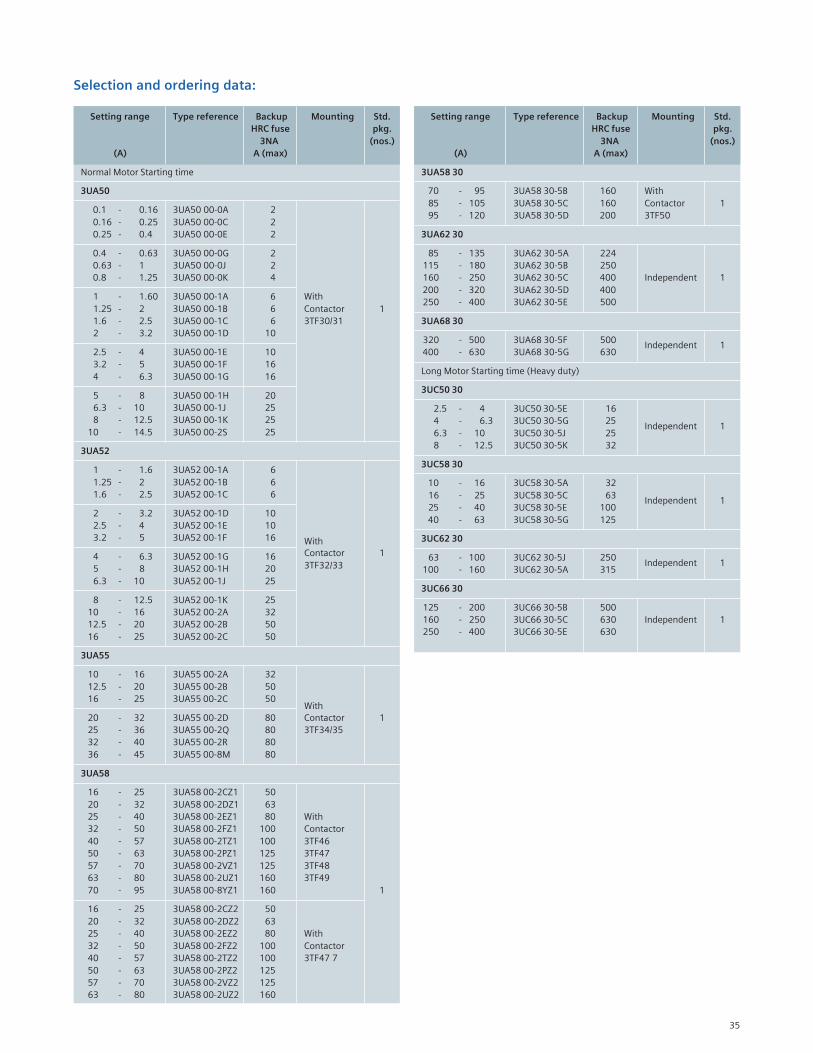
Selection and ordering data:
Setting range Type reference Backup Mounting Std.
HRC fuse pkg.
3NA (nos.)
(A) A (max)
3UA58 30
70 - 95 3UA58 30-5B 160 With
85 - 105 3UA58 30-5C 160 Contactor 1
95 - 120 3UA58 30-5D 200 3TF50
3UA62 30
85 - 135 3UA62 30-5A 224
115 - 180 3UA62 30-5B 250
160 - 250 3UA62 30-5C 400 Independent 1
200 - 320 3UA62 30-5D 400
250 - 400 3UA62 30-5E 500
3UA68 30
320 - 500 3UA68 30-5F 500Independent 1
400 - 630 3UA68 30-5G 630
Long Motor Starting time (Heavy duty)
3UC50 30
2.5 - 4 3UC50 30-5E 16
4 - 6.3 3UC50 30-5G 25Independent 1
6.3 - 10 3UC50 30-5J 25
8 - 12.5 3UC50 30-5K 32
3UC58 30
10 - 16 3UC58 30-5A 32
16 - 25 3UC58 30-5C 63Independent 1
25 - 40 3UC58 30-5E 100
40 - 63 3UC58 30-5G 125
3UC62 30
63 - 100 3UC62 30-5J 250Independent 1
100 - 160 3UC62 30-5A 315
3UC66 30
125 - 200 3UC66 30-5B 500
160 - 250 3UC66 30-5C 630 Independent 1
250 - 400 3UC66 30-5E 630
Setting range Type reference Backup Mounting Std.
HRC fuse pkg.
3NA (nos.)
(A) A (max)
Normal Motor Starting time
3UA50
0.1 - 0.16 3UA50 00-0A 2
0.16 - 0.25 3UA50 00-0C 2
0.25 - 0.4 3UA50 00-0E 2
0.4 - 0.63 3UA50 00-0G 2
0.63 - 1 3UA50 00-0J 2
0.8 - 1.25 3UA50 00-0K 4
1 - 1.60 3UA50 00-1A 6 With
1.25 - 2 3UA50 00-1B 6 Contactor 1
1.6 - 2.5 3UA50 00-1C 6 3TF30/31
2 - 3.2 3UA50 00-1D 10
2.5 - 4 3UA50 00-1E 10
3.2 - 5 3UA50 00-1F 16
4 - 6.3 3UA50 00-1G 16
5 - 8 3UA50 00-1H 20
6.3 - 10 3UA50 00-1J 25
8 - 12.5 3UA50 00-1K 25
10 - 14.5 3UA50 00-2S 25
3UA52
1 - 1.6 3UA52 00-1A 6
1.25 - 2 3UA52 00-1B 6
1.6 - 2.5 3UA52 00-1C 6
2 - 3.2 3UA52 00-1D 10
2.5 - 4 3UA52 00-1E 10
3.2 - 5 3UA52 00-1F 16 With
4 - 6.3 3UA52 00-1G 16 Contactor 1
5 - 8 3UA52 00-1H 20 3TF32/33
6.3 - 10 3UA52 00-1J 25
8 - 12.5 3UA52 00-1K 25
10 - 16 3UA52 00-2A 32
12.5 - 20 3UA52 00-2B 50
16 - 25 3UA52 00-2C 50
3UA55
10 - 16 3UA55 00-2A 32
12.5 - 20 3UA55 00-2B 50
16 - 25 3UA55 00-2C 50With
20 - 32 3UA55 00-2D 80 Contactor 1
25 - 36 3UA55 00-2Q 80 3TF34/35
32 - 40 3UA55 00-2R 80
36 - 45 3UA55 00-8M 80
3UA58
16 - 25 3UA58 00-2CZ1 50
20 - 32 3UA58 00-2DZ1 63
25 - 40 3UA58 00-2EZ1 80 With
32 - 50 3UA58 00-2FZ1 100 Contactor
40 - 57 3UA58 00-2TZ1 100 3TF46
50 - 63 3UA58 00-2PZ1 125 3TF47
57 - 70 3UA58 00-2VZ1 125 3TF48
63 - 80 3UA58 00-2UZ1 160 3TF49
70 - 95 3UA58 00-8YZ1 160 1
16 - 25 3UA58 00-2CZ2 50
20 - 32 3UA58 00-2DZ2 63
25 - 40 3UA58 00-2EZ2 80 With
32 - 50 3UA58 00-2FZ2 100 Contactor
40 - 57 3UA58 00-2TZ2 100 3TF47 7
50 - 63 3UA58 00-2PZ2 125
57 - 70 3UA58 00-2VZ2 125
63 - 80 3UA58 00-2UZ2 160
36
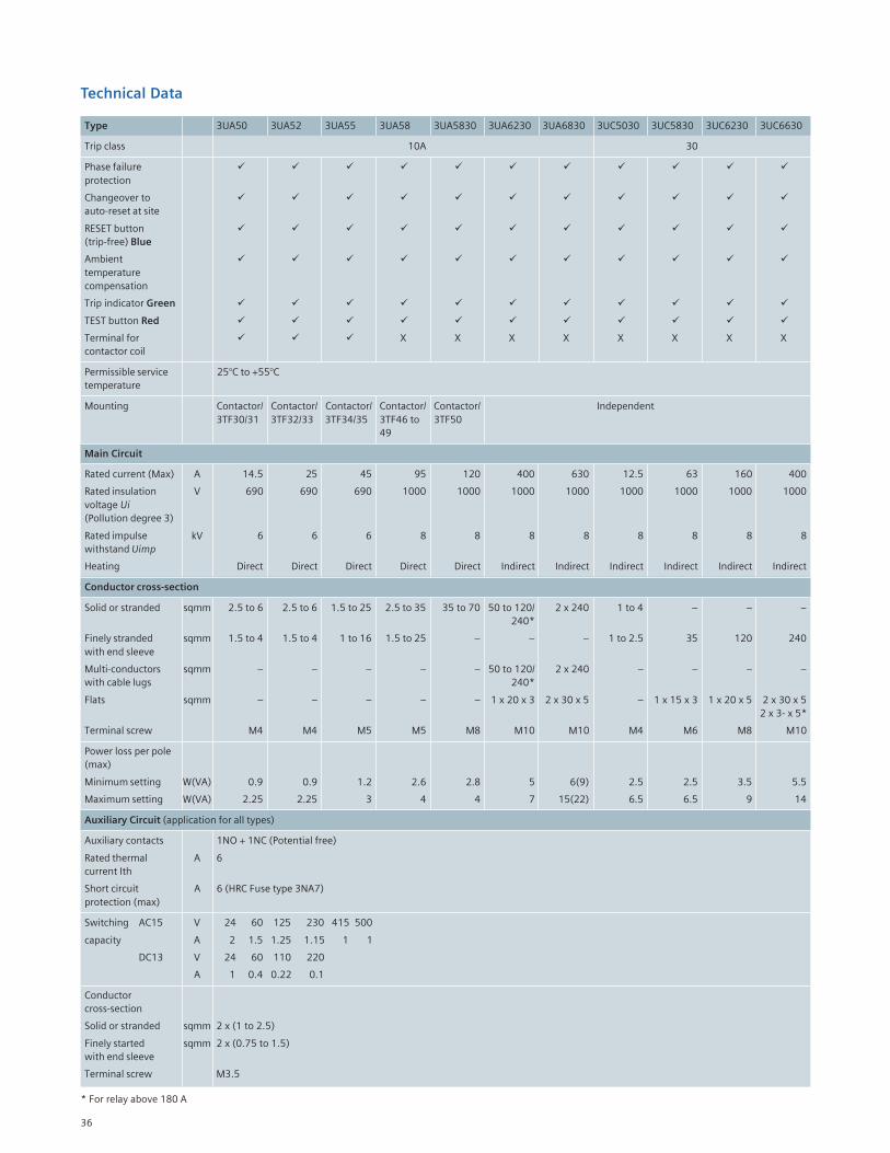
Technical Data
Type 3UA50 3UA52 3UA55 3UA58 3UA5830 3UA6230 3UA6830 3UC5030 3UC5830 3UC6230 3UC6630
Trip class 10A 30
Phase failure
protection
Changeover to
auto-reset at site
RESET button
(trip-free) Blue
Ambient
temperature
compensation
Trip indicator Green
TEST button Red
Terminal for X X X X X X X X
contactor coil
Permissible service 25°C to +55°C
temperature
Mounting Contactor/ Contactor/ Contactor/ Contactor/ Contactor/ Independent
3TF30/31 3TF32/33 3TF34/35 3TF46 to 3TF50
49
Main Circuit
Rated current (Max) A 14.5 25 45 95 120 400 630 12.5 63 160 400
Rated insulation V 690 690 690 1000 1000 1000 1000 1000 1000 1000 1000
voltage Ui
(Pollution degree 3)
Rated impulse kV 6 6 6 8 8 8 8 8 8 8 8
withstand Uimp
Heating Direct Direct Direct Direct Direct Indirect Indirect Indirect Indirect Indirect Indirect
Conductor cross-section
Solid or stranded sqmm 2.5 to 6 2.5 to 6 1.5 to 25 2.5 to 35 35 to 70 50 to 120/ 2 x 240 1 to 4 – – –
240*
Finely stranded sqmm 1.5 to 4 1.5 to 4 1 to 16 1.5 to 25 – – – 1 to 2.5 35 120 240
with end sleeve
Multi-conductors sqmm – – – – – 50 to 120/ 2 x 240 – – – –
with cable lugs 240*
Flats sqmm – – – – – 1 x 20 x 3 2 x 30 x 5 – 1 x 15 x 3 1 x 20 x 5 2 x 30 x 5
2 x 3- x 5*
Terminal screw M4 M4 M5 M5 M8 M10 M10 M4 M6 M8 M10
Power loss per pole
(max)
Minimum setting W(VA) 0.9 0.9 1.2 2.6 2.8 5 6(9) 2.5 2.5 3.5 5.5
Maximum setting W(VA) 2.25 2.25 3 4 4 7 15(22) 6.5 6.5 9 14
Auxiliary Circuit (application for all types)
Auxiliary contacts 1NO + 1NC (Potential free)
Rated thermal A 6
current Ith
Short circuit A 6 (HRC Fuse type 3NA7)
protection (max)
Switching AC15 V 24 60 125 230 415 500
capacity A 2 1.5 1.25 1.15 1 1
DC13 V 24 60 110 220
A 1 0.4 0.22 0.1
Conductor
cross-section
Solid or stranded sqmm 2 x (1 to 2.5)
Finely started sqmm 2 x (0.75 to 1.5)
with end sleeve
Terminal screw M3.5
* For relay above 180 A
37
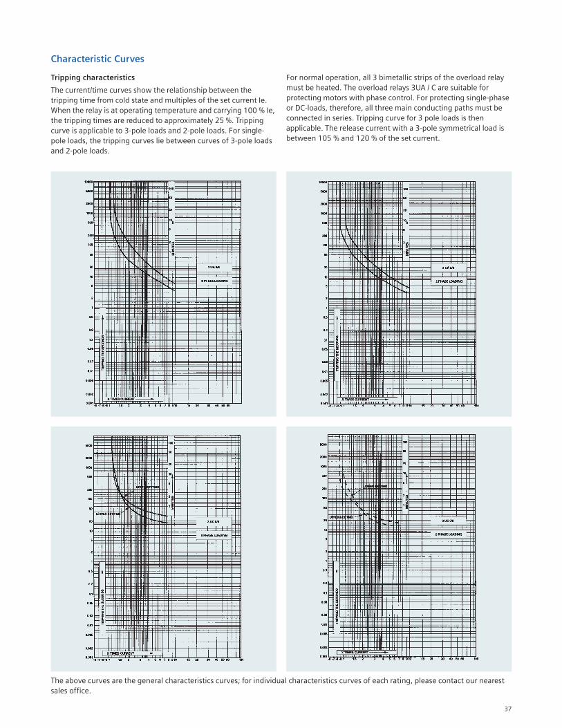
Characteristic Curves
For normal operation, all 3 bimetallic strips of the overload relay
must be heated. The overload relays 3UA / C are suitable for
protecting motors with phase control. For protecting single-phase
or DC-loads, therefore, all three main conducting paths must be
connected in series. Tripping curve for 3 pole loads is then
applicable. The release current with a 3-pole symmetrical load is
between 105 % and 120 % of the set current.
Tripping characteristics
The current/time curves show the relationship between the
tripping time from cold state and multiples of the set current Ie.
When the relay is at operating temperature and carrying 100 % Ie,
the tripping times are reduced to approximately 25 %. Tripping
curve is applicable to 3-pole loads and 2-pole loads. For single-
pole loads, the tripping curves lie between curves of 3-pole loads
and 2-pole loads.
The above curves are the general characteristics curves; for individual characteristics curves of each rating, please contact our nearest
sales office.
38
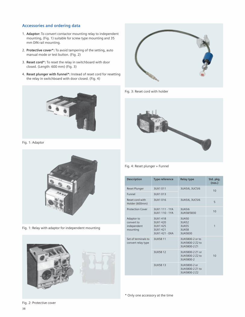
Accessories and ordering data
1. Adaptor: To convert contactor mounting relay to independent
mounting, (Fig. 1) suitable for screw type mounting and 35
mm DIN rail mounting.
2. Protective cover*: To avoid tampering of the setting, auto
manual mode or test button. (Fig. 2)
3. Reset cord*: To reset the relay in switchboard with door
closed. (Length: 600 mm) (Fig. 3)
4. Reset plunger with funnel*: Instead of reset cord for resetting
the relay in switchboard with door closed. (Fig. 4)
Fig. 2: Protective cover
Fig. 3: Reset cord with holder
Fig. 4: Reset plunger + Funnel
Description Type reference Relay type Std. pkg.
(nos.)
Reset Plunger 3UX1 011 3UA5/6, 3UC5/610
Funnel 3UX1 013
Reset cord with 3UX1 016 3UA5/6, 3UC5/65
Holder (600mm)
Protection Cover 3UX1 111 - 1YA 3UA5/610
3UX1 110 - 1YA 3UA58/5830
Adaptor to 3UX1 418 3UA50
convert to 3UX1 420 3UA52
independent 3UX1 425 3UA55 1
mounting 3UX1 421 3UA58
3UX1 421 - 0XA 3UA5830
Set of terminals to 3UX58 11 3UA5800-2 or to
convert relay type 3UA5800-2 Z2 to
3UA5800-2 Z1
3UX58 12 3UA5800-2 Z1 or
3UA5800-2 Z2 to 10
3UA5800-2
3UX58 13 3UA5800-2 or
3UA5800-2 Z1 to
3UA5800-2 Z2
Fig. 1: Relay with adaptor for independent mounting
* Only one accessory at the time
Fig. 1: Adaptor
39
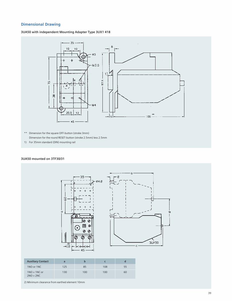
Dimensional Drawing
3UA50 with independent Mounting Adapter Type 3UX1 418
** Dimension for the square OFF-button (stroke 3mm)
Dimension for the round RESET-button (stroke 2.5mm) less 2.5mm
1) For 35mm standard (DIN) mounting rail
3UA50 mounted on 3TF30/31
Auxiliary Contact a b c d
1NO or 1NC 125 85 108 55
1NO + 1NC or 130 100 100 60
2NO + 2NC
2) Minimum clearance from earthed element 10mm
40
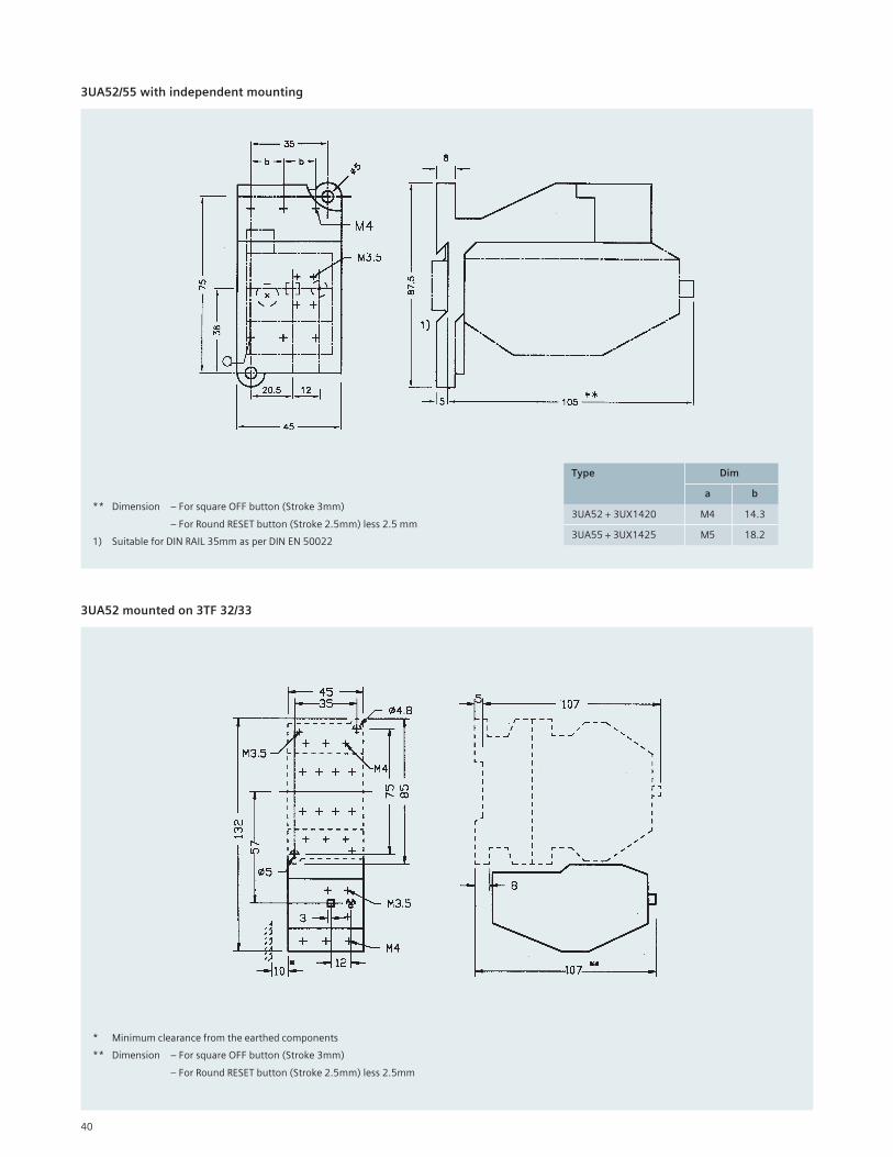
3UA52/55 with independent mounting
** Dimension – For square OFF button (Stroke 3mm)
– For Round RESET button (Stroke 2.5mm) less 2.5 mm
1) Suitable for DIN RAIL 35mm as per DIN EN 50022
3UA52 mounted on 3TF 32/33
* Minimum clearance from the earthed components
** Dimension – For square OFF button (Stroke 3mm)
– For Round RESET button (Stroke 2.5mm) less 2.5mm
Type Dim
a b
3UA52 + 3UX1420 M4 14.3
3UA55 + 3UX1425 M5 18.2
41
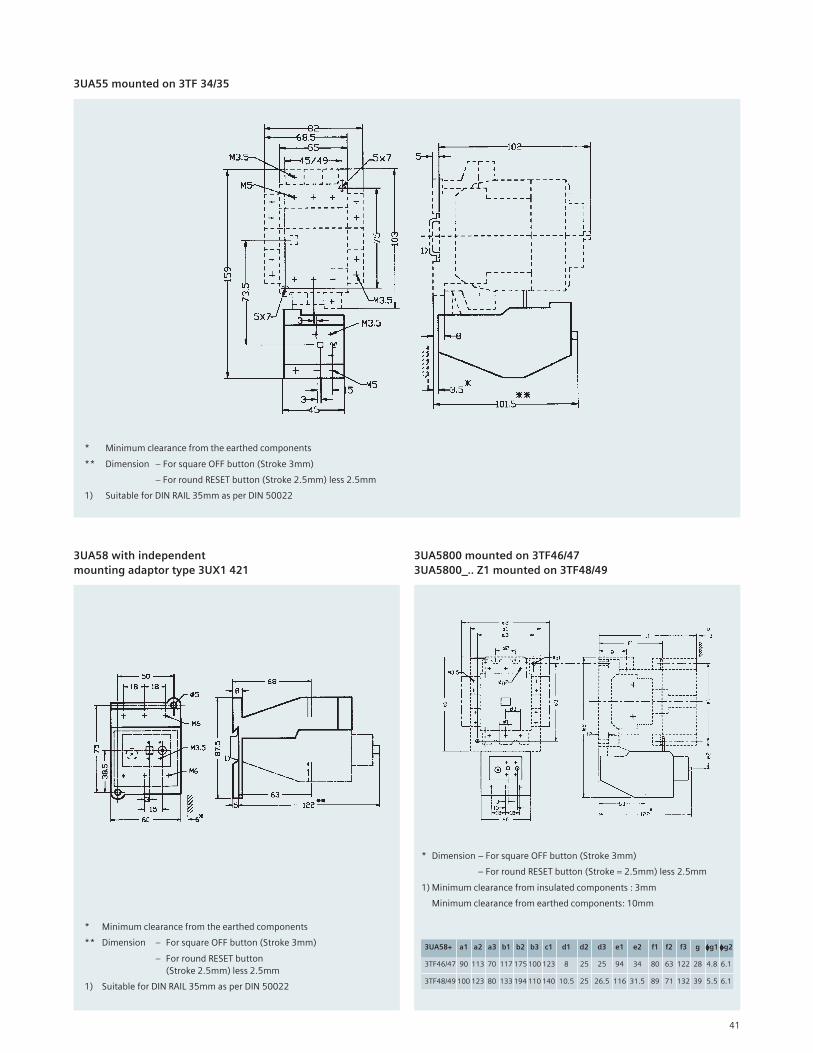
3UA55 mounted on 3TF 34/35
* Minimum clearance from the earthed components
** Dimension – For square OFF button (Stroke 3mm)
– For round RESET button (Stroke 2.5mm) less 2.5mm
1) Suitable for DIN RAIL 35mm as per DIN 50022
3UA58 with independent
mounting adaptor type 3UX1 421
* Minimum clearance from the earthed components
** Dimension – For square OFF button (Stroke 3mm)
– For round RESET button
(Stroke 2.5mm) less 2.5mm
1) Suitable for DIN RAIL 35mm as per DIN 50022
3UA5800 mounted on 3TF46/47
3UA5800_.. Z1 mounted on 3TF48/49
* Dimension – For square OFF button (Stroke 3mm)
– For round RESET button (Stroke = 2.5mm) less 2.5mm
1) Minimum clearance from insulated components : 3mm
Minimum clearance from earthed components: 10mm
3UA58+ a1 a2 a3 b1 b2 b3 c1 d1 d2 d3 e1 e2 f1 f2 f3 g φφφφφg1 φφφφφg2
3TF46/47 90 113 70 117 175 100 123 8 25 25 94 34 80 63 122 28 4.8 6.1
3TF48/49 100 123 80 133 194 110 140 10.5 25 26.5 116 31.5 89 71 132 39 5.5 6.1
42
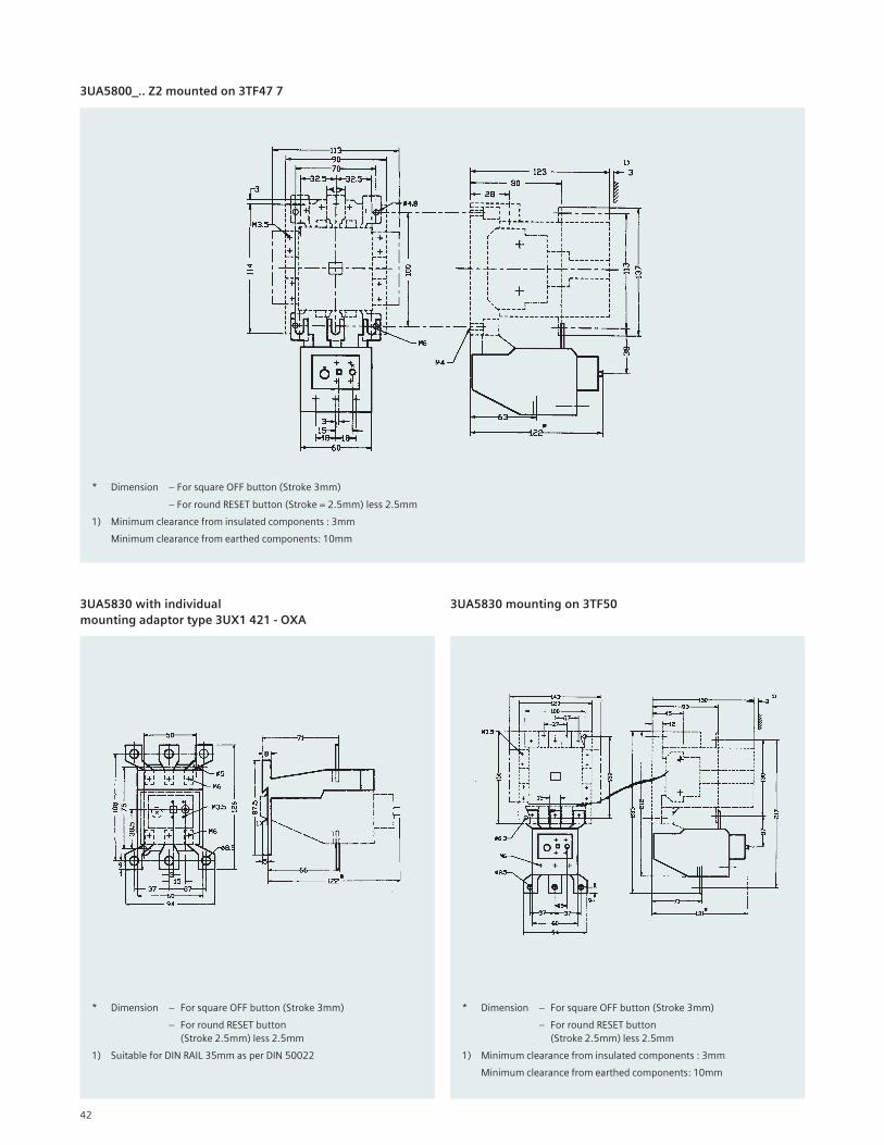
3UA5800_.. Z2 mounted on 3TF47 7
* Dimension – For square OFF button (Stroke 3mm)
– For round RESET button (Stroke = 2.5mm) less 2.5mm
1) Minimum clearance from insulated components : 3mm
Minimum clearance from earthed components: 10mm
3UA5830 with individual
mounting adaptor type 3UX1 421 - OXA
* Dimension – For square OFF button (Stroke 3mm)
– For round RESET button
(Stroke 2.5mm) less 2.5mm
1) Suitable for DIN RAIL 35mm as per DIN 50022
3UA5830 mounting on 3TF50
* Dimension – For square OFF button (Stroke 3mm)
– For round RESET button
(Stroke 2.5mm) less 2.5mm
1) Minimum clearance from insulated components : 3mm
Minimum clearance from earthed components: 10mm
43
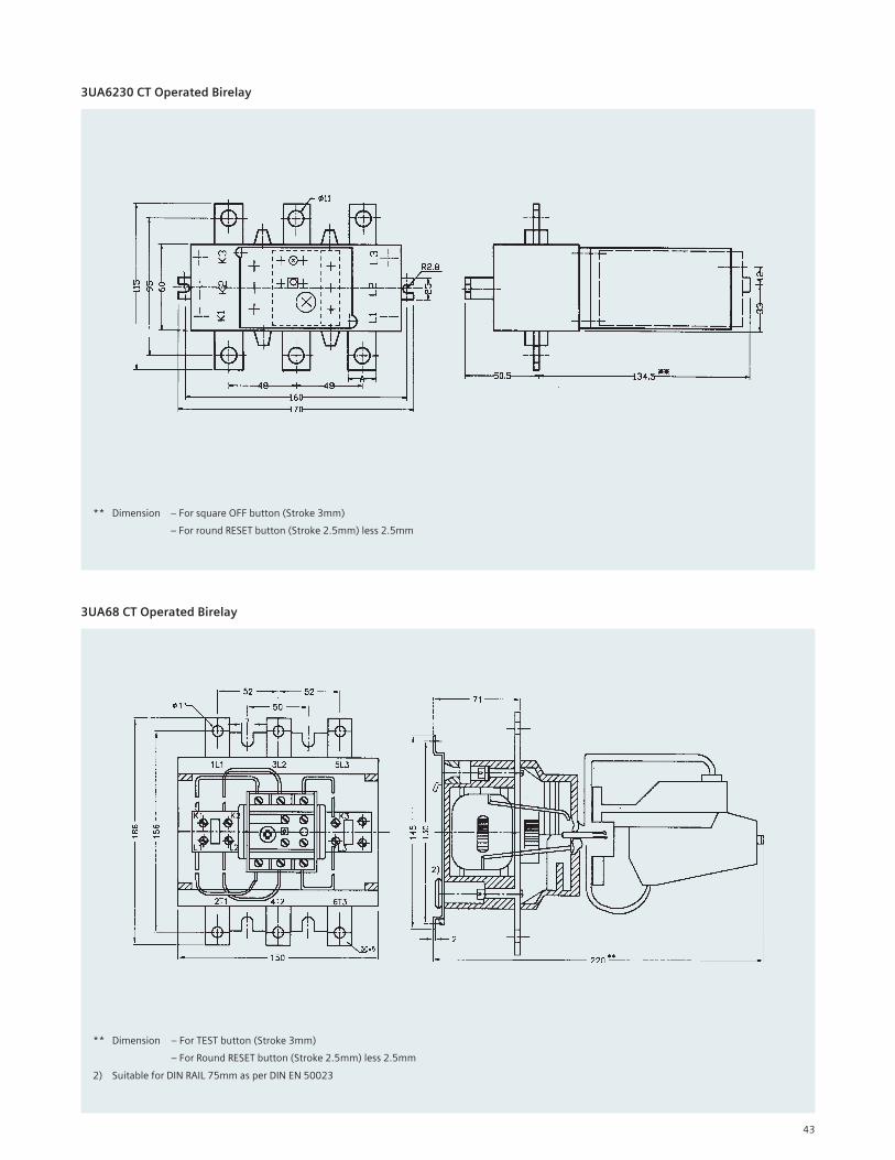
3UA6230 CT Operated Birelay
** Dimension – For square OFF button (Stroke 3mm)
– For round RESET button (Stroke 2.5mm) less 2.5mm
** Dimension – For TEST button (Stroke 3mm)
– For Round RESET button (Stroke 2.5mm) less 2.5mm
2) Suitable for DIN RAIL 75mm as per DIN EN 50023
3UA68 CT Operated Birelay
44
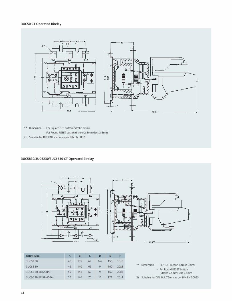
3UC50 CT Operated Birelay
** Dimension – For Square OFF button (Stroke 3mm)
– For Round RESET button (Stroke 2.5mm) less 2.5mm
2) Suitable for DIN RAIL 75mm as per DIN EN 50023
3UC5830/3UC6230/3UC6630 CT Operated Birelay
** Dimension – For TEST button (Stroke 3mm)
– For Round RESET button
(Stroke 2.5mm) less 2.5mm
2) Suitable for DIN RAIL 75mm as per DIN EN 50023
Relay Type A B C D E F
3UC58 30 46 135 69 6.6 150 15x3
3UC62 30 46 140 69 9 160 20x3
3UC66 30-5B (200A) 50 146 69 9 160 20x3
3UC66 30-5C-5E(400A) 50 146 70 11 171 25x4
Related Documents