Week 12 An Introduction to PIC microcontrollers

Welcome message from author
This document is posted to help you gain knowledge. Please leave a comment to let me know what you think about it! Share it to your friends and learn new things together.
Transcript

Week 12An Introduction to PIC microcontrollers
Microcontrollers
• In order for a microprocessor to be used, other components such as memory, or components for receiving and sending data must be added to it.
• On the other hand, microcontroller is designed to be all of that in one. No other external components are needed for its application because all necessary peripherals are already built into it. Thus, we save the time and space needed to construct devices.
• The PICmicro was originally designed around 1980 by General Instrument as a small, fast, inexpensive embedded microcontroller with strong I/O capabilities. PIC stands for "Peripheral Interface Controller".
• General Instrument recognized the potential for the PIC and eventually spun off Microchip, headquartered in Chandler, AZ to fabricate and market the PICmicro.

Advantages of PIC
• It is a RISC (Reduced Instruction Set Computer) design
• Only thirty seven instructions to remember
• Its code is extremely efficient, allowing the PIC to run with typically less program memory than its larger competitors.
• It is low cost, high clock speed
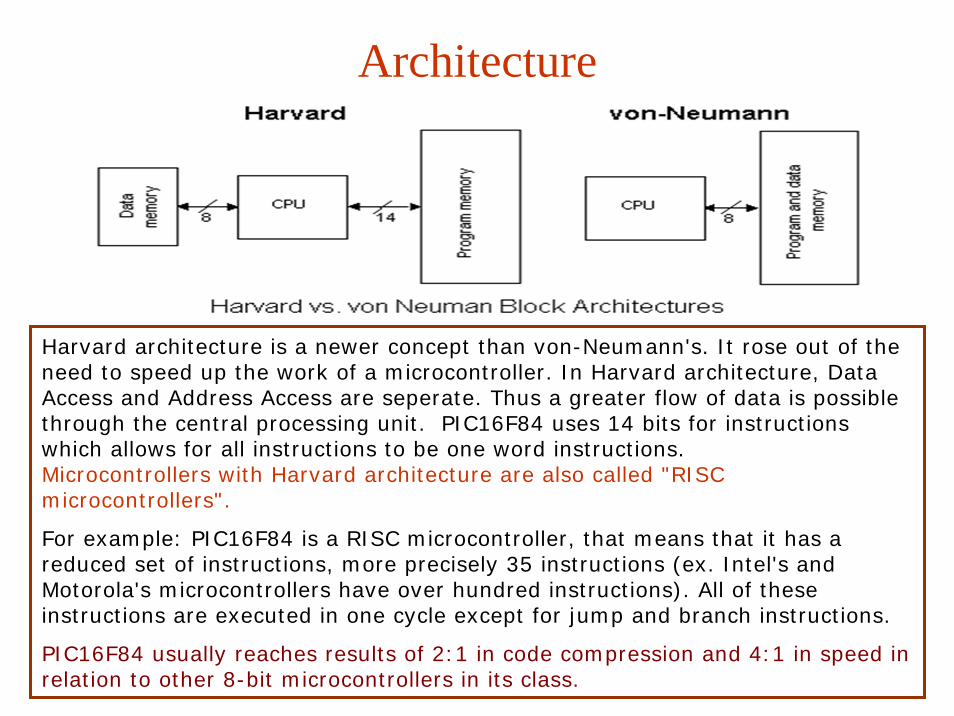
Architecture
Harvard architecture is a newer concept than von-Neumann's. It rose out of the need to speed up the work of a microcontroller. In Harvard architecture, Data Access and Address Access are seperate. Thus a greater flow of data is possible through the central processing unit. PIC16F84 uses 14 bits for instructions which allows for all instructions to be one word instructions. Microcontrollers with Harvard architecture are also called "RISCmicrocontrollers".
For example: PIC16F84 is a RISC microcontroller, that means that it has a reduced set of instructions, more precisely 35 instructions (ex. Intel's and Motorola's microcontrollers have over hundred instructions). All of these instructions are executed in one cycle except for jump and branch instructions.
PIC16F84 usually reaches results of 2:1 in code compression and 4:1 in speed in relation to other 8-bit microcontrollers in its class.

Harvard Architecture
• Used mostly in RISC CPUs• Separate program bus and data bus: can
be different widths!• For example, PICs use:
– Data memory (RAM): a small number of 8bitregisters
– Program memory (ROM): 12bit, 14bit or 16bit wide (in EPROM, FLASH, or ROM)
CPU 121416
Memory(Data) 8
Memory(Program)
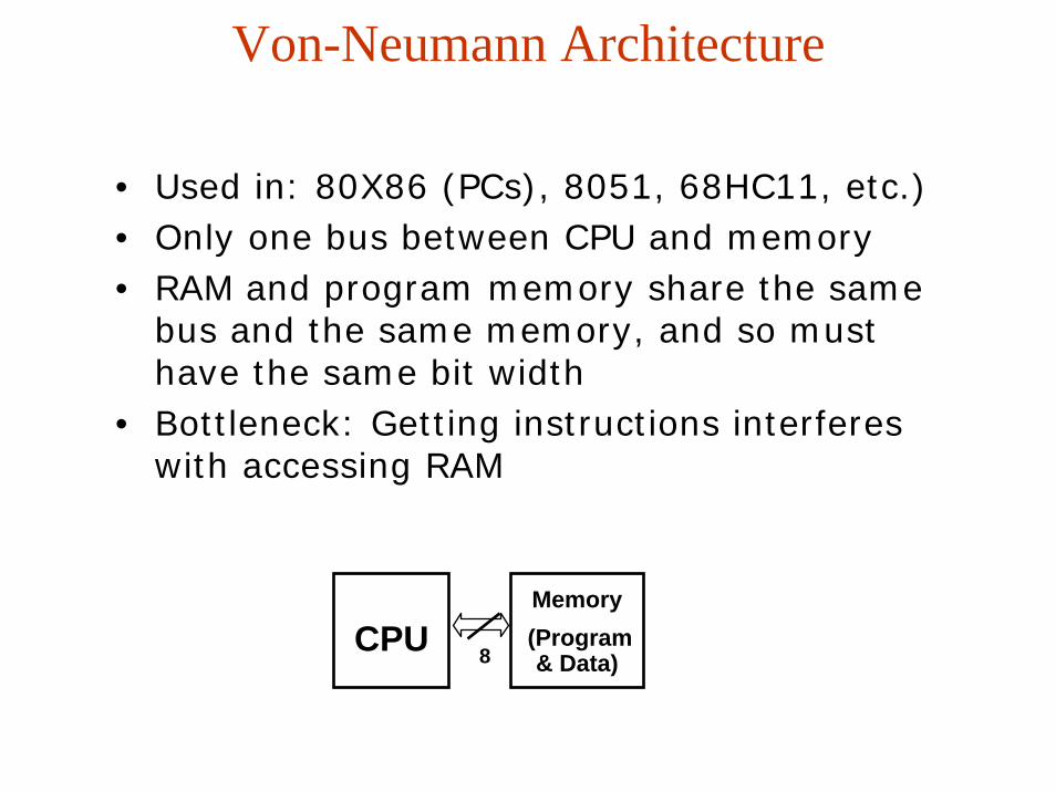
Von-Neumann Architecture
• Used in: 80X86 (PCs), 8051, 68HC11, etc.)• Only one bus between CPU and memory• RAM and program memory share the same
bus and the same memory, and so must have the same bit width
• Bottleneck: Getting instructions interferes with accessing RAM
CPU 8
Memory(Program & Data)

Complex Instruction Set Computer (CISC)
Traditionally, CPUs are “CISC”• Used in: 80X86, 8051, 68HC11, etc.• Many instructions (usually > 100)• Several addressing modes• Usually takes more than 1 internal clock cycle
(Tcyc) to execute• Example:
MC68HC05: LDAA 0x55
01010101
1000 1100 2 bytes, 2 cycles
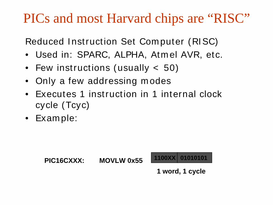
PICs and most Harvard chips are “RISC”Reduced Instruction Set Computer (RISC) • Used in: SPARC, ALPHA, Atmel AVR, etc.• Few instructions (usually < 50)• Only a few addressing modes• Executes 1 instruction in 1 internal clock
cycle (Tcyc) • Example:
PIC16CXXX: MOVLW 0x551 word, 1 cycle
1100XX 01010101

The PIC Family: Cores
PICs come with 1 of 4 CPU ‘cores’:
• 12bit cores with 33 instructions: 12C50x, 16C5x
• 14bit cores with 35 instructions: 12C67x,16Cxxx
• 16bit cores with 58 instructions: 17C4x,17C7xx
• ‘Enhanced’ 16bit cores with 77 instructions: 18Cxxx

The PIC Family: Speed
PICs require a clock to work.
• Can use crystals, clock oscillators, or even an RC circuit.• Some PICs have a built in 4MHz RC clock
• Not very accurate, but requires no external components!• Instruction speed = 1/4 clock speed (Tcyc = 4 * Tclk) • All PICs can be run from DC to their maximum spec’d
speed:
12C50x 4MHz12C67x 10MHz16Cxxx 20MHz17C4x / 17C7xxx 33MHz18Cxxx 40MHz

The PIC Family: Program Memory
PIC program space is different for each chip.
Some examples are:
12C508 512 12bit instructions16C711 1024 (1k) 14bit instructions16F877 8192 (8k) 14bit instructions17C766 16384 (16k) 16bit instructions
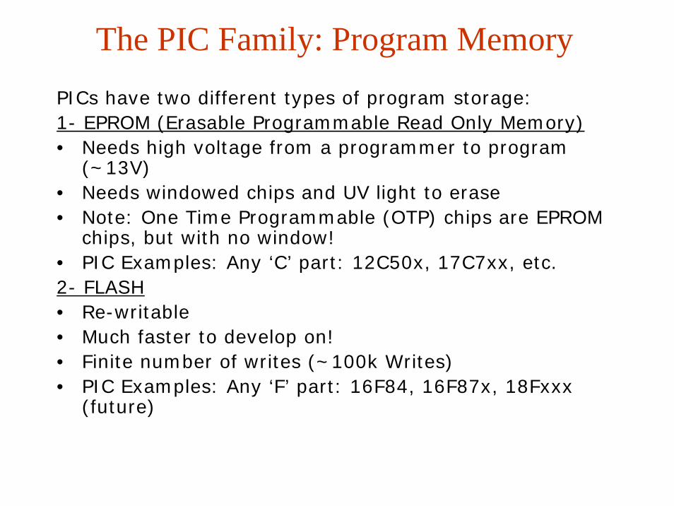
The PIC Family: Program MemoryPICs have two different types of program storage:1- EPROM (Erasable Programmable Read Only Memory)• Needs high voltage from a programmer to program
(~13V)• Needs windowed chips and UV light to erase• Note: One Time Programmable (OTP) chips are EPROM
chips, but with no window!• PIC Examples: Any ‘C’ part: 12C50x, 17C7xx, etc.2- FLASH• Re-writable • Much faster to develop on! • Finite number of writes (~100k Writes)• PIC Examples: Any ‘F’ part: 16F84, 16F87x, 18Fxxx
(future)
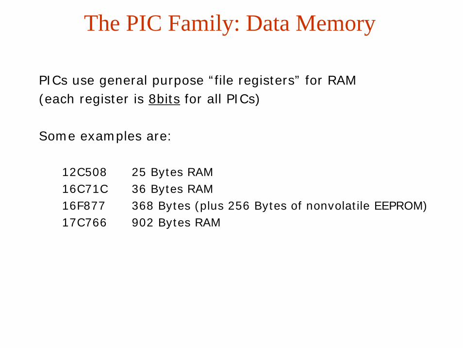
The PIC Family: Data Memory
PICs use general purpose “file registers” for RAM(each register is 8bits for all PICs)
Some examples are:
12C508 25 Bytes RAM16C71C 36 Bytes RAM16F877 368 Bytes (plus 256 Bytes of nonvolatile EEPROM)17C766 902 Bytes RAM

The PIC Family: Control Registers
PICs use a series of “special function registers” for controlling peripherals and
PIC behaviors.
Some examples are:
STATUS Bank select bits, ALU bits (zero, borrow, carry)INTCON Interrupt control: interrupt enables, flags, etc.TRIS Tristate control for digital I/O: which pins are
‘floating’TXREG UART transmit register: the next byte to transmit

The PIC Family: Peripherals
Different PICs have different on-board peripherals
Some common peripherals are:– Tri-state (“floatable”) digital I/O pins– Analog to Digital Converters (ADC) (8, 10 and 12bit,
50ksps)– Serial communications: UART (RS-232C), SPI, I2C,
CAN– Pulse Width Modulation (PWM) (10bit)– Timers and counters (8 and 16bit)– Watchdog timers, Brown out detect, LCD drivers
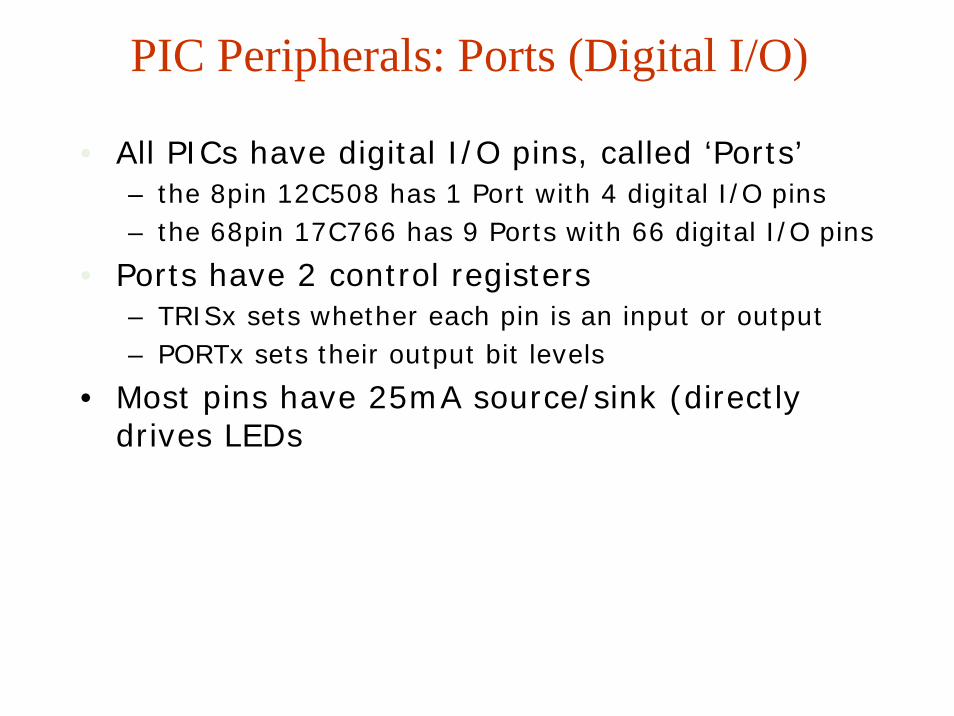
PIC Peripherals: Ports (Digital I/O)
• All PICs have digital I/O pins, called ‘Ports’– the 8pin 12C508 has 1 Port with 4 digital I/O pins– the 68pin 17C766 has 9 Ports with 66 digital I/O pins
• Ports have 2 control registers– TRISx sets whether each pin is an input or output– PORTx sets their output bit levels
• Most pins have 25mA source/sink (directly drives LEDs

Microcontrollers in General
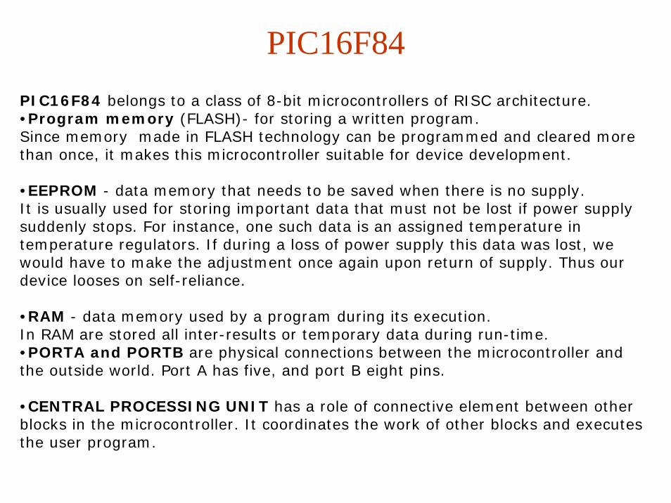
PIC16F84PIC16F84 belongs to a class of 8-bit microcontrollers of RISC architecture. •Program memory (FLASH)- for storing a written program.Since memory made in FLASH technology can be programmed and cleared more than once, it makes this microcontroller suitable for device development.
•EEPROM - data memory that needs to be saved when there is no supply.It is usually used for storing important data that must not be lost if power supply suddenly stops. For instance, one such data is an assigned temperature in temperature regulators. If during a loss of power supply this data was lost, we would have to make the adjustment once again upon return of supply. Thus our device looses on self-reliance.
•RAM - data memory used by a program during its execution.In RAM are stored all inter-results or temporary data during run-time. •PORTA and PORTB are physical connections between the microcontroller and the outside world. Port A has five, and port B eight pins.
•CENTRAL PROCESSING UNIT has a role of connective element between other blocks in the microcontroller. It coordinates the work of other blocks and executes the user program.

•FREE-RUN TIMER is an 8-bit register inside a microcontroller that works independently of the program. On every fourth clock of theoscillator it increments its value until it reaches the maximum (255), and then it starts counting over again from zero. As we know the exact timing between each two increments of the timer contents, timer can be used for measuring time which is very useful with some devices.
PIC16F84

PIN Description
Pins on PIC16F84 microcontroller have the following meaning:Pin no.1 RA2 Second pin on port A. Has no additional functionPin no.2 RA3 Third pin on port A. Has no additional function.Pin no.3 RA4 Fourth pin on port A. TOCK1 which functions as a timer is also found on this pinPin no.4 MCLR Reset input and Vpp programming voltage of a microcontrollerPin no.5 Vss Ground of power supply.Pin no.6 RB0 Zero pin on port B. Interrupt input is an additional function.Pin no.7 RB1 First pin on port B. No additional function.Pin no.8 RB2 Second pin on port B. No additional function.Pin no.9 RB3 Third pin on port B. No additional function.Pin no.10 RB4 Fourth pin on port B. No additional function.Pin no.11 RB5 Fifth pin on port B. No additional function.Pin no.12 RB6 Sixth pin on port B. 'Clock' line in program mode.Pin no.13 RB7 Seventh pin on port B. 'Data' line in program mode.Pin no.14 Vdd Positive power supply pole.Pin no.15 OSC2 Pin assigned for connecting with an oscillatorPin no.16 OSC1 Pin assigned for connecting with an oscillatorPin no.17 RA2 Second pin on port A. No additional functionPin no.18 RA1 First pin on port A. No additional function.
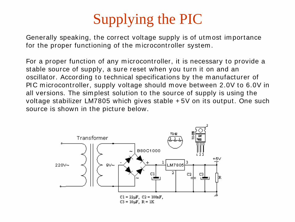
Supplying the PICGenerally speaking, the correct voltage supply is of utmost importance for the proper functioning of the microcontroller system.
For a proper function of any microcontroller, it is necessary to provide a stable source of supply, a sure reset when you turn it on and anoscillator. According to technical specifications by the manufacturer of PIC microcontroller, supply voltage should move between 2.0V to 6.0V in all versions. The simplest solution to the source of supply is using the voltage stabilizer LM7805 which gives stable +5V on its output. One such source is shown in the picture below.

Timing with the Microcontroller
All microprocessors have timer circuits on board.
The 16F84 has a single Timer called TIMER0.
This timer runs at ¼ of clock speed.
So if we use a 32768 Hz crystal internal timer will run at 8192 Hz. If we want to turn on a LED for 1 sec we would need 8192 of these timing pulses.
These timing pulses can be reduced by 2, 4, 8,16, 32, 64, 128 or 256 using the OPTION register
Setting it to 256 in the OPTION register means that our timing pulses are now 8192/256 = 32Hz.

Clock Generator - Oscillator
Types of oscillators
Crystal oscillator and resistor-capacitor (RC) are the ones that are used most frequently, these are the only ones we will mention here. Microcontroller type with a crystal oscillator has in its designation XT, and a microcontroller with resistor-capacitor pair has a designation RC.

Clock Generator - OscillatorRC OscillatorIn applications where great time precision is not necessary
Diagram shows how RC oscillator is connected with PIC16F84

Clock/Instruction Cycle
Clock from the oscillator enters a microcontroller via OSC1 pin where internal circuit of a microcontroller divides the clock into four even clocks Q1, Q2, Q3, and Q4 which do not overlap.
These four clocks make up one instruction cycle (also called machine cycle) during which one instruction is executed.
Execution of instruction starts by calling an instruction that is next in string. Instruction is called from program memory on every Q1 and is written in instruction register on Q4.
Decoding and execution of instruction are done between the next Q1 and Q4 cycles. On the following diagram we can see the relationship between instruction cycle and clock of the oscillator (OSC1) as well as that of internal clocks Q1-Q4. Program counter (PC) holds information about the address of the next instruction.

Continued
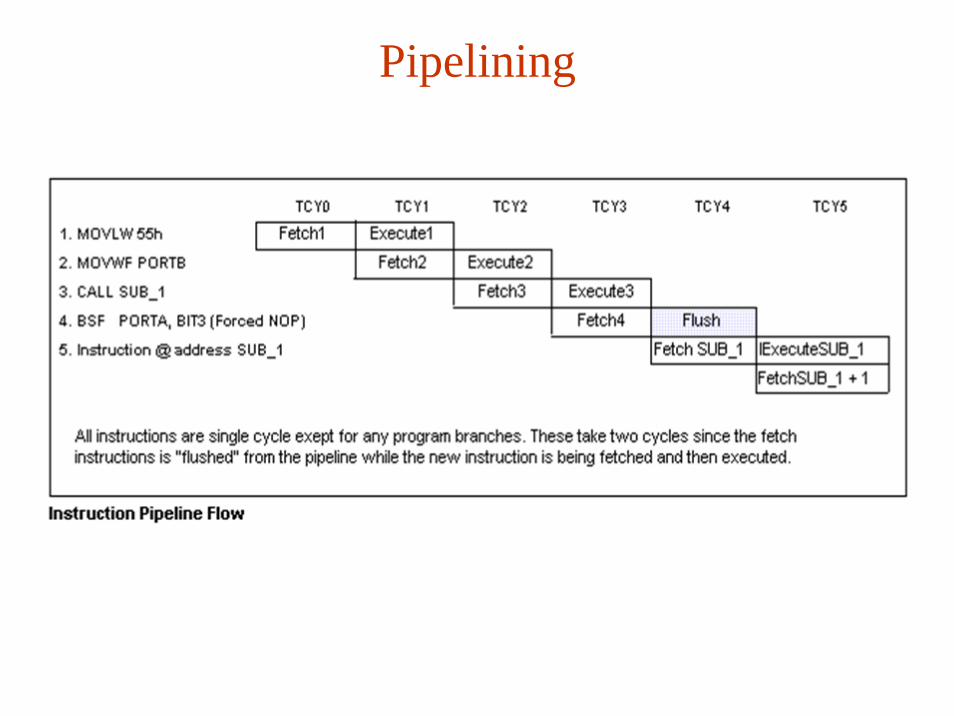
Pipelining
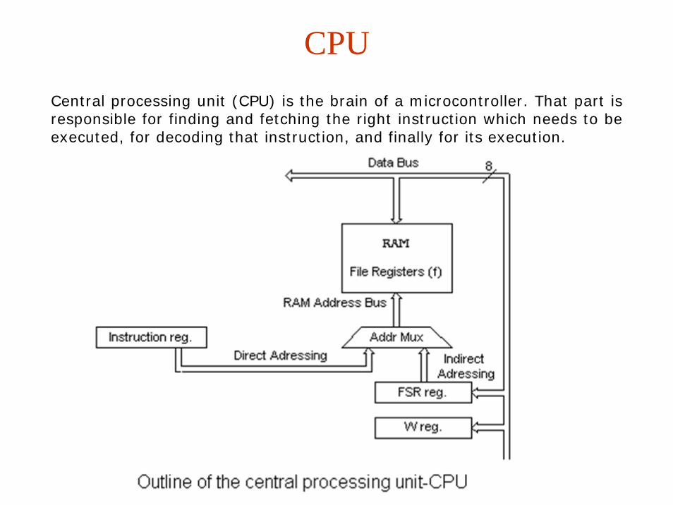
CPUCentral processing unit (CPU) is the brain of a microcontroller. That part is responsible for finding and fetching the right instruction which needs to be executed, for decoding that instruction, and finally for its execution.

ALU
Arithmetic logic unit is responsible for performing operations of adding, subtracting, moving (left or right within a register) and logic operations. PIC16F84 contains an 8-bit arithmetic logic unit and 8-bit work registers.

Detailed Block Diagram
W Register
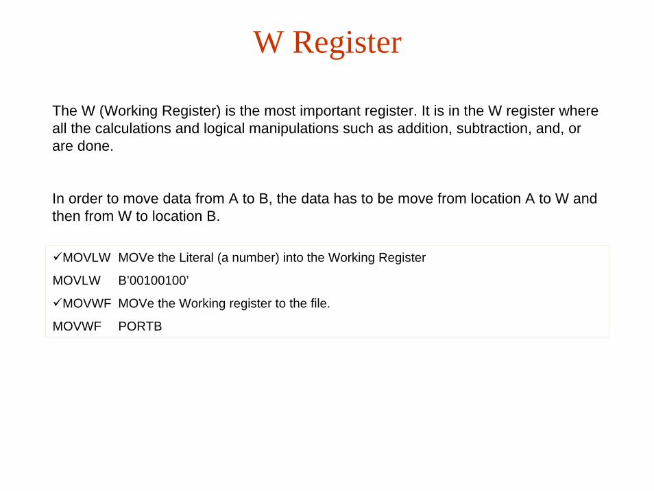
The W (Working Register) is the most important register. It is in the W register where all the calculations and logical manipulations such as addition, subtraction, and, or are done.
In order to move data from A to B, the data has to be move from location A to W and then from W to location B.
MOVLW MOVe the Literal (a number) into the Working Register
MOVLW B’00100100’
MOVWF MOVe the Working register to the file.
MOVWF PORTB
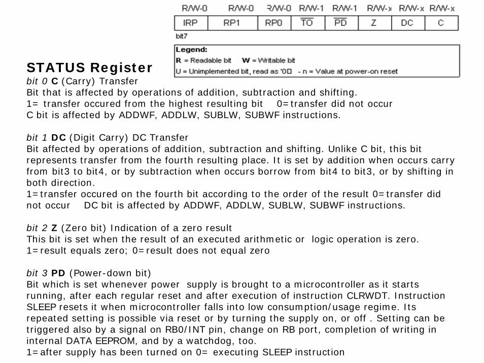
STATUS Registerbit 0 C (Carry) TransferBit that is affected by operations of addition, subtraction and shifting.1= transfer occured from the highest resulting bit 0=transfer did not occurC bit is affected by ADDWF, ADDLW, SUBLW, SUBWF instructions.
bit 1 DC (Digit Carry) DC TransferBit affected by operations of addition, subtraction and shifting. Unlike C bit, this bit represents transfer from the fourth resulting place. It is set by addition when occurs carry from bit3 to bit4, or by subtraction when occurs borrow from bit4 to bit3, or by shifting in both direction.1=transfer occured on the fourth bit according to the order of the result 0=transfer did not occur DC bit is affected by ADDWF, ADDLW, SUBLW, SUBWF instructions.
bit 2 Z (Zero bit) Indication of a zero resultThis bit is set when the result of an executed arithmetic or logic operation is zero.1=result equals zero; 0=result does not equal zero
bit 3 PD (Power-down bit)Bit which is set whenever power supply is brought to a microcontroller as it starts running, after each regular reset and after execution of instruction CLRWDT. Instruction SLEEP resets it when microcontroller falls into low consumption/usage regime. Its repeated setting is possible via reset or by turning the supply on, or off . Setting can be triggered also by a signal on RB0/INT pin, change on RB port, completion of writing in internal DATA EEPROM, and by a watchdog, too.1=after supply has been turned on 0= executing SLEEP instruction

STATUS Registerbit 4 TO Time-out ; Watchdog overflow.Bit is set after turning on the supply and execution of CLRWDT and SLEEP instructions. Bit is reset when watchdog gets to the end signaling that something is not right. 1=overflow did not occur 0=overflow did occur
bit6:5 RP1:RP0 (Register Bank Select bits)These two bits are upper part of the address for direct addressing. Since instructions which address the memory directly have only seven bits, they need one more bit in order to address all 256 bytes which is how many bytes PIC16F84 has. RP1 bit is not used, but is left for some future expansions of this microcontroller. 01=first bank 00=zero bank
bit 7 IRP (Register Bank Select bit)Bit whose role is to be an eighth bit for indirect addressing of internal RAM.
1=bank 2 and 3 0=bank 0 and 1 (from 00h to FFh)
STATUS register contains arithmetic status ALU (C, DC, Z), RESET status (TO, PD) and bits for selecting of memory bank (IRP, RP1, RP0). Considering that selection of memory bank is controlled through this register, it has to be present in each bank. STATUS register can be a destination for any instruction, with any other register. If STATUS register is a destination for instructions which affect Z, DC or C bits, then writing to these three bits is not possible.

OPTION registerbit 0:2 PS0, PS1, PS2 (Prescaler Rate Select bit)These three bits define prescaler rate select bit..
bit 3 PSA (Prescaler Assignment bit)Bit which assigns prescaler between TMR0 and watchdog.1=prescaler is assigned to watchdog 0=prescaler is assigned to a free-run timer TMR0
bit 4 T0SE (TMR0 Source Edge Select bit)If it is allowed to trigger TMR0 by impulses from the pin RA4/T0CKI, this bit determines whether this will be to the falling or rising edge of a signal.1=falling edge 0=rising edge
bit 5 TOCS (TMR0 Clock Source Select bit)This pin enables free-run timer to increment its state either from internal oscillator on every ¼ of oscillator clock, or through external impulses on RA4/T0CKI pin.1=external impulses 0=1/4 internal clock
bit 6 INTEDG (Interrupt Edge Select bit)If interrupt is enabled possible this bit will determine the edge at which an interrupt will be activated on pin RB0/INT. 1=rising edge 0=falling edge
bit 7 RBPU (PORTB Pull-up Enable bit)This bit turns on and off internal 'pull-up' resistors on port B.1= "pull-up" resistors turned off 0 = "pull-up" resistors turned on

PORTS
All port pins can be defined as input or output, according to the needs of a device that's being developed. In order to define a pin as input or output pin, the right combination of zeros and ones must be written in TRIS register. If at the appropriate place in TRIS register a logical "1" is written, then that pin is an input pin, and if the opposite is true, it's an output pin. Every port has its proper TRIS register. Thus, port A has TRISA at address 85h, and port B has TRISB at address 86h.

Port BPORTB has 8 pins joined to it. The appropriate register for direction of data is TRISB at address 86h.
Four pins PORTB, RB7:RB4 can cause an interrupt which occurs when their status changes from logical one into logical zero and opposite. Only pins configured as input can cause this interrupt to occur
(if any RB7:RB4 pin is configured as an output, an interrupt won't be generated at the change of status.) This interrupt option along with internal pull-up resistors makes it easier to solve common problems we find in practice like for instance that of matrix keyboard. If rows on the keyboard are connected to these pins, each push on a key will then cause an interrupt. A microcontroller will determine which key is at hand while processing an interrupt It is not recommended to refer to port B at the same time that interrupt is being processed.
The example shows how pins 0, 1, 2, and 3 are declared for input, and pins 4, 5, 6, and 7 for output.

Port A
PORTA has 5 pins joined to it. The corresponding register for data direction is TRISA at address 85h. The fifth pin of port A has dual function. On that pin is also situated an external input for timer TMR0. One of these two options is chosen by setting or resetting the T0CS bit (TMR0 Clock Source Select bit). This pin enables the timer TMR0 to increase its status either from internal oscillator or via external impulses on RA4/T0CKI pin.
Example shows how pins 0, 1, 2, 3, and 4 are declared to be input, and pins 5, 6, and 7 to be output pins
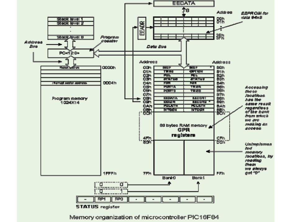
MemoryPIC16F84 has two separate memory blocks, one for data and the other for program. EEPROM memory and GPR registers in RAM memory make up a data block, and FLASH memory makes up a program block.
Program memory
Program memory has been realized in FLASH technology which makes it possible to program a microcontroller many times before it's installed into a device, and even after its installment if eventual changes in program or process parameters should occur. The size of program memory is 1024 locations with 14 bits width where locations zero and four are reserved for reset and interrupt vector.
Data memory
Data memory consists of EEPROM and RAM memories. EEPROM memory consists of 64 eight bit locations whose contents is not lost during loosing of power supply. EEPROM is not directly addressible, but is accessed indirectly through EEADR and EEDATA registers. As EEPROM memory usually serves for storing important parameters (for example, of a given temperature in temperature regulators) , there is a strict procedure for writing in EEPROM which must be followed in order to avoid accidental writing. RAM memory for data occupies space on a memory map from location 0x0C to 0x4F which comes to 68 locations. Locations of RAM memory are also called GPR registers which is an abbreviation for General Purpose Registers. GPR registers can be accessed regardless of which bank is selected at the moment.
SFR registers
Registers which take up first 12 locations in banks 0 and 1 are registers of specialized function assigned with certain blocks of the microcontroller. These are called Special Function Registers.

Memory BanksBeside this 'length' division to SFR and GPR registers, memory map is also divided in 'width' to two areas called 'banks'. Selecting one of the banks is done via RP0 and RP1 bits in STATUS register.
Example:bcf STATUS, RP0
Instruction BCF clears bit RP0 (RP0=0) in STATUS register and thus sets up bank 0.
bsf STATUS, RP0
Instruction BSF sets the bit RP0 (RP0=1) in STATUS register and thus sets up bank1.
Usually, groups of instructions that are often in use, are connected into one unit which can easily be recalled in a program, and whose name has a clear meaning, so called Macros. With their use, selection between two banks becomes more clear and the program itself more legible. BANK0 macro
Bcf STATUS, RP0 ;Select memory bank 0Endm
BANK1 macroBsf STATUS, RP0 ;Select memory bank 1Endm
Locations 0Ch - 4Fh are general purpose registers (GPR) which are used as RAM memory. When locations 8Ch - CFh in Bank 1 are accessed, we actually access the exact same locations in Bank 0. In other words , whenever you wish to access one of the GPR registers, there is no need to worry about which bank we are in!
Program Counter
Program counter (PC) is a 13 bit register that contains the address of the instruction being executed. By its incrementing or change (ex. in case of jumps) microcontroller executes program instructions step-by-step.
Stack
PIC16F84 has a 13-bit stack with 8 levels, or in other words, a group of 8 memory locations of 13 -bits width with special function. Its basic role is to keep the value of program counter after a jump from the main program to an address of a subprogram . In order for a program to know how to go back to the point where it started from, it has to return the value of a program counter from a stack. When moving from a program to a subprogram, program counter is being pushed onto a stack (example of this is CALL instruction). When executing instructions such as RETURN, RETLW or RETFIE which were executed at the end of a subprogram, program counter was taken from a stack so that program could continue where was stopped before it was interrupted. These operations of placing on and taking off from a program counter stack are called PUSH and POP, and are named according similar instructions on some bigger microcontrollers.
System Programming
In order to program a program memory, microcontroller must be set to special working mode by bringing up MCLR pin to 13.5V, and supply voltage Vdd has to be stabilized between 4.5V to 5.5V.
Program memory can be programmed serially using two 'data/clock'pins which must previously be separated from device lines, so that errors wouldn't come up during programming.
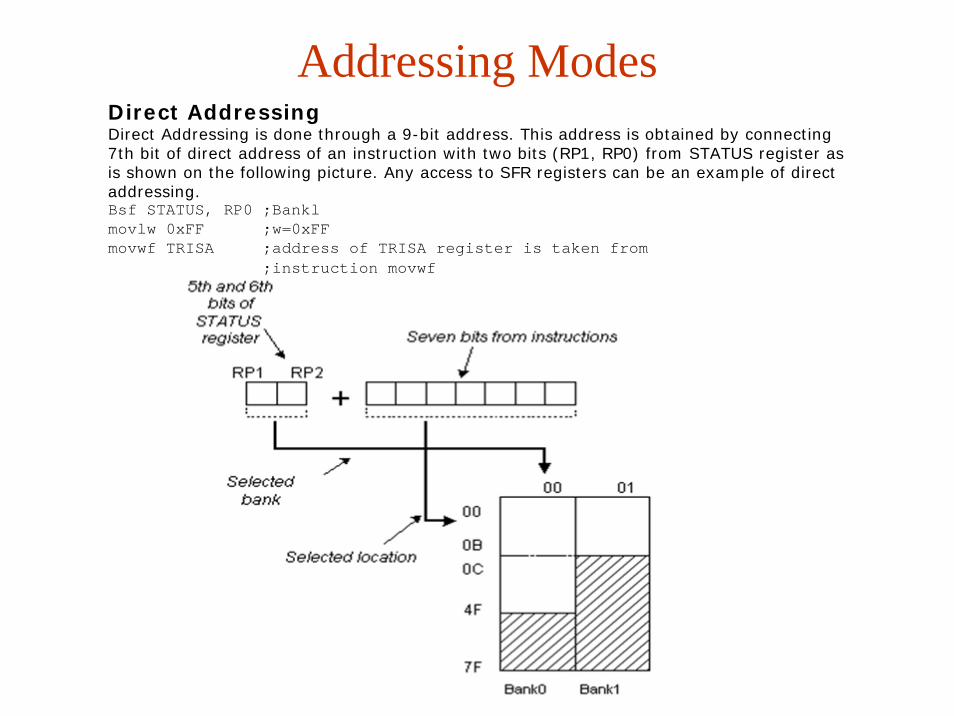
Addressing ModesDirect AddressingDirect Addressing is done through a 9-bit address. This address is obtained by connecting 7th bit of direct address of an instruction with two bits (RP1, RP0) from STATUS register as is shown on the following picture. Any access to SFR registers can be an example of direct addressing. Bsf STATUS, RP0 ;Banklmovlw 0xFF ;w=0xFFmovwf TRISA ;address of TRISA register is taken from
;instruction movwf
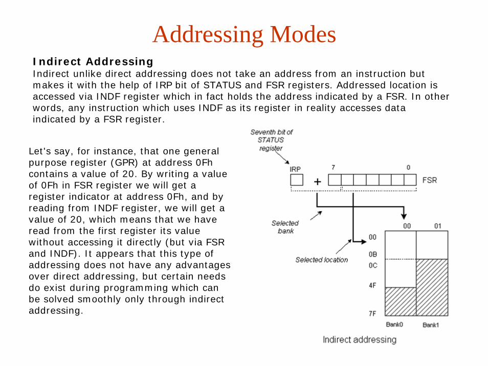
Indirect AddressingIndirect unlike direct addressing does not take an address from an instruction but makes it with the help of IRP bit of STATUS and FSR registers. Addressed location is accessed via INDF register which in fact holds the address indicated by a FSR. In other words, any instruction which uses INDF as its register in reality accesses data indicated by a FSR register.
Let's say, for instance, that one general purpose register (GPR) at address 0Fh contains a value of 20. By writing a value of 0Fh in FSR register we will get a register indicator at address 0Fh, and by reading from INDF register, we will get a value of 20, which means that we have read from the first register its value without accessing it directly (but via FSR and INDF). It appears that this type of addressing does not have any advantages over direct addressing, but certain needs do exist during programming which can be solved smoothly only through indirect addressing.
Addressing Modes
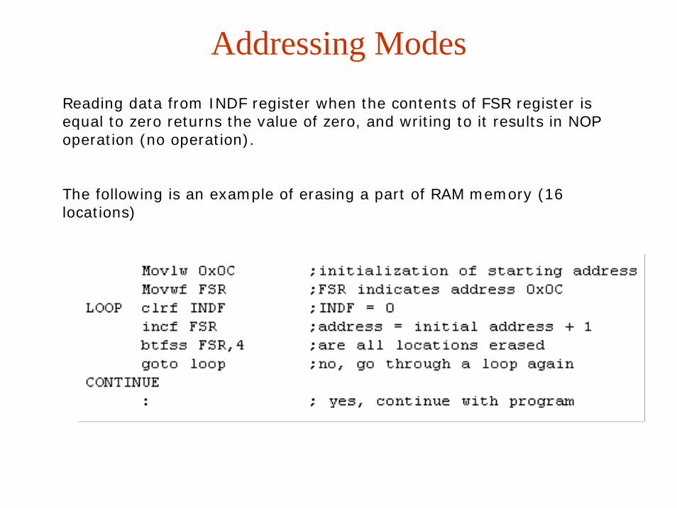
Addressing ModesReading data from INDF register when the contents of FSR register is equal to zero returns the value of zero, and writing to it results in NOP operation (no operation).
The following is an example of erasing a part of RAM memory (16 locations)

EEPROM Data MemoryPIC16F84 has 64 bytes of EEPROM memory locations on addresses from 00h to 63h those can be written to or read from. The most important characteristic of this memory is that it does not loose its contents during power supply turned off. Data can be retained in EEPROM without power supply for up to 40 years (as manufacturer of PIC16F84 microcontroller states), and up to 10000 cycles of writing can be executed.
In practice, EEPROM memory is used for storing important data or some process parameters.One such parameter is a given temperature, assigned when setting up a temperature regulator to some process. If that data wasn't retained, it would be necessary to adjust a given temperature after each loss of supply. Since this is very impractical (and even dangerous), manufacturers of microcontrollers have began installing one smaller type of EEPROM memory.
EEPROM memory is placed in a special memory space and can be accessed through special registers. These registers are:
• EEDATA at address 08h, which holds read data or that to be written.• EEADR at address 09h, which contains an address of EEPROM location being accessed.• EECON1 at address 88h, which contains control bits.• EECON2 at address 89h. This register does not exist physically and serves to protect EEPROM from accidental writing.
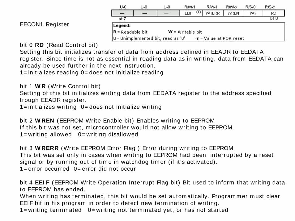
EECON1 register at address 88h is a control register with five implemented bits.Bits 5, 6 and 7 are not used, and by reading always are zero.
EEPROMEECON1 Register
bit 0 RD (Read Control bit)Setting this bit initializes transfer of data from address defined in EEADR to EEDATA register. Since time is not as essential in reading data as in writing, data from EEDATA can already be used further in the next instruction.1=initializes reading 0=does not initialize reading
bit 1 WR (Write Control bit)Setting of this bit initializes writing data from EEDATA register to the address specified trough EEADR register.1=initializes writing 0=does not initialize writing
bit 2 WREN (EEPROM Write Enable bit) Enables writing to EEPROMIf this bit was not set, microcontroller would not allow writing to EEPROM.1=writing allowed 0=writing disallowed
bit 3 WRERR (Write EEPROM Error Flag ) Error during writing to EEPROMThis bit was set only in cases when writing to EEPROM had been interrupted by a reset signal or by running out of time in watchdog timer (if it's activated).1=error occurred 0=error did not occur
bit 4 EEIF (EEPROM Write Operation Interrupt Flag bit) Bit used to inform that writing data to EEPROM has ended.When writing has terminated, this bit would be set automatically. Programmer must clear EEIF bit in his program in order to detect new termination of writing.1=writing terminated 0=writing not terminated yet, or has not started
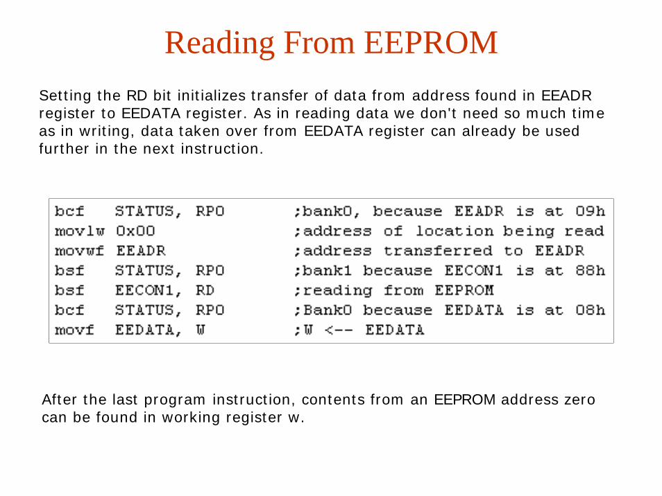
Reading From EEPROMSetting the RD bit initializes transfer of data from address found in EEADR register to EEDATA register. As in reading data we don't need so much time as in writing, data taken over from EEDATA register can already be used further in the next instruction.
After the last program instruction, contents from an EEPROM address zero can be found in working register w.

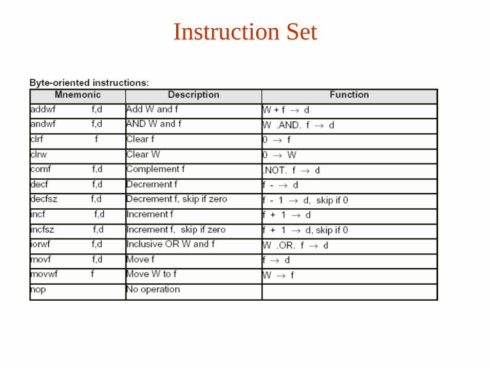
Instruction Setf any memory location in a microcontrollerW work registerb bit position in 'f' registerd destination bitlabel group of eight characters which marks the beginning of a part of the programTOS top of stack[] option <> bit position inside register

Instruction Set
Instruction Set
Instruction Set

Instruction Set
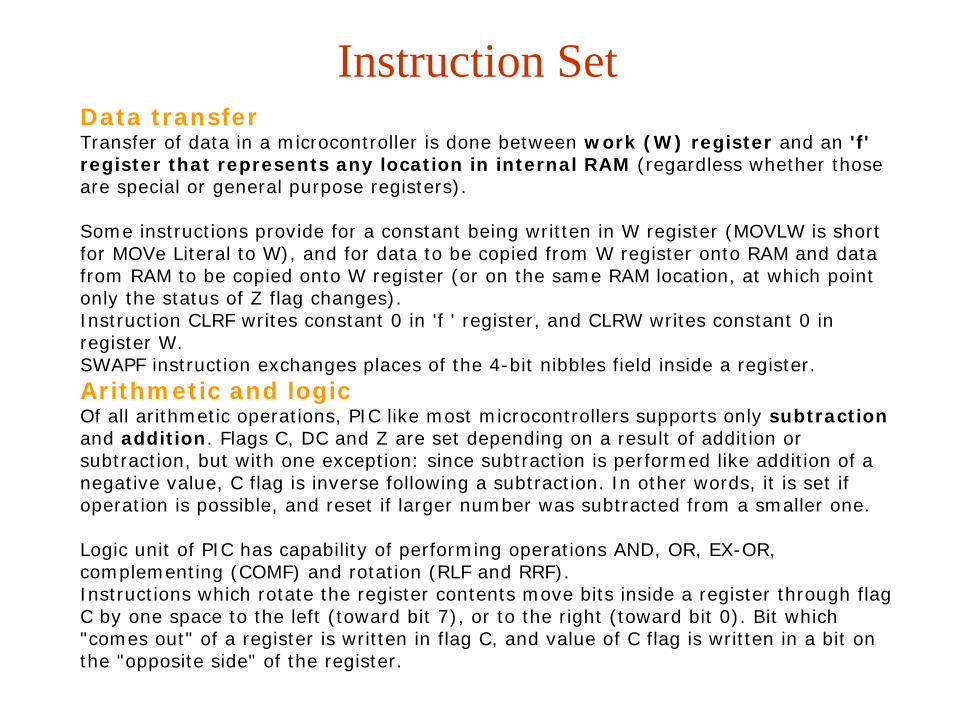
Instruction SetData transferTransfer of data in a microcontroller is done between work (W) register and an 'f' register that represents any location in internal RAM (regardless whether those are special or general purpose registers).
Some instructions provide for a constant being written in W register (MOVLW is short for MOVe Literal to W), and for data to be copied from W register onto RAM and data from RAM to be copied onto W register (or on the same RAM location, at which point only the status of Z flag changes). Instruction CLRF writes constant 0 in 'f ' register, and CLRW writes constant 0 in register W. SWAPF instruction exchanges places of the 4-bit nibbles field inside a register. Arithmetic and logicOf all arithmetic operations, PIC like most microcontrollers supports only subtractionand addition. Flags C, DC and Z are set depending on a result of addition orsubtraction, but with one exception: since subtraction is performed like addition of a negative value, C flag is inverse following a subtraction. In other words, it is set if operation is possible, and reset if larger number was subtracted from a smaller one.
Logic unit of PIC has capability of performing operations AND, OR, EX-OR, complementing (COMF) and rotation (RLF and RRF).Instructions which rotate the register contents move bits inside a register through flag C by one space to the left (toward bit 7), or to the right (toward bit 0). Bit which "comes out" of a register is written in flag C, and value of C flag is written in a bit on the "opposite side" of the register.

Instruction SetBit operations
Instructions BCF and BSF do setting or cleaning of one bit anywhere in the memory. Even though this seems like a simple operation, it is executed so that CPU first reads the whole byte, changes one bit in it and then writes in the entire byte at the same place.
Instruction Execution PeriodAll instructions are executed in one cycle except for conditional branch instructions if condition was true, or if the contents of program counter was changed by some instruction.
In that case, execution requires two instruction cycles, and the second cycle is executed as NOP (No Operation). Four oscillator clocks make up one instruction cycle. If we are using an oscillator with 4MHz frequency, the normal time for executing an instruction is 1 µs, and in case of conditional branching, execution period is 2 µs.

Directing a Program Flow
Table can be formed as a subprogram which consists of a series of 'RETLW k' instructions, where 'k' constants are members of the table.
We write the position of a member of our table in W register, and using CALL instruction we call a subprogram which creates the table. First subprogram line ADDWF PCL, f adds the position of a W register member to the starting address of our table, found in PCL register, and so we get the real data address in program memory. When returning from a subprogram we will have in W register the contents of an addressed table member. In practice d bit will be replaced by W=0 and f=1 for readability!!!
Conditional jumps are synthesized into two instructions: BTFSC and BTFSS. Depending on a bit status in 'f' register that is being tested, instructions skip or don't skip over the next program instruction
Instructions GOTO, CALL and RETURN are executed the same way as on all other microcontrollers, only stack is independent of internal RAM and limited to eight levels.'RETLW k' instruction is identical with RETURN instruction, except that before coming back from a subprogram a constant defined by instruction operand is written in W register. This instruction enables us to design easily the Look-up tables (lists). Mostly we use them by determining data position on our table adding it to the address at which the table begins, and then we read data from that location (which is usually found in program memory).
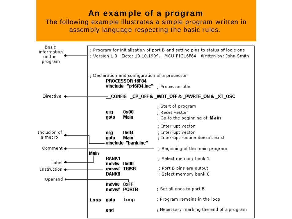
An example of a programThe following example illustrates a simple program written in
assembly language respecting the basic rules.
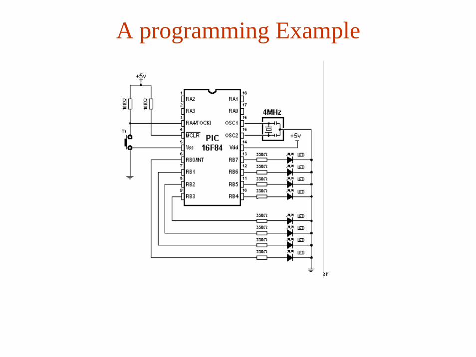
A programming Example
Connecting LED diodes to PORTB microcontroller

This example initializes port B as output and sets logic one to each pin of port B to turn on all LEDs.

Example Program

Example Program
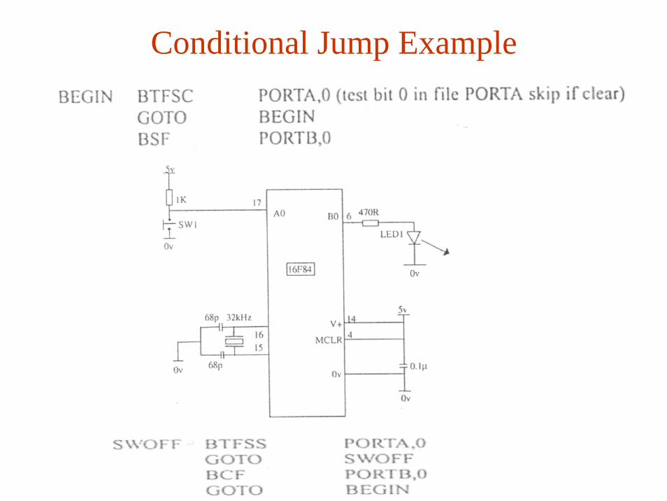
Conditional Jump Example
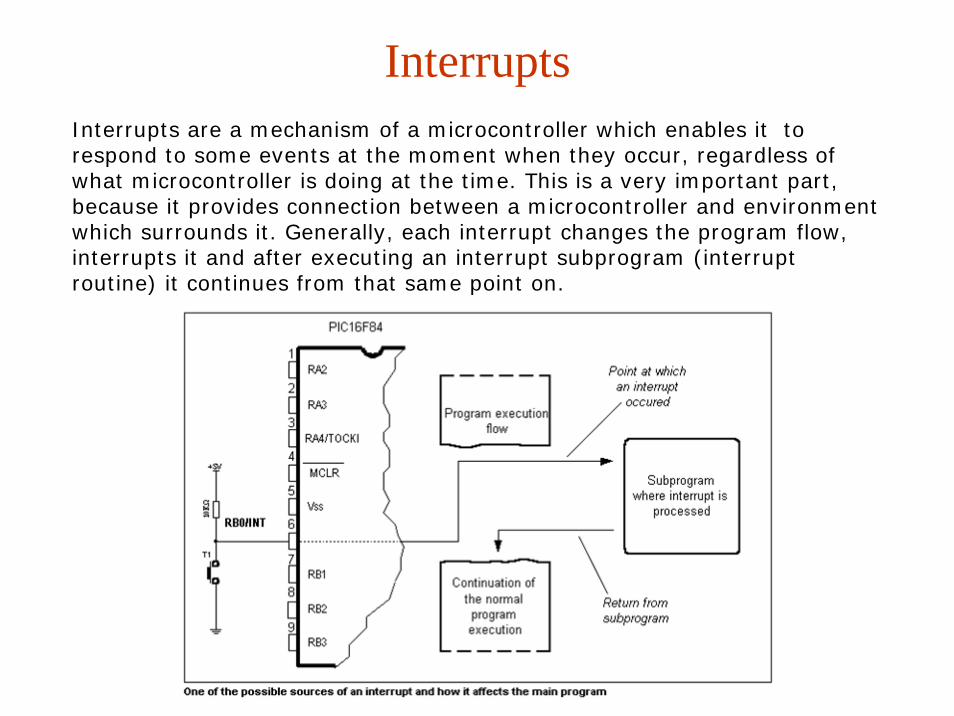
InterruptsInterrupts are a mechanism of a microcontroller which enables it to respond to some events at the moment when they occur, regardless of what microcontroller is doing at the time. This is a very important part, because it provides connection between a microcontroller and environment which surrounds it. Generally, each interrupt changes the program flow, interrupts it and after executing an interrupt subprogram (interrupt routine) it continues from that same point on.
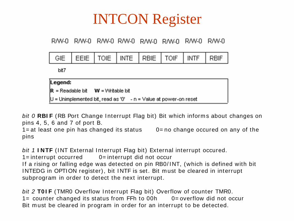
INTCON Register
bit 0 RBIF (RB Port Change Interrupt Flag bit) Bit which informs about changes on pins 4, 5, 6 and 7 of port B.1=at least one pin has changed its status 0=no change occured on any of the pins
bit 1 INTF (INT External Interrupt Flag bit) External interrupt occured.1=interrupt occurred 0=interrupt did not occurIf a rising or falling edge was detected on pin RB0/INT, (which is defined with bit INTEDG in OPTION register), bit INTF is set. Bit must be cleared in interrupt subprogram in order to detect the next interrupt.
bit 2 T0IF (TMR0 Overflow Interrupt Flag bit) Overflow of counter TMR0.1= counter changed its status from FFh to 00h 0=overflow did not occurBit must be cleared in program in order for an interrupt to be detected.
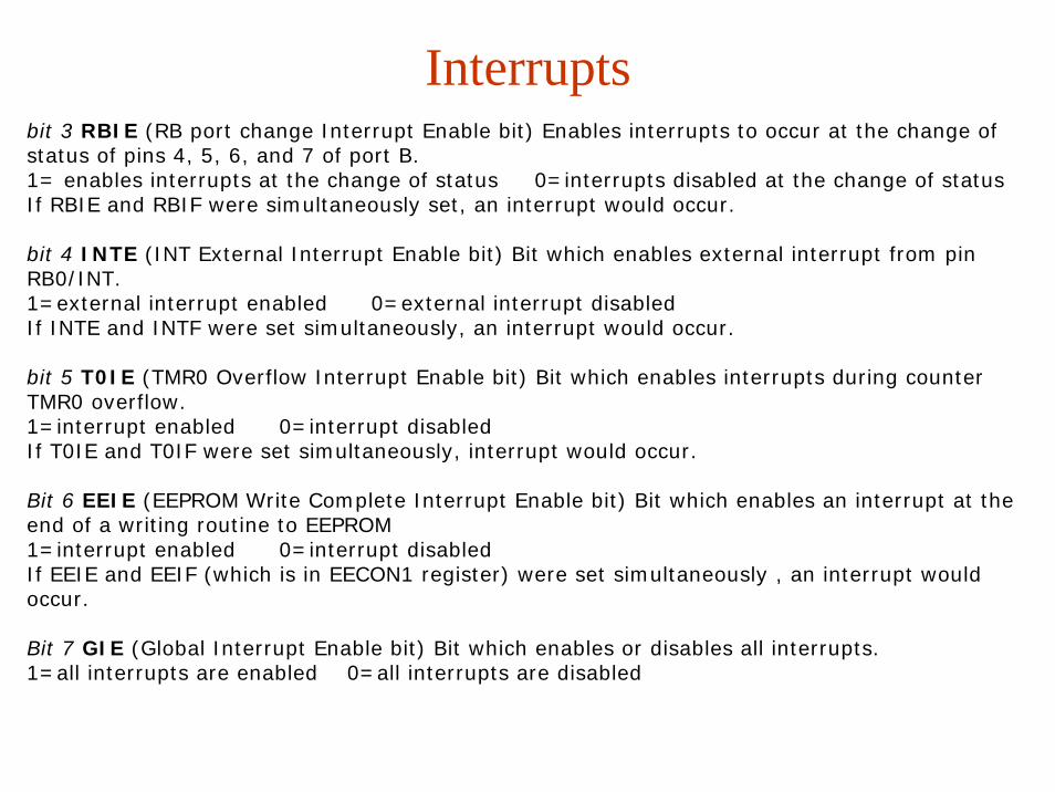
Interruptsbit 3 RBIE (RB port change Interrupt Enable bit) Enables interrupts to occur at the change of status of pins 4, 5, 6, and 7 of port B.1= enables interrupts at the change of status 0=interrupts disabled at the change of statusIf RBIE and RBIF were simultaneously set, an interrupt would occur.
bit 4 INTE (INT External Interrupt Enable bit) Bit which enables external interrupt from pin RB0/INT.1=external interrupt enabled 0=external interrupt disabledIf INTE and INTF were set simultaneously, an interrupt would occur.
bit 5 T0IE (TMR0 Overflow Interrupt Enable bit) Bit which enables interrupts during counter TMR0 overflow.1=interrupt enabled 0=interrupt disabledIf T0IE and T0IF were set simultaneously, interrupt would occur.
Bit 6 EEIE (EEPROM Write Complete Interrupt Enable bit) Bit which enables an interrupt at the end of a writing routine to EEPROM1=interrupt enabled 0=interrupt disabledIf EEIE and EEIF (which is in EECON1 register) were set simultaneously , an interrupt would occur.
Bit 7 GIE (Global Interrupt Enable bit) Bit which enables or disables all interrupts.1=all interrupts are enabled 0=all interrupts are disabled

InterruptsPIC16F84 has four interrupt sources:
1. Termination of writing data to EEPROM2. TMR0 interrupt caused by timer overflow3. Interrupt during alteration on RB4, RB5, RB6 and RB7 pins of port B.4. External interrupt from RB0/INT pin of microcontroller
Generally speaking, each interrupt source has two bits joined to it. One enables interrupts, and the other detects when interrupts occur. There is one common bit called GIE which can be used to disallow or enable all interrupts simultaneously.
This bit is very useful when writing a program because it allows for all interrupts to be disabled for a period of time, so that execution of some important part of a program would not be interrupted. When instruction which resets GIE bit was executed (GIE=0, all interrupts disallowed), any interrupt that remained unsolved should be ignored

InterruptsExternal interrupt on RB0/INT pin of microcontrollerExternal interrupt on RB0/INT pin is triggered by rising signal edge (if bit INTEDG=1 in OPTION<6> register), or falling edge (if INTEDG=0). When correct signal appears on INT pin, INTF bit is set in INTCON register. INTF bit (INTCON<1>) must be reset in interrupt routine, so that interrupt wouldn't occur again while going back to the main program. This is an important part of the program which programmer must not forget, or program will constantly go into interrupt routine. Interrupt can be turned off by resetting INTE control bit (INTCON<4>).
Interrupt during a TMR0 counter overflowOverflow of TMR0 counter (from FFh to 00h) will set T0IF (INTCON<2>) bit. This is very important interrupt because many real problems can be solved using this interrupt. One of the examples is time measurement. If we know how much time counter needs in order to complete one cycle from 00h to FFh, then a number of interrupts multiplied by that amount of time will yield the total of elapsed time. In interrupt routine some variable would be incremented in RAM memory, value of that variable multiplied by the amount of time the counter needs to count through a whole cycle, would yield total elapsed time. Interrupt can be turned on/off by setting/resetting T0IE (INTCON<5>) bit.
Interrupt during a change on pins 4, 5, 6 and 7 of port BChange of input signal on PORTB <7:4> sets RBIF (INTCON<0>) bit. Four pins RB7, RB6, RB5 and RB4 of port B, can trigger an interrupt which occurs when status on them changes from logic one to logic zero, or vice versa. For pins to be sensitive to this change, they must be defined as input. If any one of them is defined as output, interrupt will not be generated at the change of status. If they are defined as input, their current state is compared to the old value which was stored at the last reading from port B. Interrupt can be turned on/off by setting/resetting RBIE bit in INTCON register.
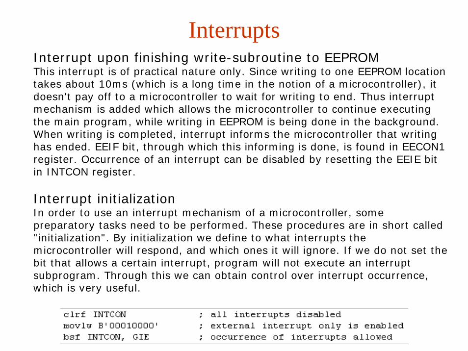
InterruptsInterrupt upon finishing write-subroutine to EEPROMThis interrupt is of practical nature only. Since writing to one EEPROM location takes about 10ms (which is a long time in the notion of a microcontroller), it doesn't pay off to a microcontroller to wait for writing to end. Thus interrupt mechanism is added which allows the microcontroller to continue executing the main program, while writing in EEPROM is being done in the background. When writing is completed, interrupt informs the microcontroller that writing has ended. EEIF bit, through which this informing is done, is found in EECON1 register. Occurrence of an interrupt can be disabled by resetting the EEIE bit in INTCON register.
Interrupt initializationIn order to use an interrupt mechanism of a microcontroller, some preparatory tasks need to be performed. These procedures are in short called "initialization". By initialization we define to what interrupts the microcontroller will respond, and which ones it will ignore. If we do not set the bit that allows a certain interrupt, program will not execute an interrupt subprogram. Through this we can obtain control over interrupt occurrence, which is very useful.

Return from interrupt routine can be accomplished with instructions RETURN, RETLW and RETFIE. It is recommended that instruction RETFIE be used because that instruction is the only one which automatically sets the GIE bit which allows new interrupts to occur.
EXAMPLE

Interrupts
Interrupts which remained unsolved and were ignored, are processed when GIE bit (GIE=1, all interrupts allowed) would be cleared. When interrupt was answered, GIE bit was cleared so that any additional interrupts would be disabled, return address was pushed onto stack and address 0004h was written in program counter - only after this does replying to an interrupt begin! After interrupt is processed, bit whose setting caused an interrupt must be cleared, or interrupt routine would automatically be processed over again during a return to the main program.

Interrupts
PIC16F84 does not have instructions like PUSH and POP, and they have to be programmed.

ProcedureThe PIC16f84 is an 18-pin 14-bit embedded micro featuring electronically erasable programmable read-only memory (EEPROM). The essential steps are:
Step 1: On a PC, type the program, successfully compile it and then generate the HEX file. Step 2: Using a PIC16F84 device programmer, upload the HEX file into the PIC16F84. This step is often called "burning". Step 3: Insert your PIC16F84 into your circuit, power up and verify the program works as expected. This step is often called "dropping" the chip. If it isn't, you must go to Step 1 and debug your program and repeat burning and dropping.
Embedded micros having EPROM versus those with EEPROM require a fourth step - the program must be erased using ultraviolet light before starting again at Step 1. However the PIC16F84 uses EEPROM and is what makes it popular -the device programmer erases the program without ultraviolet light.
Related Documents