UNIVERSIDADE DO RIO GRANDE DO NORTE FEDERAL FEDERAL UNIVERSITY OF RIO GRANDE DO NORTE TECHNOLOGY CENTER GRADUATE PROGRAM IN ELECTRICAL AND COMPUTER ENGINEERING Wavelet-based Protection Assessment of the Doubly-fed Induction Generator Max Rodrigues Marques Advisor: Prof. Dr. Flavio Bezerra Costa M.Sc Dissertation presented to the Gradu- ate Program in Electrical and Computer En- gineering at UFRN (area of concentration: Automation and Systems) as part of the re- quirements for obtain the Master of Science degree. Serial number PPgEEC: M547 Natal, RN, January 28th, 2019

Welcome message from author
This document is posted to help you gain knowledge. Please leave a comment to let me know what you think about it! Share it to your friends and learn new things together.
Transcript
UNIVERSIDADE DO RIO GRANDE DO NORTEFEDERAL
FEDERAL UNIVERSITY OF RIO GRANDE DO NORTE
TECHNOLOGY CENTER
GRADUATE PROGRAM IN ELECTRICAL AND COMPUTER
ENGINEERING
Wavelet-based Protection Assessment of theDoubly-fed Induction Generator
Max Rodrigues Marques
Advisor: Prof. Dr. Flavio Bezerra Costa
M.Sc Dissertation presented to the Gradu-ate Program in Electrical and Computer En-gineering at UFRN (area of concentration:Automation and Systems) as part of the re-quirements for obtain the Master of Sciencedegree.
Serial number PPgEEC: M547Natal, RN, January 28th, 2019
Universidade Federal do Rio Grande do Norte - UFRNSistemas de Bibliotecas - SISBI
Catalogação de publicação na fonte. UFRN - Biblioteca Central Zila Mamede
Marques, Max Rodrigues.Wavelet-based protection assessment of the doubly-fed induction generator /
Max Rodrigues Marques. - 2019.108 f.: il.
Dissertação (mestrado) - Universidade Federal do Rio Grande do Norte, Cen-tro de Tecnologia, Programa de Pós-Graduação em Engenharia Elétrica e deComputação. Natal, RN, 2019.
Orientador: Prof. Dr. Flavio Bezerra Costa
1. Doubly-fed induction machine - Dissertação. 2. Generator protections -Dissertação. 3. Wavelet transform - Dissertação. I. Costa, Flavio Bezerra II.Título.
RN/UF/BCZM CDU 621.313.332
Elaborado por Ana Cristina Cavalcanti Tinôco - CRB-15/262
Wavelet-based Protection Assessment of theDoubly-fed Induction Generator
Max Rodrigues Marques
Master dissertation approved on January 28, 2019, by the examining board composed ofthe following members:pelos seguintes membros:

‘Life is like riding a bicycle. To keepyour balance, you must keep
moving.’(Albert Einstein)

Acknowledgment
To God in the first place for this opportunity.
To my parents, Solange Rodrigues and Valdecy Marques, who give me all the support tokeep on forward.
To my advisor professor Dr. Flavio Bezerra Costa for the guidance, advising and supportin the making of this dissertation.
To my colleagues of the ProRedes research group, Marcos Sérgio, Mônica Leal, JéssikaFonseca, Frankelene Pinheiro, Rafael Lucas, and Igor Prado for all the assistance providedfor this dissertation construction, and to all my friends and girlfriend which stayed withme during all this process giving me the necessary support.
To the Coordination for the Improvement of Higher Education Personnel (CAPES) andthe National Council for Scientific and Technological Development (CNPq) due to thefinancial support.
Resumo
Com o aumento da globalização e da demanda energética mundial, tem-se buscadogarantir a sustentabilidade devido à crescente preocupação de preservar o planeta paragerações futuras. Portanto, investimentos em fontes de energia limpas e renováveis, comoa geração eólica, ganharam espaço nos grupos de pesquisas e na indústria em busca desuperar as desvantagens e aprimorar os benefícios. O gerador de indução duplamente ali-mentado (DFIG) é o predominante no mercado da energia eólica. Contudo, considerandoas falhas elétricas inerentes a este tipo de gerador e as existentes no sistema elétrico depotência (SEP), a proteção de seus elementos é um tópico importante para o qual aindanão existem estudos abrangentes. Nesta dissertação são analisados e avaliados sinaiselétricos do DFIG em caso de faltas nos seus terminais utilizando a transformada waveletestacionária com borda em tempo real (BSWT-RT) devido ser um ferramenta com grandepotencial para identificar falhas elétricas. Além disso, estudos qualitativos referentes àsproteções de sobrecorrente wavelet, subtensão wavelet, direcional wavelet e diferencialwavelet são realizados com o intuito de avaliar essas novas tendências de proteção apli-cadas a sistemas de conversão de energia eólica (SCEE). Portanto, é verificado se essasproteções funcionam corretamente quando aplicadas a um DFIG. As análises dessas pro-teções aplicadas a sinais reais, coletados em uma bancada de testes experimentais comDFIG, evidenciam que as ferramentas matemáticas utilizadas obtiveram um bom desem-penho para proteção contra faltas elétricas no ponto de conexão comum (PCC).
Palavras-chave: Gerador de Indução Duplamente Alimentado, Proteção de geradores,Transformada wavelet.
Abstract
With the globalization and the rapidly increasing global energy demand, it has beenseeking the sustainability guarantee because the growing concern to preserve the planetfor future generations. Therefore, investments in clean and renewable energy sources,such as wind power generation, have gained space in research groups in order to over-come their drawbacks and improve the benefits. The doubly fed induction generator(DFIG) is the predominant one in the market of the wind energy. Nevertheless, con-sidering the electrical failures inherent to this generator type and the ones in the powersystem (PS), the protection of its elements is an important topic that still does not havecomprehensive studies. This dissertation DFIG electrical signals in case of machine ter-minal faults are analyzed and evaluated using the real-time stationary wavelet transformwith boundary effect (RT-BSWT). Furthermore, qualitative studies on wavelet overcur-rent, wavelet under-voltage, directional, and differential protections will be introduced inorder to assess these new protection trends applied to wind energy conversion systems(WECS). Therefore, these protections are verified in order to analyze if they work cor-rectly when applied to a DFIG. Furthermore, analysis applying these protections to realsignals, collected by an experimental test-bench with DFIG, demonstrated which the usedmathematical tools had good performances for protection against electrical faults at thecommon connection point (PCC).
Keywords: Doubly-fed Induction Machine, Generator protections, wavelet Trans-form.
Contents
Summary i
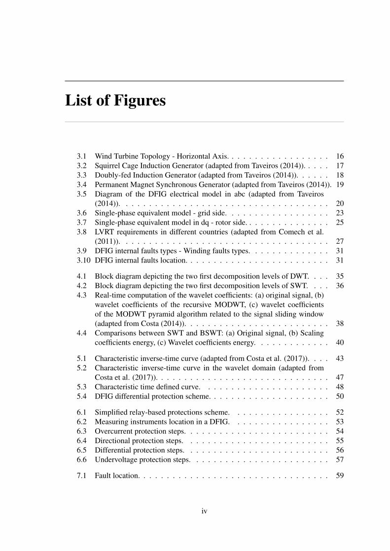
List of Figures iv
List of Tables vi
List of Symbols vii
List of Abbreviations x
1 Introduction 11.1 Motivation . . . . . . . . . . . . . . . . . . . . . . . . . . . . . . . . . . 41.2 Objectives . . . . . . . . . . . . . . . . . . . . . . . . . . . . . . . . . . 41.3 Contributions . . . . . . . . . . . . . . . . . . . . . . . . . . . . . . . . 41.4 Methodology . . . . . . . . . . . . . . . . . . . . . . . . . . . . . . . . 41.5 Work Structure . . . . . . . . . . . . . . . . . . . . . . . . . . . . . . . 5
2 State-of-The-Art 72.1 Protection and Detection Methods Against Internal Faults . . . . . . . . . 82.2 Methods to Protect the DFIG Against External Faults and Enhance the
LVRT . . . . . . . . . . . . . . . . . . . . . . . . . . . . . . . . . . . . 112.3 Summary of Literature Review . . . . . . . . . . . . . . . . . . . . . . . 13
3 Wind Energy Conversion System 153.1 Wind Turbine Components . . . . . . . . . . . . . . . . . . . . . . . . . 153.2 Main Wind Generator Topologies . . . . . . . . . . . . . . . . . . . . . 16
3.2.1 Fixed Speed Wind Generator . . . . . . . . . . . . . . . . . . . . 173.2.2 Variable-speed turbines with partial-scale power converter . . . . 173.2.3 Variable-speed turbines with full-scale power converter . . . . . . 18
3.3 DFIG Electrical System Model . . . . . . . . . . . . . . . . . . . . . . . 193.4 Electric Power Converter . . . . . . . . . . . . . . . . . . . . . . . . . . 22
3.4.1 Grid Side Converter (GSC) . . . . . . . . . . . . . . . . . . . . . 223.4.2 Rotor Side Converter (RSC) . . . . . . . . . . . . . . . . . . . . 24
3.5 Protection Challenges . . . . . . . . . . . . . . . . . . . . . . . . . . . . 263.5.1 Protections Against External Faults and LVRT Enhancement . . . 273.5.2 Internal Protections . . . . . . . . . . . . . . . . . . . . . . . . . 30
3.6 Summary . . . . . . . . . . . . . . . . . . . . . . . . . . . . . . . . . . 32
i

4 Mathematical Fundamentals 334.1 Fourier Transform . . . . . . . . . . . . . . . . . . . . . . . . . . . . . . 334.2 Wavelet Transform . . . . . . . . . . . . . . . . . . . . . . . . . . . . . 34
4.2.1 Discrete Wavelet Transform . . . . . . . . . . . . . . . . . . . . 354.2.2 Stationary Wavelet Transform (SWT) . . . . . . . . . . . . . . . 364.2.3 Real-Time Boundary Stationary Wavelet Transform . . . . . . . . 374.2.4 Scaling and wavelet filters . . . . . . . . . . . . . . . . . . . . . 374.2.5 Energy of the Scaling and Wavelet Coefficients with Boundary
Effect. . . . . . . . . . . . . . . . . . . . . . . . . . . . . . . . . 394.3 Summary . . . . . . . . . . . . . . . . . . . . . . . . . . . . . . . . . . 41
5 Fundamentals of Protection Systems 425.1 Overcurrent Protection . . . . . . . . . . . . . . . . . . . . . . . . . . . 42
5.1.1 Conventional Overcurrent Protection . . . . . . . . . . . . . . . 425.1.2 Wavelet-Based Overcurrent Protection . . . . . . . . . . . . . . . 45
5.2 Undervoltage Protection . . . . . . . . . . . . . . . . . . . . . . . . . . 475.3 Directional Protection . . . . . . . . . . . . . . . . . . . . . . . . . . . . 485.4 Differential Protection . . . . . . . . . . . . . . . . . . . . . . . . . . . 505.5 Summary . . . . . . . . . . . . . . . . . . . . . . . . . . . . . . . . . . 51
6 Methodology 526.1 Protection Applied in DFIG . . . . . . . . . . . . . . . . . . . . . . . . . 526.2 Implementation of the Overcurrent Protection . . . . . . . . . . . . . . . 536.3 Implementation of the Directional Protection . . . . . . . . . . . . . . . 546.4 Implementation of the Differential Protection . . . . . . . . . . . . . . . 566.5 Implementation of the Undervoltage Protection . . . . . . . . . . . . . . 576.6 Summary . . . . . . . . . . . . . . . . . . . . . . . . . . . . . . . . . . 58
7 Protection and Signal Analysis 597.1 Experimental Analysis . . . . . . . . . . . . . . . . . . . . . . . . . . . 59
7.1.1 Single-Line-to-Neutral Fault . . . . . . . . . . . . . . . . . . . . 607.1.2 Line-to-Line-to-Neutral Fault . . . . . . . . . . . . . . . . . . . 60
7.2 Analysis of the Overcurrent Protection . . . . . . . . . . . . . . . . . . . 637.2.1 Single Line-to-Neutral Fault Analyses . . . . . . . . . . . . . . . 637.2.2 Line-to-Line Fault Analysis . . . . . . . . . . . . . . . . . . . . 66
7.3 Analysis of the Directional Protection . . . . . . . . . . . . . . . . . . . 677.3.1 Forward Fault Analyses . . . . . . . . . . . . . . . . . . . . . . 687.3.2 Backward Fault Analyses . . . . . . . . . . . . . . . . . . . . . 70
7.4 Analysis of the Differential Protection . . . . . . . . . . . . . . . . . . . 737.4.1 Internal Fault Analyses . . . . . . . . . . . . . . . . . . . . . . . 737.4.2 External Fault Analyses . . . . . . . . . . . . . . . . . . . . . . 74
7.5 Analysis of the Undervoltage Protection . . . . . . . . . . . . . . . . . . 767.5.1 Voltage Sag Analyses . . . . . . . . . . . . . . . . . . . . . . . . 76
7.6 Discussion . . . . . . . . . . . . . . . . . . . . . . . . . . . . . . . . . . 777.7 Summary . . . . . . . . . . . . . . . . . . . . . . . . . . . . . . . . . . 78

8 Conclusion 798.1 General Conclusions . . . . . . . . . . . . . . . . . . . . . . . . . . . . 798.2 Future Works . . . . . . . . . . . . . . . . . . . . . . . . . . . . . . . . 808.3 Publications . . . . . . . . . . . . . . . . . . . . . . . . . . . . . . . . . 80
Bibliography 81
A Experimental Test-bench 87A.1 The Experimental Test-Bench . . . . . . . . . . . . . . . . . . . . . . . 87
List of Figures
3.1 Wind Turbine Topology - Horizontal Axis. . . . . . . . . . . . . . . . . . 163.2 Squirrel Cage Induction Generator (adapted from Taveiros (2014)). . . . . 173.3 Doubly-fed Induction Generator (adapted from Taveiros (2014)). . . . . . 183.4 Permanent Magnet Synchronous Generator (adapted from Taveiros (2014)). 193.5 Diagram of the DFIG electrical model in abc (adapted from Taveiros
(2014)). . . . . . . . . . . . . . . . . . . . . . . . . . . . . . . . . . . . 203.6 Single-phase equivalent model - grid side. . . . . . . . . . . . . . . . . . 233.7 Single-phase equivalent model in dq - rotor side. . . . . . . . . . . . . . . 253.8 LVRT requirements in different countries (adapted from Comech et al.
(2011)). . . . . . . . . . . . . . . . . . . . . . . . . . . . . . . . . . . . 273.9 DFIG internal faults types - Winding faults types. . . . . . . . . . . . . . 313.10 DFIG internal faults location. . . . . . . . . . . . . . . . . . . . . . . . . 31
4.1 Block diagram depicting the two first decomposition levels of DWT. . . . 354.2 Block diagram depicting the two first decomposition levels of SWT. . . . 364.3 Real-time computation of the wavelet coefficients: (a) original signal, (b)
wavelet coefficients of the recursive MODWT, (c) wavelet coefficientsof the MODWT pyramid algorithm related to the signal sliding window(adapted from Costa (2014)). . . . . . . . . . . . . . . . . . . . . . . . . 38
4.4 Comparisons between SWT and BSWT: (a) Original signal, (b) Scalingcoefficients energy, (c) Wavelet coefficients energy. . . . . . . . . . . . . 40
5.1 Characteristic inverse-time curve (adapted from Costa et al. (2017)). . . . 435.2 Characteristic inverse-time curve in the wavelet domain (adapted from
Costa et al. (2017)). . . . . . . . . . . . . . . . . . . . . . . . . . . . . . 475.3 Characteristic time defined curve. . . . . . . . . . . . . . . . . . . . . . 485.4 DFIG differential protection scheme. . . . . . . . . . . . . . . . . . . . . 50
6.1 Simplified relay-based protections scheme. . . . . . . . . . . . . . . . . 526.2 Measuring instruments location in a DFIG. . . . . . . . . . . . . . . . . 536.3 Overcurrent protection steps. . . . . . . . . . . . . . . . . . . . . . . . . 546.4 Directional protection steps. . . . . . . . . . . . . . . . . . . . . . . . . 556.5 Differential protection steps. . . . . . . . . . . . . . . . . . . . . . . . . 566.6 Undervoltage protection steps. . . . . . . . . . . . . . . . . . . . . . . . 57
7.1 Fault location. . . . . . . . . . . . . . . . . . . . . . . . . . . . . . . . . 59
iv
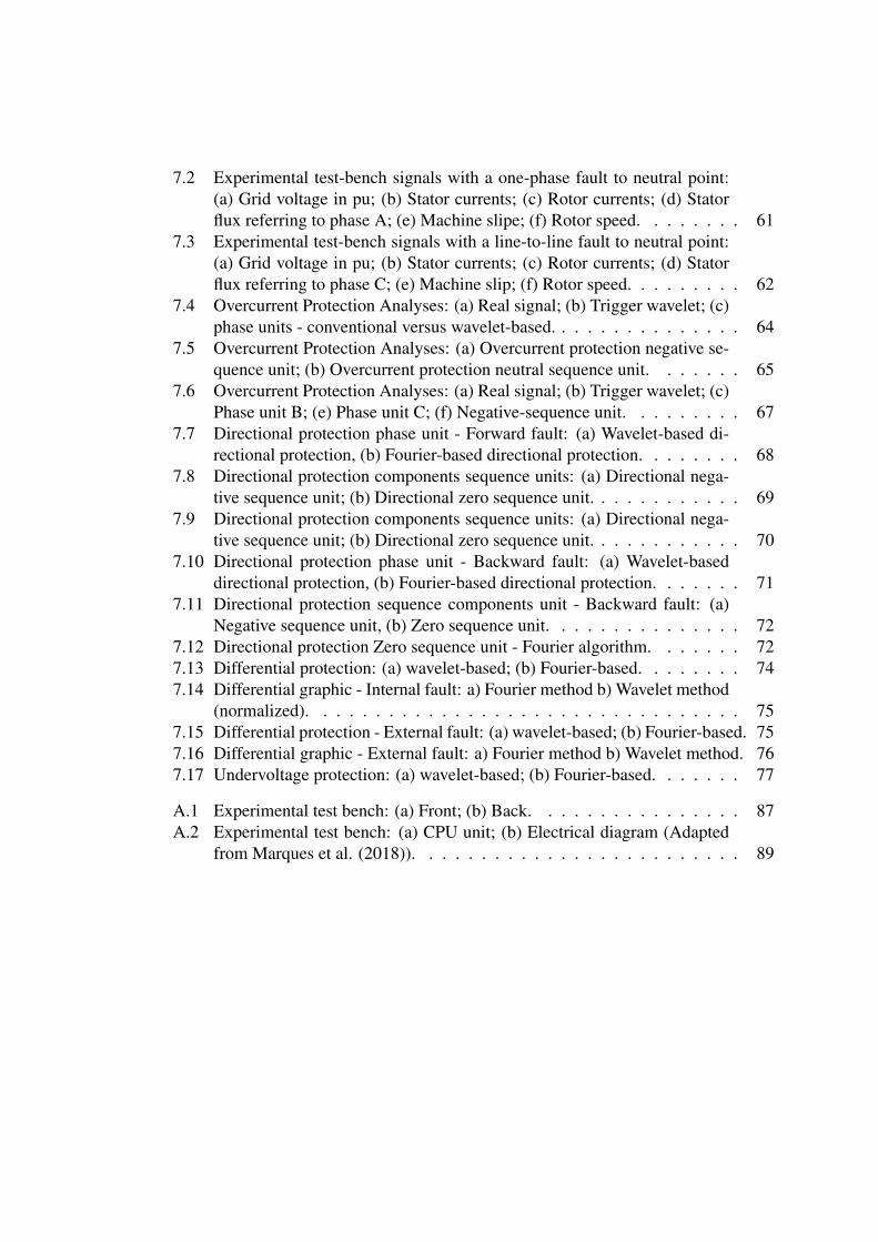
7.2 Experimental test-bench signals with a one-phase fault to neutral point:(a) Grid voltage in pu; (b) Stator currents; (c) Rotor currents; (d) Statorflux referring to phase A; (e) Machine slipe; (f) Rotor speed. . . . . . . . 61
7.3 Experimental test-bench signals with a line-to-line fault to neutral point:(a) Grid voltage in pu; (b) Stator currents; (c) Rotor currents; (d) Statorflux referring to phase C; (e) Machine slip; (f) Rotor speed. . . . . . . . . 62
7.4 Overcurrent Protection Analyses: (a) Real signal; (b) Trigger wavelet; (c)phase units - conventional versus wavelet-based. . . . . . . . . . . . . . . 64
7.5 Overcurrent Protection Analyses: (a) Overcurrent protection negative se-quence unit; (b) Overcurrent protection neutral sequence unit. . . . . . . 65
7.6 Overcurrent Protection Analyses: (a) Real signal; (b) Trigger wavelet; (c)Phase unit B; (e) Phase unit C; (f) Negative-sequence unit. . . . . . . . . 67
7.7 Directional protection phase unit - Forward fault: (a) Wavelet-based di-rectional protection, (b) Fourier-based directional protection. . . . . . . . 68
7.8 Directional protection components sequence units: (a) Directional nega-tive sequence unit; (b) Directional zero sequence unit. . . . . . . . . . . . 69
7.9 Directional protection components sequence units: (a) Directional nega-tive sequence unit; (b) Directional zero sequence unit. . . . . . . . . . . . 70
7.10 Directional protection phase unit - Backward fault: (a) Wavelet-baseddirectional protection, (b) Fourier-based directional protection. . . . . . . 71
7.11 Directional protection sequence components unit - Backward fault: (a)Negative sequence unit, (b) Zero sequence unit. . . . . . . . . . . . . . . 72
7.12 Directional protection Zero sequence unit - Fourier algorithm. . . . . . . 727.13 Differential protection: (a) wavelet-based; (b) Fourier-based. . . . . . . . 747.14 Differential graphic - Internal fault: a) Fourier method b) Wavelet method
(normalized). . . . . . . . . . . . . . . . . . . . . . . . . . . . . . . . . 757.15 Differential protection - External fault: (a) wavelet-based; (b) Fourier-based. 757.16 Differential graphic - External fault: a) Fourier method b) Wavelet method. 767.17 Undervoltage protection: (a) wavelet-based; (b) Fourier-based. . . . . . . 77
A.1 Experimental test bench: (a) Front; (b) Back. . . . . . . . . . . . . . . . 87A.2 Experimental test bench: (a) CPU unit; (b) Electrical diagram (Adapted
from Marques et al. (2018)). . . . . . . . . . . . . . . . . . . . . . . . . 89

List of Tables
2.1 Summary of the literature review related to protection and detection meth-ods against internal faults. . . . . . . . . . . . . . . . . . . . . . . . . . 14
2.2 Summary of the literature review related to methods to protect the DFIGagainst external faults and enhance the LVRT. . . . . . . . . . . . . . . . 14
3.1 DFIG protection against external faults and LVRT enhancement strategies(adapted from Justo et al.(2015)). . . . . . . . . . . . . . . . . . . . . . . 28
5.1 Instantaneous overcurrent units . . . . . . . . . . . . . . . . . . . . . . . 435.2 Curve types and their constants according to IEEE Standard Inverse-Time
Characteristic Equations for Overcurrent Relays, 1996. . . . . . . . . . . 445.3 Time-delay overcurrent units . . . . . . . . . . . . . . . . . . . . . . . . 445.4 Wavelet-based instantaneous overcurrent units . . . . . . . . . . . . . . . 455.5 Wavelet-based time-delay overcurrent units . . . . . . . . . . . . . . . . 465.6 Interconnection system response to abnormal voltages (Adapted from IEEE
(2003)) . . . . . . . . . . . . . . . . . . . . . . . . . . . . . . . . . . . 485.7 Interconnection system response to abnormal voltages (Adapted from IEEE
(2003) and de Cavalcante Paiva (2015)) . . . . . . . . . . . . . . . . . . 485.8 Conventional directionl protection units . . . . . . . . . . . . . . . . . . 495.9 The wavelet-based operation and polarization quantities (Adapted from
Leal et al. (2019)). . . . . . . . . . . . . . . . . . . . . . . . . . . . . . 49
7.1 Relay Operating Time for Different Fault Inception Angles. . . . . . . . . 657.2 Relay Operating Time for Different Fault Inception Angles. . . . . . . . . 667.3 Directional protection comparison - Forward faults. . . . . . . . . . . . . 707.4 Directional protection comparison - Backward faults. . . . . . . . . . . . 73
8.1 Papers resulted from the development of this work. . . . . . . . . . . . . 80
A.1 Experimental DFIG Parameters. . . . . . . . . . . . . . . . . . . . . . . 88
vi

List of Symbols
Ls, Lr Stator and rotor inductance, respectivelyRs, Rr Stator and rotor resistance, respectivelyΩm Rotor mechanical speedθm Rotor mechanic angleias, ibs, ibs Stator current in phase a, b, c, respectivelyiar, ibr, icr Rotor current in phase a, b, c, respectivelyvas, vbs, vcs Stator voltage in phase a, b, c, respectivelyvar, vbr, vcr Rotor voltage in phase a, b, c, respectivelyλas, λbs, λcs Stator flux in phase a, b, c, respectivelyλar, λbr, λcr Rotor flux in phase a, b, c, respectivelyωs Synchronous angular speedωr Angular frequency of rotor variablesωm Angular frequency of the rotorP Pole pairsθr Rotor electrical angular displacementsi Slip machinefr, fss Rotor and stator frequencyLsr,abc Mutual inductance matixLσs Stator leakage inductanceLσr Rotor leakage inductanceMsr Mutual inductanceTem Electromagnetic torquePs, Qs Instantaneous active and reactive power, respectivelyv f Converter output voltagevg Grid voltageig Converter output currentL f Filter inductanceR f Filter resistancevd f , vq f Converter output voltage d, q, respectivelyidg, iqg Converter output current d, q, respectivelyvdg, vqg Grid voltage in d, q, respectivelyLm Magnetizing inductancevdr, vqr Rotor voltage in d, q, respectivelyidr, iqr Rotor current in d, q, respectivelyλdr, λqr Rotor flux in d, q, respectivelyλds, λqs Stator flux in d, q, respectively

t Time domainω Frequency domainf (t) Time domain signalF(ω) Frequency domain signalXr, Xi Real and imaginary phasor component, respectively∆k Total number of samplesfs Sampling frequencyfc Cut frequencyf System fundamental frequencyx Original signalk Discrete time domain|X | Original signal module∠X Original signal angles Scaling coefficientw Wavelet coefficientj Decomposition levelhϕ Low-pass filterhψ High-pass filterN Total sample numberL Filter coefficientp Integer number∆k Total sample numbers of a sliding windowε Original signal energyz Boundary levelεs, εw Scaling and wavelet coefficients energy, respectivelyεsa, εwa Scaling and wavelet coefficient energy with boundaryεsb, εwb Scaling and wavelet coefficient energy without boundary,
respectivelyr f Fault resistancei Current signalI Absolute currentI1, I2, I0 Absolute current of the positive, negative and zero se-
quences, respectivelyIs Starting currentIA, IB, IC Absolute current in phase a,b,c, respectivelyI50, I50N , I50P, I50Q Pick-up current of unit 50, unit 50N, unit 50P, unit 50Q,
respectivelyN50, N50N , N50P, N50Q Multiplicative constant of unit 50, unit 50N, unit 50P, unit
50Q, respectivelyI51, I51N , I51P, I51Q Pick-up current of unit 51, unit 51N, unit 51NP, unit 51Q,
respectivelyN51, N51N , N51P, N51Q Multiplicative constant of unit 51, unit 51N, unit 51P, unit
51Q, respectivelyIr Load current in normal operation
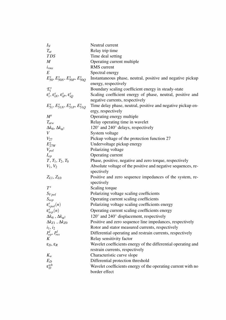
IN Neutral currentTat Relay trip timeT DS Time deal settingM Operating current multipleirms RMS currentE Spectral energyEs
50, Es50N , Es
50P, Es50Q Instantaneous phase, neutral, positive and negative pickup
energy, respectivelyE s
i Boundary scaling coefficient energy in steady-stateεs
i , εsiN , εs
iP, εsiQ Scaling coefficient energy of phase, neutral, positive and
negative currents, respectivelyEs
51, Es51N , Es
51P, Es51Q Time delay phase, neutral, positive and negative pickup en-
ergy, respectivelyMs Operating energy multipleTatw Relay operating time in wavelet∆kα, ∆kα2 120 and 240 delays, respectivelyV System voltageV27 Pickup voltage of the protection function 27Es
27W Undervoltage pickup energyVpol Polarizing voltageIop Operating currentT , T1, T2, T0 Phase, positive, negative and zero torque, respectivelyV1, V2 Absolute voltage of the positive and negative sequences, re-
spectivelyZL1, ZL0 Positive and zero sequence impedances of the system, re-
spectivelyT s Scaling torqueSV pol Polarizing voltage scaling coefficientsSiop Operating current scaling coefficientsεs
vpol(n) Polarizing voltage scaling coefficients energyεs
iop(n) Operating current scaling coefficients energy∆kα , ∆kα2 120 and 240 displacement, respectively∆kZ1 , ∆kZ0 Positive and zero sequence line impedances, respectivelyi1, i2 Rotor and stator measured currents, respectivelyIdop, Id
res Differential operating and restrain currents, respectivelyK Relay sensitivity factorεD, εR Wavelet coefficients energy of the differential operating and
restrain currents, respectivelyKw Characteristic curve slopeED Differential protection thresholdεwb
D Wavelet coefficients energy of the operating current with noborder effect


List of Abbreviations
ANFIS Adaptative neuro-fuzzy inference systemAWRF Asymmetrical winding resistive faultBESS Battery energy storage systemCSC Current source converterCWT Continuous wavelet transformCT Current transformerDG Distributed generationDFIG Doubly-fed induction generatorDSP Digital signal processorDVR Dynamic voltage restorerDWT Discrete wavelet transformdb DaubechisEESG Electrically excited synchronous generatorEPVA Extended Park‘s vector approachFCL Fault current limiterFFT Fast Fourier TransformFPGA Field Programmable Gate ArrayFRT Fault-ride throughGSC Grid side converterHIL Hardware-in-the-loopIGBT Insulated gate bipolar transistorITSC Inter-turn short circuitsLVRT Low-voltage ride throughMCSA Machine current signature analysisMODWT Maximal overlap discrete wavelet transformMPPT Maximum power point trackingPCC Common connection pointPIC Parallel interleaved convertedPMSG Permanent magnet synchronous generatorPPgEEC Graduate program in Electrical and Computing EngineeringPT Potential transformerPWM Pulse Width ModulationRES Renewable energy sourceRSC Rotor side converterRT-BSWT Real time - Stationary wavelet transform with boundaryRT-SWT Real-time stationary wavelet transformSCIG Squirrel-cage induction generator

SDBR Series dynamic braking resistorSDR Series dynamic resistorSFCL Superconducting fault current limiterSLG Single line-to-groundSMES Superconducting magnetic energy storageSVC Static var compensatorSTATCOM Static synchronous compensatorSWT Stationary wavelet transformTDS Time deal settingUFRN Federal University of Rio Grande do NorteVSC Voltage source converterWECS Wind energy conversion systemsWT Wind turbine
Chapter 1
Introduction
The wind energy conversion systems (WECS) have been inserted in the electrical gridas one of the most promising renewable energy source (RES) to reduce the use of fossilfuels. However, the large insertion of this type of generation in the grid must be basedon researches which prove its efficiency and feasibility. Consequently, the generators willobtain a better efficiency in the conversion of wind kinetic energy into electrical energy.
In 2017, the global annual installed capacity was 52,573 MW, achieving 539,581 MWin cumulative installed wind capacity according to the global wind energy council (GWS2017). In Brazil, this growth is expressive too. For instance, in 2005 there were 27.1MW of installed capacity and jumped to 14,561.3 MW in 2018, representing 8.1% of theBrazilian electric matrix. Furthermore, there is a growth forecast to 17,880.0 MW until2023 according to the Brazilian wind energy association (BAGE 2017). This highlightsthe great importance of researches about this type of generation nowadays.
In worldwide, the most commonly used WECS topologies are the permanent mag-net synchronous generator (PMSG) and the doubly-fed induction generator (DFIG) (Liand Chen 2008). However, the DFIG topology is the dominant generator in wind powerplants (Mansouri et al. 2016), and its advantage over another types of generators is thelow cost of converters because the power converters have a maximum power rate of 30%of the generator power, and it does not have the drawback of the rotor demagnetizing dueto a machine overheating.
With the large growth of WECS and the variety of existing generators, the systemoperators have been imposing high requirements on grid codes for these types of gener-ation plants. Hence, the requirements need to be achieved, such as control of reactivepower, control of active power, protective devices and power quality monitoring (Comechet al. 2011). Moreover, achieving the grid requirements is fundamental to enhance thecapacity of load flow controlling and keep working properly the interconnected electricalsystem. Furthermore, another requirement which needs to achieve is the electrical gridand power generators protection against faults and disturbances.
The electrical protection to the DFIG is a challenge because this topology is sensitiveto any abrupt drop of the grid voltage since the stator windings are directly connected tothe grid. For instance, faults cause oscillations in the stator currents and may generate anelectromagnetic torque pulsation. In addition, the DFIG can insert harmonic distortion inthe electrical grid due to the presence of the power electronic converters used to controlthe active and reactive power injection and the DC-link voltage amplitude as well.
CHAPTER 1. INTRODUCTION 2
There are other elements that increase this challenge, such as (Mansouri et al. 2016):
• Generator speed can oscillate between the sub-synchronous to the super-synchronousoperation modes.
• The direction of the rotor power flow can be positive or negative depending on themachine operation mode.
• There is magnetic coupling between rotor and stator winding variables.• Measured electric signals of the rotor and stator have different frequencies.• Rotor winding frequency is low and variable.• Wind farm’s intermittency which increases and decreases the steady-state current.• Disturbances on the electrical grid.
Protection schemes have been used to guarantee the low-voltage ride through (LVRT)by using some LVRT categories, because the DFIG operates considering that the mostfault types are transient which last for a short period of time. Together with the LVRT cat-egories are used conventional protection-based methods such as overcurrent, overvoltage,phase-loss, and undervoltage to detect and protect against grid disturbances and electricalfaults on the point of common coupling (PCC), which is characterized as a DFIG externalfault, avoiding the wind turbine disconnection.
The LVRT is a requirement imposed by grid codes which is the capability of gen-erators remain connected to the electrical grid in case of voltage sag, which is usuallyassociated to a fault in the grid. When a voltage sag occurs the wind turbines need to pro-vide support to the grid. For instance, in Germany, when a voltage drops to zero (whichcould be due to a fault near the generator) the generators need to remain connected for 150ms. To achieve the LVRT objectives there are in general three categories of solution (Zouet al. 2016) that are based on control strategies; hardware modification like reactive powerinjecting devices or protective circuits; and the application of superconducting fault cur-rent limiter (SFCL). In addition, there is a category which is a unity between the elementsof the first category with the second one. The LVRT categories are triggered in case oftemporary external faults and voltage sags at PCC by the protection-based methods orothers strategies.
In case of an internal or external permanent fault, the protection applied on the DFIGtopology is able to disconnect the turbine in order to prevent the system becoming unstabledue to the fault as also protect the generator. Therefore, the protections should be usedto monitor individually each element that composes the DFIG assembly against internalfaults, such as: the transformer, the power converters, the DC-link coupling. Moreover,the conventional protections must also be used to protect the turbine against internal faultsat the electric machine windings as also monitoring and protect against external faults atthe PCC.
Many reasons explain the emergence of internal faults in the electric machine, someof them are announced by Abadi et al. (2014):
• Insulation degradation between the individual coil.• Insulation degradation between different coils.• Electromechanical induced vibration.
CHAPTER 1. INTRODUCTION 3
• Thermal overload or contamination.• High ratio dv/dt due to power electronic converter feeding the rotor windings.
There are several types of internal faults in electric machines, such as the coil-to-coil,turn-to-turn and open-circuit. In addition, in the rotor terminals, there are faults involvingthe brushes. Furthermore, there are faults involving the stator and rotor terminal con-nection points. The most recent researches seek to identify which kinds of these faultsoccurred. Identification of faults inside generators on initial stages is plenty welcome toenable emergency operation and reduce damage risks (Stojcic et al. 2014). Notwithstand-ing, faults on the DFIG topology elements beyond the machine windings and connectionsare also considered internal faults, such as, faults on its power converters.
A mandatory assignment of the protection applied in DFIGs is to distinguish whetherthe electrical fault is internal or external. Therefore, the monitoring system needs to beuninterrupted and accurate to detect all faults inside the DFIG and at the PCC. Therefore,identifying and differentiating the fault types are essential because each type of failureneeds a different procedure to be adopted. In the case of a temporary external fault, theLVRT categories need to be triggered as aforementioned, whereas in the case of internalfaults the wind turbine needs to be disconnected.
The overcurrent, overvoltage or undervoltage protections are ineffective to identifyif the fault is external or internal. However, the differential protection, which is ex-tensively applied in power transformers (Medeiros and Costa 2018) and transmissionlines (Dambhare et al. 2009), would be suitable to distinguish if the fault was internalor not. Nevertheless, this protection is not usual in DFIGs, only in recent works this pro-tection type was applied to this generator type (Mansouri et al. 2016) - (Zarei et al. 2018).In addition, the directional protection can also be used for this purpose because it is ableto identify the direction of the power flow, in consequence, the fault direction.
The conventional directional protection is based on measuring of electrical signals, us-ing the Fourier transform, which uses phasor estimation. Fast signal processing tools, suchas the real-time stationary wavelet transform with boundary effect (RT-BSWT) proposedby Costa and Driesen (2013), can provide faster fault detection (Costa 2014). Therefore,a protection and detection method based on the RT-BSWT can provide a fast relay sensiti-zation which it is essential to ensure the rapid activation of the LVRT categories in case ofexternal faults at the PCC, and to protect against internal faults inside the DFIG topology.
In this context, the protection and detection systems must properly actuate for eachtype of fault. Therefore, the development of protection and detection methods based onmodern signal processing tools, such as the wavelet transform, is of high priority. More-over, the methods need to be capable of detecting if the fault occurred at the PCC or insidethe DFIG assembly, such as faults in the stator and rotor terminal connection points, thisis of great importance for choosing the correct protection action for each fault type. Fur-thermore, assess and validate new protection trends, for instance, the overcurrent, thedifferential, the directional and the undervoltage wavelet-based protections, is importantto prove that these new methods work properly in a system with the aforementioned char-acteristics.
CHAPTER 1. INTRODUCTION 4
1.1 MotivationNowadays, there is no standardization of protections and fault detection methods ap-
plied to DFIG topology. However, this type of wind turbine is the most used today inonshore wind farms. Some recent publications have approached the theme of protectionand fault detection methods, highlighting their challenges and the implementation diffi-culties. Notwithstanding, most of the studies only address the impact of these generationtypes on the grid code requirements in order to guarantee these specifications, instead ofdeveloping an efficient and reliable fault detection method for the wind generators capa-ble to distinguish whether the fault ocurred externally, at the PCC, or internally, inside theDFIG assembly, due to each fault type to need a different decision-making.
1.2 ObjectivesThe goal of this work is to verify if wavelet-based protections and fault detection
methods to distinguish between internal and external faults can be properly used in aDFIG.
To achieve the expected results, the following specific objectives have been defined:
• To verify if the wavelet-based overcurrent protection is feasible in a DFIG topology.• To verify if the wavelet-based undervoltage protection is feasible in a DFIG topol-
ogy.• To verify if the wavelet-based directional protection is feasible in a DFIG topology.• To verify if the wavelet-based differential protection is feasible in a DFIG topology.• To analyze DFIG signals in case of faults in the machine terminal connections using
RT-BSWT and real experimental data.
1.3 ContributionsThe main contributions are:
• Obtaining reliable analyzes of the DFIG in case of electrical faults using the RT-BSWT.
• Confirmation which it is possible to apply the wavelet-based overcurrent and un-dervoltage protections in a DFIG topology.
• Confirmation which it is possible to apply the wavelet-based directional and differ-ential protections in a DFIG topology.
1.4 MethodologyAmong the scientific method typologies, this work is anchored in the hypothetical-
deductive method, which provides all operational resources to the development of the

CHAPTER 1. INTRODUCTION 5
research processes, since the problem delimitation until the final results, in order to reachthe goals of this dissertation.
It was reviewed the state-of-the-art of the protection types and detection methods ap-plied in a DFIG topology nowadays, and verified which protection schemes are used todetect and protect against faults inside DFIG assembly and which strategies are used toenhance the LVRT in case of external faults or grid disturbances at the PCC.
Some theoretical studies about the DFIG, the wavelet transform and the relay-basedprotections were done in order to acquire the necessary knowledge to validate an internalprotection to the DFIG and a detection method capable to identify if a fault occurredinside or outside the DFIG topology.
Concerning about the exposed, it was validated protection algorithms capable to detectif the electrical fault occurred inside the DFIG topology, such as in the power converters,in the machine, and in the connections, as also capable to detect if the fault occurredoutside, externally, to the DFIG assembly such as at the PCC. Furthermore, it was carriedstudies about wavelet-based protections, for instance, overcurrent, differential, directionaland undervoltage protection, applied in a DFIG.
For finish, off-line analysis with real experimental data, obtained in a DFIG test bench,was used to the assessment in order to provide more accurate and realistic analysis to thevalidated methods.
1.5 Work StructureThis dissertation is organized in eight chapters:
• Chapter 1, that presented an introduction about the growth of WECS insertion inthe electrical grid, specifying the most used topologies and problems occasionedin the electrical power systems protection due to this insertion. In addition, thesolutions adopted to solve these problems are depicted.
• Chapter 2, that illustrates the current state-of-the-art of the protections applied toDFIG. However, this review is made in two different perspectives, the first one isabout internal protections and detection methods used to protect the DFIG assem-bly, whereas, the second one is about protections applied against external faults toprotect the DFIG elements and enhance the LVRT requirements.
• Chapter 3, that discusses about the WECS fundamental theory in order to intro-duce the main topologies applied in wind farms, as well as the electrical model ofa DFIG. In addition, it is presented an introduction about the electrical protectionapplied into DFIG and their challenges.
• Chapter 4, that introduces the theoretical basis of the Fourier transform. Further-more, the wavelet transform is introduced with focus on different versions of thistransform.
• Chapter 5, that presents the theoretical basis of the wavelet-based overcurrent,undervoltage, directional and differential protections.
• Chapter 6, that illustrates the evaluation of the DFIG experimental data variables,such as the stator and rotor currents, the voltages, and slip machine as well as the

CHAPTER 1. INTRODUCTION 6
rotor speed.• Chapter 7, that illustrates the evaluation of all the results obtained through the use
of the proposed methodology with a critical point of view.• Chapter 8, that presents the conclusions obtained in the development of this work,
as well as proposals topics for future work.

Chapter 2
State-of-The-Art
The DFIG has been gained prominence in the global scenario due to its application inwind farms, a fact of no more than 40 years. However, one of the first scientific studiespresent in the literature about this type of electric machine is dated from 1941, wherein Li-wschitz (1941) focused about the mathematical development of this machine, specificallyabout the damping and synchronizing torque. In the next year, Concordia et al. (1942)developed some analysis showing transients characteristics and the machine equivalentcircuit. Notwithstanding, until the eighties, the academical investigation about this themewas restricted to a few scientific papers.
After this period, the researches about DFIG grew exponentially due to the emergenceof wind power generation. Therefore, it was required to develop studies which circum-vented the problems of this application type, for instance, control strategies (Ioannidouand Tegopoulos 1987), efficiency (Ioannides and Tegopoulos 1988), active and reactivepower control (Pena et al. 1996, Muller et al. 2002) and system stability (Rahim 1988).
In the 2000s, the researches applied to the DFIG topology aimed to achieve the re-quirements imposed by the grid operators, mainly the LVRT, due to the increasing num-ber of WECS installed in the electrical grid. Therefore, the studies focus became theprotective devices applied during transient-state; reactive power injecting devices dur-ing transient-state; and control structures applied in steady- and transient-state (Justoet al. 2015). This research area keeps until today as the main one when it comes to DFIGtopology. Moreover, this field is important because achieve the grid codes and protect theDFIG elements against overcurrent and undervoltage in case of voltage sag or faults atthe PCC, which is considered as external faults.
In recent years, appeared an interest in protecting the DFIG topology against internalfaults, both in the machine windings and in the other elements that compose the set. Thisresearch field interest is in order to prevent against high economic losses and protect theelectrical system, avoiding wind parks disconnection and high generator damages.
This chapter provides a state-of-the-art survey of protection and detection methodsagainst internal faults in DFIG topology. Furthermore, a review about methods to protectthe DFIG against external faults and enhance the LVRT is also introduced because exter-nal faults at the PCC can cause overcurrent and undervoltage inside the DFIG assembly.The strengths and weaknesses of these two types of fault prevention are presented.
CHAPTER 2. STATE-OF-THE-ART 8
2.1 Protection and Detection Methods Against InternalFaults
A condition monitoring system of wind generators using machine current signatureanalysis (MCSA) is presented by Popa et al. (2003). The purpose of this research is toadapt a fault detection technique applied in induction machines to a DFIG with a monitor-ing system. It is done an experimental system with a wind turbine model and a generatormodel system used to validate the analysis. The AD Card - ICS 645 is used to measurethe signals and the software Matlab is used as a processing unit. Three different analysiswere presented to validate the system, the first was a stator phase unbalance, the secondwas a rotor phase unbalance, whereas the third one was a turn-to-turn fault. In relationto the presented, the results indicated that the monitoring system correctly works for allcases in accordance with the theory. However, even with good results, this article doesnot present an innovative method for detecting faults. Nevertheless, it explains in detailhow to implement a complete monitoring system.
Douglas et al. (2005) presented an inter-turn stator fault detection method for DFIGusing the DWT and the extended Park vector approach (EPVA). It is demonstrated thatsteady-state techniques are not effective when applied during transient conditions. Exper-imental simulations of a generation system model with a 2.2 kW DFIG were performedusing the ds1104 R&D controller card to validate the proposed method. In addition, therecorded data were processed in the Matlab software. The proposed is to decompose thenonstationary EPVA signal into the scaling and wavelet coefficients using Haar as motherwavelet. Furthermore, a Gaussian distribution is used to determine with occurred or not aninternal fault, where a bimodal shape indicates a turn fault. However, grid faults were notvalidated, thus this behavior may be reproduced and an equivocal detection can happen.
The employment of fast Fourier transform (FFT) to analyze the spectrum of rotormodulating signals to detect incipient electrical faults in DFIG was proposed by Stefaniet al. (2008). The proposed method analyzed the rotor modulating signal spectrum incase of internal electrical faults, as well as for comparative criteria make the same studyto the stator and rotor current spectrum. The first one demonstrated the best effectivenessand accuracy to detect faults. Simulations made on Matlab/Simulink software and ex-perimental analyzes with the control implemented on dSPACE were used to evaluate theperformance of the method. Therefore, it was obtained promise results in both validationstrategies. However, the type of faults applied to validate the method was the asymmet-rical winding resistive fault (AWRF) whereas inter-turn faults were not studied in thisresearch. Thus, only one kind of fault was validated missing another study to analyzeinter-turns faults.
Kang et al. (2009) developed a protection algorithm based on the ‘dq’ equivalent cir-cuit in the time domain. The algorithm estimates the induced voltages in the machinewindings using the stator and rotor currents and voltages at the stationary reference frame.It is obtained two fault detectors, one refers to the d-axis and another to the q-axis if thedetectors values exceed 5% sixteen times the trip signal is activated. To verify the pro-tection, a generation system was developed in the PSCAD/EMTDC, two different faulttypes were implemented, a turn-to-turn fault and a three-phase external fault. Simulation
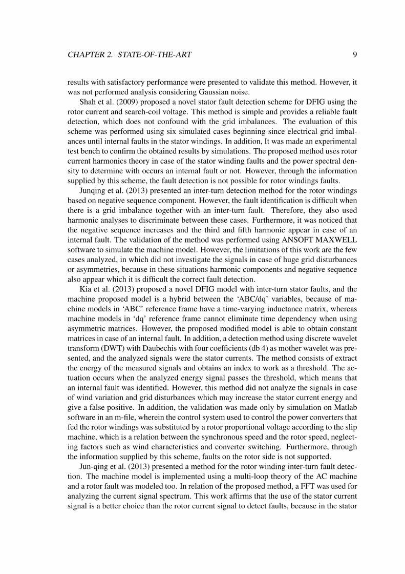
CHAPTER 2. STATE-OF-THE-ART 9
results with satisfactory performance were presented to validate this method. However, itwas not performed analysis considering Gaussian noise.
Shah et al. (2009) proposed a novel stator fault detection scheme for DFIG using therotor current and search-coil voltage. This method is simple and provides a reliable faultdetection, which does not confound with the grid imbalances. The evaluation of thisscheme was performed using six simulated cases beginning since electrical grid imbal-ances until internal faults in the stator windings. In addition, It was made an experimentaltest bench to confirm the obtained results by simulations. The proposed method uses rotorcurrent harmonics theory in case of the stator winding faults and the power spectral den-sity to determine with occurs an internal fault or not. However, through the informationsupplied by this scheme, the fault detection is not possible for rotor windings faults.
Junqing et al. (2013) presented an inter-turn detection method for the rotor windingsbased on negative sequence component. However, the fault identification is difficult whenthere is a grid imbalance together with an inter-turn fault. Therefore, they also usedharmonic analyses to discriminate between these cases. Furthermore, it was noticed thatthe negative sequence increases and the third and fifth harmonic appear in case of aninternal fault. The validation of the method was performed using ANSOFT MAXWELLsoftware to simulate the machine model. However, the limitations of this work are the fewcases analyzed, in which did not investigate the signals in case of huge grid disturbancesor asymmetries, because in these situations harmonic components and negative sequencealso appear which it is difficult the correct fault detection.
Kia et al. (2013) proposed a novel DFIG model with inter-turn stator faults, and themachine proposed model is a hybrid between the ‘ABC/dq’ variables, because of ma-chine models in ‘ABC’ reference frame have a time-varying inductance matrix, whereasmachine models in ‘dq’ reference frame cannot eliminate time dependency when usingasymmetric matrices. However, the proposed modified model is able to obtain constantmatrices in case of an internal fault. In addition, a detection method using discrete wavelettransform (DWT) with Daubechis with four coefficients (db 4) as mother wavelet was pre-sented, and the analyzed signals were the stator currents. The method consists of extractthe energy of the measured signals and obtains an index to work as a threshold. The ac-tuation occurs when the analyzed energy signal passes the threshold, which means thatan internal fault was identified. However, this method did not analyze the signals in caseof wind variation and grid disturbances which may increase the stator current energy andgive a false positive. In addition, the validation was made only by simulation on Matlabsoftware in an m-file, wherein the control system used to control the power converters thatfed the rotor windings was substituted by a rotor proportional voltage according to the slipmachine, which is a relation between the synchronous speed and the rotor speed, neglect-ing factors such as wind characteristics and converter switching. Furthermore, throughthe information supplied by this scheme, faults on the rotor side is not supported.
Jun-qing et al. (2013) presented a method for the rotor winding inter-turn fault detec-tion. The machine model is implemented using a multi-loop theory of the AC machineand a rotor fault was modeled too. In relation of the proposed method, a FFT was used foranalyzing the current signal spectrum. This work affirms that the use of the stator currentsignal is a better choice than the rotor current signal to detect faults, because in the stator

CHAPTER 2. STATE-OF-THE-ART 10
current signal appears only the third harmonic in fault case, making easier the detection.However, only one situation was analyzed, thus it was a weak validation. Furthermore,no experimental verification was performed to prove the detection method effectivenessin order to ensure that the method would not confound grid disturbance with inter-turnfaults.
A detection method for stator and rotor inter-turn faults with an automatic diagnosticsystem with remote data collection was proposed by Abadi et al. (2014) using the FFT.The stator voltages and currents are required to estimate the instantaneous reactive powerfor fault diagnostic purposes. Furthermore, the method is developed according to theproposition that in case of stator faults, a component with twice the grid frequency willappear on the signal spectrum and in case of rotor faults the same thing will happen mul-tiplied by the machine slip. However, this phenomenon occurs in cases of grid imbalancetoo. Therefore, it is not correct to use this information as the main one to detect an inter-nal fault. Experimental verification was made and the control scheme was implementedin a dSPACE. In the test rig many analyses with the machine operating in healthy, in sta-tor fault, and in rotor fault conditions were accomplished. However, in case the machineoperates close to the synchronous speed the method does not work properly.
Stojcic et al. (2014) developed a scheme to detect stator and rotor winding asym-metries for a DFIG. This method applies short voltage pulses on machine terminals byinverter switching and measures the current reaction from each phase to get the transientleakage inductance to estimate a denoted asymmetry phasor. The estimated phasor passesthrough a digital processing using FFT to analyze in its spectrum if there was any windingasymmetry. In addition, the asymmetries can be detected in position and in severity. Fur-thermore, all validation process was made by an experimental procedure. Besides that, toguarantee a reliable investigation of the method, different fault scenarios were applied forthe method verification, such as symmetrical, one turn phase, two turns phase, five turnsphase and complete phase faults.
Roshanfekr and Jalilian (2016) proposed a new fault diagnostic index using the nor-malized energy calculation from the DWT. Two types of faults were investigated, the firstone was inter-turn short-circuit fault and the second one was winding resistive asymmet-rical fault. The fault is detected when the rotor-voltage energy goes through a thresholddetermined by the energy of the DFIG when in healthy operation. The db(10) motherwavelet was used with a sampling frequency of 10KHz. A performance verification ofthis scheme was executed using the Matlab/Simulink software and satisfactory resultswere obtained. However, the diagnostic method failed under minor windings asymme-try in the stator asymmetrical winding faults. Nevertheless, the fault detection methoddemonstrated awesome performance for the detected fault types.
Abdelemam et al. (2017) presented a based DWT scheme in which any internal faultsat the stator windings is detected. There is a fault detection unit responsible to detect andanalyze the faults cases using the wavelet energy magnitude. The validation of the methodwas performed using an EMTP-ATP model and the proposed technique was applied usingthe LabVIEW software. The limitations of this work are the unique fault type used in thesimulation which was a three-phase fault in the stator terminals, consequently, limited theproposed, and the absence of inter-turn fault considerations.To protect the machine a trip
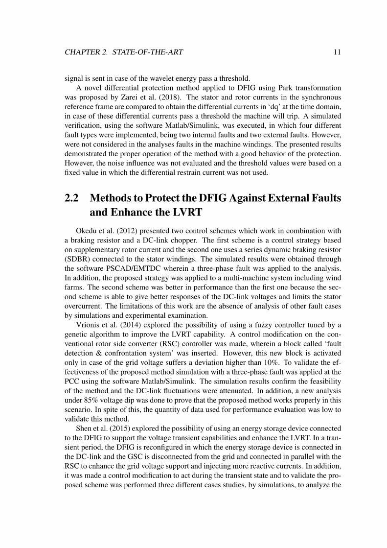
CHAPTER 2. STATE-OF-THE-ART 11
signal is sent in case of the wavelet energy pass a threshold.A novel differential protection method applied to DFIG using Park transformation
was proposed by Zarei et al. (2018). The stator and rotor currents in the synchronousreference frame are compared to obtain the differential currents in ‘dq’ at the time domain,in case of these differential currents pass a threshold the machine will trip. A simulatedverification, using the software Matlab/Simulink, was executed, in which four differentfault types were implemented, being two internal faults and two external faults. However,were not considered in the analyses faults in the machine windings. The presented resultsdemonstrated the proper operation of the method with a good behavior of the protection.However, the noise influence was not evaluated and the threshold values were based on afixed value in which the differential restrain current was not used.
2.2 Methods to Protect the DFIG Against External Faultsand Enhance the LVRT
Okedu et al. (2012) presented two control schemes which work in combination witha braking resistor and a DC-link chopper. The first scheme is a control strategy basedon supplementary rotor current and the second one uses a series dynamic braking resistor(SDBR) connected to the stator windings. The simulated results were obtained throughthe software PSCAD/EMTDC wherein a three-phase fault was applied to the analysis.In addition, the proposed strategy was applied to a multi-machine system including windfarms. The second scheme was better in performance than the first one because the sec-ond scheme is able to give better responses of the DC-link voltages and limits the statorovercurrent. The limitations of this work are the absence of analysis of other fault casesby simulations and experimental examination.
Vrionis et al. (2014) explored the possibility of using a fuzzy controller tuned by agenetic algorithm to improve the LVRT capability. A control modification on the con-ventional rotor side converter (RSC) controller was made, wherein a block called ‘faultdetection & confrontation system’ was inserted. However, this new block is activatedonly in case of the grid voltage suffers a deviation higher than 10%. To validate the ef-fectiveness of the proposed method simulation with a three-phase fault was applied at thePCC using the software Matlab/Simulink. The simulation results confirm the feasibilityof the method and the DC-link fluctuations were attenuated. In addition, a new analysisunder 85% voltage dip was done to prove that the proposed method works properly in thisscenario. In spite of this, the quantity of data used for performance evaluation was low tovalidate this method.
Shen et al. (2015) explored the possibility of using an energy storage device connectedto the DFIG to support the voltage transient capabilities and enhance the LVRT. In a tran-sient period, the DFIG is reconfigured in which the energy storage device is connected inthe DC-link and the GSC is disconnected from the grid and connected in parallel with theRSC to enhance the grid voltage support and injecting more reactive currents. In addition,it was made a control modification to act during the transient state and to validate the pro-posed scheme was performed three different cases studies, by simulations, to analyze the

CHAPTER 2. STATE-OF-THE-ART 12
system reliability, the first one was applied symmetrical and asymmetrical faults with highwind speed, the second was a similar case with a low wind speed, whereas the last onewas compared the LVRT behavior with different control strategies. The simulation resultsconfirm the feasibility of energy storage device to support transient voltage capabilities.
Zou et al. (2016) proposed a novel protection scheme for DFIG-WT using a resistivetype of SFCL, which is defined as one of the three categories to enhance the LVRT capa-bility. The superconducting fault current limiter (SFCL) is connected in series with therotor windings, and to evaluate the proposed material it was made comparative studieswith the conventional crowbar-based scheme. The validation of this scheme was per-formed using simulation, in which two different fault types were used, the first one wasa three-phase fault and the second one was a line to line fault wherein both of them wereapplied on the grid. In all analyzed cases the proposed structure obtained a better perfor-mance than the crowbar-based scheme. However, this structure has a high implementationcost, due to use an expensive superconducting material, which until today is economicallyinviable.
Guo et al. (2016) presented a fault current limiter-battery energy storage system (FCL-BESS) that enhances the LVRT ability of DFIG. The proposed assembly combines thefault current limiter and energy storage functions using a superconducting material, whereinthe FCL is used to protect the DFIG topology whereas the BESS is used to stabilizing theDC-link voltage. The FCL-BESS topology is connected in series with stator windings andin parallel with DC-link. This scheme was explained since the steady-state operation untila transient state using an experimental prototype under symmetrical, asymmetrical faultconditions and in normal operation. The proposed method solve two difficult problems.However, it is too expensive to be implemented due to use a superconducting coil to limitthe current. The scheme performance was evaluated using a DSP to the processing unitand demonstrated accurate results for all investigated cases.
The employment of parallel interleaved converted (PIC) and SDBR to enhancing theDFIG stability in a three-phase fault situation was proposed by Okedu (2016). The pro-posed strategies need two back-to-back converters connected on rotor windings and anSDBR connected in series with stator windings. Simulations were used to evaluate theperformance of the topology using the PSCAD/EMTDC software. However, only a fewcases were analyzed let it open the accuracy and reliability for different operating condi-tion. In spite of that, the scheme improves the DFIG performance during transient con-ditions for the analyzed case. However, it is expensive and complex to be implementedbecause needs two back-to-back power converters connected in parallel and a SDBR ashardware additions.
An adaptative neuro-fuzzy inference system (ANFIS) crowbar protection for detectinggrid faults in DFIG-WT systems is proposed by Noureldeen and Hamdan (2017). TheANFIS proposed is used as a fault detector to activate and deactivate the crowbar-basedprotection. Besides that, two different structures were proposed, called ANFIS innercrowbar technique and ANFIS outer crowbar protection technique. In the first one, thecrowbar was put in series with rotor windings whereas in the second one the crowbar wasput in parallel with the PCC. Based on these assemblies, a three-phase fault at the windturbine terminals was simulated using the software Matlab/Simulink to observe the system
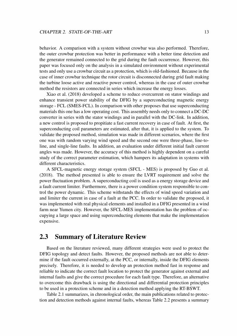
CHAPTER 2. STATE-OF-THE-ART 13
behavior. A comparison with a system without crowbar was also performed. Therefore,the outer crowbar protection was better in performance with a better time detection andthe generator remained connected to the grid during the fault occurrence. However, thispaper was focused only on the analysis in a simulated environment without experimentaltests and only use a crowbar circuit as a protection, which is old-fashioned. Because in thecase of inner crowbar technique the rotor circuit is disconnected during grid fault makingthe turbine loose active and reactive power control, whereas in the case of outer crowbarmethod the resistors are connected in series which increase the energy losses.
Xiao et al. (2018) developed a scheme to reduce overcurrent on stator windings andenhance transient power stability of the DFIG by a superconducting magnetic energystorage - FCL (SMES-FCL). In comparison with other proposes that use superconductingmaterials this one has a low operating cost. This assembly needs only to connect a DC-DCconverter in series with the stator windings and in parallel with the DC-link. In addition,a new control is proposed to propitiate a fast current recovery in case of fault. At first, thesuperconducting coil parameters are estimated, after that, it is applied to the system. Tovalidate the proposed method, simulation was made in different scenarios, where the firstone was with random varying wind speed and the second one were three-phase, line-to-line, and single-line faults. In addition, an evaluation under different initial fault currentangles was made. However, the accuracy of this method is highly dependent on a carefulstudy of the correct parameter estimation, which hampers its adaptation in systems withdifferent characteristics.
A SFCL-magnetic energy storage system (SFCL - MES) is proposed by Guo et al.(2018). The method presented is able to ensure the LVRT requirement and solve thepower fluctuation problem. A superconducting coil is used as a energy storage device anda fault current limiter. Furthermore, there is a power condition system responsible to con-trol the power dynamic. This scheme withstands the effects of wind speed variation andand limiter the current in case of a fault at the PCC. In order to validate the proposed, itwas implemented with real physical elements and installed in a DFIG presented in a windfarm near Yumen city. However, the SFCL-MES implementation has the problem of oc-cupying a large space and using superconducting elements that make the implementationexpensive.
2.3 Summary of Literature ReviewBased on the literature reviewed, many different strategies were used to protect the
DFIG topology and detect faults. However, the proposed methods are not able to deter-mine if the fault occurred externally, at the PCC, or internally, inside the DFIG elementsprecisely. Therefore, it is needed to develop an protection method fast in response andreliable to indicate the correct fault location to protect the generator against external andinternal faults and give the correct procedure for each fault type. Therefore, an alternativeto overcome this drawback is using the directional and differential protection principlesto be used in a protection scheme and in a detection method applying the RT-BSWT.
Table 2.1 summarizes, in chronological order, the main publications related to protec-tion and detection methods against internal faults, whereas Table 2.2 presents a summary

CHAPTER 2. STATE-OF-THE-ART 14
of the literature review related to methods to protect the DFIG against external faults andenhance the LVRT. The employed technique, the evaluated signals, and the validationmethod, if via simulations and/or experiments, are highlighted.
Table 2.1: Summary of the literature review related to protection and detection methodsagainst internal faults.
Reference Employed Technique Signal Processing ValidationSim. Exper.
Popa et al. (2003) MCSA Stator and Rotor Currents −√
Douglas et al. (2005) DWT & EPVA Stator current −√
Stefani et al. (2008) FFT Rotor Modulating√ √
Kang et al. (2009) Park Transformation Voltages and currents√
−Shah et al. (2009) Harmonic Theory Rotor current
√ √
Junqing et al. (2013) Negative Seq. Component Rotor Current√
−Kia et al. (2013) DWT Stator Current
√−
Jun-qing et al. (2013) FFT Stator Current√
−Abadi et al. (2014) FFT Reactive Power −
√
Stojcic et al. (2014) FFT Rotor Current −√
Roshanfekr and Jalilian (2016) DWT Rotor Voltage√
−Abdelemam et al. (2017) DWT Stator Current
√−
Zarei et al. (2018) Differential Protection Stator and Rotor Currents√
−
Table 2.2: Summary of the literature review related to methods to protect the DFIG againstexternal faults and enhance the LVRT.
Reference Employed Technique Hardware Addition Location ValidationSim. Exper.
Okedu et al. (2012) SBDR & SRC Stator and Rotor Windings√
−Vrionis et al. (2014) GA & Fuzzy No Hardware Addition
√−
Shen et al. (2015) Control modification Energy Storage Device√
−Zou et al. (2016) SFCL Rotor Windings
√−
Guo et al. (2016) FCL-BESS Stator Windings and DC-link −√
Okedu (2016) PIC & SDBR Stator Windings and Converter√
−Noureldeen and Hamdan (2017) ANFIS Stator or Rotor Windings
√−
Xiao et al. (2018) SMES-FCL Stator Windings and DC-link√
−Guo et al. (2018) SFCL - MES Stator Windings −
√
Chapter 3
Wind Energy Conversion System
This chapter presents an introduction to wind conversion systems explaining aboutthe major mechanical components that compose a typical wind generator assembly andthe main topologies applied commercially, the DFIG electrical model in "abc" and "dq",a brief explanation about grid side converter (GSC) and the rotor side converter (RSC).Furthermore, it is addressed a discussion about LVRT, internal protections and its chal-lenges.
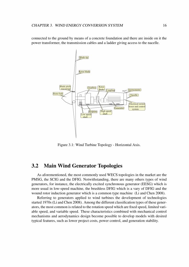
3.1 Wind Turbine ComponentsFigure 3.1 depicts a typical structure of a horizontal axis wind turbine which is com-
posed by a tower, a nacelle and a rotor, in what way this is the mostly used wind turbinetype nowadays (Ackermann 2005). However, there are wind turbines in vertical axis,for instance the Darrieus and Savonius. Notwithstanding, the researches and develop-ments of this types of wind turbine were practically interrupted after the decade of 1980(Ackermann 2005) because of some drawbacks caused by these kind of topologies, suchas low efficiency and high mechanical stress.
Horizontal wind turbines generate energy when a wind force attains on turbine bladeswhich provoke an emergence of a torque, that makes the turbine rotate. The turbinerotation triggers the low speed shaft, inside of nacelle, which transfers kinetic energy tothe gearbox which operates by rotating the high-speed shaft with an increased rotationalspeed until a nominal generator rotational speed that converts mechanical energy intoelectrical energy.
Depending on the system power, a transformer should be used to connect the gen-erator to the electrical grid, which can be of two or three windings. The transformer isessential, in some cases, because the output voltages of the generator are low. A rotorbrake is equipped in the high-speed shaft to protect the system from mechanical wearwhen exposed to severe winds. Moreover, there is a compartment with the electric powerconverters, which are present in the case of variable speed wind turbines, and the controlsystem to regulate the output power. In addition, there are different sensor types whichinclude the wind vane, the anemometer, speed or position sensors, as well as voltage andcurrent sensors.
There is the wind turbine tower that was not depicted on Figure 3.1. The tower is
CHAPTER 3. WIND ENERGY CONVERSION SYSTEM 16
connected to the ground by means of a concrete foundation and there are inside on it thepower transformer, the transmission cables and a ladder giving access to the nacelle.
Electrical switch boxes and control system
Rotor hub
Blade pitch macanism Anemometer
Rotor blade
Blade tip
Gearbox RotorBrake Coupling
Nacelle
High speedshaft
Generator
Bedplate Low speed
shaft
Figure 3.1: Wind Turbine Topology - Horizontal Axis.
3.2 Main Wind Generator TopologiesAs aforementioned, the most commonly used WECS topologies in the market are the
PMSG, the SCIG and the DFIG. Notwithstanding, there are many others types of windgenerators, for instance, the electrically excited synchronous generator (EESG) which ismore usual in low-speed machine, the brushless DFIG which is a vary of DFIG and thewound rotor induction generator which is a common type machine (Li and Chen 2008).
Referring to generators applied to wind turbines the development of technologiesstarted 1970s (Li and Chen 2008). Among the different classification types of these gener-ators, the most common is related to the rotation speed which are fixed speed, limited vari-able speed, and variable speed. These characteristics combined with mechanical controlmechanisms and aerodynamics design become possible to develop models with desiredtypical features, such as lower project costs, power control, and generation stability.

CHAPTER 3. WIND ENERGY CONVERSION SYSTEM 17
3.2.1 Fixed Speed Wind GeneratorThe fixed speed wind turbine cannot be regulated automatically and the generator
tends to work at almost in constant speed, varying according to the grid frequency, gear-box ratio, machine slip and characteristic of the electric generator independently of windspeed, because the generator is connected directly to the grid (Wu et al. 2011).
The SCIG is the first and simplest topology used in this type of generator, and itwas created reusing electrical and mechanical components existing in the market (Abadet al. 2011), which is illustrated in Figure 3.2. A transformer is needed to couple the gridvoltage to the electric machine voltage.
Soft-Starter
SCIG Capacitors bank
Transformer
Turbine
Gearbox
Figure 3.2: Squirrel Cage Induction Generator (adapted from Taveiros (2014)).
There are some advantages to use SCIG, for instance, this machine type has a well-known and tested technology because it has been widely used in the industry for years; re-duced and simple maintenance, hence robustness; and a low manufacturing cost. Nonethe-less, there are some drawbacks, such as, no speed control; low aerodynamic efficiency;and there is no fault ride-through capability according to Serrano-González and Lacal-Arántegui (2016). Furthermore, there is no reactive power control (Taveiros 2014) and itis susceptible to cause voltage instability. Therefore, this turbine can decrease the powerquality indexes at the PCC depending on the electrical grid. Moreover, this generatorneeds additional equipment, e.g., soft starter, a bank of capacitors and key protection towork properly when connected to the electrical grid when compared to the DFIG.
3.2.2 Variable-speed turbines with partial-scale power converterThe wind turbine generator with variable speed became the main technology applied
in wind power plants because they have an ability to adapt the wind turbine speed to thewind speed, greater efficiency of the wind system, reduction of mechanical stress imposedon wind unit components when occurs wind gusts and improvement of the energy qualitywhen compared to the fixed speed wind generator.
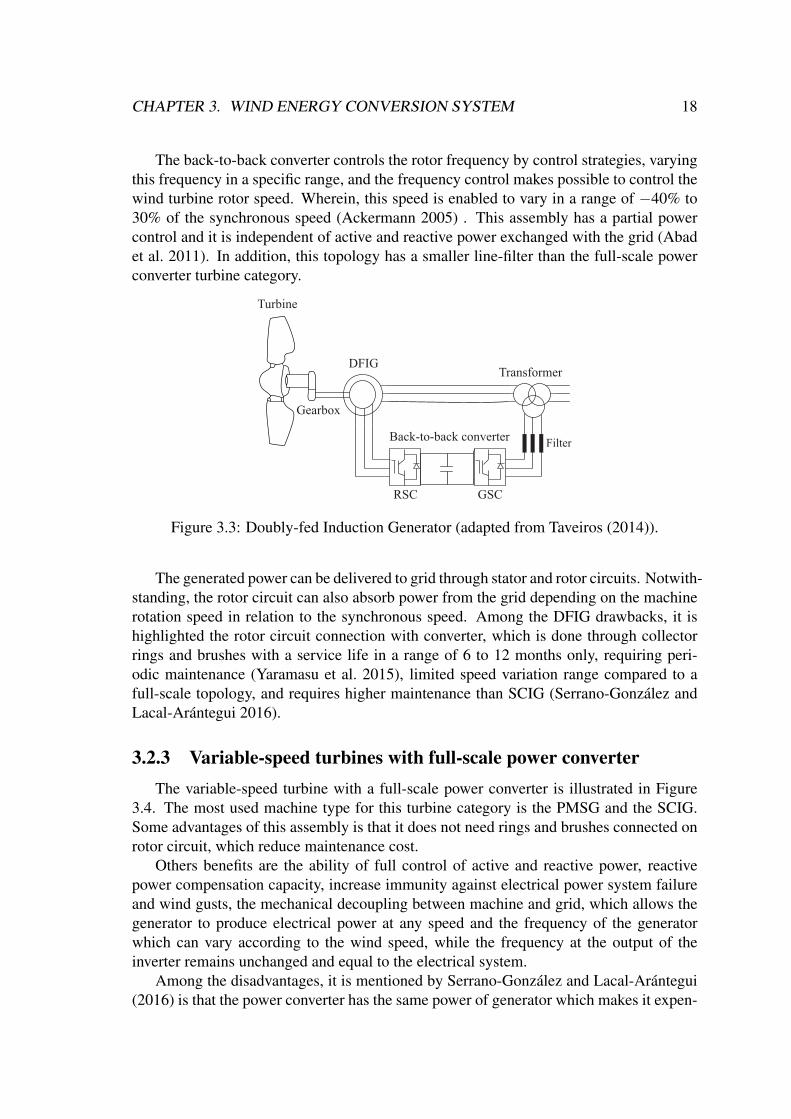
The DFIG topology, illustrated in Figure 3.3, is a variable-speed turbine with a partial-scale power converter. Furthermore, its speed is controlled by a power converter, whereinthe stator windings are connected to the electrical grid, whereas the rotor windings areconnected to a back-to-back converter.
CHAPTER 3. WIND ENERGY CONVERSION SYSTEM 18
The back-to-back converter controls the rotor frequency by control strategies, varyingthis frequency in a specific range, and the frequency control makes possible to control thewind turbine rotor speed. Wherein, this speed is enabled to vary in a range of −40% to30% of the synchronous speed (Ackermann 2005) . This assembly has a partial powercontrol and it is independent of active and reactive power exchanged with the grid (Abadet al. 2011). In addition, this topology has a smaller line-filter than the full-scale powerconverter turbine category.
Back-to-back converter
DFIGTransformer
RSC GSC
Filter
Turbine
Gearbox
Figure 3.3: Doubly-fed Induction Generator (adapted from Taveiros (2014)).
The generated power can be delivered to grid through stator and rotor circuits. Notwith-standing, the rotor circuit can also absorb power from the grid depending on the machinerotation speed in relation to the synchronous speed. Among the DFIG drawbacks, it ishighlighted the rotor circuit connection with converter, which is done through collectorrings and brushes with a service life in a range of 6 to 12 months only, requiring peri-odic maintenance (Yaramasu et al. 2015), limited speed variation range compared to afull-scale topology, and requires higher maintenance than SCIG (Serrano-González andLacal-Arántegui 2016).
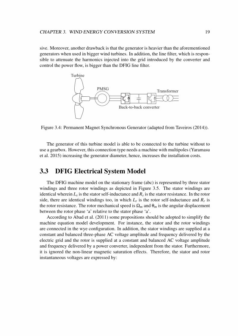
3.2.3 Variable-speed turbines with full-scale power converterThe variable-speed turbine with a full-scale power converter is illustrated in Figure
3.4. The most used machine type for this turbine category is the PMSG and the SCIG.Some advantages of this assembly is that it does not need rings and brushes connected onrotor circuit, which reduce maintenance cost.
Others benefits are the ability of full control of active and reactive power, reactivepower compensation capacity, increase immunity against electrical power system failureand wind gusts, the mechanical decoupling between machine and grid, which allows thegenerator to produce electrical power at any speed and the frequency of the generatorwhich can vary according to the wind speed, while the frequency at the output of theinverter remains unchanged and equal to the electrical system.
Among the disadvantages, it is mentioned by Serrano-González and Lacal-Arántegui(2016) is that the power converter has the same power of generator which makes it expen-
CHAPTER 3. WIND ENERGY CONVERSION SYSTEM 19
sive. Moreover, another drawback is that the generator is heavier than the aforementionedgenerators when used in bigger wind turbines. In addition, the line filter, which is respon-sible to attenuate the harmonics injected into the grid introduced by the converter andcontrol the power flow, is bigger than the DFIG line filter.
Back-to-back converter
PMSGTransformer
Turbine
Figure 3.4: Permanent Magnet Synchronous Generator (adapted from Taveiros (2014)).
The generator of this turbine model is able to be connected to the turbine without touse a gearbox. However, this connection type needs a machine with multipoles (Yaramasuet al. 2015) increasing the generator diameter, hence, increases the installation costs.
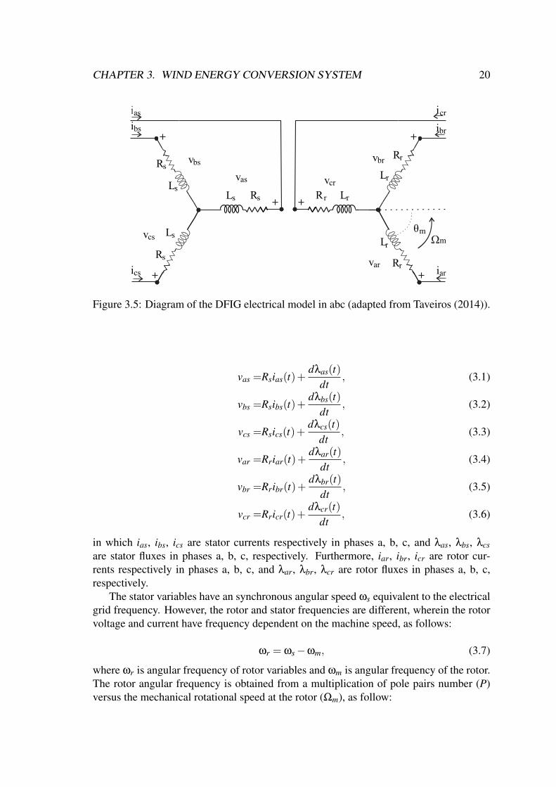
3.3 DFIG Electrical System ModelThe DFIG machine model on the stationary frame (abc) is represented by three stator
windings and three rotor windings as depicted in Figure 3.5. The stator windings areidentical wherein Ls is the stator self-inductance and Rs is the stator resistance. In the rotorside, there are identical windings too, in which Lr is the rotor self-inductance and Rr isthe rotor resistance. The rotor mechanical speed is Ωm and θm is the angular displacementbetween the rotor phase ‘a’ relative to the stator phase ‘a’.
According to Abad et al. (2011) some propositions should be adopted to simplify themachine equation model development. For instance, the stator and the rotor windingsare connected in the wye configuration. In addition, the stator windings are supplied at aconstant and balanced three-phase AC voltage amplitude and frequency delivered by theelectric grid and the rotor is supplied at a constant and balanced AC voltage amplitudeand frequency delivered by a power converter, independent from the stator. Furthermore,it is ignored the non-linear magnetic saturation effects. Therefore, the stator and rotorinstantaneous voltages are expressed by:
CHAPTER 3. WIND ENERGY CONVERSION SYSTEM 20
ias
ibs
Rs
Rs
Rs
LsLs
Ls
vbs
vas
vcs
icsvar
vcr
vbr
Rr
Rr
Rr
Lr
Lr
Lr
θmm
icr
ibr
iar
Ʊ
Figure 3.5: Diagram of the DFIG electrical model in abc (adapted from Taveiros (2014)).
vas =Rsias(t)+dλas(t)
dt, (3.1)
vbs =Rsibs(t)+dλbs(t)
dt, (3.2)
vcs =Rsics(t)+dλcs(t)
dt, (3.3)
var =Rriar(t)+dλar(t)
dt, (3.4)
vbr =Rribr(t)+dλbr(t)
dt, (3.5)
vcr =Rricr(t)+dλcr(t)
dt, (3.6)
in which ias, ibs, ics are stator currents respectively in phases a, b, c, and λas, λbs, λcsare stator fluxes in phases a, b, c, respectively. Furthermore, iar, ibr, icr are rotor cur-rents respectively in phases a, b, c, and λar, λbr, λcr are rotor fluxes in phases a, b, c,respectively.
The stator variables have an synchronous angular speed ωs equivalent to the electricalgrid frequency. However, the rotor and stator frequencies are different, wherein the rotorvoltage and current have frequency dependent on the machine speed, as follows:
ωr = ωs−ωm, (3.7)
where ωr is angular frequency of rotor variables and ωm is angular frequency of the rotor.The rotor angular frequency is obtained from a multiplication of pole pairs number (P)versus the mechanical rotational speed at the rotor (Ωm), as follow:
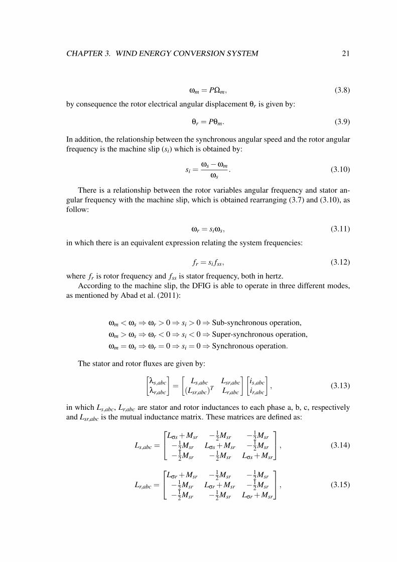
CHAPTER 3. WIND ENERGY CONVERSION SYSTEM 21
ωm = PΩm, (3.8)
by consequence the rotor electrical angular displacement θr is given by:
θr = Pθm. (3.9)
In addition, the relationship between the synchronous angular speed and the rotor angularfrequency is the machine slip (si) which is obtained by:
si =ωs−ωm
ωs. (3.10)
There is a relationship between the rotor variables angular frequency and stator an-gular frequency with the machine slip, which is obtained rearranging (3.7) and (3.10), asfollow:
ωr = siωs, (3.11)
in which there is an equivalent expression relating the system frequencies:
fr = si fss, (3.12)
where fr is rotor frequency and fss is stator frequency, both in hertz.According to the machine slip, the DFIG is able to operate in three different modes,
as mentioned by Abad et al. (2011):
ωm < ωs⇒ ωr > 0⇒ si > 0⇒ Sub-synchronous operation,ωm > ωs⇒ ωr < 0⇒ si < 0⇒ Super-synchronous operation,ωm = ωs⇒ ωr = 0⇒ si = 0⇒ Synchronous operation.
The stator and rotor fluxes are given by:[λs,abcλr,abc
]=
[Ls,abc Lsr,abc
(Lsr,abc)T Lr,abc
][is,abcir,abc
], (3.13)
in which Ls,abc, Lr,abc are stator and rotor inductances to each phase a, b, c, respectivelyand Lsr,abc is the mutual inductance matrix. These matrices are defined as:
Ls,abc =
Lσs +Msr −12Msr −1
2Msr−1
2Msr Lσs +Msr −12Msr
−12Msr −1
2Msr Lσs +Msr
, (3.14)
Lr,abc =
Lσr +Msr −12Msr −1
2Msr−1
2Msr Lσr +Msr −12Msr
−12Msr −1
2Msr Lσr +Msr
, (3.15)
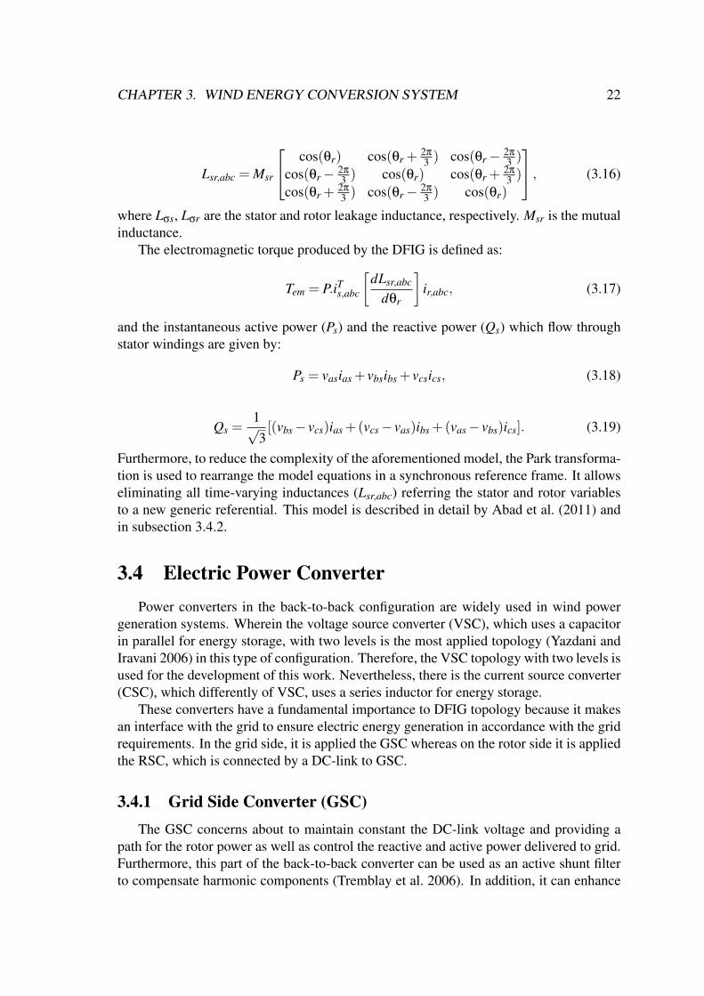
CHAPTER 3. WIND ENERGY CONVERSION SYSTEM 22
Lsr,abc = Msr
cos(θr) cos(θr +2π
3 ) cos(θr− 2π
3 )
cos(θr− 2π
3 ) cos(θr) cos(θr +2π
3 )
cos(θr +2π
3 ) cos(θr− 2π
3 ) cos(θr)
, (3.16)
where Lσs, Lσr are the stator and rotor leakage inductance, respectively. Msr is the mutualinductance.
The electromagnetic torque produced by the DFIG is defined as:
Tem = P.iTs,abc
[dLsr,abc
dθr
]ir,abc, (3.17)
and the instantaneous active power (Ps) and the reactive power (Qs) which flow throughstator windings are given by:
Ps = vasias + vbsibs + vcsics, (3.18)
Qs =1√3[(vbs− vcs)ias +(vcs− vas)ibs +(vas− vbs)ics]. (3.19)
Furthermore, to reduce the complexity of the aforementioned model, the Park transforma-tion is used to rearrange the model equations in a synchronous reference frame. It allowseliminating all time-varying inductances (Lsr,abc) referring the stator and rotor variablesto a new generic referential. This model is described in detail by Abad et al. (2011) andin subsection 3.4.2.
3.4 Electric Power ConverterPower converters in the back-to-back configuration are widely used in wind power
generation systems. Wherein the voltage source converter (VSC), which uses a capacitorin parallel for energy storage, with two levels is the most applied topology (Yazdani andIravani 2006) in this type of configuration. Therefore, the VSC topology with two levels isused for the development of this work. Nevertheless, there is the current source converter(CSC), which differently of VSC, uses a series inductor for energy storage.
These converters have a fundamental importance to DFIG topology because it makesan interface with the grid to ensure electric energy generation in accordance with the gridrequirements. In the grid side, it is applied the GSC whereas on the rotor side it is appliedthe RSC, which is connected by a DC-link to GSC.
3.4.1 Grid Side Converter (GSC)The GSC concerns about to maintain constant the DC-link voltage and providing a
path for the rotor power as well as control the reactive and active power delivered to grid.Furthermore, this part of the back-to-back converter can be used as an active shunt filterto compensate harmonic components (Tremblay et al. 2006). In addition, it can enhance
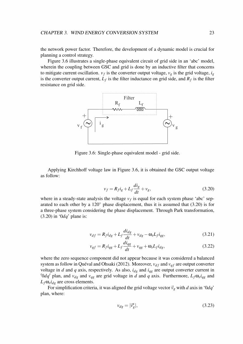
CHAPTER 3. WIND ENERGY CONVERSION SYSTEM 23
the network power factor. Therefore, the development of a dynamic model is crucial forplanning a control strategy.
Figure 3.6 illustrates a single-phase equivalent circuit of grid side in an ‘abc’ model,wherein the coupling between GSC and grid is done by an inductive filter that concernsto mitigate current oscillation. v f is the converter output voltage, vg is the grid voltage, igis the converter output current, L f is the filter inductance on grid side, and R f is the filterresistance on grid side.
Rf Lf
v f v g
Filter
i g
Figure 3.6: Single-phase equivalent model - grid side.
Applying Kirchhoff voltage law in Figure 3.6, it is obtained the GSC output voltageas follow:
v f = R f ig +L fdigdt
+ vg, (3.20)
where in a steady-state analysis the voltage v f is equal for each system phase ‘abc’ sep-arated to each other by a 120 phase displacement, thus it is assumed that (3.20) is fora three-phase system considering the phase displacement. Through Park transformation,(3.20) in ‘0dq’ plane is:
vd f = R f idg +L fdidg
dt+ vdg−ωsL f iqg, (3.21)
vq f = R f iqg +L fdiqg
dt+ vqg +ωsL f idg, (3.22)
where the zero sequence component did not appear because it was considered a balancedsystem as follow in Quéval and Ohsaki (2012). Moreover, vd f and vq f are output convertervoltage in d and q axis, respectively. As also, idg and iqg are output converter current in′0dq′ plan, and vdg and vqg are grid voltage in d and q axis. Furthermore, L f ωsiqg andL f ωsidg are cross elements.
For simplification criteria, it was aligned the grid voltage vector~vg with d axis in ‘0dq’plan, where:
vdg = |~vsg|, (3.23)
CHAPTER 3. WIND ENERGY CONVERSION SYSTEM 24
vqg = 0, (3.24)
in which the subscript s represents synchronous referential frame. Therefore, the simpli-fied equations by (3.24) and (3.23) are defined as:
vd f = R f idg +L fdidg
dt+ vdg−ωsL f iqg, (3.25)
vq f = R f iqg +L fdiqg
dt+ωsL f idg. (3.26)
The active and reactive power delivered to grid, considering simplifications in (3.24)and (3.23), are given by:
Ps =32
Re~vg~i∗g=32(vdgidg), (3.27)
Qs =32
Im~vg~i∗g=32(−vdgiqg), (3.28)
where there is a current decoupling in dq components, which the current idg is used tocalculate Pg and the current iqg is used to calculate Qg.
By the GSC equation model it is possible to develop control system strategies to con-trol the DC-link voltage, active and reactive power injection. In this work it was imple-mented the cascade PI-based control which is found in details in (Abad et al. 2011),(Penaet al. 1996) and (Quéval and Ohsaki 2012).
3.4.2 Rotor Side Converter (RSC)The RSC supplies the machine rotor and it connects with GSC by a DC-link. Fur-
thermore, this element concerns about to control active and reactive power delivered tothe electrical system from the generator, electromagnetic torque and adjusts voltage am-plitude, phase, and frequency introduced into the rotor (Abad et al. 2011). In addition,RSC is able to control the rotor machine speed and eliminate significant harmonic currentcomponents (Boutoubat et al. 2017).
Figure 3.7 illustrates a single-phase equivalent circuit of DFIG in a ‘dq’ model withneglected stator resistances used to develop the control system. Therefore, the machinebehavior will be known and will be possible to develop its control through RSC. Lm isthe magnetizing inductance, vdr and vqr are rotor voltages in dq reference, idr and iqr arerotor currents in dq reference, λdr and λqr are rotor fluxes in d and q reference frame,respectively. Finally λds and λqs are stator fluxes in dq reference.
The stator flux is aligned with the d-coordinate in the reference frame ‘dq’ whereasthe q coordinate is canceled, thus λqs = 0. In addition, stator voltage is aligned withq-coordinate, whereas vds = 0 (Abad et al. 2011). Therefore, rotor voltage is given by:
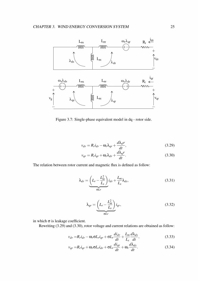
CHAPTER 3. WIND ENERGY CONVERSION SYSTEM 25
Lσs
Lσs
Lσr
Lσr ωrλqr
Rr
Rridr
vdrλdr
λqrλqsLm
Lmλds
iqr
vqr
ωrλdrωsλds
vg
Figure 3.7: Single-phase equivalent model in dq - rotor side.
vdr = Rridr−ωrλqr +dλdr
dt, (3.29)
vqr = Rriqr +ωrλdr +dλqr
dt. (3.30)
The relation between rotor current and magnetic flux is defined as follow:
λdr =
(Lr−
L2m
Ls
)︸ ︷︷ ︸
σLr
idr +Lm
Lsλds, (3.31)
λqr =
(Lr−
L2m
Ls
)︸ ︷︷ ︸
σLr
iqr, (3.32)
in which σ is leakage coefficient.Rewriting (3.29) and (3.30), rotor voltage and current relations are obtained as follow:
vdr =Rridr−ωrσLriqr +σLrdidr
dt+
Lm
Ls
dλds
dt, (3.33)
vqr =Rriqr +ωrσLridr +σLrdiqr
dt+ωr
dλds
dt. (3.34)
CHAPTER 3. WIND ENERGY CONVERSION SYSTEM 26
According to Abad et al. (2011), the last term in (3.33) is neglected , whereas the last termin (3.34) is a system perturbation. Furthermore, such as appear in GSC model equation,there are cross terms −ωrσLriqr and ωrσLridr.
The active and reactive power which is delivered to the grid is defined as:
Ps =32
vqsiqs, (3.35)
Qs =32
vqsids. (3.36)
In addition, the electromagnetic torque is given by:
Tem =−32
pLm
Ls
Vg
ωsLsiqr. (3.37)
By (3.29) until (3.37) that represent the DFIG model in ‘0dq’ reference frame is usedto obtain the transfer functions applied to develop the control system strategies to controlthe active and reactive power injection, machine speed and electromagnetic torque by theRSC. In this work it was implemented the cascade PI-based control which is found indetails in (Abad et al. 2011),(Pena et al. 1996) and (Quéval and Ohsaki 2012).
3.5 Protection ChallengesDFIG presents an intrinsic disadvantage due to its stator be directly connected to the
grid: the sensitivity to any abrupt drop of the grid voltage, for instance, symmetrical orasymmetrical electrical fault or a voltage dip make the back electromotive force oscillateand generate an electromagnetic torque pulsation. Besides that aspect, rotor power flowdirection can be positive or negative depending on the machine operation mode, machinespeed can oscillate from the sub-synchronous to the super-synchronous, rotor and statorelectric variables have different frequencies, rotor winding frequency is low and variable,and there is magnetic coupling between rotor and stator windings (Mansouri et al. 2016).Due to these characteristics, to develop and standardize electrical protections to the DFIGis a challenge.
The ongoing growth of the WECS insertion in the electrical grid and the grid code re-quirements imposed by system operators required modifications in the protection methodsdue to the peculiar characteristics of these systems, especially when it comes to DFIG.Moreover, some criteria such as voltage support, frequency maintenance, and continu-ity of connectivity in cases of stator voltage sags must be achieved for electrical gridswith DFIG’s such as applied to conventional synchronous power generators (Comechet al. 2011). Furthermore, achieve the grid requirements is fundamental to avoid gridblackout, and allow the capacity of load flow controlling and keep working properly theinterconnected electrical system, because the grid code objectives should ensure a safe,reliable, and economical operation of the power system.
Currently, protection schemes are used to guarantee the LVRT. For instance, protec-tions such as overcurrent and sub-voltage have been used to detect grid disturbances and

CHAPTER 3. WIND ENERGY CONVERSION SYSTEM 27
electrical faults on the PCC to trigger some LVRT categories. However, there is no stan-dardization (Mansouri et al. 2016).
3.5.1 Protections Against External Faults and LVRT EnhancementThe LVRT, also known as fault-ride through (FRT), which is the support for the grid in
case of faults and voltage sags, has been gaining a lot of attention in countries that startedto use WECS more expressively as a source of energy. Then, the grid operators requirethat any generator to have the ability to remain connected during the whole fault duration,such as illustrated in Figure 3.8 (Comech et al. 2011) wherein depicts the voltage sag levelsupported by each grid code of different countries, as well as to offer support to the gridin order to attempt to restore the voltage level.
0 1 2 3 4 50.5-0.5 1.5 2.5 3.5 4.5
0
0.1
0.2
0.3
0.4
0.5
0.6
0.7
0.8
0.9
1
SWEGERITA
BRAIRLESP
Time (s)
Vol
tage
(p.u
)
Figure 3.8: LVRT requirements in different countries (adapted from Comech et al.(2011)).
Some strategies were created to guarantee the LVRT and the protection of DFIG el-ements against overcurrent, overvoltage and undervoltage caused by external faults atthe PCC. These strategies are subdivided into categories: hardware modification, su-perconducting fault current limiter and control improvement for DFIG converters (Zouet al. 2016). Therefore, the most used LVRT categories applied in wind farms are de-scribed in the reminder of this section, evidencing factors such as efficiency, economicalcost, reliability, accuracy, and practical application.
When dealing with faults outside the generator, the most applied detection schemes arebased on voltage monitoring, power flow direction, and current monitoring. Furthermore,these detection schemes are used to trigger some LVRT categories, and so to activate theprotection circuit switches and to change the control strategy. Therefore, the overcurrentsand overvoltages present in DFIG components caused by grid disturbances in the PCCwill be decreased.

CHAPTER 3. WIND ENERGY CONVERSION SYSTEM 28
Table 3.1 illustrates a comparison among the LVRT categories present in the literaturenowadays. In this comparison it is addressed the advantages and disadvantages of eachcategory briefly. It was considered the aspects of whether the category is able or notto protect the generator against external faults and if it is needed a trigger to activate ordeactivate the category in case of fault detection.
Table 3.1: DFIG protection against external faults and LVRT enhancement strategies(adapted from Justo et al.(2015)).
LVRT categories Advantages DiadvantagesHardware modification:
• Protection circuits
• Reactive power devices
• Easy to implement• Useful under deep voltage
sags• Useful under symmetrical,
asymmetrical grid faults• Protect the DFIG• Decrease overcurrent and
torque oscilation
• Decrease rotor current• Useful for all transient types• Voltage support
• Reduce the system reliability• Add extra hardware• Need a trigger
• Increase the complexity• Need a trigger• Do not protect the DFIG
Control strategies
• Do not require extra hardware• Do not increase the system
cost• Partial DFIG protection• Decrease overcurrent
• Only useful under moderatevoltage sags
• Need a trigger• Difficult to implement
Superconducting materials:
• Resistive type• Inductive type
• Do not need a trigger• Protect the DFIG• Smooth the unsteady output
power (inductive type)
• High implementation costs• Difficult to design in practical
applications
Hardware modification
Hardware modifications are used to protect DFIG elements, such as DC-link, powerconverters, rotor and stator windings, against electrical disturbances in the PCC. Thefaults which occur in this point can cause overcurrent in the rotor side, overvoltage in DC-link, mechanical pulsation and others losses which damaging DFIG assembly. Hence,many strategies to avoid these situations were created, among that, there are crowbarcircuit, DC-link chopper, series dynamic resistor (SDR) and reactive power inject de-

CHAPTER 3. WIND ENERGY CONVERSION SYSTEM 29
vices (Justo et al. 2015). In addition, there are recent studies that uses superconductingmaterials and storage system to overcome these problems, such as (Zarei et al. 2018) and(Xiao et al. 2018).
The crowbar protection acting principle consists in power dissipation in moments ofvoltage sag in the electrical grid by rotor current deviation for the crowbar resistors pro-tecting the RSC and the rotor windings against overcurrent. The crowbar topologies canbe passive or active (Abad et al. 2011). The active topology is based on insulated gatebipolar transistor (IGBTs), controlled by pulse width modulation (PWM) or another con-trol tactics making the resistors fully controllable with a better performance than the pas-sive crowbar. In addition, this protection is able to be connected in series to the statorwinding or in parallel to the rotor winding. However, the last one is the most used.
This protection actuation occurs in cases of overcurrent in the rotor, overvoltage inthe DC link or voltage sags in the stator (Abad et al. 2011). Therefore, detection methodssuch as techniques based on genetic algorithm, logical fuzzy and neural networks are usedto trigger the crowbar switches in case of a fault at PCC. Furthermore, detection methodsbased on some relay protections, for instance, overcurrent and undervoltage are used todo this detection.
There are other protective circuits applied on DFIG assembly, such as the DC-chopper(Justo et al. 2015) which is coupled in the DC link in case of an overvoltage detection.Furthermore, there are protective circuits with the crowbar associated with SDR and thecrowbar associated with the DC-Chopper.
Another proposition is the reactive power injecting-device. The generator magnetiza-tion in the normal way is done over the rotor circuit by the rotor-side converter. However,in the case of an electrical fault, this magnetization is done by the stator in case of the rotorexcitation to be disconnected. Therefore, the generator will consume reactive power fromthe electrical grid. Thus, this compensation is used for improving the voltage in PCC.Some devices which inject reactive power are the DVRs, the reactive power compensatorsuch as the static synchronous compensator (STATCOM) or the static var compensator(SVC).
Installation of the aforementioned injecting-devices with a proper control strategy en-sures the LVRT and minimizes the grid fault effects to the DFIG (Justo et al. 2015).However, another strategy is presented in Hansen et al. (2007) which the RSC is reconfig-ured in parallel with the GSC in the case of electrical fault occurrence, where the crowbaris activated too. On this assembly, both converters are responsible for supply the reactivecompensation.
Control improvement for DFIG converters
Nowadays many studies of new control schemes have been developed for assuringgrid codes. Due to some drawbacks present in hardware modification, for instance, whena crowbar circuit is used the RSC is temporarily disabled which leads to a partial powercontrol loss and when the fault is cleared appears huge transients (Vrionis et al. 2014).In addition, when a reactive power inject device is used the economical cost increasemaking it inapplicable in some situations. Therefore, control methods have appeared tostrike these disadvantages.
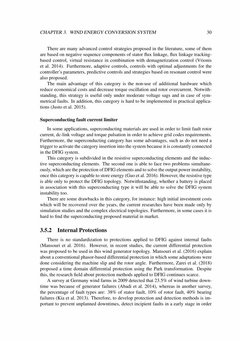
CHAPTER 3. WIND ENERGY CONVERSION SYSTEM 30
There are many advanced control strategies proposed in the literature, some of themare based on negative sequence components of stator flux linkage, flux linkage tracking-based control, virtual resistance in combination with demagnetization control (Vrioniset al. 2014). Furthermore, adaptive controls, controls with optimal adjustments for thecontroller’s parameters, predictive controls and strategies based on resonant control werealso proposed.
The main advantage of this category is the non-use of additional hardware whichreduce economical costs and decrease torque oscillation and rotor overcurrent. Notwith-standing, this strategy is useful only under moderate voltage sags and in case of sym-metrical faults. In addition, this category is hard to be implemented in practical applica-tions (Justo et al. 2015).
Superconducting fault current limiter
In some applications, superconducting materials are used in order to limit fault rotorcurrent, dc-link voltage and torque pulsation in order to achieve grid codes requirements.Furthermore, the superconducting category has some advantages, such as do not need atrigger to activate the category insertion into the system because it is constantly connectedin the DFIG system.
This category is subdivided in the resistive superconducting elements and the induc-tive superconducting elements. The second one is able to face two problems simultane-ously, which are the protection of DFIG elements and to solve the output power instability,once this category is capable to store energy (Guo et al. 2016). However, the resistive typeis able only to protect the DFIG topology. Notwithstanding, whether a battery is placedin association with this superconducting type it will be able to solve the DFIG systeminstability too.
There are some drawbacks in this category, for instance: high initial investment costswhich will be recovered over the years, the current researches have been made only bysimulation studies and the complex electrical topologies. Furthermore, in some cases it ishard to find the superconducting proposed material in market.
3.5.2 Internal ProtectionsThere is no standardization to protections applied to DFIG against internal faults
(Mansouri et al. 2016). However, in recent studies, the current differential protectionwas proposed to be used in this wind generator topology. Mansouri et al. (2016) explainabout a conventional phasor-based differential protection in which some adaptations weredone considering the machine slip and the rotor angle. Furthermore, Zarei et al. (2018)proposed a time domain differential protection using the Park transformation. Despitethis, the research field about protection methods applied to DFIG continues scarce.
A survey at Germany wind farms in 2009 detected that 23.5% of wind turbine down-time was because of generator failures (Abadi et al. 2014), whereas in another survey,the percentage of fault types are: 38% of stator fault, 10% of rotor fault, 40% bearingfailures (Kia et al. 2013). Therefore, to develop protection and detection methods is im-portant to prevent unplanned downtimes, detect incipient faults in a early stage in order
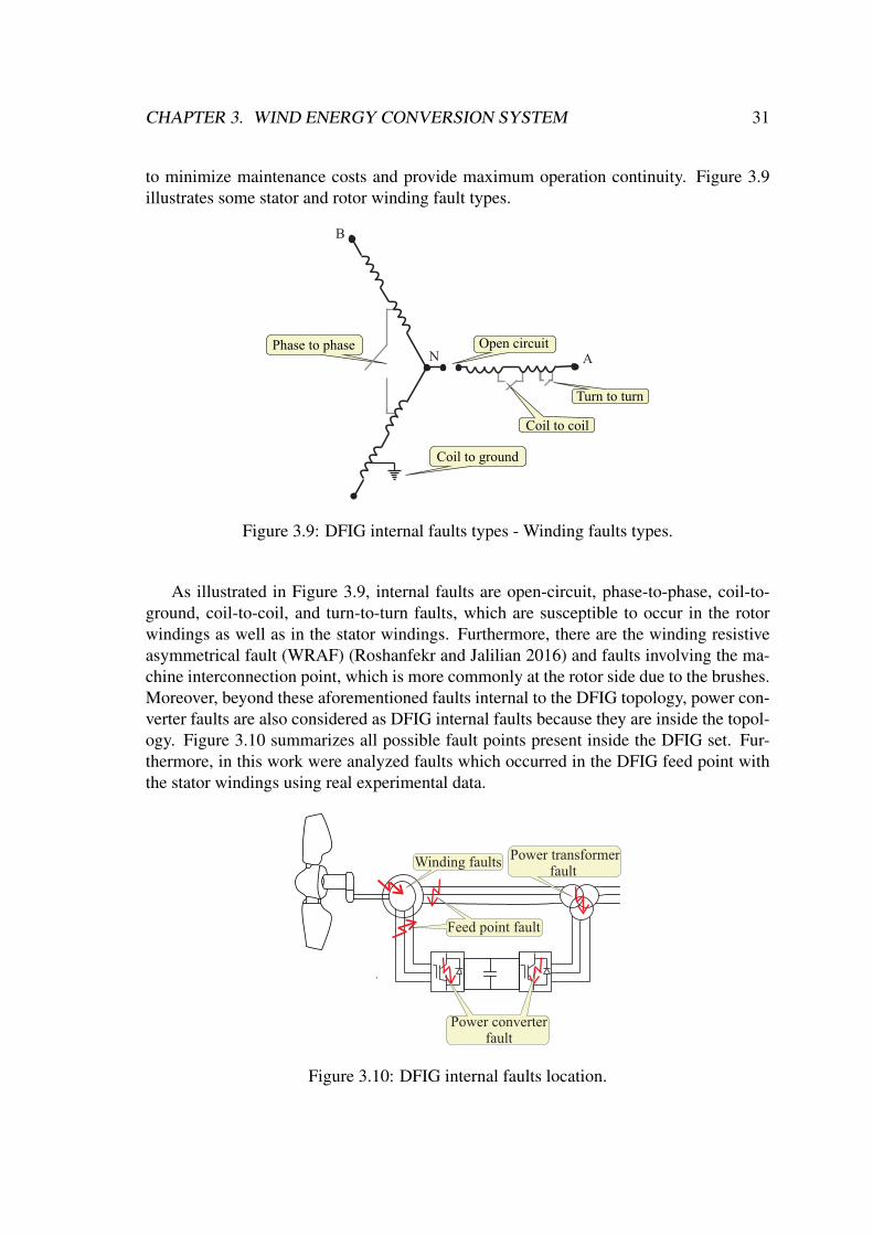
CHAPTER 3. WIND ENERGY CONVERSION SYSTEM 31
to minimize maintenance costs and provide maximum operation continuity. Figure 3.9illustrates some stator and rotor winding fault types.
A
B
NPhase to phase Open circuit
Turn to turn
Coil to coil
Coil to ground
Figure 3.9: DFIG internal faults types - Winding faults types.
As illustrated in Figure 3.9, internal faults are open-circuit, phase-to-phase, coil-to-ground, coil-to-coil, and turn-to-turn faults, which are susceptible to occur in the rotorwindings as well as in the stator windings. Furthermore, there are the winding resistiveasymmetrical fault (WRAF) (Roshanfekr and Jalilian 2016) and faults involving the ma-chine interconnection point, which is more commonly at the rotor side due to the brushes.Moreover, beyond these aforementioned faults internal to the DFIG topology, power con-verter faults are also considered as DFIG internal faults because they are inside the topol-ogy. Figure 3.10 summarizes all possible fault points present inside the DFIG set. Fur-thermore, in this work were analyzed faults which occurred in the DFIG feed point withthe stator windings using real experimental data.
Power converterfault
Feed point fault
Winding faults Power transformerfault
Figure 3.10: DFIG internal faults location.
CHAPTER 3. WIND ENERGY CONVERSION SYSTEM 32
The faults shown in Figure 3.9 occur by many reasons, some of them are abnor-mal connections, static and/or dynamic air-gap eccentricities (Kia et al. 2013), insula-tion degradation between the individual coil, insulation degradation between differentcoils, thermal overload which can cause demagnetization of permanent magnet in case ofPMSG and electromechanical-induced vibration.
3.6 SummaryIn this chapter, the main characteristics of the WECS and the DFIG topology were
discussed, addressing the essential components in the operation of these systems. Themain protection challenges were described, as well as the aspects related to internal andexternal protection schemes, advantages and disadvantages.
Chapter 4
Mathematical Fundamentals
Developing signal processing in the time domain is complex and dense in mathemat-ical processing. In this fashion, laying hands on mathematical tools which transform thesignal to another domain is useful to analyze aspects which are not easily visible in theconventional domain. Therefore, introductory concepts about the Fourier transform andthe wavelet transform will be addressed. In addition, different versions of the wavelettransform will be covered, such as the stationary wavelet transformer with boundary ef-fects.
4.1 Fourier TransformThe integral Fourier transform, developed by Jean-Baptiste Joseph Fourier in the nine-
teenth century, decomposes a periodic temporal function into frequencies in a sinusoidalbase (sine and cosine). Also, it is called representation in the frequency domain of asignal. The transform is defined as follow:
F(ω) =∫
∞
−∞
f (t)e− jωtdt, (4.1)
where t and ω are time and frequency assignments, respectively; f (t) is the time-domainsignal and F(ω) is the frequency-domain signal. For many functions, it is possible todefine a reversal operation, known as the inverse Fourier transform, defined as:
f (t) =1
2π
∫∞
−∞
F(ω)e− jωtdt. (4.2)
Fourier transform has a wide field of application, e.g. signal processing, statistics, andencryption. In the context of electrical power systems, the discrete Fourier transform wasused by Arun G. Phadke (2008) to developed a real-time phasor estimation given by:

CHAPTER 4. MATHEMATICAL FUNDAMENTALS 34
Xr(k) =2
∆k
k
∑n=k−∆k+1
x(k)
cos2πn∆k
, (4.3)
Xi(k) =2
∆k
k
∑n=k−∆k+1
x(k)
sin2πn∆k
, (4.4)
in which Xr and Xi is the real and imaginary phasor components, respectively; ∆k = fs/ fis the total number of samples, wherein fs is sampling frequency and f is the system fun-damental frequency; x(k) is a sample of the original signal in time. The module (|X(k)|)and the angle (∠X(k)) is defined as:
|X(k)|=√
Xr(k)2 +Xi(k)2, and (4.5)
∠X(k) = tan−1(
Xr(k)Xi(k)
). (4.6)
In order to reduce the computational effort, the recursive version of this algorithm isused in this work (Arun G. Phadke 2008), as follow:
Xr(k) = Xr(k−1)+(x(k)− x(k−∆k))
cos2πn∆k
, (4.7)
Xi(k) = Xi(k−1)+(x(k)− x(k−∆k))
sin2πn∆k
. (4.8)
Therefore, the calculation of the last phasor element (Xr and Xi) is availed; after that, itis taken out the oldest calculated sample contribution (x(k−∆k)). Finally, it is added themost recent calculated sample x(k).
4.2 Wavelet TransformThe wavelet transform conceptualization is derived from the Haar transform (Haar
1910). However, only some decades later a mathematical definition of wavelet trans-form was developed, wherein Grossmann and Morlet (1984) defined a continuous wavelettransform (CWT) in which was stated that a signal is able to be transformed and recoveredwithout loss of information. Thereafter, Mallat (1989) proposed a wavelet transform withthe multi-resolution analysis, and Daubechies (1992) proposed the DWT concepts. Thestationary wavelet transform (SWT) was also proposed, which is a variation of the DWT.Nowadays, the wavelet transform is used in different research fields, e.g. numbers theory,image processing and electric power systems.Furthermore, due to the wavelet transformis sensitive to high-frequency content, the application of this transform is suitable foranalysis of transients present in electric machines during an electrical fault moment.
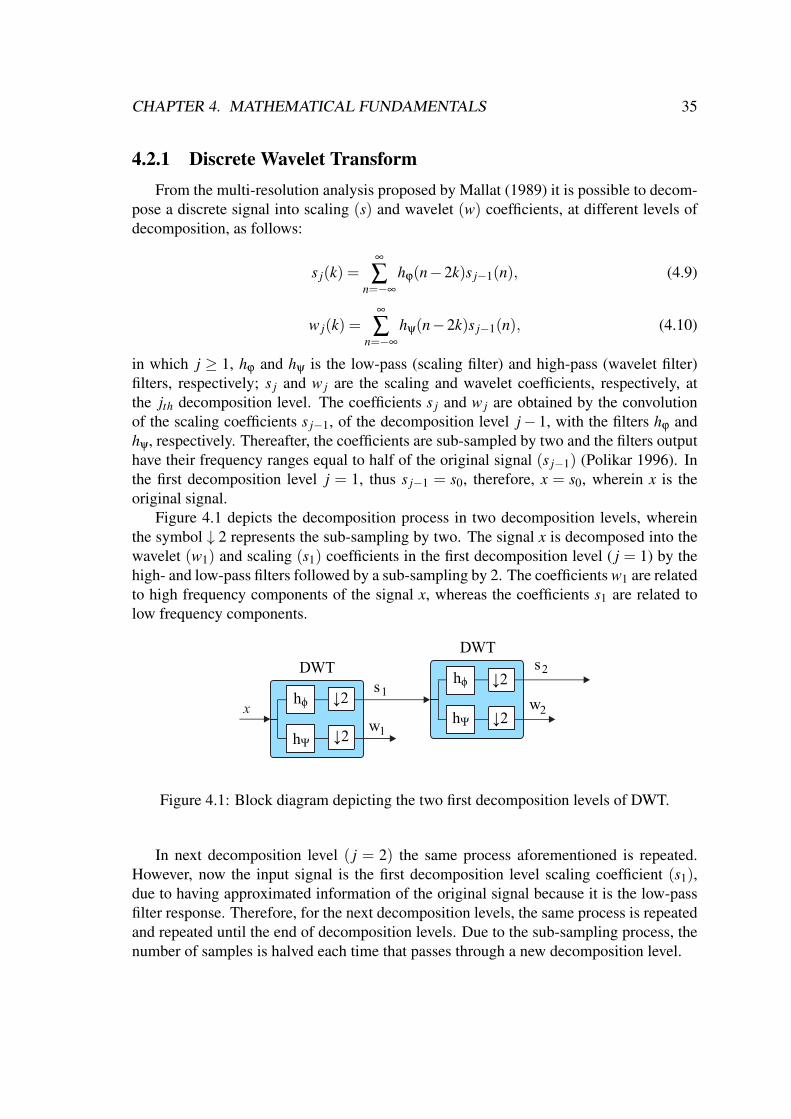
CHAPTER 4. MATHEMATICAL FUNDAMENTALS 35
4.2.1 Discrete Wavelet TransformFrom the multi-resolution analysis proposed by Mallat (1989) it is possible to decom-
pose a discrete signal into scaling (s) and wavelet (w) coefficients, at different levels ofdecomposition, as follows:
s j(k) =∞
∑n=−∞
hϕ(n−2k)s j−1(n), (4.9)
w j(k) =∞
∑n=−∞
hψ(n−2k)s j−1(n), (4.10)
in which j ≥ 1, hϕ and hψ is the low-pass (scaling filter) and high-pass (wavelet filter)filters, respectively; s j and w j are the scaling and wavelet coefficients, respectively, atthe jth decomposition level. The coefficients s j and w j are obtained by the convolutionof the scaling coefficients s j−1, of the decomposition level j− 1, with the filters hϕ andhψ, respectively. Thereafter, the coefficients are sub-sampled by two and the filters outputhave their frequency ranges equal to half of the original signal (s j−1) (Polikar 1996). Inthe first decomposition level j = 1, thus s j−1 = s0, therefore, x = s0, wherein x is theoriginal signal.
Figure 4.1 depicts the decomposition process in two decomposition levels, whereinthe symbol ↓ 2 represents the sub-sampling by two. The signal x is decomposed into thewavelet (w1) and scaling (s1) coefficients in the first decomposition level ( j = 1) by thehigh- and low-pass filters followed by a sub-sampling by 2. The coefficients w1 are relatedto high frequency components of the signal x, whereas the coefficients s1 are related tolow frequency components.
x
DWT
hϕ
↓2
s2s1
w1
w2
DWT
↓2
↓2
↓2
hϕ
hΨ
hΨ
Figure 4.1: Block diagram depicting the two first decomposition levels of DWT.
In next decomposition level ( j = 2) the same process aforementioned is repeated.However, now the input signal is the first decomposition level scaling coefficient (s1),due to having approximated information of the original signal because it is the low-passfilter response. Therefore, for the next decomposition levels, the same process is repeatedand repeated until the end of decomposition levels. Due to the sub-sampling process, thenumber of samples is halved each time that passes through a new decomposition level.

CHAPTER 4. MATHEMATICAL FUNDAMENTALS 36
4.2.2 Stationary Wavelet Transform (SWT)The name stationary refers to the fact that the SWT does not make the process of
sub-sampling by two in the input signal samples, making the SWT invariant to the cir-cular displacements in the samples in opposite to the DWT, which make this transformable to be applied for any samples number, since that N > L, in which N is total samplenumber and L is number of scaling and wavelet filter coefficients. Furthermore, SWT isthe most appropriate version of the wavelet transform for real-time fault detection appli-cations (Costa et al. 2010) because it can be applied in all samples. Due to this transformis time-invariant, always has the same number of samples, which provides significantgains in transient analysis, fault detection, and classification (Costa 2014), and it is non-orthogonal due to has different scales and to be shifted in time. Moreover, this transformis also known as maximal overlap discrete wavelet transform (MODWT).
Figure 4.2 depicts the SWT decomposition process in two decomposition levels. Thesignal x is decomposed into the wavelet (w1) and scaling (s1) coefficients in the firstdecomposition level ( j = 1) by the high- and low-pass filters. The coefficients w1 arerelated to high frequencies components of the signal x, whereas the coefficients s1 arerelated to low frequencies components.
xhϕ
hϕ
hΨ
hΨ
ss2s1s1s1s1
w1
w2
SWTSWT
Figure 4.2: Block diagram depicting the two first decomposition levels of SWT.
The process repeats in whole follow levels ( j = 2) and so on. However, such asin DWT, the input signal for the next decomposition levels are the scaling coefficientsof the previous one, which contains the low-frequency components, due to the scalingcoefficients are an approximation of the original signal.
The input signal of each decomposition level with finite sample number (N) is givenby:
s j =
s j(0),s j(1), ...,s j(N), (4.11)
in which j ≥ 0 and N ≥ L; wherein the SWT scaling and wavelet coefficients are givenby:
s j(k) =1√2
∞
∑n=−∞
hϕ(n− k)s j−1(n), (4.12)
w j(k) =1√2
∞
∑n=−∞
hψ(n− k)s j−1(n). (4.13)
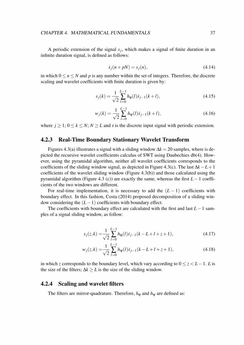
CHAPTER 4. MATHEMATICAL FUNDAMENTALS 37
A periodic extension of the signal s j, which makes a signal of finite duration in aninfinite duration signal, is defined as follows:
s j(n+ pN) = s j(n), (4.14)
in which 0≤ n≤N and p is any number within the set of integers. Therefore, the discretescaling and wavelet coefficients with finite duration is given by:
s j(k) =1√2
L−1
∑l=0
hϕ(l)s j−1(k+ l), (4.15)
w j(k) =1√2
L−1
∑l=0
hψ(l)s j−1(k+ l), (4.16)
where j ≥ 1; 0≤ k ≤ N; N ≥ L and s is the discrete input signal with periodic extension.
4.2.3 Real-Time Boundary Stationary Wavelet TransformFigures 4.3(a) illustrates a signal with a sliding window ∆k = 20 samples, where is de-
picted the recursive wavelet coefficients calculus of SWT using Daubechies db(4). How-ever, using the pyramidal algorithm, neither all wavelet coefficients corresponds to thecoefficients of the sliding window signal, as depicted in Figure 4.3(c). The last ∆k−L+1coefficients of the wavelet sliding window (Figure 4.3(b)) and those calculated using thepyramidal algorithm (Figure 4.3 (c)) are exactly the same, whereas the first L−1 coeffi-cients of the two windows are different.
For real-time implementation, it is necessary to add the (L− 1) coefficients withboundary effect. In this fashion, Costa (2014) proposed decomposition of a sliding win-dow considering the (L−1) coefficients with boundary effect.
The coefficients with boundary effect are calculated with the first and last L−1 sam-ples of a signal sliding window, as follow:
s j(z,k) =1√2
L−1
∑l=0
hϕ(l)s j−1(k−L+ l + z+1), (4.17)
w j(z,k) =1√2
L−1
∑l=0
hψ(l)s j−1(k−L+ l + z+1), (4.18)
in which z corresponds to the boundary level, which vary according to 0≤ z < L−1. L isthe size of the filters; ∆k ≥ L is the size of the sliding window.
4.2.4 Scaling and wavelet filtersThe filters are mirror-quadrature. Therefore, hϕ and hψ are defined as:
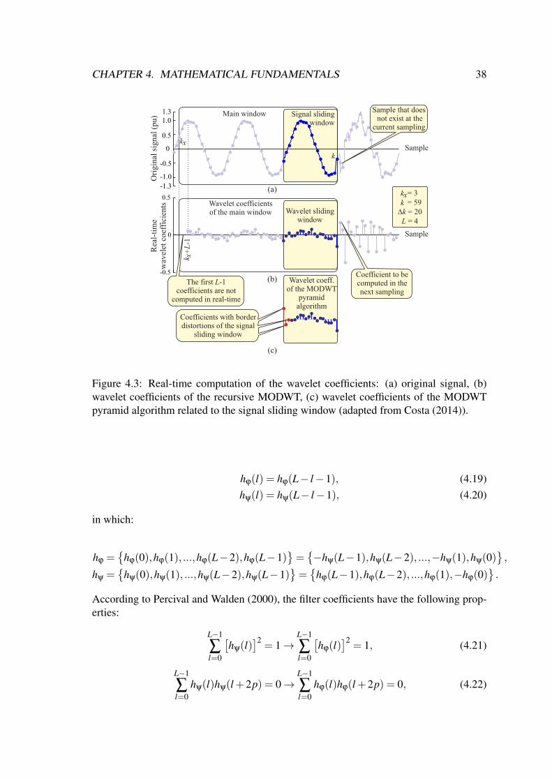
CHAPTER 4. MATHEMATICAL FUNDAMENTALS 38
Wavelet coefficients of the main window
(b)
Main window
SampleO
rigi
nal
sig
nal
(pu)
-1.3
-0.5
0
0.5
1.31.0
-1.0
Signal slidingwindow
k
Wavelet slidingwindow
Sample
Rea
l-ti
me
wav
elet
coe
ffic
ient
s
0
0.5
-0.5
(a)x+
L-1
k
kx
Sample that does not exist at the
current sampling
Coefficient to be computed in the next sampling
∆k = 20k = 59xk = 3
Wavelet coeff.of the MODWT
pyramid algorithm
(c)
Coefficients with borderdistortions of the signal
sliding window
The first L-1 coefficients are not
computed in real-time
L = 4
Figure 4.3: Real-time computation of the wavelet coefficients: (a) original signal, (b)wavelet coefficients of the recursive MODWT, (c) wavelet coefficients of the MODWTpyramid algorithm related to the signal sliding window (adapted from Costa (2014)).
hϕ(l) = hϕ(L− l−1), (4.19)hψ(l) = hψ(L− l−1), (4.20)
in which:
hϕ =
hϕ(0),hϕ(1), ...,hϕ(L−2),hϕ(L−1)=−hψ(L−1),hψ(L−2), ...,−hψ(1),hψ(0)
,
hψ =
hψ(0),hψ(1), ...,hψ(L−2),hψ(L−1)=
hϕ(L−1),hϕ(L−2), ...,hϕ(1),−hϕ(0).
According to Percival and Walden (2000), the filter coefficients have the following prop-erties:
L−1
∑l=0
[hψ(l)
]2= 1→
L−1
∑l=0
[hϕ(l)
]2= 1, (4.21)
L−1
∑l=0
hψ(l)hψ(l +2p) = 0→L−1
∑l=0
hϕ(l)hϕ(l +2p) = 0, (4.22)

CHAPTER 4. MATHEMATICAL FUNDAMENTALS 39
L−1
∑l=0
hψ(l) = 0→L−1
∑l=0
hϕ(l) =√
2, (4.23)
where l = 0,1, ...,L−1.The mother wavelet determines the wavelet and scaling filter coefficients. For in-
stance, the filter coefficients used in this work are associated to the the mother waveletDaubechies db (4), in which L = 4, given by:
hϕ(0) =1+√
34√
2, hϕ(1) =
3+√
34√
2, hϕ(2) =
3−√
34√
2, hϕ(3) =
1−√
34√
2, (4.24)
hψ(0) =1−√
34√
2, hψ(1) =
−3+√
34√
2, hψ(2) =
3+√
34√
2, hψ(3) =
−1−√
34√
2. (4.25)
4.2.5 Energy of the Scaling and Wavelet Coefficients with BoundaryEffect.
The spectral energy of a signal (ε) is able to be decomposed by the scaling (εs) andwavelet (εw) coefficient energy according to Costa (2014), as follow:
ε(k) = εs(k)+ ε
w(k), (4.26)
in which εs and εw are given by:
εs(k) =ε
sa(k)+ εsb(k), (4.27)
εw(k) =ε
wa(k)+ εwb(k), (4.28)
for k > ∆k−1. The components εsa and εwa are due to the scaling and wavelet coefficientswith boundary effect of the signal samples within the sliding window, as follows:
εsa(k) =
L−1
∑l=1
s2(l,k), (4.29)
εwa(k) =
L−1
∑l=1
w2(l,k), (4.30)
for k > ∆k−1. Finally, εsb and εwb components are due to the scaling and wavelet coeffi-cients without boundary effect, given by:

CHAPTER 4. MATHEMATICAL FUNDAMENTALS 40
εsb(k) =
k
∑l=k−∆k+L
s2(l,k), (4.31)
εwb(k) =
k
∑l=k−∆k+L
w2(l,k). (4.32)
According to Costa (2014), the energy εwb is influenced by high-frequency noise andelectromagnetic transients, whereas, εw = εwa + εwb is also influenced by high-frequencynoise and electromagnetic transients and the sliding window boundary effects. Therefore,the wavelet coefficient energy with boundary effect are higher than the wavelet coefficientenergy without boundary effect. However, the scaling coefficient energy with and withoutboundary effects have a similar behavior. Nevertheless, εs does not present time delayassociated to the mother wavelet.
Figure 4.4 illustrates a comparison between the SWT and BSWT, in which the Figure4.4(a) shows a current signal (i) with a fault in the sample k = 680.
-2
-1
0
1
2
Cur
rent
sig
nal
(pu)
0.7
0.8
0.9
1
1.1
BSWT
SWT
10-4
10-3
10-2
10-1
( b )
( c )Samples
0 200 400 600 800 1000 1200
( a )
Sca
ling
coe
ffici
ents
en
ergy
Wav
elet
coe
ffici
ents
en
ergy
i
BSWT
SWT
Fault inception time
Fault inception time
Fault inception time
Figure 4.4: Comparisons between SWT and BSWT: (a) Original signal, (b) Scaling coef-ficients energy, (c) Wavelet coefficients energy.
CHAPTER 4. MATHEMATICAL FUNDAMENTALS 41
Figure 4.4(b) depicts a comparison between the scaling coefficients energy of theSWT and the BSWT, whereas the Figure 4.4(c) depicts the same comparison with thewavelet coefficients energy. This comparisons were made using db(4) as mother wavelet,in a sampling frequency of fs = 15.360 Hz with a sliding window ∆k = 256 samples.
4.3 SummaryIn this chapter, an overview of the Fourier transform and the different versions of the
wavelet transform was presented. The energy calculations of the scaling and wavelet co-efficients were also presented, along with a new energy calculation formulation that takesinto account the boundary effects. These energies of the wavelet and scaling coefficientswill be employed at the analysis presented in this work.
Chapter 5
Fundamentals of Protection Systems
This chapter present theoretical concepts about the overcurrent, undervoltage, direc-tional and differential protections applied in an electrical power system. Initially, theconventional protection is addressed, thereafter, the wavelet-based protection aproach ispresented. Focusing on a contextualization of these protection types applied in a scenariowith DFIG.
Researches about protection systems aim to guarantee the people and animals max-imum safety as well as electrical equipment and materials connected at power system.Notwithstanding, insertion of DFIGs into the electrical distribution system can lead tofailures in the relays operation.
5.1 Overcurrent ProtectionOvercurrents can happen by system overload and by electrical short-circuits (faults).
Therefore, when the measured currents exceed a predefined threshold (pick-up current),the overcurrent relay is sensitized. Moreover, this relay is classified into two categories:instantaneous or time delay, whereas the last one can be with defined time or inverse time.
Distribution systems with DFIGs are challenging scenarios for the overcurrent protec-tion due to the power flow redistribution, reduced fault overcurrent levels in the substation,and new coordination studies are required to the system. In addition, this barrier is higherwhen the short-circuit currents are associated with high resistance faults.
5.1.1 Conventional Overcurrent ProtectionAbsolute current values are usually extracted from the Fourier transform in conven-
tional overcurrent relay (Costa et al. 2017). Therefore, in an overcurrent occurrence theFourier coefficients will increase. However, this is not an instantaneous growth, requiringa time interval to reach the new steady-state value due to transient components and thephasor estimation as well.
This protection is divided in two functions, which are the instantaneous and time-delay. Table 5.1 summarizes the instantaneous units, the pickup current and the sensiti-zation condition to occur the relay trip. The instantaneous functions are enabled whenthe absolute value of the measured overcurrent, or the absolute value of the symmetri-cal components, exceeds a threshold, in which Ir is the load current in normal operation.
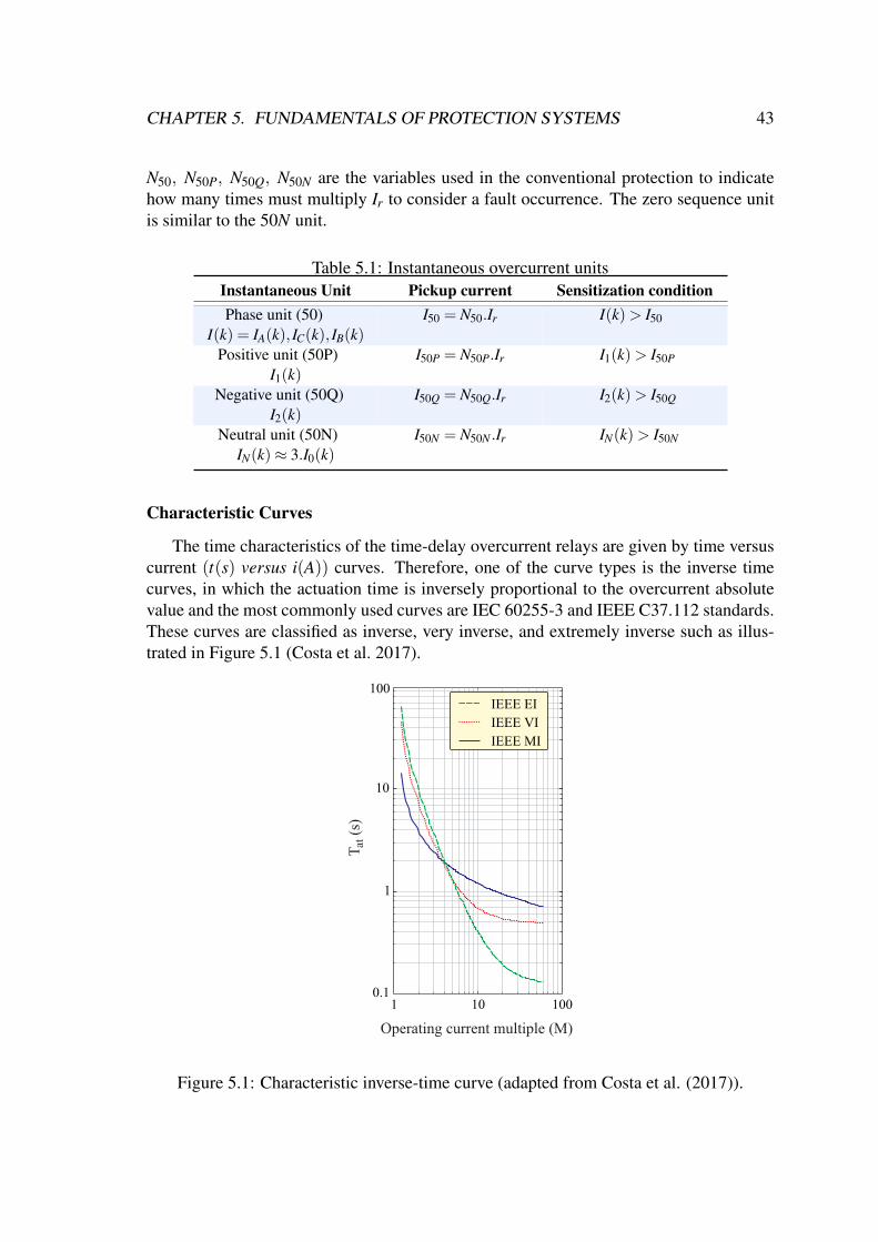
CHAPTER 5. FUNDAMENTALS OF PROTECTION SYSTEMS 43
N50, N50P, N50Q, N50N are the variables used in the conventional protection to indicatehow many times must multiply Ir to consider a fault occurrence. The zero sequence unitis similar to the 50N unit.
Table 5.1: Instantaneous overcurrent unitsInstantaneous Unit Pickup current Sensitization conditionPhase unit (50)
I(k) = IA(k), IC(k), IB(k)I50 = N50.Ir I(k)> I50
Positive unit (50P)I1(k)
I50P = N50P.Ir I1(k)> I50P
Negative unit (50Q)I2(k)
I50Q = N50Q.Ir I2(k)> I50Q
Neutral unit (50N)IN(k)≈ 3.I0(k)
I50N = N50N .Ir IN(k)> I50N
Characteristic Curves
The time characteristics of the time-delay overcurrent relays are given by time versuscurrent (t(s) versus i(A)) curves. Therefore, one of the curve types is the inverse timecurves, in which the actuation time is inversely proportional to the overcurrent absolutevalue and the most commonly used curves are IEC 60255-3 and IEEE C37.112 standards.These curves are classified as inverse, very inverse, and extremely inverse such as illus-trated in Figure 5.1 (Costa et al. 2017).
Operating current multiple (M)
T
(s
)
1 10 1000.1
1
10
100IEEE EI
IEEE VI
IEEE MI
a
t
Figure 5.1: Characteristic inverse-time curve (adapted from Costa et al. (2017)).
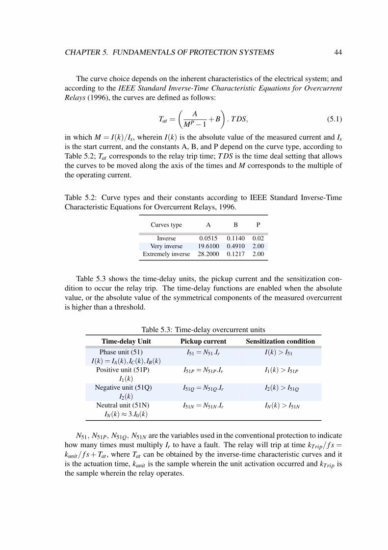
CHAPTER 5. FUNDAMENTALS OF PROTECTION SYSTEMS 44
The curve choice depends on the inherent characteristics of the electrical system; andaccording to the IEEE Standard Inverse-Time Characteristic Equations for OvercurrentRelays (1996), the curves are defined as follows:
Tat =
(A
MP−1+B). T DS, (5.1)
in which M = I(k)/Is, wherein I(k) is the absolute value of the measured current and Isis the start current, and the constants A, B, and P depend on the curve type, according toTable 5.2; Tat corresponds to the relay trip time; T DS is the time deal setting that allowsthe curves to be moved along the axis of the times and M corresponds to the multiple ofthe operating current.
Table 5.2: Curve types and their constants according to IEEE Standard Inverse-TimeCharacteristic Equations for Overcurrent Relays, 1996.
Curves type A B P
Inverse 0.0515 0.1140 0.02Very inverse 19.6100 0.4910 2.00
Extremely inverse 28.2000 0.1217 2.00
Table 5.3 shows the time-delay units, the pickup current and the sensitization con-dition to occur the relay trip. The time-delay functions are enabled when the absolutevalue, or the absolute value of the symmetrical components of the measured overcurrentis higher than a threshold.
Table 5.3: Time-delay overcurrent unitsTime-delay Unit Pickup current Sensitization condition
Phase unit (51)I(k) = IA(k), IC(k), IB(k)
I51 = N51.Ir I(k)> I51
Positive unit (51P)I1(k)
I51P = N51P.Ir I1(k)> I51P
Negative unit (51Q)I2(k)
I51Q = N51Q.Ir I2(k)> I51Q
Neutral unit (51N)IN(k)≈ 3.I0(k)
I51N = N51N .Ir IN(k)> I51N
N51, N51P, N51Q, N51N are the variables used in the conventional protection to indicatehow many times must multiply Ir to have a fault. The relay will trip at time kTrip/ f s =kunit/ f s+Tat , where Tat can be obtained by the inverse-time characteristic curves and itis the actuation time, kunit is the sample wherein the unit activation occurred and kTrip isthe sample wherein the relay operates.

CHAPTER 5. FUNDAMENTALS OF PROTECTION SYSTEMS 45
5.1.2 Wavelet-Based Overcurrent ProtectionBy using the SWT with boundary effect, the true rms currents (irms) can be associ-
ated with the spectral energy (E) during the steady-state system operation, which can beapproximated to the scaling coefficients energy as follows (Costa and Driesen 2013):
irms(k) =
√1
∆kEi(k)≈
√1
∆kεs
i (k). (5.2)
where ∆k is the window length; k ≥ ∆k.The relationship between rms current and scaling coefficient energy enables the de-
velopment of the wavelet-based overcurrent unit protection. (5.2) is used in order tocompare the wavelet- and Fourier-based overcurrent protection methods. However, thewavelet-based overcurrent protection operates with the scaling coefficient energy, whereit does not require square root and the division processing by ∆k in a real-time computa-tion (Costa et al. 2017).
Table 5.4 depicts the wavelet-based instantaneous units, the pickup energy and thesensitization condition to occur the relay trip. The instantaneous functions are enabledwhen the absolute value, or the absolute value of the symmetrical components of the mea-sured energy exceeds a threshold. E s
i is the boundary scaling coefficient energy relatedto steady-state operation, taken as the reference energy. εs
i is the measured phase energy,and εs
iP, εsiQ and εs
iN are the positive, negative and zero current energy, respectively.
Table 5.4: Wavelet-based instantaneous overcurrent unitsInstantaneous Unit Pickup energy Sensitization conditionPhase unit (50W)εs
i = εsiA,ε
siB,ε
siC
Es50 = N2
50E si εs
i (k)> Es50
Positive unit (50PW)εs
iP(k)Es
50P = N250PE s
i εsiP(k)> Es
50P
Negative unit (50QW)εs
iQ(k)Es
50Q = N250QE s
i εsiQ(k)> Es
50Q
Neutral unit (50NW)εs
iN(k)Es
50N = N250NE s
i εsiN(k)> Es
50N
Rewriting (5.2) as follow:
εs(k)≈ i2rms(k)∆k. (5.3)
There is a relationship between the absolute current estimation and the scaling coeffi-cient energy, given by:
εs(k)≈ I2(k)∆k
2, (5.4)
by (5.4) is possible to determine the wavelet-based overcurrent protection thresholdwith N2
50, N250P, N2
50Q and N250N .

CHAPTER 5. FUNDAMENTALS OF PROTECTION SYSTEMS 46
Table 5.5 depicts the wavelet-based time-delay units, the pickup energy and the sen-sitization condition to occur the relay trip. The time-delay functions are enabled whenthe absolute value , or the absolute value of the symmetrical components of the measuredenergy exceeds a threshold.
Table 5.5: Wavelet-based time-delay overcurrent unitsTime-delay Unit Pickup energy Sensitization condition
Phase unit (51W)εs
i = εsiA,ε
siB,ε
siC
Es51 = N2
51E si εs
i (k)> Es51
Positive unit (51PW)εs
iP(k)Es
51P = N251PE s
i εsiP(k)> Es
51P
Negative unit (51QW)εs
iQ(k)Es
51Q = N251QE s
i εsiQ(k)> Es
51Q
Neutral unit (51NW)εs
iN(k)Es
51N = N251NE s
i εsiN(k)> Es
51N
The relay will trip at time kTripW/ fs = k51W/ fs+Tatw, where Tatw is the relay operatingtime, which can be obtained by the inverse-time characteristic curves Figure 5.2. Tatw ismathematically defined as follows (de Cavalcante Paiva 2015):
Tatw =
(A
(Ms)P2 −1
+B
)TD, (5.5)
in which Ms = E si (k)/Es
51W .The characteristic curves use to represent the inverse time in the wavelet-based pro-
tection are similar to the conventional one. However, the inverse time characteristicsare given by time versus energy curves (t versus ε) as illustrated in Figure 5.2 (Costaet al. 2017). These curves are classified as inverse, very inverse and extremely inversetoo.
The symmetrical components can be written in sample terms (Kasztenny et al. 2000).For instance, by using an ‘abc’ phase sequence system, the positive sequence currentwith phase A reference (i1A), phase B reference (i1B ) and phase C reference (i1C) andnegative sequence current with phase A reference (i2A), phase B reference (i2B) and phaseC reference (i2C), are computed as follows:
i1A(k) =(iA(k)+iB(k−∆kα)+iC(k−∆k2
α))3 ,
i1B(k) =(iC(k)+iA(k−∆kα)+iB(k−∆k2
α))3 ,
i1C(k) =(iB(k)+iC(k−∆kα)+iA(k−∆k2
α))3 ,
(5.6)
i2A(k) =(iA(k)+iB(k−∆k2
α)+iC(k−∆kα))3 ,
i2B(k) =(iC(k)+iA(k−∆k2
α)+iB(k−∆kα))3 ,
i2C(k) =(iB(k)+iC(k−∆k2
α)+iA(k−∆kα))3 ,
(5.7)

CHAPTER 5. FUNDAMENTALS OF PROTECTION SYSTEMS 47
Ope
rati
on t
ime
(s)
1 10 100 103 104
Energy
IEEE EI
IEEE VI
IEEE MI
Figure 5.2: Characteristic inverse-time curve in the wavelet domain (adapted from Costaet al. (2017)).
where ∆kα =∆k−⌈2∆k
3
⌉and ∆kα2 =∆k−
⌊∆k3
⌋represent 120 and 240 equivalent delays,
respectively. The operator de is the ceiling function and bc is the floor function.By using the negative sequence in terms of samples, the scaling and wavelet coef-
ficients can be computed by (4.15) and (4.16), and the boundary scaling and waveletcoefficient energy can be computed by (4.27) and (4.28).
5.2 Undervoltage ProtectionThe undervoltage protection purpose is monitor the PCC to protect the DFIG, or gen-
erators in general, against voltage sags which can damage the machine elements. Fur-thermore, the main cause of this disturbance in transmission and distribution systems areelectrical faults (Costa and Driesen 2013), as also the connection of large loads in the gridand excessive loading of feeder circuits according with de Cavalcante Paiva (2015).
According to IEEE (2003), it is considered a voltage sag a measured voltage underthan 88% of the reference system voltage (V). Therefore, the conventional undervoltageprotection function (27) is sensitized and act after a defined time as described in (IEEE2003) and illustrated in Table 5.6.
As the overcurrent protection, the conventional undervoltage protection (function 27)is based on measured electrical variables which uses the Fourier algorithm of one-cycleto estimate the absolute value. However, this protection does not actuate instantly and itdoes not use the time-inverse curve. Therefore, the function (27) operates with a time-defined curve. Figure 5.3 depicts this curve characteristics, in which Tat is the actuation
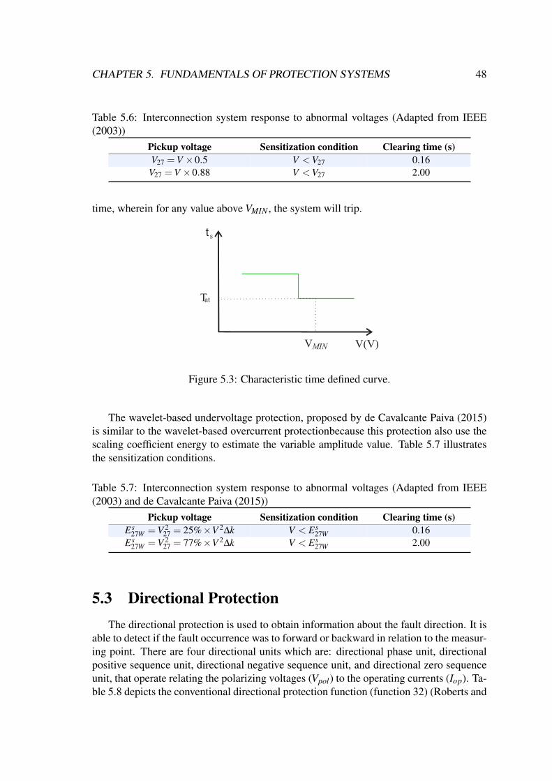
CHAPTER 5. FUNDAMENTALS OF PROTECTION SYSTEMS 48
Table 5.6: Interconnection system response to abnormal voltages (Adapted from IEEE(2003))
Pickup voltage Sensitization condition Clearing time (s)V27 =V ×0.5 V <V27 0.16V27 =V ×0.88 V <V27 2.00
time, wherein for any value above VMIN , the system will trip.
at
t s
T
V(V)VMIN
Figure 5.3: Characteristic time defined curve.
The wavelet-based undervoltage protection, proposed by de Cavalcante Paiva (2015)is similar to the wavelet-based overcurrent protectionbecause this protection also use thescaling coefficient energy to estimate the variable amplitude value. Table 5.7 illustratesthe sensitization conditions.
Table 5.7: Interconnection system response to abnormal voltages (Adapted from IEEE(2003) and de Cavalcante Paiva (2015))
Pickup voltage Sensitization condition Clearing time (s)Es
27W =V 227 = 25%×V 2∆k V < Es
27W 0.16Es
27W =V 227 = 77%×V 2∆k V < Es
27W 2.00
5.3 Directional ProtectionThe directional protection is used to obtain information about the fault direction. It is
able to detect if the fault occurrence was to forward or backward in relation to the measur-ing point. There are four directional units which are: directional phase unit, directionalpositive sequence unit, directional negative sequence unit, and directional zero sequenceunit, that operate relating the polarizing voltages (Vpol) to the operating currents (Iop). Ta-ble 5.8 depicts the conventional directional protection function (function 32) (Roberts and

CHAPTER 5. FUNDAMENTALS OF PROTECTION SYSTEMS 49
Guzman 1994) with the respective torque equation of each units that compose this func-tion. The subscripts 1, 2 and 0 refer to positive, negative and zero sequence, respectively.In addition, ZL1 and ZL0 are the positive and zero sequence impedances of the system.Table 5.8 illustrates the non-normalized torque equations. However, it is possible usesonly the cosines values from the torque equations as a normalized directional torque.
Table 5.8: Conventional directionl protection unitsFunction unit Vpol Iop Torque equation
Phase (32) V ∗ I∗ T = |V ∗||I∗|cos(∠Vpol−∠Iop)
Positive (32P) V1(1∠Z1) I1 T1 = |V1||I1|cos(∠3V1−∠3I1−∠ZL1)
Negative (32Q) −V2(1∠Z1) I2 T2 = |V2||I2|cos(∠−3V2−∠3I2−∠ZL1)
Zero (32N) −V0(1∠Z0) I0 T0 = |V0||I0|cos(∠−3V0−∠3I0−∠ZL0)
V ∗ = VBC,VCA,VAB, I∗ = IA, IB, IC.
As occurs in the overcurrent and undervoltage protections, the conventional direc-tional protection operates with phasor estimation based on the Fourier transform. How-ever, Leal et al. (2019) proposed a directional protection based on the wavelet transform(function 32W), which demonstrate a better accuracy and robustness than the Fourier-based one,for instance, the better time response with all units composition.
The scaling torque equation of the function 32W is given by (Leal et al. 2019):
T s(k) =
k∑
n=k−∆k+1svpol(n)siop(n)√
εsvpol(n)ε
siop(n)
, (5.8)
in which the svpol is the polarizing voltage scaling coefficients, siop is the operating cur-rent scaling coefficients, εs
vpol(n) is the polarizing voltage scaling coefficient energy andεs
iop(n) is the operating current scaling coefficient energy. Table 5.9 depicts the operat-ing current and polarizing voltages just units evolving phase A. However, as presented in(Leal et al. 2019), all traditional units could be recreated by using SWT.
Table 5.9: The wavelet-based operation and polarization quantities (Adapted from Leal etal. (2019)).
Function unit Iop Vpol
Phase A (32WA) iA(k) vBC(k)Positive A (32PWA) i1A(k) vA(k−∆kZ1)+ vB(k−∆kα−∆kZ1)+ vC(k−∆kα2 −∆kZ1)
Negative A (32QWA) i2A(k) vA(k+∆k/2−∆kZ1)+ vB(k−∆kα2 +∆k/2−∆kZ1)+ vC(k−∆kα +∆k/2−∆kZ1)Zero (32NW) i0(k) vA(k+∆k/2−∆kZ0)+ vB(k+∆k/2−∆kZ0)+ vC(k+∆k/2−∆kZ0)
The ∆kα and ∆kα2 refer to 120 and 240; ∆kZ1 and ∆kZ0 are positive and zero se-quence line impedances, respectively.

CHAPTER 5. FUNDAMENTALS OF PROTECTION SYSTEMS 50
5.4 Differential ProtectionThe differential protection, function (87), is widely applied in power transformers,
electrical machines and transmission lines. When related to the DFIG, few publicationsaddress about this theme, (Mansouri et al. 2016) and (Zarei et al. 2018). Figure 5.4illustrates the DFIG in a differential configuration.
DFIG
Differential relay
TC TCir is
i1 i2
Figure 5.4: DFIG differential protection scheme.
The conventional current differential protection is based on phasor estimation, wherethe principle of this protection is a phasor comparison of the currents which pass throughthe windings in both sides, both stator windings and rotor windings. Therefore, there is adifferential operating current, given by:
Idop = |i1− i2|, (5.9)
in which i1 is the rotor measured current and i2 is the stator measured current. In normalconditions, the operating current is null. However, in case of internal faults, this currentreaches significant values. Furthermore, there is another equation related to the restraintcurrent, which is given by:
Idres =
|i1 + i2|2
. (5.10)
The Idres is used as a condition to detect an internal fault, as follow:
Idop ≥ K.Id
res, (5.11)
Idop ≥ Ipickup, (5.12)
in which Ipickup is a minimum activation current and K is a relay sensitivity factor. Ifconditions (5.11) and (5.12) are met, it means that internal faults were detected.
The wavelet-based differential protection was proposed by de Medeiros (2014), whichcalculates the wavelet coefficient energy of the operation current (5.9) producing εD and
CHAPTER 5. FUNDAMENTALS OF PROTECTION SYSTEMS 51
calculates the wavelet coefficients energy of the restraint current (5.10) producing εR. Theinternal fault is detected if:
εD > ED, (5.13)
εR > KwεR, (5.14)
where Kw is the slope of characteristic curves and ED is a threshold given by (de Medeiros2014):
ED =2
k2− k1 +1
k2
∑n=k1
εwbD , (5.15)
where εwbD is the wavelet coefficient energy of the operating current with no border effect.
Furthermore, k1 and k2 are an time interval.
5.5 SummaryIn this chapter, a theoretical basis about the Fourier- and wavelet-based protections,
which are used in this work, were introduced. The instantaneous overcurrent protectionunits were described, and the time-delay overcurrent protection was also presented withtheir characteristic curves. Furthermore, the undervoltage, directional and differentialprotection were introduced in order to briefly explain about their concepts.

Chapter 6
Methodology
This chapter introduces the procedures to implement the overcurrent, undervoltage,directional, and differential wavelet-based protections applied to the DFIG topology, asdepicted in Figure 6.1, in which all relay units were validated through signals obtained bymeasurement instruments, which are potential transformers (PT) and current transformers(CT). Furthermore, a brief explanation about the protective relay localization in a DFIGassembly is also presented.
PT
DFIG
Power converters
CT
Relay
50 50W 27 27W 32 32W
CT
87 87W
PCC
Filter
Figure 6.1: Simplified relay-based protections scheme.
6.1 Protection Applied in DFIGThe protection devices seek the maximum operational continuity of the electrical sys-
tem. Furthermore, these devices need to guarantee reliable protection of the equipmentwhich compose the generation system, such as the DFIG assembly. Figure 6.2 illustratesthe possible localizations of the measuring instruments used by the protective relays on theDFIG topology according to Franco et al. (2017). The most used protections applied onit are the overcurrent (function 50/51) and undervoltage (function 27) protections. How-ever, other ones are also used, such as the overvoltage (function 59) and current unbalance
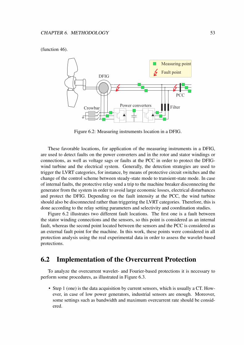
CHAPTER 6. METHODOLOGY 53
(function 46).
Power converters
DFIG
Crowbar
Measuring point
PCC
Fault point
Filter
Figure 6.2: Measuring instruments location in a DFIG.
These favorable locations, for application of the measuring instruments in a DFIG,are used to detect faults on the power converters and in the rotor and stator windings orconnections, as well as voltage sags or faults at the PCC in order to protect the DFIG-wind turbine and the electrical system. Generally, the detection strategies are used totrigger the LVRT categories, for instance, by means of protective circuit switches and thechange of the control scheme between steady-state mode to transient-state mode. In caseof internal faults, the protective relay send a trip to the machine breaker disconnecting thegenerator from the system in order to avoid large economic losses, electrical disturbancesand protect the DFIG. Depending on the fault intensity at the PCC, the wind turbineshould also be disconnected rather than triggering the LVRT categories. Therefore, this isdone according to the relay setting parameters and selectivity and coordination studies.
Figure 6.2 illustrates two different fault locations. The first one is a fault betweenthe stator winding connections and the sensors, so this point is considered as an internalfault, whereas the second point located between the sensors and the PCC is considered asan external fault point for the machine. In this work, these points were considered in allprotection analysis using the real experimental data in order to assess the wavelet-basedprotections.
6.2 Implementation of the Overcurrent ProtectionTo analyze the overcurrent wavelet- and Fourier-based protections it is necessary to
perform some procedures, as illustrated in Figure 6.3.
• Step 1 (one) is the data acquisition by current sensors, which is usually a CT. How-ever, in case of low power generators, industrial sensors are enough. Moreover,some settings such as bandwidth and maximum overcurrent rate should be consid-ered.

CHAPTER 6. METHODOLOGY 54
DFIG
Power converters
CT
PCCData acquisition
Subsampling
Anti-aliasingfilter
Absolute valueestimation
Protection Logic
1
2
3
4
5
Filter
Figure 6.3: Overcurrent protection steps.
• Step 2 (two) is the sub-sampling process made for the offline analysis. The Fourier-based protection uses fs = 1000 Hz, whereas the wavelet-based protection usesfs = 20000 Hz, i.e., the sliding window are ∆k ' 17 and ∆k ' 333, respectively.These algorithms are calculated recursively.
• Step 3 (three), the signal passes through an anti-aliasing filter with a cut-off fre-quency of fc = 450 Hz for the Fourier algorithm and fc = 9000 Hz for the waveletalgorithm, in which a second-order butterworth filter was used.
• Step 4 (four) represents the absolute value estimation, where the Fourier-basedmethod uses equation (4.5) and the wavelet-based one uses equation (5.2) in or-der to compare both protection methods.
• Step 5 (five) is the logical protection according to section 5.1.
6.3 Implementation of the Directional ProtectionFigure 6.4 illustrates the process to implement the directional protection (function 32).
• Step 1 (one) is a typical protection implementation stage which is made similarlyto the aforementioned protection: the data acquisition, the filter process; with acut frequency of fc = 450 Hz and fc = 9000 Hz to Fourier and wavelet algorithm,respectively; and sub-sampling stage, where the sampling frequency to the Fourier-
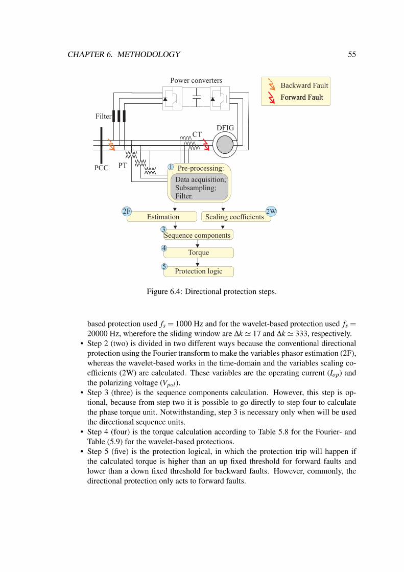
CHAPTER 6. METHODOLOGY 55
DFIG
Power converters
PCC PT
Data acquisition;Subsampling;Filter.
1 Pre-processing:
CT
Estimation2F
Sequence components
Torque
Protection logic
Scaling coefficients2W
3
4
5
Forward FaultForward Fault
Backward Fault
Filter
Figure 6.4: Directional protection steps.
based protection used fs = 1000 Hz and for the wavelet-based protection used fs =20000 Hz, wherefore the sliding window are ∆k ' 17 and ∆k ' 333, respectively.
• Step 2 (two) is divided in two different ways because the conventional directionalprotection using the Fourier transform to make the variables phasor estimation (2F),whereas the wavelet-based works in the time-domain and the variables scaling co-efficients (2W) are calculated. These variables are the operating current (Iop) andthe polarizing voltage (Vpol).
• Step 3 (three) is the sequence components calculation. However, this step is op-tional, because from step two it is possible to go directly to step four to calculatethe phase torque unit. Notwithstanding, step 3 is necessary only when will be usedthe directional sequence units.
• Step 4 (four) is the torque calculation according to Table 5.8 for the Fourier- andTable (5.9) for the wavelet-based protections.
• Step 5 (five) is the protection logical, in which the protection trip will happen ifthe calculated torque is higher than an up fixed threshold for forward faults andlower than a down fixed threshold for backward faults. However, commonly, thedirectional protection only acts to forward faults.

CHAPTER 6. METHODOLOGY 56
6.4 Implementation of the Differential ProtectionFigure 6.5 depicts the process to implement the differential protection (function 87).
DFIG
Power converters
CT
PCC
Estimation*
2
Data acquisition;Subsampling;Filter.
1 Pre-processing:
CT
Machine slip consideration
4
Protection Logic5
Amplitude adjustment
3
Internal Fault
External Fault
Filter
Figure 6.5: Differential protection steps.
• Step 1 (one) is a typical protection implementation stage, which is performed sim-ilarly to the aforementioned protections. In this protection type, two different cur-rents are needed, where the first one are stator currents and the second one are rotorcurrents.
• Step 2 (two), the normalization of stator and rotor currents are done according to(Mansouri et al. 2016). The amplitudes of the currents are normalized consideringthe turns ratio of the rotor and stator. Generally, the machine windings are con-nected in star (Y/Y). Therefore, the angle compensation, which is done for powertransform, is not applied for electrical machines. However, in case of another wind-ings connection type, such as delta/star or star/delta, an angle compensation needsto be done.
• Step 3 (three) is done with a different process to each protection method. To theFourier-based protection, a phasor estimation is performed according to (4.5) and(4.6), whereas to the wavelet-based protection, the energy of the wavelet coeffi-cients is calculated according to (4.28).

CHAPTER 6. METHODOLOGY 57
• Step 4 (four) the machine slip is considered, because the differential protectionmakes a signal comparison and, in this work, it was considered that the rotor cur-rents enter inside the machine whereas the stator currents leave the machine to thegrid. However, this consideration is true only if the machine is operating in thesub-synchronous mode. Therefore, weather the machine is operating in the super-synchronous mode it is necessary to make a signal correction in the rotor current.
• Step 5 (five) the protection logic is done according to (5.9) until (5.12).
6.5 Implementation of the Undervoltage ProtectionFigure 6.6 illustrates the procedures implemented to analyze the undervoltage protec-
tion.
DFIG
Power converters
PCC
Protection Logic2
PT
Data acquisition;Subsampling;Filter;Estimation
1 Pre-processing:
Filter
Figure 6.6: Undervoltage protection steps.
• Step 1 (one) is the pre-processing unit in which is performed the data acquisitionby voltage sensors, which depending on the generator size is needed a PT (potentialtransformer). Notwithstanding, in case of low power generators, industrial sensorsare enough. The sub-sampling process is done, where to the Fourier-based pro-tection used fs = 1000 Hz and the wavelet-based protection used fs = 20000 Hz.Thereafter, the signal passes through an anti-aliasing filter with a cut-off frequencyof fc = 450 Hz and fc = 9000 Hz to Fourier- and wavelet-based protections, re-spectively. Finally, the voltage absolute value estimation is obtained, where theFourier-based method uses (4.5) and the wavelet-based method uses (5.2).
• Step 2 (two) is the logical protection according to 5.2.
CHAPTER 6. METHODOLOGY 58
6.6 SummaryThis chapter presented the procedures to implement the Fourier- and the wavelet-
based overcurrent, directional, differential, and undervoltage protections when applied ina DFIG assembly. Some protections schemes are implemented such as the conventionalones. However, others protections needs some modifications, for instance the differen-tial protection which consider the machine slip to calculate the restraint and operatingcurrents. In addition, the measurement instruments location were introduced.

Chapter 7
Protection and Signal Analysis
This chapter presents the analysis of experimental signals in a DFIG test-bench un-der fault situations. As a first step, the main focus is to observe the behavior of theDFIG variables, such as currents, voltages, magnetic flux, and machine slip, in the pre-fault, fault, and post-fault periods. The development and assessment of new protectionmethods are needed to find and validate methods which can present a better performancethan the conventional ones. A good protection performance makes the system to respondbetter to faults at the PCC because it will make the LVRT categories act faster and pro-tect the system as well. Therefore, experimental signals were used in order to analyzethe wavelet-based overcurrent, directional, differential and Undervoltage protections andcompare with the conventional ones, in order to verify which one has a better behavior ina system with DFIG.
7.1 Experimental AnalysisIn order to analyze the experimental test bench in case of electrical faults, some anal-
ysis with the DFIG variables in case of electrical faults at the PCC were accomplished.The analyzed variables were: the grid voltage, the stator and rotor currents, the stator fluxreferring to the phase in fault, the machine slip, and the rotor speed. Beyond these signals,the behavior of active power, reactive power, and torque that compose this test bench ispossible to be verified. The sampling frequency of the signals are fs = 20000 Hz and thefault resistance is r f = 15 Ω for all cases. Figure 7.1 illustrate the fault location for thisexperimental analysis and appendix A explain about the test-bench.
Power converters
DFIG
Measuring point
PCC
Fault point
Filter
Figure 7.1: Fault location.
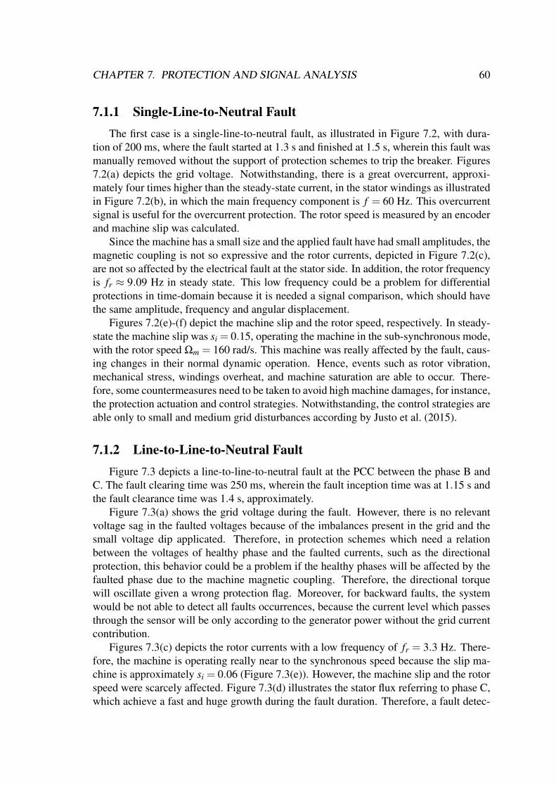
CHAPTER 7. PROTECTION AND SIGNAL ANALYSIS 60
7.1.1 Single-Line-to-Neutral FaultThe first case is a single-line-to-neutral fault, as illustrated in Figure 7.2, with dura-
tion of 200 ms, where the fault started at 1.3 s and finished at 1.5 s, wherein this fault wasmanually removed without the support of protection schemes to trip the breaker. Figures7.2(a) depicts the grid voltage. Notwithstanding, there is a great overcurrent, approxi-mately four times higher than the steady-state current, in the stator windings as illustratedin Figure 7.2(b), in which the main frequency component is f = 60 Hz. This overcurrentsignal is useful for the overcurrent protection. The rotor speed is measured by an encoderand machine slip was calculated.
Since the machine has a small size and the applied fault have had small amplitudes, themagnetic coupling is not so expressive and the rotor currents, depicted in Figure 7.2(c),are not so affected by the electrical fault at the stator side. In addition, the rotor frequencyis fr ≈ 9.09 Hz in steady state. This low frequency could be a problem for differentialprotections in time-domain because it is needed a signal comparison, which should havethe same amplitude, frequency and angular displacement.
Figures 7.2(e)-(f) depict the machine slip and the rotor speed, respectively. In steady-state the machine slip was si = 0.15, operating the machine in the sub-synchronous mode,with the rotor speed Ωm = 160 rad/s. This machine was really affected by the fault, caus-ing changes in their normal dynamic operation. Hence, events such as rotor vibration,mechanical stress, windings overheat, and machine saturation are able to occur. There-fore, some countermeasures need to be taken to avoid high machine damages, for instance,the protection actuation and control strategies. Notwithstanding, the control strategies areable only to small and medium grid disturbances according by Justo et al. (2015).
7.1.2 Line-to-Line-to-Neutral FaultFigure 7.3 depicts a line-to-line-to-neutral fault at the PCC between the phase B and
C. The fault clearing time was 250 ms, wherein the fault inception time was at 1.15 s andthe fault clearance time was 1.4 s, approximately.
Figure 7.3(a) shows the grid voltage during the fault. However, there is no relevantvoltage sag in the faulted voltages because of the imbalances present in the grid and thesmall voltage dip applicated. Therefore, in protection schemes which need a relationbetween the voltages of healthy phase and the faulted currents, such as the directionalprotection, this behavior could be a problem if the healthy phases will be affected by thefaulted phase due to the machine magnetic coupling. Therefore, the directional torquewill oscillate given a wrong protection flag. Moreover, for backward faults, the systemwould be not able to detect all faults occurrences, because the current level which passesthrough the sensor will be only according to the generator power without the grid currentcontribution.
Figures 7.3(c) depicts the rotor currents with a low frequency of fr = 3.3 Hz. There-fore, the machine is operating really near to the synchronous speed because the slip ma-chine is approximately si = 0.06 (Figure 7.3(e)). However, the machine slip and the rotorspeed were scarcely affected. Figure 7.3(d) illustrates the stator flux referring to phase C,which achieve a fast and huge growth during the fault duration. Therefore, a fault detec-

CHAPTER 7. PROTECTION AND SIGNAL ANALYSIS 61
-1.2
0
1.2
-20
0
20
-20
0
20
-2
0
2
rad/s
0.6 0.8 1.0 1.2 1.4 1.6 1.8 2.0 2.2Times (s)
( d )
( f )
( c )
( b )
( a )
160
180
Rot
orS
peed
Sta
tor
flux
Phase A
Rot
orcu
rren
ts (
A)
raIrbIrc
I
Sta
tor
curr
ents
(A
)
saIsbI sc
I
Gri
dv
olt
ages
(pu
)
sa
sb
sc
VVV
0.1
0.15
0.2
( e )
si
Mac
hine
slip
Fault clearancetime
Fault inceptiontime
Figure 7.2: Experimental test-bench signals with a one-phase fault to neutral point: (a)Grid voltage in pu; (b) Stator currents; (c) Rotor currents; (d) Stator flux referring to phaseA; (e) Machine slipe; (f) Rotor speed.
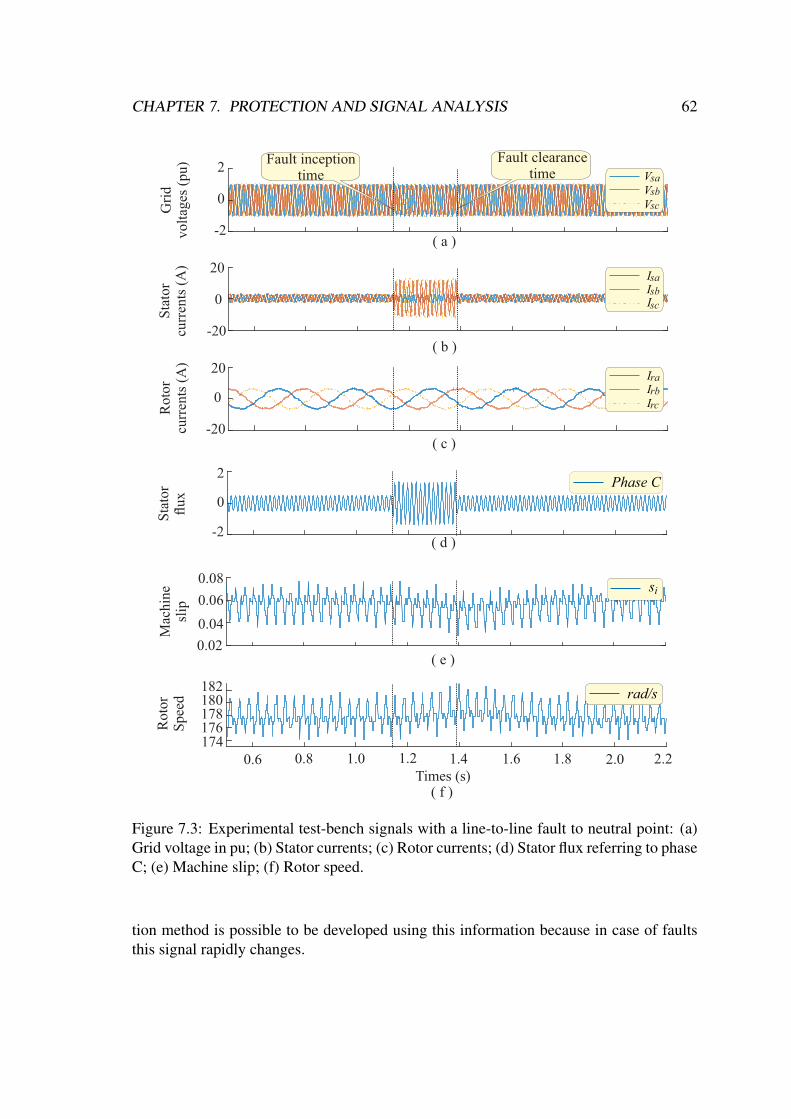
CHAPTER 7. PROTECTION AND SIGNAL ANALYSIS 62
rad/s
0.6 0.8 1.0 1.2 1.4 1.6 1.8 2.0 2.2Times (s)
( f )
( a )
Rot
orS
peed
Sta
tor
flux
Phase C
Rot
orcu
rren
ts (
A)
raIrbIrc
I
Sta
tor
curr
ents
(A
)
saIsbIsc
I
Gri
dvo
ltag
es (
pu)
sa
sb
sc
VVV
-2
0
2
-20
0
20
-20
0
20
-2
0
2
174176178180182
( b )
( d )
si
Mac
hine
slip
( e )0.02
0.04
0.06
0.08
( c )
Fault clearancetime
Fault inceptiontime
Figure 7.3: Experimental test-bench signals with a line-to-line fault to neutral point: (a)Grid voltage in pu; (b) Stator currents; (c) Rotor currents; (d) Stator flux referring to phaseC; (e) Machine slip; (f) Rotor speed.
tion method is possible to be developed using this information because in case of faultsthis signal rapidly changes.

CHAPTER 7. PROTECTION AND SIGNAL ANALYSIS 63
7.2 Analysis of the Overcurrent ProtectionAccording to section 3.5, there are many challenges to be overcome when deals to
DFIG protection. Therefore, considering these challenges, in this study, two dynamiccases were examined for the experimental analyses. The first one involves a single line-to-ground (SLG) fault and the second one is a line-to-line fault. Those evaluated short-circuits occur between the sensors and the stator winding connections such as in Figure6.3, and this location was chosen due to the presence of all characteristics inherent inDFIG, such as grid imbalance and voltage oscillations. Therefore, the results obtained atthis assembly point can be replicated for all others point of DFIG topology, for instance,to the rotor side, to the power converters, and to the line filter.
The relay operating time and the percentage of correct answers were observed for allreal cases for both overcurrent protection methods, as evaluation and comparison crite-ria. However, the time-delay overcurrent units are not applied because the time whichthe generator must remain connected to the grid depends on the grid codes imposed byeach country for faults at the PCC or near it, for instance, in Germany the turbine needsto remain connected to the PCC for 150 ms when the voltage drops to zero. Therefore,even if the time-delay overcurrent protection sent a trip to the relay the turbine shouldremain connected according to the grid code (LVRT), whereas the instantaneous overcur-rent protection sends a flag to the LVRT categories to the turbine remain connected at thePCC according to the grid codes, thereafter if the fault remains the turbine will be discon-nected. However, this function, the time-delay overcurrent protection, would be able tobe used against power converts or windings faults.
The thresholds adopted for the instantaneous overcurrent unit was N50 = 3 and forthe neutral overcurrent unit and the negative-sequence overcurrent unit were N50N = 0.2,N50Q = 0.3, respectively. These thresholds were chosen in order to allow the correct pro-tection actuation considering the steady-state current as well as the maximum overcurrentachieved by the DFIG system. The wavelet-based overcurrent protection presented wasproposed by Costa et al. (2017) for a distribution system validated only by simulations.Therefore, in this work, this wavelet-based protection has been assessed by real experi-mental data applied in a DFIG environment.
7.2.1 Single Line-to-Neutral Fault AnalysesFigure 7.4 depicts a SLG fault in phase A with fault resistance of r f = 15 Ω. Ia, Ib, Ic
are the currents in phases A, B, and C, respectively. In addition, the wavelet coefficientenergy εω
ia, Figure 7.4(b), is introduced as a trigger signal in order to be used as instanta-neous fault detector. The energy of the wavelet coefficients exceeded the threshold almostinstantly at the fault inception time, which is an additional information that can be usedto sensitized the relay such as addressed by 5.1.
As illustrated in Figure 7.4(c), the protection based on both Fourier (function 50)and wavelet (function 50W) methods actuated correctly for this fault, where |Ia| is theabsolute value of the current in phase A estimated by the Fourier method and
√εs
i/∆k isthe estimation of the absolute current in phase A by the scaling wavelet coefficient energy,
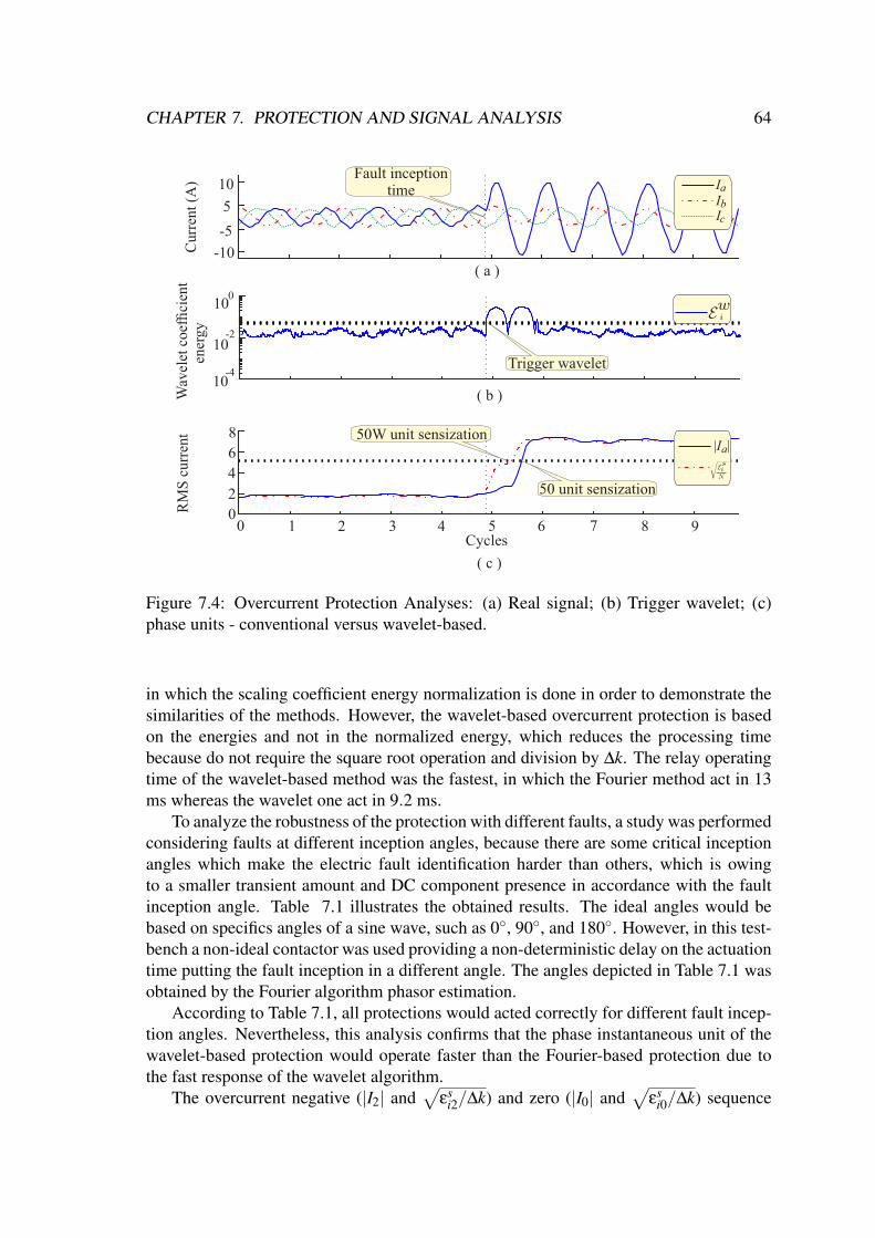
CHAPTER 7. PROTECTION AND SIGNAL ANALYSIS 64
-5
5
-10
10C
urre
nt (
A)
0
2
4
6
8Ia| |
RM
S c
urre
ntFault inception
time
50 unit sensization
Wav
elet
coe
ffici
ent
ener
gy
10
10
10
-4
-2
0
50W unit sensization
IIIab
c
Trigger wavelet
0 1 2 3 4 5 6 7 8 9Cycles
( a )
( b )
( c )
Figure 7.4: Overcurrent Protection Analyses: (a) Real signal; (b) Trigger wavelet; (c)phase units - conventional versus wavelet-based.
in which the scaling coefficient energy normalization is done in order to demonstrate thesimilarities of the methods. However, the wavelet-based overcurrent protection is basedon the energies and not in the normalized energy, which reduces the processing timebecause do not require the square root operation and division by ∆k. The relay operatingtime of the wavelet-based method was the fastest, in which the Fourier method act in 13ms whereas the wavelet one act in 9.2 ms.
To analyze the robustness of the protection with different faults, a study was performedconsidering faults at different inception angles, because there are some critical inceptionangles which make the electric fault identification harder than others, which is owingto a smaller transient amount and DC component presence in accordance with the faultinception angle. Table 7.1 illustrates the obtained results. The ideal angles would bebased on specifics angles of a sine wave, such as 0, 90, and 180. However, in this test-bench a non-ideal contactor was used providing a non-deterministic delay on the actuationtime putting the fault inception in a different angle. The angles depicted in Table 7.1 wasobtained by the Fourier algorithm phasor estimation.
According to Table 7.1, all protections would acted correctly for different fault incep-tion angles. Nevertheless, this analysis confirms that the phase instantaneous unit of thewavelet-based protection would operate faster than the Fourier-based protection due tothe fast response of the wavelet algorithm.
The overcurrent negative (|I2| and√
εsi2/∆k) and zero (|I0| and
√εs
i0/∆k) sequence

CHAPTER 7. PROTECTION AND SIGNAL ANALYSIS 65
Table 7.1: Relay Operating Time for Different Fault Inception Angles.
Angles Operating time [ms]50 50W 50Q 50QW 50N 50NW
27.98 16.5 10.6 3.5 0.5 3.5 0.677.93 12.5 9.3 2.5 0.4 3.5 0.583.59 12.0 8.5 3.0 0.9 4.0 0.9
122.67 14.5 11.7 4.5 2.5 5.5 2.4224.27 17.0 9.4 3.0 0.6 3.0 0.6269.98 13.5 10.4 3.5 0.9 3.5 0.9277.38 13.0 9.2 3.0 1.2 4.0 1.3283.91 13.5 10.1 3.5 1.0 3.5 0.9
Average 14.1 9.9 3.3 1.0 3.8 1.0
units were also tested. Figure 7.5 depicts the Fourier- and wavelet-based methods of theovercurrent negative (functions 50Q and 50QW) and zero (functionS 50N and 50NW)sequence units. According to this figure and Table 7.1, for the negative sequence (Figure7.5(a)), the Fourier-based protection would act in 4 ms and to the wavelet-based protectionwould act in 1.3 ms, whereas the zero-sequence unit (Figure 7.5(b)) would act in 3 msand 1.2 ms for Fourier- and wavelet-based protections, respectively. The Fourier- andwavelet-based overcurrent protection has performed well in all the units, with no problemsto detect the fault instant. The current fault signal is depicted in Figure 7.4(a) which is thethird case illustrated in Table 7.1.
0 1 2 3 4 5 6 7 8 90
1
2
3
Z
ero-
sequ
ence
R
MS
cur
rent
0
1
2
3
N
egat
ive-
sequ
ence
RM
S c
urre
nt
50N unit sensization50NW unit sensization
I0| |
0
50Q unit sensization50QW unit sensization
I2| |
2
( a )
Cycles( b )
Figure 7.5: Overcurrent Protection Analyses: (a) Overcurrent protection negative se-quence unit; (b) Overcurrent protection neutral sequence unit.
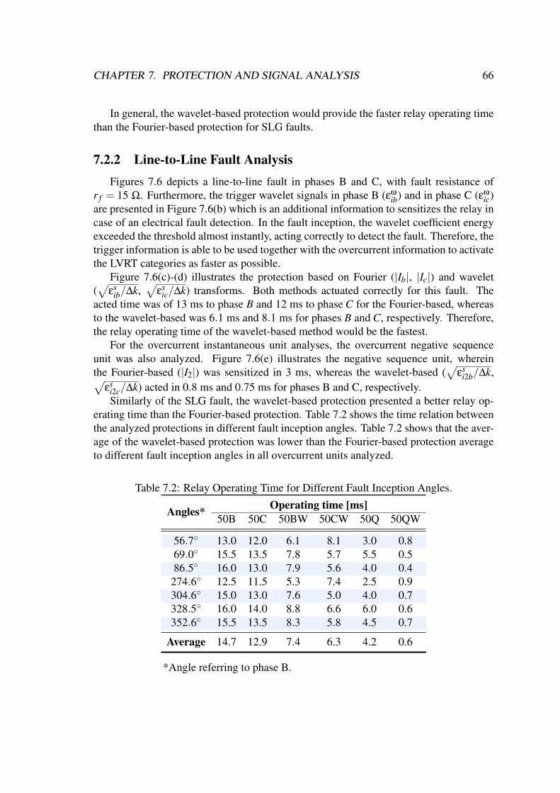
CHAPTER 7. PROTECTION AND SIGNAL ANALYSIS 66
In general, the wavelet-based protection would provide the faster relay operating timethan the Fourier-based protection for SLG faults.
7.2.2 Line-to-Line Fault AnalysisFigures 7.6 depicts a line-to-line fault in phases B and C, with fault resistance of
r f = 15 Ω. Furthermore, the trigger wavelet signals in phase B (εω
ib) and in phase C (εωic)
are presented in Figure 7.6(b) which is an additional information to sensitizes the relay incase of an electrical fault detection. In the fault inception, the wavelet coefficient energyexceeded the threshold almost instantly, acting correctly to detect the fault. Therefore, thetrigger information is able to be used together with the overcurrent information to activatethe LVRT categories as faster as possible.
Figure 7.6(c)-(d) illustrates the protection based on Fourier (|Ib|, |Ic|) and wavelet(√
εsib/∆k,
√εs
ic/∆k) transforms. Both methods actuated correctly for this fault. Theacted time was of 13 ms to phase B and 12 ms to phase C for the Fourier-based, whereasto the wavelet-based was 6.1 ms and 8.1 ms for phases B and C, respectively. Therefore,the relay operating time of the wavelet-based method would be the fastest.
For the overcurrent instantaneous unit analyses, the overcurrent negative sequenceunit was also analyzed. Figure 7.6(e) illustrates the negative sequence unit, whereinthe Fourier-based (|I2|) was sensitized in 3 ms, whereas the wavelet-based (
√εs
i2b/∆k,√εs
i2c/∆k) acted in 0.8 ms and 0.75 ms for phases B and C, respectively.Similarly of the SLG fault, the wavelet-based protection presented a better relay op-
erating time than the Fourier-based protection. Table 7.2 shows the time relation betweenthe analyzed protections in different fault inception angles. Table 7.2 shows that the aver-age of the wavelet-based protection was lower than the Fourier-based protection averageto different fault inception angles in all overcurrent units analyzed.
Table 7.2: Relay Operating Time for Different Fault Inception Angles.
Angles* Operating time [ms]50B 50C 50BW 50CW 50Q 50QW
56.7 13.0 12.0 6.1 8.1 3.0 0.869.0 15.5 13.5 7.8 5.7 5.5 0.586.5 16.0 13.0 7.9 5.6 4.0 0.4
274.6 12.5 11.5 5.3 7.4 2.5 0.9304.6 15.0 13.0 7.6 5.0 4.0 0.7328.5 16.0 14.0 8.8 6.6 6.0 0.6352.6 15.5 13.5 8.3 5.8 4.5 0.7
Average 14.7 12.9 7.4 6.3 4.2 0.6
*Angle referring to phase B.
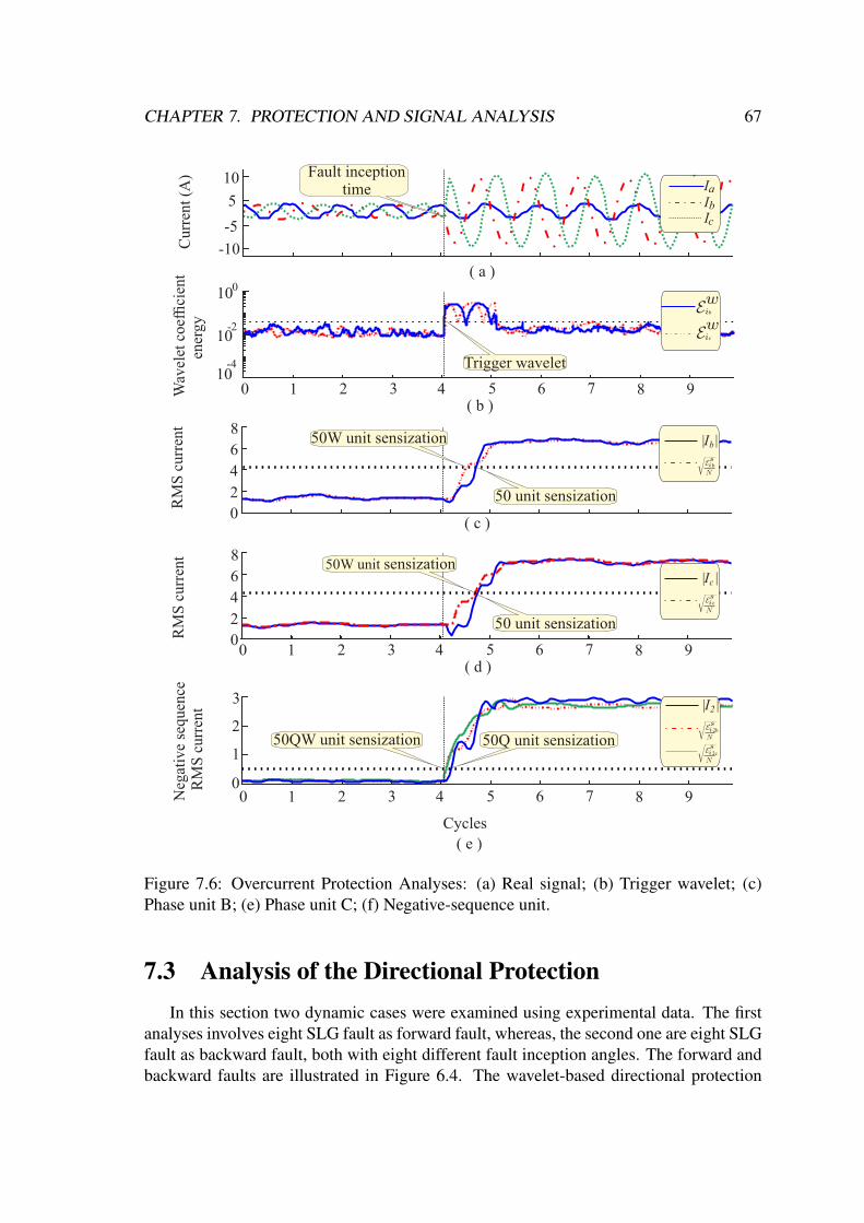
CHAPTER 7. PROTECTION AND SIGNAL ANALYSIS 67
-5
5
-10
10C
urre
nt (
A)
0
2
4
6
8Ib| |
RM
S c
urre
ntFault inception
time
50 unit sensization
0 1 2 3 4 5 6 7 8 9
Wav
elet
coe
ffici
ent
ener
gy
10
10
10
-4
-2
0
Cycles
0
1
2
3
N
egat
ive
sequ
ence
R
MS
cur
rent
50W unit sensization
IIIab
c
Trigger wavelet
50Q unit sensization50QW unit sensization
I2| |
2
b
0
2
4
6
8
RM
S c
urre
nt 50W unit sensization
50 unit sensization
Ic| |
c
c
b
2c
b
0 1 2 3 4 5 6 7 8 9
( a )
( b )
0 1 2 3 4 5 6 7 8 9( d )
( c )
( e )
Figure 7.6: Overcurrent Protection Analyses: (a) Real signal; (b) Trigger wavelet; (c)Phase unit B; (e) Phase unit C; (f) Negative-sequence unit.
7.3 Analysis of the Directional ProtectionIn this section two dynamic cases were examined using experimental data. The first
analyses involves eight SLG fault as forward fault, whereas, the second one are eight SLGfault as backward fault, both with eight different fault inception angles. The forward andbackward faults are illustrated in Figure 6.4. The wavelet-based directional protection

CHAPTER 7. PROTECTION AND SIGNAL ANALYSIS 68
applied in this work was proposed by Leal et al. (2019) for transmission line and thisprotection was validated only by simulations in the software Matlab/Simulink. Therefore,in this work, this wavelet-based protection has been assessed by real experimental dataapplied in a DFIG topology.
The relay operating time and the percentage of correct answers were observed for allreal cases for both directional protection methods, as evaluation and comparison criteria.
7.3.1 Forward Fault AnalysesFigure 7.7 depicts the directional phase unit of the wavelet- and Fourier-based pro-
tections of a forward SLG fault in phase A, respectively, in which T sa , T s
b , T sc are the
scaling phase torque and Ta, Tb, Tc are the conventional phase torque, for phases ‘ABC’,respectively. The normalized directional protection was implemented to the Fourier-basedmethod considering only the cosine from Table 5.8, whereas the wavelet-based is natu-rally normalized.
Pha
se t
orqu
e
TTTab
c
( a )
1 2 3 4 5 6 7 8 9 10 11 12 13 14 15 16 17 18 19 20
Cycles
0.80.60.40.20.0-0.2
TTTab
c
s
ss
s
Sca
ling
phas
e to
rque
0.80.60.40.20.0-0.2
( b )
Figure 7.7: Directional protection phase unit - Forward fault: (a) Wavelet-based direc-tional protection, (b) Fourier-based directional protection.
The threshold adopted for the directional phase unit was γ = 0.6 to forward analysis inboth protection methods. This value was chosen to avoid false directionality identificationgiving a wide margin of safety. For the DFIG system, the steady-state of the directionalphase unit was centralized in 0.8. Therefore, an offset of 0.8 was put in order to centralizein 0.0 the steady-state. In the phase unit to forward faults, both protections achieved 100%of right answers. Notwithstanding, the wavelet-based presented the fastest response.
The directional sequence components units, negative and zero, are illustrated in Fig-ure 7.8, respectively, in which, T 2
s and T 2 are the scaling negative torque and the negativetorque, respectively. T 0
s is the scaling zero torque and T 0 is the zero torque. The ap-plied thresholds were γQ = 0.6 and γN = 0.6 for the Fourier and wavelet algorithm. The
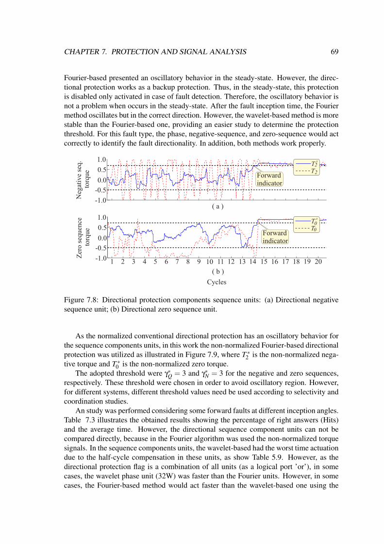
CHAPTER 7. PROTECTION AND SIGNAL ANALYSIS 69
Fourier-based presented an oscillatory behavior in the steady-state. However, the direc-tional protection works as a backup protection. Thus, in the steady-state, this protectionis disabled only activated in case of fault detection. Therefore, the oscillatory behavior isnot a problem when occurs in the steady-state. After the fault inception time, the Fouriermethod oscillates but in the correct direction. However, the wavelet-based method is morestable than the Fourier-based one, providing an easier study to determine the protectionthreshold. For this fault type, the phase, negative-sequence, and zero-sequence would actcorrectly to identify the fault directionality. In addition, both methods work properly.
Forward indicator
Forward indicator
( a )
Cycles
( b )
Neg
ativ
e se
q. t
orqu
e
1.0
0.5
0.0
-0.5
-1.0
Zer
o se
quen
ce t
orqu
e
1.0
0.5
0.0
-0.5
-1.0 1 2 3 4 5 6 7 8 9 10 11 12 13 14 15 16 17 18 19 20
TT22
s
TT00
s
Figure 7.8: Directional protection components sequence units: (a) Directional negativesequence unit; (b) Directional zero sequence unit.
As the normalized conventional directional protection has an oscillatory behavior forthe sequence components units, in this work the non-normalized Fourier-based directionalprotection was utilized as illustrated in Figure 7.9, where T ∗2 is the non-normalized nega-tive torque and T ∗0 is the non-normalized zero torque.
The adopted threshold were γ∗Q = 3 and γ∗N = 3 for the negative and zero sequences,respectively. These threshold were chosen in order to avoid oscillatory region. However,for different systems, different threshold values need be used according to selectivity andcoordination studies.
An study was performed considering some forward faults at different inception angles.Table 7.3 illustrates the obtained results showing the percentage of right answers (Hits)and the average time. However, the directional sequence component units can not becompared directly, because in the Fourier algorithm was used the non-normalized torquesignals. In the sequence components units, the wavelet-based had the worst time actuationdue to the half-cycle compensation in these units, as show Table 5.9. However, as thedirectional protection flag is a combination of all units (as a logical port ’or’), in somecases, the wavelet phase unit (32W) was faster than the Fourier units. However, in somecases, the Fourier-based method would act faster than the wavelet-based one using the
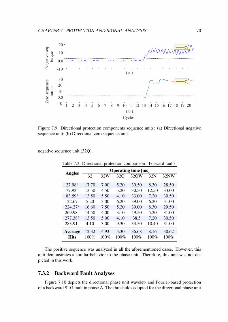
CHAPTER 7. PROTECTION AND SIGNAL ANALYSIS 70
( a )
Cycles
( b )
Neg
ativ
e se
q. t
orqu
eZ
ero
sequ
ence
tor
que
30
20
10
0.0
-10 1 2 3 4 5 6 7 8 9 10 11 12 13 14 15 16 17 18 19 20
T2*
T0*
20
10
0.0
-10
Figure 7.9: Directional protection components sequence units: (a) Directional negativesequence unit; (b) Directional zero sequence unit.
negative sequence unit (32Q).
Table 7.3: Directional protection comparison - Forward faults.
Angles Operating time [ms]32 32W 32Q 32QW 32N 32NW
27.98 17.70 7.00 5.20 30.50 8.30 28.5077.93 13.50 4.50 5.20 30.50 12.50 33.0083.59 13.50 5.50 4.10 33.00 7.20 30.50
122.67 5.20 3.00 6.20 39.00 6.20 31.00224.27 16.60 7.50 5.20 39.00 8.30 29.50269.98 14.50 4.00 3.10 49.50 5.20 31.00277.38 13.50 5.00 4.10 38.5 7.20 30.50283.91 4.10 3.00 9.30 33.50 10.40 31.00
Average 12.32 4.93 5.30 36.68 8.16 30.62Hits 100% 100% 100% 100% 100% 100%
The positive sequence was analyzed in all the aforementioned cases. However, thisunit demonstrates a similar behavior to the phase unit. Therefore, this unit was not de-picted in this work.
7.3.2 Backward Fault AnalysesFigure 7.10 depicts the directional phase unit wavelet- and Fourier-based protection
of a backward SLG fault in phase A. The thresholds adopted for the directional phase unit
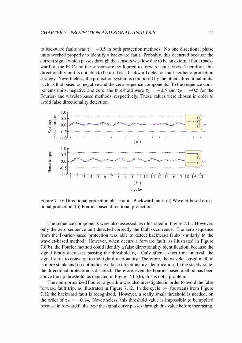
CHAPTER 7. PROTECTION AND SIGNAL ANALYSIS 71
to backward faults was τ = −0.5 in both protection methods. No one directional phaseunits worked properly to identify a backward fault. Probably, this occurred because thecurrent signal which passes through the sensors was low due to be an external fault (back-ward) at the PCC and the sensors are configured to forward fault types. Therefore, thisdirectionality unit is not able to be used as a backward detector fault neither a protectionstrategy. Nevertheless, the protection system is composed by the others directional units,such as that based on negative and the zero sequence components. To the sequence com-ponents units, negative and zero, the threshold were τQ = −0.5 and τN = −0.5 for theFourier- and wavelet-based methods, respectively. These values were chosen in order toavoid false directionality detection.
Pha
se t
orqu
e
( a )
1 2 3 4 5 6 7 8 9 10 11 12 13 14 15 16 17 18 19 20
Cycles
TTTab
c
s
ss
s
Sca
ling
phas
e to
rque
1.0
0.5
0.0
-1.0
( b )
-0.5
TTTab
c
1.0
0.5
0.0
-1.0
-0.5
Figure 7.10: Directional protection phase unit - Backward fault: (a) Wavelet-based direc-tional protection, (b) Fourier-based directional protection.
The sequence components were also assessed, as illustrated in Figure 7.11. However,only the zero sequence unit detected correctly the fault occurrence. The zero sequencefrom the Fourier-based protection was able to detect backward faults similarly to thewavelet-based method. However, when occurs a forward fault, as illustrated in Figure7.8(b), the Fourier method could identify a false directionality identification, because thesignal firstly decreases passing the threshold τN . Only after a short time interval, thesignal starts to converge to the right directionality. Therefore, the wavelet-based methodis more stable and do not indicate a false directionality identification. In the steady-state,the directional protection is disabled. Therefore, even the Fourier-based method has beenabove the up threshold, as depicted in Figure 7.11(b), this is not a problem.
The non-normalized Fourier algorithm was also investigated in order to avoid the falseforward fault trip, as illustrated in Figure 7.12. In the cycle 14 (fourteen) from Figure7.12 the backward fault is recognized. However, a really small threshold is needed, onthe order of τN = −0.14. Nevertheless, this threshold value is impossible to be appliedbecause in forward faults type the signal curve passes through this value before increasing,
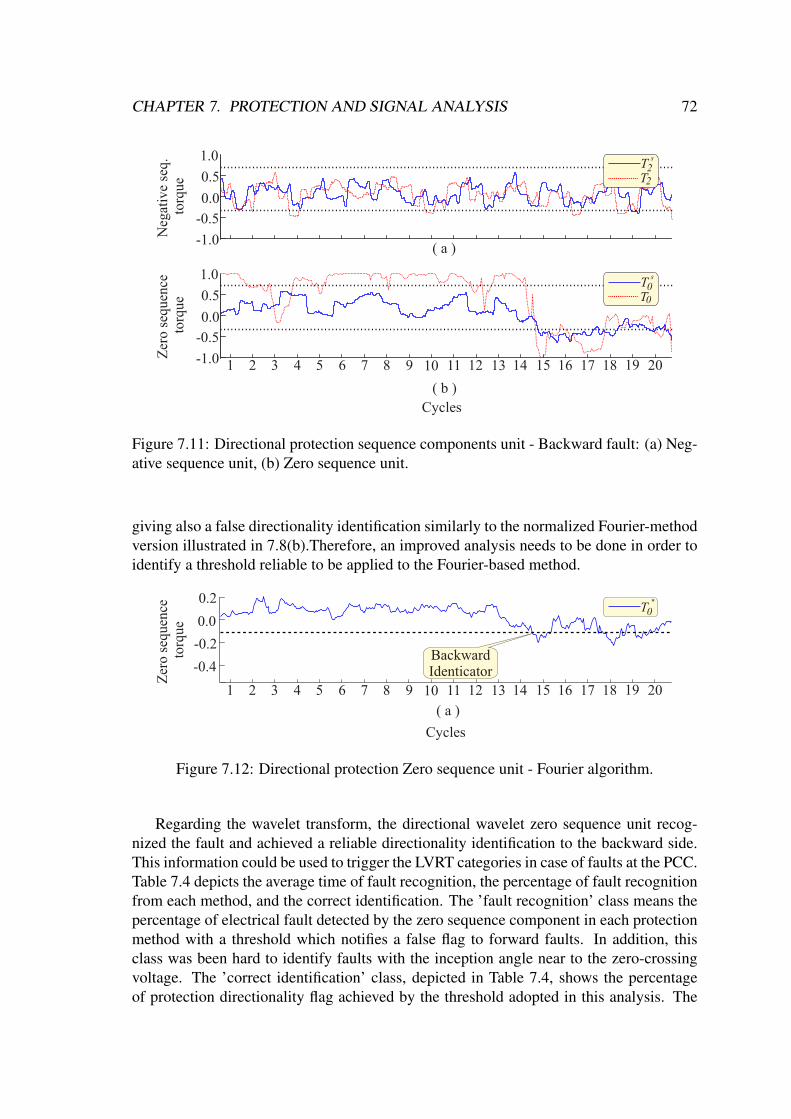
CHAPTER 7. PROTECTION AND SIGNAL ANALYSIS 72
Cycles
( b )
Zer
o se
quen
ce t
orqu
e
1.0
0.5
0.0
-0.5
-1.0 1 2 3 4 5 6 7 8 9 10 11 12 13 14 15 16 17 18 19 20
TT00
s
( a )
Neg
ativ
e se
q. t
orqu
e
1.0
0.5
0.0
-0.5
-1.0
TT22
s
Figure 7.11: Directional protection sequence components unit - Backward fault: (a) Neg-ative sequence unit, (b) Zero sequence unit.
giving also a false directionality identification similarly to the normalized Fourier-methodversion illustrated in 7.8(b).Therefore, an improved analysis needs to be done in order toidentify a threshold reliable to be applied to the Fourier-based method.
BackwardIdenticator
Cycles
( a )
Zer
o se
quen
ce t
orqu
e
0.2
0.0
-0.2
-0.4
1 2 3 4 5 6 7 8 9 10 11 12 13 14 15 16 17 18 19 20
T0*
Figure 7.12: Directional protection Zero sequence unit - Fourier algorithm.
Regarding the wavelet transform, the directional wavelet zero sequence unit recog-nized the fault and achieved a reliable directionality identification to the backward side.This information could be used to trigger the LVRT categories in case of faults at the PCC.Table 7.4 depicts the average time of fault recognition, the percentage of fault recognitionfrom each method, and the correct identification. The ’fault recognition’ class means thepercentage of electrical fault detected by the zero sequence component in each protectionmethod with a threshold which notifies a false flag to forward faults. In addition, thisclass was been hard to identify faults with the inception angle near to the zero-crossingvoltage. The ’correct identification’ class, depicted in Table 7.4, shows the percentageof protection directionality flag achieved by the threshold adopted in this analysis. The
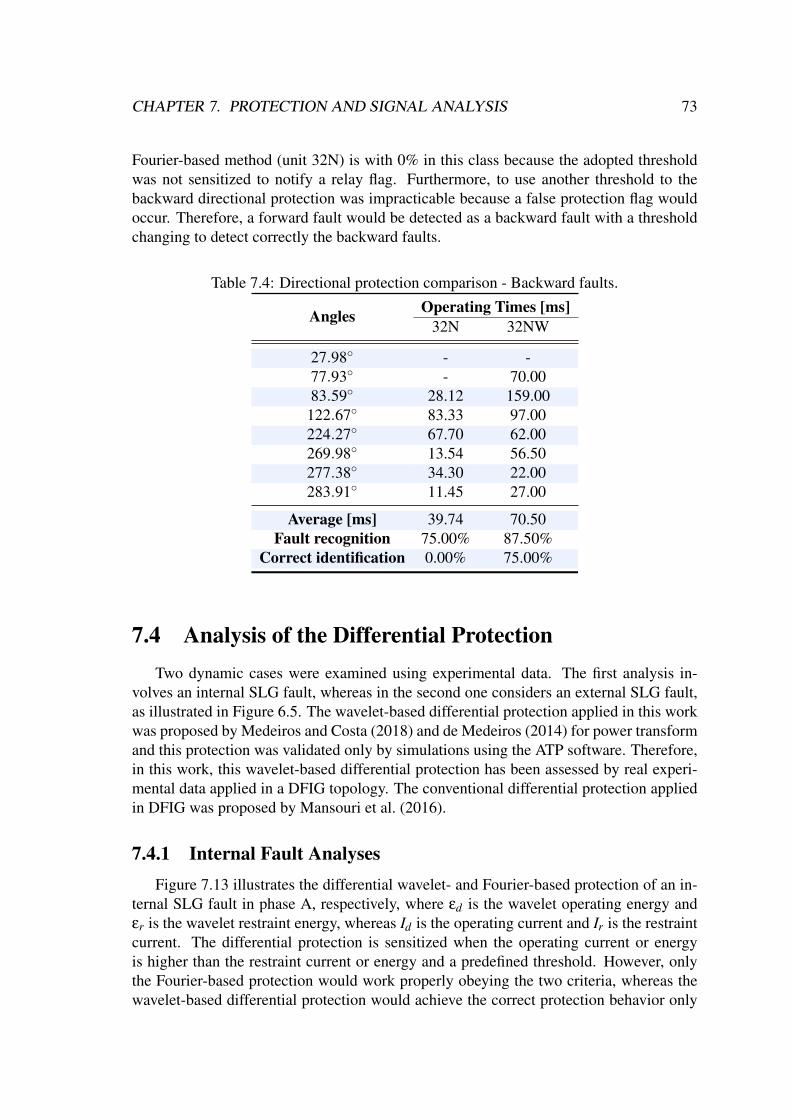
CHAPTER 7. PROTECTION AND SIGNAL ANALYSIS 73
Fourier-based method (unit 32N) is with 0% in this class because the adopted thresholdwas not sensitized to notify a relay flag. Furthermore, to use another threshold to thebackward directional protection was impracticable because a false protection flag wouldoccur. Therefore, a forward fault would be detected as a backward fault with a thresholdchanging to detect correctly the backward faults.
Table 7.4: Directional protection comparison - Backward faults.
Angles Operating Times [ms]32N 32NW
27.98 - -77.93 - 70.0083.59 28.12 159.00
122.67 83.33 97.00224.27 67.70 62.00269.98 13.54 56.50277.38 34.30 22.00283.91 11.45 27.00
Average [ms] 39.74 70.50Fault recognition 75.00% 87.50%
Correct identification 0.00% 75.00%
7.4 Analysis of the Differential ProtectionTwo dynamic cases were examined using experimental data. The first analysis in-
volves an internal SLG fault, whereas in the second one considers an external SLG fault,as illustrated in Figure 6.5. The wavelet-based differential protection applied in this workwas proposed by Medeiros and Costa (2018) and de Medeiros (2014) for power transformand this protection was validated only by simulations using the ATP software. Therefore,in this work, this wavelet-based differential protection has been assessed by real experi-mental data applied in a DFIG topology. The conventional differential protection appliedin DFIG was proposed by Mansouri et al. (2016).
7.4.1 Internal Fault AnalysesFigure 7.13 illustrates the differential wavelet- and Fourier-based protection of an in-
ternal SLG fault in phase A, respectively, where εd is the wavelet operating energy andεr is the wavelet restraint energy, whereas Id is the operating current and Ir is the restraintcurrent. The differential protection is sensitized when the operating current or energyis higher than the restraint current or energy and a predefined threshold. However, onlythe Fourier-based protection would work properly obeying the two criteria, whereas thewavelet-based differential protection would achieve the correct protection behavior only

CHAPTER 7. PROTECTION AND SIGNAL ANALYSIS 74
with uses the predefined threshold by (5.15) because the operating energy is higher thanthe restraint energy even in the steady-state.
Cur
rent
s (A
)
( a )
1 2 3 4 5 6 7 8 9 10 11 12 13 14 15 16 17 18 19 20
Cycles
Ene
rgy
( b )
IIdr
1.00.50.0
-0.5
1.52.02.5
d
r
10
10
10
-4
-1
2
Figure 7.13: Differential protection: (a) wavelet-based; (b) Fourier-based.
This wavelet-based protection problem was already expected because the frequen-cies of the rotor and stator current signals are different. The Fourier algorithm uses theabsolute value estimation, so this frequency difference did not change the final result.However, the wavelet algorithm works in the time-domain. Therefore, the current/energydifferential protection principle is broken because the current/energy comparison criteriaoperate with different current/energy amplitudes in the same time instant. Therefore, onepossible solution to this problem is to applying the Park transformation for synchronizingthe stator and rotor current vectors. However, disregarding the steady-state and consider-ing an appropriate threshold to the wavelet-based differential protection, this protectionwould operate properly.
Figure 7.14 illustrates the differential graphic (Ir× Id) and (εr× εd) generated by theFourier and wavelet algorithm, respectively. The Ipickup = 0.5 and k = 0.7 were chosen inorder to avoid false fault identification. Figure 7.14(a)-(b) illustrates two different areas,the internal fault area and the external fault/steady-state area, in which in the steady-statethe signal remains in the correct place, whereas in the fault inception time, the signalpasses through the threshold and achieve the fault region.
7.4.2 External Fault AnalysesFigure 7.15 illustrates the differential wavelet- and Fourier-based protections for an
external SLG fault in phase A, respectively. Figure 7.15(a) illustrates that the wavelet al-gorithm would not recognize an internal fault in the DFIG because the operating energy isabove the restraint energy during all analyzed period. However, Figure 7.15(a) illustratesa signal different behavior during the fault inception time. Furthermore, the operating

CHAPTER 7. PROTECTION AND SIGNAL ANALYSIS 75
1.01.2
1.41.6
1.82.0
0.8
0.6
0.4
0.20.0
0.0 0.5 1.0 1.5 2.0 2.5 3.0-0.5I
Id
r
Points duringinternal fault
Internal faultArea
External Fault/steady-state area
Points duringsteady-state
1.01.2
1.41.6
1.82.0
0.8
0.6
0.4
0.20.0
0.0 1.0 2.0 3.0
External Fault/steady-state area
d
r
Internal faultArea
( a ) ( b )
Figure 7.14: Differential graphic - Internal fault: a) Fourier method b) Wavelet method(normalized).
current (Id) illustrated in Figure 7.15(b) increased a small value in the fault inception time(in the fourteen cycle).
Cycles
( b )
0.4
0.2
0.0
1 2 3 4 5 6 7 8 9 10 11 12 13 14 15 16 17 18 19 20
( a )
IIdr
Cur
rent
s (A
)
d
r
Ene
rgy
10
10
10
-4
-1
0
Fault inceptiontime
Figure 7.15: Differential protection - External fault: (a) wavelet-based; (b) Fourier-based.
Figure 7.16 depicts the differential graphic from an external fault of the the Fourier-and wavelet-based method. Therefore, both protection differential methods had goodbehavior without a false trip occurrence. In the future, different cases such as machinesaturation, inter-turns faults, and energizing, need to be analyzed by real experimentaldata and simulations to observe whether will remain this behavior.
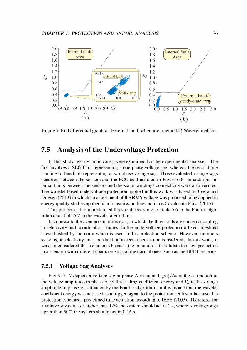
CHAPTER 7. PROTECTION AND SIGNAL ANALYSIS 76
1.01.2
1.41.6
1.82.0
0.8
0.6
0.4
0.20.0
0.0 0.5 1.0 1.5 2.0 2.5 3.0-0.5
Id0.4
0.43
0.350.0 0.1-0.1
Steady-state
External fault
Internal faultArea
1.01.2
1.41.6
1.82.0
0.8
0.6
0.4
0.20.0
0.5 1.0 1.5 2.0 2.5 3.00.0
Internal faultArea
d
Ir r( a ) ( b )
External Fault/steady-state area
Figure 7.16: Differential graphic - External fault: a) Fourier method b) Wavelet method.
7.5 Analysis of the Undervoltage ProtectionIn this study two dynamic cases were examined for the experimental analyses. The
first involves a SLG fault representing a one-phase voltage sag, whereas the second oneis a line-to-line fault representing a two-phase voltage sag. Those evaluated voltage sagsoccurred between the sensors and the PCC as illustrated in Figure 6.6. In addition, in-ternal faults between the sensors and the stator windings connections were also verified.The wavelet-based undervoltage protection applied in this work was based on Costa andDriesen (2013) in which an assessment of the RMS voltage was proposed to be applied inenergy quality studies applied in a transmission line and in de Cavalcante Paiva (2015).
This protection has a predefined threshold according to Table 5.6 to the Fourier algo-rithm and Table 5.7 to the wavelet algorithm.
In contrast to the overcurrent protection, in which the thresholds are chosen accordingto selectivity and coordination studies, in the undervoltage protection a fixed thresholdis established by the norm which is used in this protection scheme. However, in otherssystems, a selectivity and coordination aspects needs to be considered. In this work, itwas not considered these elements because the intention is to validate the new protectionin a scenario with different characteristics of the normal ones, such as the DFIG presence.
7.5.1 Voltage Sag AnalysesFigure 7.17 depicts a voltage sag at phase A in pu and
√εs
v/∆k is the estimation ofthe voltage amplitude in phase A by the scaling coefficient energy and Va is the voltageamplitude in phase A estimated by the Fourier algorithm. In this protection, the waveletcoefficient energy was not used as a trigger signal to the protection act faster because thisprotection type has a predefined time actuation according to IEEE (2003). Therefore, fora voltage sag equal or higher than 12% the system should act in 2 s, whereas voltage sagsupper than 50% the system should act in 0.16 s.
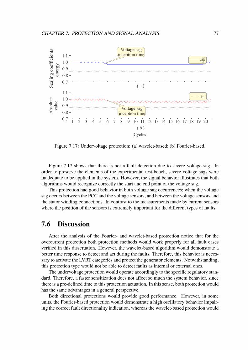
CHAPTER 7. PROTECTION AND SIGNAL ANALYSIS 77
Abs
olut
e va
lue
( a )
1 2 3 4 5 6 7 8 9 10 11 12 13 14 15 16 17 18 19 20
Cycles
1.1
1.0
0.9
0.7
( b )
0.8
Va
Sca
ling
coe
ffici
ents
en
ergy
1.1
1.0
0.9
0.7
0.8
v
Voltage sag inception time
Voltage sag inception time
Figure 7.17: Undervoltage protection: (a) wavelet-based; (b) Fourier-based.
Figure 7.17 shows that there is not a fault detection due to severe voltage sag. Inorder to preserve the elements of the experimental test bench, severe voltage sags wereinadequate to be applied in the system. However, the signal behavior illustrates that bothalgorithms would recognize correctly the start and end point of the voltage sag.
This protection had good behavior in both voltage sag occurrences; when the voltagesag occurs between the PCC and the voltage sensors, and between the voltage sensors andthe stator winding connections. In contrast to the measurements made by current sensorswhere the position of the sensors is extremely important for the different types of faults.
7.6 DiscussionAfter the analysis of the Fourier- and wavelet-based protection notice that for the
overcurrent protection both protection methods would work properly for all fault casesverified in this dissertation. However, the wavelet-based algorithm would demonstrate abetter time response to detect and act during the faults. Therefore, this behavior is neces-sary to activate the LVRT categories and protect the generator elements. Notwithstanding,this protection type would not be able to detect faults as internal or external ones.
The undervoltage protection would operate accordingly to the specific regulatory stan-dard. Therefore, a faster sensitization does not affect so much the system behavior, sincethere is a pre-defined time to this protection actuation. In this sense, both protection wouldhas the same advantages in a general perspective.
Both directional protections would provide good performance. However, in someunits, the Fourier-based protection would demonstrate a high oscillatory behavior impair-ing the correct fault directionality indication, whereas the wavelet-based protection would
CHAPTER 7. PROTECTION AND SIGNAL ANALYSIS 78
achieve a more stable and constant behavior. This protection would be able to detect thebackward fault directionality correctly by the zero sequence unit. Therefore, as this faulttype is the most common in the electrical system, this unit can be used as a prelimi-nary fault detection method to detect internal and external faults in the DFIG topology.Although, a deeper investigation is needed in order to develop a robust method capableto recognize even faults in the machine windings. Therefore, some scenarios, such asinter-turn, turn-to-turn, and coil-to-coil faults need a directionality investigation in futureworks. Thus, after this studies, a concrete fault detection method against forward faultswould be developed.
The differential wavelet-based protection would work properly when applied to theDFIG assembly when considered a predefined threshold. In addition, the wavelet oper-ating energy (εd) would act almost instantly in the fault inception time in Figure 7.13(a).Therefore, this element probably can be used as a fault detector due to its fast response todetect the internal fault events. However, some analysis such as inter-turn, turn-to-turn,coil-to-coil faults, machine saturation, and machine starting need to be done to ensure thisfeasibility.
7.7 SummaryIn this chapter, the DFIG variables signals in case of electrical faults were presented
and analyzed. Furthermore, analysis using the wavelet-based overcurrent, directional,differential, and undervoltage protections compared with the conventional ones were pre-sented, in order to assess these protections applied in an WECS scenario. Some of theseprotections are commonly applied in transmission lines, power transformers, and distri-bution systems. However, in this work was applied in a DFIG, where some of themdemonstrates a good performance in this environment.
Chapter 8
Conclusion
8.1 General ConclusionsThis master dissertation presented the performance analysis of how the wavelet- and
Fourier-based overcurrent, directional, differential and undervoltage protections wouldwork in a scenario with a DFIG connected to the power grid. These analyzes were ac-complished considering data from an experimental test bench. Some different fault typeswere analyzed, such as internal and external faults with different voltage inception angles.
Although all challenges present in this system, the analyzed overcurrent protectionwas correctly sensitized for all cases studied with real experimental data, obtained by aDFIG experimental test-bench, in which the wavelet-based method acts faster than theFourier-based one for this protection type in all units. This fast sensitization would beuseful to protect the machine against internal faults and as an LVRT categories trigger.
Both the wavelet- and conventional-based directional protections would presented asimilar behavior in the evaluated scenarios. However, to backward faults, the wavelet-based method would be better to identify the backward faults through the zero sequencecomponent unit. Furthermore, the wavelet-based method demonstrates a lower oscillatorybehavior in the sequence components units, which can provide a more reliable direction-ality detection.
The differential wavelet-based protection, as implemented, would achieve a good per-formance to detect internal faults whether considered a predefined threshold. In addition,the fault inception time was correctly recognized to all analyzed cases almost instantlybut the operating wavelet energy even in the steady state remained above the restraintwavelet energy which would give a false relay trip in a real-time application when thepredefined threshold is not considered. The Fourier-based algorithm would achieve thebest results. Many challenges still need to be overcome to achieve the expected resultsfor the wavelet-based method, such as the frequency difference of the rotor and the statorwindings.
Both the wavelet- and Fourier-based undervoltage protection obtained a similar per-formance, because this protection uses a pre-defined threshold with a pre-defined timeby norm to sensitize the relay. Therefore, the trigger wavelet, which can identify faultsalmost instantly, is not so expressive when applied in this protection type.
The current literature about this theme shows that there is no standardization to in-ternal protection applied in DFIGs. Therefore, this generator depends on conventional

CHAPTER 8. CONCLUSION 80
methods to detect and avoid all internal faults types, which are not reliable enough to givean accurate and efficient protection. In this fashion, the analyzed wavelet-based methodsprovided indication to be a reliable tool which can identify faults in the stator windingconnections faster than the conventional methods. Furthermore, in future, these wavelet-based strategies can be improved to be applied for detect inter-turn and coil-to-coil faults.Therefore, the promising analyzes by using the wavelet transform evidences the feasibil-ity of applying this mathematical tool for the development of specific detection methodsfor this application.
8.2 Future WorksBased on the presented research, the following tasks are proposed to be developed in
future works:
1. To apply more varieties of active faults in the DFIG system as well as compare thefault analysis and protections to simulated cases.
2. To propose and implement the wavelet-based overcurrent, directional, differentialand undervoltage protection in hardware to be assess in a real experimental DFIG.
3. To integrate all wavelet-based protections to be a complete WECS electrical pro-tection.
4. Development of a wavelet-based internal fault detection method capable to recog-nize all internal fault types in the rotor and stator windings.
5. Enhancement of the control techniques during faults to achieve the LVRT require-ments in conjunction with the protection system.
8.3 PublicationsAt this moment, this research resulted in the following papers:
Table 8.1: Papers resulted from the development of this work.Event/Journal Title Authors
Simpósio Brasileiro de SistemasElétricos - SBSE 2018
An experimental test bench forevaluation of techniques to en-hance the wind generator inte-gration to the grid*
M. R. Marques, F. E. V.Taveiros, F. B. Costa and L. S.Barros
3rd Workshop on Communica-tion Networks and Power Sys-tems - WCNPS 2018
Assessment of Wavelet-basedDirectional Overcurrent Protec-tion in a Distribution Systemwith DFIG*
Max Marques, Mônica Leal,Flavio Costa and Luciano Bar-ros
3rd Workshop on Communica-tion Networks and Power Sys-tems - WCNPS 2018
Performance of the Doubly-fedInduction Generator During aVoltage Sag*
Filipe Taveiros, Max Marques,Luciano Barros and FlavioCosta
* Published.

Bibliography
Abad, Gonzalo, Jesús López, Miguel Rodríguez, Luis Marroyo and Grzegorz Iwanski(2011), Doubly Fed Induction Machine: Modeling and Control for Wind EnergyGeneration Applications, IEEE.URL: https://ieeexplore.ieee.org/xpl/articleDetails.jsp?arnumber=6047768
Abadi, M. B., S. M. A. Cruz, A. P. Gonçalves, P. F. C. Gonçalves, A. M. S. Mendes, A.Ribeiro and F. Silva (2014), Detection of stator and rotor faults in a dfig based onthe stator reactive power analysis, em ‘IECON 2014 - 40th Annual Conference ofthe IEEE Industrial Electronics Society’, pp. 2037–2043.
Abdelemam, A. M. M., A. M. El-Rifaie and S. M. Moussa (2017), Discrete wavelet trans-form based protection for a wind farm double fed induction generator, em ‘2017IEEE International Conference on Environment and Electrical Engineering and 2017IEEE Industrial and Commercial Power Systems Europe (EEEIC / I CPS Europe)’,pp. 1–6.
Ackermann, T. (2005), Wind Power in Power System, Stockholm,Sweden: John Wiley &Sons Ltd.
Arun G. Phadke, James S. Thorp (2008), Synchronized Phasor Measurements and TheirApplications, SIAM.
BAGE (2017), Boletim Anual de Geração Eólica 2017, ABEEólica - AssociaçãoBrasileira de Energia Eólica.
Boutoubat, M., L. Mokrani and A. Zegaoui (2017), Power quality improvement by con-trolling the grid side converter of a wind system based on a dfig, em ‘2017 6thInternational Conference on Systems and Control (ICSC)’, pp. 360–365.
Comech, María Paz, Miguel García-Gracia, Susana Martín Arroyo and Miguel ÁngelMartínez Guillén (2011), Wind farms and grid codes, em G.Krause, ed., ‘From Tur-bine to Wind Farms’, IntechOpen, Rijeka, capítulo 2.URL: https://doi.org/10.5772/14873
Concordia, C., S. B. Crary and G. Kron (1942), ‘The doubly fed machine’, Transactionsof the American Institute of Electrical Engineers 61(5), 286–289.
Costa, F. B. (2014), ‘Fault-induced transient detection based on real-time analysis of thewavelet coefficient energy’, IEEE Transactions on Power Delivery 29(1), 140–153.
81

BIBLIOGRAPHY 82
Costa, F. B., A. Monti and S. C. Paiva (2017), ‘Overcurrent protection in distributionsystems with distributed generation based on the real-time boundary wavelet trans-form’, IEEE Transactions on Power Delivery 32(1), 462–473.
Costa, F. B. and J. Driesen (2013), ‘Assessment of voltage sag indices based on scal-ing and wavelet coefficient energy analysis’, IEEE Transactions on Power Delivery28(1), 336–346.
Costa, F.B., B. A. D. Souza and N. S. D. Brito (2010), ‘Detection and classification oftransient disturbances in power systems’, IEEJ Transactions on Power and Energy130, 910–916.
Dambhare, S., S. A. Soman and M. C. Chandorkar (2009), ‘Adaptive current differentialprotection schemes for transmission-line protection’, IEEE Transactions on PowerDelivery 24(4), 1832–1841.
Daubechies, Ingrid (1992), Ten lectures on wavelets. Philadelphia: CBMS-NSF RegionalConference Series, Springer.
de Cavalcante Paiva, Sâmara (2015), Proteção em sistemas elétricos com geração dis-tribuída utilizando a transformada wavelet, Dissertação de mestrado, UniversidadeFederal do Rio Grande do Norte.
de Medeiros, Rodrigo Prado (2014), Proteção diferencial de transformadores de potênciautilizando a transformada wavelet, Dissertação de mestrado, Universidade Federaldo Rio Grande do Norte.
Douglas, H., P. Pillay and P. Barendse (2005), The detection of interturn stator faultsin doubly-fed induction generators, em ‘Fourtieth IAS Annual Meeting. ConferenceRecord of the 2005 Industry Applications Conference, 2005.’, Vol. 2, pp. 1097–1102Vol. 2.
Franco, Flavio A. L., Fabio C. N. Caetano, Luan A. Sousa, Renato M. Monaro and Sil-vio G. Di Santo (2017), Estudo das protecoes de geradores eolicos duplamente ali-mentados em ambiente de co-simulacao embarcada, em ‘The 12th Latin-AmericanCongress on Electricity Generation and Transmission’, pp. 1–6.
Grossmann, A. and J. Morlet (1984), ‘Decomposition of hardy functions into squareintegrable wavelets of constant shape’, SIAM journal on mathematical analysis15(4), 331–371.
Guo, W., G. Zhang, J. Zhang, N. Song, Z. Gao, X. Xu, L. Jing, Y. Teng, Z. Zhuand L. Xiao (2018), ‘Development of a 1-mva/1-mj superconducting fault currentlimiter–magnetic energy storage system for lvrt capability enhancement and windpower smoothing’, IEEE Transactions on Applied Superconductivity 28(4), 1–5.
Guo, W., L. Xiao and S. Dai (2016), ‘Fault current limiter-battery energy storage systemfor the doubly-fed induction generator: analysis and experimental verification’, IETGeneration, Transmission Distribution 10(3), 653–660.

BIBLIOGRAPHY 83
GWS (2017), Global Wind Statistic 2017, Global Wind Energy Council.
Haar, Alfred (1910), Zur Theorie der orthogonalen Funktionensysteme, MathematischeAnnalen, Springer.
Hansen, Anca D., Gabriele Michalke, Poul Sørensen, Torsten Lund and Florin Iov (2007),‘Co-ordinated voltage control of dfig wind turbines in uninterrupted operation dur-ing grid faults’, Wind Energy 10(1), 51–68.URL: http:https://doi.org/10.1002/we.207
IEEE (2003), ‘Ieee standard for interconnecting distributed resources with electric powersystems’, IEEE Std 1547-2003 pp. 1–28.
IEEE Standard Inverse-Time Characteristic Equations for Overcurrent Relays (1996),IEEE Std C37.112-1996 pp. 1–20.
Ioannides, M. G. and J. A. Tegopoulos (1988), ‘Optimal efficiency slip-power recoverydrive’, IEEE Transactions on Energy Conversion 3(2), 342–348.
Ioannidou, M. G. and J. A. Tegopoulos (1987), ‘Performance of a doubly-fed inductionmotor with controlled rotor voltage magnitude and phase angle’, IEEE Transactionson Energy Conversion EC-2(2), 301–307.
Jun-qing, Li, Wang Dong and He Long (2013), Study of rotor winding inter-turn shortcircuit fault in doubly fed induction generator based on current signal spectrumanalysis, em ‘2013 International Conference on Electrical Machines and Systems(ICEMS)’, pp. 789–792.
Junqing, Li, He Long and Wang Dong (2013), Rotor winding inter-turn fault analysis ofdoubly-fed induction generator based on negative sequence component, em ‘2013International Conference on Electrical Machines and Systems (ICEMS)’, pp. 785–788.
Justo, Jackson John, Francis Mwasilu and Jin-Woo Jung (2015), ‘Doubly-fed inductiongenerator based wind turbines: A comprehensive review of fault ride-through strate-gies’, Renewable and Sustainable Energy Reviews 45, 447 – 467.URL: http://www.sciencedirect.com/science/article/pii/S136403211500074X
Kang, Y. C., H. G. Kang, J. H. Lee, T. Y. Zheng, B. E. Lee and G. C. Park (2009),Protection algorithm for the windings of a doubly-fed induction generator using thed-q equivalent circuits, em ‘2009 Transmission Distribution Conference Exposition:Asia and Pacific’, pp. 1–4.
Kasztenny, Bogdan, Dave Sharples, Bruce Campbell and Marzio Pozzuoli (2000), Fastground directional overcurrent protection–limitations and solutions, em ‘Proceed-ings of the 27th Annual Western Protective Relay Conference’, pp. 24–26.
BIBLIOGRAPHY 84
Kia, M. Y., M. Khedri, H. R. Najafi and M. A. Shamsi Nejad (2013), ‘Hybrid modelling ofdoubly fed induction generators with inter-turn stator fault and its detection methodusing wavelet analysis’, IET Generation, Transmission Distribution 7(9), 982–990.
Leal, Mônica Maria, Flavio Bezerra Costa and João Tiago Loureiro Sousa Campos(2019), ‘Improved traditional directional protection by using the stationary wavelettransform’, International Journal of Electrical Power and Energy Systems 105, 59 –69.
Li, H. and Z. Chen (2008), ‘Overview of different wind generator systems and their com-parisons’, IET Renewable Power Generation 2(2), 123–138.
Liwschitz, M. M. (1941), ‘Damping and synchronizing torque of the double-fed asyn-chronous machine’, Transactions of the American Institute of Electrical Engineers60(10), 923–924.
Mallat, S. G. (1989), ‘A theory for multiresolution signal decomposition: the waveletrepresentation’, IEEE Transactions on Pattern Analysis and Machine Intelligence11(7), 674–693.
Mansouri, M.Mahdi, Majid Nayeripour and Michael Negnevitsky (2016), Internal electri-cal protection of wind turbine with doubly fed induction generator, em ‘Renewableand Sustainable Energy Reviews’, Vol. 55, pp. 840 – 855.
Marques, M. R., F. E. V. Taveiros, F. B. Costa and L. S. Barros (2018), An experimentaltest bench for evaluation of techniques to enhance the wind generator integration tothe grid, em ‘2018 Simposio Brasileiro de Sistemas Eletricos (SBSE)’, pp. 1–6.
Medeiros, R. P. and F. B. Costa (2018), ‘A wavelet-based transformer differential protec-tion: Internal fault detection during inrush conditions’, IEEE Transactions on PowerDelivery pp. 1–1.
Muller, S., M. Deicke and R. W. De Doncker (2002), ‘Doubly fed induction generatorsystems for wind turbines’, IEEE Industry Applications Magazine 8(3), 26–33.
Noureldeen, O. and I. Hamdan (2017), An efficient anfis crowbar protection for dfig windturbines during faults, em ‘2017 Nineteenth International Middle East Power Sys-tems Conference (MEPCON)’, pp. 263–269.
Okedu, K. E. (2016), ‘Enhancing dfig wind turbine during three-phase fault using paral-lel interleaved converters and dynamic resistor’, IET Renewable Power Generation10(8), 1211–1219.
Okedu, K. E., S. M. Muyeen, R. Takahashi and J. Tamura (2012), ‘Wind farms fault ridethrough using dfig with new protection scheme’, IEEE Transactions on SustainableEnergy 3(2), 242–254.

BIBLIOGRAPHY 85
Pena, R., J. C. Clare and G. M. Asher (1996), ‘Doubly fed induction generator using back-to-back pwm converters and its application to variable-speed wind-energy genera-tion’, IEE Proceedings - Electric Power Applications 143(3), 231–241.
Percival, Donald B. and Andrew T. Walden (2000), Wavelet Methods for Time SeriesAnalysis, Cambridge Series in Statistical and Probabilistic Mathematics, CambridgeUniversity Press.
Polikar, Robi (1996), The wavelet tutorial, Rowan University.
Popa, L. M., B. B. Jensen, E. Ritchie and I. Boldea (2003), Condition monitoring of windgenerators, em ‘38th IAS Annual Meeting on Conference Record of the IndustryApplications Conference, 2003.’, Vol. 3, pp. 1839–1846 vol.3.
Quéval, L. and H. Ohsaki (2012), Back-to-back converter design and control for syn-chronous generator-based wind turbines, em ‘2012 International Conference on Re-newable Energy Research and Applications (ICRERA)’, pp. 1–6.
Rahim, A. H. M. A. (1988), ‘Stabilizing controls for a doubly fed synchronous-inductionmachine’, IEEE Transactions on Energy Conversion 3(4), 799–805.
Roberts, Jeff and Armando Guzman (1994), Directional element design and evaluation.
Roshanfekr, R. and A. Jalilian (2016), ‘Wavelet-based index to discriminate between mi-nor inter-turn short-circuit and resistive asymmetrical faults in stator windings ofdoubly fed induction generators: a simulation study’, IET Generation, TransmissionDistribution 10(2), 374–381.
Serrano-González, Javier and Roberto Lacal-Arántegui (2016), ‘Technological evolutionof onshore wind turbines—a market-based analysis’, Wind Energy 19(12), 2171–2187.URL: https://onlinelibrary.wiley.com/doi/abs/10.1002/we.1974
Shah, D., S. Nandi and P. Neti (2009), ‘Stator-interturn-fault detection of doubly fedinduction generators using rotor-current and search-coil-voltage signature analysis’,IEEE Transactions on Industry Applications 45(5), 1831–1842.
Shen, Y., D. Ke, W. Qiao, Y. Sun, D. S. Kirschen and C. Wei (2015), ‘Transient recon-figuration and coordinated control for power converters to enhance the lvrt of a dfigwind turbine with an energy storage device’, IEEE Transactions on Energy Conver-sion 30(4), 1679–1690.
Stefani, A., A. Yazidi, C. Rossi, F. Filippetti, D. Casadei and G. Capolino (2008), ‘Doublyfed induction machines diagnosis based on signature analysis of rotor modulatingsignals’, IEEE Transactions on Industry Applications 44(6), 1711–1721.
Stojcic, G., K. Pašanbegovic and T. M. Wolbank (2014), ‘Detecting faults in doubly fedinduction generator by rotor side transient current measurement’, IEEE Transactionson Industry Applications 50(5), 3494–3502.

BIBLIOGRAPHY 86
Taveiros, F. E. V., L. S. Barros and F. Bezerra Costa (2013), Wind turbine torque-speedfeature emulator using a dc motor, em ‘2013 Brazilian Power Electronics Confer-ence’, pp. 480–486.
Taveiros, Filipe Emanuel Vieira (2014), Sistema de conversão de energia eólica baseadono gerador de indução duplamente alimentado: análise e contribuição ao controle damáquina, Dissertação de mestrado, Universidade Federal do Rio Grande do Norte.
Taveiros, Filipe Emanuel Vieira (2018), A Novel Control Structure to Enhance the DFIG-based Wind Energy Conversion System Integration to the Grid, Tese de doutorado,Universidade Federal do Rio Grande do Norte.
Tremblay, E., A. Chandra and P. J. Lagace (2006), Grid-side converter control of dfigwind turbines to enhance power quality of distribution network, em ‘2006 IEEEPower Engineering Society General Meeting’, pp. 6 pp.–.
Vrionis, T. D., X. I. Koutiva and N. A. Vovos (2014), ‘A genetic algorithm-based lowvoltage ride-through control strategy for grid connected doubly fed induction windgenerators’, IEEE Transactions on Power Systems 29(3), 1325–1334.
Wu, Bin, Yongqiang Lang, Navid Zargari and Samir Kouro (2011), Power Conversionand Control of Wind Energy Systems, IEEE.URL: https://ieeexplore.ieee.org/xpl/articleDetails.jsp?arnumber=6047690
Xiao, X., R. Yang, X. Chen and Z. Zheng (2018), ‘Integrated dfig protection with a mod-ified smes-fcl under symmetrical and asymmetrical faults’, IEEE Transactions onApplied Superconductivity 28(4), 1–6.
Yaramasu, V., B. Wu, P. C. Sen, S. Kouro and M. Narimani (2015), ‘High-power wind en-ergy conversion systems: State-of-the-art and emerging technologies’, Proceedingsof the IEEE 103(5), 740–788.
Yazdani, A. and R. Iravani (2006), ‘A neutral-point clamped converter system for direct-drive variable-speed wind power unit’, IEEE Transactions on Energy Conversion21(2), 596–607.
Zarei, M. E., C. A. Platero, C. Veganzones and J. R. Arribas (2018), New differentialprotection for variable speed doubly fed induction machines, em ‘2018 XIII Inter-national Conference on Electrical Machines (ICEM)’, pp. 1906–1911.
Zou, Z., X. Xiao, Y. Liu, Y. Zhang and Y. Wang (2016), ‘Integrated protection of dfig-based wind turbine with a resistive-type sfcl under symmetrical and asymmetricalfaults’, IEEE Transactions on Applied Superconductivity 26(7), 1–5.

Appendix A
Experimental Test-bench
A.1 The Experimental Test-BenchFigure A.1 illustrates the DFIG experimental test-bench used to obtain real data to
the analysis of DFIG signals, which is essential for the development of new protectionand control strategies capable to enhance the DFIG employment in wind farms. Thisexperimental test bench was developed in Taveiros (2018).
CPU
GSCRSC
Rectifier to the DC- Motor
Voltage sensors
Breakingchopperresistance
DC-MotorDFIG
Filter bank
CrowbarCurrent sensors
Fault Generator
( a ) ( b )
Figure A.1: Experimental test bench: (a) Front; (b) Back.
The real DFIG parameters are specified in Table A.1, which are the main variablesused to design the system controls and perform the model simulations with a DFIG topol-ogy.
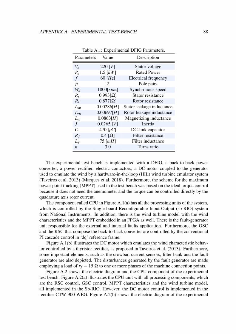
APPENDIX A. EXPERIMENTAL TEST-BENCH 88
Table A.1: Experimental DFIG Parameters.
Parameters Value Description
Vs 220 [V ] Stator voltagePn 1.5 [kW ] Rated Powerf 60 [Hz] Electrical frequencyp 2 Pole pairsWn 1800[rpm] Synchronous speedRs 0.993[Ω] Stator resistanceRr 0.877[Ω] Rotor resistanceLsσ 0.00286[H] Stator leakage inductanceLrσ 0.00697[H] Rotor leakage inductanceLm 0.0863[H] Magnetizing inductanceJ 0.0265 [V ] InertiaC 470 [µC] DC-link capacitorR f 0.4 [Ω] Filter resistanceL f 75 [mH] Filter inductancen 3.0 Turns ratio
The experimental test bench is implemented with a DFIG, a back-to-back powerconverter, a power rectifier, electric contactors, a DC-motor coupled to the generatorused to emulate the wind by a hardware-in-the-loop (HIL) wind turbine emulator system(Taveiros et al. 2013) (Marques et al. 2018). Furthermore, the scheme for the maximumpower point tracking (MPPT) used in the test bench was based on the ideal torque controlbecause it does not need the anemometer and the torque can be controlled directly by thequadrature axis rotor current.
The component called CPU in Figure A.1(a) has all the processing units of the system,which is controlled by the Single-board Reconfigurable Input-Output (sb-RIO) systemfrom National Instruments. In addition, there is the wind turbine model with the windcharacteristics and the MPPT embedded in an FPGA as well. There is the fault-generatorunit responsible for the external and internal faults application. Furthermore, the GSCand the RSC that compose the back-to-back converter are controlled by the conventionalPI cascade control in ‘dq’ reference frame.
Figure A.1(b) illustrates the DC motor which emulates the wind characteristic behav-ior controlled by a thyristor rectifier, as proposed in Taveiros et al. (2013). Furthermore,some important elements, such as the crowbar, current sensors, filter bank and the faultgenerator are also depicted. The disturbances generated by the fault generator are madeemploying a load of r f = 15 Ω to one or more phases of the machine connection points.
Figure A.2 shows the electric diagram and the CPU component of the experimentaltest bench. Figure A.2(a) illustrates the CPU unit with all processing components, whichare the RSC control, GSC control, MPPT characteristics and the wind turbine model,all implemented in the Sb-RIO. However, the DC motor control is implemented in therectifier CTW 900 WEG. Figure A.2(b) shows the electric diagram of the experimental

APPENDIX A. EXPERIMENTAL TEST-BENCH 89
test bench.
( a )
( b )
St1 - t6
Vgabc
PCC
isabc
Sa,g
Q f*
Vcc
vgabc
ifabc
Tem
VVT St1
I a
WAV Tem
*
St3
St6
Sa,r
Sb,r
Sc,r
Sa,g
Sb,g
Sc,g
Irabc Isabc Vsabc Qs
*
Vcc*
Vsabc
Vcc
Sb,g Sc,g Sc,gSb,gS
a,r
Ia
Tem
DC Motor DFIG
i fabc i rabc
SbRIO
GSC RSC
Wr
Wind turbinemodel
DC Motorcontrol
MPPT based on the ideal
torque characteristic
RSCcontrol
GSCcontrol
Figure A.2: Experimental test bench: (a) CPU unit; (b) Electrical diagram (Adapted fromMarques et al. (2018)).
There is a supervisory system used to connect the software with the hardware de-vices, which was implemented at the labview software in the G programing language. Onthis interface, it is possible to set manually or automatically the machine and the controlparameters, as well as capture and plot the transducer signals in real time, making it auser-friendly interface.
All DFIG signals data are able to be exported to the Matlab software. Therefore, allsignals collected can be processed in offline mode for different studies, which makes itpossible to process signals without the need to operate the system simultaneously because
APPENDIX A. EXPERIMENTAL TEST-BENCH 90
all data has already been stored in a database. Moreover, the system interface commandsthe online application of electrical faults.
The support for faults and voltage sags has been gaining a lot of attention nowadaysbecause there is an increasing number of WECS connected to the electrical grid. There-fore, one of the most main requirements imposed by the system operators is the abilityof wind turbines to remain connected to the grid in cases of disturbances. In order tomeet this requirement, the experimental test bench emulates some electrical disturbances,for instance, single-line, line-to-line faults or open-circuit events. Moreover, voltage sagsare able to be simulated. This tool is indispensable for conducting analyzes and studiesabout innovative control, fault detection, and protection methods capable of allowing thegenerator to remain connected or not to the grid at the moment of electrical disturbances.
Related Documents