Vol:.(1234567890) Petroleum Science (2021) 18:450–478 https://doi.org/10.1007/s12182-021-00546-1 1 3 REVIEW Water shutoff and conformance improvement: an introduction Randy Seright 1 · Bergit Brattekas 2 Received: 17 December 2020 / Accepted: 4 January 2021 / Published online: 4 February 2021 © The Author(s) 2021 Abstract This paper provides an introduction to the topic of water shutoff and conformance improvement. After indicating the volumes of water produced during oilfield operations, a strategy is provided for attacking excess water production problems. Problem types are categorized, typical methods of problem diagnosis are mentioned, and the range of solutions is introduced for each problem type. In the third section of the paper, the concept of disproportionate permeability reduction is introduced—where polymers and gels may reduce permeability to water more than to oil or gas. When and where this property is of value is discussed. The fourth section describes the properties of formed gels as they extrude through fractures and how those prop- erties can be of value when treating conformance problems caused by fractures. Section 5 covers the efficiency with which gels block fractures after gel placement—especially, the impact of fluids injected subsequent to the gel treatment. Keywords Water shutoff · Conformance improvement · Reservoir sweep improvement Abbreviations BOPD Barrels of oil per day BWPD Barrels of water per day C Final concentration, ppm (µg/g) C o Original concentration, ppm (µg/g) F r Resistance factor (water mobility/gelant or gel mobility) F rr Residual resistance factor (water mobility before gel/water mobility after) HPAM Partially hydrolyzed polyacrylamide h f Fracture height, ft (m) h 2 Height of layer 2, ft (m) k Permeability, D (μm 2 ) k 1 Permeability of layer 1, mD (μm 2 ) k 2 Permeability of layer 2, mD (μm 2 ) k f Fracture permeability, D (μm 2 ) k ro Relative permeability to oil k rw Relative permeability to water L Length, ft (m) L f Fracture length, ft (m) dL/dt Rate of gel propagation in a fracture, ft/d (m/d) Mw Polymer molecular weight, g/mol OOIP Original oil in place PV Pore volume dp/dl Pressure gradient, psi/ft (Pa/m) q tot Total injection rate, bbl/d (m 3 /d) R Correlation coefficient r gel Radius of gelant penetration, ft (m) S or Residual oil saturation S wr Residual-water saturation TDS Total dissolved solids t Time, d u l Leakoff rate, ft 3 /ft 2 /d [m 3 /m 2 /d] WOR Producing water/oil ratio w f Fracture width, ft (m) μ Viscosity, cp (mPa s) 1 Volumes of water produced Large volumes of saline water are produced during oil and gas production. In 2000, Bailey et al. (2000) reported that 3 barrels of water were produced for each barrel of oil— amounting to about 75 billion barrels of water at that time and costing an estimated $40 billion for disposal. Clark and Veil (2009) reported that 21 billion barrels of water were Edited by Yan-Hua Sun Handling Editor: Baojun Bai * Randy Seright [email protected] 1 New Mexico Institute of Mining and Technology, Socorro, NM, USA 2 Department of Physics and Technology, University of Bergen, Bergen, Norway

Welcome message from author
This document is posted to help you gain knowledge. Please leave a comment to let me know what you think about it! Share it to your friends and learn new things together.
Transcript
Vol:.(1234567890)
Petroleum Science (2021) 18:450–478https://doi.org/10.1007/s12182-021-00546-1
1 3
REVIEW
Water shutoff and conformance improvement: an introduction
Randy Seright1 · Bergit Brattekas2
Received: 17 December 2020 / Accepted: 4 January 2021 / Published online: 4 February 2021 © The Author(s) 2021
AbstractThis paper provides an introduction to the topic of water shutoff and conformance improvement. After indicating the volumes of water produced during oilfield operations, a strategy is provided for attacking excess water production problems. Problem types are categorized, typical methods of problem diagnosis are mentioned, and the range of solutions is introduced for each problem type. In the third section of the paper, the concept of disproportionate permeability reduction is introduced—where polymers and gels may reduce permeability to water more than to oil or gas. When and where this property is of value is discussed. The fourth section describes the properties of formed gels as they extrude through fractures and how those prop-erties can be of value when treating conformance problems caused by fractures. Section 5 covers the efficiency with which gels block fractures after gel placement—especially, the impact of fluids injected subsequent to the gel treatment.
Keywords Water shutoff · Conformance improvement · Reservoir sweep improvement
AbbreviationsBOPD Barrels of oil per dayBWPD Barrels of water per dayC Final concentration, ppm (µg/g)Co Original concentration, ppm (µg/g)Fr Resistance factor (water mobility/gelant or gel
mobility)Frr Residual resistance factor (water mobility before
gel/water mobility after)HPAM Partially hydrolyzed polyacrylamidehf Fracture height, ft (m)h2 Height of layer 2, ft (m)k Permeability, D (μm2)k1 Permeability of layer 1, mD (μm2)k2 Permeability of layer 2, mD (μm2)kf Fracture permeability, D (μm2)kro Relative permeability to oilkrw Relative permeability to water
L Length, ft (m)Lf Fracture length, ft (m)dL/dt Rate of gel propagation in a fracture, ft/d (m/d)Mw Polymer molecular weight, g/molOOIP Original oil in placePV Pore volumedp/dl Pressure gradient, psi/ft (Pa/m)qtot Total injection rate, bbl/d (m3/d)R Correlation coefficientrgel Radius of gelant penetration, ft (m)Sor Residual oil saturationSwr Residual-water saturationTDS Total dissolved solidst Time, dul Leakoff rate, ft3/ft2/d [m3/m2/d]WOR Producing water/oil ratiowf Fracture width, ft (m)μ Viscosity, cp (mPa s)
1 Volumes of water produced
Large volumes of saline water are produced during oil and gas production. In 2000, Bailey et al. (2000) reported that 3 barrels of water were produced for each barrel of oil—amounting to about 75 billion barrels of water at that time and costing an estimated $40 billion for disposal. Clark and Veil (2009) reported that 21 billion barrels of water were
Edited by Yan-Hua Sun
Handling Editor: Baojun Bai
* Randy Seright [email protected]
1 New Mexico Institute of Mining and Technology, Socorro, NM, USA
2 Department of Physics and Technology, University of Bergen, Bergen, Norway
451Petroleum Science (2021) 18:450–478
1 3
produced in the USA during 2007. Veil (2019) updated this number to 24.4 billion barrels for the year, 2017. Roughly half of this water is re-injected for waterflooding or enhanced oil recovery, and roughly half is injected into disposal wells. Although the salinity of this water can vary over a wide range (0.1%–40% total dissolved solids, TDS), the median salinity is 3.23% TDS and not usable for drinking or agri-cultural purposes (Benko and Drewes 2008).
From the operator’s viewpoint, produced water is gener-ally a nuisance that adds cost to hydrocarbon production. There are lifting costs (associated with lifting the water from the formation to the surface), processing costs (associated with oil/water separation), and disposal costs (associated with injecting water into a disposal well, if the water is not recycled for waterflood use). Further, produced water can accentuate costs associated with corrosion, scale forma-tion, sand production, formation damage, and environmental spills. One might consider half of the produced water as use-ful, in that it is re-injected for waterflooding operations (to displace oil). For the other half, it seems only a detriment.
Despite the costs and nuisance associated with water pro-duction, most operators choose to live with it. For example, with the recent boom in shale oil production in Southeast New Mexico (USA), typically four barrels of highly saline water were produced with each barrel of oil—with roughly 1 million BOPD produced here in early 2020 (Cather 2020). Because of infrastructure limitations, much of this water must be trucked to disposal wells, followed by injection at a cost of $0.65 per bbl. In spite of these costs, there was little interest in reducing the volume of water production. The zeal toward producing oil at $50–70/bbl greatly outweighed the cost of water treatment and disposal. Interestingly, for this area, less than 10% of the original oil in place will be recovered, given current projections.
Beyond living with the produced water, the next most common practice is either to sell the well or property or to simply shut in high water-cut wells. This approach is
reasonable if the oil saturation is low in the area around the well. If not, what should be done? This chapter is directed toward what can be done, other than just accepting the water production. Improving sweep efficiency and reducing chan-neling are also very relevant to enhanced oil recovery—since the operator would much prefer that expensive injected flu-ids (surfactant, polymer, CO2, steam, etc.) stay in the res-ervoir and displace oil rather than be produced too quickly. Thus, the concepts in this chapter should be of value for any enhanced oil recovery project.
2 A strategy to attack excess water production problems
There are many different reasons why water might be pro-duced during oil and gas production. Table 1 provides a list of many of those reasons (Seright et al. 2003).
Because each type of problem in Table 1 has a different character, each type of problem requires a different approach for solution. With unrestricted resources, the problem would be thoroughly characterized before attempting a solution. Unfortunately, for various reasons (most commonly, finan-cial or manpower-related), adequate characterization of the water production problem often does not occur. To help this situation, many people have offered strategies to attack water production problems (Aamodt et al. 2018; Chou et al. 1994; Elphick and Seright 1997; Kabir 2001; Love et al. 1998; Mennella et al. 1999; Pappas et al. 1996; Seright et al. 2003; Smith et al. 2006; Soliman et al. 2000; Sydansk and Romero-Zeron 2011) and suggested various categorizations of problems, in an attempt to simplify the analysis. The strat-egy that we advocate involves looking for and solving the easiest water production problems first. The problems in Table 1 are listed roughly in increasing order of difficulty to solve. Our strategy also advocates beginning the diagnostic process using information that is already available. Thus,
Table 1 Excess water production problems (categories are listed in increasing order of treatment difficulty)
1 Casing leaks2 Flow behind pipe3 Unfractured wells (injectors or producers) with effective barriers to crossflow4 Two-dimensional coning through a hydraulic fracture from an aquifer5 Natural fracture system leading to an aquifer6 Faults or fractures crossing a deviated or horizontal well7 Single fracture causing channeling between wells8 Natural fracture system allowing channeling between wells9 Three-dimensional coning10 Cusping11 Channeling through strata (no fractures), with crossflow12 Single zone (no fractures) with a high mobile water saturation
452 Petroleum Science (2021) 18:450–478
1 3
our approach advocates first examining existing information to determine whether any of the first listings in Table 1 are the problem, before assuming that any of the last listings are the problem. If uncertainty exists about the nature of the problem, the first new money spent on additional diagnosis would be better directed at the earlier problems on the list, rather than the later problems.
The strategy involves asking four questions in the fol-lowing order:
1. Is there a problem?2. Does the problem occur right at the wellbore?3. Is the problem due to a fracture or fracture-like feature?4. Is the problem accentuated by crossflow?
2.1 Is there a problem?
For the first question (Is there a problem?), one must ask whether the existing hydrocarbon recovery is unreasonably low for the pattern or collection of wells under considera-tion. The expected recovery depends on time, drive mecha-nism, pore volumes of fluid injected (usually water), water/oil mobility ratio, vertical heterogeneity, and pattern con-figuration. In a homogeneous, permeable reservoir with low oil viscosity that is efficiently produced by an edge-water drive, the expected recovery can be quite high. For example, the East Texas field (Wang et al. 2008) has produced over 5.42 billion barrels of ~ 7 billion barrels original oil in place (OOIP). For a linear waterflood in a thin homogeneous res-ervoir, fractional flow calculations generated Fig. 1—which plots expected oil recoveries as a function of pore volumes injected and oil/water viscosity ratio (using the conditions specified in the figure). When water displaces light (low viscosity) oil, most of the mobile oil saturation can be dis-placed very efficiently by injected water. However, as the oil
viscosity increases, the efficiency of displacement decreases. In Fig. 1, note that at 1 PV of water injection, the mobile oil recovered decreases by about 10 percentage points for each factor of 10 increase in oil viscosity.
If the injection-production pattern changes from a perfect linear displacement (as in Fig. 1, or perhaps, between paral-lel horizontal injection/production wells) to a homogeneous five-spot pattern, the efficiency of waterflooding decreases by about 20% for a unit-mobility ratio (Craig 1971; Willhite 1986). Vertical heterogeneity (i.e., layering, fractures) can dramatically decrease reservoir sweep efficiency, especially for unfavorable mobility ratios with free crossflow (Craig 1971). Craig (1971) and Willhite (1986) discussed estima-tion of recovery efficiency as a function of well pattern, reservoir layering, permeability contrast, and oil viscosity. These references (along with standard reservoir engineer-ing calculations/simulations) should be consulted to assess whether the observed producing water/oil ratio is unexpect-edly high for your particular reservoir and wells.
2.2 Does the problem occur right at the wellbore?
The easiest excess water production problems to fix occur right at the wellbore—including flow behind pipe, casing leaks, and isolated water zones. Cement is the most common water-control material (Smith 1990), especially since it is used for all completions—to seal between the formation and the casing so that hydrocarbon-productive zones are isolated from non-productive zones.
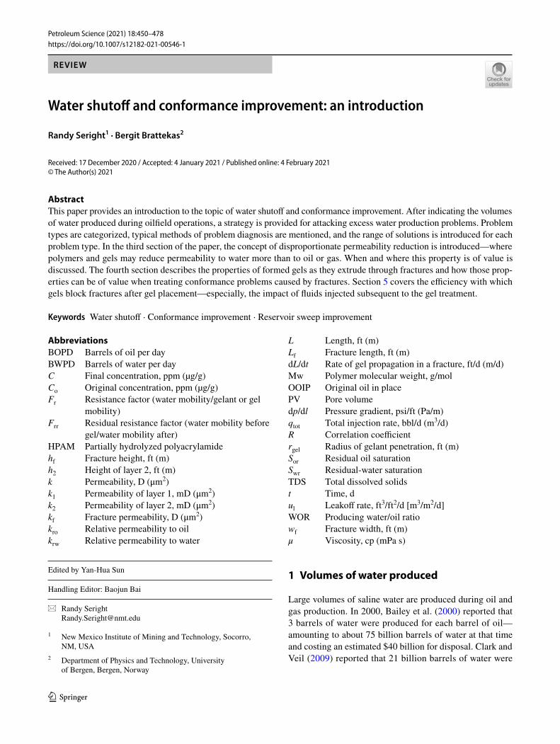
2.2.1 Flow behind pipe
Problems with flow behind pipe (Fig. 2) exist if the pri-mary cement placement was inadequate or if the primary cement fails (separates from the pipe or formation) after completion of the well. Common ways to detect flow behind pipe (Bassiouni 1994; Hill 1990) include cement bond logs, temperature surveys, and noise logs (if gas flows behind pipe). Problems with flow behind pipe are most commonly addressed using cement squeezes (Smith 1990). These
100
90
80
70
60
50
40
30
20
10
0
Mob
ile o
il re
cove
red,
%
0.01 0.1
Pore volumes of water injected1 10 100
1 cp oil
1 cp waterinjected
105 cp oil
10 cp oil103 cp
One layer, 1 cp water,linear flow, no polymer
104 cp100 cp
krw = 0.1[(Sw - 0.12)/0.76]4
kro = [(0.88 - Sw)/0.76]2.5
1 - Sor - Swr = 0.76
Fig. 1 Expected oil recovery versus PV of water injected
Oil
Water
Fig. 2 Flow behind pipe

453Petroleum Science (2021) 18:450–478
1 3
methods usually require a workover rig, and consequently, are expensive to perform. If the channel behind pipe is quite narrow (often associated with gas or separation of the cement from the formation or pipe), cement may not be able to penetrate effectively into the channel. For these cases, gel treatments have often worked (Odorisio and Curtis 1992; Perez et al. 1997; Whitney et al. 1996). Gels are able to penetrate into very narrow channels, whereas cement often cannot. Once set, gels can have sufficient strength to resist significant pressure gradients within narrow channels or within porous media. However, they usually rupture very easily in wider channels. In contrast, cements have much greater compressive and tensile strengths (many 1000s of psi) (Smith 1990).
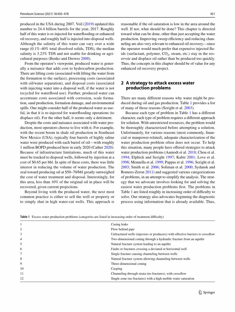
2.2.2 Casing leaks
Casing leaks (Fig. 3) are most commonly treated with either cement or mechanical devices (casing patches, packers, etc.) (Ernens et al. 2019; Al-Dhafeeri et al. 2020; Macrae 1997; Smith 1990). For very small leaks (pinhole leaks), cement often is ineffective—again because of limitations in pen-etrating small openings. Gels have been used at times to treat these small leaks (Creel and Crook 1997; Jia et al. 2020; Jurinak and Summers 1991; Urdahl et al. 1992). Leaks are commonly diagnosed with pressure tests, flow surveys (e.g., spin flowmeter), or wellbore televiewers (Johns et al. 2009; Smith 1990; Ward et al. 1994).
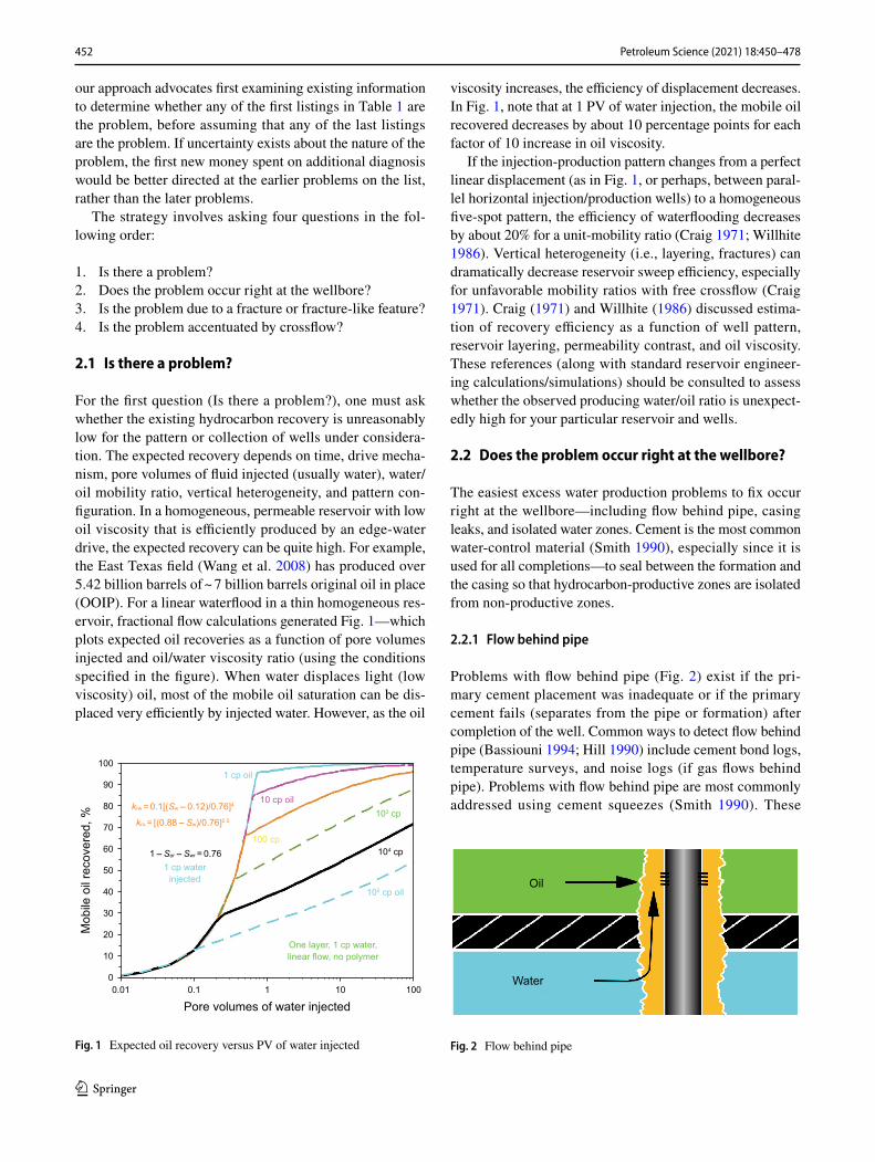
2.2.3 Isolated water zones
In many cases, the natural stratification provides flow bar-riers (e.g., shale, anhydride layers) between oil zones and water zones (Fig. 4). For those instances, isolation within the wellbore is typically pursued. In particular, for cases where water from an underlying aquifer gradually rises to flood oil zones, plug backs can effectively shut off encroaching water (Smith 1990)—where cement is placed in the bot-tom of the well. For cases where isolated water zones exist above isolated oil zones, mechanical devices are commonly
used to stop water inflow. Gels have been used in some cases (Fulleylove et al. 1996; Plahn et al. 1997). The reader must recognize that these methods cannot be effective if fluids can crossflow beyond the wellbore. Effective barri-ers that isolate the water zone are detected most effectively by observing a significant pressure difference between the water zone and other zones (after accounting for gravity) (Seright et al. 2003). Flow profiles and well logs are also helpful (Bassiouni 1994; Hill 1990).
2.2.4 Deviated or horizontal wells
Deviated or horizontal wells present a special challenge for water control. On the one hand, the well can be drilled exclusively in the hydrocarbon zone of interest—thereby, theoretically avoiding water zones. Unfortunately, hydrocar-bon zones still possess heterogeneity in the areal and verti-cal directions. Water inflow from an underlying formation can be uneven because of variations in formation thickness, vertical permeability, and placement of the well. In particu-lar, vertical fractures or non-sealing faults can cross these wells—and allow water inflow from other formations. Diag-nosis of when water enters the horizontal well is crucial information and can be accomplished using flow profiles (Cramer et al. 2020; Cui et al. 2016; Yoshioka et al. 2007). However, because of the cost and technical challenges asso-ciated with obtaining flow profiles, they are not commonly performed. Thus, making flow profiles more cost-effective or easier to perform is an important need.
Various completion types have been used for horizon-tal wells, including open hole, cased hole with cemented screens, pre-drilled or slotted liners, and various inflow con-trol devices (Aljubran and Horne 2020; Furui et al. 2007; Thompson et al. 2011). Most of these allow little or no control over fluid inflow after they are installed. Common inflow flow devices are basically pipe with a certain num-ber of openings/holes per unit of length (Augustine et al. 2008; Daneshy et al. 2012; Dikshit et al. 2020; Montero Pallares et al. 2020). More advanced inflow flow devices have mechanically activated sliding sleeves to open or cover
Water
Oil
Fig. 3 Casing leak
Water
Oil
Fig. 4 Isolated open water zone
454 Petroleum Science (2021) 18:450–478
1 3
the openings (Al-Khelaiwi et al. 2010; Augustine and Meijs 2011; Langaas et al. 2019; Li et al. 2011).
Autonomous inflow control devices have been offered which claim to selectively allow hydrocarbon entry while reducing or eliminating water entry into the pipe (Yang et al. 2020). These claims appear misleading or dubious. If the formation provides a certain fractional flow of water and oil to a particular opening in the pipe, a mass balance dic-tates that fractional flow must be maintained. Thus, even if these static pieces of metal could distinguish between oil and water, they cannot change the fractional flow. One could argue that a device might allow some degree of selectivity by changing the flow from laminar to turbulent at the point of entry into the pipe. In laminar flow, flow capacity is directly proportional to fluid viscosity, while in turbulent flow, flow capacity is directly proportional to density and much less sensitive to viscosity. If the oil is viscous, one might argue that forcing the flow to become turbulent favors oil entry over water (because the water is denser than oil). There are multiple flaws with this argument. First, changing the flow regime from laminar to turbulent necessarily means that the pressure drop across the device is increased dramatically, so all fluids will experience more resistance to entering the pipe. Second, if you knew enough about the local pressure conditions and fluids present at the device’s location to pre-dict whether flow could transition from laminar to turbulent, it would be far more cost-effective to either complete or not complete the interval without using the expensive autono-mous inflow control device.
Another type of passive inflow control device uses buoy-ant balls to open or close an opening, depending on whether oil or water is present (Augustine and Meijs 2011). Although these devices have a reasonable underlying concept, their acceptance is not yet widespread.
Some of the mechanical methods used for vertical wells are also used to control water in horizontal and deviated wells, including through-tubing bridge plugs (Al-Ghasham 2005; Al-Zubail et al. 2003), through-tubing bridge plugs with cement (Dashash et al. 2008), and coiled tubing with inflatable packers (Al-Dhafeeri et al. 2012; Al-Shahrani et al. 2007).
Intelligent completions (smart wells) are another method for control in multilateral wells (Al-Zain et al. 2016). Valves are located downhole where a lateral segment joins the main lateral. By adjusting these valves, the contributions from the high water-cut laterals can be reduced or shutoff, while allowing open flow from the more productive laterals.
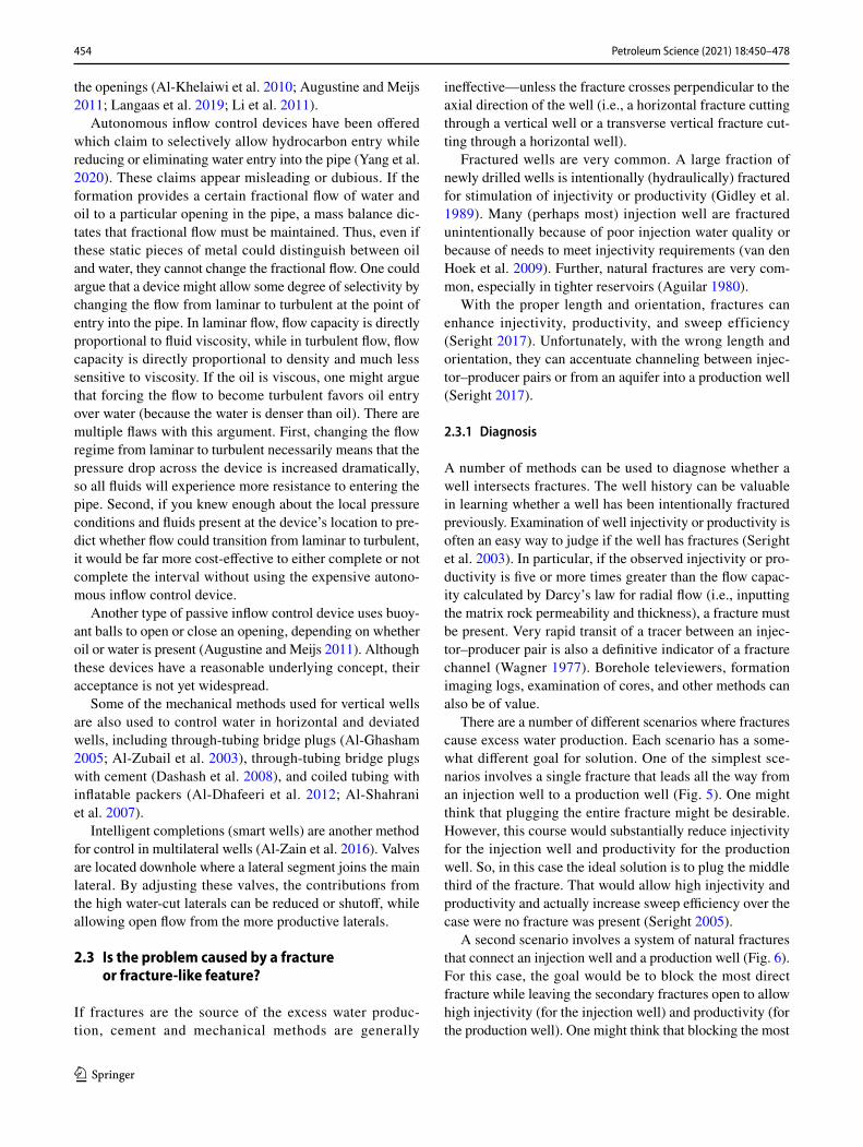
2.3 Is the problem caused by a fracture or fracture‑like feature?
If fractures are the source of the excess water produc-tion, cement and mechanical methods are generally
ineffective—unless the fracture crosses perpendicular to the axial direction of the well (i.e., a horizontal fracture cutting through a vertical well or a transverse vertical fracture cut-ting through a horizontal well).
Fractured wells are very common. A large fraction of newly drilled wells is intentionally (hydraulically) fractured for stimulation of injectivity or productivity (Gidley et al. 1989). Many (perhaps most) injection well are fractured unintentionally because of poor injection water quality or because of needs to meet injectivity requirements (van den Hoek et al. 2009). Further, natural fractures are very com-mon, especially in tighter reservoirs (Aguilar 1980).
With the proper length and orientation, fractures can enhance injectivity, productivity, and sweep efficiency (Seright 2017). Unfortunately, with the wrong length and orientation, they can accentuate channeling between injec-tor–producer pairs or from an aquifer into a production well (Seright 2017).
2.3.1 Diagnosis
A number of methods can be used to diagnose whether a well intersects fractures. The well history can be valuable in learning whether a well has been intentionally fractured previously. Examination of well injectivity or productivity is often an easy way to judge if the well has fractures (Seright et al. 2003). In particular, if the observed injectivity or pro-ductivity is five or more times greater than the flow capac-ity calculated by Darcy’s law for radial flow (i.e., inputting the matrix rock permeability and thickness), a fracture must be present. Very rapid transit of a tracer between an injec-tor–producer pair is also a definitive indicator of a fracture channel (Wagner 1977). Borehole televiewers, formation imaging logs, examination of cores, and other methods can also be of value.
There are a number of different scenarios where fractures cause excess water production. Each scenario has a some-what different goal for solution. One of the simplest sce-narios involves a single fracture that leads all the way from an injection well to a production well (Fig. 5). One might think that plugging the entire fracture might be desirable. However, this course would substantially reduce injectivity for the injection well and productivity for the production well. So, in this case the ideal solution is to plug the middle third of the fracture. That would allow high injectivity and productivity and actually increase sweep efficiency over the case were no fracture was present (Seright 2005).
A second scenario involves a system of natural fractures that connect an injection well and a production well (Fig. 6). For this case, the goal would be to block the most direct fracture while leaving the secondary fractures open to allow high injectivity (for the injection well) and productivity (for the production well). One might think that blocking the most

455Petroleum Science (2021) 18:450–478
1 3
direct channel would be of limited value because injected water would simply channel through the next most direct fracture. However, one must realize that natural fractures tend to follow a log-normal distribution of widths (Macaulay et al. 2016). Also, the conductivity of a given fracture is proportional to the third power of fracture width (Gidley et al. 1989; Seright and Lee 1999). Thus, only one or two fractures are likely responsible for the vast majority of the channeling problem. If the second-most conductive frac-ture has half the width of the most conductive fracture, the second-most conductive fracture will have only one-eighth the conductivity of the most conductive fracture. If the most conductive fracture is plugged, water channeling could be reduced by over 80% (so water is diverted into other parts of the reservoir to displace oil).
In a vertical production well, a single hydraulic fracture might lead from the well down into an aquifer (Fig. 7). In this case, one would like to plug the lower part of the frac-ture (in the aquifer), while leaving the upper of the fracture open so that oil can flow freely to the well (Seright et al. 1998, 1993).
For a vertical production well in a naturally fractured reservoir, a system of fractures may lead down to an aqui-fer (Fig. 8). Here, the goal would be to plug the fractures leading down into the aquifer while leaving the fractures open in the oil zone (Amaury et al. 2002).
In a horizontal production well, a fracture or fault may cross the well and lead to an aquifer (Fig. 9). In this case, the goal would be to plug the fracture without damaging
Fracture
Oil
Water
Fig. 5 Water channeling from an injector to a producer through a sin-gle fracture
Injector Producer
Fig. 6 Water channeling from an injector to a producer through natu-ral fractures
Fracture
Shalebarrier
Fig. 7 Fracture leading from a vertical production well down to an aquifer
Oil
Water
Fig. 8 Natural fractures leading from a vertical production well down to an aquifer
Oil
Water
Horizontal wellFracture orfault
Fig. 9 Fracture leading from a horizontal production well down to an aquifer
456 Petroleum Science (2021) 18:450–478
1 3
those parts of the horizontal well in the remainder of the oil zone (Lane and Sanders 1995; O’Brien et al. 1999).
Gels are the most effective means that we currently have to treat excess water production through fractures (Borling 1994; Hild and Wackowski 1999; Lane and Sanders 1995; O’Brien et al. 1999; Sydansk and Moore 1992; Sydansk and Southwell 2000). Cement cannot penetrate into narrow fractures, and in wide fractures, gravity segregation makes the cement drop to the lower part of the fracture—leaving the upper part open (Seright 1995a; Seright et al. 2003). Foams may reduce fracture conductivity during injection, but wash out of fractures too easily (Hughes et al. 1999; Kantzas et al. 1999) during chase floods.
Continuous injection of foam reduces fracture chan-neling (Haugen et al. 2014), but may be considered a method for enhanced oil recovery rather than a fracture remediation approach, and requires a high ratio of injected gas compared to surfactant enriched water.
2.4 If the problem is associated with matrix flow, is the problem accentuated by crossflow?
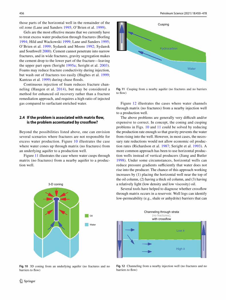
Beyond the possibilities listed above, one can envision several scenarios where fractures are not responsible for excess water production. Figure 10 illustrates the case where water cones up through matrix (no fractures) from an underlying aquifer to a production well.
Figure 11 illustrates the case where water cusps through matrix (no fractures) from a nearby aquifer to a produc-tion well.
Figure 12 illustrates the cases where water channels through matrix (no fractures) from a nearby injection well to a production well.
The above problems are generally very difficult and/or expensive to correct. In concept, the coning and cusping problems in Figs. 10 and 11 could be solved by reducing the production rate enough so that gravity prevents the water from rising into the well. However, in most cases, the neces-sary rate reductions would not allow economic oil produc-tion rates (Richardson et al. 1987; Seright et al. 1993). A more common approach has been to use horizontal produc-tion wells instead of vertical producers (Jiang and Butler 1998). Under some circumstances, horizontal wells can reduce pressure gradients sufficiently that water does not rise into the producer. The chance of this approach working increases by (1) placing the horizontal well near the top of the oil column, (2) having a thick oil column, and (3) having a relatively light (low density and low viscosity) oil.
Several tools have helped to diagnose whether crossflow through matrix occurs in a reservoir. Well logs can identify low-permeability (e.g., shale or anhydrite) barriers that can
3-D coning
Oil
Water
Fig. 10 3D coning from an underlying aquifer (no fractures and no barriers to flow)
Cusping
Hydrocarbon
Water
Fig. 11 Cusping from a nearby aquifer (no fractures and no barriers to flow)
Channeling through strata(no fractures),with crossflow
Low k
High k
Fig. 12 Channeling from a nearby injection well (no fractures and no barriers to flow)
457Petroleum Science (2021) 18:450–478
1 3
inhibit crossflow (Bassiouni 1994; Hill 1990). Perhaps, the most effective means to assess crossflow is to place a packer between the zones of interest and examine whether a pres-sure difference can be maintained (Russell and Prats 1962; Seright et al. 2003).
2.4.1 WOR diagnostic plots
A valuable indication of the origin of an excess water prob-lem can come from plots of water/oil ratio (WOR) ver-sus time (Chan 1995; Seldal 1997; Seright 1997a). When viewed along with other information, these plots can also help identify the cause of the problem. In spite of aggres-sive claims to the contrary, these diagnostic plots (of WOR or WOR derivative versus time) should not be used alone to diagnose excessive water production mechanisms and prob-lems (Seldal 1997; Seright 1997a). WOR diagnostic plots were touted as capable of distinguishing whether premature water breakthrough is caused by water coning or channeling through high-permeability layers (Chan 1995). Supposedly, gradually increasing WOR curves with negative derivative slopes are unique for coning problems, and rapidly increas-ing WOR curves with positive derivative slopes are indica-tive of a channeling problem. This method is not used to dis-tinguish between linear flow (fracture or flow behind pipe) and radial flow for either channeling or coning. Previous work (Seright 1995a) has proven that the distinction between linear flow (associated with fractures) or radial flow (asso-ciated with unfractured matrix) is extremely important to water shutoff and conformance improvement—much more so than whether the problem is due to generic channeling or coning.
Reservoir models were built for water coning and chan-neling, and sensitivity analyses were conducted using numerical simulation (Seldal 1997; Seright 1997a). Res-ervoir and fluid parameters were varied to examine WOR and WOR derivative behavior for both coning and chan-neling production problems. The study demonstrated that multi-layer channeling problems could easily be mistaken as bottom-water coning, and vice versa, if WOR diagnostic plots are used alone to identify an excessive water produc-tion mechanism. Consequently, WOR diagnostic plots can easily be misinterpreted and should not be used alone to diagnose the specific cause of a water production problem (Seldal 1997; Seright 1997a).
2.4.2 Polymer flooding
In particular for reservoirs with viscous oils, polymer flood-ing can be an effective solution for the problem in Fig. 12 (Green and Willhite 1998; Seright 2010, 2017; Sorbie and Seright 1992). With the proper design and conditions, a pol-ymer front can displace oil out of low-permeability zones as
efficiently as in an adjacent high-permeability zone (Seright 2010, 2017; Sorbie and Seright 1992). Polymer flooding is a proven technology. Nevertheless, despite claims to the contrary, we would not characterize polymer flooding as a mature technology. Many improvements remain to be made in cost-effectiveness, polymer stability, polymer propaga-tion (i.e., retention), process design, and understanding of mechanism of action (especially regarding the feasibility of displacement of capillary-trapped residual oil). Polymer floods involve significant expense and commitment since typically polymer banks injected must be in the range of 50%–100% pore volume (Seright 2017).
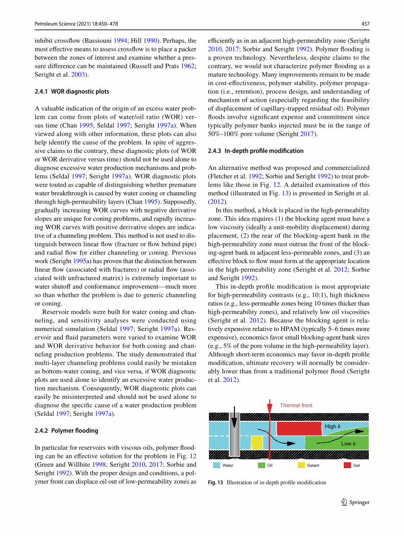
2.4.3 In‑depth profile modification
An alternative method was proposed and commercialized (Fletcher et al. 1992; Sorbie and Seright 1992) to treat prob-lems like those in Fig. 12. A detailed examination of this method (illustrated in Fig. 13) is presented in Seright et al. (2012).
In this method, a block is placed in the high-permeability zone. This idea requires (1) the blocking agent must have a low viscosity (ideally a unit-mobility displacement) during placement, (2) the rear of the blocking-agent bank in the high-permeability zone must outrun the front of the block-ing-agent bank in adjacent less-permeable zones, and (3) an effective block to flow must form at the appropriate location in the high-permeability zone (Seright et al. 2012; Sorbie and Seright 1992).
This in-depth profile modification is most appropriate for high-permeability contrasts (e.g., 10:1), high thickness ratios (e.g., less-permeable zones being 10 times thicker than high-permeability zones), and relatively low oil viscosities (Seright et al. 2012). Because the blocking agent is rela-tively expensive relative to HPAM (typically 5–6 times more expensive), economics favor small blocking-agent bank sizes (e.g., 5% of the pore volume in the high-permeability layer). Although short-term economics may favor in-depth profile modification, ultimate recovery will normally be consider-ably lower than from a traditional polymer flood (Seright et al. 2012).
Low k
High k
Thermal front
Water Oil Gelant Gel
Fig. 13 Illustration of in-depth profile modification

458 Petroleum Science (2021) 18:450–478
1 3
The commercial process (Pritchett et al. 2003) usually involves reservoirs with a thermal front. Cold water is some-times injected into hot reservoirs, creating a thermal front that moves through the reservoir more slowly and evenly than the displacement front (Fletcher et al. 1992). If a gelant is injected that is heat-activated, a plug could form in the high-permeability strata after the formulation passes the thermal front. With correct planning, no plug forms in the less-permeable strata because the gelant never reaches the thermal front (so the gelant never becomes hot enough to react and form a gel).
The commercialized concept uses polymer particles that pop or swell when activated (Chang et al. 2002; Frampton et al. 2004). The material contains cross-linked sulfonate-containing microparticles (0.1–3 µm in diameter) with both labile and stable internal cross-links (Frampton et al. 2004). The kernel particles are produced as a 30% disper-sion in light mineral oil. This dispersion is diluted using a surfactant (surfactant/polymer ratio of 1:2–1:3) to prepare polymer concentrations from 3000 ppm to 4500 ppm (Fethi et al. 2010; Pritchett et al. 2003). The polymer cost $5.71/lb in 2003 (Pritchett et al. 2003). Activation commonly occurs upon heating. The polymer particles are intended to swell when they pass the thermal front in high-permeability watered-out strata, thus diverting subsequently injected water/fluids into the less-permeable oil strata. Estimated resistance factors for the popped polymer ranged from 11 to 350 (Frampton et al. 2004; Husband et al. 2010; Ohms et al. 2010). Field applications of the process have occurred in Indonesia (Pritchett et al. 2003), Argentina (Paez Yanez et al. 2007), Alaska (Husband et al. 2010; Ohms et al. 2010), and Tunisia (Fethi et al. 2010). Ohms et al. (2010) reported injecting ~ 40,000 lbs of polymer (38,000 bbl with 3,300-ppm polymer), and recovering ~ 60,000 bbl of oil. Husband et al. (Husband et al. 2010) reported injecting ~ 200,000 lbs of polymer (190,000 bbl with 3000 ppm polymer) into three wells, and recovering ~ 500,000 bbl of oil. Interestingly, suc-cessful polymer floods commonly recover two or more times more oil per pound of polymer than observed with this in-depth profile modification method (Taber et al. 1997). In general, polymer flooding is a much less complicated, less risky, and more cost-effective method than in-depth profile modification (Seright et al. 2012). Seright et al. (2012) pro-vide a much more detailed comparison.
2.4.4 Foams
In theory, there are circumstances where foams could provide improved sweep compared to polymer solutions (Zhang and Seright 2007). These circumstances require the following: (1) foam forms in high-permeability path-ways but not in low-permeability strata, (2) no crossflow occurs between high- and low-permeability strata, and (3)
the foam resistance factor in the high-permeability strata is high enough to overcome the permeability contrast and the unfavorable mobility ratio between the gas bank and the oil/water bank in the less-permeable strata. Foams will generally not be superior to polymers under other circum-stances unless gravity effects provide a fortuitous benefit. Other limitations for foams must be recognized, including (1) difficulties formulating foams to meet the above require-ments, (2) challenges with foam propagation, especially due to surfactant retention, (3) compression costs associated with foam injection, and (4) limitations on foam stability under reservoir conditions. Another major challenge is control of the effective viscosity or mobility reduction provided in situ. In a given mobility control application, there is an optimum level of mobility desired for the injected fluid. Too little viscosity (or mobility reduction) leads to inefficient displacement, while too much viscosity leads to injectiv-ity problems. For polymer solutions, any desired viscosity level can be achieved very accurately simply by adjusting the polymer concentration. In contrast, most foams allow little or no control over the level of mobility reduction provided. Although several applications of foams have been reported in an attempt to improve conformance (Li et al. 2010; Wang et al. 2001; Zhdanov et al. 1996), they cannot yet be consid-ered a proven technology for water shutoff. Foams could, however, be more useful for gas shutoff purposes and ben-eficial when using CO2 in enhanced oil recovery applica-tions (Sharma et al. 2020). Using CO2 as a foam processing solvent may replace organic solvents such as chlorofluoro-carbons that are being phased out for environmental reasons, and promote improved CO2 storage in mature oil reservoirs (Alcorn et al. 2019). Combinations of polymer and foam injection, like polymer enhanced foams and foamed gels could overcome some inherent drawbacks of both methods but have not been widely investigated (Hughes et al. 1999; Kantzas et al. 1999).
2.4.5 Colloidal dispersion gels
Colloidal dispersion gels (Chang et al. 2004; Manrique et al. 2014; Spildo et al. 2009) are formulations that typi-cally contain low concentrations of polymer (e.g., 300-ppm HPAM) and a cross-linker (e.g., 15-ppm Al3+ or Cr3+). Typi-cally, a 10% (or less) pore-volume bank of the formulation is injected (Manrique et al. 2014). These formulations have been claimed to plug high-permeability strata without enter-ing or damaging less-permeable strata and/or acting as a lower-cost, more effective polymer-flooding agent. These claims are false. A detailed analysis and review of colloi-dal dispersion gels is available (Seright 2015). This review reveals that that colloidal dispersion gels cannot propagate deep into the porous rock of a reservoir, and at the same time, provide resistance factors (effective viscosity in porous

459Petroleum Science (2021) 18:450–478
1 3
media) or residual resistance factors (permeability reduction in porous media) that are greater than those for the same polymer formulation without the cross-linker. As with most particulate materials, gel particles that approach the size of pore throats are quickly filtered from solution during flow through porous media (Ranganathan et al. 1998). Gel par-ticles that are too small have no significant effect on liquid mobility.
2.4.6 Microorganisms, emulsions, particulates, precipitates, and nanoparticles
A number of other materials have been proposed for use in conformance improvement, and especially for in-depth profile modification, including microorganisms, emulsions, particulates, precipitates, and nanoparticles (Bae et al. 1996; Chan 1988; El-karsani et al. 2014; Kabir 2001; Lenchenkov et al. 2019; Schmidt et al. 1984; Seright 1988; Seright and Liang 1995; Spildo et al. 2009). The potential and claims for these materials must be viewed in the same light as for conformance-improvement gels. Specifically, whenever a material is considered for in-depth profile modification (Seright 1988), one should ask (1) why should the material not enter less-permeable, hydrocarbon-productive strata? (2) How far will the material penetrate into the less-permeable, hydrocarbon-productive strata? And (3) how much loss of flow capacity will the material cause to the less-permeable, hydrocarbon-productive strata after the material is in place? For the materials listed in the title of this section, they are very much in the research and development stage. None of them should be considered proven technologies. For the par-ticular case of nanoparticles, one must ask, what advantage would a nanoparticle have or other conformance materials (especially gels). The small size of nanoparticles is of no obvious value in penetrating into formations. Further, nan-oparticles have shown high adsorption/retention in porous rock (Lenchenkov et al. 2019)—suggesting difficulties with penetration very far into a given geologic stratum.
3 Use of disproportionate permeability reduction
3.1 What is it and why does it occur?
Some polymers and gels can reduce permeability to water more than to oil or gas. Many different mechanisms have been suggested to explain this phenomenon (Al-Sharji et al. 1999; Ganguly et al. 2003; Liang et al. 1995; Liang and Seright 2001; Nguyen et al. 2006; Seright 1995b; Seright et al. 2006; Willhite et al. 2002). A coherent and gener-ally accepted gel dehydration mechanism has been offered to explain disproportionate permeability reduction for
pore-filling gels in porous media (Al-Sharji et al. 1999; Gan-guly et al. 2003; Nguyen et al. 2006; Seright et al. 2006; Willhite et al. 2002). A pore-filling gel is simply a gel that completely fills all the aqueous pore space after the gelation reaction is complete. The gel typically contains more than 90% water—and often more than 99% water. These aqueous pore-filling gels are actually porous media in themselves and thus have a very low but finite permeability to water—ranging from nano-darcys to micro-darcys, depending on the concentration of polymer (Seright 1999a). One can think of the polymer strands that make up the gel to basically be a filter made from fibers. The more fibers (i.e., the higher the concentration of polymer), the lower the permeability. If pressure gradients are kept sufficiently low, so that injected water does not fracture through the gel, the water can enter one side of the gel and come out the other side—while leav-ing the gel’s structure intact with its original (very low) permeability. Thus, if the gel forms in a stratum where only water flows, the permeability can permanently be lowered to a very low value, and the water production is efficiently shutoff from that zone. In a stratum where oil or gas flows, gelant can also enter during placement, and the aqueous gel forms in the aqueous pore space (Liang et al. 1993). Oil or gas cannot enter the aqueous gel structure, so the gel’s effective permeability to oil or gas is zero. However, under a pressure gradient, the oil or gas can deform the gel. This deformation forces a small amount of water out the oppo-site side of the gel and forms a small dimple on the oil and gas side of the gel. With time under the pressure gradient, this dimple grows to form a finger or wormhole through the gel—with more water being forced from the gel as the wormhole grows (basically dehydrating a pathway through the gel). Eventually, the oil or gas wormhole penetrates all the way through the gel—restoring a relatively high effec-tive permeability to oil or gas (Seright 2006, 2009; Seright et al. 2006; Willhite et al. 2002). The rate of restoration of effective permeability for a gelant-invaded hydrocarbon strata increases with increased pressure gradient, decreased polymer content in the gel, and decreased distance of gel penetration into the hydrocarbon strata (Seright 2006, 2009).
Disproportionate permeability reduction (also called rela-tive permeability modification) can also be observed with adsorbed polymers (Barreau et al. 1997) and weak or par-ticulate-form gels (Seright 1992; Seright and Martin 1993; Wang et al. 2003). Weak or particulate-form gels are usually the product of incomplete gelation, so that the gel does not fill most or all of the aqueous pore space (Seright 1992; Seright and Martin 1993). They provide permeability reduc-tion dominantly by lodging in pore throats and causing some degree of flow restriction. On the positive size, their level of permeability reduction is modest—typically in the range from a factor of 2–100. However, a major disadvantage of these materials is that their level of permeability reduction
460 Petroleum Science (2021) 18:450–478
1 3
is usually extremely variable (Seright 2009). In one exam-ple, nine nearly identical tests of a commercial product in ~ 300-mD Berea sandstone gave permeability reductions ranging from 1.5 to 400. In contrast, a pore-filling gel have very consistent permeability reductions (down to about 200 µD in cores ranging from 100 to 7000 mD, regardless of wetting properties of the core (Seright 2009)). Because particle-form gels are commonly the product of an uncon-trolled and incomplete gelation reaction, the concentration of particles produced and the size and size distribution of the particles produced is not controlled or predictable. Since their mechanism of permeability reduction involves clogging pore throats, this makes their level of permeability reduction unpredictable.
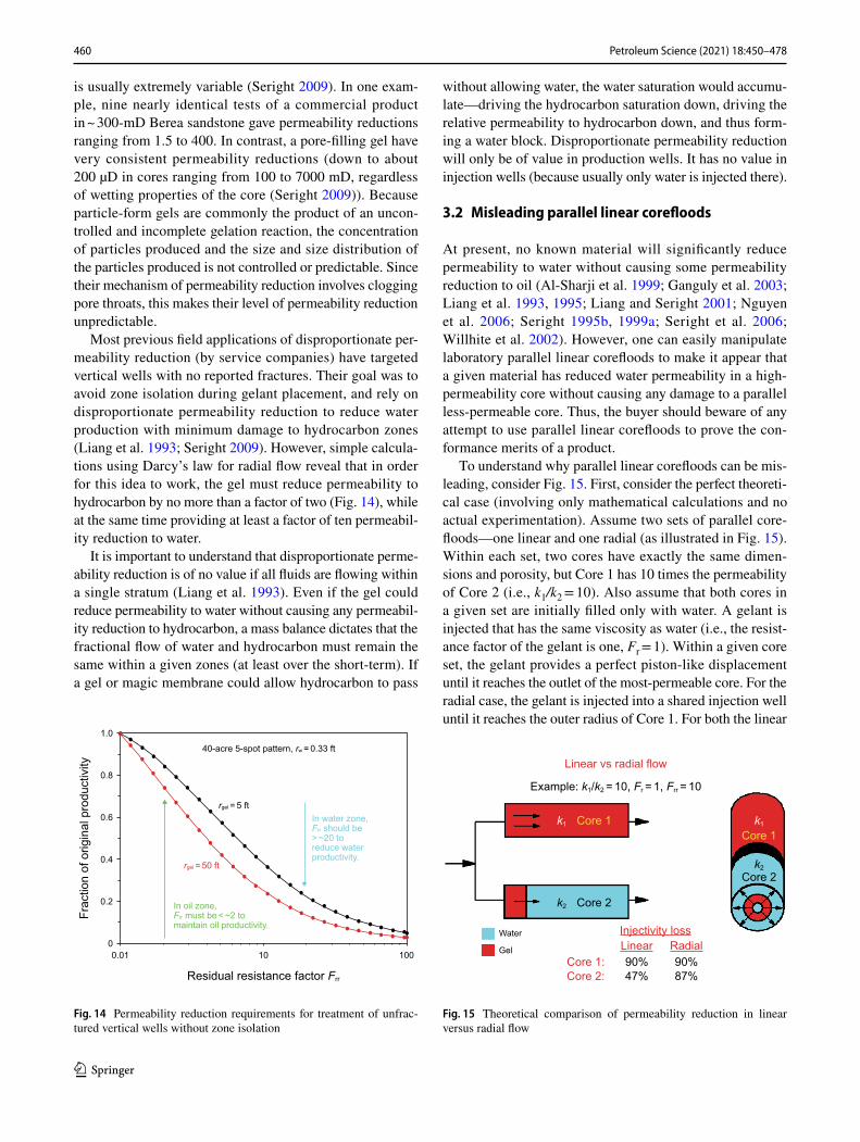
Most previous field applications of disproportionate per-meability reduction (by service companies) have targeted vertical wells with no reported fractures. Their goal was to avoid zone isolation during gelant placement, and rely on disproportionate permeability reduction to reduce water production with minimum damage to hydrocarbon zones (Liang et al. 1993; Seright 2009). However, simple calcula-tions using Darcy’s law for radial flow reveal that in order for this idea to work, the gel must reduce permeability to hydrocarbon by no more than a factor of two (Fig. 14), while at the same time providing at least a factor of ten permeabil-ity reduction to water.
It is important to understand that disproportionate perme-ability reduction is of no value if all fluids are flowing within a single stratum (Liang et al. 1993). Even if the gel could reduce permeability to water without causing any permeabil-ity reduction to hydrocarbon, a mass balance dictates that the fractional flow of water and hydrocarbon must remain the same within a given zones (at least over the short-term). If a gel or magic membrane could allow hydrocarbon to pass
without allowing water, the water saturation would accumu-late—driving the hydrocarbon saturation down, driving the relative permeability to hydrocarbon down, and thus form-ing a water block. Disproportionate permeability reduction will only be of value in production wells. It has no value in injection wells (because usually only water is injected there).
3.2 Misleading parallel linear corefloods
At present, no known material will significantly reduce permeability to water without causing some permeability reduction to oil (Al-Sharji et al. 1999; Ganguly et al. 2003; Liang et al. 1993, 1995; Liang and Seright 2001; Nguyen et al. 2006; Seright 1995b, 1999a; Seright et al. 2006; Willhite et al. 2002). However, one can easily manipulate laboratory parallel linear corefloods to make it appear that a given material has reduced water permeability in a high-permeability core without causing any damage to a parallel less-permeable core. Thus, the buyer should beware of any attempt to use parallel linear corefloods to prove the con-formance merits of a product.
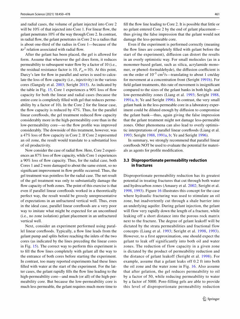
To understand why parallel linear corefloods can be mis-leading, consider Fig. 15. First, consider the perfect theoreti-cal case (involving only mathematical calculations and no actual experimentation). Assume two sets of parallel core-floods—one linear and one radial (as illustrated in Fig. 15). Within each set, two cores have exactly the same dimen-sions and porosity, but Core 1 has 10 times the permeability of Core 2 (i.e., k1/k2 = 10). Also assume that both cores in a given set are initially filled only with water. A gelant is injected that has the same viscosity as water (i.e., the resist-ance factor of the gelant is one, Fr = 1). Within a given core set, the gelant provides a perfect piston-like displacement until it reaches the outlet of the most-permeable core. For the radial case, the gelant is injected into a shared injection well until it reaches the outer radius of Core 1. For both the linear
1.0
0.8
0.6
0.4
0.2
0
Frac
tion
of o
rigin
al p
rodu
ctiv
ity
0.01
Residual resistance factor Frr
10 100
40-acre 5-spot pattern, rw = 0.33 ft
rgel = 5 ft
rgel = 50 ft
In oil zone,Frr must be < ~2 tomaintain oil productivity.
In water zone,Frr should be> ~20 toreduce waterproductivity.
Fig. 14 Permeability reduction requirements for treatment of unfrac-tured vertical wells without zone isolation
Linear vs radial flow
Example: k1/k2 = 10, Fr = 1, Frr = 10
Water
Gel
k1 Core 1
Core 1: 90%
Injectivity lossLinear Radial
Core 2: 47%90%87%
Core 1
k2 Core 2
k2Core 2
k1
Fig. 15 Theoretical comparison of permeability reduction in linear versus radial flow
461Petroleum Science (2021) 18:450–478
1 3
and radial cases, the volume of gelant injected into Core 2 will be 10% of that injected into Core 1. For linear flow, the gelant penetrates 10% of the way through Core 2. In contrast, in radial flow, the gelant penetrates in Core 2 to a radius that is about one-third of the radius in Core 1—because of the πr2 relation associated with radial flow.
After the gelant has been placed, the gel is allowed for form. Assume that wherever the gel does form, it reduces permeability to subsequent water flow by a factor of 10 (i.e., the residual resistance factor is 10, Frr = 10). At this point, Darcy’s law for flow in parallel and series is used to calcu-late the loss of flow capacity (i.e., injectivity) in the various cores (Ganguly et al. 2003; Seright 2015). As indicated by the table in Fig. 15, Core 1 experiences a 90% loss of flow capacity for both the linear and radial cases (because the entire core is completely filled with gel that reduces perme-ability by a factor of 10). In the Core 2 for the linear case, the flow capacity is reduced by 47%. Thus, for the parallel linear corefloods, the gel treatment reduced flow capacity considerably more in the high-permeability core than in the low-permeability core—so the flow profile was improved considerably. The downside of this treatment, however, was a 47% loss of flow capacity in Core 2. If Core 2 represented an oil zone, the result would translate to a substantial loss of oil productivity.
Now consider the case of radial flow. Here, Core 2 experi-ences an 87% loss of flow capacity, while Core 1 experiences a 90% loss of flow capacity. Thus, for the radial case, both Cores 1 and 2 were damaged to about the same extent, so no significant improvement in flow profile occurred. Thus, the gel treatment was pointless for the radial case. The net result of the gel treatment was only to substantially damage the flow capacity of both zones. The point of this exercise is that even if parallel linear corefloods worked in a theoretically perfect way, the result would be grossly unrepresentative of expectations in an unfractured vertical well. Thus, even in the ideal case, parallel linear corefloods are a very poor way to imitate what might be expected for an unconfined (i.e., no zone isolation) gelant placement in an unfractured vertical well.
Next, consider an experiment performed using paral-lel linear corefloods. Typically, a flow line leads from the gelant pump and splits before reaching the inlets of the two cores (as indicated by the lines preceding the linear cores in Fig. 15). The correct way to perform this experiment is to fill the flow lines completely with gelant all the way to the entrance of both cores before starting the experiment. In contrast, too many reported experiments had these lines filled with water at the start of the experiment. For the lat-ter cases, the gelant rapidly fills the flow line leading to the high-permeability core—and much (or all) of the high-per-meability core. But because the low-permeability core is much less permeable, the gelant requires much more time to
fill the flow line leading to Core 2. It is possible that little or no gelant entered Core 2 by the end of gelant placement—thus giving the false impression that the gelant would not damage the less-permeable core.
Even if the experiment is performed correctly (meaning the flow lines are completely filled with gelant before the start of the experiment), diffusion can distort the results in an overly optimistic way. For small molecules (as in a monomer-based gelant, such as silica, acrylamide mono-mer, or phenol–formaldehyde), the diffusion coefficient is on the order of 10–5 cm2/s—translating to about 1 cm/day for movement at a concentration front (Seright 1991b). For field gelant treatments, this rate of movement is insignificant compared to the sizes of the gelant banks in both high- and low-permeability zones (Liang et al. 1993; Seright 1988, 1991a, b; Ye and Seright 1996). In contrast, the very small gelant bank in the less-permeable core in a laboratory exper-iment could be diluted enough by diffusion to compromise the gelant bank—thus, again giving the false impression that the gelant treatment might not damage less-permeable zones. Other phenomena can also lead to overly optimis-tic interpretations of parallel linear corefloods (Liang et al. 1993; Seright 1988, 1991a, b; Ye and Seright 1996).
In summary, we strongly recommend that parallel linear corefloods NOT be used to evaluate the potential for materi-als as agents for profile modification.
3.3 Disproportionate permeability reduction in fractures
Disproportionate permeability reduction has its greatest potential in treating fractures that cut through both water and hydrocarbon zones (Amaury et al. 2002; Seright et al. 1998, 1993). Figure 16 illustrates this concept for the case where hydraulic fracturing was used to stimulate an oil zone, but inadvertently cut through a shale barrier into an underlying aquifer. During gelant injection, the gelant will flow very rapidly down the length of a fracture, while leaking off a short distance into the porous rock matrix next to the fracture. The degree of gelant leakoff will be dictated by the strata permeabilities and fractional flow concepts (Liang et al. 1993; Seright et al. 1998, 1993). However, to a first approximation, one should expect the gelant to leak off significantly into both oil and water zones. The reduction of flow capacity in a given zone is dictated by the product of permeability reduction and the distance of gelant leakoff (Seright et al. 1998). For example, assume that a gelant leaks off 0.2 ft into both the oil zone and the water zone in Fig. 16. Also assume that after gelation, the gel reduces permeability to oil by a factor of 50, while reducing permeability to water by a factor of 5000. Pore-filling gels are able to provide this level of disproportionate permeability reduction

462 Petroleum Science (2021) 18:450–478
1 3
(Seright 2006, 2009). For this example, the gel barrier would provide resistance equivalent to flowing through 0.2 ft × 5000 = 1000 ft of additional rock in order to enter the fracture. Thus, the gel substantially retards water flow into the fracture. In contrast, in the oil zone, the gel bar-rier provides resistance equivalent to flowing through 0.2 ft × 50 = 10 ft of additional rock in order to enter the frac-ture. Certainly, some loss of flow capacity has occurred in the oil zone, but not enough to significantly impair oil productivity.
Although the concept shown in Fig. 16 has tremendous potential, it has not been applied much to date. A service company sold a qualitative version of this concept by incorporating a disproportionate–permeability–reduction polymer into fracturing fluids (Vasquez and Eoff 2013). The concept was that if a hydraulic fracture inadvertently cut into a water zone, the disproportionate-permeability-reduction polymer would automatically inhibit water entry into the fracture. Unfortunately, the concept, as sold, had two major technical flaws. First, the distance of leakoff from the fracture faces was not known or esti-mated. Second, no attempt was made to quantify the per-meability reduction in the oil and water zones. Thus, the process had no control over the reduction of flow capacity in either the oil or water zones.
A quantitative design procedure for application of the concept in Fig. 16 was developed for hydraulically fractured vertical production wells (Seright et al. 1998). Extensions of this procedure were also developed for application in hydraulically fractured horizontal produc-tion wells (Liang et al. 2020) and in naturally fractured production wells (Amaury et al. 2002).
4 Gel extrusion through fractures
Use of gels for water shutoff has conventionally involved injecting gelant solutions, and relying on the process of gelation to form a plug after placement of the material. Gelant is defined as the fluid chemical solution before gelation, while gel is technically the product of the gela-tion reaction.
4.1 Field observations
In this section, we focus on extrusion of formed gel mate-rial through fractures. This topic has an interesting history. In the early 1980s, Marathon implemented conventional polymer floods in Wyoming (Milton et al. 1983). However, because the target reservoirs were highly fractured, much of the polymer solution simply channeled directly from injectors and producers through the natural fracture sys-tems. To slow down the movement of the polymer through the reservoir, a chromium cross-linker was added. During this time, Sydansk (Sydansk 1990; Sydansk and Moore 1990; Sydansk and Southwell 2000) developed the Cr(III)-acetate-HPAM gel system. In the same time frame, Phil-lips (Moradi-Araghi et al. 1993; Mumallah 1988) devel-oped the analogous Cr(III)-propionate-HPAM gel system. These gel systems were a major advance over previous gels for enhanced oil recovery, because their performance was reasonably insensitive to pH and salinity. Previous gels had little buffering capacity and gelled optimally at non-neutral pH values. For example, the Cr(VI)-HPAM system gelled optimally around pH = 4 (Seright 1992), and phenolic-based gels formed optimally around pH = 9 (Seright 1993; Seright and Martin 1993). Because the older gel systems did not have much buffer capacity, con-tact with carbonate and clay minerals quickly changed the formulations’ pH shortly after injection. Thus, the gels did not form well (and sometimes did not form at all) inside the reservoir. The Cr(III)-acetate and propionate systems greatly improved the predictability and controllability of gel systems (Jain et al. 2005; Marty et al. 1991; McCool et al. 1991, 2000; Moradi-Araghi et al. 1993; Mumallah 1988; Seright 1993; Sydansk 1990; Sydansk and Moore 1990).
Key field applications of the Cr(III)-acetate-HPAM gel involved injecting large gel volumes, notably by Marathon in the Oregon Basin field in Wyoming (Sydansk 1990; Sydansk and Moore 1990; Sydansk and Southwell 2000), by Amoco in the Wertz field in Wyoming (Seright 1995a), and by Chevron in the Rangely field in Colorado (Fried-mann et al. 1999; Hild and Wackowski 1999; Hughes et al. 1999). Injected gel volumes ranged from 5000 to 37,000
Gel restricting water flow into a fracture
Equivalent resistance to flow added by the gelIn oil zone: 0.2 ft x 50 = 10 ft.In water zone: 0.2 ft x 5,000 = 1,000 ft.
Oil Oil
Gel
Fracture faces
Gel
Frac
ture
WaterWater
Fig. 16 Gelant treatments of fractured production wells
463Petroleum Science (2021) 18:450–478
1 3
bbl over the course of 1 week to 1 month, with an average around 15,000 bbl over the course of two weeks (Borling 1994; Hild and Wackowski 1999; Sydansk and Moore 1992; Sydansk and Southwell 2000). Under the conditions in the particular field applications, gelation of the Cr(III)-acetate-HPAM formulations occurred from 1 h (e.g., at 60 °C) to 15 h (e.g., at room temperature). Thus, the gel formulations were injected for substantially longer than the gelation time. Once gelation takes place, the product of the cross-linking (i.e., the gel) will not flow through porous rock (i.e., less than 10 darcys) using any realistic field pressure gradient (i.e., < 10 psi/ft) (Seright 1995a, 1997b, 1998, 1999b, 2001a, 2003a). These facts lead to the realization that formed gels must extrude through fractures during most of the gel injection during the field applications. For practical reasons, it is best to keep the formulations fluid (i.e., as gelant) in the surface facilities and during the initial part of pumping downhole. How-ever, the formulations exist as gel, partially formed gel, or preformed gel during most of the process of gel place-ment within the reservoir. That fact raises the question: What are the properties of gels as they extrude through fractures?
4.2 Stable pressure behavior during extrusion
This question led to a number of experiments where gels where extruded through fractured cores after gel formation (Brattekås et al. 2020; Liu and Seright 2001; Seright 1995a, 1997b, 1998, 1999b, 2001a, 2003a, b; Sydansk et al. 2004a, b; Wang and Seright 2006). A key question was whether a gel would propagate through a fracture in a stable way, or whether screen-outs would occur in the early part of the fracture (as happens with sand, cement, and other relatively rigid materials). Figure 17 reveals that a one-day-old gel
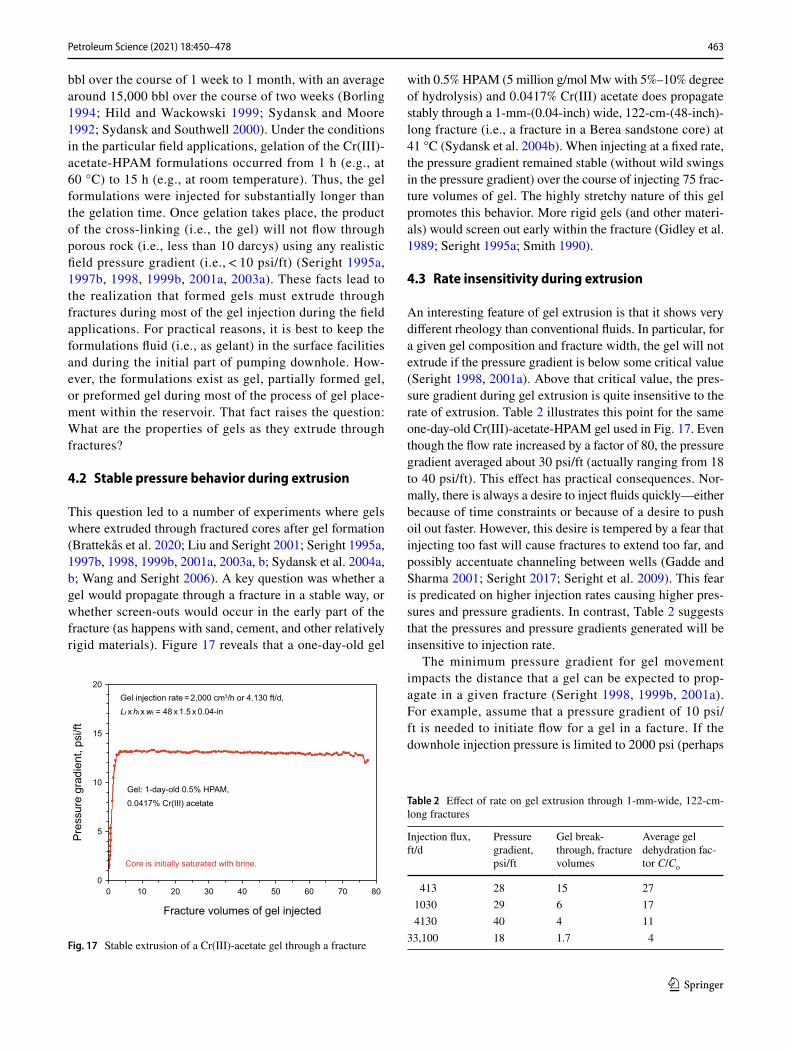
with 0.5% HPAM (5 million g/mol Mw with 5%–10% degree of hydrolysis) and 0.0417% Cr(III) acetate does propagate stably through a 1-mm-(0.04-inch) wide, 122-cm-(48-inch)-long fracture (i.e., a fracture in a Berea sandstone core) at 41 °C (Sydansk et al. 2004b). When injecting at a fixed rate, the pressure gradient remained stable (without wild swings in the pressure gradient) over the course of injecting 75 frac-ture volumes of gel. The highly stretchy nature of this gel promotes this behavior. More rigid gels (and other materi-als) would screen out early within the fracture (Gidley et al. 1989; Seright 1995a; Smith 1990).
4.3 Rate insensitivity during extrusion
An interesting feature of gel extrusion is that it shows very different rheology than conventional fluids. In particular, for a given gel composition and fracture width, the gel will not extrude if the pressure gradient is below some critical value (Seright 1998, 2001a). Above that critical value, the pres-sure gradient during gel extrusion is quite insensitive to the rate of extrusion. Table 2 illustrates this point for the same one-day-old Cr(III)-acetate-HPAM gel used in Fig. 17. Even though the flow rate increased by a factor of 80, the pressure gradient averaged about 30 psi/ft (actually ranging from 18 to 40 psi/ft). This effect has practical consequences. Nor-mally, there is always a desire to inject fluids quickly—either because of time constraints or because of a desire to push oil out faster. However, this desire is tempered by a fear that injecting too fast will cause fractures to extend too far, and possibly accentuate channeling between wells (Gadde and Sharma 2001; Seright 2017; Seright et al. 2009). This fear is predicated on higher injection rates causing higher pres-sures and pressure gradients. In contrast, Table 2 suggests that the pressures and pressure gradients generated will be insensitive to injection rate.
The minimum pressure gradient for gel movement impacts the distance that a gel can be expected to prop-agate in a given fracture (Seright 1998, 1999b, 2001a). For example, assume that a pressure gradient of 10 psi/ft is needed to initiate flow for a gel in a facture. If the downhole injection pressure is limited to 2000 psi (perhaps
20
15
10
5
0
Pre
ssur
e gr
adie
nt, p
si/ft
0 10 20 30 40 50 60 70 80
Fracture volumes of gel injected
Core is initially saturated with brine.
Gel injection rate = 2,000 cm3/h or 4.130 ft/d,Lf xhf xwf = 48 x 1.5 x 0.04-in
Gel: 1-day-old 0.5% HPAM,0.0417% Cr(III) acetate
Fig. 17 Stable extrusion of a Cr(III)-acetate gel through a fracture
Table 2 Effect of rate on gel extrusion through 1-mm-wide, 122-cm-long fractures
Injection flux, ft/d
Pressure gradient, psi/ft
Gel break-through, fracture volumes
Average gel dehydration fac-tor C/Co
413 28 15 271030 29 6 174130 40 4 11
33,100 18 1.7 4

464 Petroleum Science (2021) 18:450–478
1 3
because of regulations or equipment constraints) and if the reservoir pressure is 1000 psi (so there is a 1000 psi pres-sure differential between the injector and the reservoir), the gel will stop flowing once it reaches 100 ft along the fracture [i.e., (2000 psi minus 1000 psi)/(10 psi/ft) = 100 ft]. After propagating 100 ft along the fracture, the pres-sure gradient will fall below the minimum 10 psi/ft needed to move the gel.
4.4 Dependence on fracture width
As expected qualitatively, the pressure gradient required to extrude a gel through a fracture decreases with increased fracture width (Seright 2001a). Based on a force balance (Liu and Seright 2001; Wang and Seright 2006), one might expect the pressure gradient for gel extrusion to vary inversely with fracture width (Liu and Seright 2001; Wang and Seright 2006). However, experimental observa-tions (Seright 2001a) indicate that the required pressure gradient varies closer to the inverse square of the fracture width (Fig. 18). For the extrusion experiments shown in Fig. 18, the pressure gradient for gel extrusion did not depend on the permeability or lithology of the porous rock that contained the fracture (between 1.5 mD and 650 mD). The trend in Fig. 18 also has implications for field applica-tions of gels—specifically that gels will propagate much farther in wide fractures than in narrow fractures. For the example given in the previous paragraph, assume the pres-sure gradient for gel extrusion is 10 psi/ft in a 1-mm-wide fracture but 2.5 psi/ft in a 2-mm-wide fracture. Given the same conditions as above, the gel is expected to extrude 100 ft in the 1-mm-wide fracture but 400 ft in the 2-mm-wide fracture.
4.5 Dependence on polymer concentration and temperature
As expected, the pressure gradient for gel extrusion increases with increased concentration of polymer in the gel (Seright 2003a). Figure 19 shows an empirical correlation between pressure gradient for gel extrusion and HPAM concentra-tion in the gel. For these experiments, the ratio of HPAM to Cr(III) acetate was fixed at 12:1. The figure also shows that the ratio of elastic modulus of the gel (G’, measured in a rheometer) to fracture width (wf) follows a trend that paral-lels the pressure gradient trend—but has values that are two orders of magnitude lower (for a given polymer concentra-tion in the gel.)
For a one-day-old Cr(III)-acetate-HPAM gel (with 0.5% HPAM and 0.0417% Cr(III) acetate), Fig. 20 reveals that the
1000
100
10
1
0.1
Pre
ssur
e gr
adie
nt, p
si/ft
0.001 0.01
650-mD sandstone
dp/dL= 0.02/wf2
0.5% HPAM,0.0417% Cr(III)-acetate
50-mD sandstone1.5-mD limestone
0.1 1
Fracture width, in
Fig. 18 Pressure gradient for gel extrusion versus fracture width
1000
100
10
1
0.1
Pre
ssur
e gr
adie
nt o
r 2G
′/w, p
si/ft
0 0.5 1.0 1.5 2.0
dp/dl
2G′/wf
dp/dl= 8.54e2.27%C
R2 = 0.9863
dp/dl= 0.0979e2.27%C
R2 = 0.9894
Alcoflood 935 HPAM concentration C, %
Fig. 19 Pressure gradient for gel extrusion versus polymer concentra-tion
2.0
1.5
1.0
0.5
0
Pre
ssur
e gr
adie
nt re
lativ
e to
that
at 2
0 °C
0 20 40
1st set: Lf xhf xwf = 48 x 1.5 x 0.04 in2nd set: Lf xhf xwf = 48 x 1.5 x 0.04 in3rd set: Lf xhf xwf = 6 x 1.5 x 0.04 in
60 80 100
Temperature, °C
Fig. 20 Pressure gradient for gel extrusion versus temperature
465Petroleum Science (2021) 18:450–478
1 3
pressure gradient for gel extrusion is insensitive to tempera-ture between 20 and 80 °C (Seright 2001b). This finding was somewhat unexpected since the viscosity of water decreased by a factor of 2.8 between 20 and 80 °C.
4.6 Gel dehydration during extrusion
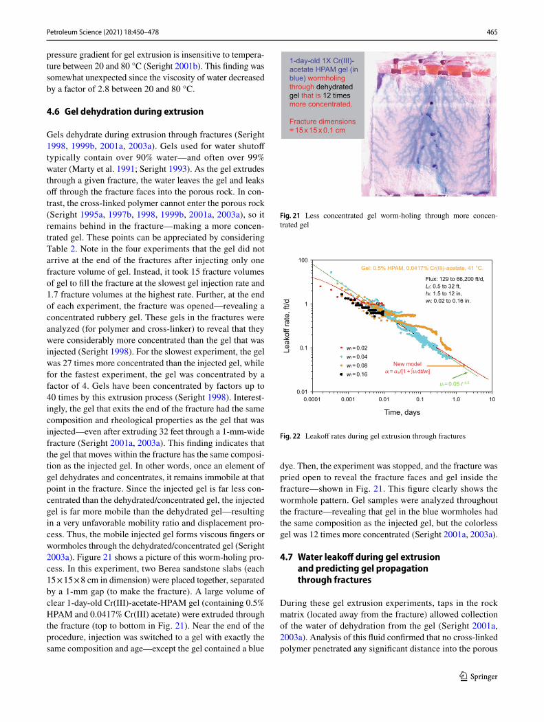
Gels dehydrate during extrusion through fractures (Seright 1998, 1999b, 2001a, 2003a). Gels used for water shutoff typically contain over 90% water—and often over 99% water (Marty et al. 1991; Seright 1993). As the gel extrudes through a given fracture, the water leaves the gel and leaks off through the fracture faces into the porous rock. In con-trast, the cross-linked polymer cannot enter the porous rock (Seright 1995a, 1997b, 1998, 1999b, 2001a, 2003a), so it remains behind in the fracture—making a more concen-trated gel. These points can be appreciated by considering Table 2. Note in the four experiments that the gel did not arrive at the end of the fractures after injecting only one fracture volume of gel. Instead, it took 15 fracture volumes of gel to fill the fracture at the slowest gel injection rate and 1.7 fracture volumes at the highest rate. Further, at the end of each experiment, the fracture was opened—revealing a concentrated rubbery gel. These gels in the fractures were analyzed (for polymer and cross-linker) to reveal that they were considerably more concentrated than the gel that was injected (Seright 1998). For the slowest experiment, the gel was 27 times more concentrated than the injected gel, while for the fastest experiment, the gel was concentrated by a factor of 4. Gels have been concentrated by factors up to 40 times by this extrusion process (Seright 1998). Interest-ingly, the gel that exits the end of the fracture had the same composition and rheological properties as the gel that was injected—even after extruding 32 feet through a 1-mm-wide fracture (Seright 2001a, 2003a). This finding indicates that the gel that moves within the fracture has the same composi-tion as the injected gel. In other words, once an element of gel dehydrates and concentrates, it remains immobile at that point in the fracture. Since the injected gel is far less con-centrated than the dehydrated/concentrated gel, the injected gel is far more mobile than the dehydrated gel—resulting in a very unfavorable mobility ratio and displacement pro-cess. Thus, the mobile injected gel forms viscous fingers or wormholes through the dehydrated/concentrated gel (Seright 2003a). Figure 21 shows a picture of this worm-holing pro-cess. In this experiment, two Berea sandstone slabs (each 15 × 15 × 8 cm in dimension) were placed together, separated by a 1-mm gap (to make the fracture). A large volume of clear 1-day-old Cr(III)-acetate-HPAM gel (containing 0.5% HPAM and 0.0417% Cr(III) acetate) were extruded through the fracture (top to bottom in Fig. 21). Near the end of the procedure, injection was switched to a gel with exactly the same composition and age—except the gel contained a blue
dye. Then, the experiment was stopped, and the fracture was pried open to reveal the fracture faces and gel inside the fracture—shown in Fig. 21. This figure clearly shows the wormhole pattern. Gel samples were analyzed throughout the fracture—revealing that gel in the blue wormholes had the same composition as the injected gel, but the colorless gel was 12 times more concentrated (Seright 2001a, 2003a).
4.7 Water leakoff during gel extrusion and predicting gel propagation through fractures
During these gel extrusion experiments, taps in the rock matrix (located away from the fracture) allowed collection of the water of dehydration from the gel (Seright 2001a, 2003a). Analysis of this fluid confirmed that no cross-linked polymer penetrated any significant distance into the porous
1-day-old 1X Cr(III)-acetate HPAM gel (inblue) wormholingthrough dehydratedgel that is 12 timesmore concentrated.
Fracture dimensions= 15 x 15 x 0.1 cm
Fig. 21 Less concentrated gel worm-holing through more concen-trated gel
100
1
0.1
0.01
Leak
off r
ate,
ft/d
0.001 0.01 0.10.0001 1.0 10
Gel: 0.5% HPAM, 0.0417% Cr(III)-acetate, 41 °C.
New modelul =um/[1 + ∫ul dtlwf]
ul = 0.05 t -0.5
Flux: 129 to 66,200 ft/d,Lf: 0.5 to 32 ft,hf: 1.5 to 12 in,wf: 0.02 to 0.16 in.
wf = 0.02wf = 0.04wf = 0.08wf = 0.16
Time, days
Fig. 22 Leakoff rates during gel extrusion through fractures
466 Petroleum Science (2021) 18:450–478
1 3
rock during the extrusion process. Collection of this leakoff fluid also allowed determination of the rate of leakoff as a function of time, although in situ imaging could also be necessary in some experiments (Brattekås et al. 2020). Leakoff rates from a large number of experiments are shown in Fig. 22 (Seright 2003a). Although there is some scatter, most of the leakoff data followed the green line and equa-tion shown, where the leakoff rate (ui, expressed in ft/d or ft3 of fluid leaking off per ft2 of fracture area per day) varied inversely with time (t) raised to the 0.5 power. This type of relation is consistent with leakoff behavior during hydraulic fracturing and during filtration experiments (Seright 2003a). This relation can be combined with a mass balance to predict (1) the distance of gel propagation through a fracture as a function of time and volume of gel injected (qtot) and (2) the degree of concentration of gel within the fracture (C/Co). Specifically, assuming that a vertical fracture (of height, hf, and width, wf) contains two wings, the rate of gel propaga-tion (dL/dt) is:
This differential equation has been solved and presented in excel spreadsheets, to allow convenient predictions at http://www.prrc.nmt.edu/group s/res-sweep /gel-treat ments /.
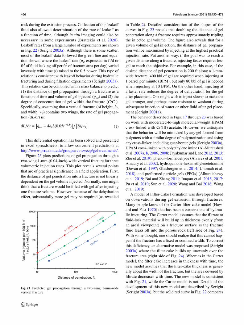
Figure 23 plots predictions of gel propagation through a two-wing 1-mm-(0.04-inch)-wide vertical fracture for three volumetric injection rates. This plot reveals several points that are of practical significance in a field application. First, the distance of gel penetration into a fracture is not linearly dependent on the gel volume injected. Normally, one might think that a fracture would be filled with gel after injecting one fracture volume. However, because of the dehydration effect, substantially more gel may be required (as revealed
(1)dL∕dt =[
qtot
− 4hfL(0.05t−0.5)
]/[
2hfwf
]
in Table 2). Detailed consideration of the slopes of the curves in Fig. 23 reveals that doubling the distance of gel penetration along a fracture requires approximately tripling the injected gel volume. The figure also reveals that for a given volume of gel injection, the distance of gel propaga-tion will be maximized by injecting at the highest practical injection rate. Put another way, if the goal was to reach a given distance along a fracture, injecting faster requires less gel to reach the objective. For example, in this case, if the desired distance of gel penetration is 200 ft along a 1-mm-wide fracture, 400 bbl of gel are required when injecting at 1 barrel per minute (BPM), but only 80 bbl of gel is needed when injecting at 10 BPM. On the other hand, injecting at a faster rate reduces the degree of dehydration for the gel after placement. One might wish to inject slower to make the gel stronger, and perhaps more resistant to washout during subsequent injection of water or other fluid after gel place-ment (Seright 2001a).
The behavior described in Figs. 17 through 23 was based on work with moderated-to-high molecular-weight HPAM cross-linked with Cr(III) acetate. However, we anticipate that the behavior will be mimicked by any gel formed from polymers with a similar degree of polymerization and using any cross-linker, including guar-borate gels (Seright 2003a), HPAM cross-linked with polyethylene imine (Al-Muntasheri et al. 2007a, b, 2006, 2008; Jayakumar and Lane 2012, 2013; Zhu et al. 2019), phenol–formaldehyde (Alvarez et al. 2001; Amaury et al. 2002), hydroquinone-hexamethylenetetramine (Dovan et al. 1997; Glasbergen et al. 2014; Unomah et al. 2018), and preformed particle gels (PPGs) (Alhuraishawy et al. 2019; Bai and Zhang 2011; Imqam et al. 2015, 2017; Pu et al. 2019; Sun et al. 2020; Wang and Bai 2018; Wang et al. 2019).
A model of Filter-Cake Formation was developed based on observations during gel extrusion through fractures. Many people know of the Carter filter-cake model (How-ard and Fast 1970) that has been a cornerstone of hydrau-lic fracturing. The Carter model assumes that the filtrate or fluid-loss material will build up in thickness evenly (from an areal viewpoint) on a fracture surface as the fracture fluid leaks off into the porous rock (left side of Fig. 24). With some thought, one should realize that this cannot hap-pen if the fracture has a fixed or confined width. To correct this deficiency, an alternative model was proposed (Seright 2003a) where the filter cake builds up unevenly over the fracture area (right side of Fig. 24). Whereas in the Carter model, the filter cake increases in thickness with time, the new model assumes that the filter-cake thickness is gener-ally about the width of the fracture, but the area covered by filtrate decreases with time. The new model is consistent with Fig. 21, while the Carter model is not. Details of the development of this new model are described by Seright (Seright 2003a), but the solid red curve in Fig. 22 compares
10000
1000
100
10
1
Volu
me
inje
cted
per
100
ft o
ffra
ctur
e he
ight
, bbl
s
10010 1000
1 BPM
0.1 BPM
10 BPM
Distance of penetration, ft
wf = 0.04 in
Fig. 23 Predicted gel propagation through a two-wing 1-mm-wide vertical fracture

467Petroleum Science (2021) 18:450–478
1 3
predictions from the new model with those of the Carter model (solid green curve in Fig. 22). As can be seen, both curves are consistent with the experimental observations. When presented with the new model, one famous hydraulic fracturing pioneer asked if the two models predict the same thing, big deal—why bother? The only response available was that the new model incorporates more correct physics of the leakoff process than the Carter model. There may be circumstances where that becomes important. That point will be revisited in the next section.
5 Gel blocking efficiency
When the purpose of polymer gel placement in fractures is to reduce conductivity during chase floods (e.g., subsequent water injection), the behavior and properties of dehydrated gel are of considerable importance. Gel ability to block frac-tures depend on several factors, which we will summarize in this section. An important and logical deduction, com-mon for all factors, is that gel is only capable of completely blocking a fracture as long as the entire fracture volume is filled with gel.
5.1 Rupture pressure
Subsequent injections of chase fluids (e.g., water) will implement a pressure gradient across the gel-filled fracture, which may reduce the gel volume (Al-Sharji et al. 1999; Bai and Zhang 2011; Dawe and Zhang 1994; Howard and Fast 1970; Imqam et al. 2015; Imqam et al. 2017; Krishnan et al. 2000; Wang and Bai 2018). The gel will maintain fracture
blocking and complete filling of the fracture at pressure gra-dients below the rupture pressure. When the rupture pressure is reached, however, water (or other injected fluids) are again allowed to pass through some parts of the fracture. The rest of the fracture will remain gel-filled. Gel rupture pressure measurements (Brattekås et al. 2015; Ganguly et al. 2002; Seright 2003b) reflect the complex nature of gel, and the rupture pressure cannot be directly projected based on injec-tion parameters. Repeated core floods have shown that the rupture pressure in a given segment of the fracture increases with increased gel throughput and decreased gel placement rates (summarized in Fig. 25). This follows directly from Sect. 4: the leakoff rate is insensitive to the gel flow rate. Hence, gel propagating slowly through a fracture will dehy-drate more compared to faster moving gel, consequently increasing its concentration and pressure resistance. This finding should not be perceived as a suggestion to reduce the gel placement rate: because gel extrusion pressure is also insensitive to the placement rate, the gel propagation distance in a fracture may be maximized by injecting gel at the highest practical injection rate. When a longer seg-ment of the fracture is gel-filled, the overall expected rupture pressure for the gel treatment will also increase. Thus, gel dehydration is beneficial for gel blocking efficiency during subsequent floods, where the manner in which dehydration occurs is also highly important.
5.2 Blocking ability of ruptured gel
Both filter-cake models (Carter and new model, Sect. 4.7) assume gel dehydration during extrusion through fractures, resulting in a concentrated gel that is more rigid and with a higher tolerance toward imposed pressure compared to gel of original composition. Macroscopically, the models
Conventionalfilter cake model New model
Frac
ture
hei
ght
Vertical viewsintersectingthe fractures
Filter cake orconcentrated gel
Active flow path
Fracture width
Porous rock
Fig. 24 Old Carter model versus new gel-extrusion model
Low gel placement rate
High gel placement rate
40
30
20
10
0
Rup
ture
pre
ssur
e, p
si/ft
0 50 100
Gel fracture volumes injected150 200 250
Fig. 25 Dehydrated gel can withstand higher pressure gradients dur-ing subsequent chase floods. Gel dehydration within a specific seg-ment of the fracture is maximized by injecting more gel or using lower injection rates

468 Petroleum Science (2021) 18:450–478
1 3
predict similar leakoff rates, but the Filter-Cake Formation within the fracture volume takes place in a quite different manner. This distinction becomes important during chase floods. According to the Carter model, gel dehydration and deposition occur on the fracture surfaces, with less concen-trated gel present in the middle of the fracture. The least concentrated gel is first washed out of the fracture during subsequent injections. Consequently, the active water flow path will resemble a narrow version of the fracture according to the Carter model (Fig. 24), and its width will determine fracture flow capacity. The permeability reduction pro-vided by gel (residual resistance factor) would in this case decrease quickly toward one, as gel occupancy decreases and the active flow path expands (Fig. 26). Experimental observations do not correspond with these low expectations; and gel permeability reduction remains high although water flow occupies up to 40% of the fracture volume (Fig. 26). Gel blocking ability has also been observed to vary with flow rate (i.e., implemented pressure gradient, Fig. 27), which cannot be explained by the Carter model. The new leakoff model proposes a volumetrically uneven filter-cake, where less concentrated gel resides in wormholes within dehydrated gel. Gel rupture will in this case occur when less concentrated gel is displaced out of the wormholes. The wormholes will thereafter conduct the flow of water through the fracture. Observations such as resistance factor depend-ency on flow rate (Fig. 27) supports the new filter-cake model; which attribute this behavior to the elasticity of the gel filter-cake, allowing wormholes to collapse and expand depending on the imposed pressure gradient (Seright 2003a).
Gel blocking ability during chase floods is often studied using core floods, where differential pressure measurements
and effluents produced from matrix and fractures give infor-mation about flow paths within the fracture. Direct visu-alization of wormholes was previously not possible within opaque porous media to confirm either filter-cake model. However, new in situ imaging methods give insight to local flow patterns, and can be used to visualize water flow through gel-filled fractures (Brattekås and Fernø 2016). In situ imaging by magnetic resonance imaging (MRI) or positron emission tomography (PET) showed the formation and development of wormholes during chase waterfloods, and strongly supported the new leakoff model (Brattekås and Fernø 2016; Brattekås and Seright 2020, 2018; Brattekås et al. 2017). Wormhole development after gel rupture is exemplified in Fig. 28. Gel rupture created a heterogeneous active flow path through the gel-filled fracture. Increasing
1000000
1000
1
Res
idua
l res
ista
nce
fact
or
1.0 0.8 0.6
Gel filling factor
0.4 0.2 0
Experimental observations
Theoretical decrease
Fig. 26 Calculated residual resistance factor for a fracture initially filled with concentrated gel, using the cubic law kf = wf/12 (Wither-spoon et al. 1980). Gel washes out of the middle of the fracture first according to the Carter model, and fracture conductivity is deter-mined by the width of the active flow path. Experimental observa-tions (Brattekås et al. 2017) do not corroborate the quickly decreasing gel permeability reduction
1000000
10000
100
1
Res
idua
l res
ista
nce
fact
or
1.0 0.8 0.6
Gel filling factor
0.4 0.2 0
Time
Flow rate
Decrease
Flow ra
te
Increa
se
Fig. 27 Permeability reduction provided by gel remains high over time and varies with injection rate and pressure. Full dataset available in Brattekås et al. (2015)
60 mL/h6 mL/hWater injection at
Wat
er in
ject
ion
Fracture outline300 mL/h
Fig. 28 Wormhole development within a 1-mm-wide fracture cap-tured by PET imaging. Injected water was labeled with positron-emit-ting isotope 18F-FDG. Upon combinations between emitted positrons and adjacent electrons, a photon pair with 511 keV energy is emitted, and this event can be spatially and temporally determined. Details are provided by Brattekås et al. (2017)

469Petroleum Science (2021) 18:450–478
1 3
injection rates expanded the initial wormhole, occasion-ally adding new rupture paths (Brattekås et al. 2017). The wormholes remained in the same shape and location for the entire waterflood, and changes in the active flow path were mainly attributed to gel erosion and elasticity. Expansion of the wormholes was observed with increasing flow rates, as expected, but the residual resistance factor (the factor by which the effective permeability was reduced by the gel) was maintained. The wormhole covered almost 35% of the fracture after long-term waterflooding—i.e., water flows through more than one-third of the fracture. The gel permeability reduction was still maintained at a high level (residual resistance factor > 22,000, Fig. 26 experimental observations are based on this experiment). Gel permeabil-ity reduction increased when the flow rate was decreased as expected (Fig. 27), but no visual evidence of significant wormhole collapse was found using imaging. Imaging did, however, confirm the existence of wormholes, and showed that they had significant variations in width within the frac-ture. Because the wormholes represent the active flow path for water, narrow constrictions in the wormholes (measured to < 0.001 cm) may act as natural chokes on fluid flow. This mechanism is only possible when the filter-cake forming during gel dehydration is heterogeneous. Consequently, the wormholes forming during gel rupture are naturally non-uniform and dependent on local gel concentrations.
5.3 Gel shrinking
The volume of gel filling a fracture may clearly be influ-enced by mechanical stimuli, as described in the previous section, but can also interact with its surroundings. Shrink-ing of gel may open parts of the fracture to fluid flow and be detrimental to gel blocking efficiency, as shown in Fig. 29.
The possible reasons for gel shrinking after placement in fractures are briefly summarized here.
Syneresis (Romero-Zeron et al. 2008; Sydansk 2007; Vargas-Vasquez et al. 2009; Vossoughi 2000) expels water from the gel structure, consequently shrinking the gel by up to 90%. The main cause for syneresis is excess cross-linker in the gel solution or increased cross-link density over time, which may be prevented by formulating the gel without exceeding the optimum cross-linker concentration (Vargas-Vasquez et al. 2009). Chemical modifications of the polymer may also cause syneresis, and may occur when gel is in con-tact with sea water over time at high temperatures (Sydansk 2007). For convenience in field applications, bulk gel tests may be performed to assess the sensitivity of gel toward brine formulations and temperature, where test parameters may be designed to target specific reservoirs (Sydansk and Moore 1990). Gel degradation, which causes solvent to separate from the gel, may also be assessed through bulk gel tests (Albonico and Lockhart 1993).
Spontaneous imbibition of gel solvent into an adjacent matrix has been observed on the core scale (Brattekås et al. 2013), shrinking the gel volume by up to 99%. Capillary forces are the driving force for spontaneous imbibition, and this effect will therefore mainly prevail in oil zones at water-wet conditions. A spontaneous reduction of the gel volume by imbibition may be an advantage in some applications because fractures will be blocked more efficiently in water zones (no imbibition) compared to oil zones (imbibition of water from gel induces gel shrinkage and opens part of the fracture volume to oil flow). Gel treatments in produc-tion wells may become less efficient with time if oil-banks move into the vicinity of gel-filled fractures. Spontaneous imbibition of solvent can theoretically be reduced by formu-lating gel with surfactants to reduce the interfacial tension between oil and gel solvent, but this has not yet been practi-cally investigated. We strongly suggest factoring in reservoir wettability during gel treatment design and assessment of its success.
Changing external conditions around a gel volume may influence the gel volume without altering its concentration. Gel shrinking (and swelling, discussed in the next section) can be attributed to changes in temperature, solvent compo-sition, ionic strength and external electrical field (Horkay et al. 2000). Interactions between gel and formation brine are of special importance. The viscosity and long-term sta-bility of polymer solutions are generally known to decrease with increasing salinity in the surrounding brine (Choi et al. 2010; Uhl et al. 1995). Bulk gel studies also showed that cross-linked gel volume changed when the salinity or pH of surrounding brine differed from the gel (Aalaie et al. 2009; Rydzewski 1990; Tu and Wisup 2011). Specifically, the presence of mono- and multivalent cations in formation water can shrink a gel (Aalaie et al. 2009). This phenomenon
107
105
103
10
10-1
10-3
Frac
ture
con
duct
ivity
, D
0.1 1
Gel shrinkage, %
10 100
10 mm1 mm0.1 mm0.01 mm0.001 mm
Fig. 29 Shrinkage of gel and its influence on fracture conductivity for different fracture widths. The fracture is assumed to be filled by con-centrated gel initially
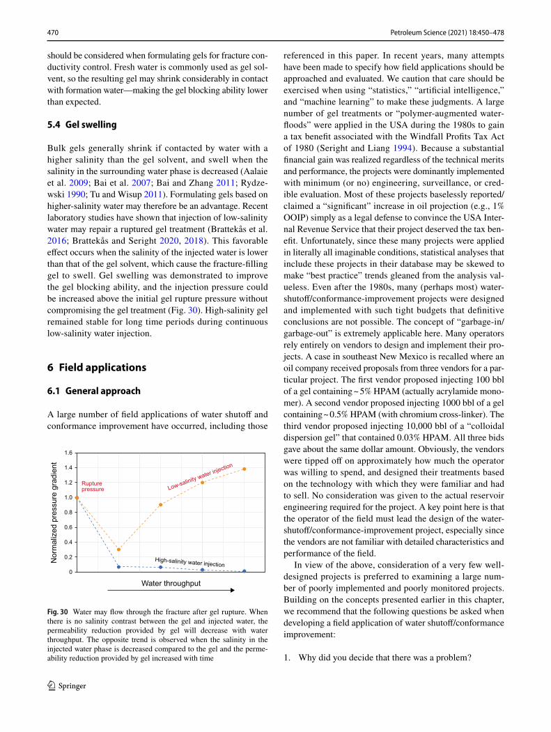
470 Petroleum Science (2021) 18:450–478
1 3
should be considered when formulating gels for fracture con-ductivity control. Fresh water is commonly used as gel sol-vent, so the resulting gel may shrink considerably in contact with formation water—making the gel blocking ability lower than expected.
5.4 Gel swelling
Bulk gels generally shrink if contacted by water with a higher salinity than the gel solvent, and swell when the salinity in the surrounding water phase is decreased (Aalaie et al. 2009; Bai et al. 2007; Bai and Zhang 2011; Rydze-wski 1990; Tu and Wisup 2011). Formulating gels based on higher-salinity water may therefore be an advantage. Recent laboratory studies have shown that injection of low-salinity water may repair a ruptured gel treatment (Brattekås et al. 2016; Brattekås and Seright 2020, 2018). This favorable effect occurs when the salinity of the injected water is lower than that of the gel solvent, which cause the fracture-filling gel to swell. Gel swelling was demonstrated to improve the gel blocking ability, and the injection pressure could be increased above the initial gel rupture pressure without compromising the gel treatment (Fig. 30). High-salinity gel remained stable for long time periods during continuous low-salinity water injection.
6 Field applications
6.1 General approach
A large number of field applications of water shutoff and conformance improvement have occurred, including those
referenced in this paper. In recent years, many attempts have been made to specify how field applications should be approached and evaluated. We caution that care should be exercised when using “statistics,” “artificial intelligence,” and “machine learning” to make these judgments. A large number of gel treatments or “polymer-augmented water-floods” were applied in the USA during the 1980s to gain a tax benefit associated with the Windfall Profits Tax Act of 1980 (Seright and Liang 1994). Because a substantial financial gain was realized regardless of the technical merits and performance, the projects were dominantly implemented with minimum (or no) engineering, surveillance, or cred-ible evaluation. Most of these projects baselessly reported/claimed a “significant” increase in oil projection (e.g., 1% OOIP) simply as a legal defense to convince the USA Inter-nal Revenue Service that their project deserved the tax ben-efit. Unfortunately, since these many projects were applied in literally all imaginable conditions, statistical analyses that include these projects in their database may be skewed to make “best practice” trends gleaned from the analysis val-ueless. Even after the 1980s, many (perhaps most) water-shutoff/conformance-improvement projects were designed and implemented with such tight budgets that definitive conclusions are not possible. The concept of “garbage-in/garbage-out” is extremely applicable here. Many operators rely entirely on vendors to design and implement their pro-jects. A case in southeast New Mexico is recalled where an oil company received proposals from three vendors for a par-ticular project. The first vendor proposed injecting 100 bbl of a gel containing ~ 5% HPAM (actually acrylamide mono-mer). A second vendor proposed injecting 1000 bbl of a gel containing ~ 0.5% HPAM (with chromium cross-linker). The third vendor proposed injecting 10,000 bbl of a “colloidal dispersion gel” that contained 0.03% HPAM. All three bids gave about the same dollar amount. Obviously, the vendors were tipped off on approximately how much the operator was willing to spend, and designed their treatments based on the technology with which they were familiar and had to sell. No consideration was given to the actual reservoir engineering required for the project. A key point here is that the operator of the field must lead the design of the water-shutoff/conformance-improvement project, especially since the vendors are not familiar with detailed characteristics and performance of the field.
In view of the above, consideration of a very few well-designed projects is preferred to examining a large num-ber of poorly implemented and poorly monitored projects. Building on the concepts presented earlier in this chapter, we recommend that the following questions be asked when developing a field application of water shutoff/conformance improvement:
1. Why did you decide that there was a problem?
1.6
1.4
1.2
1.0
0.8
0.6
0.4
0.2
0
Nor
mal
ized
pre
ssur
e gr
adie
nt
Water throughput
Rupturepressure Low-salinity water injection
High-salinity water injection
Fig. 30 Water may flow through the fracture after gel rupture. When there is no salinity contrast between the gel and injected water, the permeability reduction provided by gel will decrease with water throughput. The opposite trend is observed when the salinity in the injected water phase is decreased compared to the gel and the perme-ability reduction provided by gel increased with time
471Petroleum Science (2021) 18:450–478
1 3
2. What did you do to diagnose the problem?3. What additional information do you need to properly
diagnose the problem and how will you get it?4. What types of solutions did you consider?5. Why did you choose your solution over other possibili-
ties?6. How did you size and place the treatment or method?7. How will you know if it works?
6.2 A case history: the Rangely field in Colorado
The Rangely field in Colorado provides an interesting case history because (1) many papers have been written about the reservoir, (2) many different conformance methods have been tried, and (3) the picture of the reservoir has evolved over time. The Rangely field in northwest Colorado was produced by primary production from 1944 to 1949, hydro-carbon gas re-injection from 1949 to 1956, waterflooding from 1958 to 1986, and CO2 flooding beginning in 1986 (Wackowski and Masoner 1995). Estimated OOIP was 1.9 billion bbls, with 21% OOIP produced from primary produc-tion, 21% produced from secondary means, and ~ 7% OOIP estimated ultimate production from CO2 flooding. Oil was produced from the Weber Formation, which is interbedded eolian sandstones and fluvial siltstones and shales between 5500 and 6500-ft depth. Within the formation, six major producing intervals were identified, separated by five areally extensive shale barriers. The average gross thickness of the reservoir is 526 ft, with an average effective thickness of 189 ft. The field has a significant dip (6°–30°) and a sizeable gas cap (130 ft maximum original thickness). Average porosity is 12%, and average permeability is 8 mD (ranging from 0.1 to 200 mD).
The CO2 flood was planned, anticipating injection of a 30% PV slug of CO2 using 1:1 ratio of water-alternating gas (WAG) (Wackowski and Masoner 1995) Thus, the WAG cycles were one of the first means to control conformance during the CO2 flood (to reducing channeling of the very mobile gas). Within a few years, the operator (Chevron) noted increased gas channeling. As a remedy, the length of the water portions of a given WAG cycle were increased, while the gas portions were decreased (Wackowski and Masoner 1995). Field experiments examined the effective-ness of decreasing the frequency of the WAG cycles (from 1.5% to 0.25% PV), yielding positive results.
In spite of the WAG cycles, inefficient recycling of injected CO2 was reported in 1991. Franks described the use of selective injection equipment—packers, mandrels, and chokes—to control the amount of fluid injected into the six producing intervals (Franks 1991). Although some improve-ment in sweep efficiency was noted, corrosion limited the lifetime of the selective injection equipment (especially associated with the WAG cycles used during the CO2 flood).
A program of infill drilling occurred throughout the life of the Rangely field. Of course, this process can be viewed as a means of conformance control—drill new producers where oil has been bypassed, and shut in or convert produc-ers to injectors if they become watered out. Interestingly, the operator noted that the producing water–oil ratio (WOR) increased significantly as the well spacing increased (e.g., from 40 to 20 acres). Shut-in of key injection wells effec-tively realigned the flow pattern in some cases, resulting in significant reductions in channeling (Collings et al. 1996). Prior to the 1990s, natural fractures were not considered a significant contributor to channeling at Rangely. Natural fractures were more commonly associated with carbonate reservoirs, not sandstones. Subsequent to 1990, a greater appreciation was gained of the importance of natural frac-tures (Wackowski and Masoner 1995).
Injection of gel conformance methods have been attempted at Rangely since the 1960s (Hild and Wackowski 1999). Small-volume gel treatments (along with mechanical isolation methods and recompletions) were applied in both injectors and producers to mitigate flow from the gas cap and to reduce channeling through lower zones. However, the most extensive and successful application of gels began with large-volume Cr(III)-acetate-HPAM treatments in the mid-1990s. Treatment volumes were typically around 15,000 bbl of gel per treatment, requiring between 1 and 3 weeks to inject. Since the gelation time of the gelant formulations was about 1 h at the reservoir temperature (60 °C), the gel placement times greatly exceeded the gelation times. This observation was one of the key inspirations for realizing that formed gels were extruding through fractures during most of the placement process (Seright 1995a, 1997b, 1998, 1999a, b, 2001a, 2003a). During this time at Rangely, it was noted that inter-well tracer transit times were very rapid (hours to days) in some cases, but gel breakthrough in producers was rarely seen, in spite of the large gel volumes. These observations were consistent with laboratory observations of substantial gel dehydration during extrusion through frac-tures (Seright 1997b, 1998, 1999b, 2001a, 2003a). The close interaction between laboratory and field personnel was key to the development of gels and gel placement concepts dur-ing the 1990s.
A specialized workflow and set of screening criteria were developed at Rangely that fit the individual needs of gel applications in that field (Hild and Wackowski 1999). Based on a large number of gel treatments that were applied, a range of responses were observed, including (1) oil rate increase, (2) reduction in water production, (3) reduction in gas production, (4) areal sweep improvement, (5) reduction or elimination of oil decline rate, (6) “smoothing” of produc-tion, (7) improved pattern CO2 retention and utilization, and (8) in some cases, no apparent effect. A three-year campaign of gel injection in 44 injectors resulted in 685,000 bbl of

472 Petroleum Science (2021) 18:450–478
1 3
incremental oil from an investment of ~ $2 million. Treat-ment success rates were given at 80% (Hild and Wackowski 1999). Important lessons learned from the project included (1) rapid communication and associated poor CO2 economic performance were the most important candidate selection criteria, (2) larger-volume (> 15,000 bbl) treatments were the most successful, (3) repeat treatments of gel in the same well were very successful, (4) the best results occurred in parts of the field with the best reservoir quality, (5) treat-ments worked best for wells where both gas and water were known to channel, (6) the water injection rate should be kept below 1200 BWPD, (7) areas of the field with high bottom-hole pressure should be avoided, and (8) post-treatment res-ervoir management was critical.
Foam-gel treatments were also applied at Rangely (Fried-mann et al. 1999; Hughes et al. 1999). The major motiva-tion for using foam gels instead of gels was a hope that the chemical costs associated with the large gel volumes could be reduced by up to 80% (because much of the liquid gel volume was replaced with gas). However, a major finding of these applications was that costs associated with compress-ing the gas for the foam outweighed the cost-savings from the reduced volume of gel.
7 Final comments
There are an immense number of materials that have been proposed for conformance improvement or water shutoff (Al-Muntasheri et al. 2006; Amaury et al. 2002; Bae et al. 1996; Chan 1988; Creel and Crook 1997; El-karsani et al. 2014; Glasbergen et al. 2014; Jurinak and Summers 1991; Kabir 2001; Kantzas et al. 1999; Lenchenkov et al. 2019; Marty et al. 1991; Moradi-Araghi et al. 1993; Mumallah 1988; Perez et al. 1997; Pu et al. 2019; Schmidt et al. 1984; Seright 1988, 1993; Seright and Liang 1995; Sun et al. 2020; Sydansk 1990; Sydansk and Romero-Zeron 2011; Vossoughi 2000; Wang et al. 2019; Whitney et al. 1996). Rather than try to discuss them all, we suggest that the key question to be asked is: What do you want the material to do in your particular application? Plug a fracture or plug porous rock? Exhibit disproportionate permeability reduc-tion or not? Provide mobility control? Be resistant to high temperatures? Have a slow gelation time at reservoir condi-tions or not? Penetrate deep into a fracture or fracture sys-tem? Penetrate deep into porous rock? Not washout from fractures given a certain fracture width? Resist washout from a porous medium given a certain pressure gradient, salin-ity, H2S level, or other condition? Be compatible with other oilfield chemicals in use (like corrosion or scale inhibitors)? Be inexpensive and/or locally available? Finally, one should realize that these materials are not black magic. Effectively reducing excess water production or channeling within a
reservoir requires that the operator has significant knowl-edge of the reservoir and conformance-improvement mate-rials before application. One caution should be mentioned: You should hold onto your wallet if someone tries to sell you a chemical that they claim (1) can be injected into any well without precautions and will shut off water or water channels without damaging hydrocarbon flow or (2) will act like a super-polymer-flooding agent (i.e., provide effective mobility control) without peer-reviewed proof.
Open Access This article is licensed under a Creative Commons Attri-bution 4.0 International License, which permits use, sharing, adapta-tion, distribution and reproduction in any medium or format, as long as you give appropriate credit to the original author(s) and the source, provide a link to the Creative Commons licence, and indicate if changes were made. The images or other third party material in this article are included in the article’s Creative Commons licence, unless indicated otherwise in a credit line to the material. If material is not included in the article’s Creative Commons licence and your intended use is not permitted by statutory regulation or exceeds the permitted use, you will need to obtain permission directly from the copyright holder. To view a copy of this licence, visit http://creat iveco mmons .org/licen ses/by/4.0/.
References
Aalaie J, Rahmatpour A, Vasheghani-Farahani E. Rheological and swelling behavior of semi-interpenetrating networks of polyacrylamide and scleroglucan. Polym Adv Technol. 2009;20(12):1102–6. https ://doi.org/10.1002/pat.1369.
Aamodt G, Abbas S, Arghir DV, Frazer LC, Mueller DT, Pettersen P, et al. Identification, problem characterization, solution design and execution for a waterflood conformance problem in the Ekofisk Field-Norway. In: SPE Improved Oil Recovery Conference, Tulsa, Oklahoma, USA. 2018. https ://doi.org/10.2118/19020 9-MS
Aguilar R. Naturally fractured reservoirs. Chapters 3–4, vol 125. Tulsa: Pennwell; 1980.
Al-Dhafeeri AM, Mohammed T, Moawad T. Lesson learned from a water shutoff technique for cross flow between two perforation intervals in Al-Khafji Field. In: SPE Asia Pacific Oil and Gas Conference and Exhibition, Perth, Australia. 2012. https ://doi.org/10.2118/15874 7-MS
Al-Dhafeeri AM, Zkery SFA, Al-Aklubi SA, Al Sdeiri SA. Effective-ness well integrity management for casing leak detection uti-lizing temperature profile in offshore oil field. In: International Petroleum Technology Conference, Dhahran, Kingdom of Saudi Arabia. 2020. https ://doi.org/10.2523/IPTC-19907 -Abstr act
Al-Ghasham YY. Assessment of rig-less water shut-off using through-tubing bridge plug in a large onshore oil field in Saudi Arabia. In: SPE Middle East Oil and Gas Show and Conference, Kingdom of Bahrain. 2005. https ://doi.org/10.2118/92883 -MS
Al-Khelaiwi FT, Birchenko VM, Konopczynski MR, Davies D. Advanced wells: a comprehensive approach to the selection between passive and active inflow-control completions. SPE Prod Oper. 2010;25(03):305–26. https ://doi.org/10.2118/13297 6-PA.
Al-Muntasheri GA, Nasr-El-Din HA, Peters J, Zitha PLJ. Investi-gation of a high temperature organic water shutoff gel: reac-tion mechanisms. SPE J. 2006;11(04):497–504. https ://doi.org/10.2118/97530 -PA.
473Petroleum Science (2021) 18:450–478
1 3
Al-Muntasheri GA, Hussein IA, Nasr-El-Din HA, Amin MB. Viscoe-lastic properties of a high temperature cross-linked water shut-off polymeric gel. J Pet Sci Eng. 2007a;55(1):56–66. https ://doi.org/10.1016/j.petro l.2006.04.004.
Al-Muntasheri GA, Nasr-El-Din HA, Hussein IA. A rheological inves-tigation of a high temperature organic gel used for water shut-off treatments. J Pet Sci Eng. 2007b;59(1):73–83. https ://doi.org/10.1016/j.petro l.2007.02.010.
Al-Muntasheri GA, Nasr-El-Din HA, Zitha PLJ. Gelation kinetics and performance evaluation of an organically crosslinked gel at high temperature and pressure. SPE J. 2008;13(03):337–45. https ://doi.org/10.2118/10407 1-PA.
Al-Shahrani FF, Baluch ZA, Al-Otaibi NM, Sarfraz T. Successful water shut-off in open hole horizontal well using inflatables. In: SPE Saudi Arabia Section Technical Symposium, Dhahran, Saudi Arabia. 2007. https ://doi.org/10.2118/11096 8-MS
Al-Sharji HH, Grattoni CA, Dawe RA, Zimmerman RW. Pore-scale study of the flow of oil and water through polymer gels. In: SPE Annual Technical Conference and Exhibition, Houston, Texas. 1999. https ://doi.org/10.2118/56738 -MS
Al-Zain A, Al-Atwi M, Al-Jandal A, Al-Abdalmohsen R, Al-Ghafli H. Advancements in well conformance technologies used in a major field in Saudi Arabia: case histories. In: SPE/IADC Middle East Drilling Technology Conference and Exhibition, Abu Dhabi, UAE. 2016. https ://doi.org/10.2118/17819 4-MS
Al-Zubail MA, Al-Nasser RH, Al-Umran SA, Al-Saeed SS. Rigless water shut-off experience in offshore Saudi Arabia. In: Middle East Oil Show, Bahrain. 2003. https ://doi.org/10.2118/81443 -MS
Albonico P, Lockhart TP. Divalent ion-resistant polymer gels for high-temperature applications: syneresis inhibiting additives. In: SPE International Symposium on Oilfield Chemistry, New Orleans, Louisiana. 1993. https ://doi.org/10.2118/25220 -MS
Alcorn ZP, Fredriksen SB, Sharma M, Rognmo AU, Føyen TL, Fernø MA, et al. An integrated carbon-dioxide-foam enhanced-oil-recovery pilot program with combined carbon capture, utiliza-tion, and storage in an onshore Texas heterogeneous carbonate field. SPE Reserv Eval Eng. 2019;22(04):1449–66. https ://doi.org/10.2118/19020 4-PA.
Alhuraishawy AK, Bai B, Wei M, Almansour A. Preformed partial gel injection chased by low-salinity waterflooding in fractured car-bonate cores. SPE Reserv Eval Eng. 2019;22(01):110–21. https ://doi.org/10.2118/19136 4-PA.
Aljubran M, Horne R. Prediction of multilateral inflow control valve flow performance using machine learning. SPE Prod Oper. 2020;35(03):691–702. https ://doi.org/10.2118/19600 3-PA.
Alvarez I, Espinoza MG, Marin TA, Hernandez MI, Rossana C, Der Sarkissian J, et al. Water control experiences in the Motatan Field using specially designed gels. In: SPE Latin American and Carib-bean Petroleum Engineering Conference, Buenos Aires, Argen-tina. 2001. https ://doi.org/10.2118/69545 -MS
Amaury M, Seright R, Hernandez M, Espinoza M, Mejias F. Connect-ing laboratory and field results for gelant treatments in naturally fractured production wells. In: SPE Annual Technical Confer-ence and Exhibition, San Antonio, Texas. 2002. https ://doi.org/10.2118/77411 -MS
Augustine JR, Meijs R. Modeling the dynamic pressure response of ball-actuated stimulation sleeves. SPE Prod Oper. 2011;26(02):162–72. https ://doi.org/10.2118/12782 1-PA.
Augustine JR, Mathis SP, Nguyen HT, Gann CL, Gill J. World’s first gravel-packed inflow-control completion. SPE Drill Complet. 2008;23(01):61–7. https ://doi.org/10.2118/10319 5-PA.
Bae JH, Chambers KT, Lee HO. Microbial profile modification with spores. SPE Reserv Eng. 1996;11(03):163–7. https ://doi.org/10.2118/28617 -PA.
Bai B, Zhang H. Preformed-particle-gel transport through open frac-tures and its effect on water flow. SPE J. 2011;16(02):388–400. https ://doi.org/10.2118/12990 8-PA.
Bai B, Li L, Liu Y, Liu H, Wang Z, You C. Preformed particle gel for conformance control: factors affecting its properties and appli-cations. SPE Reserv Eval Eng. 2007;10(04):415–22. https ://doi.org/10.2118/89389 -PA.
Bailey B, Crabtree M, Tyrie J, Elphick J, Kuchuk F, Romano C, et al. Water control. Oilfield Rev. 2000;12(1):30–51.
Barreau P, Bertin H, Lasseux D, Glénat P, Zaitoun A. Water control in producing wells: influence of an adsorbed-polymer layer on relative permeabilities and capillary pressure. SPE Reserv Eng. 1997;12(04):234–9. https ://doi.org/10.2118/35447 -PA.
Bassiouni Z. Theory, measurement, and interpretation of well logs. Richardson: Society of Petroleum Engineers; 1994.
Benko K, Drewes J. Produced water in the Western United States: geo-graphical distribution, occurrence, and composition. Environ Eng Sci. 2008;25(2):239–46. https ://doi.org/10.1089/ees.2007.0026.
Borling DC. Injection conformance control case histories using gels at the Wertz Field CO2 tertiary flood in Wyoming. In: SPE/DOE Improved Oil Recovery Symposium, Tulsa, Oklahoma. 1994. https ://doi.org/10.2118/27825 -MS
Brattekås B, Fernø MA. New insight from visualization of mobil-ity control for enhanced oil recovery using polymer gels and foams. In: Romero-Zèron L, editor. Chemical enhanced oil recovery (cEOR)—a practical overview. London: InTech; 2016.
Brattekås B, Seright RS. Implications for improved polymer gel conformance control during low-salinity chase-floods in frac-tured carbonates. J Pet Sci Eng. 2018;163:661–70. https ://doi.org/10.1016/j.petro l.2017.10.033.
Brattekås B, Seright R. The mechanism for improved polymer gel blocking during low-salinity waterfloods, investigated using positron emission tomography imaging. Transp Porous Media. 2020;133(1):119–38. https ://doi.org/10.1007/s1124 2-020-01417 -w.
Brattekås B, Haugen Å, Graue A, Seright R. Gel dehydration by spontaneous imbibition of brine from aged polymer gel. SPE J. 2013;19(01):122–34. https ://doi.org/10.2118/15311 8-PA.
Brattekås B, Pedersen SG, Nistov HT, Haugen A, Graue A, Liang J-T, et al. Washout of Cr(III)-acetate-HPAM gels from frac-tures: effect of gel state during placement. SPE Prod Oper. 2015;30(02):99–109. https ://doi.org/10.2118/16906 4-PA.
Brattekås B, Graue A, Seright R. Low-salinity chase waterfloods improve performance of Cr(III)-acetate hydrolyzed poly-acrylamide gel in fractured cores. SPE Reserv Eval Eng. 2016;19(02):331–9. https ://doi.org/10.2118/17374 9-PA.
Brattekås B, Steinsbø M, Graue A, Fernø MA, Espedal H, Seright RS. New insight into wormhole formation in polymer gel during water chase floods with positron emission tomography. SPE J. 2017;22(01):32–40. https ://doi.org/10.2118/18005 1-PA.
Brattekås B, Seright R, Ersland G. Water leakoff during gel placement in fractures: extension to oil-saturated porous media. SPE Prod Oper. 2020;35(02):202–13. https ://doi.org/10.2118/19025 6-PA.
Cather M. Personal communication based on examination of the data base of the oil conservation commission of new Mexico. 2020.
Chan KS. Reservoir water control treatments using a non-polymer gelling system. In: Offshore South East Asia Show, Singapore. 1988. https ://doi.org/10.2118/17674 -MS
Chan KS. Water control diagnostic plots. In: SPE Annual Technical Conference and Exhibition, Dallas, Texas. 1995. https ://doi.org/10.2118/30775 -MS
Chang K-T, Frampton H, Morgan JC. U.S. Patent 6,454,003 B1. 2002Chang HL, Sui X, Xiao L, Liu H, Guo Z, Yao Y, et al. Successful
field pilot of in-depth colloidal dispersion gel (CDG) technology in Daqing oil field. In: SPE/DOE Symposium on Improved Oil

474 Petroleum Science (2021) 18:450–478
1 3
Recovery, Tulsa, Oklahoma. 2004. https ://doi.org/10.2118/89460 -MS
Choi SK, Sharma MM, Bryant S, Huh C. pH-sensitive polymers for novel conformance-control and polymer-flood applica-tions. SPE Reserv Eval Eng. 2010;13(06):926–39. https ://doi.org/10.2118/12168 6-PA.
Chou SI, Bae JH, Friedmann F, Dolan JD. Development of optimal water control strategies. In: SPE Annual Technical Conference and Exhibition, New Orleans, Louisiana. 1994. https ://doi.org/10.2118/28571 -MS
Clark CE, Veil JA. Produced water volumes and management practices in the United States (Contract DE-AC02–06CH11357). 2009. US Department of Energy, Office of Fossil Energy: https ://www.osti.gov/servl ets/purl/10073 97
Collings RC, Hild GP, Abidi HR. Pattern modification by injection-well shut-in: a combined cost-reduction and sweep-improve-ment effort. SPE Reserv Eng. 1996;11(02):69–72. https ://doi.org/10.2118/30730 -PA.
Craig FF Jr. The reservoir engineering aspects of waterflooding. Rich-ardson, Texas: Society of Petroleum Engineers; 1971.
Cramer D, Friehauf K, Roberts G, Whittaker J. Integrating distrib-uted acoustic sensing, treatment-pressure analysis, and video-based perforation imaging to evaluate limited-entry-treatment effectiveness. SPE Prod Oper. 2020;35(04):730–55. https ://doi.org/10.2118/19433 4-PA.
Creel P, Crook R. Gels, monomer solutions fix pinhole casing leaks. Oil Gas J. 1997;95(41):44–6.
Cui J, Zhu D, Jin M. Diagnosis of production performance after multi-stage fracture stimulation in horizontal wells by downhole tem-perature measurements. SPE Prod Oper. 2016;31(04):280–8. https ://doi.org/10.2118/17087 4-PA.
Daneshy AA, Guo B, Krasnov V, Zimin S. Inflow-control-device design: revisiting objectives and techniques. SPE Prod Oper. 2012;27(01):44–51. https ://doi.org/10.2118/13323 4-PA.
Dashash AA, Al-Arnaout I, Al-Driweesh SM, Sarakbi SA, Al Sha-harani K. Horizontal water shut-off for better production opti-mization and reservoir sweep efficiency (case study). In: SPE Saudi Arabia section Young Professionals Technical Symposium, Dharan, Saudi Arabia. 2008. https ://doi.org/10.2118/11706 6-MS
Dawe RA, Zhang Y. Mechanistic study of the selective action of oil and water penetrating into a gel emplaced in a porous medium. J Pet Sci Eng. 1994;12(2):113–25. https ://doi.org/10.1016/0920-4105(94)90011 -6.
Dikshit A, Woiceshyn G, Hagel L. A systematic approach to the design and development of a new ICD to minimize erosion and erosion-corrosion. SPE Drill Complet. 2020;35(03):414–27. https ://doi.org/10.2118/19760 1-PA.
Dovan HT, Hutchins RD, Sandiford BB. Delaying gelation of aqueous polymers at elevated temperatures using novel organic crosslink-ers. In: International Symposium on Oilfield Chemistry, Hou-ston, Texas. 1997. https ://doi.org/10.2118/37246 -MS
El-karsani KSM, Al-Muntasheri GA, Hussein IA. Polymer systems for water shutoff and profile modification: a review over the last dec-ade. SPE J. 2014;19(01):135–49. https ://doi.org/10.2118/16310 0-PA.
Elphick J, Seright R. A classification of water problem types. In: PNC 3rd International Conference on Reservoir Conformance, Profile Control, Water and Gas Shut Off, Houston Houston. 1997.
Ernens D, Peréz-Ràfols F, Van Hoecke D, Roijmans RFH, van Riet EJ, Vande Voorde JBE, et al. On the sealability of metal-to-metal seals with application to premium casing and tubing connec-tions. SPE Drill Complet. 2019;34(04):382–96. https ://doi.org/10.2118/19414 6-PA.
Fethi G, Kaddour K, Tesconi M, Alberto B, Carlo C, Angelo GG. EI Borma-bright water-tertiary method of enhanced oil recov-ery for a mature field. In: SPE Production and Operations
Conference and Exhibition, Tunis, Tunisia. 2010. https ://doi.org/10.2118/13614 0-MS
Fletcher AJP, Flew S, Forsdyke IN, Morgan JC, Rogers C, Suttles D. Deep diverting gels for very cost-effective waterflood control. J Pet Sci Eng. 1992;7(1):33–43. https ://doi.org/10.1016/0920-4105(92)90006 -M.
Frampton H, Morgan JC, Cheung SK, Munson L, Chang KT, Williams D. Development of a novel waterflood conformance control sys-tem. In: SPE/DOE Symposium on Improved Oil Recovery, Tulsa, Oklahoma. 2004. https ://doi.org/10.2118/89391 -MS
Franks AP. The use of selective injection equipment in the Rangely Weber Sand Unit. In: SPE Production Operations Symposium, Oklahoma City, Oklahoma. 1991. https ://doi.org/10.2118/21649 -MS
Friedmann F, Hughes TL, Smith ME, Hild GP, Wilson A, Davies SN. Development and testing of a foam-gel technology to improve conformance of the Rangely CO2 flood. SPE Reserv Eval Eng. 1999;2(01):4–13. https ://doi.org/10.2118/54429 -PA.
Fulleylove RJ, Morgan JC, Stevens DG, Thrasher DR. Water shut-off in oil production wells—lessons from 12 treatments. In: Abu Dhabi International Petroleum Exhibition and Confer-ence, Abu Dhabi, United Arab Emirates. 1996. https ://doi.org/10.2118/36211 -MS
Furui K, Zhu D, Hill AD, Davis ER, Buck BR. Optimization of hori-zontal well-completion design with cased/perforated or slotted liner completions. SPE Prod Oper. 2007;22(02):248–53. https ://doi.org/10.2118/90579 -PA.
Gadde PB, Sharma MM. Growing injection well fractures and their impact on waterflood performance. In: SPE Annual Technical Conference and Exhibition, New Orleans, Louisiana. 2001. https ://doi.org/10.2118/71614 -MS
Ganguly S, Willhite GP, Green DW, McCool CS. The effect of fluid leakoff on gel placement and gel stability in fractures. SPE J. 2002;7(03):309–15. https ://doi.org/10.2118/79402 -PA.
Ganguly S, Willhite GP, Green DW, McCool CS. Effect of flow rate on disproportionate permeability reduction. In: International Sym-posium on Oilfield Chemistry, Houston, Texas. 2003. https ://doi.org/10.2118/80205 -MS
Gidley JL, Holdiditch SA, Nierode DE, Veatch RW. Recent advances in hydraulic fracturing. Monograph Volume 12, Henry l. Doherty Series. Richardson, Texas: Society of Petroleum Engineers; 1989.
Glasbergen G, Abu-Shiekah I, Balushi S, van Wunnik J. Conform-ance control treatments for water and chemical flooding: material screening and design. In: SPE EOR Conference at Oil and Gas West Asia, Muscat, Oman. 2014. https ://doi.org/10.2118/16966 4-MS
Green DW, Willhite GP. Enhanced oil recovery: textbook series. Rich-ardson, Texas: Society of Petroleum Engineers; 1998. p. 100–85.
Haugen Å, Mani N, Svenningsen S, Brattekås B, Graue A, Ersland G, et al. Miscible and immiscible foam injection for mobility control and EOR in fractured oil-wet carbonate rocks. Transp Porous Media. 2014;104(1):109–31. https ://doi.org/10.1007/s1124 2-014-0323-6.
Hild GP, Wackowski RK. Reservoir polymer gel treatments to improve miscible CO2 flood. SPE Reserv Eval Eng. 1999;2(02):196–204. https ://doi.org/10.2118/56008 -PA.
Hill AD. Production logging—theoretical and interpretive elements. SPE Monograph Vol. 14. Richardson: Society of Petroleum Engi-neers; 1990. p. 1990.
Horkay F, Tasaki I, Basser PJ. Osmotic swelling of polyacrylate hydro-gels in physiological salt solutions. Biomacromol. 2000;1(1):84–90. https ://doi.org/10.1021/bm990 5031.
Howard GC, Fast CR. Hydraulic fracturing Monograph Volume2—Henry l. Doherty Series. Richardson: Society of Petroleum Engi-neers of AIME; 1970. p. 32–42.
475Petroleum Science (2021) 18:450–478
1 3
Hughes TL, Friedmann F, Johnson D, Hild GP, Wilson A, Davies SN. Large-volume foam-gel treatments to improve conformance of the Rangely CO2 flood. SPE Reserv Eval Eng. 1999;2(01):14–24. https ://doi.org/10.2118/54772 -PA.
Husband ME, Ohms DS, Frampton H, Carhart SR, Carlson BH, Chang K-T, et al. Results of a three-well waterflood sweep improvement trial in the Prudhoe Bay Field using a thermally activated parti-cle system. In: SPE Improved Oil Recovery Symposium, Tulsa, Oklahoma, USA. 2010. https ://doi.org/10.2118/12996 7-MS
Imqam A, Bai B, Al Ramadan M, Wei M, Delshad M, Sepehrnoori K. Preformed-particle-gel extrusion through open conduits during conformance-control treatments. SPE J. 2015;20(05):1083–93. https ://doi.org/10.2118/16910 7-PA.
Imqam A, Wang Z, Bai B. Preformed-particle-gel transport through heterogeneous void-space conduits. SPE J. 2017;22(05):1437–47. https ://doi.org/10.2118/17970 5-PA.
Jain R, McCool CS, Green DW, Willhite GP, Michnick MJ. Reac-tion kinetics of the uptake of chromium (III) acetate by polyacrylamide. SPE J. 2005;10(03):247–55. https ://doi.org/10.2118/89399 -PA.
Jayakumar S, Lane RH. Delayed crosslink polymer flowing gel sys-tem for water shutoff in conventional and unconventional oil and gas reservoirs. In: SPE International Symposium and Exhi-bition on Formation Damage Control, Lafayette, Louisiana, USA. 2012. https ://doi.org/10.2118/15169 9-MS
Jayakumar S, Lane RH. Delayed crosslink polymer gel system for water shutoff in conventional and unconventional oil and gas reservoirs. In: SPE International Symposium on Oilfield Chemistry, The Woodlands, Texas, USA. 2013. https ://doi.org/10.2118/16404 6-MS
Jia H, Chen H, Zhao J-Z. Development of a highly elastic composite gel through novel intercalated crosslinking method for well-bore temporary plugging in high-temperature reservoirs. SPE J. 2020. https ://doi.org/10.2118/20109 0-PA.
Jiang Q, Butler RM. Experimental and numerical modelling of bottom water coning to a horizontal well. J Can Pet Technol. 1998;37(10):10. https ://doi.org/10.2118/98-10-02.
Johns JE, Blount CG, Dethlefs JC, Julian JY, Loveland MJ, McCo-nnell ML, et al. Applied ultrasonic technology in wellbore: leak detection and case histories in Alaska North Slope wells. SPE Prod Oper. 2009;24(02):225–32. https ://doi.org/10.2118/10281 5-PA.
Jurinak JJ, Summers LE. Oilfield applications of colloidal sil-ica gel. SPE Prod Eng. 1991;6(04):406–12. https ://doi.org/10.2118/18505 -PA.
Kabir AH. Chemical water and gas shutoff technology-an overview. In: SPE Asia Pacific Improved Oil Recovery Conference, Kuala Lumpur, Malaysia. 2001. https ://doi.org/10.2118/72119 -MS
Kantzas A, Marentette DF, Allsopp K. Utilization of polymer gels, polymer enhanced foams, and foamed gels for improving res-ervoir conformance. J Can Pet Technol. 1999;38(13):8. https ://doi.org/10.2118/99-13-58.
Krishnan P, Asghari K, Willhite GP, McCool CS, Green DW, Vos-soughi S. Dehydration and permeability of gels used in in-situ permeability modification treatments. In: SPE/DOE Improved Oil Recovery Symposium, Tulsa, Oklahoma. 2000. https ://doi.org/10.2118/59347 -MS
Lane RH, Sanders GS. Water shutoff through fullbore placement of polymer gel in faulted and in hydraulically fractured produc-ers of the Prudhoe Bay Field. In: SPE Production Operations Symposium, Oklahoma City, Oklahoma. 1995. https ://doi.org/10.2118/29475 -MS
Langaas K, Jeurissen EJWG, Abay HK. Combining passive and autonomous inflow-control devices in a trilateral horizontal well in the Alvheim Field. SPE Prod Oper. 2019;34(03):446–60. https ://doi.org/10.2118/18728 8-PA.
Lenchenkov NS, Slob M, Glasbergen G, van Kruijsdjik C. Prop-agation of polymer nanospheres in outcrop cores. SPE J. 2019;24(06):2776–92. https ://doi.org/10.2118/19448 9-PA.
Li RF, Yan W, Liu S, Hirasaki G, Miller CA. Foam mobility control for surfactant enhanced oil recovery. SPE J. 2010;15(04):928–42. https ://doi.org/10.2118/11391 0-PA.
Li Z, Fernandes PX, Zhu D. Understanding the roles of inflow-control devices in optimizing horizontal-well performance. SPE Drill Complet. 2011;26(03):376–85. https ://doi.org/10.2118/12467 7-PA.
Liang B, Jiang H, Li J, Li M, Lan Y, Seright R. Sizing gelant treat-ment for conformance control in hydraulically-fractured hori-zontal wells. In: SPE Improved Oil Recovery Conference, Tulsa, Oklahoma, USA. 2020. https ://doi.org/10.2118/20033 8-MS.
Liang J, Seright RS. Wall-effect/gel-droplet model of disproportionate permeability reduction. SPE J. 2001;6(03):268–72. https ://doi.org/10.2118/74137 -PA.
Liang J-T, Lee RL, Seright RS. Gel placement in production wells. SPE Prod Facil. 1993;8(04):276–84. https ://doi.org/10.2118/20211 -PA.
Liang J-T, Sun H, Seright RS. Why do gels reduce water permeability more than oil permeability? SPE Reserv Eng. 1995;10(04):282–6. https ://doi.org/10.2118/27829 -PA.
Liu J, Seright RS. Rheology of gels used for conformance con-trol in fractures. SPE J. 2001;6(02):120–5. https ://doi.org/10.2118/70810 -PA.
Love T, McCarty A, Miller MJ, Semmelbeck M. Problem diagno-sis, treatment design, and implementation process improves waterflood conformance. In: SPE Annual Technical Confer-ence and Exhibition, New Orleans, Louisiana. 1998. https ://doi.org/10.2118/49201 -MS
Macaulay E, Reilly C, Anderson H, Broichhausen H, Vaughan A, Muir R, et al. Predicting realistic natural fracture distributions using structural modelling: best practice workflows for evaluating pros-pects and targeting sweet spots in unconventional reservoirs. In: SPE/AAPG/SEG Unconventional Resources Technology Confer-ence, San Antonio, Texas, USA. 2016. https ://doi.org/10.15530 /URTEC -2016-24612 43
Macrae J. Zero extrusion casing patch. In: SPE/IADC Drilling Conference, Amsterdam, Netherlands. 1997. https ://doi.org/10.2118/37650 -MS
Manrique E, Reyes S, Romero J, Aye N, Kiani M, North W, et al. Col-loidal dispersion gels (CDG): field projects review. In: SPE EOR Conference at Oil and Gas West Asia, Muscat, Oman. 2014. https ://doi.org/10.2118/16970 5-MS
Marty L, Green DW, Willhite GP. The effect of flow rate on the in-situ gelation of a chrome/redox/polyacrylamide system. SPE Reserv Eng. 1991;6(02):219–24. https ://doi.org/10.2118/18504 -PA.
McCool CS, Green DW, Willhite GP. Permeability reduction mechanisms involved in in-situ gelation of a polyacrylamide/chromium(VI)/thiourea system. SPE Reserv Eng. 1991;6(01):77–83. https ://doi.org/10.2118/17333 -PA.
McCool CS, Green DW, Willhite GP. Fluid/rock interactions between xanthan/chromium(III) gel systems and dolomite core material. SPE Prod Facil. 2000;15(03):159–67. https ://doi.org/10.2118/65067 -PA.
Mennella A, Chiappa L, Lockhart TP, Burrafato G. Candidate and chemical selection rules for water shutoff polymer treatments. In: SPE European Formation Damage Conference, The Hague, Netherlands. 1999. https ://doi.org/10.2118/54736 -MS
Milton HW Jr, Argabright PA, Gogarty WB. EOR prospect evalu-ation using field manufactured polymer. In: SPE California Regional Meeting, Ventura, California. 1983. https ://doi.org/10.2118/11720 -MS
476 Petroleum Science (2021) 18:450–478
1 3
Montero Pallares JD, Wang C, Haftani M, Nouri A. Experimental correlations for the performance and aperture selection of wire-wrapped screens in steam-assisted gravity drainage produc-tion wells. SPE Prod Oper. 2020;35(03):537–48. https ://doi.org/10.2118/20047 3-PA.
Moradi-Araghi A, Bjornson G, Doe PH. Thermally stable gels for near-wellbore permeability contrast corrections. SPE Adv Technol Ser. 1993;1(01):140–5. https ://doi.org/10.2118/18500 -PA.
Mumallah NA. Chromium (III) propionate: a crosslinking agent for water-soluble polymers in hard oilfield brines. SPE Reserv Eng. 1988;3(01):243–50. https ://doi.org/10.2118/15906 -PA.
Nguyen TQ, Green DW, Willhite GP, McCool CS. Effects of gelant composition and pressure gradients of water and oil on dispro-portionate permeability reduction of sandpacks treated with pol-yacrylamide-chromium acetate gels. SPE J. 2006;11(02):145–57. https ://doi.org/10.2118/89404 -PA.
O’Brien WJ, Stratton JJ, Lane RH. Mechanistic reservoir modeling improves fissure treatment gel design in horizontal injectors, Idd El Shargi North Dome Field, Qatar. In: SPE Annual Tech-nical Conference and Exhibition, Houston, Texas. 1999. https ://doi.org/10.2118/56743 -MS.
Odorisio VG, Curtis SC. Operational advances from field application of short-radius horizontal drilling in the Yates Field Unit. In: SPE Annual Technical Conference and Exhibition, Washing-ton, D.C. 1992. https ://doi.org/10.2118/24612 -MS.
Ohms D, McLeod JD, Graff CJ, Frampton H, Morgan JC, Cheung SK, et al. Incremental-oil success from waterflood sweep improvement in Alaska. SPE Prod Oper. 2010;25(03):247–54. https ://doi.org/10.2118/12176 1-PA.
Paez Yanez PA, Mustoni JL, Frampton H, Relling MF, Chang K-T, Hopkinson PC. New attempt in improving sweep efficiency at the mature Koluel Kaike and Piedra Clavada waterflooding projects of the s. Jorge basin in Argentina. In: Latin American and Caribbean Petroleum Engineering Conference, Buenos Aires, Argentina. 2007. https ://doi.org/10.2118/10792 3-MS.
Pappas J, Creel P, Crook R. Problem identification and solution method for water flow problems. In: Permian Basin Oil and Gas Recovery Conference, Midland, Texas. 1996. https ://doi.org/10.2118/35249 -MS.
Perez D, Fragachan FE, Ramirez A, Ferraud JP. Applications of a polymer gel for establishment of zonal isolations and water shut-off in carbonate formation. In: SPE/IADC Drill-ing Conference, Amsterdam, Netherlands. 1997. https ://doi.org/10.2118/37622 -MS.
Plahn SV, Stevens DG, Enkababian PG, Anyan SL, Feraud JP. A novel dual injection system for water shut-off treatments. In: SPE European Formation Damage Conference, The Hague, Netherlands. 1997. https ://doi.org/10.2118/38194 -MS.
Pritchett J, Frampton H, Brinkman J, Cheung S, Morgan J, Chang KT, et al. Field application of a new in-depth waterflood con-formance improvement tool. In: SPE International Improved Oil Recovery Conference in Asia Pacific, Kuala Lumpur, Malaysia. 2003. https ://doi.org/10.2118/84897 -MS.
Pu J, Bai B, Alhuraishawy A, Schuman T, Chen Y, Sun X. A recrosslinkable preformed particle gel for conformance con-trol in heterogeneous reservoirs containing linear-flow features. SPE J. 2019;24(04):1714–25. https ://doi.org/10.2118/19169 7-PA.
Ranganathan R, Lewis R, McCool CS, Green DW, Willhite GP. Experimental study of the gelation behavior of a polyacryla-mide/aluminum citrate colloidal-dispersion gel system. SPE J. 1998;3(04):337–43. https ://doi.org/10.2118/52503 -PA.
Richardson JG, Sangree JB, Sneider RM. Coning. J Pet Technol. 1987;39(08):883–4. https ://doi.org/10.2118/15787 -PA.
Romero-Zeron LB, Hum FM, Kantzas A. Characterization of crosslinked gel kinetics and gel strength by use of nmr.
SPE Reserv Eval Eng. 2008;11(03):439–53. https ://doi.org/10.2118/86548 -PA.
Russell DG, Prats M. The practical aspects of interlayer cross-f low. J Pet Technol. 1962;14(06):589–94. https ://doi.org/10.2118/369-PA.
Rydzewski R. Swelling and shrinking of a polyelectrolyte gel induced by a salt solution. Continuum Mech Thermodyn. 1990;2(2):77–97. https ://doi.org/10.1007/BF011 26716 .
Schmidt DP, Soo H, Radke CJ. Linear oil displacement by the emulsion entrapment process. Soc Pet Eng J. 1984;24(03):351–60. https ://doi.org/10.2118/11333 -PA.
Seldal M. Using water/oil ratios to diagnose excessive water production mechanisms. Master of Science, New Mexico Institute of Mining and Technology, 1997
Seright RS. Placement of gels to modify injection profiles. In: SPE Enhanced Oil Recovery Symposium, Tulsa, Oklahoma. 1988. https ://doi.org/10.2118/17332 -MS
Seright RS. Effect of rheology on gel placement. SPE Reserv Eng. 1991a;6(02):212–8. https ://doi.org/10.2118/18502 -PA.
Seright RS. Impact of dispersion on gel placement for profile control. SPE Reserv Eng. 1991b;6(03):343–52. https ://doi.org/10.2118/20127 -PA.
Seright RS. Impact of permeability and lithology on gel perfor-mance. In: SPE/DOE Enhanced Oil Recovery Symposium, Tulsa, Oklahoma. 1992. https ://doi.org/10.2118/24190 -MS
Seright RS. Effect of rock permeability on gel performance in fluid-diversion applications. Situ. 1993;17(4):363–86.
Seright RS. Gel placement in fractured systems. SPE Prod Facil. 1995a;10(04):241–8. https ://doi.org/10.2118/27740 -PA.
Seright RS. Reduction of gas and water permeabilities using gels. SPE Prod Facil. 1995b;10(02):103–8. https ://doi.org/10.2118/25855 -PA.
Seright RS. Improved methods for water shutoff. Annual Technical Progress Report (U.S. DOE Report DOE/PC/91008-4), U.S. DOE Contract DE-AC22-94PC91008, BDM-Oklahoma Sub-contract G4S60330. 1997a.
Seright RS. Use of preformed gels for conformance control in frac-tured systems. SPE Prod Facil. 1997b;12(01):59–65. https ://doi.org/10.2118/35351 -PA.
Seright RS. Gel dehydration during extrusion through fractures. In: SPE Rocky Mountain Regional/Low-Permeability Res-ervoirs Symposium, Denver, Colorado. 1998. https ://doi.org/10.2118/39957 -MS
Seright RS. Mechanism for gel propagation through fractures. In: SPE Rocky Mountain Regional Meeting, Gillette, Wyoming. 1999a. https ://doi.org/10.2118/55628 -MS
Seright RS. Polymer gel dehydration during extrusion through fractures. SPE Prod Facil. 1999b;14(02):110–6. https ://doi.org/10.2118/56126 -PA.
Seright RS. Gel propagation through fractures. SPE Prod Facil. 2001a;16(04):225–31. https ://doi.org/10.2118/74602 -PA.
Seright RS. Using chemicals to optimize conformance control in fractured reservoirs. Annual Technical Progress Report. Report No. DOE/BC/15110–6. U.S. DOE, Office of Fossil Energy, Washington, D.C. 2001b.
Seright RS. An alternative view of filter-cake formation in fractures inspired by Cr(III)-acetate-HPAM gel extrusion. SPE Prod Facil. 2003a;18(01):65–72. https ://doi.org/10.2118/81829 -PA.
Seright RS. Washout of Cr(III)-acetate-HPAM gels from fractures. In: International Symposium on Oilfield Chemistry, Houston, Texas. 2003b. https ://doi.org/10.2118/80200 -MS
Seright RS. Aperture-tolerant, chemical-based methods to reduce channeling. Annual Technical Progress Report. Report No. DOE/NT/15519-2, U.S. DOE, Office of Fossil Energy, Wash-ington, D.C. Chapter 2. 2005.

477Petroleum Science (2021) 18:450–478
1 3
Seright RS. Cleanup of oil zones after a gel treatment. SPE Prod Oper. 2006;21(02):237–44. https ://doi.org/10.2118/92772 -PA.
Seright RS. Disproportionate permeability reduction with pore-filling gels. SPE J. 2009;14(01):5–13. https ://doi.org/10.2118/99443 -PA.
Seright RS. Potential for polymer flooding reservoirs with viscous oils. SPE Reserv Eval Eng. 2010;13(04):730–40. https ://doi.org/10.2118/12989 9-PA.
Seright RS. Examination of literature on colloidal dispersion gels for oil recovery. 2015 http://prrc.nmt.edu/group s/res-sweep /
Seright RS. How much polymer should be injected during a poly-mer flood? Review of previous and current practices. SPE J. 2017;22(01):1–18. https ://doi.org/10.2118/17954 3-PA.
Seright RS, Martin FD. Impact of gelation pH, rock permeability, and lithology on the performance of a monomer-based gel. SPE Reserv Eng. 1993;8(01):43–50. https ://doi.org/10.2118/20999 -PA.
Seright RS, Liang J. A survey of field applications of gel treatments for water shutoff. In: SPE Latin America/Caribbean Petroleum Engineering Conference, Buenos Aires, Argentina. 1994. https ://doi.org/10.2118/26991 -MS
Seright RS, Liang J. A comparison of different types of blocking agents. In: SPE European Formation Damage Conference, The Hague, Netherlands. 1995. https ://doi.org/10.2118/30120 -MS
Seright RS, Lee RL. Gel treatments for reducing channeling in natu-rally fractured reservoirs. SPE Prod Facil. 1999;14(04):269–76. https ://doi.org/10.2118/59095 -PA.
Seright RS, Liang J, Sun H. Gel treatments in production wells with water coning problems. Situ. 1993;17(3):243–72.
Seright RS, Liang J, Seldal M. Sizing gelant treatments in hydraulically fractured production wells. SPE Prod Facil. 1998;13(04):223–9. https ://doi.org/10.2118/52398 -PA.
Seright RS, Lane RH, Sydansk RD. A strategy for attacking excess water production. SPE Prod Facil. 2003;18(03):158–69. https ://doi.org/10.2118/84966 -PA.
Seright RS, Prodanovic M, Lindquist WB. X-ray computed microto-mography studies of fluid partitioning in drainage and imbi-bition before and after gel placement: disproportionate per-meability reduction. SPE J. 2006;11(02):159–70. https ://doi.org/10.2118/89393 -PA.
Seright RS, Seheult JM, Talashek T. Injectivity characteristics of EOR polymers. SPE Reserv Eval Eng. 2009;12(05):783–92. https ://doi.org/10.2118/11514 2-PA.
Seright RS, Zhang G, Akanni O, Wang D. A comparison of polymer flooding with in-depth profile modification. J Can Pet Technol. 2012;51(05):393–402. https ://doi.org/10.2118/14608 7-PA.
Sharma M, Alcorn MZP, Fredriksen SB, Graue FA. Foam for CO2 EOR in a carbonate reservoir; scale-up from lab to field. In: Singh K, Joshi R, editors. Petro-physics and rock physics of car-bonate reservoirs. Singapore: Springer; 2020. p. 71–92.
Smith DK. Cementing. SPE Monograph Series 4, Henry l. Doherty series. London: Society of Petroleum Engineers; 1990.
Smith DD, Giraud MJ, Kemp C, McBee MS, Taitano J, Winfield M, et al. The successful evolution of Anton Irish conformance efforts. In: SPE Annual Technical Conference and Exhibition, San Antonio, Texas, USA. 2006. https ://doi.org/10.2118/10304 4-MS
Soliman MY, Rester S, Sigal R, Everett D, Johnson MH. Integration of technology supports preventive conformance reservoir tech-niques. In: SPE/AAPG Western Regional Meeting, Long Beach, California. 2000. https ://doi.org/10.2118/62553 -MS
Sorbie KS, Seright RS. Gel placement in heterogeneous systems with crossflow. In: SPE/DOE Enhanced Oil Recovery Symposium, Tulsa, Oklahoma. 1992. https ://doi.org/10.2118/24192 -MS
Spildo K, Skauge A, Aarra MG, Tweheyo MT. A new polymer application for North Sea reservoirs. SPE Reserv Eval Eng. 2009;12(03):427–32. https ://doi.org/10.2118/11346 0-PA.
Sun X, Long Y, Bai B, Wei M, Suresh S. Evaluation and plugging performance of carbon dioxide-resistant particle gels for con-formance control. SPE J. 2020;25(04):1745–60. https ://doi.org/10.2118/20049 3-PA.
Sydansk RD. A newly developed chromium(III) gel technology. SPE Reserv Eng. 1990;5(03):346–52. https ://doi.org/10.2118/19308 -PA.
Sydansk RD. Polymers, gels, foams and resins. Petroleum Engineer-ing Handbook B(13), (2nd edition). Richardson, TX: Society of Petroleum Engineers. 2007
Sydansk RD, Moore PE. Production responses in Wyoming’s big horn basin resulting from application of acrylamide-polymer/Cr(III)-carboxylate gels. Society of Petroleum Engineers, Richardson. SPE-21894-MS. 1990.
Sydansk RD, Moore PE. Gel conformance treatments increase oil pro-duction in Wyoming. Oil Gas J. 1992;90(3):40–5.
Sydansk RD, Southwell GP. More than 12 years’ experience with a suc-cessful conformance-control polymer-gel technology. SPE Prod Facil. 2000;15(04):270–8. https ://doi.org/10.2118/66558 -PA.
Sydansk RD, Romero-Zeron L. Reservoir conformance improvement: an interdisciplinary approach to topics in petroleum engineering and geosciences. Richardson: Society of Petroleum Engineers; 2011.
Sydansk RD, Al-Dhafeeri AM, Xiong Y, Seright RS. Polymer gels formulated with a combination of high- and low-molecular-weight polymers provide improved performance for water-shut-off treatments of fractured production wells. SPE Prod Facil. 2004a;19(04):229–36. https ://doi.org/10.2118/89402 -PA.
Sydansk RD, Xiong Y, Al-Dhafeeri AM, Schrader RJ, Seright RS. Characterization of partially formed polymer gels for application to fractured production wells for water-shutoff purposes. In: SPE/DOE Symposium on Improved Oil Recovery, Tulsa, Oklahoma. 2004b. https ://doi.org/10.2118/89401 -MS
Taber JJ, Martin FD, Seright RS. EOR screening criteria revisited—part 2: applications and impact of oil prices. SPE Reserv Eng. 1997;12(03):199–206. https ://doi.org/10.2118/39234 -PA.
Thompson J, Fan L, Grant D, Martin RB, Kanneganti KT, Lindsay GJ. An overview of horizontal-well completions in the Haynes-ville Shale. J Can Pet Technol. 2011;50(06):22–35. https ://doi.org/10.2118/13687 5-PA.
Tu TN, Wisup B. Investigating the effect of polymer gels swelling phenomenon under reservoir conditions on polymer conform-ance control process. In: International Petroleum Technology Conference, Bangkok, Thailand. 2011. https ://doi.org/10.2523/IPTC-14673 -MS
Uhl JT, Ching TY, Bae JH. A laboratory study of new, surfactant-con-taining polymers for high-salinity reservoirs. SPE Adv Technol Ser. 1995;3(01):113–9. https ://doi.org/10.2118/26400 -PA.
Unomah M, Thach S, Shong R, App J, Zhang T, Kim DH, et al. Per-formance of conformance gels under harsh conditions. In: SPE Improved Oil Recovery Conference, Tulsa, Oklahoma, USA. 2018. https ://doi.org/10.2118/19026 6-MS
Urdahl H, Kettl FC, Crossley EG, Williams TA. Experience with tem-porarily sealing leaking tubing annuli with extended-life polymer gel plugs in the greater Ekofisk Area. In: European Petroleum Conference, Cannes, France. 1992. https ://doi.org/10.2118/24982 -MS
van den Hoek PJ, Al-Masfry RA, Zwarts D, Jansen J-D, Hustedt B, van Schijndel L. Optimizing recovery for waterflooding under dynamic induced fracturing conditions. SPE Reserv Eval Eng. 2009;12(05):671–82. https ://doi.org/10.2118/11037 9-PA.
Vargas-Vasquez SM, Romero-Zerón LB, MacMillan B. Analysis of syneresis of HPAM/Cr(II) and HPAM/Cr(III) acetate gels
478 Petroleum Science (2021) 18:450–478
1 3
through 1H nuclear magnetic resonance, bottle testing, and UV-vis spectroscopy. Pet Sci Technol. 2009;27(15):1727–43. https ://doi.org/10.1080/10916 46080 26115 64.
Vasquez J, Eoff L. Field implementation of a relative permeability modifier during stimulation treatments: case histories and les-sons learned after more than 3000 treatments. In: EAGE Annual Conference and Exhibition incorporating SPE Europec, London, UK. 2013. https ://doi.org/10.2118/16480 4-MS
Veil J. Produced water volumes and management in 2017—an update. GWPC Annual Forum. Oklahoma city, OK. September 15–17, 2019. 2019.
Vossoughi S. Profile modification using in situ gelation technol-ogy—a review. J Pet Sci Eng. 2000;26(1):199–209. https ://doi.org/10.1016/S0920 -4105(00)00034 -6.
Wackowski RK, Masoner LO. Rangely Weber Sand Unit CO2 project update: operating history. SPE Reserv Eng. 1995;10(03):203–7. https ://doi.org/10.2118/27755 -PA.
Wagner OR. The use of tracers in diagnosing interwell reservoir het-erogeneities - field results. J Pet Technol. 1977;29(11):1410–6. https ://doi.org/10.2118/6046-PA.
Wang Y, Seright RS. Correlating gel rheology with behavior dur-ing extrusion through fractures. In: SPE/DOE Symposium on Improved Oil Recovery, Tulsa, Oklahoma, USA. 2006. https ://doi.org/10.2118/99462 -MS
Wang Z, Bai B. Preformed-particle-gel placement and plugging perfor-mance in fractures with tips. SPE J. 2018;23(06):2316–26. https ://doi.org/10.2118/19399 7-PA.
Wang D, Cheng J, Yang Z, Qun L, Wu W, Yu H. Successful field test of the first ultra-low interfacial tension foam flood. In: SPE Asia Pacific Improved Oil Recovery Conference, Kuala Lumpur, Malaysia. 2001. https ://doi.org/10.2118/72147 -MS
Wang W, Gu Y, Liu Y. Applications of weak gel for in-depth pro-file modification and oil displacement. J Can Pet Technol. 2003;42(06):8. https ://doi.org/10.2118/03-06-04.
Wang FP, Ambrose WA, Hentz TF, Bonnaffe F, Loucks RG. Engineer-ing and geologic characterization of giant east Texas Oil Field: northern and southern pilot studies. In: SPE Annual Technical Conference and Exhibition, Denver, Colorado, USA. 2008. https ://doi.org/10.2118/11568 3-MS
Wang Z, Bai B, Long Y, Wang L. An investigation of CO2-responsive preformed particle gel for conformance control of CO2 flood-ing in reservoirs with fractures or fracture-like channels. SPE J. 2019;24(05):2398–408. https ://doi.org/10.2118/19704 6-PA.
Ward SL, Allen TT, Chavers RD, Robertson TN, Schultz PK. Diag-nosing production problems with downhole video surveying at Prudhoe Bay. J Pet Technol. 1994;46(11):973–8. https ://doi.org/10.2118/26043 -PA.
Whitney DD, Montgomery DW, Hutchins RD. Water shutoff in the North Sea: testing a new polymer gel system in the Heather Field, UKCS Block 2/5. SPE Prod Facil. 1996;11(02):108–12. https ://doi.org/10.2118/30426 -PA.
Willhite GP. Waterflooding. SPE textbook series (Vol 3). Richardson, Texas: Society of Petroleum Engineers; 1986.
Willhite GP, Zhu H, Natarajan D, McCool CS, Green DW. Mecha-nisms causing disproportionate permeability reduction in porous media treated with chromium acetate/HPAM gels. SPE J. 2002;7(01):100–8. https ://doi.org/10.2118/77185 -PA.
Witherspoon PA, Wang JSY, Iwai K, Gale JE. Validity of cubic law for fluid flow in a deformable rock fracture. Water Resour Res. 1980;16(6):1016–24. https ://doi.org/10.1029/WR016 i006p 01016 .
Yang M, Wu X, Yue Y, Zhang Y, Chen Y, Tang Y. Design and analy-sis of a new profile control tool: swirling autonomous inflow-control device. SPE Prod Oper. 2020;35(02):351–61. https ://doi.org/10.2118/19936 4-PA.
Ye M, Seright SR. Gel placement in anisotropic flow systems. Situ. 1996;20(2):115–35.
Yoshioka K, Zhu D, Hill AD. A new inversion method to interpret flow profiles from distributed temperature and pressure meas-urements in horizontal wells. In: SPE Annual Technical Confer-ence and Exhibition, Anaheim, California, USA. 2007. https ://doi.org/10.2118/10974 9-MS
Zhang G, Seright RS. Conformance and mobility control: foams versus polymers. In: International Symposium on Oilfield Chemistry, Houston, Texas, USA. 2007. https ://doi.org/10.2118/10590 7-MS
Zhdanov SA, Amiyan AV, Surguchev LM, Castanier LM, Hanssen JE. Application of foam for gas and water shut-off: review of field experience. In: European Petroleum Conference, Milan, Italy. 1996. https ://doi.org/10.2118/36914 -MS
Zhu D, Hou J, Chen Y, Wei Q, Zhao S, Bai B. Evaluation of ter-polymer-gel systems crosslinked by polyethylenimine for con-formance improvement in high-temperature reservoirs. SPE J. 2019;24(04):1726–40. https ://doi.org/10.2118/19400 4-PA.
Related Documents