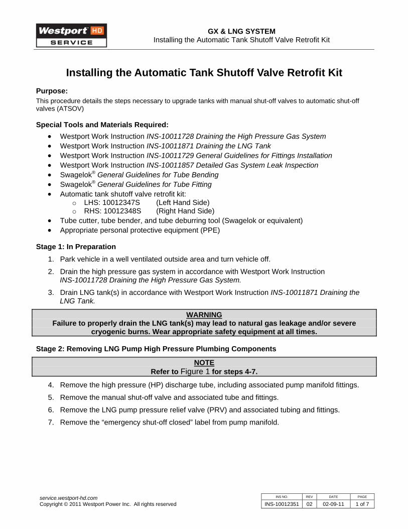
GX & LNG SYSTEM Installing the Automatic Tank Shutoff Valve Retrofit Kit INS NO. REV DATE PAGE service.westport-hd.com Copyright © 2011 Westport Power Inc. All rights reserved INS-10012351 02 02-09-11 1 of 7 Installing the Automatic Tank Shutoff Valve Retrofit Kit Purpose: This procedure details the steps necessary to upgrade tanks with manual shut-off valves to automatic shut-off valves (ATSOV) Special Tools and Materials Required: • Westport Work Instruction INS-10011728 Draining the High Pressure Gas System • Westport Work Instruction INS-10011871 Draining the LNG Tank • Westport Work Instruction INS-10011729 General Guidelines for Fittings Installation • Westport Work Instruction INS-10011857 Detailed Gas System Leak Inspection • Swagelok ® General Guidelines for Tube Bending • Swagelok ® General Guidelines for Tube Fitting • Automatic tank shutoff valve retrofit kit: o LHS: 10012347S (Left Hand Side) o RHS: 10012348S (Right Hand Side) • Tube cutter, tube bender, and tube deburring tool (Swagelok or equivalent) • Appropriate personal protective equipment (PPE) Stage 1: In Preparation 1. Park vehicle in a well ventilated outside area and turn vehicle off. 2. Drain the high pressure gas system in accordance with Westport Work Instruction INS-10011728 Draining the High Pressure Gas System. 3. Drain LNG tank(s) in accordance with Westport Work Instruction INS-10011871 Draining the LNG Tank. WARNING Failure to properly drain the LNG tank(s) may lead to natural gas leakage and/or severe cryogenic burns. Wear appropriate safety equipment at all times. Stage 2: Removing LNG Pump High Pressure Plumbing Components NOTE Refer to Figure 1 for steps 4-7. 4. Remove the high pressure (HP) discharge tube, including associated pump manifold fittings. 5. Remove the manual shut-off valve and associated tube and fittings. 6. Remove the LNG pump pressure relief valve (PRV) and associated tubing and fittings. 7. Remove the “emergency shut-off closed” label from pump manifold.

Welcome message from author
This document is posted to help you gain knowledge. Please leave a comment to let me know what you think about it! Share it to your friends and learn new things together.
Transcript
GX & LNG SYSTEM Installing the Automatic Tank Shutoff Valve Retrofit Kit
INS NO. REV DATE PAGE service.westport-hd.com Copyright © 2011 Westport Power Inc. All rights reserved INS-10012351 02 02-09-11 1 of 7
Installing the Automatic Tank Shutoff Valve Retrofit Kit Purpose: This procedure details the steps necessary to upgrade tanks with manual shut-off valves to automatic shut-off valves (ATSOV)
Special Tools and Materials Required: • Westport Work Instruction INS-10011728 Draining the High Pressure Gas System • Westport Work Instruction INS-10011871 Draining the LNG Tank • Westport Work Instruction INS-10011729 General Guidelines for Fittings Installation • Westport Work Instruction INS-10011857 Detailed Gas System Leak Inspection • Swagelok® General Guidelines for Tube Bending • Swagelok® General Guidelines for Tube Fitting • Automatic tank shutoff valve retrofit kit:
o LHS: 10012347S (Left Hand Side) o RHS: 10012348S (Right Hand Side)
• Tube cutter, tube bender, and tube deburring tool (Swagelok or equivalent) • Appropriate personal protective equipment (PPE)
Stage 1: In Preparation 1. Park vehicle in a well ventilated outside area and turn vehicle off.
2. Drain the high pressure gas system in accordance with Westport Work Instruction INS-10011728 Draining the High Pressure Gas System.
3. Drain LNG tank(s) in accordance with Westport Work Instruction INS-10011871 Draining the LNG Tank.
WARNING Failure to properly drain the LNG tank(s) may lead to natural gas leakage and/or severe
cryogenic burns. Wear appropriate safety equipment at all times.
Stage 2: Removing LNG Pump High Pressure Plumbing Components
NOTE Refer to Figure 1 for steps 4-7.
4. Remove the high pressure (HP) discharge tube, including associated pump manifold fittings.
5. Remove the manual shut-off valve and associated tube and fittings.
6. Remove the LNG pump pressure relief valve (PRV) and associated tubing and fittings.
7. Remove the “emergency shut-off closed” label from pump manifold.
GX & LNG SYSTEM Installing the Automatic Tank Shutoff Valve Retrofit Kit
INS NO. REV DATE PAGE service.westport-hd.com Copyright © 2011 Westport Power Inc. All rights reserved INS-10012351 02 02-09-11 2 of 7
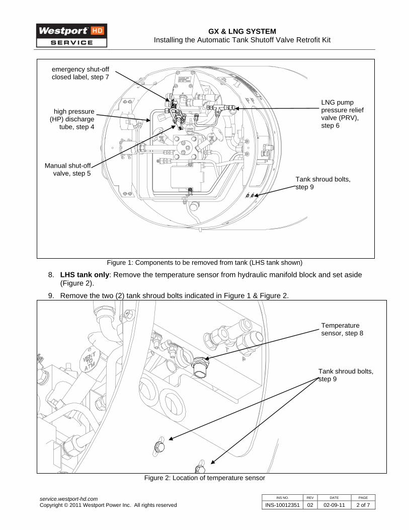
Figure 1: Components to be removed from tank (LHS tank shown)
8. LHS tank only: Remove the temperature sensor from hydraulic manifold block and set aside (Figure 2).
9. Remove the two (2) tank shroud bolts indicated in Figure 1 & Figure 2.
Figure 2: Location of temperature sensor
Manual shut-off valve, step 5
high pressure (HP) discharge
tube, step 4
Tank shroud bolts, step 9
emergency shut-off closed label, step 7
LNG pump pressure relief valve (PRV), step 6
Temperature sensor, step 8
Tank shroud bolts, step 9
GX & LNG SYSTEM Installing the Automatic Tank Shutoff Valve Retrofit Kit
INS NO. REV DATE PAGE service.westport-hd.com Copyright © 2011 Westport Power Inc. All rights reserved INS-10012351 02 02-09-11 3 of 7
Stage 3: Installing retrofit components on the LNG pump 10. Prior to installing the provided port plugs (1x -06 plug and 3x -04 plugs), ensure the fittings have
white Disogrin® o-rings. If black nitrile o-rings are installed, replace them with the provided white Disogrin® o-rings.
11. Ensure the o-rings are in acceptable condition before installation (ie: not twisted, nicked, torn, or otherwise damaged). Lubricate the o-rings with clean 15W-40 oil.
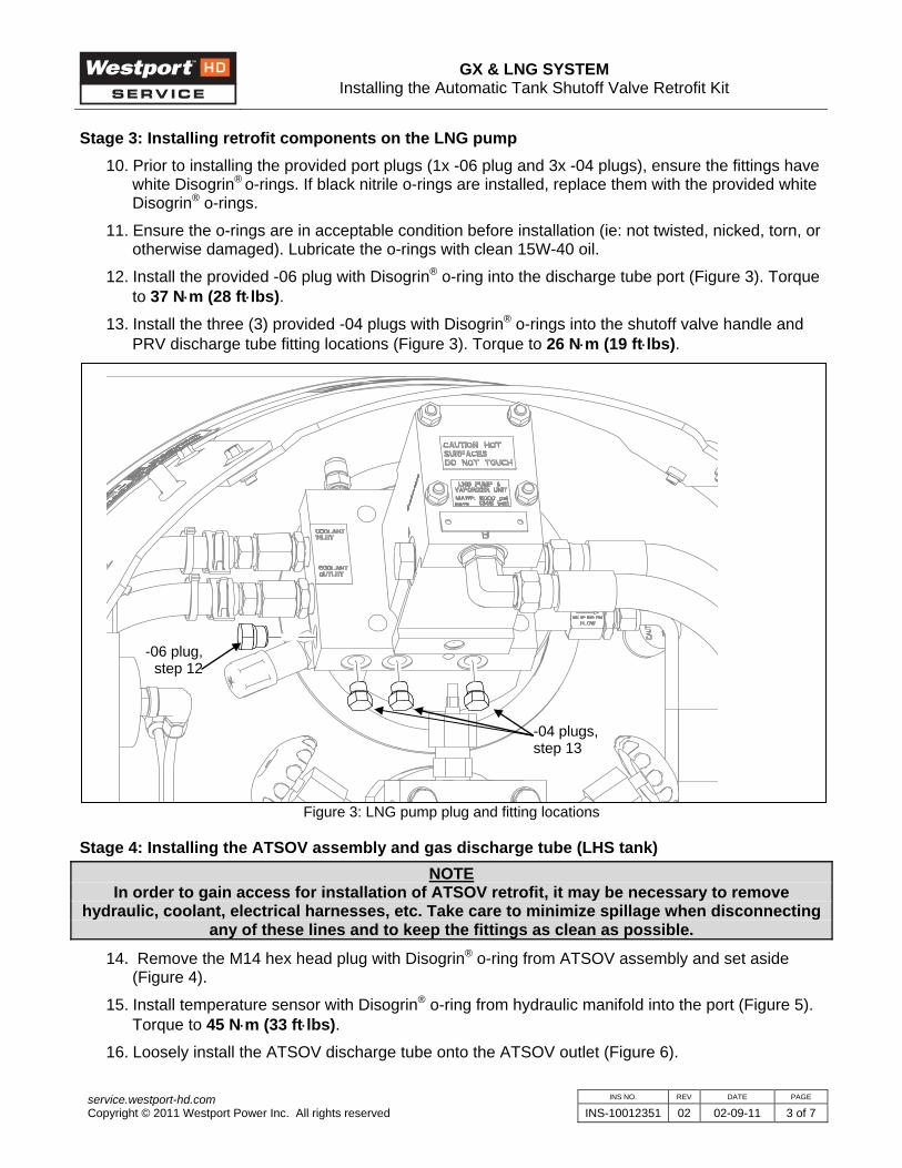
12. Install the provided -06 plug with Disogrin® o-ring into the discharge tube port (Figure 3). Torque to 37 N⋅m (28 ft⋅lbs).
13. Install the three (3) provided -04 plugs with Disogrin® o-rings into the shutoff valve handle and PRV discharge tube fitting locations (Figure 3). Torque to 26 N⋅m (19 ft⋅lbs).
Figure 3: LNG pump plug and fitting locations
Stage 4: Installing the ATSOV assembly and gas discharge tube (LHS tank) NOTE
In order to gain access for installation of ATSOV retrofit, it may be necessary to remove hydraulic, coolant, electrical harnesses, etc. Take care to minimize spillage when disconnecting
any of these lines and to keep the fittings as clean as possible.
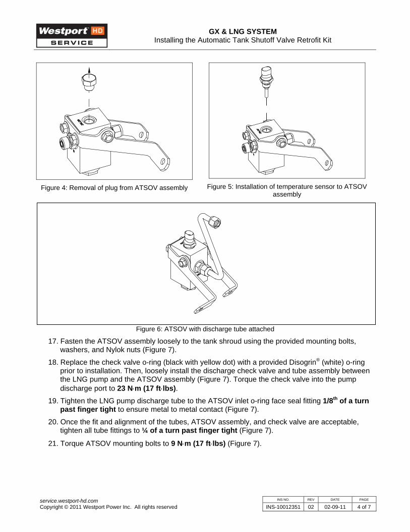
14. Remove the M14 hex head plug with Disogrin® o-ring from ATSOV assembly and set aside (Figure 4).
15. Install temperature sensor with Disogrin® o-ring from hydraulic manifold into the port (Figure 5). Torque to 45 N⋅m (33 ft⋅lbs).
16. Loosely install the ATSOV discharge tube onto the ATSOV outlet (Figure 6).
-06 plug,step 12
-04 plugs, step 13
GX & LNG SYSTEM Installing the Automatic Tank Shutoff Valve Retrofit Kit
INS NO. REV DATE PAGE service.westport-hd.com Copyright © 2011 Westport Power Inc. All rights reserved INS-10012351 02 02-09-11 4 of 7
Figure 4: Removal of plug from ATSOV assembly
Figure 5: Installation of temperature sensor to ATSOV
assembly
Figure 6: ATSOV with discharge tube attached
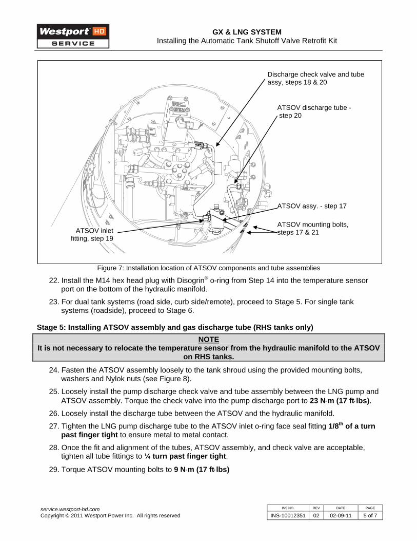
17. Fasten the ATSOV assembly loosely to the tank shroud using the provided mounting bolts, washers, and Nylok nuts (Figure 7).
18. Replace the check valve o-ring (black with yellow dot) with a provided Disogrin® (white) o-ring prior to installation. Then, loosely install the discharge check valve and tube assembly between the LNG pump and the ATSOV assembly (Figure 7). Torque the check valve into the pump discharge port to 23 N⋅m (17 ft⋅lbs).
19. Tighten the LNG pump discharge tube to the ATSOV inlet o-ring face seal fitting 1/8th of a turn past finger tight to ensure metal to metal contact (Figure 7).
20. Once the fit and alignment of the tubes, ATSOV assembly, and check valve are acceptable, tighten all tube fittings to ¼ of a turn past finger tight (Figure 7).
21. Torque ATSOV mounting bolts to 9 N⋅m (17 ft⋅lbs) (Figure 7).
GX & LNG SYSTEM Installing the Automatic Tank Shutoff Valve Retrofit Kit
INS NO. REV DATE PAGE service.westport-hd.com Copyright © 2011 Westport Power Inc. All rights reserved INS-10012351 02 02-09-11 5 of 7
Figure 7: Installation location of ATSOV components and tube assemblies
22. Install the M14 hex head plug with Disogrin® o-ring from Step 14 into the temperature sensor port on the bottom of the hydraulic manifold.
23. For dual tank systems (road side, curb side/remote), proceed to Stage 5. For single tank systems (roadside), proceed to Stage 6.
Stage 5: Installing ATSOV assembly and gas discharge tube (RHS tanks only) NOTE
It is not necessary to relocate the temperature sensor from the hydraulic manifold to the ATSOV on RHS tanks.
24. Fasten the ATSOV assembly loosely to the tank shroud using the provided mounting bolts, washers and Nylok nuts (see Figure 8).
25. Loosely install the pump discharge check valve and tube assembly between the LNG pump and ATSOV assembly. Torque the check valve into the pump discharge port to 23 N⋅m (17 ft⋅lbs).
26. Loosely install the discharge tube between the ATSOV and the hydraulic manifold.
27. Tighten the LNG pump discharge tube to the ATSOV inlet o-ring face seal fitting 1/8th of a turn past finger tight to ensure metal to metal contact.
28. Once the fit and alignment of the tubes, ATSOV assembly, and check valve are acceptable, tighten all tube fittings to ¼ turn past finger tight.
29. Torque ATSOV mounting bolts to 9 N⋅m (17 ft⋅lbs)
Discharge check valve and tube assy, steps 18 & 20
ATSOV discharge tube - step 20
ATSOV assy. - step 17
ATSOV mounting bolts, steps 17 & 21 ATSOV inlet
fitting, step 19
GX & LNG SYSTEM Installing the Automatic Tank Shutoff Valve Retrofit Kit
INS NO. REV DATE PAGE service.westport-hd.com Copyright © 2011 Westport Power Inc. All rights reserved INS-10012351 02 02-09-11 6 of 7
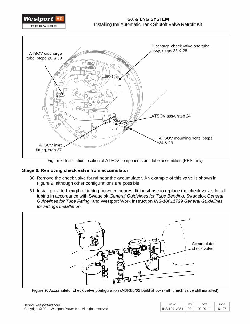
Figure 8: Installation location of ATSOV components and tube assemblies (RHS tank)
Stage 6: Removing check valve from accumulator 30. Remove the check valve found near the accumulator. An example of this valve is shown in
Figure 9, although other configurations are possible.
31. Install provided length of tubing between nearest fittings/hose to replace the check valve. Install tubing in accordance with Swagelok General Guidelines for Tube Bending, Swagelok General Guidelines for Tube Fitting, and Westport Work Instruction INS-10011729 General Guidelines for Fittings Installation.
Figure 9: Accumulator check valve configuration (ADR80/02 build shown with check valve still installed)
Discharge check valve and tube assy, steps 25 & 28
ATSOV assy, step 24
ATSOV mounting bolts, steps 24 & 29
ATSOV dischargetube, steps 26 & 29
Accumulator check valve
ATSOV inlet fitting, step 27

GX & LNG SYSTEM Installing the Automatic Tank Shutoff Valve Retrofit Kit
INS NO. REV DATE PAGE service.westport-hd.com Copyright © 2011 Westport Power Inc. All rights reserved INS-10012351 02 02-09-11 7 of 7
Stage 7: Completion 32. Remove tank shroud labels from tanks and replace with provided labels.
33. Leak check LNG tank and high pressure gas system in accordance with Westport Work Instruction INS-10011857 Detailed Gas System Leak Inspection.
Revision Date (MM/DD/YY) Description
00 30/05/08 Initial Release
01 19/06/09 New discharge plumbing in tank shroud (Steps 17, 23) and removal of accumulator assy CV (Stage 6).
02 09/02/11 Step 10 updated to reflect changes in service part kit.
Related Documents