Water, Sewer & Natural Gas Design Guidelines Revised August 2015

Welcome message from author
This document is posted to help you gain knowledge. Please leave a comment to let me know what you think about it! Share it to your friends and learn new things together.
Transcript

Water, Sewer & Natural Gas
Design Guidelines
Revised August 2015

City of Thomasville Water, Sewer & Natural Gas Design Guidelines
2 of 45
Section 1.0 General Information
1.0 General 5
1.1 Getting Started 5
1.1.1 Service Availability Request
1.1.1.1 Verification of City Points of Service
1.1.1.2 Project Phasing
1.1.2 Special Service Considerations
1.1.2.1 Additional Costs for Special Service Conditions
1.2 Pre-Application Meeting 6
1.3 Modifications to Existing City Systems 6
1.4 Master Plan Requirements 6
Section 2.0 Design Guidelines
2.0 General 7
2.1 Order of Precedence 7
2.2 City Plan Approval Effective Dates 8
2.3 Design Review 8
2.3.1 General Plan Submittal Requirements
2.3.2 Water Plan Submittal Requirements
2.3.3 Sewer Plan Submittal Requirements
2.3.4 Natural Gas Plan Submittal Requirements
2.3.5 Utility Construction Notes
2.4 Preliminary Design Review 11
2.5 Final Design Review 12
2.6 Permits 12
2.7 Pre-Construction Meeting 13
2.8 Construction and Inspection 13
2.9 Shop Drawings 13
2.10 As-Built Drawings 13
2.11 Substantial Completion Inspection 13
2.12 Final Inspection and Acceptance of the System 14
2.13 System Warranty 14
2.14 City Connection Fees 14
2.15 Dedication of Existing Privately-Owned Systems 14
2.16 Public and Private Point of Service 15
2.17 Utility Easements 15
2.18 Revision to Dedicated Infrastructure 16
2.18.1 Water Services
2.18.2 Fire Hydrants
2.18.3 Sewer Services
2.18.4 Construction and Dedication of Redesigned Infrastructure
Section 3.0 Potable Water Design Guidelines
3.0 General 19
3.1 Design Flows 19
3.1.1 Average Daily Flow (ADF)
3.1.2 Single Family Residential
3.1.3 Multi-Family Residential, Commercial and Industrial

City of Thomasville Water, Sewer & Natural Gas Design Guidelines
3 of 45
3.2 Fire Flow 19
3.2.1 Single Family Residential
3.2.2 Multi-Family Residential
3.2.3 Manufactured Home Communities
3.2.4 Commercial and Industrial
3.2.5 Fire Hydrant Test Data
3.3 Sizing Water Mains 21
3.3.1 Major Transmission Mains
3.3.2 Distribution Mains
3.3.3 Velocities
3.3.4 “C” Factor
3.4 Water Main Materials 21
3.5 Water Main Bury Depths 21
3.6 Water Main Locations 22
3.7 Water Main Separation Requirements 22
3.8 System Connections 22
3.9 Fire Hydrant Locations 23
3.9.1 General
3.9.2 Single Family Residential
3.9.3 Multi-Family Residential, Commercial and Industrial
3.9.4 Open Rural Areas
3.10 Valves 24
3.11 Flushing Hydrants and Sample Points 24
3.12 Services 25
3.13 Water Meters 25
3.13.1 General
3.13.2 Water Meter Sizing
3.13.3 Temporary Water Meters
3.13.4 Portable Fire Hydrant Meters for Construction Activities
3.13.5 Multi-Family, Commercial or Industrial Development Metering
3.14 Backflow Preventers 27
Section 4.0 Sewer Design Guidelines
4.0 General 28
4.1 Design Flows 28
4.1.1 Average Daily Flow (ADF)
4.1.2 Equivalent Dwelling Units
4.1.3 Peak Flow
4.2 Gravity Sewer Mains 28
4.2.1 Sizing Gravity Sewer Mains
4.2.2 Gravity Sewer Slope Requirements
4.2.3 Gravity Sewer Main Materials
4.2.4 Gravity Sewer Main Depth
4.2.5 Gravity Sewer Main Location
4.3 Sewer Main Separation Requirements 30
4.4 Gravity Services 31
4.4.1 Single Family Residential Services
4.4.2 Multi-Family Residential, Commercial and Industrial Services
4.5 Sewer Meters 32
4.6 Sewer Manholes 33

City of Thomasville Water, Sewer & Natural Gas Design Guidelines
4 of 45
4.6.1 Invert and Rim Elevations
4.6.2 Drop Connections
4.6.3 Lining
4.7 Force Mains 33
4.7.1 Pipe Diameter
4.7.2 Depth of Bury
4.7.3 Material and Fittings
4.7.4 Location
4.7.5 Force Main Separation Requirements
4.7.6 Valves
4.7.7 Force Main Connections to Existing Force Mains
4.7.7.1 Taps
4.7.7.2 To Existing Force Mains > 12” diameter
4.8 Access Road 36
Section 5.0 Pump Station Design Guidelines
5.0 City Dedicated Pump Stations 37
5.0.1 General
5.0.2 Site Plan
5.0.3 Junction Manhole
5.0.4 Low Flow Pump Station
5.0.5 Wet Well – Duplex
5.0.6 Wet Well – Triplex
5.0.7 Pumps
5.0.8 Electrical Control Panel
5.0.9 Emergency Power
5.0.10 Water Service
5.1 Private Pump Stations 42
5.2 Low Pressure Systems 43
Section 6.0 Natural Gas Design Guidelines
6.0 General 45

City of Thomasville Water, Sewer & Natural Gas Design Guidelines
5 of 45
Section 1.0
General Information
1.0 General
City of Thomasville Engineering Department consists of the City Engineer, Asst. City Engineer,
Engineers, GIS Analysts, Technicians, and Coordination staff.
Engineering team members are trained to assist in the project management, coordination with
planning, system availability, hydraulic analysis, design review, construction inspection, as-built
review, and acceptance processes of developer installed utility systems.
This section provides a summary of the processes included in the initial stages of project
development and the City personnel involved in coordination of new developer installed utility
system projects.
All applicants shall follow the design review process, except for a single residential lot and
commercial properties that do not require a force main connection and utilize no greater than a 2”
water meter.
1.1 Getting Started
1.1.1 Service Availability Request
Prior to submitting for a building permit with local City or county agencies, an
Availability Request Form shall be submitted to Engineering. This form can be
completed on-line at www.thomasville.org. Service availability requests are reviewed by
Engineering to determine the nearest point of connection. Requests are normally
completed within 7 (seven) business days. Responses from Engineering are in the form of
an availability letter.
The availability has an expiration of 1 (one) year from the date written and contains a
tracking number known as the availability number. This number will be the reference
number used throughout the project’s lifecycle.
1.1.1.1 Verification of City Points of Service
In its evaluation of availability requests, Engineering will rely upon GIS records
for the accuracy of existing City utilities. It shall be the sole and exclusive
responsibility of the applicant and/or its affiliated parties to determine the
suitability and accuracy of the record information and locate through field
verification (including but not limited to subsurface utility investigations, open
excavation, ground penetrating radar etc.) during the design process. Should field
verification of existing utilities not match the availability response, the applicant
shall notify Engineering immediately so a new point of connection can be
identified.
1.1.1.2 Project Phasing
For projects which will be constructed in several phases, Engineering shall be
provided with a phased master plan. Engineering will require projects be broken
into logical phases. Each phase will be a separate project with a separate plan
review.
1.1.2 Special Service Considerations
1.1.2.1 Additional Costs for Special Service Conditions
During the plan review process, Engineering may observe unusual conditions
(ex. additional costs due to GDOT right-of-way requirements, a conflict with

City of Thomasville Water, Sewer & Natural Gas Design Guidelines
6 of 45
resurfacing schedule, or other unusual connection requirements) and add
comments to the submitted drawing set so to alert the applicant that (for the City
to install requested utilities) the City must ascertain the magnitude of cost for the
tap construction. The additional cost will be the responsibility of the developer.
The City has the right to refuse to install complex services, in which case the
construction of the connection will be accomplished by the developer and the
project must complete the design review and dedication process.
1.2 Pre-Application Meeting
It is strongly recommended that the applicant schedule a pre-application meeting with
Engineering to discuss conceptual water, sewer, and natural gas requirements for any project
other than simple tap projects. For large, complex, or phased projects, a pre-application meeting
shall be mandatory. To schedule a pre-application meeting ...
1.3 Modifications to Existing City Systems
Once a project has been accepted by the City, no further revisions are allowed and the developer
or its engineer must resubmit plans to make changes.
1.4 Master Plan Requirements
A Master Development Plan shall be required for all development projects being constructed in
multiple phases. The Master Development Plan shall include, but not be limited to:
• Project boundary - The Project Boundary shall match the project boundary approved by
either the City of Thomasville Planning Department or Thomas County.
• Identification and Scheduling of all Phases.
• A description of the Type and Quantity of development (example: 300 Single Family
Homes) within each phase.
• Routing for all piping (Water, Wastewater and Natural Gas) along with proposed pipe
sizes and connection points.
• Identify whether piping will be located in public right of way, easements or other.
• Preliminary locations of all pump stations and/or master lift stations
The Master Development Plan shall be submitted prior to or concurrently with the first phase of
construction. Approval of the Master Development Plan does not override the requirements of the
design and construction standards.

City of Thomasville Water, Sewer & Natural Gas Design Guidelines
7 of 45
Section 2.0
Design Guidelines
2.0 General
This section applies to all new residential, commercial or industrial developments requiring or
requesting a new or modified water, sanitary sewer, and/or natural gas service or main
construction. For these new developments, an Engineering Plan Review is required. To initiate an
Engineering Plan Review, the developer must first obtain a Utility Availability Letter, which
defines the City point of service. The availability number is utilized for tracking the project from
start to finish. The developer or engineer submits proposed construction plans, permits and other
applicable data to the Engineering Department for water, sewer, and natural gas utility review.
This Plan Review process typically involves two submittals (a preliminary and final plan review)
as described below.
The City, in coordination with the Developer’s Engineer, reserves the right to specify the point of
service, the size of service, the type of service, and the general layout of the overall system within
the guidelines established in this manual.
Water, sewer, and natural gas distribution and collection systems shall be designed and
constructed according to the most current editions of the following publications:
• City of Thomasville Code of Ordinances
• City of Thomasville Water, Sewer & Natural Gas Design Guidelines
• City of Thomasville Water, Sewer & Natural Gas Specifications
• The Recommended Standards for Sewage Works (Ten State Standards)
• EPD and other applicable federal, state and local requirements
For utility work outside of the City, the location of water valves, meter boxes and the type and
location of fire hydrants shall comply with the local (County) design and construction utility
standards.
The engineer shall coordinate the location of water, sewer, and natural gas facilities with other
utilities (electric, telecommunication, drainage and cable) to minimize conflicts. Facilities shall be
designed such that conflicts with driveways and sidewalks are minimized. In the event of conflict
with a future driveway or sidewalk, the Developer and/or Builder shall be responsible to resolve
the conflict at its expense.
For private water distribution systems involving two or more units which are connected to the
City water distribution system (such as a master meter arrangement), the owner or its engineer
shall ensure that the above rules and standards are complied with during the design and
construction phase of the project. Although a City Plan Review and/or a regulatory permit may
not be required, it is the responsibility of the owner or engineer to maintain the public drinking
water standards by complying with the above applicable rules and standards including, but not
limited to utility separation requirements, pressure and leakage testing and private bacteriological
clearance testing. It should also be noted, in some cases, the private water distribution system
may require a plumbing permit from the City or County having jurisdiction.
2.1 Order of Precedence
City will use the following order of precedence in resolving any conflict, error, or discrepancy for
all installed systems:
1. Approved regulatory permits (City, EPD)

City of Thomasville Water, Sewer & Natural Gas Design Guidelines
8 of 45
2. Approved County/GDOT agency permit requirements
3. Approved final design plans
4. City Water, Sewer and Natural Gas Specifications
5. City Water, Sewer and Natural Gas Design Guidelines
2.2 City Plan Approval Effective Dates
City approved plans will be effective for 2 years from the date of City Plan Approval. The date of
City Plan Review Approval will be provided on the cover sheet of the approved construction
plans. This approval date will define the acceptable City construction standards which will be
utilized during the construction period. After the 2 year period has expired, City may grant up to
one, 2 year time extension and subsequently, one, 1 year time extension for a maximum of a 5-
year construction time period. At each request for extension, a copy of the existing approved City
plans, identifying any construction that has occurred, will be submitted for approval. Any
construction not completed and accepted by City will adhere to the City standards in effect at the
time the extension and plans are approved.
2.3 Design Review
2.3.1 General Plan Submittal Requirements
As a minimum requirement, the following shall be included on the design drawings:
a. A north arrow with scale indicated,
b. Cover sheet with a vicinity map, City availability number.
c. Lot numbers, street names and street address (if available),
d. A permanent benchmark or temporary benchmark (referenced to a permanent
benchmark) referenced to State Plane Coordinates as well as topography depicted as one
foot contours,
e. The engineer’s name, project name and all phases to be planned, designed, and
constructed on all sheets,
f. Developer’s name and contact number,
g. All materials shown and clearly labeled (pipe, valves, fire hydrants, fire sprinkler lines,
water meters, fittings, manholes, services) with associated elevations, sizes, types,
composition, slopes, and appurtenances,
h. Location of existing utilities within the right-of-way including water mains, force mains,
gravity sewers, storm sewers, electric, natural gas, fiber optic, cable, and telephone,
i. Where connecting to an existing utility line, both horizontal and vertical field verification
of the main location,
j. Elevations (manhole tops and inverts) of all existing sewer facilities within the right-of-
way and easements.
k. A site plan indicating any required grease, oil, sand, or lint separators and/or other
required pretreatment systems such as dumpster pad run off,
l. A master paving and drainage plan showing all storm water facilities, retention or
detention ponds with elevations, the design high water and 100 year flood elevations and
site contours shown at 2' maximum intervals,

City of Thomasville Water, Sewer & Natural Gas Design Guidelines
9 of 45
m. All drainage design plan sheets with profiles depicting proposed water, sewer, and natural
gas systems.
n. Utility Master Site Plan drawn with proposed phases clearly indicated. Updates provided
as revisions are made,
o. Match lines, when applicable, shall be indicated on all plan sheets,
p. When available, preliminary plat shall be submitted on all platted projects in order for
City to provide electric, water, sewer, or natural gas services to the development,
q. Design plan shall include station numbers along proposed roadways for all projects,
r. For commercial or residential subdivisions, plan only sheets drawn at a maximum
horizontal scale of 1” = 50’. For commercial and residential subdivisions, plan and
profile sheets drawn at a maximum horizontal scale of 1” = 50’ and a maximum vertical
scale of 1” = 5'.
s. Roadway cross sections with proposed and existing utilities depicted, road crossing
details for open cuts, profiles for jack and bores and directional drills showing all existing
utilities with actual surveyed elevations and field verified locations where possible,
t. Plan and profile sheets shall include all sewer design information including pipe size,
length, material, slope, manhole top and invert elevations, existing and proposed grades,
the location of new gravity sewers and force mains, all crossings (storm water and water
mains) and all additional pertinent information such as trench details, manhole details,
joint details, and material specifications. Profiles may not be required for sewer force
main projects which involve less than 50 LF,
u. Landscaping plans with location of proposed utilities shown,
v. All existing and proposed utility easements and rights-of way with dimensions, locations
and grantee,
w. All existing or proposed drainage easements with dimensions, locations and grantee.
x. When available, building footprints (for commercial projects), minimum finished floor
elevations and number of floors, decorative brick walls and paving, entrance signs,
fountains, fences, and landscape buffers shown,
y. Ownership of the proposed utility system shall be clearly designated as “City” or
“Private”,
z. Stabilized access road shown in easements crossing wetlands or limited access areas
which include manholes,
aa. The limits of joint deflection for vertical and horizontal offsets must be reflected on the
drawings. It could be “start vertical joint deflection” and “stop vertical joint deflection”
or a dimensional line at each end labeled “limits of deflection.” Joint deflection must
conform to City Specifications.
2.3.2 Water Plan Submittal Requirements
In addition to the general plan submittal requirements discussed above. Water design
plans shall include the following:
a. All backflow prevention required in accordance with the CITY cross connection
control program.
b. Location of all points of connection to the existing water distribution system.

City of Thomasville Water, Sewer & Natural Gas Design Guidelines
10 of 45
2.3.3 Sewer Plan Submittal Requirements
In addition to the general plan submittal requirements discussed above, sewer design
plans shall include the following:
a. Force main elevations every 100' minimum and at any grade changes exceeding 2
feet,
b. Pump station drawings shall include, cross sectional view of pump station
showing pump station piping and fittings and wet well elevations, pump
information including model, impeller diameter, horsepower, motor speed,
operating voltage, control panel, and operating point,
c. For City pump station sites, a Standard Penetration soil boring shall be performed
at each wet well location and submitted prior to final plan approval. The soil
boring shall be a minimum of 15 feet deeper than the wet well bottom or extend
until suitable soil is located up to a maximum of 25 feet below the wet well
bottom.
d. City pump station standard detail sheets where the pump station is to be
dedicated to City: Where required, the standard site layout may be modified as
necessary, provided the minimum site dimensions are maintained and all
standard general notes are included.
2.3.4 Natural Gas Plan Submittal Requirements
In addition to the general plan submittal requirements discussed above, natural gas design
plans shall include the following:
a. Location of all regulator stations,
b. System operating pressure (High or Low pressure),
c. ...
2.3.5 Utility Construction Notes
The following notes, at a minimum, shall be included on all plan submittals. Any
deviation from the standards shall be requested by the Developer’s Engineer and shall be
approved, in writing, by City:
1. All water, natural gas and sanitary sewer work shall be constructed in accordance
with the latest City Water, Sewer & Natural Gas Specifications, all applicable
local and state regulatory rules & regulations and other applicable City rules.
2. All water, sewer, and natural gas construction shall be provided by an
underground utility contractor, licensed under the provisions of O.C.G.A. § 43-
14-8.2.
3. The owner/developer shall be responsible for obtaining County Right-Of- Way
permits for work in the County R/W or a GDOT permit for work in the GDOT
R/W.
4. The contractor shall contact the City field inspector and schedule a "Pre-
Construction Meeting" 48 hours prior to initiating the City water, sewer, and
natural gas utility work, including all utility main taps by the contractor.
5. City water, sewer, and natural gas tap fees, City sewer connection fees, City
meter fees, and City construction assistance fees shall be paid prior to the water
meter installation. Water meters will not be installed prior to the issuance of

City of Thomasville Water, Sewer & Natural Gas Design Guidelines
11 of 45
required acceptance (transfer of ownership) documents which may include the
issuance of a regulatory clearance letter (COC) for the water and sewer
improvements, completion and approval of Final Inspection and approved As-
Built drawings.
6. Final connection to the City system may be contingent upon the construction,
dedication and final acceptance (transfer of ownership/maintenance) of the City
off-site utilities.
7. The minimum horizontal and vertical separation requirements for the water,
sewer, and natural gas improvements shall conform to the latest City and EPD
rules. The minimum horizontal separation requirements between the proposed
water and sewer utilities and ponds or structures shall conform to the latest City
Water, Sewer & Natural Gas Specifications.
8. Water and sewer pipes shall be constructed with a minimum 30" cover in
unpaved areas and a minimum of 36" cover in paved areas. The maximum cover
for utilities, both open cut and utilizing Horizontal Directional Drill methods,
shall comply with the latest City Water, Sewer & Natural Gas Specifications.
9. Water and sewer pressure mains and services shall pass a City pressure and
leakage test at 150 psi for 2 hours. In addition, water mains shall be disinfected
and pass a bacteriological analysis. All tests shall conform to City and EPD rules
and regulations and AWWA C-651.
10. Natural gas mains and services shall pass a City pressure and leakage test at 150
psi for 2 hours. In addition, water mains shall be disinfected and pass a
bacteriological analysis. All tests shall conform to City and EPD rules and
regulations and AWWA C-651.
11. The City Inspector shall be notified 48 hours (min) prior to performing these
tests. No final connection(s) to existing potable water mains shall be made until
the new main is pressure tested, disinfected, and cleared for service.
12. In the areas where solvent contamination is found in the trench, work shall be
stopped and the proper regulatory authorities notified. A revised construction
plan shall be approved by City and EPD which complies with all regulatory rules.
The revised construction plan for the City water main system including water
service lines may involve galvanized or ductile iron pipe with special solvent
resistant (fluorocarbon type) gaskets which extend 100 feet beyond the
contaminated areas.
13. The contractor shall minimize service interruptions to existing City water and
sewer customers. If City approves a service interruption, then the contractor will
be responsible for notifying the affected customers in accordance with the latest
City rules.
14. Residential and commercial services using well water for irrigation must have a
City approved backflow preventer installed on each potable water service prior to
the installation of a City water meter. The installation of a backflow preventer
shall be in accordance with the City Ordinances, Section 13-82 Cross-connection
control.
2.4 Preliminary Design Review
Two sets of clear and legible design plans that have been signed and sealed by a professional
engineer registered in the state of Georgia shall be submitted on 24” by 36” sheets for preliminary

City of Thomasville Water, Sewer & Natural Gas Design Guidelines
12 of 45
plan review by City. Plans shall also be submitted in PDF format. One PDF file shall contain all
plan sheets.
To submit for preliminary design review, visit our website at www.thomasville.org and download
the City checklist. This form and related documents may be submitted via e-mail to
[email protected]. The hard copies of plans shall be deposited at City’s
Development Services offices in the lobby.
A list of documents that must be submitted for a Preliminary Design Plan Review is listed on the
form and can be found at www.thomasville.org.
Plan review submittals that are missing required information will be returned as incomplete
submittals.
2.5 Final Design Review
Final design plans which have been revised and re-submitted for final review shall have the
revisions listed in revision block on all affected sheets. After incorporation of reviewer’s final
comments, all subsequent revisions shall be “clouded” to bring attention to the proposed changes.
Any revisions to the development following final plan approval prior to beginning construction
will require a pre-design meeting with City’s Development group to determine if a new
availability and plan review is required.
City review and approval will be required for any significant changes which may require permit
modification, property line or easement change.
Four sets of clear and legible design plans that have been signed and sealed by a professional
engineer registered in the state of Georgia shall be submitted on 24” by 36” sheets for final plan
review by City. Plans shall also be submitted in AutoCAD or MicroStation and in PDF format.
One DF file shall contain all plan sheets.
To submit for final design review, visit our website at www.thomasville.org and download our
City Development Design Plan Review Form. This form and related comments may be submitted
via e-mail to [email protected]. The hard copies of plans shall be deposited at
City’s Development Services offices in the lobby.
A list of documents that must be submitted for a Final Design Plan Review is listed in the form,
and can be found at www.thomasville.org.
Plan review submittals that are missing required information will be returned as an incomplete
submittal.
2.6 Permits
The Developer and Engineer are responsible for ensuring that all permits, permit criteria, permit
fees, forms and other permitting requirements are met for the proposed project.
Under the Rules and Regulations of the Environmental Protection Division, 391-3-5-.04, the City
of Thomasville staff may approve water distribution lines serving subdivisions, apartment
complexes and shopping centers.
All water and/or sewer mains exceeding12” in diameter will require an EPD permit. All private
sewer facilities shall be permitted through EPD or, if applicable, the Engineering Department.
Right of Way permits are required for work within the county and state rights-of-way. Contact the
appropriate agency for R/W permitting requirements. If a GDOT permit is required, the
owner/developer (aka Permittee) is required to provide the City Engineering Department a
complete GDOT Utility Permit Application. Upon City review and approval of the GDOT permit

City of Thomasville Water, Sewer & Natural Gas Design Guidelines
13 of 45
application package, a City representative having delegated authority to submit GDOT Utility
permits will execute the “Special GDOT Instructions” form. Please submit 2 copies of the entire
GDOT permit application package along with the required number of original forms for CITY
review and signature.
2.7 Pre-Construction Meeting
Upon final plan approval, the owner/developer or authorized agent shall schedule a pre-
construction meeting to be held at City’s Engineering office located at 411 W Jackson Street. To
schedule a Pre Construction meeting contact the Engineering Department at (229) 227-7009.
2.8 Construction and Inspection
With distribution of the final design drawings, the project will be turned over to the Developer’s
Engineer for coordination of construction. The City will assign a representative from Engineering
who will be responsible for the City’s inspection activities of any facilities constructed for
dedication to the City. The representative will maintain communication with all applicable parties
throughout the project construction.
Unless approved otherwise by Engineering, the utility system shall be installed as depicted on the
approved project drawings and in accordance with the City Water, Sewer & Natural Gas
Specifications.
Any utility adjustments resulting from finish grade changes made after plan approval must be
approved by Engineering and shall be the sole responsibility of the Developer. In no case shall
maximum or minimum slopes or depth of bury be exceeded as a result of the field finish grade
changes.
The actual field locations of utility appurtenances (i.e. fire hydrants, line valves, services, flushing
hydrants) shall be approved by Engineering prior to construction.
For additional details refer to City Water, Sewer & Natural Gas Specifications.
2.9 Shop Drawings
Any specialty pump station structures, pumps, panels, or materials not included in the City
Specifications will require two complete sets of shop drawings to be submitted to Engineering for
review and approval prior to ordering materials. The City availability number associated with the
project shall be shown on the shop drawings. The Developer’s Engineer shall review and approve
shop drawings prior to submittal to City for review and approval. For additional details, refer to
City Water, Sewer & Natural Gas Specifications.
2.10 As-Built Drawings
Upon completion of the project and prior to dedication of utilities to City or final payment under
a contract with City, the Contractor shall furnish to City an electronic file and 2 sets of the As-
Built drawings revised in accordance with the City Water, Sewer & Natural Gas Specifications,
Section XXXX. The Contractor shall deliver initial As-Built drawings within 30 days of
substantial completion. As-Built drawings shall be submitted to the Engineering Department.
The City shall review the documents to ensure accuracy with respect to actual construction and
City Standards. After initial As-Built submittal and after City preliminary As-Built review, a
Substantial Completion Inspection will be scheduled.
As-Built drawings must include recording document numbers for all utility work located within
easements.
In the event data is missing, the Contractor will be notified and provided a marked-up copy
showing the required changes. Within 30 days, the contractor shall furnish the corrected signed

City of Thomasville Water, Sewer & Natural Gas Design Guidelines
14 of 45
and sealed As-Built drawings along with two copies and an electronic file on CD to the City for
approval. Upon approval, an approval letter shall be issued to the contractor with copies
distributed to the appropriate segments within the City.
2.11 Substantial Completion Inspection
Upon substantial completion of the project, the City will perform a Substantial Completion
Inspection with City’s Operations personnel, the developer’s engineer and the contractor. The
purpose of the walk through is to generate a punch list of items that need to be addressed to meet
City standards, to field verify As-Built drawings submitted, and to operate all valves.
2.12 Final Inspection and Acceptance of the System
Upon construction completion, resolution of all punch list items and approval of As-Built
drawings, the developer may request a final inspection and acceptance of the system. The City
inspector with the Developer’s engineer and the contractor will perform the final inspection of the
system to ensure the project has been completed and is ready for dedication to the City.
To schedule a Final Inspection contact the Engineering Department.
2.13 System Warranty
All portions of the installed utility system shall be unconditionally guaranteed, in accordance with
the City Water, Sewer & Natural Gas Specifications, against material defects or improper
workmanship. The Developer shall repair and/or replace defective material and/or installations at
no cost to the City. In the event of failure by the Developer to provide complete replacement,
delivery to the site of materials and installation of same to replace defective materials or defective
workmanship with new materials/workmanship conforming to the City Water, Sewer & Natural
Gas Specifications, or during emergency events or in the event of imminent danger to City
facilities or customers, repairs may be made by City at the Developer’s expense.
If any facilities, including service lines that are installed, do not conform to the final lot layout, it
shall be considered a misplacement of the installed system and all costs incurred by CITY for
relocation shall be paid in advance by the Developer, or its successor.
2.14 City Connection Fees
Prior to connection to City’s utility systems and/or issuance of meters, all applicable fees must be
paid and project acceptance must be obtained.
2.15 Dedication of Existing Privately-Owned Systems
City will not accept existing privately owned, operated and maintained systems for dedication.
These systems include, but are not limited to, the following:
a. Existing master metered onsite water distribution systems.
b. Existing private pump stations.
c. Existing private onsite gravity sewer collection systems.
On a case by case basis, City may consider exceptions to the above given one or more of the
following criteria are met.
a. City’s system reliability or capacity may be improved or increased as a result of system
dedication.
b. Additional customers who currently are not served will be provided service via the
dedicated facilities.

City of Thomasville Water, Sewer & Natural Gas Design Guidelines
15 of 45
c. Dedication of the system is warranted to eliminate or prevent potential environmental
damage.
In the event City agrees to accept a privately-owned system, the following events shall occur:
a. City will evaluate the system, at the Owner’s expense, to determine repairs and/or
upgrades needed to bring the system into compliance with current City standards and
regulatory requirements.
b. System owner shall, at no cost to City, repair or improve the system accordingly.
c. Repairs or improvements shall be designed and permitted in accordance with all Local
and State rules and regulations.
d. Repairs and improvements shall be inspected by City during construction.
e. System shall be tested by owner’s contractor and witnessed by City. This includes, but is
not limited to; water and sewer pressure tests, gravity sewer television inspection and
pump station start up testing.
f. The system owner shall prepare an As-Built of the system and submit to City for
approval.
g. The system owner shall provide or obtain any easements required for City to own and
operate the system.
Once these items are complete, City will submit a written letter of system acceptance to the
owner informing them that City has accepted the system for ownership and maintenance.
2.16 Public and Private Point of Service
A customer’s point of service is defined by City as the location of the connection points
indentified in the City's Utility Availability response. Points of connection provided by City are
located in the Right-of-Way at a utility owned by the City.
From the customer’s point of service, the City is obligated to own, operate and maintain only
those utilities which will be constructed in existing or proposed Right -of-Way.
Proposed utilities which will be constructed in an approved City utility easement must be located
adjacent to or abut existing or proposed Right-of-Ways.
With the exception of proposed dedicated Right-of-Ways, City is under no obligation to accept
ownership, operations or maintenance responsibilities associated with utilities which will be
constructed on private property and in those cases, developers and their engineers should design
their projects with private utilities which meet or exceed their service requirements.
2.17 Utility Easements
Utilities shall not be located in easements unless approved by the City Engineer. Approval shall
be requested at the pre-application meeting (prior to plan review submittal). Utilities located
within easements between lots are discouraged and will be allowed only with the City Engineer's
approval.
Easements, where allowed, shall be identified as unobstructed and shall have a minimum width of
15' for water only or as shown in Table 2.
Landscaping, other than grass, is considered to be an obstruction.
A Hold Harmless Agreement may be required when installing special landscaping, special paving
and/or other specialties in right-of-way or easements over City utilities.

City of Thomasville Water, Sewer & Natural Gas Design Guidelines
16 of 45
Table 2: Easement Width
PIPE DEPTH, ft EASEMENT WIDTH, ft
One Utility Two Utilities Three Utilities
0 - 6 15 20 25
6 - 8 20 25 30
8 - 10 25 35 40
10 - 12 30 40 45
Greater than 12 50 N/A N/A
Gravity sewer greater than 12' deep shall not be located within easements.
When easements are adjacent to and parallel to a public right-of-way, the minimum easement
width shall be 10’ for water only or 20’ for both water and sewer mains. If an electrical easement
is proposed adjacent to the right-of-way and a water, sewer or natural gas easement is also
proposed adjacent to the right-of-way, then a water, force main, or natural gas easement with a
minimum width of 5’ each is required adjacent to and in addition to City electric easements.
If an electrical easement is proposed that is not City owned the water, sewer, natural gas easement
must be 10 feet wide adjacent to and in addition to the electric easements.
2.18 Revision to Dedicated Infrastructure
The City may allow construction revisions to water, sewer, and natural gas utilities for
developments which have already been fully dedicated to the City. This may occur in special
cases where the developer/engineer intends to modify property lines within an existing
development in which water, sewer, and/or natural gas utilities have been recently constructed
and fully dedicated to the City. The City reserves the right to require that all construction
revisions to dedicated utilities be performed by City forces.
All revision to existing City water, sewer and/or natural gas utilities must be reviewed and
approved by the City prior to any construction. The developer/engineer must submit the following
support documentation to Engineering. All submittals are to be delivered to the Development
Services office at 413 W Jackson Street, Lobby or documents may be submitted to
a. Copy of Approved Addressing Map for the original design.
b. Copy of Recorded Plat for the original design.
c. Copy of City Approved As-Built drawings for the original design
d. Proposed re-designed drawings.
e. Purpose of re-design
f. City/County Planning Correspondence
g. Proposed Re-addressing Map
The County will require a Right-of-Way permit for all work in the R/W. The County will define
the limits of road re-construction or overlay limits. The City will not be responsible for any
repairs to asphalt, sidewalk or other non-City infrastructures.
The following subparagraphs provide general design guidance for redesign of existing dedicated
facilities; however, site conditions may dictate variants to these guidelines as provided and
approved by City on a case by case basis. All construction work shall be in accordance with the
City Water, Sewer & Natural Gas Design Guidelines and Specifications.

City of Thomasville Water, Sewer & Natural Gas Design Guidelines
17 of 45
2.18.1 Water Services
a. Water meter boxes shall be constructed in accordance with City Water, Sewer &
Natural Gas Specifications. Meter boxes shall be located 2 feet from the property
line (P/L), unless there is an electric box on the P/L, in which case the water
meter box will be 5 feet from the P/L.
b. Meter boxes shall not be located in an existing or future driveway (D/W) or
sidewalk (S/W).
c. If developer/engineer wants to move the P/L (see special case description above),
City will require the meter box to be relocated to meet the above standard (i.e. 2
feet from the new P/L)
d. City may allow relocation of an existing meter box up to 3 feet horizontally.
e. If the relocation of the water service exceeds 3 feet, then the existing water
service will be removed or abandoned including shutting-off and capping
existing corporation stop at the water main and a new water service will be
constructed.
f. Locate wire will be required on all new or modified water services (Along the
poly service lines) and only one (1) water service will be allowed for each lot.
g. The meter box and brass fittings may be reused if in excellent condition, as
determined by City.
h. City will require re-submittal of As-Built drawings which must be approved by
City.
i. City will require a new 12 month warranty to be provided for the affected area.
2.18.2 Fire Hydrants
Generally, fire hydrants will be located at the property lines (P/L) between two lots. If
developer or engineer moves property lines then:
a. City will require fire hydrants to be relocated to the property line between two
lots.
b. City will allow extension of the existing fire hydrant branch main up to 15 feet
(locate wire is required).
c. If more than 15 feet is required, than a new 6” tap and valve is required. In this
case, the existing hydrant branch will be plugged at the valve; the valve box shall
be removed from the plugged valve since it will not serve any future use. For
maintenance reasons, this plugged valve should remain on the water As-Built
drawings.
d. Fire hydrant may be reused if in excellent condition, as determined by City.
e. City will require re-submittal of As-Built drawings which must be approved by
City.
f. City will require a new 12 month warranty to be provided for work completed.
2.18.3 Sewer Services
Normally, one (1) 6” sewer service shall be provided for each single family lot. The
sewer service shall generally be perpendicular to the main and terminate in the center
portion of the lot. To allow for field modifications to minimize tree and other conflicts

City of Thomasville Water, Sewer & Natural Gas Design Guidelines
18 of 45
and to allow general flexibility in the construction, the center portion of the lot shall be
defined to include the center 50% of the lot width. That is, if the lot is 100 feet wide, then
the sewer service may be located inside the 50 LF center portion of the lot. Sewer service
laterals within the right-of-way shall avoid being located under an existing or future D/W.
If the developer/engineer wants to move property lines then:
a. In rare instances, City may allow more than one 6” sewer service to remain for
each residential lot and not enforce the above center 50% rule.
b. No horizontal adjustments will be allowed to the existing sewer service lateral.
c. The developer/engineer shall refrain from abandoning any existing 6” sewer
service. If absolutely required, the abandonment of an existing 6” sewer service
would include permanently capping the 6” pipe (capped within 2 feet back of
curb).
d. City will require re-submittal of As-Built drawings which must be approved by
City. As-Built drawings will include any abandoned infrastructure left in place.
e. City will require a new 12 month warranty to be provided for the affected area.
2.18.4 Construction and Dedication of Redesigned Infrastructure
Upon City preliminary approval, the developer/engineer will submit all applicable
required documents as outlined in these guidelines. Once City reviews final plan
submittal and issues approval, the developer/engineer will proceed with the project as
outlined in the City Water, Sewer and Natural Gas Design Guidelines. In other words, a
redesign of dedicated infrastructure is considered a new project and any changes to
existing infrastructure requires As-Built drawings, dedication and warranty of any
additional assets or notification of any removed assets.

City of Thomasville Water, Sewer & Natural Gas Design Guidelines
19 of 45
Section 3.0
Potable Water Design Guidelines
3.0 General
This section provides the minimum guidelines for the design of potable water transmission and
distribution systems. The method of design and/or construction shall be according to accepted
engineering practices, this manual, the most current City Water, Sewer & Natural Gas
Specifications, the American Water Works Association (AWWA), O.C.G.A. § 12-5-170 Georgia
Safe Drinking Water Act of 1977, O.C.G.A. § 12-5-470 Georgia Water Supply Act, O.C.G.A. §
12-5-120 Georgia Water Well Standards Act and all applicable Sections of the Environmental
Protection Division of the State of Georgia Department of Natural Resources Rules and
Regulations for Safe Drinking Water as well as all applicable federal, state, and local
requirements.
3.1 Design Flows
All systems should be sized to provide at least maximum day domestic requirements plus fire
flow at residual pressures of not less than 20 psi at all points in the system.
3.1.1 Average Daily Flow (ADF)
The developer’s submittal to City should clearly state the basis for the design flows.
3.1.2 Single Family Residential
An Equivalent Residential Connection (ERC) is the equivalent flow that can be
anticipated from one residential connection. In the absence of historical data to the
contrary, assume 100 gallons per capita per day (gpcd) or per bedroom or 350 gpd/ERC
to calculate the average daily flow (ADF).
3.1.3 Multi-Family Residential, Commercial and Industrial
Flows from these sites should be estimated on an individual case-by-case basis. When
possible, actual historical data should be used. In the case where one utility is already
served, this may be in the form of a 12 month average of the billing history. If billing for
the proposed project does not exist, the average billing from a like-for-like project may
be used. Design flows for new water distribution systems may be based upon Table JT-1
Sewage Flow Schedule of the State of Georgia Department of Public Health (GDPH),
Manual for On-Site Sewage Management Systems or other approvable method where
historical data is not available.
3.2 Fire Flow
The Developer shall furnish calculations from a registered Professional Engineer licensed to
practice in the State of Florida supporting fire protection requirements in accordance with
applicable City/County codes. The City/County Fire Marshall’s Office shall perform its own
review. At a minimum, the following fire flow requirements shall be provided.
3.2.1 Single Family Residential
For fire protection purposes, single family residential is defined as detached buildings of
no more than one living unit. In single-family residential developments, the developer’s
engineer shall design for fire flows of at least 1000 gpm at a minimum residual pressure
of 20 psi at the hydrant. If automatic sprinklers are used, then 500 gpm at a residual
pressure of 20 psi is acceptable.
3.2.2 Multi-Family Residential

City of Thomasville Water, Sewer & Natural Gas Design Guidelines
20 of 45
Buildings containing two or more units are defined as multi-family. In multifamily
developments, the developer’s engineer shall design for fire flows of at least 1500 gpm
from two fire hydrants (750 gpm minimum at each hydrant) with a residual pressure of at
least 20 psi at the hydrant.
3.2.3 Manufactured Home Communities
In Manufactured Home Communities, design for fire flows of at least 750 gpm at a
residual pressure of at least 20 psi at the hydrant.
3.2.4 Commercial and Industrial
Minimum fire flow requirements for commercial and industrial developments are the
same as for multi-family residential developments. The developer’s engineer shall design
for fire flows of at least 1500 gpm from two fire hydrants (750 gpm minimum at each
hydrant) with a residual pressure of at least 20 psi at the hydrant.
3.2.5 Fire Hydrant Test Data
Thomasville Fire Rescue will perform a flow test on existing City fire hydrants within
the City limits free of charge. All inquires contact the Fire Marshall at (229) 227-7030.
Contact Thomas County Fire Rescue (229) 225-4190 for flow tests outside the City
limits.
The results of hydrant flow tests are used primarily to evaluate the distribution system’s
capacity to provide water for fighting fires. The standard formula for converting the test
flow to the distribution capacity at some desired residual pressure – usually 20 psi – was
developed by the Insurance Services Office (1963), and is given on AWWA M-17 (1989)
as:
Qr = Qt ((Ps – Pr)/(Ps - Pt))0.54
Qr = fire flow at residual pressure Pr (gpm)
Qt = hydrant discharge during test (gpm)
Ps = static pressure (psi)
Pr = desired residual pressure (psi)
Pt = residual pressure during test (psi)
The value of Qr is referred to as the distribution main capacity in that location, and is
used in evaluation of water systems for City and insurance purposes. This Qr value is
provided in all CITY fire hydrant test reports. This equation can also be rearranged to
provide a rough estimate of residual pressure for some future flow (typically 1500 gpm),
given hydrant flow test results according to:
Pr = Ps – (Ps – Pt)(Qr / Qt)1.85
Qr = the estimated flow (usually 1500 gpm)
Pr = the pressure that will exist at that flow rate, given that all other conditions
remain the same.
Minimum fire flow requirements for commercial and industrial developments are the
same as for multi-family residential developments. The developer’s engineer shall design
for fire flows of at least 1500 gpm from two fire hydrants with a residual pressure of at
least 20 psi at the hydrant.

City of Thomasville Water, Sewer & Natural Gas Design Guidelines
21 of 45
3.3 Sizing Water Mains
The pipe sizes as listed herein represent the approximate inside diameter (ID). For HDPE piping,
the pipe size may require “up-sizing” to maintain the ID.
3.3.1 Major Transmission Mains
Size of major transmission mains shall conform to City Water Master Plan and City
Water, Sewer & Natural Gas Specifications, where applicable.
3.3.2 Distribution Mains
In non-residential areas, distribution mains shall be a minimum of 12" in diameter, unless
they are in a closely interconnected grid, in which case they shall be a minimum of 8" in
diameter.
It is preferred that residential subdivisions are designed with two feeds from distribution
mains external to the subdivision to increase hydraulic reliability. Without two feeds
from distribution mains external to the project, water mains serving hydrants in
residential developments shall be a minimum of 6" in diameter arranged so that they form
a closely interconnected grid.
Single main extensions supplying a looped grid or long lengths of dead end mains
(greater than 1000') serving more than one hydrant shall not be less than 8" in diameter.
2" dead end water mains shall be a maximum of 600' and shall serve no more than 5
EDU’s. The use of dead end mains shall be minimized where possible.
Dead end water mains shall terminate with a City standard stub-out and a 2" flushing
hydrant or 6" fire hydrant.
3.3.3 Velocities
Velocities shall be less than 5 fps at peak hour.
3.3.4 “C” Factor
Use the following Hazen-Williams roughness coefficients for new construction:
Pipe Size / Type Coefficient of
Roughness
16” diameter and larger cement-lined ductile iron pipe 120
Less than 16” diameter cement-lined ductile iron pipe 130
PVC (all sizes including HDPE) 140
3.4 Water Main Materials
Materials for potable water mains and reclaimed water mains shall be in accordance with the
most recent City Water, Sewer & Natural Gas Specifications.
3.5 Water Main Bury Depths
All water mains less than 24” in diameter shall be designed meeting minimum depth of cover
requirements of 30” in unpaved areas and 36” in paved areas with a maximum of 60” in arterial
or collector roadways where reconstruction is anticipated. Water mains of 24” or greater diameter
shall be designed meeting minimum depth of cover requirements of 36" (paved and unpaved
areas) unless approved otherwise by City. Cover for pipe under pavement shall be measured from
finished grade.

City of Thomasville Water, Sewer & Natural Gas Design Guidelines
22 of 45
For 12 inch and larger mains, the proper installation and depth requirements for gate valves may
require additional depth of cover. In cases of a16” or larger water main, side actuated valve
operators may be required to minimize the depth of bury of the main.
If a utility conflict is encountered and is located in a non-traffic area (no traffic loads) and the
new pipe is D.I., the minimum cover may be reduced to 24” only in the area of the conflict.
In GDOT and railroad rights-of-way, the minimum cover shall be established by the GDOT and
railroad respectively.
3.6 Water Main Locations
Preferred utility locations within Thomas County rights-of-ways are to be as established by the
County Department of Public Works. Water mains shall be designed to be a minimum 3' from
right-of-way lines depending on size and depth and a minimum 3' from outside of edge of
pavement (or back of curb). Exceptions may be granted as appropriate by City provided the
County is in agreement with the proposed location.
Water mains shall have a minimum 3' of horizontal distance between the outside of the water
main and the outside of any other parallel underground utility or structures unless otherwise
defined below under paragraph titled "Water Main Separation Requirements”.
Where possible water mains shall not be designed below open ditch bottoms due to difficulties
with utility access and potential damage from future dredging of the ditch.
Water mains shall be designed to be located above box culverts & drainage pipes. DIP shall be
required if the minimum cover is not possible and approved by City (case-bycase basis).
Parallel water mains are not allowed. If a proposed water main is to be constructed in a right-of-
way or easement where there is an existing City water main, the existing main must be abandoned
for the length of the new main being installed. All affected services and fire hydrants shall be
transferred to the new main and the remaining portion of the existing main shall be connected to
the new main.
Water mains shall be located outside of paved areas except at roadway crossings. Exceptions to
this requirement may be considered within town home, multi-family or commercial development
projects provided the mains do not lie under parking areas.
Proposed development main extensions required to achieve connection to the point of service
identified in the City Availability response shall be designed within existing or proposed public
right-of-way.
3.7 Water Main Separation Requirements
Water main separation (from other utilities, structures and hardwood trees) shall be in accordance
with sections 350, 428 and 429 of the City Water, Sewer & Natural Gas Specifications (including
City Standard Construction Details W-10, W-11, S-26 and S-27).
3.8 System Connections
Connections and ties to the City Water System and transfer of services shall be performed by or
under the supervision of the City. Taps shall be scheduled at least 48 hours in advance by
contacting the City Inspector.
City will install a temporary or permanent meter , as applicable, upon application and payment of
all fees by the requestor at the Engineering Department, 411 W. Jackson St (phone # (229) 227-
7009).

City of Thomasville Water, Sewer & Natural Gas Design Guidelines
23 of 45
Unless approved by City, size-on-size taps are limited on PVC mains to 12 inch and smaller.
Size-on size taps are acceptable on DIP (all sizes). For size-on-size taps, on 8" and larger mains,
the actual tap hole size shall be reduced by 1inch.
No taps shall be made within 5' of a joint. When connecting a 2” main to an existing main, a
minimum 4” gate valve shall be used with a 4” plug with a 2” tap. No 2” main valves will be
allowed.
Taps requiring meter installations of size 2” and smaller shall include the service pipe, meter box,
and corporation stop sized ready to accept the meter installation by City. (City Water Standard
Construction Detail W-2).
Taps requiring meter installation of size 4” and larger must include the service pipe and meter
vault. For meters 4" and larger, City will build and install the meter assembly. After installation,
City will install the meter vault (furnished by the developer's contractor) to grade. (City Water
Standard Construction Detail W-6).
Taps shall be piped straight through where the meter is to be set according to the following laying
lengths as measured between the control valve and the backflow prevention device:
• Meters size 4” shall have a laying length of at least 14'.
• Meters size 6” to 8” shall have a laying length of at least 20'.
• Meters size 10” shall have a laying length of at least 24'.
3.9 Fire Hydrant Locations
3.9.1 General
Hydrants shall be painted and installed in accordance with the applicable fire codes.
Private fire hydrants shall be painted red unless otherwise specified. (See City Water
Standard Construction Details W-12, W-13 and W-14).
Fire hydrants shall be constructed on the same side of the road as the water main.
Exceptions may be approved depending on a specific situation. Fire hydrants shall be
located in easily visible and accessible locations. They should be located at entrances and
intersections whenever possible or fire hydrants should be located at property corners just
inside the right-of- way. Fire hydrants should not be located at the same corners as water
meters or electric transformers.
Fire hydrants should have a minimum clearance of 4' from the edge of pavement or the
back of curb.
New or relocated fire hydrants shall be located so that the hydrants are at least 3' from
any existing or proposed storm sewer, or reclaimed water main; at least 3', and preferably
10', from any existing or proposed vacuum- type sanitary sewer; and at least 6', and
preferably 10', from any existing or proposed gravity or pressure-type sanitary sewer or
sewer force main.
Fire hydrants shall be located with the steamer nozzle (largest opening) directed towards
the street or parking area.
There shall be no trees or permanent structures within 10' of any hydrant. There shall be
no obstructions (fences, landscaping, signs, etc.) within 5' of each hydrant.
3.9.2 Single Family Residential
Single family residential areas shall have fire hydrants located not more than 600' apart
when measured along streets or acceptable access ways, except in a cul-de-sac or dead-
City of Thomasville Water, Sewer & Natural Gas Design Guidelines
24 of 45
end street where a fire hydrant shall be located not more than 600' from the center of the
turnaround. Single family detached residential property shall have a fire hydrant located
within 600' of each building location.
No more than one (1) fire hydrant shall be provided on a dead end six inch water main.
3.9.3 Multi-Family Residential, Commercial and Industrial
Fire hydrants in commercial, industrial, or multi-family residential areas shall be located
not more than 500' apart when measured along streets or acceptable access ways, and
shall be within 500' of the most distant corner of each commercial or multifamily
structure.
All fire hydrants and independent valves are to be located within the street right-of-way
or easement.
Multiple fire hydrants within commercial and multi-family residential projects shall be
served with a minimum 8” water main.
If the proposed project is to be served by a well, fire protection must be addressed and
approved per the Fire Marshal’s requirements and indicated on the design plans. The Fire
Marshal will require an on-site water storage tank or alternate water source.
All fire hydrant spacing must be approved by the Fire Marshal or authority having
jurisdiction.
3.9.4 Open Rural Areas
For open rural areas with few services (excluding the service areas described above),
water mains larger than 6" shall include a fire hydrant every 1000 LF (max) for City line
maintenance, unless otherwise approved by City.
3.10 Valves
There shall be a sufficient number of valves designed such that single mains in the network can
be isolated from the remainder of the system thereby providing flexibility for operation and
maintenance while minimizing number of customers out of service.
Valves shall be provided at 800' (maximum) intervals within single-family residential areas.
Valves shall be provided at 500' (maximum) intervals within multi-family residential projects as
well as industrial and commercial areas.
On transmission mains less than or equal to 16” in diameter with a limited number of service
connections, valves shall be installed at a maximum of 1,000' intervals and at distribution
branches. On transmission mains greater than 16" in diameter, valves shall be located at a
maximum of 2500' intervals and at distribution branches. Where applicable, valves on
transmission mains should be located next to the fire hydrant tees to facilitate field location.
Valves shall be installed on all water main branches as follows: two directions on a tee and three
directions on a cross.
Valves should be located so as not to conflict with curb and gutter or be in the normal path of
tires and should be located near the tee or cross fitting.
3.11 Flushing Hydrants and Sample Points
A 2” flushing hydrant assembly or a 6" fire hydrant shall be provided at the end of all dead-end,
non-circulating water mains and stub-outs.

City of Thomasville Water, Sewer & Natural Gas Design Guidelines
25 of 45
Fire hydrants shall not be used as sample points. The contractor shall remove all temporary
sample points after clearance from City.
3.12 Services
Water services shall be provided to each lot, building, or parcel requiring a separate water meter.
Single long and short side water services shall be 1” for single-family residential subdivisions and
shall be located at adjacent property lines along the front of the property to be served as shown in
City Water Standard Construction Detail W-1 of the City Water, Sewer & Natural Gas
Specifications.
Double 1 ½" long side services and gang water services may be utilized and shall terminate with
a 1" service for each adjacent lot per City Water Standard Construction Detail W-1 of the City
Water, Sewer & Natural Gas Specifications. Gang water services (3 or more services in one area)
are discouraged if property lines may be modified in the future.
Gang services are acceptable if constructed in accordance with City Water Standard Construction
Detail W-1 of the City Water, Sewer & Natural Gas Specifications.
No more than 5 domestic service connections are allowed on a 2" water main in a new
subdivision.
The service size shall be smaller than or equal to the main size to which it is connecting.
Domestic service size shall not exceed meter size.
No service shall be allowed beyond the valve on a phase line water main stub-out.
No 2” or smaller water service taps shall be permitted on water mains which are greater than or
equal to 18" in diameter.
The maximum length of a water service (distance from the connection at the main to the water
meter) shall be 100' unless approved otherwise by the City.
Residential and commercial services using well water for irrigation or process water must have a
City approved backflow preventer installed on each potable water service prior to the installation
of a City water meter. The installation of a backflow preventer shall be in accordance with the
City Ordinances, Section 13-82 Cross-connection control.
3.13 Water Meters
3.13.1 General
All water meters shall be located in accordance with the City Water, Sewer & Natural
Gas Specifications unless otherwise approved. For typical residential layout, refer to City
Water Standard Construction Detail W-1. Water meter installation shall be in accordance
with the City Ordinances, Section xxx. The installation of 2 or more meters in lieu of one
large meter serving a single service is prohibited.
For non-active services, the meter box shall be located adjacent to the right of way at the
property, lot, or parcel which it is serving and clearly marked with a 2”x4”x4’ pressure
treated post.
Water meter boxes shall not be located within driveways or sidewalks. Exceptions may
be approved by the City on a case by case basis.
A separate water supply meter and a separate fire service is required for projects with on-
site fire protection. City policy does not allow the installation of sewer deduct meters. In
order to achieve a metering/billing arrangement that would reduce sewer charges when
less sewage enters the City system than water consumed, the site can be designed with
City of Thomasville Water, Sewer & Natural Gas Design Guidelines
26 of 45
irrigation or water only meters or a separate sewer flow meter to correctly establish
metering/billing service. Examples of this type of service include: cooling tower
evaporation, industrial process water, etc. All sewer flow metering designs shall be
approved by Wastewater Treatment Operations.
3.13.2 Water Meter Sizing
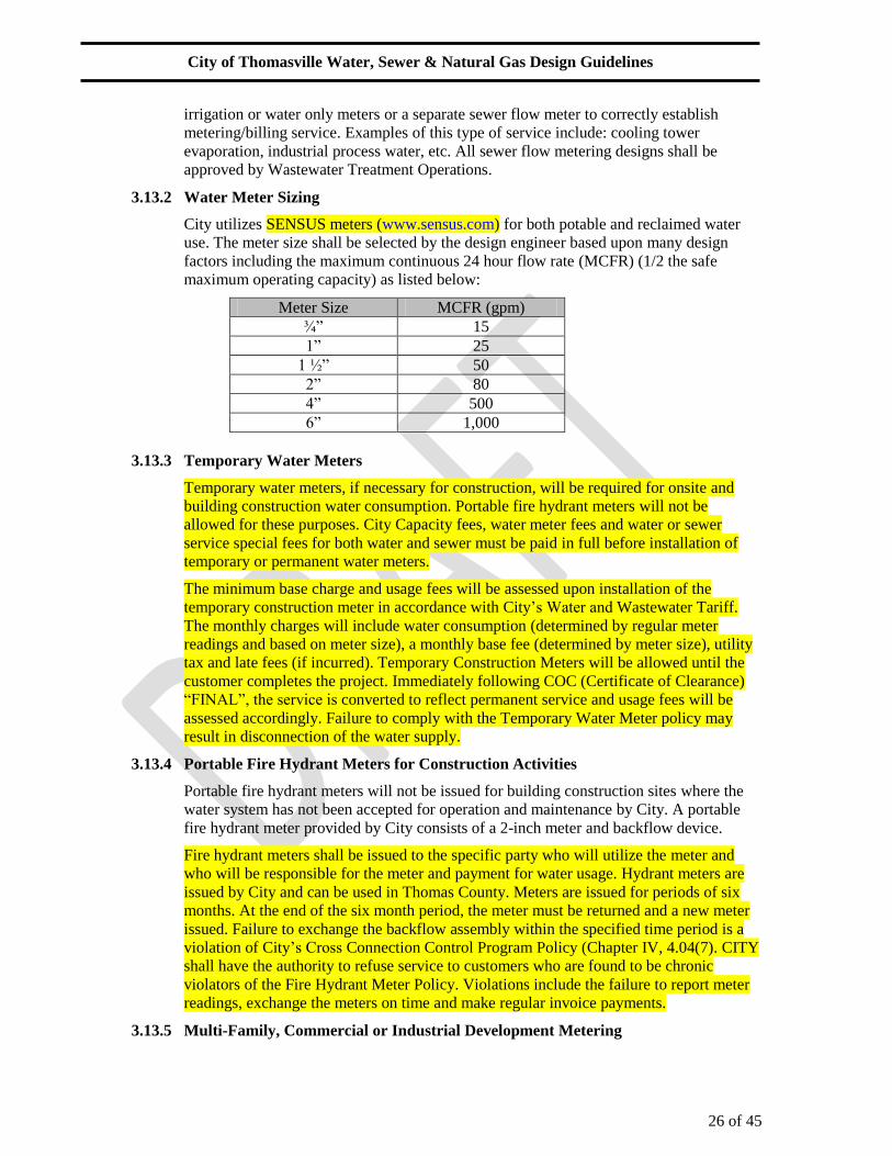
City utilizes SENSUS meters (www.sensus.com) for both potable and reclaimed water
use. The meter size shall be selected by the design engineer based upon many design
factors including the maximum continuous 24 hour flow rate (MCFR) (1/2 the safe
maximum operating capacity) as listed below:
Meter Size MCFR (gpm)
¾” 15
1” 25
1 ½” 50
2” 80
4” 500
6” 1,000
3.13.3 Temporary Water Meters
Temporary water meters, if necessary for construction, will be required for onsite and
building construction water consumption. Portable fire hydrant meters will not be
allowed for these purposes. City Capacity fees, water meter fees and water or sewer
service special fees for both water and sewer must be paid in full before installation of
temporary or permanent water meters.
The minimum base charge and usage fees will be assessed upon installation of the
temporary construction meter in accordance with City’s Water and Wastewater Tariff.
The monthly charges will include water consumption (determined by regular meter
readings and based on meter size), a monthly base fee (determined by meter size), utility
tax and late fees (if incurred). Temporary Construction Meters will be allowed until the
customer completes the project. Immediately following COC (Certificate of Clearance)
“FINAL”, the service is converted to reflect permanent service and usage fees will be
assessed accordingly. Failure to comply with the Temporary Water Meter policy may
result in disconnection of the water supply.
3.13.4 Portable Fire Hydrant Meters for Construction Activities
Portable fire hydrant meters will not be issued for building construction sites where the
water system has not been accepted for operation and maintenance by City. A portable
fire hydrant meter provided by City consists of a 2-inch meter and backflow device.
Fire hydrant meters shall be issued to the specific party who will utilize the meter and
who will be responsible for the meter and payment for water usage. Hydrant meters are
issued by City and can be used in Thomas County. Meters are issued for periods of six
months. At the end of the six month period, the meter must be returned and a new meter
issued. Failure to exchange the backflow assembly within the specified time period is a
violation of City’s Cross Connection Control Program Policy (Chapter IV, 4.04(7). CITY
shall have the authority to refuse service to customers who are found to be chronic
violators of the Fire Hydrant Meter Policy. Violations include the failure to report meter
readings, exchange the meters on time and make regular invoice payments.
3.13.5 Multi-Family, Commercial or Industrial Development Metering

City of Thomasville Water, Sewer & Natural Gas Design Guidelines
27 of 45
For multi-family developments and commercial developments serving multiple tenants
where the entire project is to remain under single ownership, the entire site will be master
metered with all on-site utilities remaining under private ownership and operation unless
otherwise approved by City. If the site is master metered, the property owner must
provide for sub-metering of individual units as a condition of water service from City.
When pre-approved by City Engineer, on-site utilities for projects under single ownership
serving multiple tenants (individually metered) may be accepted for operation and
maintenance provided that the dedicated on-site utilities are contained within an
acceptable, dedicated right-of-way or similar quality, dedicated, unobstructed, exclusive
City utility easement sized as per these guidelines.
For multi-family and commercial projects, water meters shall be located in accessible
areas, outside of landscaped and paved areas, a minimum of 5' from buildings, behind
sidewalks, and generally adjacent to parking areas or roadways and a minimum of 3' from
the edge of pavement.
For water meters greater than 2", the engineer shall submit a detailed water demand
estimate with the average daily flow and peak hourly demand indicated for review
(signed and sealed by registered engineer) and approval by City.
A 4" or larger meter shall be located in a 15' by 20' minimum easement provided adjacent
to the right-of-way line.
3.14 Backflow Preventers
A metered detector check backflow preventer shall be required on all projects requiring automatic
sprinkler (AS) system services and/or the use of on-site private fire hydrants for fire protection.
Backflow preventers shall be in accordance with City Ordinances, Section xxx and shall be
located on private property within 10' of the meter. Alternative locations must be approved by
City prior to installation.
A backflow device is required on all potable water services installed on private property after the
meter where well water is available onsite.
Freeze protection may be required on a backflow device associated with fire mains. The design
engineer shall consult with the local Fire Marshall to determine if freeze protection is required.
City recommends freeze protection on all backflow devices.

City of Thomasville Water, Sewer & Natural Gas Design Guidelines
28 of 45
Section 4.0
Sewer Design Guidelines
4.0 General
This section provides the minimum guidelines for the design of sanitary sewer collection and
force main systems. The method of design and/or construction shall be according to accepted
engineering practices, this manual, the most current City Water, Sewer & Natural Gas
Specifications, the latest edition of the Recommended Standards for Sewage Works (Ten State
Standards), and all applicable Sections of the Environmental Protection Division of the State of
Georgia Department of Natural Resources Rules and Regulations for Water Quality Control.
Sewer hydraulic design notes (signed and sealed) shall be submitted to City for review and
approval and will be submitted to the regulatory agencies for permit approval. The hydraulic
design notes submittal shall include the hydraulic design, catalog data for the pumps, electrical
system, controls and up-lift calculations for the wet-well.
4.1 Design Flows
4.1.1 Average Daily Flow (ADF)
Design flows for new sewage collection systems shall be based upon Table JT-1 Sewage
Flow Schedule of the State of Georgia Department of Public Health (GDPH), Manual for
On-Site Sewage Management Systems or other approvable method where historical data
is not available.
4.1.2 Equivalent Dwelling Units
An Equivalent Dwelling Unit (EDU) is the equivalent flow that can be anticipated from
one residential connection. In all City sewage treatment areas, assume 100 gallons per
capita per day (gpcd) to calculate the average daily flow (ADF). To calculate the ADF
from a single EDU, multiply the gpcd by an occupancy factor of 3.5.
4.1.3 Peak Flow
Sewer systems and facilities shall be designed for peak flows calculated in accordance
with the Recommended Standards for Sewage Works, latest edition (Ten State
Standards), and as shown below.
Peak Flow = Peaking Factor * Average Daily Flow (ADF)
Peaking Factor = [18+ (Population/1000)0.5] / [4+ (Population/1000)0.5]
4.2 Gravity Sewer Mains
4.2.1 Sizing Gravity Sewer Mains
Design all sewer mains to carry peak design flow when flowing full (no hydraulic head
allowed). Peak design flow may not exceed pipe capacity. Gravity sewer mains shall be a
minimum 8" diameter in the City right-of-way (R/W) and/or private R/W (easements).
Gravity sewer mains shall be installed on a uniform alignment and grade between
manholes.
Collection systems serving more than two buildings, lots or parcels shall be 8" gravity
mains with manholes.
4.2.2 Gravity Sewer Slope Requirements

City of Thomasville Water, Sewer & Natural Gas Design Guidelines
29 of 45
Gravity sewer mains shall be designed in accordance with the preferred slopes shown in
Table 1. Prior to preliminary review, the owner/developer must obtain City Engineer's
pre-approval, in writing, for any deviation from the preferred slope. All mains approved
for construction at less than the preferred slope shall be PVC SDR 26 material. Minimum
slope is only to be used (limited use) when no other engineering or economic solution is
possible. However, it is not to be used on beginning runs from terminal manholes. The
maximum slope for all pipe diameters shall be such that the velocity in the pipes does not
exceed 5 fps when calculated using Manning’s Equation. Maximum slope may be used
on terminal pipe runs only unless otherwise approved by City. The maximum slope may
be exceeded on the final run of gravity sewer between the junction manhole and the
pump station structure. City reserves the right to require specific slopes as needed to
insure future service and maintenance needs.
Table 1: Gravity Sewer Slope
Pipe Diameter
(inch)
Preferred Slope
(ft/ft)
Minimum
Slope (ft/ft)
Max Slope @
5 FPS (ft/ft)
8 0.004 0.0035 0.018
10 0.0028 0.0026 0.014
12 0.0022 0.0021 0.011
15 0.0015 0.0015 0.009
16 0.0014 0.0013 0.0075
18 0.0012 0.0011 0.0070
21 0.0010 0.0009 0.0050
24 0.0008 0.0008 0.0045
30 0.0006 0.0005 0.0032
36 0.0005 0.0004 0.0024
4.2.3 Gravity Sewer Main Materials
Materials shall be in accordance with the most recent City Water, Sewer & Natural Gas
Specifications.
The type, class, grade, and alignment of sewer pipe may be changed only at manholes.
Gravity mains constructed at a depth of 12' or greater or within easements must be PVC
SDR-26 heavy wall sewer pipe.
DIP pipe is not allowed for gravity sewer . Where the mains or laterals are above ground
or otherwise exposed as in bridge crossings or ditch crossings, sewer mains shall be
stainless steel.
4.2.4 Gravity Sewer Main Depth
Gravity sewer mains shall be designed for minimum depth requirements of 30 inches in
unpaved areas and 36" in paved areas.
No gravity sewer main with sewer service laterals shall be constructed with greater than
12' depth of cut from finished grade. Sewer service laterals associated with gravity sewer
mains which are deeper than 12', must be routed to a gravity sewer high-line, a manhole,
or other City approved method. All proposed sewer high lines shall be reviewed and
approved by City Engineer.
No gravity sewer main shall be constructed with greater than 15 feet depth of cut from
finished grade.

City of Thomasville Water, Sewer & Natural Gas Design Guidelines
30 of 45
4.2.5 Gravity Sewer Main Location
Gravity sewer mains shall be designed for installation on the centerline of roadways
where possible. On curved roads, the sewer main and manholes shall be located such that
the pipe and manholes remain within the limits of the paved area.
Install gravity sewer mains with a straight alignment between manholes.
Locate gravity sewer manholes a minimum distance of 4' from the face of the curb to the
edge of the manhole.
Locate trunk sewers 24" and larger 5' west of, or 5' south of the centerline of the public
rights-of-way or private rights-of-way (easements), unless approved otherwise by City.
A horizontal distance of 3' minimum (6' preferred) shall be maintained from all gravity
sewer mains to drainage structures, telephone duct banks, electrical transformers, signal
relays, power poles and other structures in the right-of-way as well as any other parallel
underground utility with the exception of water mains. Where gravity mains cross other
underground utilities with the exception of water mains, a minimum vertical separation of
6" shall be maintained. (See below for water main and gravity sewer main separation
requirements.) All distances shall be measured from the outside edge of the pipes.
Distance from building foundations, or tops of banks, to gravity sewer mains must be a
minimum distance of 2 times the vertical depth of the deepest portion of the manhole-to-
manhole sewer run.
In locations where gravity sewer mains cross under a box-culvert or 48” diameter and
larger storm water main, City will require an approved flowable fill material surrounding
the sewer main. In these cases, provide 12” of flowable fill around the outside of the
sewer main, approximately 10 feet in each direction from the crossing point.
Gravity main stub-outs shall be extended to the property line, plat line or phase line and
shall extend a minimum of 10’ past the edge of pavement or a distance of 1.5 times the
sewer depth whichever is greater and terminate with a manhole, to allow for future sewer
main extension.
Gravity sewer mains located adjacent to retention pond areas shall be designed with
sufficient distance from pond to avoid side slope collapse based on 3 to 1 side slopes,
anticipated pond water elevations and depth of bury. City reserves the right to require
casing pipe as necessary to maintain the utility.
All proposed gravity sewers located in easements that cross wetlands must be approved
in writing by City Engineer prior to design. If approved by City, the following design
features shall be included:
Long runs of gravity sewer located in easements that cross wetlands, which are restored
as wetlands, shall be encased in a steel casing. Those runs which include manholes,
located across wetlands or limited access areas, shall be accessible to vehicles and heavy
equipment. A stabilized access road, 12’ wide with a 12” deep sub base (min) with a
minimum Limerock Bearing Ratio of 40 shall be provided over the gravity pipe and shall
be indicated on the drawings. The access road should be designed to provide adequate
drainage and to prevent erosion from storm runoff. A truck turnaround area may be
required at the end of all access roads.
In some cases City will require the addition of 6” thick gravel or crush-crete along the 12’
wide access road.
4.3 Sewer Main Separation Requirements

City of Thomasville Water, Sewer & Natural Gas Design Guidelines
31 of 45
Sewer main separations (from other utilities, structures and hardwood trees) shall be in
accordance with FAC Chapters 62-555, 62-604, 62-610 and sections 350, 428 and 429 of the City
Water, Sewer & Natural Gas Specifications including City Standard Construction Details W-10,
W-11, S-26 and S-27.
The table below provides the minimum horizontal separation requirements between the proposed
utility and structures (see notes).
Table 4.3.1
Pressure Main (water, sewer & natural
gas) Nominal Size (inches)
Horizontal Separation Requirements
from Structures (min)
(See note 1)
up to 6” 10 feet
8” 14 feet
10”-12” 18 feet
14” and larger See note 3
For gravity sewer mains, see note 2.
Notes:
1. The table above provides the minimum horizontal separation requirements between the
proposed City maintained utilities (including water mains, water service laterals, meter
boxes and sewer force mains) and existing, proposed and future structures (including
above ground structures, concrete footers and top of bank of ponds).
2. For gravity sewer mains, the horizontal separation from existing, proposed and future
structures (including above ground structures, concrete footers and top of bank of ponds)
shall be a minimum of 2 times the vertical depth of the deepest portion of the manhole to
manhole sewer run.
3. Pressure mains 14 inch and larger will require additional horizontal separation as
reviewed and approved by City.
4.4 Gravity Services
In areas where on-site sewage disposal systems exist, new gravity service termination at the right-
of-way shall be established by the designer to accommodate rerouting of yard piping to the
service termination elevation via gravity flow; otherwise, an on-site permitted private pump
station will be required.
City shall not connect any customer that does not abut Water/Sewer/Natural Gas mains without
requiring the construction of a main line extension. Single gravity services shall be provided to
each lot, building, or parcel provided that adequate and unobstructed easements are dedicated to
City for maintenance. Easements must be approved by City.
New 6" sewer service laterals which tap into existing City manholes or existing City sewer
collection mains shall be constructed by City only, unless approved otherwise by City.
No 6" gravity sewer service connection is permitted on City gravity sewer mains which are 16"
size or larger. A high-line may be acceptable for these situations.
If a project site is currently served by a private well for potable water supply, a City approved
water meter, reading in gallons must be installed on the service side of the well for the purpose of
sewer billing.

City of Thomasville Water, Sewer & Natural Gas Design Guidelines
32 of 45
Single gravity services shall not exceed the size of the gravity main. For eight (8) inch
connections to an 8” main, provide manhole at connection to main.
Single services shall be 6” minimum diameter at 1/8” per foot minimum slope.
Stub-outs for services shall be marked with a 2”x4”x4’ pressure treated pine post painted green.
Private clean-outs shall not be installed in the R/W or CITY easement. Private cleanouts if
installed must be installed on private property and shall be maintained by the customer.
Services shall be designed with 30" minimum cover and shall terminate 30" to 60" deep at the
R/W line where not in conflict with water mains, drainage pipes, and other existing utilities or
buried electric.
A service shall be designed to connect to the gravity main with a tee fitting rotated 45 degrees up.
The invert elevation of the service at the main shall be at or above the crown of the mainline pipe.
(See CITY Standard Construction Details S-19 and S-20).
Gravity sewer service laterals shall be provided to all undeveloped property and future phases of
the project in accordance with the sewer master plan. The location and length of sewer service
lateral shall be designed to minimize future maintenance of traffic, roadway repairs and
restoration work.
4.4.1 Single Family Residential Services
Single services shall be installed at the center of the lot and front the property being
served. Services shall be installed perpendicular to the sewer main. Deviations from this
criterion must be pre-approved in writing by the City. The center portion of the lot shall
be defined to include the center 50% of the lot width. That is, if the lot is 100 feet wide,
then the sewer service may be located inside the 50 linear foot center portion of the lot.
6" single services shall be limited to 60' maximum length (length between sewer main or
manhole and the customer’s property line).
Terminal manholes located in residential cul-de-sacs are allowed 3 service connections
(6” diameter maximum) provided the service connection inverts are a minimum of 3”
above that of the manhole.
4.4.2 Multi-Family Residential, Commercial and Industrial Services
6" services shall serve no more than 6 multi-family units.
All 8" and larger sewer services shall be connected into manholes (not the sewer main).
Wastewater inflow from a general dumpster area less than 250 SF is acceptable to enter
City sewer system if a grease trap is installed.
Service Connections to manholes are allowed as follows:
a. Inline manhole connections are limited to 2 (8” diameter and larger) services, one
(1) from each side of the street.
Services shall not be connected to stub-outs without a manhole.
4.5 Sewer Meters
City policy does not allow the installation of sewer deduct meters. In order to achieve a
metering/billing arrangement that would reduce sewer charges when less sewage enters the City
system than water consumed, the site can be designed with irrigation or water only meters or a
separate sewer flow meter to correctly establish metering/billing service. Examples of this type of

City of Thomasville Water, Sewer & Natural Gas Design Guidelines
33 of 45
service include: cooling tower evaporation, industrial process water, etc. All sewer flow metering
designs shall be approved by Wastewater Treatment Operations.
4.6 Sewer Manholes
Manholes shall be installed at the end of each main and at all changes in grade, pipe size, pipe
material, or alignment and at all pipe intersections.
Manholes where main pipe size changes occur shall place the 0.8 depth point of both sewers at
the same elevation.
The maximum spacing of manholes shall be 400' for sewer mains less than or equal to 16"
diameter and 500' for sewer mains greater than 16". A gravity main exceeding the maximum
length may be allowed, with prior written approval from City, if it is required to complete a
terminal run. If this occurs, a note shall be added instructing the contractor “not to exceed the
additional length required to complete the run”.
Manholes shall be located along the centerline of City or private roadways (including parking
lots), out of the tire lane and a minimum of 4' from the edge of the manhole to the face of curb
and gutter.
Manholes shall not be installed in the flow line of inverted crown roads or within the design high
water limits of gutters, swales, storm water ditches or retention/detention areas.
Terminal manholes may be required on stub-outs for the purpose of inspection and maintenance
or future extension of the system.
Manholes shall be assigned an ID number, beginning at the junction or deepest manhole as
number 1 and subsequent manholes being numbered consecutively up to the shallowest manhole.
4.6.1 Invert and Rim Elevations
Manholes shall have the ring and cover at final grade level.
Design depth for all terminal manholes is to be at no less than four (4)' from the top of the
manhole ring and cover to the pipe invert, and must include at least one course of
manhole adjustments as shown in City Standard Construction Detail S-6.
4.6.2 Drop Connections
Outside drop connections are only allowed for 12" drop pipe size and larger per City
Standard Construction Detail S-7.
Inside drop construction is required for 2' or greater drops and shall be constructed per
City Standard Construction Detail S-4.
4.6.3 Lining
At a minimum, all junction manholes (manholes located closest to the pump station wet
well), manholes which include a 24” or larger pipe and manholes receiving a force main
shall be coated internally as outlined in Section 446 of City Water, Sewer & Natural Gas
Specifications. In addition, for new construction projects, additional manholes
downstream of the point of connection of a 6 inch or larger force main may be required to
be lined based on flow quantities and/or velocities.
4.7 Force Mains
4.7.1 Pipe Diameter

City of Thomasville Water, Sewer & Natural Gas Design Guidelines
34 of 45
Force mains shall be a minimum 4" diameter in the right-of-way or within City easement
if the main is to be dedicated. Exceptions may be granted for low pressure systems or low
flow pump stations which discharge directly into a gravity sewer system.
Force mains shall be sized for peak flow at a minimum velocity of 2.0 fps (feet per
second) and a maximum velocity of 5.0 fps. If approved by City, 4-inch force mains may
be initially sized at less than 2 FPS. Exceptions may be made on a case by case basis
during the plan review process.
A plan and profile shall be provided for all 6" and larger horizontal directional drill
(HDD) pipe and for all other force mains (open-cut) 12" and larger.
4.7.2 Depth of Bury
Force mains shall be designed meeting minimum depth requirements of 30” in unpaved
areas and 36” in paved areas with a maximum of 60” in arterial or collector roadways
where reconstruction is anticipated, unless approved otherwise by City. Cover for pipe
under pavement shall be measured from finished grade.
For 12 inch and larger mains, the proper installation and depth requirements for gate
valves may require additional depth of cover.
Where conflicts require a deflection, a minimum cover of 24” may be allowed to design
over the conflict using PVC DR18 pipe to clear the conflict before deflecting back to 36”
depth. Any reduction in pipe cover will require written approval from City.
Force mains shall be designed so as to reduce or minimize the number of high points.
Changes in elevation which exceed two feet will require an air release valve. (See City
Standard Construction Detail S-29).
4.7.3 Material and Fittings
Materials shall be in accordance with the most recent City Water, Sewer & Natural Gas
Specifications Section 429 and 430. For 6" and larger HDPE pipe, the pipe size may
require up-sizing to maintain a consistent inside diameter of the main.
Force mains shall have restrained joints for changes in direction. Bends 45 degrees or less
should be used in lieu of 90 degree bends.
All proposed force main extensions shall terminate with a City standard stub-out past the
proposed project connection and shall consist of 40' of pipe, a resilient seat gate valve
installed adjacent to the last tee or tapping sleeve and a plug. The plug fitting shall
include a 2” (bronze) corporation stop (MIP) on the dead end. The length of the stub-out
may be reduced to 20' (minimum) if approved by City to avoid installation conflicts in
the right-of-way. See CITY Standard Construction Detail S-44.
4.7.4 Location
Install force mains, where feasible, on the opposite side of the street from the water main
unless otherwise approved by City. Force mains shall be designed to be a minimum 3 feet
from the right of way line and a minimum 3 feet from the edge of pavement or back of
curb. Larger pipes and greater depths of cover may require greater distances from the
right of way line and edge of roadway.
A horizontal distance of 3' minimum (6' preferred) shall be maintained from all force
mains to drainage structures, telephone duct banks, electrical transformers, signal relays,
power poles, and other structures in the right-of-way as well as any other parallel
underground utility with the exception of water mains. Where mains cross other

City of Thomasville Water, Sewer & Natural Gas Design Guidelines
35 of 45
underground utilities with the exception of water mains, a minimum vertical separation of
6" shall be maintained. (See below for water main and force main separation
requirements.) All distances shall be measured from the outside edge of the pipes.
Force main connections to manholes shall connect at the bottom of the manhole matching
the crown of the existing pipe as shown in City Standard Construction Detail S-18. The
angle between influent force main and effluent gravity pipe shall be between 130 degrees
and 180 degrees unless approved otherwise by City. The flow from the force main should
be directed into the effluent gravity pipe of the manhole in an effort to reduce turbulence.
Force mains shall not be constructed below open ditch bottoms unless no other location is
available due to crowded corridor conditions caused by other utilities.
Sewer force mains shall be located outside of paved areas except at roadway crossings.
Exceptions to this pavement rule may be considered within commercial development
projects provided the mains do not lie under parking areas.
4.7.5 Force Main Separation Requirements
Force main separation (from other utilities, structures and hardwood trees) shall be in
accordance with Sections 350 and 429 of the City Water, Sewer and Natural Gas
Specifications including City Standard Construction Details W-10, W-11, S-26 and S-27.
(See Table 4.3.1)
4.7.6 Valves
Valves and appurtenances shall conform to City Water, Sewer & Natural Gas
Specifications, Section 430.
On force mains less than or equal to 12" in diameter, resilient seat gate valves shall be
installed at a maximum of 1,000' intervals and at branches of intersecting force mains on
tees and wyes, and at force main stubs.
On force mains greater than 12" in diameter, valves shall be located at a maximum of
2500' intervals.
A resilient seat gate valve shall be provided on the force main in the right-of-way
adjacent to the discharge manhole. (See City Standard Construction Detail S-18).
Generally, resilient seat gate valves are preferred on sewer force mains (main valves and
tapping valves), but must be in the vertical position (stem in vertical position). If a gate
valve must be in the horizontal position (stem horizontal), then a double disc gate valve
must be utilized. Horizontal valves are to be utilized only in extreme cases and as
approved by City.
In cases where gate valves are not practical, plug valves may be utilized.
Plug valve 8" and larger must be equipped with worm-gear actuators.
Valves shall be located so as not to conflict with curb and gutter, not be located in the tire
tracks and shall be located outside of pavement when possible.
For private pump stations with CITY dedicated off-site force mains, a City pump-out box
is required for all force main pipe which exceeds 15' within the City right-of- way per
City Standard Construction Detail S-46. A 4” (minimum) gate valve is required at the
right-of way-line, adjacent to the pump out box. The gate valve is not required on force
main piping where the connection at the CITY main is located on the same side of the
street as the pump-out box and consists of 15' or less within the City right-of-way area.

City of Thomasville Water, Sewer & Natural Gas Design Guidelines
36 of 45
This gate valve defines the “City Point of Service”. If no gate valve exists, the right-of-
way line defines the “City Point of Service”.
Air release valve assemblies (2”) with manholes shall be provided at all force main high
points and when change of elevation is 2' or greater. The design engineer shall size the air
release valves. If an air release valve larger than 2” is required, multiple 2” assemblies
shall be provided. Air release valves on force mains hung from bridges should be manual
if accessible.
Air release valves shall be constructed as per City Standard Construction Detail S-29.
Combination valves (air release and vacuum valves) shall only be utilized if a major
vacuum condition exists as specified by the design engineer.
4.7.7 Force Main Connections to Existing Force Mains
4.7.7.1 Taps
Unless approved otherwise by City, size-on-size taps are limited on PVC mains
to 12 inch size and smaller. Size-onsize taps are acceptable on DIP (all sizes). For
size-on-size taps, on 8" and larger mains, the actual tap hole shall be reduced by
1-inch.
4.7.7.2 To Existing Force Mains > 12” diameter
Taps on existing City force mains larger than 12” diameter must be pre-approved
by City. In these cases, some restrictions may apply. Approval is based on each
individual development project. Developer shall request a pre-application
meeting. City will perform a site visit to determine upstream and downstream
mainline valve locations, and to verify the mainline can be isolated by operating
the valves. If valves are unable to be located, are inoperable, or spacing is not a
reasonable distance (depends on number of manifold stations, size of main,
location, etc.), Developer may be required to provide an insert a-valve(s) as
required by City to make the connection.
4.8 Access Road
Long runs of force mains or gravity sewer located in easements that cross wetlands, which shall
be restored as wetlands, shall be encased in a steel casing. Those runs which include manholes,
located across wetlands, shall be accessible. A stabilized access road, 12’ wide with a minimum
Limerock Bearing Ratio (LBR) of 30 shall be provided and indicated on the drawings for
easements requiring multiple manholes. The access road should be designed to provide adequate
drainage and to prevent erosion from storm runoff. A truck turnaround area should be provided at
the end of all access roads.

City of Thomasville Water, Sewer & Natural Gas Design Guidelines
37 of 45
Section 5.0
Pump Station Design Guidelines
5.0 City Dedicated Pump Stations
5.0.1 General
Design sewer pump stations in accordance with applicable sections of the Environmental
Protection Division of the State of Georgia Department of Natural Resources Rules and
Regulations for Water Quality Control, Recommended Standards for Sewage Works (Ten
State Standards), City Water, Sewer & Natural Gas Specifications, latest editions, and as
specified herein.
Pump stations shall be designed specifically to pump domestic sewage containing solids
and fibrous materials.
Pump stations shall be designed and located on the site so as to minimize the effects
resulting from odor, noise, and lighting.
Pump stations shall be designed to pump at a minimum the anticipated peak hourly flow
with one pump out of service.
The engineer must submit buoyancy calculations for the wet well to demonstrate design
precludes flotation.
5.0.2 Site Plan
The pump station site is to be located outside of the street right-of-way (R/W) and/or
private R/W (easement) on a parcel of property indicated on the record plat or dedicated
to City by Warranty Deed. Prior to recording, the owner/developer must submit the plat
and/or Warranty Deed to City Real Estate for review and signature. Upon City signature
the owner/developer shall then proceed with recording the document.
The pump station site plan shall conform to the City Pump Station Site Plan Detail sheet
unless otherwise approved. See www.thomasville.org for detail sheets.
On-site elevations shall be indicated to establish that the concrete on-site is sloped at 1/8”
per foot (minimum) to allow for drainage toward the public R/W. The site elevation shall
be set at a minimum of 1' above the design high water level, or 100 year flood elevation
of adjacent storm water areas, whichever is the higher elevation. The driveway shall be
designed with a tee for turning around when, in the opinion of City, the station location
and the roadway traffic conditions prohibit backing in and out of the site safely. The
paved driveway should have a uniform elevation along the wet well and, if possible,
should slope at 1/8” per foot away from the station.
The trees and ground cover to be used at the site shall be identified on the site landscape
plan and shall conform to the City Water, Sewer & Natural Gas Specifications. For sites
within Thomasville, landscape and irrigation design shall conform to the City Standard
Pump Station Landscape Plan (see www.thomasville.org).
No catch basin shall be located within the pump station site.
5.0.3 Junction Manhole
Pump stations shall be equipped with a junction manhole with only one influent main to
the wet well to facilitate bypass pumping. The junction manhole shall be 5’ diameter
(minimum). The junction manhole serving a low flow pump station may be 4’ diameter
(minimum).

City of Thomasville Water, Sewer & Natural Gas Design Guidelines
38 of 45
The junction manhole shall be located on the same side of the driveway as the pump- out
connection within 60' of the wet well as accessed from the entrance gate.
At a minimum, there should be 1' of separation for every 1' of wet well depth between the
junction manhole and the wet well to avoid disturbing both structures if construction
work on either is necessary in the future.
The junction manhole shall be located in the grass area and not located in the driveway or
in the traffic lane of the street.
An approved City liner shall be installed on all junction manholes.
5.0.4 Low Flow Pump Station
A “low flow” pump station is a typical duplex pump station but utilizes grinder
pumps, a 6 ft. inside diameter wet well and a 4 ft. diameter junction manhole.
The maximum depth of a low flow pump station wet well is 15 feet.
If approved by City, a low flow pump station may be used if the following
criteria are met:
1. Development does not exceed 100 EDUs (Equivalent Dwelling Units)
2. Development is located such that no other developable areas are adjacent
to the property.
3. The off-site force main does not parallel a proposed force main route
identified by the sewer master plan, 2010 comprehensive plan or any
other regulatory, planning, or design document.
Wet well bottom elevation shall be 1.5 ft. (minimum) below the “pumps off”
elevation.
5.0.5 Wet Well – Duplex
The wet well shall have a minimum diameter of 8', unless written approval for a lesser
diameter is granted by City.
No wet well shall exceed 27' in depth unless pre-approved in writing by City. The wet
well shall have only one influent main, 8” diameter minimum.
The wet well’s operating water levels shall be arranged to insure pump operation without
cavitations and insure the gravity sewer system is not surcharged.
The wet well’s storage volume shall be calculated assuming a 15 minute cycle time,
without considering pump alternation, for the pump rate at design flow condition. If City
has approved an “initial/ultimate” station design, the storage volume must be sized for the
ultimate pumps and flows. Minimum storage volume depth shall be 12”.
The storage height (distance between “Lead Pump On” and “Pumps Off” elevations)
should be calculated and rounded up to the next highest increment divisible by 0.25'. If
City has approved an “initial/ultimate” station design, the storage height should be
designed for the ultimate pumps.
The Mercoid Operating Level (emergency high level alarm) should be set at 0.5' above
the invert elevation.
The operating levels for High Water Level, Lag Pump On, and Lead Pump On are
established in 0.5' increments as follows:
High Water Level Alarm = Influent Invert Level – 0.5'

City of Thomasville Water, Sewer & Natural Gas Design Guidelines
39 of 45
Lag Pump On = High Water Level Alarm – 0.5'
Lead Pump On = Lag Pump On – 0.5'
The “Both Pumps Off Level” is established by subtracting the Storage Height from the
Lead Pump On elevation.
The wet well bottom elevation should be set at 3' (minimum) below the “Pumps Off”
elevation, for a standard pump station.
Where CITY has approved an “initial/ultimate” design, the wet well is sized for the
ultimate pumps whereas the storage height is established for the initial pumps. For
“initial/ultimate” stations, the operating levels are established as follows:
High Water Level Alarm = Lag Pump On + 0.5'
Lag Pump On = Lead Pump On + 0.5'
Lead Pump On = Pumps Off + Storage Height for Initial Pumps
Pumps Off = Bottom Elevation + 3'
An approved City liner shall be installed on all wet well concrete surfaces exposed to
sewage or sewer gases, including the underside of the concrete top slab.
5.0.6 Wet Well – Triplex
The wet well shall have a minimum inner diameter of 10' for 8" and smaller pump
discharge size and 12' for greater than 10" pump discharge size, unless otherwise
approved.
No wet well greater than 27' deep shall be allowed unless approved otherwise by City.
The wet well shall have only one influent main, set at the “control elevation.”
The wet well’s operating water levels shall be arranged to insure pump operation without
cavitations, provide cycle times not less than the manufacturer’s recommendations, and
insure the gravity sewer system is not surcharged.
The wet well’s storage volume should be calculated assuming a 15 minute cycle time,
without considering pump alternation, for the pump rate at design flow condition. The
storage volume is determined as shown below:
SV1 = (Q1) (Cycle Time/4) = (Q1) (3.75 min)
SV2 = (Q2 - Q1) (Cycle Time/4) = (Q2 - Q1) (3.75 min)
Where:
SV1 = Volume between pumps off and lead pump on
SV2 = Volume between lead pump on and #1 lag pump on
Q1 = Flow of One Pump at design flow Condition
Q2 = Flow of Two Pumps at design flow Condition
The storage height1 (distance between “Lead Pump On” and “Pumps Off” elevations)
should be calculated by dividing the SV1 by the wet well area and rounding up to the
next highest increment divisible by 0.25'. The storage height2 (distance between “Lead
Pump On” and “#1 Lag Pump On” elevations) should be calculated by dividing the SV2
by the wet well area and rounding up to the next highest increment divisible by 0.25'.

City of Thomasville Water, Sewer & Natural Gas Design Guidelines
40 of 45
The Mercoid Operating Level (emergency high water level alarm) should be set at 0.5'
above the influent invert elevation.
The operating levels are established in 0.5' increments as follows:
High Water Level Alarm = Influent Invert Level – 0.5'
#2 Lag Pump On = High Water Level Alarm – 0.5'
#1 Lag Pump On = #2 Lag Pump On -0.5'
The “Lead Pump On” elevation is established by subtracting the Storage Height 2 from
the #1 Lag Pump On elevations.
The “All Pumps Off Level” is established by subtracting the Storage Height1 from the
Lead Pump On elevation.
The wet well bottom elevation should be set at 3' below the “Pumps Off” elevation.
If two pumps are to be installed initially (3rd pump to be installed in the future), piping
and valves for the third pump must still be installed complete through the base elbow.
An approved City liner shall be installed on all wet well concrete surfaces exposed to
sewage or sewer gases, including the underside of the concrete top slab.
5.0.7 Pumps
Pumps shall be in accordance with the latest version of the City Water, Sewer and
Natural Gas Specifications.
The pump impeller shall be a non-clog design capable of passing a minimum 3" solid.
Screw impellers are not acceptable. Low flow pumps shall be grinder types.
Pump motors shall be of sufficient horse power to be non-overloading throughout the
curve. Pump motors shall be a minimum 3 Hp unless otherwise approved. Pump motors
shall be 1800 rpm or less. Low flow pumps shall be 2 Hp (minimum). Low flow pump
motors shall be 3500 rpm or less. All City dedicated pump stations shall be rated at 80
gpm (minimum).
All motors shall be suitable for operation with a 3-phase electric supply. Any special
exception for single phase motors must be pre-approved through City.
Shutoff and check valves shall be provided on the discharge main of each pump. The
check valve shall be between the shutoff valve and the pump’s discharge. The check
valve shall not be placed in the vertical position. Valves shall be accessible above ground.
No valves shall be located inside the wet well.
All pump stations shall be equipped with an easily accessible pump out connect ion
assembly for use with portable pumps to allow bypass operation of the pump station.
Where City has approved the station to be designed as “initial/ultimate”, the pump’s base
elbow should be sized for the ultimate pumps. The pump manufacturer shall provide an
adapter plate for the initial pumps.
Pump access covers shall be suitably sized to provide adequate clearances for installation
and removal of the pumping units. The access hatch shall be designed for a minimum
width of 36" or 6" beyond the manufacturer’s minimum required width, whichever is
greater. The minimum hatch length should be 48" for standard duplex stations, (including
low flow stations) and 96" for triplex stations or the sum of the pump width, centerline

City of Thomasville Water, Sewer & Natural Gas Design Guidelines
41 of 45
pump separation, and 12", whichever is greater. If City has approved an “initial/ultimate”
pump station design, the hatches should be sized for the “ultimate” pump design.
5.0.8 Electrical Control Panel
The panel and all electrical components shall be in accordance with the latest version of
the City Water, Sewer and Natural Gas Specifications, Section xxx.
The enclosure shall be sized to enable all breakers and controls to be located not more
than 5' above the walkway.
If the chosen pump has a motor greater than or equal to 20 Hp, a 480 volt service must be
used. If a pump motor is less than 20 Hp, but the kilo-voltamps (kVA) as determined by
the equation kVA = (Total Load) x (Voltage) x (1.73/1000) is greater than 150, a 480 volt
service may be used. Otherwise, a 240 volt service should be used.
If City has approved the station to be designed as an “initial/ultimate” station, the pump
breakers should be sized for the initial pumps, but a note should be added to the drawings
stating: “Pump breakers should be spaced to accommodate future pump breakers.” Also,
under an initial/ultimate station, if City approved the construction of a generator at a later
date, then a standby generator receptacle shall be provided.
The Main and Emergency breaker sizes are determined by adding the pump breaker size,
the full load amperage (FLA) of additional pump motors (beyond the one), and any
auxiliary loads and rounding down to the nearest breaker size. If the total load for a 240-
volt service is less than or equal to 100 Amps, 100 Amp emergency and main breakers
should be used. If the total is greater than 100 and less than 200 Amps, round down to the
nearest available breaker size, but, set the service size to 200 Amps. If the total is greater
than 200 Amps, the service size shall be the same as the emergency and main breaker
size. Where City has approved an “initial/ultimate” station, the main and emergency
breakers, as well as service size shall be designed for ultimate design conditions.
Starters should be sized corresponding to the NEMA ratings shown in the table below.
Use the pump manufacturer’s catalog to determine the FLA corresponding to the
appropriate voltage.
NEMA Ratings for Starters:
Max FLA 9 18 27 45 90 135 270 540
Starter Size 0 0 1 2 3 4 5 6
If City has approved the station to be designed as an “initial/ultimate” station, the starters
should be sized for the ultimate pumps with a note added to the drawings stating: “Heater
coil should be sized to protect the initial pumps.”
5.0.9 Emergency Power
Pump stations with a design capacity of greater than or equal to 500 gpm shall include a
means for continued pumping operations (emergency operating system) during a power
outage/failure. The emergency operating system shall be one of the following based upon
the peak gpm design capacity of the station:
Emergency Equipment Peak GPM
Generator receptacle 0-499
Automatic Emergency Pump Engine or Generator 500 – 1,000
Automatic Emergency Generator > 1,000
City of Thomasville Water, Sewer & Natural Gas Design Guidelines
42 of 45
The generator system shall conform to the City Water, Sewer & Natural Gas
Specifications, Section xxx.
The generator installation must be completed in conjunction with whichever phase of a
project that causes the pump station influent flow to exceed 500 EDU’s.
Pump stations with a design capacity less than 500 gpm shall be equipped with a
generator receptacle for use with a portable generator. Generator receptacles, where used,
should be in accordance with City Water, Sewer and Natural Gas Specifications, Section
xxx.
5.0.10 Water Service
The pump station site shall include a 1 ½” Commercial Irrigation meter to be utilized for
the hose station. Where allowed, the water from this irrigation meter may be utilized for
irrigation use. Associated fees shall be paid by the Developer/Owner.
Water service piping for the pump station site shall be 1 ½" diameter (minimum) and
shall meet material and installation standards for water service construction as detailed in
City.
For other water service information, see Water, Sewer & Natural Gas Specifications,
Section xxx, paragraph xxx.
5.1 Private Pump Stations
All private pump stations discharging to the collection or treatment systems owned by City must
be designed in accordance with EPD Regulations and EPB Rule 3 criteria (in Duval County).
Pump stations shall be designed specifically to pump domestic sewage containing solids and
fibrous materials.
Pump stations shall be designed and located on the site so as to minimize the effects resulting
from odor, noise, and lighting.
Pump stations shall have a minimum of 2 pumps with each pump being of the same capacity.
Pump stations should be designed to pump the design peak hourly flow with one pump out of
service.
Pump stations must be designed to withstand floatation when empty.
Pump stations shall be equipped with an audible and visible high water level alarm. A 24-hour
emergency contact number should be posted at the station.
Pump stations shall have a locked fence or other appropriate features (such as locking hasps for
wet well, control panel, and valve box) to discourage unauthorized entry.
Control panel shall be equipped with lightning arrestors, surge capacitors, and phase protection.
Pump stations serving 500 EDUs or greater shall have provisions for continual operation.
Auxiliary power in the form of an emergency pumping engine or on-site generator is required.
Pump stations serving less than 500 EDUs shall be equipped with a generator receptacle. A shut-
off valve shall be provided on the suction main of a dry pit pump.
A shut-off and check valve shall be provided in the discharge main of each pump. The check
valve shall be between the shut-off valve and the pump’s discharge. The check valve shall not be
placed in the vertical position. Valves shall be accessible either above ground or in a dry valve
pit.

City of Thomasville Water, Sewer & Natural Gas Design Guidelines
43 of 45
No valves shall be located inside the wet well.
A pump out at the station shall be required. A pump out is an appropriate coupling device and
valving to the discharge pipe to allow for connection of portable pumps.
Private pump stations manifolding with force mains owned or to be owned by City shall require a
City pump-out box consisting of the installation of a check valve, pump out tee, and shut-off
valve in a valve pit located on the property adjacent to the right-of-way as per Detail No. S-46 of
the City Water, Sewer & Natural Gas Specifications. This pump out shall be accessible to City at
all times. Operation and Maintenance of this pump out shall be the private owner’s responsibility.
The City pump-out box is not required if the private pump station is within 25 feet of the right of
way. In the case where the City pump-out box is not required, a 4-inch minimum gate valve at the
property line/right of way line shall be provided.
All pump out assemblies shall be accessible to City at all times.
5.2 Low Pressure Systems
The Environmental Protection Agency defines a Pressure Sewer as: An alternative wastewater
collection system in which household wastewater is pretreated by a septic tank or grinder and
pumped through small plastic sewer pipes buried at shallow depths to either a conventional
gravity sewer or a treatment system. For the purposes of this document, Pressure Sewer Systems
will be referred to as Low Pressure Sewer Systems and shall be for residential customers only and
shall be constructed in accordance with the City Water, Sewer & Natural Gas Specifications.
Low pressure sewer systems are not allowed for new developments. Exceptions may be approved
on a case by case basis by City Engineer.
It is the policy of City to construct gravity wastewater collection systems to serve customers
within the City’s service territory. Low-Pressure Sewer Systems shall only be allowed when the
project meets all of the following criteria:
a. A gravity wastewater collection system, designed in accordance with City standards, will
be placed at a depth greater than twelve feet (12’) with service laterals or at a depth
greater than fifteen feet (15’) without service laterals.
b. There are less than 20 customers that will be served by the low-pressure system.
c. The surrounding land is fully developed or cannot be developed due to environmental
constraints and a gravity sewer system would not be economically feasible.
d. A gravity wastewater collection system with a low flow lift station cannot be constructed.
e. An on-site sewage treatment system can be constructed but would not be in the best
interest of City.
A low pressure pump station shall not be allowed to connect into a City force main per EPD and
EPB Rule No. 3. No exceptions will be allowed.


City of Thomasville Water, Sewer & Natural Gas Design Guidelines
45 of 45
Section 6.0
Natural Gas Design Guidelines
6.0 General
Related Documents


![Sewer Processes and Design - SKYSCRAPERS · 2018-09-02 · SANITARY SEWER SYSTEM [Foul Sewer] I. Storm Sewer System STORM SEWER is designed to drain excess rainfall and groundwater](https://static.cupdf.com/doc/110x72/5e9b180035942256b30ec806/sewer-processes-and-design-skyscrapers-2018-09-02-sanitary-sewer-system-foul.jpg)