Imagine the result Town of Brownsburg Wastewater Treatment Plant Expansion Master Plan – 2012 Update

Welcome message from author
This document is posted to help you gain knowledge. Please leave a comment to let me know what you think about it! Share it to your friends and learn new things together.
Transcript

Imagine the result
Town of Brownsburg
Wastewater Treatment Plant Expansion Master Plan – 2012 Update
Imagine the result
Town of Brownsburg
Wastewater Treatment Plant Expansion Master Plan – 2012 Update
September 2012

Imagine the result
This page is intentionally left blank
Wastewater Treatment Plant Expansion Master Plan – 2012 Update
Prepared for:
Town of Brownsburg
Prepared by:
ARCADIS U.S., Inc. 132 East Washington Street, Suite 600 Indianapolis, Indiana 46204 Tel 317 231 6500 Fax 317 231 6514
Our Ref.:
004494008.0000
Date:
September 2012 This document is intended only for the use of the individual or entity for which it was prepared and may contain information that is privileged, confidential and exempt from disclosure under applicable law. Any dissemination, distribution or copying of this document is strictly prohibited.

This page is intentionally left blank

i
Table of Contents
Executive Summary 1
1. Introduction 3
1.1 Background Information 3
1.2 Objectives 3
2. Existing WWTP Conditions and Capacities 5
2.1 Study Area 5
2.2 Wastewater Collection System Background 5
2.3 Wastewater Treatment Plant Background 6
2.4 Existing East Plant Evaluation 9
2.4.1 East Plant Mechanical Overview 9
2.4.2 East Plant Structural Overview 11
2.5 Current Influent and Effluent Wastewater Parameters 12
3. Future Conditions and Population Projections 15
3.1 Planning Period 15
3.2 Population and Flow Projections 15
3.3 Future Wastewater Influent Characteristics 18
4. Review of Treatment Process Alternatives 21
4.1 East Plant Replacement Alternatives 22
4.1.1 Grit Tank 22
4.1.2 Screening Facility 24
4.1.3 Degritter 24
4.1.4 Sewage Pumps 25
4.2 Preliminary Treatment 25
4.2.1 Option 1 – Mechanical Plate Screen 27
4.2.2 Option 2 – Mechanical Auger Screen 28
4.2.3 Option 3 – Mechanical Rake Screen 29
4.3 Surge Tank and Influent Flow Control 30
4.3.1 Option 1 – Cast in Place Concrete Tank 31
4.3.2 Option 2 – Precast Concrete Tank 32
ii
Table of Contents
4.3.3 Option 3 – Odor Control and Aeration of Surge Tank 33
4.4 Biological Treatment 34
4.4.1 Option 1 – Conventional Activated Sludge 34
4.4.2 Option 2 – Extended Aeration 35
4.4.3 Option 3 – Oxidation Ditch 36
4.5 Secondary Clarifiers 37
4.5.1 Option 1 – Rapid Sludge Pickup 37
4.5.2 Option 2 – Conventional Scrapers 38
4.5.3 Option 3 – Spiral Scrapers 40
4.5.4 Launder Covers in Secondary Clarifiers 41
4.6 Tertiary Filtration 42
4.6.1 Option 1 – Continuous Backwash Filter 43
4.6.2 Option 2 – Dual Media Filter 44
4.6.3 Option 3 – Cloth Media Disc Filter 46
4.7 Disinfection 47
4.7.1 Option 1 – Liquid Chlorine Disinfection 48
4.7.2 Option 2 – Gas Chlorine Disinfection 48
4.7.3 Option 3 – Ultraviolet Disinfection 50
4.8 Outfall Pipe and Cascade Aeration 51
4.8.1 Option 1 – Dual 24” Outfall Pipes 52
4.8.2 Option 2 – Increasing Pipe Size towards Outfall 52
4.8.3 Option 3 – All 42” Outfall Pipe 53
4.9 Sludge Thickening and Dewatering 53
4.9.1 Option 1 – Centrifuge 53
4.9.2 Option 2 – Gravity Belt Thickener 55
4.9.3 Option 3 – Combination Dewatering and Thickening Belt Press 56
4.10 Sludge Stabilization Storage and Disposal 57
4.10.1 Option 1 – Sludge Storage Pads with Roofs 58
4.10.2 Option 2 – Upgrading to Class A Sludge 58

iii
Table of Contents
4.10.3 Option 3 – Composting 59
4.11 Operations/Administration Building Annex and Blower Relocation 60
4.11.1 Option 1 – 1600 sq ft building 60
4.12 Backup Power 61
4.12.1 Option 1 – Standby Generator for Plant 61
4.12.2 Option 2 – Mobile Generator 62
4.13 Non-Potable Water Distribution 62
4.13.1 Option 1 – Increase Pump Size 62
4.13.2 Option 2 – Hydro Pneumatic Tank 62
4.14 Septage Receiving Station 63
4.15 Energy Saving Recommendations 64
5. Recommended Plan 67
5.1 Summary of Recommended Plan 67
5.1.1 Influent Pumping 69
5.1.2 East Plant Improvements 69
5.1.3 Screening and Grit Removal 70
5.1.4 Surge Tank 70
5.1.5 Flow Splitting 70
5.1.6 Septage Receiving Station 71
5.1.7 Oxidation Ditches 71
5.1.8 Secondary Clarifiers 71
5.1.9 Tertiary Filters 72
5.1.10 UV Disinfection 73
5.1.11 Outfall and Cascade Aeration 73
5.1.12 Sludge Digestion 73
5.1.13 Sludge Dewatering and Storage 74
5.1.14 Main Building 74
5.1.15 Scum Pump and Non-Potable Water 74
5.2 Summary of Costs 75
iv
Table of Contents
5.3 Summary of Project Phases and Construction Timeline 75
Tables
Table 2.1 NPDES Permit Effluent Limits 12
Table 3.1 Historic Population of Brownsburg and Flow per Capita 15
Table 3.2 Projected Populations and Average Daily Flows 17
Table 3.3 Sizes of Study Areas 17
Table 3.4 Historical Influent Parameters 18
Table 4.1 Proposed WWTP Treatment Average Daily Capacity 21
Table 4.2 Summary of Treatment Process Alternatives 22
Table 5.1 Summary of Recommended Process Alternatives 68
Table 5.2 Timeline Details 76
Table 5.3 Flow Projection Details 76
Table 5.4 Estimated Construction Costs and Construction Phasing 77
Figures
Figure 2.1 Town of Brownsburg WWTP Flow Schematic (Existing) 7
Figure 2.2 East Plant System Hydraulics 10
Figure 3.1 Historic Population and Population Projection for Brownsburg 16
Figure 5.1 Schematic of Recommended Facilities 69
Figure 5.2 Proposed WWTP Site Layout 69
Figure 5.3 Proposed Screening Building Layout 70
Figure 5.4 Proposed UV Channel Layout 73
Figure 5.5 Proposed Cascade Aerators and Effluent Pipe 73
Figure 5.6 Proposed Annex Building Layout 74
Figure 5.7 Proposed Construction Timeline 78
Appendices
A Recommended Basis of Design Summary
1
Wastewater Treatment Plant Expansion Master Plan - 2012 Update
Executive Summary
During 2009 to 2011, flows to the Brownsburg Wastewater Treatment Plant (WWTP) averaged 2.9 million gallons per day (mgd), over 80 percent of the plant’s existing design capacity of 3.5 mgd. The recommended improvements in this Master Plan comprise the next increment of treatment plant construction to increase the firm average design treatment capacity to 6.9 mgd. The recommended projects will also increase the plant’s peak capacity, enabling it to accept and treat higher flows during wet weather events, further reducing the frequency of wet weather overflows. The peak treatment capacity of the plant will be increased from 9 mgd to 15 mgd.
The capital improvements to the WWTP will allow the Town of Brownsburg to accept the increased flow from an industrial user’s facility expansion and extend sewer service to currently unsewered areas of Brownsburg. Brownsburg expects a steady increase in population and an increase in commercial users in the future. The WWTP expansion plans for increased flow from more users and for extending sewer service to accommodate residential, commercial, and industrial growths.
The recommended WWTP improvements will be completed within the existing plant site which is owned by Brownsburg. The projects are planned to avoid impacting wetlands and the White Lick Creek Floodway.
This Master Plan reviewed and evaluated different alternatives for plant processes to recommend the most suitable treatment alternatives. The evaluation of alternatives compares both monetary and non-monetary factors. The monetary evaluation compares estimated capital costs, operation and maintenance costs and salvage values for the various alternatives.
The East Plant Pump Station (EPPS) is nearing the end of its useful design life and is need of improvements. This master plan evaluated the existing structures and made recommendations for their improvement.
The existing detritus grit tanks will be replaced with a Vortex style grit removal system. The grit system can handle flows up to the hydraulic peak flow of 9.2 mgd. The auger monster headworks system and the mechanical grabber screen will be replaced with two new multi-rake bar screens. The bar screen spacing will be 1/4–inch and capable of handling flows up to the hydraulic peak flow of 9.2 mgd. The existing centrifugal pumps will be replaced with four new pumps with VFDs. Each pump shall be rated for 2.4 mgd, providing the EPPS an installed capacity of 9.6 mgd and a firm capacity of 7.2 mgd.
The East Plant Pump Station equipment upgrade will cost, not including structural rehab, approximately $600,000.
2
Wastewater Treatment Plant Expansion Master Plan - 2012 Update
The recommended WWTP improvements plan comprises of wastewater treatment projects to increase the treatment capacity of the plant. To be cost efficient, this master plan consists of new treatment units, utilization of existing units, and combination of new and existing units. The preferred plan recommends the following new treatment unit additions: influent flow splitter box, two fine screens, one surge tank, new conditioner tank, two oxidation ditches, two secondary clarifiers, one aerobic digestion tank, tertiary filters, ultraviolet disinfection, new outfall post aeration cascades, covered sludge storage pad, septage receiving station and an operation office building.
Two phases of expansion are scheduled to raise treatment capacity of the plant for the expected increase of influent flow. The first phase of construction will bring the treatment capacity up to 5.2 million gallons per day. The second phase of construction will bring the treatment capacity up to 6.9 mgd. The WWTP upgrades to increase the treatment capacity to 6.9 mgd and the East Plant Pump Station upgrade will cost approximately $29,900,000.

3
Wastewater Treatment Plant Expansion Master Plan - 2012 Update
1. Introduction
This section provides an introduction to the Town of Brownsburg Wastewater Treatment Plant Expansion Master Plan – 2012 Update. The background for the report is presented, along with a discussion of the master plan’s objectives. 1.1 Background Information
The Brownsburg Wastewater Treatment Plant (WWTP) provides service to the Town of Brownsburg and surrounding areas. The Town of Brownsburg, Indiana is located in Hendricks County, eight miles west of Indianapolis. The wastewater system serves a population of approximately 23,000. Brownsburg comprises approximately 15 percent of Hendricks County by population.
The areas surrounding Brownsburg have been subject to increasing residential and commercial development. Brownsburg desires to extend sewer service to areas along the future Ronald Reagan Parkway and areas of future developments. In the near future an industrial user is scheduled for a plant expansion and will begin to discharge increased flows to the Brownsburg WWTP.
The increase of the residential sector is predicted to be the largest contributor to the wastewater flow, with the commercial sector also continuing steady growth to support the anticipated residential growth. The industrial sector is anticipated to grow in proportion to the residential and commercial sections of Brownsburg. The northern and eastern portions of Brownsburg are expected to experience the most development. Newer subdivisions away from the center of Brownsburg are served by separate sanitary sewers which are typically tributary to sanitary lift stations. The force mains from some of the lift stations discharge to combined sewers leading to the East Plant Pump Station. Other sanitary lift stations are tributary to the Northwest Sanitary Sewer and West Lift Station.
1.2 Objectives
The purpose of this master plan is to evaluate the wastewater treatment needs of Brownsburg and to evaluate, identify and schedule the recommendations for improvements. The planning period is for 20 years until 2036. This plan has been prepared to enable Brownsburg to accept and treat flows to meet the National Pollutant Discharge Elimination System (NPDES) requirements under the current permit pollutant limits. The Master Plan has incorporated the findings and recommendations of previous and ongoing plans and studies.

4
Wastewater Treatment Plant Expansion Master Plan - 2012 Update
This page is intentionally left blank

5
Wastewater Treatment Plant Expansion Master Plan - 2012 Update
2. Existing WWTP Conditions and Capacities
This section provides a summary of the existing WWTP conditions and capacities. The present day collection system and existing WWTP schematic are discussed. The East Plant Pump Station (EPPS) is described and its structure is evaluated.
2.1 Study Area
The Sanitary Sewer Master Plan – 2012 Update shows a map of the study area used for Brownsburg. The northern boundary extends to the Boone County line for the first service area and extends to CR 900 N for the second service area. Full sanitary service extension to the Boone county line is the service area considered for this master plan to ensure adequate future plant capacity for Brownsburg. The CR 900 N boundary service area was used to determine phasing of construction projects. The different construction phases of the plant improvements will incorporate the different sewer service area extensions. The Brownsburg Sanitary Sewer Master Plan – 2012 Update collaborated with this master plan, to coordinate the service area boundaries, ultimate flows and the information of Brownsburg’s major sewers and lift stations.
2.2 Wastewater Collection System Background
Brownsburg’s sewer system includes both combined and separate sanitary sewers. The older, central portion of Brownsburg is served by combined sewers. Two combined trunk sewers – North and South Trunk Sewers, convey wastewater and, during rains, storm water runoff to the East Plant Pump Station.
The 48-inch North Trunk Sewer runs north on Green Street and receives flows from combined branch sewers and, on the north end, from separate sanitary sewers and sanitary force mains. The 48-inch South Trunk Sewer runs south on Acre Avenue, then east on Tilden Road. It conveys flows from combined branch sewers and from separate sanitary sewers and sanitary force mains.
The East Plant has a combined sewer overflow structure. North and South Swirl Concentrators, located at the East Plant, provide partial treatment of overflows. During heavy rains, partially treated combined sewer overflows are discharged to White Lick Creek. A CSO storage tank at the East Plant captures overflows up to a one-year storm before an overflow will occur.
Brownsburg’s newer subdivisions are served by separate sanitary sewers which are typically tributary to sanitary lift stations. The force mains from some of the lift stations discharge to combined sewers leading to the East Plant Pump Station. Other sanitary lift stations discharge to the Northwest Sanitary Sewer leading to the West Lift Station.
6
Wastewater Treatment Plant Expansion Master Plan - 2012 Update
Constructed in 1995, the 18-inch Northwest Sanitary Sewer conveys sanitary wastewater to the West Lift Station located near the West Plant entrance gate along Mardale Drive.
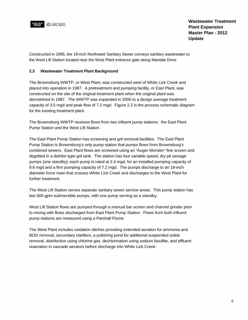
2.3 Wastewater Treatment Plant Background
The Brownsburg WWTP, or West Plant, was constructed west of White Lick Creek and placed into operation in 1987. A pretreatment and pumping facility, or East Plant, was constructed on the site of the original treatment plant when the original plant was demolished in 1987. The WWTP was expanded in 2000 to a design average treatment capacity of 3.5 mgd and peak flow of 7.2 mgd. Figure 2.2 is the process schematic diagram for the existing treatment plant.
The Brownsburg WWTP receives flows from two influent pump stations: the East Plant Pump Station and the West Lift Station.
The East Plant Pump Station has screening and grit removal facilities. The East Plant Pump Station is Brownsburg’s only pump station that pumps flows from Brownsburg’s combined sewers. East Plant flows are screened using an “Auger Monster” fine screen and degritted in a detritor-type grit tank. The station has four variable speed, dry pit sewage pumps (one standby); each pump is rated at 2.4 mgd, for an installed pumping capacity of 9.6 mgd and a firm pumping capacity of 7.2 mgd. The pumps discharge to an 18-inch diameter force main that crosses White Lick Creek and discharges to the West Plant for further treatment.
The West Lift Station serves separate sanitary sewer service areas. This pump station has two 600 gpm submersible pumps, with one pump serving as a standby.
West Lift Station flows are pumped through a manual bar screen and channel grinder prior to mixing with flows discharged from East Plant Pump Station. Flows from both influent pump stations are measured using a Parshall Flume.
The West Plant includes oxidation ditches providing extended aeration for ammonia and BOD removal, secondary clarifiers, a polishing pond for additional suspended solids removal, disinfection using chlorine gas, dechlorination using sodium bisulfite, and effluent reaeration in cascade aerators before discharge into White Lick Creek.

7
Wastewater Treatment Plant Expansion Master Plan - 2012 Update
Figure 2.1 Town of Brownsburg WWTP Flow Schematic (Existing)

8
Wastewater Treatment Plant Expansion Master Plan - 2012 Update
The conditioner structure for Oxidation Ditches Nos. 3 and 4 consists of one flow splitter structure that splits the flows to anoxic selectors (conditioner structures) prior to discharge into the oxidation ditches. The conditioner structure for Oxidation Ditches Nos. 1 and 2 consists of three compartments, where the conditioner structure for Oxidation Ditches Nos. 3 and 4 consists of one compartment. The effluent discharge from each conditioner structure is then split and discharged into the oxidation ditches. Oxidation Ditches Nos. 1 and 2 were constructed in 1987 as part of the original West Plant construction. Oxidation Ditches Nos. 3 and 4 were constructed in 2000 as part of the West Plant expansion.
There are four secondary clarifiers, each 55 feet in diameter and with a side water depth of 12 feet. These clarifiers are rim feed units with scraper sludge collector mechanisms.
Secondary clarifier effluent is chlorinated and is discharged to Polishing Pond No. 1. Polishing Pond No. 2 has been decommissioned. Pond effluent is dechlorinated and discharged through a 24-inch outfall pipe into two cascade aerators arranged in series. Plant effluent is discharged into the White Lick Creek.
There are five return activated sludge (RAS) pumps located in the basement of the Main Building. These pumps convey RAS from the bottom of the secondary clarifiers to the anoxic selectors. A branch pipe and control valve allow the RAS pumps to be used to pump waste activated sludge (WAS) to the aerobic digesters.
Waste activated sludge (WAS) is stabilized by aerobic digestion. There are four sludge tanks each 70 feet in diameter and with a side water depth of 15 feet. Each sludge tank has a coarse bubble aeration system that provides the air for aerobic digestion as well as for mixing. Normally, two of the sludge tanks are used for WAS storage and thickening. The other two sludge tanks are used for biosolids stabilization prior to dewatering. A combination gravity belt thickener/belt filter press is used for thickening the sludge prior to digestion and for dewatering the stabilized sludge.
There are a total of six drying beds, two drying beds are used for storm water debris and sanitary sewer debris. Four beds are used for drying dewatered biosolids. There is a cover storage pad for biosolids. Normally, the combination gravity belt/thickener belt filter press is used for dewatering rather than the drying beds. Dewatered biosolids are stored on the sand drying beds as Class B biosolids. Periodically a sludge application contractor hauls dewatered biosolids to farms for land application.
9
Wastewater Treatment Plant Expansion Master Plan - 2012 Update
2.4 Existing East Plant Evaluation
This section summarizes the current condition of Brownsburg’s East Plant Pump Station (EPSS). Most of the facilities and equipment is aged and has been in operation for over twenty five years. The plant will be reviewed to determine the extent of upgrades required.
2.4.1 East Plant Mechanical Overview
Constructed in 1987, the EPPS is Brownsburg’s only pump station that pumps flows from Brownsburg’s combined sewers. The East Plant Pump Station consists of the following facilities and infrastructure:
§ Grit Removal § Screenings § Pumping
The EPPS has combined two Swirl Concentrators – North and South that provide partial treatment of overflows. A CSO storage tank at the EPPS captures overflows up to a one-year storm. During heavy rains, partially treated combined sewer overflows are discharged to the White Lick Creek.
The EPPS receives flow at the influent chamber from the North and South Swirls. The influent chamber discharges flow into one of two 30-inch wide influent channels. The flow through this chamber is controlled by two Rotork sluice gates which regulate how much flow is discharged into the 30-inch channels. During high flows the Rotork valve will sense higher wet well levels. The valve will then begin to close to restrict the flow to the wet well, which in turn will prevent the wet well from overflowing and causing the influent flow to fill the North and South swirls. During dry weather, channel one receives all of the flow from the influent chamber. Channel one is equipped with an Auger Monster Headworks System. The channel width is increased from 30-inch to 42-inch to accommodate the channel grinder. The system includes a channel monster and a perforated screen drum. The screen drum openings are ¼ -inch diameter holes. The screen drum and the channel monster are nominally rated for 10 mgd. During wet weather, the wastewater overflows into channel two that is equipped with a grabber type mechanical bar screen. The bar screen has a 26-inch long rake with spacing at ½-inch and is nominally rated for 7.2 mgd. The mechanical bar screen was installed during the original construction.
The grit removal system consists of a detritus style grit tank, grit pumps, and a grit washer. The grit tank is fed by a 24-inch gravity line from the influent channels. Flow enters a tangential channel and is dispersed through deflector angles before entering the 14’x14’ chamber. The tank is equipped with a mechanical scraper arm that advances heavy grit particles into a hopper at the bottom of the tank. Two vortex type solids-handling grit pumps

10
Wastewater Treatment Plant Expansion Master Plan - 2012 Update
draw grit from the hopper and pump into the grit washer. The pumps are rated for 210 gpm at 34 feet of head. The pumps discharge into a 12” straight tank classifier with a single cyclone. The cyclone is rated for 210 gpm. The classifier will wash the grit from the cyclone separator; the grit is then discharged into a dumpster for disposal. The overflow and drain from the grit classifier is fed back into the grit tanks for further treatment.
Effluent from the grit tank is discharged into the west and east wet wells. The EPPS currently has four dry pit sewage pumps, which were installed during the original construction. Each pump has a rated capacity of 1660 gpm (2.4 mgd) at 1200 rpm and 76 feet of TDH, and can pass 3-inch solids. Each pump has a 50 hp motor equipped with variable frequency drives. The original motors were replaced with high efficiency motors. The original intent was for EPPS to have an installed pumping capacity of 9.6 mgd (one standby) and a firm pumping capacity of 7.2 mgd. Currently, all four pumps are used to meet the peak hydraulic demand of the EPPS. Figure 2.2 estimates the actual flows when each pump is running. One pump running discharges roughly 2.8 mgd, 2 pumps running discharges roughly 5.1 mgd, 3 pumps running discharges roughly 6.9 mgd, and 4 pumps running discharges 8.2 mgd.
Figure 2.2 East Plant System Hydraulics
30
40
50
60
70
80
90
100
110
120
0 500 1000 1500 2000 2500 3000 3500 4000 4500 5000 5500 6000 6500 7000
Head
(ft)
Flow (gpm)
East Plant System Hydraulics C-120 14.35 Inch Dia Impeller
1 Pump System Curve (LWL) 1 Pump Morse, 6"5414 (BH) 1 Pump System Curve (HWL) 2 Pump Morse, 6"5414 (BH) 2 Pump System Curve (LWL) 2 Pump System Curve (HWL) 3 Pump Morse, 6"5414 (BH) 4 Pump Morse, 6"5414 (BH) 3 Pump System Curve (LWL) 3 Pump System Curve (HWL) 4 Pump System Curve (LWL) 4 Pump System Curve (HWL)
11
Wastewater Treatment Plant Expansion Master Plan - 2012 Update
The pumps discharge to an 18-inch diameter force main that crosses White Lick Creek and onto the West Plant for further treatment. Currently the 18-inch force main does not have a flow meter to record the flow being pumped to the West plant influent structure.
2.4.2 East Plant Structural Overview
The EPPS structural condition assessment findings include the need for repairs to the concrete including walls above and below the normal operating water surface, concrete cracks, spalled concrete, exposed reinforcement, railing, and metal platform framing.
The following describes the general condition assessment findings discovered in structures listed below:
§ Grit Tank § Influent Splitter § Fine Screen Influent Channel § Rake Influent Channel
The metal framing and grating at the grit tank were found to be in moderately good condition with minor coating failure and surface corrosion on the framing members. To protect the metal framing and minimize further deterioration, it is recommended that the metal framing be cleaned of all corrosion and loose failed coating and recoated with a coating system compatible with the existing coating. The cast in place concrete walls were found to be in generally good condition with minor vertical shrinkage cracks and minor concrete surface defects such as pits. All shrinkage cracks and minor surface defects are considered non-critical and no further action is recommended at this time.
The existing railing appears in generally good condition, with the exception of the free standing posts. The free standing posts appear to be painted steel and were observed to have varying degrees of corrosion and coating failures particularly at the bases. It is recommended that the free standing posts be removed, cleaned of all corrosion and loose coating and recoated with a coating system compatible with the existing coating system. The free standing posts control the position of the influent baffles in the grit tank.
The metal grating and embeds at the influent splitter structure were found to be in good condition and no further action is recommended at this time. The elevated cast in place concrete slab was found to be in generally good condition with minor shrinkage cracks and minor concrete surface defects such as pits. All shrinkage cracks and minor surface defects are considered non-critical and no further action is recommended at this time. The cast in place concrete walls were found in generally good condition with minor vertical shrinkage cracks and minor concrete surface defects such as pits, and exposed aggregate. Few locations of surface spalls with exposed reinforcing were observed at the top exterior face of
12
Wastewater Treatment Plant Expansion Master Plan - 2012 Update
the walls. This is likely related to relatively low concrete cover. All shrinkage cracks and minor surface defects are considered non-critical and no further action is recommended at this time. The exposed reinforcing should be cleaned and any location identified with greater than 20 percent reduction in cross should be replaced. Then the concrete surface should be repaired using a repair mortar of similar strength as the existing concrete to allow the repair and substrate to react uniformly to thermal changes, and minimize stresses at the interface between the repair and base material (repairs shall be completed in accordance with ICRI Guideline No. 310.1R). The railing was found to be in good condition and no further action is recommended at this time.
The metal grating and embeds at the fine screen influent channel were found to be in good condition and no further action is recommended at this time. The cast in place concrete walls were found to be in generally good condition with minor vertical shrinkage cracks and minor concrete surface defects such as pits. All shrinkage cracks and minor surface defects are considered non-critical and no further action is recommended at this time.
The metal framing at the rake influent channel was found to be in moderately good condition with minor coating failure and surface corrosion. To protect the metal framing and minimize further deterioration, it is recommended that the metal framing be cleaned of all corrosion and loose failed coating and recoated with a coating system compatible with the existing coating. The cast in place concrete walls were found to be in generally good condition with minor vertical shrinkage cracks and minor concrete surface defects such as pits. All shrinkage cracks and minor surface defects are considered non-critical and no further action is recommended at this time. The railing was found to be in good condition and no further action is recommended at this time.
2.5 Current Influent and Effluent Wastewater Parameters
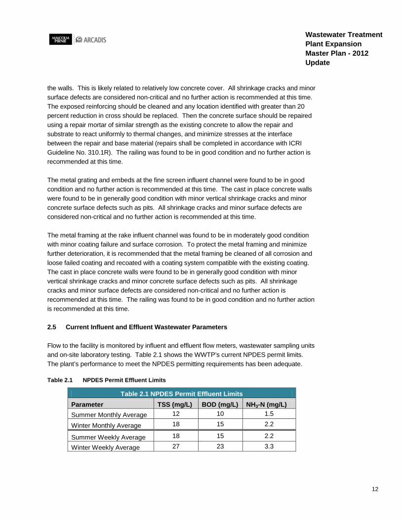
Flow to the facility is monitored by influent and effluent flow meters, wastewater sampling units and on-site laboratory testing. Table 2.1 shows the WWTP’s current NPDES permit limits. The plant’s performance to meet the NPDES permitting requirements has been adequate.
Table 2.1 NPDES Permit Effluent Limits
Table 2.1 NPDES Permit Effluent Limits Parameter TSS (mg/L) BOD (mg/L) NH3-N (mg/L) Summer Monthly Average 12 10 1.5
Winter Monthly Average 18 15 2.2
Summer Weekly Average 18 15 2.2
Winter Weekly Average 27 23 3.3
13
Wastewater Treatment Plant Expansion Master Plan - 2012 Update
Comparing the last three years (2008-2011) of historical plant data, the treatment plant is currently operating at roughly 82% of hydraulic capacity, or 2.87 mgd average daily flow. The existing oxidation ditches regularly receive organic loadings higher than their design capacity. A planned expansion from a local industrial user will further strain the oxidation ditches with higher than design organic loadings.
As the plant approaches the design capacity, the plant’s processes will require increased operator attention to maintain NPDES permit compliance. The last major WWTP upgrade was completed in 2000. The upgrade addressed capacity and regulatory needs. It has been 12 years since completion of these renovations.

14
Wastewater Treatment Plant Expansion Master Plan - 2012 Update
This page is intentionally left blank
15
Wastewater Treatment Plant Expansion Master Plan - 2012 Update
3. Future Conditions and Population Projections
This section provides a summary of the future population and wastewater flow for the twenty year planning period. The flow quantities and characteristics projections will be used as a basis for the design criteria in sizing treatment processes.
3.1 Planning Period
The planning period was chosen to be 20 years in order to estimate the future needs of Brownsburg and regulations. Environmental regulations are constantly evolving and generally become more stringent, potentially requiring more advanced treatment to assure higher levels of water quality. Because these regulations are often discussed for several years prior to being incorporated into wastewater permits, it is possible to anticipate some future requirements. Average equipment life expectancy for pumps and other mechanical devices is 15 to 20 years.
Brownsburg has updated its comprehensive plan (July 2012), which identifies the areas for potential development inside and outside of the existing Sewer Service Area. The resulting population equivalents were identified within the Sanitary Sewer Master Plan – 2012 Update. The Sanitary Sewer Master Plan has established a plan to provide capacity and service to each of these areas. The study area boundary used in the Sanitary Sewer Master Plan is the same area used in this WWTP Expansion Master Plan. A population projection was developed for the full study area to determine the future influent flows.
3.2 Population and Flow Projections
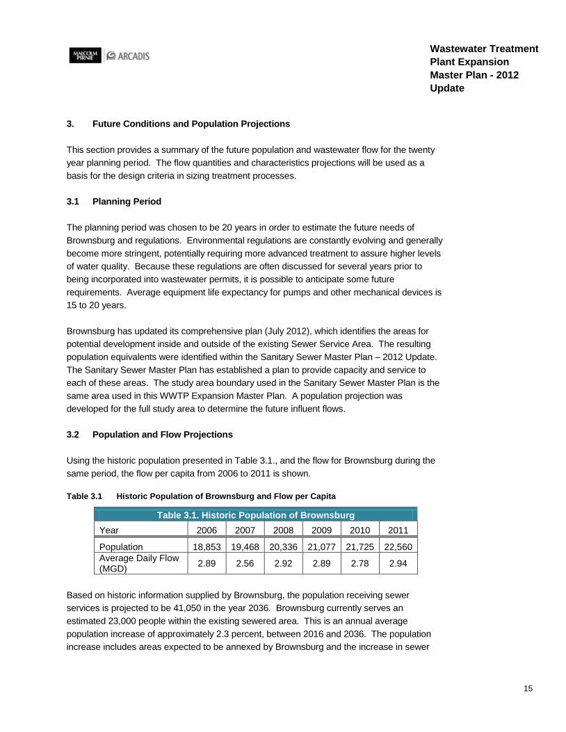
Using the historic population presented in Table 3.1., and the flow for Brownsburg during the same period, the flow per capita from 2006 to 2011 is shown.
Table 3.1 Historic Population of Brownsburg and Flow per Capita
Table 3.1. Historic Population of Brownsburg Year 2006 2007 2008 2009 2010 2011
Population 18,853 19,468 20,336 21,077 21,725 22,560 Average Daily Flow (MGD) 2.89 2.56 2.92 2.89 2.78 2.94
Based on historic information supplied by Brownsburg, the population receiving sewer services is projected to be 41,050 in the year 2036. Brownsburg currently serves an estimated 23,000 people within the existing sewered area. This is an annual average population increase of approximately 2.3 percent, between 2016 and 2036. The population increase includes areas expected to be annexed by Brownsburg and the increase in sewer

16
Wastewater Treatment Plant Expansion Master Plan - 2012 Update
customers. Figure 3.1 graphically presents the historic population and the population projection for Brownsburg. A linear increase is applied to the projected population for the years between 2016 and 2036. The projected population numbers are summarized along with the projected flows in Table 3.2. Brownsburg has elected to concentrate its efforts on providing service to areas within the sewer study boundary, specifically north and east of the existing Town boundaries. Brownsburg has established a plan to provide capacity and service to areas in the sewer study area with the Sanitary Sewer Master Plan – 2012 Update.
Figure 3.1 Historic Population and Population Projection for Brownsburg
0.00
1.00
2.00
3.00
4.00
5.00
6.00
0
5,000
10,000
15,000
20,000
25,000
30,000
35,000
40,000
45,000
2002 2007 2012 2017 2022 2027 2032 2037
Future Population
Historic Population
Future Flow
Historic Flow
Year
Popu
latio
n
Flow
in M
GD
Figure 3.1 Population Versus Flow (Projected)
17
Wastewater Treatment Plant Expansion Master Plan - 2012 Update
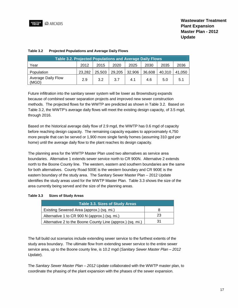
Table 3.2 Projected Populations and Average Daily Flows
Table 3.2. Projected Populations and Average Daily Flows Year 2012 2015 2020 2025 2030 2035 2036
Population 23,282 25,503 29,205 32,906 36,608 40,310 41,050 Average Daily Flow (MGD)
2.9 3.2 3.7 4.1 4.6 5.0 5.1
Future infiltration into the sanitary sewer system will be lower as Brownsburg expands because of combined sewer separation projects and improved new sewer construction methods. The projected flows for the WWTP are predicted as shown in Table 3.2. Based on Table 3.2, the WWTP’s average daily flows will meet the existing design capacity, of 3.5 mgd, through 2016.
Based on the historical average daily flow of 2.9 mgd, the WWTP has 0.6 mgd of capacity before reaching design capacity. The remaining capacity equates to approximately 4,750 more people that can be served or 1,900 more single family homes (assuming 310 gpd per home) until the average daily flow to the plant reaches its design capacity.
The planning area for the WWTP Master Plan used two alternatives as service area boundaries. Alternative 1 extends sewer service north to CR 900N. Alternative 2 extends north to the Boone County line. The western, eastern and southern boundaries are the same for both alternatives. County Road 500E is the western boundary and CR 900E is the eastern boundary of the study area. The Sanitary Sewer Master Plan – 2012 Update identifies the study areas used for the WWTP Master Plan. Table 3.3 shows the size of the area currently being served and the size of the planning areas.
Table 3.3 Sizes of Study Areas
Table 3.3. Sizes of Study Areas Existing Sewered Area (approx.) (sq. mi.) 8 Alternative 1 to CR 900 N (approx.) (sq. mi.) 23
Alternative 2 to the Boone County Line (approx.) (sq. mi.) 31
The full build out scenarios include extending sewer service to the furthest extents of the study area boundary. The ultimate flow from extending sewer service to the entire sewer service area, up to the Boone county line, is 10.2 mgd (Sanitary Sewer Master Plan – 2012 Update).
The Sanitary Sewer Master Plan – 2012 Update collaborated with the WWTP master plan, to coordinate the phasing of the plant expansion with the phases of the sewer expansion.
18
Wastewater Treatment Plant Expansion Master Plan - 2012 Update
3.3 Future Wastewater Influent Characteristics
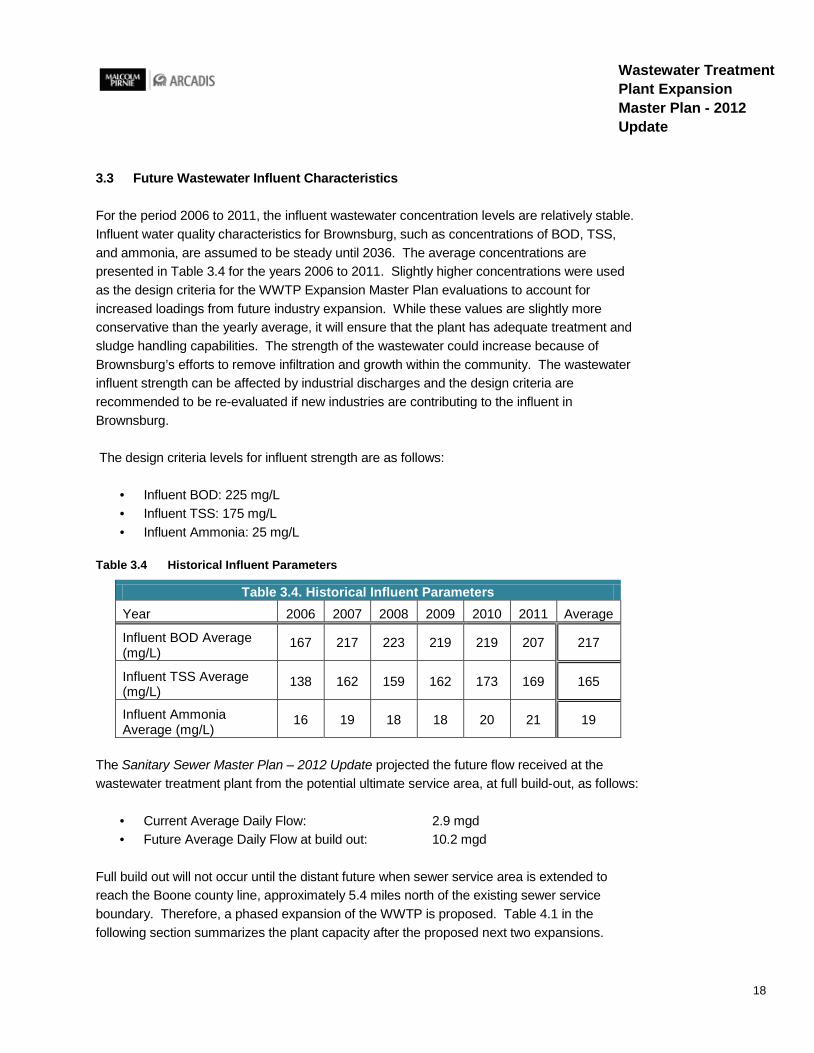
For the period 2006 to 2011, the influent wastewater concentration levels are relatively stable. Influent water quality characteristics for Brownsburg, such as concentrations of BOD, TSS, and ammonia, are assumed to be steady until 2036. The average concentrations are presented in Table 3.4 for the years 2006 to 2011. Slightly higher concentrations were used as the design criteria for the WWTP Expansion Master Plan evaluations to account for increased loadings from future industry expansion. While these values are slightly more conservative than the yearly average, it will ensure that the plant has adequate treatment and sludge handling capabilities. The strength of the wastewater could increase because of Brownsburg’s efforts to remove infiltration and growth within the community. The wastewater influent strength can be affected by industrial discharges and the design criteria are recommended to be re-evaluated if new industries are contributing to the influent in Brownsburg.
The design criteria levels for influent strength are as follows:
· Influent BOD: 225 mg/L · Influent TSS: 175 mg/L · Influent Ammonia: 25 mg/L
Table 3.4 Historical Influent Parameters
Table 3.4. Historical Influent Parameters Year 2006 2007 2008 2009 2010 2011 Average
Influent BOD Average (mg/L)
167 217 223 219 219 207 217
Influent TSS Average (mg/L)
138 162 159 162 173 169 165
Influent Ammonia Average (mg/L)
16 19 18 18 20 21 19
The Sanitary Sewer Master Plan – 2012 Update projected the future flow received at the wastewater treatment plant from the potential ultimate service area, at full build-out, as follows:
· Current Average Daily Flow: 2.9 mgd · Future Average Daily Flow at build out: 10.2 mgd
Full build out will not occur until the distant future when sewer service area is extended to reach the Boone county line, approximately 5.4 miles north of the existing sewer service boundary. Therefore, a phased expansion of the WWTP is proposed. Table 4.1 in the following section summarizes the plant capacity after the proposed next two expansions.
19
Wastewater Treatment Plant Expansion Master Plan - 2012 Update
Following the Ten State Standards recommended organic loading for oxidation ditches of 15 lbs BOD5/day/1000 ft3, at the current design organic loading (225 mg/L), the existing oxidation ditches are borderline overloaded. An already scheduled facility expansion by a local industry will increase their organic discharge by 25%. An increase in volume of flow and organic loading discharge from an industrial user will further exacerbate the nearly overloaded oxidation ditches. To prevent future NPDES permit violations and adequately treat industry expansion, the WWTP requires an expansion to increase the flow and organic treatment capacity of the plant.
In order to choose the most effective equipment for the Brownsburg WWTP, alternatives for each major process were identified and evaluated. Section 4 of this report will discuss and evaluate the different alternatives.

20
Wastewater Treatment Plant Expansion Master Plan - 2012 Update
This page is intentionally left blank
21
Wastewater Treatment Plant Expansion Master Plan - 2012 Update
4. Review of Treatment Process Alternatives
This section provides a summary of the alternative treatment process evaluation. All elements of the treatment process design including performance evaluation, cost, and layout are discussed. The highest ranked option is presented and the treatment process evaluation process is described. Brownsburg’s goal is to reuse as much of the existing infrastructure as practical and yet meet the long-term needs of the community and environment.
A wide range of technologies exist for the expansion of the Brownsburg Wastewater Treatment Plant (WWTP). The factors that influence the selection of a preferred technology are case-specific, and will vary between treatment plants. This section provides a preliminary evaluation of process technologies. All technologies are applicable to treating influent at the Brownsburg WWTP. The alternatives for each process presented in this plan have been narrowed down to the two to three most suitable. Each alternative is designed to fit the existing plant schematic with minimal modifications. This section evaluates specific treatment plant expansion options for increased flow rates from population/industrial growth anticipated for the Town of Brownsburg.
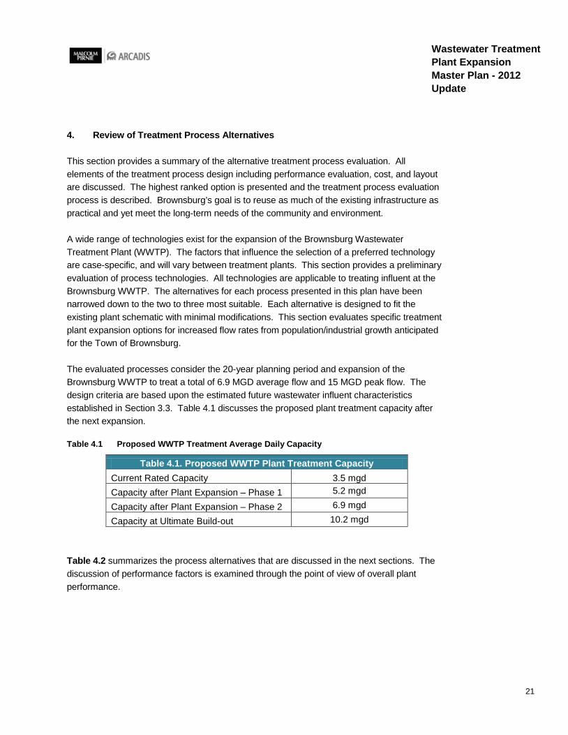
The evaluated processes consider the 20-year planning period and expansion of the Brownsburg WWTP to treat a total of 6.9 MGD average flow and 15 MGD peak flow. The design criteria are based upon the estimated future wastewater influent characteristics established in Section 3.3. Table 4.1 discusses the proposed plant treatment capacity after the next expansion.
Table 4.1 Proposed WWTP Treatment Average Daily Capacity
Table 4.1. Proposed WWTP Plant Treatment Capacity Current Rated Capacity 3.5 mgd Capacity after Plant Expansion – Phase 1 5.2 mgd
Capacity after Plant Expansion – Phase 2 6.9 mgd
Capacity at Ultimate Build-out 10.2 mgd
Table 4.2 summarizes the process alternatives that are discussed in the next sections. The discussion of performance factors is examined through the point of view of overall plant performance.
22
Wastewater Treatment Plant Expansion Master Plan - 2012 Update
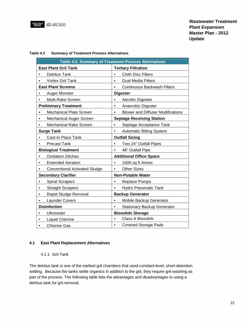
Table 4.2 Summary of Treatment Process Alternatives
Table 4.2. Summary of Treatment Process Alternatives East Plant Grit Tank Tertiary Filtration • Detritus Tank • Cloth Disc Filters • Vortex Grit Tank • Dual Media Filters East Plant Screens • Continuous Backwash Filters • Auger Monster Digester • Multi-Rake Screen • Aerobic Digester Preliminary Treatment • Anaerobic Digester • Mechanical Plate Screen • Blower and Diffuser Modifications • Mechanical Auger Screen Septage Receiving Station • Mechanical Rake Screen • Septage Acceptance Tank Surge Tank • Automatic Billing System • Cast-In Place Tank Outfall Sizing • Precast Tank • Two 24" Outfall Pipes Biological Treatment • 48" Outfall Pipe • Oxidation Ditches Additional Office Space • Extended Aeration • 1600 sq ft Annex • Conventional Activated Sludge • Other Sizes Secondary Clarifier Non-Potable Water • Spiral Scrapers • Replace Pumps • Straight Scrapers • Hydro Pneumatic Tank • Rapid Sludge Removal Backup Generator • Launder Covers • Mobile Backup Generator Disinfection • Stationary Backup Generator • Ultraviolet Biosolids Storage • Liquid Chlorine • Class A Biosolids
• Chlorine Gas • Covered Storage Pads
4.1 East Plant Replacement Alternatives
4.1.1 Grit Tank
The detritus tank is one of the earliest grit chambers that used constant-level, short-detention settling. Because the tanks settle organics in addition to the grit, they require grit-washing as part of the process. The following table lists the advantages and disadvantages to using a detritus tank for grit removal.

23
Wastewater Treatment Plant Expansion Master Plan - 2012 Update
Detritus Tank Advantages Disadvantages
Flow control is not required Inlet baffles cannot be adjusted to achieve a uniform flow distribution over a wide range of flows
Bearings and moving mechanical parts are above the water line
Tanks will remove significant quantities of organic material, especially at low flows, requiring grit washing and classifying
Units are sized on an area basis; thus, all grit is removed, washed, and classified up to the design flow
In shallow tanks (<0.9 m [3ft]), grit can be lost because of agitation created by the rake arm
Minimal head loss across the unit
The vortex style grit removal system relies primarily on a mechanically induced vortex to capture the grit into the grit hopper in the bottom of the tank. To minimize turbulence, the incoming flow is straightened in an upstream inlet flume at the inlet chamber. A ramp located at the end of the inlet flume causes grit that may already be on the flume floor to slide downward until it reaches the grit chamber floor where it is captured. Adjustable rotating paddles located in the center of the chamber maintain proper circulation within the camber for all flows. Paddles, baffles, and the flow produce the spiraling flow pattern that lifts the lighter organic particles up and settles the heavier grit. The grit is pumped from the center hopper and sent for further concentration and washing.
Vortex Grit Tank Advantages Disadvantages
Effective over a wide flow variation Proprietary design No submerged bearings or parts that require maintenance
Paddles may collect rags
Requires minimal space, thus reducing construction costs
Grit sump may become compacted and clog; requires high-pressure agitation water or air; air lift pumps are often not effective in removing grit from the sump
Minimal head loss Energy efficiency Removes high percentages of fine grit, up to 73% of 140-mesh (0.11-mm diameter) size
The vortex grit tank is recommended for the east plant in lieu of the existing detritus tank. The cost of a new unit is approximately $150,000.

24
Wastewater Treatment Plant Expansion Master Plan - 2012 Update
4.1.2 Screening Facility
The auger monster system influent enters the entrance of the channel and goes through a channel grinder which shreds clumps of rags, clothing, and debris. Next solids are captured by a perforated screening trough and removed by a rotating auger. As the solids are removed, dual wash water zones clear off organic material. The auger then conveys solids to the discharge point where an optional compactor squeezes out water before depositing the cleaned and dried material into a dumpster. Installing new screening and grit removal, equipment at the East Plant will extend the life of the pumps; also, it will drastically reduce the frequency of cleaning the wetwell and eliminate the need to clean the grit tank.
Auger Monster Advantages Disadvantages
Solids carry-over is minimized The single auger limits the capacity to handle extreme loads
Low maintenance due to elimination of permanently submerged moving parts
Long travel time for deep channels, which can result in heavy screen loads
Inclination angle of 35 degrees Easy inspection because channel does not have to be dewatered
The multi-rake screen bars have either a tear drop or rectangular profile to reduce headloss. For fine screen application, the rake is designed to operate at a higher cleaning frequency because of the higher solids collected on the bars. Screenings are removed by rotating rakes and conveyed out of the channel to the discharge point.
Multi-Rake Screen Advantages Disadvantages
Fine screen with low head loss Maximum recommended inclination angle Unimpaired by grit Blinding can lead to screen failure
Low overhead clearance Low maintenance Removes high screenings load
The muli-rake screen is recommended for the east plant in lieu of the existing auger monster system. The cost of the new unit is approximately $145,000.
4.1.3 Degritter
When heavier organic matter remains in the grit, degritters are commonly used to provide a second stage of solids separation. A typical degritter consists of a classifier and a cyclone
25
Wastewater Treatment Plant Expansion Master Plan - 2012 Update
separator. The flow is fed into the cyclone where the grit is concentrated centrifugally. The heavy density grit is removed at the bottom of the cyclone by centrifugal and gravitational forces. The lighter organics exit the top of the cyclone through the vortex finder. The classifier is usually an inclined screw that uses wash water to further clean the grit by separating out remaining organics. It is recommended that Brownsburg replace the existing degritter in kind, with an additional cyclone. The cost of the new degritter is approximately $260,000.
4.1.4 Sewage Pumps
The centrifugal nonclog mixed flow pump design has high volume and good efficiency for wastewater pump application. When selecting a centrifugal pump, it is imperative that the proper size is chosen. These pumps operate well only if the system head is within a narrow range. Since throttling is impractical, it is essential that these pumps be supplied with variable speed drives.
To increase the capacity of a centrifugal pump, the impeller can be upsized to a larger diameter. Currently, the EPPS pumps have 14.35-inch diameter impellers; these can be upsized to 15.5-inch diameter. Increasing the impeller diameter may require the motor to be upsized from 50 hp to 75 hp. The cost for a larger motor and impeller is approximately $17,000 per pump. The cost to replace the existing pump with the same model is approximately $25,000 per pump. Variable frequency drives are an additional $7,500. It is recommended that the EPPS replace the existing aging pumps with the same model pumps.
4.2 Preliminary Treatment
Preliminary treatment processes are methods of removing large solids and inorganic materials from the influent prior to treatment at the plant. All recommended alternatives have screen openings of ¼”. Solids that are captured on the screen assembly are discharged out of the unit for disposal. Removal of solids at the headworks of wastewater treatment plants is essential for the protection of downstream processes and equipment. Pump and pipe clogging can be prevented by proper screening. Mechanically cleaned screens tend to have lower labor costs than manually cleaned screens and offer the advantages of improved flow conditions and screening capture over manually cleaned screens. However, the rake teeth on mechanically cleaned screens must be routinely inspected because of their susceptibility to breakage and bending. Drive mechanisms must also be frequently inspected to prevent fouling due to grit and rags. Grit removed from screens must be disposed of regularly. Fine screens are susceptible to grease build up, therefore flush water should be available nearby to dislodge collected grease and solids.
The use of fine screens produces removal characteristics similar to primary sludge removal in primary sedimentation. Fine screens are capable of removing 20 to 35 percent suspended solids and BOD5. Fine screens may be either fixed or movable, but are permanently set in a
26
Wastewater Treatment Plant Expansion Master Plan - 2012 Update
vertical, inclined, or horizontal position and must be cleaned by rakes, teeth, or brushes. Peak head loss through fine screens ranges from 0.5 feet to 2 feet.
Cleaner more compact screenings discharge keeps odors to a minimum and lowers disposal costs, as less water and solid materials are sent to the landfill. The current trend in the industry is to install screens with smaller openings and to wash and compact the screenings to reduce volume and odor potential to capture more solids upstream to reduce downstream operation and maintenance costs.
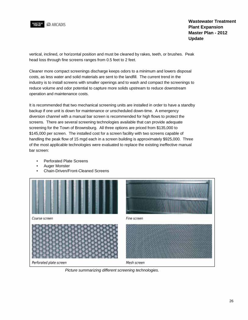
It is recommended that two mechanical screening units are installed in order to have a standby backup if one unit is down for maintenance or unscheduled down-time. A emergency diversion channel with a manual bar screen is recommended for high flows to protect the screens. There are several screening technologies available that can provide adequate screening for the Town of Brownsburg. All three options are priced from $135,000 to $145,000 per screen. The installed cost for a screen facility with two screens capable of handling the peak flow of 15 mgd each in a screen building is approximately $925,000. Three of the most applicable technologies were evaluated to replace the existing ineffective manual bar screen:
· Perforated Plate Screens · Auger Monster · Chain-Driven/Front-Cleaned Screens
Picture summarizing different screening technologies.

27
Wastewater Treatment Plant Expansion Master Plan - 2012 Update
4.2.1 Option 1 – Mechanical Plate Screen
Description
The mechanical plate screen uses stainless steel perforated plate media to automatically and efficiently remove solids from municipal waste streams. The steps form an endless moving belt that collects, conveys and discharges solids greater than ¼”. The goal of fine screens is to remove the rags and debris from the system. The frequency of pump cleaning will be decreased with properly operating screens.
Performance Factors
The screening process reduces solids in the plant’s biological process by removing the solids from the influent stream. The downstream treatment processes will receive reduced bacteria, floatables, suspended solids, CBOD, and nutrients. A precoat, or mat of organics, can build up on the screen providing enhanced treatment. All the major components are located above the deck for easy access and maintenance. Surge flows in the channel can cause waves to wash backwards through the screen knocking the screenings off and can cause a large accumulation that requires manual removal. The step screen alternative requires a building to provide housing and easier removal of the dumpster or bagger. An optional solids washer adds cost to the installation but reduces the amount of organic solids for disposal.
Perforated Plate Screens Advantages Disadvantages
Greater capture of solids from the waste stream
Possible solids carry-over resulting from the front clean/back return design Submerged moving parts
Efficient removal of large quantities of solids Long screens result in several heavy plates that cause more wear on the chain
Low maintenance Plugging that could lead to screen failure
Low overhead clearance Perforated plates not as resilient as bars and are more susceptible to damage from large objects in wastewater flow
Maximum recommended inclination angle is 75 to 85 degrees
Screen’s binding factor is higher than the reciprocating rake and chain-driven screens

28
Wastewater Treatment Plant Expansion Master Plan - 2012 Update
Picture showing the difference between a bar screen (left) and a perforated plate screen and an installed application (right).
Construction Impacts
The influent channel needs to be modified to accommodate the screens and screen building. Modifications to the influent channel are also necessary for improvements to the biological processes and higher flows at the plant. The influent channel design will accommodate all scheduled processes and scheduled future expansions in order to be the most cost effective.
4.2.2 Option 2 – Mechanical Auger Screen
Description
Inflow enters the entrance of the channel and goes through an auger screen which shreds clumps of rags, clothing, and debris. Next solids are captured by a perforated screening trough and removed by a rotating auger. As the solids are removed, dual wash water zones clean off organic solids. The auger then conveys solids to the discharge point where an optional compactor squeezes out water before depositing the cleaned and dried material into a dumpster.
Performance Factors
An auger screen helps with solids that need to be ground up before removal. The primary advantage is that the screenings must pass through a grinder before removal. A grinder will prevent large material from damaging the fine screen components.
29
Wastewater Treatment Plant Expansion Master Plan - 2012 Update
Auger System Screen Advantages Disadvantages
Solids carry-over is minimized The single auger limits the capacity to handle extreme loads
Low maintenance due to elimination of permanently submerged moving parts
Long travel time for deep channels, which can result in heavy screen loads
Inclination angle of 35 degrees Easy inspection because channel does not have to be dewatered
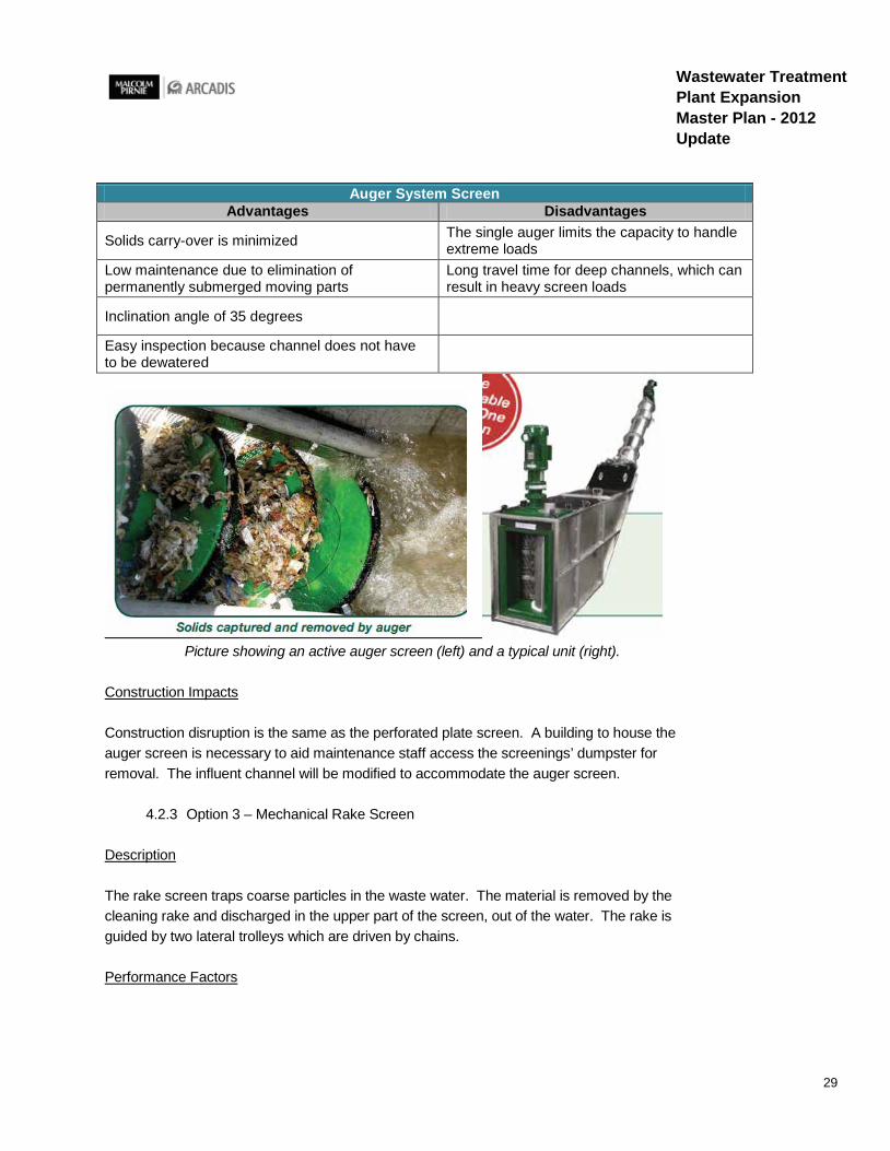
Picture showing an active auger screen (left) and a typical unit (right).
Construction Impacts
Construction disruption is the same as the perforated plate screen. A building to house the auger screen is necessary to aid maintenance staff access the screenings’ dumpster for removal. The influent channel will be modified to accommodate the auger screen.
4.2.3 Option 3 – Mechanical Rake Screen
Description
The rake screen traps coarse particles in the waste water. The material is removed by the cleaning rake and discharged in the upper part of the screen, out of the water. The rake is guided by two lateral trolleys which are driven by chains.
Performance Factors

30
Wastewater Treatment Plant Expansion Master Plan - 2012 Update
A mechanical bar screen performs the same way a manual bar screen would perform but eliminates the need for continuous maintenance from staff. The chains and moving parts are above the water level to provide maintenance access.
Chain-Driven Front Cleaned Screens Advantages Disadvantages
Efficiently retains captured screenings by minimizing carryover
Possibility of bottom jamming by unusual deposits of trash
Low headloss across the screen Chain-driven raking mechanism consisting of submerged sprockets or other mechanical devices is subject to fouling by grit and rags
Cleaning cycle can be automatically adjusted based on water differential in the channel
Frequent inspection and maintenance of the drive mechanisms are required
Low head room Channel dewatering may be required for maintenance
Picture showing an installed chain driven bar screen (left) and an active unit (right).
Construction Impacts
Construction disruption will be the same for all screen alternatives. A building to house the screen will likely be necessary to aid maintenance staff access the screenings’ dumpster for removal. The influent channel will be modified to accommodate the screen and screen building.
4.3 Surge Tank and Influent Flow Control
A surge tank at the WWTP is required to minimize the impact of high flows into the WWTP. The pumping and the diurnal cycles of inflow can bring large amounts of flow into the WWTP

31
Wastewater Treatment Plant Expansion Master Plan - 2012 Update
during a short period of time. In order to stabilize the hydraulic loadings to the oxidation ditches a 100,000 gallon surge tank is proposed to be built. At 6.9 mgd flow the surge tank will have a hydraulic detention time of 20 minutes and will help to equalize the plant influent. Since long runs of force main will feed into the WWTP, odor control is recommended for the surge tank. The surge tank location is after the screens, but before the oxidation ditches so the screens are able to remove a portion of the solids.
Concrete tanks require little or no maintenance. Concrete is well-suited for exposure to all types of weather conditions. The strength of precast concrete gradually increases over time. Concrete is resistant to most substances and has a durable service life. A diameter of 40 feet and side water depth of 11 feet were assumed to provide the most efficient construction. Concrete tanks are the industry standard for surge tank construction and two different construction alternatives are evaluated below.
· Cast-In Place Concrete Tank · Precast Concrete Tank · Adding Odor control to tank
4.3.1 Option 1 – Cast in Place Concrete Tank
Description
A cast in place concrete surge tank is installed by setting forms and then pouring the concrete from a concrete truck. On-site strength tests are performed to ensure that the concrete mix is suitable. After the concrete is poured the concrete tank will cure and harden in place. The estimated installed cost for a cast in place concrete tank to hold 100,000 gallons of influent wastewater is $510,000. The cost estimate includes odor control and a cover on the tank.
Performance Factors
A cast in place concrete tank has less seams than a precast tank assembled on site. However a cast in place tank is more costly and can be delayed or affected by adverse weather conditions. It takes a longer construction time compared to a precast tank.
Cast-In Place Tank Advantages Disadvantages
The structure will have less seams/joints More costly More versatile designs can be achieved Weather can affect concrete strength and durability Greater control of the construction schedule Longer construction time Use local materials and local labor Formwork can be 40-60% of total cost

32
Wastewater Treatment Plant Expansion Master Plan - 2012 Update
Construction Impacts
Construction disruption will be similar for either tank construction method. A cast in place tank takes a longer period of time for construction. Both methods require soil borings and a site assessment for the foundation system design.
4.3.2 Option 2 – Precast Concrete Tank
Description
A precast concrete tank is installed with specifically designed pre-cast concrete structures that are shipped or precast at the construction site. The structures are manufactured in advance and held until the time of construction. Tank construction begins with the sub base and floor. A reinforced concrete membrane floor provides water-tightness and the ability to settle differentially without being subjected to high secondary bending stresses. The wall panels are placed by a crane and high strength shotcrete is used to fill the vertical slot joints between the individual panels. The dome roof is either cast in place or precast and provides venting and access hatches. The estimated installed cost for a precast concrete tank to hold 100,000 gallons of influent wastewater is $460,000. The cost estimate includes odor control and a cover on the tank.
Performance Factors
With precast concrete, the structures are poured in a controlled environment so weather is not usually a factor. Controlled pour conditions, strict quality control measures and factory strength testing ensure precast concrete that meets strength and durability specifications. The strength of precast concrete gradually increases over time. The speed of installation of precast concrete is more dependent on excavation than product handling and placement. Standard watertight sealants are specially formulated to adhere to precast concrete, making watertight multiple seam precast concrete structures possible.
Precast Tank Advantages Disadvantages
Shorter construction time Design limited by precast dimensions
Little formwork required Openings in tank need to be coordinated with tank supplier
Easier to control mix, placement, and curing Caulking/grouting of joints can be a source of leaks
Precast concrete is generally more durable and has more decorative options
33
Wastewater Treatment Plant Expansion Master Plan - 2012 Update
Construction Impacts
Construction disruption is similar for either tank construction method. A precast tank requires a shorter period of time for on-site construction. Both methods require geotechnical investigations and a site assessment for the foundation system design.
4.3.3 Option 3 – Odor Control and Aeration of Surge Tank
Description
Long force main runs and transporting wastewater for far distances may cause odor and septic issues at the surge tank. Mitigating odor issues at the surge tank also helps control odor downstream of the surge tank. One option is to use chemical addition to destroy the odor causing bacteria. Oxidation chemicals added in the surge tank prevent the odor causing bacteria from causing odors. Aeration diffusers on the bottom of the tank could aerate and mix the wastewater to keep the tank from turning septic.
Performance Factors
An odor control system costs more money but lowers the odors from the surge tank. Also an aeration system helps to keep the forcemain wastewater from turning septic before biological treatment at the plant. Due to the long force main runs leading into the plant and extended wastewater travel times before entering the plant, it is recommended to have a form of odor control both at the surge tank and somewhere in the collection system to mitigate the odors.
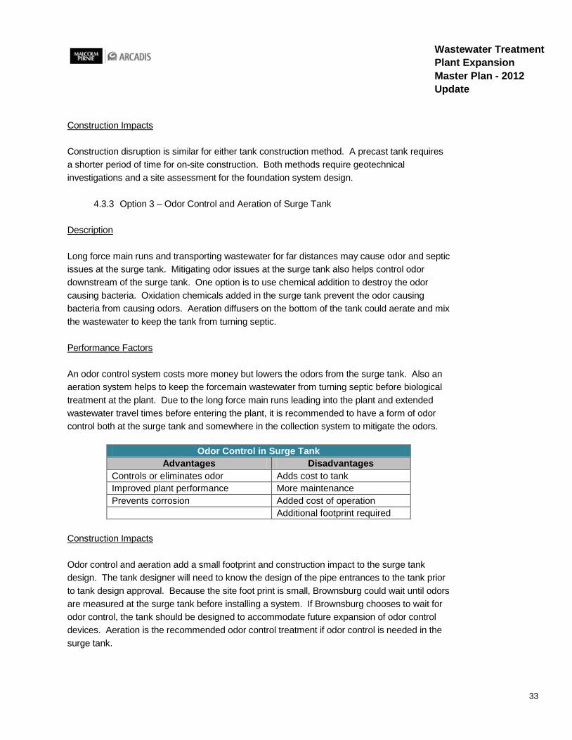
Odor Control in Surge Tank Advantages Disadvantages
Controls or eliminates odor Adds cost to tank Improved plant performance More maintenance Prevents corrosion Added cost of operation Additional footprint required
Construction Impacts
Odor control and aeration add a small footprint and construction impact to the surge tank design. The tank designer will need to know the design of the pipe entrances to the tank prior to tank design approval. Because the site foot print is small, Brownsburg could wait until odors are measured at the surge tank before installing a system. If Brownsburg chooses to wait for odor control, the tank should be designed to accommodate future expansion of odor control devices. Aeration is the recommended odor control treatment if odor control is needed in the surge tank.

34
Wastewater Treatment Plant Expansion Master Plan - 2012 Update
4.4 Biological Treatment
The biological treatment process alternatives considered for the Brownsburg WWTP are all modified forms of the activated sludge process. Activated sludge uses a suspended growth of organisms to removed BOD and suspended solids from the wastewater. Both biological treatment processes, oxidation ditch and extended aeration, do not require primary clarification. Both have good settling characteristics and are stable processes. The average hydraulic residence time (HRT) is longer than 24 hours and the average solids residence time (SRT) ranges from 12 to 24 days. Mechanical aeration equipment, either rotors or diffused air, are required to move water around the tank as well as provide aeration.
4.4.1 Option 1 – Conventional Activated Sludge
Description
The conventional activated sludge process requires a primary settling tank, aeration tank, and a secondary settling tank. The mixed liquor is aerated for a specified length of time. During the aeration the activated sludge organisms use the available organic matter as food producing stable solids and more organisms.
Performance Factors
Many factors affect the performance of an activated sludge treatment system. The waste rates and return rates affect the solids rates. The amount of oxygen available, aeration time and amount of organic matter affect the efficiency of the process. The temperature and pH affect the overall capacity of the microorganisms.
Conventional Activated Sludge Advantages Disadvantages
Flexible operation, accommodates anoxic and aerobic processes with single biomass for biological nutrient removal
Will create two different processes at plant
Able to handle peak loads and dilute toxic substances
Associated with biomass instabilities, like sludge bulking
Reduced mixing requirement, per unit reactor volume
Requires primary settling and produces primary sludge
Smaller volume than extended aeration, easier for phased construction Higher operations cost
Construction Impacts
A primary settling tank is required for the conventional activated sludge process, and will add a significant cost and site footprint. Also, operating two different biological processes (oxidation
35
Wastewater Treatment Plant Expansion Master Plan - 2012 Update
ditch and conventional activated sludge) will place a difficulty on operators to distribute flow evenly. Aeration is provided by either mechanical surface agitators or by submerged diffusers. The size of the activated sludge tanks will be about 7000 ft2 assuming a 12 day Solids Retention Time (SRT) for colder temperature operation. The estimated installed cost for a conventional activated sludge system including the primary clarifiers is $4.6 million dollars.
4.4.2 Option 2 – Extended Aeration
Description
In extended aeration there is an increased hydraulic retention time and an increased solids retention time compared to conventional activated sludge treatment. This causes the least quantity of sludge to be produced among the various modifications of activated sludge. Extended aeration and an oxidation ditch are very similar and only differ in a few minor areas. Extended aeration typically uses submerged aeration to aerate the flow, whereas oxidation ditches use brush or disk aerators.
Performance Factors
The land area for setting up an extended aeration basin is less than an oxidation ditch. Air is supplied to the diffusers by blowers. The blowers produce more noise than an oxidation ditch’s brush aerators. But if blowers are enclosed in an enclosure, the noise is typically not an issue. The blowers are designed to provide sufficient air to ensure that the dissolved oxygen content of the aeration chambers can always be maintained within the range of 1.0 to 2.0 mg/L.
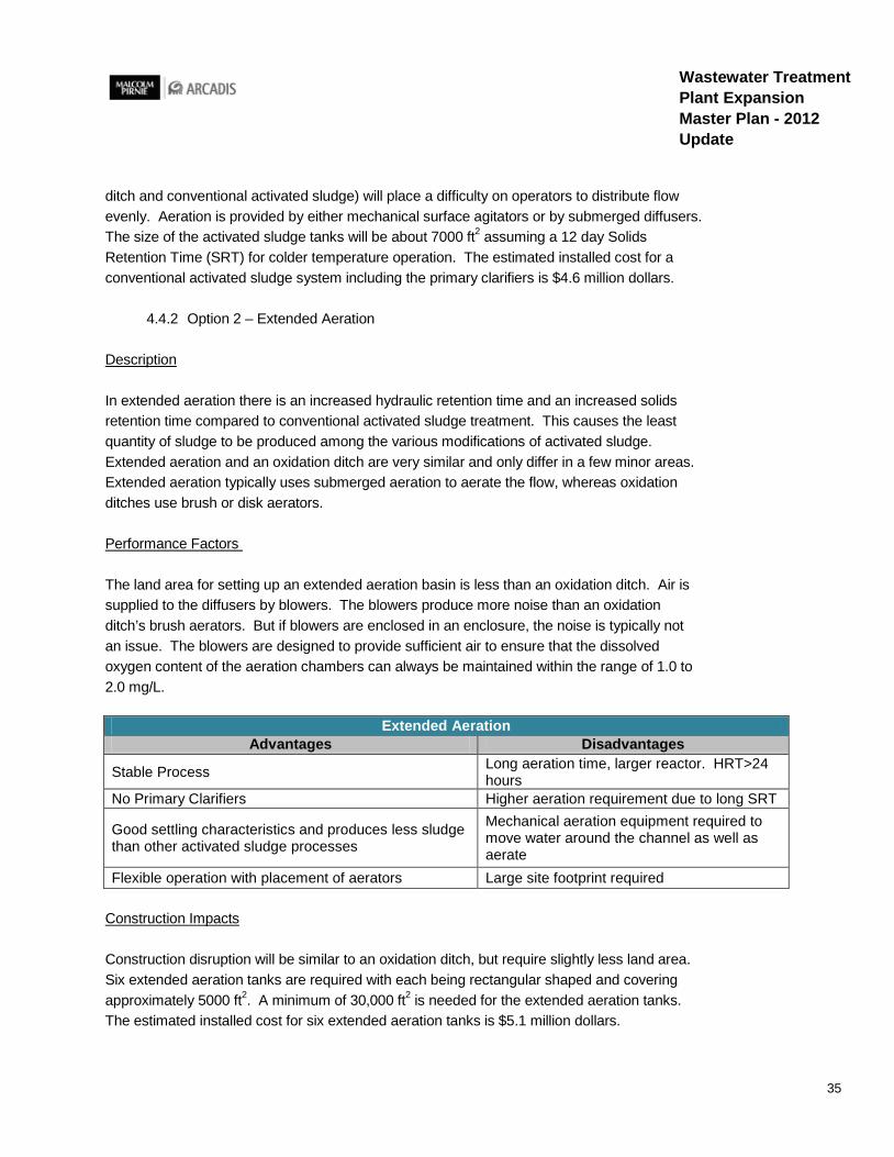
Extended Aeration Advantages Disadvantages
Stable Process Long aeration time, larger reactor. HRT>24 hours
No Primary Clarifiers Higher aeration requirement due to long SRT
Good settling characteristics and produces less sludge than other activated sludge processes
Mechanical aeration equipment required to move water around the channel as well as aerate
Flexible operation with placement of aerators Large site footprint required
Construction Impacts
Construction disruption will be similar to an oxidation ditch, but require slightly less land area. Six extended aeration tanks are required with each being rectangular shaped and covering approximately 5000 ft2. A minimum of 30,000 ft2 is needed for the extended aeration tanks. The estimated installed cost for six extended aeration tanks is $5.1 million dollars.

36
Wastewater Treatment Plant Expansion Master Plan - 2012 Update
4.4.3 Option 3 – Oxidation Ditch
Description
An oxidation ditch is a modified form of activated sludge biological treatment process that uses long solids retention time to remove organics. Flow to the oxidation ditch is aerated and mixed with return sludge from a secondary clarifier. The tanks have a race track shape and uses surface aerators to aerate and completely mix the water.
Performance Factors
The oxidation ditch process is a fully demonstrated biological wastewater treatment technology, applicable in any situation where activated sludge treatment is appropriate.
The largest obstacle to implementation is available land. This technology is very effective in small installations, small communities, and isolated institutions, because it requires more land than conventional activated sludge treatment plants. The long hydraulic retention time and complete mixing minimize the impact of a shock load or hydraulic surge. Oxidation ditches produce less sludge than other biological treatment processes because of the extended biological activity during the activated sludge process. A constant water level in the oxidation ditch with a continuous discharge lowers the weir overflow rate and eliminated the periodic effluent surge common to other biological processes. The effluent suspended solids concentrations are relatively higher compared to other modifications of the activated sludge process. Chemical addition is not required and operator attention is minimal.
Oxidation Ditches Advantages Disadvantages
Stable process and does not require chemical addition Larger footprint than extended aeration Good settling characteristics and produces less sludge than other activated sludge processes
Long aeration time, larger reactor. HRT>24 hours
No primary clarifiers Higher aeration requirement due to long SRT
Completely mixed Surface aerators required to move water around the channel as well as aerate
Construction Impacts
More land will be required for oxidation ditches than other activated sludge processes. The two oxidation ditches will require a minimum of 34,000 ft2 site footprint. The estimated installed cost for two oxidation ditches is $5.1 million dollars.
37
Wastewater Treatment Plant Expansion Master Plan - 2012 Update
4.5 Secondary Clarifiers
The secondary clarifiers are responsible for removing microorganisms from the wastewater. Some of the microorganisms from the clarifiers are added back to the biological treatment process to start the process over again. The circular clarifier tanks settle out the activated sludge by gravity. Phase 1 of plant expansion will build two circular clarifiers where the MLSS will be separated from the clean overflow. The MLSS settles to the bottom of the clarifier, collected by a series of clarifier mechanisms and enters sludge intake ports along the bottom of the tank and the center column. The collected sludge is either wasted to the sludge holding tanks or returned back to the biological treatment tanks to maintain the biological population. The size of each of the two proposed secondary clarifiers is 90 feet in diameter by 15 feet deep (side water depth). This provides a volume of 95,000 cubic feet which is 711,000 gallons.
All clarifier alternatives are either circular rim feed, rim collection or center feed, rim collection. The total estimated installed cost for two additional secondary clarifiers is 2.3 million dollars. The different sludge collection equipment considered in the three alternatives range in budgetary price estimates from $210,000 to $230,000 each. Cost difference between sludge collection equipment was not focused on for the secondary clarifier evaluation.
4.5.1 Option 1 – Rapid Sludge Pickup
General Description
In rapid sludge pickup mechanisms, a header suction tube removes the concentrated sludge along the bottom of the clarifier using gravity and a pump. The header uses suction pickup to remove the sludge from the bottom of the clarifier. The header rotates along the bottom of the clarifier similar to the spiral scraper mechanism.
Performance Factors
The suction type clarifiers will be dependent on the plant’s ability to remove rags, grit and grease ahead of the secondary clarifiers. Large amounts of rags and grit can damage or clog the suction headers. The header design and gentle removal action reduces the chance for the concentrated settled sludge to resuspend into the upper liquid. There is a minimum of underwater disturbance. The header is of tapered design with the cross section decreasing from the center of the tank to the outer tip for a uniform sludge withdrawal velocity. The constant velocities prevent the possibility of sludge build up in the header or orifice clogging. The header is mounted at an angle to physically and hydraulically trap the sludge.
The tank floor is virtually flat which simplifies excavation and forming. There is no need for a separate drain line, sloping floors or special hoppers. The orifice size on the headers is based

38
Wastewater Treatment Plant Expansion Master Plan - 2012 Update
on the amount of sludge that each orifice must remove to assure the hydraulic balance required for proportional sludge withdrawal volumes over the entire tank bottom.
Rapid Sludge Removal Advantages Disadvantages
Minimum of underwater disturbance Potential for clogging intake orifices
Simplifies construction of tank due to flat floor Suction headers can be damaged from rags or grit
Less valves and hoppers required More control to prevent sludge buildup Rapid removal ensures fresher sludge
Picture showing a cross section of a rapid sludge removal header
Construction Impacts
One valve controls sludge withdrawal by pumping or gravity. Single control allows the final clarifier to be more flexible in meeting changing process conditions. Plugging of orifices is a rare occurrence with adequate preliminary treatment so frequent demands for unplugging are eliminated. The estimated installed cost for two rapid sludge removal secondary clarifiers is $2.3 million dollars.
4.5.2 Option 2 – Conventional Scrapers
General Description
A conventional scraper collection system offers sludge removal with multiple straight blades placed on an angle and a rotating sludge collection drum. The conventional scraper clarifiers offer full radius sludge removal and an energy dissipation well. The blades are constructed to an optimal angle to provide a constant sludge removal across the blades. The sludge drum

39
Wastewater Treatment Plant Expansion Master Plan - 2012 Update
removes highly concentrated sludge that is brought by the blades to the center of the tank. The hydraulic flow in the main settling area moves in the same direction as the scrapers and helps move the sludge gently toward the center of the tank. The drum does not clog and requires little maintenance. Each drive mechanism is equipped with speed control devices.
Performance Factors
Conventional scraper clarifier mechanisms are a tested technology that is currently implemented at the Brownsburg WWTP. The conventional scrapers are less efficient than spiral scrapers because multiple passes of the scraper arms are required to remove sludge from the edge of the clarifier
Conventional Scrapers Advantages Disadvantages
Does not clog Requires multiple passes of scraper mechanism to remove sludge from outskirts of tank
Stable process Longer solids retention in clarifier Fewer moving parts than rapid sludge pickup Cheapest Option
Picture showing the difference between a spiral blade and conventional blades in a clarifier.
Construction Impacts
The construction impacts and concerns are similar for all the clarifier alternatives. All the secondary clarifiers and oxidation ditches will be interconnected to provide backups for each other. The flow will be split evenly among clarifiers. The estimated installed cost for two conventional scraper secondary clarifiers is $2.3 million dollars.

40
Wastewater Treatment Plant Expansion Master Plan - 2012 Update
4.5.3 Option 3 – Spiral Scrapers
General Description
Spiral Scrapers offer quick sludge removal with spiral blades and a rotating sludge collection drum. The spiral scraper clarifier offer full radius skimming and an enhanced energy dissipation well. The blades are constructed to a logarithmic spiral curve with a constant 30 degree angle of attack. The sludge drum removes highly concentrated sludge that is brought by the spiral blades to the center of the tank. The drum does not clog and requires little maintenance. Each drive is equipped with an overload control device.
Performance Factors
Spiral scrapers are a proven technology that has been implemented at numerous plants. The spiral scraper clarifier removes sludge quickly because only one rotation of the scrapers is required to bring the sludge from the edge of the clarifier to the center for removal.
The clarification capacity is related to the rate at which the incoming solids can be separated and conveyed to the sludge collection mechanism at the bottom of the tank. Clarifier performance is primarily impacted by the sludge settleability and MLSS concentration. Favorable hydrodynamic characteristics are also vital to clarifier performance. Even flow splitting to allow the full capacity of all clarifiers to be realized is necessary. If the flows are unevenly split, poor performance of an overloaded clarifier generally cannot be compensated by good performance of an underloaded clarifier.
Spiral Scrapers Advantages Disadvantages
Does not clog Higher torque loading on drive mechanism Requires one rotation to bring sludge from outskirts of tank to collection drum More costly than conventional scrapers
Fewer moving parts than rapid sludge pickup

41
Wastewater Treatment Plant Expansion Master Plan - 2012 Update
Picture showing a section cut of an installed spiral scraper clarifier.
Construction Impacts
The construction impacts and considerations are similar for each clarifier alternative. The flow will be split between the two proposed clarifiers while being able to backup the existing four clarifiers. The RAS pumps for the new secondary clarifiers will be located in the proposed RAS/Electrical Building. All proposed clarifier discharge weirs will match the existing weir levels so that the secondary clarifiers can backup each other and receive discharge from all oxidation ditches. The estimated installed cost for two spiral scraper secondary clarifiers is 2.3 million dollars.
4.5.4 Launder Covers in Secondary Clarifiers
General Description
Algae grow rapidly at the weir plates and the scum baffles then require maintenance for its removal. Algae create serious problems by restricting the V-notches in the weirs as well as other equipment. When sloughed algae move on from the clarifier and into the next treatment process they cause potential permit violations. Covering the effluent trough launders with outward sloping covers from the outer wall to inboard of the scum baffle will remove sunlight penetration and prevent algae growth.
Performance Factors
The fiberglass reinforced plastic launder covers are resistant to corrosion, normal abrasion, sunlight, atmospheric conditions, and environmental abuse. Odors are contained under the
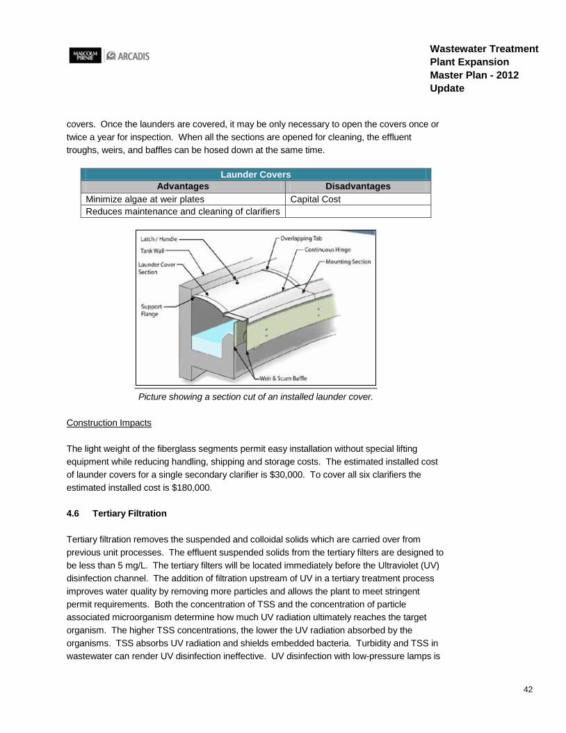
42
Wastewater Treatment Plant Expansion Master Plan - 2012 Update
covers. Once the launders are covered, it may be only necessary to open the covers once or twice a year for inspection. When all the sections are opened for cleaning, the effluent troughs, weirs, and baffles can be hosed down at the same time.
Launder Covers Advantages Disadvantages
Minimize algae at weir plates Capital Cost Reduces maintenance and cleaning of clarifiers
Picture showing a section cut of an installed launder cover.
Construction Impacts
The light weight of the fiberglass segments permit easy installation without special lifting equipment while reducing handling, shipping and storage costs. The estimated installed cost of launder covers for a single secondary clarifier is $30,000. To cover all six clarifiers the estimated installed cost is $180,000.
4.6 Tertiary Filtration
Tertiary filtration removes the suspended and colloidal solids which are carried over from previous unit processes. The effluent suspended solids from the tertiary filters are designed to be less than 5 mg/L. The tertiary filters will be located immediately before the Ultraviolet (UV) disinfection channel. The addition of filtration upstream of UV in a tertiary treatment process improves water quality by removing more particles and allows the plant to meet stringent permit requirements. Both the concentration of TSS and the concentration of particle associated microorganism determine how much UV radiation ultimately reaches the target organism. The higher TSS concentrations, the lower the UV radiation absorbed by the organisms. TSS absorbs UV radiation and shields embedded bacteria. Turbidity and TSS in wastewater can render UV disinfection ineffective. UV disinfection with low-pressure lamps is

43
Wastewater Treatment Plant Expansion Master Plan - 2012 Update
not as effective for secondary effluent with TSS levels above 30 mg/L. The filters are sized to handle a peak flow of 15 mgd.
The tertiary filter system will require a building to house the filters and protect them from weather damage. The filters that require a larger site footprint will require a larger building and additional costs. Tertiary filtration is recommended before UV disinfection and three different alternatives are evaluated below.
· Continuous Backwash Filter · Dual Media Filter · Cloth Media Disc Filter
4.6.1 Option 1 – Continuous Backwash Filter
General Description
The filtration process of a continuous backwash filter is comparable to fixed bed filters in that it removes particulate material. However, the continuous backwash filter operates under a constant backwash mode, continuously cleaning the filter bed. The continuous wash water flow is independent of the suspended solids load and the hydraulic load on the filter.
The influent feed wastewater is introduced at the bottom of the filter and then flows upward through the sand. As the influent flows upward the sand bed is moving downwards to an airlift pipe where it is removed for cleaning. The clean filtrate water continues to move upward and exits at the top of the filter over the filtrate weir and out through the effluent pipe. The proposed continuous backwash filters are 24 feet deep.
Performance Factors
Because the sand is continuously being backwashed there is no shutdown for a backwash cycle. No underdrains or media screens are required. The filter media is cleaned by an internal washing system that does not require backwash pumps or storage tanks. A volume of compressed air is required to clean the sand. The scouring by the air dislodges any solids particles attached to the sand grains.
Continuous Backwash Filters Advantages Disadvantages
No shutdown for backwash cycles Clogging of filter media is possible Elimination of ancillary backwash equipment and no short circuiting Requires air supply
Minimizes operator attention and overall pressure drop Higher capital cost
Continuously cleaned sand bed

44
Wastewater Treatment Plant Expansion Master Plan - 2012 Update
Picture showing a cutout section view of a continuous backwash filter
Construction Impacts
The continuous backwash filters footprint will be 215’ long x 22’ wide x 24’ deep. A larger construction cost is required for the continuous backwash filters because they are housed in deep concrete or metal tanks. The estimated total installed cost for the continuous backwash filters is $3.2 million, which includes the filters, the tanks, and the building to house them. The site foot print for the filter and building is approximately 4,500 square feet.
4.6.2 Option 2 – Dual Media Filter
General Description
Suspended particulates are removed from water by water flowing via gravity through granular filter media at a high rate. The solids are removed within the depth of the granular material. Filtered water is removed from the filter through an underdrain system. The dual media generally consists of anthracite coal over sand. Cleaning the filter media is accomplished with an upflow water wash with full bed fluidization. Air scour is also used to ensure thorough

45
Wastewater Treatment Plant Expansion Master Plan - 2012 Update
cleaning and abrasion between grains. The solids are dislodged and flushed out of the media to be captured by the water overflowing into the waste trough. The backwash water is evacuated from the filter for recovery.
Performance Factors
The dual media filter works with gravity, eliminating the need to pump influent through the media. High filtration rates of 5 gpm/sf can be achieved. Low backwash consumption can be as little as 2% of influent flow. Four sand filters measuring 36’ long x 12’ wide x 12’ deep are recommended for the peak flow. When one filter is in backwash mode the other three filters will be able to filter the peak flow of 15 mgd. The dual media filters have a higher headloss and larger footprint than the cloth media filters.
Dual Media Filters Advantages Disadvantages
Air scouring cleans the media during backwash High headloss and highest capital cost
Automatic sequencing of backwash procedure Removed from service for backwash
Efficient solids loading Requires water and air for backwash Larger footprint Required
Picture showing sections of a dual media filter.

46
Wastewater Treatment Plant Expansion Master Plan - 2012 Update
Construction Impacts
The filter media will be housed in concrete tanks and require an approximate footprint of 3,000 square feet. Additional backwash pumps, air scour blowers, and mudwell pumps will be required. The estimated installed cost for four dual media filters is $5.5 million, which includes the filters, equipment, the tanks, and the building to house them.
4.6.3 Option 3 – Cloth Media Disc Filter
General Description
A cloth media disc filter uses woven cloth fiber in a disc to filter wastewater. The water to be treated flows by gravity into the filter segments. Solids catch on the cloth filter panels. As the solids catch on the filter media impending the flow of the water through the disc, the water level beings to rise which triggers a level sensor to start the disc to rotate and a backwash cycle begins. High pressure rinse water automatically washes the solids off the filter media.
Performance Factors
Flow through a cloth disc filter is continuous. The filter never goes off line even during a backwash cleaning cycle. The unsubmerged media is clean and available for immediate use, allowing the filter to handle high solids spikes while maintaining full treatment capacity. Partial submergence of the discs enables routine inspection and maintenance to be conveniently performed in a clean environment instead of requiring contact with unfiltered water. The effluent collection tank does not need to be drained in order to clean or inspect the disc filter media because the backwash cleaning system is above the submergence. Cloth filters should not be used for wastewater streams that include corrosive materials that could chemically attack the filter cloth.
Cloth Disc Filters Advantages Disadvantages
Lower backwash rates Lower resistance to chemicals and sensitive to polymer concentrations
Smaller footprint Continuous filtration during backwash Eliminates sand media and underdrains Can operate at partial submergence
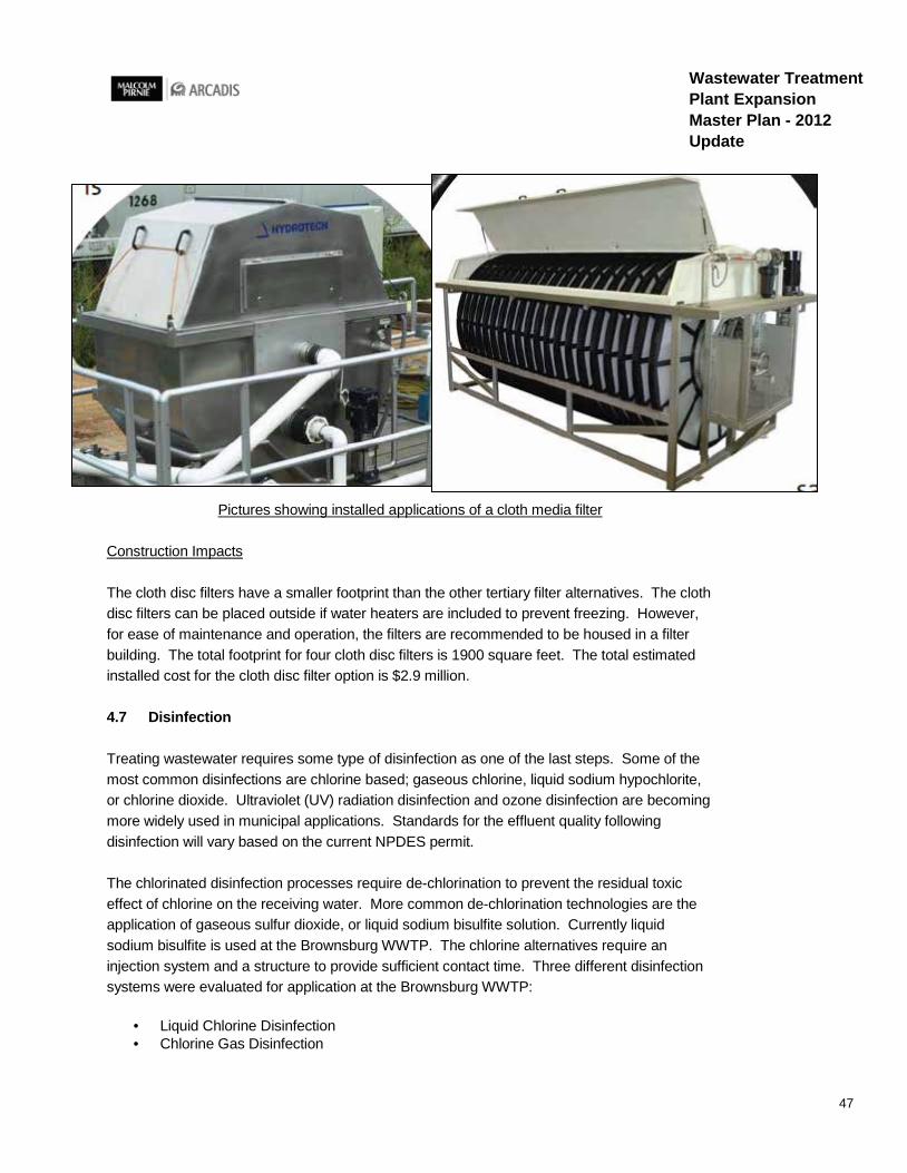
47
Wastewater Treatment Plant Expansion Master Plan - 2012 Update
Pictures showing installed applications of a cloth media filter
Construction Impacts
The cloth disc filters have a smaller footprint than the other tertiary filter alternatives. The cloth disc filters can be placed outside if water heaters are included to prevent freezing. However, for ease of maintenance and operation, the filters are recommended to be housed in a filter building. The total footprint for four cloth disc filters is 1900 square feet. The total estimated installed cost for the cloth disc filter option is $2.9 million.
4.7 Disinfection
Treating wastewater requires some type of disinfection as one of the last steps. Some of the most common disinfections are chlorine based; gaseous chlorine, liquid sodium hypochlorite, or chlorine dioxide. Ultraviolet (UV) radiation disinfection and ozone disinfection are becoming more widely used in municipal applications. Standards for the effluent quality following disinfection will vary based on the current NPDES permit.
The chlorinated disinfection processes require de-chlorination to prevent the residual toxic effect of chlorine on the receiving water. More common de-chlorination technologies are the application of gaseous sulfur dioxide, or liquid sodium bisulfite solution. Currently liquid sodium bisulfite is used at the Brownsburg WWTP. The chlorine alternatives require an injection system and a structure to provide sufficient contact time. Three different disinfection systems were evaluated for application at the Brownsburg WWTP:
· Liquid Chlorine Disinfection · Chlorine Gas Disinfection

48
Wastewater Treatment Plant Expansion Master Plan - 2012 Update
· Ultraviolet Disinfection
4.7.1 Option 1 – Liquid Chlorine Disinfection
General Description
Liquid Sodium Hypochlorite is often used to disinfect effluent from treatment plants. The liquid form is easy to meter, and is safer for public health than gaseous forms of chlorine. A drawback to using liquid sodium hypochlorite is its relatively short shelf life (before it starts losing its disinfecting ability). Shelf life depends on initial concentration, temperature, pH, light exposure, and presence of metallic or organic impurities. The shelf life may prove difficult to manage for equipment and chemicals that only use low doses. Liquid Sodium Hypochlorite disinfection requires additional operating costs for purchasing the chemical, storing the chemical, and injecting the chemical.
Performance Factors
All forms of chlorine are highly corrosive and toxic. The storage, shipping, and handling of chlorine pose a risk. Chlorine oxidizes certain types of organic matter in wastewater, creating more hazardous compounds like trihalomethanes. Chlorine can eliminate certain noxious odors while disinfecting at the same time. The chlorine residual is easy to measure in wastewater and can be used to estimate the effectiveness of disinfection.
Liquid Chlorine Disinfection Advantages Disadvantages
Assists with ammonia removal Ongoing cleanup and corrosion of equipment
Controls odor Requires underground piping modifications and conversion of existing structures
Tried and Tested process Potential chemical hazards
Requires a minimum of 15 minutes of contact time
Construction Impacts
The liquid chlorine option will require a new chlorine contact tank in addition to storage tanks and chlorine injection equipment. The chlorine contact tank footprint is approximately 4000 square feet. The estimated installed cost for implementing a liquid chlorine disinfection system is $1.5 million.
4.7.2 Option 2 – Gas Chlorine Disinfection
General Description

49
Wastewater Treatment Plant Expansion Master Plan - 2012 Update
Chlorine gas is elemental chlorine and is the most used form of chlorine. It is a yellow-green gas that is stored as a liquid under pressure. It is introduced into the wastewater by gas injectors. Chlorine gas is normally stored in steel containers. Because chlorine is hazardous, safety precautions must be exercised during all phases of shipment, storage handling and use.
Performance Factors
A routine O&M schedule should be developed to clean the meters, floats, valves, pumps, and various components every six months. Hypochlorite compounds are more expensive than chlorine gas. The total cost of chlorination is increased by approximately 30 to 50% with the addition of dechlorination. The chlorine gas system features a storage system, feed pump, metering system, control valve, and injection device.
Chlorine Gas Advantages Disadvantages
Tried and Tested process Potential air quality concerns and potential hazards
Assists with ammonia removal Requires a minimum of 15 minutes of contact time at peak flow
Controls odor Requires dechlorination facilities, chemical feed system, and contact tank
Existing disinfectant, so operating experience exists
Plant Expansion and increased chlorine may require augmented safety plans and procedures
Picture showing the existing layout of a chlorine gas disinfection room

50
Wastewater Treatment Plant Expansion Master Plan - 2012 Update
Construction Impacts
The gas chlorine option will require a new chlorine contact tank, but most of the existing equipment can continue to be used. If Brownsburg decides to increase their onsite storage or chlorine gas feed rates, the existing equipment will need to be replaced because it is not sized to treat the higher future flows. The chlorine contact tank footprint is approximately 4,000 square feet. The estimated installed cost for increasing the capacity of the existing gas chlorine disinfection system and constructing a contact tank is $1.2 million.
4.7.3 Option 3 – Ultraviolet Disinfection
General Description
Ultraviolet (UV) disinfection uses light wavelengths between 40 and 400 nanometers to alter pathogenic organisms and render them harmless. The principle advantage of UV disinfection is the lack of chlorine residual that must be treated. A drawback to UV disinfection is waters must pass through a solids separation process such as sedimentation, high-rate sedimentation, or filtration to reduce suspended solids to concentrations of 20 to 40 mg/l in order to produce clear water for UV light to penetrate and disinfect the flow. Turbidity and total suspended solids in the wastewater can render UV disinfection ineffective. When optimal water clarity cannot be reached, UV disinfection has been used to drastically reduce pathogens in the water although not to water quality standards. Ultraviolet radiation disinfection operation requires electricity to operate the UV bulbs and regular replacement of the bulbs.
Performance Factors
All surfaces between the UV radiation and the target organisms must be clean for the ballasts, lamps, and reactor to function at peak efficiency. Inadequate cleaning is one of the most common causes of a UV system’s ineffectiveness. Most UV systems are equipped with automatic lamp cleaning wipers. UV disinfection has a shorter contact time of only 20 to 30 seconds. A smaller site footprint is required because the UV system is installed in a channel. There is no residual effect that can be harmful to humans or aquatic life. UV disinfection is a physical process rather than a chemical disinfectant, so the need to handle toxic chemicals is eliminated.

51
Wastewater Treatment Plant Expansion Master Plan - 2012 Update
UV Disinfection Advantages Disadvantages
Smaller footprint than chlorine Lamps require maintenance and replacement Easily phased and expanded Requires tertiary treatment prior to lamps No toxic side effects, residuals, or harmful byproducts Efficiency of UV is affected by temperature
Safe and simple system for operators to use Performance sensitivity to water quality
Non-corrosive No need for contact tanks
Picture showing an installed application of UV disinfection.
Construction Impacts
The UV system will be installed in two concrete channels after the tertiary filters. One UV channel will be able to backup the other. The site footprint is approximately 300 square feet for a two channel UV disinfection system. Electrical equipment to support the UV disinfection system is required. The estimated installed cost for the UV system is $1.2 million.
4.8 Outfall Pipe and Cascade Aeration
An outfall pipe is used to carry the final treated effluent from the disinfection discharge through the cascade aerators and to the White Lick Creek. The current outfall pipe is 24 inches in

52
Wastewater Treatment Plant Expansion Master Plan - 2012 Update
diameter, 1,500 feet long, and has a total drop of about 21.5 feet through the aeration cascades. The discharge velocity was used to determine which pipe size was most suitable. Excessive and possibly supercritical velocities can create manhole surcharging, backwater conditions or erosion of inverts. A flow velocity of 2 to 3 feet per second (fps) is standard as the desired flow velocity range for gravity sewer pipe.
A new outfall will require a discharge permit modification. At this time the permit modification to obtain a new outfall discharge designation is assumed to be a minor permit modification. Concrete pipe was chosen because it is a durable material and can withstand deterioration in multiple conditions.
4.8.1 Option 1 – Dual 24” Outfall Pipes
Performance Factors
The first alternative proposes to add a 24” diameter concrete pipe and two cascade aerators on the west side of the south plant road to parallel the existing 24” outfall pipe. Both outfalls would be used to convey the future higher flows to the White Lick Creek. The existing outfall could still be used if a permit modification is approved and the two 24” pipes are rejoined before the outfall. With a small pipe diameter the flow velocities will be greater. At the peak flow of 15 mgd, the flow velocity in a single pipe will reach 7.39 feet per second (fps). Velocities greatly above 3 fps begin to cause scouring at the discharge point, possible erosion of inverts, and loss of efficiency at the cascade aerators. Also as the plant expands beyond this 20 year planning period, the 24” line will discharge with even higher velocities.
Parallel 24" Outfall Lines Advantages Disadvantages
Cheapest Option - $400k Potential flow splitting issues Potential regulatory outfall issues with new outfall Connection to disinfection process issues High velocities (7.39 fps @ 15 MGD) Medium velocities (3.4 fps @ 6.9 MGD)
4.8.2 Option 2 – Increasing Pipe Size towards Outfall
Performance Factors
Alternative 2 suggests beginning with a 24” diameter pipe from the disinfection discharge to the cascades and increasing to a 42” pipe after the cascades. A new outfall designation will be required with this alternative. High flow velocities will be discharging out of the 24” portion of the outfall pipe. As with alternative 1, the 24” line will be flowing above the recommended 50% full dry weather flow as the plant expands beyond this planning period.
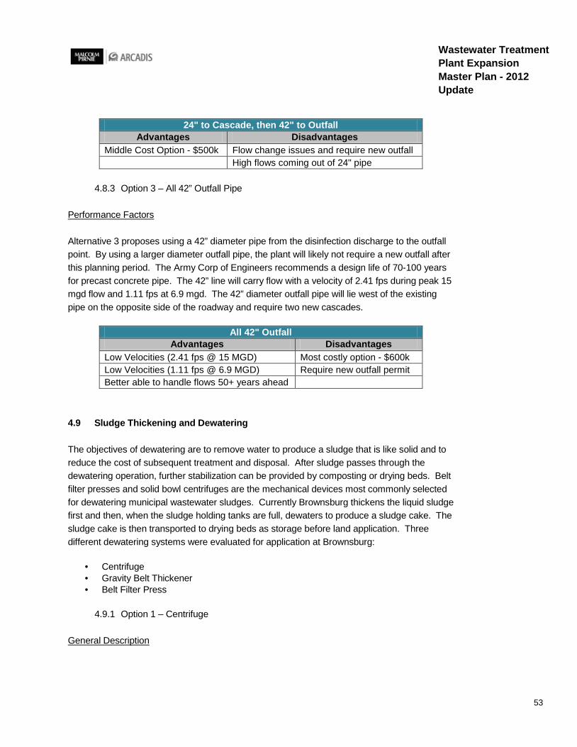
53
Wastewater Treatment Plant Expansion Master Plan - 2012 Update
24" to Cascade, then 42" to Outfall Advantages Disadvantages
Middle Cost Option - $500k Flow change issues and require new outfall High flows coming out of 24" pipe
4.8.3 Option 3 – All 42” Outfall Pipe
Performance Factors
Alternative 3 proposes using a 42” diameter pipe from the disinfection discharge to the outfall point. By using a larger diameter outfall pipe, the plant will likely not require a new outfall after this planning period. The Army Corp of Engineers recommends a design life of 70-100 years for precast concrete pipe. The 42” line will carry flow with a velocity of 2.41 fps during peak 15 mgd flow and 1.11 fps at 6.9 mgd. The 42” diameter outfall pipe will lie west of the existing pipe on the opposite side of the roadway and require two new cascades.
All 42" Outfall Advantages Disadvantages
Low Velocities (2.41 fps @ 15 MGD) Most costly option - $600k Low Velocities (1.11 fps @ 6.9 MGD) Require new outfall permit Better able to handle flows 50+ years ahead
4.9 Sludge Thickening and Dewatering
The objectives of dewatering are to remove water to produce a sludge that is like solid and to reduce the cost of subsequent treatment and disposal. After sludge passes through the dewatering operation, further stabilization can be provided by composting or drying beds. Belt filter presses and solid bowl centrifuges are the mechanical devices most commonly selected for dewatering municipal wastewater sludges. Currently Brownsburg thickens the liquid sludge first and then, when the sludge holding tanks are full, dewaters to produce a sludge cake. The sludge cake is then transported to drying beds as storage before land application. Three different dewatering systems were evaluated for application at Brownsburg:
· Centrifuge · Gravity Belt Thickener · Belt Filter Press
4.9.1 Option 1 – Centrifuge
General Description

54
Wastewater Treatment Plant Expansion Master Plan - 2012 Update
Centrifugal thickening and dewatering is a high speed process that uses the force from rapid rotation of a bowl to separate wastewater solids from liquid. The wastewater can be dewatered to a sludge cake with a solids content of 20-35%. A centrifuge can also be placed in thickening mode to thicken to 2-4% solids.
Performance Factors
Centrifuges require a small amount of floor space relative to their capacity. Minimal operator attention is required when operations are stable. Centrifuges are easy to clean and can outperform conventional belt filter presses. A higher power consumption than a belt filter press is required for a centrifuge. More noise is produced than a belt filter press and experience operating the equipment is required to optimize the performance. The maintenance and replacement of centrifuge parts is more involved than a belt filter press. After shutdown, the centrifuge automatically cleans itself. During startup the initial sludge product is liquid before the centrifuge reaches the speeds high enough to create cake. A diverter gate can be used to send the startup liquid to the head of the plant instead of the conveyor.
Centrifuges Advantages Disadvantages
Minimal release of gas High Energy Usage Automatic washing Longer start up and Shut down Produces drier cake More noise Sensitive to damage from grit and rags
Picture showing a section view of sludge separation inside a centrifuge.
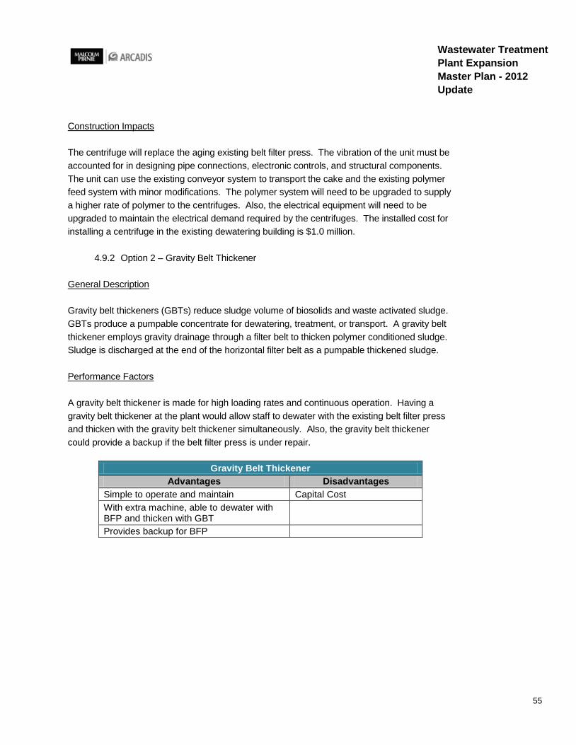
55
Wastewater Treatment Plant Expansion Master Plan - 2012 Update
Construction Impacts
The centrifuge will replace the aging existing belt filter press. The vibration of the unit must be accounted for in designing pipe connections, electronic controls, and structural components. The unit can use the existing conveyor system to transport the cake and the existing polymer feed system with minor modifications. The polymer system will need to be upgraded to supply a higher rate of polymer to the centrifuges. Also, the electrical equipment will need to be upgraded to maintain the electrical demand required by the centrifuges. The installed cost for installing a centrifuge in the existing dewatering building is $1.0 million.
4.9.2 Option 2 – Gravity Belt Thickener
General Description
Gravity belt thickeners (GBTs) reduce sludge volume of biosolids and waste activated sludge. GBTs produce a pumpable concentrate for dewatering, treatment, or transport. A gravity belt thickener employs gravity drainage through a filter belt to thicken polymer conditioned sludge. Sludge is discharged at the end of the horizontal filter belt as a pumpable thickened sludge.
Performance Factors
A gravity belt thickener is made for high loading rates and continuous operation. Having a gravity belt thickener at the plant would allow staff to dewater with the existing belt filter press and thicken with the gravity belt thickener simultaneously. Also, the gravity belt thickener could provide a backup if the belt filter press is under repair.
Gravity Belt Thickener Advantages Disadvantages
Simple to operate and maintain Capital Cost With extra machine, able to dewater with BFP and thicken with GBT
Provides backup for BFP
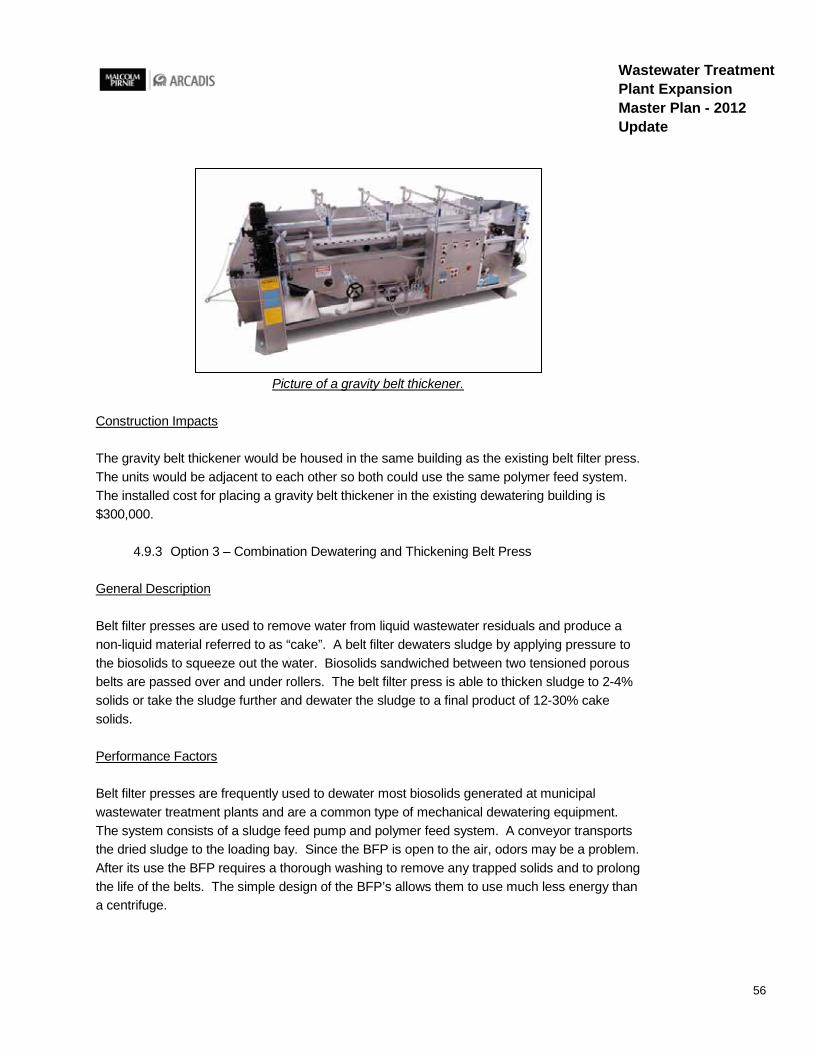
56
Wastewater Treatment Plant Expansion Master Plan - 2012 Update
Picture of a gravity belt thickener.
Construction Impacts
The gravity belt thickener would be housed in the same building as the existing belt filter press. The units would be adjacent to each other so both could use the same polymer feed system. The installed cost for placing a gravity belt thickener in the existing dewatering building is $300,000.
4.9.3 Option 3 – Combination Dewatering and Thickening Belt Press
General Description
Belt filter presses are used to remove water from liquid wastewater residuals and produce a non-liquid material referred to as “cake”. A belt filter dewaters sludge by applying pressure to the biosolids to squeeze out the water. Biosolids sandwiched between two tensioned porous belts are passed over and under rollers. The belt filter press is able to thicken sludge to 2-4% solids or take the sludge further and dewater the sludge to a final product of 12-30% cake solids.
Performance Factors
Belt filter presses are frequently used to dewater most biosolids generated at municipal wastewater treatment plants and are a common type of mechanical dewatering equipment. The system consists of a sludge feed pump and polymer feed system. A conveyor transports the dried sludge to the loading bay. Since the BFP is open to the air, odors may be a problem. After its use the BFP requires a thorough washing to remove any trapped solids and to prolong the life of the belts. The simple design of the BFP’s allows them to use much less energy than a centrifuge.
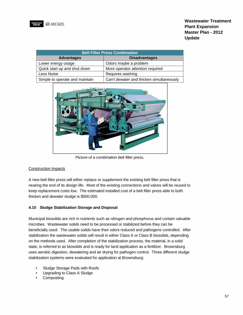
57
Wastewater Treatment Plant Expansion Master Plan - 2012 Update
Belt Filter Press Combination Advantages Disadvantages
Lower energy usage Odors maybe a problem Quick start up and shut down More operator attention required Less Noise Requires washing Simple to operate and maintain Can't dewater and thicken simultaneously
Picture of a combination belt filter press.
Construction Impacts
A new belt filter press will either replace or supplement the existing belt filter press that is nearing the end of its design life. Most of the existing connections and valves will be reused to keep replacement costs low. The estimated installed cost of a belt filter press able to both thicken and dewater sludge is $500,000.
4.10 Sludge Stabilization Storage and Disposal
Municipal biosolids are rich in nutrients such as nitrogen and phosphorus and contain valuable microbes. Wastewater solids need to be processed or stabilized before they can be beneficially used. The usable solids have their odors reduced and pathogens controlled. After stabilization the wastewater solids will result in either Class A or Class B biosolids, depending on the methods used. After completion of the stabilization process, the material, in a solid state, is referred to as biosolids and is ready for land application as a fertilizer. Brownsburg uses aerobic digestion, dewatering and air drying for pathogen control. Three different sludge stabilization systems were evaluated for application at Brownsburg:
· Sludge Storage Pads with Roofs · Upgrading to Class A Sludge · Composting
58
Wastewater Treatment Plant Expansion Master Plan - 2012 Update
4.10.1 Option 1 – Sludge Storage Pads with Roofs
General Description
Sludge storage pads or drying beds are the current process being used to further stabilize the biosolids before land application. This alternative proposes to add an additional sludge storage pad with a roof to allow more biosolids to be produced. The sludge is dried naturally through percolation and evaporation. In the central Indiana region with frequent rainfall, covering the drying beds with a roof to prevent surface runoff may be considered.
Performance Factors
A large land area is required for additional drying beds. Additional labor is required to remove the dried sludge from the beds and can cause odor problems. Drying beds are easy to operate and perform a high reduction of the sludge volume. The dried sludge can be used as a fertilizer and is classified as a class B biosolid. The roofs over the drying beds will provide shelter from precipitation and reduce the amount of potentially contaminated runoff.
Adding Sludge Storage Pads with Roofs Advantages Disadvantages
Creates Class B Sludge Requires large land area Easy to operate Requires treatment of percolate High reduction of sludge volume Can cause odor problems Additional labor to remove sludge from beds
Construction Impacts
An additional sludge drying bed is proposed to double the biosolids storage capacity of the plant. The bed will be located directly west of the dewatering building across the roadway. The fence line will be relocated to add the proposed drying beds. The new beds will cover approximately 6,600 square feet. The estimated installed cost of six additional drying beds with roofs is $920,000.
4.10.2 Option 2 – Upgrading to Class A Sludge
General Description
Class A biosolids contain extremely low pathogen concentrations and have few or no use restrictions. To meet Class A requirements for pathogen destruction, the plant can use lime stabilization or other EPA approved time/temperature processes. Class A biosolids can be used for home lawns and gardens. Class B biosolids contain higher pathogen concentrations

59
Wastewater Treatment Plant Expansion Master Plan - 2012 Update
than Class A, but have levels low enough for some beneficial use such as land application restricted to farm land.
Performance Factors
Upgrading to produce Class A sludge instead of Class B sludge will require either additional chemical costs for lime addition or a sludge stabilization facility with a high-temperature treatment. If the plant begins to produce Class A biosolids, Brownsburg could use the biosolids as fertilizer for home land application. It is unknown at this time if citizen demand would be high enough to keep up with the plant’s sludge production. If the demand is too low to keep up with production Brownsburg would still have to employ a sludge hauling company to land apply the biosolids. The estimated installed cost for upgrading to Class A biosolids would include the additional drying beds to provide storage and would add the annual cost of chemical addition.
Upgrading to Class A Biosolids Advantages Disadvantages
Ability to provide Class A biosolids for sale Cost of chemical Greater opportunities for end use Cost of operation to add chemical Less space required Operation of a more complex process
4.10.3 Option 3 – Composting
General Description
In composting, the biosolids are first digested to Class B standards and dewatered. The material is then mixed with wood chips or some other amendment and spread over a pad. The piles are aerated through the composting period, which may last as long as a month. Finished compost is designated as a Class A biosolid. Three methods of aerating the composting biosolids are common: aerated static pile, windrows, and in vessel composting. The physical characteristics of most biosolids allows for their successful composting. However many characteristics (including moisture content, volatile solids content, carbon content, nitrogen content, and bulk density) will impact design decisions for the composting method.
Performance Factors
The advantages of composting are that it produces Class A product and can be used in home gardens. The compost facilities are generally simple technology and easy to operate. However the facilities are relatively expensive compared to drying beds and require a larger area. A higher level of dewatering is required and may create odors. The estimated installed cost of the composting facility cannot be fully determined at this time. The proposed additional covered drying bed will be used for the curing, mixing, and distribution of finished compost

60
Wastewater Treatment Plant Expansion Master Plan - 2012 Update
material. The cost of bulking agents and operation of the composting facility will be determined by the amount of sludge Brownsburg decides to compost. Dedicating drying beds for composting will reduce the overall sludge storage capacity of the WWTP. Since composting requires a longer period of time than Class B sludge drying, the storage area may need expansion depending on the frequency of land application of the biosolids.
It is recommended that the WWTP perform pilot tests to see which compost processes and mix ratios are most applicable for their sludge if Brownsburg wants to investigate composting further. Composting is typically labor intensive because turning, monitoring, and process control is necessary. Storage piles and materials must be moved with mechanical equipment and maintained for curing and distribution. If the WWTP has a steady source of wood chips, such as the Brownsburg street department, the costs for a bulking agent could be low.
Composting Advantages Disadvantages
Composting economics are more favorable when landfill fees escalate
Cost and potential odor production at the composting site
Emphasis on beneficial reuse for local citizens Bulking agents must be added Ease of storage, handling, and use of composted product
Turning, monitoring, or process control is necessary
Addition of compost to soil increase the soil's phosphorus, potassium, nitrogen, and organic carbon content
Storage piles must be maintained for curing and distribution
Feed and finished material must be moved with mechanical equipment
4.11 Operations/Administration Building Annex and Blower Relocation
The increase of influent flow may require more staff to operate the plant. Brownsburg has expressed an interest in adding additional meeting and office space with the treatment capacity expansion. A new office building could be a connected annex to the existing administration building or a new stand alone building. The additional office building will provide a dedicated meeting room, a break room, staff offices, male and female locker rooms, and a document storage room.
4.11.1 Option 1 – 1600 sq ft building
If the operations/administration building is an annex to the existing administration building, the aeration piping for the sludge tanks will need to be relocated. Figure 5.4 is a preliminary drawing summarizing the layout for a 1600 sq ft annex to the north of the administration building. The estimated installed cost of the 1600 sq ft operation/administration building is
61
Wastewater Treatment Plant Expansion Master Plan - 2012 Update
$320,000. The preliminary design has a meeting room for 16 people and three offices. An existing office will be converted to a women’s locker room, while an existing restroom will be converted to a men’s locker room. The existing parking area will be retained directly east of the proposed building annex. A document storage room and break room will also be in the annex building.
The blower relocation includes replacing the existing blowers in the basement of the administration building with blowers located outdoors and adjacent to the aerobic digester tanks. The installed cost of replacing seven blowers and placing the blowers outdoors is $705,000.
4.12 Backup Power
The Ten State Standard for Wastewater Facilities recommends all plants shall be provided with an alternate source of electric power or pumping capability to allow continuity of operation during power failures. Methods of providing alternate sources include: (1) the connection of at least two independent power sources such as substations. A power line from each substation is recommended, and will be required unless documentation is received and approved by the reviewing authority verifying that a duplicate line is not necessary; (2) Portable or in-place internal combustion engine equipment which will generate electrical or mechanical energy; and (3) Portable pumping equipment when only emergency pumping is required. The Brownsburg WWTP currently has two independent power sources. The objective of emergency operation is to prevent the discharge of raw or partially treated wastewater to any waters and to protect public health by preventing back up of wastewater and subsequent discharge to basements, street, and other property. Two options were considered to provide backup power to the plant:
· Permanent Standby Generator · Mobile Generator
4.12.1 Option 1 – Standby Generator for Plant
A permanent standby generator would use a fuel engine to power the essential process at the plant during an emergency loss of power. The pumps, oxidation ditches, and disinfection systems are considered essential processes. It is critical to keep the generator maintained and to test it regularly under its operating load. Underground emergency generators must be able to withstand climate extremes and be able to operate under all conditions. Underground fuel storage would store enough fuel for a 24 hour period at the required electricty generation. The estimated installed cost for a permanent standby 600kw generator and 1000 gallon fuel tank is $320,000.

62
Wastewater Treatment Plant Expansion Master Plan - 2012 Update
4.12.2 Option 2 – Mobile Generator
A mobile standby generator would be used to power a lift station if power was lost at the lift station. Only lift stations equipped with an outlet to accept the mobile generator would be accessible. The estimated installed cost for an EPA compliant mobile standby 200kw generator is $100,000. The mobile generator requires regulary testing and maintenance.
4.13 Non-Potable Water Distribution
The non potable water pumping system located in the basement of the Main Building has maintenance issues from lack of water pressure when multiple hydrants are in use and from maintaining sufficient water pressure when one hydrant is in use. The discharge piping connects to all the existing hydrants and booster pumps. The water is pumped from the chamber directly before the chlorine contact pond. The proposed alternatives to the existing non potable water distribution system are:
· Increase pump size · Hydropneumatic tank
4.13.1 Option 1 – Increase Pump Size
The existing pumps cannot maintain a sufficient pressure when more than one hydrant is being used. One alternative is to replace the existing non potable water pumps with larger pumps to provide more pressure and flow. The water tank supplying the pumps will also be increased to fit the larger pumps. The estimated installed cost of increasing the non potable water pump size is $50,000.
Increase Pump Capacity Advantages Disadvantages
Cheapest option May provide intermittent pressure
4.13.2 Option 2 – Hydro Pneumatic Tank
General Description
Hydropneumatic tanks are vessels that hold water and air under pressure. To provide efficient water supply, the tanks regulate system pressures to quickly meet system demand. The compressed air creates a cushion that can absorb or apply pressure as needed. The effects of a water hammer will be lessened by a hydro pneumatic tank. Air that is reabsorbed into the water system is replenished with a small air compressor. Normal operating pressure is in the range of 60 to 80 psi.

63
Wastewater Treatment Plant Expansion Master Plan - 2012 Update
Performance Factors
To achieve a flow of 15 gpm at 70 psi, a 600-gallon hydropneumatic tank is required. The non potable water system currently uses a 500-gallon hydropneumatic tank. An additional tank will increase the flow and pressure of the system. A 3” pipe line carries the flow from the administration building basement to the six hydrants throughout the plant. The estimated installed cost for an additional hydropneumatic tank is $100,000.
Hydropneumatic Tank Advantages Disadvantages
Stores water under pressure Capital cost and Larger Footprint Pumps don't have to turn on as often Added maintenance and pressure equipment Buffer pressure surges Requires a compressor
4.14 Septage Receiving Station
A septage receiving station is designed to receive, screen and separate septage solids. Septage is the liquid, solid, and semisolid material that is pumped from a septic tank, recreational vehicle holding tank, porta-potty or other primary treatment source. Users connect to the station and discharge their septic load into the station’s preliminary treatment zone. A grinder, fine screening screw system, spray wash and control system are incorporated in the preliminary treatment zone to efficiently screen septage. Next the septage travels into a compaction zone and backwash system to reduce the moisture content of the septage. The septage is then discharged into the plant treatment stream when the plant decides. Optional data collection can authenticate users with a card swipe system.
A septage receiving station will be able to treat hauled septic tanks, holding tanks and industrial wastes. Septage is 6 to 80 times more concentrated than municipal wastewater. If not handled properly the solids and higher concentrations can disrupt the treatment process. The plant will limit their intake to domestic septage or porta-potty waste.
The estimated installed cost for a septage receiving station is $320,000 to be placed near the west plant lift station and along the roadway for public access. Besides the basic control system a data collection system is recommended to identify haulers and print a receipt to record the transaction. The transaction data is stored in the system memory for use by the plant for billing and tracking purposes.
Septage Receiving Station Advantages Disadvantages
Source of revenue for Brownsburg Added maintenance and operation cost Capital cost
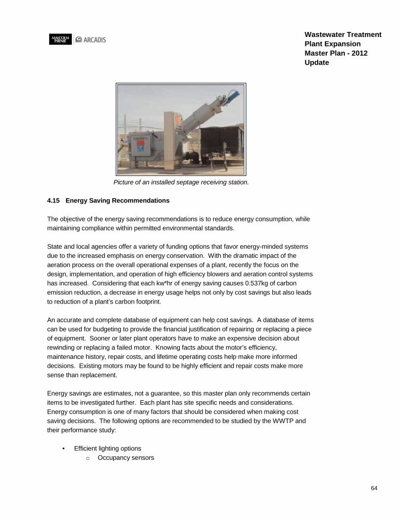
64
Wastewater Treatment Plant Expansion Master Plan - 2012 Update
Picture of an installed septage receiving station.
4.15 Energy Saving Recommendations
The objective of the energy saving recommendations is to reduce energy consumption, while maintaining compliance within permitted environmental standards.
State and local agencies offer a variety of funding options that favor energy-minded systems due to the increased emphasis on energy conservation. With the dramatic impact of the aeration process on the overall operational expenses of a plant, recently the focus on the design, implementation, and operation of high efficiency blowers and aeration control systems has increased. Considering that each kw*hr of energy saving causes 0.537kg of carbon emission reduction, a decrease in energy usage helps not only by cost savings but also leads to reduction of a plant’s carbon footprint.
An accurate and complete database of equipment can help cost savings. A database of items can be used for budgeting to provide the financial justification of repairing or replacing a piece of equipment. Sooner or later plant operators have to make an expensive decision about rewinding or replacing a failed motor. Knowing facts about the motor’s efficiency, maintenance history, repair costs, and lifetime operating costs help make more informed decisions. Existing motors may be found to be highly efficient and repair costs make more sense than replacement.
Energy savings are estimates, not a guarantee, so this master plan only recommends certain items to be investigated further. Each plant has site specific needs and considerations. Energy consumption is one of many factors that should be considered when making cost saving decisions. The following options are recommended to be studied by the WWTP and their performance study:
· Efficient lighting options o Occupancy sensors

65
Wastewater Treatment Plant Expansion Master Plan - 2012 Update
o Switching from incandescent to CFLs o Switching from fluorescent T-12 to T-8
· Installing a micro-turbine at the outfall to provide electricity for outfall cascade lighting · Install solar powered/wind powered exterior lighting · Improve building envelopes/HVAC
o Look into insulation, sealing, high efficiency furnaces o Replace aged water boilers, refurbish exterior doors
· Replace pumps, motors, diffusers o Look at both the WWTP and lift stations o Install premium efficiency motors, and DO control of aeration tanks
The performance study of the WWTP has not been finalized at the time of the Master Plan approval. It is suggested however, that the approved recommendations of the performance study contract be incorporated into the construction phasing of this Master Plan. The accepted energy saving measures are recommended to be included as design criteria for any future expansion projects.

66
Wastewater Treatment Plant Expansion Master Plan - 2012 Update
This page left intentionally blank
67
Wastewater Treatment Plant Expansion Master Plan - 2012 Update
5. Recommended Plan
This section provides a summary of the Wastewater Treatment Plant Expansion recommended design and the recommended East Plant Pump Station upgrades. Numerous elements of the treatment plant design have been taken into account with special consideration given to layout and increased treatment capacity. The recommended design is presented along with preliminary layout drawings. The preliminary basis of design for the treatment plant expansion can be found in Appendix A. Brownsburg has developed this master plan for the expansion and development of the wastewater treatment facility to meet the growing needs of the community.
5.1 Summary of Recommended Plan
The recommended wastewater treatment expansion plan proposes to increase the rated daily average treatment capacity of the WWTP from 3.5 mgd to 6.9 mgd. The design peak treatment capacity of the plant will increase from 9.5 mgd to 15 mgd.
Many alternative designs were considered. The recommended alternatives represent cost effective options that will allow the facility to operate at its current high level of treatment. Several project meetings have been held to discuss process alternatives for the wastewater treatment system for the 3.5 mgd expansion. Based on the decisions at the meetings, the selected expansion alternatives for the Brownsburg WWTP are summarized in Section Five.
The East Plant Pump Station has sufficient capacity for future flow conditions, and capacity increases are not proposed for the East Plant. However, Brownsburg is recommended to monitor the ongoing sewer separation projects. The increase in plant treatment peak capacity will allow the collection system to pump higher flows to the plant and possibly decrease the number of combined sewer overflows. If combined sewer flows are higher than the existing system can convey, then increased pumping capacity is recommended at the East Plant to alleviate the combined sewer collection system. But if the sewer separation projects continue, the sewer system will not benefit from an East Plant Pump Station capacity increase. This Master Plan discusses evaluations, improvements and rehabilitation to the screen, grit removal system and pumps at EPPS.
Based on the evaluations performed in Section 4, a site layout and flow schematic have been developed for plant expansion. Figure 5.1 is a schematic drawing of the recommended facilities. Figure 5.2 is a drawing of the proposed site plan. Figure 5.5 shows the locations of the proposed cascade aerators and outfall pipe. The new screening facility will be located southeast of the existing flow splitter for oxidation ditches. The new plant oxidation ditches will be located south of the existing oxidation ditches. Space south of the proposed oxidation ditches will be reserved for possible future expansion beyond this Master Plan’s planning period for future oxidation ditches. Secondary clarifiers for the proposed oxidation ditches will

68
Wastewater Treatment Plant Expansion Master Plan - 2012 Update
be added directly west of the proposed oxidation ditches. The secondary clarifiers will have the same weir elevations of the existing secondary clarifiers so all clarifiers can back up each other. Also flow from the oxidation ditches will be able to be directed to any secondary clarifier. The proposed tertiary filter and UV disinfection channel will be installed on the existing effluent pipeline from the existing secondary clarifiers. A fifth aerobic digester tank will be placed south of the existing aerobic digesters and across the roadway. The proposed covered sludge storage pad will be constructed directly west across the roadway of the dewatering building. The proposed annex building will connect to the existing administration building through a hallway leading from the north entrance. The existing parking spaces at the main administration building will remain. The proposed septage receiving station will be located adjacent to the west lift station.
New pipes and connections will be needed for the new facilities. An influent splitter box for the oxidation ditches will be needed. Channels for the tertiary filters, UV disinfection and screening building will be installed. New pipes will be installed to accommodate the increased Return Activated Sludge (RAS) and waste activated sludge (WAS) flows.
Appendix A includes the Basis of Design Summary for the recommended plan. Table 5.1 summarizes the recommended process alternatives for the plant expansion.
Table 5.1 Summary of Recommended Process Alternatives
Table 5.1. Summary of Recommended Process Alternatives East Plant Grit Tank Biosolids Storage • Vortex Grit Tank • Covered Storage Pad
East Plant Screen Digester • Mechanical Rake Screen • Aerobic Digester Preliminary Treatment Septage Receiving Station • Mechanical Plate Screen • Septage Acceptance Tank Surge Tank • Automatic Billing System • Precast Tank Outfall Sizing Biological Treatment • 48" Outfall Pipe • Oxidation Ditches Additional Office Space Secondary Clarifier • 1600 sq ft Annex • Spiral Scrapers Non-Potable Water • Launder Covers • Replace Pumps Disinfection • Hydro Pneumatic Tank • Ultraviolet Backup Generator Tertiary Filtration • None • Cloth Disc Filters

69
Wastewater Treatment Plant Expansion Master Plan - 2012 Update
Figure 5.1 Schematic of Recommended Facilities
Figure 5.2 Proposed WWTP Site Layout
5.1.1 Influent Pumping
The plant has two existing influent pump stations: the East Plant Pump Station and the West Lift Station. The Sanitary Sewer Master Plan recommends construction of a US-136 Lift Station near County Road 625 E and US-136. The proposed US-136 lift station will pump all wastewater from north of I-74 through a 30-inch diameter force main directly to the treatment plant. The US-136 Lift Station will become the WWTP’s third influent pump station.
Flows from five outlying lift stations that are currently tributary to the West Lift Station – Highland Springs, Maplehurst, Bethesda, Lake Ridge and Windridge Landing – are proposed to be redirected and be tributary to the US-136 Lift Station. As a result of the recommended flow redirection the need for a capacity increase of the West Lift Station is not necessary.
Oxygen depletion in long force mains throughout the Brownsburg collection system typically results in the wastewater becoming septic and odorous. Therefore it is recommended that a hydrogen sulfide control system, such as a super oxygenation cone, be installed as part of force main construction. The proposed system will add high purity oxygen to the force main at a specific location upstream of the treatment plant so that the wastewater will be aerobic and non-odorous when it exits the force main at the plant.
5.1.2 East Plant Improvements
The fine screening and grit removal currently provided at the East Plant Pump Station (EPPS) is inadequate and near the end of its useful design life. The detritus grit tanks are recommended to be replaced with vortex style grit removal system. The grit system will handle flows up to the hydraulic peak flow of 9.2 mgd.
The auger monster headworks system and the mechanical grabber screen are recommended to be replaced with two new multi-rake bar screens. The bar screen spacing shall be 1/4 – inch and capable of handling flows up to the hydraulic peak flow of 9.2 mgd.
The existing pumps are constant maintenance problems. To maintain efficiency, the existing centrifugal pumps are recommended to be replaced with four new pumps with VFDs. Each pump will be rated for 2.4 mgd to supply the EPPS an installed pumping capacity of 9.6 mgd and a firm capacity of 7.2 mgd.

70
Wastewater Treatment Plant Expansion Master Plan - 2012 Update
5.1.3 Screening and Grit Removal
Fine screening and grit removal is currently provided at the East Plant for wastewater pumped from the East Plant Pump Station. However, fine screening and grit removal are not provided for influent wastewater pumped from the West Lift Station. Wastewater from the West Lift Station is currently screened through a manual bar screen.
A West Plant Screen Building is recommended to provide fine screening of flows from both the West Lift Station and the proposed US-136 Lift Station. The Screen Building will include two fine screens and a manual bar screen. The two fine screens are recommended to be perforated plate screens with ¼” bar spacing. The manual bar screen will be used for peak events to prevent damage to the screens. Each screen will be designed to treat the peak design flow of 15 mgd. Installing new screening at the WWTP will drastically reduce the frequency of cleaning equipment.
Figure 5.3 Proposed Screening Building Layout
5.1.4 Surge Tank
The US-136 Lift Station will include large capacity, constant speed pumps that will turn on and off as the wet well fills and empties. When the wet well is filling, the pumps will be off, and the force main flow will be zero. The large capacity pumps are needed to achieve sufficient velocities in the force main to resuspend solids that will have settled in the pipe when the pumps are off. Therefore a surge tank is proposed after the fine screens of the West Plant to dampen flow spikes from the US-136 Lift Station. The surge tank will provide equalization of the influent fluctuations which will help the downstream biological system. Large pumps at the regional lift stations will pump large flows to the plant. The surge tank will provide a buffer for the plant. If smaller pumps that operate on a more continuous basis, then no surge tank would likely be required. To prevent odor and other treatment issues, the system should avoid sewage in the lift station wet wells from going septic.
The surge tank will include coarse bubble diffusers to mix and aerate the wastewater to prevent the flow from turning septic. The surge tank will be covered and the off gasses will be treated with a biofilter system for odor control. The recommended size of surge tank is 100,000 gallons to provide a 10 minute hydraulic detention time at peak flow. A precast concrete tank with a 40-foot diameter is recommended to minimize costs and supply a reliable tank.
5.1.5 Flow Splitting
It is recommended that the current flow splitter be replaced with a flow splitting system using magnetic flow meters and motor-operated control valves. The system will be designed to

FIGURE 5.1 TOWN OF BROWNSBURG WWTP FLOW SCHEMATIC (PROPOSED)
CSO Tank
Parshall Flume
Tertiary Filter
Grinder
Oxidation D
itch N
o. 2
RA
S
Fine Screen Flow Splitter Box
South Swirl Concentrator
West Lift Station
Outfall 001A
Effluent
Sludge
Solids Disposal Solids-Land Applied (152 DTY)
Land Filled (160 DTY) Merrell Center (19 DTY)
Conditioner
Legend EXISTING
PHASE 1 (5.2 MGD)
(≈ 2014)
PHASE 2 (6.9 MGD) (≈ 2025)
CSO
002 Outfall
East Plant Lift Station
Backup Automatic Rake Channel Monster Auger Monster
Grit Tank, Grit Washer
North Swirl Concentrator
Parshall Flume
Conditioner
Oxidation D
itch N
o. 1
Oxidation D
itch N
o. 3
Oxidation D
itch N
o. 4
Clarifier NO. 1
Clarifier NO. 2
Clarifier NO. 3
Clarifier NO. 4
RA
S
UV Channel
Flow Meter
Cascade Aeration Units
Sludge Storage NO. 1
Sludge Storage NO. 2
Aerobic Digester
NO.1
Aerobic Digester
NO.2
Sludge Belt Filter Press
Covered Sludge Storage Pad
Sludge Drying Beds (6)
WA
S
WA
S
WA
S
WA
S
Parshall Flume
Conditioner O
xidation Ditch
No. 5
Oxidation D
itch N
o. 6
RA
S
Clarifier NO. 6
Clarifier NO. 5
Aerobic Digester
NO.3
WA
S
WA
S
Sludge Drying Beds (6)
Surge Tank

PROPOSED WWTPSITE LAYOUT
±
OXIDATION DITCH NO. 6
TERTIARY FILTER INFLUENT CHAMBER
POLE BARN
SCREEN BUILDING
ANNEX BUILDINGTHICKENERBUILDING
MAIN BUILIDNG
SEPTEMBER 2012FIGURE 5.2
BROWNSBURG INDIANAWASTEWATER TREATMENT PLANT
MASTER PLAN
0 40 80 12020Feet
Legend
Phase 1 2 Future
OXIDATION DITCH NO. 5
SURGE TANK
SLUDGE STORAGE PAD
AEROBIC DIGESTER NO. 3 SECONDARY
CLARIFIER NO. 5
SECONDARY CLARIFIER NO. 6
UV DISINFECTION CHANNEL
TERTIARY FILTER
SEPTAGERECEIVING
STATION
CONDITIONER
RAS/ELECTRICALBUILDING
BLOWERS
OXIDATION DITCH NO. 7
OXIDATION DITCH NO. 8
SECONDARY CLARIFIER NO. 8
SECONDARY CLARIFIER NO. 7
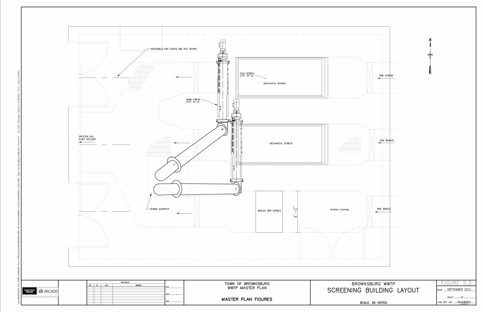

71
Wastewater Treatment Plant Expansion Master Plan - 2012 Update
proportionately split influent flow to the different anoxic selectors and corresponding oxidation ditches. The flow splitter is to be located after the surge tank and before the oxidation ditches. A similar system is proposed to proportionately split RAS flow coming into the anoxic selectors. The magnetic flow meters and control valves would flow pace the RAS flow, unless Brownsburg prefers to manually control the RAS flow rates based on the plant influent flow
5.1.6 Septage Receiving Station
A septage receiving station is recommended as part of the proposed expansion in Phase 2. The septage receiving station would not only serve the public but the revenue generated from septage haulers can offset treatment costs. Brownsburg has expressed that there is an existing need for a septage receiving station. The septage receiving station will be located adjacent to the roadway near the west lift station. An electronic accounting system is recommended to reduce operator attention and allow users to automatically discharge into the station.
The septage receiving station will include a storage well to allow plant staff to inspect and test septage prior to acceptance. The stored septage will drain to the head of the WWTP for treatment when the storage well is full and after staff testing and approval.
5.1.7 Oxidation Ditches
Two new oxidation ditches are proposed to treat the additional 3.5 mgd design average flow. One ditch will be built in each of the proposed two phases of construction. The proposed ditches will be similar to the existing ditches but will be 2 times larger. An anoxic selector for control of filamentous organisms in the activated sludge will be constructed upstream of the oxidation ditches.
Four mechanical mixers (rotors) will provide aeration and mixing in each new oxidation ditch. It is proposed that each rotor be fitted with a variable frequency drive and a cover for the surface aerators.
Modifications are recommended for the rotors in the existing ditches. Four covers are recommended for installation over the rotors that are not already covered. The chambers that house the motors for the current and future ditches are recommended to have drain lines installed.
5.1.8 Secondary Clarifiers
Two secondary clarifiers are proposed, each larger and deeper than the existing clarifiers. The proposed clarifiers are 90 feet in diameter and have a side water depth of 15 feet. The new clarifiers will be rim feed similar to the existing units or center feed type, but will have
72
Wastewater Treatment Plant Expansion Master Plan - 2012 Update
spiral scraper type sludge removal mechanisms. One clarifier will be built in each of the proposed two phases of construction
A RAS Pump Station is proposed to house the RAS pumps and electrical equipment for the new oxidation ditches and secondary clarifiers. Four dry pit RAS pumps are proposed, two for each clarifier. The RAS pump station will be located adjacent to the clarifiers. The new clarifiers will be able to receive flow from the proposed oxidation ditches.
RAS piping and necessary control valve arrangement will be provided to direct RAS flow into the proposed anoxic selector tank from either of the two proposed clarifiers. A control valve arrangement similar to the current one will be installed to direct WAS flows into the aerobic digesters or sludge holding tanks.
Launder covers are recommended for the existing clarifiers and the proposed clarifiers. Installing launder covers will eliminate the algae growth at the weirs and significantly reduce the amount of maintenance required to keep the clarifiers clean.
5.1.9 Tertiary Filters
Cloth media disc filters are proposed for enhanced suspended solids removal. The disc filters will be housed in the proposed Filter Building ahead of the disinfection channel. The disc filter system, four (4) units (three duty, 1 standby) will filter a peak flow of 15.0 MGD (10,417gpm) and an average flow of 6.9 MGD (4,792 gpm). The system is designed to provide solids removal to a final effluent average concentration of ≤5 mg/L TSS. The cloth media disc filter units will be constructed of stainless steel and be placed in concrete basins within the Filter Building.
The basic concept in cloth media tertiary filter technology is to filter the secondary effluent through a cloth media (such as polyester fabric) with a pore size of 10 µm. The advantages of cloth media filters, compared to the conventional sand filters, include their smaller foot prints, lower cost, and the low volume required for backwashing. Another advantage is that the filter discs are backwashed continuously while the filters are in operation. Hence, there is no reduction in capacity while backwashing.
UV channel effluent will be used for belt filter press wash water and other non potable plant uses. A sodium hypochlorite system will be provided for periodic filter disinfection and for disinfection of non potable water. The non potable water system will remain in the basement of the administration building. The sodium hypochorlite disinfection will be small and used only during non disinfection season to disinfect the non-potable water.

73
Wastewater Treatment Plant Expansion Master Plan - 2012 Update
5.1.10 UV Disinfection
It is proposed that the chlorination-dechlorination disinfection system will be replaced with a low pressure ultraviolet light disinfection system. A UV system has several advantages. It does not require construction of large tanks because only channels to accommodate the UV modules are needed. No known residuals are produced while disinfecting with UV system. There is no need for a chemical storage room or transportation of hazardous chemicals. The overall ease of operation and maintenance requires little operator attention.
UV disinfection has been shown in many installations to provide dependable performance and simplified maintenance. The system has features to reduce O&M costs, including variable output electronic ballasts to provide dimming capability and automatic chemical and mechanical quartz sleeve cleaning system. Figure 5.4 shows the proposed layout of the UV channel and disinfection equipment.
Figure 5.4 Proposed UV Channel Layout
5.1.11 Outfall and Cascade Aeration
It is recommended that a new 42-inch diameter outfall pipe be constructed to replace the existing 24-inch diameter outfall pipe. The new pipe will provide a more suitable range of velocity, headloss and capacity than the existing 24-inch pipe. The 42-inch outfall pipe will start at the UV effluent chamber, lead to two new cascade aerators, and will discharge to White Lick Creek. Figure 5.5 shows the proposed alignment of the new outfall pipe and cascade aerators. A new outfall designation will be required from IDEM after the existing 24-inch line is abandoned.
Figure 5.5 Proposed Cascade Aerators and Effluent Pipe
5.1.12 Sludge Digestion
It is recommended that a fifth 70-foot diameter sludge tank be constructed similar to the existing sludge tanks in construction phase 2.
It is recommended that current sludge blowers in the Main Building basement be replaced with new outdoor blowers. These blowers will be designed to provide adequate air supply to the coarse bubble diffuser aeration system. The proposed blowers will be compact packaged units with sound attenuation enclosures and will be mounted on concrete pads adjacent to the sludge tanks. The blowers will be located adjacent to the sludge aeration tanks.

74
Wastewater Treatment Plant Expansion Master Plan - 2012 Update
5.1.13 Sludge Dewatering and Storage
A 1.5-meter belt filter press unit is recommended to be installed adjacent to the existing 1.5- meter combination gravity belt thickener/belt filter press. The existing control panel on the north wall of the Thickener Building will be relocated to make room for the new belt filter press.
After installation of the new belt filter press, the existing combination unit will be used primarily for thickening. It is recommended that using filtered effluent from the proposed tertiary filters as wash water for existing and proposed belt press units are continued.
It is recommended that the current dewatered biosolids truck loading room remain and the conveyor configuration modified to accept sludge from the additional belt filter press.
It is also recommended that a larger outdoor, covered concrete storage area be constructed for additional biosolids storage. The biosolids storage areas will be located directly west of the dewatering building across the roadway. The existing fence line will be relocated.
5.1.14 Main Building
There is a need for additional operation/administrative space for the plant personnel. The current Main Building does not have adequate area for expansion. An administrative annex is proposed just north of the Main Building. The annex will include three offices, a training/meeting room, document storage room and a break room. The existing main building will be modified to convert an office to the men’s locker room. An existing restroom in the main building will be converted to a women’s locker room. Figure 5.6 shows the proposed annex building layout.
Figure 5.6 Proposed Annex Building Layout
5.1.15 Scum Pump and Non-Potable Water
The current scum collection in the scum manhole located in the basement of the Main Building has maintenance issues from floatables collected at the manhole. The existing scum manhole will be abandoned and the replacement scum pump station is proposed to be located near the new secondary clarifiers. The discharge piping will include a valve to direct the scum either to the digesters, sludge holding tanks or directly to the biosolids drying beds.
The non-potable water system is recommended to have an additional hydro pneumatic tank installed. The existing pumps and air compressor will also be upgraded. The additional tank will provide increased reliability to the system. The effect of a water hammer will be reduced by the additional hydro pneumatic tank.
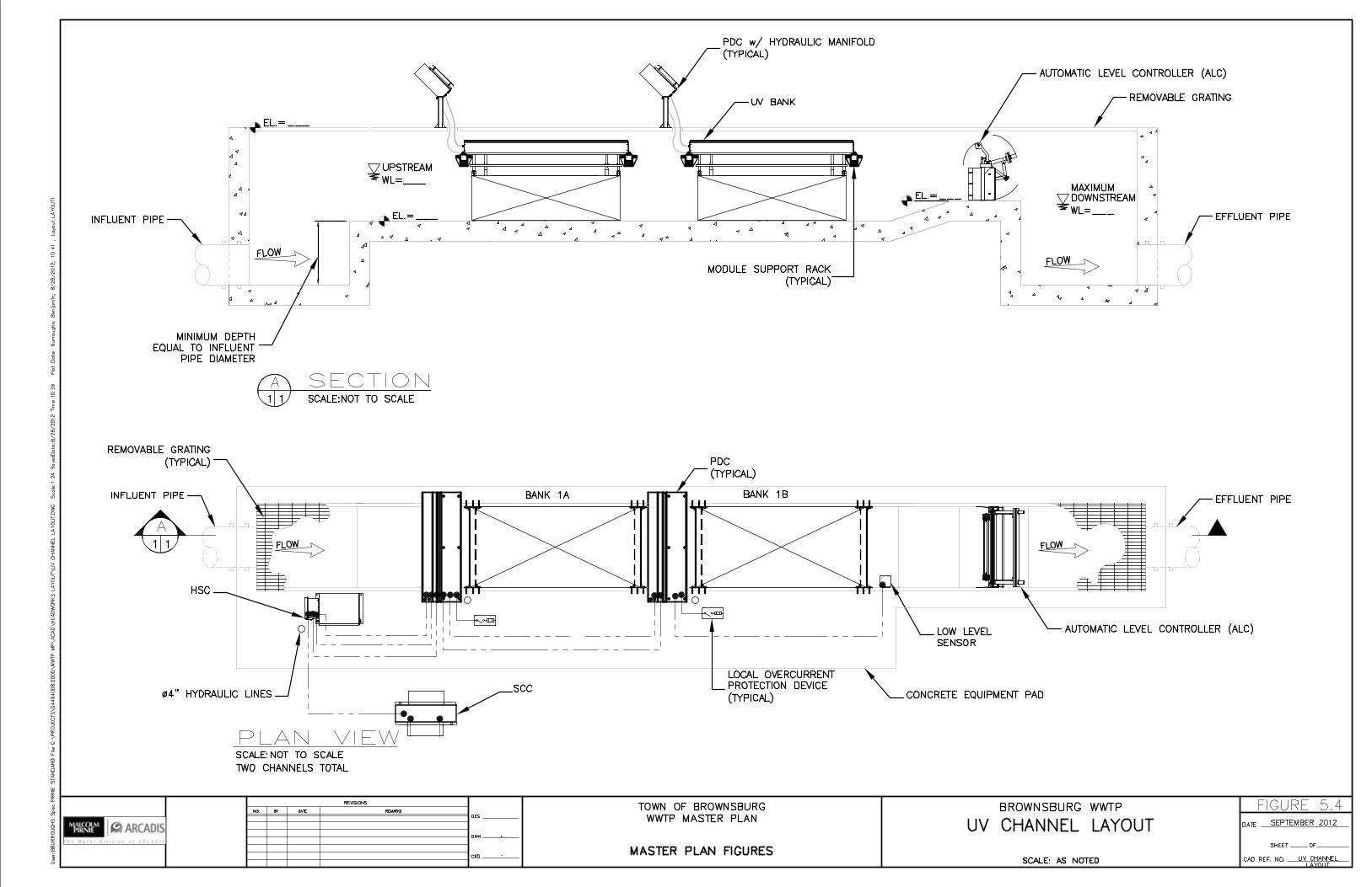

Legend
Existing Outfall
Proposed Outfall
PROPOSED EFFLUENT PIPEWITH CASCADES
±
PROPOSED 42"EFFLUENT PIPE
24" EXISTING EFFLUENTPIPE
(TO BE ABANDONED)
WHITE LICK CREEK
EXISTING CASCADES(TO BE ABANDONED)
PROPOSED CASCADEAERATORS
POLISHINGPOND
ABANDONED POND
SEPTEMBER 2012FIGURE 5.5
BROWNSBURG INDIANAWASTEWATER TREATMENT PLANT
MASTER PLAN
0 70 140 21035Feet
PROPOSED 42"EFFLUENT PIPE
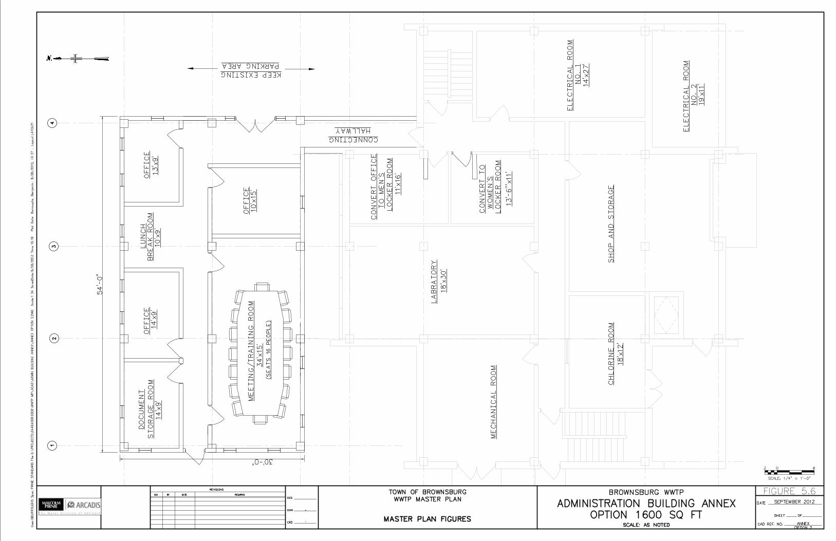
75
Wastewater Treatment Plant Expansion Master Plan - 2012 Update
5.2 Summary of Costs
The opinion of probable construction costs including contingencies for the recommended plant expansion is $29,900,000. The itemization of the costs is presented in Table 5.4 and Appendix B. Based on the design of the recommended master plan, estimated costs were prepared. The costs are in 2012 dollars. Construction costs will continue to rise over the planning period and should be accounted for in the anticipated funding service. Cost estimates consist of all the items that will be constructed and/or purchased for the projects that have been evaluated for the Master Plan. The direct cost of each equipment item or process area was based on vendor quoted information, quantity take off and unit prices when applicable information is necessary and available, and historical costs from recent Pirnie/ARCADIS projects.
Construction costs are a preliminary engineer’s estimate of the cost and are based on Pirnie/ARCADIS knowledge of the industry and may not reflect actual construction costs. The estimated construction costs are separated by major process and between the two construction phases. The equipment installed cost includes the cost for the equipment and the installation. The site piping, structures, and site work are included in the cost estimate.
The contingency is an amount added to the construction cost estimate to provide for undefined project elements and to reduce the risk for underestimation. The contingency usually ranges from 0 to 30 percent. The contingency is estimated as 30 percent of the total direct cost in the Master Plan. The costs for mobilization, site work, instrumentation and yard piping are estimated as percentages of the subtotal direct cost. Typical percentages are between 2 to 5 percent.
5.3 Summary of Project Phases and Construction Timeline
After reviewing the scope of improvements required to meet the treatment plant’s long term needs, it is recommended that Brownsburg divide the improvements into two phases. This phased approach will result in a cost savings and allow Brownsburg to maximize the useful life of existing equipment. The top priority is required expansion, which would need to be completed to maintain adequate treatment capacity for Town expansion. Table 5.2 and Figure 5.7 summarize the proposed project timeline and duration of significant events. The construction phasing allows the plant to plan ahead and to be prepared for the increase in average daily flow. The implementation schedule for each phase consists of a planning/design period and a construction/start-up period. A 1-year duration for the design period is used for each phase to include a conservative schedule. The construction period is estimated to be 2 years for each phase based on a conservative schedule. When final design is established, adjustments should be made to this schedule guideline based on experience and equipment procurement times. For some projects it may be possible to shorten the

76
Wastewater Treatment Plant Expansion Master Plan - 2012 Update
schedule. However for this Master Plan, the schedules will be presented based on conservative criteria.
Table 5.2 Timeline Details
Table 5.2 Timeline Details Start Date Event Duration (month)
3/1/2013 Detailed Design for Phase 1 12 6/1/2014 Construction for Phase 1 24 1/1/2024 Detailed Design for Phase 2 12 4/1/2025 Construction for Phase 2 24
Table 5.3 shows the projected population and average daily flow the plant can expect to receive through the planning period. Each phase is scheduled to be complete when the plant daily inflow is projected to reach 80% of its design capacity. The construction phases have a required completion date based on the projected flow compared to the existing treatment capacity.
Table 5.3 Flow Projection Details
Table 5.3 Flow Projection Details Year Projected Average Daily Flow (MGD) Projected Population 2012 2.84 23,301 2017 3.43 27,800 2022 3.91 31,519 2027 4.38 32,938 2032 4.85 38,958 2039 5.32 42,677 2048 6.26 50,115
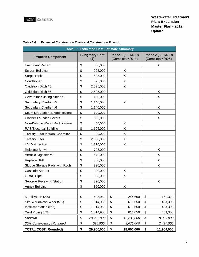
77
Wastewater Treatment Plant Expansion Master Plan - 2012 Update
Table 5.4 Estimated Construction Costs and Construction Phasing
Table 5.1 Estimated Cost Estimate Summary
Process Component Budgetary Cost ($)
Phase 1 (5.2 MGD) (Complete ≈2014)
Phase 2 (6.9 MGD) (Complete ≈2025)
East Plant Rehab $ 600,000 X Screen Building $ 925,000 X Surge Tank $ 505,000 X Conditioner $ 575,000 X Oxidation Ditch #5 $ 2,595,000 X Oxidation Ditch #6 $ 2,595,000 X Covers for existing ditches $ 120,000 X Secondary Clarifier #5 $ 1,140,000 X Secondary Clarifier #6 $ 1,140,000 X Scum Lift Station & Modifications $ 100,000 X Clarifier Launder Covers $ 396,000 X Non-Potable Water Modifications $ 50,000 X RAS/Electrical Building $ 1,105,000 X Tertiary Filter Influent Chamber $ 80,000 X Tertiary Filter $ 2,880,000 X UV Disinfection $ 1,170,000 X Relocate Blowers $ 705,000 X Aerobic Digester #3 $ 670,000 X Replace BFP $ 500,000 X Sludge Storage Pads with Roofs $ 920,000 X Cascade Aerator $ 290,000 X Outfall Pipe $ 598,000 X Septage Receiving Station $ 320,000 X Annex Building $ 320,000 X Mobilization (2%) $ 405,980 $ 244,660 $ 161,320 Site Work/Road Work (5%) $ 1,014,950 $ 611,650 $ 403,300 Instrumentation (5%) $ 1,014,950 $ 611,650 $ 403,300 Yard Piping (5%) $ 1,014,950 $ 611,650 $ 403,300
Subtotal $ 20,299,000 $ 12,233,000 $ 8,066,000 30% Contingency (Rounded) $ ,090,000 $ 3,670,000 $ 2,420,000
TOTAL COST (Rounded) $ 29,900,000 $ 18,000,000 $ 11,900,000
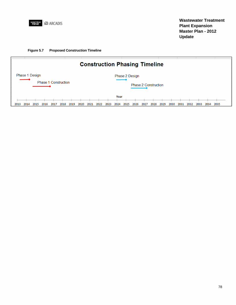
78
Wastewater Treatment Plant Expansion Master Plan - 2012 Update
Figure 5.7 Proposed Construction Timeline

Appendix A
Recommended Basis of Design Summary

This page is intentionally left blank
Brownsburg Wastewater Treatment Plant Expansion Recommended Basis of Design Summary
I. GENERAL
1. Applicant's Name: Town of Brownsburg 2. Project Name: Proposed WWTP Expansion 3. Location: 61 North Green Street, Brownsburg, IN-46112-1296 4. Engineer (Consultant): Malcolm Pirnie/ARCADIS 5. NPDES Permit Number: IN0021245 A. Date of final Permit Issuance: September 16, 2011 B. Expiration Date: September 30, 2015
II. DESIGN DATA – PROPOSED WWTP EXPANSION:
1. Current Population: 23,282 (Source: Estimate for 2012) 2. Design Year and Population: 2036; 41,050 3. Design Population Equivalent P.E.: 77,902 4. Average Design Flow: 6.9 MGD or 4,792 gpm 5. Maximum Plant Flow Capacity, MGD: 15.0 MGD or 10,147 gpm 6. Design Waste Strength: A. Average CBOD: 225 mg/l or 12,197 lbs/day B. Average TSS: 175 mg/l or 9,487 lbs/day D. NH3-N: 25 mg/l or 1,355 lbs/day E. TKN: 42 mg/l or 1,735 lbs/day (Assumed to be 1.67 times NH3-N) F. P: NA E. Other: None 7. NPDES Permit Limitation on Effluent Quality:

A. CBOD a. Summer: 10 mg/l b. Winter: 15 mg/l
B. TSS: a. Summer: 12 mg/l b. Winter: 18 mg/l
C. NH3-N: a. Summer: 1.5 mg/l b. Winter: 2.2 mg/l
D. P: None E. E-coli: 125 Colonies/ 100 ml F. Chlorine Residual: 0.01 mg/l G. pH:
a. Daily Minimum- 6.0; b. Daily Maximum- 9.0
H. D.O: a. Summer Daily Minimum- 7.0 b. Winter Daily Minimum-5.0
8. Receiving Stream:
A. Name: White Lick Creek B. Tributary to: White River C. Stream Uses: Drainage D. 7-day, 1-in-10 year low flow, ft: 0
III. TREATMENT UNITS
A. Influent Flow Meter (Proposed – One in Phase 1 and One in Phase 2)
1. Type:
a. Existing: Parshall Flume b. Proposed: Magnetic Flow Meter
2. Location: a. Existing: Upstream of Oxidation Ditch b. Proposed: Upstream of Oxidation Ditch
3. Indicating, recording and totalizing: Yes
B. Grit Chamber (East Plant) -(Proposed Phase 2)
1. Type of grit chamber: a. Existing: Detritus b. Proposed: Vortex
2. Number of units: (Existing and Proposed)

a. 1 3. Maximum flow, MGD:
a. Existing: 7.2 b. Proposed: 9.2
4. Size of unit a. Existing: Length, ft: 14, Width, ft: 14, Water depth, ft: 2 b. Proposed: Upper Chamber Dia., ft, 12, Upper Chamber Depth, ft, 6.66, Lower
Chamber Dia., ft, 5, Lower Chamber Depth, ft, 6.66, Inlet & Outlet Channel Widths, ft, 3
5. Particle size removal capability, mesh number: a. Proposed: 95% of grit particles down to 140
6. Dumpster (Existing and Proposed) a. Number: 2 b. Capacity: 2
C. Screens (East Plant) - (Proposed Phase 2)
1. Type:
a. Existing: Mechanically Cleaned Screen b. Proposed: Mechanical Multi-Rake Bar Screen
2. Number: a. Existing: Auger Monster (Duty)-1 b. Proposed: Mechanical Multi-Rake Bar Screen-2
3. Capacity, MGD: a. Existing: 10 b. Proposed: 10
4. Bar spacing: a. Existing: Auger Monster -1/4 inch b. Existing: Mechanically Cleaned Bar Screen- 1-inch c. Proposed: Mechanical Multi-Rake Bar Screen – ¼ inch
5. Method of cleaning: a. Existing: Auger Monster: Wash water b. Mechanically cleaned bar screen: Not Applicable c. Proposed: Multi-Rake Bar Screen: Wash water
6. Disposal of screenings: (Existing and Proposed) a. Dumpster and then landfill
D. New Screen Building (Proposed - Phase 1)
1. Type: Mechanically Cleaned Screen & Manual Bar Rack 2. Number: Mechanically Cleaned-2 (1 standby); Manually Cleaned-1 3. Bar spacing: Mechanical Spacing: 1/4 - inch; Manual Spacing: 1.75-inch 4. Manual Bar Screen for Bypass Flow

5. Capacity: 15 MGD for each screen 6. Method of cleaning: Mechanically Cleaned 7. Disposal of screenings: Screenings press and landfill
E. New Surge Tank (Proposed - Phase 1)
1. Size, ft: 40 (Diameter) x 11 (Side Water Depth) 2. Volume, gal: 100,793 3. Detention Time, min: 9.6 (at 15 MGD peak flow)
F. Anoxic Selector (Proposed - Phase 1)
1. Number of units:
a. Existing : 4 b. New : 1
2. Size of units: a. Existing, ft:
i. 3 Units - 14 (Length) x 14 (Width) x 11.4 (Side Water Depth) ii. 1 Unit -24 (Length) x 24 (Width) x 11.4 (Side Water Depth)
b. Proposed, ft: i. 1 Unit -60 (Length) x 20 (Width) x 10 (Side Water Depth)
3. Volume, cu ft: a. Existing : 13,270 b. Proposed : 12,000
4. Detention Time, min: a. Existing: 41 at 3.5 MGD b. Proposed : 37 at 3.5 MGD
G. Oxidation Ditch (Proposed - Phase 1 for Ditch #5, Phase 2 for Ditch # 6)
1. Number of units :
a. Existing: 4 b. Proposed :2
2. Size of units, ft : a. Existing: 151 (Length) x 51 (Width) x 12 (Side Water Depth) b. Proposed: 257 (Length) x 65 (Width) x 14 (Side Water Depth)
3. Volume of Oxidation Ditches, cu ft : a. Existing: 399,020 b. Proposed: 436,954
4. Detention time, hrs : a. Existing: 20.46 b. Proposed: 22.40
5. Average Organic loading , (lb BOD/ day /1000 cu ft) :

a. Existing: 13.5 b. Proposed: 15.0
6. Average Mixed Liquor Suspended Solids, mg/l : a. Existing: 2,800 b. Proposed: 2,800
7. Solids retention time, days : a. Existing: >15 b. Proposed: > 15
8. Type and efficiency of aeration equipment (lbO2 /BHP-hr) : a. Existing: Horizontal Bladed Rotor Aerator: 3.30 b. Proposed: Horizontal Bladed Rotor Aerator: 3.15
9. Oxygen required, lbs/day : a. Existing:
i. Carbonaceous, Total: 9, 852 ii. Nitrogenous, Total: 2,417
iii. Total Demand: 12, 269 b. Proposed :
i. Carbonaceous, Total: 9, 852 ii. Nitrogenous, Total: 2,417
iii. Total Demand : 12,269 10. Oxygen provided, lbs/day :
a. Existing: i. Actual Oxygen Transfer Rate (AOTR): 9, 500
ii. Standard Oxygen Transfer Rate (SOTR): 14,700 b. Proposed:
i. Actual Oxygen Transfer Rate (AOTR): 12,538 ii. Standard Oxygen Transfer Rate (SOTR): 19,403
11. Flow velocity in ditch, fps : a. Existing: 1 b. Proposed:1
12. Facilities to isolate units (Existing & Proposed) : Yes 13. Facilities for flow split control (Existing & Proposed) : Yes
H. Secondary Clarifier (Proposed – One in Phase 1 and One in Phase 2) 1. Type of Clarifier:
a. Existing: Circular, Peripheral Feed, Peripheral Collection b. Proposed: Peripheral Feed, Peripheral Collection, Spiral Scrapers sludge
collection mechanisms 2. Number of units
a. Existing: 4 b. Proposed: 2

3. Size of units, ft: a. Existing:
i. Diameter : 55 ii. Side water depth: 12
b. Proposed: i. Diameter: 90
ii. Side water depth: 15 4. Total surface area, sq ft:
a. Existing: 9,503 b. Proposed: 12,724
5. Surface overflow rate at the design flow-installed capacity, gpd/sq ft: a. Existing:
i. Average design flow: 368 ii. Design peak flow: 789
b. Proposed: i. Average design flow: 275
ii. Design peak flow: 589 6. Detention time, hrs:
a. Existing: i. Average design flow: 5.84
ii. Design peak flow: 2.32 b. Proposed:
i. Average design flow: 9.79 ii. Design peak flow: 4.57
7. Type of sludge removal mechanism: a. Existing: Scraper type collector b. Proposed: Spiral Scraper type collector
8. Solids loading rate, lbs/day/sq ft: a. Existing: 21.50 b. Proposed: 16.05
9. Disposal of scum (Existing & Proposed): Scum trough to drain pipe to digester 10. Facilities for unit isolation (Existing & Proposed): Yes 11. Facilities for flow split control (Existing & Proposed): Yes 12. Design secondary clarifier effluent quality, mg/l (Existing & Proposed) :
a. Average BOD: 10 b. Average TSS: 10 c. Average NH3-N, in Summer: 1.5 d. Average NH3-N, in Winter: 2.2
I. Waste Activated Sludge (WAS)
1. Minimum concentration, mg/l :
a. Existing: 5,000 b. Proposed: 5,000

2. Maximum concentration, mg/l: a. Existing: 9,000 b. Proposed: 9,000
3. Number of Pumps (Existing & Proposed) : RAS Pumps used for Pumping WAS 4. Capacity, each, gpm (Existing & Proposed): Same as that of the RAS Pumps 5. Design WAS Flow, gpm :
a. Existing: 70 b. Proposed: 140
6. Dry weight at average WAS concentration, lbs/day: a. Existing: 5,885 b. Proposed: 11,769
7. Volatile solids, % : a. Existing: 75 b. Proposed: 75
8. Volatile solids, lbs/day : a. Existing: 4,414 b. Proposed: 8,827
J. Return Activated Sludge (RAS) (Proposed-Two new pumps in Phase 1. One additional
pump in Phase 2) 1. Number of Pumps (including 1 standby pump):
a. Existing: 5 b. Proposed: 8
2. Capacity of one return sludge pump, MGD (Existing & Proposed): 1.8 3. Method of return sludge rate control (Existing & Proposed): Control Valve 4. Return sludge rate as % of design flow (Existing & Proposed): 150 (% of max flow) 5. Provisions for return sludge metering (Existing & Proposed): Magnetic Flow Meter 6. Location of return sludge discharge (Existing & Proposed): Anoxic Selector Tank 7. Location of new RAS pumps: New RAS and Electrical Building
K. Polishing Ponds (Currently used for disinfection; To be replaced by tertiary filters/UV
disinfection system) 1. Number of Ponds: 1 2. Total Volume, cu ft: 321,000 3. Total Detention Time, days (@ average flow): 0.68 4. Total Detention Time, days (@ maximum flow): 0.27 5. Design polishing pond effluent quality
a. Average BOD, mg/l: 10.0 b. Average TSS, mg/l: 10.0
L. Tertiary Filter – Cloth Media Disc Filter (Proposed - Phase 1)
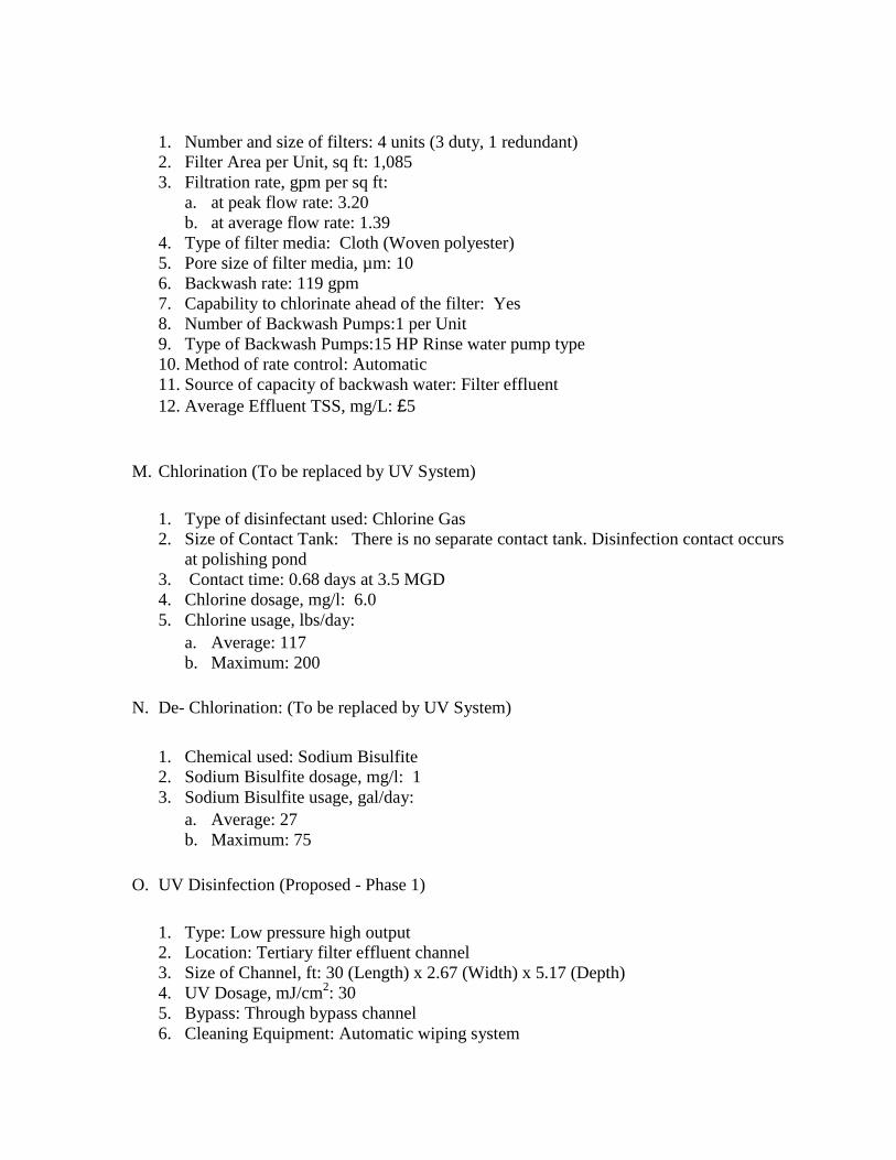
1. Number and size of filters: 4 units (3 duty, 1 redundant) 2. Filter Area per Unit, sq ft: 1,085 3. Filtration rate, gpm per sq ft:
a. at peak flow rate: 3.20 b. at average flow rate: 1.39
4. Type of filter media: Cloth (Woven polyester) 5. Pore size of filter media, µm: 10 6. Backwash rate: 119 gpm 7. Capability to chlorinate ahead of the filter: Yes 8. Number of Backwash Pumps:1 per Unit 9. Type of Backwash Pumps:15 HP Rinse water pump type 10. Method of rate control: Automatic 11. Source of capacity of backwash water: Filter effluent 12. Average Effluent TSS, mg/L: £5
M. Chlorination (To be replaced by UV System)
1. Type of disinfectant used: Chlorine Gas 2. Size of Contact Tank: There is no separate contact tank. Disinfection contact occurs
at polishing pond 3. Contact time: 0.68 days at 3.5 MGD 4. Chlorine dosage, mg/l: 6.0 5. Chlorine usage, lbs/day:
a. Average: 117 b. Maximum: 200
N. De- Chlorination: (To be replaced by UV System)
1. Chemical used: Sodium Bisulfite 2. Sodium Bisulfite dosage, mg/l: 1 3. Sodium Bisulfite usage, gal/day:
a. Average: 27 b. Maximum: 75
O. UV Disinfection (Proposed - Phase 1)
1. Type: Low pressure high output 2. Location: Tertiary filter effluent channel 3. Size of Channel, ft: 30 (Length) x 2.67 (Width) x 5.17 (Depth) 4. UV Dosage, mJ/cm2: 30 5. Bypass: Through bypass channel 6. Cleaning Equipment: Automatic wiping system

7. Intensity Monitoring: Yes 8. Number of UV channels: 2 (1 duty, 1 backup)
P. Cascade Aerators (Existing cascade aerators will be abandoned and larger cascade aerators will be built with a larger 42” diameter outfall pipe) (Proposed – Phase 1) 1. Total number of cascade aerators:
a. Existing: 2 b. Proposed: 2
2. Number (in series): a. Existing: 1 b. Proposed: 1
3. Influent dissolved oxygen , mg/l (Existing & Proposed): 3.0 4. Effluent dissolved oxygen, mg/l (Existing & Proposed): 7.0 5. Maximum temperature, o C (Existing & Proposed): 25.0 6. Total height of fall, ft (Existing & Proposed): 21.5 7. Average dissolved oxygen, mg/l (Existing & Proposed): 7.0
Q. Combination Unit- Sludge Thickening/ Sludge Dewatering (New Belt Press Proposed – Phase 2) 1. Sludge Thickening & Dewatering Units:
a. Existing: i. Number and size of thickener: 1; Belt Width, m: 1.5
b. Proposed: ii. Number and size of thickener: 1; Belt Width, m: 2.0
2. Type of Sludge Thickeners / Dewatering Unit (Existing & Proposed): Belt Press 3. Thickener/Dewatering Unit Capacity, gpm:
a. Existing: 225 b. Proposed: 300
4. Hydraulic Loading – Thickening, lbs/hour: a. Existing: 1125 b. Proposed: 1500
5. Hydraulic Loading – TWAS Dewatering, lbs/hour: a. Existing: 750 b. Proposed: 1000
6. Provisions to Chlorinate (Existing & Proposed): 7. Thickened Sludge Concentration:
a. Existing: 2-4% b. Proposed: 2-4%
8. Thickened Sludge Flow, gpd: a. Existing: 12,960

9. Thickened Sludge Filtrate, gpd: a. Existing: 51,840 b. Proposed: 51,840
10. Liquid Polymer Dosage, mg/l
a. Existing: i. Minimum: 1.0
ii. Maximum: 2.0 b. Proposed:
i. Minimum: 1.0 ii. Maximum: 2.0
11. Liquid Polymer Feed Rate, gph @ 8.6 lbs/.gal
a. Existing: i. Average flow at minimum dosage: 0.14
ii. Maximum flow at maximum dosage: 0.71 b. Proposed:
i. Average flow at minimum dosage: 0.28 ii. Maximum flow at maximum dosage: 1.42
12. Liquid Polymer Maximum Day Usage, gpd:
a. Existing: 17.1 b. Proposed: 34.2
R. Aerobic Digesters (Proposed – Phase 2, New Blowers Proposed – Phase 2)
1. Number :
a. Existing: 2 b. Proposed: 1
2. Size of units, ft: a. Existing: Diameter-70; Side Water Depth: 15 b. Proposed: Diameter-70; Side Water Depth: 15
3. Volume, each, cu ft (Existing and Proposed): 60,300 4. Hydraulic detention time after thickening, days: 36.54 5. Solids retention time, days:
a. Digester Tanks at 2% Solids: 19.2 b. Digester Tanks at 3% Solids: 28.8
6. Solids loading, lbs volatile solids/cu ft/day: 0.027 7. Percent VSS reduction, maximum,
a. Existing: i. Summer: 45
ii. Winter: 38 b. Proposed:
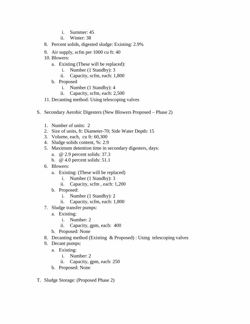
i. Summer: 45 ii. Winter: 38
8. Percent solids, digested sludge: Existing: 2.9% 9. Air supply, scfm per 1000 cu ft: 40 10. Blowers:
a. Existing (These will be replaced): i. Number (1 Standby): 3
ii. Capacity, scfm, each: 1,800 b. Proposed
i. Number (1 Standby): 4 ii. Capacity, scfm, each: 2,500
11. Decanting method: Using telescoping valves
S. Secondary Aerobic Digesters (New Blowers Proposed – Phase 2)
1. Number of units: 2 2. Size of units, ft: Diameter-70; Side Water Depth: 15 3. Volume, each, cu ft: 60,300 4. Sludge solids content, %: 2.9 5. Maximum detention time in secondary digesters, days:
a. @ 2.9 percent solids: 37.3 b. @ 4.0 percent solids: 51.1
6. Blowers: a. Existing: (These will be replaced)
i. Number (1 Standby): 3 ii. Capacity, scfm , each: 1,200
b. Proposed: i. Number (1 Standby): 2
ii. Capacity, scfm, each: 1,800 7. Sludge transfer pumps:
a. Existing: i. Number: 2
ii. Capacity, gpm, each: 400 b. Proposed: None
8. Decanting method (Existing & Proposed) : Using telescoping valves 9. Decant pumps:
a. Existing: i. Number: 2
ii. Capacity, gpm, each: 250 b. Proposed: None
T. Sludge Storage: (Proposed Phase 2)

1. Type: a. Existing: Sludge Drying Bed b. Proposed: Sludge Storage Pad
2. Number of beds: a. Existing: 6 b. Proposed: 6
3. Size, ft: a. Existing Beds:
i. Width: 20 ii. Length: 110
b. Proposed Pads: i. Width: 20
ii. Length: 110 4. Total surface area, sq ft:
a. Existing: 13,200 b. Proposed: 13,200
5. Maximum sludge depth, in: a. Existing: 10 b. Proposed: 10
6. Storage available at 10 inch depth, cu ft: a. Existing: 11,000 b. Proposed: 11,000
7. Storage available at 10 inch depth, gallons: a. Existing: 82,286 b. Proposed: 82,286
U. Sludge Disposal (No Change) 1. Ultimate disposal method of sludge: Land application by private hauler 2. Expected solids content of land-applied dewatered biosolids (principal method of
disposal): 15-20%
V. Septage Receiving Station (Proposed - Phase 2) 1. Capacity, gpm @ 3% solids: 400 2. Bar Screen Spacing, inch: ¼ 3. Treatment: Septage screened and storage 4. Water Requirements: 20 gpm at 60 psi 5. Discharge: Gravity discharge to West Lift Station wet well 6. Location: Adjacent to West Lift Station wet well
Related Documents