DNV Software Sesam User Course Wajac – Wave, current and wind loads on fixed frame structures

Welcome message from author
This document is posted to help you gain knowledge. Please leave a comment to let me know what you think about it! Share it to your friends and learn new things together.
Transcript
DNV Software Sesam User Course
Wajac – Wave, current and wind loads on fixed frame structures
© Det Norske Veritas AS. All rights reserved.
Sesam Wajac
27 February, 2013 Slide 2
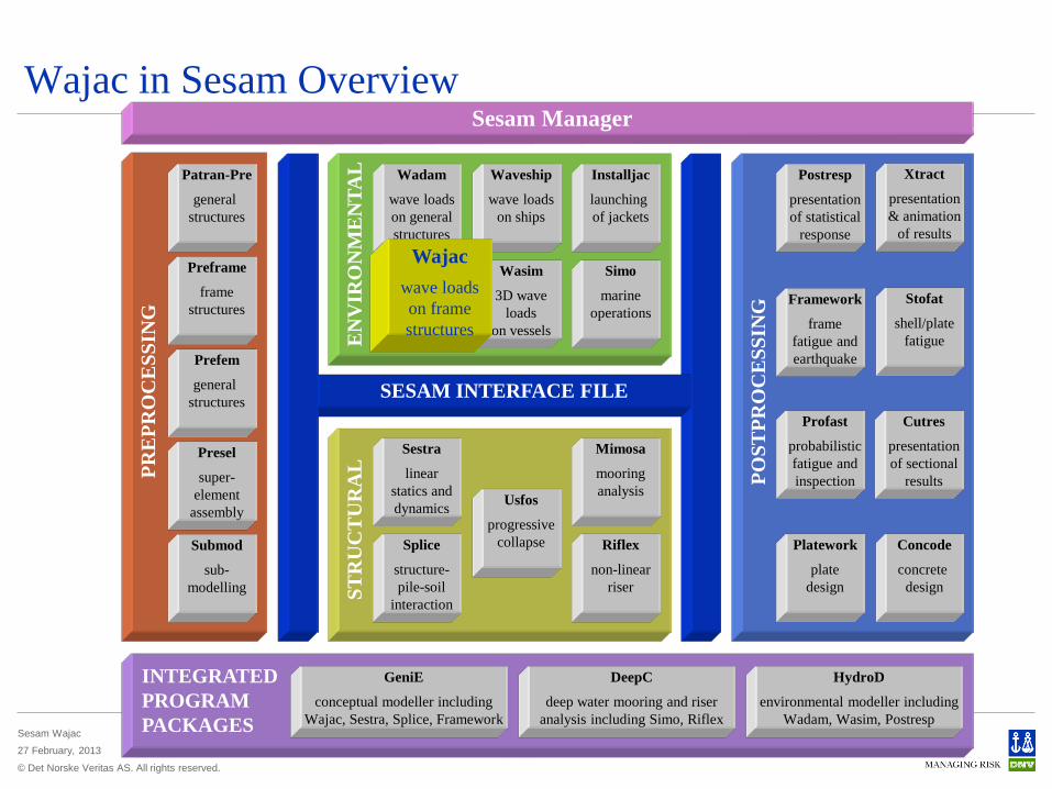
Wajac in Sesam Overview Sesam Manager
INTEGRATED PROGRAM PACKAGES
GeniE
conceptual modeller including Wajac, Sestra, Splice, Framework
DeepC
deep water mooring and riser analysis including Simo, Riflex
HydroD
environmental modeller including Wadam, Wasim, Postresp
SESAM INTERFACE FILE
POST
PRO
CE
SSIN
G
Xtract
presentation & animation
of results
Framework
frame fatigue and earthquake
Stofat
shell/plate fatigue
Profast
probabilistic fatigue and inspection
Cutres
presentation of sectional
results
Platework
plate design
Concode
concrete design ST
RU
CT
UR
AL
E
NV
IRO
NM
EN
TAL
Installjac
launching of jackets
Waveship
wave loads on ships
Wajac
wave loads on frame structures
Wasim
3D wave loads
on vessels
PRE
PRO
CE
SSIN
G
Simo
marine operations
Preframe
frame structures
Patran-Pre
general structures
Submod
sub- modelling
Prefem
general structures
Wadam
wave loads on general structures
Splice
structure- pile-soil
interaction
Usfos
progressive collapse
Mimosa
mooring analysis
Riflex
non-linear riser
Sestra
linear statics and dynamics
Postresp
presentation of statistical
response
Presel
super- element
assembly
Xtract
presentation & animation
of results
Wajac wave loads on frame structures
© Det Norske Veritas AS. All rights reserved.
Sesam Wajac
27 February, 2013 Slide 3
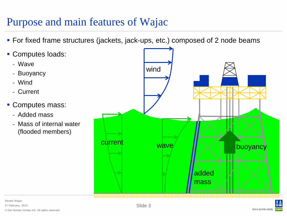
Purpose and main features of Wajac For fixed frame structures (jackets, jack-ups, etc.) composed of 2 node beams
Computes loads: - Wave - Buoyancy - Wind - Current
Computes mass: - Added mass - Mass of internal water
(flooded members)
wave current
wind
buoyancy
added mass
© Det Norske Veritas AS. All rights reserved.
Sesam Wajac
27 February, 2013 Slide 4
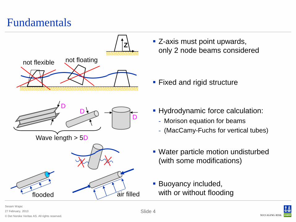
Fundamentals Z-axis must point upwards,
only 2 node beams considered
Fixed and rigid structure
Hydrodynamic force calculation: - Morison equation for beams - (MacCamy-Fuchs for vertical tubes)
Water particle motion undisturbed (with some modifications)
Buoyancy included, with or without flooding
not floating not flexible
D
Wave length > 5D
D D
Z
flooded air filled
© Det Norske Veritas AS. All rights reserved.
Sesam Wajac
27 February, 2013 Slide 5
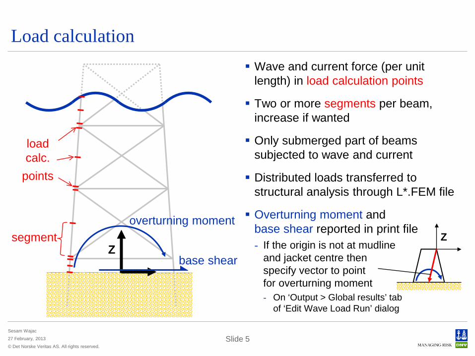
Load calculation Wave and current force (per unit
length) in load calculation points
Two or more segments per beam, increase if wanted
Only submerged part of beams subjected to wave and current
Distributed loads transferred to structural analysis through L*.FEM file
Overturning moment and base shear reported in print file - If the origin is not at mudline
and jacket centre then specify vector to point for overturning moment - On ‘Output > Global results’ tab
of ‘Edit Wave Load Run’ dialog
base shear Z
load calc.
points
segment overturning moment
Z

© Det Norske Veritas AS. All rights reserved.
Sesam Wajac
27 February, 2013 Slide 6
Load calculation – Morison equation Force per unit length in each
load calculation point is F = FInertia + FDrag
- FInertia is inertia part of force
- FDrag is drag part of force
FInertia = ρ π D2/4 Cm an
FDrag = ρ D/2 Cd vn |vn|
Linear variation of force between load calculation points
Water particle acceleration an and velocity vn are normal to member, vn include current
F
D
vn / an
segment
load calc. points
wave current
© Det Norske Veritas AS. All rights reserved.
Sesam Wajac
27 February, 2013 Slide 7
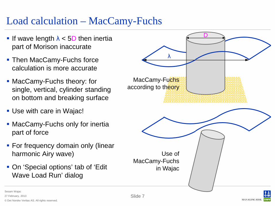
Load calculation – MacCamy-Fuchs If wave length λ < 5D then inertia
part of Morison inaccurate
Then MacCamy-Fuchs force calculation is more accurate
MacCamy-Fuchs theory: for single, vertical, cylinder standing on bottom and breaking surface
Use with care in Wajac!
MacCamy-Fuchs only for inertia part of force
For frequency domain only (linear harmonic Airy wave)
On ‘Special options’ tab of ‘Edit Wave Load Run’ dialog
D
λ
MacCamy-Fuchs according to theory
Use of MacCamy-Fuchs
in Wajac
© Det Norske Veritas AS. All rights reserved.
Sesam Wajac
27 February, 2013 Slide 8
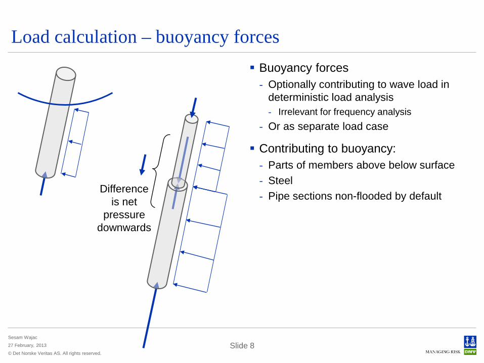
Load calculation – buoyancy forces Buoyancy forces
- Optionally contributing to wave load in deterministic load analysis - Irrelevant for frequency analysis
- Or as separate load case
Contributing to buoyancy: - Parts of members above below surface - Steel - Pipe sections non-flooded by default
Difference is net
pressure downwards
© Det Norske Veritas AS. All rights reserved.
Sesam Wajac
27 February, 2013 Slide 9
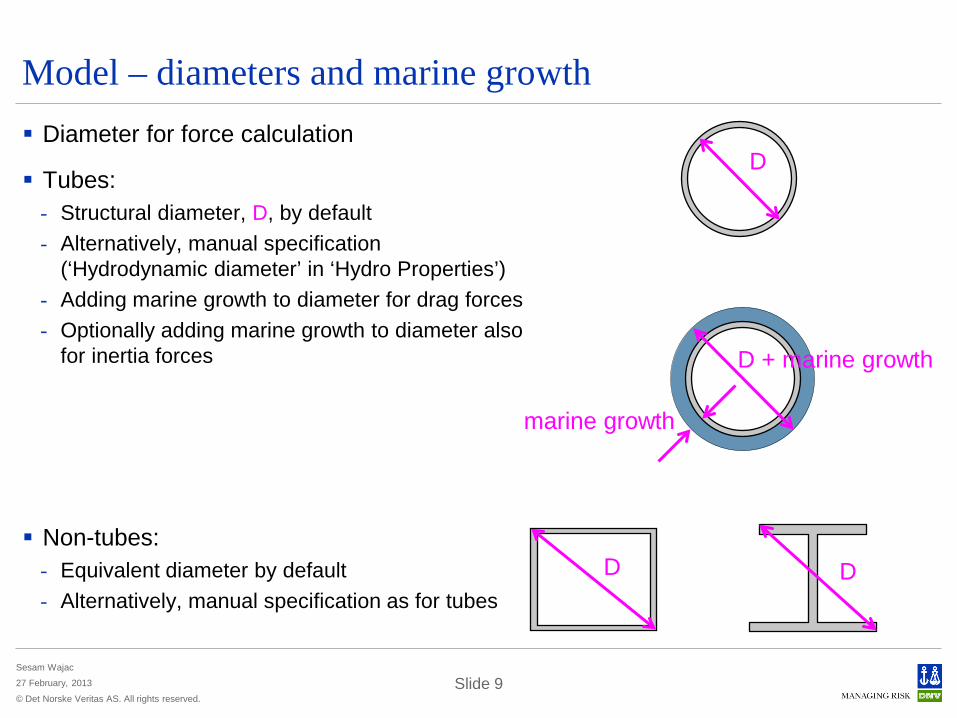
Model – diameters and marine growth Diameter for force calculation
Tubes: - Structural diameter, D, by default - Alternatively, manual specification
(‘Hydrodynamic diameter’ in ‘Hydro Properties’) - Adding marine growth to diameter for drag forces - Optionally adding marine growth to diameter also
for inertia forces
Non-tubes: - Equivalent diameter by default - Alternatively, manual specification as for tubes
D
D D
D + marine growth
marine growth
© Det Norske Veritas AS. All rights reserved.
Sesam Wajac
27 February, 2013 Slide 10
Model – hydrodynamic coefficients Hydrodynamic coefficients: inertia Cm and drag Cd
Constant assigned to whole or part of structure - Different constant values to different parts of structure
Function of diameter
Function of roughness and Reynolds number - Rn = vn D / ʋ, ʋ is kinematic viscosity
Function of roughness and Keulegan-Carpenter number - KC = 2 ρ vn / ω D
By API rule
Coefficients are normally on T*.FEM file created by GeniE
Coefficients on T*.FEM are overruled if coefficients are given in Wajac input file - A few additional ways of specification
© Det Norske Veritas AS. All rights reserved.
Sesam Wajac
27 February, 2013 Slide 11
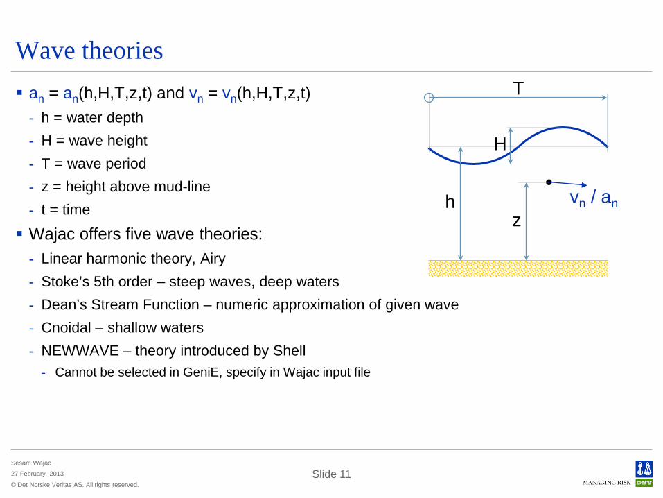
Wave theories an = an(h,H,T,z,t) and vn = vn(h,H,T,z,t)
- h = water depth - H = wave height - T = wave period - z = height above mud-line - t = time
Wajac offers five wave theories: - Linear harmonic theory, Airy - Stoke’s 5th order – steep waves, deep waters - Dean’s Stream Function – numeric approximation of given wave - Cnoidal – shallow waters - NEWWAVE – theory introduced by Shell
- Cannot be selected in GeniE, specify in Wajac input file
H
h z
T
vn / an

© Det Norske Veritas AS. All rights reserved.
Sesam Wajac
27 February, 2013 Slide 12
Linear harmonic wave theory, Airy Harmonic waves (sinus)
Linear theory, i.e. velocities and accelerations are linear with respect to wave height
While other theories describe wave crest and trough, Airy describe up to still water level
Alternative assumptions: - Constant above still water level - Extrapolation of exponential curve
- Cannot be selected in GeniE - Wheeler stretching
constant
extra- polation
Wheeler
extrap.
Wheeler

© Det Norske Veritas AS. All rights reserved.
Sesam Wajac
27 February, 2013 Slide 13
Current Application of current:
- Contributes to drag force for deterministic wave
- Contributes to drag force for time domain simulation of short term sea state
- Used in equivalent linearisation of drag force for spectral wave
Direction of current: - X-, Y- and Z-component - Horizontal and given direction - Horizontal and parallel with wave
© Det Norske Veritas AS. All rights reserved.
Sesam Wajac
27 February, 2013 Slide 14
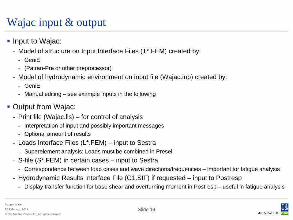
Wajac input & output Input to Wajac:
- Model of structure on Input Interface Files (T*.FEM) created by: - GeniE - (Patran-Pre or other preprocessor)
- Model of hydrodynamic environment on input file (Wajac.inp) created by: - GeniE - Manual editing – see example inputs in the following
Output from Wajac: - Print file (Wajac.lis) – for control of analysis
- Interpretation of input and possibly important messages - Optional amount of results
- Loads Interface Files (L*.FEM) – input to Sestra - Superelement analysis: Loads must be combined in Presel
- S-file (S*.FEM) in certain cases – input to Sestra - Correspondence between load cases and wave directions/frequencies – important for fatigue analysis
- Hydrodynamic Results Interface File (G1.SIF) if requested – input to Postresp - Display transfer function for base shear and overturning moment in Postresp – useful in fatigue analysis
© Det Norske Veritas AS. All rights reserved.
Sesam Wajac
27 February, 2013 Slide 15
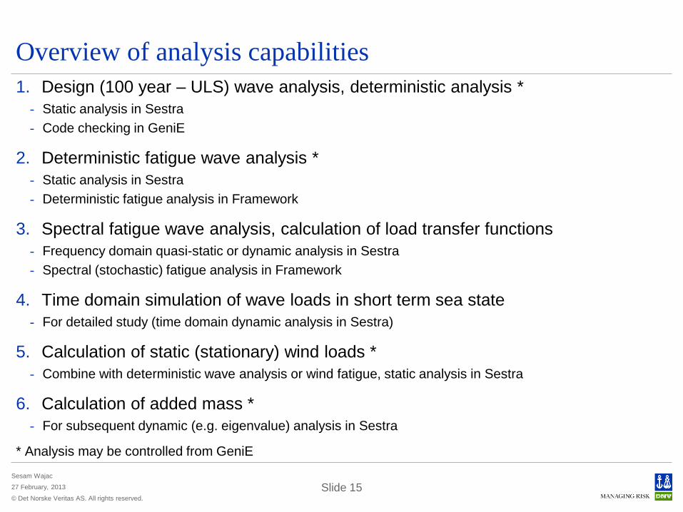
Overview of analysis capabilities 1. Design (100 year – ULS) wave analysis, deterministic analysis *
- Static analysis in Sestra - Code checking in GeniE
2. Deterministic fatigue wave analysis * - Static analysis in Sestra - Deterministic fatigue analysis in Framework
3. Spectral fatigue wave analysis, calculation of load transfer functions - Frequency domain quasi-static or dynamic analysis in Sestra - Spectral (stochastic) fatigue analysis in Framework
4. Time domain simulation of wave loads in short term sea state - For detailed study (time domain dynamic analysis in Sestra)
5. Calculation of static (stationary) wind loads * - Combine with deterministic wave analysis or wind fatigue, static analysis in Sestra
6. Calculation of added mass * - For subsequent dynamic (e.g. eigenvalue) analysis in Sestra
* Analysis may be controlled from GeniE
© Det Norske Veritas AS. All rights reserved.
Sesam Wajac
27 February, 2013 Slide 16
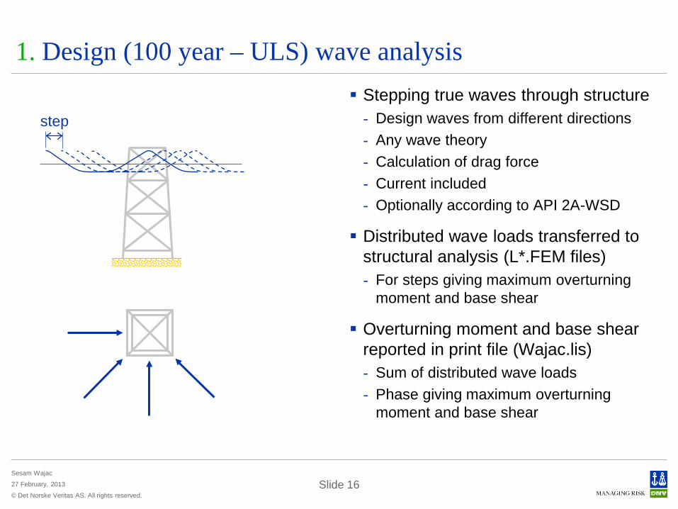
1. Design (100 year – ULS) wave analysis Stepping true waves through structure
- Design waves from different directions - Any wave theory - Calculation of drag force - Current included - Optionally according to API 2A-WSD
Distributed wave loads transferred to structural analysis (L*.FEM files) - For steps giving maximum overturning
moment and base shear
Overturning moment and base shear reported in print file (Wajac.lis) - Sum of distributed wave loads - Phase giving maximum overturning
moment and base shear
step
© Det Norske Veritas AS. All rights reserved.
Sesam Wajac
27 February, 2013 Slide 17
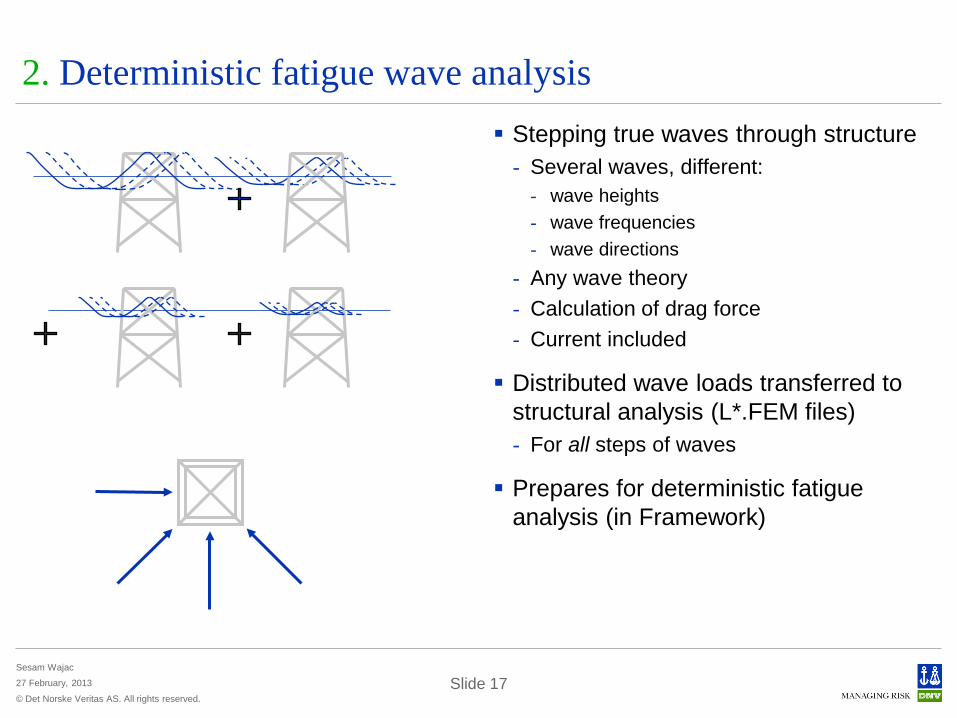
2. Deterministic fatigue wave analysis Stepping true waves through structure
- Several waves, different: - wave heights - wave frequencies - wave directions
- Any wave theory - Calculation of drag force - Current included
Distributed wave loads transferred to structural analysis (L*.FEM files) - For all steps of waves
Prepares for deterministic fatigue analysis (in Framework)
© Det Norske Veritas AS. All rights reserved.
Sesam Wajac
27 February, 2013 Slide 18
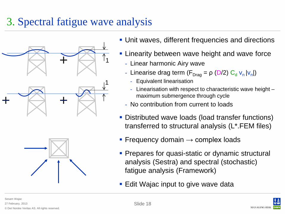
3. Spectral fatigue wave analysis Unit waves, different frequencies and directions
Linearity between wave height and wave force - Linear harmonic Airy wave - Linearise drag term (FDrag = ρ (D/2) Cd vn |vn|)
- Equivalent linearisation - Linearisation with respect to characteristic wave height –
maximum submergence through cycle - No contribution from current to loads
Distributed wave loads (load transfer functions) transferred to structural analysis (L*.FEM files)
Frequency domain → complex loads
Prepares for quasi-static or dynamic structural analysis (Sestra) and spectral (stochastic) fatigue analysis (Framework)
Edit Wajac input to give wave data
1
1
© Det Norske Veritas AS. All rights reserved.
Sesam Wajac
27 February, 2013 Slide 19
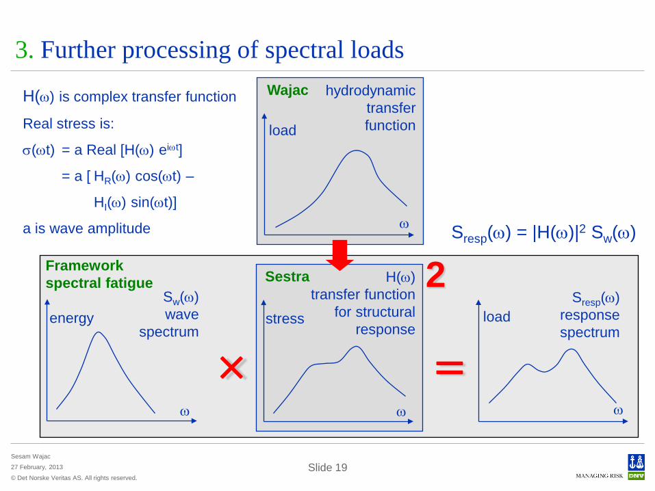
3. Further processing of spectral loads Wajac
ω
load
hydrodynamic transfer function
Framework spectral fatigue
ω
energy Sw(ω) wave
spectrum
Sestra
ω
stress
H(ω) transfer function
for structural response
ω
load Sresp(ω)
response spectrum
= ×
2 Sresp(ω) = |H(ω)|2 Sw(ω)
H(ω) is complex transfer function
Real stress is:
σ(ωt) = a Real [H(ω) eiωt]
= a [ HR(ω) cos(ωt) –
HI(ω) sin(ωt)]
a is wave amplitude
© Det Norske Veritas AS. All rights reserved.
Sesam Wajac
27 February, 2013 Slide 20
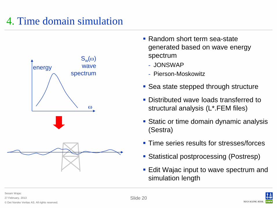
4. Time domain simulation Random short term sea-state
generated based on wave energy spectrum - JONSWAP - Pierson-Moskowitz
Sea state stepped through structure
Distributed wave loads transferred to structural analysis (L*.FEM files)
Static or time domain dynamic analysis (Sestra)
Time series results for stresses/forces
Statistical postprocessing (Postresp)
Edit Wajac input to wave spectrum and simulation length
ω
energy Sw(ω) wave
spectrum
© Det Norske Veritas AS. All rights reserved.
Sesam Wajac
27 February, 2013 Slide 21
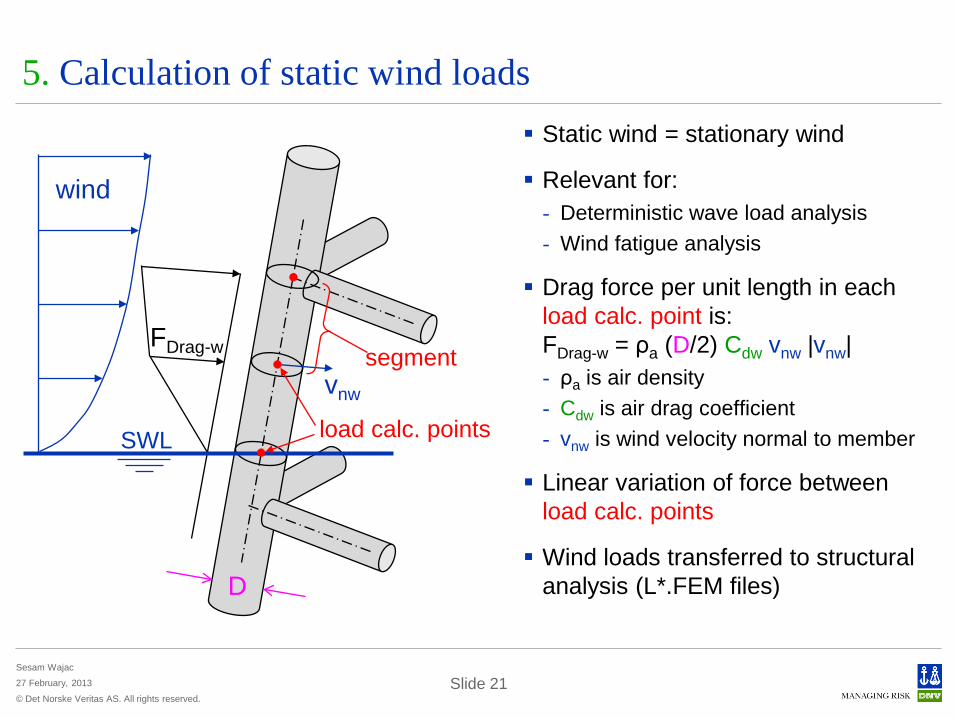
5. Calculation of static wind loads Static wind = stationary wind
Relevant for: - Deterministic wave load analysis - Wind fatigue analysis
Drag force per unit length in each load calc. point is: FDrag-w = ρa (D/2) Cdw vnw |vnw| - ρa is air density - Cdw is air drag coefficient - vnw is wind velocity normal to member
Linear variation of force between load calc. points
Wind loads transferred to structural analysis (L*.FEM files)
FDrag-w
D
vnw
segment
load calc. points
wind
SWL
© Det Norske Veritas AS. All rights reserved.
Sesam Wajac
27 February, 2013 Slide 22
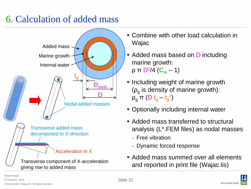
6. Calculation of added mass Combine with other load calculation in
Wajac
Added mass based on D including marine growth: ρ π D2/4 (Cm – 1)
Including weight of marine growth (ρg is density of marine growth): ρg π (D tg – tg2)
Optionally including internal water
Added mass transferred to structural analysis (L*.FEM files) as nodal masses - Free vibration - Dynamic forced response
Added mass summed over all elements and reported in print file (Wajac.lis)
Added mass
D
Marine growth
Internal water
tg
Dsteel
Acceleration in X
Transverse component of X-acceleration giving rise to added mass
Transverse added mass decomposed to X-direction
Nodal added masses
Related Documents