MESA WATER DISTRICT APRIL 2018 STANDARD SPECIFICATIONS AND STANDARD DRAWINGS FOR THE CONSTRUCTION OF WATER FACILITIES Phil Lauri, P.E. District Engineer APRIL 2018 MESA WATER DISTRICT 1965 Placentia Avenue Costa Mesa, CA 92627 (949) 631-1291

Welcome message from author
This document is posted to help you gain knowledge. Please leave a comment to let me know what you think about it! Share it to your friends and learn new things together.
Transcript
MESA WATER DISTRICT
APRIL 2018
STANDARD SPECIFICATIONS
AND STANDARD DRAWINGS FOR
THE CONSTRUCTION OF
WATER FACILITIES
Phil Lauri, P.E.
District Engineer
APRIL 2018
MESA WATER DISTRICT
1965 Placentia Avenue
Costa Mesa, CA 92627
(949) 631-1291
MESA WATER DISTRICT
APRIL 2018
Mesa Water District
STANDARD
SPECIFICATIONS
AND STANDARD DRAWINGS FOR
THE CONSTRUCTION OF
WATER FACILITIES
Master Table of Contents
PART I.................................................................................... Procedural Guide and Design Requirements
PART II .................................................................................. General Conditions
PART III ................................................................................ Technical Specifications
PART IV................................................................................. Standard Drawings

MESA WATER DISTRICT
APRIL 2018
PART 1
PROCEDURAL GUIDE AND DESIGN REQUIREMENTS
FOR CONSTRUCTION OF
WATER FACILITIES
Mesa Water District
1965 Placentia Avenue
Costa Mesa, CA 92627
(949) 631-1291
MESA WATER DISTRICT
APRIL 2018
MESA WATER DISTRICT
TABLE OF CONTENTS
PART 1
PROCEDURAL GUIDE AND DESIGN REQUIREMENTS
Section Description
100 Procuring Water Service from Mesa Water District
200 Mesa Water Fees and Charges for New Development
300 Design and Inspection Procedures
400 Design Criteria, Water Facilities
Appendix 1 Recommended Conditions of Approval/Code Requirement
Appendix 2 Application For New Service
Appendix 3 Payment Voucher
Appendix 4 Water Service Agreement
Appendix 5 Final Inspection and Cash Bond Release Request
Appendix 6 Fees And Charges for New Development
Appendix 7 Capacity Charges Worksheet
Appendix 8 Fixture Unit Conversion Table

MESA WATER DISTRICT
APRIL 2018
100-1
SECTION 100
PROCURING WATER SERVICE FROM
MESA WATER DISTRICT
100.1 PURPOSE
The purpose of these Procedural Guide and Design Requirements is to provide developers (applicant) and
their agents with the general steps for procuring a water service from Mesa Water District (Mesa Water), as
well as, providing the general design requirements for the preparation and processing of water improvement
plans for a new water service from Mesa Water.
This manual is a declaration of existing policy and is not intended as a change by Mesa Water District of
any of its terms and conditions contained in Mesa Water’s “Rules and Regulations for Water Service”. All
requests for water service by Mesa Water District shall be completed in accordance with all of the terms and
conditions of Mesa Water’s Water Service Agreement and the “Rules and Regulations for Water Service”.
Upon acceptance of the Water Service Agreement by Mesa Water, together with all fees and charges,
including the Capacity Charge, as determined by the District Engineer or an authorized representative,
subject to appeal to the General Manager or the Board of Directors, plans and specifications, bonds,
conveyance of necessary easements, and other items as may be required, Mesa Water District will agree to
provide the requested water service subject to the terms and conditions set forth in the Water Service
Agreement and Mesa Water’s “Rules and Regulations for Water Service”.
100.2 AVAILABILITY OF SERVICE
Mesa Water provides domestic water to all properties within its service area boundaries. The developer
(applicant) or his agent shall check with Mesa Water to determine the current boundaries of Mesa Water
District and the availability of service prior to preparing water improvement plans. The developer
(applicant) or his agent may confirm service availability with the Mesa Water’s Engineering Department,
located at 1965 Placentia Avenue, Costa Mesa, California, or by calling (949) 631-1291.
100.3 PRELIMINARY FEASIBILITY INVESTIGATION
In some areas, a feasibility investigation and/or report may be necessary to establish whether and how Mesa
Water can serve the proposed development area. An agreement whereby the applicant shall advance the
estimated cost to Mesa Water for making any feasibility study shall be executed and money deposited if
deemed necessary by Mesa Water. The applicant's engineer shall submit an initial concept plan and/or
design report, as required by Mesa Water, of the water facilities for review and approval by Mesa Water.
100.4 VERIFICATION OF SERVICE AVAILABILITY
If service verification is requested by the Builder/Developer (applicant), the service verification request
shall be addressed to the District Engineer, and must be accompanied by an 8- ½ inches by 11 inches
vicinity map and two (2) copies of the tentative tract map showing the proposed services and their points of
connection to the existing Mesa Water facilities. Conceptual sizing of the water system shall be shown
along with dwelling unit densities, and estimated water demands. The normal information required on
tentative tract maps is also required.
MESA WATER DISTRICT
APRIL 2018
100-2
A “Will-Serve” letter or “Statement of Certification” will be prepared by Mesa Water upon the applicant’s
request for a development within the boundaries of Mesa Water District. This document may be required
by local jurisdictional agencies for processing tentative maps or development reviews. Water supply
assessments and water service verifications will need to be requested for developments of 500 dwelling
units or more, in accordance with the California Water Code Section 10910.
100.5 CONSTRUCTION PROJECTS AND WATER SERVICE REQUIREMENTS
For projects that require construction of a new water service or changes to existing water services, Mesa
Water requires the following specific procedures to be followed before these water services can be
constructed or modified. For project notifications that were received from the City of Costa Mesa Planning
Division (or from City of Newport Beach or County of Orange), Mesa Water will send a letter to all
prospective Builders/Developers that water plans must be submitted for the proposed project. See Appendix
1 for an example of this notification letter.
A new water service will be required if one does not currently exist at the location. An additional service
may be needed or modifications to the existing services if:
Existing meter is too small or too large for the amount of water needed for the project.
The project wants to add or remove a water service.
Fire or irrigation services will be modified or constructed as part of the project.
A dedicated irrigation water meter will be required for all irrigated landscape areas greater than
2,500 square feet to facilitate water management. This policy pertains to commercial, industrial,
and multi-tenant projects of four units or more.
If new or modified water services are needed, the following are the procedures that will need to be followed:
1. An Application for New Service (Appendix 2) must be completed.
2. Project plans must be submitted for Mesa Water’s approval, including the plumbing plans, showing
all external and internal water fixtures, as well as the irrigation plans. The submittal shall include
the total number of fixture units to be served by the new or modified water service, and the future
expected flow rates of the irrigation system. Payment of the plan check deposit is required prior to
Mesa Water initiating the plan check process.
3. Payment of deposits which may include: plan check and inspection deposit; capacity charges; and
meter installation deposits.
4. An acceptable Payment and Performance Bond must be posted.
5. Project plans must be approved and signed by Mesa Water.
6. Water Services Agreement (Appendix 4) must be signed by the applicant property owner and by
Mesa Water.
100.6 SPECIAL CONDITIONS FOR CONDOMINIUMS AND LAND SUBDIVISIONS
All projects must conform to Mesa Water’s single metering policy, which requires “each dwelling unit or
building under separate ownership must be provided with its own service connections.” Mesa Water
reserves the right to limit the number of houses or buildings, or the area of land under one ownership, to be
supplied by one service connection.

MESA WATER DISTRICT
APRIL 2018
100-3
Condominiums – Mesa Water will require a separate meter for each condominium (except in
unusual cases).
Land Subdivisions – When property with an existing service is subdivided, the service connection
shall be considered as belonging to the lot or parcel of land, which it directly enters. A service
connection shall not be used to supply adjoining property of the same or a different owner. Mesa
Water will require a separate service and meter for each lot at the time of subdivision.
100.7 REMODELS / TENANT IMPROVEMENT PROCEDURES
If the project will include the installation of new plumbing fixtures, Mesa Water requires that the adequacy
of the existing meter be evaluated and that the meter be upgraded if the addition of new plumbing fixtures
and/or landscaping will cause water flow rates to exceed the capacity of the existing meter.
The following procedures must be followed before water meters can be upgraded:
1. Provide payment of Plan Check Deposit.
2. Submit a plumbing plan showing all future plumbing fixtures including existing plumbing fixtures
to remain and landscape plans showing the future expected flow rates of the irrigation system. A
listing of plumbing fixtures can be supplied in place of a plumbing plan.
3. Mesa Water Engineering Department will calculate the required meter size and determine if a meter
upgrade is required.
4. If a meter upgrade is required, a capacity charge and meter installation deposit will be assessed.
5. Following payment of all required deposits, the existing meter will be replaced with a larger meter
by Mesa Water.
100.8 PLAN CHECKING OF PROPOSED DESIGN
The applicant shall submit one (1) set of design plans, 24" by 36" in size (maximum), of the proposed water
facilities for any improvement/development to Mesa Water for review and approval. The plan submittal
shall include, as a minimum, one set of site plans, one set of plumbing plans, and one set of irrigation plans
and the completed Application for New Service including the Standard Terms (Appendix 2). Included
within the submittal shall be the total number of fixture units to be served by the new or modified water
service, and the future expected flow rates of the irrigation system. The Builder/Developer or his
engineer/agent shall pay a deposit for plan check to the Engineering Department to start the plan check
process. The Builder/Developer shall also submit other pertinent information to assist Mesa Water in
reviewing the plan submittal (e.g.: tract map, fire master plan, water calculations, etc.).
Plans shall also be submitted to the City Engineer of the City of Costa Mesa (or City of Newport Beach or
County of Orange) for review and determination of the requirements for approval of work within their
jurisdiction.
100.9 APPLICATION, AGREEMENT, AND FEE PAYMENT
Upon the applicant's and/or his engineer's submission of the application form, plans and payment of the
plan check deposit, Mesa Water’s Engineering Department will perform its review of the plans and
MESA WATER DISTRICT
APRIL 2018
100-4
application submittal.
Once the plans and submittal have been reviewed by the Engineering Department, Mesa Water will
notify the Builder/Developer that the plans are ready for pick-up with Mesa Water’s
corrections/comments noted. When the plans are close to final, the plan comments will include Mesa
Water’s preliminary summary of the Capacity and Plan Check Deposits – Payment Voucher (Appendix
3) for the proposed construction/development. Since the Capacity and Plan Check Deposits are based on
the project’s quantities of water improvements, Mesa Water reserves the right to postpone the
preparation of the Capacity and Plan Check Deposits until such time when the quantities are finalized.
The Builder/Developer shall make corrections and re-submit to the Engineering Department along with
Mesa Water’s previous redlined check print. Mesa Water will review the second submittal and return
with corrections/comments as noted. This process is repeated until Mesa Water is satisfied that the plans
meet Mesa Water’s Standard Specifications.
Once the plans meet Mesa Water’s Standard Specifications and there are no more comments, Mesa
Water will request a 24” by 36” 4-mil duplicate mylar for the District Engineer’s signature. Mesa Water
will require the submittal of a copy of the approved Fire Master Plan for the project site prior to
approving the plans. The Capacity Charges and Plan Check Deposit shall be collected by Mesa Water,
and the acceptable bond posted prior to the approving of the plans by the District Engineer.
In addition, the Owner shall sign the Water Service Agreement (Appendix 4) and return the original
Agreement to Mesa Water. Once the Water Service Agreement is accepted and executed by the District
Engineer the Builder/Developer must submit to Mesa Water a 24” by 36” 4-mil mylar of the plan for the
District Engineer’s signature and Engineering Department files along with one (1) compact disk (CD).
The CD will contain a single PDF file of the entire approved plan set, i.e. reflecting Mesa Water’s
approval signatures. The PDF file will be of a quality high resolution since it will be made a part of Mesa
Water’s public electronic library of plans.
100.10 EASEMENTS
The applicant shall grant, or cause to be granted to Mesa Water District, without cost to Mesa Water, all
necessary easements for construction, installation, maintenance and access to the water facilities, across all
privately-owned lands to be traversed by the facilities, which easements shall be in a form and condition of
title satisfactory to Mesa Water District and shall be executed by all necessary parties having an interest in
said lands. All easement documents and plat map and legal descriptions shall be submitted to Mesa Water.
Mesa Water will submit the easement documents to the County of Orange for recording. A copy will be
mailed to the property owner(s) after recording.
100.11 RESPONSIBILITY FOR FURNISHING MATERIAL AND INSTALLATION
Installation of the development's water facilities and any other required off-site facilities will be the
obligation of, and at, developer's expense. The applicant shall cause all installation work to meet Mesa
Water's "Standard Specifications," and upon final acceptance, convey the off-site facilities to Mesa Water
District. Prior to the onset of construction activities, the project contractor is required to schedule a pre-
construction meeting with Mesa Water’s Construction Inspector. That Developer to provide material
specifications to Mesa Water District for approval two weeks prior to commencing construction.
100.12 GUARANTEES
MESA WATER DISTRICT
APRIL 2018
100-5
As set forth in the Agreement, the applicant guarantees the water facilities against defects in workmanship
and materials for a period of one (1) year after the date of acceptance of the facilities by Mesa Water
District.
It is further agreed that the facilities shall be restored to full compliance with the requirements of Mesa
Water’s Standard Specifications and Plans, including any test requirements, if during said one (1) year
period the facilities or any portion thereof are found not be in conformance with any provisions of said
Standard Specifications and Plans. This guarantee is in addition to any and all other warranties, express or
implied, with respect to the facilities.
100.13 DEDICATION OF FACILITIES
Upon completion and final inspection of all work, the inspector shall file a Final Inspection and Cash Bond
Release Request (Appendix 5) at least 30 days prior to a regular Board Meeting for dedication and formal
acceptances. The applicant shall furnish Mesa Water with a report of the actual costs of the water facilities,
and to substantiate such report with invoices and receipts acceptable to Mesa Water. Mesa Water shall also
be provided with a complete set of record drawings ("as-builts") on reproducible mylars. Upon said
acceptance, Mesa Water will give approval for the release of bonds held by Mesa Water District or posted
to the city or county for the construction of the water facilities.
100.14 INDEMNITY BOND
If water facilities are to be constructed in a right-of-way under the jurisdiction of an agency requiring Mesa
Water District to sign the encroachment permit, the applicant shall furnish Mesa Water with an Indemnity
Bond prior to execution of the permit. The bond shall be for a sum not less than the completed value of said
facilities. The value shall be determined by the District Engineer.
100.15 IMPROVEMENT BONDS
The Developer shall post improvement bonds directly with Mesa Water District prior to construction of the
offsite water systems. A detailed Engineer’s cost estimate will be submitted by the Developer. Ten percent
(10%) o r a m i n i m u m o f $ 1 , 0 0 0 ( w h i c h e v e r i s m o r e ) of the total cost estimate will
be paid by the Developer before construction. The bonds shall guarantee the satisfactory completion of
the water systems in the sole opinion of Mesa Water District.
100.16 BOND RELEASE
Subject to Government Code Section 66499.7, forty (40) days following satisfactory completion of the
construction of the improvements and upon written request of the Developer, Mesa Water District will
release the construction bonds. The developer surety bonds will be released one year after the acceptance of
the facilities by Mesa Water District.
END OF SECTION
MESA WATER DISTRICT
APRIL 2018
200-1
SECTION 200
MESA WATER FEES AND CHARGES
FOR NEW DEVELOPMENT
200.1 ADMINISTRATION AND ENGINEERING FEES
As set forth in the Water Service Agreement (Appendix 4), the applicant hereby agrees to pay all
administration and engineering fees, (including inspection and plan check costs), calculated as a percentage
of the total cost as estimated by Mesa Water, as well as Capacity Charges, meter charges, interim water
service line charges, (if applicable), and any other charges of Mesa Water District. The amount of such fees
and charges shall be based on the applicable schedules of the Rules and Regulations in effect on the date
when the applicant has submitted to Mesa Water its completed Application, payment of all fees and charges,
plans and specifications, bonds, conveyance of necessary easements and other items which may be required
herein prior to issuance of the permit and the plans of the Applicant have been approved by Mesa Water.
The meter charge includes provisions by Mesa Water of a water meter and customer control valve. The
customer control valve is to be obtained from Mesa Water and installed by the applicant’s contractor as the
work progresses, and that the water meter is to be installed by Mesa Water prior to the provision of
permanent water service by Mesa Water.
200.2 DEPOSIT
A deposit will be collected on all new development to cover the actual cost for time and materials, including
Mesa Water’s fully burdened labor rate, for Plan Check, Installation and Inspection Work performed. After
the work has been completed, the actual cost of the project will be determined and any excess funds from
the deposit will be refunded or the applicant shall be required to pay the costs in excess of the deposit. The
current approved Fees and Charges for New Development are included within Appendix 6.
200.2.1 Plan Check
The plan check deposit shall be determined using the current approved Water Rate and Charges schedule for
New Development.
The most current and up-to-date approved Water Rate and Charge Schedule can be found at
www.mesawater.org.
200.2.2 Construction Inspection
The construction inspection deposit shall be determined using the current approved Fees and Charges for
New Development.
200.2.3 Construction Performance Bond
The customer or applicant shall provide a construction performance bond in the amount of 10% of the
estimated installation and construction costs or a minimum of $1,000 (whichever is more) as determined by:
1. Cost estimate certified by a Registered California Civil Engineer; or
2. Executed construction contract for water system implementation.

MESA WATER DISTRICT
APRIL 2018
200-2
200.2.4 Capacity Charges
The current approved Capacity Charges based on meter type and size are included within Appendix 6, Fees
and Charges for New Development. The most current and up-to-date approved Water Rate and Charge
Schedule can be found at www.mesawater.org. Capacity charges are not a deposit and applicants are not
entitled to a refund except as conditioned under the terms of the Rules and Regulations for Water Service,
Section 4.1.5, for consideration of upsizing meter sizes.
200.2.5 Meters
The current approved Meter Installation Deposit is based on meter type and size or on the water rate charge
schedule for New Developments and can be found at www.mesawater.org.
200.2.6 Construction Work Performed by Mesa Water for Customers
The applicant is encouraged to perform construction with the assistance of a Contractor. However, the
applicant may request Mesa Water to perform the work. Mesa Water may construct facilities upon approval
of the General Manager.
It will be the responsibility of the Contractor to furnish all materials which shall meet Mesa Water’s
Standard Specifications. Contractor to submit material specifications and cut sheets to Mesa Water District
for approval, two weeks prior to construction. It will also be the responsibility of the Contractor to provide
all labor and equipment necessary to construct or install the water facilities in conformance with the
approved plans and the specifications contained in the latest edition of Mesa Water’s Standard
Specifications. Contractor to provide proof of valid contractor’s license issued by the State of California for
pipeline construction work (C34 or Class A).
END OF SECTION
MESA WATER DISTRICT
APRIL 2018
300-1
SECTION 300
DESIGN AND INSPECTION PROCEDURES
300.1 WATER DEVELOPMENT CONCEPT PLAN
300.1.1 Development Concept Plan
In some areas, a feasibility investigation and/or report may be necessary to establish whether and how
Mesa Water can serve the proposed development area. An agreement whereby the applicant shall advance
the estimated cost to Mesa Water for making any feasibility study shall be executed and money deposited if
deemed necessary by Mesa Water. The applicant's engineer shall submit an initial concept plan and/or
design report, as required by Mesa Water, of the water facilities for review and approval by Mesa Water.
One (1) set of the development concept water plans are to be submitted to Mesa Water’s Engineering
Department for review by the applicant or the applicant's engineer at least thirty (30) days before filing any
tentative map for the development. The initial plan checking deposit shall accompany this submittal.
It is Mesa Water’s recommendation, but not a requirement, that the local Fire Authority review a copy of
the concept plan prior to the submittal to Mesa Water.
300.1.2 Concept Plan Approval
Mesa Water’s Engineering Department will review for approval the water system concept plans for the
development, taking into consideration the following:
1. Existing water transmission/distribution main locations and sizes.
2. The proposed points of connection to the existing distribution system.
3. The estimated water demands calculated by the developer’s engineer.
4. City and/or County fire flow requirements. Whether or not local Fire Authority criteria have been
met, it is the responsibility of the Developer to meet with the local Fire Authority separately, to
determine specific Fire Authority concerns and requirements.
5. Mesa Water's Water Master Plan.
6. Mesa Water's design criteria (Section 400).
Mesa Water reserves the right to change proposed water main sizes and required system looping after
considering the above criteria. The Developer will be required to improve the existing distribution system,
if necessary, to support the proposed development project.
Correction comments will be indicated on the development water conceptual plan and returned to the
applicant’s engineer.
Upon approval of the development water system concept plan, one red-lined copy will be returned to the
applicant’s engineer showing Mesa Water’s comments and corrections.
MESA WATER DISTRICT
APRIL 2018
300-2
300.1.3 Fire Department Approval
The applicant’s engineer shall obtain approval from the governing local fire department for fire hydrant
spacing and proposed water main sizing for the fire flows for the tentative water system concept plan for
the development.
Fire Authority’s approval shall be obtained by the Developer and/or applicant’s engineer and will be
required prior to Mesa Water’s approval of the plans with submission of a letter from the Fire Department.
300.2 INDIVIDUAL TRACT IMPROVEMENT PLANS
300.2.1 First Plan Check Requirements
The applicant/engineer shall submit the following items for first review of residential/
commercial/industrial subdivisions:
1. One (1) set of water improvement plans (bond paper), maximum size 24” x 36” (without
exception); plus one (1) set of the plans in electronic (PDF file) format on CD. The set of plans
shall include the site plans, plumbing plans, and the irrigation plans.
2. One (1) copy of tract/parcel map (bond paper) showing gross acreage, street names, Mesa Water
District easements with provision for Mesa Water’s execution; plus one (1) set of the tract/parcel
map in electronic (PDF file) format on CD.
3. One (1) set of grading plans (bond paper); plus one (1) set of the plans in electronic (PDF file)
format on CD.
4. Engineer's quantity estimate for water system, including the total number of fixture units to be
served by the new or modified water service, and the future expected flow rates of the irrigation
system.
5. Plan check deposit amount and signed Application for New Service.
6. Transmittal from applicant’s engineer.
The improvement plans will be checked against the tentatively approved development water concept plan
and the minimum design standards. Tract maps and parcel maps will be checked against improvement
plans for the required easements (if applicable). After the first plan check, Mesa Water will return one red-
lined set each of the improvement plans and the tract/parcel map. The returned sets will note any specific
variations from the basic requirements.
300.2.2 Detailed Plan Requirements
All plans submitted to Mesa Water for plan checking and approval of water facilities will be submitted on
24" x 36", maximum overall size. These plans shall conform to the “Standard Procedure for Processing
Maps and Improvement Plans" of the city having jurisdiction; and the following requirements.
300.2.2.1 Required Details:
1. Title Sheet
MESA WATER DISTRICT
APRIL 2018
300-3
A. Project Title, Tract/Parcel Map Development Number, or Project Name.
B. Location Map showing general area with project noted.
C. Index Map is required and must contain all of the following information:
1. Scale: 1” = 100 feet.
2. All existing and proposed water mains, fire hydrants, water valves and meters/services.
3. The size and material for all mains.
4. Lot lines for the proposed development, footprints of buildings, total square footage,
number of stories, service stub locations for each lot.
5. North arrow and street names.
6. Legend of symbols and lines.
7. All proposed easements for Mesa Water facilities.
D. Signature block – Mesa Water’s approval of facilities. Indicate which facilities are included
on the water improvement plans.
E. Bench Mark, description and latest elevations, and survey horizontal control.
F. Name, address, and phone number of engineering firm; name, address, and phone no. of
developer; and legal description of property (Tract/Lot, Parcel Map No.)
G. Quantity estimates may appear on Title Sheet.
H. Index of sheets.
I. Underground Service Alert Notification Block per Section 4212/5217 of the Government
Code.
J. Revision block.
2. Second Sheet
The second sheet of the plan set will have the following information:
A. Detailed quantity estimates (if not shown on Title Sheet).
B. General Notes.
C. Utility, addresses, and phone numbers, including but not limited to: gas, telephone, power,
cable TV, water, sewer, recycled water, and storm drain.
D. Mesa Water’s Standard Notes and Construction Notes.
E. Street sections showing street widths to right-of-way and location of sidewalks, if they fit.
3. Plan and Profile Sheets
Separate plan and profile sheets are required for all water pipelines, as follows:
A. Scale: 1-inch = 40-feet.
B. The plan and profile should be on same sheet if possible and aligned.

MESA WATER DISTRICT
APRIL 2018
300-4
C. Existing water, recycled water, and sewer facilities adjacent to development must be shown.
D. Easements (if applicable) dedicated to Mesa Water District for water facilities must appear on
plans.
E. Building/D.U. pad elevation.
F. Water, sewer, and recycled water system crossing elevations.
G. Storm drain alignment shall be indicated in the plan view and all crossings of water facilities
and the storm drain shall be shown in the storm drain profile. Where water lines cross over the
storm drains the top of the storm drain and the bottom of the water line must be shown, along
with the proposed depth of cover.
H. Provide a key map on each sheet at a scale of 1-inch = 400 feet, if necessary.
300.2.3 Non-Residential Application Procedure Requirements.
In addition to the requirements described in Section 300.2.2, the following is required for all commercial or
industrial developments:
300.2.3.1 Water Services
1. Site Utility Plans Showing:
A. Property lines.
B. “Footprint” of building.
C. All on-site public and private fire hydrants.
D. Stamped/signed by Fire Authority
E. Fire services for other than residential development, will be required to have a back flow
prevention device (minimum double check valve), as determined by Mesa Water.
F. Non-residential domestic water service will be required to have a reduced pressure principal
backflow device as determined by Mesa Water.
G. One complete set of Plumbing Plans, along with a letter from the developer or his engineer
stating the number of fixture units, recommended meter size , not to exceed gpm, to
serve (Company Name) at (Address) .
H. One complete set of Irrigation plans, along with a letter from the developer or his engineer
stating the future expected flow rates of the irrigation system , size of the area to be irrigated,
recommended meter size , not to exceed gpm, to serve (Company Name) at
(Address) . This information may be included in letter for water service (submittal of the
plumbing plans). Also, submit MAWA calculations per AB 1881 if required by the City or
County of Orange.
I. Address to be served.
J. All fees and deposits, stipulated in the agreement, must have been paid.
300.2.3.2 Fire Service Requirements

MESA WATER DISTRICT
APRIL 2018
300-5
All 2-inch diameter and larger fire service connections will require, at a minimum, a double check valve
assembly (DCVA), fireline turbine water meter with strainer, and the by-pass meter reading in cubic feet.
For all fire services with a contaminant control hazard, a reduced pressure principle assembly (RPPA),
fireline turbine water meter with strainer, and with the bypass meter reading in cubic feet will be required,
as determined by Mesa Water. The RPPA or DCVA fireline turbine water meter and fireline strainer are
required to be Underwriters Laboratory (UL) listed and Factory Mutual (FM) approved for fire service.
All fire service connections smaller than 2-inches in diameter, required by either NFPA 13D (one & two
family residential fire sprinkler systems) or NFPA 13R (multi-family residential fire sprinkler systems),
shall be provided with the following:
Closed fire sprinkler systems will require a double check (DC) backflow device.
Open (flow-through) fire sprinkler systems will not require a backflow device as long as the ends
of these systems are connected to a fixture that is regularly used. This prevents the water in the fire
system from becoming stagnant.
The required backflow device shall be located adjacent to the building but upstream of the residential
building valve, and shall be testable, and accessible for maintenance and repairs.
A “domestic water shutoff valve” may be used to effectively negate the need for any additional water
demand by the home in the event of a fire. The design of the “domestic water shutoff valve” is such that if
there is a fire sprinkler operation/activation during domestic usage, the valve will automatically shut off the
flow to the domestic system and divert the available water supply to the sprinkler system, thereby
eliminating the lower flow into the sprinkler system that might otherwise be caused by possible significant
domestic water usage. The use of a domestic valve can eliminate the need to combine the domestic and
sprinkler demand (gallons per minute) when performing the hydraulic design calculation.
All residential fire sprinkler systems shall be designed, fabricated, and installed in accordance with 2010
NFPA 13R or 13D and amendments as adopted by the City, local fire authority and Mesa Water. At least
one water pressure gauge shall be installed on the riser assembly for multi-family residential units. All
valves shall have permanently affixed signs that designate their function. The water flow switch shall be
connected to the service panel on an uninterruptible house circuit. Underground mains and lead-in
connections shall be flushed before connection is made to the sprinkler piping. All new systems and
additions or modifications to existing piping shall be hydrostatically tested in accordance with NFPA 13R
or NFPA 13D. All FDC, wall PIVs, and exposed exterior riser valves shall be painted OSHA safety red.
Other fire sprinkler or supply pipe exposed or susceptible to wet conditions shall be painted (any color) or
otherwise coated to inhibit corrosion. Stainless steel assemblies and piping may be left unpainted provided
that any hose connections, valves, or other components operated by the fire department are painted red.
300.2.3.3 Irrigation Service Requirements:
Facilities for irrigation of new and existing parks, medians, landscaped public area or landscaped areas,
lawns, or gardens surrounding condominiums, townhouses, apartments, and industrial parks shall be
designed and installed in such a way as to conserve water. Rate and extent of application of water shall be
controlled by the owner so as to minimize the water usage.
Irrigation systems for areas of 2,500 sf or less will be allowed to run off the domestic water meter.
MESA WATER DISTRICT
APRIL 2018
300-6
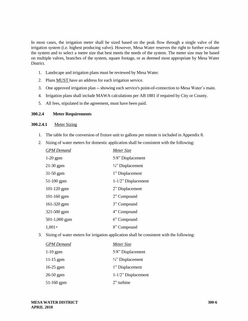
In most cases, the irrigation meter shall be sized based on the peak flow through a single valve of the
irrigation system (i.e. highest producing valve). However, Mesa Water reserves the right to further evaluate
the system and to select a meter size that best meets the needs of the system. The meter size may be based
on multiple valves, branches of the system, square footage, or as deemed most appropriate by Mesa Water
District.
1. Landscape and irrigation plans must be reviewed by Mesa Water.
2. Plans MUST have an address for each irrigation service.
3. One approved irrigation plan -- showing each service's point-of-connection to Mesa Water’s main.
4. Irrigation plans shall include MAWA calculations per AB 1881 if required by City or County.
5. All fees, stipulated in the agreement, must have been paid.
300.2.4 Meter Requirements
300.2.4.1 Meter Sizing
1. The table for the conversion of fixture unit to gallons per minute is included in Appendix 8.
2. Sizing of water meters for domestic application shall be consistent with the following:
GPM Demand Meter Size
1-20 gpm 5/8” Displacement
21-30 gpm ¾” Displacement
31-50 gpm 1” Displacement
51-100 gpm 1-1/2” Displacement
101-120 gpm 2” Displacement
101-160 gpm 2” Compound
161-320 gpm 3” Compound
321-500 gpm 4” Compound
501-1,000 gpm 6” Compound
1,001+ 8” Compound
3. Sizing of water meters for irrigation application shall be consistent with the following:
GPM Demand Meter Size
1-10 gpm 5/8” Displacement
11-15 gpm ¾” Displacement
16-25 gpm 1” Displacement
26-50 gpm 1-1/2” Displacement
51-160 gpm 2” turbine

MESA WATER DISTRICT
APRIL 2018
300-7
161-350 gpm 3” turbine
351-1,000 gpm 4” turbine
1,001-2,000 gpm 6” turbine
2,001-3,500 gpm 8” turbine
3,501-5,500 gpm 10” turbine
5,501+ 12” turbine
Mesa Water reserves the right to size meters.
300.2.4.2 Type of Meter
A turbine meter and strainer shall be used on all irrigation services 2-inch and larger or as determined by
Mesa Water.
A compound meter shall be used on all master metered multi-unit developments or as determined by Mesa
Water.
300.2.5 License Requirements
The applicant’s contractor shall have a Class A or C-34 license. The applicant’s contractor shall have a
business license to operate within the city having jurisdiction.
300.2.6 Mesa Water’s Regulation Regarding Cross-Connection
All domestic water services shall be subject to the provisions of Mesa Water’s “Rules and Regulations for
Water Service”. The following summarizes the cross-connection provisions included within these Rules
and Regulations.
The purpose of these provisions is to protect Mesa Water’s water supply against actual or potential cross-
connections by isolating, within the premises, contamination or pollution that may occur because of
undiscovered or unauthorized cross-connections on the premises. These provisions are in accordance with
the California Administration Code, Title 17 (Public Health), entitled “Regulations Relating to Cross-
Connections”. Additional information concerning backflow prevention may be obtained from the “Manual
of Cross-Connection Control”, Foundation for Cross-Connection Control and Hydraulic Research,
University of Southern California, School of Engineering.
Cross-connections of any type that permit a back flow condition from any source or system other than that
of Mesa Water's domestic water mains are prohibited. A connection constituting a potential or actual back
flow hazard is not permissible unless a back flow device or air gap, which is approved by the California
Department of Public Health and the local health agency and complies with Title 17 of the California
Administrative Code, is installed. Such an installation shall at all times be subject to inspection and
regulation by Mesa Water for the purpose of avoiding possibility of back flow.
Mesa Water recognizes that the water purveyor has a responsibility to take all reasonable precautions to
protect the integrity of the public water supply. Thus, in the exercise of this responsibility, Mesa Water
may need to conduct a cross-connection control survey of the applicant’s plumbing system. Mesa Water

MESA WATER DISTRICT
APRIL 2018
300-8
will not address internal protection requirements. Mesa Water recommends that the applicant or his
engineer contact the local health agency (Orange County Health Care Agency) to ensure the on-site water
system complies with current plumbing codes, and requirements of the local health agency. Mesa Water
has a cross-connection specialist who is available for consulting on any questions regarding cross-
connections.
Mesa Water will not provide any water service to any premises unless the public domestic water supply is
protected as required by State, County and Mesa Water regulations. Except in special situations, it is now
required to have back-flow devices installed for:
All commercial domestic water services.
All industrial domestic water services.
All fire service connections except as noted in Section 300.2.3.2.
All private domestic systems or fire line systems having two, or more, points of connection to
Mesa’s water mains.
All irrigation services on the domestic water system.
All domestic services to sites where there is recycled water on-site.
Back-flow prevention devices shall be approved by the U.S.C. Foundation for Cross-Connection Control
and shall be installed by and at the expense of the customer.
The customer shall have the device: tested annually by a tester certified by the Orange County Health Care
Agency; service such devices to maintain them in satisfactory operating condition; and shall overhaul or
replace such devices if they are found defective. Test results shall be provided before Mesa Water will
accept service as complete.
Records of such annual tests, repairs, and overhauling shall be kept by the customer and copies forwarded
to Mesa Water cross-connection specialist and local health agency within ten (10) working days after
testing.
Service of water to any premises may be discontinued by Mesa Water if a back-flow prevention device
required by Mesa Water’s Rules and Regulations is not installed, tested, and maintained; or if any defect is
found in an installed back-flow prevention device; or if it is found that a back-flow prevention device has
been removed or bypassed; or if unprotected cross-connections exist on the premises. Services will be
restored only when such conditions or defects are corrected to the satisfaction of Mesa Water.
Mesa Water will further define how water lines must be marked where multiple water systems are in use
and outline the duties and responsibilities of a property's water supervisor.
Additional reference for guidelines to when, why, and what types of back-flow and cross-connection
control devices are approved may be found in:
A. “Regulations Relating to Cross-Connections”, California Administrative Code - Title 17 - Public
Health.
B. “Manual of Cross-Connection Control”, published by Foundation for Cross-Connection Control
and Hydraulic Research, University of Southern California, School of Engineering.
C. EPA Cross-Connection Control Manual.

MESA WATER DISTRICT
APRIL 2018
300-9
300.2.7 Backflow Device Locations
All commercial and industrial domestic water services, and domestic services to sites where there is
recycled water on-site, will require that a Reduced Pressure Principle backflow device (RPPD) be installed
immediately downstream of the water meter. The device must be installed in accordance with Mesa
Water’s Standard Drawings. The assembly must be installed above ground and cannot be installed in an
underground vault. These assemblies can be installed in such a manner as to be screened from view, but
must be easily accessible to Mesa Water’s personnel to facilitate testing and servicing. There must be a
minimum of five (5) feet of clearance on all sides of the backflow assembly. In addition, a fifteen (15
foot wide easement must be dedicated to Mesa Water from the public right-of-way to the fireline
backflow assembly combination.
All fire services requiring a backflow assembly as specified in Section 300.2.3.2 (Fire Service
Requirements) must be installed in accordance with Mesa Water’s Standard Drawings. The required
backflow assemblies must be on private property and shall be located adjacent to the building but upstream
of the residential building valve, and shall be testable and easily accessible for maintenance and repairs. In
addition, a fifteen (15) foot wide easement must be dedicated to Mesa Water from the public right-of-way
to the backflow assembly.
300.3 PROVIDING REQUIRED EASEMENTS
If an easement outside of the public right-of-way is granted by the District Engineer and General Manager,
per Section 4.2.15 of the Rules and Regulations for Water Service for construction and/or maintenance of
water facilities, including but not limited to, water mains, hydrants, meter vaults, and any other water
appurtenances; its minimum width shall be 15 feet for water mains; and 5 feet on all sides for meters, fire
hydrants, meter vaults, and other appurtenances, unless otherwise determined by Mesa Water.
An easement running parallel with a lot line shall not be split so as to occur on two lots. The easement,
title report, and legal descriptions with accompanying sketch and plans shall be prepared by the applicant's
engineer, two copies of which shall be sent to Mesa Water’s Engineering Department, or easements for
Mesa Water facilities shall be shown on a tract or parcel map.
Easement descriptions shall be in a form acceptable to Mesa Water and will be checked by Mesa Water’s
Engineering Department. Easements shall also be shown on the construction plans. Mesa Water will
approve the plans only after all required easements have been deeded to Mesa Water District together with
any necessary partial re-conveyance or subordination agreements. Exhibits will be 8-1/2" X 11", no
exceptions.
Along public streets, a three or five foot utility parallel easement on private property for Mesa Water
District may be required depending upon public right-of-way widths and sidewalk locations.
Applicant shall submit two copies of the easement description, plat and boundary closure calculations to
Mesa Water for review.
If acceptable, the applicant shall furnish two additional copies of the description, plat and boundary closure
calculations, signed by a professional land surveyor, a current (within 30 days) title report of the property
reflecting all deeds of trust and encumbrances, and subordinations signed by the trustees shown on the title
MESA WATER DISTRICT
APRIL 2018
300-10
report. If not acceptable, Mesa Water will return the documents with the required corrections noted.
Proposed Easements shall be approved by Mesa Water’s Board of Directors prior to the installation and
activation of water service.
All blanks in the documents, such as project identifications, title report number, map and book numbers
and pages, dates, etc., must be filled in. The easement sketch must contain a vicinity map showing the
location of the easement in relation to major streets and highways, as well as a sketch depicting the
easement boundaries with bearings, distances, points of beginning, north arrow, and any other information
required by Mesa Water.
NOTE: Approval by Mesa Water District will not be given for the tract water systems until all
easements have been obtained to the satisfaction of Mesa Water District.
300.4 COST ESTIMATE
The developer's engineer shall provide the quantities, to allow Mesa Water’s Engineering Department to
estimate the project costs for the water facilities to be dedicated to Mesa Water. The items listed will
include, but will not be limited to pipes, valves, meters & appurtenances, backflow devices, connections,
hot taps, and facilities construction.
300.5 FIRE AUTHORITY APPROVAL
After the first plan check by Mesa Water, it will become the responsibility of the applicant's engineer to
have the local Fire Authority approval before submitting the water improvement plans for a second plan
check. Fire flow requirements for the development shall be submitted with the second plan check
submitted as well as the required fire hydrant spacing. Mesa Water reserves the right to require additional
fire protection or modify water facility sizes as deemed necessary. Fire Department letter of requirement
as stated under condition of approval will be submitted.
Local Fire Authority’s approval shall be coordinated by the Developer and/or his engineer and will be
required prior to Mesa Water’s approval of the plans.
300.6 SECOND (& SUBSEQUENT) PLAN CHECK SUBMITTALS
The applicant/engineer shall submit the following items for second (and all subsequent plan-checks) of any
residential, commercial, or industrial subdivisions:
1. One (1) set of the revised water improvement plans (bond paper) and one (1) set tract/parcel map
(bond paper). The plans must be approved by the Fire Authority having jurisdiction over the area
of development prior to the second plan check.
2. Redlined plan check set from first plan review.
When the plans are substantially complete, with only minor revisions remaining, Mesa Water may choose
to compute the required Capacity and Plan Check Deposits (Payment Voucher included in Appendix 3)
and prepare the Water Service Agreement. The applicant will be notified when the agreement and the
Payment Voucher are available. One (1) red-lined set of plan check comments will be returned to the
applicant’s engineer for corrections upon completion of any plan check.
MESA WATER DISTRICT
APRIL 2018
300-11
300.7 WATER SERVICE AGREEMENT
When the plans are substantially complete, with only minor revisions remaining, Mesa Water will compute
the required Capacity Charges, Meter Charges, and Administrative and Engineering Fees (Payment
Voucher included in Appendix 3) and prepare the Water Service Agreement. The applicant will be
notified when the agreement and the Payment Voucher are available.
Mesa Water will send a draft copy of the Agreement to the developer including the attached Exhibit “A”
summarizing the Water Service Fees and Charges.
300.7.1 Bonds
The applicant will provide, concurrently with the signed Water Service Agreement, if applicable, Payment
and Performance Bonds, in connection with the water facilities to be constructed and for an amount to be
determined per section 200.2.3 of this document.
300.8 FINAL PLAN APPROVAL
Water improvement plans must be approved by the District Engineer before any construction can start.
Approval by the District Engineer will be contingent upon satisfying the following requirements:
1. All required corrections have been made on the water improvement plans, and are in conformance
with Mesa Water’s Standard Specifications.
2. The Water Service Agreement (Appendix 4) has been executed by the applicant and returned to
Mesa Water.
3. All required easement documents have been executed and delivered to Mesa Water. Tract/parcel
maps must be signed by Mesa Water prior to plan approval.
4. All required Fees and Charges have been paid by the developer/applicant.
5. All required bonds have been posted with the appropriate entity.
6. All plan submission requirements have been met (mylars, prints and CD).
When the plans have been approved, the applicant’s engineer will be notified.
300.9 WATER SERVICE FEES AND CHARGES
The applicant agrees to pay all administrative and engineering fees, (including inspection and plan check
costs), as well as Capacity Charges, meter charges, interim water service line charges, if applicable, and
any other charges of Mesa Water. Such fees and charges shall be set forth on Exhibit “A” of the Water
Services Agreement between the applicant and Mesa Water District.
300.10 BOARD APPROVAL OF AGREEMENT

MESA WATER DISTRICT
APRIL 2018
300-12
Upon satisfactory completion of items 300.1 through 300.9, Mesa Water will, at the request of the
applicant, finalize cost of services and issue a permit.
300.11 SIGNED PLANS
300.11.1 Submittal of Signed Plans
Once the plan has been signed by the District Engineer, the applicant must submit to Mesa Water a 24”
by 36” 4-mil duplicate mylar of the signed plan for the Engineering Department files along with one
full-sized set of prints on bond paper (blueprints) of the approved plans and one (1) compact disk (CD).
The CD will contain a single PDF file of the entire approved plan set, i.e. reflecting Mesa Water’s
approval signatures. The PDF file will be of a quality high resolution since it will be made a part of
Mesa Water’s public electronic library of plans.
300.11.2 Validity of Signed Plans
Plans will be valid for one (1) year from the date of Mesa Water’s approval. If construction has not started
within one year from date of approval, the signed plans shall become "null and void." Mesa Water will
require rechecking of the plans and it reserves the right to charge additional plan check fees.
300.12 ORDER OF PRECEDENCE OF STANDARDS
In the case of conflict between the specifications, drawings, and permit requirements, with regard to
construction of facilities, the following order of precedence will apply: the permit requirements of other
agencies, special details, plans, special conditions, Standard Drawings, Technical Specifications, General
Conditions, the Standard Specifications for Public Works Construction, and the Cal Trans Manual.
Figured dimensions of the drawings shall govern, but work not dimensioned shall be as directed. Work not
particularly shown or specified shall be the same as similar parts that are shown or specified or as directed.
Full-size details shall take precedence over scale drawings as to shape and details of construction. Scale
drawings, full-size details, and specifications are intended to be fully cooperative and to agree; but should
any discrepancy or apparent difference occur between the plans and specifications, or should errors occur
in projects being constructed by others affecting the work, and the contractor proceeds with the work
affected without instruction from Mesa Water, the contractor shall be fully responsible for any resultant
damage or defect.
300.12.1 Permit Requirements
The permit requirements, as approved by the agency having jurisdiction, will take precedence over the
below listed details and standards with regard to the construction of water facilities.
300.12.2 Special Details
The special details, as approved by the signature of the District Engineer, will take precedence over the
below listed details and standards with regard to the construction of water facilities.
300.12.3 Plans
MESA WATER DISTRICT
APRIL 2018
300-13
The plans, as approved by the signature of the District Engineer, will take precedence over the below listed
details and standards with regard to the construction of water facilities.
300.12.4 Special Conditions
The special conditions, for the specific project and incorporated into the project contract documents, as
approved by the District Engineer, will take precedence over the below listed standards with regard to the
construction of water facilities.
300.12.5 Mesa Water’s Standard Drawings
Mesa Water's Standard Drawings, as approved by the signature of the District Engineer, will take
precedence over the below listed details and standards with regard to the construction of water facilities.
300.12.6 Mesa Water’s Standard Specifications
Mesa Water’s “Standard Specifications and Drawings,” as approved by the signature of the District
Engineer, will take precedence over the below listed standards with regard to the construction of water
facilities.
300.12.7 Mesa Water’s Technical Specifications
The Technical Specifications, of Mesa Water’s "Standard Specifications and Drawings," as detailed above,
and as approved by the District Engineer, will take precedence over the below listed standards with regard
to the construction of water facilities.
300.12.8 Standard Specifications for Public Works Construction
The Standard Specifications for Public Works Construction as reference by Mesa Water’s details,
standards and specifications, will take precedence over other standards with regard to the construction of
water facilities.
The "Standard Specifications for Public Works Construction," (Green Book), are incorporated herein by
this reference. Copies may be purchased from Building News, Inc., 3055 Overland Avenue, Los Angeles,
California 90034.
300.12.9 The Cal-Trans Manual
The Cal-Trans Manual, as referenced by Mesa Water’s details, standards and specifications, will take
precedence over other standards with regard to the construction of water facilities. The "Standard
Specifications," CALTRANS, are incorporated herein by this reference, copies of which may be
purchased from the State of California, Department of Transportation.
300.13 RECORD DRAWINGS
Record drawings documenting “as-built” changes will be provided to Mesa Water once construction has
been completed. These record drawings will be reviewed by Mesa Water’s Construction Inspector to
confirm its accuracy.

MESA WATER DISTRICT
APRIL 2018
300-14
300.14 PROJECT CONSTRUCTION
300.14.1 Notification
Notice shall be given to Mesa Water Construction Inspector at least 48 hours before starting construction.
Signed water improvement plans must be delivered to the inspector at least two working days before the
contractor will be allowed to start construction. The City or County inspector shall be notified prior to
work within public right-of-way.
300.14.2 Preconstruction Meeting
A preconstruction conference is to be held 24 hours before starting construction, at which will be present
the applicant's contractor's working foremen and/or job superintendent, the applicant's engineer, and Mesa
Water Construction Inspector. The purpose of this meeting will be to answer any questions on Mesa Water
specification requirements, to obtain the contractor's construction schedule, and to discuss any known
circumstances that might affect job installation.
300.14.2.1 Preconstruction Meeting Agenda
Without relieving the developer of responsibilities outlined elsewhere in the specifications, Mesa Water
will present a list of requirements that may contain, but will not be limited to, the following items:
1. Order of work.
2. Working hours.
3. Operation manuals.
4. Manufacture’s specifications.
5. Pressure test results.
6. Bacterial test results.
7. Record Drawings
300.14.2.2 Order of Precedence
The order of precedence as defined in Section 300.12 will be reviewed in the pre-construction meeting.
300.14.3 Curbs Installed Before Starting Water Facilities
It is a basic requirement of Mesa Water that the curbs be installed in tracts prior to starting the
installation of water facilities. They act as positive grade control for setting services and fire hydrants.
Mesa Water may approve an exception if the developer signs a written letter, agreeing to comply with
the following requirements:
1. All requirements shall be met before the excavation of pipeline trenches.
2. The owner is to submit engineered drawings showing both the plan and profile of the proposed
pipelines for Mesa Water review and acceptance.
MESA WATER DISTRICT
APRIL 2018
300-15
3. The owner is to provide survey staking. The proposed pipelines per the profile with cuts to flow
line at a maximum of 25-foot stationing showing all horizontal and vertical grades breaks, tees, and
valves, fire hydrant, blow-offs, air vacs, services, and all other appurtenances indicated on the
plans.
4. Prior to backfill, the engineer shall certify line and grade of the pipeline and all the appurtenances
and provide Mesa Water Construction Inspector with a copy of the certification.
5. In the event that a portion or any part of the pipeline and its appurtenances is not installed to the
satisfaction of the Mesa Water Construction Inspector, the owner agrees to expose and re-lay the
pipeline accordingly.
300.14.4 Water for Construction Purposes
The contractor will be furnished construction water at a connection point designated by Mesa Water after
payment of fees. The water shall be taken through a metered delivery and the developer shall pay all costs
related thereto, including (but not limited to) Mesa Water's standard deposit for temporary meter and actual
costs of water used, pumping costs, loading, hauling and the use thereof. The developer shall make all
arrangements for transporting the water to the construction site.
300.14.5 Inspection of Work
All materials and equipment that would be in direct contact with the potable water supply shall be
NSF 61 compliant.
300.14.5.1 Access
All work shall be subject to inspection by Mesa Water and shall be left open and uncovered until approved
by appropriate Mesa Water personnel.
300.14.5.2 Domestic Water System Inspections
The Contractor shall not proceed with any subsequent phase of work until the previous phase has been
inspected and approved by Mesa Water. Inspection shall be made at the following intervals of work:
1. Delivery of materials to job site.
2. Trench excavation and bedding.
3. Placing of pipe, fittings, and structures, including notification/warning tape on potable mains and
recycled irrigation water main and service lines.
4. Pouring all concrete anchors and thrust blocks.
5. Placing and compacting the pipe zone back fill.
6. Backfilling balance of trench to grade. Compaction tests are to be performed by governing agency
road departments in public right-of-way or by private soils consultant retained by the applicant and
acceptable to Mesa Water in private streets and easements. Copies of test results shall be given to
Mesa Water, and the governing agency, by the applicant for approval before final acceptance of
the work. Backfilling and repaving shall be in accordance with the requirements of the city having

MESA WATER DISTRICT
APRIL 2018
300-16
jurisdiction.
7. Pressure testing all mains and services.
8. Disinfecting and flushing (Chlorination and bacteriological testing).
9. Health samples.
10. Repaving trench cuts.
11. Raising valve box covers to finish grade and paint to Mesa Water Standards.
12. Fire hydrants painted and pads poured.
13. Installation of service lines, appurtenances meter boxes, and customer service valves.
14. Connection to the existing system.
300.14.6 Mesa Water Authority
300.14.6.1 Access
Mesa Water shall at all times have access to the work during construction and shall be furnished with every
reasonable facility for ascertaining full knowledge respecting the progress, quality of labor, and character
of materials used and employed in the work. No pipe, fittings, or other materials shall be installed or
backfilled until inspected and approved by Mesa Water or its representative. The contractor shall give due
notice in advance of backfilling to Mesa Water Inspector so that proper inspection may be provided.
300.14.6.2 Obligation
Inspection of the work shall not relieve the contractor of any obligations to complete the work as
prescribed by the Standard Specifications. Any known defective work shall be corrected before testing or
final inspection will be permitted. Unsuitable materials may be rejected, even though they may have been
previously overlooked by the inspector.
300.14.6.3 Suspension of Work
Mesa Water shall have the authority to suspend the work wholly or in part for such time as it may deem
necessary if the contractor fails to carry out orders given by Mesa Water's inspector, or to perform any
required provisions of the plans and specifications. The contractor shall immediately comply with a written
order of Mesa Water to suspend the work wholly or in part. The work shall be resumed when methods or
defective work are corrected as ordered and approved in writing by Mesa Water.
300.14.7 Pressure Test
A pressure test of the newly constructed domestic water lines shall be conducted as detailed in Technical
Specification Section 15042.
300.14.8 Water for Flushing, Testing and Sterilization
Domestic water for flushing, testing and sterilization of the completed pipelines or sections thereof will be
available from Mesa Water at the point, or points, of connection with the existing domestic water mains via

MESA WATER DISTRICT
APRIL 2018
300-17
the construction water connection. The developer shall make all arrangements for this water with Mesa
Water, which shall designate the exact location of the outlet or outlets and the time periods these
connections may be used.
If, due to construction problems or for any other reason, the developer desires to use water from some other
source for testing, flushing, or chlorination, it shall be the responsibility of the developer to obtain the
source of water, which water shall be tested and approved by the County of Orange Health Care Agency
prior to the use thereof. All expenses for obtaining and using another source of water shall be paid by the
developer.
Flushing operations shall be conducted with a residual line pressure not less than 30 psi and a Mesa Water
representative will be present. Adequate connections to conduct the flushing, testing and sterilization
operations shall be furnished by the contractor and reviewed by the engineer, at no added cost to Mesa
Water, and the developer shall pay for any and all costs for flushing, testing and sterilization.
300.14.9 Chlorination and Bacteriological Testing
After a passing pressure test, the domestic water lines shall be chlorinated and tested for bacteria as
detailed in Technical Specification Section 15041.
300.14.10 Final Domestic Water Facilities Inspection
Before final acceptance, Mesa Water's inspector will make a final inspection of all work, accompanied by
the contractor's superintendent or representative, to verify that:
1. All phases of the job are complete in accordance with plans and specifications.
2. All valve boxes are raised to finish grade and that all repairs are completed.
3. All valves are referenced and the inspector has been given all reference measurements. Valves
shall be located by a 2-inch "V" chiseled in the adjacent curb face.
4. All right-angle meter stops, and the meters, are properly positioned and all meter boxes are
positioned and raised to proper grade.
5. Fire hydrants are raised to proper grade, are in a vertical position, painted; and its concrete pad is
poured.
6. Backfill has passed all compaction testing.
7. All system valves are turned and left open (except those specifically required to be normally
closed), turns required for complete open/close cycle are recorded on the record drawings.
8. Domestic water lines have been chlorinated and have passed the required bacteriological tests.
9. Water line pressure testing and flushing have been completed.
10. The job site is clean and cleared of all the contractor's equipment and materials.
11. All service lateral locations have been marked on curbs.
12. Certified test results have been provided for all backflow prevention devices.
13. A mylar and a blue line or bond copy of the water facility plans labeled "RECORD DRAWINGS"
MESA WATER DISTRICT
APRIL 2018
300-18
with the "As-Built" revisions have been delivered to Mesa Water.
14. Digital submittal of plan information in a format acceptable to Mesa Water.
300.14.11 Raising of Valve Boxes
For paved areas in the applicant's development, Mesa Water will raise all valves for Mesa Water
constructed facilities to the first lift of pavement. For succeeding pavement lifts, it shall be the
responsibility of the applicant to raise to grade all valves after each lift of pavement.
Applicant is required to raise all valves constructed by applicant after each pavement lift.
300.15 RECORD MYLARS
Record drawings shall be completed and submitted by the developer's California Registered Civil Engineer
(for Easement documents), as detailed in these Standard Specifications. The applicant shall furnish to Mesa
Water “record drawings” (one set of blue line or bond prints and one set of mylar) showing all revisions to
the original approved plans. All future extension of water transmission mains will have the invert elevation
of the terminal pipe verified by the applicant and posted on the drawings. Failure to comply with these
requirements will necessitate withholding the letter of acceptance.
300.16 EASEMENT VERIFICATION
The developer's engineer or Professional Land Surveyor will verify in writing that the facilities to be
accepted by Mesa Water were constructed within the easements as listed in the easement documents
300.17 METER USE AND FEE VERIFICATION
With the record drawings, the applicant is to furnish Mesa Water a cost breakdown of the newly installed
facilities for Mesa Water accounting purposes. This is to be furnished to Mesa Water before an acceptance
letter releasing bond will be written. Mesa Water will verify the quantities used in the calculation of the
fees for the Water Service Agreement. Any adjustments to the fees will be made at this time.
300.18 BOARD ACCEPTANCE
After satisfactory completion of the items in Section 300.1 through 300.17, Mesa Water will, upon the
request of the developer, petition Mesa Water District's governing board for acceptance of the project, and
the commencement of the one year warranty period.
Mesa Water will also re-evaluate the plans for compliance with the Water Service Agreement and reserves
the right to re-assess the charges and fees if deviations from the originally approved plans have been made.
Changes include, but are not limited to: The number of service connections, meter sizes, building square
footage, the irrigated area, the number of dwelling units, and any other measure used to calculate the
original charges and fees.
300.19 RELEASE GIVEN TO CITY AND/OR COUNTY

MESA WATER DISTRICT
APRIL 2018
300-19
300.19.1 Bond Release
All final inspection requirements shall be fulfilled before Mesa Water will give its final acceptance
notice to the city and/or County for release of the applicant's bond to those agencies. The applicant's
bond with Mesa Water shall remain in effect in accordance with the Water Service Agreement.
300.19.2 Domestic Water Service in service prior to Acceptance
Mesa Water’s District Engineer may approve putting newly installed domestic water system into service
prior to Board acceptance after compaction has been approved by the governing agency and the portions
have been pressure tested, chlorinated, flushed, and have passed the bacteriological test and inspection
for domestic water mains. This partial acceptance shall be granted only upon written request from the
applicant and subsequent approval by the District Engineer. Upon this written approval for partial
acceptance of facilities, the applicant shall be relieved of the duty to maintain the portions so used or
place into operation provided, however, that nothing in this section shall be constructed as relieving the
applicant of full responsibility for completing the work in its entirety, for making good any defective
work and materials, for protecting the work from damage, and for being responsible for damage and for
work as set forth in the agreement and other contractual documents; nor shall such action by Mesa
Water be deemed completion and acceptance, and such action shall not relieve the applicant of the
guarantee provision of the Water Service Agreement with Mesa Water District.
300.20 SECURITY RELEASE
If in the time period of one year from the date of Board acceptance no failure of the system has occurred,
which has gone unrepaired by the developer, to the satisfaction of Mesa Water: the developer may petition
Mesa Water District to request final acceptance of the project by the Board and release of the surety.
END OF SECTION
MESA WATER DISTRICT
APRIL 2018
400-1
SECTION 400
DESIGN CRITERIA, WATER FACILITIES
The following sections are design criteria to be used in the design of water facilities for Mesa Water. The
developer/applicant and his engineer shall be responsible to ensure that designs submitted are consistent
with Mesa Water “Rules and Regulations for Water Service”, these Standard Specifications, and generally
accepted standards of good engineering practice.
400.1 MINIMUM SIZE MAINS
The normal minimum size distribution main pipe shall be looped 8-inch AWWA C-900 PVC, SDR-14,
unless otherwise noted and approved. On short cul-de-sac dead-end mains 4-inch (with a maximum of ten
(10) each, 1-inch or smaller services) or 6-inch (with more than ten (10) each, 1-inch or smaller service
lines) lines may be allowed, however, 8-inch size main must be used to the last fire hydrant.
These smaller mains may be individually approved by the District Engineer on dead-end mains without fire
hydrants. These mains shall be sized so that sufficient water is regularly drawn to prevent stagnation.
400.2 DESIGN FLOW AND PIPE VELOCITY CRITERIA
The criteria for velocity shall be as described herein. The maximum velocity in a line shall not exceed 5 fps
(feet per second) during the peak hour condition. The peak hour is defined as 4 times the average day
demand. The maximum velocity in a line shall not exceed 7 fps during the maximum day plus fire demand
condition. The maximum day is defined as 2 times the average day demand.
400.3 TYPE OF MAIN PIPE
Distribution Mains. Typically, AWWA C-900 P.V.C. pipe, SDR-14 is to be used for distribution mains of 4
inches thru 12 inches in diameter.
Transmission Mains. For 16-inch thru 20-inch diameters, pipe shall be ductile-iron pipe, Class 200, or
AWWA C-905 P.V.C. pipe, SDR-18 or CML&C steel pipe. For pipe, 24 inches and larger in diameter, only
CML&C steel pipe will be allowed.
400.4 MINIMUM DEPTH TO TOP OF WATER MAIN PIPE
400.4.1 Residential Areas (Distribution Mains 10"and smaller)
The top of the pipe is to be a minimum of 30 inches below the street subgrade or 30 inches below the
undercut, whichever is greater, unless indicated otherwise on the project construction plans or as directed
otherwise by the Mesa Water Inspector because of unusual field conditions. At no time shall the pipe have
less than 42 inches of cover between the top of the pipe and the finished street grade.
The top of pipe is to be a minimum of 48 inches below finish grade in unpaved areas.
MESA WATER DISTRICT
APRIL 2018
400-2
400.4.2 Transmission Mains (12" and larger)
The top of the pipe is to be a minimum of 36 inches below the street subgrade or 36 inches below the
undercut, whichever is greater, unless indicated otherwise on the project construction plans or as directed
otherwise by the Mesa Water Inspector because of unusual field conditions. At no time shall the pipe have
less than 48 inches of cover between the top of the pipe and the finished street grade.
The top of pipe is to be a minimum of 60 inches below finish grade in unpaved areas.
400.4.3 Storm Drain Systems
Storm drain systems must be designed with sufficient cover so that the water mains and service laterals can
be constructed over the top of the storm drain mainline and laterals while still maintaining the above
minimum depth of cover.
400.5 STANDARD LOCATION
Water main center-lines shall normally be located six (6) feet from the curb face for all pipelines 12-inches
in diameter and smaller. For pipelines 16-inches in diameter and larger, the water main center-line shall be
located eight (8) feet from the curb face. Alignments may need to be deflected to avoid cross gutters,
concrete bus lanes or other interferences as directed by Mesa Water.
Where water pipelines are designed to cross perpendicular beneath retaining walls or other structures
(specific written permission required for each instance), the pipeline shall be constructed in a steel pipe
casing of sufficient size and thickness and with a minimum vertical clearance of at least eighteen (18) inches
from the footing or structure itself.
400.6 WATER VALVE SPACING
As a general rule, there should be three (3) control valves where one main ties into another. Where two
mains cross, there shall be four valves.
On long blocks, intermediate valves should be installed so that no more than twenty-eight (28) dwelling
units, six hundred (600) feet of main, or two (2) fire hydrants will be out of service at any time. Additional
looping of the main lines may be necessary to satisfy this condition and the arrangement of valves within the
distribution system will be reviewed to identify the optimum network layout.
In most cases where water mains pass through easements outside traveled streets, a valve shall be located at
each end of the easement.
The final determination of the quantity of valves and their locations shall be as directed and approved by
Mesa Water.
400.7 SEPARATION REQUIREMENTS
400.7.1 Horizontal Separation
State Health Department regulations require that new water mains shall be installed at least ten (10) feet
horizontally from and one (1) foot above, any parallel pipeline conveying:
MESA WATER DISTRICT
APRIL 2018
400-3
Untreated sewage;
Primary or secondary treated sewage;
Disinfected secondary recycled water; and
Hazardous fluids such as fuels, industrial wastes, and wastewater sludge.
New water mains shall be installed at least four (4) feet horizontally from, and one (1) foot vertically above,
any parallel pipeline conveying: disinfected tertiary recycled water (Title 22); and storm drainage.
If crossing a pipeline containing sewage, recycled water, or storm drainage, a new water main shall be
constructed no less than 45-degrees to and at least one (1) foot above the pipeline. No connection joints
shall be made in the water main within eight (8) horizontal feet of the other pipeline.
The vertical separation noted above is required only when the horizontal distance between a water main and
the pipeline carrying the above fluids is less than ten (10) feet.
The minimum separation distances noted above shall be measured from the nearest outside edge of each
pipe barrel.
With the State Health Department’s approval, newly installed water mains may be exempt from the
separation distances noted above if the newly installed main is:
Less than 1,320 linear feet in length;
Replacing an existing main, installed in the same location, and has a diameter no greater than six (6)
inches more than the diameter of the main it is replacing; and
Installed in a manner that minimizes the potential for contamination, including, but not limited to:
sleeving the newly installed main; or utilizing upgraded piping material.
These requirements are shown on Mesa Water’s Separation Requirements Standard Drawing as well as the
special construction methods which may be used where this separation cannot be achieved. Separation
other than the Health Department minimums must be approved by the District Engineer.
400.7.2 Vertical Separation
Normally, water, sewer, and recycled water shall be located vertically from the street surface of the higher
quality, i.e., domestic water shall be above recycled water and recycled water shall be above sewer.
Whenever a crossing must occur where a sewer main passes within one (1) foot of a domestic water main,
special construction will be required as shown on Mesa Water Separation Requirement Standard Drawing.
Encasement may be required if vertical separation requirements cannot be met. One of the following types
of encasement may be required:
1. Reinforced concrete encasement, a minimum thickness of 6 inches.
2. Piping within a continuous steel casing which shall have a thickness of not less than 1/4 inch.

MESA WATER DISTRICT
APRIL 2018
400-4
If a sewer is above a water main, the special construction shall extend a minimum of ten (10) feet of
horizontal clearance on both sides, or if not feasible, center the piece of new water pipe under the crossing to
maximize this horizontal clearance.
If a sewer is located below a water main, and within a vertical distance of a one (1) foot clearance distance,
the special construction shall extend a minimum of four (4) feet of horizontal clearance on both sides of the
crossing. These construction requirements shall not apply to house laterals that cross perpendicular less than
one (1) foot below a pressure water main.
400.7.3 Separation from New and Existing Utilities
Construction of new utilities or structures shall maintain a minimum of five (5) foot parallel separation and a
minimum of one (1) foot vertical separation from all Mesa Water pipelines, construction of new water
facilities shall maintain a minimum of five (5) foot parallel separation and one (1) foot minimum vertical
separation from all existing utilities and structures.
400.8 FIRE FLOW REQUIREMENTS
The design criteria to be used for determining fire flow requirements shall be the actual fire flow
requirements as determined by the Costa Mesa Fire Department, or per appropriate local fire
jurisdiction for the specific area under development.
Before designing the domestic water system for a project, the applicant shall obtain the Orange County Fire
Authority or the appropriate local fire jurisdiction fire flow requirements for the project. These requirements,
plus indication of the Fire Authority's approval, are required to be on the improvement plans prior to Mesa
Water's approval. All existing fire flow tests shall be performed by Mesa Water. Mesa Water will charge a
fee to perform this fire flow test. As a general guide, the following shall be considered, as the minimum:
400.8.1 Residential Dwelling Units
The water system shall be capable of providing a residential fire flow minimum of 2,000 gpm, combined
flow, for a 4-hour duration from any two adjacent hydrants at a minimum 20 pounds of residual pressure
(psi) at the main. For residences 3,600 square feet and under and not contiguous with open space areas, the
minimum requirement shall be 1,000 gpm per hydrant at 20 psi (for a total flow of 2,000 gpm). For
residences 3,600 square feet and under which are contiguous with open space areas, the minimum
requirement shall be 1,000 gpm per hydrant at 30 psi (for a total flow of 2,000 gpm). For residences over
3,600 square feet, the Fire Authority shall be consulted. The open space area is defined as any area
bordering an undeveloped open space with no fire control mechanism. New residential dwelling units may
be constructed with residential fire sprinkler systems (if required by NFPA 13D or NFPA 13R) which will
reduce the minimum fire flow requirements.
400.8.2 Schools and Commercial Areas
The system shall be capable of providing a fire flow of at least 3,000 gpm for 3 hours duration (or as
required by the Fire Authority) out of any two adjacent hydrants at a minimum 20 pounds of residual
pressure at the main. Most schools and commercial areas will have built-in sprinkler protection for the
buildings which will reduce the minimum fire flow requirements.
400.8.3 Industrial Areas

MESA WATER DISTRICT
APRIL 2018
400-5
In industrial developments requiring a high fire flow, the applicant shall consult with the Fire Authority to
discuss options for upgrading the domestic water system to deliver the fire flow or provide built-in sprinkler
protection for the structures.
400.9 FIRE HYDRANT LOCATIONS
The location of fire hydrants shall be as determined by the Orange County Fire Authority or the appropriate
local fire jurisdiction for the specific area under development. The exact location with respect to the curb
and sidewalk shall be as shown per Mesa Water Standard Drawings.
400.9.1 Fire Hydrant spacing
The maximum fire hydrant separation shall be 300 feet from fire hydrant to fire hydrant. The actual spacing
will be determined by the Fire Authority. Fire hydrants shall be located a minimum of three (3) feet from
the ECR or BCR at intersections or near lot lines. No fire hydrant shall be located within 3 feet of a
driveway, or closer than 40 feet to any structure (unless approved by the Fire Authority).
In selected situations where the fire hydrant run is over 20 feet, the size of the hydrant lateral may be
increased to 8-inches.
400.9.2 Types of Hydrants
Wet barrel all- bronze type hydrants with check valve, as specified by Mesa Water Standard Specifications,
are to be used at all locations.
400.9.3 Plan Requirements
Fire hydrants shall be shown on the plans where the hydrant is to be located with respect to the property
line. Mesa Water fire hydrants shall be located within the public right of way. Maintenance and
construction of private hydrants shall be the responsibility of the property owner, and painted red. The
building foot prints or building pad areas are also to be shown.
400.10 SERVICE MATERIALS AND MINIMUM SERVICE SIZE
400.10.1 General
Approved materials and manufacturers for various service material tubing and connections are as listed in
Mesa Water's Standard Specifications.
400.10.2 Minimum Domestic Service Size
Minimum domestic service line size shall be 1-inch in diameter for 5/8-inch, ¾”-inch and 1-inch meters.
Shared services, termed a “Dominguez Tee,” that serve two adjacent properties shall require an individual
service upgrade to accommodate an increase in meter size due to a remodel or new construction demands.
Improvements shall be paid by the property owner undertaking the proposed property improvements. The
sizing of the service shall be specified on the plans designated by lot numbers. Services for private-street
residential, commercial or industrial developments are to be as shown on plans and may require a detail on
the plans of the location of the proposed service.

MESA WATER DISTRICT
APRIL 2018
400-6
400.10.3 Type of Service Line
Acceptable service line material is as described below:
1-inch and 2-inch service lines shall be copper tubing, Type “K” soft.
4- inch and larger service lines shall use PVC pipe per Technical Specification Section 15064. 3-
inch service is not acceptable, use 4-inch piping upstream of meter.
400.10.4 Meters
All residential meters 5/8" through 2" will be furnished by Mesa Water, subsequent to payment of all
applicable charges, and installed by Mesa Water. All industrial, commercial, individual service meters 3"
and larger will be furnished by Mesa Water, subsequent to payment of all applicable charges, and installed
by the applicant.
400.10.5 Pressure Reducing Valves
Individual pressure regulators are required by the Uniform Plumbing Code if the average static pressure in the
water main is 80 psi or more. Where required, the water service shall be provided with approved pressure
regulators set at 80 psi, and shall be installed per Mesa Water Standard Drawings or appropriate governing
agency's standards.
400.11 STANDARD WATER NOTES
The following Standard Water Notes shall be included on all improvement plans or water system
construction plans:
1. All water system work shall conform to Mesa Water's "Standard Specifications for the Construction
of Water Facilities", as last revised. The contractor shall have a copy of the project plans and Mesa
Water’s Standard Specifications on the job at all times.
2. A pre-construction meeting of representatives from various other affected utility companies,
agencies and the contractor shall be held on the job site (or at a location approved by Mesa Water)
at least forty-eight (48) hours prior to the start of work.
3. Mesa Water’s Inspector shall be notified at least two working days before start of work or any
inspection. To arrange for inspection, call (949) 631-1291.
4. Water mains shall be installed after the installation of curb and gutter at six feet off of curb face, or
as staked by the applicant's surveyor at a minimum 50-foot stationing, if there are no existing curbs.
5. Water meters shall not be located within a driveway. Any water meter found to be within a
driveway shall be removed completely and reinstalled at the proper location, at no cost to Mesa
Water.
6. All water service laterals shall be constructed perpendicular to the water main without bends or
angles from the connection point on the main.
7. All main line valves shall be maintained so as to be accessible during tract development and
construction. All valve stem tops having over 48 inches of cover will require an extension meeting
Mesa Water Standard Drawing.
MESA WATER DISTRICT
APRIL 2018
400-7
8. The top of the pipe 10 inches in diameter and smaller shall be a minimum of 30 inches of cover
from the street subgrade or undercut, whichever is greater, unless indicated otherwise on the job
plans or as directed otherwise by Mesa Water Inspector because of unusual field conditions. At no
time shall the pipe have less than 42 inches of cover between the top of the pipe and the finished
street grade.
9. The top of the pipe 12 inches in diameter and larger shall be a minimum of 36 inches of cover from
the street subgrade or undercut, whichever is greater, unless indicated otherwise on the job plans or
as directed otherwise by Mesa Water Inspector because of unusual field conditions. At no time shall
the pipe have less than 48 inches of cover between the top of the pipe and the finished street grade.
10. Pipe shall be bedded and backfilled per Mesa Water Standard Drawings.
11. Fire hydrants shall be installed in accordance with Mesa Water’s Standard Drawings and installed
behind curbs and sidewalks where the sidewalks are adjacent to the curbs. Fire hydrants shall be per
Mesa Water's Standard Specifications and shall have a concrete pad poured around them. All fire
hydrants shall be set with the bottom flange 4 inches above the concrete pad or sidewalk.
12. All water mains 4-inches through 12-inches shall be SDR-14 or thicker, AWWA C-900 PVC,
unless otherwise approved by Mesa Water.
13. No facility is to be backfilled until inspected and approved by a Mesa Water Inspector.
14. Shut down or tapping of existing waterlines to facilitate connection to existing facilities shall be
coordinated with Mesa Water. Any relocation of existing facilities are subject to approval of the
District Engineer.
15. No ”hot-taps” or other tie-in connections shall be made to existing Mesa Water mains prior to
conducting and passing an approved pressure test and a bacteriological test on the new water
distribution system.
16. Tapping sleeves, where called for on the plans, shall be pressure tested in an approved manner in
the field, in the presence of Water Mesa Inspector, prior to tapping the main line. Tapping of the
main line shall not proceed unless a Mesa Water Inspector is present. Size on size taps of water
mains will require approval from Mesa Water on a case-by-case basis.
17. All water services shall be installed per Mesa Water's Standard Specifications. All meters shall be
installed in grass or planter areas and accessible by vehicle. Any services located in sidewalks are
subject to the City or appropriate governing agency and Mesa Water approval. Any meters located
in banks of 4 shall be manifolded per Mesa Water Standard Drawings. All meter registers and lids
shall be marked with address identification.
18. Where meters and meter boxes are located within slopes, the angle meter stops shall be so located
that the meters and boxes will be parallel and flush, respectively, with the finished surface.
Wherever the surrounding grade exceeds eight (8) percent, or in the opinion of Mesa Water
Inspector, the adjacent slope is too great, a small retaining wall, clear of the meter box, shall be
constructed to the satisfaction of the Mesa Water representative.
19. The applicant shall furnish and install the service lateral between water mains, meters and meter
boxes. Water services shall be installed to the property line prior to paving of the street.
20. Curbs shall be inscribed with a "W" indicating locations of all domestic water services. Letter
inscription shall be made using a 4-inch power tool wheel grinder.
21. Curbs shall be inscribed with tie downs for all valve locations. Letter inscription shall be made
using a 4-inch power tool wheel grinder.

MESA WATER DISTRICT
APRIL 2018
400-8
22. The contractor shall expose all points of connection to the existing water system for verification of
horizontal and vertical location before construction.
23. All valves shall be located off the tee unless otherwise approved by Mesa Water.
24. At street intersections and bus stops with concrete pads, the main line shall be roped to avoid cross
gutter conflict.
25. Individual pressure regulators will be required by the Uniform Plumbing Code if static pressure in
the main is 80 psi or more.
26. All 5/8" through 2" meters and customer service valves will be furnished by Mesa Water
following receipt of payment of all applicable charges and fees. Mesa Water shall install all 5/8”
through 2” meters and customer service valves. The contractor shall expose all angle meter stops
and properly locate the meter boxes to grade prior to requesting inspection and installation of the
meters and customer service valves by Mesa Water.
27. All nuts and bolts, including valves body bolts and flanges, shall be grade 316 stainless steel. All
buried flanges, valves and fittings shall be wrapped with 10-mil polyethylene sheet.
28. Final inspection of new water mains must include water samples that will be tested for presence of
bacteria. Two (2) consecutive “passing” samples are required for acceptance.
29. Any water obtained from Mesa Water facilities shall be metered with a construction meter obtained
from Mesa Water. The use of jumpers is allowed by permit only. Meters must be installed prior to
occupancy of a dwelling.
30. The contractor working on Mesa Water facilities must have a C-34 license issued by the State
Contractor’s License Board or Class “A” General Contractors License.
31. Contractor shall obtain and show proof of a construction dewatering permit from the State of
California, Regional Water Quality Control Board prior to the start of construction, unless otherwise
approved by the District Engineer.
32. An Encroachment Permit from the appropriate jurisdictional agency (City of Costa Mesa, City of
Newport Beach or the County of Orange) is required prior to any work within public right-of-way
or easement.
33. The existence and location of any underground utilities or structures shown on these plans were
obtained by a search of the available records. Approval of these plans by Mesa Water does not
guarantee the accuracy, completeness, location, or the existence or non-existence of any utility pipe
or structure within the limits of this project. The contractor is required to take all due precautionary
means necessary to protect those utility lines not shown on these plans.
34. The applicant shall remove to the satisfaction of Mesa Water’s Inspector all unused water stubs
and/or services that were provided to the project site.
35. All valves 12-inches in diameter and larger shall be flanged and shall be bi-directionally tested
and installed in accordance with Mesa Water’s Standard Specifications and Standard Drawings.
36. If a 13D sprinkler system is not a flow through (passive purge) system, then a testable backflow
device next to building (residential only) shall be installed. Mesa Water’s Inspector shall verify all
flow through systems by:
• Turning off house valve
• Check for flow on flow through connection (i.e. toilet or sink)
37. Vegetation, including trees and shrubbery, shall not be planted within 5 feet of water meters,
services, or pipelines.
MESA WATER DISTRICT
APRIL 2018
400-9
400.12 MISCELLANEOUS STANDARD GUIDELINES
1. Separate estimate of quantities for the domestic water systems indicating quantity of pipes, valves,
fire hydrants, domestic water services, etc. are to be included on the plans.

MESA WATER DISTRICT
APRIL 2018
400-
10
2. Plan and profile sheet to show existing underground utilities as well as proposed underground
utilities. Vertical clearance at crossings shall be indicated by showing top of pipe and bottom pipe
elevation at point of intersection.
3. Blow-off assemblies shall be installed at low points of all mains. Temporary blow-offs shall be
installed as service stub-outs for testing and flushing purposes.
4. Combination air valves are to be installed at all high points of water mains in accordance with Mesa
Water’s Standard Specifications.
5. Generally, Mesa Water requires all fittings and valves (smaller than 12-inches in diameter) to have
"push-on" type ends, except at tees and crosses where valves are required. Valve and fitting are to
have flange to flange connection.
6. Water sample stations shall be provided for each contiguous water service area.
7. Water mains to be constructed in landscape slopes and within easements shall be constructed with
C-900 SDR 14 or C-905 PVC SDR 18 PVC pipe. Slope anchors may be required in accordance
with Mesa Water’s Standard Drawings dependent upon grades and local soil conditions. Thrust
blocks will also be required at the angle points at both the top and bottom of the slope.
8. The contractor shall restore or replace all removed or damaged or otherwise disturbed existing
surfaces or structures not otherwise noted on the plans or specified herein to a condition equal to
that before the work began and to the satisfaction of the Director of Engineering, and the City
Engineer. All excess earth and all other debris shall be removed and disposed off by the contractor
and the entire site of the work shall be left in a condition acceptable to the City and/or Mesa Water
prior to final acceptance of the work. All restoration and cleanup shall be performed in accordance
with Mesa Water's Standard Specifications.
400.13 RECORD “AS-BUILT” DRAWINGS
400.13.1 Record Drawings
Record drawings shall be based on an “as built” review and shall show all changes in the work constituting
departures from the original contract drawings. Upon completion of each increment of work, all required
information and dimensions shall be transferred to the record drawings. Facilities and items to be located
and verified on the record drawings shall include the following:
1. Point of connection;
2. Location and elevation of all valves, bends and tees;
3. Location of all services;
4. Type, manufacturer, and model of valves and fire hydrant. Turns required for complete open/close
cycle shall be provided for all valves.
5. Location of buried conduit and sensor line assemblies;
6. Items located and constructed as called out in the plans need not be noted as such.
7. Final settings of instrumentation and control equipment.
Prior to submission of the record mylars, two sets of blue lines or bond copy, and CAD files will be
submitted for review by Mesa Water’s Inspector. One set will be returned with comments if necessary.
Final 4-mil mylar record drawings are to be submitted only upon incorporation of Mesa Water's Inspector
comments.

MESA WATER DISTRICT
APRIL 2018
2016APRIL 2018
400-10
400.13.2 “As-Built” Review
An "as-built" survey of the completed water line and appurtenances shall be made by the developer's
engineer prior to placement of final paving. Markers or monuments shall be set during the placement of
backfill so that all connection points, horizontal and vertical angle points, utility crossings, service
connections and any other features and/or appurtenances designated by the engineer may be located. The
contractor shall submit to the engineer for review, prior to the start of construction, a program for installing
the markers or monuments and shall comply with any recommendations of the engineer to modify such a
program. It shall be the responsibility of the contractor to re-establish any lost markers or monuments.
400.13.3 Record Drawings Requirements
400.13.3.1 General Requirements
Keep accurate and legible records on a single set of full size project blue line or bond prints of the drawings.
1. Make the record drawings available for review by Mesa Water's representative in contractor's field
office.
2. Maintain record drawings on an up-to-date basis with all entries reviewed by Mesa Water's
representative.
3. Protect the record set from damage or loss.
400.13.3.2 Detailed Requirements
1. Mark on the drawings all changes in the work which occur during construction, including adding
approved changes.
2. Show locations by key dimensions, depths, elevations of all underground lines, conduit runs, sensor
lines, valves, capped ends, branch fittings, pull boxes, etc.
3. Record information on maintenance access and/or concealed work.
4. Make a record of finalized hydraulic and electrical equipment control settings in the tables and
spaces provided on the drawings.
5. Deliver the marked record set of drawings to Mesa Water prior to acceptance of the work.
END OF SECTION
APPENDIX
STANDARD SPECIFICATIONS FOR
CONSTRUCTION OF WATER FACILITIES
Mesa Water District
1965 Placentia Avenue
Costa Mesa, CA 92627
(949) 631-1291
MESA WATER DISTRICT
APRIL 2018
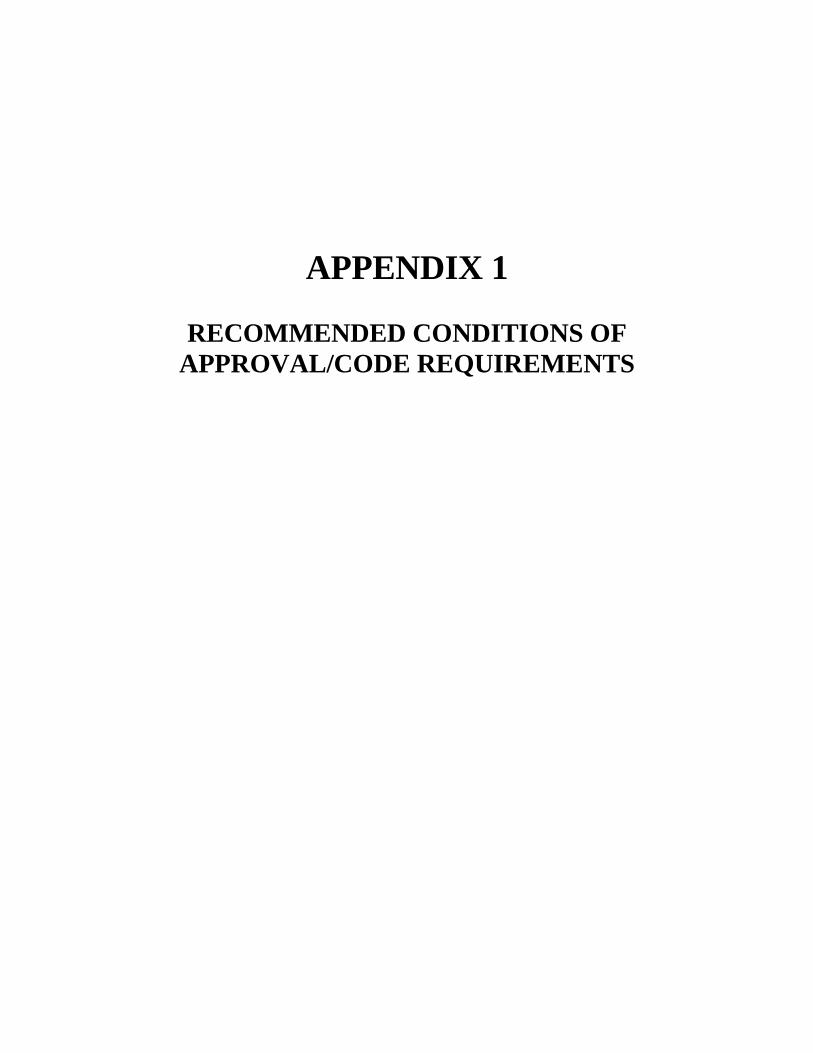
APPENDIX 1
RECOMMENDED CONDITIONS OF
APPROVAL/CODE REQUIREMENTS
ED-002 ATTACHMENT B
MESA CONSOLIDATED WATER DISTRICT
PLANNING DIVISION
Recommended conditions of approval/code requirements
Date: December 8, 2005
Case Number: DR-05-17
Planner:
Annlicant: Bristol Park Medical
DUE BACK BY: Dec. 13, 2005 Address: 722 Baker Street
Assessor Parcel No: 418-131-12
Authorized aaent: WBSA-Mike Swain
Publish: No Number of labels: N/A
Description:
Development Review DR-05-17 for WBSA/Mike Swain, authorized agent for Bristol Park Medical, to construct a new 10,064 sq. ft. medical office and demolish existing building, located at 722 Baker Street, in a C1 zone. Environmental determination: exempt.
Signatures: Division:
_ Date.· _
For all projects:
Building Division
Engineering Division
Fire Prevention
Police Department
Parks and Parkways
Transportation Services
I '' - 1 /.It
Head:, /_; _
For subdivision maps:
All of the list to the left
School District
Water District
Sanitary District
0: Bristol Park Medical: Address above- no phone indicated
A: WBSN/Mike Swain: 4850 Barranca Pky. #203, Irvine 92606 (949) 552-2061
APPENDIX 2
APPLICATION FOR NEW SERVICE

APPLICANT (Property Owner Only) Type or Print
MESA WATER DISTRICT
1965 Placentia Ave., Costa Mesa, CA 92627
Engineering & Inspection: 949-631-1291; Billing 949-631-1200
ED-002 ATTACHMENT C
Legal Description of
Property
APPLICATION FOR NEW SERVICE
Assessors Parcel No.
Address of Property
WATER BILLING SERVICE CUSTOMER
(Property Owner) Applicant Contractor Other (Below)
(Mailing Address) Name
Phone
(City/State/Zip) Address
Zip
I attest under penalty of law to the truth and correctness
of all facts, exhibits, maps and attachments presented
Phone
with and made a part of this application. CONTRACTOR Type or Print (if applicable)
I hereby authorize Name to act as my representative and to bind me in all matters
concerning this application. Address
Signature – Applicant (Property Owner only)
day of , 20
Bus.
Phone
Job Site
Phone
Signature (Notary)
(SEAL)
License No.
License Type
FOR DISTRICT USE ONLY – Do Not Write Below This Line
Signature of Applicant (Property Owner only)
PERMIT APPROVED FOR MESA WATER
By
Date
Permit Expires
PERMIT THE TERMS AND CONDITIONS OF THIS PERMIT ARE PRINTED ON BOTH SIDES OF
THIS FORM. APPLICANT HEREBY ACKNOWLEDGES THAT HE OR SHE HAS READ
AND UNDERSTANDS SAID TERMS AND CONDITIONS AND AGREES TO ABIDE BY
THEM.
Date Entered on Computer
Customer No.
Account Nos.
MESA FILE NO.
THIS APPLICATION BECOMES A PERMIT
WHEN APPROVED AND VALIDATED
VALIDATION

ED-002 ATTACHMENT C
STANDARD TERMS
For Work Done By Mesa Water District
AGREEMENT: I agree to have my installation fee credited to charges for installation
costs and I understand the installation fee is on a fixed cost basis. I further understand that
the installation shall at all times remain under the exclusive control of Mesa Water, and
that the water will not be turned on until any required backflow devices have been
installed, tested and certified. I further understand that the water service will be billed to
the applicant whose name appears on this form, or if specified to the billing customer, until
Mesa Water has been instructed to bill otherwise. This Agreement is subject to the current
Mesa Water Rules and Regulations and Standard Specifications on file at Mesa Water
District’s office.
For Work Done Under Permit
A construction performance bond shall be posted in accordance with the current Mesa
Water Rules and Regulations. The bond and Permit Fee must be received by Mesa Water
prior to Mesa Water’s final approval of plans and/or issuance of Permit. All work done
under this Permit shall be in accordance with the current Mesa Water Rules and
Regulations and Standard Specifications.
I understand that the installation shall at all times remain under the exclusive control of
Mesa Water, and that the water will not be turned on until any required backflow devices
have been installed, tested and certified. I further understand that the water service will be
billed to the applicant whose name appears on this form, or if specified to the billing
customer, until Mesa Water has been instructed to bill otherwise.
Capacity Charges
Capacity Charges will be collected by Mesa Water on all projects requiring new or
additional water service in accordance with the current Mesa Water Rules and Regulations.
I understand that if Mesa Water determines after installation that water use exceeds the
expected amount for the sized capacity of a meter, a larger meter with a larger flow
capacity will be installed and I will be required to pay the additional net increase in the
Capacity Charges.

APPENDIX 3
PAYMENT VOUCHER


pr/payment voucher
APPENDIX 4
WATER SERVICE AGREEMENT

ED-002 ATTACHMENT F
FILE NO.
WATER SERVICE AGREEMENT WITH THE
MESA WATER DISTRICT
FOR WATER SERVICE

Page 2 of 7
Rev. 12/16/05
ED-002 ATTACHMENT F WATER SEVICE AGREEMENT
Date:
File No.:
Location:
Tract: Atlas
Sheet No.:
The undersigned, (hereinafter referred to as “Applicant”), hereby requests water service by
the MESA WATER DISTRICT, (hereinafter referred to as “The District”), in accordance with all of the
terms and conditions of this Water Service Agreement and the District’s Rules and Regulations For Water
Service”, (hereinafter referred to as “Rules and Regulations”), which are incorporated herein by this
reference and made a part hereof as though fully set forth.
Applicant hereby applies for that service as applicable, which can be provided by the
facilities described below, to that certain real property located within the District, in the County of
Orange, State of California, described as follows (metes and bounds description or as acceptable to the
District):
AP-
Said property is to be used for the purpose(s) of:
Applicant hereby represents that Applicant is the owner of said real
property. Applicant estimates that the total service to be required of the District upon development of said
real property is gallons per minute (“GPM”) on the basis of the connected capacity demand
(“CCD”) as defined in the Rules and Regulations of the District.
Upon acceptance of this Application by the District, together with all fees and charges,
including the Capacity Charge as determined by the District Engineer or an authorized representative
subject to appeal to the General Manager or the Board of Directors, plans and specifications, bonds,
conveyance of necessary easements, and other items as may be required herein, the District agrees to
provide the requested water service subject to the terms and conditions herein set forth and set forth in the
Rules and Regulations of the District. The District shall deliver to the Applicant an executed copy of this
Agreement.

Page 3 of 7
Rev. 12/16/05
ED-002 ATTACHMENT F WATER SEVICE AGREEMENT
1. Applicant shall adhere to the requirements prescribed by the Rules and
Regulations, as amended from time to time, and to any additional requirements prescribed from time to
time by the General Manager or Board of Directors of the District, or both, to insure compliance with
such Rules and Regulations as to obtaining water.
2. Applicant hereby agrees to build or cause to be built the described water facilities,
(hereinafter collectively referred to as “the Facilities”), and agrees to pay all costs of installation of same,
including, but not limited to, cost of labor, materials, equipment, contractor’s expense and profit,
environmental studies, design, engineering, surveying, inspection, testing, plan check, land and easement
acquisition, condemnation, attorney’s fees, insurance and bond premiums.
3. Applicant agrees that the Facilities shall be constructed in accordance with plans
and specifications which shall comply with all applicable requirements of the District’s “Standard
Specifications for the Construction of Water Facilities”, including, but not limited to, requirements as to
information to be shown on the plans. Said document is on file at the office of the District and is by this
reference incorporated herein. Such plans and specifications shall be approved by the District. Such
approval of the plans and specifications by the District shall not constitute approval of the permit applied
for herein. The Facilities shall be constructed by a contractor licensed by the State of California to install
said Facilities.
4. Applicant guarantees the Facilities constructed under this Agreement against
defects in workmanship and materials for a period of one (1) year after the date of acceptance of the
Facilities by the District. It is further agreed that the Facilities shall be restored to full compliance with
the requirements of the plans and specifications, including any test requirements, if during said one (1)
year period the Facilities or any portion thereof are found not to be in conformance with any provisions of
said plans and specifications. This guarantee is in addition to any and all other warranties, express or
implied, with respect to the Facilities.
5. Applicant agrees to grant, or cause to be granted to the District, without cost to the
District, all necessary easements for construction, installation, maintenance and access to the Facilities,
across all privately-owned lands to be traversed by the Facilities, which easements shall be in a form and
condition of title satisfactory to the District and shall be executed by all necessary parties having an
interest in said lands.
6. Applicant, if applicable, agrees to provide to the District, prior to acceptance of the
Facilities, a complete set of reproducible mylars of the approved plans and specifications for the
Facilities.
7. Upon completion of the Facilities, Applicant, if applicable, agrees to execute and
deliver to the District a report of the actual costs of the Facilities and to substantiate such report with
invoices and receipts acceptable to the District. Applicant further agrees that such Facilities will become
the property of the District when it is accepted by its duly authorized employee, evidencing acceptance of
the Facilities. However, Applicant hereby disclaims in favor of the District all right, title and interest in
and to said systems, appurtenances and easements; and Applicant hereby covenants and agrees to execute
and deliver to the District any documents required to complete the transfer of the Facilities concurrently
with the acceptance thereof by the District; and Applicant hereby agrees that Applicant is holding any title
to said Facilities, pending acceptance thereof by the District, as trustee, acknowledging Applicant’s
obligation to complete said Facilities and transfer the same debt free to the District.
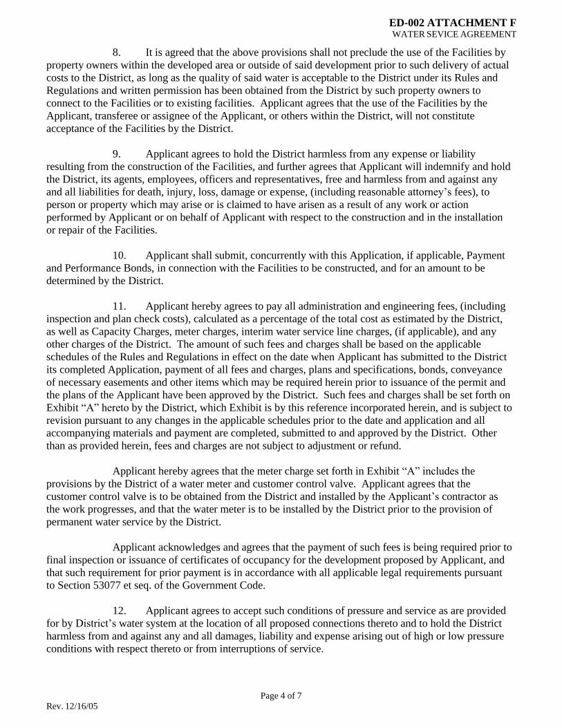
Page 4 of 7
Rev. 12/16/05
ED-002 ATTACHMENT F WATER SEVICE AGREEMENT
8. It is agreed that the above provisions shall not preclude the use of the Facilities by
property owners within the developed area or outside of said development prior to such delivery of actual
costs to the District, as long as the quality of said water is acceptable to the District under its Rules and
Regulations and written permission has been obtained from the District by such property owners to
connect to the Facilities or to existing facilities. Applicant agrees that the use of the Facilities by the
Applicant, transferee or assignee of the Applicant, or others within the District, will not constitute
acceptance of the Facilities by the District.
9. Applicant agrees to hold the District harmless from any expense or liability
resulting from the construction of the Facilities, and further agrees that Applicant will indemnify and hold
the District, its agents, employees, officers and representatives, free and harmless from and against any
and all liabilities for death, injury, loss, damage or expense, (including reasonable attorney’s fees), to
person or property which may arise or is claimed to have arisen as a result of any work or action
performed by Applicant or on behalf of Applicant with respect to the construction and in the installation
or repair of the Facilities.
10. Applicant shall submit, concurrently with this Application, if applicable, Payment
and Performance Bonds, in connection with the Facilities to be constructed, and for an amount to be
determined by the District.
11. Applicant hereby agrees to pay all administration and engineering fees, (including
inspection and plan check costs), calculated as a percentage of the total cost as estimated by the District,
as well as Capacity Charges, meter charges, interim water service line charges, (if applicable), and any
other charges of the District. The amount of such fees and charges shall be based on the applicable
schedules of the Rules and Regulations in effect on the date when Applicant has submitted to the District
its completed Application, payment of all fees and charges, plans and specifications, bonds, conveyance
of necessary easements and other items which may be required herein prior to issuance of the permit and
the plans of the Applicant have been approved by the District. Such fees and charges shall be set forth on
Exhibit “A” hereto by the District, which Exhibit is by this reference incorporated herein, and is subject to
revision pursuant to any changes in the applicable schedules prior to the date and application and all
accompanying materials and payment are completed, submitted to and approved by the District. Other
than as provided herein, fees and charges are not subject to adjustment or refund.
Applicant hereby agrees that the meter charge set forth in Exhibit “A” includes the
provisions by the District of a water meter and customer control valve. Applicant agrees that the
customer control valve is to be obtained from the District and installed by the Applicant’s contractor as
the work progresses, and that the water meter is to be installed by the District prior to the provision of
permanent water service by the District.
Applicant acknowledges and agrees that the payment of such fees is being required prior to
final inspection or issuance of certificates of occupancy for the development proposed by Applicant, and
that such requirement for prior payment is in accordance with all applicable legal requirements pursuant
to Section 53077 et seq. of the Government Code.
12. Applicant agrees to accept such conditions of pressure and service as are provided
for by District’s water system at the location of all proposed connections thereto and to hold the District
harmless from and against any and all damages, liability and expense arising out of high or low pressure
conditions with respect thereto or from interruptions of service.

Page 5 of 7
Rev. 12/16/05
ED-002 ATTACHMENT F WATER SEVICE AGREEMENT
13. Applicant agrees, if said District employs an attorney to enforce this Agreement, to
pay said District for all attorney’s fees to be incurred.
14. Applicant agrees that the General Manager of the District or his authorized
representative may enter upon the hereinabove described property during reasonable hours for the purpose
of ascertaining whether the provisions of this Agreement are being performed. Applicant shall not be
responsible in any way for the failure of its successors or assigns to comply with any of the provisions of
this Agreement.
15. Applicant agrees that service shall be commenced only after the Facilities have
been completed and transferred to the District and all required testing and inspection has been
accomplished by the District.
Applicant is aware that the contracts may not have been let for all necessary water facilities
of the District that Applicant can actually receive water service. Applicant further agrees that the District
shall not be obligated to the Applicant or the successors of the Applicant for water service until such time
as the actual completion of said necessary District facilities.
16. Special conditions for service, if any:
affixed hereto.
IN WITNESS WHEREOF, the parties have duly caused their authorized signatures to be
APPLICANT PROPERTY OWNER
Date: Da te:
Print Name Print Name
MESA WATER DISTRICT
By:
By
General Manager
:
Da
Secretary
te:
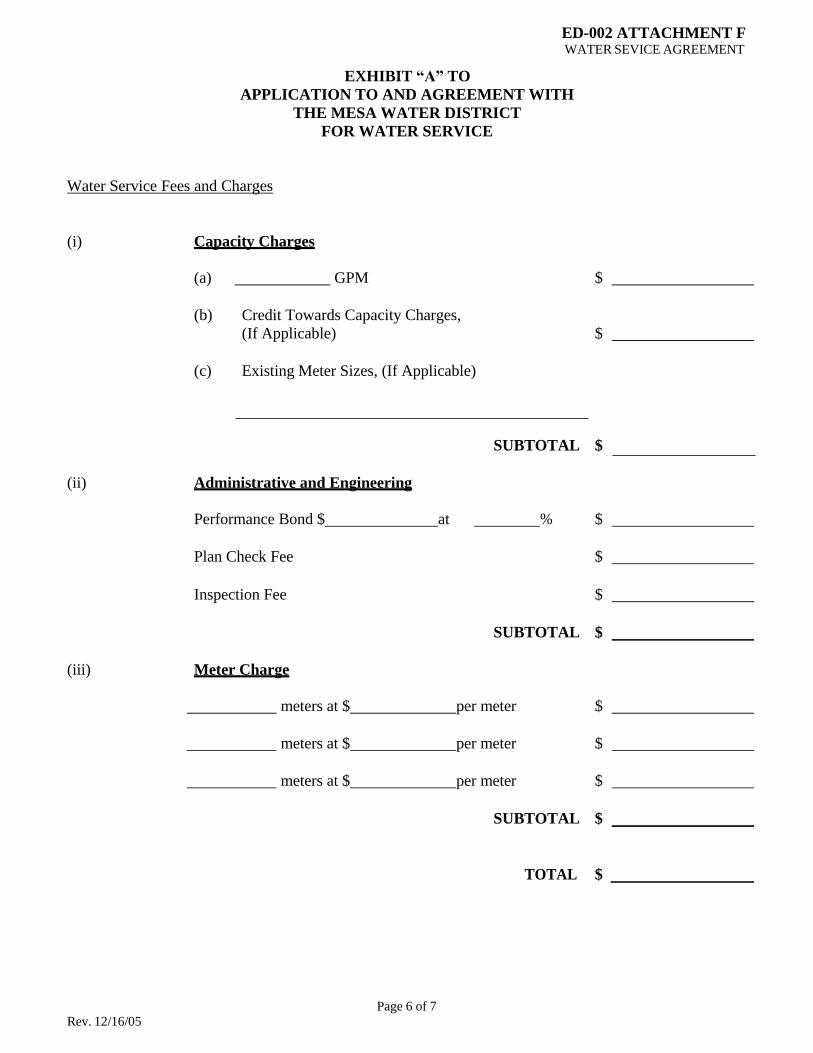
Page 6 of 7
Rev. 12/16/05
EXHIBIT “A” TO
ED-002 ATTACHMENT F WATER SEVICE AGREEMENT
APPLICATION TO AND AGREEMENT WITH
THE MESA WATER DISTRICT
FOR WATER SERVICE
Water Service Fees and Charges
(i) Capacity Charges
(a) GPM $
(b) Credit Towards Capacity Charges,
(If Applicable) $
(c) Existing Meter Sizes, (If Applicable)
SUBTOTAL $
(ii) Administrative and Engineering
Performance Bond $ at % $
Plan Check Fee $
Inspection Fee $
SUBTOTAL $
(iii) Meter Charge
meters at $ per meter $
meters at $ per meter $
meters at $ per meter $
SUBTOTAL $
TOTAL $
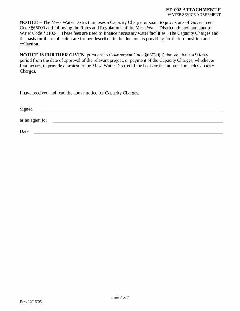
Page 7 of 7
Rev. 12/16/05
ED-002 ATTACHMENT F WATER SEVICE AGREEMENT
NOTICE – The Mesa Water District imposes a Capacity Charge pursuant to provisions of Government
Code §66000 and following the Rules and Regulations of the Mesa Water District adopted pursuant to
Water Code §31024. These fees are used to finance necessary water facilities. The Capacity Charges and
the basis for their collection are further described in the documents providing for their imposition and
collection.
NOTICE IS FURTHER GIVEN, pursuant to Government Code §66020(d) that you have a 90-day
period from the date of approval of the relevant project, or payment of the Capacity Charges, whichever
first occurs, to provide a protest to the Mesa Water District of the basis or the amount for such Capacity
Charges.
I have received and read the above notice for Capacity Charges.
Signed
as an agent for
Date
APPENDIX 5
FINAL INSPECTION AND
CASH BOND RELEASE REQUEST
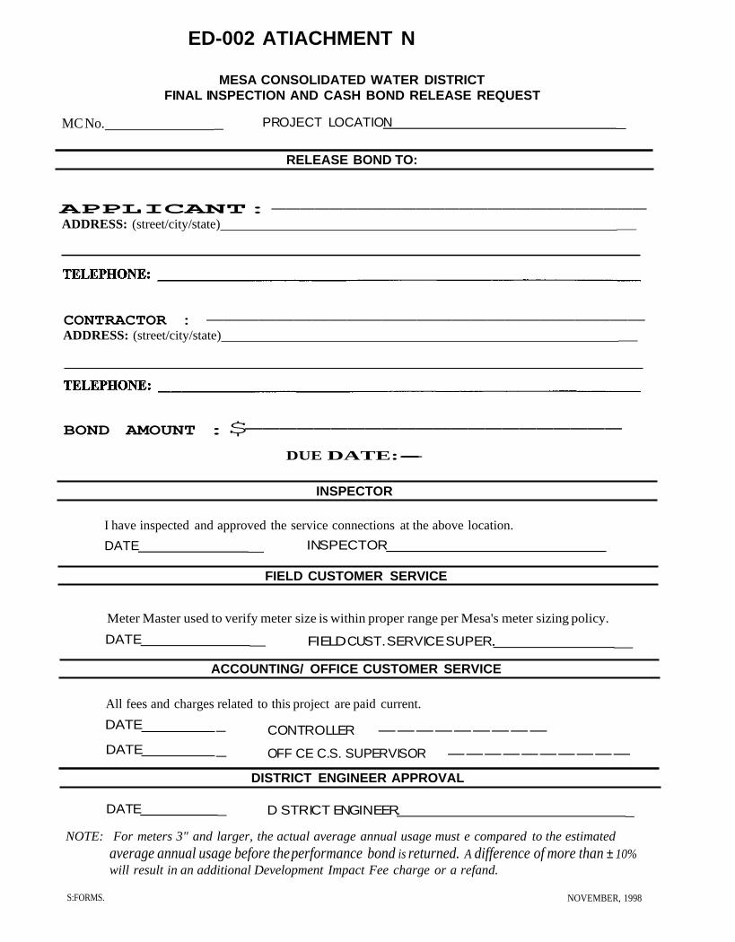
ED-002 ATIACHMENT N
MESA CONSOLIDATED WATER DISTRICT
FINAL INSPECTION AND CASH BOND RELEASE REQUEST
MC No. _ PROJECT LOCATION _
RELEASE BOND TO:
APPLICANT:--------------------------
ADDRESS: (street/city/state) _
CONTRACTOR : -------------------------
ADDRESS: (street/city/state) _
BOND AMOUNT :$----------------------
DUE DATE:---------------------------
INSPECTOR
I have inspected and approved the service connections at the above location.
DATE _ INSPECTOR
FIELD CUSTOMER SERVICE
Meter Master used to verify meter size is within proper range per Mesa's meter sizing policy.
DATE _ FIELD CUST. SERVICE SUPER.. _
ACCOUNTING/ OFFICE CUSTOMER SERVICE
All fees and charges related to this project are paid current.
DATE
DATE
_ CONTROLLER ---------
_ OFF CE C.S. SUPERVISOR ----------
DISTRICT ENGINEER APPROVAL
DATE _ D STRICT ENGINEER. _
NOTE: For meters 3" and larger, the actual average annual usage must e compared to the estimated
average annual usage before theperformance bond is returned. A difference of more than ± 10%
will result in an additional Development Impact Fee charge or a refand.
S:FORMS. NOVEMBER, 1998

APPENDIX 6
FEES AND CHARGES FOR
NEW DEVELOPMENT
AND
MODIFICATION TO
EXISTING STRUCTURES
The most current and up-to-date approved
Water Rate and Charge Schedule can be
found at www.mesawater.org.
APPENDIX 7
CAPACITY CHARGES
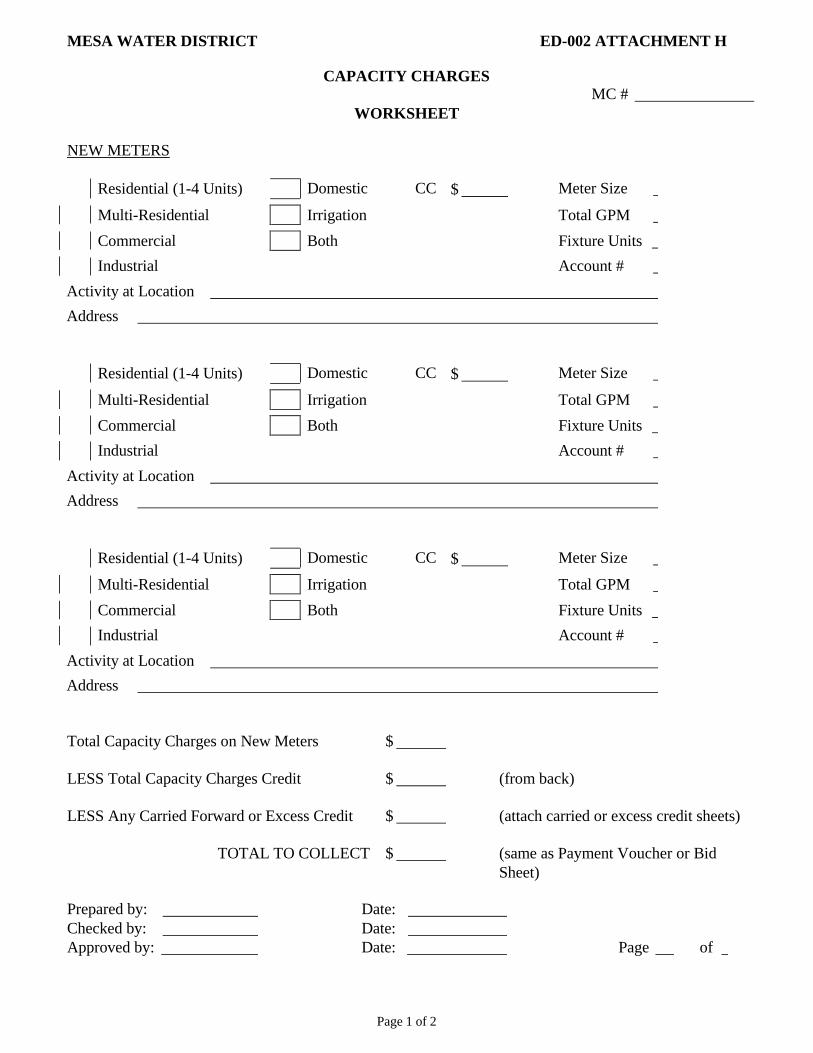
Page 1 of 2
MESA WATER DISTRICT ED-002 ATTACHMENT H
CAPACITY CHARGES
WORKSHEET
MC #
NEW METERS
Residential (1-4 Units) Domestic CC $ Meter Size
Multi-Residential Irrigation Total GPM
Commercial Both Fixture Units
Industrial Account #
Activity at Location
Address
Residential (1-4 Units) Domestic CC $ Meter Size
Multi-Residential Irrigation Total GPM
Commercial Both Fixture Units
Industrial Account #
Activity at Location
Address
Residential (1-4 Units) Domestic CC $ Meter Size
Multi-Residential Irrigation Total GPM
Commercial Both Fixture Units
Industrial Account #
Activity at Location
Address
Total Capacity Charges on New Meters $
LESS Total Capacity Charges Credit $ (from back)
LESS Any Carried Forward or Excess Credit $ (attach carried or excess credit sheets)
TOTAL TO COLLECT $ (same as Payment Voucher or Bid
Sheet)
Prepared by: Date:
Checked by: Date:
Approved by: Date: Page of
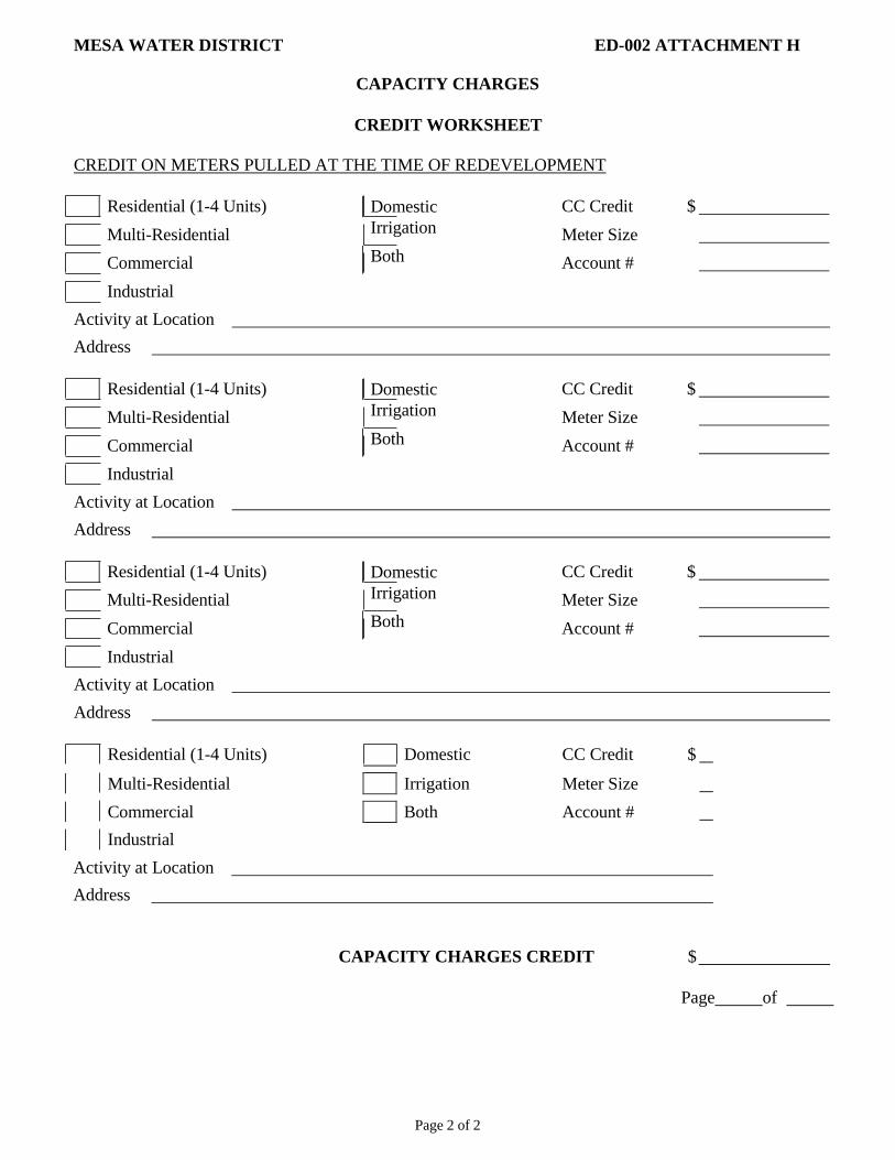
Page 2 of 2
MESA WATER DISTRICT ED-002 ATTACHMENT H
CAPACITY CHARGES
CREDIT WORKSHEET
CREDIT ON METERS PULLED AT THE TIME OF REDEVELOPMENT
Residential (1-4 Units) Domestic CC Credit $
Multi-Residential Irrigation Meter Size
Commercial Both Account #
Industrial
Activity at Location
Address
Residential (1-4 Units) Domestic CC Credit $
Multi-Residential Irrigation Meter Size
Commercial Both Account #
Industrial
Activity at Location
Address
Residential (1-4 Units) Domestic CC Credit $
Multi-Residential Irrigation Meter Size
Commercial Both Account #
Industrial
Activity at Location
Address
Residential (1-4 Units) Domestic CC Credit $
Multi-Residential Irrigation Meter Size
Commercial Both Account #
Industrial
Activity at Location
Address
CAPACITY CHARGES CREDIT $
Page of
APPENDIX 8
FIXTURE UNITS TO
GPM CONVERSION TABLE

MESA WATER DISTRICT ED-002 ATTACHMENT I
FIXTURE UNITS TO GPM CONVERSION TABLE
E
Page 1 of 21
FLUSH TANK
FIXTURE
UNITS
GPM FIXTURE
UNITS GPM
1 2 1 --
2 3 2 --
3 3 3 --
4 4 4 --
5 5 5 22
6 5 6 23
7 6 7 24
8 7 8 25
9 8 9 26
10 8 10 27
11 9 11 28
12 9 12 29
13 10 13 30
14 11 14 31
15 11 15 32
16 12 16 33
17 13 17 34
18 13 18 34
19 14 19 35
20 14 20 35
21 15 21 36
22 16 22 37
23 16 23 37
24 17 24 38
25 18 25 38
26 18 26 39
27 19 27 40
28 19 28 40
29 20 29 41
30 20 30 41
31 21 31 42
32 21 32 43
33 22 33 43
34 22 34 44
35 23 35 44
36 23 36 45
37 23 37 45
38 24 38 46
39 24 39 46
40 24 40 46
41 25 41 47
42 25 42 47
43 26 43 48
44 26 44 48
45 27 45 49
46 27 46 49
47 27 47 50
48 28 48 50
49 28 49 51
50 29 50 51
51 29 51 52
52 29 52 52
53 30 53 53

Page 2 of 21
pr/forms
MESA WATER DISTRICT ED-002 ATTACHMENT I FIXTURE UNITS TO GPM CONVERSION TABLE
FLUSH TANK FLUSH VALVE
FIXTURE
UNITS
GPM FIXTURE
UNITS
GPM
54 30 54 53
55 31 55 53
56 31 56 54
57 32 57 54
58 32 58 54
59 33 59 55
60 33 60 55
61 33 61 55
62 34 62 56
63 34 63 56
64 34 64 56
65 35 65 57
66 35 66 57
67 35 67 57
68 36 68 58
69 36 69 58
70 36 70 58
71 36 71 59
72 37 72 59
73 37 73 59
74 37 74 59
75 37 75 60
76 38 76 60
77 38 77 60
78 38 78 61
79 38 79 61
80 38 80 61
81 39 81 62
82 39 82 62
83 39 83 62
84 39 84 63
85 40 85 63
86 40 86 63
87 40 87 64
88 41 88 64
89 41 89 64
90 41 90 65
91 41 91 65
92 41 92 65
93 42 93 66
94 42 94 66
95 42 95 66
96 42 96 66
97 43 97 67
98 43 98 67
99 43 99 67
100 43 100 68
101 44 101 68
102 44 102 68
103 44 103 68
104 44 104 69
105 45 105 69
106 45 106 69
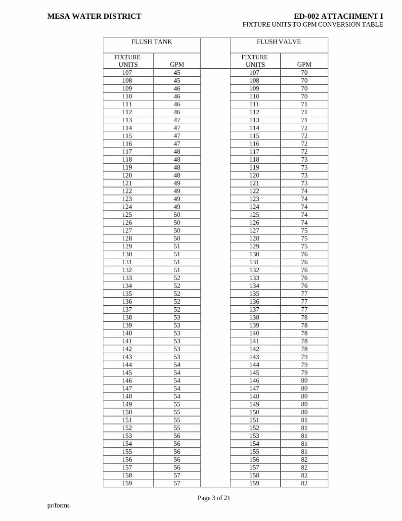
Page 3 of 21
pr/forms
MESA WATER DISTRICT ED-002 ATTACHMENT I FIXTURE UNITS TO GPM CONVERSION TABLE
FLUSH TANK FLUSH VALVE
FIXTURE
UNITS
GPM FIXTURE
UNITS
GPM
107 45 107 70
108 45 108 70
109 46 109 70
110 46 110 70
111 46 111 71
112 46 112 71
113 47 113 71
114 47 114 72
115 47 115 72
116 47 116 72
117 48 117 72
118 48 118 73
119 48 119 73
120 48 120 73
121 49 121 73
122 49 122 74
123 49 123 74
124 49 124 74
125 50 125 74
126 50 126 74
127 50 127 75
128 50 128 75
129 51 129 75
130 51 130 76
131 51 131 76
132 51 132 76
133 52 133 76
134 52 134 76
135 52 135 77
136 52 136 77
137 52 137 77
138 53 138 78
139 53 139 78
140 53 140 78
141 53 141 78
142 53 142 78
143 53 143 79
144 54 144 79
145 54 145 79
146 54 146 80
147 54 147 80
148 54 148 80
149 55 149 80
150 55 150 80
151 55 151 81
152 55 152 81
153 56 153 81
154 56 154 81
155 56 155 81
156 56 156 82
157 56 157 82
158 57 158 82
159 57 159 82

Page 4 of 21
pr/forms
MESA WATER DISTRICT ED-002 ATTACHMENT I FIXTURE UNITS TO GPM CONVERSION TABLE
FLUSH TANK FLUSH VALVE
FIXTURE
UNITS
GPM FIXTURE
UNITS
GPM
160 57 160 82
161 57 161 83
162 57 162 83
163 58 163 83
164 58 164 83
165 58 165 84
166 58 166 84
167 58 167 84
168 59 168 84
169 59 169 84
170 59 170 85
171 59 171 85
172 59 172 85
173 60 173 85
174 60 174 86
175 60 175 86
176 60 176 86
177 60 177 86
178 61 178 86
179 61 179 87
180 61 180 87
181 61 181 87
182 61 182 87
183 62 183 87
184 62 184 88
185 62 185 88
186 62 186 88
187 62 187 88
188 63 188 88
189 63 189 89
190 63 190 89
191 63 191 89
192 63 192 89
193 64 193 90
194 64 194 90
195 64 195 90
196 64 196 90
197 64 197 90
198 65 198 91
199 65 199 91
200 65 200 91
201 65 201 91
202 65 202 92
203 66 203 92
204 66 204 92
205 66 205 92
206 66 206 92
207 66 207 92
208 67 208 93
209 67 209 93
210 67 210 93
211 67 211 93
212 67 212 94

Page 5 of 21
pr/forms
MESA WATER DISTRICT ED-002 ATTACHMENT I FIXTURE UNITS TO GPM CONVERSION TABLE
FLUSH TANK FLUSH VALVE
FIXTURE
UNITS
GPM FIXTURE
UNITS
GPM
213 68 213 94
214 68 214 94
215 68 215 94
216 68 216 94
217 68 217 95
218 69 218 95
219 69 219 95
220 69 220 95
221 69 221 96
222 69 222 96
223 70 223 96
224 70 224 96
225 70 225 96
226 70 226 96
227 70 227 97
228 71 228 97
229 71 229 97
230 71 230 97
231 71 231 98
232 71 232 98
233 71 233 98
234 72 234 98
235 72 235 98
236 72 236 98
237 72 237 99
238 72 238 99
239 73 239 99
240 73 240 99
241 73 241 99
242 73 242 100
243 74 243 100
244 74 244 100
245 74 245 100
246 74 246 100
247 74 247 100
248 75 248 101
249 75 249 101
250 75 250 101
251 75 251 101
252 76 252 101
253 76 253 102
254 76 254 102
255 76 255 102
256 76 256 102
257 77 257 102
258 77 258 103
259 77 259 103
260 77 260 103
261 77 261 103
262 78 262 103
263 78 263 104
264 78 264 104
265 78 265 104

Page 6 of 21
pr/forms
MESA WATER DISTRICT ED-002 ATTACHMENT I FIXTURE UNITS TO GPM CONVERSION TABLE
FLUSH TANK FLUSH VALVE
FIXTURE
UNITS
GPM FIXTURE
UNITS
GPM
266 78 266 104
267 79 267 104
268 79 268 105
269 79 269 105
270 79 270 105
271 79 271 105
272 79 272 105
273 80 273 106
274 80 274 106
275 80 275 106
276 80 276 106
277 80 277 106
278 81 278 107
279 81 279 107
280 81 280 107
281 81 281 107
282 82 282 107
283 82 283 108
284 82 284 108
285 82 285 108
286 82 286 108
287 83 287 108
288 83 288 109
289 83 289 109
290 83 290 109
291 83 291 109
292 84 292 109
293 84 293 110
294 84 294 110
295 84 295 110
296 84 296 110
297 85 297 110
298 85 298 110
299 85 299 110
300 85 300 110
301 85 301 111
302 85 302 111
303 86 303 111
304 86 304 111
305 86 305 111
306 86 306 111
307 86 307 112
308 87 308 112
309 87 309 112
310 87 310 112
311 87 311 112
312 87 312 112
313 88 313 112
314 88 314 113
315 88 315 113
316 88 316 113
317 88 317 113
318 89 318 113

Page 7 of 21
pr/forms
MESA WATER DISTRICT ED-002 ATTACHMENT I FIXTURE UNITS TO GPM CONVERSION TABLE
FLUSH TANK FLUSH VALVE
FIXTURE
UNITS
GPM FIXTURE
UNITS
GPM
319 89 319 113
320 89 320 114
321 89 321 114
322 89 322 114
323 89 323 114
324 90 324 114
325 90 325 114
326 90 326 115
327 90 327 115
328 90 328 115
329 91 329 115
330 91 330 115
331 91 331 115
332 91 332 115
333 91 333 116
334 91 334 116
335 92 335 116
336 92 336 116
337 92 337 116
338 92 338 116
339 92 339 116
340 93 340 117
341 93 341 117
342 93 342 117
343 93 343 117
344 93 344 117
345 93 345 117
346 94 346 117
347 94 347 118
348 94 348 118
349 94 349 118
350 94 350 118
351 95 351 118
352 95 352 118
353 95 353 118
354 95 354 119
355 95 355 119
356 95 356 119
357 96 357 119
358 96 358 119
359 96 359 119
360 96 360 119
361 96 361 120
362 97 362 120
363 97 363 120
364 97 364 120
365 97 365 120
366 97 366 120
367 97 367 120
368 98 368 120
369 98 369 121
370 98 370 121
371 98 371 121

Page 8 of 21
pr/forms
MESA WATER DISTRICT ED-002 ATTACHMENT I FIXTURE UNITS TO GPM CONVERSION TABLE
FLUSH TANK FLUSH VALVE
FIXTURE
UNITS
GPM FIXTURE
UNITS
GPM
372 98 372 121
373 99 373 121
374 99 374 121
375 99 375 122
376 99 376 122
377 99 377 122
378 100 378 122
379 100 379 122
380 100 380 122
381 100 381 123
382 100 382 123
383 100 383 123
384 101 384 123
385 101 385 123
386 101 386 124
387 101 387 124
388 101 388 124
389 102 389 124
390 102 390 124
391 102 391 124
392 102 392 125
393 102 393 125
394 103 394 125
395 103 395 125
396 103 396 125
397 103 397 125
398 103 398 125
399 104 399 126
400 104 400 126
401 104 401 126
402 104 402 126
403 104 403 126
404 105 404 126
405 105 405 126
406 105 406 127
407 105 407 127
408 105 408 127
409 106 409 127
410 106 410 127
411 106 411 127
412 106 412 127
413 106 413 127
414 107 414 128
415 107 415 128
416 107 416 128
417 107 417 128
418 107 418 128
419 108 419 128
420 108 420 128
421 108 421 129
422 108 422 129
423 108 423 129
424 109 424 129

Page 9 of 21
pr/forms
MESA WATER DISTRICT ED-002 ATTACHMENT I FIXTURE UNITS TO GPM CONVERSION TABLE
FLUSH TANK FLUSH VALVE
FIXTURE
UNITS
GPM FIXTURE
UNITS
GPM
425 109 425 129
426 109 426 129
427 109 427 130
428 109 428 130
429 110 429 130
430 110 430 130
431 110 431 130
432 110 432 130
433 110 433 130
434 111 434 131
435 111 435 131
436 111 436 131
437 111 437 131
438 112 438 131
439 112 439 131
440 112 440 132
441 112 441 132
442 112 442 132
443 113 443 132
444 113 444 132
445 113 445 132
446 113 446 133
447 113 447 133
448 114 448 133
449 114 449 133
450 114 450 133
451 114 451 133
452 114 452 134
453 115 453 134
454 115 454 134
455 115 455 134
456 115 456 134
457 115 457 134
458 116 458 135
459 116 459 135
460 116 460 135
461 116 461 135
462 117 462 135
463 117 463 135
464 117 464 135
465 117 465 136
466 117 466 136
467 118 467 136
468 118 468 136
469 118 469 136
470 118 470 136
471 118 471 137
472 119 472 137
473 119 473 137
474 119 474 137
475 119 475 137
476 119 476 137
477 120 477 138
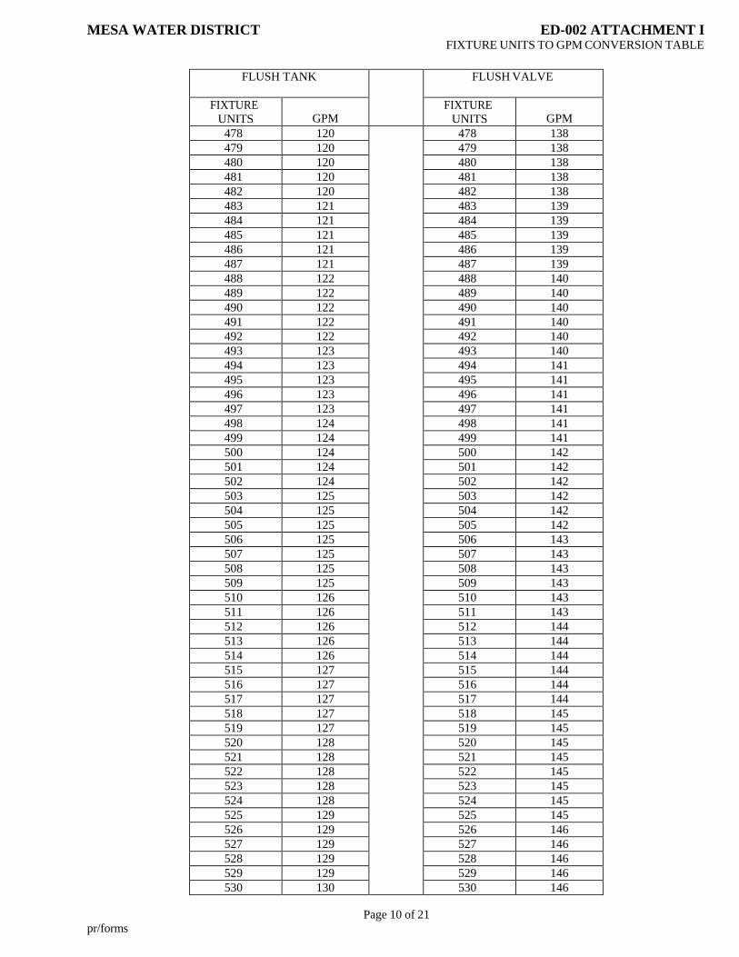
Page 10 of 21
pr/forms
MESA WATER DISTRICT ED-002 ATTACHMENT I FIXTURE UNITS TO GPM CONVERSION TABLE
FLUSH TANK FLUSH VALVE
FIXTURE
UNITS
GPM FIXTURE
UNITS
GPM
478 120 478 138
479 120 479 138
480 120 480 138
481 120 481 138
482 120 482 138
483 121 483 139
484 121 484 139
485 121 485 139
486 121 486 139
487 121 487 139
488 122 488 140
489 122 489 140
490 122 490 140
491 122 491 140
492 122 492 140
493 123 493 140
494 123 494 141
495 123 495 141
496 123 496 141
497 123 497 141
498 124 498 141
499 124 499 141
500 124 500 142
501 124 501 142
502 124 502 142
503 125 503 142
504 125 504 142
505 125 505 142
506 125 506 143
507 125 507 143
508 125 508 143
509 125 509 143
510 126 510 143
511 126 511 143
512 126 512 144
513 126 513 144
514 126 514 144
515 127 515 144
516 127 516 144
517 127 517 144
518 127 518 145
519 127 519 145
520 128 520 145
521 128 521 145
522 128 522 145
523 128 523 145
524 128 524 145
525 129 525 145
526 129 526 146
527 129 527 146
528 129 528 146
529 129 529 146
530 130 530 146

Page 11 of 21
pr/forms
MESA WATER DISTRICT ED-002 ATTACHMENT I FIXTURE UNITS TO GPM CONVERSION TABLE
FLUSH TANK FLUSH VALVE
FIXTURE
UNITS
GPM FIXTURE
UNITS
GPM
531 130 531 146
532 130 532 146
533 130 533 147
534 130 534 147
535 130 535 147
536 131 536 147
537 131 537 147
538 131 538 147
539 131 539 147
540 131 540 148
541 132 541 148
542 132 542 148
543 132 543 148
544 132 544 148
545 132 545 148
546 133 546 148
547 133 547 148
548 133 548 149
549 133 549 149
550 133 550 149
551 134 551 149
552 134 552 149
553 134 553 149
554 134 554 149
555 134 555 150
556 135 556 150
557 135 557 150
558 135 558 150
559 135 559 150
560 135 560 150
561 135 561 150
562 136 562 150
563 136 563 151
564 136 564 151
565 136 565 151
566 136 566 151
567 137 567 151
568 137 568 151
569 137 569 151
570 137 570 151
571 137 571 152
572 138 572 152
573 138 573 152
574 138 574 152
575 138 575 152
576 138 576 152
577 139 577 152
578 139 578 152
579 139 579 153
580 139 580 153
581 139 581 153
582 140 582 153
583 140 583 153

Page 12 of 21
pr/forms
MESA WATER DISTRICT ED-002 ATTACHMENT I FIXTURE UNITS TO GPM CONVERSION TABLE
FLUSH TANK FLUSH VALVE
FIXTURE
UNITS
GPM FIXTURE
UNITS
GPM
584 140 584 153
585 140 585 153
586 140 586 154
587 140 587 154
588 141 588 154
589 141 589 154
590 141 590 154
591 141 591 154
592 141 592 154
593 142 593 155
594 142 594 155
595 142 595 155
596 142 596 155
597 142 597 155
598 143 598 155
599 143 599 155
600 143 600 155
601 143 601 156
602 143 602 156
603 144 603 156
604 144 604 156
605 144 605 156
606 144 606 156
607 144 607 156
608 145 608 157
609 145 609 157
610 145 610 157
611 145 611 157
612 145 612 157
613 145 613 157
614 146 614 157
615 146 615 158
616 146 616 158
617 146 617 158
618 146 618 158
619 147 619 158
620 147 620 158
621 147 621 158
622 147 622 159
623 147 623 159
624 148 624 159
625 148 625 159
626 148 626 159
627 148 627 159
628 148 628 160
629 149 629 160
630 149 630 160
631 149 631 160
632 149 632 160
633 149 633 160
634 149 634 160
635 150 635 160
636 150 636 161

Page 13 of 21
pr/forms
MESA WATER DISTRICT ED-002 ATTACHMENT I FIXTURE UNITS TO GPM CONVERSION TABLE
FLUSH TANK FLUSH VALVE
FIXTURE
UNITS
GPM FIXTURE
UNITS
GPM
637 150 637 161
638 150 638 161
639 150 639 161
640 150 640 161
641 151 641 161
642 151 642 161
643 151 643 162
644 151 644 162
645 151 645 162
646 152 646 162
647 152 647 162
648 152 648 162
649 152 649 162
650 152 650 163
651 153 651 163
652 153 652 163
653 153 653 163
654 153 654 163
655 153 655 163
656 154 656 164
657 154 657 164
658 154 658 164
659 154 659 164
660 154 660 164
661 154 661 164
662 155 662 164
663 155 663 165
664 155 664 165
665 155 665 165
666 155 666 165
667 155 667 165
668 156 668 165
669 156 669 165
670 156 670 165
671 156 671 166
672 156 672 166
673 157 673 166
674 157 674 166
675 157 675 166
676 157 676 166
677 157 677 166
678 158 678 167
679 158 679 167
680 158 680 167
681 158 681 167
682 158 682 167
683 159 683 167
684 159 684 168
685 159 685 168
686 159 686 168
687 159 687 168
688 159 688 168
689 160 689 168

Page 14 of 21
pr/forms
MESA WATER DISTRICT ED-002 ATTACHMENT I FIXTURE UNITS TO GPM CONVERSION TABLE
FLUSH TANK FLUSH VALVE
FIXTURE
UNITS
GPM FIXTURE
UNITS
GPM
690 160 690 169
691 160 691 169
692 160 692 169
693 160 693 169
694 160 694 169
695 161 695 169
696 161 696 170
697 161 697 170
698 161 698 170
699 161 699 170
700 162 700 170
701 162 701 170
702 162 702 170
703 162 703 170
704 162 704 171
705 163 705 171
706 163 706 171
707 163 707 171
708 163 708 171
709 163 709 171
710 164 710 171
711 164 711 171
712 164 712 172
713 164 713 172
714 164 714 172
715 164 715 172
716 165 716 172
717 165 717 172
718 165 718 172
719 165 719 172
720 165 720 172
721 165 721 173
722 166 722 173
723 166 723 173
724 166 724 173
725 166 725 173
726 166 726 173
727 166 727 173
728 167 728 173
729 167 729 174
730 167 730 174
731 167 731 174
732 167 732 174
733 167 733 174
734 168 734 174
735 168 735 174
736 168 736 175
737 168 737 175
738 168 738 175
739 168 739 175
740 169 740 175
741 169 741 175
742 169 742 175

Page 15 of 21
pr/forms
MESA WATER DISTRICT ED-002 ATTACHMENT I FIXTURE UNITS TO GPM CONVERSION TABLE
FLUSH TANK FLUSH VALVE
FIXTURE
UNITS
GPM FIXTURE
UNITS
GPM
743 169 743 175
744 169 744 176
745 169 745 176
746 170 746 176
747 170 747 176
748 170 748 176
749 170 749 176
750 170 750 176
751 170 751 177
752 171 752 177
753 171 753 177
754 171 754 177
755 171 755 177
756 171 756 177
757 171 757 177
758 172 758 178
759 172 759 178
760 172 760 178
761 172 761 178
762 172 762 178
763 172 763 178
764 173 764 178
765 173 765 179
766 173 766 179
767 173 767 179
768 173 768 179
769 173 769 179
770 174 770 179
771 174 771 179
772 174 772 180
773 174 773 180
774 174 774 180
775 174 775 180
776 175 776 180
777 175 777 180
778 175 778 180
779 175 779 180
780 175 780 181
781 175 781 181
782 176 782 181
783 176 783 181
784 176 784 181
785 176 785 181
786 176 786 181
787 176 787 182
788 177 788 182
789 177 789 182
790 177 790 182
791 177 791 182
792 177 792 182
793 177 793 182
794 178 794 183
795 178 795 183

Page 16 of 21
pr/forms
MESA WATER DISTRICT ED-002 ATTACHMENT I FIXTURE UNITS TO GPM CONVERSION TABLE
FLUSH TANK FLUSH VALVE
FIXTURE
UNITS
GPM FIXTURE
UNITS
GPM
796 178 796 183
797 178 797 183
798 178 798 183
799 178 799 183
800 179 800 183
801 179 801 184
802 179 802 184
803 179 803 184
804 179 804 184
805 179 805 184
806 180 806 184
807 180 807 184
808 180 808 185
809 180 809 185
810 180 810 185
811 180 811 185
812 181 812 185
813 181 813 185
814 181 814 185
815 181 815 185
816 181 816 186
817 181 817 186
818 182 818 186
819 182 819 186
820 182 820 186
821 182 821 186
822 182 822 186
823 182 823 187
824 183 824 187
825 183 825 187
826 183 826 187
827 183 827 187
828 183 828 187
829 183 829 187
830 184 830 188
831 184 831 188
832 184 832 188
833 184 833 188
834 184 834 188
835 184 835 188
836 185 836 188
837 185 837 188
838 185 838 189
839 185 839 189
840 185 840 189
841 185 841 189
842 185 842 189
843 186 843 189
844 186 844 189
845 186 845 189
846 186 846 190
847 186 847 190
848 186 848 190

Page 17 of 21
pr/forms
MESA WATER DISTRICT ED-002 ATTACHMENT I FIXTURE UNITS TO GPM CONVERSION TABLE
FLUSH TANK FLUSH VALVE
FIXTURE
UNITS
GPM FIXTURE
UNITS
GPM
849 186 849 190
850 187 850 190
851 187 851 190
852 187 852 190
853 187 853 190
854 187 854 190
855 187 855 191
856 187 856 191
857 188 857 191
858 188 858 191
859 188 859 191
860 188 860 191
861 188 861 191
862 188 862 191
863 188 863 192
864 189 864 192
865 189 865 192
866 189 866 192
867 189 867 192
868 189 868 192
869 189 869 192
870 189 870 192
871 190 871 193
872 190 872 193
873 190 873 193
874 190 874 193
875 190 875 193
876 190 876 193
877 190 877 193
878 190 878 193
879 190 879 194
880 191 880 194
881 191 881 194
882 191 882 194
883 191 883 194
884 191 884 194
885 191 885 194
886 192 886 194
887 192 887 195
888 192 888 195
889 192 889 195
890 192 890 195
891 192 891 195
892 192 892 195
893 193 893 195
894 193 894 195
895 193 895 196
896 193 896 196
897 193 897 196
898 193 898 196
899 194 899 196
900 194 900 196
901 194 901 196

Page 18 of 21
pr/forms
MESA WATER DISTRICT ED-002 ATTACHMENT I FIXTURE UNITS TO GPM CONVERSION TABLE
FLUSH TANK FLUSH VALVE
FIXTURE
UNITS
GPM FIXTURE
UNITS
GPM
902 194 902 196
903 194 903 197
904 194 904 197
905 194 905 197
906 195 906 197
907 195 907 197
908 195 908 197
909 195 909 197
910 195 910 197
911 195 911 198
912 195 912 198
913 196 913 198
914 196 914 198
915 196 915 198
916 196 916 198
917 196 917 198
918 196 918 198
919 196 919 199
920 197 920 199
921 197 921 199
922 197 922 199
923 197 923 199
924 197 924 199
925 197 925 199
926 197 926 199
927 198 927 200
928 198 928 200
929 198 929 200
930 198 930 200
931 198 931 200
932 198 932 200
933 198 933 200
934 199 934 200
935 199 935 200
936 199 936 201
937 199 937 201
938 199 938 201
939 199 939 201
940 199 940 201
941 200 941 201
942 200 942 201
943 200 943 201
944 200 944 202
945 200 945 202
946 200 946 202
947 200 947 202
948 200 948 202
949 201 949 202
950 201 950 202
951 201 951 202
952 201 952 203
953 201 953 203
954 201 954 203

Page 19 of 21
pr/forms
MESA WATER DISTRICT ED-002 ATTACHMENT I FIXTURE UNITS TO GPM CONVERSION TABLE
FLUSH TANK FLUSH VALVE
FIXTURE
UNITS
GPM FIXTURE
UNITS
GPM
955 201 955 203
956 202 956 203
957 202 957 203
958 202 958 203
959 202 959 203
960 202 960 204
961 202 961 204
962 202 962 204
963 203 963 204
964 203 964 204
965 203 965 204
966 203 966 204
967 203 967 204
968 203 968 205
969 203 969 205
970 204 970 205
971 204 971 205
972 204 972 205
973 204 973 205
974 204 974 205
975 204 975 205
976 204 976 206
977 205 977 206
978 205 978 206
979 205 979 206
980 205 980 206
981 205 981 206
982 205 982 206
983 205 983 206
984 206 984 207
985 206 985 207
986 206 986 207
987 206 987 207
988 206 988 207
989 206 989 207
990 206 990 207
991 207 991 208
992 207 992 208
993 207 993 208
994 207 994 208
995 207 995 208
996 207 996 208
997 207 997 208
998 208 998 209
999 208 999 209
1000 208 1000 209
1001 208 1001 209
1002 208 1002 209
1003 208 1003 209
1004 208 1004 209
1005 208 1005 210
1006 209 1006 210
1007 209 1007 210

Page 20 of 21
pr/forms
MESA WATER DISTRICT ED-002 ATTACHMENT I FIXTURE UNITS TO GPM CONVERSION TABLE
FLUSH TANK FLUSH VALVE
FIXTURE
UNITS
GPM FIXTURE
UNITS
GPM
1008 209 1008 210
1009 209 1009 210
1010 209 1010 210
1011 209 1011 210
1012 209 1012 210
1013 209 1013 210
1014 210 1014 211
1015 210 1015 211
1016 210 1016 211
1017 210 1017 211
1018 210 1018 211
1019 210 1019 211
1020 210 1020 211
1021 210 1021 211
1022 211 1022 212
1023 211 1023 212
1024 211 1024 212
1025 211 1025 212
1026 211 1026 212
1027 211 1027 212
1028 211 1028 212
1029 212 1029 212
1030 212 1030 213
1031 212 1031 213
1032 212 1032 213
1033 212 1033 213
1034 212 1034 213
1035 212 1035 213
1036 213 1036 213
1037 213 1037 213
1038 213 1038 214
1039 213 1039 214
1040 213 1040 214
1041 213 1041 214
1042 213 1042 214
1043 214 1043 214
1044 214 1044 214
1045 214 1045 214
1046 214 1046 215
1047 214 1047 215
1048 214 1048 215
1049 214 1049 215
1050 215 1050 215
1051 215 1051 215
1052 215 1052 215
1053 215 1053 215
1054 215 1054 216
1055 215 1055 216
1056 215 1056 216
1057 216 1057 216
1058 216 1058 216
1059 216 1059 216
1060 216 1060 216
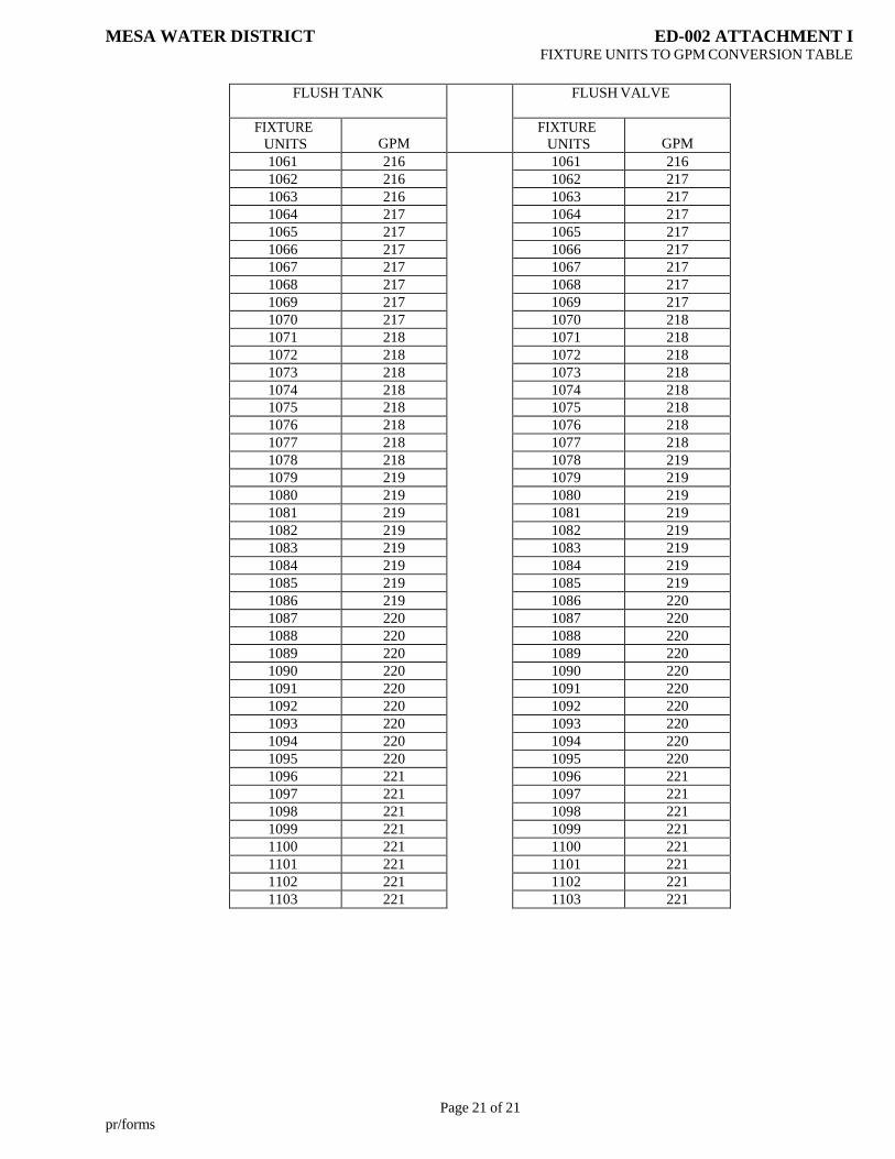
Page 21 of 21
pr/forms
MESA WATER DISTRICT ED-002 ATTACHMENT I FIXTURE UNITS TO GPM CONVERSION TABLE
FLUSH TANK FLUSH VALVE
FIXTURE
UNITS
GPM FIXTURE
UNITS
GPM
1061 216 1061 216
1062 216 1062 217
1063 216 1063 217
1064 217 1064 217
1065 217 1065 217
1066 217 1066 217
1067 217 1067 217
1068 217 1068 217
1069 217 1069 217
1070 217 1070 218
1071 218 1071 218
1072 218 1072 218
1073 218 1073 218
1074 218 1074 218
1075 218 1075 218
1076 218 1076 218
1077 218 1077 218
1078 218 1078 219
1079 219 1079 219
1080 219 1080 219
1081 219 1081 219
1082 219 1082 219
1083 219 1083 219
1084 219 1084 219
1085 219 1085 219
1086 219 1086 220
1087 220 1087 220
1088 220 1088 220
1089 220 1089 220
1090 220 1090 220
1091 220 1091 220
1092 220 1092 220
1093 220 1093 220
1094 220 1094 220
1095 220 1095 220
1096 221 1096 221
1097 221 1097 221
1098 221 1098 221
1099 221 1099 221
1100 221 1100 221
1101 221 1101 221
1102 221 1102 221
1103 221 1103 221
PART 2
GENERAL CONDITIONS FOR CONSTRUCTION
OF WATER FACILITIES
Mesa Water District
1965 Placentia Avenue
Costa Mesa, CA 92627
(949) 631-1291
MESA WATER DISTRICT
APRIL 2018
MESA WATER DISTRICT
APRIL 2018
II-1
TABLE OF CONTENTS
PART II – GENERAL CONDITIONS
Section 100 DEFINITIONS AND ABBREVIATIONS
100.1 DEFINITIONS
100.2 MEANING OF SPECIFIC WORDS
100.3 ABBREVIATIONS
Section 200 SCOPE AND CONTROL OF WORK
200.1 RESPONSIBILITY FOR FURNISHING MATERIAL AND INSTALLATION
200.2 GUARANTEE
200.3 LICENSES, PERMITS, AND FEES
200.4 PLANS AND SPECIFICATIONS
200.5 SHOP DRAWINGS
200.6 WORK TO BE DONE
200.7 RIGHT-OF-WAY
200.8 “RECORD DRAWINGS”
Section 300 CONTROL OF MATERIALS
300.1 MATERIALS AND WORKMANSHIP
300.2 PROTECTION OF WORK MATERIALS
300.3 INSPECTION REQUIREMENTS
300.4 TESTS OF MATERIALS
Section 400 UTILITIES
400.1 LOCATION
400.2 PROTECTION
Section 500 PROGRESS, ACCEPTANCE OF WORK, AND PROTECTION
500.1 CONSTRUCTION SCHEDULE AND COMMENCEMENT OF WORK
500.1.1 Capital Project Schedule (Non-Complex Projects)
500.1.2 Capital Project Schedule (Complex Projects)
500.1.2.1 Contractor’s Project Schedule
500.1.2.2 Network Details
500.1.2.3 Weekly Progress Reports
500.1.2.4 Responsibility for Completion
500.1.2.5 Schedule Time Extensions
500.1.2.6 Manpower
500.2 PROSECUTION OF WORK FOR OFFSITE CONSTRUCTION
Section 600 RESPONSIBILITIES OF CONTRACTOR IN CONDUCT OF WORK
600.1 SUPERVISION
600.2 NO PERSONAL LIABILITY

MESA WATER DISTRICT
APRIL 2018
II-2
600.3 RESPONSIBILITY FOR DAMAGE
600.4 LEGAL RELATIOSN AND RESPONSIBILITY
600.5 STORAGE OF EQUIPMENT AND MATERIALS IN PUBLIC STREETS
600.6 STREETS CLOSURES, DETOURS, BARRICADES
600.7 PUBLIC SAFETY
600.7.1 Safety Orders
600.7.2 Use of Explosives
600.8 CAL OSHA REQUIREMENTS
600.8.1 Trench Work
600.8.2 Confined Space
600.8.3 Permit-required Confined Space
600.8.4 Confined Space Operating Procedures

MESA WATER DISTRICT
APRIL 2018
100-1
SECTION 100
DEFINITIONS AND ABBREVIATIONS
100.1 DEFINITIONS
Whenever the words are used in this document or pronouns used in their stead occur in these specifications or
other documents, they shall have the meanings here given:
1. Acceptance - The formal action by Mesa Water accepting the dedication of completed facilities.
2. Applicant - An owner, developer, builder, engineer, or other authorized representative who applies as
the owner's official agent to Mesa Water for water service.
3. Board or Board of Directors - The Board of Directors of Mesa Water District.
4. City - Incorporated area within the County of Orange having local governing powers.
5. Contractor - The person, firm, or corporation entering into contract with the owner, developer, or
Mesa Water for the performance of work required under said contract and Mesa Water's ordinances,
rules, regulations, and specifications.
6. County - The County of Orange, State of California.
7. Date of Acceptance - The date Mesa Water formally accepts the dedication of completed facilities.
8. District – Mesa Water District. See Mesa Water.
9. District Engineer - The person holding the position or acting in the capacity of the District Engineer
of Mesa Water District.
10. Domestic Water (Potable Water) - That water which is pure and wholesome, does not endanger the
lives or health of human beings, and conforms to the latest edition of the United States Public Health
Service Drinking Water Standards, the California Safe Drinking Water Act, or other applicable
standards.
11. Engineer – Individual or firm authorized by the owner to oversee the execution of the contract, acting
either directly or through properly authorized agents, each agent acting only within the scope of
authority delegated to them by the Engineer.
12. General Manager - The person holding the position or acting in the capacity of the General Manager
of Mesa Water District.
13. Inspector - Any person authorized by Mesa Water to perform inspection of the water facilities prior
to construction, during construction, after construction, and during operation.
14. Laboratory - The materials-testing laboratory authorized by Mesa Water to test materials and work
involved in the construction governed by these specifications.
15. Mesa Water or Mesa Water District – The Mesa Water District, its authorized employees, Board of
Directors, and agents.
16. Mesa Water Standards or Mesa Water Standard Specifications – Mesa Water District “Standard
Specifications for the Construction of Water Facilities”. These Standards shall apply to all water
mains, laterals, and appurtenances whose ownership upon completion is to be transferred to Mesa
Water.
MESA WATER DISTRICT
APRIL 2018
100-2
17. Offsite Facilities - Shall mean facilities under the control of Mesa Water; including, but not limited
to: water mains, reservoirs, pumping stations, fire hydrants, valves, connections, supply interties,
treatment facilities, and other appurtenances and property up to the point of connection with the
customer's facilities.
18. Onsite Facilities - Shall mean facilities under the control of the applicant, owner or customer;
including, but not limited to, residential, commercial, and industrial building water systems. For
water, the onsite facilities shall be those downstream of the service connection, which shall normally
be the downstream end of the meter tailpiece.
19. Owner - Any holder of legal title, contract purchaser, or lessee of property for which service is
requested from Mesa Water.
20. Record Drawings - Drawings which show the facilities, including all revisions to the original plans.
21. Recycled (Reclaimed) Water – Disinfected tertiary recycled water served from Orange County
Water District’s recycled water distribution system.
22. Subcontractor – Secondary contractor who performs, at the site of the work, some part of the
contractor’s obligation under the contract.
23. Standard Drawings - The details of standard structures, devices or instructions referred to on the
plans or in specifications by title or number; also known as Standard Plans. Mesa Water Standard
Drawings are included within the “Standard Specifications for the Construction of Water Facilities”.
24. Standard Specifications – Mesa Water’s “Standard Specifications for the Construction of Water
Facilities”.
25. Water Systems - The term "water systems" includes both domestic water and on-site fire water
facilities.
100.2 MEANING OF SPECIFIC WORDS
Whenever, in these Specifications or upon the Standard Drawings, the words DIRECTED, REQUIRED,
PERMITTED, ORDERED, DESIGNATED, PRESCRIBED, or words of like importance are used, they shall
mean directed, required, permitted, ordered, designated, or prescribed by the District Engineer. The words
APPROVED, ACCEPTABLE, SATISFACTORY, or words of such importance shall mean approved by,
acceptable to, or satisfactory to the District Engineer, unless otherwise expressly stated.
100.3 ABBREVIATIONS
Whenever used in these Specifications, the following abbreviations shall refer to the agency shown:
Abbreviation Agency Address
AWWA The American Water Works
Association, Inc.
6666 West Quincy Avenue
Denver, CO 80235
ASTM The American Society for
Testing and Materials
1916 Race Street
Philadelphia, PA 19103
ANSI The American National
Standards Institute
1430 Broadway
New York, NY 10018
ACI
American Concrete Institute Box 19150 Redford Station
Detroit, MI 48219
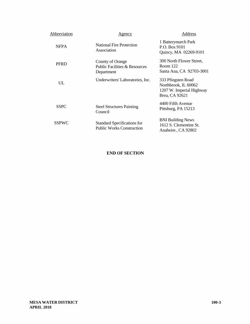
MESA WATER DISTRICT
APRIL 2018
100-3
Abbreviation Agency Address
NFPA
National Fire Protection
Association
1 Batterymarch Park
P.O. Box 9101
Quincy, MA 02269-9101
PFRD County of Orange
Public Facilities & Resources
Department
300 North Flower Street,
Room 122
Santa Ana, CA 92703-3001
UL Underwriters' Laboratories, Inc. 333 Pfingsten Road
Northbrook, IL 60062
1207 W. Imperial Highway
Brea, CA 92621
SSPC
Steel Structures Painting
Council
4400 Fifth Avenue
Pittsburg, PA 15213
SSPWC
Standard Specifications for
Public Works Construction
BNI Building News
1612 S. Clementine St.
Anaheim , CA 92802
END OF SECTION

MESA WATER DISTRICT
APRIL 2018
200-1
SECTION 200
SCOPE AND CONTROL OF WORK
200.1 RESPONSIBILITY FOR FURNISHING MATERIAL AND INSTALLATION
It will be the responsibility of the applicant and his contractor to furnish all materials that meet the following
material specifications and all labor and equipment to install facilities in conformance with approved plans
and specifications, including Mesa Water’s Standard Specifications.
200.2 GUARANTEE
The applicant and his contractor shall guarantee the work, upon completion, against leaks and breaks due to
defective materials or workmanship furnished by the contractor, against settlement of backfill, and damage to
resurfacing for a period of one year from the date of completion and acceptance by Mesa Water.
Arrangement shall be made for the faithful performance bond to be enforced for a period of one year after the
date of final acceptance to cover this guarantee. Damage or leaks due to acts of God, from sabotage, and/or
vandalism are specifically exempt from this guarantee.
The date of acceptance by Mesa Water will commence when completion of the entire tract, commercial, or
industrial complex is final. Partial releases are not considered to relieve applicant and his contractor of
responsibilities under this section.
When defective material or workmanship discovered in the work requires repairs to be made under this
guarantee, the applicant shall be notified by telephone and shall make all repairs at their own expense within
three calendar days after receipt of such telephoned notice. This telephone notice shall be followed up by
written correspondence. Should the applicant or his contractor fail to repair the damage within the three days,
Mesa Water may make the necessary repairs and charge the applicant with the actual cost of the repairs. In
emergencies demanding immediate attention, Mesa Water shall have the right to repair the defect or damage
and charge the applicant with the actual cost of all labor and material required.
200.3 LICENSES, PERMITS, AND FEES
The contractor shall have a valid Contractor’s License of the appropriate class (Class “A” or “C-34”). The
contractor or applicant shall obtain all permits, pay all fees, obtain business licenses, and give all necessary
notices required for the construction of the work. The contractor shall provide proof of licensing to the
District Engineer. Class “A” license shall be required for all non-pipeline work.
200.4 PLANS AND SPECIFICATIONS
Prior to the commencement of construction of any pipelines or pipeline structures, the applicant shall furnish
to Mesa Water, design drawings showing pipeline plans and profiles and details of pipeline structures. Work
shall not be commenced until Mesa Water has approved said design drawings. The contractor shall keep at
the worksite a copy of the approved plans and specifications, and a copy of Mesa Water’s Standard
Specifications to which Mesa Water shall have access at all times.
200.5 SUBMITTALS
Wherever called for in these Standard Specifications or on the drawings, or where required by Mesa Water,
the contractor shall furnish, to Mesa Water for review, three prints of each shop drawing.

MESA WATER DISTRICT
APRIL 2018
200-2
The term “shop drawing” as used herein shall be understood to include detail design calculations, fabrication
and installation drawings, lists, graphs, operating instructions, etc. The shop drawings shall be prepared in
accordance with current modern engineering practice and at the contractor's expense. Drawings shall be of a
size and scale to show clearly all necessary details. Unless otherwise required, the shop drawings shall be
submitted at a time sufficiently early to allow the review of the same, and to accommodate the rate of
construction progress required under the contract.
All shop drawing submittals shall be accompanied by a transmittal form using the format bound with the
contract or as provided by Mesa Water. Any shop drawing submittal not accompanied by such a form, or
where all applicable items on the form are not completed, will be returned for resubmittal. The contractor
may authorize a material or equipment supplier to deal directly with Mesa Water with regard to shop
drawings, however, ultimate responsibility for the accuracy and completeness of the information contained in
the submittal shall remain with the contractor.
A separate transmittal form shall be used for each specific item or class of material or equipment for which a
submittal is required. Transmittal of shop drawings on various items using a single transmittal form will be
permitted only when the items taken together constitute a manufacturer’s “package” or are so functionally
related that expediency indicates review of the group or package as a whole.
Within fifteen (15) calendar days after receipt of said prints, Mesa Water will return prints of each drawing to
the contractor with his comments noted thereon. It is considered reasonable that the contractor shall make a
complete and acceptable submittal to Mesa Water by the second submission of drawings. Mesa Water
reserves the right to withhold moneys due to the contractor to cover additional costs of Mesa Water’s review
beyond the second submission.
If three prints of the drawing are returned to the contractor marked “NO EXCEPTIONS TAKEN”, formal
revision of said drawing will not be required.
If three prints of the drawing are returned to the contractor marked “MAKE CORRECTIONS NOTED”,
formal revision of said drawing will not be required.
If one print of the drawing is returned to the contractor marked “REJECTED-RESUBMIT”, the contractor
shall revise said drawing and shall resubmit six copies of said revised drawing to Mesa Water.
Fabrication of an item shall not be commenced before Mesa Water has reviewed the pertinent shop drawings
and returned copies to the contractor marked “NO EXCEPTIONS TAKEN”, or “MAKE CORRECTIONS
NOTED”. Revisions indicated on shop drawings shall be considered as changes necessary to meet the
requirements of the contract drawings and specifications and shall not be taken as the basis of claims of extra
work. The contractor shall have no claim for damages or extension of the required revisions to shop
drawings (unless review by Mesa Water of said drawings is delayed beyond a reasonable period of time and
unless the contractor can establish that Mesa Water’s delay in review actually resulted in a delay in the
contractor’s construction schedule).
The review of said drawings by Mesa Water will be limited to checking for general agreement with the
specifications and drawings, and shall in no way relieve the contractor of responsibility for errors or
omissions contained therein nor shall review operate to waive or modify any provision contained in the
specifications or contract drawings. Fabricating dimensions, quantities of material, applicable code
requirements, and other contract requirements shall be the contractor’s responsibility.

MESA WATER DISTRICT
APRIL 2018
200-3
200.6 WORK TO BE DONE
All work shall be performed in a thorough workmanlike and professional manner in accordance with the
plans, profiles, and specifications that have been approved by Mesa Water. All work shall conform to the
lines, elevations, and grades shown on these plans and profiles.
Mesa Water's approval of the plans prepared by the applicant or the developer’s engineer denotes agreement
with the plans as prepared and is not an acceptance of responsibility as to their accuracy or completeness.
The applicant or the developer’s engineer shall be responsible for any error, coordination with other facilities,
and interpretation of the plans. The intent is to obtain a completed facility that shall be in conformance with
the approved plans and in accordance with Mesa Water's requirements and these specifications. All revisions
and changes in the plans must be approved by Mesa Water prior to commencement of work.
200.7 RIGHT-OF-WAY
Rights-of-way or easements for the waterlines or water facilities as shown on the plans will be provided by
the applicant. Unless otherwise provided, the contractor shall make arrangements for, pay for, and assume all
responsibility for acquiring, using, and disposing of additional work areas and facilities temporarily required.
The contractor shall indemnify and hold Mesa Water harmless from all claims for damages occasioned by
such actions.
The contractor shall be responsible for all costs associated with Mesa Water’s review of the easement
documentation and approval process. Costs shall include, but not be limited to:
Legal review of easement description;
Surveyor review of legal description; and
Other miscellaneous review.
200.8 RECORD DRAWINGS
The contractor shall, after the work is completed, furnish Mesa Water with a set of “record drawings”
showing the work as actually constructed before acceptance of the project by Mesa Water.
END OF SECTION

SECTION 300
CONTROL OF MATERIALS
300.1 MATERIALS AND WORKMANSHIP
All materials, parts, and equipment furnished by the contractor shall be new, high grade, and free from
defects. Workmanship shall be in accordance with the generally accepted standards. Materials and
workmanship shall be subject to Mesa Water's approval.
Materials and workmanship not conforming to the requirements of these specifications shall be considered
defective and will be subject to rejection. Defective work or material, whether in place or not, shall be
removed immediately from the site by the contractor at its expense when so directed by Mesa Water.
300.2 PROTECTION OF WORK AND MATERIALS
The contractor shall provide and maintain storage facilities and employ such measures as will preserve the
specified quality and fitness of materials to be used in the work. Stored materials shall be reasonably
accessible for inspection. The contractor shall also adequately protect new and existing work and all items of
equipment for the duration of the contract.
300.3 INSPECTION REQUIREMENTS
Unless otherwise specified, inspection is required at the jobsite for such typical materials and fabricated items
as pipe, valves, fittings, service materials, structural concrete, welding, and protective coating application.
300.4 TESTS OF MATERIALS
Before incorporation in the work, the contractor shall submit samples of materials, as Mesa Water may
require, at no cost to Mesa Water. The contractor, at his own expense, shall deliver the materials for testing
to the place and at the time designated by Mesa Water. Unless otherwise provided, all initial testing and a
reasonable amount of retesting shall be performed under the direction of Mesa Water, at no expense to the
contractor. In general, the following summarizes which entity will pay for specific testing unless otherwise
agreed upon with the Water Service Agreement.
1. Geotechnical Testing (Private Contract): testing expense shall be borne by the permittee (contractor
or the applicant).
2. Geotechnical Testing (Capital Project): testing expense shall be borne by Mesa Water unless
otherwise noted in the Project Specifications. All retesting expenses shall be borne by the contractor.
3. Pipe or pump/motor inspection at the manufacturer’s facility shall be borne by Mesa Water unless
otherwise noted in the Project Specifications.
4. Valve leakage testing for all butterfly valves 12-inches in diameter and larger shall be borne by the
contractor. The test will be witnessed by Mesa Water.
5. Third party inspection shall be borne by Mesa Water unless otherwise agreed upon within the Water
Service Agreement.
END OF SECTION
MESA WATER DISTRICT
APRIL 2018 300-1
MESA WATER DISTRICT
APRIL 2018
400-1
SECTION 400
UTILITIES
400.1 LOCATION
The applicant shall be responsible for searching utility records and indicating the location of all known
utilities on the plans. At least two working days (48 hours) before beginning the work, the contractor shall
call Underground Service Alert (USA) for all utility owners to mark or otherwise indicate the location of their
substructures, except for public sewers and storm drains. It shall be the contractor's responsibility to
determine the true location and depth of all utilities and service connections. The contractor shall also
familiarize himself with the type, material, age, and condition of any utility that may be affected by the work.
The contractor shall pothole all points of connections, crossing utilities and parallel utilities which may be
affected by or affect the work as specified within Section 02223 (Trenching, Backfilling and Compacting)
and Section 02222 (Protecting Existing Utilities) of these Technical Specifications.
400.2 PROTECTION
The contractor shall not interrupt the service function or disturb the supporting base of any utility without
authority from the owner and order from Mesa Water.
Where protection is required to ensure support of utilities, the contractor shall furnish and place the necessary
protection at its expense. The contractor shall maintain a minimum of 12 inches separation at perpendicular
crossings between Mesa Water facilities and other utilities.
The contractor shall immediately notify Mesa Water and the utility owner if he disturbs, disconnects, or
damages any utility. In the event of necessary repair work on a Mesa Water facility, Mesa Water has the
right to hire another contractor to do the repair work. The project contractor will be responsible for the cost
of the repair.
END OF SECTION

MESA WATER DISTRICT
APRIL 2018
500-1
SECTION 500
PROGRESS, ACCEPTANCE OF WORK, AND PROSECUTION
500.1 CONSTRUCTION SCHEDULE AND COMMENCEMENT OF WORK
Prior to start of any work, the contractor shall submit a proposed construction schedule to Mesa Water for
approval. Construction of water facilities will not commence until curb and gutter have been completed.
Before starting construction on all jobs within Mesa Water, a preconstruction conference is to be held at
which Mesa Water and its Inspector, the contractor's foreman and/or superintendent for that job, and the
applicant's tract superintendent shall be present. Mesa Water Inspector shall review job plans and the
contractor's work schedule, answer any questions regarding Mesa Water specifications, verify that all permits
have been obtained, and check the contractor's license. Evidence of a performance bond, signed agreement,
and applicable Mesa Water-signed plans shall be available to Mesa Water 48 hours before the
preconstruction conference.
If the contractor desires to make a major change in the method of operations after commencing construction
or if the schedule fails to reflect the actual progress, the contractor shall submit to Mesa Water a revised
construction schedule before beginning revised operations.
The District Engineer may waive these requirements for work constructed under permit.
500.1.1 Capital Project Schedule (Non-Complex Projects)
The following construction schedule requirements shall apply for non-complex capital projects, less than
$200,000 construction cost, requiring few interfaces and minimal coordination with sub-contractors,
material suppliers, and other projects.
The schedule shall be a Gant Chart or CPM (Microsoft Project) based schedule, and shall show the various
parts of the work in sufficient detail so as to identify the beginning and end of each of the various
construction activities. The schedule shall include, at a minimum, the following:
Submittal milestones;
All construction activities;
Equipment/material procurement and deliveries;
Permit imposed work times;
Partial, substantial, and final completion milestones; and
Critical path activities.
The schedule shall also include any other activities or milestones or scheduling constraints that may impact
the construction.
500.1.2 Capital Project Schedule (Complex Projects)
The following construction schedule requirements shall apply for complex capital projects, more than
$200,000 construction cost, requiring several interfaces and coordination with sub-contractors, material
suppliers, and other projects.
MESA WATER DISTRICT
APRIL 2018
500-2
500.1.2.1 Contractor’s Project Schedule
1. Seven (7) days after Notice to Proceed, the contractor shall submit the Project Schedule.
2. The Project Schedule shall show the sequence and interdependence of activities required for
complete performance of the work, beginning with the date of the Notice to Proceed and
concluding with the date of Final Completion of the Contract.
3. Use of float suppression techniques such as preferential sequencing, special lead/lag logic
restraints, extended activity times or imposed date shall be cause of rejection of the Project
Schedule and any revisions or updates.
4. Any approved schedule, revision, or update having an early completion date shall show the time
between the early completion date and the current contract completion date as “project float”.
5. Comments made by Mesa Water on the Project Schedule, during review, will not relieve the
contractor from compliance with requirements of the Project Specifications. To the extent that
there are any conflicts between the approved schedule and the requirements of the Project
Specifications, the Project Specifications shall govern.
6. If requested by Mesa Water at any time during the project, the contractor shall provide highly
detailed, short-term schedules for specific crucial items (work-arounds, start-up, etc.).
500.1.2.2 Network Details
1. The Project Schedule shall provide Mesa Water with a tool to monitor and follow the progress of
all phases of the work. The Project Schedule submitted to Mesa Water shall comply with all
limits imposed by the scope of the work, with all contractually specified completion dates, and
with all constraints, restraints, or sequences included in the Project Specifications. The degree of
detail shall include factors to the satisfaction of Mesa Water, including, but not limited to:
a. Physical breakdown of the project including a predecessor/successor report or a list showing
the predecessor activities and successor activities for each activity in the schedule sorted by
Early Start.
b. Activity report sorted by activity number or a list showing each activity in the schedule.
c. Contract completion dates, substantial completion dates, constraints, restraints, sequences of
work shown in Project Specifications, the planned substantial completion date, and the final
completion date.
d. Type of work to be performed, the sequences, and the labor trades involved.
e. All purchase, submittals, submittal reviews, manufacturer, test, delivery, and installation
activities for all major material and equipment, and a separate list of all major items or items
of equipment for which the contractor intends to seek payment prior to installation.
f. Preparation, submittal and approval of shop and/or working drawings and material samples.
g. Plans for all subcontract work.
h. Assignment of responsibility for performing specific activities.
i. Access to and availability of work areas.

MESA WATER DISTRICT
APRIL 2018
500-3
j. Punch list and final cleanup.
2. The activities included in the Project Schedule shall be analyzed in detail to determine activity
time durations in units of project working days. Durations shall be based on the labor,
equipment, and materials required to perform each activity on a normal work day basis.
500.1.2.3 Weekly Progress Reports
1. Once each week, on a day established by Mesa Water, the contractor shall submit two progress
schedules:
a. The first shall be a progress schedule listing the activities completed and in progress for the
previous week and the activities scheduled for the succeeding two weeks. The activity
designations shall be consistent with the activity designations in the Current Record
Schedule. A bar chart shall be used to display the information in pictorial form. The
appropriate schedule activity number shall be listed for each bar.
b. The second shall be a utility work/access alteration report. This report and schedule shall
include any and all work that affects other operations, utilities, equipment, and like detail as
well as alterations.
500.1.2.4 Responsibility for Completion
1. Whenever it becomes apparent from the current Project Schedule that Contract completion dates
will not be met, the contractor shall execute some or all of the following remedial actions:
a. Increase construction manpower in such quantities and crafts as necessary to eliminate the
backlog of work.
b. Increase the number of work hours in conformance with the Project Specifications
requirements.
2. Prior to implementing any of the above actions, the contractor shall notify and obtain approval
from Mesa Water. If such actions are approved, the Project Schedule revisions shall be
incorporated by the contractor into the Network Diagram before the next update.
3. Under no circumstances will the addition of equipment or construction forces, increasing the
working hours or any other method, manner, or procedure to return to the contractually required
completion date be considered justification for a Change Order or be treated as acceleration
where the need for a recovery schedule has been caused by the contractor and/or its
subcontractors or suppliers, at any tier.
4. Mesa Water may elect to withhold progress payments until the contractor’s progress indicates
that the Contract completion date will be met.
500.1.2.5 Schedule Time Extensions
1. When Change Orders or delays are experienced by the contractor and a time extension is
requested, the contractor shall submit to Mesa Water, a written Time Impact Analysis illustrating
the influence of each change or delay on the current Contract schedule completion date utilizing
the approved Current Record Schedule. Each Time Impact Analysis shall include a fragnet
MESA WATER DISTRICT
APRIL 2018
500-4
demonstrating how the contractor proposes to incorporate the Change Order or delay into the
Current Record Schedule. A fragnet is defined as a sequence of new and/or activity revisions that
are proposed to be added to the approved Baseline Project Schedule or current Record Schedule
in effect at the time the change or delay is encountered to demonstrate the influence of the delay
and the method for incorporating the delay and its impact into the schedule as they are
encountered.
2. Each Time Impact Analysis shall demonstrate the estimated time impact based on the events of
delay, the date the Preliminary Change Order, Emergency Change Authorization, the Time and
Materials Change Order, or the Unilateral Change Order was given to the contractor, the status of
construction at that point in time, and the event time computation of all activities affected by the
change or delay. The event times used in the analysis shall be those included in the latest update
of the Current Record Schedule, in effect at the time the change or delay was encountered.
3. Time extensions will be granted only to the extent that equitable time adjustments for the activity
or activities affected exceed the total or remaining float along the critical path of activities at the
time of actual delay, or at the time the Proposed Change Order, the Emergency Change
Authorization, the Time and Materials Change Order, or the Unilateral Change Order was issued.
Float or slack time is not for the exclusive use or benefit of Mesa Water, or the contractor but is
an expiring resource available to all parties as needed to meet Contract milestones and the
contract completion date. Time extensions shall not be granted nor delay damages paid until:
a. A delay occurs which is beyond the control and without the fault or negligence of the
contractor and its subcontractors or suppliers, at any tier; and
b. Which extends actual performance of the work beyond the applicable current Contract
completion date and the most recent date predicated for completion of the project on the
approved schedule update current as of the time of the delay or as of the of issuance of the
Proposed Change Order, the Emergency Change Authorization, the Time and Materials
Change Order, or the Unilateral Change Order.
4. Each Time Impact Analysis shall be submitted in triplicate, within ten (10) days after a delay
occurs, or issuance of the Proposed Change Order, Change Authorization, Time and Materials
Change Order, or Unilateral Change Order. If the contractor does not submit a Time Impact
Analysis for a specific Change Order or delay with the specified period of time, the contractor
shall be deemed to have irrevocably waived any rights to additional time and cost.
5. Since float time within the Project Schedule and the Record Schedule is jointly owned it is
acknowledged and agreed by the contractor that Owner caused delays on the project may be
offset by Owner caused time savings (including, but not limited to: critical path submittals
returned in less time than allowed for in the Contract, approval of substitution requests which
result in a savings of time along the critical path of the contractor, etc.). In such an event the
contractor shall not be entitled to receive an extension of time or delay damages until Owner
caused time savings are exceeded and the Contract completion date also exceeded.
6. Approval or rejection of each Time Impact Analysis by Mesa Water shall be made within fifteen
(15) days after receipt of each Time Impact Analysis, unless subsequent meetings and
negotiations are necessary. Upon approval, a copy of a Time Impact Analysis signed by Mesa
Water shall be returned to the contractor for incorporation into the schedule.

MESA WATER DISTRICT
APRIL 2018
500-5
7. Upon mutual agreement by both parties, fragnets illustrating the influence of Change Orders and
delays shall be incorporated into the Project Schedule or Record Schedule during the first update
after agreement is reached.
500.1.2.6 Manpower
The contractor shall submit the initial Project Schedule a histogram depicting total project manpower for
its own forces and for each of its subcontractors for each month. The histogram shall be based upon and
shall be in substantive agreement with the number of shifts and crew sizes in the Project Schedule.
500.2 PROSECUTION OF WORK FOR OFFSITE CONSTRUCTION
To minimize public inconvenience and possible hazard, and to restore streets and other work areas to their
original condition and former state of usefulness as soon as practicable, the contractor shall diligently
prosecute the work to completion.
As soon as possible under the provisions of these specifications, the contractor shall backfill all excavations
and restore to usefulness all improvements existing before the start of the work.
END OF SECTION

MESA WATER DISTRICT
APRIL 2018
600-6
SECTION 600
RESPONSIBILITIES OF CONTRACTOR IN CONDUCT OF WORK
600.1 SUPERVISION
The contractor shall designate and keep on the work at all times during its progress a competent
superintendent, who shall not be replaced without written notice to Mesa Water. The superintendent will be
the contractor's representative at the site and shall have authority to act on behalf of the contractor. All
communications given to the superintendent shall be as binding as if given to the contractor. During periods
when the work is suspended, the contractor shall make appropriate arrangements for any emergency work
which may be required.
Whenever the contractor's superintendent is not present on any particular part of the work where Mesa
Water's representative may desire to inform the contractor relative to interpretation of the plans and
specifications or to disapproval or rejection of materials or work performed, Mesa Water's representative may
so inform the foreman or other worker in charge of the particular part of the work in reference to which the
information is given. Information so given shall be as binding as if given to the superintendent.
600.2 NO PERSONAL LIABILITY
The Board of Directors, Mesa Water District, or any officer, or authorized assistant, or an agent of Mesa
Water shall not be personally responsible for any liability arising out of the work performed.
600.3 RESPONSIBILITY FOR DAMAGE
Mesa Water, its officers, employees, and agents; the Board of Directors; and the District Engineer, shall not
be answerable or accountable in any manner for any loss or damage that may happen to the work or any part
thereof; or for any material or equipment used in performing the work; or for injury or damage to any person
or persons, workmen, or the public; or for damage to adjoining property from any cause whatsoever during
the progress of the work or at any time before final acceptance.
600.4 LEGAL RELATIONS AND RESPONSIBILITY
The contractor shall keep himself fully informed of all laws, ordinances, and regulations that in any manner
affect those engaged or employed in the work or the materials used in the work, or that in any way affect the
conduct of the work, and of all such orders and decrees of bodies or tribunals having any jurisdiction or
authority over the same. If any discrepancy or inconsistency is discovered in the plans, drawings,
specifications, or other documents in relation to any such law, ordinance, regulation, order, or decree, the
contractor shall forthwith report the same to Mesa Water in writing. The contractor shall at the time observe
and comply with all such existing and future laws, ordinances, resolutions, regulations, orders, and decrees
and shall protect and indemnify Mesa Water District, its officers, employees, and agents against any claim or
liability arising from or based on the violation of any such law, ordinance, regulation, order, or decree,
whether by themselves or their employees.
The contractor shall hold harmless, indemnify, and defend Mesa Water District and its officers, employees,
and agents from any and all liability claims, losses, or damages, including attorney's fees, arising or alleged to
arise from the performance of the work, provided, however, that if the loss or damage is ultimately
determined to be the proximate result of the sole negligence of one or more of the aforesaid, this
indemnification shall not apply.
MESA WATER DISTRICT
APRIL 2018
600-7
The contractor shall also indemnify and hold Mesa Water District and its officers, employees, and agents
harmless from all costs, losses, expenses, damages, attorney's fees, and other costs of defense that any of
them may incur with respect to the failure, neglect, or refusal of contractor to faithfully perform the work and
all of contractor’s obligations under the contract. Such costs, expenses, and damages shall include all costs
incurred by Mesa Water District and its officers, employees, and agents to defend against any claims, stop
notices, or lawsuits based thereon in which any of them are made a party.
The contractor shall, in general, observe the rules and regulations of the State of California, Department of
Industrial Relations, Division of Industrial Safety (CAL/OSHA) and, in particular, rules and regulations
relating to shoring of trenches and excavations and confined spaces.
600.5 STORAGE OF EQUIPMENT AND MATERIALS IN PUBLIC STREETS
Construction materials may not be stored in streets, roads, or highways for a period longer than that
authorized by the agency having jurisdiction over said street, road, or highway.
Construction equipment shall not be stored at the worksite before its actual use on the work or for a period
longer than that authorized by the agency having jurisdiction over said street, road, or highway.
The contractor shall acquire at their own expense any additional storage/staging area of adequate size and
access to facilitate contractor’s own operations including storing and staging of materials, and
contractor/employee vehicle parking. The contractor shall meet all conditions and requirements of the
Property Owner. The contractor shall be responsible for securing the site to protect his property from
vandalism and loss and to protect the public from possible injury.
The contractor shall inform Mesa Water of his activities for obtaining additional staging area they deem
necessary. The contractor is advised that the additional staging area must be obtained directly in writing
from the Property Owner by the contractor for use during the construction period. In obtaining such
additional staging area, the contractor shall obtain all necessary permits and comply with local ordinances
and regulations. The contractor is responsible for any rents, fines, damages, and restoration costs
associated with the additional staging area. Mesa Water shall be furnished a copy of the written
agreement with the affected Property Owner prior to using the additional staging area. The agreement
shall contain a written release statement approved by Mesa Water and shall be executed by the Property
Owner that all work including restoration was completed to the Property Owner’s satisfaction. Mesa
Water shall be provided with a copy of the written release from the Property Owner releasing the
contractor from any future claims prior to filing the Notice of Completion.
600.6 STREETS CLOSURES, DETOURS, BARRICADES
The contractor shall comply with all applicable state, county, and city requirements for closure of streets.
The contractor shall provide barriers, guards, lights, signs, temporary bridges, flagmen, and watchmen
advising the public of detours and construction hazards that may arise during construction and promptly
remove all signs and warning devices upon completion of the work. The contractor shall provide a traffic
control plan stamped by a Registered Traffic Engineer. The contractor shall also be responsible for
compliance with additional public safety requirements that may arise during construction.
At least two working days (48 hours) before closing, partially closing, or reopening of any street, alley, or
other public thoroughfare, the contractor shall notify the police, fire, traffic, and engineering department of
jurisdictional agencies involved, obtain the necessary permits, and comply with their requirements.
Deviations must first be approved in writing by the District Engineer. Traffic control shall be in accordance
MESA WATER DISTRICT
APRIL 2018
600-8
with the "Work Area Traffic Control Handbook" (WATCH), unless otherwise specified by the jurisdictional
agency.
600.7 PUBLIC SAFETY
600.7.1 Safety Orders
The contractor shall have at the worksite copies or suitable extracts of Construction Safety Orders, Tunnel
Safety Orders, and General Industrial Safety Orders as issued by the State Division of Industrial Safety. The
contractor shall comply with provisions of these and all other applicable laws, ordinances, and regulations.
600.7.2 Use of Explosives
Explosives may be used only when authorized in writing by the District Engineer. Explosives shall be
handled, used, and stored in accordance with all applicable regulations.
The District Engineer's approval of the use of explosives shall not relieve the contractor from his liability for
claims caused by blasting operations.
600.8 CAL OSHA REQUIREMENTS
The following are Cal/OSHA requirements as of the printing of these Mesa Water standard specifications.
The requirements are listed for information purposes only; work must be in compliance with the current
Cal/OSHA requirements. Requirements for construction work for Cal/OSHA are listed in Title 8, Division 1,
Chapter 4, Subchapter 4, of the California Code of Regulations.
600.8.1 Trench Work
Division of Occupational Safety and Health (DOSH) requires a DOSH permit for construction of trenches or
excavations 5 feet or more in depth into which a person is required to descend.
Each employee in an excavation shall be protected from cave-ins by an appropriate protective system.
A competent person will make daily inspections of excavations, adjacent areas, and protective systems for
potential cave-in, failure of protective systems, hazardous atmospheres, or other hazardous conditions.
A competent person must demonstrate:
1. Knowledge of current safety orders pertaining to excavation and trenching.
2. Knowledge of soil analysis and classification.
3. Knowledge of design and use of protective systems.
4. Authority to take prompt corrective action when conditions change.
5. Ability to recognize and test for hazardous atmospheres.
Protective system design will be based on soil classification: Type A, B, or C soils (refer to Section 1541(b)
Title 8). Sloping or benching for excavations greater than 20 feet deep shall be designed by a registered
professional engineer.
MESA WATER DISTRICT
APRIL 2018
600-9
Determine the location of underground utilities and notify the owners.
Inspect the area for hazards from moving ground.
Inspect the excavation after every rainstorm, earthquake, or other hazard-increasing occurrence.
Inspect the face, banks, and top daily when workers are exposed to falling or rolling material.
Shore, bench, slope, shield, or use equivalent methods to protect workers in excavations 5 feet deep or more.
Locate spoil, materials, and equipment at least 2 feet from the edge of excavation.
In trenches 4 feet deep or more, provide safe access within 25 feet of any work area.
Install walkways or bridges with standard guardrails when employees or equipment are required or permitted
to cross over.
Do not excavate beneath the level of adjacent foundations, retaining walls, or other structures until a qualified
person has determined that the work will not be hazardous.
Shore, brace, or underpin structures when their stability is threatened. Inspect structures daily.
Erect barriers around excavations in remote work locations. Cover or barricade all wells, pits, shafts or
caissons.
Note: A shoring detail shall be designed by a registered professional engineer for all excavations 5 feet or
more in depth into which a person is required to descend.
600.8.2 Confined Space
The General Industry Safety Orders define a confined space as a space that has the following characteristics:
1. Its size and shape allow a person to enter it.
2. It has limited openings for workers to enter and exit.
3. It is not designed for continuous occupancy.
Attention is directed to the provisions of: Article 108 of the General Industry Safety Orders, Title 8,
California Code of Regulations; and Article 4 of the Construction Safety Orders, Title 8, California Code of
Regulations.
Confined spaces shall be as described above, and shall include the interior of storm drains, sewers, vaults,
utility pipelines, manholes, reservoirs, and any other such structure which is similarly surrounded by
confining surfaces so as to permit an oxygen deficient atmosphere or the accumulation of dangerous gases or
vapors.
The contractor shall notify in writing the Mesa Water Inspector 48 hours prior to performing work in a Mesa
Water facility classified as a confined space.

MESA WATER DISTRICT
APRIL 2018
600-10
600.8.3 Permit-required Confined Space
A permit-required confined space has one or more of the following characteristics:
1. Contains or has potential to contain a hazardous atmosphere.
2. Contains a liquid or solid material that can engulf an entrant.
3. Has an internal configuration such that the entrant could be trapped or asphyxiated by inwardly
converging walls or by a floor which slopes downward and tapers to a smaller cross-section.
4. Mechanical or electrical hazards.
5. Contains any other recognized serious safety or health hazard.
6. Contains unknown atmospheric environment.
The general industry regulations define a Non-Permit Required Confined Space as a confined space that does
not contain or, with respect to atmospheric hazards, have the potential to contain any hazard capable of
causing death or physical harm.
Confined spaces shall be considered permit-required confined spaces (PRCS) until proven safe from
atmospheric hazards by testing and ventilation; and until evaluated as safe from any other serious safety or
health hazards.
No one shall enter a Mesa Water facility that is classified as a permit-required confined space without a Mesa
Water Inspector being present. The contractor shall submit the permit to Mesa Water Inspector 48 hours
prior to doing work in a Mesa Water confined space facility.
An entry permit is a written or printed document that is provided by the contractor to allow and control entry
into a permit-required confined space and that contains, but is not limited to, the following information:
1. Specific permit space identification.
2. Purpose and date of entry.
3. Duration of authorization.
4. Authorized entrants by name.
5. Names of authorized attendant and entry supervisor.
6. Actual hazards of the identified space.
7. Control and isolation methods to be used.
8. Acceptable entry conditions.
9. Results of initial and periodic atmospheric testing.
10. Rescue and emergency services to be summoned.
11. Communication procedures authorized between attendant and entrants.
12. Equipment to be provided.
13. Other information as necessary.
14. Other permits, such as hotwork.

MESA WATER DISTRICT
APRIL 2018
600-11
600.8.4 Confined Space Operating Procedures
Contractor shall comply with Mesa Water’s Confined Space Entry Procedures.
1. Contractor shall submit confined space operating and rescue procedures to Mesa Water for record
keeping purposes. Procedures shall conform to the applicable provisions of Article 108, General
Industry Safety Orders, Title 8, California Code of Regulations.
2. Contractor shall test for the presence of combustible or dangerous gases and/or oxygen deficiency in
confined spaces using an approved device immediately prior to a worker entering the confined space,
and at intervals frequent enough to ensure a safe atmosphere during the time a worker is in such a
structure. A record of such tests shall be kept at the jobsite.
3. Employees shall not be permitted to enter a confined space, where tests indicate the presence of a
hazardous atmosphere, unless the employee is wearing suitable and approved respiratory equipment,
or until such time that continuous forced air ventilation has removed the hazardous atmosphere from
the confined space.
4. Confined spaces that contain or that have last been used as containers of toxic gases, light oils,
hydrogen sulfide, corrosives, or poisonous substances, shall, in every case, be tested by means of
approved devices or chemical analysis before being entered without wearing approved respiratory
equipment.
5. Sources of ignition shall be prohibited in any confined space until after the atmosphere within the
confined space has been tested and found safe.
6. Reservoirs, vessels, or other confined spaces having openings or manholes in the side as well as in
the top shall be entered from the side openings or manholes when practicable.
7. Contractor shall coordinate entry operations with Mesa Water when both the contractor personnel
and Mesa Water personnel will be working together as authorized entrants into a permit-required
confined space.
8. Contractor shall submit to Mesa Water a photocopy of the canceled permit at the conclusion of the
entry operation. This information is for record-keeping purposes only, and is not intended to provide
enforcement of confined space regulations.
END OF SECTION
PART 3
TECHNICAL SPECIFICATIONS FOR
CONSTRUCTION OF WATER FACILITIES
Mesa Water District
1965 Placentia Avenue
Costa Mesa, CA 92627
(949) 631-1291
MESA WATER DISTRICT
APRIL 2018

TABLE OF CONTENTS
MESA WATER DISTRICT TOC - 1
MESA WATER DISTRICT
TECHNICAL SPECIFICATIONS
TABLE OF CONTENTS
SECTION 01045 – EXISTING FACILITIES
SECTION 01380 – RECORDING EXISTING AND NEW FACILITIES
SECTION 01570 – STORM WATER POLLUTION PREVENTION PLAN
SECTION 02140 – DEWATERING
SECTION 02200 – STRUCTURAL EARTHWORK
SECTION 02222 – PROTECTING EXISTING UTILITIES
SECTION 02223 – TRENCHING, BACKFILLING, AND COMPACTION
SECTION 02315 – JACKED CASING
SECTION 02528 – CONCRETE CURBS, GUTTERS, AND SIDEWALKS
SECTION 02578 – PAVEMENT REMOVAL AND REPLACEMENT
SECTION 03100 – CONCRETE FORMWORK
SECTION 03201 – CONCRETE REINFORCEMENT
SECTION 03260 – CONCRETE JOINTS
SECTION 03300 – CONCRETE
SECTION 03462 – PRECAST CONCRETE VAULTS AND METER BOXES
SECTION 05120 – STRUCTURAL STEEL AND MISCELLANEOUS METALWORK
SECTION 09900 – PAINTING AND COATING
SECTION 15041 – CHLORINATION OF WATER MAINS FOR DISINFECTION
SECTION 15042 – HYDROSTATIC TESTING OF PRESSURE PIPELINES
SECTION 15051 – INSTALLATION OF PRESSURE PIPELINES
SECTION 15056 – DUCTILE-IRON PIPE AND FITTINGS
SECTION 15057 – COPPER PIPE AND FITTINGS
SECTION 15064 – PVC PRESSURE DISTRIBUTION PIPE AND FITTINGS
SECTION 15076 – CEMENT-MORTAR LINED AND COATED STEEL PIPE
SECTION 15089 – COMBINATION AIR AND VACUUM RELEASE VALVES
SECTION 15100 – MANUAL VALVES
SECTION 15112 – BACKFLOW PREVENTERS
SECTION 15120 – DIAPHRAGM-ACTUATED CONTROL VALVES
SECTION 15139 – FIRE HYDRANTS
TABLE OF CONTENTS
MESA WATER DISTRICT TOC - 2
MESA WATER DISTRICT
TECHNICAL SPECIFICATIONS
TABLE OF CONTENTS (CONTINUED)
SECTION 15150 – METERS
SECTION 15151 – DOMESTIC AND RECYCLED WATER FACILITIES IDENTIFICATION
SECTION 15162 – FLEXIBLE PIPE COUPLINGS AND EXPANSION JOINTS
SECTION 16640 – CATHODIC PROTECTION AND JOINT BONDING
EXISTING FACILITIES
MESA WATER DISTRICT
01045 - 1
SECTION 01045
EXISTING FACILITIES
PART 1 – GENERAL
A. Description
This section includes requirements for connection to and abandonment of existing water
facilities.
B. Related Work Specified Elsewhere
1. Protecting Existing Utilities: 02222.
2. Trenching, Backfilling, and Compacting: 02223.
3. Chlorination of Water Mains for Disinfection: 15041.
4. Hydrostatic Testing of Pressure Pipelines: 15042.
5. Manual Valves: 15100.
C. Location
1. The contractor shall be responsible for potholing and determining in advance the
location and elevation of all existing pipelines to which connections are to be made.
Discrepancies shall be reported to Mesa Water and/or design engineer, prior to the
fabrication of, or purchase of material affected by the discrepancy.
2. The contractor shall notify Underground Service Alert of Southern California (Dig
Alert) at least two working days prior to construction at 1-800-422-4133.
D. Condition of Existing Facilities
Mesa Water does not warranty the condition, size, material, and location of existing facilities.
The contractor shall be responsible for verifying the properties of the existing pipe that will
be connected to the proposed piping.
E. Protection of Existing Utilities and Facilities
1. The contractor shall be responsible for the care and protection of all existing sewer pipe,
water pipe, gas mains, culverts, power or communications lines, sidewalks, curbs,
pavement, or other facilities and structures that may be encountered in or near the area
of the work.
2. It shall be the duty of the contractor to notify Underground Service Alert (USA) and
each agency of jurisdiction and make arrangements for locating their facilities prior to
pipeline construction.

EXISTING FACILITIES
MESA WATER DISTRICT
01045 - 2
3. The contractor shall submit a plan as to the method the contractor will use to protect and
support any utilities which will become exposed during excavation or that which are
vulnerable to failure due to unsupported trenches or other construction activity.
4. In the event of damage to any existing facilities during the progress of the work and of
the failure of the contractor to exercise the proper precautions, the contractor will pay
for the cost of all repairs and protection to said facilities. The contractor's work may be
stopped until repair operations are complete.
F. Protection of Landscaping
1. The contractor shall be responsible for the protection of all the trees, shrubs, irrigation
systems, fences, and other landscape items adjacent to or within the work area, unless
they are directed to do otherwise on the plans.
2. In the event of damage to landscape items, the contractor shall replace the damaged
items in a manner satisfactory to Mesa Water, the owner, or the jurisdictional agency in
control, or pay damages to the owner as directed by Mesa Water. The contractor shall
verify that any damaged or renovated landscaping shall be replaced with landscaping
that meets the current and applicable local landscape standards, codes, and ordinances,
including but not limited to AB 1881 (Water Efficient Landscape Ordinance).
3. When the proposed pipeline, vault facility or other appurtenances are to be within
planted or other improved areas in public or private easements, the contractor shall
restore such areas to the original condition after completion of the work. This
restoration shall include grading, a placement of 5 inches of topsoil, resoding, and
replacement of all landscape items indicated. All irrigation facilities shall be
restored/replaced to a condition equal to or better than existing per the manufacturer’s
recommendations and/or industry standards.
4. If the contractor does not proceed with the restoration after completion of the work or
does not complete the restoration in a satisfactory manner, Mesa Water reserves the
right to have the work done and to charge the contractor for the actual cost of the
restoration including all labor, material, and overhead required for restoration.
G. Permits
All work shall conform to the specifications and requirements of the city having jurisdiction,
the County of Orange, CALTRANS or other affected agencies involved. The contractor shall
keep a copy of all required permits at the job site and comply with all the terms and
conditions of said permits.
PART 2 – MATERIALS
All materials used in making the connection or removing the facility from service shall conform to the
applicable sections of these specifications.
EXISTING FACILITIES
MESA WATER DISTRICT
01045 - 3
A. Grout
Grout shall consist of Portland cement and water or of Portland cement, sand, and water; and all
grout mixtures shall contain 2% of bentonite by weight of the cement. Grout shall be a pump
mix with a minimum of six sacks cement (564 lbs) per cubic yard.
Portland cement, water and sand shall conform to the applicable requirements of Section 03300
(Concrete), except that sand to be used shall be of such fineness that 100% will pass a standard
8-mesh sieve and at least 45%, by weight, will pass a standard 40-mesh sieve.
B. Concrete
Concrete used for the replacement of damaged or removed facilities shall be in accordance with
Section 03300 (Concrete) and shall match the mix design of the existing facility and per the
requirement of the jurisdictional agency.
PART 3 – EXECUTION
A. Connection to Existing Water Lines
1. Notification: The contractor shall give Mesa Water a minimum of five (5) working
days notice before the time of any proposed shutdown of existing mains or services.
2. Notice to Proceed: Connections shall be made only in the presence of Mesa Water
Representative and no connection work shall proceed until the Mesa Water
Representative has given notice to proceed.
3. Material: The contractor shall furnish all pipe and materials including as may be
required: labor and equipment necessary to make the connections, all required
excavation, backfill, pavement replacement, lights and barricades, water truck,
highline hose, and fittings for making the connections. In addition, the Contractor
shall assist Mesa Water in alleviating any hardship incurred during the shutdown for
connections.
4. Temporary Work: Where connections are made to existing valves, the Contractor
shall furnish and install all temporary blocking, steel clamps, shackles, and anchors as
required by the Mesa Water Representative. Valve boxes and covers shall be replaced
and adjusted to the proper grade in accordance with Section 15100 (Manual Valves).
5. Dewatering: The contractor shall dewater existing mains, as required, in the presence
of the Mesa Water Representative. The dewatering shall be discharged to a sewer
system, unless the Contractor has obtained a NPDES Permit for discharge to a storm
drain. Prior to using existing sanitary sewer systems for disposal, the contractor shall
obtain written permission of the owner of the sewer. The contractor will need to
coordinate this disposal with the sewer agency to schedule the disposal as well as
confirm that the sewer system has adequate capacity to handle the dewatering rate.
Obtain a permit, if required, and meet all permit requirements. The contractor

EXISTING FACILITIES
MESA WATER DISTRICT
01045 - 4
shall notify Mesa Water of the dewatering activities two working days prior to
commencing the activity.
6. Inadequate Progress: If progress is inadequate during the connection operations to
complete the connection in the time specified, the Mesa Water Representative shall
order necessary corrective measures. All costs for corrective measures shall be paid
by the contractor.
7. Tapping Sleeves and Valves: Tapping sleeves and valves shall be installed in
accordance with Section 15100 (Manual Valves). Tapping connection can be made
to the existing water main while it is either in service or shut down depending on
Mesa Water’s prior direction. A tapping valve shall be used when the existing main
is maintained in service during the connection.
8. Connections: Connections shall be made with as little change as possible in the grade
of new main. If the grade of the existing pipe is below that of the new pipeline, a
sufficient length of the new line shall be deepened so as to prevent the creation of any
high spot or abrupt changes in grade of the new line.
Where the grade of the existing pipe is above that of the new pipeline, the new line
shall be laid at specified depth, except for the first joint adjacent to the connection,
which shall be deflected as necessary to meet the grade of the existing pipe. If
sufficient change in direction cannot be obtained by the limited deflection of the first
joint, a fitting of the proper angle shall be installed.
Where the connection creates a high or low spot in the line, a standard air release or
blow-off assembly shall be installed as directed by the Mesa Water Representative.
9. Connection Planning: Connections shall be initiated, scheduled, and coordinated
with Mesa Water’s field representative. All connections shall be planned and
implemented with sufficient time allowances to complete the work within a standard
8-hour work day. Connections that require a main line shutdown shall be coordinated
a minimum of five (5) working days in advance with Mesa Water’s representative.
10. Testing: The new pipeline shall NOT be connected to an existing facility until the
new pipeline has successfully passed all pressure and water quality tests following
disinfection in accordance with Section 15041 (Chlorination of Water Mains for
Disinfection) and Section 15042 (Hydrostatic Testing of Pressure Pipelines).
B. Removal from Service of Existing Mains and Appurtenances
1. General: Existing mains and appurtenances shall be removed from service at the
locations shown on the plans or as directed by the Mesa Water Representative.
2. Method of Abandonment: Existing pipe and appurtenances shall be abandoned by the
following methods. In all cases, backfill and repair of surface shall be in accordance
with Section 02223 (Trenching, Backfilling, and Compacting).
EXISTING FACILITIES
MESA WATER DISTRICT
01045 - 5
Item
Allowable Demolition and Abandonment
Methods
Sealing Ends
Grout Fill
Removal
A. Pressure Mains: 1. Piping not under roadway:
a) 12-inch and smaller X X X
b) Larger than 12-inch X X
2. Piping under roadway: a) 6-inch and smaller X X X
b) Larger than 6-inch X X
a. Abandonment by Sealing: Pipe section shall be cut and sealed solid with
concrete to a depth of not less than one pipe diameter, forming a solid
waterproof plug completely bonded to the pipe.
b. Abandonment by Grout Filling: The abandoned pipe section shall be grout
filled by pumping a one-sack sand cement slurry mixture into the pipe. The
pipe shall be completely filled, leaving no voids or air space.
The grout shall be pumped into the pipe from the inlet end to the receiving
end (exit end). Samples of the outgoing water (at exit end) shall be made until
the exiting grout mix is observed as similar to the grout being injected at the
inlet end. The cost of the testing, including labor and testing equipment shall
be provided by the contractor. The grouting plan, including the grout mix
design shall be reviewed and approved by the Mesa Water Representative
prior to initiating the work.
c. Abandonment by Removal: Removal of existing pipelines shall mean
complete removal of the existing pipeline and disposal of the pipe and
appurtenances designated as unsalvageable. Contractor is responsible for
disposal of all pipe materials and associated costs.
Where connections or stub-outs are abandoned, all valves shall be removed and the
remaining flanged fitting shall be closed/plugged using a blind-flange fitting and
thrust block.
3. Storage of Removed Material: Removed pipe and appurtenances may be temporarily
stockpiled on the job in a location that will not disrupt traffic or be a safety hazard. In
all cases the contractor shall be responsible for the final disposal of all removed
materials, including asbestos cement pipe.
4. Asbestos Cement Pipe (ACP): Asbestos cement pipe shall be removed at the joint or
fitting, and disposed of in a proper manner. If field cutting of ACP is required by
Mesa Water, the removal shall be performed by a contractor registered by
CAL/OSHA and certified by the State Contractors Licensing Board for asbestos
removal. Snap cutting of the ACP per OSHA requirements will be allowed. The

EXISTING FACILITIES
MESA WATER DISTRICT
01045 - 6
contractor shall be responsible for the proper manifesting of the ACP at an authorized
disposal site.
5. Maintenance of Service: Prior to performing any work to replace existing pipes
and/or services, the contractor shall make proper provisions for the maintenance and
continuation of service as directed by the Mesa Water Representative.
6. Abandoned Water Services: For a water service to be considered abandoned, all
surface fittings, meter, meter box and customer service valves shall be removed.
As directed by Mesa Water, the service line and corporation stop shall be removed
and the service saddle plugged with a brass (with no lead) plug or its service saddle
and corporation stop removed and the tap plugged with a repair clamp. If there is no
corporation stop on the service, the adapter shall be removed and a brass plug
installed in the service saddle. If the water service is a direct tap, the corporation stop
shall be removed and a repair clamp shall be installed.
7. Abandoned Meter Vaults, and Other Structures: For meter vaults, PRV vaults, and
other structures to be abandoned, the top hatch or covers, cover slab or hatch or box
grade ring, manhole/vault grade rings and other structural elements shall be removed
and properly disposed of.
All portions of the vault or structure to be abandoned shall be removed to a point six
(6) feet below finished ground surface. The remaining portions of the vault shall be
filled with one-sack sand cement slurry. Sufficient quantity of holes shall be provided
through the bottom of the vault to allow for water to drain out of abandoned structure.
8. Contractor shall record all abandonment, tie-ins and revision to existing facilities and
submit this information to Mesa Water and the design engineer to be incorporated
into the Record Drawings.
C. Cutting and Restoring Street Surfacing
1. In cutting or breaking up street surfacing, the contractor shall not use equipment that
will damage adjacent pavement.
2. All asphalt and/or Portland cement concrete surfaces shall be scored with sawing
equipment of a type meeting the approval of the jurisdictional agency or Mesa Water;
providing however, that any cement concrete base under an asphaltic mix surface will
not be required to be scored by sawing. Existing paving surfaces shall be saw cut
back beyond the edge of the trenches to form neat square cuts before repaving is
commenced.
3. Pavement, sidewalks, curbs, or gutters removed or destroyed in connection with
performance of the work shall be saw cut to the nearest score marks, if any, and shall
be replaced with pavement sidewalks, curbs, or gutters of the same kind, or better by
the Contractor in accordance with the latest specifications, rules, and regulations and
subject to the inspection of the agency having jurisdiction over the street or highway.
4. Aggregate base shall be placed beneath the restored pavement to the thickness
required by the agency having jurisdiction.

EXISTING FACILITIES
MESA WATER DISTRICT
01045 - 7
END OF SECTION
RECORDING EXISTING AND NEW FACILITIES MESA WATER DISTRICT
01380-1
SECTION 01380
RECORDING EXISTING AND NEW FACILITIES
PART 1 – GENERAL
A. Description
This section specifies photographs and DVD recordings to be provided by the contractor prior to,
during, and after construction.
B. Payment
The contractor shall pay costs for specified photography, video tape recording, and prints.
Parties requiring additional photography, prints, video tape recordings, or copies of video tapes
will pay the photographer or videographer directly.
C. Submittals
The contractor shall submit pre-construction, construction, and post construction photographs
and video tape recordings. The contractor shall be responsible for modifications to his equipment
and/or inspection procedures to achieve report material of acceptable quality. No construction
activities shall commence prior to approval of the pre-construction photographs and video tape
recordings by Mesa Water.
PART 2 – MATERIALS
A. General
1. The photographs and color video tapes are intended for use as indisputable evidence in
ascertaining the extent of any damage which may occur as a result of the contractor’s
operations and are for the protection of the property owners, the contractor, and the
owner, and will be a means of determining whether and to what extent damage, resulting
from the contractor’s operations, occurred during the work.
2. The contractor shall maintain a copy of site examination documentation for the duration
of the work.
B. Photographs
Photographic prints shall be made from digital SRL camera with a minimum resolution of 8
mega pixels in raw and .JPEG formats and shall indicate on the front of each print the date, name
of work, and location where the photograph was taken. A compilation of all digital photos shall
be delivered in an electronic, digital format compatible with the latest version of Adobe
Lightroom to Mesa Water at the end of each month. The photographer shall be experienced in
this type of work and equipped to photograph either interior or exterior scenes, with lenses
having diagonal fields of coverage that range at least from 18 degrees to 84 degrees.
RECORDING EXISTING AND NEW FACILITIES MESA WATER DISTRICT
01380-2
C. DVD Tapes
The video shall be provided on DVD or flash drive and shall indicate on the video case and the
box the date, name of the contract, and the location where the video was recorded. The video
shall contain an audio track, which narrates the progression of the video through the site. Two
copies of each DVD or flash drive shall be delivered to Mesa Water within ten working days
after a video is completed. The videographer shall be experienced in this type of work and
equipped to video either interior or exterior scenes, with lenses having diagonal fields of
coverage that range at least from 15 degrees to 65 degrees. The video on the DVD or flash drive
shall be write protected.
PART 3 – EXECUTION
A. Pre-construction Photographs And Video
Provide pre-construction photographs and video recording prior to commencement of the work
taken along the proposed routing of the entire project, including staging areas, storage areas,
nearby existing structures, fences, retaining walls, paved surfaces, access points to the project,
primary delivery routes and vegetation. Examination of the existing conditions of the work site,
including the areas adjacent to the work area, shall be made by the Contractor and documented
with photographs and video recordings.
B. Construction Photographs And Video
1. Photographs and video recording shall be provided during construction to show all utility
crossings, tunneling pits, excavations for pipe, installation of structures, pipe and
appurtenances, and items of special interest upon the request of Mesa Water. Provide
construction photographs during the progress of the work and at all major equipment
setups. Take weekly exposures starting one week after the date of acceptance of the pre-
construction photographs and video recordings and continuing as long as the work is in
progress.
2. Print photograph shall have attached to the backing a paper label containing thereon in
neat lettering:
a. Contractor’s Name and Photographer’s Name
b. Short Caption – Description of View
c. Photo ID Number and Date Taken
Electronic photos shall have the above mentioned information annotated on the photo.
C. Post-construction Photographs And Video
Post-restoration photographs and video recordings shall be taken within seven (7) calendar days
from final completion along the routing of the entire project, including staging areas, storage
areas, nearby existing structures, fences, retaining walls, paved surfaces, and vegetation. The
post-restoration photographs and video recordings shall be submitted to Mesa Water. Mesa
Water Representative will ascertain the extent of any damage, and will determine whether
improvements, damaged or removed during construction, have been returned to specified or
original condition.

RECORDING EXISTING AND NEW FACILITIES MESA WATER DISTRICT
01380-3
END OF SECTION
STORM WATER POLLUTION PREVENTION PLAN
MESA WATER DISTRICT
01570 - 1
SECTION 01570
STORM WATER POLLUTION PREVENTION PLAN
PART 1 – GENERAL
A. Description
Contractor shall use appropriate Best Management Practices (BMPs) to reduce construction-
related impacts and control runoffs to protect channels, storm drains, and bodies of water
from pollution. The following Section applies to projects where Mesa Water is a party to the
contract for the construction activities.
For projects that will disturb less than one (1) acre of land, the contractor will not be required
to prepare a site-specific Storm Water Pollution Prevention Plan (SWPPP). For projects
greater than one (1) acre, a site-specific SWPPP is required.
Disposal of construction water from operations such as groundwater dewatering and water
used for testing, disinfecting, and flushing pipelines is not part of the work under this Section.
B. Projects Disturbing Less Than One Acre of Land
If the project disturbs less than one (1) acre of land, the contractor will not be required to
prepare a site-specific Storm Water Pollution Plan (SWPPP). The contractor shall implement
and maintain such BMP’s as are relevant to the work. The BMP’s can be found on the
internet at http://www.cabmphandbooks.com. Appropriate BMPSs for construction-related
materials, wastes, spills or residues shall be implemented to minimize transport from the site
to streets, drainage facilities, or adjoining properties by wind or runoff. The contractor shall
contain all wastewater or storm water runoff from the project site. This shall include, but not
be limited to, the following: no placement of construction materials where they could enter
storm drain system; checking construction vehicles for leaking fluids; providing a controlled
area for cleaning or rinse-down activities; monitoring of construction activities; minimizing
usage of water when saw-cutting and vacuum the residue; providing measures to capture or
vacuum-up water contaminated with construction debris; removing any construction related
debris on a daily basis; protecting work areas from erosion; sand bags at the catch basins; and
desilt/filter the runoff until it meets the Clean Water Act requirements.
C. Projects Disturbing More Than One Acre of Land
For projects disturbing more than one (1) acre of land, the contractor will be required to
prepare a site-specific SWPPP. The contractor shall develop, submit, and implement a site-
specific SWPPP for the project per this Section. This Section describes the work necessary
by the contractor to allow Mesa Water, for projects where Mesa Water is a party of the
contract, to comply with the existing California State Water Resources Control Board
(SWRCB) General Construction Activity Storm Water Permit No. CAS000002 (general
permit) for discharges of storm water associated with construction activities as the permit
requirements are edited to fit. Specifically, this includes the development, submittal process,
and implementation of the SWPPP and a Monitoring Program (MP).
STORM WATER POLLUTION PREVENTION PLAN
MESA WATER DISTRICT
01570 - 2
D. General Construction Activity Storm Water Permit
1. The contractor shall read and be familiar with all requirements contained in the
general permit necessary to develop a SWPPP and MP. Attention is directed to the
publication entitled "Storm Water Quality Handbooks" which have been prepared by
the State and should assist the contractor in the development of the SWPPP. Copies
of the handbooks may be purchased by writing the Department of Transportation,
Material Operations Branch, Publication Unit, 1900 Royal Oaks Drive, Sacramento,
California 95815, telephone 916/445-3520.
2. The contractor shall note that compliance with the requirements contained in the
general permit may require the use of erosion and sedimentation control procedures
outside the limits of immediate construction activity, and the implementation of Best
Management Practices (BMP).
E. Notice of Intent
The general permit requires Mesa Water, for projects where Mesa Water is party to the
contract, to file a Notice of Intent (NOI) with the SWRCB. A copy of this NOI must be
included in the SWPPP.
F. Submittals
The contractor shall submit the SWPPP and MP following the procedure described for shop
drawing submittals. The submittal shall address (among other items) street sweeping, placing
silt fences around catch basins, containing lubricants and other equipment maintenance fluids,
and covering or protecting stockpiles. Mesa Water may request a re-submittal, in whole or in
part, if at any time during construction the protective measures are insufficient to control
detrimental impacts of runoff.
G. Measurement and Payment
All costs to the contractor for preparing the SWPPP and MP for Mesa Water’s review and
approval shall be included as part of the appropriate bid item for developing, submitting and
implementing the SWPPP. In addition, the contractor shall be responsible for all of his costs
associated with the implementation of the SWPPP and coordination with Mesa Water,
including the installation, maintenance, and removal of erosion control practices specified in
the SWPPP upon completion of the project or as requested by Mesa Water’s Representative.
These costs shall be included in the appropriate bid amount as noted above.
PART 2 – MATERIALS
A. Storm Water Pollution Prevention Plan
The contractor shall develop a site-specific SWPPP in accordance with the requirements
specified in the general permit. The site-specific SWPPP shall be prepared by a qualified
SWPPP developer (QSD) as defined by the Construction General Permit (CGP).
STORM WATER POLLUTION PREVENTION PLAN
MESA WATER DISTRICT
01570 - 3
The SWPPP shall be developed to conform to the appropriate Risk Level and the contractor’s
actual construction practices. A copy of the permit and related documents/attachments may be
found on the internet at:
http://www.swrcb.ca.gov/water_issues/programs/stormwater/constpermits.shtml
Prior to commencing the work, the contractor shall electronically submit the required Permit
Registration Documents (PRDs) to Mesa Water. If any of the required items are missing, the
PRD submittal is considered incomplete and will be rejected.
Upon receipt and acceptance of a complete PRD submittal, Mesa Water will designate the
contractor’s QSD through the Stormwater Multi-Application Reporting and Tracking System
(SMARTS) to submit the project information on Mesa Water’s behalf. The contractor’s QSD
will electronically submit these documents through SMARTS to the State Water Resources
Control Board (SWRCB) to obtain coverage under the CGP.
The SWPPP shall be developed and updated using Section 2 and Appendix B of the
California Stormwater Quality Association (CASQA) Stormwater Best Management Practice
Handbook Web Portal for Construction (requires subscription to access). The CASQA
Construction BMP Web Portal required subscription can be purchased from CASQA and can
be accessed at the following link:
https://www/casqa.org/LeftNavigation/BMPHandbooksPortal/tabid/200/Default.aspx
The contractor shall implement, maintain and amend the SWPPP as needed during the course
of the work to reflect actual construction progress and construction practices. Mesa Water
will designate a Qualified SWPPP Practitioner (QSP), as defined by the CGP, who will be
responsible for confirming the compliance with CGP requirements on the project at all times.
The SWPPP shall not be construed to be a waiver of the contractor’s obligations to review
and understand the CGP before submitting a bid. By submitting a bid, the Contractor
acknowledges that he has read and understands the requirements of the CGP.
The Contractor shall be responsible for and shall submit to Mesa Water copies of all
contractor generated SWPPP documents, including all sampling test results, inspection
reports, Rain Event Action Plans (REAP), annual reports, and other time sensitive documents
involving monitoring data. Such documentation shall be provided as soon as the information
is available and shall be provided within twenty-four (24) hours when requested by Mesa
Water. The contractor shall be required to produce such data and documentation at the project
site on demand if so requested by the RWQCB during a site inspection.
The contractor shall be responsible to prepare and submit the following, as a minimum:
Notice of Intent (NOI), Risk Assessment, Site Map, SWPPP, the Notice of Termination
(NOT), and the required components of the PRD.
B. Monitoring Program
The contractor shall develop an MP in accordance with the requirements specified in the
general permit.
STORM WATER POLLUTION PREVENTION PLAN
MESA WATER DISTRICT
01570 - 4
PART 3 – EXECUTION
A. General
1. The SWPPP and MP shall be developed and submitted by the contractor and accepted
by Mesa Water prior to commencement of construction activities.
2. The contractor shall comply with all conditions identified in the general permit,
which could apply to the work under this contract.
3. The contractor shall be responsible for the compliance of his personnel and
subcontractors with the SWPPP and for cooperation with Mesa Water in the
implementation of the MP.
4. The SWPPP shall be kept on site during construction activity and made available
upon request of a representative of the Regional Water Quality Control Board
(RWQCB) and/or other regulatory agency.
5. The contractor shall amend the SWPPP whenever there is a change in construction or
operations which may affect the discharge of significant quantities of pollutants to
surface waters, groundwaters, or a municipal storm sewer system.
B. Removal from Service of Existing Mains and Appurtenances
The SWPPP shall provide a description of potential sources which are likely to add
significant quantities of pollutants to storm water discharges or which may result in non-storm
water discharges from the construction site. A description of the items required to be included
in the SWPPP is included in the general permit under Section A, "Storm Water Pollution
Prevention Plan."
C. Monitoring Program
1. The contractor shall develop an MP as identified in the general permit under Section
B, "Monitoring Program and Reporting Requirements."
2. Mesa Water will implement the MP developed by the contractor once the District
accepts all of the work under this contract; however, until the final acceptance of the
work, the contractor shall be responsible for monitoring his actions and the activities
of those responsible to the Contractor.
3. At any time the contractor shall allow representatives of Mesa Water, RWQCB,
and/or other regulatory agencies to enter upon the construction site, inspect the
construction site for compliance, and sample and monitor the construction site
discharges.
4. If the MP extends past the completion date for the contract, the contractor’s
responsibilities for the MP will cease upon acceptance by Mesa Water of all work
under the contract.
STORM WATER POLLUTION PREVENTION PLAN
MESA WATER DISTRICT
01570 - 5
D. Duty to Comply
1. The contractor shall comply with all conditions identified in the general permit and
the SWPPP. Non-adherence with the conditions specified in the general permit may
constitute a violation of the Clean Water Act and the Porter-Cologne Water Quality
Control Act, and may be grounds for enforcement action by the RWQCB. Any fines
incurred by Mesa Water due to the contractor’s lack of compliance with the SWPPP,
shall be back-charged by Mesa Water to the Contractor.
2. The contractor shall take all reasonable steps to minimize or prevent any discharge in
violation of the general permit.
E. Compliance Certification
1. An officer or other authorized representative of the contractor shall certify in writing
to Mesa Water annually and at the completion of construction, if it occurs before the
next annual report, that its construction activity is and has been in compliance or has
been modified to comply with the requirements of the general permit and the SWPPP.
2. If the contractor determines that he cannot certify compliance with any of the general
permit and SWPPP requirements, he shall notify Mesa Water immediately. The
notification shall identify the type of noncompliance, describe the actions necessary
to achieve compliance, and include a time schedule when compliance will be
achieved. Each noncompliance notification to Mesa Water shall be submitted within
15 days of identification of the event by the contractor.
END OF SECTION

DEWATERING
MESA WATER DISTRICT
02140 - 1
SECTION 02140
DEWATERING
PART 1 – GENERAL
A. Description
This section includes the general requirements for providing all labor, equipment, materials to
perform all of the work necessary to design, construct, operate and maintain effective
dewatering system(s) to assure a safe and dewatered condition of all areas on which the work
will be performed.
The contractor shall continue the operation of the dewatering system(s) as required to
complete the work and to protect adjacent property or construction until danger of damage
resulting from the rise and fall of groundwater and/or inflow of surface water is precluded.
The contractor shall remove or relocate the equipment when it is no longer required, or as
approved well points and like items may be abandoned in place in accordance with all laws
and regulations.
B. Related Work Specified Elsewhere
1. Trenching, Backfilling, and Compacting: 02223.
C. Statutory Requirements
The California Regional Water Quality Control Board governs the discharge of any
groundwater or inflow of surface water to a storm drain system. The contractor will not be
authorized to discharge groundwater, pipeline dewatering, or water for pressure testing or
flushing to the storm drain without obtaining a General Water Discharge Permit for
Groundwater Remediation and Dewatering Waste Discharges from the Regional Water
Quality Control Board. The contractor will be required to obtain and pay for any NPDES
permit required for the temporary dewatering and surface drainage control discharges to a
storm drain facility. The NPDES permit shall be prominently displayed on the site prior to
constructing dewatering and surface water discharge operations.
D. Quality Assurance
The contractor shall furnish the services of an experienced, qualified and equipped
dewatering subcontractor to design and operate the dewatering system(s) required for the
work. In lieu of the above, the contractor can implement the dewatering in accordance with a
system designed by a Civil Engineer who is registered in the State of California who has a
minimum of five (5) years of professional experience in the design and construction of
dewatering systems.
DEWATERING
MESA WATER DISTRICT
02140 - 2
E. Submittals
Contractor shall submit a dewatering submittal showing the intended work plan for dewatering
operations. The dewatering plan shall include drawings, and data showing the planned method
of dewatering, excavation plan, location and capacity of such facilities as dewatering wells, well
points, pumps, sumps, collection and discharge lines, standby units proposed, and protective fills
and ditches required for control of groundwater and surface water. Included within the plan
shall be a summary of the monitoring and settlement measuring equipment, and data collection
and dissemination procedures. The submittal will be for information purposes only.
Review by Mesa Water will not relieve the contractor of the responsibility for the adequacy of
the dewatering and excavation plan or for furnishing all equipment, labor, and materials
necessary for performing the various parts of the work. The dewatering submittal shall be
submitted not less than thirty (30) days prior to start of dewatering.
If, during the progress of the work, it is determined in the field that the dewatering system and
excavation plan are inadequate or the contractor’s plan of construction is inoperative, the
contractor shall, at his own expense, furnish, install, and operate such additional dewatering
equipment and make such changes in other features of the plan or operation as may be necessary
to perform the work in a manner satisfactory to Mesa Water or the agency with jurisdiction.
F. Definitions
Where the phrase “in-the-dry” is used in this Section, it shall be defined as in situ soil moisture
content of no more than two (2) percentage points above the optimum moisture content for that
soil.
PART 2 – MATERIALS
The contractor shall furnish and maintain all materials, tools, equipment, facilities and services as
required for providing the necessary dewater work and facilities. Dewatering may include the use of
gravel filled trenches, sumps, well points, sump pumps, temporary pipeline for water disposal, rock or
gravel placement, and other means.
The contractor shall provide sufficient pumping equipment and machinery in good working condition
and have available, at all times, competent workmen for the operation of the pumping equipment.
Adequate standby equipment shall be available at all times to insure efficient dewatering and
maintenance of dewater operation during power failure.
PART 3 – EXECUTION
A. General
1. Control surface water and groundwater such that excavation to final grade can be
made in-the-dry, and bearing soils are maintained undisturbed. Contractor shall
prevent softening, or instability of, or disturbance to, the subgrade due to water
seepage.
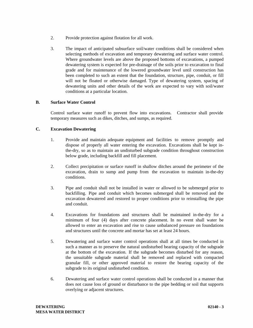
DEWATERING
MESA WATER DISTRICT
02140 - 3
2. Provide protection against flotation for all work.
3. The impact of anticipated subsurface soil/water conditions shall be considered when
selecting methods of excavation and temporary dewatering and surface water control.
Where groundwater levels are above the proposed bottoms of excavations, a pumped
dewatering system is expected for pre-drainage of the soils prior to excavation to final
grade and for maintenance of the lowered groundwater level until construction has
been completed to such an extent that the foundation, structure, pipe, conduit, or fill
will not be floated or otherwise damaged. Type of dewatering system, spacing of
dewatering units and other details of the work are expected to vary with soil/water
conditions at a particular location.
B. Surface Water Control
Control surface water runoff to prevent flow into excavations. Contractor shall provide
temporary measures such as dikes, ditches, and sumps, as required.
C. Excavation Dewatering
1. Provide and maintain adequate equipment and facilities to remove promptly and
dispose of properly all water entering the excavation. Excavations shall be kept in-
the-dry, so as to maintain an undisturbed subgrade condition throughout construction
below grade, including backfill and fill placement.
2. Collect precipitation or surface runoff in shallow ditches around the perimeter of the
excavation, drain to sump and pump from the excavation to maintain in-the-dry
conditions.
3. Pipe and conduit shall not be installed in water or allowed to be submerged prior to
backfilling. Pipe and conduit which becomes submerged shall be removed and the
excavation dewatered and restored to proper conditions prior to reinstalling the pipe
and conduit.
4. Excavations for foundations and structures shall be maintained in-the-dry for a
minimum of four (4) days after concrete placement. In no event shall water be
allowed to enter an excavation and rise to cause unbalanced pressure on foundations
and structures until the concrete and mortar has set at least 24 hours.
5. Dewatering and surface water control operations shall at all times be conducted in
such a manner as to preserve the natural undisturbed bearing capacity of the subgrade
at the bottom of the excavation. If the subgrade becomes disturbed for any reason,
the unsuitable subgrade material shall be removed and replaced with compacted
granular fill, or other approved material to restore the bearing capacity of the
subgrade to its original undisturbed condition.
6. Dewatering and surface water control operations shall be conducted in a manner that
does not cause loss of ground or disturbance to the pipe bedding or soil that supports
overlying or adjacent structures.

DEWATERING
MESA WATER DISTRICT
02140 - 4
7. At contractor’s sole expense and to the owner and/or Mesa Water’s satisfaction, the
contractor shall repair and make good all damage or settlement to the foundation or
other portion of any new or any existing facilities or structures caused by permanent
or temporary failure or operation of the dewatering or by failure to maintain the
existing groundwater level outside the dewatering areas.
D. Testing and Field Quality Control
Contractor shall observe and record the elevation of the groundwater on a 12-hour or less
interval during the period that the dewatering system is in operation.
E. Disposal of Drainage
All water discharged from the temporary dewatering and surface control shall be disposed of
in accordance with project permits. Dewatering of non-contaminated or contaminated
groundwater via surface erosion is prohibited. All dewatering of groundwater shall be
discharged to the nearest sewer facility. Prior to using existing sanitary sewer systems for
disposal, the contractor shall obtain written permission of the owner of the sewer. The
contractor will need to coordinate this disposal with the sewer agency to schedule the
disposal as well as confirm that the sewer system has adequate capacity to handle the
dewatering rate. Contractor shall obtain a permit to discharge to the sewer, if required, and
meet all permit requirements.
END OF SECTION

STRUCTURAL EARTHWORK
MESA WATER DISTRICT
02200-1
SECTION 02200
STRUCTURAL EARTHWORK
PART 1 – GENERAL
A. Description
This section describes excavation, backfilling, materials, testing, and shoring for underground
structures, including control valve vaults, pressure reducing stations, meter vaults, and valve vaults.
B. Related Work Specified Elsewhere
1. Protecting Existing Utilities: 02222.
2. Trenching, Backfilling, and Compacting: 02223.
3. Concrete: 03300.
4. Precast Concrete Vaults and Meter Boxes: 03462.
C. Submittals
1. Submit six copies of a report from a testing laboratory verifying that gravel base and
structural backfill conforms to the specified gradations or characteristics.
2. Test reports on borrow material.
D. Protection of Existing Utilities and Facilities
Protection of existing utilities and facilities shall conform to Section 02222 (Protecting Existing
Utilities) and to Section 02223 (Trenching, Backfilling, and Compacting).
E. Protection of Landscaping
Protection of landscaping shall conform to Section 02223 (Trenching, Backfilling, and
Compacting).
F. Testing for Compaction
Testing for compaction shall conform to Section 02223 (Trenching, Backfilling, and Compacting).
G. Permits
All work shall conform to the specifications and requirements of the jurisdictional agencies. The
contractor shall keep a copy of all the required permits in the job site and comply with all the terms
and conditions of said permits.
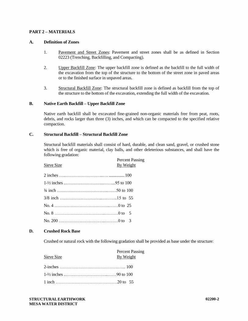
STRUCTURAL EARTHWORK
MESA WATER DISTRICT
02200-2
PART 2 – MATERIALS
A. Definition of Zones
1. Pavement and Street Zones: Pavement and street zones shall be as defined in Section
02223 (Trenching, Backfilling, and Compacting).
2. Upper Backfill Zone: The upper backfill zone is defined as the backfill to the full width of
the excavation from the top of the structure to the bottom of the street zone in paved areas
or to the finished surface in unpaved areas.
3. Structural Backfill Zone: The structural backfill zone is defined as backfill from the top of
the structure to the bottom of the excavation, extending the full width of the excavation.
B. Native Earth Backfill – Upper Backfill Zone
Native earth backfill shall be excavated fine-grained non-organic materials free from peat, roots,
debris, and rocks larger than three (3) inches, and which can be compacted to the specified relative
compaction.
C. Structural Backfill – Structural Backfill Zone
Structural backfill materials shall consist of hard, durable, and clean sand, gravel, or crushed stone
which is free of organic material, clay balls, and other deleterious substances, and shall have the
following gradation:
Percent Passing
Sieve Size By Weight
2 inches …..……………………..…. ............... 100
1-½ inches ..……………………..……...95 to 100
¾ inch ……………………………..……50 to 100
3/8 inch ………………………..………..15 to 55
No. 4 ………………………………..……0 to 25
No. 8 ……………………………..………0 to 5
No. 200 …………………………..………0 to 3
D. Crushed Rock Base
Crushed or natural rock with the following gradation shall be provided as base under the structure:
Percent Passing
Sieve Size By Weight
2-inches ………………………………….…... 100
1-½ inches ..………………………..……90 to 100
1 inch ……………………………………20 to 55
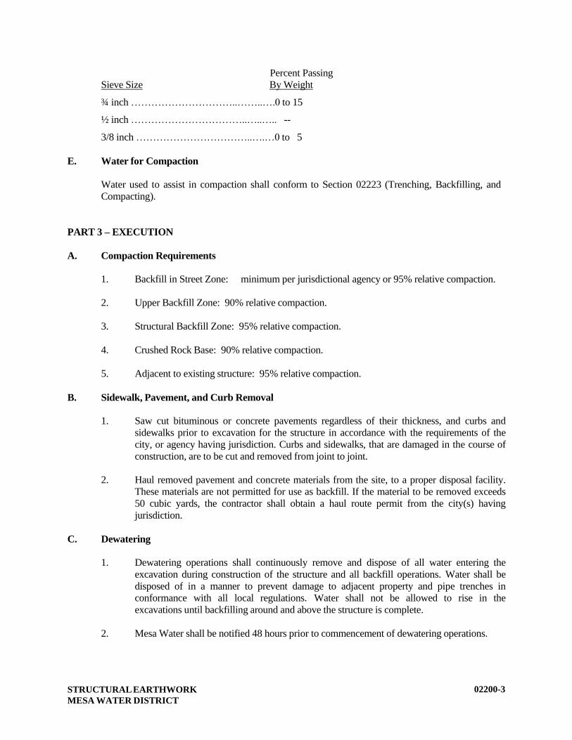
STRUCTURAL EARTHWORK
MESA WATER DISTRICT
02200-3
Percent Passing
Sieve Size By Weight
¾ inch …………………………..……..….0 to 15
½ inch ……………………………..…..….. --
3/8 inch ……………………………..….…0 to 5
E. Water for Compaction
Water used to assist in compaction shall conform to Section 02223 (Trenching, Backfilling, and
Compacting).
PART 3 – EXECUTION
A. Compaction Requirements
1. Backfill in Street Zone: minimum per jurisdictional agency or 95% relative compaction.
2. Upper Backfill Zone: 90% relative compaction.
3. Structural Backfill Zone: 95% relative compaction.
4. Crushed Rock Base: 90% relative compaction.
5. Adjacent to existing structure: 95% relative compaction.
B. Sidewalk, Pavement, and Curb Removal
1. Saw cut bituminous or concrete pavements regardless of their thickness, and curbs and
sidewalks prior to excavation for the structure in accordance with the requirements of the
city, or agency having jurisdiction. Curbs and sidewalks, that are damaged in the course of
construction, are to be cut and removed from joint to joint.
2. Haul removed pavement and concrete materials from the site, to a proper disposal facility.
These materials are not permitted for use as backfill. If the material to be removed exceeds
50 cubic yards, the contractor shall obtain a haul route permit from the city(s) having
jurisdiction.
C. Dewatering
1. Dewatering operations shall continuously remove and dispose of all water entering the
excavation during construction of the structure and all backfill operations. Water shall be
disposed of in a manner to prevent damage to adjacent property and pipe trenches in
conformance with all local regulations. Water shall not be allowed to rise in the
excavations until backfilling around and above the structure is complete.
2. Mesa Water shall be notified 48 hours prior to commencement of dewatering operations.

STRUCTURAL EARTHWORK
MESA WATER DISTRICT
02200-4
3. The sewer system shall be used as a discharge for the dewatering effort unless the
Contractor has obtained a NPDES permit for the dewatering operations. Contractor shall
obtain a permit to discharge to the sewer, if required, and meet all permit requirements.
4. Methods employed shall be in compliance with the Contractor’s NPDES permit. A copy of
the Contractor’s NPDES permit shall be on-site at all times.
D. Structure Excavation
1. Structure excavation shall include the removal of all material necessary for the construction
of structures and foundations.
2. Unless noted otherwise on the plans, the sides of excavations for structures shall be suffi-
cient to leave at least a 2-foot clearance, as measured from the extreme outside of form
work or the structure, as the case may be.
3. Surplus material shall be disposed of by the Contractor in accordance with Section 02223
(Trenching, Backfilling, and Compacting).
E. Correction of Over Excavation
1. Where excavation is inadvertently carried below design depths, suitable provision shall be
made by the Contractor to adjust construction, as directed by Mesa Water’s Representative,
to meet requirements incurred by the deeper excavation.
2. No earth backfill will be permitted to correct over excavation beneath structures.
3. Over excavation shall be corrected by backfilling with crushed rock, as directed by Mesa
Water’s Representative.
F. Support for Excavations for Structures
1. A safe working area shall be provided for workers. The services of a Registered Civil
Engineer shall be obtained to design sheeting, shoring and bracing, or side slopes. The
requirements of CAL/OSHA and of these specifications shall be used as minimum design
criteria. Sufficient geotechnical data shall be obtained to provide safe design.
2. The Contractor's design and installation of bracing and sheeting shall take the necessary
precautions to be consistent with the rules, orders, and regulations of the State of California
Construction Safety Orders.
3. Excavations shall be so braced, sheeted, and supported that they will be safe, such that the
walls of the excavation will not slide or settle and all existing improvements of any kind,
either on public or private property, will be fully protected from damage.
4. The sheeting, shoring, and bracing shall be arranged so as not to place any stress on
portions of the completed work.
5. Carefully remove sheeting, shoring, bracing, and timbering to prevent the caving or
collapse of the excavation faces being supported.
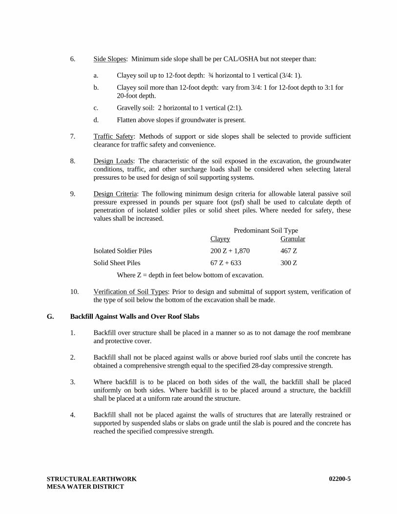
STRUCTURAL EARTHWORK
MESA WATER DISTRICT
02200-5
6. Side Slopes: Minimum side slope shall be per CAL/OSHA but not steeper than:
a. Clayey soil up to 12-foot depth: ¾ horizontal to 1 vertical (3/4: 1).
b. Clayey soil more than 12-foot depth: vary from 3/4: 1 for 12-foot depth to 3:1 for
20-foot depth.
c. Gravelly soil: 2 horizontal to 1 vertical (2:1).
d. Flatten above slopes if groundwater is present.
7. Traffic Safety: Methods of support or side slopes shall be selected to provide sufficient
clearance for traffic safety and convenience.
8. Design Loads: The characteristic of the soil exposed in the excavation, the groundwater
conditions, traffic, and other surcharge loads shall be considered when selecting lateral
pressures to be used for design of soil supporting systems.
9. Design Criteria: The following minimum design criteria for allowable lateral passive soil
pressure expressed in pounds per square foot (psf) shall be used to calculate depth of
penetration of isolated soldier piles or solid sheet piles. Where needed for safety, these
values shall be increased.
Predominant Soil Type
Clayey Granular
Isolated Soldier Piles 200 Z + 1,870 467 Z
Solid Sheet Piles 67 Z + 633 300 Z
Where Z = depth in feet below bottom of excavation.
10. Verification of Soil Types: Prior to design and submittal of support system, verification of
the type of soil below the bottom of the excavation shall be made.
G. Backfill Against Walls and Over Roof Slabs
1. Backfill over structure shall be placed in a manner so as to not damage the roof membrane
and protective cover.
2. Backfill shall not be placed against walls or above buried roof slabs until the concrete has
obtained a comprehensive strength equal to the specified 28-day compressive strength.
3. Where backfill is to be placed on both sides of the wall, the backfill shall be placed
uniformly on both sides. Where backfill is to be placed around a structure, the backfill
shall be placed at a uniform rate around the structure.
4. Backfill shall not be placed against the walls of structures that are laterally restrained or
supported by suspended slabs or slabs on grade until the slab is poured and the concrete has
reached the specified compressive strength.

STRUCTURAL EARTHWORK
MESA WATER DISTRICT
02200-6
5. When backfill is to be placed before 7-day concrete strength tests have been conducted on
concrete arches or thrust blocks, the concrete shall have achieved 50 percent of the
specified minimum 28-day strength. An additional test cylinder shall be made for this test.
6. Equipment for placing and compacting backfill over structures shall not exceed 15 tons
total weight and a maximum wheel load of 10,000 pounds. Equipment weighing more than
10,000 pounds shall not be used closer to walls and structures than a horizontal distance
equal to the depth of fill at the time.
H. Compaction
1. Compaction shall be controlled to the percentage of density specified for each zone.
2. When subgrade or soil material layers must be moisture conditioned before compaction,
water shall be uniformly applied to the subgrade surface or soil layer material to prevent
free water from appearing on the surface during or subsequent to compaction
operations. The moisture content of the compacted soil shall be within three (3) percentage
points of the optimum.
3. Soil material that is too wet to permit compaction to specified density shall be removed and
replaced or scarified and air dried.
4. Soil material that has been removed because it is too wet to permit compaction may be
stockpiled or spread within an approved area and allowed to dry. Drying may be assisted
by discing, harrowing or pulverizing, until moisture content is reduced to satisfactory value.
5. Backfill or fill material shall not be placed on surfaces that are muddy, frozen, or contain
frost or ice.
6. Excavations shall be backfilled as work permits, but not until completion of the following:
a. Acceptance of construction below finished grade including, where applicable,
dampproofing, waterproofing, and perimeter insulation.
b. Inspection, testing, approval, and recording locations of underground utilities.
c. Removal of concrete formwork.
d. Removal of shoring and bracing, and backfilling of voids with satisfactory
materials. Cut off temporary sheet piling driven below bottom of the structures
and remove in manner to prevent settlement of the structure or utilities, or leave in
place, if required.
e. Removal of trash and debris.
f. Permanent or temporary horizontal bracing is in place on horizontally supported
walls.
7. Backfill and fill materials shall be placed in layers not more than eight (8) inches in loose
depth for material compacted by heavy compaction equipment, and not more than four (4)
inches in loose depth for material compacted by hand-operated tampers.

STRUCTURAL EARTHWORK
MESA WATER DISTRICT
02200-7
8. Unless specified otherwise, jetting techniques shall not be employed to densify granular fill
materials.
9. Backfill and fill materials shall be placed evenly adjacent to structures, to required finish
elevations. Care shall be taken to prevent wedging action of backfill against structures
carrying material uniformly around structure to approximately same elevation in each lift.
I. Pavement Replacement
Pavement replacement shall be in accordance with the requirements of the city or the agency having
jurisdiction.
J. Permits
An Encroachment Permit from the jurisdictional agency is required prior to any work within public
right-of-way. All traffic control and pavement replacement work shall be in accordance with the
requirements of the permit and the agency Inspector.
A permit from OSHA is required of any excavation exceeding 5 feet.
END OF SECTION

PROTECTING EXISTING UTILITIES
MESA WATER DISTRICT
02222 - 1
SECTION 02222
PROTECTING EXISTING UTILITIES
PART 1 – GENERAL
A. Description
This section describes materials and procedures for protecting existing underground utilities.
B. Related Work Specified Elsewhere
1. Existing Facilities: 01045.
2. Trenching, Backfilling, and Compacting: 02223.
C. Submittals
Contractor shall submit drawings and calculations for support and protection at the pipeline
crossings larger than 36-inch in diameter at least thirty (30) calendar days prior to excavation
of the crossing.
D. Construction Interferences
1. As used in this Section, the word “utility” shall be understood to include tracks,
overhead or underground wires, cables, pipelines, conduits, ducts, sewers, or storm
drains. As used in this Section, the term “service connection” shall be understood to
mean all or any portion of a pipeline conduit, wire, cable or duct, including meter,
between a utility distribution line and an individual customer when served by a single
service connection. As used in this Section, the term “construction interference” shall
be understood to include any utility or service connection within the limits of
excavation or over-excavation required for the work under the contract as shown or as
ordered by Mesa Water or the design engineer, or any utility or service connection
located in the space which will be required by any of the work under the contract.
2. In the event any utility or service connection is required to be disturbed or removed to
permit construction of a pipeline or other structure under the contract, such
disturbance or removal shall be done only with the approval of Mesa Water, and
following notification to the owner of the interfering utility or service connection.
Any such utility or service connection removed or otherwise disturbed shall be
reconstructed as promptly as possible in its original or other authorized location in a
condition at least as good as prior to such removal or disturbance, subject to the
inspection of the owner of same. The contractor’s responsibility under this Section to
remove or replace shall apply even in the event such damage or destruction occurs
after backfilling or is not discovered until after completion of backfilling. The owner
of the utility or service connection shall be notified immediately after damage or
destruction occurs or is discovered.
PROTECTING EXISTING UTILITIES
MESA WATER DISTRICT
02222 - 2
3. During the performance of the work under this contract, the owner of any utility
affected by the work shall have the right to enter when necessary upon any portion of
the work for the purpose of maintaining service and of making changes in or repairs
to said utility.
4. The drawings show the approximate positions of known utilities in the immediate
vicinity of the work, but Mesa Water does not guarantee that all existing utilities are
shown. Service connections normally are not shown on drawings. The contractor,
before commencing any excavation, shall ascertain from records or otherwise, the
existence, position and ownership of all existing utilities and service connections. If
the contractor discovers any utility or sewer house laterals in the line of work which
is not shown on the drawings, he shall immediately notify Mesa Water and the design
engineer of the existence of same. Mesa Water will not be liable for any
consequences arising as a result of a service connection being incorrectly located in
the field by the agency having jurisdiction over said service connection.
5. All costs involved in removing, relocating, protecting, supporting, repairing,
maintaining or replacing a utility which actually constitutes a construction
interference, when said utility is shown on the drawings as an interference, however
approximate the location shown may be, shall be borne by the contractor.
6. All costs involved in removing, relocating, protecting, supporting, repairing,
maintaining or replacing a utility which actually constitutes a construction
interference, when said utility is not shown as an interference or is omitted from the
drawings, will be paid for by the developer/owner or by Mesa Water as extra work
where Mesa Water is a party to the contract and is determined to have responsibility.
7. All costs involved in removing, relocating, protecting, supporting, repairing,
maintaining or replacing a service connection larger than two (2) inches in nominal
diameter which actually constitutes a construction interference, when said service
connection is shown on the drawings as an interference, however approximate the
location shown may be, shall be borne by the contractor.
8. All costs involved in removing, relocating, protecting, supporting, repairing,
maintaining or replacing a service connection larger than two (2) inches in nominal
diameter which actually constitutes a construction interference, when said service
connection is not shown as an interference or is omitted from the drawings, will be
paid for by the developer/owner or by Mesa Water as extra work where Mesa Water
is a party to the contract and is determined to have responsibility.
9. All costs involved in removing, relocating, protecting, supporting, repairing,
maintaining or replacing a service connection two (2) inches or smaller in nominal
diameter which actually constitutes a construction interference, whether or not said
service connection is shown on the drawings, shall be borne by the contractor.
10. The contractor shall not be assessed liquidated damages for failure to complete the
work on time to the extent that such delay was caused by failure of Mesa Water or of
the agency having jurisdiction over the utility or service connection to authorize or
otherwise provide for its removal, relocation, protection, support, repair,
maintenance, or replacement.
PROTECTING EXISTING UTILITIES
MESA WATER DISTRICT
02222 - 3
11. Mesa Water reserves the right, upon determination of the actual position of existing
utilities and service connections, to make changes in alignment or grade of the Mesa
Water’s pipelines when, by so doing, the necessity for relocation of existing utilities
or service connections will be avoided. Such changes will be ordered in writing by
Mesa Water. Where applicable, adjustment in contract price will be on the basis on
the unit prices stated in the Bidding Schedule where Mesa Water is a party to the
contract.
PART 2 – MATERIALS
Except as indicated on the drawings, or as specifically authorized by Mesa Water Representative or
the owner of the utility, utilities shall be reconstructed with new material of the same size, type, and
original quality as that removed.
PART 3 – EXECUTION
A. General
1. The drawings provide the specific pipeline protection notes required for this project.
The following requirements are general and are in addition to the specific
requirements noted on the drawings.
2. Where utilities are parallel to or cross the excavation or the pipeline trench, but do
not conflict with the permanent work to be constructed, follow the procedures given
below and as indicated on the drawings. Notify the utility owner 48 hours in advance
of the crossing construction and coordinate the construction schedule with the utility
owner’s requirements. Contractor shall obtain utility owner approval before
submitting shop drawings for review by Mesa Water.
3. Contractor shall determine the true location and depth of utilities, service connections
and points of connections which may be affected by or affect the work. The
contractor shall determine the type, material, and condition of these utilities. The
contractor shall pothole all crossing utilities, closely parallel utilities and all points of
connections.
B. Procedures
1. Protect in Place: Protect utilities in place, unless abandoned, and maintain the utility
in service, unless otherwise specified on the drawings, or in the project specifications.
2. Cut and Plug Ends: Cut abandoned utility lines (conduits) and plug the ends with
brick and mortar wall (a minimum of 8-inches thick) or concrete plug (minimum of
6-inches thick). Dispose of the cut pipe as unsuitable material.
3. Contractor shall provide temporary support for all pipelines crossing the proposed
trench. All pipelines 18-inches in diameter or larger crossing over the proposed Mesa
Water main with less than four (4) feet of clearance shall have a concrete support

PROTECTING EXISTING UTILITIES
MESA WATER DISTRICT
02222 - 4
poured as shown on the drawings or as directed by Mesa Water’s Representative. All
pipelines less than 18-inches in diameter and crossing over the proposed water main
with less than two (2) feet of clearance shall be protected by pouring a 1-sack
sand/cement slurry from the top of the water main to the bottom of the crossing
pipeline.
C. Thrust Blocks on Water Lines
The contractor’s attention is called to thrust blocks on existing water lines throughout the
project area whose thrust is in the direction of the trench excavation and, therefore, may be
affected by the pipeline construction. The contractor shall protect the thrust blocks in place
or shore to resist the thrust by a means acceptable to Mesa Water.
If the thrust blocks are exposed or rendered to be ineffective in the opinion of the owner’s
representative or Mesa Water, the contractor shall reconstruct the thrust block to bear against
firm unexcavated or backfill material. Provide firm support by backfilling that portion of the
trench for a distance of a minimum of two (2) feet on each side of the thrust block to be
reconstructed from the pipe bedding to the pavement subgrade, with one sack sand-cement
slurry. Then excavate the backfill material for construction of the thrust block.
D. Abandoned Utilities
The contractor shall remove and dispose of abandoned utilities within the trench excavation.
END OF SECTION
TRENCHING, BACKFILLING, AND COMPACTING
MESA WATER DISTRICT
02223 - 1
SECTION 02223
TRENCHING, BACKFILLING, AND COMPACTING
PART 1 - GENERAL
A. Description
This section describes materials, testing, and performance of trench excavation, backfilling,
and compacting.
B. Related Work Specified Elsewhere
1. Structural Earthwork: 02200.
2. Protecting Existing Utilities: 02222.
3. Pavement Removal and Replacement: 02578.
4. Concrete: 03300.
C. Submittals
1. Shop drawings shall be submitted showing excavation and shoring, bracing, or
sloping for worker protection.
2. Copies of a report from a testing laboratory shall be submitted verifying that backfill
material conforms to the specified gradations or characteristics for pea gravel,
granular material, imported sand, rock refill for foundation stabilization, and water.
D. Measurement and Payment
1. Payment for the work in this section shall be included within the appropriate pipeline
or appurtenance bid item.
2. Payment for over-excavation where the bottom of trench is wet or spongy (Over-
Excavation Ordered by Mesa Water) will be paid for at the unit price bid for “Over-
Excavation Ordered by Mesa Water”. The refilling of the over-excavation with
aggregate bedding will be paid for at the unit price bid for “Imported Aggregate
Bedding Ordered by Mesa Water”.
The unit price bid amount will hold for any quantity of over-excavation and/or refill
material from 0 to 1,000 cubic yards, based on the trench details shown on the plans.
This item has been included in the bid schedule for work that may possibly be
required to complete the project, but which cannot be reasonably predicted, and shall
be the basis of payment for over-excavation and refill material for trench foundation
stabilization if authorized in writing by Mesa Water.
TRENCHING, BACKFILLING, AND COMPACTING
MESA WATER DISTRICT
02223 - 2
The unit price bid shall be for any quantity installed, complete in place, including all
additional earthwork, disposal of all excess or waste material, and placing of the refill
material. The Mesa Water Representative shall be the sole judge as to the necessity,
the amount, and depth that may be required in any given situation. No additional
payment shall be made for foundation stabilization that is not authorized in writing by
Mesa Water.
3. Any over-excavation which may become necessary due to changes in grade of the
pipelines to be constructed, where Mesa Water is a party to the contract, to avoid
existing subsurface structures and utilities, as ordered by Mesa Water
Representative, in writing, shall be performed by the contractor at his own expense
when such over-excavation is less than six (6) inches below the grade of the bottom
of the trench.
4. Any excavation carried below the subgrade, or below the grade shown or ordered,
shall be refilled to the required grade with selected material and compacted by
mechanical means to 90 percent of maximum density. Such work shall be performed
by the contractor at his own expense where Mesa Water is a party to the contract.
5. All costs of drying, blending, transporting, and/or importing backfill material and all
costs for the removal and disposal of unsuitable material and excess excavated
material shall be included in the prices bid for the various items of work.
6. Full compensation for protection of utilities or replacement of utilities and street
improvements including, but not limited, to removal and disposal and reconstruction
of existing curb, gutter, spandrels, cross-gutters, sidewalks, driveway aprons, and
handicapped ramps shall be included in the contract unit prices for which such work
is appurtenant thereto, and no additional allowance or payment will be made
therefore, where Mesa Water is a party to the contract. Said various contract unit
prices shall include all labor, materials, tools, and equipment necessary or incidental
to the replacement work.
7. The same shall apply to all costs incurred in exposing or excavating existing utilities
and service lines, and no additional allowance will be made therefore, as they shall be
included in the prices bid for the various items of work where Mesa Water is a party
to the contract.
E. Protection of Existing Utilities and Facilities
1. General: The contractor shall be responsible for the care and protection of all
existing sewer pipelines, water pipelines, gas mains, storm drains, culverts, or other
facilities and structures that may be encountered in or near the area of work. Unless
otherwise indicated on the drawings, all utilities shall be protected in place and
service shall be continuously maintained.
The contractor shall be responsible for the location of and protection in place, of all
service connections whether or not shown on the drawings.

TRENCHING, BACKFILLING, AND COMPACTING
MESA WATER DISTRICT
02223 - 3
Utilities crossing the proposed pipeline alignment or project work (where shown in
“plan” and “profile” view) on the drawings are plotted from the information obtained
from the respective utility’s owner or from available pothole information. The
accuracy of the utilities is not guaranteed. Actual locations (not depth) will be
provided by utilities through the Underground Service Alert (USA) process.
It shall be the contractor’s responsibility to make exploratory excavations (by “hand”
where prudent) to determine the true location and depth of all utilities shown on the
drawings. The contractor shall also determine the type of material and condition of
any utility which may be affected by or affect the work. The contractor shall conduct
the exploratory excavations at least 1,500 feet ahead of a pipe trench heading (or a
minimum of ten (10) working days in advance of the planned construction, whichever
is greater) to provide sufficient lead-time to resolve utility conflicts. For portions of
the pipeline where steel pipe is proposed to be used, the potholing shall be completed
prior to submittal of the actual pipe laying diagrams. The contractor shall submit a
set of potholing plans to Mesa Water or the design engineer prior to submitting the
actual line lay diagrams.
2. Notification: It shall be the duty of the contractor to notify each agency of jurisdiction
and make arrangements for locating each agency's facilities prior to beginning
construction. The contractor shall notify Underground Services Alert (Dig Alert) at
least two working days prior to construction at 1-800-422-4133.
3. Damage: In the event of damage to any existing facilities during the progress of the
work due to the failure of the contractor to exercise the proper precautions, the
contractor shall be responsible for the cost of all repairs and protection to said
facilities. The Contractor's work may be stopped until repair operations are complete.
F. Protection of Landscaping
1. General: The contractor shall be responsible for the protection of all the trees,
shrubs, fences, and other landscape items adjacent to or within the work area, unless
directed otherwise on the drawings. In the event of damage to landscape items, the
contractor shall replace the damaged items in a manner satisfactory to owner, the
jurisdictional agency and/or Mesa Water.
The contractor shall verify that any damaged landscaping shall be replaced with
landscaping that meets the current and applicable local landscape standards, codes, and
ordinances, including but not limited to AB 1881 (Water Efficient Landscape
Ordinance).
2. Restoration: After the completion of work in planted or improved areas within public
or private easements, the contractor shall restore such areas to original condition.
Restoration shall include regrading, placement of 5-inches of topsoil, reseeding, and
replacement of landscaping. All irrigation facilities shall be restored/replaced to a
condition equal to or better than existing per the manufacturer’s recommendations
and/or industry standards.
TRENCHING, BACKFILLING, AND COMPACTING
MESA WATER DISTRICT
02223 - 4
G. Definition of Zones
1. Pavement Zone: The pavement zone shall include the asphaltic concrete and
aggregate base pavement section placed over the street zone. This zone is often
referred to as the “structural section” of the street or highway.
2. Trench Zone: The trench zone shall include the portion of the trench from the top of
the pipe zone to the bottom of the pavement zone in paved areas or to the existing
surface in unpaved areas.
3. Street Zone: The street zone is the top 12 inches of the trench zone and is
immediately below the pavement zone in paved areas or areas to be paved.
4. Pipe Zone: The pipe zone shall include the full width of trench from the bottom of
the pipe or conduit to a horizontal level 12-inches above the top of the pipe. Where
multiple pipes or conduits are placed in the same trench, the pipe zone shall extend
from the bottom of the lowest pipes to a horizontal level above the top of the highest
or topmost pipe.
5. Pipe Base: The pipe base shall be defined as a 4 or 6-inch layer of material
immediately below the pipe zone and extending over the full trench width.
PART 2 - MATERIALS
A. Pavement Zone Materials
Pavement zone materials shall be as required by the jurisdictional agency for trenches in
public streets, or as shown on the drawings, or as specified in Section 02578 (Pavement
Removal and Replacement). For trenches within public streets, the jurisdictional agency
permit requirements will have precedence.
B. Trench Zone
Native or imported backfill shall be excavated, fine-grained non-organic materials free from
peat, roots, debris, and rocks larger than 3-inches, and which can be compacted to the
specified relative compaction, unless otherwise directed by the jurisdictional agency.
Trench zone backfill for all public streets shall be in accordance with Mesa Water Standard
Drawings or as specified by the jurisdictional agency and as shown on the agencies typical
trench detail. For trenches within public streets, the jurisdictional agency permit
requirements will have precedence on the trench zone backfill unless Mesa Water’s
requirements are more stringent than the jurisdictional agency permit requirements.
C. Pipe Zone and Pipe Base
The pipe base and pipe zone backfill material shall be imported sand and shall conform to the
Standard Specifications for Public Works Construction, Section 200-1.5.1 and shall meet the
following gradation:
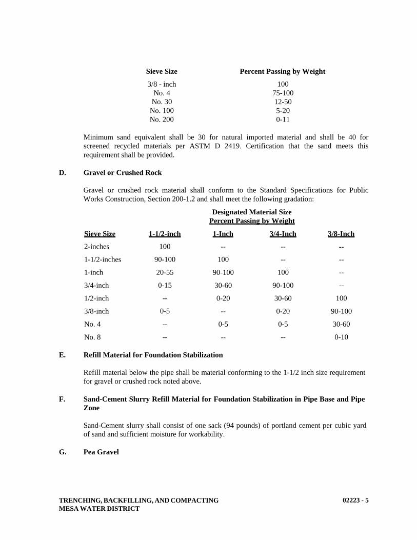
TRENCHING, BACKFILLING, AND COMPACTING
MESA WATER DISTRICT
02223 - 5
Sieve Size Percent Passing by Weight
3/8 - inch
No. 4
No. 30
No. 100
No. 200
100
75-100
12-50
5-20
0-11
Minimum sand equivalent shall be 30 for natural imported material and shall be 40 for
screened recycled materials per ASTM D 2419. Certification that the sand meets this
requirement shall be provided.
D. Gravel or Crushed Rock
Gravel or crushed rock material shall conform to the Standard Specifications for Public
Works Construction, Section 200-1.2 and shall meet the following gradation:
Designated Material Size
Percent Passing by Weight
Sieve Size 1-1/2-inch 1-Inch 3/4-Inch 3/8-Inch
2-inches
1-1/2-inches
1-inch
3/4-inch
1/2-inch
3/8-inch
No. 4
No. 8
100
90-100
20-55
0-15
--
0-5
--
--
--
100
90-100
30-60
0-20
--
0-5
--
--
--
100
90-100
30-60
0-20
0-5
--
--
--
--
--
100
90-100
30-60
0-10
E. Refill Material for Foundation Stabilization
Refill material below the pipe shall be material conforming to the 1-1/2 inch size requirement
for gravel or crushed rock noted above.
F. Sand-Cement Slurry Refill Material for Foundation Stabilization in Pipe Base and Pipe
Zone
Sand-Cement slurry shall consist of one sack (94 pounds) of portland cement per cubic yard
of sand and sufficient moisture for workability.
G. Pea Gravel
TRENCHING, BACKFILLING, AND COMPACTING
MESA WATER DISTRICT
02223 - 6
Pea gravel shall be defined as gravel, uniformly graded from coarse to fine with less than 10%
passing a No. 200 sieve, less than 50% passing a No. 4 sieve, and having a maximum particle
size of 3/4-inch.
H. Water for Compaction
Water used in compaction shall have a maximum chloride concentration of 500 mg/l, a
maximum sulfate concentration of 500 mg/l, and shall have a pH of 7.0 to 9.0. Water shall be
free of acid, alkali, or organic materials injurious to the pipe coatings or the environment.
PART 3 - EXECUTION
A. Testing for Compaction
1. Methods: The density of soil shall be determined in place by the sand cone method,
ASTM D 1556, or by the nuclear method, ASTM D 2922 or D 3017.
2. Soil Moisture-Density Relationship: The laboratory moisture-density relations of
soils shall be determined per ASTM D 1557.
3. Cohesionless Materials: The relative density of cohesionless materials shall be
determined by ASTM D 4253 and D 4254.
4. Sampling: Backfill materials shall be sampled per ASTM D 75.
5. Relative Compaction: "Relative compaction" shall be expressed as the ratio,
expressed as a percentage, of the in place dry density to the laboratory maximum dry
density.
6. Compaction Compliance: Compaction shall be deemed to comply with the
specifications when none of the tests falls below the specified relative compaction.
When tests are conducted by Mesa Water, the contractor shall notify Mesa Water 24-
hours in advance of when backfill lifts are ready for testing, and shall pay the costs of
any retesting of work not conforming to the specifications.
7. Testing Intervals: Unless noted otherwise, compaction tests shall be performed at
random depths and at 200-foot intervals, and as directed by Mesa Water
Representative. The presence of marginal materials, poor soil conditions or a
prevalence of failed test results will be cause for substantially increasing the
frequency and intervals of required testing.
8. The applicant/developer will secure the services of a soil tester and pay the costs of
all compaction testing for developer construction. On Mesa Water projects, Mesa
Water will secure the service of a soils tester and pay the cost of the initial testing.
The contractor will be responsible for the cost of all retests in failed areas. Test
results will be furnished by Mesa Water.
B. Compaction Requirements
TRENCHING, BACKFILLING, AND COMPACTING
MESA WATER DISTRICT
02223 - 7
Unless otherwise shown on the drawings or otherwise described in the specifications for the
particular type of pipe installed, relative compaction in pipe trenches shall be as follows:
1. Pipe Base and Pipe Zone: Pipe base and pipe zone--90% relative compaction.
2. Trench Zone - Not Beneath Paving: Backfill in trench zone not beneath paving--90%
relative compaction; backfill in trench zone within landscape areas – 85% relative
compaction per Section 308 of Standard Specifications.
3. Trench Zone - Paved Areas: Backfill in trench zone in paved areas--90% relative
compaction.
4. Street Zone: Backfill in street zone in paved areas--95% relative compaction, or as
required by the jurisdictional agency.
5. Foundation Stabilization: Rock refill material for foundation stabilization--90%
relative density.
6. Overexcavation: Rock refill for overexcavation--90% relative density.
7. Material Testing: All imported or native materials shall be tested before the start of
compaction operations to determine the moisture density relationship for materials
with cohesive components, and the maximum density for cohesionless materials.
Variations in imported or native earth materials may require a number of base curves
of the moisture-density relationship.
C. Material Replacement
Trenching and backfilling material which does not meet the specifications shall be removed
and replaced at no additional expense to Mesa Water where Mesa Water is a party to the
contract.
D. Sheeting, Shoring, and Bracing of Trenches
All excavations shall be performed, protected, and supported as required for safety and in the
manner set forth in the operation rules, orders, and regulations prescribed by the Division of
Industrial Safety of the State of California. If the total amount of the contract, where Mesa
Water is a party of the contract, is in excess of $25,000, the contractor shall submit to Mesa
Water, in advance of excavation, a detailed plan showing the design of shoring, bracing,
sloping, or other provisions to be made for worker protection from the hazard of caving
ground during the excavation of any trench or trenches five feet or more in depth. Lateral
pressures for design of trench sheeting, shoring, and bracing shall be based on type of soil
exposed in the trench, groundwater conditions, surcharge loads adjacent to the trench, and
type of shoring that will be used in the trench.
The plan shall be prepared by a registered civil or structural engineer. As part of the plan, a
note shall be included stating that the registered civil or structural engineer certifies that the
plan complies with the CAL-OSHA Construction Safety Orders. If, however, the plan does

TRENCHING, BACKFILLING, AND COMPACTING
MESA WATER DISTRICT
02223 - 8
not comply with the Safety Orders, the plan shall include a note stating that the registered
civil or structural engineer certifies that the plan is not less effective than the shoring, bracing,
sloping, or other provisions of the Safety Orders.
Barriers shall be placed at each end of all excavations and at such places as may be necessary
along excavations to warn all pedestrians and vehicular traffic of such excavations.
Lights shall also be placed along excavations from sunset each day to sunrise of the next day
until such excavation is entirely refilled.
E. Sidewalk, Pavement, and Curb Removal
Bituminous and concrete pavements regardless of the thickness and curbs and sidewalks shall
be cut prior to excavation of the trenches in accordance with Section 02578 (Pavement
Removal and Replacement). Pavement and concrete materials shall be removed from the site
and shall not be used for trench backfill.
F. Trench Width
For All Pipe Diameters (except services): Unless shown otherwise on the drawings, trench
widths in the pipe zone shall be equal to the pipe outside diameter plus 12-inches minimum
and 20 inches maximum on each side of the pipe.
Excavation and trenching shall be true to line so that a clear space is provided in the pipe zone
on each side of the largest outside diameter of the pipe. The largest outside diameter shall be
the outside diameter of the bell on bell and spigot pipe.
Trench width at the top of the trench shall not be limited except where the width of
excavation impact the proposed traffic control plans or would undercut adjacent structures
and footings. In such cases, the width of the trench shall be such that there is at least 18-
inches between the top edge of the trench and the structure or footing.
G. Grade
Trenches shall be excavated to the lines and grades shown on the drawings with allowance for
pipe thickness and for pipe base. If the trench is excavated below the required grade, the
portion of the trench excavated below the grade shall be refilled with refill material at no
additional cost to Mesa Water. The refill material shall be placed over the full width of trench
in compacted layers not exceeding 6-inches deep to the required grade with allowance for the
pipe base. Hard spots that would prevent a uniform thickness of pipe base shall be removed.
Before laying pipe sections, the grade shall be checked with a straightedge and any
irregularities corrected. The trench bottom shall form a continuous and uniform bearing and
support for the pipe at every point.
H. Pipe Base Thickness
Thickness of the pipe base shall be as shown on the drawings: 4-inches thick for pipes smaller
than 6-inches in diameter and 6-inches thick for pipes 6-inches in diameter or greater.
I. Dewatering

TRENCHING, BACKFILLING, AND COMPACTING
MESA WATER DISTRICT
02223 - 9
1. Means and Devices: Suitable means and devices shall be provided and maintained to
continuously remove and dispose of all water entering the trench excavation during
the time the trench is being prepared for the pipe laying, during the laying of the pipe,
and until the backfill at the pipe zone has been completed.
These provisions shall apply during the noon hour as well as overnight. Water shall
be disposed of in a manner to prevent damage to adjacent property. Trench water
shall not be drained through the pipeline under construction. Groundwater shall not
be allowed to rise around the pipe until jointing compound has firmly set.
2. De-watering shall commence when groundwater is first encountered and shall be
continuous until such times as water can be allowed to rise. No concrete shall be
poured in water, nor shall water be allowed to rise around the concrete or mortar until
it has set at least eight (8) hours.
3. Notification: Mesa Water shall be notified 48 hours prior to commencement of
dewatering. Water shall be discharged to a sewer system.
J. Storage of Excavated Material
During trench excavation, excavated material shall be stored only within the working area.
Roadways or streets shall not be obstructed. The safe loading of trenches with excavated
material shall conform to federal, state, and local codes.
K. Length of Open Trench
The maximum allowable length of open trench shall be 300 feet, or the distance necessary to
accommodate the amount of pipe installed in a single day, whichever is less. Backfilling and
temporary or first layer paving shall be completed so that not more than 200 feet of trench is
open in the rear of pipe laying.
No trench or excavation shall remain open during non-working hours. The trench or
excavation shall be covered with steel plates, spiked in place, or secured with temporary A.C.
pavement around the edges, or backfilled. The maximum amount of steel plates within travel
lanes (for the whole project) at one time is 200 feet.
Sidewalks, driveways and other traveled ways shall be backfilled or adequately bridged to
provide safe access and egress at the completion of each day’s work. The length of open
trench may be restricted further as directed by appropriate jurisdictional agency.
L. Foundation Stabilization
After the required excavation has been completed, Mesa Water Representative shall inspect
the exposed trench subgrade to determine the need for any additional excavation. It is the
intent that additional excavation shall be conducted in all areas within the influence of the
pipeline where unacceptable materials exist at the exposed subgrade. Over-excavation shall
include the removal of all such unacceptable material that exists directly beneath the pipe
base and to the depth required. The presence of unacceptable material may require excavating

TRENCHING, BACKFILLING, AND COMPACTING
MESA WATER DISTRICT
02223 - 10
a wider trench. The width and depth of known areas to be over-excavated shall be shown on
the drawings. The over-excavated portion of the trench shall be backfilled to the subgrade of
the pipe base with refill material for foundation stabilization.
Foundation stabilization material shall be placed over the full width of the excavation and
compacted in layers not exceeding 6-inches in depth, to the required grade.
M. Trench Backfilling and Compaction
1. General: Trench backfill shall conform to requirements of the detailed piping
specification for the particular type of pipe and the following.
2. Pipe Base: The specified thickness of pipe base material shall be placed over the full
width of trench. The top of the pipe base shall be graded ahead of the pipe laying to
provide firm, uniform support along the full length of pipe.
3. Bell Holes: Bell holes shall be excavated at each joint to permit proper assembly and
inspection of the entire joint.
4. Pipe Zone: After the pipe has been bedded, pipe zone material shall be placed
simultaneously on both sides of the pipe, keeping the level of backfill the same on
each side. Material shall be carefully placed around the pipe so that the pipe barrel is
completely supported and that no voids or uncompacted areas are left beneath the
pipe. Particular care shall be taken in placing material on the underside of the pipe to
prevent lateral movement during subsequent backfilling. Material placed within the
pipe zone shall be compacted by hand tamping only.
5. Trench Zone: Backfill material shall be carefully deposited onto the backfill
previously placed in the pipe zone. Free fall of the material shall not be permitted
until at least two (2) feet of cover is provided over the top of the pipe. Sharp, heavy
pieces of material shall not be dropped directly onto the pipe or the tamped material
around the pipe.
6. Trench Backfill: Trench backfill shall be compacted to the specified relative
compaction. Compaction shall be performed by using mechanical compaction or hand
tamping equipment. Unless specified otherwise, consolidation by jetting or flooding
shall not be permitted. High impact hammer-type equipment shall not be used except
where the pipe manufacturer warrants in writing that such use will not damage the
pipe.
7. Equipment: Axle-driven or tractor-drawn compaction equipment shall not be used
within 5 feet of walls and structures.
8. Street Zone Backfill: Street zone backfill shall be done in accordance with the
requirements and to the satisfaction of the City agency having jurisdiction. Street
zone backfill can be placed with mechanical compaction.
N. Import or Export of Backfill Material
TRENCHING, BACKFILLING, AND COMPACTING
MESA WATER DISTRICT
02223 - 11
1. Excess Material: Excess excavated soil material shall be removed and disposed of off
the project site at no additional expense to Mesa Water where Mesa Water is party to
the contract. Excess soil material shall be disposed of in accordance with local
regulations.
No excavated material shall be deposited on private property unless written
permission from the owner thereof is secured by the contractor.
Before Mesa Water will accept the work, the contractor shall file a written release
signed by all property owners with whom he has entered into agreements for
disposing excess excavated material, absolving Mesa Water from any liability
connected therewith.
The contractor shall obtain a haul route permit from the corresponding city or agency
having jurisdiction.
2. Imported Material: Any additional backfill material necessary to return all grades to
plus or minus 0.5 feet from the grade encountered at the beginning of construction or
as shown on the contract drawings shall be imported, placed, and compacted at no
additional cost to Mesa Water where Mesa Water is party to the contract. Only
approved imported material is allowed.
O. Moisture Content of Backfill Material
During the compacting operations, optimum practicable moisture content required for
compaction purposes shall be maintained in each lift of the backfill material. Moisture content
throughout the lift shall be maintained at a uniform level. If placement is discontinued and
proper moisture content not maintained, the upper layer shall be brought back to proper
moisture content by sprinkling, cultivating and rolling the backfill material before placing
new material. At the time of compaction, the water content of the material shall be at
optimum water content plus or minus two percentage points.
Material which contains excessive moisture shall not be worked to obtain the required
compaction. Material having excessive moisture content may be dried by blading, discing, or
harrowing to hasten the drying process.
P. Access
The contractor shall conduct his operation so as not to close or obstruct any portion of any
highway, road, or street, or prevent in any way free access to fire hydrants until they have
secured permits to do so from the proper authorities.
The contractor shall conduct his operations so as to avoid unnecessary interference with the
flow of traffic along highways and streets. Unobstructed access must be provided to all
driveways, water valves, hydrants, or other property or facilities that require routine use.
Q. Slope Protection
Slope protection shall be installed where shown on the drawings, wherever the profile of the
ground surface above the water main exceeds 20%, and where no pavement or other surfacing
is to laid over the facility. The slope protection shall consist of cutoff walls or concrete
TRENCHING, BACKFILLING, AND COMPACTING
MESA WATER DISTRICT
02223 - 12
anchors with a minimum thickness of 12 inches. The wall shall extend at least twelve (12)
inches into undisturbed material on each side of the trench as excavated.
Wall or anchors shall be placed with a minimum horizontal spacing of:
1. Not over 36 feet center to center on grades 25% to 35%.
2. Not over 24 feet center to center on grades 35% to 50%.
3. Not over 16 feet center to center on grades 50% and over.
Materials used for construction of cutoff walls or concrete anchors shall consist of cast-in-
place reinforced concrete. They shall have No. 4 reinforcing bars placed at six (6) inches on
center each way in the center of the wall. The bars shall extend full length and height of the
wall.
The installation of the slope protection shall be considered a part of the work, and the
contractor shall include the expense in his cost.
R. Tunneling
Tunneling will not be permitted. The use of jack and bore or hydraulic ram may be
employed.
S. Temporary Steel Plates
When the backfilling operations of an excavation in the traveled way, whether transverse or
longitudinal cannot be properly completed within a work day, steel plate bridging with a non-
skid surface and shoring may be required to preserve unobstructed traffic flow. In such cases,
the following conditions shall apply.
1. Steel plates used for bridging shall extend a minimum of twelve (12) inches beyond
the edges of the trench.
2. Steel plate bridging shall be installed to operate with minimum noise.
3. The trench shall be adequately shored to support the bridging and traffic loads.
4. Temporary paving with hot mix asphalt concrete shall be used to feather the edges of
the plates, if plate installation method (2) described below, is used.
5. Bridging shall be secured against displacement by using adjustable cleats, shims or
other devices.
Steel plating bridging and shoring shall be installed using either the following Method (1) or
Method (2):
Method (1) (For speeds 45 mph or greater)
TRENCHING, BACKFILLING, AND COMPACTING
MESA WATER DISTRICT
02223 - 13
The pavement shall be cold planed to a depth equal to the thickness of the plate and to a width
and length equal to the dimensions of the plate.
Method (2) (For speeds less than 45 mph)
Approach plate(s) and ending plate (if longitudinal placement) shall be attached to the
roadway by a minimum of two (2) dowels pre-drilled into the corners of the plate and drilled
two (2) inches into the pavement. Subsequent plates are butted to each other. Fine grade hot
mix asphalt concrete shall be compacted to form ramps, maximum slope of 8.5% with a
minimum of 12-inch taper to cover all edges of the steel plates.
When the steel plates are removed, the dowel holes in the pavement shall be backfilled with
either graded fines or asphalt concrete hot mix, concrete slurry or an equivalent slurry that is
satisfactory to the city having jurisdiction. The contractor shall be responsible for
maintenance of the steel plates, shoring and asphalt concrete ramps.
The following table shows the advisory minimal thickness of steel plates bridging required for
a given width (A-36 grade steel, designed for HS 20-44 truck loading).
Trench Width Minimum Plate Thickness
10” ½”
1’-11” ¾”
2’-7” 7/8”
3’-5” 1”
5’-3” 1-1/4”
For spans greater than 5’-3”, a structural design prepared by a California registered civil
engineer is required.
All steel plates within the public right-of-way whether used in or out of the travel way shall
be without deformation. Steel plates shall be non-skid. Advanced warning signs shall be
required for steel plates within traveled ways (Type P per the Watch Manual or a “Rough
Road” sign (W33) per Caltrans requirements).
END OF SECTION
JACKED CASING
MESA WATER DISTRICT
02315 - 1
SECTION 02315
JACKED CASING
PART - 1 GENERAL
A. Description
This section describes tunneling using jacked steel casing and carrier pipe installation within
the steel casing for highway, culvert, utility and structure crossings less than 500 feet in length.
B. Related Work Specified Elsewhere
1. Trenching, Backfilling, and Compacting: 02223
2. Concrete: 03300
3. Hydrostatic Testing of Pressure Pipelines: 15042
4. Installation of Pressure Pipelines: 15051
C. Submittals
1. Submit manufacturer’s mill specification sheet listing diameter, thickness, and class
of steel used in making the casing, and the mill certification.
2. Submit drawings showing the location of approach trench, jacking pit and receiving
pit, and joint type for both casing and carrier pipe. Include the details of all grout
couplings and other attachments and appurtenances to the casing.
3. Submit a bore and jack construction schedule which includes casing installation,
carrier pipe installation, approach trench backfill and receiving pit backfill.
4. Submit an engineered shoring plan for the bore-pit and receiving pit. Shoring
submittals shall be wet-signed and stamped by a California-licensed Civil or
Structural Engineer.
D. Permits
For bores exceeding 30-inches in diameter, an Underground Classification from the Division
of Industrial Safety shall be obtained. It shall also be the contractor’s responsibility to call the
required safety meeting with representatives from the State Division of Industrial Safety prior
to beginning the construction of the bore.
It shall be the contractor’s responsibility to see that the work is done in conformance with the
State of California, the Orange County Planning & Development Services, the City or the
railroad company requirements, if any are involved in the crossing. The contractor shall
secure all required permits for the construction of the casing pipe and its installation.
JACKED CASING
MESA WATER DISTRICT
02315 - 2
E. Alternate Methods
For pipelines having a pipe diameter 8-inches and smaller, the contractor may present an
alternative detailed proposal in lieu of the methods and material specified herein to jack and
bore the casing pipe at the locations shown on the drawings. Any such proposal shall be
submitted to Mesa Water a minimum of thirty (30) calendar days in advance of the work to
allow for adequate time for review and approval. The alternative method shall be in
accordance with all the conditions set forth by the jurisdictional agency controlling the
crossing.
F Scheduling
If the pipeline is not installed within the casing as a continuous operation following
completion of the jacking of the casing, the casing portals shall be bulk-headed and the
approach trenches backfilled and later reopened for pipe installation.
G. Line and Grade
The contractor shall continuously survey the jacked casing for conformance with the design
line and grade. Survey data shall be taken at a maximum of 40-foot intervals, unless otherwise
directed by Mesa Water.
It is the contractor’s responsibility to choose a size of casing and thickness of casing at or
above the minimum specified on the Standard Drawings, to insure that the jacking is done
with the high degree of accuracy to permit the installation of the carrier pipe to the grades
shown on the drawings.
PART 2 - MATERIALS
A. Steel Casing
1. Materials: Steel casing shall new and shall be ASTM A 283, Grade C, ASTM A 570
Grade 30, 33, and ASTM A-36 unless noted otherwise. The minimum inside diameter
and wall thickness of the casing shall be as shown on the Standard Drawings. Greater
casing thickness and diameter may be used as convenient for the method of work and
loadings involved, as suitable for the site and as limited by possible interferences, but
at no additional cost to Mesa Water where Mesa Water is a party of the contract.
The contractor shall choose a size of casing and thickness of casing at or above the
minimum specified on the drawings, to insure that the jacking is done with a
sufficient degree of accuracy to permit the installation of the carrier pipe to the grades
shown on the drawings and to properly accommodate the largest dimension of the
carrier pipe.
2. Joints and Welding: Casing sections shall be joined by full circumference welding.
Field welds shall be full-penetration bevel welds in accordance with the standards of
quality as set forth in the Specifications of the American Welding Society. All
welding shall be performed by skilled welders qualified under the provisions of
ANSI/AWS D1.1.
JACKED CASING
MESA WATER DISTRICT
02315 - 3
Welder qualifications shall be certified by an independent local, approved testing
agency not more than six (6) months prior to commencing work. Prepare ends of
casing for proper bevel by providing a 45-degree bevel on the end of one of the two
casing pieces being joined.
3. Wall Thickness: Minimum size and thickness of casing pipes for insertion of the
various sizes and types of carrier pipes are shown in Mesa Water’s Standard
Drawings. However, a larger or heavier wall casing pipe may be required by the
agency having jurisdiction over the road or railroad crossing or the contractor
requests use of a thicker wall pipe.
B. Casing Seals
Casing seals shall be a pull-on rubber end seal to fit snugly around pipe and casing. Casing
seals may be one piece with no field seams or the wrap-around style to facilitate installation
after the casing and carrier pipe are already installed. Seamless style is preferred. Bands and
hardware for attachment to pipe and casing OD shall be Type 316 stainless steel. Both ends
of the casing between the casing and carrier pipe shall be sealed watertight. The casing seals
shall be as manufactured by Advanced Products and Systems, Inc., PSI or approved equal.
C. Grout
Grout shall consist of one part portland cement, four parts sand, 2% bentonite by weight of
the cement, and sufficient water to produce a workable mixture. Portland cement, water and
sand shall conform to the applicable requirements of Section 03300 (Concrete), except that
the sand shall be of such fineness that 100% will pass a standard No. 8 sieve, and at least
45%, by weight, will pass a standard No. 40 sieve. Bentonite shall be a commercially-
processed powdered bentonite, Wyoming type, Black Hills, or approved equal.
D. Grout Connections
The contractor shall provide 2-inch diameter threaded steel half-couplings on the inside of the
casing pipe at the locations, spacing and orientation called for on the Standard Drawings.
Longitudinal spacing between grout connections shown on the Standard Drawings may be
decreased to provide more frequent grouting, but in no case shall the spacing shown on the
Standard Drawings be exceeded.
E. Spacers
Casing spacer skids and blocking shall be bolt-on style with a shell made of at least two halves.
The band material shall be manufactured of a minimum 14 gauge T-304 stainless steel and 10
gauge T-304 stainless steel risers when needed. All welds are to be chemically passivated. The
runners shall be at least 11 inches long and shall be manufactured of high abrasion resistant and
low coefficient of friction, glass filled polymer. Fasteners and hardware for securing the spacers
and runners shall be stainless steel. Spacers shall be installed at min-sections if the carrier pipe
segment is over ten (10) feet long. Detailed product submittals showing all dimensions shall be
provided. Casing spacers shall have a flexible EPDM liner having a minimum thickness of
0.090-inches with a hardness of Durometer “A” 85-90. The liner shall have a rating of no less
than 60,000 VPM and water absorption of 1% maximum.

JACKED CASING
MESA WATER DISTRICT
02315 - 4
Casing spacers shall be as manufactured by Advance Products & Systems, Inc., Cascade
Waterworks JFG. Co., or Pipeline Seal & Insulator, Inc.
PART 3 - EXECUTION
A. Jacking Pit
1. The approach trench for jacking or boring operations shall be adequately shored to
safeguard existing substructures and surface improvements and to ensure against ground
movement in the vicinity of the casing portal.
2. Heavy guide timbers, structural steel, or concrete cradle of sufficient length shall be
placed in the approach trench of jacking pit and firmly bedded on the required line and
grade to provide accurate control of jacking alignment. Provide adequate space to insert
the casing lengths to be jacked. Anchor the timbers and structural steel sections to
ensure action of the jacks in line with the axis of the casing. A bearing block consisting
of a timber or structural steel framework shall be inserted between the jacks and the end
of the casing to provide uniform end bearing over the perimeter of the casing and
distribute the jacking pressure evenly.
3. Provide bracing, shoring and ladders necessary to meet trench safety requirements.
Confined space testing may be required as conditions dictate.
B. Sectional Shield or Jacking Head
1. A sectional shield or steel jacking head shall be attached to the leading section of the
casing to extend around the outer surface of the upper two-thirds of the casing and to
project at least 18 inches beyond the driving end of the casing. It shall not protrude
more than ½ inch beyond the outer casing surface.
2. Anchor the head to prevent any wobble or alignment variation during the jacking
operation.
3. To avoid loss of ground outside the casing, excavation shall be restricted to the least
clearance necessary to prevent binding, and shall be carried out entirely within the
jacking head and not in advance of the head. Excavated material shall be removed from
the casing as jacking progresses and no accumulation of excavated material within the
casing will be permitted.
C. Control of Alignment and Grade
Application of jacking pressure and excavation of material ahead of the casing as it advances
shall be controlled to prevent the casing from becoming earthbound or deviating from the
required line and grade as shown on the drawings. Allowable grade deviations in horizontal and
vertical alignments shall be no greater than 0.2 feet per 100 feet in any direction over the length
of the jacking and boring operation. A maximum cumulative deviation shall not exceed 0.5 feet
overall. Do not encroach upon the minimum annular space detailed. Restrict the excavation of
material to the least clearance necessary to prevent binding to avoid settlement or possible
damage to overlying structures or utilities.

JACKED CASING
MESA WATER DISTRICT
02315 - 5
D. Sand Backfill for Annular Space in Jacked Casing
1. Use air-blown sand to fill the annular space between the casing and carrier pipe, unless
otherwise required by the agency having jurisdiction over the road or railroad crossing.
2. Furnish the necessary sand, air compressor, hoses, pressure gauges, valves, and fittings
for the filling operation.
3. Air blown sand shall conform with the requirements for imported sand in Section
02223. Sand shall be free of lumps when put into the hopper. Sand shall be of a
consistency to flow unimpeded and completely fill all voids.
4. Place a bulkhead for retaining the sand in the annular space between the casing and the
carrier pipe at each end of the jacked casing. At the start of the sand fill operation,
extend the sand discharge pipe from the placing equipment, through the inside of the
casing, and to the bulkhead at the remote end of the casing. The method used to place
the sand shall be such to ensure complete filling of the annular space. During
placement, position the sand discharge pipe so that its discharge end shall be kept well
buried in the sand at all times after the sand has been built up over the crown of the pipe
at the remote end of the section being filled. Install a riser pipe suitable for a vent in the
casing adjacent to the bulkhead at the near end of the casing. Plug the vent pipe with
grout upon completion of sand filling.
E. Grouting Exterior of Casing
Immediately after completion of the jacking or boring operation, grout shall be injected through
the grout connections of casings 30-inches in diameter and larger in a manner that will
completely fill all voids outside the casing pipe resulting from the jacking or boring operation.
Where loss of ground outside the casing is suspected, additional grout connections shall be
welded to the casing. Grout pressure is to be controlled so as to avoid deformation of the casing
and/or avoid movement of the surrounding ground. After completion of grouting, the grout
connections shall be closed with extra heavy black steel threaded plugs.
F. Installation of Carrier Pipe
1. After grouting the exterior of the casing pipe, the interior shall be cleaned and the
carrier pipe installed. The carrier pipe shall be installed on skids of sufficient number
and dimensions to prevent the pipe bells from touching the casing pipe and to allow for
proper alignment of the carrier pipe to meet the specified grade.
2. The top of the carrier pipe shall be blocked to prevent flotation. The carrier pipe shall be
secured in a manner satisfactory to the Mesa Water Representative to prevent floating
and subsequent change of grade.
3. The pipe spacers shall be manufactured of stainless steel casing spacers with composite
runner skids.
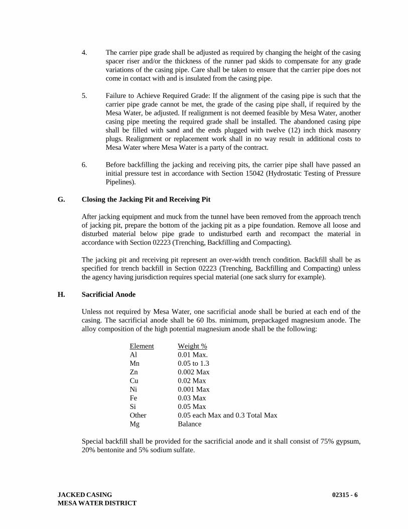
JACKED CASING
MESA WATER DISTRICT
02315 - 6
4. The carrier pipe grade shall be adjusted as required by changing the height of the casing
spacer riser and/or the thickness of the runner pad skids to compensate for any grade
variations of the casing pipe. Care shall be taken to ensure that the carrier pipe does not
come in contact with and is insulated from the casing pipe.
5. Failure to Achieve Required Grade: If the alignment of the casing pipe is such that the
carrier pipe grade cannot be met, the grade of the casing pipe shall, if required by the
Mesa Water, be adjusted. If realignment is not deemed feasible by Mesa Water, another
casing pipe meeting the required grade shall be installed. The abandoned casing pipe
shall be filled with sand and the ends plugged with twelve (12) inch thick masonry
plugs. Realignment or replacement work shall in no way result in additional costs to
Mesa Water where Mesa Water is a party of the contract.
6. Before backfilling the jacking and receiving pits, the carrier pipe shall have passed an
initial pressure test in accordance with Section 15042 (Hydrostatic Testing of Pressure
Pipelines).
G. Closing the Jacking Pit and Receiving Pit
After jacking equipment and muck from the tunnel have been removed from the approach trench
of jacking pit, prepare the bottom of the jacking pit as a pipe foundation. Remove all loose and
disturbed material below pipe grade to undisturbed earth and recompact the material in
accordance with Section 02223 (Trenching, Backfilling and Compacting).
The jacking pit and receiving pit represent an over-width trench condition. Backfill shall be as
specified for trench backfill in Section 02223 (Trenching, Backfilling and Compacting) unless
the agency having jurisdiction requires special material (one sack slurry for example).
H. Sacrificial Anode
Unless not required by Mesa Water, one sacrificial anode shall be buried at each end of the
casing. The sacrificial anode shall be 60 lbs. minimum, prepackaged magnesium anode. The
alloy composition of the high potential magnesium anode shall be the following:
Element Weight %
Al 0.01 Max.
Mn 0.05 to 1.3
Zn 0.002 Max
Cu 0.02 Max
Ni 0.001 Max
Fe 0.03 Max
Si 0.05 Max
Other 0.05 each Max and 0.3 Total Max
Mg Balance
Special backfill shall be provided for the sacrificial anode and it shall consist of 75% gypsum,
20% bentonite and 5% sodium sulfate.
JACKED CASING
MESA WATER DISTRICT
02315 - 7
Anode shall be offset from the pipe a minimum of ten (10) feet. Anode positions can be
adjusted slightly to avoid interference. Anodes may be installed in backhoe trench instead or
augured hole with Mesa Water’s approval.
Anode shall be prepackaged in a permeable cloth bag with a backfill of the above composition
or installed bare and filled with the above composition. The packaged weight of the anode
and backfill shall be approximately twice the weight of the anode ingot weight.
Anode lead wire shall be cadwelded to the casing in accordance with Erico Engineering
Specification No. A160-A05 and shall be #8 AWG stranded copper with HMWPE. Cover
each weld with Royston “Handy Cap”. The anode lead wire shall be attached to the steel core
of the anode with a silver solder by the manufacturer. The connection shall be encapsulated in
a heat-shrinkable sleeve.
Each anode shall be saturated with 20 gallons of water, prior to backfill of the trench.
END OF SECTION

CONCRETE CURBS, GUTTERS AND SIDEWALKS
MESA WATER DISTRICT
02528 - 1
SECTION 02528
CONCRETE CURBS, GUTTERS AND SIDEWALKS
PART 1 - GENERAL
A. Description
This section describes materials and construction of concrete curbs, gutters, and sidewalks.
For projects located in the public right-of-way, the respective jurisdictional agency (City of
Costa Mesa, the City of Newport Beach, or the County of Orange) permit requirements and
specifications shall take precedence over the requirements specified herein.
B. Related Work Specified Elsewhere
1. Trenching, Backfilling, and Compacting: 02223.
2. Concrete Formwork: 03100.
3. Concrete Reinforcement: 03201.
4. Concrete: 03300.
PART 2 - MATERIALS
A. Forms
1. General: Forms shall be as required in Section 03100 (Concrete Formwork). Stakes
and braces shall be provided to hold forms securely in place.
2. Sidewalk Forms: Sidewalk forms shall be 2-inch dressed lumber, straight and free
from defects, or standard metal forms. Where short-radius forms are required, 1-inch
dressed lumber of plywood may be used.
B. Aggregate Base Course
Crushed rock base shall be clean 3/4-inch and smaller crushed rock or crushed gravel, free
from foreign material, and conforming to Crushed Aggregate Base as specified by Standard
Specifications of Public Works Construction Section 400-2. An acceptable alternative to
Crushed Aggregate Base is Crushed Miscellaneous Base as specified by Standard
Specifications Section 200-2.4.
C. Expansion Joint Filler
Premolded expansion joint filler shall be 1/4-inch thick for curbs and 1/4-inch thick for
sidewalks, or as required or allowed by the permitting agency.
CONCRETE CURBS, GUTTERS AND SIDEWALKS
MESA WATER DISTRICT
02528 - 2
D. Concrete
Conform to Section 03300 (Concrete).
E. Reinforcing Steel
Conform to Section 03201 (Concrete Reinforcement).
F. Excavation and Backfill
Conform to Section 02223 (Trenching, Backfilling, and Compacting).
PART 3 - EXECUTION
A. Preparation of Subgrade
Subgrade shall be excavated and shaped to line, grade, and cross section. The top 12-inches
of subgrade shall be compacted to 90% relative compaction. All soft material disclosed by
excavating shall be removed and replaced with aggregate base as directed. The finished
subgrade shall be within a tolerance of +/-0.02 of a foot of the grade and cross section shown
and shall be smooth and free from irregularities at the specified relative compaction. The
subgrade shall extend over the full width of construction. The Mesa Water Representative's
approval of finished subgrades must be received prior to continuance of the work.
B. Placing Aggregate Base
After the subgrade for curbs, sidewalks, and roadway slabs is compacted and accepted, the
contractor shall place and spread aggregate base material, sprinkle with water, and compact to
90% relative density. The surface of the compacted base shall be at the proper level to
receive concrete. Curbs and sidewalks shall be underlain by 4-inches or more of compacted
aggregate base material.
C. Setting Forms
Forms shall conform to Section 03100 (Concrete Formwork). Forms for a face-of-curb shall
not have any horizontal joints within 7-inches of the top of the curb. Forms shall be braced to
prevent change of shape or movement in any direction resulting from the weight of the
concrete. Short-radius curved forms shall be constructed to exact radius. Tops of forms shall
not depart from gradeline more than 1/8-inch when checked with a 10-foot straightedge.
Alignment of straight sections shall not vary more than 1/8-inch in 10-feet.
D. Curb Construction
1. Jurisdictional Requirements: Curbs shall be reconstructed to original line and grade
if removed. Curbs shall conform to the requirements of the respective jurisdictional
agency.
CONCRETE CURBS, GUTTERS AND SIDEWALKS
MESA WATER DISTRICT
02528 - 3
2. Expansion Joints: Preformed asphalt-impregnated expansion joints shall be placed at
20-foot intervals, at the beginning and end of curved portions of the curb, at each
change in thickness of section, at the end of curbs at buildings and other structures,
and at connections to existing curbs.
3. Notification: The Mesa Water's Representative shall be notified one day in advance
of planned concrete placement.
4. Concrete Finish: When the concrete has set sufficiently to support its own weight,
the front form shall be removed and exposed surfaces finished. The formed face shall
be finished by rubbing with a burlap sack or similar device to produce a uniformly
textured surface, free of form marks, honeycomb, and other defects. Defective
concrete shall be removed and replaced at no expense to Mesa Water where Mesa
Water is a party of the contract. Upon completion of the finishing, curing compound
shall be applied to exposed surfaces of the curb. Curing shall continue for a
minimum of five days.
5. Backfill: Seven days (minimum) after pouring the concrete, the curb shall be
backfilled with earth free from rocks, 2-inches and larger, and other foreign material.
Backfill shall be tamped firmly in place.
6. Alignment and Grade: Finished curb shall have a uniform grade and alignment. Any
section of curb showing abrupt changes in alignment or grade, or which is more than
1/4-inch away from its intended location, as staked, shall be removed and
reconstructed at no additional cost to Mesa Water where Mesa Water is a party to the
contract.
7. Protection of Work: All concrete surfaces and/or structures shall be protected until
the project containing the work is accepted.
E. Sidewalk Construction
1. General Requirements: Unless shown otherwise, sidewalks shall be placed in a single
pour, 4-inches thick. Walks shall slope 1/4-inch per foot upward from the top of
curb. Concrete shall be placed, processed, finished, and cured in conformance with
the applicable requirements of ACI 614.
2. For sidewalks within a City public right-of-way, sidewalk construction shall be in
accordance with the jurisdictional agency’s requirements.
3. New Sidewalk: Where new sidewalk is to abut existing concrete, the existing
concrete shall be sawcut to a depth of 2-inches and the concrete chipped out to sound
material and a plane surface.
4. Expansion Joints: Preformed expansion joints shall be placed at 20-foot intervals or
less to match those in the adjacent curb, where the sidewalk ends at a curb, and
around posts, poles, or other facilities located within the sidewalk. Expansion joints
shall be placed between sidewalks and buildings or other structures.
CONCRETE CURBS, GUTTERS AND SIDEWALKS
MESA WATER DISTRICT
02528 - 4
5. Contraction Joints: Contraction joints shall be provided transversely to the walks at
locations opposite the contraction joints in the curb and at 10-foot intervals along the
sidewalk. These joints shall be 3/16-inch by 1-inch weakened plane joints. They
shall be straight and at right angles to the top of the walk.
6. Notification: The Mesa Water's Representative shall be notified one day in advance
of planned concrete placement.
7. Concrete Finish: The top surface of the sidewalk shall receive a broom finish with a
fine-hair broom in line with the length of the walk. All edges, joints, and markings
shall be tooled. The walk shall be scored transversely at 5-foot intervals with a
jointing tool. Upon completion of the finishing, an approved curing compound shall
be applied to exposed surfaces. Sidewalks shall be protected from damage until final
acceptance.
END OF SECTION
PAVEMENT REMOVAL AND REPLACEMENT
MESA WATER DISTRICT
02578 - 1
SECTION 02578
PAVEMENT REMOVAL AND REPLACEMENT
PART 1 - GENERAL
A. Description
This section describes materials, testing, removal, and replacement of asphalt concrete
pavement, seal coat, aggregate base course, prime coat, tack coat, and portland cement
concrete surfaces.
Work of this section shall be performed in accordance with the Standard Specifications for
Public Works Construction (SSPWC), unless otherwise specified herein.
For projects located in the public right-of-way, the respective jurisdictional agency (City of
Costa Mesa, City of Newport Beach or County of Orange) pavement specification and/or
approved encroachment permit requirements shall take precedence over the requirements
specified herein.
B. Related Work Specified Elsewhere
1. Trenching, Backfilling, and Compacting: 02223.
2. Concrete Curbs, Gutters, and Sidewalks: 02528.
C. Submittals
1. Submit asphalt mix design data prepared within the last year by a certified laboratory
for each asphalt concrete material type used on the project.
2. Submit materials certificates signed by material producer and contractor, certifying
that each material item complies with, or exceeds, specified requirements.
3. Submit materials certificates signed by material producer and contractor, identifying
material producer by name, location of material producing plant, and type of plant
from which material will be produced and delivered.
4. Submit completed manufacturer’s warranty form providing an unconditional
installation guarantee for a period of no less than two (2) years beginning from the
date of the Notice of Completion.
5. Submit proposed pavement placement sequence and schedule.

PAVEMENT REMOVAL AND REPLACEMENT
MESA WATER DISTRICT
02578 - 2
PART 2 – MATERIALS
A. Asphalt Concrete Paving
Asphalt Concrete paving shall be as specified in Section 203-6 of the SSPWC. Where
construction pavement is to be accomplished in a single course, Class C2 grading shall be used.
Where the construction consists of two or more courses, the surface course shall be Class C2
and the lower courses shall be Class B grading.
Asphalt shall be performance grade PG 64-10.
Asphalt binder content in the pavement shall be 4.5% to 5.8% for Class B grading and 4.6% to
6.0% for Class C2 grading. The base course pavement shall be a minimum of 3-inches thick.
B. Emulsion-Aggregate Slurry
Materials for emulsion-aggregate slurry (EAS) shall be as specified in SSPWC Subsection 203-
5.4.
C. Aggregate for Asphalt Concrete
Aggregate base shall conform to Section 200-2.2 of the SSPWC, Crushed Aggregate Base. In
the absence of available rock dust, sand of comparable gradation will be acceptable. Aggregate
shall be asbestos free. Evaluation of gradation and sand equivalent test results shall conform to
the provisions of SSPWC.
D. Aggregate Base Course
Aggregate base shall be Crushed Aggregate Base as specified in Section 200-2.2 of the
SSPWC. Crushed Miscellaneous Base, in accordance with Section 200-2.4 of the SSPWC is
an acceptable alternative for Crushed Aggregate Base. All crushed miscellaneous base
material shall have a minimum R-value of 80.
E. Seal Coat
Seal coat material shall be a plant-blended product composed of mineral aggregates uniformly
distributed in a petroleum-base asphalt emulsion. The asphalt emulsion shall conform to
Section 203-3 of the SSPWC and shall be free of asbestos fibers or coal tar additives.
Seal coat materials shall conform to Section 203-9 of the SSPWC. In complying with the seal
requirements, the seal shall have a minimum of 60% non-volatiles at the delivery from the
supplier and 48% non-volatiles at the point of seal material placement.
F. Tack Coat
Asphalt emulsion shall be CSS1 or CSS-1h and shall conform to the requirements of SSPWC
Section 203-3 Emulsified Asphalt.
PAVEMENT REMOVAL AND REPLACEMENT
MESA WATER DISTRICT
02578 - 3
G. Crack Treatment
Construction materials shall consist of a combination of a crack filling emulsion and that of
asphalt concrete material for filling the milled areas according to the following schedule:
1. Crack widths equal to or greater than ¼-inch but less than ½-inch:
A hot applied crack fill material shall be placed in all cracks.
2. Crack widths equal to or greater than ½-inch:
The crack fill material shall be a D2 PG 64-10 asphalt concrete material, per Section
203-6 of the SSPWC.
H. Striping
Paint shall conform to Section 214-4 of the SSPWC. Paint color and type shall be as indicated
on the drawings, or if not indicated, shall match as nearly as practical the existing conditions
of the site.
I. Redwood Header
Redwood headers shall comply with the material requirements of Section 212-1.5 of the
SSPWC.
J. Weed Killer
Weed killer shall be Karmex 80, as manufactured by Dupont Chemical Company, or Diuron
4L, as manufactured by Drexel Chemical Company, or approved equal.
PART 3 – EXECUTION
A. Pavement Removal
1. Asphalt concrete pavement shall initially be cut with a pavement cutter or other
equipment at the limits of the excavation before the pavement is removed. After
backfilling and compacting the excavation, asphalt concrete pavement shall be saw
cut to a minimum depth of 2-inches at a point not less than 9-inches outside the limits
of the excavation or the previous pavement cut, whichever is greater, and the
additional pavement removed. If the cut is within 3-feet of an existing joint or curb
and gutter, the asphalt concrete pavement shall be replaced to the joint or curb and
gutter. Saw cut lines shall be parallel or perpendicular to the flow of traffic.
The original saw cutting of the trench for removal of existing pavement structural
section can be either accomplished by saw cutting with a power-driven saw or
grinding with an asphalt zipper or cold planer. The final saw cutting, in conjunction
with the trench pavement replacement, shall be accomplished by the use of a power-
driven saw. The depth of the cut shall be deep enough to produce a clean, straight
break without loosening, cracking, or damaging adjoining asphalt so that there will be
a good join between the existing pavement structural section and the trench pavement
replacement structural section. The use of a grinder (cold planer) shall not be allowed
in lieu of power-driven saw.
PAVEMENT REMOVAL AND REPLACEMENT
MESA WATER DISTRICT
02578 - 4
2. Concrete pavement, cross gutters, curbs and gutters, sidewalks, or driveways, shall be
saw cut to a minimum depth of 1-1/2-inches at a point 1-foot beyond the edge of the
excavation and the strip of improvement removed. Concrete pavement may initially
be cut at the limits of the excavation by other methods prior to removal and the saw
cut made after backfilling the excavation. If the saw cut falls within 3-feet of a
concrete joint or pavement edge, the concrete shall be removed and replaced to the
joint or edge.
3. All pavement and other improvements demolished shall be removed from the site and
disposed off the site in a manner acceptable to agencies having jurisdiction over the
work and to Mesa Water.
4. Final pavement saw cuts shall be straight along both sides of the trench, parallel to the
pipeline alignment, and provide clean, solid, vertical faces free from loose material.
Adjoining pavement which has been damaged or disturbed shall also be saw cut and
removed. Saw cuts shall be parallel to the pipeline alignment or the roadway
centerline or perpendicular to same.
B. Pavement Replacement
1. Producing, hauling, placing, compacting, and finishing of asphalt concrete shall
conform to Section 302-5 of the SSPWC. Seal coat shall be applied to all new asphalt
concrete paving, except open grade asphalt concrete.
2. Base course paving shall be complete at all times to a point not to exceed 200 feet
behind any working heading. The final asphalt surface course shall be at least 2-inch
thick and shall be placed within a period of two weeks after traffic has been returned
to that portion of the street, unless otherwise noted on the drawings. Temporary
striping shall be applied after the base course of asphalt concrete pavement has been
placed, in the same configuration as the existing permanent striping, so that traffic can
be returned to normal patterns. Temporary striping shall be maintained until
permanent striping is applied.
C. Preparation of Subgrade
Subgrade shall be excavated and shaped to line, grade, and cross section. The top 12- inches
of subgrade shall be removed and recompacted to 95% relative compaction. All soft material
disclosed by the compacting effort shall be removed and replaced. The finished subgrade
shall be within a tolerance of +/-0.08 of a foot of the grade and cross section shown, smooth
and free from irregularities and at the specified relative compaction. The subgrade shall be
considered to extend over the full width of the aggregate base course.
D. Placing Aggregate Base
Aggregate base shall be placed to thickness shown on the drawing, to match existing, or per
the applicable permit. Aggregate base shall be compacted to 95% relative compaction and
installed in accordance with Section 301-2 of the SSPWC.
PAVEMENT REMOVAL AND REPLACEMENT
MESA WATER DISTRICT
02578 - 5
E. Placing Tack Coat
Tack coat shall be applied at the rate of 0.05 to 0.10 gallons per square yard to the surfaces to
receive finish pavement per Section 302-5.4 of the SSPWC. Tack coat shall be applied to
existing asphalt, metal, or concrete surfaces that will be in contact with new asphalt concrete
paving.
F. Placing Asphalt Paving
Asphalt paving shall be applied to the thickness shown on the drawing, as listed above, or per
the applicable permit. Asphalt paving shall be installed in accordance with Section 302-5 of the
SSPWC.
Asphalt concrete shall be placed in lifts having a maximum of 4-inches. A tack coat of SS-1h
shall be placed between lifts and on all vertical faces.
The asphalt concrete mat paving machine shall have a vibratory plate in operation during all of
the laydown operations. In the case that the plate is non-operational, the contractor shall
increase the thicknesses to include an additional 1/16 of an inch for each inch of asphalt
concrete material placed.
G. Applying Seal Coat
Pavement seal operations shall be performed in accordance with the manufacturer’s
recommendations. The material spread rate shall be a minimum of 25 gallons per 1,000 square
feet and shall be placed in a minimum of two coats.
The contractor shall black out old striping prior to sealing. This procedure is intended to
prevent the shadow effect that occurs due to the old lines or stripes wearing through the new
sealed surface. Application of black out paint shall comply with Section 314 of the SSPWC.
H. Compaction of Base and Leveling Courses
Compaction and rolling of base and leveling courses shall begin at the outer edges of the
surfacing and continue toward the center. Water shall be applied uniformly throughout the
material to provide moisture for obtaining the specified compaction. Each layer shall be
compacted to the specified relative compaction before the next layer is placed.
I. Surface Tolerance
Finished grade shall not deviate more than 0.02 foot in elevation from the grade indicated on
the drawings. Slopes shall not vary more than 1/8-inch in 10 feet from the slopes shown on the
drawings.
J. Concrete Curbs, Gutters, and Sidewalks
Concrete curbs, gutters, and sidewalks shall be replaced in accordance with Section 02528
(Concrete Curbs, Gutters, and Sidewalks).

PAVEMENT REMOVAL AND REPLACEMENT
MESA WATER DISTRICT
02578 - 6
K. Emulsion-Aggregate Slurry
Certain street sections where shown on the drawing or where required by the jurisdictional
agency may be required to receive an asphaltic slurry seal in conformance with Section 302-4
of the SSPWC after the final asphalt surface course. The composition and aggregate grading
for slurry shall be Type II of Subsection 203-5.3.
L. Pavement Milling
Areas designated for placement of a asphalt concrete overlay shall have a minimum of six (6)
foot tapered cut at roadway edges. At the transition from paving to non-paving, the tapered
cut shall be a minimum width of twelve (12) feet wide. At the lip of gutter and asphalt
concrete pavement interface, the asphalt concrete overlay shall be 3/8-inch higher than the lip
of gutter. The milled surface within the taper shall be uniform, shall not vary from its highs
and lows by more than 3/8-inch, and shall be performed in accordance with Section 302 of
the SSPWC. A temporary cold mix ramp shall be constructed after the pavement is milled
and before the cap is placed.
M. Placing Crack Fill Materials
1. Crack widths greater than ¼-inch but less than ½-inch:
A hot applied crack fill material shall be placed in all cracks. Hot crack fill material
shall be filled to within ¼-inch of the finish surface. The contractor shall take care
not to excessively place crack fill material along the edges of the crack at the finish
surface. Excessive crack fill over splash shall be removed under the direction of the
Mesa Water’s Representative. Crack filling operations shall only be performed
during the Winter or early Spring months.
2. Crack widths equal to or greater than ½ -inch:
Prior to crack filling, the existing cracks shall be marked out. Cracked areas shall be
milled out to a depth of 3-inches and a width of 18-inches. Each area shall then be
cleaned and all vertical and horizontal areas shall then be tack coated with an SS-1h
material and permitted to “break” before any new asphalt concrete material is
applied. The new asphalt concrete material shall be placed in one lift, compacted and
brought to the finish surface of the existing pavement.
N. Painting
Paint, except for black out line paint, shall be placed in a minimum of two coats per Section
314 of the SSPWC. The two coats shall be applied a minimum of one week a part from one
another. Black out line paint shall be applied per Section 314 of SSPWC.
O. Redwood Header
Redwood headers shall be placed at a maximum spacing of 48-inches on center. The
placement of headers, stakes, and joint spacing shall be in accordance with Section 212-1.5.2
of the SSPWC.
END OF SECTION
CONCRETE FORMWORK
MESA WATER DISTRICT
03100 - 1
SECTION 03100
CONCRETE FORMWORK
PART 1 - GENERAL
A. Description
This section describes materials and installation of concrete forms.
B. Related Specification Sections
1. Concrete Reinforcement: 03201.
2. Concrete: 03300.
C. Submittals
1. If requested by Mesa Water, submit manufacturer's literature for form ties, spreaders,
corner form, form coating, and bond breakers.
PART 2 - MATERIALS
A. Form Construction and Design
1. Forms shall be designed according to the applicable portions of ACI 347,
"Recommended Practice for Concrete Formwork," and all applicable regulations and
codes. All concrete shall be formed unless specified otherwise.
2. Form windows or stage forms shall be provided to allow observation at all times
before concrete is poured. Formwork and placement design shall be such as to limit
free fall of concrete to 4 feet.
3. The Mesa Water's Representative shall be notified a minimum of one day prior to
concrete placement.
B. Classes of Forms
1. Class I Forms: Smooth-surface plywood ¾-inch minimum thickness shall be used for
straight surfaces and ½-inch minimum thickness for curved surfaces.
2. Class II Forms: Forms shall be made of plywood in good condition, metal, or
smooth-planed boards free from large or loose knots with tongue and groove or ship
lap joints. Forms shall be oiled.
3. Application: Class II forms shall be used for exterior concrete surfaces which are 1
foot or more below finished grade. Class I forms shall be used for all other surfaces.

CONCRETE FORMWORK
MESA WATER DISTRICT
03100 - 2
C. Form Material
1. Forms shall be made of plywood, lumber, or steel of sufficient strength and surface
smoothness to produce the specified finish. Joints, gaps, and apertures in forms shall
be taped, gasketed, plugged and/or caulked so that the joint will remain watertight
and withstand placing pressures without bulging outward or creating surface
irregularities.
2. Lumber used in form construction shall be standard grade Douglas fir, S4S Standard
Grading and Dressing Rules No. 16, West Coast Lumber Inspection Bureau. Boards
in contact with concrete shall be 6 inches or more in width.
3. Plywood used in form construction shall be Grade B-B, Class 1 plyform, mill-oiled,
and sanded on both sides in conformance with U.S. Product Standard PS-1.
D. Form Ties
1. Form ties shall be located on exposed surfaces in a uniform pattern or as indicated on
the drawings. Form ties shall be constructed so that the tie remains embedded in the
wall except for a removable portion at each end. Form ties shall have conical or
spherical type inserts with a maximum diameter of 1 inch. Form ties shall be
constructed so that no metal is within 1 inch of the concrete surface when the forms,
inserts, and tie ends are removed. Wire ties shall not be used. Ties shall withstand all
pressures and limit deflection of forms to acceptable limits.
2. Flat bar ties for panel forms shall have plastic or rubber inserts having a minimum
depth of 1-inch and sufficient dimensions to permit patching of the tie hole.
3. Ties for water-holding structures or dry structures with access, such as basement
access shafts or pipe galleries, that are below finish grade, shall have an integral steel
waterstop that is tightly and continuously welded to the tie. The waterstop shall be at
least two times larger in area than the tie cross-sectional area and shall be oriented
perpendicular to the tie and symmetrical about the center of the tie. Ties shall be
constructed to provide a positive means of preventing rotation or disturbance of the
center portion of the tie during removal of the ends.
4. Tapered form ties shall be tapered through-bolts at least 1 inch in diameter at smallest
end, or through-bolts that utilize a removable tapered sleeve of the same minimum
size.
E. Bond Breaker
Bond breaker shall be a nonstaining type which will provide a positive bond prevention, such
as Williams Tilt-Up Compound, as manufactured by Williams Distributors, Inc., Seattle,
Washington; Silcoseal 77, as manufactured by SCA Construction Supply Division, Superior
Concrete Accessories, Franklin Park, Illinois; or approved equal.

CONCRETE FORMWORK
MESA WATER DISTRICT
03100 - 3
F. Form Release Agent
Form release agent shall effectively prevent absorption of moisture and prevent bond with the
concrete. Agent shall be nonstaining and nontoxic after 30 days.
For steel forms, release agent shall prevent discoloration of the concrete due to rust.
PART 3 - EXECUTION
A. Form Tolerances
1. Failure of the forms to produce the specified concrete surface and surface tolerance
shall be grounds for rejection of the concrete work. Rejected work shall be repaired
or replaced at no additional cost to Mesa Water where Mesa Water is a party of the
contract.
2. The following table indicates tolerances or allowable variations from dimensions or
positions of structural concrete work:
Item Maximum Tolerance
Sleeves and inserts
Projected ends of anchors
Anchor bolt setting
Finished concrete, all locations
Finished concrete, total length
+1/4" to -1/4"
+1/4" to 0.0"
+1/4" to -1/4"
+1/4" to -1/4" in 10 feet
+1"
The planes or axes from which the above tolerances are to be measured shall be as
follows:
Sleeves and inserts: Centerline of sleeve or insert.
Projected ends of anchors: Plane perpendicular to the end of the anchor as located
on the drawings.
Anchor bolt setting: Centerline of anchor bolt.
Finish concrete: The concrete surface as located on the drawings.
Where equipment is to be installed, the manufacturer's tolerances shall be complied
with if more stringent than the above.
B. Form Surface Preparation
1. Form surfaces to be in contact with the concrete shall be cleaned of all previous
concrete, dirt, and other surface contaminants prior to preparation by the applicable
method below.

CONCRETE FORMWORK
MESA WATER DISTRICT
03100 - 4
2. Wood surfaces and steel surfaces in contact with the concrete shall be coated with a
release agent prior to form installation. Release agent shall be submitted to and
approved by Mesa Water prior to construction. For water storage facilities, a non-
hazardous mineral oil type release agent shall be used.
C. Chamfers
1. 3/4-inch bevels shall be formed at concrete edges except those on top of walls and
elevated slabs and beams. Edges at top of walls, slabs, and beams shall be rounded to
a 3/4-inch radius.
2. Exterior corners in concrete members shall be provided with 3/4-inch chamfers.
Reentrant corners in concrete members shall not have fillets, unless otherwise shown
on the drawings.
D. Form Placement
1. Forms shall be provided with adequate means for holding adjacent edges and ends of
panels and sections tightly together and in accurate alignment so as to prevent the
formation of ridges, fins, offsets, or similar surface defects in the finished concrete.
The forms shall be tight and braced to prevent movement and the loss of mortar
and fines during placing and vibration of the concrete.
2. Cleanout and inspection openings shall be provided at the bottom of each lift of
forms. There shall be one 12-inch-wide by 18-inch-high opening every 7 feet at the
bottom of each lift of forms.
3. No part of any form tying device other than metal shall be embedded in the concrete.
4. The large end of taper ties shall be located on the "wet" side of the wall.
5. Only form or form-tying methods which do not cause spalling of the concrete upon
form stripping or tie removal shall be allowed.
6. Surfaces of concrete members shall be formed except where placement of the
concrete against the ground is shown on the drawings. The dimensions of concrete
members shown on the drawings shall apply to formed surfaces, except where
otherwise indicated. At least 2 inches of concrete shall be added where concrete is
placed against trimmed undisturbed ground in lieu of forms. Placement of concrete
against the ground shall be limited to footings and only where the character of the
ground is such that it can be trimmed to the required lines and will stand securely
without caving or sloughing.
E. Form Reuse
Only forms which maintain a uniform surface texture on exposed concrete surfaces shall be
used. Light sanding shall be applied between uses to obtain uniform texture. Unused tie rod
holes with corks, shaved flush, and sandpapered on the concrete surface side.

CONCRETE FORMWORK
MESA WATER DISTRICT
03100 - 5
Other than filling tie rod holes, forms shall not be patched except in the case of Class II
forms. Metal patching discs shall not be used on Class I forms.
F. Form Removal and Timing
1. Means shall be provided for removing forms without injury to the surface of the
finished concrete.
2. Forms and shoring for elevated structural slabs or beams shall remain in place until
the concrete has reached a compressive strength equal to the specified 28-day
compressive strength as determined by test cylinders. Supports shall not be removed
and reshored. The following table indicates the minimum allowable time after the
last cast concrete is placed before forms, shoring, or wall bracing shall be removed:
Sides of footings and encasements 24 hours
Walls not supporting load 48 hours
Vertical sides of beams, girders, and similar
members
48 hours
Slabs, beams, and girders 10 days (forms only)
Shoring for slab, beams, and girders Until concrete strength reaches
specified 28-day strength
Wall bracing Until top or roof slab concrete
reaches 2,500 psi
3. Forms shall not be removed from concrete which has been placed with outside air
temperature below 50° F without first determining if the concrete has properly set
without regard for time. Heavy loading shall not be applied to green concrete.
Immediately after forms are removed, the surface of the concrete shall be carefully
examined and any irregularities in the surface shall be repaired and finished as
specified.
G. Formed Openings
Openings shall be of sufficient size to permit final alignment of the items within it without
deflection or offsets of any kind and to allow space for packing where the items pass through
the wall to ensure watertightness around openings so formed. Openings shall be provided
with continuous keyways with waterstops where required, and a slight flare to facilitate
grouting and the escape of entrained air during grouting. Formed openings shall be provided
with reinforcement as indicated in the typical structural details. Reinforcing shall be at least
2-inches clear from the opening.
H. Embedded Items
Anchor bolts and other embedded items shall be set accurately and held securely in position
in the forms until the concrete is placed and set.
CONCRETE FORMWORK
MESA WATER DISTRICT
03100 - 6
All special castings, channels, or other metal parts that are to be embedded in the concrete
shall be checked prior to and again after concreting. All nailing blocks, plugs, and strips
necessary for the attachment of trim, finish, and similar work shall be checked prior to
concreting.
I. Pipes and Wall Spools Cast in Concrete
1. Wall spools, wall flanges, and wall anchors shall be installed before placing concrete.
Wall spools or anchors shall not be welded, tied, or otherwise connected to the
reinforcing steel.
2. Pipe and fabricated fittings to be encased in concrete shall be supported on concrete
piers or pedestals. Concrete supports shall be carried to firm foundations so that no
settlement occurs during construction.
END OF SECTION
CONCRETE REINFORCEMENT
MESA WATER DISTRICT
03201 - 1
SECTION 03201
CONCRETE REINFORCEMENT
PART 1 - GENERAL
A. Description
This section describes materials, testing, and installation of reinforcing steel for concrete.
B. Related Work Specified Elsewhere
1. Concrete Formwork: 03100.
2. Concrete: 03300.
C. Submittals
1. Submit mill test certificates identifying chemical and physical analyses of each load of
reinforcing steel delivered. If mill test reports are unavailable and the quantity of steel
for a structure exceeds 5 tons, then provide a laboratory test to prove yield strength and
bending.
2. Submit bending lists and placing drawings for all reinforcing steel. Each bending list
submitted shall be complete, including corner bars as required. Furnishing such lists
shall not be construed that the lists will be reviewed for accuracy. The contractor shall
be wholly and completely responsible for the accuracy of the lists and for furnishing and
placing reinforcing steel in accordance with the details shown on the plans and as may
be specified elsewhere in the contract documents.
PART 2 - MATERIALS
A. Reinforcing Steel
1. Reinforcing steel shall be new material conforming to ASTM A 615, Grade 60, and shall
be fabricated in accordance with the current edition of the Manual of Standard Practice,
published by the Concrete Reinforcing Steel Institute. Reinforcing steel shall be bent
while cold. Reinforcing steel which is to be welded, shall conform to ASTM A 706,
Grade 60.
2. Reinforcing steel shall be delivered to the site bundled and with identifying tags.
B. Welded Wire Fabric
Welded wire fabric shall conform to ASTM A 185. The minimum gauge of the welded wire
fabric shall be 6 x 6 – W1.4 x W1.4. The welded wire fabric shall be determined by the
design/structural engineer and approved by Mesa Water.

CONCRETE REINFORCEMENT
MESA WATER DISTRICT
03201 - 2
C. Tie Wire
Tie wire shall be 16 gage minimum, black, soft annealed.
D. Bar Supports
Bar supports in beams and slabs exposed to view after form stripping shall be non-metallic and
of sufficient strength to properly secure the reinforcement bars during the placement of concrete.
Concrete supports shall be used for reinforcing in concrete placed on grade.
PART 3 - EXECUTION
A. Placing
1. Reinforcing steel shall be placed in accordance with ACI and the current edition of
Recommended Practice for Placing Reinforcing Bars, published by the Concrete
Reinforcing Steel Institute.
2. Reinforcing steel, before being positioned, shall be free from loose mill and rust scale
and from any coatings that may destroy or reduce the bond. Where there is delay in
depositing concrete, reinforcement steel shall be cleaned by abrasive sandblasting to
remove mortar, oil, dirt, excessive mill scale, scabby rust, and coatings of any character
that would destroy or reduce the bonding capability.
3. Reinforcing steel shall not be straightened or reshaped in a manner that will injure the
material. Bars with bends not shown on the drawings shall not be used. Bars that are
partially embedded in concrete shall not be bent.
4. Reinforcing steel shall be positioned in accordance with the drawings and secured by
using annealed wire ties or clips at inter-sections and support by concrete or metal
supports, spacers, or metal hangers. Metal clips or supports shall not come in contact
with the forms. Tie wires shall be bent away from the forms to provide the specified
concrete coverage. Bars in addition to those shown on the drawings, which may be
found necessary or desirable for the purpose of securing reinforcement in position, may
be provided, at no additional expense to Mesa Water where Mesa Water is a party of the
contract.
5. Reinforcing steel shall be placed a minimum of 2 inches clear of any metal pipe or
fittings. Unless otherwise indicated on the drawings, reinforcement shall be placed so as
to provide the thickness of protective concrete covering as indicated on the Typical
Details, and or drawings. If not indicated on the drawings or Standard Drawings,
protective covering shall be in accordance with ACI 318.
B. Splices
Unless otherwise shown, splices in adjacent horizontal bars shall be staggered 48 bar diameters.
END OF SECTION
CONCRETE JOINTS
MESA WATER DISTRICT
03260 - 1
SECTION 03260
CONCRETE JOINTS
PART 1 - GENERAL
A. Description
This section describes materials, testing, and installation of construction and expansion joints,
premolded joint filler, joint sealant, and bond breaker tape.
B. Related Work Specified Elsewhere
1. Concrete Formwork: 03100.
2. Concrete Reinforcement: 03201.
3. Concrete: 03300.
C. Submittals
1. Submit manufacturer's literature, catalog data, and statement of compliance with
referenced standards and specifications.
PART 2 - MATERIALS
A. Joint Sealant for Concrete Structures
The joint sealant shall be a two-part, gray, nonstaining, nonsagging, polyurethane sealant,
which cures at ambient temperature to a firm, flexible, tear-resistant rubber. The sealer shall
be resilient and have excellent recovery characteristics after extended periods of compression
or elongation. Sealant shall be PRC 270, Vulkem 227, Sika 2C or approved equal.
Technical Requirements
Consistency Gun grade
Tack free time 24 hours at 75°F and 50% R.H.
Pot life 1 to 3 hours
Hardness 30 Shore A, +/-5
Elongation 750%
Tensile Strength, ASTM D 412 325 psi
Peel strength on concrete 18 psi cohesive
Temperature service range -40°F to +175°F
Immersion in water Continuous
CONCRETE JOINTS
MESA WATER DISTRICT
03260 - 2
B. Neoprene Rods for Precast Slab Joints
Neoprene rods shall be of the indicated diameter, 50 durometer.
C. Premolded Joint Filler
Joint filler shall be preformed, nonextruded type, constructed of closed-cell neoprene
conforming to ASTM D 1752, Type I, as manufactured by W. R. Grace Company of
Cambridge, Massachusetts; W. R. Meadows, Inc., Elgin, Illinois; or approved equal.
D. Neoprene Bearing Pads
Neoprene bearing pads for precast concrete slabs shall be of the indicated size, thickness, and
length, 60 durometer.
E. Bond Breaker Tape
Bond breaker tape shall be an adhesive backed glazed butyl or polyethylene which will adhere
to the premolded joint material or concrete surface. The tape shall be the same width as the
joint. The tape shall be compatible with the sealant.
PART 3 - EXECUTION
A. Construction Joints
1. Construction joints shall be provided where shown on the drawings. In case of
emergency, additional construction joints shall be placed. An interval of 45 minutes
between two consecutive batches of concrete shall constitute cause for an emergency
construction joint. All emergency construction joints are subject to final approval by
Mesa Water.
2. Construction joints shall be keyed, if indicated on the drawings. Keyways shall be
formed by beveled strips or boards placed at right angles to the direction of shear.
Except where otherwise shown on the drawings or specified, keyways shall be at least
1-1/2 inches in depth over at least 25% of the area of the section.
3. When an emergency joint is necessary, the joint shall be keyed and reinforcing
dowels shall be furnished and placed across the joint. These dowels shall be
embedded 60 bar diameters into each side of the joint. Size and number of dowels
shall match reinforcing in the member. Furnishing and placing such reinforcing steel
shall be done at no additional expense to Mesa Water where Mesa Water is a party of
the contract.
4. After the pour has been completed to the construction joint and the concrete has
hardened, the entire surface of the joint shall be thoroughly cleaned of surface
laitance, loose or defective concrete, and foreign material, and clean aggregate shall
be exposed by sandblasting the surface of construction joints before placing the new
concrete.

CONCRETE JOINTS
MESA WATER DISTRICT
03260 - 3
Horizontal construction joints shall be covered with mortar. Mortar shall be spread
uniformly and worked thoroughly into all irregularities of the surface. The mortar
shall be flowable and shall consist of sand, water, and a minimum of 12 sacks of
cement per cubic yard. A positive measuring device, such as a bucket, or other device
shall be provided that will contain only enough mortar for depositing in one place in
the wall or column to ensure that portion of the form does not receive too much
mortar. Mortar shall not be deposited from pump hoses or large concrete buckets
unless inspection windows close to the joint are available to allow visual
measurement of mortar thickness and means for mortar removal is available for
removal of any excess. The water-cement ratio of the mortar in place shall not
exceed that of the concrete to be placed upon it. The consistency of the mortar shall
be suitable for placing and working.
B. Installation of Premolded Joint Filler
Premolded joint filler shall be installed in joints accurately as shown. Joint filler shall be
attached to concrete with a bonding agent recommended by the joint sealant and joint filler
manufacturer for compatibility.
C. Installation of Joint Sealants
1. Immediately before installing the joint sealant, the joint cavity shall be cleaned by
sandblasting or power wire brushing. Bond breaker tape shall be installed per
manufacturer's instructions.
2. After the joints have been prepared as described above, the joint sealant shall be
applied. Primer, if required, and joint sealant shall be applied only with the equipment
and methods recommended by the joint sealant manufacturer. Application criteria for
the sealant materials, such as temperature and moisture requirements and primer cure
time, shall be in accordance with the recommendations of the sealant manufacturer.
3. Masking tape shall be applied along the edges of the exposed surface of the exposed
joints. Joints shall be troweled smooth with a tuck pointing tool wiped with a solvent
as recommended by the sealant manufacturer.
4. After the sealant has been applied, masking tape and any sealant spillage shall be
removed.
D. Installation of Neoprene Rods in Precast Slab Joints
Neoprene rods shall be forced down to the bottom of the shaped joint prior to placing drypack
in the joint.
E. Installation of Neoprene Bearing Pads
Neoprene bearing pads shall be placed in the indicated position on the concrete walls and
glued to the wall with suitable adhesive.
END OF SECTION
CONCRETE
MESA WATER DISTRICT
03300 - 1
SECTION 03300
CONCRETE
PART 1 - GENERAL
A. Description
This section describes materials, mixing, and placing of concrete and grout. All portland
cement concrete shall conform to the provisions of Section 201 of the Standard Specifications
for Public Works Construction (SSPWC) except as herein modified.
B. Related Work Specified Elsewhere
1. Concrete Formwork: 03100.
2. Concrete Reinforcement: 03201.
3. Concrete Joints: 03260.
C. Submittals
1. Shop drawings shall be submitted in accordance with ACI 318, and the following.
2. Mix design with proof of design by laboratory 7-day and 28-day compressive tests, or
test reports of 7-day and 28-day compressive tests of the mix where the same mix was
used on two previous projects, shall be submitted in writing for review by Mesa
Water at least 15 days before placing of any concrete.
3. Certificate that cement used in the concrete complies with ASTM C 150 and these
specifications shall be submitted.
4. Aggregates: Certificate of compliance with ASTM C 33 shall be provided.
Weathering region limits of coarse aggregates: severe, moderate, or negligible shall
be stated. Basis of determining that potential reactivity is negligible shall be stated.
5. Ready Mix Concrete: Delivery tickets or weighmasters certificate per ASTM C 94,
including weights of cement and each size aggregate, volume of water in the
aggregate, and volume of water added at the plant shall be provided. The volume of
water added on the job shall be written on the ticket or certificate.
6. Concrete admixtures: Manufacturer's certificate of compliance with these
specifications shall be provided.
7. Epoxy Bonding Compound: Manufacturer's specific instructions for use shall be
provided.
8. Nonshrink Grout: Manufacturer's certificate of compliance with these specifications
and specific instructions for use shall be provided.

CONCRETE
MESA WATER DISTRICT
03300 - 2
PART 2 - MATERIALS
A. Cement
Cement shall conform to ASTM C 150, Type II or Type V, with maximum tricalcium
aluminate content not to exceed 6%. The maximum percent alkalies shall not exceed 0.6%.
B. Aggregates
Aggregates shall comply with ASTM C 33 and shall be free from any substances that will
react with the cement alkalies.
C. Water and Ice
Water and ice that is clean and free from objectionable quantities of organic matter, alkali,
salts, and any other impurities which might reduce the strength, durability, and quality of the
concrete shall be used in the concrete mix.
D. High-Early Strength Concrete
Admixtures for high-early strength concrete shall be non-chloride admixtures which meet the
requirements of ASTM C494. Acceptable products are Pozzutec 20 and Pozzolith NC 534,
by Master Builders, Inc. or approved equal. Concrete shall reach 2,500 psi by eight (8) hours
of being placed.
E. Concrete Admixtures
1. Air Entraining Admixture: Concrete may contain an air-entraining admixture which
shall conform to ASTM C 260, except it shall be nontoxic after 30 days and shall
contain no chlorides. Admixture shall be Master Builders MB-VR, Sika AER
(Sikamix 104), or approved equal.
2. Water Reduction Admixture: Concrete may contain a water-reducing admixture
which shall conform to ASTM C 494, Type A or Type D, except it shall contain no
chlorides, shall be nontoxic after 30 days, and shall be compatible with the air-
entraining admixture. The amount of admixture added to the concrete shall be in
accordance with the manufacturer's recommendations. Admixture shall be Master
Builders Pozzolith polymer-type normal setting, Plastocrete (Sikamix 160) Normal
Set, Sika Chemical Corporation, or approved equal.
3. Restrictions: Accelerating water-reducing admixtures or any other type of admixture
that contains chlorides or other corrosive elements shall not be used in any concrete.
F. Nonshrink Grout
Nonshrink grout shall conform to the Corps of Engineers Specification for Nonshrink Grout,
CRD-C588-78, and to these specifications. Use a non gas-liberating type, cement base,
premixed product requiring only the addition of water for the required consistency. Grout
shall be UPCON High Flow, Master Flow 713, or approved equal. All components shall be
inorganic.
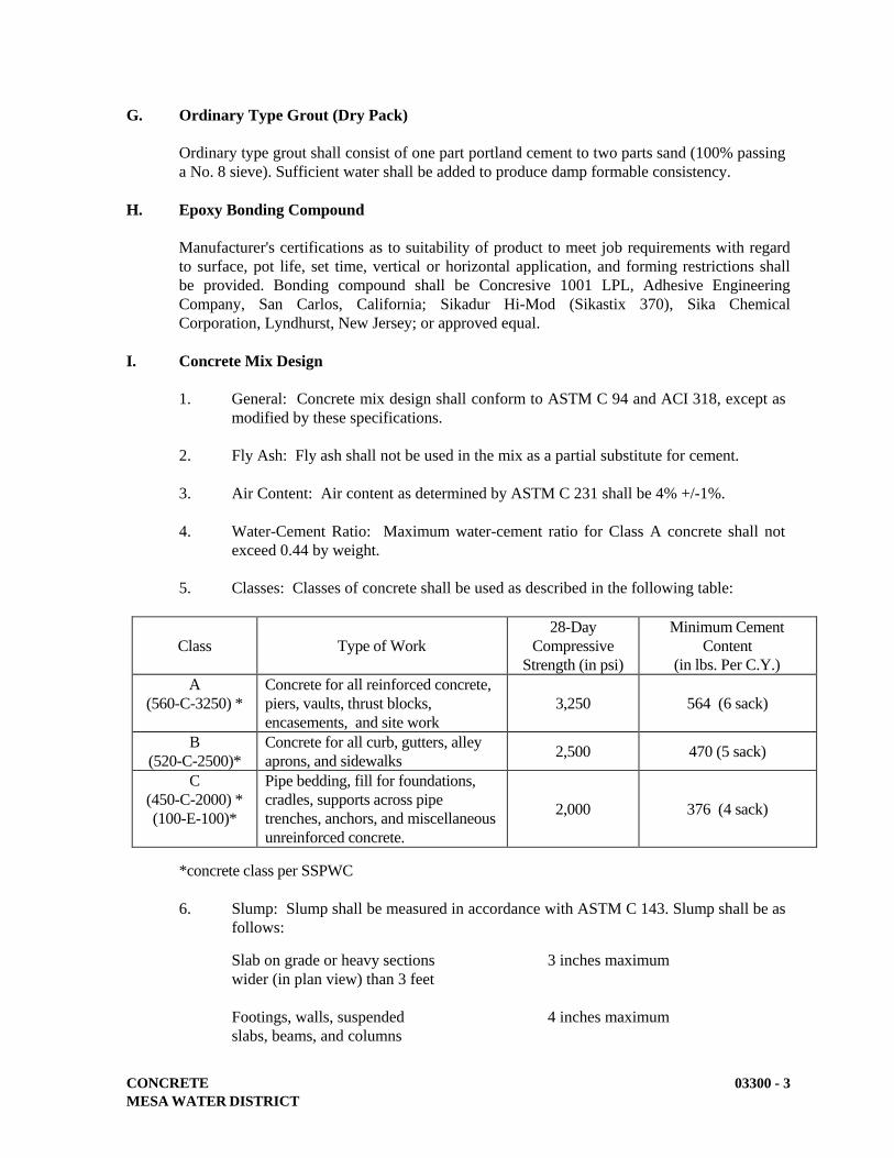
CONCRETE
MESA WATER DISTRICT
03300 - 3
G. Ordinary Type Grout (Dry Pack)
Ordinary type grout shall consist of one part portland cement to two parts sand (100% passing
a No. 8 sieve). Sufficient water shall be added to produce damp formable consistency.
H. Epoxy Bonding Compound
Manufacturer's certifications as to suitability of product to meet job requirements with regard
to surface, pot life, set time, vertical or horizontal application, and forming restrictions shall
be provided. Bonding compound shall be Concresive 1001 LPL, Adhesive Engineering
Company, San Carlos, California; Sikadur Hi-Mod (Sikastix 370), Sika Chemical
Corporation, Lyndhurst, New Jersey; or approved equal.
I. Concrete Mix Design
1. General: Concrete mix design shall conform to ASTM C 94 and ACI 318, except as
modified by these specifications.
2. Fly Ash: Fly ash shall not be used in the mix as a partial substitute for cement.
3. Air Content: Air content as determined by ASTM C 231 shall be 4% +/-1%.
4. Water-Cement Ratio: Maximum water-cement ratio for Class A concrete shall not
exceed 0.44 by weight.
5. Classes: Classes of concrete shall be used as described in the following table:
Class
Type of Work
28-Day
Compressive
Strength (in psi)
Minimum Cement
Content
(in lbs. Per C.Y.)
A
(560-C-3250) *
Concrete for all reinforced concrete,
piers, vaults, thrust blocks,
encasements, and site work
3,250
564 (6 sack)
B
(520-C-2500)*
Concrete for all curb, gutters, alley
aprons, and sidewalks 2,500 470 (5 sack)
C
(450-C-2000) *
(100-E-100)*
Pipe bedding, fill for foundations,
cradles, supports across pipe
trenches, anchors, and miscellaneous
unreinforced concrete.
2,000
376 (4 sack)
*concrete class per SSPWC
6. Slump: Slump shall be measured in accordance with ASTM C 143. Slump shall be as
follows:
Slab on grade or heavy sections 3 inches maximum
wider (in plan view) than 3 feet
Footings, walls, suspended 4 inches maximum
slabs, beams, and columns
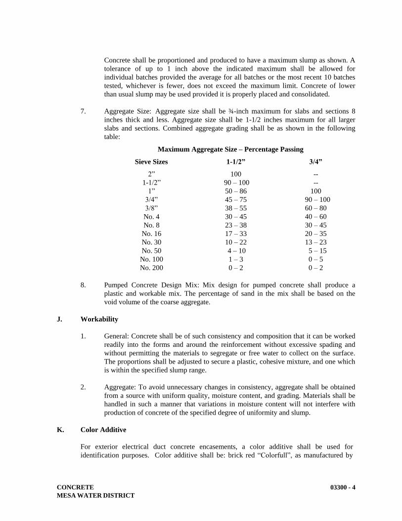
CONCRETE
MESA WATER DISTRICT
03300 - 4
Concrete shall be proportioned and produced to have a maximum slump as shown. A
tolerance of up to 1 inch above the indicated maximum shall be allowed for
individual batches provided the average for all batches or the most recent 10 batches
tested, whichever is fewer, does not exceed the maximum limit. Concrete of lower
than usual slump may be used provided it is properly placed and consolidated.
7. Aggregate Size: Aggregate size shall be ¾-inch maximum for slabs and sections 8
inches thick and less. Aggregate size shall be 1-1/2 inches maximum for all larger
slabs and sections. Combined aggregate grading shall be as shown in the following
table:
Maximum Aggregate Size – Percentage Passing
Sieve Sizes 1-1/2” 3/4”
2”
1-1/2”
1”
3/4”
3/8”
No. 4
No. 8
No. 16
No. 30
No. 50
No. 100
No. 200
100
90 – 100
50 – 86
45 – 75
38 – 55
30 – 45
23 – 38
17 – 33
10 – 22
4 – 10
1 – 3
0 – 2
--
--
100
90 – 100
60 – 80
40 – 60
30 – 45
20 – 35
13 – 23
5 – 15
0 – 5
0 – 2
8. Pumped Concrete Design Mix: Mix design for pumped concrete shall produce a
plastic and workable mix. The percentage of sand in the mix shall be based on the
void volume of the coarse aggregate.
J. Workability
1. General: Concrete shall be of such consistency and composition that it can be worked
readily into the forms and around the reinforcement without excessive spading and
without permitting the materials to segregate or free water to collect on the surface.
The proportions shall be adjusted to secure a plastic, cohesive mixture, and one which
is within the specified slump range.
2. Aggregate: To avoid unnecessary changes in consistency, aggregate shall be obtained
from a source with uniform quality, moisture content, and grading. Materials shall be
handled in such a manner that variations in moisture content will not interfere with
production of concrete of the specified degree of uniformity and slump.
K. Color Additive
For exterior electrical duct concrete encasements, a color additive shall be used for
identification purposes. Color additive shall be: brick red “Colorfull”, as manufactured by
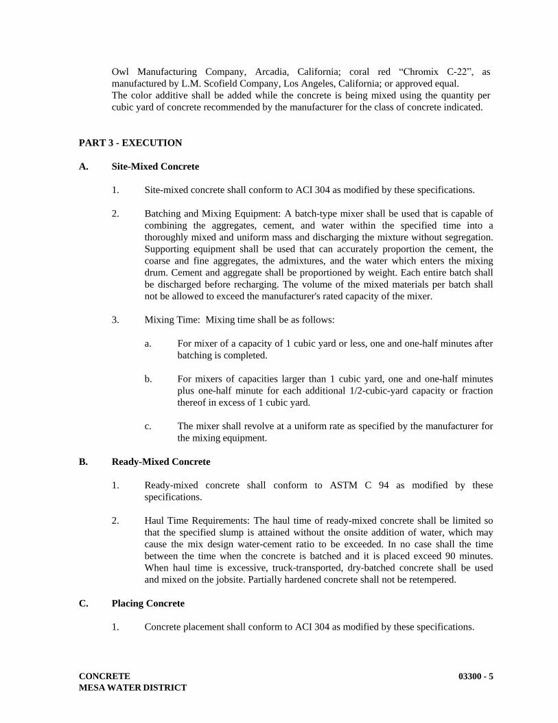
CONCRETE
MESA WATER DISTRICT
03300 - 5
Owl Manufacturing Company, Arcadia, California; coral red “Chromix C-22”, as
manufactured by L.M. Scofield Company, Los Angeles, California; or approved equal.
The color additive shall be added while the concrete is being mixed using the quantity per
cubic yard of concrete recommended by the manufacturer for the class of concrete indicated.
PART 3 - EXECUTION
A. Site-Mixed Concrete
1. Site-mixed concrete shall conform to ACI 304 as modified by these specifications.
2. Batching and Mixing Equipment: A batch-type mixer shall be used that is capable of
combining the aggregates, cement, and water within the specified time into a
thoroughly mixed and uniform mass and discharging the mixture without segregation.
Supporting equipment shall be used that can accurately proportion the cement, the
coarse and fine aggregates, the admixtures, and the water which enters the mixing
drum. Cement and aggregate shall be proportioned by weight. Each entire batch shall
be discharged before recharging. The volume of the mixed materials per batch shall
not be allowed to exceed the manufacturer's rated capacity of the mixer.
3. Mixing Time: Mixing time shall be as follows:
a. For mixer of a capacity of 1 cubic yard or less, one and one-half minutes after
batching is completed.
b. For mixers of capacities larger than 1 cubic yard, one and one-half minutes
plus one-half minute for each additional 1/2-cubic-yard capacity or fraction
thereof in excess of 1 cubic yard.
c. The mixer shall revolve at a uniform rate as specified by the manufacturer for
the mixing equipment.
B. Ready-Mixed Concrete
1. Ready-mixed concrete shall conform to ASTM C 94 as modified by these
specifications.
2. Haul Time Requirements: The haul time of ready-mixed concrete shall be limited so
that the specified slump is attained without the onsite addition of water, which may
cause the mix design water-cement ratio to be exceeded. In no case shall the time
between the time when the concrete is batched and it is placed exceed 90 minutes.
When haul time is excessive, truck-transported, dry-batched concrete shall be used
and mixed on the jobsite. Partially hardened concrete shall not be retempered.
C. Placing Concrete
1. Concrete placement shall conform to ACI 304 as modified by these specifications.
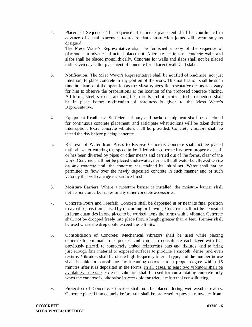
CONCRETE
MESA WATER DISTRICT
03300 - 6
2. Placement Sequence: The sequence of concrete placement shall be coordinated in
advance of actual placement to assure that construction joints will occur only as
designed.
The Mesa Water's Representative shall be furnished a copy of the sequence of
placement in advance of actual placement. Alternate sections of concrete walls and
slabs shall be placed monolithically. Concrete for walls and slabs shall not be placed
until seven days after placement of concrete for adjacent walls and slabs.
3. Notification: The Mesa Water's Representative shall be notified of readiness, not just
intention, to place concrete in any portion of the work. This notification shall be such
time in advance of the operation as the Mesa Water's Representative deems necessary
for him to observe the preparations at the location of the proposed concrete placing.
All forms, steel, screeds, anchors, ties, inserts and other items to be embedded shall
be in place before notification of readiness is given to the Mesa Water's
Representative.
4. Equipment Readiness: Sufficient primary and backup equipment shall be scheduled
for continuous concrete placement, and anticipate what actions will be taken during
interruption. Extra concrete vibrators shall be provided. Concrete vibrators shall be
tested the day before placing concrete.
5. Removal of Water from Areas to Receive Concrete: Concrete shall not be placed
until all water entering the space to be filled with concrete has been properly cut off
or has been diverted by pipes or other means and carried out of the forms, clear of the
work. Concrete shall not be placed underwater, nor shall still water be allowed to rise
on any concrete until the concrete has attained its initial set. Water shall not be
permitted to flow over the newly deposited concrete in such manner and of such
velocity that will damage the surface finish.
6. Moisture Barriers: Where a moisture barrier is installed, the moisture barrier shall
not be punctured by stakes or any other concrete accessories.
7. Concrete Pours and Freefall: Concrete shall be deposited at or near its final position
to avoid segregation caused by rehandling or flowing. Concrete shall not be deposited
in large quantities in one place to be worked along the forms with a vibrator. Concrete
shall not be dropped freely into place from a height greater than 4 feet. Tremies shall
be used where the drop could exceed these limits.
8. Consolidation of Concrete: Mechanical vibrators shall be used while placing
concrete to eliminate rock pockets and voids, to consolidate each layer with that
previously placed, to completely embed reinforcing bars and fixtures, and to bring
just enough fine material to exposed surfaces to produce a smooth, dense, and even
texture. Vibrators shall be of the high-frequency internal type, and the number in use
shall be able to consolidate the incoming concrete to a proper degree within 15
minutes after it is deposited in the forms. In all cases, at least two vibrators shall be
available at the site. External vibrators shall be used for consolidating concrete only
when the concrete is otherwise inaccessible for adequate internal consolidating.
9. Protection of Concrete: Concrete shall not be placed during wet weather events.
Concrete placed immediately before rain shall be protected to prevent rainwater from

CONCRETE
MESA WATER DISTRICT
03300 - 7
coming in contact with it. Sufficient protective covering shall be kept on hand at all
times for this purpose.
D. Concrete Tests
1. Strength tests shall be performed on the concrete by the Mesa Water's Representative
as follows:
a. Mold and cure three concrete test cylinders from each 50 cubic yards, or
fraction thereof, of each class of concrete placed in any one day. Mold and
cure the cylinders in accordance with ASTM C 31.
b. Test cylinders in accordance with ASTM C 39. Test two cylinders at 28 days
for acceptance, and test one at 7 days for information. Hold one cylinder for
verification. The test results shall be the average of the strengths of the two
cylinders tested at 28 days. If one cylinder in a test manifests evidence of
improper sampling, molding, or testing, other than low strength, discard it
and use the strength of the remaining cylinder for the test result. Should both
cylinders in a test show any of the above defects, discard the entire test.
c. Determine slump of the concrete using ASTM C 143 for each strength test
sample and as required to establish consistency.
d. Determine air content of the concrete using ASTM C 231 for each strength
test sample and as required to establish consistency.
2. Notification and Handling of Samples: To facilitate testing and inspection:
a. Mesa Water shall be advised in advance of concrete placing operations to
allow for completion of quality tests.
b. Labor necessary to assist the Mesa Water’s Representative in obtaining and
handling samples at the project shall be furnished by the contractor.
c. Facilities for safe storage and proper curing of concrete test specimens on the
project site, as required by ASTM C 31 shall be provided and maintained by
the contractor for the sole use of Mesa Water.
3. Requirements for Attainment of Compressive Strength: Concrete specified by
compressive strength shall attain the 28-day strength specified in Part 2, Paragraph I
of this section. The average of any three consecutive strength tests shall be equal to or
greater than the specified 28-day strength. Not more than 10% of the tests shall be
less than specified 28-day strength. No test shall be less than 90% of the specified 28-
day strength.
4. Failure to Attain Specified Strength: If the 28-day tests fail to meet the specified
minimum compressive strength, the concrete will be assumed to be defective and one
set of three cores from each area may be taken as selected by Mesa Water and in
accordance with ASTM C 42. If the average compressive strength, of the set of three
concrete cores fails to equal 85% of the specified minimum compressive strength or if

CONCRETE
MESA WATER DISTRICT
03300 - 8
any single core is less than 75% of the minimum compressive strength, the concrete
will be considered defective and shall be removed and replaced, all at no cost to Mesa
Water where Mesa Water is a party of the contract.
Costs of coring, testing of cores, and all required repairing pertaining thereto shall be
the responsibility of the contractor.
E. Pumping Concrete
1. Equipment Capacity Requirements: Pump size shall be determined by the rate of
concrete placement, length of delivery pipe or hose, aggregate size, mix proportions,
vertical lift, and slump of concrete.
Minimum inside diameter of pipe or hose shall be based on the maximum aggregate
size as follows:
3/4-inch-max aggregate: 2 inches min ID
1-1/2-inch-max aggregate: 4 inches min ID
2. Disallowance of Aluminum Pipe: Aluminum pipes shall not be used for delivery of
concrete to the forms.
3. Priming: Before pumping is started, the delivery pipe or hose shall be primed by
pumping mortar through the line using 5 gallons of mortar for each 50 feet of delivery
line. Mortar shall be pumped to waste and not deposited in the forms.
F. Hot Weather Requirements
1. General: During hot weather, proper attention shall be given to ingredients,
production methods, handling, placing, protection, and curing to prevent excessive
concrete temperatures or water evaporation in accordance with ACI 305 and the
following. There shall be no additional reimbursement for costs incurred for placing
concrete in hot weather.
2. Cooling Methods: When the weather is such that the temperature of the concrete as
placed would exceed 90°F, ice or other effective means of cooling the concrete during
mixing and transportation shall be used so that the temperature of the concrete as
placed will not exceed 90°F.
3. Prevention Against Early Setting of Concrete: Precautions shall be taken when
placing concrete during hot, dry weather to eliminate early setting of concrete. This
includes protection of reinforcing from direct sunlight to prevent heating of
reinforcing, placing concrete during cooler hours of the day, and the proper and
timely application of specified curing methods.
G. Cold Weather Requirements
1. General: Adequate equipment shall be provided for heating concrete materials and
protecting concrete during freezing or near-freezing weather in accordance with ACI
306 and the following. There shall be no additional reimbursement for costs incurred
for placing concrete during cold weather.
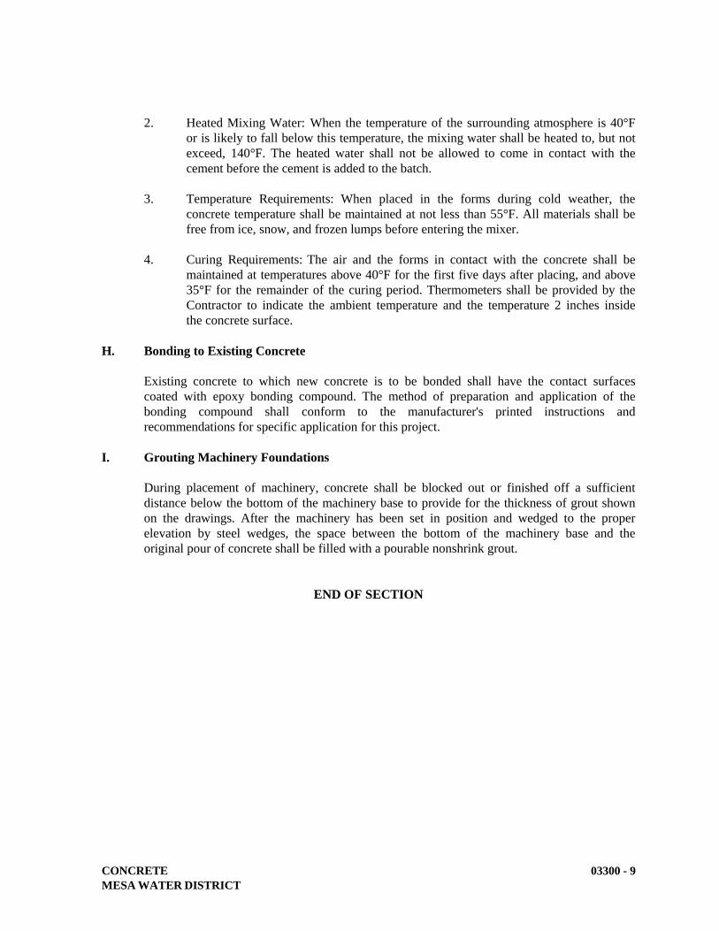
CONCRETE
MESA WATER DISTRICT
03300 - 9
2. Heated Mixing Water: When the temperature of the surrounding atmosphere is 40°F
or is likely to fall below this temperature, the mixing water shall be heated to, but not
exceed, 140°F. The heated water shall not be allowed to come in contact with the
cement before the cement is added to the batch.
3. Temperature Requirements: When placed in the forms during cold weather, the
concrete temperature shall be maintained at not less than 55°F. All materials shall be
free from ice, snow, and frozen lumps before entering the mixer.
4. Curing Requirements: The air and the forms in contact with the concrete shall be
maintained at temperatures above 40°F for the first five days after placing, and above
35°F for the remainder of the curing period. Thermometers shall be provided by the
Contractor to indicate the ambient temperature and the temperature 2 inches inside
the concrete surface.
H. Bonding to Existing Concrete
Existing concrete to which new concrete is to be bonded shall have the contact surfaces
coated with epoxy bonding compound. The method of preparation and application of the
bonding compound shall conform to the manufacturer's printed instructions and
recommendations for specific application for this project.
I. Grouting Machinery Foundations
During placement of machinery, concrete shall be blocked out or finished off a sufficient
distance below the bottom of the machinery base to provide for the thickness of grout shown
on the drawings. After the machinery has been set in position and wedged to the proper
elevation by steel wedges, the space between the bottom of the machinery base and the
original pour of concrete shall be filled with a pourable nonshrink grout.
END OF SECTION

PRECAST CONCRETE VAULTS AND METER BOXES
MESA WATER DISTRICT
03462 - 1
SECTION 03462
PRECAST CONCRETE VAULTS AND METER BOXES
PART 1 - GENERAL
A. Description
This section describes the materials, manufacture, and installation of precast concrete vaults,
precast concrete manholes, manhole frame and covers, and meter boxes.
B. Related Work Specified Elsewhere
1. Structural Earthwork: 02220.
2. Trenching, Backfilling and Compacting: 02223.
3. Concrete: 03300.
4. Structural Steel and Miscellaneous Metalwork: 05120.
C. Submittals
1. Submit manufacturer's catalog data on precast concrete vaults and meter boxes. Show
dimensions and materials of construction by ASTM reference and grade.
2. Submit manufacturer's catalog data on precast concrete manholes, frames and covers.
Show dimensions and materials of construction by ASTM reference and grade. Show
manhole cover lettering and pattern.
PART 2 – MATERIALS
A. Precast Concrete Vault
1. Manufacturers: Precast concrete vaults and covers shall be manufactured in a plant
especially designed for that purpose and shall conform to the size, shape and
dimensions indicated on the detailed plans. Vaults and covers shall be Jensen Precast,
Eisel Enterprises, Inc., Inland Concrete Enterprises, Inc., J&R Concrete Products, Inc.,
Christy Concrete, Olson Precast, or approved equal.
2. Design Loads: Design loads shall consist of dead load, live load, impact, and in
addition, loads due to water table and any other loads which may be imposed upon the
structure. Live loads shall be based on H-20 loading per AASHTO standard
specifications for highway bridges. Design wheel load shall be 16 kips. The live load
shall be that which produces the maximum shear and bending moments in the
structure.

PRECAST CONCRETE VAULTS AND METER BOXES
MESA WATER DISTRICT
03462 - 2
3. Concrete: Concrete for vaults shall be Class A conforming to Section 03300,
Concrete.
4. Sectional Vaults: Sectional precast concrete vaults may be used where specified on
the drawings or approved by Mesa Water
B. Precast Concrete Manholes
1. General: Precast reinforced concrete manholes shall comply with ASTM C 478, with
a minimum wall thickness of 6-inches.
2. Design Loads: Manhole components shall be designed for H-20 highway loads and
site soil conditions.
3. Concrete: Precast reinforced concrete manhole risers and tops shall be constructed of
Class A concrete conforming to Section 03300, Concrete.
4. Manhole Section Configuration: Manholes shall be fabricated only from eccentric
sections and standard cylinder units of the proper internal diameter.
5. Manufacturers: Precast reinforced concrete manholes shall be manufactured by
Associated Concrete Products, Inland Concrete Products, Olson Precast Company,
Precon Products, Southwest Concrete Products, or approved equal.
.
C. Manhole Frames and Covers
1. General Requirements: Manhole frames and covers shall be made of ductile iron
conforming to ASTM 536, Class 400, or cast iron conforming to ASTM A 48, Class
30. Castings shall be smooth, clean, and free from blisters, blowholes, and shrinkage.
Frames and covers shall be of the traffic type, designed for H-20 loading.
2. Fit and Matchmarking: Each manhole cover shall be ground or otherwise finished so
that it will fit in its frame without rocking. Frames and covers shall be matchmarked
in sets before shipping to the site.
3. Cover Inscription: Covers shall have the words “MESA WATER” and “BLOWOFF”
cast as shown on the Standard Drawings or on the drawings. No other lettering on the
top side shall be permitted. Cast letters shall be 3-inches and the relief depth shall be
at least 3/16-inch. Top surface of the letters and diamond tread pattern shall be flush
with the outer ring edge and the frame top surfaces.
4. Inspection and Coating: Before leaving the foundry, castings shall be cleaned and
subjected to a hammer inspection. Castings shall then be dipped twice in a preparation
of asphalt or coal tar and oil applied at a temperature of not less than 290° F, not more
than 310° F, and in such a manner as to form a firm and tenacious coating.
5. Manufacturers: Manhole frames and covers shall be manufactured by Alhambra
Foundry, National Casting, Neenah Foundry, Pont-A-Mousson, South Bay Foundry,
or approved equal.
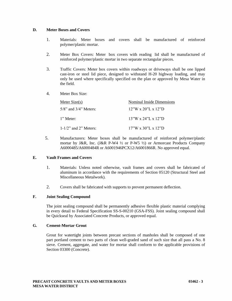
PRECAST CONCRETE VAULTS AND METER BOXES
MESA WATER DISTRICT
03462 - 3
D. Meter Boxes and Covers
1. Materials: Meter boxes and covers shall be manufactured of reinforced
polymer/plastic mortar.
2. Meter Box Covers: Meter box covers with reading lid shall be manufactured of
reinforced polymer/plastic mortar in two separate rectangular pieces.
3. Traffic Covers: Meter box covers within roadways or driveways shall be one lipped
cast-iron or steel lid piece, designed to withstand H-20 highway loading, and may
only be used where specifically specified on the plan or approved by Mesa Water in
the field.
4. Meter Box Size:
Meter Size(s) Nominal Inside Dimensions
5/8” and 3/4” Meters: 12”W x 20”L x 12”D
1” Meter: 13”W x 24”L x 12”D
1-1/2” and 2” Meters: 17”W x 30”L x 12”D
5. Manufacturers: Meter boxes shall be manufactured of reinforced polymer/plastic
mortar by J&R, Inc. (J&R P-W4 ½ or P-W5 ½) or Armorcast Products Company
A6000485/A6000484R or A6001946PCX12/A6001866R. No approved equal.
E. Vault Frames and Covers
1. Materials: Unless noted otherwise, vault frames and covers shall be fabricated of
aluminum in accordance with the requirements of Section 05120 (Structural Steel and
Miscellaneous Metalwork).
2. Covers shall be fabricated with supports to prevent permanent deflection.
F. Joint Sealing Compound
The joint sealing compound shall be permanently adhesive flexible plastic material complying
in every detail to Federal Specification SS-S-00210 (GSA-FSS). Joint sealing compound shall
be Quickseal by Associated Concrete Products, or approved equal.
G. Cement-Mortar Grout
Grout for watertight joints between precast sections of manholes shall be composed of one
part portland cement to two parts of clean well-graded sand of such size that all pass a No. 8
sieve. Cement, aggregate, and water for mortar shall conform to the applicable provisions of
Section 03300 (Concrete).

PRECAST CONCRETE VAULTS AND METER BOXES
MESA WATER DISTRICT
03462 - 4
PART 3 – EXECUTION
A. Earthwork
1. General: Excavation and backfill for precast concrete vaults and meter boxes shall be
in accordance with Section 02220 (Structural Earthwork), and the requirements
herein. Excavation limits shall be large enough to accommodate the structure and
permit grouting of openings and backfilling operations.
2. Sub-base: The bottom of the structure shall be placed on 6-inches of compacted,
crushed rock sub-base, graded level and to the proper elevation as shown on the
Standard Drawings and shall conform to the specifications in Section 02220
(Structural Earthwork).
B. Vault Installation
1. Vault Wall Openings: Openings or "knockouts" in precast concrete vaults shall be
located as shown on the drawings and shall be sized sufficiently to permit passage of
the largest dimension of pipe and/or coupling flange. Upon completion of installation,
all voids or openings in the vault walls around pipes shall be filled with the following:
a. 3-inches outside diameter and smaller: Fill with Class A concrete or mortar,
using an epoxy for bonding concrete surfaces, as specified in Section 03300
(Concrete).
b. Larger than 3-inches outside diameter: Annular openings shall be sealed with
rubber linked mechanical sealing mechanism such as Leak-Seal or Inner-Linx
in accord with the Standard Drawings. The vault wall opening shall be round
and lined with a wall sleeve and integral water stop ring. The rubber linked
mechanical sealing mechanism shall be used to seal the annual space between
the outside of the pipe penetrating the vault wall and the inside of the wall
sleeve. Wall sleeves may be coated steel pipe or pre-molded high density
polyethylene.
2. Backfill: After the structure and all appurtenances are in place and approved, backfill
shall be placed to the original groundline or to the limits designated on the plans.
3. Watertightness: All joints between precast concrete vault sections shall be made
watertight. The sealing compound shall be installed according to the manufacturer's
recommendations to provide a watertight joint.
4. Installed Elevation: Vaults shall be built up so that the cover is flush with the
surrounding surface unless otherwise specified on the drawings or by the Mesa
Water’s Representative in the field. The Contractor is responsible for placing the
cover at the proper elevation and slope where paving is to be installed, and shall make
all necessary adjustments so that the cover meets these requirements.

PRECAST CONCRETE VAULTS AND METER BOXES
MESA WATER DISTRICT
03462 - 5
C. Meter Box Installation
1. Line and Grade: Meter boxes shall be set true to line and to the grade of the top of the
curb, sidewalk, or surrounding graded area. For landscaped, or other unpaved
surfaces, the meter box shall be set with the top 0.1 foot above the adjacent
surrounding area, or as directed by the Mesa Water’s Representative in the field. The
contractor is responsible for placing the cover at the proper elevation and slope, and
shall all necessary adjustments so that the cover meets these requirements.
2. Sequence of Installation: Meter boxes shall not be set until fine grading or landscape
grading in the vicinity has been completed.
D. Installing Manholes
1. Precast concrete manhole units shall be set in a bed of grout to make a watertight joint
at least ½-inch thick with the concrete base or with the preceding unit. Manhole
sections shall be set perfectly plumb. Joints shall be pointed and trowelled and
smooth inside and outside of the manhole shaft joint. The excess grout shall be wiped
off and removed.
2. Precast sections shall be assembled so that the cover conforms to the elevation
determined by the manhole locations as follows, but limited to maximum of 18-inches
of grade ring unless otherwise instructed by Mesa Water. In paved areas, the top of
cover shall be flush with the paving surface. In unpaved areas, the top of cover shall
be flush with the existing surface where it is in the “traveled way” or shoulder and the
concrete pad shall be two (2) inches above the adjacent unpaved surface.
3. The manhole frame shall be secured to the grade ring with grout and cement mortar.
After the frames are securely set, the frames and the covers shall be cleaned and
scraped free of foreign materials, and shall be ground or otherwise finished as needed
so the cover fits in its frame without rocking.
4. A concrete collar shall be cast around manhole frames that are flush with the surface.
The collar shall be placed after final grading or paving together with final cleanup.
END OF SECTION
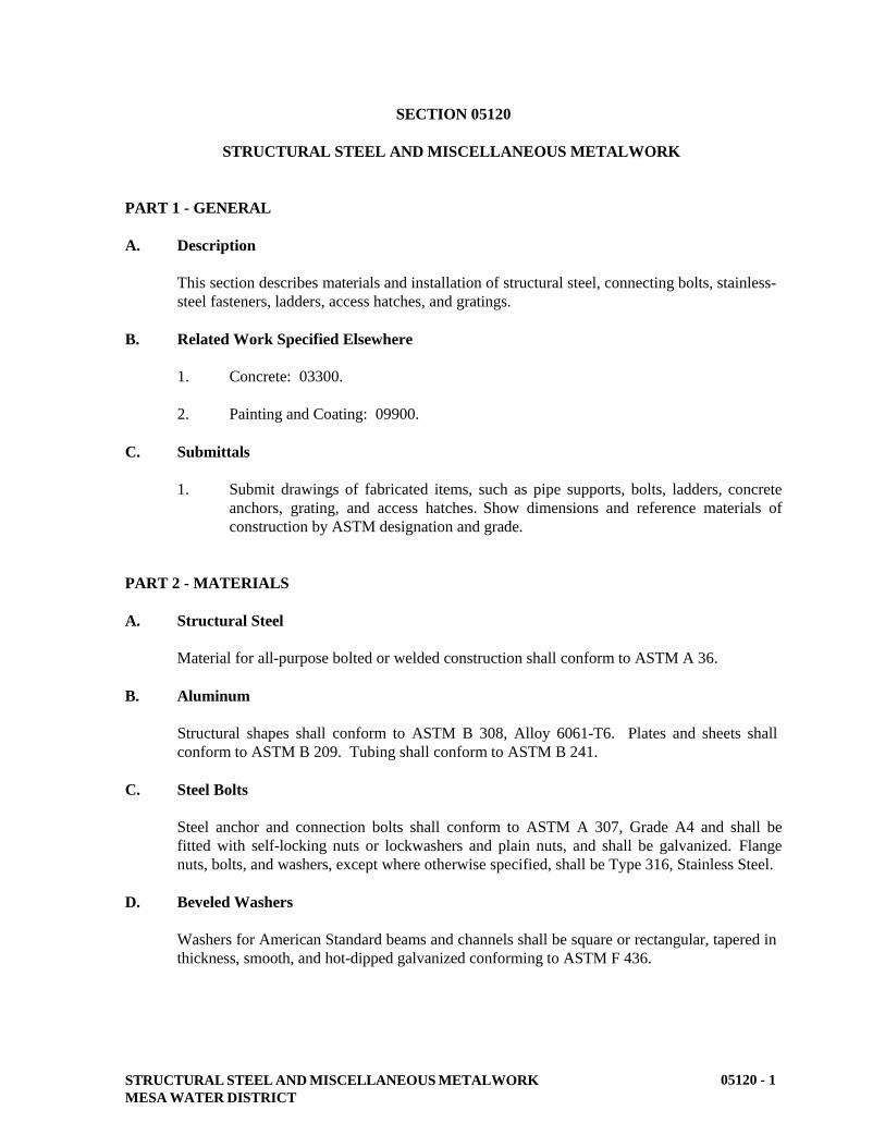
STRUCTURAL STEEL AND MISCELLANEOUS METALWORK
MESA WATER DISTRICT
05120 - 1
SECTION 05120
STRUCTURAL STEEL AND MISCELLANEOUS METALWORK
PART 1 - GENERAL
A. Description
This section describes materials and installation of structural steel, connecting bolts, stainless-
steel fasteners, ladders, access hatches, and gratings.
B. Related Work Specified Elsewhere
1. Concrete: 03300.
2. Painting and Coating: 09900.
C. Submittals
1. Submit drawings of fabricated items, such as pipe supports, bolts, ladders, concrete
anchors, grating, and access hatches. Show dimensions and reference materials of
construction by ASTM designation and grade.
PART 2 - MATERIALS
A. Structural Steel
Material for all-purpose bolted or welded construction shall conform to ASTM A 36.
B. Aluminum
Structural shapes shall conform to ASTM B 308, Alloy 6061-T6. Plates and sheets shall
conform to ASTM B 209. Tubing shall conform to ASTM B 241.
C. Steel Bolts
Steel anchor and connection bolts shall conform to ASTM A 307, Grade A4 and shall be
fitted with self-locking nuts or lockwashers and plain nuts, and shall be galvanized. Flange
nuts, bolts, and washers, except where otherwise specified, shall be Type 316, Stainless Steel.
D. Beveled Washers
Washers for American Standard beams and channels shall be square or rectangular, tapered in
thickness, smooth, and hot-dipped galvanized conforming to ASTM F 436.
STRUCTURAL STEEL AND MISCELLANEOUS METALWORK
MESA WATER DISTRICT
05120 - 2
E. Galvanizing
Zinc coating for all plates, bolts, anchor bolts, and threaded parts shall be hot-dipped coated
in accordance with ASTM A 153. Structural steel and pipe shall be zinc coated in accordance
with ASTM A 123.
F. Stainless Steel
Except where otherwise specified, stainless steel plate, members, and washers shall be Type
316, ASTM A 167. Bolts shall be ASTM A 193, Grade B8M. Nuts shall be ASTM A 194,
Grade 8M.
G. Welding Electrodes
Welding electrodes for structural steel shall conform to AWS A5.5. Use electrodes in the E-
70 series. Welding electrode for aluminum shall be 4043 filler metal and Type 347 electrode
for stainless steel.
H. Ladders
1. General: Ladders shall be fabricated as shown on the drawings and shall comply with
OSHA Safety Standards. Ladders shall be of welded steel construction and
galvanized after fabrication or stainless steel where indicated on the drawings.
2. Safety Devices: When indicated on the plans, a safety climb device (ladder fall
prevention device) shall be provided, consisting of a SAF-T-NOTCH rail, standard
attaching parts, SAF-T-LOK sleeve, SAF-T-CLIMB removable extension, and two
complete safety belt assemblies. The device shall comply with OSHA requirements
and shall be SAF-T-CLIMB as manufactured by Air Space Devices Norton Co.,
Paramount, California, or approved equal. All safety climb device assemblies and
parts shall be fabricated of Type 316 stainless steel.
3. Side-rail Extensions: All ladders shall have side-rail extensions fabricated onto the
ladder.
I. Concrete Anchors
Drilled anchors shall be Type 316, stainless steel wedge anchors, unless otherwise indicated,
as manufactured by Phillips Drill Company, or approved equal. Where steel anchors are
indicated, they shall be one-piece design with expander ring consisting of steel zinc coated
and chrome plated as manufactured by McCullough Industries, Inc., Kwik Bolt, or approved
equal.
J. Access Hatches
Hatches may be of aluminum or stainless steel construction, as called for and specified on the
project plans. In general aluminum hatches may be used in applications of parkway loading
(i.e., low-volume traffic with H-5 loading), and where a severe corrosion environment is not
present. In every case, hinges, hardware and all threaded pieces and connectors shall be Type
316 stainless steel.

STRUCTURAL STEEL AND MISCELLANEOUS METALWORK
MESA WATER DISTRICT
05120 - 3
Aluminum or stainless steel access hatches shall be of the size and type indicated on the
drawings. Hardware shall be 316 stainless steel and shall include but not be limited to hinges,
hold-open arms, springs, and spring covers. Hatches shall be equipped with extruded
aluminum or stainless steel channel trough frames with 1-1/2 inch drain coupling, flush
aluminum or stainless steel drop handles which do not protrude above the cover, a recessed
padlock box and stainless steel staple sized for a No. 6 padlock, and shall be as manufactured
by BILCO, U. S. Foundry, INRYCO, or approved equal.
K. Grating
Unless noted otherwise, grating shall be aluminum. Main bars shall be of the size and
thickness indicated on the drawings.
PART 3 - EXECUTION
A. Fabrication and Erection
1. General: Miscellaneous metal items shall be fabricated to straight lines and true
curves. Drilling and punching shall not leave burrs or deformations. Permanent
connections shall be welded continuously along the entire area of contact. Exposed
work shall have a smooth finish with welds ground smooth. Joints shall have a close
fit with corner joints coped or mitered and shall be in true alignment. Unless
specifically indicated, there shall be no bends, twists, or open joints in any finished
member nor any projecting edges or corners at intersections. Fastenings shall be
concealed wherever possible. Built-up parts shall be free of warp. Exposed ends and
edges of metal shall be slightly rounded. All boltholes shall be 1/16-inch in diameter
larger than bolt size. Cast-in-place bolt locations shall be measured in the field before
drilling companion holes in structural steel beam or assembly.
2. Surfaces in Contact with Concrete: Surfaces of metalwork to be in contact with
concrete shall be cleaned of rust, dirt, grease, and other foreign substances before
placing concrete.
3. Embedded Metalwork: Embedded metalwork shall be set accurately in position when
concrete is placed and supported rigidly to prevent displacement or undue vibration
during or after the placement of concrete. Unless otherwise specified, where
metalwork is to be installed in recesses in formed concrete, said recesses shall be
made, metalwork installed, and recesses filled with dry-pack mortar in conformance
with Section 03300 (Concrete).
B. Ladders
Ladder rungs shall have a minimum diameter of 3/4-inch. The distance between rungs, cleats,
and steps shall not exceed 12-inches and shall be uniform throughout the length of the ladder.
The minimum clear length of rungs or cleats shall be 16-inches. Ladders shall be mounted to
provide clearance in back of ladder so that the distance from the centerline of rungs, cleats, or
steps to the nearest permanent object in back of the ladder shall be not less than 7-inches.

STRUCTURAL STEEL AND MISCELLANEOUS METALWORK
MESA WATER DISTRICT
05120 - 4
C. Common Machine Bolts and Nuts
1. General: Bolts shall be inserted accurately into the boltholes without damaging the
thread. Boltheads shall be protected from damage during driving. Boltheads and nuts
shall rest squarely against the metal. Where bolts are to be used on beveled surfaces
having slopes greater than 1 in 20 with a plane normal to the bolt axis, beveled
washers shall be provided to give full bearing to the head or nut. Where self-locking
nuts are not furnished, bolt threads shall be upset to prevent the nuts from backing
off.
2. Bolt Insertion: Bolts shall be of the length that will extend entirely through but not
more than 1/4-inch beyond the nuts. Boltheads and nuts shall be drawn tight against
the work. Boltheads shall be tapped with a hammer while the nut is being tightened.
After having been finally tightened, the nuts shall be locked.
D. Anchor Bolts and Anchors
1. General: Bolts and anchors shall be preset by the use of templates. Concrete anchors
shall not be used where cast-in-place anchor bolts are called for.
2. Protection of Anchor Bolts: After anchor bolts have been embedded, bolt threads
shall be protected by applying grease and be having the nuts screwed on until the time
of installation of the equipment or metalwork.
E. Control of Flame Cutting
The use of a gas-cutting torch in the field for correcting fabrication errors on any member in
structural framing shall not be permitted. A flame-cutting torch shall be used only on minor
members, when the member is not under stress.
F. Repair of Galvanized Surfaces
Damaged galvanized metal surfaces shall be repaired or replaced at no additional cost to the
District. Repair of galvanized surfaces shall be accomplished by use of DRYGALV as
manufactured by the American Solder and Flux Company; Cold Galvanizing Repair
Compound as manufactured by Rust-Oleum, applied in accordance with the manufacturer's
instructions; or approved equal.
G. Storage of Materials
All material, either plain or fabricated, shall be stored above ground on platforms, skids, or
other supports. Material shall be kept free from dirt, grease, and other foreign matter and
protect from corrosion.
H. Welding
1. Steel: Welding of steel shall be performed by the Shielded Metal Arc Welding
(SMAW) process. Welding procedures shall comply with AWS D1.1.

STRUCTURAL STEEL AND MISCELLANEOUS METALWORK
MESA WATER DISTRICT
05120 - 5
2. Aluminum: Welding of aluminum shall be performed by the Gas Metal Arc (MIG) or
Gas Tungsten Arc (TIG) process, per the AWS Welding Handbook.
I. Grating
1. Measurement: Grated areas shall be field measured for proper size.
2. Banding: Grating shall be completely banded.
3. Grating Angles: Seat angles for grating shall be set so that the top of the vertical leg
is flush with the concrete floor. Seat angles and anchors shall be stainless steel.
J. Corrosion Protection
Aluminum surfaces that are in contact with or embedded in concrete shall be coated in
accordance with Section 09900 (Painting and Coating). Coating shall be allowed to dry
before placing in or against concrete.
END OF SECTION
PAINTING AND COATING
MESA WATER DISTRICT
09900 - 1
SECTION 09900
PAINTING AND COATING
PART 1 - GENERAL
A. Description
This section describes materials and application of painting and coating systems for
submerged metal surfaces, exposed metal surfaces, buried metal surfaces, and metal surfaces
in contact with concrete, submerged concrete, exposed PVC, and valve interiors.
Coating thicknesses specified herein are given as “dry-film thickness” in mils. Mil
thicknesses specified are minimums.
B. Related Work Specified Elsewhere
1. Structural Steel and Miscellaneous Metalwork: 05120.
2. Cement-Mortar Lined and Coated Steel Pipe: 15076.
3. Air Release and Vacuum Relief Valves: 15089.
4. Manual Valves: 15100.
5. Fire Hydrants: 15139.
6. Flexible Pipe Couplings and Expansion Joints: 15162.
7. Cathodic Protection and Joint Bonding: 16640
C. Submittals
1. Submit manufacturer's data sheets showing the following information:
a. Recommended surface preparation.
b. Minimum recommended dry-film thicknesses per coat for prime,
intermediate, and finish coats.
c. Percent solids by volume.
d. Recommended thinners.
e. Statement that the selected prime coat is recommended by the manufacturer
for use with the selected intermediate and finish coats.
f. Application instructions including recommended application, equipment,
humidity, and temperature limitations.

PAINTING AND COATING
MESA WATER DISTRICT
09900 - 2
g. Submit the Material Data Sheets (MSDS) for each coating material.
h. For all coatings that will be in contact with potable water, provide a
certification or statement that the coating is NSF 61 certified.
3. Submit certification that all coatings conform to South Coast Air Quality
Management District Rules and Regulations for products and application.
D. Air Quality Requirements
Materials shall comply with South Coast Air Quality Management District’s Rule 1107 for
shop coating and Rule 1113 for field coating.
E. Painting Systems
All paints shall be delivered to the jobsite in the original, unopened containers. All materials
of a specified painting system, including primer, and finish coats, shall be produced by the
same manufacturer. Thinners, cleaners, driers, and other additives shall be as recommended
by the paint manufacturer for the particular coating system.
PART 2 - MATERIALS
A. Color System for Coatings and Coating System Summary
Unless noted otherwise, colors for surfaces that are to be coated shall be defined as follows:
Color
Pantone ID No.
(closest match in sunlight)
Amershield Color Designation
Dark Blue 2776 C Newport Coast #33
Olive Light 451 C PMS 451 C
Purple 512 C PMS 512 C
Safety Red 485 C 2X RO-1 Bright Red
Safety Yellow U2X Safety Yellow
White (Fire Hydrant) -- --
Factory Finish N/A No Color Coating
The following table provides a summary of the coating systems and the various surfaces to be
coated:
Application (Potable or Recycled) Coating System No.
Public Fire Hydrants (Potable) A-1
Submerged Metal (Potable) B-2
Submerged Metal (Recycled) B-1

PAINTING AND COATING
MESA WATER DISTRICT
09900 - 3
Exposed Metal (Both)
Application (Utility)
C-1 and C-2
Coating System No.
Buried Metal (Both) D-1
Metal in Contact with Concrete (Both) E-1
Exposed PVC (Both) F-1
Valves (Both) G-1 and G-2
B. Specialty Items
Surfaces shall be coated as described below:
1. Valve Can and Test Box Lids: Valve can and test box lids shall be coated per System
C-2.
2. Buried Items: Buried flanges, nuts and bolts, valves, flexible pipe couplings, exposed
rebar from thrust blocks, and valve boxes shall be coated per System No. D-1 unless
otherwise specified in the particular specifications for these items.
3. Above Ground Structural Steel and Structural Steel in Vaults: Above ground
structural steel or structural steel located in vaults and steel structures shall be coated
as described in the exposed metal coating system section.
4. Pipe Supports: All non-galvanized and non-stainless steel pipe supports in vaults
shall be coated the same as the adjacent piping. If pipe is PVC, pipe supports shall be
coated per System No. C-1.
C. Public Fire Hydrant Coating Systems
1. System No. A-1 -– Public Fire Hydrants
a. Type: Water-based low Volatile Organic Compound (VOC) acrylic coating.
Thinners, cleaners, driers, and other additives shall be as recommended by
the paint manufacturer. A total dry-film consisting of the combined thickness
of both a prime coat and finish coat is described herein. The total dry-film
thickness of this system shall be 5 mils.
b. Surface preparation: Remove oil, grease, and chalking. Abrade existing
paint and visible rust areas. Do not sandblast or prepare more surface area
than can be coated in one day. Surface preparation shall conform to the
Society of Protective Coatings (SSPC) specifications: SP-1 Solvent Tool
Cleaning; SP-2 Hand Tool Cleaning; and SP-3 Power Tool Cleaning.
c. Color: White Frazee Gloss Enamel MIRRO GLIDE GLOSS.
d. Prime Coat: Apply to a dry-film thickness of 2 to 3 mils. Primer shall be
synthetic. Approved manufacturers for previously paint surfaces include:
Carboline Carbocrylic 120; Sherwin Williams Zero VOC Acrylic; Tnemec
PAINTING AND COATING
MESA WATER DISTRICT
09900 - 4
Series 1028 Enduratone; International/Devoe Devflex 4216 HP; or approved
equal.
e. Finish Coat: Apply to a dry-film thickness of 3 to 4 mils. Approved
manufacturers for finish coats include: Carboline Carbocrylic 3359 MC;
Sherwin Williams Zero VOC Acrylic; Tnemec Series 1028 Enduratone;
International/Devoe Devflex 4216 HP; or approved equal.
D. Submerged Metal and Concrete Coating Systems
1. System No. B-1--Submerged Metal, Recycled
Type: Two part low VOC epoxy-polyamide. A total dry-film consisting of the
combined thickness of both a prime coat and finish coat is described herein. The total
dry-film thickness of this system shall be 20 mils.
Service Conditions: Shall be used on metal structures, pipes, or equipment including,
but not limited to tanks, slide gates and other miscellaneous metal exposed to
recycled water.
Surface Preparation: SSPC SP-10
Prime Coat: Apply to a dry-film thickness of 8 mils. Approved manufacturers for
prime coat include: PPG Ameron Amerlock VOC; Carboline Carboguard 890 VOC;
Tnemec Series L69 Hi-build Epoxoline II; International/Devoe 233H; or approved
equal.
Finish Coats: Apply two coats, each with a 6 mil dry-film thickness to achieve the
total dry-film thickness. The coating material shall be the same material as the prime
coat.
2. System No. B-2--Submerged Metal, Potable Water
Type: Two part low VOC epoxy-polyamide, or two-part amido-amine epoxy. A total
dry-film consisting of the combined thickness of both a prime coat and finish coat is
described herein. The total dry-film thickness of this system shall be 15 mils. Coating
shall be NSF 61 approved.
Service Conditions: Shall be used on surfaces including, but not limited to, structural
steel, tank interiors and piping exposed to potable water.
Surface Preparation: SSPC SP-10
Prime Coat: Apply to a dry-film thickness of 5 mils. Approved manufacturers for
prime coat include: PPG Ameron Amerlock VOC; Tnemec Series L140F Pota Pox;
Sherwin Williams Macropoxy 646-100PW; International/Devoe 233H; or approved
equal.
Finish Coats: Apply two coats, each with a 5 mil dry-film thickness, to achieve the
total dry-film thickness. The coating material shall be the same material as the prime
coat.
PAINTING AND COATING
MESA WATER DISTRICT
09900 - 5
E. Exposed Metal Coating Systems
1. System No. C-1--Exposed Metal, Severely Corrosive Environment
Type: Low VOC Inorganic zinc prime coat with low VOC epoxy-polyamide finish
coat. A total dry-film consisting of the combined thickness of both a prime coat and
finish coat is described herein. The total dry-film thickness of this system shall be 12
mils.
Service Conditions: Shall be used on metal surfaces including, but not limited to,
structures, piping, fittings, and appurtenances subjected to continuous water
condensation, occasional immersion or splashing. Below grade vaults shall be
considered as severely corrosive environments.
Surface Preparation: Surface preparation shall be SSPC SP-10 for steel surfaces.
Surface preparation shall be NAPF 500-03-05 Clean No. 2 for ductile iron or cast iron
surfaces.
Prime Coat: Apply to a dry-film thickness of 3 mils. For ductile iron surfaces, the
ductile iron shall have an asphaltic free surface with a factory applied prime coat the
same as the finish coat. For all other surfaces, a two-component inorganic zinc rich
primer shall be used with a minimum zinc content of 14 pounds per gallon. Approved
zinc primer manufacturers include: Ameron Amercoat 68HS VOC; Tnemec Series
94-H20 Hydro-zinc; International/Devoe Cathacoat 302V; Sherwin Williams Zinc
Clad XI; Carboline Carbozinc 11; or approved equal.
Finish Coats: Apply two coats, each with a 4 to 5 mil dry-film thickness, to achieve
the total dry-film thickness. Approved manufacturers include: Ameron Amerlock
VOC; Tnemec Series L69 Hi-build Epoxoline II; International/Devoe Devran 224 HS
VOC; Sherwin Williams Macropoxy 646-100; Carboline Carboguard 890 VOC; or
approved equal.
2. System No. C-2--Exposed Metal, Atmospheric Weathering Environment
Type: Low VOC Aliphatic Polyurethane with low VOC epoxy-polyamide or amino-
amine epoxy primer. A total dry-film consisting of the combined thickness of both a
prime coat and finish coat is described herein. The total dry-film thickness of this
system shall be 8 mils.
Service Conditions: Shall be used on metal surfaces including, but not limited to,
structures, piping, fittings, and appurtenances subjected to atmospheric elements and
weathering.
Surface Preparation: Surface preparation shall be SSPC SP-6 for steel surfaces.
Surface preparation shall be NAPF 500-03-05 Clean No. 2 for ductile iron or cast iron
surfaces. Surface preparation shall be SSPC SP-1 for galvanized surfaces and shall
be brush blasted or acid etched surface prior to application of prime coat.
PAINTING AND COATING
MESA WATER DISTRICT
09900 - 6
Prime Coat: Apply one or two coats to a dry-film thickness of 5 mils.
For ductile iron surfaces, the ductile iron shall have an asphaltic free surface with a
factory applied prime coat the same as the finish coat. Approved manufacturers
include: Ameron Amerlock VOC; Tnemec Series 135 Chembuild with low VOC
thinner or L69 Epoxyline; Sherwin Williams Macropoxy 646-100;
International/Devoe BarRust 231; Carboline Carboguard 890 VOC; or approved
equal.
Finish Coats: Apply one coat to a dry-film thickness of 3 mils to achieve the total dry-
film thickness. Approved manufacturers include: Ameron Amershield VOC;
Tnemec Series 1080 Endura-shield; International/Devoe Devthane 379; Sherwin
Williams Hi-Solids Polyurethane 100; Carboline Carbothane 134 MC; or approved
equal.
F. Buried Metal Coating Systems
1. System No. D-1--Buried Metal
Type: Low VOC epoxy coating. A total dry-film consisting of the combined
thickness of both a prime coat and finish coat is described herein. The total dry-film
thickness of this system shall be 24 mils.
Service Conditions: Shall be used to coat buried metal including, but not limited to,
valves, flanges, bolts and nuts, fittings, flexible pipe couplings, and structural steel.
Surface Preparation: SSPC SP-10.
Prime Coat: Apply to a dry-film thickness of 8 mils. Approved manufacturers
include: Ameron Amerlock VOC; Tnemec Series L69F; International/Devoe BarRust
231; Carboline Carboguard 890 VOC; or approved equal.
Finish Coats: Apply two coats, each with an 8 mil dry-film thickness, to achieve the
total dry-film thickness. The coating material shall be the same material as the prime
coat.
G. Coating System for Metal in Contact with Concrete
1. System No. E-1--Aluminum and Galvanized Surface in Concrete
Type: Low VOC epoxy coating. A total dry-film consisting of the combined
thickness of both a prime coat and finish coat is described herein. The total dry-film
thickness of this system shall be 15 mils.
Service Conditions: Shall be used to coat buried areas including, but not limited to,
gates, stairs, or structural members in contact with concrete.
Surface Preparation: Apply synthetic resin wash primer (phosphoric acid or vinyl
butyral acid) to surface. Surface preparation shall comply with SSPC SP-1.
Prime Coat: Apply to a dry-film thickness of 5 mils.

PAINTING AND COATING
MESA WATER DISTRICT
09900 - 7
Approved manufacturers include: Ameron Amerlock VOC; Tnemec Series L69F;
International/Devoe BarRust 231; Carboline Carboguard 890 VOC; or approved
equal.
Finish Coats: Apply two coats, each with a 5 mil dry-film thickness, to achieve the
total dry-film thickness. The coating material shall be the same material as the prime
coat.
H. PVC Pipe Coating System
1. System No. F-1--Exposed PVC Pipe, Atmospheric Weathering Environment
Type: Low VOC Aliphatic Polyurethane with low VOC epoxy-polyamide primer. A
total dry-film consisting of the combined thickness of both a prime coat and finish
coat is described herein. The total dry-film thickness of this system shall be 6 mils.
Service Conditions: Shall be used to coat PVC piping exposed to atmospheric
elements and weathering.
Surface Preparation: Surface shall be cleaned and dried prior to application of
coating.
Prime Coat: Apply one coat to a dry-film thickness of 3 mils. Approved
manufacturers include: Ameron Amerlock VOC; Tnemec Series 135 Chembuild with
low VOC thinner or L69 Epoxyline; Sherwin Williams Macropoxy 646-100;
International/Devoe BarRust 231; Carboline Carboguard 890 VOC; or approved
equal.
Finish Coats: Apply one coat to a dry-film thickness of 3 mils to achieve the total dry-
film thickness. Approved manufacturers include: Ameron Amershield VOC;
Tnemec Series 1080 Endura-shield; International/Devoe Devthane 379; Sherwin
Williams Hi-Solids Polyurethane 100; Carboline Carbothane 134 MC; or approved
equal.
I. Valve Coating System
1. System No. G-1--Surface of Ferrous-Metal Valves
Type: Thermosetting powdered epoxy coating.
Service Conditions: Shall be used to coat interior surfaces of ferrous metal valves,
excluding seating areas and bronze and stainless steel pieces.
Surface Preparation: Protuberances which may produce pinholes in the coating shall
be removed. Sharp edges shall be rounded. Surface contaminants which may prevent
bonding of the coating shall be removed. Surface preparation shall comply with
SSPC SP-5.

PAINTING AND COATING
MESA WATER DISTRICT
09900 - 8
Coating: Apply to a dry-film thickness of 12 mils in accordance with manufacturer's
recommendation.
Approved manufacturers include: 3M Scotchkote 134; or approved equal.
2. System No. G-2 – Surfaces of Ferrous-Metal Valves (Alternative)
General: This is an alternative to System No. G-1 when specified in the Technical
Specifications.
Type: Two part low VOC epoxy-polyamide coating. A total dry-film consisting of
the combined thickness of both a prime coat and finish coat is described herein. The
total dry-film thickness of this system shall be 15 mils. Coating shall be NSF 61
approved.
Service Conditions: Shall be used to coat interior surfaces of ferrous metal valves,
excluding seating areas and bronze and stainless steel pieces.
Surface Preparation: Protuberances which may produce pinholes in the coating shall
be removed. Sharp edges shall be rounded. Surface contaminants which may prevent
bonding of the coating shall be removed. Surface preparation shall comply with
SSPC SP-10.
Prime Coat: Apply to a dry-film thickness of 5 mils in accordance with
manufacturer’s recommendation. Approved manufacturers include: Ameron
Amerlock VOC; Tnemec Series L140F Pota Pox; Sherwin Williams Macropoxy 646-
100PW; International/Devoe 233H; or approved equal.
Finish Coats: Apply two coats, each with a 5 mil dry-film thickness, to achieve the
total dry-film thickness. The coating material shall be the same material as the prime
coat.
PART 3 - EXECUTION
A. General
1. Quality assurance procedures and practices shall be utilized to monitor all phases of
surface preparation, application, and inspection throughout the duration of the
project. Procedures or practices not specifically defined herein may be utilized
provided they meet recognized and acceptable professional standards and are
approved by Mesa Water.
2. Worked accomplished in the absence of prescribed inspection may be required to be
removed and replaced under the proper inspection, and the entire cost of removal and
replacement, including the cost of all materials, shall be borne by the contractor,
regardless of whether the work removed is found to be defective or not. Work
covered up within the authority of Mesa Water, shall, upon order of Mesa Water, be
uncovered to the extent required, and the contractor shall similarly bear the entire cost
PAINTING AND COATING
MESA WATER DISTRICT
09900 - 9
of accomplishing all the work and furnishing all the materials necessary for the
removal of the covering and its subsequent replacement, as directed and approved by
Mesa Water.
3. Mesa Water will make, or have made, such tests as it deems necessary to assure the
work is being accomplished in accordance with the requirements of the specifications.
Unless otherwise specified, the cost of such testing will be borne by Mesa Water. In
the event such tests reveal non-compliance with the requirements of the
specifications, the contractor shall bear the cost of such corrective measures deemed
necessary by Mesa Water, as well as the cost of subsequent retesting and re-
inspection. Tests shall not constitute an acceptance of any portion of the work, nor
relieve the contractor from compliance with the terms of the specifcations.
4. Application: No coating shall be applied under the following conditions:
a. When the surrounding air temperature or the temperature of the surface to be
coated or painted is below 55° F for epoxy coatings, below 45° F for epoxy
low temperature cure coatings, or above 125° F for all materials;
b. To wet or damp surfaces or in rain, snow, fog or mist;
c. When the air temperature is less than 5° F above the dew point;
d. When it is expected the air temperature will drop below 55° F for epoxy
coating; or 45° F for epoxy low temperature cure coatings; or less than 5° F
above the dew point within two hours after application of coating or paints.
5. Overspray and Dust Control: The contractor shall conduct all operations so as to
confine abrasive blasting debris and coating and paint overspray to within the bounds
of the site. The contractor shall take all precautions necessary to prevent adverse off-
site consequences of application operations.
6. Inspection Devices: Contractor shall furnish, until final acceptance of coatings and
paints, inspection devices in good working condition for detection of holidays and
measurement of dry-film and wet-film thickness. Dry film thickness gauges and
holiday detectors shall be available at all times until final acceptance of application.
Inspection devices shall be operated by, or in the presence of Mesa Water
Representative with location and frequency basis determined by Mesa Water.
7. All surface preparation, coating and paint application shall conform to applicable
standards of the SSPC, Mesa Water’s Representative and the manufacturer’s printed
instructions. Material applied prior to approval of the surface, by Mesa Water’s
Representative, shall be removed and reapplied to the satisfaction of Mesa Water at
the expense of the contractor.
8. All work shall be accomplished by skilled craftsman qualified to accomplish the
required work in a manner comparable with the best standards of practice.
9. The contractor shall provide a supervisor to be at the work site during cleaning and
application operations.

PAINTING AND COATING
MESA WATER DISTRICT
09900 - 10
10. The contractor’s equipment shall be designed for application of materials specified
and shall be maintained in first class working condition.
Compressors shall have suitable traps and filters to remove water and oils from the
air. Blotter test shall be accomplished at each start-up period and as deemed
necessary by Mesa Water.
11. Because of presence of moisture and possible contaminants in the atmosphere, care
shall be taken to ensure previously coated or painted surfaces are protected or re-
cleaned prior to application of subsequent coat(s). Methods of protection and re-
cleaning shall be approved by Mesa Water.
B. Surface Preparation
1. General: Sandblast or prepare only as much surface area as can be coated in one day.
All sharp edges, burrs, and weld spatter shall be removed. Epoxy-coated pipe that has
been factory coated shall not be sandblasted.
2. SSPC Specifications: Wherever the words "solvent cleaning," "hand tool cleaning,"
"wire brushing," or "blast cleaning" or similar words are used in these specifications
or in paint manufacturer's specifications, they shall be understood to refer to the
applicable SSPC (Steel Structures Painting Council, Surfaces Preparation
Specifications, ANSI A159.1) specifications listed below:
SP-1 Solvent Cleaning
SP-2 Hand Tool Cleaning
SP-3 Power Tool Cleaning
SP-5 White Metal Blast Cleaning
SP-6 Commercial Blast Cleaning
SP-7 Brush-Off Blast Cleaning
SP-8 Pickling
SP-10 Near White Blast Cleaning
3. The contractor shall provide suitable enclosure, exhaust system, and bag house for
sandblasting operations to prevent violations of applicable air quality requirements.
4. Surface preparation shall be based upon comparison with “Pictorial Surface
Preparation Standards for Painting Steel Surfaces”, SSPC-Vis 1, ASTM Designatio
D2200, NACE Standard TM-01-70. Anchor profile for prepared surfaces shall be
measured by using a non-destructive instrument such as a K-T Surface Profile
Comparator or Testex Press-O-Film System. Temperature and dew point
requirements shall apply to all surface preparation operations.
5. Dust, dirt, oil, grease or any foreign matter which will affect the adhesion or
durability of the finish must be removed by washing with clean rags dipped in an
approved commercial cleaning solution, rinsed with clean water and wiped dry with
clean rags. Abrasive blasting nozzles shall be equipped with “deadman” emergency
shut-off nozzles. Blast nozzle pressure shall be a minimum of 95 psi and shall be
verified by using an approved nozzle pressure gauge at each start-up period or as
directed by Mesa Water Representative.
PAINTING AND COATING
MESA WATER DISTRICT
09900 - 11
6. All blast hose connections shall be tethered and secured to prevent separation during
blast cleaning operations, and shall be taped with duct tape prior to pressurizing.
All taped connections shall be visually inspected for leaks within five minutes after
start of blast cleaning operations and at the end of blast cleaning operations.
7. Particle size of abrasives used in blast cleaning shall be that which will produce a 2
mil surface profile or in accordance with recommendations of the manufacturer of the
specified coating system to be applied.
8. Abrasive used in blast cleaning operation shall be new, washed, graded and free of
contaminants which would interfere with adhesion of coatings and shall not be reused
unless specifically approved by Mesa Water. Abrasives shall be certified for
unconfined dry blasting pursuant to the California Administrative Code, Section
92520 of Subchapter 6, Title 17, and shall appear on the current listing of approved
abrasives.
9. During blast cleaning operations, caution shall be exercised to ensure existing
coatings and paint are not exposed to abrasion from blast cleaning.
10. Blast cleaning from rolling scaffolds shall only be accomplished within confines of
interior perimeter of scaffold. Reaching beyond limits of perimeter will be allowed
only if blast nozzle is maintained in a position which will produce a profile
acceptable to Mesa Water’s Representative.
11. The contractor shall keep the area of his work in a clean condition and shall not
permit blasting materials to accumulate as to constitute a nuisance or hazard to the
prosecution of the work or the operation of the existing facilities. Spent abrasives
and other debris shall be removed at the contractor’s expense as directed by Mesa
Water.
12. Blast cleaned and coated/painted surfaces shall be cleaned prior to application of
specified coatings/paints via a combination of blowing with clean dry air,
brushing/brooming and/or vacuuming as directed by Mesa Water’s Representative.
Air hose for blowing shall be at least ½-inch in diameter and shall be equipped with a
shut-off device. Tests on surfaces of abrasively blast cleaned steel shall be
accomplished to detect oil and other contaminants which might be deposited on
surfaces. This will include chemical tests or ultraviolet (black light) tests, as
required.
C. Application
1. Multiple-component coatings shall be prepared using all the contents of each
component container as packaged by the paint manufacturer. Partial batches shall not
be used. Multiple-component coatings shall have been mixed beyond their pot life
shall not be used. Small quantity kits for touch-up painting and for painting other
small areas shall be provided. Only the components specified and furnished by the
paint manufacturer shall be mixed. For reasons of color or otherwise, additional
components shall not be intermixed even with the same generic type of coating.
PAINTING AND COATING
MESA WATER DISTRICT
09900 - 12
2. Application of the first coat shall follow immediately after surface preparation and
cleaning within an eight hour working day. Any cleaned areas not receiving first coat
within an eight hour period shall be re-cleaned prior to application of first coat.
3. Coating and paint application shall conform to the requirements of the Society of
Protective Coating Paint Application Specification SSPC-PA1, latest revision, for
“Shop, Field and Maintenance Painting”, Mesa Water, the manufacturer of the
coating and painting materials printed literature and as specified herein.
4. All coating components shall be mixed in exact proportions specified by the
manufacturer. Care shall be exercised to ensure all material is removed from
containers during mixing and metering operations.
5. All coatings shall be thoroughly mixed, utilizing an approved slow-speed power
mixer until all components are thoroughly combined and are of a smooth consistency.
6. Thinning shall only be permitted as recommended by the manufacturer and approved
by the Mesa Water’s Representative and shall not exceed limits set by applicable
regulatory agencies. If the contractor applies any materials which have been modified
or thinned to such a degree as to cause them to exceed established VOC levels, the
contractor shall be responsible for any fines, costs, remedies, or legal action and costs
that may result.
7. Each application of coating or paint shall be applied evenly, free of brush marks,
sags, runs and no evidence of poor workmanship. Care should be exercised to avoid
lapping on glass or hardware. Coatings and paints shall be sharply cut to lines.
Finished surfaces shall be free from defects or blemishes.
8. Protective coverings or drop cloths shall be used to protect floors, fixtures,
equipment, prepared surface and applied coatings or paints. Care shall be exercised
to prevent coating or paint from being spattered onto surfaces which are not to be
coated or painted. Surfaces from which such material cannot be removed
satisfactorily shall be refinished.
9. All welds and irregular surfaces specified by Mesa Water shall receive a brush coat of
the specified product prior to application of each coat. Coating shall be brushed in
multiple directions to ensure penetration and coverage. Care shall be exercised to
ensure dry film thickness of coatings and paints do not exceed the maximum
thickness allowed by the manufacturer of the specific product being applied.
10. At the conclusion of each day’s blast cleaning and coating operations, a 6-inch wide
strip of blast cleaned substrate shall remain uncoated to facilitate locating point of
origin for successive day’s blast cleaning operations.
11. Epoxy coated surfaces or other multi-component materials exposed to excessive
sunlight or an excessive time element beyond manufacturer’s recommended recoat
cycle, shall be scarified by Brush-Off Blast Cleaning (SSPC SP-7), prior to
application of additional coating or paint. Scarified coating or paint shall have
sufficient depth to assure a mechanical bond of subsequent coat.

PAINTING AND COATING
MESA WATER DISTRICT
09900 - 13
12. When two or more coats are specified, where possible, each coat shall contain
sufficient approved color additive to act as an indicator of coverage or the coats must
be of contrasting color.
13. Care shall be exercised during spray operations to hold the spray nozzle perpendicular
and sufficiently close to surfaces being coated, to avoid excessive evaporation of
volatile constituents and loss of material into the air or the bridging of cracks and
crevices. Reaching beyond limits of scaffold perimeter shall not be permitted. All
overspray identified by Mesa Water’s Representative shall be removed by hand or
pole sanding prior to application of subsequent coat.
D. Surfaces Not To Be Painted
Unless noted otherwise, the following surfaces shall not be painted and shall be fully
protected when adjacent areas are painted.
1. Mortar-coated pipe and fittings.
2. Stainless Steel surfaces.
3. Aluminum guardrails and handrails.
4. Galvanized pipe supports and ladders.
5. Nameplates and grease fittings.
6. Brass and copper tubing.
7. Aluminum grating.
E. Protection of Surfaces Not To Be Painted
Hardware, lighting fixtures, switch plates, aluminum surfaces, machined surfaces, couplings,
shafts, bearings, nameplates on machinery, and other surfaces not intended to be painted shall
be removed, masked, or otherwise protected. Drop cloths shall be provided to prevent paint
materials from falling on or marring adjacent surfaces. Working parts of mechanical and
electrical equipment shall be protected from damage during surface preparation and painting
process. Openings in motors shall be safely masked to prevent paint and other materials from
entering the motors. All masking materials shall be completely removed and surfaces cleaned
at completion of painting operations.
F. Color Schedule
1. Color Guidelines: Unless noted otherwise, surfaces that are to be coated and which
require a color designation for any of the following uses, shall be coated to match the
colors listed below. Final color selection shall be determined by Mesa Water.
2. Definitions:

PAINTING AND COATING
MESA WATER DISTRICT
09900 - 14
At Grade: Facilities that are flush with streets, sidewalks, parking lots, green belts or
graded areas. This also includes pipelines and other facilities that are protruding
through and are located above finish grade, out of doors and not enclosed by a shelter,
cover, vault or housing.
Enclosed: Pipeline and other facilities that are located above or below grade and are
enclosed within a shelter, covers, or vaults.
N/A: Not Applicable.
I.D. Mark: System identification marker as described herein. The I.D. Mark shall
identify the system of which the facility is a part.
3. Potable Water System:
Facility Enclosed Color At Grade Color
Airvac Assemblies Dark Blue Olive Light (w/ ID Mark)
Airvac Covers (metallic) N/A Light Blue (w/ ID Mark)
Backflow Devices Olive Light Olive Light
Piping Olive Light (ID Mark) Olive Light (w/ ID Mark)
Valves (all types) Olive Light Olive Light
Valve Can Lids
Normally Open N/A Safety Yellow
Normally Open N/A Dark Blue
(Fire Hydrants)
Normally Closed N/A Safety Red
4. Recycled Water Systems shall be the same as Potable Water Systems except that the
various facilities painted “Dark Blue” or “Light Blue” shall be painted “Purple”.
5. Test station box lids for cathodic protection shall be painted safety orange.
6. Identification (I.D.) Mark:
Certain facilities listed above to be coated shall have an identification system applied
by the contractor at Mesa Water’s direction. Vault hatches (coated or uncoated) shall
be identified with MESA WATER initials. The identification mark shall be able to
stand up to traffic and not pose a tripping hazard.
Other facilities listed above that are to be coated and/or provided with an I.D. mark
shall receive a Mesa Water supplied identification decal that consists of Mesa
Water’s logo, phone number, system identification color, and the system the facility
serves.
G. Field Touch Up of Shop-Applied Prime Coats
PAINTING AND COATING
MESA WATER DISTRICT
09900 - 15
1. Organic Zinc Primer: Surfaces that are shop primed with inorganic zinc primers shall
receive surface preparation and a field touchup of organic zinc primer to cover all
scratches or abraded areas. Organic zinc coating system shall have a minimum
volume solids of 70%. Finish coats shall be in accordance with System No. C-1.
Organic zinc primer shall be manufactured by the prime coat and finish coat
manufacturer.
2. Other Surfaces: Other surfaces that are shop primed shall receive surface preparation
and a field touchup of the same primer used in the original prime coat.
H. Dry-Film Thickness Testing
1. Coating Thickness Testing: Coating thickness specified herein is “dry-film
thickness” in mils. Mil thicknesses specified are minimums. Coating thickness
specified for steel surfaces shall be measured with a magnetic-type dry-film thickness
gage. Dry-film thickness gage shall be provided as manufactured by Mikrotest,
Positector, Quanix or Elcometer.
Each coat shall be checked for the correct dry-film thickness. Measurement shall not
be made until a minimum of eight hours after application of the coating. Non-
magnetic surfaces shall be checked for coating thickness by micrometer measurement
of cut and removed coupons. Contractor shall repair coating at all locations where
coupons are removed.
2. Holiday Testing: The finish coat (except zinc primer and galvanizing) shall be tested
for holidays and discontinuities using only the specified high voltage instrument ,
with a wire brush electrode, at a minimum of 100 volts per mil in accordance with
AWWA Standard C203 Detector shall be provided as manufactured by Tinker and
Rasor, Models AP and AP-W holiday detector or K-D Bird Dog.
3. Repair: If the item has an improper finish color, insufficient film thickness, or
holidays, the surface shall be cleaned and top-coated with the specified paint material
to obtain the specified color and coverage. Visible areas of chipped, peeled, or
abraded paint shall be hand or power-sanded, feathering the edges. The areas shall
then be primed and finish coated in accordance with the specifications. Work shall be
free of runs, bridges, shiners, laps, or other imperfections.
END OF SECTION
CHLORINATION OF WATER MAINS FOR DISINFECTION
MESA WATER DISTRICT
15041 - 1
SECTION 15041
CHLORINATION OF WATER MAINS FOR DISINFECTION
PART 1 - GENERAL
A. Description
This section describes the disinfection of potable water mains, services, appurtenances, and
connections by chlorination, in accordance with ANSI/AWWA B300, B301, C651 and C652
and as specified herein. All chlorine products shall be NSF 60 certified.
B. Related Work Specified Elsewhere
Hydrostatic Testing of Pressure Pipelines: 15042.
C. Job Conditions
1. Discharge of chlorinated water into watercourses or surface waters is regulated by the
National Pollutant Discharge Elimination System (NPDES). Contractor shall procure
an NPDES permit prior to beginning of work if he plans to discharge water into
watercourses, stormdrains, or surface waters.
2. The rate of flow and locations of discharges shall be scheduled in advance to permit
review and coordination with Mesa Water and cognizant regulatory authorities.
a. Orange County EMA--Flood Control.
b. Cities of Costa Mesa and Newport Beach and portions of unincorporated
County of Orange.
3. Potable water shall be used for chlorination.
4. Requests for use of water from Mesa Water lines shall be submitted 48 hours in
advance.
5. Chlorination shall be performed prior to hydrostatic testing for pipelines having a
diameter of 10-inches and larger. See Part 3, Paragraph A-9 for concurrent testing of
smaller diameter pipelines.
PART 2 - MATERIALS
A. Liquid Chlorine Solution
Liquid chlorine solution shall be in accordance with the requirements of ANSI/AWWA B301,
and shall be injected with a solution feed chlorinator and a water booster pump or a
sufficiently pressurized source of water to provide an adequate flow to inject and disperse the
chlorine solution.

CHLORINATION OF WATER MAINS FOR DISINFECTION
MESA WATER DISTRICT
15041 - 2
B. Calcium Hypochlorite (Dry)
Calcium Hypochlorite shall be in accordance with the requirements of ANSI/AWWA B300,
and shall be dissolved in water to a known concentration in a container and pumped into the
pipeline at a measured rate.
C. Sodium Hypochlorite (Solution)
Sodium Hypochlorite shall be in accordance with the requirements of ANSI/AWWA B300,
and shall be diluted in water to desired concentration and pumped into the pipeline at a
measured rate.
D. Calcium Hypochlorite Tablets and Adhesive
The use of calcium hypochlorite tablets for disinfection will not be allowed.
E. Chlorine Residual Test Kit
For measuring chlorine concentration, a medium range, drop count, titration kit or an
orthotolidine indicator comparator with wide range color discs shall be used. The kit shall be
capable of determining chlorine concentration in the range 1.0 to 25 mg/L. Test kits shall be
Hach Chemical, Hellige, or approved equal. An adequate number of kits shall be maintained
by the contractor in good working order and available for immediate test of residuals at points
of sampling.
PART 3 - EXECUTION
A. PIPELINES
1. General: Before being placed into service, all pipelines and appurtenances shall be
chlorinated. All pipelines shall be disinfected by direct chlorine solution injection.
Bacteriological testing after disinfection shall be performed by Mesa Water or an
approved laboratory.
2. Chlorination Contractor: Chlorination shall be performed by a certified chlorination
and testing contractor. Chlorination shall be in accordance with the instructions of the
chlorinator manufacturer.
3. Groundwater: In the event groundwater is encountered and it is impossible to prevent
its entrance into the mains, or the mains are not free from dirt, they shall be
thoroughly flushed prior to disinfection. Disinfection shall be by direct chlorine
solution injection.
4. Services: Every service connection served by a main being disinfected shall be
tightly shutoff at the curb stop before water is applied to the main. Care shall be
taken to expel all air from the main and services during the filling operation.

CHLORINATION OF WATER MAINS FOR DISINFECTION
MESA WATER DISTRICT
15041 - 3
5. Pipeline Flushing:
a. Before chlorinating pipeline, flush pipes with water to remove dirt and debris.
Maintain a flushing velocity of at least 3 feet per second. Flush pipes for a
minimum of the time period calculated from the formula: T = 2/3L in which:
T = flushing time in seconds
L = pipe length in feet
6. Chlorine Solution Injection by the Continuous Feed Method
a. Chlorine solution shall be applied by means of a vacuum-operated chlorinator
and a booster pump or a sufficiently pressurized source of water to provide an
adequate flow to operate the eductor system and properly disperse the
chlorine solution. Direct-feed chlorinators, which operate from gas pressure
in the chlorine cylinder, without a vacuum regulator, shall not be used for
application of a chlorine solution.
b. Chlorine solution shall be applied at the beginning of the section to be
chlorinated and shall be injected through a corporation stop, a hydrant, or
other approved connection to ensure treatment of the entire system being
disinfected. All required corporation stops and other plumbing materials
necessary for chlorination or flushing of the main shall be installed by the
contractor.
c. Potable water shall be introduced into the pipeline at a constant measured
rate. Chlorine solution shall be injected into the potable feed water at a
measured rate. The two rates shall be proportioned so that the chlorine
concentration in the pipeline is maintained at a minimum concentration of 50
mg/L to 100 mg/L, with a chlorine residual of 25 mg/L after 24 hours in the
pipe. The concentration at points downstream shall be checked periodically
during the filling to ascertain that sufficient chlorine is being added.
7. Disinfection by Calcium Hypochlorite Tablets: This will not be allowed.
8. Disinfection of Valves and Appurtenances: During the period that the chlorine
solution or slug is in the section of pipeline, valves shall be opened and closed to
obtain a chlorine residual at hydrants and other pipeline appurtenances. Care shall be
taken to ensure that no chlorinated water enters any active pipeline.
9. Concurrent Testing (for Pipelines with Diameter of 8-inches or Less): Disinfecting
mains and appurtenances, and hydrostatic testing may run concurrently for the
required 24-hour test period. In the event there is leakage and repairs are necessary,
disinfection of the pipeline shall be repeated by injection of chlorine solution into the
line as provided in this section.
10. Confirmation of Residual: After the chlorine solution applied by the continuous feed
method has been retained in the pipeline for 24 hours, samples shall be taken at air
valves and other points of access to confirm that a chlorine residual of 25 mg/L
minimum exists along the pipeline.
CHLORINATION OF WATER MAINS FOR DISINFECTION
MESA WATER DISTRICT
15041 - 4
With the slug method, samples shall be taken as the slug passes each access point and
as it leaves the pipeline to confirm that a chlorine residual of 25 mg/L
minimum is present.
11. Water Quality Samples and Testing: The contractor shall provide adequate and
convenient means for a certified contract lab, hired by the contractor, to collect and
appropriate number of water samples for each segment of pipeline tested. A
bacteriologic test will be performed by Mesa Water (or at an approved laboratory) to
demonstrate the absence of coliform organisms in each separate section of the
pipeline after chlorination and refilling.
12. Repetition of Procedure: If the initial chlorination fails to produce required residuals
and bacteriologic results, chlorination and testing shall be repeated until satisfactory
results are obtained.
13. Pipeline Flushing: After confirming the chlorine residual, excess chlorine solution
shall be flushed from the pipeline until the chlorine concentration in the water leaving
the pipe is within 0.5 mg/L of the replacement water. See Part 3, Execution, Sub-part
B. (Disposal of Chlorinated Water for other requirements).
14. Test Facility Removal: After satisfactory disinfection, all temporary disinfection and
test facilities shall be removed and restored to the satisfaction of Mesa Water.
B. Disposal of Chlorinated Water
1. Disposal to Local Sewer System: Unless noted otherwise in the contract, or directed
by Mesa Water Representative, chlorinated water shall be disposed of into the local
sewer collection system. The contractor shall contact and coordinate this disposal
with the local sewer agency to schedule the disposal as well as confirm that the
sewer system has adequate capacity to handle the flushing rate. All costs for
disposing of or reutilizing the water shall be paid for by the contractor at his sole
expense.
The contractor shall submit a “Flushing Plan” to Mesa Water for review and
approval. The plan shall indicate the following, as a minimum: source of flushing
water; type and configuration of connection required to introduce the flushing water
into the proposed water main; method of disposal of flushed water; total number and
locations of sampling points; and types of testing to be performed.
2. De-chlorination Prior to Disposal: If discharge to sewer collection system is not
permitted, chlorinated water shall be de-chlorinated during flushing, prior to disposal.
De-chlorination shall be performed by a certified chlorination and testing company.
De-chlorination water shall have a total chlorine residual concentration of less than
0.1 mg/L. The disposal of the de-chlorinated water shall be performed in compliance
with the NPDES permit conditions.
C. Connections to Existing System
CHLORINATION OF WATER MAINS FOR DISINFECTION
MESA WATER DISTRICT
15041 - 5
Where connections are to be made to an existing water system, the interior surfaces of all pipe
and fittings used in making the connections shall be swabbed or sprayed with a one percent
hypochlorite solution before they are installed. Contractor shall place about two ounces of
HTH (High Test Hypochlorite) at each point where the existing main is cut. Thorough
flushing shall be started as soon as the connection is completed and shall be continued until
discolored water is eliminated.
END OF SECTION

HYDROSTATIC TESTING OF PRESSURE PIPELINES
MESA WATER DISTRICT
15042 - 1
SECTION 15042
HYDROSTATIC TESTING OF PRESSURE PIPELINES
PART 1 - GENERAL
A. Description
This section describes pressure and leakage testing of all pressure pipelines, in accordance
with ANSI/AWWA C600 and as specified herein.
B. Related Work Specified Elsewhere
Chlorination of Water Mains for Disinfection: 15041.
C. Submittals
1. Hydrostatic Testing Plan including locations of all test bulkhead locations.
D. Job Conditions
1. Obtain and use only potable water for hydrostatic testing.
2. Submit request for use of Mesa Water to Mesa Water 48 hours in advance.
3. Hydrostatic testing and disinfection shall be successfully completed before new
pipelines are connected to existing Mesa Water pipes and mains.
E. Testing Company
All testing shall be performed by independent testing companies with a Class A license,
and/or are certified and Mesa Water approved to perform the required pressure testing and
disinfection. Testing companies will be required to provide the Mesa Water Representative
with certified testing results. The testing company shall provide gauges and meters which
have been calibrated and certified at least quarterly.
PART 2 - MATERIALS
A. Test Bulkheads
Test bulkheads shall be designed and tested in accordance with Section VIII of the ASME
Boiler and Pressure Vessel Code. Materials shall comply with Part UCS of said code.
Bulkhead design pressure shall be at least two (2) times the specified test pressure for the
section of pipe containing the bulkhead. Stress shall be limited to 70% of yield strength of
the bulkhead material at the bulkhead design pressure. Air-release and water drainage
connections shall be included.
HYDROSTATIC TESTING OF PRESSURE PIPELINES
MESA WATER DISTRICT
15042 - 2
The contractor shall prepare and submit a Hydrostatic Testing Plan showing the proposed
location and length of each test section for Mesa Water’s review and approval. The plan shall
also show the locations of the source of potable water and the air valves (permanent or
temporary) to be used to remove air from the pipeline being tested.
B. Manual Air-Release Valves
Temporary manual air-release valves shall be provided as necessary for pipeline test. The
number and location of release valves shall be subject to the review and approval of the Mesa
Water Representative. The pipe outlet shall be constructed in the same manner as for a
permanent air valve. After use, the connection shall be sealed with a blind flange, pipe cap,
or plug in a manner and with the fittings satisfactory to Mesa Water. All connections and
exposed fittings which are installed shall be coated equivalently to the adjacent pipe and in
accordance with Mesa Water Specifications.
C. Water
The same water used for chlorination of the pipeline may be used to fill the line for testing.
Make up water for testing shall also be potable water.
PART 3 - EXECUTION
A. General
All labor, materials, tools, and equipment for testing shall be furnished by the contractor. The
test shall be conducted with valves in the test section open. Ends of each test section, open
ends of pipes, valves, and fittings shall be suitably closed. Valves in the test section shall be
operated during the test period.
B. Testing and Disinfection Sequence
See Section 15041 (Chlorination for Disinfection of Water Mains).
C. Isolation of Test Pipe Section from Existing Pipelines
Test bulkheads, valves, connections to existing pipelines, and other appurtenances shall be
located and installed in a manner to provide air gap separation between existing pipelines and
pipeline being tested.
D. Length of Test Section
The maximum length of test section for pipe of 12-inches or smaller in diameter shall be
3,500 feet; for pipe larger than 12-inches, 1 mile. Test bulkheads shall be provided where the
distance between valves exceeds these limits.
E. Requirements Prior to Testing
1. Backfill: The pipe trench shall be backfilled with a minimum of 2 ½ feet of material.
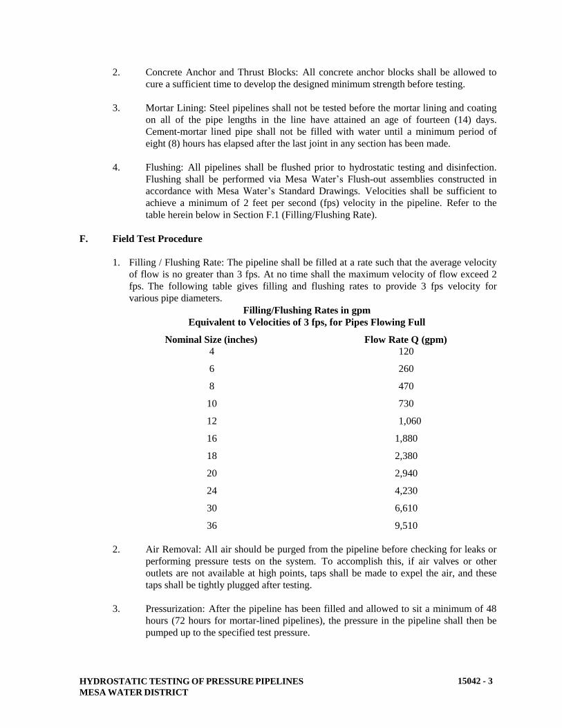
HYDROSTATIC TESTING OF PRESSURE PIPELINES
MESA WATER DISTRICT
15042 - 3
2. Concrete Anchor and Thrust Blocks: All concrete anchor blocks shall be allowed to
cure a sufficient time to develop the designed minimum strength before testing.
3. Mortar Lining: Steel pipelines shall not be tested before the mortar lining and coating
on all of the pipe lengths in the line have attained an age of fourteen (14) days.
Cement-mortar lined pipe shall not be filled with water until a minimum period of
eight (8) hours has elapsed after the last joint in any section has been made.
4. Flushing: All pipelines shall be flushed prior to hydrostatic testing and disinfection.
Flushing shall be performed via Mesa Water’s Flush-out assemblies constructed in
accordance with Mesa Water’s Standard Drawings. Velocities shall be sufficient to
achieve a minimum of 2 feet per second (fps) velocity in the pipeline. Refer to the
table herein below in Section F.1 (Filling/Flushing Rate).
F. Field Test Procedure
1. Filling / Flushing Rate: The pipeline shall be filled at a rate such that the average velocity
of flow is no greater than 3 fps. At no time shall the maximum velocity of flow exceed 2
fps. The following table gives filling and flushing rates to provide 3 fps velocity for
various pipe diameters.
2. Air Removal: All air should be purged from the pipeline before checking for leaks or
performing pressure tests on the system. To accomplish this, if air valves or other
outlets are not available at high points, taps shall be made to expel the air, and these
taps shall be tightly plugged after testing.
3. Pressurization: After the pipeline has been filled and allowed to sit a minimum of 48
hours (72 hours for mortar-lined pipelines), the pressure in the pipeline shall then be
pumped up to the specified test pressure.
Filling/Flushing Rates in gpm
Equivalent to Velocities of 3 fps, for Pipes Flowing Full
Nominal Size (inches) Flow Rate Q (gpm)
4
6
8
10
12
16
18
20
24
30
36
120
260
470
730
1,060
1,880
2,380
2,940
4,230
6,610
9,510

HYDROSTATIC TESTING OF PRESSURE PIPELINES
MESA WATER DISTRICT
15042 - 4
If a large quantity of water is required to increase the pressure during testing,
entrapped air, leakage at joints, or a broken pipe may be suspected. TESTS
SHOULD BE DISCONTINUED until the source of trouble is identified and
corrected.
4. Field Test Pressure: Unless otherwise specified, the pipeline shall be subjected to a
field hydrostatic pressure of 200 psi (or 50 psi in excess of operating pressures greater
than 150 psi).
G. Allowable Leakage
1. Pipelines of Diameter 10-inches and Under
a. When the test pressure has been reached, pumping shall be discontinued until
the pressure in the line has dropped 5 psi, at which time the pressure shall
again be pumped up to the specified test pressure. This procedure shall be
repeated until four hours have elapsed from the time the specified test
pressure was first applied. At the end of the four-hour period, the pressure
shall be pumped up to the test pressure for the last time.
b. The leakage shall be considered as the total amount of water pumped into the
pipeline during the four-hour period, including the amount required in
reaching the test pressure for the final time. Leakage shall not exceed the rate
of 30 gallons per inch of diameter per mile of pipe per 24 hours for test
pressure of 250 psi. The following table indicates the leakage allowance for
various sizes of pipe for test pressure of 200 psi and 250 psi:
LEAKAGE ALLOWANCE
Allowable Leakage Gallons per Four Hours
per 1,000 feet of Pipe
Test Pressure: 200 psi Test Pressure: 250 psi
4” 0.38 gal 0.43 gal
6” 0.57 gal 0.61 gal
8” 0.76 gal 0.85 gal
10” 0.96 gal 1.07 gal
2. Pipelines Diameter 12-inches and Larger.
a. The test pressure shall be maintained for the following duration by restoring
it whenever it falls an amount of 5 psi: pipe of 18-inches in diameter and
smaller, 4 hours; over 18-inches to 36-inches in diameter, 8 hours; and over
36-inches in diameter, 24 hours.
b. One to three days shall be allowed for the filled pipeline to soak and to
release entrapped air. The test pressure shall be applied with a positive
displacement pump.

HYDROSTATIC TESTING OF PRESSURE PIPELINES
MESA WATER DISTRICT
15042 - 5
A snubber and dampener shall be provided between the pump and the
pipeline to reduce instantaneous pressure pulses to 10% of the specified test
pressure. Water shall be drawn from containers in which the volume of water
can be readily measured or through a positive displacement meter. The
amount of water used to maintain the test pressure during the test period shall
be considered the leakage. The allowable leakage shall be determined by the
following formula:
L = ND(P)½
7400
where L is the allowable leakage in gallons per hour,
N is the number of rubber-gasketed pipe joints in the test section
D is the inside pipe test diameter in inches,
P is the pipe test pressure (psig), which is defined as the average of
the highest and lowest test pressures in the pipe section being
tested.
Note the allowable leakage rate for pipeline sections with flanged, welded,
and/or grooved-end joints shall show zero.
H. Repetition of Test
If the actual leakage exceeds the allowable, the faulty work shall be located and corrected and
the test repeated. The work shall be restored, and all damage resulting from leaks repaired.
All visible leakage shall be eliminated.
I. Bulkhead and Test Facility Removal
After a satisfactory test, water shall be drained, test bulkheads and other test facilities
removed, pipe coatings restored, and the section of pipe shall be connected to the adjacent
piping.
END OF SECTION

INSTALLATION OF PRESSURE PIPELINES
MESA WATER DISTRICT
15051 - 1
SECTION 15051
INSTALLATION OF PRESSURE PIPELINES
PART 1 - GENERAL
A. Description
This section describes the installation of: pressure pipelines fabricated of polyvinyl chloride,
ductile iron, CML & C steel, including pipeline closures, connections and encasement.
B. Related Work Described Elsewhere
1. Trenching, Backfilling, and Compacting: 02223.
2. Concrete: 03300.
3. Painting and Coating: 09900.
4. Chlorination of Water Mains for Disinfection: 15041
5. Hydrostatic Testing of Pressure Pipelines: 15042.
6. Air-Release and Vacuum-Release Valves: 15089.
7. Manual Valves: 15100.
8. Domestic and Recycled Water Facilities Identification: 15151.
9. Cathodic Protection and Joint Bonding: 16640.
C. Submittals
1. An installation schedule (tabulated layout) shall be submitted for CML &C steel pipe
which includes:
a. Order of installation and closures.
b. Pipe centerline station and elevation at each change of grade and alignment.
c. Elements, curves, and bends, both in horizontal and vertical alignment
including elements of the resultant true angular deflections in cases of
combined curvature.
d. The location, length, size, design designation, and number designation of
each pipe section and pipe special.
2. Welder qualification certificates shall be submitted.

INSTALLATION OF PRESSURE PIPELINES
MESA WATER DISTRICT
15051 - 2
D. Definitions
1. Buried piping is piping buried in the soil, or encased in concrete, commencing at the
inside face of the wall or top of the slab of a structure. Where a coating is specified,
and pipe enters or leaves the ground, extend the coating a minimum of six (6) inches
above the ground surface. Where a coating is specified, extend the coating up to three
(3) inches inside of the structure.
2. Exposed piping is piping in any of the following conditions or locations: above
ground; and inside vaults or other structures.
PART 2 - MATERIALS
A. Installation Material
Refer to the various referenced sections on pipe by type for material requirements.
B. Piping Schedule
Unless noted otherwise on the drawings or in the specifications, pipe shall be furnished in
accordance with the following materials schedule.
Diameter Potable Water
2-inch and smaller Copper (below ground) or Brass (above ground)
4-inch through 12-inch AWWA C-900 PVC Pipe, SDR-14
16-inch through 20-inch AWWA C-905 PVC Pipe, SDR-18
Ductile Iron Pipe, Class 200
CML&C Steel Pipe
24-inch and larger CML&C Steel Pipe
Notes: Copper – per Section 15057 (Copper Pipe and Fittings)
PVC Pipe – per Section 15064 (PVC Pressure Pipe and Fittings)
Ductile Iron Pipe – per Section 15056 (Ductile-Iron Pipe and Fittings)
CML&C Steel Pipe – per Section 15057 (Cement-Mortar Lined and Coated Steel
Pipe)
PART 3 - EXECUTION
A. Delivery and Temporary Storage of Pipe at Site
1. Onsite Storage Limitation: Onsite pipe storage shall be limited to a maximum of one
week, unless exception is approved by Mesa Water.

INSTALLATION OF PRESSURE PIPELINES
MESA WATER DISTRICT
15051 - 3
2. Care of Pipe: Care shall be taken to avoid cracking of the cement mortar coating
and/or lining on steel pipe. If necessary, plastic sheet caps shall be used to close pipe
ends and keep coatings and linings moist.
B. Handling of Pipe
1. Moving Pipe: Pipes shall be lifted with handling beams or wide belt slings as
recommended by the pipe manufacturer. Cable slings, chains or other equipment
likely to cause damage to the pipe coating shall not be used. Pipe shall be handled in
a manner to avoid damage to the pipe and pipe coating. Pipe shall not be dropped or
dumped from trucks or into trenches under any circumstances.
2. Internal Pipe Braces: Internal braces placed in steel pipes shall be maintained until
backfilling is completed. After backfill braces are removed, the bracing shall become
the contractor’s property.
3. Pipe Caps: Plastic caps placed over the ends of steel pipe shall not be removed until
the pipe is ready to be placed in the trench. Plastic caps may be opened temporarily
to spray water inside the pipe for moisture control.
4. Inspection of Pipe: The pipe and accessories shall be inspected for defects prior to
lowering into the trench. Any defective, damaged or unsound pipe shall be repaired
or replaced. All foreign matter or dirt shall be removed from the interior of the pipe
before lowering into position in the trench.
C. Placement of Pipe in Trench
1. General: Dewatering, excavation, shoring, sheeting, bracing, backfilling material
placement, material compaction, compaction testing, and pipe laying requirements
and limitations shall be in accordance with Section 02223 (Trenching, Backfilling
and Compacting).
2. Sanitation of Pipe Interior: During laying operations, tools, clothing, or other
materials shall not be placed in the pipe.
3. Prevention of Entry into Pipe: When pipe laying is not in progress, including lunch-
hour, the ends of the pipe shall be closed using plugs constructed in a manner to
prevent entry by any child, debris, animal or vermin.
4. Laying Pipe on Grades over 5 Percent: Pipes shall be laid uphill with the bell or
collared joints on the uphill end of each pipe length, whenever the grade exceeds five
(5) percent.
5. Pipe Base Thickness: Pipe base thickness and material shall be as specified in
Section 02223 (Trenching, Backfilling, and Compacting).
6. Depressions at Joints and Pipe Sling Points: Depressions shall be dug into pipe base
material to accommodate the pipe bell and external joint filler form (“diapers”), and
to permit removal of the pipe handling slings.

INSTALLATION OF PRESSURE PIPELINES
MESA WATER DISTRICT
15051 - 4
7. Placement of Pipe on Pipe Base: Pipe shall be lowered onto the bedding and installed
to line and grade its full length on firm bearing except at the bell and at sling
depressions. Unless specified otherwise, the tolerance on grade shall be ¼-inch; the
tolerance on line shall be 1-inch. Grade shall be measured along the pipe invert.
8. Pipe Installation: Pipe shall be installed without springing, forcing, or stressing the
pipe or any adjacent connecting valves or equipment. Precautions shall be taken to
prevent pipe from being displaced by water entering trench. Damaged or displaced
pipe shall be replaced or returned to specified condition and grade.
9. Trench Curvature and Pipe Deflection: The radius of curvature of the trench shall be
determined by the maximum length of pipe section that can be used without
exceeding the allowable deflection at each pipe joint and without causing deviation
from Mesa Water’s trench width requirements. Refer to the various referenced
sections on pipe by type for allowable deflection. The deflection at any flexible joint
shall not exceed that prescribed by the manufacturer of the pipe. The manufacturer's
printed installation guide outlining the radius of curvature that can be negotiated with
pipe sections of various lengths shall be followed. When installing beveled pipe, do
not deviate the pipe top mark by more than ½ inch from the vertical line passing
through the pipe center.
10. Equipment for Installation of Pipe: Proper implements, tools, and facilities as
recommended by the pipe manufacturer's standard printed installation instructions
shall be provided and used by the contractor for safe and efficient execution of the
work. All pipe, fittings, valves, and accessories shall be carefully lowered into the
trench using suitable equipment in such a manner as to prevent damage to pipe and
fittings. Under no circumstances shall pipe or accessories be dropped or dumped into
the trench. Do not use dog clips, lugs or other devices welded to the pipe to force it
into position.
11. Cutting and Machining Pipe: Cutting and machining of the pipe shall be
accomplished in accordance with the pipe manufacturer's standard procedures for this
operation. Pipe shall not be cut with a cold chisel, standard iron pipe cutter, nor any
other method that may fracture the pipe or produce ragged, uneven edges.
D. Assembling Rubber Ring Joints
1. Cleaning Ends of Pipe: The ends of the pipe to be joined shall be cleaned of foreign
material.
2. Lubrication: After placing pipe in trench, a nontoxic water soluble vegetable soap
solution shall be applied to the inside of the bell of the pipe in the trench and to the
rubber gasket and spigot groove of the pipe to be installed. The rubber gasket shall
be stretched into the groove of the bell-end of the pipe and distributed uniformly
around the circumference.
3. Joint Assembly: Without tilting the pipe to be installed, the spigot shall be inserted
into the bell of the pipe. Come-a-longs or pipe jacks shall be used to drive spigot end
into the bell until properly seated. The joint recess recommended by pipe
manufacturer for made-up joints shall be maintained.
INSTALLATION OF PRESSURE PIPELINES
MESA WATER DISTRICT
15051 - 5
Where deflections at joints are required for curved alignment, the manufacturer’s
recommended allowable joint opening on one side shall not be exceeded. A feeler
gauge shall be used to verify proper placement of each gasket.
E. Flanged Connections
1. Bolthole Alignment: Pipe shall be set with flange boltholes straddling the pipe
horizontal and vertical centerlines. Inspect gasket seating surfaces, gasket, each stud
or bolt, each nut, each washer, and the facing on which the nuts will rotate. Repalce
any damaged item.
2. Nuts and Bolts: Nuts and bolts shall be lubricated with anit-seize prior to installation.
Assemble all bolts on flange, then tighten bolts in the sequence and to the torque as
recommended by the manufacturer. Retighten the bolts after 24 hours. Replace
galled, cracked or distorted bolts and nuts. Do not reuse bolts or nuts.
3. Flange Wrapping: Flanges which connect with buried valves or other equipment
shall be wrapped with sheet polyethylene film as specified for the valves and
equipment. The wrap shall be extended over the flanges and bolts and secured
around the adjacent pipe circumference with tape.
4. Coating: Buried flanges and non-stainless steel bolts shall be completely coated as
specified in Section 09900 (Painting and Coating). For above ground applications,
the flanges and bolts shall be painted as specified in Section 09900 (Painting and
Coating).
F. Installation of Bends, Tees, and Reducers
Fittings shall be installed utilizing standard installation procedures. Fittings shall be lowered
into trench by means of rope, cable, chain, or other acceptable means without damage to the
fittings or its interior coating. Cable, rope, or other devices used for lowering fitting into
trench, shall be attached around exterior of fitting for handling. Under no circumstances shall
the cable, rope or other device be attached through the fittings interior for handling. Fittings
shall be carefully connected to pipe or other facility, and joint shall be checked to insure a
sound and proper joint.
G. Installing Threaded Piping
Threaded piping shall be reamed, deburred, and cleaned before making up joints. Thread
lubricant shall be applied to threaded pipe ends before installing fittings, couplings, unions, or
joints.
H. Completion of Interior Joints for Mortar-Lined Pipes 20-Inches in Diameter and
Smaller
1. Preparation: A tight-fitting swab or squeegee shall be inserted in the joint end of the
pipe to be joined.

INSTALLATION OF PRESSURE PIPELINES
MESA WATER DISTRICT
15051 - 6
2. Application of Cement Mortar: When ready to insert the spigot, the face of the
cement mortar lining at the bell shall be coated with a sufficient amount of stiff
cement mortar to fill the space between adjacent mortar linings of the two pipes to be
joined.
3. Removal of Excess Mortar: Immediately after joining the pipes, the swab or
squeegee shall be drawn through the pipe to remove all excess mortar and expel it
from the open pipe end.
4. Where bends or other fittings preclude the use of balls or squeegees, detail fabrication
and assembly drawings shall be prepared showing the location of handholes or butt
straps required to finish interior mortar joints.
I. Completion of Interior Joints for Mortar-Lined Pipes 24-Inches in Diameter and Larger
1. Backfill Requirement: The trench shall be backfilled, compacted and meet the
compaction requirements before applying mortar at joints.
2. Cleaning and Application of Cement Mortar: Working inside the pipe, foreign
substances which adhere to the steel joint rings shall be removed, the surface cleaned,
and stiff cement mortar packed into each joint. The mortar shall be finished with a
steel trowel to match the lining in the adjoining pipes.
3. Removal of Excess Mortar: Excess mortar and other construction debris shall be
removed from the pipe interior.
J. Pipeline Closure Assemblies
1. General: Pipeline closure assemblies shall be employed to unite sections of pipeline
laid from opposite directions; to adjust the field length of the pipeline to meet
structures, other pipelines, and points established by design stations; and to close
areas left open to accommodate temporary test bulkheads for hydrostatic testing.
Either follower ring design or butt strap design shall be used. Follower ring closures
shall be installed as recommended by the pipe manufacturer. Minimum length of pipe
closure sections shall be four (4) feet.
2. Butt Straps: Shaped steel butt straps, a minimum of 14-inches in width, shall be
centered over the ends of the pipe sections they are to join. Butt straps shall be
welded to the outside of the pipes with complete circumferential fillet welds equal in
size to the thinnest part being joined. The details shown on the drawings shall be
referred to when joining pipes larger than 36-inches in diameter.
3. General Requirements for Cement Mortar Lining for Closure Assemblies: Closure
assemblies shall be cement-mortar lined to a mortar thickness at least equal to the
adjoining standard pipe sections. The steel shall be cleaned with wire brushes and a
cement and water wash coat applied prior to applying the cement mortar. Where
more than a 4-inch joint strip of mortar is required, welded wire mesh reinforcement
having a 2-inch by 4-inch pattern of No. 13 gage shall be placed over the exposed
steel.

INSTALLATION OF PRESSURE PIPELINES
MESA WATER DISTRICT
15051 - 7
The mesh shall be installed so that the wires on the 2-inch spacing run
circumferentially around the pipe. The wires on the 4-inch spacing shall be crimped
to support the mesh 3/8-inch from the metal surface. The interior mortar shall have a
steel-trowled finish to match adjoining mortar lined pipe sections.
4. For lining of closure assemblies on pipelines 20-inches in diameter and smaller, butt
straps with 6-inch diameter hand holes with plugs shall be provided around the
perimeter of the closure at third-point intervals to facilitate mortar lining of the
interior surface.
5. Mortar Coating Exterior Surfaces of Closure Assemblies: The exterior of closure
assemblies shall be reinforced with wire mesh as described in Paragraph 3 above.
The surface shall be coated with mortar, or a poured concrete encasement to cover all
steel to a minimum thickness of 1-1/2 inches. Exterior mortar shall be protected to
retard drying while curing. Concrete shall be poured and vibrated on one side of the
closure assembly only, until mortar is visible on the opposite side, after which the
coating can be completed over the top of the assembly.
K. Welded Joints
1. Locations: Welded joints shall be provided where detailed on the plans.
2. Reference Standard: Welding shall be in accordance with AWWA C206. Welder's
qualification shall be in accordance with Section IX of the ASME Boiler and Pressure
Vessel Code. Current certifications shall be provided for all welders.
3. Sequence: Interior joints shall not be welded before backfilling, compaction and
compaction testing are successfully completed.
4. Joint Rings: Joint rings (butt-straps or weld collars) that are rusted or pitted where
weld metal is to be deposited shall be cleaned by brushing or sand blasting.
5. Restrictions: Concrete or other coating adjacent to the joint rings shall not be heated.
6. Cleaning Requirements: Each layer of deposited weld metal shall be cleaned using a
power-driven wire brush prior to depositing the next layer of weld metal.
L. Field Welding Joints
1. Field welding shall be in accordance with AWWA C206, except as modified herein.
2. Welder's qualification shall be in accordance with Section IX, Part QW, of the ASME
Boiler and Pressure Vessel Code. Any welder performing field work shall have been
qualified for the process involved within the past three years.
3. Provide single-welded lap joints, butt-welded joints and butt-strap joints where called
for on the drawings. The minimum overlap of the assembled bell and spigot sections
of the lap joints shall be as shown on the drawings.

INSTALLATION OF PRESSURE PIPELINES
MESA WATER DISTRICT
15051 - 8
4. Prior to welding interior joint shade pipe to 60 degrees except at the joints. Complete
the interior weld prior to coating the outside joint.
5. If joint laying surfaces are rusted or pitted where weld metal is be deposited, clean
them by wire brushing or sand blasting.
6. Complete the butt-welded longitudinal seams of butt straps before completing
circumferential fillet welds. Grind the backing bar clear of abutting pipe section prior
to completing the circumferential fillet welds. Backing bars shall be left in place.
7. Completed fillet welds shall be convex with a maximum reinforcement of 1/8 inch.
Minimum leg length shall be the sum of the greatest abutting plate thickness plus
joint clearance. Equalize joint clearance around entire circumference prior to
welding. Remove all tack welds prior to the start of joint welding.
8. Preheat the joints to be welded where required in accordance with Table 1 of AWWA
C206.
9. Where weld metal is to deposited, clean joints by wire brushing or sand blasting.
Clean each layer of deposited weld metal prior to depositing the next layer of weld
metal, including the final pass, by a power-driven wire brush.
10. No welding ground shall be made on the coated part of the pipe.
11. In all hand welding, the metal shall be deposited in successive layers so that there will
be at least as many passes or beads in the completed weld as indicated in the
following table;
Steel Cylinder Thickness Fillet Weld
(inches) Minimum Number of Passes
3/16 or less 1
7/32 through ¼ 2
9/32 through 3/8 3
13/32 through ½ 4
12. The plate edges shall be so prepared that there will be sufficient angle in the welding
groove to prevent side arching of the electrode and to permit penetration at the
deepest point of the groove. All such welds shall be back-chipped with a round-nosed
tool to clean metal on the reverse side from the side of the deepest penetration before
any welding is done on said reverse side. Each hand pass and each back-chipped
welding groove shall be subject to inspection before the ensuing pass is made. Each
hand pass shall be the full width of the weld.
13. Not more than 1/8 inch of metal shall be deposited in each pass. Each pass except the
final one, whether in butt or fillet welds, shall be thoroughly bubbed or peened to
relieve shrinkage stresses and to remove dirt, slag, or flux before the succeeding bead
is applied.

INSTALLATION OF PRESSURE PIPELINES
MESA WATER DISTRICT
15051 - 9
Each pass shall be thoroughly fused in the plates at each side of the welding groove or
fillet and shall not be permitted to pile up in the center of the weld. Undercuting
along either side will not be permitted.
14. Complete each pass around the entire circumference of the pipe before commencing
the next pass. Use the electrodes recommended by the pipe fabricator. Do not
deposit more than 1/8 inch of throat thickness per pass.
15. During welding exterior welds, the coating of the steel pipe shall be protected by
draping an 18-inch wide strip of heat-resistant material over the top half of the pipe
on each side of the coating holdback to avoid damage to the coating by hot weld
splatter.
16. Test all butt-strap joints by the soap and compressed air test after the steel is cool to
the touch and before completing joint coating and lining. Test the longitudinal sears
of butt-strap joints, single-welded lap joints and all butt-welded joints by the liquid
penetrant method. Test to be conducted and interpreted by skilled staff certified in
dye testing per ASTM E165.
M. Operations Incidental to Joint Completion
1. Hydrostatic Testing: Joint completion shall be planned to accommodate temporary
test bulkheads for hydrostatic testing.
2. Bonding Pipe: Metallic jumper bonds or bars shall be installed on all metallic pipe,
as shown on plans and as specified within Section 16640 (Cathodic Protection and
Joint Bonding).
N. Completion of Exterior Pipe Joint for Cement-Mortar Coated Pipe
Outside joint recess shall be filled with cement-mortar grout using a fabric form (joint diaper)
placed around the joint and secured with steel straps. Grout shall be poured and rodded from
one side only until it is visible on the opposite side. After approximately one hour, the joint
shall be topped off with additional grout.
Grout used for completion of the exterior pipe joint shall be mixed in proportion of one part
cement, by weight, to not more than two parts, by weight, of sand passing a No. 16 mesh
screen and thoroughly mixed with water to the consistency of rich cream. A cloth band nine
(9) inches wide shall be placed around the outside of the pipe and centered over the joint.
The joint band shall be bound to the pipe by use of steel box strapping. The band shall
completely and snugly encase the joint except for an opening at the top through which to pour
the grout. The outside grout space, prior to filling with grout, shall be flushed with water so
that the surfaces of the joint to be in contact with the grout filling will be thoroughly
moistened when the grout is poured.
Fluid grout shall be poured in only one opening in this joint and pouring shall be continuous
until grout appears at the other side. The grout shall be rodded on both sides of the pipe, if
necessary to settle the grout, and more grout added to fill the joint completely. The bands
shall not be removed from the joint, and exposed portions of the joint, after filling, shall be
covered with wet burlap or moist earth.

INSTALLATION OF PRESSURE PIPELINES
MESA WATER DISTRICT
15051 - 10
O. Thrust Restraint and Anchor Blocks
1. Location: Thrust restraint and anchor blocks shall be provided on all pressure
pipelines, and shall be installed as shown on the plans and at all rubber gasketed
fittings that are not otherwise restrained. Thrust restraint blocks or anchor blocks
shall be installed at all valves, tees, crosses, ends of pipelines, and at all changes of
direction of the pipeline greater than 5 degrees deflection either vertically or
horizontally when joints are not otherwise restrained.
2. General Requirements: Thrust restraint and anchor blocks shall be of not less than
3,250 psi concrete (Class A); and shall provide a thrust bearing area to resist
horizontal or downward thrust; and shall be of sufficient gross weight and area to give
bearing against undisturbed vertical earth banks sufficient to absorb the thrust,
allowing an earth bearing of 1500 pounds per square foot maximum.
3. Thrust Restraint not Called for on the Plans: Thrust restraint elements, where not
called for on the plans, shall be sized for 150 percent of operating pipeline pressure or
the pipeline test pressure, whichever is greater. Prior to construction, thrust and
anchor block sizing shall be submitted to Mesa Water for approval. Pipe clamps, tie-
rods, and their assembly shall meet the requirements of the National Fire Protection
Association Bulletin No. 24, latest edition.
4. Concrete Placement: Concrete shall be placed against wetted and undisturbed soil,
and the exterior of the fitting shall be cleaned and wetted to provide a good bond with
the concrete. The concrete interface with the fitting shall be an area of not less than
the projected area of the fitting normal to the thrust resultant and centered on the
resultant.
5. Accessibility to Joints and Fittings: Unless otherwise directed by Mesa Water, thrust
restraint and anchor blocks shall be placed so that the pipe and fitting joints are
accessible for repair. Placement shall include isolation of adjacent utilities and shall
ensure that bearing is against undisturbed soil.
6. Harness and Tie-Rods: Metal harness or tie-rods and pipe clamps shall be used to
prevent movement if shown on the plans or directed by Mesa Water. The rods and
clamp harnessing arrangement shall be installed utilizing flanged harness hold-downs
or lugged fittings and pipe with saddle clamps placed (where feasible and practical) to
bear against the pipe bells. Saddle clamps around the barrel of the pipe, which
depend on friction or setscrews to prevent sliding of the clamp, are not acceptable.
However, restraints with pointed set-screws which bear into the pipe wall, are not
acceptable and shall not be used. All surfaces of exposed and buried steel rods,
reinforcing steel, bolts, clamps, and other metal work shall be coated before
installation and touched up after assembly as specified in Section 09900 (Painting and
Coating).
7. In-line Valves: Reinforcing steel tiedown rods shall be used on all in-line valves. See
Mesa Water Standard Drawings for typical valve anchor and thrust restrain details.
Exposed metal portions shall be coated as specified in Section 09900 (Painting and
Coating).

INSTALLATION OF PRESSURE PIPELINES
MESA WATER DISTRICT
15051 - 11
P. Blowoff Assemblies
1. General: In-line type or end-of-line type blowoff assemblies shall be installed in
accord with the plans at the locations noted, and at such additional locations as
required by Mesa Water for removing water or sediment from the pipeline.
2. Location: The assembly shall be installed in a level section of pipe. The tap for
blowoff in the line shall be no closer than 18 inches to a valve, coupling, joint, or
fitting unless it is at the end of the main. No tap will be permitted in any existing
machined section of asbestos cement pipe.
Q. Combination Air and Vacuum Release Valves
1. General: Air release valve assemblies and combination air and vacuum valves shall
be installed at each point in the pipeline as shown on the drawings or as specified by
the Mesa Water, and in accordance with Section 15089 (Combination Air-Release
and Vacuum-Relief Valves).
2. Location: The tap for the air valves shall be made in a level section of pipe no closer
than 18 inches to a bell, coupling, joint, or fitting. No tap shall be permitted in any
existing machined section of asbestos cement pipe.
R. Aboveground Piping Installation/Support
1. General: Installation of aboveground pipeline materials and appurtenances include
requirements for buried pipeline materials and appurtenances as applicable.
2. Supports: All exposed pipe shall be adequately supported with devices of appropriate
design. Where details are shown, the supports shall conform thereto and shall be
placed as indicated; provided, that the support for all piping shall be complete and
adequate as herein specified, whether or not supporting devices are specifically called
for. Pipe hangers and supports shall conform to the requirements of the latest editions
of the MSS-SP58 and SP69 and ANSI/ASME B31.1.
3. Grooved-End Pipe and Fittings: Grooved-end pipe and fittings shall be installed in
accordance with the coupling manufacturer's recommendations and the following:
a. Loose scale, rust, oil, grease, and dirt shall be cleaned from the pipe or fitting
groove. The coupling manufacturer's gasket lubricant shall be applied to the
gasket exterior including lips, pipe ends, and housing interiors.
b. Coupling shall be tightened alternately and evenly until coupling halves are
seated properly.
S. Cathodic Protection and Joint Bonding
All ferrous metal pipes and all pipes specified or shown on the plans to be cathodically
protected shall be completed in accordance with Section 16640 (Cathodic Protection and
Joint Bonding).
INSTALLATION OF PRESSURE PIPELINES
MESA WATER DISTRICT
15051 - 12
T. Warning and Locator Tape
Warning tape shall be installed on all pipelines. For non-metallic pipelines, pipe locater tape
and copper wire shall also be provided. The pipe identification shall be in accord with
Section 15151 (Domestic and Recycled Water Facilities Identification).
U. Disinfection
All potable water pipelines shall be disinfected in accordance with Section 15041
(Chlorination of Water Mains for Disinfection).
V. Testing
All pressure piping shall be hydrostatically pressure tested in accordance with Section 15042
(Hydrostatic Testing of Pressure Pipelines).
END OF SECTION
DUCTILE-IRON PIPE AND FITTINGS
MESA WATER DISTRICT
15056 - 1
SECTION 15056
DUCTILE-IRON PIPE AND FITTINGS
PART 1 – GENERAL
A. Description
This section describes materials, installation, and testing of ductile-iron pipe and fittings.
B. Related Work Specified Elsewhere
1. Trenching, Backfilling, and Compacting: 02223.
2. Chlorination of Water Mains for Disinfection: 15041.
3. Hydrostatic Testing of Pressure Pipelines: 15042.
4. Installation of Pressure Pipeline: 15051.
5. Manual Valves: 15100.
6. Cathodic Protection and Joint Bonding: 16640.
C. Submittals
1. Affidavits of compliance with standards referenced in this specification, e.g., AWWA
C151, shall be provided.
2. Layout drawings showing the locations and dimensions of pipe and fittings shall be
submitted where the proposed pipeline is to be placed along streets or alignments
with a radius of curvature which dictates the use of shorter-than-standard pipe
lengths. In cases where restrained joint pipe is specified, lay drawings shall clearly
identify the joints, lengths, fittings, and deviations from the curved centerline of the
pipe trench. Consideration for adjacent parallel utility conflicts is important in
developing the lay diagrams to avoid conflicts and encroaching into adjacent trench
areas.
3. Lining, coating and wall thickness for all piping shall be provided.
4. Joint details for all types of joints used, e.g., push-on joints shall be submitted.
5. Calculations and/or test data proving that each proposed restrained joint arrangement
can transmit the required forces shall be submitted.

DUCTILE-IRON PIPE AND FITTINGS
MESA WATER DISTRICT
15056 - 2
PART 2 - MATERIALS
A. Ductile-Iron Pipe
1. AWWA Reference Standard: Ductile-iron pipe shall be manufactured in accordance
with ANSI/AWWA C151/A21.51.
2. Minimum Wall Thickness: The minimum wall thickness for ductile-iron pipe shall
be as specified in AWWA C150 for the design pressure class for bell and spigot pipe,
thickness Class 53 for flanged spools, and design pressure class 350 for plain end
pipe, unless indicated otherwise on the plans. Unless otherwise noted on the
drawings, ductile iron pipe shall be Pressure Class 200.
3. Joints: Unless otherwise called out on the plans, push-on type joints shall be used.
The joint dimension and gasket shall be as specified in ANSI/AWWA C111/ A21.11.
At the direction of Mesa Water, ductile iron pipe joints shall be bonded to provide
electrical continuity for corrosion monitoring and future cathodic protection. For
joint-bonding details and requirements refer to Mesa Water Standard Drawings and
Section 16640 (Cathodic Protection and Joint Bonding).
4. Flanges: Flanges for ductile-iron pipe, when required, shall be "screwed-on" type in
accordance with ANSI/AWWA C115/A21.15.
5. Restrained Joints: Where called for on the plans, pipe and fittings shall be restrained.
Joint restraint type shall be as specified in this Section and shall be one of the
following types:
a. Flanged fittings per Part .A.4 above and Part 2.B.8 below.
b. Where restrained joints are called for on 10-inches in diameter and larger
pipe, use a manufactured locking restraint pipe with fittings: “TR-Flex”
restrained joint pipe as manufactured by U.S. Pipe & Foundry Company;
“Flex-Ring (only) as manufactured by American Cast Iron Pipe Company;
“Thrust-Lock” manufactured by Pacific States Cast Iron Pipe Company; “F-
128 Super-lock” pipe as manufactured by Clow Water Systems Company, or
approved equal. The restrained joint shall be a boltless restrained push-on
joint design and shall contain a positive axial locking restrained system and
be capable of deflection after assembly. Restraint of field cut pipe by using
U.S. Pipe’s “TR Flex Gripper Ring” or approved equal will be permitted as
long as the “TR Flex” pipe field weldments are not required. Any restrained
joint fitting which will require a pipe field weldment will not be permitted
under any circumstances. Restraint of field cut pipe shall be kept to a
minimum.
c. Where restrained joints are called for on 8-inches in diameter and smaller
pipe, push-on joints shall be restrained with locking gasket rated for 250 psi
operating pressure.

DUCTILE-IRON PIPE AND FITTINGS
MESA WATER DISTRICT
15056 - 3
Joint restraint shall be push-on joint with "Field-Lok" gaskets as
manufactured by U.S. Pipe & Foundry Company, Perma-Lock Joint as
manufactured by Pacific States Cast Iron Pipe Company or approved equal.
"TR-Flex" restrained joint pipe as manufactured by U.S. Pipe or approved
equal is also an acceptable option for restraint of push-on joints.
d. Mechanical Joints with Mechanical Joint Restraints per Part 2.B. 6 and 7
herein below.
e. Push-on joint pipe with restrained harness assembly (for use within steel
casing applications only). Shop drawings reflecting every part, material and
dimension of the restraint assembly shall be submitted to Mesa Water for
approval. Restraint of push-on joints shall be of the type utilizing cast lugs,
or retainer rings bearing against the pipe shoulders at the bell or fitting. All
threaded harness parts shall be manufactured of type 316 stainless steel.
Restraint systems using lugs integral to the pipe shall be cast with the pipe or
fitting by the pipe manufacturer. Attachment of angle iron: angle-clips;
harness-lugs or tabs by field welding to the ductile iron pipe or fitting is
strictly prohibited.
f. Grooved pipe and fittings (for un-buried installations only), per sub-section
No. 2.E. herein below. Wall thickness beneath the groove shall be equal to or
greater than the minimum specified wall thickness and shall be sufficient to
meet the maximum pressure.
6. Outlets for DIP shall be as follows:
2” or smaller: brass saddle with stainless steel bands
2-1/2”: brass saddle with stainless steel bands or tapped tee
4” and larger: D.I. tee fitting
7. Manufacturers: Ductile-iron pipe shall be as manufactured by: American Cast Iron
Pipe Company; Pacific States Cast Iron Pipe Company; U.S. Pipe and Foundry
Company; Griffin Pipe Products Company; McWane Cast Iron Pipe Company; Clow
Water Systems Company; or approved equal.
B. Ductile-Iron Fittings
1. AWWA Reference Standard: Ductile-iron fittings shall be manufactured in
accordance with ANSI/AWWA C110/A21.10. Ductile iron compact body fittings
may be used for fitting sizes 4-inches through 12-inches in diameter and shall be
manufactured in accordance with ANSI/AWWA C153/A21.53.
2. Push-on Joints: All fittings shall be made with push-on joints designed for use with
the type of pipe to be joined unless noted otherwise on the plans.

DUCTILE-IRON PIPE AND FITTINGS
MESA WATER DISTRICT
15056 - 4
3. Restrained Joints: Restrained fittings shall be used only as shown on the plans. Joint
restraint type shall be as specified in this Section for ductile iron pipe, and shall be
either:
a. Flanged fittings per Part .A.4 above and Part 2.B.8 below.
b. For pipe sizes 10-inches in diameter and larger, restrained joint fittings shall
either be “TR-Flex” restrained joint fitting as manufactured by U.S. Pipe or
approved equal, or mechanical joint ductile iron fittings fitted with joint
restraints. Mechanical joint restraint shall be incorporated with the design of
the follower gland and shall include a restraining mechanism which, when
activated, imparts multiple wedging action against the pipe, increasing its
resistance as the pressure increases. The joint shall maintain flexibility after
burial. Follower glands shall be manufactured of ductile iron conforming to
ASTM A536-80. Torque off bolts shall be tightened per manufacturer’s
recommendations and shall be inspected by Mesa Water prior to backfill.
The mechanical joint restraint shall be EBBA IRON, Inc., MEGALUG,
UNIFLANGE Series 1400, The Ford Meter Box Co., Inc. or approved equal.
Any restrained joint fitting which will require a pipe field weldment will not
be permitted.
c. For pipe sizes 8-inches in diameter and smaller, push-on joint fittings shall be
restrained with locking gasket rated for 250 psi operating pressure. Joint
restraint shall be push-on joint with "Field-Lok" gaskets as manufactured by
U.S. Pipe, Perma-Lock Joint as manufactured by Pacific States Cast Iron Pipe
Company or approved equal. "TR-Flex" restrained joint fitting as
manufactured by U.S. Pipe or approved equal is also an acceptable option for
restraint of push-on joint fittings in this size.
d. Push-on joint pipe with restrained harness assembly (for use within steel
casing applications only). The pipe manufacturers’ standard restraint joints
shall be of the type utilizing cast lugs, or shop welded retainer lugs bearing
against the pipe shoulders retainer rings in pipe grooves. All threaded harness
parts shall be manufactured of type 316 stainless steel.
e. Grooved pipe and fittings (for un-buried installations only), per sub-section
No. 2.E. herein below. Wall thickness beneath the groove shall be equal to or
greater than the minimum specified wall thickness and shall be sufficient to
meet the maximum pressure.
4. Hydrostatic Pressure Test: Each fitting shall be tested before lining to one and one-
half times the operating pressure for a duration of 10 seconds. Suitable controls and
recording devices shall be provided so that the test pressure and duration may be
adequately ascertained. Any fitting that does not withstand the test pressure shall be
rejected.
5. Bell Ends: Bell ends shall be compatible with the pipe ends so as to provide
confinement of the rubber rings and prevent damage to the ends of the pipe.
DUCTILE-IRON PIPE AND FITTINGS
MESA WATER DISTRICT
15056 - 5
Ring grooves and interior surfaces of the bell shall be smooth and free from ridges,
notches, or uneven surfaces.
6. Mechanical Joints: Mechanical joint fittings will be allowed only in areas
specifically called for on the plans or as approved by Mesa Water as a substitute for
other types of fittings. Mechanical joint fittings may be used in areas where there is
limited room for a thrust block and restrained joints are required, or in cases where
the pipeline needs to be activated in a short time period so thrust blocks will not be
feasible.
Ductile iron mechanical joint fittings shall comply with AWWA C-111/A-21.11, with
a pressure rating of 250 psi and ANSI Class 125 and Class 150 bolt pattern. Tee bolts
for mechanical joint fittings shall be Type 316 stainless steel.
Field applications where speed of construction to facilitate tie-ins and where there is
limited space available for concrete thrust blocks, are examples of where mechanical
joint fittings with retainer glands are appropriate.
7. Flanged Fittings: All fittings with flanged ends shall comply with AWWA
C110/A21.10, with a pressure rating of 250 psi and a Class 125 ASME/ANSI B-16.1
flange or AWWA C-115/A-21.15 Class 125 flange. The contractor shall be careful to
confirm the mating flange, especially of valves, to make sure the compatibility of the
two flanges.
The gasket surface shall have a serrated finish of approximately 16 serrations per
inch, approximately 1/32-inch deep, with serrations in either a concentric or spiral
pattern. In addition, all flanges shall meet the following tolerances:
Bolt circle drilling ±1/16 inch
Bolthole spacing ±1/32 inch
Eccentricity of both circle and
facing with respect to bore ±1/32 inch maximum
9. Manufacturers: Fittings shall be manufactured by American Pipe, Pacific States,
Sigma, Star Pipe Produces, U.S. Pipe, Tyler, Pipeline Components, Inc. (PCI) or
approved equal.
C. Gaskets
1. Gaskets for Flanged Joints: Gaskets for flanged joints shall be 1/8-inch thick, cloth-
inserted rubber. Gaskets shall be suitable for a water pressure of 350 psi at a
temperature of 180°F.
2. Full Face Type Gaskets or Ring Gaskets for Flanged Joints: Full face type gaskets
with pre-punched holes shall be used where both flanges are flat face. Ring gaskets
extending to the inner edge of the bolts may be used where a raised face flange is
present.
DUCTILE-IRON PIPE AND FITTINGS
MESA WATER DISTRICT
15056 - 6
3. Gaskets for Push-on, Mechanical, and Restrained Joints: Gaskets for push-on,
mechanical, and restrained joints shall be synthetic or natural rubber in accordance
with AWWA C111.
4. Manufacturers: Gasket shall be John Crane Company Style 777, Johns Manville No.
109, or approved equal.
D. Bolts, Nuts, and Washers
1. General: Bolts and nuts for buried flanges, flanges located outdoors above ground,
flanges located in open vaults and structures, and submerged flanges shall be Type
316 stainless steel conforming to ASTM A 193, Grade B8M for bolts, and ASTM A
194, Grade 8M for nuts.
2. Washers: A washer shall be provided for each nut. Washers shall be Type 316
stainless steel.
3. Bolt Projection: The length of each bolt or stud shall be such that between 1/4 inch
and ½ inch will project through the nut when drawn tight.
E. Grooved-End Fittings and Couplings
Grooved-end fittings shall conform to AWWA C-6-6, rigid radius-cut groove. Grooved-end
couplings shall be ductile iron, ASTM A-536, Grade 65-45-12. Bolts shall be Type 316
stainless steel and conform to ASTM A-183, minimum tensile strength of 110,000 psi.
Gaskets shall be EPDM and shall conform to ASTM D-2000. Coupling shall be Victualic
Style 77, Gustin-Bacon, Grinnel or approved equal. All of the threaded parts shall be Type
316 stainless steel and shall be lubricated with anti-seize compound. Where the restraint joint
is of the grooved type, the wall thickness beneath the groove shall be equal to or greater than
the minimum specified wall thickness.
F. Lining for Pipe and Fittings
The interior of all pipe and fittings shall be lined with cement-mortar per ANSI/AWWA
C104/A21.4. Lining shall be the double thickness listed in AWWA C104, Section 4.8.
Lining materials shall conform to ASTM C150, Type II.
G. Coating for Pipe and Fittings
1. Exterior Surfaces: Exterior surfaces of pipe and fittings shall be coated with an
asphaltic material in conformance with ANSI/AWWA C110/A21.10, and
ANSI/AWWA C151/A21.51. The coating shall be free from blisters and holes; shall
adhere to the metal surface at ambient temperatures encountered in the field.
2. Coating for Bolts, Nuts, and Glands: Buried mechanical joint bolts, nuts and glands,
and restrained joint bolts for field-cut closure pipe shall be coated per Section 09900
(Painting and Coating). Stainless steel parts shall not be coated except for the
threaded portion, which shall be assembled with a liberal coat of anti-seize
compound.

DUCTILE-IRON PIPE AND FITTINGS
MESA WATER DISTRICT
15056 - 7
H. Polyethylene Encasement
Pipe and fittings shall be polyethylene encased in accordance with ANSI/AWWA
C105/A21.5. Contractor shall encase the pipe and fittings in two layers of polyethylene.
I. Flange Insulation Kit
Flange insulation kits, suitable for the design pressure of the pipeline, shall be provided where
shown on the drawings, and shall be as specified in Section 16640 (Cathodic Protection and
Joint Bonding).
J. Joint Bonding
As directed by Mesa Water, provide joint bonding for each fitting and pipe joint with bonding
wires as specified in Section 16640 (Cathodic Protection and Joint Bonding).
PART 3 - EXECUTION
A. General
Ductile-iron pipe and ductile iron fittings shall be installed in accordance with the applicable
sections of AWWA C600 and as specified in Section 15051 (Installation of Pressure
Pipelines).
B. Installation
1. Allowable Joint Deflection for Restrained Joint Pipe and Fittings: For restrained
joints, deflection of the joint shall not exceed 80% of the manufacturer's
recommended maximum deflection.
2. Acceptable Line and Grade for Piping: The pipe shall be laid true to the line and
grade shown on the plans within acceptable tolerances. The tolerance on grade is 1-
inch. The tolerance on line is 2-inches.
3. Touch-Up Coating: All exposed flanges and other metal surfaces and all damaged
coatings shall be coated after assembly per Section 09900 (Painting and Coating).
Stainless steel bolts shall not be coated.
C. Wrapping pipe with Polyethylene Encasement
All ductile-iron pipe and ductile iron fittings buried underground shall be protected with a
double layer of polyethylene encasement wrap in accordance with the latest revision of
AWWA C105. Each layer of polyethylene encasement shall be a loose 8-mil-thick minimum
LLD polyethylene tube or loose 4-mil thick minimum HDCL polyethylene tube. All joints
between plastic tubes shall be wrapped with 2-inch-wide, 10-mil thick, polyethylene adhesive
tape, Polyken 900, Scotchwrap 50, or approved equal. Installation of plastic film shall
conform to the following procedure, and wrapping shall be applied to the pipe in the field in
the following manner:
DUCTILE-IRON PIPE AND FITTINGS
MESA WATER DISTRICT
15056 - 8
1. Placement of Polyethylene Encasement: Using a sling, the pipe shall be picked up
with a crane at the side of the trench and raised about 3 feet off the ground. The
polyethylene tube, cut approximately 2 feet longer than the length of pipe, shall be
slipped over the spigot end of the pipe and bunched up, accordion fashion, between
end of the pipe and the sling. The Contractor shall place two layers (double bag) of
polyethylene tube over the pipe.
2. Placement of Pipe into Trench: The pipe shall be lowered into the trench. The spigot
shall be seated into the bell of the adjacent installed pipe, and the pipe lowered into
the trench bottom. A shallow bell hole shall be provided in the trench bottom to
facilitate the wrapping of the joint.
3. Joint Assembly: The pipe joint shall then be made up as described herein.
4. Adjustment of Polyethylene Encasement: The sling shall be removed from the center
of the pipe and hooked into the bell cavity. The bell shall be raised approximately 12
inches and the tube of polyethylene film slipped along the full length of the pipe
barrel. Enough of the film shall be left bunched up, accordion fashion, at each end of
the pipe to overlap the adjoining pipe about 1 foot. Care shall be taken to ensure that
soil that adheres to the pipe is removed as the polyethylene film is placed around the
pipe.
5. Overlapped Joints: To make the overlapped joint wrap, the film shall be pulled over
the bell of the pipe, folded around the adjacent spigot, and wrapped with about three
circumferential turns of the plastic adhesive tape to seal the tube of film to the
pipe. The tube on the adjacent pipe shall be then pulled over the first wrap on the
pipe bell and sealed in place behind the bell, using about three circumferential turns
of the polyethylene adhesive tape.
6. Attachment of Encasement: The resulting loose wrap on the barrel of the pipe shall
be pulled snugly around the barrel of pipe, the excess material folded over the top and
the fold held in place by means of short strips of 2-inch wide, 10-mil thick polythlene
adhesive tape at intervals 3 feet apart along the pipe barrel.
D. Flanged Connections
Flanged pipe and fittings shall be shop fabricated, not field fabricated. Threaded flanges shall
comply with AWWA C115 and shall be individually fitted and machine tightened in the shop.
E. Mechanical Joint Connections with Retainer Gland Restraints
Mechanical joint connections with retainer glands shall be assembled in accord with the
manufacturer’s recommendations for the specific fitting and retainer gland being used.
Torquing of break-off gland bolts shall be done in the presence of Mesa Water’s field
representative. Each fitting shall be observed by Mesa Water’s field representative prior to
bagging and backfill. Any such fittings not observed by Mesa Water’s field representative
shall be excavated and exposed for detailed re-inspection of the fitting and bolt torque.
END OF SECTION
COPPER PIPE AND FITTINGS
MESA WATER DISTRICT
15057 - 1
SECTION 15057
COPPER PIPE AND FITTINGS
PART 1 - GENERAL
A. Description
This section describes materials, installation, and testing of copper and brass pipe, and
copper, and brass fittings and appurtenances.
B. Related Work Specified Elsewhere
1. Trenching, Backfilling, and Compacting: 02223.
2. Painting and Coating: 09900.
3. Hydrostatic Testing of Pressure Pipelines: 15042.
4. Installation of Pressure Pipelines: 15051.
5. Manual Valves: 15100.
C. Submittals
1. Submit detailed layout if pipe runs in copper exceeding 50 lineal feet.
2. Submit catalogue order sheets for materials of pipe, flanges, flange insulation kits,
companion flanges and unions, showing metal composition and conformance to
industry standards (ASTM, etc.) specified.
PART 2 - MATERIALS
A. Copper Pipe and Tubing
Copper piping shall conform to ASTM B 88. Copper pipe and tubing shall be cylindrical, of
uniform wall thickness, and shall be free from any cracks, seams, or other defects. Piping
located above floors or suspended from ceilings shall be Type L. Piping buried or located
beneath floor slabs shall be Type “K”.
1-inch and 2-inch in diameter copper pipe shall be Type “K” soft copper pipe.
Copper pipe shall be as manufactured by Anaconda, Phelps-Dodge, Revere, Cambridge-Lee
Industries, Inc., Cerro Copper Products Company, Halstead Industries, Inc., IUSA/Reading,
Mueller Manufacturing Entities c/o Mueller Industries, Inc., or approved equal.

COPPER PIPE AND FITTINGS
MESA WATER DISTRICT
15057 - 2
B. Copper Fittings
Copper fittings shall be copper conforming to ASTM B 75 and ANSI B16.22, with solder end
joints. Fittings 3/8-inch and smaller may have flared end connections or compression joint
connections.
C. Solder
Solder shall be tin-silver solder conforming to ASTM B 32, Grade Sn94, Sn95 or Sn96.
Cored solder shall not be used. Solder and flux used in joints of potable waterlines shall
contain no more than 0.2 percent lead. All potable water facilities shall be provided with
materials that meet the lead free requirements as defined in AB 1953.
D. Brass Pipe and Nipples
Short threaded nipples and brass pipe shall conform to ASTM B 43, Schedule-40 thickness,
except that nipples and pipe of sizes 1 inch and smaller shall be Schedule-80. Threads shall
conform to ANSI B1.20.1. Brass material shall conform to ANSI/AWWA Standard C800
with a maximum lead content of 0.25% by average weight. All potable water facilities shall
be provided with materials that meet the lead free requirements as defined in AB 1953.
E. Brass and Bronze Appurtenances
1. General: All items specified herein shall be manufactured of brass conforming to
AWWA C800 with a maximum lead content of 0.25% by average weight. All
potable water facilities shall be provided with materials that meet the lead free
requirements as defined in AB 1953.
2. Service Saddles: Service saddle bodies shall be manufactured of brass, and/or
stainless steel as called for on Mesa Water’s Standard Drawings for the various types
of pipe connections. Saddles shall be tapped with a female iron pipe thread outlet (to
receive a corporation stop thread). The seal with the outer wall of the pipe shall be
effected with either a rubber gasket or an O-ring, except for the stainless steel full-
circle style repair clamp connection, which shall have a full-circle rubber gasket.
Service saddles shall be as manufactured by Jones, Mueller, Ford, Romac, Rockwell,
Smith-Blair, or approved equal.
a. Service Saddles shall be double strap type for all sizes of ductile iron pipe.
The straps (or bails) shall be flat and shall be manufactured of Everdur or
Silicon bronze or 316 stainless steel.
b. Service saddles for C900 PVC pipe shall be manufactured of brass with
stainless steel band. The strong, extra wide fabricated stainless steel band will
conform to the PVC pipe surface resulting in nearly 360 degree contact.
Each saddle shall accurately fit the contour of the pipe O.D. without causing
distortion of the pipe. The saddle shall be securely held in place with Type
316 stainless steel hex-head screws or bolts. The brass service saddle for
C900 PVC shall be as manufactured by Ford Styles 202BS, Smith-Blair
Series 325, A.Y. McDonald Model 3845, or approved equal.
COPPER PIPE AND FITTINGS
MESA WATER DISTRICT
15057 - 3
3. Corporation Stops: Corporation stops shall be manufactured of brass. The inlet
fitting shall be corporation stop thread when used with saddle and the outlet
connection shall be a compression type or flare for 1” valves and compression type
only for 2-inch valves. For 1-inch hot taps, the outlet connection for the corporation
stop shall be flare. Corporation stops shall be “ball style” and shall be rated for 300
psi. Corporation stops shall be as manufactured by Jones, Mueller, Ford, McDonald,
or approved equal.
4. Angle Meter Stops: Angle meter stops shall be manufactured of brass and shall be of
the “ball valve” style and shall be rated for 300 PSI. The inlet connection shall be
flare inlet for 1-inch valve and female iron pipe thread for 2-inch valve. The outlet
fitting 1-inch and 2-inch valves shall be a meter flange or meter coupling. The inlet
and outlet shall form an angle of 90 degrees on a vertical plane through the centerline
of the meter stop. A rectangular lug and lock wing shall be provided on the top of the
fitting to operate the shutoff mechanism. Two-inch angle meter stops shall be with
"slotted" holes for 1 ½-inch or 2-inch meters. Angle meter stops shall be as
manufactured by Jones, Mueller, Ford, McDonald, or approved equal.
5. Customer Service Valve: Customer service valves shall be manufactured of brass,
and shall be “ball valve” style with lever-type turn handle. The inlet connection shall
be a meter flange or a meter coupling and the outlet female iron pipe. Customer
service valves shall be as manufactured by Jones, Ford, Mueller McDonald, or
approved equal. Customer service valves shall be purchased from Mesa Water.
F. Insulating Bushings and Unions
Pipe fittings, and appurtenances (air vacs, pressure gauges, etc.) made of dissimilar metals
shall be isolated from each other. For applications where pipeline pressures exceed 150 psi,
and where the pipe tap for the appurtenance into the main is larger than 1-inch in diameter, a
2½-inch extra heavy carbon steel coupling shall be provided as the outlet, and the fitting/
appurtenance shall be isolated from the main by means of a 2 ½ by 2 -inch 316 stainless steel
bushing, 2-inch 316 stainless steel nipple, and 2-inch stainless steel ball valve.
G. Flanges, Gaskets, Bolts and Nuts
1. Flanges for Valves and Fittings: Copper pipe shall be connected to flanged valves
and fittings with bronze flanges conforming to ANSI B16.24, Class 125 (150 ob.
Rating) to match the connecting flange. Solder end companion flanges shall be used
for copper and threaded companion flanges shall be used for brass or stainless steel
pipe connections.
2. Gaskets: Gaskets for flanged-end fittings shall be made of synthetic rubber binder
and shall be fullface, 1/8-inch thick Johns-Manville 60, John Crane Co. "Cranite", or
approved equal.
3. Flange Connections: All flanged connections shall be made using Type 316 stainless-
steel bolts and nuts conforming to ASTM A 193, Grade B8M, for bolts and ASTM A
194, Grade 8M, for nuts shall be used. Washers shall be provided for each nut.
Washers shall be Type 316 stainless steel.
COPPER PIPE AND FITTINGS
MESA WATER DISTRICT
15057 - 4
4. Flange Insulating Kits: Flange insulation kits suitable for the design pressure of the
pipeline, shall be provided where shown on the drawings and/or wherever pipelines
of dissimilar metals are joined together. Insulation kits and materials shall be as
specified in Section 16640 (Cathodic Protection and Joint Bonding).
F. Union
Union for copper piping systems (non-buried applications) shall conform to the following:
Unions shall be the same size as the pipe, and shall be of the three part type, with silver
soldered “sweat” hub-end connections. Unions shall be brass conforming to AWWA C800.
Unions shall be Mueller, Ford, Jones or approved equal.
PART 3 - EXECUTION
A. General
Pipe shall be installed without springing, forcing, or stressing the pipe or any adjacent
connecting valves or equipments. Pipe hangers and supports, and pipe penetrations through
walls, slabs, and floors shall be as detailed on the drawings.
B. Installing Flange Bolts and Nuts
1. Bolt Thread Lubrication: Bolt threads shall be lubricated with an anti-seize
compound prior to installation. Anti-seize compound shall be as manufactured by
Tri-Flow, Permatex or Crouse-Hinds.
2. Flange Alignment: Flanges pipe shall be set with the flange boltholes straddling the
pipe horizontal and vertical centerlines. This is referred to as the “two holing”.
C. Installation
1. Related Installation Specification: Pipe shall be installed in accordance with the
requirements of Section 15051 (Installation of Pressure Pipelines).
2. Pipe/Tubing Preparation: Tubing shall be cut square and burrs removed. Both the
inside and outside of fitting and pipe ends shall be cleaned with steel wool and
muriatic acid before soldering. Care shall be taken to prevent annealing of fittings
and tubing when making connections. Miter joints shall not be permitted in lieu of
elbows. Notching straight runs of pipe in lieu of tees is prohibited.
3. Pipe Bends: Bends in soft copper tubing shall be long sweep. Bends shall be shaped
with shaping tools. Bends shall be formed without flattening, buckling, or thinning
the tubing wall at any point.
4. Brazing: Brazing procedures shall be in accordance with Articles XII and XIII,
Section IX, of the ASME Boiler and Pressure Vessel Code. Solder shall penetrate to
the full depth of the bell in joints and fittings. Solders shall comply with ANSI
B31.3, paragraph 328.

COPPER PIPE AND FITTINGS
MESA WATER DISTRICT
15057 - 5
5. Pipe Flexibility and Minimum Cover for Service Laterals: Buried piping shall be
installed with some slack to provide flexibility in the event of a load due to
settlement, expansion or contraction. A minimum cover of 36-inches below the
finished street grade shall be adhered to. The tubing is to be bedded and covered with
sand in accordance with Section 02223 (Trenching, Backfilling and Compacting).
6. Copper Service Laterals: All copper service laterals shall be either 1-inch diameter or
2-inch diameter copper tubing. Refer to Mesa Water’s Standard Drawings. For 1-
inch angle stops the inlet shall be a flare connection. For 2-inch angle stops, the inlet
shall be an FIP connection. All other couplings, fittings and joints shall be silver
soldered. Piping for 1-inch and 2-inch size services shall be Type “K” soft.
D. Service Saddles
1. Proximity to Valves, Couplings, Joints, and Fittings: Service saddles shall be no
closer than 18-inches to valves, couplings, joints, or fittings unless it is at the end of
the main. The installation of a service saddle on any existing machined section of
asbestos cement pipe will NOT be permitted.
2. Pipe Surface Preparation: The surface of the pipe shall be cleaned, smoothed and de-
burred to remove all loose material and to provide a hard, clean surface before
installing the service saddle.
3. Installation: The service saddle shall be tightened firmly to ensure a tight seal;
however, care shall be used to prevent damage or distortion of the pipe by over-
tightening.
4. Pipe Tap: The tap into the pipe shall be made in accordance with the pipe
manufacturer's recommendation. Tap hole diameter shall be 7/8-inch for 1-inch
service taps and shall be 1 7/8-inch for 2-inch service taps.
END OF SECTION
PVC PRESSURE DISTRIBUTION PIPE AND FITTINGS
MESA WATER DISTRICT
15064 - 1
SECTION 15064
PVC PRESSURE DISTRIBUTION PIPE AND FITTINGS
PART - 1 GENERAL
A. Description
This section includes materials, installation, and testing of polyvinyl chloride (PVC) pipe for
4-inch through 24-inch diameter domestic water lines, in accordance with the applicable
provisions of AWWA C900 and AWWA C905.
B. Related Work Specified Elsewhere
1. Trenching, Backfilling, and Compacting: 02223.
2. Chlorination of Water Mains for Disinfection: 15041.
3. Hydrostatic Testing of Pressure Pipe: 15042.
4. Installation of Pressure Pipelines: 15051.
5. Ductile-Iron Pipe and Fittings: 15056.
6. Copper Pipe and Fittings: 15057.
7. Domestic and Recycled Water Facilities Identification: 15151.
C. Submittals
1. Submit materials list showing material of pipe and fittings with ASTM reference and
grade.
D. Reference Standard
1. Pipe sizes 4-inch through 12-inch shall conform to AWWA C900, “Polyvinyl
Chloride (PVC) Pressure Pipe, 4-inch through 12-inch for Water Distribution”, unless
noted otherwise below.
2. Pipe sizes 14-inch and larger in diameter shall conform to AWWA C905, “Polyvinyl
Chloride (PVC) Pressure Pipe, 14-inch through 48-inch for Water Transmission and
Distribution”, unless noted otherwise below.

PVC PRESSURE DISTRIBUTION PIPE AND FITTINGS
MESA WATER DISTRICT
15064 - 2
PART 2 - MATERIALS
A. PVC Pipe
1. General: PVC pipe shall be manufactured in accordance with AWWA C900 and
AWWA C905, and shall be of the sizes and pressure classes shown on the plans. The
standard dimension ratio (SDR) for C900 PVC pressure pipe shall be DR-18 (150 psi
pressure rating) or DR 14 (200 psi pressure rating). The standard dimension ratio
(SDR) for C905 PVC pressure pipe shall be DR 25 (165 psi pressure rating) or DR 21
(200 psi pressure rating). The pipe shall have gasket bell end or plain end with
elastomeric gasket coupling. All PVC pressure pipe for domestic water applications
shall be blue.
2. Material: Material used to produce the pipe and couplings shall be made from Class
12454-A or B virgin compounds as defined in ASTM D 1784, with an established
hydrostatic design basis rating of 4,000 psi for water at 73.4°F (23°C).
3. Pipe Lengths: Laying lengths shall be 20 feet with the manufacturer's option to
supply up to 15% random (minimum length 10 feet).
4. Pipe Marking: Each pipe length shall be marked showing the date of manufacture,
nominal pipe size and O.D. base, the AWWA pressure class, and the AWWA
specification designation (AWWA C900/C905). For potable water application, the
seal of the testing agency that verified the suitability of the material for such service
shall be included.
5. Manufacturers: Pipe shall be as manufactured by Certainteed Corporation, Ipex, Inc.,
Vinyltech Corporation, and Diamond Plastics Corporation, or approved equal.
B. Fittings
1. Materials: Fittings shall be ductile-iron conforming to Section 15056 (Ductile-Iron
Pipe and Fittings).
2. Bell Sizes: Bell size shall be for Class 200 cast-iron equivalent PVC pipe, including
the rubber-ring retaining groove.
3. Reference Standard: All castings shall be marked “DI” or “Ductile” and
ANSI/AWWA C153/A21.53 or CI/PVC AWWA C110.
4. All fittings shall be thrust-blocked and anchored in accordance with the plans.
C. Rubber Rings
Rubber rings for use in the PVC couplings and fittings shall conform to the requirements of
ASTM D 1869. Rubber rings shall be stored and protected in a manner to prevent
deterioration. Lubricant for pipe insertion shall be food grade, and biodegradable.

PVC PRESSURE DISTRIBUTION PIPE AND FITTINGS
MESA WATER DISTRICT
15064 - 3
D. Service Saddles
Service saddles shall be designed for use on C900/C905 PVC pipe and shall conform to the
requirements of Section 15057 (Copper Pipe and Fittings). Service saddles for service sizes
up to 2-inch on pipe nominally sized up to 12-inch. For outlets of larger than 2-inch in
diameter and for all outlets on larger diameter pipelines, ductile iron tees with flanged outlets
shall be used.
PART 3 - EXECUTION
A. General
1. Related Installation Specification: PVC pipe shall be installed in accordance with the
requirements of Section 15051 (Installation of Pressure Pipelines).
2. At all times when the work of installing pipe is not in progress, all openings into the
pipe and the ends of the pipe in the trenches or structure shall be kept tightly closed to
prevent the entrance of animals and foreign materials. The contractor shall maintain
the inside of the pipe clean, sanitary, and free from foreign materials until its
acceptance by Mesa Water.
3. The pipe sections shall be laid in the trench to true alignment and grade in accordance
with the drawings.
4. Cover: Where the grade is not shown, or when there is a conflict with the design, the
pipe shall have a cover of 42-inches in paved areas and 48-inches in unpaved areas.
5. Closure Sections: Where closure sections are required, the sections shall be installed
in accordance with the applicable sections of these specifications. Closures shall be
made using gasketed-PVC closure collars.
6. High Deflection Couplings: Where called for on the drawings or where required to
meet the line and grade shown on the drawings, the Contractor can provide and install
high deflection couplings. The high deflection couplings shall be PVC couplings,
meeting the requirements of AWWA C900, with twin elastomeric gaskets which
allow two (2) degrees of deflection at each gasket for a total of four (4) degrees per
coupling. The couplings shall be provided for cast iron equivalent outside diameter
and have a 200 psi working pressure rating. The high deflection couplings shall be
High Deflection (HD) Stop Couplings as manufactured by CertainTeed, or approved
equal.
7. Closure Couplings: For closure applications, PVC couplings, meeting the
requirements of AWWA C900, with twin elastomeric gaskets which are designed to
connection plain ends of pipe can be used. The closure couplings shall be provided
for cast iron equivalent outside diameter and have a 200 psi working pressure rating.
The closure couplings shall be Closure/Repair Couplings as manufactured by
CertainTeed, or approved equal. Do not deflect pipe in these couplings.
PVC PRESSURE DISTRIBUTION PIPE AND FITTINGS
MESA WATER DISTRICT
15064 - 4
8. Curved Alignment: The pipe shall not be laid along curves at a radius less than that
listed below. The minimum-radius curves are determined by the limit of 1-degree
deflection for C-900 and C-905 PVC pipe joints with factory-assembled bell
couplings:
Length of Pipe Section Minimum Curve Radius
20 feet
10 feet
1146 feet
573 feet
For integral bell PVC pipe, the minimum radius curves obtained by deflecting joints
shall not exceed the manufacturer's recommendation (which may be less than 1
degree). Pipe may not be offset to a degree such that the spigot end of the pipe
deflects (touches) against the end of the pipe bell. Pipe sections shall not be bent to
achieve a curve. For curves of smaller radius, ductile-iron fittings or high deflection
couplings shall be used. High deflection couplings may be used for angles of 4° or
less.
B. Installation
1. Trenching, backfilling and compacting shall be in accordance with Section 02223.
2. Pipe Cutting: When pipe is cut and is to be joined to a ductile-iron fitting or another
piece of pipe, the end shall be beveled in the field or shop to create a beveled end
equal in shape, and quality to the machined ends of the pipe as furnished by the
manufacturer. Such machining shall not result in undercutting the wall thickness and
must be approved by the Mesa Water’s Representative before installation. Pipe shall
be cut by a method recommended in the pipe manufacturer’s installation guide.
3. Joints: Connecting parts of pipe, rings, couplings, and castings shall be cleaned
before assembly. After bearing has been obtained, couplings shall be assembled in a
workmanlike manner. The use of excessive lubricant will not be permitted, and the
assembly of the couplings and rings shall be in accordance with the manufacturer's
recommendations. Lubricant and rubber rings shall be supplied by the pipe
manufacturer. All fittings and valves shall have joints that are compatible for use
with the adjoining pipe.
4. Pipe Storage: Pipe shall not be stored in direct sunlight. Pipe stored outdoors shall
be protected from discoloration by covering it with opaque material such as canvas.
The covering shall be placed in such a way as to allow adequate air circulation
between the cover and the pipe. Discolored pipe shall be rejected.
6. All fittings and valves shall be supported so that the pipe is not subjected to the
weight of these appurtenances.
7. Concrete thrust blocks of the size shown on the construction plans shall be provided
at the location of all fittings, valves, fire hydrants, and end of line plugs.
8. Imported sand shall be used for backfill per Section 02223.

PVC PRESSURE DISTRIBUTION PIPE AND FITTINGS
MESA WATER DISTRICT
15064 - 5
C. Pipe Identification
Warning and identification tape shall be installed on all potable water piping in accordance
with Section 15151 (Domestic and Recycled Water Facilities Identification). Detector tape
shall also be installed above the pipe.
D. Locator Wire
Copper tracer wire shall be placed continuously at the top of the pipe for the purpose of
providing a continuous signal path for electronic pipe locators used to determine the pipe
alignment after installation. The copper wire shall be No. 14 AWG. with HMWPE insulation.
The wire shall be electrically continuous throughout the entire pipe system including adjacent
service line assemblies. The ties or hitches shall be spaced not more than 13 feet apart. At
service lines and air-vacuum assemblies, the wire shall extend up into the meter box. The wire
shall be brought to the surface at valve locations and shall be accessible by removing the valve
can cover. At blow-offs assemblies, the wire shall extend up into the blow-off cover. All splices
shall be wrapped with PVC tape and the wire shall be tied to the pipe at 10 foot intervals with
plastic adhesive tape.
The contractor shall provide Mesa Water with the results of an electrical continuity test. The
contractor shall perform the initial electrical continuity test at the expense of the contractor. All
corrective work and subsequent testing required due to failure of the tracer wire to be
electrically continuous, shall be also at the expense of the contractor.
END OF SECTION
CEMENT-MORTAR LINED AND COATED STEEL PIPE
MESA WATER DISTRICT
15076-1
SECTION 15076
CEMENT-MORTAR LINED AND COATED STEEL PIPE
PART 1 - GENERAL
A. Description
The Contractor shall furnish and install cement mortar lined and coated steel pipe, complete in place,
in accordance with the requirements of the Contract Documents. This section describes the materials,
fabrication, installation, and testing of cement-mortar lined and coated steel pipe in accordance with
the applicable requirements of AWWA C-200, C-205, C-206, C-207 and C-208.
B. Related Work Specified Elsewhere
1. Trenching, Backfilling and Compacting: 02223.
2. Painting and Coating: 09900.
3. Chlorination of Water Mains for Disinfection: 15041.
4. Hydrostatic Testing of Pressure Pipelines: 15042.
5. Installation of Pressure Pipe: 15051.
6. Cathodic Protection and Joint Bonding: 16640.
C. Submittals
1. Piping layout drawings showing location and dimensions of all pipe and fittings. Include
laying lengths of valves, and other equipment which determine piping dimensions. Label or
number each fitting or piece of pipe and provide the following information for each item:
a. Materials of construction, including references to industry standards being met (i.e.
ASTM, ANSI, AWWA, etc.).
b. Inside diameter, steel wall thickness, internal design pressure (cement-mortar lining
and coating thicknesses) for each class of pipe to be furnished.
c. Order of installation and closure locations for length adjustment and for construction
convenience.
d. Pipe invert station and elevation of each change of grade and alignment.
e. Elements of curves and bends, both in horizontal and vertical alignment, including
elements of the resultant true angular deflections in cases of combined curvature.
f. Paint primer type and thickness where joints and other cement-mortar holdbacks
occur.
CEMENT-MORTAR LINED AND COATED STEEL PIPE
MESA WATER DISTRICT
15076-2
g. Call out types and sizes, and dimensions of grooved-end collars, flanges, reinforcing
collars, wrapper plates, and crotch plates.
h. Limits of each reach of field-welded joints and of concrete encasement.
i. Locations of manways and other points of access.
j. Location of valves and other mechanical equipment.
k. Locations and calculations of bulkheads, pipe restraints and all methods required to
prevent excessive pipe wall stresses for hydrostatic testing of pipeline.
2. Manufacturer's certificates of compliance with prescribed industry standards (i.e. AWWA
C200, C205, C-206, C-207 and C208, ASTM C150, etc.)
3. Detail drawings of:
a. Fittings
b. Joints
c. Butt Straps
d. Bulkheads and means of attachment to pipe.
4. Mill test reports on each heat from which steel is rolled.
5. Test reports on physical properties of elastomeric material used in gaskets.
D. Quality Assurance
1. Inspection: All pipe shall be subject to inspection at the place of manufacture in accordance
with the provisions of ANSI/AWWA C200 and C205, respectively, as supplemented by the
requirements herein. Only pipe manufacturers with continuous experience for the past five
years who provide completed lined and coated pipe are qualified for this project.
2. Tests: Except as modified herein, all materials used in the manufacture of the pipe shall be
tested in accordance with the requirements of ANSI/AWWA C200 and C205, as applicable.
a. After the joint configuration is completed and prior to lining with cement-mortar,
each length of pipe of each diameter and pressure class shall be shop-tested and
certified to a pressure of at least 80 percent of the yield strength of the pipe steel.
b. In addition to the tests required in ANSI/AWWA C200, weld tests shall be conducted
on each 5,000 feet of production welds and at any other times there is a change in the
grade of steel, welding procedure, or welding equipment.
3. Welding Requirements: All welding procedures used to fabricate pipe shall be prequalified
under the provisions of ANSI/AWS D1.1. Welding procedures shall be required for, but not
necessarily limited to, longitudinal and girth or spiral welds for pipe cylinders, spigot and bell
ring attachments, reinforcing plates and ring flange welds, and plates for lug connections.
CEMENT-MORTAR LINED AND COATED STEEL PIPE
MESA WATER DISTRICT
15076-3
4. Welder Qualifications: All welding shall be done by skilled welders, welding operators, and
tackers who have had adequate experience in the methods and materials to be used. Welders
shall be qualified under the provisions of ANSI/AWS D1.1 by an independent local, approved
testing agency not more than 6 months prior to commencing work on the pipeline. Machines
and electrodes similar to those used in the WORK shall be used in qualification tests. The
contractor shall furnish all material and bear the expense of qualifying welders.
E. Design Criteria
1. The nominal diameter or inside diameter of the pipe and other fabricated steel sections as
shown on the Plans is the clear diameter of the lined pipe after the application of the interior
mortar lining.
2. Obtain the following information from the Plans: elevation of the pipe invert and of the final
ground surface; alignment of the pipeline; nominal internal diameter, after cement-mortar
lining; minimum pipe wall thickness; and location of welded joints.
3. Unless otherwise noted on the Plans, the working pressure of the pipeline shall be assumed to
be 150 psi.
4. The proportioning and detailing of fabricated fittings, manholes, outlets and pass holes and
the fabrication thereof, shall be performed in accordance with the requirements of the latest
edition of the ASME Boiler and Pressure Vessel Code, Section VIII, Pressure Vessels;
provided, that if the details shown on the Plans are better suited for the work, in the opinion of
the Engineer, such details shall be controlling. Where not detailed on the Plans, the design of
wyes, tees and fitting reinforcement shall be in accordance with the applicable procedures of
AWWA manual M11.
F. Inspection
Mesa Water reserves the right to inspect materials, production, or testing of the pipe at the
manufacturer’s plant.
PART 2 - MATERIALS
A. Steel Pipe
1. Pipe shall conform to AWWA C-200, AWWA M-11, latest edition. Steel shall be ASTM A-
36, ASTM A-1011 or A-1018, Grade 36, having a 0.25% maximum carbon content.
Cylinders shall be fabricated from hot-rolled carbon steel sheets or plates conforming to
ASTM A570 or ASTM A283, with a minimum yield point of 33,000 psi, or shall conform to
ASTM A53, Type E or S, Grade B.
2. Steel cylinder thickness shall be minimum of 0.188 inch for straight runs of distribution and
transmission pipe with diameters less than 30-inches and shall be a minimum of ¼-inch (0.25
inches) for diameters 30-inches and larger.
CEMENT-MORTAR LINED AND COATED STEEL PIPE
MESA WATER DISTRICT
15076-4
3. Additionally, the minimum wall thickness shall be ¼ -inch (0.25 inches) for all pipe specials,
and all pipes regardless of size, within ten (10) feet of structures, vaults, and other significant
pipe appurtenances (such as blow-offs, manways, PRV vaults, valve vaults, meter vaults,
pump stations, etc.); wherever the pipe is to be installed or jacked inside pipe casings; and
wherever pipe penetrations are required.
B. Cement
Cement for cement-mortar lining shall be ASTM C 150, Type II or V. Cement for cement-mortar
coating shall be ASTM C 150, Type V.
C. Fittings
1. Definition: A fitting shall be defined as a piece of pipe other than a straight full length joint.
Elbows, manhole sections, reducers, and sections of pipe with outlets shall be considered
fittings. Dimensions shall be per AWWA C-208. Minimum wall thickness of all fittings
(pipe specials) shall be 0.25 inch.
2. Pressure Rating: Fittings 4 through 10-inches shall be designed for 250 psi and conform to
ANSI B16.9. Fittings 12-inches diameter and larger shall comply with AWWA C208. Note,
the minimum plate thickness required for the steel pipe shall also apply to fittings.
Reinforcement of fittings shall be in accordance with AWWA M11.
3. Materials: Material for fittings 4 through 10-inches shall comply with ASTM A-234, Grade
WPB. Material for fittings larger than 10-inches but less than or equal to 30-inches in
diameter shall be the same as the pipe. Cement-mortar lining and I.D. dimensions shall be the
same as the specified pipe.
4. Allowable Stresses: Allowable circumferential stress at the design internal pressure shall not
be greater than 40% of minimum yield stress. Minimum wall thickness of steel fitting shall
be the same as the pipe of same size per ANSI B36.10 and as required for the steel pipe
(Section A, above).
a. Allowable circumferential stress at the design internal pressure shall not exceed 40%
of minimum yield stress.
b. Outlet reinforcement at branches and openings shall be determined by the procedure
given in ANSI B31.3, paragraph 304.3, and Appendix H. If reinforcement is
required, it shall be accomplished as described below.
i. The type of reinforcement for fittings with outlets shall be selected from the
following table:
R Type of Reinforcement
Max. 0.5 Collar
Max. 0.7 Wrapper Plate
To. 1.0 Crotch Plate
Calc. R = I.D. Outlet
I.D. Main run x sin (B)
CEMENT-MORTAR LINED AND COATED STEEL PIPE
MESA WATER DISTRICT
15076-5
Where B = Angle between the longitudinal axis of the main run and
the branch.
ii. For collar reinforcement, select an effective shoulder width "W" of a collar
from the inside surface of the steel outlet to the outside edge of the collar,
measured on the surface of the cylinder of the main run, shall be selected
such that:
W = (1/3 to 1/2) x I.D. outlet
Sin (B)
The minimum thickness "T" of the collar is determined by:
T = P x I.D. main run x I.D. outlet x [2 – sin (B)]
4 x F x W x sin (B)
Where P = Design internal pressure, psi.
F = Allowable design stress = 40% of minimum yield stress
B = As in part C.i.
Collars may be oval in shape or rectangular with rounded corners.
iii. For a wrapper plate, the above collar formula shall be used except that the
wrapper is of thickness "T", its total width is (2W + ID outlet/sin (B)), and it
wraps entirely around the main pipe.
iv. Base crotch plate design on Swanson, H. S. et al., DESIGN OF WYE
BRANCHES FOR STEEL PIPES, summarized in AWWA Manual M 11.
v. Long Radius Curves and Vertical Curves:
For curved alignment, straight or beveled pipe of normal or one-half normal
lengths pulled partially open on one side of the joint may be used with a
welded mitered bend of up to 10 degrees next to the joint ring. Pipes with a
bend in excess of 10 shall be designed as fittings.
Joints shall not be pulled more than one-half of the watertight extensibility
provided by the bell and spigot design.
5. Grooved End Fittings: Fittings smaller the 24-inches in diameter with grooved ends shall
have rolled grooves, flexible type, with dimensions as shown in AWWA C-606, Table 3.
Steel wall thickness shall be standard weight, ANSI B36.10. Cement-mortar lining and I.D.
dimensions shall be same as the specified pipe.
6. Welded Fittings: Welded fittings shall be standard weight, Tube Turns, Ladish, or approve
equal.
D. Flanges
Flanges shall be in accordance with AWWA C207, Class E, flat face, except depending on the
connecting flange of the adjacent fitting, valve or piece of equipment. Flanges shall match the
connecting flanges on the adjacent fitting, valve, or piece of equipment.
CEMENT-MORTAR LINED AND COATED STEEL PIPE
MESA WATER DISTRICT
15076-6
For valves or fittings with ANSI B16.5, Class 150 flanges, the steel pipe flange shall be Class E.
Slip-on or weld-neck flanges shall be provided for piping larger than 3-inches in diameter.
E. Bolts, Nuts, and Gaskets for Joints and Flanges
Rubber gaskets shall be furnished for all joints, along with other parts, including flange gaskets, bolts,
nuts, washers, jumper rods, and flange insulation kits. One bolt/gasket set shall be provided for each
flange.
1. Materials: Bolts and nuts for flanges located indoors, buried flanges, flanges located outdoors
above ground, flanges located in underground vaults, and submerged flanges shall be Type
316 stainless steel. Bolts shall conform to ASTM A-193, Grade B8M, and nuts to ASTM A-
194, Grade 8M.
2. Washers: A washer shall be provided for each nut. Washers shall be of the same material as
the nuts.
3. Gaskets: Gaskets shall be composed of synthetic fiber with rubger binder and shall be “full
faced”, 1/16-inch thick Garlock 3400, Anchor 441, or approved equal. Gaskets shall conform
dimensionally to ANSI B16.21. Ring gaskets extending to the inner edge of flange bolts may
be used where a raised face flange is present.
4. Bolts for Flange Insulation Kits: Bolts and nuts for flange insulation kits shall conform to the
same requirements as outlined in item 1, above.
F. Flange Insulation Kits
Flange insulation kits suitable for the design pressure of the pipeline shall be provided where shown
on the drawings and shall be as specified in Section 16640 (Cathodic Protection and Joint Bonding).
G. Grooved-End Couplings
Grooved-end couplings shall be malleable iron, ASTM A-47, or ductile iron, ASTM A-536. Bolts
and nuts for couplings shall be type 316 stainless steel and shall conform to ASTM A-193 and A-
194. Gaskets shall be EPDM and shall conform to ASTM D-2000. Couplings for pipe 24-inches
in diameter and smaller shall be flexible type, rolledgroove, per AWWA C-606, and shall be
Victualic Style 77, Gustin-Bacon Figure 100, or approved equal.
H. Outlets
1. Outlets 2-inches in Diameter and Smaller: Outlets of sizes 2-inches in diameter and smaller
shall be of the “Thread-o-let” type, per AWWA Manual M-11, Figure 13.26. Outlets shall be
3,000 pound WOG forged steel per ASTM A 105 or ASTM A 216, Grade WCB. Threads
shall comply with ASNI B2.1. Outlets shall be Bonney Forge Co. "Thread-o-let", Allied
Piping Products Co. "Branch-let", or approved equal.
2. Outlets Larger than 2-1/2 inches in Diameter: For outlet larger than 2-1/2-inches in diameter,
flanged tees shall be used. Structural steel for outlet reinforcement shall conform to the
CEMENT-MORTAR LINED AND COATED STEEL PIPE
MESA WATER DISTRICT
15076-7
requirements of ASTM A36.
I. Length of Pipe Sections
Pipe sections shall be limited to 40 feet or less. For sections longer than 30 feet, spreader beams,
and lifting straps shall be used to lift pipe sections and prevent sagging or deflection of the pipe
and preserve the integrity of the mortar lining.
J. Joints
1. Above Ground Joints: Joints above ground or in vaults and structures shall be flanged or
grooved end, unless specifically indicated otherwise on the project plans.
2. Buried Joints: Buried joints shall be:
a. Bell and Carnegie shape spigot with rubber gaskets.
b. Bell and spigot lap welded joints for field welded joints, except where butt-strap
joints, butt-welded joints, or flanged joints are used. Lap joints shall be in accordance
with AWWA C-200. The method used to form, shape and size bell ends shall be
such that the physical properties of the steel are not substantially altered.
c. Provide plain-end pipe for flexible pipe couplings.
d. Butt-strap joints. Closure pieces may also require butt-strap joints with “hand-holes”
and threaded steel plugs welded into place (for proper repair of the lining of the
interior pipe joints).
3. Grooved-End Joints: Grooved-end joints shall be flexible, rolled grooves, per AWWA C-
606, Table 5.
K. Product Marking
Each length of straight pipe and each special shall be plainly marked inside and out at the bell end to
identify the design pressure or head, the steel wall thickness, the date of manufacture, and the proper
location of the pipe item by reference to the layout schedule. For beveled pipe, the degree of bevel
and the point on the circumference to be laid uppermost shall be shown.
L. Painting and Coating
1. General: Unless noted otherwise, buried pipe shall be cement-mortar coated per AWWA
C205. Cement-mortar coating shall be ¾ inch, minimum thickness for all sizes of pipe unless
otherwise specified on the contract plans. The tolerance for the coating is -0.0” to +1/4”.
2. Exposed Pipe: Pipe located above ground or in vaults and structures shall be painted in
accordance with Section 09900 (Painting and Coating). Primer shall be shop applied.
3. Grooved-End Couplings: Grooved-end couplings shall be coated the same as the adjacent
pipe.
M. Lining
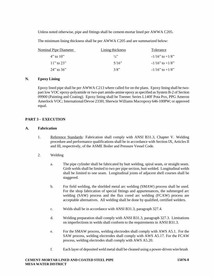
CEMENT-MORTAR LINED AND COATED STEEL PIPE
MESA WATER DISTRICT
15076-8
Unless noted otherwise, pipe and fittings shall be cement-mortar lined per AWWA C205.
The minimum lining thickness shall be per AWWA C205 and are summarized below:
N. Epoxy Lining
Epoxy lined pipe shall be per AWWA C213 where called for on the plans. Epoxy lining shall be two-
part low VOC epoxy-polyamide or two-part amido-amine epoxy as specified as System B-2 of Section
09900 (Painting and Coating). Epoxy lining shall be Tnemec Series L140F Pota Pox, PPG Ameron
Amerlock VOC; International/Devoe 233H; Sherwin Williams Macropoxy 646-100PW; or approved
equal.
PART 3 - EXECUTION
A. Fabrication
1. Reference Standards: Fabrication shall comply with ANSI B31.3, Chapter V. Welding
procedure and performance qualifications shall be in accordance with Section IX, Articles II
and III, respectively, of the ASME Boiler and Pressure Vessel Code.
2. Welding
a. The pipe cylinder shall be fabricated by butt welding, spiral seam, or straight seam.
Girth welds shall be limited to two per pipe section, butt welded. Longitudinal welds
shall be limited to one seam. Longitudinal joints of adjacent shell courses shall be
staggered.
b. For field welding, the shielded metal arc welding (SMAW) process shall be used.
For the shop fabrication of special fittings and appurtenances, the submerged arc
welding (SAW) process and the flux cored arc welding (FCAW) process are
acceptable alternatives. All welding shall be done by qualified, certified welders.
c. Welds shall be in accordance with ANSI B31.3, paragraph 327.4.
d. Welding preparation shall comply with ANSI B31.3, paragraph 327.3. Limitations
on imperfections in welds shall conform to the requirements in ANSI B31.3.
e. For the SMAW process, welding electrodes shall comply with AWS A5.1. For the
SAW process, welding electrodes shall comply with AWS A5.17. For the FCAW
process, welding electrodes shall comply with AWS A5.20.
f. Each layer of deposited weld metal shall be cleaned using a power-driven wire brush
Nominal Pipe Diameter Lining thickness Tolerance
4” to 10” ¼” -1/16” to +1/8”
11” to 23” 5/16” -1/16” to +1/8”
24” to 36” 3/8” -1/16” to +1/8”

CEMENT-MORTAR LINED AND COATED STEEL PIPE
MESA WATER DISTRICT
15076-9
prior to depositing the next layer of weld metal. The final pass shall be cleaned by a
power-driven wire brush.
g. For field welds using the SMAW process, a minimum of three passes shall be used
for welded joints on 36-inches in diameter and larger. Welds shall be full
circumferential. For controlled shop welding processes using SAW or FCAW, weld
joints may be made with two passes.
h. Beveled ends for butt welding shall conform to ANSI B16.25. Slag shall be removed
by chipping or grinding. Surfaces shall be clean of paint, oil, rust, scale, slag, and
other material detrimental to welding. When welding the reverse side, slag shall be
chipped out before welding.
B. Joint Ring Protective Coating
The exposed portion of joint rings shall be coated with a 3-mil minimum thickness organic zinc
pigmented coating meeting U.S. Federal Specification TT-P-641.
C. Shop Hydrostatic Test
After completion of fabrication and welding in the shop, and prior to the application of any lining and
coating, each section of steel pipe shall be shop tested. The steel cylinder with joint rings shall be
stressed to 75% of the minimum yield stress of the steel.
D. Shop Testing of Fittings
1. Dye Penetrant Test: Seams in fittings which have not been previously shop hydrostatically
tested shall be tested by the dye penetrant method as described in ASME Boiler and Pressure
Vessel Code Section VIII, Appendix B.
2. Air-Soap Test: In addition to the dye penetrant method of testing, the air-soap method with
air at 5 psi shall be used on joints susceptible to being tested by such a method.
3. Pressure Test in Lieu of Dye Penetrant Test: In lieu of the dye penetrant method of testing,
completed fittings may be hydrostatically tested using the field hydrostatic test pressure or
125% of the design pressure, whichever is higher.
E. Pipe Bracing
1. Adequate pipe bracing shall be provided on all specials, fittings and straight pipe so as to
avoid damage to the pipe and fittings during handling, storage, and hauling. The pipe bracing
shall be placed as soon as practical and shall remain in place while the pipe is loaded,
transported, and unloaded at the job site. Pipe sections shall be braced within 12 inches of
each end with two 2 x 4’s wedged in the pipe at right angles to each other for 18 inch
diameter pipe and larger.
2. Piping shall be transported with vertical and horizontal bracing per manufacturer’s plan. Any
pipe damaged during handling, hauling, or storage due to improper bracing shall be repaired
or replaced.
F. Delivery of Small Parts
CEMENT-MORTAR LINED AND COATED STEEL PIPE
MESA WATER DISTRICT
15076-10
Small parts, consisting of gaskets, bolts, nuts, washers, jumper rods, and flange insulation kits, shall be
delivered to the job site in suitable containers, each marked to identify the contents.
G. Installation
Pipe shall be installed in accordance with the requirements of Section 15051 (Installation of Pressure
Pipelines).
H. Field Inspection of Cement Mortar Lining and Interior Pipe Joints
Mesa Water my require the contractor to perform closed circuit television (CCTV) inspection of the
interior of all pipeline segments with diameters less than 30-inches; and for all sections of pipe,
regardless of diameter, which are deemed not readily accessible for inspection by Mesa Water’s
personnel. Mesa Water will provide the specifications and requirements for the interior pipe inspection
on a case by case basis.
END OF SECTION
COMBINATION AIR RELEASE AND VACUUM RELIEF VALVES
MESA WATER DISTRICT
15089 - 1
SECTION 15089
COMBINATION AIR RELEASE AND VACUUM RELIEF VALVES
PART 1 - GENERAL
A. Description
This section describes materials and installation of combination air release and vacuum relief
valves, air-release valves, and air and vacuum valves.
B. Related Work Specified Elsewhere
1. Painting and Coating: 09900.
2. Hydrostatic Testing of Pressure Pipelines: 15042.
3. Copper Pipe and Fittings: 15057.
4. Manual Valves: 15100.
C. Submittals
1. Submit manufacturer's catalog data. Show dimensions, materials of construction by
ASTM reference and grade, and coatings.
D. Application
1. Combination air release and vacuum relief valves (combination air valves) shall be
installed at high points on the pipelines and as shown on the plans.
2. If the profile changes during construction from that shown on the drawings,
combination air valve assemblies shall be installed at the high points on the pipelines
as constructed. The location of the valve cover shall be coordinated with Mesa
Water’s field representative.
3. Combination air valve assemblies shall function to slowly release pockets of air which
accumulate at high points, changes in line gradient, exhaust large quantities of air
from pipeline while being filled and admit large quantities of air into the pipeline
when being drained to prevent air lock or vacuum collapse of the pipe.
PART 2 – MATERIALS
A. Coating
Valves shall be coated on the exterior in accordance with Section 09900 (Painting and
Coating). Prime coat shall be shop-applied at the place of manufacture. Color of finish coat
shall match the color of the adjacent piping. Finish coat shall be applied in the field.

COMBINATION AIR RELEASE AND VACUUM RELIEF VALVES
MESA WATER DISTRICT
15089 - 2
B. Lining
The interior surfaces of the combination air valves shall be coated per Section 09900 (Painting
and Coating), System G-1. Seating areas and plastic, stainless steel, or other high alloy parts
shall not be coated. Internal lining for potable water facilities shall be NSF 61 approved epoxy
to a minimum thickness of 12 mils (DFT) and shall be Holiday tested.
C. Bolts and Nuts for Flanged Valves
1. Bolts and nuts for flanged valves and flanges shall be Type 316 stainless steel
conforming to ASTM A 193, Grade B8M, for bolts and ASTM A 194, Grade 8M, for
nuts. The length of each bolt or stud shall be such that between ¼ inch and ½ inch
will project through the nut when drawn tight.
2. Washers: Washers shall be provided for each nut; shall be of the same material as the
nuts; and shall be installed adjacent to the nut, between the nut and the flange.
D. Gaskets
Gaskets for flanged end valves shall be as described in the detailed, individual piping
specifications.
E. Valves
1. Valves shall be manufactured in accordance with AWWA C-512.
2. Air Release Valves, 1-Inch and 2-Inch.
a. Air-release valves for water service shall function to slowly release pockets of
air which accumulate at high points in piping systems. Valves shall have a
float-actuated compound lever with linkage mechanism to release air. Float
shall withstand an external pressure of 1,000 psig without collapsing.
b. Air-release valves shall incorporate a body with flanged top cover and
replaceable orifice and a synthetic rubber needle or disc actuated by the float
and linkage mechanism. Top cover or near the bottom of the valve body shall
include a 3/8-inch threaded outlet with stainless steel plug.
c. Materials of construction for air release valves shall be as follows:
Component Material Specification
Body and cover Cast iron ASTM A 126, Class B
Float Stainless-steel AISI Type 316, ASTM A 240
or A 276
Linkage, orifice air-
release mechanism
Stainless-steel AISA Type 316, ASTM A 240 or
A 276
Seat EPDM --

COMBINATION AIR RELEASE AND VACUUM RELIEF VALVES
MESA WATER DISTRICT
15089 - 3
d. Valves shall be designed for an operating pressure of 150 psi. Valves shall be
APCO, ValMatic, Crispin or approved equal.
3. Air and Vacuum Valves, 3-Inch and greater.
a. Air and vacuum valves for water service shall have a float assembly and
large venting orifice to exhaust large quantities of air from pipelines when
being filled and to admit large quantities of air when pipelines are being
drained. The float shall rise with the water level in the valve body to close
the orifice by sealing against a synthetic rubber seat. Float shall withstand
an external pressure of 1,000 psig without collapsing.
b. Air and vacuum valves 3-inches and smaller shall have 1/2-inch threaded
outlets with stainless steel plugs in the top cover and near the bottom of the
valve body. Air and vacuum valves larger than 3-inches shall have a 1-inch
threaded drain outlet with stainless steel plug near the bottom of the valve
body and a 1-inch threaded outlet with stainless steel plug on the side of the
valve body above the minimum water level. Float shall be able to withstand
an external pressure of 1,000 psig without collapsing.
c. Materials of construction for air and vacuum valves for shall be as follows:
Component Material Specification
Body and cover Cast iron ASTM A 126, Class B
Float, guide rod,
guide bushings
Stainless-steel AISI Type 316, ASTM A 240 or
A 276
Seat EPDM ---
d. Valves shall be designed for an operating pressure of 150 psi. Valves shall be
APCO, Crispin, Val-Matic or approved equal.
4. Combination Air Release and Vacuum Relief Valves, 1-Inch Through 4-Inch
a. Combination air-release valves for water service shall consist of both an air
and vacuum valve and air-release functions contained in one body. The air
and vacuum shall serve to release and admit large quantities of air when
pipelines are filled and drained. The air-release shall serve to release small
quantities of air that accumulate during pipeline operation.
b. Valves shall have an operating pressure of 150 psi. Valves shall be APCO
140C/150C Series; Val-Matic 200C Series, Crispin UL Series or approved
equal.
c. Materials of construction for the combination air valves shall be as follows:

COMBINATION AIR RELEASE AND VACUUM RELIEF VALVES
MESA WATER DISTRICT
15089 - 4
Materials of
construction for Material Specification
Body and cover Cast iron ASTM A 126, Class B
Float, float arm,
poppet
Stainless-steel AISI Type 316, ASTM A
240 or A 276
Valve Trim Stainless-steel AISI Type 316, ASTM A 240
or A 276
Seat, orifice button EPDM --
Cover Bolts Stainless-steel AISI Type 316
F. Valve End Connections
1. Applications: Valves smaller than 3-inches shall have threaded ends. Valves
3-inches and larger shall have flanged ends.
2. Flanged Connections: Flanges for Class 150 valves shall comply with ANSI B16.1,
Class 125.
3. Threaded Connections: Threaded ends shall comply with ANSI B1.20.1.
G. Service Piping
Water service piping utilized in the installation of the 2" and smaller combination air release
and vacuum relief valves shall be Type K copper with brass accessories per Section 15057
(Copper Pipe and Fittings).
H. Vented Cover
1-inch and 2-inch valves shall be enclosed inside a removable, cylindrically-shaped, vented
cover as shown on Mesa Water’s Standard Drawings. Vented covers shall be manufactured of
linear-low-density polyethylene (LLDPE) as made by Amorcast Products, Pipeline Products,
Inc. or approved equal. The color of the vented cover shall be selected by Mesa Water. The
cover shall be 18-inch diameter by 30-inches high vented enclosure.
3-inch and 4-inch valves shall be enclosed inside a removable, cylindrically-shaped, vented
cover fabricated of welded steel pipe, hot dip galvanized after fabrication and painted in
accordance with Section 09900 (Painting and Coating).
PART 3 – EXECUTION
A. Installation
1. Combination air valve assemblies shall be installed in accordance with the details on
Mesa Water’s Standard Drawings.
2. The tap for the air valves shall be made in a level section of pipe no closer than 18-
inches to a bell, coupling, joint, or fitting.
COMBINATION AIR RELEASE AND VACUUM RELIEF VALVES
MESA WATER DISTRICT
15089 - 5
3. Flanged Connections: Flanges shall be cleaned by wire brushing before
installing flanged valves. Flange bolts and nuts shall be cleaned by wire brushing,
and threads lubricated with oil and graphite. Nuts shall be tightened uniformly and
progressively. If flanges leak under pressure testing, nuts and bolts shall be
loosened or removed, the gasket reseated or replaced, the bolts and nuts reinstalled
or retightened, and joints retested. Joints shall be watertight.
4. Threaded Connections: Threaded joints shall be cleaned by wire brushing or
swabbing. Teflon joint compound or Teflon tape shall be applied to pipe threads
before installing threaded valves. Joints shall be watertight.
B. Valve Pressure Testing
Valves shall be tested at the same time that the connecting pipelines are pressure tested. See
Section 15042 (Hydrostatic Testing of Pressure Pipelines) for pressure testing requirements.
Protect or isolate any parts whose pressure rating is less than the test pressure.
END OF SECTION
MANUAL VALVES
MESA WATER DISTRICT
15100 - 1
SECTION 15100
MANUAL VALVES
PART 1 - GENERAL
A. Description
This section includes materials, testing, and installation of manually operated valves and
check valves.
B. Related Work Specified Elsewhere
1. Painting and Coating: 09900.
2. Hydrostatic Testing of Pressure Pipelines: 15042.
C. Submittals
1. Submittals shall include the following minimum information. Factory signed and
dated certification of compliance shall accompany all submittals. Signatures of
agents or distributors of the factory will not be accepted.
a. Manufacturer's catalog data and detail construction sheets showing all valve
parts and describing material of construction by material and specification
(such as AISI, ASTM, SAE, or CDA).
b. Show valve dimensions including laying lengths. Show dimensions and
orientation of valve operators, as installed on the valves.
c. Show valve linings and coatings.
d. Factory torque sheets minimally supplying actuator output and valve input
torque requirements. Method for calculating input torque shall be the same
as per AWWA Class 150B designation.
e. Manufacturer’s warranty.
D. Valve Selection
For 4-inch through 12-inch diameter valves, the contractor shall provide resilient-seated gate
valves rated for 250 psi working pressure. For valves larger than 12-inches in diameter, the
contractor shall provide butterfly valves or resilient-seated gate valves.
MANUAL VALVES
MESA WATER DISTRICT
15100 - 2
PART 2 - MATERIALS
A. General
Valves shall be provided complete with operating hand-wheels, levers, chain-wheels,
extension stems, floor stands, worm gear operators, operating nuts, chains, and wrenches
required for operation.
Valves shall have the name of the manufacturer and the size of the valve cast or molded onto
the valve body or bonnet or shown on a permanently attached corrosion-resistant plate.
The flanges of valves may be raised or plain faced. Flanges of valves designed for a working
pressure of 150 psi or less shall be faced and drilled to a 125 pound American Standard
dimension. Flanges of all valves designed for a working pressure of greater than 150 psi shall
be faced and drilled to 250 pound American Standard dimensions.
Body bolts for all valves shall be Type 316 stainless steel.
The contractor or developer shall choose an approved valve manufacturer and then use it
throughout the development.
B. Butterfly Valve Actuators
1. Actuators for Exposed Valves Smaller Than 6-Inches: See section on gate valves.
2. Actuators for Buried Valves
a. Valves for buried and submerged applications shall be provided with a direct
acting 2-inch square AWWA wrench nut. The wrench nut shall have an arrow
cast thereon, indicating the direction of opening. All valves shall be open by
turning the nut counter-clockwise and close by turning the nut clockwise. The
wrench nut shall be suitably fastened to the actuator input shaft. If the shaft is
smooth, the wrench nut shall be fastened to the input shaft by means of a
5/16-inch diameter stainless steel pin passing entirely through the shaft and
the wrench nut. Key with keyway shall also be acceptable. If the shaft is
splined, the wrench nut shall be formed to fit the splined shaft.
b. Provide totally enclosed operators designed for buried service with watertight
shaft seals and watertight valve and actuator cover gaskets.
c. Buried valves shall have a water tight seal plate in place of the valve position
indicator. No rotating part indicating position shall be allowed for valves
intended for buried service.
3. Actuators for Valves 4-Inches and Larger
MANUAL VALVES
MESA WATER DISTRICT
15100 - 3
Gear actuators shall be provided on all butterfly valves,12-inches. Butterfly valves
less than 24-inch in diameter shall have gear actuators of the “traveling nut type”.
Traveling-nut actuators shall be furnished on all valves in this size range unless
torque or pressure conditions dictate a “worm gear type”. Gear actuators for valves
24-inch in diameter and larger shall be of the “worm gear type”. Worm gear actuators
shall be furnished on all valves in this size range.
4. General Requirements for Gear Actuators
a. Gear actuators shall be enclosed, suitable for running in grease with seals
provided on shafts to prevent entry of dirt and water into the actuator.
External trim and all threaded parts of the actuator shall be Type 316 stainless
steel material.
b. Gear actuators shall be of the totally enclosed design, proportioned to permit
operation of the valve under full operating head in either direction, with a
maximum pull of 80 pounds on the hand-wheel or with a maximum input of
150 ft-lbs applied to the AWWA wrench nut. Design and torque capacity
shall consider flow and shut-off in “Both” directions.
c. Actuators shall be provided with “open” and “closed” position stop limiting
devices. Actuators shall be of the self-locking type to prevent the disc or plug
from creeping.
5. Specific Requirements for Traveling Nut Gear Actuators
a. Traveling nut actuators shall withstand 450 foot pounds of input torque
against the stop limiting devices without causing damage.
b. Signed factory compliance shall accompany submittals stating that these
specifications and the applicable standards have been adhered to.
c. All exposed threaded parts, including cap screws, case bolts, carriage bolts,
cover screws, machine screws, set screws, bonnet bolts on the worm gear
housing or any other exterior location of the actuator, its cover or housing
shall be Type 316 stainless steel.
d. Traveling nut type gear actuators shall be able to rotate the valve element
(disc, plug, or ball) from the fully “closed” position to the fully “open”
position with a number of turns of the actuator nut or wheel. For 4-inch
through 10-inch valves, the number of turns shall not be fewer than 29 turns.
For 12-inch through 20-inch valves, the number of turns shall not be fewer
than 29 turns and not more than three (3) times the number of diameter
inches. Where the number of turns may fall outside of the range for turn
limits above, the use of a factory attached spur gear reducer shall be used to
provide the appropriate number of rotations from the fully “open” to the fully
“closed” position.
Spur gear assemblies shall be mounted integrally to the actuator by approved
means and shall meet all of the other component and torque requirements
listed herein.
MANUAL VALVES
MESA WATER DISTRICT
15100 - 4
e. Actuators shall be Pratt Series MDT, Dezuirk M-Series, Mueller MDT, or
approved equal.
6. Specific Requirements for Worm Gear Actuators
a. Worm gears shall be of the “self-locking” one-piece design of gear bronze
material (ASTM B-427), accurately machine cut.
b. The worm shall be hardened alloy steel (ASTM A 322, Grade G 41500; or
ASTM A 148, Grade 105-85), with thread ground and polished.
c. The reduction gearing shall run in a proper lubricant inside a ductile iron
housing.
d. All exposed (at the exterior of the actuator) threaded parts, including cap
screws, case bolts, carriage bolts, cover screws, machine screws, set screws,
bonnet bolts on the worm gear housing or any other exterior location of the
actuator, its cover or housing shall be Type 316 stainless steel.
e. Actuator components shall be designed to withstand a pull of 200 pounds for
hand-wheel or chain-wheel actuators between the input and stop limiting
devices without damage, and an input torque of 300-foot-pounds for
operating nuts when operating against the stops.
f. Gear actuators shall be able to rotate the valve element (disc, plug or ball)
from the fully “closed” position to the fully “open” position with a number of
turns of the operator nut or wheel, not fewer than one-and-a-half (1.5) times
the number of diameter inches and not more than three (3) times the number
of diameter inches.
Where the number of turns may fall outside of the range for turn limits above,
the use of a factory attached spur gear reducer shall be used to provide the
appropriate number of rotations from the fully “open” to the fully “closed”
position. Spur gear assemblies shall be mounted integrally to the actuator by
approved means and shall meet all of the other component and torque
requirements listed herein.
g. Actuators shall be Limitorque Model HBC or PT Series, EIM Model WB
Series, or Auma GS Series. There are no known equals.
7. Operating Torque Requirement for Buried Valves: Actuators on buried valves shall
be designed to produce the specified torque with a maximum input of 150 ft-lbs
applied to the wrench nut (at the maximum rated pressure and a velocity of 15 fps).
Submittals shall include factory torque sheets minimally supplying operator output
and valve input torque requirements. Torque safety factors shall comply with the
latest versions of AWWA Standards.
8. Hand wheels: Valves for above-ground applications shall be provided with a hand-
wheel. Minimum hand-wheel diameter shall be 12-inches. The hand-wheel shall have

MANUAL VALVES
MESA WATER DISTRICT
15100 - 5
an arrow thereon, indicating the direction of the opening. The hand-wheel shall be
suitably fastened to the actuator input shaft.
Actuators equipped with hand-wheels shall be designed to produce the specified
torque with a maximum pull of 80 pounds of the hand-wheel rim. Submittals shall
include factory torque sheets minimally supplying operator output and valve input
torque requirements. Torque safety factors shall comply with the latest versions of
AWWA Standards.
9. Opening Direction: Valve actuators, hand-wheels, or levers shall open by turning
counterclockwise. (Commonly stated as, “open-left – close-right”).
10. Position Indicators: Valve position indicators shall be provided for all above ground
valves.
C. Valve Boxes for Buried Valves
1. General: Valve risers shall be 8-inch SDR 35 or Schedule 40 PVC pipe.
2. Valve Box Lids: Valve box lids shall be for traffic use, and shall be concrete and
cast-iron, and shall be designed to rest without a frame on a cast-in-place concrete
ring surrounding the valve extension pipe. The lid skirt shall be tapered for a close fit
inside the upper sleeve portion of the valve box. Lids shall be triangular with the
word “Water” cast into the top surface of the valve box lid. Lids shall be coated and
colored in accordance with Section 09900 (Painting and Coating), System No. C-1.
3. Manufacturers: Valve boxes shall be triangular in shape and shall be Brooks 4-TT,
Eisel Enterprises, Inc. No. 4TT, H&C 4TT. There are No Equals.
D. Extension Stems for Buried Valve Actuators
Where the depth of the valve is such that its operating nut is more than 4-feet below grade,
operating extension stems shall be provided to bring the operating nut to a point between 24
to 36-inches below the surface of the ground and/or box cover. Extension stems shall be solid
Type 316 stainless steel, and shall be complete with 2-inch-square operating nut. Stem shall
be provided with a 1/8-inch centerguide to keep stem centered. Pinned couplings are not
permitted. Extension stems shall conform to Mesa Water’s Standard Drawings.
E. Bolts, Nuts, and Gaskets for Flanged Valves
Bolts and nuts for flanged valves shall be heavy hex head Type 316 stainless steel (B8M)
described in the detailed individual piping specifications.
F. Painting and Coating for Valves
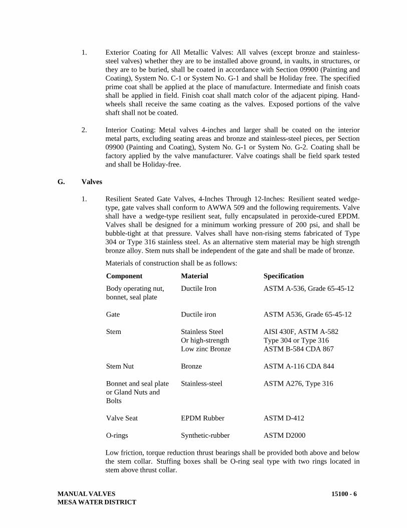
MANUAL VALVES
MESA WATER DISTRICT
15100 - 6
1. Exterior Coating for All Metallic Valves: All valves (except bronze and stainless-
steel valves) whether they are to be installed above ground, in vaults, in structures, or
they are to be buried, shall be coated in accordance with Section 09900 (Painting and
Coating), System No. C-1 or System No. G-1 and shall be Holiday free. The specified
prime coat shall be applied at the place of manufacture. Intermediate and finish coats
shall be applied in field. Finish coat shall match color of the adjacent piping. Hand-
wheels shall receive the same coating as the valves. Exposed portions of the valve
shaft shall not be coated.
2. Interior Coating: Metal valves 4-inches and larger shall be coated on the interior
metal parts, excluding seating areas and bronze and stainless-steel pieces, per Section
09900 (Painting and Coating), System No. G-1 or System No. G-2. Coating shall be
factory applied by the valve manufacturer. Valve coatings shall be field spark tested
and shall be Holiday-free.
G. Valves
1. Resilient Seated Gate Valves, 4-Inches Through 12-Inches: Resilient seated wedge-
type, gate valves shall conform to AWWA 509 and the following requirements. Valve
shall have a wedge-type resilient seat, fully encapsulated in peroxide-cured EPDM.
Valves shall be designed for a minimum working pressure of 200 psi, and shall be
bubble-tight at that pressure. Valves shall have non-rising stems fabricated of Type
304 or Type 316 stainless steel. As an alternative stem material may be high strength
bronze alloy. Stem nuts shall be independent of the gate and shall be made of bronze.
Materials of construction shall be as follows:
Component Material Specification
Body operating nut,
bonnet, seal plate
Ductile Iron ASTM A-536, Grade 65-45-12
Gate Ductile iron ASTM A536, Grade 65-45-12
Stem Stainless Steel
Or high-strength
Low zinc Bronze
AISI 430F, ASTM A-582
Type 304 or Type 316
ASTM B-584 CDA 867
Stem Nut Bronze ASTM A-116 CDA 844
Bonnet and seal plate
or Gland Nuts and
Bolts
Stainless-steel ASTM A276, Type 316
Valve Seat EPDM Rubber ASTM D-412
O-rings Synthetic-rubber ASTM D2000
Low friction, torque reduction thrust bearings shall be provided both above and below
the stem collar. Stuffing boxes shall be O-ring seal type with two rings located in
stem above thrust collar.

MANUAL VALVES
MESA WATER DISTRICT
15100 - 7
Each valve shall have a smooth unobstructed waterway free from any sediment
pockets.
Valves shall be Clow Resilient Wedge Gate Valve, Mueller A2360, American AVK,
M&H Style 4067, or approved equal.
2. Butterfly Valves: Butterfly valves shall be short body, flanged type, conforming to
AWWA C504, Class 150B. Wafer style valves are not permitted. The minimum
working differential pressure across the valve disc shall be 150 psi.
Valve ends shall be as shown on the drawings and in all cases shall match the class
rating of the valve. Class 150 valves shall have 150-lb flanges and Class 250 valves
shall have 250 lb. flanges. Flanged ends shall be Class 125, ANSI B-16.1 unless
otherwise specified.
Valve shafts shall be Type 304 or 316 stainless steel for Class 150 valves and 17-4
PH stainless steel for class 250 valves. Valve shafts shall be stub shaft or one-piece
units extending completely through the valve disc.
Valve bodies shall be tested at a pressure equal to twice the design working pressure.
Gears shall be sized for bi-directional flow at 15 fps and at full rated pressure
differential.
Materials of construction shall be as follows:
Component Material Specification
Body Ductile iron ASTM A536, Grade 65-45-12
Valve Shaft (CL 150)
Valve Shaft (CL 250)
Stainless Steel
Stainless Steel
Type 304 or Type 316
Type 17-4 PH
Exposed body
capscrews, bolts &
nuts (including
squeeze-pins)
Stainless-steel ASTM A276, Type 316
Discs Ductile iron ASTM A536, Grade 65-45-12
Valve Seat EPDM Rubber ASTM D-412
O-Rings Synthetic Rubber ASTM D-2000
The rubber seat shall be made from peroxide-cured EPDM rubber and shall be
fastened integrally with the valve body. Rubber seats fastened to the disc by any
means shall not be allowed.

MANUAL VALVES
MESA WATER DISTRICT
15100 - 8
Valves shall be Pratt Groundhog, Dezurik BAW, Mueller Lineseal, or approved
equal.
3. Ball Valves 2-Inches and Smaller: Ball valves, 2-inches and smaller, for water
service shall be three-piece body style and shall be manufactured of Type 316
stainless steel. The minimum design operating pressure rating shall be 300 psi WOG
at a temperature of 150°F. Valves shall have plastic coated lever operators with a
locking mechanism. Valves shall have full bore ports, female iron pipe thread
screwed ends, and non-blowout stems.
Materials of construction shall be as follows:
Component Material Specification
Body, ball, stem Stainless-steel Type 316, ASTM A276
Seat, seals Teflon
Valves shall be Apollo, Sharpe, Xomox, or Stockham Figure S-127 or approved
equal.
4. Check Valves 4-inches and Larger:
a. Swing Check Valves: Swing check valves shall conform to AWWA C-508,
and shall be iron body, mounted with the following materials of construction:
Component
Disc
Material
Ductile Iron
Specification
ASTM A-536, Grade 65-45-12
Body and Cap Ductile Iron ASTM A-536, Grade 65-45 -12
Hinge or Arm Cast Iron ASTM A-126, Class B
Hinge Pin Stainless Steel ASM A-276, Type 304 or 410
Cover Bolts & Nuts Stainless Steel ASTM A276, Type 316
Ends shall be flanged, Class 125, ANSI B-16.1. Valves shall be designed for
a minimum working pressure of 150 psi. Valves shall be equipped with
outside lever and spring.
Valves shall be Clow 1106, M&H Style 259, Pratt Series 8001, or approved
equal.
b. Silent Check Valves, Class 150: Silent check valves shall be flanged. Valves
shall be equipped with a spring mechanism to provide for non-slam closure of
the valve without backflow, in any position, and shall not be dependent on
gravity or backflow for closure.

MANUAL VALVES
MESA WATER DISTRICT
15100 - 9
Materials for construction shall be as follows:
Component
Disc
Material
Aluminum
Specification
ASTM B-148
Bronze
Body Ductile Iron ASTM A-536, Grade 65-45 -12
Spring, Pin, Stops Stainless Steel ASM A-276, Type 316
Cover Bolts & Nuts Stainless Steel ASTM A276, Type 316
Seat EPDM Rubber ASTM D-412
Ends shall be flanged, Class 125, ANSI B-16.1.
Valves shall be APCO Series 600, Pratt Series 821, Val-Matic or approved
equal.
5. Solenoid Valves 1-1/2 inch and Smaller:
Solenoid valves of sizes ¼-inch through 1-1/2 inch for water and air service shall
have forged brass (Alloy C-23000) or bronze (ASTM B-62) bodies with Teflon main
seats. Valve components in contact with potable water shall be NSF 61 certified.
Internal plunger, core tube, plunger spring, and cage assembly shall be stainless steel
(Types 302, 304, or 305). Solenoid enclosures shall be NEMA Type 4. Valve
actuators shall be 120-volt AC or 24-volt DC as stated on the plans. Seals shall be
Teflon. Valves shall have a maximum operating pressure and a maximum differential
pressure of 250 psi.
Solenoid valves shall be energized to open or close, as required, and as noted on the
plans. Valves shall be ASCO “Red Hat” only. There are no equals.
6. Tapping Valves
Tapping valves shall conform with the requirements for resilient seated gate valves.
Valve ends shall be flanged, and the flange at one end shall have slotted bolt holes to
fit standard tapping machines. Seat rings shall be oversized to permit the use of full-
size cutters. Tapping valves shall be Clow Resilient Wedge Gate Valve, Mueller,
American AVK, M&H, or approved equal.
7. Tapping Sleeves
Tapping sleeves shall be either the “mechanical joint” type with stainless steel plug,
or stainless steel full-circle style sleeves. Gaskets shall be EPDM rubber with a wide
cross-section. Bolts, nuts, and washers shall be Type 316 stainless steel. Mechanical

MANUAL VALVES
MESA WATER DISTRICT
15100 - 10
joint tapping sleeves shall be JCM Industries, Inc., JCM 414, Mueller H-615, or
approved equal. Stainless steel full-circle tapping sleeves shall be JCM Industries,
Inc., JCM 432, Mueller H-304SS, Romac SST111 or approved equal. All tapping
sleeves for use on Asbestos Cement Pipe shall be mechanical joint type.
PART 3 - EXECUTION
A. Joints
1. Flanged Joints: Boltholes of flanged valves shall straddle the horizontal and vertical
centerlines of the pipe run to which the valves are attached. Flanges shall be cleaned
by wire brushing before installing flanged valves. Flange bolts and nuts shall be
cleaned by wire brushing, threads shall be lubricated with oil and graphite, and nuts
shall be tightened uniformly and progressively. If flanges leak under pressure testing,
nuts and bolts shall be loosened or removed, the gasket shall be reseated or replaced,
the bolts and nuts shall be reinstalled or re-tightened, and the joint retested. Joints
shall be watertight.
2. Threaded Joints: Threaded joints shall be cleaned by wire brushing or swabbing.
Teflon joint compound or Teflon tape shall be applied to pipe threads before
installing threaded valves. Joints shall be watertight.
B. Valve Installation
1. Buried Valves: Buried valves shall be wrapped with two layers of 8-mil polyethylene
wrap per AWWA C105.
2. Valve Supports: Valves shall be anchored in concrete as shown on Mesa Water’s
Standard Drawings. Supports are not required for buried valves bolted to flanged
pipe or fixed or supported fittings. Supports shall be installed prior to pressurizing
the system.
3. Backfill: Backfill within 24-inches of valves shall be clean washed sand in
accordance with the requirements of Section 02223 (Trenching, Backfilling, and
Compacting).
4. Valves in horizontal runs of pipe shall be installed with their operating stems
horizontal.
5. Valves on vertical runs of pipe that are next to wall shall be installed with their stems
horizontal, away from the wall. Valves on vertical runs of pipe that are not located
next to walls shall be installed with their stems horizontal, oriented to facilitate valve
operation.
C. Valve Boxes
MANUAL VALVES
MESA WATER DISTRICT
15100 - 11
Valve boxes shall be firmly supported and shall be kept centered and plumb over the
operating nut of the valve. Beveled sections of pipe will not be allowed at the top of the valve
riser pipe. The top cut shall be square and machine made.
In new tracts, and where pavement has not been placed, the valve extension risers for “key
valves” shall extend well above the ground level to permit ease of location in the event of the
need for emergency shut-off. The final valve box elevation shall be flush with the finished
pavement surface.
D. Valve Leakage Testing
1. Valves shall be tested for leakage at the same time that the connecting pipelines are
tested. See Section 15042 (Hydrostatic Testing of Pressure Pipelines) for pressure
testing requirements.
2. Valve Leakage Witness – Pressure Testing:
All butterfly valves 12-inches in diameter and larger, shall be flanged to facilitate
testing. Valves may be tested in a horizontal position. All valves shall be tested bi-
directionally after the actuator is installed and the adjustment stops are set. Each side
of the valve is to be tested for a duration of at least five (5) minutes at the pressure
class rating of the valve with zero loss or leakage.
The pressure test shall be witnessed by Mesa Water’s field representative. Final tests
shall be performed within 20 miles of the project site. A minimum of 72 hours
advance notice to Mesa Water for testing scheduling is required.
E. Tapping Sleeves
Tapping sleeves shall be installed in accordance with the manufacturer’s instructions. The
pipe barrel shall be thoroughly cleaned with a wire brush to provide a smooth, hard surface
for the sleeve. The sleeve shall be supported independent of the pipe during the tapping
operations. The sleeve shall be pressure tested in the presence of Mesa Water’s
Representative prior to tapping. The stainless steel bolts on the tapping sleeve shall be
tightened with 85 to 125 foot-pounds of torque, and retightened after tap is completed. Thrust
blocks shall be provided at the tapping sleeve.
END OF SECTION
BACKFLOW PREVENTERS
MESA WATER DISTRICT
15112 - 1
SECTION 15112
BACKFLOW PREVENTERS
PART 1 - GENERAL
A. Description
This section includes materials, installation, and testing of backflow prevention assemblies.
B. Related Work Specified Elsewhere
1. Copper Pipe and Fittings: 15057.
2. Manual Valves: 15100.
3. Meters: 15150.
C. Submittals
1. Submit certification showing that the backflow device is approved by the Foundation
for Cross-Connection Control and Hydraulic Research, University of Southern
California, School of Engineering.
PART 2 - MATERIALS
A. Shut-Off Valves
1. Gate Valves: The shut-off valves shall be resilient seated gate valves conforming to
Section 15100 (Manual Valves), except that these valves shall have outside stems and
yokes.
2. Ball Valves: Valves two-inches and smaller shall be ball valves and shall conform to
the requirements of Section 15057 (Copper Pipe and Fittings).
B. Fireline By-Pass Piping
By-pass piping shall be copper or brass conforming with Section 15057 (Copper Pipe and
Fittings). The by-pass shall include a meter conforming to the requirements of Section 15150
(Meters) and an approved backflow prevention assembly.
C. Backflow Prevention Assembly
Backflow prevention assemblies shall conform to the latest edition of AWWA C510 or C511
and the "Manual of Cross-Connection Control", Foundation for Cross-Connection Control
and Hydraulic Research, University of Southern California, School of Engineering.

BACKFLOW PREVENTERS
MESA WATER DISTRICT
15112 - 2
D. By-Pass Meter and Backflow Prevention Assembly
The by-pass meter shall conform with the requirements of Section 15150 (Meters), and shall
be compatible with the main backflow device to which it is installed. Mesa Water has
standardized with Badger M25 Meter. A Badger M25 meter shall be supplied unless
otherwise approved by Mesa Water. The backflow prevention assembly and the by-pass meter
and backflow prevention assembly shall be furnished as one complete unit. All by-pass
meters shall be 5/8-inch or 3/4-inch in size and shall read in cubic feet.
E. Pipe and Fittings
Riser pipe and fittings for residential, commercial and irrigation backflow prevention
assemblies shall be consistent with the pipe materials specified within Section 15051
(Installation of Pressure Pipelines).
Pipe and fittings smaller than 4-inches in diameter shall be brass. Short threaded nipples and
brass pipe shall conform to ASTM B 43, regular wall thickness, except that nipples and pipe
of sizes 1-inch and smaller shall be extra strong. Threads shall conform to ANSI B1.20.1.
Brass material shall conform to ANSI/AWWA Standard C800, with a maximum lead content
of 0.25% by average weight.
Pipe and fittings for 4-inch diameter and larger backflow prevention assemblies shall be
ductile iron or cement-mortar lined steel pipe.
PART 3 - EXECUTION
A. Installation
Installation shall comply with the requirements of the latest edition of the Manual of Cross-
Connection Control, and with the latest plumbing codes and applicable local agency
requirements. All backflow prevention devices shall be accessible. Backflow devices shall
not be installed in pits, vaults, or similar potential for submergence locations.
B. Testing
1. Testing should be performed according to Mesa Water Rules & Regulations.
2.
END OF SECTION
DIAPHRAGM-ACTUATED CONTROL VALVES
MESA WATER DISTRICT
15120 - 1
SECTION 15120
DIAPHRAGM-ACTUATED CONTROL VALVES
PART 1 - GENERAL
A. Description
This section includes materials and installation of hydraulically controlled diaphragm-
actuated control valves acting as pressure reducing valves, pressure sustaining valves,
solenoid control valves, booster pump control valves, and altitude valves.
B. Related Work Specified Elsewhere
1. Painting and Coating: 09900.
2. Hydrostatic Testing of Pressure Pipelines: 15042.
C. Submittals
1. Submit dimensional drawings for each size and type of valve provided.
2. Provide listing of materials of construction, with ASTM reference and grade. Show
valve lining and paint primer coating with coating manufacturer and coating system
number or designation.
3. Submit electrical drawings, showing wire and terminal connections, for valves that
are electrically controlled.
4. Submit manufacturer's recommended maximum operating pressure and maximum
recommended flows.
PART 2 - MATERIALS
A. Valve Design
1. General: Valves shall be hydraulically actuated diaphragm type. The body shall
contain a removable seat insert. A resilient rubber disc shall form a drip-tight seal
with the valve seat when pressure is applied above the diaphragm. The diaphragm
assembly shall form a sealed chamber in the upper portion of the valve, separating
operating pressure from line pressure.
2. Component Parts: The pilot control system shall include a fixed or variable orifice,
and all major components of this system, except solenoid pilots, shall be
manufactured by the same company that manufactures the main valve.
Elastomers shall be EPDM rubber material. The diaphragm shall not be used as a
seating surface.
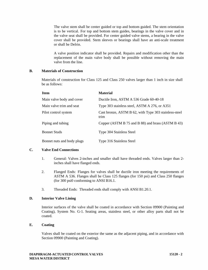
DIAPHRAGM-ACTUATED CONTROL VALVES
MESA WATER DISTRICT
15120 - 2
The valve stem shall be center guided or top and bottom guided. The stem orientation
is to be vertical. For top and bottom stem guides, bearings in the valve cover and in
the valve seat shall be provided. For center guided valve stems, a bearing in the valve
cover shall be provided. Stem sleeves or bearings shall have an anti-scale treatment
or shall be Delrin.
A valve position indicator shall be provided. Repairs and modification other than the
replacement of the main valve body shall be possible without removing the main
valve from the line.
B. Materials of Construction
Materials of construction for Class 125 and Class 250 valves larger than 1 inch in size shall
be as follows:
Item Material
Main valve body and cover Ductile Iron, ASTM A 536 Grade 60-40-18
Main valve trim and seat Type 303 stainless steel, ASTM A 276, or A351
Pilot control system Cast bronze, ASTM B 62, with Type 303 stainless-steel
trim
Piping and tubing
Bonnet Studs
Bonnet nuts and body plugs
Copper (ASTM B 75 and B 88) and brass (ASTM B 43)
Type 304 Stainless Steel
Type 316 Stainless Steel
C. Valve End Connections
1. General: Valves 2-inches and smaller shall have threaded ends. Valves larger than 2-
inches shall have flanged ends.
2. Flanged Ends: Flanges for valves shall be ductile iron meeting the requirements of
ASTM A 536. Flanges shall be Class 125 flanges (for 150 psi) and Class 250 flanges
(for 300 psi0 conforming to ANSI B16.1.
3. Threaded Ends: Threaded ends shall comply with ANSI B1.20.1.
D. Interior Valve Lining
Interior surfaces of the valve shall be coated in accordance with Section 09900 (Painting and
Coating), System No. G-1. Seating areas, stainless steel, or other alloy parts shall not be
coated.
E. Coating
Valves shall be coated on the exterior the same as the adjacent piping, and in accordance with
Section 09900 (Painting and Coating).

DIAPHRAGM-ACTUATED CONTROL VALVES
MESA WATER DISTRICT
15120 - 3
Prime coat shall be shop applied at the place of manufacturer. Finish coats shall be applied in
the field. Paint system and color of finish coat shall match that of connecting piping.
F. Valves
1. Class 125 (150 psi) or Class 250 (300 psi) Pressure-Reducing Valves: Pressure
reducing valves shall automatically maintain a constant downstream pressure
regardless of changing flow rates and/or varying inlet pressures. The pilot control
shall be direct-acting, spring loaded, diaphragm valve, designed to permit flow when
controlled pressure is less than the spring setting. The pilot control system shall be
provided with a strainer, isolation valves, opening speed control, closing speed
control, and, where required for low flow, a flow stabilizer or V-port throttling plug.
Consult Mesa Water for pressure ranges and initial pressure settings. The valve shall
be globe pattern Cla-Val 90-01 Series, Ames ACV 910 Series “Mustang Valve”,
Watts ACV 115 Series, or approved equal.
2. Class 125 (150 psi) or Class 250 (300 psi) Pressure Sustaining or Pressure Relief
Valves: Pressure sustaining/relief valves shall maintain a constant upstream pressure
by relieving excess pressure without causing surges. The pilot control system shall
operate such that as excess line pressure is dissipated, the valve shall slowly close.
The pilot control shall be a direct acting, spring-loaded, diaphragm valve, designed to
permit flow when controlling pressure exceeds a spring setting. The pilot control
system shall be provided with a strainer, isolation valves, opening speed control
(pressure sustaining valves only), and closing speed control. Consult Mesa Water for
pressure ranges and initial pressure settings. The valve shall be globe pattern Cla-Val
50-01 Series, Ames ACV 920 Series “Mustang Valve”, Watts ACV 116 Series, or
approved equal.
3. Class 125 (150 psi) or Class 250 (300 psi) Solenoid Control Valves: Solenoid control
valves shall provide on or off service for controlling flow. The pilot control shall be a
three-way solenoid valve as specified herein. The pilot control system shall be
provided with strainers, isolation valves, opening speed control, and closing speed
control. Consult Mesa Water for energized-to-open or de-energized-to-open
requirements. The valve shall be globe pattern Cla-Val Series 136-03, Ames ACV
300 Series, “Mustang Valve”, Watts ACV 113 Series, or approved equal.
4. Class 125 (150 psi) or Class 250 (300 psi) Booster Pump Control Valve: Booster
pump control valves shall be designed for installation on the discharge of booster
pumps to eliminate pipeline surges caused by starting and stopping of pumps.
Control of valve operation shall be by means of an externally mounted solenoid pilot
valve. The solenoid pilot valve shall be as specified herein. Self-cleaning strainers
shall be used to protect the control system. Valves shall utilize line pressure for
operation. A limit switch shall be provided to be adjustable over entire valve travel.
Valve shall be equipped with a check feature to prevent reversal of flow. The valve
shall be globe pattern Cla-Val 60-11 Series, ACV 980 Series “Mustang Valve”, Watts
ACV 113-21, 413-21, or 513-5 Series, or approved equal.
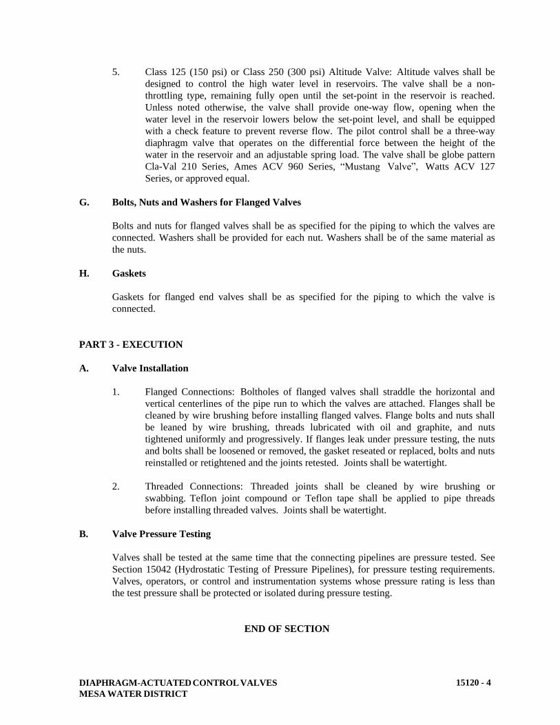
DIAPHRAGM-ACTUATED CONTROL VALVES
MESA WATER DISTRICT
15120 - 4
5. Class 125 (150 psi) or Class 250 (300 psi) Altitude Valve: Altitude valves shall be
designed to control the high water level in reservoirs. The valve shall be a non-
throttling type, remaining fully open until the set-point in the reservoir is reached.
Unless noted otherwise, the valve shall provide one-way flow, opening when the
water level in the reservoir lowers below the set-point level, and shall be equipped
with a check feature to prevent reverse flow. The pilot control shall be a three-way
diaphragm valve that operates on the differential force between the height of the
water in the reservoir and an adjustable spring load. The valve shall be globe pattern
Cla-Val 210 Series, Ames ACV 960 Series, “Mustang Valve”, Watts ACV 127
Series, or approved equal.
G. Bolts, Nuts and Washers for Flanged Valves
Bolts and nuts for flanged valves shall be as specified for the piping to which the valves are
connected. Washers shall be provided for each nut. Washers shall be of the same material as
the nuts.
H. Gaskets
Gaskets for flanged end valves shall be as specified for the piping to which the valve is
connected.
PART 3 - EXECUTION
A. Valve Installation
1. Flanged Connections: Boltholes of flanged valves shall straddle the horizontal and
vertical centerlines of the pipe run to which the valves are attached. Flanges shall be
cleaned by wire brushing before installing flanged valves. Flange bolts and nuts shall
be leaned by wire brushing, threads lubricated with oil and graphite, and nuts
tightened uniformly and progressively. If flanges leak under pressure testing, the nuts
and bolts shall be loosened or removed, the gasket reseated or replaced, bolts and nuts
reinstalled or retightened and the joints retested. Joints shall be watertight.
2. Threaded Connections: Threaded joints shall be cleaned by wire brushing or
swabbing. Teflon joint compound or Teflon tape shall be applied to pipe threads
before installing threaded valves. Joints shall be watertight.
B. Valve Pressure Testing
Valves shall be tested at the same time that the connecting pipelines are pressure tested. See
Section 15042 (Hydrostatic Testing of Pressure Pipelines), for pressure testing requirements.
Valves, operators, or control and instrumentation systems whose pressure rating is less than
the test pressure shall be protected or isolated during pressure testing.
END OF SECTION
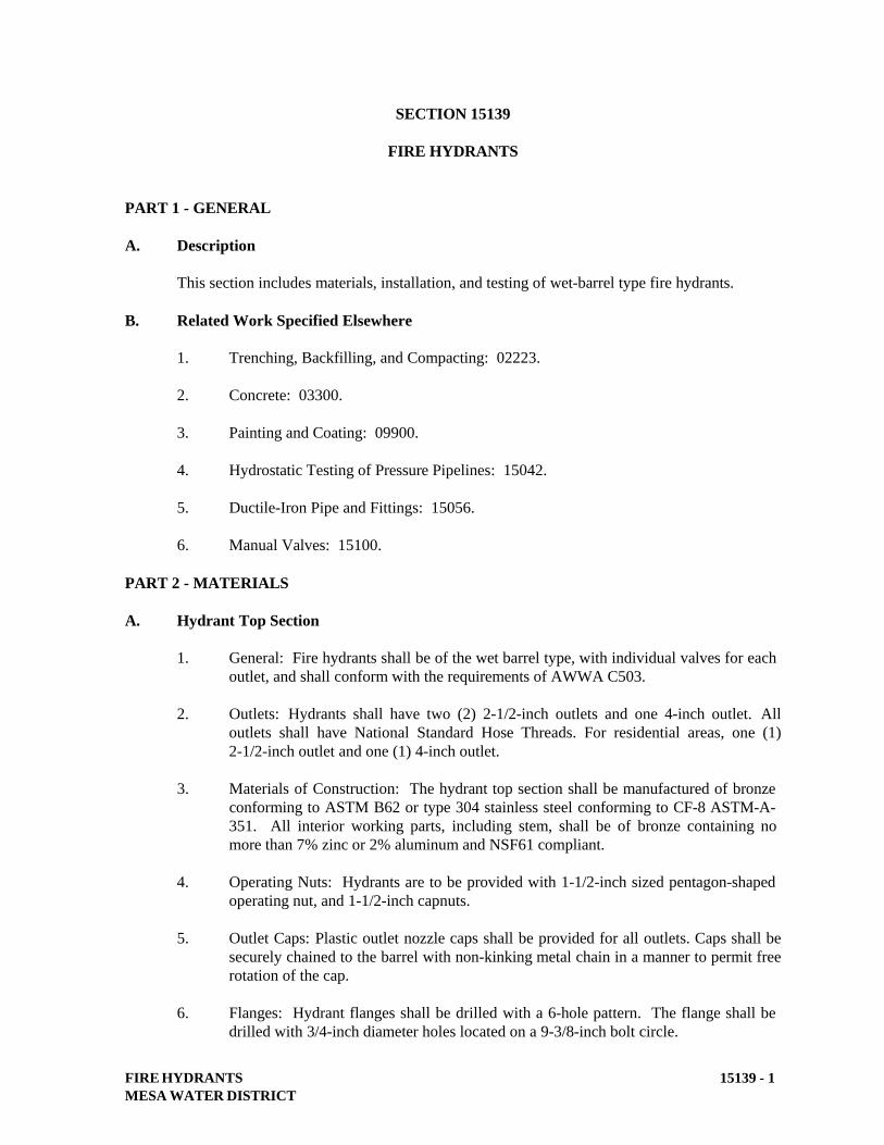
FIRE HYDRANTS
MESA WATER DISTRICT
15139 - 1
SECTION 15139
FIRE HYDRANTS
PART 1 - GENERAL
A. Description
This section includes materials, installation, and testing of wet-barrel type fire hydrants.
B. Related Work Specified Elsewhere
1. Trenching, Backfilling, and Compacting: 02223.
2. Concrete: 03300.
3. Painting and Coating: 09900.
4. Hydrostatic Testing of Pressure Pipelines: 15042.
5. Ductile-Iron Pipe and Fittings: 15056.
6. Manual Valves: 15100.
PART 2 - MATERIALS
A. Hydrant Top Section
1. General: Fire hydrants shall be of the wet barrel type, with individual valves for each
outlet, and shall conform with the requirements of AWWA C503.
2. Outlets: Hydrants shall have two (2) 2-1/2-inch outlets and one 4-inch outlet. All
outlets shall have National Standard Hose Threads. For residential areas, one (1)
2-1/2-inch outlet and one (1) 4-inch outlet.
3. Materials of Construction: The hydrant top section shall be manufactured of bronze
conforming to ASTM B62 or type 304 stainless steel conforming to CF-8 ASTM-A-
351. All interior working parts, including stem, shall be of bronze containing no
more than 7% zinc or 2% aluminum and NSF61 compliant.
4. Operating Nuts: Hydrants are to be provided with 1-1/2-inch sized pentagon-shaped
operating nut, and 1-1/2-inch capnuts.
5. Outlet Caps: Plastic outlet nozzle caps shall be provided for all outlets. Caps shall be
securely chained to the barrel with non-kinking metal chain in a manner to permit free
rotation of the cap.
6. Flanges: Hydrant flanges shall be drilled with a 6-hole pattern. The flange shall be
drilled with 3/4-inch diameter holes located on a 9-3/8-inch bolt circle.
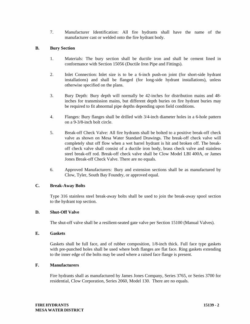
FIRE HYDRANTS
MESA WATER DISTRICT
15139 - 2
7. Manufacturer Identification: All fire hydrants shall have the name of the
manufacturer cast or welded onto the fire hydrant body.
B. Bury Section
1. Materials: The bury section shall be ductile iron and shall be cement lined in
conformance with Section 15056 (Ductile Iron Pipe and Fittings).
2. Inlet Connection: Inlet size is to be a 6-inch push-on joint (for short-side hydrant
installations) and shall be flanged (for long-side hydrant installations), unless
otherwise specified on the plans.
3. Bury Depth: Bury depth will normally be 42-inches for distribution mains and 48-
inches for transmission mains, but different depth buries on fire hydrant buries may
be required to fit abnormal pipe depths depending upon field conditions.
4. Flanges: Bury flanges shall be drilled with 3/4-inch diameter holes in a 6-hole pattern
on a 9-3/8-inch bolt circle.
5. Break-off Check Valve: All fire hydrants shall be bolted to a positive break-off check
valve as shown on Mesa Water Standard Drawings. The break-off check valve will
completely shut off flow when a wet barrel hydrant is hit and broken off. The break-
off check valve shall consist of a ductile iron body, brass check valve and stainless
steel break-off rod. Break-off check valve shall be Clow Model LBI 400A, or James
Jones Break-off Check Valve. There are no equals.
6. Approved Manufacturers: Bury and extension sections shall be as manufactured by
Clow, Tyler, South Bay Foundry, or approved equal.
C. Break-Away Bolts
Type 316 stainless steel break-away bolts shall be used to join the break-away spool section
to the hydrant top section.
D. Shut-Off Valve
The shut-off valve shall be a resilient-seated gate valve per Section 15100 (Manual Valves).
E. Gaskets
Gaskets shall be full face, and of rubber composition, 1/8-inch thick. Full face type gaskets
with pre-punched holes shall be used where both flanges are flat face. Ring gaskets extending
to the inner edge of the bolts may be used where a raised face flange is present.
F. Manufacturers
Fire hydrants shall as manufactured by James Jones Company, Series 3765, or Series 3700 for
residential, Clow Corporation, Series 2060, Model 130. There are no equals.
FIRE HYDRANTS
MESA WATER DISTRICT
15139 - 3
G. Residential Fire Service Type
Meters serving residential buildings designed to meet NFPA 13D Fire Sprinkler Systems in
One and Two Family Dwellings and Manufactured Homes shall be in compliance with
applicable sections of AWWA Standard C701, and shall hold a current UL Fire Service
Approval. Refer to Section 15150 (Meters) for the specific specification requirements.
PART 3 - EXECUTION
A. General
Fire hydrant assemblies shall be installed in accordance with Mesa Water Standard Drawings,
and as specified herein, and shall include the connection to the main, the fire hydrant, hydrant
bury, break-away spool, shutoff valve, valve box, connection piping, concrete thrust blocks,
and appurtenances.
B. Location: Fire hydrant assemblies shall be located as shown on Mesa Water’s Standard
Drawings, detail drawings, or as approved by the Mesa Water Representative. Spools less
than 6-inches in length will not be permitted when correcting the flange elevation.
C. Valve and Valve Box
The valve and valve box shall be installed in accordance with Section 15100 (Manual
Valves).
D. Break-Away Bolts
Break-away bolts shall be installed with the threads toward the top of the hydrant. Bolts shall
be packed with clear silicon sealant.
E. Concrete
The concrete pad and thrust blocks shall be Class C concrete placed per Section 03300
(Concrete).
F. Painting
All above ground portions of the fire hydrant and bury shall be painted with one prime coat
and two finish coats of paint in the field, in accordance with Section 09900 (Painting and
Coating), after the fire hydrant has been installed. The second finish coat shall be applied just
prior to the final inspection.
G. Testing
Hydrants shall be tested at the same time that the connecting pipeline is pressure tested. See
Section 15042 (Hydrostatic Testing of Pressure Pipelines), for pressure testing requirements.
END OF SECTION

METERS
MESA WATER DISTRICT
15150 - 1
SECTION 15150
METERS
PART 1 - GENERAL
A. Description
This section describes the materials, installation, and testing of meter assemblies.
B. Related Work Specified Elsewhere
1. Structural Earthwork: 02200.
2. Concrete: 03300.
3. Precast Concrete Vaults and Meter Boxes: 03462.
4. Painting and Coating: 09900.
5. Copper Pipe and Fittings: 15057.
6. Manual Valves: 15100.
PART 2 - MATERIALS
A. General
This specification covers Positive Displacement Meters, Compound Meters, and Turbine
Meters. Positive Displacement Meters shall be used for small diameter applications (5/8”
through 2-inch) requiring very accurate low-flow ranges. For larger metered connections (2-
inch through 8-inch) low-flow applications (non-irrigation) shall be metered by Compound
Meters. For irrigation applications 2-inch and larger, Turbine Meters shall be used.
All meters shall be new and of current design, and all parts of the meters of the same size and
model shall be interchangeable. All meters shall be NSF 61 approved.
All meters shall be purchased from Mesa Water. All residential meters 5/8 inch through 2-
inch will be furnished and installed by Mesa Water. All industrial, commercial, and larger
individual service meters 3-inches and larger will be furnished by Mesa Water and installed
by the contractor.
All meters shall read in cubic feet.
B. End Connections
Unless otherwise specified herein, all meters shall have standard flanged connections, with
Type 316 stainless steel bolts, nuts, capscrews, studs, and washers.
METERS
MESA WATER DISTRICT
15150 - 2
C. Fire Line Meter Assembly
1. Fire line meter assemblies may be required for residential structures and commercial
and industrial installations where separate fire service installations are not provided.
2. Fire line meter assemblies shall be furnished as complete units by the manufacturer.
Each fire line meter assembly shall consist of a U.L. approved strainer, a turbine
meter sized for fire flow, a positive displacement or turbine meter sized for maximum
demand without fire flow, positive displacement meter piping, lockable ball valves to
isolate the positive displacement meter, a check valve downstream of the positive
displacement meter, and an internally weighted check valve adjusted to open prior to
exceeding the maximum flow range of the positive displacement meter. The positive
displacement meter piping shall extend from the outlet of the strainer to the
downstream side of the swing check valve.
3. Ductile iron or steel components shall be epoxy lined and coated per Section 09900
(Painting and Coating).
4. Each fire line meter assembly shall conform to AWWA C703 and shall be U.L. listed,
and shall be F.M. approved for fire service.
5. Manufacturer: Fire line meter assemblies shall be Sensus Fireline. There is no
approved equal.
D. Residential Fire Service Meter
1. Meters serving residential buildings designed to meet NFPA 13D Fire Sprinkler
Systems in One and Two Family Dwellings and Manufactured Homes shall be in
compliance with applicable sections of AWWA Standard C701, and shall hold a
current UL Fire Service Approval.
2. Meters shall have a minimum strainer open area of four times the inlet pipe diameter
and shall be capable of providing full meter flows under a “locked” measuring
element condition.
3. All meters shall be provided with materials that meet the lead free requirements as
defined in AB 1953.
4. All meters shall be stamped with serial numbers on the main case.
5. All meters shall read in cubic feet.
6. Manufacturer: Residential fire service type meters shall be Hershey Meters Model
RFM or approved equal.
E. Manual Valves
Valves shall conform with Section 15100 (Manual Valves). Valves on by-pass shall be
lockable in the closed position. On 4-inch and larger by-pass lines, outside stem and yoke
valves with a chain and lock are permitted.

METERS
MESA WATER DISTRICT
15150 - 3
PART 3 - EXECUTION
A. Meter Installations
1. Residential Meters: Residential meters shall be installed as shown on the plans, or
per Mesa Water’s Standard Drawings.
2. Commercial/Industrial Meters: Commercial/Industrial meters shall be installed as
shown on the plans or per Mesa Water’s Standard Drawings.
B. Service Piping
All piping for service lines and by-pass lines shall be installed in conformance with Section
15057 (Copper Pipe and Fittings), and Section 15051 (Installation of Pressure Pipelines).
C. Test Tap
On services 3-inches and larger, a 2-inch service saddle and corporation stop shall be installed
on the spool downstream of the meter. The tap shall be located a minimum of two pipe
diameters downstream of the meter. In lieu of a test tap, a tee with a tapped blind flange may
be installed immediately downstream of the meter. On propeller meter installations, the
location of the test tap will be determined by Mesa Water.
D. Painting and Coating
Exposed and buried piping, and meter lids on all potable and reclaimed water services shall
be painted or coated in accordance with Section 09900 (Painting and Coating).
E. Testing
Meter services shall be hydrostatically pressure tested during the testing of pipeline in
accordance with Section 15042 (Hydrostatic Testing of Pressure Pipelines). Meters 3-inches
and larger will be tested by Mesa Water to verify accuracy prior to being put into service.
END OF SECTION
DOMESTIC AND RECYCLED WATER FACILITIES IDENTIFICATION
MESA WATER DISTRICT
15151-1
SECTION 15151
DOMESTIC AND RECYCLED WATER FACILITIES IDENTIFICATION
PART 1 – GENERAL
A. Description
This section describes materials and installation of domestic and recycled water facilities
identification for pipe, valves, valve boxes, and other pipeline appurtenances.
This section describes special identification, markings, materials and their installation procedures
for recycled water facilities. All domestic water systems and appurtenances shall be identified as
herein described.
B. Related Work Specified Elsewhere
1. Painting and Coating: 09900
2. Ductile Iron Pipe & Fittings: 15056
3. PVC Pressure Distribution Pipe: 15064
4. Manual Valves: 15100
C. Recycled Water Identification
For buried PVC pipe carrying recycled water:
1. Purple colored pipe marked with the wording “CAUTION: RECYCLED WATER, DO
NOT DRINK” on opposite sides of the pipe. Lettering shall be a minimum of ½-inch high
black letters, and shall be repeated every 12-inches.
2. Purple identification tape with the wording “CAUTION: RECYCLED WATER, DO NOT
DRINK” may be attached directly to the top of the pipe with plastic adhesive tape.
3. Encase PVC pipe with purple colored polyethylene encasement with the wording
“CAUTION: RECYCLED WATER, DO NOT DRINK”.
For buried Ductile Iron and Copper Pipe:
1. Attach purple colored identification tape with the wording “CAUTION: RECYCLED
WATER, DO NOT DRINK” directly to the top of the ductile iron and polyethylene
encasement and copper pipe with plastic adhesive tape.
2. Encase ductile iron pipe with purple colored polyethylene encasement with the wording
“CAUTION: RECYCLED WATER, DO NOT DRINK”. Polyethylene encasement shall
conform to the requirements of Section 15056.3.C “Wrapping pipe with Polyethylene
Encasement”.
DOMESTIC AND RECYCLED WATER FACILITIES IDENTIFICATION
MESA WATER DISTRICT
15151-2
D. Recycled Water Warning Tape
For PVC, ductile iron or copper pipe, all pipelines shall have purple colored warning tape placed in
the trench 12-inches above the pipe with the wording, “CAUTION: RECYCLED WATER LINE
BURIED BELOW”.
The warning tape shall extend up into the meter box, air-vacuum release assembly or other
appurtenances a minimum of 12-inches, so that it can be read clearly by opening the box or
enclosure.
E. Valve Boxes
Valve boxes shall be as specified in Section 15100 (Manual Valves).
F. Color and Painting Schedule
Recycled water facilities shall be painted purple (Pantone 512) per Section 09900 (Painting and
Coating). Potable water facilities shall be painted blue per Section 09900 (Painting and Coating).
G. Warning Signs and Labels
1. Mesa Water requires warning labels on all appurtenances in vaults, such as air release
valves, blow offs, and meters, and on designated facilities, such as, but not limited to,
pressure reducing valves, above ground valves, and controller panels.
2. Each and every pipe shall be identified with a painted label. In a fenced area, at least one
sign shall be posted on the fence which can be readily seen by all operations personnel
using the facilities.
3. Painted labels may, at Mesa Water Representative's discretion be acceptable in lieu of
plastic labels.
H. Domestic Water Piping
1. All buried domestic water piping shall be installed with domestic water identification.
2. All PVC domestic water piping shall be blue with stenciling appearing on both sides of the
pipe with the marking "DOMESTIC WATER" in 5/8-inch letters repeated every 12 inches.
3. Blue warning tape identifying it as a domestic water line and stating "CAUTION:
DOMESTIC WATER-LINE BURIED BELOW" shall be used as well if requested by
Mesa Water. The tape shall run continuously for the entire length of the main line piping.
I. Submittals
Submit shop drawings on the following materials: warning tape, tags, and labels.
PART 2 – MATERIALS
A. Buried Piping Warning and Locator Tape
DOMESTIC AND RECYCLED WATER FACILITIES IDENTIFICATION
MESA WATER DISTRICT
15151-3
Warning tape shall be an inert virgin low-density polyethylene specifically formulated for
prolonged underground use. The minimum thickness shall be 4 mils and the overall width of the
tape shall be 12 inches (for 8-inch pipe and larger) and 6 inches (for 6-inch and smaller pipe).
Locator tape shall be installed over non-metallic pipe, in addition to the warning tape placed on the
pipe. It shall be similar to the warning tape, and shall include a metallic substance that can be
registered by a magnetic field location device. Locator tape shall be 3-inches wide.
Warning and locator tape shall be as supplied by T. Christy Enterprises, Inc. (714/507-3300;
Griffolyn Co., Inc. (800/213-6074); Terra Tape, Division of Reef Industries (800/231-2417); or
approved equal.
1. For potable water pipelines: Blue warning tape with white lettering identifying the potable
water line, shall be used on all metallic pipelines 1-inch and larger. For copper services,
warning tape shall be placed over the top of the pipe and shall be taped to the copper pipe at
five (5) foot intervals. The warning tape shall extend up into the meter box, combination
air valves, or other appurtenances a minimum of 12-inches, so that it can be read clearly by
opening the box or enclosure. Lettering shall be a minimum of 2-inch high letters with the
wording: “CAUTION: DOMESTIC WATERLINE BURIED BELOW”.
2. For recycled water pipelines: Purple (Pantone 512) warning tape with black lettering
identifying the recycled water line, shall be used on all metallic pipelines 1-inch and larger.
For copper services, warning tape shall be placed over the top of the pipe and shall be taped
to the copper pipe at five (5) foot intervals. The warning tape shall extend up into the meter
box, combination air valves, or other appurtenances a minimum of 12-inches, so that it can
be read clearly by opening the box or enclosure. Lettering shall be a minimum of 2-inch
high letters with the wording: “CAUTION: RECYCLED WATER – DO NOT DRINK”.
B. Warning Tags
Warning tags shall be inert plastic film or polyurethane specifically formulated for prolonged
exposure. The warning tag shall incorporate an integral attachment neck and reinforced
attachment hole. The size of the tag shall be 3-inch by 4-inch with a minimum thickness of 10
mils. Warning tags shall be attached with heavy-duty nylon fasteners. The size, type of label and
location will be dictated by each individual application and subject to acceptance by Mesa Water
Representative. The minimum size shall be 1/2-inch letters.
Potable water identification tags shall be prepared on blue field, and shall have the words:
“POTABLE WATER” printed on the field in black letters. Minimum letter height shall be ½-inch.
Recycled water warning tags shall be prepared on purple field, and shall have the words:
“CAUTION: RECYCLED WATER – DO NOT DRINK” printed on the field in black letters.
Minimum letter height shall be ½-inch.
C. Warning Labels
Warning labels shall be a minimum 3.5 mil flexible vinyl base with a permanent acrylic adhesive
backing on a 90# stayflat liner. Both the background and legend are printed with a UV cured

DOMESTIC AND RECYCLED WATER FACILITIES IDENTIFICATION
MESA WATER DISTRICT
15151-4
vinyl ink. The entire decal shall be clear flood over-printed for superior weathering and UV
protection. The size shall be 3.5-inch by 4.3-inch for controllers, 2.5-inch by 8.25-inch for
pumping equipment, and 1.25-inch by 5.75-inch for potable water decals.
In all cases the warning labels must be approved prior to installation. Failure to receive prior
approval may result in the contractor removing and providing approved replacement(s). All costs
shall be borne by the contractor for the replacements.
PART 3 – EXECUTION
A. Installation of Pipe Warning Tape and Locator Tape
Warning tape shall be installed directly on the top of the pipe longitudinally and shall be centered.
The warning tape shall be installed continuously for the entire length of the pipe and shall be
fastened to each pipe length by plastic adhesive tape banded around the pipe and warning tape at no
more than five (5) foot intervals. Taping attached to the sections of pipe before laying in the trench
shall have five (5) foot minimum overlap for continuous coverage. All risers between the main line
and control valves shall be installed with warning tape.
Locator tape shall be installed directly on top of the pipe zone backfill layer, and shall be centered
over non-metallic pipelines. This is in addition to the warning tape installed on the top of the pipe.
B. Installation of Warning Tags and Labels
Warning tags shall be firmly attached to all appurtenances using heavy-duty nylon fasteners. One
warning tag shall be attached to each appurtenance as follows: attach to valve stem directly or
with plastic tie wrap; attach to solenoid wire directly or with plastic tie wrap; attach to valve
cover with existing valve cover bolt; or attach to the body of the relative appurtenance with a
plastic tie-wrap. Warning labels (decals) shall be placed on all controllers and pumping equipment.
-END OF SECTION-
FLEXIBLE PIPE COUPLINGS AND EXPANSION JOINTS
MESA WATER DISTRICT
15162 - 1
SECTION 15162
FLEXIBLE PIPE COUPLINGS AND EXPANSION JOINTS
PART 1 - GENERAL
A. Description
This section describes materials and installation of flexible gasket sleeve-type compression
pipe couplings for steel, PVC, ACP, and ductile iron pipe.
B. Related Work Specified Elsewhere
1. Painting and Coating: 09900.
2. Hydrostatic Testing of Pressure Pipelines: 15042.
C. Submittals
1. Submit manufacturer's catalog data on flexible pipe couplings. Show manufacturer's
model or figure number for each type of coupling or joint for each type of pipe
material for which couplings are used.
2. Submit manufacturer's recommended torques to which the coupling bolts shall be
tightened for the flexible gasket sleeve-type compression pipe couplings.
3. Show materials of construction by ASTM reference and grade. Show dimensions.
4. Show number, size, and material of construction of the rods and lugs for each thrust
harness on the project.
PART 2 - MATERIALS
A. Flexible Pipe Couplings for Steel Pipe
1. General: Steel couplings shall have center sleeves of steel conforming to ASTM A
36, A 53 (Type E or S), or A 512 having a minimum yield strength of 30,000 psi.
Follower rings shall be malleable iron (ASTM A 47, Grade 32510), ductile iron
(ASTM A 536), or steel (ASTM A 108, Grade 1018, or ASTM A 510, Grades 1018
or 1021). Follower ring material shall match that of the pipe being joined: i.e.: steel
follower rings on steel pipe; malleable iron rings for ductile iron pipe. Minimum
center sleeve length shall be 5-inches for pipe sizes 1-inch through 3-inches; 7-inches
for pipe size 4-inches; and 10-inches for pipe sizes larger than 4-inches.
2. Sleeve Bolts: Sleeve bolts shall have a minimum yield strength of 40,000 psi, an
ultimate strength of 60,000 psi, shall be Type 316 stainless steel conforming to
ASTM A 193 (Grade B8M) for bolts and ASTM A 194 (Grade 8N) for nuts, and shall
conform to AWWA C111.
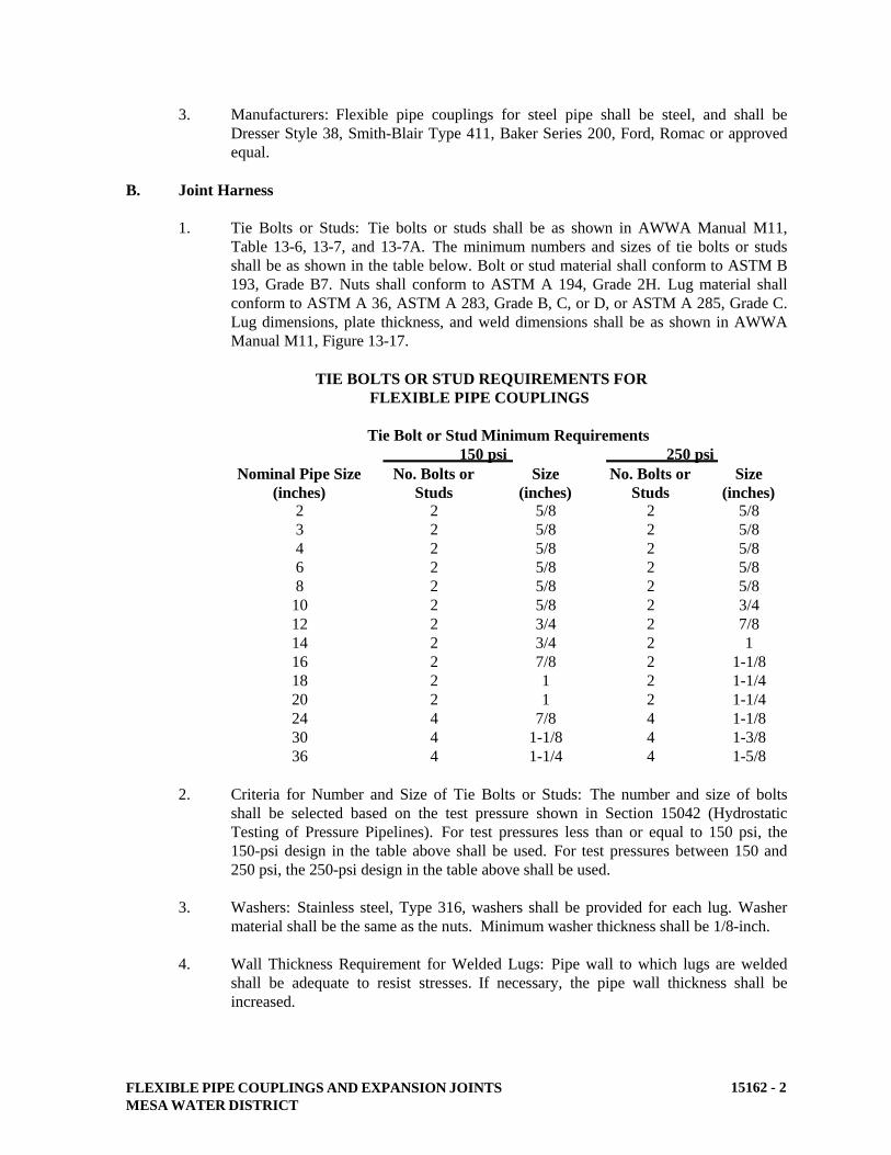
FLEXIBLE PIPE COUPLINGS AND EXPANSION JOINTS
MESA WATER DISTRICT
15162 - 2
3. Manufacturers: Flexible pipe couplings for steel pipe shall be steel, and shall be
Dresser Style 38, Smith-Blair Type 411, Baker Series 200, Ford, Romac or approved
equal.
B. Joint Harness
1. Tie Bolts or Studs: Tie bolts or studs shall be as shown in AWWA Manual M11,
Table 13-6, 13-7, and 13-7A. The minimum numbers and sizes of tie bolts or studs
shall be as shown in the table below. Bolt or stud material shall conform to ASTM B
193, Grade B7. Nuts shall conform to ASTM A 194, Grade 2H. Lug material shall
conform to ASTM A 36, ASTM A 283, Grade B, C, or D, or ASTM A 285, Grade C.
Lug dimensions, plate thickness, and weld dimensions shall be as shown in AWWA
Manual M11, Figure 13-17.
TIE BOLTS OR STUD REQUIREMENTS FOR
FLEXIBLE PIPE COUPLINGS
Tie Bolt or Stud Minimum Requirements
150 psi 250 psi Nominal Pipe Size
(inches)
No. Bolts or
Studs
Size
(inches)
No. Bolts or
Studs
Size
(inches) 2
3
4
6
8
10
12
14
16
18
20
24
30
36
2
2
2
2
2
2
2
2
2
2
2
4
4
4
5/8
5/8
5/8
5/8
5/8
5/8
3/4
3/4
7/8
1
1
7/8
1-1/8
1-1/4
2
2
2
2
2
2
2
2
2
2
2
4
4
4
5/8
5/8
5/8
5/8
5/8
3/4
7/8
1
1-1/8
1-1/4
1-1/4
1-1/8
1-3/8
1-5/8
2. Criteria for Number and Size of Tie Bolts or Studs: The number and size of bolts
shall be selected based on the test pressure shown in Section 15042 (Hydrostatic
Testing of Pressure Pipelines). For test pressures less than or equal to 150 psi, the
150-psi design in the table above shall be used. For test pressures between 150 and
250 psi, the 250-psi design in the table above shall be used.
3. Washers: Stainless steel, Type 316, washers shall be provided for each lug. Washer
material shall be the same as the nuts. Minimum washer thickness shall be 1/8-inch.
4. Wall Thickness Requirement for Welded Lugs: Pipe wall to which lugs are welded
shall be adequate to resist stresses. If necessary, the pipe wall thickness shall be
increased.
FLEXIBLE PIPE COUPLINGS AND EXPANSION JOINTS
MESA WATER DISTRICT
15162 - 3
C. Flexible Couplings for Ductile Iron Pipe
1. General: Ductile iron pipe couplings shall have sleeves of ASTM A 126 Class B
ductile iron with a minimum yield strength of 30,000 psi. Follower rings shall be
malleable iron ASTM A 47 Grade 32510 or ductile iron ASTM A 536. Minimum
center sleeve length shall be 7-inches for pipe sizes up to 6-inches in diameter; 10-
inches for pipe sizes larger than 6-inches pipe diameters.
2. Sleeve Bolts: Sleeve bolts shall be corrosion resistant Type 316 stainless steel with
minimum yield strength of 45,000 psi and shall conform to ASTM-A-193 and
AWWA C111.
3. Manufacturers: Flexible couplings for ductile iron pipe shall be ductile iron: Dresser
Style 153, Smith-Blair Type 442, Baker Series 228, Ford Style FCI, Romac Style 501,
or approved equal.
D. Transition Couplings
1. Steel Pipe: Transition couplings for connecting steel pipe having different outside
diameters shall be steel: Dresser Style 62 or 162, Smith-Blair Type 413, Baker Series
212 or 240, Romac 501, or approved equal.
2. Ductile Iron Pipe, PVC Pipe, and Asbestos Cement Pipe: Transition couplings for
connecting ductile iron pipe, PVC pipe, and asbestos cement pipe having different
outside diameters shall be ductile iron, and shall be Smith-Blair Type 441, Baker
Series 236, Ford Style FC2A, Romac and Dresser or approved equal.
3. Sleeve Bolts: Sleeve bolts shall have a minimum yield strength of 40,000 psi, an
ultimate strength of 60,000 psi, shall be Type 316 stainless steel conforming to
ASTM A 193 (Grade B8M) for bolts and ASTM A 194 (Grade 8N) for nuts, and shall
conform to AWWA C111.
E. Reducing Couplings
Reducing couplings for steel pipe shall be steel. Reducing couplings for ductile iron pipe,
PVC pipe, and asbestos cement pipe shall be ductile iron. Couplings shall be Dresser Style
62, Baker Series 220 or 240, Smith-Blair Type 415 or R441, Romac, Ford, or approved equal.
F. Flanged Coupling Adapters
Flanged coupling adapters may be used to install valves, meters, and other types of flanged
fittings to plain end pipe of diameter 10-inches and smaller. Flanged coupling adapters shall
be Smith-Blair Type 912, Baker Series 601 or 604, Dresser Style 127, Ford Style FFCA,
Romac Style FAC501, Romac Alpha, or approved equal.
G. Expansion Joints
1. General: Expansion joints shall have body, flanges, and slip pipe of carbon steel.
Packing shall consist of a minimum of four rubber rings, each separated by jute
packing.
FLEXIBLE PIPE COUPLINGS AND EXPANSION JOINTS
MESA WATER DISTRICT
15162 - 4
For installation in steel pipelines, expansion joint shall have plain ends, beveled for
welding. For installation in ductile iron pipelines, expansion joint shall have plain
ends. Slip pipe shall have a machined surface, and body shall be equipped with pipe
stops. Where called for on the plans, limit or stop rings and limit rods shall be
provided to prevent the slip pipe from pulling out of the joint.
2. Limit Rods and Body Studs, Bolts and Nuts: Limit rods and body studs, bolts, and
nuts shall be Type 316 stainless steel conforming to ASTM A 193 (Grade B8M) for
rods and bolts, and ASTM A 194 (Grade 8M) for nuts.
3. Manufacturers: Expansion joints shall be Baker Series 403 or 404, Smith-Blair Type
611 or 612, Romac EJ400, or approved equal.
H. Sleeve Bolts and Nuts for Flanges
1. Stainless Steel Bolts: Bolts and nuts for buried and submerged flanges, flanges in
underground vaults and structures, and flanges located outdoors above ground shall
be Type 316 stainless steel conforming to ASTM A 193 (Grade B8M) for bolts and
ASTM A 194 (Grade 8M) for nuts.
2. Washers: Washers shall be provided for each nut. Washers shall be of the same
material as the nuts.
PART 3 - EXECUTION
A. Installation of Flexible Pipe Couplings and Expansion Joints
1. General: Oil, scale, rust, and dirt shall be cleaned from pipe ends. Gaskets in flexible
pipe couplings shall be cleaned before installing. Expansion joints shall be installed
per manufacturer's recommendations. Expansion joints shall be installed so that 50%
of total travel is available for expansion and 50% is available for contraction.
2. Bolt Thread Lubrication: Bolt threads shall be lubricated with graphite and oil prior
to installation.
B. Painting and Coating
1. Flexible Couplings: Flexible pipe couplings (including joint harness assemblies),
transition couplings, flanged coupling adapters, and expansion joints shall be coated
per Section 09900 (Painting and Coating); sleeves shall be coated per System G-1.
After installation couplings shall be wrapped with 8-mil polyethylene wrap per
AWWA C105.
2. Interior Surface Coating: Interior surfaces of flexible coupling and transition
coupling sleeves, and the body of expansion joints shall be coated per Section 09900
(Painting and Coating), System G-1.
FLEXIBLE PIPE COUPLINGS AND EXPANSION JOINTS
MESA WATER DISTRICT
15162 - 5
C. Bonding Flexible Pipe Couplings
Buried flexible pipe couplings that are connected to ductile-iron, cast-iron, or steel pipe shall
be bonded to adjacent piping as described in Section 16640 (Cathodic Protection and Joint
Bonding).
D. Hydrostatic Testing
Flexible pipe couplings, expansion joints, and expansion joints shall be hydrostatically tested
in place with the pipe being tested. Test shall be performed in accordance with Section 15042
(Hydrostatic Testing of Pressure Pipelines).
END OF SECTION
CATHODIC PROTECTION AND JOINT BONDING
MESA WATER DISTRICT
16640 - 1
SECTION 16640
CATHODIC PROTECTION AND JOINT BONDING
PART 1 - GENERAL
A. Description
This section describes materials and installation of cathodic protection and testing equipment
including wiring, zinc anodes, joint bonding, test stations, reference cells, alumino-thermic
welds, and flange insulation kits. As directed by Mesa Water, the developer, applicant or his
design engineer shall complete soils testing to determine the level of cathodic protection
required for each project. This Section will only be applicable to projects noted or specified
by Mesa Water.
B. Related Work Specified Elsewhere
1. Trenching, Backfilling, and Compacting: 02223.
2. Painting and Coating: 09900.
C. Submittals
1. Submit manufacturer's catalog data on wire and cables, test stations, reference cells,
thermic welds, insulation kits, dielectric coatings, and anodes.
2. Submit qualifications of company performing required testing and record keeping.
The testing shall be performed under the direction and oversight of a registered
corrosion engineered or certified NACE Cathodic Protection (CP) specialist.
PART 2 - MATERIALS
A. Alumino-Thermic Weld Materials
Cartridges and sleeves for welding test lead wires, joint bonding wires and anode lead wires
to the pipe, shall be "Cadweld," "Thermoweld," or approved equal. Cartridge type, size and
weight shall be as recommended by the manufacturer for the type of pipe (steel, ductile iron,
or cast iron) to which the wire is to be welded, size of wire, and welder mold being used.
B. Alumino-Thermic Weld Caps
Alumino-thermic weld caps shall incorporate a high-density polyethylene plastic sheet, 10
mils (minimum) thick, with a protective adhesive, 165 mils (minimum) thickness, as
manufactured by Farwest Corrosion Control Company, Chase Corporation’s Royston
Products, or approved equal. Design shall incorporate an elastomeric or a mastic-filled dome
and a tunnel portion to contain lead wire from the alumino-thermic weld connection.
CATHODIC PROTECTION AND JOINT BONDING
MESA WATER DISTRICT
16640 - 2
The mastic coating shall be Carboline Bitumastic 50, Tnemec 46-465, Tnemec 46H413, or
approved equal. Prior to application of the mastic coating, the manufacturer's recommended
primer shall be applied to exposed metal.
Weld caps shall be Royston Handy Cap IP, Royston Handy Cap XL, or approved equal.
C. Test Stations Boxes
Test station boxes shall be a minimum of 10-inch diameter, 12-inch deep, precast concrete
meter boxes with a cast iron lids designed for H-20 traffic loading. Cast on the lid shall be
the words "CPTS". Test box shall be Brooks Products 3RT, Christy G05T, Eisel Enterprises,
or approved equal. Test boxes with terminal boards for anodes shall be rectangular in
accordance with Section 03462 (Precast Concrete Vaults and Meter Boxes). Test box lids
shall be painted.
D. Pipe Leads
Unless noted otherwise, pipe leads shall be stranded copper wire with high molecular weight
polyethylene (HMW/PE) insulation specifically designed for cathodic protection service and
suitable for direct burial in corrosive soil or water. Wire gauge shall be as shown on the
plans. Polyethylene insulation shall conform to ASTM D 1248, Type 1, Class C, Grades E-4
and E-5. Each pipe lead shall be of sufficient length to extend from the attachment to the pipe
to the text box or anode test box without a splice. Wires with cut or damaged insulation shall
be rejected. Insulation color shall be as shown on the plans.
E. Joint Bonding Wires
Pipe joint bonding wires shall be AWG No. 4 stranded copper wire with minimum 7/64-inch
thick high molecular weight polyethylene (HMW/PE) insulation rated for 600 volts. The
number of conductors shall be as shown on the plans. Polyethylene insulation shall conform
to ASTM D1248, Type 3, Class C, Grade 5. Each bond wire shall not exceed 18-inches in
length for 18-inch pipes or less and 24 inches for pipes larger than 18-inch.
F. Flange Insulation Kits
Insulating material shall be of the type designated by the manufacturer as suitable for the
operating temperature and pressure of the service. Flange insulation kits shall consist of:
1. Insulating Gaskets: Gaskets shall be Type E fullfaced, 1/8-inch-minimum thickness,
dielectric neoprene faced phenolic. Gaskets shall be Pipeline Seal & Insulator, Inc.
(PSI), Advance Products & Systems, Inc. (APS) George Fischer Central Plastics, or
approved equal.
2. Insulating Sleeves and Washers: Insulating stud sleeves and washers shall be one-
piece and full length, made of Minlon or Mylar. One 1/8-inch thick gasket shall be
attached to the sleeve, while the other shall be loose. Single insulating washers and
sleeves shall be used on buried insulating flanges. Double insulating washers and
sleeves shall be used on insulating flanges above ground, in structures, or in vaults.
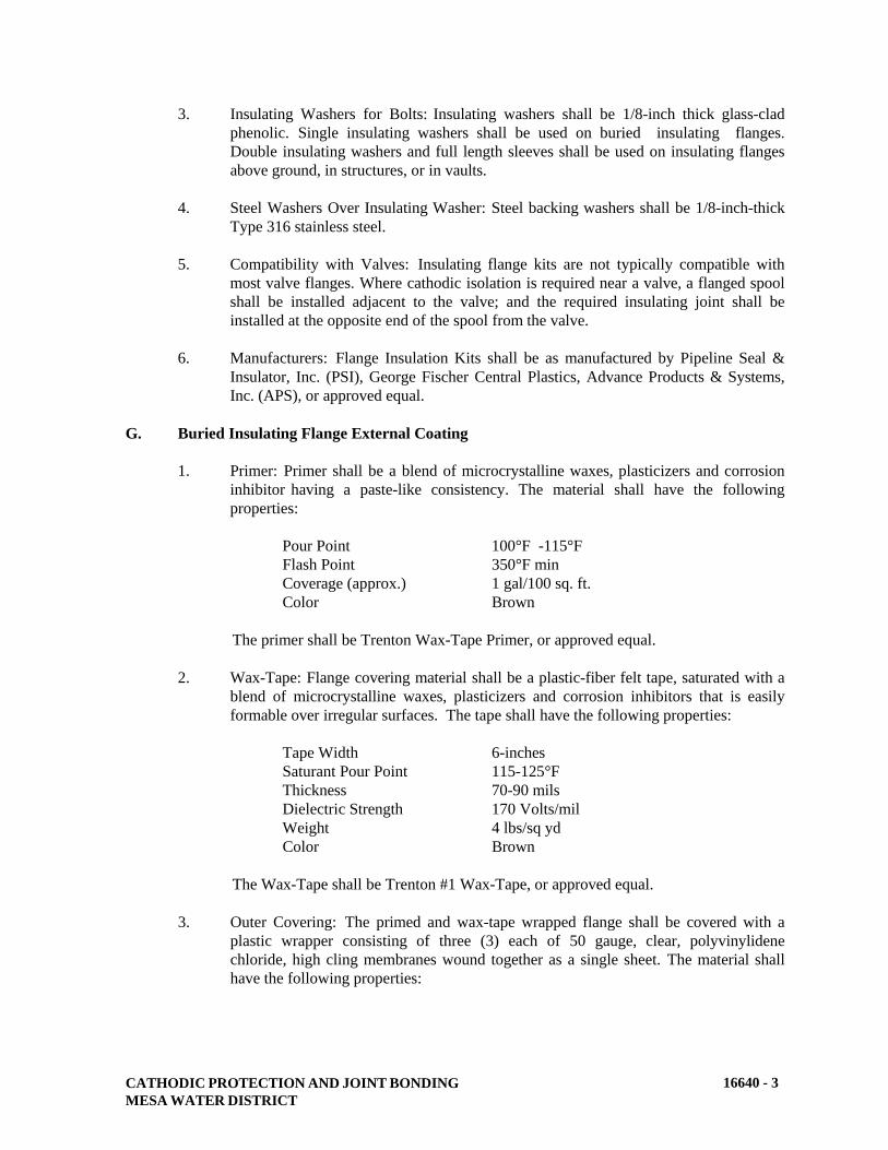
CATHODIC PROTECTION AND JOINT BONDING
MESA WATER DISTRICT
16640 - 3
3. Insulating Washers for Bolts: Insulating washers shall be 1/8-inch thick glass-clad
phenolic. Single insulating washers shall be used on buried insulating flanges.
Double insulating washers and full length sleeves shall be used on insulating flanges
above ground, in structures, or in vaults.
4. Steel Washers Over Insulating Washer: Steel backing washers shall be 1/8-inch-thick
Type 316 stainless steel.
5. Compatibility with Valves: Insulating flange kits are not typically compatible with
most valve flanges. Where cathodic isolation is required near a valve, a flanged spool
shall be installed adjacent to the valve; and the required insulating joint shall be
installed at the opposite end of the spool from the valve.
6. Manufacturers: Flange Insulation Kits shall be as manufactured by Pipeline Seal &
Insulator, Inc. (PSI), George Fischer Central Plastics, Advance Products & Systems,
Inc. (APS), or approved equal.
G. Buried Insulating Flange External Coating
1. Primer: Primer shall be a blend of microcrystalline waxes, plasticizers and corrosion
inhibitor having a paste-like consistency. The material shall have the following
properties:
Pour Point 100°F -115°F
Flash Point 350°F min
Coverage (approx.) 1 gal/100 sq. ft.
Color Brown
The primer shall be Trenton Wax-Tape Primer, or approved equal.
2. Wax-Tape: Flange covering material shall be a plastic-fiber felt tape, saturated with a
blend of microcrystalline waxes, plasticizers and corrosion inhibitors that is easily
formable over irregular surfaces. The tape shall have the following properties:
Tape Width 6-inches
Saturant Pour Point 115-125°F
Thickness 70-90 mils
Dielectric Strength 170 Volts/mil
Weight 4 lbs/sq yd
Color Brown
The Wax-Tape shall be Trenton #1 Wax-Tape, or approved equal.
3. Outer Covering: The primed and wax-tape wrapped flange shall be covered with a
plastic wrapper consisting of three (3) each of 50 gauge, clear, polyvinylidene
chloride, high cling membranes wound together as a single sheet. The material shall
have the following properties:
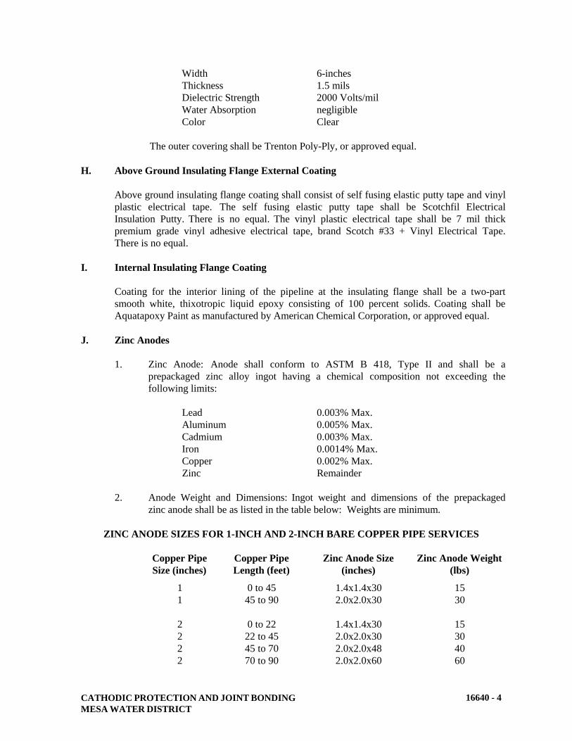
CATHODIC PROTECTION AND JOINT BONDING
MESA WATER DISTRICT
16640 - 4
Width 6-inches
Thickness 1.5 mils
Dielectric Strength 2000 Volts/mil
Water Absorption negligible
Color Clear
The outer covering shall be Trenton Poly-Ply, or approved equal.
H. Above Ground Insulating Flange External Coating
Above ground insulating flange coating shall consist of self fusing elastic putty tape and vinyl
plastic electrical tape. The self fusing elastic putty tape shall be Scotchfil Electrical
Insulation Putty. There is no equal. The vinyl plastic electrical tape shall be 7 mil thick
premium grade vinyl adhesive electrical tape, brand Scotch #33 + Vinyl Electrical Tape.
There is no equal.
I. Internal Insulating Flange Coating
Coating for the interior lining of the pipeline at the insulating flange shall be a two-part
smooth white, thixotropic liquid epoxy consisting of 100 percent solids. Coating shall be
Aquatapoxy Paint as manufactured by American Chemical Corporation, or approved equal.
J. Zinc Anodes
1. Zinc Anode: Anode shall conform to ASTM B 418, Type II and shall be a
prepackaged zinc alloy ingot having a chemical composition not exceeding the
following limits:
Lead 0.003% Max.
Aluminum 0.005% Max.
Cadmium 0.003% Max.
Iron 0.0014% Max.
Copper 0.002% Max.
Zinc Remainder
2. Anode Weight and Dimensions: Ingot weight and dimensions of the prepackaged
zinc anode shall be as listed in the table below: Weights are minimum.
ZINC ANODE SIZES FOR 1-INCH AND 2-INCH BARE COPPER PIPE SERVICES
Copper Pipe
Size (inches)
Copper Pipe
Length (feet)
Zinc Anode Size
(inches)
Zinc Anode Weight
(lbs)
1
1
0 to 45
45 to 90
1.4x1.4x30
2.0x2.0x30
15
30
2
2
2
2
0 to 22
22 to 45
45 to 70
70 to 90
1.4x1.4x30
2.0x2.0x30
2.0x2.0x48
2.0x2.0x60
15
30
40
60

CATHODIC PROTECTION AND JOINT BONDING
MESA WATER DISTRICT
16640 - 5
Note: For copper pipe length greater than that listed above, an additional Zinc
Anode of appropriate size shall be added.
3. Anode Backfill: Each zinc anode shall be prepackaged in a permeable cloth bag with
a backfill of the following composition or installed bare and backfilled with material
having the following composition:
Gypsum 75%
Powdered Bentonite 20%
Anhydrous Sodium Sulfate 5%
Backfill grains shall be capable of 100% passing through a 20 mesh screen and 50%
passing through a 100 mesh screen. The backfill shall be firmly packed around the
anode by mechanical vibration to density which will maintain the zinc ingot in the
center of the cloth bag and surrounded by at least 1-inch of backfill. The packaged
weight of the zinc anode and backfill shall be approximately twice the weight of the
zinc anode ingot weight.
4. Steel Core: Anode shall be cast full length with an electrogalvanized 1/4-inch
diameter steel core which shall be exposed at one end for connection of the anode
lead wire.
5. Anode Lead Wire: Anode lead wire shall be AWG No. 8 stranded copper wire with
high-molecular weight polyethylene (HMW/PE) insulation suitable for direct burial
use. HMW/PE insulation shall conform to ASTM D-1248, Type 1, Class “C”,
Category 5, Grades E4 and E5 with tensile strengths J1, J3. Wire shall be attached to
the steel core with silver solder by the manufacturer. The connection shall be
encapsulated in a heat-shrinkable sleeve. Anode lead wire shall be of sufficient
length of extend from the anode to the designated termination point without a splice,
minimum of 15 feet long and a minimum of 3-feet of coiled wire provided in the test
box. Wires with cut or damaged insulation will not be accepted and replacement of
the entire lead will be required at the contractor's expense.
6. Anode Manufacture’s: Pre-packaged anodes, with lead wire and bagged backfill shall
be supplied by Northtown Company, Far West Corrosion Control Company or
Galvotech Alloys, Inc. or approve equal.
K. Brass Identification Tags
Identification tags shall be rotary engraved with identifying letters and numbers. The circular
plastic tag shall be 1/16-inch thick, 2-inch in diameter, and the exterior shall be UV resistant
ply (color on both sides) lamicoid plastic by Rowmark, Gravoply, or approved equal. Color
shall be Blue with a white core for potable water. There shall be a small hole in the tag for
attachment to the wires in the various test boxes.
L. Warning Tape
Warning tape shall be 3-inch wide red detectable metallic utility warning tape. The tape shall
be inductively locatable and conductively traceable using a standard pipe and cable locating
device.
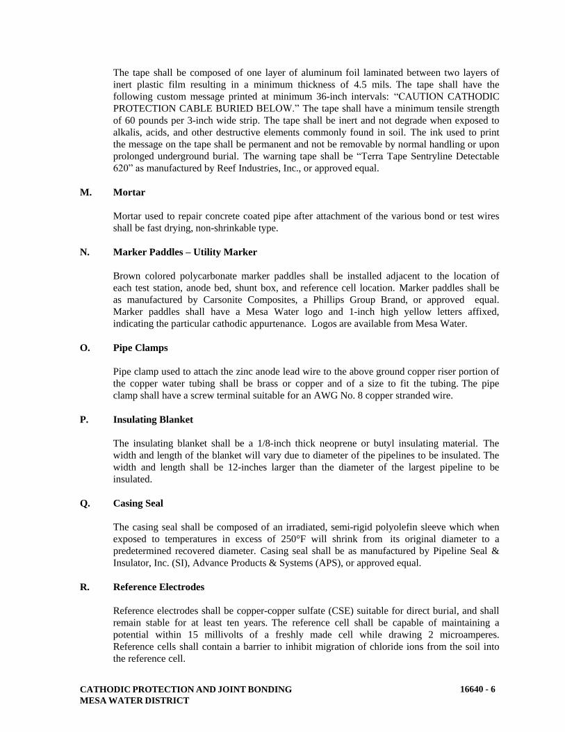
CATHODIC PROTECTION AND JOINT BONDING
MESA WATER DISTRICT
16640 - 6
The tape shall be composed of one layer of aluminum foil laminated between two layers of
inert plastic film resulting in a minimum thickness of 4.5 mils. The tape shall have the
following custom message printed at minimum 36-inch intervals: “CAUTION CATHODIC
PROTECTION CABLE BURIED BELOW.” The tape shall have a minimum tensile strength
of 60 pounds per 3-inch wide strip. The tape shall be inert and not degrade when exposed to
alkalis, acids, and other destructive elements commonly found in soil. The ink used to print
the message on the tape shall be permanent and not be removable by normal handling or upon
prolonged underground burial. The warning tape shall be “Terra Tape Sentryline Detectable
620” as manufactured by Reef Industries, Inc., or approved equal.
M. Mortar
Mortar used to repair concrete coated pipe after attachment of the various bond or test wires
shall be fast drying, non-shrinkable type.
N. Marker Paddles – Utility Marker
Brown colored polycarbonate marker paddles shall be installed adjacent to the location of
each test station, anode bed, shunt box, and reference cell location. Marker paddles shall be
as manufactured by Carsonite Composites, a Phillips Group Brand, or approved equal.
Marker paddles shall have a Mesa Water logo and 1-inch high yellow letters affixed,
indicating the particular cathodic appurtenance. Logos are available from Mesa Water.
O. Pipe Clamps
Pipe clamp used to attach the zinc anode lead wire to the above ground copper riser portion of
the copper water tubing shall be brass or copper and of a size to fit the tubing. The pipe
clamp shall have a screw terminal suitable for an AWG No. 8 copper stranded wire.
P. Insulating Blanket
The insulating blanket shall be a 1/8-inch thick neoprene or butyl insulating material. The
width and length of the blanket will vary due to diameter of the pipelines to be insulated. The
width and length shall be 12-inches larger than the diameter of the largest pipeline to be
insulated.
Q. Casing Seal
The casing seal shall be composed of an irradiated, semi-rigid polyolefin sleeve which when
exposed to temperatures in excess of 250°F will shrink from its original diameter to a
predetermined recovered diameter. Casing seal shall be as manufactured by Pipeline Seal &
Insulator, Inc. (SI), Advance Products & Systems (APS), or approved equal.
R. Reference Electrodes
Reference electrodes shall be copper-copper sulfate (CSE) suitable for direct burial, and shall
remain stable for at least ten years. The reference cell shall be capable of maintaining a
potential within 15 millivolts of a freshly made cell while drawing 2 microamperes.
Reference cells shall contain a barrier to inhibit migration of chloride ions from the soil into
the reference cell.
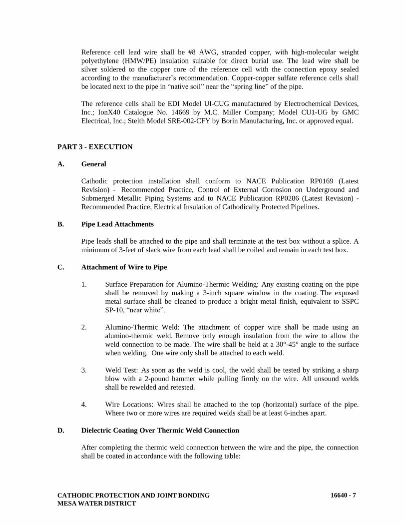
CATHODIC PROTECTION AND JOINT BONDING
MESA WATER DISTRICT
16640 - 7
Reference cell lead wire shall be #8 AWG, stranded copper, with high-molecular weight
polyethylene (HMW/PE) insulation suitable for direct burial use. The lead wire shall be
silver soldered to the copper core of the reference cell with the connection epoxy sealed
according to the manufacturer’s recommendation. Copper-copper sulfate reference cells shall
be located next to the pipe in “native soil” near the “spring line” of the pipe.
The reference cells shall be EDI Model UI-CUG manufactured by Electrochemical Devices,
Inc.; IonX40 Catalogue No. 14669 by M.C. Miller Company; Model CU1-UG by GMC
Electrical, Inc.; Stelth Model SRE-002-CFY by Borin Manufacturing, Inc. or approved equal.
PART 3 - EXECUTION
A. General
Cathodic protection installation shall conform to NACE Publication RP0169 (Latest
Revision) - Recommended Practice, Control of External Corrosion on Underground and
Submerged Metallic Piping Systems and to NACE Publication RP0286 (Latest Revision) -
Recommended Practice, Electrical Insulation of Cathodically Protected Pipelines.
B. Pipe Lead Attachments
Pipe leads shall be attached to the pipe and shall terminate at the test box without a splice. A
minimum of 3-feet of slack wire from each lead shall be coiled and remain in each test box.
C. Attachment of Wire to Pipe
1. Surface Preparation for Alumino-Thermic Welding: Any existing coating on the pipe
shall be removed by making a 3-inch square window in the coating. The exposed
metal surface shall be cleaned to produce a bright metal finish, equivalent to SSPC
SP-10, “near white”.
2. Alumino-Thermic Weld: The attachment of copper wire shall be made using an
alumino-thermic weld. Remove only enough insulation from the wire to allow the
weld connection to be made. The wire shall be held at a 30°-45° angle to the surface
when welding. One wire only shall be attached to each weld.
3. Weld Test: As soon as the weld is cool, the weld shall be tested by striking a sharp
blow with a 2-pound hammer while pulling firmly on the wire. All unsound welds
shall be rewelded and retested.
4. Wire Locations: Wires shall be attached to the top (horizontal) surface of the pipe.
Where two or more wires are required welds shall be at least 6-inches apart.
D. Dielectric Coating Over Thermic Weld Connection
After completing the thermic weld connection between the wire and the pipe, the connection
shall be coated in accordance with the following table:
CATHODIC PROTECTION AND JOINT BONDING
MESA WATER DISTRICT
16640 - 8
Pipe Material Connection Coating
Cement-mortar coated steel Carboline Bitumastic 50, Tnemec Series 46H-413 or
approved equal and cement mortar.
Carbon steel, Ductile iron Thermic weld cap, Royston Handy Cap XL IP or
Royston Handy Cap IP
Cement mortar coating shall be of the same material and thickness as specified for the pipe.
E. Backfill Over Wire
Buried wire shall be installed at a minimum depth of 36-inches. The trench bottom shall be
free of exposed rocks. The first 12-inches of backfill above and the first 12-inch below the
cable shall be sand per Mesa Water bedding requirements. The remainder of the trench shall
be backfilled with stone-free soil in accordance with Section 02223 (Trenching, Backfilling
and Compaction). Plastic warning tape shall be installed 12-inches above the wire.
F. Test Stations
1. At Grade Test Boxes: Concrete test boxes shall be located as shown on the plans, and
shall be positioned in the parkway or raised median, as close to above the pipeline as
practical. Concrete boxes shall be installed on a 6-inch deep base of 3/4-inch crushed
rock.
3. Two-Wire Test Box Spacing: Two-wire test boxes shall be placed at intervals not to
exceed 500 feet and at the end-points of all metallic pipelines and casings.
G. Joint Bonding Wires
Joint bonding wires shall be installed on ferrous metal pipelines at all unwelded joints,
fittings, valves, and flanges (excluding insulating flanges). Two bond wires shall be welded
across joints for pipe diameters under 18-inches. Three bond wires shall be welded across
joints for pipe diameters 18-inches and larger. Bond wires shall be attached using the
alumino-thermic weld process. Bond wires shall not be attached to valve bodies, but instead
to the valve flanges.
H. Flange Insulation Kits
Flange Insulation Kits shall be installed as follows:
1. Cleaning: Faces of flange pairs shall be cleaned of all dirt, rust or fouling materials
which would interfere with a watertight joint and insulating properties of the flange
kit.
2. Alignment: Alignment pins shall be used to properly align the flange and gasket.
The manufacturer's recommended bolt tightening sequence shall be followed. Bolt
insulation sleeves shall be centered within the insulation washers so that the
insulating sleeve is not compressed and cracked.
CATHODIC PROTECTION AND JOINT BONDING
MESA WATER DISTRICT
16640 - 9
3. Locations: A cathodic protection bonding test station shall be installed at each buried
flange insulation. Two test wires shall be installed on each side of the buried
insulator according to this specification and details of the plans.
I. External Insulating Flange Coating
1. Buried Insulating Flange Coating:
a. Primer: Surface shall be cleaned of all dirt, dust, and loose rust or mill scale
by wire brush and by wiping with a clean cloth. The surface shall be dry.
Apply primer by hand or brush. A thick coating of primer shall be worked
into all crevices, around bolts and in threads, and shall completely cover all
exposed metal surface. The primer should overlap the pipe coating by 3-inch
minimum.
b. Wax-Tape: The wax-type can be applied immediately after primer
application. Short lengths of tape shall be cut and formed completely around
each individual bolt and stud-end. After all bolts are covered, the tape shall
be applied circumferentially and formed by hand into all voids and spaces.
There shall be no gaps or air spaces under the tape. The tape shall be applied
with at least 55% overlap.
c. Outer Covering: The clear plastic outer covering shall be applied by hand
such that the material conforms and adheres to the wax-tape surface. Two
layers of plastic outer wrapping shall be applied.
2. Above Ground Insulating Flange Tape Coating: All flange and pipe surfaces shall be
clean and free of all dirt, grease, water, and other foreign material prior to installation
of tape coating. The two separate tapes shall be half-lapped twice over the outer
surface of the flange.
J. Internal Coating at Insulating Flange
The interior of the pipeline shall be coated for a distance of two pipe diameters in each
direction away from the insulating flange. At an insulated valve flange, interior of pipeline
shall be coated away from the valve for a distance of two pipe diameters. Coating shall be as
specified in Section 09900 (Painting and Coating), System B-1 or B-2 as appropriate.
1. Surface Preparation: The surface preparation of the mortar lining shall consist of
wire brushing to remove all loose mortar to provide a suitable surface for adhesion of
the coating.
2. Application: Coating shall be applied by brushing until a minimum coating thickness
of 20 mils is achieved. Each ensuing coat shall be applied before subsequent coat
cures, usually within 3 to 6 hours after subsequent coat has been applied.
K. Zinc Anodes
Where called for on the drawings, prepackaged zinc anodes shall be installed in excavated,
drilled, or punched holes a minimum of 3-inches larger in diameter than the prepackaged

CATHODIC PROTECTION AND JOINT BONDING
MESA WATER DISTRICT
16640 - 10
anode diameter. Anodes shall be installed below the level of the service main, with a
minimum separation of 2-feet between the copper water tubing and the zinc anode maintained
at all times. Anodes shall not be lowered, transported, handled, or lifted by the lead wire.
1. Backfilling: After the prepackaged anode is placed in the hole, water shall be poured
into the hole so that the anode is completely covered with water. Stone-free native
soil shall then be used to backfill the anode hole. Imported sand shall not be used for
backfilling. The anode hole shall be backfilled in stages and carefully compacted to
ensure that no voids exist around the bag and that the bag and anode wire are not
damaged. After backfill is level with the top of the anode, a minimum of 15 gallons
of water shall be poured into the hole to completely saturate the soil backfill. More
water shall be added if it is suspected that the backfill is not completely saturated.
Care shall be taken to avoid damage to the anode and anode lead wires.
2. Anode Lead Wire: The anode lead wire shall run to the point of connection at the
end of the pipe run in the meter box. The anode lead wire shall be clamped to the
copper tubing riser. Sufficient slack shall be provided in the wire, and it shall be
coiled in the meter box for attachment to a future point of connection at the water
meter. At air releases and sample points, the anode lead wire shall run through the
concrete pad in a 1/2-inch diameter PVC conduit clamped to the riser. At blow-offs
and manual air releases, anode lead wire shall be coiled in the valve box and clamped
to the riser.
L. Identification Tags
Identification tags shall be securely attached to each of the wires in the test box using UV
rated zip ties rated to hold 50 pounds. Tags shall be stamped "P" for pipe, “C” for casing, and
"A" for anode to indicate to which structure each wire attached. Tags on wires in the test box
at insulating flanges shall be stamped "N", "S", "E", or "W" for North, South, East, or West
and with the pipeline diameter to indicate on which side of the insulating joint and to which
pipeline the wires are attached.
M. Insulating Blanket
Install an insulating blanket as shown on the plans between any metallic pipelines that cross
or parallel each other when the distance between the two pipelines is less than 18-inches.
N. Casing Seal
The casing seal shall be installed wherever a metallic pipeline passes through a casing. The
casing seal shall be installed according to the manufacturer's recommendations.
O. Earthwork
Trenching, backfilling, and compacting shall be in accordance with Section 02223
(Trenching, Backfilling and Compacting).
CATHODIC PROTECTION AND JOINT BONDING
MESA WATER DISTRICT
16640 - 11
P. Required Test and Record Keeping
The contractor shall furnish all necessary equipment, material and qualified personnel
required to perform all tests described herein.
1. Continuity Tests: The contractor shall notify Mesa Water’s Representative when
continuity bonding has been completed and all test boxes have been completed. A
registered corrosion engineer or certified NACE CP specialist retained by the
contractor shall oversee certify the testing and measuring of the electrical continuity
of metallic pipelines. The pipeline shall be considered electrically continuous when
the measured longitudinal resistance of the pipeline between each pair of adjacent test
stations is no greater than 20 percent higher than the theoretical resistance of that
section of pipeline.
If tests indicate that adequate electrical continuity has not been achieved, the
contractor shall excavate to investigate and locate improperly bonded joints and shall
make repairs until electrical continuity is achieved to the satisfaction of Mesa Water.
2. Test Stations: The contractor shall notify Mesa Water’s Representative when
insulator test box wires, two and four wire test station wires are ready for testing.
The wires shall remain disconnected to facilitate testing. A registered corrosion
engineer or certified NACE CP specialist retained by the contractor shall oversee and
certify the tests to certify that none of the wires were damaged or broken during the
installation. If test indicate damage, the entire wire shall be replaced and retested at
the contractor’s expense.
Records shall be made of all test stations and reference electrode tested and submitted
to Mesa Water.
3. Insulation Joints: The contractor shall test each insulated joint with the insulator
tester in accordance with the manufacturer’s written instructions. All damaged or
defective insulation parts shall be replaced and retested. Records shall be kept of all
insulated joint tests and shall be submitted to Mesa Water.
4. Anode and Pipe Lead Wire Integrity Tests: After the pipe and anodes are buried, the
pipe lead wire and anode lead wire trenches are backfilled, and the test boxes are
installed, the contractor shall notify Mesa Water’s Representative that the anode and
pipe lead wires are ready for hookup and testing. The wires shall remain
disconnected to facilitate testing. A registered corrosion engineer or certified NACE
CP specialist retained by the contractor shall oversee and certify the tests to check
that none of the anode wires or pipe lead wires were damaged or broken during the
installation. Each anode lead wire will be tested for electrical continuity to the anode
by measuring the anode’s potential with respect to a copper copper-sulfate reference
electrode. The measured open circuit potential of the anode shall be as specified in
the project technical specifications, and a potential less than that indicates a broken
wire or faulty anode installation in which case the anode shall be replaced.
CATHODIC PROTECTION AND JOINT BONDING
MESA WATER DISTRICT
16640 - 12
5. Acceptance: The contractor shall submit a certified report by the corrosion engineer
stating that the facilities are performing satisfactorily. All test made must be
reviewed and approved by Mesa Water before the corrosion control work is accepted.
Mesa Water reserves the right to spot check any or all tests performed by the
contractor.
All construction defects must be repaired and retested before the final acceptance is
made. All unacceptable test must be re-performed by the contractor at no additional
cost to Mesa Water.
END OF SECTION
MESA WATER DISTRICT
APRIL 2018
STANDARD
SPECIFICATIONS
AND STANDARD DRAWINGS FOR
THE CONSTRUCTION OF
WATER FACILITIES
MESA WATER DISTRICT
1965 Placentia Avenue
Costa Mesa, CA 92627
(949) 631-1291

STANDARD DRAWINGS
MESA WATER DISTRICT TOC - 1
MESA WATER DISTRICT
STANDARD DRAWINGS
TABLE OF CONTENTS
Standard
Drawing
Number Description
1 Standard 1" Copper Service Assembly
1A Standard 1" Copper Recycled Water Service Assembly
2 Standard 2" Copper Service Assembly
2A Standard 2" Copper Recycled Water Service Assembly
3 Standard Meter Assembly
4 Standard Fire Hydrant Installation
4A Standard Blow-off Hydrant Detail
4B Standard Post Detail
5 Standard Taps on Steel Mains
6 Standard Tapping Sleeve and Valve for Cast Iron, Asbestos Cement and Polyvinyl
Chloride Pipe
7 2" Service Standard Manifold Installation
8 Standard 1” or 2" Air and Vacuum Valve Assembly
9 2" Standard Blow-off and Chlorination Assembly
9A 4” Standard Blow-off and Chlorination Assembly
10 Standard Installation of Carrier Pipe in Casing
11 Standard Detail of Concrete Gravity Block
12 Standard Detail of Concrete Thrust Block
13 Standard Tap to Cement Mortar Lined and Coated Steel Main
14 Standard Butterfly Valve Installation
14A Standard R.W. Gate Valve Installation
15 Valve Extension
16 Reduced Pressure Principle Assembly (3” or Larger)
16N Compact Reduced Pressure Principle Assembly for Large Services
17 Double Check Detector Assembly
17N Compact Double Check Detector Assembly
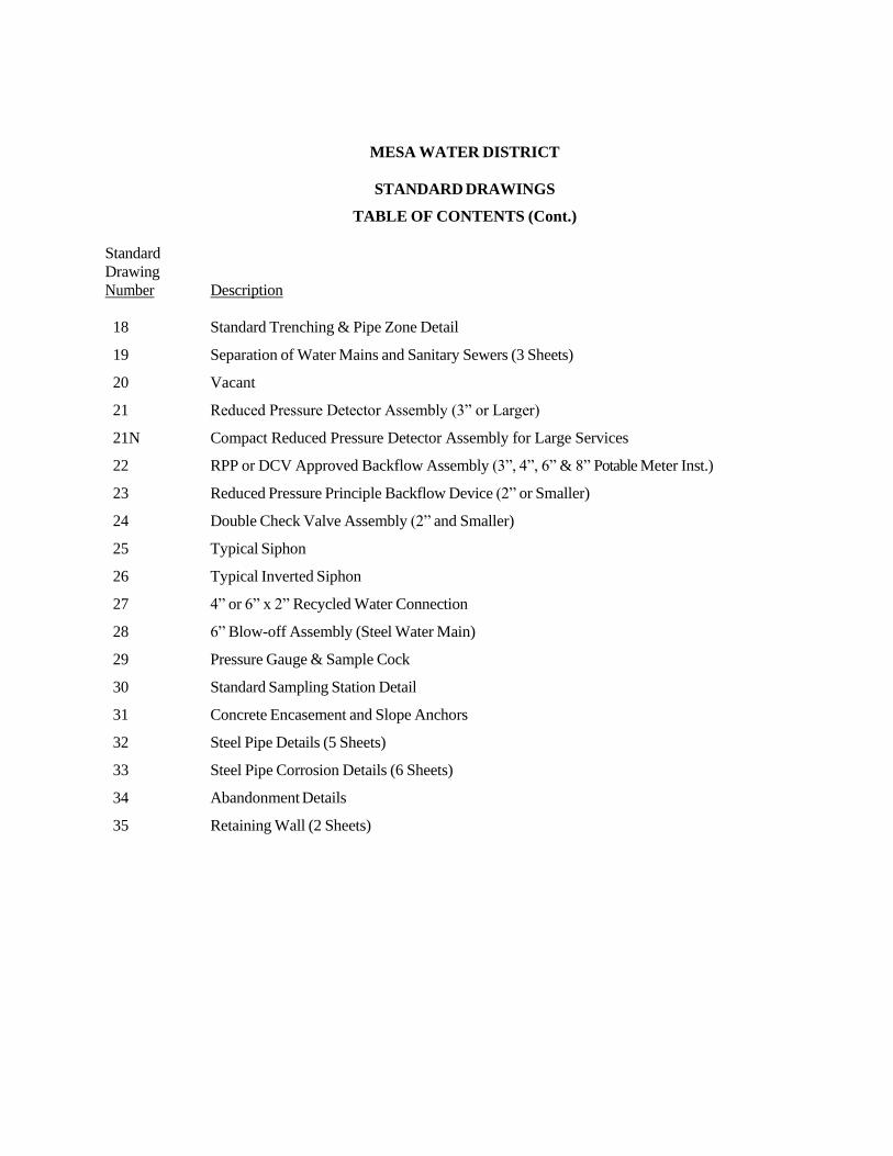
MESA WATER DISTRICT
STANDARD DRAWINGS
TABLE OF CONTENTS (Cont.)
Standard
Drawing
Number Description
18 Standard Trenching & Pipe Zone Detail
19 Separation of Water Mains and Sanitary Sewers (3 Sheets)
20 Vacant
21 Reduced Pressure Detector Assembly (3” or Larger)
21N Compact Reduced Pressure Detector Assembly for Large Services
22 RPP or DCV Approved Backflow Assembly (3”, 4”, 6” & 8” Potable Meter Inst.)
23 Reduced Pressure Principle Backflow Device (2” or Smaller)
24 Double Check Valve Assembly (2” and Smaller)
25 Typical Siphon
26 Typical Inverted Siphon
27 4” or 6” x 2” Recycled Water Connection
28 6” Blow-off Assembly (Steel Water Main)
29 Pressure Gauge & Sample Cock
30 Standard Sampling Station Detail
31 Concrete Encasement and Slope Anchors
32 Steel Pipe Details (5 Sheets)
33 Steel Pipe Corrosion Details (6 Sheets)
34 Abandonment Details
35 Retaining Wall (2 Sheets)
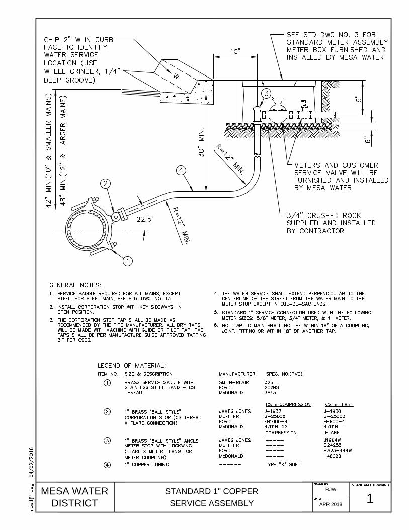
MESA WATER
DISTRICT
STANDARD 1" COPPER
SERVICE ASSEMBLY
1
RJW
APR 2018
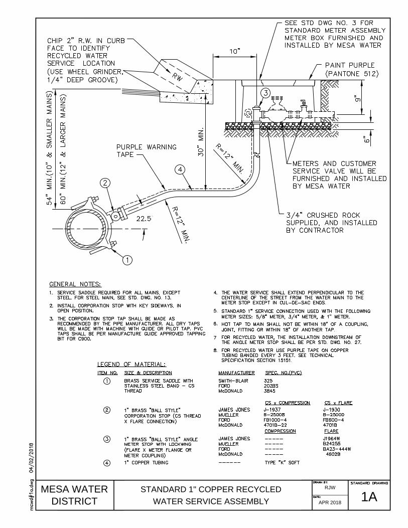
MESA WATER
DISTRICT
STANDARD 1" COPPER RECYCLED
WATER SERVICE ASSEMBLY
1A
RJW
APR 2018

MESA WATER
DISTRICT
STANDARD 2" COPPER
SERVICE ASSEMBLY
2
RJW
APR 2018

MESA WATER
DISTRICT
STANDARD 2" COPPER RECYCLED
WATER SERVICE ASSEMBLY
2A
RJW
APR 2018
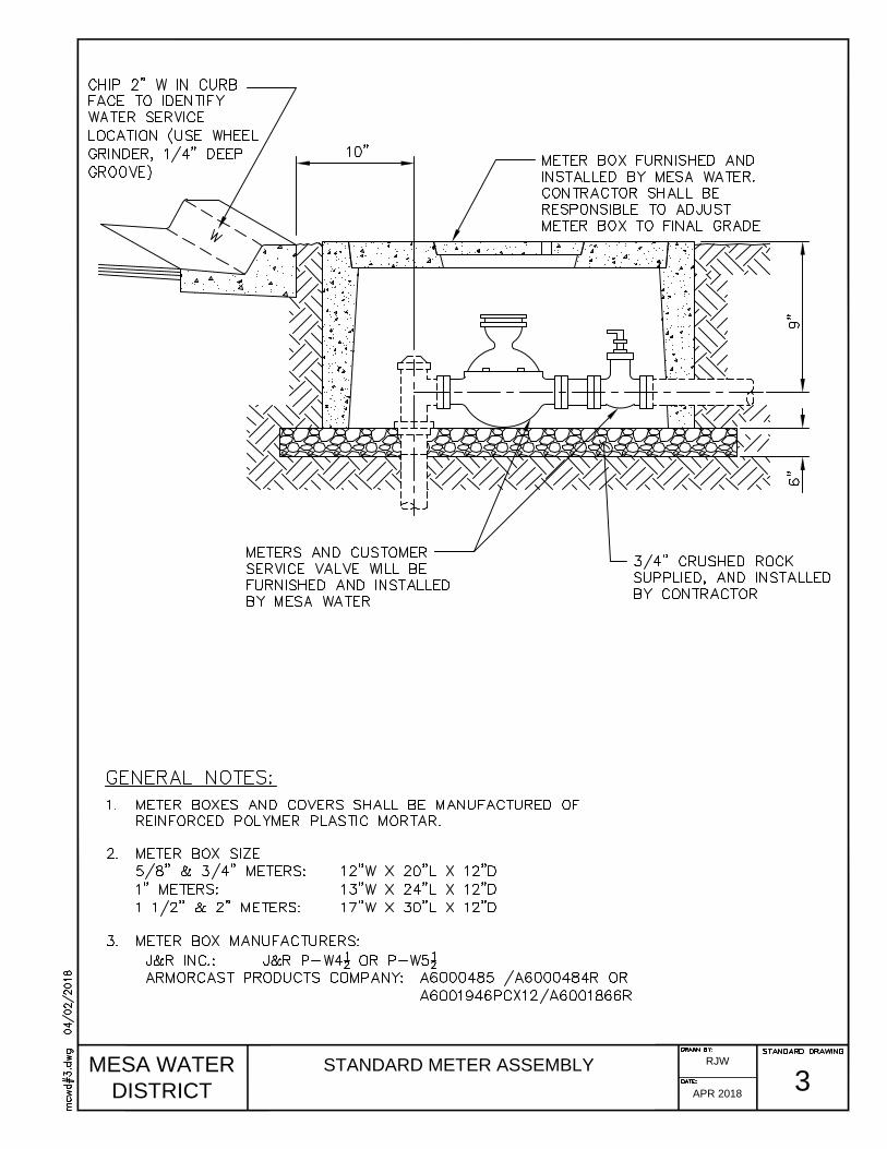
MESA WATER
DISTRICT
STANDARD METER ASSEMBLY
3
RJW
APR 2018
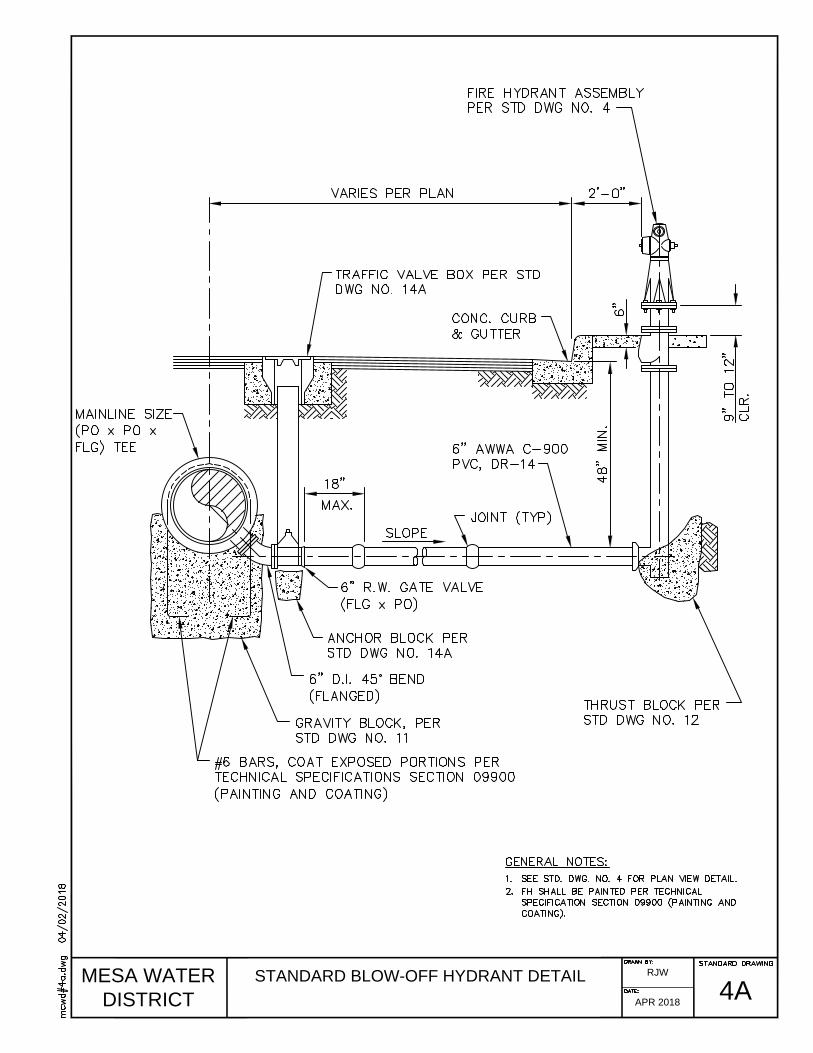
MESA WATER
DISTRICT
STANDARD BLOW-OFF HYDRANT DETAIL
4A
RJW
APR 2018

MESA WATER
DISTRICT
STANDARD POST DETAIL
4B
RJW
APR 2018
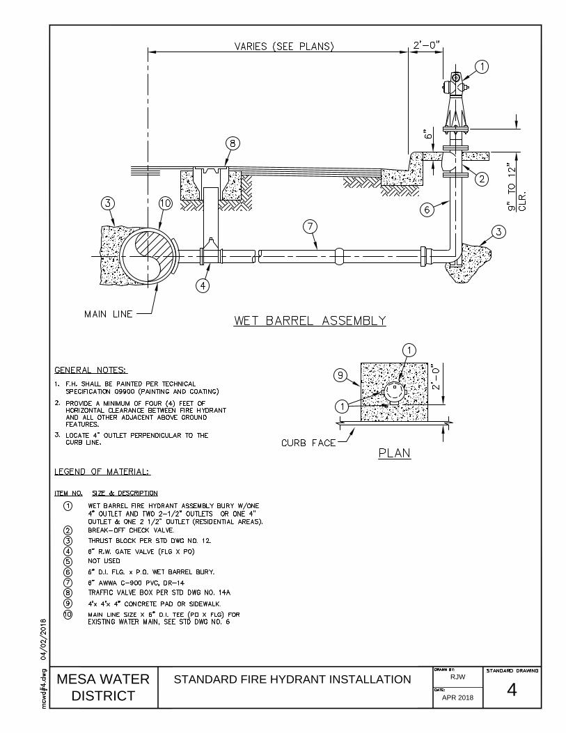
MESA WATER
DISTRICT
STANDARD FIRE HYDRANT INSTALLATION
4
RJW
APR 2018
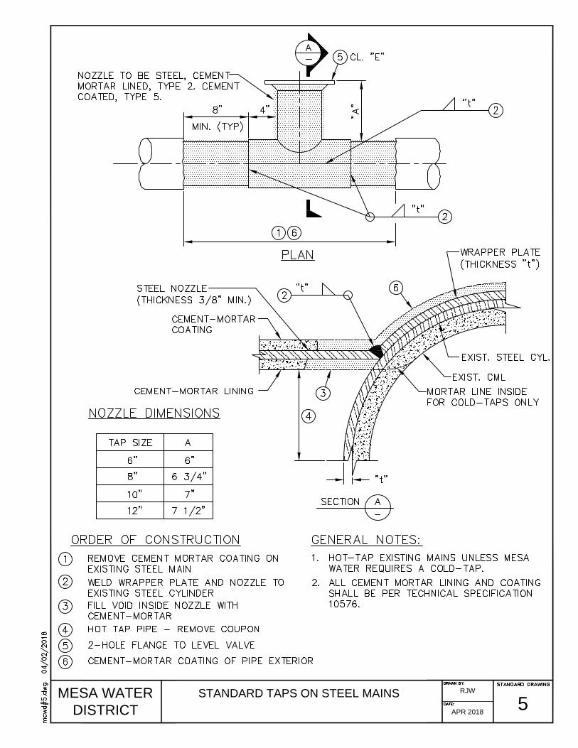
MESA WATER
DISTRICT
STANDARD TAPS ON STEEL MAINS
5
RJW
APR 2018

MESA WATER
DISTRICT
6
RJW
APR 2018
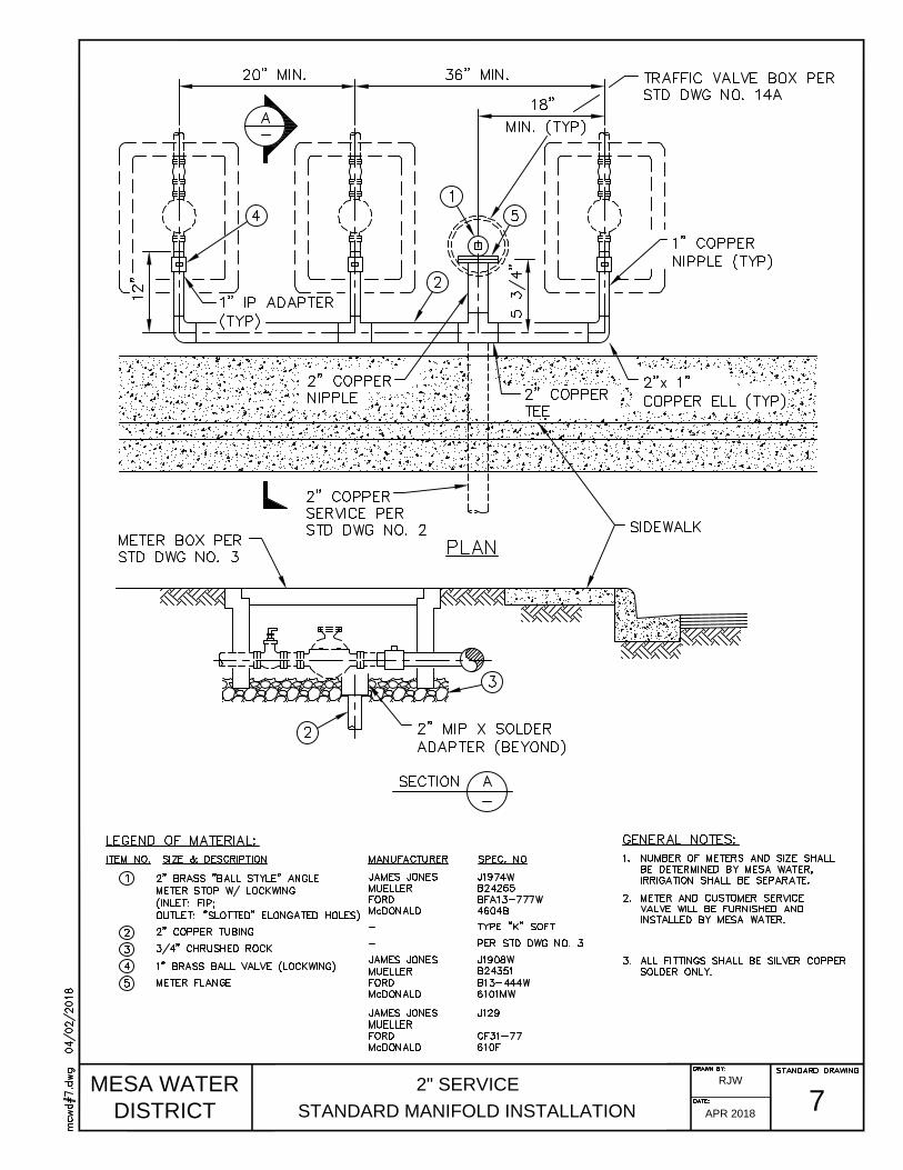
MESA WATER
DISTRICT
2" SERVICE
STANDARD MANIFOLD INSTALLATION
7
RJW
APR 2018
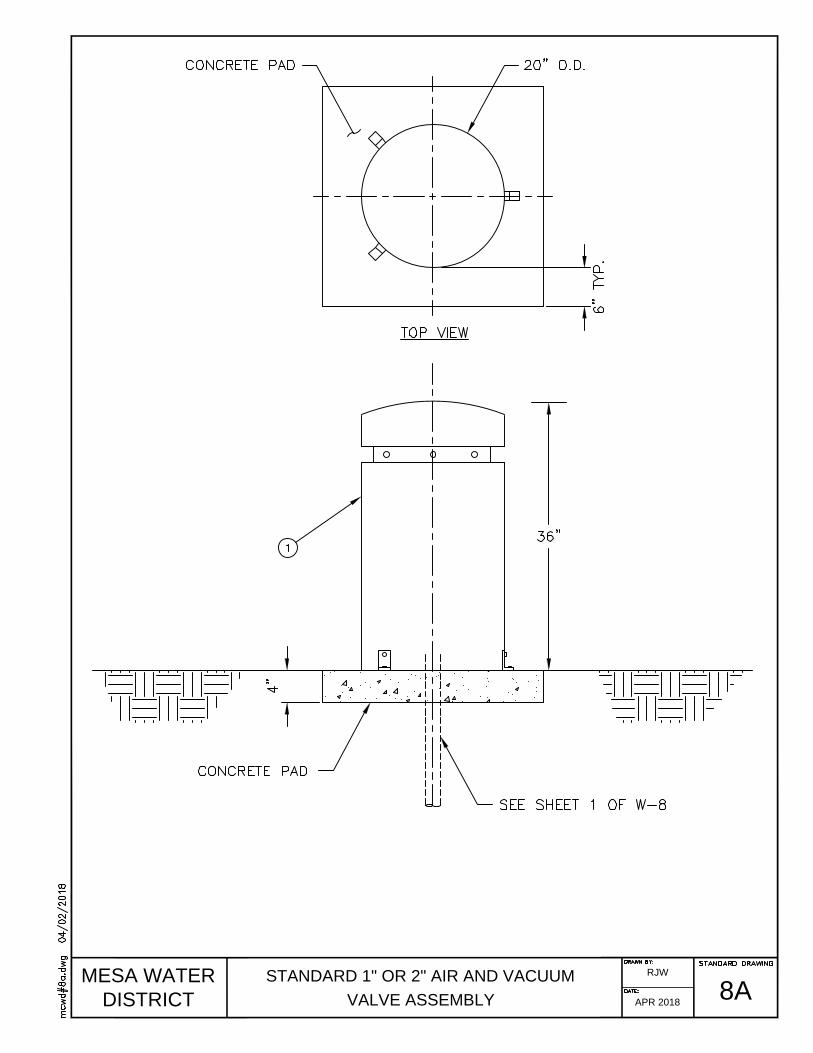
MESA WATER
DISTRICT
STANDARD 1" OR 2" AIR AND VACUUM
VALVE ASSEMBLY
8A
RJW
APR 2018
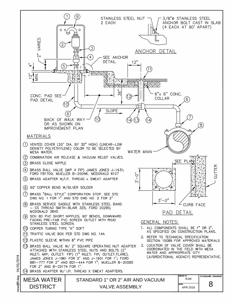
MESA WATER
DISTRICT
STANDARD 1" OR 2" AIR AND VACUUM
VALVE ASSEMBLY
8
RJW
APR 2018

MESA WATER
DISTRICT
2" STANDARD BLOW-OFF
AND CHLORINATION ASSEMBLY
9
RJW
APR 2018

MESA WATER
DISTRICT
4" STANDARD BLOW-OFF
AND CHLORINATION ASSEMBLY
9A
RJW
APR 2018
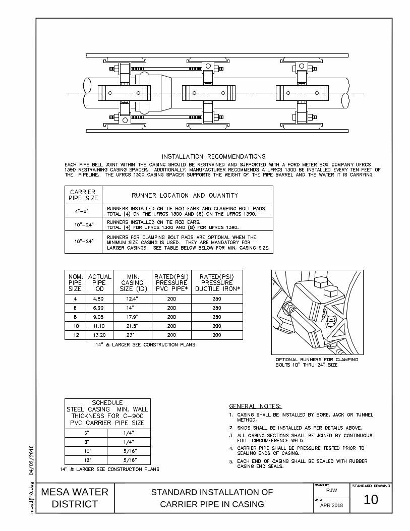
MESA WATER
DISTRICT
STANDARD INSTALLATION OF
CARRIER PIPE IN CASING
10
RJW
APR 2018

MESA WATER
DISTRICT
STANDARD DETAIL OF CONCRETE
GRAVITY BLOCK
11
RJW
APR 2018

MESA WATER
DISTRICT
STANDARD DETAIL OF CONCRETE
THRUST BLOCK
12
RJW
APR 2018
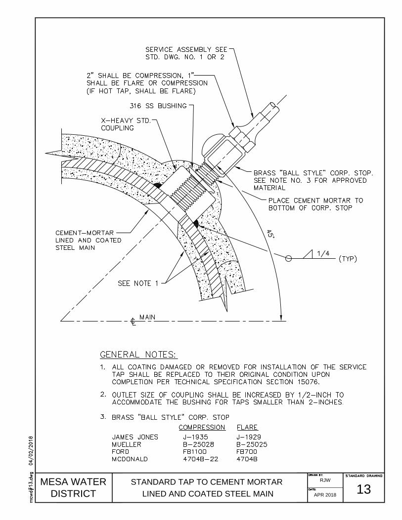
MESA WATER
DISTRICT
STANDARD TAP TO CEMENT MORTAR
LINED AND COATED STEEL MAIN
13
RJW
APR 2018
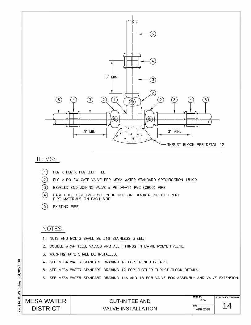
MESA WATER
DISTRICT
CUT-IN TEE AND
VALVE INSTALLATION
14
RJW
APR 2018

MESA WATER
DISTRICT
STANDARD R.W. GATE
VALVE INSTALLATION
14A
RJW
APR 2018
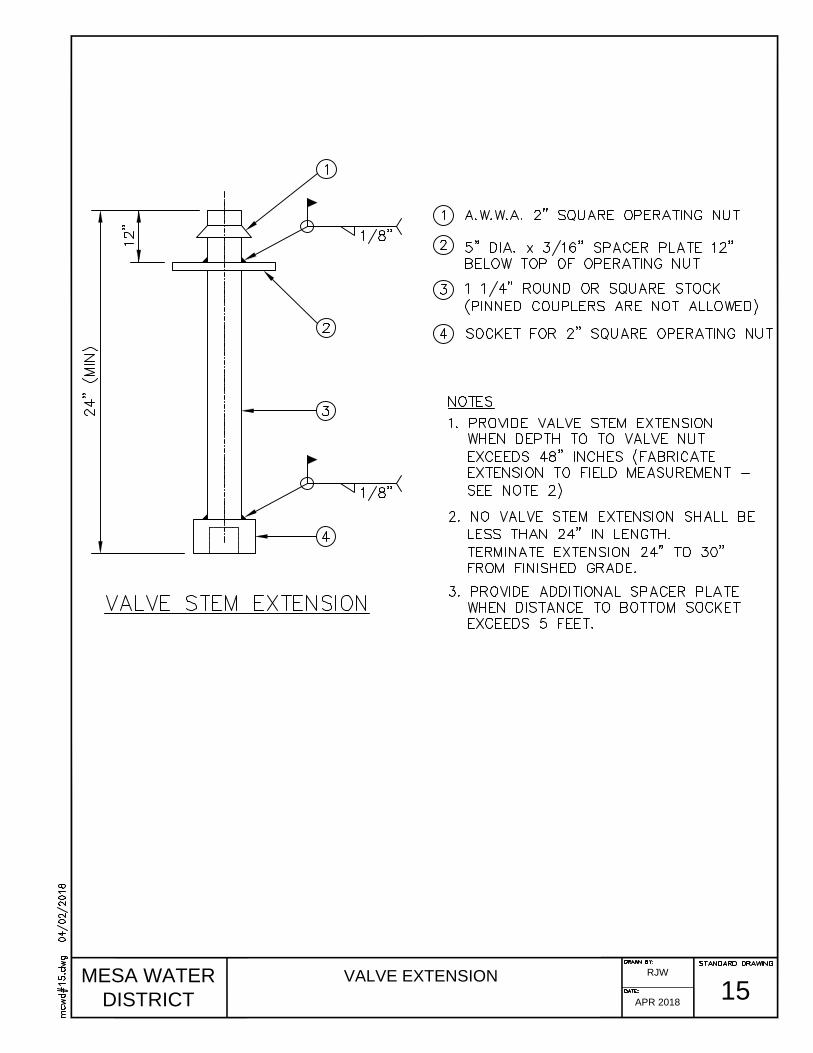
MESA WATER
DISTRICT
VALVE EXTENSION
15
RJW
APR 2018

MESA WATER
DISTRICT
REDUCED PRESSURE PRINCIPLE
ASSEMBLY (3" OR LARGER)
16
RJW
APR 2018

MESA WATER
DISTRICT
COMPACT REDUCED PRESSURE PRINCIPLE
ASSEMBLY FOR LARGE SERVICES
16N
RJW
APR 2018
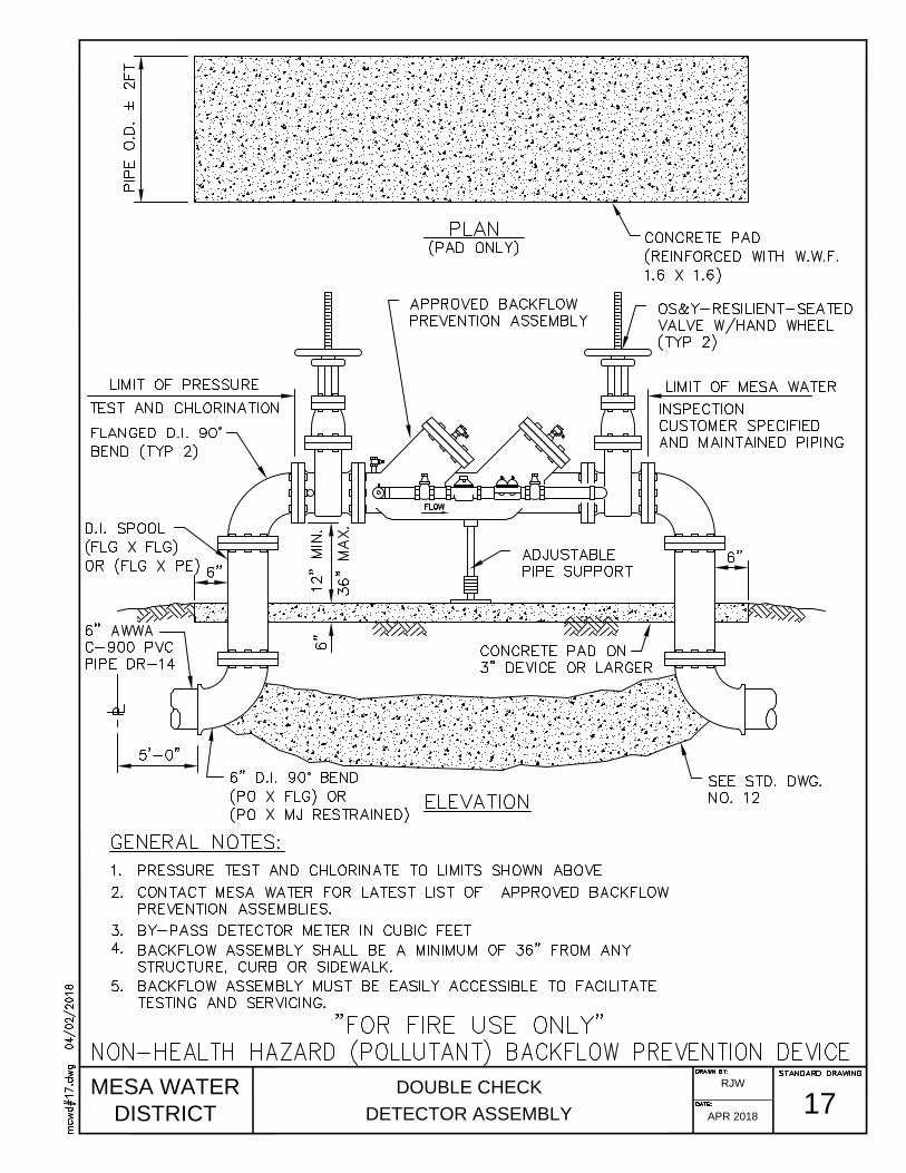
MESA WATER
DISTRICT
DOUBLE CHECK
DETECTOR ASSEMBLY
17
RJW
APR 2018
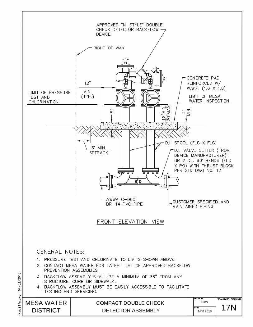
MESA WATER
DISTRICT
COMPACT DOUBLE CHECK
DETECTOR ASSEMBLY
17N
RJW
APR 2018

MESA WATER
DISTRICT
STANDARD TRENCHING
& PIPE ZONE DETAIL
18
RJW
APR 2018
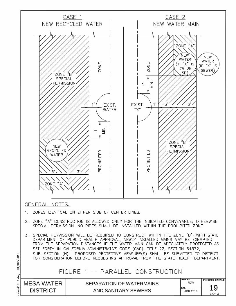
MESA WATER
DISTRICT
SEPARATION OF WATERMAINS
AND SANITARY SEWERS
19
RJW
APR 2018
1 OF 3

MESA WATER
DISTRICT
SEPARATION OF WATERMAINS
AND SANITARY SEWERS
19
RJW
APR 2018
2 OF 3
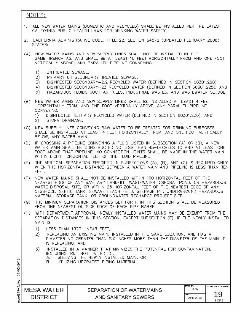
MESA WATER
DISTRICT
SEPARATION OF WATERMAINS
AND SANITARY SEWERS
19
RJW
APR 2018
3 OF 3

MESA WATER
DISTRICT
REDUCED PRESSURE DETECTOR
ASSEMBLY (3" OR LARGER)
21
RJW
APR 2018

MESA WATER
DISTRICT
COMPACT REDUCED PRESSURE DETECTOR
ASSEMBLY FOR LARGE SERVICES
21N
RJW
APR 2018
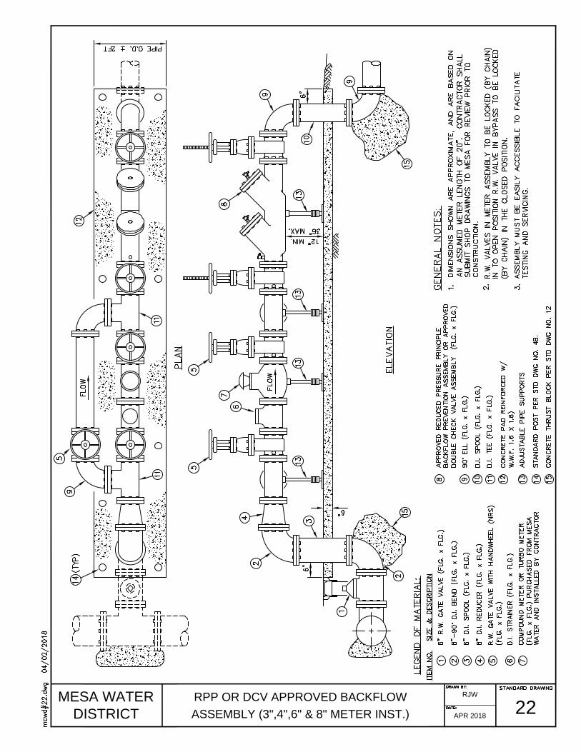
MESA WATER
DISTRICT
RPP OR DCV APPROVED BACKFLOW
ASSEMBLY (3",4",6" & 8" METER INST.)
22
RJW
APR 2018

MESA WATER
DISTRICT
REDUCED PRESSURE PRINCIPLE
BACKFLOW DEVICE (2" OR SMALLER)
23
RJW
APR 2018
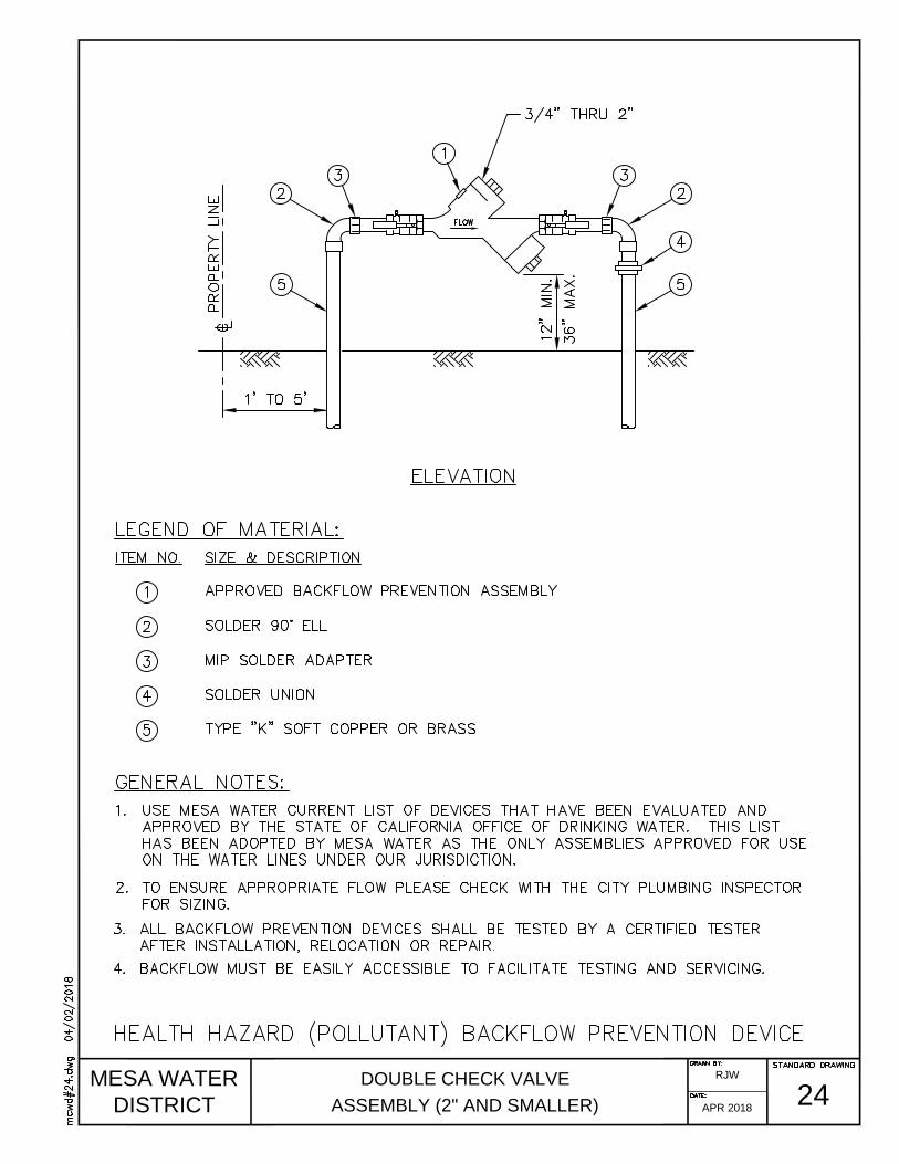
MESA WATER
DISTRICT
DOUBLE CHECK VALVE
ASSEMBLY (2" AND SMALLER)
24
RJW
APR 2018

MESA WATER
DISTRICT
TYPICAL SIPHON
25
RJW
APR 2018

MESA WATER
DISTRICT
TYPICAL INVERTED SIPHON
26
RJW
APR 2018
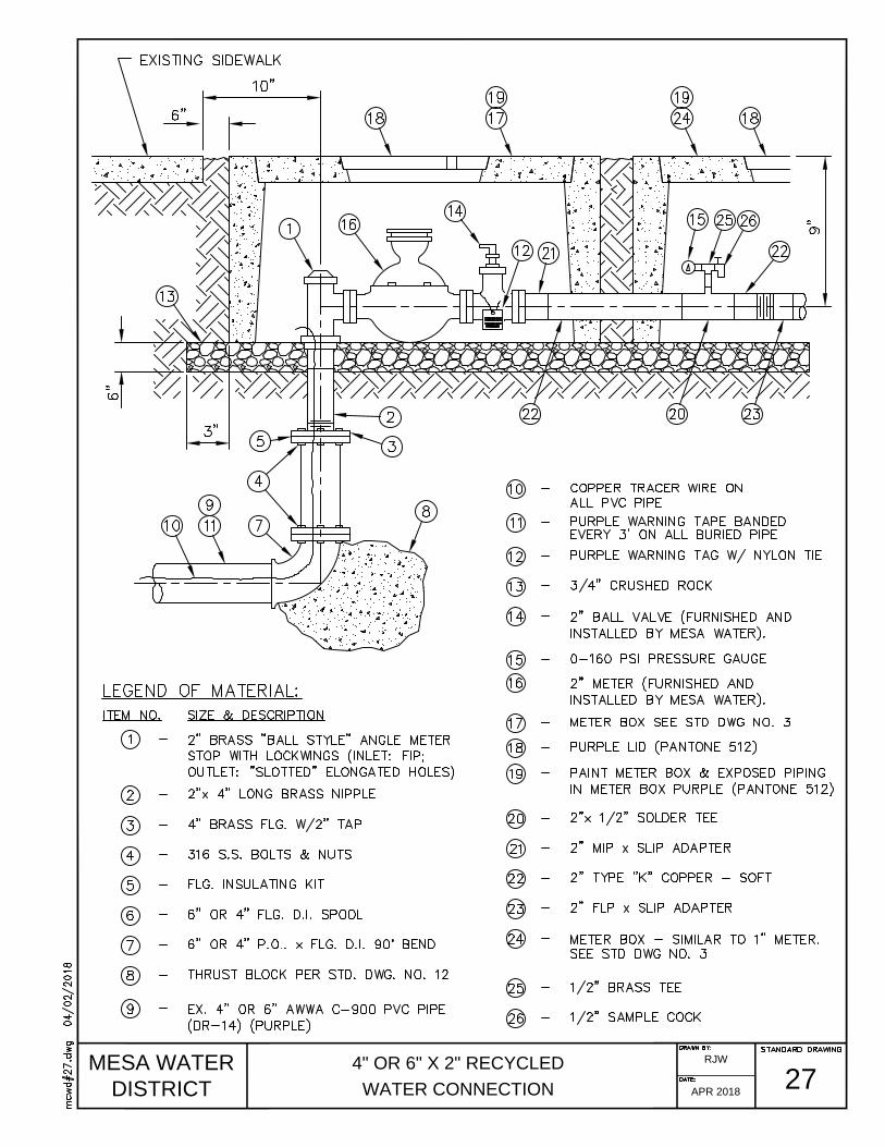
MESA WATER
DISTRICT
4" OR 6" X 2" RECYCLED
WATER CONNECTION
27
RJW
APR 2018

MESA WATER
DISTRICT
6" BLOWOFF ASSEMBLY
(STEEL WATER MAIN)
28
RJW
APR 2018

MESA WATER
DISTRICT
PRESSURE GAUGE & SAMPLE COCK
29
RJW
APR 2018
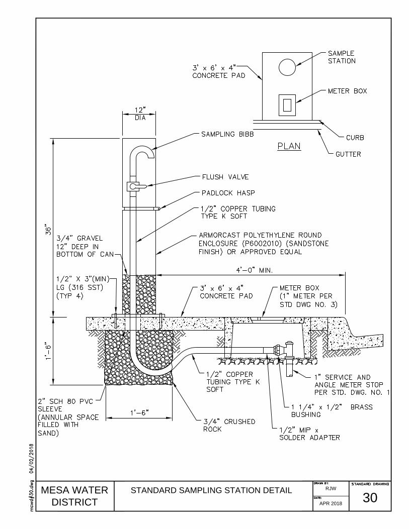
MESA WATER
DISTRICT
STANDARD SAMPLING STATION DETAIL
30
RJW
APR 2018

MESA WATER
DISTRICT
CONCRETE ENCASEMENT
AND SLOPE ANCHORS
31
RJW
APR 2018
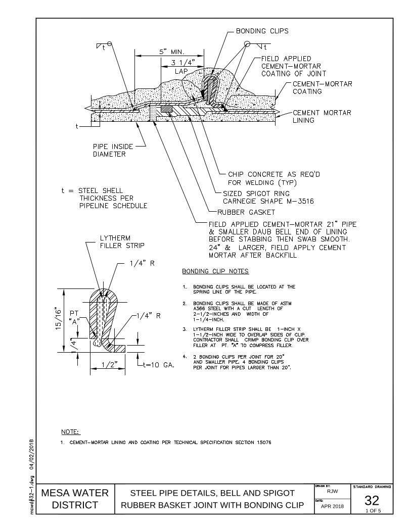
MESA WATER
DISTRICT
STEEL PIPE DETAILS, BELL AND SPIGOT
RUBBER BASKET JOINT WITH BONDING CLIP
32
RJW
APR 2018
1 OF 5

MESA WATER
DISTRICT
STEEL PIPE DETAILS
LAP WELD JOINT
32
RJW
APR 2018
2 OF 5
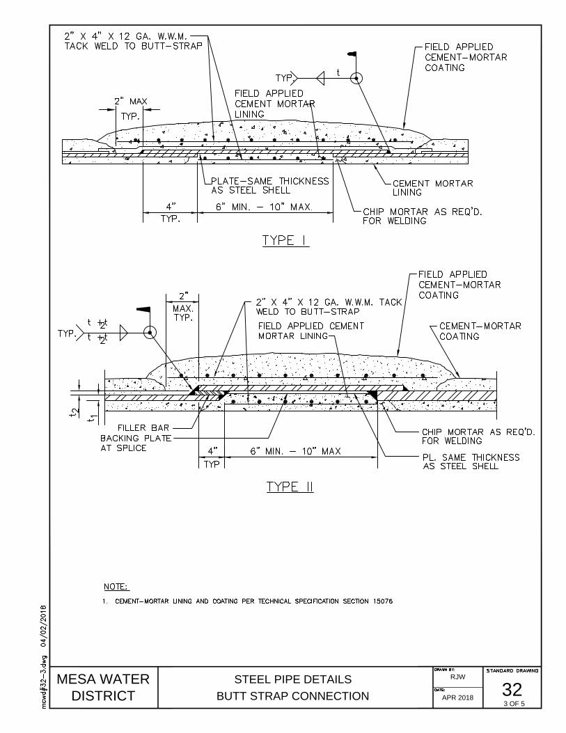
MESA WATER
DISTRICT
STEEL PIPE DETAILS
BUTT STRAP CONNECTION
32
RJW
APR 2018
3 OF 5

MESA WATER
DISTRICT
STEEL PIPE DETAILS
TYPICAL HANDHOLE
32
RJW
APR 2018
4 OF 5
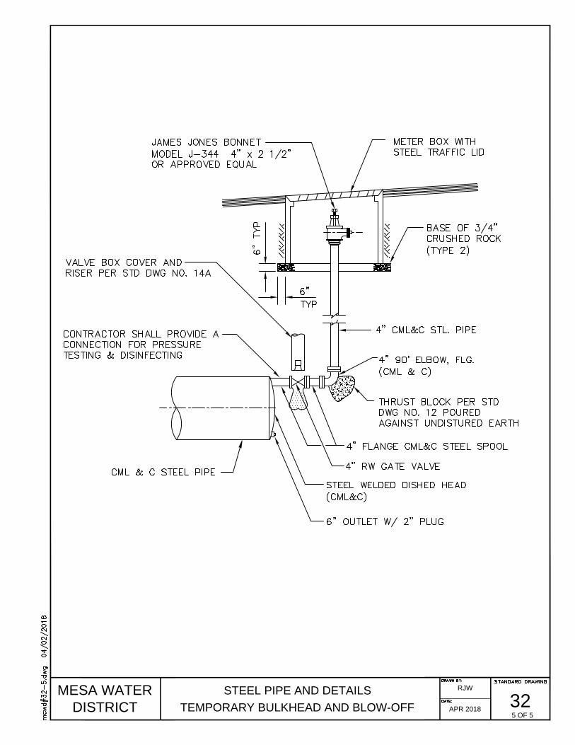
MESA WATER
DISTRICT
STEEL PIPE AND DETAILS
TEMPORARY BULKHEAD AND BLOW-OFF
32
RJW
APR 2018
5 OF 5
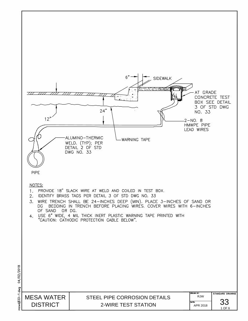
MESA WATER
DISTRICT
STEEL PIPE CORROSION DETAILS
2-WIRE TEST STATION
33
RJW
APR 2018
1 OF 6
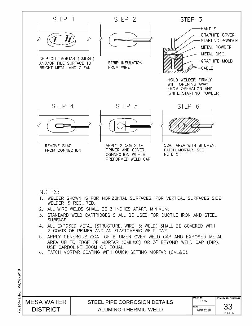
MESA WATER
DISTRICT
STEEL PIPE CORROSION DETAILS
ALUMINO-THERMIC WELD
33
RJW
APR 2018
2 OF 6

MESA WATER
DISTRICT
STEEL PIPE CORROSION DETAILS
AT-GRADE TEST BOX
33
RJW
APR 2018
3 OF 6

MESA WATER
DISTRICT
STEEL PIPE CORROSION DETAILS
BURIED INSULATING FLANGE & TEST STATION
33
RJW
APR 2018
4 OF 6

MESA WATER
DISTRICT
STEEL PIPE CORROSION DETAILS
4-WIRE TEST STATION
33
RJW
APR 2018
5 OF 6

MESA WATER
DISTRICT
STEEL PIPE CORROSION DETAILS
MECHANICAL JOINT BOND
33
RJW
APR 2018
6 OF 6
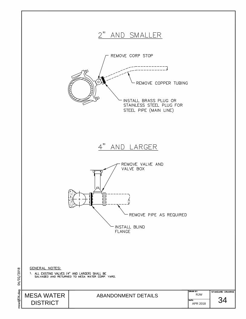
MESA WATER
DISTRICT
ABANDONMENT DETAILS
34
RJW
APR 2018
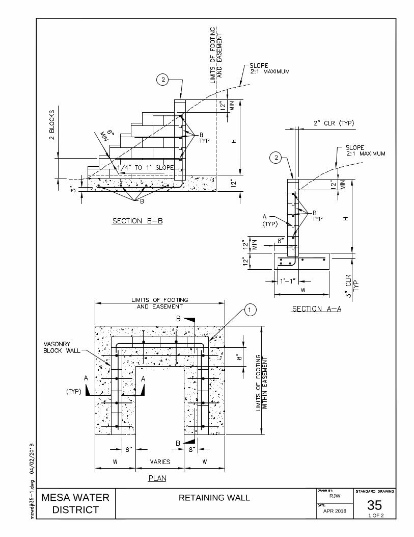
MESA WATER
DISTRICT
RETAINING WALL
35
RJW
APR 2018
1 OF 2

MESA WATER
DISTRICT
RETAINING WALL
35
RJW
APR 2018
2 OF 2
Related Documents