AFFDL-TR-76-17 VUILLEUMIER CYCLE CRYOGENIC REFRIGERATION ENVIRONMENTAL CONTROL BRANCH 4 VEHICLE EQUIPMENT DIVISION APRIL 1976 TECHNICAL REPORT AFFDL-TR-76-17 FINAL REPORT FOR PERIOD FEBRUARY 1975 - AUGUST 1975 Approved for public release; distribution unlimited AIR FORCE FLIGHT DYNAMICS LABORATORY AIR FORCE WRIGHT AERONAUTICAL LABORATORIES Air Force Systems Command Best Available Copy Wright-Patterson Air Force Base, Ohio 45433

Welcome message from author
This document is posted to help you gain knowledge. Please leave a comment to let me know what you think about it! Share it to your friends and learn new things together.
Transcript
AFFDL-TR-76-17
VUILLEUMIER CYCLE CRYOGENICREFRIGERATION
ENVIRONMENTAL CONTROL BRANCH 4VEHICLE EQUIPMENT DIVISION
APRIL 1976
TECHNICAL REPORT AFFDL-TR-76-17FINAL REPORT FOR PERIOD FEBRUARY 1975 - AUGUST 1975
Approved for public release; distribution unlimited
AIR FORCE FLIGHT DYNAMICS LABORATORYAIR FORCE WRIGHT AERONAUTICAL LABORATORIESAir Force Systems Command Best Available CopyWright-Patterson Air Force Base, Ohio 45433
NOTICE
When Government drawings, specifications, or other data are used for any purposeother than in connection with a definitely related Government procurement operation,the United States Government thereby incurs no responsibility nor any obligationwhatsoever; and the fact that the government may have formulated, furnished, or inany way supplied the said drawings, specifications, or other data, is not to beregarded by implication or otherwise as in any manner licensing the holder or anyother person or corporation, or conveying any rights or permission to manufacture,use, or sell any patented invention that may in any way be related thereto.
"This report has been reviewed by the Information Office (01) and is releasableto the National Technical Information Service (NTIS). At NTIS it will be availableto the general public, including foriegn nations."
This technical report has been reviewed and is approved for publication.
RONALD WHITEMechanical Engineer
FOR THE COMMANDER
WILLIAM C. SAVAGEChief, Environmental Control BranchVehicle Equipment Division
Copies of this report thould hot be returned, unless return is required by securityconsiderations, contractual obligations,, "o notice on a specific document.
AIR FORCE - 6 JULY 76 - 200
UNCLASSIFIEDSECURITY CLASSIFICATION OF THIS PAGE (When Dat. Fnered)
REPORT DOCUMENTATION PAGE .READ INSTRUCTIONSBEFORE COMPLETING FORM
I. REPORT NUMBER 12. GOVT ACCESSION NO. 3. RECIPIENT'S CATALOG NUMBERAFFDL-TR-76-17
4. TITLE (and Subtitle) 5. TYPE OF REPORT & PERIOD COVERED
VUILLEUMIER CYCLE CRYOGENIC REFR~IGERATION Final report for periodFebruary 1975 - August 1975
6. PERFORMING ORG. REPORT NUMBER
7. AUTHOR(s) 8. CONTRACT OR GRANT NUMBER(s)
Ronald White
9. PERFORMING ORGANIZATION NAME AND ADDRESS 10. PROGRAM ELEMENT, PROJECT, TASKAREA & WORKI UNIT NUMBERSAir Force Flight Dynamics Laboratory Prog. Ele. 63428F
Environmental Control Branch (FEE) Project 2126Wright-Patterson Air FnrceBkse.,_Ohinj 45432 t _ a _k _ .21.26O3
|1. CONTROLLING OFFICE NAME AND ADDRESS 12. REPORT DATE
Air Force Flight Dynamics Laboratory April 1976Wright-Patterson Air Force Base, Ohio 45433 13. NUMBER OF PAGES
6714. MONITORING AGENCY NAME & ADDRESS(if different from Conitrolling Office) 15. SECURITY CLASS. (of this report)
UNCLASSIFIEDISa. DECLASSI FICATION/DOWN GRADING
SCHEDULE
16. DISTRIBUTION STATEMENT (of this Report)
Approved for public release; distribution unlimited.
17. DISTRIBUTION STATEMENT (of the abstract entered in Block 20, If different from Report)
18. SUPPLEMENTARY NOTES
19. KEY WORDS (Continue on reverse side if necessary and identify by block number)
Cryogenic RefrigeratorVuilleumier Cycle
20. ABSTRACT (Continue on reverse side If necessary and identify by block number)
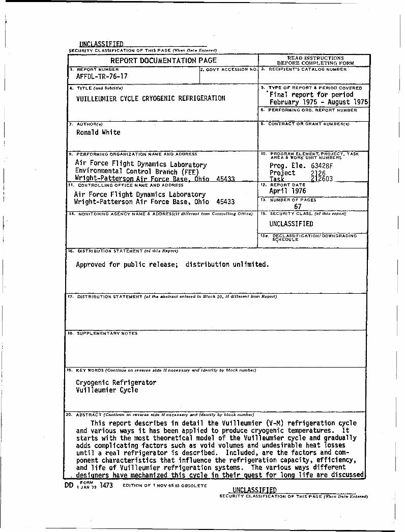
This report describes in detail the Vuilleumier (V-M) refrigeration cycleand various ways it has been applied to produce cryogenic temperatures. Itstarts with the most theoretical model of the Vuilleumier cycle and graduallyadds complicating factors such as void volumes and undesirable heat lossesuntil a real refrigerator is described. Included, are the factors and com-ponent characteristics that influence the refrigeration capacity, efficiency,and life of Vuilleumier refrigeration systems. The various ways differentdesigners have mechanized this cycle in their quest for long life are discussed
DD F RM73 1473 EDITION OF I NOV65 IS OBSOLETE UNCLASSIFIEDSECURITY CLASSIFICATION OF THIS PAGE (IIh`cn Dot E'ntered)
AFFDL-TR-76-17
FOREWORD
This final report was prepared by Ronald White of the Air Force
Flight Dynamics Laboratory, Wright-Patterson Air Force Base, Ohio.
This report was written to satisfy one of the requirements for a Master
of Mechanical Engineering degree at the University of Dayton. This
report provides a basic description of the Vuilleumier cycle refrig-
erators and summarizes a number of Air Force and NASA development efforts.
This work was accomplished in the Environmental Control Branch (FEE),
Vehicle Equipment Division (FE) under Project Number 2126 "Advanced
Surveillance Technology"Task Number 212603 "Cryo Cooler Technology."
The time period covered by the effort was February 1975 to August 1975.
This report was submitted by the author January 1976.
iii
AFFDL-TR-76-17
TABLE OF CONTENTS (Cont'd)
SECTION Page
2. Heaters ----------------------------------------- 53
3. Motors ----------------------------------------- 55
4. Regenerators------------------------------------- 55
5. Heat Rejection ---------------------------------------- 57
VII. CONCLUSIONS ----------------------------------------- 58
REFERENCES ---------------------------------------------- 59
vi
AFFDL-TR-76-17
LIST OF FIGURES
Page
1. Displacer and Cylinder ------------------------------------- 4
2. Power Input Section ------------------------------------ 7
3. Cold Section ----------------------------------------- 9
4. Schematic of Vuilleumier Refrigerator -------------------- 12
5. Theoretical T-S Diagram------------------------------- 15
6. T-S Diagram For First Mass of Gas ---------------------- 15
7. T-S Diagram For Second Mass of Gas --------------------- 16
8. T-S Diagram For Third Mass of Gas ---------------------- 16
9. Cold Volume Indicator Diagram -------------------------- 17
10. Hot Volume Indicator Diagram --------------------------- 17
11. Ambient Volume Indicator Diagram ------------------------ 17
12. Ideal Refrigerator Interactions ------------------------- 22
13. Parallel Cold Displacers ------------------------------- 37
14. Series Cold Displacers --------------------------.---------- 38
15. Dry-Lubricated Vuilleumier Refrigerator------------------- 43
16. Labyrinth Seal Type V-M Refrigerator --------------------- 46
17. Oil Lubricated V-M Crankcase --------------------------- 48
18. Roll Sock Seal Installed------------------------------- 49
vii
-AFFDL-TR-76-17
SECTION I
THE VUILLEUMIER CYCLE
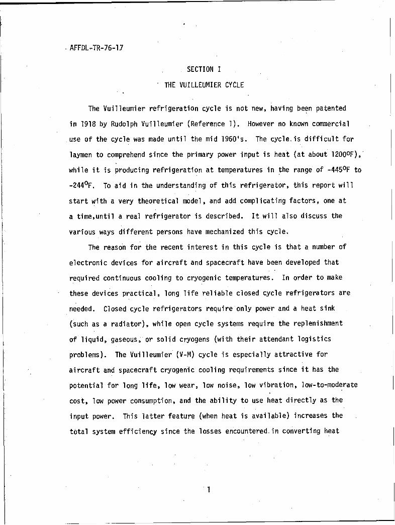
The Vuilleumier refrigeration cycle is not new, having been patented
in 1918 by Rudolph Vuilleumier (Reference 1). However no known commercial
use of the cycle was made until the mid 1960's. The cycleis difficult for
laymen to comprehend since the primary power input is heat (at about 1200 0F),
while it is producing refrigeration at temperatures in the range of -445 0 F to
-244 0F. To aid in the understanding of this refrigerator, this report will
start with a very theoretical model, and add complicating factors, one at
a time,until a real refrigerator is described. It will also discuss the
various ways different persons have mechanized this cycle.
The reason for the recent interest in this cycle is that a number of
electronic devices for aircraft and spacecraft have been developed that
required continuous cooling to cryogenic temperatures. In order to make
these devices practical, long life reliable closed cycle refrigerators are
needed. Closed cycle refrigerators require only power and a heat sink
(such as a radiator), while open cycle systems require the replenishment
of liquid, gaseous, or solid cryogens (with their attendant logistics
problems). The Vuilleumier (V-M) cycle is especially attractive for
aircraft and spacecraft cryogenic cooling requirements since it has the
potential for long life, low wear, low noise, low vibration, low-to-moderate
cost, low power consumption, and the ability to use heat directly as the
input power. This latter feature (when heat is available) increases the
total system efficiency since the losses encountered in converting heat
AFFDL-TR-76-17
to electricity and then converting the electricity to a refrigerator pressure
change, are avoided. The degree to which the various advantages of this cycle
can be realized is somewhat dependent on the details of how the cycle is
mechanized and conversely, the objectives of the refrigerator designer.
Therefore, design techniques that contribute to these advantages will be
pointed out throughout this report.
2
AFFDL-TR-76-17
SECTION II
THEORY OF OPERATION
The continuous production of refrigeration at low temperature requires
the expenditure of a certain amount of energy. In most refrigeration cycles
this is supplied as mechanical energy by an electric motor. In the Vuilleumier
(V-M) cycle the energy is supplied in the form of heat. Externally, the V-M
refrigerator is viewed as a machine which absorbs heat at both a high and low
,temperature and then rejects this heat at some intermediate temperature. The
heat input at the hot end of the machine provides the energy required to produce
the cooling effect at the cold end, while the heat from both the hot and cold
ýends is rejected at the ambient (intermediate) end.
The V-M refrigerator, in its simplest form,is composed of two cylinders
with displacers, two thermal regenerators, three heat exchange areas, connecting
passages, and a mechanism to drive the displacers in the proper sequence.
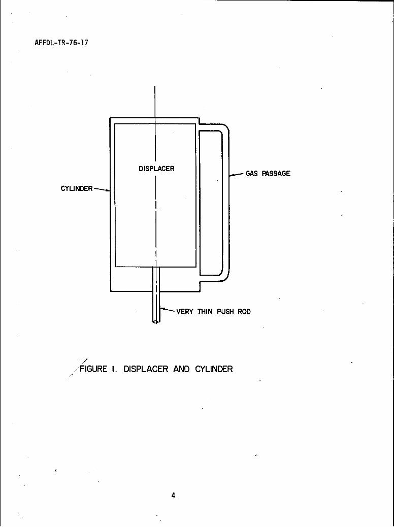
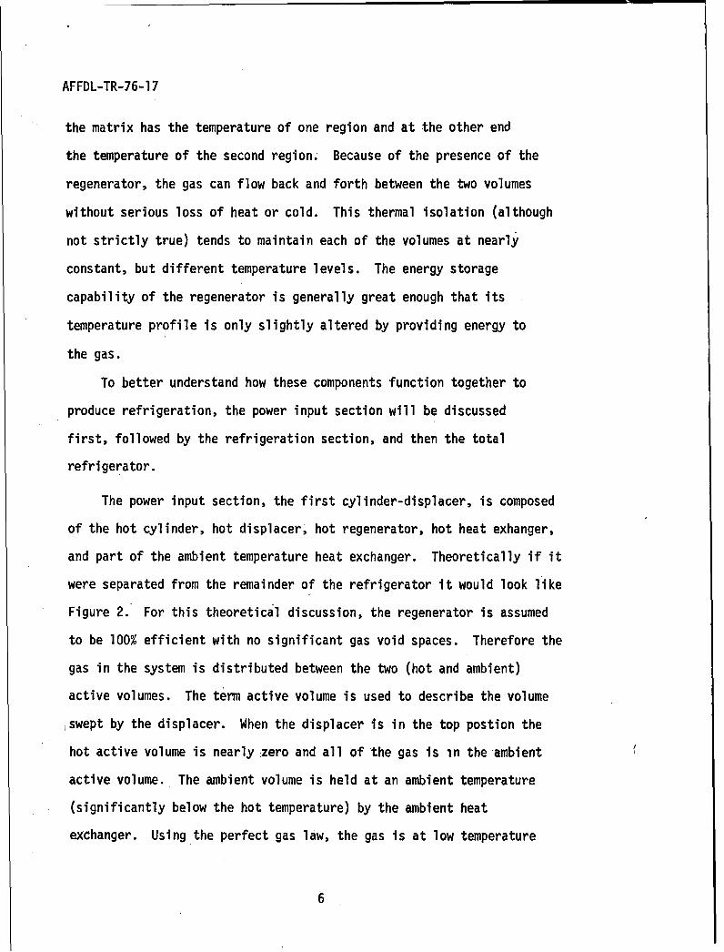
The displacer is a long loose fitting piston-like device whose function
is to move (displace) gas from one end of the cylinder to the other
(See Figure 1). The cylinder-displacer combination is arranged so that
there is a gas passage connecting the two ends of the cylinder.
With this connection, the effect of moving the displacer is to displace
the gas from one end of the cylinder to the other. Note that the total
volume of the gas remains constant (assuming an infinitely thin push rod).
This is in contrast to a piston-cylinder combination that would change the
gas volume. Since the only V-M that utilized a piston is the special-case
self driven V-M, the term 'isplacer"will be used throughout this report as
a reminder that the total gas volume of the system is not affected by the
movement of the displacers. The pressure on each end of the displacer is
3
AFFDL-TR-76-17
DISPLACER GAS FSSAGE
CYLINDER
VERY THIN PUSH ROD
,//'FIGURE I. DISPLACER AND CYLINDER
4
AFFDL-TR-76-17
theoretically the same (in real refrigerators it differs by the pressure
drop through the regenerator and connecting passages). Therefore, the
energy needed to move the displacer is very low, especially when compared
to a refrigerator using pistons. Since the two ends of the cylinder will
be at significantly different temperatures-the displacer is long with
thin walls and packed with insulation to reduce the end-to-end heat
conduction.
Next, a thermal regenerator is arranged to connect the two ends of
the cylinder so that gas passing from one end of the cylinder to the other
-,must pass through the regenerator. The thermalyregenerator is an energy
ýstorage device whose heat capacity greatly exceeds that of the gas.
In operation, gas passing through a regenerator is heated or cooled
depending on flow direction. For example, gas flowing from the
ambient temperature end to the high temperature end of a cylinder is
*heated by the hot regenerator. The energy added to the gas was stored
in the regenerator packing, or matrix, by gas flow in the reverse
direction during a previous part of the cycle. The regenerator matrix
consists of a porous material with a high ratio of surface area to
volume, a high heat capacity, and low heat conductivity in the direction
in which the gas flows through it. Examples of regenerator matrix
materials used in VM refrigerators are: Balls, stacked screens,
and "wool" made of (depending on temperature) stainless steel, monel,
bronze, copper, or lead. At each point in the regenerator there is
a very high heat transfer coefficient between the matrix and the gas.
The regeneratOi- connects two regions of different temperatures, and
therefore has a temperature gradient along its matrix. At one end,
5
AFFDL-TR-76-17
the matrix has the temperature of one region and at the other end
the temperature of the second region; Because of the presence of the
regenerator, the gas can flow back and forth between the two volumes
without serious loss of heat or cold. This thermal isolation (although
not strictly true) tends to maintain each of the volumes at nearly
constant, but different temperature levels. The energy storage
capability of the regenerator is generally great enough that its
temperature profile is only slightly altered by providing energy to
the gas.
To better understand how these components function together to
produce refrigeration, the power input section will be discussed
first, followed by the refrigeration section, and then the total
refrigerator.
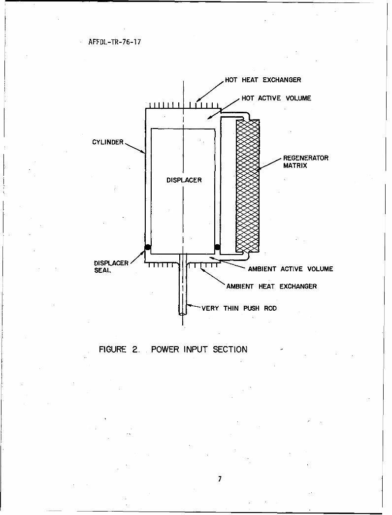
The power input section, the first cylinder-displacer, is composed
of the hot cylinder, hot displacer, hot regenerator, hot heat exhanger,
and part of the ambient temperature heat exchanger. Theoretically if it
were separated from the remainder of the refrigerator it would look like
Figure 2. For this theoretical discussion, the regenerator is assumed
to be 100% efficient with no significant gas void spaces. Therefore the
gas in the system is distributed between the two (hot and ambient)
active volumes. The term active volume is used to describe the volume
,swept by the displacer. When the displacer is in the top postion the
hot active volume is nearly zero and all of the gas is in the ambient
active volume. The ambient volume is held at an ambient temperature
(significantly below the hot temperature) by the ambient heat
exchanger. Using the perfect gas law, the gas is at low temperature
6
AFFDL-TR-76-17
HOT HEAT EXCHANGER
HOT ACTIVE VOLUME
CYLINDER
REGENERATORMATRIX
DISPLACER
DISPLACERSEAL AMBIENT ACTIVE VOLUME
AMBIENT HEAT EXCHANGER
ý-VERY THIN PUSH ROD
FIGURE 2. POWER INPUT SECTION
AFFDL-TR-76-17
(volume is constant) therefore it is at a low pressure. When the
displacer is in the bottom position the ambient active volume is
nearly zero and all of the gas is in the hot active volume. Since
this volume is maintained at a high temperature (usually about 12000 F)
by addition of heat through the hot end heat exchanger, the gas is
fhot and therefore at high pressure. Since there are no valves in the
system, all of the gas throughout the system including any at the
other end of the cylinder (or in any dead volumes to be discussed
later) is at the same pressure. Therefore, it can be seen that by
moving the hot displacer, the system pressure can be varied from a
maximum to a minimum in a cyclic way and that heat is supplied to the
hot end and rejected at the ambient end. The hot section acts as a
thermal compressor (whose effect on pressure is similar to a piston in
a dead ended cylinder). A similar thermal compressor was patented by
V. Bush (Reference 2).
The manner in which the cold section, the second cylinder-displacer,
of the V-M refrigerator uses the changing pressure to produce a cooling
effect is similar to that of the cold section of the Stirling cycle
refrigerator, since the method by which the cyclic pressure is produced
(thermal compressor or mechanical compressor) has little effect on the
cold section.
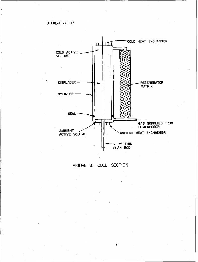
Referring to Figure 3, if the displacer is in the top position
and pressure from the compressor is increasing, gas will flow into
the ambient active volume (the cold active volume is zero) and increase
in pressure. This compression causes the temperature of the ambient
volume gas to increase, but this heat is rejected by the ambient heat
8
AFFDL-TR-76-17
COLD HEAT EXCHANGER
COLD ACTIVE •
VOLUME
DISPLACER REGENERATORMATRIX
CYLINDER
S E A L
GAS SUPPLIED FROMCOMPRESSOR
AMBIENTACTIVE VOLUME . PAMBIENT HEAT EXCHANGER
PUSH ROD
FIGURE 3. COLD SECTION
9
AFFDL-TR-76-17
exchanger so that at the end of the compression process the ambient
active volume is filled with high pressure ambient temperature gas.
The cold displacer is then moved to its lower position and the gas is
displaced from the ambient end, through the cold regenerator to the
cold end. As the gas passes through the cold regenerator, it deposits
its heat in the regenerator matrix and emerges at the cold end as
cold high pressure gas (any decrease in volume of the gas is made up
by the compressor). After all the gas had been displaced to the cold
active volume, the compressor displacer is moved so that the pressure
decreases to the minimum. This decreases the pressure throughout
the refrigerator including the cold section. The gas in the cold
active volume undergoes an expansion (some of it goes back through
the regenerator toward the compressor) becoming colder low pressure
gas. This colder gas then has the ability to absorb heat from the
device to be cooled (refrigeration). After the gas has absorbed the
heat, the cold displacer is moved to the upper position, displacing
the gas from the cold volume through the regenerator where it picks
up the heat that was deposited on the previous half cycle and emerges
at the ambient end where it will reject the heat picked up from the
refrigeration load. After this displacement is completed, the com-
pressor starts to increase the pressure and the cycle begins again.
From this description it can be seen that by combining two
cylinder-displacer-regenerator assemblies and phasing their motion
properly, useful refrigeration can be obtained.
10
AFFDL-TR-76-17
Tp this point, nothing has been said about what sort of mech-
.anism drives the displacer push rods. In the previous discussion a
stop-start square wave motion was implied to simplify the discussion
of the events in each section. In almost all of the real V-M refrig-
erators built to date, the displacers have been driven harmonically.
Harmonic drives (such as a crankshaft with connecting rods) are easy
to fabricate and avoid the problem of high acceleration at the end of
the stroke. However, harmonic drives do complicate the discussion
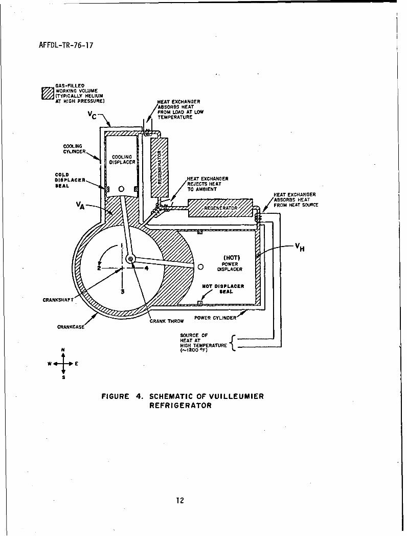
of the V-M cycle. A schematic of a harmonically (sinusoidal) driven
V-M refrigerator is shown in Figure 4.
The cycle operates through the use of displacers moving the gas
from one section to another without the requirement to compress the
gas in a closed volume. Therefore, the pressures throughout the system
are nearly equal at any moment. The seals shown in the schematic
are to force all of the displaced gas through the regenerators.
Since the pressure drop across the regenerators in real refrigerators
is only a few pounds per square inch the loading on the seals and
displacer drive bearings is minimal, which contributes significantly
to the long life of V-M refrigerators. Only a small (few watt) timing
motor is needed to drive the mechanism, since the forces are so small.
The equations to be presented in this report assume isothermal
operation in the refrigerator expansion and compression volumes since
such an assumption makes it possible to derive a set of thermodynamic
equations that are relatively simple and that are fairly representative
of the thermodynamics of the V-M refrigerator. Isothermal operation
is not achieved in an actual refrigerator, but can be approached by
careful design.11
AFFDL-TR-76-17
GAS-FILLED
WORKING VOLUME(TYPICALLY HELIUMAT HIGH PRESSURE) HEAT EXCHANGER
ABSORBS HEATVc • FROM LOAD AT LOW
TEMPERATURE
CYLINDER, COLN
DISPLACER
Cop-DIS PLAC ER.,,, HEAT EXCHANGER
SEAL /REJECTS HEAT
TO AMIENT EAT EXCHANGERABSORBS HEAT
REGENERATOR FROM HEAT SOURCE
VHF • (HOT)
4 0 POWER4-0 DISPLACER
NOT DISPLACE*
CRANKSHAFTS
CRANK THROW POWER CYLINDER
CRANKCASE
SOURCE OFHEAT ATHIGH TEMPERATURE('•1200 OF)
S
FIGURE 4. SCHEMATIC OF VUILLEUMIERREFRIGERATOR
12
AFFDL-TR-76-17
As shown in Figure 4, the idealizedV-Mrefrigerator has two
cylinders fitted with displacers which separate the refrigerator into
three volumes VH, VAs and Vc. The subscript H is the hot temperature
.level, A is the ambient temperature level, and C is the cold temp-
erature level. VA actually consists of the summation of the two
active volumes at the ambient end of the two cylinders. The crankcase
is fitted with filler blocks so that the volume in the crankcase
region is only the ambient active volume. It is assumed that there are
no pressure drops within the refrigerator in the idealized model. The
thermal regenerators are assumed to be perfect; i.e., no temperature
difference is required between gas flows in each direction in order
to transfer heat, and therefore no heat flows through the regen-
erators over a complete cycle. The regenerators are assumed to have
an infinite heat capacity and therefore the temperature of the regen-
erator is invariant with time. In the idealized refrigerator it is
assumed that there are no dead volumes, that is, all the volume inside
the refrigerator is active volume (VH, VA, and VC) This means the
gas volume in the regenerators, heat exchangers, around the sides of
the displacers, around crankcase parts, at the ends of cylinders,
etc. is assumed negligible (this will be modified later). The heat
conduction axially through the regenerator matrix, and along the walls
of the displacers and cylinders is assumed negligible.
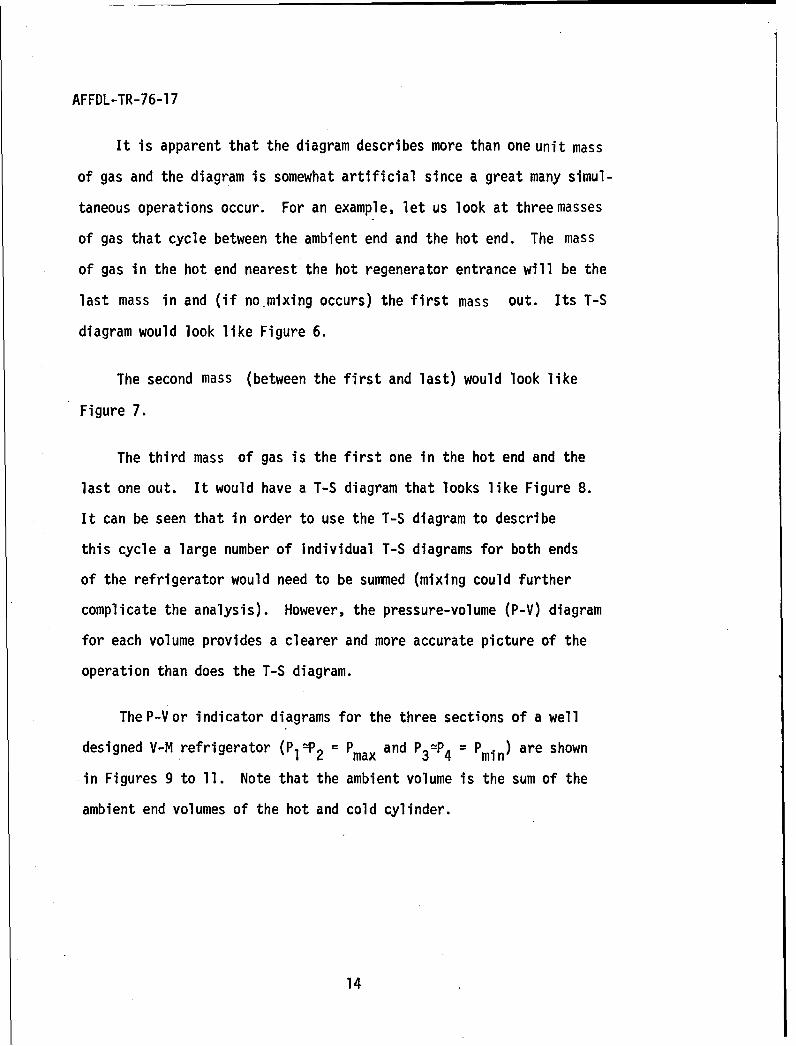
Attempts have been made to describe the cycle using a temperature-
entrophy (T-S) diagram such as Figure 5.
13
AFFDL-TR-76-17
It is apparent that the diagram describes more than one unit mass
of gas and the diagram is somewhat artificial since a great many simul-
taneous operations occur. For an example, let us look at three masses
of gas that cycle between the ambient end and the hot end. The mass
of gas in the hot end nearest the hot regenerator entrance will be the
last mass in and (if no-mixing occurs) the first mass out. Its T-S
diagram would look like Figure 6.
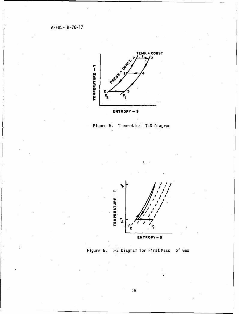
The second mass (between the first and last) would look like
Figure 7.
The third mass of gas is the first one in the hot end and the
last one out. It would have a T-S diagram that looks like Figure 8.
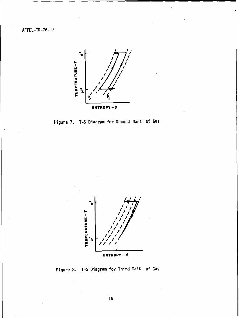
It can be seen that in order to use the T-S diagram to describe
this cycle a large number of Individual T-S diagrams for both ends
of the refrigerator would need to be summed (mixing could further
complicate the analysis). However, the pressure-volume (P-V) diagram
for each volume provides a clearer and more accurate picture of the
operation than does the T-S diagram.
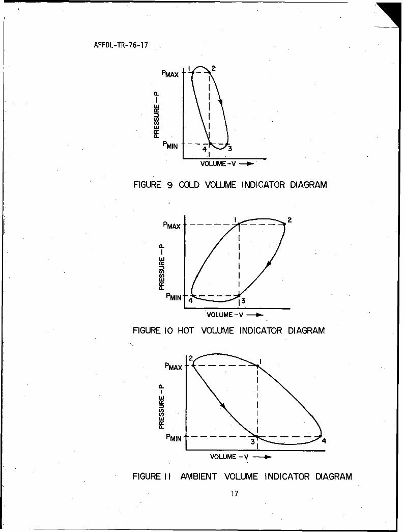
The P-V or indicator diagrams for the three sections of a well
designed V-M refrigerator (PIC9 2 = Pmax and P3 =P4 = Pmin) are shown
in Figures 9 to 11. Note that the ambient volume is the sum of the
ambient end volumes of the hot and cold cylinder.
14
AFFDL-TR-76-17
TEMP. CONST2 2 3
4.
I-.r•
I-
. 2 3
i P2 I
ENTROPY - S
Figure 5. Theoretical T-S Diagram
TH0-.I i/,,l
i / /
hii I,,
ENTROPY - S
Figure 6. T-S Diagram for First Mass of Gas
15
AFFDL-TR-76-17
I I i
TNT.- I• ,
/ /
,TA ,
PJ2 • P
ENTROPY-S
Figure 7. T-S Diagram for Second Mass of Gas
TNi.. / 1/
I ////d I, //
•'.< /111/
;TA -
I-I
ENTROPY -S
Figure 8. T-S Diagram for Third Mass of Gas
16
AFFDL-TR-76-17
MINLU
PMAX I
VOLUME -V 0
FIGURE 10 HOLD VOLUME INDICATOR DIAGRAM
wII.
PMAX -
0-
PMIN
3VOLUME-V 0.
FIGURE I COTD VOLUME INDICATOR DIAGRAM
017
w ,I
AX
VOLUME- -V-
FIGURE I0 HOIET VOLUME INDICATOR DIAGRAM
~MA7
AFFDL-TR-76-17
At each volume for a complete cycle, the first law reduced to:
Q = (h 2 - hl) + W
where Q and W represent energy per unit mass of gas flowing into or
out of the active volume. The temperature of the gas crossing the
boundaries does not vary with time (since ideal regenerators were
assumed), so h2 = hI and Q = W or:
Q = W = PdV
The heat flow is equal to the work at that volume. There is,
of course, no net work resulting from the idealized refrigerator
because no pressure differences exist within the machine at any given
time. Since the pressure at each end of each displacer is equal and
by elementary geometry the change of volume at one end of a cylinder
is exactly equal to the negative of the volume change at the other end:
fPAdVA = IPHdVH + 4PcdVc
Since the displacer motion has been assumed harmonic, the pressure
changes are assumed to occur isothermally, and if the phase separation angle
is assumed to be 90 0 , the volume at each of the ends can be described by
the maximum active hot and cold volumes.
VH = 1/2 VHM (1 - coso) (1)
VC = 1/2 VCM (1 - sin 0) (2)
VA = 1/2 VHM (0 + cos c) + 1/2 VCM (1 + sin G) (3)
Where: VHM = maximum swept volume of the hot end
VCM = maximum swept volume of the cold end
18
AFFDL-TR-76-17
If the gas is assumed to be ideal,
n = PV
RTn:P VHMQ I c_ s)_ + VCM (1- sine) + VHM (I + cose) + VCM (I + sine) (4)
R 2TH 2TC 2TA 2TA
(4)
rearranging. the equation becomes:
nH + lVVcMi +H \VHM' -l1 cos e+ VCMf - 1 sinEj
RV L IT. 12T ,/ \~2TC+' 2T/ TTA TH) k2TA 2c
multiplying numerator and denominator by 2 TA the equation becomes:
S2T- HM(+ + VCM(L+ 1+ VHM I TA cose + VCM (1 sin (5)
This equation can be simplified by grouping the parameters, using the symbols
a, b, and c defined by:
a = VHM l A )+ VCM (6)
b = VHM (1 - TA) (7)
c = VCM 1 (8)
Where"a" reflects the charge of gas in the refrigerator, "b" reflects the effect
of the movement of the hot end displacer on the total pressure, and "c" reflects
the effect of the cold-end displacer on the pressure.
The pressure, P, at any instant and at every point in the working medium is:
= 2nRTAa + b cose + c sine (9)
To obtain the angle e at which P is maximum or minimum, differentiate the
equation and set dP/de = 0. Then:
tan e cb
19
AFFDL-TR-76-17
Using Equation 9 to calculate the area inside the P-V diagrams:
= iPdVH = fRTAVHM aY sino do (10)= a + bcosO+ c sino
2 cos® do (l1)QC = J PdVc = nRTAVCM a + b cose+ c sine
where: QH = heat input to the hot end
QC= heat input to the cold end
These equations can be integrated using formula 2.558-2. from Table of
Integrals Series and Products by I. S. Gradshteyn and I. M. Ryshik. Note
that a2 > (b2 + c2 ) and that f do/(a + bcoso + c sino) must be integrated
from 0 to ff and from 7r to 2ff with - 7r/2 <arctan EK • r/2. The result is:
27 cnR VHM TA 2a (12)H = b2 + c2 - c
27¶bnR VCM TA 1 a (13)Qc 1 b2 + c2 IL faL 2b c
These are the equations for the heat input to the hot end and the heat
absorbed by the cold end (per cycle) for an ideal V-M refrigerator.
The relationship between the maximum hot active volume and the maximum
cold active volume is:
VHM - TH (TA - TC) (14)
VCM TC (TH - TA)
This equation is derived from the ideal work and the ideal refrigeration that
takes place in the machine during a cycle, when the pressure at crank position 1
is assumed equal to the pressure at crank position 2 as indicated in Figure 4.
20
AFFDL-TR-76-17
The coefficient of performance of this ideal refrigerator is:
cop - - = [_M}~ HM T__ _T _C
COP TH- TA} (TA ICTC (15)
which is the same as a Carnot engine, driving a Carnot refrigerator,
therefore the figure of merit (FOM) is one.
The maximum pressure ratio is obtained by differentiating the pressure
equation:
Pmax = a +b + c2 (16)Pmin a -4b 2 + cZ
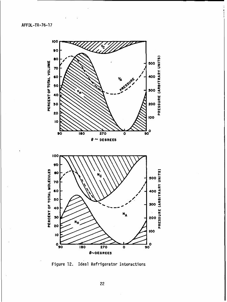
In order to better understand this ideal refrigerator an example was
calculated and plotted in Figure 12. The assumptions were:
Temperature of hot end= 812 0K
Temperature of ambient end = 366 0K
Temperature of cold end = 770K
VHM is 87.23% of the total volume
VCM is 12.77% of the total volume
Phase angle is 900
e = 0 at hot displacer top dead center
The volumes VH, VA, and VC were plotted to show how they vary with
crank position, 0. The percentage of the total number of molecules NHs NA,
NC, in each of the volumes vs. crank position was also plotted, as was the
resulting pressure (in arbitrary units).
21
AFFDL-TR-76-17
100
90
S- 500
= 70 -70
.j 60 V 4004
50 n/0 ." 300
1- 40 ''4zo 30 200hiA. Iii
20 a:a.
100"II010
90 ISO 270 0 90
9 DEGREES
100
SDI-W -soo500 z
o-/700
o 50
0 40 -""I- w
0 -200 0
ILO. 20100
0 090 ISO 270 0 90
&-,DEGREES
Figure 12. Ideal Refrigerator Interactions
22
AFFDL-TR-76-17
From Figure 12, it can be seen that although the maximum cold volume
is only 12.77% of the total, at one point of the cycle 52% of the molecules
of the system are in the cold end. Also the maximum percentage of molecules
ever in the hot end is 55%. The maximum pressure occurs 450 before the maximum
hot volume occurs and the minimum pressure occurs 450 before the minimum hot
volume occurs. Noting the shape of the pressure curve in the region of 1800
to 2700, it can be seen that the pressure curve is not quite sinusoidal.
All of the above equations and discussion assumed an ideal refrigerator,
now the various nonideal factors will be added to these equations until a
real refrigerator is discussed.
There are a number of void volumes in a real refrigerator. These include
clearances around the displacers to prevent scraping, clearance at the ends of
the cylinders to prevent hitting the end and to allow for thermal expansion,
gas flow spaces in the regenerators, heat exchangers, gas transfer passages,
and clearances in and around the mechanism. The void volumes must undergo the
pressure variations of the cycle but do not contribute to the cooling effect.
The void volumes decrease the maximum pressure ratio produced and, therefore,
the amount of cooling produced.
To illustrate the magnitude of some of these void volumes, the cold
regenerator flow passage void volume is usually 1.5 to 3.5 times the active
cold volume, while the displacer side clearance void volume is usually about
0.17 times the active cold volume. The effect of void volumes is related to
the temperature of the void volume. The void volumes at the coldest temperatures
have the greatest effect on the refrigerator performance while the void volumes
at the hot end have the least effect on refrigerator performance. The effect
of void volumes is more pronounced in miniature V-M refrigerators, due in part
23
AFFDL-TR-76-17
to ordinary manufacturing tolerances. In miniature V-M refrigerators, decreasing
the void volume is both essential and expensive. Reduction of void volume requires
close tolerances and unusual shaped parts (especially in the crankcase). Void
volume reduction techniques used in current refrigerators even include the use
of epoxy to fill the screw slots in the internal screws.
The effect of void volume can be accounted for by adding terms to
Equation 4 of the form:
Vvl + Vv2 + Vvn
Tv-- T v Tvn
where: VVl = a void volume
Tvl =,temperature of that void volume
or
Vv
where: Vv = sum of void volumes
TV = f Tv dVV
fdVv
rhe addition of void volumes will change Equation 6 to:
aVHM { TlH)}+ VCM 1 T T~+}2 v)Ž (17)
rhe other-Equations 9 thru 16 remain the same except the numerical value
)f "a" has changed. Typical values of the reduced void volume ratio (reduced
foid volume to cold end volume) for small V-M refrigerators built to date are
n the range of 1.5 to 3.7, where reduced void volume is defined as:
Vvreduced = Vvactual X actual(
24
AFFDL-TR-76-17
Another correction needed for the basic V-M equations is the compressi-
bility factor for the working fluid which is helium. Helium has been used as
the working fluid in all V-M refrigerators built to date since it behaves as a
nearly perfect gas and has the lowest temperature capability. The effect of
compressibility of helium is slight until temperatures below 700 K are reached.
Adding the compressibility factor (Z) to Equation 4:
n = VHM~l'cs_) + VCM(l-sine) + VHM(l+cosO) + VCM(l+sine)+ 2 Vv (19)2R THZH TTCZC TAZA TAZA (19)
which changes Equations 6 or 17 , 7 , 8 , and 14 to:
a=VHM ZLH + TA VCM CZcZ + TA1 2Vv_ A (20)ZH--- A Z -C +A L ZvTv
b VHM ZH TA (21)
c=VCM( C TLAI (22)
VHM = THZH [TAZA- TcZcI (23)
VCM THZH - TAZA CT TZC
COP THZH TAZ ZA} TcZc (24)
Equations 9 through 13 and 16 are still valid, however the values of "a",
"b", and "c" within these equations have changed slightly.
To summarize the theoretical V-M section, if compressibility effects and
void volumes are to be accounted'for, the equations to use are 9 through 13,
16, and 18 through 24.
25
AFFDL-TR-76-17
Equation 13 QC, is the gross refrigeration produced by the refrigerator.
To obtain the net refrigeration produced by the refrigerator, all of the various
cold end losses must be subtracted from the gross refrigeration. Equation 12,
QH, is the P-V heat input to the hot cylinder. To obtain the actual heat
(power) input needed, the various hot end losses must be added to the P-V
input.
26
,AFFDL-TR-76-17
SECTION III
INHERENT THERMODYNAMIC AND HEAT TRANSFER LOSSES
Since it is impossible to build perfect regenerators and to eliminate
all undesirable heat transfer processes in the refrigerator, these losses
must be subtracted from the gross refrigeration to determine the net
refrigeration available at the cold end. Similar losses must be added
to the heat input to the gas to determine the required heat input to the
hot end.
1. SHUTTLE LOSS
Shuttle loss is caused by the mismatch of thermal gradients between the
displacer and the cylinder. The cold cylinder wall is at ambient temperature at
one end and at cryogenic temperature at the other. It has a fixed length
and a gradient from warm to cold that is approximately linear. The displacer
is shorter than the cylinder wall by the length of the stroke, however it
has the same temperature extremes; warm at one end and cold at-the other.
When the displacer is at one extreme of its travel the temperature gradients
are somewhat mismatched. As it passes thru its stroke and reaches the other
extreme the gradients are again mismatched, but now they are mismatched in
the opposite direction so that the displacer picks up heat from the cylinder
when it is at the warm end and it gives off heat to the cylinder when it is
at the cold end of its stroke. Hence, there is a picking up of heat at the
warm end, a shuttling of the displacer to the cold end where it drops off the
energy to the cylinder. It is thus termed a shuttle loss.
If the motion of the displacer is approximately harmonic and if the
thermal time lag of the cylinder and displacer materials is small compared
27
AFFDL-TR-76-17
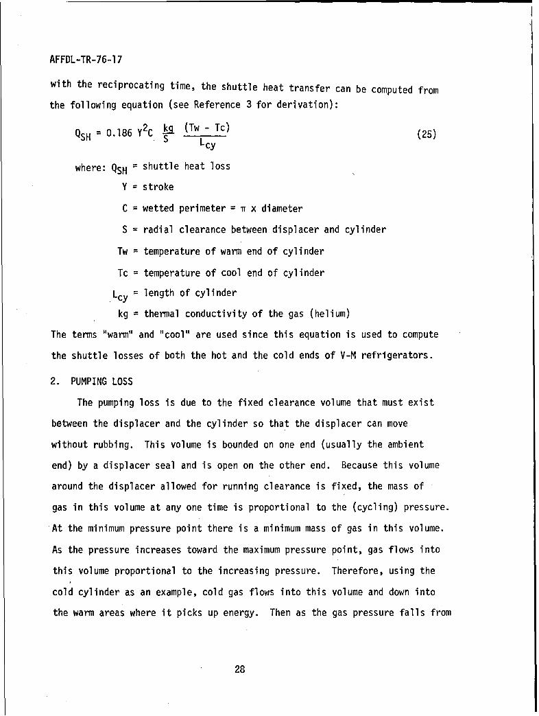
with the reciprocating time, the shuttle heat transfer can be computed from
the following equation (see Reference 3 for derivation):
QSH = 0.186 Y2C Sk (Tw - Tc) (25)
where: QSH = shuttle heat loss
Y = stroke
C = wetted perimeter = n x diameter
S = radial clearance between displacer and cylinder
Tw = temperature of warm end of cylinder
Tc = temperature of cool end of cylinder
Lcy = length of cylinder
kg = thermal conductivity of the gas (helium)
The terms "warm" and "cool" are used since this equation is used to compute
the shuttle losses of both the hot and the cold ends of V-M refrigerators.
2. PUMPING LOSS
The pumping loss is due to the fixed clearance volume that must exist
between the displacer and the cylinder so that the displacer can move
without rubbing. This volume is bounded on one end (usually the ambient
end) by a displacer seal and is open on the other end. Because this volume
around the displacer allowed for running clearance is fixed, the mass of
gas in this volume at any one time is proportional to the (cycling) pressure.
At the minimum pressure point there is a minimum mass of gas in this volume.
As the pressure increases toward the maximum pressure point, gas flows into
this volume proportional to the increasing pressure. Therefore, using the
cold cylinder as an example, cold gas flows into this volume and down into
the warm areas where it picks up energy. Then as the gas pressure falls from
28
AFFDL-TR-76-17
the maximum back to the minimum pressure, some warm gas flows out of this volume
into the cold regions. This causes a loss of refrigeration called the pumping
loss. This loss occurs on both the cold end and the hot end of V-M
refrigerators when displacer seals are used to force gas flow thru the
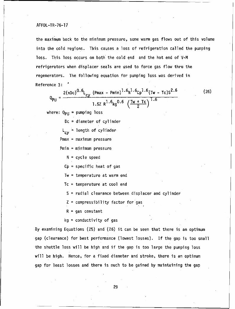
regenerators. The following equation for pumping loss was derived in
Reference 3:
2(TrDc)O0 6 L (Pmax - Pmin)1.6N'1 6CpI6(Tw - Tc)S 2 . 6 (26)'4PU - cyl'5Z R1 .6kg0 .6 (Tw + Tc)l'.6
where: QpU = pumping loss
Dc = diameter of cylinder
Lcy = length of cylinderPmax = maximum pressure
Pmin = minimum pressure
N = cycle speed
Cp = specific heat of gas
Tw = temperature at warm end
Tc = temperature at cool end
S = radial clearance between displacer and cylinder
Z = compressibility factor for gas
R = gas constant
kg = conductivity of gas
By examining Equations (25) and (26) it can be seen that there is an optimum
gap (clearance) for best performance (lowest losses). If the gap is too small
the shuttle loss will be high and if the gap is too large the pumping loss
will be high. Hence, for a fixed diameter and stroke, there is an optimum
gap for least losses and there is much to be gained by maintaining the gap
29
AFFDL-TR-76-17
accurately. To accomplish this the materials of the cylinder and displacer are
selected so that their coefficients of thermal expansion are matched.
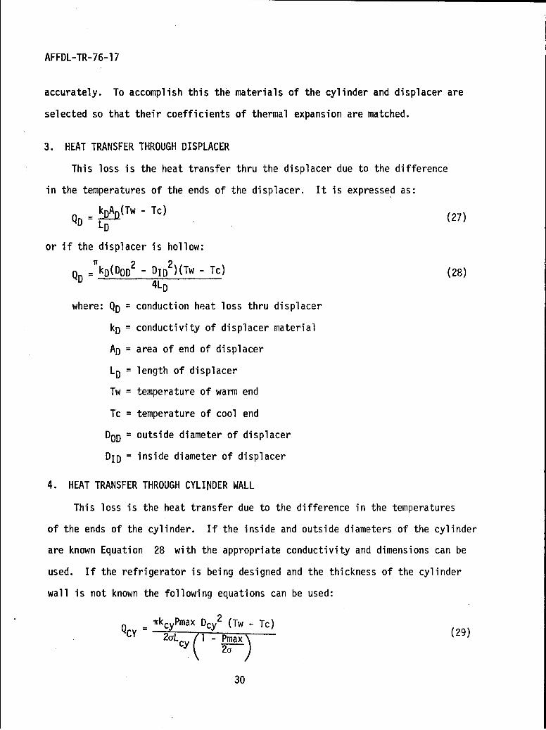
3. HEAT TRANSFER THROUGH DISPLACER
This loss is the heat transfer thru the displacer due to the difference
in the temperatures of the ends of the displacer. It is expressed as:
kDAp(Tw - Tc) (27)QD = LD
or if the displacer is hollow:
QD =kD(DOD2 _ DID2 )(Tw - Tc) (28)
4 LD
where: QD = conduction heat loss thru displacer
kD = conductivity of displacer material
AD = area of end of displacer
LD = length of displacer
Tw = temperature of warm end
Tc = temperature of cool end
DOD = outside diameter of displacer
DID = inside diameter of displacer
4. HEAT TRANSFER THROUGH CYLINDER WALL
This loss is the heat transfer due to the difference in the temperatures
of the ends of the cylinder. If the inside and outside diameters of the cylinder
are known Equation 28 with the appropriate conductivity and dimensions can be
used. If the refrigerator is being designed and the thickness of the cylinder
wall is not known the following equations can be used:
Q r wkcyPmax Dcy 2 (Tw - Tc) (29)
2OLcy - Pmax)
30
AFFDL-TR-76-17
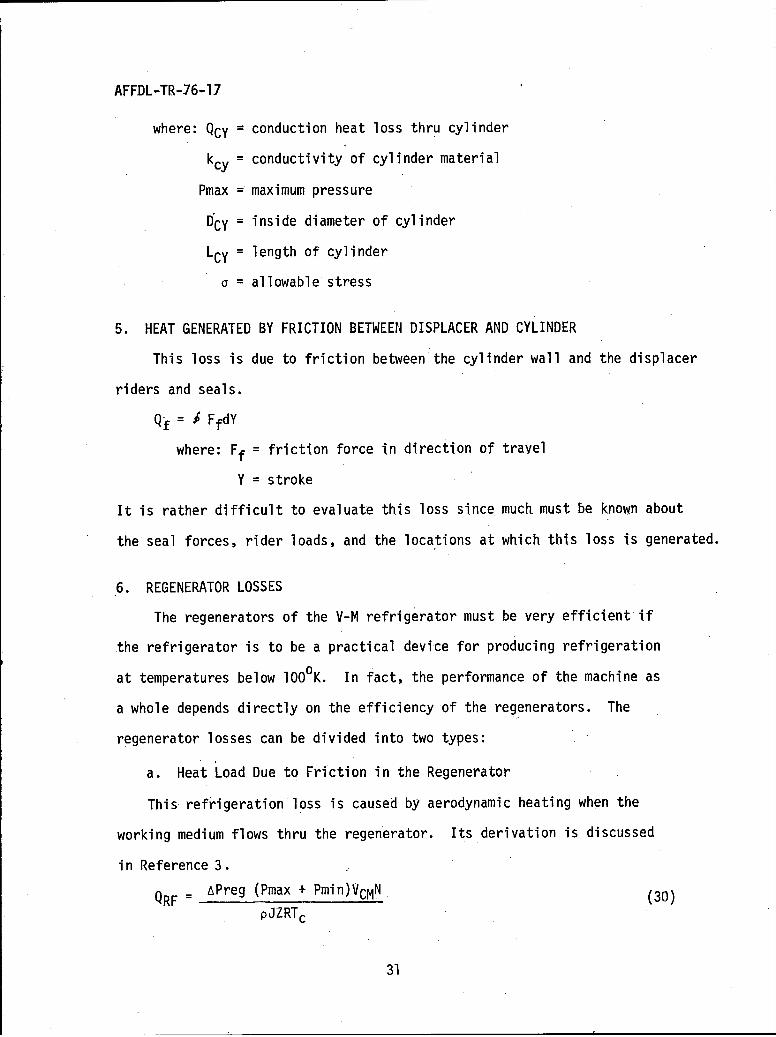
where: QCy = conduction heat loss thru cylinder
kcy = conductivity of cylinder material
Pmax = maximum pressure
DCy = inside diameter of cylinder
LCy = length of cylinder
a = allowable'stress
5. HEAT GENERATED BY FRICTION BETWEEN DISPLACER AND CYLINDER
This loss is due to friction between the cylinder wall and the displacer
riders and seals.
Q= f FfdY
where: Ff = friction force in direction of travel
Y = stroke
It is rather difficult to evaluate this loss since much must be known about
the seal forces, rider loads, and the locations at which this loss is generated.
6. REGENERATOR LOSSES
The regenerators of the V-M refrigerator must be very efficient if
the refrigerator is to be a practical device for producing refrigeration
at temperatures below 1000K. In fact, the performance of the machine as
a whole depends directly on the efficiency of the regenerators. The
regenerator losses can be divided into two types:
a. Heat Load Due to Friction in the Regenerator
This refrigeration loss is caused by aerodynamic heating when the
working medium flows thru the regenerator. Its derivation is discussed
in Reference 3.
QRF = APreg (Pmax + Pmin)VCMN (30)pJZRTc
31
AFFDL-TR-76-17
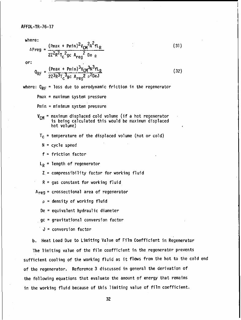
where:
APreg (Pmax + Pmin)2VCM2N2 fLR (31)
2Z2 R2Tc2gc Areg2 De p
or:
QRF = (Pmax + Pmin) 3 VCM3N3fLR (32)2Z3 R3Tc3 gc Areg2 p2 DeJ
where: QRF = loss due to aerodynamic friction in the regenerator
Pmax = maximum system pressure
Pmin = minimum system pressure
VCM = maximum displaced cold volume (if a hot regeneratoris being calculated this would be maximum displacedhot volume)
Tc = temperature of the displaced volume (hot or cold)
N = cycle speed
f = friction factor
LR = length of regenerator
Z.= compressibility factor for working fluid
R = gas constant for working fluid
Areg = crossectional area of regenerator
p = density of working fluid
De = equivalent hydraulic diameter
gc = gravitational conversion factor
J = conversion factor
b. Heat Load Due to Limiting Value of Film Coefficient in Regenerator
The limiting value of the film coefficient in the regenerator prevents
sufficient cooling of the working fluid as it flows from the hot to the cold end
of the regenerator. Reference 3 discussed in general the derivation of
the following equations that evaluate the amount of energy that remains
in the working fluid because of this limiting value of film coefficient.
32
AFFDL-TR-76-17
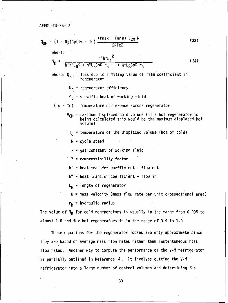
-(ma + Pmin) VCM N
QRH = (1 - NR)Cp(Tw - Tc) (Pmax C(33)2RTcZ
where:
NR = h'h"LR 2 (34)h h"LR4 + h"LRCpG rh + h"LRrpG rh
where: QRH = loss due to limiting value of film coefficient inregenerator
NR = regenerator efficiency
Cp = specific heat of working fluid
(Tw - Tc) = temperaturE difference across regenerator
VCM = maximum displaced cold volume (if a hot regenerator isbeing calculated this would be the maximum displaced hotvolume)
TC = temperature of the displaced volume (hot or cold)
N = cycle speed
R = gas constant of working fluid
Z = compressibility factor
h' = heat transfer coefficient - flow out
V = heat transfer coefficient - flow in
LR = length of regenerator
G = mass velocity (mass flow rate per unit crossectional area)
rh = hydraulic radius
The value of NR for cold regenerators is usually in the range from 0.995 to
almost 1.0 and for hot regenerators is in the range of 0.9 to 1.0.
These equations for the regenerator losses are only approximate since
they are based on average mass flow rates rather than instantaneous mass
flow rates. Another way to compute the performance of the V-M refrigerator
is partially outlined in Reference 4,. It involves cutting the V-M
refrigerator into a large number of control volumes and determining the
33
AFFDL-TR-76-17
mass flow rate into and out of each of these control volumes as a function
of crank position. The losses, especially the regenerator and pumping
losses, can be calculated and their effect on the pressure can be iterated
with the mass flow equations so that a more accurate description of the
refrigeration at every crank position is obtained. This can be done for
an existing refrigerator design with the aid of a computer but is extremely
difficult to do when optimizing a new design since the control volumes
themselves are being changed during the optimization process. Therefore, the
equations presented above or similar equations are usually used for optimizing
new designs.
7. NET REFRIGERATION
To obtain the net refrigeration, the cold end losses for each stage
are summed and subtracted from the gross refrigeration for that stage. In
multistage refrigerators some of the losses from colder stages appear as
increased refrigeration at warmer refrigeration stages. These include
conduction losses, regeneration heat loss, shuttle loss, and pumping loss.
These losses from a colder stage are called interstage heat flow and should
be added to the gross refrigeration of the warmer stage. Other cold end
losses that were not discussed here but might be applicable depending on
refrigerator design are regenerator conduction, insulation, seal leakage
losses, and heat leaks down instrumentation leads.
34
AFFDL-TR-76-17
8. TOTAL HEATER POWER INPUT
To calculate the heater power required at the hot end, the hot end
losses are summed and added to the heat input to the gas. Losses not
discussed above that should be included depending on the actual design
are the hot end insulation loss, conduction losses down heater and
instrumentation leads, and heat leaks thru the insulation inside the hollow
hot displacer.
35
AFFDL-TR-76-17
SECTION IV
V-M COOLER VARIATIONS
1. MULTISTAGE V-M COOLERS
In many applications there is a need to produce useful refrig-
eration at more than one temperature level at the same time. An
example of this is cooling an electronic device to a very low temp-
erature while cooling a dewar heat shield surrounding the device to
an intermediate temperature to intercept the dewar heat leaks. This
saves considerable power since the majority of the heat is removed
at the higher temperature for much less input power (and refrigerator
size) than if all the heat had been removed at the lower temperature.
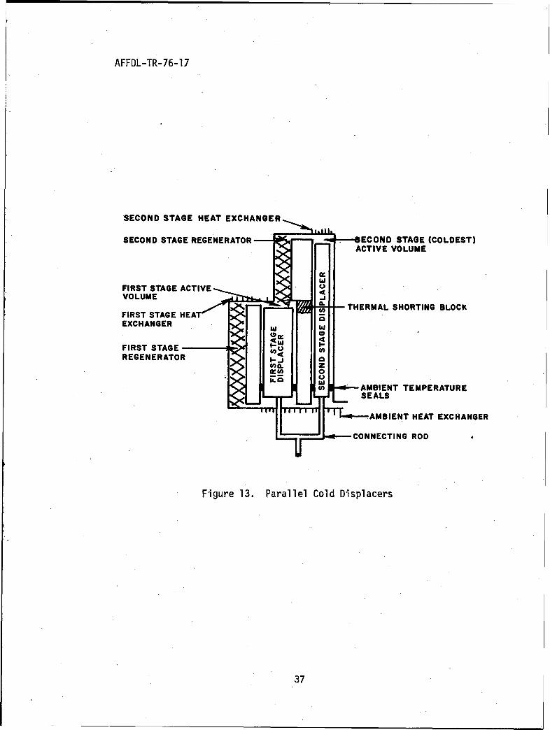
Two mechanisms have been used to add additional cold stages to
V-M refrigerators. The parallel cylinder system (Figure 13) adds
another smaller diameter cold cylinder parallel to the first cold
cylinder. In this configuration the displacer seals are at the
ambient temperature region of the displacers (an advantage) but
fabrication of the cylinder assembly is more difficult. Keeping the
two cylinders straight and parallel from brazing temperature down
through cryogenic temperature is difficult and expensive.
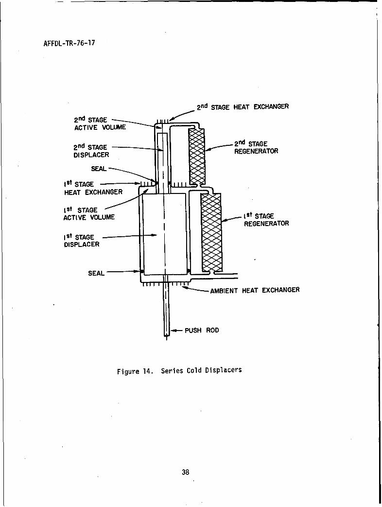
The other configuration is the series cold cylinder config-
uration (Figure 14). This configuration is easier to fabricate
but requires a displacer seal at the base of the second stage displacer
that seals properly at the first stage (cryogenic) temperature.
Adding additional cold stages affects the previously developed
equations in the following ways. Additional cold stage factors
36
AFFDL-TR-76-17
SECOND STAGE HEAT EXCHANGER
SECOND STAGE REGENERATOR ECOND STAGE (COLDEST)ACTIVE VOLUME
FIRST STAGE ACTIVEVOLUME
T S HEAT - THERMAL SHORTING BLOCKFIRST STAGE HA
EXCHANGER
FIRST STAGEREGENERATOR
U AMBIENT TEMPERATURE• SEALS
AMBIENT HEAT EXCHANGER
CONNECTING ROD 4
Figure 13. Parallel Cold Displacers
37
AFFDL-TR-76-1 7
2 nd STAGE HEAT EXCHANGER2 nd STAGE •L • 'ACTIVE VOLUME
2nd STAGE pn2 d STAGE
DISPLACER REGENERATORSEAL •
Ist STAGE
HEAT EXCHANGER
Ist STAGE
ACTIVE VOLUME I st STAGEREGENERATOR
ISt STAGEDISPLACER
SEAL- 9
"--AMBIENT HEAT EXCHANGER
S--PUSH ROD
Figure 14. Series Cold Displacers
38
AFFDL-TR-76-17
(second term) are added to Equation 20. Additional terms are
added to Equation 22 and additional equations similar to Equation
13 are written to describe the gross refrigeration of the additional
stages. The ratio between the cold active volumes of a two stage
refrigerator is obtained by taking the ratio of the gross refrigeration
equations (similar to Equation 13). The result is:
QC 1 VCM (35)
QC2 VCM
2. PHASE ANGLE
Phase angles other than 900 were investigated by E. B. Quale
and T. T. Rule (Reference 5) and by B. Leo (Reference 3). Phase angles
other than 900 complicate the equations (1 through 13) considerably
and make the fabrication of parts more difficult. The optimum phase
angle is a function of the active swept volumes of the hot and cold
cylinders and of the thermal boundary conditions. The investigations
showed that for refrigerators with heat rejection temperatures near
room temperature, the optimum phase angle would be in the range from
90' to 1020 depending on cold end temperature (the lower the temperature
the greater the angle). Multistage refrigerators further complicate
these relationships and reduce the range of optimum -phase angles.
Since the gross refrigeration is changing very slowly with respect to
phase angle near the optimum, most manufacturers are using a 90° phase
angle.
39
AFFDL-TR-76-17
3. SIMILAR CYCLESJ
There are other heat powered refrigeration cycles similar to
the V-M cycle. One by Bush (Reference 6) is quite similar to the V-4
except that the two ambient volumes (one at the ambient end of the
cold cylinder and one at the ambient end of the hot cylinder) are
separated by a thermal regenerator and reject heat to heat sinks at
different temperatures. Another heat powered refrigerator was pat-
ented by Taconis (Reference 7). It differs from the V-M in the
timing of the movements (three instead of four motions) of the displacers.
Another heat powered refrigerator was patented by Hogan (References
8 and 9). It produced cooling in the 100 to 20 0 K range, while the
hot end absorbed heat at room temperature and the heat rejection
was at 77 0 K (the heat was rejected to liquid nitrogen). A patent by
Cowans (Reference 10) describes a modification to the V-M refrigerator
that allows it to drive its own displacers and produce useful shaft
power. This is done by increasing the crosssectional area of either
the hot displacer connecting rod or both connecting rods, so that with
the addition of connecting rod seals, and by lowering the crankcase
pressure below the minimum pressure in the V-M cycle, a net force
can be created to drive the refrigerator. This has the advantage
that the small timing motor used on most V-M refrigerators is not
needed (but something must give it a shove to get it started).
However this adds the life limiting problem of dynamic connecting rod
seals that must be able to seal against the full cycle pressure (several
hundred pounds per square inch). This type of sealing problem is
40
AFFDL-TR-76-17
avoided by most V-M refrigerators since in a "pure" V-M cycle the
only dynamic seals in the system are the displacer seals. Displacer
seals usually experience very small pressure differences of 5 to 15'
psi which contributes to their very long life.
41
AFFDL-TR-76-17
SECTION V
V-M REFRIGERATOR MECHANIZATION
The V-M refrigerator is a very compact high performance refrigerator that
can produce refrigeration at cryogenic temperatures for long periods of time
without maintenance. It can be powered by electrical heating, direct solar
energy, exothermic chemical reactions, a gas burner, and even nuclear energy
or isotopes. The noise level of the V-M refrigerator is low because of the
very small gas pressure difference between the faces of the displacers. This
coupled with the low speed of the refrigerator results in low bearing loadings,
considerably less wear, and long life. The low speeds and low loads present
opportunities to use contamination control techniques, unavailable to highly
loaded machines, that significantly improve the time between servicing.
To date there have been a number of V-M refrigerators built for a variety
of applications by a number of different designers from several companies. The
design philosophy for these refrigerators has varied widely due to constraints
imposed by the applications and preferences of the designers.
To date there have been three major philosophies on how to mechanize
the V-M cycle to produce long life.
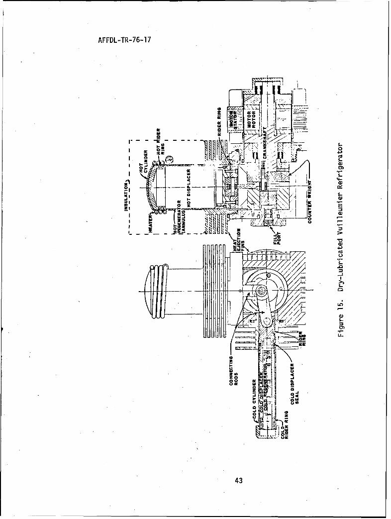
The first mechanization concept (Figure 15) is a refrigeration configuration
with the hot and cold cylinders at 900 (sometimes 1800) to each other. The
displacers are driven by a simple crank mechanism that is relatively easy to
balance if the displacers are the same weight. The crankcase volume is part
of the ambient active volume and odd shaped bits of metal are used to reduce
the void volume in the crankcase. Dynamic seals are used at the ambient end
of both displacers to force the gas to flow thru the regenerators. One of the
42
AFFDL-TR-76-1 7
-1 m
00
'~ ~1~'oI-~ me
-II
WC
z'
cc ~0 W3'
OW-
0,
43-
AFFDL-TR-76-17
more successful seal configurations has been the "C" crossection
glass loaded teflon lip seals. These seals have a special spring
inside the "C" to expand the seal lip and provide continuous sealing
under a wide variety of temperature and wear conditions. These seals
are lightly loaded since they need to seal against only the pressure
drop across the regenerator (about 5 to 15 psi). The displacers are
guided within the cylinders by rider rings at each end of the dis-
placer. The rider rings act as solid lubricated linear bearings.
Common materials used are filled teflons in the cold and ambient
regions and flouride eutectic lubricated composites or carbon in the
hot region. The only forces on the displacers in this design are caused
by the product of the displacer area and the regenerator pressure drop
(a few psi), therefore the bearing loads are very small and only a small
motor is needed to drive the mechanism. These low loads coupled with
the low speed contributes to the long life of this concept. The
bearings usually used are solid lubricant film transfer ball bearings.
Journal bearings have also been used, especially in the wrist pins.
To prevent contamination of the working fluid that would freeze out
in the cold end of the refrigerator, only solid lubricants are used
(and the bearings loads derated). Motor windings are kept outside the
working fluid space so that the contaminates trapped in the windings
and outgassing of the wire insulation will not contaminate the working
fluid. This has been accomplished by using an AC induction motor. A
matching inverter is used to convert to the proper AC frequency. The
motor rotor (solid metal) is inside the working space and is separated
from the stator (with its winding) by a thin nonmagnetic pressure
shell containing the working fluid. The pressure ratio attained in
44
AFFDL-TR-76-17
this type of refrigeriator (maximum cycle pressure to minimum cycle
pressure) has been in the range of 1.3 to 1.7. This concept has a
finite life since riders, seals, and bearings are wearing components.
To date, the most critical life limiting component is the hot displacer
rider ring. This mechanization concept results in a long life,
relatively compact, rugged refrigerator that is easy to apply, and needs
no special handling. One, two, and three stage refrigerators have been
built using this concept (References 4 and 11) and a number of these
refrigerators have successfully completed environmental and flight
qualification testing.
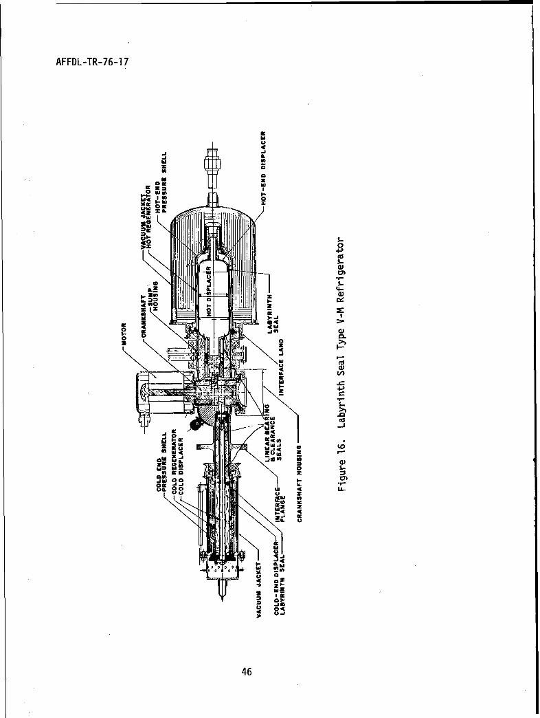
The second long life concept (Figure 16) avoids the seal wear
problems by using a combination of labyrinth and clearance seals to
provide displacer sealing. Since these seals allow a certain amount
of leakage to occur, the refrigerator must be somewhat larger to over-
come the effects of this leakage. To minimize the leakage past these
displacer seals the pressure drop through the regenerators and
therefore across the seals is kept low by increasing the flow area of
the regenerators. This requires better gas flow distributors at the
ends of the regenerators and low pressure drop heat exchangers. These
add to the dead volume of the refrigerator. The effect of adding these
dead volumes is to reduce the pressure ratio (maximum cycle pressure
to minimum cycle pressure) to about 1.15 which means the refrigerator
is larger and less compact than the first concept. The bearings used
in this concept are hard-on-hard materials lubricated with MoS12.
This has been used for both the linear and rotary bearings. These
bearings show excellent promise of long life but have not yet been
45
AFFDL-TR-76-1 7
JU
FAi
, z
-- 43-
0 Idj.4-
I. 'o- M -
UuU
Cz Z
0 00
0 a
46
2
AFFDL-TR-76-17
tested to destruction in a refrigerator. In this concept there are
no organic compounds (not even seals and riders) to contaminate the
working fluid. This concept requires parts machined to closer toler-
ances especially in the bearing, seal, and heat exchanger regions than
the refrigerators of concept one. The motor used in this concept is
similar to the motor used in the first concept. To date only three
versions of this concept are known to exist. All of them are single
stage refrigerators (References 12 through 18).
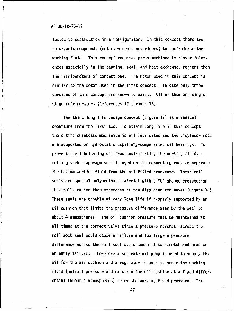
The third long life design concept (Figure 17) is a radical
departure from the first two. To attain long life in this concept
the entire crankcase mechanism is oil lubricated and the displacer rods
are supported on hydrostatic capillary-compensated oil bearings. To
prevent the lubricating oil from contaminating the working fluid, a
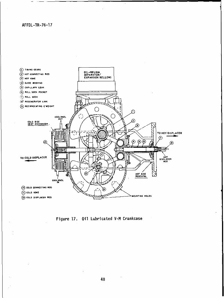
rolling sock diaphragm seal is used on the connecting rods to separate
the helium working fluid from the oil filled crankcase. These roll
seals are special polyurethane material with a "U" shaped crossection
that rolls rather than stretches as the displacer rod moves (Figure 18).
These seals are capable of very long life if properly supported by an
oil cushion that limits the pressure difference seen by the seal to
about 4 atmospheres. The oil cushion pressure must be maintained at
all times at the correct value since a pressure reversal across the
roll sock seal would cause a failure and too large a pressure
difference across the roll sock would cause it to stretch and produce
an early failure. Therefore a separate oil pump is used to supply the
oil for the oil cushion and a regulator is used to sense the working
fluid (.helium) pressure and maintain the oil cushion at a fixed differ-
ential (about 4 atmospheres) below the working fluid pressure. The
47
AFFDL-TR-76-17
O TIMING GEARS OOI L-H ELIUM
HOT CONNECTING ROD SEPARATOR/
NHOT YOKE EXPANSION BELLOWS
SGUIDE BUSHING
(i5) CAPILLARY LEAK
ROLL SOCK POCKET
, ROLL SOCK
(8) REGENERATOR LINK
)RECIPROCATING C'WEIGHT
COLD SIDEHEAT EXCHANGER-,3
TO HOT DISPLACER
TO COLD DISPLACER HOTS• •;'- DISPLACER~o
10 HOT SIDES PIEDESTAL
COOLANOL
0 COLD CONNECTING ROD 9
O COLD YOKE
COLD DISPLACER ROD MOUNTING HOLES
Figure 17. Oil Lubricated V-M Crankcase
48
AFFDL-TR-76-1 7
CRYOGENICASECTION
(OILL
Figur 18. oll ock Sal CUSHIONe
REGULAT9
AFFDL-TR-76-17
refrigerator includes a safety system to dump part of the helium so
that the maximum pressure difference across the rolling diaphragms
will not be greater than 4 atmospheres in case the oil cushion pump
stops. It should be noted that the oil cushion must be maintained at
all times when the working fluid is pressurized above 6 atmospheres,
whether the refrigerator is running or not.
Since the diaphragm material with the best life is somewhat
permeable to helium a helium refill system was added to the refrig-
erator to replace the helium lost by permeation and by activation of
the safety system. The refill system is composed of a high pressure
helium bottle, a pressure regulator valve for filling the refrigerator
and a shutoff valve to prevent emptying the refill system when the
safety system is activated. Since the refrigerator is designed to
operate in a zero gravity environment, it uses a crankcase completely
filled with oil so that the oil pump intakes will see only oil.
To have a completely oil filled crankcase, a bellows system was nec-
essary to compensate for the change in crankcase volume caused by
the movement of the displacer rods. Also, since helium diffuses into
the crankcase through the rolling sock seals, a system to remove the
helium from the crankcase oil was included. A crankcase heater was
included to maintain the crankcase oil within the proper temperature
(viscosity) range. The crankcase mechanism is a unique rhombic drive
which can be balanced to reduce vibration to an extremely low level.
The bearings in the rhombic mechanism are oil lubricated for very long
life. These hydrodynamic and squeeze film journal bearings are supplied
oil by two oil pumps directly connected to the refrigerator motors.
50
AFFDL-TR-76-17
The refrigerator uses two counter rotating brushless DC motors to drive
the rhombic mechanism. The motors are geared together for proper
timing and to provide redundancy in case one motor fails. The rhombic
drive provides a straight pushpull on the displacer rods. The cold
displacer seal is a long close fitting clearance seal that in theory
does not touch the cylinder or touches very lightly. The hot displacer
is supported by the combination of a hydrostatic bearing in the crank-
case and a five-inch long dry lubricated rider-seal on the ambient end
of the displacer (a hot rider ring is not needed). This refrigerator
has been built in a three stage configuration. The oil lubricated mech-
anism (with only one dry lubricated rider) potentially offers very long
life, however the large part count of the supporting items may detract
from this long life potential. Although parts of this system have
been tested in other refrigerators, a complete system has not been
life tested. This life test is scheduled to begin in the near future.
51
AFFDL-TR-76-17
SECTION VI
V-M ACCESSORIES AND COMPONENTS
1. HOT END TEMPERATURE CONTROLLER
One important accessory required by electrically heated V-M
refrigerators is the hot end temperature controller. By examining
the V-M theoretical equations, it can be seen that the higher the
temperature of the hot end, the higher the efficiency of the refrig-
erator. V-M refrigerators are usually designed to operate at the
highest temperature possible, consistent with metallurgical limits.
The most popular hot end material is Inconel 718. The strength of
this material falls off quite rapidly above 12500 F, so V-M refrigerators
are usually designed to operate at about 12000 F. However, there are
several problems with trying to operate at 12001F. A change of input
voltage to the heater can change the heater power and the hot end
temperature. Aircraft power supply voltages can vary as much as
+1/6 of the mean voltage. In additon, the ambient heat rejection
temperature aboard an aircraft can vary as much as 2000 F, which will
affect the power requirement and therefore the hot end temperature.
Cold end load changes also have an effect on the power required and the
hot end temperature. Refrigerator malfunctions such as loss of working
fluid or a stalled motor prevent the working fluid from absorbing
sufficient heat and causes the hot end to overheat. The heater is
usually sized to supply the correct power at the minimum voltage and
maximum ambient temperature. To prevent hot end overheating problems,
a hot end temperature controller is used.
52
AFFDL-TR-76-17
Proportional controllers are usually used since njaintaining the
heater at a nearly uniform temperature reduces the heater stresses
and improves the life of this component. Frequently a simple ON-OFF
controller, set at a higher temperature, backs up the primary controller
as an additional safety measure. A variety of controller concepts
have been used. One of the most popular is pulse width.modulation,
due to its high efficiency. However this type controller requires
considerable filtering and shielding to prevent the electromagnetic
interference it creates from affecting nearby equipment. Other con-
cepts include linear proportional control, zero voltage (AC) switching,
slow ON-OFF switching, and mechanical devices such as curie point
switches and vapor bulb thermometers, On large V-M refrigerators the
controller problem is reduced by calculating both the minimum power ana.
the maximum power required. The minimum power is then supplied by a
large heater with a simple ON-OFF controller for malfunction protection
only. The difference between the minimum and maximum power is supplied
by a smaller heater with a proportional controller and necessary shielding.
This arrangement is more efficient and reduces the size and weight of
the-controller and electronic filters.
2. HEATERS
Two types of electric hot end heaters have been used in V-M
refrigerators. The furnace type is a ribbon of heater wire wrapped
on a ceramic mandrel and held in place with cement. The ceramic
furnace surrounds the hot end of the hot cylinder and transfers heat
by radiation. The Calrod type sheathed heater has been the most popular.
53
AFFDL-TR-76-17
Heat is transferred-either by radiation (Reference 12) or by brazing
the heater sheath directly to the hot cylinder. Since the watt
density of the heaters required by most V-M designs is very high
(for this type of heater) the heater must be properly heat sunk to the
hot. cylinder or burnouts will occur. Care also must be taken to be
sure that the active (heat producing) portion of the heater terminates
while still thermally connected to the hot cylinder. The larger
diameter low resistance lead-in wire that runs between the heater wire
and the terminal (inside the sheath) must be of a material that does
not embrittle or corrode when exposed to insulation or atmospheric con-
taminants. Single ended straight wire heaters have caused numerous
failures and have been largely abandoned in favor of two ended helically
wound single wire heaters. Straight wire heaters are available in
smaller sheath diameters but must use smaller diameter heater wire
since the total length of the heater wire is less. This, coupled with
the possibl'e nonuniform reduction of heater wire diameter during the
swaging of the heater sheath and higher stresses during heater cycling
have contributed to numerous straight wire heater failures. The helical
single wire heaters have larger heater sheaths (less convenient for
the refrigerator designer) but have a larger diameter longer heater
wire that does not change crossection (the helix angle changes) during
the swaging of the heater sheath. The heater wire is closer to the
sheath (less temperature drop) and is less sensitive to thermal cycling.
These heaters are much more reliable than straight wire heaters. In
critical applications additional redundant heaters are added to avoid
54
AFFDL-TR-76-17
scrapping an expensive hot cylinder assembly due to a burned out
heater.
3. MOTORS
As mentioned earlier, AC induction motors with the rotor inside
the helium space and the stator with its windings outside the helium
space have been successfully used in a large number of applications.
These motors are either two or three phase and are purchased with a
matching inverter. Total efficiency for the motor and inverter is about
25%. In small V-M refrigerators, the motor power is a small fraction of
the total power, therefore cleanliness and reliability are more important
than efficiency. In a few applications an inverter could not be used
(due to space or ambient temperature problems) and since life was
less critical a DC brush type motor was used. Special brush materials
were used along with special commutator coatings. The motor windings
were potted to reduce the genevation of contaminates. Very little
data has been gathered on this motor,'so its limitations are still
unknown. A brushless DC motor is being used on one refrigerator. The
motor efficiency is expected to be at least 55%. It will be in the oil
filled crankcase of the refrigerator and should present no contamination
problem.
4. REGENERATORS
The cold regenerators have been previously discussed and are
discussed in considerabie detail in all of the references. The term
internal regenerator is used for regenerators inside the displacer and
the term external regenerator is used for regenerators attached to or
55
AFFDL-TR-76-17
a part of the cylinder. Cold regenerator matrix materials are
usually screens of 100 mesh to 500 mesh in copper alloys or stainless
steel and balls of monel or lead in sizes down to 0.002 inch. Lead
balls are usually used for temperatures below 50'K since lead is one
of the few materials with appreciable specific heat at these temper-
atures.
The hot regenerators are described as internal or external also,
however the forms of this matrix are more varied. Stacked screens,
balls, tubes, and the annulus have been used for the hot regenerator
matrix. The internal annular regenerator is composed of the walls
of the displacer and the cylinder. In this configuration the gas flows
between the displacer and the cylinder. A displacer seal is not used.
This eliminates one wearing part (the seal) and eliminates the pumping
loss, but makes the radial location of the displacer within the cylinder
very critical, which in turn makes hot rider ring wear extremely
critical. As an example, if the regenerator is designed with a
0.007 inch radial gap between the displacer and cylinder, and if rider
wear allows the displacer to be out of concentricity by 0.002 inch,
15% of the gas flow is on the narrow side of the regenerator while
85% of the flow is on the wide side. This causes the regenerator loss
to be doubled (Reference 3). Since lubrication and wear of the hot
rider is a serious problem the internal annular regenerator is rarely
used anymore. The external annular regenerator is composed of the walls
of the cylinder and one or more linear sleeves. The linear sleeves must
be very thin and concentric with the cylinder. A displacer seal riding
56
AFFDL-TR-76-17
on the sleeve assures gas flow through the regenerator. Concentricity
is a problem with this regenerator also.
The tubular regenerator is composed of small diameter thin wall
tubes constrained (usually in a single layer) between the cylinder
(or displacer) and a cylindrical liner with the tube axi~s in the
direction of the cylinder axis. The gas flows in the axial direction
either through the tubes or in the triangular shaped spaces between
the tubes and the liner (or cylinder). This type of hot regenerator
is easy to fabricate and is being used in several V-M refrigerators.
The screen and ball regenerators are similar to the cold regenerators
except matrix elements are larger and of materials such as monel and
stainless steel.
5. HEAT REJECTION
Heat rejection has been accomplished in several ways. These include
rejection to forced ambient air (Reference 4), rejection to a pumped
liquid which in turn rejects the heat to air or a radiator (Reference
11) and rejection by heat pipes (References 12 through 18).
57
AFFDL-TR-76-17
SECTION VII
CONCLUSIONS
This report has described in detail the theoretical V-M
refrigerator and the ways it has been applied to produce cyrogenic
temperatures. Complicating factors such as void volumes and unde-
sirable heat losses were added to the refrigerator description until
a real refrigerator was described. Included in this study were the
factors and component characteristics which influence the refrigeration
capacity, efficiency, and life of Vuilleumier refrigeration systems.
The various ways different designers have mechanized this cycle in
the quest for long life were discussed. V-M refrigeration technology
is now to the point where extended life tests can be run to determine
the life of these different V-M refrigerator concepts.
58
AFFDL-TR-76-17
REFERENCES
1. Rudolph Vuilleumier, U. S. Patent No. 1,275,507, Method AndApparatus For Inducing Heat Changes, 13 August 1918.
2. V. Bush, U. S. Patent No. 2,157,229, Apparatus For CompressingGases, 9 May 1939.
3. B. Leo, Vuilleumier Cycle Cryogenic Refrigeration System TechnologyReport, AFFDL-TR-71-85, DDC Number AD888992L, September 1971.
4. J. B. Glode, F. J. Rhia III, R. T. Gainey, Vuilleumier CycleCryogenic Refrigerator System For Infrared Scanner Applications,AFFDL-TR-71-18, DDC Number AD886823, August 1971.
5. F. B. Quale, T. T. Rule, "Steady-State Operation Of The TdealizedVuilleumier Refrigerator," 1968. Cryogenic Engineering Conference,19 August 1968.
6. V. Bush, U. S. Patent No. 2,127,286, Apparatus For Heat Transfer16 August 1938.
7. K. W. Taconis, U. S. Patent No. 2,567,454, Process Of And ApparatusFor Heat Pumping, 11 September 1951.
8. W. H. Hogan, U. S. Patent No. 3,151,446, Closed-Cycle CryogenicRefrigerator And Apparatus Embodying Same, 6 October 1964.
9. F. F. Chellis, W. H. Hogan, "A Liquid-Nitrogen-OperatedRefrigerator For Temperatures Below 77°K," Advances In CryogenicEngineering, Vol. 9, Plenum Press 1964.
10. K. W. Cowans, U. S. Patent No. 3,379,026, Heat Powered Engine,23 April 1968.
11. R. D. Doody, Two-Stage Vuilleumier Cycle Cryogenic RefrigeratorSystem For Advancec Forward Looking Infrared (AFLIR) ApplicationsAFFDL-TR-71-17, DDC Number AD886822, August 1971.
12. D. K. Yoshikawa, /5°K Miniature Vuilleumier Cryogenic Engine,Final Report For Task I - Preliminary Design, Contract NAS 5-21096,Goddard Space Flight Center, Greenbelt Maryland, October 1970.
13. C. W. Browning, V. L. Potter, 75 0 K Vuilleumier Cryogenic Refrig-erator, Final Report For Task II - Analytical and Test Program,Contract NAS 5-21096, Goddard Space Flight Center, GreenbeltMaryland, August 1972.
14. Airesearch Manufacturing Co., Vuilleumier Program EngineeringNotebook, Contract NAS 5-21096, Goddard Space Flight Center,Greenbelt Maryland, August 1972.
59
AFFDL-TR-76-17
REFERENCES (Cont'd)
15. C. W. Browning, W. S. Miller, V. L. Potter, 750K VuilleumierCryogenic Refrigerator - Final Report For Task TV Model Fabrication,Contract NAS 5-21096, Goddard Space Flight Center, GreenbeltMaryland, November 1972.
16. W. S. Miller, V. L. Potter, Fractional Watt Vuilleumier CryogenicRefrigerator - Final Report For Task I Preliminary Design,Contract NAS 5-21715, Goddard Space Flight Center, GreenbeltMaryland, March 1973.
17. W. S. Millpr, V. L. Potter, Fractional Watt Vuilleumier CryogenicRefrigerator - Final Report For Task II Analytical And Test Programs,Contract NAS 5-21715, Goddard Space Flight Center, GreenbeltMaryland, March 1974.
18. Airesearch Manufacturing Co., Fractional Watt Vuilleumier CryogenicRefrigerator Program Engineering Notebook, Vol. 1, Thermal Analysis,Contract NAS 5-21715, Goddard Space Flight Center, GreenbeltMaryland, May 1974.
60U. S. GOVERNMENT PRINTING OFFICE: 1976 - 657-630/795
Related Documents