TECHNOLOGY TECHNOLOGY TECHNOLOGY FLIGHT CONTROL SYSTEMS FLIGHT CONTROL SYSTEMS BULLETIN OF DEFENCE RESEARCH AND DEVELOPMENT ORGANISATON ISSN : 0971-4413 Vol. 16 No. 2 April 2008 F light of modern manned aircraft and Unmanned Air Vehicles (UAVs) entails design and development of sophisticated avionics systems, the most critical of them being the Flight Control Systems (FCS). In order to fly a manned aircraft or an UAV safely and reliably through out their flight envelope (speed and altitude envelope) and for execution of their missions, it is imperative that their FCS is highly reliable and fast responding to the pilot commands. The FCS translates pilot's or controller's manoeuver-specific commands into electric signals that actuate control surfaces of the aircraft and enable the aircraft to achieve the commanded motion or trajectory. The attitude of the aircraft and its velocities and accelerations are sensed by inertial motion sensors, air data transducers and accelerometers. The sensed values are transduced into electric signals and depending upon the differences between the sensed and commanded values appropriate electric signals are transmitted to servo-actuators of the aircraft's control-surfaces. The relationships of aircraft motion and control-surface (elevator, ailerons and rudder) positions are called 'Flight Control Laws'. These laws are incorporated in the Flight Control Computer, which may be either an analog computer or a digital computer. All these elements together constitute the FCS of any aircraft. DRDO has made significant advances in the field of FCS for high-speed combat aircraft and UAVs. DRDO, has been spearheading the indigenous FCS development efforts in the country and has successfully developed the state-of-the- art FCS for India's indigenous LCA Tejas, UAV Nishant, re-usable aerial target system Lakshya, and controlled aerial delivery parafoil system. V SDu k sy k Wt h Q k sdl

Welcome message from author
This document is posted to help you gain knowledge. Please leave a comment to let me know what you think about it! Share it to your friends and learn new things together.
Transcript

TECHNOLOGY TECHNOLOGY TECHNOLOGY
FLIGHT CONTROL SYSTEMSFLIGHT CONTROL SYSTEMS
BULLETIN OF DEFENCE RESEARCH AND DEVELOPMENT ORGANISATON ISSN : 0971-4413 Vol. 16 No. 2 April 2008
Flight of modern manned aircraft and Unmanned Air Vehicles (UAVs) entails design and development of sophisticated avionics systems, the most critical of
them being the Flight Control Systems (FCS). In order to fly a manned aircraft or an UAV safely and reliably through out their flight envelope (speed and altitude envelope) and for execution of their missions, it is imperative that their FCS is highly reliable and fast responding to the pilot commands.
The FCS translates pilot's or controller's manoeuver-specific commands into electric signals that actuate control surfaces of the aircraft and enable the aircraft to achieve the commanded motion or trajectory. The attitude of the aircraft and its velocities and accelerations are sensed by inertial motion sensors, air data transducers and accelerometers. The sensed values are transduced into electric signals and depending upon the differences between the sensed and commanded values appropriate electric signals are transmitted to servo-actuators of the aircraft's control-surfaces. The relationships of aircraft motion and control-surface (elevator, ailerons and rudder) positions are called 'Flight Control Laws'. These laws are incorporated in the Flight Control Computer, which may be either an analog computer or a digital computer. All these elements together constitute the FCS of any aircraft.
DRDO has made significant advances in the field of FCS for high-speed combat aircraft and UAVs. DRDO, has been spearheading the indigenous FCS development efforts in the country and has successfully developed the state-of-the-art FCS for India's indigenous LCA Tejas, UAV Nishant, re-usable aerial target system Lakshya, and controlled aerial delivery parafoil system.
VSDuksykWt
h Qksd
l

2
TECHNOLOGY TECHNOLOGY TECHNOLOGY
From the Desk of Guest Editor
Flight Control Systems for UAVs
DRDO has spearheaded Unmanned Aerial Vehicles (UAV) technologies in India with successful design, development and flight testing of Ulka—an air launched drone, Sparrow—mini remotely piloted vehicle, Kapothaka and Nishant—tactical UAVs and Lakshya—an aerial target, which have been productionised for all the users. In accordance with the UAV roadmap to meet the requirements of services, DRDO has embarked on the design of Rustom—a medium altitude long endurance UAV.
DRDO has built significant competence in the core area of flight control
systems for UAVs through systematic and disciplined approaches. It has
successfully test flown Tejas and flown UAVs like the Nishant, Lakshya and controlled aerial
delivery parafoil system through a careful design and development process, iterative process of
control law design using various high-fidelity simulation models, dedicated system engineering
activity, conservative and safety conscious hardware designs, structured software development
coupled with rigorous and uncompromising test procedures. This issue of Technology Focus gives
the overview of the flight control systems developed by DRDO for manned and unmanned aerial
vehicles.
(P.S. Krishnan)Outstanding Scientist and Director
ADE, Bangalore
Nishant surveillance UAV is a low speed, all composite material air vehicle designed for battlefield surveillance and reconnaissance. The target acquisition and tracking by Nishant is performed by electro-optic payloads mounted on a stabilised steerable platform. A sophisticated image processing system is used for analysing the video images received from the onboard system. A Ground Control Station (GCS) provides facility to the Controller for planning, validation and execution of the UAV's missions. An integrated avionics package (IAP) comprising flight control mission and navigation computer, air data transducers, and command encoder-decoder manages the flight control, navigation and mission functions on the UAV.
Nishant has been designed for following flight modes:
Automated launch phase
Manual flying
Semi-autonomous flight
Pitch hold, roll hold, heading hold and altitude hold, track hold
Fully autonomous mode with waypoint navigation (WPN)
Air data dead reckoning navigation with GPS and ground tracker updates
Link loss mode
Capability for in-flight mission plan change
Get-U-Home mode
Autonomous programmed flight modes
Nishant Surveillance System
3
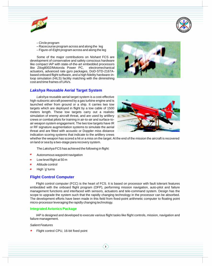
– Circle program– Racecourse program across and along the leg– Figure-of-Eight program across and along the leg
Some of the major contributions on Nishant FCS are development of conservative and safety conscious hardware like compact IAP with state-of-the-art embedded processors like Zilog8002/Motorola Power PC, electromechanical actuators, advanced rate gyro packages, DoD-STD-2167A-based onboard flight software, and a high fidelity hardware-in-loop simulation (HILS) facility matching with the diminishing cost and time frames of UAVs.
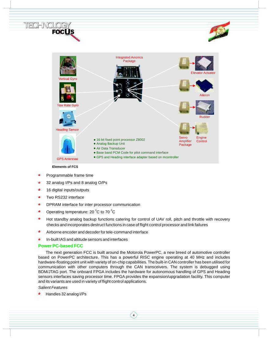
Lakshya reusable aerial target system is a cost-effective high-subsonic aircraft powered by a gas turbine engine and is launched either from ground or a ship. It carries two tow targets which are deployed in flight by a tow cable of 1500 meters length. These tow targets carry out a realistic simulation of enemy aircraft threat, and are used by artillery crews or combat pilots for training in air-to-air and surface-to-air weapon system engagement. The two tow targets have IR or RF signature augmentation systems to simulate the aerial threat and are fitted with acoustic or Doppler miss distance indication scoring systems that indicate to the artillery crews whether the weapon has scored a hit or a miss on the target. At the end of the mission the aircraft is recovered on land or sea by a two-stage para recovery system.
The Lakshya FCS has achieved the following in flight:
Autonomous waypoint navigation
Low level flight at 50 m
Altitude control
High ̀ g' turns
Flight control computer (FCC) is the heart of FCS. It is based on processor with fault tolerant features embedded with the onboard flight program (OFP), performing mission navigation, auto-pilot and failure management functions and interfaced with sensors, actuators and tele-command system. Design has the scope to upgrade the system such that the rapidly changing technology in the processor can be absorbed. The development efforts have been made in this field from fixed-point arithmetic computer to floating point micro-processor leveraging the rapidly changing technology.
IAP is designed and developed to execute various flight tasks like flight controls, mission, navigation and failure management.
Salient Features
Flight control CPU, 16-bit fixed point
Lakshya Reusable Aerial Target System
Flight Control Computer
Integrated Avionics Package
4
TECHNOLOGY TECHNOLOGY TECHNOLOGY
Programmable frame time
32 analog I/Ps and 8 analog O/Ps
16 digital inputs/outputs
Two RS232 interface
DPRAM interface for inter processor communicationo o
Operating temperature: 20 C to 70 C
Hot standby analog backup functions catering for control of UAV roll, pitch and throttle with recovery
checks and incorporates destruct functions in case of flight control processor and link failures
Airborne encoder and decoder for tele-command interface
In-built IAS and altitude sensors and interfaces
The next generation FCC is built around the Motorola PowerPC, a new breed of automotive controller based on PowerPC architecture. This has a powerful RISC engine operating at 40 MHz and includes hardware-floating point unit with variety of on-chip capabilities. The built-in CAN controller has been utilised for communication with other computers through the CAN transceivers. The system is debugged using BDM/JTAG port. The onboard FPGA includes the hardware for autonomous handling of GPS and Heading sensors interfaces saving processor time. FPGA provides the expansion/upgradation facility. This computer and its variants are used in variety of flight control applications.
Salient Features
Handles 32 analog I/Ps
Power PC-based FCC
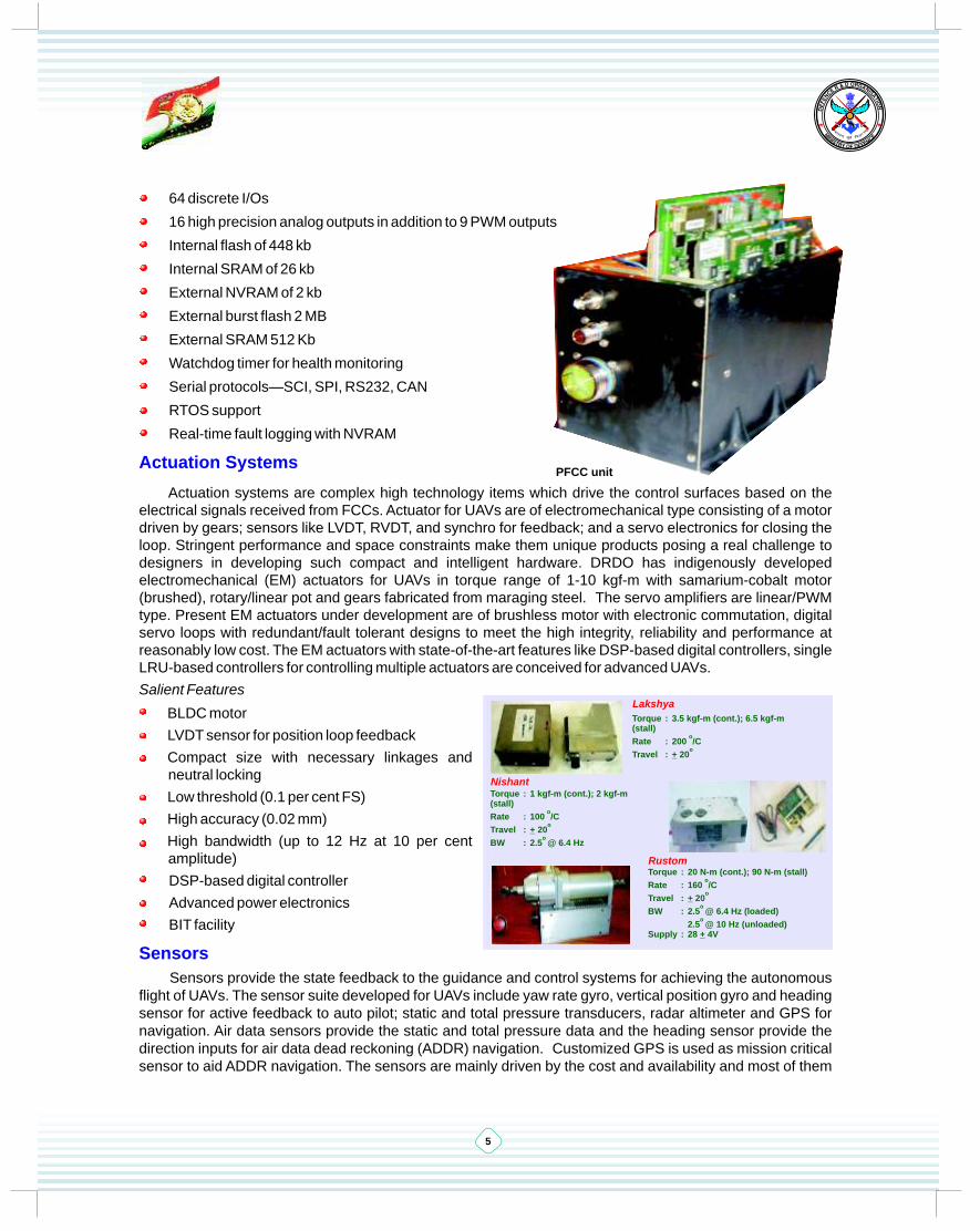
Heading Sensor
Vertical Gyro
Yaw Rate Gyro
GPS Antennae
Rudder
Aileron
Elevator Actuator
Integrated AvionicsPackage
• 16 bit fixed point processor Z8002
• Analog Backup Unit
• Air Data Transducer
• Base band PCM Code for pilot command interface
• GPS and Heading interface adapter based on mcontroller
Servo AmplifierPackage
EngineControl
Elements of FCS
5
64 discrete I/Os
16 high precision analog outputs in addition to 9 PWM outputs
Internal flash of 448 kb
Internal SRAM of 26 kb
External NVRAM of 2 kb
External burst flash 2 MB
External SRAM 512 Kb
Watchdog timer for health monitoring
Serial protocols—SCI, SPI, RS232, CAN
RTOS support
Real-time fault logging with NVRAM
Actuation systems are complex high technology items which drive the control surfaces based on the electrical signals received from FCCs. Actuator for UAVs are of electromechanical type consisting of a motor driven by gears; sensors like LVDT, RVDT, and synchro for feedback; and a servo electronics for closing the loop. Stringent performance and space constraints make them unique products posing a real challenge to designers in developing such compact and intelligent hardware. DRDO has indigenously developed electromechanical (EM) actuators for UAVs in torque range of 1-10 kgf-m with samarium-cobalt motor (brushed), rotary/linear pot and gears fabricated from maraging steel. The servo amplifiers are linear/PWM type. Present EM actuators under development are of brushless motor with electronic commutation, digital servo loops with redundant/fault tolerant designs to meet the high integrity, reliability and performance at reasonably low cost. The EM actuators with state-of-the-art features like DSP-based digital controllers, single LRU-based controllers for controlling multiple actuators are conceived for advanced UAVs.
Salient Features
BLDC motor
LVDT sensor for position loop feedback
Compact size with necessary linkages and neutral locking
Low threshold (0.1 per cent FS)
High accuracy (0.02 mm)
High bandwidth (up to 12 Hz at 10 per cent amplitude)
DSP-based digital controller
Advanced power electronics
BIT facility
Sensors provide the state feedback to the guidance and control systems for achieving the autonomous flight of UAVs. The sensor suite developed for UAVs include yaw rate gyro, vertical position gyro and heading sensor for active feedback to auto pilot; static and total pressure transducers, radar altimeter and GPS for navigation. Air data sensors provide the static and total pressure data and the heading sensor provide the direction inputs for air data dead reckoning (ADDR) navigation. Customized GPS is used as mission critical sensor to aid ADDR navigation. The sensors are mainly driven by the cost and availability and most of them
Actuation Systems
Sensors
Lakshya
Torque : 3.5 kgf-m (cont.); 6.5 kgf-m (stall)
oRate : 200 /C
oTravel : + 20
RustomTorque : 20 N-m (cont.); 90 N-m (stall)
oRate : 160 /C
oTravel : + 20
o BW : 2.5 @ 6.4 Hz (loaded)
o 2.5 @ 10 Hz (unloaded)
Supply : 28 + 4V
NishantTorque : 1 kgf-m (cont.); 2 kgf-m (stall)
oRate : 100 /C
oTravel : + 20
o BW : 2.5 @ 6.4 Hz
PFCC unit

TECHNOLOGY TECHNOLOGY TECHNOLOGY
6
are COTS based. The rate and vertical position gyro provide the vital inputs for the control of UAV for damping augmentation and attitude tracking. Micro electromechanical sensors (MEMS) are replacing the conventional electromechanical sensors saving cost, weight and volume for the UAVs under development.
Onboard flight program (OFP) is the brain of entire FCS integrating all the subsystems. OFP supervises the functionality of sensors, actuators and FCC. The OFP primarily executes the navigation, guidance and control (NGC) algorithms, mission logics, failure detection functions in addition to initialization of I/O drivers, data acquisition from sensors and driving actuators.
A strict development methodology based on DoD-STD-2167A/DO 178B with standard software engineering practices are followed throughout the software development process for UAVs to ensure high degree of reliability and traceability.
At each milestone of the different phases of software development, baselines are identified and placed under configuration control. Further updates follow a strict change control process. An independent software quality assurance team supervises/ensures the quality aspects of the software.
Salient Features
Tailored version of DoD-STD-2167A/DO 178B
S/W Development through case tools for each phase
– SRS/IRS – DOORs analyst
– Design – Rhapsody
– Code – Green Hills Ada/GNAT Pro Ada compiler
– Test – Ada test
– Configuration – Synergy
Separate teams for SRS/IRS generation, design and coding, CSU/CSC test and SQA
Language for S/W development—Assembly/Ada95
Development platform: Sun Server with thin clients/PC servers
RTOS—VxWorks
Hardware-in-loop-simulation (HILS) is a very important test facility in which the simulated aircraft dynamics activates the actual flight control electronics, the associated sensors and the control surface actuators in an interactive manner with high degree of fidelity. It is an essential and major tool in design evaluation and analysis of FCS, optimisation of flight control laws, hardware-software integration, and verification and validation of integrated software.
Software
Testing and Evaluation of FCS
Hardware-in-loop Simulation Facility for UAVS
7
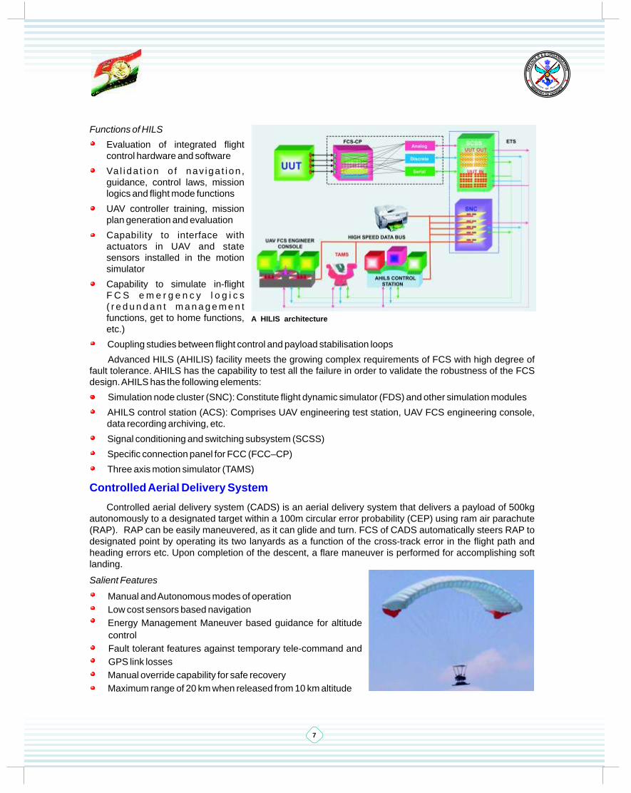
Functions of HILS
Evaluation of integrated flight control hardware and software
Va l i da t i on o f nav iga t i on , guidance, control laws, mission logics and flight mode functions
UAV controller training, mission plan generation and evaluation
Capability to interface with actuators in UAV and state sensors installed in the motion simulator
Capability to simulate in-flight F C S e m e r g e n c y l o g i c s ( r e d u n d a n t m a n a g e m e n t functions, get to home functions, etc.)
Coupling studies between flight control and payload stabilisation loops
Advanced HILS (AHILIS) facility meets the growing complex requirements of FCS with high degree of fault tolerance. AHILS has the capability to test all the failure in order to validate the robustness of the FCS design. AHILS has the following elements:
Simulation node cluster (SNC): Constitute flight dynamic simulator (FDS) and other simulation modules
AHILS control station (ACS): Comprises UAV engineering test station, UAV FCS engineering console, data recording archiving, etc.
Signal conditioning and switching subsystem (SCSS)
Specific connection panel for FCC (FCC–CP)
Three axis motion simulator (TAMS)
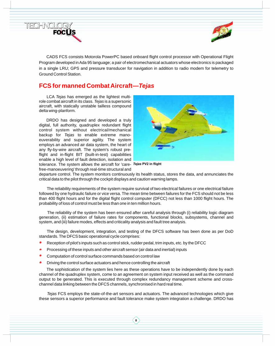
Controlled aerial delivery system (CADS) is an aerial delivery system that delivers a payload of 500kg autonomously to a designated target within a 100m circular error probability (CEP) using ram air parachute (RAP). RAP can be easily maneuvered, as it can glide and turn. FCS of CADS automatically steers RAP to designated point by operating its two lanyards as a function of the cross-track error in the flight path and heading errors etc. Upon completion of the descent, a flare maneuver is performed for accomplishing soft landing.
Salient Features
Manual and Autonomous modes of operation
Low cost sensors based navigation
Energy Management Maneuver based guidance for altitude
control
Fault tolerant features against temporary tele-command and
GPS link losses
Manual override capability for safe recovery
Maximum range of 20 km when released from 10 km altitude
Controlled Aerial Delivery System
A HILIS architecture
TECHNOLOGY TECHNOLOGY TECHNOLOGY
8
CADS FCS consists Motorola PowerPC based onboard flight control processor with Operational Flight
Program developed in Ada 95 language; a pair of electromechanical actuators whose electronics is packaged
in a single LRU; GPS and pressure transducer for navigation in addition to radio modem for telemetry to
Ground Control Station.
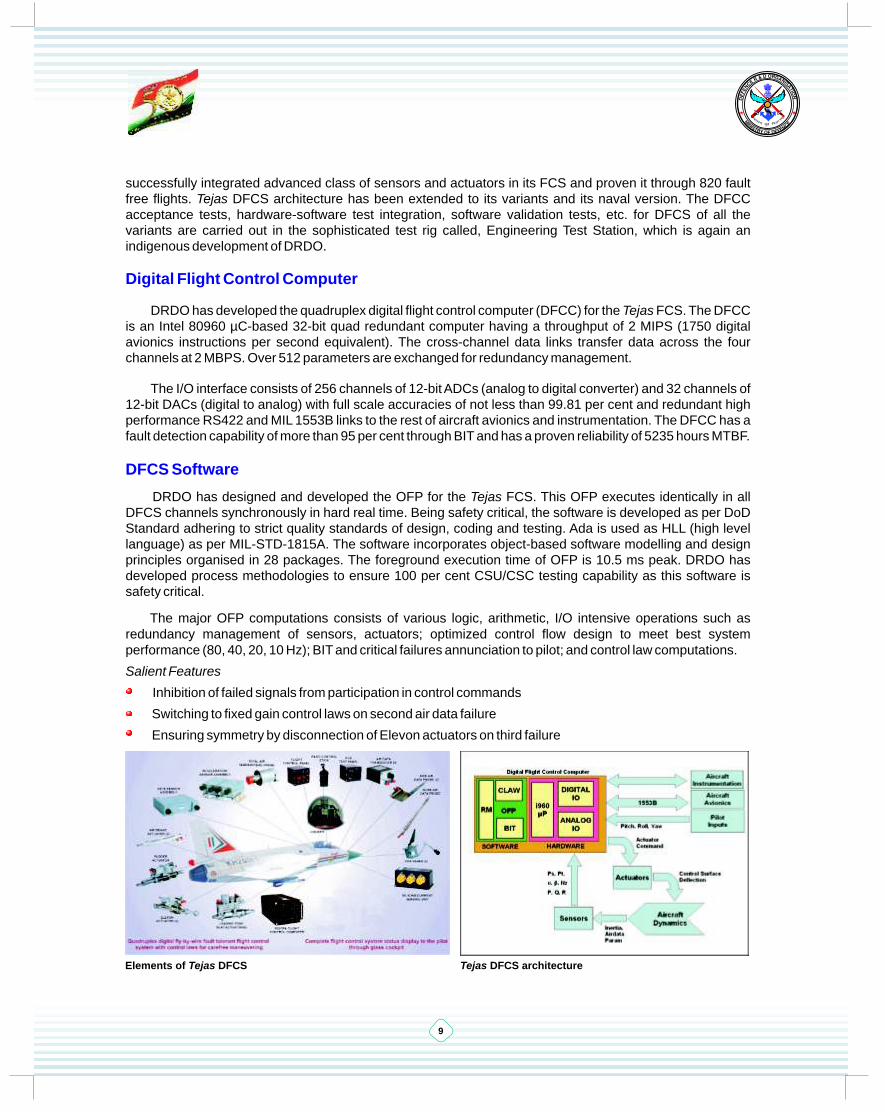
LCA Tejas has emerged as the lightest multi-role combat aircraft in its class. Tejas is a supersonic aircraft, with statically unstable tailless compound delta wing-planform.
DRDO has designed and developed a truly digital, full authority, quadruplex redundant flight control system without electrical/mechanical backup for Tejas to enable extreme mano-euverability and superior agility. The system employs an advanced air data system, the heart of any fly-by-wire aircraft. The system's robust pre-flight and in-flight BIT (built-in-test) capabilities enable a high level of fault detection, isolation and tolerance. The system allows the aircraft for 'care-free-manoeuvering' through real-time structural and departure control. The system monitors continuously its health status, stores the data, and annunciates the critical data to the pilot through the cockpit displays and caution warning lamps.
The reliability requirements of the system require survival of two electrical failures or one electrical failure followed by one hydraulic failure or vice versa. The mean time between failures for the FCS should not be less than 400 flight hours and for the digital flight control computer (DFCC) not less than 1000 flight hours. The probability of loss of control must be less than one in ten million hours.
The reliability of the system has been ensured after careful analysis through (i) reliability logic diagram generation, (ii) estimation of failure rates for components, functional blocks, subsystems, channel and system, and (iii) failure modes, effects and criticality analysis and fault tree analysis.
The design, development, integration, and testing of the DFCS software has been done as per DoD standards. The DFCS basic operational cycle comprises:
Reception of pilot's inputs such as control stick, rudder pedal, trim inputs, etc. by the DFCC
Processing of these inputs and other aircraft sensor (air data and inertial) inputs
Computation of control surface commands based on control law
Driving the control surface actuators and hence controlling the aircraft
The sophistication of the system lies here as these operations have to be independently done by each channel of the quadruplex system, come to an agreement on system input received as well as the command output to be generated. This is executed through complex redundancy management scheme and cross-channel data linking between the DFCS channels, synchronised in hard real time.
Tejas FCS employs the state-of-the-art sensors and actuators. The advanced technologies which give these sensors a superior performance and fault tolerance make system integration a challenge. DRDO has
FCS for manned Combat Aircraft—Tejas
9
successfully integrated advanced class of sensors and actuators in its FCS and proven it through 820 fault free flights. Tejas DFCS architecture has been extended to its variants and its naval version. The DFCC acceptance tests, hardware-software test integration, software validation tests, etc. for DFCS of all the variants are carried out in the sophisticated test rig called, Engineering Test Station, which is again an indigenous development of DRDO.
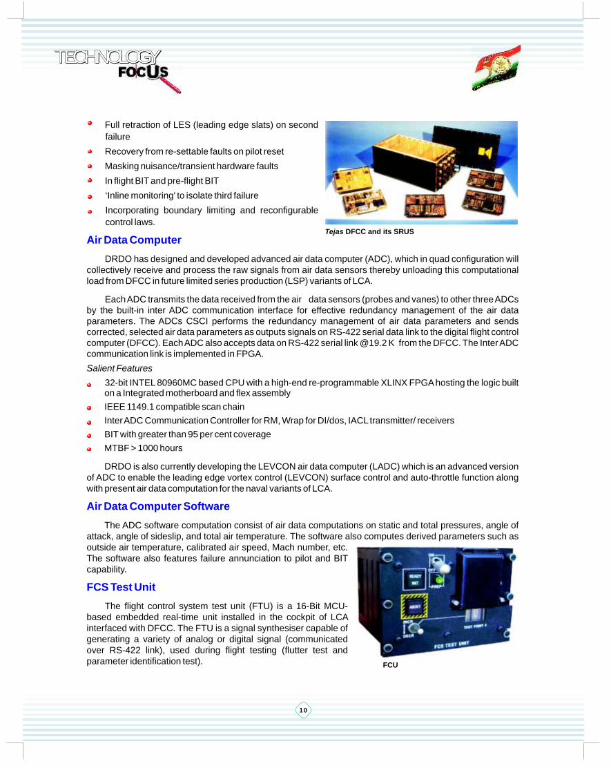
DRDO has developed the quadruplex digital flight control computer (DFCC) for the Tejas FCS. The DFCC is an Intel 80960 µC-based 32-bit quad redundant computer having a throughput of 2 MIPS (1750 digital avionics instructions per second equivalent). The cross-channel data links transfer data across the four channels at 2 MBPS. Over 512 parameters are exchanged for redundancy management.
The I/O interface consists of 256 channels of 12-bit ADCs (analog to digital converter) and 32 channels of 12-bit DACs (digital to analog) with full scale accuracies of not less than 99.81 per cent and redundant high performance RS422 and MIL 1553B links to the rest of aircraft avionics and instrumentation. The DFCC has a fault detection capability of more than 95 per cent through BIT and has a proven reliability of 5235 hours MTBF.
DRDO has designed and developed the OFP for the Tejas FCS. This OFP executes identically in all DFCS channels synchronously in hard real time. Being safety critical, the software is developed as per DoD Standard adhering to strict quality standards of design, coding and testing. Ada is used as HLL (high level language) as per MIL-STD-1815A. The software incorporates object-based software modelling and design principles organised in 28 packages. The foreground execution time of OFP is 10.5 ms peak. DRDO has developed process methodologies to ensure 100 per cent CSU/CSC testing capability as this software is safety critical.
The major OFP computations consists of various logic, arithmetic, I/O intensive operations such as redundancy management of sensors, actuators; optimized control flow design to meet best system performance (80, 40, 20, 10 Hz); BIT and critical failures annunciation to pilot; and control law computations.
Salient Features
Inhibition of failed signals from participation in control commands
Switching to fixed gain control laws on second air data failure
Ensuring symmetry by disconnection of Elevon actuators on third failure
Digital Flight Control Computer
DFCS Software
Elements of Tejas DFCS Tejas DFCS architecture
TECHNOLOGY TECHNOLOGY TECHNOLOGY
10
Full retraction of LES (leading edge slats) on second
failure
Recovery from re-settable faults on pilot reset
Masking nuisance/transient hardware faults
In flight BIT and pre-flight BIT
‘Inline monitoring' to isolate third failure
Incorporating boundary limiting and reconfigurable
control laws.
DRDO has designed and developed advanced air data computer (ADC), which in quad configuration will collectively receive and process the raw signals from air data sensors thereby unloading this computational load from DFCC in future limited series production (LSP) variants of LCA.
Each ADC transmits the data received from the air data sensors (probes and vanes) to other three ADCs by the built-in inter ADC communication interface for effective redundancy management of the air data parameters. The ADCs CSCI performs the redundancy management of air data parameters and sends corrected, selected air data parameters as outputs signals on RS-422 serial data link to the digital flight control computer (DFCC). Each ADC also accepts data on RS-422 serial link @19.2 K from the DFCC. The Inter ADC communication link is implemented in FPGA.
Salient Features
32-bit INTEL 80960MC based CPU with a high-end re-programmable XLINX FPGA hosting the logic built on a Integrated motherboard and flex assembly
IEEE 1149.1 compatible scan chain
Inter ADC Communication Controller for RM, Wrap for DI/dos, IACL transmitter/ receivers
BIT with greater than 95 per cent coverage
MTBF > 1000 hours
DRDO is also currently developing the LEVCON air data computer (LADC) which is an advanced version of ADC to enable the leading edge vortex control (LEVCON) surface control and auto-throttle function along with present air data computation for the naval variants of LCA.
The ADC software computation consist of air data computations on static and total pressures, angle of attack, angle of sideslip, and total air temperature. The software also computes derived parameters such as outside air temperature, calibrated air speed, Mach number, etc. The software also features failure annunciation to pilot and BIT capability.
The flight control system test unit (FTU) is a 16-Bit MCU-based embedded real-time unit installed in the cockpit of LCA interfaced with DFCC. The FTU is a signal synthesiser capable of generating a variety of analog or digital signal (communicated over RS-422 link), used during flight testing (flutter test and parameter identification test).
Air Data Computer
Air Data Computer Software
FCS Test Unit
Tejas DFCC and its SRUS
FCU
11
Waveforms such as linear sine sweep, logarithmic sine sweep, random signal, half-sine pulse, 3-2-1-1 pulse train, etc. are synthesised using algorithms with any desired characteristics, i.e., amplitude, frequency/period, off-time, numbers of repeats, etc. The FTU provides control switches and indicators on the front panel for quick selection of test point initiate and abort the signal synthesis and discrete signals to indicate the event/status of unit. It serves as means to insert an external EPROM with signal characteristics of 100 test points.
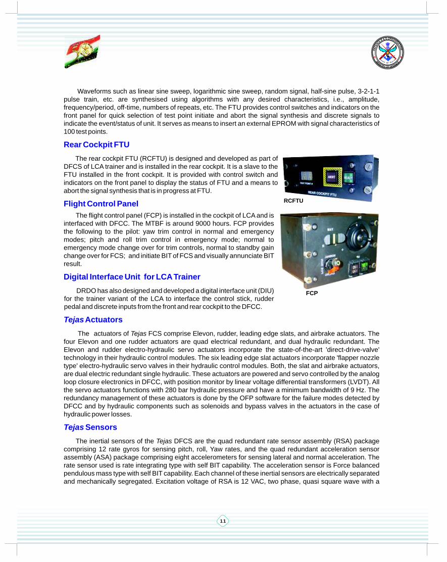
The rear cockpit FTU (RCFTU) is designed and developed as part of DFCS of LCA trainer and is installed in the rear cockpit. It is a slave to the FTU installed in the front cockpit. It is provided with control switch and indicators on the front panel to display the status of FTU and a means to abort the signal synthesis that is in progress at FTU.
The flight control panel (FCP) is installed in the cockpit of LCA and is interfaced with DFCC. The MTBF is around 9000 hours. FCP provides the following to the pilot: yaw trim control in normal and emergency modes; pitch and roll trim control in emergency mode; normal to emergency mode change over for trim controls, normal to standby gain change over for FCS; and initiate BIT of FCS and visually annunciate BIT result.
DRDO has also designed and developed a digital interface unit (DIU) for the trainer variant of the LCA to interface the control stick, rudder pedal and discrete inputs from the front and rear cockpit to the DFCC.
The actuators of Tejas FCS comprise Elevon, rudder, leading edge slats, and airbrake actuators. The four Elevon and one rudder actuators are quad electrical redundant, and dual hydraulic redundant. The Elevon and rudder electro-hydraulic servo actuators incorporate the state-of-the-art 'direct-drive-valve' technology in their hydraulic control modules. The six leading edge slat actuators incorporate 'flapper nozzle type' electro-hydraulic servo valves in their hydraulic control modules. Both, the slat and airbrake actuators, are dual electric redundant single hydraulic. These actuators are powered and servo controlled by the analog loop closure electronics in DFCC, with position monitor by linear voltage differential transformers (LVDT). All the servo actuators functions with 280 bar hydraulic pressure and have a minimum bandwidth of 9 Hz. The redundancy management of these actuators is done by the OFP software for the failure modes detected by DFCC and by hydraulic components such as solenoids and bypass valves in the actuators in the case of hydraulic power losses.
The inertial sensors of the Tejas DFCS are the quad redundant rate sensor assembly (RSA) package comprising 12 rate gyros for sensing pitch, roll, Yaw rates, and the quad redundant acceleration sensor assembly (ASA) package comprising eight accelerometers for sensing lateral and normal acceleration. The rate sensor used is rate integrating type with self BIT capability. The acceleration sensor is Force balanced pendulous mass type with self BIT capability. Each channel of these inertial sensors are electrically separated and mechanically segregated. Excitation voltage of RSA is 12 VAC, two phase, quasi square wave with a
Rear Cockpit FTU
Flight Control Panel
Digital Interface Unit for LCA Trainer
Tejas Actuators
Tejas Sensors
RCFTU
FCP

RNI No. 55787/93
frequency of 400 Hz with maximum rated output of 6 V. Excitation voltage of ASA is +15 V and maximum rated input is 13 g and 4.5 g for normal and lateral accelerations, respectively.
There are two angle of attack (AOA) sensors (vane type), one total air temperature probe, two-side air data probes and one nose air data probe for sensing and providing air data parameters to the air data computer (ADC) for computations. DRDO has designed and developed the indigenous de-icing current sensor unit (DCSU) to accommodate the requirements of the improved air data system for the future variants of LCA.
Th is i s a mu l t i -processor-based real-time, automatic/manual test station used for the functional verification of FCS. Engineering test station (ETS) provides capability to simulate, stimulate, monitor and generate failure for all the inputs/outputs of the DFCC. The ETS is used for acceptance testing and real-time hardware/software integration of the DFCC, system integration, and testing of the LCA-FCS. It can replace some or all simulated sensors and actuators with real hardware. Also, the ETS interfaces with the mini-bird and iron-bird test facilities to monitor the DFCC performance during closed-loop testing, pilot-in-the-loop testing, interface calibration, end-to-end dynamic testing and FCS verification and validation.
Ground Test Rig Facilities
Engineering Test Station and Mini-Bird
Engineering test station Mini-bird test stand
Technology Focus highlights the technological developments in DRDO, and also covers the products, processes, and technologies.
Readers of Technology Focus are invited to send their
communications to the Editors, Technology Focus
DESIDOC, Metcalfe House, Delhi-110 054. India
VSDuksykWth Qksdl ds ikBd vius lq>ko laiknd] VSDuksykWth Qksdl] MslhMkWd] esVdkWQ gkml] fnYyh-110 054 dks Hkst ldrs gSaA
Telephone: 011-23902475 Fax: 011-23813591Drona-mail: [email protected]: [email protected]; [email protected]: http//www.drdo.org/pub/index.shtml
nwjHkkÔ: 011-23902475; 23902465
QSDl: 011-23813591; 23819151
nzks.kk&esy: [email protected]
bZ&esy: [email protected], [email protected]
baVjusV: http//www.drdo.org/pub/index.shtml
Printed & published by Director, DESIDOC, on behalf of DRDO
MhvkjMhvks dh vksj ls funs’kd] MslhMkWd }kjk eqfnzr ,oa izdkf’kr
lEikndh; LVkWQ / Editorial Staff
Dr AL Moorthy, Director, DESIDOC, Metcalfe House, Delhi
Dr BR Gandhe, Director of Armaments, DRDO
Director of Materials, DRDO
Shri CU Hari, Director of Aeronautics, DRDO Bhavan, New Delhi
Director of Life Sciences, DRDO
Shri Ranjit Elias, SO to SA to RM, DRDO Bhavan, New Delhi
Coordinator
Members
Bhavan, New Delhi
Dr Sudarshan Kumar, Bhavan, New Delhi
Dr RC Sawhney, Bhavan, New Delhi
Editorial Committee
àÉÖJªÉ ºÉà{ÉÉnBÉE ºÉc-àÉÖJªÉ ºÉà{ÉÉnBÉE ºÉà{ÉÉnBÉE àÉÖphÉ ÉÊ´É{ÉhÉxÉ+É ãÉ àÉÚÉÊiÉÇ +ɶÉÉäBÉE BÉÖEàÉÉ® gÉÉÒ ¤ÉÉÒ ÉÊxÉiªÉÉxÉÆn AºÉ BÉäE iªÉÉMÉÉÒ AàÉ VÉÉÒ ¶ÉàÉÉÇ
àÉxÉÉäVÉ BÉÖEàÉÉ® AºÉ BÉäE MÉÖ{iÉÉ +ÉÉ® {ÉÉÒ ÉʺÉÆcEditor-in-Chief Assoc. Editor-in-Chief Editors Printing DistributionAL Moorthy Ashok Kumar B Nityanand SK Tyagi MG Sharma Manoj Kumar SK Gupta RP Singh
ºÉà{ÉÉnBÉEÉÒªÉ eaMy
bÉì +É ãÉ àÉÚÉÊiÉÇ, 110054
bÉì ¤ÉÉÒ +ÉÉ® MÉÉÆvÉä, ÉÊxÉnä¶ÉBÉE +ÉɪÉÖvÉ ÉÊxÉnä¶ÉÉãɪÉ, bÉÒ +ÉÉ® bÉÒ +ÉÉä £É´ÉxÉ, ®ÉVÉÉVÉÉÒ àÉÉMÉÇ, xÉ<Ç ÉÊnããÉÉÒbÉì ºÉÖn¶ÉÇxÉ BÉÖEàÉÉ®, ÉÊxÉnä¶ÉBÉE ºÉÉàÉOÉÉÒ ÉÊxÉnä¶ÉÉãɪÉ, bÉÒ +ÉÉ® bÉÒ +ÉÉä £É´ÉxÉ, ®ÉVÉÉVÉÉÒ àÉÉMÉÇ, xÉ<Ç ÉÊnããÉÉÒgÉÉÒ ºÉÉÒ ªÉÚ c®ÉÒ, ÉÊxÉnä¶ÉBÉE ´ÉèàÉÉÉÊxÉBÉEÉÒ ÉÊxÉnä¶ÉÉãɪÉ, bÉÒ +ÉÉ® bÉÒ +ÉÉä £É´ÉxÉ, ®ÉVÉÉVÉÉÒ àÉÉMÉÇ, xÉ<Ç ÉÊnããÉÉÒbÉì +ÉÉ® ºÉÉÒ ºÉÉcxÉÉÒ, ÉÊxÉnä¶ÉBÉE VÉÉÒ´É-ÉÊ´ÉYÉÉxÉ ÉÊxÉnä¶ÉÉãɪÉ, bÉÒ +ÉÉ® bÉÒ +ÉÉä £É´ÉxÉ, ®ÉVÉÉVÉÉÒ àÉÉMÉÇ, xÉ<Ç ÉÊnããÉÉÒgÉÉÒ ®xVÉÉÒiÉ <ÇãɪÉɺÉ, ®FÉÉ àÉÆjÉÉÒ BÉäE ́ ÉèYÉÉÉÊxÉBÉE ºÉãÉÉcBÉEÉ® BÉäE LVkWQ +ÉÉÊvÉBÉEÉ®ÉÒ,bÉÒ +ÉÉ® bÉÒ +ÉÉä £É´ÉxÉ ®ÉVÉÉVÉÉÒ àÉÉMÉÇ, xÉ<Ç ÉÊnããÉÉÒ
ºÉàÉx´ÉªÉBÉE
ºÉnºªÉfuns’kd] MslhMkWd ] esVdkWQ gkml] fnYyh-
Related Documents