University of Pennsylvania ScholarlyCommons Real-Time and Embedded Systems Lab (mLAB) School of Engineering and Applied Science 12-2006 Voice Over Sensor Networks Rahul Mangharam University of Pennsylvania, [email protected] Anthony Rowe Carnegie Mellon University Raj Rajkumar Carnegie Mellon University Ryohei Suzuki Tokyo Denki University Follow this and additional works at: hp://repository.upenn.edu/mlab_papers Part of the Electrical and Computer Engineering Commons Suggested Citation: R. Mangharam, A. Rowe and R. Rajkumar, "Voice over Sensor Networks" 27th IEEE Real-Time Systems Symposium (RTSS), Rio de Janeiro, Brazil, December 2006. ©2006 IEEE Personal use of this material is permied. However, permission to reprint/republish this material for advertising or promotional purposes or for creating new collective works for resale or redistribution to servers or lists, or to reuse any copyrighted component of this work in other works must be obtained from the IEEE. is paper is posted at ScholarlyCommons. hp://repository.upenn.edu/mlab_papers/3 For more information, please contact [email protected]. Recommended Citation Rahul Mangharam, Anthony Rowe, Raj Rajkumar, and Ryohei Suzuki, "Voice Over Sensor Networks", . December 2006.

Welcome message from author
This document is posted to help you gain knowledge. Please leave a comment to let me know what you think about it! Share it to your friends and learn new things together.
Transcript
University of PennsylvaniaScholarlyCommons
Real-Time and Embedded Systems Lab (mLAB) School of Engineering and Applied Science
12-2006
Voice Over Sensor NetworksRahul MangharamUniversity of Pennsylvania, [email protected]
Anthony RoweCarnegie Mellon University
Raj RajkumarCarnegie Mellon University
Ryohei SuzukiTokyo Denki University
Follow this and additional works at: http://repository.upenn.edu/mlab_papers
Part of the Electrical and Computer Engineering Commons
Suggested Citation:R. Mangharam, A. Rowe and R. Rajkumar, "Voice over Sensor Networks" 27th IEEE Real-Time Systems Symposium (RTSS), Rio de Janeiro, Brazil,December 2006.
©2006 IEEE Personal use of this material is permitted. However, permission to reprint/republish this material for advertising or promotional purposesor for creating new collective works for resale or redistribution to servers or lists, or to reuse any copyrighted component of this work in other worksmust be obtained from the IEEE.
This paper is posted at ScholarlyCommons. http://repository.upenn.edu/mlab_papers/3For more information, please contact [email protected].
Recommended CitationRahul Mangharam, Anthony Rowe, Raj Rajkumar, and Ryohei Suzuki, "Voice Over Sensor Networks", . December 2006.
Voice Over Sensor Networks
AbstractWireless sensor networks have traditionally focused on low duty-cycle applications where sensor data arereported periodically in the order of seconds or even longer. This is due to typically slow changes in physicalvariables, the need to keep node costs low and the goal of extending battery lifetime. However, there is agrowing need to support real-time streaming of audio and/or low-rate video even in wireless sensor networksfor use in emergency situations and shortterm intruder detection. In this paper, we describe a real-time voicestream-capability in wireless sensor networks and summarize our deployment experiences of voice streamingacross a large sensor network of FireFly nodes in an operational coal mine. FireFly is composed of severalintegrated layers including specialized low-cost hardware, a sensor network operating system, a real-time linklayer and network scheduling. We are able to provide efficient support for applications with timing constraintsby tightly coupling the network and task scheduling with hardware-based global time synchronization. We usethis platform to support 2-way audio streaming concurrently with sensing tasks. For interactive voice, weinvestigate TDMA-based slot scheduling with balanced bi-directional latency while meeting audio timelinessrequirements. Finally, we describe our experimental deployment of 42 nodes in a coal mine, and presentmeasurements of the end-to-end throughput, jitter, packet loss and voice quality.
KeywordsScheduling Algorithms for Embedded Wireless Networks
DisciplinesElectrical and Computer Engineering | Engineering
CommentsSuggested Citation:R. Mangharam, A. Rowe and R. Rajkumar, "Voice over Sensor Networks" 27th IEEE Real-Time SystemsSymposium (RTSS), Rio de Janeiro, Brazil, December 2006.
©2006 IEEE Personal use of this material is permitted. However, permission to reprint/republish this materialfor advertising or promotional purposes or for creating new collective works for resale or redistribution toservers or lists, or to reuse any copyrighted component of this work in other works must be obtained from theIEEE.
This conference paper is available at ScholarlyCommons: http://repository.upenn.edu/mlab_papers/3
Voice over Sensor Networks
Rahul Mangharam1 Anthony Rowe1 Raj Rajkumar1 Ryohei Suzuki21Dept. of Electrical & Computer Engineering 2Ubiquitous Networking Laboratory
Carnegie Mellon University, U.S.A. Tokyo Denki University, Japan{rahulm, agr, raj}@ece.cmu.edu [email protected]
Abstract
Wireless sensor networks have traditionally focused on lowduty-cycle applications where sensor data are reported peri-odically in the order of seconds or even longer. This is dueto typically slow changes in physical variables, the need tokeep node costs low and the goal of extending battery life-time. However, there is a growing need to support real-timestreaming of audio and/or low-rate video even in wirelesssensor networks for use in emergency situations and short-term intruder detection. In this paper, we describe a real-timevoice stream-capability in wireless sensor networks and sum-marize our deployment experiences of voice streaming acrossa large sensor network of FireFly nodes in an operationalcoal mine. FireFly is composed of several integrated lay-ers including specialized low-cost hardware, a sensor net-work operating system, a real-time link layer and networkscheduling. We are able to provide efficient support for ap-plications with timing constraints by tightly coupling the net-work and task scheduling with hardware-based global timesynchronization. We use this platform to support 2-way au-dio streaming concurrently with sensing tasks. For interactivevoice, we investigate TDMA-based slot scheduling with bal-anced bi-directional latency while meeting audio timelinessrequirements. Finally, we describe our experimental deploy-ment of 42 nodes in a coal mine, and present measurements ofthe end-to-end throughput, jitter, packet loss and voice qual-ity.
1. IntroductionWireless sensor networks are composed of low-cost
battery-operated nodes which communicate across one ormore hops to at least one gateway. In order to keep costslow and maintain energy-efficient operation, nodes generallyemploy an 8-bit or 16-bit microcontroller and a low-rate short-range radio transceiver [1]. The limited processing power andnetwork bandwidth available in such networks has tradition-ally restricted operation to applications with low duty-cyclesuch as infrequent sensing and monitoring, in-network datareduction and asynchronous operation [2][3][4]. While a ma-jority of traditional sensor network applications focuses onpassive sensing and reporting, there is a growing need to sup-port real-time streaming for voice and low-rate video deliveryin both mission-critical operations and in wide-area surveil-lance, particularly under emergency conditions and for in-
truder detection alerts. Such applications require relativelyhigh bandwidth utilization, impose severe constraints on theend-to-end delay and require tight coordination between sen-sor nodes. The goal of this paper is to describe a real-timevoice streaming capability in wireless sensor networks, andsummarize our deployment experiences with voice streamingacross a large sensor network in a coal mine. We describe thesystem-level decisions we made in hardware design for tighttime synchronization, a TDMA-based media access protocol,the use of a real-time operating system for sensor nodes andpacket scheduling for streaming voice across multiple hops.
We now describe an application domain which captures therequirements that we aim at satisfying. Over the past decade,there has been a surge of accidents in coal mines across theworld. In most cases, miners are trapped several thousandfeet below the surface for several hours while rescuers try tofind their location and attempt to communicate with them. InJanuary 2006, 13 miners were trapped for nearly two days inthe Sago Coal Mine in West Virginia, USA. The miners wereless than a few hundred feet from an escape route but werenot aware of it. Similarly, in February 2006, in the Pasta deConchos coal mine in Mexico, 65 miners were trapped morethan 1 mile below the ground level. After more than 100 hoursof rescue attempts, the authorities were still unable to locateor establish communication with the miners. In both cases,the prevalent wired communication systems were destroyedwhen a portion of the mine collapsed and there was no way tore-establish connection to the affected areas. Fatalities oftenresult in such mining incidents.
The normal practice to check the status of the trapped min-ers is to drill a narrow hole (of 1-2 inch radius) from the sur-face to a mine tunnel and drop a microphone, camera and airquality sensors at different locations around the disaster area.This method provides limited access to the affected regionas medium-sized mines may span several miles across. An-other method of communicating to the miners is by installinga loop antenna that is several miles long, over the surface ofthe mine. This scheme uses a low-frequency transmitter onthe surface to send one-way broadcasts of short text messagesand is unable to get feedback about the status or location fromthe miners below.
Our group was invited to investigate the use of wirelesssensor nodes to track miners and to evaluate their viabilityas an end-to-end rescue communication network for minersduring an incident. We proposed the establishment of a self-healing wireless network in such mine-like environments to
Hazardous Obstruction
Mobile Gateway
Infrastructure Node
Mobile Node
Drill Hole
Figure 1. Rescue Sensor Network in Coal Mine
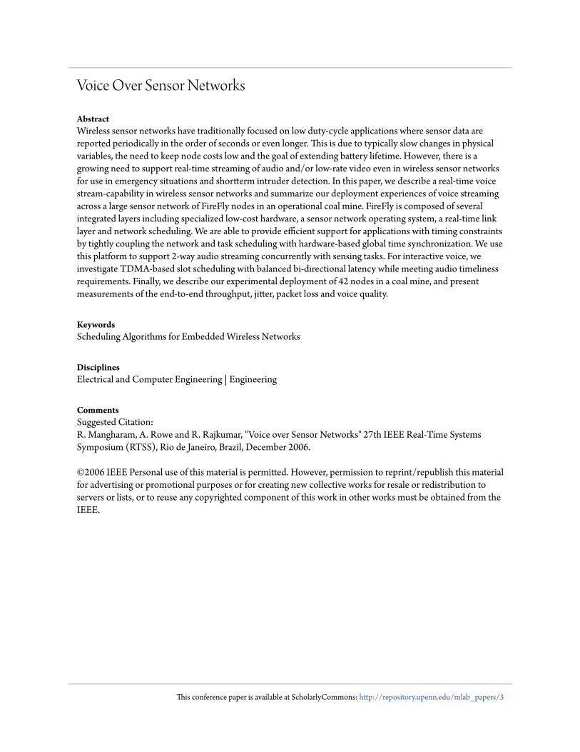
maintain communication in the remaining connected network.As shown in Figure 1, if a wireless node was lowered throughthe drill-hole, it could re-establish communications with theremaining network and initiate two-way communication withthe miners. In addition, the miners would be able to leavebroadcast voice mail-type messages and allow it to propagateto all nodes in the remaining network. It is important to notethat during normal operation, the network’s primary task is totrack miners and record environmental data.
In order to keep normal network maintenance costs low, itis necessary to meet the following design goals:
1. All nodes are to be battery-powered.
2. Nodes must have a predictable lifetime of at least one totwo years under normal operation.
3. Nodes must provision continuous voice communicationfor at least one week with fully-charged batteries.
4. Voice communications must include two-way interac-tive calling, one-way "push-to-talk" voice messaging andsupport for store and broadcast voicemail messaging.
5. The network must be able to tolerate topology changesand self-heal to maintain connectivity after a networkpartition.
The two fundamental challenges in delivering delay-bounded service in sensor networks are (a) coordinating trans-mission so that all active nodes communicate in a tightlysynchronized manner and (b) ensuring all transmissions arecollision-free. Time synchronization is important because itcan be used to pack the activity of all the nodes so that theymay maximize a common sleep interval between activities.Furthermore, it can be used to provide guarantees on time-liness, throughput and network lifetime for end-to-end com-munication. In this paper, we focus on the first four goals ofvoice streaming during steady-state network operation.
1.1. Overview of Sensor Network StreamingWe use the FireFly sensor network platform to implement
on-board audio sampling, ADPCM encoding, packet trans-mission and forwarding. Each FireFly node has an 8-bit mi-crocontroller and two radios: an IEEE 802.15.4 transceiverfor multi-hop data communication and a low-power AM re-ceiver for global time synchronization. Each node receives ashort (e.g. 50µs) periodic pulse from an AM transmitter once
every few seconds (e.g. 6 sec). The AM time sync pulse isbroadcast to all nodes in the network and provides a globaltime reference. This design enables each node to operate ina tightly coupled local and networked synchronized regimewith nominal overhead.
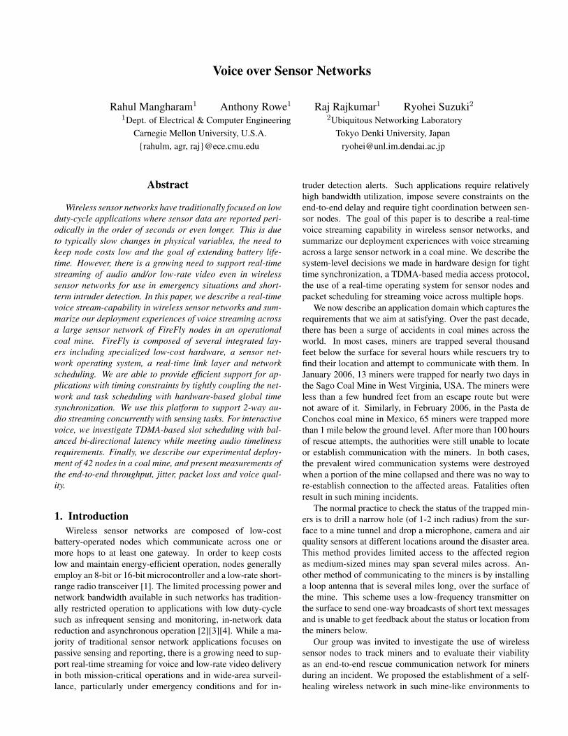
Multiple applications such as audio processing, localiza-tion and sensor updates are managed by the Nano-RK real-time sensor operating system [5]. As shown in Figure 2, theNano-RK kernel includes the RT-Link real-time link proto-col [6] which uses hardware-based time synchronization tomark the beginning of a new TDMA communication cycle.RT-Link supports fixed and mobile nodes. RT-Link also sup-ports both out-of-band hardware-based global time sync andin-band software-based time sync. Audio packet transmissionand forwarding are executed in explicitly scheduled time slotswhich are assigned by the gateway and maintained by the net-work task in Nano-RK.
1.2. Organization of this PaperWe provide a review of our hardware platform and our real-
time link protocol in Section 3. We describe our implemen-tation of various voice codecs for an 8-bit microcontroller inSection 4. In order to facilitate multiple delay-sensitive taskson each node, we describe the use of the Nano-RK RTOSand network scheduling in Section 5. A performance study ispresented in Section 6. Concluding remarks are provided inSection 7.
2. Related WorkLink and network support for real-time communications
over sensor networks have attracted much attention in therecent years. Constraints on computing power, bandwidth,memory and energy supply in sensor networks make the prob-lem of delivering timeliness guarantees across multiple hopsespecially challenging. In [7], Abdelzaher presents the ca-pacity bounds on how much real-time data a sensor networkcan transfer by the imposed deadlines. He derives a sufficientschedulability condition for a class of fixed-priority packetscheduling algorithms and provides a theoretical basis for ca-pacity planning. Several media access schemes have been
Figure 2. Time synchronization tightly couples the real-time operating system, link and network protocols in theFireFly sensor network platform
proposed for real-time communication over sensor networks,with the goal of bounding the end-to-end delay. In [8], theauthors present velocity-monotonic scheduling that accountsfor both time and distance in large-scale networks. Simulationstudies show that such a scheme is effective in minimizing thedeadline-miss ratios in multi-hop sensor networks. Finally,both [9] and [10] present simulation studies on resource reser-vation and routing protocols for applications with end-to-endtimeliness constraints.
TDMA protocols such as TRAMA [11] and LMAC [12]are able to communicate between node pairs in dedicated timeslots. Both protocols assume the provision of global timesynchronization but consider support for it to be an orthog-onal problem. FireFly integrates time synchronization withinthe link protocol and also in the hardware specification. Fire-Fly has been inspired by dual-radio systems such as [13, 14]used for low-power wake-up. However, neither system hasbeen used for time-synchronized operation. Several in-bandsoftware-based time-synchronization schemes such as RBS[15], TPSN [16] and FTSP [17] have been proposed and pro-vide good accuracy. In [18], Zhao provides experimental evi-dence showing that nodes participating in multi-hop commu-nications in an indoor environment routinely suffer link er-ror rate over 50% even when the receive signal strength isabove the sensitivity threshold. This limits the diffusion ofin-band time synchronization updates and hence reduces thenetwork performance. RT-Link employs an out-of-band time-synchronization mechanism which also globally synchronizesall nodes and is less vulnerable than the above schemes.
Real-time voice encoding on 8-bit microcontrollers is asevere challenge due to the limited amounts of processingpower, random access memory and bandwidth available inlow-cost sensor nodes. A description of ADPCM decodingusing a PIC microcontroller is provided in [19]. Similarly,[20] describes an off-line method to decode ADPCM on anAtmel microcontroller but requires the use of flash memory.Our implementation has drawn from these experiences but en-codes the raw audio samples on-line and does not require writ-ing samples to flash.
To the best of our knowledge, the FireFly platform is one ofthe first low-cost and low-power systems capable of real-timestreaming across multiple hops in a wireless sensor network.The combination of global hardware-based time synchroniza-tion, a TDMA link layer capable of collision-free communica-tion, multiple task scheduling on each node, implementationof low-rate low-complexity audio compression and networkscheduling provide a stable framework for real-time stream-ing.
3. FireFly Sensor PlatformIn this section, we present a review of the FireFly hard-
ware, Nano-RK RTOS and the RT-Link protocol on eachnode.
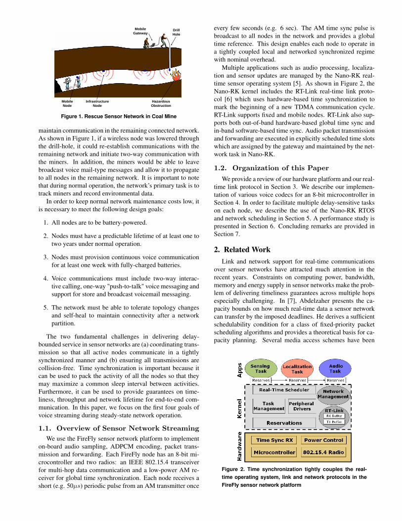
3.1. FireFly Sensor HardwareAt Carnegie Mellon, we have developed a low-cost low-
power hardware platform called FireFly as shown in Fig-ure 3. Firefly uses an Atmel ATmega32 [21] 8-bit Har-vard architecture microcontroller with 2KB of RAM and
PIR Motion
Audio
Light
FLASHTemperature
Acceleration
CC2420 RadioAtmega128L Processor
Hardware Time Sync
Expansion Port
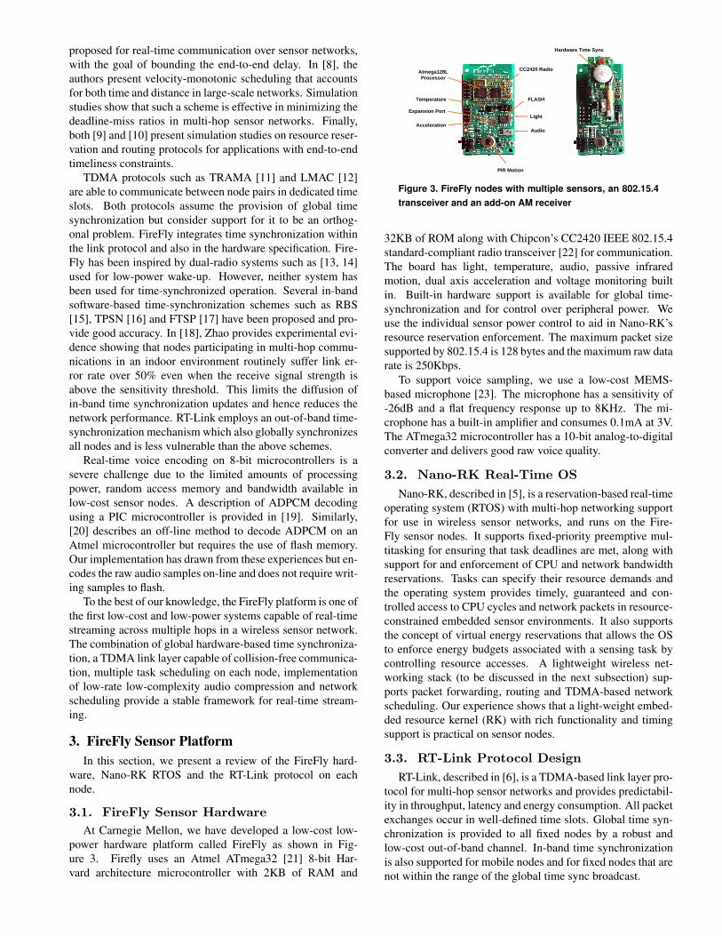
Figure 3. FireFly nodes with multiple sensors, an 802.15.4transceiver and an add-on AM receiver
32KB of ROM along with Chipcon’s CC2420 IEEE 802.15.4standard-compliant radio transceiver [22] for communication.The board has light, temperature, audio, passive infraredmotion, dual axis acceleration and voltage monitoring builtin. Built-in hardware support is available for global time-synchronization and for control over peripheral power. Weuse the individual sensor power control to aid in Nano-RK’sresource reservation enforcement. The maximum packet sizesupported by 802.15.4 is 128 bytes and the maximum raw datarate is 250Kbps.
To support voice sampling, we use a low-cost MEMS-based microphone [23]. The microphone has a sensitivity of-26dB and a flat frequency response up to 8KHz. The mi-crophone has a built-in amplifier and consumes 0.1mA at 3V.The ATmega32 microcontroller has a 10-bit analog-to-digitalconverter and delivers good raw voice quality.
3.2. Nano-RK Real-Time OSNano-RK, described in [5], is a reservation-based real-time
operating system (RTOS) with multi-hop networking supportfor use in wireless sensor networks, and runs on the Fire-Fly sensor nodes. It supports fixed-priority preemptive mul-titasking for ensuring that task deadlines are met, along withsupport for and enforcement of CPU and network bandwidthreservations. Tasks can specify their resource demands andthe operating system provides timely, guaranteed and con-trolled access to CPU cycles and network packets in resource-constrained embedded sensor environments. It also supportsthe concept of virtual energy reservations that allows the OSto enforce energy budgets associated with a sensing task bycontrolling resource accesses. A lightweight wireless net-working stack (to be discussed in the next subsection) sup-ports packet forwarding, routing and TDMA-based networkscheduling. Our experience shows that a light-weight embed-ded resource kernel (RK) with rich functionality and timingsupport is practical on sensor nodes.
3.3. RT-Link Protocol DesignRT-Link, described in [6], is a TDMA-based link layer pro-
tocol for multi-hop sensor networks and provides predictabil-ity in throughput, latency and energy consumption. All packetexchanges occur in well-defined time slots. Global time syn-chronization is provided to all fixed nodes by a robust andlow-cost out-of-band channel. In-band time synchronizationis also supported for mobile nodes and for fixed nodes that arenot within the range of the global time sync broadcast.
Time Synchronization Transmitter
Carrier Current Adapter
Power Grid Antenna
FireFly Nodes
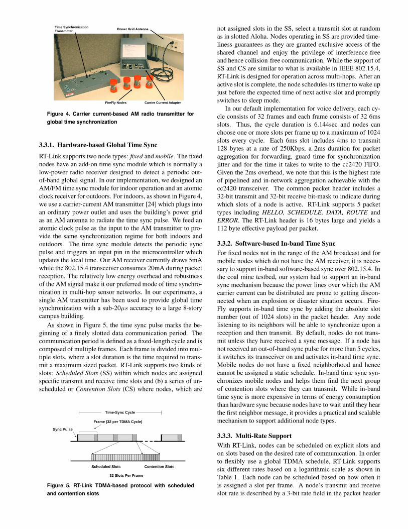
Figure 4. Carrier current-based AM radio transmitter forglobal time synchronization
3.3.1. Hardware-based Global Time Sync
RT-Link supports two node types: fixed and mobile. The fixednodes have an add-on time sync module which is normally alow-power radio receiver designed to detect a periodic out-of-band global signal. In our implementation, we designed anAM/FM time sync module for indoor operation and an atomicclock receiver for outdoors. For indoors, as shown in Figure 4,we use a carrier-current AM transmitter [24] which plugs intoan ordinary power outlet and uses the building’s power gridas an AM antenna to radiate the time sync pulse. We feed anatomic clock pulse as the input to the AM transmitter to pro-vide the same synchronization regime for both indoors andoutdoors. The time sync module detects the periodic syncpulse and triggers an input pin in the microcontroller whichupdates the local time. Our AM receiver currently draws 5mAwhile the 802.15.4 transceiver consumes 20mA during packetreception. The relatively low energy overhead and robustnessof the AM signal make it our preferred mode of time synchro-nization in multi-hop sensor networks. In our experiments, asingle AM transmitter has been used to provide global timesynchronization with a sub-20µs accuracy to a large 8-storycampus building.
As shown in Figure 5, the time sync pulse marks the be-ginning of a finely slotted data communication period. Thecommunication period is defined as a fixed-length cycle and iscomposed of multiple frames. Each frame is divided into mul-tiple slots, where a slot duration is the time required to trans-mit a maximum sized packet. RT-Link supports two kinds ofslots: Scheduled Slots (SS) within which nodes are assignedspecific transmit and receive time slots and (b) a series of un-scheduled or Contention Slots (CS) where nodes, which are
Time-Sync Cycle
Sync Pulse
Frame (32 per TDMA Cycle)
Scheduled Slots Contention Slots
32 Slots Per Frame
Figure 5. RT-Link TDMA-based protocol with scheduledand contention slots
not assigned slots in the SS, select a transmit slot at randomas in slotted Aloha. Nodes operating in SS are provided time-liness guarantees as they are granted exclusive access of theshared channel and enjoy the privilege of interference-freeand hence collision-free communication. While the support ofSS and CS are similar to what is available in IEEE 802.15.4,RT-Link is designed for operation across multi-hops. After anactive slot is complete, the node schedules its timer to wake upjust before the expected time of next active slot and promptlyswitches to sleep mode.
In our default implementation for voice delivery, each cy-cle consists of 32 frames and each frame consists of 32 6msslots. Thus, the cycle duration is 6.144sec and nodes canchoose one or more slots per frame up to a maximum of 1024slots every cycle. Each 6ms slot includes 4ms to transmit128 bytes at a rate of 250Kbps, a 2ms duration for packetaggregation for forwarding, guard time for synchronizationjitter and for the time it takes to write to the cc2420 FIFO.Given the 2ms overhead, we note that this is the highest rateof pipelined and in-network aggregation achievable with thecc2420 transceiver. The common packet header includes a32-bit transmit and 32-bit receive bit-mask to indicate duringwhich slots of a node is active. RT-Link supports 5 packettypes including HELLO, SCHEDULE, DATA, ROUTE andERROR. The RT-Link header is 16 bytes large and yields a112 byte effective payload per packet.
3.3.2. Software-based In-band Time SyncFor fixed nodes not in the range of the AM broadcast and formobile nodes which do not have the AM receiver, it is neces-sary to support in-band software-based sync over 802.15.4. Inthe coal mine testbed, our system had to support an in-bandsync mechanism because the power lines over which the AMcarrier current can be distributed are prone to getting discon-nected when an explosion or disaster situation occurs. Fire-Fly supports in-band time sync by adding the absolute slotnumber (out of 1024 slots) in the packet header. Any nodelistening to its neighbors will be able to synchronize upon areception and then transmit. By default, nodes do not trans-mit unless they have received a sync message. If a node hasnot received an out-of-band sync pulse for more than 5 cycles,it switches its transceiver on and activates in-band time sync.Mobile nodes do not have a fixed neighborhood and hencecannot be assigned a static schedule. In-band time sync syn-chronizes mobile nodes and helps them find the next groupof contention slots where they can transmit. While in-bandtime sync is more expensive in terms of energy consumptionthan hardware sync because nodes have to wait until they hearthe first neighbor message, it provides a practical and scalablemechanism to support additional node types.
3.3.3. Multi-Rate SupportWith RT-Link, nodes can be scheduled on explicit slots andon slots based on the desired rate of communication. In orderto flexibly use a global TDMA schedule, RT-Link supportssix different rates based on a logarithmic scale as shown inTable 1. Each node can be scheduled based on how often itis assigned a slot per frame. A node’s transmit and receiveslot rate is described by a 3-bit rate field in the packet header
Frame Rate Slot Frames/ Max. GoodputIndex Interval Cycle (Kbps)
0 - 0 01 1 32 149.32 2 16 74.63 4 8 37.34 8 4 18.65 16 2 9.36 32 1 4.6
Table 1. RT-Link Multi-rate support.
and is assigned its slot schedule via the SCHEDULE frame.The highest frame rate supported is rate 1 where the nodetransmits on every frame and provides the maximum goodputof 149.3Kbps if all slots are set in each active frame. Nodesoperating on rate 2 transmit or receive every other frame or16 frames per cycle. If all slots are set in each active frame,this results in 512 active slots per 6.114ms cycle and have agoodput of 74.6Kbps.
4. Voice over RT-Link ProtocolIn order to deliver voice as a primary means of commu-
nication under emergency conditions, we needed to support2-way interactive voice, 1-way push-to-talk messaging and avoice mail application where a user could broadcast a voicesnippet at moderate speed to nodes on the periphery of thenetwork. We focus on 2-way voice communication as it isthe most stringent in terms of end-to-end delay and through-put requirements. We choose the Adaptive Differential PulseCode Modulation (ADPCM) waveform codec as it providedus with a set of low transmission data rates, was easy to imple-ment on an 8-bit fixed-point architecture and has low process-ing overhead. ADPCM is simpler than advanced low bit-ratevocoders and can complete encoding and decoding in a rela-tively short time. The principle of ADPCM is to predict thecurrent signal value from the previous values and to transmitonly the difference between the real and the predicted value.As the dynamic range of this difference is small, we are ableto get a compression ratio of 8:1. The microphone was sam-pled at 4KHz and output an 8-bit value which was compressedto a 4-bit, 3-bit or 2-bit ADPCM code. This enabled us to re-duce a full-rate uncompressed voice stream of 64Kbps into a16, 12 or 8Kbps compressed stream. We chose to sample themicrophone at a rate lower than the normal 8KHz because itreduced the data rate by 50% and did not degrade the voicequality significantly.
4.1. FireFly Voice CodecsFireFly currently supports raw audio sampling, 16Kbps,
12Kbps and 8Kbps ADPCM encoding. Each ADPCM unitis encoded at the time the microphone is sampled. Nano-RKmaintains a double buffer to store the encoded data betweentransmission intervals. Table 2 lists the number of concur-rent unidirectional raw audio and ADPCM streams supportedbetween a node and the gateway across multiple hops. Wecompare its performance with GSM as it is an efficient codecthat can also be implemented in 8-bit fixed point with moder-ate processing overhead. The number of unique slots which
repeat are given by 2r, where r is the RT-Link rate. For exam-ple, rate 3 features an 8 slot repetition interval. A node maybe only scheduled to transmit on slots that are separated by atleast 3 slots so as to facilitate pipelining in the presence of thehidden terminals [25].
For rates 1 and 2, where a node transmits on every or ev-ery other slot respectively, only single-hop communication ispossible. For rate 1, every 6ms slot is used to forward a voicepacket to a receiver. In 6ms, 24 bytes of raw audio or 12 bytesof ADPCM-1 or 6 bytes of ADPCM-3 are captured. ADPCM-1 is able to pack 9 concurrent flows in the 112-byte payloadevery 6ms. As voice can be pipelined along a chain of nodeswhen at least 3 unique slots are available [25], ADPCM-1,ADPCM-2, ADPCM-2 and GSM-1 are able to support bi-directional voice across multiple hops. For rate 3, a nodealong a chain transmits only once every 4 slots and hence cap-tures 24ms of voice data. At rate 4, a node along a chain maytransmit once every 4 slots for bi-directional streams or onceevery 8 slots for unidirectional streams. With the networkschedules used in Section 7, a node transmits a packet every4 slots for bi-directional traffic. As each node is assigned aslot unique in its 2-hop neighborhood, both its neighbors arein receive mode during its transmit slot. Thus a node is ableto concatenate both neighbors data in one packet and send itas a single transmission.
4.2. Voice Quality Trade-offsAs the RT-Link slot interval increases, fewer concurrent
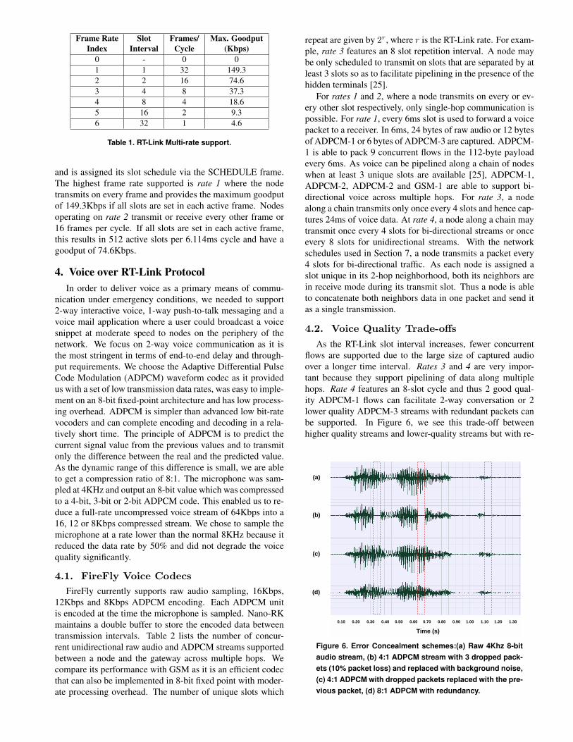
flows are supported due to the large size of captured audioover a longer time interval. Rates 3 and 4 are very impor-tant because they support pipelining of data along multiplehops. Rate 4 features an 8-slot cycle and thus 2 good qual-ity ADPCM-1 flows can facilitate 2-way conversation or 2lower quality ADPCM-3 streams with redundant packets canbe supported. In Figure 6, we see this trade-off betweenhigher quality streams and lower-quality streams but with re-
(a)
(b)
(c)
(d)
0.10 0.20 0.30 0.40 0.50 0.60 0.70 0.80 0.90 1.00 1.10 1.20 1.30
Time (s)
Figure 6. Error Concealment schemes:(a) Raw 4Khz 8-bitaudio stream, (b) 4:1 ADPCM stream with 3 dropped pack-ets (10% packet loss) and replaced with background noise,(c) 4:1 ADPCM with dropped packets replaced with the pre-vious packet, (d) 8:1 ADPCM with redundancy.
RT-Link Raw Audio ADPCM-1 GSM-1 ADPCM-2 ADPCM-3 GSM-2 Avg. Hop VoiceSlot Rate 32Kbps 16Kbps 13Kbps 12Kbps 8Kbps 7Kbps Delay Reliability
1 4 9 11 12 18 21 6ms Single2 2 4 5 6 9 10 12ms Single3 1 2 2 3 4 5 24ms Single4 1 2 2 2 4 4 24ms Double5 0 0 0 0 4 4 48ms Double
Table 2. Number of concurrent voice streams supported over RT-Link
dundant data. Figure 6(a) shows the original 4KHz sampledvoice signal and Figure 6(b) shows the good quality ADPCM-1 with three lost packets. As detailed in [26], error conceal-ment by replacing silence due to dropped packets with back-ground noise is more effective than forward error correction,source coding or interleaving in delivering reasonable qualityinteractive voice even with lost packets. Figure 6(c) shows thesame signal with dropped packets concealed by inserting theprevious packet in place of the silence. This scheme results ina slight echo but the voice is audible. Finally, in Figure 6(d),we observe a lower amplitude output of low quality ADPCM-3 with packet repetition. While the voice quality is lower thanFigure 6(c), there are no echoes or partial words.
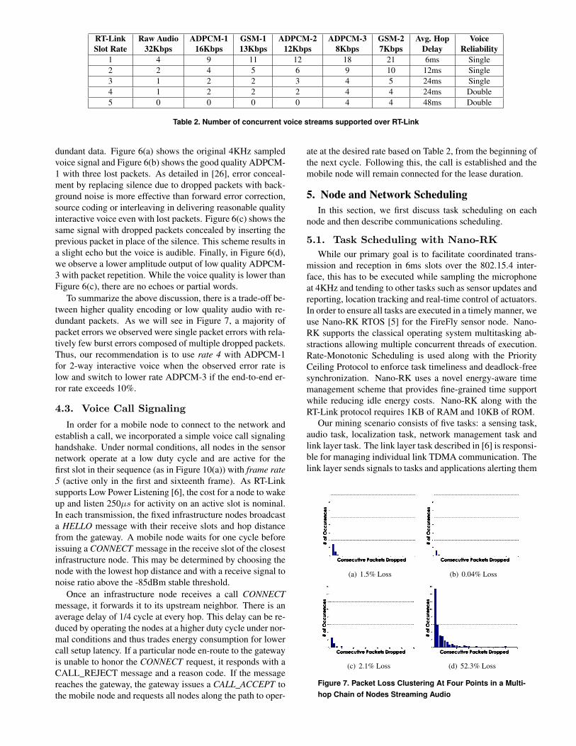
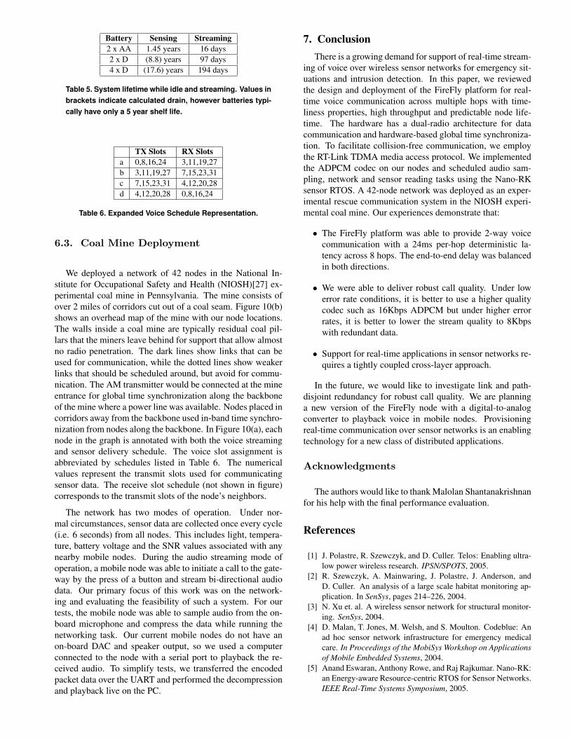
To summarize the above discussion, there is a trade-off be-tween higher quality encoding or low quality audio with re-dundant packets. As we will see in Figure 7, a majority ofpacket errors we observed were single packet errors with rela-tively few burst errors composed of multiple dropped packets.Thus, our recommendation is to use rate 4 with ADPCM-1for 2-way interactive voice when the observed error rate islow and switch to lower rate ADPCM-3 if the end-to-end er-ror rate exceeds 10%.
4.3. Voice Call Signaling
In order for a mobile node to connect to the network andestablish a call, we incorporated a simple voice call signalinghandshake. Under normal conditions, all nodes in the sensornetwork operate at a low duty cycle and are active for thefirst slot in their sequence (as in Figure 10(a)) with frame rate5 (active only in the first and sixteenth frame). As RT-Linksupports Low Power Listening [6], the cost for a node to wakeup and listen 250µs for activity on an active slot is nominal.In each transmission, the fixed infrastructure nodes broadcasta HELLO message with their receive slots and hop distancefrom the gateway. A mobile node waits for one cycle beforeissuing a CONNECT message in the receive slot of the closestinfrastructure node. This may be determined by choosing thenode with the lowest hop distance and with a receive signal tonoise ratio above the -85dBm stable threshold.
Once an infrastructure node receives a call CONNECTmessage, it forwards it to its upstream neighbor. There is anaverage delay of 1/4 cycle at every hop. This delay can be re-duced by operating the nodes at a higher duty cycle under nor-mal conditions and thus trades energy consumption for lowercall setup latency. If a particular node en-route to the gatewayis unable to honor the CONNECT request, it responds with aCALL_REJECT message and a reason code. If the messagereaches the gateway, the gateway issues a CALL_ACCEPT tothe mobile node and requests all nodes along the path to oper-
ate at the desired rate based on Table 2, from the beginning ofthe next cycle. Following this, the call is established and themobile node will remain connected for the lease duration.
5. Node and Network SchedulingIn this section, we first discuss task scheduling on each
node and then describe communications scheduling.
5.1. Task Scheduling with Nano-RKWhile our primary goal is to facilitate coordinated trans-
mission and reception in 6ms slots over the 802.15.4 inter-face, this has to be executed while sampling the microphoneat 4KHz and tending to other tasks such as sensor updates andreporting, location tracking and real-time control of actuators.In order to ensure all tasks are executed in a timely manner, weuse Nano-RK RTOS [5] for the FireFly sensor node. Nano-RK supports the classical operating system multitasking ab-stractions allowing multiple concurrent threads of execution.Rate-Monotonic Scheduling is used along with the PriorityCeiling Protocol to enforce task timeliness and deadlock-freesynchronization. Nano-RK uses a novel energy-aware timemanagement scheme that provides fine-grained time supportwhile reducing idle energy costs. Nano-RK along with theRT-Link protocol requires 1KB of RAM and 10KB of ROM.
Our mining scenario consists of five tasks: a sensing task,audio task, localization task, network management task andlink layer task. The link layer task described in [6] is responsi-ble for managing individual link TDMA communication. Thelink layer sends signals to tasks and applications alerting them
(a) 1.5% Loss (b) 0.04% Loss
(c) 2.1% Loss (d) 52.3% Loss
Figure 7. Packet Loss Clustering At Four Points in a Multi-hop Chain of Nodes Streaming Audio
when packets are sent or received. The network managementtask is responsible for coordinating voice call setup, TDMAslot scheduling, mode changes and periodic network statusupdates. The audio task runs an audio driver (an interruptroutine) as well as the ADPCM compression algorithm. Inour implementation, the sensing and localization tasks simplysampled RSSI values of mobile nodes and recorded sensorvalues. In a mature system, these tasks would be responsiblefor event detection processing and running in-network local-ization algorithms. In our configuration, the link layer is thehighest priority task, followed by the audio driver, the net-work management task and then the sensing and localizationtasks.
5.2. Network SchedulingGiven a sensor network topology, our goal is to schedule
at least one interactive bi-directional audio stream from anyconnected point in the network to the gateway while unob-trusively allowing sensing tasks to continue normal networkoperations. Given a connected graph G = {V,E}, we find aschedule such that from any V to the root node, there is a pathcomposed of nodes each of which transmits every n slots. ndefines the data rate of the network and hence governs whichaudio encoding schemes are best suited for the system. Toaccommodate interactive voice, we must ensure that packetlatency is symmetric between upstream and downstream com-munications and that packets arrive within acceptable timeli-ness bounds. The end-to-end latency of an audio stream is afunction of the TDMA slot rate as well as the number of hops.Interactive voice requires an end-to-end latency of 250ms orless, beyond which users notice a drop in interaction qual-ity. The goal for voice scheduling is therefore to minimizethe number of unique slots to maximize n and to ensure theordering of the slots results in balanced end-to-end delay inboth directions of the flow.
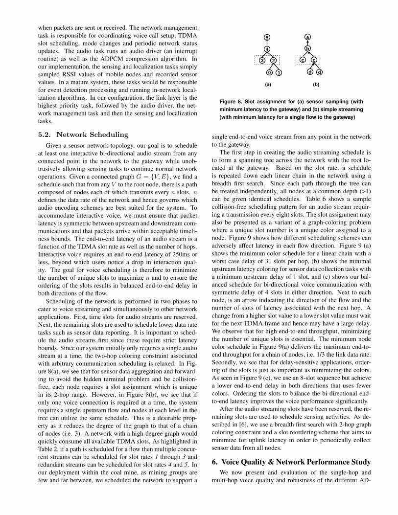
Scheduling of the network is performed in two phases tocater to voice streaming and simultaneously to other networkapplications. First, time slots for audio streams are reserved.Next, the remaining slots are used to schedule lower data ratetasks such as sensor data reporting. It is important to sched-ule the audio streams first since these require strict latencybounds. Since our system initially only requires a single audiostream at a time, the two-hop coloring constraint associatedwith arbitrary communication scheduling is relaxed. In Fig-ure 8(a), we see that for sensor data aggregation and forward-ing to avoid the hidden terminal problem and be collision-free, each node requires a slot assignment which is uniquein its 2-hop range. However, in Figure 8(b), we see that ifonly one voice connection is required at a time, the systemrequires a single upstream flow and nodes at each level in thetree can utilize the same schedule. This is a desirable prop-erty as it reduces the degree of the graph to that of a chainof nodes (i.e. 3). A network with a high-degree graph wouldquickly consume all available TDMA slots. As highlighted inTable 2, if a path is scheduled for a flow then multiple concur-rent streams can be scheduled for slot rates 1 through 3 andredundant streams can be scheduled for slot rates 4 and 5. Inour deployment within the coal mine, as mining groups arefew and far between, we scheduled the network to support a
5
4
3 2
0 1
a
b
c c
d d
(a) (b)
Figure 8. Slot assignment for (a) sensor sampling (withminimum latency to the gateway) and (b) simple streaming(with minimum latency for a single flow to the gateway)
single end-to-end voice stream from any point in the networkto the gateway.
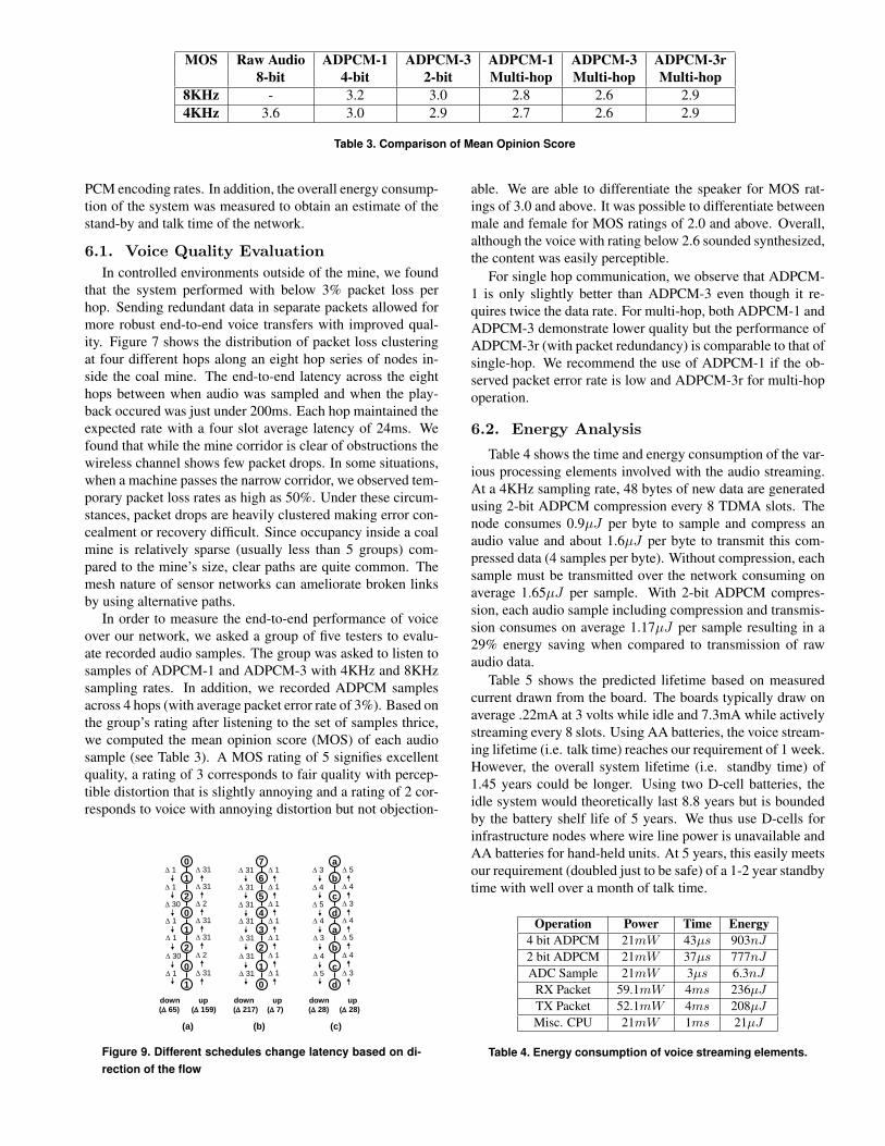
The first step in creating the audio streaming schedule isto form a spanning tree across the network with the root lo-cated at the gateway. Based on the slot rate, a scheduleis repeated down each linear chain in the network using abreadth first search. Since each path through the tree canbe treated independently, all nodes at a common depth (>1)can be given identical schedules. Table 6 shows a samplecollision-free scheduling pattern for an audio stream requir-ing a transmission every eight slots. The slot assignment mayalso be presented as a variant of a graph-coloring problemwhere a unique slot number is a unique color assigned to anode. Figure 9 shows how different scheduling schemes canadversely affect latency in each flow direction. Figure 9 (a)shows the minimum color schedule for a linear chain with aworst case delay of 31 slots per hop, (b) shows the minimalupstream latency coloring for sensor data collection tasks witha minimum upstream delay of 1 slot, and (c) shows our bal-anced schedule for bi-directional voice communication withsymmetric delay of 4 slots in either direction. Next to eachnode, is an arrow indicating the direction of the flow and thenumber of slots of latency associated with the next hop. Achange from a higher slot value to a lower slot value must waitfor the next TDMA frame and hence may have a large delay.We observe that for high end-to-end throughput, minimizingthe number of unique slots is essential. The minimum nodecolor schedule in Figure 9(a) delivers the maximum end-to-end throughput for a chain of nodes, i.e. 1/3 the link data rate.Secondly, we see that for delay-sensitive applications, order-ing of the slots is just as important as minimizing the colors.As seen in Figure 9 (c), we use an 8-slot sequence but achievea lower end-to-end delay in both directions that uses fewercolors. Ordering the slots to balance the bi-directional end-to-end latency improves the voice performance significantly.
After the audio streaming slots have been reserved, the re-maining slots are used to schedule sensing activities. As de-scribed in [6], we use a breadth first search with 2-hop graphcoloring constraint and a slot reordering scheme that aims tominimize for uplink latency in order to periodically collectsensor data from all nodes.
6. Voice Quality & Network Performance StudyWe now present and evaluation of the single-hop and
multi-hop voice quality and robustness of the different AD-
MOS Raw Audio ADPCM-1 ADPCM-3 ADPCM-1 ADPCM-3 ADPCM-3r8-bit 4-bit 2-bit Multi-hop Multi-hop Multi-hop
8KHz - 3.2 3.0 2.8 2.6 2.94KHz 3.6 3.0 2.9 2.7 2.6 2.9
Table 3. Comparison of Mean Opinion Score
PCM encoding rates. In addition, the overall energy consump-tion of the system was measured to obtain an estimate of thestand-by and talk time of the network.
6.1. Voice Quality EvaluationIn controlled environments outside of the mine, we found
that the system performed with below 3% packet loss perhop. Sending redundant data in separate packets allowed formore robust end-to-end voice transfers with improved qual-ity. Figure 7 shows the distribution of packet loss clusteringat four different hops along an eight hop series of nodes in-side the coal mine. The end-to-end latency across the eighthops between when audio was sampled and when the play-back occured was just under 200ms. Each hop maintained theexpected rate with a four slot average latency of 24ms. Wefound that while the mine corridor is clear of obstructions thewireless channel shows few packet drops. In some situations,when a machine passes the narrow corridor, we observed tem-porary packet loss rates as high as 50%. Under these circum-stances, packet drops are heavily clustered making error con-cealment or recovery difficult. Since occupancy inside a coalmine is relatively sparse (usually less than 5 groups) com-pared to the mine’s size, clear paths are quite common. Themesh nature of sensor networks can ameliorate broken linksby using alternative paths.
In order to measure the end-to-end performance of voiceover our network, we asked a group of five testers to evalu-ate recorded audio samples. The group was asked to listen tosamples of ADPCM-1 and ADPCM-3 with 4KHz and 8KHzsampling rates. In addition, we recorded ADPCM samplesacross 4 hops (with average packet error rate of 3%). Based onthe group’s rating after listening to the set of samples thrice,we computed the mean opinion score (MOS) of each audiosample (see Table 3). A MOS rating of 5 signifies excellentquality, a rating of 3 corresponds to fair quality with percep-tible distortion that is slightly annoying and a rating of 2 cor-responds to voice with annoying distortion but not objection-
0
1
2
0
1
2
0
1
7
6
5
4
3
2
1
0
a
b
c
d
a
b
c
d
Δ 31
Δ 31
Δ 31
Δ 31
Δ 31
Δ 31
Δ 31
Δ 1
Δ 1
Δ 1
Δ 1
Δ 1
Δ 1
Δ 1
Δ 3
Δ 4
Δ 5
Δ 4
Δ 3
Δ 4
Δ 5
Δ 5
Δ 4
Δ 3
Δ 4
Δ 5
Δ 4
Δ 3
Δ 1
Δ 1
Δ 30
Δ 1
Δ 1
Δ 30
Δ 1
Δ 31
Δ 31
Δ 2
Δ 31
Δ 31
Δ 2
Δ 31
(Δ 65) (Δ 159) (Δ 217) (Δ 7) (Δ 28) (Δ 28)down up down up down up
(a) (b) (c)
Figure 9. Different schedules change latency based on di-rection of the flow
able. We are able to differentiate the speaker for MOS rat-ings of 3.0 and above. It was possible to differentiate betweenmale and female for MOS ratings of 2.0 and above. Overall,although the voice with rating below 2.6 sounded synthesized,the content was easily perceptible.
For single hop communication, we observe that ADPCM-1 is only slightly better than ADPCM-3 even though it re-quires twice the data rate. For multi-hop, both ADPCM-1 andADPCM-3 demonstrate lower quality but the performance ofADPCM-3r (with packet redundancy) is comparable to that ofsingle-hop. We recommend the use of ADPCM-1 if the ob-served packet error rate is low and ADPCM-3r for multi-hopoperation.
6.2. Energy Analysis
Table 4 shows the time and energy consumption of the var-ious processing elements involved with the audio streaming.At a 4KHz sampling rate, 48 bytes of new data are generatedusing 2-bit ADPCM compression every 8 TDMA slots. Thenode consumes 0.9µJ per byte to sample and compress anaudio value and about 1.6µJ per byte to transmit this com-pressed data (4 samples per byte). Without compression, eachsample must be transmitted over the network consuming onaverage 1.65µJ per sample. With 2-bit ADPCM compres-sion, each audio sample including compression and transmis-sion consumes on average 1.17µJ per sample resulting in a29% energy saving when compared to transmission of rawaudio data.
Table 5 shows the predicted lifetime based on measuredcurrent drawn from the board. The boards typically draw onaverage .22mA at 3 volts while idle and 7.3mA while activelystreaming every 8 slots. Using AA batteries, the voice stream-ing lifetime (i.e. talk time) reaches our requirement of 1 week.However, the overall system lifetime (i.e. standby time) of1.45 years could be longer. Using two D-cell batteries, theidle system would theoretically last 8.8 years but is boundedby the battery shelf life of 5 years. We thus use D-cells forinfrastructure nodes where wire line power is unavailable andAA batteries for hand-held units. At 5 years, this easily meetsour requirement (doubled just to be safe) of a 1-2 year standbytime with well over a month of talk time.
Operation Power Time Energy4 bit ADPCM 21mW 43µs 903nJ
2 bit ADPCM 21mW 37µs 777nJ
ADC Sample 21mW 3µs 6.3nJ
RX Packet 59.1mW 4ms 236µJ
TX Packet 52.1mW 4ms 208µJ
Misc. CPU 21mW 1ms 21µJ
Table 4. Energy consumption of voice streaming elements.
Battery Sensing Streaming2 x AA 1.45 years 16 days2 x D (8.8) years 97 days4 x D (17.6) years 194 days
Table 5. System lifetime while idle and streaming. Values inbrackets indicate calculated drain, however batteries typi-cally have only a 5 year shelf life.
TX Slots RX Slotsa 0,8,16,24 3,11,19,27b 3,11,19,27 7,15,23,31c 7,15,23,31 4,12,20,28d 4,12,20,28 0,8,16,24
Table 6. Expanded Voice Schedule Representation.
6.3. Coal Mine Deployment
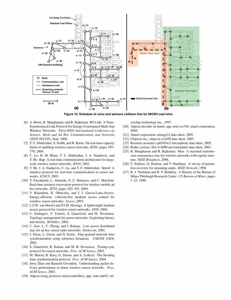
We deployed a network of 42 nodes in the National In-stitute for Occupational Safety and Health (NIOSH)[27] ex-perimental coal mine in Pennsylvania. The mine consists ofover 2 miles of corridors cut out of a coal seam. Figure 10(b)shows an overhead map of the mine with our node locations.The walls inside a coal mine are typically residual coal pil-lars that the miners leave behind for support that allow almostno radio penetration. The dark lines show links that can beused for communication, while the dotted lines show weakerlinks that should be scheduled around, but avoid for commu-nication. The AM transmitter would be connected at the mineentrance for global time synchronization along the backboneof the mine where a power line was available. Nodes placed incorridors away from the backbone used in-band time synchro-nization from nodes along the backbone. In Figure 10(a), eachnode in the graph is annotated with both the voice streamingand sensor delivery schedule. The voice slot assignment isabbreviated by schedules listed in Table 6. The numericalvalues represent the transmit slots used for communicatingsensor data. The receive slot schedule (not shown in figure)corresponds to the transmit slots of the node’s neighbors.
The network has two modes of operation. Under nor-mal circumstances, sensor data are collected once every cycle(i.e. 6 seconds) from all nodes. This includes light, tempera-ture, battery voltage and the SNR values associated with anynearby mobile nodes. During the audio streaming mode ofoperation, a mobile node was able to initiate a call to the gate-way by the press of a button and stream bi-directional audiodata. Our primary focus of this work was on the network-ing and evaluating the feasibility of such a system. For ourtests, the mobile node was able to sample audio from the on-board microphone and compress the data while running thenetworking task. Our current mobile nodes do not have anon-board DAC and speaker output, so we used a computerconnected to the node with a serial port to playback the re-ceived audio. To simplify tests, we transferred the encodedpacket data over the UART and performed the decompressionand playback live on the PC.
7. ConclusionThere is a growing demand for support of real-time stream-
ing of voice over wireless sensor networks for emergency sit-uations and intrusion detection. In this paper, we reviewedthe design and deployment of the FireFly platform for real-time voice communication across multiple hops with time-liness properties, high throughput and predictable node life-time. The hardware has a dual-radio architecture for datacommunication and hardware-based global time synchroniza-tion. To facilitate collision-free communication, we employthe RT-Link TDMA media access protocol. We implementedthe ADPCM codec on our nodes and scheduled audio sam-pling, network and sensor reading tasks using the Nano-RKsensor RTOS. A 42-node network was deployed as an exper-imental rescue communication system in the NIOSH experi-mental coal mine. Our experiences demonstrate that:
• The FireFly platform was able to provide 2-way voicecommunication with a 24ms per-hop deterministic la-tency across 8 hops. The end-to-end delay was balancedin both directions.
• We were able to deliver robust call quality. Under lowerror rate conditions, it is better to use a higher qualitycodec such as 16Kbps ADPCM but under higher errorrates, it is better to lower the stream quality to 8Kbpswith redundant data.
• Support for real-time applications in sensor networks re-quires a tightly coupled cross-layer approach.
In the future, we would like to investigate link and path-disjoint redundancy for robust call quality. We are planninga new version of the FireFly node with a digital-to-analogconverter to playback voice in mobile nodes. Provisioningreal-time communication over sensor networks is an enablingtechnology for a new class of distributed applications.
Acknowledgments
The authors would like to thank Malolan Shantanakrishnanfor his help with the final performance evaluation.
References
[1] J. Polastre, R. Szewczyk, and D. Culler. Telos: Enabling ultra-low power wireless research. IPSN/SPOTS, 2005.
[2] R. Szewczyk, A. Mainwaring, J. Polastre, J. Anderson, andD. Culler. An analysis of a large scale habitat monitoring ap-plication. In SenSys, pages 214–226, 2004.
[3] N. Xu et. al. A wireless sensor network for structural monitor-ing. SenSys, 2004.
[4] D. Malan, T. Jones, M. Welsh, and S. Moulton. Codeblue: Anad hoc sensor network infrastructure for emergency medicalcare. In Proceedings of the MobiSys Workshop on Applicationsof Mobile Embedded Systems, 2004.
[5] Anand Eswaran, Anthony Rowe, and Raj Rajkumar. Nano-RK:an Energy-aware Resource-centric RTOS for Sensor Networks.IEEE Real-Time Systems Symposium, 2005.
(a) (b)
Figure 10. Schedule of voice and sensors collision free for NIOSH coal mine.
[6] A. Rowe, R. Mangharam, and R. Rajkumar. RT-Link: A Time-Synchronized Link Protocol for Energy-Constrained Multi-hopWireless Networks. Third IEEE International Conference onSensors, Mesh and Ad Hoc Communications and Networks(IEEE SECON), Sept. 2006.
[7] T. F. Abdelzaher, S. Prabh, and R. Kiran. On real-time capacitylimits of multihop wireless sensor networks. RTSS, pages 359–370, 2004.
[8] C. Lu, B. M. Blum, T. F. Abdelzaher, J. A. Stankovic, andT. He. Rap: A real-time communication architecture for large-scale wireless sensor networks. RTAS, 2002.
[9] T. He, J. A. Stankovic, C. Lu, and T. F. Abdelzaher. Speed: Astateless protocol for real-time communication in sensor net-works. ICDCS, 2003.
[10] T. Facchinetti, L. Almeida, G. C. Buttazzo, and C. Marchini.Real-time resource reservation protocol for wireless mobile adhoc networks. RTSS, pages 382–391, 2004.
[11] V. Rajendran, K. Obraczka, and J. J. Garcia-Luna-Aceves.Energy-efficient, collision-free medium access control forwireless sensor networks. Sensys, 2003.
[12] L.F.W. van Hoesel and P.J.M. Havinga. A lightweight mediumaccess protocol for wireless sensor networks. INSS, 2004.
[13] C. Schurgers, V. Tsiatsis, S. Ganeriwal, and M. Srivastava.Topology management for sensor networks: Exploiting latencyand density. MobiHoc, 2002.
[14] C. Guo, L. C. Zhong, and J. Rabaey. Low power distributedmac for ad hoc sensor radio networks. Globecom, 2001.
[15] J. Elson, L. Girod, and D. Estrin. Fine-grained network timesynchronization using reference broadcast. USENIX OSDI,2002.
[16] S. Ganeriwal, R. Kumar, and M. B. Srivastava. Timing-syncprotocol for sensor networks. Proc. ACM Sensys, 2003.
[17] M. Maroti, B. Kusy, G. Simon, and A. Ledeczi. The floodingtime synchronization protocol. Proc. ACM Sensys, 2004.
[18] Jerry Zhao and Ramesh Govindan. Understanding packet de-livery performance in dense wireless sensor networks. Proc.ACM Sensys, 2003.
[19] Adpcm using picmicro microcontrollers, app. note an643. mi-
crochip technology inc., 1997.[20] Adpcm decoder on atmel, app. note avr336. atmel corporation,
2004.[21] Atmel corporation, atmega32 data sheet, 2005.[22] Chipcon inc., chipcon cc2420 data sheet, 2003.[23] Knowles acoustics sp0103nc3 microphone data sheet, 2005.[24] Radio systems 30w tr-6000 am transmitter data sheet, 2001.[25] R. Mangharam and R. Rajkumar. Max: A maximal transmis-
sion concurrency mac for wireless networks with regular struc-ture. IEEE Broadnets, 2006.
[26] C. Perkins, O. Hodson, and V. Hardman. A survey of packet-loss recovery for streaming audio. IEEE Network, 1998.
[27] R. J. Tuchman and R. F. Brinkley. A History of the Bureau ofMines Pittsburgh Research Center. US Bureau of Mines, pages1–23, 1990.
Related Documents