VLSI DSP 2008 Y.T. Hwang 3-1 Chapter 3 Algorithm Representation & Iteration Bound

VLSI DSP 2008Y.T. Hwang3-1 Chapter 3 Algorithm Representation & Iteration Bound.
Dec 22, 2015
Welcome message from author
This document is posted to help you gain knowledge. Please leave a comment to let me know what you think about it! Share it to your friends and learn new things together.
Transcript
VLSI DSP 2008 Y.T. Hwang 3-1
Chapter 3 Algorithm Representation & Iteration Bound
VLSI DSP 2008 Y.T. Hwang 3-2
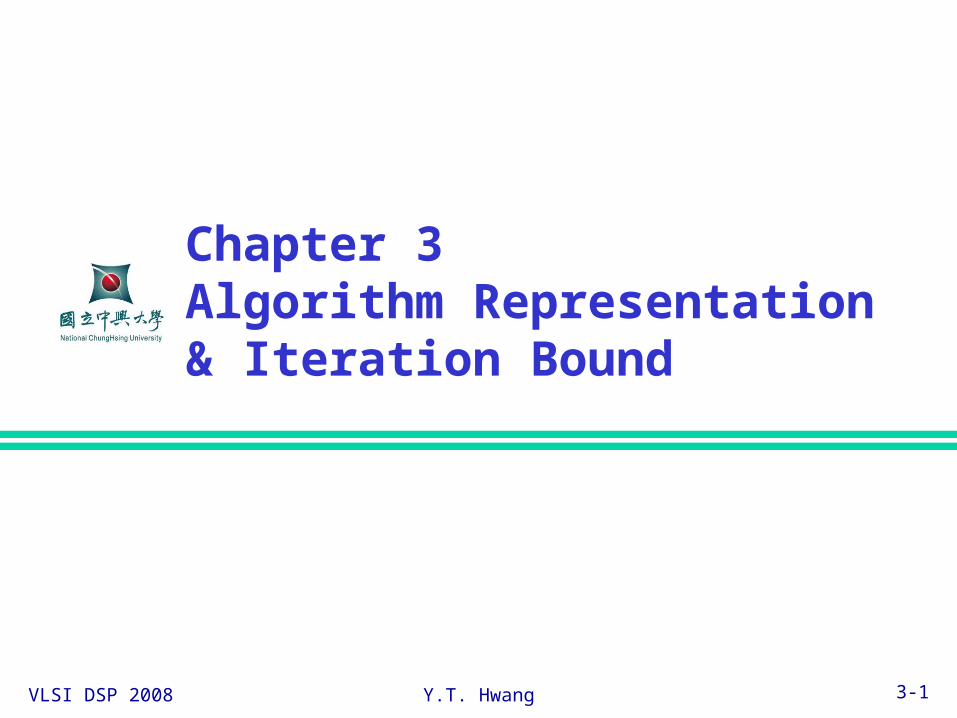
Representations of DSP Algorithms
Mathematical formulationsBehavioral description languages
Applicative language Represents a set of equations satisfied by the variables, e.g. Silage
Perspective language Explicitly specify the order of assignment, e.g. C and other HLLs
Descriptive language Represents the structure of a DSP system, e.g. VHDL, Verilog
Graphical representationsBlock diagramsSignal flow graph (SFG)Data flow graph (DFG)Dependence graph (DG)
VLSI DSP 2008 Y.T. Hwang 3-3
Block Diagrams (1)
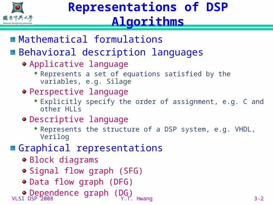
Consists of functional blocks connected with directed edges
Functional block, e.g. Add, Mult
Unit delay element
Directed edge representing the data flow between blocks
Basic blocks

VLSI DSP 2008 Y.T. Hwang 3-4
Block Diagrams (2)
3-tap FIR example
Alternative block diagram with data broadcast
VLSI DSP 2008 Y.T. Hwang 3-5
Signal Flow Graph (1)
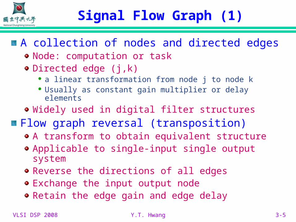
A collection of nodes and directed edgesNode: computation or taskDirected edge (j,k)
a linear transformation from node j to node k Usually as constant gain multiplier or delay elements
Widely used in digital filter structures
Flow graph reversal (transposition)A transform to obtain equivalent structureApplicable to single-input single output systemReverse the directions of all edgesExchange the input output nodeRetain the edge gain and edge delay

VLSI DSP 2008 Y.T. Hwang 3-6
Signal Flow Graph (2)
SFG of a 3-tap FIR filter
Original SFG
Transposed SFG
VLSI DSP 2008 Y.T. Hwang 3-7
Signal Flow Graph (3)
Limitations of transpositioncan be applied to MIMO systems described by symmetric transform matrices
More on SFGApplicable to linear network
Cannot be used to described multi-rate system

VLSI DSP 2008 Y.T. Hwang 3-8
Data Flow Graph (1)
DFGNode: computation (function or subtask)
Directed edge: data path or communication between nodes
Associated edge delay: non-negative
Associated node delay: execution time of each node
Block diagram Conventional DFG Synchronous DFG
add
mpy

VLSI DSP 2008 Y.T. Hwang 3-9
Data Flow Graph (2)
Applications: high level synthesis
Firing rulesA node can fire whenever all the input data are available
Concurrency: multiple nodes can be fired simultaneously
Data driven (implicit) scheduling
Precedence constraintIntra-iteration: imposed by edge with no delay
Inter-iteration: imposed by edge with delay
fine-grain (atomic) v.s. coarse grain DFG

VLSI DSP 2008 Y.T. Hwang 3-10
Data Flow Graph (3)
3-tap FIR filter example
Direct form
Transpose form
VLSI DSP 2008 Y.T. Hwang 3-11
Data Flow Graph (4)
Synchronous DFGNumber of data samples produced or consumed by each node is specified a priori
Single rate system
Multi-rate system: different nodes working on different frequencies
Multi-rate system can be represented by a single rate system via unfolding (unrolling)
VLSI DSP 2008 Y.T. Hwang 4-12
Introduction to Iteration bound
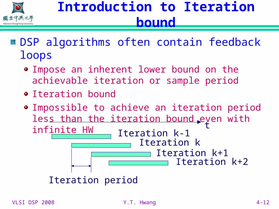
DSP algorithms often contain feedback loopsImpose an inherent lower bound on the achievable iteration or sample period
Iteration bound
Impossible to achieve an iteration period less than the iteration bound even with infinite HW
Iteration kIteration k-1
Iteration k+1Iteration k+2
t
Iteration period

VLSI DSP 2008 Y.T. Hwang 4-13
Data Flow Graph Representations
For n = 0 to ∞y(n) = ay(n-1) + x(n)
Iteration – execution of each DFG node oncePrecedence constraints
Intra-iteration – no delay on edgeInter-iteration – at least one delay on edge
Execution time of a
node
Inter-iteration
Intra-iteration
Critical pathAB

VLSI DSP 2008 Y.T. Hwang 4-14
Critical Path
Critical path of a DFGThe path with the longest computation time among all paths containing zero delaysThe minimum computation time for one iteration of the DFG6→3→2→15→3→2→1Iteration period = 5 u.t.
Iteration boundRecursive DFG has a lowerbound on the shortestiteration period
VLSI DSP 2008 Y.T. Hwang 4-15
Loop bound and iteration bound (1)
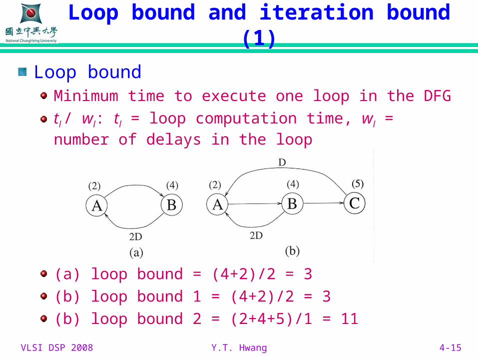
Loop boundMinimum time to execute one loop in the DFG
tl / wl: tl = loop computation time, wl = number of delays in the loop
(a) loop bound = (4+2)/2 = 3
(b) loop bound 1 = (4+2)/2 = 3
(b) loop bound 2 = (2+4+5)/1 = 11
VLSI DSP 2008 Y.T. Hwang 4-16
Loop bound and iteration bound (2)
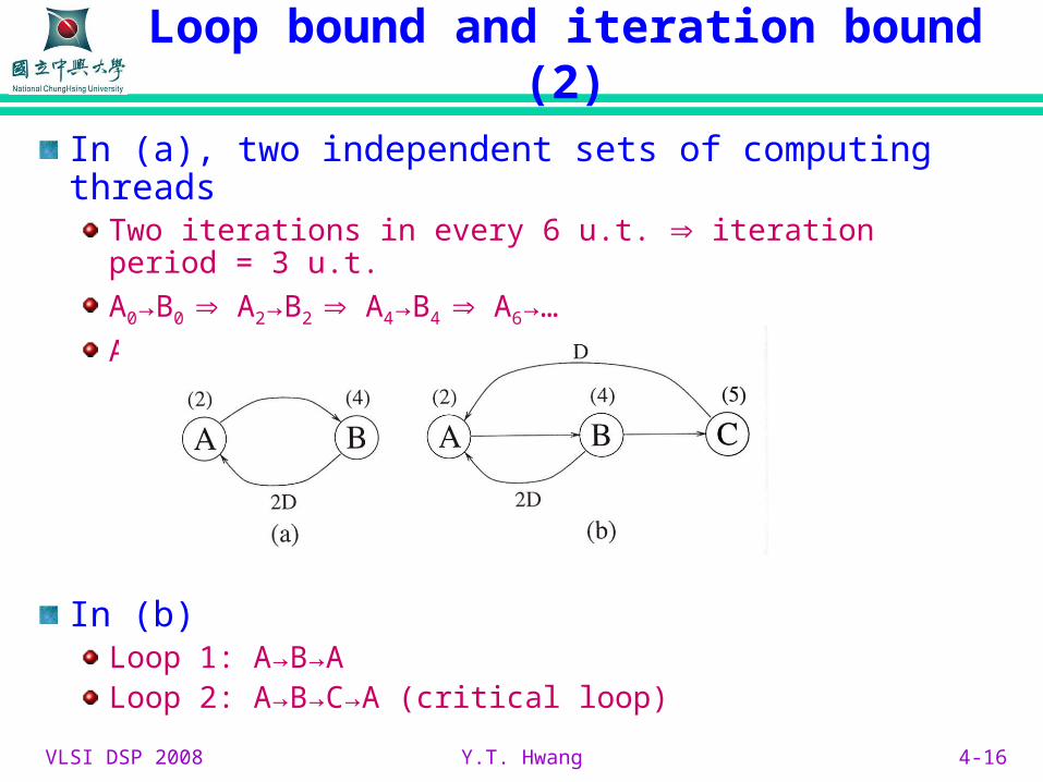
In (a), two independent sets of computing threadsTwo iterations in every 6 u.t. iteration period = 3 u.t.
A0→B0 A2→B2 A4→B4 A6→…
A1→B1 A3→B3 A5→B5 A7→…
In (b)Loop 1: A→B→ALoop 2: A→B→C→A (critical loop)
VLSI DSP 2008 Y.T. Hwang 4-17
Loop bound and iteration bound (3)
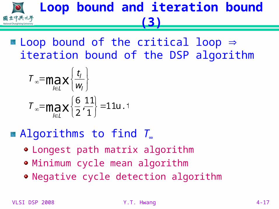
Loop bound of the critical loop iteration bound of the DSP algorithm
Algorithms to find T∞
Longest path matrix algorithm
Minimum cycle mean algorithm
Negative cycle detection algorithm
u.t. 111
11,
2
6max
max
Ll
l
l
Ll
T
w
tT
Related Documents

![T-76.4115 Iteration Demo Tikkaajat [PP] Iteration 18.10.2007.](https://static.cupdf.com/doc/110x72/5a4d1b607f8b9ab0599ace21/t-764115-iteration-demo-tikkaajat-pp-iteration-18102007.jpg)