VistaNET Help

Welcome message from author
This document is posted to help you gain knowledge. Please leave a comment to let me know what you think about it! Share it to your friends and learn new things together.
Transcript

VistaNET Help
VistaNET Help
1
Table Of Contents 1. VistaNET .............................................................................................................................................. 5
1.1 Introduction to VistaNET ............................................................................................................... 5
1.1.1 Features .................................................................................................................................. 6
1.1.2 Components ........................................................................................................................... 7
1.1.3 Architecture ............................................................................................................................ 8
1.1.4 Communication Links ........................................................................................................... 10
1.1.5 License .................................................................................................................................. 11
1.1.6 Related Publication and Documentation Support ............................................................... 11
1.1.7 Known Limitations ................................................................................................................ 11
1.1.8 Known Deficiencies .............................................................................................................. 11
1.2 Getting Started ............................................................................................................................ 12
1.2.1 Computer Requirements ...................................................................................................... 12
1.2.2 VistaNET Network Administrator ......................................................................................... 13
1.2.3 Installing VistaNET ................................................................................................................ 14
1.2.4 Licensing & Activating VistaNET ........................................................................................... 15
1.2.4.1 License File .................................................................................................................... 15
1.2.4.2 Applying for License ...................................................................................................... 16
1.2.4.3 Licensing VistaNET ......................................................................................................... 17
1.2.4.4 24/7 VistaNET PC ........................................................................................................... 18
1.2.4.5 Activation Pin ................................................................................................................ 19
1.2.4.6 VistaNET Login System .................................................................................................. 20
1.2.4.7 Activating VistaNET ....................................................................................................... 26
1.2.4.8 Upgrading to VistaNET version 5.04 and higher ........................................................... 31
1.2.4.9 Upgrading to VistaNET version 5.10 and higher ........................................................... 33
1.2.5 Customizing VistaNET after Activation ................................................................................. 35
1.2.6 Starting VistaNET Service and GUI ....................................................................................... 36
1.2.7 Closing VistaNET ................................................................................................................... 36
1.2.8 Upgrading VistaNET .............................................................................................................. 36
1.2.9 Downgrading VistaNET ......................................................................................................... 37
1.2.10 Windows scaling issues for high-DPI devices ..................................................................... 37
1.3 VistaNET Service .......................................................................................................................... 41
1.3.1 Management ........................................................................................................................ 41
1.4 VistaNET User Interface............................................................................................................... 42
1.4.1 VistaNET Screen Layout ........................................................................................................ 42
VistaNET Help
2
1.4.2 System Icons Toolbar ........................................................................................................... 43
1.4.3 System Tree .......................................................................................................................... 44
1.4.3.1 System Tree Layers ........................................................................................................ 44
1.4.3.2 Expanding and Collapsing Tree Levels ........................................................................... 46
1.4.3.3 Tree Icons and Entry Coloring ....................................................................................... 47
1.4.3.4 Search Tree Functionality .............................................................................................. 48
1.4.3.5 System Tree Right-Click Menu....................................................................................... 49
1.4.4 Application Tabs ................................................................................................................... 51
1.4.4.1 Alarms Tab (Alarm Engine) ............................................................................................ 52
1.4.4.1.1 Current Alarms ....................................................................................................... 53
1.4.4.1.2 Alarms History ........................................................................................................ 55
1.4.4.1.3 Pop-Up Menu ......................................................................................................... 57
1.4.4.2 View Tab (Network, Ring, Node, Unit) .......................................................................... 58
1.4.4.2.1 Network Map View................................................................................................. 58
1.4.4.2.2 Ring Map View........................................................................................................ 62
1.4.4.2.3 Node View .............................................................................................................. 66
1.4.4.2.4 Unit View ................................................................................................................ 67
1.4.4.3 Inventory Tab ................................................................................................................ 76
1.4.4.3.1 Inventory View ....................................................................................................... 76
1.4.4.3.2 Physical Location .................................................................................................... 80
1.4.4.4 Activity Log .................................................................................................................... 81
1.4.4.4.1 Activity Log Entry .................................................................................................... 82
1.4.4.4.2 Filtering ................................................................................................................... 83
1.4.4.4.3 Printing & Saving .................................................................................................... 85
1.4.5 Clear Error Counters/Clear Ethernet Traffic Counters ......................................................... 85
1.4.6 Utility Toolbar ....................................................................................................................... 89
1.4.7 Configuration Session ........................................................................................................... 90
1.4.8 Active Services ...................................................................................................................... 91
1.4.9 Information about VistaNET ................................................................................................. 92
1.4.10 Unit & Traffic Data Capturing & Backup ............................................................................. 94
1.4.10.1 Captures Tab ............................................................................................................... 94
1.4.10.2 Queue Tab ................................................................................................................... 98
1.4.10.3 Output Folder Structure ............................................................................................ 103
1.4.10.4 Restoring Unit Configurations ................................................................................... 106
1.4.10.5 Licensing .................................................................................................................... 107
1.4.11 Administration & Startup Options.................................................................................... 108
VistaNET Help
3
1.4.11.1 Startup Tab ................................................................................................................ 108
1.4.11.2 System Tab ................................................................................................................ 109
1.4.11.3 Users Tab ................................................................................................................... 111
1.4.11.4 Groups Tab ................................................................................................................ 113
1.4.11.5 Certificates Tab .......................................................................................................... 115
1.4.11.6 SNMP Tab .................................................................................................................. 118
1.5 Communication Links ................................................................................................................ 120
1.5.1 COM Port Connections ....................................................................................................... 120
1.5.2 Serial-over-IP Connection ................................................................................................... 122
1.5.3 Modem Connections .......................................................................................................... 125
1.5.4 Enabling Serial Connection as VSA Server Port .................................................................. 128
1.5.5 Closing Serial Connection ................................................................................................... 129
1.6 Discovering Network Inventory ................................................................................................. 130
1.6.1 Requirements for Discovery Process .................................................................................. 130
1.6.2 Traffic Paths ........................................................................................................................ 131
1.6.3 Executing Network Discovery ............................................................................................. 131
1.6.4 Monitoring Network Discovery Progress ........................................................................... 133
1.6.5 Stopping Discovery ............................................................................................................. 133
1.6.6 Erasing Network Inventory ................................................................................................. 134
1.7 Synchronization ......................................................................................................................... 135
1.7.1 Synchronization Strategy Examples ................................................................................... 135
1.7.2 TCP/IP Port Used by VistaNET ............................................................................................ 136
1.8 Connectivity Models .................................................................................................................. 137
1.8.1 Single User, Serial or IP Connection to Service Unit ........................................................... 137
1.8.2 Single User, IP Connection to IPSU ..................................................................................... 137
1.8.3 Multiple Users, Serial or IP Connection to Service Unit ..................................................... 138
1.8.4 Multiple Users, IP Connection to IPSU ............................................................................... 139
1.9 VistaNET Unit Names ................................................................................................................ 140
1.10 Ordering Information .............................................................................................................. 141
1.11 List of Acronyms and Abbreviations ........................................................................................ 142
1.12 Third Party End User License Agreements .............................................................................. 144
1.12.1 Boost Software License 1.0 (BSL1.0) ................................................................................ 144
1.12.2 Libtorrent.......................................................................................................................... 145
1.12.3 Libxml2 Copyright ............................................................................................................. 145
1.12.4 Net-SNMP ......................................................................................................................... 146
1.12.5 OpenSSL and SSLeay Licenses .......................................................................................... 151

VistaNET Help
4
1.12.6 SharpSnmpLib ................................................................................................................... 154
1.12.7 SQLite Copyright ............................................................................................................... 154
1.12.8 SQLCipher Copyright ........................................................................................................ 155
1.12.9 Xmlsec Copyright .............................................................................................................. 155
1.12.10 Spdlog Copyright ............................................................................................................ 157
2. Addenda .......................................................................................................................................... 158
2.1 New Alarms ............................................................................................................................... 158
VistaNET Help
5
1. VistaNET VistaNET Help >
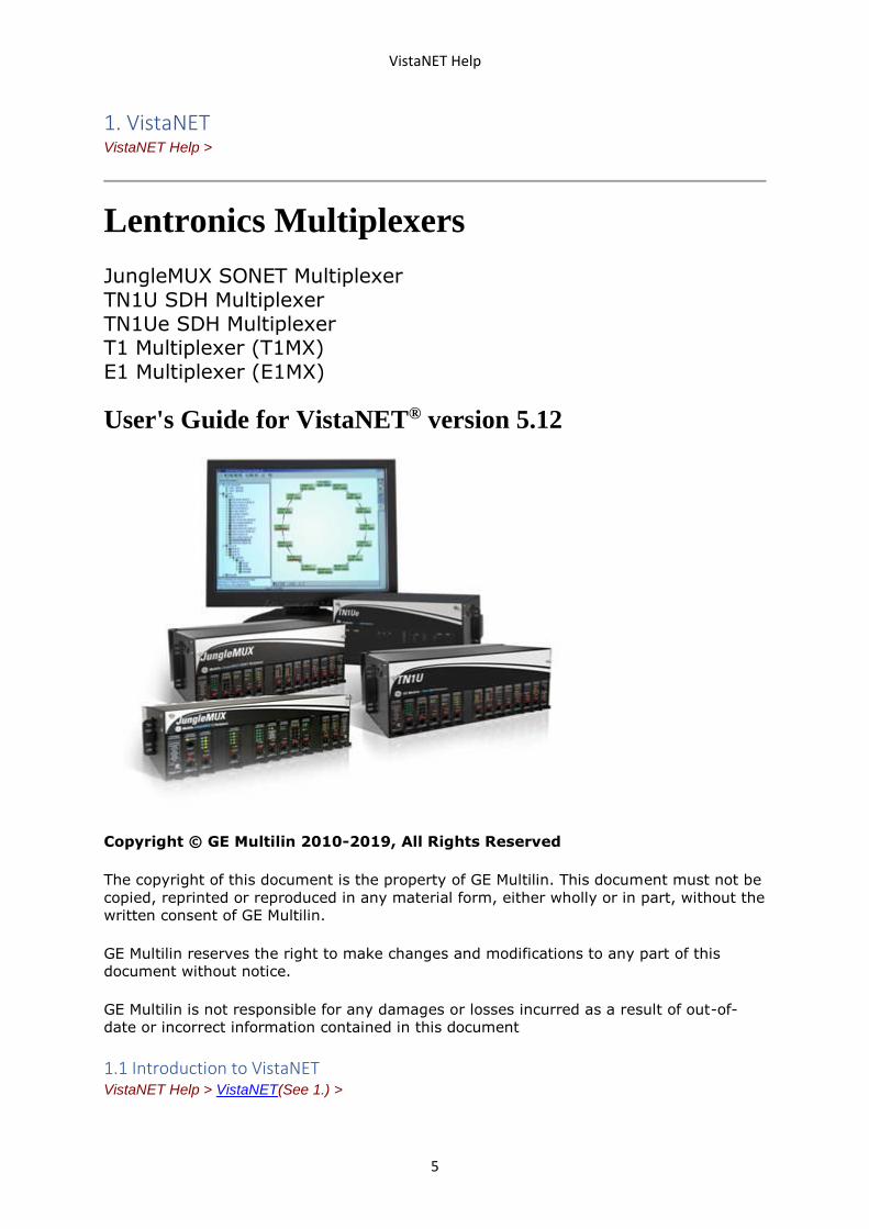
Lentronics Multiplexers
JungleMUX SONET Multiplexer TN1U SDH Multiplexer TN1Ue SDH Multiplexer T1 Multiplexer (T1MX) E1 Multiplexer (E1MX)
User's Guide for VistaNET® version 5.12
Copyright © GE Multilin 2010-2019, All Rights Reserved
The copyright of this document is the property of GE Multilin. This document must not be
copied, reprinted or reproduced in any material form, either wholly or in part, without the
written consent of GE Multilin.
GE Multilin reserves the right to make changes and modifications to any part of this
document without notice.
GE Multilin is not responsible for any damages or losses incurred as a result of out-of-
date or incorrect information contained in this document
1.1 Introduction to VistaNET VistaNET Help > VistaNET(See 1.) >
VistaNET Help
6
Welcome to the User’s guide for the VistaNET suite of software programs. VistaNET is an
enhanced set of Network Management System (NMS) tools for the Lentronics
Multiplexers family of products, which includes JungleMUX SONET Multiplexers, TN1U and
TN1Ue SDH Multiplexers, and JungleMUX T1 Multiplexers. Lentronics Multiplexers are
designed specifically for the requirements of the utility industry (Power, Transportation,
Pipelines, Oil & Gas, etc.).
VistaNET provides centralized network management capability for both contiguous and
non-contiguous networks whose size may range from a few to hundreds of Lentronics
Multiplexer nodes. NMS domain may include one or more contiguous rings and/or linear
systems where NMS information is passed between them by means of dedicated NMS tie
cables.
The NMS communication with a Lentronics Multiplexer network can take place through a
direct cable connection, a traditional dialup (modem) connection or through a high-speed
corporate LAN/WAN.
VistaNET software, along with NMS properties built in the Lentronics Multiplexers
themselves, allows for remote monitoring and configuring of any node from any other
node in the same Lentronics Multiplexer NMS domain.
Moreover, it allows for simultaneous monitoring and configuring from more than one
node. Multiple user access allows maintenance personnel in different parts of the network
to have real time information of the network for testing and troubleshooting.
Note: The number of NMS access points should be kept as low as possible to improve
efficiency.
1.1.1 Features VistaNET Help > VistaNET(See 1.) > Introduction to VistaNET(See 1.1) >
Most important VistaNET features are listed below. Note that the actual set of features
available depends on the purchased licenses.
• Ability to remotely monitor and configure all Lentronics Multiplexer units presently
offered in the Lentronics Multiplexers product portfolio. Note: Orderwire and
Partyline units do not support NMS communications.
• Ability to connect to a Lentronics Multiplexer node through a serial RS-232
connection (locally or remotely) or through an IP connection (locally or remotely).
Note: The serial RS-232 connection may be a local (hardwire) connection, a dialup
(modem) connection, or an RS-232 circuit routed through a Lentronics Multiplexer
network using Data-LS units at both ends.
• Ability to provide redundant NMS communication paths.
• Ability to "discover" Lentronics Multiplexer network inventory.
• Powerful alarm engine, which provides:
o Logging, stamping and automatic saving of alarm/alert conditions
o Alarm filtering by node, ring or network
o Audible tone for new alarms
• GUI with system tree and system map for easy network navigation.
• Name aliasing for rings, nodes and units.
VistaNET Help
7
• Synchronization of discovered network data, user profiles, name aliases, network
map layouts, alarm history, configuration history and licensing data between
networked VistaNET PCs.
• Simultaneous configuring of multiple unit parameters.
• Enhanced product security including:
o Mandatory user login for configuration changes
o Different configuration priveleges that can be applied at the ring, node, or
unit level for different user groups
o Activity log (e.g., configuration history)
o Database tampering prevention
• Allows 'copy & paste' of unit configuration settings to the units of the same type.
• Supports upload/download of unit configuration settings to/from a file.
• Allows for "undoing" previous configurations changes.
• Simultaneous viewing of near and far end units to aid troubleshooting.
• Provides optional server functionality to allow full visibility of the Lentronics
Multiplexer network to the users without direct connectivity to the network.
• Ability to generate inventory report for the whole network, or for a selected ring
or node.
1.1.2 Components VistaNET Help > VistaNET(See 1.) > Introduction to VistaNET(See 1.1) >
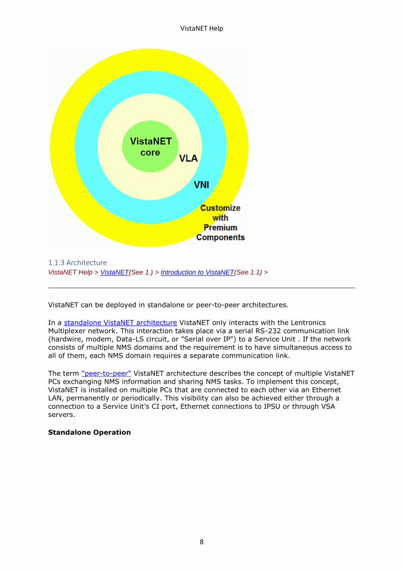
VistaNET is a platform which allows building a customized NMS solution to suit the needs
of the organization. It is extendable and supports two main components and several
premium components.
The main components include:
• VistaNET Local Access (VLA) – a local provisioning package, which allows local and
remote monitoring of all units visible through NMS when the PC is connected to a
Service Unit CI port. Units can be configured using local connections only.
• VistaNET Network Interface (VNI) – a package that, in addition to local
provisioning, supports network monitoring and remote configuring of all units
visible through NMS.
VistaNET cannot operate unless one of the two main components is activated. By
activating VNI, the VLA component is also activated. Therefore, VLA is considered a
subset of VNI.
Premium components presently include:
• VistaNET Server Application (VSA) - a software component which adds server
functionality to a PC serially connected to a Lentronics Multiplexer network so that
other VistaNET PCs without such connection can perform network monitoring and
remote unit configuring over an IP network. Lentronics Multiplexer network can be
a hardwire, modem, Data-LS or "Serial-over-IP" connection.
• Alternate Traffic Routing (ATR) - a component that provides a network
administrator with the capability to create, store and execute alternate traffic
routing scenarios for delivery of critical telecommunication services. Requires use
of optical aggregate units supporting this feature.
• VistaNET SNMP (VSNMP) - a component that converts Lentronics Multiplexer
alarms received in the VistaNET alarm engine into SNMP traps that are sent to a
user-defined list of SNMP managers.
VistaNET Help
8
1.1.3 Architecture VistaNET Help > VistaNET(See 1.) > Introduction to VistaNET(See 1.1) >
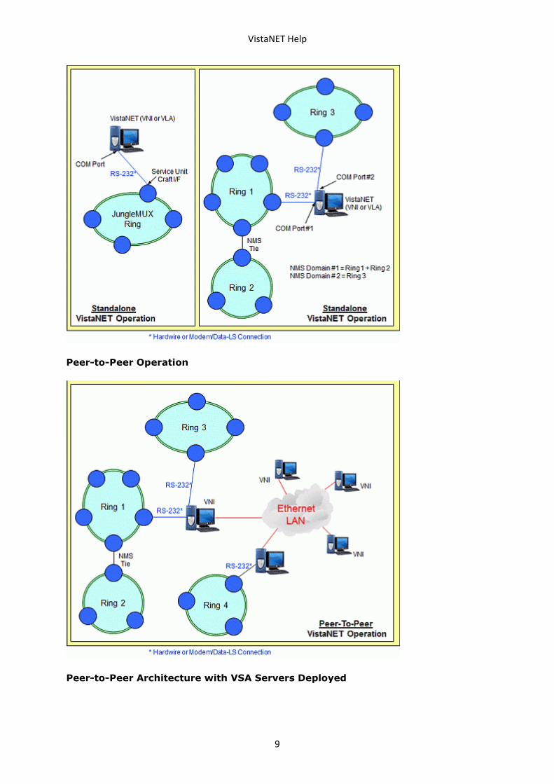
VistaNET can be deployed in standalone or peer-to-peer architectures.
In a standalone VistaNET architecture VistaNET only interacts with the Lentronics
Multiplexer network. This interaction takes place via a serial RS-232 communication link
(hardwire, modem, Data-LS circuit, or "Serial over IP") to a Service Unit . If the network
consists of multiple NMS domains and the requirement is to have simultaneous access to
all of them, each NMS domain requires a separate communication link.
The term "peer-to-peer" VistaNET architecture describes the concept of multiple VistaNET
PCs exchanging NMS information and sharing NMS tasks. To implement this concept,
VistaNET is installed on multiple PCs that are connected to each other via an Ethernet
LAN, permanently or periodically. This visibility can also be achieved either through a
connection to a Service Unit’s CI port, Ethernet connections to IPSU or through VSA
servers.
Standalone Operation
VistaNET Help
9
Peer-to-Peer Operation
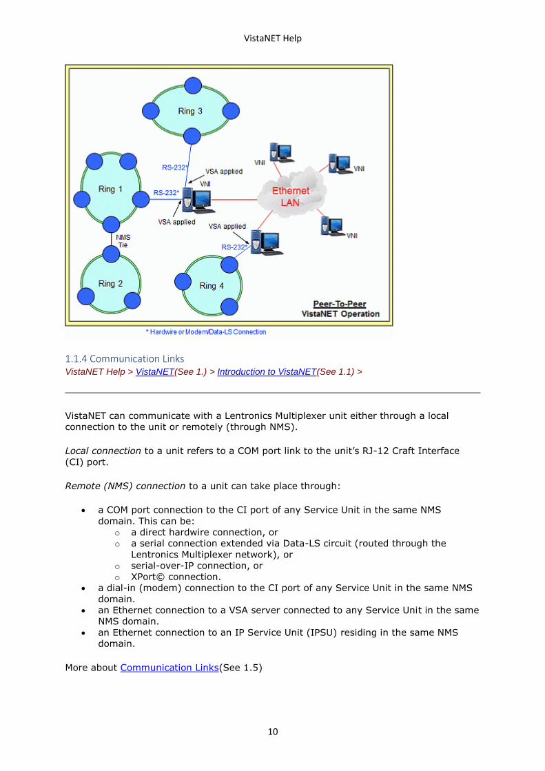
Peer-to-Peer Architecture with VSA Servers Deployed
VistaNET Help
10
1.1.4 Communication Links VistaNET Help > VistaNET(See 1.) > Introduction to VistaNET(See 1.1) >
VistaNET can communicate with a Lentronics Multiplexer unit either through a local
connection to the unit or remotely (through NMS).
Local connection to a unit refers to a COM port link to the unit’s RJ-12 Craft Interface
(CI) port.
Remote (NMS) connection to a unit can take place through:
• a COM port connection to the CI port of any Service Unit in the same NMS
domain. This can be:
o a direct hardwire connection, or
o a serial connection extended via Data-LS circuit (routed through the
Lentronics Multiplexer network), or
o serial-over-IP connection, or
o XPort© connection.
• a dial-in (modem) connection to the CI port of any Service Unit in the same NMS
domain.
• an Ethernet connection to a VSA server connected to any Service Unit in the same
NMS domain.
• an Ethernet connection to an IP Service Unit (IPSU) residing in the same NMS
domain.
More about Communication Links(See 1.5)
VistaNET Help
11
1.1.5 License VistaNET Help > VistaNET(See 1.) > Introduction to VistaNET(See 1.1) >
VistaNET license file is a customer-specific license file, which is the key that activates the
VistaNET product, registers it to a specific organization and defines the program’s
functionality.
The license file is prepared by General Electric for each customer. It contains the
customer organization name, administrator’s initial password as well as licenses for the
purchased VistaNET components.
Information stored in the license file must be 'transferred' to each VistaNET PC upon
installation to activate the program.
If the customer desires to activate additional VistaNET components at a later date, a new
license file with respective additional licenses must be obtained from General Electric.
1.1.6 Related Publication and Documentation Support VistaNET Help > VistaNET(See 1.) > Introduction to VistaNET(See 1.1) >
Useful information is provided in JungleMUX / TN1U / TN1Ue Technical Overview and
Reference Manuals as well as Technical Practice and Installation Manuals (TPIMs) for
individual Lentronics Multiplexer units. Readers should especially familiarize themselves
with the 86434 Service Unit / IP Service Unit Technical Practice and Installation Manual
since the Service and IP Service Units provide NMS interface function between Lentronics
Multiplexers and VistaNET.
Customer inquiries for information contained in this manual should be directed to the
Lentronics Multiplexer customer support department.
1.1.7 Known Limitations
1. Rediscover the unit every time its Rack/Shelf/Slot information was changed
through local configuration.
2. It is not allowed to have an XPort and a Craft Interface connection to the same
Service unit at the same time. If attempted, one or both connections from
VistaNET may become unresponsive and the results will be unpredictable.
3. After upgrading from an older version of VistaNET, it can be observed that the
tree is empty and all previously discovered by older version of VistaNET inventory
is missing.
Workaround: Rediscover all network. Note that all aliases will be preserved and
rediscovery is needed only after the upgrade.
1.1.8 Known Deficiencies VistaNET Help > VistaNET(See 1.) > Introduction to VistaNET(See 1.1) >
The following deficiencies identified in previous versions of VistaNET remain outstanding,
with plans to correct in future versions:
VistaNET Help
12
1. After upgrading from VistaNET versions 3.00 or later, you must rediscover the
existing network in order to populate database with required data. This discovery
is required for the nodes containing CDAXes, to properly obtain and store CDAX
side information. Also, the discovery is needed to obtain and store units' Serial
Numbers to properly refresh the tree.
2. In VNI/VSA networks, restart VistaNET anytime the IP address of the VSA
machine changes (for example, from 127.0.0.1 to the external address). Failure
to do so may cause some nodes to appear as if they are visible, even if they are
not, due to the node controllers for the port not being updated properly in the
database. Workaround: Restart VistaNET after the IP address changes.
3. In JIFshare, after physically adding a new DS0 unit or clearing DS0 channel table,
allow couple minutes before initiating discovery on the node this JIFshare belongs
to. JIFshare requires some time to obtain DS0 unit information required for
discovery. If discovery is performed too fast, JIFshare may return incorrect
discovery results: presents non-existing units or misses existing units.
Workaround: If first discovery is incorrect, do rediscover to correct the issue. Or,
wait for up to 1 minute before initiating discovery after making changes to
JIFshare DS0 channel table.
4. VistaNET 4.00 or newer is supported only on Windows XP or newer OS.
1.2 Getting Started
In order to get VistaNET up and running, there are some actions that need to be
performed and some requirements that need to be followed.
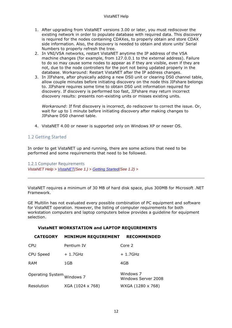
1.2.1 Computer Requirements VistaNET Help > VistaNET(See 1.) > Getting Started(See 1.2) >
VistaNET requires a minimum of 30 MB of hard disk space, plus 300MB for Microsoft .NET
Framework.
GE Multilin has not evaluated every possible combination of PC equipment and software
for VistaNET operation. However, the listing of computer requirements for both
workstation computers and laptop computers below provides a guideline for equipment
selection.
VistaNET WORKSTATION and LAPTOP REQUIREMENTS
CATEGORY MINIMUM REQUIREMENT RECOMMENDED
CPU Pentium IV Core 2
CPU Speed + 1.7GHz + 1.7GHz
RAM 1GB 4GB
Operating System
Windows 7 Windows 7
Windows Server 2008
Resolution XGA (1024 x 768) WXGA (1280 x 768)
VistaNET Help
13
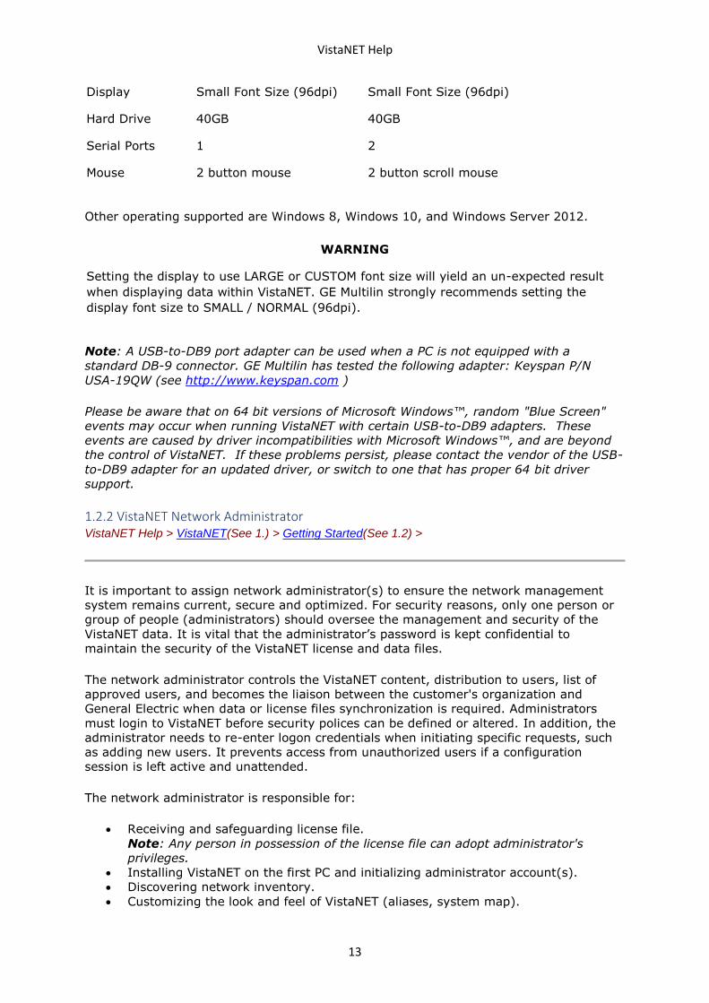
Display Small Font Size (96dpi) Small Font Size (96dpi)
Hard Drive 40GB 40GB
Serial Ports 1 2
Mouse 2 button mouse 2 button scroll mouse
Other operating supported are Windows 8, Windows 10, and Windows Server 2012.
WARNING
Setting the display to use LARGE or CUSTOM font size will yield an un-expected result
when displaying data within VistaNET. GE Multilin strongly recommends setting the
display font size to SMALL / NORMAL (96dpi).
Note: A USB-to-DB9 port adapter can be used when a PC is not equipped with a
standard DB-9 connector. GE Multilin has tested the following adapter: Keyspan P/N
USA-19QW (see http://www.keyspan.com )
Please be aware that on 64 bit versions of Microsoft Windows™, random "Blue Screen"
events may occur when running VistaNET with certain USB-to-DB9 adapters. These
events are caused by driver incompatibilities with Microsoft Windows™, and are beyond
the control of VistaNET. If these problems persist, please contact the vendor of the USB-
to-DB9 adapter for an updated driver, or switch to one that has proper 64 bit driver
support.
1.2.2 VistaNET Network Administrator VistaNET Help > VistaNET(See 1.) > Getting Started(See 1.2) >
It is important to assign network administrator(s) to ensure the network management
system remains current, secure and optimized. For security reasons, only one person or
group of people (administrators) should oversee the management and security of the
VistaNET data. It is vital that the administrator’s password is kept confidential to
maintain the security of the VistaNET license and data files.
The network administrator controls the VistaNET content, distribution to users, list of
approved users, and becomes the liaison between the customer's organization and
General Electric when data or license files synchronization is required. Administrators
must login to VistaNET before security polices can be defined or altered. In addition, the
administrator needs to re-enter logon credentials when initiating specific requests, such
as adding new users. It prevents access from unauthorized users if a configuration
session is left active and unattended.
The network administrator is responsible for:
• Receiving and safeguarding license file.
Note: Any person in possession of the license file can adopt administrator's
privileges.
• Installing VistaNET on the first PC and initializing administrator account(s).
• Discovering network inventory.
• Customizing the look and feel of VistaNET (aliases, system map).
VistaNET Help
14
• Creating and maintaining user accounts.
• Configuring restrictions for individual user groups.
• Supervising VistaNET installation on other users' PCs.
• Integrating purchased VistaNET components (e.g. enabling VSA ports on
designated PCs, enabling SNMP functionality on designated PCs etc.).
• Working closely with IT department to ensure proper IP communications between
distributed VistaNET services (if applicable).
• Coordinating distribution of new VistaNET releases/updates.
• Performing regular local data file backups (critical for standalone VistaNET
applications).
Note: GE Multilin recommends that administrative changes are made on a PC that is
connected to the customer’s LAN, with connection to remote services enabled.
Administrative changes that are made while the PC is disconnected from remote VistaNET
services will not take effect until the PC is connected to the LAN.
1.2.3 Installing VistaNET VistaNET Help > VistaNET(See 1.) > Getting Started(See 1.2) >
VistaNET core load installation can be performed from a setup file downloaded from the
GE Multilin website.
Downloading VistaNET Setup File from the Web
1. Go to the JMUX website (www.jmux.com).
2. Click on the Login button under Existing Customers. The website requires a
security login name and password. If you do not have a user name and password,
click on New Users click here, complete the form, and click on Submit
3. Go to the Software tab and click on the VistaNET Software Download link. You will
be prompted to either Run or Save the VistaNET_xxx_setup.msi file (xxx is the
current VistaNET version).
4. Click on Save to store the file to your PC. (GE Multilin recommends that you save
the file to a disk and run it from the PC.) Select a location where the file will be
saved, and click on OK to save it.
5. Locate the saved file (VistaNET_xxx_setup.msi) and run it by double-clicking on
it.
6. Go to the Executing VistaNET Setup File section .
The JMUX website contains additional information on other VistaNET product offerings,
the product activation process and the software license agreement.
Executing VistaNET Setup File
The following procedure assumes that the procedure described above (Downloading
VistaNET Setup File from the Web) has been completed.
You might be prompted to install Microsoft .NET framework version based on the
VistaNET version being installed, if you computer does not have one installed yet.
Note: The user needs to install Microsoft .NET Framework only once. Updates of
VistaNET do not require repeated .NET installations, unless the .NET Framework version
has been incremented for the version of VistaNET being installed.
VistaNET Help
15
WARNING
In order to install VistaNET, the installer requires to be run with Windows administrator
privilege.
Installation of a new VistaNET version can be performed directly over a previous copy
(see Upgrading VistaNET(See 1.2.8) for instructions regarding VistaNET versions). The
data file, which retains specific network information (user profiles, ring and node name
aliases, map positioning etc.), is not affected by this upgrade.
7. Click Next to start the installation.
8. Click to Accept the agreement and then click Next.
Note : The user's agreement to the software licensing is required to proceed with
VistaNET installation.
9. Click Finish.
10. Verify that the VistaNET icon appears on the desktop.
Note: The VistaNET.exe file is located in C:\ Program Files \ GE \ VistaNET.
1.2.4 Licensing & Activating VistaNET VistaNET Help > VistaNET(See 1.) > Getting Started(See 1.2) >
VistaNET 5.00 supports new XML-based license format. The new licenses are digitally
signed and have an expiry date. Moreover, a two-factor initialization is required in order
to validate the new license. In order to use VistaNET 5.0, you need to:
• Request a new license file
• Obtain a PIN associated with this license file
Once VistaNET is started, users are prompted to synchronize with the new license file
(.lic). If the license is valid (i.e. has not expired), the contents of the existing database
are encrypted and VistaNET will run normally, however the software must still be
activated. For the first VistaNET installation in a network, the activation process consists
of entering the PIN, and then creating one or more administrator accounts. For
subsequent installations, VistaNET can be synchronized over the network to an activated
installation. These steps are explained in the subpages of this section of the help file.
1.2.4.1 License File VistaNET Help > VistaNET(See 1.) > Getting Started(See 1.2) > Licensing & Activating VistaNET(See
1.2.4) >
The VistaNET license file used to activate and control licensed features has been changed
for VistaNET version 5.00. A new license file (issued by GE Digital Energy) will facilitate
improved security for VistaNET administrators and users in the following ways:
1. VistaNET activation requires two security factors, a license file (*.lic) and
activation PIN.
2. Previous copies of the VistaNET passport (company_name.psr, .dat or .db3 files)
will not successfully activate this version of VistaNET.
3. The new license file contains no default users. Distribution of this license file is
recommended and will successfully start VistaNET, but prevents equipment
configuration because it contains no users or user privileges.
VistaNET Help
16
o An Activation PIN is required to add users and privileges (typically
performed on a 24/7 VistaNET service by the VistaNET administrator).
o Successful synchronization to a VistaNET service containing users and user
privileges is another acceptable method of activating remote VistaNET
instances.
4. The license file is digitally signed, and as such, authentication is verifiable.
5. The license file also contains an expiry date (36 months by default, but
configurable from 1 month to 60 months), preventing activation of VistaNET with
the underlying base code, and preventing normal VistaNET operation. This will
ensure that uncontrolled copies of the license file are (in time) rendered
inoperable.
6. An activation PIN used to activate VistaNET expires after a defined period,
preventing activation of VistaNET with the license file (3 months by default, but
configurable from 1 month to 60 months).
A representative (VistaNET administrator) from each organization will need to register for
a new VistaNET License file. This file is in an XML format following this naming
convention “company_name.lic”.
1.2.4.2 Applying for License VistaNET Help > VistaNET(See 1.) > Getting Started(See 1.2) > Licensing & Activating VistaNET(See
1.2.4) >
The core VistaNET program must be activated with an appropriate set of licenses before
any feature is usable. The license file is only required to activate a new installation of
VistaNET.
Each company requires a license file to activate the program. The VistaNET license file is
provided to the primary network administrator. Only one license is required per
organization. Administrators should retain this license file and not distribute it to all
users.
The file contains the following information:
• A temporary username and password to allow the network administrator(s) to log
into administrative setup screens to add user accounts.
• An approved company name that displays on each session of VistaNET running
within that organization.
• A list of Right-to-Use (RTU) licenses for VistaNET components purchased from GE.
To obtain a VistaNET license file, visit the Lentronics Multiplexers website
(www.jmux.com) and refer to the VistaNET Passport Registration Process - Readme or
submit a VistaNET Passport Registration form:
• Click on the 'Existing Customers' login button.
• Click on the "Software" link.
• Select the "VistaNET Passport Registration Form" link.
• Complete all fields on the form. You can add up to 5 network administrators. One
must be 'marked' as the primary administrator.
• Specify desired PIN and LICENSE file expiration dates.
• Click the "Submit" button to request a VistaNET license.
Note: The recipient list for VistaNET correspondence will include each administrator
added to the application. You may only apply for one license . Once you submit the form,
VistaNET Help
17
any requests to change the information entered must be made via e-mail to:
For customers experiencing any difficulty obtaining a license, or if contact details for
administrators change, please contact Lentronics ETAC department:
• ETAC Phone Number: (604) 421 8610
• VistaNET E-Mail: [email protected]
1.2.4.3 Licensing VistaNET VistaNET Help > VistaNET(See 1.) > Getting Started(See 1.2) > Licensing & Activating VistaNET(See
1.2.4) >
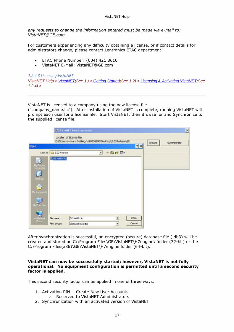
VistaNET is licensed to a company using the new license file
(“company_name.lic”). After installation of VistaNET is complete, running VistaNET will
prompt each user for a license file. Start VistaNET, then Browse for and Synchronize to
the supplied license file.
After synchronization is successful, an encrypted (secure) database file (.db3) will be
created and stored on C:\Program Files\GE\VistaNET\H7engine\ folder (32-bit) or the
C:\Program Files(x86)\GE\VistaNET\H7engine folder (64-bit).
VistaNET can now be successfully started; however, VistaNET is not fully
operational. No equipment configuration is permitted until a second security
factor is applied.
This second security factor can be applied in one of three ways:
1. Activation PIN + Create New User Accounts
o Reserved to VistaNET Administrators
2. Synchronization with an activated version of VistaNET
VistaNET Help
18
o Recommended for general VistaNET users
3. Supply remote VistaNET instances with a secure db3 file
o Recommended for remote VistaNET users without network access to a
centralized VistaNET service. Windows™ administrative privileges are
required.
1.2.4.4 24/7 VistaNET PC VistaNET Help > VistaNET(See 1.) > Getting Started(See 1.2) > Licensing & Activating VistaNET(See
1.2.4) >
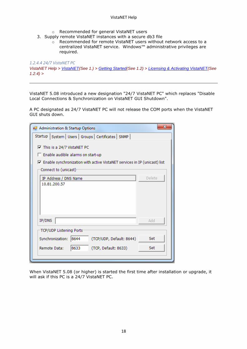
VistaNET 5.08 introduced a new designation "24/7 VistaNET PC" which replaces "Disable
Local Connections & Synchronization on VistaNET GUI Shutdown".
A PC designated as 24/7 VistaNET PC will not release the COM ports when the VistaNET
GUI shuts down.
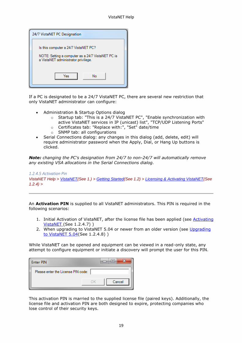
When VistaNET 5.08 (or higher) is started the first time after installation or upgrade, it
will ask if this PC is a 24/7 VistaNET PC.
VistaNET Help
19
If a PC is designated to be a 24/7 VistaNET PC, there are several new restriction that
only VistaNET administrator can configure:
• Administration & Startup Options dialog
o Startup tab: "This is a 24/7 VistaNET PC", "Enable synchronization with
active VistaNET services in IP (unicast) list", "TCP/UDP Listening Ports"
o Certificates tab: "Replace with:", "Set" date/time
o SNMP tab: all configurations
• Serial Connections dialog: any changes in this dialog (add, delete, edit) will
require administrator password when the Apply, Dial, or Hang Up buttons is
clicked.
Note: changing the PC's designation from 24/7 to non-24/7 will automatically remove
any existing VSA allocations in the Serial Connections dialog.
1.2.4.5 Activation Pin VistaNET Help > VistaNET(See 1.) > Getting Started(See 1.2) > Licensing & Activating VistaNET(See
1.2.4) >
An Activation PIN is supplied to all VistaNET administrators. This PIN is required in the
following scenarios:
1. Initial Activation of VistaNET, after the license file has been applied (see Activating
VistaNET (See 1.2.4.7) )
2. When upgrading to VistaNET 5.04 or newer from an older version (see Upgrading
to VistaNET 5.04(See 1.2.4.8) )
While VistaNET can be opened and equipment can be viewed in a read-only state, any
attempt to configure equipment or initiate a discovery will prompt the user for this PIN.
This activation PIN is married to the supplied license file (paired keys). Additionally, the
license file and activation PIN are both designed to expire, protecting companies who
lose control of their security keys.
VistaNET Help
20
RECOMMENDATION: GE strongly recommends that the activation PIN be
protected, and NOT distributed .
1.2.4.6 VistaNET Login System VistaNET Help > VistaNET(See 1.) > Getting Started(See 1.2) > Licensing & Activating VistaNET(See
1.2.4) >
Beginning with VistaNET 5.04, the stand-alone VistaNET user accounts have been
replaced with accounts linked to an existing authentication service. There are two types
of linked accounts: Network User and Local User. They are described below.
When installing or upgrading to VistaNET 5.04 or later, the administrator is required to
create at least one linked administrative account before VistaNET will be functional. This
process is described in the following sections. For new VistaNET installations, please refer
to the section Activating VistaNET(See 1.2.4.7). For upgrading to VistaNET 5.04 or later,
please refer to the section Upgrading to VistaNET 5.04(See 1.2.4.8).
Types of linked accounts
• Network User
An account linked to a corporate network domain, such as Active Directory. This method
is strongly recommended for maximum security. This method allows users to log in from
any VistaNET PC connected to the corporate domain, or an offline PC with cached
credentials.
Under default settings, Windows caches encrypted login information for the 10 most
recent users that have logged in. This information allows users to subsequently log
into the PC with their network accounts even when the PC has been disconnected from
the network. VistaNET can use this information to access a linked network account
without network access. This behavior is enabled by default and requires no action from
the administrator.
• Local User
An account linked to a local Windows user account. This method is less secure and should
only be used if Network User accounts are unavailable. This method allows users to log in
only from the PC on which the linked Windows user account exists.
A word of caution
Linked accounts are permanently associated with the domain they are selected from.
When a company is planning changes to their network domain or any other network
change that will affect users' network accounts, it is extremely important for the
VistaNET admins to be involved early on in this process. If it occurs that all of the admin
accounts in a VistaNET database are linked to domains that become inaccessible, the
VistaNET database will become inaccessible -- along with all of the data contained in it:
user information and permissions, discovered units, aliases, etc. The admins can prevent
this situation by ensuring a VistaNET admin account is created for the new domain before
the old domain has been retired.
VistaNET Help
21
Creating a linked account
VistaNET 5.04 includes an interactive Add User Wizard that streamlines the process of
creating linked accounts. There are two contexts in which user accounts can be added:
• creating one or more administrator accounts when first installing or upgrading to
VistaNET 5.04 or newer (see Activating VistaNET(See 1.2.4.7) or Upgrading to
VistaNET 5.04(See 1.2.4.8)), or
• adding additional users later (see VistaNET User Interface > Administration
& Startup Options > Users Tab(See 1.4.11.3) )
This section steps through the Add User Wizard.
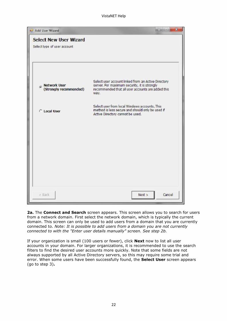
1. The first screen determines the type of domain from which the account will be
selected. Select either Network User or Local User and click Next. For instructions on
adding a Network User, continue with step 2a. For instructions on adding a Local User,
skip to step 2b below.
VistaNET Help
22
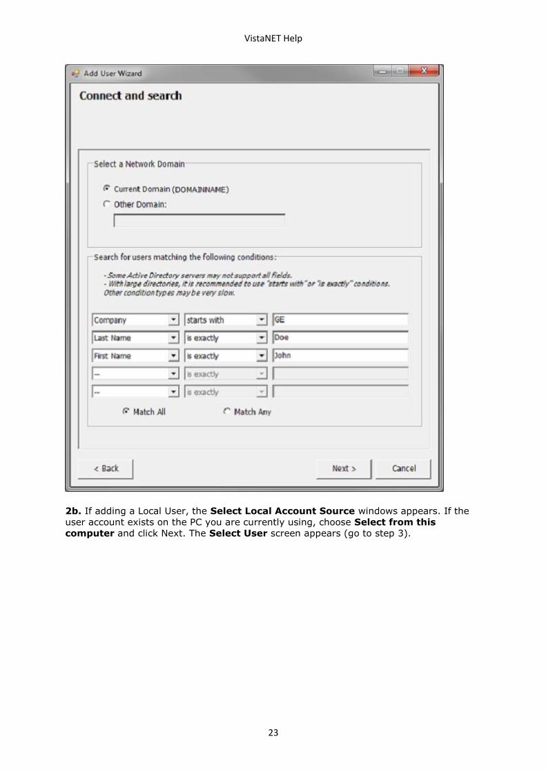
2a. The Connect and Search screen appears. This screen allows you to search for users
from a network domain. First select the network domain, which is typically the current
domain. This screen can only be used to add users from a domain that you are currently
connected to. Note: It is possible to add users from a domain you are not currently
connected to with the "Enter user details manually" screen. See step 2b.
If your organization is small (100 users or fewer), click Next now to list all user
accounts in your domain. For larger organizations, it is recommended to use the search
filters to find the desired user accounts more quickly. Note that some fields are not
always supported by all Active Directory servers, so this may require some trial and
error. When some users have been successfully found, the Select User screen appears
(go to step 3).
VistaNET Help
23
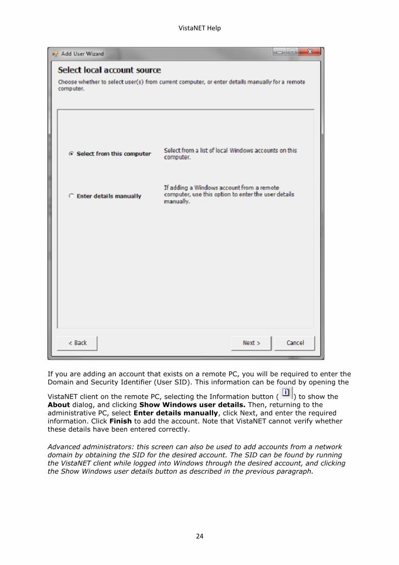
2b. If adding a Local User, the Select Local Account Source windows appears. If the
user account exists on the PC you are currently using, choose Select from this
computer and click Next. The Select User screen appears (go to step 3).
VistaNET Help
24
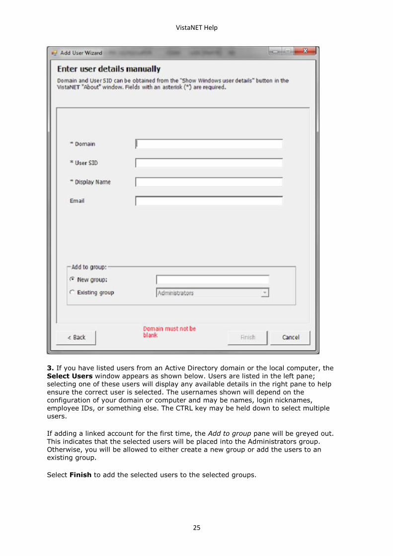
If you are adding an account that exists on a remote PC, you will be required to enter the
Domain and Security Identifier (User SID). This information can be found by opening the
VistaNET client on the remote PC, selecting the Information button ( ) to show the
About dialog, and clicking Show Windows user details. Then, returning to the
administrative PC, select Enter details manually, click Next, and enter the required
information. Click Finish to add the account. Note that VistaNET cannot verify whether
these details have been entered correctly.
Advanced administrators: this screen can also be used to add accounts from a network
domain by obtaining the SID for the desired account. The SID can be found by running
the VistaNET client while logged into Windows through the desired account, and clicking
the Show Windows user details button as described in the previous paragraph.
VistaNET Help
25
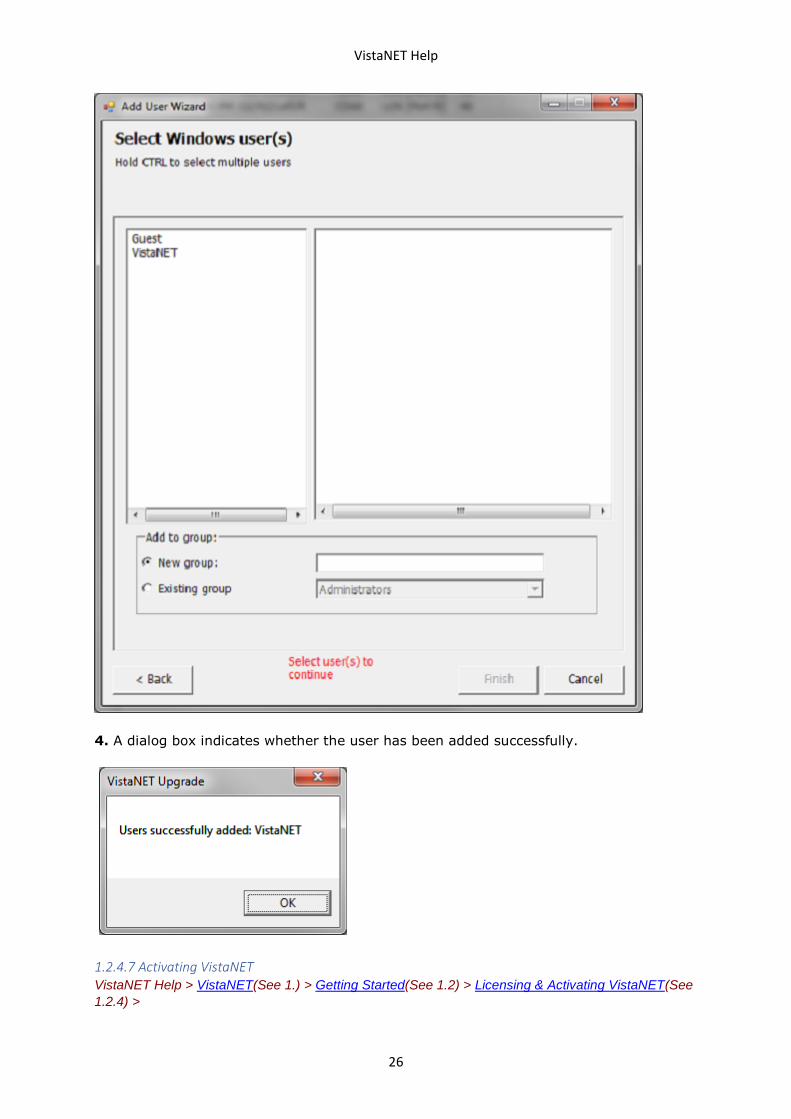
3. If you have listed users from an Active Directory domain or the local computer, the
Select Users window appears as shown below. Users are listed in the left pane;
selecting one of these users will display any available details in the right pane to help
ensure the correct user is selected. The usernames shown will depend on the
configuration of your domain or computer and may be names, login nicknames,
employee IDs, or something else. The CTRL key may be held down to select multiple
users.
If adding a linked account for the first time, the Add to group pane will be greyed out.
This indicates that the selected users will be placed into the Administrators group.
Otherwise, you will be allowed to either create a new group or add the users to an
existing group.
Select Finish to add the selected users to the selected groups.
VistaNET Help
26
4. A dialog box indicates whether the user has been added successfully.
1.2.4.7 Activating VistaNET VistaNET Help > VistaNET(See 1.) > Getting Started(See 1.2) > Licensing & Activating VistaNET(See
1.2.4) >
VistaNET Help
27
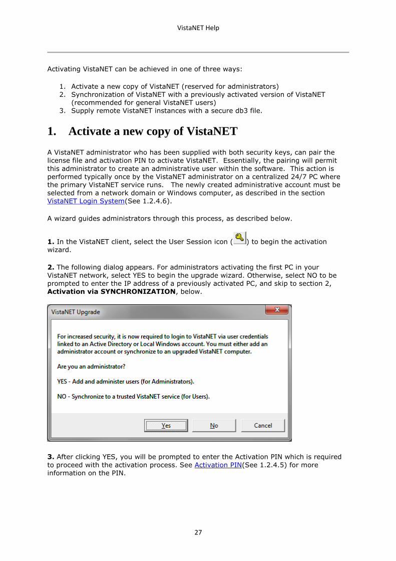
Activating VistaNET can be achieved in one of three ways:
1. Activate a new copy of VistaNET (reserved for administrators)
2. Synchronization of VistaNET with a previously activated version of VistaNET
(recommended for general VistaNET users)
3. Supply remote VistaNET instances with a secure db3 file.
1. Activate a new copy of VistaNET
A VistaNET administrator who has been supplied with both security keys, can pair the
license file and activation PIN to activate VistaNET. Essentially, the pairing will permit
this administrator to create an administrative user within the software. This action is
performed typically once by the VistaNET administrator on a centralized 24/7 PC where
the primary VistaNET service runs. The newly created administrative account must be
selected from a network domain or Windows computer, as described in the section
VistaNET Login System(See 1.2.4.6).
A wizard guides administrators through this process, as described below.
1. In the VistaNET client, select the User Session icon ( ) to begin the activation
wizard.
2. The following dialog appears. For administrators activating the first PC in your
VistaNET network, select YES to begin the upgrade wizard. Otherwise, select NO to be
prompted to enter the IP address of a previously activated PC, and skip to section 2,
Activation via SYNCHRONIZATION, below.
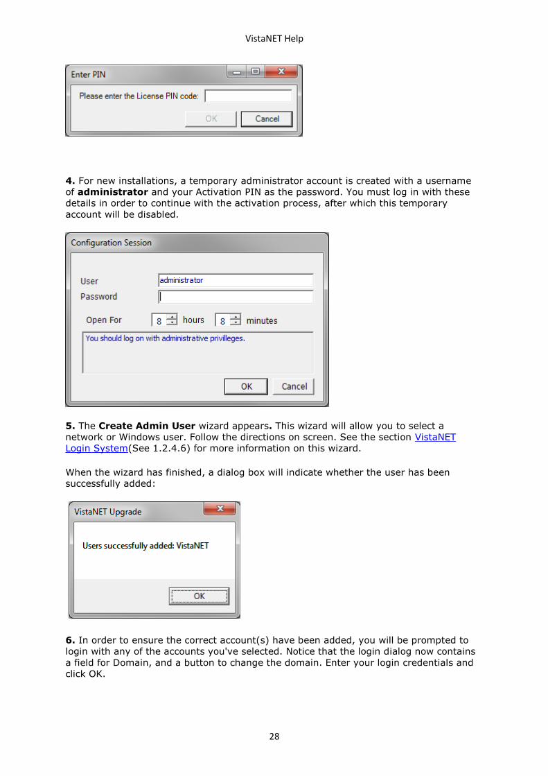
3. After clicking YES, you will be prompted to enter the Activation PIN which is required
to proceed with the activation process. See Activation PIN(See 1.2.4.5) for more
information on the PIN.
VistaNET Help
28
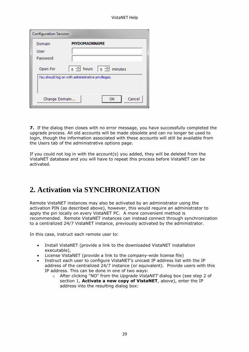
4. For new installations, a temporary administrator account is created with a username
of administrator and your Activation PIN as the password. You must log in with these
details in order to continue with the activation process, after which this temporary
account will be disabled.
5. The Create Admin User wizard appears. This wizard will allow you to select a
network or Windows user. Follow the directions on screen. See the section VistaNET
Login System(See 1.2.4.6) for more information on this wizard.
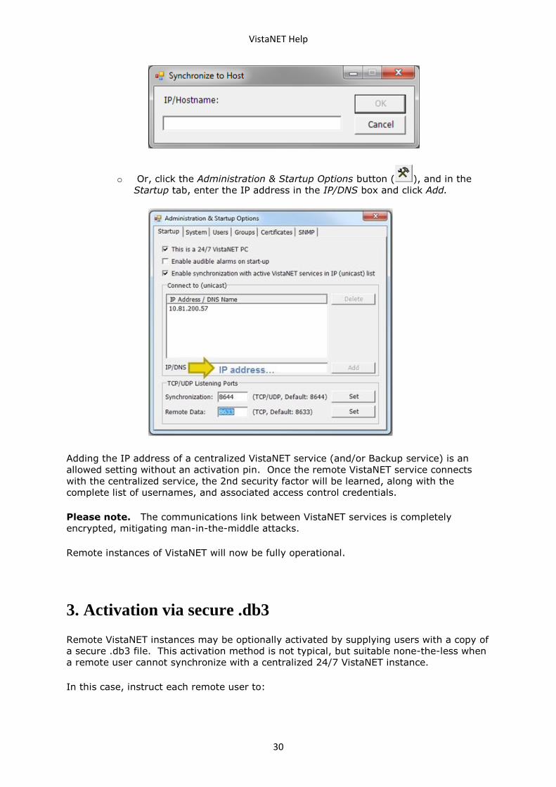
When the wizard has finished, a dialog box will indicate whether the user has been
successfully added:
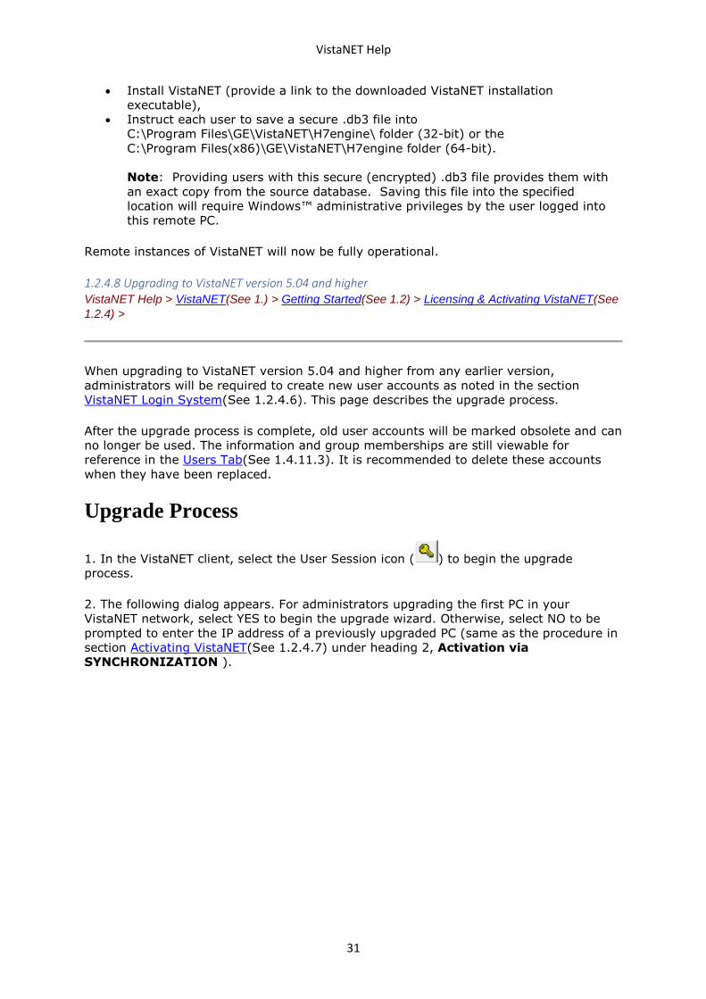
6. In order to ensure the correct account(s) have been added, you will be prompted to
login with any of the accounts you've selected. Notice that the login dialog now contains
a field for Domain, and a button to change the domain. Enter your login credentials and
click OK.
VistaNET Help
29
7. If the dialog then closes with no error message, you have successfully completed the
upgrade process. All old accounts will be made obsolete and can no longer be used to
login, though the information associated with these accounts will still be available from
the Users tab of the administrative options page.
If you could not log in with the account(s) you added, they will be deleted from the
VistaNET database and you will have to repeat this process before VistaNET can be
activated.
2. Activation via SYNCHRONIZATION
Remote VistaNET instances may also be activated by an administrator using the
activation PIN (as described above), however, this would require an administrator to
apply the pin locally on every VistaNET PC. A more convenient method is
recommended. Remote VistaNET instances can instead connect through synchronization
to a centralized 24/7 VistaNET instance, previously activated by the administrator.
In this case, instruct each remote user to:
• Install VistaNET (provide a link to the downloaded VistaNET installation
executable),
• License VistaNET (provide a link to the company-wide license file)
• Instruct each user to configure VistaNET’s unicast IP address list with the IP
address of the centralized 24/7 instance (or equivalent). Provide users with this
IP address. This can be done in one of two ways:
o After clicking "NO" from the Upgrade VistaNET dialog box (see step 2 of
section 1, Activate a new copy of VistaNET, above), enter the IP
address into the resulting dialog box:
VistaNET Help
30
o Or, click the Administration & Startup Options button ( ), and in the
Startup tab, enter the IP address in the IP/DNS box and click Add.
Adding the IP address of a centralized VistaNET service (and/or Backup service) is an
allowed setting without an activation pin. Once the remote VistaNET service connects
with the centralized service, the 2nd security factor will be learned, along with the
complete list of usernames, and associated access control credentials.
Please note. The communications link between VistaNET services is completely
encrypted, mitigating man-in-the-middle attacks.
Remote instances of VistaNET will now be fully operational.
3. Activation via secure .db3
Remote VistaNET instances may be optionally activated by supplying users with a copy of
a secure .db3 file. This activation method is not typical, but suitable none-the-less when
a remote user cannot synchronize with a centralized 24/7 VistaNET instance.
In this case, instruct each remote user to:
VistaNET Help
31
• Install VistaNET (provide a link to the downloaded VistaNET installation
executable),
• Instruct each user to save a secure .db3 file into
C:\Program Files\GE\VistaNET\H7engine\ folder (32-bit) or the
C:\Program Files(x86)\GE\VistaNET\H7engine folder (64-bit).
Note: Providing users with this secure (encrypted) .db3 file provides them with
an exact copy from the source database. Saving this file into the specified
location will require Windows™ administrative privileges by the user logged into
this remote PC.
Remote instances of VistaNET will now be fully operational.
1.2.4.8 Upgrading to VistaNET version 5.04 and higher VistaNET Help > VistaNET(See 1.) > Getting Started(See 1.2) > Licensing & Activating VistaNET(See
1.2.4) >
When upgrading to VistaNET version 5.04 and higher from any earlier version,
administrators will be required to create new user accounts as noted in the section
VistaNET Login System(See 1.2.4.6). This page describes the upgrade process.
After the upgrade process is complete, old user accounts will be marked obsolete and can
no longer be used. The information and group memberships are still viewable for
reference in the Users Tab(See 1.4.11.3). It is recommended to delete these accounts
when they have been replaced.
Upgrade Process
1. In the VistaNET client, select the User Session icon ( ) to begin the upgrade
process.
2. The following dialog appears. For administrators upgrading the first PC in your
VistaNET network, select YES to begin the upgrade wizard. Otherwise, select NO to be
prompted to enter the IP address of a previously upgraded PC (same as the procedure in
section Activating VistaNET(See 1.2.4.7) under heading 2, Activation via
SYNCHRONIZATION ).
VistaNET Help
32
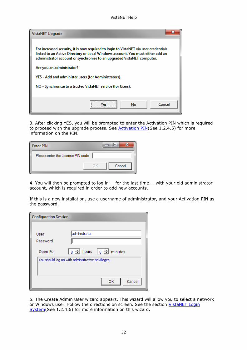
3. After clicking YES, you will be prompted to enter the Activation PIN which is required
to proceed with the upgrade process. See Activation PIN(See 1.2.4.5) for more
information on the PIN.
4. You will then be prompted to log in -- for the last time -- with your old administrator
account, which is required in order to add new accounts.
If this is a new installation, use a username of administrator, and your Activation PIN as
the password.
5. The Create Admin User wizard appears. This wizard will allow you to select a network
or Windows user. Follow the directions on screen. See the section VistaNET Login
System(See 1.2.4.6) for more information on this wizard.
VistaNET Help
33
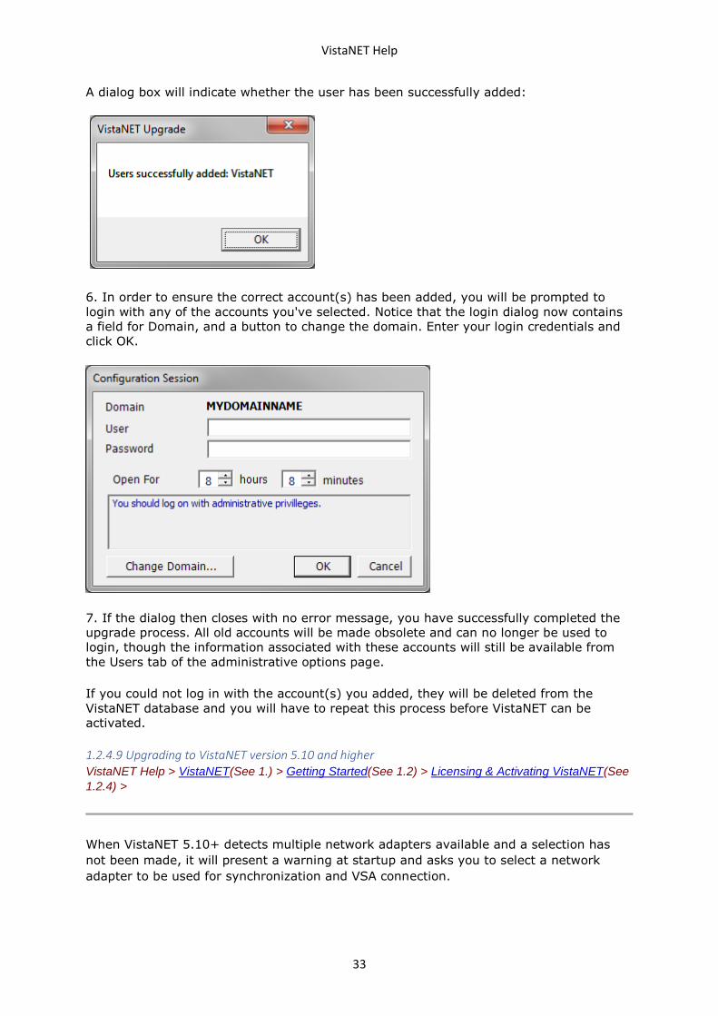
A dialog box will indicate whether the user has been successfully added:
6. In order to ensure the correct account(s) has been added, you will be prompted to
login with any of the accounts you've selected. Notice that the login dialog now contains
a field for Domain, and a button to change the domain. Enter your login credentials and
click OK.
7. If the dialog then closes with no error message, you have successfully completed the
upgrade process. All old accounts will be made obsolete and can no longer be used to
login, though the information associated with these accounts will still be available from
the Users tab of the administrative options page.
If you could not log in with the account(s) you added, they will be deleted from the
VistaNET database and you will have to repeat this process before VistaNET can be
activated.
1.2.4.9 Upgrading to VistaNET version 5.10 and higher VistaNET Help > VistaNET(See 1.) > Getting Started(See 1.2) > Licensing & Activating VistaNET(See
1.2.4) >
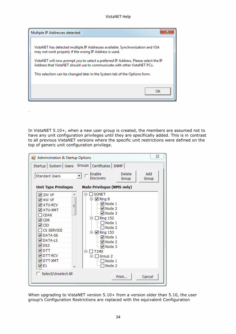
When VistaNET 5.10+ detects multiple network adapters available and a selection has
not been made, it will present a warning at startup and asks you to select a network
adapter to be used for synchronization and VSA connection.
VistaNET Help
34
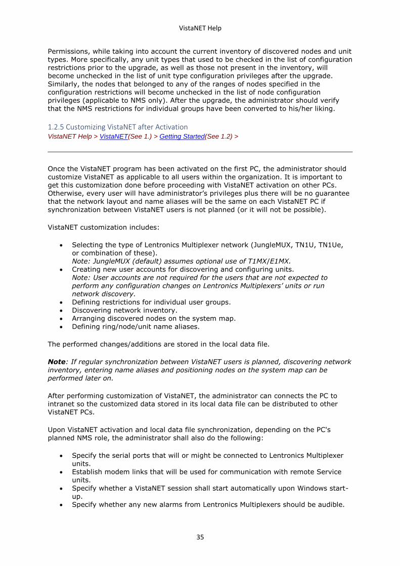
In VistaNET 5.10+, when a new user group is created, the members are assumed not to
have any unit configuration privileges until they are specifically added. This is in contrast
to all previous VistaNET versions where the specific unit restrictions were defined on the
top of generic unit configuration privilege.
When upgrading to VistaNET version 5.10+ from a version older than 5.10, the user
group's Configuration Restrictions are replaced with the equivalent Configuration
VistaNET Help
35
Permissions, while taking into account the current inventory of discovered nodes and unit
types. More specifically, any unit types that used to be checked in the list of configuration
restrictions prior to the upgrade, as well as those not present in the inventory, will
become unchecked in the list of unit type configuration privileges after the upgrade.
Similarly, the nodes that belonged to any of the ranges of nodes specified in the
configuration restrictions will become unchecked in the list of node configuration
privileges (applicable to NMS only). After the upgrade, the administrator should verify
that the NMS restrictions for individual groups have been converted to his/her liking.
1.2.5 Customizing VistaNET after Activation VistaNET Help > VistaNET(See 1.) > Getting Started(See 1.2) >
Once the VistaNET program has been activated on the first PC, the administrator should
customize VistaNET as applicable to all users within the organization. It is important to
get this customization done before proceeding with VistaNET activation on other PCs.
Otherwise, every user will have administrator’s privileges plus there will be no guarantee
that the network layout and name aliases will be the same on each VistaNET PC if
synchronization between VistaNET users is not planned (or it will not be possible).
VistaNET customization includes:
• Selecting the type of Lentronics Multiplexer network (JungleMUX, TN1U, TN1Ue,
or combination of these).
Note: JungleMUX (default) assumes optional use of T1MX/E1MX.
• Creating new user accounts for discovering and configuring units.
Note: User accounts are not required for the users that are not expected to
perform any configuration changes on Lentronics Multiplexers’ units or run
network discovery.
• Defining restrictions for individual user groups.
• Discovering network inventory.
• Arranging discovered nodes on the system map.
• Defining ring/node/unit name aliases.
The performed changes/additions are stored in the local data file.
Note: If regular synchronization between VistaNET users is planned, discovering network
inventory, entering name aliases and positioning nodes on the system map can be
performed later on.
After performing customization of VistaNET, the administrator can connects the PC to
intranet so the customized data stored in its local data file can be distributed to other
VistaNET PCs.
Upon VistaNET activation and local data file synchronization, depending on the PC's
planned NMS role, the administrator shall also do the following:
• Specify the serial ports that will or might be connected to Lentronics Multiplexer
units.
• Establish modem links that will be used for communication with remote Service
units.
• Specify whether a VistaNET session shall start automatically upon Windows start-
up.
• Specify whether any new alarms from Lentronics Multiplexers should be audible.
VistaNET Help
36
• Specify whether the given PC shall (attempt to) synchronize with other VistaNET
PCs.
Note: GE Multilin recommends that each session of VistaNET be permanently connected
to a distributed VistaNET network. This ensures that data stored in all local data files are
synchronized.
1.2.6 Starting VistaNET Service and GUI VistaNET Help > VistaNET(See 1.) > Getting Started(See 1.2) >
Each session of VistaNET contains two elements, the Graphical User Interface (GUI)
VistaNET and the local Windows service VistaNetService.
The VistaNetService service is a background agent that:
• Facilitates the connections of local COM port(s) to units.
• Synchronizes data with all available remote VistaNetService services over
Ethernet LAN.
The peer-to-peer VistaNET architecture relies on VistaNetService services to coordinate
NMS communications.
To start the VistaNET GUI:
• Double-click on the VistaNET icon placed on the desktop after installation, or
• Click on Start, Programs, VistaNET, and VistaNET.
To start the VistaNetService service:
1. Run Services.msc
2. In the Services window, locate VistaNetService
3. Start the service from toolbar or right-click menu
1.2.7 Closing VistaNET VistaNET Help > VistaNET(See 1.) > Getting Started(See 1.2) >
Clicking the X in the upper right hand corner of the VistaNET GUI display closes the
VistaNET GUI display.
VistaNET service can be stopped from Services.msc MMC snap-in.
1.2.8 Upgrading VistaNET VistaNET Help > VistaNET(See 1.) > Getting Started(See 1.2) >
The current version of VistaNET should be removed first when:
• upgrading from version 1.xx to 2.xx, or
• upgrading from version 2.xx to 3.xx, or
VistaNET Help
37
• downgrading from a higher version to a lower version.
Otherwise, removal of the older version is not required and upgrading procedures are the
same as first-time installation (see Installing VistaNET(See 1.2.3)).
To remove the older version of VistaNET::
• Shut down both VistaNET GUI and VistaNetService.
• Go to Microsoft Windows™ Control Panel.
• Select 'Add or Remove Programs'.
• Select 'VistaNET' and click 'Change/Remove'.
• Follow instructions to remove the program.
Note: Removing the VistaNET program will not erase the local data file. All previous
customizations made within the program will be retained in the local data file and will be
applied to the updated program.
1.2.9 Downgrading VistaNET VistaNET Help > VistaNET(See 1.) > Getting Started(See 1.2) >
To downgrade to an earlier version of VistaNET:
• Shut down both VistaNET GUI and VistaNetService.
• Go to Microsoft Windows™ Control Panel.
• Select 'Add or Remove Programs'.
• Select 'VistaNET' and click 'Change/Remove'.
• Follow instructions to remove the program.
• Delete the VistaNET folder, if present, from the current user's application data
folder by typing "%AppData%\GE" (without quotes) into the command bar of the
Windows Explorer and removing the relevant entry.
• Delete the VistaNET folder, if present, from the GE sub-folder of the system
application folder. This folder is typically found in "C:\Program Files" on 32 bit
versions of Microsoft Windows™, and "C:\Program Files (x86)" on 64 bit versions
of Microsoft Windows™.
After removing an existing VistaNET version, install an earlier version as described
in Installing VistaNET(See 1.2.3) section.
1.2.10 Windows scaling issues for high-DPI devices VistaNET Help > VistaNET(See 1.) > Getting Started(See 1.2) >
Source: https://support.microsoft.com/en-us/help/3025083/windows-scaling-issues-for-
high-dpi-devices
This section applies to users running VistaNET on Windows 10, Windows 8.1, Surface Pro
4, Surface Pro 3, Surface Book
When you use a high-DPI device such as a Surface Pro 3, Surface Pro 4, or Surface Book
together with external monitors, you experience the following issues:
VistaNET Help
38
• Elements such as applications, the taskbar, icons, toolbars, text, and dialog boxes
appear to be fuzzy.
• Elements are too large or too small compared to the rest of the desktop.
• Blurry text appears in applications or in the Windows interface.
Although these symptoms may be seen on a single monitor, they're more common when
you use multiple monitors that vary in display resolution. These symptoms also occur
when the hardware configuration changes, such as when you dock and undock a device
that uses external monitors, or you detach an external monitor from the device.
These issues commonly occur in the following scenarios:
• Applications are moved between monitors that use different display resolutions.
• The monitor that applications are displayed on changes between docked and
undocked configurations.
• Users mix connections during the same logon session. For example, users log on
through a remote desktop connection (RDC), and later connect directly without
first logging off.
Display information is determined when a user logs on to the system. A logoff-logon
process resets the display information and improves behavior. However, the issue recurs
if the monitor configuration changes during the same logon session, such as when you
dock or undock the device or detach an external monitor.
This issue has become more prevalent since the introduction of 4k and higher resolution
monitors, especially when these monitors are mixed together with older, standard
monitors.
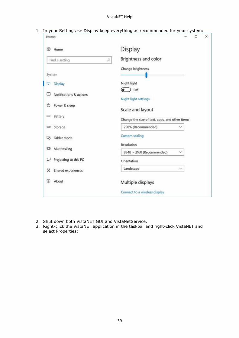
If you experience any of the issues listed above, please follow these steps:
VistaNET Help
39
1. In your Settings -> Display keep everything as recommended for your system:
2. Shut down both VistaNET GUI and VistaNetService.
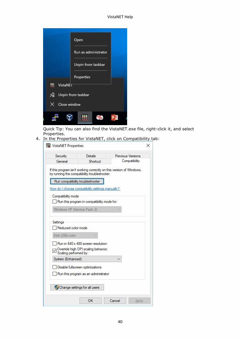
3. Right-click the VistaNET application in the taskbar and right-click VistaNET and
select Properties:
VistaNET Help
40
Quick Tip: You can also find the VistaNET.exe file, right-click it, and select
Properties.
4. In the Properties for VistaNET, click on Compatibility tab:
VistaNET Help
41
5. Under "Settings", check the Override high DPI scaling behavior option.
6. Under "Scaling performed by" drop-down menu, select System (Enhanced).
7. Click Apply.
8. Click OK.
1.3 VistaNET Service VistaNET Help > VistaNET(See 1.) >
VistaNET Service allows discovery, configuration, and monitorring of Lentronics
Multiplexers.
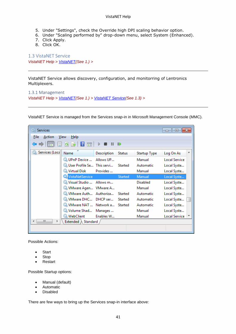
1.3.1 Management VistaNET Help > VistaNET(See 1.) > VistaNET Service(See 1.3) >
VistaNET Service is managed from the Services snap-in in Microsoft Management Console (MMC).
Possible Actions:
• Start
• Stop
• Restart
Possible Startup options:
• Manual (default)
• Automatic
• Disabled
There are few ways to bring up the Services snap-in interface above:
VistaNET Help
42
• Run Services.msc
• Open Control Panel, Administrative Tools, Services
• Run mmc and add Services snap-in from the File menu
1.4 VistaNET User Interface VistaNET Help > VistaNET(See 1.) >
VistaNET Graphical User Interface (GUI) allows users to interact with Lentronics
Multiplexers. It offers graphical icons and visual indicators to represent the information
and actions available to the user.
1.4.1 VistaNET Screen Layout VistaNET Help > VistaNET(See 1.) > VistaNET User Interface(See 1.4) >
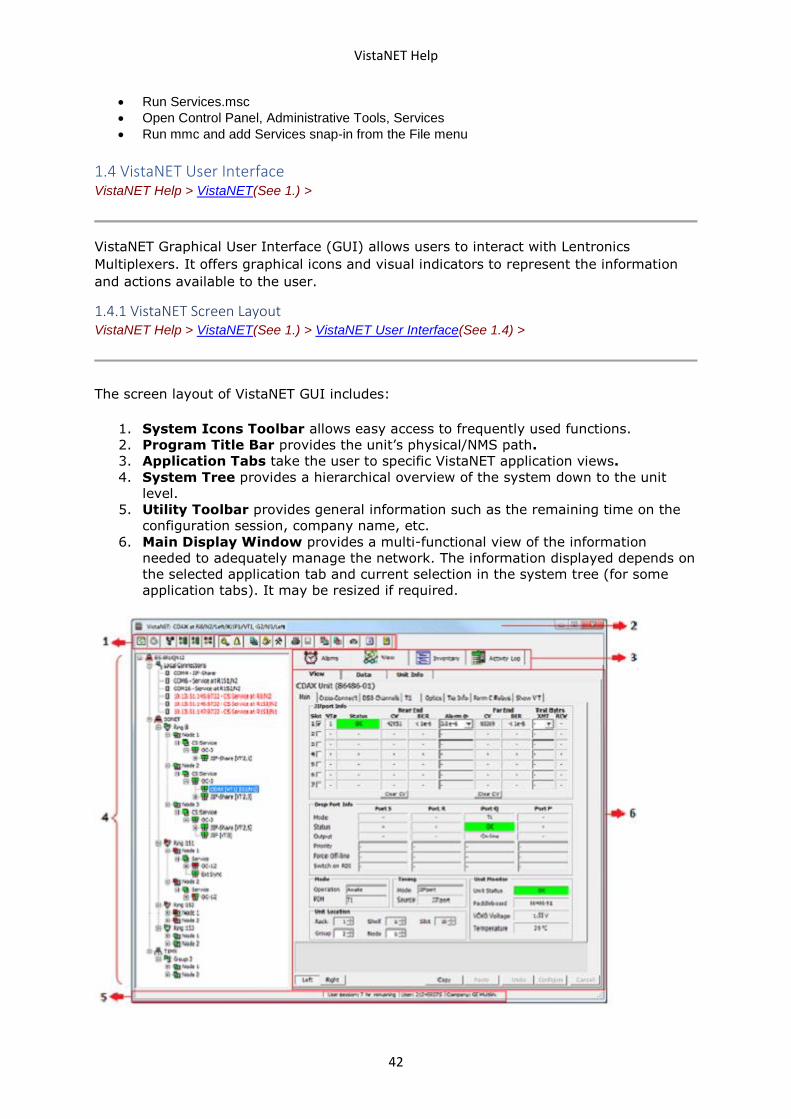
The screen layout of VistaNET GUI includes:
1. System Icons Toolbar allows easy access to frequently used functions.
2. Program Title Bar provides the unit’s physical/NMS path.
3. Application Tabs take the user to specific VistaNET application views.
4. System Tree provides a hierarchical overview of the system down to the unit
level.
5. Utility Toolbar provides general information such as the remaining time on the
configuration session, company name, etc.
6. Main Display Window provides a multi-functional view of the information
needed to adequately manage the network. The information displayed depends on
the selected application tab and current selection in the system tree (for some
application tabs). It may be resized if required.
VistaNET Help
43
By default, VistaNET starts with a GUI screen opened. If closed, VistaNET service will
continue to run in the background. To open it again, double-click on the VistaNET icon
placed on the desktop after installation, or click on Start, Programs, VistaNET, and
VistaNET.
The main VistaNET window and most of its internal windows can be resized to display
information adequately. To resize the main VistaNET window, either horizontally or
vertically, select any corner and drag it to resize. To resize internal windows, position the
mouse pointer over any peripheral window boundary, wait for the mouse icon to change
to a resizing arrow, and then, with the left mouse button held down, drag and resize
window as desired.
1.4.2 System Icons Toolbar VistaNET Help > VistaNET(See 1.) > VistaNET User Interface(See 1.4) >
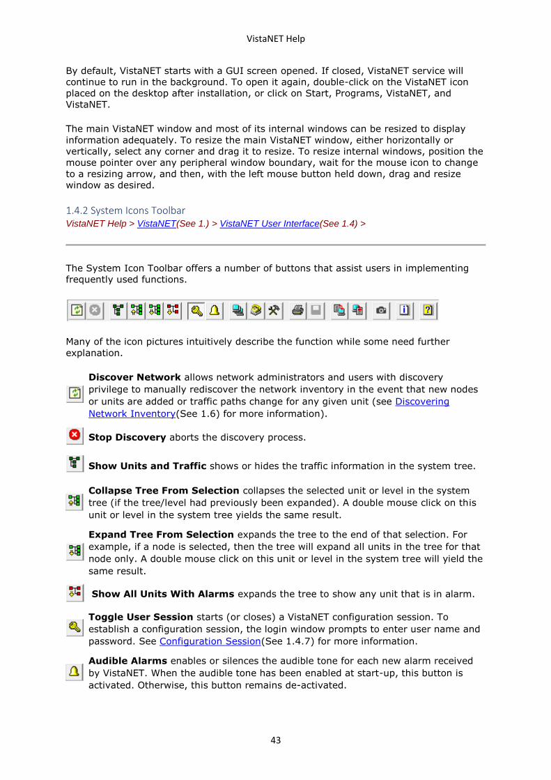
The System Icon Toolbar offers a number of buttons that assist users in implementing
frequently used functions.
Many of the icon pictures intuitively describe the function while some need further
explanation.
Discover Network allows network administrators and users with discovery
privilege to manually rediscover the network inventory in the event that new nodes
or units are added or traffic paths change for any given unit (see Discovering
Network Inventory(See 1.6) for more information).
Stop Discovery aborts the discovery process.
Show Units and Traffic shows or hides the traffic information in the system tree.
Collapse Tree From Selection collapses the selected unit or level in the system
tree (if the tree/level had previously been expanded). A double mouse click on this
unit or level in the system tree yields the same result.
Expand Tree From Selection expands the tree to the end of that selection. For
example, if a node is selected, then the tree will expand all units in the tree for that
node only. A double mouse click on this unit or level in the system tree will yield the
same result.
Show All Units With Alarms expands the tree to show any unit that is in alarm.
Toggle User Session starts (or closes) a VistaNET configuration session. To
establish a configuration session, the login window prompts to enter user name and
password. See Configuration Session(See 1.4.7) for more information.
Audible Alarms enables or silences the audible tone for each new alarm received
by VistaNET. When the audible tone has been enabled at start-up, this button is
activated. Otherwise, this button remains de-activated.
VistaNET Help
44
Active Services provides information about visible VistaNET sessions (IP
addresses).
Serial and Modem Connections opens the Serial Connections window to allow
assigning of COM ports used by VistaNET and adding modem connections.
Administration and Startup Options opens the Administration & Startup
Options(See 1.4.11) window. This allows setting different start-up options, fibre
data format, user accounts, user group restrictions, and SNMP agent parameters (if
applicable).
Print Current Tab allows sending the contents of the main display window to the
default printer. The availability of this function depends on the content.
Save To File saves the content of the main display window to a file. The availability
of this function depends on content.
Save Unit Data to a File saves the selected unit's data to a file.
Restore Unit Data from a File restores the selected unit's data from a file.
Unit and Traffic Data Capturing opens the Unit and Traffic Data Capturing
window, which allows taking a snapshot of Unit Config data and Traffic Analyzer data
from selected networks, rings, and nodes
Information identifies VistaNET version and licenses information.
Help opens VistaNET user guide.
1.4.3 System Tree VistaNET Help > VistaNET(See 1.) > VistaNET User Interface(See 1.4) >
The system tree is built by:
• discovering new inventory, or
• restoring previously discovered network inventory from the local data file.
For most users, the tree will be restored and then updated based on remote VistaNET
services synchronizing with the local service.
For administrators who first install VistaNET, a system discovery is required since the
local data file is empty of any discovered results.
The tree is redrawn and repainted upon restoring the inventory or updating the system
tree. Redrawing the tree can be time consuming when a large number of rings and nodes
is present.
1.4.3.1 System Tree Layers VistaNET Help > VistaNET(See 1.) > VistaNET User Interface(See 1.4) > System Tree(See 1.4.3) >
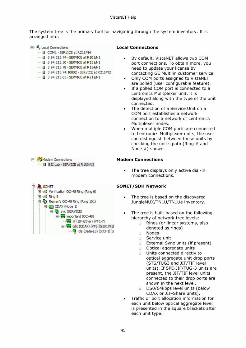
VistaNET Help
45
The system tree is the primary tool for navigating through the system inventory. It is
arranged into:
Local Connections
• By default, VistaNET allows two COM
port connections. To obtain more, you
need to update your license by
contacting GE Multilin customer service.
• Only COM ports assigned to VistaNET
are polled (user configurable feature).
• If a polled COM port is connected to a
Lentronics Mulitplexer unit, it is
displayed along with the type of the unit
connected.
• The detection of a Service Unit on a
COM port establishes a network
connection to a network of Lentronics
Multiplexer nodes.
• When multiple COM ports are connected
to Lentronics Multiplexer units, the user
can distinguish between these units by
checking the unit’s path (Ring # and
Node #) shown.
Modem Connections
• The tree displays only active dial-in
modem connections.
SONET/SDH Network
• The tree is based on the discovered
JungleMUX/TN1U/TN1Ue inventory.
• The tree is built based on the following
hierarchy of network tree levels:
o Rings (or linear systems, also
denoted as rings)
o Nodes
o Service unit
o External Sync units (if present)
o Optical aggregate units
o Units connected directly to
optical aggregate unit drop ports
(STS/TUG3 and JIF/TIF level
units). If SPE-JIF/TUG-3 units are
present, the JIF/TIF level units
connected to their drop ports are
shown in the next level.
o DS0/64kbps level units (below
CDAX or JIF-Share units).
• Traffic or port allocation information for
each unit below optical aggregate level
is presented in the square brackets after
each unit type.
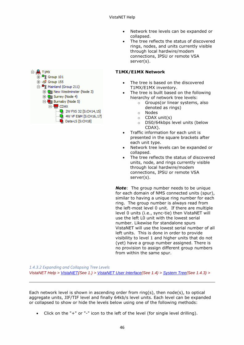
VistaNET Help
46
• Network tree levels can be expanded or
collapsed.
• The tree reflects the status of discovered
rings, nodes, and units currently visible
through local hardwire/modem
connections, IPSU or remote VSA
server(s).
T1MX/E1MX Network
• The tree is based on the discovered
T1MX/E1MX inventory.
• The tree is built based on the following
hierarchy of network tree levels:
o Groups(or linear systems, also
denoted as rings)
o Nodes
o CDAX unit(s)
o DS0/64kbps level units (below
CDAX).
• Traffic information for each unit is
presented in the square brackets after
each unit type.
• Network tree levels can be expanded or
collapsed.
• The tree reflects the status of discovered
units, node, and rings currently visible
through local hardwire/modem
connections, IPSU or remote VSA
server(s).
Note: The group number needs to be unique
for each domain of NMS connected units (spur),
similar to having a unique ring number for each
ring. The group number is always read from
the left-most level 0 unit. If there are multiple
level 0 units (i.e., sync-tie) then VistaNET will
use the left L0 unit with the lowest serial
number. Likewise for standalone spurs
VistaNET will use the lowest serial number of all
left units. This is done in order to provide
visibility to level 1 and higher units that do not
(yet) have a group number assigned. There is
no provision to assign different group numbers
from within the same spur.
1.4.3.2 Expanding and Collapsing Tree Levels VistaNET Help > VistaNET(See 1.) > VistaNET User Interface(See 1.4) > System Tree(See 1.4.3) >
Each network level is shown in ascending order from ring(s), then node(s), to optical
aggregate units, JIF/TIF level and finally 64kb/s level units. Each level can be expanded
or collapsed to show or hide the levels below using one of the following methods:
• Click on the "+" or "-" icon to the left of the level (for single level drilling).
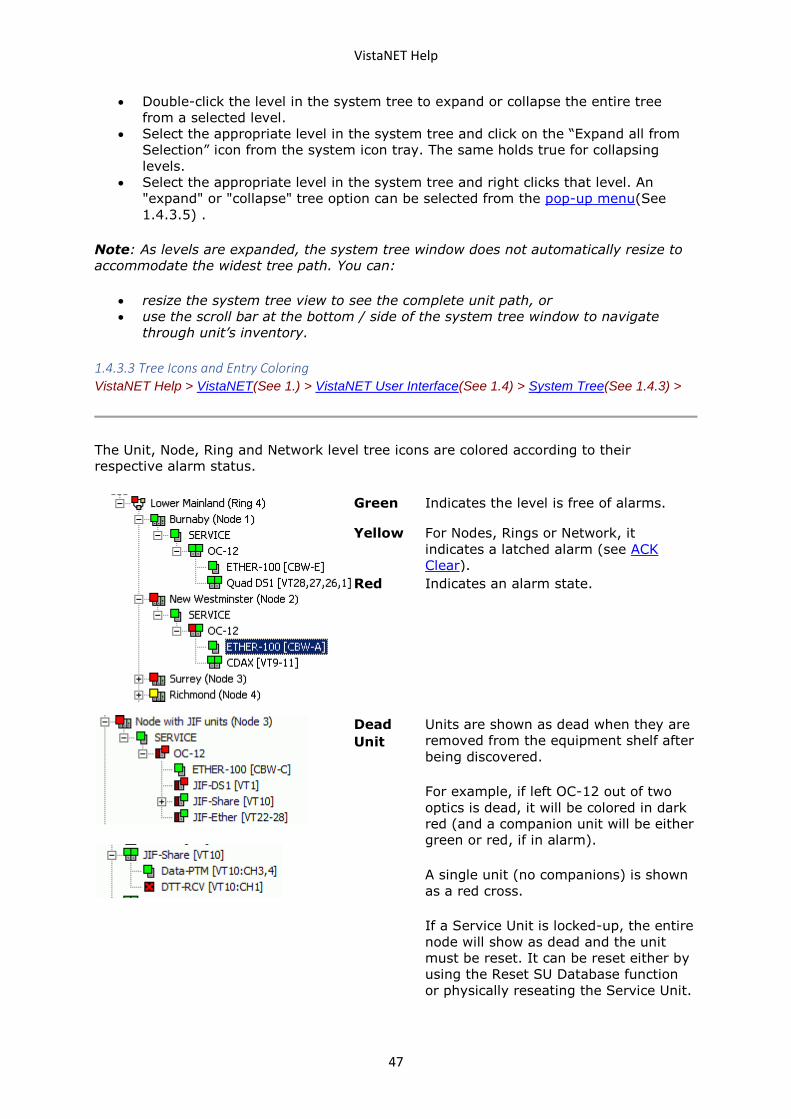
VistaNET Help
47
• Double-click the level in the system tree to expand or collapse the entire tree
from a selected level.
• Select the appropriate level in the system tree and click on the “Expand all from
Selection” icon from the system icon tray. The same holds true for collapsing
levels.
• Select the appropriate level in the system tree and right clicks that level. An
"expand" or "collapse" tree option can be selected from the pop-up menu(See
1.4.3.5) .
Note: As levels are expanded, the system tree window does not automatically resize to
accommodate the widest tree path. You can:
• resize the system tree view to see the complete unit path, or
• use the scroll bar at the bottom / side of the system tree window to navigate
through unit’s inventory.
1.4.3.3 Tree Icons and Entry Coloring VistaNET Help > VistaNET(See 1.) > VistaNET User Interface(See 1.4) > System Tree(See 1.4.3) >
The Unit, Node, Ring and Network level tree icons are colored according to their
respective alarm status.
Green Indicates the level is free of alarms.
Yellow For Nodes, Rings or Network, it
indicates a latched alarm (see ACK
Clear).
Red Indicates an alarm state.
Dead
Unit
Units are shown as dead when they are
removed from the equipment shelf after
being discovered.
For example, if left OC-12 out of two
optics is dead, it will be colored in dark
red (and a companion unit will be either
green or red, if in alarm).
A single unit (no companions) is shown
as a red cross.
If a Service Unit is locked-up, the entire
node will show as dead and the unit
must be reset. It can be reset either by
using the Reset SU Database function
or physically reseating the Service Unit.
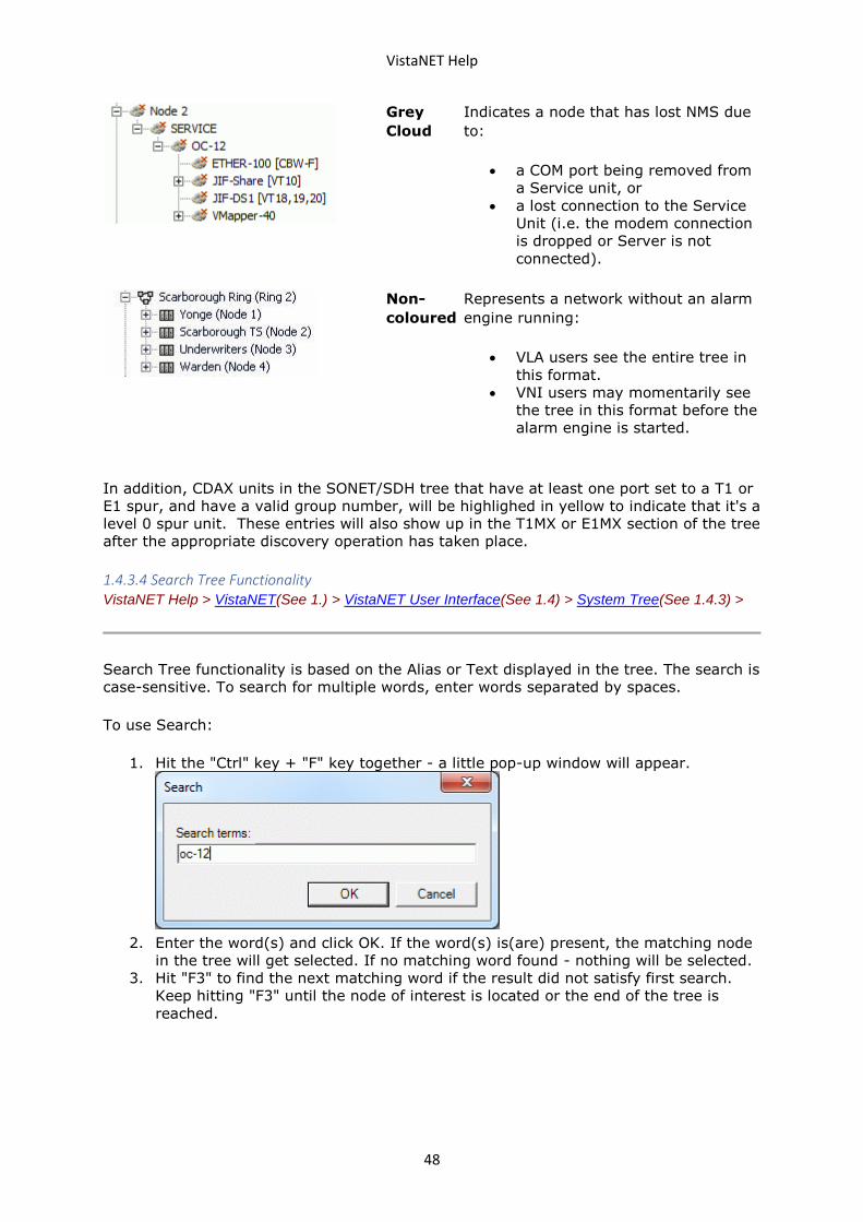
VistaNET Help
48
Grey
Cloud
Indicates a node that has lost NMS due
to:
• a COM port being removed from
a Service unit, or
• a lost connection to the Service
Unit (i.e. the modem connection
is dropped or Server is not
connected).
Non-
coloured
Represents a network without an alarm
engine running:
• VLA users see the entire tree in
this format.
• VNI users may momentarily see
the tree in this format before the
alarm engine is started.
In addition, CDAX units in the SONET/SDH tree that have at least one port set to a T1 or
E1 spur, and have a valid group number, will be highlighed in yellow to indicate that it's a
level 0 spur unit. These entries will also show up in the T1MX or E1MX section of the tree
after the appropriate discovery operation has taken place.
1.4.3.4 Search Tree Functionality VistaNET Help > VistaNET(See 1.) > VistaNET User Interface(See 1.4) > System Tree(See 1.4.3) >
Search Tree functionality is based on the Alias or Text displayed in the tree. The search is
case-sensitive. To search for multiple words, enter words separated by spaces.
To use Search:
1. Hit the "Ctrl" key + "F" key together - a little pop-up window will appear.
2. Enter the word(s) and click OK. If the word(s) is(are) present, the matching node
in the tree will get selected. If no matching word found - nothing will be selected.
3. Hit "F3" to find the next matching word if the result did not satisfy first search.
Keep hitting "F3" until the node of interest is located or the end of the tree is
reached.
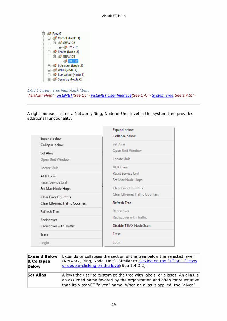
VistaNET Help
49
1.4.3.5 System Tree Right-Click Menu VistaNET Help > VistaNET(See 1.) > VistaNET User Interface(See 1.4) > System Tree(See 1.4.3) >
A right mouse click on a Network, Ring, Node or Unit level in the system tree provides
additional functionality.
Expand Below
& Collapse
Below
Expands or collapses the section of the tree below the selected layer
(Network, Ring, Node, Unit). Similar to clicking on the "+" or "-" icons
or double-clicking on the level(See 1.4.3.2) .
Set Alias Allows the user to customize the tree with labels, or aliases. An alias is
an assumed name favored by the organization and often more intuitive
than its VistaNET "given" name. When an alias is applied, the "given"
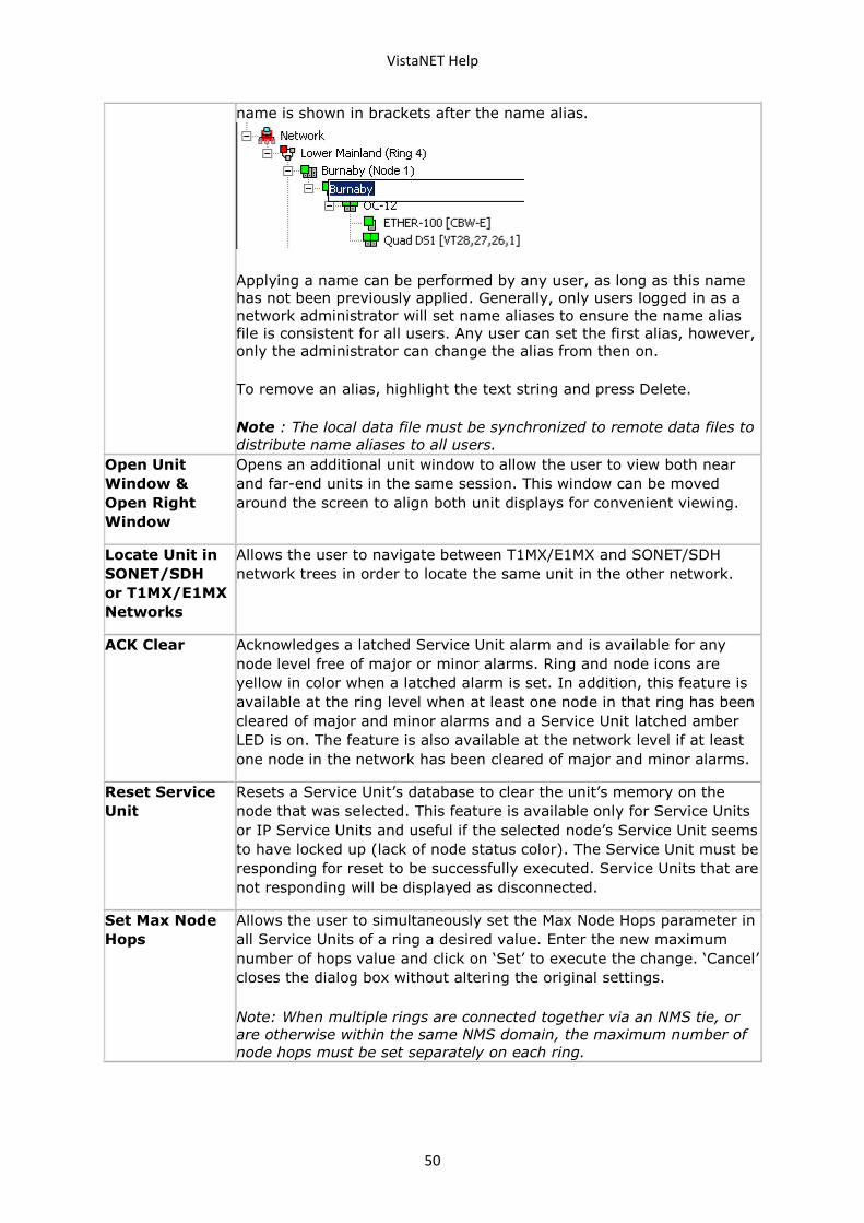
VistaNET Help
50
name is shown in brackets after the name alias.
Applying a name can be performed by any user, as long as this name
has not been previously applied. Generally, only users logged in as a
network administrator will set name aliases to ensure the name alias
file is consistent for all users. Any user can set the first alias, however,
only the administrator can change the alias from then on.
To remove an alias, highlight the text string and press Delete.
Note : The local data file must be synchronized to remote data files to
distribute name aliases to all users.
Open Unit
Window &
Open Right
Window
Opens an additional unit window to allow the user to view both near
and far-end units in the same session. This window can be moved
around the screen to align both unit displays for convenient viewing.
Locate Unit in
SONET/SDH
or T1MX/E1MX
Networks
Allows the user to navigate between T1MX/E1MX and SONET/SDH
network trees in order to locate the same unit in the other network.
ACK Clear Acknowledges a latched Service Unit alarm and is available for any
node level free of major or minor alarms. Ring and node icons are
yellow in color when a latched alarm is set. In addition, this feature is
available at the ring level when at least one node in that ring has been
cleared of major and minor alarms and a Service Unit latched amber
LED is on. The feature is also available at the network level if at least
one node in the network has been cleared of major and minor alarms.
Reset Service
Unit
Resets a Service Unit’s database to clear the unit’s memory on the
node that was selected. This feature is available only for Service Units
or IP Service Units and useful if the selected node’s Service Unit seems
to have locked up (lack of node status color). The Service Unit must be
responding for reset to be successfully executed. Service Units that are
not responding will be displayed as disconnected.
Set Max Node
Hops
Allows the user to simultaneously set the Max Node Hops parameter in
all Service Units of a ring a desired value. Enter the new maximum
number of hops value and click on ‘Set’ to execute the change. ‘Cancel’
closes the dialog box without altering the original settings.
Note: When multiple rings are connected together via an NMS tie, or
are otherwise within the same NMS domain, the maximum number of
node hops must be set separately on each ring.
VistaNET Help
51
Clear Error
Counters
Allows the user to clear the CV/BPV error counters on selected unit
types.
This option is availabe at the Ring and Node levels and allows to clear
error counters for any JMUX unit that supports this functionality.
Clear Ethernet
Traffic
Counters
Allows the user to clear the Ethernet Traffic Counters/Statistics
selected Ethernet unit types.
This option is availabe at the Ring and Node levels.
Refresh Tree Refreshes the System Tree view. Use of this command is required
when, for example, name aliases have been changed at a remote
VistaNET session. The local VistaNET service receives the updated
aliases through the synchronization process, however, the tree must
be refreshed to show this change on the screen.
Rediscover &
Rediscover
with Traffic
Initiates a rediscovery process of a selected ring or node. This option is
available only to administrators and users with discovery
privileges. Rediscover with traffic will collect additional cross
connect information from each unit, and is only available if the traffic
management license has been purchased.
Erase Erases the inventory for selected item (Network, Ring, or Node).
Note: Erasing the inventory does not erase the aliases defined for the
erased inventory. These aliases will be automatically applied when the
matching inventory (same NMS paths) is discovered next time.
Enable/Disable
T1/E1MX Node
Scan
This item only appears when you right-click on the T1/E1MX network
root node.
VistaNetService regularly scans T1/E1MX nodes to check for any
changes, such as a replaced CDAX unit. For large networks, this scan
can take a long time, disrupting network management activity. This
option allows you to disable the scan, and re-enable it at a later time.
This setting does not persist after the service is stopped, and will be
reset to Enabled the next time the service starts.
Please note that VistaNetService has just been started, T1/E1MX nodes
will not be accessible until they have been scanned.
Login/Logout Allows to login to or logout from CS Service unit running in Secure
mode.
1.4.4 Application Tabs VistaNET Help > VistaNET(See 1.) > VistaNET User Interface(See 1.4) >
Application Tabs
The application tabs allow the user to switch between various Main Display Window views
associated with specific VistaNET functions.
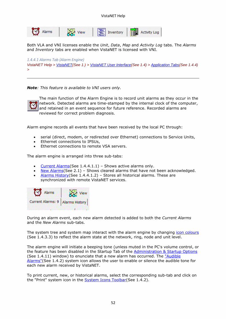
VistaNET Help
52
Both VLA and VNI licenses enable the Unit, Data, Map and Activity Log tabs. The Alarms
and Inventory tabs are enabled when VistaNET is licensed with VNI.
1.4.4.1 Alarms Tab (Alarm Engine) VistaNET Help > VistaNET(See 1.) > VistaNET User Interface(See 1.4) > Application Tabs(See 1.4.4)
>
Note: This feature is available to VNI users only.
The main function of the Alarm Engine is to record unit alarms as they occur in the
network. Detected alarms are time-stamped by the internal clock of the computer,
and retained in an event sequence for future reference. Recorded alarms are
reviewed for correct problem diagnosis.
Alarm engine records all events that have been received by the local PC through:
• serial (direct, modem, or redirected over Ethernet) connections to Service Units,
• Ethernet connections to IPSUs,
• Ethernet connections to remote VSA servers.
The alarm engine is arranged into three sub-tabs:
• Current Alarms(See 1.4.4.1.1) – Shows active alarms only.
• New Alarms(See 2.1) – Shows cleared alarms that have not been acknowledged.
• Alarms History(See 1.4.4.1.2) – Stores all historical alarms. These are
synchronized with remote VistaNET services.
During an alarm event, each new alarm detected is added to both the Current Alarms
and the New Alarms sub-tabs.
The system tree and system map interact with the alarm engine by changing icon colours
(See 1.4.3.3) to reflect the alarm state at the network, ring, node and unit level.
The alarm engine will initiate a beeping tone (unless muted in the PC's volume control, or
the feature has been disabled in the Startup Tab of the Administration & Startup Options
(See 1.4.11) window) to enunciate that a new alarm has occurred. The "Audible
Alarms"(See 1.4.2) system icon allows the user to enable or silence the audible tone for
each new alarm received by VistaNET.
To print current, new, or historical alarms, select the corresponding sub-tab and click on
the "Print" system icon in the System Icons Toolbar(See 1.4.2).
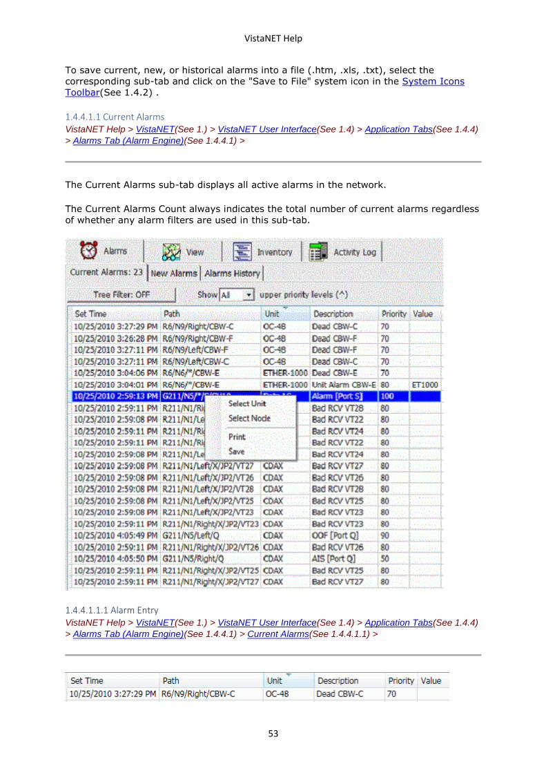
VistaNET Help
53
To save current, new, or historical alarms into a file (.htm, .xls, .txt), select the
corresponding sub-tab and click on the "Save to File" system icon in the System Icons
Toolbar(See 1.4.2) .
1.4.4.1.1 Current Alarms VistaNET Help > VistaNET(See 1.) > VistaNET User Interface(See 1.4) > Application Tabs(See 1.4.4)
> Alarms Tab (Alarm Engine)(See 1.4.4.1) >
The Current Alarms sub-tab displays all active alarms in the network.
The Current Alarms Count always indicates the total number of current alarms regardless
of whether any alarm filters are used in this sub-tab.
1.4.4.1.1.1 Alarm Entry VistaNET Help > VistaNET(See 1.) > VistaNET User Interface(See 1.4) > Application Tabs(See 1.4.4)
> Alarms Tab (Alarm Engine)(See 1.4.4.1) > Current Alarms(See 1.4.4.1.1) >
VistaNET Help
54
For each new alarm, the Current Alarms sub-tab adds an alarm entry that includes the
following information:
• Set Time – the time when the alarm was detected by VistaNET
• Path – the traffic path to the unit declaring an alarm
• Unit – the type of unit declaring an alarm
• Description – an alarm description
• Priority– the priority of the alarm (the lower the number, the higher the priority)
• Value – an alarm value, if available
• Alias – the unit’s name alias, if defined.
The user cannot remove alarms entries. They are removed only when the alarm condition
clears.
The alarm engine masks lower level alarms in order to focus troubleshooting on the most
severe alarm (i.e. when AIS is declared in the Aggregate Units, then JIF / TIF level unit
alarms will not be shown).
In most cases, an active alarm will clear naturally. When the condition that originally
caused the alarm is removed, the alarm entry is moved from the Current Alarms to the
Alarms History sub-tab. Sometimes, however, cleared alarms can be a result of a lost
connection to an IPSU or VSA. If this connection is lost, VistaNET clears the alarms but
does not move them to Alarms History sub-tab. When a connection with the remote
server is re-established, synchronization process updates the alarm history.
Note: Current Alarms are not cleared if a connection to the VistaNET service presenting
these alarms is lost. When the connection is re-established to this service, alarms will
then be updated.
To print entries, use the "Print" system icon in the System Icons Toolbar(See 1.4.2) .
To save entries into a file, use the "Save to File" system icon in the System Icons
Toolbar(See 1.4.2) .
1.4.4.1.1.2 Filtering Current Alarms VistaNET Help > VistaNET(See 1.) > VistaNET User Interface(See 1.4) > Application Tabs(See 1.4.4)
> Alarms Tab (Alarm Engine)(See 1.4.4.1) > Current Alarms(See 1.4.4.1.1) >
Two types of filters for current alarms are available:
• Tree Filter – filtering by selected tree layer
• Priority Filter – filtering by severity
The "Tree Filter" button allows for filtering alarms based on the system tree selection:
• If "Tree Filter" is OFF – the Current Alarms sub-tab displays all active alarms for
the whole network.
• If "Tree Filter" is ON – the Current Alarms sub-tab displays only those alarms that
belong to the selected tree level (SONET/SDH or T1MX/E1MX network, ring,
group, or node).
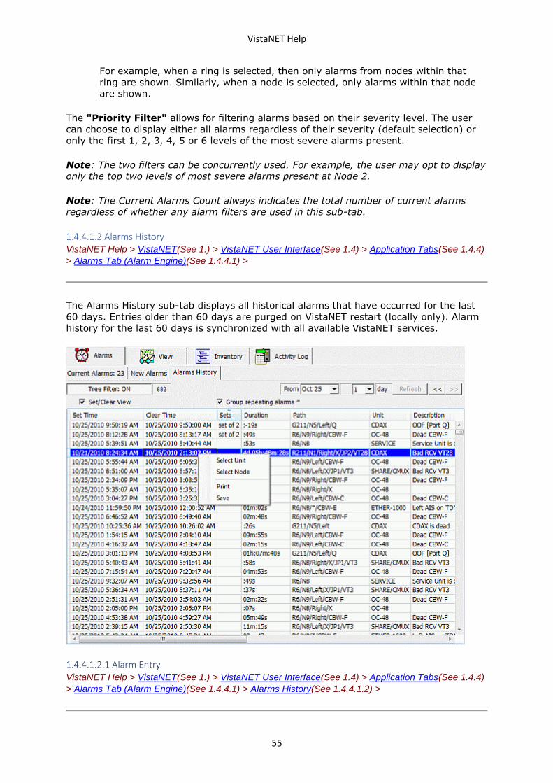
VistaNET Help
55
For example, when a ring is selected, then only alarms from nodes within that
ring are shown. Similarly, when a node is selected, only alarms within that node
are shown.
The "Priority Filter" allows for filtering alarms based on their severity level. The user
can choose to display either all alarms regardless of their severity (default selection) or
only the first 1, 2, 3, 4, 5 or 6 levels of the most severe alarms present.
Note: The two filters can be concurrently used. For example, the user may opt to display
only the top two levels of most severe alarms present at Node 2.
Note: The Current Alarms Count always indicates the total number of current alarms
regardless of whether any alarm filters are used in this sub-tab.
1.4.4.1.2 Alarms History VistaNET Help > VistaNET(See 1.) > VistaNET User Interface(See 1.4) > Application Tabs(See 1.4.4)
> Alarms Tab (Alarm Engine)(See 1.4.4.1) >
The Alarms History sub-tab displays all historical alarms that have occurred for the last
60 days. Entries older than 60 days are purged on VistaNET restart (locally only). Alarm
history for the last 60 days is synchronized with all available VistaNET services.
1.4.4.1.2.1 Alarm Entry VistaNET Help > VistaNET(See 1.) > VistaNET User Interface(See 1.4) > Application Tabs(See 1.4.4)
> Alarms Tab (Alarm Engine)(See 1.4.4.1) > Alarms History(See 1.4.4.1.2) >
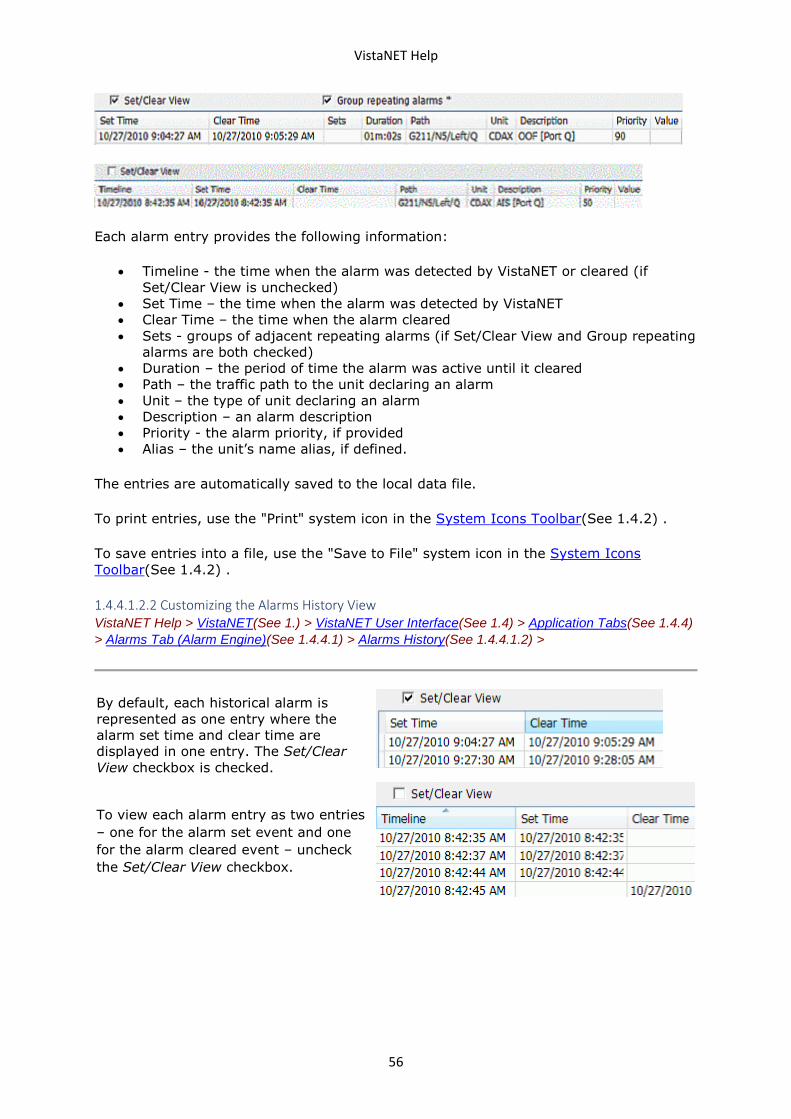
VistaNET Help
56
Each alarm entry provides the following information:
• Timeline - the time when the alarm was detected by VistaNET or cleared (if
Set/Clear View is unchecked)
• Set Time – the time when the alarm was detected by VistaNET
• Clear Time – the time when the alarm cleared
• Sets - groups of adjacent repeating alarms (if Set/Clear View and Group repeating
alarms are both checked)
• Duration – the period of time the alarm was active until it cleared
• Path – the traffic path to the unit declaring an alarm
• Unit – the type of unit declaring an alarm
• Description – an alarm description
• Priority - the alarm priority, if provided
• Alias – the unit’s name alias, if defined.
The entries are automatically saved to the local data file.
To print entries, use the "Print" system icon in the System Icons Toolbar(See 1.4.2) .
To save entries into a file, use the "Save to File" system icon in the System Icons
Toolbar(See 1.4.2) .
1.4.4.1.2.2 Customizing the Alarms History View VistaNET Help > VistaNET(See 1.) > VistaNET User Interface(See 1.4) > Application Tabs(See 1.4.4)
> Alarms Tab (Alarm Engine)(See 1.4.4.1) > Alarms History(See 1.4.4.1.2) >
By default, each historical alarm is
represented as one entry where the
alarm set time and clear time are
displayed in one entry. The Set/Clear
View checkbox is checked.
To view each alarm entry as two entries
– one for the alarm set event and one
for the alarm cleared event – uncheck
the Set/Clear View checkbox.
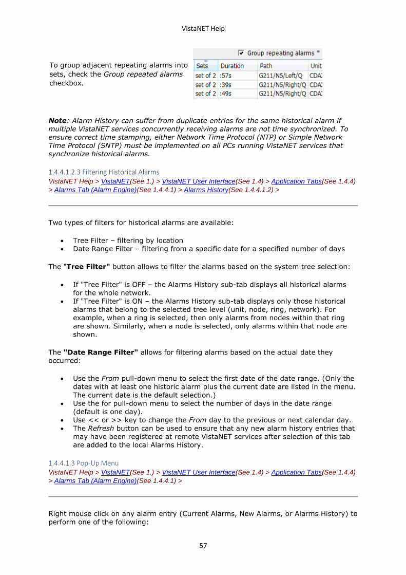
VistaNET Help
57
To group adjacent repeating alarms into
sets, check the Group repeated alarms
checkbox.
Note: Alarm History can suffer from duplicate entries for the same historical alarm if
multiple VistaNET services concurrently receiving alarms are not time synchronized. To
ensure correct time stamping, either Network Time Protocol (NTP) or Simple Network
Time Protocol (SNTP) must be implemented on all PCs running VistaNET services that
synchronize historical alarms.
1.4.4.1.2.3 Filtering Historical Alarms VistaNET Help > VistaNET(See 1.) > VistaNET User Interface(See 1.4) > Application Tabs(See 1.4.4)
> Alarms Tab (Alarm Engine)(See 1.4.4.1) > Alarms History(See 1.4.4.1.2) >
Two types of filters for historical alarms are available:
• Tree Filter – filtering by location
• Date Range Filter – filtering from a specific date for a specified number of days
The "Tree Filter" button allows to filter the alarms based on the system tree selection:
• If "Tree Filter" is OFF – the Alarms History sub-tab displays all historical alarms
for the whole network.
• If "Tree Filter" is ON – the Alarms History sub-tab displays only those historical
alarms that belong to the selected tree level (unit, node, ring, network). For
example, when a ring is selected, then only alarms from nodes within that ring
are shown. Similarly, when a node is selected, only alarms within that node are
shown.
The "Date Range Filter" allows for filtering alarms based on the actual date they
occurred:
• Use the From pull-down menu to select the first date of the date range. (Only the
dates with at least one historic alarm plus the current date are listed in the menu.
The current date is the default selection.)
• Use the for pull-down menu to select the number of days in the date range
(default is one day).
• Use << or >> key to change the From day to the previous or next calendar day.
• The Refresh button can be used to ensure that any new alarm history entries that
may have been registered at remote VistaNET services after selection of this tab
are added to the local Alarms History.
1.4.4.1.3 Pop-Up Menu VistaNET Help > VistaNET(See 1.) > VistaNET User Interface(See 1.4) > Application Tabs(See 1.4.4)
> Alarms Tab (Alarm Engine)(See 1.4.4.1) >
Right mouse click on any alarm entry (Current Alarms, New Alarms, or Alarms History) to
perform one of the following:
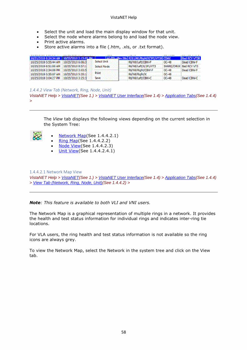
VistaNET Help
58
• Select the unit and load the main display window for that unit.
• Select the node where alarms belong to and load the node view.
• Print active alarms.
• Store active alarms into a file (.htm, .xls, or .txt format).
1.4.4.2 View Tab (Network, Ring, Node, Unit) VistaNET Help > VistaNET(See 1.) > VistaNET User Interface(See 1.4) > Application Tabs(See 1.4.4)
>
The View tab displays the following views depending on the current selection in
the System Tree:
• Network Map(See 1.4.4.2.1)
• Ring Map(See 1.4.4.2.2)
• Node View(See 1.4.4.2.3)
• Unit View(See 1.4.4.2.4.1)
1.4.4.2.1 Network Map View VistaNET Help > VistaNET(See 1.) > VistaNET User Interface(See 1.4) > Application Tabs(See 1.4.4)
> View Tab (Network, Ring, Node, Unit)(See 1.4.4.2) >
Note: This feature is available to both VLI and VNI users.
The Network Map is a graphical representation of multiple rings in a network. It provides
the health and test status information for individual rings and indicates inter-ring tie
locations.
For VLA users, the ring health and test status information is not available so the ring
icons are always grey.
To view the Network Map, select the Network in the system tree and click on the View
tab.
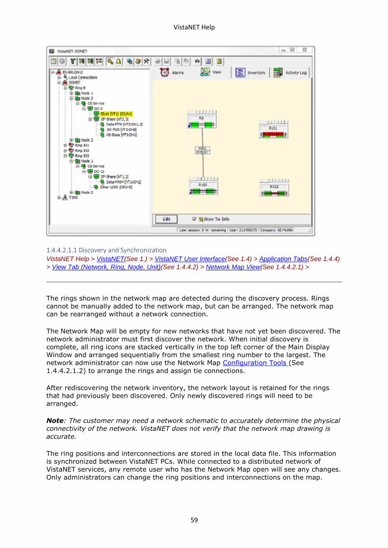
VistaNET Help
59
1.4.4.2.1.1 Discovery and Synchronization VistaNET Help > VistaNET(See 1.) > VistaNET User Interface(See 1.4) > Application Tabs(See 1.4.4)
> View Tab (Network, Ring, Node, Unit)(See 1.4.4.2) > Network Map View(See 1.4.4.2.1) >
The rings shown in the network map are detected during the discovery process. Rings
cannot be manually added to the network map, but can be arranged. The network map
can be rearranged without a network connection.
The Network Map will be empty for new networks that have not yet been discovered. The
network administrator must first discover the network. When initial discovery is
complete, all ring icons are stacked vertically in the top left corner of the Main Display
Window and arranged sequentially from the smallest ring number to the largest. The
network administrator can now use the Network Map Configuration Tools (See
1.4.4.2.1.2) to arrange the rings and assign tie connections.
After rediscovering the network inventory, the network layout is retained for the rings
that had previously been discovered. Only newly discovered rings will need to be
arranged.
Note: The customer may need a network schematic to accurately determine the physical
connectivity of the network. VistaNET does not verify that the network map drawing is
accurate.
The ring positions and interconnections are stored in the local data file. This information
is synchronized between VistaNET PCs. While connected to a distributed network of
VistaNET services, any remote user who has the Network Map open will see any changes.
Only administrators can change the ring positions and interconnections on the map.
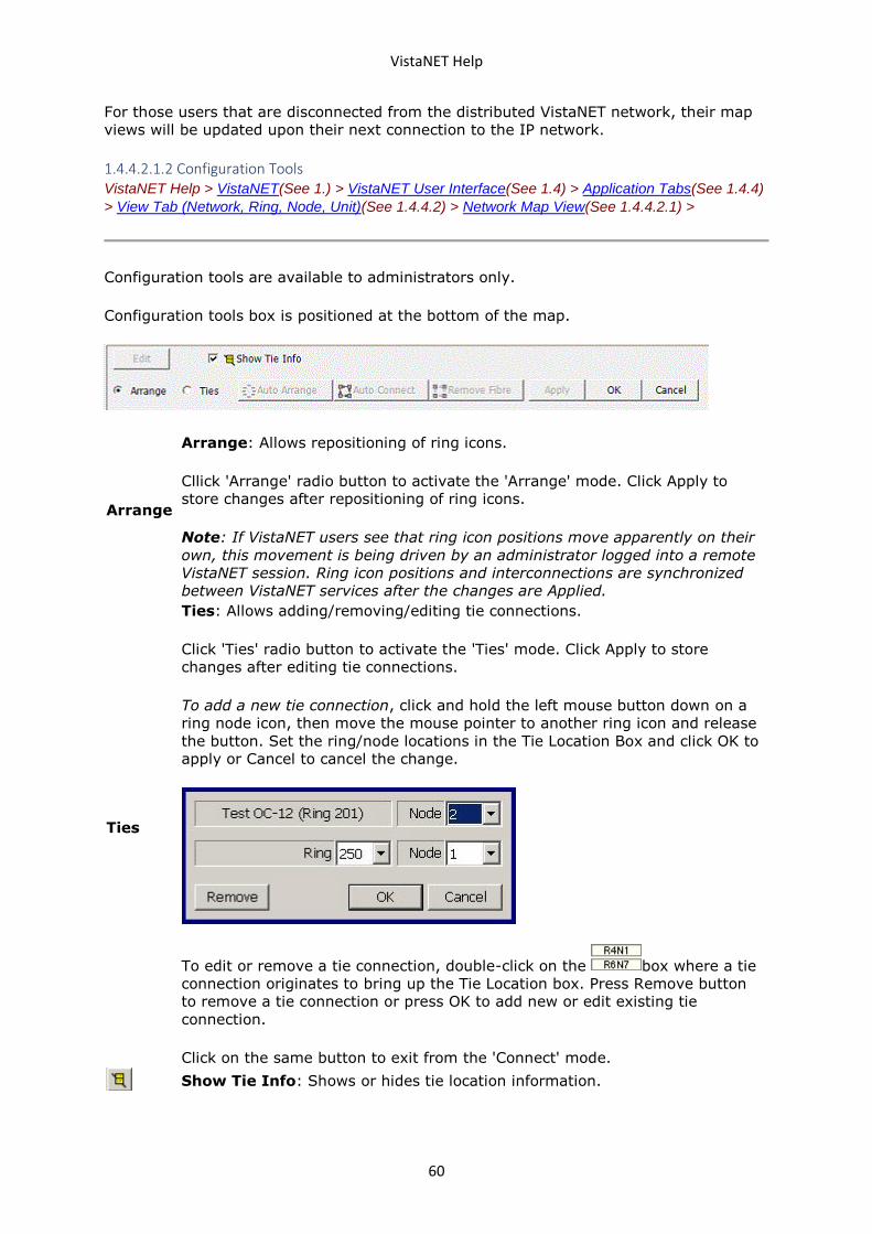
VistaNET Help
60
For those users that are disconnected from the distributed VistaNET network, their map
views will be updated upon their next connection to the IP network.
1.4.4.2.1.2 Configuration Tools VistaNET Help > VistaNET(See 1.) > VistaNET User Interface(See 1.4) > Application Tabs(See 1.4.4)
> View Tab (Network, Ring, Node, Unit)(See 1.4.4.2) > Network Map View(See 1.4.4.2.1) >
Configuration tools are available to administrators only.
Configuration tools box is positioned at the bottom of the map.
Arrange
Arrange: Allows repositioning of ring icons.
Cllick 'Arrange' radio button to activate the 'Arrange' mode. Click Apply to
store changes after repositioning of ring icons.
Note: If VistaNET users see that ring icon positions move apparently on their
own, this movement is being driven by an administrator logged into a remote
VistaNET session. Ring icon positions and interconnections are synchronized
between VistaNET services after the changes are Applied.
Ties
Ties: Allows adding/removing/editing tie connections.
Click 'Ties' radio button to activate the 'Ties' mode. Click Apply to store
changes after editing tie connections.
To add a new tie connection, click and hold the left mouse button down on a
ring node icon, then move the mouse pointer to another ring icon and release
the button. Set the ring/node locations in the Tie Location Box and click OK to
apply or Cancel to cancel the change.
To edit or remove a tie connection, double-click on the box where a tie
connection originates to bring up the Tie Location box. Press Remove button
to remove a tie connection or press OK to add new or edit existing tie
connection.
Click on the same button to exit from the 'Connect' mode.
Show Tie Info: Shows or hides tie location information.
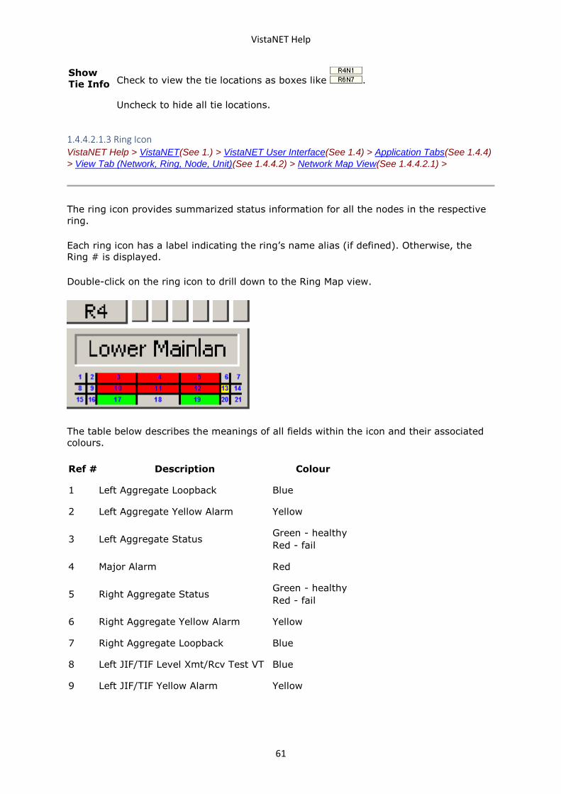
VistaNET Help
61
Show
Tie Info Check to view the tie locations as boxes like .
Uncheck to hide all tie locations.
1.4.4.2.1.3 Ring Icon VistaNET Help > VistaNET(See 1.) > VistaNET User Interface(See 1.4) > Application Tabs(See 1.4.4)
> View Tab (Network, Ring, Node, Unit)(See 1.4.4.2) > Network Map View(See 1.4.4.2.1) >
The ring icon provides summarized status information for all the nodes in the respective
ring.
Each ring icon has a label indicating the ring’s name alias (if defined). Otherwise, the
Ring # is displayed.
Double-click on the ring icon to drill down to the Ring Map view.
The table below describes the meanings of all fields within the icon and their associated
colours.
Ref # Description Colour
1 Left Aggregate Loopback Blue
2 Left Aggregate Yellow Alarm Yellow
3 Left Aggregate Status Green - healthy
Red - fail
4 Major Alarm Red
5 Right Aggregate Status Green - healthy
Red - fail
6 Right Aggregate Yellow Alarm Yellow
7 Right Aggregate Loopback Blue
8 Left JIF/TIF Level Xmt/Rcv Test VT Blue
9 Left JIF/TIF Yellow Alarm Yellow
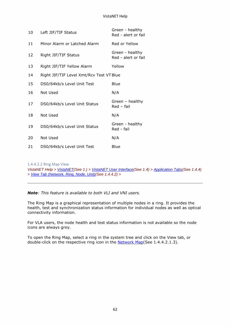
VistaNET Help
62
10 Left JIF/TIF Status Green - healthy
Red - alert or fail
11 Minor Alarm or Latched Alarm Red or Yellow
12 Right JIF/TIF Status Green - healthy
Red - alert or fail
13 Right JIF/TIF Yellow Alarm Yellow
14 Right JIF/TIF Level Xmt/Rcv Test VT Blue
15 DS0/64kb/s Level Unit Test Blue
16 Not Used N/A
17 DS0/64kb/s Level Unit Status Green – healthy
Red – fail
18 Not Used N/A
19 DS0/64kb/s Level Unit Status Green - healthy
Red - fail
20 Not Used N/A
21 DS0/64kb/s Level Unit Test Blue
1.4.4.2.2 Ring Map View VistaNET Help > VistaNET(See 1.) > VistaNET User Interface(See 1.4) > Application Tabs(See 1.4.4)
> View Tab (Network, Ring, Node, Unit)(See 1.4.4.2) >
Note: This feature is available to both VLI and VNI users.
The Ring Map is a graphical representation of multiple nodes in a ring. It provides the
health, test and synchronization status information for individual nodes as well as optical
connectivity information.
For VLA users, the node health and test status information is not available so the node
icons are always grey.
To open the Ring Map, select a ring in the system tree and click on the View tab, or
double-click on the respective ring icon in the Network Map(See 1.4.4.2.1.3).
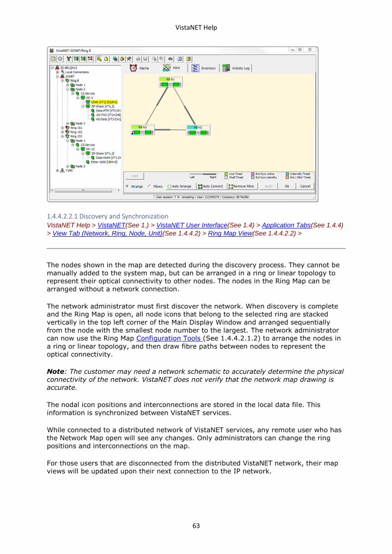
VistaNET Help
63
1.4.4.2.2.1 Discovery and Synchronization VistaNET Help > VistaNET(See 1.) > VistaNET User Interface(See 1.4) > Application Tabs(See 1.4.4)
> View Tab (Network, Ring, Node, Unit)(See 1.4.4.2) > Ring Map View(See 1.4.4.2.2) >
The nodes shown in the map are detected during the discovery process. They cannot be
manually added to the system map, but can be arranged in a ring or linear topology to
represent their optical connectivity to other nodes. The nodes in the Ring Map can be
arranged without a network connection.
The network administrator must first discover the network. When discovery is complete
and the Ring Map is open, all node icons that belong to the selected ring are stacked
vertically in the top left corner of the Main Display Window and arranged sequentially
from the node with the smallest node number to the largest. The network administrator
can now use the Ring Map Configuration Tools (See 1.4.4.2.1.2) to arrange the nodes in
a ring or linear topology, and then draw fibre paths between nodes to represent the
optical connectivity.
Note: The customer may need a network schematic to accurately determine the physical
connectivity of the network. VistaNET does not verify that the network map drawing is
accurate.
The nodal icon positions and interconnections are stored in the local data file. This
information is synchronized between VistaNET services.
While connected to a distributed network of VistaNET services, any remote user who has
the Network Map open will see any changes. Only administrators can change the ring
positions and interconnections on the map.
For those users that are disconnected from the distributed VistaNET network, their map
views will be updated upon their next connection to the IP network.
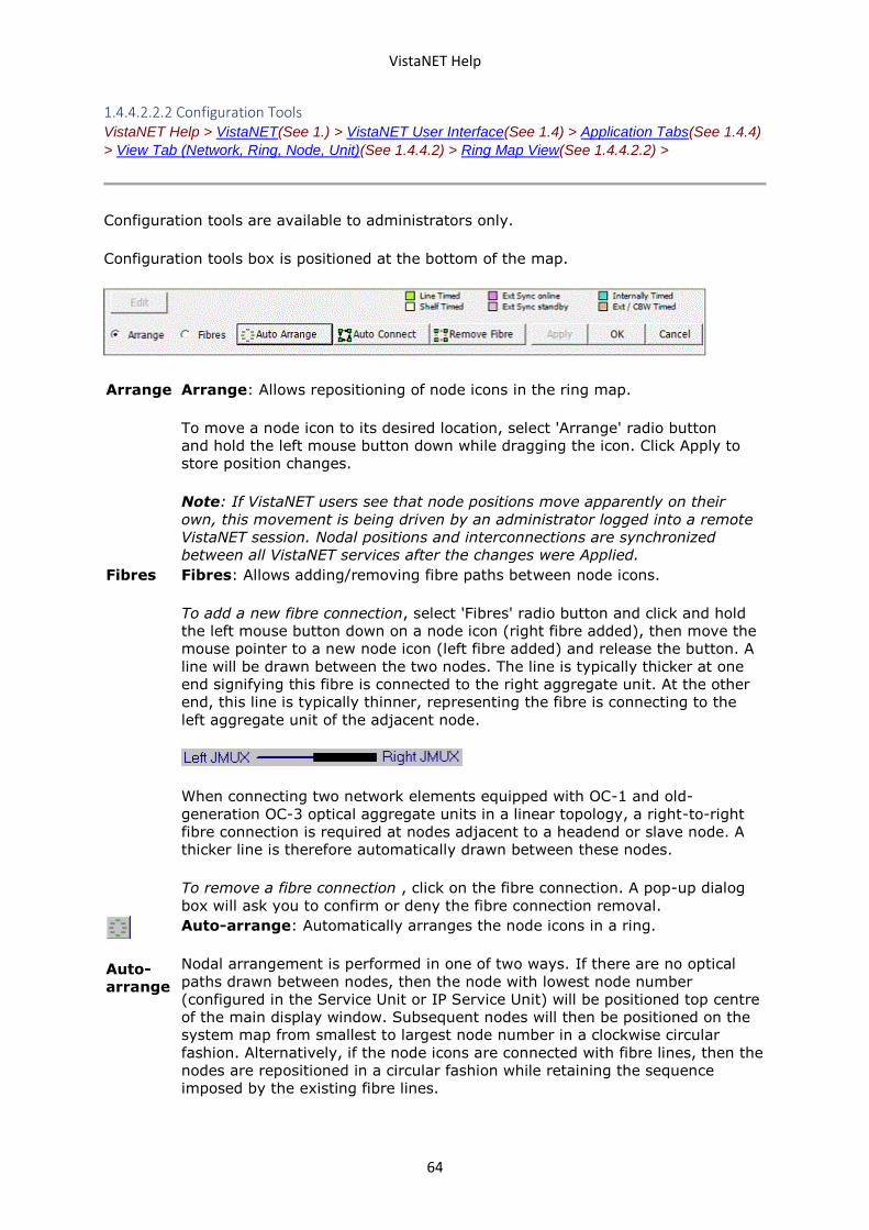
VistaNET Help
64
1.4.4.2.2.2 Configuration Tools VistaNET Help > VistaNET(See 1.) > VistaNET User Interface(See 1.4) > Application Tabs(See 1.4.4)
> View Tab (Network, Ring, Node, Unit)(See 1.4.4.2) > Ring Map View(See 1.4.4.2.2) >
Configuration tools are available to administrators only.
Configuration tools box is positioned at the bottom of the map.
Arrange Arrange: Allows repositioning of node icons in the ring map.
To move a node icon to its desired location, select 'Arrange' radio button
and hold the left mouse button down while dragging the icon. Click Apply to
store position changes.
Note: If VistaNET users see that node positions move apparently on their
own, this movement is being driven by an administrator logged into a remote
VistaNET session. Nodal positions and interconnections are synchronized
between all VistaNET services after the changes were Applied.
Fibres Fibres: Allows adding/removing fibre paths between node icons.
To add a new fibre connection, select 'Fibres' radio button and click and hold
the left mouse button down on a node icon (right fibre added), then move the
mouse pointer to a new node icon (left fibre added) and release the button. A
line will be drawn between the two nodes. The line is typically thicker at one
end signifying this fibre is connected to the right aggregate unit. At the other
end, this line is typically thinner, representing the fibre is connecting to the
left aggregate unit of the adjacent node.
When connecting two network elements equipped with OC-1 and old-
generation OC-3 optical aggregate units in a linear topology, a right-to-right
fibre connection is required at nodes adjacent to a headend or slave node. A
thicker line is therefore automatically drawn between these nodes.
To remove a fibre connection , click on the fibre connection. A pop-up dialog
box will ask you to confirm or deny the fibre connection removal.
Auto-
arrange
Auto-arrange: Automatically arranges the node icons in a ring.
Nodal arrangement is performed in one of two ways. If there are no optical
paths drawn between nodes, then the node with lowest node number
(configured in the Service Unit or IP Service Unit) will be positioned top centre
of the main display window. Subsequent nodes will then be positioned on the
system map from smallest to largest node number in a clockwise circular
fashion. Alternatively, if the node icons are connected with fibre lines, then the
nodes are repositioned in a circular fashion while retaining the sequence
imposed by the existing fibre lines.
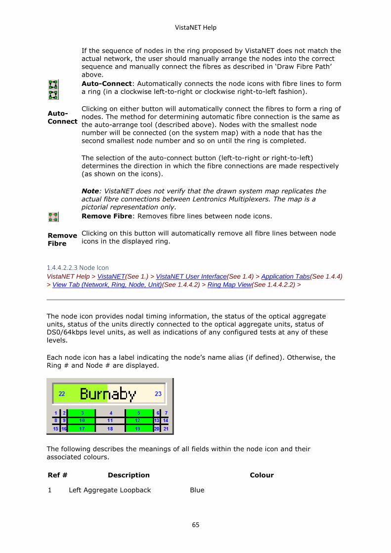
VistaNET Help
65
If the sequence of nodes in the ring proposed by VistaNET does not match the
actual network, the user should manually arrange the nodes into the correct
sequence and manually connect the fibres as described in ‘Draw Fibre Path’
above.
Auto-
Connect
Auto-Connect: Automatically connects the node icons with fibre lines to form
a ring (in a clockwise left-to-right or clockwise right-to-left fashion).
Clicking on either button will automatically connect the fibres to form a ring of
nodes. The method for determining automatic fibre connection is the same as
the auto-arrange tool (described above). Nodes with the smallest node
number will be connected (on the system map) with a node that has the
second smallest node number and so on until the ring is completed.
The selection of the auto-connect button (left-to-right or right-to-left)
determines the direction in which the fibre connections are made respectively
(as shown on the icons).
Note: VistaNET does not verify that the drawn system map replicates the
actual fibre connections between Lentronics Multiplexers. The map is a
pictorial representation only.
Remove
Fibre
Remove Fibre: Removes fibre lines between node icons.
Clicking on this button will automatically remove all fibre lines between node
icons in the displayed ring.
1.4.4.2.2.3 Node Icon VistaNET Help > VistaNET(See 1.) > VistaNET User Interface(See 1.4) > Application Tabs(See 1.4.4)
> View Tab (Network, Ring, Node, Unit)(See 1.4.4.2) > Ring Map View(See 1.4.4.2.2) >
The node icon provides nodal timing information, the status of the optical aggregate
units, status of the units directly connected to the optical aggregate units, status of
DS0/64kbps level units, as well as indications of any configured tests at any of these
levels.
Each node icon has a label indicating the node’s name alias (if defined). Otherwise, the
Ring # and Node # are displayed.
The following describes the meanings of all fields within the node icon and their
associated colours.
Ref # Description Colour
1 Left Aggregate Loopback Blue
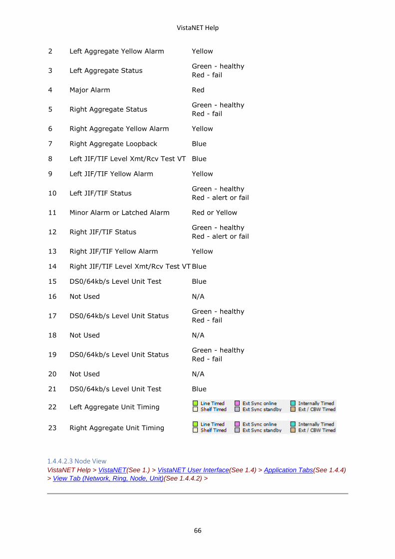
VistaNET Help
66
2 Left Aggregate Yellow Alarm Yellow
3 Left Aggregate Status Green - healthy
Red - fail
4 Major Alarm Red
5 Right Aggregate Status Green - healthy
Red - fail
6 Right Aggregate Yellow Alarm Yellow
7 Right Aggregate Loopback Blue
8 Left JIF/TIF Level Xmt/Rcv Test VT Blue
9 Left JIF/TIF Yellow Alarm Yellow
10 Left JIF/TIF Status Green - healthy
Red - alert or fail
11 Minor Alarm or Latched Alarm Red or Yellow
12 Right JIF/TIF Status Green - healthy
Red - alert or fail
13 Right JIF/TIF Yellow Alarm Yellow
14 Right JIF/TIF Level Xmt/Rcv Test VT Blue
15 DS0/64kb/s Level Unit Test Blue
16 Not Used N/A
17 DS0/64kb/s Level Unit Status Green - healthy
Red - fail
18 Not Used N/A
19 DS0/64kb/s Level Unit Status Green - healthy
Red - fail
20 Not Used N/A
21 DS0/64kb/s Level Unit Test Blue
22 Left Aggregate Unit Timing
23 Right Aggregate Unit Timing
1.4.4.2.3 Node View VistaNET Help > VistaNET(See 1.) > VistaNET User Interface(See 1.4) > Application Tabs(See 1.4.4)
> View Tab (Network, Ring, Node, Unit)(See 1.4.4.2) >
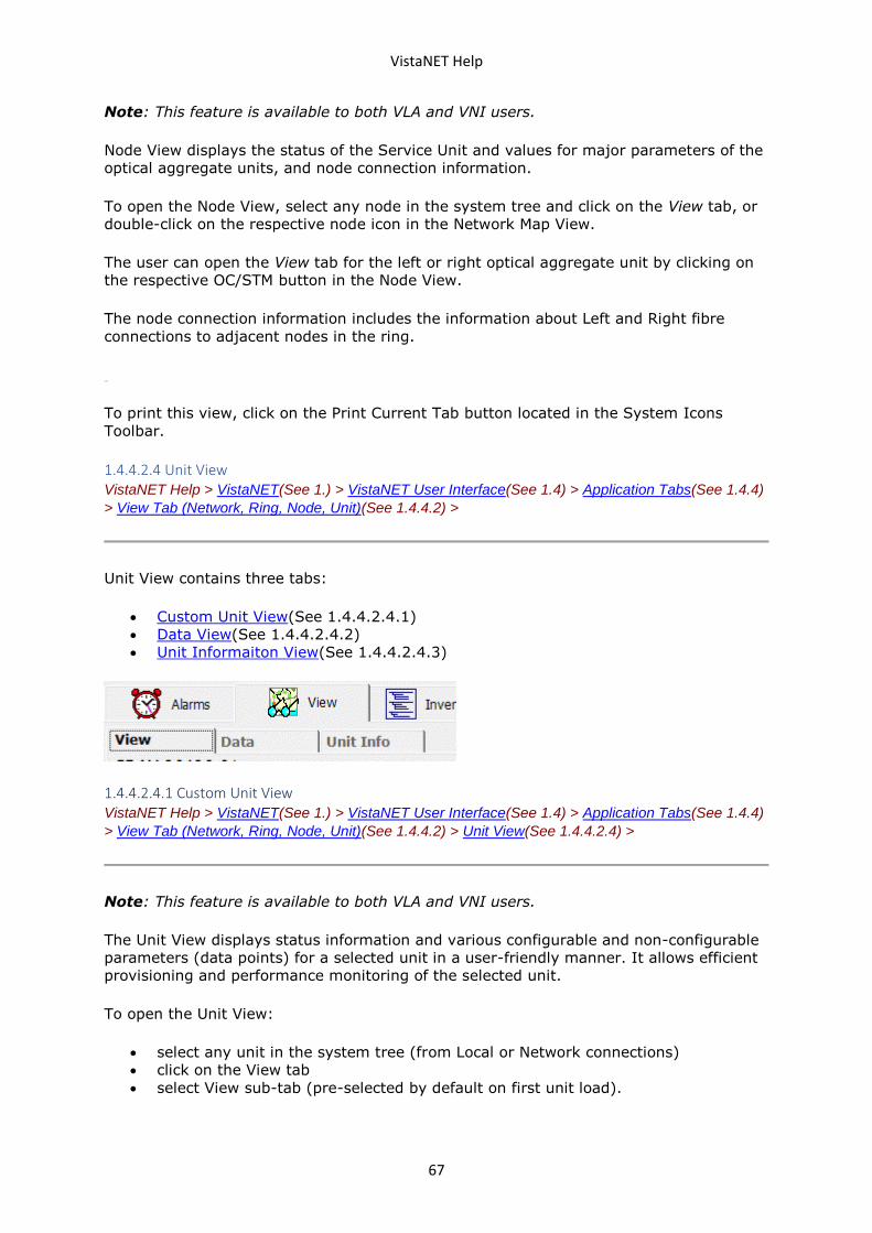
VistaNET Help
67
Note: This feature is available to both VLA and VNI users.
Node View displays the status of the Service Unit and values for major parameters of the
optical aggregate units, and node connection information.
To open the Node View, select any node in the system tree and click on the View tab, or
double-click on the respective node icon in the Network Map View.
The user can open the View tab for the left or right optical aggregate unit by clicking on
the respective OC/STM button in the Node View.
The node connection information includes the information about Left and Right fibre
connections to adjacent nodes in the ring.
To print this view, click on the Print Current Tab button located in the System Icons
Toolbar.
1.4.4.2.4 Unit View VistaNET Help > VistaNET(See 1.) > VistaNET User Interface(See 1.4) > Application Tabs(See 1.4.4)
> View Tab (Network, Ring, Node, Unit)(See 1.4.4.2) >
Unit View contains three tabs:
• Custom Unit View(See 1.4.4.2.4.1)
• Data View(See 1.4.4.2.4.2)
• Unit Informaiton View(See 1.4.4.2.4.3)
1.4.4.2.4.1 Custom Unit View VistaNET Help > VistaNET(See 1.) > VistaNET User Interface(See 1.4) > Application Tabs(See 1.4.4)
> View Tab (Network, Ring, Node, Unit)(See 1.4.4.2) > Unit View(See 1.4.4.2.4) >
Note: This feature is available to both VLA and VNI users.
The Unit View displays status information and various configurable and non-configurable
parameters (data points) for a selected unit in a user-friendly manner. It allows efficient
provisioning and performance monitoring of the selected unit.
To open the Unit View:
• select any unit in the system tree (from Local or Network connections)
• click on the View tab
• select View sub-tab (pre-selected by default on first unit load).
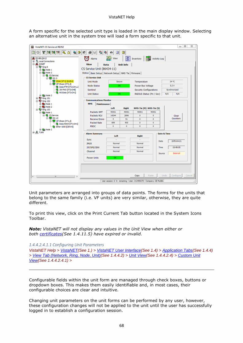
VistaNET Help
68
A form specific for the selected unit type is loaded in the main display window. Selecting
an alternative unit in the system tree will load a form specific to that unit.
Unit parameters are arranged into groups of data points. The forms for the units that
belong to the same family (i.e. VF units) are very similar, otherwise, they are quite
different.
To print this view, click on the Print Current Tab button located in the System Icons
Toolbar.
Note: VistaNET will not display any values in the Unit View when either or
both certificates(See 1.4.11.5) have expired or invalid.
1.4.4.2.4.1.1 Configuring Unit Parameters VistaNET Help > VistaNET(See 1.) > VistaNET User Interface(See 1.4) > Application Tabs(See 1.4.4)
> View Tab (Network, Ring, Node, Unit)(See 1.4.4.2) > Unit View(See 1.4.4.2.4) > Custom Unit
View(See 1.4.4.2.4.1) >
Configurable fields within the unit form are managed through check boxes, buttons or
dropdown boxes. This makes them easily identifiable and, in most cases, their
configurable choices are clear and intuitive.
Changing unit parameters on the unit forms can be performed by any user, however,
these configuration changes will not be applied to the unit until the user has successfully
logged in to establish a configuration session.
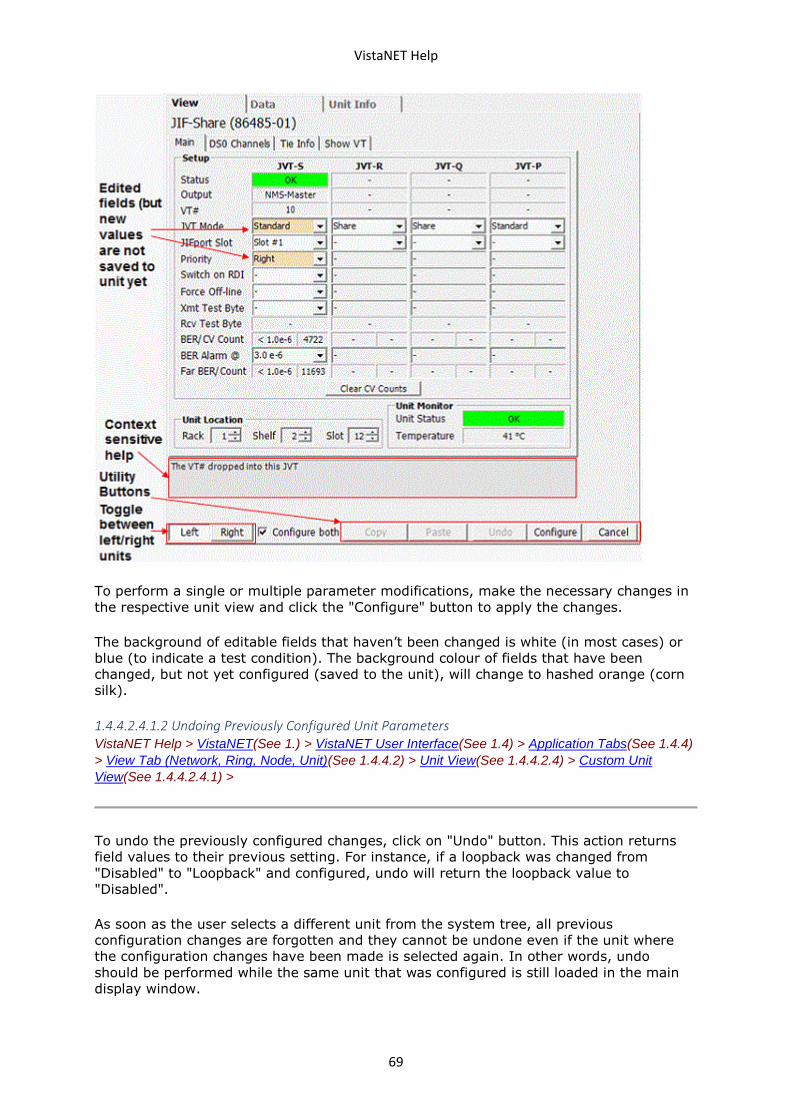
VistaNET Help
69
To perform a single or multiple parameter modifications, make the necessary changes in
the respective unit view and click the "Configure" button to apply the changes.
The background of editable fields that haven’t been changed is white (in most cases) or
blue (to indicate a test condition). The background colour of fields that have been
changed, but not yet configured (saved to the unit), will change to hashed orange (corn
silk).
1.4.4.2.4.1.2 Undoing Previously Configured Unit Parameters VistaNET Help > VistaNET(See 1.) > VistaNET User Interface(See 1.4) > Application Tabs(See 1.4.4)
> View Tab (Network, Ring, Node, Unit)(See 1.4.4.2) > Unit View(See 1.4.4.2.4) > Custom Unit
View(See 1.4.4.2.4.1) >
To undo the previously configured changes, click on "Undo" button. This action returns
field values to their previous setting. For instance, if a loopback was changed from
"Disabled" to "Loopback" and configured, undo will return the loopback value to
"Disabled".
As soon as the user selects a different unit from the system tree, all previous
configuration changes are forgotten and they cannot be undone even if the unit where
the configuration changes have been made is selected again. In other words, undo
should be performed while the same unit that was configured is still loaded in the main
display window.
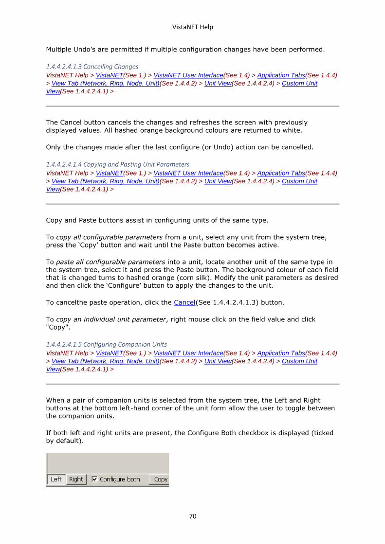
VistaNET Help
70
Multiple Undo’s are permitted if multiple configuration changes have been performed.
1.4.4.2.4.1.3 Cancelling Changes VistaNET Help > VistaNET(See 1.) > VistaNET User Interface(See 1.4) > Application Tabs(See 1.4.4)
> View Tab (Network, Ring, Node, Unit)(See 1.4.4.2) > Unit View(See 1.4.4.2.4) > Custom Unit
View(See 1.4.4.2.4.1) >
The Cancel button cancels the changes and refreshes the screen with previously
displayed values. All hashed orange background colours are returned to white.
Only the changes made after the last configure (or Undo) action can be cancelled.
1.4.4.2.4.1.4 Copying and Pasting Unit Parameters VistaNET Help > VistaNET(See 1.) > VistaNET User Interface(See 1.4) > Application Tabs(See 1.4.4)
> View Tab (Network, Ring, Node, Unit)(See 1.4.4.2) > Unit View(See 1.4.4.2.4) > Custom Unit
View(See 1.4.4.2.4.1) >
Copy and Paste buttons assist in configuring units of the same type.
To copy all configurable parameters from a unit, select any unit from the system tree,
press the ‘Copy’ button and wait until the Paste button becomes active.
To paste all configurable parameters into a unit, locate another unit of the same type in
the system tree, select it and press the Paste button. The background colour of each field
that is changed turns to hashed orange (corn silk). Modify the unit parameters as desired
and then click the ‘Configure’ button to apply the changes to the unit.
To cancelthe paste operation, click the Cancel(See 1.4.4.2.4.1.3) button.
To copy an individual unit parameter, right mouse click on the field value and click
"Copy".
1.4.4.2.4.1.5 Configuring Companion Units VistaNET Help > VistaNET(See 1.) > VistaNET User Interface(See 1.4) > Application Tabs(See 1.4.4)
> View Tab (Network, Ring, Node, Unit)(See 1.4.4.2) > Unit View(See 1.4.4.2.4) > Custom Unit
View(See 1.4.4.2.4.1) >
When a pair of companion units is selected from the system tree, the Left and Right
buttons at the bottom left-hand corner of the unit form allow the user to toggle between
the companion units.
If both left and right units are present, the Configure Both checkbox is displayed (ticked
by default).
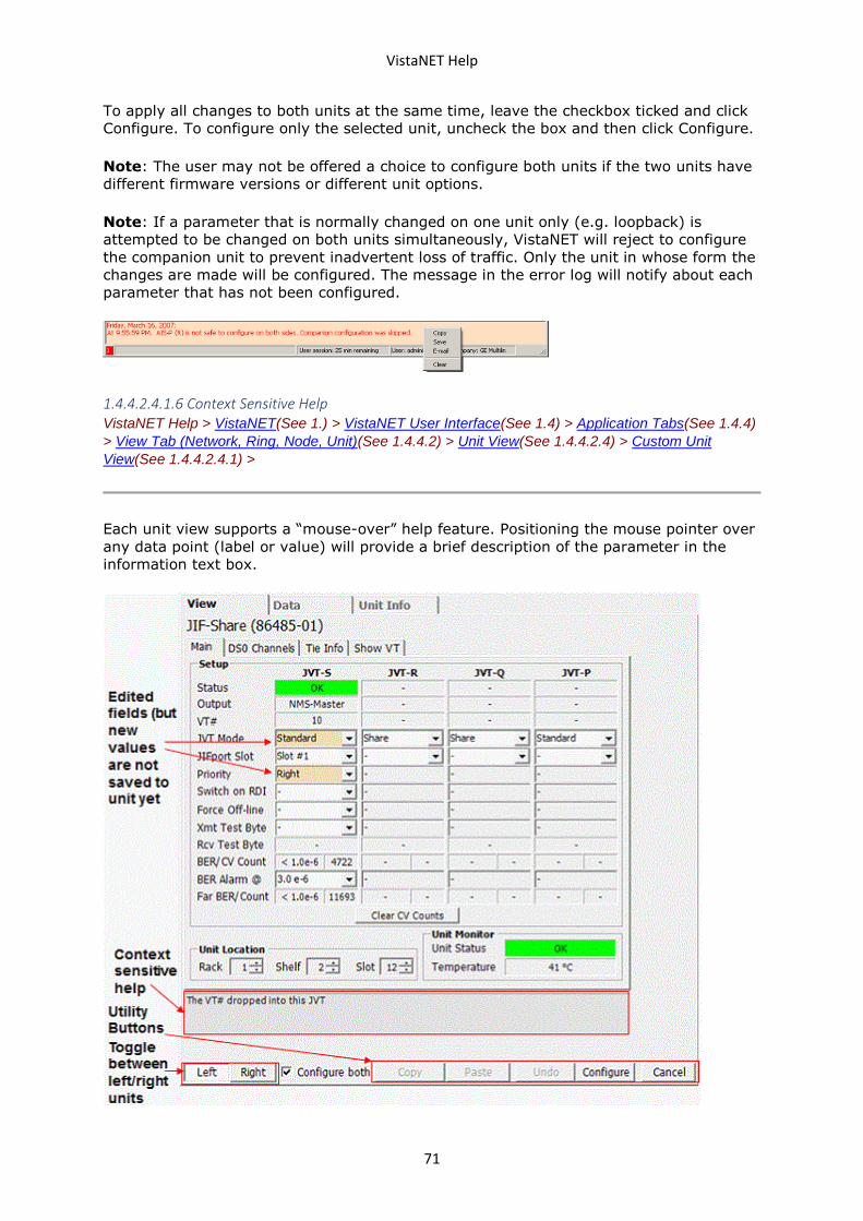
VistaNET Help
71
To apply all changes to both units at the same time, leave the checkbox ticked and click
Configure. To configure only the selected unit, uncheck the box and then click Configure.
Note: The user may not be offered a choice to configure both units if the two units have
different firmware versions or different unit options.
Note: If a parameter that is normally changed on one unit only (e.g. loopback) is
attempted to be changed on both units simultaneously, VistaNET will reject to configure
the companion unit to prevent inadvertent loss of traffic. Only the unit in whose form the
changes are made will be configured. The message in the error log will notify about each
parameter that has not been configured.
1.4.4.2.4.1.6 Context Sensitive Help VistaNET Help > VistaNET(See 1.) > VistaNET User Interface(See 1.4) > Application Tabs(See 1.4.4)
> View Tab (Network, Ring, Node, Unit)(See 1.4.4.2) > Unit View(See 1.4.4.2.4) > Custom Unit
View(See 1.4.4.2.4.1) >
Each unit view supports a “mouse-over” help feature. Positioning the mouse pointer over
any data point (label or value) will provide a brief description of the parameter in the
information text box.
VistaNET Help
72
1.4.4.2.4.1.7 Storing Unit Configuration VistaNET Help > VistaNET(See 1.) > VistaNET User Interface(See 1.4) > Application Tabs(See 1.4.4)
> View Tab (Network, Ring, Node, Unit)(See 1.4.4.2) > Unit View(See 1.4.4.2.4) > Custom Unit
View(See 1.4.4.2.4.1) >
To save unit configuration into a file (.vux):
• Select "Save Unit Data to a File" icon on the System Icons Toolbar(See 1.4.2)
• Navigate to the directory where unit configuration file is to be stored
• Click "Save" button.
1.4.4.2.4.1.8 Restoring Unit Configuration VistaNET Help > VistaNET(See 1.) > VistaNET User Interface(See 1.4) > Application Tabs(See 1.4.4)
> View Tab (Network, Ring, Node, Unit)(See 1.4.4.2) > Unit View(See 1.4.4.2.4) > Custom Unit
View(See 1.4.4.2.4.1) >
To restore unit configuration from a previously stored file:
• Select "Restore Unit Data from a File" icon on the System Icons Toolbar(See
1.4.2)
• Navigate to the directory where file was previously stored (.vux extension)
• Click OK and wait for VistaNET to apply the differences to the current unit view.
1.4.4.2.4.1.9 Printing VistaNET Help > VistaNET(See 1.) > VistaNET User Interface(See 1.4) > Application Tabs(See 1.4.4)
> View Tab (Network, Ring, Node, Unit)(See 1.4.4.2) > Unit View(See 1.4.4.2.4) > Custom Unit
View(See 1.4.4.2.4.1) >
To print the current unit view, click on the Print Current Tab icon located in the
System Icons Toolbar(See 1.4.2) .
1.4.4.2.4.2 Data View VistaNET Help > VistaNET(See 1.) > VistaNET User Interface(See 1.4) > Application Tabs(See 1.4.4)
> View Tab (Network, Ring, Node, Unit)(See 1.4.4.2) > Unit View(See 1.4.4.2.4) >
Note: This feature is available to both VLA and VNI users.
The Data View displays values, access types and descriptions for all unit parameters
(data points) for a selected unit in raw (non-user-friendly) format.
To open the Data View, select any unit in the system tree (from Local or Network
connections) and click on the Data tab.
To open the Data View:
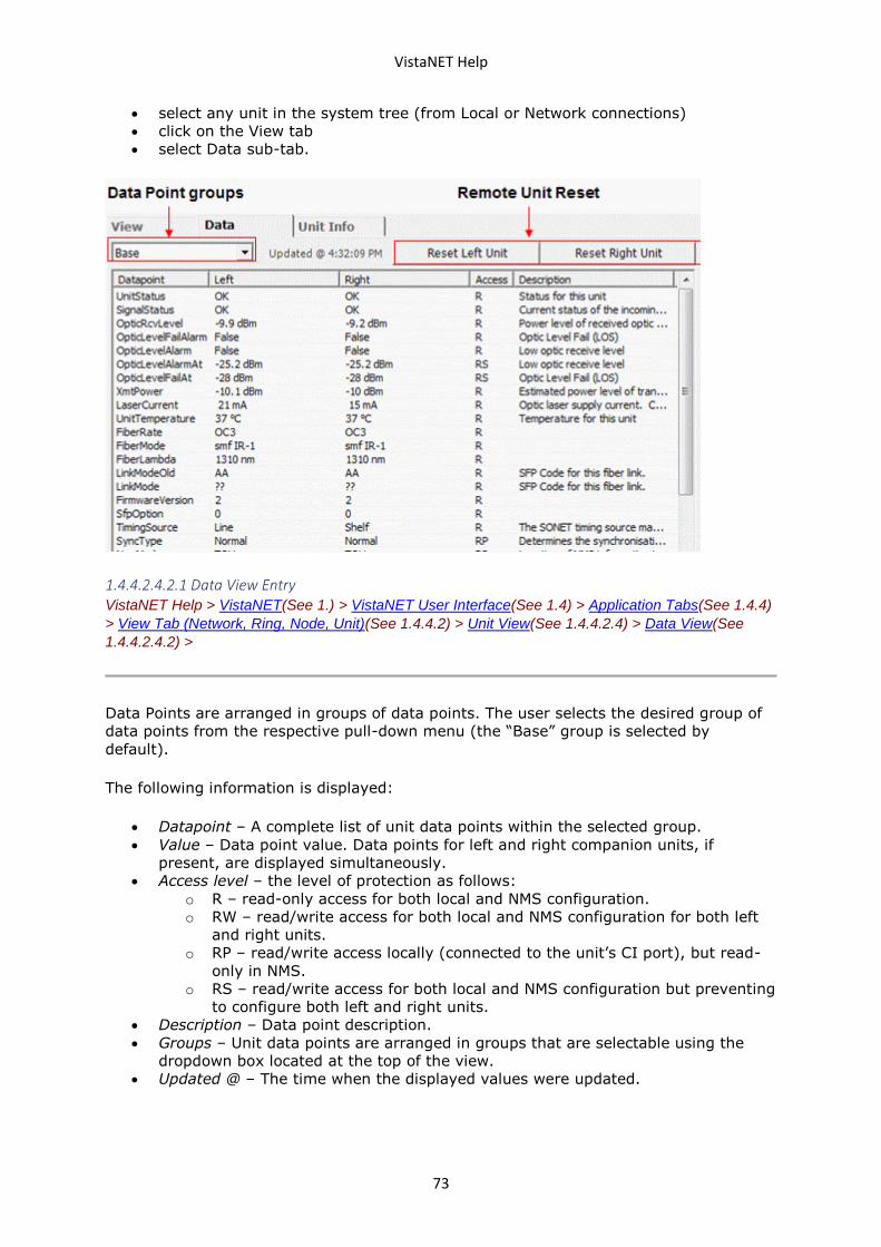
VistaNET Help
73
• select any unit in the system tree (from Local or Network connections)
• click on the View tab
• select Data sub-tab.
1.4.4.2.4.2.1 Data View Entry VistaNET Help > VistaNET(See 1.) > VistaNET User Interface(See 1.4) > Application Tabs(See 1.4.4)
> View Tab (Network, Ring, Node, Unit)(See 1.4.4.2) > Unit View(See 1.4.4.2.4) > Data View(See
1.4.4.2.4.2) >
Data Points are arranged in groups of data points. The user selects the desired group of
data points from the respective pull-down menu (the “Base” group is selected by
default).
The following information is displayed:
• Datapoint – A complete list of unit data points within the selected group.
• Value – Data point value. Data points for left and right companion units, if
present, are displayed simultaneously.
• Access level – the level of protection as follows:
o R – read-only access for both local and NMS configuration.
o RW – read/write access for both local and NMS configuration for both left
and right units.
o RP – read/write access locally (connected to the unit’s CI port), but read-
only in NMS.
o RS – read/write access for both local and NMS configuration but preventing
to configure both left and right units.
• Description – Data point description.
• Groups – Unit data points are arranged in groups that are selectable using the
dropdown box located at the top of the view.
• Updated @ – The time when the displayed values were updated.
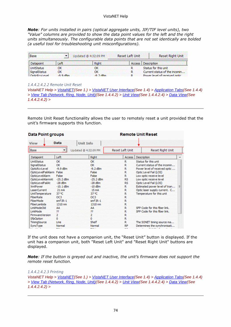
VistaNET Help
74
Note: For units installed in pairs (optical aggregate units, JIF/TIF level units), two
"Value" columns are provided to show the data point values for the left and the right
units simultaneously. The configurable data points that are not set identically are bolded
(a useful tool for troubleshooting unit misconfigurations).
1.4.4.2.4.2.2 Remote Unit Reset VistaNET Help > VistaNET(See 1.) > VistaNET User Interface(See 1.4) > Application Tabs(See 1.4.4)
> View Tab (Network, Ring, Node, Unit)(See 1.4.4.2) > Unit View(See 1.4.4.2.4) > Data View(See
1.4.4.2.4.2) >
Remote Unit Reset functionality allows the user to remotely reset a unit provided that the
unit’s firmware supports this function.
If the unit does not have a companion unit, the “Reset Unit” button is displayed. If the
unit has a companion unit, both "Reset Left Unit" and "Reset Right Unit" buttons are
displayed.
Note: If the button is greyed out and inactive, the unit’s firmware does not support the
remote reset function.
1.4.4.2.4.2.3 Printing VistaNET Help > VistaNET(See 1.) > VistaNET User Interface(See 1.4) > Application Tabs(See 1.4.4)
> View Tab (Network, Ring, Node, Unit)(See 1.4.4.2) > Unit View(See 1.4.4.2.4) > Data View(See
1.4.4.2.4.2) >
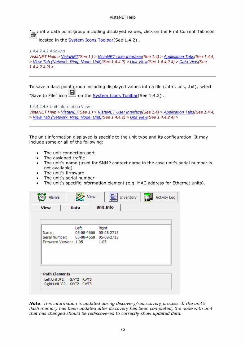
VistaNET Help
75
To print a data point group including displayed values, click on the Print Current Tab icon
located in the System Icons Toolbar(See 1.4.2) .
1.4.4.2.4.2.4 Saving VistaNET Help > VistaNET(See 1.) > VistaNET User Interface(See 1.4) > Application Tabs(See 1.4.4)
> View Tab (Network, Ring, Node, Unit)(See 1.4.4.2) > Unit View(See 1.4.4.2.4) > Data View(See
1.4.4.2.4.2) >
To save a data point group including displayed values into a file (.htm, .xls, .txt), select
"Save to File" icon on the System Icons Toolbar(See 1.4.2) .
1.4.4.2.4.3 Unit Information View VistaNET Help > VistaNET(See 1.) > VistaNET User Interface(See 1.4) > Application Tabs(See 1.4.4)
> View Tab (Network, Ring, Node, Unit)(See 1.4.4.2) > Unit View(See 1.4.4.2.4) >
The unit information displayed is specific to the unit type and its configuration. It may
include some or all of the following:
• The unit connection port
• The assigned traffic
• The unit's name (used for SNMP context name in the case unit's serial number is
not available)
• The unit's firmware
• The unit's serial number
• The unit's specific information element (e.g. MAC address for Ethernet units).
Note: This information is updated during discovery/rediscovery process. If the unit’s
flash memory has been updated after discovery has been completed, the node with unit
that has changed should be rediscovered to correctly show updated data.
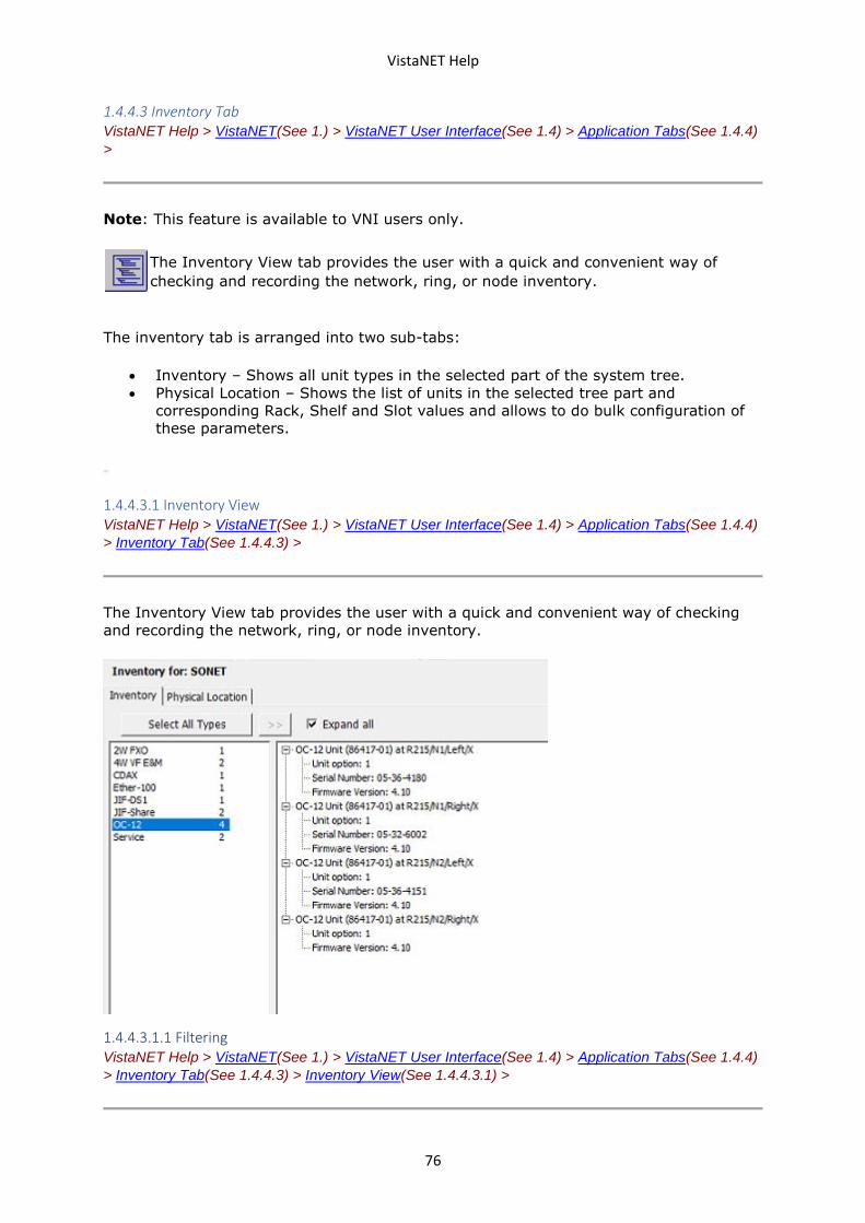
VistaNET Help
76
1.4.4.3 Inventory Tab VistaNET Help > VistaNET(See 1.) > VistaNET User Interface(See 1.4) > Application Tabs(See 1.4.4)
>
Note: This feature is available to VNI users only.
The Inventory View tab provides the user with a quick and convenient way of
checking and recording the network, ring, or node inventory.
The inventory tab is arranged into two sub-tabs:
• Inventory – Shows all unit types in the selected part of the system tree.
• Physical Location – Shows the list of units in the selected tree part and
corresponding Rack, Shelf and Slot values and allows to do bulk configuration of
these parameters.
1.4.4.3.1 Inventory View VistaNET Help > VistaNET(See 1.) > VistaNET User Interface(See 1.4) > Application Tabs(See 1.4.4)
> Inventory Tab(See 1.4.4.3) >
The Inventory View tab provides the user with a quick and convenient way of checking
and recording the network, ring, or node inventory.
1.4.4.3.1.1 Filtering VistaNET Help > VistaNET(See 1.) > VistaNET User Interface(See 1.4) > Application Tabs(See 1.4.4)
> Inventory Tab(See 1.4.4.3) > Inventory View(See 1.4.4.3.1) >
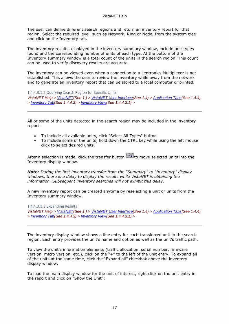
VistaNET Help
77
The user can define different search regions and return an inventory report for that
region. Select the required level, such as Network, Ring or Node, from the system tree
and click on the Inventory tab.
The inventory results, displayed in the inventory summary window, include unit types
found and the corresponding number of units of each type. At the bottom of the
Inventory summary window is a total count of the units in the search region. This count
can be used to verify discovery results are accurate.
The inventory can be viewed even when a connection to a Lentronics Multiplexer is not
established. This allows the user to review the inventory while away from the network
and to generate an inventory report that can be stored to a local computer or printed.
1.4.4.3.1.2 Querying Search Region for Specific Units VistaNET Help > VistaNET(See 1.) > VistaNET User Interface(See 1.4) > Application Tabs(See 1.4.4)
> Inventory Tab(See 1.4.4.3) > Inventory View(See 1.4.4.3.1) >
All or some of the units detected in the search region may be included in the inventory
report:
• To include all available units, click "Select All Types" button
• To include some of the units, hold down the CTRL key while using the left mouse
click to select desired units.
After a selection is made, click the transfer button to move selected units into the
Inventory display window.
Note: During the first inventory transfer from the "Summary" to "Inventory" display
windows, there is a delay to display the results while VistaNET is obtaining the
information. Subsequent inventory searches will not exhibit this delay.
A new inventory report can be created anytime by reselecting a unit or units from the
Inventory summary window.
1.4.4.3.1.3 Expanding Results VistaNET Help > VistaNET(See 1.) > VistaNET User Interface(See 1.4) > Application Tabs(See 1.4.4)
> Inventory Tab(See 1.4.4.3) > Inventory View(See 1.4.4.3.1) >
The inventory display window shows a line entry for each transferred unit in the search
region. Each entry provides the unit’s name and option as well as the unit’s traffic path.
To view the unit’s information elements (traffic allocation, serial number, firmware
version, micro version, etc.), click on the “+” to the left of the unit entry. To expand all
of the units at the same time, click the “Expand all” checkbox above the inventory
display window.
To load the main display window for the unit of interest, right click on the unit entry in
the report and click on "Show the Unit":
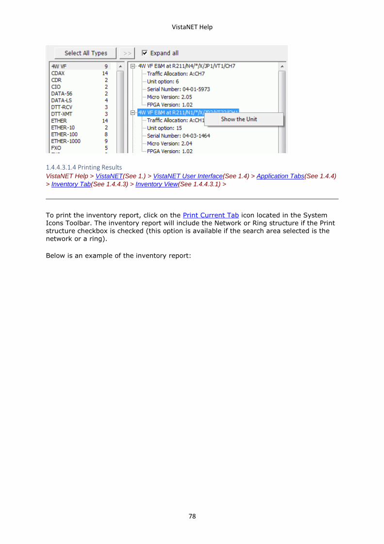
VistaNET Help
78
1.4.4.3.1.4 Printing Results VistaNET Help > VistaNET(See 1.) > VistaNET User Interface(See 1.4) > Application Tabs(See 1.4.4)
> Inventory Tab(See 1.4.4.3) > Inventory View(See 1.4.4.3.1) >
To print the inventory report, click on the Print Current Tab icon located in the System
Icons Toolbar. The inventory report will include the Network or Ring structure if the Print
structure checkbox is checked (this option is available if the search area selected is the
network or a ring).
Below is an example of the inventory report:
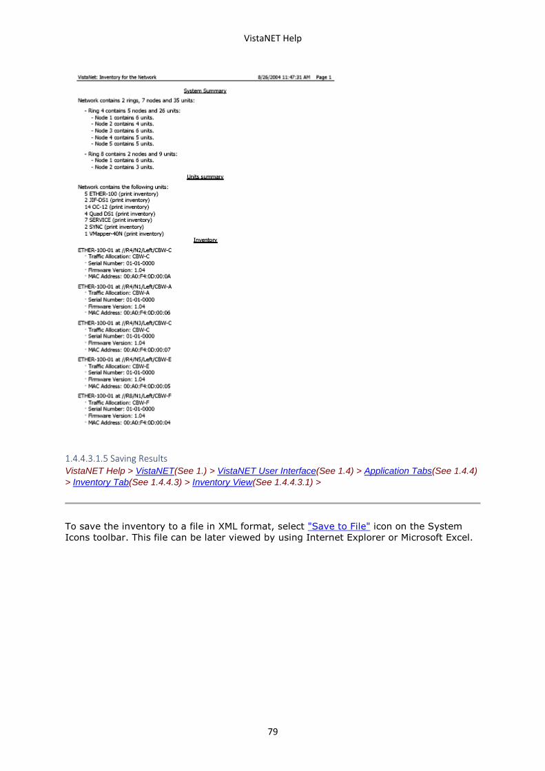
VistaNET Help
79
1.4.4.3.1.5 Saving Results VistaNET Help > VistaNET(See 1.) > VistaNET User Interface(See 1.4) > Application Tabs(See 1.4.4)
> Inventory Tab(See 1.4.4.3) > Inventory View(See 1.4.4.3.1) >
To save the inventory to a file in XML format, select "Save to File" icon on the System
Icons toolbar. This file can be later viewed by using Internet Explorer or Microsoft Excel.
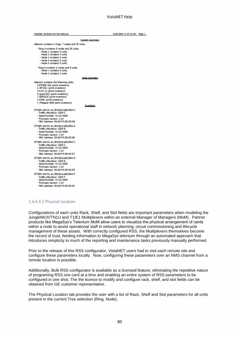
VistaNET Help
80
1.4.4.3.2 Physical Location
Configurations of each units Rack, Shelf, and Slot fields are important parameters when modeling the JungleMUX/TN1U and T1/E1 Multiplexers within an external Manager of Managers (MoM). Partner products like MegaSys’s Telenium MoM allow users to visualize the physical arrangement of cards within a node to assist operational staff in network planning, circuit commissioning and lifecycle management of these assets. With correctly configured RSS, the Multiplexers themselves become the record of trust, feeding information to MegaSys telenium through an automated approach that introduces simplicity to much of the reporting and maintenance tasks previously manually performed.
Prior to the release of this RSS configurator, VistaNET users had to visit each remote site and configure these parameters locally. Now, configuring these parameters over an NMS channel from a remote location is possible.
Additionally, Bulk RSS configurator is available as a licensed feature, eliminating the repetitive nature of programing RSS one card at a time and enabling an entire system of RSS parameters to be configured in one shot. The the licence to modify and configure rack, shelf, and slot fields can be obtained from GE customer representative.
The Physical Location tab provides the user with a list of Rack, Shelf and Slot parameters for all units present in the current Tree selection (Ring, Node).
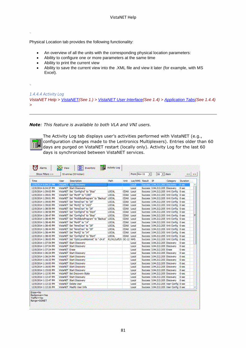
VistaNET Help
81
Physical Location tab provides the following functionality:
• An overview of all the units with the corresponding physical location parameters:
• Ability to configure one or more parameters at the same time
• Ability to print the current view
• Ability to save the current view into the .XML file and view it later (for example, with MS Excel).
1.4.4.4 Activity Log VistaNET Help > VistaNET(See 1.) > VistaNET User Interface(See 1.4) > Application Tabs(See 1.4.4)
>
Note: This feature is available to both VLA and VNI users.
The Activity Log tab displays user’s activities performed with VistaNET (e.g.,
configuration changes made to the Lentronics Multiplexers). Entries older than 60
days are purged on VistaNET restart (locally only). Activity Log for the last 60
days is synchronized between VistaNET services.
VistaNET Help
82
1.4.4.4.1 Activity Log Entry VistaNET Help > VistaNET(See 1.) > VistaNET User Interface(See 1.4) > Application Tabs(See 1.4.4)
> Activity Log(See 1.4.4.4) >
Each activity log entry provides the following information:
• Time – Time when the activity started.
• User – User that was logged in to perform the action.
• Description – Brief description of the action.
• Path – Unit’s traffic path, if action was performed on a specific unit.
• Unit – Type of unit, if action was performed on a specific unit
• Loc/NMS – How was action executed (locally or through NMS).
• Result – Result of action (Success, Fail).
• IP – IP address of the computer where the action was performed from.
• Category – Type of action performed. Possible categories are explained below.
• Duration – Time required by the VistaNET service to complete the action.
For some actions, clicking its entry in the log will show further details (user input, error
messages, etc.) in the textbox below.
Entry Categories
Below is a list of the possible entry categories and explanations of some of the entries
that may appear in that category.
Startup
Service Initialize/Shutdown – When the VistaNET Service is started or stopped
Client Connected/Disconnected – When the Service has detected a connection from a
VistaNET Client
Log In/Out
VistaNET Login/Logout – When a user has attempted to begin or end a VistaNET
configuration session. LoginName indicates the login name the user has entered, which
might not be the same as the VistaNET display name.
CSSU Send Login/Logout – When a user sends a login or logout command to a CSSU.
Note that for this action, Success only shows that the command was successfully sent,
and does not indicate whether the login was accepted.
Configuration
Set "Datapoint" to "Value" – When a user makes any configuration change to a unit. Note
that this entry may appear multiple times for one configuration action – this is because
some configuration changes set multiple datapoints at once.
Discovery
Start (Re)discovery – When a user initiates a network discovery. Erase indicates whether
the selected network tree was erased first. Traffic indicates whether traffic routing
data was collected. Range indicates the portion of the network that was discovered.
Set Discovery State – Typically occurs when a user has aborted a discovery in progress.
Erase
Erase – When a user erases part of a network tree without rediscovering it. This entry
will show the same details as Start (Re)discovery.
VistaNET Help
83
Unit Reset
Reset Service Unit – When a user initiates a service unit reset (by right-clicking a node in
the System Tree).
Reset Unit – When a user initiates a unit reset (from the unit's Data tab).
User Config
Add/Delete User – When an administrator adds or deletes user accounts from the
VistaNET Access Control List. Domain-linked account names appear in the format
L/<domain>/<user SID>.
Modify User Info – When an administrator modifies the display name or email associated
with a user account, or changes the user's group membership.
Add/Delete User Group – When an administrator creates or deletes a user group.
Modify NMS Write Restriction – When an administrator changes the unit configuration
permissions associated with a user group. Group inidicates the user group, UnitType
indicates the unit (blank indicates all units), and Range indicates the portion of the
network tree this rule applies to ("-" indicates the entire network).
Modify Group Permissions – When an administrator changes miscellaneous permissions
for a user group, such as Enable Discovery.
Register License PIN – When a new PIN has been entered to activate a VistaNET license.
Certificate
Certificate details – When a user views a certificate details.
Save certificate – When an administrator saves a copy of the selected certificate.
Select certificate – When an administrator selects a certificate file.
Validate certificate – When the certificate being selected is not valid.
Replace certificate – When an administrator replaces a certificate.
Restart VistaNET Service – When an administrator sets a schedule to restart VistaNET to
replace certificates.
Remove scheduled restart – When an administrator cancels a scheduled restart to
replace certificates.
Admin Config
24/7 VistaNET PC – When an administrator enables or disables 24/7 VistaNET PC.
Removed VSA assignment – When VSA assignments in the Serial Connections window
are removed, as a result of enabling 24/7 VistaNET PC.
VistaNET Synchronization – When synchronization and TCP/UDP listening ports
configurations are modified.
Add new connection – When a user adds a new serial, serial over IP, or modem
connection.
Modify existing connection – When a user modifies an existing serial, serial over IP, or
modem connection configuration.
Remove existing connection – When a user deletes an existing serial, serial over IP, or
modem connection.
SNMP Engine ID – When an administrator sets, edits or removes the SNMP engine ID.
SNMP Trap – When an administrator enables or disables SNMP Send Trap configuration.
SNMP V1/V2/V3 – When an administrator configures or edits the SNMP V1/V2 or V3 and
its settings.
1.4.4.4.2 Filtering VistaNET Help > VistaNET(See 1.) > VistaNET User Interface(See 1.4) > Application Tabs(See 1.4.4)
> Activity Log(See 1.4.4.4) >
Filtering allows to focus only on specific areas within the network. Several types of filters
for activity log entries are available:
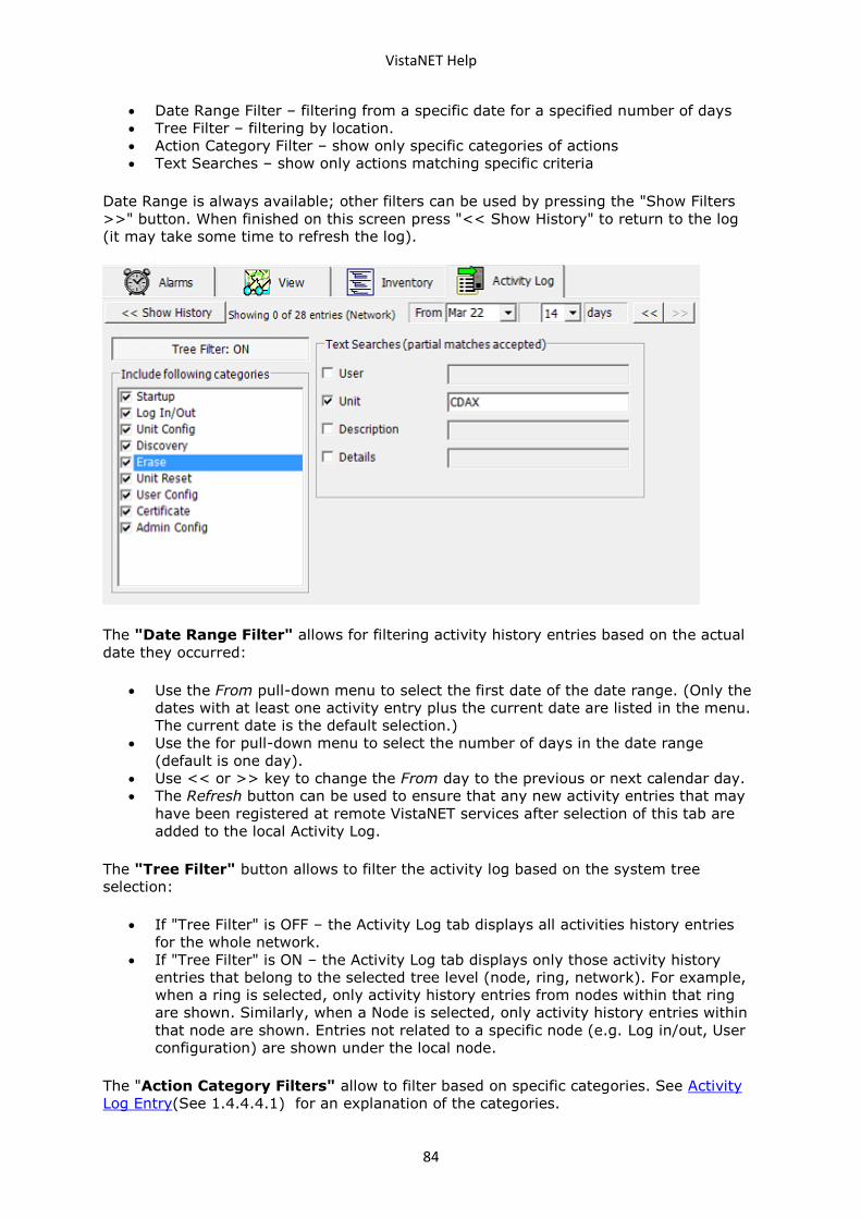
VistaNET Help
84
• Date Range Filter – filtering from a specific date for a specified number of days
• Tree Filter – filtering by location.
• Action Category Filter – show only specific categories of actions
• Text Searches – show only actions matching specific criteria
Date Range is always available; other filters can be used by pressing the "Show Filters
>>" button. When finished on this screen press "<< Show History" to return to the log
(it may take some time to refresh the log).
The "Date Range Filter" allows for filtering activity history entries based on the actual
date they occurred:
• Use the From pull-down menu to select the first date of the date range. (Only the
dates with at least one activity entry plus the current date are listed in the menu.
The current date is the default selection.)
• Use the for pull-down menu to select the number of days in the date range
(default is one day).
• Use << or >> key to change the From day to the previous or next calendar day.
• The Refresh button can be used to ensure that any new activity entries that may
have been registered at remote VistaNET services after selection of this tab are
added to the local Activity Log.
The "Tree Filter" button allows to filter the activity log based on the system tree
selection:
• If "Tree Filter" is OFF – the Activity Log tab displays all activities history entries
for the whole network.
• If "Tree Filter" is ON – the Activity Log tab displays only those activity history
entries that belong to the selected tree level (node, ring, network). For example,
when a ring is selected, only activity history entries from nodes within that ring
are shown. Similarly, when a Node is selected, only activity history entries within
that node are shown. Entries not related to a specific node (e.g. Log in/out, User
configuration) are shown under the local node.
The "Action Category Filters" allow to filter based on specific categories. See Activity
Log Entry(See 1.4.4.4.1) for an explanation of the categories.
VistaNET Help
85
The "Text Searches" allow to show only entries matching specific text searches. When
checked, the log will only show entries where the chosen field contains the given text.
More than one text search may be used.
1.4.4.4.3 Printing & Saving VistaNET Help > VistaNET(See 1.) > VistaNET User Interface(See 1.4) > Application Tabs(See 1.4.4)
> Activity Log(See 1.4.4.4) >
To print the activity log, click on the Print Current Tab icon located in the System Icons
Toolbar.
To save activity log into a file, select "Save to File" icon on the System Icons toolbar.
Three formats are available:
• CSV – Comma-seperated values; For use in Excel and most other spreadsheet
programs.
• HTM – HTML; For viewing in any web browser
• TXT – Tab seperated text; for text-based interfaces.
1.4.5 Clear Error Counters/Clear Ethernet Traffic Counters VistaNET Help > VistaNET(See 1.) > VistaNET User Interface(See 1.4) >
Clear Error Counters is a licensed VistaNET feature that allows users to remotely clear CV
counters across a wide range of nodes and across different equipment categories. Until
the release of this feature, users were only able to Clear Error Counters on a unit by unit
basis.
Clear Error Counters:
Now, with Clear Error Counters licensed, users can clear all CV across all Optics,
SPE/TUG-3, JIF/TIF level cards within defined ranges (Rings or within a Node).
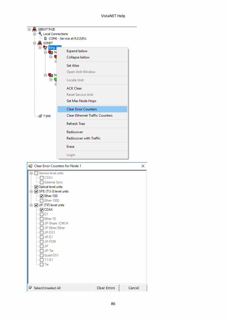
VistaNET Help
86
VistaNET Help
87
Clear Ethernet Traffic Counters:
For Ether-100/1000 units, clearing Traffic counters is also now available. Select between
clearing Error counters or Clearing Ethernet Traffic counters from VistaNET’s navigation
tree at the ring or node level.
The implications on efficiency and overall costs savings are immediately obvious. Users
can clear all the error counts within a single ring in one configuration step or reset all the
counters within each of their Ether-100/1000 units without clearing counters within the
T1/E1 units.
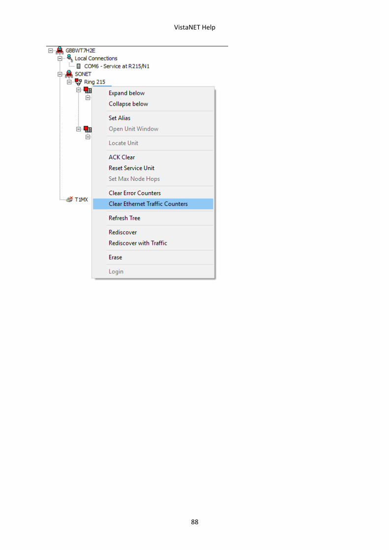
VistaNET Help
88
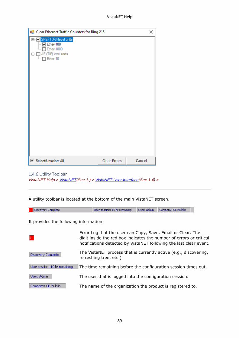
VistaNET Help
89
1.4.6 Utility Toolbar VistaNET Help > VistaNET(See 1.) > VistaNET User Interface(See 1.4) >
A utility toolbar is located at the bottom of the main VistaNET screen.
It provides the following information:
Error Log that the user can Copy, Save, Email or Clear. The
digit inside the red box indicates the number of errors or critical
notifications detected by VistaNET following the last clear event.
The VistaNET process that is currently active (e.g., discovering,
refreshing tree, etc.)
The time remaining before the configuration session times out.
The user that is logged into the configuration session.
The name of the organization the product is registered to.
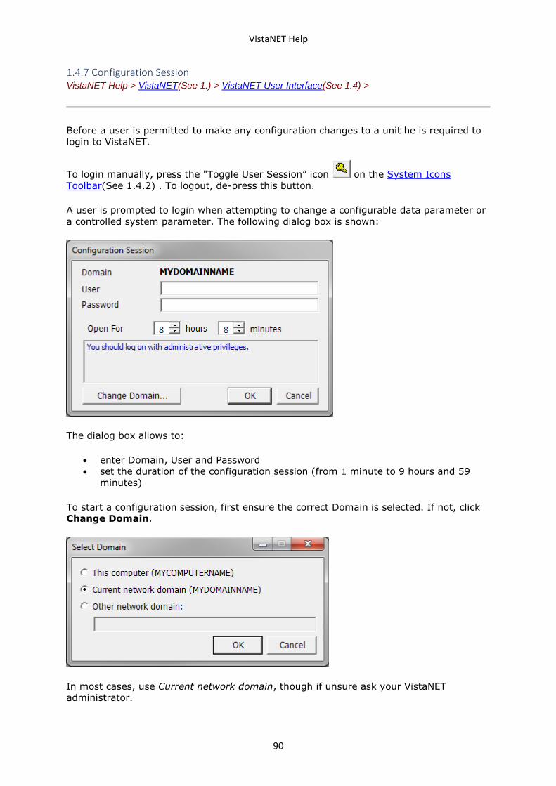
VistaNET Help
90
1.4.7 Configuration Session VistaNET Help > VistaNET(See 1.) > VistaNET User Interface(See 1.4) >
Before a user is permitted to make any configuration changes to a unit he is required to
login to VistaNET.
To login manually, press the "Toggle User Session” icon on the System Icons
Toolbar(See 1.4.2) . To logout, de-press this button.
A user is prompted to login when attempting to change a configurable data parameter or
a controlled system parameter. The following dialog box is shown:
The dialog box allows to:
• enter Domain, User and Password
• set the duration of the configuration session (from 1 minute to 9 hours and 59
minutes)
To start a configuration session, first ensure the correct Domain is selected. If not, click
Change Domain.
In most cases, use Current network domain, though if unsure ask your VistaNET
administrator.
VistaNET Help
91
When the correct domain is selected, enter user name and password and click “OK”. If
the login is successful, configuration session information (the user name, the
organization name the data file is licensed to, and the remaining session time) appears in
the utility toolbar(See 1.4.6).
Once a configuration session has been activated, the user can make changes to
configurable unit parameters unless prevented by the security restrictions imposed by
the administrator for the user group he belongs to. Note that only the Unit View can be
used to change unit parameters. Refer to individual unit’s Technical Practice and
Installation Manuals for more information on units’ configurable parameters.
Both VLA and VNI will permit users to configure units connected via a local connection.
VNI will also permit users to make changes to remote units through a direct or modem
connection to a Service Unit’s CI port or through VistaNET servers.
1.4.8 Active Services VistaNET Help > VistaNET(See 1.) > VistaNET User Interface(See 1.4) >
The Active Services window provides information about services connected to the
distributed VistaNET network and which nodes each service is managing.
To open the Active Services window, click on the Active Services icon in the System
Icons Toolbar(See 1.4.2) .
The Peers tab allows viewing all active peers (computers running the same version of
VistaNET) currently connected to the local VistaNET. When a particular peer is selected,
the second half of the window shows rings and nodes available through the selected
peer.
To view the list of nodes managed by any listed service, double-click on a service of
interest. Services with no VSA-enabled ports will show ‘None’. Services with VSA-enabled
ports and IPSUs will display the Ring and Node numbers of the managed nodes.

VistaNET Help
92
1.4.9 Information about VistaNET VistaNET Help > VistaNET(See 1.) > VistaNET User Interface(See 1.4) >
To obtain the information about VistaNET, click on the Information icon in the
VistaNET System Icons Toolbar(See 1.4.2) .
The Version tab provides:
• software version
• passport (license/data file) version
• a link to the GE Multilin website that provides access to all user guides and
Technical Practice and Installation Manuals online, including this user’s manual
• build date
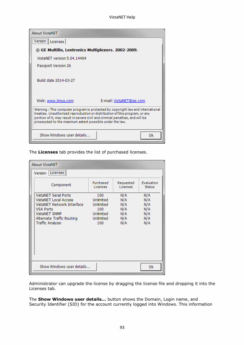
VistaNET Help
93
The Licenses tab provides the list of purchased licenses.
Administrator can upgrade the license by dragging the license file and dropping it into the
Licenses tab.
The Show Windows user details... button shows the Domain, Login name, and
Security Identifier (SID) for the account currently logged into Windows. This information
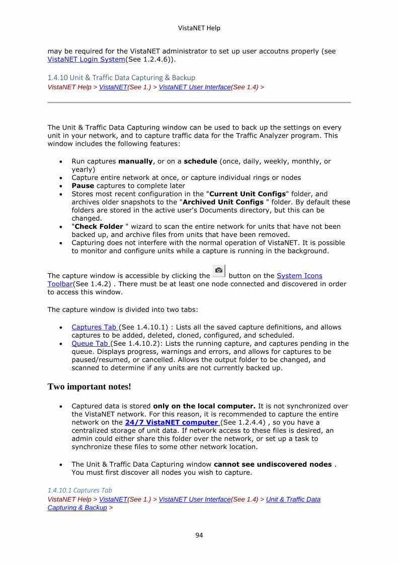
VistaNET Help
94
may be required for the VistaNET administrator to set up user accoutns properly (see
VistaNET Login System(See 1.2.4.6)).
1.4.10 Unit & Traffic Data Capturing & Backup VistaNET Help > VistaNET(See 1.) > VistaNET User Interface(See 1.4) >
The Unit & Traffic Data Capturing window can be used to back up the settings on every
unit in your network, and to capture traffic data for the Traffic Analyzer program. This
window includes the following features:
• Run captures manually, or on a schedule (once, daily, weekly, monthly, or
yearly)
• Capture entire network at once, or capture individual rings or nodes
• Pause captures to complete later
• Stores most recent configuration in the "Current Unit Configs" folder, and
archives older snapshots to the "Archived Unit Configs " folder. By default these
folders are stored in the active user's Documents directory, but this can be
changed.
• "Check Folder " wizard to scan the entire network for units that have not been
backed up, and archive files from units that have been removed.
• Capturing does not interfere with the normal operation of VistaNET. It is possible
to monitor and configure units while a capture is running in the background.
The capture window is accessible by clicking the button on the System Icons
Toolbar(See 1.4.2) . There must be at least one node connected and discovered in order
to access this window.
The capture window is divided into two tabs:
• Captures Tab (See 1.4.10.1) : Lists all the saved capture definitions, and allows
captures to be added, deleted, cloned, configured, and scheduled.
• Queue Tab (See 1.4.10.2): Lists the running capture, and captures pending in the
queue. Displays progress, warnings and errors, and allows for captures to be
paused/resumed, or cancelled. Allows the output folder to be changed, and
scanned to determine if any units are not currently backed up.
Two important notes!
• Captured data is stored only on the local computer. It is not synchronized over
the VistaNET network. For this reason, it is recommended to capture the entire
network on the 24/7 VistaNET computer (See 1.2.4.4) , so you have a
centralized storage of unit data. If network access to these files is desired, an
admin could either share this folder over the network, or set up a task to
synchronize these files to some other network location.
• The Unit & Traffic Data Capturing window cannot see undiscovered nodes .
You must first discover all nodes you wish to capture.
1.4.10.1 Captures Tab VistaNET Help > VistaNET(See 1.) > VistaNET User Interface(See 1.4) > Unit & Traffic Data
Capturing & Backup >
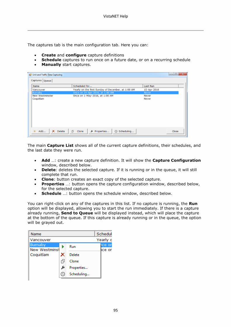
VistaNET Help
95
The captures tab is the main configuration tab. Here you can:
• Create and configure capture definitions
• Schedule captures to run once on a future date, or on a recurring schedule
• Manually start captures.
The main Capture List shows all of the current capture definitions, their schedules, and
the last date they were run.
• Add …: create a new capture definition. It will show the Capture Configuration
window, described below.
• Delete: deletes the selected capture. If it is running or in the queue, it will still
complete that run.
• Clone: button creates an exact copy of the selected capture.
• Properties …: button opens the capture configuration window, described below,
for the selected capture.
• Schedule …: button opens the schedule window, described below.
You can right-click on any of the captures in this list. If no capture is running, the Run
option will be displayed, allowing you to start the run immediately. If there is a capture
already running, Send to Queue will be displayed instead, which will place the capture
at the bottom of the queue. If this capture is already running or in the queue, the option
will be grayed out.
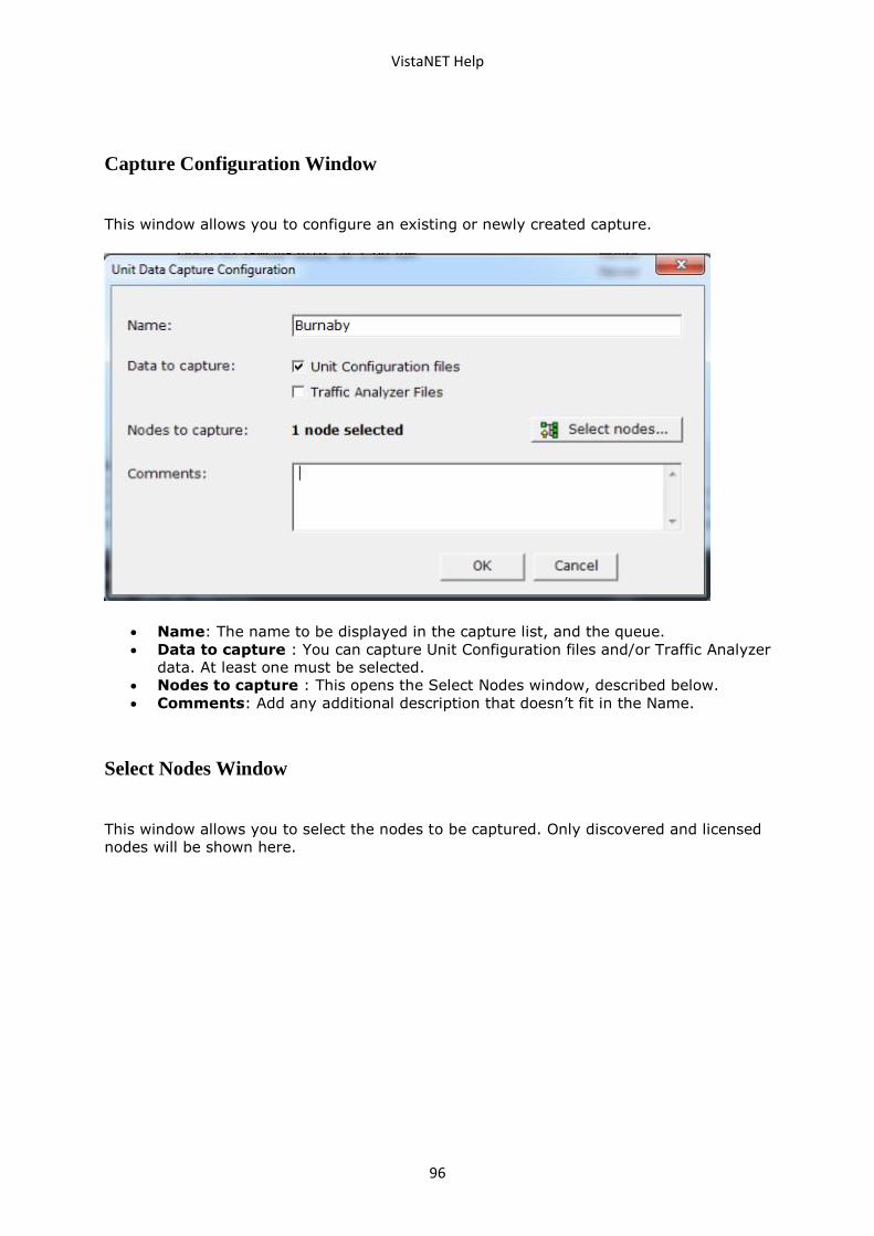
VistaNET Help
96
Capture Configuration Window
This window allows you to configure an existing or newly created capture.
• Name: The name to be displayed in the capture list, and the queue.
• Data to capture : You can capture Unit Configuration files and/or Traffic Analyzer
data. At least one must be selected.
• Nodes to capture : This opens the Select Nodes window, described below.
• Comments: Add any additional description that doesn’t fit in the Name.
Select Nodes Window
This window allows you to select the nodes to be captured. Only discovered and licensed
nodes will be shown here.
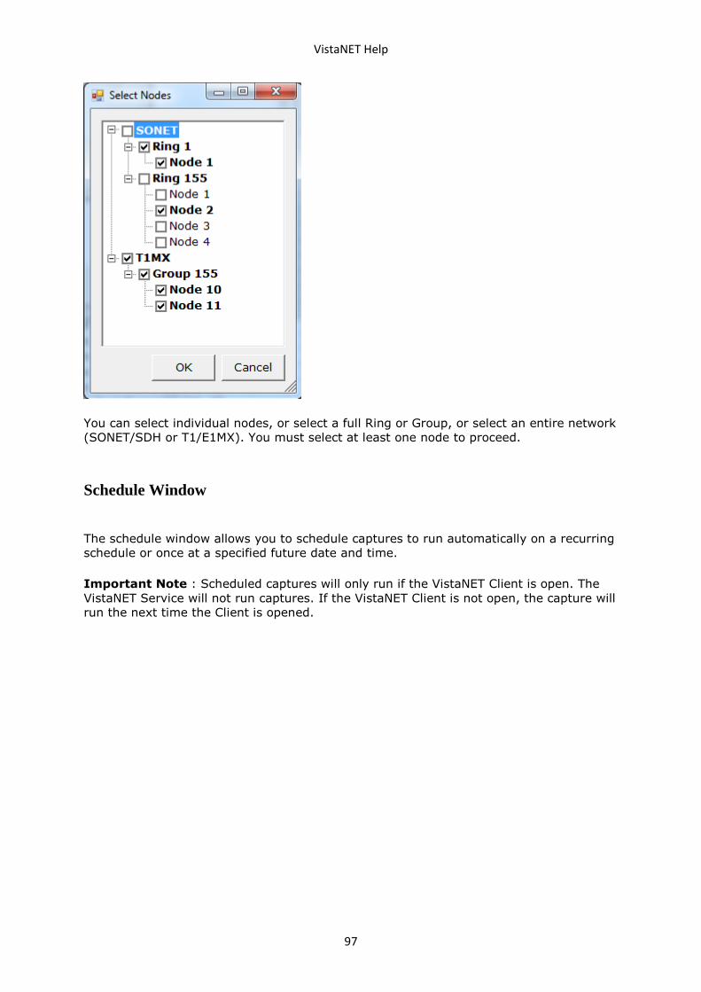
VistaNET Help
97
You can select individual nodes, or select a full Ring or Group, or select an entire network
(SONET/SDH or T1/E1MX). You must select at least one node to proceed.
Schedule Window
The schedule window allows you to schedule captures to run automatically on a recurring
schedule or once at a specified future date and time.
Important Note : Scheduled captures will only run if the VistaNET Client is open. The
VistaNET Service will not run captures. If the VistaNET Client is not open, the capture will
run the next time the Client is opened.
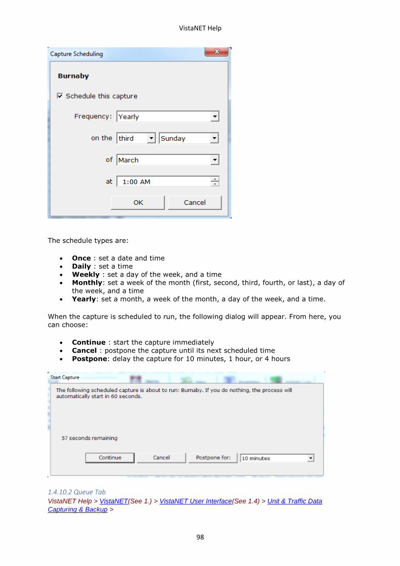
VistaNET Help
98
The schedule types are:
• Once : set a date and time
• Daily : set a time
• Weekly : set a day of the week, and a time
• Monthly: set a week of the month (first, second, third, fourth, or last), a day of
the week, and a time
• Yearly: set a month, a week of the month, a day of the week, and a time.
When the capture is scheduled to run, the following dialog will appear. From here, you
can choose:
• Continue : start the capture immediately
• Cancel : postpone the capture until its next scheduled time
• Postpone: delay the capture for 10 minutes, 1 hour, or 4 hours
1.4.10.2 Queue Tab VistaNET Help > VistaNET(See 1.) > VistaNET User Interface(See 1.4) > Unit & Traffic Data
Capturing & Backup >
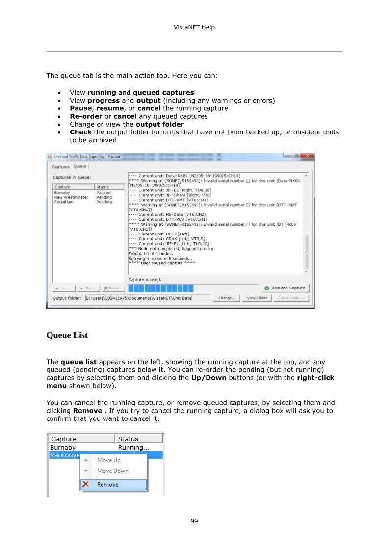
VistaNET Help
99
The queue tab is the main action tab. Here you can:
• View running and queued captures
• View progress and output (including any warnings or errors)
• Pause, resume, or cancel the running capture
• Re-order or cancel any queued captures
• Change or view the output folder
• Check the output folder for units that have not been backed up, or obsolete units
to be archived
Queue List
The queue list appears on the left, showing the running capture at the top, and any
queued (pending) captures below it. You can re-order the pending (but not running)
captures by selecting them and clicking the Up/Down buttons (or with the right-click
menu shown below).
You can cancel the running capture, or remove queued captures, by selecting them and
clicking Remove . If you try to cancel the running capture, a dialog box will ask you to
confirm that you want to cancel it.
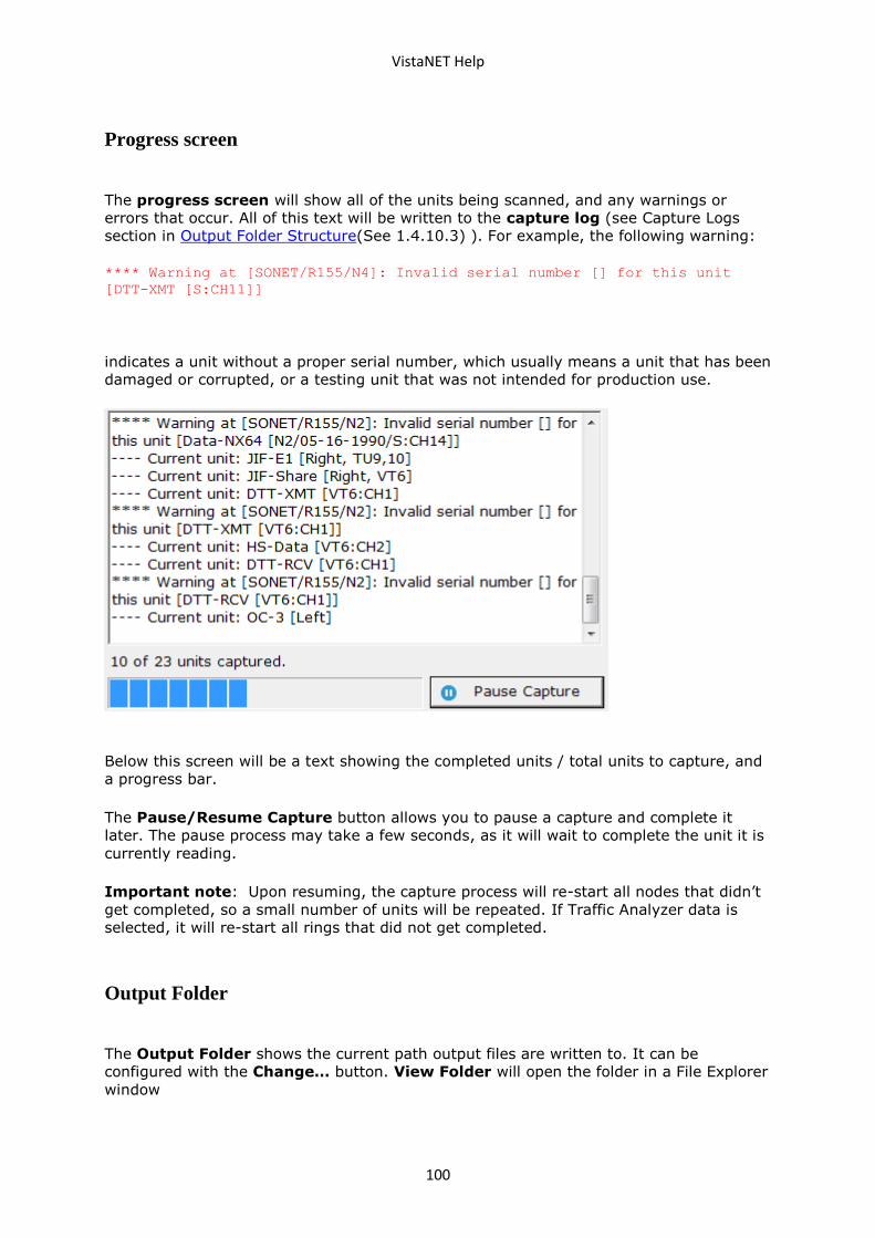
VistaNET Help
100
Progress screen
The progress screen will show all of the units being scanned, and any warnings or
errors that occur. All of this text will be written to the capture log (see Capture Logs
section in Output Folder Structure(See 1.4.10.3) ). For example, the following warning:
**** Warning at [SONET/R155/N4]: Invalid serial number [] for this unit
[DTT-XMT [S:CH11]]
indicates a unit without a proper serial number, which usually means a unit that has been
damaged or corrupted, or a testing unit that was not intended for production use.
Below this screen will be a text showing the completed units / total units to capture, and
a progress bar.
The Pause/Resume Capture button allows you to pause a capture and complete it
later. The pause process may take a few seconds, as it will wait to complete the unit it is
currently reading.
Important note: Upon resuming, the capture process will re-start all nodes that didn’t
get completed, so a small number of units will be repeated. If Traffic Analyzer data is
selected, it will re-start all rings that did not get completed.
Output Folder
The Output Folder shows the current path output files are written to. It can be
configured with the Change… button. View Folder will open the folder in a File Explorer
window
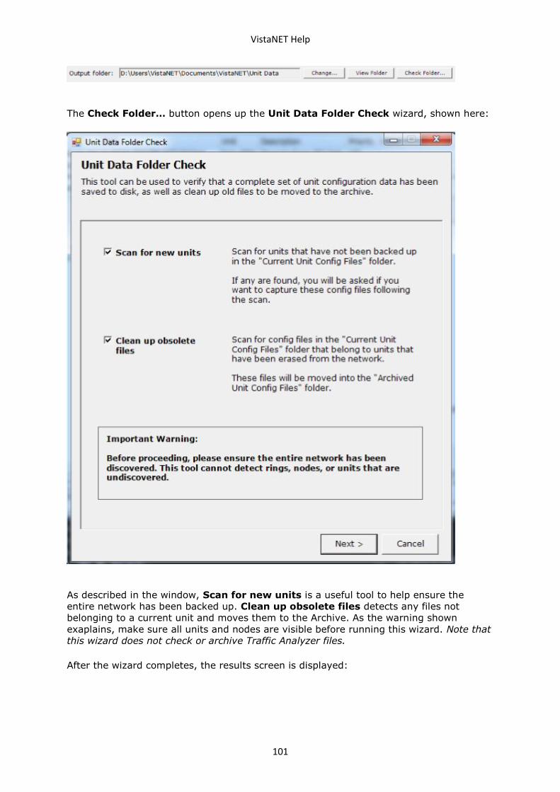
VistaNET Help
101
The Check Folder… button opens up the Unit Data Folder Check wizard, shown here:
As described in the window, Scan for new units is a useful tool to help ensure the
entire network has been backed up. Clean up obsolete files detects any files not
belonging to a current unit and moves them to the Archive. As the warning shown
exaplains, make sure all units and nodes are visible before running this wizard. Note that
this wizard does not check or archive Traffic Analyzer files.
After the wizard completes, the results screen is displayed:
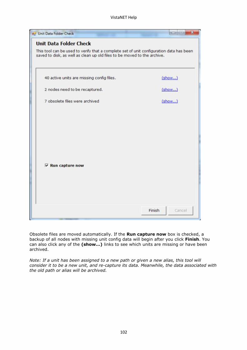
VistaNET Help
102
Obsolete files are moved automatically. If the Run capture now box is checked, a
backup of all nodes with missing unit config data will begin after you click Finish. You
can also click any of the (show…) links to see which units are missing or have been
archived.
Note: If a unit has been assigned to a new path or given a new alias, this tool will
consider it to be a new unit, and re-capture its data. Meanwhile, the data associated with
the old path or alias will be archived.
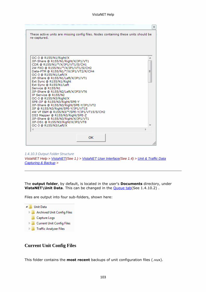
VistaNET Help
103
1.4.10.3 Output Folder Structure VistaNET Help > VistaNET(See 1.) > VistaNET User Interface(See 1.4) > Unit & Traffic Data
Capturing & Backup >
The output folder, by default, is located in the user's Documents directory, under
VistaNET\Unit Data. This can be changed in the Queue tab(See 1.4.10.2) .
Files are output into four sub-folders, shown here:
Current Unit Config Files
This folder contains the most recent backups of unit configuration files (.vux).
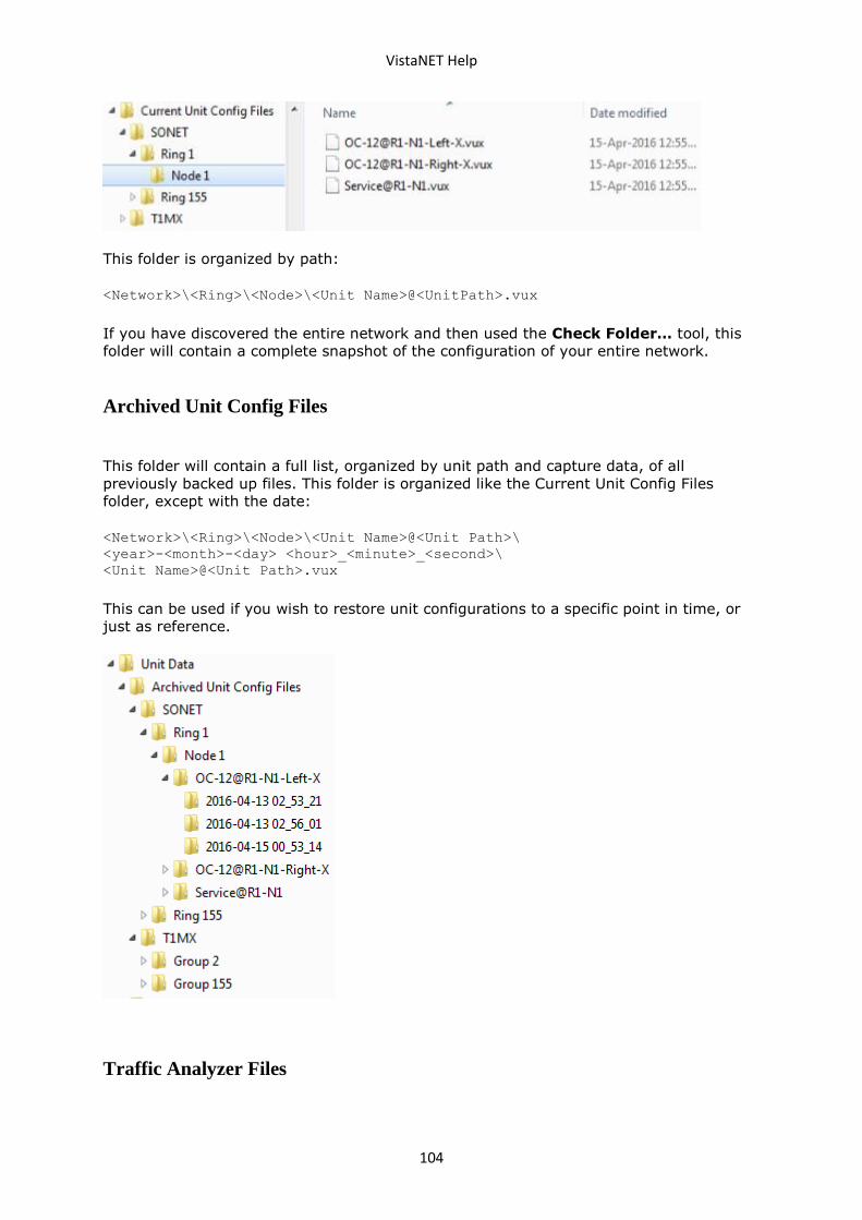
VistaNET Help
104
This folder is organized by path:
<Network>\<Ring>\<Node>\<Unit Name>@<UnitPath>.vux
If you have discovered the entire network and then used the Check Folder… tool, this
folder will contain a complete snapshot of the configuration of your entire network.
Archived Unit Config Files
This folder will contain a full list, organized by unit path and capture data, of all
previously backed up files. This folder is organized like the Current Unit Config Files
folder, except with the date:
<Network>\<Ring>\<Node>\<Unit Name>@<Unit Path>\
<year>-<month>-<day> <hour>_<minute>_<second>\
<Unit Name>@<Unit Path>.vux
This can be used if you wish to restore unit configurations to a specific point in time, or
just as reference.
Traffic Analyzer Files
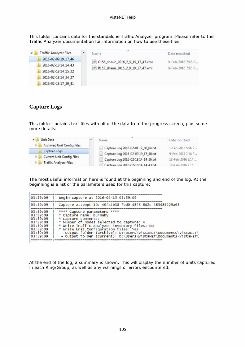
VistaNET Help
105
This folder contains data for the standalone Traffic Analyzer program. Please refer to the
Traffic Analyzer documentation for information on how to use these files.
Capture Logs
This folder contains text files with all of the data from the progress screen, plus some
more details.
The most useful information here is found at the beginning and end of the log. At the
beginning is a list of the parameters used for this capture:
At the end of the log, a summary is shown. This will display the number of units captured
in each Ring/Group, as well as any warnings or errors encountered.
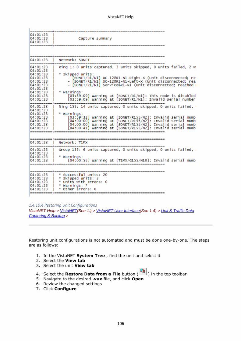
VistaNET Help
106
1.4.10.4 Restoring Unit Configurations VistaNET Help > VistaNET(See 1.) > VistaNET User Interface(See 1.4) > Unit & Traffic Data
Capturing & Backup >
Restoring unit configurations is not automated and must be done one-by-one. The steps
are as follows:
1. In the VistaNET System Tree , find the unit and select it
2. Select the View tab
3. Select the unit View tab
4. Select the Restore Data from a File button ( ) in the top toolbar
5. Navigate to the desired .vux file, and click Open
6. Review the changed settings
7. Click Configure
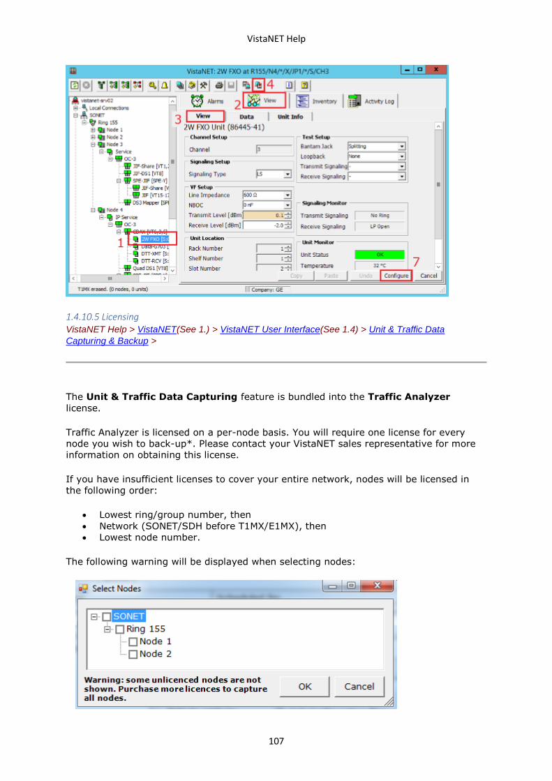
VistaNET Help
107
1.4.10.5 Licensing VistaNET Help > VistaNET(See 1.) > VistaNET User Interface(See 1.4) > Unit & Traffic Data
Capturing & Backup >
The Unit & Traffic Data Capturing feature is bundled into the Traffic Analyzer
license.
Traffic Analyzer is licensed on a per-node basis. You will require one license for every
node you wish to back-up*. Please contact your VistaNET sales representative for more
information on obtaining this license.
If you have insufficient licenses to cover your entire network, nodes will be licensed in
the following order:
• Lowest ring/group number, then
• Network (SONET/SDH before T1MX/E1MX), then
• Lowest node number.
The following warning will be displayed when selecting nodes:
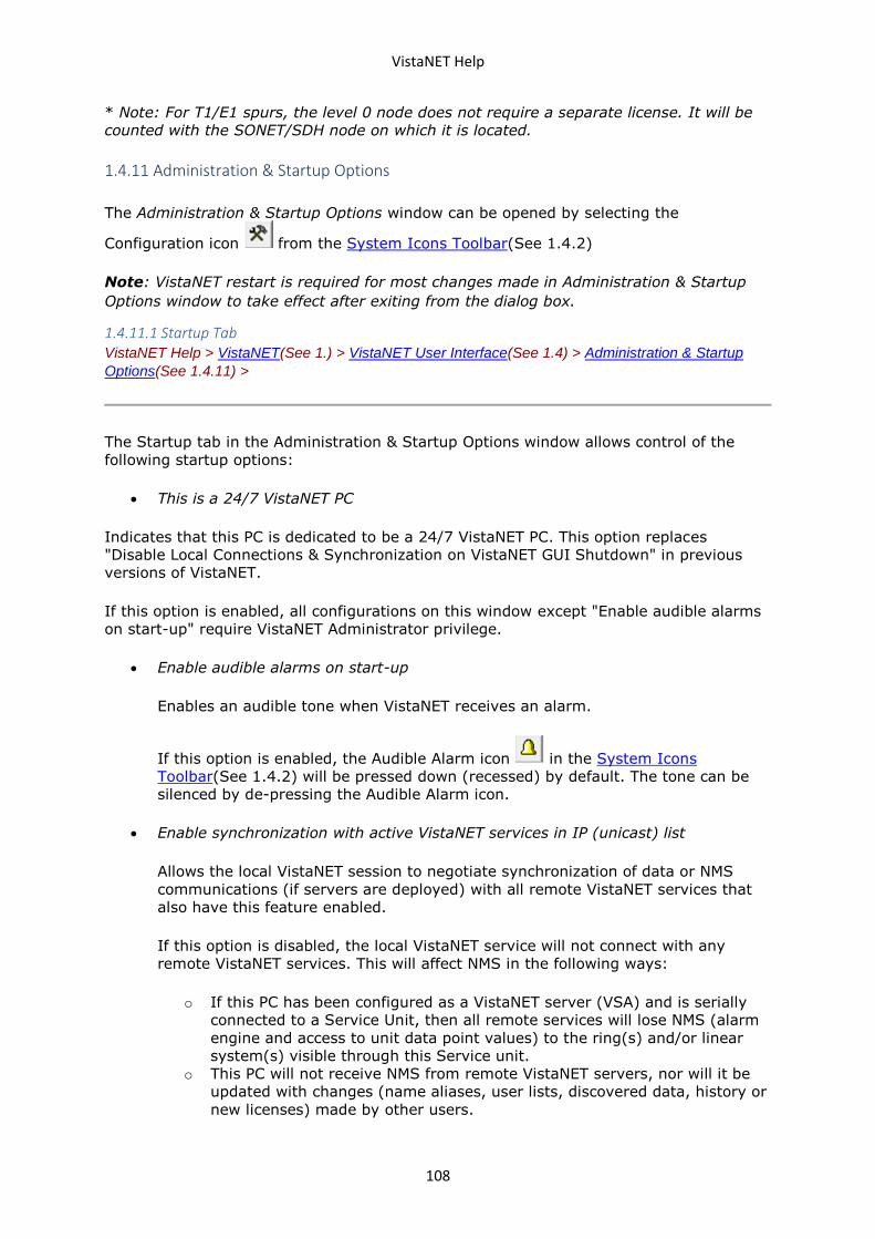
VistaNET Help
108
* Note: For T1/E1 spurs, the level 0 node does not require a separate license. It will be
counted with the SONET/SDH node on which it is located.
1.4.11 Administration & Startup Options
The Administration & Startup Options window can be opened by selecting the
Configuration icon from the System Icons Toolbar(See 1.4.2)
Note: VistaNET restart is required for most changes made in Administration & Startup
Options window to take effect after exiting from the dialog box.
1.4.11.1 Startup Tab VistaNET Help > VistaNET(See 1.) > VistaNET User Interface(See 1.4) > Administration & Startup
Options(See 1.4.11) >
The Startup tab in the Administration & Startup Options window allows control of the
following startup options:
• This is a 24/7 VistaNET PC
Indicates that this PC is dedicated to be a 24/7 VistaNET PC. This option replaces
"Disable Local Connections & Synchronization on VistaNET GUI Shutdown" in previous
versions of VistaNET.
If this option is enabled, all configurations on this window except "Enable audible alarms
on start-up" require VistaNET Administrator privilege.
• Enable audible alarms on start-up
Enables an audible tone when VistaNET receives an alarm.
If this option is enabled, the Audible Alarm icon in the System Icons
Toolbar(See 1.4.2) will be pressed down (recessed) by default. The tone can be
silenced by de-pressing the Audible Alarm icon.
• Enable synchronization with active VistaNET services in IP (unicast) list
Allows the local VistaNET session to negotiate synchronization of data or NMS
communications (if servers are deployed) with all remote VistaNET services that
also have this feature enabled.
If this option is disabled, the local VistaNET service will not connect with any
remote VistaNET services. This will affect NMS in the following ways:
o If this PC has been configured as a VistaNET server (VSA) and is serially
connected to a Service Unit, then all remote services will lose NMS (alarm
engine and access to unit data point values) to the ring(s) and/or linear
system(s) visible through this Service unit.
o This PC will not receive NMS from remote VistaNET servers, nor will it be
updated with changes (name aliases, user lists, discovered data, history or
new licenses) made by other users.
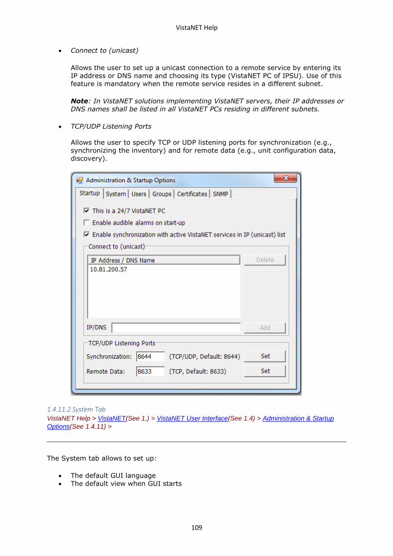
VistaNET Help
109
• Connect to (unicast)
Allows the user to set up a unicast connection to a remote service by entering its
IP address or DNS name and choosing its type (VistaNET PC of IPSU). Use of this
feature is mandatory when the remote service resides in a different subnet.
Note: In VistaNET solutions implementing VistaNET servers, their IP addresses or
DNS names shall be listed in all VistaNET PCs residing in different subnets.
• TCP/UDP Listening Ports
Allows the user to specify TCP or UDP listening ports for synchronization (e.g.,
synchronizing the inventory) and for remote data (e.g., unit configuration data,
discovery).
1.4.11.2 System Tab VistaNET Help > VistaNET(See 1.) > VistaNET User Interface(See 1.4) > Administration & Startup
Options(See 1.4.11) >
The System tab allows to set up:
• The default GUI language
• The default view when GUI starts
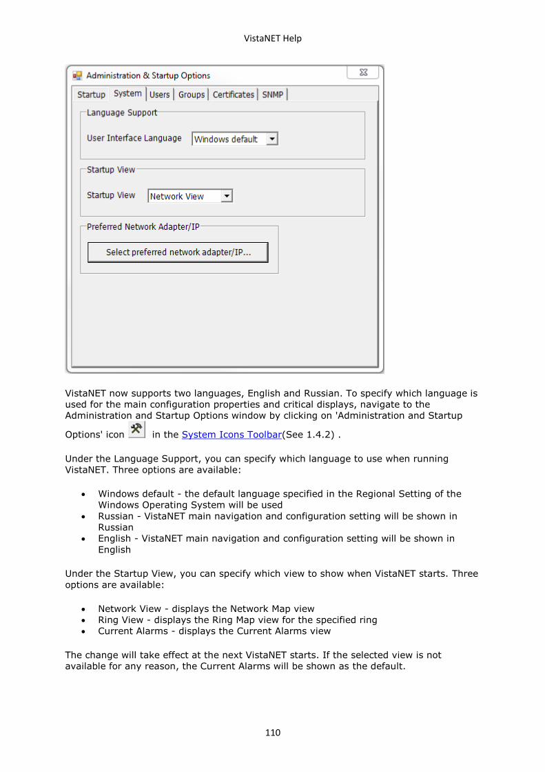
VistaNET Help
110
VistaNET now supports two languages, English and Russian. To specify which language is
used for the main configuration properties and critical displays, navigate to the
Administration and Startup Options window by clicking on 'Administration and Startup
Options' icon in the System Icons Toolbar(See 1.4.2) .
Under the Language Support, you can specify which language to use when running
VistaNET. Three options are available:
• Windows default - the default language specified in the Regional Setting of the
Windows Operating System will be used
• Russian - VistaNET main navigation and configuration setting will be shown in
Russian
• English - VistaNET main navigation and configuration setting will be shown in
English
Under the Startup View, you can specify which view to show when VistaNET starts. Three
options are available:
• Network View - displays the Network Map view
• Ring View - displays the Ring Map view for the specified ring
• Current Alarms - displays the Current Alarms view
The change will take effect at the next VistaNET starts. If the selected view is not
available for any reason, the Current Alarms will be shown as the default.
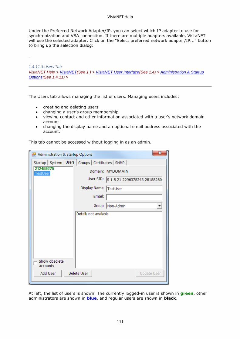
VistaNET Help
111
Under the Preferred Network Adapter/IP, you can select which IP adapter to use for
synchronization and VSA connection. If there are multiple adapters available, VistaNET
will use the selected adapter. Click on the "Select preferred network adapter/IP..." button
to bring up the selection dialog:
1.4.11.3 Users Tab VistaNET Help > VistaNET(See 1.) > VistaNET User Interface(See 1.4) > Administration & Startup
Options(See 1.4.11) >
The Users tab allows managing the list of users. Managing users includes:
• creating and deleting users
• changing a user's group membership
• viewing contact and other information associated with a user's network domain
account
• changing the display name and an optional email address associated with the
account.
This tab cannot be accessed without logging in as an admin.
At left, the list of users is shown. The currently logged-in user is shown in green, other
administrators are shown in blue, and regular users are shown in black.
VistaNET Help
112
If any obsolete accounts exist in the database, the Show obsolete accounts checkbox
will appear. If this is checked, the obsolete accounts will be shown in gray. These
accounts cannot be logged into, and are viewable for reference. It is recommended to
delete these accounts when they have been replaced. See Upgrading to VistaNET
5.04(See 1.2.4.8).
At right, information about the selected user is displayed.
Domain The domain from which this user logs on. This can be a network domain
controller (such as Active Directory) or a Windows PC.
User SID Security Identifier. This string is assigned by the domain and cannot be
changed. It is used to link a domain account to a VistaNET account.
Display
Name
A maximum 60-character string which can be changed by the administrator
as desired. This name will be shown in the VistaNET client and activity logs.
Email This field can optionally be used to store a user's email address (or any
other contact information desired). Maximum 60 characters.
Group
Selects the user's current group. You cannot change your own group -- this
prevents accidentally leaving the database without any admins. See Groups
Tab(See 1.4.11.4) for more information.
Attributes
If available, this box will display any additional information associated with
this account. This is usually only available for network accounts, and will
display whatever information is available in your company's network
directory.
Any updates, additions, or deletions of users by an administrator are stored in the
administrator's local data file and synchronized with connected remote services.
Synchronization of user information is initiated when the Administration & Startup
Options window is closed and upon VistaNET start-up.
VistaNET can accommodate any number of users within a user group, and any number of
user groups. There must always be at least one administrator. To ensure this, it is
impossible for the current user to delete himself.
More than one user can be defined with administrator's privileges. As more users with
administrative privileges are added, coordination of administrative services between
these users is necessary.
Adding a New User
The Add User Wizard streamlines the creation of VistaNET user accounts. Click Add
User to launch the wizard. See the section VistaNET Login System(See 1.2.4.6) for help
with this wizard.
A pop-up message box will indicate that a new user has been added.
Modifying an Existing User
To modify an existing profile:
VistaNET Help
113
• select a user name from the list of previously defined users
• change specific fields as required
• press the "Update User" button (becomes enabled after change is made) to save
the changes
A pop-up message box will indicate that the user info has been updated.
Deleting a User
To delete a user:
• select a user name from the list of previously defined users
• press the ‘Delete User’ button
• accept or cancel a confirmation message. Selecting ‘Yes’ deletes selected user
profile.
A pop-up message box will indicate that the user has been deleted.
1.4.11.4 Groups Tab VistaNET Help > VistaNET(See 1.) > VistaNET User Interface(See 1.4) > Administration & Startup
Options(See 1.4.11) >
The Groups tab allows the administrator to set configuration permissions for individual
user groups.
VistaNET prompts the user to start a configuration session when a change to a
configurable parameter is attempted. The appropriate configuration permissions, as
defined by the administrator under the groups tab for the group that the user is a
member of, are then applied to the configuration session.
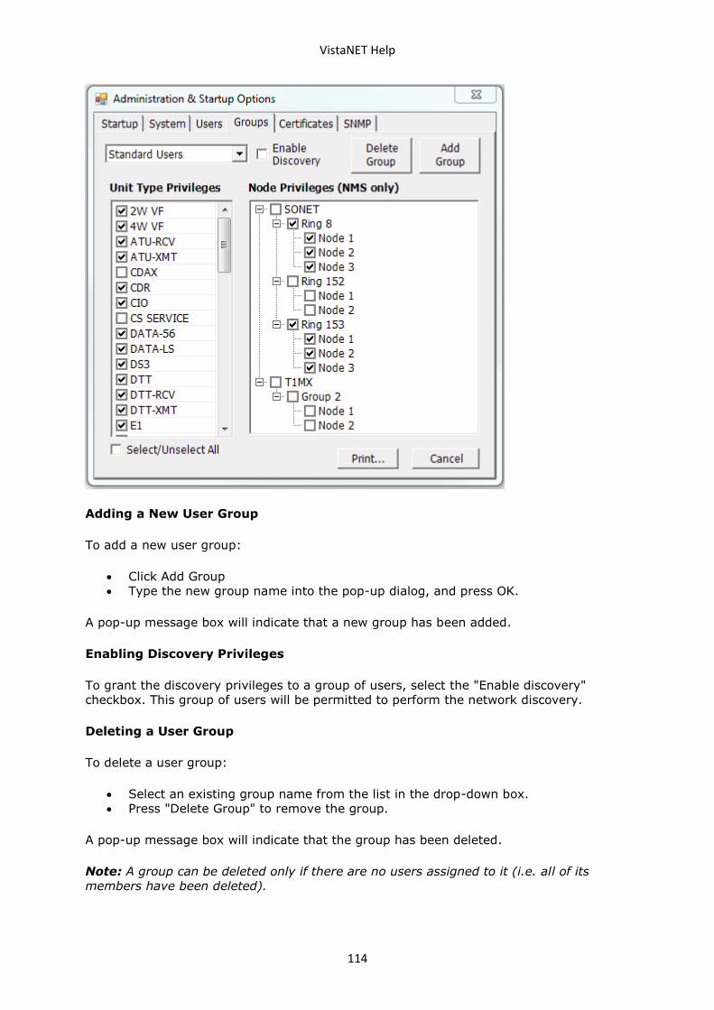
VistaNET Help
114
Adding a New User Group
To add a new user group:
• Click Add Group
• Type the new group name into the pop-up dialog, and press OK.
A pop-up message box will indicate that a new group has been added.
Enabling Discovery Privileges
To grant the discovery privileges to a group of users, select the "Enable discovery"
checkbox. This group of users will be permitted to perform the network discovery.
Deleting a User Group
To delete a user group:
• Select an existing group name from the list in the drop-down box.
• Press "Delete Group" to remove the group.
A pop-up message box will indicate that the group has been deleted.
Note: A group can be deleted only if there are no users assigned to it (i.e. all of its
members have been deleted).
VistaNET Help
115
Configuration Permissions
The administrator can permit the selected user group to locally configure some or all unit
types. The administrator can also permit the user group to configure these unit types
remotely (via NMS) at some or all discovered nodes.
The Unit Types Privileges lists all available unit types known to VistaNET but only those
checked will be configurable by the selected user group.
The Node Privileges (NMS only) controls which nodes (from the list of rings and nodes
that have been discovered) the unit types selected in the Unit Type Privileges list can be
configured by the selected user group remotely (using NMS access). Note that the tree
representation will not show any new rings or nodes added since the last Discovery
process.
Note: Members of the "Administrators" group have a global permission to configure all
unit types at all nodes. These permissions cannot be removed.
To add a new unit type permission:
• Select the unit type in the Unit Type Privileges list.
Note: Having a new unit type selected will permit the members of the selected user
group to make configuration changes to this unit locally as well as remotely (per the
selections made in the Node Privileges list).
To add a remote configuration permission for a new node or ring:
• Verify that the node/ring is in the Nodes Privileges tree. If not, rediscover the
network/ring prior to selection.
• Select the node/ring in the Nodes Privileges tree.
To remove a unit type or ring/node permission, uncheck the corresponding checkbox.
If changes have been made to the currently selected group and the user selects a
different group or tab, or closes the Administration & Startup Options view, VistaNET will
ask the user if the changes should be saved or discarded.
The Cancel button cancels any changes made to the currently selected group.
The Print button opens the dialog for printing the permissions of the currently selected
group.
1.4.11.5 Certificates Tab VistaNET Help > VistaNET(See 1.) > VistaNET User Interface(See 1.4) > Administration & Startup
Options(See 1.4.11) >
The Certificates tab allows managing the SSL certificates.
VistaNET provides X.509 SSL certificates and uses these to secure communications to
CSSU and synchronization with other instances of VistaNET. The three certificate files
are:
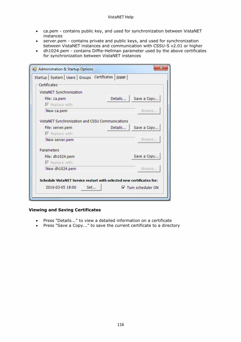
VistaNET Help
116
• ca.pem - contains public key, and used for synchronization between VistaNET
instances
• server.pem - contains private and public keys, and used for synchronization
between VistaNET instances and communication with CSSU-S v2.01 or higher
• dh1024.pem - contains Diffie-Hellman parameter used by the above certificates
for synchronization between VistaNET instances
Viewing and Saving Certificates
• Press "Details..." to view a detailed information on a certificate
• Press "Save a Copy..." to save the current certificate to a directory
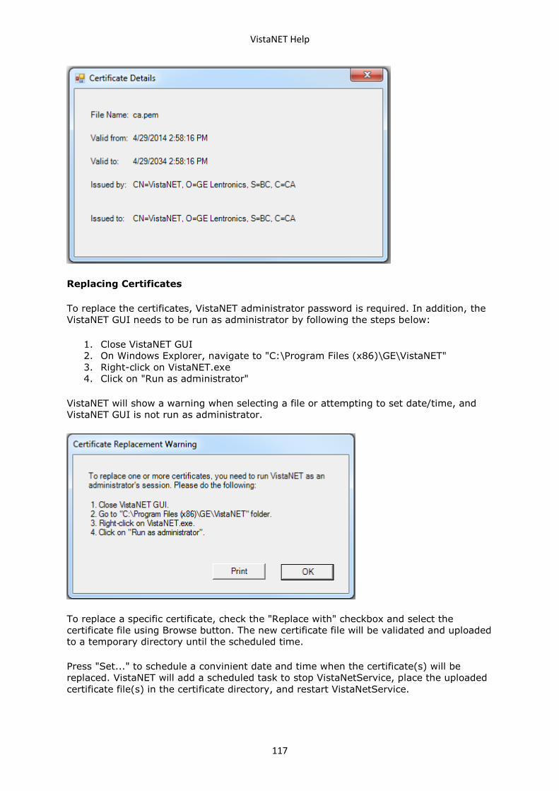
VistaNET Help
117
Replacing Certificates
To replace the certificates, VistaNET administrator password is required. In addition, the
VistaNET GUI needs to be run as administrator by following the steps below:
1. Close VistaNET GUI
2. On Windows Explorer, navigate to "C:\Program Files (x86)\GE\VistaNET"
3. Right-click on VistaNET.exe
4. Click on "Run as administrator"
VistaNET will show a warning when selecting a file or attempting to set date/time, and
VistaNET GUI is not run as administrator.
To replace a specific certificate, check the "Replace with" checkbox and select the
certificate file using Browse button. The new certificate file will be validated and uploaded
to a temporary directory until the scheduled time.
Press "Set..." to schedule a convinient date and time when the certificate(s) will be
replaced. VistaNET will add a scheduled task to stop VistaNetService, place the uploaded
certificate file(s) in the certificate directory, and restart VistaNetService.
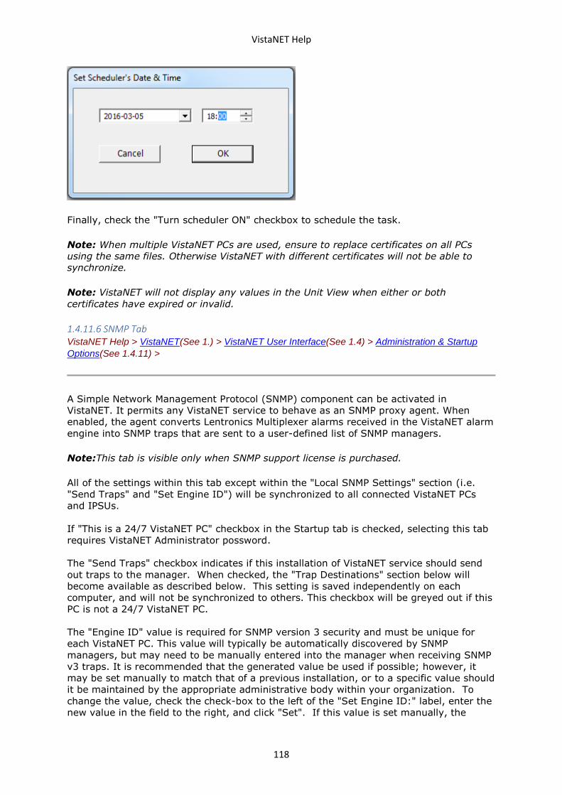
VistaNET Help
118
Finally, check the "Turn scheduler ON" checkbox to schedule the task.
Note: When multiple VistaNET PCs are used, ensure to replace certificates on all PCs
using the same files. Otherwise VistaNET with different certificates will not be able to
synchronize.
Note: VistaNET will not display any values in the Unit View when either or both
certificates have expired or invalid.
1.4.11.6 SNMP Tab VistaNET Help > VistaNET(See 1.) > VistaNET User Interface(See 1.4) > Administration & Startup
Options(See 1.4.11) >
A Simple Network Management Protocol (SNMP) component can be activated in
VistaNET. It permits any VistaNET service to behave as an SNMP proxy agent. When
enabled, the agent converts Lentronics Multiplexer alarms received in the VistaNET alarm
engine into SNMP traps that are sent to a user-defined list of SNMP managers.
Note:This tab is visible only when SNMP support license is purchased.
All of the settings within this tab except within the "Local SNMP Settings" section (i.e.
"Send Traps" and "Set Engine ID") will be synchronized to all connected VistaNET PCs
and IPSUs.
If "This is a 24/7 VistaNET PC" checkbox in the Startup tab is checked, selecting this tab
requires VistaNET Administrator possword.
The "Send Traps" checkbox indicates if this installation of VistaNET service should send
out traps to the manager. When checked, the "Trap Destinations" section below will
become available as described below. This setting is saved independently on each
computer, and will not be synchronized to others. This checkbox will be greyed out if this
PC is not a 24/7 VistaNET PC.
The "Engine ID" value is required for SNMP version 3 security and must be unique for
each VistaNET PC. This value will typically be automatically discovered by SNMP
managers, but may need to be manually entered into the manager when receiving SNMP
v3 traps. It is recommended that the generated value be used if possible; however, it
may be set manually to match that of a previous installation, or to a specific value should
it be maintained by the appropriate administrative body within your organization. To
change the value, check the check-box to the left of the "Set Engine ID:" label, enter the
new value in the field to the right, and click "Set". If this value is set manually, the
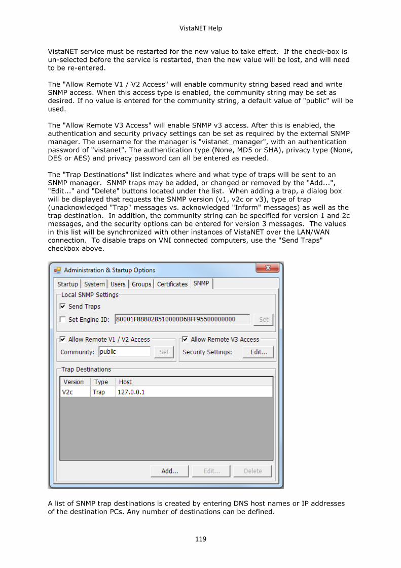
VistaNET Help
119
VistaNET service must be restarted for the new value to take effect. If the check-box is
un-selected before the service is restarted, then the new value will be lost, and will need
to be re-entered.
The "Allow Remote V1 / V2 Access" will enable community string based read and write
SNMP access. When this access type is enabled, the community string may be set as
desired. If no value is entered for the community string, a default value of "public" will be
used.
The "Allow Remote V3 Access" will enable SNMP v3 access. After this is enabled, the
authentication and security privacy settings can be set as required by the external SNMP
manager. The username for the manager is "vistanet_manager", with an authentication
password of "vistanet". The authentication type (None, MD5 or SHA), privacy type (None,
DES or AES) and privacy password can all be entered as needed.
The "Trap Destinations" list indicates where and what type of traps will be sent to an
SNMP manager. SNMP traps may be added, or changed or removed by the "Add...",
"Edit..." and "Delete" buttons located under the list. When adding a trap, a dialog box
will be displayed that requests the SNMP version (v1, v2c or v3), type of trap
(unacknowledged "Trap" messages vs. acknowledged "Inform" messages) as well as the
trap destination. In addition, the community string can be specified for version 1 and 2c
messages, and the security options can be entered for version 3 messages. The values
in this list will be synchronized with other instances of VistaNET over the LAN/WAN
connection. To disable traps on VNI connected computers, use the "Send Traps"
checkbox above.
A list of SNMP trap destinations is created by entering DNS host names or IP addresses
of the destination PCs. Any number of destinations can be defined.
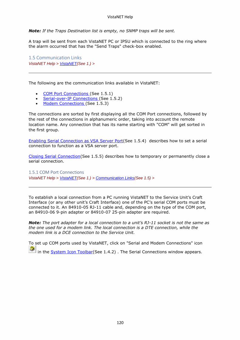
VistaNET Help
120
Note: If the Traps Destination list is empty, no SNMP traps will be sent.
A trap will be sent from each VistaNET PC or IPSU which is connected to the ring where
the alarm occurred that has the "Send Traps" check-box enabled.
1.5 Communication Links VistaNET Help > VistaNET(See 1.) >
The following are the communication links available in VistaNET:
• COM Port Connections (See 1.5.1)
• Serial-over-IP Connections (See 1.5.2)
• Modem Connections (See 1.5.3)
The connections are sorted by first displaying all the COM Port connections, followed by
the rest of the connections in alphanumeric order, taking into account the remote
location name. Any connection that has its name starting with "COM" will get sorted in
the first group.
Enabling Serial Connection as VSA Server Port(See 1.5.4) describes how to set a serial
connection to function as a VSA server port.
Closing Serial Connection(See 1.5.5) describes how to temporary or permanently close a
serial connection.
1.5.1 COM Port Connections VistaNET Help > VistaNET(See 1.) > Communication Links(See 1.5) >
To establish a local connection from a PC running VistaNET to the Service Unit’s Craft
Interface (or any other unit’s Craft Interface) one of the PC’s serial COM ports must be
connected to it. An 84910-05 RJ-11 cable and, depending on the type of the COM port,
an 84910-06 9-pin adapter or 84910-07 25-pin adapter are required.
Note: The port adapter for a local connection to a unit’s RJ-11 socket is not the same as
the one used for a modem link. The local connection is a DTE connection, while the
modem link is a DCE connection to the Service Unit.
To set up COM ports used by VistaNET, click on "Serial and Modem Connections" icon
in the System Icon Toolbar(See 1.4.2) . The Serial Connections window appears.
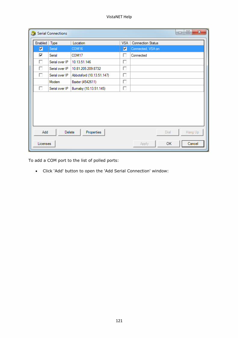
VistaNET Help
121
To add a COM port to the list of polled ports:
• Click ‘Add' button to open the 'Add Serial Connection' window:
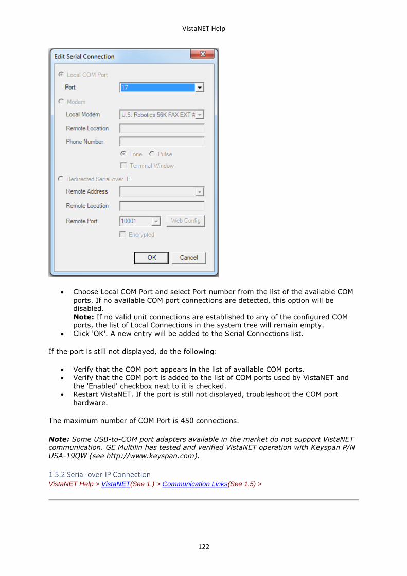
VistaNET Help
122
• Choose Local COM Port and select Port number from the list of the available COM
ports. If no available COM port connections are detected, this option will be
disabled.
Note: If no valid unit connections are established to any of the configured COM
ports, the list of Local Connections in the system tree will remain empty.
• Click 'OK'. A new entry will be added to the Serial Connections list.
If the port is still not displayed, do the following:
• Verify that the COM port appears in the list of available COM ports.
• Verify that the COM port is added to the list of COM ports used by VistaNET and
the 'Enabled' checkbox next to it is checked.
• Restart VistaNET. If the port is still not displayed, troubleshoot the COM port
hardware.
The maximum number of COM Port is 450 connections.
Note: Some USB-to-COM port adapters available in the market do not support VistaNET
communication. GE Multilin has tested and verified VistaNET operation with Keyspan P/N
USA-19QW (see http://www.keyspan.com).
1.5.2 Serial-over-IP Connection VistaNET Help > VistaNET(See 1.) > Communication Links(See 1.5) >
VistaNET Help
123
VistaNET can use a ‘virtual COM port’ connected to a remote Service Unit over Ethernet.
This requires use of Com Port Redirector software that will redirect VistaNET application
data from the virtual COM port to the PC's Ethernet network card. Data is transmitted
across an Ethernet network using TCP/IP. A serial-to-Ethernet media converter on
remote Service Unit IP paddleboard (86434-93) receives the data and transfers it
through its own serial port to the Service Unit CI.
VistaNET supports the 86434-93 paddleboard (optionally used with 86434-02 Service
Unit), which has an on-board LANTRONIX® Xport® serial-to-Ethernet media converter to
provide access to the unit's craft interface over an Ethernet LAN. VistaNET connects to
the Xport over a standard Ethernet network using TCP/IP, which in turn connects to the
Service Unit's CI.
The serial-to-Ethernet converter must be setup with the following settings:
Baud rate 9600 bps
Parity None
Stop bits 1
Flow Control None
There should be no input translation on the TCP/IP connection such as adding line feeds
or null characters after carriage returns.
If you are using the 86434-93 paddleboard, these settings can be accessed via the web
interface for the converter. A shortcut to the web interface is available via the "Web
Config" button in the properties window for the connection. In addition, please make
sure that "Telnet Mode" option is disabled in the Connection settings.
To set up a Serial-over-IP connection, click on "Serial and Modem Connections" icon
in the System Icon Toolbar(See 1.4.2) . The Serial Connections window appears.
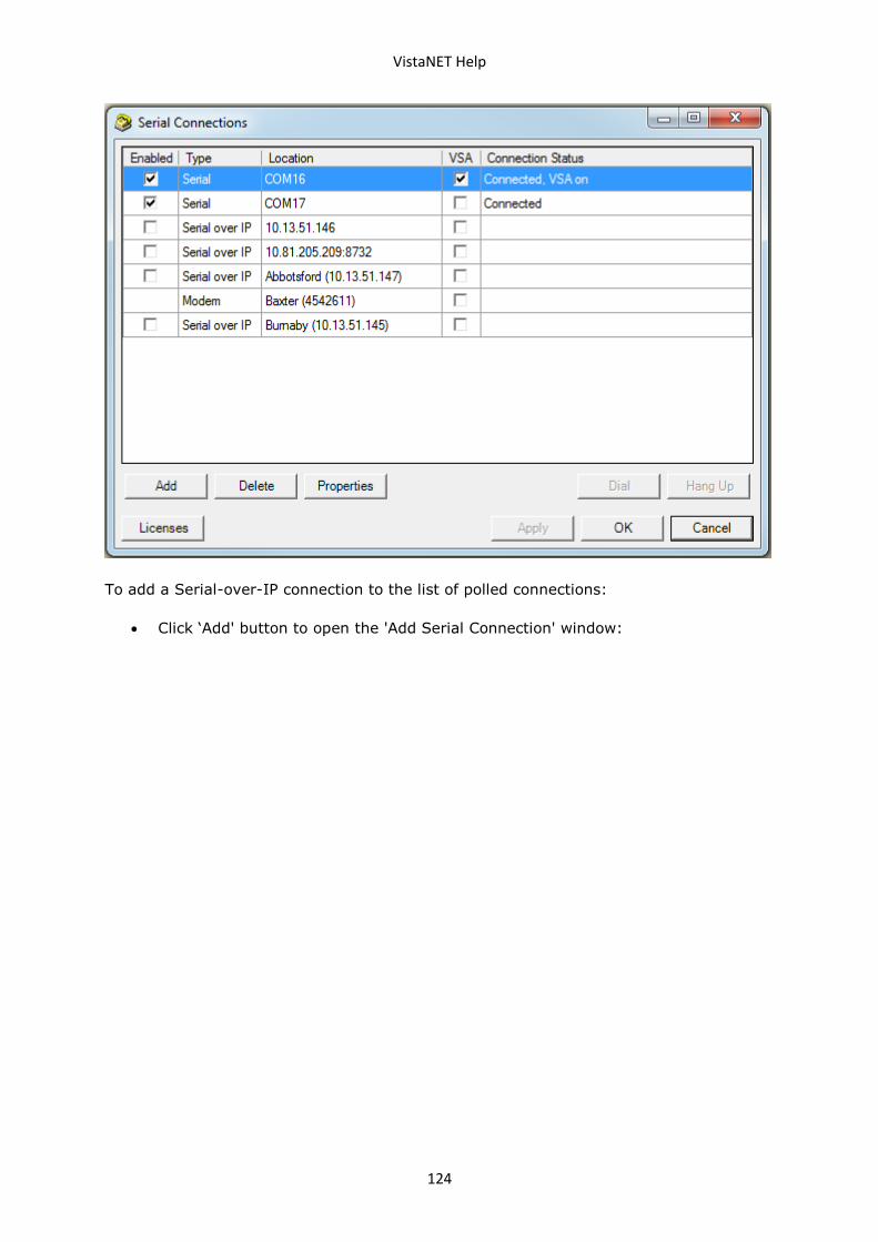
VistaNET Help
124
To add a Serial-over-IP connection to the list of polled connections:
• Click ‘Add' button to open the 'Add Serial Connection' window:
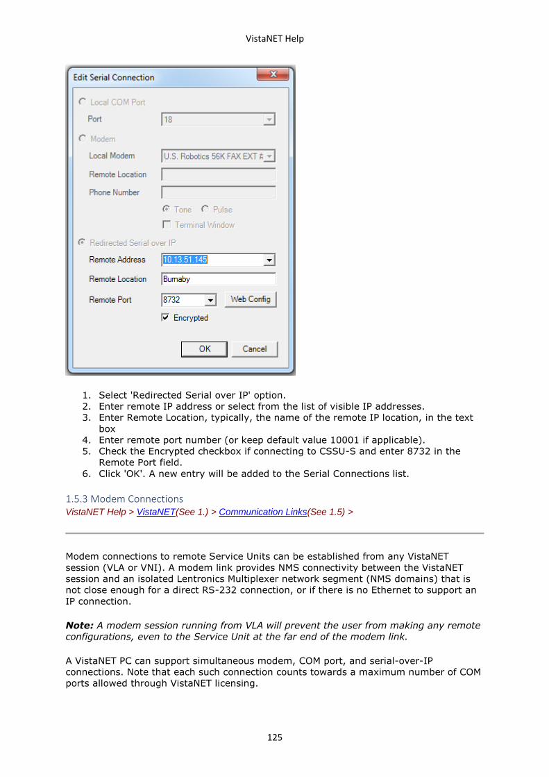
VistaNET Help
125
1. Select 'Redirected Serial over IP' option.
2. Enter remote IP address or select from the list of visible IP addresses.
3. Enter Remote Location, typically, the name of the remote IP location, in the text
box
4. Enter remote port number (or keep default value 10001 if applicable).
5. Check the Encrypted checkbox if connecting to CSSU-S and enter 8732 in the
Remote Port field.
6. Click 'OK'. A new entry will be added to the Serial Connections list.
1.5.3 Modem Connections VistaNET Help > VistaNET(See 1.) > Communication Links(See 1.5) >
Modem connections to remote Service Units can be established from any VistaNET
session (VLA or VNI). A modem link provides NMS connectivity between the VistaNET
session and an isolated Lentronics Multiplexer network segment (NMS domains) that is
not close enough for a direct RS-232 connection, or if there is no Ethernet to support an
IP connection.
Note: A modem session running from VLA will prevent the user from making any remote
configurations, even to the Service Unit at the far end of the modem link.
A VistaNET PC can support simultaneous modem, COM port, and serial-over-IP
connections. Note that each such connection counts towards a maximum number of COM
ports allowed through VistaNET licensing.
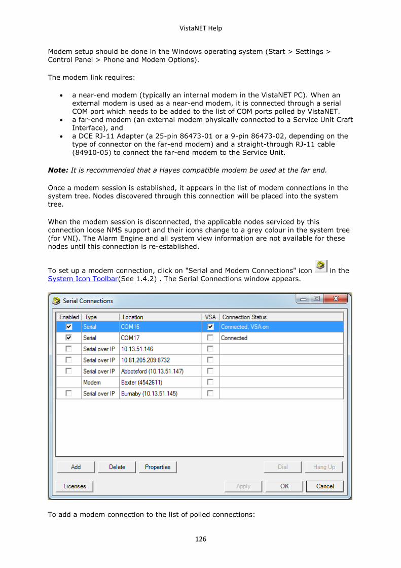
VistaNET Help
126
Modem setup should be done in the Windows operating system (Start > Settings >
Control Panel > Phone and Modem Options).
The modem link requires:
• a near-end modem (typically an internal modem in the VistaNET PC). When an
external modem is used as a near-end modem, it is connected through a serial
COM port which needs to be added to the list of COM ports polled by VistaNET.
• a far-end modem (an external modem physically connected to a Service Unit Craft
Interface), and
• a DCE RJ-11 Adapter (a 25-pin 86473-01 or a 9-pin 86473-02, depending on the
type of connector on the far-end modem) and a straight-through RJ-11 cable
(84910-05) to connect the far-end modem to the Service Unit.
Note: It is recommended that a Hayes compatible modem be used at the far end.
Once a modem session is established, it appears in the list of modem connections in the
system tree. Nodes discovered through this connection will be placed into the system
tree.
When the modem session is disconnected, the applicable nodes serviced by this
connection loose NMS support and their icons change to a grey colour in the system tree
(for VNI). The Alarm Engine and all system view information are not available for these
nodes until this connection is re-established.
To set up a modem connection, click on "Serial and Modem Connections" icon in the
System Icon Toolbar(See 1.4.2) . The Serial Connections window appears.
To add a modem connection to the list of polled connections:
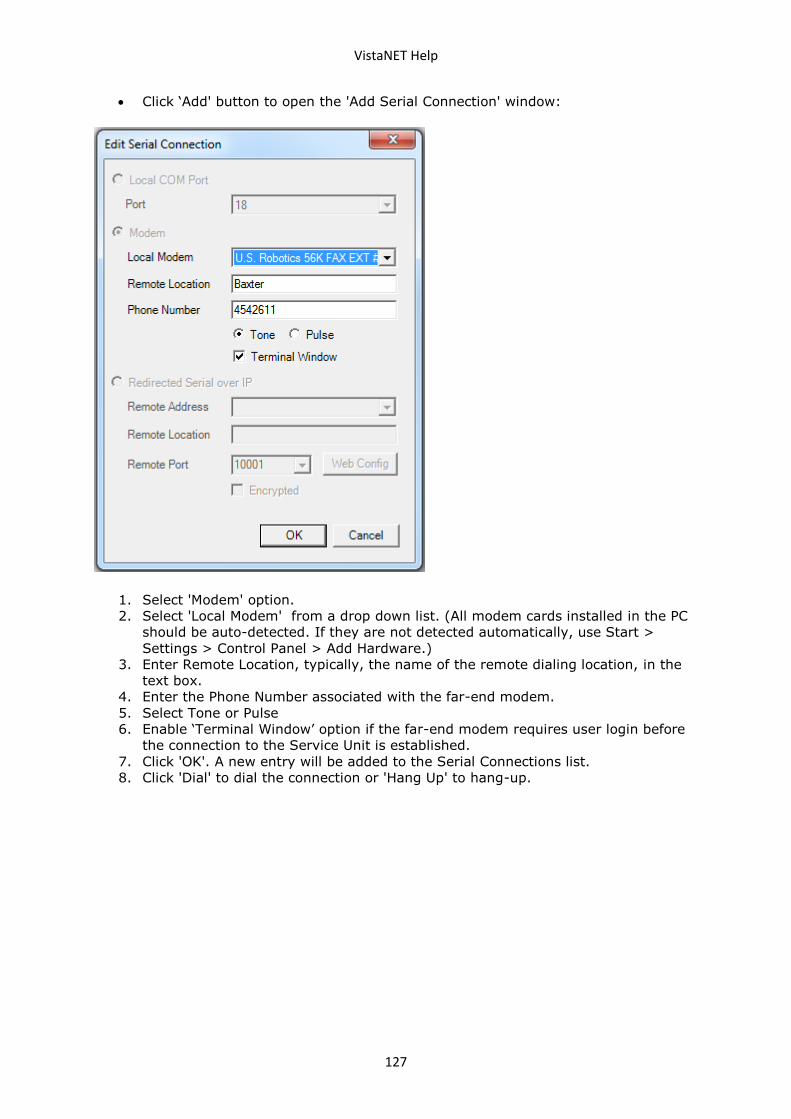
VistaNET Help
127
• Click ‘Add' button to open the 'Add Serial Connection' window:
1. Select 'Modem' option.
2. Select 'Local Modem' from a drop down list. (All modem cards installed in the PC
should be auto-detected. If they are not detected automatically, use Start >
Settings > Control Panel > Add Hardware.)
3. Enter Remote Location, typically, the name of the remote dialing location, in the
text box.
4. Enter the Phone Number associated with the far-end modem.
5. Select Tone or Pulse
6. Enable ‘Terminal Window’ option if the far-end modem requires user login before
the connection to the Service Unit is established.
7. Click 'OK'. A new entry will be added to the Serial Connections list.
8. Click 'Dial' to dial the connection or 'Hang Up' to hang-up.
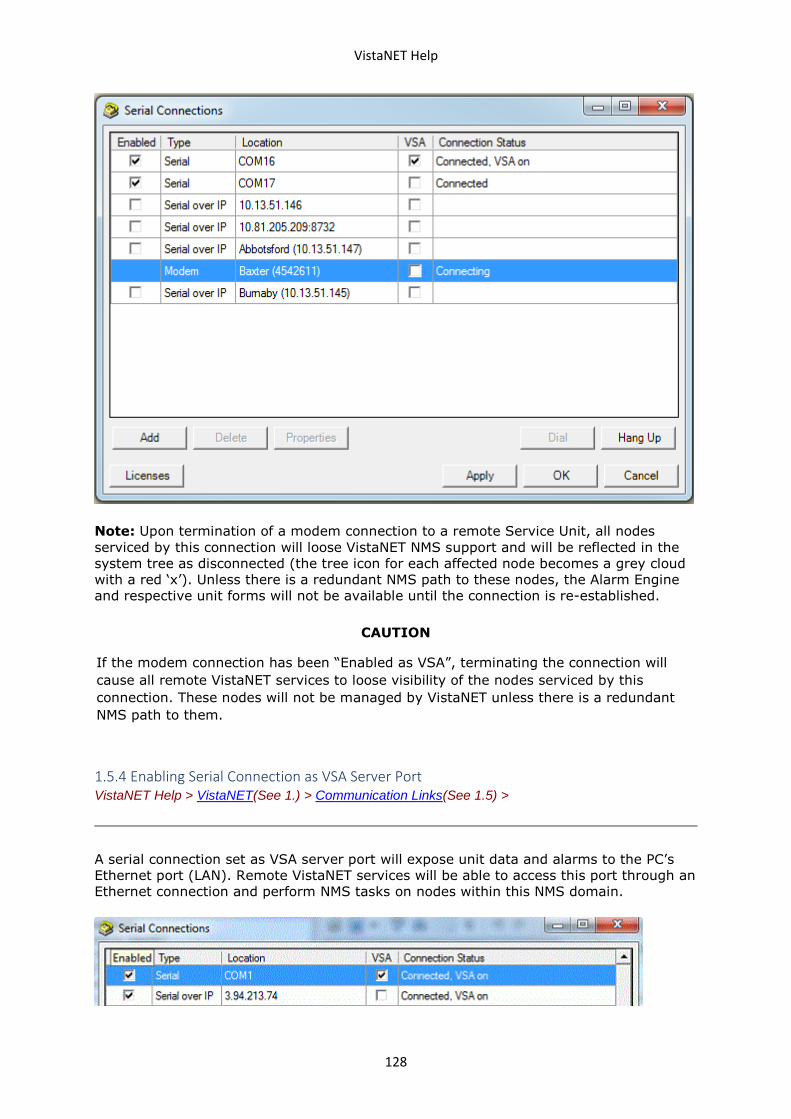
VistaNET Help
128
Note: Upon termination of a modem connection to a remote Service Unit, all nodes
serviced by this connection will loose VistaNET NMS support and will be reflected in the
system tree as disconnected (the tree icon for each affected node becomes a grey cloud
with a red ‘x’). Unless there is a redundant NMS path to these nodes, the Alarm Engine
and respective unit forms will not be available until the connection is re-established.
CAUTION
If the modem connection has been “Enabled as VSA”, terminating the connection will
cause all remote VistaNET services to loose visibility of the nodes serviced by this
connection. These nodes will not be managed by VistaNET unless there is a redundant
NMS path to them.
1.5.4 Enabling Serial Connection as VSA Server Port VistaNET Help > VistaNET(See 1.) > Communication Links(See 1.5) >
A serial connection set as VSA server port will expose unit data and alarms to the PC’s
Ethernet port (LAN). Remote VistaNET services will be able to access this port through an
Ethernet connection and perform NMS tasks on nodes within this NMS domain.
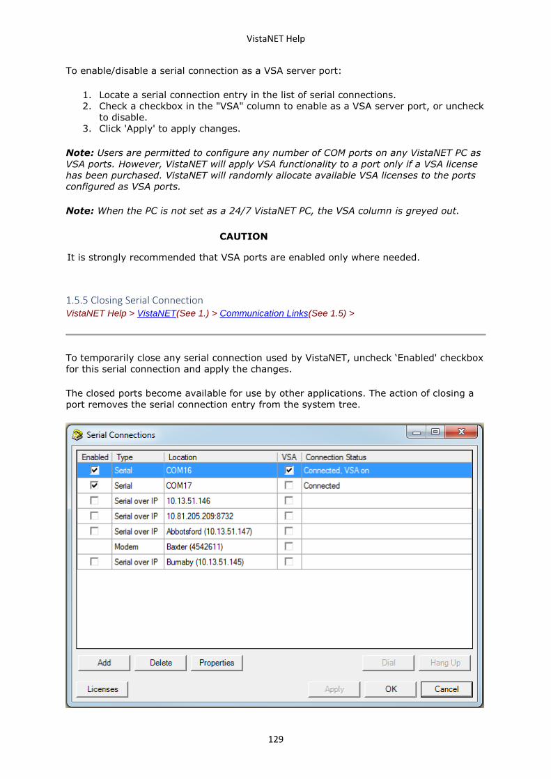
VistaNET Help
129
To enable/disable a serial connection as a VSA server port:
1. Locate a serial connection entry in the list of serial connections.
2. Check a checkbox in the "VSA" column to enable as a VSA server port, or uncheck
to disable.
3. Click 'Apply' to apply changes.
Note: Users are permitted to configure any number of COM ports on any VistaNET PC as
VSA ports. However, VistaNET will apply VSA functionality to a port only if a VSA license
has been purchased. VistaNET will randomly allocate available VSA licenses to the ports
configured as VSA ports.
Note: When the PC is not set as a 24/7 VistaNET PC, the VSA column is greyed out.
CAUTION
It is strongly recommended that VSA ports are enabled only where needed.
1.5.5 Closing Serial Connection VistaNET Help > VistaNET(See 1.) > Communication Links(See 1.5) >
To temporarily close any serial connection used by VistaNET, uncheck ‘Enabled' checkbox
for this serial connection and apply the changes.
The closed ports become available for use by other applications. The action of closing a
port removes the serial connection entry from the system tree.
VistaNET Help
130
To permanently remove the serial connection, select a corresponding entry in the list of
serial connections and click 'Delete'.
1.6 Discovering Network Inventory VistaNET Help > VistaNET(See 1.) >
Every manageable unit in the Lentronics Multiplexer network needs to be discovered in
order for it to be visible through NMS and its alarms to be displayed in the VistaNET
alarm engine (The alarm engine is not available unless VistaNET is initialized with VNI
license).
A VistaNET service can acquire the network inventory information through one of two
mechanisms:
• By running a 'network discovery' process initiated by clicking on the "Discover
Network" button in the System Icon Toolbar(See 1.4.2). This action is
available to VistaNET network administrators or to the members of the user
groups with discovery privilege.
• By receiving it from a remote VistaNET session (whose image of the network
inventory has already been created/updated) by means of “synchronization”. A
peer-to-peer network of VistaNET sessions must be established across an Ethernet
network.
In both cases, VistaNET updates the local data file with discovery results. They will be
reflected in the system tree and the system map each time the program is started (The
system map is not available unless VistaNET is initialized with VNI license).
Network (re)discovery is required when:
• a discovery has never been done
• new units, nodes or rings are added to a previously discovered network
• unit traffic paths change.
Note:Any changes made to the node inventory or unit traffic assignments require
‘rediscovery’ of the node.
1.6.1 Requirements for Discovery Process VistaNET Help > VistaNET(See 1.) > Discovering Network Inventory(See 1.6) >
The discovery process can be run for the whole Lentronics Mutliplexer network, a
selected ring, a selected node, or a range of nodes that may stretch across multiple
rings. In order to run a discovery process, the following must be ensured:
• The VistaNET software must be installed and activated as VistaNET Local Access
(VLA) or VistaNET Network Interface (VNI).
• A valid connection to a Lentronics Multiplexer must exist. This connection can be
serial (hardwire or modem link) or Ethernet (to an IPSU or a VSA server).
• The user must be an administrator or a member of a user group with discovery
privilege.
VistaNET Help
131
1.6.2 Traffic Paths VistaNET Help > VistaNET(See 1.) > Discovering Network Inventory(See 1.6) >
Through the discovery process, VistaNET detects each unit according to its unique
provisioned traffic path.
SONET/SDH Node
The traffic path syntax for a unit at a SONET/SDH node is as follows:
Ring / Node / Side / SPE or TUG3 or CBW port / JIF or TIF port / VT or TU / Channel
Example for JungleMUX: Ring 1 / Node 4 / Left / X / JP2 / VT5 / CH13
Example for TN1U & TN1Ue: Ring 2 / Node 5 / Right / B / TP3 / TU4 / CH18
Note: VMapper-40 units use VM 1-4 designations to indicate the unit position in the
cascaded VMapper-40 unit configuration (e.g. Ring 1 / Node 4 / * / B / VM1) while Video
units use VP1-4 designations to indicate the VMapper unit Vport they are connected to
(e.g. Ring 1 / Node 4 / * / B / VM1 / VP3).
Note : CDAX units belonging to both SONET/SDH network (attached to optic units) and
T1MX network (have Group # assigned) and DS0 unit attached to this CDAX units
provide traffic path for both networks, such as:
Example for
JungleMUX:
Ring 1 / Node 4 / Left / X / JP2 / VT5 / CH13, Group 1 / Node 4
/ Left / S /CH13
T1MX/E1MX Node
The traffic path syntax for a unit at a T1MX/E1MX node is as follows:
Group/ Node / Side / Drop Port /Channel
Example for T1MX/E1MX: Group 1 / Node 4 / Left / S /CH13
Note : CDAX units belonging to both SONET/SDH network (attached to optic units) and
T1MX/E1MX network (have Group # assigned) and DS0 unit attached to this CDAX units
provide traffic path for both networks, such as:
Example for
T1MX/E1MX:
Ring 1 / Node 4 / Left / X / JP2 / VT5 / CH13, Group 1 / Node
4 / Left / S /CH13
1.6.3 Executing Network Discovery VistaNET Help > VistaNET(See 1.) > Discovering Network Inventory(See 1.6) >
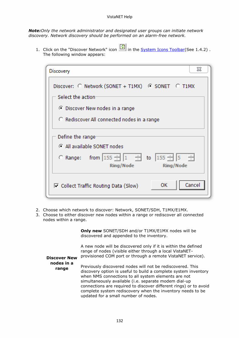
VistaNET Help
132
Note:Only the network administrator and designated user groups can initiate network
discovery. Network discovery should be performed on an alarm-free network.
1. Click on the "Discover Network" icon in the System Icons Toolbar(See 1.4.2) .
The following window appears:
2. Choose which network to discover: Network, SONET/SDH, T1MX/E1MX.
3. Choose to either discover new nodes within a range or rediscover all connected
nodes within a range.
Discover New
nodes in a
range
Only new SONET/SDH and/or T1MX/E1MX nodes will be
discovered and appended to the inventory.
A new node will be discovered only if it is within the defined
range of nodes (visible either through a local VistaNET-
provisioned COM port or through a remote VistaNET service).
Previously discovered nodes will not be rediscovered. This
discovery option is useful to build a complete system inventory
when NMS connections to all system elements are not
simultaneously available (i.e. separate modem dial-up
connections are required to discover different rings) or to avoid
complete system rediscovery when the inventory needs to be
updated for a small number of nodes.
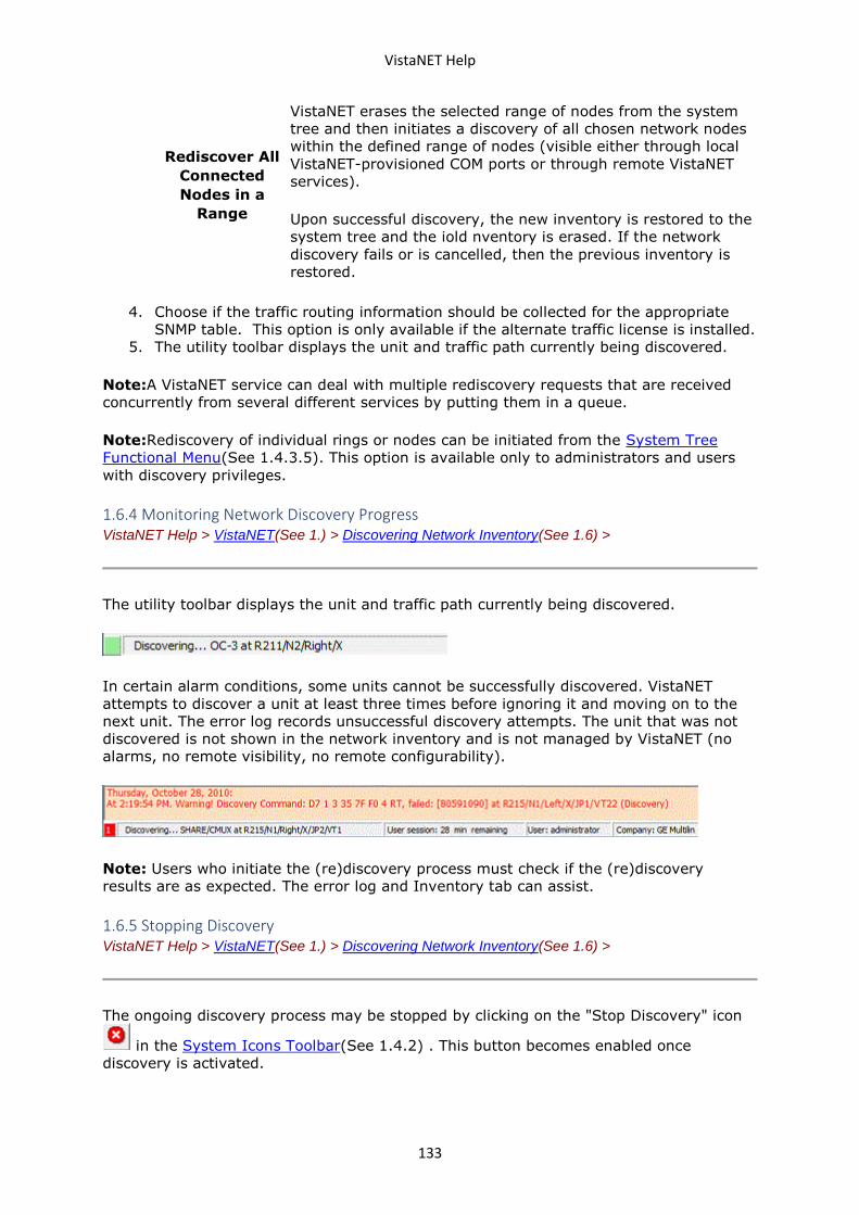
VistaNET Help
133
Rediscover All
Connected
Nodes in a
Range
VistaNET erases the selected range of nodes from the system
tree and then initiates a discovery of all chosen network nodes
within the defined range of nodes (visible either through local
VistaNET-provisioned COM ports or through remote VistaNET
services).
Upon successful discovery, the new inventory is restored to the
system tree and the iold nventory is erased. If the network
discovery fails or is cancelled, then the previous inventory is
restored.
4. Choose if the traffic routing information should be collected for the appropriate
SNMP table. This option is only available if the alternate traffic license is installed.
5. The utility toolbar displays the unit and traffic path currently being discovered.
Note:A VistaNET service can deal with multiple rediscovery requests that are received
concurrently from several different services by putting them in a queue.
Note:Rediscovery of individual rings or nodes can be initiated from the System Tree
Functional Menu(See 1.4.3.5). This option is available only to administrators and users
with discovery privileges.
1.6.4 Monitoring Network Discovery Progress VistaNET Help > VistaNET(See 1.) > Discovering Network Inventory(See 1.6) >
The utility toolbar displays the unit and traffic path currently being discovered.
In certain alarm conditions, some units cannot be successfully discovered. VistaNET
attempts to discover a unit at least three times before ignoring it and moving on to the
next unit. The error log records unsuccessful discovery attempts. The unit that was not
discovered is not shown in the network inventory and is not managed by VistaNET (no
alarms, no remote visibility, no remote configurability).
Note: Users who initiate the (re)discovery process must check if the (re)discovery
results are as expected. The error log and Inventory tab can assist.
1.6.5 Stopping Discovery VistaNET Help > VistaNET(See 1.) > Discovering Network Inventory(See 1.6) >
The ongoing discovery process may be stopped by clicking on the "Stop Discovery" icon
in the System Icons Toolbar(See 1.4.2) . This button becomes enabled once
discovery is activated.
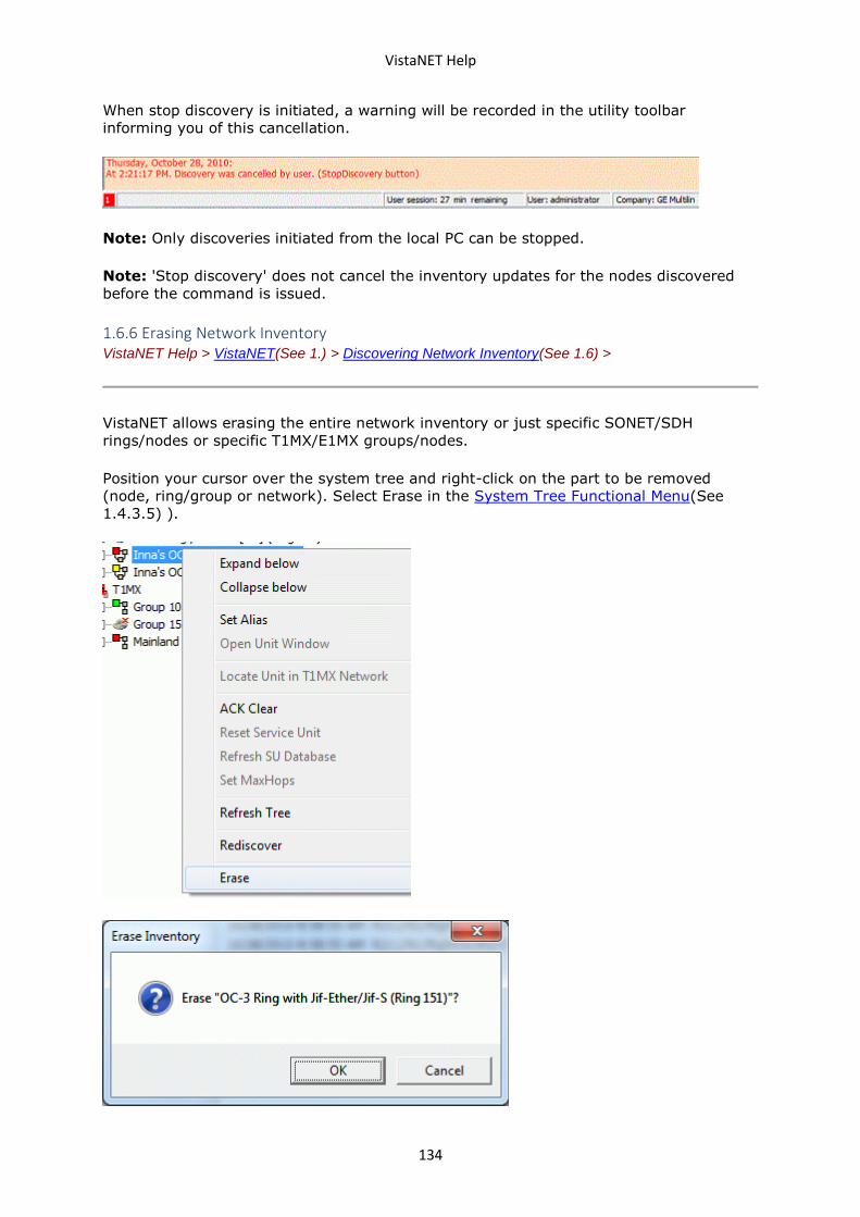
VistaNET Help
134
When stop discovery is initiated, a warning will be recorded in the utility toolbar
informing you of this cancellation.
Note: Only discoveries initiated from the local PC can be stopped.
Note: 'Stop discovery' does not cancel the inventory updates for the nodes discovered
before the command is issued.
1.6.6 Erasing Network Inventory VistaNET Help > VistaNET(See 1.) > Discovering Network Inventory(See 1.6) >
VistaNET allows erasing the entire network inventory or just specific SONET/SDH
rings/nodes or specific T1MX/E1MX groups/nodes.
Position your cursor over the system tree and right-click on the part to be removed
(node, ring/group or network). Select Erase in the System Tree Functional Menu(See
1.4.3.5) ).
VistaNET Help
135
Once the respective inventory has been erased, the user must restart VistaNET;
otherwise, the changes may not be properly reflected in the system map.
1.7 Synchronization VistaNET Help > VistaNET(See 1.) >
The objective of synchronization is to have each session of VistaNET using the same
data, adopting the same security policies, and ensuring that all locally captured events
(alarms and configuration history) are distributed to all other sessions. Synchronization
also allows network administrators to easily update field PCs, and users to be able to
seamlessly move from PC to PC and continue their work without losing momentum.
A local data file stores information about the Lentronics Multiplexer network the local
VistaNET session interacts with. It also stores any customizations made by a VistaNET
administrator logged into this PC. If VistaNET sessions are left isolated, their local data
are completely independent. On the other hand, when connected on the same Ethernet
LAN, VistaNET sessions synchronize contents of their local data automatically. This is
handled by the VistaNET service running in the background of each VistaNET session
(regardless of whether VistaNET GUI is active or not).
Before any synchronization is possible, each PC running VistaNET must be connected to
an Ethernet LAN and connection to remote VistaNET services must be enabled in the
Startup tab(See 1.4.11.1) of the "Administration and Startup Options"(See 1.4.11) view.
As soon as a VistaNET service connects to another VistaNET service (or to an IPSU) it
automatically synchronizes local data with the remote service.
CAUTION
GE Multilin recommends that Administrative changes be made on a PC connected to the
LAN with connection to remote VistaNET services enabled. Administrative changes that
are made on a PC disconnected from remote VistaNET services will not take effect on
remote services until the PC is connected to the LAN.
At some locations, PCs are isolated from other VistaNET sessions and operate
standalone. These users should still periodically synchronize to other VistaNET services.
GE recommends that these PCs be occasionally connected to the organization’s intranet
through a VPN connection.
In extreme cases, creating a small, isolated, private LAN of two or more VistaNET
services can be a solution. One PC can run 24/7 and emulate a backup server to store
VistaNET data. Where such small private networks are deployed, administrators must
designate a remote user as an administrator to manage this network.
Note: The location of the local data file is at
%ProgramFiles%\GE\VistaNET\H7Engine\H7Engine.db3. This file should be regularly
backed up.
1.7.1 Synchronization Strategy Examples VistaNET Help > VistaNET(See 1.) > Synchronization(See 1.7) >
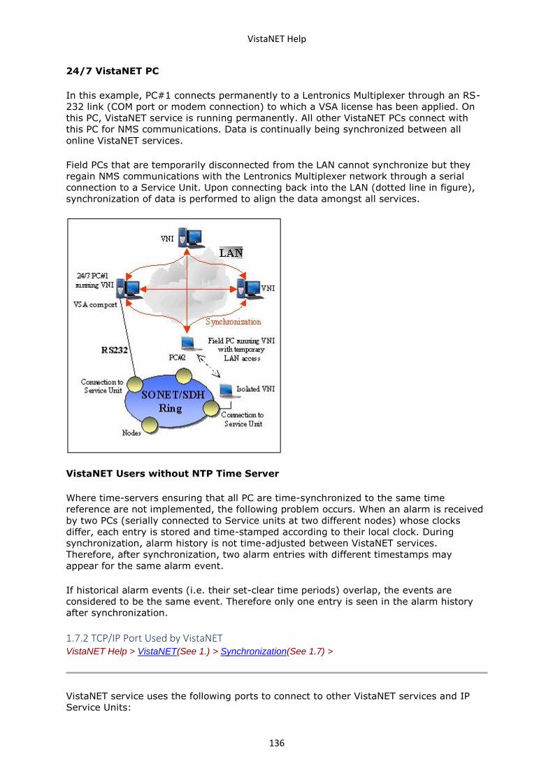
VistaNET Help
136
24/7 VistaNET PC
In this example, PC#1 connects permanently to a Lentronics Multiplexer through an RS-
232 link (COM port or modem connection) to which a VSA license has been applied. On
this PC, VistaNET service is running permanently. All other VistaNET PCs connect with
this PC for NMS communications. Data is continually being synchronized between all
online VistaNET services.
Field PCs that are temporarily disconnected from the LAN cannot synchronize but they
regain NMS communications with the Lentronics Multiplexer network through a serial
connection to a Service Unit. Upon connecting back into the LAN (dotted line in figure),
synchronization of data is performed to align the data amongst all services.
VistaNET Users without NTP Time Server
Where time-servers ensuring that all PC are time-synchronized to the same time
reference are not implemented, the following problem occurs. When an alarm is received
by two PCs (serially connected to Service units at two different nodes) whose clocks
differ, each entry is stored and time-stamped according to their local clock. During
synchronization, alarm history is not time-adjusted between VistaNET services.
Therefore, after synchronization, two alarm entries with different timestamps may
appear for the same alarm event.
If historical alarm events (i.e. their set-clear time periods) overlap, the events are
considered to be the same event. Therefore only one entry is seen in the alarm history
after synchronization.
1.7.2 TCP/IP Port Used by VistaNET VistaNET Help > VistaNET(See 1.) > Synchronization(See 1.7) >
VistaNET service uses the following ports to connect to other VistaNET services and IP
Service Units:
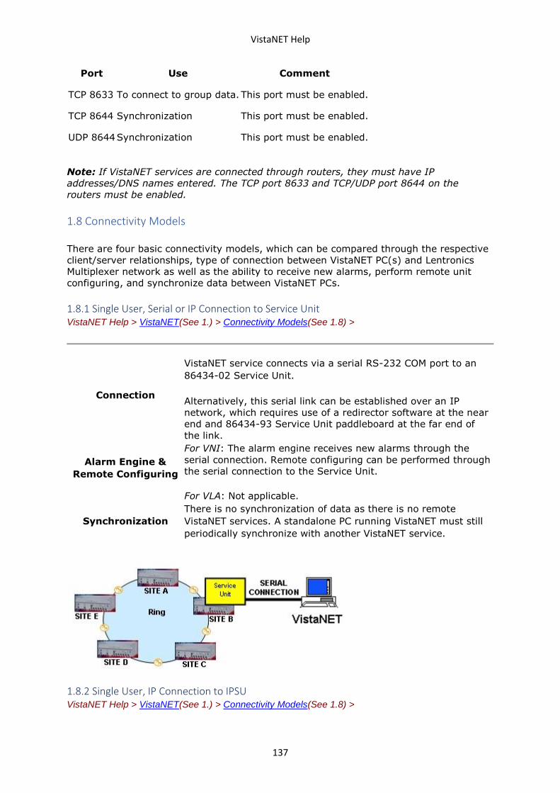
VistaNET Help
137
Port Use Comment
TCP 8633 To connect to group data. This port must be enabled.
TCP 8644 Synchronization This port must be enabled.
UDP 8644 Synchronization This port must be enabled.
Note: If VistaNET services are connected through routers, they must have IP
addresses/DNS names entered. The TCP port 8633 and TCP/UDP port 8644 on the
routers must be enabled.
1.8 Connectivity Models
There are four basic connectivity models, which can be compared through the respective
client/server relationships, type of connection between VistaNET PC(s) and Lentronics
Multiplexer network as well as the ability to receive new alarms, perform remote unit
configuring, and synchronize data between VistaNET PCs.
1.8.1 Single User, Serial or IP Connection to Service Unit VistaNET Help > VistaNET(See 1.) > Connectivity Models(See 1.8) >
Connection
VistaNET service connects via a serial RS-232 COM port to an
86434-02 Service Unit.
Alternatively, this serial link can be established over an IP
network, which requires use of a redirector software at the near
end and 86434-93 Service Unit paddleboard at the far end of
the link.
Alarm Engine &
Remote Configuring
For VNI: The alarm engine receives new alarms through the
serial connection. Remote configuring can be performed through
the serial connection to the Service Unit.
For VLA: Not applicable.
Synchronization
There is no synchronization of data as there is no remote
VistaNET services. A standalone PC running VistaNET must still
periodically synchronize with another VistaNET service.
1.8.2 Single User, IP Connection to IPSU VistaNET Help > VistaNET(See 1.) > Connectivity Models(See 1.8) >
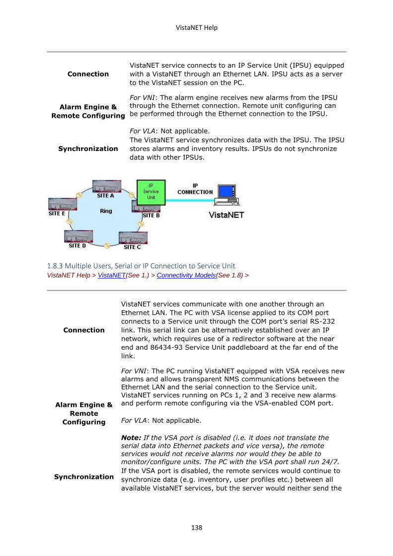
VistaNET Help
138
Connection
VistaNET service connects to an IP Service Unit (IPSU) equipped
with a VistaNET through an Ethernet LAN. IPSU acts as a server
to the VistaNET session on the PC.
Alarm Engine &
Remote Configuring
For VNI: The alarm engine receives new alarms from the IPSU
through the Ethernet connection. Remote unit configuring can
be performed through the Ethernet connection to the IPSU.
For VLA: Not applicable.
Synchronization
The VistaNET service synchronizes data with the IPSU. The IPSU
stores alarms and inventory results. IPSUs do not synchronize
data with other IPSUs.
1.8.3 Multiple Users, Serial or IP Connection to Service Unit VistaNET Help > VistaNET(See 1.) > Connectivity Models(See 1.8) >
Connection
VistaNET services communicate with one another through an
Ethernet LAN. The PC with VSA license applied to its COM port
connects to a Service unit through the COM port’s serial RS-232
link. This serial link can be alternatively established over an IP
network, which requires use of a redirector software at the near
end and 86434-93 Service Unit paddleboard at the far end of the
link.
Alarm Engine &
Remote
Configuring
For VNI: The PC running VistaNET equipped with VSA receives new
alarms and allows transparent NMS communications between the
Ethernet LAN and the serial connection to the Service unit.
VistaNET services running on PCs 1, 2 and 3 receive new alarms
and perform remote configuring via the VSA-enabled COM port.
For VLA: Not applicable.
Note: If the VSA port is disabled (i.e. it does not translate the
serial data into Ethernet packets and vice versa), the remote
services would not receive alarms nor would they be able to
monitor/configure units. The PC with the VSA port shall run 24/7.
Synchronization If the VSA port is disabled, the remote services would continue to
synchronize data (e.g. inventory, user profiles etc.) between all
available VistaNET services, but the server would neither send the
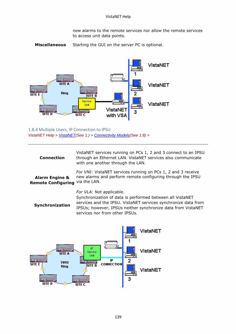
VistaNET Help
139
new alarms to the remote services nor allow the remote services
to access unit data points.
Miscellaneous Starting the GUI on the server PC is optional.
1.8.4 Multiple Users, IP Connection to IPSU VistaNET Help > VistaNET(See 1.) > Connectivity Models(See 1.8) >
Connection
VistaNET services running on PCs 1, 2 and 3 connect to an IPSU
through an Ethernet LAN. VistaNET services also communicate
with one another through the LAN.
Alarm Engine &
Remote Configuring
For VNI: VistaNET services running on PCs 1, 2 and 3 receive
new alarms and perform remote configuring through the IPSU
via the LAN.
For VLA: Not applicable.
Synchronization
Synchronization of data is performed between all VistaNET
services and the IPSU. VistaNET services synchronize data from
IPSUs; however, IPSUs neither synchronize data from VistaNET
services nor from other IPSUs.
VistaNET Help
140
1.9 VistaNET Unit Names
VistaNET Unit Name JungleMUX/TN1U/TN1Ue/T1MX//E1MX Name
2W FXO 2W FXO Unit
2W FXS 2W FXS Unit
2W VF 2W VF Unit
2W VF E&M 2W VF E&M Unit
4W VF 4W VF Unit
4W VF E&M 4W VF E&M Unit
ATU-RCV ATU Receive Unit
ATU-XMT ATU Transmit Unit
CMUX CMUX Unit
CDAX CDAX Unit
CDR CDR Unit
CONTACT IO Contact I/O Unit
CSSU Cyber Secure Service Unit
DATA-G703 64K Data-G703 Unit
DATA-LS Data-LS Unit
DATA-NX64 Data-Nx64 Unit
DATA-NX64F Data-Nx64F Unit
DATA-PTM Data-PTM Unit
DTT-RCV DTT Receive Unit
DTT-XMT DTT Transmit Unit
DTT DTT Receive & Transmit Unit
DS3 DS3 Unit
E1 JIF-E1 / E1 Unit
ETHER-10 ETHER-10 Unit
ETHER-100 ETHER-100 Unit
FDM JIF-FDM / FDM Unit
HS-DATA HS-Data Unit
IPSU IP Service Unit
JIF JIF Unit
VistaNET Help
141
JIF-DS1 JIF-DS1 Unit
JIF-ETHER JIF-ETHER Unit
JIF-SHARE JIF-Share Unit
JIF-TIE JIF-Tie / Tie Unit
LS-DATA LS Data Unit (no remote visibility)
OC-1 OC-1 JMUX Unit
OC-3 OC-3 JMUX Unit
OC-12 OC-12 JMUX Unit
OC-48 OC-48 JMUX Unit
QUAD DS1 Quad DS1 Unit
SERVICE Service Unit
STM-1 STM-1 Aggregate Unit
STM-4 STM-4 Aggregate Unit
SPE-JIF SPE-JIF Unit
TUG-3 TUG-3 Unit
VIDEO-IN VIDEO-IN Unit (configured as IN)
VIDEO-MPEG MPEG-4 Video I/O Unit
VIDEO-OUT VIDEO-OUT Unit (configured as OUT)
VMapper-10 VMapper-10 Unit
VMapper-40 VMapper-40 Unit (Version 2)
VMapper-40x VMapper-40x Unit (Version 1, no remote visibility)
1.10 Ordering Information VistaNET Help > VistaNET(See 1.) >
The VistaNET core load software can be downloaded directly from GE Multilin’s website,
while software licenses must be ordered.
Please contact the Lentronics Multiplexer sales manager for your area regarding ordering
the VistaNET software.
Equipment and Option Code List
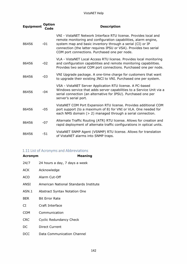
VistaNET Help
142
Equipment Option
Code Description
86456 -01
VNI - VistaNET Network Interface RTU license. Provides local and
remote monitoring and configuration capabilities, alarm engine,
system map and basic inventory through a serial (CI) or IP
connection (the latter requires IPSU or VSA). Provides two serial
COM port connections. Purchased one per node.
86456 -02
VLA - VistaNET Local Access RTU license. Provides local monitoring
and configuration capabilities and remote monitoring capabilities.
Provides two serial COM port connections. Purchased one per node.
86456 -03 VNI Upgrade package. A one-time charge for customers that want
to upgrade their existing JNCI to VNI. Purchased one per system.
86456 -04
VSA - VistaNET Server Application RTU license. A PC-based
Windows service that adds server capabilities to a Service Unit via a
serial connection (an alternative for IPSU). Purchased one per
server’s serial port.
86456 -05
VistaNET COM Port Expansion RTU license. Provides additional COM
port support (to a maximum of 8) for VNI or VLA. One needed for
each NMS domain (> 2) managed through a serial connection.
86456 -07 Alternate Traffic Routing (ATR) RTU license. Allows for creation and
rapid deployment of alternate traffic configurations in optical units.
86456 -51 VistaNET SNMP Agent (VSNMP) RTU license. Allows for translation
of VistaNET alarms into SNMP traps.
1.11 List of Acronyms and Abbreviations
Acronym Meaning
24/7 24 hours a day, 7 days a week
ACK Acknowledge
ACO Alarm Cut-Off
ANSI American National Standards Institute
ASN.1 Abstract Syntax Notation One
BER Bit Error Rate
CI Craft Interface
COM Communication
CRC Cyclic Redundancy Check
DC Direct Current
DCC Data Communication Channel
VistaNET Help
143
DHCP Dynamic Host Configuration Protocol
DOS Disk Operating System
DNS Dynamic Name System (or Service)
DS0 Digital Signal Zero
DTT Direct Transfer Trip
EAS Equipment Assembly Schematic
EIA Electronic Industries Association
FPGA Field Programmable Logic Gate Array
GUI Graphical User Interface
ID Identification
ICMP Internet Control Message Protocol
IEEE Institute of Electrical and Electronics Engineers
IP Internet Protocol
IPSU IP Service Unit
JCI JungleMUX Craft Interface
JIF JungleMUX Intermediate Format
JNCI JungleMUX Network Craft Interface
LAN Local Area Network
LED Light Emitting Diode
LS Low Speed
MTBF Mean Time Between Failure
NAD Node Assignment Drawing
NMS Network Management System
NTP Network Time Protocol
OAM&P Operations, Administration, Maintenance and Provisioning
PC Personal Computer
PLM Product Line Management
RCV Receive
RTU Remote Terminal Unit
SCADA Supervisory Control and Data Acquisition
VistaNET Help
144
SDH Synchronous Digital Hierarchy
SNMP Simple Network Management Protocol
SNTP Simple Network Time Protocol
SONET Synchronous Optical Network
SPE Synchronous Payload Envelope
SPI Serial Port Interface
TCP Transmission Control Protocol
TIF TN1U Intermediate Format
TLCI TN1U Local Craft Interface
TNCI TN1U Network Craft Interface
TOH Transport Overhead
TPIM Technical Practice and Installation Manual
TSI Time Slot Interchange
TU Tributary Unit
TUG3 Tributary Unit Group 3
UDP User Datagram Protocol
UTC Universal Time, Coordinated
VLA VistaNET Local Access
VNI VistaNET Network Interface
VPN Virtual Private Network
VSA VistaNET Server Application
VT Virtual Tributary
1.12 Third Party End User License Agreements
1.12.1 Boost Software License 1.0 (BSL1.0) VistaNET Help > VistaNET(See 1.) > Third Party End User License Agreements >
Permission is hereby granted, free of charge, to any person or organization obtaining a
copy of the software and accompanying documentation covered by this license (the
"Software") to use, reproduce, display, distribute, execute, and transmit the Software,
and to prepare derivative works of the Software, and to permit third-parties to whom the
Software is furnished to do so, all subject to the following:
VistaNET Help
145
The copyright notices in the Software and this entire statement, including the above
license grant, this restriction and the following disclaimer, must be included in all copies
of the Software, in whole or in part, and all derivative works of the Software, unless such
copies or derivative works are solely in the form of machine-executable object code
generated by a source language processor.
THE SOFTWARE IS PROVIDED "AS IS", WITHOUT WARRANTY OF ANY KIND, EXPRESS OR
IMPLIED, INCLUDING BUT NOT LIMITED TO THE WARRANTIES OF MERCHANTABILITY,
FITNESS FOR A PARTICULAR PURPOSE, TITLE AND NON-INFRINGEMENT. IN NO EVENT
SHALL THE COPYRIGHT HOLDERS OR ANYONE DISTRIBUTING THE SOFTWARE BE
LIABLE FOR ANY DAMAGES OR OTHER LIABILITY, WHETHER IN CONTRACT, TORT OR
OTHERWISE, ARISING FROM, OUT OF OR IN CONNECTION WITH THE SOFTWARE OR
THE USE OR OTHER DEALINGS IN THE SOFTWARE.
1.12.2 Libtorrent
Copyright (c) 2009, Libtorrent
All rights reserved.
Redistribution and use in source and binary forms, with or without modification, are
permitted provided that the following conditions are met:
• Redistributions of source code must retain the above copyright notice, this list of
conditions and the following disclaimer.
• Redistributions in binary form must reproduce the above copyright notice, this list
of conditions and the following disclaimer in the documentation and/or other
materials provided with the distribution.
• Neither the name of the nor the names of its contributors may be used to endorse
or promote products derived from this software without specific prior written
permission.
THIS SOFTWARE IS PROVIDED BY THE COPYRIGHT HOLDERS AND CONTRIBUTORS "AS
IS" AND ANY EXPRESS OR IMPLIED WARRANTIES, INCLUDING, BUT NOT LIMITED TO,
THE IMPLIED WARRANTIES OF MERCHANTABILITY AND FITNESS FOR A PARTICULAR
PURPOSE ARE DISCLAIMED. IN NO EVENT SHALL THE COPYRIGHT HOLDER OR
CONTRIBUTORS BE LIABLE FOR ANY DIRECT, INDIRECT, INCIDENTAL, SPECIAL,
EXEMPLARY, OR CONSEQUENTIAL DAMAGES (INCLUDING, BUT NOT LIMITED TO,
PROCUREMENT OF SUBSTITUTE GOODS OR SERVICES; LOSS OF USE, DATA, OR
PROFITS; OR BUSINESS INTERRUPTION) HOWEVER CAUSED AND ON ANY THEORY OF
LIABILITY, WHETHER IN CONTRACT, STRICT LIABILITY, OR TORT (INCLUDING
NEGLIGENCE OR OTHERWISE) ARISING IN ANY WAY OUT OF THE USE OF THIS
SOFTWARE, EVEN IF ADVISED OF THE POSSIBILITY OF SUCH DAMAGE.
1.12.3 Libxml2 Copyright VistaNET Help > VistaNET(See 1.) > Third Party End User License Agreements >
Except where otherwise noted in the source code (e.g. the files hash.c, list.c and the trio files, which are covered by a similar licence but with different Copyright notices) all the files are:
Copyright (C) 1998-2012 Daniel Veillard. All Rights Reserved.
Permission is hereby granted, free of charge, to any person obtaining a copy of this software and associated documentation files (the "Software"), to deal in the Software without restriction, including without limitation the rights
VistaNET Help
146
to use, copy, modify, merge, publish, distribute, sublicense, and/or sell copies of the Software, and to permit persons to whom the Software is fur- nished to do so, subject to the following conditions:
The above copyright notice and this permission notice shall be included in all copies or substantial portions of the Software.
THE SOFTWARE IS PROVIDED "AS IS", WITHOUT WARRANTY OF ANY KIND, EXPRESS OR IMPLIED, INCLUDING BUT NOT LIMITED TO THE WARRANTIES OF MERCHANTABILITY, FIT- NESS FOR A PARTICULAR PURPOSE AND NONINFRINGEMENT. IN NO EVENT SHALL THE AUTHORS OR COPYRIGHT HOLDERS BE LIABLE FOR ANY CLAIM, DAMAGES OR OTHER LIABILITY, WHETHER IN AN ACTION OF CONTRACT, TORT OR OTHERWISE, ARISING FROM, OUT OF OR IN CONNECTION WITH THE SOFTWARE OR THE USE OR OTHER DEALINGS IN THE SOFTWARE.
1.12.4 Net-SNMP VistaNET Help > VistaNET(See 1.) > Third Party End User License Agreements >
License
Various copyrights apply to this package, listed in various separate
parts below. Please make sure that you read all the parts.
---- Part 1: CMU/UCD copyright notice: (BSD like) -----
Copyright 1989, 1991, 1992 by Carnegie Mellon University
Derivative Work - 1996, 1998-2000
Copyright 1996, 1998-2000 The Regents of the University of California
All Rights Reserved
Permission to use, copy, modify and distribute this software and its
documentation for any purpose and without fee is hereby granted,
provided that the above copyright notice appears in all copies and
that both that copyright notice and this permission notice appear in
supporting documentation, and that the name of CMU and The Regents of
the University of California not be used in advertising or publicity
pertaining to distribution of the software without specific written
permission.
CMU AND THE REGENTS OF THE UNIVERSITY OF CALIFORNIA DISCLAIM ALL
WARRANTIES WITH REGARD TO THIS SOFTWARE, INCLUDING ALL IMPLIED
WARRANTIES OF MERCHANTABILITY AND FITNESS. IN NO EVENT SHALL CMU OR
THE REGENTS OF THE UNIVERSITY OF CALIFORNIA BE LIABLE FOR ANY SPECIAL,
INDIRECT OR CONSEQUENTIAL DAMAGES OR ANY DAMAGES WHATSOEVER RESULTING
FROM THE LOSS OF USE, DATA OR PROFITS, WHETHER IN AN ACTION OF
CONTRACT, NEGLIGENCE OR OTHER TORTIOUS ACTION, ARISING OUT OF OR IN
CONNECTION WITH THE USE OR PERFORMANCE OF THIS SOFTWARE.
---- Part 2: Networks Associates Technology, Inc copyright notice (BSD) -----
VistaNET Help
147
Copyright (c) 2001-2003, Networks Associates Technology, Inc
All rights reserved.
Redistribution and use in source and binary forms, with or without
modification, are permitted provided that the following conditions are met:
* Redistributions of source code must retain the above copyright notice,
this list of conditions and the following disclaimer.
* Redistributions in binary form must reproduce the above copyright
notice, this list of conditions and the following disclaimer in the
documentation and/or other materials provided with the distribution.
* Neither the name of the Networks Associates Technology, Inc nor the
names of its contributors may be used to endorse or promote
products derived from this software without specific prior written
permission.
THIS SOFTWARE IS PROVIDED BY THE COPYRIGHT HOLDERS AND CONTRIBUTORS ``AS
IS'' AND ANY EXPRESS OR IMPLIED WARRANTIES, INCLUDING, BUT NOT LIMITED TO,
THE IMPLIED WARRANTIES OF MERCHANTABILITY AND FITNESS FOR A PARTICULAR
PURPOSE ARE DISCLAIMED. IN NO EVENT SHALL THE COPYRIGHT HOLDERS OR
CONTRIBUTORS BE LIABLE FOR ANY DIRECT, INDIRECT, INCIDENTAL, SPECIAL,
EXEMPLARY, OR CONSEQUENTIAL DAMAGES (INCLUDING, BUT NOT LIMITED TO,
PROCUREMENT OF SUBSTITUTE GOODS OR SERVICES; LOSS OF USE, DATA, OR
PROFITS;
OR BUSINESS INTERRUPTION) HOWEVER CAUSED AND ON ANY THEORY OF LIABILITY,
WHETHER IN CONTRACT, STRICT LIABILITY, OR TORT (INCLUDING NEGLIGENCE OR
OTHERWISE) ARISING IN ANY WAY OUT OF THE USE OF THIS SOFTWARE, EVEN IF
ADVISED OF THE POSSIBILITY OF SUCH DAMAGE.
---- Part 3: Cambridge Broadband Ltd. copyright notice (BSD) -----
Portions of this code are copyright (c) 2001-2003, Cambridge Broadband Ltd.
All rights reserved.
Redistribution and use in source and binary forms, with or without
modification, are permitted provided that the following conditions are met:
* Redistributions of source code must retain the above copyright notice,
this list of conditions and the following disclaimer.
* Redistributions in binary form must reproduce the above copyright
notice, this list of conditions and the following disclaimer in the
documentation and/or other materials provided with the distribution.
* The name of Cambridge Broadband Ltd. may not be used to endorse or
promote products derived from this software without specific prior
written permission.
THIS SOFTWARE IS PROVIDED BY THE COPYRIGHT HOLDER ``AS IS'' AND ANY
EXPRESS OR IMPLIED WARRANTIES, INCLUDING, BUT NOT LIMITED TO, THE
IMPLIED WARRANTIES OF MERCHANTABILITY AND FITNESS FOR A PARTICULAR
PURPOSE ARE DISCLAIMED. IN NO EVENT SHALL THE COPYRIGHT HOLDER BE
LIABLE FOR ANY DIRECT, INDIRECT, INCIDENTAL, SPECIAL, EXEMPLARY, OR
CONSEQUENTIAL DAMAGES (INCLUDING, BUT NOT LIMITED TO, PROCUREMENT OF
SUBSTITUTE GOODS OR SERVICES; LOSS OF USE, DATA, OR PROFITS; OR
VistaNET Help
148
BUSINESS INTERRUPTION) HOWEVER CAUSED AND ON ANY THEORY OF LIABILITY,
WHETHER IN CONTRACT, STRICT LIABILITY, OR TORT (INCLUDING NEGLIGENCE
OR OTHERWISE) ARISING IN ANY WAY OUT OF THE USE OF THIS SOFTWARE, EVEN
IF ADVISED OF THE POSSIBILITY OF SUCH DAMAGE.
---- Part 4: Sun Microsystems, Inc. copyright notice (BSD) -----
Copyright © 2003 Sun Microsystems, Inc., 4150 Network Circle, Santa Clara,
California 95054, U.S.A. All rights reserved.
Use is subject to license terms below.
This distribution may include materials developed by third parties.
Sun, Sun Microsystems, the Sun logo and Solaris are trademarks or registered
trademarks of Sun Microsystems, Inc. in the U.S. and other countries.
Redistribution and use in source and binary forms, with or without
modification, are permitted provided that the following conditions are met:
* Redistributions of source code must retain the above copyright notice,
this list of conditions and the following disclaimer.
* Redistributions in binary form must reproduce the above copyright
notice, this list of conditions and the following disclaimer in the
documentation and/or other materials provided with the distribution.
* Neither the name of the Sun Microsystems, Inc. nor the
names of its contributors may be used to endorse or promote
products derived from this software without specific prior written
permission.
THIS SOFTWARE IS PROVIDED BY THE COPYRIGHT HOLDERS AND CONTRIBUTORS ``AS
IS'' AND ANY EXPRESS OR IMPLIED WARRANTIES, INCLUDING, BUT NOT LIMITED TO,
THE IMPLIED WARRANTIES OF MERCHANTABILITY AND FITNESS FOR A PARTICULAR
PURPOSE ARE DISCLAIMED. IN NO EVENT SHALL THE COPYRIGHT HOLDERS OR
CONTRIBUTORS BE LIABLE FOR ANY DIRECT, INDIRECT, INCIDENTAL, SPECIAL,
EXEMPLARY, OR CONSEQUENTIAL DAMAGES (INCLUDING, BUT NOT LIMITED TO,
PROCUREMENT OF SUBSTITUTE GOODS OR SERVICES; LOSS OF USE, DATA, OR
PROFITS;
OR BUSINESS INTERRUPTION) HOWEVER CAUSED AND ON ANY THEORY OF LIABILITY,
WHETHER IN CONTRACT, STRICT LIABILITY, OR TORT (INCLUDING NEGLIGENCE OR
OTHERWISE) ARISING IN ANY WAY OUT OF THE USE OF THIS SOFTWARE, EVEN IF
ADVISED OF THE POSSIBILITY OF SUCH DAMAGE.
---- Part 5: Sparta, Inc copyright notice (BSD) -----
Copyright (c) 2003-2009, Sparta, Inc
All rights reserved.
Redistribution and use in source and binary forms, with or without
modification, are permitted provided that the following conditions are met:
* Redistributions of source code must retain the above copyright notice,
VistaNET Help
149
this list of conditions and the following disclaimer.
* Redistributions in binary form must reproduce the above copyright
notice, this list of conditions and the following disclaimer in the
documentation and/or other materials provided with the distribution.
* Neither the name of Sparta, Inc nor the names of its contributors may
be used to endorse or promote products derived from this software
without specific prior written permission.
THIS SOFTWARE IS PROVIDED BY THE COPYRIGHT HOLDERS AND CONTRIBUTORS ``AS
IS'' AND ANY EXPRESS OR IMPLIED WARRANTIES, INCLUDING, BUT NOT LIMITED TO,
THE IMPLIED WARRANTIES OF MERCHANTABILITY AND FITNESS FOR A PARTICULAR
PURPOSE ARE DISCLAIMED. IN NO EVENT SHALL THE COPYRIGHT HOLDERS OR
CONTRIBUTORS BE LIABLE FOR ANY DIRECT, INDIRECT, INCIDENTAL, SPECIAL,
EXEMPLARY, OR CONSEQUENTIAL DAMAGES (INCLUDING, BUT NOT LIMITED TO,
PROCUREMENT OF SUBSTITUTE GOODS OR SERVICES; LOSS OF USE, DATA, OR
PROFITS;
OR BUSINESS INTERRUPTION) HOWEVER CAUSED AND ON ANY THEORY OF LIABILITY,
WHETHER IN CONTRACT, STRICT LIABILITY, OR TORT (INCLUDING NEGLIGENCE OR
OTHERWISE) ARISING IN ANY WAY OUT OF THE USE OF THIS SOFTWARE, EVEN IF
ADVISED OF THE POSSIBILITY OF SUCH DAMAGE.
---- Part 6: Cisco/BUPTNIC copyright notice (BSD) -----
Copyright (c) 2004, Cisco, Inc and Information Network
Center of Beijing University of Posts and Telecommunications.
All rights reserved.
Redistribution and use in source and binary forms, with or without
modification, are permitted provided that the following conditions are met:
* Redistributions of source code must retain the above copyright notice,
this list of conditions and the following disclaimer.
* Redistributions in binary form must reproduce the above copyright
notice, this list of conditions and the following disclaimer in the
documentation and/or other materials provided with the distribution.
* Neither the name of Cisco, Inc, Beijing University of Posts and
Telecommunications, nor the names of their contributors may
be used to endorse or promote products derived from this software
without specific prior written permission.
THIS SOFTWARE IS PROVIDED BY THE COPYRIGHT HOLDERS AND CONTRIBUTORS ``AS
IS'' AND ANY EXPRESS OR IMPLIED WARRANTIES, INCLUDING, BUT NOT LIMITED TO,
THE IMPLIED WARRANTIES OF MERCHANTABILITY AND FITNESS FOR A PARTICULAR
PURPOSE ARE DISCLAIMED. IN NO EVENT SHALL THE COPYRIGHT HOLDERS OR
CONTRIBUTORS BE LIABLE FOR ANY DIRECT, INDIRECT, INCIDENTAL, SPECIAL,
EXEMPLARY, OR CONSEQUENTIAL DAMAGES (INCLUDING, BUT NOT LIMITED TO,
PROCUREMENT OF SUBSTITUTE GOODS OR SERVICES; LOSS OF USE, DATA, OR
PROFITS;
OR BUSINESS INTERRUPTION) HOWEVER CAUSED AND ON ANY THEORY OF LIABILITY,
WHETHER IN CONTRACT, STRICT LIABILITY, OR TORT (INCLUDING NEGLIGENCE OR
OTHERWISE) ARISING IN ANY WAY OUT OF THE USE OF THIS SOFTWARE, EVEN IF
ADVISED OF THE POSSIBILITY OF SUCH DAMAGE.
VistaNET Help
150
---- Part 7: Fabasoft R&D Software GmbH & Co KG copyright notice (BSD) -----
Copyright (c) Fabasoft R&D Software GmbH & Co KG, 2003
Author: Bernhard Penz
Redistribution and use in source and binary forms, with or without
modification, are permitted provided that the following conditions are met:
* Redistributions of source code must retain the above copyright notice,
this list of conditions and the following disclaimer.
* Redistributions in binary form must reproduce the above copyright
notice, this list of conditions and the following disclaimer in the
documentation and/or other materials provided with the distribution.
* The name of Fabasoft R&D Software GmbH & Co KG or any of its subsidiaries,
brand or product names may not be used to endorse or promote products
derived from this software without specific prior written permission.
THIS SOFTWARE IS PROVIDED BY THE COPYRIGHT HOLDER ``AS IS'' AND ANY
EXPRESS OR IMPLIED WARRANTIES, INCLUDING, BUT NOT LIMITED TO, THE
IMPLIED WARRANTIES OF MERCHANTABILITY AND FITNESS FOR A PARTICULAR
PURPOSE ARE DISCLAIMED. IN NO EVENT SHALL THE COPYRIGHT HOLDER BE
LIABLE FOR ANY DIRECT, INDIRECT, INCIDENTAL, SPECIAL, EXEMPLARY, OR
CONSEQUENTIAL DAMAGES (INCLUDING, BUT NOT LIMITED TO, PROCUREMENT OF
SUBSTITUTE GOODS OR SERVICES; LOSS OF USE, DATA, OR PROFITS; OR
BUSINESS INTERRUPTION) HOWEVER CAUSED AND ON ANY THEORY OF LIABILITY,
WHETHER IN CONTRACT, STRICT LIABILITY, OR TORT (INCLUDING NEGLIGENCE
OR OTHERWISE) ARISING IN ANY WAY OUT OF THE USE OF THIS SOFTWARE, EVEN
IF ADVISED OF THE POSSIBILITY OF SUCH DAMAGE.
---- Part 8: Apple Inc. copyright notice (BSD) -----
Copyright (c) 2007 Apple Inc. All rights reserved.
Redistribution and use in source and binary forms, with or without
modification, are permitted provided that the following conditions
are met:
1. Redistributions of source code must retain the above copyright
notice, this list of conditions and the following disclaimer.
2. Redistributions in binary form must reproduce the above
copyright notice, this list of conditions and the following
disclaimer in the documentation and/or other materials provided
with the distribution.
3. Neither the name of Apple Inc. ("Apple") nor the names of its
contributors may be used to endorse or promote products derived
from this software without specific prior written permission.
THIS SOFTWARE IS PROVIDED BY APPLE AND ITS CONTRIBUTORS "AS IS" AND
ANY EXPRESS OR IMPLIED WARRANTIES, INCLUDING, BUT NOT LIMITED TO,
THE IMPLIED WARRANTIES OF MERCHANTABILITY AND FITNESS FOR A
PARTICULAR PURPOSE ARE DISCLAIMED. IN NO EVENT SHALL APPLE OR ITS
CONTRIBUTORS BE LIABLE FOR ANY DIRECT, INDIRECT, INCIDENTAL,
VistaNET Help
151
SPECIAL, EXEMPLARY, OR CONSEQUENTIAL DAMAGES (INCLUDING, BUT NOT
LIMITED TO, PROCUREMENT OF SUBSTITUTE GOODS OR SERVICES; LOSS OF
USE, DATA, OR PROFITS; OR BUSINESS INTERRUPTION) HOWEVER CAUSED AND
ON ANY THEORY OF LIABILITY, WHETHER IN CONTRACT, STRICT LIABILITY,
OR TORT (INCLUDING NEGLIGENCE OR OTHERWISE) ARISING IN ANY WAY OUT
OF THE USE OF THIS SOFTWARE, EVEN IF ADVISED OF THE POSSIBILITY OF
SUCH DAMAGE.
---- Part 9: ScienceLogic, LLC copyright notice (BSD) -----
Copyright (c) 2009, ScienceLogic, LLC
All rights reserved.
Redistribution and use in source and binary forms, with or without
modification, are permitted provided that the following conditions are
met:
* Redistributions of source code must retain the above copyright notice,
this list of conditions and the following disclaimer.
* Redistributions in binary form must reproduce the above copyright
notice, this list of conditions and the following disclaimer in the
documentation and/or other materials provided with the distribution.
* Neither the name of ScienceLogic, LLC nor the names of its
contributors may be used to endorse or promote products derived
from this software without specific prior written permission.
THIS SOFTWARE IS PROVIDED BY THE COPYRIGHT HOLDERS AND CONTRIBUTORS
``AS IS'' AND ANY EXPRESS OR IMPLIED WARRANTIES, INCLUDING, BUT NOT
LIMITED TO, THE IMPLIED WARRANTIES OF MERCHANTABILITY AND FITNESS FOR
A PARTICULAR PURPOSE ARE DISCLAIMED. IN NO EVENT SHALL THE COPYRIGHT
HOLDERS OR CONTRIBUTORS BE LIABLE FOR ANY DIRECT, INDIRECT,
INCIDENTAL, SPECIAL, EXEMPLARY, OR CONSEQUENTIAL DAMAGES (INCLUDING,
BUT NOT LIMITED TO, PROCUREMENT OF SUBSTITUTE GOODS OR SERVICES; LOSS
OF USE, DATA, OR PROFITS; OR BUSINESS INTERRUPTION) HOWEVER CAUSED AND
ON ANY THEORY OF LIABILITY, WHETHER IN CONTRACT, STRICT LIABILITY, OR
TORT (INCLUDING NEGLIGENCE OR OTHERWISE) ARISING IN ANY WAY OUT OF THE
USE OF THIS SOFTWARE, EVEN IF ADVISED OF THE POSSIBILITY OF SUCH
DAMAGE.
1.12.5 OpenSSL and SSLeay Licenses VistaNET Help > VistaNET(See 1.) > Third Party End User License Agreements >
LICENSE ISSUES
=
The OpenSSL toolkit stays under a dual license, i.e. both the conditions of
the OpenSSL License and the original SSLeay license apply to the toolkit.
See below for the actual license texts. Actually both licenses are BSD-style
Open Source licenses. In case of any license issues related to OpenSSL
please contact [email protected].
VistaNET Help
152
OpenSSL License
---------------
/* =
* Copyright (c) 1998-2011 The OpenSSL Project. All rights reserved.
*
* Redistribution and use in source and binary forms, with or without
* modification, are permitted provided that the following conditions
* are met:
*
* 1. Redistributions of source code must retain the above copyright
* notice, this list of conditions and the following disclaimer.
*
* 2. Redistributions in binary form must reproduce the above copyright
* notice, this list of conditions and the following disclaimer in
* the documentation and/or other materials provided with the
* distribution.
*
* 3. All advertising materials mentioning features or use of this
* software must display the following acknowledgment:
* "This product includes software developed by the OpenSSL Project
* for use in the OpenSSL Toolkit. (http://www.openssl.org/)"
*
* 4. The names "OpenSSL Toolkit" and "OpenSSL Project" must not be used to
* endorse or promote products derived from this software without
* prior written permission. For written permission, please contact
*
* 5. Products derived from this software may not be called "OpenSSL"
* nor may "OpenSSL" appear in their names without prior written
* permission of the OpenSSL Project.
*
* 6. Redistributions of any form whatsoever must retain the following
* acknowledgment:
* "This product includes software developed by the OpenSSL Project
* for use in the OpenSSL Toolkit (http://www.openssl.org/)"
*
* THIS SOFTWARE IS PROVIDED BY THE OpenSSL PROJECT ``AS IS'' AND ANY
* EXPRESSED OR IMPLIED WARRANTIES, INCLUDING, BUT NOT LIMITED TO, THE
* IMPLIED WARRANTIES OF MERCHANTABILITY AND FITNESS FOR A PARTICULAR
* PURPOSE ARE DISCLAIMED. IN NO EVENT SHALL THE OpenSSL PROJECT OR
* ITS CONTRIBUTORS BE LIABLE FOR ANY DIRECT, INDIRECT, INCIDENTAL,
* SPECIAL, EXEMPLARY, OR CONSEQUENTIAL DAMAGES (INCLUDING, BUT
* NOT LIMITED TO, PROCUREMENT OF SUBSTITUTE GOODS OR SERVICES;
* LOSS OF USE, DATA, OR PROFITS; OR BUSINESS INTERRUPTION)
* HOWEVER CAUSED AND ON ANY THEORY OF LIABILITY, WHETHER IN CONTRACT,
* STRICT LIABILITY, OR TORT (INCLUDING NEGLIGENCE OR OTHERWISE)
* ARISING IN ANY WAY OUT OF THE USE OF THIS SOFTWARE, EVEN IF ADVISED
* OF THE POSSIBILITY OF SUCH DAMAGE.
* =
*
* This product includes cryptographic software written by Eric Young
* ([email protected]). This product includes software written by Tim
* Hudson ([email protected]).
*
*/
VistaNET Help
153
Original SSLeay License
-----------------------
/* Copyright (C) 1995-1998 Eric Young ([email protected])
* All rights reserved.
*
* This package is an SSL implementation written
* by Eric Young ([email protected]).
* The implementation was written so as to conform with Netscapes SSL.
*
* This library is free for commercial and non-commercial use as long as
* the following conditions are aheared to. The following conditions
* apply to all code found in this distribution, be it the RC4, RSA,
* lhash, DES, etc., code; not just the SSL code. The SSL documentation
* included with this distribution is covered by the same copyright terms
* except that the holder is Tim Hudson ([email protected]).
*
* Copyright remains Eric Young's, and as such any Copyright notices in
* the code are not to be removed.
* If this package is used in a product, Eric Young should be given attribution
* as the author of the parts of the library used.
* This can be in the form of a textual message at program startup or
* in documentation (online or textual) provided with the package.
*
* Redistribution and use in source and binary forms, with or without
* modification, are permitted provided that the following conditions
* are met:
* 1. Redistributions of source code must retain the copyright
* notice, this list of conditions and the following disclaimer.
* 2. Redistributions in binary form must reproduce the above copyright
* notice, this list of conditions and the following disclaimer in the
* documentation and/or other materials provided with the distribution.
* 3. All advertising materials mentioning features or use of this software
* must display the following acknowledgement:
* "This product includes cryptographic software written by
* Eric Young ([email protected])"
* The word 'cryptographic' can be left out if the rouines from the library
* being used are not cryptographic related :-).
* 4. If you include any Windows specific code (or a derivative thereof) from
* the apps directory (application code) you must include an acknowledgement:
* "This product includes software written by Tim Hudson ([email protected])"
*
* THIS SOFTWARE IS PROVIDED BY ERIC YOUNG ``AS IS'' AND
* ANY EXPRESS OR IMPLIED WARRANTIES, INCLUDING, BUT NOT LIMITED TO, THE
* IMPLIED WARRANTIES OF MERCHANTABILITY AND FITNESS FOR A PARTICULAR
PURPOSE
* ARE DISCLAIMED. IN NO EVENT SHALL THE AUTHOR OR CONTRIBUTORS BE LIABLE
* FOR ANY DIRECT, INDIRECT, INCIDENTAL, SPECIAL, EXEMPLARY, OR
CONSEQUENTIAL
* DAMAGES (INCLUDING, BUT NOT LIMITED TO, PROCUREMENT OF SUBSTITUTE
GOODS
* OR SERVICES; LOSS OF USE, DATA, OR PROFITS; OR BUSINESS INTERRUPTION)
* HOWEVER CAUSED AND ON ANY THEORY OF LIABILITY, WHETHER IN CONTRACT,
STRICT
* LIABILITY, OR TORT (INCLUDING NEGLIGENCE OR OTHERWISE) ARISING IN ANY
WAY
* OUT OF THE USE OF THIS SOFTWARE, EVEN IF ADVISED OF THE POSSIBILITY OF
VistaNET Help
154
* SUCH DAMAGE.
*
* The licence and distribution terms for any publically available version or
* derivative of this code cannot be changed. i.e. this code cannot simply be
* copied and put under another distribution licence
* [including the GNU Public Licence.]
*/
1.12.6 SharpSnmpLib
Copyright (c) 2008 Malcolm Crowe, Lex Li, and other contributors.
Permission is hereby granted, free of charge, to any person obtaining a copy of this
software and associated documentation files (the "Software"), to deal in the
Software without restriction, including without limitation the rights to use, copy,
modify, merge, publish, distribute, sublicense, and/or sell copies of the Software,
and to permit persons to whom the Software is furnished to do so, subject to the
following conditions:
The above copyright notice and this permission notice shall be included in all
copies or substantial portions of the Software.
THE SOFTWARE IS PROVIDED "AS IS", WITHOUT WARRANTY OF ANY
KIND, EXPRESS OR IMPLIED, INCLUDING BUT NOT LIMITED TO THE
WARRANTIES OF MERCHANTABILITY, FITNESS FOR A PARTICULAR
PURPOSE AND NONINFRINGEMENT. IN NO EVENT SHALL THE
AUTHORS OR COPYRIGHT HOLDERS BE LIABLE FOR ANY CLAIM,
DAMAGES OR OTHER LIABILITY, WHETHER IN AN ACTION OF
CONTRACT, TORT OR OTHERWISE, ARISING FROM, OUT OF OR IN
CONNECTION WITH THE SOFTWARE OR THE USE OR OTHER
DEALINGS IN THE SOFTWARE.
1.12.7 SQLite Copyright VistaNET Help > VistaNET(See 1.) > Third Party End User License Agreements >
All of the deliverable code in SQLite has been dedicated to the public domain by the
authors. All code authors, and representatives of the companies they work for, have
signed affidavits dedicating their contributions to the public domain and originals of those
signed affidavits are stored in a firesafe at the main offices of Hwaci. Anyone is free to
copy, modify, publish, use, compile, sell, or distribute the original SQLite code, either in
source code form or as a compiled binary, for any purpose, commercial or non-
commercial, and by any means.
The previous paragraph applies to the deliverable code in SQLite - those parts of the
SQLite library that you actually bundle and ship with a larger application. Portions of the
documentation and some code used as part of the build process might fall under other
licenses. The details here are unclear. We do not worry about the licensing of the
VistaNET Help
155
documentation and build code so much because none of these things are part of the core
deliverable SQLite library.
All of the deliverable code in SQLite has been written from scratch. No code has been
taken from other projects or from the open internet. Every line of code can be traced
back to its original author, and all of those authors have public domain dedications on
file. So the SQLite code base is clean and is uncontaminated with licensed code from
other projects.
1.12.8 SQLCipher Copyright Copyright (c) 2008-2012 Zetetic LLC
All rights reserved.
Redistribution and use in source and binary forms, with or without
modification, are permitted provided that the following conditions are met:
* Redistributions of source code must retain the above copyright
notice, this list of conditions and the following disclaimer.
* Redistributions in binary form must reproduce the above copyright
notice, this list of conditions and the following disclaimer in the
documentation and/or other materials provided with the distribution.
* Neither the name of the ZETETIC LLC nor the
names of its contributors may be used to endorse or promote products
derived from this software without specific prior written permission.
THIS SOFTWARE IS PROVIDED BY ZETETIC LLC ''AS IS'' AND ANY
EXPRESS OR IMPLIED WARRANTIES, INCLUDING, BUT NOT LIMITED TO, THE IMPLIED
WARRANTIES OF MERCHANTABILITY AND FITNESS FOR A PARTICULAR PURPOSE
ARE
DISCLAIMED. IN NO EVENT SHALL ZETETIC LLC BE LIABLE FOR ANY
DIRECT, INDIRECT, INCIDENTAL, SPECIAL, EXEMPLARY, OR CONSEQUENTIAL
DAMAGES
(INCLUDING, BUT NOT LIMITED TO, PROCUREMENT OF SUBSTITUTE GOODS OR
SERVICES;
LOSS OF USE, DATA, OR PROFITS; OR BUSINESS INTERRUPTION) HOWEVER CAUSED
AND
ON ANY THEORY OF LIABILITY, WHETHER IN CONTRACT, STRICT LIABILITY, OR TORT
(INCLUDING NEGLIGENCE OR OTHERWISE) ARISING IN ANY WAY OUT OF THE USE
OF THIS
SOFTWARE, EVEN IF ADVISED OF THE POSSIBILITY OF SUCH DAMAGE.
1.12.9 Xmlsec Copyright VistaNET Help > VistaNET(See 1.) > Third Party End User License Agreements >
xmlsec, xmlsec-openssl, xmlsec-gnutls, xmlsec-gcrypt libraries
------------------------------------------------------------------------------
Copyright (C) 2002-2010 Aleksey Sanin. All Rights Reserved.
Permission is hereby granted, free of charge, to any person obtaining a copy
of this software and associated documentation files (the "Software"), to deal
in the Software without restriction, including without limitation the rights
to use, copy, modify, merge, publish, distribute, sublicense, and/or sell
copies of the Software, and to permit persons to whom the Software is fur-
nished to do so, subject to the following conditions:
VistaNET Help
156
The above copyright notice and this permission notice shall be included in
all copies or substantial portions of the Software.
THE SOFTWARE IS PROVIDED "AS IS", WITHOUT WARRANTY OF ANY KIND, EXPRESS OR
IMPLIED, INCLUDING BUT NOT LIMITED TO THE WARRANTIES OF MERCHANTABILITY,
FIT-
NESS FOR A PARTICULAR PURPOSE AND NONINFRINGEMENT. IN NO EVENT SHALL THE
ALEKSEY SANIN BE LIABLE FOR ANY CLAIM, DAMAGES OR OTHER LIABILITY, WHETHER
IN AN ACTION OF CONTRACT, TORT OR OTHERWISE, ARISING FROM, OUT OF OR IN
CON-
NECTION WITH THE SOFTWARE OR THE USE OR OTHER DEALINGS IN THE SOFTWARE.
Except as contained in this notice, the name of Aleksey Sanin shall not
be used in advertising or otherwise to promote the sale, use or other deal-
ings in this Software without prior written authorization from him.
xmlsec-nss library
------------------------------------------------------------------------------
Copyright (C) 2002-2010 Aleksey Sanin. All Rights Reserved.
Copyright (c) 2003 America Online, Inc. All rights reserved.
Permission is hereby granted, free of charge, to any person obtaining a copy
of this software and associated documentation files (the "Software"), to deal
in the Software without restriction, including without limitation the rights
to use, copy, modify, merge, publish, distribute, sublicense, and/or sell
copies of the Software, and to permit persons to whom the Software is fur-
nished to do so, subject to the following conditions:
The above copyright notice and this permission notice shall be included in
all copies or substantial portions of the Software.
Portions of the Software were created using source code and/or APIs
governed by the Mozilla Public License (MPL). The MPL is available
at http://www.mozilla.org/MPL/MPL-1.1.html. The MPL permits such
portions to be distributed with code not governed by MPL, as long
as the requirements of MPL are fulfilled for such portions.
THE SOFTWARE IS PROVIDED "AS IS", WITHOUT WARRANTY OF ANY KIND, EXPRESS OR
IMPLIED, INCLUDING BUT NOT LIMITED TO THE WARRANTIES OF MERCHANTABILITY,
FIT-
NESS FOR A PARTICULAR PURPOSE AND NONINFRINGEMENT. IN NO EVENT SHALL THE
ALEKSEY SANIN BE LIABLE FOR ANY CLAIM, DAMAGES OR OTHER LIABILITY, WHETHER
IN AN ACTION OF CONTRACT, TORT OR OTHERWISE, ARISING FROM, OUT OF OR IN
CON-
NECTION WITH THE SOFTWARE OR THE USE OR OTHER DEALINGS IN THE SOFTWARE.
Except as contained in this notice, the name of Aleksey Sanin shall not
be used in advertising or otherwise to promote the sale, use or other deal-
ings in this Software without prior written authorization from him.
xmlsec-mscrypto library
------------------------------------------------------------------------------
VistaNET Help
157
Copyright (C) 2002-2010 Aleksey Sanin. All Rights Reserved.
Copyright (C) 2003 Cordys R&D BV, All rights reserved.
Copyright (C) 2007 Roumen Petrov.
Copyright (c) 2005-2006 Cryptocom LTD (http://www.cryptocom.ru).
Permission is hereby granted, free of charge, to any person obtaining a copy
of this software and associated documentation files (the "Software"), to deal
in the Software without restriction, including without limitation the rights
to use, copy, modify, merge, publish, distribute, sublicense, and/or sell
copies of the Software, and to permit persons to whom the Software is fur-
nished to do so, subject to the following conditions:
The above copyright notice and this permission notice shall be included in
all copies or substantial portions of the Software.
THE SOFTWARE IS PROVIDED "AS IS", WITHOUT WARRANTY OF ANY KIND, EXPRESS OR
IMPLIED, INCLUDING BUT NOT LIMITED TO THE WARRANTIES OF MERCHANTABILITY,
FIT-
NESS FOR A PARTICULAR PURPOSE AND NONINFRINGEMENT. IN NO EVENT SHALL THE
ALEKSEY SANIN BE LIABLE FOR ANY CLAIM, DAMAGES OR OTHER LIABILITY, WHETHER
IN AN ACTION OF CONTRACT, TORT OR OTHERWISE, ARISING FROM, OUT OF OR IN
CON-
NECTION WITH THE SOFTWARE OR THE USE OR OTHER DEALINGS IN THE SOFTWARE.
Except as contained in this notice, the name of Aleksey Sanin shall not
be used in advertising or otherwise to promote the sale, use or other deal-
ings in this Software without prior written authorization from him.
References
------------------------------------------------------------------------------
* AOL
http://www.aleksey.com/pipermail/xmlsec/2003/005488.html
http://www.aleksey.com/pipermail/xmlsec/attachments/20030729/0e25648e/attachmen
t.htm
* Cordys R&D BV
http://www.aleksey.com/pipermail/xmlsec/2003/005581.html
* Cryptocom LTD
http://www.aleksey.com/pipermail/xmlsec/2006/007410.html
1.12.10 Spdlog Copyright VistaNET Help > VistaNET(See 1.) > Third Party End User License Agreements >
The MIT License (MIT)
Copyright (c) 2016 Gabi Melman.
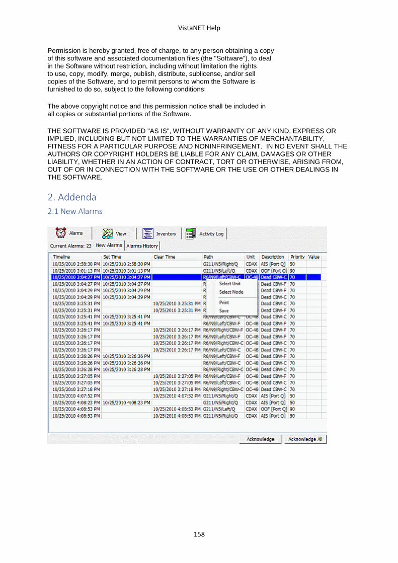
VistaNET Help
158
Permission is hereby granted, free of charge, to any person obtaining a copy of this software and associated documentation files (the "Software"), to deal in the Software without restriction, including without limitation the rights to use, copy, modify, merge, publish, distribute, sublicense, and/or sell copies of the Software, and to permit persons to whom the Software is furnished to do so, subject to the following conditions:
The above copyright notice and this permission notice shall be included in all copies or substantial portions of the Software.
THE SOFTWARE IS PROVIDED "AS IS", WITHOUT WARRANTY OF ANY KIND, EXPRESS OR IMPLIED, INCLUDING BUT NOT LIMITED TO THE WARRANTIES OF MERCHANTABILITY, FITNESS FOR A PARTICULAR PURPOSE AND NONINFRINGEMENT. IN NO EVENT SHALL THE AUTHORS OR COPYRIGHT HOLDERS BE LIABLE FOR ANY CLAIM, DAMAGES OR OTHER LIABILITY, WHETHER IN AN ACTION OF CONTRACT, TORT OR OTHERWISE, ARISING FROM, OUT OF OR IN CONNECTION WITH THE SOFTWARE OR THE USE OR OTHER DEALINGS IN THE SOFTWARE.
2. Addenda
2.1 New Alarms
Related Documents