Grid Solutions Innovative Technology & Design • Advanced motor protection, control and diagnostics capability • Patented environmental monitoring and diagnostics • Advanced, flexible and embedded communications: IEC ® 61850 Ed2, IEC 62439/PRP, Modbus ® RTU & TCP/IP, DNP3.0, IEC 60870-5-104 • Single setup and configuration across the platform • Elimination of electrolytic capacitors • Field swappable power supply • Enhanced relay draw-out construction Exceptional Quality & Reliability • IPC A-610-E Class 3 manufacturing standards • Highest reliability standards for electronics testing • 100% Environmental Stress Screening and full functional testing • Rated for IP54 (front) applications • Standard Harsh Environment Conformal Coating Uncompromising Service & Support • Covered under GE’s 10 year warranty plan • Designed, tested and assembled by GE Comprehensive Motor Protection and Management for Medium and Large Motors The Multilin™ 869 relay is a member of the Multilin 8 Series protective relay platform and has been designed for the protection, control and management of medium and large induction and synchronous motors. The Multilin 869 provides advanced functionality for various types of applications such as high-speed protection, extensively customizable programmable logic, advanced motor monitoring and diagnostics, and flexible configuration capabilities. Advanced communications of the 8 Series platform allows easy integration into process and electrical control systems for smoother asset monitoring and control. Key Benefits • Comprehensive motor protection for medium and large induction motors • Advanced motor diagnostics with high-end fault and disturbance recording • Integrated arc flash detection using light sensors supervised by over current to reduce incident energy and equipment damage • High-end cyber security such as AAA, Radius, RBAC, and Syslog helps enable NERC ® CIP requirements • Draw-out design simplifies testing and increases process uptime • Supporting the latest in communication protocols and networking technology, enabling seamless system integration and interoperability • Optional Wi-Fi connectivity minimizes system configuration and facilitates safe relay programming and diagnostic retrieval • Monitored environmental conditions helps reduce system downtime Applications • Wide range of motor applications for oil & gas, mining & metals, cement, and wastewater • Comprehensive protection and management of medium to large motors; two-speed, VFD-driven, cyclic loading and synchronous motors • Specific and advanced features for high inertia loads and reduced-voltage starting motors • Stator protection of medium to large synchronous motors where field functions are provided by excitation panels • Advanced predictive motor diagnostics and motor health visualization Multilin 869 WORLDWIDE WARRANTY 10 YEAR

Welcome message from author
This document is posted to help you gain knowledge. Please leave a comment to let me know what you think about it! Share it to your friends and learn new things together.
Transcript

Grid Solutions
Innovative Technology & Design • Advanced motor protection, control and
diagnostics capability
• Patented environmental monitoring and diagnostics
• Advanced, flexible and embedded communications: IEC® 61850 Ed2, IEC 62439/PRP, Modbus® RTU & TCP/IP, DNP3.0, IEC 60870-5-104
• Single setup and configuration across the platform
• Elimination of electrolytic capacitors
• Field swappable power supply
• Enhanced relay draw-out construction
Exceptional Quality & Reliability• IPC A-610-E Class 3 manufacturing standards
• Highest reliability standards for electronics testing
• 100% Environmental Stress Screening and full functional testing
• Rated for IP54 (front) applications
• Standard Harsh Environment Conformal Coating
Uncompromising Service & Support • Covered under GE’s 10 year warranty plan
• Designed, tested and assembled by GE
Comprehensive Motor Protection and Management for Medium and Large Motors
The Multilin™ 869 relay is a member of the Multilin 8 Series protective relay platform and has been designed for the protection, control and management of medium and large induction and synchronous motors.
The Multilin 869 provides advanced functionality for various types of applications such as high-speed protection, extensively customizable programmable logic, advanced motor monitoring and diagnostics, and flexible configuration capabilities.
Advanced communications of the 8 Series platform allows easy integration into process and electrical control systems for smoother asset monitoring and control.
Key Benefits• Comprehensive motor protection for medium and large induction motors
• Advanced motor diagnostics with high-end fault and disturbance recording
• Integrated arc flash detection using light sensors supervised by over current to reduce incident energy and equipment damage
• High-end cyber security such as AAA, Radius, RBAC, and Syslog helps enable NERC® CIP requirements
• Draw-out design simplifies testing and increases process uptime
• Supporting the latest in communication protocols and networking technology, enabling seamless system integration and interoperability
• Optional Wi-Fi connectivity minimizes system configuration and facilitates safe relay programming and diagnostic retrieval
• Monitored environmental conditions helps reduce system downtime
Applications• Wide range of motor applications for oil & gas, mining & metals, cement, and wastewater
• Comprehensive protection and management of medium to large motors; two-speed, VFD-driven, cyclic loading and synchronous motors
• Specific and advanced features for high inertia loads and reduced-voltage starting motors
• Stator protection of medium to large synchronous motors where field functions are provided by excitation panels
• Advanced predictive motor diagnostics and motor health visualization
Multilin 869WORLDWIDE
WARRANTY
10YEAR

869 Motor Protection System
GEGridSolutions.com2
Multilin 8 Series Platform OverviewFrom oil pumping and refining facilities, to open pit or underground mining and processing operations, to large or small utilities, customers demand solutions that ensure maximum process uptime, minimum operational and maintenance efforts, and have the durability to withstand harsh environmental conditions.
The Multilin 8 Series is GE’s next-generation protection and control relay platform provides comprehensive protection and asset monitoring for critical feeders, motors, generators, and transformers.
The 8 Series is designed to solve the challenges that customers face in running their day-to-day operations including maximizing system and process uptime, simplifying system integration and maintenance, and extending the life of critical assets. Utilizing advanced design practices, superior technology (elimination of all electrolytic capacitors), and state-of-the art test and manufacturing facilities, GE is raising the bar on system performance and reliability.
With advanced communications the 8 Series integrates easily and seamlessly into new or existing DCS/SCADA system, along with other Multilin protection devices, providing a comprehensive solution for the end-to-end electrical system within the operations.
Multilin 8 Series Platform - Application Example

869 Motor Protection System
GEGridSolutions.com 3
Exceptional Quality & ReliabilityIndustry-leading quality, reliability and design processes are at the core of GE’s next generation protective relay platform. With significant investments in state-of-the-art type test facilities that simulate a complete range of operating environments and manufactured to the IPC A-610 Class 3 standard, adhering to the highest reliability standards and ensuring rugged performance, each device completes Environmental Stress Screening prior to shipping from GE’s facility.
The Multilin 8 Series Protection Relays are manufactured in an ISO® 9001:2008 certified manufacturing facility.
Pioneering Technology & DesignThe Multilin 869 is part of the 8 Series platform that provides comprehensive, high performance protection and control for critical assets in Industrial and utility environment.
The Multilin 869 Motor Protection System offers a powerful solution for critical motor protection applications with advanced thermal model and voltage dependant curves for high inertial loads.
Utilizing decades of experience in motor protection, GE has implemented ease-of-use features, such as single screen set-ups delivering faster motor configuration and startup and motor health reports providing detailed motor diagnostic enabling quick and easy identification of motor issues.
The Mutilin 8 Series products have an integrated protection integrity engine that utilizes customized algorithms, providing advanced diagnostics to ensure asset protection is not compromised.

869 Motor Protection System
GEGridSolutions.com4
Maintaining and safeguarding the electrical supply of an operation is critical to ensuring maximum process availability and performance.
The 8 Series incorporates the latest cyber security features, including password complexity, RADIUS authentication and role-based access control (RBAC), enabling customers to comply with NERC CIP and NISTIR 7628 requirements.
Understanding that customers need protection and control devices that must reliably operate in harsh and challenging environments, GE delivers the Multilin 8 Series with harsh conformal coating on all printed circuit boards and a patented environmental awareness module that provides real-time detection of environmental factors that affect product life, as part of its standard offering, delivering higher reliability and extended relay life.
Uncompromised Reliability & Service In addition to the superior technology and innovative design advancements that enable delivery of uncompromised performance and reliability, the Multilin 8 Series is also backed by GE’s 10 year warranty plan.
Multilin 869 Overview Motors are the workhorses of any industrial plant. Industrial facilities depend on reliable and secure motor operation to keep their processes running. Regardless of the type of motor, the load it runs or the process requirements, a fully integrated protection and control scheme is critical to maintaining uninterrupted service to the entire facility.
The Multilin 869 Motor Protection System is a protection device designed for the management, protection and control of medium to large horsepower motors. The 869 provides comprehensive protection and control of various types of motors with different loads they run.
With a fast protection pass, running every 1/8th of a cycle, the 869 relay provides faster current, voltage, power and frequency protection elements. Supporting the latest in industry standard communication protocols, including IEC 62439/PRP and IEC 61850 Ed2, the Multilin 869 relay easily integrates into new or existing networks.
The 869 is an advanced motor protection relay that provides high performance protection, extensive programmable logic and flexible configuration capabilities. With protection and control logic, the 869 allows for simplified coordination with upstream and downstream disconnect devices. The 869 also offers enhanced features, such as diagnostics, preventative maintenance, condition monitoring and security options. These advanced tools, including broken rotor bar detection, provide operators with early warning of potential problems before they become critical failures, enabling a pro-active maintenance approach that mitigates the risks and costs associated with equipment failures, replacement or unplanned downtown.
No Electrolytic Capacitors
Increasing quality and reliability for continuous plant operations by removing high failure components (excluding low voltage power supply)
Robust Extruded Aluminum Chassis
Custom-designed extruded aluminum chassis delivering optimal thermal management to extend component life
3
5
5
IPC A-610 Class 3 Manufacturing
Drives to the highest level of reliability standards delivering rugged performance
4
Draw-Out
Providing simplified device fleet management
6
Field Swappable Power Supply
Extends the usable life of the protection relay and minimizes costly, time consuming replacement and re-configuration.
1
Harsh Environment Conformal Coating
Standard on all printed circuit boards delivering higher reliability and extended relay life
2
21
643
WANT TO LEARN MORE? EXPLORE IN 3D

869 Motor Protection System
GEGridSolutions.com 5
Protection & ControlAs part of the 8 Series family, the Multilin 869 provides superior protection and control. The 869 offers comprehensive protection and control solutions for medium and large motors for various applications. It contains a full range of selectively enabled, self contained protection and control elements.
Motor Thermal Model
Many motor failures are directly or indirectly related to, or caused by, extensive heating of the different motor parts involved in electromechanical operation. Proven through several generations of GE’s Multilin motor relays, an enhanced thermal model is used in the 869 relay with seven major features:
Motor thermal limit curves - NEMA® standard, voltage dependent and customized motor curves
• IEC 60255-8 thermal overload curves
• Smoothing filter for cyclic loads
• Current unbalance biasing
• Independent running and stopped exponential cooling curves
• Optional RTD biasing of the thermal model to adapt to real-time temperature measurements
• Compensation for hot/cold motor condition
The flexibility of the Multilin 869 thermal models will allow proper set up and performance for applications, including high inertia and cyclic loads.
Multilin 869 – Advanced Thermal Model
High inertia overload curves sample,
8500HP, 13.2kV, Reactor coolant Pump
Stator Differential
Differential protection is considered as the first line of protection for internal phase-to-phase or phase-to-ground faults for medium and large motors to provide sensitive and fast clearing protection against winding faults including turn-to-turn faults. The Multilin 869 provides two flavors of the stator current differential protection:
Traditional dual slope percent differential enhanced with CT saturation detection and directional check for both AC and DC saturation providing exceptional security without sacrificing sensitivity.
Core balanced differential protection enhanced with biasing during motor starting to inhibit differential protection during motor starting when inrush currents may upset differential protection.
All differential values are available in metering and oscillography allowing easy testing and troubleshooting.
Multilin 869 Stator Differential
Two-CT set and Core-Balanced configurations

869 Motor Protection System
GEGridSolutions.com6
VFD-Driven Motors
The Multilin 869 provides protection for motors fed through VFDs (Variable Frequency Drives). A wide range of the frequency tracking (3-72Hz) allows the 869 to track the motor frequency and adjust its sampling rate to accurately measure phasors. An advanced algorithm allows switchable current and voltage tracking in case VFD is bypassed.
To provide even more accurate phasor measurement, there is an option that filters ripples in phasors due to harmonics for major motor functions. Additionally, users may indicate a starting VFD frequency that helps the device to track the motor frequency faster and eliminate unnecessary delay in the averaging filter during motor startup that can cause delayed protection operation during motor failures.
Reduced Voltage Starting
The Multilin 869 can control the transition of a reduced voltage starter from reduced to full voltage based on “Current Only”, “Current and Time”, or “Current or Timer”. During this process, the relay continuously monitors the motor current to ensure an effective transition.
Multilin 869 – VFD Driven Motor Protection with or without bypass switch
Functional Block Diagram
DEVICE # FUNCTION
14 Under speed
19 Motor Starter
27P Phase Undervoltage
32P Directional Power
37 Undercurrent
37P Underpower
38 Bearing Temperature
46 Current Unbalance
47 Voltage Reversal
49 Thermal Model
DEVICE # FUNCTION
50P Mechanical Jam
50P Motor Overload Alarm
50P Motor Short Circuit
50 P/N/G
Phase/Neutral/Ground Instantaneous Overcurrent
50_2 Negative Sequence Instantaneous Overcurrent
50LR Acceleration Time
51 P/N/G
Phase/Neutral/Ground Time Overcurrent
51G Motor Ground Fault
DEVICE # FUNCTION
51V Voltage Restrained Phase Time Overcurrent
55 Power Factor
59P Phase Overvoltage
59N Neutral Overvoltage
59_2 Negative Sequence Overvoltage
59X Auxiliary Overvoltage
66 Maximum starting rate
66 Time Between Starts
DEVICE # FUNCTION
67P Phase Directional Overcurrent
67N Neutral Directional Overcurrent
81 O/U Over/Under frequency
86 Lock-out
87S Percent Differential
VTFF Fuse Failure
RTD Protection
Thermal Inhibit
869 Motor Protection System
GEGridSolutions.com 7
Two-Speed Thermal Model
The two-speed motor protection feature allows for the protection of motors that can operate at two different speeds. The algorithm integrates the heating at each speed into one thermal model.
The Multilin 869 automatically determines which settings should be active at any given time considering a transition from speed one to speed two within a period of time. The device has all required logic and time delays to safely transfer speeds.
Protection of Motors with High-Inertia Loads
The voltage dependent overload curve feature is tailored to protect motors which are used in high inertia load applications.
Voltage is continually monitored when the motor is started and during acceleration. The thermal limit curve is then adjusted accordingly. This enables the Multilin 869 to distinguish between a locked rotor condition, an accelerating condition and a running condition.
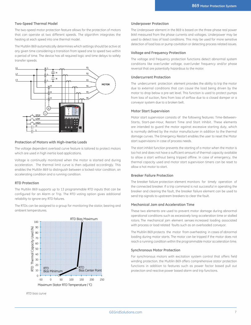
RTD Protection
The Multilin 869 supports up to 13 programmable RTD inputs that can be configured for an Alarm or Trip. The RTD voting option gives additional reliability to ignore any RTD failures.
The RTDs can be assigned to a group for monitoring the stator, bearing and ambient temperatures.
RTD
The
rmal
Cap
acity
Use
d (%
)
RTD Bias Maximum
RTDBias Minimum
RTDBias Center Point
100
90
80
70
60
50
40
30
20
10
0-50 0 50 100 200 250150
Maximum Stator RTD Temperature ( C)
RTD bias curve
Underpower Protection
The Underpower element in the 869 is based on the three-phase real power (kW) measured from the phase currents and voltages. Underpower may be used to detect loss of load conditions. This may be used for more sensitive detection of load loss or pump cavitation or detecting process related issues.
Voltage and Frequency Protection
The voltage and frequency protection functions detect abnormal system conditions like over/under voltage, over/under frequency and/or phase reversal that are potentially hazardous to the motor.
Undercurrent Protection
The undercurrent protection element provides the ability to trip the motor due to external conditions that can cause the load being driven by the motor to drop below a pre-set level. This function is used to protect pumps from loss of suction, fans from loss of airflow due to a closed damper or a conveyor system due to a broken belt .
Motor Start Supervision
Motor start supervision consists of the following features: Time-Between-Starts, Start-per-Hour, Restart Time and Start Inhibit . These elements are intended to guard the motor against excessive starting duty, which is normally defined by the motor manufacturer in addition to the thermal damage curves. The Emergency Restart enables the user to reset the Motor start supervisions in case of process needs.
The start inhibit function prevents the starting of a motor when the motor is too hot and does not have a sufficient amount of thermal capacity available to allow a start without being tripped offline. In case of emergency, the thermal capacity used and motor start supervision timers can be reset to allow a hot motor to start.
Breaker Failure Protection
The breaker failure protection element monitors for timely operation of the connected breaker. If a trip command is not successful in operating the breaker and clearing the fault , the breaker failure element can be used to send trip signals to upstream breakers to clear the fault .
Mechanical Jam and Acceleration Time
These two elements are used to prevent motor damage during abnormal operational conditions such as excessively long acceleration time or stalled rotors. The mechanical jam element senses increased loading associated with process or load related faults such as an overloaded conveyor.
The Multilin 869 protects the motor from overheating in cases of abnormal loading during motor starts. The motor can be tripped if the motor does not reach a running condition within the programmable motor acceleration time.
Synchronous Motor Protection
For synchronous motors with excitation system control that offers field winding protection, the Multilin 869 offers comprehensive stator protection functions in addition to features such as power factor based pull out protection and reactive power based alarm and trip functions.
869 Motor Protection System
GEGridSolutions.com8
Adaptive ProtectionThe Multilin 869 offers effective, reliable management of motors. With dynamic, sensitive settings, the 869 provides secure and dependable protection. With six setting groups, the 869 provides the sensitive settings range and groups required to ensure no compromise is made to meet changing system conditions. These setting groups can be enabled automatically or manually via digital Inputs, virtual inputs or remote communications to address system needs, ensuring greater system reliability and efficiency.
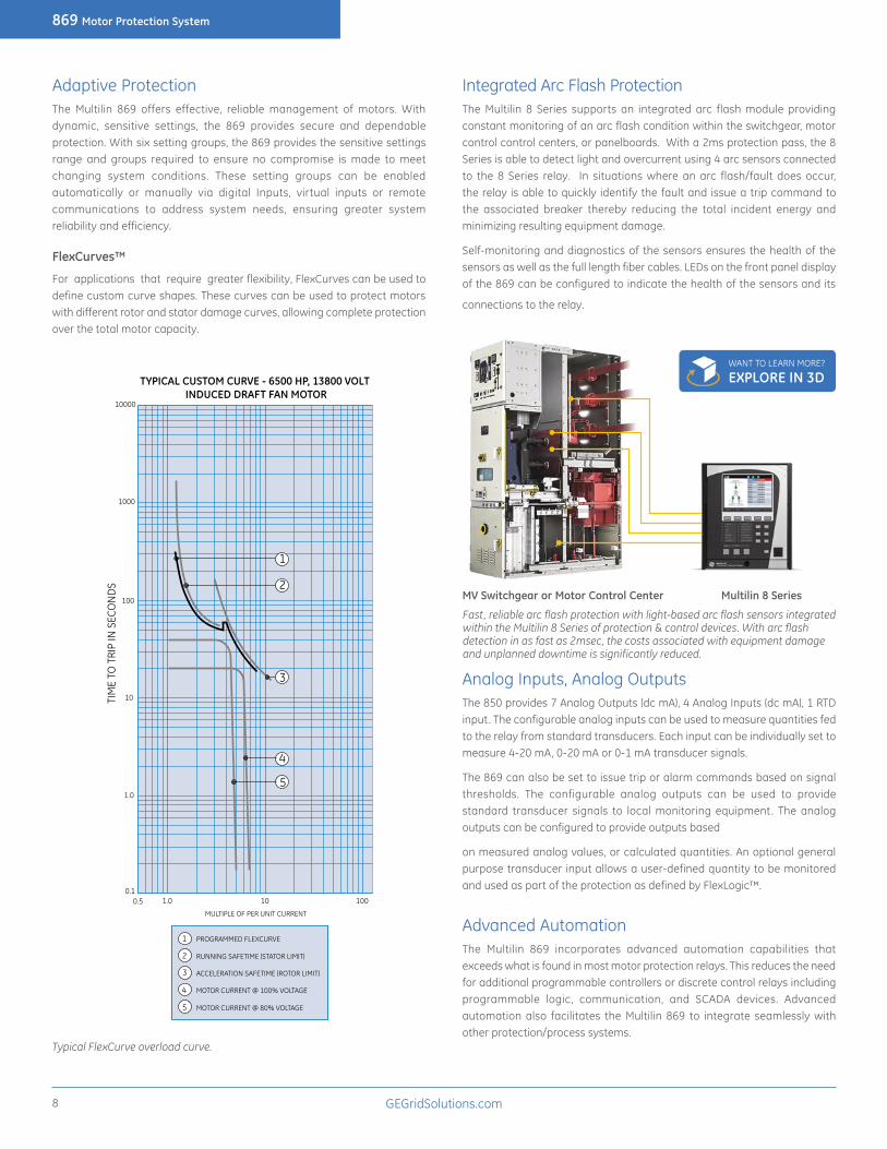
FlexCurves™
For applications that require greater flexibility, FlexCurves can be used to define custom curve shapes. These curves can be used to protect motors with different rotor and stator damage curves, allowing complete protection over the total motor capacity.
TYPICAL CUSTOM CURVE - 6500 HP, 13800 VOLT INDUCED DRAFT FAN MOTOR
10000
1000
100
10
1.0
0.10.5 1.0 10 100
MULTIPLE OF PER UNIT CURRENT
TIM
E TO
TRI
P IN
SEC
ON
DS
1
2
3
4
5
PROGRAMMED FLEXCURVE
RUNNING SAFETIME (STATOR LIMIT)
ACCELERATION SAFETIME (ROTOR LIMIT)
MOTOR CURRENT @ 100% VOLTAGE
MOTOR CURRENT @ 80% VOLTAGE
1
2
3
4
5
Typical FlexCurve overload curve.
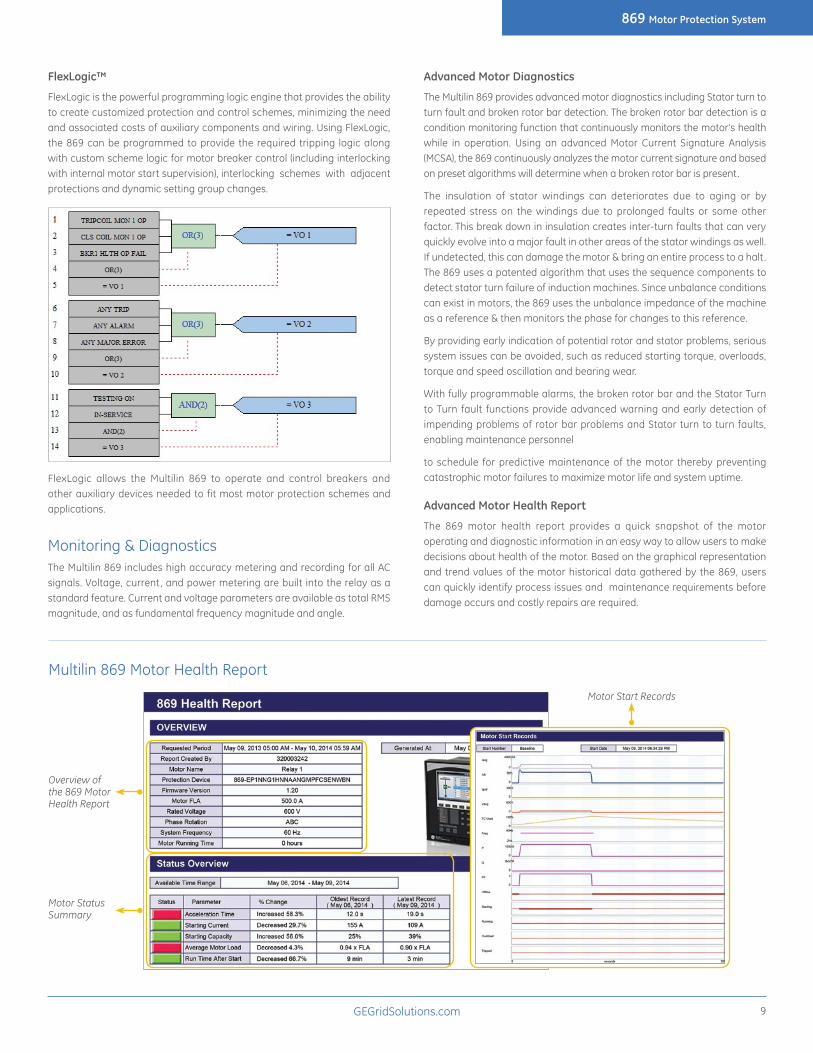
Integrated Arc Flash ProtectionThe Multilin 8 Series supports an integrated arc flash module providing constant monitoring of an arc flash condition within the switchgear, motor control control centers, or panelboards. With a 2ms protection pass, the 8 Series is able to detect light and overcurrent using 4 arc sensors connected to the 8 Series relay. In situations where an arc flash/fault does occur, the relay is able to quickly identify the fault and issue a trip command to the associated breaker thereby reducing the total incident energy and minimizing resulting equipment damage.
Self-monitoring and diagnostics of the sensors ensures the health of the sensors as well as the full length fiber cables. LEDs on the front panel display of the 869 can be configured to indicate the health of the sensors and its
connections to the relay.
Analog Inputs, Analog OutputsThe 850 provides 7 Analog Outputs (dc mA), 4 Analog Inputs (dc mA), 1 RTD input. The configurable analog inputs can be used to measure quantities fed to the relay from standard transducers. Each input can be individually set to measure 4-20 mA, 0-20 mA or 0-1 mA transducer signals.
The 869 can also be set to issue trip or alarm commands based on signal thresholds. The configurable analog outputs can be used to provide standard transducer signals to local monitoring equipment. The analog outputs can be configured to provide outputs based
on measured analog values, or calculated quantities. An optional general purpose transducer input allows a user-defined quantity to be monitored and used as part of the protection as defined by FlexLogic™.
Advanced AutomationThe Multilin 869 incorporates advanced automation capabilities that exceeds what is found in most motor protection relays. This reduces the need for additional programmable controllers or discrete control relays including programmable logic, communication, and SCADA devices. Advanced automation also facilitates the Multilin 869 to integrate seamlessly with other protection/process systems.
MV Switchgear or Motor Control Center Multilin 8 Series
Fast, reliable arc flash protection with light-based arc flash sensors integrated within the Multilin 8 Series of protection & control devices. With arc flash detection in as fast as 2msec, the costs associated with equipment damage and unplanned downtime is significantly reduced.
WANT TO LEARN MORE? EXPLORE IN 3D
869 Motor Protection System
GEGridSolutions.com 9
FlexLogic™
FlexLogic is the powerful programming logic engine that provides the ability to create customized protection and control schemes, minimizing the need and associated costs of auxiliary components and wiring. Using FlexLogic, the 869 can be programmed to provide the required tripping logic along with custom scheme logic for motor breaker control (including interlocking with internal motor start supervision), interlocking schemes with adjacent protections and dynamic setting group changes.
FlexLogic allows the Multilin 869 to operate and control breakers and other auxiliary devices needed to fit most motor protection schemes and applications.
Monitoring & DiagnosticsThe Multilin 869 includes high accuracy metering and recording for all AC signals. Voltage, current, and power metering are built into the relay as a standard feature. Current and voltage parameters are available as total RMS magnitude, and as fundamental frequency magnitude and angle.
Advanced Motor Diagnostics
The Multilin 869 provides advanced motor diagnostics including Stator turn to turn fault and broken rotor bar detection. The broken rotor bar detection is a condition monitoring function that continuously monitors the motor's health while in operation. Using an advanced Motor Current Signature Analysis (MCSA), the 869 continuously analyzes the motor current signature and based on preset algorithms will determine when a broken rotor bar is present.
The insulation of stator windings can deteriorates due to aging or by repeated stress on the windings due to prolonged faults or some other factor. This break down in insulation creates inter-turn faults that can very quickly evolve into a major fault in other areas of the stator windings as well. If undetected, this can damage the motor & bring an entire process to a halt . The 869 uses a patented algorithm that uses the sequence components to detect stator turn failure of induction machines. Since unbalance conditions can exist in motors, the 869 uses the unbalance impedance of the machine as a reference & then monitors the phase for changes to this reference.
By providing early indication of potential rotor and stator problems, serious system issues can be avoided, such as reduced starting torque, overloads, torque and speed oscillation and bearing wear.
With fully programmable alarms, the broken rotor bar and the Stator Turn to Turn fault functions provide advanced warning and early detection of impending problems of rotor bar problems and Stator turn to turn faults, enabling maintenance personnel
to schedule for predictive maintenance of the motor thereby preventing catastrophic motor failures to maximize motor life and system uptime.
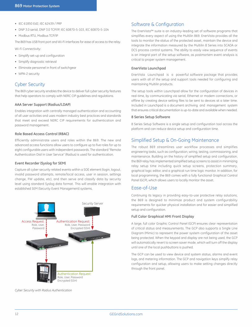
Advanced Motor Health Report
The 869 motor health report provides a quick snapshot of the motor operating and diagnostic information in an easy way to allow users to make decisions about health of the motor. Based on the graphical representation and trend values of the motor historical data gathered by the 869, users can quickly identify process issues and maintenance requirements before damage occurs and costly repairs are required.
Motor Status Summary
Overview of the 869 Motor Health Report
Multilin 869 Motor Health Report
Motor Start Records

869 Motor Protection System
GEGridSolutions.com10
The motor health report quickly provides a motor operation summary with detailed information in seven categories.
• Device Overview: gives general information on the motor, including requested period, user name, device name, order code, firmware version, motor and system settings, and motor total running time.
• Status Overview: summarizes the historical learned data and gives an evaluation of the status of the motor, including the oldest and latest values of acceleration time, starting current, start thermal capacity used, average motor load, and average running time.
• Trip Summary: presents a summary of the events that have tripped the motor.
• Motor Operating History: counts the amount of events in terms of Motor Starting/Running, Manual Stop Commands, Trip Commands, Lockouts, Alarm Conditions, and Emergency Restarts.
• Motor Starting Learned Data: collects the learned data, including acceleration time, starting current, start thermal capacity used, average motor load, and average running time.
• Motor Start Records: displays the start data, including average of three-phase RMS currents, current unbalance, ground current, average of three-phase RMS voltages, thermal capacity used, frequency and motor status.
• Motor Stopping/Tripping: gives details on the events that are specifically related to the stopping and tripping of the motor.
Breaker Health Monitoring
The breaker is monitored by the relay not only for detection of breaker failure, but also for the overall “breaker health” which includes:
• Breaker close and breaker open times
• Trip circuit monitoring
• Spring charging time
• Per-phase arcing current
• Trip counters
All algorithms provide the user with the flexibility to set up initial breaker trip counter conditions and define the criteria for breaker wear throughout a number of setpoints.
Multilin 8 Series Breaker Health Report available on the display or via the setup software
Environmental Monitoring
The 869 implements a patented environmental monitoring system that measures and provides operating condition information. Reliable and secure operation of the 869 relay and other electronic devices in the vicinity may be affected by environmental factors. The 869 relay has been designed to meet or exceed required industry standards. Some operating conditions may be beyond those standards and reduce total lifespan of the device.
Typical environmental conditions that may affect electronic device reliability include voltage, current , temperature, humidity, dust , contaminants, mechanical stress, shock, radiation and intensity of electrical and magnetic fields. These environmental factors are different from natural weather conditions at particular installation conditions and are beneficial to monitor. The 869 relay’s built-in environmental awareness feature (patent “Systems and methods for predicting maintenance of intelligent electronic devices”) collects the histograms of operating conditions from the point the device is put into service. Monitored environmental conditions include temperature, humidity and transient voltage. The histogram of each environmental factor may be retrieved from the diagnostic page accessed through a PC running the EnerVista Multilin 8 Series Setup program.
Environmental health report is available via Multilin PC Software

869 Motor Protection System
GEGridSolutions.com 11
MeteringThe Multilin 869 offers high accuracy power quality monitoring for fault and system disturbance analysis. The Multilin 8 Series delivers unmatched power system analytics through the following advanced features and monitoring and recording tools:
• Harmonics measurement up to 25th harmonic for both currents and voltages including THD.
• The length of the transient recorder record ranges from 31 cycles to 1549 cycles, depending on the user specified configuration. This gives the user the ability to capture long disturbance records which is critical for some applications.
• 32 digital points and 16 analog values, assigned by the user, can be captured in the COMTRADE format by the transient recorder.
• Comprehensive data logger provides the recording of 16 analog values selected from any analog values calculated by the relay. Capture rates range from 16 ms, 20ms, 1 second, 30 seconds, 1 minute, 30 minutes, or 1 hour rate. This data capture flexibility allows the operator to measure power factor or reactive power flow (for example), for several hours or even days, enabling detailed analysis and corrective action to be taken, if required.
• Detailed Fault Report allows the user to identify the fault location, fault type and element(s) that triggered the 869 to trip. It carries other useful information, such as pre-fault and fault phasors, relay name and model, firmware revision and other details. The 869 stores fault reports for the last 16 events.
• 1024 Event Recorder chronologically lists all triggered elements with an accurate time stamp over a long period of time. The 869 stores the last 1024 events locally in the relay.
The 869 monitoring system performance with oscillography and event records
Multilin 869 Event Recorder
The 869 monitoring system performance with harmonic analysis
Multilin 869 Phasor viewer
CommunicationsThe 869 provides advanced communications technologies for remote data and engineering access, making it easy and flexible to use and integrate into new and existing infrastructures. Direct support for fiber optic Ethernet provides high-bandwidth communications, allowing for low-latency controls and high-speed file transfers of relay fault and event record information. The 869 also supports two independent IP addresses, providing high flexibility for the most challenging of communication networks.
Providing several Ethernet and serial port options, dual independent Ethernet Ports, and supporti for a wide range of industry standard protocols, the 869 enables easy, direct integration into DCS and SCADA systems. The 869 supports the following protocols:
LOCAL AREA NETWORK
ALOCAL AREA NETWORK
B
F650 350 469 850 869 889 845
SCADA EMS DMS Data Historian
Local HMI / Single Line
D400
ML3000 SWITCH
ML3000 SWITCH
ML3000 SWITCH
ML3000 SWITCH
ML3000 SWITCH
ML3000 SWITCH
D400
UR
869 Motor Protection System
GEGridSolutions.com12
• IEC 61850 Ed2, IEC 62439 / PRP
• DNP 3.0 serial, DNP 3.0 TCP/IP, IEC 60870-5-103, IEC 60870-5-104
• Modbus RTU, Modbus TCP/IP
The 869 has USB front port and Wi-Fi interfaces for ease of access to the relay.
Wi-Fi Connectivity:
• Simplify set-up and configuration
• Simplify diagnostic retrieval
• Eliminate personnel in front of switchgear
• WPA-2 security
Cyber SecurityThe 869 cyber security enables the device to deliver full cyber security features that help operators to comply with NERC CIP guidelines and regulations.
AAA Server Support (Radius/LDAP)
Enables integration with centrally managed authentication and accounting of all user activities and uses modern industry best practices and standards that meet and exceed NERC CIP requirements for authentication and password management.
Role Based Access Control (RBAC)
Efficiently administrate users and roles within the 869. The new and advanced access functions allow users to configure up to five roles for up to eight configurable users with independent passwords. The standard “Remote Authentication Dial In User Service” (Radius) is used for authentication.
Event Recorder (Syslog for SEM)
Capture all cyber security related events within a SOE element (login, logout, invalid password attempts, remote/local access, user in session, settings change, FW update, etc), and then serve and classify data by security level using standard Syslog data format. This will enable integration with established SEM (Security Event Management) systems.
Access Request:Role, User,Password
Authentication Request:Role, User, PasswordEncrypted (SSH)
Security Server
Authentication Request:Role, User, Password
Encrypted (SSH)
Cyber Security with Radius Authentication
Software & ConfigurationThe EnerVista™ suite is an industry-leading set of software programs that simplifies every aspect of using the Multilin 869. EnerVista provides all the tools to monitor the status of the protected asset, maintain the device and integrate the information measured by the Multilin 8 Series into SCADA or DCS process control systems. The ability to easily view sequence of events is an integral part of the setup software, as postmortem event analysis is critical to proper system management.
EnerVista Launchpad
EnerVista Launchpad is a powerful software package that provides users with all of the setup and support tools needed for configuring and maintaining Multilin products.
The setup tools within Launchpad allow for the configuration of devices in real-time, by communicating via serial, Ethernet or modem connections, or offline by creating device setting files to be sent to devices at a later time. Included in Launchpad is a document archiving and management system that ensures critical documentation is up-to-date and available when needed.
8 Series Setup Software
8 Series Setup Software is a single setup and configuration tool across the platform and can reduce device setup and configuration time.
Simplified Setup & On-Going MaintenanceThe robust 869 streamlines user workflow processes and simplifies engineering tasks, such as configuration, wiring, testing, commissioning, and maintenance. Building on the history of simplified setup and configuration, the 869 relay has implemented simplified setup screens to assist in minimizing relay setup time including quick setup screens, protection summary, graphical logic editor, and a graphical run time logic monitor. In addition, for local programming, the 869 comes with a fully functional Graphical Control Panel (GCP), which allows users to locally monitor the asset.
Ease-of-UseContinuing its legacy in providing easy-to-use protective relay solutions, the 869 is designed to minimize product and system configurability requirements for quicker physical installation and for easier and simplified setup and configuration.
Full Color Graphical HMI Front Display
A large, full color Graphic Control Panel (GCP) ensures clear representation of critical status and measurements. The GCP also supports a Single Line Diagram (Mimic) to represent the power system configuration of the asset being protected. When the keypad and display are not being used, the GCP will automatically revert to screen saver mode, which will turn off the display until one of the local pushbuttons is pushed.
The GCP can be used to view device and system status, alarms and event logs, and metering information. The GCP and navigation keys simplify relay configuration and setup, allowing users to make setting changes directly through the front panel.
869 Motor Protection System
GEGridSolutions.com 13
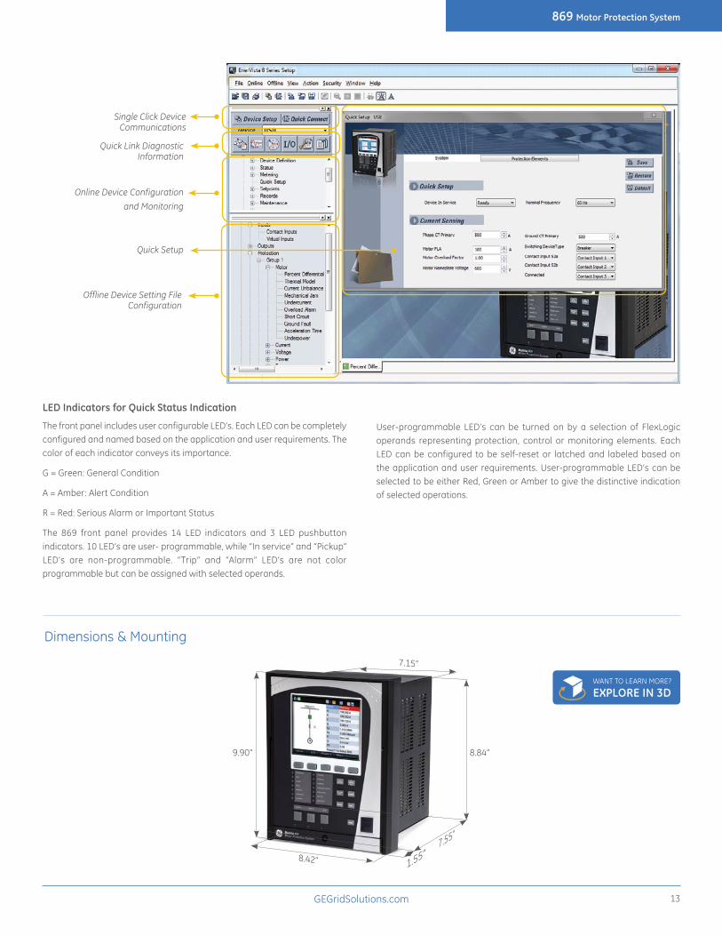
LED Indicators for Quick Status Indication
The front panel includes user configurable LED’s. Each LED can be completely configured and named based on the application and user requirements. The color of each indicator conveys its importance.
G = Green: General Condition
A = Amber: Alert Condition
R = Red: Serious Alarm or Important Status
The 869 front panel provides 14 LED indicators and 3 LED pushbutton indicators. 10 LED’s are user- programmable, while “In service” and “Pickup” LED’s are non-programmable. “Trip” and “Alarm” LED’s are not color programmable but can be assigned with selected operands.
User-programmable LED’s can be turned on by a selection of FlexLogic operands representing protection, control or monitoring elements. Each LED can be configured to be self-reset or latched and labeled based on the application and user requirements. User-programmable LED’s can be selected to be either Red, Green or Amber to give the distinctive indication of selected operations.
Single Click Device Communications
Quick Link Diagnostic Information
Online Device Configuration
and Monitoring
Quick Setup
Offline Device Setting File Configuration
Dimensions & Mounting
7.15”
8.42”
8.84”9.90”
7.55”
1.55”
WANT TO LEARN MORE? EXPLORE IN 3D

869 Motor Protection System
GEGridSolutions.com14
Soft menu navigation keys
LED status indicators
User-programmable pushbuttons
Menu path display indicating location within menu structure
Graphic Control Panel (GCP)
Navigation keys
Front USB port
Self-captive screw on draw-out handle
Soft key navigation menu
Front View
Standard serial and RJ45 Ethernet module
Advanced communications module (fiber optic port)
CT, VT inputs
Grounding screwPower supply
RTDs
Digital I/O,DCMA, Arc Flash sensors
Rear View
APPROVALSAPPLICABLE COUNCIL DIRECTIVE ACCORDING TO
CE compliance Low voltage directive EN60255-5 / EN60255-27EMC Directive EN60255-26 / EN50263
EN61000-6-2 / EN61000-6-4North America cULus UL508
UL1053C22.2.No 14
ISO Manufactured under a registered quality program
ISO9001
ENVIRONMENTALAmbient temperatures:
Storage/Shipping: -40°C to 85°COperating: -40°C to 60°C (continuous)Humidity: Operating up to 95% (non condensing) @ 55°C
(As per IEC60068-2-30 Variant 2, 6days)Altitude: 2000m (max)Pollution Degree: IIOvervoltage Category: IIIIngress Protection: IP54 Front
Certifications and Environmental Specifications
869 Motor Protection System
GEGridSolutions.com 15
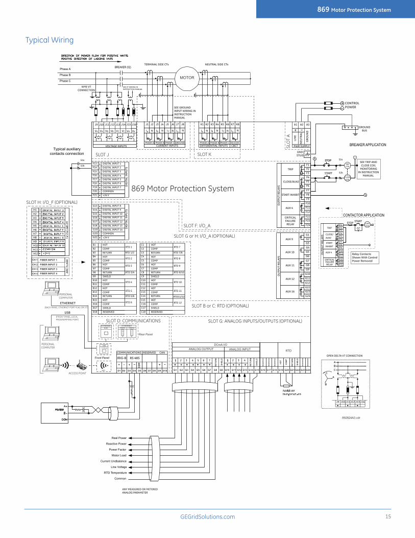
Typical Wiring
J1 J2 J3 J4 J5 J6 J7 J8J9 J10 J11 J12 J13 J14 J16 A1 A2 A3
LIN
E
NEU
TRAL
GRO
UN
D
J15
F13F14F15F16F17F18F19F20
DIG
ITAL
INPU
TS
DIGITAL INPUT 1DIGITAL INPUT 2DIGITAL INPUT 3
DIGITAL INPUT 4DIGITAL INPUT 5DIGITAL INPUT 6DIGITAL INPUT 7COMMON
SEE TRIP ANDCLOSE COIL
MONITORINGIN INSTRUCTION
MANUAL
GROUNDBUS
GNDSTUD
PWR SUPPLY
892824A3.cdr
USB
PERSONALCOMPUTER
ETHERNET
CURRENT INPUTSVOLTAGE INPUTS
SLOT F: I/O_A
[BACK PANEL ETHERNET PORT RJ45 OR ST]
[FRONT PANEL LOCALPROGRAMMING PORT]
IRIG-B
COMMUNICATIONS
RS 485
CONTROLPOWER
SLOT K
SLO
T A
SLOT D: COMMUNICATIONS
USBTYPE B
Front Panel
ETHERNETRJ45
Rear Panel
PERSONALCOMPUTER
VA VB VC VX VXVA VB VC
COM
RESERVED CAN
WIFI
PHASE A PHASE B PHASE C GROUND
IBN I C IGIA N N
ETHERNETFIBER1
ST
FIBER2
ST
OPEN DELTA VT CONNECTION
J9 J10 J11 J12 J13 J14
SEE GROUND INPUT WIRING IN INSTRUCTIONMANUAL
WYE VTCONNECTION
SEE VT WIRING IN INSTRUCTION MANUAL
N
F21 +24 V
AUX 9
AUX 11
AUX 12
G3G4G5G6
G7G8G9
G10G11
G12G22G23G24
G13G14G15G16G17G18G19G20
DIG
ITAL
INPU
TS
DIGITAL INPUT 8DIGITAL INPUT 9DIGITAL INPUT 10DIGITAL INPUT 11
DIGITAL INPUT 12DIGITAL INPUT 13DIGITAL INPUT 14COMMON
OU
TPU
T RE
LAYS
G1G2
SLOT G or H: I/O_A (OPTIONAL)G21 +24 V
AUX 10
AUX 16
MOTOR
Phase A
Phase B
Phase C
BREAKER (52)
TRIP
CLOSE/AUX2
START INHIBIT
AUX 4
CRITICALFAILURERELAY
F3F4F5F6
F7F8F9
F10F11F12F22F23F24
V
V
OU
TPU
T RE
LAYS
F1F2
STOP
START
52a
52b
TRIP COIL
CLOSE COIL
+ -
BREAKER APPLICATION
52a
52b
Typical auxiliary contacts connection
TERMINAL SIDE CTs
CONTACTOR APPLICATION
TRIP
CLOSE/AUX2
STARTINHIBIT
AUX 4
CRITICALFAILURERELAY
F3F4F5F6F7F8F9F10F11F12F22F23F24
V
V
OU
TPU
T RE
LAYS
F1F2
STARTSTOP CONT COIL -
ACCESS POINT
SLOT J
NEUTRAL SIDE CTs
K1 K2 K3 K4 K5 K6 K7 K8
DIFFERENTIAL INPUTSPHASE A PHASE B PHASE C 50:0.025
IBN I C IGIA N NN
HOTCOMPRETURN
HOTCOMPHOT
869 Motor Protection System
HOTCOMPHOT
COMPRETURNHOT
RTD 6
B1B2B3B4B5B6B7B8
COMPRETURN
B9 SHIELDB10B11B12B13B14B15B16B17
COMPSHIELD
B18 RESERVED
RTD 1/2
RTD 1
RTD 3
RTD 2
RTD 5
RTD 4
RTD 5/6
RTD 3/4
C1C2C3C4C5C6C7C8
COMPRETURN
C9 SHIELDC10C11C12C13C14C15C16C17
COMPSHIELD
C18 RESERVED
RTD 7/8
RTD 7
RTD 9
RTD 8
RTD 11
RTD 10
RTD11/12
RTD 9/10
RTD 12
HOTCOMPRETURN
HOTCOMPHOT
HOTCOMPHOT
COMPRETURNHOT
CBCT
+
V
V
V
V
G1 G2 G3 G4 G5 G6 G7 G8 G9 G10 G11 G12 G13 G14 G15 G16 G17 G18 G19 G20 G21 G22 G23 G24
DCmA I/OANALOG OUTPUT ANALOG INPUT RTD
11 2 3 4 5 6 7 11 2 3 4
SHIE
LD
SHIE
LD
SHIE
LD
RET
UR
N
HO
T
CO
MP
RES
ERVE
D
RES
ERVE
D
RET
UR
N
RET
UR
N
D1 D2 D3 D4 D5 D6 D7 D8 D9 D10
CC
Real Power
Reactive Power
Power Factor
Motor Load
Current Undbalance
Line Voltage
RTD Temperature
Common
ANY MEASURED OR METERED ANALOG PARAMETER
SLOT G: ANALOG INPUTS/OUTPUTS (OPTIONAL)
H1H2H3H4H5H6H7H8H9H10H11H12
8910
CH 1
CH 2
CH 3
CH 4
FIBER INPUT 3
FIBER INPUT 4
FIBER INPUT 1
FIBER INPUT 2
AR
C F
LASH
SLOT H: I/O_F (OPTIONAL)
RES
ERVE
D
RES
ERVE
D
RES
ERVE
D
SLOT B or C: RTD (OPTIONAL)
Relay Contacts Shown With Control Power Removed

GEA-12784C(E)English160421
869 E ** ** ** * * * * * * * * * * * * * * * * N Description
Base Unit 869 Motor Protection Relay (Standard : English Language; High Voltage PS, Graphical Control Panel)
Language E EnglishPhase Currents - Slot J Bank 1/2
P1 1A three phase current inputs (J1)P5 5A three phase current inputs (J1)
Phase Currents - Slot K Bank 2/2
NN No phase current inputsP1 1A three phase current inputs (K1)P5 5A three phase current inputs (K1)
Ground Currents G1 1A ground current input (qty 1 per phase current bank)G5 5A ground current input (qty 1 per phase current bank)B1 1A ground (J1) + 50:0.025A (K1, included with 'current protection' M
option only)B5 5A ground (J1) + 50:0.025A (K1, included with 'current protection'
M option only)Power Supply H 110 - 250 V dc/110 - 230 Vac
L 24 - 48 VDCSlot B - LV I/O N None
R 6 x RTDs (Pt100, Ni100, Ni120)S 6 x RTDs (Pt100, Ni100, Ni120, Cu10)
Slot C - LV I/O N NoneR 6 x RTDs (Pt100, Ni100, Ni120)S 6 x RTDs (Pt100, Ni100, Ni120, Cu10)
Slot F - HV I/O* A 2 Form A (Vmon), 3 Form C, 7 Digital Inputs (Low / High voltage, Int/Ext supply)
Slot G - HV I/O* N NoneA 2 Form A (Vmon), 3 Form C, 7 Digital Inputs (Low / High voltage,
Int/Ext supply)
L 7 DcmA O/P + 4 DcmA I/P + 1 RTD
Slot H - HV I/O* N None
F 10 Digital Inputs + 4 Arc flash inputsA 2 Form A (Vmon), 3 Form C, 7 Digital Inputs (Low / High voltage,
Int/Ext supply)
Faceplate G Color Graphical Display
Current Protection S Basic = 14, 19, 37, 38, 46, 49, 50P, 50N, 50G, 50_2, 50LR, 51P, 51N, 51G, 51_2, 66, 86,
M Standard = Basic + 67P, 67N, 87 (2nd CT Bank required for 87)
Voltage Monitoring & Protection
S Standard = 27P, 47, 59P, 59N, 59X, 81O, 81U, VTFF
P Advanced = Standard + 32, 55, 59_2, 81R
Control B Basic = Setpoint Group Control, Breaker / Contactor Control, Virtual Inputs, Trip Bus
F Standard = Basic + FlexLogic, 50BFMonitoring B Basic = Motor Health Report, Motor Start Report, Data Logger
C Standard = Basic + Motor Learned Data, Breaker Health Report, Broken Rotor Bar
A Advanced = Standard + Harmonic Detection, Stator Inter-Turn FaultCommunications S E Standard = Front USB, 1xRS485 : Modbus RTU, DNP3.0, IEC60870-5-
103 + 1xEthernet Copper: Modbus TCP, DNP3.0 TCP1 E Advanced = Front USB, 1 x Rear RS485 + 2 x Ethernet Fiber, MODBUS
RTU / TCP, DNP3.0, IEC 60870-5-103/104, 1588, SNTP, OPC UA1 P Advanced + PRP
2 A Advanced + IEC 61850
2 E Advanced + PRP + IEC 61850Advanced Communications Connector
N NoneS ST, Multi-mode 1310nm
Wireless Communication
N NoneW WiFi 802.11
Security B Basic A Advanced - CyberSentry Level 1
Note: Harsh Environment Coating is a standard feature on all 8 series units.
*HV I/O, Option A - Max 2 across slots F through H
Arc Flash Detection (Option F): Includes 4 x Arc Flash sensors, each 18 feet long
Ordering
CONFIGURE ONLINEGEGridSolutions.comIEC is a registered trademark of Commission Electrotechnique Internationale. IEEE is a registered trademark of the Institute of Electrical Electronics Engineers, Inc. Modbus is a registered trademark of Schneider Automation. NERC is a registered trademark of North American Electric Reliability Council. NIST is a registered trademark of the National Institute of Standards and Technology.
GE, the GE monogram, Multilin, FlexLogic, EnerVista and CyberSentry are trademarks of General Electric Company.
GE reserves the right to make changes to specifications of products described at any time without notice and without obligation to notify any person of such changes.
Copyright 2016, General Electric Company. All Rights Reserved.
Related Documents