0 GE Power Management HEA Auxiliary Relay Electric Reset Model I2HEA99BT(-) Manual P/N: GEK-106277 Insert: GEH-2058L INTRODUCTION This instruction book, along with the manual GEH-2058, form the instructions for the 12HEA99BT(-) auxiliary relay. DESCRIPTION The 12HEA99BT(-) relay is similar to the 12HEA61 B235, except that contact 11 is similar to contact 5. The contact arrangement in the reset position is: Closed -6, 7,8,9, 10, 12; Open - 1,2, 3,4, 5, 11. GE Power Management 215 Anderson Avenue, Markham, Ontario Canada L6E 1B3 Tel: (905) 294-6222 Fax: (905) 294-8512 Internet: http:Ilwww.ge.comlIndsysl pm!

Welcome message from author
This document is posted to help you gain knowledge. Please leave a comment to let me know what you think about it! Share it to your friends and learn new things together.
Transcript
0GE Power Management
HEA Auxiliary RelayElectric Reset
Model I2HEA99BT(-)Manual P/N: GEK-106277
Insert: GEH-2058L
INTRODUCTION
This instruction book, along with the manual GEH-2058, form the instructions for the 12HEA99BT(-) auxiliary relay.
DESCRIPTION
The 12HEA99BT(-) relay is similar to the 12HEA61 B235, except that contact 11 is similar to contact 5. The contact
arrangement in the reset position is: Closed -6, 7,8,9, 10, 12; Open - 1,2, 3,4, 5, 11.
GE Power Management
215 Anderson Avenue, Markham, Ontario
Canada L6E 1B3
Tel: (905) 294-6222 Fax: (905) 294-8512
Internet: http:Ilwww.ge.comlIndsyslpm!

GE Power Management
215 Anderson AvenueMarkham, OntarioCanada L6E 1B3Tel: (905) 294-6222Fax: (905) 201-2098www.ge.comlindsyslpm
G EH—2058L
INSTRUCTIONS
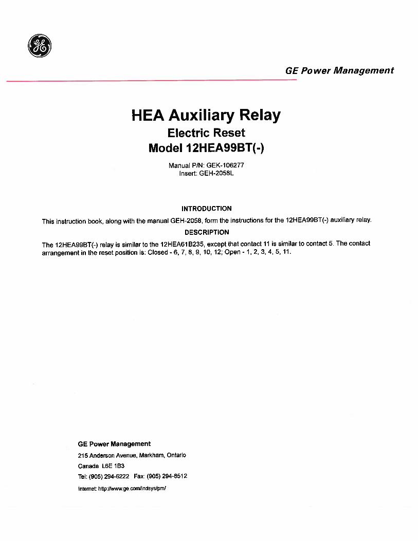
AUXILIARY RELAYS
HAND RESET WITH TargetTypes HEA61
HEA6 2
GE Protection and Control205 Great Valley ParkwayMalvern, PA 19355-1337
GEH-2058
CONTENTS
DESCRIPTION 3
CHARACTERISTIC 3
APPLICATION 4
OPERATING CHARACTERISTICS 4
RATINGS 4
BURDENS 5
CONSTRUCTION AND CIRCUITRY 5
INSTALLATION 5
RECEIVING 5INSTALLATION AND WIRING PRACTICES 6MOUNTING 7CONNECTIONS 7
MAINTENANCE 7
PERIODIC TESTS 7
SERVICING 9
CONTACT CLEANING 9
RENEWAL PARTS INSTALLATION 9
RENEWAL PARTS 9
Since the last edition, a change has been made in item 5 underMAINTENANCE PERIODIC TESTS
2
GEH-2058
AUXILIARY RELAYS - HAND RESET
TYPES HEA61H EA6 2
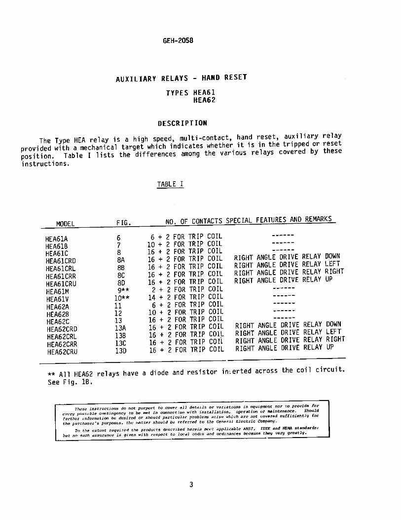
DESCRIPTION
The Type HEA relay is a high speed, multi-contact, hand reset, auxiliary relay
provided with a mechanical target which indicates whether it is in the tripped or reset
position. Table I lists the differences among the various relays covered by these
instructions.
TABLE I
MODEL FIG. NO. OF CONTACTS SPECIAL FEATURES AND REMARKS
HEA61A 6 6 + 2 FOR TRIP COIL
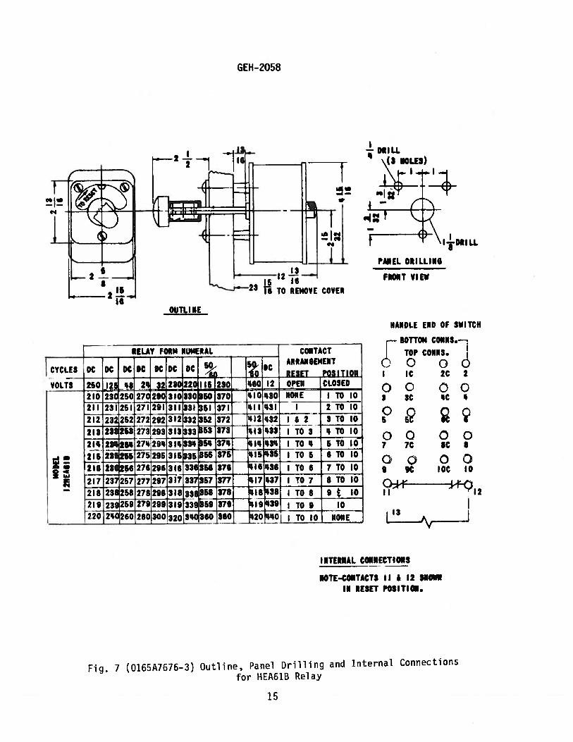
HEA61B 7 10 + 2 FOR TRIP COIL
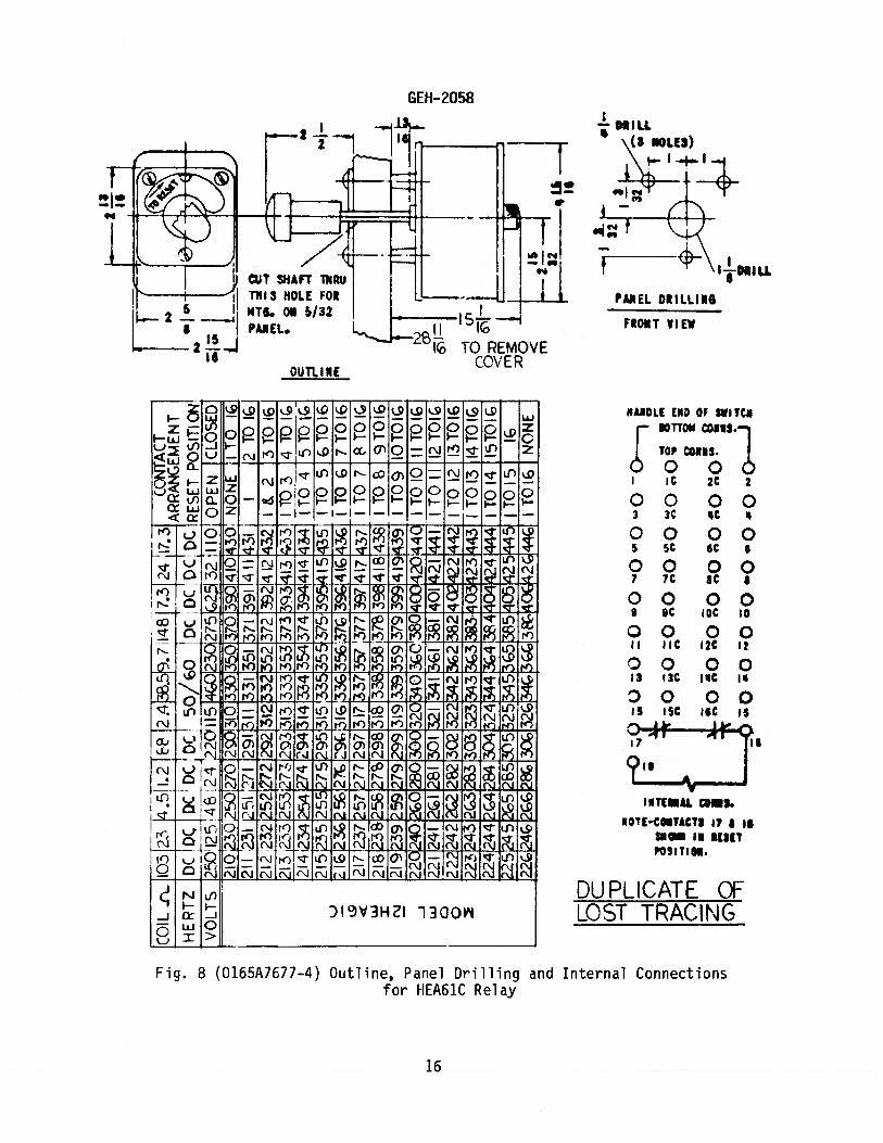
HEA61C 8 16 + 2 FOR TRIP COIL
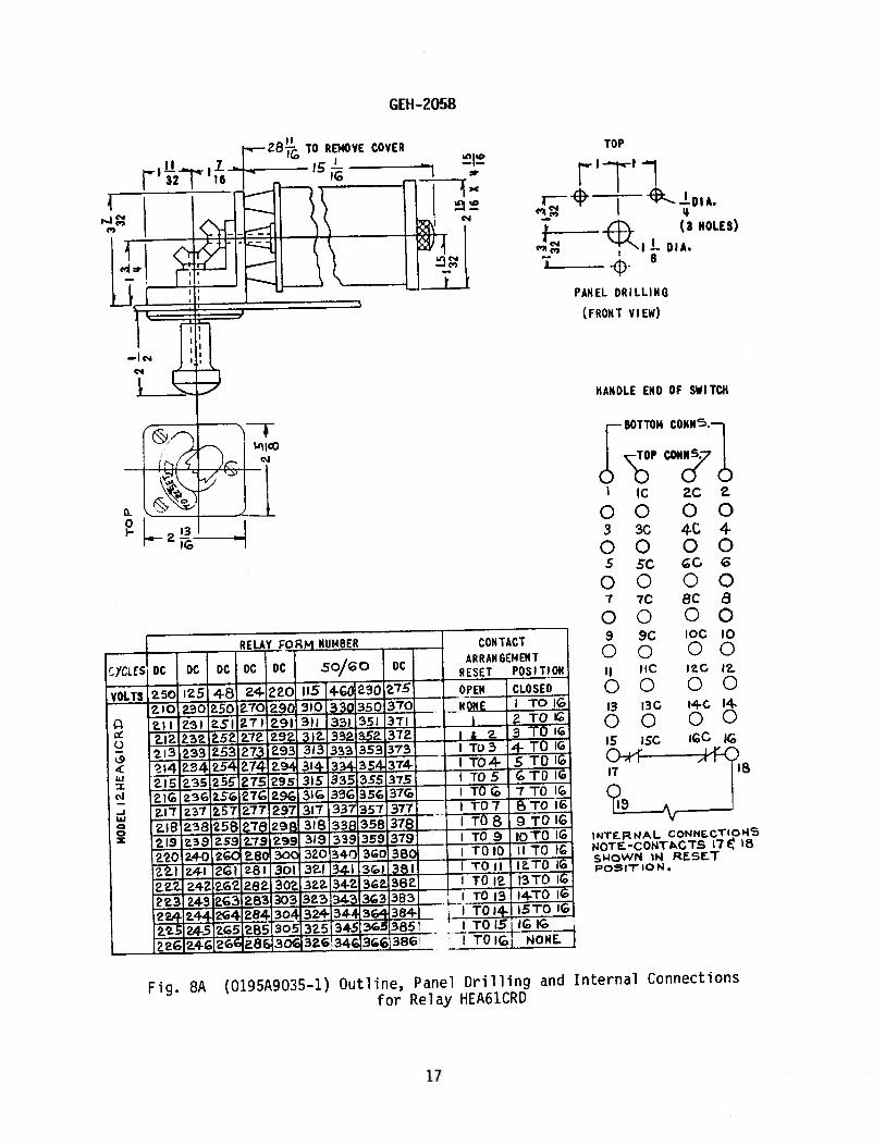
HEA61CRD 8A 16 + 2 FOR TRIP COIL RIGHT ANGLE DRIVE RELAY DOWN
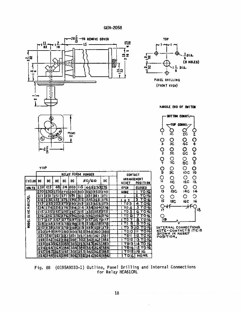
HEA61CRL 8B 16 + 2 FOR TRIP COIL RIGHT ANGLE DRIVE RELAY LEFT
HEA61CRR 8C 16 + 2 FOR TRIP COIL RIGHT ANGLE DRIVE RELAY RIGHT
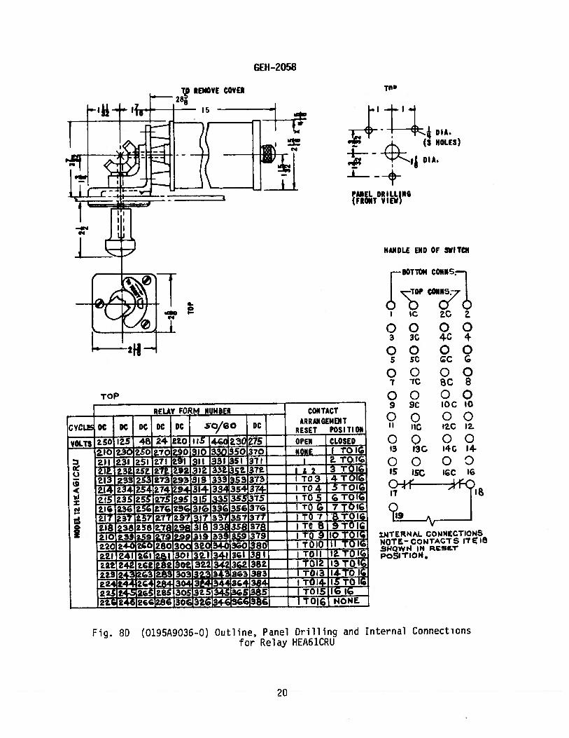
HEA61CRU 8D 16 + 2 FOR TRIP COIL RIGHT ANGLE DRIVE RELAY UP
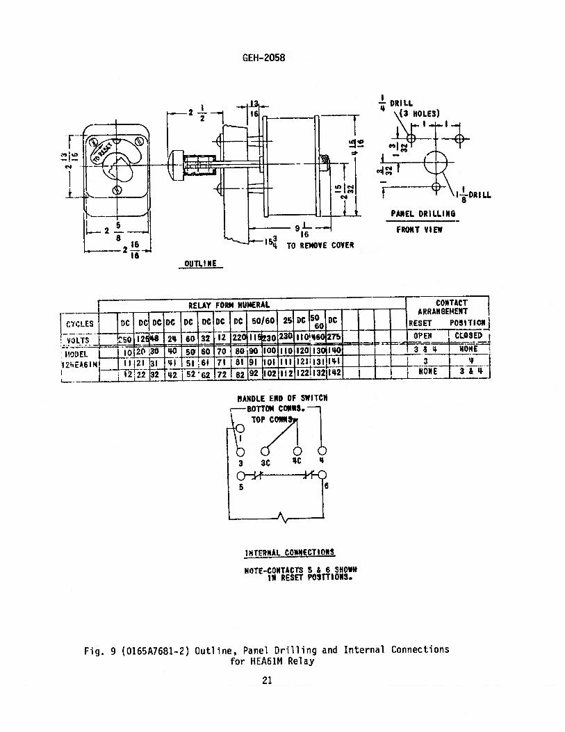
HEA61M 2 + 2 FOR TRIP COIL
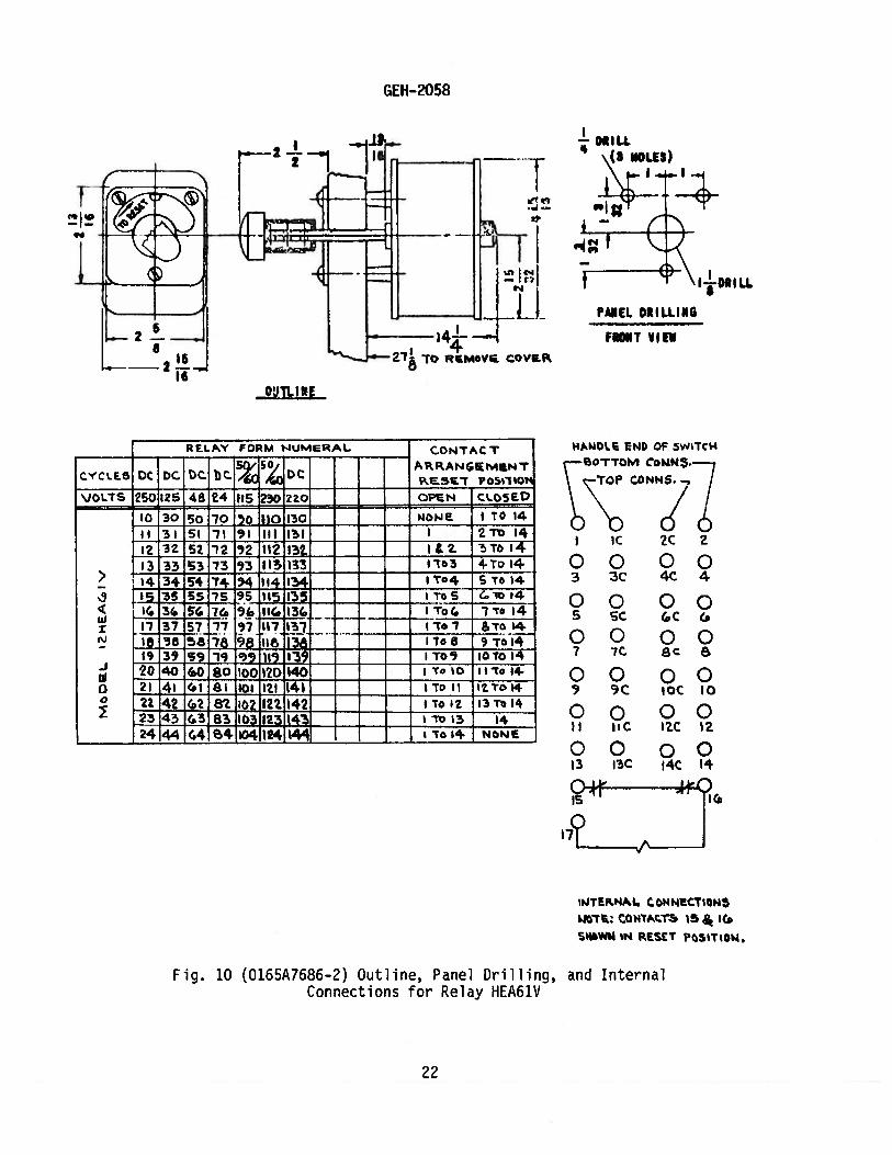
HEA61V 1O** 14 + 2 FOR TRIP COIL
HEA62A 11 6 + 2 FOR TRIP COIL
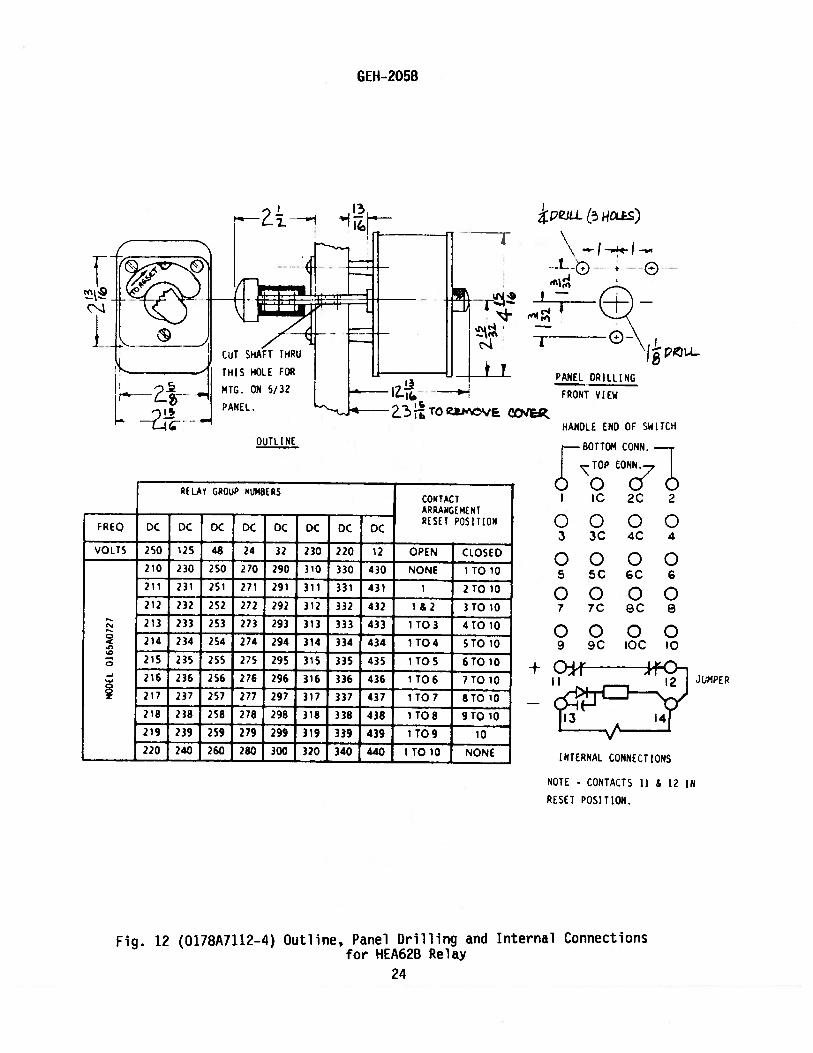
HEA62B 12 10 + 2 FOR TRIP COIL
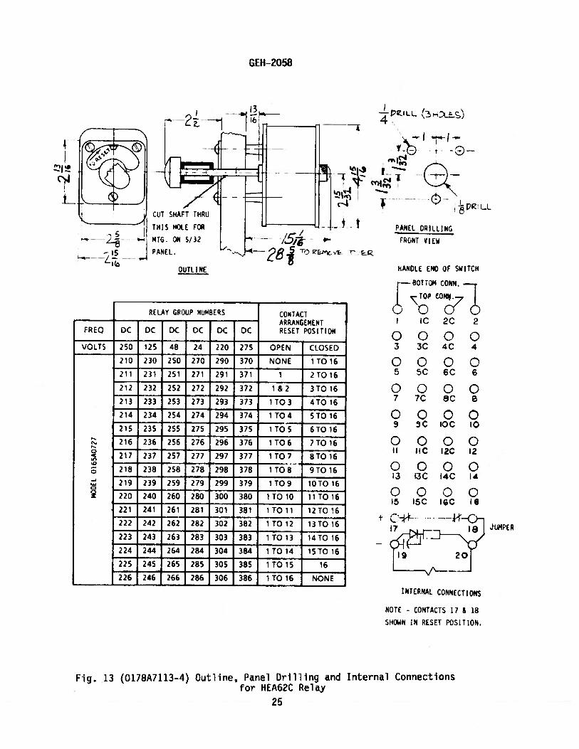
HEA62C 13 16 + 2 FOR TRIP COIL
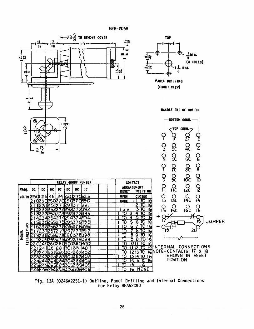
HEA62CRD 13A 16 + 2 FOR TRIP COIL RIGHT ANGLE DRIVE RELAY DOWN
HEA62CRL 138 16 + 2 FOR TRIP COiL RIGHT ANGLE DRIVE RELAY LEFT
HEA62CRR 13C 16 + 2 FOR TRIP COIL RIGHT ANGLE DRIVE RELAY RIGHT
HEA62CRU 13D 16 + 2 FOR TRIP COIL RIGHT ANGLE DRIVE RELAY UP
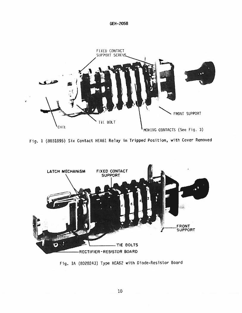
** All HEA62 relays have a diode and resistor inerted across the coil circuit.
See Fig. 18.
nstructnn,.jo not purport to cover nh det,u 1.; or var1t ons :0 qIJ;mrknt nor to provide for
ver jos ble coetn;eucy to be met In conne trot, w: th ,nstulioLjnn, operation or ,tifltt,itaflce. Should
Further i uformat. on be desired or ,iJOUhrI purt fu;Ir ;:roi urrue which are not covered sufficiently for
the ur< riser’s i urposes. tic I-otter should be referred to the Genital Electric Comr,anv.
Tn the cutcirt. r-qu_ e0 the pr-air s-lena rhii beret, mitt Ihi.-,i,t. 45SF, IEEE and ,YEMA standards;
hut no <uch aSSLiriflce Ia (JY Win W En flsur<t to itunul codes -md ordInate-es because they vary greatly.
3
GEH-2058
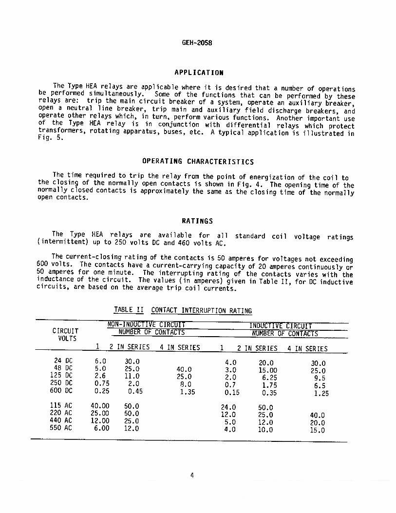
APPLICATION
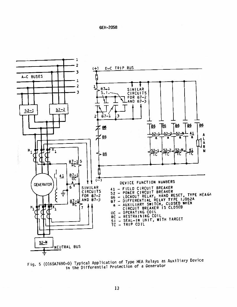
The Type HEA relays are applicable where it is desired that a number of operationsbe performed simultaneously. Some of the functions that can be performed by theserelays are: trip the main circuit breaker of a system, operate an auxiliary breaker,open a neutral line breaker, trip main and auxiliary field discharge breakers, andoperate other relays which, in turn, perform various functions. Another important useof the Type HEA relay is in conjunction with differential relays which protecttransformers, rotating apparatus, buses, etc. A typical application is illustrated inFig. 5.
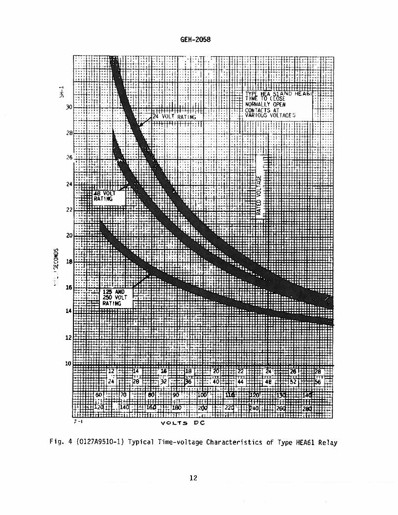
OPERATING CHARACTERISTICS
The time required to trip the relay from the point of energization of the coil tothe closing of the normally open contacts is shown in Fig. 4. The opening time of thenormally closed contacts is approximately the same as the closing time of the normallyopen contacts.
RATINGS
The Type HEA relays are available for all standard coil voltage ratings(intermittent) up to 250 volts DC and 460 volts AC.
The current—closing rating of the contacts is 50 amperes for voltages not exceeding600 volts. The contacts have a current-carrying capacity of 20 amperes continuously or50 amperes for one minute. The interrupting rating of the contacts varies with theinductance of the circuit. The values (in amperes) given in Table II, for DC inductivecircuits, are based on the average trip coil currents.
TABLE II CONTACT INTERRUPTION RATING
NON-INDUCTIVE CIRCUIT INDUCTIVE CIRCUITCIRCUIT NUMBER OF CONTACTS NUMBER OF CONTACTS
VOLTS1 2 IN SERIES 4 IN SERIES 1 2 IN SERIES 4 IN SERIES
24 DC 6.0 30.0 4.0 20.0 30.08 DC 5.0 25.0 40.0 3.0 15.00 25.0
125 DC 2.6 11.0 25.0 2.0 6.25 9.5250 DC 0.75 2.0 8.0 0.7 1.75 6.5600 DC 0.25 0.45 1.35 0.15 0.35 1.25
115 AC 40.00 50.0 24.0 50.0220 AC 25.00 50.0 12.0 25.0 40.0440 AC 12.00 25.0 5.0 12.0 20.0550 AC 6.00 12.0 4.0 10.0 15.0
4
GEH-2058
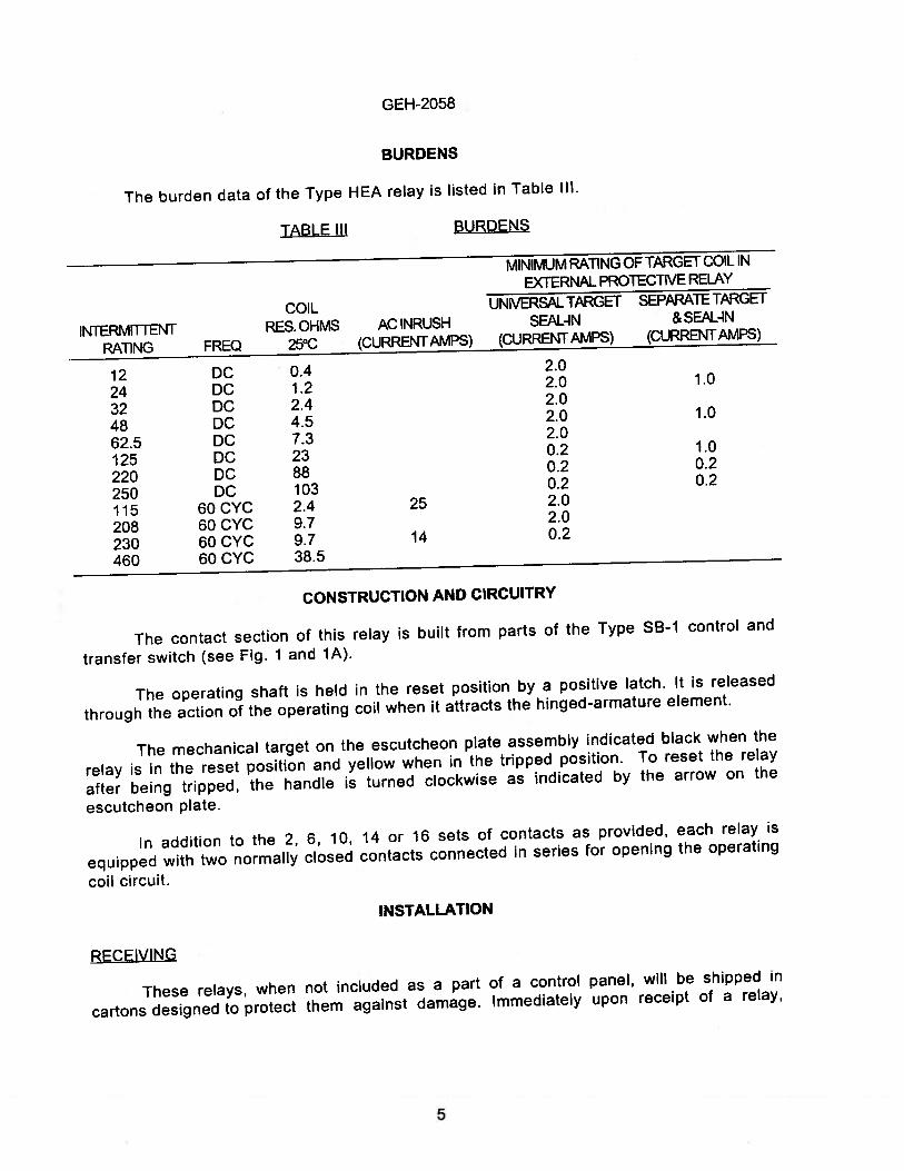
BURDENS
The burden data of the Type HEA relay is listed in Table Ill.
TABLE HI BURDENS
MINIMUM RATiNG OF TARGET COIL IN
EXTERNAL PROTECThIE RELAY
COIL UNlVERSL TARGET SEPARATE TARGET
INTERMITTENT RES. OHMS AC INRUSH SEAL-IN & SEAL-IN
RATING FREQ 25°C (CURRENT AMPS) (CURRENT AMPS) (CURRENT AMPS)
12 DC 0.4 2.0
24 DC 1.2 2.0 1.0
32 DC 2.4 2.0
48 DC 4.5 2.0 1.0
62.5 DC 7.3 2.0
125 DC 23 0.2 1.0
220 DC 88 0.2 0.2
250 DC 103 0.2 0.2
115 6OCYC 2.4 25 2.0
208 60 CYC 9.7 2.0
230 60 CYC 9.7 14 0.2
460 60 CYC 38.5
CONSTRUCTION AND CIRCUITRY
The contact section of this relay is buflt from parts of the Type SB-i control and
transfer switch (see Fig. 1 and 1A).
The operating shaft is held in the reset position by a positive latch. It is released
through the action of the operating coil when it attracts the hinged-armature element.
The mechanical target on the escutcheon plate assembly indicated black when the
relay is in the reset position and yellow when in the tripped position. To reset the relay
after being tripped, the handle is turned clockwise as indicated by the arrow on the
escutcheon plate.
In addition to the 2, 6, 10, 14 or 16 sets of contacts as provided, each relay is
equipped with two normally closed contacts connected in series for opening the operating
coil circuit.
INSTALLATION
RECEIVING
These relays, when not included as a part of a control panel, will be shipped in
cartons designed to protect them against damage. Immediately upon receipt of a relay,
5
GEH-2058
examine it for any damage sustained in transit. If injury or damage resulting fromrough handling is evident, file a damage claim at once with the transportationcompany and promptly notify the nearest General Electric Sales Office.
If the relays are not to be installed immediately, they should be stored intheir original cartons in a place that is free from moisture, dust and metallicchips.
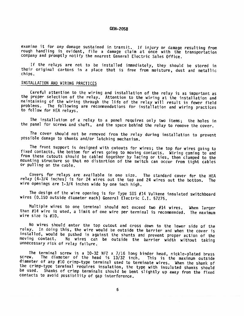
INSTALLATION AND WIRING PRACTICES
Careful attention to the wiring and installation of the relay is as important asthe proper selection of the relay. Attention to the wiring at the installation andmaintaining of the wiring through the life of the relay will result in fewer fieldproblems. The following are recommendations for installation and wiring practicesto follow for HEA relays.
The installation of a relay to a panel requires only two items; the holes inthe panel for screws and shaft, and the space behind the relay to remove the cover.
The cover should not be removed from the relay during installation to preventpossible damage to shunts and/or latching mechanism.
The front support is designed with cutouts for wires; the top for wires going tofixed contacts, the bottom for wires going to moving contacts. Wiring coming to andfrom these cutouts should be cabled together by lacing or ties, then clamped to themounting structure so that no distortion of the switch can occur from tight cablesor pulling on the cable.
Covers for relays are available in one size. The standard cover for the HEArelay (4-3/4 inches) is for 24 wires out the top and 24 wires out the bottom. Thewire openings are 1-3/4 inches wide by one inch high.
The design of the wire opening is for Type SIS #14 Vulkene insulated switchboardwires (0.150 outside diameter each) General Electric C.I. 57275.
Multiple wires to one terminal should not exceed two #14 wires. When largerthan #14 wire is used, a limit of one wire per terminal is recommended. The maximumwire size is #10.
No wires should enter the top cutout and cross down to the lower side of therelay. In doing this, the wire would be outside the barrier and when the cover isinstalled, would be pushed in against the shunts and prevent proper action of themoving contact. No wires can be outside the barrier width without takingunnecessary risk of relay failure.
The terminal screw is a 10-32 NF2 x 7/16 long binder head, nickle-plated brassscrew. The diameter of the head is 13/32 inch. This is the maximum outsidediameter of any #10 crimp-type terminal used to terminate wires. When the shank ofthe crimp—type terminal requires insulation, the type with insulated shanks shouldbe used. Shanks of crimp terminals should be bent slightly up away from the fixedcontacts to avoid possibility of gap interference.
6
GEH-2058
Never use tape wrapped around the shank and wire insulation. The tape may
eventually unwrap and could possibly position itself in the contact gap preventing the
relay from operating properly.
Moving contacts have the terminal screws positioned at 45 degrees and facing away
from the relay axis. This position should never be changed at time of installation.
The reason for this is that if the moving contact terminal is turned in the opposite
direction from which the screw is pointed, the contact will open up and be loose on the
hexagon barrier boss. This, in turn, affects the action and gap of the moving contact
by stretching the shunt. The terminal should never be changed from the position in
which it is received from the factory.
The terminal screws are tightened to 15-20 inch—pounds torque. When applying this
torque to tighten the terminal screw on the moving contact, caution should be exercised
not to exceed 20 pounds force in the direction the screw is being driven. It is also
important that a correct fitting screwdriver he used to prevent relay contact damage
and screw head distortion.
MOUNTING
The relay should be mounted on a vertical surface. The relay may be mounted on
panels up to two inches thick. If the panel thickness is not specified when ordering,
the relay will be furnished for panels up to 3/16 inch thick. The “x 2” after the group
number identifies the panel thickness (12HEA61A 224x2). By changing the “x 2” to “x 4”
the relay will be suitable for 1/4 inch panel. The number after the “x” equals
increments of 1/16 inch, up to 32 for two inches.
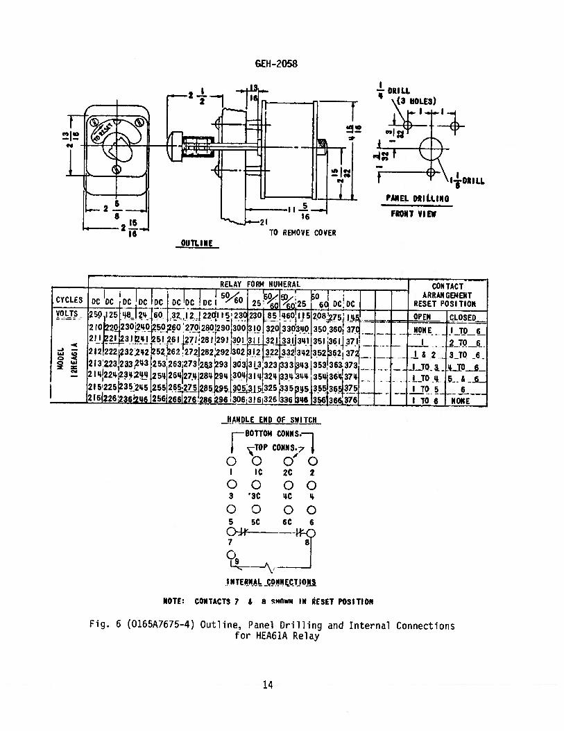
The outline and panel drilling diagrams for the various types of HEA relays are
shown in Figs. 6 to ].3D, inclusive.
CONNECTIONS
The internal connection diagrams for the various types of HEA relays are shown in
Figs. 6 to 13D, inclusive. When connecting switchboard wires to the coil circuit, be
sure they are kept away from the arc path which occurs when the relay contacts
interrupt the coil circuit.
NOTE 1: When connecting wires to all types of switches, excessive thrust must not be
applied to the heads of the screws as the switch contacts may become distorted
permitting rotation on the switch barrier supports. Likewise the connected wires must
not be pulled away from the switch contacts when forming a wiring harness.
NOTE 2: It is also important that a correct fitting screwdriver be used to prevent
switch contact damage and screw head distortion.
MA INTENANCE
PERIODIC TESTS
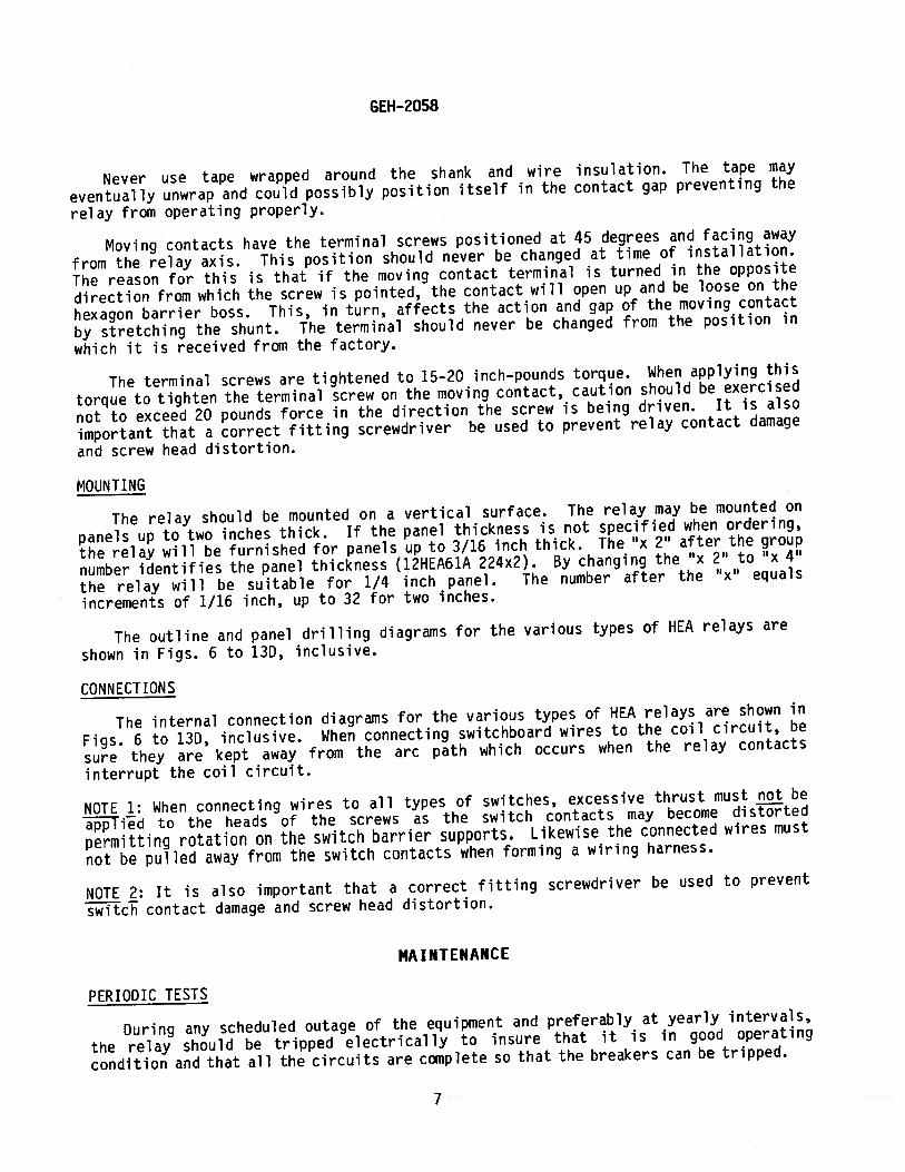
During any scheduled outage of the equipment and preferably at yearly intervals,
the relay should be tripped electrically to insure that it is in good operating
condition and that all the circuits are complete so that the breakers can be tripped.
7
GEH-2058
Remove cover, visually inspect relay and trip manually by applying force on thearmature (Step 7 below).
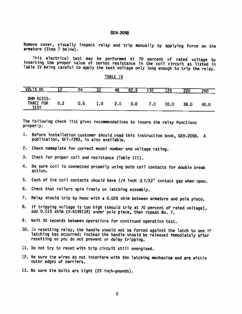
This electrical test may be performed at 10 percent of rated voltage byInserting the proper value of series resistance in the coil circuit as listed InTable IV being careful to apply the test voltage only long enough to trip the relay.
TABLE IV
VOLTS DC 12 24 32 48 62.5 110 125 220 250
OHM RESIS—TANCE FOR 0.2 0.5 1.0 2.0 3.0 7.0 10.0 38.0 40.0
TEST
The following check list gives recommendations to insure the relay functionsproperly.
1. Before Installation customer should read this instruction book, GEI-l—2058. Apublication, GET—7293, is also available.
2. Check nameplate for correct model number and voltage rating.
3. Check for proper coil and resistance (Table III).
4. Be sure coil is connected properly using both coil contacts for double breakaction.
5. Each of the coil contacts should have 1/4 inch ±1/32” contact gap when open.
6. Check that rollers spin freely on latching assembly.
7. Relay should trip by hand with a 0.025 shim between armature and pole piece.
8. If tripping voltage is too high (should trip at 70 percent of rated voltage),add 0.015 shIm (V-6149118) under pole piece, then repeat No. 7.
9. Wait 30 seconds between operations for continued operation test.
10. In resetting relay, the handle should not be forced against the latch to see Iflatching has occurred; instead the handle should be released immediately afterresetting so you do not prevent or delay tripping.
11. Do not try to reset with trip circuit still energized.
12. Be sure the wires do not Interfere with the latching mechanism and are withinouter edges of barriers.
13. Be sure tie bolts are tIght (25 inch—pounds).
8
GEH-?058
SERVICING
CONTACT CLEANING
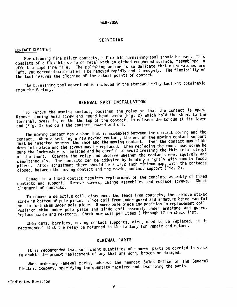
For cleaning fine silver contacts, a flexible burnishing tool should be used. This
consists of a flexible strip of metal with an etched roughened surface, resembling in
effect a superfin file. The polishing action is so delicate that no scratches are
left, yet corroded material will be removed rapidly and thoroughly. The flexibility of
the tool insures the cleaning of the actual points of contact.
The burnishing tool described is included in the standard relay tool kit obtainable
from the factory.
RENEWAL PART INSTALLATION
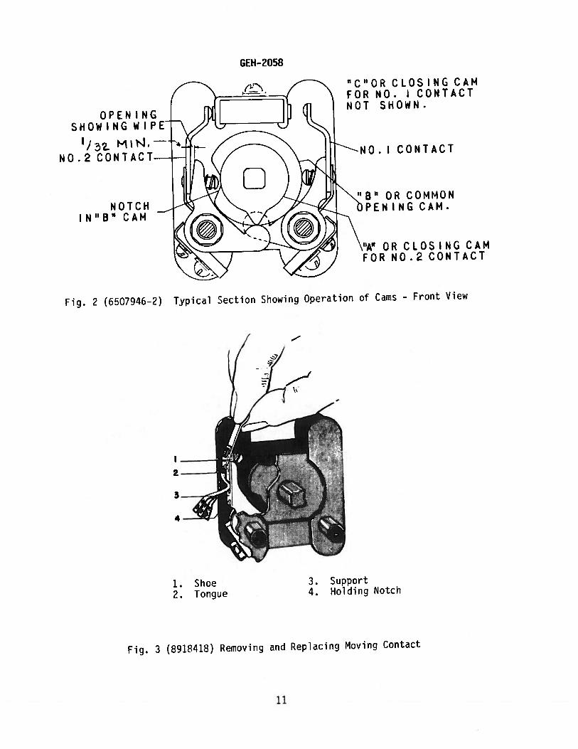
To remove the moving contact, position the relay so that the contact is open.
Remove binding head screw and round head screw (Fig. 2) which hold the shunt to the
terminal, press in, on the the top of the contact, to release the torque at its lower
end (Fig. 3) and pull the contact upward and off.
The moving contact has a shoe that is assembled between the contact spring and the
contact. When assembling a new moving contact, the end of the moving contact support
must be inserted between the shoe and the moving contact. Then the contact may slide
down into place and the screws may be replaced. When replacing the round head screw be
sure the lockwasher is replaced and be careful to avoid creasing the thin metal strips
of the shunt. Operate the relay and observe whether the contacts meet squarely and
simultaneously. The contacts can be adjusted by bending slightly with smooth faced
pliers. After adjustment there should be a 1/32 inch minimum gap, with the contacts
closed, between the moving contact and the moving contact support (Fig. 2).
Damage to a fixed contact requires replacement of the complete assembly of fixed
contacts and support. Remove screws, change assemblies and replace screws. Check
alignment of contacts.
To remove a defective coil, disconnect the leads from contacts, then remove staked
screw in bottom of pole piece. Slide coil from under guard and armature being careful
not to lose shim under pole piece. Remove pole piece and position in replacement coil.
Position shim under pole piece and slide coil assembly under armature and guard.
Replace screw and re-store. Check new coil per Items 3 through 12 on check list.
When cams, barriers, moving contact supports, etc., need to be replaced, it is
recommended that the relay be returned to the factory for repair and return.
RENEWAL PARTS
It is recommended that sufficient quantities of renewal parts be carried in stock
to enable the prompt replacement of any that are worn, broken or damaged.
When ordering renewal parts, address the nearest Sales Office of the General
Electric Company, specifying the quantity required and describing the parts.
*Indicates Revision9
GEH-2058
F YLU CON F,CT‘OPT CRF’1c
it’
Co \ MOVhP CONTACTS (See Fig. 3)
Fig. 1 (8031895) Six Contact HEA61 Relay in Tripped Position, with Cover Removed
N TI I BOLT
FR0ii SUPPORT
LATCH MECHANISM FIXED CONTACT\ SUPPORT
--
(1 —
_____FRONT
SUPPORT
TIE BOLTS
RECTIFIER-RESISTOR BOARD
Fig. 1A (8028243) Type HEA62 with Diode—Resistor Board
10
GEH-2058
OPEN I NGSHOWING WIPE
1. Shoe2. Tongue
ONTACT
COMMONNG CAM.
“A” OR CLOSING CAMFOR NO.2 CONTACT
3. Support4. Holding Notch
Fig. 3 (8918418) Removing and Replacing Moving Contact
“C”ORCLOSINGCAMFOR NO. I CONTACTNOT SHOWN.
1Ja MIN.NO.2 CONTACT
NOTCHIN”B” CAM
Fig. 2 (6507946—2) Typical Section Showing Operation of Cams — Front View
11
Lu
=a)>.,
F-
4-C4)1?)
a)C—)
L)a)0a)2F(a0>,
FLfl
C\J
C=Lu
(\J
—4
ID-.4-.4
(N-l
0.-1
ON
OD
’]C.i
-
Lu
GEH-?058
, 66
DECE FUNCTION NUMBERS
41 — FIELD CIRCUIT BREAKER
52 — POWER CIRCUIT BREAKER
66 — LOCKOUT RELAY, HAND RESET. TYPE HEAG
87 — DIFFERENTIAL RELAY TYPE IJD52A
8 — AUXILIARY SWITCH, CLOSED WHEN
CIRCUIT BREAKER IS CLOSED
OC — OPERATING COILRC — RESTRAINING COIL
SI — SEAL—IN UNIT, WITH TARGET
TC — TRIP COIL
Fig. 5 (0165A7690—O) Typical Application of Type HEA Relays as Auxiliary Device
in the Differential Protection of a Generator
(+) D—C HR
I: l152I214l A8 8 8TL
}t’}’41
lilA
13
I DRILL(3 HOLES)
_80TT0)4 CONHS.—1
i-TOP COHN S.7 4o 0 0’ 0
I IC 2C 2
00 003 ‘3C LC t
00 005 5C 6C 6
7 8
0LJ\
I NTER$A _cWE.CTJO1
NOTE: CONTACTS 7 & 8 cHOwN IN RESET POSITION
Fig. 6 (0165A7675-4) Outline, Panel Drilling and Internal Connectionsfor HEA61A Relay
GEH -2058
OIJTL I NE
I--DRI IL
PANEL DRILLING
FRONT VIEW
CYCLES
VOLTS
-Jw0 w
RELAY FORM NUMERAL1537 -1*_; o1DC_DCjDC DC DCJDCDC DC 60 25g ‘p25_ 6O DC;DC
2 rO2o42302O45O6O 27O28O29043O0 3101 32O33d3O 3503601 37C2H3ILH 5I 261 7l28l29l 301 3ij_2fl3j3I4II35! 36J137I2 121222 23224252262 2721282:292 302 l2t322332!3Lt2i35262 372
213223233,2431253263L273!2a3 93 ‘303 3 L3 323333’l3 13531363.3732I42223L2 25426427.t+2894. 3O,3I!3233J3541364137l2! 522512352t5 25526275 ?85J52I622623642u 256l266I276 286 296 ‘30631 6,3261336 b46 Ia56366,376
CON TACTARRANGEMENT
RESET POSITION
OPEN
HONE
I&2
.J20 3IjO I
I TO 5I TO 6
CLOSED
I TO 6
2 TO 63_TO 6
5&_.6
NONE
hANDLE END OF SWITCH
14
$II
2w-.
HANDLE END OF SWITCH
RELAY FONM NUMERAL
DC DC-
250 i2 8 2! 23022! 230210 23! 25027(290310330 350 370
271 291 311 131 351 371272292312 132352 372
313 133 353 373
314 34 158 374375221 fl5 275295 315 35355
318 33! 356 376
217 23 257 277297317 33 357 377211 22! 56 276296
460 12 OPEN‘110 N I TO 10811 431 I 2 TO 10
832 I 6 2433 I TO 3
I TO 5
I TO 6I TO 7
415 3S
416 436
Wi 437
6 TO 10
7 TO 10
8 TO 10
r BOTTOW CONNS.---
TOP CONNS.(0 00I IC 2C 2
00 00I SC 4C 4
On 05 5 IC
00 007 7C BC S
00 00S9CIOCIO
INTERNAL CONNECTIONS
NOTE-CONTACTS II & 12 SMIN RESET POSITION.
Fig. 7 (0165A7676—3) Outline, Panel Drilling and Interna’ Connections
for HEA61B Relay
L
GEH-2058
E±’—- I
- Is -ii“—_i—-—23 ii TO REMOVE COVER
J
OUTLINE
IL
PEL DRILL1N6
FRONT VIEW
DC DC DC OC DCCYCLES
VOLTS
r1
211 231251212 23 252
CONTACTARRANGEMENTRESET POSITION
CLOSED
213214
215
221 253 273 293
IP 214 274294
412
413
I t3%
3 TO 10
S TO 10
5 TO idI TO 4
220124! 260280
218 23! 258 278298 318 331 358 378 118 138 I TO 8 9 10
io300 32OS4! 360 3801 2O I TO 10 NONE
15
M3IAiO4
9WI1IIO13WV4
niiof
J—•(31oet)
,1IIG
,ceaD!9V31-lOJpuebuL[LAaIOUPdauLuno(-Lt9Lvs9To)6L
9’
SUOLDaUUO3UAeUI
<:1:or
MODELI2HEAQ,ICIcPij
FIR 6ThI(Jc;Sj))-
‘u,c,J
r’iI’J
0
I\-)Q
-*r
oa’
1”
I’,Ui
R)N1I
r’J
pJ
Is-)
r’JI\Jr\Ja’ 1
r’J
I’)0
0
\)F’)rr’t\J)D-JjD’DcP—.
U,
[\)ror—J-,J-J-JU•i-r.
L
rci‘ric,ii0000
ONID\/LJSO1JO±VDfldPG
POILIOdLflfliiis
.1ISIIi3VL3—3LCI
1111*3TuuuI
‘r4r- SI3)135151
00OCii3I2L1LI00CCitDiI311II00CCCI301ee0000Ie0000•ss
0000E£
0000321I
Q00Sfl3401.
N0ilIIOJi*SQON]31QVYN
—o
c’ir
4(Th--
0’0
0
(j4(tJ
cP—JCM
LP(1(jLJ(JC4(I
0C,’
I,:0>rrio
mfl---I
-u
I_n-r”-=Iz
9-_I
QI-
Z35JiJG4ULflUiUU(,1u,tJtU,UlC,J
E.0?c-QO
r\)rJr’rJr?----—-——O
-...-((iC,4(-41(J(pJ(j4CM—
EizP9
z
ZIL:sii=ID‘X)—4aU1CMP
E_3N11iflO
1NVd
tLIS*0ciw
IO]101lI1LLflJW.JJYNSLMD
HANDLE END OF SWITCH
BOTTOM COHNS.
9 9C bC JO
00 00JIC I2C I?.
__
0000
______
13 i3C (4-C, 14
__
0000isc C j
orrQ
_______
Ir4TER,IAL CONN&CTIO4S4QYECOt4ThCTS l7 IS
2-at 241 261 28’ 3 321 341 —— TO (I laTOIG
222- 22628302.32-1 34-Z — Jj TO ta I3T0 6
? 2-4-3 2-63 3
_____
——lZJJ1EI_
22-42-44 264 284
__
2-5 24-52-652-85
____________
I TO I5 16
____ ________
oi
Fig. 8A (0195A9035—1) Outline, Panel Drilling and Internal Connections
for Relay HEA61CRD
GEH-2058
IL.16
TO REMOVE COVER TOP
—J-DtA.4
cL; (3 HOLES)
DIA.
PANEL DRILLING
(FRONT VIEW)
ci0I-
DC
__________
RELAY NUMBER
/CLES DC DC DC DC so/so DC
YO1.TS 250 25 48 24 22-0 115 ‘43 2-30
.LPan 2’.1 2Ij g1 31l j i IL
‘c2 292- 3)2. 332 ssa 372
2-75
3rE
ARRANGEMENTRESET POSITION
LOSEDTO 6
I ZTOIG
IL 3T016C-)
‘-94:U
(‘I
-J
0x
-- — — — — — -
213 233 253 2-7.3 2-93 313 333 353 373 I To 3 4 TO 6
)4 a34254 74 a i4- I TO 4 5 TO 16
atE a3525E275295 3)5 I 705 GTDIG
2-16 236 256 276 2-96 316 336 356 376 I TO 6 7 TO IC
1i7 237 572-77 297 317 337 57 377 JTt07 8T0 16
1I8a’38 5B27829 3) 358 378 1 TO8 9TOIG
219 292-592.792-93l3_339359379 T09 IOTOIC
220 4-O 2-CC 2.80 30C 32-01340 360 350 L I TO 10 II TO IG
36) 381Z 382-
03 3231343 363 3830 3Z4j34_36’ 384-05 3a5[l365386
2-46 26 a86 3a6!34636I 386
17
GEH-2058
HANDLE END OF SWITCN
BOTTOM CO?iNS.
(R00003 3C. 4-C 4-
0000S SC GC G
II4TERI4AL COI4NECT)ONSN01E-COJTACTS 17E185HQWN IN EsE.rPoSITioH
—TO RE)4OVE COVER TOP
&ii*.I’
— (8 HOLEs)
1_DIA.
PANEL DRILLING
(FRONT VIEW)
TOP
RELAY FORM NIJMRFR
GYC1. DC DC DC DC DC so/so DC
CONTACTARRANGEMENT
RESET POSITION
0000.7 -re Sc 800009 9C IOC tO
0000I IaC 12..
000013 13C. 14C 14-
0000I 15C IGC 16
VOLTS 2.50 125 4 24 22.0 itS 4( Z30275 OPEN CLOSED
!2 ? aw — NONE i TO-J 2J a31 251 2.71 91 311 .31 351 371 a TOI
aia 2.32.2.52. 2.72. 92 312 3.3 a 372. 3 TOI13 2.332532732.93313 33 5 373 — I Q3 4TOIG
.( 2.14 234. 274 29 3(4 3 5 — - TO 4 5 TO I GZLS 2.35 255E 2.752. 5 15 35 375 — TO 5 T0It 236 a% a7 2 G 3j, 33 5 37 — To 7 TOIG
2.17 237 2.57 an 97 317 337 57317 TO 7 8 T0162.18 238258 2.78 3i8 33E 5837 TO B 9-rOIG
X aI0a33a592.7g 993I.9333.59379 YO9IOTOIG2.20 240 2.€O 280 30C 32.0340360380 TOlD II TOI(o
221 2412.61 2. 301 32.1 341 361 .3j - TOll I2.10U2.22. 24ZaG228233423238a T012 I3TOIGze3ga3ae3 303 3433 - T013 I4-TOl22 a44 Z4 284 30 34 384 — TO I 4 IS TO I
2a5265a853o5il34.53S385 ITOIS I€iG2a462G€a863oG32g4E G386l 1T0I NONE
Fig. 8B (0195A9033—1) Outline, Panelfor Relay
Drilling and Internal ConnectionsHEA61CRL
18
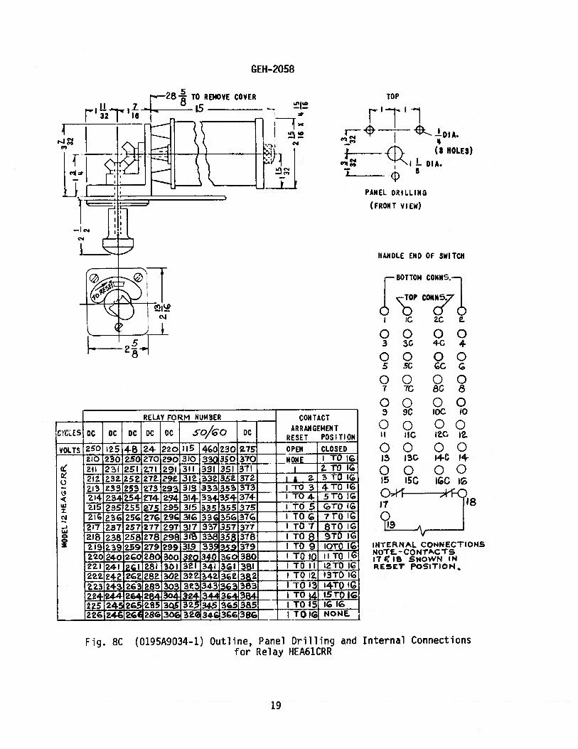
CYCLES DC DC DC DC DC
VOLTS 250 125 4B 24 220
U(9
UiI
-JLi
Fig. SC (0195A9034-1) Outline, Panel Drilling and Internal Connectionsfor Relay HEA61CRR
GEII-2058
- --
C4
TO P
rII
I’
________
- (a HOLES)
i-Loi*.8
PANEL DRILLING
(FRONT VIEW)
HANDLE END OF SWITCH
BOTTOM CONIIS.
CO?;E
RELAY FORM NUMBER
so/Qo
J15 I4O1Z3O ais
—— CONTACT
ARRANGEMENTDC
RESET
—
POSITION
210 230 250270290— NONE TO
au 231 251 7I 2-91 311 331i351 371 I 2-TV IG
OPEN CLOSED
003 9C
00II IIC
0013 13C
00(5 150
00bC 10
0012-C 12
00*CI4
001c it212- aa &5a 272 292- 312. 332.’332 37’Z
-a S TO
23 2-33 253 2.73 313 333I53 -ro 3 4T0 1€T04 5TOIG
215 235 2-55 27.5 295 3(5 335 355 375 TO 5 TQ IG
Z a3G2527G a9 3l 33C35G37G TOG 7T0 I
217 2.37 257 277 297 3(7 337 3.57 377 — - TO 7 STO IG
218 2382582-78 298 3383 318 — - TO 5 9T0 IG
2.19 2-392.59 279 299 319 33S 3 79 — - TO 9 IOTO G220 240 ZG 280 300 320 40 360 80 TO 10 II TO I2ZI24ba2j3j3Gl3!_ TOIl 2TOIG22.2 4-2 2G 2-82- 302 3Z 342 3f 2 I TO ‘a 13T0 IG
2.23 243 2-6 33 343 3383 —- TO 13 I4T() !
44 2E 2 4 324 34.i 3G 4 —- TO (4 15T0 IG22-5 24.’ 52 325345 85 — TO 15 IG IE.
4-62 28Q3OE 32343G6
INTERNAL CONNECTIONSNOTE. - CON1-ACr5I7t8 SHOWN INRESET POSITION.,
TOIG N0N
19
DIA.(3 HOLES)
(bD$A.
PANEL DRILLING(FRONT VIEW)
HANDLE END OF SWITCN
BOTTOI4 CONKS.
7 7C BC 8
00 009 9C IOC 10
OQ 00ii I2C 12-
OQ 0013 13C 14C 14-
00005G 16C 16
)4TERMAL CONHCTION5N0T-CO.rrACTS l7l85HOW4 IN R.SXPOStTION.
GEH -2058
RENOVE COVER288
zzz
[H
I...
TOP
cYcIlsjDc DC DC
RELAY FORM NUMBER
DC DC SO/GO DC
CONTACTARRANGEMENT
RESET POSITIOW
VOLTS aSO 25 48 24 22.0 4-6( 2.3 275 OPEN CLOSED
aIo23czsoa7oago3,o35o37o NONE I TOIG
au z31 asi 27) z91 311 331 35) 371 a ro.i
2.12. 2.32. 2 2.92 312 3 352. 372 jjj T0162i3 233273a933I3 3 353 373 TQ3 4TOIGaI4a34.E4a29 314 3 35 374 T04 STOIG
215 2.35 a pgs 315 3 355375 TO 5 TO1G
aiG a36 a G 2.72963J.3%35637 TQ 7T016
2.1 2.37 2. 29731733 357377 — TG7 BTOIG2.18 238 82.782.983)8 3 35837 — t08 9T016210 ! ?.99 .3)9 3,5 37 — O 9 tO TO IGa20a4 028030 32 3-4 360380 TOIC TOi
2.21 241 26 2.j 301 32. 4I 361 381 — — TOIl .TOIG
222 24. 2.62 82 302. 32 342 3Z 382 — TOi 13 TO I2.23 24 63 aä 303 3 3 33 383 1 7-013 4Th IGaz 2.4 2.843__3434 364 38. I T014 S To T2a24- £a3os3a_345365385
— ITOIS £JG22. 2.4 €a8630632G[34 3G38b[T0I€ NONE
Fig. 8D (0195A9O35—o) Outline, Panelfor Relay
Drilling and Internal ConnectionsHEA61CRU
20
DRILL(3 HOLES)
— RELAY FORM NUMERAL
________ ______
]cJ DC DC DC1OC DC 50/60 251 DC1o
DC
_____
ioZO :30 ‘W 5)60 70 80j90 tOO II0II20II30I1lO — —
IL1L L 5J61 71 8I9I 101 III All — - —
— I2:22j 42 5262 72, 82 92 102 112112211321142 _I_ —
______
HANDLE END OF SWITCHOflOM C OWNS.
A1
$tERNAL CO)INECTIONS
NOTE—CONTACTS S & 6 SHOWNIN RESET POSTTIONS.
Fig. 9 (0165A7681-2) Outline, Panel Drilling and Internal Connectionsfor HEA61M Relay
GEH-2058
.—-- 1
OUTLINE
ir3Al TO REMOVE COVER
PANEL DRILLING
FRONT VIEW
LT
MOD EL
L.-
CONTACT
1 ARRANBEMENTPOTIO$
OPEN I CLOSED
3
21
GEH-2058
LI.
PAIEL DRILLIMG
FIOT VIEW
%4?.NDLE ND OF 5WITCH
çBOTTOM
10P CONN5.-.,
‘ 9C bC 10
0000II liC 12.C 12.
000013 I3C 14C 14
- DuLL
(3 HOLES)
(.YCi.E5 DC tC D bC.50, SO
RELM FORM 4UMERAL CONTACT
RRANEMENTREt PO5’i1OI
\)C)L15 2501 4 itS 230 220 — — — — OPEN ci.osED
LI____ NONE 11014
II 31 St 7% 9) III ll I 2Th 14
‘ZZ‘3 33 53 73 93 113)33 1u3 4’oI414 3454 ‘1jM I4 ITo4 51o14
‘9 ,ZZJJZbOI4< I( 3( % 7 bl(d.I3(, tTo(. 7T0 t4
17 37 S7 17 7 117 37 lo7 Tol4
38818He, 11o6 TOl419 39 ‘59 19 I 9 —
i To3 to to 144o (O 80 100 120 140 — —
I To ID It 10 14-
n 21 4i (.1 i ioi izi 41 11011 ItTGI4
2Z 42 (o2 82 1b2 12t 42 —— I TO PZ 13 To ‘4
‘ %T013 142444 44Io4)?4I44 Tot4 NONE
‘7?
____
tI,JTEP.NAL C.ONNECTIDN5
hJEONTcTh lStCD
S%ieW)4 IN RESET PiTio.i.
and InternalFig. 10 (0165P7686—2) Outline, Panel Drilling,Connections for Relay HEA61V
22
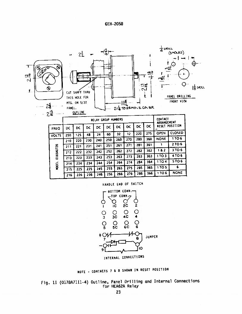
- cILL
(!1OS)
— I — I
0-
RELAY GROUP NUMBERS CONTACT— — —
— ARRANGEMENT
DC DC DC DC RESET POSITION
VOLTS 250 125 48 24 60 32 12 220 275 OPEN CLOSED
210 220 230 240 250 260 270 280 360 NONE 1T06
2 231 241 2 261 271 281 361 1 2T06
212 222 232 242 252 262 272 282 362 1 &2 3T06
‘0—
213 223 233 243 253 263 273 283 363 1 T03 4T06
214 224 234 244 254 264 274 284 364 1 TO 4 5 TO 6
255 265 275 285 365 1 TO 5 6
216 226 236 246 256 266 276 286 366 1T06 NONE
GEH-2058
1
I CuT SHAFT THRU
-frJ
- .11111.2i-r’ E.MO
THIS ILE FOR
MTG. ON 5/32
- ‘ANEL.
—OUTLINE
FREQ
PANEL DRILLING
DC
FRONT VIEW
DC DC DC DC
HANDLE END OF SWiTCH
BOTTOM CDNNc co77O
IC 2C 2
00003 3C 4C 4
00005 5C 6C 6
+014 JUMPER
______ _____
10
INTERNAL CONNECTiONS
NOTE - CONTACTS 7 1 8 SHOWN IN RESET POSITiON
Fig. 11 (0118A1111-4) Outline, Panel Drilling and Internal Connectionsfor HEA62A Relay
23
CONTACTARRANGL4ENTRESET P05111014
HANDLE END OF SWITCH
BOTTOM CONN.
p
00003 3C 4C 4
00005 5C GC G
00007 7C ec e
00009 90 bC 10
—t- ..w4?.l JUMPER
NOTE - CONTAcTS II & 12 IN
RESET POSITION.
Fig. 12 (0178A7112—4) Outline, Panel Drilling and Internal Connectionsfor HEA62B Relay
GEII-2058
a —. 4PJLL HcF-S)
- -
-
_I
I -.
{ ! e -
CuT SHA6RUr
THIS HOLE FOR PANEL DRILLING1410. ON 5/32
— FRONT VIEWPANEL. 4--
.- CcYR.
OUTLINE
RELAY GROUP NUNB[R5
FREQ DC DC DC DC DC DC DC DC
VOLTS 250 125 4.8 24 32 230 220 12 OPEN CLOSED
210 230 250 270 290 310 330 430 NONE I TO 10
211 231 251 271 291 311 331 431 1 21010
212 232 252 272 292 312 332 432 1 &2 3TO 10
213 233 253 273 293 313 333 433 1 T03 41010
214 234 254 274 294 314 334 434 1 T04 STO 10
215 235 255 2)5 295 315 335 435 1 TO 5 6 TO 10
, 216 236 256 276 296 316 336 436 1TOG 7T010
217 237 257 277 297 317 337 437 1 107 8T0 10
218 238 258 278 298 318 338 438 1 T08 9T0 10
219 239 259 279 299 319 339 439 1109 10
220 24.0 260 280 300 320 340 440 1 TO 10 NONE iNTERNAL CONNECTIONS
24
_______
HANDLE END OF SWITCH
8OTT CONN.
_ ____
c-p
0ñ
__ __ __
00003 3C 4C 4
__ __
00005 SC 6C 6
__ __
00007 7C SC B
_ __
00009 C IOC 10
__ __
0000II IIC 12C 12
000013 13C 14C l
0000
______ ______
15 15C IGC 16
± c*-..--
__________ __________
—
JUMPER
INTERNAL CONN[CrJo
NOTE - CONTACTS 17 & 18
SHOWN iN RESET POSITION.
Fig. 13 (0178A7113—4) Outline1 Panel Drilling and Internal Connectionsfor HEA62C Relay
25
GEH-2058
I
—
CUT SHAFT THRU
THIS HOIE FOR
NIG. ON 5/32
_
-
-- J PANEL.
OUTLINE
4
-.! +H-.
1.nc.4
-...—..
PANEL DRILLING
FRONT VIEW//
--28
DC DC
RELAY GROUP NUMBERS CONTACT—- — —
— ARRANGEMENTFREQ DC DC DC DC RESET POSITION
VOLTS 250 125 48 24 220 275 OPEN CLOSED
210 230 250 270 290 370 NONE 1 TO 16
211 231 251 271 291 371 1 2T0 16
212 232 2S2 272 292 372 1 &2 3TO 16
213 233 253 273 293 373 1 T03 4TO 16
214 234 2S4 274 294 374 1T04 5T016
215 235 255 275 295 375 1 TO 5 6T0 16
216 236 256 276 296 376 1TOG 7T016
237 257 277 297 377 1 TO7 8 TO 16
218 238 258 278 298 378 1TO8 9TO16
219 239 259 279 299 379 1TO9 1OT016
220 240 260 280 300 380 1 TO 10 11 TO 16
221 241 261 281 301 381 1 TOll 12T0 16
222 242 262 282 302 382 1 TO 12 13TO 16
223 243 263 283 303 383 1 TO 13 14T0 16
224 244 264 284 304 384 1 TO 14 15TO 16
225 245 265 285 305 385 1 TO 15 16
226 246 266 286 306 386 1 TO 16 NONE
GEI1-?058
TOP
I’
-E (3 HOLES)
IJ—DIA.
PANEL DRILLING
(FRoNT VIEW)
HANDLE END OF SWITCH
BOTTOM COHN.
hOP
C0N
3 3C 4C 4
00005 5C SC 6
00007 7C 8C 8
Fig. 13A (0246A2251—1) Outline, Panel Drilling and Internal Connectionsfor Relay HEA62CRD
jUMPER
TO REMOVE COVER
LN
0Lflj
I—
FIEQ. DC DC
3’
— VjOjIUMR_ —— CONTACT
ARRANGEMENTDC DC DC DC DC
RESET POSITION
I in ICVOLTS 2 4 24 2( 27 — — — OPEN CLOSED
C 7( 7( 3C N AN F
00009 C IOC to
0000II IIC 12C 12
000013 13C I’rC 4
00 0015 ISC IGC 16
0
UI‘0
X UI
C,’
I 3 51’? I Vi 37) Z9 I 2 TQ Ic2ZZEIL2 3T0
3 Z73L — — ITO 3 4iOl52737 SToic
3 7H 35 — ——
10 5 GTO çc SE 7C59 I To G 7 TO jçr Tp7pTpç
8 VS3Z 39 — — TO 8 9 10 çL’ — —
— T0510T02C 4’
+
‘46C 8( 301 8( 1O‘l’RI3OII OI
TO IC II TO IC
‘2€ 4:
TO 11)2 TO‘ Qj 8
—— I TQ I ‘3 TQ I
EE —
5.- Q 4Q__ —- TQ )415 & 16
) C— — — j TO t I
IC
2GC E3Of38(OE
INTERNAL CONNECTIONSNOTE-CONTACTS 17 & 18
SHOWN IN RESETPOSIT ION
TO I NONF
26
GEH-2058
TO REMOVE COVER TOP
_________
(a HOLES)
ILDIA.
PANEL DRILLING
(FR0sIT VIEW)
HANDLE END OF SWITCH
BOTTOM COHN.
co
3 3C 4C 4
00005 5C LC 6
00 007 7C 8C 8
TOP
FREQ. DC DC DC DC
RELAY GROfjIIJR_ — — CONTACTARRANGEMENT
DC DC DCRESET POSITION
0000SC IOC IC
00 00II lic I2C 12
00 0013 13C I4C 14
00 00IS ISC 16C IG
VOLTS 5( 12548 24 2C7E 2.f OPEN CLOSED
ZE NONE ITOIEI J 7j S I ]j 5.9j — —
— 2 TO ICiJ ? ?S2V? — — — i & 2 3 10 IC
39___ITO3410IQH23 )7 I 10 4 510 ic
— I 10 S T IC57J 2 f___ i TO G 710 IE
Zi___LT078TOIEH.
9 3___ 110 8 910 ie— —
— TO S 10 To 1EE C 28 3S IQ — —
— TO I 0 I I 10 ICI 4) Ei 2 J QJ — — — 1 1210 1€
)2_2 4 8 Q — — — jQ_ 2 13 TO ICL 1 Q — — —
‘410 I4 8%3Q
— — JQ_ i5 & IC.2S 30 — IQ 162c zc e ao . 8 Qf — TO I ( N ON E_
J U M PER
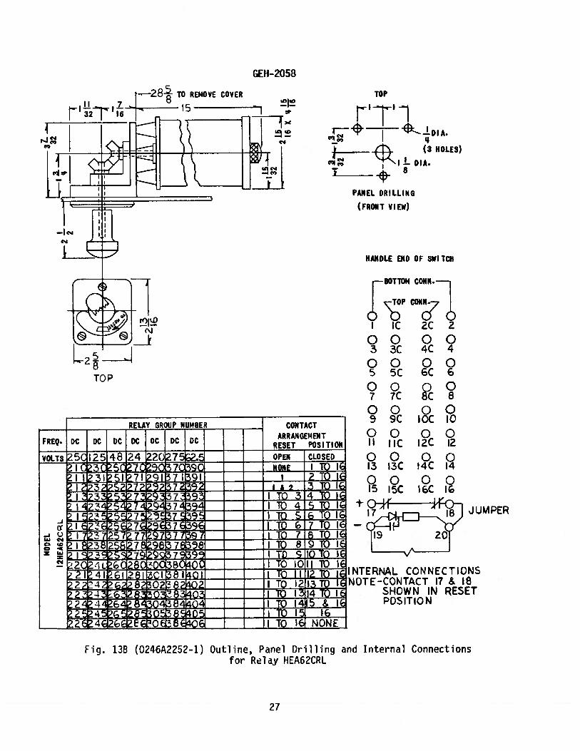
Fig. 13B (0246A2252-1)
,NTERNAL CONNECTIONSr$OTE-CONTACT 17 & 18
SHOWN IN RESETPOSITION
Outline, Panel Drilling and Internal Connectionsfor Relay HEA62CRL
27

GEH-2058
TOP
F1--!-DIA.
II(3 HOLES)
Il-NA.
+8
PANEL DRILLING
(FRONT VIEW)
HANDLE END OF SWITCH
BOTTOM CQNN.
CONy
0005 SC £C
0007 7C 8C
JU M PER
TO REMOVE COVER
C..’
c’J
2
(
RELAY GROUP NUMBER— CONTACT
— ARRANGEMENTFREQ. DC DC DC DC DC DC DCRESET POSITION
I TO ic3( 5( 7( 9C S7C 3CVOLTS 5( I 2 48 24 2C 2E OPEN CLOSED
NON F
0000S SC ICC 10
00 00II tIC 12C IZ
00 0033 13C 14C 34
00 00IS 15C 16C 36
-Ic)uJ C..,O
C’,
!i ]3 -i-1i i 21 i2122__ IL2 3ID1G
I U __ I 10 410 IE723__ 10 45101E
.‘3 ? TO 610 IETO71O
7’7j___ TO 75T0 c3 TQ 8sIo c
LL- 39_ — — 19 910T0 if! -!4J Q Q___ TO iCllTOI
+
>224?2220Z-.F1? ifl2I 4 I 8I OI 381 C1 I IC II 12T0
TOTCi3l4TOl
— — — 10 l Is & IEEEZ ioi 16
I
€,c28i 30€ 38 OC
1213 TfliNTERNAL CONNECTIONSNOTE—CONTACT 7 & 38
SHOWN IN RESETPOSITION.
TC II NONE
Fig. 13C (0246A2253-1) Outline, Panel Drilling and rnternal Connectiorsfor Relay HEA62CRR
28
GEH-?058
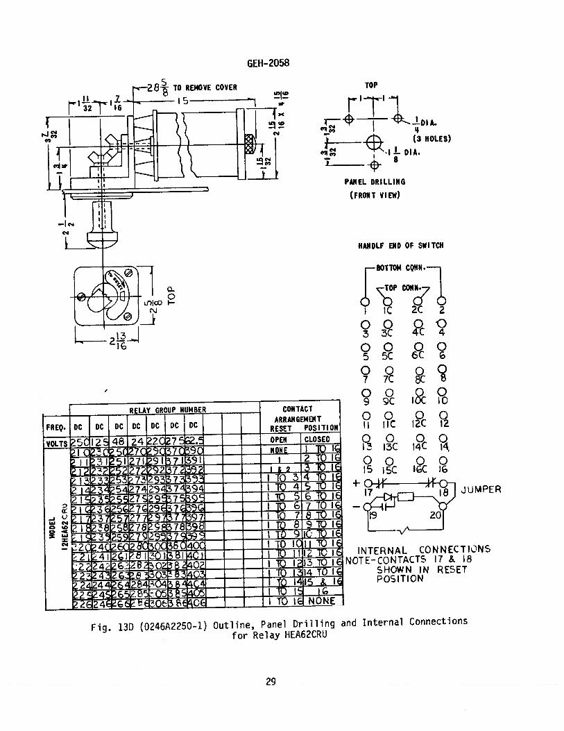
Fig. 13D (0246A2250—1) Outline, Panel Drilling and Internal Connections
for Relay HEA62CRIJ
TO REMOVE COVER TOP
‘1(3 HOLES)
DIA.
PANEL DRILLING
(FRONT VIEW)
ifllco —
c\J
L
RELAY GROUP NLIM8ER
FREQ. DC DC DC DC DC DC DC
HAJ4DLF END OF SWITCH
BOTTOM COHN.
OP co
3 3C 4C 4
00005 5C 6C
0007 7C 8C
0000s vc ioc ID
00 00ii tic tzc tz
00 0013 13C 14C 14
O 00IS 5C IGC 16
CONTACT
ARRANGEMENTRESET POSITION
VOLTS 5C I 2 48 24 2C 7 OPEN CLOSED
—E::z::z NONE I10III 3I 5I27t 9H7I39i i 2 TO I
I&2 TOI€53 73 — — — I TO 3 4 1€
3’5 j2 ITO 4510)1— — I 10 5 6 10 If
J_ç3Ea5c 12c_ — I 10 7 TO ic
W7L7L97__ Tc7elOtç2I38’S8 789 78 I TO 8 910 1
X Z iS Z I TO 0 IC1O2’ 41 8C SC 4CC TO IC II 10 f
-jI-iQj iZEZ l]12TO:2?242?iBO2 jQ JjI3TO I
2O4 8 I TO I IS & II1Oi 6
EEc P cs — — —
I TO I E NO NE
-I-JUMPER
INTERNAL CONNECTkNSNOTE-CONTACTS 17 & 18
SHOWN IN RESETPOSITION
29

GE Power Management
215 Anderson AvenueMarkham, OntarioCanada L6E 1B3Tel: (905) 294-6222Fax: (905) 201-2098www.ge.comlindsyslpm
Related Documents