RESEARCH ARTICLE Virtual inertia for variable speed wind turbines Lorenzo Zeni 1 , Andreas Jakob Rudolph 1 , Janus Münster-Swendsen 1 , Ioannis Margaris 2 , Anca Daniela Hansen 1 and Poul Sørensen 1 1 DTU, Wind Energy Department, Roskilde, Denmark 2 National Technical University of Athens, Department of Electrical Engineering, Athens, Greece ABSTRACT Inertia provision for frequency control is among the ancillary services that different national grid codes will likely require to be provided by future wind turbines. The aim of this paper is analysing how the inertia response support from a variable speed wind turbine (VSWT) to the primary frequency control of a power system can be enhanced. Unlike fixed speed wind turbines, VSWTs do not inherently contribute to system inertia, as they are decoupled from the power system through electronic converters. Emphasis in this paper is on how to emulate VSWTs inertia using control of the power electronic converter and on its impact on the primary frequency response of a power system. An additional control for the power electronics is implemented to give VSWTs a virtual inertia, referring to the kinetic energy stored in the rotating masses, which can be released initially to support the system’s inertia. A simple Matlab/Simulink model and control of a VSWT and of a generic power system are developed to analyse the primary frequency response following different generation losses in a system comprising VSWTs provided with virtual inertia. The possibility of substituting a 50% share of conven- tional power with wind is also assessed and investigated. The intrinsic problems related to the implementation of virtual inertia are illustrated, addressing their origin in the action of pitch and power control. A solution is proposed, which aims at obtaining the same response as for the system with only conventional generation. The range of wind speeds near the power limitation zone seems to be the most critical from a primary response point of view. The theoretical reasons behind this are elucidated in the paper. Copyright © 2012 John Wiley & Sons, Ltd. KEYWORDS virtual inertia; primary frequency response; variable speed wind turbine; integration of wind power Correspondence Lorenzo Zeni, DTU, Wind Energy Department, Roskilde, Denmark. E-mail: [email protected] Received 13 October 2010; Revised 27 April 2012; Accepted 22 July 2012 1. INTRODUCTION The number of wind power installations in many power systems has been continuously growing during the past few years and it seems that it will continue to do so in the future. Besides problems related to the fluctuations in wind power produc- tion, other concerns have been progressively taken into consideration by system operators. For example, a growing share of wind power in the power system may require wind farms to be able to provide other services than only power production, namely to support the power system as conventional power plants typically do. These services include for example active and reactive power control, frequency and voltage control. 1 Many research projects have started looking into possible ways to integrate more and more wind power in the power systems without depriving it of the capability of providing adequate power quality, security of supply and reliability. Among those, one can find studies addressing the solutions from a wind turbine perspective, i.e. committing the wind turbines to furnish the full suite of ancillary services. In the area of frequency control, the newest and widely used variable speed wind turbines (VSWTs) pose a supplementary issue, which is the lack of any inertia contribution due to decoupling of the turbines from the grid through electronic converters. A number of studies have addressed this topic, 2–4 but solutions still need to be proposed and developed in this respect. WIND ENERGY Wind Energ. (2012) Published online in Wiley Online Library (wileyonlinelibrary.com). DOI: 10.1002/we.1549 Copyright © 2012 John Wiley & Sons, Ltd.

Welcome message from author
This document is posted to help you gain knowledge. Please leave a comment to let me know what you think about it! Share it to your friends and learn new things together.
Transcript
WIND ENERGY
Wind Energ. (2012)
Published online in Wiley Online Library (wileyonlinelibrary.com). DOI: 10.1002/we.1549
RESEARCH ARTICLE
Virtual inertia for variable speed wind turbinesLorenzo Zeni1, Andreas Jakob Rudolph1, Janus Münster-Swendsen1, Ioannis Margaris2,Anca Daniela Hansen1 and Poul Sørensen1
1 DTU, Wind Energy Department, Roskilde, Denmark2 National Technical University of Athens, Department of Electrical Engineering, Athens, Greece
ABSTRACT
Inertia provision for frequency control is among the ancillary services that different national grid codes will likely require tobe provided by future wind turbines. The aim of this paper is analysing how the inertia response support from a variablespeed wind turbine (VSWT) to the primary frequency control of a power system can be enhanced. Unlike fixed speed windturbines, VSWTs do not inherently contribute to system inertia, as they are decoupled from the power system throughelectronic converters. Emphasis in this paper is on how to emulate VSWTs inertia using control of the power electronicconverter and on its impact on the primary frequency response of a power system. An additional control for the powerelectronics is implemented to give VSWTs a virtual inertia, referring to the kinetic energy stored in the rotating masses,which can be released initially to support the system’s inertia. A simple Matlab/Simulink model and control of a VSWTand of a generic power system are developed to analyse the primary frequency response following different generationlosses in a system comprising VSWTs provided with virtual inertia. The possibility of substituting a 50% share of conven-tional power with wind is also assessed and investigated. The intrinsic problems related to the implementation of virtualinertia are illustrated, addressing their origin in the action of pitch and power control. A solution is proposed, which aimsat obtaining the same response as for the system with only conventional generation. The range of wind speeds near thepower limitation zone seems to be the most critical from a primary response point of view. The theoretical reasons behindthis are elucidated in the paper. Copyright © 2012 John Wiley & Sons, Ltd.
KEYWORDS
virtual inertia; primary frequency response; variable speed wind turbine; integration of wind power
Correspondence
Lorenzo Zeni, DTU, Wind Energy Department, Roskilde, Denmark.E-mail: [email protected]
Received 13 October 2010; Revised 27 April 2012; Accepted 22 July 2012
1. INTRODUCTION
The number of wind power installations in many power systems has been continuously growing during the past few yearsand it seems that it will continue to do so in the future. Besides problems related to the fluctuations in wind power produc-tion, other concerns have been progressively taken into consideration by system operators. For example, a growing share ofwind power in the power system may require wind farms to be able to provide other services than only power production,namely to support the power system as conventional power plants typically do. These services include for example activeand reactive power control, frequency and voltage control.1
Many research projects have started looking into possible ways to integrate more and more wind power in the powersystems without depriving it of the capability of providing adequate power quality, security of supply and reliability.Among those, one can find studies addressing the solutions from a wind turbine perspective, i.e. committing the windturbines to furnish the full suite of ancillary services. In the area of frequency control, the newest and widely used variablespeed wind turbines (VSWTs) pose a supplementary issue, which is the lack of any inertia contribution due to decouplingof the turbines from the grid through electronic converters. A number of studies have addressed this topic,2–4 but solutionsstill need to be proposed and developed in this respect.
Copyright © 2012 John Wiley & Sons, Ltd.
Virtual inertia for variable speed wind turbines L. Zeni et al.
The focus of this study therefore lies on primary frequency control, paying particular attention to the initial response ofthe system to sudden frequency changes as a consequence of a load change or a loss of a generating unit, looking at thecontribution VSWTs could give. Such a response is dependent on the total kinetic energy (inertia) stored in the rotatingmachines of the system. Usually, it will be necessary to permanently have some generators operating in spinning reservemode, even if not strictly needed for matching the power demand, in order for the system to withstand a possible suddenchange of the load or loss of generation.
The increasing volume of wind power penetration into the system may worsen the dynamic security and stability ofthe power system, as it can imply lower values of its total inertia. Nonetheless, as being directly coupled to the grid, thewidely used fixed speed wind turbines have the intrinsic capability of providing inertia to the power system. Theinertia stored in such turbines is comparable with that delivered by a conventional synchronous generator withthe same rated power.4 Despite introducing several advantages, such as control flexibility and power maximization,the presence of power electronics inside more modern VSWTs deprives wind farms of the ability to provide inertiato the system. VSWTs can be either totally or partially decoupled from the electrical grid by power electronics, as inthe case of wind turbines based on permanent magnet multi-pole synchronous generators (PMSG) or on doublyfed induction generators (DFIG), respectively. This means that these wind turbines are not able to inherentlyrespond to any possible frequency variations in the system. Consequently their power output will not automati-cally respond to changes in system frequency. This problem is a serious challenge, particularly for autonomoussystems, which typically have low available inertia and cannot rely on import/export of power to deal with suddenpower unbalances.
This paper investigates the VSWTs’ ability to provide frequency response for the power system, when their powerelectronics are equipped with additional control functionality to emulate and exploit the virtual inertia stored as kineticenergy of the rotating masses. The possibility of making the value of the virtual inertia a controllable parameter is alsoinvestigated, providing an improvement of the initial response compared with the case with merely conventional genera-tion. The focus of the work solely lies on inertia provision, leaving out of the study other aspects of frequency control, suchas for example droop control.
The main issues encountered during the investigation are given a theoretical origin, elucidating the constraints—power,energy, control, etc.—which VSWTs are subject to and which may pose limitations to the optimal exploitation of their inertia.
2. SYSTEM DESCRIPTION
In order to evaluate the dynamic capability of VSWTs to provide frequency response, a simplified model and control of ageneric power system and of a VSWT-DFIG have been developed based on the detailed studies of Wood and Wollenberg5
and Akhmatov.6
2.1. Power system modelling
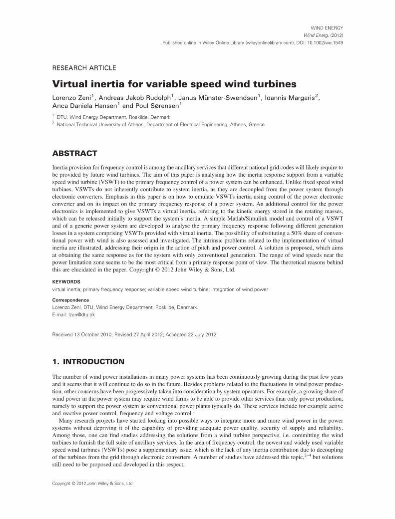
Figure 1 shows a block diagram of the power system including the governor, droop, prime mover, generator, loads andwind turbine model. All generating units in the system are lumped together as a unique generator, as described in the studyof Wood and Wollenberg.5 The parameters of the blocks, i.e. governor time constant TG, prime mover time constant TPM,angular momentum M and frequency dependency D of the generator and loads and the slope R of the droop control blockare provided in the Appendix. It should be noticed that such system representation is heavily simplified, as the delay ofdifferent units is unified in only one time constant, introducing a rough approximation. However, this approach is usuallyaccepted for this kind of study.
Notice that the model also includes a value for the initial load reference, which can be changed if a load step is consid-ered. Flexibility is then guaranteed by the use of a per unit notation in the model.
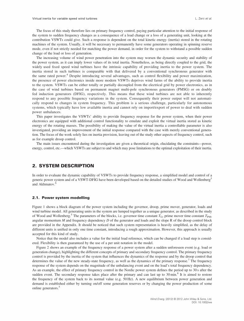
Figure 2 shows an example of the frequency response of a power system after a sudden unforeseen event (e.g. load orgeneration change), highlighting the different concepts of primary and secondary frequency control. The primary frequencycontrol is provided by the inertia of the system that influences the dynamics of the response and by the droop control thatdetermines the value of the new steady-state frequency, as well as the dynamics of the primary response.7 The frequencyresponse of the system depends on the magnitude of the unbalancing event and on the load’s total frequency dependency.As an example, the effect of primary frequency control in the Nordic power system defines the period up to 30 s after thesudden event. The secondary response takes place after the primary and can last up to 30min.8 It is aimed to restorethe frequency of the system back to its normal value (e.g. 50Hz). A new equilibrium between power generation anddemand is established either by turning on/off some generation reserves or by changing the power production of someonline generators.5
Wind Energ. (2012) © 2012 John Wiley & Sons, Ltd.DOI: 10.1002/we
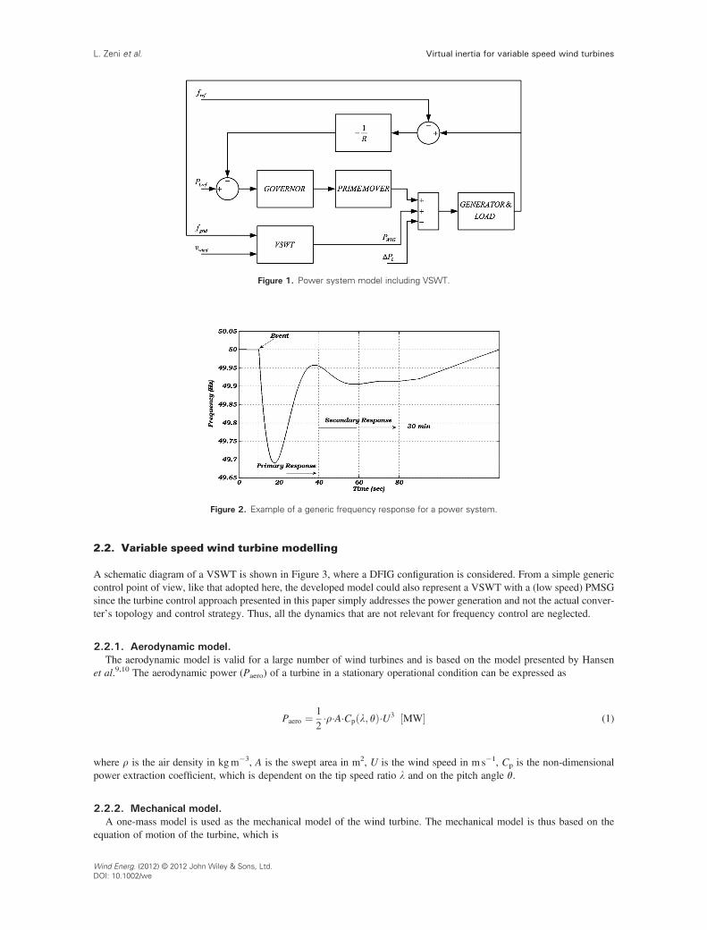
Figure 2. Example of a generic frequency response for a power system.
Figure 1. Power system model including VSWT.
Virtual inertia for variable speed wind turbinesL. Zeni et al.
2.2. Variable speed wind turbine modelling
A schematic diagram of a VSWT is shown in Figure 3, where a DFIG configuration is considered. From a simple genericcontrol point of view, like that adopted here, the developed model could also represent a VSWT with a (low speed) PMSGsince the turbine control approach presented in this paper simply addresses the power generation and not the actual conver-ter’s topology and control strategy. Thus, all the dynamics that are not relevant for frequency control are neglected.
2.2.1. Aerodynamic model.The aerodynamic model is valid for a large number of wind turbines and is based on the model presented by Hansen
et al.9,10 The aerodynamic power (Paero) of a turbine in a stationary operational condition can be expressed as
Paero ¼ 12�r�A�Cp l; θð Þ�U3 MW½ � (1)
where r is the air density in kgm�3, A is the swept area in m2, U is the wind speed in m s�1, Cp is the non-dimensionalpower extraction coefficient, which is dependent on the tip speed ratio l and on the pitch angle θ.
2.2.2. Mechanical model.A one-mass model is used as the mechanical model of the wind turbine. The mechanical model is thus based on the
equation of motion of the turbine, which is
Wind Energ. (2012) © 2012 John Wiley & Sons, Ltd.DOI: 10.1002/we
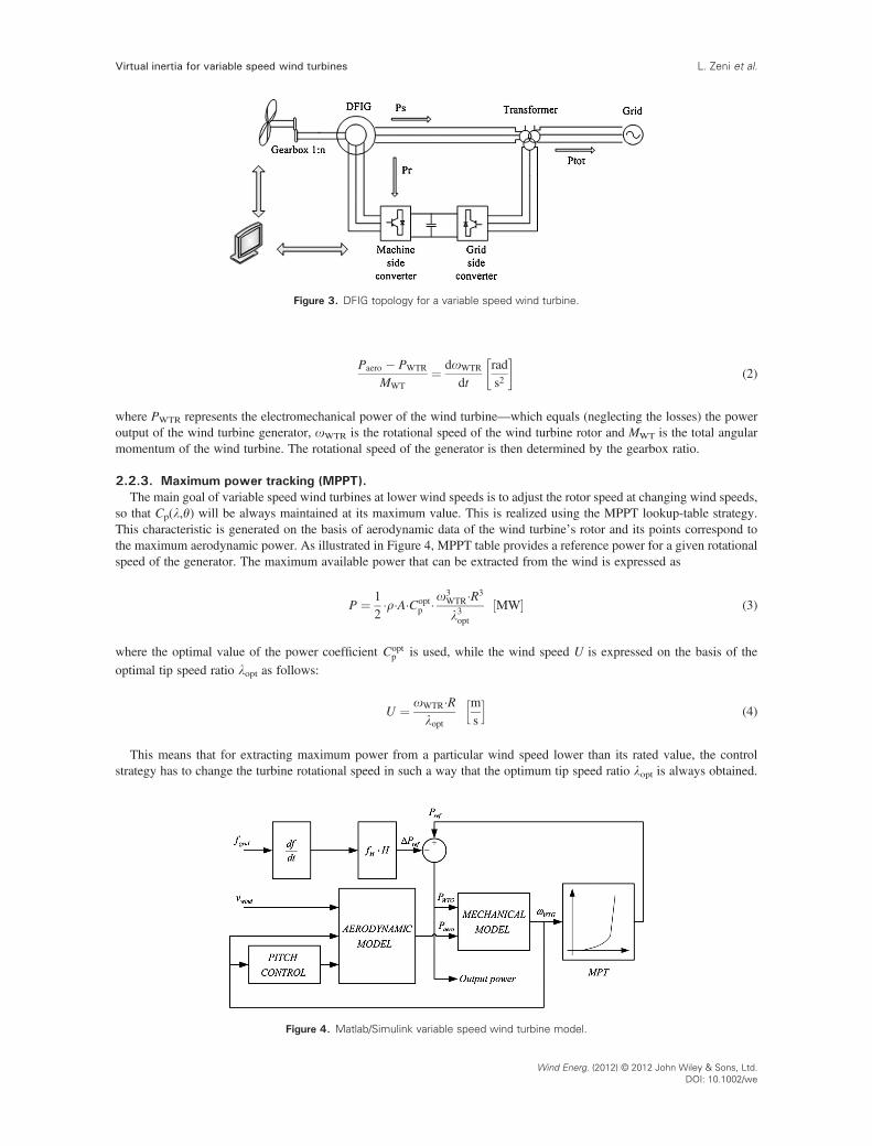
Figure 3. DFIG topology for a variable speed wind turbine.
Virtual inertia for variable speed wind turbines L. Zeni et al.
Paero � PWTR
MWT¼ doWTR
dtrads2
� �(2)
where PWTR represents the electromechanical power of the wind turbine—which equals (neglecting the losses) the poweroutput of the wind turbine generator, oWTR is the rotational speed of the wind turbine rotor and MWT is the total angularmomentum of the wind turbine. The rotational speed of the generator is then determined by the gearbox ratio.
2.2.3. Maximum power tracking (MPPT).The main goal of variable speed wind turbines at lower wind speeds is to adjust the rotor speed at changing wind speeds,
so that Cp(l,θ) will be always maintained at its maximum value. This is realized using the MPPT lookup-table strategy.This characteristic is generated on the basis of aerodynamic data of the wind turbine’s rotor and its points correspond tothe maximum aerodynamic power. As illustrated in Figure 4, MPPT table provides a reference power for a given rotationalspeed of the generator. The maximum available power that can be extracted from the wind is expressed as
P ¼ 12�r�A�Copt
p �o3WTR�R3
l3optMW½ � (3)
where the optimal value of the power coefficient Coptp is used, while the wind speed U is expressed on the basis of the
optimal tip speed ratio lopt as follows:
U ¼ oWTR�Rlopt
ms
h i(4)
This means that for extracting maximum power from a particular wind speed lower than its rated value, the controlstrategy has to change the turbine rotational speed in such a way that the optimum tip speed ratio lopt is always obtained.
Figure 4. Matlab/Simulink variable speed wind turbine model.
Wind Energ. (2012) © 2012 John Wiley & Sons, Ltd.DOI: 10.1002/we
Virtual inertia for variable speed wind turbinesL. Zeni et al.
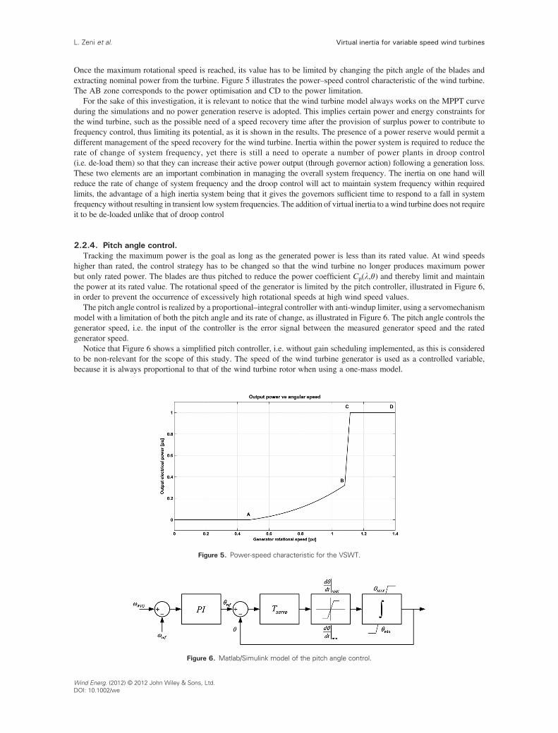
Once the maximum rotational speed is reached, its value has to be limited by changing the pitch angle of the blades andextracting nominal power from the turbine. Figure 5 illustrates the power–speed control characteristic of the wind turbine.The AB zone corresponds to the power optimisation and CD to the power limitation.
For the sake of this investigation, it is relevant to notice that the wind turbine model always works on the MPPT curveduring the simulations and no power generation reserve is adopted. This implies certain power and energy constraints forthe wind turbine, such as the possible need of a speed recovery time after the provision of surplus power to contribute tofrequency control, thus limiting its potential, as it is shown in the results. The presence of a power reserve would permit adifferent management of the speed recovery for the wind turbine. Inertia within the power system is required to reduce therate of change of system frequency, yet there is still a need to operate a number of power plants in droop control(i.e. de-load them) so that they can increase their active power output (through governor action) following a generation loss.These two elements are an important combination in managing the overall system frequency. The inertia on one hand willreduce the rate of change of system frequency and the droop control will act to maintain system frequency within requiredlimits, the advantage of a high inertia system being that it gives the governors sufficient time to respond to a fall in systemfrequency without resulting in transient low system frequencies. The addition of virtual inertia to a wind turbine does not requireit to be de-loaded unlike that of droop control
2.2.4. Pitch angle control.Tracking the maximum power is the goal as long as the generated power is less than its rated value. At wind speeds
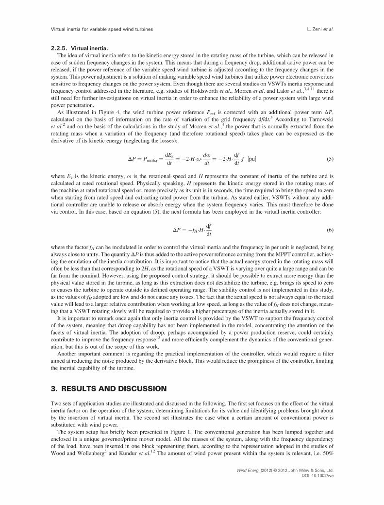
higher than rated, the control strategy has to be changed so that the wind turbine no longer produces maximum powerbut only rated power. The blades are thus pitched to reduce the power coefficient Cp(l,θ) and thereby limit and maintainthe power at its rated value. The rotational speed of the generator is limited by the pitch controller, illustrated in Figure 6,in order to prevent the occurrence of excessively high rotational speeds at high wind speed values.
The pitch angle control is realized by a proportional–integral controller with anti-windup limiter, using a servomechanismmodel with a limitation of both the pitch angle and its rate of change, as illustrated in Figure 6. The pitch angle controls thegenerator speed, i.e. the input of the controller is the error signal between the measured generator speed and the ratedgenerator speed.
Notice that Figure 6 shows a simplified pitch controller, i.e. without gain scheduling implemented, as this is consideredto be non-relevant for the scope of this study. The speed of the wind turbine generator is used as a controlled variable,because it is always proportional to that of the wind turbine rotor when using a one-mass model.
Figure 5. Power-speed characteristic for the VSWT.
Figure 6. Matlab/Simulink model of the pitch angle control.
Wind Energ. (2012) © 2012 John Wiley & Sons, Ltd.DOI: 10.1002/we
Virtual inertia for variable speed wind turbines L. Zeni et al.
2.2.5. Virtual inertia.The idea of virtual inertia refers to the kinetic energy stored in the rotating mass of the turbine, which can be released in
case of sudden frequency changes in the system. This means that during a frequency drop, additional active power can bereleased, if the power reference of the variable speed wind turbine is adjusted according to the frequency changes in thesystem. This power adjustment is a solution of making variable speed wind turbines that utilize power electronic converterssensitive to frequency changes on the power system. Even though there are several studies on VSWTs inertia response andfrequency control addressed in the literature, e.g. studies of Holdsworth et al., Morren et al. and Lalor et al.,3,4,11 there isstill need for further investigations on virtual inertia in order to enhance the reliability of a power system with large windpower penetration.
As illustrated in Figure 4, the wind turbine power reference Pref is corrected with an additional power term ΔP,calculated on the basis of information on the rate of variation of the grid frequency df/dt.3 According to Tarnowskiet al.2 and on the basis of the calculations in the study of Morren et al.,4 the power that is normally extracted from therotating mass when a variation of the frequency (and therefore rotational speed) takes place can be expressed as thederivative of its kinetic energy (neglecting the losses):
ΔP ¼ Pinertia ¼ dEk
dt¼ �2�H�o� do
dt¼ �2�H� df
dt�f pu½ � (5)
where Ek is the kinetic energy, o is the rotational speed and H represents the constant of inertia of the turbine and iscalculated at rated rotational speed. Physically speaking, H represents the kinetic energy stored in the rotating mass ofthe machine at rated rotational speed or, more precisely as its unit is in seconds, the time required to bring the speed to zerowhen starting from rated speed and extracting rated power from the turbine. As stated earlier, VSWTs without any addi-tional controller are unable to release or absorb energy when the system frequency varies. This must therefore be donevia control. In this case, based on equation (5), the next formula has been employed in the virtual inertia controller:
ΔP ¼ �fH �H� dfdt
(6)
where the factor fH can be modulated in order to control the virtual inertia and the frequency in per unit is neglected, beingalways close to unity. The quantityΔP is thus added to the active power reference coming from theMPPT controller, achiev-ing the emulation of the inertia contribution. It is important to notice that the actual energy stored in the rotating mass willoften be less than that corresponding to 2H, as the rotational speed of a VSWT is varying over quite a large range and can befar from the nominal. However, using the proposed control strategy, it should be possible to extract more energy than thephysical value stored in the turbine, as long as this extraction does not destabilize the turbine, e.g. brings its speed to zeroor causes the turbine to operate outside its defined operating range. The stability control is not implemented in this study,as the values of fH adopted are low and do not cause any issues. The fact that the actual speed is not always equal to the ratedvalue will lead to a larger relative contribution when working at low speed, as long as the value of fH does not change, mean-ing that a VSWT rotating slowly will be required to provide a higher percentage of the inertia actually stored in it.
It is important to remark once again that only inertia control is provided by the VSWT to support the frequency controlof the system, meaning that droop capability has not been implemented in the model, concentrating the attention on thefacets of virtual inertia. The adoption of droop, perhaps accompanied by a power production reserve, could certainlycontribute to improve the frequency response13 and more efficiently complement the dynamics of the conventional gener-ation, but this is out of the scope of this work.
Another important comment is regarding the practical implementation of the controller, which would require a filteraimed at reducing the noise produced by the derivative block. This would reduce the promptness of the controller, limitingthe inertial capability of the turbine.
3. RESULTS AND DISCUSSION
Two sets of application studies are illustrated and discussed in the following. The first set focuses on the effect of the virtualinertia factor on the operation of the system, determining limitations for its value and identifying problems brought aboutby the insertion of virtual inertia. The second set illustrates the case when a certain amount of conventional power issubstituted with wind power.
The system setup has briefly been presented in Figure 1. The conventional generation has been lumped together andenclosed in a unique governor/prime mover model. All the masses of the system, along with the frequency dependencyof the load, have been inserted in one block representing them, according to the representation adopted in the studies ofWood and Wollenberg5 and Kundur et al.12 The amount of wind power present within the system is relevant, i.e. 50%
Wind Energ. (2012) © 2012 John Wiley & Sons, Ltd.DOI: 10.1002/we

Virtual inertia for variable speed wind turbinesL. Zeni et al.
of the total generation, in order to analyse a very stressful situation. Only variable speed wind turbines are employed andlumped together in one block. The loss of 25% of the conventional generation is then simulated, at first when simply having50% wind power penetration without turning any conventional plant off, and finally substituting 50% of the conventionalgeneration with the power coming from the wind.
3.1. Analysing the effect of different values of virtual inertia
In this case the effect of different values of virtual inertia in a system with high penetration of wind power is investigated.The angular momentum of the conventional units is set to its default value, meaning that, despite having 50% of generationcoming from the wind, all the other power plants remain online. A loss of 25% of the conventional power generation isassumed to occur at the time t= 10 s. This is a severe situation considering that the power generated from the wind accountsfor a 50% share of the total production.
Three different values of virtual inertia factor fH are considered in the investigation: 0, 5 and 10 that correspond to insert-ing 0 (no virtual inertia), 2.5 and 5 times the actual rated inertia of the wind turbine, respectively. For example if a windturbine has a natural inertia of 3.5 MWs/MVA, a factor of fH would equate 2.5� 3.5 = 8.75 MWs/MVA.
In order to investigate the effect of inertia in different wind turbine operational conditions, three values of the wind speedare considered, i.e. 8, 12 and 16m s�1. Figures 7–9 illustrate the effect of the virtual inertia factor during the conventionalpower generation loss. The grid frequency [Hz], the wind power production [per unit] and the wind turbines’ rotor speed[per unit] are illustrated for the situations of low, medium and high wind speed, respectively. The per-unit quantities ofwind power and rotational speed refer to the rated wind power production and the nominal grid frequency, respectively.
Figure 7. Influence of different values of the virtual inertia factor at wind speed 8ms�1—(a) fH=0, (b) fH=5 and (c) fH=10.
Figure 8. Influence of different values of the virtual inertia factor at wind speed 12ms�1—(a) fH=0, (b) fH=5 and (c) fH=10.
Wind Energ. (2012) © 2012 John Wiley & Sons, Ltd.DOI: 10.1002/we
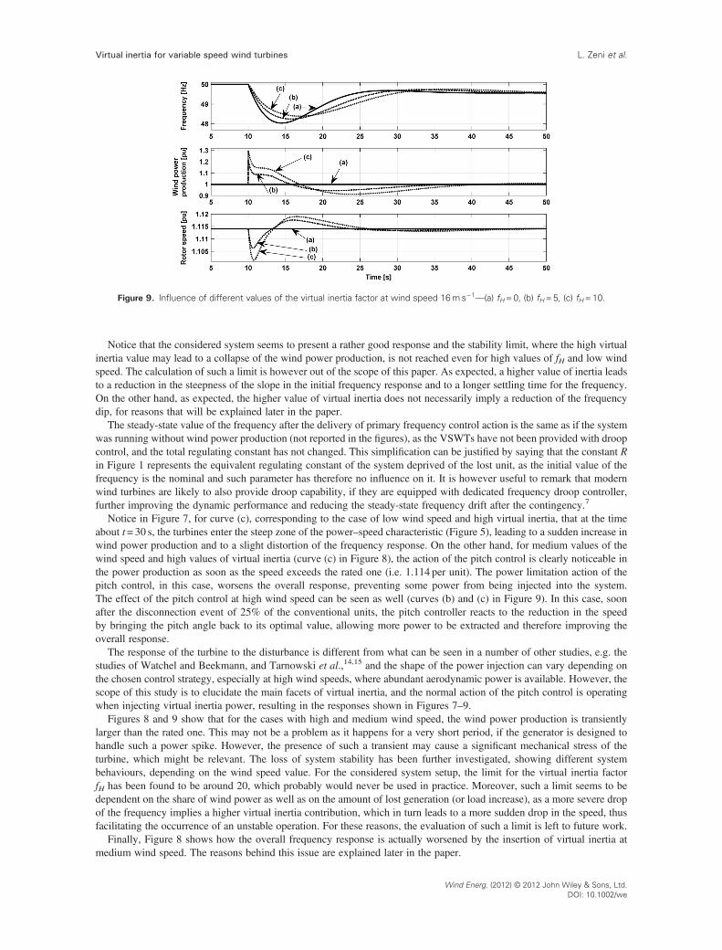
Figure 9. Influence of different values of the virtual inertia factor at wind speed 16ms�1—(a) fH=0, (b) fH=5, (c) fH=10.
Virtual inertia for variable speed wind turbines L. Zeni et al.
Notice that the considered system seems to present a rather good response and the stability limit, where the high virtualinertia value may lead to a collapse of the wind power production, is not reached even for high values of fH and low windspeed. The calculation of such a limit is however out of the scope of this paper. As expected, a higher value of inertia leadsto a reduction in the steepness of the slope in the initial frequency response and to a longer settling time for the frequency.On the other hand, as expected, the higher value of virtual inertia does not necessarily imply a reduction of the frequencydip, for reasons that will be explained later in the paper.
The steady-state value of the frequency after the delivery of primary frequency control action is the same as if the systemwas running without wind power production (not reported in the figures), as the VSWTs have not been provided with droopcontrol, and the total regulating constant has not changed. This simplification can be justified by saying that the constant Rin Figure 1 represents the equivalent regulating constant of the system deprived of the lost unit, as the initial value of thefrequency is the nominal and such parameter has therefore no influence on it. It is however useful to remark that modernwind turbines are likely to also provide droop capability, if they are equipped with dedicated frequency droop controller,further improving the dynamic performance and reducing the steady-state frequency drift after the contingency.7
Notice in Figure 7, for curve (c), corresponding to the case of low wind speed and high virtual inertia, that at the timeabout t= 30 s, the turbines enter the steep zone of the power–speed characteristic (Figure 5), leading to a sudden increase inwind power production and to a slight distortion of the frequency response. On the other hand, for medium values of thewind speed and high values of virtual inertia (curve (c) in Figure 8), the action of the pitch control is clearly noticeable inthe power production as soon as the speed exceeds the rated one (i.e. 1.114 per unit). The power limitation action of thepitch control, in this case, worsens the overall response, preventing some power from being injected into the system.The effect of the pitch control at high wind speed can be seen as well (curves (b) and (c) in Figure 9). In this case, soonafter the disconnection event of 25% of the conventional units, the pitch controller reacts to the reduction in the speedby bringing the pitch angle back to its optimal value, allowing more power to be extracted and therefore improving theoverall response.
The response of the turbine to the disturbance is different from what can be seen in a number of other studies, e.g. thestudies of Watchel and Beekmann, and Tarnowski et al.,14,15 and the shape of the power injection can vary depending onthe chosen control strategy, especially at high wind speeds, where abundant aerodynamic power is available. However, thescope of this study is to elucidate the main facets of virtual inertia, and the normal action of the pitch control is operatingwhen injecting virtual inertia power, resulting in the responses shown in Figures 7–9.
Figures 8 and 9 show that for the cases with high and medium wind speed, the wind power production is transientlylarger than the rated one. This may not be a problem as it happens for a very short period, if the generator is designed tohandle such a power spike. However, the presence of such a transient may cause a significant mechanical stress of theturbine, which might be relevant. The loss of system stability has been further investigated, showing different systembehaviours, depending on the wind speed value. For the considered system setup, the limit for the virtual inertia factorfH has been found to be around 20, which probably would never be used in practice. Moreover, such a limit seems to bedependent on the share of wind power as well as on the amount of lost generation (or load increase), as a more severe dropof the frequency implies a higher virtual inertia contribution, which in turn leads to a more sudden drop in the speed, thusfacilitating the occurrence of an unstable operation. For these reasons, the evaluation of such a limit is left to future work.
Finally, Figure 8 shows how the overall frequency response is actually worsened by the insertion of virtual inertia atmedium wind speed. The reasons behind this issue are explained later in the paper.
Wind Energ. (2012) © 2012 John Wiley & Sons, Ltd.DOI: 10.1002/we

Virtual inertia for variable speed wind turbinesL. Zeni et al.
3.2. Substituting conventional power with wind power
The possibility of substituting a certain amount of conventional power with wind power is investigated in the following.The simulation scenarios are considered the same as in the first simulations set, with the difference that this time, withthe same amount of wind power, a substitution of 50% of conventional power with wind is implemented by reducingthe total angular momentum of the system to half of its rated value. Such angular momentum is to be substituted by thecontribution of virtual inertia.
As indicated in equation (6), during a frequency drop, the turbine is instantaneously supplying an amount of additionalpower into the system, equal to the product between virtual inertia factor fH, the constant of inertia H and the rate of changeof frequency, which can be scaled down by the share of wind power in the system, i.e. SWP. This quantity represents a‘virtual angular momentum’ that should substitute the angular momentum which the system has been deprived of.Recalling equation (6), the supplementary power contribution due to virtual inertia should exactly equal the contributionthat would be given by 50% of conventional generation that has now been substituted and is given by the equation ofmotion of the system. Remembering that the system’s frequency is close to rated (f =o = 1 per unit) one can write
12�fH �MWT�SWP� dfdt ¼ M50%� dfdt (7)
MWT is the angular momentum of the wind turbine in per unit (notice that MWT = 2H, when expressing them in per unitand at rated speed), whereas M50% is equal to 50% of the angular momentum of the original power system. Simplifying thederivative term of the frequency, the needed fH can be computed on the basis of the following:
12�fH �MWT�SWP ¼ M50% (8)
With the figures adopted here, a value fH= 4.4 has been found to be required in order to insert the needed quantity ofvirtual inertia. The results are depicted in Figures 10–12, respectively for low (8m s�1), medium (12m s�1) and high(16m s�1) wind speed.
The graphs justify that the calculated value of the virtual inertia factor of 4.4, using expression (8), is correct, since theinitial steepness of the response is the desired one. At medium and high wind speed, a zoom window is necessary to realizethat curves (a) and (c) do actually have the same initial slope, representing the total inertia of the system. Nonetheless,further discussion must be made on the results, as despite the initial steepness is the targeted one, as previously noticed,the overall response turned out to be significantly worse than the response without wind. In the case of medium wind speed,the frequency response is even worse than that with no virtual inertia (look at the magnitude of the dip in Figure 11). Theexplanation stems directly from the shape of the characteristic shown in Figure 5 and from the combined operation of powerand pitch control. At low and medium wind speed, the pitch angle is fixed and the power output is directly read from thepower–speed curve (Figure 5). Thus, a reduction in the rotational speed of the turbine, caused by the extra powerproduction requested for providing the virtual inertia, leads to an immediate decrease in the total wind power production,as the power control acts instantaneously and the pitch control is not active (MPPT). Moreover, a larger power sensitivity(dP/do) is present at medium wind speed (steep linear part of the curve in Figure 5), which further worsens the overall
Figure 10. Substitution of 50% of conventional power production at wind speed 8ms�1—(a) no wind power—base case, (b) 50% of
conventional units substituted with wind power with fH=0 and (c) 50% of conventional units substituted with wind power with fH=4.4.
Wind Energ. (2012) © 2012 John Wiley & Sons, Ltd.DOI: 10.1002/we

Figure 11. Substitution of 50% of conventional power production at wind speed 12ms�1—(a) no wind power, (b) 50% of conven-
tional units substituted with wind power with fH=0 and (c) 50% of conventional units substituted with wind power with fH=4.4.
Figure 12. Substitution of 50% of conventional power production at wind speed 16ms�1—(a) no wind power, (b) 50% of conven-
tional units substituted with wind power with fH=0 and (c) 50% of conventional units substituted with wind power with fH=4.4.
Virtual inertia for variable speed wind turbines L. Zeni et al.
response for that range of speeds. The response proved to be worse also for high wind speeds, since the pitch control actionis in this case not fast and large enough, because the situation is more severe than that which Figure 9 refers to, being due tothe lower angular momentum. However, the response improves as the wind speed increases, and for higher values theperformance of the system is very similar to that obtained without wind power.
A better understanding of these issues can be obtained by looking at Figure 13 that shows the extra wind power produc-tion at the three different wind speed levels, for the same value of fH= 4.4, the same power unbalance and the same value ofthe system’s angular momentum and droop constant. The area between the curves and the level 0 per unit represents theextra energy provided by the wind turbine. The difference among the three cases is evident. It is also worth noting that,from a primary response point of view, the contribution given soon after the event is more important than that given later.Thus, even though the net contribution is roughly the same for the three cases, it is clear how at 8m s�1 more energy isinitially injected into the grid compared with the other two cases.
The emergence of these issues makes it necessary to further improve the functionality of the virtual inertia controller inorder to reach a better overall response. However, it is important to state that the concept of virtual inertia refers just to theinitial part of the primary response. Under this point of view, the formula for its implementation has proven to be valid.Nevertheless, the desired inertia response comes at the expense of a possible reduction of the overall primary controlperformance. Other strategies can be chosen to overcome this problem, such as those suggested in the studies of Laloret al. and Ullah et al.11,16 Here, a different approach has been analysed, which consists of providing a frequency controlcontribution that still makes use of equation (6), but also bypasses the power control in the case of a sudden event. Theblock diagram of this simple solution is shown in Figure 14.
As stated, in normal operation, the MPPT control is working, although it is bypassed if a virtual inertia contribution isneeded, by activating the block fixed point + virtual inertia in Figure 14. The MPPT is then reactivated if the rotationalspeed drops under a certain level, whose value depends on the wind speed. It is important to notice that, when the need
Wind Energ. (2012) © 2012 John Wiley & Sons, Ltd.DOI: 10.1002/we
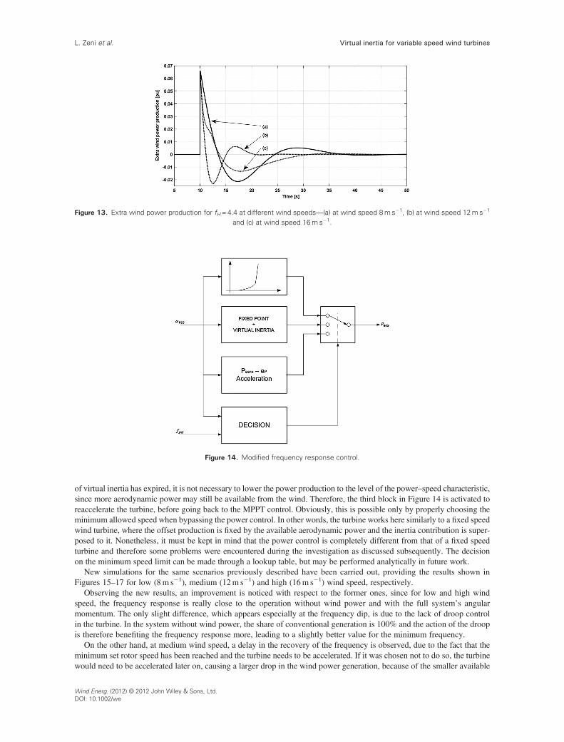
Figure 13. Extra wind power production for fH=4.4 at different wind speeds—(a) at wind speed 8ms�1, (b) at wind speed 12ms�1
and (c) at wind speed 16ms�1.
Figure 14. Modified frequency response control.
Virtual inertia for variable speed wind turbinesL. Zeni et al.
of virtual inertia has expired, it is not necessary to lower the power production to the level of the power–speed characteristic,since more aerodynamic power may still be available from the wind. Therefore, the third block in Figure 14 is activated toreaccelerate the turbine, before going back to the MPPT control. Obviously, this is possible only by properly choosing theminimum allowed speed when bypassing the power control. In other words, the turbine works here similarly to a fixed speedwind turbine, where the offset production is fixed by the available aerodynamic power and the inertia contribution is super-posed to it. Nonetheless, it must be kept in mind that the power control is completely different from that of a fixed speedturbine and therefore some problems were encountered during the investigation as discussed subsequently. The decisionon the minimum speed limit can be made through a lookup table, but may be performed analytically in future work.
New simulations for the same scenarios previously described have been carried out, providing the results shown inFigures 15–17 for low (8m s�1), medium (12m s�1) and high (16m s�1) wind speed, respectively.
Observing the new results, an improvement is noticed with respect to the former ones, since for low and high windspeed, the frequency response is really close to the operation without wind power and with the full system’s angularmomentum. The only slight difference, which appears especially at the frequency dip, is due to the lack of droop controlin the turbine. In the system without wind power, the share of conventional generation is 100% and the action of the droopis therefore benefiting the frequency response more, leading to a slightly better value for the minimum frequency.
On the other hand, at medium wind speed, a delay in the recovery of the frequency is observed, due to the fact that theminimum set rotor speed has been reached and the turbine needs to be accelerated. If it was chosen not to do so, the turbinewould need to be accelerated later on, causing a larger drop in the wind power generation, because of the smaller available
Wind Energ. (2012) © 2012 John Wiley & Sons, Ltd.DOI: 10.1002/we

Figure 15. Substitution of 50% of conventional power production at wind speed 8ms�1 with enhanced controller—(a) no windpower—solid line, (b) 50% of wind power with fH=0—long-dashed line and (c) 50% of wind power with fH=4.4—short-dashed line;
curves (a) and (c) are superposed.
Figure 16. Substitution of 50% of conventional power production at wind speed 12ms�1 with enhanced controller—(a) no windpower—solid line, (b) 50% of wind power with fH=0—long-dashed line and (c) 50% of wind power with fH=4.4—short-dashed line.
Figure 17. Substitution of 50% of conventional power production at wind speed 16ms�1 with enhanced controller—(a) no windpower—solid line, (b) 50% of wind power with fH=0—long-dashed line and (c) 50% of wind power with fH=4.4—short-dashed line;
curves (a) and (c) are nearly superposed.
Virtual inertia for variable speed wind turbines L. Zeni et al.
Wind Energ. (2012) © 2012 John Wiley & Sons, Ltd.DOI: 10.1002/we
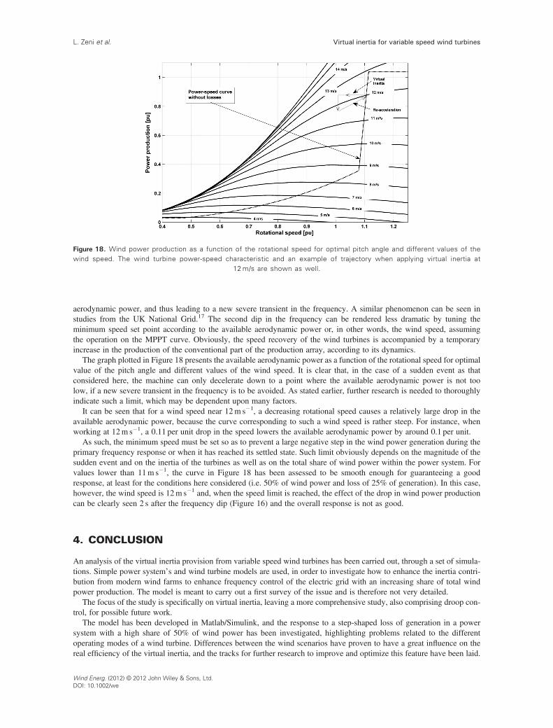
Figure 18. Wind power production as a function of the rotational speed for optimal pitch angle and different values of thewind speed. The wind turbine power-speed characteristic and an example of trajectory when applying virtual inertia at
12m/s are shown as well.
Virtual inertia for variable speed wind turbinesL. Zeni et al.
aerodynamic power, and thus leading to a new severe transient in the frequency. A similar phenomenon can be seen instudies from the UK National Grid.17 The second dip in the frequency can be rendered less dramatic by tuning theminimum speed set point according to the available aerodynamic power or, in other words, the wind speed, assumingthe operation on the MPPT curve. Obviously, the speed recovery of the wind turbines is accompanied by a temporaryincrease in the production of the conventional part of the production array, according to its dynamics.
The graph plotted in Figure 18 presents the available aerodynamic power as a function of the rotational speed for optimalvalue of the pitch angle and different values of the wind speed. It is clear that, in the case of a sudden event as thatconsidered here, the machine can only decelerate down to a point where the available aerodynamic power is not toolow, if a new severe transient in the frequency is to be avoided. As stated earlier, further research is needed to thoroughlyindicate such a limit, which may be dependent upon many factors.
It can be seen that for a wind speed near 12m s�1, a decreasing rotational speed causes a relatively large drop in theavailable aerodynamic power, because the curve corresponding to such a wind speed is rather steep. For instance, whenworking at 12m s�1, a 0.11 per unit drop in the speed lowers the available aerodynamic power by around 0.1 per unit.
As such, the minimum speed must be set so as to prevent a large negative step in the wind power generation during theprimary frequency response or when it has reached its settled state. Such limit obviously depends on the magnitude of thesudden event and on the inertia of the turbines as well as on the total share of wind power within the power system. Forvalues lower than 11m s�1, the curve in Figure 18 has been assessed to be smooth enough for guaranteeing a goodresponse, at least for the conditions here considered (i.e. 50% of wind power and loss of 25% of generation). In this case,however, the wind speed is 12m s�1 and, when the speed limit is reached, the effect of the drop in wind power productioncan be clearly seen 2 s after the frequency dip (Figure 16) and the overall response is not as good.
4. CONCLUSION
An analysis of the virtual inertia provision from variable speed wind turbines has been carried out, through a set of simula-tions. Simple power system’s and wind turbine models are used, in order to investigate how to enhance the inertia contri-bution from modern wind farms to enhance frequency control of the electric grid with an increasing share of total windpower production. The model is meant to carry out a first survey of the issue and is therefore not very detailed.
The focus of the study is specifically on virtual inertia, leaving a more comprehensive study, also comprising droop con-trol, for possible future work.
The model has been developed in Matlab/Simulink, and the response to a step-shaped loss of generation in a powersystem with a high share of 50% of wind power has been investigated, highlighting problems related to the differentoperating modes of a wind turbine. Differences between the wind scenarios have proven to have a great influence on thereal efficiency of the virtual inertia, and the tracks for further research to improve and optimize this feature have been laid.
Wind Energ. (2012) © 2012 John Wiley & Sons, Ltd.DOI: 10.1002/we

Virtual inertia for variable speed wind turbines L. Zeni et al.
The basic hypotheses under which the investigation is carried out are the operation of the VSWT on the MPPT curve aswell as the absence of any droop controller on the wind generators. The main theoretical aspects regarding virtual inertiaare analysed as a consequence of the issues that were encountered during the investigation. On the basis of such analysis,a possible simple solution has been presented as an example, showing the improvements that a more sophisticated controlcould bring about. The principal aspects to be accounted for are the power and energy constraints of the wind turbines,along with the power and pitch control strategy.
Even more sophisticated control strategies, as those adopted by manufacturers, are more comprehensive than that shownhere, and differences may be found also in the power and pitch control. Nevertheless, such approach permits a quitedetailed exploration of the theoretical facets of virtual inertia capability, highlighting the causes of the issues and thussuggesting the track for their solution.
Furthermore, the simple adoption of a virtual inertia factor is certainly not sufficient to provide a thorough and satisfyingcontribution to the primary frequency control. The insertion of a droop controller, if accompanied by a certain amount ofgeneration reserve, which could support the controllers of the conventional power plants, would surely be beneficial, andhas already been put in place by some manufacturers. Such a general perspective is however out of the scope of this study,as it focuses more on particular theoretical aspects related to inertia provision and on possible solutions rather than emulat-ing the behaviour of conventional power plants.
It has been demonstrated that variable speed wind turbines are able to help the power system carry out the primaryfrequency control in the very first instance following a disturbance. Using a proper control strategy, it is possible to exploitall the inertia of the wind turbines and, for some time, even more than what would be given by the machine directly coupledto the grid. This means that the VSWT’s potential for contributing to frequency control is even larger than that of a fixedspeed wind turbine. Furthermore, the possibility of substituting conventional power with wind power has been analysed,leading to the conclusion that an improved control strategy can be employed to implement such a target. However, therange of wind speeds near the limit between the power and speed limitation zone proved to be quite critical and requiresfurther development of the control strategy. The theoretical reasons behind such a problem have however been highlighted.More work is needed to estimate the actual range of critical wind speeds and to assess the limitations of the controller basedon power system’s and specific turbine’s characteristics.
A simple relation to calculate the gain for the virtual inertia block needed to substitute a certain share of conventionalgeneration emulating its behaviour has been found and successfully tested, thus suggesting a possible way to approximatelytune the factor in real systems.
The described investigations have been realized in the first place using a rather simple model developed in Matlab/Simulink. Further research, as a natural next step in the investigation, might be directed towards a validation of theachievements presented in this paper by means of a more detailed model and by making use of more specific tools.Usage of a more detailed model would also allow for the development of a more sophisticated control strategy. How-ever, the general lines of the issue are pointed out here, giving useful indications for future work.
ACKNOWLEDGEMENT
The authors would like to acknowledge the support received from the Integrated Project ‘UpWind’, which partially fundedthe work, supported by the EU Sixth Framework Program, grant no. 019945.
APPENDIX
The parameters of the power system’s model (Figure 1) are the following:
• Governor time constant TG = 0.1 s• Prime mover time constant TPM = 30 s• Angular momentum M= 16 per unit• Damping factor D= 4 per unit• Droop factor R= 4%
REFERENCES
1. Tsili M, Papathanassiou S. A review of grid code technical requirements for wind farms. IET Renewable PowerGeneration 2009; 3: 308–332.
2. Tarnowski GC, Kjaer PC, Sørensen P, �stergaard J. Study on variable speed wind turbines capability for frequencyresponse. In European Wind Energy Conference EWEC 2009, Marseille, 2009; 16–19.
Wind Energ. (2012) © 2012 John Wiley & Sons, Ltd.DOI: 10.1002/we

Virtual inertia for variable speed wind turbinesL. Zeni et al.
3. Holdsworth L, Ekanayake JB, Jenkins N. Power system frequency response from fixed speed and doubly fed inductiongenerator-based wind turbines. Wind Energy 2004; 7: 21–35. DOI: 10.1002/we.105.
4. Morren J, de Haan SWH, Kling WL, Ferreira JA. Inertial response of variable speed wind turbines. Electric PowerSystems Research 2006; 76: 980–987. DOI: 10.1016/j.epsr.2005.12.002
5. Wood AJ, Wollenberg BF. Power Generation, Operation and Control. John Wiley and Sons: New York, 1996.6. Akhmatov V. Induction Generators for Wind Power. Multi-Science: Brentwood (UK), 2005.7. Margaris ID, Hansen AD, Sørensen P, Hatziargyriou ND. Investigating power control in autonomous power systems
with increasing wind power penetration. In 8th International Workshop on Large-Scale Integration of Wind Power intoPower Systems as well as on Transmission Networks for Offshore Wind Farms, Bremen, Germany, October 2009.
8. Nordel. Nordic Grid Code 2007 (Nordic Collection of Rules). Nordic TSOs: Oslo, 2007.9. Hansen MH, Hansen A, Larsen TJ,�ye S, Sørensen P, Fuglsang P. Control design for a pitch-regulated, variable speed
wind turbine. Risø R–Report 1500.10. Sørensen P, Hansen AD, Iov F, Blaabjerg F, Donovan MH. Wind farm models and control strategies. Risø R–Report
1464.11. Lalor G, Mullane A, O’Malley M. Frequency control and wind turbine technologies. IEEE Transactions on Power
Systems 2005; 20: 1905–1913.12. Kundur P, Balu NJ, Lauby MG. Power System Stability and Control. McGraw-Hill Professional: New York, 1994.13. Margaris ID, Hansen AD, Sørensen P, Hatziargyriou ND. Illustration of modern wind turbine ancillary services.
Energies 2010; 3: 1290–1302. DOI: 10.3390/en3061290.14. Watchel S, Beekmann A. Contribution of wind energy converters with inertia emulation to frequency control and
frequency stability in power systems. In 8th International Workshop on Large-Scale Integration of Wind Power intoPower Systems as well as Transmission Networks for Offshore Wind Farms, Bremen, 14–15 October 2009.
15. Tarnowski GC, Kjaer PC, Sørensen P, �stergaard J. Variable speed wind turbines capability for temporary over-production. In Power and Energy Society General Meeting, IEEE, 2009; 1–7.
16. Ullah NR, Thiringer T, Karlsson D. Temporary primary frequency control support by variable speed wind turbines—potential and applications. IEEE Transactions on Power Systems 2008; 23: 601–612.
17. http://www.nationalgrid.com/NR/rdonlyres/581E3571-4FA9-401F-B970-9467A2C0B498/43234/SimulatedInertiaPresentation100910.pdf [Accessed 13 April 2011].
Wind Energ. (2012) © 2012 John Wiley & Sons, Ltd.DOI: 10.1002/we
Related Documents


