3314 IEEE TRANSACTIONS ON INDUSTRIAL ELECTRONICS, VOL. 56, NO. 9, SEPTEMBER 2009 High-Order Sliding-Mode Control of Variable-Speed Wind Turbines Brice Beltran, Tarek Ahmed-Ali, and Mohamed El Hachemi Benbouzid, Senior Member, IEEE Abstract—This paper deals with the power generation control in variable-speed wind turbines. These systems have two oper- ation regions which depend on wind turbine tip speed ratio. A high-order sliding-mode control strategy is then proposed to ensure stability in both operation regions and to impose the ideal feedback control solution in spite of model uncertainties. This control strategy presents attractive features such as robustness to parametric uncertainties of the turbine. The proposed sliding- mode control approach has been validated on a 1.5-MW three- blade wind turbine using the National Renewable Energy Laboratory wind turbine simulator FAST (Fatigue, Aerodynam- ics, Structures, and Turbulence) code. Validation results show that the proposed control strategy is effective in terms of power regulation. Moreover, the sliding-mode approach is arranged so as to produce no chattering in the generated torque that could lead to increased mechanical stress because of strong torque variations. Index Terms—High-order sliding mode, power generation control, wind turbine. NOMENCLATURE v Wind speed (in meters per second). ρ Air density (in kilograms per cubic meter). R Rotor radius (in meters). P a Aerodynamic power (in watts). T a Aerodynamic torque (in newton–meters). λ Tip speed ratio. C p (λ) Power coefficient. C q (λ) Torque coefficient. ω r Rotor speed (in radians per seconds). ω g Generator speed (in radians per seconds). T g Generator electromagnetic torque (in newton–meters). T ls Low-speed torque (in newton–meters). T hs High-speed torque (in newton–meters). K g Generator external damping (in newton–meters per radian–second). K r Rotor external damping (in newton–meters per radian–second). J r Rotor inertia (in kilogram–square meter). J g Generator inertia (in kilogram–square meter). J t Turbine total inertia (in kilogram–square meter). K t Turbine total external damping (in newton–meters per radian–second). Manuscript received January 13, 2008; revised September 4, 2008. First published October 31, 2008; current version published August 12, 2009. The authors are with the Laboratoire Brestois de Mécanique et des Systèmes, University of Brest, 29238 Brest Cedex 03, France (e-mail: brice.beltran@dga. defense.gouv.fr; [email protected]). Color versions of one or more of the figures in this paper are available online at http://ieeexplore.ieee.org. Digital Object Identifier 10.1109/TIE.2008.2006949 B r Rotor external stiffness (in newton–meters per radian–second). B g Generator external stiffness (in newton–meters per radian–second). B t Turbine total external stiffness (in newton–meters per radian–second). I. I NTRODUCTION W IND ENERGY conversion is the fastest growing energy source among the new power generation sources in the world, and this trend should endure for some time. At the end of 2006, the total U.S. wind energy capacity had grown to 11 603 MW or enough to provide the electrical energy needs of more than 2.9 million American homes. Wind capacity in the United States and in Europe has grown at a rate of 20%–30% per year over the past decade (Fig. 1). Despite this rapid growth, wind currently provides less than 1% of total electricity consumption in the United States. The vision of the wind industry in the United States and in Europe is to increase wind fraction of the electrical energy mix to more than 20% within the next two decades [1]. Harnessing wind energy for electric power generation is an area of research interest, and nowadays, the emphasis is given to the cost-effective utilization of this energy aiming at quality and reliability in the electricity delivery [2]. During the last two decades, wind turbine sizes have been developed from 20 kW to 2 MW, while even larger wind turbines are being designed. Moreover, a lot of different concepts have been developed and tested [3]. In fact, variable-speed wind turbines (VSWTs) are continu- ously increasing their market share, since it is possible to track the changes in wind speed by adapting shaft speed and thus maintaining optimal power generation. The more VSWTs are investigated, the more it becomes obvious that their behavior is significantly affected by the control strategy used. Typically, VSWTs use aerodynamic controls in combination with power electronics to regulate torque, speed, and power. The aerody- namic control systems, usually variable-pitch blades or trailing- edge devices, are expensive and complex, particularly when the turbines are larger. This situation provides a motivation to consider alternative control approaches. The main control objective of VSWT is power efficiency maximization. To reach this goal, the turbine tip speed ratio should be maintained at its optimum value despite wind vari- ations. Nevertheless, control is not always aimed at capturing as much energy as possible. In fact, in above rated wind speed, the captured power needs to be limited. Although there are 0278-0046/$26.00 © 2009 IEEE Authorized licensed use limited to: Mohamed Benbouzid. Downloaded on August 25, 2009 at 08:29 from IEEE Xplore. Restrictions apply.

Welcome message from author
This document is posted to help you gain knowledge. Please leave a comment to let me know what you think about it! Share it to your friends and learn new things together.
Transcript
3314 IEEE TRANSACTIONS ON INDUSTRIAL ELECTRONICS, VOL. 56, NO. 9, SEPTEMBER 2009
High-Order Sliding-Mode Control ofVariable-Speed Wind Turbines
Brice Beltran, Tarek Ahmed-Ali, and Mohamed El Hachemi Benbouzid, Senior Member, IEEE
Abstract—This paper deals with the power generation controlin variable-speed wind turbines. These systems have two oper-ation regions which depend on wind turbine tip speed ratio.A high-order sliding-mode control strategy is then proposed toensure stability in both operation regions and to impose the idealfeedback control solution in spite of model uncertainties. Thiscontrol strategy presents attractive features such as robustnessto parametric uncertainties of the turbine. The proposed sliding-mode control approach has been validated on a 1.5-MW three-blade wind turbine using the National Renewable EnergyLaboratory wind turbine simulator FAST (Fatigue, Aerodynam-ics, Structures, and Turbulence) code. Validation results showthat the proposed control strategy is effective in terms of powerregulation. Moreover, the sliding-mode approach is arranged so asto produce no chattering in the generated torque that could lead toincreased mechanical stress because of strong torque variations.
Index Terms—High-order sliding mode, power generationcontrol, wind turbine.
NOMENCLATURE
v Wind speed (in meters per second).ρ Air density (in kilograms per cubic meter).R Rotor radius (in meters).Pa Aerodynamic power (in watts).Ta Aerodynamic torque (in newton–meters).λ Tip speed ratio.Cp(λ) Power coefficient.Cq(λ) Torque coefficient.ωr Rotor speed (in radians per seconds).ωg Generator speed (in radians per seconds).Tg Generator electromagnetic torque (in newton–meters).Tls Low-speed torque (in newton–meters).Ths High-speed torque (in newton–meters).Kg Generator external damping (in newton–meters per
radian–second).Kr Rotor external damping (in newton–meters per
radian–second).Jr Rotor inertia (in kilogram–square meter).Jg Generator inertia (in kilogram–square meter).Jt Turbine total inertia (in kilogram–square meter).Kt Turbine total external damping (in newton–meters per
radian–second).
Manuscript received January 13, 2008; revised September 4, 2008. Firstpublished October 31, 2008; current version published August 12, 2009.
The authors are with the Laboratoire Brestois de Mécanique et des Systèmes,University of Brest, 29238 Brest Cedex 03, France (e-mail: [email protected]; [email protected]).
Color versions of one or more of the figures in this paper are available onlineat http://ieeexplore.ieee.org.
Digital Object Identifier 10.1109/TIE.2008.2006949
Br Rotor external stiffness (in newton–meters perradian–second).
Bg Generator external stiffness (in newton–meters perradian–second).
Bt Turbine total external stiffness (in newton–meters perradian–second).
I. INTRODUCTION
W IND ENERGY conversion is the fastest growing energysource among the new power generation sources in the
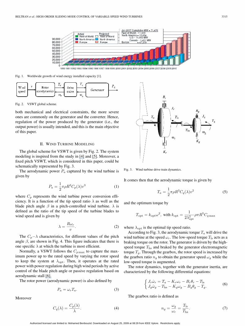
world, and this trend should endure for some time. At the endof 2006, the total U.S. wind energy capacity had grown to11 603 MW or enough to provide the electrical energy needsof more than 2.9 million American homes. Wind capacityin the United States and in Europe has grown at a rate of20%–30% per year over the past decade (Fig. 1). Despite thisrapid growth, wind currently provides less than 1% of totalelectricity consumption in the United States. The vision of thewind industry in the United States and in Europe is to increasewind fraction of the electrical energy mix to more than 20%within the next two decades [1].
Harnessing wind energy for electric power generation is anarea of research interest, and nowadays, the emphasis is givento the cost-effective utilization of this energy aiming at qualityand reliability in the electricity delivery [2]. During the last twodecades, wind turbine sizes have been developed from 20 kWto 2 MW, while even larger wind turbines are being designed.Moreover, a lot of different concepts have been developed andtested [3].
In fact, variable-speed wind turbines (VSWTs) are continu-ously increasing their market share, since it is possible to trackthe changes in wind speed by adapting shaft speed and thusmaintaining optimal power generation. The more VSWTs areinvestigated, the more it becomes obvious that their behavioris significantly affected by the control strategy used. Typically,VSWTs use aerodynamic controls in combination with powerelectronics to regulate torque, speed, and power. The aerody-namic control systems, usually variable-pitch blades or trailing-edge devices, are expensive and complex, particularly whenthe turbines are larger. This situation provides a motivation toconsider alternative control approaches.
The main control objective of VSWT is power efficiencymaximization. To reach this goal, the turbine tip speed ratioshould be maintained at its optimum value despite wind vari-ations. Nevertheless, control is not always aimed at capturingas much energy as possible. In fact, in above rated wind speed,the captured power needs to be limited. Although there are
0278-0046/$26.00 © 2009 IEEE
Authorized licensed use limited to: Mohamed Benbouzid. Downloaded on August 25, 2009 at 08:29 from IEEE Xplore. Restrictions apply.
BELTRAN et al.: HIGH-ORDER SLIDING-MODE CONTROL OF VARIABLE-SPEED WIND TURBINES 3315
Fig. 1. Worldwide growth of wind energy installed capacity [1].
Fig. 2. VSWT global scheme.
both mechanical and electrical constraints, the more severeones are commonly on the generator and the converter. Hence,regulation of the power produced by the generator (i.e., theoutput power) is usually intended, and this is the main objectiveof this paper.
II. WIND TURBINE MODELING
The global scheme for VSWT is given by Fig. 2. The systemmodeling is inspired from the study in [4] and [5]. Moreover, afixed pitch VSWT, which is considered in this paper, could beschematically represented by Fig. 3.
The aerodynamic power Pa captured by the wind turbine isgiven by
Pa =12πρR2Cp(λ)v3 (1)
where Cp represents the wind turbine power conversion effi-ciency. It is a function of the tip speed ratio λ as well as theblade pitch angle β in a pitch-controlled wind turbine. λ isdefined as the ratio of the tip speed of the turbine blades towind speed and is given by
λ =Rωr
v. (2)
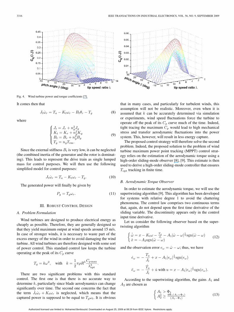
The Cp−λ characteristics, for different values of the pitchangle β, are shown in Fig. 4. This figure indicates that there isone specific λ at which the turbine is most efficient.
Normally, a VSWT follows the Cpmax to capture the max-imum power up to the rated speed by varying the rotor speedto keep the system at λopt. Then, it operates at the ratedpower with power regulation during high wind periods by activecontrol of the blade pitch angle or passive regulation based onaerodynamic stall [6].
The rotor power (aerodynamic power) is also defined by
Pa = ωrTa. (3)
Moreover
Cq(λ) =Cp(λ)
λ. (4)
Fig. 3. Wind turbine drive train dynamics.
It comes then that the aerodynamic torque is given by
Ta =12πρR3Cq(λ)v2 (5)
and the optimum torque by
Topt = koptω2, with kopt =
12λ2
opt
ρπR5Cq max
where λopt is the optimal tip speed ratio.According to Fig. 3, the aerodynamic torque Ta will drive the
wind turbine at the speed ωr. The low-speed torque Tls acts as abraking torque on the rotor. The generator is driven by the high-speed torque Ths and braked by the generator electromagnetictorque Tg . Through the gearbox, the rotor speed is increased bythe gearbox ratio ng to obtain the generator speed ωg while thelow-speed torque is augmented.
The rotor dynamics, together with the generator inertia, arecharacterized by the following differential equations:
{Jrωr = Ta − Krωr − Brθr − Tls
Jgωg − Ths − Kgωg − Bgθg − Tg.(6)
The gearbox ratio is defined as
ng =ωg
ωr=
Tls
Ths. (7)
Authorized licensed use limited to: Mohamed Benbouzid. Downloaded on August 25, 2009 at 08:29 from IEEE Xplore. Restrictions apply.
3316 IEEE TRANSACTIONS ON INDUSTRIAL ELECTRONICS, VOL. 56, NO. 9, SEPTEMBER 2009
Fig. 4. Wind turbine power and torque coefficients [7].
It comes then that
Jtωr = Ta − Ktωr − Btθr − Tg (8)
where ⎧⎪⎪⎨⎪⎪⎩
Jt = Jr + n2gJg
Kt = Kr + n2gKg
Bt = Br + n2gBg
Tg = ngTem.
(9)
Since the external stiffness Bt is very low, it can be neglected(the combined inertia of the generator and the rotor is dominat-ing). This leads to represent the drive train as single lumpedmass for control purposes. We will then use the followingsimplified model for control purposes:
Jtωr = Ta − Ktωr − Tg. (10)
The generated power will finally be given by
Pg = Tgωr. (11)
III. ROBUST CONTROL DESIGN
A. Problem Formulation
Wind turbines are designed to produce electrical energy ascheaply as possible. Therefore, they are generally designed sothat they yield maximum output at wind speeds around 15 m/s.In case of stronger winds, it is necessary to waste part of theexcess energy of the wind in order to avoid damaging the windturbine. All wind turbines are therefore designed with some sortof power control. This standard control law keeps the turbineoperating at the peak of its Cp curve
Tg = kω2, with k =12πρR5 Cpmax
λ3opt
.
There are two significant problems with this standardcontrol. The first one is that there is no accurate way todetermine k, particularly since blade aerodynamics can changesignificantly over time. The second one concerns the fact thatthe term Jtωr + Ktωr is neglected, which means that thecaptured power is supposed to be equal to Tgωt. It is obvious
that in many cases, and particularly for turbulent winds, thisassumption will not be realistic. Moreover, even when it isassumed that k can be accurately determined via simulationor experiments, wind speed fluctuations force the turbine tooperate off the peak of its Cp curve much of the time. Indeed,tight tracing the maximum Cp would lead to high mechanicalstress and transfer aerodynamic fluctuations into the powersystem. This, however, will result in less energy capture.
The proposed control strategy will therefore solve the secondproblem. Indeed, the proposed solution to the problem of windturbine maximum power point tracking (MPPT) control strat-egy relies on the estimation of the aerodynamic torque using ahigh-order sliding-mode observer [8], [9]. This estimate is thenused to derive a high-order sliding-mode controller that ensuresTopt tracking in finite time.
B. Aerodynamic Torque Observer
In order to estimate the aerodynamic torque, we will use thesupertwisting algorithm [9]. This algorithm has been developedfor systems with relative degree 1 to avoid the chatteringphenomena. The control law comprises two continuous termsthat, again, do not depend upon the first time derivative of thesliding variable. The discontinuity appears only in the controlinput time derivative.
Let us consider the following observer based on the super-twisting algorithm{
˙ω = x − Ktω − Tg
Jt− A1|ω − ω| 12 sgn(ω − ω)
x = −A2sgn(ω − ω)(12)
and the observation error eω = ω − ω; thus, we have
eω = − Ta
Jt+ x − A1|eω|
12 sgn(eω)
eω = − Ta
Jt+ u with u = x − A1|eω|
12 sgn(eω).
According to the supertwisting algorithm, the gains A1 andA2 are chosen as {
A1 > Φ1
A22 ≥ 4Φ1(A1+Φ1)
(A1−Φ1)(13)
Authorized licensed use limited to: Mohamed Benbouzid. Downloaded on August 25, 2009 at 08:29 from IEEE Xplore. Restrictions apply.
BELTRAN et al.: HIGH-ORDER SLIDING-MODE CONTROL OF VARIABLE-SPEED WIND TURBINES 3317
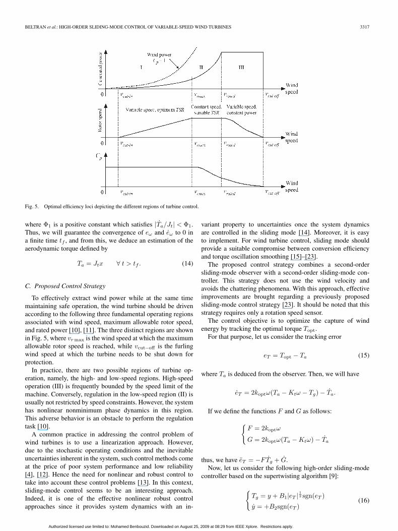
Fig. 5. Optimal efficiency loci depicting the different regions of turbine control.
where Φ1 is a positive constant which satisfies |Ta/Jt| < Φ1.Thus, we will guarantee the convergence of eω and eω to 0 ina finite time tf , and from this, we deduce an estimation of theaerodynamic torque defined by
Ta = Jtx ∀ t > tf . (14)
C. Proposed Control Strategy
To effectively extract wind power while at the same timemaintaining safe operation, the wind turbine should be drivenaccording to the following three fundamental operating regionsassociated with wind speed, maximum allowable rotor speed,and rated power [10], [11]. The three distinct regions are shownin Fig. 5, where vr max is the wind speed at which the maximumallowable rotor speed is reached, while vcut−off is the furlingwind speed at which the turbine needs to be shut down forprotection.
In practice, there are two possible regions of turbine op-eration, namely, the high- and low-speed regions. High-speedoperation (III) is frequently bounded by the speed limit of themachine. Conversely, regulation in the low-speed region (II) isusually not restricted by speed constraints. However, the systemhas nonlinear nonminimum phase dynamics in this region.This adverse behavior is an obstacle to perform the regulationtask [10].
A common practice in addressing the control problem ofwind turbines is to use a linearization approach. However,due to the stochastic operating conditions and the inevitableuncertainties inherent in the system, such control methods comeat the price of poor system performance and low reliability[4], [12]. Hence the need for nonlinear and robust control totake into account these control problems [13]. In this context,sliding-mode control seems to be an interesting approach.Indeed, it is one of the effective nonlinear robust controlapproaches since it provides system dynamics with an in-
variant property to uncertainties once the system dynamicsare controlled in the sliding mode [14]. Moreover, it is easyto implement. For wind turbine control, sliding mode shouldprovide a suitable compromise between conversion efficiencyand torque oscillation smoothing [15]–[23].
The proposed control strategy combines a second-ordersliding-mode observer with a second-order sliding-mode con-troller. This strategy does not use the wind velocity andavoids the chattering phenomena. With this approach, effectiveimprovements are brought regarding a previously proposedsliding-mode control strategy [23]. It should be noted that thisstrategy requires only a rotation speed sensor.
The control objective is to optimize the capture of windenergy by tracking the optimal torque Topt.
For that purpose, let us consider the tracking error
eT = Topt − Ta (15)
where Ta is deduced from the observer. Then, we will have
eT = 2koptω(Ta − Ktω − Tg) − Ta.
If we define the functions F and G as follows:
{F = 2koptω
G = 2koptω(Ta − Ktω) − Ta
thus, we have eT = −FTg + G.Now, let us consider the following high-order sliding-mode
controller based on the supertwisting algorithm [9]:
{Tg = y + B1|eT |
12 sgn(eT )
y = +B2sgn(eT )(16)
Authorized licensed use limited to: Mohamed Benbouzid. Downloaded on August 25, 2009 at 08:29 from IEEE Xplore. Restrictions apply.
3318 IEEE TRANSACTIONS ON INDUSTRIAL ELECTRONICS, VOL. 56, NO. 9, SEPTEMBER 2009
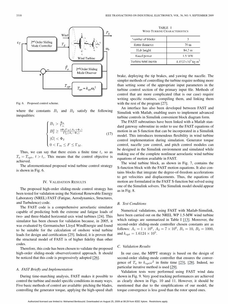
Fig. 6. Proposed control scheme.
where the constants B1 and B2 satisfy the followinginequalities: ⎧⎪⎪⎪⎪⎪⎨
⎪⎪⎪⎪⎪⎩
B1 > Φ2Γm
B22 ≥ 4Φ2ΓM (A1+Φ1)
Γ3m(A1−Φ1)
|G| < Φ2
0 < Γm ≤ F ≤ ΓM .
(17)
Thus, we can say that there exists a finite time tc so asTa = Topt, t > tc. This means that the control objective isachieved.
The aforementioned proposed wind turbine control strategyis shown in Fig. 6.
IV. VALIDATION RESULTS
The proposed high-order sliding-mode control strategy hasbeen tested for validation using the National Renewable EnergyLaboratory (NREL) FAST (Fatigue, Aerodynamics, Structures,and Turbulence) code.
The FAST code is a comprehensive aeroelastic simulatorcapable of predicting both the extreme and fatigue loads oftwo- and three-bladed horizontal-axis wind turbines [24]. Thissimulator has been chosen for validation because, in 2005, itwas evaluated by Germanischer Lloyd WindEnergie and foundto be suitable for the calculation of onshore wind turbineloads for design and certification [25]. Indeed, it is proven thatthe structural model of FAST is of higher fidelity than othercodes.
Therefore, this code has been chosen to validate the proposedhigh-order sliding-mode observer/control approach. It shouldbe noticed that this code is progressively adopted [26].
A. FAST Briefly and Implementation
During time-marching analysis, FAST makes it possible tocontrol the turbine and model specific conditions in many ways.Five basic methods of control are available: pitching the blades,controlling the generator torque, applying the high-speed shaft
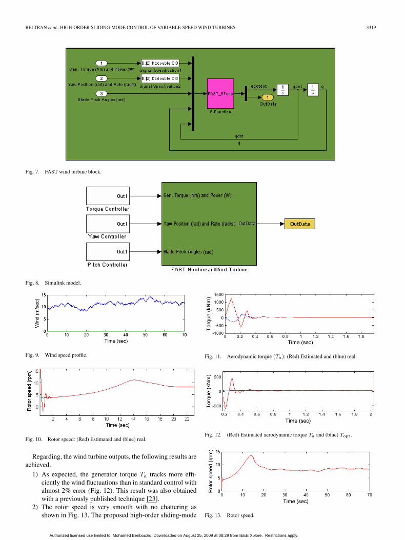
TABLE IWIND TURBINE CHARACTERISTICS
brake, deploying the tip brakes, and yawing the nacelle. Thesimpler methods of controlling the turbine require nothing morethan setting some of the appropriate input parameters in theturbine control section of the primary input file. Methods ofcontrol that are more complicated (that is our case) requirewriting specific routines, compiling them, and linking themwith the rest of the program [27].
An interface has also been developed between FAST andSimulink with Matlab, enabling users to implement advancedturbine controls in Simulink convenient block diagram form.
The FAST subroutines have been linked with a Matlab stan-dard gateway subroutine in order to use the FAST equations ofmotion in an S-function that can be incorporated in a Simulinkmodel. This introduces tremendous flexibility in wind turbinecontrol implementation during simulation. Generator torquecontrol, nacelle yaw control, and pitch control modules canbe designed in the Simulink environment and simulated whilemaking use of the complete nonlinear aeroelastic wind turbineequations of motion available in FAST.
The wind turbine block, as shown in Fig. 7, contains theS-function block with the FAST motion equations. It also con-tains blocks that integrate the degree-of-freedom accelerationsto get velocities and displacements. Thus, the equations ofmotion are formulated in the FAST S-function but solved usingone of the Simulink solvers. The Simulink model should appearas in Fig. 8.
B. Test Conditions
Numerical validations, using FAST with Matlab-Simulink,have been carried out on the NREL WP 1.5-MW wind turbinewhich ratings are summarized in Table I [13]. Moreover, thesecond-order sliding-mode controller chosen constants are asfollows: A1 = 1 × 10⁶, A2 = 7 × 10⁶, B1 = 10, B2 = 1000,and kopt = 1.6124 × 10⁵.
C. Validation Results
In our case, the MPPT strategy is based on the design ofsecond-order sliding-mode controller that ensures the conver-gence of Ta to koptω
2 in finite time [23], [28]. Indeed, noparticular iterative method is used [29].
Validation tests were performed using FAST wind datashown in Fig. 9. Very good tracking performances are achievedas clearly shown in Figs. 10 and 11. However, it should bementioned that due to the simplifications of our model, thetorque convergence is less good than the rotor speed ones.
Authorized licensed use limited to: Mohamed Benbouzid. Downloaded on August 25, 2009 at 08:29 from IEEE Xplore. Restrictions apply.
BELTRAN et al.: HIGH-ORDER SLIDING-MODE CONTROL OF VARIABLE-SPEED WIND TURBINES 3319
Fig. 7. FAST wind turbine block.
Fig. 8. Simulink model.
Fig. 9. Wind speed profile.
Fig. 10. Rotor speed: (Red) Estimated and (blue) real.
Regarding, the wind turbine outputs, the following results areachieved.
1) As expected, the generator torque Ta tracks more effi-ciently the wind fluctuations than in standard control withalmost 2% error (Fig. 12). This result was also obtainedwith a previously published technique [23].
2) The rotor speed is very smooth with no chattering asshown in Fig. 13. The proposed high-order sliding-mode
Fig. 11. Aerodynamic torque (Ta): (Red) Estimated and (blue) real.
Fig. 12. (Red) Estimated aerodynamic torque Ta and (blue) Topt.
Fig. 13. Rotor speed.
Authorized licensed use limited to: Mohamed Benbouzid. Downloaded on August 25, 2009 at 08:29 from IEEE Xplore. Restrictions apply.
3320 IEEE TRANSACTIONS ON INDUSTRIAL ELECTRONICS, VOL. 56, NO. 9, SEPTEMBER 2009
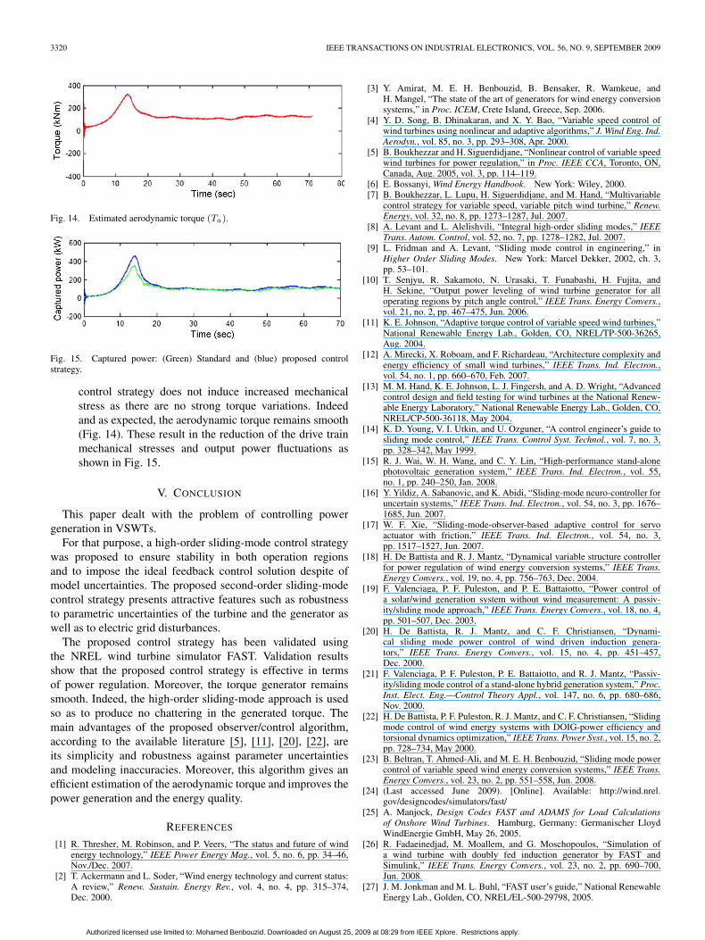
Fig. 14. Estimated aerodynamic torque (Ta).
Fig. 15. Captured power: (Green) Standard and (blue) proposed controlstrategy.
control strategy does not induce increased mechanicalstress as there are no strong torque variations. Indeedand as expected, the aerodynamic torque remains smooth(Fig. 14). These result in the reduction of the drive trainmechanical stresses and output power fluctuations asshown in Fig. 15.
V. CONCLUSION
This paper dealt with the problem of controlling powergeneration in VSWTs.
For that purpose, a high-order sliding-mode control strategywas proposed to ensure stability in both operation regionsand to impose the ideal feedback control solution despite ofmodel uncertainties. The proposed second-order sliding-modecontrol strategy presents attractive features such as robustnessto parametric uncertainties of the turbine and the generator aswell as to electric grid disturbances.
The proposed control strategy has been validated usingthe NREL wind turbine simulator FAST. Validation resultsshow that the proposed control strategy is effective in termsof power regulation. Moreover, the torque generator remainssmooth. Indeed, the high-order sliding-mode approach is usedso as to produce no chattering in the generated torque. Themain advantages of the proposed observer/control algorithm,according to the available literature [5], [11], [20], [22], areits simplicity and robustness against parameter uncertaintiesand modeling inaccuracies. Moreover, this algorithm gives anefficient estimation of the aerodynamic torque and improves thepower generation and the energy quality.
REFERENCES
[1] R. Thresher, M. Robinson, and P. Veers, “The status and future of windenergy technology,” IEEE Power Energy Mag., vol. 5, no. 6, pp. 34–46,Nov./Dec. 2007.
[2] T. Ackermann and L. Soder, “Wind energy technology and current status:A review,” Renew. Sustain. Energy Rev., vol. 4, no. 4, pp. 315–374,Dec. 2000.
[3] Y. Amirat, M. E. H. Benbouzid, B. Bensaker, R. Wamkeue, andH. Mangel, “The state of the art of generators for wind energy conversionsystems,” in Proc. ICEM, Crete Island, Greece, Sep. 2006.
[4] Y. D. Song, B. Dhinakaran, and X. Y. Bao, “Variable speed control ofwind turbines using nonlinear and adaptive algorithms,” J. Wind Eng. Ind.Aerodyn., vol. 85, no. 3, pp. 293–308, Apr. 2000.
[5] B. Boukhezzar and H. Siguerdidjane, “Nonlinear control of variable speedwind turbines for power regulation,” in Proc. IEEE CCA, Toronto, ON,Canada, Aug. 2005, vol. 3, pp. 114–119.
[6] E. Bossanyi, Wind Energy Handbook. New York: Wiley, 2000.[7] B. Boukhezzar, L. Lupu, H. Siguerdidjane, and M. Hand, “Multivariable
control strategy for variable speed, variable pitch wind turbine,” Renew.Energy, vol. 32, no. 8, pp. 1273–1287, Jul. 2007.
[8] A. Levant and L. Alelishvili, “Integral high-order sliding modes,” IEEETrans. Autom. Control, vol. 52, no. 7, pp. 1278–1282, Jul. 2007.
[9] L. Fridman and A. Levant, “Sliding mode control in engineering,” inHigher Order Sliding Modes. New York: Marcel Dekker, 2002, ch. 3,pp. 53–101.
[10] T. Senjyu, R. Sakamoto, N. Urasaki, T. Funabashi, H. Fujita, andH. Sekine, “Output power leveling of wind turbine generator for alloperating regions by pitch angle control,” IEEE Trans. Energy Convers.,vol. 21, no. 2, pp. 467–475, Jun. 2006.
[11] K. E. Johnson, “Adaptive torque control of variable speed wind turbines,”National Renewable Energy Lab., Golden, CO, NREL/TP-500-36265,Aug. 2004.
[12] A. Mirecki, X. Roboam, and F. Richardeau, “Architecture complexity andenergy efficiency of small wind turbines,” IEEE Trans. Ind. Electron.,vol. 54, no. 1, pp. 660–670, Feb. 2007.
[13] M. M. Hand, K. E. Johnson, L. J. Fingersh, and A. D. Wright, “Advancedcontrol design and field testing for wind turbines at the National Renew-able Energy Laboratory,” National Renewable Energy Lab., Golden, CO,NREL/CP-500-36118, May 2004.
[14] K. D. Young, V. I. Utkin, and U. Ozguner, “A control engineer’s guide tosliding mode control,” IEEE Trans. Control Syst. Technol., vol. 7, no. 3,pp. 328–342, May 1999.
[15] R. J. Wai, W. H. Wang, and C. Y. Lin, “High-performance stand-alonephotovoltaic generation system,” IEEE Trans. Ind. Electron., vol. 55,no. 1, pp. 240–250, Jan. 2008.
[16] Y. Yildiz, A. Sabanovic, and K. Abidi, “Sliding-mode neuro-controller foruncertain systems,” IEEE Trans. Ind. Electron., vol. 54, no. 3, pp. 1676–1685, Jun. 2007.
[17] W. F. Xie, “Sliding-mode-observer-based adaptive control for servoactuator with friction,” IEEE Trans. Ind. Electron., vol. 54, no. 3,pp. 1517–1527, Jun. 2007.
[18] H. De Battista and R. J. Mantz, “Dynamical variable structure controllerfor power regulation of wind energy conversion systems,” IEEE Trans.Energy Convers., vol. 19, no. 4, pp. 756–763, Dec. 2004.
[19] F. Valenciaga, P. F. Puleston, and P. E. Battaiotto, “Power control ofa solar/wind generation system without wind measurement: A passiv-ity/sliding mode approach,” IEEE Trans. Energy Convers., vol. 18, no. 4,pp. 501–507, Dec. 2003.
[20] H. De Battista, R. J. Mantz, and C. F. Christiansen, “Dynami-cal sliding mode power control of wind driven induction genera-tors,” IEEE Trans. Energy Convers., vol. 15, no. 4, pp. 451–457,Dec. 2000.
[21] F. Valenciaga, P. F. Puleston, P. E. Battaiotto, and R. J. Mantz, “Passiv-ity/sliding mode control of a stand-alone hybrid generation system,” Proc.Inst. Elect. Eng.—Control Theory Appl., vol. 147, no. 6, pp. 680–686,Nov. 2000.
[22] H. De Battista, P. F. Puleston, R. J. Mantz, and C. F. Christiansen, “Slidingmode control of wind energy systems with DOIG-power efficiency andtorsional dynamics optimization,” IEEE Trans. Power Syst., vol. 15, no. 2,pp. 728–734, May 2000.
[23] B. Beltran, T. Ahmed-Ali, and M. E. H. Benbouzid, “Sliding mode powercontrol of variable speed wind energy conversion systems,” IEEE Trans.Energy Convers., vol. 23, no. 2, pp. 551–558, Jun. 2008.
[24] (Last accessed June 2009). [Online]. Available: http://wind.nrel.gov/designcodes/simulators/fast/
[25] A. Manjock, Design Codes FAST and ADAMS for Load Calculationsof Onshore Wind Turbines. Hamburg, Germany: Germanischer LloydWindEnergie GmbH, May 26, 2005.
[26] R. Fadaeinedjad, M. Moallem, and G. Moschopoulos, “Simulation ofa wind turbine with doubly fed induction generator by FAST andSimulink,” IEEE Trans. Energy Convers., vol. 23, no. 2, pp. 690–700,Jun. 2008.
[27] J. M. Jonkman and M. L. Buhl, “FAST user’s guide,” National RenewableEnergy Lab., Golden, CO, NREL/EL-500-29798, 2005.
Authorized licensed use limited to: Mohamed Benbouzid. Downloaded on August 25, 2009 at 08:29 from IEEE Xplore. Restrictions apply.
BELTRAN et al.: HIGH-ORDER SLIDING-MODE CONTROL OF VARIABLE-SPEED WIND TURBINES 3321
[28] I. S. Kim, M. B. Kim, and M. J. Youn, “New maximum power pointtracker using sliding-mode observer for estimation of solar array currentin the grid-connected photovoltaic system,” IEEE Trans. Ind. Electron.,vol. 53, no. 4, pp. 1027–1035, Jun. 2006.
[29] E. Koutroulis and K. Kalaitzakis, “Design of a maximum power trackingsystem for wind-energy-conversion applications,” IEEE Trans. Ind. Elec-tron., vol. 53, no. 2, pp. 486–494, Apr. 2006.
Brice Beltran was born in Arles, France, in 1981.He received the Engineer degree in electricalengineering from the Ecole Nationale Supérieured’Ingénieurs des Etudes et Techniques d’Armement,Brest, France, in 2006. He is currently workingtoward the Ph.D. degree in the Laboratoire Brestoisde Mécanique et des Systèmes, University of Brest,Brest, focusing on wind energy conversion systems’advanced control and fault-tolerant control.
In 2006, he was with the Délégation Générale pourl’Armenent as an Engineer and Technical Expert in
information systems.
Tarek Ahmed-Ali was born in Algiers, Algeria,in 1972. He received the B.Sc. degree in electricalengineering from the Ecole Nationale Polytechniqueof Algiers, Algiers, in 1994, the M.Sc. degree in elec-trical and computer engineering from the Universityof Paris VI, Paris, France, in 1995, and the Ph.D.degree in electrical and computer engineering fromthe University of Paris Sud, Paris, in 1998.
In 1998, he was with the University of Paris XIII,Paris, as a Teaching and Research Assistant. In1998, he then moved to the Ecole Centrale de Lille,
Lille, France, also as a Teaching and Research Assistant. In 2000, he wasappointed as a Research and Development Engineer with SNCF (the FrenchRailway Corporation). In 2002, he was appointed to a lectureship in controlengineering with the Ecole Nationale des Ingénieurs des Etudes et Techniquesde l’Armement of Brest, France. He is currently with the Laboratoire Brestoisde Mécanique et des Systèmes, University of Brest, Brest. His main researchinterests include sliding-mode control, nonlinear observers, and fault-tolerantcontrol and diagnosis in the field of ac drives.
Mohamed El Hachemi Benbouzid (S’92–M’95–SM’98) was born in Batna, Algeria, in 1968. Hereceived the B.Sc. degree in electrical engineeringfrom the University of Batna, Batna, in 1990, theM.Sc. and Ph.D. degrees in electrical and computerengineering from the National Polytechnic Instituteof Grenoble, Grenoble, France, in 1991 and 1994,respectively, and the Habilitation à Diriger desRecherches degree from the University of Picardie“Jules Verne”, Amiens, France, in 2000.
After receiving the Ph.D. degree, he joined theProfessional Institute of Amiens, University of Picardie “Jules Verne”, wherehe was an Associate Professor of electrical and computer engineering. InSeptember 2004, he was with the University Institute of Technology (IUT) ofBrest, University of Western Brittany, Brest, France, as a Professor of electricalengineering. He is currently with the Laboratoire Brestois de Mécanique etdes Systèmes, University of Brest. His main research interests and experienceinclude analysis, design, and control of electric machines, variable-speeddrives for traction and propulsion applications, and fault diagnosis of electricmachines.
Prof. Benbouzid is a Senior Member of the IEEE Power Engineering,Industrial Electronics, Industry Applications, Power Electronics, and VehicularTechnology Societies. He is an Associate Editor of the IEEE TRANSACTIONS
ON ENERGY CONVERSION, the IEEE TRANSACTIONS ON INDUSTRIAL
ELECTRONICS, the IEEE TRANSACTIONS ON VEHICULAR TECHNOLOGY,and the IEEE/ASME TRANSACTIONS ON MECHATRONICS.
Authorized licensed use limited to: Mohamed Benbouzid. Downloaded on August 25, 2009 at 08:29 from IEEE Xplore. Restrictions apply.
Related Documents


