International Journal of Science and Research (IJSR) ISSN (Online): 2319-7064 Index Copernicus Value (2013): 6.14 | Impact Factor (2013): 4.438 Volume 4 Issue 8, August 2015 www.ijsr.net Licensed Under Creative Commons Attribution CC BY Vibration Analysis of Turbo Generator in Kota Super Thermal Power Station Neeraj Gochar 1 , Dharmendra Kumar Jain 2 1 Department of Thermal Engineering, Career Point University, Kota, India 2 Assistant Professor, Department of Thermal Engineering, Kota, India Abstract: Super Thermal Power Stations (STPS) or Super Power Station are a series of ambitious power projects planned by the Government of India. With India being a country of chronic power deficits, the Government of India has planned to provide 'power for all' by the end of the plan, The capacity of thermal power is 1000 MW and above. This paper presents an analysis of steam turbine vibration monitoring system of kota super thermal power plant. In this paper, a detailed concept and techniques used in turbine vibration monitoring, monitoring equipments and vibration analysis of turbo generator of 195 MW, UNIT-7 has been discussed to evaluate performance of turbine. A detailed report on vibrations of bearings corresponding to the bearing temperatures of turbo generator has been done by using IRD 880 instruments. Keywords: power generating plant, steam turbine, shaft vibration, bearing, turbo generator. 1. Introduction Energy consumption in India is become very important aspect to improving the power production by using different input energy resources. To improve the power production we have many ways that are useful for fulfill the demand of energy. Condition monitoring and analysis of turbine vibration of power plants has another way to minimize unnecessary shut down and reduce maintenance cost the of turbo generator. Reducing maintenance and shut downs use reduces energy costs and may result in a financial cost saving to consumers. Preventive maintenance is most important aspect to reduce the unwanted failure of turbo generator .condition monitoring of turbine vibration with fluctuating load has been measured by using different equipments and sensing devises continuously with time. This monitoring system used to check out the real time vibration occurs in turbine shaft and bearings during operation. This solution is cost effective as maintenance can be planned without influencing the total availability of the plant. Condition characteristics of the machine such as bearing damage, unbalance, alignment or cavitations enable a differentiated evaluation of mechanical stress which will keep all on track for when to have the shut down and the process is ongoing without any manual interruption. Hence we will be able to protect the equipment from expensive consequential costs. The machines can be taken for maintenance, without dismantling, just by knowing the health of the machine which is possible by online monitoring. Implementing predictive maintenance leads to a substantial increase in productivity of up to (35%). Preventing unpredicted shutdowns on one hand and anticipating corrective operations on the other can be carried out under the best conditions. Knowledge of the root cause of the malfunctioning of the machine can help expedite the actions that are needed to be taken instead of shutting down the whole system. This is nothing but predictive maintenance for prediction of the health of the machine. Here the performance level is decided with the help of the reports taken at intervals. There is rapid notification and fast error detection. Diagnostics feature give the root cause of the failure of machinery. 2. Causes of Vibration in Turbine There are several reasons for vibration in machines. They can be due to: Unbalance of shaft Bearing of the rings Fluid coupling problem Shaft misalignment Oil whirl and other dynamic instabilities problem Cracking of the ring These problems can gradually become very severe and result in unplanned shut downs. To avoid this, shutdowns are planned. Time Based Maintenance System (TBM) is called preventive maintenance. One can extend the life of the machines by monitoring these online in a cost effective way. Vibration Monitoring and Analysis is the easiest way to keep machines healthy and efficient in the long run and increase the overall efficiency of the plant. It reduces the overall operating cost as well as the down time period. Vibration sensors are used to predict faults in a running machine without dismantling it and give a clear indication of the severity by showing the amplitude of vibration. 2.1. Vibration Instrument (IRD 880) The IRD Model 880 Spectrum Analyzer/Dynamic Balancer is a portable instrument designed for industrial use in detecting and resolving machinery vibration problems. Using the Model 880, an operator can perform many analysis techniques that are essential to obtain comprehensive vibration data. Also, precision in-place balancing can be performed using the single plane or two plane methods. Pressing a single switch generates a completely annotated hard-copy frequency spectrum from 600-600,000 cpm in only 25 seconds. You can also obtain low frequency measurements down to 60 cpm. A single Paper ID: SUB157656 1612

Welcome message from author
This document is posted to help you gain knowledge. Please leave a comment to let me know what you think about it! Share it to your friends and learn new things together.
Transcript
International Journal of Science and Research (IJSR) ISSN (Online): 2319-7064
Index Copernicus Value (2013): 6.14 | Impact Factor (2013): 4.438
Volume 4 Issue 8, August 2015
www.ijsr.net Licensed Under Creative Commons Attribution CC BY
Vibration Analysis of Turbo Generator in Kota
Super Thermal Power Station
Neeraj Gochar1, Dharmendra Kumar Jain
2
1Department of Thermal Engineering, Career Point University, Kota, India
2Assistant Professor, Department of Thermal Engineering, Kota, India
Abstract: Super Thermal Power Stations (STPS) or Super Power Station are a series of ambitious power projects planned by the
Government of India. With India being a country of chronic power deficits, the Government of India has planned to provide 'power for
all' by the end of the plan, The capacity of thermal power is 1000 MW and above. This paper presents an analysis of steam turbine
vibration monitoring system of kota super thermal power plant. In this paper, a detailed concept and techniques used in turbine
vibration monitoring, monitoring equipments and vibration analysis of turbo generator of 195 MW, UNIT-7 has been discussed to
evaluate performance of turbine. A detailed report on vibrations of bearings corresponding to the bearing temperatures of turbo
generator has been done by using IRD 880 instruments.
Keywords: power generating plant, steam turbine, shaft vibration, bearing, turbo generator.
1. Introduction
Energy consumption in India is become very important
aspect to improving the power production by using different
input energy resources. To improve the power production we
have many ways that are useful for fulfill the demand of
energy. Condition monitoring and analysis of turbine
vibration of power plants has another way to minimize
unnecessary shut down and reduce maintenance cost the of
turbo generator. Reducing maintenance and shut downs use
reduces energy costs and may result in a financial cost
saving to consumers. Preventive maintenance is most
important aspect to reduce the unwanted failure of turbo
generator .condition monitoring of turbine vibration with
fluctuating load has been measured by using different
equipments and sensing devises continuously with time.
This monitoring system used to check out the real time
vibration occurs in turbine shaft and bearings during
operation. This solution is cost effective as maintenance can
be planned without influencing the total availability of the
plant. Condition characteristics of the machine such as
bearing damage, unbalance, alignment or cavitations enable
a differentiated evaluation of mechanical stress which will
keep all on track for when to have the shut down and the
process is ongoing without any manual interruption. Hence
we will be able to protect the equipment from expensive
consequential costs. The machines can be taken for
maintenance, without dismantling, just by knowing the
health of the machine which is possible by online
monitoring. Implementing predictive maintenance leads to a
substantial increase in productivity of up to (35%).
Preventing unpredicted shutdowns on one hand and
anticipating corrective operations on the other can be carried
out under the best conditions. Knowledge of the root cause
of the malfunctioning of the machine can help expedite the
actions that are needed to be taken instead of shutting down
the whole system. This is nothing but predictive
maintenance for prediction of the health of the machine.
Here the performance level is decided with the help of the
reports taken at intervals. There is rapid notification and fast
error detection. Diagnostics feature give the root cause of the
failure of machinery.
2. Causes of Vibration in Turbine
There are several reasons for vibration in machines. They
can be due to:
Unbalance of shaft
Bearing of the rings
Fluid coupling problem
Shaft misalignment
Oil whirl and other dynamic instabilities problem
Cracking of the ring
These problems can gradually become very severe and result
in unplanned shut downs. To avoid this, shutdowns are
planned. Time Based Maintenance System (TBM) is called
preventive maintenance. One can extend the life of the
machines by monitoring these online in a cost effective way.
Vibration Monitoring and Analysis is the easiest way to
keep machines healthy and efficient in the long run and
increase the overall efficiency of the plant. It reduces the
overall operating cost as well as the down time period.
Vibration sensors are used to predict faults in a running
machine without dismantling it and give a clear indication of
the severity by showing the amplitude of vibration.
2.1. Vibration Instrument (IRD 880)
The IRD Model 880 Spectrum Analyzer/Dynamic Balancer
is a portable instrument designed for industrial use in
detecting and resolving machinery vibration problems.
Using the Model 880, an operator can perform many
analysis techniques that are essential to obtain
comprehensive vibration data. Also, precision in-place
balancing can be performed using the single plane or two
plane methods. Pressing a single switch generates a
completely annotated hard-copy frequency spectrum from
600-600,000 cpm in only 25 seconds. You can also obtain
low frequency measurements down to 60 cpm. A single
Paper ID: SUB157656 1612
International Journal of Science and Research (IJSR) ISSN (Online): 2319-7064
Index Copernicus Value (2013): 6.14 | Impact Factor (2013): 4.438
Volume 4 Issue 8, August 2015
www.ijsr.net Licensed Under Creative Commons Attribution CC BY
sensor measures machinery vibration in displacement,
velocity, acceleration, and Spike Energy units.
Features:
Digital amplitude or frequency display provides a high
precision readout for balancing and analysis.
Analog amplitude and frequency meters supplement the
digital displays and aid in analyzing unsteady signals.
Automatic tabular listing of spectrum frequency peaks and
amplitudes.
Chart speed selector with three time-plot speeds records
short transients and slowly changing vibration over a
number of hours.
Automatic "order" indication of the spectrum frequency
peaks to show harmonic relationships of frequency peaks
to rpm.
Diagnostic capability includes hard-copy tabular readout
of the most likely causes of vibration.
Prints out AVERAGE, MINIMUM, and MAXIMUM
overall values tor both spectrum and amplitude vs. time
plots.
Event marking feature prints a short vertical line to
indicate the precise time of events on amplitude vs. time
plots.
3. Observation
My observations are related to the measuring and analysis of
vibrations corresponding to the bearing temperature of turbo
generator at unit-7 in kota super thermal power station.
Vibrations in bearings corresponding to bearing temperature
of turbo generator are taken by using mechanalysis
instrument IRD 880. I have observed and measured bearing
vibrations as well as bearing temperature on 09-03-2015.
Number-1, 3, 4,5,6,7 are Radial Journal Bearings and
Number-2 is Thrust Bearing and Radial Journal Bearing.
The vibrations of these bearings of turbo generator are taken
in three ways
1. Vertical Displacement
2. Horizontal Displacement
3. Axial Displacement
Table 1: Turbine Parameter S.
No.
Parameter Pressure
(Kg/Cm2)
Temperature
(°C)
1. Main Steam 117 531
2. C.R.H. 32.3 380
3. H.R.H. 31.4 531
4. Curts Wheel 99 _
5. Thrust Bearing _ 59
6. LP Exhaust Hood _ 59
Lube oil temperature before cooler (c) - 44 .1
Lube oil temperature after cooler (c) - 99
Table 2: Generation Parameter S. No. Miscellaneous HP IP LP
1. Eccentricity 13.31 24.41 24.7
2. Expansion O.A 27.1 1.65 _
3. Expansion Diff. 2.10 2.07 2.07
4. Analysis and Results
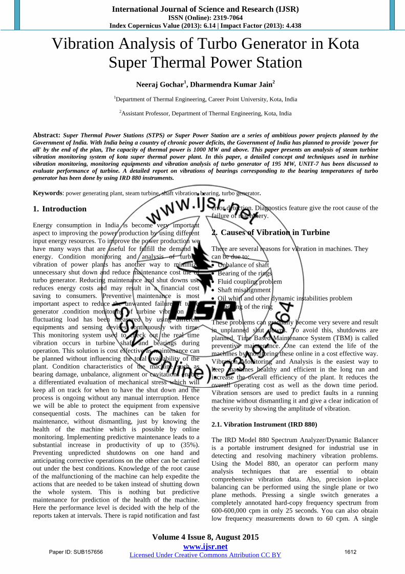
The following plots are generated by IRD 880 instrument.
These plots are between the displacement amplitude of
vibration and frequency in cpm (k).
The maximum displacement amplitude observed in
bearing no. 4,5,and 6.
Figurer 1(a): Frequency (K) – Vertical Displacement (V)
Figure 1(b): Frequency (K) – Horizontal Displacement (H)
Figure 1(c): Frequency (K) – Axial Displacement (A)
Figure 2(a): Frequency (K) – Vertical Displacement (v)
Figure 2(b): Frequency (K) – Horizontal Displacement (H)
Figure 2(c): Frequency (K) – Axial Displacement (A)
Paper ID: SUB157656 1613
International Journal of Science and Research (IJSR) ISSN (Online): 2319-7064
Index Copernicus Value (2013): 6.14 | Impact Factor (2013): 4.438
Volume 4 Issue 8, August 2015
www.ijsr.net Licensed Under Creative Commons Attribution CC BY
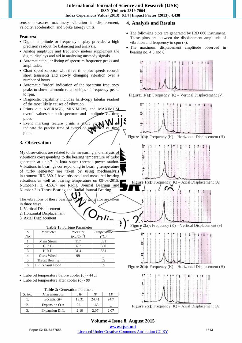
Figure 3(a): Frequency (K) – Vertical Displacement (V)
Figure 3(b): Frequency (K) – Horizontal Displacement (H)
Figure 3(c): Frequency (K) – Axial Displacement (A)
Figure 4(a): Frequency (K) – Vertical Displacement (V)
Figure 4(b): Frequency (K) – Horizontal Displacement (H)
Figure 4(c): Frequency (K) – Axial Displacement (A)
Figure 5(a): Frequency (K) – Vertical Displacement (V)
Figure 5(b): Frequency (K) – Horizontal Displacement (H)
Figure 5(c): Frequency (K) – Axial Displacement (A)
Figure 6(a): Frequency (K) – Vertical Displacement (V)
Figure 6(b): Frequency (K) – Horizontal Displacement (H)
Figure 6(c): Frequency (K) – Axial Displacement (A)
Figure 7(a): Frequency (K) – Vertical Displacement (V)
Paper ID: SUB157656 1614
International Journal of Science and Research (IJSR) ISSN (Online): 2319-7064
Index Copernicus Value (2013): 6.14 | Impact Factor (2013): 4.438
Volume 4 Issue 8, August 2015
www.ijsr.net Licensed Under Creative Commons Attribution CC BY
Figure 7(b): Frequency (K) – Horizontal Displacement (H)
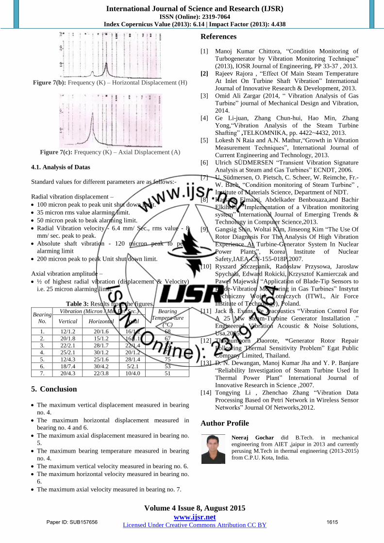
Figure 7(c): Frequency (K) – Axial Displacement (A)
4.1. Analysis of Datas
Standard values for different parameters are as follows:-
Radial vibration displacement –
100 micron peak to peak unit shut down limit.
35 micron rms value alarming limit.
50 micron peak to beak alarming limit.
Radial Vibration velocity - 6.4 mm/ Sec., rms value - 8
mm/ sec. peak to peak.
Absolute shaft vibration - 120 micron peak to peak
alarming limit
200 micron peak to peak Unit shut down limit.
Axial vibration amplitude –
½ of highest radial vibration (displacement & Velocity)
i.e. 25 micron alarming limit.
Table 3: Results from the figures.
Bearing
No.
Vibration (Micron / Mm Per Sec.) Bearing
Tempera-ture
(°C) Vertical Horizontal Axial
1. 12/1.2 20/1.6 16/1.2 68 2. 20/1.8 15/1.2 16/1.1 67 3. 22/2.1 28/1.7 22/1.4 72 4. 25/2.1 30/1.2 20/1.2 77 5. 12/4.3 25/1.6 28/1.4 75 6. 18/7.4 30/4.2 5/2.1 53 7. 20/4.3 22/3.8 10/4.0 51
5. Conclusion
The maximum vertical displacement measured in bearing
no. 4.
The maximum horizontal displacement measured in
bearing no. 4 and 6.
The maximum axial displacement measured in bearing no.
5.
The maximum bearing temperature measured in bearing
no. 4.
The maximum vertical velocity measured in bearing no. 6.
The maximum horizontal velocity measured in bearing no.
6.
The maximum axial velocity measured in bearing no. 7.
References
[1] Manoj Kumar Chittora, “Condition Monitoring of
Turbogenerator by Vibration Monitoring Technique”
(2013), IOSR Journal of Engineering, PP 33-37 , 2013.
[2] Rajeev Rajora , “Effect Of Main Steam Temperature
At Inlet On Turbine Shaft Vibration” International
Journal of Innovative Research & Development, 2013.
[3] Omid Ali Zargar (2014, “ Vibration Analysis of Gas
Turbine” journal of Mechanical Design and Vibration,
2014.
[4] Ge Li-juan, Zhang Chun-hui, Hao Min, Zhang
Yong,“Vibration Analysis of the Steam Turbine
Shafting” ,TELKOMNIKA, pp. 4422~4432, 2013.
[5] Lokesh N Raia and A.N. Mathur,“Growth in Vibration
Measurement Techniques”, International Journal of
Current Engineering and Technology, 2013.
[6] Ulrich SÜDMERSEN “Transient Vibration Signature
Analysis at Steam and Gas Turbines” ECNDT, 2006.
[7] U. Südmersen, O. Pietsch, C. Scheer, W. Reimche, Fr.-
W. Bach, “Condition monitoring of Steam Turbine” ,
Institute of Materials Science, Department of NDT.
[8] Hassane Elmaati, Abdelkader Benbouaza,and Bachir
Elkihel3, “Implementation of a Vibration monitoring
system” International Journal of Emerging Trends &
Technology in Computer Science,2013.
[9] Gangsig Shin, Woltai Kim, Jinseong Kim “The Use Of
Rotor Diagnosis For The Analysis Of High Vibration
Experience At Turbine-Generator System In Nuclear
Power Plants”, Korea Institute of Nuclear
Safety,IAEA-CN-155-018P,2007.
[10] Ryszard Szczepanik, Radosław Przysowa, Jarosław
Spychała, Edward Rokicki, Krzysztof Kamierczak and
Paweł Majewski “Application of Blade-Tip Sensors to
Blade-Vibration Monitoring in Gas Turbines” Instytut
Techniczny Wojsk Lotniczych (ITWL, Air Force
Institute of Technology), Poland.
[11] Jack B. Evans, Pe Jeacoustics “Vibration Control For
A 25 Mw Steam-Turbine Generator Installation .”
Engineered Vibration Acoustic & Noise Solutions,
Usa,2005.
[12] Thikhumporn Daorote, “Generator Rotor Repair
Following Thermal Sensitivity Problem” Egat Public
Company Limited, Thailand.
[13] D. N. Dewangan, Manoj Kumar Jha and Y. P. Banjare
“Reliability Investigation of Steam Turbine Used In
Thermal Power Plant” International Journal of
Innovative Research in Science ,2007.
[14] Tongying Li , Zhenchao Zhang “Vibration Data
Processing Based on Petri Network in Wireless Sensor
Networks” Journal Of Networks,2012.
Author Profile
Neeraj Gochar did B.Tech. in mechanical
engineering from AIET ,jaipur in 2013 and currently
perusing M.Tech in thermal engineering (2013-2015)
from C.P.U. Kota, India.
Paper ID: SUB157656 1615
Related Documents