DRAFT Australian Design Rule 38/05 Trailer Brake Systems 1 Vehicle Standard (Australian Design Rule 38/05 – Trailer Brake Systems) 2018 I, PAUL FLETCHER, Minister for Urban Infrastructure, determine this vehicle standard under section 7 of the Motor Vehicle Standards Act 1989. Dated 2018 Paul Fletcher [DRAFT NOT FOR SIGNATURE] Minister for Urban Infrastructure

Welcome message from author
This document is posted to help you gain knowledge. Please leave a comment to let me know what you think about it! Share it to your friends and learn new things together.
Transcript
DRAFT Australian Design Rule 38/05 Trailer Brake Systems 1
Vehicle Standard (Australian Design Rule 38/05 – Trailer Brake Systems) 2018
I, PAUL FLETCHER, Minister for Urban Infrastructure, determine this vehicle standard under section 7 of the Motor Vehicle Standards Act 1989. Dated 2018
Paul Fletcher [DRAFT NOT FOR SIGNATURE]
Minister for Urban Infrastructure
DRAFT Australian Design Rule 38/05 Trailer Brake Systems 2
CONTENTS 1. LEGISLATIVE PROVISIONS .......................................................................... 3
2. FUNCTION ........................................................................................................ 3
3. APPLICABILITY .............................................................................................. 3
4. DEFINITIONS ................................................................................................... 5
5. DESIGN REQUIREMENTS FOR TRAILERS UP TO 4.5 TONNES ‘ATM’ . 5
6. GENERAL DESIGN REQUIREMENTS FOR TRAILERS OVER 4.5 TONNES ‘ATM’ ................................................................................................ 5
7. SERVICE BRAKE SYSTEM ............................................................................ 8
8. EMERGENCY BRAKE SYSTEM .................................................................. 12
9. PARKING BRAKE SYSTEM ......................................................................... 12
10. GENERAL PERFORMANCE ROAD TEST CONDITIONS ........................ 13
11. SERVICE BRAKE EFFECTIVENESS TEST CONDITIONS ....................... 14
12. DOG TRAILER FRICTION UTILISATION .................................................. 15
13. SERVICE BRAKE FADE EFFECTIVENESS TEST ..................................... 15
14. EMERGENCY BRAKE SYSTEM EFFECTIVENESS TEST ....................... 16
15. PARKING BRAKE EFFECTIVENESS TEST ............................................... 16
16. TIME RESPONSE MEASUREMENT ............................................................ 17
17. SERVICE BRAKE EFFECTIVENESS CALCULATION ............................. 19
18. SERVICE BRAKE FADE CALCULATION .................................................. 21
19. EMERGENCY BRAKE SYSTEM CALCULATION. ................................... 21
20. PARKING BRAKE CALCULATION ............................................................ 21
21. TIME RESPONSE ........................................................................................... 22
22. SPECIFICATION OF BRAKE SYSTEM COMPONENTS ........................... 22
23. ALTERNATIVE STANDARDS ..................................................................... 26
APPENDIX 1 ................................................................................................................. 33
APPENDIX 2 ................................................................................................................. 35
APPENDIX 3 ................................................................................................................. 36
APPENDIX 4 ................................................................................................................. 38
DRAFT Australian Design Rule 38/05 Trailer Brake Systems 3
1. LEGISLATIVE PROVISIONS 1.1. Name of Standard 1.1.1. This Standard is the Vehicle Standard (Australian Design Rule
38/05 – Trailer Brake Systems) 2018. 1.1.2. This Standard may also be cited as Australian Design Rule
38/05 — Trailer Brake Systems. 1.2. Commencement 1.2.1. This Standard commences on the day after it is registered.
2. FUNCTION 2.1. The function of this vehicle standard is to specify requirements for
braking of trailers under both normal operating and emergency conditions.
2.2. Compliance can be demonstrated by road testing and/or calculations based on data for ‘Approved’ components.
3. APPLICABILITY 3.1. This standard applies to category T vehicles with a ‘Gross Trailer Mass’
exceeding 750 kg from the dates set out in clauses 3.1.1 to 3.1.2 and the table under clause 3.3 below (except those trailers designed for use behind a drawing vehicle with a maximum speed less than 50 km/h).
3.1.1. 1 [July 2019] for all new model vehicles. 3.1.2. 1 [November 2019] for all vehicles. 3.2. For the purposes of clause 3.1 a "new model" is a vehicle model first
produced with a 'Date of manufacture' on or after the agreed date in clause 3.1.1.
DRAFT Australian Design Rule 38/05 Trailer Brake Systems 4
3.3. Applicability Table
Vehicle Category
ADR Category Code *
UNECE Category Code *
Manufactured on or After
Acceptable Prior Rules
Moped 2 wheels LA L1 not applicable Moped 3 wheels LB L2 not applicable Motor cycle LC L3 not applicable Motor cycle and sidecar LD L4 not applicable Motor tricycle LE L5 not applicable
Passenger car MA M1 not applicable Forward-control passenger vehicle MB M1 not applicable Off-road passenger vehicle MC M1 not applicable Light omnibus MD M2 not applicable Heavy omnibus ME M3 not applicable
Light goods vehicle NA N1 not applicable Medium goods vehicle NB N2 not applicable Heavy goods vehicle NC N3 not applicable
Very light trailer TA O1 not applicable Light trailer TB O2 [1 July 2019]** /03, /04 Medium trailer TC O3 [1 July 2019]** nil Heavy trailer TD O4 [1 July 2019]** nil
* The category code may also be in the format L1, L2, L3 etc. ** See clause 3.1.
DRAFT Australian Design Rule 38/05 Trailer Brake Systems 5
4. DEFINITIONS 4.1. For vehicle categories, definitions and meanings used in this standard,
refer to: 4.1.1. Vehicle Standard (Australian Design Rule Definitions and Vehicle
Categories) 2005; and 4.1.2. Definitions in clause 1 of APPENDIX 3 of this standard.
5. DESIGN REQUIREMENTS FOR TRAILERS UP TO 4.5 TONNES ‘ATM’
5.1. Every trailer must be equipped with an efficient ‘Service Brake System’ which, with the exception of trailers equipped with an ‘Over-run Braking System’, must be designed so that the braking force can be progressively increased and decreased by means of the ‘Control Signal’ from the towing vehicle.
5.2. In the case of trailers with a ‘Gross Trailer Mass’ of greater than 2 tonne, the ‘Brake System’ must operate on all wheels.
5.3. The ‘Brake System’ on trailers with a ‘Gross Trailer Mass’ up to 2 tonnes may be actuated for both ‘Service Brake System’ and ‘Secondary Brake System’ by the over-run of the trailer.
5.4. Every trailer having a ‘Gross Trailer Mass’ over 2 tonnes must be equipped with an efficient ‘Emergency Brake System’ which will cause immediate automatic application of its ‘Brakes’ in the event of the trailer accidentally becoming disconnected from the towing vehicle. ‘Brakes’ so applied must remain applied for at least 15 minutes.
5.5. Trailers up to 4.5 tonnes ‘ATM’ are not required to comply with subsequent sections of this standard.
6. GENERAL DESIGN REQUIREMENTS FOR TRAILERS OVER 4.5 TONNES ‘ATM’
6.1. A ‘Service Brake System’ must be fitted to all trailer wheels and be in accordance with the requirements of part 7.
6.2. The trailer ‘Brake System’ must be capable of being actuated from the towing vehicle by means of a connection between the trailer and towing vehicle with a performance not less than that specified for the ‘Emergency Brake System’ in part 8 after any one failure in a ‘Brake Device’ in the trailer ‘Brake System’.
6.3. A ‘Parking Brake System 38/...’ must be fitted and must meet the requirements of part 9.
6.4. The trailer ‘Brake System’ must restrain the trailer automatically in the event of a trailer break-away with a performance not less than that specified for the ‘Emergency Brake System’ in part 8.
6.5. A ‘Brake System’ which utilises ‘Stored Energy’ to actuate the ‘Service Brake System’ must be designed so that when the ‘Supply Line’ energy level is reduced at a rate of not less than 0.15E/sec (100 kPa/sec) the following conditions are met;
DRAFT Australian Design Rule 38/05 Trailer Brake Systems 6
6.5.1. the ‘Brake System’ must not start to automatically apply the ‘Brakes’ at a ‘Supply Line’ energy level of more than 0.65 ‘E’ (420 kpa) and,
6.5.2. the ‘Brake System’ must start to automatically apply the ‘Brakes’ at a ‘Supply Line’ energy level not less than:
6.5.2.1. 0.31 ‘E’ (200 kPa) where the maximum braking effectiveness of the ‘Brakes’ so applied is dependent on ‘Stored Fluid Energy’ or;
6.5.2.2. 0.24 ‘E’ (155 kPa) where the maximum braking effectiveness of the ‘Brakes’ so applied is not dependent on ‘Stored Fluid Energy’ and;
6.5.2.3. with the ‘Supply Line’ energy level at 0.0 ‘E’ the braking effectiveness must be at least that specified for the ‘Emergency Brake System’ in clause 8.1.
6.6. The ‘Brake System’ must be designed so that no single failure in a ‘Brake Device’ in the ‘Service Brake System’, except of a ‘Supply Line’ or ‘Control Line’, must cause the ‘Brakes’ to apply without a ‘Control Signal’ provided by the towing vehicle.
6.7. Manual devices for the isolation of faulty devices or brake circuits may be included in the ‘Brake System’ but automatic devices of the type that normally remain passive and whose function cannot readily be checked during normal operation of the trailer are not permitted. For the purposes of this clause normal operation also includes the activity of coupling and uncoupling the trailer connections.
6.8. Where a trailer is fitted with an auxiliary park brake release device, enabling stored energy actuation or release of any part of the ‘Brake System’ to be cut out, the device must be such that the ‘Brake System’ is restored to normal no later than on the resumption of the supply of ‘Stored Energy’ to the trailer from the towing vehicle.
6.9. All components and devices in the ‘Brake System’ must meet or exceed at least one appropriate and recognised international, national or association standard, where such standards exist, or the relevant parts thereof. ‘Recognised’ can be taken to include SA, SAE, BS, JIS, DIN, performance and design related ISO standards and UN regulations.
6.10. Brake line couplings must not be interchangeable and must be polarised. Couplings must comply with the requirements – AS 4945:2000, ‘Commercial road vehicle – Interchangeable quick release couplings for use with air-pressure braking systems’ where applicable or compatible couplings which meet the requirements of ISO 1728:2006 ‘Road vehicles – Pneumatic Braking connections between motor vehicles and towed vehicles – Interchangeability’ may be used.
6.11. Each air reservoir in a compressed air ‘Brake System’ must be fitted with a manual condensate drain valve at the lowest point. An automatic condensate valve may be fitted provided it also drains the lowest point. The manual drain valve may be incorporated in the automatic valve.
DRAFT Australian Design Rule 38/05 Trailer Brake Systems 7
6.12. Each ‘Brake System’ must incorporate devices which automatically compensate for any increased movement of its components arising from wear. Such devices must themselves contain provision for securing them throughout their working range in any position to which they adjust.
6.13. Except for braking systems capable of producing asymmetric braking in response to prevailing tractive conditions, or as required by the ‘Braking Systems’ of clause 7.2, each ‘Brake System’ must, when applied, produce a resultant braking force acting along the longitudinal centre line of the trailer.
6.14. Where the ‘Supply Line’ supplies energy to devices other than ‘Brake Power Unit 35/...’ including spring brakes, the design must be such that all the ‘Brake Power Unit 35/...’ are preferentially charged until the supply line reaches an energy level of not less than 0.69 ‘E’ (450 kPa); or
6.14.1. the spring brakes must not release before there is sufficient pressure in the service air tank to allow application of a service brake to at least the emergency ERC as required by clause 8.1.
6.14.2. Systems that utilize spring brakes for emergency and parking brakes are deemed to comply with this requirement if the parking/emergency brakes do not release until a service tank pressure of 0.435 ‘E’ (283 kPa) is reached.
6.14.3. Spring brake release is deemed to occur when the brake friction materials cease to contact.
6.15. The first call on the ‘Stored Energy’ must be that of the ‘Brake System’. Any other demand for ‘Stored Energy’ must be disconnected automatically if the ‘Stored Energy’ level falls below 0.69 ‘E’ (450 kPa).
6.16. Where separate methods of actuation are provided for any of the functions of the ‘Brake System’, the actuation of one function must not cause the operation of another function.
6.16.1. Where a trailer is equipped with both a pneumatic ‘Control Line’ and an electric ‘Control Line’, ‘Control Signals’ for both ‘Control Lines’ must be present at the coupling head and the trailer must use the electric ‘Control Signal’ unless this signal is deemed to have failed. In this case the trailer must automatically switch to the pneumatic ‘Control Line’.
6.17. ‘Stored Energy’ devices must be safeguarded to prevent depletion of the ‘Stored Fluid Energy’ through failure of any part of the supplying system.
6.18. In the case of a compressed air ‘Brake system’, a pressure test connection complying with clause 4 of ISO Standard 3583-1984 must be fitted at either the inlet to, or in the body of, the brake chamber with the slowest reaction time in each ‘Axle Group’ (in respect of brake timing as specified in part 16).
DRAFT Australian Design Rule 38/05 Trailer Brake Systems 8
6.19. Where a ‘Retractable Axle’ is fitted, a trailer has a number of ‘Configurations’. It must be demonstrated by physical testing or by calculation as described in the appropriate sections of this rule that in each ‘Configuration’, the trailer complies with the laden condition requirements of this rule for that ‘Configuration’. The laden condition for ‘Configurations’ with the ‘Axle’ retracted must be considered to be when the ‘Axle Group’ is laden to the ‘Prescribed Transition Mass’ for the ‘Configuration’ being considered. As the trailer must automatically change its ‘Configuration’ at the ‘Prescribed Transition Mass’ by lowering an ‘Axle’, for the purpose of demonstrating compliance with the requirements of this clause, the automatic system for lowering the axle may be rendered inoperative.
6.19.1. The requirements of clause 6.19 do not apply to: 6.19.1.1. the ‘Service Brake System’ compatibility requirements as described in
clause 7.1.6. This requirement must only be demonstrated in the conditions as specified in clause 10.6; or
6.19.1.2. the service Brake Actuation Time Test as described in clause 16.1 6.19.2. When determining the Park Brake Effectiveness either by test as in part
15 or by calculation as in part 20, the ‘Aggregate Trailer Mass’ is to be multiplied by the ratio of the ‘Prescribed Transition Mass’ for each ‘Configuration’ divided by the ‘Group Gross Axle Load Rating’.
6.19.3. When determining the Emergency Brake Effectiveness either by test as in part 14 or by calculation as in part 19, the ‘Gross Trailer Mass’ is to be multiplied by the ratio of the ‘Prescribed Transition Mass’ for each ‘Configuration’ divided by the ‘Group Gross Axle Load Rating’.
7. SERVICE BRAKE SYSTEM 7.1. General Requirements 7.1.1. The ‘Service Brake System’ must be designed so that the braking force
can be progressively increased and decreased by means of the ‘Control Signal’ from the towing vehicle.
7.1.2. The combined total energy capacity of energy storage devices incorporated into the ‘Service Brake System’ must be not less than 8 times the combined maximum energy capacity of the service brakes actuating devices.
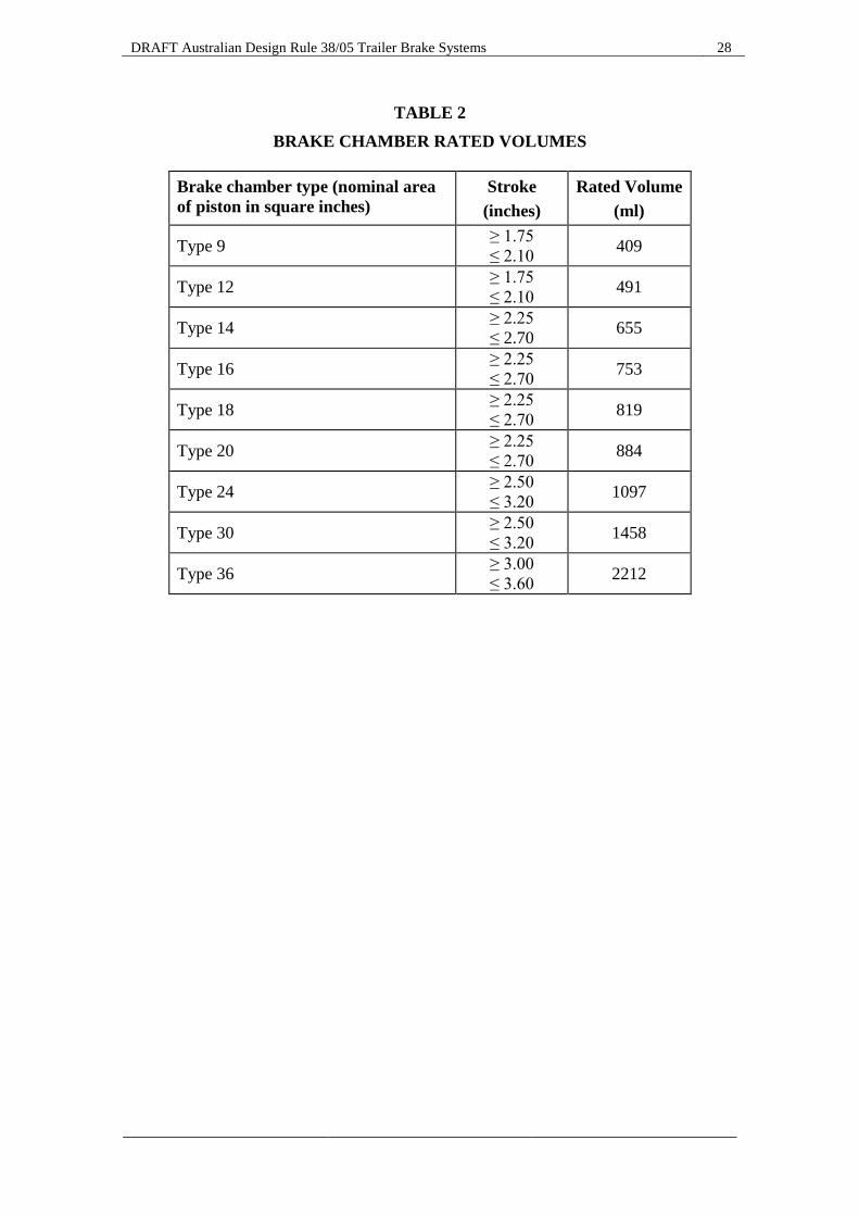
7.1.2.1. In the case of compressed air ‘Braking Systems’, the ratio of air reservoir volume to actuator volume will be taken as being the ratio of energy capacity.
7.1.2.2. The volume of an actuator (brake chamber) of a type specified in Table 2 is taken as being either the rated volume listed in this table or the actual volume of the actuator at the maximum travel of the actuator piston/pushrod, whichever is lower.
7.1.2.3. The volume of an actuator not listed in Table 2 is the actual volume of the actuator at the maximum travel of the actuator piston/pushrod.
DRAFT Australian Design Rule 38/05 Trailer Brake Systems 9
7.1.3. The elapsed time, as measured in accordance with the procedure specified in part 16 for measuring brake actuation time response must not exceed in the case of:
7.1.3.1. any brake actuator of any ‘Axle Group’ on the trailer, 0.4 seconds; and 7.1.3.2. any trailer or dolly rear service coupling for towed trailers, 0.4 seconds. 7.1.4. In the case of trailers, other than ‘Pig Trailers’ that are not ‘Converter
Dollies’, the elapsed time as measured in accordance with the procedure specified in part 16 for measuring brake release time must not exceed, in the case of:
7.1.4.1. any trailer or dolly rear service coupling for towed trailers, 0.65 seconds. 7.1.5. At least one ‘Axle’ in each ‘Axle Group’ of each ‘Unique’ trailer ‘Service
Brake System’ must be shown to commence to develop a braking force, at a ‘Control Signal’ (measured at each ‘Control Line’ coupling) not exceeding 0.154 ‘E’ (100 kPa for the pneumatic ‘Control Line’ and the equivalent digital demand value in the case of any electric ‘Control Line’), when at ‘UTM’ with the energy storage devices charged to the ‘Nominal Minimum Energy Level’.
7.1.5.1. For the purpose of this clause, an ‘Axle’ is deemed to have commenced to develop a braking force, when the total static brake torque for the axle concerned reaches the lesser of: (a) 100 N.m; or (b) 1 per cent of the product of the static vertical load (N) on the ‘Axle’
concerned and the rolling radius of the tyres (m) fitted to the wheels, at ‘UTM’.
7.1.5.2. Compliance with this clause may be shown by: (a) Lifting the wheels of the ‘Axles’ of each ‘Axle Group’ above the
ground, so they can be freely rotated by hand when the pressure in the ‘Control Line’ is 0 kPa;
(b) Setting any ‘Variable Proportioning Brake System’ (including an electronic load proportioning system) to the ‘UTM’ operating condition, without increasing the torque required to rotate the wheels; and
(c) Gradually increasing the ‘Control Signal’ (measured at the ‘Control Line’ coupling) until the total torque required to begin to rotate the wheels/hubs of at least one ‘Axle’ in each ‘Axle Group’, reaches the lesser of: i. 100 N.m; or
ii. 1 per cent of the product of the static vertical load (N) on the ‘Axle’ concerned and the rolling radius of the tyres (m) fitted to the wheels, at ‘UTM’.
DRAFT Australian Design Rule 38/05 Trailer Brake Systems 10
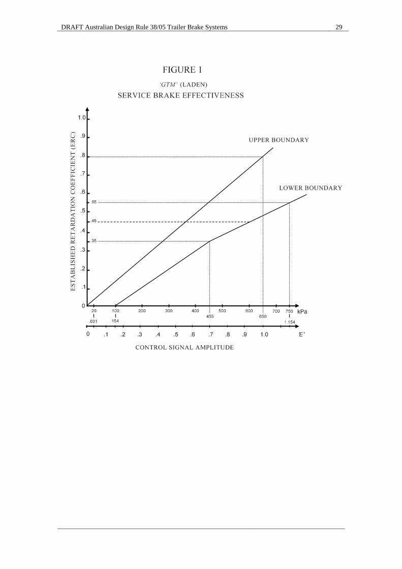
7.1.6. Each ‘Unique’ trailer ‘Service Brake System’ must be shown by either testing in accordance with parts 10 and 11, or by calculation based on data for ‘Approved’ components in accordance with clause 17, to have ‘Established Retardation Coefficients’ between the ‘Upper Boundary’ and the ‘Lower Boundary’ of: (a) Figure 1 when fully laden; and (b) For trailers not equipped with an ‘Antilock System’ (only where
permitted by clause 7.2.1.1), but fitted with a ‘Variable Proportioning Brake System’, Figure 2 when at ‘UTM’, and progressively between Figure 2 and Figure 1 for intermediate states of load.
7.1.6.1. The requirements specified in this clause are applicable for trailers equipped with a pneumatic ‘Control Line’, as well as for trailers with an additional electric ‘Control Line’. In both cases, the reference value (horizontal coordinate of the figure) will be the value of the transmitted pressure in the ‘Control Line’: (a) For a pneumatic ‘Control Line’, this will be the actual pneumatic
pressure in the ‘Control Line’; (b) In the case of an additional electric ‘Control Line’, this will be the
pressure corresponding to the transmitted digital demand value in the electric ‘Control Line’, according to ISO 11992:2003 including ISO 11992-2:2003 and its Amd.1:2007.
Trailers equipped with both pneumatic and electric ‘Control Lines’ must satisfy the requirements of this clause for each ‘Control Line’. However, identical braking characteristic curves are not required for each of these ‘Control Lines’.
7.1.6.2. ‘Established Retardation Coefficients’ may be determined by calculation for intermediate states of load between ‘UTM’ and fully laden. These calculations must include not less than 5 points and include any critical point.
7.1.6.3. The ‘Upper Boundary’ of Figure 2 may be increased by up to 40 per cent in the case of a trailer with a ‘Variable Proportioning Brake System’, which can be set to achieve a retardation response between the conventional ‘Upper Boundary’ and the ‘Lower Boundary’ of Figure 2, but is adjusted to allow for the braking responses of particular towing vehicles not equipped with a ‘Variable Proportioning Brake System’.
7.1.7. Each ‘Unique’ trailer ‘Service Brake System’ must be shown by either testing in accordance with parts 10 and 13 or by the calculation based on data for ‘Approved’ components in accordance with part 18, to meet the requirements of clause 13.1.
7.1.8. Trailers fitted with a ‘Variable Proportioning Brake System’, including an electronically controlled brake force distribution system (including for example as part of a ‘Vehicle Stability Function’), must meet the requirements of APPENDIX 1.
DRAFT Australian Design Rule 38/05 Trailer Brake Systems 11
7.2. Electric ‘Control Line’, ‘Antilock System’ and ‘Vehicle Stability Function’ requirements
7.2.1. Except as set out in clause 7.2.1.1 below, trailers must be equipped on each ‘Axle Group’ with an ‘Antilock System’ which meets the requirements of APPENDIX 2.
7.2.1.1. A ‘Converter Dolly’ and any trailer fitted with an ‘Axle Group’ arrangement consisting of more than four tyres in a row of ‘Axles’ or more than four ‘Axles’ in an ‘Axle Group’, need not be equipped with an ‘Antilock System’.
7.2.1.1.1. Where a trailer is not equipped with an ‘Antilock System’ (only if permitted by clause 7.2.1.1 above) or a ‘Variable Proportioning Brake System’, the information on the Vehicle Plate referred to in clause 8 of ADR 61/... must include the words ― “THIS VEHICLE IS NOT FITTED WITH ANTILOCK BRAKES OR VARIABLE PROPORTIONING BRAKES”.
7.2.1.1.2. Where a trailer is not equipped with an ‘Antilock System’ (only if permitted by clause 7.2.1.1 above) but is fitted with a ‘Variable Proportioning Brake System’, the information on the Vehicle Plate referred to in clause 8 of ADR 61/... must include the words ― “THIS VEHICLE IS NOT FITTED WITH ANTILOCK BRAKES”.
7.2.1.2. Notwithstanding clause 7.2.1.1 above, the requirements of APPENDIX 2 must also be met if an ‘Antilock System’ is fitted to a ‘Converter Dolly’ or any trailer fitted with an ‘Axle Group’ arrangement consisting of more than four tyres in a row of ‘Axles’ or more than four ‘Axles’ in an ‘Axle Group’.
7.2.2. Except as set out in clause 7.2.2.1 below, category TD trailers must be equipped with a ‘Vehicle Stability Function’ which includes at least ‘Roll-over Control’ and meets the requirements of APPENDIX 3.
7.2.2.1. A ‘Converter Dolly’ and any trailer fitted with an ‘Axle Group’ arrangement consisting of more than four tyres in a row of ‘Axles’ or more than four ‘Axles’ in an ‘Axle Group’, need not be equipped with a ‘Vehicle Stability Function’. If a ‘Vehicle Stability Function’ is fitted to such a trailer, this function may be manually disabled, provided this does not adversely affect the performance of any ‘Antilock System’, the power supply to any towed trailer(s) and/or the transmission of any electric ‘Control Signal’.
7.2.3. Trailers equipped with an electric ‘Control Line’, an ‘Antilock System’, or a ‘Vehicle Stability Function’, must meet the requirements of APPENDIX 4.
7.2.4. Notwithstanding the fitment preconditions of clause 7.2.3 above (i.e. fitment of an electric ‘Control Line’, an ‘Antilock System’, or a ‘Vehicle Stability Function’), any trailer (including a ‘Converter Dolly’) equipped to tow another trailer with an ‘ATM’ greater than 4.5 tonnes, must meet the requirements of part 3 (clauses 3.1 and 3.2) of APPENDIX 4.
DRAFT Australian Design Rule 38/05 Trailer Brake Systems 12
8. EMERGENCY BRAKE SYSTEM 8.1. Each ‘Unique’ trailer ‘Emergency Brake System’ must be shown by
either test in accordance with part 10 and clause 14.1 or by the calculation based on data for ‘Approved’ components in part 19, to have an ‘Established Retardation Co-efficient’ of not less than 0.18 and to be able to sustain a ‘Brake’ force required to obtain an ‘ERC’ of 0.18 for a period not less than 15 minutes.
8.2. The ‘Emergency Brake System’ may utilise parts of the ‘Service Brake System’ on the condition that any one failure of a ‘Brake Device’ in the ‘Service Brake System’ does not prevent the ‘Emergency Brake System’ from achieving its performance requirement. For the purpose of this clause, the ‘Brakes’ and any mechanical linkage connected directly thereto, must be considered as not subject to failure.
8.3. In the case of ‘Semi-Trailers’, when disconnected from the ‘Prime-Mover’, the failure of any structure designed to support the front of the trailer must not reduce the effectiveness of the ‘Emergency Brake System’ to less than half that required by clause 8.1.
8.4. ‘Emergency Brake Systems’ that employ ‘Stored Fluid Energy’ to hold them in the release position must be provided with an auxiliary release mechanism. The auxiliary device, control or tool, may rely on fluid energy stored within the trailer brake system, and must be attached to the trailer chassis rail, or equivalent structure, forward of the forward most ‘Axle’ on the rear ‘Axle Group’ on the right hand side of the trailer.
8.4.1. If the auxiliary device utilises stored energy then, with the energy storage devices initially charged to 1.0 ‘E’ the release system must have sufficient reserve to provide at least 3 applications and releases of the ‘Emergency Brake System’ when the towing vehicle is disconnected.
9. PARKING BRAKE SYSTEM 9.1. The ‘Parking Brake System 38/...’ must be independent of the ‘Service
Brake System’ except that the brakes and any mechanical system attached directly thereto may be common.
9.2. The ‘Parking Brake System 38/...’ must be able to be applied by means of a single ‘Control’ and once applied, must be able to be held in position by purely mechanical means.
9.3. It must not be possible to release the Parking Brake unless a means of immediately reapplying it is available.
9.4. The parking brake must operate when the ‘Supply Line’ energy level drops below 0.24 ‘E’ (155 kPa). The provisions of clause 9.3 do not apply to the auxiliary release mechanism required by clause 8.4 but the other provisions of clause 8.4 must apply.
9.5. Additional parking brake facilities are permitted provided that the requirements of clauses 9.2, 9.3 and 9.4 are met.
DRAFT Australian Design Rule 38/05 Trailer Brake Systems 13
9.6. Each ‘Unique’ trailer ‘Parking Brake System 38/...’ must be shown to be capable of holding the trailer stationary on an 18 percent gradient in either direction by either:
9.6.1. test in accordance with part 10 and clause 15.1; or 9.6.2. test in accordance with part 10 and clause 15.2; or 9.6.3. calculation based on data for ‘Approved’ components in part 20.
10. GENERAL PERFORMANCE ROAD TEST CONDITIONS 10.1. The ambient temperature at the test site must be greater than 0°C and less
than 40°C. 10.2. All road tests must be conducted with tyres fitted of the size specified by
the ‘Manufacturer’ as original equipment and must be inflated to pressures not less than those recommended by the ‘Manufacturer’.
10.3. Braking tests must be carried out on approximately level surfaces. 10.3.1. Where the levels are unsurveyed, the test must be completed in both
directions, the brakes being applied over the same section, and the two results averaged to determine the final result.
10.3.2. Where the difference in start and finish elevations for a brake test, expressed as a percentage of the ‘Stopping Distance’, is known, the brake test need only be completed in one direction and the result corrected for any difference in elevation exceeding 1 percent.
10.4. The wind speed difference between two tests in opposite directions, or against the direction of travel in the case of a single brake test, must not exceed 15 km/h.
10.5. The towing vehicle used to facilitate the tests must be of a type normally employed to tow the particular trailer under test and must have enough power to attain the initial speed required for the specified braking tests.
10.6. All road tests must be conducted with energy storage devices charged to ‘Nominal Minimum Energy Level’ and the ‘Axle Groups’ loaded, unless otherwise required by this rule, to:
10.6.1. The ‘GTM’ and in a separate series of tests to the values allowed by Table 1 if this results in a trailer mass lower than ‘GTM’; and
10.6.2. In the case of trailers fitted with a ‘Variable Proportioning Brake System’ in a separate test to the ‘UTM’; and
10.6.3. In the case of trailers not equipped with an ‘Antilock System’, solely in accordance with clause 7.2.1.1 above, but fitted with a ‘Variable Proportioning Brake System’, in a separate series of tests to the ‘UTM’.
10.7. The test surface must be either concrete or bitumen pavement and must be free from loose material.
10.8. No towing vehicle braking system or other contrived means must contribute to braking effort and the towing vehicle engine must be declutched or neutral engaged, during the braking tests required by this rule.

DRAFT Australian Design Rule 38/05 Trailer Brake Systems 14
10.9. The ‘Brakes’ may be burnished before conducting any effectiveness tests according to the brake manufacturer’s recommended procedures.
10.10. The ‘Brake System’ must be adjusted in accordance with the brake manufacturer’s recommendations before performance tests are conducted.
10.11. The performance requirements must be met with no deviation of the vehicle from its course greater than 300 millimetres.
10.12. No part of the ‘Brake System’ shall exceed 100°C immediately prior to the commencement of a brake test sequence.
11. SERVICE BRAKE EFFECTIVENESS TEST CONDITIONS 11.1. Except as provided in clause 11.1.1 below, the initial speed at the point
where trailer braking commences must be, 58 to 64 km/h. 11.1.1. For special trailers having a design speed less than 58 km/h, the initial
speed at the point where trailer braking commences must not be less than the ‘Manufacturer’s’ nominated design speed.
11.2. The trailer must be braked to a stop from initial speed starting with a ‘Control Signal’ of 0.2 ‘E’ and in increasing increments of not greater than 0.2 ‘E’ for subsequent stops until an ‘Established Retardation Coefficient’ of not less than 0.45 is achieved.
11.3. In the case of a compressed air ‘Brake System’ the ‘Control Signal’, applied to the ‘Control Line’ at the front of the trailer, must reach 65 percent of the final value in less than 0.4 second.
11.4. ‘Stopping Distance’ or ‘Stopping Time’ may be used to calculate the ‘ERC’ according to the equations in clause 11.5.
11.5. The ‘Service Brake System’ ‘ERC’ must be determined according to the following as required:
where: V is the initial speed in km/h S is the ‘Stopping Distance’ in metres T is the ‘Stopping Time’ in seconds TR is the response time measured from the time the ‘Control’ leaves the
‘Initial Brake Control Location’ until the energy level at the least favoured actuator reaches 65 percent of final value
‘Total Combination Mass’ in tonnes ‘Total Trailer Axle Load’ in tonnes with the trailer loaded as specified in
clause 10.6
DRAFT Australian Design Rule 38/05 Trailer Brake Systems 15
11.6. The computed ‘Established Retardation Coefficients’ determined from clause 11.5 must comply with clause 7.1.6. Where a test was not conducted at 1.0 ‘E’ the ‘ERC’ from a test conducted at 0.8 ‘E’ or greater may be increased pro-rata to derive the ‘ERC’ at 1.0 ‘E’.
11.7. No trailer wheels must remain locked, except below 15 km/h, during completion of the braking tests required by part 11.
11.8. Allowance must be made for the effect of the increased rolling resistance resulting from the combination of vehicles being used to carry out the tests.
11.9. Computer simulation of the requirements of this part 11 is allowed where the simulation is sufficiently sophisticated and has been ‘Approved’ on the basis of an adequate back to back comparison with physical test results.
12. DOG TRAILER FRICTION UTILISATION 12.1. In the case of ‘Dog Trailers’ and with any ‘Antilock System’ disengaged
or otherwise made not operational, at least one front ‘Axle’ must skid before at least one rear ‘Axle’ at an ‘ERC’ greater than:
(a) 0.3 in the case of two ‘Axle’ ‘Dog Trailers’; (b) 0.15 in the case of ‘Dog Trailers’ with three or more ‘Axles’.
12.2. The test must be conducted in accordance with part 11 with the ‘Control Signal’ and surface type selected to demonstrate the requirement of clause 12.1 above.
12.3. The initial speed requirement of part 11 does not apply.
13. SERVICE BRAKE FADE EFFECTIVENESS TEST 13.1. The ‘Service Brake System’ must, on the next application after not less
than 20 successive applications, each not more than 70 seconds after the preceding one and with the total of 20 applications completed within 20 minutes, of the trailer ‘Brakes’ from an initial speed of V1 km/h to a final speed as calculated below or by clause 13.2, achieve a calculated ‘Established Retardation Coefficient’, when tested in accordance with part 11, at a nominated ‘Control Signal’ level, of not less than 60 percent of the value obtained at that ‘Control Signal’ level for the Service Brake Effectiveness Test required by part 11 nor less than 80 percent of the value specified by the lower boundary of Figure 1 at that ‘Control Signal’ level. The nominated ‘Control Signal’ level chosen must not be less than that necessary to produce a calculated ‘Established Retardation Coefficient’ of 0.45 under the Service Brake test conditions described in part 11 without prior fade conditioning stops.
DRAFT Australian Design Rule 38/05 Trailer Brake Systems 16
13.2. The final speed to which the trailer has to be successively braked as part of the brake fade conditioning procedure must be determined from the equation:
where: V1 is the initial speed in km/h;
V2 is the final speed in km/h;
Masses and Loads in tonnes 13.3. The temperature (100°C) requirement of clause 10.12 does not apply to
the test required by clause 13.1.
14. EMERGENCY BRAKE SYSTEM EFFECTIVENESS TEST 14.1. The ‘Established Retardation Coefficient’, as determined by clause 11.5
must be determined by a test to the requirements of part 11 except where clause 14.2 applies, and except that:
14.1.1. The ‘Control Signal’ source must be left in the “off” position with no ‘Control Signal’ being provided to the trailer control line; and
14.1.2. The energy level in the ‘Supply Line’ must be reduced to zero (in a 2-line compressed air system this will be the emergency line).
14.2. Where the actuation of the ‘Emergency Brake System’ depends on one or more sources of ‘Stored Energy’ that are common to the ‘Service Brake System’, for the purposes of testing for compliance with the requirements of clause 14.1, the trailer energy storage devices must be charged to an energy level no greater than 0.05 ‘E’ above the supply level determined for clause 6.5, or the energy storage device level if higher, at which the ‘Emergency Brake System’ commences to activate the ‘Brakes’.
14.3. Wheel-locking at ‘Established Retardation Coefficients’ above 0.18 is permitted.
15. PARKING BRAKE EFFECTIVENESS TEST 15.1. The ‘Parking Brake System 38/...’ must be able to meet the requirements
of clause 9.6 for a 5 minute period in each direction with the force required to actuate the parking brake not exceeding 685 N in the case of a foot operated brake and not exceeding 590 N in the case of a hand operated brake.
15.1.1. The necessary longitudinal force will be considered to have been applied if the sum of the force applied to the trailer towing point and the force due to the effect of gravity on the laden trailer mass, in the direction parallel to the test surface and trailer longitudinal axis, is greater than 0.18 times the ‘Aggregate Trailer Mass’.
15.1.2. Where the test involves a force depending on the slope of the test surface, the slope must not be less than 10 percent.

DRAFT Australian Design Rule 38/05 Trailer Brake Systems 17
15.1.3. When the test involves the action of slope on the trailer or combination mass, and the towing vehicle remains connected, 1.5 percent of the towing vehicle mass must be subtracted from the other forces parallel to the test plane, to allow for rolling friction.
15.1.4. The test slope must be specified in terms of unit vertical per unit horizontal distance expressed as a percentage.
15.2. The ‘Parking Brake System 38/...’ must meet the requirements of clause 14.1 when the ‘Foundation Brakes’ geometry is such that a reversal of the required braking torque will not reduce the ability of the ‘Parking Brake System 38/...’ to generate the required braking torque.
16. TIME RESPONSE MEASUREMENT 16.1. Except where hydraulic brakes are used, each ‘Unique’ trailer ‘Brake
System’ must be shown to meet the requirements of clause 7.1.3 and 7.1.4 by testing in accordance with clause 16.3, or in accordance with part 21.
16.1.1. Where a trailer is fitted with a ‘Variable Proportioning Brake System’ the test must be conducted with the ‘Variable Proportioning Brake System’ set for the fully laden case.
16.2. A variant of a ‘Unique’ trailer ‘Brake System’ will be considered to be identical in regard to time response, when the only variation from the ‘Unique’ ‘Brake System’ is one or more of the following:
16.2.1. Plumbing or energy transmission line lengths and number of fittings are reduced but other characteristics including diameter, material, type of connecting fittings and the characteristic transmission loss per unit length are not changed.
16.2.2. Entire subsections of the ‘Brake System’ have been removed, as would be the case in converting a modular three ‘Axle’ system to a modular two ‘Axle’ system, such that the effect if any is to slightly increase the energy flow rate to and from the remaining brake sub-systems.
16.2.3. The energy required to actuate the substitute brake actuators to their maximum design level is less.
16.3. Where a trailer ‘Brake System’ is required to be tested for compliance with clauses 7.1.3 and where applicable 7.1.4 in the case of compressed air ‘Brake System’:
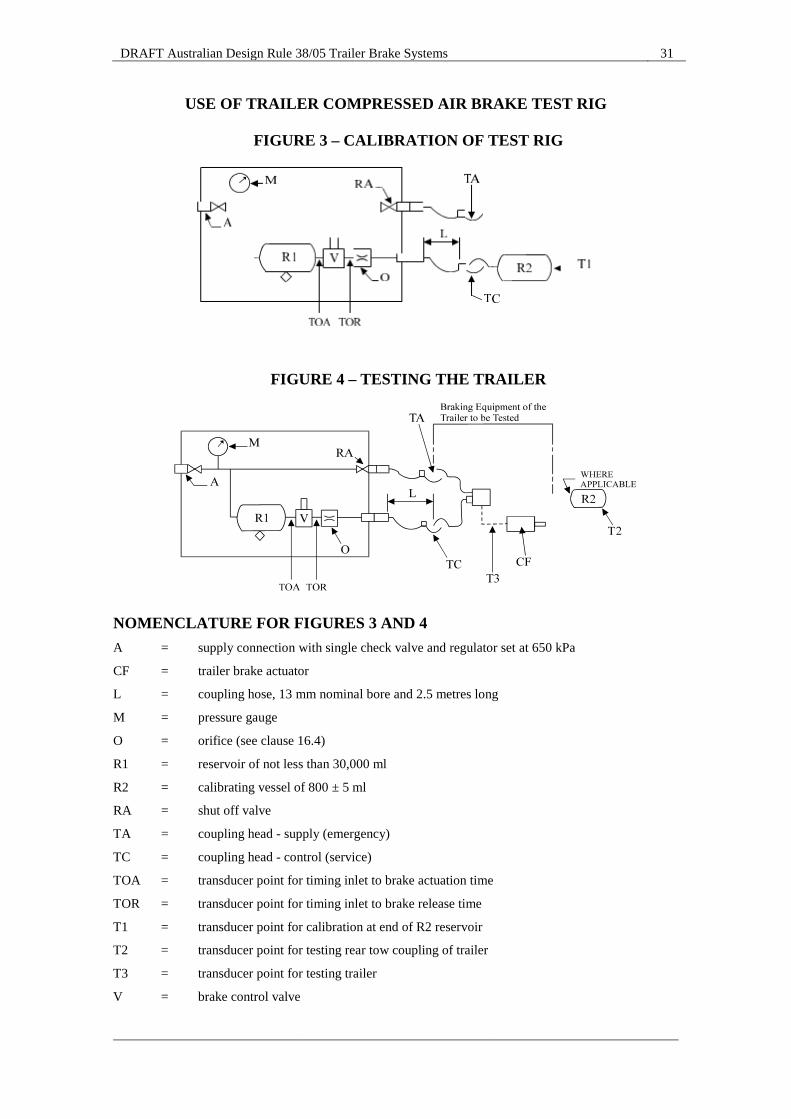
16.3.1. for a pneumatic ‘Control Line’, the test rig described in Figure 3 must be calibrated in accordance with clause 16.4 and connected as described in Figure 4;
16.3.2. for an electric ‘Control Line’, Figure 5 gives an example of the correct configuration of the simulator for setting and use and must be used according to clause 16.10 to comply with clause 7.1.3.
16.3.3. Where the trailer has both a pneumatic and an electric ‘Control Line’, the response time measurement for each control line must be determined independently according to the relevant procedure.
DRAFT Australian Design Rule 38/05 Trailer Brake Systems 18
16.4. The test rig described in Figure 3 must be calibrated by adjustment of the orifice (O) such that:
16.4.1. upon application of the brake control valve (V) with the storage reservoir (R1) charged to 1.0 ‘E’ (650 kPa), the time interval is between 0.18 and 0.22 seconds from when the initial pressure drops measured between the storage reservoir and the control valve (V), or the initial pressure rises at the output of brake control valve (V), to when the pressure at the end of the calibrating vessel (R2) increases to 0.65 ‘E’ (420 kPa);
16.4.2. after the pressure in the calibrating vessel (R2) has stabilised, upon release of the brake control valve (V) must be such that the time between the initial pressure drop in the calibrating vessel (R2) and the pressure in the calibrating vessel (R2) reaching 0.05 ‘E’ (35.0 kPa) is between 0.4 and 0.5 seconds.
16.4.3. Where one setting of the orifice (O) does not meet both of these conditions simultaneously, two different settings meeting the appropriate condition can be used in the tests prescribed in clauses 16.7 and 16.8.
16.5. Where a rear service coupling for towed trailers is provided, time responses must be measured with an 800-millilitre vessel attached to the rear service coupling as in Figure 4.
16.6. The test rig and the trailer energy storage devices must be charged to 1.0 ‘E’ (650 kPa) prior to the test being conducted and no additional energy must be added to the storage vessel (R1) or the trailer ‘Supply Line’ during the period of the test.
16.7. The brake actuation time must be taken from when the pressure level, measured between the storage reservoir and the control valve (V) initially drops, or measured at the output of brake control valve (V) initially rises to when the pressure in the least favoured brake actuator reaches 0.65 ‘E’ (420 kPa).
16.8. With an initial service brake application level of 1.0 ‘E’ (650 kPa) the brake release time must be taken from when the pressure level, measured between the control valve and the orifice, initially drops to the greater of when the pressure in the least favoured brake actuator reaches 0.05 ‘E’ (35 kPa) or when the friction materials cease to contact each other.
16.9. The brake control valve must be of a configuration such that; 16.9.1. it permits energy to flow from the storage reservoir to the orifice (O)
when in the “ON” position and from the orifice to waste when in the “OFF” position; and,
16.9.2. it must not allow additional energy to flow into the test rig ‘Control Line’ by way of its own ‘Control Signal’; and
16.9.3. it must be designed so that the manner of its operation has no effect on the output response of the test rig; and
16.9.4. it may be arranged to provide a modulated test rig output signal for other brake development purposes which will be rendered inoperative for the purpose of measuring trailer ‘Brake System’ response in accordance with clause 16.3.
DRAFT Australian Design Rule 38/05 Trailer Brake Systems 19
16.10. The simulator must produce a digital demand signal in the electric control line according to ISO 11992-2:2003 and its Amd.1:2007 and must provide the appropriate information to the trailer via pins 6 and 7 of the ISO 7638:2003 connector. For the purpose of response time measurement, the simulator may at the manufacturer's request transmit to the trailer information that no pneumatic control line is present and that the electric control line demand signal is generated from two independent circuits (see paragraphs 6.4.2.2.24 and 6.4.2.2.25 of ISO 11992-2:2003 and its Amd.1:2007).
16.10.1. For the purpose of response time measurement the signal produced by the electric simulator must be equivalent to a linear pneumatic pressure increase from 0.0 to 650 kPa in 0.2 ± 0.01 second.
17. SERVICE BRAKE EFFECTIVENESS CALCULATION 17.1. In the case of an ‘Axle Group’ fitted with a ‘Brake Reactive Suspension’
the distribution of braking effort amongst the ‘Axles’ in an ‘Axle Group’ must be in the range of ‘Skid Limit’ values determined for the suspension in accordance with clause 22.4.
17.2. In the case of ‘Dog Trailers’ at least one front ‘Axle’ must have a higher friction utilisation than that of at least one rear ‘Axle’ at decelerations greater than:
(a) 0.3 g in the case of 2 ‘Axle’ ‘Dog Trailers’, (b) 0.15 g in the case of ‘Dog Trailers’ with 3 or more ‘Axles’.
17.2.1. In the case of two-‘Axle’ ‘Dog Trailers’-the friction utilisation factors may be calculated according to:
so:
and:
DRAFT Australian Design Rule 38/05 Trailer Brake Systems 20
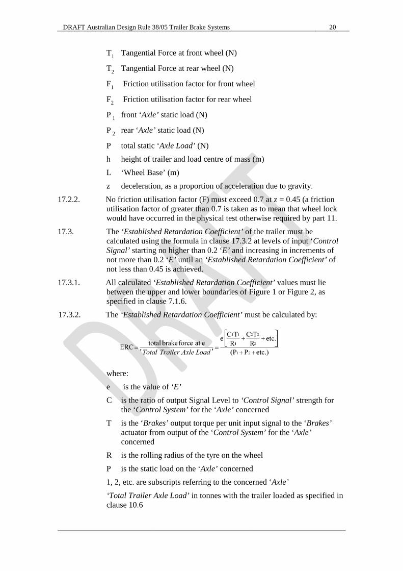
T1 Tangential Force at front wheel (N)
T2 Tangential Force at rear wheel (N)
F1 Friction utilisation factor for front wheel
F2 Friction utilisation factor for rear wheel
P 1 front ‘Axle’ static load (N)
P 2 rear ‘Axle’ static load (N)
P total static ‘Axle Load’ (N) h height of trailer and load centre of mass (m) L ‘Wheel Base’ (m) z deceleration, as a proportion of acceleration due to gravity.
17.2.2. No friction utilisation factor (F) must exceed 0.7 at z = 0.45 (a friction utilisation factor of greater than 0.7 is taken as to mean that wheel lock would have occurred in the physical test otherwise required by part 11.
17.3. The ‘Established Retardation Coefficient’ of the trailer must be calculated using the formula in clause 17.3.2 at levels of input ‘Control Signal’ starting no higher than 0.2 ‘E’ and increasing in increments of not more than 0.2 ‘E’ until an ‘Established Retardation Coefficient’ of not less than 0.45 is achieved.
17.3.1. All calculated ‘Established Retardation Coefficient’ values must lie between the upper and lower boundaries of Figure 1 or Figure 2, as specified in clause 7.1.6.
17.3.2. The ‘Established Retardation Coefficient’ must be calculated by:
where: e is the value of ‘E’ C is the ratio of output Signal Level to ‘Control Signal’ strength for
the ‘Control System’ for the ‘Axle’ concerned T is the ‘Brakes’ output torque per unit input signal to the ‘Brakes’
actuator from output of the ‘Control System’ for the ‘Axle’ concerned
R is the rolling radius of the tyre on the wheel P is the static load on the ‘Axle’ concerned 1, 2, etc. are subscripts referring to the concerned ‘Axle’ ‘Total Trailer Axle Load’ in tonnes with the trailer loaded as specified in
clause 10.6
DRAFT Australian Design Rule 38/05 Trailer Brake Systems 21
18. SERVICE BRAKE FADE CALCULATION 18.1. The ‘Service Brake System’ will be considered to have sufficient brake
fade resistance to meet the requirements of this rule if the ‘Gross Axle Load Rating’ of each ‘Foundation Brake’ rated according to the fade test in clause 22.3.6 is greater than the ‘Gross Trailer Mass’ multiplied by the percentage of total brake torque provided by that ‘Foundation Brake’ for at least one ‘Control Signal’ level necessary to produce a calculated ‘Established Retardation Coefficient’ of not less than 0.45 under the Service Brake test Conditions described in part 11 without prior fade conditioning stops.
19. EMERGENCY BRAKE SYSTEM CALCULATION. 19.1. The ‘Established Retardation Coefficient’ for the ‘Emergency Brake
System’ must be determined by computing the total braking force (kN) at the wheels to which emergency brakes are fitted and dividing by [9.81 × ‘Gross Trailer Mass’ (tonnes)].
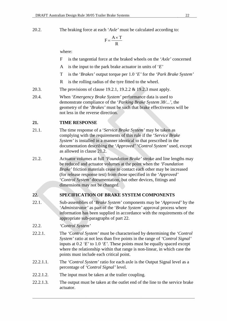
19.2. The braking force at each ‘Axle’ must be calculated according to:
where: F is the tangential force at the braked wheels on the ‘Axle’ concerned A is the input to the emergency brakes actuator in units of ‘E’ T is the ‘Brakes’ output torque per 1.0 ‘E’ for the ‘Emergency Brake
System’ R is the rolling radius of the tyre fitted to the wheel
19.2.1. Where the actuating force is dependent on the stroke, as in the case of spring brakes, the value of A used in the equation above must be that corresponding to the ‘Brakes’ actuator stroke achieved by the ‘Emergency Brake System’. This can be determined by plotting on a graph of ‘Control Signal’ versus stroke as detailed in clauses 19.2.2 and 19.2.3:
19.2.2. The input to the emergency brakes actuator in units of ‘E’ from the data provided for the ‘Control System’ at various strokes; and
19.2.3. The ‘Foundation Brake’ stroke achieved at various ‘Control System’ inputs.
20. PARKING BRAKE CALCULATION 20.1. The gradient, expressed as a percentage, on which the ‘Parking Brake
System 38/...’ can hold the trailer must be determined by computing the total braking force at the wheels (N) to which the ‘Parking Brake System 38/...’ is fitted and dividing by [98.1 x ‘Aggregate Trailer Mass’ (tonnes)].
RT A F ×
=
DRAFT Australian Design Rule 38/05 Trailer Brake Systems 22
20.2. The braking force at each ‘Axle’ must be calculated according to:
where: F is the tangential force at the braked wheels on the ‘Axle’ concerned A is the input to the park brake actuator in units of ‘E’ T is the ‘Brakes’ output torque per 1.0 ‘E’ for the ‘Park Brake System’ R is the rolling radius of the tyre fitted to the wheel.
20.3. The provisions of clause 19.2.1, 19.2.2 & 19.2.3 must apply. 20.4. When ‘Emergency Brake System’ performance data is used to
demonstrate compliance of the ‘Parking Brake System 38/...’, the geometry of the ‘Brakes’ must be such that brake effectiveness will be not less in the reverse direction.
21. TIME RESPONSE 21.1. The time response of a ‘Service Brake System’ may be taken as
complying with the requirements of this rule if the ‘Service Brake System’ is installed in a manner identical to that prescribed in the documentation describing the ‘Approved’ ‘Control System’ used, except as allowed in clause 21.2.
21.2. Actuator volumes at full ‘Foundation Brake’ stroke and line lengths may be reduced and actuator volumes at the point when the ‘Foundation Brake’ friction materials cease to contact each other may be increased (for release response test) from those specified in the ‘Approved’ ‘Control System’ documentation, but other devices, fittings and dimensions may not be changed.
22. SPECIFICATION OF BRAKE SYSTEM COMPONENTS 22.1. Sub-assemblies of ‘Brake System’ components may be ‘Approved’ by the
‘Administrator’ as part of the ‘Brake System’ approval process where information has been supplied in accordance with the requirements of the appropriate sub-paragraphs of part 22.
22.2. ‘Control System’ 22.2.1. The ‘Control System’ must be characterised by determining the ‘Control
System’ ratio at not less than five points in the range of ‘Control Signal’ inputs at 0.2 ‘E’ to 1.0 ‘E’. These points must be equally spaced except where the relationship within that range is non-linear, in which case the points must include each critical point.
22.2.1.1. The ‘Control System’ ratio for each axle is the Output Signal level as a percentage of ‘Control Signal’ level.
22.2.1.2. The input must be taken at the trailer coupling. 22.2.1.3. The output must be taken at the outlet end of the line to the service brake
actuator.
RT A F ×
=
DRAFT Australian Design Rule 38/05 Trailer Brake Systems 23
22.2.2. The input signal strength must be the final value of the applied signal and must be applied to the ‘Control System’ such that it rises from zero to 65 percent of the final value in not more than 0.22 second. In the case of air ‘Brake System’s’ the input ‘Control Signal’ strength (kPa) will be measured at the trailer ‘Control Line’ coupling.
22.2.3. The output signal strength must be the final value of the signal generated for control of the ‘Brakes’ actuator and which must be reached in not more than two seconds. The output signal strength will be measured in the actuator attached to each output having a fundamentally different relation to the input. In the case of air ‘Brake Systems’ a ‘Control Signal’ path having additional pressure limiters, relay valves or other active devices will be considered as being fundamentally different.
22.2.4. Time response must be measured where necessary in accordance with part 16.
22.2.5. Where the ‘Control System’ is not installed on an actual trailer, it must be installed in an essentially identical manner, in the laboratory, with all bends, fittings and worst case line lengths and representative actuator volumes installed.
22.2.6. For the application test, clause 16.7, the actuator displacement must be the largest volume for which the ‘Control System’ is designed and it may be represented by an equivalent fixed volume.
22.2.7. The release test, clause 16.8, must commence at an actuator displacement corresponding to the largest volume for which the ‘Control System’ is designed. Alternatively, the actuators may be replaced by an equivalent fixed volume.
22.2.8. All relevant test conditions pertaining to part 10 must be complied with. 22.2.9. The relationship between brake actuator volume and stroke must be
measured and plotted from zero to full actuator stroke. 22.2.9.1. If the relationship between stroke and volume is not linear, all critical
points must be measured and plotted. 22.2.9.2. The value of the maximum brake actuator design stroke and volume must
be stated. 22.3. ‘Foundation Brakes’ 22.3.1. The effectiveness of the ‘Foundation Brakes’ must be characterised by
comparing the energy level of the signal provided to the ‘Brakes’ actuator against the output brake torque of the ‘Brakes’ device at not less than five points in the range 0.2 ‘E’ to 1.0 ‘E’. These points must be equally spaced. Where a test was not conducted at 1.0 ‘E’, the torque from a test conducted at 0.8 ‘E’ or greater may be increased pro-rata to derive output torque at 1.0 ‘E’.
22.3.2. Parameters relevant to the specification of the ‘Brakes’ actuator including its stroke at each energy level of the signal provided to the ‘Brakes’ actuator must be recorded. In the case of ‘S-Cam’ air systems this will include the actuator size, slack adjuster length and any other special feature.
DRAFT Australian Design Rule 38/05 Trailer Brake Systems 24
22.3.3. Measurements must be taken in accordance with the relevant conditions for the road test described in parts 10 and 11.
22.3.4. The ‘Brakes’ must be burnished before conducting any effectiveness tests according to the brake manufacturer’s recommended procedures.
22.3.5. Specification of effectiveness for ‘Foundation Brakes’ must be on the basis of ‘Axle’ performance with two brake assemblies rather than wheel performance.
22.3.6. The ‘Foundation Brake’ must, on the next application after not less than 20 successive applications, each not more than 70 seconds after the preceding one and with the total of 20 applications completed within 20 minutes, of the trailer ‘Brakes’ from an initial speed of V1 km/h to a final speed as calculated by clause 22.3.6.1, achieve a calculated brake torque, when tested in accordance with part 11, at a nominated energy level of the signal provided to the ‘Brakes’ actuator, of not less than 60 percent of the brake torque achieved at that Actuator Supply Energy level when tested in accordance with clause 22.3.1. The chosen, nominated energy level of the signal provided to the ‘Brakes’ actuator, must not be less than that necessary to produce a calculated ‘Established Retardation Coefficient’ of 0.45 under the Service Brake Test Conditions described in part 11 when laden to the ‘GALR’ without prior fade conditioning stops.
22.3.6.1. The final speed to which the trailer has to be successively braked as part of the brake fade conditioning procedure must be determined from the equation:
where: V1 is the initial speed in km/h V2 is the final speed in km/h
Masses and Loads in tonnes 22.3.6.2. The temperature (100 °C) requirement of clause 10.3 does not apply to
the test required by clause 13.1. 22.4. Suspension Behaviour, ‘Brake Reactive Suspensions’ only. 22.4.1. ‘Suspension Systems’ for other than hinged drawbar ‘Pig Trailers’. 22.4.1.1. The suspension must be installed according to the ‘Manufacturer’s’
instructions to a representative trailer, be fitted with ‘Axles’, wheels and tyres of a size appropriate to the mass rating of the suspension, and be fitted with identical “Pre-calibrated” ‘Brakes’ at each ‘Axle’.
22.4.1.1.1. “Pre-calibrated” in this case means that the relationship between the input actuation energy level and the output torque for the ‘Brakes’ on each ‘Axle’ has been measured.

DRAFT Australian Design Rule 38/05 Trailer Brake Systems 25
22.4.1.2. To determine the ‘Service Brake System’ ‘Skid Limit’ a Service Brake Effectiveness Test must be conducted applying the brakes on all ‘Axles’ of the trailer and using the General Test Conditions of part 10 and generally in accordance with the particular conditions of part 11 with not less than 50% of the ‘Suspension Systems’ rated ‘Axle Group’ load used in place of ‘Gross Trailer Mass’. Clause 11.2 need not be complied with.
22.4.1.3. The test result must be reported as the value of the computed retardation force for each ‘Axle’ divided by the greatest of the ‘Axle’ retardation forces at which an ‘Established Retardation Coefficient’ of 0.45 can be achieved without wheel lock.
22.4.1.3.1. In the case of ‘S-Cam’ air ‘Brake Systems’ the overall effect of changing actuator and slack adjuster sizes can be simulated by individually adjusting the air pressure to each ‘Axle’.
22.4.2. ‘Suspension Systems’ for hinged drawbar ‘Pig Trailers’. 22.4.2.1. The suspension must be installed according to the manufacturer’s
instructions to a representative trailer, be fitted with ‘Axles’, wheels and tyres of a size appropriate to the mass rating of the suspension, and be fitted with identical “Pre-calibrated” ‘Brakes’ at each ‘Axle’.
22.4.2.1.1. “Pre-calibrated” in this case means that the relationship between the input actuation energy level and the output torque for the ‘Brakes’ on each ‘Axle’ has been measured.
22.4.2.2. The trailer must be laden such that the ‘Axle Group’ load equals the suspension system’s rated ‘Axle Group’ load and that the centre of gravity of the trailer is at the same height as for a typical trailer laden to the rated ‘Axle Group’.
22.4.2.3. To determine the ‘Service Brake System’ ‘Skid Limit’ a Service Brake Effectiveness Test Conditions test must be conducted applying the brakes on all ‘Axles’ on both the trailer and the towing vehicle such that the computed retardation of the trailer is within 0.05 m/s2 of that of the towing vehicle.
22.4.2.4. The computed retardation must be derived from tests of each vehicle braked alone comparing the ‘Control Signal’ at the truck to trailer coupling with the retardation achieved.
22.4.2.5. The test must be conducted using the General Test Conditions of part 10 and the generally in accordance with the particular conditions of part 11. Clause 11.2 need not be complied with.
22.4.2.6. The test result must be reported as the value of the indicated retardation force for each ‘Axle’ divided by the greatest of the ‘Axle’ retardation forces at which an ‘Established Retardation Coefficient’ of 0.45, calculated with ‘Total Combination Mass’ held equal to ‘Gross Trailer Mass’, can be achieved without wheel lock.
22.4.2.6.1. In the case of ‘S-Cam’ air ‘Brake Systems’ the overall effect of changing actuator and slack adjuster sizes can be simulated by individually adjusting the air pressure to each ‘Axle’.
DRAFT Australian Design Rule 38/05 Trailer Brake Systems 26
23. ALTERNATIVE STANDARDS 23.1. The technical requirements of the United Nations Regulation No. 13 –
UNIFORM PROVISIONS CONCERNING THE APPROVAL OF VEHICLES OF CATEGORIES M, N AND O WITH REGARD TO BRAKING, incorporating the 11 series of amendments, are deemed to be equivalent to all technical requirements of this standard, except for the requirements of:
23.1.1. Clause 7.1.4, in the case of trailers, other than ‘Pig Trailers’ that are not ‘Converter Dollies’;
23.1.2. Clause 7.2.1, in the case of trailers with more than three ‘Axles’ in an ‘Axle Group’;
23.1.3. Clause 7.2.2, in the case of trailers with more than three ‘Axles’, or trailers without air suspension;
23.1.4. Clause 7.2.3, in the case of trailers equipped to tow another trailer with an ‘ATM’ greater than 4.5 tonnes; and
23.1.5. Clauses 9.2 to 9.4, in the case of trailers with an ‘ATM’ greater than 4.5 tonnes.
DRAFT Australian Design Rule 38/05 Trailer Brake Systems 27
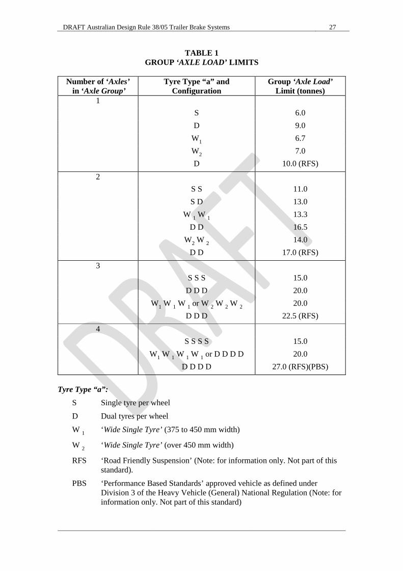
TABLE 1 GROUP ‘AXLE LOAD’ LIMITS
Number of ‘Axles’
in ‘Axle Group’ Tyre Type “a” and
Configuration Group ‘Axle Load’
Limit (tonnes) 1 S 6.0 D 9.0 W1 6.7 W2 7.0 D 10.0 (RFS) 2 S S 11.0 S D 13.0 W 1 W 1 13.3 D D 16.5 W2 W 2 14.0 D D 17.0 (RFS) 3 S S S 15.0 D D D 20.0 W1 W 1 W 1 or W 2 W 2 W 2 20.0 D D D 22.5 (RFS) 4 S S S S 15.0 W1 W 1 W 1 W 1 or D D D D 20.0 D D D D 27.0 (RFS)(PBS)
Tyre Type “a”: S Single tyre per wheel D Dual tyres per wheel W 1 ‘Wide Single Tyre’ (375 to 450 mm width)
W 2 ‘Wide Single Tyre’ (over 450 mm width)
RFS ‘Road Friendly Suspension’ (Note: for information only. Not part of this standard).
PBS ‘Performance Based Standards’ approved vehicle as defined under Division 3 of the Heavy Vehicle (General) National Regulation (Note: for information only. Not part of this standard)
DRAFT Australian Design Rule 38/05 Trailer Brake Systems 28
TABLE 2 BRAKE CHAMBER RATED VOLUMES
Brake chamber type (nominal area of piston in square inches)
Stroke (inches)
Rated Volume (ml)
Type 9 ≥ 1.75 ≤ 2.10 409
Type 12 ≥ 1.75 ≤ 2.10 491
Type 14 ≥ 2.25 ≤ 2.70 655
Type 16 ≥ 2.25 ≤ 2.70 753
Type 18 ≥ 2.25 ≤ 2.70 819
Type 20 ≥ 2.25 ≤ 2.70 884
Type 24 ≥ 2.50 ≤ 3.20 1097
Type 30 ≥ 2.50 ≤ 3.20 1458
Type 36 ≥ 3.00 ≤ 3.60 2212
DRAFT Australian Design Rule 38/05 Trailer Brake Systems 29

DRAFT Australian Design Rule 38/05 Trailer Brake Systems 30
DRAFT Australian Design Rule 38/05 Trailer Brake Systems 31
USE OF TRAILER COMPRESSED AIR BRAKE TEST RIG
FIGURE 3 – CALIBRATION OF TEST RIG
FIGURE 4 – TESTING THE TRAILER
NOMENCLATURE FOR FIGURES 3 AND 4 A = supply connection with single check valve and regulator set at 650 kPa
CF = trailer brake actuator
L = coupling hose, 13 mm nominal bore and 2.5 metres long
M = pressure gauge
O = orifice (see clause 16.4)
R1 = reservoir of not less than 30,000 ml
R2 = calibrating vessel of 800 ± 5 ml
RA = shut off valve
TA = coupling head - supply (emergency)
TC = coupling head - control (service)
TOA = transducer point for timing inlet to brake actuation time
TOR = transducer point for timing inlet to brake release time
T1 = transducer point for calibration at end of R2 reservoir
T2 = transducer point for testing rear tow coupling of trailer
T3 = transducer point for testing trailer
V = brake control valve
DRAFT Australian Design Rule 38/05 Trailer Brake Systems 32
FIGURE 5 – EXAMPLE ELECTRIC ‘CONTROL LINE’ TEST RIG
NOMENCLATURE FOR FIGURE 5 ECL = Electric Control Line corresponding to ISO 7638
SIMU = Simulator of Byte 3,4 of EBS 11 according to ISO 11992-2:2003 including its Amd-1
2007 with output signals at start, 65 kPa and 650 kPa
A = Supply connection with shut-off valve
C2 = Pressure switch to be connected to the brake actuator of the trailer, to operate at 75
per cent of the asymptotic pressure in the brake actuator CF
CF = Brake cylinder
M = Pressure gauge
PP = Pressure test connection
TA = Coupling head, supply line
VRU = Emergency relay valve
DRAFT Australian Design Rule 38/05 Trailer Brake Systems 33
APPENDIX 1 Additional requirements for trailers (over 4.5 tonnes ‘ATM’) fitted
with a ‘Variable Proportioning Brake System’
1. Requirements 1.1. Trailers fitted with a ‘Variable Proportioning Brake System’ must have
markings affixed in a visible position on the trailer in indelible form and containing the following information:
1.1.1. Where the ‘Variable Proportioning Brake System’ consists of a device mechanically controlled by the suspension of the trailer, the useful travel (recommended units of mm) of the device between the positions corresponding to ‘UTM’ and ‘GTM’, as well as any further information to enable the setting of the device to be checked in service.
1.1.1.1. Where the ‘Variable Proportioning Brake System’ consists of a device controlled via the suspension of the trailer by any other means, the information necessary to enable the setting of the device to be checked in service.
1.1.2. Where the ‘Variable Proportioning Brake System’ consists of a device which modulates the air pressure in the brake transmission, the ‘Axle’ load(s) (recommended units of kg) corresponding to the ‘UTM’ and ‘GTM’ for the ‘Axle(s)’ which control(s) the device and the corresponding nominal inlet and outlet pressures (recommended units of kPa) of the device, as well as any further information to enable the setting of the device to be checked in service. The inlet pressure must be not less than 80 per cent of the maximum design inlet pressure, as declared by the trailer manufacturer.
1.2. Trailers fitted with an electronically controlled ‘Variable Proportioning Brake System’ (including as part of a ‘Vehicle Stability Function’), that cannot fulfil the requirements of clause 1.1 of this appendix above, must have a self-checking procedure of the functions which influence brake force distribution.
1.3. Each ‘Unique’ trailer ‘Service Brake System’ must be shown by either testing in accordance with parts 10 and 11 (excluding clause 11.2) of this standard, or by calculation based on data for ‘Approved’ components using the formula in clause 17.3.2, to develop an ‘Established Retardation Coefficient’ of at least 0.45, for at least one ‘Control Signal’ (measured at the ‘Control Line’ coupling) not exceeding 0.8 ‘E’ (520 kPa in the case of a pneumatic ‘Control Line’), when at ‘UTM’.
1.3.1. Linear interpolation of data obtained from tests conducted in ‘Control Signal’ increments not exceeding 0.2 ‘E’ may be used to demonstrate compliance with this clause.
1.3.2. Trailers equipped with both pneumatic and electric ‘Control Lines’ must satisfy the requirements of this clause for each ‘Control Line’. In the case of an additional electric ‘Control Line’, the pressure in the ‘Control Line’ is the pressure corresponding to the transmitted digital demand value in the electric ‘Control Line’, according to ISO 11992:2003 including ISO 11992-2:2003 and its Amd.1:2007.
DRAFT Australian Design Rule 38/05 Trailer Brake Systems 34
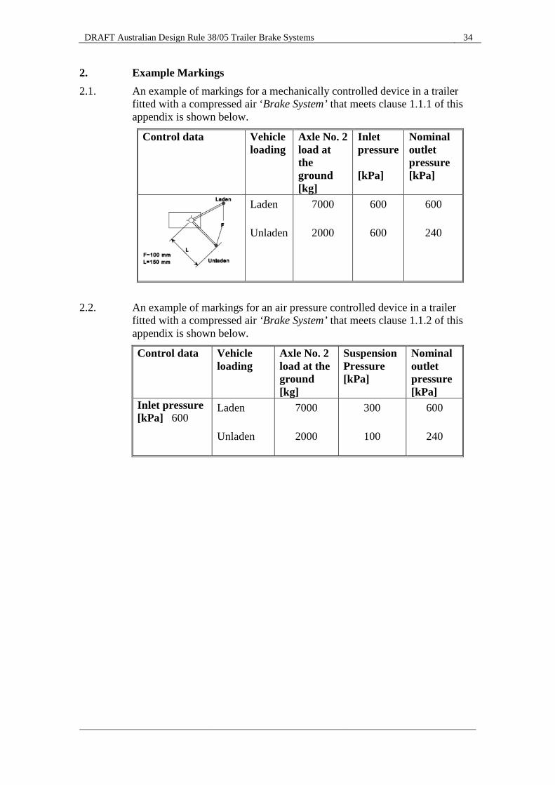
2. Example Markings 2.1. An example of markings for a mechanically controlled device in a trailer
fitted with a compressed air ‘Brake System’ that meets clause 1.1.1 of this appendix is shown below.
Control data Vehicle loading
Axle No. 2 load at the ground [kg]
Inlet pressure [kPa]
Nominal outlet pressure [kPa]
Laden Unladen
7000
2000
600
600
600
240
2.2. An example of markings for an air pressure controlled device in a trailer
fitted with a compressed air ‘Brake System’ that meets clause 1.1.2 of this appendix is shown below.
Control data
Vehicle loading
Axle No. 2 load at the ground [kg]
Suspension Pressure [kPa]
Nominal outlet pressure [kPa]
Inlet pressure [kPa] 600
Laden Unladen
7000
2000
300
100
600
240
DRAFT Australian Design Rule 38/05 Trailer Brake Systems 35
APPENDIX 2 Performance and installation requirements for ‘Antilock Systems’
fitted to trailers with an ‘ATM’ greater than 4.5 tonnes
1. Performance requirements 1.1. The ‘Brake System’ of trailers equipped with an ‘Antilock System’, must:
(a) Comply with the requirements of clauses 7.1.3 to 7.1.8 of this ADR with the ‘Antilock Systems’ operational and in the event of any one electrical failure of the ‘Antilock System’; and
(b) Be capable of developing, including by actuation through a ‘Control Line’ connected to a towing vehicle, an ‘Established Retardation Co-efficient’ of at least that required for the ‘Emergency Brake System’ in part 8 of this ADR, in the event of any one failure of the ‘Antilock System’.
1.2. At speeds exceeding 15 km/h the wheels on the ‘Axle(s)’ specified in clause 2.1 of this appendix must remain unlocked when a ‘Control Signal’ of 1.0 ‘E’ (650 kPa) is suddenly applied from an initial speed of 40 km/h +5 to -1 km/h and from an initial speed of at least 80 km/h on a road surface having approximately uniform surface friction on both sides of the trailer.
1.2.1. This test is to be performed according to the general test conditions of part 10 with the trailer laden to both ‘Lightly Laden Test Mass’ and ‘Maximum Loaded Test Mass’.
1.2.2. Brief periods of locking of the wheels are allowed, but stability must not be affected.
1.3. The operation of an ‘Antilock System’ must not be adversely affected by magnetic or electric fields.
2. Installation requirements 2.1. An ‘Antilock System’ complying with clause 1 of this appendix must be
fitted to: 2.1.1. each ‘Single Axle’; 2.1.2. at least one ‘Axle’ in any ‘Tandem Axle Group’; 2.1.3. at least two ‘Axles’ in any ‘Triaxle Group’; 2.1.4. at least three ‘Axles’ in any ‘Axle Group’ with four ‘Axles’.

DRAFT Australian Design Rule 38/05 Trailer Brake Systems 36
APPENDIX 3 ‘Vehicle Stability Function’ requirements for category TD trailers
1. Definitions 1.1. ‘Vehicle Stability Function’ means an electronic control function for a
vehicle which improves the dynamic stability of the vehicle. 1.2. A ‘Vehicle Stability Function’ includes one or both of the following:
(a) ‘Directional Control’; (b) ‘Roll-over Control’.
1.3. Control functions within a ‘Vehicle Stability Function’: 1.3.1. ‘Directional control’ - means a function within a ‘Vehicle Stability
Function’ that assists the driver, in the event of understeer and oversteer conditions, within the physical limits of the vehicle in maintaining the direction intended by the driver in the case of a power-driven vehicle, and assists in maintaining the direction of the trailer with that of the towing vehicle in the case of a trailer.
1.3.2. ‘Roll-over control’ - means a function within a ‘Vehicle Stability Function’ that reacts to an impending roll-over in order to stabilise the power-driven vehicle or towing vehicle and trailer combination or the trailer during dynamic manoeuvres within the physical limits of the vehicle.
1.4. ‘Automatically Commanded Braking’ and ‘Selective Braking’ events: 1.4.1. ‘Automatically Commanded Braking’ – means a function within a complex
electronic control system where actuation of the braking system(s) or brakes of certain axles is made for the purpose of generating vehicle retardation with or without a direct action of the driver, resulting from the automatic evaluation of on board initiated information.
1.4.2. ‘Selective Braking’ - means a function within a complex electronic control system where actuation of individual brakes is made by automatic means in which vehicle retardation is secondary to vehicle behaviour modification.
2. Functional requirements 2.1. For each category TD trailer required to be equipped with a ‘Vehicle
Stability Function’ as defined above, the following shall apply: 2.1.1. In the case of ‘Directional Control’ the function must have the ability to
automatically control individually the speed of the left and right wheels on each ‘Axle’ or an ‘Axle’ of each ‘Axle Group’ by ‘Selective Braking’ based on the evaluation of actual trailer behaviour in comparison with a determination of the relative behaviour of the towing vehicle.
2.1.2. In the case of ‘Roll-over Control’ the function must have the ability to automatically control the wheel speeds on at least two wheels of each ‘Axle’ or ‘Axle Group’ by ‘Selective Braking’ or ‘Automatically Commanded Braking’ based on the evaluation of actual trailer behaviour that may lead to roll-over.
DRAFT Australian Design Rule 38/05 Trailer Brake Systems 37
2.1.3. The ‘Vehicle Stability Function’, including the ‘Roll-over Control’ function, does not need to be operational during system initialisation, at trailer operating speeds below 20 km/h, when the trailer is being reversed, or if disabled by an operator according to clause 2.1.3.1 below.
2.1.3.1. A separate and distinct means (for example an off road mode selector/switch on the trailer) may be provided to enable an operator to disable the ‘Vehicle Stability Function’ for trailer operating speeds up to 40 km/h.
2.2. To realise the functionality defined above a ‘Vehicle Stability Function’ must include, in addition to ‘Automatically Commanded Braking’ and where appropriate ‘Selective Braking’, at least the following:
2.2.1. The determination of actual trailer behaviour from values of the vertical force on the tyre(s), or at least lateral acceleration and wheel speeds. Only on-board generated information may be used. If these values are not directly measured, the ‘Manufacturer’ must supply to the ‘Administrator’ sufficient evidence of the appropriate correlation with directly measured values under all driving conditions (e.g. including driving in a tunnel).
2.3. Trailers equipped with an electric ‘Control Line’ must, when electrically connected to a towing vehicle with an electric ‘Control Line’, provide the information "VDC active" via the data communications part of the electric ‘Control Line’ when the ‘Vehicle Stability Function’ is in an intervention mode. Interventions of the ‘Vehicle Stability Function’ used in any learning process to determine the trailer operational characteristics must not generate the above information (note: VDC or Vehicle Dynamic Control, as defined within ISO 11992-2:2003 including Amd.1:2007, is defined within this national standard as a ‘Vehicle Stability Function’).
DRAFT Australian Design Rule 38/05 Trailer Brake Systems 38
APPENDIX 4 Electrical requirements for all trailers (over 4.5 tonnes ‘ATM’) incorporating
an electric ‘Control Line’, an ‘Antilock System’, or a ‘Vehicle Stability Function’
1. Electrical supply system requirements 1.1. Each trailer must be fitted at the front with a special connector conforming
to ISO 7638-1:2003 configured for 24 volt operation or ISO 7638-2:2003 configured for 12 volt operation. The ‘Vehicle Stability Function’ and the ‘Antilock Systems’ of the trailer must be able to be simultaneously powered by an electrical supply from a towing vehicle through this connector.
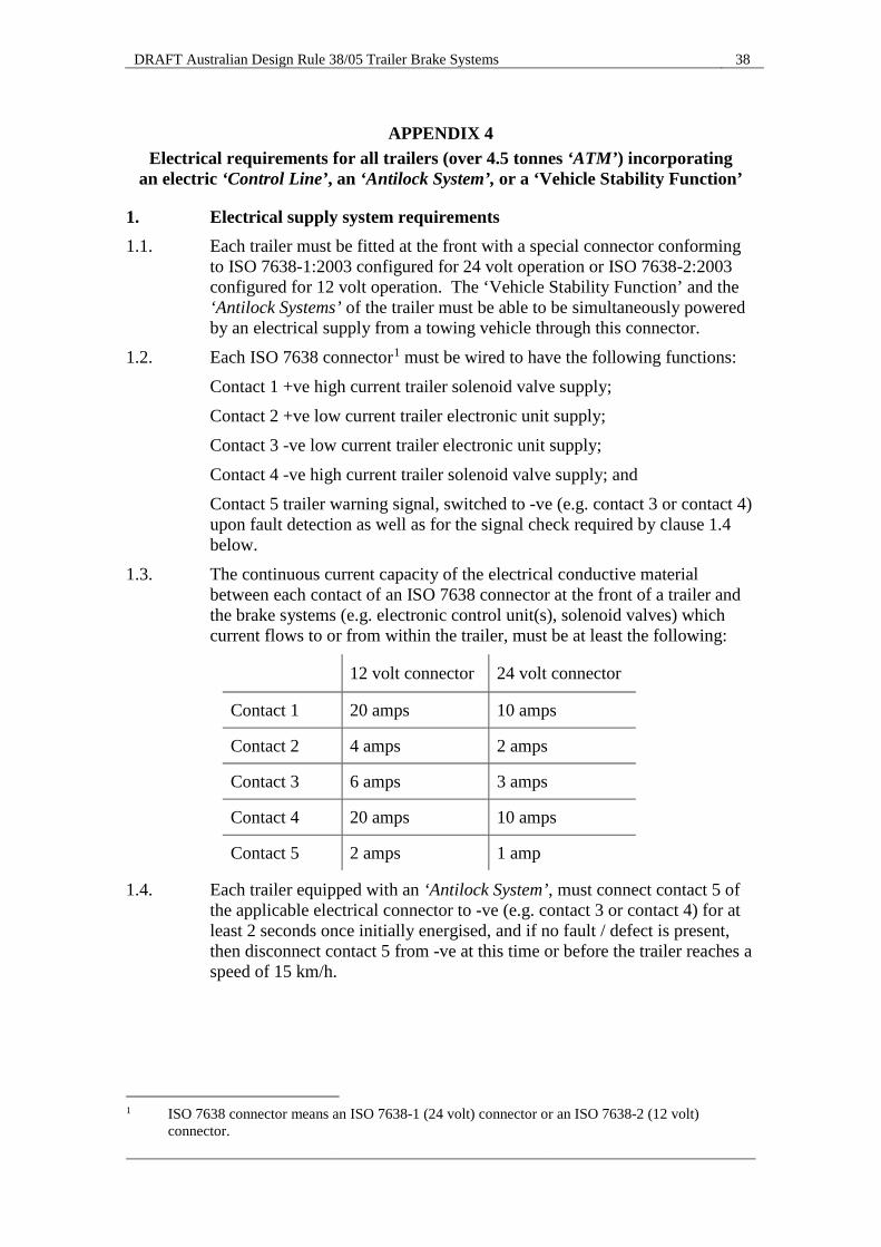
1.2. Each ISO 7638 connector1 must be wired to have the following functions: Contact 1 +ve high current trailer solenoid valve supply; Contact 2 +ve low current trailer electronic unit supply; Contact 3 -ve low current trailer electronic unit supply; Contact 4 -ve high current trailer solenoid valve supply; and Contact 5 trailer warning signal, switched to -ve (e.g. contact 3 or contact 4) upon fault detection as well as for the signal check required by clause 1.4 below.
1.3. The continuous current capacity of the electrical conductive material between each contact of an ISO 7638 connector at the front of a trailer and the brake systems (e.g. electronic control unit(s), solenoid valves) which current flows to or from within the trailer, must be at least the following:
12 volt connector 24 volt connector
Contact 1 20 amps 10 amps
Contact 2 4 amps 2 amps
Contact 3 6 amps 3 amps
Contact 4 20 amps 10 amps
Contact 5 2 amps 1 amp
1.4. Each trailer equipped with an ‘Antilock System’, must connect contact 5 of the applicable electrical connector to -ve (e.g. contact 3 or contact 4) for at least 2 seconds once initially energised, and if no fault / defect is present, then disconnect contact 5 from -ve at this time or before the trailer reaches a speed of 15 km/h.
1 ISO 7638 connector means an ISO 7638-1 (24 volt) connector or an ISO 7638-2 (12 volt)
connector.
DRAFT Australian Design Rule 38/05 Trailer Brake Systems 39
1.5. Each trailer equipped with a ‘Vehicle Stability Function’ and/or an ‘Antilock System’, must connect contact 5 of the applicable electrical connector to -ve (e.g. contact 3 or contact 4) whenever:
1.5.1. There is a break in the supply of electricity to a ‘Vehicle Stability Function’ and/or an ‘Antilock System’ and any electrical failure of a ‘Vehicle Stability Function’ and/or an ‘Antilock System’, other than a failure of one or all of the electrical conductors between contacts 3, 4 and 5 on the electrical connector and the vehicle stability/antilock control module; or
1.5.2. The supply voltage to the trailer falls below a value nominated by the manufacturer at which the prescribed requirements for any of the braking functions required by clause 7.2 of this standard can no longer be met.
1.6. Each category TD trailer other than a ‘Converter Dolly’, which is equipped with a ‘Vehicle Stability Function’, must also connect contact 5 of the applicable electrical connector to -ve (e.g. contact 3 or contact 4), if/when its ‘Vehicle Stability Function’ is disabled in operation above 20 km/h, by a means satisfying clause 2.1.3.1 of APPENDIX 3.
1.7. The power supply transmitted through an ISO 7638 connector must be used exclusively for braking and running gear functions and that required for the transfer of trailer related information not transmitted via an electric ‘Control Line’.
1.7.1. However, in all cases, whenever power transmitted through an ISO 7638 connector is used for the functions defined in this clause above, the braking system must have priority and be protected from an overload external to the braking system. This protection must be a function of the braking system.
1.7.2. The power supply for all other functions must use other measures.
2. Electric ‘Control Line’ requirements 2.1. In the case of a trailer equipped with an electric ‘Control Line’: 2.1.1. The communications via the electric ‘Control Line’ must conform to
ISO 11992-1:2003 and ISO 11992-2:2003 including its amendment 1:2007.2 2.1.2. The electric ‘Control Line’ must be a point-to-point type using a seven pin
(or tube) connector in accordance with ISO 7638-1:2003 or ISO 7638-2:2003; as per which, contact 6 must be wired for the CAN_H signal and contact 7 must be wired for the CAN_L signal.
2.1.3. The electric ‘Control Line’ must meet the requirements of ISO 11992-1:2003 including: (a) The wiring must be an unshielded twisted pair; and (b) The maximum cable length of the electric ‘Control Line’ within the
trailer must not exceed 18 m and the bus capacitance of the cable must not exceed 2.9 nF, except where otherwise permitted by clause 2.3 of this appendix below.
2 These include specific CAN voltage range requirements for 12 volt and 24 volt nominal voltage
systems.
DRAFT Australian Design Rule 38/05 Trailer Brake Systems 40
2.1.4. The message "illuminate stop lamps" must be transmitted by the trailer via the electric ‘Control Line’ when the trailer ‘Service Brake System’ is activated during ‘Automatically Commanded Braking’ initiated by the trailer. However, the signal may be suppressed, when the retardation generated is less than 0.7 m/s2.
2.1.5. The message "illuminate stop lamps" must not be transmitted by the trailer via the electric ‘Control Line’ during ‘Selective Braking’ initiated by the trailer (note: during a ‘Selective Braking’ event, the function may change to ‘Automatically Commanded Braking’).
2.2. The data contacts of an ISO 7638 connector incorporating an electric ‘Control Line’ must be used to transfer information exclusively for braking (including the ‘Vehicle Stability Function’ and ‘Antilock System’) and running gear (steering, tyres and suspension) functions as specified in ISO 11992-2:2003 including its amendment 1:2007.
2.2.1. The braking functions have priority and must be maintained in the normal and failed modes. The transmission of running gear information must not delay braking functions.
2.3. The overall length of the electric ‘Control Line’ installed within a trailer may exceed the 18 m permitted by ISO 11992-1:2013, where a device (e.g. CAN repeater) is installed to amplify and repeat messages in such a way that all communications throughout the electric ‘Control Line’ otherwise conform with ISO 11992-1:2003 and ISO 11992-2:2003 including its amendment 1:2007.
2.4. A message routing device/function (e.g. CAN router) conforming to ISO 11992-2:2003, paragraph 6.3 (Message Routing), is required for all trailers incorporating electric ‘Control Line’ through which messages are distributed between more than two electronic nodes (e.g. trailers for which multiple control units are used to provide the braking functions required by clause 7.2 of this standard). Such a device/function is necessary to satisfy the point-to-point type requirement for the electric ‘Control Line’ between electronic devices.
3. Additional requirements for all trailers equipped to tow another trailer with an ‘ATM’ greater than 4.5 tonnes
3.1. Except as provided in clause 3.1.1 below, each trailer (including any ‘Converter Dolly’) equipped to tow another trailer with an ‘Aggregate Trailer Mass (ATM)’ greater than 4.5 tonnes, must be fitted at the rear with a connector conforming to ISO 7638-1:2003 and meeting the requirements of clause 1.2 of this appendix.3 This connector must be configured to distribute a 24 volt electrical supply, received via a connector in accordance with ISO 7638-1:2003 at the front of the trailer, to a ‘Vehicle Stability Function’ and/or the ‘Antilock Systems’ of a towed trailer.4
3 Where a seven contact ISO 7638 connector is used at the rear of a trailer equipped to tow another
trailer, any electric ‘Control Line’ wired to contacts 6 and 7 of this connector must also meet clause 2 of this appendix.
4 This does not prevent ISO 7638-2 connectors and through wiring from also being fitted to distribute a 12 volt nominal supply voltage to a towed trailer.
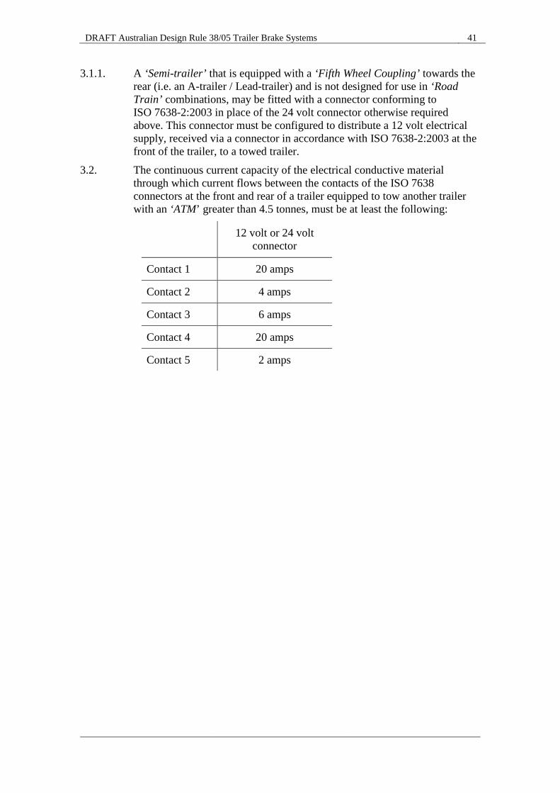
DRAFT Australian Design Rule 38/05 Trailer Brake Systems 41
3.1.1. A ‘Semi-trailer’ that is equipped with a ‘Fifth Wheel Coupling’ towards the rear (i.e. an A-trailer / Lead-trailer) and is not designed for use in ‘Road Train’ combinations, may be fitted with a connector conforming to ISO 7638-2:2003 in place of the 24 volt connector otherwise required above. This connector must be configured to distribute a 12 volt electrical supply, received via a connector in accordance with ISO 7638-2:2003 at the front of the trailer, to a towed trailer.
3.2. The continuous current capacity of the electrical conductive material through which current flows between the contacts of the ISO 7638 connectors at the front and rear of a trailer equipped to tow another trailer with an ‘ATM’ greater than 4.5 tonnes, must be at least the following:
12 volt or 24 volt connector
Contact 1 20 amps
Contact 2 4 amps
Contact 3 6 amps
Contact 4 20 amps
Contact 5 2 amps
Related Documents