Design Criteria UTA Commuter Rail Rev No. Prepared By Approved By Approval Date Document Date 0 MGr JWebb 12/1/04 12/1/04 1 DGoeres CCC 11/30/07 11/30/07 2 T. W. Jones CCC 3/19/10 July 2010 Utah Transit Authority Commuter Rail Design Criteria Chapter 1 General Requirements and Table of Contents Revision 2, July 2010

Welcome message from author
This document is posted to help you gain knowledge. Please leave a comment to let me know what you think about it! Share it to your friends and learn new things together.
Transcript

Design Criteria UTA Commuter Rail
Rev No. Prepared By
Approved By
Approval Date Document Date
0 MGr JWebb 12/1/04 12/1/04 1 DGoeres CCC 11/30/07 11/30/07 2 T. W. Jones CCC 3/19/10 July 2010
Utah Transit Authority
Commuter Rail Design Criteria
Chapter 1
General Requirements and Table of Contents
Revision 2, July 2010

Utah Transit Authority
UTA Commuter Rail Design Criteria 1-i July 2010 Chapter 1 Revision 2
Table of Contents
CHAPTER 1 General Requirements ...................................................................................................... 1
1.1 Introduction ..................................................................................................................................... 1 1.1.1 Purpose ............................................................................................................................... 1 1.1.2 Project Overview ................................................................................................................ 1 1.1.3 Service Objectives .............................................................................................................. 1
1.2 Design Philosophy ........................................................................................................................... 4 1.2.1 Baseline CRT System ......................................................................................................... 4
1.3 Design Criteria Table of Contents ................................................................................................... 4 1.3.1 Specific Chapters ................................................................................................................ 4
1.4 Related Documents .......................................................................................................................... 5

Utah Transit Authority
UTA Commuter Rail Design Criteria 1-1 July 2010 Chapter 1 Revision 2
CHAPTER 1 GENERAL REQUIREMENTS
1.1 Introduction
1.1.1 Purpose This chapter provides an overview of the Utah Transit Authority (UTA) commuter rail program, and an introduction to the design criteria and standards to be used for the commuter rail system. These documents are intended to guide the preliminary and final design of the system, and apply to both the initial phase of the system as well as future extensions. This design criteria is not a detailed engineering design. UTA may approve modifications to the design criteria if justified by sound engineering judgment, practice, and economics. Changes to the design criteria may only be made with UTA approval. Approved changes not only apply to any preliminary and final design of the system, but also to all UTA commuter rail projects including new construction, remodel, and rehabilitation projects
1.1.2 Project Overview The system will utilize diesel-electric powered locomotives and passenger cars operating primarily on dedicated railroad track. The initial segment of the UTA commuter rail system is the 44-mile Weber County to Salt Lake City line, which will extend from Pleasant View through Ogden to the Salt Lake City Intermodal Center in the heart of Salt Lake City’s central business district (CBD). The commuter rail service will connect with UTA’s light rail and bus system to provide transportation solutions throughout the region. The second major portion of the commuter rail program is a 43-mile route from Utah County to Salt Lake City. It will extend from Provo in Utah County to the Intermodal Center in Salt Lake City. The route will follow existing UTA right-of-way (ROW) through Provo and generally along the west side of I-15. The commuter rail system has the potential of being expanded to other destinations. The track alignment for the existing program and potential extensions are shown in Figure 1-1. The line will be single-track, with passing sidings or double-tracked sections, located on dedicated UTA right-of-way parallel to the Union Pacific Railroad (UPRR). Trains will operate at maximum speeds of up to 79 mph. Equipment and rolling stock to be used for the commuter rail trains will consist of diesel passenger locomotives, coaches, and cab cars in a push-pull configuration.
1.1.3 Service Objectives Utah Transit Authority is responsible for the delivery of safe, reliable, cost effective and efficient public transportation within the Wasatch Front area of the state of Utah. UTA is constantly seeking to provide new and improved services to meet the transportation needs of the public and increase operational efficiency. The principal objectives of the UTA commuter rail system are to:
• Facilitate the safe and cost effective movement of people within the project corridor. • Provide efficient, high-capacity transit service to the communities located in the project corridor. • Enhance economic potential in the corridor by improving access to existing and planned
employment and activity centers by creating transit-oriented development (TOD) opportunities.

Utah Transit Authority
UTA Commuter Rail Design Criteria 1-2 July 2010 Chapter 1 Revision 2
• Support regional plans and policies that describe a balanced transportation system. • Support and contribute to regional air quality goals.

Utah Transit Authority
UTA Commuter Rail Design Criteria 1-3 July 2010 Chapter 1 Revision 2
Figure 1-1

Utah Transit Authority
UTA Commuter Rail Design Criteria 1-4 July 2010 Chapter 1 Revision 2
1.2 Design Philosophy The system shall be designed using subsystems consisting of proven equipment and design concepts. Subsystems and spare parts are to have a documented operating history of previous and current usage and be available off the shelf, so far as practical. Designs and specifications shall be prepared in such a way as to encourage competitive bidding by established manufacturers of transportation equipment. Industry guidelines from recognized and established organizations such as the American Railway Engineering and Maintenance-of-Way Association and Utah Department of Transportation shall be used. Fixed facilities such as structures and buildings shall be designed for continued operation over a minimum of 50 years before refurbishment and renovations are necessary due to wear and tear and obsolescence.
1.2.1 Baseline CRT System The commuter rail system is designed to be a safe, reliable, and cost-effective system that enhances the transportation options for the residents of the Wasatch Front region. The baseline CRT system consists of the following elements:
• Design and construction of a safe, reliable, and cost-effective system using a “bare bones, no frills” philosophy
• Ballasted track with concrete ties, continuous welded 115 RE rail on top of existing subgrade
• An at-grade corridor primarily within the existing UTA right-of-way
• Standard railway crossing gates to meet safety requirements (will work with communities to install quiet zone crossings)
• Center loading, basic station platforms
• Park-and-ride lots to serve the stations that are minimally lit and not landscaped, unless required by existing city ordinances
1.3 Design Criteria Table of Contents
1.3.1 Specific Chapters Design criteria have been developed for the following areas of work:
Chapter 1 General Requirements and Table of Contents
Chapter 2 Environmental
Chapter 3 Alignment
Chapter 4 Track Work
Chapter 5 Civil and Drainage
Chapter 6 Utilities
Chapter 7 Structures
Chapter 8 Stations
Chapter 9 Landscaping

Utah Transit Authority
UTA Commuter Rail Design Criteria 1-5 July 2010 Chapter 1 Revision 2
Chapter 10 Traffic Control
Chapter 11 Commuter Rail Vehicles
Chapter 12 Electric Distribution Systems (Not Used)
Chapter 13 Train Control
Chapter 14 Communication
Chapter 15 Fare Collection
Chapter 16 Corrosion Control (Not Used)
Chapter 17 Yards and Shops
Chapter 18 Rail Trails (Not Used)
Chapter 19 Pedestrian Crossings (Not Used)
Chapter 20 Elevators/Escalators (Not Used)
Chapter 21 Operations and Maintenance (Not Used)
Chapter 22 Safety and Security (Not Used)
Chapter 23 System Assurance (Not Used)
Chapter 24 Parking Deck (Not Used)
Chapter 25 Railroad (Freight) (Not Used)
1.4 Related Documents Other applicable documents, published separately, for use in design include the current editions of:
• CAD standards
• Draft/Final Environmental Impact Statement, Environmental Assessment, or Environmental Study Report
• Operations and Maintenance Plan
• Fleet Management Plan
• Facilities Master Plan
• System Safety Program Plan
• Rail Activation Plan
• Project Management Plans
• Storm Water Pollution Protection Plans
• Vehicle Specifications END OF CHAPTER 1.
tjones
Typewritten Text

Design Criteria
UTA Commuter Rail Rev No. Prepared
By Approved By
Approval Date Document Date
0 MGr JWebb 12/1/04 12/1/04 1 DGoeres CCC 11/30/07 11/30/07 2 T. W. Jones CCC 3/19/10 July 2010
Utah Transit Authority
Commuter Rail Design Criteria
Chapter 2
Environmental Revision 2, July 2010
Utah Transit Authority
UTA Commuter Rail Design Criteria 2-i July 2010 Chapter 2 Revision 2
Table of Contents
CHAPTER 2 ENVIRONMENTAL CRITERIA ................................................................................... 1
2.1 General ............................................................................................................................................ 1 2.2 Natural Environment Criteria .......................................................................................................... 1
2.2.1 Geologic Hazard ................................................................................................................. 1 2.2.2 Air Quality .......................................................................................................................... 1 2.2.3 Transit Noise and Vibration ................................................................................................ 1
2.2.3.1 Project Noise .......................................................................................................... 2 2.2.3.2 Horn Noise ............................................................................................................. 2 2.2.3.3 Yard and Shop Noise ............................................................................................. 2 2.2.3.4 Construction Noise and Vibration ......................................................................... 2
2.2.4 Water ................................................................................................................................... 2 2.2.4.1 Surface Water Quality ........................................................................................... 2 2.2.4.2 Streams................................................................................................................... 3 2.2.4.3 Floodplains ............................................................................................................ 3 2.2.4.4 Wetlands ................................................................................................................ 3
2.2.5 Vegetation/Wildlife ............................................................................................................ 3 2.2.6 Hazardous Waste Sites ........................................................................................................ 4 2.2.7 Energy Conservation ........................................................................................................... 4
2.3 Socioeconomic Environment Criteria .............................................................................................. 4 2.3.1 Displacement/Relocations ................................................................................................... 4 2.3.2 Safety/Security .................................................................................................................... 5 2.3.3 Historic, Architectural, Archaeological, and Cultural Resources ....................................... 5
2.3.3.1 Summary of MOA Stipulations ............................................................................. 5 2.3.3.2 Inadvertent Discovery ............................................................................................ 6
2.3.4 Visual .................................................................................................................................. 6 2.3.4.1 Lighting .................................................................................................................. 6 2.3.4.2 Urban Design ......................................................................................................... 7
2.3.5 Public Parks and Greenways ............................................................................................... 7 2.3.6 Environmental Justice ......................................................................................................... 7
2.4 Traffic and Transportation Criteria ................................................................................................. 7 2.5 Construction Criteria ....................................................................................................................... 7
2.5.1 Impacts to Businesses ......................................................................................................... 7 2.5.2 Impacts to Emergency Vehicle Operation .......................................................................... 8

Utah Transit Authority
UTA Commuter Rail Design Criteria 2-1 July 2010 Chapter 2 Revision 2
CHAPTER 2 ENVIRONMENTAL CRITERIA
2.1 General This section provides guidance and criteria for implementing environmental features into Utah Transit Authority’s (UTA) commuter rail projects. It also establishes criteria by which to avoid, minimize, and/or mitigate environmental impacts. Prior to final design and construction of a commuter rail project, the project will undergo an environmental review in compliance with the National Environmental Policy Act (NEPA) if federal funding is being sought, or in compliance with UTA’s internal Environmental Review Process for non-federally funded projects. This review shall include an approved Final Environmental Impact Statement (FEIS) and a Record of Decision (ROD) or a Final Environmental Assessment (EA) and a Finding of No Significant Impact (FONSI) issued by the Federal Transit Administration (FTA) for federally-funded projects, or a Final Environmental Study Report (FESR) and Decision Document (DD) for locally-funded projects. The environmental document for each project will contain mitigation measures, which are intended to reduce the level of adverse effects resulting from implementation of the project. These measures will be formally adopted as part of the project, incorporated into the project design, and reflected in the construction contract documents. During project construction and operation, all activities will be monitored for compliance with the mitigation measures as developed in the environmental document. UTA will prepare a Mitigation Monitoring Plan for each project to ensure all applicable permits are in place and all mitigation commitments are implemented appropriately. The UTA Environmental Studies Manager will oversee compliance monitoring for the project.
2.2 Natural Environment Criteria
2.2.1 Geologic Hazard UTA’s service area is seismically active. The maximum magnitude earthquake is 7.25 with a recurrence interval on the order of 1,900 to 2,000 years according to the initial geotechnical investigations. The structures are assigned a Seismic Performance Category C in accordance with the American Association of State Highway and Transportation Officials (AASHTO) requirements. This is based on a system of categories A through D with D being the most severe. A geotechnical report shall be prepared for each rail transit project. 2.2.2 Air Quality Project facilities which provide for the movement of automobiles (i.e., roads and parking lots) shall be designed so as to minimize delays and vehicle idling, thereby minimizing increased contributions to local carbon monoxide levels. A “hot spot analysis” will be conducted as necessary as part of the environmental documentation to determine if transit-related traffic accessing the stations will affect the level of service at nearby intersections. A dust control plan must be submitted to the Utah Division of Air Quality for any construction activities that will disturb more than ¼ acre. 2.2.3 Transit Noise and Vibration This section presents the noise and vibration design criteria applicable to the operation of vehicles/train sets, noise from transit support facilities, and noise attributable to construction of the system, and describes the methods to be employed to mitigate noise impacts. The primary goal is to minimize the

Utah Transit Authority
UTA Commuter Rail Design Criteria 2-2 July 2010 Chapter 2 Revision 2
adverse noise and vibration impacts on the community and, where necessary and appropriate, to provide feasible and reasonable noise and vibration mitigation measures. 2.2.3.1 Project Noise When conducting an environmental study for a proposed Capital Development project, UTA will assess the potential for noise and vibration impacts from the proposed project in accordance with FTA’s guidance document Transit Noise and Vibration Impact Assessment (May 2006). The findings will be documented in a noise study report and/or the project’s environmental document. The noise study will identify noise sensitive receivers that will have moderate or severe noise impacts from the proposed action, and noise mitigation measures will be developed for those receivers where reasonable and feasible. Mitigation commitments will be specified in the environmental document and may include measures such as special track work at crossovers in noise sensitive areas, rail lubrication on sharp curves, construction of sound barriers (such as walls or berms) between the receiver and the noise source, and building noise insulation. These mitigation commitments will be incorporated into the project design and construction. UTA has also developed vehicle noise specifications for both its light rail and commuter rail vehicles. These specifications will be followed to minimize noise impacts from new vehicles. 2.2.3.2 Horn Noise Quiet zones may be employed to eliminate horn use and noise except in emergencies. Quiet zones will be established in coordination with the Utah Department of Transportation, affected cities, and the Federal Railroad Administration. Affected cities have the responsibility to apply for quiet zones. Upon request, UTA will provide assistance to cities in the application process. 2.2.3.3 Yard and Shop Noise The noise levels from yard and shop activities generally will satisfy the daytime noise criteria at most of the residential sites near the yard site. UTA will ensure that noise-producing yard activities will be limited to daytime hours to the extent possible. Nighttime yard activities, other than trains moving in the yard, will be performed inside a closed building, which is the normal practice in maintenance yards. 2.2.3.4 Construction Noise and Vibration Construction noise is regulated by local ordinances and by U.S. Environmental Protection Agency emission standards for construction equipment. Construction contractors will be contractually required to meet all federal, state, and local noise requirements and ordinances. Noise mitigation measures will be implemented in accordance with the mitigation requirements contained in the environmental document. 2.2.4 Water 2.2.4.1 Surface Water Quality The addition of new fixed facilities will increase the potential for water runoff. This potential extends to both the construction and operation phases of a project. A Utah Pollutant Discharge Elimination System (UPDES) storm water permit shall be obtained by the contractor from the Utah Division of Water Quality prior to the start of construction. As part of this permit, the contractor will develop a Storm Water Pollution Prevention Plan (SWPPP). The SWPPP will include sedimentation and erosion control best management practices (BMPs) for the elimination or reduction of sediment during construction. Methods that may be employed during construction include silt fences, temporary seeding, temporary diversions, sediment traps, and temporary stream crossings. The SWPPP will also include measures for spill
Utah Transit Authority
UTA Commuter Rail Design Criteria 2-3 July 2010 Chapter 2 Revision 2
prevention, containment, and an emergency cleanup plan. Any required permits from the local storm water management authority shall also be obtained prior to the start of construction. Catch basins, curbing, culverts, gutters, and storm sewers shall be constructed, as necessary, for the permanent control of water runoff during the operation phase of the project. No storm water runoff resulting from the project shall be permitted to enter canals, in compliance with applicable local requirements. Any proposed yard and maintenance facilities shall be designed with storm drain systems, filters, traps, grit chambers, and so forth, in accordance with municipal water design standards and in compliance with UPDES storm water regulations. 2.2.4.2 Streams Any required stream alteration permits shall be obtained from the Utah State Engineer’s office. The permit applications will be reviewed as required by the U.S. Army Corps of Engineers.
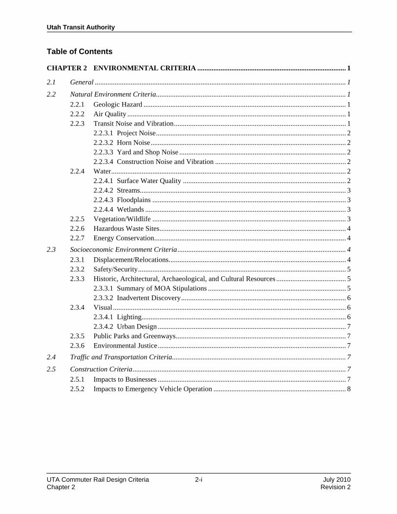
2.2.4.3 Floodplains Construction of the project has the potential to impact regulatory floodways and floodplains within the corridor. Local county flood control and Federal Emergency Management Agency (FEMA) guidelines shall be observed for the design of the permanent structures and construction activities. Disturbances to creek channels should be held to a minimum. Construction in designated floodplains will require a Section 404 permit from the U.S. Army Corps of Engineers. Construction impacts shall be addressed to mitigate potential water quality and flooding problems. 2.2.4.4 Wetlands Wetlands within or adjacent to project right-of-way will be delineated in the project’s environmental studies. The type and extent of the disturbance shall be coordinated with the U.S. Army Corps of Engineers. Replacement wetlands shall be provided as part of the rail transit project if required by the permit requirements and in accordance with applicable laws and regulations. Construction activity shall have a short-term disruption affect and portions of these wetlands could be displaced. The proposed mitigation is to minimize disturbance to these areas, and where direct impacts occur, to restore the wetlands to as near original condition as possible, or as prescribed by the Army Corps of Engineers. Required wetland permitting will be completed during final design. Contractors will be required to comply with all permit provisions.
2.2.5 Vegetation/Wildlife As a result of construction, it may be necessary to remove some existing vegetation or disturb existing wild life. In order to mitigate these losses, the following criteria shall apply:
• UTA will comply with all local landscaping ordinances.
• Disturbed areas will be revegetated as quickly as possible.
• Where existing vegetation is removed, new landscaping shall be planted where possible and appropriate. The placement and types of which vegetation shall be specified in an established landscaping plan.
• The landscaping plan should include a master plant list which identifies new vegetation that is designed to conform to the surrounding environment and be consistent with the operations and maintenance requirements of the rail transit system.

Utah Transit Authority
UTA Commuter Rail Design Criteria 2-4 July 2010 Chapter 2 Revision 2
• The landscaping plan may extend to the system stations, parking, and public areas of fixed system facilities.
• A program shall be developed as part of the overall maintenance-of-way procedures for the rail system which shall provide for the regular maintenance of system-related landscaping.
• If required, the project design and construction shall be coordinated with the U.S. Fish and Wildlife Service.
2.2.6 Hazardous Waste Sites As defined in federal and state statutes, hazardous substances, hazardous wastes, and special wastes are regulated in all aspects, from their generation, storage, transport, and disposal, including associated reporting and record keeping. In the development and implementation of rail projects, UTA shall consider hazardous substances, hazardous wastes, and special wastes and shall comply with all applicable regulations and controls. Due care shall be exercised to determine whether hazardous substances, hazardous wastes, or special wastes may be present on, adjacent to, or in close proximity to property being considered for use in UTA projects. A property may be impacted by such substances or wastes that are located within the property boundaries as well as migration to the property from off-site sources. The presence of hazardous substances, hazardous wastes, or special wastes may impact all aspects of a rail transit project, including property acquisition and project construction. For properties being considered for acquisition, a “due diligence” Phase I Environmental Site Assessments (ESA) or Property Transaction Screens (PTS) shall be conducted to determine the presence of such substances or wastes in accordance with the current edition of the American Society for Testing and Material (ASTM) Standard E-1527, “Standard Practice for Environmental Site Assessments: Phase I Environmental Site Assessment Process.” The Phase I ESA or PTS shall be conducted prior to acquisition. Acquisition of an interest in a property determined to contain such substances shall be avoided unless the risks and liabilities of such acquisition can be justified. If avoidance is not feasible, proper management of substances and wastes shall conform to all applicable laws and regulations. For properties where acquisition is not a factor, a Phase I ESA or PTS shall be conducted to identify potential construction-related impacts associated with such substances and wastes. The Phase I ESA shall use the ASTM Phase I ESA standards as a guideline to determine the appropriate level of environmental inquiry necessary to identify and evaluate project specific construction impacts. Once construction impacts have been identified, proper management of substances and wastes encountered during construction shall conform to all applicable laws and regulations. 2.2.7 Energy Conservation In order to reduce energy consumption, conservation features and operating procedures shall be developed for operating systems and subsystems as part of final design activities.
2.3 Socioeconomic Environment Criteria
2.3.1 Displacement/Relocations For each rail transit project, UTA’s relocation program will provide for studies of the availability of equivalent accommodations, definitions of eligibility for assistance, procedures for dealing with relocations, payment methods, procedures for processing claims and typical schedule event times to effect relocations. This program will provide relocation moving payments to cover actual moving expenses and

Utah Transit Authority
UTA Commuter Rail Design Criteria 2-5 July 2010 Chapter 2 Revision 2
replacement housing payments or rent supplements where an owner or tenant will have to purchase or rent property at a higher cost or lose a favorable financing arrangement. All relocations shall be carried out in accordance with applicable state laws and requirements. For federally-funded projects, all relocations shall be carried out in accordance with the Federal Uniform Relocation Assistance and Real Property Acquisitions Act of 1970 (Public Law 91-646), as amended. 2.3.2 Safety/Security The implementation of a rail transit system carries with it the potential for crimes against persons and property, extending to vehicles, stations, parking areas, and other public areas created by the system. In order to minimize this potential, all system public areas shall be designed to promote maximum safety and security for all system patrons. Specific design measures which shall be employed are discussed in the design criteria for the specific system element. 2.3.3 Historic, Architectural, Archaeological, and Cultural Resources Section 106 of the National Historic Preservation Act (NHPA) requires that federal agencies, or state agencies that receive federal assistance, consider any effects a project may have on significant cultural resources. In addition, Section 9-8-404 of the Utah Code Annotated (UCA) requires that state agencies “take into account” how their activities will affect historic properties. As part of the environmental study for the rail transit project, UTA will identify all historic resources located within the project’s area of potential effect (APE) that are on or eligible for the National Register of Historic Places (NRHP) and will consult with the State Historic Preservation Office (SHPO) to determine the effect of the project on those resources. For projects that will have an Adverse Effect on eligible historic resources, UTA will develop a Memorandum of Agreement (MOA) with the SHPO that identifies the mitigation measures that will be incorporated into the project. For federally-funded projects, FTA will also be a party to the MOA. UCA 63-73-19 protects significant paleontological resources included in or eligible for inclusion in the State Paleontological Register. This regulation requires that state agencies take into account the effect of the project on paleontological resources and allow the director of the Utah Geological Survey (UGS) an opportunity to comment. If the project would have No Effect on paleontological resources, no further action is necessary. If there may be an effect on paleontological resources, documentation and surveys may be required. 2.3.3.1 Summary of MOA Stipulations For sites or properties that are found to be eligible for inclusion in the NRHP, and which will be adversely affected by the rail project, UTA will consult with the SHPO to develop an appropriate mitigation plan. This mitigation plan will be documented in the MOA. Types of mitigation include, but are not necessarily limited to:
• Mitigation for Adverse Effects on historic structures may consist of intensive-level survey documentation. A qualified architectural historian who meets the Secretary of the Interior’s standards for historian or architectural historian must conduct the fieldwork, research, and formal documentation of each building in accordance with the SHPO’s Intensive Level Survey—Basic Survey Standards (Utah State Historic Preservation Office, 2007b).
• Mitigation may consist of thorough Historic American Engineering Record documentation. A qualified historian or archaeologist who meets the Secretary of the Interior’s standards for historian or historical archaeologist must conduct the fieldwork, research, and formal documentation of the resource in accordance with the Secretary of the Interior’s Standards and Guidelines for Architectural and Engineering Documentation, consisting of historical research, measured drawings, and large-format black-and-white photography.

Utah Transit Authority
UTA Commuter Rail Design Criteria 2-6 July 2010 Chapter 2 Revision 2
• Data Recovery Plans: In consultation with the SHPO, UTA will develop data recovery plans for archaeological sites where it is determined that this treatment will be the most appropriate and effective, considering the design requirements of the rail project. Plans will be consistent with the Secretary of the Interior’s Standards and Guidelines for Archaeological Documentation.
• Preservation in Place: In consultation with the SHPO, UTA will develop plans for preservation in place for archaeological sites where it has been determined that this treatment will be the most appropriate and effective, considering the design requirements of the rail project. UTA will implement approved preservation plans to ensure that the archaeological properties selected for such treatment are preserved during construction.
• Educational Component: The project may include an educational component as mitigation for impacts to archaeological sites. The format of the educational component would be developed by UTA in consultation with the SHPO. The educational materials produced could be in the form of a popular report suitable for distribution to the public and presenting the results of the archaeological investigations or as display boards mounted in the trains.
2.3.3.2 Inadvertent Discovery If buried cultural or unanticipated archaeological resources are inadvertently discovered during ground-disturbing activities, the contractor will contact a qualified archaeologist who, in consultation with UTA and the SHPO, will determine the appropriate action to pursue regarding the resource. Work will not resume in the area until approval is given by the UTA Project Manager, in consultation with the SHPO. Buried human remains that were not identified during research or field surveys could be inadvertently unearthed during excavation activities, which could result in damage to the human remains. If human remains of Native American origin are discovered during ground-disturbing activities, it is necessary to comply with state laws relating to the disposition of Native American burials, following state regulation UCA 9-9-401 and the Utah Native American Graves Protection and Repatriation Act of 1992. Utah State Code (63-73-11 through 63-73-19) currently states that paleontological resources are important and requires the preservation of critical fossil resources on State lands. If paleontological resources are unearthed before or during construction, a qualified paleontologist should be notified. The paleontologist then will salvage the fossils and assess the necessity for further mitigation measures, if applicable.
2.3.4 Visual The UTA rail project may affect visual quality at station locations and track work areas. These impacts may result from removal of existing vegetation and from construction of station or parking lot infrastructure adjacent to residential areas or historic resources. Areas disturbed by construction activities will be re-vegetated as discussed in Section 2.2.5. Design standards for the visual characteristics of stations will be developed in consultation with local jurisdictions through the design review process. 2.3.4.1 Lighting Lighting design shall incorporate CPTED (crime prevention through environmental design) design standards. Area and guideway lighting fixtures and standards shall incorporate directional shielding where needed to avoid the intrusion of unwanted light and glare into adjacent sensitive land uses, such as residential areas. Lighting should be planned with consideration to growth of landscaping. Lighting plans may be subject to local jurisdictional requirements and approval.

Utah Transit Authority
UTA Commuter Rail Design Criteria 2-7 July 2010 Chapter 2 Revision 2
2.3.4.2 Urban Design The goal of the rail transit system is to provide economical, functional stations that blend with the land uses and community patterns around them. At downtown station sites, historic station sites, mixed-use station sites, and along the corridor, urban design issues shall be addressed in ways that achieve that goal. Urban design plans may be subject to local jurisdictional zoning or design regulations. 2.3.5 Public Parks and Greenways Section 4(f) of the Department of Transportation Act of 1996, as amended (49 USC § 303) protects historic, cultural, public parks, and wildlife refuges from conversion to transportation use unless it can be demonstrated that there is no prudent or feasible alternative. For all federally-funded projects, a 4(f) evaluation will be conducted if there is a federal EIS or EA process, documenting the reasons for the use of land, the benefits associated with that use, and lack of prudent or feasible alternatives for avoiding the resource. 2.3.6 Environmental Justice UTA will consider potential impacts to minority, low-income, and disadvantaged populations in the planning and design of its rail and bus service systems. In compliance with NEPA regulations, environmental documents will identify any potential for disproportionate impacts to these populations. UTA will conduct public outreach to inform and consult with environmental justice populations.
2.4 Traffic and Transportation Criteria In areas around rail transit stations, increases in local traffic congestion may result. Bus service shall be restructured to provide feeder service to rail transit stations. Additional or revised traffic signals and transportation system management (TSM) improvements shall be implemented, as determined necessary, in consultation with local jurisdictions.
2.5 Construction Criteria The project construction specifications shall be written to require compliance with all appropriate environmental regulation guidelines and permit requirements. When required, construction impact mitigation plans shall be included in the construction packages. Construction noise and vibration limits shall be defined by the regulations of each jurisdiction. 2.5.1 Impacts to Businesses The following mitigation shall be considered to minimize the impact of construction activities on businesses adjacent to the project:
• Minimize the length of time that any street block is closed.
• Schedule construction during off-peak traffic periods in sensitive areas, if possible.
• Maintain maximum possible number of traffic lanes for operation during construction periods.
• Maintain sidewalks for operation or provide alternative walkways.
• Maintain the visibility of businesses through coordination with local merchants, using temporary signing, and other appropriate special measures.

Utah Transit Authority
UTA Commuter Rail Design Criteria 2-8 July 2010 Chapter 2 Revision 2
2.5.2 Impacts to Emergency Vehicle Operation Mitigation measures to facilitate the operation of emergency vehicles during the construction phase may include:
• Implementing traffic control measures to reduce congestion (i.e., use of barriers, proper identification of detours, and proper legible signing)
• Informing emergency services providers of construction schedules and activities
• Developing alternative emergency access routes to affected facilities such as hospitals END OF CHAPTER 2.
Design Criteria
UTA Commuter Rail Rev No. Prepared By Approved By Approval
Date Document Date
0 PPa JWebb 12/1/04 12/1/04 1 DGoeres CCC 11/30/07 11/30/07 2 T. W. Jones CCC 3/19/10 July 2010
Utah Transit Authority
Commuter Rail Design Criteria
Chapter 3 Alignment
Revision 2, July 2010

Utah Transit Authority
UTA Commuter Rail Design Criteria 3-i July 2010 Chapter 3 Revision 2
Table of Contents
CHAPTER 3 ALIGNMENT ............................................................................................................... 1
3.1 Introduction ..................................................................................................................................... 1 3.2 Track Alignment ............................................................................................................................... 1
3.2.1 General ................................................................................................................................ 1 3.2.2 Design Speed ...................................................................................................................... 1 3.2.3 Track Center Spacing .......................................................................................................... 1 3.2.4 Horizontal Alignment ......................................................................................................... 2
3.2.4.1 Tangent Alignment ................................................................................................ 2 3.2.4.2 Curved Alignment .................................................................................................. 2
3.2.5 Vertical Alignment.............................................................................................................. 5 3.2.5.1 General ................................................................................................................... 5 3.2.5.2 Vertical Tangents ................................................................................................... 5 3.2.5.3 Vertical Grades ...................................................................................................... 5 3.2.5.4 Vertical Curves ...................................................................................................... 5
3.3 Clearances ....................................................................................................................................... 6 3.3.1 General ................................................................................................................................ 6
Utah Transit Authority
UTA Commuter Rail Design Criteria 3-1 July 2010 Chapter 3 Revision 2
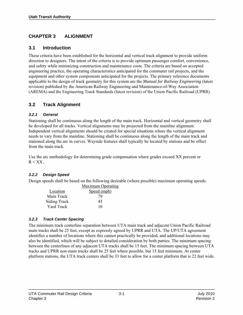
CHAPTER 3 ALIGNMENT
3.1 Introduction These criteria have been established for the horizontal and vertical track alignment to provide uniform direction to designers. The intent of the criteria is to provide optimum passenger comfort, convenience, and safety while minimizing construction and maintenance costs. The criteria are based on accepted engineering practice, the operating characteristics anticipated for the commuter rail projects, and the equipment and other system components anticipated for the projects. The primary reference documents applicable to the design of track geometry for this system are the Manual for Railway Engineering (latest revision) published by the American Railway Engineering and Maintenance-of-Way Association (AREMA) and the Engineering Track Standards (latest revision) of the Union Pacific Railroad (UPRR).
3.2 Track Alignment
3.2.1 General Stationing shall be continuous along the length of the main track. Horizontal and vertical geometry shall be developed for all tracks. Vertical alignments may be projected from the mainline alignment. Independent vertical alignments should be created for special situations where the vertical alignment needs to vary from the mainline. Stationing shall be continuous along the length of the main track and stationed along the arc in curves. Wayside features shall typically be located by stations and be offset from the main track. Use the arc methodology for determining grade compensation where grades exceed XX percent or R < XX.
3.2.2 Design Speed Design speeds shall be based on the following desirable (where possible) maximum operating speeds: Maximum Operating Location Speed (mph) Main Track 79 Siding Track 45 Yard Track 10
3.2.3 Track Center Spacing The minimum track centerline separation between UTA main track and adjacent Union Pacific Railroad main tracks shall be 25 feet, except as expressly agreed by UPRR and UTA. The UP/UTA agreement identifies a number of locations where this cannot practically be provided, and additional locations may also be identified, which will be subject to detailed consideration by both parties. The minimum spacing between the centerlines of any adjacent UTA tracks shall be 15 feet. The minimum spacing between UTA tracks and UPRR non-main tracks shall be 25 feet where possible, but 15 feet minimum. At center platform stations, the UTA track centers shall be 33 feet to allow for a center platform that is 22 feet wide.

Utah Transit Authority
UTA Commuter Rail Design Criteria 3-2 July 2010 Chapter 3 Revision 2
3.2.4 Horizontal Alignment The horizontal alignment of mainline tracks shall consist of a series of tangents joined to circular curves, usually by means of spiral transition curves. The nomenclature and calculations used to define horizontal alignments are per AREMA, and are included later in this chapter. 3.2.4.1 Tangent Alignment Line Sections The minimum length of a tangent track, between curved tracks, for mainline or sidings, is 200 feet or three times the design speed (in mph), whichever is greater. Refer to AREMA 3.5 for minimum/desired length for yard track. For adjacent curves in the same direction that cannot be replaced by a single simple curve due to geometric constraints, an alignment containing a series of compound curves and/or spirals is preferred to a series of curves and short tangents. Stations At station platforms, the horizontal alignment shall be tangent throughout the length of the platform unless specifically approved by UTA. The tangent shall extend at least 100 feet beyond both ends of the platform. At terminal stations, tracks shall extend beyond platforms to allow for vehicle storage where possible, subject to UTA approval. If feasible, these tail tracks shall be placed on the probable alignment for any future service extensions. Special Track work All special track work shall be located on horizontal and vertical tangents, unless otherwise approved by UTA. The minimum distance between the start/end of a curve and the point of switch or point of frog shall be 100 feet. Any distance less than 100 feet requires approval by UTA. 3.2.4.2 Curved Alignment Circular Curves Circular curves shall be defined by the arc definition and specified by their degree of curvature and radius in accordance with the following formula:
R = (18,000/π) / D
Where: R is the radius, in feet
D is the degree of curvature The track alignment shall be based on the use of the largest feasible radius, with considerations made for operating requirements, constructability, right-of-way constraints, and adjoining existing conditions. Nomenclature for circular curves is depicted in Figure 3-3 later in this chapter. Preferred maximum degree of circular curve (minimum radius) is 573 feet (10°). Absolute minimum circular curve radius is 459 feet (12° 30′). This is also the preferable minimum for trackage to be operated on by UP or other freight railroads. Modifications to trackage serving industries, to be operated by UPRR and/or a freight railroad, may exceed this minimum, but shall incorporate curvature of no greater severity than that of the original/existing trackage. Increases in curvature may only be used with UTA and freight railroad approval.

Utah Transit Authority
UTA Commuter Rail Design Criteria 3-3 July 2010 Chapter 3 Revision 2
The normal minimum circular curve length shall be determined by the following formula:
L = 3 V
Where: L = minimum length of curve, in feet
V = design speed through the curve, in mph The absolute minimum length of a superelevated circular curve shall be 50 feet unless otherwise approved by UTA. Superelevation Superelevation is defined as the number of inches the outer (high) rail on a curve is raised above the inner (low) rail. Equilibrium superelevation is the amount of superelevation that would be required so that the resultant force from the center of gravity of the vehicle will be perpendicular to the plane of the two rails and halfway in between them at a given speed. Equilibrium superelevation is defined by radius, using the equation:
Eq = 4.011 V2/R
Where: Eq = total amount of superelevation required for equilibrium, in inches
V = design speed through the curve, in mph
R = radius in feet Superelevation shall be introduced to meet the design speed divided as closely as possible between ⅔ actual and ⅓ unbalance. However, in restricted areas, superelevation may be divided approximately equally in order to minimize spiral length and maximize design speed. Actual superelevation shall be rounded to the nearest ½ inch. Actual superelevation of less than 1 inch shall not be used. Superelevation shall be avoided, if possible, in road crossings. Maximum superelevation values are:
Ea = 5 inches
Eu = 3 inches The inside rail of curves shall be designated as the profile rail. Actual superelevation (Ea) shall be attained and removed linearly throughout the full length of the spiral transition curve by raising the outside rail while maintaining the inside rail at the profile grade. In areas where vehicles will frequently operate at lower speeds, actual superelevation, Ea, is a balance between passenger comfort and desired design speed with a maximum actual superelevation of 4 inches. Station approaches are generally designed to match the speed of the corresponding turnout (45 mph generally for #20 turnouts, and 30 mph at #15 turnouts). No superelevation is permitted on yard tracks. Spiral Curves Spiral transition curves shall be used to develop the superelevation of the track and limit lateral acceleration during the horizontal transition of the vehicle as it enters the curve. Spirals shall be provided

Utah Transit Authority
UTA Commuter Rail Design Criteria 3-4 July 2010 Chapter 3 Revision 2
on all mainline track horizontal curves, except where the calculated value of the throw, P, is less than 0.02 feet. Details of spiral transition curves are shown in Figure 3-2. The maximum Eu and Ea shall not exceed 3 and 5 inches, respectively. Spiral lengths shall be determined based on the greater of the length as computed for either actual superelevation or the unbalanced superelevation underbalance and speed for each curve and their maximum value determined from the following equations:
Ls = 1.63 Eu V (desirable)
Ls = 1.22 Eu V (minimum)
Ls = 62 Ea (absolute)
Where: Ls = spiral length in feet Spiral lengths shall be determined from the above equations and rounded up to the nearest multiple of 5 feet. Where geometric constraints exist, the equation for minimum spiral length may be used with prior approval of UTA in lieu of the equation for desirable spiral length providing Eu is the governing superelevation. The normal minimum length shall be 100 feet. In areas where geometric conditions are extremely restricted, the spiral length may be reduced to the absolute minimum of 62 feet, with a corresponding maximum Ea of 1 inch. Compound Circular Curves Where compound curves are used, they shall be connected by a spiral transition curve. The absolute minimum spiral length shall be the greater of the lengths as determined by the following:
Ls = 1.63(Eu2 − Eu1) V (desirable)
Ls = 1.22(Eu2 − Eu1) V (minimum)
Ls = 62(Ea2 − Ea1)
Where: Ls = minimum length of spiral, in feet
Ea1 = actual superelevation of the first circular curve, in inches
Ea2 = actual superelevation of the second circular curve, in inches
Eu1 = unbalanced superelevation of the first circular curve, in inches
Eu2 = unbalanced superelevation of the second circular curve, in inches
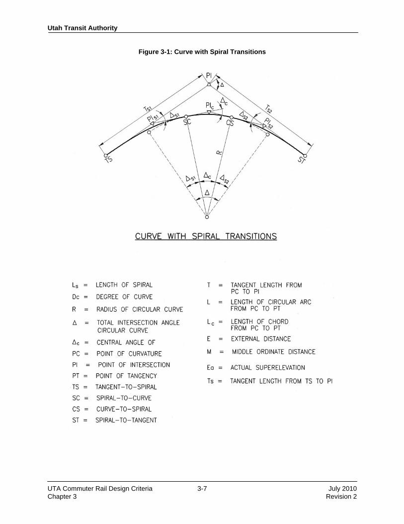
V = design speed through the circular curves, in mph Spiral curves connecting compound curves are not required when both (Ea2 − Ea1) and (Eu2 – Eu1) are less than 1 inch. For compound circular curves without a spiral, the change in actual superelevation shall be run out entirely within the curve of the larger radius for the largest distance required by the equations for compound circular curves. The nomenclature for circular curves with spirals is given in Figure 3-1.
Utah Transit Authority
UTA Commuter Rail Design Criteria 3-5 July 2010 Chapter 3 Revision 2
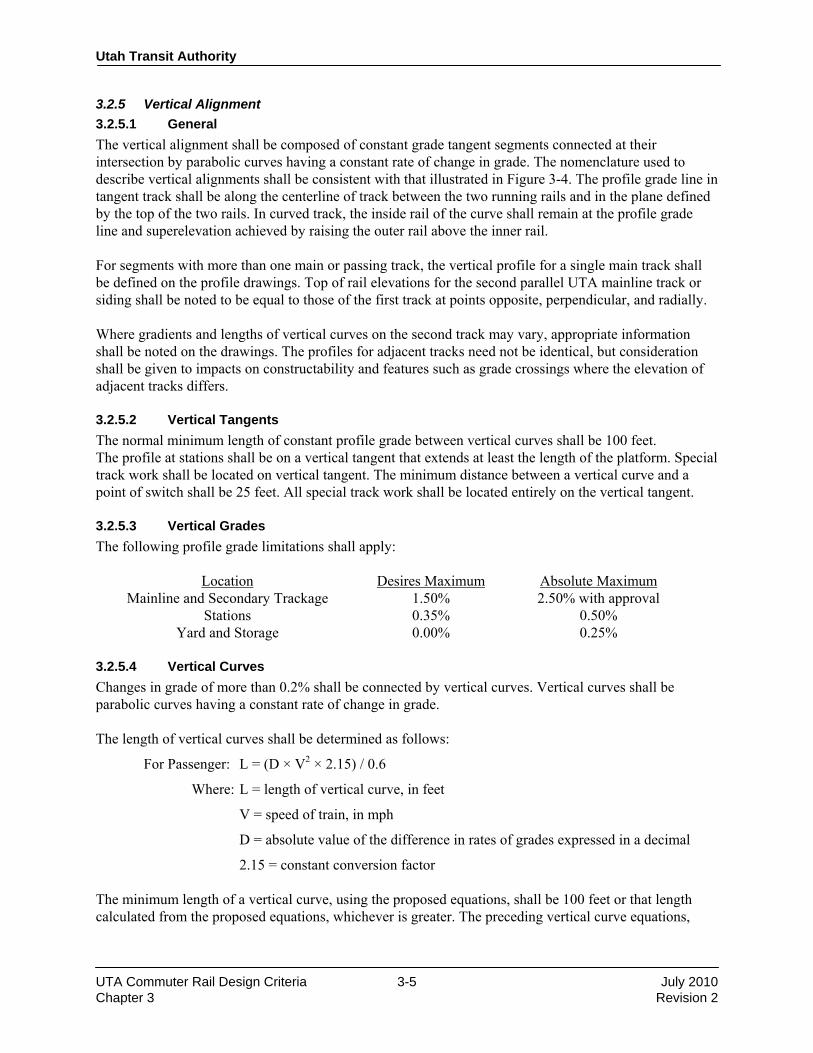
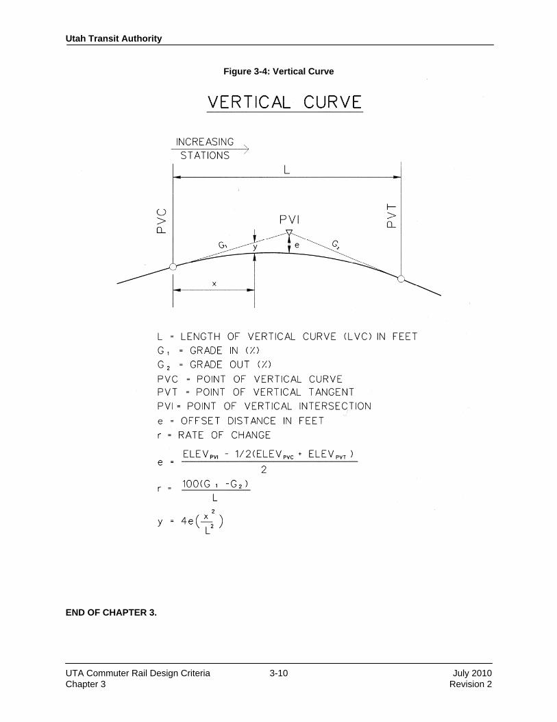
3.2.5 Vertical Alignment 3.2.5.1 General The vertical alignment shall be composed of constant grade tangent segments connected at their intersection by parabolic curves having a constant rate of change in grade. The nomenclature used to describe vertical alignments shall be consistent with that illustrated in Figure 3-4. The profile grade line in tangent track shall be along the centerline of track between the two running rails and in the plane defined by the top of the two rails. In curved track, the inside rail of the curve shall remain at the profile grade line and superelevation achieved by raising the outer rail above the inner rail. For segments with more than one main or passing track, the vertical profile for a single main track shall be defined on the profile drawings. Top of rail elevations for the second parallel UTA mainline track or siding shall be noted to be equal to those of the first track at points opposite, perpendicular, and radially. Where gradients and lengths of vertical curves on the second track may vary, appropriate information shall be noted on the drawings. The profiles for adjacent tracks need not be identical, but consideration shall be given to impacts on constructability and features such as grade crossings where the elevation of adjacent tracks differs. 3.2.5.2 Vertical Tangents The normal minimum length of constant profile grade between vertical curves shall be 100 feet. The profile at stations shall be on a vertical tangent that extends at least the length of the platform. Special track work shall be located on vertical tangent. The minimum distance between a vertical curve and a point of switch shall be 25 feet. All special track work shall be located entirely on the vertical tangent. 3.2.5.3 Vertical Grades The following profile grade limitations shall apply: Location Desires Maximum Absolute Maximum Mainline and Secondary Trackage 1.50% 2.50% with approval Stations 0.35% 0.50% Yard and Storage 0.00% 0.25% 3.2.5.4 Vertical Curves Changes in grade of more than 0.2% shall be connected by vertical curves. Vertical curves shall be parabolic curves having a constant rate of change in grade. The length of vertical curves shall be determined as follows:
For Passenger: L = (D × V2 × 2.15) / 0.6
Where: L = length of vertical curve, in feet
V = speed of train, in mph
D = absolute value of the difference in rates of grades expressed in a decimal
2.15 = constant conversion factor The minimum length of a vertical curve, using the proposed equations, shall be 100 feet or that length calculated from the proposed equations, whichever is greater. The preceding vertical curve equations,

Utah Transit Authority
UTA Commuter Rail Design Criteria 3-6 July 2010 Chapter 3 Revision 2
developed by Subcommittee 8, Track Geometry of AREMA Committee 5–Track, are included (as of 2002) in the AREMA Manual for Railway Engineering. Compound vertical curves will be permitted provided each curve conforms to the requirements stated previously in this chapter.
3.3 Clearances
3.3.1 General Dimensions and clearances shall be per State of Utah statutory minimum clearance requirements for railroads, as published in Chapter 28 of the AREMA Manual and State Code R930-5-15. Standard AREMA freight and passenger clearance envelopes will be used.
Utah Transit Authority
UTA Commuter Rail Design Criteria 3-7 July 2010 Chapter 3 Revision 2
Figure 3-1: Curve with Spiral Transitions

Utah Transit Authority
UTA Commuter Rail Design Criteria 3-8 July 2010 Chapter 3 Revision 2
Figure 3-2: Spiral Curve Formulas

Utah Transit Authority
UTA Commuter Rail Design Criteria 3-9 July 2010 Chapter 3 Revision 2
Figure 3-3: Circular Curve Formulas
Utah Transit Authority
UTA Commuter Rail Design Criteria 3-10 July 2010 Chapter 3 Revision 2
Figure 3-4: Vertical Curve
END OF CHAPTER 3.

Design Criteria
UTA Commuter Rail Rev No. Prepared By Approved By Approval
Date Document Date
0 PPa JWebb 12/1/04 12/1/04 1 DGoeres CCC 11/30/07 11/30/07 2 T. W. Jones CCC 3/19/10 July 2010
Utah Transit Authority Commuter Rail Design Criteria
Chapter 4
Trackwork Revision 2, July 2010

Utah Transit Authority
UTA Commuter Rail Design Criteria 4-i July 2010 Chapter 4 Revision 2
Table of Contents
CHAPTER 4 TRACKWORK ............................................................................................................. 1
4.1 General ............................................................................................................................................ 1 4.1.1 Description .......................................................................................................................... 1 4.1.2 References ........................................................................................................................... 1 4.1.3 Track Standards .................................................................................................................. 1
4.1.3.1 Flange Profile ......................................................................................................... 1 4.1.3.2 Standard Gauge of Track ....................................................................................... 1 4.1.3.3 Rail Cant ................................................................................................................ 1
4.2 Track Classification ......................................................................................................................... 1 4.2.1 Main Track .......................................................................................................................... 1 4.2.2 Siding Track ........................................................................................................................ 1 4.2.3 Yard Track .......................................................................................................................... 2
4.3 Types of Track .................................................................................................................................. 2 4.3.1 Ballasted Track ................................................................................................................... 2 4.3.2 Direct Fixation Track .......................................................................................................... 2
4.4 Track Materials ................................................................................................................................ 2 4.4.1 Subballast ............................................................................................................................ 2 4.4.2 Ballast ................................................................................................................................. 2 4.4.3 Ties ..................................................................................................................................... 2 4.4.4 Tie Plates ............................................................................................................................. 3 4.4.5 Running Rail ....................................................................................................................... 3 4.4.6 Insulated Joints ................................................................................................................... 3 4.4.7 Fasteners ............................................................................................................................. 3
4.4.7.1 Track Spikes .......................................................................................................... 3 4.4.7.2 Resilient Rail Fasteners ......................................................................................... 3
4.4.8 Compromise Joints.............................................................................................................. 3 4.5 Special Trackwork ........................................................................................................................... 4
4.5.1 Turnouts .............................................................................................................................. 4 4.5.2 Railroad Crossings at Grade ............................................................................................... 4
4.6 Miscellaneous Track Components ................................................................................................... 4 4.6.1 Bumping Posts .................................................................................................................... 4 4.6.2 Roadway Grade Crossings .................................................................................................. 4 4.6.3 Guardrails ............................................................................................................................ 4
4.7 Coordination with Other Disciplines ............................................................................................... 5 4.7.1 Fill ....................................................................................................................................... 5 4.7.2 Drainage .............................................................................................................................. 5 4.7.3 Structures ............................................................................................................................ 5
Utah Transit Authority
UTA Commuter Rail Design Criteria 4-1 July 2010 Chapter 4 Revision 2
CHAPTER 4 TRACKWORK
4.1 General
4.1.1 Description This chapter includes criteria for the design of track and track components for the construction and maintenance of Utah Transit Authority (UTA) trackage. It is also for use in the design of trackage constructed by UTA for use by the Union Pacific Railroad (UPRR) or other railroads, in conjunction with the appropriate railroad company standards. The primary considerations in the design of track are safety, economy, maintainability, and constructability.
4.1.2 References The primary reference documents applicable to the design of track for this system are the Manual for Railway Engineering (latest revision) published by the American Railway Engineering and Maintenance-of-Way Association (AREMA) and the Track Standard Drawings (latest revision) of the Union Pacific Railroad.
4.1.3 Track Standards All new and existing main track and components shall be constructed or upgraded to accommodate passenger train speeds of up to 79 mph and FRA Class 5 standards. In locations where existing alignment or other restrictions preclude this, trackwork shall accommodate train speeds equal to or in excess of existing speeds. 4.1.3.1 Flange Profile All trackage shall be suitable for operation of equipment with an AAR-1b wheel flange profile. 4.1.3.2 Standard Gauge of Track The standard track gauge shall be 4 feet 8½ inches measured at a point ⅝ inch below the top of rail. 4.1.3.3 Rail Cant Running rail shall have an inward cant of 1:40 (toward the centerline of track) except in special trackwork. This cant is provided for with the use of tie plates fabricated for that purpose (timber ties) or cast into the rail seat area (concrete ties). In special trackwork, switch plates, gauge plates, frog plates, and guard rail plates shall provide zero cant.
4.2 Track Classification
4.2.1 Main Track Main tracks are defined as tracks extending through yards and between stations upon which trains are operated by timetable or authority of a train dispatcher, the use of which is governed by signal indication. Trains are operated in both directions on any single main track.
4.2.2 Siding Track Siding tracks are defined as track auxiliary to the main track used for the meeting and passing of trains.

Utah Transit Authority
UTA Commuter Rail Design Criteria 4-2 July 2010 Chapter 4 Revision 2
4.2.3 Yard Track Yard tracks are defined as a system of tracks within defined limits provided for the making up of trains, storing of cars, and other purposes, over which movements not authorized by timetable or by dispatcher may be made, subject to prescribed signals and rules or special instructions.
4.3 Types of Track
4.3.1 Ballasted Track Ballasted track is a track structure composed of rail, rail anchorage, track fasteners, ties, plates, ballast, and subballast constructed over an earth subgrade or on a trough-type bridge deck.
4.3.2 Direct Fixation Track Direct fixation track is a track structure composed of rail and special fasteners for anchorage to a concrete substructure without the use of ties or ballast. It may be used on bridges and aerial structures exceeding 110 feet in length. It may also be used in depressed trackway structures in excess of 500 feet in length. It may be considered for use in other locations where it provides a significant economic benefit compared to ballasted track, subject to the approval of UTA.
4.4 Track Materials
4.4.1 Subballast Subballast material conforming to UDOT Specification Section 02721–Untreated Base Course shall be used on the subgrade to provide a stable surface for track construction. (Reference to pay items in the specification should be removed.) The top surface of the subgrade (or roadbed) shall be sloped to direct water laterally away from the track with a minimum cross slope of 2.0%. Subballast depth shall be a minimum of 6 inches. The depth shall be verified during final track design and increased if necessary to achieve the optimal overall track structure design. Subballast may be omitted from the track section and be replaced with a geotextile fabric if approved by UTA.
4.4.2 Ballast Ballast material shall be selected in conformance with UPRR specifications for ballast and the AREMA Manual for Railway Engineering. The ballast section shall provide for a 12 inch shoulder of ballast material beyond both ends of the ties. Slope of the ballast section shall be a maximum of 2:1. The ballast depth shall be a minimum of 12 inches, as measured below the bottom of the tie.
4.4.3 Ties Ties for all ballasted track shall be concrete, with wood ties to be used only as approved by UTA. Concrete ties shall meet the provisions of the AREMA Manual for Railway Engineering (latest revision). For formulas in the Manual for Railway Engineering for concrete tie design (such as Chapter 28), inputs shall include 79 mph for maximum speed and 15 million gross tons (MGT) or less for annual tonnage. Concrete ties shall not exceed 13 inches in width, and height shall not exceed 10 inches. Timber ties shall be 7″ × 9″ and 8′ 6″ long and comply with the AREMA Manual for Railway Engineering (latest revision).

Utah Transit Authority
UTA Commuter Rail Design Criteria 4-3 July 2010 Chapter 4 Revision 2
Wood crossties shall be nominally spaced no greater than 19½ inches on center. Concrete crossties shall be nominally spaced no greater than 28 inches on center. Switch ties and railroad crossing diamond timbers shall be installed per the approved turnout and railroad crossing-at-grade plan drawings. Switch ties or railroad crossing-at-grade timbers shall be wood and comply with the AREMA Manual for Railway Engineering (latest revision). Concrete switch ties may be used with UTA approval to take advantage of economic benefits of movable-point frogs. Transition ties from standard 8′ 3″ ties to 10′ 0″ ties for 12 ties before the beginning of each at-grade crossing. The 10′ 0″ ties will be placed at the same 28″ spacing as 8′ 3″ ties. The final transition tie will be placed 24″ from the end of the crossing and be retained by a 24″ end restraint. 10′ 0″ ties at 24″ spacing will be used for the full length of the crossing.
4.4.4 Tie Plates Tie plates shall meet the requirements of the UPRR Track Standard Drawings.
4.4.5 Running Rail Running rail shall be 136 pounds per yard or 115 pounds per yard, RE section, head hardened for use in curved track with less than 900′ radius, in accordance with UPRR Track Standard Drawings. Alternative sections may be used with economic justification only as approved by UTA. All rail shall be continuously welded, except for bolted joints as required within special trackwork or insulated joints as required for the signal system. Continuous welded rail (CWR) shall be installed and fastened at an appropriate neutral thermal temperature in accordance with UPRR Track Standard Drawings.
4.4.6 Insulated Joints The use and design of insulated joints (six-hole and glued) shall comply with UPRR Track Standard Drawings.
4.4.7 Fasteners 4.4.7.1 Track Spikes Track spikes for timber ties shall be mild steel cut spikes fabricated in accordance with the AREMA Manual for Railway Engineering (latest revision). 4.4.7.2 Resilient Rail Fasteners The use of rail fasteners and their associated appurtenances (such as insulators, tie pads, and shoulder inserts) shall be resilient spring type forged from alloy steel bars and shall comply with the AREMA Manual for Railway Engineering (latest revision).
4.4.8 Compromise Joints Where rails of dissimilar weight and cross section are to be connected, a compromise joint or compromise weld designed and manufactured for that purpose shall be used. The physical properties of the compromise joint shall comply with UPRR Track Standard Drawings.
Utah Transit Authority
UTA Commuter Rail Design Criteria 4-4 July 2010 Chapter 4 Revision 2
4.5 Special Trackwork
4.5.1 Turnouts Turnouts shall conform to UPRR standards, and shall incorporate curved switch points and railbound manganese frogs. Frog angles of turnouts shall be selected based on the required geometry and the required operating speed. In general, frog angles for turnouts in mainline tracks shall be selected as appropriate for the location, based on the following guidelines:
#9 Yard tracks 10 mph
#11 Yard leads 15 mph
#15 Exit from main track, low speed crossovers 30 mph
#20 Siding turnouts and universal crossovers 45 mph
#30 Very high speed crossovers/end of two-main tracks 70 mph
4.5.2 Railroad Crossings at Grade At-grade crossings shall be constructed of 115 RE rail with railbound manganese frogs in compliance with UPRR Track Standard Drawings. Design of crossovers and turnouts connecting to UPRR main or spur tracks shall be as approved by UPRR.
4.6 Miscellaneous Track Components
4.6.1 Bumping Posts Bumping posts or other fixed devices shall be provided at the ends of single-ended spur tracks to stop trains. On yard tracks, fixed devices suitable for stopping a train operating at a slow speed may be used. On tracks that may carry trains with passengers on board a device shall be used which will safely bring the train to a stop in a manner that will minimize personal injury. The deceleration rate shall be limited to 0.3g.
4.6.2 Roadway Grade Crossings Crossings of streets or other at-grade vehicular roadways shall be full depth precast concrete panels with rubber flange fillers designed and fabricated in accordance with UPRR Track Standard Drawings. At crossings, care shall be taken to provide for proper drainage in the ballast by use of underdrains or other positive measures. Roadway profiles in approach to the crossing shall be designed to provide a smooth profile throughout the crossing to minimize impact to the crossing panels and reduce the risk of loss of control by drivers.
4.6.3 Guardrails Guardrail will be placed along the piers or structural walls of major bridges and aerial structures to reduce the likelihood of derailed rail vehicle wheels leaving the trackbed. The guardrail shall be new or secondhand rail, fastened to the crossties in accordance with UPRR Track Standard Drawings for guardrails. The guardrails shall be continuous for the length of the line of piers or wall and will extend a minimum of 50 feet beyond each end.

Utah Transit Authority
UTA Commuter Rail Design Criteria 4-5 July 2010 Chapter 4 Revision 2
4.7 Coordination with Other Disciplines
4.7.1 Fill In locations where new UTA track construction will closely parallel existing railroad track structure and subgrade, and existing side slope is equivalent or steeper than a 3:1 slope, then the interface between the existing and new subgrade is to be key benched at a ratio of 5:1 (horizontal:vertical).
4.7.2 Drainage A properly drained subgrade is essential to the stability of track. Provision shall be made for ditches, underdrains, and other drainage features as needed to maintain a stable subgrade.
4.7.3 Structures Design of bridges and other structures shall take into account the nature of the track to be constructed. Ballasted deck structures shall have proper drainage to ensure no standing water will remain in the ballast. Structures to carry direct fixation track must have provision for placement of anchor bolts for the direct fixation fasteners and other track components. All bridges carrying tracks must take into account forces introduced by curved track and by thermal effects of continuous welded rail. END OF CHAPTER 4.

Design Criteria UTA Commuter Rail
Rev No. Prepared By
Approved By Approval Date Document
Date 0 PPa JWebb 12/01/04 12/01/04 1 DGoeres CCC 11/30/07 11/30/07 2 T. W. Jones CCC 3/19/10 July 2010
Utah Transit Authority
Commuter Rail Design Criteria
Chapter 5
Civil and Drainage Revision 2, July 2010

Utah Transit Authority
UTA Commuter Rail Design Criteria 5-i July 2010 Chapter 5 Revision 2
Table of Contents
CHAPTER 5 CIVIL AND DRAINAGE ............................................................................................ 1
5.1 Introduction ..................................................................................................................................... 1
5.2 Surveying and Mapping ................................................................................................................... 1 5.2.1 Survey Control System ....................................................................................................... 1
5.2.1.1 Horizontal Control ................................................................................................. 1 5.2.2 Vertical Control .................................................................................................................. 1 5.2.3 Surveys and Monumentation .............................................................................................. 1
5.3 Grading ............................................................................................................................................ 1
5.4 Roads and Paving ............................................................................................................................ 2 5.4.1 General ................................................................................................................................ 2 5.4.2 Applicable Standards .......................................................................................................... 2 5.4.3 Design of Roadways and Parking Facilities ....................................................................... 2 5.4.4 Curbs, Wheelchair Ramps, and Curb Cuts ......................................................................... 3 5.4.5 Sidewalks and Walkways ................................................................................................... 3 5.4.6 Driveways ........................................................................................................................... 4 5.4.7 Bus Loading Zones ............................................................................................................. 4 5.4.8 Paving ................................................................................................................................. 4 5.4.9 Pavement Marking .............................................................................................................. 4 5.4.10 Traffic Maintenance and Protection .................................................................................... 5
5.5 Drainage .......................................................................................................................................... 5 5.5.1 General ................................................................................................................................ 5 5.5.2 Submittals ......................................................................................................................... 12 5.5.3 Drainage Provisions .......................................................................................................... 12 5.5.4 Hydrology and Hydraulics ................................................................................................ 12 5.5.5 Selection of Drainage Structures ...................................................................................... 14 5.5.6 Pipe Materials ................................................................................................................... 14 5.5.7 Location of Drains ............................................................................................................ 14 5.5.8 Parking Lots ...................................................................................................................... 14 5.5.9 Storm Water Management and Sediment Control ............................................................ 14
5.6 Fencing .......................................................................................................................................... 15
5.7 Right-of-Way .................................................................................................................................. 15 5.7.1 General .............................................................................................................................. 15 5.7.2 Types of Property Ownership and Rights ......................................................................... 15 5.7.3 ROW Limits ...................................................................................................................... 16 5.7.4 Storm Drainage ................................................................................................................. 16 5.7.5 ROW Information Requirements ...................................................................................... 17

Utah Transit Authority
UTA Commuter Rail Design Criteria 5-1 July 2010 Chapter 5 Revision 2
CHAPTER 5 CIVIL AND DRAINAGE
5.1 Introduction This section establishes criteria to be used for the design of Utah Transit Authority (UTA) civil and drainage facilities, and for modifications to other properties as necessary to accommodate the construction of UTA facilities. It includes criteria for the design of earthwork, roadways, drainage, and miscellaneous site work. It also includes requirements for surveying and mapping, and for determining required right-of-way (ROW).
5.2 Surveying and Mapping
5.2.1 Survey Control System 5.2.1.1 Horizontal Control All horizontal controls shall be based on the Utah State Plane Coordinate System, NAD ’83 in the appropriate zone. The precision of any secondary horizontal ground control surveys shall be, as a minimum, 1:50,000. All subsequent horizontal surveys shall, as a minimum, have a precision of 1:25,000. 5.2.2 Vertical Control Vertical controls for this project shall be based on the National Geodetic Vertical Datum of 1929. The precision of the vertical ground control and of supporting vertical ground surveys shall be at least Second Order, Class I, as defined by the Federal Geodetic Control Committee and published under the title “Classifications, Standards of Accuracy and General Specification of Geodetic Control Stations,” authored by the National Geodetic Survey in February 1974. 5.2.3 Surveys and Monumentation Using field surveys, record information and computations, the consultant shall provide individual plats of survey. The final plats shall comply with the recording requirements of the state of Utah, and appropriate counties and municipalities. The ROW envelope shall be described by metes and bounds, ensuring that the pertinent portions of all tracts, subdivisions, U.S. lands, parcels, and other areas affected by the envelope shall be similarly described and shown on the plats. Coordinates shall be provided for corners and angle and curve points along the limits of the ROW. Permanent monuments shall be used wherever monumentation is required. Monuments shall be placed at each point of curve (PC) and point of tangent (PT) of ROW line curves, and as necessary to satisfy involved jurisdictions.
5.3 Grading The design drawings shall clearly depict the limits of permissible construction disturbance, which shall include only those areas necessary for construction of the proposed facilities. Requirements for clearing, grubbing, and removing unsuitable materials shall be defined. Areas disturbed by construction shall be protected by an erosion and sediment control system approved by the appropriate local agency having

Utah Transit Authority
UTA Commuter Rail Design Criteria 5-2 July 2010 Chapter 5 Revision 2
jurisdiction. Methods of erosion control to be considered include seeding and mulching, sodding, application of geotextile fabrics to stabilize areas, and application of gravel or coarse rock. In areas where fill slopes may encroach upon properties adjacent to UTA right-of-way, the use of retaining structures should be considered. Cut and fill slopes along UTA trackage shall be two horizontal to one vertical (2:1) except where the use of other slope rates is practical and economically beneficial. Along roadway and parking areas, cut slopes shall generally be 2:1 maximum except flatter slopes shall be used if required for sight distance on curved alignments. Roadway and parking area fill slopes shall be 2:1 maximum, but shall be flattened to 4:1 where possible when the top of slope is adjacent to a roadway that does not have curbs.
5.4 Roads and Paving
5.4.1 General Roadway design in public ROW shall conform to the specifications and design guidelines of UDOT or of the local agency having jurisdiction. Pavement structural cross sections shall be designed for a 20-year life to support the anticipated traffic use. Road and parking surface materials shall be either Portland cement or bituminous concrete. The criteria set forth in this section are applicable to the design of alterations of existing streets, new streets, and UTA facilities. They also apply to modifications made to driveways and parking lots of adjacent property required to construct UTA facilities, in the absence of any other stipulations by the property owner. 5.4.2 Applicable Standards Roadway design shall be in accordance with the latest edition or version of the following requirements at the time of the Notice to Proceed (NTP), unless otherwise stated:
• A Policy on Geometric Design of Highways and Streets, 2001, of the American Association of State Highway and Transportation Officials (AASHTO, 2001)
• UDOT Standard Specifications for Road and Bridge Construction
• UDOT Roadway Design Manual of Instruction
• UDOT Structures Design and Detailing Manual
• UDOT Standard Drawings
• USDOT Standards for Accessible Transportation Facilities
• Manual of Uniform Traffic Control Devices (MUTCD)
• Design standards, including American Public Works Association (APWA) as may be established by the respective city, county, or other entity with jurisdiction for roadways and facilities
5.4.3 Design of Roadways and Parking Facilities The number, configuration, and characteristics of traffic lanes shall be determined by an appropriate traffic analysis which considers projected traffic volumes, critical traffic movements, and geometric configurations.
Utah Transit Authority
UTA Commuter Rail Design Criteria 5-3 July 2010 Chapter 5 Revision 2
The desirable cross slopes to be provided in pavement areas are:
• Portland cement concrete and bituminous concrete pavement roads: 2%
• Shoulders: 2%
• Paved parking areas: 1% min., 5% max. (2% in ADA accessible areas) The minimum vertical clearance above traffic lanes and shoulders on all roadways shall meet UDOT standards. 5.4.4 Curbs, Wheelchair Ramps, and Curb Cuts Concrete vertical curbs shall be installed in the following locations:
• Around the perimeter and islands of parking lots on UTA property
• Modifications to existing facilities (such as adjacent streets, driveways, and parking lots) that now have existing curbs
• As necessary to meet jurisdictional requirements for runoff control The nominal height of the vertical curb face above the finished pavement elevation shall be 6 inches for new curbing. The height of the curb face may be reduced to a minimum of 4 inches along existing streets and sidewalks in order to minimize areas of sidewalk reconstruction and impacts to adjacent properties, subject to the approval of the local governing jurisdiction. Wheelchair ramps with curb cuts shall be provided in the following locations and circumstances:
• Existing ramps affected by construction shall be replaced or relocated.
• At intersections where a sidewalk exists and the curb returns are to be modified. It is not necessary to provide ramps and curb cuts where no sidewalk exists.
• At intersections and mid-block crosswalks where new curb and sidewalk are to be constructed.
• In the vicinity of all designated accessible parking spaces.
• In all locations where pedestrian paths to the stations cross curbs on UTA property. This includes routes from parking lots, bus loading locations, and public streets.
The design and location of curb cuts and ramps shall be in accordance with the applicable provisions of UDOT Roadway Design Manual, the USDOT Standards for Accessible Transportation Facilities to comply with the Americans with Disabilities Act (ADA), and the local governing jurisdiction. The provisions of this section do not apply to station platforms, which are described in other documents. 5.4.5 Sidewalks and Walkways Sidewalks shall be constructed to comply with the standards of the applicable state, municipal, or county jurisdiction. The clear width of all sidewalks shall be a minimum of 5 feet. Cross slopes on sidewalks shall be 2%. Existing sidewalks impacted by the project shall be repaired or replaced in kind where practical. New sidewalks shall be provided upon request of the agency having jurisdictional responsibility, subject to UTA approval.
Utah Transit Authority
UTA Commuter Rail Design Criteria 5-4 July 2010 Chapter 5 Revision 2
On UTA property, sidewalks shall be located immediately adjacent to the curb where curbs are provided. Where no curbs are to be provided, the sidewalk shall be separated from roadway pavements by a minimum of 5 feet. Walkways which do not parallel streets shall be constructed to the same standards as sidewalks. No stairways shall be used in walkways unless an alternate route that meets the requirements of ADA is located in close proximity. 5.4.6 Driveways Driveway characteristics, including pavement type and minimum width, shall meet state, county, or local standards as applicable. In general, all existing driveways impacted by the project shall be replaced in kind. Driveway closings required to facilitate UTA operations or construction shall be approved by the local agency having jurisdiction. 5.4.7 Bus Loading Zones Bus turning radii and arrangements shall be verified utilizing turning template software. The efficiency and effectiveness of utilizing a street bus pull-out versus a bus-loop shall be coordinated through the appropriate Business Unit and the Bus Rail Integration program. The number of bus bays shall be based upon anticipated potential for queuing for the current long range planning year (typically 30 years), as projected by the regional travel demand model. If such information is unavailable then the number of bus bays shall be based upon the best estimate available. Bus loading zone configurations shall suit local site conditions. Configurations, in descending order of preference are sawtooth (most preferred), recessed, then parallel, in relation to the curb. The locations for bus loading zones shall incorporate input from UTA’s Bus Operations Division and the local municipality having jurisdiction. Dimensions and arrangements shall conform to Figures 5-1 through 5-6, as appropriate. The sawtooth design shall include a 2-foot radius rounded curb on the outside of the sawtooth. Each bus loading zone shall have one standard UTA bus shelter. There shall be one trash receptacle for every two bus loading zones. 5.4.8 Paving New pavements shall be of materials conforming to the latest standards of the agency having jurisdiction and maintenance responsibility. Restored or widened pavements shall be of materials similar to those existing prior to construction. However, where existing materials and components are found to include obsolete paving materials such as wood block, replacement shall not be in kind but shall meet current specifications and practices. Roadways and pavements typically used by busses shall be of Portland cement concrete. Other pavements shall be bituminous. All pavements shall be designed for the expected traffic volumes. Pavement mix characteristics shall be selected based on standard practice and as commonly available in the local jurisdiction. 5.4.9 Pavement Marking Pavement marking on public streets shall be in accordance with the requirements of the relevant jurisdiction. Pavement marking on roadways within UTA property shall be in accordance with the latest edition of MUTCD. Parking stalls shall be delineated with 4-inch white stripes.
Utah Transit Authority
UTA Commuter Rail Design Criteria 5-5 July 2010 Chapter 5 Revision 2
5.4.10 Traffic Maintenance and Protection The maintenance and protection of both vehicular and pedestrian traffic during construction shall be properly addressed during design, and delineated on plan documents. The design shall be in accordance with MUTCD, and the additional requirements of the applicable jurisdiction where applicable, and shall include traffic staging and detour plans. Plans shall be as approved by local authorities.
5.5 Drainage
5.5.1 General The design of UTA drainage facilities shall be in accordance with the provisions of the UDOT Manual of Instruction–Roadway Drainage, the AREMA Manual for Railway Engineering, and/or those established by local agencies having jurisdiction. The intent of drainage system’s design is to protect the rail system and facilities from damage occurring from water and storm-runoff, to accommodate runoff passing through UTA property or caused by UTA construction, and to protect UTA from liability related to runoff.
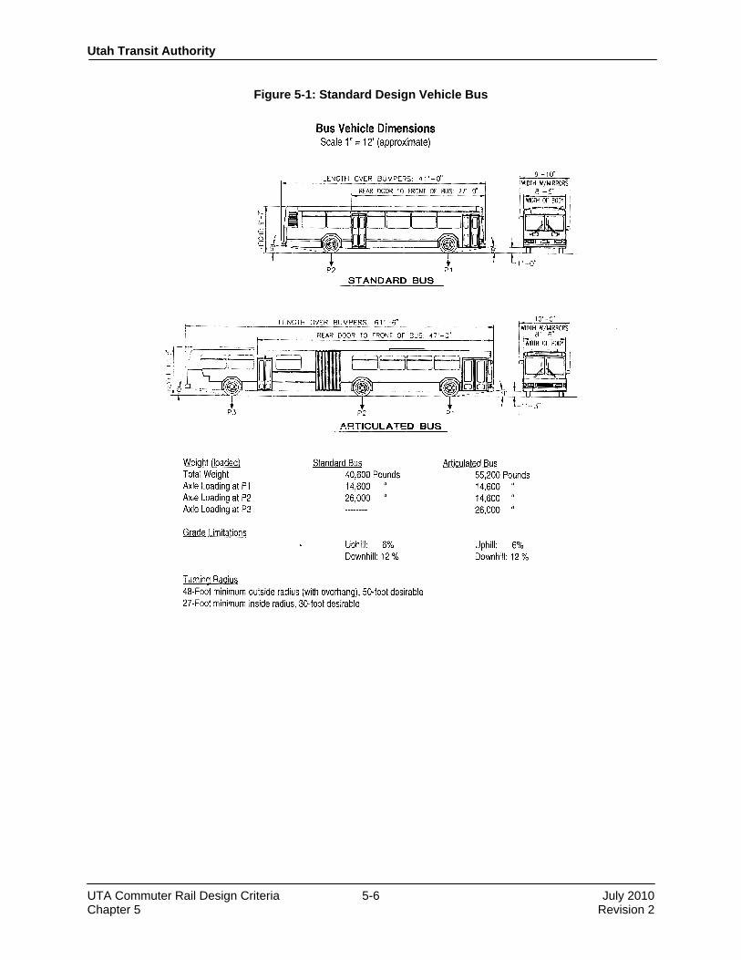
Utah Transit Authority
UTA Commuter Rail Design Criteria 5-6 July 2010 Chapter 5 Revision 2
Figure 5-1: Standard Design Vehicle Bus

Utah Transit Authority
UTA Commuter Rail Design Criteria 5-7 July 2010 Chapter 5 Revision 2
Figure 5-2: Bus Turn Arounds
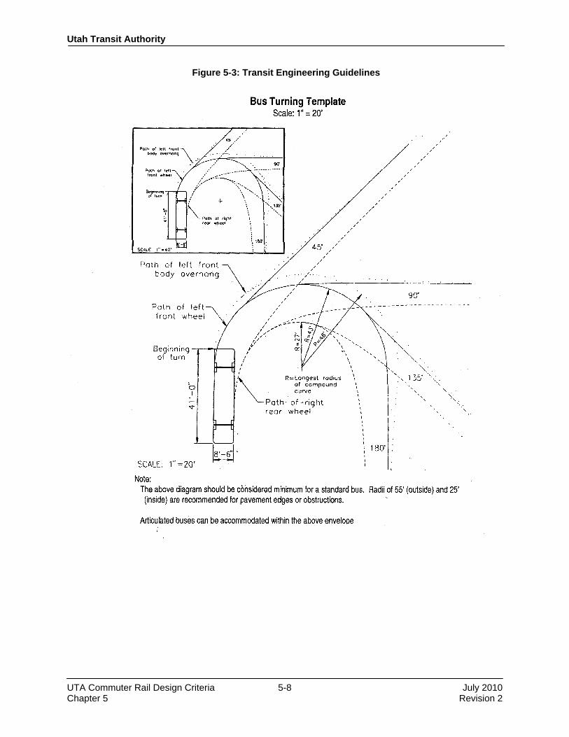
Utah Transit Authority
UTA Commuter Rail Design Criteria 5-8 July 2010 Chapter 5 Revision 2
Figure 5-3: Transit Engineering Guidelines
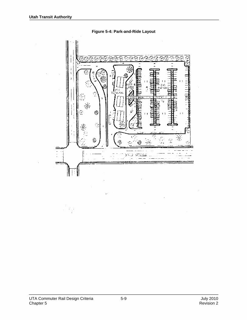
Utah Transit Authority
UTA Commuter Rail Design Criteria 5-9 July 2010 Chapter 5 Revision 2
Figure 5-4: Park-and-Ride Layout

Utah Transit Authority
UTA Commuter Rail Design Criteria 5-10 July 2010 Chapter 5 Revision 2
Figure 5-5: Bus Turnouts
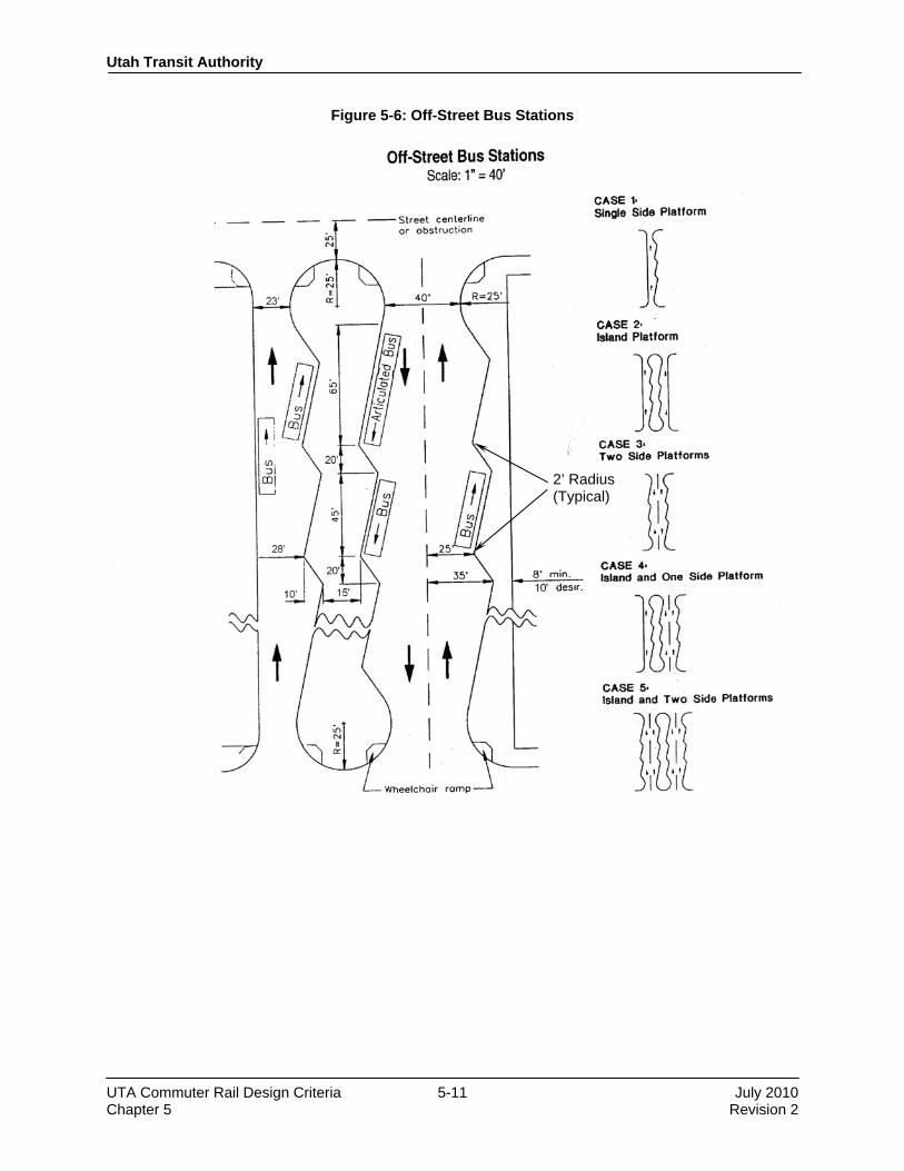
Utah Transit Authority
UTA Commuter Rail Design Criteria 5-11 July 2010 Chapter 5 Revision 2
Figure 5-6: Off-Street Bus Stations
2’ Radius (Typical)

Utah Transit Authority
UTA Commuter Rail Design Criteria 5-12 July 2010 Chapter 5 Revision 2
Most UTA rail facilities are expected to be located parallel to existing Union Pacific (UP) Railroad trackage, and in some instances also parallel to interstate and surface roadways. Existing drainage patterns are generally well established. Where retaining walls or other required structures alter surface existing drainage patterns, appropriate drainage systems shall be provided to accommodate expected flow. It is intended that changes in the overall runoff pattern be minimized. It is intended that drainage facilities related to the construction of UTA trackage and facilities shall be sized to match the capacity of these existing adjacent drainage systems. Improvements to drainage components and systems owned by UP, UDOT, or others are not envisioned for the commuter rail project, and shall be considered only on a case-by-case basis based on a separate agreement between the involved parties. Drainage facilities not owned by or located on UTA property, but which will be relocated or modified (and which do not cross or parallel rail track beds) shall conform to the design criteria and standards of the facility owner. In general, relocation of existing drainage facilities shall be “replacement-in-kind” or “equal construction.” Enhancements and improvements shall not be incorporated without UTA approval. The criteria relating to storm water drainage shall meet the requirements of specifications and design guidelines of the local agency having jurisdiction of the drainage area under consideration. 5.5.2 Submittals Design of drainage facilities requiring review and approval of jurisdictional agencies shall be submitted in accordance with the procedures established by the respective agency. Agencies having jurisdiction may include UDOT, Utah Department of Natural Resources, county soil conservation districts, and local municipalities. All construction, relocation, and restoration of storm sewers and drainage facilities and maintenance of existing facilities during construction shall conform to the design standards of those agencies. 5.5.3 Drainage Provisions UTA drainage criteria apply only to design of drainage facilities under the jurisdiction of UTA. Drainage of other facilities and connections to other drainage systems shall be designed in accordance with the criteria of the agency having jurisdiction. Invert elevations and locations of drainage facilities at the limits of contract design segments shall be coordinated with those of adjacent segments. As far as practical, drainage shall be by gravity flow. Where systems cannot be designed to use gravity outfalls, pumping stations shall be provided. No sanitary sewer discharge shall be permitted to enter the UTA drainage system. Ditches shall be provided as appropriate, configured where possible with a 2-foot flat bottom and a 2-foot drop from top of subgrade to bottom of ditch (larger if determined by hydraulic study). A geotechnical analysis shall be conducted to verify the appropriateness of slopes to be used. 5.5.4 Hydrology and Hydraulics The following procedures shall be used in preparing hydrologic computations:
a. All storm water facilities draining 5 acres or less may be designed for the expected discharge resulting from the applicable design storm frequency (shown below) as determined by the

Utah Transit Authority
UTA Commuter Rail Design Criteria 5-13 July 2010 Chapter 5 Revision 2
Rational Method. Storm water facilities draining areas may require water storage or detention considerations. Therefore, a hydrograph method shall be used for the applicable storm frequencies. The U.S. Soil Conservation Service TR-55 or TR-20 are acceptable. In jurisdictions with more strict guidelines, local codes and guidelines shall take precedence.
b. All cross culverts and storm water management facilities draining 5 acres or less may be designed for the expected discharge from the applicable design storm, determined by using the “United States Soil Conservation Service (SCS) Hydrograph Method” utilizing either (1) the TR-20 computer program or (2) the TR-55 Tabular Hydrograph Method using SCS Type 2 storm distribution.
c. If no water storage or potential detention considerations exist, storm water facilities draining more than 640 acres (1 square mile) may be designed for the maximum expected discharge determined by using the USGS Special Report 38 methodology for the applicable design storm.
d. The hydraulic capacity of open channels, swales, gutters, storm sewer pipe systems, and culverts shall be determined using the Manning equation. The hydraulic parameters of a stream shall be determined using the HEC-RAS computer program. The definition of a stream shall be determined by the local jurisdiction having authority. Open channels and swales shall be protected where the flow velocities exceed the values allowed by the UDOT Highway Drainage Manual.
e. Wherever feasible, the top of rail elevation shall be a minimum of 1 foot above the 100-year flood elevation.
f. Design for facilities shall accommodate storm frequency as follows, except when the local jurisdictional agency has differing standards, in which case the more conservative standards shall apply:
• Culverts and drainage facilities crossing the UTA system 100 year and primary roadways and freeways, where flooding could damage or disrupt the system
• All culverts and drainage facilities crossing secondary roads 50 year
• Track roadbed (to top of sub-ballast) 50 year
• Longitudinal storm drains in roadways 10 year
• Parking lot storm sewer systems 10 year
• Longitudinal drains or sub-drains at low points that could 50 year flood roadways or track roadbed
Where impoundment of water behind the rail system is necessary, impoundments of more than 10-acre feet of storage shall be designed in accordance with the Utah Division of Water Rights–Dam Safety design requirements for small dams, and submitted to the Utah Division of Water Rights–Dam Safety group for approval and permitting.
g. Methodologies—Hydrologic and hydraulic design shall be in accordance with the procedures and criteria as described in the current version of the UDOT Roadway Design Manual, UDOT Manual of Instruction for Roadway Drainage, the AREMA Manual for Railway Engineering, the Utah Department of Natural Resources regulations, U.S. Soil Conservation Service Technical Release No. 55 (TR-55), as established by local municipalities, or other methodology used by pertinent agencies having jurisdiction.
h. Minimum pipe size for new pipe perpendicular to the track is 24 inches.

Utah Transit Authority
UTA Commuter Rail Design Criteria 5-14 July 2010 Chapter 5 Revision 2
i. Pipe will be designed for a minimum velocity of 3.0 feet per second where feasible. 5.5.5 Selection of Drainage Structures Wherever possible, drainage structures to be maintained by UTA shall meet UDOT and/or UTA standards. In cases in which the standard drainage structures are not suitable, structures shall be designed to satisfy the conditions. 5.5.6 Pipe Materials Class V, Wall C reinforced concrete pipe shall be used. Use of perforated PVC or HDPE materials is subject to UTA approval on a case-by-case basis, which will generally be limited to locations not near railroad trackage. All pipe materials designed for other facilities shall conform to the requirements of the local jurisdictional agency, or on a case-by-case basis. 5.5.7 Location of Drains Manholes or other means of access shall be provided at changes in pipe slope, alignment and size, and at multiple pipe intersections. Underdrain cleanouts shall be provided at maximum 1,000-foot centers. Cleanouts are required at each 90-degree bend and for every two 45-degree bends. Manholes or catch basin spacing shall be in accordance with the following criteria: Size of Pipe (inches) Maximum Distance (feet) 18–24 300 27–36 400 42–54 500 ≥ 60 1,000 5.5.8 Parking Lots Parking lots shall be designed so that storm water is removed by overland flow to a gutter or curb and gutter, then to an inlet where the water will enter either a closed drainage system or an open ditch. Overland flow shall have minimum 1.0% grade wherever possible. The maximum permissible spread for gutter flow shall be 12 feet. 5.5.9 Storm Water Management and Sediment Control Sediment control shall be in accordance with the standards and specifications of the Utah Department of Environmental Quality Division of Water Quality. Appropriate UPDES permits shall be obtained, a Storm Water Pollution Prevention Plan (SWPPP) developed, and erosion and sediment control procedures established based on the approval of the Division of Water Quality. Local sediment and erosion control requirements established by the municipality or entity having jurisdiction shall also be met. Sediment control measures may be accomplished by various measures, as required and appropriate. The use of Best Management Practices (BMPs) should be used where possible. Some BMPs to be considered when designing storm water management include:
• Bioretention facilities such as grass buffer strips or vegetated filter strips • Catch basin inserts • Constructed wetlands • Dry wells • Infiltration basins and trenches
Utah Transit Authority
UTA Commuter Rail Design Criteria 5-15 July 2010 Chapter 5 Revision 2
• Media filtration • Porous pavements • Storm drain inserts (may be required by local jurisdiction • Bioswales • Wet and dry detention ponds
5.6 Fencing Fencing shall extend along the entire right-of-way to enhance security and safety. Fencing shall be provided as follows:
• Stations—Fencing shall be installed to prevent pedestrians from crossing UTA or UPRR trackage except at designated pedestrian crossings. Fencing shall be provided between UTA and UPRR trackage, parallel to the track, and typically extending 100 feet beyond the end of the platform. Fence shall be 4-foot high chain link, black vinyl coated.
• Along right-of-way with existing fencing—Replace fencing in-kind where existing fencing is disturbed.
• Vehicle service, maintenance, and storage areas—Use 6-foot high galvanized chain link fencing in accordance with UDOT standard construction details and specifications.
• Along new or existing pedestrian accessible bridges over trackage—Use fencing to prevent or minimize objects from being thrown or dropped onto the right-of-way. Use fencing appropriate for the bridge structure, with top of fence a minimum of 10 feet above adjacent surface, in accordance with UDOT standard construction details and specifications.
5.7 Right-of-Way
5.7.1 General Right-of-way refers to the composite total of all interests and uses of real property required to construct, maintain, protect, and operate the rail system. Some ROW requirements are temporary and reversionary in nature, while other requirements are permanent. The intent of the project is to acquire and maintain the minimum ROW necessary, consistent with the requirements of the operating system and good practices. Proposed taking envelopes should consider topography, drainage, ditches, retaining walls, service roads, utilities, construction staging needs, and the nature of existing and proposed structures and earthworks. Because ROW plans are typically used as a basis for acquisition of property, all proposed interests and uses shall be shown on the ROW plans along with the detailed property dispositions. The limits of permanent ROW shall be shown on the ROW plans as an unbroken line, utilizing simple curves and tangents. Spiral curves shall not be used. Chords may be used in lieu of curves under special conditions when approved by UTA. 5.7.2 Types of Property Ownership and Rights Fee simple, which refers to full ownership of property, should generally be proposed as the preferred approach for the construction of permanent facilities. Where easements are proposed, they shall be developed considering track width, drainage, supporting slopes, and utilities, and must consider the overall effect on the affected property. Easements shall be fully described, including lateral limits, vertical limits where required, and other features.

Utah Transit Authority
UTA Commuter Rail Design Criteria 5-16 July 2010 Chapter 5 Revision 2
Utility easements shall be treated as right-of-way, and bearings and distances along the sides shall be shown as well as the length and widths of the easements and ties to the limits of the ROW. All easements shall meet local and utility regulations. 5.7.3 ROW Limits The following criteria are provided as a guideline for establishing the limits of the ROW. The dimensions specified shall be considered to be minimum conditions, and are to be modified as appropriate. For at-grade construction:
a. An upper limit is not typically required. When an upper limit is appropriate, the limit shall be described by the elevations of horizontal planes, stepped as required and co-locating the steps with existing property lines or prominent suitable topographical features. The minimum desirable vertical distance from top of rail to horizontal plane is 18 feet.
b. The absolute minimum distance from the centerline of the nearest track to the limit of the ROW is 10 feet.
c. Where possible, the right-of-way shall normally extend to 5 feet beyond the limits of the side slope, except where retaining walls are used. Additional distance may be required for maintenance road and drainage ditches.
d. In retained cuts or on retained fills, the ROW shall extend laterally to 2 feet outside the outside edge of the retaining wall footings. Allowances shall be made for pile or anchor tie encroachments.
e. When required, the lower limit shall be defined in a manner similar to that for the upper limit, using a minimum vertical distance of 10 feet below top of rail, except in retained fill sections. In retained fill sections, the lower limit shall include the structural support system required for fill sections.
f. ROW for stations shall include space necessary for platforms, fare collection, waiting areas, stations’ ancillary facilities, and the structure. In addition to the structural, mechanical, and electrical requirements for space, the requirements for pedestrian and vehicular circulation space shall be observed.
For aerial construction:
a. Where required by local conditions, the upper limit is delineated by elevations of horizontal planes, stepped as required, co-locating the steps with existing property lines or prominent suitable topographical features. The minimum required vertical distance from top of rail to the horizontal plane is 18 feet.
b. Lateral limits shall be located a minimum of 2 feet beyond the limit of structures. Additional easements shall be required for maintenance of and repairs to structures.
c. Lower limits, where required by local conditions and/or specifically directed by UTA, shall be the ground level with specified use restrictions, except where crossing other ROW. For aerial support structures, lower limits shall include support foundation.
5.7.4 Storm Drainage For open ditches carrying surface drainage, minimum total easement width shall be governed by local agency requirements, but in no case shall be less than 6 feet for paved ditches and channels and 8 feet for unpaved ditches.

Utah Transit Authority
UTA Commuter Rail Design Criteria 5-17 July 2010 Chapter 5 Revision 2
Easement widths for underground drainage systems shall be approved by the local agency having jurisdiction. As a guideline, minimum easement width shall be 10 feet with 2 feet minimum clearance from outside edge of structure to easement line. 5.7.5 ROW Information Requirements
a. All spirals shall be reduced to circular curves at the limits of the ROW. Circular curves are the only types of curves acceptable for recording purposes. Curve data shall be shown on the ROW plan sheet in a table of curve data. Tangent sections shall be used in lieu of curves to show the limits of the ROW when curves are extremely flat.
b. Although the project may not require the acquisition of public property, all plans shall show the ROW envelope as being continuous crossing public as well as private property. Such private property shall be identified.
c. The boundary for all areas supporting all new construction shall be defined geometrically with ties shown wherever the location is not contiguous to the ROW.
d. For street closings, separate drawings shall be provided showing the areas of public property to be closed and utilized for the project. These drawings shall be prepared in accordance with local requirements.
END OF CHAPTER 5.

Design Criteria UTA Commuter Rail
Rev No. Prepared By
Approved By
Approval Date Document Date
0 PPa JWebb 12/1/04 12/1/04 1 DGoeres CCC 11/30/07 11/30/07 2 T. W. Jones CCC 3/19/10 July 2010
Utah Transit Authority
Commuter Rail Design Criteria
Chapter 6 Utilities
Revision 2, July 2010

Utah Transit Authority
UTA Commuter Rail Design Criteria 6-i July 2010 Chapter 6 Revision 2
Table of Contents
CHAPTER 6 UTILITIES ................................................................................................................. 6-1
6.1 General ......................................................................................................................................... 6-1 6.1.1 Existing Information ........................................................................................................ 6-1 6.1.2 Ownership by Others ....................................................................................................... 6-1 6.1.3 Scope of Relocation ......................................................................................................... 6-2
6.2 Drawings ....................................................................................................................................... 6-2 6.2.1 Requirements ................................................................................................................... 6-2 6.2.2 Procedures ........................................................................................................................ 6-2
6.3 Casement Pipes within Railroad ROW ......................................................................................... 6-2 6.4 Gas Lines ...................................................................................................................................... 6-3
6.4.1 Standards .......................................................................................................................... 6-3 6.4.2 Requirements within Railroad ROW ............................................................................... 6-3
6.5 Sanitary Sewers ............................................................................................................................. 6-3 6.5.1 Standards .......................................................................................................................... 6-3 6.5.2 General Requirements ...................................................................................................... 6-3 6.5.3 Manhole Locations .......................................................................................................... 6-4 6.5.4 Requirements within Railroad ROW ............................................................................... 6-4
6.6 Underground Communication Systems ......................................................................................... 6-4 6.7 Water Mains .................................................................................................................................. 6-5
6.7.1 Standards .......................................................................................................................... 6-5 6.7.2 Requirements ................................................................................................................... 6-5
6.8 Liquid-Petroleum Pipelines .......................................................................................................... 6-5 6.8.1 Standards .......................................................................................................................... 6-5
6.9 Street Lights and Traffic Signals................................................................................................... 6-6 6.9.1 Standards .......................................................................................................................... 6-6
6.10 Overhead Utility Lines .................................................................................................................. 6-6 6.10.1 Standards .......................................................................................................................... 6-6

Utah Transit Authority
UTA Commuter Rail Design Criteria 6-1 July 2010 Chapter 6 Revision 2
CHAPTER 6 UTILITIES
6.1 General This section describes criteria for new utility construction outside of buildings, and the support, maintenance, relocation, or restoration of existing utilities affected by construction of the Utah Transit Authority (UTA) system. Attention shall be given to the needs of UTA, the requirements and obligations of utility owners, and the utility service needs of affected properties. 6.1.1 Existing Information The designer shall identify and contact all utility owners whose facilities may be affected by the project. Copies of all available information concerning affected utilities shall be obtained. Information to be acquired includes owner, type, size, material, location, and existing easements of existing and proposed utility facilities. Where information is incomplete or insufficiently definitive, arrangements shall be made for surveys, subsurface utility engineering (SUE), and non-intrusive vacuum test holes as necessary. To the extent practicable and economical, existing utilities shall be undisturbed. Where construction of the UTA system makes that objective impractical or economically burdensome, provisions for relocation or reconstruction shall be included as part of the design. The designer shall coordinate with the appropriate utility owners and appropriate regulatory agencies at all stages of design, and shall reach agreement with respective owners before completion of detailing drawings. In cases in which utility owners prepare designs, the designer shall ascertain that work is compatible with UTA system needs and shall reference the work on UTA plans. 6.1.2 Ownership by Others Utility work performed for facilities not owned by UTA shall conform to the standards of the utility owner. It is the responsibility of the designer to submit drawings and specifications to the respective utility owners and government agencies for review at various stages of completion. Documentation of acceptance and approval by the utility owners is required. Upon completion of design, the designer shall submit a list of improvements and shall secure from each affected utility owner a firm estimate of the cost of work to be undertaken by the utility in order to accommodate the proposed construction. Utility lines crossing beneath railroad trackage shall conform to Chapter 1, Part 5 “Pipelines” of the AREMA Manual for Railway Engineering. Casement pipes shall be provided for pipelines carrying oil, gas, petroleum products, or other flammable or volatile substances, or steam, water, or other nonflammable substances under pressure. Electric duct, telephone conduit and drain crossings shall not require encasement where the strength of the facility is capable of withstanding railroad loading. Where the rail system is constructed above existing utilities to be retained in service, the facilities shall be uncovered and encased prior to placing track or, if more economical, replaced by a new system with a casement pipe. A variance to casing requirements may be granted by UTA, upon request, for an existing utility, if any of the following circumstances exist:
1. If there is an existing adjacent rail line and there is no casing under the existing adjacent rail line and the utility can structurally support the rail loadings without the casing.

Utah Transit Authority
UTA Commuter Rail Design Criteria 6-2 July 2010 Chapter 6 Revision 2
2. If there is an existing adjacent rail line and an existing pressurized, cast iron, lead-jointed pipe that crosses the existing adjacent rail line and the pipe can structurally support the rail loadings without a casing.
3. If there exists an opportunity to use a concrete slab to provide structural support and protection. 6.1.3 Scope of Relocation Utility relocation is to be performed only to the extent required by the construction of commuter rail facilities. No additional improvements, betterments, and other changes to utility systems shall be incorporated into UTA-sponsored work except as expressly agreed and approved by UTA in writing.
6.2 Drawings
6.2.1 Requirements Composite utility plans shall be prepared showing all existing and proposed utilities in the vicinity of all proposed construction. Information to be indicated on the plans includes track centerlines, buildings, sidewalks, paved areas, poles, pipelines, tunnels, and other surface and subsurface features. It shall be noted on the drawings that the contractor must maintain service connections. Service lines between utilities and adjoining properties shall be investigated for maintenance of service consideration, but need not be indicated on the drawings unless required by the owner of the utility to which the service is connected. 6.2.2 Procedures As the design is developed, the affected utility companies shall be furnished with preliminary plans. The affected utility companies shall be requested to verify their existing facility types, sizes, and locations, and to supply marked-up plans or prints of owners’ plan sets reflecting the necessary information. The designer shall then prepare drawings reflecting all assembled information and latest planned developments. Drawings shall indicate sufficient detail in order to consider conflicts and develop drawings for proposed utility relocations, and to prepare alternative relocation schemes to accommodate the project. Critical utility elevations and locations shall be determined and checked by SUE investigation. Where existing utility locations are critical to the design of UTA facilities, non-intrusive vacuum test holes shall be dug as approved by UTA. Coordination between the designer and the utility agencies shall be an on going activity during the design phase. Proposed designs that affect utilities shall be jointly considered by representatives of UTA, the designer, and the utility company in order to reach agreement as to implementation of the improvements or modifications. Prints of the final utility design documents shall be forwarded to each utility agency for final approval. Additional right-of-way (ROW) acquisitions that may be required shall be identified as early in the design process as possible, and acquisition details identified as soon as utility concurrence is secured.
6.3 Casement Pipes within Railroad ROW Casement pipes for existing utilities shall be of leakproof, steel construction as provided under railroad trackage per the requirements of the latest edition of AREMA.
Utah Transit Authority
UTA Commuter Rail Design Criteria 6-3 July 2010 Chapter 6 Revision 2
6.4 Gas Lines
6.4.1 Standards Permanently relocated gas lines shall be designed, installed, and tested in accordance with the current standards of the owner utility company, and the following:
• “Minimum Federal Safety Standards for Gas Lines,” Title 49 Code of Federal Regulations, Part 192
• “ASME Guide for Gas Transmission and Distribution Piping Systems” (American Society of Mechanical Engineers’ Gas Piping Standards Committee)
Construction of temporary and/or permanent gas mains and replacement of mains may be performed by the utility company owner or by a UTA contractor (with proper approval and contractor certification by the utility owner) as agreed by the utility owner and UTA. The designer shall make recommendations on a case-by-case basis. The lines to be maintained in place shall be the responsibility of the construction contractor, and the work shall be performed in accordance with the contract documents and the utility company owner’s standards and procedures. 6.4.2 Requirements within Railroad ROW Steel pipelines installed within any railroad ROW that are designed to operate at a pressure which will produce a hoop stress in the pipe equal to 30% specific minimum yield stress (SMYS) or greater shall be subjected to a hydrostatic test to a pressure of at least 1.5 times the maximum allowable operating pressure for a period of at least 8 hours. Inspection of welding on pipelines installed within any railroad ROW shall be in conformity with Federal Pipeline Safety Standards, Title 49 of the Code of Federal Regulations, Part 192, Articles 192.241 and 192.243, and in accordance with the current standards of the owner utility. Steel pipelines of 6-inch diameter or greater, and operating at a pressure which will produce a hoop stress of 20% of the SMYS or greater, shall have all girth welds tested non-destructively over their entire circumference. Testing of pipeline mains and services installed within the ROW shall be in conformity with Title 49-Part 192, Subpart-J-Test Requirements and in accordance with the current standards of the owner utility.
6.5 Sanitary Sewers
6.5.1 Standards All relocation, replacement, or extension of existing sanitary sewer systems shall:
• Comply with applicable federal, state, and local standards.
• Be designed to the criteria of the governing municipality and the Utah Department of Environment and Natural Resources (Utah DENR).
• Be approved by the governing municipality/agency and the Utah DENR. 6.5.2 General Requirements Where replacement or relocation of existing sewers and appurtenances is necessary, capacity and function equivalent to that of existing facilities shall be provided. However, no sanitary sewer trunk line shall be replaced with a pipe of less than 8-inch diameter. Pipe material, size, and appurtenances shall be in accordance with the current standards of the governing utility agency or Utah DENR. Sewers shall be

Utah Transit Authority
UTA Commuter Rail Design Criteria 6-4 July 2010 Chapter 6 Revision 2
designed with a hydraulic slope that will provide a mean velocity in the range of 2 feet per second (minimum) to 10 feet per second (maximum) when flowing full, based on Manning’s formula with a roughness coefficient of n = 0.013. Sanitary sewer pipe shall be installed to a minimum depth of 7 feet measured from ground surface to top of pipe where possible. Sanitary sewers, excluding house connections shall be a minimum of 10 feet horizontally away from and 1½ feet below water mains. Separate trenches shall be provided. Sewers crossing streams or within 10 feet of stream embankment, within 100 feet of water supply wells, or below water surface grade of water storage reservoirs shall be concrete encased. Sanitary sewer service to adjoining properties shall be maintained at all times by supporting in place, by providing alternate temporary facilities, or by diverting to other points. Closed flumes of sufficient size shall be provided to carry sewage flow temporarily when pipes must be removed from service. No sewage shall be discharged into excavations, public streets, or public and private ROW. 6.5.3 Manhole Locations Manholes, including frames and covers, shall be centered on sewer lines where feasible, to facilitate the use of mechanical sewer cleaning equipment. Manholes shall be provided at all changes in grade, size, and alignment and at multiple pipe intersections. At intersections of sewers having different diameters, invert elevations shall be adjusted to maintain a uniform energy gradient. Drop manholes shall be provided where the inflow invert is 2 feet or greater above outflow invert. Manhole infiltration shall not exceed 4.5 gallons per day per manhole at any location. Maximum distance between manholes shall be as follows, or as otherwise prescribed by the jurisdictional agency:
• 400 feet for pipes less than 18 inches in diameter
• 500 feet for pipes greater than 18 inches in diameter Manholes shall have clearance of 11 feet to the edge of the nearest tie. Where trackage and roadbed is constructed near existing utilities to be retained in service, manholes that do not maintain 11 feet of clearance shall be abandoned or relocated. A variance may be granted by UTA, upon request, to allow an existing manhole to remain as close as 5 feet to the edge of tie. Distances up to 600 feet may be approved in cases where adequate cleaning equipment for such spacing is provided by sewer owner. 6.5.4 Requirements within Railroad ROW Pipelines installed within any railroad ROW shall be subjected to infiltration testing procedure with regard to leakage and joint failure. The rate of infiltration shall not exceed 100 gallons per day per mile per inch of pipe diameter, with the rate of infiltration determined by means of a V-notch weir or other approved measuring device as may be directed by the utility company or UTA.
6.6 Underground Communication Systems Communications systems include all systems for the transmission of information and can be electrical or optical. This includes telephone, security systems, cable television, and multipurpose fiber optic systems. Plans shall clearly indicate the location of all communication systems affected by UTA construction, and shall indicate the disposition of all facilities. Each plan sheet shall include information concerning existing manholes and ducts; overhead poles; manhole number, size, and depth; number of cables; number of ducts and type; and number of vacant

Utah Transit Authority
UTA Commuter Rail Design Criteria 6-5 July 2010 Chapter 6 Revision 2
ducts. Details for duct banks and structures shall be included. For facilities to be built by other parties, including direct burial cables, the routing of all cables and the location of all structures shall be shown.
6.7 Water Mains
6.7.1 Standards All relocations, replacements, or extensions of existing water systems shall:
• Comply with applicable federal, state, and local standards.
• Be designed to the criteria of the governing municipality.
• Be approved by the governing municipality/agency. 6.7.2 Requirements Replacement or relocation of existing water mains and appurtenances shall provide capacity and function equivalent to that of existing facilities, and shall meet current standards of the utility owner. Pipes of equal or larger size shall replace water mains removed from service. Water mains and fire hydrants shall not be taken out of service without prior approval of the jurisdictional agency and local fire marshal. Service to adjoining properties shall be maintained by supporting in place, by providing alternate temporary facilities, or by connection to other points. Construction of water services to abutting properties shall comply with applicable plumbing codes of the appropriate county or local jurisdiction. Pipe used for water mains shall be as specified by the owning agency. Straight runs of pipe may be of either the mechanical joint or push-on type, with gasket. All valves and fittings shall be of the mechanical joint end type, with fittings lined and coated as noted herein. Pipe with bends shall be designed to resist thrust forces through the use of thrust blocks, flanges, or restrained joint pipe. Water mains shall be a minimum of 10 feet horizontally away from and 1½ feet higher than sanitary sewer lines. Separate trenches shall be provided. Disinfection, pressure, and leakage tests of new water mains are required according to the AWWA Standard C651 or the owner’s standards. The water shall be tested for potability by an approved Utah DENR laboratory. The utility owner shall be given the opportunity to witness the pressure and leakage tests.
6.8 Liquid-Petroleum Pipelines
6.8.1 Standards Relocation or modification of liquid petroleum pipelines, if necessary, shall be performed by the pipeline owner. Where casing pipes must be extended for the protection of existing pipes, this work can be performed by UTA or its contractor with the concurrence of the pipeline owner. Work involving liquid petroleum pipelines shall conform to the following standards:
• “ANSI Standard for Liquid-Petroleum-Transportation Piping Systems Part B31.4”
• “API Recommended Practice for Crossing Highways and Railroads”
• U.S. Department of Transportation (USDOT) “Part 195 of Government Requirements for Transportation of Liquids by Pipeline”

Utah Transit Authority
UTA Commuter Rail Design Criteria 6-6 July 2010 Chapter 6 Revision 2
The provisions of USDOT include:
• Pipelines installed within any railroad or street ROW shall have 100% of all girth welds tested non-destructively.
• Carrier pipes located longitudinally in or crossing any railroad ROW within a casing shall be subjected to hydrostatic testing.
• Carrier pipes shall be protectively coated and wrapped.
• Carrier pipe installed within a casing shall be manufactured to an acceptable specification and designed to operate at the appropriate stress level.
6.9 Street Lights and Traffic Signals
6.9.1 Standards All relocations, temporary or permanent, and maintenance of streetlights and traffic signal equipment shall be in accordance with the requirements of the governing owner agency and/or municipality. The contractor shall be required to protect existing streetlights and traffic signal equipment during construction. The designer shall indicate on the drawings work required in support of necessary modifications or relocations.
6.10 Overhead Utility Lines
6.10.1 Standards Modification of existing overhead utility lines, poles, and appurtenances, including service lines to adjoining properties, shall be performed by the facility owner in accordance with the laws and regulations of the appropriate jurisdiction, utility owners’ standards, the National Electrical Safety Code, and appropriate railroad overhead wire standards including those of AREMA. Poles supporting overhead facilities may be owned by one party and shared with or rented to others under mutual agreement. The designer shall identify the owners of all overhead wires and coordinate as needed to assure that the proposed design is mutually acceptable to all owners and UTA. Clearances shall be in accordance with the standards adopted by the utilities involved. Standards specified in the National Electrical Safety Code shall be considered the minimum requirements with respect to any railroad ROW crossings and structures. END OF CHAPTER 6.

Design Criteria UTA Commuter Rail
Rev No. Prepared By
Approved By
Approval Date Document Date
0 PPa JWebb 12/1/04 12/1/04 1 DGoeres CCC 11/30/07 11/30/07 2 T. W. Jones CCC 3/19/10 July 2010
Utah Transit Authority
Commuter Rail Design Criteria
Chapter 7 Structures
Revision 2, July 2010

Utah Transit Authority
UTA Commuter Rail Design Criteria 7-i July 2010 Chapter 7 Revision 2
Table of Contents
CHAPTER 7 STRUCTURES ............................................................................................................. 1
7.1 General ............................................................................................................................................ 1 7.1.1 Referenced Standards, Codes, and Guidelines .................................................................... 1 7.1.2 Primary Standards ............................................................................................................... 1 7.1.3 Improvements on UP or Other Non-UTA Right-of-Way ................................................... 2 7.1.4 Responsibility for Geotechnical Information ...................................................................... 2
7.2 Design Inputs ................................................................................................................................... 2 7.2.1 Loading ............................................................................................................................... 2 7.2.2 Clearances ........................................................................................................................... 2 7.2.3 Superstructure Types .......................................................................................................... 2
7.3 Crash Walls ...................................................................................................................................... 2 7.4 Emergency Access and Provisions ................................................................................................... 3

Utah Transit Authority
UTA Commuter Rail Design Criteria 7-1 July 2010 Chapter 7 Revision 2
CHAPTER 7 STRUCTURES
7.1 General The design of all structures constructed or reconstructed in conjunction with the UTA commuter rail project shall comply with the criteria provided herein. Where special design situations are encountered that are not specifically covered in these criteria, supplemental design criteria shall be identified for use based on documented technical sources, and submitted for approval by UTA. 7.1.1 Referenced Standards, Codes, and Guidelines Design of structures shall comply with the latest revisions of the following standards, codes, and guidelines:
• American Railway Engineering and Maintenance of Way Association (AREMA) Manual for Railway Engineering (latest revision), referred to in this document as AREMA Manual
• American Association of State Highway and Transportation Officials (AASHTO) “LRFD Bridge Design Specifications,” referred to in this document as AASHTO Specifications
• International Building Code (IBC)
• Utah Department of Transportation “Structures Division, Design and Detailing Standards”
• Union Pacific Railroad (UPRR) Design Guidelines and Engineering Standards
• AASHTO Standard Specifications for Structural Supports for Highway Signs, Luminaires and Traffic Signals
• Minimum Design Loads for Buildings and Other Structures, ASCE/SEI 7 7.1.2 Primary Standards When multiple standards and guidelines are applicable, the overriding source shall be as follows:
• Structures supporting UTA railroad trains and equipment: The primary standard is the AREMA Manual with modifications as identified in this document.
• Structures supporting railroad trains and equipment not owned or operated by UTA: The primary standard for UPRR properties is the Union Pacific Design Guidelines. For properties not owned by UPRR or UTA the primary standard shall be the AREMA Manual.
• Structures supporting roadways carrying non-railroad traffic: The primary standard is AASHTO Specifications, Utah Department of Transportation “Structures Division, Design and Detailing Standards,” and UPRR Engineering Standards (Structures).
• Buildings and parking decks: The primary standard is the IBC.
• Miscellaneous structures within 25 feet of track centerline: The primary standard is the more stringent of the listed standards. Miscellaneous structures include, but are not limited to, crash walls, retaining walls, and hydraulic structures.
• Miscellaneous structures more than 25 feet from track centerline but within 25 feet of a road: The primary standard is AASHTO Specifications and the Utah Department of Transportation “Structures Division, Design and Detailing Standards.”
• Miscellaneous structures more than 25 feet from track centerline or a road: The primary standard is the IBC.

Utah Transit Authority
UTA Commuter Rail Design Criteria 7-2 July 2010 Chapter 7 Revision 2
7.1.3 Improvements on UP or Other Non-UTA Right-of-Way Railroad-related right-of-way and structures near or adjacent to UTA, but not owned by UTA, are the property of the Union Pacific Railroad (UPRR) or other owners. All railroad-related improvements not on UTA right-of-way are subject to the review and approval of Union Pacific or other owner. UTA or its representatives will provide coordination and oversight of the review process, but the designer shall be responsible for the provision of a design acceptable to Union Pacific or other owner. The design of bridge and structural improvements on or affecting adjacent UP trackage shall minimize operating impacts on UP operations. 7.1.4 Responsibility for Geotechnical Information Unless specifically stated otherwise in contractual documents, geotechnical information that may have been previously gathered will be made available by UTA, but it is the responsibility of the designer to obtain geotechnical information as may be required to complete design and construction.
7.2 Design Inputs
7.2.1 Loading Unless otherwise provided, the load requirements specified in the referenced standards, codes, and guidelines shall be used for structural design, including load requirements for electrical, signal, and communication equipment as appropriate. Structures supporting commuter rail vehicles shall be designed for the loading diagrams shown in Figure 7-1 without hammer blow (diesel impact load) as prescribed in the AREMA Manual. Maintenance trains must operate over these UTA structures at 10 mph or less. This statement must also appear in the Operation and Maintenance Plans for the commuter rail projects. Bridges that will accommodate freight traffic during construction or during operation will be designed to E 80 loadings. 7.2.2 Clearances Where existing bridges and structures are rehabilitated or modified, or where superstructure is replaced, existing horizontal and vertical clearances shall be maintained unless otherwise provided. 7.2.3 Superstructure Types Bridge superstructure types shall be determined based on referenced standards, codes, and guidelines, and approved by UTA.
7.3 Crash Walls Crash walls shall be provided where highway overpasses or other structures span rail lines, and horizontal clearance between an interior bridge support or pier and the rail line is insufficient to minimize the risk of bridge collapse as a result of an impact from a shifted load on a train or a train derailment. Where the clear distance from the centerline of the track to the face of the column is less than 25 feet but greater than or equal to 12 feet, a crash wall extending 6 feet above the top of rail is required. Where the clear distance from the centerline of the track to the face of the columns is less than 12 feet, a crash wall extending 12 feet above the top of rail is required. Crash walls shall extend 4 feet below grade at the base of the wall

Utah Transit Authority
UTA Commuter Rail Design Criteria 7-3 July 2010 Chapter 7 Revision 2
and be at least 2 feet 6 inches thick. Minimum horizontal clearance between tangent track centerline and crash wall or bridge support shall be 10 feet.
7.4 Emergency Access and Provisions The ability to evacuate passengers from disabled trains, and for emergency responders to access disabled trains, shall be considered in the design of structures. In particular, for locations incorporating lengthy elevated structures and other track segments with limited access, a plan for emergency access shall be developed, and infrastructure provisions incorporated into the design. The identification of locations meeting this requirement shall be at the discretion of the UTA. The plan, and components of the plan, shall be based on good practice, the AREMA Manual (which requires a means of egress for passengers from a disabled train), NFPA 130, local fire codes, and other applicable sources. Plan is subject to the approval of local emergency responding agencies, which must be solicited for input during design.
Figure 7-1: Load Diagram
END OF CHAPTER 7.

Design Criteria UTA Commuter Rail
Rev No. Prepared By
Approved By
Approval Date Document Date
0 PPa JWebb 12/1/04 12/1/04 1 DGoeres CCC 11/30/07 11/30/07 2 T. W. Jones CCC 3/19/10 July 2010
Utah Transit Authority
Commuter Rail Design Criteria
Chapter 8 Stations
Revision 2, July 2010

Utah Transit Authority
UTA Commuter Rail Design Criteria 8-i July 2010 Chapter 8 Revision 2
Table of Contents
CHAPTER 8 STATIONS .................................................................................................................... 1
8.1 General ............................................................................................................................................ 1 8.1.1 Form .................................................................................................................................... 1 8.1.2 Functionality ....................................................................................................................... 2 8.1.3 Community Relationship .................................................................................................... 2
8.2 Station Layout .................................................................................................................................. 2 8.2.1 Modal Hierarchy ................................................................................................................. 2 8.2.2 Jurisdictional Codes and Governmental Regulations ......................................................... 3 8.2.3 Drawings ............................................................................................................................. 3 8.2.4 Station Context ................................................................................................................... 3 8.2.5 Station Types ...................................................................................................................... 4
8.2.5.1 Platform Type 1: Center Platform ................................................................... 4 8.2.5.2 Platform Type 2: Dual Side Platform .............................................................. 5 8.2.5.3 Slopes, Equipment, and Manholes .................................................................. 5
8.3 Circulation and Site Requirements .................................................................................................. 5 8.3.1 Design Objectives ............................................................................................................... 6
8.3.1.1 Passenger Flow Accommodation .................................................................... 6 8.3.1.2 Patron Accommodation ................................................................................... 6 8.3.1.3 Design Flexibility ............................................................................................ 6 8.3.1.4 Community Enhancement ............................................................................... 6
8.3.2 Modal Interchange .............................................................................................................. 6 8.3.2.1 Intercity Rail and Bus Services and Light Rail ............................................... 7 8.3.2.2 Bus Access ...................................................................................................... 7 8.3.2.3 Pedestrian Access ............................................................................................ 7 8.3.2.4 ADA Access .................................................................................................... 9 8.3.2.5 Bike Access ..................................................................................................... 9 8.3.2.6 Auto Access..................................................................................................... 9
8.3.3 Horizontal Circulation ........................................................................................................ 9 8.3.3.1 Passageways .................................................................................................. 10
8.3.4 Vertical Circulation ........................................................................................................... 11 8.3.4.1 Stairs .............................................................................................................. 11 8.3.4.2 Ramps ............................................................................................................ 11 8.3.4.3 Escalators and Elevators ................................................................................ 11
8.3.5 Emergency Exiting ........................................................................................................... 12 8.3.6 Parking .............................................................................................................................. 12
8.3.6.1 Park-and-Ride Facilities ................................................................................ 12 8.3.6.2 Kiss-and-Ride Areas ..................................................................................... 13

Utah Transit Authority
UTA Commuter Rail Design Criteria 8-ii July 2010 Chapter 8 Revision 2
8.3.6.3 Motorcycle Parking ....................................................................................... 13 8.3.6.4 Service Vehicle Parking ................................................................................ 13 8.3.6.5 ADA .............................................................................................................. 13 8.3.6.6 Air Quality..................................................................................................... 13 8.3.6.7 Park-and-Ride Entrance Signs....................................................................... 14 8.3.6.8 Pedestrian Access and Walking Distances .................................................... 14 8.3.6.9 Ease of Maintenance ..................................................................................... 14
8.3.7 Bus, Shuttle, and Para-transit Zones ................................................................................. 14 8.3.7.1 Bus Service .................................................................................................... 14 8.3.7.2 Shuttle Service ............................................................................................... 14 8.3.7.3 Paratransit Service ......................................................................................... 15
8.3.8 Station Visibility ............................................................................................................... 15 8.3.9 Historic Preservation ......................................................................................................... 15
8.4 Station Furniture and Amenities .................................................................................................... 15 8.4.1 Trash Receptacles ............................................................................................................. 15 8.4.2 Planters/Landscaping ........................................................................................................ 15 8.4.3 Seating .............................................................................................................................. 15 8.4.4 Water ................................................................................................................................. 15 8.4.5 Public Telephones and Emergency Telephones ................................................................ 16 8.4.6 Vending Equipment .......................................................................................................... 16 8.4.7 Ticket Vending Equipment ............................................................................................... 16 8.4.8 Car Sharing ....................................................................................................................... 16
8.5 Structures and Shelters .................................................................................................................. 16 8.5.1 Design Objectives ............................................................................................................. 16 8.5.2 Platform Canopies and Shelters ........................................................................................ 16 8.5.3 Service Buildings .............................................................................................................. 17 8.5.4 Business Kiosk .................................................................................................................. 17 8.5.5 Materials and Finishes ...................................................................................................... 17
8.6 Performance Standards ................................................................................................................. 17
8.7 Crime Prevention and Vandal Resistance ..................................................................................... 19 8.7.1 CCTV ................................................................................................................................ 19 8.7.2 Emergency Phone and Panic Button Lights ...................................................................... 20 8.7.3 Security Equipment on Station Platforms ......................................................................... 20
8.8 Fare Collection Equipment ............................................................................................................ 20
8.9 Signage and Communications ........................................................................................................ 20 8.9.1 Design Objectives ............................................................................................................. 20 8.9.2 Design Criteria .................................................................................................................. 20 8.9.3 Roadway Signage ............................................................................................................. 21

Utah Transit Authority
UTA Commuter Rail Design Criteria 8-iii July 2010 Chapter 8 Revision 2
8.9.4 Platform Map Cases .......................................................................................................... 21 8.9.5 Variable Message Signs .................................................................................................... 21 8.9.6 Station Entrance Signs ...................................................................................................... 21
8.10 Mechanical Systems ....................................................................................................................... 21 8.10.1 Plumbing ........................................................................................................................... 21 8.10.2 Water Service .................................................................................................................... 21 8.10.3 Pipes and Fittings .............................................................................................................. 22 8.10.4 Insulation and Freeze Protection ....................................................................................... 22 8.10.5 Plumbing Fixtures ............................................................................................................. 22 8.10.6 Heating and Ventilating .................................................................................................... 22
8.10.6.1 Equipment Rooms ......................................................................................... 22 8.10.6.2 Driver Relief Kiosks ...................................................................................... 22
8.10.7 Fire Protection System ...................................................................................................... 22 8.10.8 Snow Melt System ............................................................................................................ 22
8.11 Electrical Systems .......................................................................................................................... 23 8.11.1 Standards and Codes ......................................................................................................... 23 8.11.2 System Voltages ............................................................................................................... 23 8.11.3 Power Distribution Method .............................................................................................. 23 8.11.4 Equipment ......................................................................................................................... 24 8.11.5 Communication and Power Conduits ............................................................................... 24 8.11.6 Lighting ............................................................................................................................. 24
8.11.6.1 Design Objectives ......................................................................................... 25 8.11.6.2 Performance Standards .................................................................................. 25 8.11.6.3 Standard Elements ......................................................................................... 25 8.11.6.4 Illumination Levels ....................................................................................... 25 8.11.6.5 Station Site Lighting ...................................................................................... 26 8.11.6.6 Vehicular Access Lighting ............................................................................ 26 8.11.6.7 Pedestrian Access Lighting ........................................................................... 26 8.11.6.8 Platform Lighting .......................................................................................... 26 8.11.6.9 Control of Lighting Systems ......................................................................... 27
8.11.7 Snow Melt System ............................................................................................................ 27
Utah Transit Authority
UTA Commuter Rail Design Criteria 8-1 July 2010 Chapter 8 Revision 2
CHAPTER 8 STATIONS
8.1 General These criteria provide guidance for the design of Utah Transit Authority (UTA) commuter rail system stations. They were developed to attract and sustain system patronage, protect the safety of patrons using the stations, and establish the general quality of the stations and their fit into the community in which they are located. The design of the stations shall be standardized. Equipment, shelters, platform features, structural elements, and signage used shall be the same system-wide and compatible with UTA’s existing identity. Deviations from standard design elements may be required for specific sites, but must be approved by the UTA Commuter Rail Project Manager before design proceeds. The basic goals for station facility design, applicable to all sections of this chapter, will provide the basis for current design decisions, and will be used in the future to evaluate designs for new and renovated facilities. The goals are grouped into three categories: form, functionality, and community relationship. 8.1.1 Form Create a civic form that is permanent, functional, and pleasant for the patrons, has a character that is identifiable with UTA, and contributes to its context. This form should be compatible with and adjustable to the qualities of the neighborhoods and communities of which it is a part, while maintaining an overall line recognition and system identity. Specifically the station design shall:
• Provide system-wide recognition while maintaining station specific individuality.
• Protect passengers from adverse weather conditions such as snow, rain, wind, and summer sun.
• Make transit safe, secure, aesthetically pleasing, and accessible to all.
• Develop designs that use maintainable materials, products, and finishes and minimize life cycle costs.
• Provide an architectural and urban design framework that encourages joint development opportunities.
• Develop designs that conserve resources and energy. In addition, station designs shall meet the following codes and requirements:
• International Building Code (IBC)
• 49 CFR Part 37, Appendix A “Standards for Accessible Transportation Facilities”
• National Fire Protection Association (NFPA) code 130
• Local ordinances and guidelines
• Other applicable codes
Utah Transit Authority
UTA Commuter Rail Design Criteria 8-2 July 2010 Chapter 8 Revision 2
8.1.2 Functionality Stations shall:
• Provide a safe, efficient, and convenient station configuration for intermodal transfer with accommodations for buses, vans, taxis, kiss-and-ride areas, park-and-ride lots, bicyclists, pedestrians, and alternative modes of transportation.
• Provide clear and easily understood transit information that can be referenced quickly and that minimizes disorientation.
• Foster operational efficiencies that simplify modal interchange and patron movements.
• Allow for reasonable expansions and modifications of commuter rail and other transit services in accordance with UTA policies for future transit development, without requiring major reconstructions or replacements of station elements.
• Provide fare purchase facilities.
• Provide facilities for contacting emergency services. 8.1.3 Community Relationship Stations shall:
• Protect, maintain, and enhance existing neighborhood qualities.
• Promote transit-oriented and transit-adjacent land development in accordance with UTA and local community policies and guidelines.
• Permit coordination with community programs that limit local traffic impacts and minimize disruption during and after construction.
• Comply with local jurisdictional processes and agencies throughout project design and implementation.
8.2 Station Layout The purpose of this section is to describe the system-wide design philosophy for station layout and related site development. The elements described in the following sections, in total or in part, are to be located at each station site in a manner that is functional, safe, easily maintained, and attractive to passengers and neighboring residents. 8.2.1 Modal Hierarchy Stations shall be located so that total passenger access time from all modes is minimized. Particular attention should be paid to walk-on passengers from existing or planned developments. Vehicular access shall be located relative to the rail platforms in the following hierarchy:
1. UTA (or other) public transit modes (buses, commuter rail, light rail, paratransit, etc.)
2. Private shuttles and taxis
3. Accessible parking
4. Bicycle parking
5. Kiss-and-ride (if provided)
6. Auto and motorcycle parking (park-and-ride and/or short-term lots plus options for alternative fuel vehicles)
Utah Transit Authority
UTA Commuter Rail Design Criteria 8-3 July 2010 Chapter 8 Revision 2
8.2.2 Jurisdictional Codes and Governmental Regulations The UTA commuter rail system transverses numerous municipalities and governmental boundaries. Each of these legally defined jurisdictions has specific land use and development regulations and legislative procedures directly affecting station site planning and design. Therefore, designers shall:
• Identify the governing jurisdiction for each station site at every governmental level.
• Locate jurisdictional boundaries.
• Review applicable adopted master plans, municipal codes, ordinances, guidelines, and agreements.
Stations shall meet the requirements of the following codes and standards, based on the latest edition:
• International Building Code
• Applicable National Fire Protection Association codes and their Appendices including but not limited to NFPA 130
• American’s with Disabilities Act Accessibility Guidelines (ADAAG)
• Master Interlocal Agreement Regarding Fixed Guideway Systems Located within Railroad Corridors
Station facilities shall be designed to meet all requirements of all applicable federal, state, and local codes and regulations, except as exempted by the Master Interlocal Agreement Regarding Fixed Guideway Systems Located within Railroad Corridors. UTA should be notified in writing of any code or ordinance conflicts discovered. Where no provisions are made in the applicable codes or these criteria for particular aspects of the station designs, the best architectural practice standards shall be used. The intent, stipulations, and cooperation outlined in the executed Interlocal Agreements between UTA and the communities along the corridor on February 13, 2004, will be followed and pursued during the design and construction of commuter rail projects. 8.2.3 Drawings All drawings shall be prepared as per UTA’s drafting/CADD standards. 8.2.4 Station Context The “station context” refers to the nature of development that surrounds a station site. It may be residential, commercial, industrial, agricultural, suburban, urban, or rural. The station platforms shall generally be consistent in context throughout the corridor. Outside of the UTA right-of-way (ROW), each station shall be reflective of the neighborhoods and communities of which it is a part as well as the elements common to the entire UTA system. Therefore station site designs should:
• Contribute to the character and quality of their context.
• Help establish new development patterns where appropriate, in concurrence with the Station Area Development Guidelines and/or other municipal design guidelines.
• Reinforce and guide desired and/or established development patterns.

Utah Transit Authority
UTA Commuter Rail Design Criteria 8-4 July 2010 Chapter 8 Revision 2
• Recognize emerging development patterns that can be complemented and that will complement station development.
• Take the lead in establishing more transit-supportive development patterns and/or interconnected street networks by providing focus and structure for future development.
Two options exist for station/use integration at proposed rail station locations: freestanding stations and joint-use stations. Freestanding Stations: Station and related site solely serving access to the commuter rail service. A freestanding station is typically sited on property belonging to UTA. Joint-Use Stations: Station and related site integrated with other (non-transit) uses (shopping centers, offices, public use buildings) through a shared structural envelope and/or access points. The joint-use station can be developed either as a fully integrated structure with other uses (with common access and circulation) or as a partially integrated structure (with common access and circulation, but physically separated from the other uses). Joint-use development offers good potential for possible reduction in operating costs (heating, lighting, and other station services) as well as initial capital investment, and can provide the added feature of security for patrons where the joint or shared facility provides visual observation by other individuals or tenants. 8.2.5 Station Types Generally, the stations shall be based on one of two types—center platform (preferred where possible) or dual side platform (alternative where required). These are surface stations and consist of boarding platforms, weather shelters, and other appurtenances located within the commuter rail corridor right-of-way. Stations with grade-separated pedestrian concourses (above or below grade) linking station entrance areas to the platforms must account for future vertical circulation features (e.g., stairs, elevators, and escalators). Platforms shall be cast-in-place concrete slabs comparable in finish to standard urban sidewalks. The platform edge facing the trackway consists of a “tactile strip,” a safety feature providing a band of contrasting color and texture to demark the safe setback from moving trains and to warn the mobility disabled of the platform edge and drop off to the trackway. The tactile strip shall be ADA compliant. A 4-inch yellow stripe shall be painted behind the tactile strip. The trackway, on both sides of the station platform, shall be fenced to prevent crossing of the trackway onto the platform. The fencing shall be placed along the entire platform length. Fencing shall be 48-inch high, black chain link, with 1-inch openings between the platform and station parking area. Fencing shall be installed in curbing or in a concrete strip for increased weed control. Between the commuter rail track and UPRR track fencing should be 10-feet high, galvanized with 1-inch openings. Fencing will extend the length of the platform and for an additional 100 feet in each direction. Station platforms shall be located on tangent trackage. The use of curved station platforms will require approval by UTA. Track alignment and profile shall be established by UTA, and no later changes may be made without written concurrence from UTA. 8.2.5.1 Platform Type 1: Center Platform This platform type consists of a single platform, located between the two tracks, thus serving trains operating in both directions. This shall be used wherever possible in the interest of passenger convenience. The station is typically accessed from paved walkways connecting the platform ends across

Utah Transit Authority
UTA Commuter Rail Design Criteria 8-5 July 2010 Chapter 8 Revision 2
one track to an adjacent sidewalk serving as the station entrance and access to station area facilities. Accessible ramps at one platform end connect to the track crossings, allowing full access to wheelchair users. Center platforms shall conform to the following criteria:
1. Platform ultimate length (excluding ped access landing)
(parallel to track) 875 feet
2. Platform height (above top of rail)* 8 inches 3. Minimum platform width 22 feet 3 inches 4. Distance from platform edge to commuter rail track center 5 feet 2 inches 5. Minimum distance between longitudinal fence and commuter
rail track center 10 feet
* See Section 9.3.2.4 for ADA raised platform height.
8.2.5.2 Platform Type 2: Dual Side Platform This prototype consists of two platforms, one on each side of a pair of tracks. Each platform serves one of the two tracks. Each track is generally (but not exclusively) used for train operations in a single direction. The platforms are typically accessed from a paved walkway at each end of the station connecting the platform to the sidewalk serving as the station entrance and access to station area facilities. All other aspects of this prototype are similar to those of Platform Type 1. Dual side platforms shall conform to the following criteria:
1. Platform ultimate length (excluding ped access landing) (parallel to track)
875 feet
2. Platform height (above top of rail)* 8 inches 3. Minimum platform width 15 feet 4. Distance from platform edge to commuter rail track center 5 feet 2 inches
* See Section 8.3.2.4 for ADA raised platform height. 8.2.5.3 Slopes, Equipment, and Manholes Platforms shall be sloped to match the adjacent tracks. Side platforms shall be slopped to drain toward the track at a gradient of not more than 1%. Center platforms shall be crowned in the middle and sloped to drain towards the tracks on each side at a gradient not greater than 1%. Mechanical and electrical equipment shall be mounted on or embedded in vertical surfaces, in rooms or placed underground to reduce obstructions. Consider maintenance implications for each piece of equipment prior to designing it for underground placement. Manholes and handholes on the platform and in other station walkway areas shall not be located along main pedestrian walkways.
8.3 Circulation and Site Requirements Each mode of transportation that connects with the commuter rail service at stations has specific circulation and operational requirements. While each mode has its own unique characteristics, it is recognized that all modes must respect and enhance the operation and access of other modes that interface in and around rail transit facilities.
Utah Transit Authority
UTA Commuter Rail Design Criteria 8-6 July 2010 Chapter 8 Revision 2
Underlying site requirements that support transit, such as parking, furnishings, operating equipment, shelters, and site improvements provide safety, convenience, comfort, accessibility, and a positive experience for transit passengers and employees. The design objectives outlined below shall be the basis for design decisions. They provide the fundamental framework for resolving the interrelationship between each of the station activities and the means for minimizing conflicts and maximizing efficiency. 8.3.1 Design Objectives Design objectives guide and measure the design response to the basic goals of the station design and site planning. Four categories divide the objectives into related subjects. 8.3.1.1 Passenger Flow Accommodation
• Minimize crowding, movement obstructions and conflicts, patron disorientation, level changes, and physical barriers.
• Maximize safety, reliability, efficiencies of fare collection/ticket vending, and the ability to accommodate emergencies.
• Insure that all routes within station sites, buildings, and facilities are accessible as defined in the International Building Code. For example, all means of egress will be accessible, not just some as would be required in the International Building Code.
8.3.1.2 Patron Accommodation
• Provide adequate lighting, personal comfort, aesthetic quality, weather protection, and security. 8.3.1.3 Design Flexibility
• Allow for future operating changes in the number and configuration of transit vehicles with minimal reconstruction.
• Allow for positive interface with future development. 8.3.1.4 Community Enhancement
• Minimize negative impacts on local vehicular and pedestrian traffic.
• Promote desired growth.
• Design within the existing neighborhood context utilizing common system elements. 8.3.2 Modal Interchange Passengers tend to arrive at commuter rail stations at or near the scheduled departure time and do not spend a lot of time waiting. Therefore, modal interchange becomes a key consideration in station design. Modes to be considered in these criteria are:
• Commuter rail
• Intercity rail and light rail
• Bus and shuttle
• Walking
• Bicycle
• Automobile including kiss-and-ride and park-and-ride areas

Utah Transit Authority
UTA Commuter Rail Design Criteria 8-7 July 2010 Chapter 8 Revision 2
• Taxi
• Motorcycle There are distinct differences between each mode in terms of maneuverability, safety, speed, visibility, space requirements, compatibility, and reliability. The following describes the basic characteristics for each mode. 8.3.2.1 Intercity Rail and Bus Services and Light Rail Transfer from intercity rail, intercity bus, and UTA TRAX light rail services shall be optimized and convenient. The following general planning criteria will support transfers:
• Arrange tracks and platforms to provide the maximum opportunity for direct cross-platform transfers.
• Minimize walking distances between commuter rail and intercity rail and bus services in accordance with the following descending priorities (designer to verify the heaviest transfer priorities at each station):
1. Commuter rail and light rail
2. Commuter rail and transit bus (UTA, other services)
3. Commuter rail and intercity services (train and bus)
4. Commuter rail and drop-off services (taxi, kiss-and-ride, etc.)
5. Commuter rail and parking
• Minimize conflicts between trains, light rail, buses, shuttles, automobiles, bicycles, pedestrians and the mobility impaired.
8.3.2.2 Bus Access Several public and private bus/shuttle systems in addition to the UTA bus network will be integrated with or will interface with the commuter rail service and provide feeder routes to station facilities. Where applicable, there will be a hierarchy of vehicular modes of access, giving priority to feeder buses. The following general criteria should guide the site planning process:
• Locate bus drop off and pick up areas to minimize passenger travel distances from the bus to the south end of the rail platform. Accessible rail vehicles, initially, will be located at the south end of the train.
• Provide direct bus routing to and from bus bays to minimize bus travel time and distance.
• Minimize situations where buses are required to cross railroad tracks.
• Separate bus and automobile traffic wherever possible.
• Minimize conflicts between buses, shuttles, trains, automobiles, bicycles, pedestrians, and the mobility impaired.
• Design bus circulation to ensure forward movement only. 8.3.2.3 Pedestrian Access Good pedestrian circulation to, from, and across train platforms is essential for the smooth and safe operation of stations. Circulation patterns should be accessible and as simple, obvious, and comfortable as possible. In achieving good pedestrian orientation and circulation, careful consideration should include, but not be limited to, the following:

Utah Transit Authority
UTA Commuter Rail Design Criteria 8-8 July 2010 Chapter 8 Revision 2
• Limit at-grade pedestrian crossings of rail tracks to two locations.
• Locate the two pedestrian at-grade track crossings at each end of the station outside of the length of the platform.
• Design pedestrian at-grade track crossings to maximize passenger safety.
• Clearly identify track crossings.
• Create no new at-grade crossings of freight railroad tracks.
• Minimize turns, dead ends, and bottlenecks.
• Design pedestrian access from bus, kiss-and-ride, and park-and-ride areas to be as clear and as simple as possible.
• Create visually pleasing environments through the use of color, texture, and lighting.
• Provide safe and secure pedestrian access through the appropriate use of wayfinding and lighting.
• Provide a minimum queue length of at least the distance indicated below:
– Bottom and top of stairs 15 feet
– Fare collection equipment 6 feet
• Surge and queuing spaces shall be provided ahead of barriers and changes in circulation, direction, or mode.
• Locate maps, furniture, stairways, etc., to encourage balanced train loading and unloading.
• Provide ramps as required for mobility impaired patrons.
• Provide the shortest practical path of travel for mobility impaired patrons.
• Minimize grade changes, and where they are necessary they shall conform to slope criteria for mobility impaired access.
• Provide ample space for patron waiting out of the mainstream of pedestrian flow.
• Obstructions such as shelter structures, telephone booths, pylons, advertising displays, coin changers, concessions, seating, or maps shall not be located in obvious pedestrian pathways.
• Avoid cross-circulation at fare collection areas and decision points. Generally provide right-hand circulation.
• Shelters where provided for bus, kiss-and-ride, and rail patrons shall have sufficient transparency to provide adequate visual surveillance of the station area to discourage vandalism and enhance patron safety.
• Provide adequate sight distance and visibility along pedestrian routes.
• Sidewalk access to platform shall require pedestrians to face both directions of the trackway prior to crossing the track(s), using fencing or railing as a guide. The purpose is to see oncoming trains in either direction prior to crossing the track(s).
• At stations where site facilities are constructed adjacent to the platform, provide at least 6 feet of landscapable space and a maximum of 12 feet of landscapable space between the alignment fencing and hardscape elements (such as the bus loop or walkway). Refer to landscape requirements for landscape design.

Utah Transit Authority
UTA Commuter Rail Design Criteria 8-9 July 2010 Chapter 8 Revision 2
8.3.2.4 ADA Access ADA access to and from the train should be via a 24-inch platform. The 24-inch platform shall serve all new rail coach vehicles including the cab car. The raised platform shall be located at the south end of the platform and serve both train directions. The raised platform should be 24 inches above top of rail. The edge raised platform shall be 5 feet 8 inches from centerline of track. The slope of ramps to the raised platform shall be no greater than 1:15 and should be located to avoid conflicts with rail vehicle doorways. The surface of ramps shall be slip-resistant. The raised platform and ramps shall be heated to eliminate snow and icing. Canopies shall be placed on the raised portion of the platform in the same spacing pattern devised for the entire length of the platform. 8.3.2.5 Bike Access Bicycle storage shall be provided at each station. Racks shall conform to the requirements listed below:
• Located so as to be readily visible
• Located to cause minimum interference with other station activities
• Provide a secure stanchion that allows bicycles to be locked
Racks shall not be located on the platforms. 8.3.2.6 Auto Access Access for taxis, kiss-and-ride areas, park-and-ride lots, and motorcycles shall be provided in a manner that meets all state and local codes and does not interfere with access modes of higher priority as discussed earlier.
The design of entrances for motor vehicles shall take into consideration adjacent land uses by avoiding large unplanted, paved areas or dimensions that are out of scale compared to adjacent streets and structures. Curb cuts shall be minimized, while fulfilling the following requirements:
• Access is preferred from minor arterials and collectors.
• Access roadways to station sites should be designed to contain sufficient traffic storage capacity to meet expected transit patronage at peak times and to prevent backing up into public streets.
• Conflicts should be avoided between access roadways and large pedestrian movements.
• Access to a station site with more than 1,000 spaces should be from more than one street since the availability of several feeder routes is desirable.
• Access management shall be applied as much as possible. Access coordination with local jurisdictions and Utah Department of Transportation shall look to anticipate future road relocations or changes that can be anticipated within a reasonable time.
• Wherever possible entrances and exits should align with opposite intersecting streets or driveways.
8.3.3 Horizontal Circulation This section provides fundamental criteria for passenger and automobile circulation. Horizontal circulation is affected by fundamental station activities such as walking, sitting, standing, operating a wheelchair, queuing, loading, and so forth. Each activity has its own set of space requirements.

Utah Transit Authority
UTA Commuter Rail Design Criteria 8-10 July 2010 Chapter 8 Revision 2
The circulation to, from, and across train and bus waiting areas is essential for efficient and safe operation of stations. Circulation patterns shall be simple, obvious, and comfortable so as to result in an easily understood, friendly, and protected environment for passengers while providing an efficient system for the various transit and transportation modes. A key consideration is modal interchange, which is the means for passengers to connect between pedestrian movements, feeder bus, paratransit, multi-passenger vans, bike, automobile, and motorcycles. The following list identifies Station Area Circulation Zones to be considered in station design:
• A through zone is an unobstructed area that provides free flow of pedestrian movement. This area shall be void of above-grade utility boxes, vertical elements, furnishings, etc.
• A curb zone is an unobstructed area void of utility boxes, vertical elements, furnishings, etc., that provides space for loading and unloading of vehicles.
• A furniture zone is an area where furnishings, utility boxes, light and sign poles, newsstands, trash receptacles, passenger shelters, platform equipment, etc., are located.
• A guideway zone is the horizontal area that corresponds with the rail vehicle dynamic envelope.
• A bus zone is an area where buses transition in and out of the station and stop for passenger loading and unloading.
• A building frontage zone is the area between a building line and the through zone.
• A drop-off zone is an area for automobile drivers to drop-off and pick-up passengers. This is often termed “kiss-and-ride.”
• A taxi zone is an area designated for taxi drop-off and pick-up.
• A clear zone is an area at the corner of an intersection that is void of utility boxes, vertical elements, signs, newsstands, trash receptacles, etc., to allow adequate sight distances.
• An accessible crossing zone is an area designated for patrons crossing a street, bus lane, or guideway and that is clearly marked by paving or paint.
8.3.3.1 Passageways Criteria in this section apply to the possible future augmentation of stations with grade-separated pedestrian concourses linking station entrances to multiple platforms. In such cases, pedestrian bridges or underground passageways shall be designed to meet the following requirements:
• Minimum underground passageway width shall be 16 feet.
• Minimum width for pedestrian bridges shall be 16 feet.
• Sidewalk enclosures, if provided, shall be noncombustible and permit full view of the interior.
• Passageway lighting shall be provided, using similar standards as for lighting in station platform/shelters.
• Minimum vertical clearance to continuous ceiling shall be 10 feet and 8 feet 6 inches to minor obstructions.
• Minimum vertical clearance from top of rail to bottom of pedestrian bridges shall be 23 feet.

Utah Transit Authority
UTA Commuter Rail Design Criteria 8-11 July 2010 Chapter 8 Revision 2
8.3.4 Vertical Circulation Each station will have specific vertical circulation requirements based on the station’s configuration and site layout. Included are general standards used to arrange and size vertical circulation in a transit station under standard “peak period” operational conditions and also under emergency conditions. 8.3.4.1 Stairs The number, width, and location of stairs shall be in accordance with NFPA 130. The following shall be incorporated into the design of all public stairs.
• Minimum headroom clearance should be 9 feet measured vertically from stair tread nosing.
• Maximum riser height shall be 6 ¾ inches; increased to 7 inches with prior UTA approval.
• Minimum tread width shall be 11 inches.
• The minimum clear width of stairs for public use shall be 48 inches between handrails. Handrails may not project into the required clear width. The minimum length of landing for straight-line stairs shall be 54 inches. Larger dimensions shall be provided where planning indicates that more space is needed.
• Maximum height between landings shall be 12 feet.
• Treads shall have a non-slip surface.
• Open risers are not permitted.
• Tactile warning cues for the visually impaired shall be provided.
• The upper approach and the lower tread of each stair shall be marked by a strip of clearly contrasting color at least 2 inches wide, placed parallel to and not more than 1 inch from the nose of the step or landing to alert the visually impaired. The strip shall be of material that is at least as slip-resistant as the other treads on the stairs.
8.3.4.2 Ramps All ramps shall be accessible under the provisions of ADA and comply with the following requirements:
• The maximum allowed gradient is 5%; up to 8.0% (1:12.5 maximum) may be used with prior approval by UTA.
• Ramps with gradients between 5% and 8% require handrails and intermediate level landings in accordance with UBC, ADA, and other accessibility requirements.
• Handrails (where required) shall be provided on both sides and shall be continuous above non-skid surface of ramp. Inside handrails on switchback ramps shall be continuous.
• Level landings (where required) must be provided at intervals of 30 feet (horizontal projection) and wherever ramps change direction.
• Minimum ramp width between handrails is 48 inches. See raised platform ramp requirements in 8.3.2.4. 8.3.4.3 Escalators and Elevators The use of escalators is not anticipated. Elevators are required at all station locations where at-grade ADA access to the platform is not available. Stairway only access is not allowed. The use of elevators shall comply with the following requirements:
• Meet current International Building Code and code requirements for state and local jurisdictions.

Utah Transit Authority
UTA Commuter Rail Design Criteria 8-12 July 2010 Chapter 8 Revision 2
• Dual elevators are required for redundancy.
• Elevators should be large enough to carry an emergency stretcher. Additional design criteria for elevators and escalators are provided in a separate chapter. 8.3.5 Emergency Exiting Provisions shall be made to accommodate exit requirements from a transit station under emergency conditions, which could include evacuation of a train entering the station, crisis conditions in the station such as fire or bomb threat, or other situations. These emergency exit provisions shall apply to:
• Center platform stations which require patrons to exit at the platform ends if trains are occupying the station tracks
• Side platform stations where a train in the station forces patrons on the platform adjacent to the UP mainline railroad to exit at the platform ends
• Stations relying on grade-separated pedestrian concourses to access platforms
Emergency exiting provisions shall meet the requirements of NFPA 130, and be developed in collaboration with local emergency response personnel. 8.3.6 Parking This section identifies design criteria for pedestrian movements in parking lots. 8.3.6.1 Park-and-Ride Facilities Park-and-ride areas shall be provided at stations, with capacity as determined by UTA. The park-and-ride areas shall be designed to optimize the site area. Minimum stall and aisle sizes for park-and-ride and kiss-and-ride parking, including angled parking, shall be as indicated in Table 8-1. Designs laid out at 90 degrees to the aisle are preferred. Park-and-ride design should seek to utilize best and most efficient use of the land. The minimum allowable setback is typically desirable. The recommended numbers of stalls for station locations are discussed in the Park-and-Ride Master Plan. Typically the number of stalls will be approximately 80 stalls per acre which allows for some bus loop area. The park and ride areas shall be designed to optimize the site area available. Angled parking should be avoided where possible. Design shall conform to local jurisdiction requirements. Refer to Chapter 5 of Light Rail Design Criteria to identify civil element criteria for the site work of the facility. Site work shall follow American Public Works Association or Utah Transit Authority standards and specifications wherever possible. Table 8-1: Minimum Stall Sizes for Park-and-Ride Parking
Angle Stall Width (in feet)
Stall Depth (in feet)
1-Way Traffic (in feet)
2-Way Traffic (in feet)
90 8.5 18 24 24 80 8.5 18 23 23 70 8.5 18 19 19 60 8.5 18 18 18 50 8.5 18 16 22 45 8.5 18 16 22

Utah Transit Authority
UTA Commuter Rail Design Criteria 8-13 July 2010 Chapter 8 Revision 2
Angle Stall Width (in feet)
Stall Depth (in feet)
1-Way Traffic (in feet)
2-Way Traffic (in feet)
40 8.5 18 16 22 30 8.5 18 16 22 20 8.5 18 16 22 0 8.5 23 12 18
8.3.6.2 Kiss-and-Ride Areas A sidewalk of 10 feet minimum width shall be provided along parallel parking kiss-and-ride areas. A sidewalk of 12 feet minimum width shall be provided along the head end of angle parking kiss-and-ride areas. See section 8.6.2 of the UTA Light Rail Transit Design Criteria for further Kiss-and-Ride design guidance. 8.3.6.3 Motorcycle Parking Motorcycle parking stalls may be added in triangles and corners set off by the park-and-ride layout which are readily accessible to the station and which would otherwise be underutilized. Stall sizes shall be 4 feet by 8 feet. Maneuvering lanes shall be at least 10 feet wide. 8.3.6.4 Service Vehicle Parking One reserved parking space for service vehicles shall be provided per station and located convenient to the station platform. This space shall be signed accordingly. 8.3.6.5 ADA Accessible parking spaces should be clearly designated as reserved by a sign showing the symbol of accessibility. The accessible parking is required to be located adjacent to the passenger loading and platform areas, or in as close proximity as reasonably possible. Parking spaces and access aisles should be level with surface slopes. The number and dimensions of parking stalls for persons with disabilities at each facility should meet current ADA accessible parking stall guidelines. 8.3.6.6 Air Quality The following criteria should be considered, but is not required for the preliminary site location and general design of park-and-ride lots:
• Entry to Park-and-ride lots should be located at least 1000 feet from the corner of any at-grade intersection serving over 70,000 vehicles per day or projected to serve over 70,000 vehicles per day.
• Entry to Park-and-ride lots should be located at least 500 feet from the corner of any at-grade intersection serving between 50,000 and 70,000 vehicles per day or projected to serve between 50,000 and 70,000 vehicles per day.
• Park-and-ride lots should be located and designed so that they do not contribute to peak hour traffic by more than 5 percent of any single movement to an intersection operating at level of service D or worse or projected to operate at level of service D of worse.
• Access to park-and-ride lots should be located at least 300 feet from a signalized intersection on an arterial street and at least 200 feet from a signalized intersection on a collector street.
PM10 hot spot reduction recommendation:
• Guidelines should be developed to minimize left turns from diesel buses, allow for adequate space for prompt arrival and departures (without waiting for other buses or traffic), provide bus

Utah Transit Authority
UTA Commuter Rail Design Criteria 8-14 July 2010 Chapter 8 Revision 2
shelters where bus to bus transfers are anticipated, and provide for efficient transit scheduling to minimize diesel bus idling.
8.3.6.7 Park-and-Ride Entrance Signs When possible illuminated station name signs in UTA standard Royal Blue should be provided near park-and –ride entrances. This sign may be the same sign used for the station monument sign. 8.3.6.8 Pedestrian Access and Walking Distances Pedestrian circulation shall provide direct, convenient, safe and delineated approaches to station platforms and bus loading areas from off the site and from each of the individual sections of the lot. Parking aisle orientation shall be planned to consider pedestrian directness, lot capacity, efficiency, and pedestrian safety. Walking distances from parked cars to bus loading areas should be kept to a minimum, preferably less than 300 feet when possible. Pedestrian movements within the park and ride area will normally occur within the driving aisles; however, pedestrian walkways may be provided to minimize vehicular interference, to reduce the number of points where pedestrians cross the aisles, or to shorten irregular routes through successive aisles by a considerable distance. Where walkways are installed provide for a minimum of 5 feet of clear. 8.3.6.9 Ease of Maintenance Parking lots, curbs, medians and islands should be laid out in such a manner which allows quick and easy snow removal so lots are continuously available during inclement weather. 8.3.7 Bus, Shuttle, and Para-transit Zones The layout of certain stations will include bus service access, and shall be coordinated with the transit providers (private and public) that will service these stations. The design shall address the potential for relocating bus zones, rerouting bus lines, establishing new bus lines, and estabiling layover and turn back facilities. 8.3.7.1 Bus Service Bus stops shall be placed to minimize patron travel time (total bus and walk time). In general, street curb service is preferred over on-site access, especially for “through” buses. Where buses will circulate within the site, roadway geometry shall appropriately accommodate bus movements. The driving and parking surface for the buses shall be concrete, as called for in Chapter 6—Civil, to withstand the turning and stopping loads of buses. Modified saw tooth layout of bus stops shall be used in off-street locations at the stations where more than three buses are required, unless prior approval is obtained from UTA for an alternative layout. The prominent display of schedule and route information is essential. Bus information at bus stops shall be in accordance with the transit operator’s criteria. 8.3.7.2 Shuttle Service Private or public shuttle services may serve certain stations. The physical requirements for these shuttles (typically large vans or small buses) shall be coordinated with the potential operators. These services typically do not use transit bus stops due to the shuttles’ longer load/unload time.

Utah Transit Authority
UTA Commuter Rail Design Criteria 8-15 July 2010 Chapter 8 Revision 2
8.3.7.3 Paratransit Service Paratransit service shall be accommodated at each station, and shall generally be located adjacent to bus stops. Access to the platform shall be as direct as practical. The physical requirements for these vehicles, which usually consist of large vans or small buses, shall conform to van accessible standards. 8.3.8 Station Visibility Stations should be readily identifiable and clearly associate the facility with UTA. 8.3.9 Historic Preservation Regulations for designated historic sites (if applicable) must be accommodated.
8.4 Station Furniture and Amenities This section describes criteria for the design and specification of station furniture and equipment. The objective of the furnishings is to be functional, attractive, and theft- and vandal-resistant at a reasonable cost. The designer shall propose off-the-shelf street and station furniture from which UTA will select a limited number of models. Alternative designs may be used with prior UTA approval. All furnishings and equipment shall be selected from standard models suitable for heavy duty outdoor use and shall be compatible with station architecture. 8.4.1 Trash Receptacles Four trash receptacles shall be provided on all platforms, with additional receptacles at ticket vending machines, bus boarding areas, and at kiss-and-ride and taxi boarding zones. Trash receptacles shall be of design that contents of the receptacle can be seen from the platform. Clear trash bags shall be used, and held in place by a lid. Trash receptacles shall have a lid that locks securely to receptacle frame. Lid shall limit the size of objects that can be placed into the bag. 8.4.2 Planters/Landscaping There shall be no landscaping or planters on the station platforms. 8.4.3 Seating Benches shall be provided on platforms to provide a seating capacity of 12 persons per platform, or as directed by UTA. At least one bench will be located under each platform shelter. Benches could also be developed as stakeholder betterments or the Art in Transit program. Benches shall be provided at on-site and on-street bus stops with a minimum seating capacity of 4 persons per bus stall. Benches and/or seating units shall be of designs that will discourage individuals from lying down and/or sleeping. One-half of the platform seating shall be designed with backs and full-length armrests to facilitate use by individuals with disabilities. 8.4.4 Water Drinking water fountains will not be provided at stations. A hose bib for use in maintenance activities will be provided at each station. Provide water connections or hose bibs so that any location on the platform can be reached by a 100-foot long hose. Designer will consider winterized use of water connections. Hose bibs shall be freeze proof.

Utah Transit Authority
UTA Commuter Rail Design Criteria 8-16 July 2010 Chapter 8 Revision 2
8.4.5 Public Telephones and Emergency Telephones One public telephone kiosk shall be provided at each station. The phone shall be located on the station platform. An emergency telephone shall be provided on each platform. The emergency phone can be integrated with the public phone, or a separate unit. The emergency phone shall connect to the local police department. There shall be no cost to use the emergency phone. 8.4.6 Vending Equipment Retail vending equipment may be provided at stations, only as approved by UTA. If provided equipment shall be located outside of platform and fare control zones to avoid conflicts with queuing and boarding passengers, and consolidated in a single, protected location. 8.4.7 Ticket Vending Equipment Ticket vending equipment is described in following sections. 8.4.8 Car Sharing Community car sharing parking and signage may be provided as directed by UTA at selected stations for car sharing vehicles. These are third-party vehicles to be shared and accessed by the public. Reserved spaces shall conform to the requirements listed below:
• Located so as to be readily visible from the train • Located to cause minimum interference with other station activities (i.e. snow removal).
8.5 Structures and Shelters
8.5.1 Design Objectives The overall objectives for layout and selection of paving, platforms, platform canopies, passenger shelters, and ancillary buildings located at or near UTA stations include:
• Provision of safety and convenience for patrons and UTA employees
• Comply with local codes and enhance local asthetics
• Use of materials and construction practices that minimize maintenance requirements
• Use of materials and construction practices that minimize life cycle costs
• Standardization of materials and construction practices, including compatibility with materials used in other UTA facilities
8.5.2 Platform Canopies and Shelters Platform canopies or shelters, and shelters in bus and kiss-and-ride areas, shall provide passengers with comfort and protection from expected adverse weather conditions. In general, there shall be a canopy over a portion of each part of the platform. Cladding on structural supports for the canopies and any window frames will be constructed from anodized aluminum.
Minimum coverage of platform area 7% Minimum vertical clearance under canopy 8 feet Minimum clearance from platform edge to canopy column or wall 6.5 feet
Utah Transit Authority
UTA Commuter Rail Design Criteria 8-17 July 2010 Chapter 8 Revision 2
Canopy columns or walls shall be centered on the platform width for center platforms and supported away from the track for side platforms. Single center columns shall be used to maximize circulation around canopies where possible. Double column canopies may be considered where needed for structural and design considerations. Windscreens shall be incorporated into the canopy structure. Windscreens must be sufficiently transparent to allow easy surveillance for patron security and to discourage vandalism. Acrylic panels are not acceptable. Glass must be tempered and laminated. Canopy roofs shall have no longitudinal slope. Canopy roofs shall have positive drainage to the track or municipal drainage system. Gabled roofs shall not allow snow to slide onto platform. Flat roofs are not allowed. All downspouts shall have heat tape to prevent clogging due to freezing. Each canopy shall have electrical conduit to accommodate future infrared heating elements. The station electrical system shall be designed to facilitate the future infrared heating elements. 8.5.3 Service Buildings Service buildings are defined as all structures not accessible to passengers, for the use of UTA employees or contractors. This includes:
• Equipment Rooms—Signal, electrical, and communication spaces where required shall be sized according to the requirements identified by UTA.
• Driver Relief Kiosks—Driver relief kiosks are to be provided at stations identified by UTA. No provisions will be made for public toilets at UTA stations.
8.5.4 Business Kiosk Park-and-ride stations shall include the facilities for a future business kiosk. The future kiosk shall be located to maximize pedestrian business opportunity. The kiosk site shall be a concrete pad and include water, sewer, power, and telephone utilities. 8.5.5 Materials and Finishes In specifying manufactured items or materials, preference shall be given to standard off-the-shelf items available from more than one supplier over custom-made or single source items. In specifying finish, size, color, pattern, or composition, slight variations in appearance should be allowed so less costly products or materials of equal quality can be utilized. Products shall be durable and vandal resistant.
8.6 Performance Standards Performance standards include the following:
• Durability—Durable and cost-effective materials shall be used that have long-term wear, strength, and weathering qualities. Materials shall be capable of good appearance throughout their useful life and shall be colorfast.
• Low Maintenance—Life cycle maintenance costs shall be considered in the evaluation of all materials and finishes used in station design.
• Quality of Appearance—Materials shall be appealing and harmonious in appearance and texture, and shall reinforce system continuity while relating to the local context.

Utah Transit Authority
UTA Commuter Rail Design Criteria 8-18 July 2010 Chapter 8 Revision 2
• Cleaning—Materials that do not soil nor stain easily shall be used and shall have surfaces that are easily cleaned in a single operation using commonly available equipment and cleaning agents should be able to be utilized. All porous finishes subject to public contact shall be treated or finished in a manner that allows easy removal of vandalism.
• Repair or Replacement—To reduce inventory and maintenance costs, materials shall be standardized as much as possible for easy repair or replacement without undue cost or disruption of the rail service. For example, hose bibs, electrical outlets, lighting fixtures and lamps, glass or plastic lights, information panels, signs, shelter materials, etc., shall be standardized on commonly available sizes and finishes for easy inventory stocking and installation.
• Safety—Pedestrian safety shall be increased and the presence of the individuals with mobility impairments shall be recognized by using floor materials with non-slip qualities. Stairways, platform edge strips, and areas around equipment shall have high non-slip properties. Areas of less use or hazard may have less stringent properties.
The following static coefficients of friction as defined in ASTM C1028 and surface treatments shall be provided as a minimum:
Surface Coefficient of Friction and Surface Treatments Public horizontal surfaces 0.6 per ADA Non-public horizontal surfaces, exterior 0.6 Non-public horizontal surfaces, interior 0.5 Platform edge strips material Textured and visually contrasting material
conforming to ADA requirements Stairs, ramps, sloping sidewalks 0.8 per ADA Area around equipment 0.6
• Compatibility—Selected materials shall be compatible with the local climate and consistent with existing materials within the station vicinity. Materials for structures should harmonize with existing facilities on a site-specific basis.
• Availability—Selection of materials shall permit competitive bidding and emphasize regional products and processes over those not locally available.
• Fire Resistance—Fire resistance and smoke generation hazard from fire shall be reduced by using finish materials with minimum burning rates, smoke generation, and toxicity characteristics consistent with Code requirements as noted in the International Building Code.
• Finish Materials—Dense, hard, nonporous materials shall be used in all applications. Finish materials shall be corrosion, acid, and alkali resistant and shall be compatible with chemical compounds required for maintenance.
• Detailing—Detailing of finishes shall avoid unnecessary surfaces which may collect dirt and complicate cleaning. Wall surfaces shall be vertical and flush allowing for texture. All edge and finish materials shall be detailed, incorporating joints and textures, which reduce the requirements for true, visually perfect installation over long distances.
• Waterproofing—All finish materials in underground spaces shall be selected and detailed with proper attention to waterproofing, cavity walls, drainage, and venting. All drainage cavities shall include provisions for cleanout.
• Texture—Materials within reach of passengers shall be easily cleaned, with a finish to prevent or conceal scratching, soiling, and minor damage.

Utah Transit Authority
UTA Commuter Rail Design Criteria 8-19 July 2010 Chapter 8 Revision 2
• Color—Materials shall be selected with consideration to harmony or color on a system-wide basis. Color selection shall favor materials that are light and reflective to maintain desired illumination levels. Materials with homogeneous colors shall be selected over those with surface finishes or veneers. The use of paint, stains, and coatings shall be minimized.
• Graffiti and Vandal Resistance—Graffiti-proofing products shall be used to protect surfaces susceptible to graffiti. Provide materials and details that do not encourage vandalism and that are difficult to deface, damage, or remove. All surfaces exposed to the public shall be finished in such a manner that the results of casual vandalism can be readily removed with common maintenance techniques.
8.7 Crime Prevention and Vandal Resistance The criteria in this section relate to two aspects of crime: the prevention of crimes against passengers, and crimes against UTA property, the most common of which is vandalism. Both can be significantly reduced by thoughtful planning and design of facilities and through careful selection of building materials and products. An approach to facility planning and design shall be used that incorporates crime prevention through environmental design (CPTED) principles, which seek to reduce the incidence and severity of criminal behavior by creating a built environment that deters crime. The central principle of CPTED is known as natural surveillance, or planning a facility such that its legitimate users (i.e., passengers and staff) can easily observe all areas of the facility while these users are seen by potential criminals as being clearly in control. Possible CPTED strategies for commuter rail stations include:
• Area identity—The zone around a station shall be clearly designated for the purpose of passengers boarding or alighting trains and other transit modes and using other legitimate secondary transit facilities.
• Boundary Demarcation—Signs shall clearly demark the boundaries of the designated “transit use” zone around the station. The zone can be further demarked by clearly defined use of paving materials, finishes, structures, site furnishings, lighting, or landscape plantings.
• Lighting—Stations shall be well lighted at night, both for the protection of passengers and effective surveillance by public safety and law enforcement personnel.
• Natural Surveillance—Placing stations in direct view of residences or businesses that are occupied or staffed during operating hours allows constant, natural surveillance of station activities.
• Clear Lines of Sight—The design and placement of vertical structures such as walls, screens, and shelters shall incorporate clear lines of sight into the station by public safety and law enforcement personnel. Natural surveillance is enhanced by the use of transparent materials (e.g., glass and glass block) or screen-like materials (e.g., expanded metal mesh and wire grids).
8.7.1 CCTV Four 1½ inch conduits (power, video, commo, spare) with appropriately spaced pull boxes and pull-strings will be placed to at least four light poles at the outer extent of the parking lots for potential CCTV cameras. The conduit will terminate at the pull box at the power control cabinet (PCC). The number of poles will be determined during the design process. The CCTV equipment to be placed will be determined in coordination with UTA police and central surveillance personnel.

Utah Transit Authority
UTA Commuter Rail Design Criteria 8-20 July 2010 Chapter 8 Revision 2
8.7.2 Emergency Phone and Panic Button Lights Four 1½ inch conduits (power, commo, spare, spare) with appropriately spaced pull boxes and pull-strings will be placed to at least two locations within the parking lot for potential emergency phones and panic button boxes. The conduit will terminate at a pull box at the power control cabinet (PCC). The equipment to be placed will be determined in coordination with UTA police and central surveillance personnel. 8.7.3 Security Equipment on Station Platforms The use of surveillance equipment for monitoring of platforms may be desirable in the future. The infrastructure for this future need will be met if the requirements of Section 8.11.5 are met.
8.8 Fare Collection Equipment All stations shall have provisions for either free standing or integrated ticket vending machines and electronic fare card readers. There shall be two ticket vending machines and a minimum of two electronic fare card readers at each station entrance point, but not on the platform. All ticket vending machines and card readers will be located such that they do not impede pedestrian flow onto the platform. Weather protection shall be provided for each machine unless otherwise approved by UTA. The front face of the vending machines shall not be oriented to the south, west, or southwest, unless protection from the sun is provided.
8.9 Signage and Communications This section contains general guidelines for the planning and design of signage and graphic displays in commuter rail and transit stations. Signage includes directional signage, safety and regulatory signage, informational signage and graphics, and variable message signs (VMS). Signage shall comply with ADAAG requirements. 8.9.1 Design Objectives Clear and easily-understood signage provides numerous benefits to customers. Design objectives for signage include:
• Arrange signage so that it is easily visible.
• Utilize materials and construction practices that minimize maintenance requirements.
• Utilize materials and construction practices that minimize initial cost.
• Standardize materials and construction practices.
• Minimize the number of decisions a passenger must make in order to transfer between modes. At decision points it is preferable to limit the number of choices to two.
8.9.2 Design Criteria A consistent style of lettering shall be used for all graphics in stations indicating regulation, direction, and orientation. Consider assigning color coding to signs and other graphics to differentiate direction of travel. Locate information signs at decision points for maximum visibility. Signs shall orient outbound passengers to the surrounding community with appropriate signage or display maps. Locate maps (local

Utah Transit Authority
UTA Commuter Rail Design Criteria 8-21 July 2010 Chapter 8 Revision 2
area and transit maps) in the immediate proximity of fare collection equipment and at points of intermodal transfer. Advertising signage shall be segregated from informational signage and graphics. Avoid placing advertising at critical decision-making points. In boarding areas, locate advertising opposite departing and waiting passengers, in linear clusters, and with accent lighting. 8.9.3 Roadway Signage Signs directing motorists to, or within, transit station areas must be coordinated with appropriate local and national signage standards, and should include standard international symbols whenever possible. The kiosk power and communications conduit shall be provided to the base of the kiosk. 8.9.4 Platform Map Cases Free standing map cases shall be provided on the platforms. There shall be four map cases per platform. They shall provide system, station, and train destination identification. At least two signs shall be provided on each platform. The cases shall be large enough to accommodate power and communications conduit. Section 8.11.5 delineates the conduit requirements into map cases. Station name signs shall be located on top of each platform map case. The station sign shall be easily seen by on-board passengers, both sitting and standing. 8.9.5 Variable Message Signs Provisions shall be made for initial or future VMS. The VMS shall be located on top of the station platform map cases, on light poles, under canopies, or other appropriate locations. Section 8.11.5 delineates the conduit requirement for possible VMS locations. 8.9.6 Station Entrance Signs Illuminated station name signs should be provided at major station entrances.
8.10 Mechanical Systems This section of the Design Criteria establishes the design standards for the mechanical systems associated with stations. Unless otherwise required herein, local codes and the following codes, manuals, or specifications shall govern the mechanical design. Local codes shall take precedence. 8.10.1 Plumbing Piping, where required, in station areas shall be run as directly as possible and concealed from public view. All piping shall be run parallel to and at right angles to walls and partitions. Multiple pipes, if required, shall be grouped in parallel lines. Where required, sleeves shall be provided in structures for future piping. 8.10.2 Water Service At least 1-inch diameter water service connection shall be provided to each passenger station. Each irrigation service shall have a main shut-off valve and backflow preventer or a double-check valve.

Utah Transit Authority
UTA Commuter Rail Design Criteria 8-22 July 2010 Chapter 8 Revision 2
8.10.3 Pipes and Fittings The following general design guidelines shall apply to all pipes and fittings:
• Drainage pipes shall be service-weight cast iron.
• Pipes for water service entrance shall be ductile iron, or copper mechanical joint 8.10.4 Insulation and Freeze Protection Electric resistance tape shall be used where required for freeze protection. The following shall be insulated:
• Portions of all water piping subject to freezing
• Portions of drainage and cold water piping subject to sweating 8.10.5 Plumbing Fixtures All water supplies to fixtures shall have key-operated service valves. Each connection shall carry the pressure recommended by the fixture manufacturer, but not less than 15 psi for flush valves and 8 psi for other fixtures. 8.10.6 Heating and Ventilating 8.10.6.1 Equipment Rooms
• Heating—Thermostatically controlled heaters shall be provided to maintain an interior temperature of 50 °F minimum.
• Ventilation—Sufficient air changes and ventilation openings shall be provided to ensure that the temperature will not exceed 104 °F. Louvers and fans shall be sized to maintain a positive pressure to reduce infiltration of dust. Filtration shall also be provided to remove particles from the air.
8.10.6.2 Driver Relief Kiosks
• Heating—Thermostatically controlled heaters shall be provided to maintain an internal temperature of 55 °F minimum.
• Ventilation—Discharge a minimum of 2 cfm per sq. ft. of air to an area such that patrons, nearby residents, and pedestrians will not be offended by odors.
8.10.7 Fire Protection System Fire protection systems shall conform to the IBC. 8.10.8 Snow Melt System Design and installation of a potential snow melt system will be considered for electronic, mechanical, thermal, or geothermal systems. The decision on the type of system to construct will depend upon effectiveness and reliability of existing systems and designs.

Utah Transit Authority
UTA Commuter Rail Design Criteria 8-23 July 2010 Chapter 8 Revision 2
8.11 Electrical Systems This section establishes the design criteria for all electrical equipment for passenger stations. These criteria include functional and design requirements for the supply, control, and protection of AC power electrical systems. The electrical and mechanical equipment requiring power shall include the following:
• Lighting
• Heating, ventilation, and air conditioning equipment (HVAC) (if required)
• Fare collection equipment
• Communications and cable television
• Emergency lighting and power systems (if required)
• Transit signal equipment 8.11.1 Standards and Codes AC power and electrical system design shall conform to the latest edition of the following standards and codes where applicable:
• International Building Code
• American National Standards Institute (ANSI)
• National Electrical Safety Code (ANSI C.2)
• National Electrical and Electronic Engineers (IEEE)
• Life Safety Code (NFPA) - 101
• Insulated Power Cable (IPCEA) 8.11.2 System Voltages All stations shall have 240/120-volt power supply. Utilization of voltages are as follows:
• Lighting fluorescent (sodium) 120 V 1 phase
• Incandescent 120 V 1 phase
• Fare collection equipment 120 V 1 phase
• Communication and cable TV 120 V 1 phase
• Other loads use applicable voltage Where 1-phase power is taken from a 3-phase source, the loads shall be balanced among the three distribution phases. Station power systems shall be structured from a single power distribution panel. The power distribution panel shall be of sufficient capacity to power all station loads. 8.11.3 Power Distribution Method It is the intent of the distribution and circuiting requirement to provide a system such that failure of any one over-current device, conductor, or raceway will not result in total disruption of electrical services required for normal and safe operation of the station. Loads shall be locally fed from power distribution panels. Each major distribution element shall be circuited from an AC feeder circuit breaker.

Utah Transit Authority
UTA Commuter Rail Design Criteria 8-24 July 2010 Chapter 8 Revision 2
8.11.4 Equipment The AC equipment requirements shall be based upon station electrical load requirements. Equipment used shall in all cases be listed as required and labeled as required by the appropriate Code. Sizing of equipment shall include:
• Circuit breaker size requirements
• Surge protection for transformers and outlets
• Transformer capacities
• Wire size measurements The low-voltage distribution section shall be composed of a low voltage main circuit breaker and distribution breakers. Primary metering shall conform to the requirements of local power companies. Phase over-current and ground fault devices shall be coordinated such that ground faults, short circuits, or overloads will trip only the immediate upstream protective device from the point where the fault or overload occurs. 8.11.5 Communication and Power Conduits Each center platform will contain two 2-inch conduits for UTA communications on the south or east side of the platform. Each center platform will also contain two 2-inch conduits for power, and an additional two 2-inch conduits for snow melt sensor wire on the north or west side of the platform. These conduits will run from the power control cabinet (PCC) and along the entire length of the platform, terminating at a pull box on each end of the run. Appropriately spaced pull boxes will be installed. The PCC should be located off the platform. On side platforms, the communication conduits will be located on the inside (trackside) of the platform and the power/sensor conduits will be located on the outside of the platforms. Conduits in the platform area will be concrete encased. Pull boxes should be located outside of primary walk paths. Lateral 2” conduits will be provided from appropriately placed pull boxes for both communications and power conduits to each of the following locations: Ticket vending machines, Card readers, phones, canopies ( for lights, public address, and passenger information signs), stand-alone message signs, light poles, kiosks and map cases. Each bus cutout or pullout shall contain one 1 ½” and one 2” conduit, plus spares, for UTA communication and electrical. These conduits shall be swept up and stubbed or connected underneath where the bench of a bus shelter will be placed, and to the base of the bus stop sign. Two conduit lines will be extended from the ticket vending machines to a nearby location where a digital directional and wayfinding sign can be mounted. The conduit lines shall terminate at the power and communications source (PCC). 8.11.6 Lighting The lighting criteria contained herein are intended to provide the functional and aesthetic guidelines necessary to design lighting for site areas and passenger stations. Conformance with these criteria will insure adequate lighting levels for the system facilities, and provide intended maintenance quality, convenience, safety, and efficiency.

Utah Transit Authority
UTA Commuter Rail Design Criteria 8-25 July 2010 Chapter 8 Revision 2
8.11.6.1 Design Objectives General objectives for station lighting are as follows:
• Promote safety by identifying and properly illuminating areas and elements of potential hazard.
• Enhance the system’s visual and functional clarity by differentiating between site circulation networks, station entrances, fare vending areas, and platforms.
• Reinforce the presentation of graphic messages. 8.11.6.2 Performance Standards
• Illumination Engineering Society Lighting Handbook
• Underwriters’ Laboratories, Inc.
• National Electrical Safety Code 8.11.6.3 Standard Elements All luminaries and lamp types shall be standardized system wide to provide design and perceptual unity and simplify maintenance requirements. Architectural Arm-Mounted Full Cutoff Area Light with single head or double head at 180 degrees, 18’ height is the UTA standard light. Changes will be made to accommodate illumination requirements, as required by applicable code. Any other changes or beautification to lighting is considered a betterment and funded by the requesting entity. 8.11.6.4 Illumination Levels Illumination levels shall define and differentiate between task areas, decision and transition points, and areas of potential hazard. In addition to quantity of light, it is essential that illumination be designed to minimize glare and provide uniform distribution. Luminaries shall be selected, located, and/or aimed to accomplish their primary purpose while producing a minimum of objectionable glare and/or interference with task accuracy, vehicular traffic, and neighboring areas. Light design must comply with any jurisdictional requirements for light trespassing and light pollution. See tables below for required illumination levels. Illumination Levels
Station Element Recommended Average Minimum Maintained Illumination at Ground Levels (fc)
Open platform 5 Platform under shelter 15 Below grade platform concourse (if provided) 20 Stairs and escalators (if provided) 25 Concession and vending areas (if provided) 30 Electrical, mechanical, and equipment rooms 20 Bus boarding platforms 5 Kiss-and-ride areas 5 Park-and-ride areas 2 Washrooms and other enclosed public spaces 30 Pedestrian walkways 3 Entrance and exit roads 3
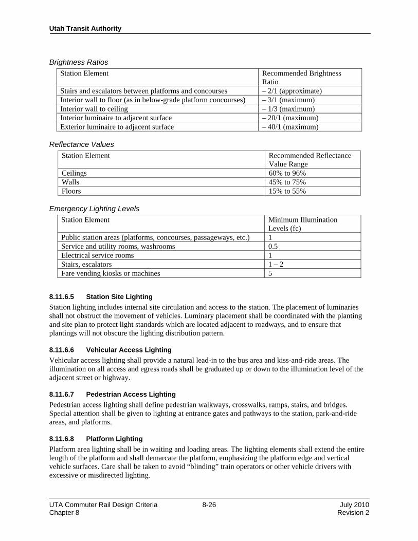
Utah Transit Authority
UTA Commuter Rail Design Criteria 8-26 July 2010 Chapter 8 Revision 2
Brightness Ratios
Station Element Recommended Brightness Ratio
Stairs and escalators between platforms and concourses – 2/1 (approximate) Interior wall to floor (as in below-grade platform concourses) – 3/1 (maximum) Interior wall to ceiling – 1/3 (maximum) Interior luminaire to adjacent surface – 20/1 (maximum) Exterior luminaire to adjacent surface – 40/1 (maximum)
Reflectance Values
Station Element Recommended Reflectance Value Range
Ceilings 60% to 96% Walls 45% to 75% Floors 15% to 55%
Emergency Lighting Levels
Station Element Minimum Illumination Levels (fc)
Public station areas (platforms, concourses, passageways, etc.) 1 Service and utility rooms, washrooms 0.5 Electrical service rooms 1 Stairs, escalators 1 – 2 Fare vending kiosks or machines 5
8.11.6.5 Station Site Lighting Station lighting includes internal site circulation and access to the station. The placement of luminaries shall not obstruct the movement of vehicles. Luminary placement shall be coordinated with the planting and site plan to protect light standards which are located adjacent to roadways, and to ensure that plantings will not obscure the lighting distribution pattern. 8.11.6.6 Vehicular Access Lighting Vehicular access lighting shall provide a natural lead-in to the bus area and kiss-and-ride areas. The illumination on all access and egress roads shall be graduated up or down to the illumination level of the adjacent street or highway. 8.11.6.7 Pedestrian Access Lighting Pedestrian access lighting shall define pedestrian walkways, crosswalks, ramps, stairs, and bridges. Special attention shall be given to lighting at entrance gates and pathways to the station, park-and-ride areas, and platforms. 8.11.6.8 Platform Lighting Platform area lighting shall be in waiting and loading areas. The lighting elements shall extend the entire length of the platform and shall demarcate the platform, emphasizing the platform edge and vertical vehicle surfaces. Care shall be taken to avoid “blinding” train operators or other vehicle drivers with excessive or misdirected lighting.

Utah Transit Authority
UTA Commuter Rail Design Criteria 8-27 July 2010 Chapter 8 Revision 2
8.11.6.9 Control of Lighting Systems Lighting control shall be designed to use energy efficiently. Automatic and manual control arrangements shall ensure efficient utilization of energy and maintenance procedures. All exterior site areas shall be illuminated when the ambient daylight drops below 30 fc and all but security site lighting is turned off ½ hour after revenue service stops. Provision shall be made for photocell with time clock or manual override. Ancillary areas shall be individually switched. Lighting in stations will be provided by a variety of standardized fixture and luminaire types, depending on station types (surface or underground), and particular site conditions. These details will be developed later in the design phases of this project. Included in this section is a range of general planning and design criteria related to station lighting, presented in tabular form. 8.11.7 Snow Melt System Design and installation of a potential electrical snow melt system will be considered. The decision to construct a snow melt system will depend upon economics and reliability of existing systems and designs. END OF CHAPTER 8.

Design Criteria
UTA Commuter Rail Rev No. Prepared
By Approved By
Approval Date Document Date
0 PPa JWe 12/01/04 12/01/04 1 DGoeres CCC 11/30/07 11/30/07 5 T. W. Jones CCC 3/19/2010 July 2010
Utah Transit Authority
Commuter Rail Design Criteria
Chapter 9
Landscaping Revision 2, July 2010

Utah Transit Authority
UTA Commuter Rail Design Criteria 9-i July 2010 Chapter 9 Revision 2
Table of Contents
CHAPTER 9 LANDSCAPING ........................................................................................................... 1
9.1 General ............................................................................................................................................ 1
9.2 Goals ................................................................................................................................................ 1
9.3 Reference Codes and Landscape Standards .................................................................................... 2
9.4 Landscaping Considerations and Criteria ....................................................................................... 2 9.4.1 Climate Control ................................................................................................................... 3 9.4.2 Height Requirements .......................................................................................................... 3 9.4.3 Movement Control .............................................................................................................. 3 9.4.4 Grading and Drainage ......................................................................................................... 4 9.4.5 Berming .............................................................................................................................. 4 9.4.6 Slope Stabilization .............................................................................................................. 4 9.4.7 Retaining Walls ................................................................................................................... 4 9.4.8 Planter Walls/Landscape Walls .......................................................................................... 4 9.4.9 Lighting and Signage Interface ........................................................................................... 5 9.4.10 Irrigation ............................................................................................................................. 5
9.5 Security/Safety Considerations ........................................................................................................ 6
9.6 Site Specific Objectives .................................................................................................................... 6 9.6.1 Station ................................................................................................................................. 6 9.6.2 Relationship of the Park-and-Ride Facility to the Platform ................................................ 6 9.6.3 Parking Lot (Park-and-Ride) .............................................................................................. 7 9.6.4 Bus Drop-Off to the Platform ............................................................................................. 7 9.6.5 Kiss-and-Ride Relationship to the Platform ....................................................................... 7 9.6.6 Railroad Right-of-Way ....................................................................................................... 7
9.7 Master Plant List ............................................................................................................................. 8 9.7.1 Standard Plant Materials ..................................................................................................... 8 9.7.2 Recommended Planting List (Low Water Use) .................................................................. 8
9.8 Plant Materials ................................................................................................................................ 9 9.8.1 Canopy Trees .................................................................................................................... 10 9.8.2 Understory/Decorative Trees ............................................................................................ 10 9.8.3 Conifers ............................................................................................................................. 10 9.8.4 Shrubs and Hedges ............................................................................................................ 10 9.8.5 Vines and Ground Cover .................................................................................................. 10
9.9 Trees ............................................................................................................................................... 10 9.9.1 Patterns.............................................................................................................................. 10 9.9.2 Size Guidelines ................................................................................................................. 11
Utah Transit Authority
UTA Commuter Rail Design Criteria 9-ii July 2010 Chapter 9 Revision 2
9.9.3 Tree Pits ............................................................................................................................ 12 9.9.4 Tree Grates ........................................................................................................................ 12 9.9.5 Tree Guards ....................................................................................................................... 12 9.9.6 Guying and Staking .......................................................................................................... 12
9.10 Topsoil ........................................................................................................................................... 12
9.11 Recommended Rock Materials ....................................................................................................... 13

Utah Transit Authority
UTA Commuter Rail Design Criteria 9-1 July 2010 Chapter 9 Revision 2
CHAPTER 9 LANDSCAPING
9.1 General This chapter provides objectives and design parameters for the landscaping of the UTA Commuter Rail facilities. These facilities include the passenger stations, park-and-ride lots, kiss-and-ride areas, the yard and shop site, and the layover yard. In addition, selective landscaping may be provided along the right-of-way to mitigate the impacts of the construction to adjacent properties and, where required, to establish visual screening by the environmental process through the use of walls, fences and plantings. These design criteria establish specific plant and material use and provide a “palette” of design devices that allows for the development of low-maintenance landscape areas, while maintaining safety and aesthetic considerations. Although the design of each passenger station and UTA Commuter Rail facility will be site specific, the design shall fall within the parameters of the basic goals contained in these criteria. Exceptions may be necessary in some specific cases, and the Agency encourages the Designer to make recommendations for deviations where this might result in improved design and less capital and/or maintenance costs.
9.2 Goals At a minimum, the landscape design shall meet the following basic goals:
• Provide a safe, secure, and comfortable environment throughout the commuter rail system, particularly at the passenger station areas.
• Create a pedestrian environment projecting a sense of quality and visual identification of the UTA passenger stations. Design the landscaping to provide mitigation of adverse visual impacts where applicable and appropriate.
• Control access to the system by reinforcing designated pedestrian and vehicular circulation system movements. Use ground cover in landscaped areas and slopes to discourage pedestrian activity in non-designated areas. Provide appropriate barriers and directional control to assist pedestrians in making the logical choices and progressions through the station by promoting safe pedestrian movements.
• Create a station setting that shall become a part of the particular neighborhood and compliment the established streetscape/surroundings. Where possible, express local historical and cultural information while conforming to all applicable codes and regulations.
• Provide landscape architectural components that are standardized to the extent that system wide elements have continuity, but that the individual stations have unique characteristics.
• Provide compatibility of landscape architectural elements with the architecture of the stations graphics, and lighting to create a harmonious and unified commuter rail system.
• Achieve a landscape design that is compatible with the local climatic conditions, is salt and pollution tolerant, and conserves water and other resources.
• Make provisions for the design guidelines to fit within the budget allocations for planting/irrigation/hardscape at each station.
Utah Transit Authority
UTA Commuter Rail Design Criteria 9-2 July 2010 Chapter 9 Revision 2
• Utilize site elements, both in terms of vegetative materials and hardscape features, that have a high probability of survival. Specify indigenous/adaptable plants and local construction materials to attain this goal.
• Provide landscaping with low maintenance requirements and plant materials that are non-toxic and non hazardous.
• Define landscape spaces where art and the site are woven together to create a sense of arrival, destination, and excitement to the user. These landscape spaces shall guide the flow of the patron and automobile and function as public gathering places.
• Protect existing views and vistas, provide mitigation of adverse visual impacts, and screen unsightly views where applicable and appropriate.
• All landscape proposals in the vicinity of historic buildings shall conform to the requirements of the Secretary of the Interior's Standards for the Treatment of Historic Properties, latest edition, the Salt Lake City Historic Landmark Commission, and similar applicable local agencies.
9.3 Reference Codes and Landscape Standards To simplify the construction details, the Designer shall develop standard landscape detail drawings and specifications for use throughout the Project. The Designer shall be responsible for contacting the local Forestry Organization in the area to determine what policies and plans are in existence, and to ensure an understanding of recommended plant materials in local authority planning jurisdictions. Landscape design shall be guided by the recommendations of the latest edition of the following codes and standards, as applicable:
• Recommended plant materials of Utah DOT and other governing agencies.
• Utah Water-Wise plant guidelines
• American Joint Committee on Horticultural Nomenclature Standards (AJCHNS), - Standardized Plant Names.
• American National Standards Institute, ANSI Z60.1 - Nursery Stock, adopted by the American Association of Nurserymen, Inc.
• American National Standards Institute, ANSI Z133.1 - American National Standard for Arboricultural Operations - Pruning, Repairing, Maintaining, and Removing Trees, and Cutting Brush - Safety Requirements.
• L. H. Bailey Standard Encyclopedia of Horticulture.
• Mary S. Smith Crime Prevention Through Environmental Design in Parking Facilities. Series: NIJ Research in Brief, April 1996.
• The Secretary of the Interior's Standards for the Treatment of Historic Properties.
9.4 Landscaping Considerations and Criteria Considerations for the selection of plant material shall include, but are not limited to:
• Initial cost
Utah Transit Authority
UTA Commuter Rail Design Criteria 9-3 July 2010 Chapter 9 Revision 2
• Irrigation/maintenance costs
• Mature height and spread
• Growth rate
• Seasonal form and color
• Hardiness
• Sun/shade preferences
• Seed/fruit formation
• Disease and pest resistance
• Soil and drainage conditions
• Tolerance to wind, pollutants, salt, and abuse
• Transplant tolerance
• Availability
• Relationship to existing planting materials
• Native to the region
• Potential for contributing to allergic reactions to patrons Based on the above, the following Landscape Design Criteria shall be used to ensure the cohesiveness of the final design form:
9.4.1 Climate Control Create a beneficial microclimate regarding sun and shade patterns by the placement of plant materials (shrubs, trees, ground cover, grass, etc.) and appropriate landscape elements. Utilize landscape elements such as walls and berms with planting, to promote noise mitigation in areas of heavy traffic, and to control and direct desirable and undesirable winds and breezes.
9.4.2 Height Requirements Landscaping, other than trees, shall not exceed 2′-6″ in height for both security and safety reasons. The only exception shall be taller hedges, where neighborhood concerns require mitigation.
9.4.3 Movement Control The patrons must have unobstructed access to the commuter rail system. Waiting areas at bus stops and kiss-and-ride areas shall be pleasant and comfortable for short-term use, but shall be visibly open for reasons of safety and security. Patrons must never feel trapped or unsafe. Discourage bicycle and skateboarders from creating hazardous conditions for pedestrian and vehicular traffic. Wherever possible, there shall be a clearly defined separator for pedestrians from bus and auto traffic. Specify the use of physical barriers such as bollards, fences, railings, and plantings, where determined appropriate to separate and control movement.

Utah Transit Authority
UTA Commuter Rail Design Criteria 9-4 July 2010 Chapter 9 Revision 2
9.4.4 Grading and Drainage Coordinate with the Civil Designer and ensure that planting and other landscape elements shall provide positive drainage away from shrubs. Avoid excessive slopes that would cause erosion. Create a positive environmental impact by coordinating any water retention areas with other site elements. Blend the finish grading with adjacent land elevations. Swales for surface drainage in lawn or plant areas shall have a shallow dished cross-section with a uniform gradient (1% minimum to 6% maximum) to provide a drainage flow line that can be easily maintained and traversed.
9.4.5 Berming Use skillful grading and incorporate mounds and depressed areas where appropriate to control pedestrian movements, modify wind, and precipitation patterns, obscure objectionable views, and mitigate objectionable noise.
9.4.6 Slope Stabilization Stabilize all slopes to prevent physical failure, erosion, and maintenance problems. Slopes that are to receive mowed turf, or aggregate mulches, shall not to exceed a slope of 4:1 (horizontal to vertical). Slopes that are to receive non-mowed grasses, or ground covers, shall not exceed 2:1 (horizontal to vertical). Specify the use of straw, with a mulch overspray tackifier; to stabilize all newly seeded areas with slopes of less than 4:1 (horizontal to vertical). For engineered fill areas, a minimum of 3 feet flat area at the top and bottom of each slope shall be provided. Specify the use of biodegradable erosion control blankets to stabilize seeded slopes as follows:
• Maximum slopes - use an erosion control blanket, or mat, with a minimum 36-month functional longevity
• Slopes that are to receive ground covers, or shrub masses, shall be mulched using an erosion control blanket with a minimum 24-month functional longevity.
Refer to Chapter 6 for additional slope, cut, and fill requirements.
9.4.7 Retaining Walls The decision on the type of wall to use shall take into consideration the urban design impact to the surrounding environment. Select and design retaining walls with consideration to scale, color, texture, and appropriate materials in relationship to the transit facilities and the adjacent neighborhoods.
9.4.8 Planter Walls/Landscape Walls To promote visibility into the site, and serve the dual function as a ‘seating’ wall, no planter shall exceed 22- inches in height. The exception shall be screening walls i.e., at a property line with residential adjacency. For user comfort, ‘seating’ walls shall be 20-inches wide. Materials for planter walls shall be durable and compatible with the passenger station.

Utah Transit Authority
UTA Commuter Rail Design Criteria 9-5 July 2010 Chapter 9 Revision 2
9.4.9 Lighting and Signage Interface Coordinate plant selection and location with lighting placement clearances and with the limits of the sign and luminary palette. To keep lighting and/or signage free from obstructions, select plant materials to be independent of excessive trimming.
9.4.10 Irrigation The long-term goal of the landscape design is for the landscape to be sustainable with as little water as possible. Specify plants with low water requirements to minimize water usage. In areas that are not accessible to the public, such as the rail corridor, plant materials should be self-sustaining without additional water after a two- to three-year establishment period. To establish such a landscape, a temporary irrigation system shall be installed for a period of two to three years, depending on conditions. In station areas, such as park-and-ride lots and other areas readily accessible by the public, permanent irrigation systems are required to ensure a long term attractive landscape. Except where turf grass and other “lush” plant materials are required by the local municipality, specify plants with low water requirements to minimize water usage that will not require additional water after the two- to three-year establishment period. Following the establishment of low water landscapes, the permanent irrigation system may be used periodically to mitigate extreme drought conditions.
• Plants shall be drought tolerant, native, and adapted species that shall provide color and textural interest to the transit environment, and shall create a pleasant pedestrian-oriented facility.
• Plants shall be grouped according to their water requirements and the temporary versus permanent irrigation system shall be zoned accordingly. Employ the principle of a water conserving landscape throughout the design.
• Provide mulch in all shrubs, ground cover beds, and other landscape areas not planted in lawn. The landscape for all UTA stations and facilities shall be fully irrigated with 100% coverage. Carefully coordinate the location of components with minimal accessibility to the public. Where irrigation is to be carried out as part of future construction, irrigation pipes shall be installed under all paved surfaces as part of the initial construction. Provide a landscape irrigation system that requires little maintenance, and is automatic, vandal resistant, and water conserving. Where appropriate, provide yard hydrants with quick coupler valves and outlet boxes for hose attachments and/or freeze-protected hose bibs that can be used for general maintenance and irrigation (i.e., to clean pavement surfaces and plant materials) at facilities and in Park-and-Ride lots. Coordinate the locations to permit site coverage with a 100-foot hose. Specify that each irrigation system shall be provided with a pressure vacuum breaker (PVB) (or other equipment to meet state and local codes), a moisture sensor, a rain “freeze” (mini-click) sensor, a central output module, and a field satellite controller unit compatible for linkup with the Agency’s central computer control system. Where feasible, specify equipment to match existing components in the UTA system. Controllers and other automated components must be compatible with UTA’s central comper control system. Unless current system components are found to be defective or substandard, irrigation heads, drip system components, and valves should match existing equipment to limit replacement inventory required by UTA maintenance personnel.

Utah Transit Authority
UTA Commuter Rail Design Criteria 9-6 July 2010 Chapter 9 Revision 2
9.5 Security/Safety Considerations Crime prevention through environmental design (CPTED), which emphasizes the proper design and effective use of a created environment to reduce crime and enhance the quality of life, is particularly applicable to the landscape design of the facilities. The Designer shall incorporate CPTED strategies to significantly reduce the fear and risk of crime as well as the considerable costs associated with hiring security personnel. Place plantings, raised planters, hardscape structures, and similar landscaping elements in such a manner so that they do not provide spaces for loiterers, or persons intending to hide behind such features, or where a bomb or other explosive device could be hidden from public view. When locating shrubs taller than eye level, consideration shall be given to ease of surveillance for security/police patrol cars. For improved safety in pedestrian areas and paths, delineate paving design changes in texture, scale, and color. At railroad/highway grade crossings, plant materials shall not block line of site visibility triangles. Major roadway intersections and/or interfaces with highway service roads should use a 45′-0″ minimum site visibility triangle free of obstructions caused by plantings. Intersections of the railroad with driveways and private roads may use a 25′-0″ minimum line of site visibility triangle. Discourage pedestrians and motorists from crossing tracks at unauthorized points by clear and defined pavement edges and/or landscaping.
9.6 Site Specific Objectives
9.6.1 Station A main objective is to set the station in a visual park-like atmosphere with low maintenance conditions. To the maximum extent possible, minimize grass areas, especially in proximity to the station platform. Grass areas shall only be specified where required by ordinance, for visual mitigation, or in areas so large that other materials would not be cost effective/practical.
9.6.2 Relationship of the Park-and-Ride Facility to the Platform The goal is to create attractive pedestrian spaces for patrons waiting for trains and rides. These people oriented spaces, although designed for heavy traffic flow, will provide the pedestrian with a waiting space to be utilized for a limited duration. Linear edge treatment of the Park-and-Ride side of the station will allow entry to the station along the entire length of the platform. Coordinate locations of fare vending equipment, and station entry with the Architectural Designer(s). The specific design elements for the Park-and-Ride façade of the station are as follows:
• The massing of trees and vertical elements to emphasize and define pedestrian flow
• Trees within tree grates to provide shade, visual relief, and definition
• Raised planters/walls to define pedestrian areas and function as seating walls in certain site specific areas
• Enriched pavement at parking lot edge/platform and at specific points of access
• To increase the probability of survival, and, providing site conditions permit, plants and trees shall be in raised planters as opposed to grade planters
Utah Transit Authority
UTA Commuter Rail Design Criteria 9-7 July 2010 Chapter 9 Revision 2
• Specify the use of walls, earth sculpturing, and level changes to create visual interest while maintaining handicap accessibility
• Specify the use of landscape elements as opportunities for art that are integral to the station design, i.e. wall design, seating, berms, tree grates, lighting, etc.
• Specify the use of ground cover areas in controlled situations where they are largely defined by hardscape elements and are away from the passenger station platform.
NOTE: None of the above elements shall block visibility into the passenger station or provide hiding areas.
9.6.3 Parking Lot (Park-and-Ride) The objective of landscaping features is to break the parking lot up with landscape islands containing shade trees to add visual impact and to assist in directional flow of vehicular and pedestrian users. Preserve existing planting wherever possible, and when the plant material is judged appropriate.
9.6.4 Bus Drop-Off to the Platform Landscape design shall be coordinated with the station design, including making appropriate provisions for the location of bus bays adjacent to the platform. Passengers connecting between services shall be provided direct, unobstructed routes. Softscape development shall be provided between ingress/egress points. Expected high traffic volumes will preclude the use of large planting areas. Specify utilizing tree grates, or regularly spaced planters. Formulate contingency planning of shortened space between bus drop-off and platform in situations where busses are only a few feet away from the platform.
9.6.5 Kiss-and-Ride Relationship to the Platform Specify the use of bar islands, with trees and plant materials, to control traffic flow and to break up the expanse of concrete parking.
9.6.6 Railroad Right-of-Way Landscaping of the railroad right-of-way is to be minimal. Specify landscape cut and fill areas requiring erosion protection using low maintenance shrub masses, ground covers, or native grasses and forbs (wildflowers). Accomplish the mulching of shrub masses and ground covers on slopes using biodegradable erosion control blankets. Take particular care during the development of the landscape design to avoid plantings adjacent to the tracks where they may contribute to fouling the ballast, clogging drainage systems, or could be destroyed by the periodic herbicide treatment by track maintenance personnel. Right-of-way landscape treatment shall follow all design objectives and be safe, appear pleasant, orderly, and clean, with emphasis on minimal maintenance and costs consistent with those objectives. Maintain an adequate clear sight distance at all grade crossing intersections. Low maintenance characteristics are of prime importance in selecting plant material, particularly where drought conditions prevail on high embankment slopes where no irrigation shall be provided. Planting design shall emphasize simplicity rather than complexity, using naturalistic tree groupings and mass plantings. Integration with adjoining plant material shall be the objective.
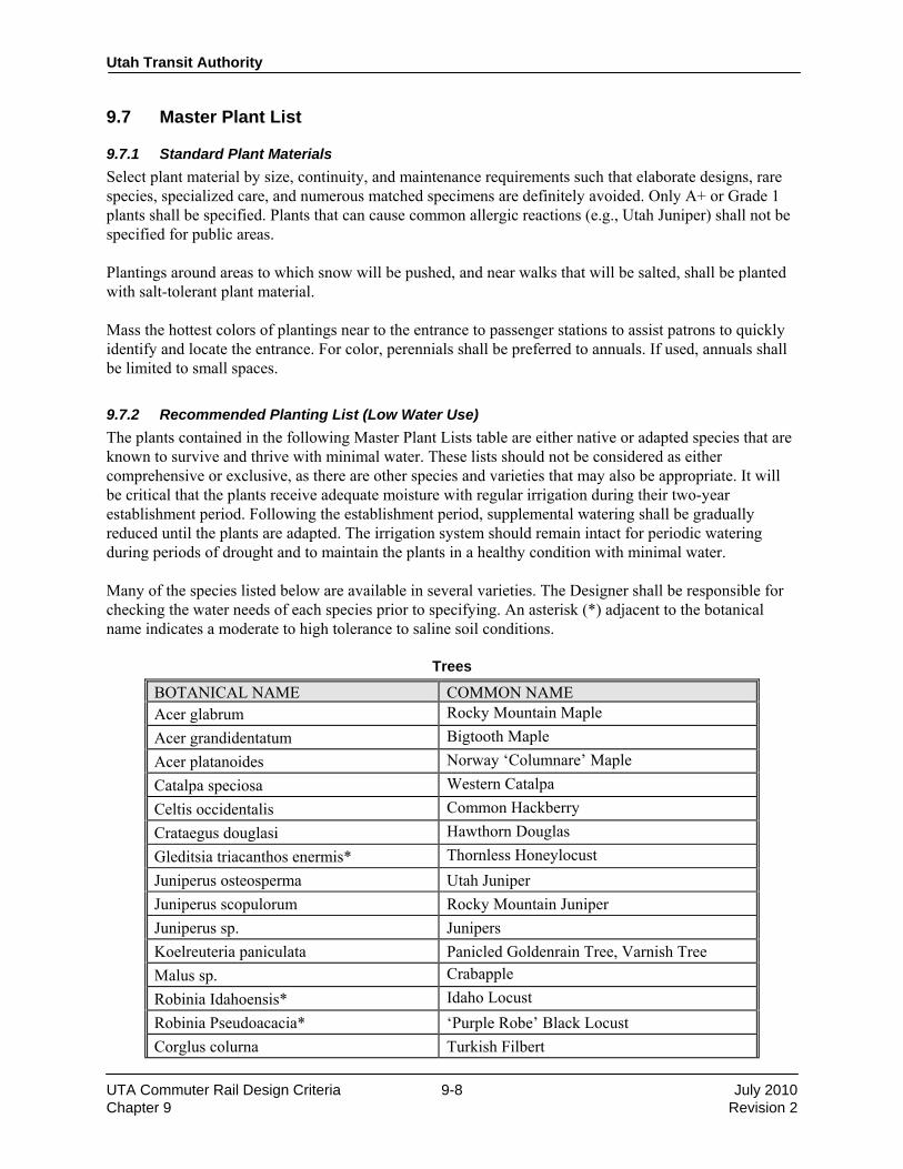
Utah Transit Authority
UTA Commuter Rail Design Criteria 9-8 July 2010 Chapter 9 Revision 2
9.7 Master Plant List
9.7.1 Standard Plant Materials Select plant material by size, continuity, and maintenance requirements such that elaborate designs, rare species, specialized care, and numerous matched specimens are definitely avoided. Only A+ or Grade 1 plants shall be specified. Plants that can cause common allergic reactions (e.g., Utah Juniper) shall not be specified for public areas. Plantings around areas to which snow will be pushed, and near walks that will be salted, shall be planted with salt-tolerant plant material. Mass the hottest colors of plantings near to the entrance to passenger stations to assist patrons to quickly identify and locate the entrance. For color, perennials shall be preferred to annuals. If used, annuals shall be limited to small spaces.
9.7.2 Recommended Planting List (Low Water Use) The plants contained in the following Master Plant Lists table are either native or adapted species that are known to survive and thrive with minimal water. These lists should not be considered as either comprehensive or exclusive, as there are other species and varieties that may also be appropriate. It will be critical that the plants receive adequate moisture with regular irrigation during their two-year establishment period. Following the establishment period, supplemental watering shall be gradually reduced until the plants are adapted. The irrigation system should remain intact for periodic watering during periods of drought and to maintain the plants in a healthy condition with minimal water. Many of the species listed below are available in several varieties. The Designer shall be responsible for checking the water needs of each species prior to specifying. An asterisk (*) adjacent to the botanical name indicates a moderate to high tolerance to saline soil conditions.
Trees
BOTANICAL NAME COMMON NAMEAcer glabrum Rocky Mountain Maple Acer grandidentatum Bigtooth Maple Acer platanoides Norway ‘Columnare’ Maple Catalpa speciosa Western Catalpa Celtis occidentalis Common Hackberry Crataegus douglasi Hawthorn Douglas Gleditsia triacanthos enermis* Thornless Honeylocust Juniperus osteosperma Utah Juniper Juniperus scopulorum Rocky Mountain Juniper Juniperus sp. Junipers Koelreuteria paniculata Panicled Goldenrain Tree, Varnish Tree Malus sp. Crabapple Robinia Idahoensis* Idaho Locust Robinia Pseudoacacia* ‘Purple Robe’ Black Locust Corglus colurna Turkish Filbert

Utah Transit Authority
UTA Commuter Rail Design Criteria 9-9 July 2010 Chapter 9 Revision 2
Zelkova Serrata Zelkova
Vines and Ground Cover (Flowers and Forbs) Plantings shall be selected from those included on the Utah Water-Wise listing, which can be viewed at the Internet site at the address: www:/waterwiseplantsutah.gov. Other plants may be used with UTA approval.
BOTANICAL NAME COMMON NAMEAchillea millefolium* Yarrow Coreopsis sp. Coreopsis Eriogonum umbellatum Sulfur-flower buckwheat Gailardia aristata Blanket Flower Geranium viscossisimum Sticky Geranium Hemerocallis sp. Daylily Iris sp. Iris Lavandula sp. Lavender Oenothera speciosa Evening Primrose Penstemon sp.* Penstemon Sphaeralcea grossulariaefolia Gooseberry Globemallow
Vines and Ground Cover (Ornamental Grasses)
BOTANICAL NAME COMMON NAMEAgropyron intermedium Intermediate Wheatgrass Agropyron sibericum Siberian Wheatgrass Agropyron trichophorum Pubescent Wheatgrass Bouteloua gracilis Blue Grama Buchloe dactyloides Buffalo Grass Festuca sp. Fescue Helictotrichon sempervirens Blue Oat Grass Miscanthus sinensis sp. Maidenhair Grass Oryzopsis hymenoides* Indian Rice Grass Stipa sp.* Needlegrass
9.8 Plant Materials Plantings will be used to strengthen the visual quality of the facilities and to integrate them with their surroundings by either blending with the existing, and/or where appropriate, setting off the facilities as a special feature. Trees and shrubs with fruits or seeds which can stain pavements or create hazards, plants which are prickly or poisonous, and shallow rooted trees which can damage pavements, shall not be used.

Utah Transit Authority
UTA Commuter Rail Design Criteria 9-10 July 2010 Chapter 9 Revision 2
Utilize plant material resistant to pests and the impacts associated with their proposed environment. In urban areas, select indigenous/adaptable plants known for their hardiness and pollution tolerance. In park and ride lots, and other UTA facilities greater than one acre in size, a minimum of four different species of tree shall be used. Trees shall be planted to maximize shade in the summer months. Tree locations shall be identified considering the site lighting plan and implications of tree growth patterns. Planting materials classification includes the following:
9.8.1 Canopy Trees Considered to be larger and structural in nature and shall be employed to accent entry or decision points. Examples of areas where pattern landscaping is desired are facility peripheries, along adjacent streets, along the outer station platform edge of side platform configurations, and on either side of the alignment for center platform configurations.
9.8.2 Understory/Decorative Trees Tending to be smaller than canopy trees, these are appropriate as infill between canopy trees. Use special care in the arrangement of these trees as they have lower branches and may obstruct sight lines.
9.8.3 Conifers Conifers can be considered for limited use at sites where unobstructed sight lines are not required, such as areas that require wind-breaks. However, because conifers restrict visibility, they shall not be used where security considerations require clear sight lines.
9.8.4 Shrubs and Hedges Shrubs and hedges shall be relatively small in scale and shall be employed to control pedestrian circulation where unobstructed sight lines are required.
9.8.5 Vines and Ground Cover Employ ground cover for erosion control, decoration, and for the ability to assist in the control of pedestrian circulation. In special areas, specify an evergreen groundcover at trees and provide a minimum of 6-inches prepared soil for groundcover. Selectively use vines to landscape and soften vertical surfaces.
9.9 Trees
9.9.1 Patterns Landscaping shall incorporate a street tree pattern and shall match existing patterns, or shall form part of a pattern already established by the local governmental authority for the adjoining area. Obtain the approval of the local jurisdiction(s) before selecting a standard street tree design. Where no pattern exists, the design shall establish an orderly pattern. Canopy trees are recommended for this purpose. Note: Using a 3-inch minimum caliper for trees located in paved areas shall allow a larger selection of available species and better overall quality in this area. Adjust the longitudinal spacing as necessary to accommodate subsurface conditions such as utilities and vaults, as well as special conditions such as existing or proposed sidewalk canopies, awnings, and shelters.

Utah Transit Authority
UTA Commuter Rail Design Criteria 9-11 July 2010 Chapter 9 Revision 2
Specify in the design the relationship of the root ball size and the size of the tree well to ensure a proper fit of the tree. Excavation for tree root balls shall be minimally two times wider and 6-inches deeper than the size of the root ball. To prevent settlement, specify planting the tree ball on an unexcavated subgrade. Make every possible effort to retain existing healthy and mature trees and other site features during construction, if they enhance the system design. This may be accomplished by utilizing tree-wells or retaining walls as appropriate to avoid smothering roots in fill or damage to the other site features where grading is not feasible. Construction techniques and site layout shall dictate which trees and shrubs can be saved. Clearly identify existing items to be retained in the Contract Documents. Replace any trees that will be removed due to construction within the framework of the proposed landscape design prepared for each specific site. To protect trees from damage by heavy equipment during construction operations, include the care of existing trees and groups of trees to be preserved in the construction Contract Documents. Specify trees and plant materials of a type that shall not interfere with pedestrian use of walks and platform surfaces, or that shall contribute to leaf and sap litter. Select relatively clean, upright evergreen trees wherever possible. Small to medium sized native deciduous understory or flowering trees are preferred for selection where room within the alignment is limited. A ratio of one shade tree for every ten cars is desirable in the parking areas, exclusive of trees along major pedestrian walkways and peripheral plantings. The ratio may be varied according to local conditions. Locate the trees in pockets at the division between stalls; in the end islands of parking rows, on the parking perimeter, and in large strategically placed islands depending on size, shape and location of each parking lot. Place groupings of trees informally among the parking stalls to further subdivide and contrast with the visual regularity of the parking areas. Coordinate the actual layout considering snow removal and piling requirements, CCTV security camera placements, ‘blue light’ stations, and site lighting strategies. At facilities with park-and-ride lots, or major bus transfer facilities, locate large trees (viz., greater than 3-inch caliper) in areas selected as most effective. Considerations should be around the perimeter and along the major pedestrian walks leading to the facility to achieve the initial large-scale subdivision of the site, and to emphasize the major pedestrian routes to the facility. Emphasize the entrances to the passenger station facility by grouping trees in strong masses; however, keep the ground level clear to allow good visibility. Where trees are located in areas of paving, provide tree grates to allow for root aeration and watering. All new trees shall be underdrained. Locate small trees (viz., ½-inch to 1-inch caliper) and medium trees (viz., 1-inch to 3-inch caliper) to achieve a secondary subdivision of the site and to provide an intermediate scale between the structure, the large tree pattern, and the smallest elements. Locate small trees to emphasize the direction of important internal traffic.
9.9.2 Size Guidelines Choose trees with a maximum mature height of 20 feet when planting under utility lines, including future OCS lines, and no more than 45 feet in height when planting within 15 feet of utility lines. Small trees, 30 feet or less in mature height, shall be planted at least 8 to 10 feet from any UTA structure. Medium sized trees, 30 to 70 feet in mature height, need to be at least 12 to 15 feet from a structure, and large trees, greater than 70 feet, shall be planted 15 to 20 feet from a structure.
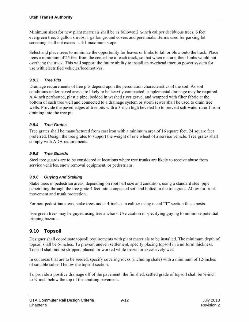
Utah Transit Authority
UTA Commuter Rail Design Criteria 9-12 July 2010 Chapter 9 Revision 2
Minimum sizes for new plant materials shall be as follows: 2½-inch caliper deciduous trees, 6 feet evergreen tree, 5 gallon shrubs, 1 gallon ground covers and perennials. Berms used for parking lot screening shall not exceed a 3:1 maximum slope. Select and place trees to minimize the opportunity for leaves or limbs to fall or blow onto the track. Place trees a minimum of 25 feet from the centerline of each track, so that when mature, their limbs would not overhang the track. This will support the future ability to install an overhead traction power system for use with electrified vehicles/locomotives.
9.9.3 Tree Pits Drainage requirements of tree pits depend upon the percolation characteristics of the soil. As soil conditions under paved areas are likely to be heavily compacted, supplemental drainage may be required. A 4-inch perforated, plastic pipe, bedded in washed river gravel and wrapped with filter fabric at the bottom of each tree well and connected to a drainage system or storm sewer shall be used to drain tree wells. Provide the paved edges of tree pits with a 3-inch high beveled lip to prevent salt-water runoff from draining into the tree pit.
9.9.4 Tree Grates Tree grates shall be manufactured from cast iron with a minimum area of 16 square feet, 24 square feet preferred. Design the tree grates to support the weight of one wheel of a service vehicle. Tree grates shall comply with ADA requirements.
9.9.5 Tree Guards Steel tree guards are to be considered at locations where tree trunks are likely to receive abuse from service vehicles, snow removal equipment, or pedestrians.
9.9.6 Guying and Staking Stake trees in pedestrian areas, depending on root ball size and condition, using a standard steel pipe penetrating through the tree grate 4 feet into compacted soil and bolted to the tree grate. Allow for trunk movement and trunk protection. For non-pedestrian areas, stake trees under 4-inches in caliper using metal “T” section fence posts. Evergreen trees may be guyed using tree anchors. Use caution in specifying guying to minimize potential tripping hazards.
9.10 Topsoil Designer shall coordinate topsoil requirements with plant materials to be installed. The minimum depth of topsoil shall be 6-inches. To prevent uneven settlement, specify placing topsoil in a uniform thickness. Topsoil shall not be stripped, placed, or worked while frozen or excessively wet. In cut areas that are to be seeded, specify covering rocks (including shale) with a minimum of 12-inches of suitable subsoil below the topsoil section. To provide a positive drainage off of the pavement, the finished, settled grade of topsoil shall be ½-inch to ¾-inch below the top of the abutting pavement.

Utah Transit Authority
UTA Commuter Rail Design Criteria 9-13 July 2010 Chapter 9 Revision 2
9.11 Recommended Rock Materials If the landscaping design calls for use of decorative rock as a mulch/ground cover, the gradation of the rock materials shall be 1/2” minus. If decorative boulders are to be utilized, the boulders shall weigh 80 pounds or more. END OF CHAPTER 9.

Design Criteria UTA Commuter Rail
Rev No. Prepared By
Approved By
Approval Date
Document Date
0 PPa JWe 12/01/04 12/01/04 1 DGoeres CCC 11/30/07 11/30/07 2 T. W. Jones CCC 3/19/10 July 2010
Utah Transit Authority
Commuter Rail Design Criteria
Chapter 10
Traffic Control Revision2, July 2010
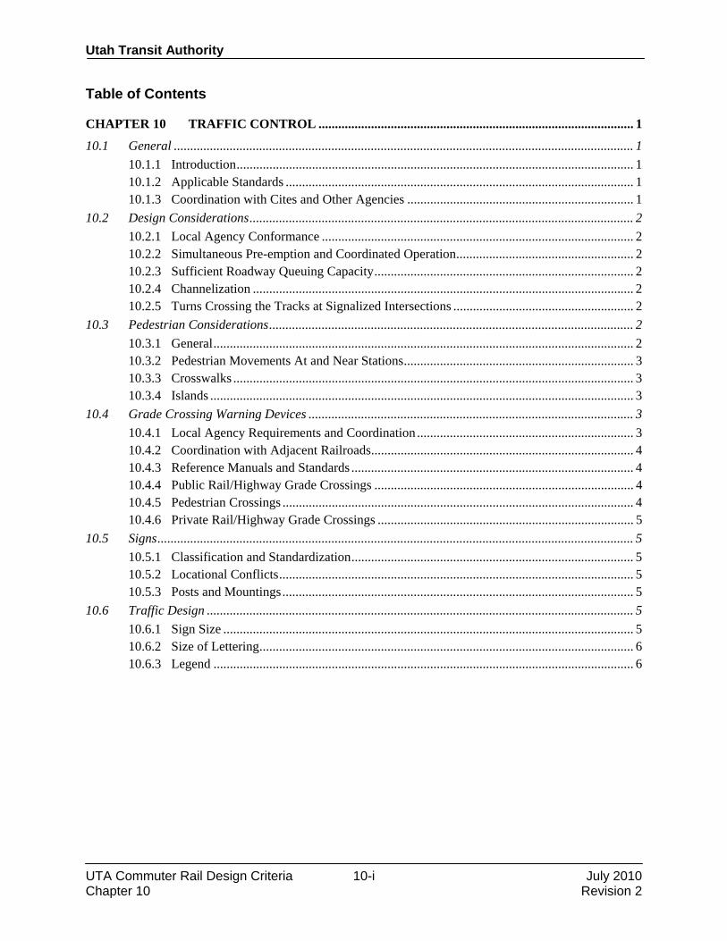
Utah Transit Authority
UTA Commuter Rail Design Criteria 10-i July 2010 Chapter 10 Revision 2
Table of Contents
CHAPTER 10 TRAFFIC CONTROL ................................................................................................ 1 10.1 General ............................................................................................................................................ 1
10.1.1 Introduction ......................................................................................................................... 1 10.1.2 Applicable Standards .......................................................................................................... 1 10.1.3 Coordination with Cites and Other Agencies ..................................................................... 1
10.2 Design Considerations ..................................................................................................................... 2 10.2.1 Local Agency Conformance ............................................................................................... 2 10.2.2 Simultaneous Pre-emption and Coordinated Operation ...................................................... 2 10.2.3 Sufficient Roadway Queuing Capacity ............................................................................... 2 10.2.4 Channelization .................................................................................................................... 2 10.2.5 Turns Crossing the Tracks at Signalized Intersections ....................................................... 2
10.3 Pedestrian Considerations ............................................................................................................... 2 10.3.1 General ................................................................................................................................ 2 10.3.2 Pedestrian Movements At and Near Stations ...................................................................... 3 10.3.3 Crosswalks .......................................................................................................................... 3 10.3.4 Islands ................................................................................................................................. 3
10.4 Grade Crossing Warning Devices ................................................................................................... 3 10.4.1 Local Agency Requirements and Coordination .................................................................. 3 10.4.2 Coordination with Adjacent Railroads ................................................................................ 4 10.4.3 Reference Manuals and Standards ...................................................................................... 4 10.4.4 Public Rail/Highway Grade Crossings ............................................................................... 4 10.4.5 Pedestrian Crossings ........................................................................................................... 4 10.4.6 Private Rail/Highway Grade Crossings .............................................................................. 5
10.5 Signs ................................................................................................................................................. 5 10.5.1 Classification and Standardization ...................................................................................... 5 10.5.2 Locational Conflicts ............................................................................................................ 5 10.5.3 Posts and Mountings ........................................................................................................... 5
10.6 Traffic Design .................................................................................................................................. 5 10.6.1 Sign Size ............................................................................................................................. 5 10.6.2 Size of Lettering .................................................................................................................. 6 10.6.3 Legend ................................................................................................................................ 6

Utah Transit Authority
UTA Commuter Rail Design Criteria 10-1 July 2010 Chapter 10 Revision 2
CHAPTER 10 TRAFFIC CONTROL
10.1 General 10.1.1 Introduction This chapter establishes criteria and standards for the design of roadway traffic control devices for streets, parking lots, and parking structures. This chapter includes an overview of highway/rail grade crossing warning devices and related equipment, but the details of highway/rail grade crossing equipment is contained in other design criteria chapters. The objectives of this chapter are:
• To communicate requirements to provide for the safety of passengers, motorists, and the general public,
• To establish uniform policies and procedures for traffic functions, and
• To ensure that UTA traffic control devices and policies relating to commuter rail facilities are compatible with those of other agencies.
Traffic control devices located on or for the benefit of public roadway traffic shall be owned and maintained by the agency having jurisdiction. Traffic control devices on station, parking, or other sites owned by the Utah Transit Authority (UTA) shall be owned and maintained by the UTA. Replacement of traffic control devices and facilities (not including highway/rail grade crossing equipment) owned or maintained by others shall be replacement-in-kind. New facilities to be maintained by others shall be designed in conformance with current standards of the agency having jurisdiction, or these criteria if approved by such agency. These criteria and guidelines do not free the designer from responsibility for proper traffic control, nor do they supersede more stringent requirements of the Federal Highway Administration’s (FHWA) Manual on Uniform Traffic Control Devices (MUTCD). All traffic control devices shall conform to the requirements, principles, and concepts of this Manual. 10.1.2 Applicable Standards Signals, signs and markings shall be in accordance with the practices of the counties and local jurisdictions in which the system will be constructed and with the Manual on Uniform Traffic Control Devices (MUTCD). All appropriate publications shall govern the design of traffic control systems. The latest available revisions of each publication shall be used to determine compliance with applicable codes and ordinances. Materials and equipment used in each installation and/or modification of traffic signal systems, signing and paving markings shall conform to the latest specifications contained in the standards of the highway agency having jurisdiction at the location of the installation. All railroad-related equipment shall meet the provisions of the Manual for Railway Engineering (latest revision) published by the American Railway Engineering and Maintenance-of-Way Association (AREMA), and the Engineering Track Standards and signal guidelines of the Union Pacific Railroad (UPRR), latest revisions. 10.1.3 Coordination with Cites and Other Agencies Design of traffic control devices shall be coordinated with the city or agency responsible for the roadway. This coordination shall commence following initial consideration of potential traffic control treatments and roadway configurations.

Utah Transit Authority
UTA Commuter Rail Design Criteria 10-2 July 2010 Chapter 10 Revision 2
10.2 Design Considerations 10.2.1 Local Agency Conformance Design shall conform to the requirements of the agency having jurisdiction, as shown in that agency’s standard plans and policies unless otherwise agreed in advance by the agency. 10.2.2 Simultaneous Pre-emption and Coordinated Operation Simultaneous pre-emption features shall be considered for any traffic signal systems at intersections located within 200 feet of a rail grade crossing, and considered for traffic control signals located more than 200 feet from the crossing. Proposed features shall be submitted to UTA for approval. Advance pre-emption shall also be considered. 10.2.3 Sufficient Roadway Queuing Capacity Capacity shall be provided both upstream and downstream from the a highway/railroad grade crossing to ensure queues do not block the UTA or other crossings or adjacent intersections, and traffic signal phasing and timing shall be set to clear queues prior to train arrival at the crossing (i.e., neither adjacent intersections nor rail crossings are to be blocked by vehicular queues). 10.2.4 Channelization Opposing traffic lanes on both highway approaches to the crossing shall be separated by either: medians bounded by non-traversable curbs, or channelization devices. Non-traversable curbs are defined as a highway curb designed to discourage a motor vehicle from leaving the roadway. Such curb may be used where highway speeds do not exceed 40 miles per hour, and shall be more than six inches but not more than nine inches high. If not equipped with reboundable, reflectorized vertical markers, paint and reflective beads should be applied to the curb for night visibility. Design specifications of the local governmental entity shall apply. Medians or channelization devices must extend at least 100 feet from the gate arm, unless otherwise approved by UTA. The gap between the lowered gate and the curb or channelization device shall be one foot or less, measured horizontally across the road from the end of the lowered gate to the curb or channelization device or to a point over the curb edge or channelization device. The gate and the curb top or channelization device do not have to be at the same elevation. 10.2.5 Turns Crossing the Tracks at Signalized Intersections Left turns crossing the tracks at signalized intersections shall only be allowed from exclusive turn lanes for traffic traveling parallel to the rail line. These left-turns will be allowed on green arrow only with a R10-5L or R10-10L sign installed adjacent to the left turn signal head. Right Turns crossing the tracks at signalized intersections shall be permitted only from exclusive right-turn lanes with a separate right turn signal and appropriate MUTCD signs, such as R10-11a, R10-11b, and R10-11c should be used. Right turns shall be prohibited upon the approach of a UTA vehicle by the display of double red signal indications. Right turns on red shall be prohibited at these locations.
10.3 Pedestrian Considerations 10.3.1 General Pedestrian capacity and control shall be considered in design. Pedestrian indications shall be provided at all crosswalks controlled by traffic signals and shall be coordinated with vehicular and train movements. Pedestrian crossing time and signal layout shall generally provide for crossing of the entire street. Where

Utah Transit Authority
UTA Commuter Rail Design Criteria 10-3 July 2010 Chapter 10 Revision 2
sufficient pedestrian queuing is provided in the median, pedestrian crossing time can be limited to allow pedestrians to reach the median. 10.3.2 Pedestrian Movements At and Near Stations Passenger stations and pedestrian movements near stations shall be designed to minimize the need for pedestrians to cross railroad trackage. Where crossings are necessary, such as to access center platforms between UTA tracks, pedestrians shall cross tracks only at specifically designated grade crossings. Pedestrians shall not cross Union Pacific or other railroad trackage except at authorized public grade crossings. Warning devices shall be provided as described in Chapter 11. To the extent possible, the walkway approach to the designated pedestrian/railroad crossing should be oriented such that pedestrians’ visibility of oncoming train traffic is maximized. Fencing and other appropriate features shall also be provided to discourage pedestrians from gaining access to the track except at the authorized crossing. Passenger stations and pedestrian movements near stations shall also be designed to minimize the need for pedestrians to cross streets and major traffic patterns in parking areas. Where a pedestrian crossing is part of a signalized street intersection, control shall be provided by means of standard vehicle and/or pedestrian traffic signals. At other pedestrian crossing locations, where justified by a site-specific engineering study, these devices may be supplanted or supplemented by appropriate passive signs, active signs, flashing beacons, movable gates, or any combination thereof. 10.3.3 Crosswalks Minimum crosswalk widths, when crossing public streets or major driveways next to public streets, shall be 10 feet. 10.3.4 Islands Pedestrian refuge islands located between traffic lanes, where necessary, shall be a minimum of 6 feet wide, measured from face-of-curb-to-face-of-curb, and shall be sized through a capacity analysis as presented in the current edition of the Highway Capacity Manual. Level of Service “C” shall be the minimum acceptable level of service for pedestrian facilities. The minimum usable length of the island shall be the width of the crosswalk or 20 feet whichever is greater. All pedestrian refuge islands at or on the UTA’s facilities shall be constructed with a raised barrier curb and appropriate disabled access, rather than only pavement markings.
10.4 Grade Crossing Warning Devices Traffic control measures shall be provided to permit safe and efficient operation of vehicular, pedestrian and rail traffic at all highway/rail grade crossings. Such measures shall generally include, but not be limited to: crossbucks, flashers, bells, automatic gates, signs, pavement markings, and channelization. These may be supplemented by traffic signals, turn restrictions, and street or driveway modifications, as appropriate. The designer shall analyze each grade crossing individually to determine specific traffic control and crossing protection needs and design these provisions accordingly. 10.4.1 Local Agency Requirements and Coordination For facilities affected by the UTA Commuter Rail project, at-grade crossing traffic control and protection designs for these affected facilities shall incorporate applicable criteria, standards, and specifications of the municipality with jurisdiction, the Utah Department of Transportation (UDOT), and railroads
Utah Transit Authority
UTA Commuter Rail Design Criteria 10-4 July 2010 Chapter 10 Revision 2
operating on the same or adjacent trackage as the UTA. Each proposed design shall be coordinated and reviewed with entities having jurisdiction at or next to the crossing, including any equipment being used in conjunction with crossing protection or traffic control devices. 10.4.2 Coordination with Adjacent Railroads Many UTA grade crossings are located parallel to Union Pacific or other railroad grade crossings. Warning device design, installation, and other provisions shall be coordinated with the adjacent railroad, and shall meet all provisions of that railroad’s standards and policies. A detailed identification of responsibilities and issues with regard to grade crossing devices is under discussion with Union Pacific and will be provided separately. 10.4.3 Reference Manuals and Standards All traffic control devices used at or in conjunction with at-grade highway/rail crossings shall conform to the MUTCD supplemented by information contained in the FHWA Traffic Control Devices Handbook. In the case of conflict between the documents, the provisions of the MUTCD shall govern. All devices shall also meet the provisions of the Manual for Railway Engineering published by the American Railway Engineering and Maintenance-of-Way Association (AREMA), and the Engineering Track Standards and signal guidelines of the Union Pacific Railroad (UPRR). 10.4.4 Public Rail/Highway Grade Crossings As a minimum, the following elements should be provided at public grade crossings:
• Crossbucks, electronic bells, flashing light signals, and automatic gates.
• Flashing light signals shall be mounted as required to provide maximum visibility, including cantilever mountings, etc., especially on multi-lane roadways or roadways with profile restrictions. If their installation will distract driver attention from nearby traffic signals, supplemental ground-mounted flashing light signals shall be installed, if required, to provide adequate signal visibility.
• Crossing area illumination in conformance with the American National Standards Institute’s “Practice for Roadway Lighting", RP-8, available from the Illuminating Engineering Society.
• Channelization provisions as described previously in this chapter.
• All other necessary and appropriate traffic control signs and markings included in the MUTCD and per AREMA guidelines.
10.4.5 Pedestrian Crossings Where sidewalks or other designated pedestrianways parallel a highway/railroad crossing, where possible the automatic gates shall be mounted such that the gate will extend over the sidewalk when in lowered position. Independent gate mechanisms for the sidewalk only shall not be used. Where authorized pedestrian crossings are not located in conjunction with a roadway, such as at station platforms, passive warning devices shall be provided.

Utah Transit Authority
UTA Commuter Rail Design Criteria 10-5 July 2010 Chapter 10 Revision 2
10.4.6 Private Rail/Highway Grade Crossings As a minimum, crossbucks shall be provided where private crossings (driveways) cross UTA trackage. Adequate sight distance must be provided along the track in both directions. Standard flashing light signals or gates may be installed at the direction of the UTA and in coordination with Union Pacific.
10.5 Signs 10.5.1 Classification and Standardization In situations where messages are required other than those found in the MUTCD, the signs shall be of the same shape and color as standard signs of the same functional type. Traffic control signs shall be referred to by code number and size. Code numbers shall confirm to those found in the MUTCD. The basic requirements of a traffic control sign are that it be legible to those for whom it is intended and that it is understood in time to allow a proper response. Sign designs should therefore have high visibility, lettering and symbols of adequate size, and a short legend for quick comprehension by drivers. 10.5.2 Locational Conflicts Where two or more signs are needed at approximately the same location, Regulatory signs shall take precedence over Warning or Guide signs. Within the regulatory sign group, the sign with the most important regulation supercedes the others. Priority for sign types shall be as follows in descending order:
• Regulatory Signs
• Warning Signs
• Guide Signs
• Emergency Service Signs
• Public Transportation Signs 10.5.3 Posts and Mountings Sign supports shall be of a suitable breakaway or yielding design, as dictated by the design speed of the traveled way, when ground mounted signs cannot be sufficiently offset from the edge of pavement, and shall be in accordance with UDOT or local governing highway design standards. Concrete bases for sign supports shall be flush with ground level. When signs can be appropriately placed on other supports, such as traffic signal poles, street light poles, or utility poles, such placement shall be considered in order to reduce costs and minimize sidewalk obstruction.
10.6 Traffic Design 10.6.1 Sign Size The size of traffic signs for the UTA’s facilities shall be a function of legibility distance, required letter size and spacing, and length of message. The length of message shall be as brief as possible to avoid excessively large signs, although driver comprehension should not be compromised as a result of brevity. Special traffic signs, which make course routes to the UTA’s facilities, shall normally be 24 inches square for use on low speed streets and larger for high- speed facilities, as specified in the MUTCD.
Utah Transit Authority
UTA Commuter Rail Design Criteria 10-6 July 2010 Chapter 10 Revision 2
10.6.2 Size of Lettering For traffic signs with varying legends, sign legibility is a direct function of letter size. For traffic signs on circulation roadways and facilities, the minimum letter size shall be as prescribed by the MUTCD, which is based on the type of highway rather than to variable speeds. Within parking facilities the minimum letter size shall be 4 inches in height. Letter of at least 5-inches in height shall be desirable within parking structures with restricted clearances. Letters of at least 6-inches in height shall be desirable within open parking lots and in parking structures without clearance restrictions. 10.6.3 Legend The length of the legend on traffic control guide signs to be used at or on the UTA’s facilities shall be kept to a minimum. Three lines of legend shall be the maximum number of lines per guide sign. Where two or more traffic signs are placed at the same location, either on the same mount or close to each other, the amount of legend shall be further reduced to prevent overburdening the driver. END OF CHAPTER 10.

Design Criteria UTA Commuter Rail
Rev No. Prepared By
Approved By Approval Date Document
Date 0 MGr JWebb 12/1/04 12/1/04 1 DGoeres CCC 11/30/07 11/30/07 2 T. W. Jones CCC 3/19/10 July 2010
Utah Transit Authority
Commuter Rail Design Criteria
Chapter 11
Commuter Rail Vehicles Revision 2, July 2010

Utah Transit Authority
UTA Commuter Rail Design Criteria 11-i July 2010 Chapter 11 Revision 2
Table of Contents
CHAPTER 11 COMMUTER RAIL VEHICLES .............................................................................. 1
11.1 General Description ......................................................................................................................... 1 11.2 Locomotive ....................................................................................................................................... 1 11.3 Commuter Passenger Vehicles......................................................................................................... 1
11.3.1 Comet Commuter Rail Cars ................................................................................................ 1 11.3.2 Bi-level Commuter Rail Cars .............................................................................................. 2

Utah Transit Authority
UTA Commuter Rail Design Criteria 11-1 July 2010 Chapter 11 Revision 2
CHAPTER 11 COMMUTER RAIL VEHICLES
11.1 General Description This section describes the basic attributes of the Commuter Rail Vehicles (CRV) Locomotives and Passenger Cars to be used by UTA. The vehicles shall be fully compatible with the existing vehicles for mixed consist operation. Information contained herein is intended to generally define the composite aspects of the vehicle which relate to the interfaces between the vehicle and other portions of the UTA Commuter Rail System. The locomotives and passenger cars are detailed in the procurement and selection documents. The UTA commuter rail system (named Frontrunner) is designed to operate at a maximum safe speed of 95 mph, with normal operating speed of 79 mph. Vehicles are designed to operate on track gauge of 4′-8½″. A train will be made up of a maximum of 10 cars. The vehicles are designed for an average annual operating distance of 70,000 miles. Other applicable documents, published separately, for use in design include the current editions of:
• Vehicle Procurement Documents
• Vehicle Specifications
• Operating Instructions Manuals
• Operations and Maintenance Plan
• Fleet Management Plan
• Rail Activation Plan
11.2 Locomotive Commuter rail locomotives used on the UTA system are manufactured by MotivePower. General Dimensions are:
• Height 15′-5″
• Length 70′-0″ (to coupler pulling faces)
• Width 10′-0″
• Weight XXXXXX
11.3 Commuter Passenger Vehicles UTA has purchased or is procuring and will operate both single-level and bi-level vehicles. 11.3.1 Comet Commuter Rail Cars Commuter rail single-level cars were purchased from the New Jersey Transit Authority and rehabilitted for use on the UTA system. General Dimensions are:
• Height 15′-11″
• Length 85′ (over pulling face of coupler)

Utah Transit Authority
UTA Commuter Rail Design Criteria 11-2 July 2010 Chapter 11 Revision 2
11.3.2 Bi-level Commuter Rail Cars Commuter Rail Bi-level cars to be used on the UTA system are being solicited from manufacturers. General Dimensions are:
• Height 15′-11″
• Length 85′-0″ (to coupler pulling faces)
• Width 9′-10″
• Interior Height 6′-7″ (floor to ceiling, upper and lower level)
• Interior Height 7′-0″ (floor to ceiling, intermediate level)
• Height from Top of Rail
– To station platform 24″
– To lower floor level 25″
• Door Openings 2 per side
• Number of Passengers
– Cab Car seats 135
– Coach Car seats 140
– Maximum standing 215
• Ready to run tare weight
– Trailer 122,000 lb
– Cab 124,000 lb
END OF CHAPTER 11.

Design Criteria UTA Commuter Rail
Rev No. Prepared By
Approved By
Approval Date
Document Date
0 TPr JWebb 12/01/04 12/01/04 1 DGoeres CCC 11/30/07 11/30/07 2 T. W. Jones CCC 3/19/10 July 2010
Utah Transit Authority
Commuter Rail Design Criteria
Chapter 13
Train Control Revision 2, July 2010
Utah Transit Authority
UTA Commuter Rail Design Criteria 13-i July 2010 Chapter 13 Revision 2
Table of Contents
CHAPTER 13 TRAIN CONTROL .................................................................................................... 1
13.1 General ............................................................................................................................................ 1 13.1.1 Definitions .......................................................................................................................... 1 13.1.2 System Description ............................................................................................................. 5 13.1.3 Systems Assurance ............................................................................................................. 6 13.1.4 System Safety ..................................................................................................................... 6 13.1.5 Recommended Spare Parts List .......................................................................................... 6 13.1.6 Circuit Design Drawings .................................................................................................... 6 13.1.7 Technical Literature ............................................................................................................ 7 13.1.8 As-Built Drawings .............................................................................................................. 7 13.1.9 Warranty ............................................................................................................................. 8
13.2 System Interfaces ............................................................................................................................. 8 13.2.1 Commuter Rail Rolling Stock ............................................................................................. 8 13.2.2 Communications Systems ................................................................................................... 9 13.2.3 Highway Systems ............................................................................................................... 9 13.2.4 Civil Engineering Systems (Track way) ............................................................................. 9 13.2.5 Backbone Signal/Communications Duct Bank ................................................................... 9
13.3 Functional Design Requirements ................................................................................................... 10 13.3.1 Signal Block Layouts ........................................................................................................ 11 13.3.2 Block Signal System ......................................................................................................... 15 13.3.3 Interlocking Systems ......................................................................................................... 16 13.3.4 Highway Grade Crossing Warning Systems ..................................................................... 16 13.3.5 Yard Systems .................................................................................................................... 17 13.3.6 Track Switches .................................................................................................................. 17 13.3.7 Utility Power ..................................................................................................................... 18 13.3.8 Electromagnetic Interference (EMI) ................................................................................. 18
13.4 Signal Equipment and Technologies .............................................................................................. 18 13.4.1 Track Circuits and Train Detection ................................................................................... 19 13.4.2 Track Switches .................................................................................................................. 19 13.4.3 Wayside Signals ................................................................................................................ 19 13.4.4 Track Switch Heaters ........................................................................................................ 19 13.4.5 Equipment Housings and Foundations ............................................................................. 20 13.4.6 Signal Power ..................................................................................................................... 20 13.4.7 Interlocking Control .......................................................................................................... 21 13.4.8 Miscellaneous Equipment ................................................................................................. 21 13.4.9 Maintainability Design Requirements .............................................................................. 21
Utah Transit Authority
UTA Commuter Rail Design Criteria 13-1 July 2010 Chapter 13 Revision 2
CHAPTER 13 TRAIN CONTROL
13.1 General This chapter describes the functional design requirements, interface criteria and general hardware technologies for the Utah Transit Authority Commuter Rail Transit Signaling and Train Control System. 13.1.1 Definitions The definition of terms listed in this chapter and others incorporated by reference, shall apply to like terms wherever they are used in reference to the signal system. Advance of Signal—The area relative to a signal, located beyond the signal as viewed from an approaching train governed by the signal. Alarm—Any abnormal condition which requires the attention of an attendant or operator. Applicable Standard(s)—Reference made in these Specifications and drawings to standard designations of AREMA, IEEE, MUTCD, ASTM, ACI, AISC and other similar organizations and associations is intended to refer to Specifications, Codes, Standards, etc., of the latest revisions to such standard, as of the date of the Specifications. The Authority will not give consideration to any claimed ignorance as to what cited standard contains, since each Contractor is considered to be experienced and familiar with the Contractor’s own trades generally accepted, published standards of quality and workmanship. Some common organization abbreviations are:
AAR American Association of Railroads
ACI American Concrete Institute
AISC American Institute for Steel Construction
AISI American Iron and Steel Institute
ANSI American National Standards Institute
AREA American Railway Engineering Association
AREMA American Railway Engineering and Maintenance of Way Association
ASTM American Society for Testing and Materials
AWS American Welding Society
CRSI Concrete Reinforcing Steel Institute
NEC National Electric Code
NEMA National Electrical Manufacturers Association
NESC National Electric Safety Code
NFPA National Fire Protection Association
SSPC Steel Structures Painting Council
UL Underwriters' Laboratories
UDOT Utah Department of Transportation

Utah Transit Authority
UTA Commuter Rail Design Criteria 13-2 July 2010 Chapter 13 Revision 2
UTA Utah Transit Authority Automatic Train Control (ATC)—The wayside and vehicle systems that provide ATO, ATP, and ATS automatically controlling train movement, enforcing train safety, and directing train operation and sub-systems of ATC. Automatic Train Operation (ATO)—A subsystem of automatic train control of train movements from start to stop. Automatic Train Protection (ATP)—This subsystem within Automatic Train Control shall maintain safe train operations. This system will initiate braking if proper operator response does not occur. Automatic Train Stop—A mechanical or electrical device on a train that interfaces with a wayside device to effect a penalty brake application if the train operator fails to respond as required by the signal system. Automatic Train Supervision (ATS)—The subsystem within Automatic Train Control which monitors and provides requests necessary to direct the operation of a system of trains in order to maintain intended traffic patterns and minimize the effects of train delays on the operating schedule. Block—A length of track of defined limits, on which train movements are governed by block signals, block limit signs or cab signals. Block Signal—A fixed wayside signal operated either automatically or manually at the entrance to a block, governing use of that block. Braking Assurance—For the service brake application of non-penalty and penalty braking, a device shall monitor the deceleration rate of the train. If the value of this deceleration should become less than a preset value, the system will then apply the train brakes in the emergency mode. Braking Distance—The maximum distance to bring a train to a stop from normal speed under full service braking, measured from the point the braking is initiated to the point the train is stopped. Cab Signal—A signal located in operator's compartment or cab, indicating a condition affecting the movement of a train and used in conjunction with interlocking signals and in conjunction with or in lieu of wayside block signals. Centralized Traffic Control (CTC)—Traffic, absolute and home signals that are controlled by a dispatcher to authorize train movements. Crossover—Two turnouts, with track between the track frogs, arranged to form a continuous passage between two tracks. Fail-Safe—Fail-safe Engineering provides the method by which any single failure due to opening of any single element of an electrical circuit, predictable and acceptable equipment failure, or accepted environmental conditions will not produce a result in the controlled apparatus that is less restrictive than would be otherwise affected. Full Service Brake Application—An application of the brakes at a service rate until maximum brake force is developed.
Utah Transit Authority
UTA Commuter Rail Design Criteria 13-3 July 2010 Chapter 13 Revision 2
Home Signal—A fixed signal governing the entrance to an interlocking. Insulated Joint—A rail joint in which electrical insulation is provided between adjoining rails. Instrument Housing—A walk-in type metal house or metal case used to house signal equipment or terminate cable located along the right-of-way. Interlocking—An interconnection of signals with corresponding track circuits and signal appliances such that their movement or operation must succeed each other in a predetermined sequence, assuring that signals cannot be displayed simultaneously on conflicting routes. Interlocking Limits—The tracks between the opposing home signals of an interlocking. Interlocking System Site—A site where one or more Interlockings, within close proximity, are controlled. Intermediate Signal—A fixed signal indicating the condition on the next block. Line of Sight—Operator prepared to stop within the range of vision. Locking—The electrical or mechanical establishment of a condition for a switch, interlocked route, speed limited, or automatic function which cannot be altered except by a prescribed and inviolate sequence of unlocking. Manual Braking—Braking initiated by the train operator. MTBF (mean time between failures)—Operating time/number of failures MTTF (mean time to restore)—Restore time accumulated / number of failures. Noise, Electrical—Interference brought about by undesirable random voltage or currents. Non-penalty Braking—Braking initiated in response to a decrease of speed command by the ATP system, for which the train operator has made an acknowledgment and applied the brakes in full service application within the prescribed time limit. When train speed has been reduced to the rate corresponding to the ATP command, the train operator may release the brakes. Braking Assurance—For the service brake application of non-penalty braking and penalty described above, a device shall monitor the deceleration rate of the train. If the value of this deceleration should become less than a preset value, the system will then apply the train brakes in the emergency mode. Non-vital System—Non-vital systems perform functions of control, indication, communications and related tasks that do not directly perform any logic or function affecting the safety of train movement and protection of life and property. They may or may not interface with vital systems. Penalty Stop—Braking initiated by the car borne ATP equipment in the case of an ATP decrease of speed command or on over speed on an existing ATP speed command, which the train operator failed to acknowledge, and at which the operator failed to initiate full service braking. The full service brake application will be retained until train speed is reduced to zero.

Utah Transit Authority
UTA Commuter Rail Design Criteria 13-4 July 2010 Chapter 13 Revision 2
Route—A specified succession of one or more continuous blocks over which a signal governs movement of trains between two controlled interlocked signals. Rear of Signal—The position relative to a wayside signal from which the aspect is in normal view. Signal—An appliance which conveys information governing train movements at a stationary wayside location responsive to dynamic information based on conditions affecting safe train movement in advance of that location. Signal Indication—The information conveyed by the aspect of a signal or cab signal display. Signal Aspect—The signal appearance which conveys an indication as viewed either: (1) from the direction of an approaching train, or (2) on the cab signal display unit in the operator control compartment. System Safety Program Plan (SSPP)—UTA’s approved safety plan pertaining to all rail projects. Subsystem—A subsystem comprises elements within a system which are interconnected to perform a specific function. Switch-and-Lock Movement—A device which performs the sequential functions of, unlocking, operating, and locking a track switch. Switch (Electric)—A device by means of which an electric circuit may be opened or closed. Switch (Track)—A pair of switch points with their fasteners and operating rods providing the means for establishing a route from one track to another. Track Circuit—An arrangement of electrical and/or electronic equipment, including a length, of the running rails, which permits detection of trains. Traffic Control System (TCS)—A block signal system, under which train movements are authorized by block signals whose indications supersede the superiority of trains for both, opposing and following movements on the same track. Train—One or more locomotive(s) and one or more cab car(s) or multiple coaches coupled together and operated from a single control compartment. Train Detection Equipment—The track circuits and associated equipment used to detect the presence of trains. Train Shunt Impedance—The electrical impedance between running rails when spanned by train wheels and axles. Turnout—An arrangement of track switch and frog with closure rails that provides the means for rolling stock to be diverted from one track to another. Unsafe Condition—Any condition which endangers human life or property.

Utah Transit Authority
UTA Commuter Rail Design Criteria 13-5 July 2010 Chapter 13 Revision 2
Vital Circuit—Any circuit directly affecting the safety of train operations as a portion of a vital system. Vital System—Vital systems include all signal circuits; software and apparatus designed to directly perform a function to protect the safety of train movement, and actively used to protect life and property. 13.1.2 System Description The signal system shall provide the functions of train detection, movement authority for safe train separation, and route security through signaled areas. It shall provide equipment for, and operation of, highway grade crossing warning systems, and potential interfaces with highway traffic devices and the Union Pacific Railroad signal system. It shall provide a means for automatic and manual control of routes, monitoring of train movement and system status. It includes the design of all circuitry and software necessary to provide operation of and indications from the field signal equipment required to perform these functions, including track switch-and-lock movements, wayside signals, field code systems, track circuit bonds, interlocking logic and related devices to maintain the proper functioning of the signal system. The system shall use off-the-shelf, standard material and components to the greatest extent possible to provide the lowest cost and highest levels of reliability, maintainability and safety performance. Unless otherwise stated, all aspects of the signal system shall be approved by UTA Systems Engineer. The Contractor shall immediately notify the Engineer of requirements in these specifications and/or on Drawings, which do not strictly comply with the applicable laws, ordinances and rules governing the work, before proceeding with that part of the work. Failure of the Contractor to do so shall be understood as an agreement on the part of the Contractor to guarantee compliance with the requirements for work covered by this Contract.
The Signal system shall provide for three distinct operating characteristics of signaled areas on the system:
1. Dedicated rail corridor which will provide UTA primarily with a single track system, station and passing sidings utilizing push pull Commuter Rail rolling stock equipped with a continuous cab signaling system. The system shall be designed for headways as low as 8 minutes in either direction.
2. Corridor shared by freight rail carriers in daily industrial siding deliveries as well as emergency operations during non-revenue periods without cab signaling.
The system shall include an Operations Control Center (OCC) for Dispatcher monitoring and control. The OCC location will be determined by the facilities master plan. The OCC shall provide a means for both unit lever and N/X routing, automatic and manual control of routes, monitoring of train movement and system status. Controls and indications for switch heaters, track occupancies, switch and signal status, grade crossing health status, and all industry standard control and indicators shall be provided at the OCC. The system shall be capable of normal operation and routing of trains for normal direction of travel without Dispatcher contro1 or intervention. All routes shall be selectable; by both a wayside process and from the OCC. The wayside process may include manual push buttons and automatic routing. All communication to and from field components, communication interface between these components and integration of all signal system related equipment, including interface with Union Pacific equipment, shall be the responsibility of contractor.

Utah Transit Authority
UTA Commuter Rail Design Criteria 13-6 July 2010 Chapter 13 Revision 2
13.1.3 Systems Assurance Systems Assurance includes Reliability and Maintainability. The Contractor shall be required to develop and implement a Systems Assurance Program based on applicable recommendations of APTA, AREMA and FRA as guidelines. This program shall be employed to meet the project goals of UTA’s System Safety Program Plan (SSPP). The goal of the Systems Assurance Program is to use scientific and engineering principles to optimize the reliability and maintainability characteristics of the signal system within the environment of the Commuter Rail Transit (CRT) system by eliminating critical and catastrophic hazards, providing a high degree of reliability, and minimizing downtime during maintenance and malfunctions. The signal system shall be designed to be fail safe; that is, any malfunction affecting safety shall cause the system to revert to a state know to be safe. 13.1.4 System Safety The signal design shall employ safety as its primary objective. Fail-safe design shall be achieved by using the closed loop principle on vital circuitry, and shall protect against open circuits and short circuits. All such vital circuits shall consist of two-wire, double-break circuits in any instance where the relay controlled, and all portions of the control circuit, are not within the same instrument housing. All relays or solid state equivalents being energized by a vital circuit shall be vital units. All contacts used within any vital circuit shall be contacts of vital relays. All signal equipment, including relays, wires, cables, assemblies and components, shall be identified by labels or tags as further specified to provide positive identification. 13.1.5 Recommended Spare Parts List The Contractor shall submit a recommended spare parts list tabulating all replacement parts necessary to maintain all of the equipment furnished on this project. This list shall separately identify parts which are necessary for emergency repairs, and parts which are necessary for routine maintenance. For parts not of the Contractor’s manufacture, the following information shall be provided:
• Name and Address of the Manufacturer
• Manufacturer’s Part Number
• Contractor's Part Number For non-standard items, submit reproducible copies of the Manufacturer’s specifications. All data submitted by the Contractor shall be reproducible in character and shall have a minimum size of 8½″ by 11″. 13.1.6 Circuit Design Drawings A complete, system wide detailed circuit plans shall be provided showing all termination points, relay coils and contacts, microprocessor vital and non-vital logic functions and equipment, controls, signal equipment and energy buses, and all interconnections and tie-in circuits to the existing signal system. These plans shall be approved by the Project Engineer prior to any installation or factory wiring of racks,

Utah Transit Authority
UTA Commuter Rail Design Criteria 13-7 July 2010 Chapter 13 Revision 2
cases or housings. It shall be the Contractor's responsibility to ensure that the completed signal system and signal circuit plans provide the safety and operation required by the Contract Documents. Wiring and connection drawings shall include all cable runs and termination points and the wiring of all cases, racks and housings. Relay Contacts usage shall be shown. It is necessary to show detailed wire routing within the case, rack or housing. Wiring and connection drawings shall include all cable runs and termination points and the wiring of all cases, Drawings showing the physical arrangement of wayside equipment cases, housings, and all control office equipment shall be provided. The Contractor shall prepare Cutover Phasing Plans as part of the initial design submission, and all necessary tie in plans for each cutover phase as part of the final design submission. Two sets of approved plans shall be colored showing Red = In; and Yellow = Out. 13.1.7 Technical Literature The Contractor shall furnish six copies of the following types of technical literature:
• Maintenance manuals, which shall cover track circuit adjustment tables, operation of electric switch machines, code system operation, vital processor operation, event recorder operation, transformers, crossing gates, cantilevers, flashing lights and any other component which requires other than routine signal maintenance.
• Specifications, internal wiring plans and parts lists for all products used on the project.
• All equipment operating values and specifications required by UTA to facilitate future periodic testing.
All literature shall be furnished in three ring binders, in Microsoft Word and in PDF electronic format. One copy shall be submitted during the shop drawing review cycle, and five copies shall be submitted not less than 30 days prior to the first cutover. UTA shall have the right to reproduce all technical literature for its own use. 13.1.8 As-Built Drawings Three complete sets of detailed circuit plans revised to show changes made during the factory tests shall be made available by the Contractor to the UTA Systems Engineer to facilitate field construction and cutover testing. Final as built drawings, corrected to show all changes made at any stage of the construction, shall be submitted to the UTA Systems Engineer for approval within 30 days after the system cutover. The master set of prints kept at the job site and identified as “As Built” shall be retained at the site for UTA until the permanent “As Built” drawings are delivered to the UTA Systems Engineer during the final inspection. When the project has been completed, and prior to final acceptance, all Mylar drawings, floppy disks, and five sets of prints shall be delivered to the UTA Systems Engineer for UTA’s permanent records.

Utah Transit Authority
UTA Commuter Rail Design Criteria 13-8 July 2010 Chapter 13 Revision 2
Drawing information shall be supplied on compact disc (CD). Drawings shall include, but are not limited to the following:
• All design tracings which were delivered to the Contractor at the start of the project.
• All Contractor prepared documentation which shall include, but not be limited to the following:
– Circuit Design Details
– Equipment Housing Layouts
– Vital and Non-Vital Relay and Equipment Rack Layouts
– Cable Entrance Layouts
– Terminal Assignments
– Apparatus Rack and Mounting Board Assignments
– Cable Routings and Installation Details
– Energy Loops and Relay Contact Assignments
– Site Improvement Details
– Switch Layouts, Switch circuit controllers and Derails
– Signal Power Details and Arrangement
– Local Control Panel Details and Arrangement
– Control Office Details, Arrangements and Software
– Grounding Details and Arrangement
– Event Recorder 13.1.9 Warranty Except as stated elsewhere in the Contract Documents, the Contractor shall replace (furnish, deliver to destination and install or correct) without charge, any part of material which fails within a period of one year after revenue operation opening due to defects of material, design or manufacture and/or workmanship.
13.2 System Interfaces The signal system shall be designed such that it is fully interfaced with other systems. The basic system interfaces identified are rolling stock, communications, highway systems and civil Engineering work such as station platforms, passing sidings and grade crossings. 13.2.1 Commuter Rail Rolling Stock The track circuits and wayside signal equipment shall be compatible with Electro-magnetic Interference (EMI) generated by CRT rolling stock. The vehicle parameters and performance specifications described in the design criteria, Chapter 12, “Passenger Vehicles,” shall be used to develop safe braking requirements and the signal block design. Speed Enforcement—These systems shall be provided through interfaces with a cab signal system to force a penalty brake application if the equipment operator fails to respond properly to the movement

Utah Transit Authority
UTA Commuter Rail Design Criteria 13-9 July 2010 Chapter 13 Revision 2
authority provided by the signal system. Equipment mounted on board the Rolling Stock shall be positioned to receive control signals from wayside mounted transmitting equipment, integrated with the operator’s console and interfaced with the traction and brake control systems. 13.2.2 Communications Systems Controls and indicators will be provided to the OCC to provide a means of following general movement on the CRT system. Controls and indications for switch heaters, track occupancies, switch, signal, grade crossing health status, and all industry standard control and indicators shall be available at the OCC. 13.2.3 Highway Systems Throughout the system highway crossings at grade exist. Automatic warning, constant warning protection and/or traffic control devices shall be provided to govern railroad Rolling Stock movement. See Chapter 11, “Traffic Control” for details and descriptions. Two types of highway at-grade crossings will exist:
• Public Roadway crossing tracks—These roadway crossings shall be provided with automatic crossing gates, flashers and bells. These, roadway crossings may include a preemption of traffic signals at a nearby intersection, and designs shall be determined on a site-specific basis by traffic Engineering. All gated crossings in advance of a station stop shall be circuited to meet all the necessary time requirements of UTA and local oversight agencies. The train operator shall manually control acceleration, deceleration, train speed, and station dwell time.
All public roadway crossings are shared with the Union Pacific. UP will be responsible for design, construction, and maintenance of all UP crossing equipment. UTA, through its contractor, will be responsible for design, construction and maintenance of all UTA crossing equipment. UTA will also be responsible for all integration, interconnection, and testing between UP equipment and UTA equipment. Interconnection is used to activate all equipment regardless of the train that activates.
• Private Crossings—These crossings shall be provided with static signs as recommended by MUTCD. No grade crossing warning devices shall be installed in these areas.
13.2.4 Civil Engineering Systems (Track way) Site-specific constraints shall be integrated with every location designed for signal equipment. This shall include the effects of grades on acceleration and deceleration, effect of curves on sighting preview of wayside signals, and effect of all structures adjacent to the right-of-way. Placement of all signal locations and equipment shall be adjusted to provide for ease of maintenance where practicable to do so. Wayside signals shall be placed right-hand running for north bound and left hand running for south bound unless otherwise necessary. 13.2.5 Backbone Signal/Communications Duct Bank An exclusive use UTA signal and communication “backbone” conduit system (duct bank) consisting of four 1 ½″ conduits will be provided along the entire length of the corridor. The following color coded conduits will be used: red stripe on black, black, orange, and gray. Fiber will be placed in the conduit, according to the specifications provided for each project. Pull boxes will be located every 1,200 feet maximum along the duct bank run, or as designed in project drawings, and at each station.

Utah Transit Authority
UTA Commuter Rail Design Criteria 13-10 July 2010 Chapter 13 Revision 2
The duct bank will be located on UTA property along the entire corridor. Laterals consisting of four 2″ conduits will be placed from the duct bank to each power control cabinet at platforms and to all signal interlocking and grade crossing house locations, and other UTA facilities, as identify in the project plans and specifications. Additional conduit and pull boxes may be necessary at signal locations or stations, as shown in project drawings.
13.3 Functional Design Requirements The signaling system shall use proven state-of-the-art, off-the-shelf standard material and components to the greatest extent possible to provide the highest levels of reliability, maintainability and safety performance. The system shall be compatible with all existing and proposed systems and shall consist of systems proven safe and reliable in the designed environment. All materials provided shall be new, except as may be indicated otherwise in the contract. The materials shall be manufactured, handled, tested, installed and provide completed work in accordance with the contract. The signaling system shall be designed to be fail-safe. Any single or multiple predictable pair of malfunctions affecting safety shall cause the system to revert to a state known to be safe. The Contractor shall provide a valid assessment of the MTBF and MTTR capabilities of all equipment and subsystems furnished under this contract. At a minimum the assessment shall include:
1. The furnishing of predicted design reliabilities
2. The monitoring of equipment and subsystem reliability during design, testing, and warranty periods
3. All corrective measures required to obtain predicted reliability. All circuits or portions of circuits, required for the safety of train movements in order to protect life and property shall be considered vital. Systems that provide the interface to accept requests for control or provide indications to the dispatcher shall be non-vital. These non-vital systems shall interface with vital systems. Following control requests by the non-vital systems, the vital systems shall provide the vital decisions that determine response and action. Vital interlocking circuits shall be designed using standard signaling techniques. They shall be positive energy, single break within housings. All vital circuits exiting a housing shall be double wire, double break. If a vital microprocessor system is used, it shall be fail-safe and conform to all industry requirements. Non-vital circuits shall utilize non-vital relay or solid state technology. Failures of non-vital equipment shall not affect the safety of the system. Signal equipment shall be located along the track only where necessary. All other equipment shall be located in signal bungalows of adequate size or on the rolling stock as necessary. Typical wayside equipment includes:
• Track circuit connections to rails (cables and bonding)
• Wayside signals (Appropriate height for the condition shall be approved by UTA)
• Wayside means for operator control for use if CTC communication fails.
• Track switch machines, electric locks, switch circuit controllers
Utah Transit Authority
UTA Commuter Rail Design Criteria 13-11 July 2010 Chapter 13 Revision 2
• Track switch heaters
• Highway grade crossing devices
• Transmitters for cab signaling
• Wayside cab signaling devices 13.3.1 Signal Block Layouts The signal block layout shall use the minimum number of blocks necessary to provide for headway requirements for the particular area. The signal layout shall not provide signals for freight train movement or protection from their encroachment on the right-of-way, except switches, derails and electrically locked, hand-operated switches. The block design shall be a cab signal-type system without wayside signals present, except for interlocking home signals and approaches to interlocking home signals, in order to minimize wayside maintenance and vandalism potential. The system shall be designed such that a train traveling at reduced speed as required by the cab signals shall be stopped short of the fouling point of a move-over-the-switch, in advance and in reverse positions. Signal placement shall not allow a train stopped for a red aspect to block a grade crossing. Signals shall not be placed in roadways, or within special track work. Where the civil speed is 79 mph, the maximum attainable speed shall be assumed to be 81 mph (79 mph speed command plus 2 mph over speed tolerance). All civil speed restrictions are comfort speeds and shall be accounted for, and all speed commands shall be obeyed by all train operators. A dwell time of 30 seconds, controlled manually for all station stops, shall be accounted for, excluding terminals. Requirements for activation of grade crossing operation shall be provided as part of the block design. The block layout shall be designed to provide cab signal indications, with a maximum speed enforced on the vehicle for each speed. The automatic train protection shall provide for the following cab signal indications: 79, 60, 45, 30, and 15 mph. The over speed protection shall provide safety of train movement in the absence of proper response by the train operator to a more restrictive signal indication. Block limits shall be determined by placement of track switches and their governing interlocking signals, station platforms and site constraints. Locations for all signals and determination of available signal aspects shall be based upon safe braking requirements. The block designer shall ascertain that adequate braking distance is provided for all conditions requiring a stop from the maximum possible speed attainable upon approaching such condition. Conditions requiring a stop aspect or zero speed command include the following as a minimum:
a. Occupancy by a train, or other rail vehicle
b. Points of switch not closed and locked in proper position
c. An independently operated fouling point derail, equipped with switch circuit controller, not in derailing position
d. The device that is indicating track occupancy is activated; and;
e. Route in conflict, including traffic of the opposing direction, established with any aspect less restrictive than stop displayed, governing such conflicting movement.

Utah Transit Authority
UTA Commuter Rail Design Criteria 13-12 July 2010 Chapter 13 Revision 2
All distance calculations to stop a train by means of automatic brake application using the automatic train control system shall include the distance covered by the train during equipment recognition and delay times as defined by current regulations and standards. 13.3.1.1 Speed Limits Civil speed limits for curves shall apply to adjacent spirals. In the case of compound curves, the connecting spiral shall be assumed to have a civil speed limit equal to the lower of the civil speed limits of the two curves. A maximum authorized speed (MAS) of 79 mph is the highest train cab signal speed command that shall be transmitted for normal and reverse running. The maximum cab speed limit, on diverging routes for turnouts and crossovers, shall be:
• Number 9 Turnout 15 mph
• Number 11 Turnout 15 mph
• Number 15 Turnout 30 mph
• Number 20 Turnout 45 mph Worst case trains shall be used to enforce safe speed limits. Ideal trains shall be used to enforce speed limits in speed restriction areas. Refer to Section 13.3.1.6, Train Models, for descriptions of worst case and ideal trains. When approaching a restrictive speed zone, the train speed shall be reduced, as specified above, so that the front-end of the train enters the speed restriction at a speed no greater than 3 mph greater than the restrictive speed limit. When leaving a restrictive speed zone to a more permissive zone, the rear-end of an ideal train shall accelerate to a speed no greater than 5 mph greater than the restrictive speed limit at the leaving end of the restrictive speed zone. 13.3.1.2 Safe Speed Limits
a. The safe speed limit where the civil speed limit is restricted by turnouts shall be set equal to the civil speed limit of the given speed zone.
b. The safe speed limit shall not exceed 81mph. 13.3.1.3 Safe Braking Distance Safe braking distance is the distance determined, through prescribed procedures, to be the maximum distance a train is likely to travel between the time conditions that dictate a speed reduction and the time that the speed reduction has been achieved. A safe braking model shall be developed. The safe braking model shall, as a minimum, include consideration of the following:
a. Location uncertainty of lead train (including roll-back tolerance)
b. Location uncertainty of following train
c. Train length (All possible train lengths shall be calculated. Worst case train shall be used)
d. Allowable over speed permitted by the system
e. Maximum speed measurement error

Utah Transit Authority
UTA Commuter Rail Design Criteria 13-13 July 2010 Chapter 13 Revision 2
f. System reaction times and latencies
g. Maximum train acceleration rate possible at the time an over speed condition is detected by the system
h. Worse case reaction times to disable the propulsion system and apply the emergency brakes following detection of an over speed condition by the system
i. Guaranteed emergency brake rate
j. Grade The guaranteed emergency brake rate shall be the minimum emergency brake rate achieved by a train under the range of environmental conditions, and worse case credible latent brake equipment failure modes, which can be anticipated to exist for that train in the specific application. The worst case train identified shall be used. The guaranteed emergency brake rate shall be specified and shall include consideration of maximum passenger load (plus snow and ice load), minimum anticipated adhesion levels, and maximum design tailwind. 13.3.1.4 Train Resistance Factors
a. Track Geometry: Contractor shall use the Commuter Rail Design Criteria, (latest version) and civil design plans to determine all operational speeds throughout the entire system.
b. Vehicle: The characteristics of the vehicle shall be as specified in Commuter Rail Design Criteria, Chapter 12, “Passenger Vehicles.”
13.3.1.5 Headway The system shall be designed for headways of 20 minutes but as low as 8 minutes in either direction. Design headway shall be defined as the time internal required for a similar point of a following train to pass a fixed wayside location. The system of block boundaries and train protection speed commands shall be designed for:
a. Normal traffic direction with minimum achievable headway using block boundaries established for the normal direction of traffic.
13.3.1.6 Train Models
a. Ideal trains shall be used to obtain the headway requirements for block design and to simulate normal train operations. Ideal trains shall be assumed as:
1. Length: 1 locomotive, 3 coach cars, and 1 cab car with the ability to expand to 9 coach cars and 1 cab in the future.
b. Worst-case trains shall be used for determining safe braking distances and other required safety considerations. A worst-case train shall be determined by the contractor as per section 13.3.1.3.
13.3.1.7 Headway Requirements
a. Normal Direction:
1. The block design shall permit two ideal trains to move in the normal direction of traffic, stopping at each passenger station enroute and turning back at terminals at the design headway for each station pair, with both trains operating in accordance with design profile train protection speed commands not exceeding the maximum authorized speed in each block.

Utah Transit Authority
UTA Commuter Rail Design Criteria 13-14 July 2010 Chapter 13 Revision 2
2. For each station pair, the design headway shall be no less than 8 minutes in the peak period. When operating at the design headway, each block shall transmit the same train protection speed command to the second train that it transmitted to the first train, when the first train occupied that block.
3. In areas where the headway is not achievable at the design maximum authorized speed, an intermediate speed shall be selected to meet the design headway requirements. The minimum run time shall be increased in order to satisfy the design headway requirements when operating at longer headways.
13.3.1.8 Block Boundaries
a. Locate block boundaries to provide compliance with safety and headway criteria at the following locations:
1. At each end of each station
2. Interlockings
3. Additional points as specified below
b. Locate a block boundary in the normal direction of traffic in approach to a more restrictive speed zone to slow a train to the more restrictive speed when entering the zone. This boundary shall be no greater than the worst-case braking distance to the civil speed limit of that zone.
c. Locate a block boundary in the normal direction of traffic at the point of entry to a more permissive speed zone in the normal direction. Provide look-back capability so that, as soon as the track circuit in the rear of the moving train in a more restrictive speed zone becomes unoccupied, the track circuits in the more permissive speed zone shall, if the appropriate number of track circuits ahead are unoccupied, transmit the more permissive train protection speed command to the train. The look-back capability shall not apply to the run through station operating speed limit.
d. The block design shall not permit worst case trains or ideal trains to run past an interlocking home signal displaying a stop aspect. Such a signal shall be considered as having an occupied block just ahead of the signal.
e. Block boundaries shall not be located solely for the purpose of facilitating operation of the station stop.
f. Train protection speed commands shall not be lower than the maximum authorized speed determined by headway requirements, except as specified.
13.3.1.9 Train Protection Speed Command Logic
a. Establish the speed command logic in each block to provide compliance with safety and headway criteria.
b. All blocks shall have at least two train protection speed command logic arrangements for each direction of traffic where required to meet theoretical headways.
c. The speed command logic in the normal direction of traffic shall permit a train to close in to an interlocking signal at stop, within safe braking distance at 15 mph.
d. Each block in the direction of traffic shall have, as a minimum, train protection speed commands for MAS and an intermediate speed provided that there are enough commands available below MAS, and also provided that there are enough blocks ahead. In addition, each block shall have speed commands to permit the closing-in requirements specified above. Each speed command

Utah Transit Authority
UTA Commuter Rail Design Criteria 13-15 July 2010 Chapter 13 Revision 2
shall be transmitted to a train entering a block when the combined length of unoccupied blocks ahead is at least safe braking distance from the leaving end of that block. Only the transmitter directly ahead of a train shall transmit a command.
e. Select intermediate train protection speed commands to:
1. Obtain the design or peak capacity headway when it is not obtainable at MAS.
2. Permit closing in to a leading train or an interlocking signal at stop when trains are moving in the normal direction as specified above.
13.3.1.10 Performance Evaluation
a. Evaluate the performance of trains operating in the normal direction of traffic in response to the MAS, train protection speed commands and programmed station stop limits, with specified station dwells.
b. Calculate safe braking distance for each location of the simulated trains, taking into account the track and civil design characteristics, as well as the vehicle performance characteristics.
c. For each station pair, determine the theoretical minimum headway between two trains with the given velocity location profile, with the trains always separated by at least safe braking distance.
d. On the basis of the theoretical minimum headway thus determined, quantify the minimum theoretical headway achievable by the block design for trains operating at the design profile speed. Where the theoretical minimum headway is larger than 20 minutes, determine whether trains operating at reduced speeds can achieve the desired headway. If so, evaluate the performance of a train responding to these revised speed commands by determining safe braking distance and theoretical minimum headway as described above.
The interlocking signal aspects will be determined based upon the block layout requirements. The aspects will include:
1 Red Aspect Stop STOP, Contact OCC 2 Flashing Red Stop;
Call on STOP, Contact OCC and follow dispatchers instructions
3 Yellow Approach Proceed, approaching next signal prepared to STOP.
4 Green Clear Proceed at authorized speed. 5 Flashing Yellow Diverge Proceed on diverging route, prepared to stop
at next signal. 6 Flashing Green Clear
Diverge Proceed on diverging route at authorized speed.
Timed sections to determine that a train has reduced speed prior to allowing a signal to upgrade in advance may be required for safe operation, which will activate the brakes through the ATP devices if a train operator fails to control the train. The look-back circuit shall be employed to upgrade the speed command after the train has passed the civil restriction. 13.3.2 Block Signal System The block signal system shall include a vital Traffic Control System (TCS) that will provide route protection for moves of conflicting direction. Traffic locking shall be effective to prevent changing the

Utah Transit Authority
UTA Commuter Rail Design Criteria 13-16 July 2010 Chapter 13 Revision 2
direction of traffic if any route is lined and locked to enter the TCS area or any track circuit is occupied between the Interlockings governing the moves to that track. All signals at Stop will be provided with a method to allow movement past the signal after the train has stopped. This may be by means of a train to wayside communication device activated by the train operator, or by design to allow the move without train operator activation. 13.3.3 Interlocking Systems The location of interlocking signals and interlocking block limits are dictated by the location of track switches. Since the location of these interlocking blocks is fixed, the block limits in approach to or in advance of such locations shall be determined relative to the location of interlocking blocks. Approach locking or time locking with two-track release shall be provided for routes in approach to, and through Interlockings. No routes will be cleared through an interlocking until the switches are locked in the proper position and vital traffic circuits are not in conflict. Route locking shall be provided to prevent movement of a track switch or traffic change once a signal has been displayed until an approaching train has received sufficient distance and time to stop. Detector locking shall be provided to prevent operation of a track switch when a train occupies the track circuit encompassing the switch. Traffic shall be locked in direction when any track circuit is occupied or track switch is not closed and locked, or electric lock not locked, between the extreme limits, or a signal cleared or route locked to advance into the protected section, direction of traffic, throughout any block while it is occupied or while a route has been cleared into the block. The unit lever panel, located inside the central instrument house at each interlocking system site, shall control the signals and switches and shall provide a means for both unit lever and N/X routing, automatic and manual control of routes, monitoring of train movement and system status. The mode of control for the lock of control panel shall not be in effect simultaneously with the automatic mode of route selection via track circuit occupancy, at the same location. For normal train operation, straight through routes shall be selected and signals cleared automatically whenever track circuits detect occupancy by trains on the approach to the interlocking. 13.3.4 Highway Grade Crossing Warning Systems Highway grade crossing warning systems shall include all signs, operative warning devices, except highway traffic signals, and the logic necessary to activate these devices. These devices will interface with the signal system and highway engineering to provide adequate warning essential for safe highway traffic operation over crossings at grade. At private grade crossings, roadway traffic shall be controlled by static signs as required by the latest MUTCD. All grade crossing systems shall be designed in accordance with applicable laws and regulations and shall operate in a consistent, predictable manner with the Union Pacific equipment. UP will be responsible for all design, construction, and maintenance of all UP crossing equipment. UTA, through its contractor, will be responsible for design, construction and maintenance of all UTA crossing equipment. UTA will also be responsible for interconnection between UP equipment and UTA equipment. Interconnection is used to activate all equipment regardless of the train that activates. The system will utilize overlay track circuits or speed prediction equipment where block limits do not provide proper spacing to control all automatic warning devices for grade crossings in signaled areas. In non-signaled areas, highway traffic Engineering will provide any warning device or pre-empt required; in
Utah Transit Authority
UTA Commuter Rail Design Criteria 13-17 July 2010 Chapter 13 Revision 2
such areas, the signal system shall be capable of providing input to traffic signal apparatus that the CRT vehicle is present. Preemption of highway traffic signals shall be provided as necessary on a site-specific basis. The warning devices required shall be determined on a site-specific basis. The typical grade crossing will be provided with flashing light units, gates, crossing sign, and bells, unless a unique site requires special consideration. Unless limited to lower speeds by site-specific conditions, a train shall approach a gated crossing at a speed no higher than 81 mph. Approach circuits for CRT highway crossing warning devices shall be designed to provide a minimum 25 seconds warning at maximum authorized speed, except when shared with freight trains, 30 seconds shall be used prior to the train occupying the grade crossing. All crossings shall communicate with existing freight crossing equipment via buried cable. Where clearing distance exceeds 35 feet, one second shall be added to the warning time of 25 seconds for every 10 feet (or fraction thereof) over 35 feet. Clearance distance shall be measured in each direction, and the longer distance shall be used in the calculations. Approach circuits for grade crossings shall be located for the running speed based on train simulation with 30 second station dwell. The circuits shall be designed to retain the crossing warning until the last car has passed the edge of the highway crossing at a predetermined distance. This distance shall be calculated separately for each grade crossing. Grade crossings that are located immediately following a station platform shall be provided with circuitry to prevent unnecessary operation of the warning and traffic control devices. This may include a start or restart circuit as the train begins to advance from the station to the crossing. Data recorders for highway crossing shall be furnished. 13.3.5 Yard Systems No signal system will be provided within the CRT yard. All movements shall be made at restricted speeds not to exceed 10 mph within the yard. The yard shall be provided with hand-throw switch machines. Movement to enter the main track from the yard shall be governed by dispatcher control from OCC. This may be a holding signal, or integrated as a part of the interlocking in advance. Movement from the main track to the yard lead shall be governed by the signals exiting the main track. Routes will be lined automatically. 13.3.6 Track Switches All track switches in signaled areas will interface with the signal system. All powered switches outside of the yard shall be interlocked and full route security shall be provided by the Interlocking logic. Electric locks shall be provided on all hand-thrown switches on signaled track. Electric locks on hand-thrown switches shall be released in three manners:
a. Exiting from the main track—This shall be automatic by means of a track circuit provided to determine the move is required, in conjunction with removal of the locking padlock.

Utah Transit Authority
UTA Commuter Rail Design Criteria 13-18 July 2010 Chapter 13 Revision 2
b. Entering the main track—This shall be automatic and will be initiated by removal of the padlock. If the signal system is out of service by the control of the OCC and the adjacent Interlockings, the lock will release.
c. Entry or exit—A timer may be provided to indicate that a safe period has transpired following removal of the padlock to provide a release when normal automatic release fails to function. Removal of the padlock will place all signals to Stop approaching the switch, and will begin the time sequence.
13.3.7 Utility Power The normal 60 Hz power will be provided for signal system, switch machine power, switch heaters, power supplies, and rectifier, feeding all circuits. UTA will provide the lead for all utility drops related to the signal system or any of the related components. Contractor shall provide UTA with the electrical requirements, specifications and schedule for each piece of equipment related to the signal system, switch machines, switch heaters or any other item. 13.3.8 Electromagnetic Interference (EMI) The signal system shall be designed to operate in the electromagnetic environment of the CRT system, while causing the minimum possible interference to other systems. The equipment shall be designed, selected and installed with consideration given to the electromagnetic environment, which includes the adjacent AC power distribution systems, vehicle propulsion systems, communication systems, adjacent railroads, industrial facilities, and electric utility lines. The contractor shall perform and provide an EMI analysis and plan for the entire project. The plan shall provide an analysis of typical vehicle emissions and their potential impact on the reliable and safe operation of the vehicles over the proposed signal system. All portions of the signal system and its components shall be designed to operate in the electromagnetic environment that will exist in the vicinity at the time of construction. No portion of the signal system shall suffer from, or contribute to, harmful electromagnetic interference, whether conducted, radiated, or induced.
13.4 Signal Equipment and Technologies The system shall use off-the-shelf, standard material and components to the greatest extent possible to provide the lowest cost and highest levels of reliability, maintainability and safety performance, including all components used therein. The delivery of materials and equipment to the site shall be planned such that there is no delay in the progress of overall project work. There shall not be an accumulation of material that is not scheduled to be used within a reasonable time. UTA will provide a sheltered storage facility at the Warm Springs Service Center. All other storage locations are the responsibility of the Contractor. All equipment used shall be standard products produced by a manufacturer regularly engaged in the production of such equipment or material, and shall conform to all applicable codes and standards. Assemblies and components used to perform identical functions within the system shall be mechanically and electrically interchangeable. Standard commercially available equipment and material available from multiple sources shall be used where practicable. The contractor shall be responsible for design, manufacture, and installation of all car borne equipment and technology. The contractor shall provide the specifications for the needed space and appropriate technology interfaces (propulsion and braking).
Utah Transit Authority
UTA Commuter Rail Design Criteria 13-19 July 2010 Chapter 13 Revision 2
The contractor shall be responsible for all documentation related to the installation, maintenance, testing, and fault logging. 13.4.1 Track Circuits and Train Detection All the track circuit equipment used for control of wayside signals shall have a shunting sensitivity and ballast resistance as specified by appropriate regulations. In no case shall momentary loss of shunt affect the block or cab signaling system. The track circuit shall always shunt properly with the appropriate shunt applied at any point within the track circuit. Broken rail indication shall be included and designed such that they meet all requirements and standards. The track circuits and train detection shall be immune to interference from high tension and high current commercial utility transmission lines adjacent or parallel to the tracks. 13.4.2 Track Switches Three types of track switches shall be provided:
a. Vital dual control, high speed switch and lock movements—These shall be used in all signaled areas.
b. Hand-thrown switch machines—These shall be used with electric locks, switch circuit controllers and facing point lock protection in signaled areas. The switch shall interface with a derail if any opportunity to store a vehicle on the track exists.
c. Yard switch machine—These shall be used in the yard with hand operation. Hand-operated switch machines shall be locking-type, adaptable to either left or right hand installation. The mechanism shall contain a switch circuit controller to detect switch status when locked, and shall include a point detector as part of the switch circuit controller's operation. Electric switch locks shall be low-profile type. The unlocking device shall operate on a low voltage dc power supply. 13.4.3 Wayside Signals Signals shall be color light types, and shall be provided with lenses that provide for close up observation and high long-range visibility to the train operator. Signal layouts shall include the apparatus necessary to install a complete signal, including color light signals, masts and masts heights, bases, foundations junction boxes, terminals, conduit, cable and wire, electrical fittings, and other hardware necessary for installation at the signal location. Signal lighting may be ac or dc, and may be driven by a vital microprocessor or by relay contacts. 13.4.4 Track Switch Heaters Switch heaters shall be furnished and installed by the contractor at each powered switch on UTA’s alignment. Hand thrown switches do not require switch heaters. The rating of the heaters shall be sufficient to provide uninterrupted switch operation under snow and ice conditions for the Utah environment.

Utah Transit Authority
UTA Commuter Rail Design Criteria 13-20 July 2010 Chapter 13 Revision 2
13.4.5 Equipment Housings and Foundations Signal masts, grade crossing gate, flasher masts and cantilever signal masts shall be approved by UTA and installed on pre-cast or cast in place concrete. All concrete signal structures shall follow the AAR recommendations for like structures. Signal equipment houses and cases may be placed on standard pre-cast concrete pads or piers. Houses shall be level and plumb. Local control and indication panels shall be installed and have a geographical relationship between the panel and the physical track layout. Wayside signal instrument houses shall be furnished with heaters and ventilator fans as required to maintain the operating environment necessary to protect the signal equipment. All openings of instrument houses and cases shall be screened or sealed to prevent entry of animals and insects to the extent practical. Sealing compound shall be provided of sufficient quantity to seal all entryways following installation of cables and wiring entering the case or house. Signal houses shall be constructed of an approved aluminum or powdered coated steel. The size of each house shall be determined by the Contractor and be of adequate size to house all equipment and provide spare space for maintainers. Each house shall be provided with a cable tray system. Doors of instrument houses and cases shall be gasketed to provide a weatherproof seal, hinged, and secured with handles and clasps providing a three point locking device. Houses shall be provided with a ventilation system capable of maintaining a temperature not greater than 10 degrees above the outside air temperature. Louvered intake vents, exhaust fans and associated louvers shall be arranged to prevent water from entering. Intake vents shall be provided with dust filters. Ribbed, rubber matting shall be provided for floors and shelving within all instrument houses and cases. Each house shall be provided with interior and exterior lighting and convenience outlets. Insulation material shall line the interior of instrument house walls, doors and roofs, and shall be two inches of the highest R-value material available. The material shall be flame retardant and non-electrically conductive, and shall be so installed to avoid introducing a hazard of any type. Conduit or galvanized pipe shall be provided for cable entry to each house, connected to the house, and arranged to provide protection such that no cable is exposed. Sufficient conduit or pipe shall be supplied to provide that cables or pipe with 10% of cross-sectional area not in use. Racks shall be used within instrument houses for mounting of all relays, code equipment, test and maintenance panels, and other items designed for rack mounting. The Contractor shall factory test each house and the functioning equipment contained with the house. All tests shall be conducted in accordance with the Contractor’s factory test procedure. 13.4.6 Signal Power Two types of ac signal power shall be provided:
a. 240/120 Vac, single-phase, 60 Hz power shall be provided for distribution at all instrument houses and cases for operation of battery chargers, track switches, fans, heaters, lighting, and similar standard equipment.
The signal power distribution system, and the associated hardware including step-down transformers, shall be included in the design. The signal system design shall determine load requirements and coordinate with the systems design.

Utah Transit Authority
UTA Commuter Rail Design Criteria 13-21 July 2010 Chapter 13 Revision 2
Signal power shall be used for the power supply, battery charging, signal lighting, track circuits, and switch operation. Where signal power is used for a purpose other than signaling, transformers shall be interposed into the circuit to avoid the possibility of a ground affecting the signal system. No batteries shall be provided for electric switch operation.
Battery backup, with at least 8 hours of standby power, shall be provided at highway grade crossing locations and wayside signal locations.
Surge arresters shall be used for track circuits, solid state equipment, and other devices, where determined necessary to protect against damage caused by lightning and electrical transients.
13.4.7 Interlocking Control A local control panel shall be provided at each interlocking system site to provide a means for local operation to override automatic operation, and for testing purposes. The faceplate of the panel will be of photo engraved aluminum or of modular plastic components. It shall depict the interlocking, adjacent tracks and signal functions. All circuitry or logic to ascertain required switch and signal operation due to manual operation from local or remote control shall be within non vital relays or non-vital microprocessor software. All indication circuits shall be non-vital in purpose, and shall not be wired using vital standards. Indication circuits shall not require vital relays to perform their function, but may use contacts within vital relays. 13.4.8 Miscellaneous Equipment All running rail bonding shall be rail-head type bonds, using a thermit-type weld attachment where joint bars are in use. Fuses shall protect the various pieces of signal apparatus from the effects of short circuits or overload in accordance with the manufacturer’s equipment requirements. Data recorders shall be provided for each interlocking system site to monitor all vital functions. This shall include track circuits, cab code, train stop control circuits, switch correspondence, signal control, stop signal checks, track blocking functions, and approach circuits used for automatic operation and remote-local control relay operation. Data recorders shall be solid state devices. 13.4.9 Maintainability Design Requirements All test points, indications and components requiring adjustment or replacement shall be visible and accessible while mounted in their normal position, without disassembly of other components. All equipment shall have test points for remote diagnostics, downloading event logs, downloading software, checking essential voltages and wave forms. Each test point shall be clearly labeled, shall be provided wherever required for troubleshooting and routine maintenance, and shall be capable of accepting probes and connectors used with standard equipment, such as voltmeters, oscilloscopes and industry standard laptop equipment. Accessible points shall also be provided where signals need to be injected for testing. Built-in indicators or meters shall be provided as necessary when frequent observations or adjustments are necessary. All electronic modules shall be equipped with LED or other approved indicators. They shall, at a minimum, demonstrate that each function of the module is performing correctly. All indicators shall be

Utah Transit Authority
UTA Commuter Rail Design Criteria 13-22 July 2010 Chapter 13 Revision 2
labeled. As an alternate, electronic modules may be equipped with a receptacle to permit observation of equipment with a portable plug-in diagnostic unit in place of LED indicators. END OF CHAPTER 13.

Design Criteria UTA Commuter Rail
Rev No. Prepared By
Approved By
Approval Date Document Date
0 PPa JWe 12/01/04 12/01/04 1 DGoeres CCC 11/30/07 11/30/07 2 T. W. Jones CCC 3/19/10 July 2010
Utah Transit Authority
Commuter Rail Design Criteria
Chapter 14
Communications Revision 2, July 2010
Utah Transit Authority
UTA Commuter Rail Design Criteria 14-i July 2010 Chapter 14 Revision 2
Table of Contents
CHAPTER 14 COMMUNICATIONS ............................................................................................... 1
14.1 Introduction ..................................................................................................................................... 1 14.2 Scope ................................................................................................................................................ 1
14.2.1 Communications Interfaces ................................................................................................ 2 14.2.2 Operational Compatibility .................................................................................................. 2 14.2.3 EMI/RFI Mitigation ............................................................................................................ 2 14.2.4 Testing 2
14.3 Codes and Design Standards ........................................................................................................... 2 14.4 Wayside Communications Equipment .............................................................................................. 3 14.5 Central Control System (CCS) and SCADA RTUs .......................................................................... 3 14.6 Radio System .................................................................................................................................... 3
14.6.1 Voice Radio ........................................................................................................................ 3 14.6.2 Radios for Communications with the Union Pacific Railroad ............................................ 4
14.7 Microwave System ........................................................................................................................... 4 14.8 Telephone System ............................................................................................................................. 4
14.8.1 PBX Telephones ................................................................................................................. 5 14.8.2 Emergency Telephones ....................................................................................................... 5 14.8.3 Microprocessor Control Communications Unit (MCCU) .................................................. 5
14.9 Closed Circuit Television (CCTV) System ....................................................................................... 5 14.9.1 Coverage ............................................................................................................................. 5 14.9.2 Equipment ........................................................................................................................... 5
14.10 Electronic Passenger Information Signs.......................................................................................... 6 14.11 Carrier Transmission System (CTS) ................................................................................................ 6 14.12 Fire and Intrusion Detection System Alarms ................................................................................... 6
14.12.1 Fire and Intrusion Control ................................................................................................... 6 14.12.2 Intrusion Alarms ................................................................................................................. 6 14.12.3 Fire Alarms ......................................................................................................................... 7
14.13 Fiber Optic System (FOS) ................................................................................................................ 7 14.14 Rail Control Center Facility (RCC) ................................................................................................. 7
14.14.1 Equipment ........................................................................................................................... 7 14.14.2 Workstations and Dispatcher Consoles .............................................................................. 8 14.14.3 Overview Display ............................................................................................................... 8 14.14.4 Battery and UPS Back-up Power Supplies ......................................................................... 8
Utah Transit Authority
UTA Commuter Rail Design Criteria 14-1 July 2010 Chapter 14 Revision 2
CHAPTER 14 COMMUNICATIONS
14.1 Introduction This chapter describes the functional requirements of the communications system and identifies important interface criteria to be used in the development of the final design contract documents. The communications system presently supports current UTA LRT and bus radio operations. After modification, the communications system shall have the capability to support future geographic expansions to the UTA rail system, increased levels of service, and provide support for integration with UTA and regional transportation information and communications systems.
14.2 Scope The scope of the communications design criteria includes the following:
• A Central Control System (CCS) with supervisory control and audio interface equipment to allow UTA Operations personnel to remotely monitor and control UTA trains and the signal system. In addition, ticket vending machines (TVMs), passenger stations, and wayside facilities may also be monitored.
• SCADA equipment interconnecting the UTA Rail Control Center (RCC), envisioned to be located at the UTA Warm Springs facility, with all passenger stations, signal cases and houses, communications equipment rooms/houses and cabinets, bridge facilities, storage and maintenance facilities at the North Yard Maintenance Facility and other yards. SCADA equipment must also connect an alternate commuter rail control function (for use during emergencies, off-hours, and other instances) at the UTA TRAX control center.
• Radio control equipment to be used at the RCC, which shall be coordinated with UTA’s commuter rail, light rail transit (LRT) and bus operations.
• Microwave equipment, fiber optic cable, and other transmission media shall be used to connect the RCC to other UTA facilities.
• Digital telephone PBXs and telephone and voice communication from the RCC to other UTA personnel and to other outside personnel.
• Emergency telephones as may be installed on platforms and other strategically placed passenger areas.
• Communication rooms, cabinets, batteries, battery chargers, raceways etc. to enable reliable operation of wayside communications equipment.
The scope of the communications design criteria also covers the following features that may or may not be provided for the commuter rail system. At minimum, appropriate infrastructure provisions, and other reasonable and cost-effective design-related actions, shall be provided to simplify the installation of these features at a later date.
• A surveillance system comprised of digital cameras, of various types, to allow UTA personnel at the CCF, UTA Police, and others with an official need, to monitor activities at the Warm Springs Maintenance Facility, yards, station parking facilities, and passenger station platforms.
• A public address/variable message sign system (PA/VMS) and interface equipment accessible from the central control room, the security command-monitoring console, and at the passenger stations to enable real-time audible and visual text display of passenger information.
• Fire and intrusion detection alarms at designated locations.

Utah Transit Authority
UTA Commuter Rail Design Criteria 14-2 July 2010 Chapter 14 Revision 2
• Grade crossing warning system monitoring (details to be provided in Chapter 13).
• A digital fiber-optic based Cable Transmission System (CTS), to carry UTA voice and data.
• An analogue fiber optic CTS that connects selected commuter rail facilities with the CCF for UTA CCTV video and radio communication information.
14.2.1 Communications Interfaces The communications system design, construction, and testing activities must be fully interfaced with other project activities and the existing systems. The most significant interfaces are with the existing CCF, the commuter rail vehicles, and the fiber optic cable transmission system. 14.2.2 Operational Compatibility The designer shall be responsible for ensuring that all extensions and/or modifications to the existing UTA communications system are compatible with, and capable of, operating with the existing UTA system(s) and in the existing environment(s). The existing in-service communications systems must remain operational during all modifications and extensions. All extensions and/or modifications to the existing UTA communications system, including but not limited to concepts, specifications, designs, and drawings shall be approved by UTA Information Systems before construction begins. 14.2.3 EMI/RFI Mitigation Design the communications equipment to satisfactorily function within the electromagnetic environment where it will operate. This includes the vehicle propulsion system, the signaling system, and any nearby non-UTA utilities. Give consideration to all sources capable of generating undesirable emanations within the communications system. Include specific mitigation measures in the design of the communications system and recommend any mitigation measures required to be included in the designs by the vehicle, facilities and/or station designers. 14.2.4 Testing Provisions shall be made for appropriate communications system testing to ensure that all elements to the communications design are properly integrated and mutually compatible with each other and are compatible with the existing UTA communications system.
14.3 Codes and Design Standards The CCF, SCADA and the communications system shall be designed to the latest revision of the codes and standards of the following organizations:
• American National Standards Institute (ANSI)
• American Railway Engineering and Maintenance-of-Way Association (AREMA)
• Building Industry Consulting Services International (BICSI)
• Building Officials and Code Administrators (BOCA)
• Consultative Committee for International Telephone and Telegraph (CCITT)
• Electronic Industries Alliance (EIA)
• Federal Communications Commission (FCC)
• Institute of Electrical and Electronic Engineers (IEEE)

Utah Transit Authority
UTA Commuter Rail Design Criteria 14-3 July 2010 Chapter 14 Revision 2
• International Building Code (IBC)
• International Organization for Standardization (ISO)
• Internet Engineering Task Force (IETF)
• National Electrical Manufacturers Association (NEMA)
• National Fire Protection Association (NFPA)
• National Television Systems Committee (NTSC)
• Telecommunications Industry Association (TIA)
14.4 Wayside Communications Equipment Unless ROW constraints preclude it, all wayside communications equipment shall be installed in an environmentally controlled room or house. When communications equipment is to be installed in equipment rooms, the equipment and all cross-connect panels shall be of modular design. The room or house for each communications node shall be sized to accommodate all communications equipment necessary to provide a fully operational system and include space for future expansion.
14.5 Central Control System (CCS) and SCADA RTUs CCS and SCADA shall operate as a homogeneous control system to provide indications from the field to the dispatcher at the RCC and controls from the dispatcher at the RCC to the field equipment. Modifications to the CCS/SCADA subsystem shall be such that no action or lack of action by the users, or any malfunction of the CCS/SCADA subsystem equipment could cause an unsafe condition. The design shall ensure that should the CCS/SCADA subsystem become inoperative for any reason, the UTA commuter rail system shall continue to safely operate. The CCS shall normally function without intervention except for routine service of hard copy and external magnetic storage peripherals. SCADA remote terminal units (RTUs) shall normally operate in an unattended mode. The CCS equipment shall continue operation in the event of failure of RTUs, and upon return to service of failed equipment, automatically resume normal monitoring and management of that equipment.
14.6 Radio System 14.6.1 Voice Radio The commuter rail radio system shall be operationally independent of the bus and LRT systems, except when intercommunication is required. Radio system elements shall include:
• On-board train cab radios
• Handheld units (portable radios)
• Radio units mounted within vehicles (mobile radios)
• Dispatcher station radios, located in the UTA RCC The radio system supporting UTA commuter rail will provide critical voice communications to train operators and field personnel, therefore the system must provide push-to-talk communications anytime and anywhere within the area of operation. This push-to-talk communication must act like a single system

Utah Transit Authority
UTA Commuter Rail Design Criteria 14-4 July 2010 Chapter 14 Revision 2
across all commuter rail sites, particularly for ‘all group’ calls. Additionally, the system shall support full duplex interconnectivity, fixed/mobile data services, short message service paging, alphanumeric paging, and voice mail. The system design and all required modifications shall be coordinated with UTA Information Systems for integration of the radios and any necessary license modifications. Train control by voice radio will occur at the start, end and during each run. Train operators will be required to report by voice conversation via the train radio system all schedule delays using established UTA procedures. Each cab of the train shall be equipped with a radio. The radio in the active cab only will be operational. A panel mounted mobile communications device control head shall be installed in each of the two cabs on the commuter rail train. Separate MCDs, radios, antennas, transmission lines, and power supplies for each cab shall be installed. The mobile equipment shall be installed in the commuter rail vehicles and locomotives after UTA acceptance of the commuter rail vehicles and locomotives. The RCC requires two identical communications workstations. Workstations shall provide integrated control of telephone and intercom, as well as radio channels. Incoming calls shall be displayed on a color monitor with channel selection via radio-controlled mouse, keyboard, or touch screen. All communications to the control center shall be digitally recorded. Radio coverage along the alignment shall enable a two-watt portable radio to be heard with 20 dB quieting at the CCF along 98% of the alignment 99% of the time. No “dead sections,” with less than 20 db quieting longer than 100 feet, shall be allowed. Additional fixed radio channels (repeaters) shall be implemented at existing UTA sites, as necessary to support additional channel loading at the time of implementation. A specific number of channels shall be made available, providing for an “open mike” system. Quality mobile radios, portable radios, and accessories that are commercially available shall be secured to support the field operations and maintenance. The portable radios shall be compact, have multiple channel capability, be rugged in construction and comply with existing UTA specifications and the requirements of MIL Standard 810, Environmental Engineering Considerations and Laboratory Tests, latest edition. 14.6.2 Radios for Communications with the Union Pacific Railroad Commuter rail trains will regularly operate on segments of track owned and controlled by the Union Pacific and/or other railroads. UTA radios shall be capable of communicating with the appropriate railroad dispatcher for this purpose. All necessary accessories and capabilities shall be provided to meet this requirement.
14.7 Microwave System Where communications are required to UTA facilities not on the commuter rail right-of-way, UTA maintenance and operations facilities and the CCF shall be interconnected via UTA’s existing digital microwave system. The quantity of new microwave channels to be supplied shall be consistent with the UTA’s operating requirements for that location. The microwave system may carry UTA’s radio audio. All new microwave equipment shall be of the same manufacturer and model number as the UTA’s existing equipment and shall be installed to support a ‘ring’ configuration whenever possible.
14.8 Telephone System Telephone equipment modifications shall be compatible and interfaced with the UTA’s existing corporate telephone system. Such modifications shall be coordinated through the UTA’s Communications Manager.
Utah Transit Authority
UTA Commuter Rail Design Criteria 14-5 July 2010 Chapter 14 Revision 2
14.8.1 PBX Telephones Standard push button dial (PBX) telephones shall be provided in the communications rooms/houses, signal houses, the CCF, the maintenance facility, layover yard, and at other locations as designated by the UTA. In general, these telephone sets shall be featured for internal (UTA) calls only with four digit dialing for all UTA extensions. Telephones shall include remote polling capability to determine the operational status based on internal diagnosis of the instrument and to ensure proper operation. The telephones shall use one of the carrier transmission system (CTS) channels to terminate at one of the line interfaces of the Private Branch Exchange (PBX) at the CCF. The telephones shall include all of the features of the existing UTA telephone system. 14.8.2 Emergency Telephones Emergency telephones shall be provided only where agreements are in place (or are expected to be in place) with local law enforcement agencies for response and support. If provided, Passenger Assistance Telephones (PATs) may be located near the middle of each platform, at TVM locations, in parking lots, walkways, access gates to UTA facilities, and other areas selected by the UTA. Their operation shall be as simple as possible for use by a person unfamiliar with the device and in a state of panic. Dialing shall not be required. Pressing a button shall make a direct connection to the operator. Emergency telephones shall be vandal resistant and of a weatherproof design for hands free operation and shall comply with the requirements of ADA. A blue light shall mark their location. 14.8.3 Microprocessor Control Communications Unit (MCCU) The MCCU shall provide access and control from the CCF to all radio, PAT, and PA (audio and visual) circuits. All conversations to and from the MCCU shall be recorded. Operator interface to the MCCU shall be via a computer generated Graphical User Interface (GUI).
14.9 Closed Circuit Television (CCTV) System A CCTV system may be provided to protect UTA assets through a combination of monitoring and recording of activities within the railroad right-of-way (ROW), either in the first phase of the commuter rail project or in later phases. All video images shall be digitally encoded and recorded by a local server at all times for historical purposes. At minimum, infrastructure such as conduits and other features shall be provided to support the later installation of this system. 14.9.1 Coverage CCTV cameras shall be shall be solid state, mini-dome, color, charge couple device (CCD) units with integral camera, housing, lens, and pan/tilt mechanism where required to maximize the viewing area. CCTV cameras shall be installed within vandal resistant enclosures. Cameras shall be located on station parking lots, walkways, platforms, entrances, in fare vending areas, and at the North Yard Maintenance Facility and at the Ogden Layover Yard to view access gates and building access areas. The station areas shall use stationary cameras with fixed lenses. 14.9.2 Equipment Video signals shall be real time transmissions using Dense Wavelength Division Multiplexing (DWDM) techniques from the passenger stations over dedicated single mode fiber optic cable with video multiplexers to transmit camera signals to the CCF. Multiple cameras shall be viewed using a selectable quad screen, autoscan video switcher with time, date and location stamps. The video transmission system (VTS) shall provide video and control transmission from/to the CCF.

Utah Transit Authority
UTA Commuter Rail Design Criteria 14-6 July 2010 Chapter 14 Revision 2
The CCTV system shall incorporate a video motion anomaly detection (VMAD) image processing technique to enable the CCTV camera system to “think” and by employing intelligent scene analysis software automatically alert the operator at the security console of any abnormal behavior and highlight it on the security monitor.
14.10 Electronic Passenger Information Signs A minimum of two conduits and junction boxes (1 power and 1 communications) shall be placed from the station service pedestal to designated canopy sign locations on the platform. Each designated sign location will have two signs mounted back to back to display passenger information messages as well as a public address speaker related to that location. The sign pairs as currently deployed in the system require a 20 amp circuit per fours signs and two speaker amplifiers and should be provided with an available spare circuit. Each sign pair will be placed at 200 linear foot maximum distance between sign locations depending on platform sight lines. Provision should be made in the conduit design for future messaging and/or communications systems at designated locations.
14.11 Carrier Transmission System (CTS) A SONET based fiber-optic carrier transmission system (CTS) may be installed along the UTA and UP right of ways to inter-connect the various signals from the field (including CCTV, Radio, SCADA, PAT, PA, ET, grade crossing and TVM network data and voice signals) to/from the CCF. This system may be installed either in the first phase of the commuter rail project or in later phases. If provided, the CTS shall include fiber optic cable plant, optical and electronic transmission equipment, grooming and provisioning equipment, and other equipment necessary to provide communication channels at native signal level between sites. The backbone SONET system shall be configured so that it will continue to operate normally on loss of a single fiber or any single equipment module. At minimum, consideration shall be made of infrastructure and other features that might be provided to support the later installation of this system.
14.12 Fire and Intrusion Detection System Alarms 14.12.1 Fire and Intrusion Control A Fire and Intrusion (F&I) system may be provided to provide indications to SCADA about facility status (armed, disarmed, zone fault, system fault etc.), either in the first phase of the commuter rail project or in later phases. At minimum, infrastructure such as conduits and other features shall be provided to support the later installation of this system. The F&I system shall be capable of being armed and disarmed by the use of a local control panel, and remotely via SCADA. The status of the armed state, and entry door state (open/closed) shall be logged and displayed graphically by the SCADA system. Detection of a rise in temperature, a manually pulled fire alarm, products of combustion (heat or smoke), or intrusion at any site shall initiate an alarm locally at each passenger station and at the CCF. The fire and intrusion system for each communications room/house and signal house shall include its own battery back-up system and automatic cutover circuitry. 14.12.2 Intrusion Alarms Intrusion detectors shall be designed for protection of the communications rooms/houses, signal houses, TVMs and at other locations as specified by the UTA and shall sound an alarm locally and in the CCF to

Utah Transit Authority
UTA Commuter Rail Design Criteria 14-7 July 2010 Chapter 14 Revision 2
alert the dispatcher of any unauthorized entry or tampering. Intrusion alarms shall use the SCADA system and shall provide both audible and visual indication of the nature of the alarm. The intrusion alarm system shall utilize code activation and deactivation. Doors shall be monitored with proximity switches. 14.12.3 Fire Alarms The fire alarm system shall conform to NFPA requirements. Heat detectors shall be installed per code, in all communication rooms/houses, signal houses, and specific rooms at passenger stations. The SCADA system shall be used to transmit fire alarm information to the CCF.
14.13 Fiber Optic System (FOS) A Fiber Optic System may be installed to provide communications along the UTA right-of-way to support operations, maintenance, security, and passenger information system communications needs. This system may be installed either in the first phase of the commuter rail project or in later phases. At minimum, infrastructure such as conduits and other features shall be considered for installation to support the later full implementation of this system. The FOS may support communications including those involving:
• Passenger Station Information audio and data communications channels, such as the distribution of public address (PA) announcements, control of PA announcements, and control of variable message signs (VMS).
• Ticket Vending Machines (TVM)
• Train Control Data
• Grade Crossings
• Telephones
• CCTV
• Other miscellaneous data communications needs
14.14 Rail Control Center Facility (RCC) The RCC shall be located at the UTA Warm Springs facility. 14.14.1 Equipment The RCC shall be equipped with two identical workstation consoles. Each console shall be modified to oversee the commuter rail dispatch console, in the event the commuter rail dispatcher workstation is unavailable for service. The supervisor’s console shall have the capability to assume control of any part of the mainline track or yard, as necessary, to deal with any unusual operational requirements. An additional console, remotely located from the RCC, also shall be provided at a location to be specified by the UTA, possibly the TRAX control center. This console shall be available in the event that the dispatch center is unavailable for use. Under normal operating conditions, the remote console will only display train control information; controls will be disabled. Equipment to be located in the RCC shall include a control console with a console based color graphic monitor, keyboard and mouse input device, digital security camera monitor, IP based radio consoles,

Utah Transit Authority
UTA Commuter Rail Design Criteria 14-8 July 2010 Chapter 14 Revision 2
telephone, real-time information interface equipment, and a modified overview display panel. All IP based consoles are to be such that interoperability with all IP based console functions shall be achieved. The RCC equipment shall include the additional data communications servers, CCS database server and database management systems, a “jukebox” to store and access prerecorded PA messages, system manager workstation equipment, digital access and cross-connect system, fare collection network equipment, channel banks, a LAN backplane to interconnect the CCS equipment, and terminations for the fiber optic communications transmission system required for the commuter rail system. The RCC shall be capable of continuous 24 hours per day, seven days per week operation and the communications design shall minimize disruption to existing rail and bus operations during construction. The designer shall coordinate design features affecting the RCC with the appropriate UTA Operations and Communications Managers. 14.14.2 Workstations and Dispatcher Consoles A console shall be provided to monitor and control commuter rail system activities. The consol shall contain the communications, reporting, controls, and monitoring equipment necessary to carry out the assigned functions by the dispatcher. 14.14.3 Overview Display The overview shall display a dynamic summary of the UTA commuter rail system, in sufficient detail to allow the dispatcher the ability to integrate information regarding train locations, track status, and critical alarm conditions. 14.14.4 Battery and UPS Back-up Power Supplies The communications system design shall utilize UPS and battery backup equipment for all critical communication nodes and equipment at the RCC and elsewhere to ensure continuous operations in the event of a loss of commercial utility power such that it shall provide reliable, continuous, intelligent power failure protection for the wide range of equipment used in the communications system. The UPS and battery backup equipment shall include all associated ancillary devices including cabling, recharging devices, monitoring circuits, power panels, breakers, and automatic power switchover devices to provide uninterruptible essential power. END OF CHAPTER 14.

Design Criteria UTA Commuter Rail
Rev No. Prepared By
Approved By
Approval Date Document Date
0 PPa JWe 12/01/04 12/01/04 1 DGoeres CCC 11/30/07 11/30/07 2 T. W. Jones CCC 3/19/10 July 2010
Utah Transit Authority
Commuter Rail Design Criteria
Chapter 15
Fare Collection Revision 2, July 2010
Utah Transit Authority
UTA Commuter Rail Design Criteria 15-i July 2010 Chapter 15 Revision 2
Table of Contents
CHAPTER 15 FARE COLLECTION ............................................................................................... 1
15.1 General ............................................................................................................................................ 1 15.1.1 Conditions of Service .......................................................................................................... 1 15.1.2 Handicapped Accessibility.................................................................................................. 1
15.2 Functions of Fare Collection Equipment ......................................................................................... 2 15.2.1 General ................................................................................................................................ 2 15.2.2 Power Supply ...................................................................................................................... 3 15.2.3 Mounting ............................................................................................................................. 3 15.2.4 Functions of TVMs ............................................................................................................. 3
15.2.4.1 Tariff ...................................................................................................................... 3 15.2.4.2 Vending ................................................................................................................. 3 15.2.4.3 Coin Handling ....................................................................................................... 4 15.2.4.4 Bill Handling ......................................................................................................... 4 15.2.4.5 Tickets ................................................................................................................... 4 15.2.4.6 Protection against Theft ........................................................................................ 5 15.2.4.7 Other Design Requirements .................................................................................. 5 15.2.4.8 Failure Modes ....................................................................................................... 6
15.2.5 Functions of Card Reader ................................................................................................... 6 15.2.5.1 General .................................................................................................................. 6 15.2.5.2 Power Supply ........................................................................................................ 7 15.2.5.3 Mounting ............................................................................................................... 7 15.2.5.4 Tariff ..................................................................................................................... 7 15.2.5.5 Vending ................................................................................................................. 7 15.2.5.6 Fare Validation ..................................................................................................... 7 15.2.5.7 Protection Against Theft ....................................................................................... 7 15.2.5.8 Other Design Requirements .................................................................................. 8 15.2.5.9 Failure Modes ....................................................................................................... 8

Utah Transit Authority
UTA Commuter Rail Design Criteria 15-1 July 2010 Chapter 15 Revision 2
CHAPTER 15 FARE COLLECTION
15.1 General This chapter describes provisions for the purchase of tickets and passes for passage on the UTA commuter rail system. The ticket, pass, use of electronic fare card readers, or transfer, in each case, evidences payment of fare and enables barrier-free fare control throughout the commuter rail system. No fares or currency should be collected aboard trains. Self-service ticket vending machines (TVMs), located at stations, should make change and vend single ride tickets and day passes, with the future capability of vending multi-trip tickets and validating tickets. TVMs will be located on access routes to, and not on, the platforms. Card readers, providing Near Field Communications, located on access routes to, and not on, the platforms, shall provide for the use of Smart Card credit cards, employee cards and student ID cards in payment of fares. These card readers shall provide for Tap On, Tap Off ridership and the backend processing shall be configured so that riders may change modes of UTA transportation by taping on and off the various legs of a single trip with appropriate transfers being recognized. 15.1.1 Conditions of Service TVM and Card Reader equipment should be installed on approach walkways or areas near stations, but should not be located directly on station platforms. Locations should permit a clear view from all directions and may be exposed to the weather and ambient conditions, including exposure to sunlight, snow and rain. Selected locations should be capable of accommodating two TVMs with card readers to their right sides and a minimum of two other Card Readers in appropriate traffic flow locations. The TVM and Card Reader equipment should be capable of satisfactory operation in the local ambient conditions. The front plate of the TVM should have the capability to display permanent and contemporary information for passengers. Systems equipment including vehicles, electric traction supply and distribution system, signal system and fare collection equipment should be capable of maintaining operation within the climatic conditions of the Salt Lake City area. The following data are to be used as the design weather conditions:
Temperature Range −30 to +110 degrees F Relative humidity 8 to 100 % Maximum rainfall in 24 hours 6.7 inches Maximum snowfall in 24 hours 18.4 inches Maximum wind speed 71 mph Freezing rain Average of 1 time per year Elevation 4,330 feet
All facilities should be designed to accommodate safe storage and/or removal of snow, melting snow and ice. 15.1.2 Handicapped Accessibility Locations for TVMs and Card Readers should comply with the requirements of 49 CFR Parts 27, 37, and 30 implementing the provisions of the Americans with Disabilities Act of 1990 (ADA-90) as follows:
• Each machine should be on an accessible route to the station.

Utah Transit Authority
UTA Commuter Rail Design Criteria 15-2 July 2010 Chapter 15 Revision 2
• Controls for user activation should comply with the following requirements:
– Clear Floor Space—Clear floor space that allows a parallel approach by a person using a wheelchair should be provided at controls, dispensers, receptacles, and other operable equipment.
– Size and Approach—The minimum clear floor or ground space required to accommodate a single, stationary wheelchair and occupant is 30 inches by 48 inches. The minimum clear floor or ground space for wheelchairs may be positioned for forward or parallel approach to an object.
– Relationship of Maneuvering Clearance to Wheelchair Spaces—One full unobstructed side of the clear floor or ground space for a wheelchair should adjoin or overlap an accessible route or adjoin another wheelchair clear floor space.
• The highest operable part of controls, dispensers, receptacles, and other operable equipment should be placed within at least one of the reach ranges specified below:
– Forward Reach—If the clear floor space only allows forward approach to an object, the maximum high forward reach allowed should be 48 inches. The minimum low forward reach is 15 inches.
– Side Reach—If the clear floor space allows parallel approach by a person in a wheelchair, the maximum high side reach allowed should be 54 inches and the low side reach should be no less than nine inches.
• Controls and operating mechanism should be operable with one hand and should not require tight grasping, pinching, or twisting of the wrist. The force required to activate controls should be not greater than five pounds per foot (22.2 N).
• Instructions and all information for use should be made accessible to and independently usable by persons with vision impairments.
• The front plate of the card reader will show which credit cards it will accept, the card reader will have a numbered ID label, and a Braille label to identify it.
15.2 Functions of Fare Collection Equipment 15.2.1 General Fare collection equipment shall be standard production models of each type of equipment that is in use, which shall have a certifiable record of reliable, low maintenance operation on one or more existing transit systems under service conditions similar to those indicated herein for a period of not less than the past 3 years. The components of all fare collection equipment shall be modules capable of field replacement. All types of fare collection equipment in use shall have a certifiable record of satisfactory performance on similar types of installation. The failure rate shall not exceed 1.5 failures per month for each type of equipment in use (i.e., the number of failures in each 3-month period divided by the number of units in the equipment group shall yield a quotient not greater than 4.5), nor shall the failure rate exceed 1 per 8,000 transactions completed (I.e., the number of failures in each 3-month period when multiplied by the number 8,000 and that product divided by the total number of transactions completed by all units in the equipment group shall yield a quotient not greater than unity)

Utah Transit Authority
UTA Commuter Rail Design Criteria 15-3 July 2010 Chapter 15 Revision 2
Listing and labeling of all fare collection equipment shall conform to the following: • For fare collection equipment of U.S. manufacture, each type of fare collection equipment in
use shall comply with the standards of a testing organization nationally recognized in the United States, such as UL.
• For fare collection equipment of foreign manufacture, a certificate or other evidence that the equipment is in compliance with the standards of a testing organization which is nationally recognized in the country of manufacture.
15.2.2 Power Supply Fare Collection equipment shall operate on primary power from a single phase, 120-V, 60-Hz service having a voltage variation of +10% and −15%. Power shall enter the base of the equipment. 15.2.3 Mounting Each type of fare collection equipment shall include a base, either integral or separate as a pedestal, suitable for mounting to a concrete footing or floor. 15.2.4 Functions of TVMs 15.2.4.1 Tariff The TVM should vend tickets ranging in value from $0.05 to $99.95 at selected $0.05 increments. The value of any ticket in the tariff should be adjustable by UTA, to accommodate tariff revisions on each TVM installed and in service. The number of values in the tariff should be at least 32. 15.2.4.2 Vending Passengers should select a ticket or multiples of the same ticket by pressing a corresponding push-button on the selection keyboard. An LCD display, with backlighting or equivalent, easily distinguishable in sunlight, should show the correct fare for the ticket selected. Alternatively, a 9-inch diagonal programmable LCD screen with backlighting or equivalent easily distinguishable in sunlight, may be provided to direct the customer through the steps of the transaction, with the customer’s responses being entered through function keys as in ATM operations. The screen should be capable of displaying 40 alphanumeric characters per line and up to 25 lines at a time and should be shaded from direct sunlight by means of a hood or optical filter. A passenger may deposit a single bill and/or multiple coins in the TVM and the display should decrease to zero as money is inserted. When the money is sufficient to pay the fare, as should occur when the display reaches zero, the TVM should automatically print and vend the ticket selected. Change should be provided. In the event a passenger decides to discontinue the payment after selection and before the display decreases to zero, he/she may do so by depressing the cancel button on the face of the TVM. The TVM should then return the amount of money the passenger has deposited. In the event a passenger simply discontinues payment of the selection before the display decreases to zero, the TVM should self cancel in the manner indicated above after a period adjustable from 10 to 60 seconds.

Utah Transit Authority
UTA Commuter Rail Design Criteria 15-4 July 2010 Chapter 15 Revision 2
15.2.4.3 Coin Handling A single vertically oriented coin slot should be provided. The coin slot should be closed normally except when vending is enabled. The following U.S. coins should be accepted:
Diameter Thickness Weight
UTA-issued tokens 0.900″ 0.050″ * Half-dollar (50¢) 1.205″ 0.086″ 11.30 g Quarter (25¢) 0.955″ 0.067″ 5.67 g Dime (10¢) 0.705″ 0.053″ 2.268 g Nickel (5¢) 0.835″ 0.078″ 5.00 g Minting tolerances +/−0.003″ +/−0.002″ +/−4%
The TVM should reject coins, slugs and objects other than the above coins and tokens and return them to the user via a reject exit. The coin acceptor should have a verifiable adjustment of its tolerance to accept coins. The adjustment should be controllable without return to the manufacturer or requiring specialized technical services on site. Design of the coin slot should minimize the possible entry of foreign objects including liquids and dirt. Where such objects are inserted in the coin slot, the coin tracks and coin acceptor should have the maximum possible self-clearing ability. Accepted coins should ultimately be collected and temporarily vaulted prior to removal to the counting room. The coin vault should have a volume of not less than 425 cubic inches. 15.2.4.4 Bill Handling A single horizontal slot should be provided for accepting or returning bills. A bill acceptor capable of accepting U.S. $1, $5, $10, and $20 bills should be provided. The bill acceptor should not have an escrow unit but should be capable of returning one bill in case a transaction is canceled. 15.2.4.5 Tickets The TVM should vend tickets having physical dimensions within the following ranges:
• Length: 2.0 to 3.375 inches
• Width: 0.75 to 2.125 inches
• Thickness: 0.007 to 0.010 inches Tickets should be vended on pre-printed ticket stock. After payment is received for the fare of a selected ticket, the TVM should print the following:
• Expiration time in 12-hour notations, including “AM” or “PM” designation, in 10-minute increments derived from an internal clock
• Month, day, and year in six numerals (two numerals for each)
• Boarding station name — at least 13 letters
• Machine number — up to three digits

Utah Transit Authority
UTA Commuter Rail Design Criteria 15-5 July 2010 Chapter 15 Revision 2
• Amount of fare paid The printer should print the indicated data in programmable variations of format at the rate of at least 150 characters/second. The TVM should issue the vended ticket via a weather protected hopper designed to minimize the possibility of jamming and vandalism. Access to the hopper should be through a sprung plastic swivel door; the hopper should have a drain hole. 15.2.4.6 Protection against Theft The design of the TVM should provide separate secure locked access to the interior for maintenance and separately to the money. Each access on each TVM should be by a lock designed to minimize vandalism and theft. All locks should be flush mounted. The locks to each access on any TVM should be keyed differently according to function. However, all TVMs should be keyed alike. All keys should be controlled and registered equivalent to level IV, Medeco Security Locks, Inc. Two coin and bill vaults should be provided for each TVM. One vault should normally be in service in each TVM. The second vault should be used in rotation for revenue collections. Each vault should have security from access such that, when removed from the TVM, it is automatically locked. Additional spare vaults should be required for use during service and maintenance of the two base vaults. Each vault should be fitted with a device that is encoded with a number unique to that container. The device should be used by the TVM to automatically identify the vault serial number. In addition, each vault should be individually identified by a unique, permanently inscribed serial number. The inscribed serial number should be identical to the number automatically readable by the TVM. The total amount of money by denomination deposited into a vault should be monitored from the time the vault is inserted in the TVM. This monitoring should allow the contents to be reported when the vault is replaced and prevent the vault from overfilling without warning. The TVM should be constructed to enhance protection against theft. All screws should be covered over. All hinges should be covered over or constructed so as to prevent entry by drilling. All exterior seams should be overlapping. The design should provide for a set of contacts to enable a local security alarm in the event unauthorized tampering opens any access door more than 0.08 in. An internal klaxon, or equivalent device, should locally annunciate the security alarm. A switch should be provided to select enablement or suppression of the klaxon. 15.2.4.7 Other Design Requirements The TVM should have interlocks such that the coin and bill slots should close and an out-of-service sign should be shown or illuminated if the TVM detects a bill, coin or paper jam, runs out of paper, or any other malfunction which should completely disable the TVM. The TVM should be provided with an internal battery to operate its clock during a power interruption of up to six hours.

Utah Transit Authority
UTA Commuter Rail Design Criteria 15-6 July 2010 Chapter 15 Revision 2
The TVM should accumulate and summarize data to enable audit of vending transactions occurring between vault replacements. These data should include:
• The number of vended tickets by ticket class
• Revenue collected by ticket class
• The sum of all vended tickets and total revenue collected The TVM should generate and imprint an audit ticket with these data. The audit ticket should be suitable for inserting in the vaults removed when replaced for purposes of the counting room’s audit. As an alternative to inserting the audit ticket in the vault, the TVM should automatically generate the serial identification number of the removed vault either during removal or immediately following removal and before the replacement vault is inserted. The TVMs should have a system which should automatically and independently transfer the indicated audit data from each TVM for subsequent reading and processing on the UTA’s central processor. Each TVM should be equipped with a 3.5-inch, high-density disk drive where service personnel may download statistical information periodically onto a 3.5-inch disk. Construction materials for the TVM should be as defined below:
• The TVM should use stainless steel for the construction of the base and the enclosure.
• All pushbuttons, function keys and numeric keys on the exterior of the TVM should be metal and should not be removable from the exterior of the machine.
• All displays on the exterior of the TVM are to be protected by shatter resistant plexiglass or polycarbonate covers.
• Any messages to be permanently affixed to display windows are to be applied by silk screening.
• Construction and installation should be in accordance with the requirements of the NEC. 15.2.4.8 Failure Modes In general, unless for cause of security, or for a transaction of improper value, the TVM should fail gracefully (i.e., the mode of failure should permit as much of the TVM to function as possible). In the event there is a failure of the commercial power energizing the TVM, the TVM should lose no data, nor require reset of the clock, and for any transaction in progress, the TVM should either allow the transaction to conclude, or cancel the transaction at the point of interruption. 15.2.5 Functions of Card Reader 15.2.5.1 General The Card Readers shall be a standard production model which shall have a certifiable record of reliable, low maintenance operation on one or more existing transit systems under service conditions similar to those indicated herein for a period not less than the past 3 years. The components of the Card Readers shall be modules capable of field replacement. The Card Readers shall have a certifiable record of satisfactory performance reliability on similar types of installations.
Utah Transit Authority
UTA Commuter Rail Design Criteria 15-7 July 2010 Chapter 15 Revision 2
The failure rate shall not exceed 1.5 per Card Reader per month (i.e, the number of failures in each 3-month period divided by the number of Card Readers in the group shall yield a quotient not greater than 4.5), nor shall the failure rate exceed 1 per 8,000 uses (i.e., the number of failures in each 3-month period when multiplied by the number 8,000 and that product divided by the total number of uses by all Card Readers in the group, shall yield a quotient not greater than unity). Listing and labeling of the Card Reader shall conform to the following:
• For Card Readers of U.S. manufacture: The Card Readers shall comply with the standards of a testing organization nationally recognized in the United States, such as UL.
• Card Readers of foreign manufacture: A certificate or other evidence that the Card Reader is in
compliance with the standards of a testing organization which is nationally recognized in the country of manufacture.
15.2.5.2 Power Supply The Card Readers shall operate on primary power from a single phase, 120-V, 60-Hz service having a voltage variation of +10% and −15%. Power shall enter the base of the Card Reader. 15.2.5.3 Mounting The Card Reader shall include a base, either integral or separate as a pedestal, suitable for mounting to a concrete footing or floor. 15.2.5.4 Tariff The Card Reader shall charge user card accounts using the most current tariff schedule applicable to Electronic Fare Collection. The value of any fare in the Electronic Fare Collection tariff shall be adjustable by UTA to accommodate tariff revisions and expansions on each Card Reader installed and in service. The number of values in the Electronic Fare Collection tariff for Card Readers shall be adjusted from time to time to accommodate UTA business practices and the latest card technology. 15.2.5.5 Vending The Card Reader shall be capable of being certified to accept all major credit cards, specifically VISA, MasterCard, American Express, and Discover. The Card Reader shall also be capable of accepting all third party pre-paid cards issued by UTA partners such as employers, schools, and other third party card sources. The Card Reader shall be capable of downloading ‘hot lists’ and other developed front end processing software in order to properly screen or validate cards used in purchasing fares. Card Readers shall be capable of identifying single or multiple readings from the same card as separate and perhaps different fares as determined by the then current backend transaction processing in place. 15.2.5.6 Fare Validation The Card Readers shall not dispense pre-printed tickets. Validation of fare payment shall be accomplished by UTA Transit Police using a scanning device to scan the credit card used to pay the fare which will then display validation data on the scanner device. 15.2.5.7 Protection Against Theft The design of the Card Reader shall provide secure locked access to the interior for maintenance. Access on each Card Reader shall be by a lock designed to minimize vandalism and theft.

Utah Transit Authority
UTA Commuter Rail Design Criteria 15-8 July 2010 Chapter 15 Revision 2
The locks to access any Card Reader shall be keyed differently from other equipment on the platform or station. However, all Card Readers shall be keyed alike. All keys shall be controlled and registered equivalent to level IV, Medeco Security Locks, Inc. All locks shall be flush mounted. The Card Reader shall be constructed to enhance protection against theft. All screws shall be covered over. All hinges shall be covered over or constructed so as to prevent entry by drilling. All exterior seams shall be overlapping. 15.2.5.8 Other Design Requirements The Card Reader shall be provided with an internal battery to operate its clock during a power interruption of up to 6 hours. Construction materials for the Card Reader shall be as defined below:
• The Card Reader shall use stainless steel for the construction of the base and the enclosure.
• Any push buttons, function keys, and numeric keys on the exterior of the Card Reader shall be metal and shall not be removable from the exterior of the machine.
• All displays on the exterior of the Card Reader are to be protected by shatter resistant Plexiglas or polycarbonate covers.
• Any messages to be permanently affixed to display windows are to be applied by silk screening.
• Construction and installation shall be in accordance with the requirements of the NEC.
15.2.5.9 Failure Modes In general, unless for cause of security, or for a transaction of improper value, the Card Reader shall fail gracefully (i.e., the mode of failure shall permit as much of the Card Reader to function as possible). In the event there is a failure of the commercial power energizing the Card Reader, the Card Reader shall lose no data, nor require reset of the clock, and for any transaction in progress, the Card Reader shall either allow the transaction to conclude, or cancel the transaction at the point of interruption.
END OF CHAPTER 15.

DESIGN CRITERIA UTA COMMUTER RAIL
Rev No. Prepared By
Approved By Approval Date Document
Date
0 PPA JWE 12/01/04 12/01/04
1 DGoeres CCC 11/30/07 11/30/07 2 T. W. Jones CCC 3/19/10 July 2010
Utah Transit Authority
Commuter Rail Design Criteria
Chapter 17
Yards and Shops Revision 2, July 2010

Utah Transit Authority
UTA Commuter Rail Design Criteria 17-i July 2010 Chapter 17 Revision 2
Table of Contents
CHAPTER 17 YARDS AND SHOPS ................................................................................................ 1
17.1 Introduction ..................................................................................................................................... 1
17.2 Standards, Codes, and Guidelines ................................................................................................... 1
17.3 Operating Concepts ......................................................................................................................... 2
17.4 Support Facilities Overview ............................................................................................................ 2 17.4.1 Former UP Maintenance Facility and Yard ........................................................................ 2 17.4.2 Ogden Layover Yard .......................................................................................................... 3 17.4.3 Salt Lake City Intermodal Station ....................................................................................... 3 17.4.4 Pleasant View Station ......................................................................................................... 3 17.4.5 Other Terminal Stations ...................................................................................................... 3
17.5 Maintenance Shop ............................................................................................................................ 3 17.5.1 Maintenance Overview and Philosophy ............................................................................. 3 17.5.2 Functional Work Areas ....................................................................................................... 4 17.5.3 Workflow Process ............................................................................................................... 5
17.6 Functional Area Requirements ........................................................................................................ 5 17.6.1 Inspection, Repair and Cleaning ......................................................................................... 5
17.6.1.1 Configuration of Floor and Work Space ......................................................... 6 17.6.1.2 Utility Requirements ....................................................................................... 6 17.6.1.3 Special Equipment ........................................................................................... 6
17.6.2 Fueling ................................................................................................................................ 7 17.6.3 Locomotive Sanding ........................................................................................................... 7
17.7 Maintenance of Way Support Facility ............................................................................................. 7
17.8 Yard Design ..................................................................................................................................... 7 17.8.1 Yard Layout Guidelines ...................................................................................................... 8 17.8.2 Yard Drainage ..................................................................................................................... 8 17.8.3 Utilities and Services .......................................................................................................... 8 17.8.4 Roadways/Parking .............................................................................................................. 9
17.9 Architectural .................................................................................................................................... 9
17.10 Electrical .......................................................................................................................................... 9 17.10.1 Incoming Power Services ................................................................................................... 9 17.10.2 Power Distribution System ................................................................................................. 9 17.10.3 Lighting ............................................................................................................................. 10 17.10.4 Grounding ......................................................................................................................... 10 17.10.5 Lightning (Surge) Arresters .............................................................................................. 11
17.11 Communications and Security Systems .......................................................................................... 11

Utah Transit Authority
UTA Commuter Rail Design Criteria 17-ii July 2010 Chapter 17 Revision 2
17.12 Mechanical ..................................................................................................................................... 11 17.12.1 Standards ........................................................................................................................... 11 17.12.2 Heating, Ventilation, and Air Conditioning (HVAC) ....................................................... 11 17.12.3 Plumbing ........................................................................................................................... 12 17.12.4 Fire Protection ................................................................................................................... 12 17.12.5 Compressed Air ................................................................................................................ 12

Utah Transit Authority
UTA Commuter Rail Design Criteria 17-1 July 2010 Chapter 17 Revision 2
CHAPTER 17 YARDS AND SHOPS
17.1 Introduction This chapter describes the functional requirements and criteria for design of facilities for the maintenance, repair, and storage of locomotives, passenger cars, and related equipment for the Utah Transit Authority (UTA) commuter rail system. It is envisioned that the work required to provide this capability will generally consist of modifications to the former UP North Salt Lake maintenance facility. This facility, and separate facilities at other locations, will support maintenance of equipment; provide overnight equipment storage; provide areas for maintenance of track, structures, and systems including signals and communications maintenance; and other activities.
17.2 Standards, Codes, and Guidelines The design for the yard, locomotive and passenger car shop, and other buildings shall comply with applicable local, state, and federal laws, regulations, rules, codes, and standards relating to building construction, site design, engineering, and environmental concerns. Principal applicable codes and standards include the latest revisions of the following:
• American Railway Engineering and Maintenance-of-Way Association (AREMA)
• Final Environmental Impact Statement (FEIS) as approved for this project
• Operations and Maintenance Plan
• Vehicle Fleet Management Plan
• Utah State Building Code
• Applicable State, County and Local building and construction Codes
• BOCA National Mechanical Code
• BOCA National Building Code
• National Electrical Code
• National Fire Protection Association (NFPA Std. 130 et al)
• American Society of Heating, Refrigeration and Air-conditioning Engineers, Inc. (ASHRAE)
• American Conference of Government Industrial Hygienists (ACGIH)
• ANSI Standard A17.1 for Elevators, Dumbwaiters, Escalators, and Moving Walks
• ASCE 7-98 “Minimum Design Loads for Buildings and Other Structures”, American Society of Civil Engineers
• Illuminating Engineering Society of North America
• Underwriters’ Laboratories, Inc.
• International Building Code
• Utah Environmental regulations
• County Zoning & Building Regulations

Utah Transit Authority
UTA Commuter Rail Design Criteria 17-2 July 2010 Chapter 17 Revision 2
17.3 Operating Concepts Commuter rail service equipment is expected to be “push-pull” trains capable of bi-directional operation, i.e. a locomotive on one end of the train and a passenger car equipped with cab controls on the other. The number and size of trains throughout the day, week, or season may vary depending upon travel demands. During normal operations, the UTA controller will control routings of trains from the Salt Lake City Intermodal Terminal to Cecil Junction in Ogden. From and including Cecil Jct., the UP Dispatcher in Omaha will control operations over the Ogden Subdivision to Pleasant View. All mainline and yard movements on UTA trackage will be performed under the authority and direction of the UTA controller in accordance with established operating rules, procedures, special instructions, and operating timetables. The yard and shop shall be designed to service the fleet of locomotives and passenger cars that are required for initial phase of operations, and for foreseeable future expansions as referenced in the UTA Commuter Rail Fleet Plan, latest revision. The shop shall be designed to support commuter rail working hours. The shop may be directly operated by UTA, or may be contracted out to a third party. Yards and shops shall allow for flexibility in locomotive and passenger car maintenance procedures as operations and other needs evolve.
17.4 Support Facilities Overview
17.4.1 Former UP Maintenance Facility and Yard In September 2002, UTA acquired the existing UP Diesel Locomotive Maintenance Shop and North Yard, now also designated as the Warm Springs maintenance facility. This facility is located between 600 North and 1000 North Streets in Salt Lake City, adjacent to the UP mainline tracks. The shop includes an 180,000 square foot building, half of which will be utilized for normal, preventative, and corrective maintenance, repair, and storage of commuter rail rolling stock. It is also proposed that the other half of the building may provide space for UTA large parts storage for bus and light rail; maintenance of right-of-way storage and activities; rail maintenance work equipment or other future use.
• Specifically, the UTA shop is to include facilities and equipment to support the following functions: Storage for locomotives and passenger cars, inspection, service, and maintenance of locomotives and passenger cars (including fueling, daily cleaning, exterior washing, water fill, sewage disposal, and sanding). This includes preventive maintenance at manufacturer’s specified mileage or calendar intervals.
• Repair of locomotives and passenger car components such as:
– Truck disassembly and repair
– Electrical/electronics component repair
– Door and window replacement and repair
– Brake system trouble-shooting and repair
– HVAC systems maintenance
• Ordering, shipping and receiving, inventory, and storage of system parts and supplies
• Mechanical maintenance administration
• Support facilities for system maintenance of track, signal, and facilities

Utah Transit Authority
UTA Commuter Rail Design Criteria 17-3 July 2010 Chapter 17 Revision 2
• Parking and employee welfare and training facilities for all rail operating and maintenance personnel
Access to any turntables will be provided for both UTA and UPRR. The configuration of the modified shop shall have at minimum one through track to be used for dumping, sanitary wastes, water service, sanding, small repairs, daily inspections, and interior/exterior cleaning. An additional bay will house one full train (minimum length to accommodate locomotive and four cars) used for preventative maintenance and minor repairs. Another bay shall be provided for repairs of one locomotive and two coaches. Layover tracks at the yard are envisioned to accommodate approximately eight trains consisting of five cars each and provide facilities for cleaning the interior of cars and waste dumping facilities. Track ladders in the maintenance yard will allow for additional outside storage capacity of about four trains consisting of five cars each, and would provide for access to the diesel shop tracks from the yard and commuter rail mainline. They will also facilitate access to fueling, sanding, and vehicle washing facilities within the service and inspection area of the yard. Trains returning for mid-day servicing or for overnight layover, will follow a prescribed sequence of activities for safe and efficient workflow and throughput, which includes, but not limited to, interior cleaning, fueling and sanding, waste removal, and exterior washing. 17.4.2 Ogden Layover Yard The Ogden layover yard will have sufficient track space to accommodate four (4) trains of five cars each. The facility shall have provisions for emergency fueling of locomotives. A small area for minor parts storage will also be located at Ogden to support unscheduled minor repairs, such as brake shoe replacement and daily inspections and interior cleaning. Provisions for HEP and compressed air will be provided for the maintenance of the layover fleet. All other maintenance and repairs will be performed at the Salt Lake City facility. 17.4.3 Salt Lake City Intermodal Station The Salt Lake City Intermodal Terminal will have two tracks for berthing at the passenger platforms. Standard inspections and brake tests will be performed during terminal layovers. 17.4.4 Pleasant View Station The Pleasant View station will be an island terminal configuration located off of the UP main line with a short siding for berthing and staging trains. Standard inspections and brake tests will be performed during terminal layovers. 17.4.5 Other Terminal Stations As the commuter rail system expands, all terminal stations will contain short siding for berthing and staging trains. Standard inspections and brake tests will be performed during terminal layovers.
17.5 Maintenance Shop
17.5.1 Maintenance Overview and Philosophy The maintenance of equipment (MOE) plan calls for work to be generally carried out at the maintenance facility, with only the occasional requirement for maintenance personnel to travel on mainline in the event
Utah Transit Authority
UTA Commuter Rail Design Criteria 17-4 July 2010 Chapter 17 Revision 2
of unscheduled maintenance. The majority of the work associated with the rolling stock will be preventative maintenance, where components are inspected and repaired if needed. Malfunctioning components are repaired or replaced in house or sent to contract personnel for repair. The former UP maintenance facility at Warm Springs shall be modified and enhanced as an all-purpose facility supporting scheduled inspections and minor or running repairs. The shop layout shall be designed to separate work functions so that cars may be inspected, serviced and returned to revenue operation as quickly as possible. The shop shall be sized to service the ultimate fleet but the initial construction, within practicable limits, shall be built for the initial fleet. Locomotive and coach inspections will be performed in separate bays, each suited for the inspection and minor preventative maintenance (PM) work associated with the equipment. Elevated work platforms are required along both sides of one track in the locomotive inspection/preventive maintenance bay. Undercar access is required at two tracks in the inspection/PM/CM bays. Fixed facilities in the shop shall be designed to maximize forklift access in as many locations as possible in the shop. Other work to be completed will be in the areas of refueling, cleaning of the interior and exterior, and the preparation of trains for revenue service. Each locomotive will typically be refueled at the maintenance facility, with emergency refueling at the end-of-the-line in the Ogden area. Contracted personnel will perform the refueling. Preparation of trains as well as the cleaning of the interior will be performed at the layover facilities. The philosophy that will be employed is to establish a regular, cyclical pattern of both short-term correction and long-term lifecycle rehabilitation. It is the goal of the maintenance plan to avoid failures and delays by replacement/repair before the expected end of the life of the system or component, while obtaining maximum value of the component. The maintenance program will be supported by a comprehensive inventory control program, similar to or incorporated into the existing UTA system program. The inventory will be housed at the maintenance facility as well as other UTA support facilities. Activities include purchasing spare parts, issuing parts, monitoring and tracking of inventory including warranty. 17.5.2 Functional Work Areas The following functional work areas are required to support the proposed maintenance operations:
• Inspection/PM area for locomotives
• Inspection/PM area for passenger cars
• Corrective Maintenance
• Component Repair ( mechanical, electrical, pneumatic/hydraulic)
• Minor Truck Repair
• Air Brake Repair
• HVAC Repair
• Minor Welding Repair
• Parts Cleaning Room
• Minor Electronics Repair
• Parts Warehouse and storage

Utah Transit Authority
UTA Commuter Rail Design Criteria 17-5 July 2010 Chapter 17 Revision 2
• Tool Crib
• Shipping/Receiving
• Lube Area
• Steam Cleaning Area
• Electric Cart/Forklift Battery Charging and Storage
• Administration and support areas include offices, lunchrooms, training rooms, rest rooms, locker rooms, maintenance storage, and mechanical/electrical rooms
• Filter Cleaning Some maintenance functions may be performed by outside contract. For those items the only requirement within the yard is shipping defective or scrapped components and receiving replacement items. Although the list may be subject to revision during final design, the following work items are currently planned for offsite performance:
• Major heavy component repairs, rebuilds and overhauls
• Pressing of wheels, bearings and brake disc hubs on/off axles
• Diesel engine and alternator major repairs and rebuilds
• Wheel boring and axle grinding
• Seat repairs/replacements
• Radio and electronic repairs
• Glass cutting and fabrication
• Battery overhaul
• Metal component fabrication
• Paint and body repair 17.5.3 Workflow Process The maintenance shop shall have a functional layout that will allow an efficient transfer of parts and materials throughout the facility. Locomotive and car truck access to the parts cleaning room shall be provided. The ability to load truck assemblies on/off delivery vehicles is required. Highway vehicle access to lube room for delivery of lubricants by either drums or bulk.
17.6 Functional Area Requirements
17.6.1 Inspection, Repair and Cleaning At scheduled intervals, each car will receive a thorough inspection of all systems and scheduled and necessary repairs will be performed. The following design philosophies should be followed and equipment should be considered. Inspection bays shall be provided to handle inspections. The inspection bays can also be used for minor repair work on the control, brake, and other systems. Pits shall allow inspection of trucks, couplings, draft gear and equipment under the car; portable steps shall allow adequate access to equipment boxes under the side of the car. As part of the locomotive inspection, lubricant levels will be checked. Lubrication

Utah Transit Authority
UTA Commuter Rail Design Criteria 17-6 July 2010 Chapter 17 Revision 2
equipment shall allow topping-up lubricants as required. Provisions for placement of the lubricants and associated equipment shall be provided in the vicinity of the inspection tracks. Repairs such as minor truck repair, wheel set or truck change-out, engine/ alternator change-out, renovating under car structures, refurbishing interiors, etc. These repairs normally take an extended period of time. An area for minor car body repair work and painting shall be provided. An enclosed train wash, using recycled water, will be utilized. Storm water pollution prevention regulations shall be met. To reduce water consumption, a suitable water-reclaiming unit shall reclaim a high proportion of the rinse water. The car wash system shall be a drive-through type, with fixed brush and spray arches. A self-contained, enclosed pit with steam cleaning facilities shall be provided at the train wash to clean car underbody components. The facility shall be equipped with a high-pressure steam cleaner, compressed air outlets and pit lighting. 17.6.1.1 Configuration of Floor and Work Space
• Rail mounted on pedestals in pits
• Continuous pits, 3’-5” deep, with utility services listed below
• Ramps and steps from rail level aisles to pit floor
• Portable hoist equipment
• Sufficient clear space beside work positions to bring a small forklift near a raised locomotive and car to remove equipment
• Fixed and Portable scaffolding or mobile platform lift to access roof equipment
• Effluent discharge with oil and grit removal provisions 17.6.1.2 Utility Requirements
• Compressed air outlets
• Floor drainage
• Ability to dump car sanitary holding tanks
• Area overhead lighting per industry standard
• Pit and platform lighting
• 120V and 480V receptacles available at all work levels
• Cold water hose bib for shop housekeeping and for filling car tanks
• AC power for auxiliary equipment 17.6.1.3 Special Equipment
• Overhead bridge crane
• Truck transfer
• Eye wash
• Portable step platforms
• Portable acetylene/oxygen cut-off unit

Utah Transit Authority
UTA Commuter Rail Design Criteria 17-7 July 2010 Chapter 17 Revision 2
• Portable paint sprayer
• Portable paint spray containment 17.6.2 Fueling An outdoor locomotive fueling facility shall receive, store and dispense fuel. The fuel facility shall be located on the lead track to the locomotive inspection bay. Fuel will be delivered by tank truck and stored in above ground storage tanks. Locomotives will be fueled at a concrete pad with multiple fuel stations to allow at least two locomotives to be serviced concurrently. Fuel stations shall be equipped with fuel cranes and platform cabinets as required to house accessory equipment. The spacing and number of fueling stations shall take into consideration the location of the fuel tank with respect to the locomotive. Fuel shall be dispensed at rate not less than 100 gallons per minute. Filler hoses shall be fitted with dry-break mechanical interlocks. For spill protection, catch basins shall be provided and equipped with pumps or drains to remove accumulated liquid. Storage tanks shall be of double-wall construction and equipped with leak detection overfill protection devices. Electronic monitoring of fuel dispensing shall be provided. 17.6.3 Locomotive Sanding A locomotive sanding system will be provided for the replacement of traction sand in the locomotives. The sanding system will be located at or near the fueling facility such that locomotives can be sanded as they are fueled. The sanding system will be gravity fed from a tower to multiple hoses such that all locomotive sand reservoirs can be refilled simultaneously. Valves shall be provided to control the flow of sand to the nozzle of the hose. The sand tower silo shall be replenished by pumping from a tanker truck. The sanding silo shall include sand level sensors; fill system, dust filtration and access ladders, as required by OSHA.
17.7 Maintenance of Way Support Facility The MOW facility is expected to be located at Lovendahl. A supervisor office and small storage area in the basement will be provided at the Maintenance Facility.
17.8 Yard Design Adjacent to the maintenance shop, a storage yard shall be designed to provide for storage of the entire initial fleet and expansion as identified in the Fleet Operating Plan, latest revision. The yard complex will be the starting point of all mainline train service. The many diverse yard functions, plus the critical time requirements directly proceeding, during and after peak hour operations, necessitate a yard configuration that provides maximum train movement flexibility. The yard and lead tracks shall efficiently support activities including:
• Insertion of trains into and removing trains from mainline service
• Adding passenger cars to trains to meet peak hour requirements and decreasing train length for off-peak operation.
• Replacing a malfunctioning train or individual equipment with a properly operating train.
• Ability to wash the exterior of train consists upon entry to the yard.
• Locomotive and sanding facilities convenient to the yard and shop.
• Movement between storage and shop.

Utah Transit Authority
UTA Commuter Rail Design Criteria 17-8 July 2010 Chapter 17 Revision 2
17.8.1 Yard Layout Guidelines Direct access from the UTA mainline to the storage tracks is required, preferably incorporating two lead tracks from the mainline to the storage yard to permit simultaneous receiving and dispatching of trains. Convenient access from freight mainlines shall also be provided for the delivery of cars and other heavy components. A yard run-around track separate from make-up and storage tracks is desirable for service, and access to shop tracks. Double-ended storage tracks are desirable for maximum flexibility and to reduce reversing movements. Storage tracks shall be spaced to allow sufficient clearance for maintenance operations and access, and shall be of sufficient length to accommodate typical train sets. Crossover tracks, leading into and out of the yard from the mainline, shall be provided to allow access from the yard lead tracks to either mainline track. Movements to and from storage, fueling, sanding, washing, etc. should require the least number of switching movements and still not block other movements. The yard should be structured to permit movements with a minimum of congestion. The yard should provide double-ended access for each storage track. Refer to Chapter 4, “Alignment” and Chapter 5, “Trackwork” for Yard Track Design Criteria. High-mast lighting adequate for covering yard, parking, and storage areas. Lighting shall be sufficient for operations to be performed safely. Access roads shall provide convenient access for employees, deliveries, and emergency response vehicles. 17.8.2 Yard Drainage A complete drainage system shall be provided for track, storage, and parking areas. Pipes in the yard areas shall be of polyvinyl-chloride (PVC) construction with a minimum diameter of 4 inches. Sub drainpipes shall be perforated and wrapped in filter fabric material. Pipes in other areas shall be of reinforced-concrete construction (RCP) with a minimum diameter of 12 inches. Pipe velocities shall be per local code requirements. Drainage system elements should have minimum slopes of:
Sub-drains 0.5%
Laterals 0.3%
Main Collectors 0.25%
Ditches 0.25% Cleanouts shall be provided at the terminus of each sub-drain and lateral, and manholes should be provided at maximum intervals of 200 feet at the laterals and main collectors in order to facilitate the maintenance of the yard drainage system. The individual sub-drain runs shall not be longer than 200 feet. Reinforced-concrete pipes shall be connected by manholes every 400 feet. 17.8.3 Utilities and Services Prior to the design effort, the size, capacity, and location of all existing utilities affected by construction of the maintenance facilities shall be located and documented. Water service to the UTA shop facility will be required for basic sanitation, vehicle cleaning, and fire protection. Gas service shall be provided for facility heating and hot water. Sewer systems for the

Utah Transit Authority
UTA Commuter Rail Design Criteria 17-9 July 2010 Chapter 17 Revision 2
maintenance facility are to be divided into separate sanitary and storm drainage systems. Roof drainage from the shop building will be directed to site storm sewers. Flow from pit drains and floor drains, which may contain grease or oil, will be piped through Waste Water Treatment System. Grease and oil will be separated before discharge into the sewer. Water separated from the oils will be discharged to the sanitary sewer by gravity flow. Electric service to the site will be provided by the local power company. The facility will utilize substation to provide power for lighting, heating, ventilating and air-conditioning, shop and office equipment, operating control center requirements, pumps and other miscellaneous loads. Telephone service will be provided as necessary to accommodate the facility office and shop areas. New telephone lines shall be provided to selected shop areas and all office areas. The new lines will be brought to a centrally located telephone PBX. 17.8.4 Roadways/Parking Internal roadways and parking lots shall consist of asphalt concrete pavement on an aggregate base designed for traffic loads.
17.9 Architectural The structural design of all buildings and facilities is adequate for the proposed use. The shop building shall be sized and arranged to provide an efficient movement of vehicles, materials and personnel with a minimum of conflicts between each one's movements. Arrangements that require extensive vertical movement shall be avoided. Exposed concrete floors shall be sealed to resist staining.
17.10 Electrical
17.10.1 Incoming Power Services The incoming service for the UTA maintenance shop and yard shall be obtained at medium-voltage if possible. One reliable service feeder shall be provided to feed the demand load for the shop and yard. 17.10.2 Power Distribution System The power distribution system shall include lighting, heating, ventilating and air-conditioning, elevators, shop equipment, office equipment, operation control center power requirements, pumps and other miscellaneous loads. The facility shall have a unit substation to form a secondary selective network, fed from the medium-voltage utility service. The unit substation shall consist of primary metal-enclosed or metal clad switchgear, dry-type transformer and low-voltage switchgear using power circuit breakers and molded-case breakers as appropriate. The secondary distribution shall be at 480 volts, three phases, 4-wire. The power to utilize equipment will be distributed at 480/277, three phase, 4-wire from local switches, circuit breaker panel boards, or motor-control center located in the shop area. Provisions shall be made in the design for increase in future capacity. This shall include service equipment, transformers, switchgear, main feeders and panels. Although the distribution system provides for some redundancy, emergency loads such as substation control power, exit lighting, computers, Operation/Control Center (if incorporated), communication, fire alarm and intrusion detection (surveillance) shall be fed from an Uninterruptible Power System (UPS).

Utah Transit Authority
UTA Commuter Rail Design Criteria 17-10 July 2010 Chapter 17 Revision 2
The UPS shall consist of a reliable battery bank with 3 hours capacity to feed all connected loads at 100% demand, rectifier-charger, inverter, transfer switch and emergency panel. General lighting shall operate at 277 volts, single phase, and motors 1/2 HP and larger shall operate on 480 volts, three phase. Smaller motors shall operate at 120 or 208 volts single phase. Shop workstations and selected pit locations shall receive a 480V receptacle to allow operation of a portable arc welder. Painting and solvent area wiring shall be treated as hazardous areas as required by the National Electrical Code. All miscellaneous tools and shop equipment shall be powered via nearby circuit breaker panel boards. Shop equipment panel boards shall be controlled by emergency mushroom-type safety shutoff switches that will immediately cut off power to all tools connected to the panel in the event of an accident. Motor-operated overhead doors shall be wired to operate from a push-button station at the door inside the building. Doors shall receive a mechanism that reverses the operation of the door if an object impedes the door. 480-volt 3-pole receptacles shall be provided alongside storage tracks to facilitate powering up for layover, minor maintenance and cleaning. For exposed surface runs, galvanized rigid steel (GRS) shall be used. PVC schedule 40 or equivalent conduits shall be used for applications where conduit is concrete-encased. All buried, underground and concealed conduits shall be concrete-encased. In all major runs for service and feeders, spare conduits shall be provided for future use. Conductors for insulated wires and cables shall be copper. Wire and cable shall be insulated and jacketed types XHHW/RHH-RHW rated for 90C. However, the design shall consider the application to be at 75C. Voltage drop calculations shall be provided for all feeders and branch circuits and be limited to preferably 3% with 5% being the maximum permissible. Short circuit calculation shall be performed to determine protective devise ratings and proper selection of cables and electrical equipment. 17.10.3 Lighting Lighting shall be designed in accordance with the Illuminating Engineering Society of North America Lighting Handbook, latest edition, with appropriate illumination of various areas. Outdoor yard lighting shall be provided. Indoor large high bay shop areas shall receive H.I.D. type lighting fixtures to allow good vertical and horizontal lighting at low levels. Low bay shop areas shall utilize industrial fluorescent type light fixtures. Office areas shall receive fluorescent light fixtures that allow viewing of computer monitors and reading of documents with minimum glare. Storage areas and mechanical/electrical equipment rooms shall be illuminated using industrial fluorescent type lighting fixtures. 17.10.4 Grounding The grounding system shall comply with the National Electrical Code (NEC). Separate equipment grounding conductors shall be provided for all feeders and branch circuits. Metallic raceway systems alone shall not be used for this purpose. Grounding rods made of copper clad steel of appropriate diameter will be used.
Utah Transit Authority
UTA Commuter Rail Design Criteria 17-11 July 2010 Chapter 17 Revision 2
17.10.5 Lightning (Surge) Arresters Surge arresters shall limit surge voltages and prevent surge currents while remaining capable of repeating these functions. Lightning arresters shall be provided for the Maintenance/Storage Facility. Arresters shall be designed for exposure to severe conditions, and arrester performance shall not be degraded or impaired by repeated over voltage discharges. Arrester hardware shall be designed for installation in an open severe atmosphere. Arresters installed on system or equipment with a nominal voltage rating of 15 kV or below shall be intermediate arresters when applied to such installations as unit substations, power transformers, and cable terminations.
17.11 Communications and Security Systems A public address (PA) system shall be provided for the shop and yard areas. The PA system shall be a heavy-duty industrial type system and speakers. PA system shall be accessible from the telephone system for paging capability. A telephone system shall be provided to office and shop areas. Telephone lines shall be provided to selected shop locations and all office areas. The lines will be brought back to the telephone PBX panel. Where computers are required on the shop floor, fiber optic or copper cable may be utilized for signals. Branch computer circuits shall be designed in accordance with the EIA/TIA standards as applicable. The fire sprinkler alarm system shall provide audible and visual alarms when a sprinkler zone is in an alarm condition for personnel evacuation and to alert the local fire department. Large high bay areas shall receive horns as well as strobes to alert the hearing impaired of a fire. Office areas shall receive speakers and strobes. Smoke detection and/or heat detection shall be provided in heating, ventilation, and air conditioning ducts, electrical rooms, storage areas, and hazardous areas in accordance with applicable codes. The controls for the fire and sprinkler alarm systems shall be in one location, which is maintenance accessible. Outlying buildings shall be provided with smoke and heat detection tied into the fire alarm panel. These areas shall be equipped with horns and strobes to alert any occupants of a fire.
17.12 Mechanical
17.12.1 Standards Design for HVAC systems will be based on the following climatic conditions for northern Utah:
• Summer Conditions = 95 ºF DB, 74 ºF WB (50% RH)
• Winter Conditions = 5 ºF 17.12.2 Heating, Ventilation, and Air Conditioning (HVAC) Systems to maintain appropriate interior temperatures during summer and winter will be designed. Air conditioning system design shall provide for temperature control of individual spaces. The designer shall evaluate and incorporate the following :
• The most economical energy source for the proposed heating system
• The use of a heat recovery system during winter shop area exhaust system operation
• The use of an economizer system to provide office area cooling with 100% outdoor air during the intermediate season
• Provisions for equipment and maintenance access
Utah Transit Authority
UTA Commuter Rail Design Criteria 17-12 July 2010 Chapter 17 Revision 2
The design shall conform to local codes in reference to ventilation rates. Special ventilation systems for smoke, mist or fume removal shall have specially designed ductwork and controls to provide an appropriate exhaust rate. Depending on area, final design will consider the requirements for relief openings, make-up air and tempering of make-up air during the heating season. 17.12.3 Plumbing Cold-water service piping shall be extended to serve plumbing fixtures. Local electric water heaters shall be provided close to fixture locations to minimize hot water supply piping and eliminate the need for any hot water re-circulation piping, insulation or re-circulation pump. Fixtures and their arrangement will comply with the American with Disabilities Act, as applicable. 17.12.4 Fire Protection Local codes and National Fire Protective Association (NFPA) standards shall be followed to establish fire protection procedures. These codes will establish the necessary fire ratings, containment criteria and spacing requirements of fire protection devices. All spaces except electrical equipment rooms, computer rooms and flammable storage rooms shall be provided with an overhead automatic sprinkler system. The designer shall investigate and recommend suppression systems for use in electrical, computer and flammable storage rooms. 17.12.5 Compressed Air Compressed air will be used in the shop areas for powering tools and pneumatic systems and for air jet cleaning. The compressed air system shall consist of two air compressors, an after cooler, an ASME rated receiver, and refrigerated air dryer installed in a mechanical room. Compressed air piping shall be extended to new shop areas and points of use, and shall be made available in those locations from valve outlets or hose reels installed on a modular basis to accommodate work areas. The designer shall size the compressed air system and air compressors based on the actual requirements of the shop. END OF CHAPTER 17.
Related Documents