Using UML, Patterns, and Java Object-Oriented Software Engineering System Design Chapters 6-7 Object-Oriented Software Engineering: Using UML, Patterns, and Java, 2 nd Edition By B. Bruegge and A. Dutoit Prentice Hall, 2004.

Using UML, Patterns, and Java Object-Oriented Software Engineering System Design Chapters 6-7 Object-Oriented Software Engineering: Using UML, Patterns,
Dec 19, 2015
Welcome message from author
This document is posted to help you gain knowledge. Please leave a comment to let me know what you think about it! Share it to your friends and learn new things together.
Transcript
Usi
ng U
ML
, Pat
tern
s, a
nd J
ava
Ob
ject
-Ori
ente
d S
oftw
are
En
gin
eeri
ng
System Design
Chapters 6-7Object-Oriented Software Engineering:
Using UML, Patterns, and Java, 2nd EditionBy B. Bruegge and A. Dutoit
Prentice Hall, 2004.
Modified from Bruegge & Dutoit’s originals Object-Oriented Software Engineering: Using UML, Patterns, and Java 2
Overview
System Design1. Identifying Design Goals
2. Mapping Objects to Subsystems
3. Hardware/Software Mapping
4. Persistent Data Management
5. Global Resource Handling and Access Control
6. Software Control and Concurrency
7. Boundary Conditions
Practical Matters
Modified from Bruegge & Dutoit’s originals Object-Oriented Software Engineering: Using UML, Patterns, and Java 3
System Design
Tells the customer what the system will do Where will the data come from? What will happen to the data in the system? What will the system look like to users? What choices will be offered to users? What is the timing of events? What will the reports and screens look like?
Tells the programmers what the system will do major hardware components and their function hierarchy and functions of software components data structures data flow
Modified from Bruegge & Dutoit’s originals Object-Oriented Software Engineering: Using UML, Patterns, and Java 4
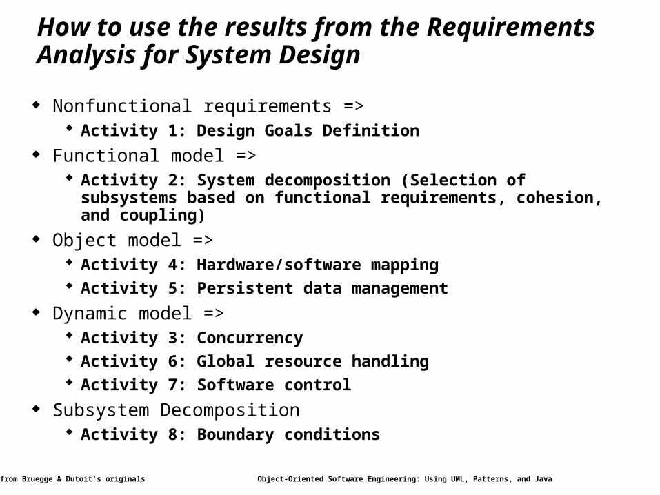
How to use the results from the Requirements Analysis for System Design
Nonfunctional requirements => Activity 1: Design Goals Definition
Functional model => Activity 2: System decomposition (Selection of subsystems based on
functional requirements, cohesion, and coupling) Object model =>
Activity 4: Hardware/software mapping Activity 5: Persistent data management
Dynamic model => Activity 3: Concurrency Activity 6: Global resource handling Activity 7: Software control
Subsystem Decomposition Activity 8: Boundary conditions
Modified from Bruegge & Dutoit’s originals Object-Oriented Software Engineering: Using UML, Patterns, and Java 5
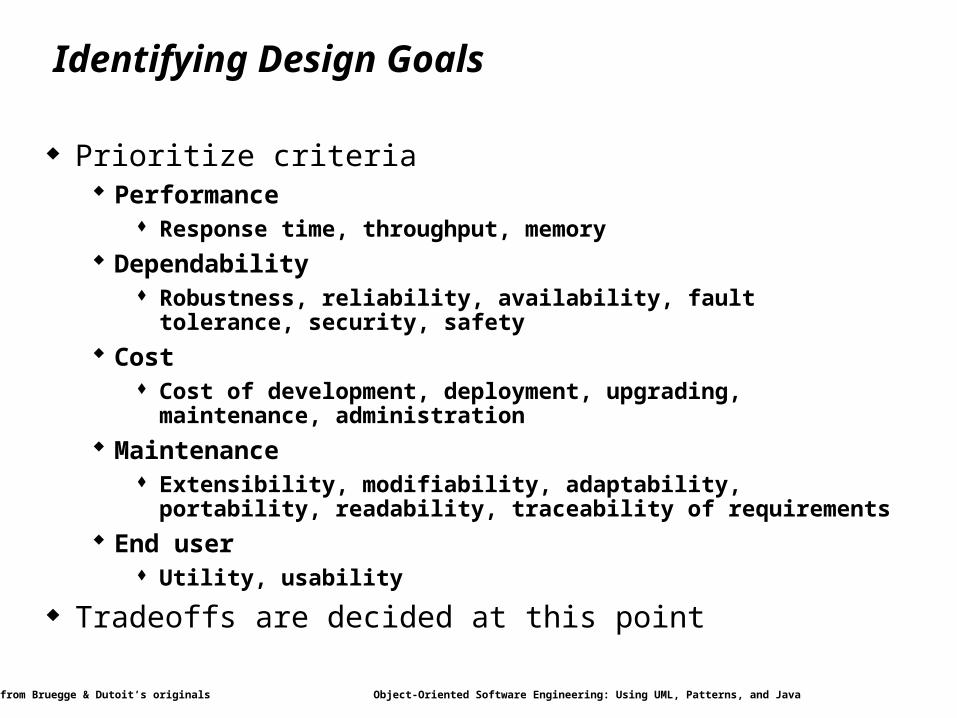
Identifying Design Goals
Prioritize criteria Performance
Response time, throughput, memory
Dependability Robustness, reliability, availability, fault tolerance, security, safety
Cost Cost of development, deployment, upgrading, maintenance,
administration
Maintenance Extensibility, modifiability, adaptability, portability, readability,
traceability of requirements
End user Utility, usability
Tradeoffs are decided at this point
Modified from Bruegge & Dutoit’s originals Object-Oriented Software Engineering: Using UML, Patterns, and Java 6
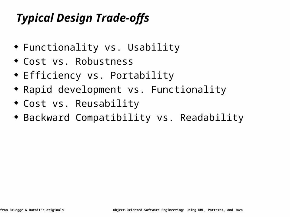
Typical Design Trade-offs
Functionality vs. Usability Cost vs. Robustness Efficiency vs. Portability Rapid development vs. Functionality Cost vs. Reusability Backward Compatibility vs. Readability
Modified from Bruegge & Dutoit’s originals Object-Oriented Software Engineering: Using UML, Patterns, and Java 7
Overview
System Design1. Identifying Design Goals
2. Mapping Objects to Subsystems
3. Hardware/Software Mapping
4. Persistent Data Management
5. Global Resource Handling and Access Control
6. Software Control and Concurrency
7. Boundary Conditions
Practical Matters
Modified from Bruegge & Dutoit’s originals Object-Oriented Software Engineering: Using UML, Patterns, and Java 8
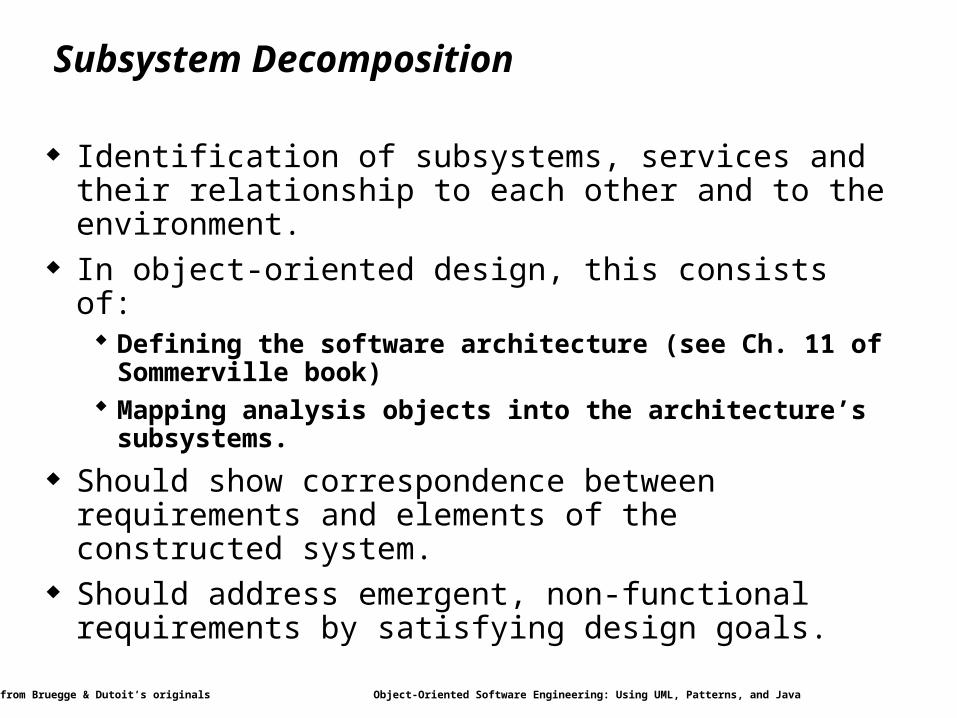
Subsystem Decomposition
Identification of subsystems, services and their relationship to each other and to the environment.
In object-oriented design, this consists of: Defining the software architecture (see Ch. 11 of Sommerville book) Mapping analysis objects into the architecture’s subsystems.
Should show correspondence between requirements and elements of the constructed system.
Should address emergent, non-functional requirements by satisfying design goals.
Modified from Bruegge & Dutoit’s originals Object-Oriented Software Engineering: Using UML, Patterns, and Java 9
Subsystems and Services
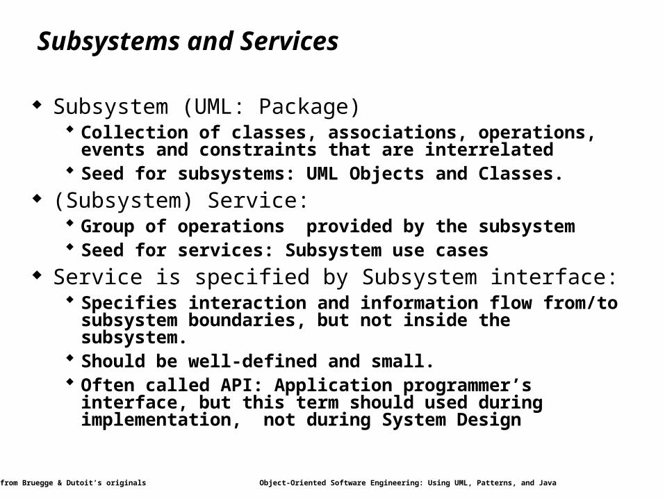
Subsystem (UML: Package) Collection of classes, associations, operations, events and
constraints that are interrelated Seed for subsystems: UML Objects and Classes.
(Subsystem) Service: Group of operations provided by the subsystem Seed for services: Subsystem use cases
Service is specified by Subsystem interface: Specifies interaction and information flow from/to subsystem
boundaries, but not inside the subsystem. Should be well-defined and small. Often called API: Application programmer’s interface, but this
term should used during implementation, not during System Design
Modified from Bruegge & Dutoit’s originals Object-Oriented Software Engineering: Using UML, Patterns, and Java 10
Services and Subsystem Interfaces
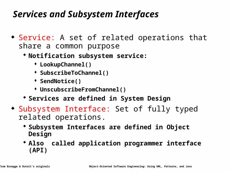
Service: A set of related operations that share a common purpose Notification subsystem service:
LookupChannel() SubscribeToChannel() SendNotice() UnscubscribeFromChannel()
Services are defined in System Design
Subsystem Interface: Set of fully typed related operations. Subsystem Interfaces are defined in Object Design Also called application programmer interface (API)
Modified from Bruegge & Dutoit’s originals Object-Oriented Software Engineering: Using UML, Patterns, and Java 11
Identifying Subsystems
Heuristics Assign objects identified in one use case into the same subsystem Create a dedicated subsystem for objects used for moving data
among subsystems Minimize the number of associations crossing subsystem
boundaries All objects in the same subsystem should be functionally related
Modified from Bruegge & Dutoit’s originals Object-Oriented Software Engineering: Using UML, Patterns, and Java 12
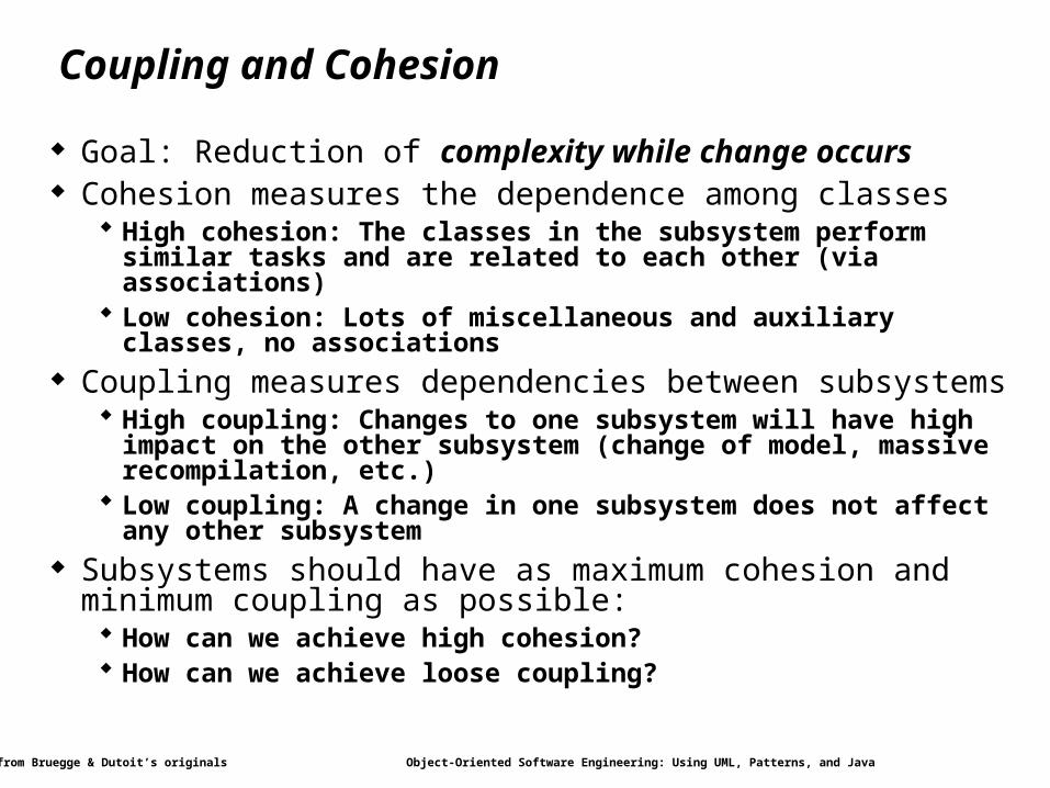
Coupling and Cohesion
Goal: Reduction of complexity while change occurs Cohesion measures the dependence among classes
High cohesion: The classes in the subsystem perform similar tasks and are related to each other (via associations)
Low cohesion: Lots of miscellaneous and auxiliary classes, no associations
Coupling measures dependencies between subsystems High coupling: Changes to one subsystem will have high impact on the
other subsystem (change of model, massive recompilation, etc.) Low coupling: A change in one subsystem does not affect any other
subsystem Subsystems should have as maximum cohesion and minimum
coupling as possible: How can we achieve high cohesion? How can we achieve loose coupling?
Modified from Bruegge & Dutoit’s originals Object-Oriented Software Engineering: Using UML, Patterns, and Java 13
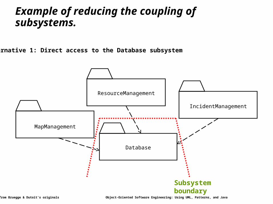
Example of reducing the coupling of subsystems.
MapManagement
IncidentManagement
Database
ResourceManagement
Alternative 1: Direct access to the Database subsystem
Subsystem boundary
Modified from Bruegge & Dutoit’s originals Object-Oriented Software Engineering: Using UML, Patterns, and Java 14
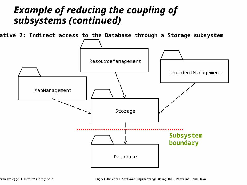
Example of reducing the coupling of subsystems (continued)
MapManagement
IncidentManagement
Storage
ResourceManagement
Database
Alternative 2: Indirect access to the Database through a Storage subsystem
Subsystem boundary
Modified from Bruegge & Dutoit’s originals Object-Oriented Software Engineering: Using UML, Patterns, and Java 15
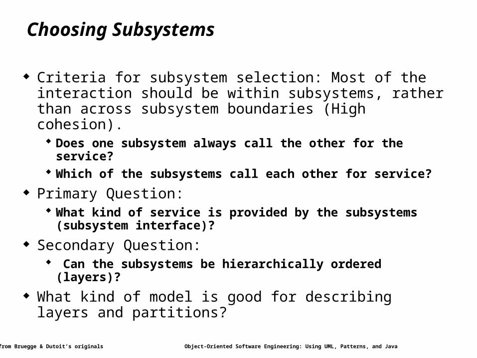
Choosing Subsystems
Criteria for subsystem selection: Most of the interaction should be within subsystems, rather than across subsystem boundaries (High cohesion). Does one subsystem always call the other for the service? Which of the subsystems call each other for service?
Primary Question: What kind of service is provided by the subsystems (subsystem
interface)?
Secondary Question: Can the subsystems be hierarchically ordered (layers)?
What kind of model is good for describing layers and partitions?
Modified from Bruegge & Dutoit’s originals Object-Oriented Software Engineering: Using UML, Patterns, and Java 16
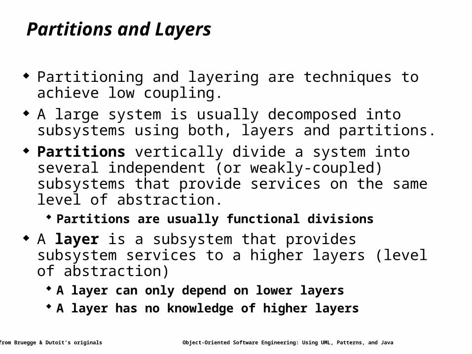
Partitions and Layers
Partitioning and layering are techniques to achieve low coupling.
A large system is usually decomposed into subsystems using both, layers and partitions.
Partitions vertically divide a system into several independent (or weakly-coupled) subsystems that provide services on the same level of abstraction. Partitions are usually functional divisions
A layer is a subsystem that provides subsystem services to a higher layers (level of abstraction) A layer can only depend on lower layers A layer has no knowledge of higher layers
Modified from Bruegge & Dutoit’s originals Object-Oriented Software Engineering: Using UML, Patterns, and Java 17
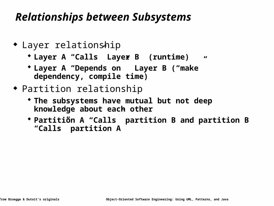
Relationships between Subsystems
Layer relationship Layer A “Calls” Layer B (runtime) Layer A “Depends on” Layer B (“make” dependency, compile
time)
Partition relationship The subsystems have mutual but not deep knowledge about each
other Partition A “Calls” partition B and partition B “Calls” partition A

Modified from Bruegge & Dutoit’s originals Object-Oriented Software Engineering: Using UML, Patterns, and Java 18
Overview
System Design1. Identifying Design Goals
2. Mapping Objects to Subsystems
3. Hardware/Software Mapping
4. Persistent Data Management
5. Global Resource Handling and Access Control
6. Software Control and Concurrency
7. Boundary Conditions
Practical Matters
Modified from Bruegge & Dutoit’s originals Object-Oriented Software Engineering: Using UML, Patterns, and Java 19
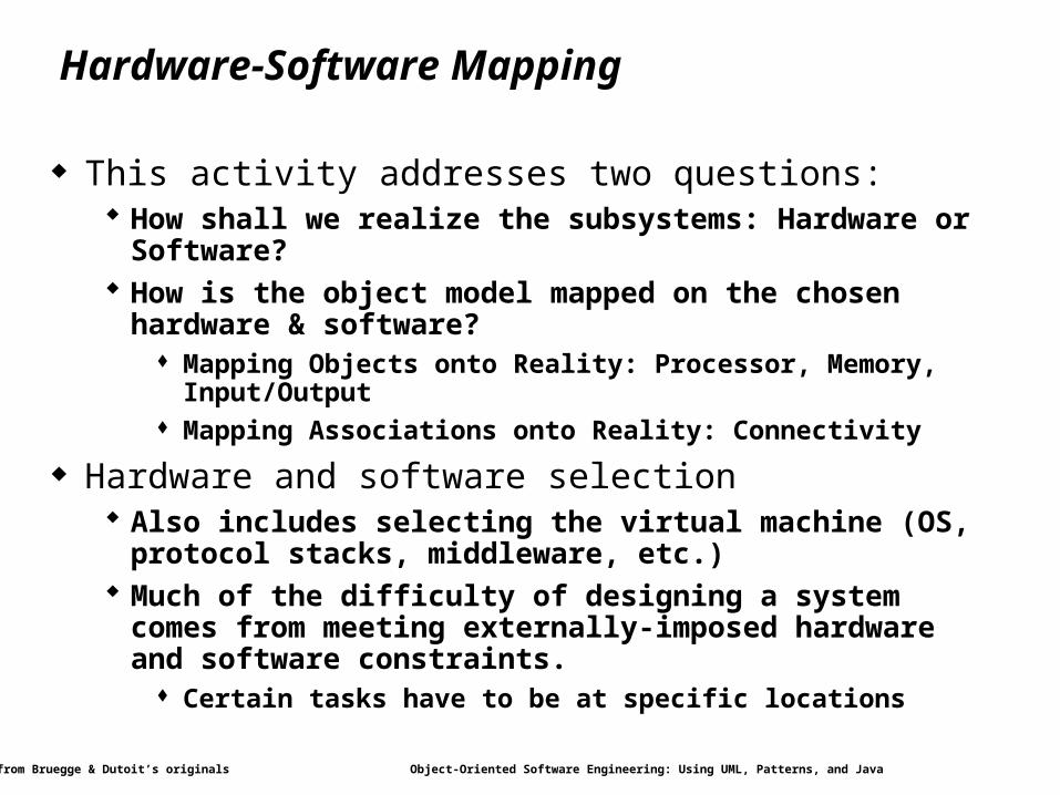
Hardware-Software Mapping
This activity addresses two questions: How shall we realize the subsystems: Hardware or Software? How is the object model mapped on the chosen hardware &
software? Mapping Objects onto Reality: Processor, Memory, Input/Output Mapping Associations onto Reality: Connectivity
Hardware and software selection Also includes selecting the virtual machine (OS, protocol stacks,
middleware, etc.) Much of the difficulty of designing a system comes from meeting
externally-imposed hardware and software constraints. Certain tasks have to be at specific locations
Modified from Bruegge & Dutoit’s originals Object-Oriented Software Engineering: Using UML, Patterns, and Java 20
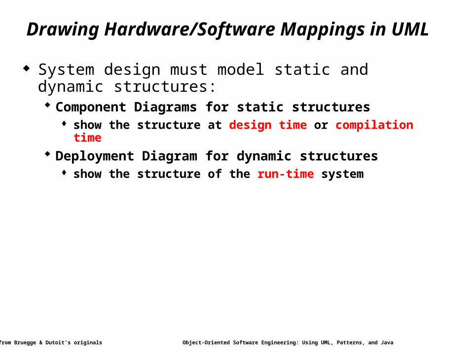
Drawing Hardware/Software Mappings in UML
System design must model static and dynamic structures: Component Diagrams for static structures
show the structure at design time or compilation time
Deployment Diagram for dynamic structures show the structure of the run-time system
Modified from Bruegge & Dutoit’s originals Object-Oriented Software Engineering: Using UML, Patterns, and Java 21
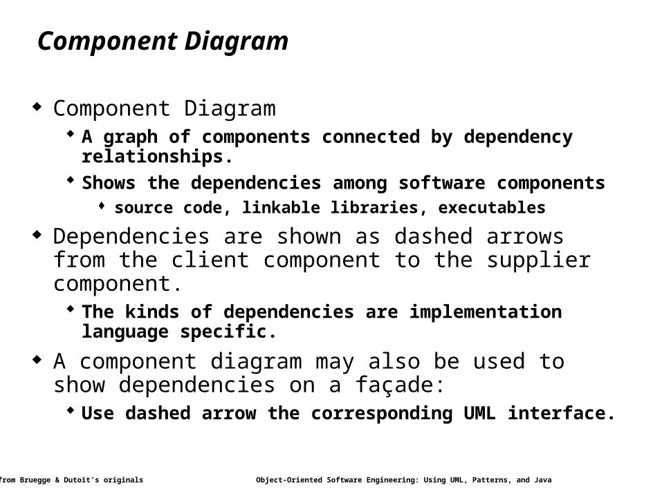
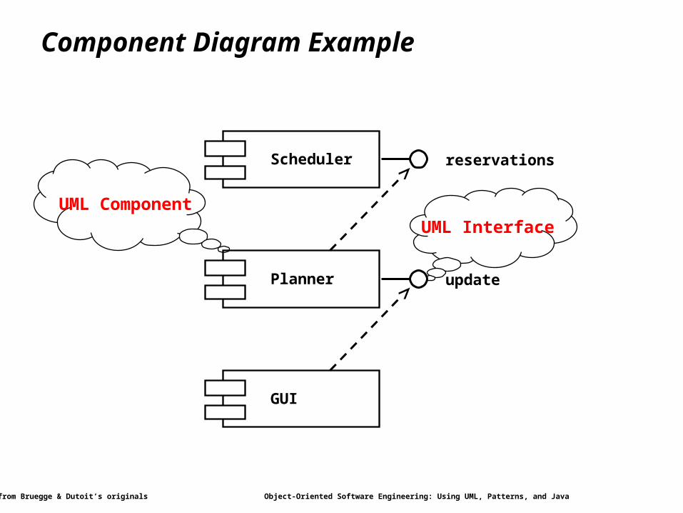
Component Diagram
Component Diagram A graph of components connected by dependency relationships. Shows the dependencies among software components
source code, linkable libraries, executables
Dependencies are shown as dashed arrows from the client component to the supplier component. The kinds of dependencies are implementation language specific.
A component diagram may also be used to show dependencies on a façade: Use dashed arrow the corresponding UML interface.
Modified from Bruegge & Dutoit’s originals Object-Oriented Software Engineering: Using UML, Patterns, and Java 22
Component Diagram Example
UML InterfaceUML Component
Scheduler
Planner
GUI
reservations
update
Modified from Bruegge & Dutoit’s originals Object-Oriented Software Engineering: Using UML, Patterns, and Java 23
Deployment Diagram
Deployment diagrams are useful for showing a system design after the following decisions are made Subsystem decomposition Concurrency Hardware/Software Mapping
A deployment diagram is a graph of nodes connected by communication associations. Nodes are shown as 3-D boxes. Nodes may contain component instances. Components may contain objects (indicating that the object is part
of the component)
Modified from Bruegge & Dutoit’s originals Object-Oriented Software Engineering: Using UML, Patterns, and Java 24
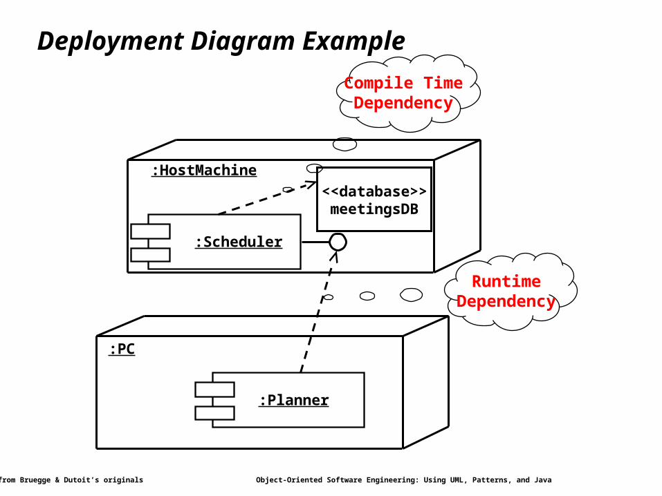
Deployment Diagram Example
RuntimeDependency
Compile TimeDependency
:Planner
:PC
:Scheduler
:HostMachine
<<database>>meetingsDB

Modified from Bruegge & Dutoit’s originals Object-Oriented Software Engineering: Using UML, Patterns, and Java 25
Mapping the Objects to Nodes
Processor issues: Is the computation rate too demanding for a single processor? Can we get a speedup by distributing tasks across several
processors? How many processors are required to maintain steady state load?
Memory issues: Is there enough memory to buffer bursts of requests?
I/O issues: Do you need an extra piece of hardware to handle the data
generation rate? Does the response time exceed the available communication
bandwidth between subsystems or a task and a piece of hardware?
Modified from Bruegge & Dutoit’s originals Object-Oriented Software Engineering: Using UML, Patterns, and Java 26
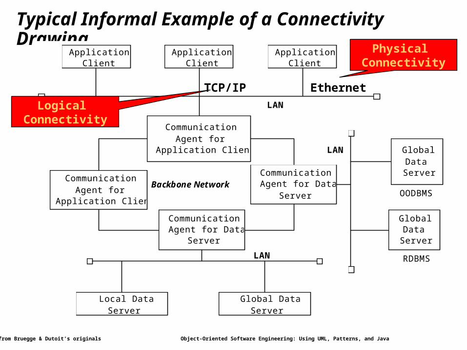
Mapping the Subsystems Associations: Connectivity
Describe the physical connectivity of the hardware Often the physical layer in ISO’s OSI Reference Model
Which associations in the object model are mapped to physical connections?
Which of the client-supplier relationships in the analysis/design model correspond to physical connections?
Describe the logical connectivity (subsystem associations) Identify associations that do not directly map into physical
connections: How should these associations be implemented?
Modified from Bruegge & Dutoit’s originals Object-Oriented Software Engineering: Using UML, Patterns, and Java 27
Typical Informal Example of a Connectivity DrawingDistributedDatabaseArchitecture Tue, Oct 13, 1992 12:53 AM
Application Client
Application Client
Application Client
Communication Agent for
Application Clients
Communication Agent for
Application Clients
Communication Agent for Data
Server
Communication Agent for Data
Server
Local Data Server
Global Data Server
Global Data Server
Global Data
Server
OODBMS
RDBMS
Backbone Network
LAN
LAN
LAN
TCP/IP Ethernet
Physical Connectivity
Logical Connectivity
Modified from Bruegge & Dutoit’s originals Object-Oriented Software Engineering: Using UML, Patterns, and Java 28
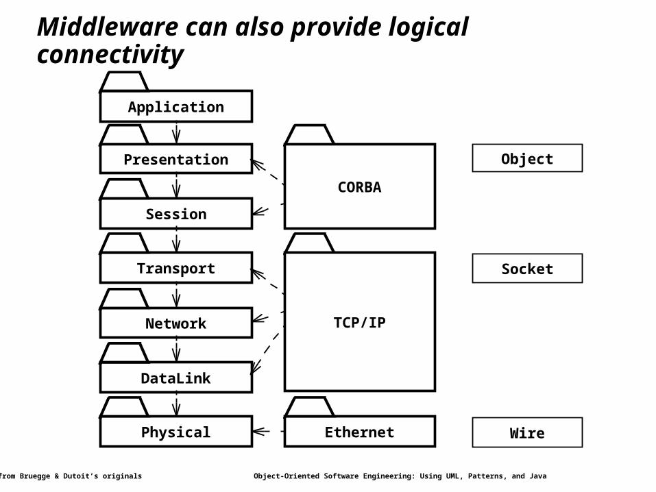
Middleware can also provide logical connectivity
Application
Presentation
Session
Transport
Network
DataLink
Physical
Socket
CORBA
TCP/IP
Object
Ethernet Wire
Modified from Bruegge & Dutoit’s originals Object-Oriented Software Engineering: Using UML, Patterns, and Java 29
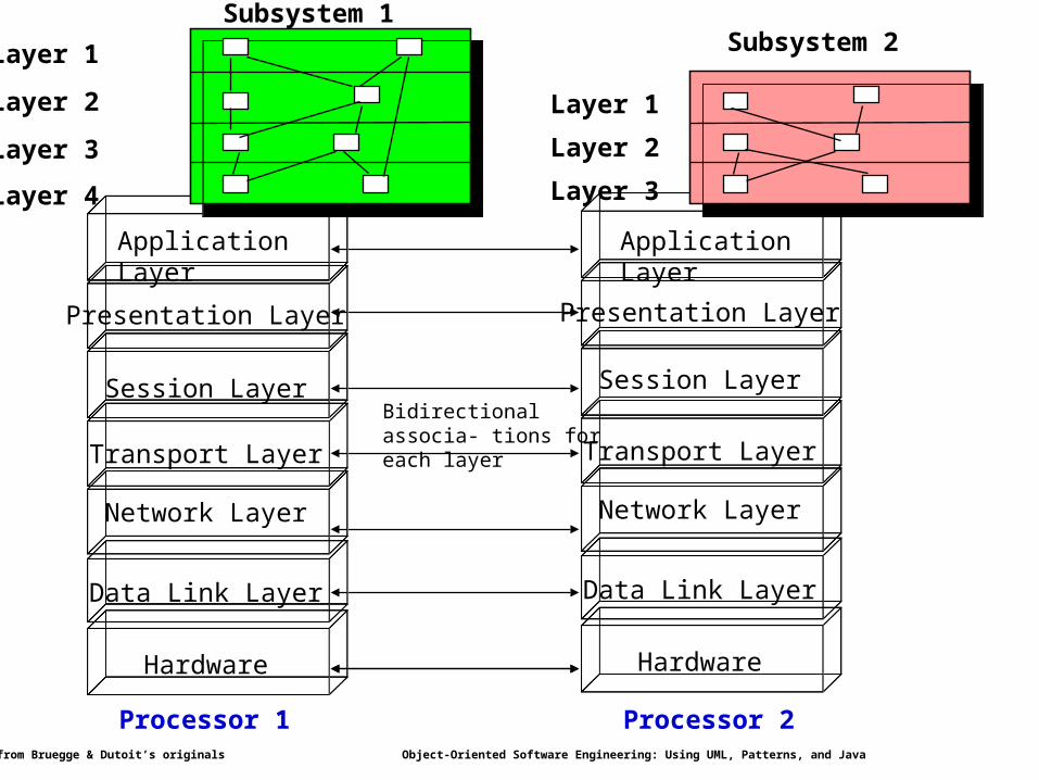
Application Layer
Presentation Layer
Session Layer
Transport Layer
Network Layer
Data Link Layer
Hardware
Bidirectional associa- tions for each layer
Presentation Layer
Session Layer
Transport Layer
Network Layer
Data Link Layer
Hardware
Application Layer
Layer 1
Layer 2
Layer 3
Layer 4
Subsystem 1
Processor 1 Processor 2
Layer 1
Layer 2
Layer 3
Subsystem 2
Modified from Bruegge & Dutoit’s originals Object-Oriented Software Engineering: Using UML, Patterns, and Java 30
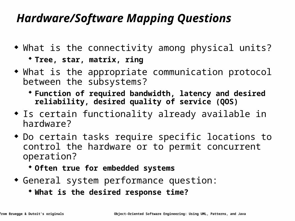
Hardware/Software Mapping Questions
What is the connectivity among physical units? Tree, star, matrix, ring
What is the appropriate communication protocol between the subsystems? Function of required bandwidth, latency and desired reliability,
desired quality of service (QOS)
Is certain functionality already available in hardware? Do certain tasks require specific locations to control the
hardware or to permit concurrent operation? Often true for embedded systems
General system performance question: What is the desired response time?
Modified from Bruegge & Dutoit’s originals Object-Oriented Software Engineering: Using UML, Patterns, and Java 31
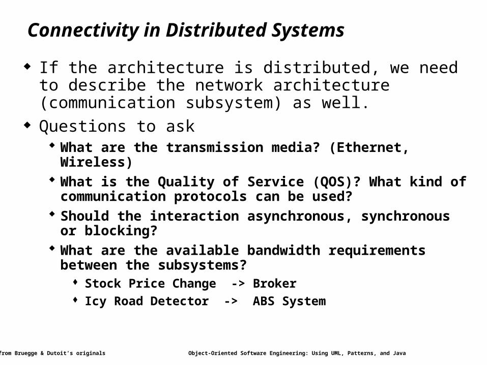
Connectivity in Distributed Systems
If the architecture is distributed, we need to describe the network architecture (communication subsystem) as well.
Questions to ask What are the transmission media? (Ethernet, Wireless) What is the Quality of Service (QOS)? What kind of communication
protocols can be used? Should the interaction asynchronous, synchronous or blocking? What are the available bandwidth requirements between the
subsystems? Stock Price Change -> Broker Icy Road Detector -> ABS System
Modified from Bruegge & Dutoit’s originals Object-Oriented Software Engineering: Using UML, Patterns, and Java 32
Overview
System Design1. Identifying Design Goals
2. Mapping Objects to Subsystems
3. Hardware/Software Mapping
4. Persistent Data Management
5. Global Resource Handling and Access Control
6. Software Control and Concurrency
7. Boundary Conditions
Practical Matters
Modified from Bruegge & Dutoit’s originals Object-Oriented Software Engineering: Using UML, Patterns, and Java 33
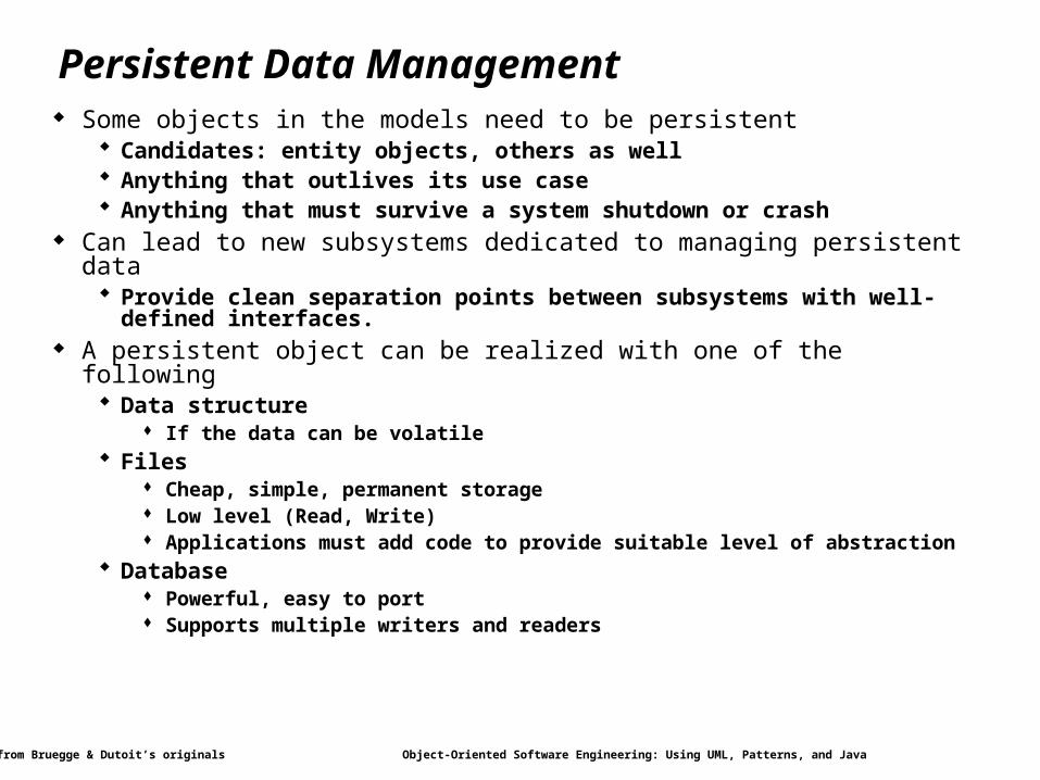
Persistent Data Management Some objects in the models need to be persistent
Candidates: entity objects, others as well Anything that outlives its use case Anything that must survive a system shutdown or crash
Can lead to new subsystems dedicated to managing persistent data Provide clean separation points between subsystems with well-defined
interfaces. A persistent object can be realized with one of the following
Data structure If the data can be volatile
Files Cheap, simple, permanent storage Low level (Read, Write) Applications must add code to provide suitable level of abstraction
Database Powerful, easy to port Supports multiple writers and readers
Modified from Bruegge & Dutoit’s originals Object-Oriented Software Engineering: Using UML, Patterns, and Java 34
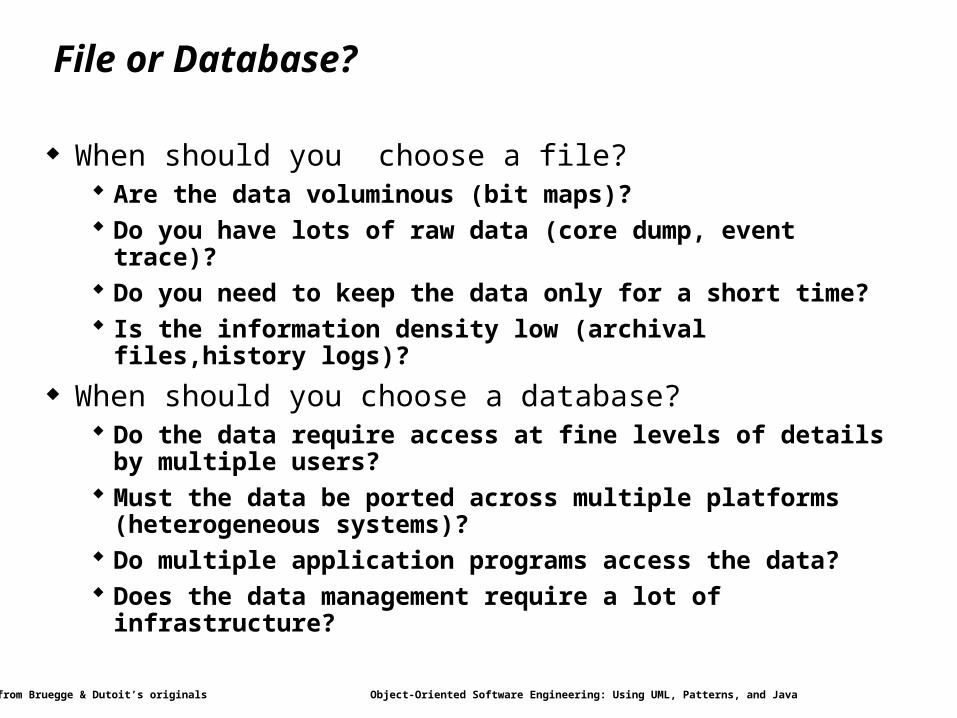
File or Database?
When should you choose a file? Are the data voluminous (bit maps)? Do you have lots of raw data (core dump, event trace)? Do you need to keep the data only for a short time? Is the information density low (archival files,history logs)?
When should you choose a database? Do the data require access at fine levels of details by multiple users? Must the data be ported across multiple platforms (heterogeneous
systems)? Do multiple application programs access the data? Does the data management require a lot of infrastructure?

Modified from Bruegge & Dutoit’s originals Object-Oriented Software Engineering: Using UML, Patterns, and Java 35
Object-Oriented Databases
Support all fundamental object modeling concepts Classes, Attributes, Methods, Associations, Inheritance
Mapping an object model to an OO-database Determine which objects are persistent. Perform normal requirement analysis and object design Create single attribute indices to reduce performance bottlenecks Do the mapping (specific to commercially available product).
Example: In ObjectStore, implement classes and associations by preparing C++
declarations for each class and each association in the object model
When to use Complex data relationships, medium-size dataset
Modified from Bruegge & Dutoit’s originals Object-Oriented Software Engineering: Using UML, Patterns, and Java 36
Relational Databases
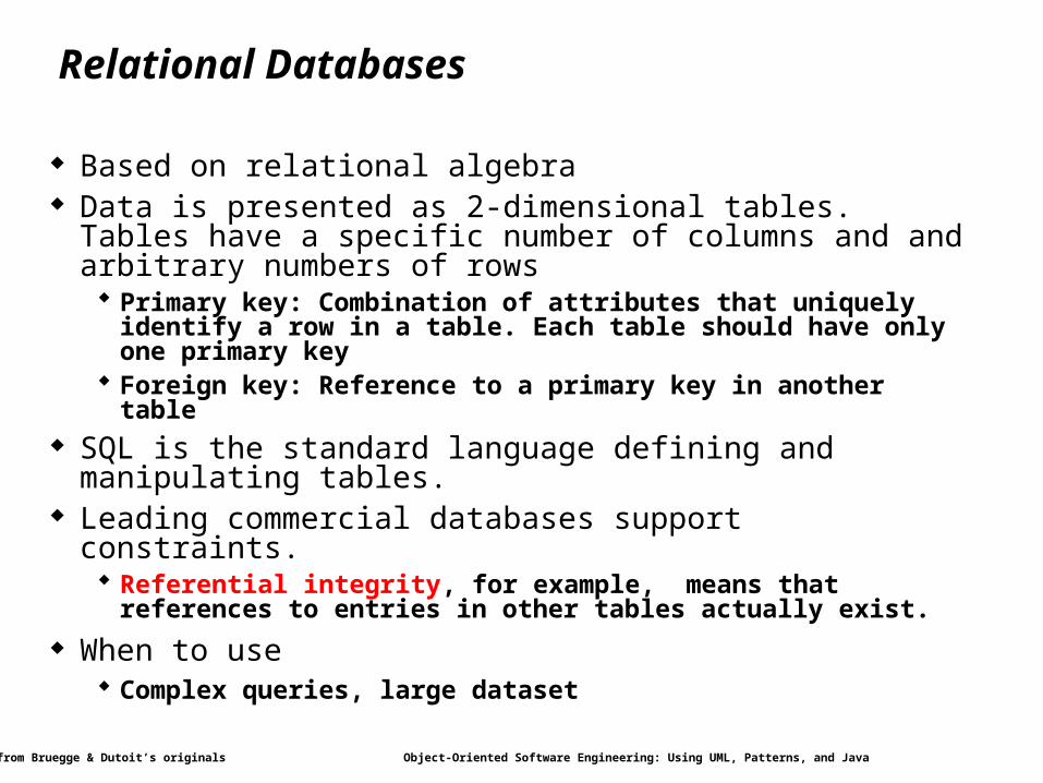
Based on relational algebra Data is presented as 2-dimensional tables. Tables have a
specific number of columns and and arbitrary numbers of rows Primary key: Combination of attributes that uniquely identify a
row in a table. Each table should have only one primary key Foreign key: Reference to a primary key in another table
SQL is the standard language defining and manipulating tables. Leading commercial databases support constraints.
Referential integrity, for example, means that references to entries in other tables actually exist.
When to use Complex queries, large dataset
Modified from Bruegge & Dutoit’s originals Object-Oriented Software Engineering: Using UML, Patterns, and Java 37
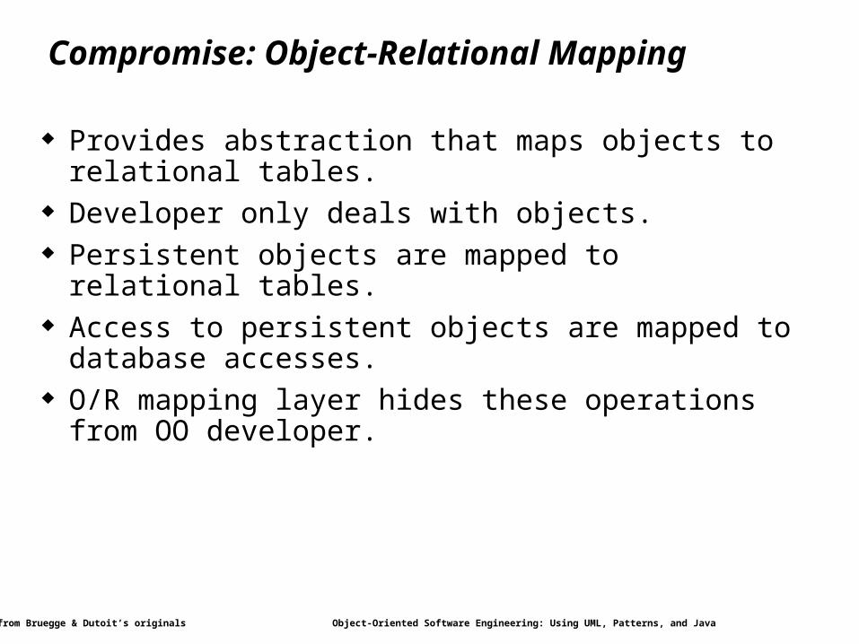
Compromise: Object-Relational Mapping
Provides abstraction that maps objects to relational tables. Developer only deals with objects. Persistent objects are mapped to relational tables. Access to persistent objects are mapped to database accesses. O/R mapping layer hides these operations from OO developer.
Modified from Bruegge & Dutoit’s originals Object-Oriented Software Engineering: Using UML, Patterns, and Java 38
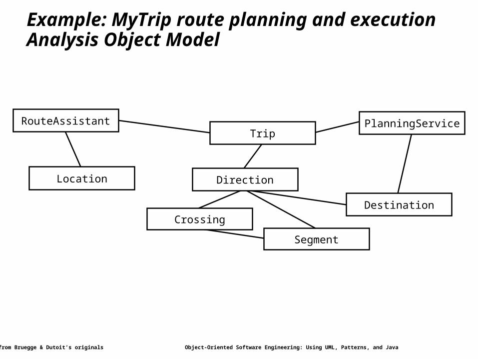
Location
Segment
Crossing
Direction
Destination
TripRouteAssistant PlanningService
Example: MyTrip route planning and executionAnalysis Object Model
Modified from Bruegge & Dutoit’s originals Object-Oriented Software Engineering: Using UML, Patterns, and Java 39
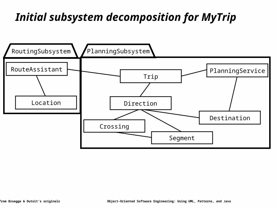
Location
Segment
Crossing
Direction
Destination
RoutingSubsystem PlanningSubsystem
TripRouteAssistant PlanningService
Initial subsystem decomposition for MyTrip
Modified from Bruegge & Dutoit’s originals Object-Oriented Software Engineering: Using UML, Patterns, and Java 40
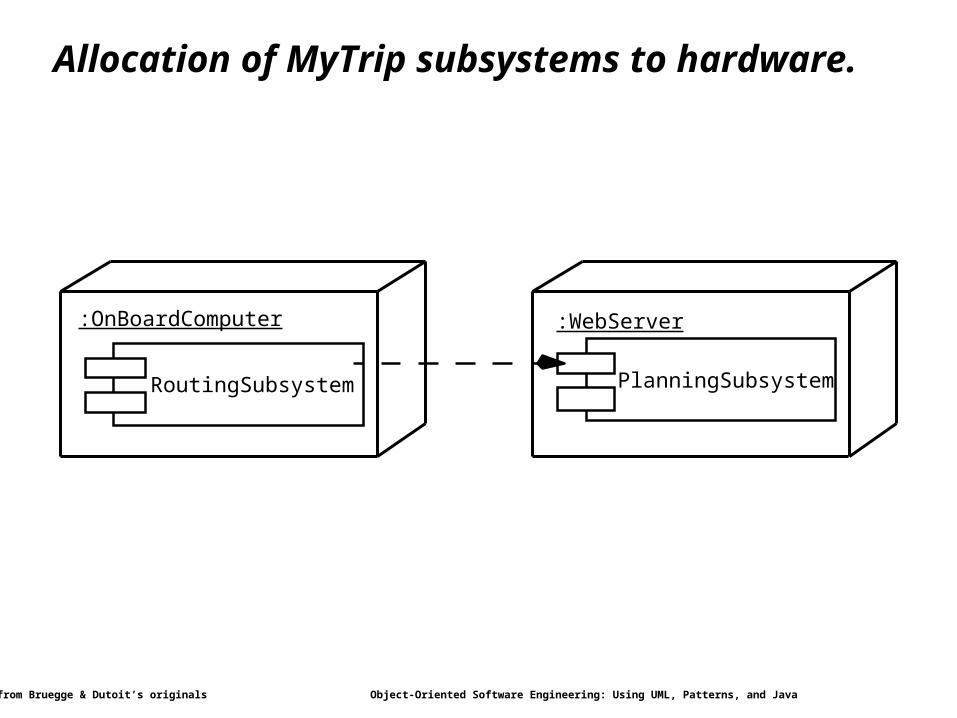
RoutingSubsystem PlanningSubsystem
:OnBoardComputer :WebServer
Allocation of MyTrip subsystems to hardware.
Modified from Bruegge & Dutoit’s originals Object-Oriented Software Engineering: Using UML, Patterns, and Java 41
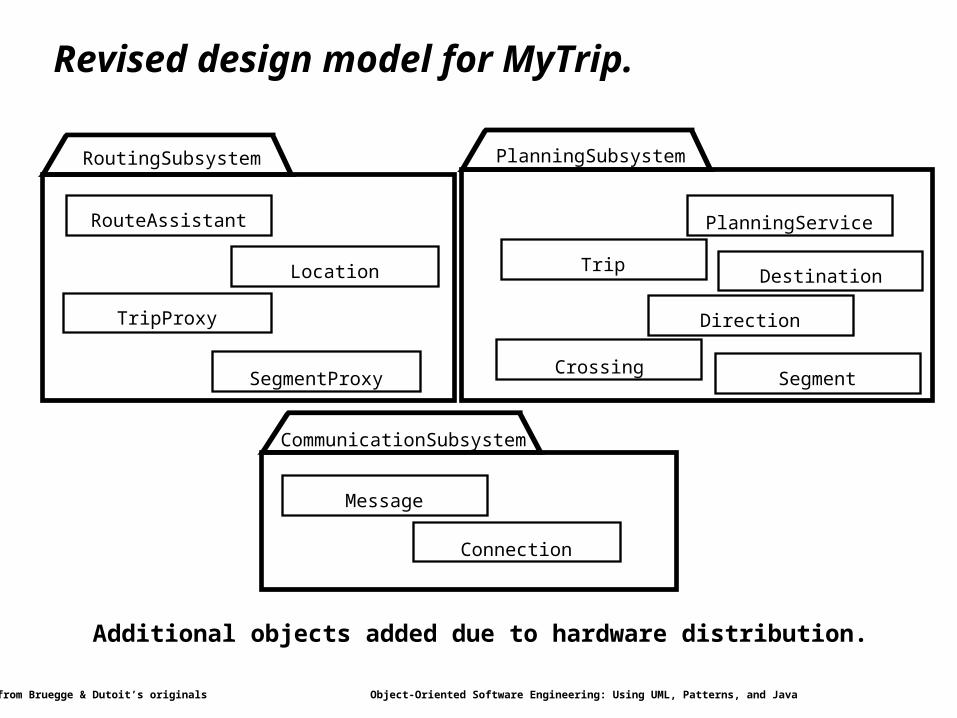
TripLocation
PlanningService
SegmentCrossing
RouteAssistant
Direction
Destination
TripProxy
SegmentProxy
PlanningSubsystem
Message
Connection
CommunicationSubsystem
RoutingSubsystem
Revised design model for MyTrip.
Additional objects added due to hardware distribution.
Modified from Bruegge & Dutoit’s originals Object-Oriented Software Engineering: Using UML, Patterns, and Java 42
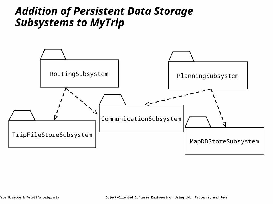
PlanningSubsystem
MapDBStoreSubsystemTripFileStoreSubsystem
RoutingSubsystem
CommunicationSubsystem
Addition of Persistent Data Storage Subsystems to MyTrip

Modified from Bruegge & Dutoit’s originals Object-Oriented Software Engineering: Using UML, Patterns, and Java 43
Overview
System Design1. Identifying Design Goals
2. Mapping Objects to Subsystems
3. Hardware/Software Mapping
4. Persistent Data Management
5. Global Resource Handling and Access Control
6. Software Control and Concurrency
7. Boundary Conditions
Practical Matters
Modified from Bruegge & Dutoit’s originals Object-Oriented Software Engineering: Using UML, Patterns, and Java 44
Global Resource Handling
Discusses access control Describes access rights for different classes of actors Describes how objects guard against unauthorized access
Modified from Bruegge & Dutoit’s originals Object-Oriented Software Engineering: Using UML, Patterns, and Java 45
Defining Access Control
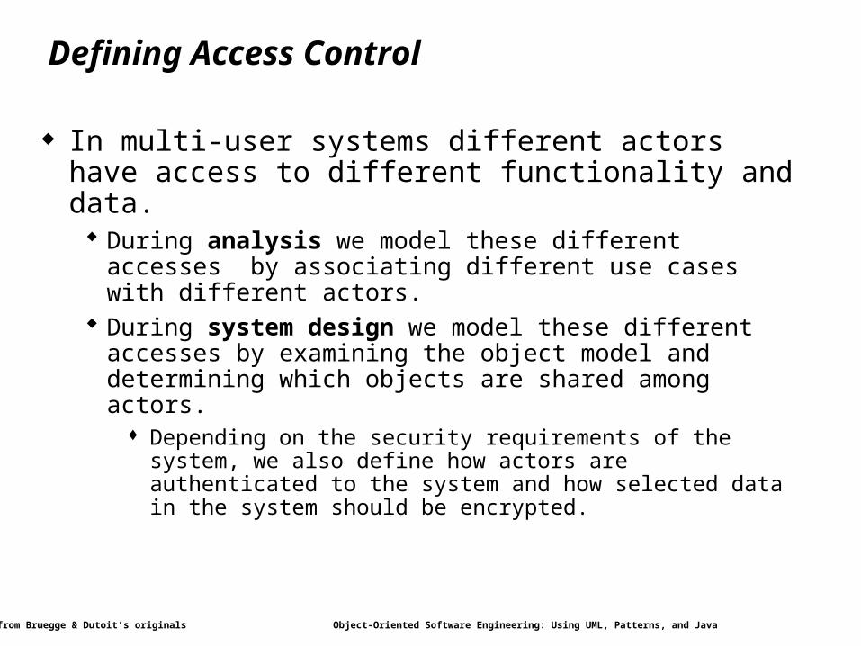
In multi-user systems different actors have access to different functionality and data. During analysis we model these different accesses by associating
different use cases with different actors. During system design we model these different accesses by examining
the object model and determining which objects are shared among actors.
Depending on the security requirements of the system, we also define how actors are authenticated to the system and how selected data in the system should be encrypted.
Modified from Bruegge & Dutoit’s originals Object-Oriented Software Engineering: Using UML, Patterns, and Java 46
Access Matrix
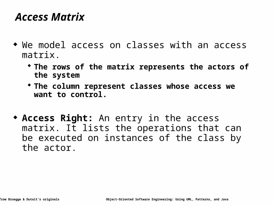
We model access on classes with an access matrix. The rows of the matrix represents the actors of the system The column represent classes whose access we want to control.
Access Right: An entry in the access matrix. It lists the operations that can be executed on instances of the class by the actor.
Modified from Bruegge & Dutoit’s originals Object-Oriented Software Engineering: Using UML, Patterns, and Java 47
Access Matrix Implementations
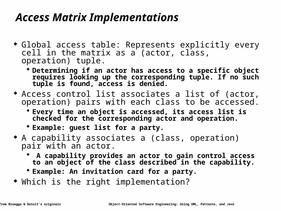
Global access table: Represents explicitly every cell in the matrix as a (actor, class, operation) tuple. Determining if an actor has access to a specific object requires
looking up the corresponding tuple. If no such tuple is found, access is denied.
Access control list associates a list of (actor, operation) pairs with each class to be accessed. Every time an object is accessed, its access list is checked for the
corresponding actor and operation. Example: guest list for a party.
A capability associates a (class, operation) pair with an actor. A capability provides an actor to gain control access to an object of
the class described in the capability. Example: An invitation card for a party.
Which is the right implementation?
Modified from Bruegge & Dutoit’s originals Object-Oriented Software Engineering: Using UML, Patterns, and Java 48
Global Resource Access Questions
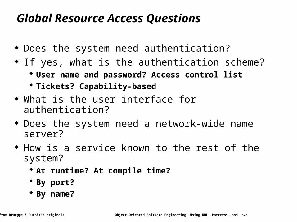
Does the system need authentication? If yes, what is the authentication scheme?
User name and password? Access control list Tickets? Capability-based
What is the user interface for authentication? Does the system need a network-wide name server? How is a service known to the rest of the system?
At runtime? At compile time? By port? By name?
Modified from Bruegge & Dutoit’s originals Object-Oriented Software Engineering: Using UML, Patterns, and Java 49
Overview
System Design1. Identifying Design Goals
2. Mapping Objects to Subsystems
3. Hardware/Software Mapping
4. Persistent Data Management
5. Global Resource Handling and Access Control
6. Software Control and Concurrency
7. Boundary Conditions
Practical Matters

Modified from Bruegge & Dutoit’s originals Object-Oriented Software Engineering: Using UML, Patterns, and Java 53
Centralized vs. Decentralized Designs Should you use a centralized or decentralized design?
Take the sequence diagrams and control objects from the analysis model
Check the participation of the control objects in the sequence diagrams
If sequence diagram looks more like a fork: Centralized design The sequence diagram looks more like a stair: Decentralized design
Centralized Design One control object or subsystem ("spider") controls everything
Pro: Change in the control structure is very easy Con: The single control object is a possible performance bottleneck
Decentralized Design Not a single object is in control, control is distributed
Con: The responsibility is spread out Pro: Fits nicely into object-oriented development
Modified from Bruegge & Dutoit’s originals Object-Oriented Software Engineering: Using UML, Patterns, and Java 54
Concurrency
Concurrency – multiple flows of control Identify concurrent threads and address concurrency issues. Design goal: response time, performance.
Threads A thread of control is a path through a set of state diagrams on
which a single object is active at a time. A thread remains within a state diagram until an object sends an
event to another object and waits for another event Thread splitting: Object does a nonblocking send of an event.
Modified from Bruegge & Dutoit’s originals Object-Oriented Software Engineering: Using UML, Patterns, and Java 55
Concurrency (continued)
Two objects are inherently concurrent if they can receive events at the same time without interacting
Inherently concurrent objects should be assigned to different threads of control
Objects with mutually exclusive activity should be folded into a single thread of control (Why?)
Modified from Bruegge & Dutoit’s originals Object-Oriented Software Engineering: Using UML, Patterns, and Java 56
Implementing Concurrency
Concurrent systems can be implemented on any system that provides physical concurrency (multi-processor hardware)
or logical concurrency (software): Scheduling problem
(Operating systems)
Modified from Bruegge & Dutoit’s originals Object-Oriented Software Engineering: Using UML, Patterns, and Java 57
Concurrency Questions
Which objects of the object model are independent? What kinds of threads of control are identifiable? Does the system provide access to multiple users? Can a single request to the system be decomposed into multiple
requests? Can these requests be handled in parallel?
Modified from Bruegge & Dutoit’s originals Object-Oriented Software Engineering: Using UML, Patterns, and Java 58
Overview
System Design1. Identifying Design Goals
2. Mapping Objects to Subsystems
3. Hardware/Software Mapping
4. Persistent Data Management
5. Global Resource Handling and Access Control
6. Software Control and Concurrency
7. Boundary Conditions
Practical Matters
Modified from Bruegge & Dutoit’s originals Object-Oriented Software Engineering: Using UML, Patterns, and Java 59
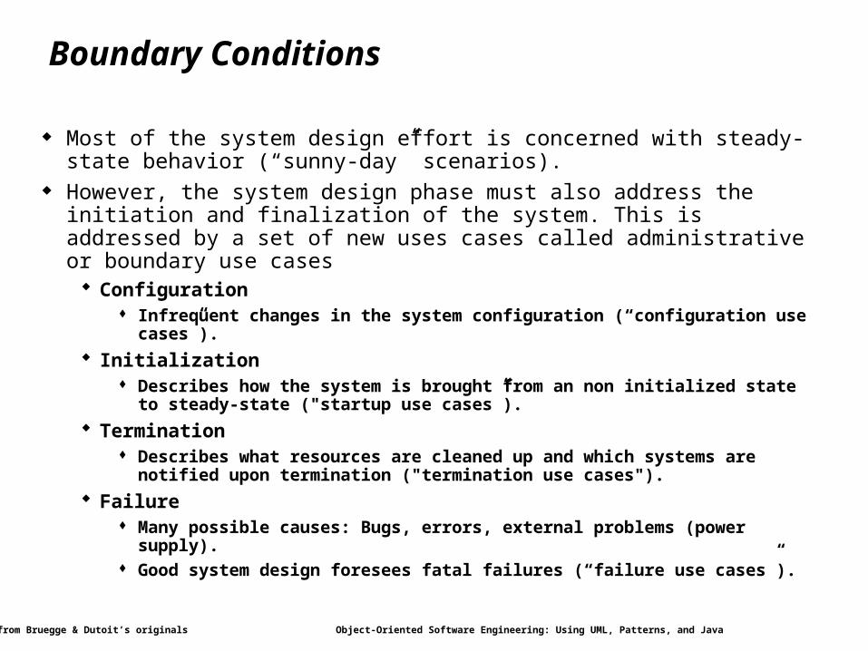
Boundary Conditions
Most of the system design effort is concerned with steady-state behavior (“sunny-day” scenarios).
However, the system design phase must also address the initiation and finalization of the system. This is addressed by a set of new uses cases called administrative or boundary use cases
Configuration Infrequent changes in the system configuration (“configuration use cases”).
Initialization Describes how the system is brought from an non initialized state to steady-state
("startup use cases”).
Termination Describes what resources are cleaned up and which systems are notified upon
termination ("termination use cases").
Failure Many possible causes: Bugs, errors, external problems (power supply). Good system design foresees fatal failures (“failure use cases”).
Modified from Bruegge & Dutoit’s originals Object-Oriented Software Engineering: Using UML, Patterns, and Java 60
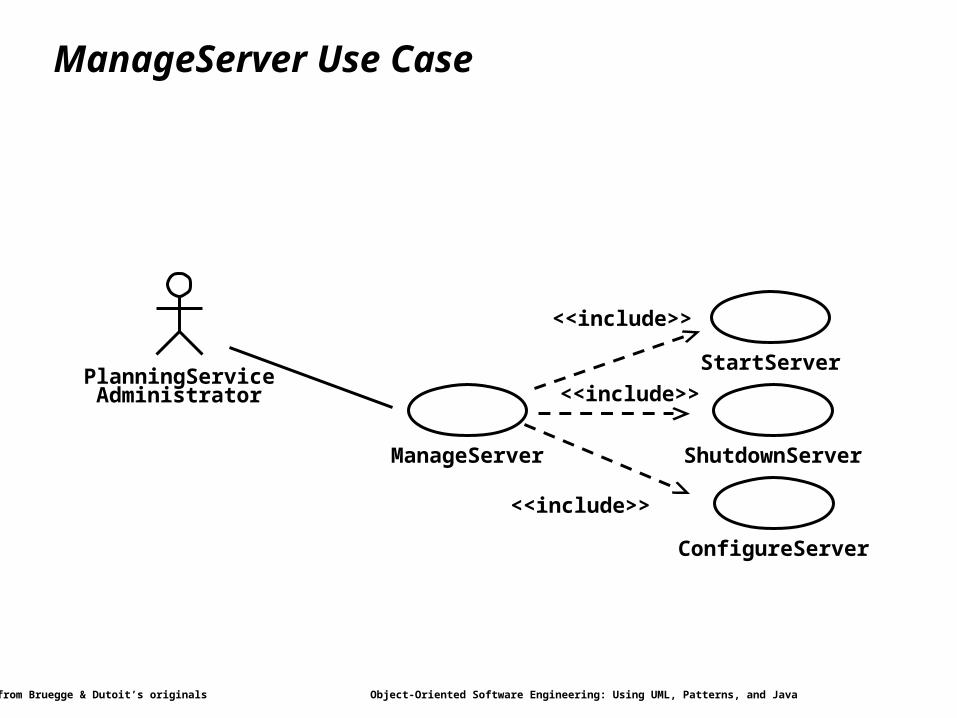
Example: Administrative Use Cases for MyTrip
An additional subsystem that was found during system design is the server. For this new subsystem we need to define use cases.
ManageServer includes all the functions necessary to start up and shutdown the server.
Modified from Bruegge & Dutoit’s originals Object-Oriented Software Engineering: Using UML, Patterns, and Java 61
ManageServer Use Case
PlanningService
ManageServer
Administrator
StartServer
ShutdownServer
ConfigureServer
<<include>>
<<include>>
<<include>>
Modified from Bruegge & Dutoit’s originals Object-Oriented Software Engineering: Using UML, Patterns, and Java 62
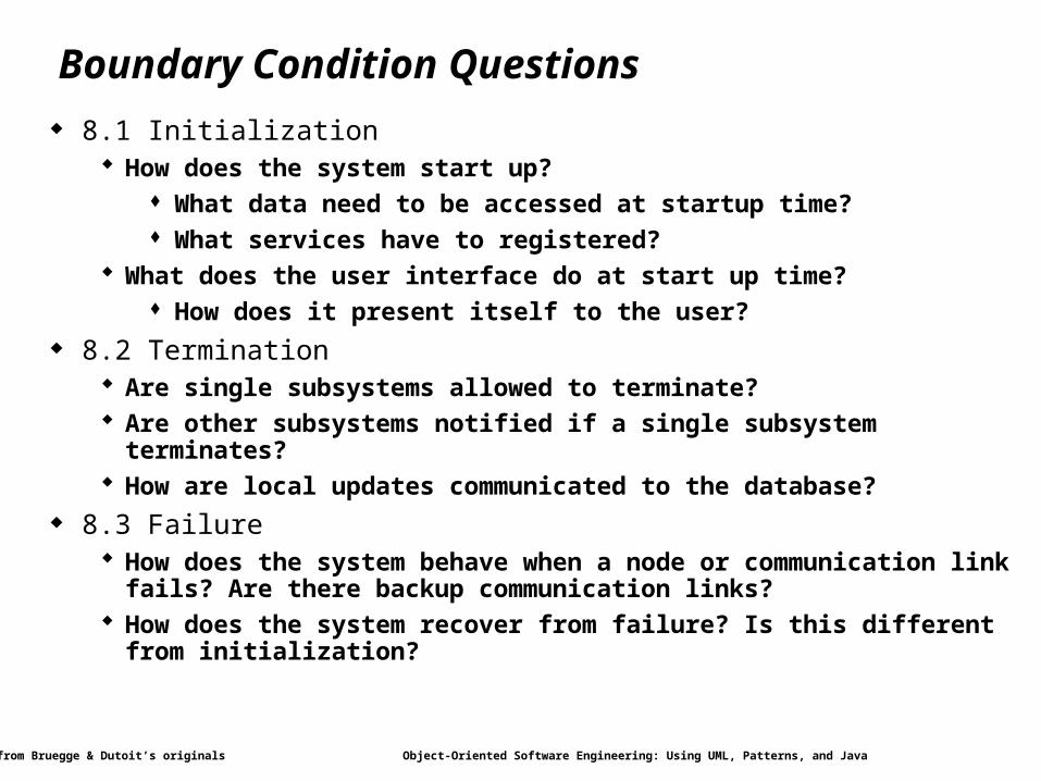
Boundary Condition Questions
8.1 Initialization How does the system start up?
What data need to be accessed at startup time? What services have to registered?
What does the user interface do at start up time? How does it present itself to the user?
8.2 Termination Are single subsystems allowed to terminate? Are other subsystems notified if a single subsystem terminates? How are local updates communicated to the database?
8.3 Failure How does the system behave when a node or communication link fails? Are
there backup communication links? How does the system recover from failure? Is this different from initialization?
Modified from Bruegge & Dutoit’s originals Object-Oriented Software Engineering: Using UML, Patterns, and Java 63
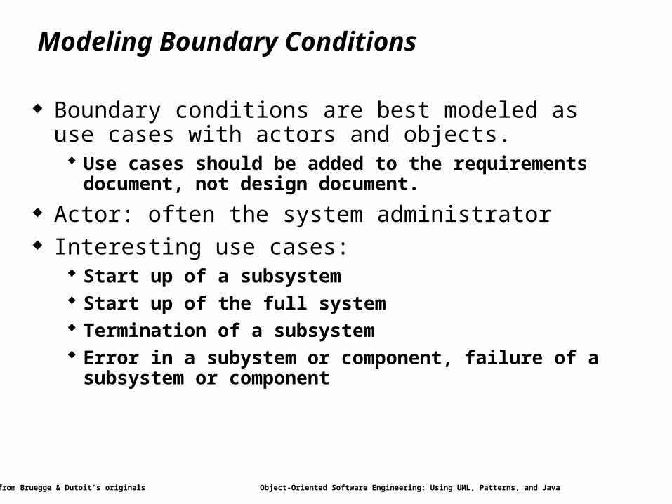
Modeling Boundary Conditions
Boundary conditions are best modeled as use cases with actors and objects. Use cases should be added to the requirements document, not
design document.
Actor: often the system administrator Interesting use cases:
Start up of a subsystem Start up of the full system Termination of a subsystem Error in a subystem or component, failure of a subsystem or
component
Modified from Bruegge & Dutoit’s originals Object-Oriented Software Engineering: Using UML, Patterns, and Java 64
Practical Matters
Reviewing system designs Communication challenges among developers Design iterations
Modified from Bruegge & Dutoit’s originals Object-Oriented Software Engineering: Using UML, Patterns, and Java 65
Reviewing System Design
Correct – design satisfies requirements Complete – all requirements are covered Consistent – conflicting design goals resolved Realistic – can be implemented with current technology Readable – developers can understand the design to translate it
to an implementation
Modified from Bruegge & Dutoit’s originals Object-Oriented Software Engineering: Using UML, Patterns, and Java 66
Communication Challenges
Size – large number of design issues, candidate designs, candidate platforms and implementation technologies
Change – constant flux of requirements, application and solution domain knowledge
Level of abstraction – system design is abstract compared to later stages
Reluctance to confront problems – resolution of difficult issues are delayed
Conflicting goals and criteria – due to different backgrounds and experiences of developers
Modified from Bruegge & Dutoit’s originals Object-Oriented Software Engineering: Using UML, Patterns, and Java 67
Iterating over Design
Characteristic activities during iterations Early phases
Subsystem decomposition is changing as each system design activity is initiated
Examine several alternatives Need brainstorming meetings
Once subsystem decomposition is stable Making hard decisions about the platform Investigation of hardware/software technologies Horizontal prototypes – try out the user interface Vertical prototypes – one slice of functionality
Late phases (implementation, testing, deployment) Errors and oversights discovered could trigger changes to the
subsystem interfaces and system decomposition Need careful change management and tracking at this point
Modified from Bruegge & Dutoit’s originals Object-Oriented Software Engineering: Using UML, Patterns, and Java 68
Summary
In this lecture, we reviewed the activities of system design : Hardware/Software mapping – nodes and connectivity Persistent data management – files and databases Global resource handling – access and security Software control selection – distribution of intelligence Boundary conditions – initializations, exceptions
Each of these activities revises the subsystem decomposition to address a specific issue. Once these activities are completed, the interface of the subsystems can be defined.
Related Documents


![Object-oriented design patterns in UML [Software Modeling] [Computer Science] [Vrije Universiteit Amsterdam] [2016/2017]](https://static.cupdf.com/doc/110x72/58ed35c21a28ab74758b4631/object-oriented-design-patterns-in-uml-software-modeling-computer-science.jpg)


