Software Engineering: OO Models Object Oriented Models & UML

Object Oriented Models & UML
Dec 31, 2015
Object Oriented Models & UML. Chapter Objective. Introduce the Unified Modelling Language ( UML) Identify basic UML diagrams Present popular and free UML tools Define forward, reverse, and round-trip software engineering. Object models. - PowerPoint PPT Presentation
Welcome message from author
This document is posted to help you gain knowledge. Please leave a comment to let me know what you think about it! Share it to your friends and learn new things together.
Transcript
GA Software Engineering: OO Models Slide 1
Object Oriented Models
&
UML

GA Software Engineering: OO Models Slide 2
Chapter Objective Introduce the Unified Modelling Language
(UML)
Identify basic UML diagrams
Present popular and free UML tools
Define forward, reverse, and round-trip software engineering
GA Software Engineering: OO Models Slide 3
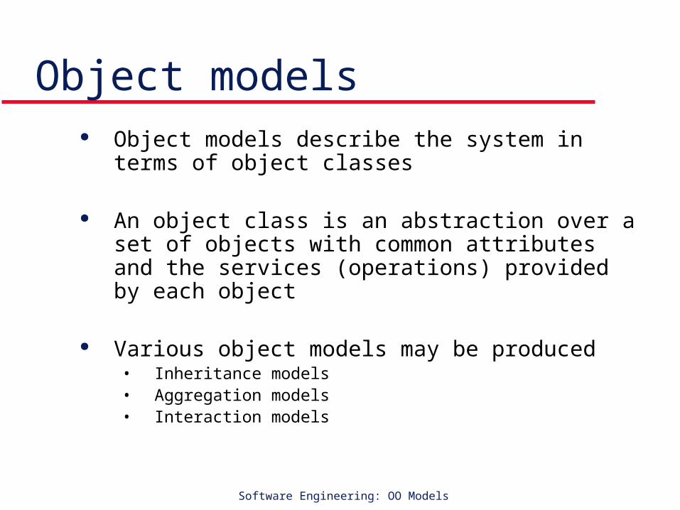
Object models Object models describe the system in terms of object
classes
An object class is an abstraction over a set of objects with common attributes and the services (operations) provided by each object
Various object models may be produced• Inheritance models• Aggregation models• Interaction models

GA Software Engineering: OO Models Slide 4
Object models Natural ways of reflecting the real-world entities
manipulated by the system
Object class identification is recognised as a difficult process requiring a deep understanding of the application domain
Object classes reflecting domain entities are reusable across systems
GA Software Engineering: OO Models Slide 5
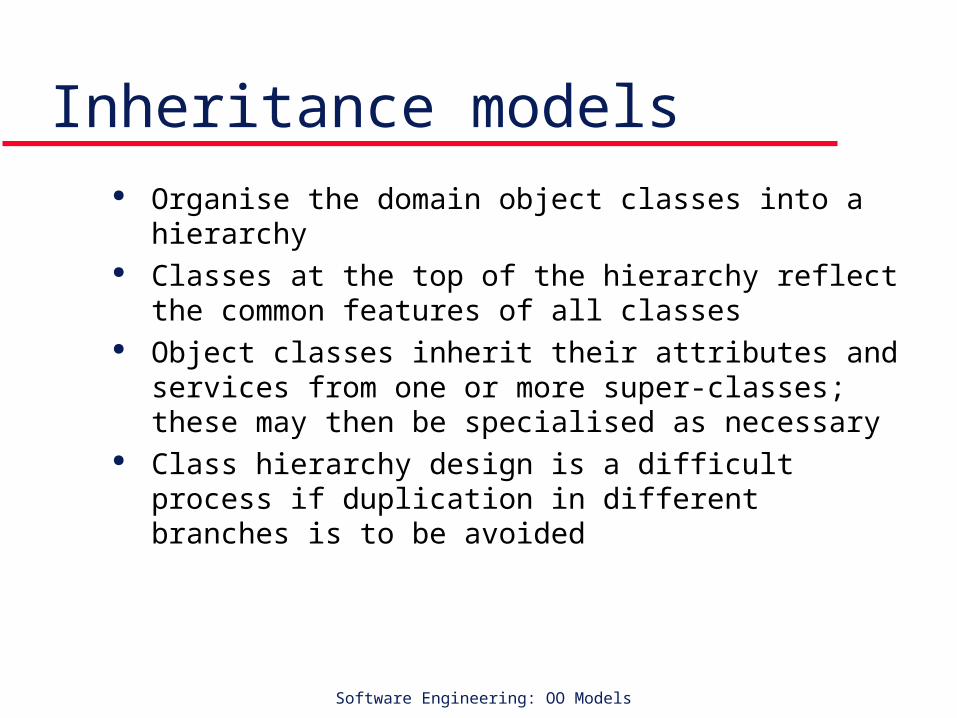
Inheritance models Organise the domain object classes into a
hierarchy Classes at the top of the hierarchy reflect the
common features of all classes Object classes inherit their attributes and services
from one or more super-classes; these may then be specialised as necessary
Class hierarchy design is a difficult process if duplication in different branches is to be avoided

GA Software Engineering: OO Models Slide 6
The Unified Modelling Language –UML
Old version: UML 1.1 Current version: UML 2.0
Devised by the developers of widely used object-oriented analysis and design methods
Has become an effective standard for object-oriented modelling

GA Software Engineering: OO Models Slide 7
UML Notation Object classes are
rectangles with the name at the top, attributes in the middle section and operations in the bottom section
Relationships between object classes (known as associations) are shown as lines linking objects
Inheritance is referred to as generalisation and is shown ‘upwards’ rather than ‘downwards’ in a hierarchy
Class
Attribute 1Attribute 2
…………
Operation1()
Operation2()
Operation3()….….
Class Name

GA Software Engineering: OO Models Slide 8
UML Diagrams Present multiple views of a system
• static and
• dynamic views
The “multiple views” is called a model.
UML model• Describes what a system is supposed to do.
• It doesn't tell how to implement the system.

GA Software Engineering: OO Models Slide 9
UML model
What is a UML model? • Multiple static & dynamic views of the UML diagram
Objective of a UML model:
• Describe WHAT a system is supposed to do.
• It doesn't tell how to implement the system.
GA Software Engineering: OO Models Slide 10
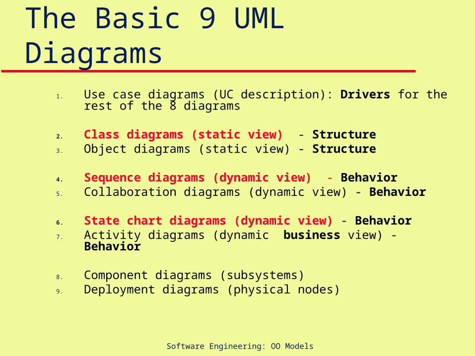
The Basic 9 UML Diagrams 1. Use case diagrams (UC description): Drivers for the rest of the 8 diagrams
2. Class diagrams (static view) - Structure3. Object diagrams (static view) - Structure 4. Sequence diagrams (dynamic view) - Behavior5. Collaboration diagrams (dynamic view) - Behavior 6. State chart diagrams (dynamic view) - Behavior 7. Activity diagrams (dynamic business view) - Behavior
8. Component diagrams (subsystems)9. Deployment diagrams (physical nodes)
GA Software Engineering: OO Models Slide 11
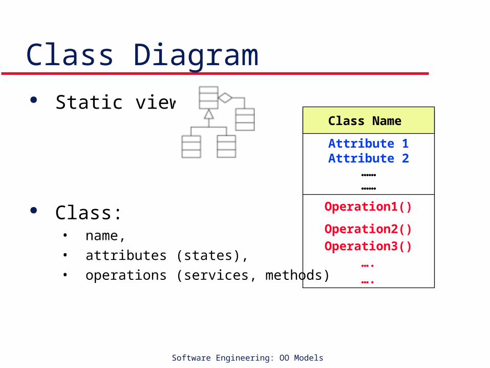
Class Diagram Static view
Class: • name,
• attributes (states),
• operations (services, methods)
Class
Attribute 1Attribute 2
…………
Operation1()
Operation2()
Operation3()….….
Class Name
GA Software Engineering: OO Models Slide 12
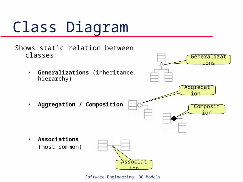
Class DiagramShows static relation between classes:
• Generalizations (inheritance, hierarchy)
• Aggregation / Composition
• Associations(most common)
Generalizations
Aggregation
Composition
Association

GA Software Engineering: OO Models Slide 13
Object diagram - Instance diagram
Static view Contains object instances instead of classes Structure similar to class diagram
Shows relationship among objects instances created at run time
Focus on the runtime instantiations of the classes
May show attribute values of the objects

GA Software Engineering: OO Models Slide 14
Object and class naming Named object
Anonymous object (any object of the same class)
or
object name : class name
: class name
: class name

GA Software Engineering: OO Models Slide 15
Sequence & Collaboration diagrams
Dynamic view (behavior)
Show the internal working of a use case scenario
Show how messages pass between objects to satisfy a use case.
Sequence Diagram

GA Software Engineering: OO Models Slide 16
State charts & Activity diagrams Dynamic views Focus on transition from one state to another Compare sequence and collaboration diagrams
where focus is on the messages that pass between objects
State charts: for simple state transition views
Activity diagrams: for more complex views

GA Software Engineering: OO Models Slide 17
Component Diagrams Help move the system from a collection of fine
grained objects to a collection of coarser-grained components
Show the relation between the system components

GA Software Engineering: OO Models Slide 18
Deployment Diagrams Show how components of the system will be
deployed to different physical nodes, or machines, in the production environment.

GA Software Engineering: OO Models Slide 19
Popular UML Tools

GA Software Engineering: OO Models Slide 20
Popular UML Tools Rational Rose (the Rose stands for "Rational Object-
oriented Software Engineering") visual modeling tool for UML • http://www.rational.com/products/rose/index.jsp
Together Control Center: Together Control Center (formerly from Togethersoft) from Borland• http://www.togethersoft.com/
Poseidon: Poseidon from Gentleware• http://www.gentleware.com/

GA Software Engineering: OO Models Slide 21
Free UML Tools Rational Rose trial for one month
• http://www.rational.com/products/rose/index.jsp
ArgoUML open source project• http://www.agrouml.tigris.org
Dia• http://hans.breuer.org/dia/
Violet tool• http://horstmann.com.violet

GA Software Engineering: OO Models Slide 22
Tools: Rational Rose Rational Rose provides support for :
• UML diagram
• forward and reverse engineering
• documentation
• and round-trip engineering
• version control
• IDE integration
• design pattern modeling
• test script generation
• and collaborative modeling environment.
GA Software Engineering: OO Models Slide 23
Tools: Together Control Center
Together Control Center supports: UML diagrams, MVC modeling, forward and reverse engineering round-trip engineering, integration with IDEs such as IBM WebSphere Studio documentation collaborative modeling environment eXtreme Programming methodologies.

GA Software Engineering: OO Models Slide 24
Tools: Poseidon for UML
Poseidon for UML Community Edition 1.5 free for individual software developers.
GA Software Engineering: OO Models Slide 25
UML & Software Engineering Forward engineering Reverse engineering Round-trip engineering
GA Software Engineering: OO Models Slide 26
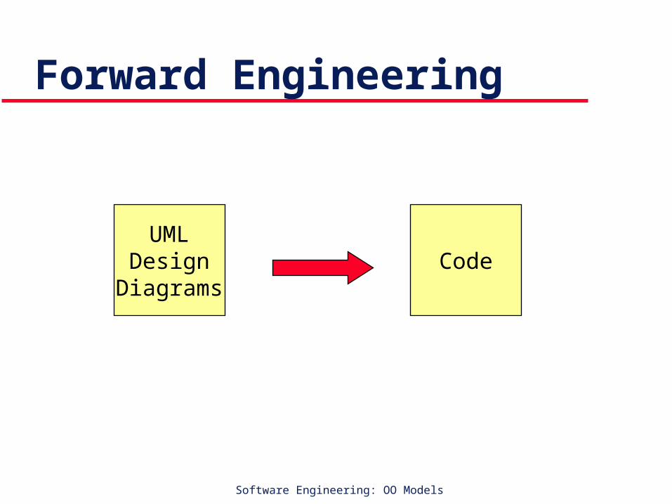
Forward Engineering
UMLDesign
DiagramsCode
GA Software Engineering: OO Models Slide 27
Forward Engineering UML tools generate the source code of the classes
(defined in the class diagram) with the methods stubbed out.
Developers can take up this stub code and fill in with the actual code.
Forward engineering support by a UML tool is normally for a specific language or a set of languages.
If you are a Java developer, verify that the UML tool that you want to use has forward engineering support for Java. Similarly, if you are a C++ developer, the UML tool should provide you forward engineering support for C++.
GA Software Engineering: OO Models Slide 28
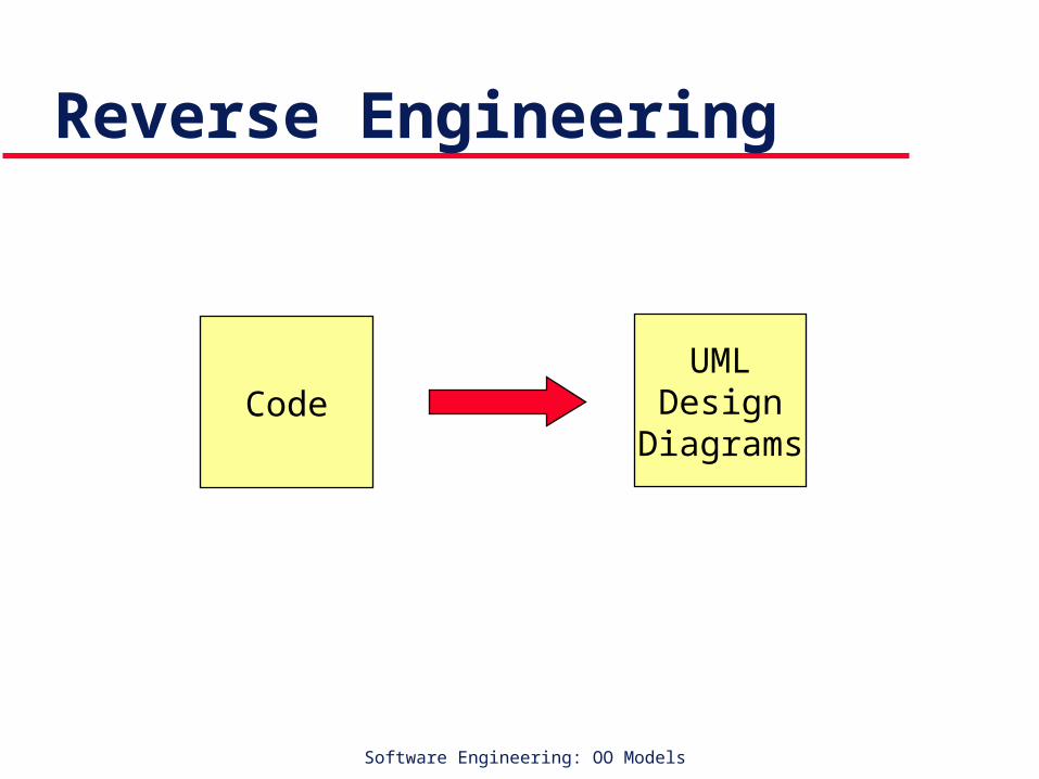
Reverse Engineering
UMLDesign
DiagramsCode

GA Software Engineering: OO Models Slide 29
Reverse Engineering Opposite of forward engineering. The UML tool loads all the files of the
application/system Reconstructs the entire application structure
along with all the relationships between the classes.
Reverse engineering is a feature normally provided by sophisticated and high-end UML tools.

GA Software Engineering: OO Models Slide 30
Round-trip Engineering
Initial Design Initial CodeForward Eng
Reverse Eng Updated Code
Maintenance
Synchronize Design
GA Software Engineering: OO Models Slide 31
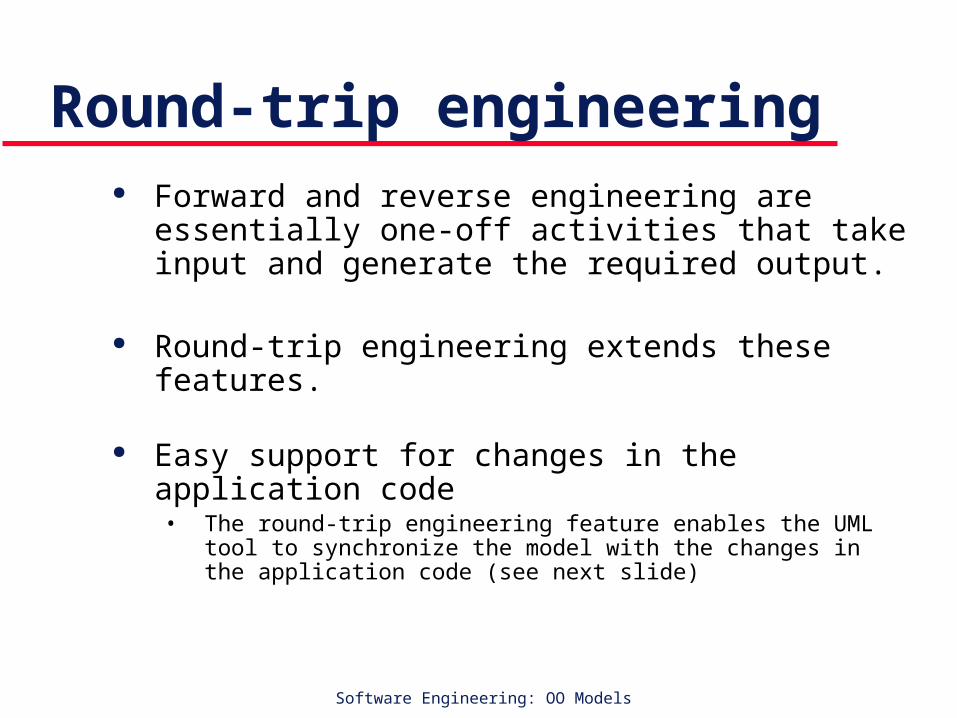
Round-trip engineering Forward and reverse engineering are essentially
one-off activities that take input and generate the required output.
Round-trip engineering extends these features.
Easy support for changes in the application code • The round-trip engineering feature enables the UML tool to
synchronize the model with the changes in the application code (see next slide)

GA Software Engineering: OO Models Slide 32
Round-trip engineering No design remains unchanged. During development, the design structure (defined in the
UML model) does undergo changes to incorporate physical differences in implementation that may not have been envisaged during design.
It becomes very difficult to keep the design of the system updated with the changes in the source code.
The round-trip engineering feature enables the UML tool to synchronize the model with the changes in the application code.
GA Software Engineering: OO Models Slide 33
OO Engineering OOA - Analysis OOD - Design OO Implementation OO Testing

GA Software Engineering: OO Models Slide 34
OO Analysis Activities Use case analysis
• Mostly focused on writing text -one overview context diagram is often enough• Use cases are just a part of functional requirements (only the interactive ones)
Structural analysis ‘domain modeling’• Finding the “real-world” objects involved in the use cases and creating class
diagrams to represent them
Behavioral analysis• Creating activity diagrams and sequence diagrams to capture use case details• Activity diagrams for business workflow• System sequence diagrams for reactive behavior (also with timing)• Possibly creating state charts to capture external reactive behavior of the system
and other domain objects
GA Software Engineering: OO Models Slide 35
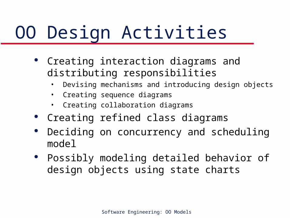
OO Design Activities Creating interaction diagrams and distributing
responsibilities• Devising mechanisms and introducing design objects
• Creating sequence diagrams
• Creating collaboration diagrams
Creating refined class diagrams Deciding on concurrency and scheduling model Possibly modeling detailed behavior of design
objects using state charts
Related Documents