1 2018 Users’ Group Conference Users’ Group Conference 2018 Rocky Auterson Equipment Analyst, Windrock, Inc. Magnetic Pickup Verification

Welcome message from author
This document is posted to help you gain knowledge. Please leave a comment to let me know what you think about it! Share it to your friends and learn new things together.
Transcript

1 2018 Users’ Group Conference
Users’ Group Conference 2018
Rocky AutersonEquipment Analyst, Windrock, Inc.
Magnetic Pickup Verification

2 2018 Users’ Group Conference
Magnetic Pickup VerificationSetup and verification of signal strength
3 2018 Users’ Group Conference
Magnetic Pickup Verification
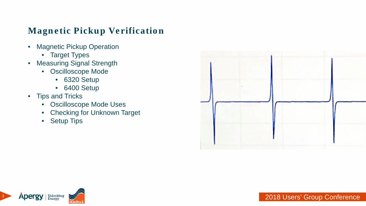
• Magnetic Pickup Operation• Target Types
• Measuring Signal Strength• Oscilloscope Mode
• 6320 Setup• 6400 Setup
• Tips and Tricks• Oscilloscope Mode Uses• Checking for Unknown Target• Setup Tips
4 2018 Users’ Group Conference
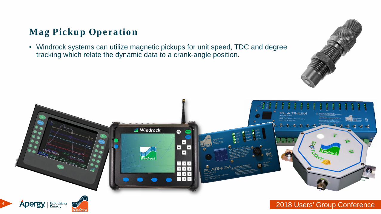
Mag Pickup Operation• Windrock systems can utilize magnetic pickups for unit speed, TDC and degree
tracking which relate the dynamic data to a crank-angle position.
5 2018 Users’ Group Conference
Mag Pickup Operation
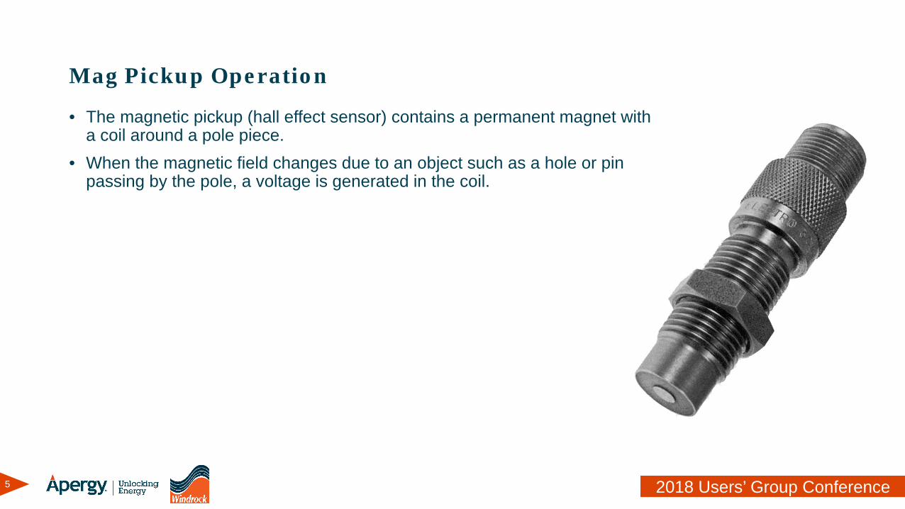
• The magnetic pickup (hall effect sensor) contains a permanent magnet with a coil around a pole piece.
• When the magnetic field changes due to an object such as a hole or pin passing by the pole, a voltage is generated in the coil.
6 2018 Users’ Group Conference
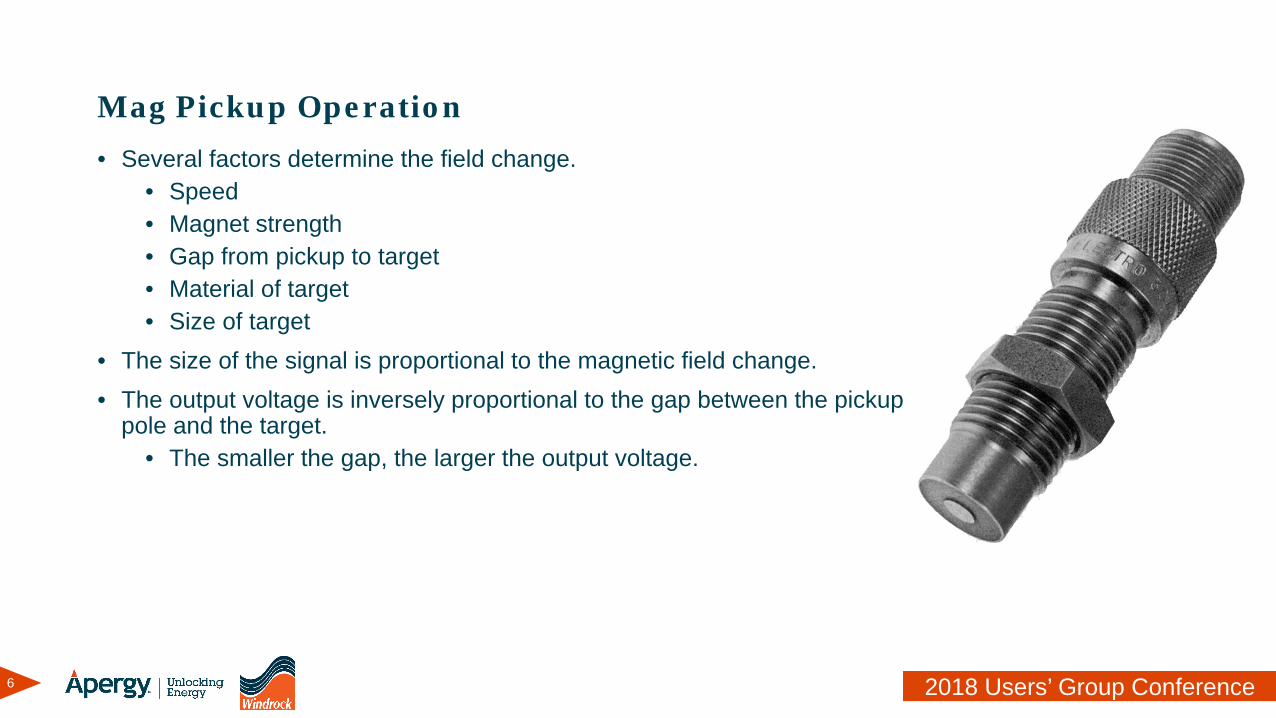
Mag Pickup Operation• Several factors determine the field change.
• Speed• Magnet strength• Gap from pickup to target• Material of target• Size of target
• The size of the signal is proportional to the magnetic field change.• The output voltage is inversely proportional to the gap between the pickup
pole and the target.• The smaller the gap, the larger the output voltage.
7 2018 Users’ Group Conference
Mag Pickup Operation
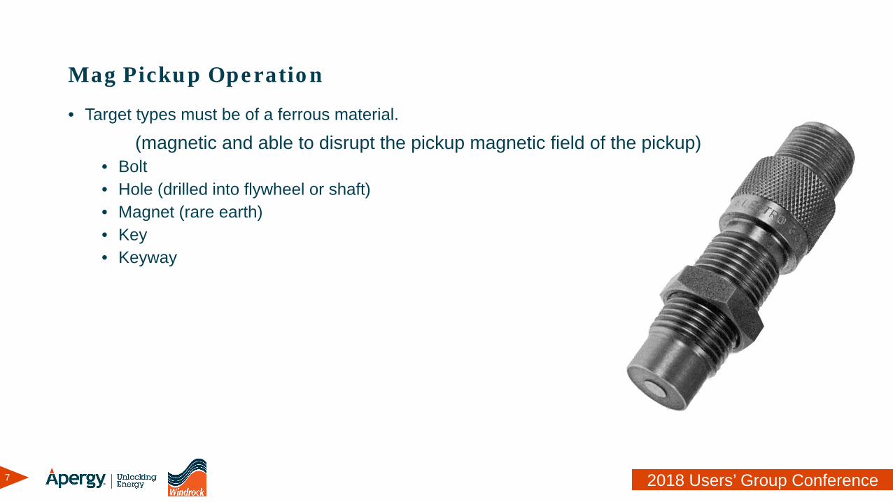
• Target types must be of a ferrous material.
(magnetic and able to disrupt the pickup magnetic field of the pickup)• Bolt • Hole (drilled into flywheel or shaft)• Magnet (rare earth)• Key• Keyway
8 2018 Users’ Group Conference
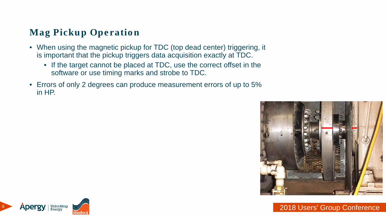
Mag Pickup Operation• When using the magnetic pickup for TDC (top dead center) triggering, it
is important that the pickup triggers data acquisition exactly at TDC.• If the target cannot be placed at TDC, use the correct offset in the
software or use timing marks and strobe to TDC.• Errors of only 2 degrees can produce measurement errors of up to 5%
in HP.
9 2018 Users’ Group Conference
Mag Pickup Operation
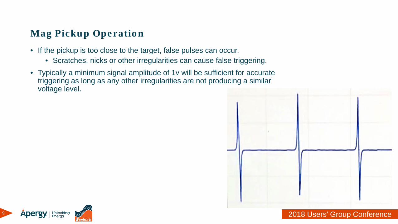
• If the pickup is too close to the target, false pulses can occur.• Scratches, nicks or other irregularities can cause false triggering.
• Typically a minimum signal amplitude of 1v will be sufficient for accurate triggering as long as any other irregularities are not producing a similar voltage level.
10 2018 Users’ Group Conference
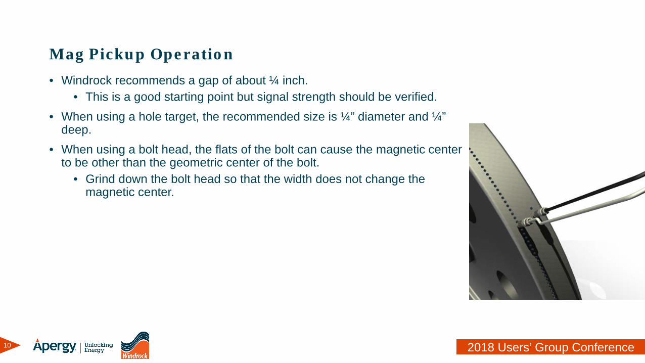
Mag Pickup Operation• Windrock recommends a gap of about ¼ inch.
• This is a good starting point but signal strength should be verified.• When using a hole target, the recommended size is ¼” diameter and ¼”
deep.• When using a bolt head, the flats of the bolt can cause the magnetic center
to be other than the geometric center of the bolt.• Grind down the bolt head so that the width does not change the
magnetic center.

11 2018 Users’ Group Conference
Measuring Signal Strength with the 6320
12 2018 Users’ Group Conference
Measuring Signal Strength with the 6320
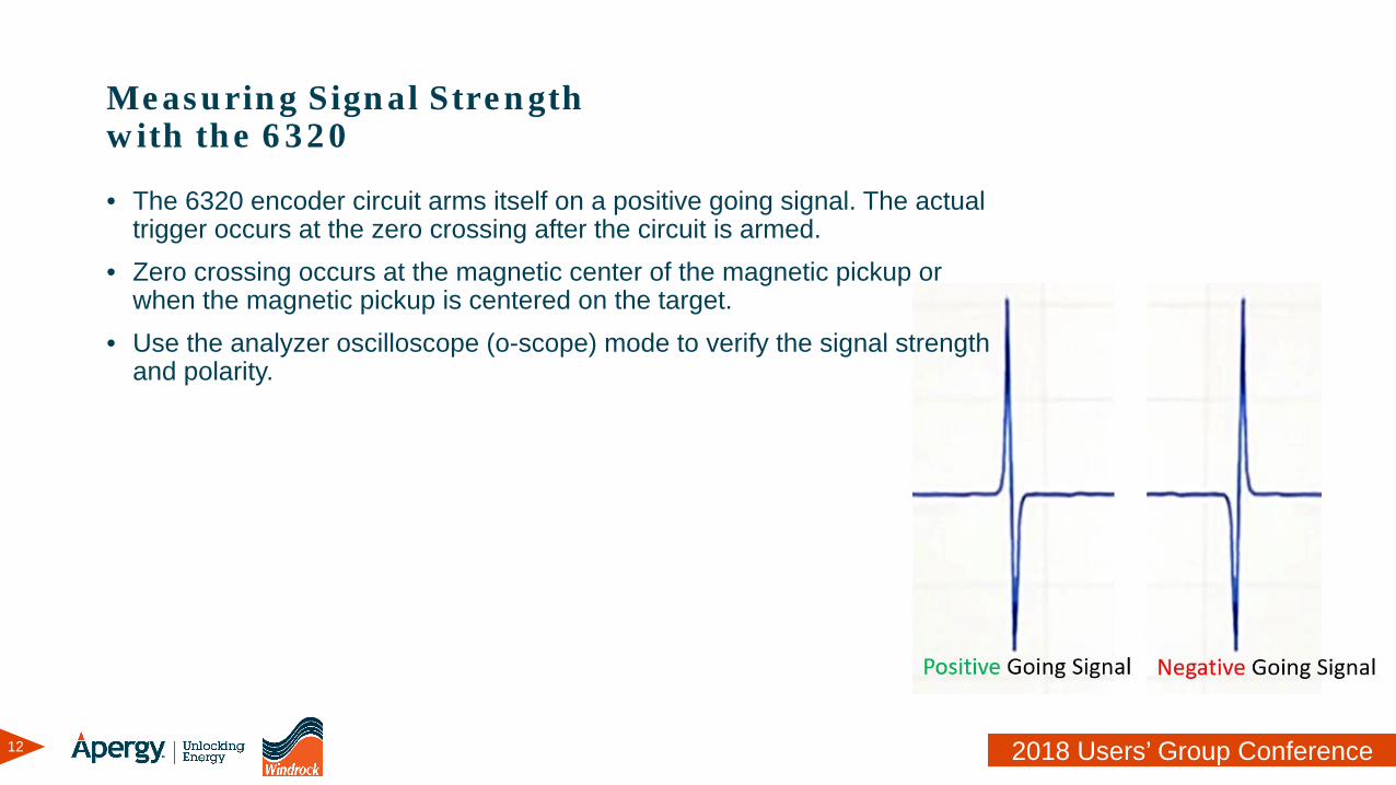
• The 6320 encoder circuit arms itself on a positive going signal. The actual trigger occurs at the zero crossing after the circuit is armed.
• Zero crossing occurs at the magnetic center of the magnetic pickup or when the magnetic pickup is centered on the target.
• Use the analyzer oscilloscope (o-scope) mode to verify the signal strength and polarity.
13 2018 Users’ Group Conference
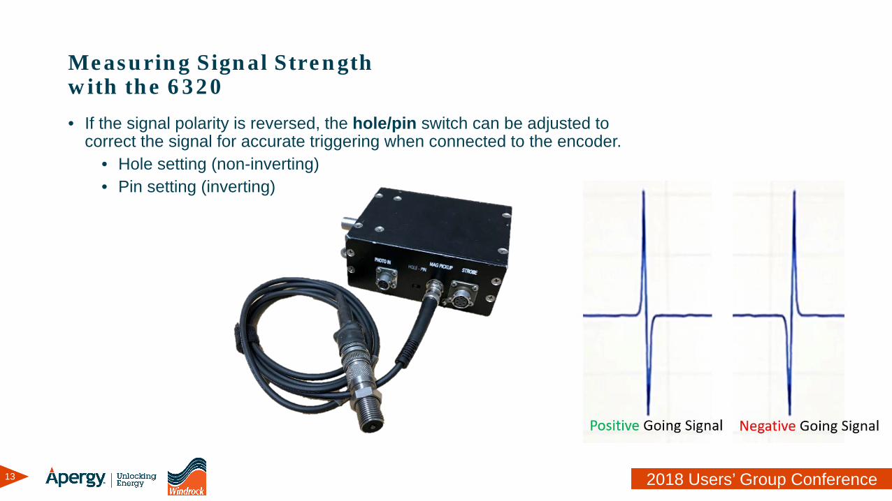
Measuring Signal Strength with the 6320• If the signal polarity is reversed, the hole/pin switch can be adjusted to
correct the signal for accurate triggering when connected to the encoder.• Hole setting (non-inverting)• Pin setting (inverting)
14 2018 Users’ Group Conference
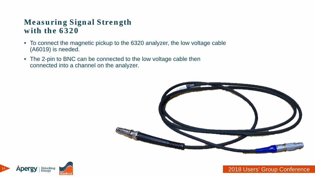
Measuring Signal Strength with the 6320• To connect the magnetic pickup to the 6320 analyzer, the low voltage cable
(A6019) is needed.• The 2-pin to BNC can be connected to the low voltage cable then
connected into a channel on the analyzer.
15 2018 Users’ Group Conference
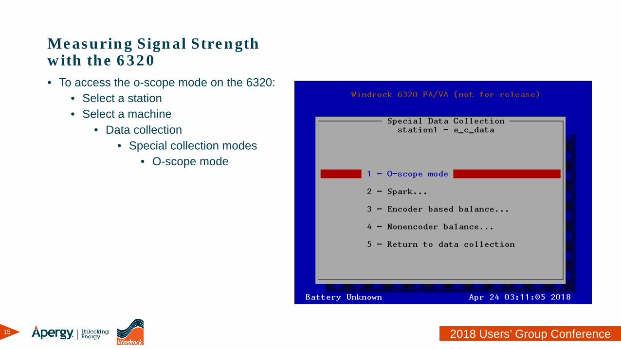
Measuring Signal Strength with the 6320• To access the o-scope mode on the 6320:
• Select a station• Select a machine
• Data collection• Special collection modes
• O-scope mode
16 2018 Users’ Group Conference
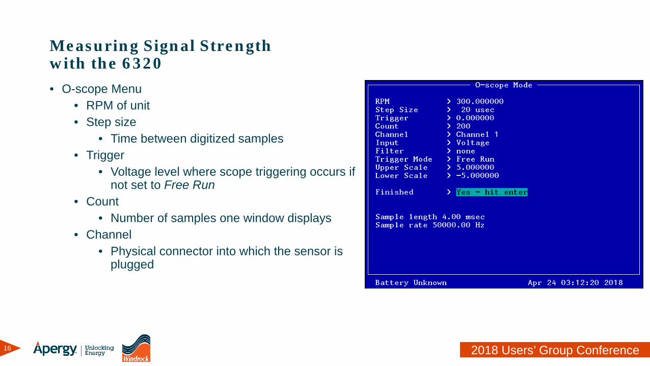
Measuring Signal Strength with the 6320• O-scope Menu
• RPM of unit• Step size
• Time between digitized samples• Trigger
• Voltage level where scope triggering occurs if not set to Free Run
• Count• Number of samples one window displays
• Channel• Physical connector into which the sensor is
plugged
17 2018 Users’ Group Conference
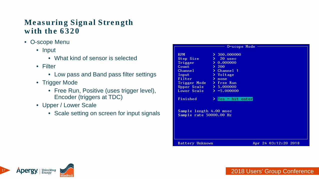
Measuring Signal Strength with the 6320• O-scope Menu
• Input• What kind of sensor is selected
• Filter• Low pass and Band pass filter settings
• Trigger Mode• Free Run, Positive (uses trigger level),
Encoder (triggers at TDC)• Upper / Lower Scale
• Scale setting on screen for input signals
18 2018 Users’ Group Conference
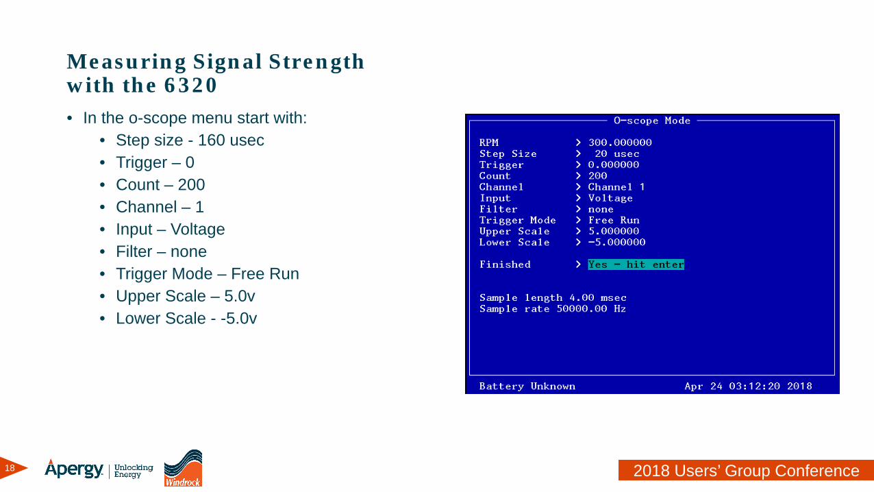
Measuring Signal Strength with the 6320• In the o-scope menu start with:
• Step size - 160 usec• Trigger – 0• Count – 200• Channel – 1• Input – Voltage• Filter – none• Trigger Mode – Free Run• Upper Scale – 5.0v• Lower Scale - -5.0v
19 2018 Users’ Group Conference
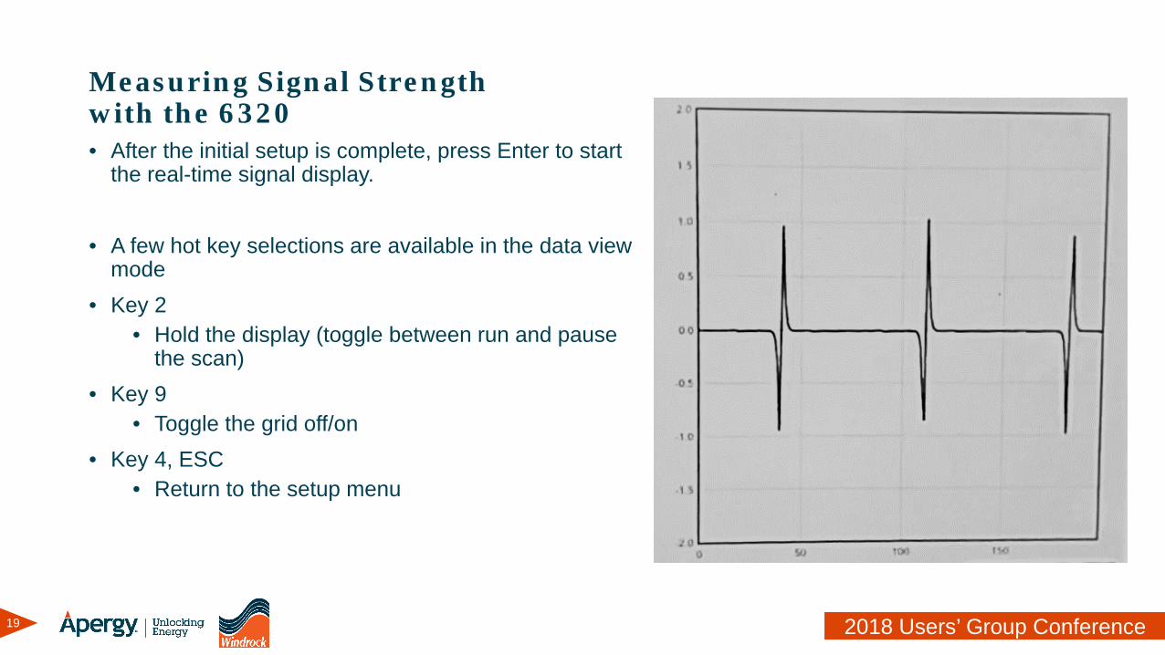
Measuring Signal Strength with the 6320• After the initial setup is complete, press Enter to start
the real-time signal display.
• A few hot key selections are available in the data view mode
• Key 2• Hold the display (toggle between run and pause
the scan)• Key 9
• Toggle the grid off/on• Key 4, ESC
• Return to the setup menu
20 2018 Users’ Group Conference
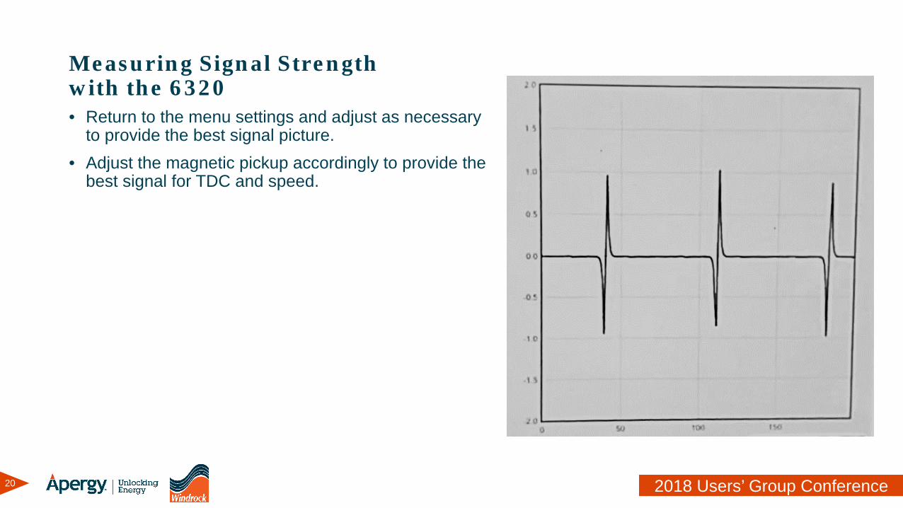
Measuring Signal Strength with the 6320• Return to the menu settings and adjust as necessary
to provide the best signal picture.• Adjust the magnetic pickup accordingly to provide the
best signal for TDC and speed.
21 2018 Users’ Group Conference
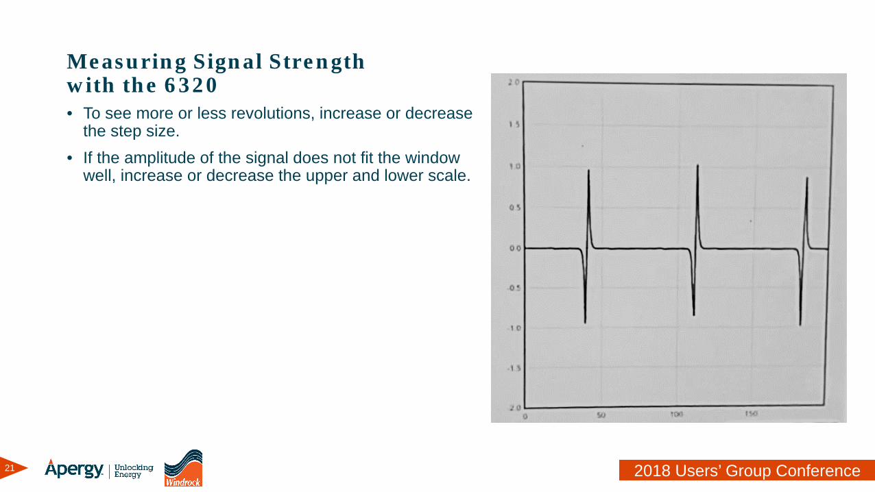
Measuring Signal Strength with the 6320• To see more or less revolutions, increase or decrease
the step size.• If the amplitude of the signal does not fit the window
well, increase or decrease the upper and lower scale.
22 2018 Users’ Group Conference
Measuring Signal Strength with the 6400
23 2018 Users’ Group Conference
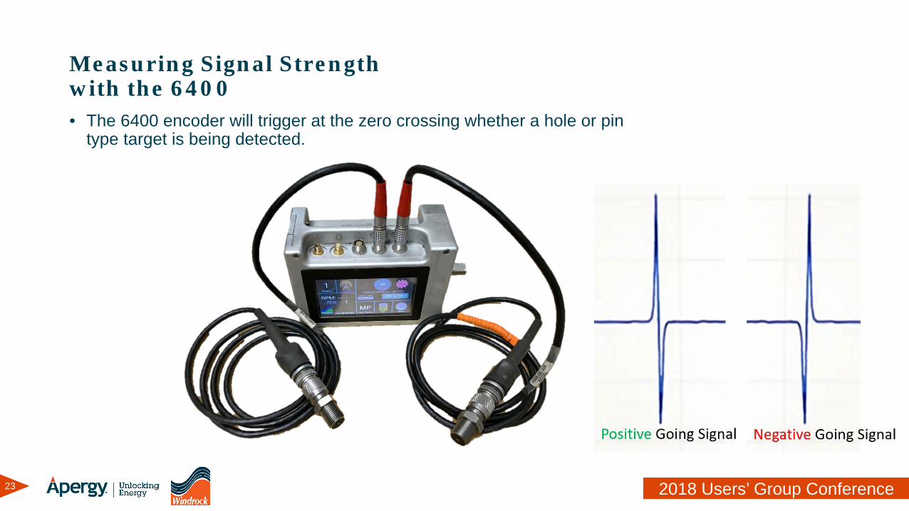
Measuring Signal Strength with the 6400• The 6400 encoder will trigger at the zero crossing whether a hole or pin
type target is being detected.
24 2018 Users’ Group Conference
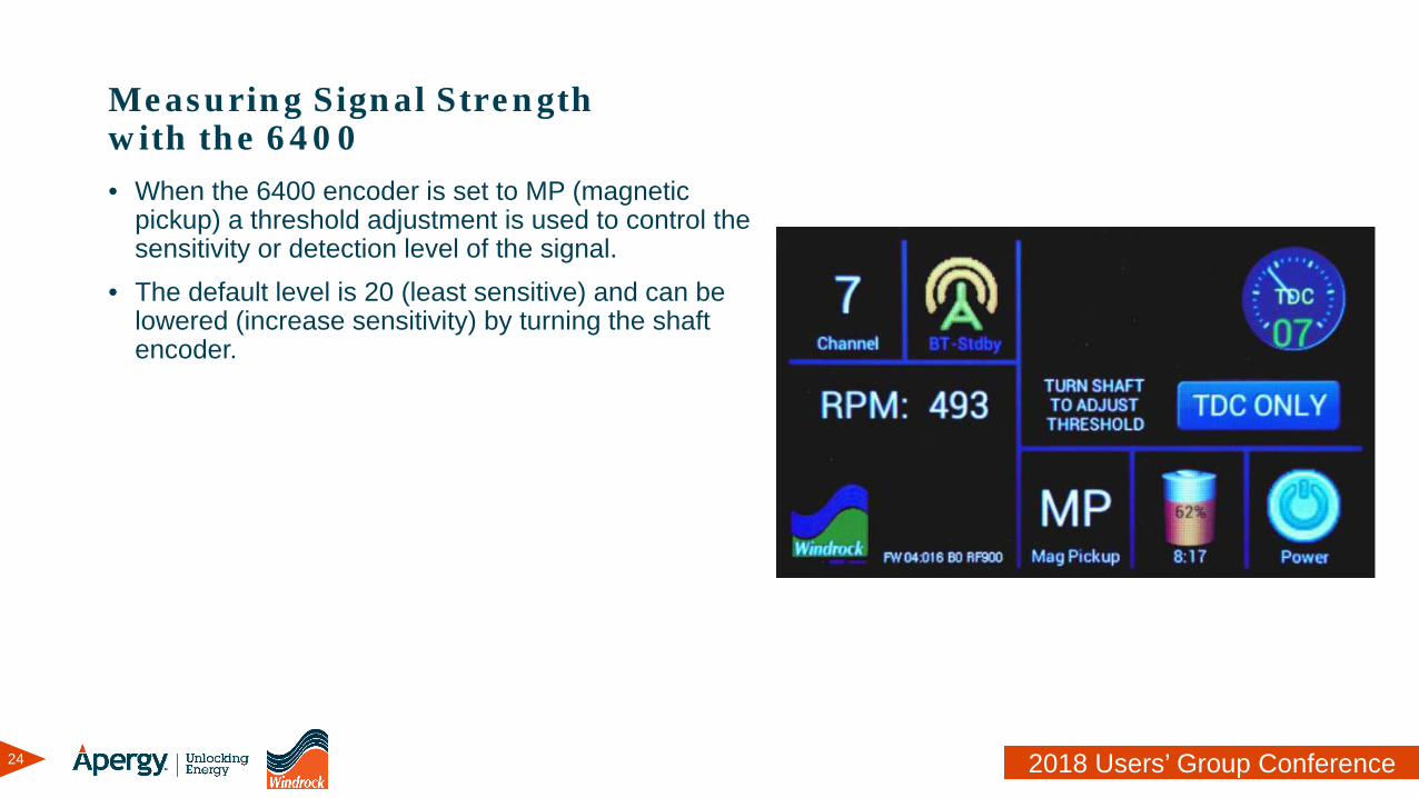
Measuring Signal Strength with the 6400• When the 6400 encoder is set to MP (magnetic
pickup) a threshold adjustment is used to control the sensitivity or detection level of the signal.
• The default level is 20 (least sensitive) and can be lowered (increase sensitivity) by turning the shaft encoder.
25 2018 Users’ Group Conference
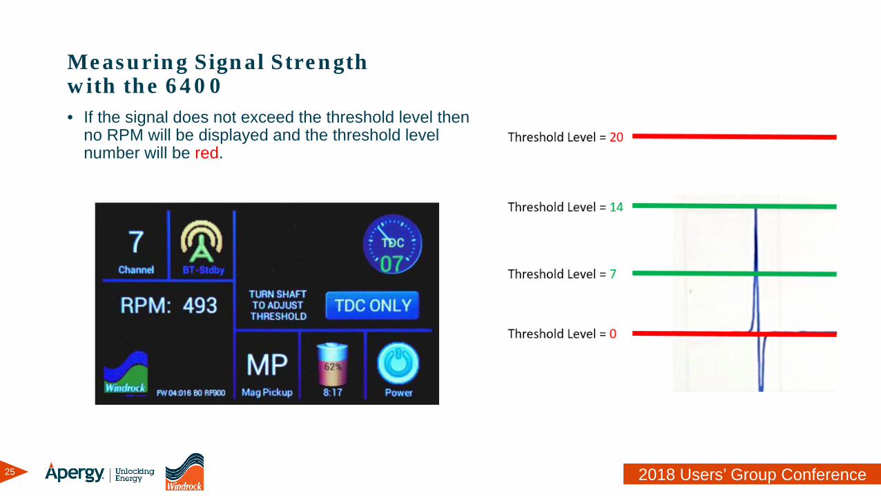
Measuring Signal Strength with the 6400• If the signal does not exceed the threshold level then
no RPM will be displayed and the threshold level number will be red.
26 2018 Users’ Group Conference
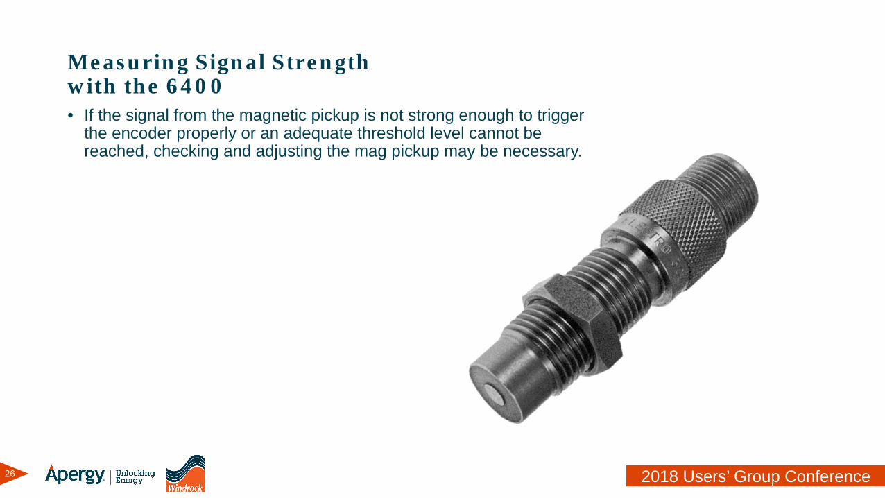
Measuring Signal Strength with the 6400• If the signal from the magnetic pickup is not strong enough to trigger
the encoder properly or an adequate threshold level cannot be reached, checking and adjusting the mag pickup may be necessary.
27 2018 Users’ Group Conference
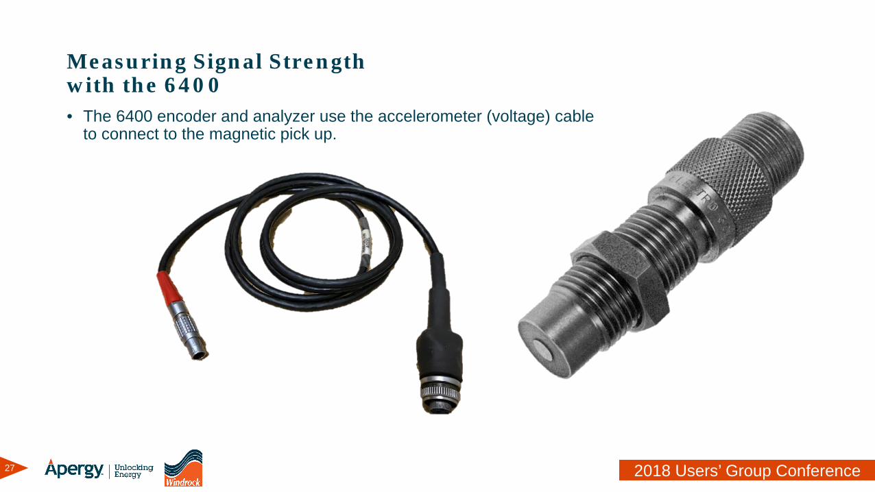
Measuring Signal Strength with the 6400• The 6400 encoder and analyzer use the accelerometer (voltage) cable
to connect to the magnetic pick up.
28 2018 Users’ Group Conference
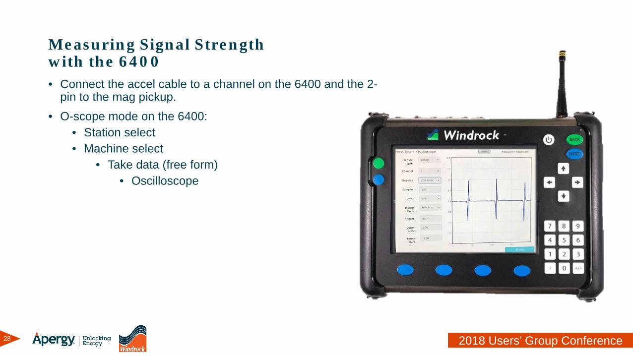
Measuring Signal Strength with the 6400• Connect the accel cable to a channel on the 6400 and the 2-
pin to the mag pickup.• O-scope mode on the 6400:
• Station select• Machine select
• Take data (free form)• Oscilloscope
29 2018 Users’ Group Conference
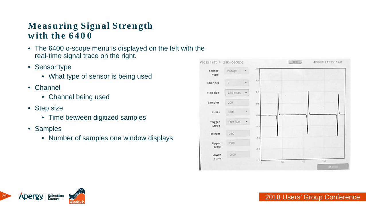
Measuring Signal Strength with the 6400• The 6400 o-scope menu is displayed on the left with the
real-time signal trace on the right.• Sensor type
• What type of sensor is being used• Channel
• Channel being used• Step size
• Time between digitized samples• Samples
• Number of samples one window displays
30 2018 Users’ Group Conference
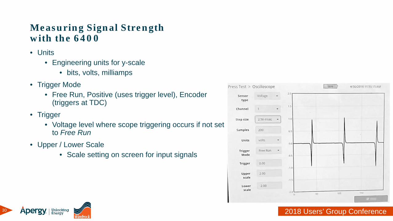
Measuring Signal Strength with the 6400• Units
• Engineering units for y-scale • bits, volts, milliamps
• Trigger Mode• Free Run, Positive (uses trigger level), Encoder
(triggers at TDC)• Trigger
• Voltage level where scope triggering occurs if not set to Free Run
• Upper / Lower Scale• Scale setting on screen for input signals
31 2018 Users’ Group Conference
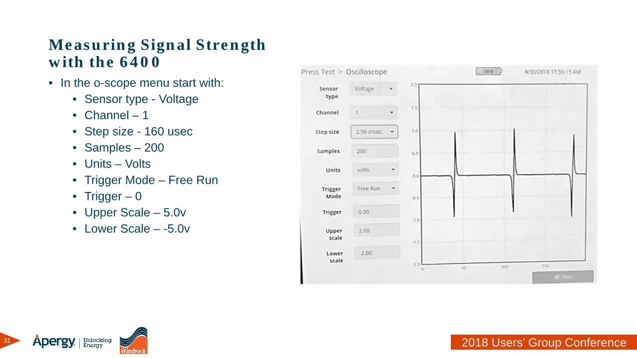
Measuring Signal Strength with the 6400• In the o-scope menu start with:
• Sensor type - Voltage• Channel – 1• Step size - 160 usec• Samples – 200• Units – Volts• Trigger Mode – Free Run• Trigger – 0• Upper Scale – 5.0v• Lower Scale – -5.0v
32 2018 Users’ Group Conference
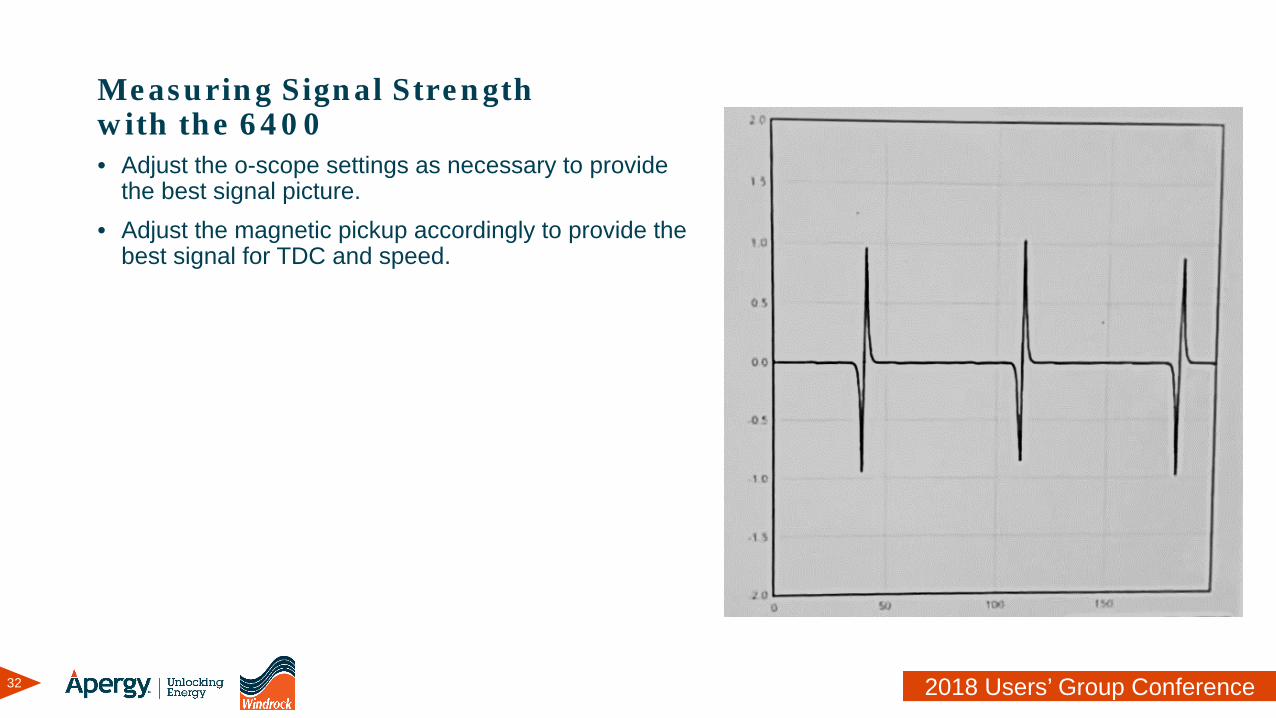
Measuring Signal Strength with the 6400• Adjust the o-scope settings as necessary to provide
the best signal picture.• Adjust the magnetic pickup accordingly to provide the
best signal for TDC and speed.

33 2018 Users’ Group Conference
Magnetic Pickup VerificationTips and Tricks
34 2018 Users’ Group Conference
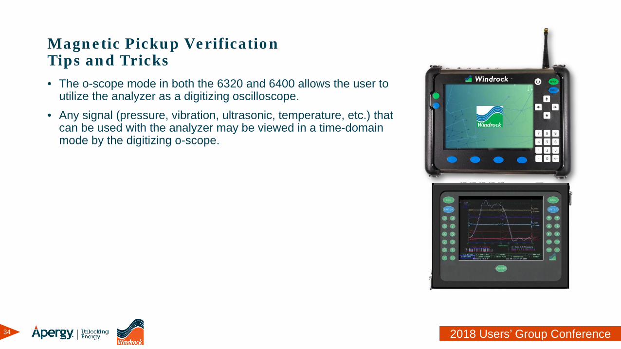
Magnetic Pickup VerificationTips and Tricks• The o-scope mode in both the 6320 and 6400 allows the user to
utilize the analyzer as a digitizing oscilloscope.• Any signal (pressure, vibration, ultrasonic, temperature, etc.) that
can be used with the analyzer may be viewed in a time-domain mode by the digitizing o-scope.
35 2018 Users’ Group Conference
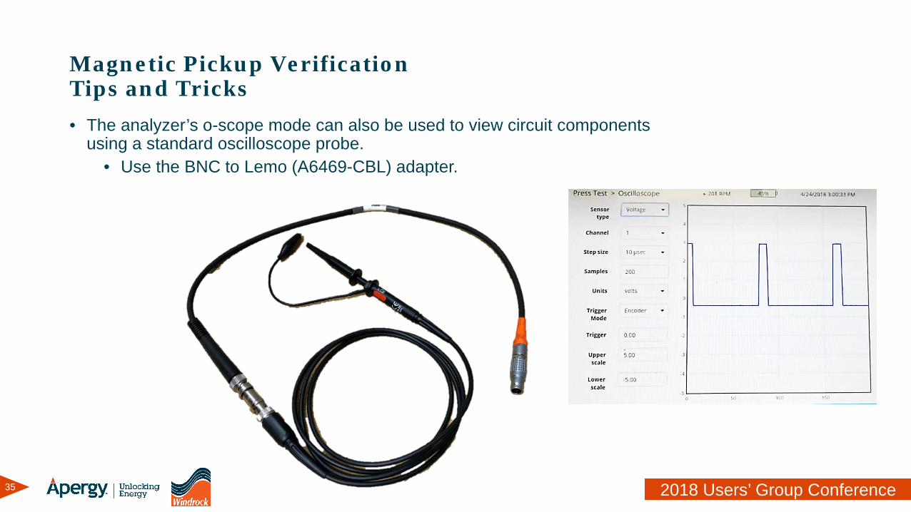
Magnetic Pickup VerificationTips and Tricks• The analyzer’s o-scope mode can also be used to view circuit components
using a standard oscilloscope probe.• Use the BNC to Lemo (A6469-CBL) adapter.
36 2018 Users’ Group Conference
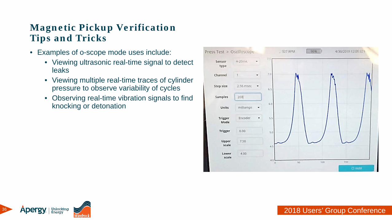
Magnetic Pickup VerificationTips and Tricks• Examples of o-scope mode uses include:
• Viewing ultrasonic real-time signal to detect leaks
• Viewing multiple real-time traces of cylinder pressure to observe variability of cycles
• Observing real-time vibration signals to find knocking or detonation
37 2018 Users’ Group Conference
Magnetic Pickup VerificationTips and Tricks• Over time metal debris can attach to the end of the mag pickup causing the signal
quality to degrade.• Check the mag pickup periodically for cleanliness
• If the unit is running and the pickup can safely be accessed, use an approved aerosol degreaser or cleaner to spray the pole end of the pickup to dislodge any foreign debris.
• If the unit is not running, clean the mag pickup and the target to remove any possible debris.
38 2018 Users’ Group Conference
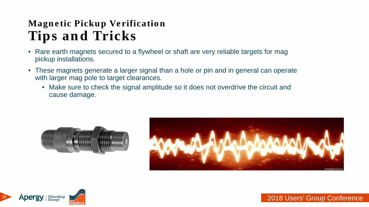
Magnetic Pickup VerificationTips and Tricks• Rare earth magnets secured to a flywheel or shaft are very reliable targets for mag
pickup installations.• These magnets generate a larger signal than a hole or pin and in general can operate
with larger mag pole to target clearances.• Make sure to check the signal amplitude so it does not overdrive the circuit and
cause damage.
39 2018 Users’ Group Conference
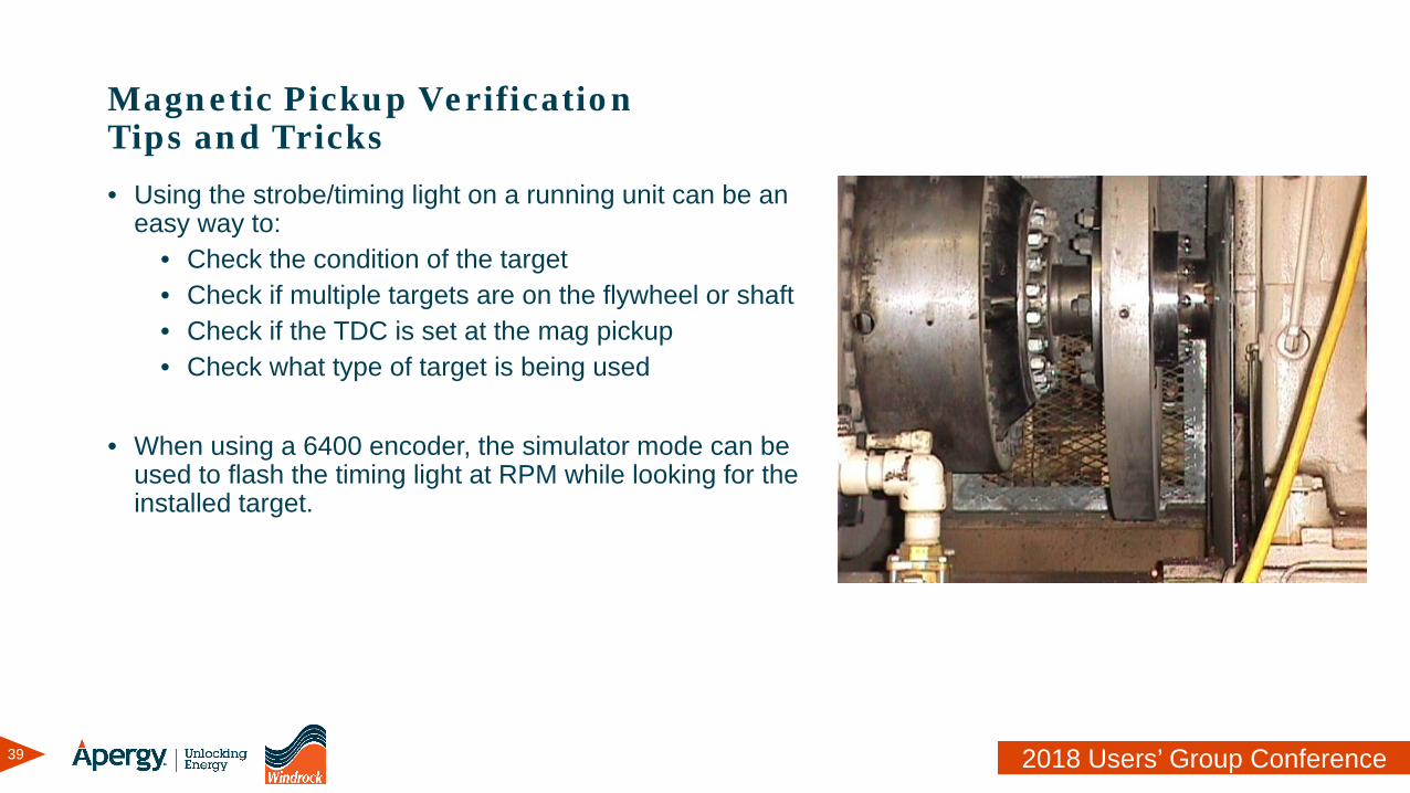
Magnetic Pickup VerificationTips and Tricks• Using the strobe/timing light on a running unit can be an
easy way to:• Check the condition of the target• Check if multiple targets are on the flywheel or shaft• Check if the TDC is set at the mag pickup• Check what type of target is being used
• When using a 6400 encoder, the simulator mode can be used to flash the timing light at RPM while looking for the installed target.
40 2018 Users’ Group Conference
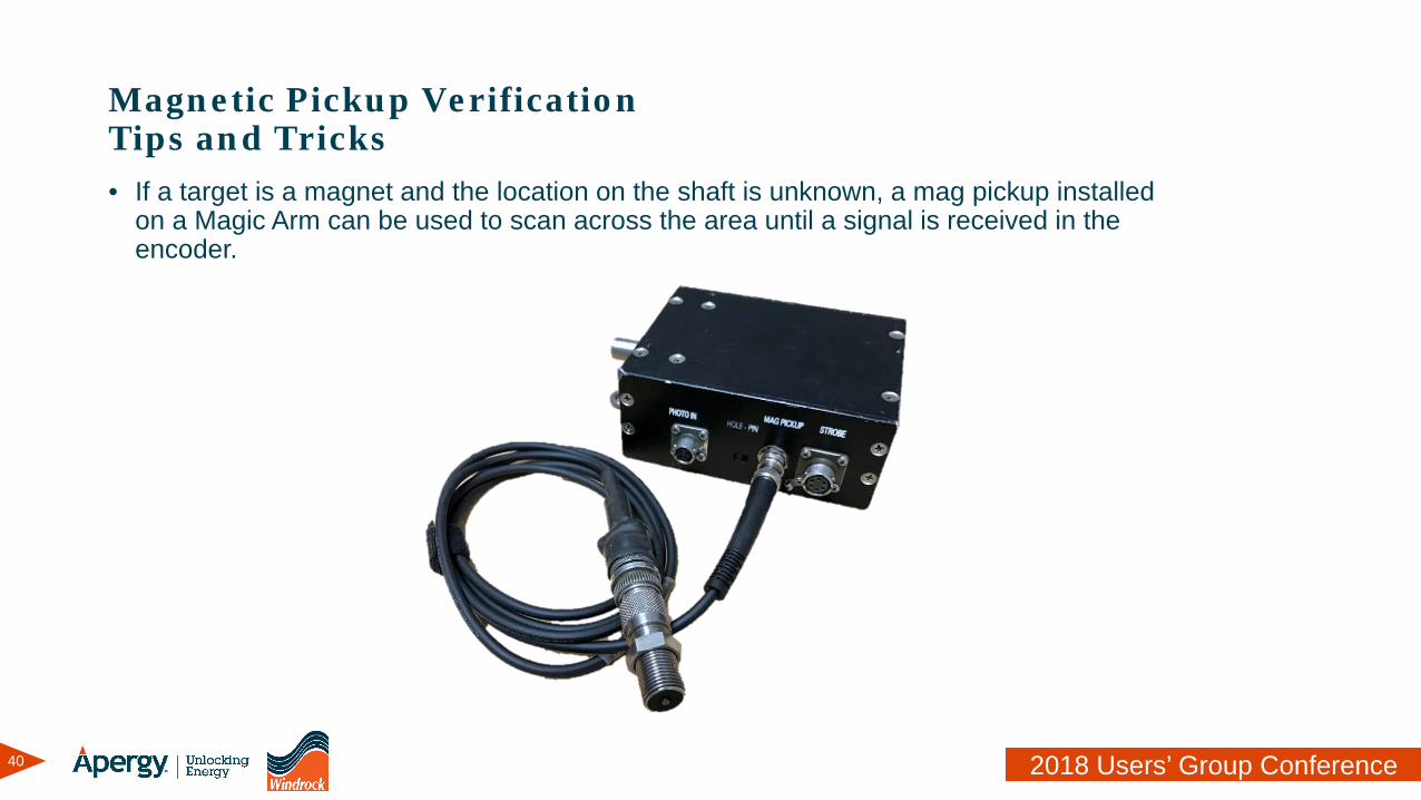
Magnetic Pickup VerificationTips and Tricks• If a target is a magnet and the location on the shaft is unknown, a mag pickup installed
on a Magic Arm can be used to scan across the area until a signal is received in the encoder.
41 2018 Users’ Group Conference
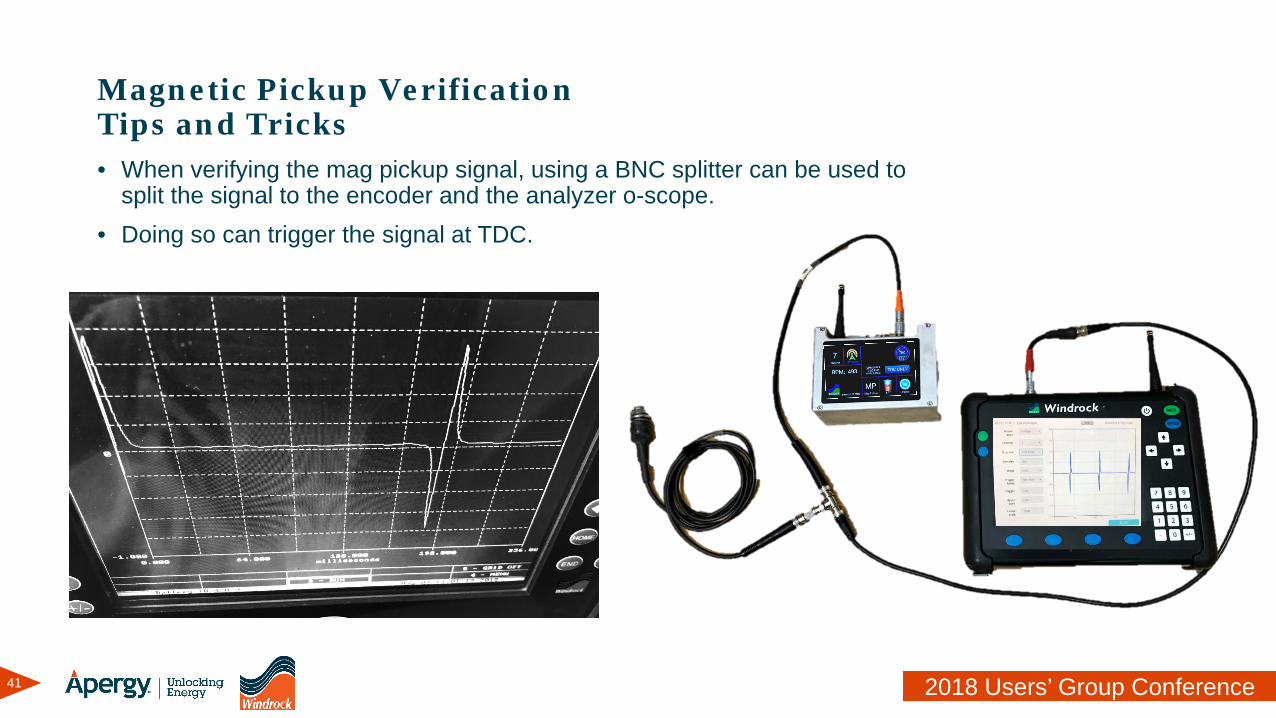
Magnetic Pickup VerificationTips and Tricks• When verifying the mag pickup signal, using a BNC splitter can be used to
split the signal to the encoder and the analyzer o-scope.• Doing so can trigger the signal at TDC.
42 2018 Users’ Group Conference
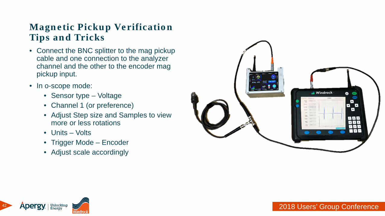
Magnetic Pickup VerificationTips and Tricks• Connect the BNC splitter to the mag pickup
cable and one connection to the analyzer channel and the other to the encoder mag pickup input.
• In o-scope mode:• Sensor type – Voltage• Channel 1 (or preference)• Adjust Step size and Samples to view
more or less rotations• Units – Volts• Trigger Mode – Encoder• Adjust scale accordingly
43 2018 Users’ Group Conference
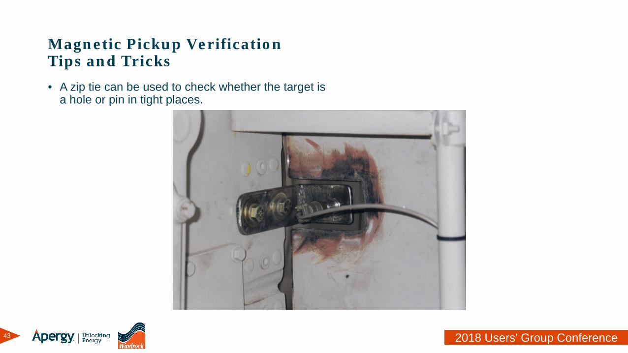
Magnetic Pickup VerificationTips and Tricks• A zip tie can be used to check whether the target is
a hole or pin in tight places.
44 2018 Users’ Group Conference
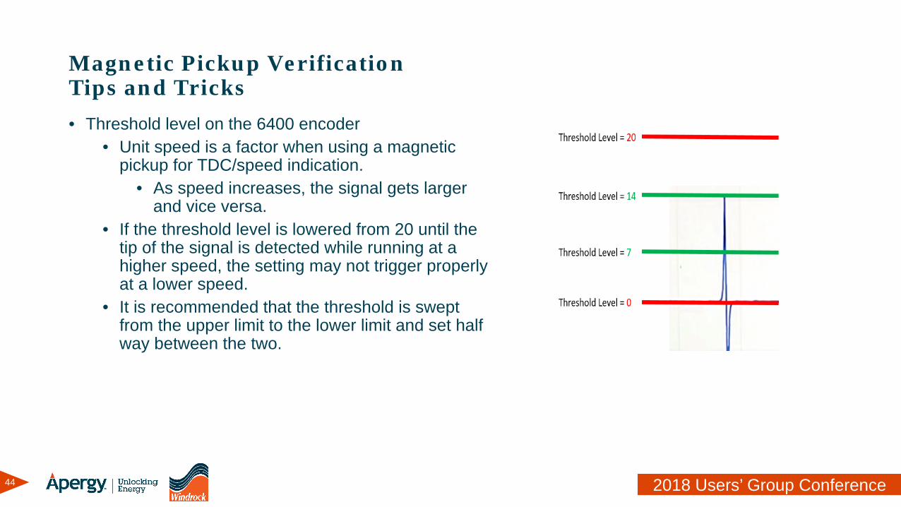
Magnetic Pickup VerificationTips and Tricks• Threshold level on the 6400 encoder
• Unit speed is a factor when using a magnetic pickup for TDC/speed indication.
• As speed increases, the signal gets larger and vice versa.
• If the threshold level is lowered from 20 until the tip of the signal is detected while running at a higher speed, the setting may not trigger properly at a lower speed.
• It is recommended that the threshold is swept from the upper limit to the lower limit and set half way between the two.
45 2018 Users’ Group Conference
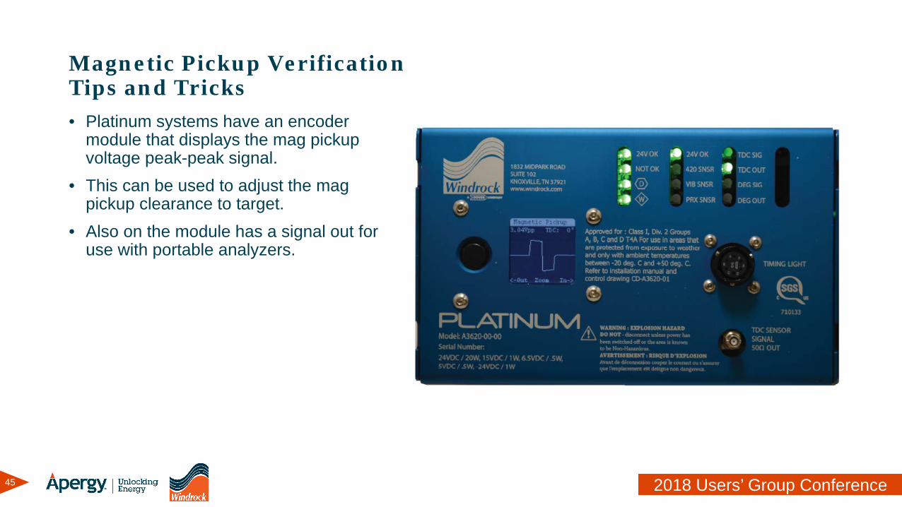
Magnetic Pickup VerificationTips and Tricks• Platinum systems have an encoder
module that displays the mag pickup voltage peak-peak signal.
• This can be used to adjust the mag pickup clearance to target.
• Also on the module has a signal out for use with portable analyzers.
46 2018 Users’ Group Conference
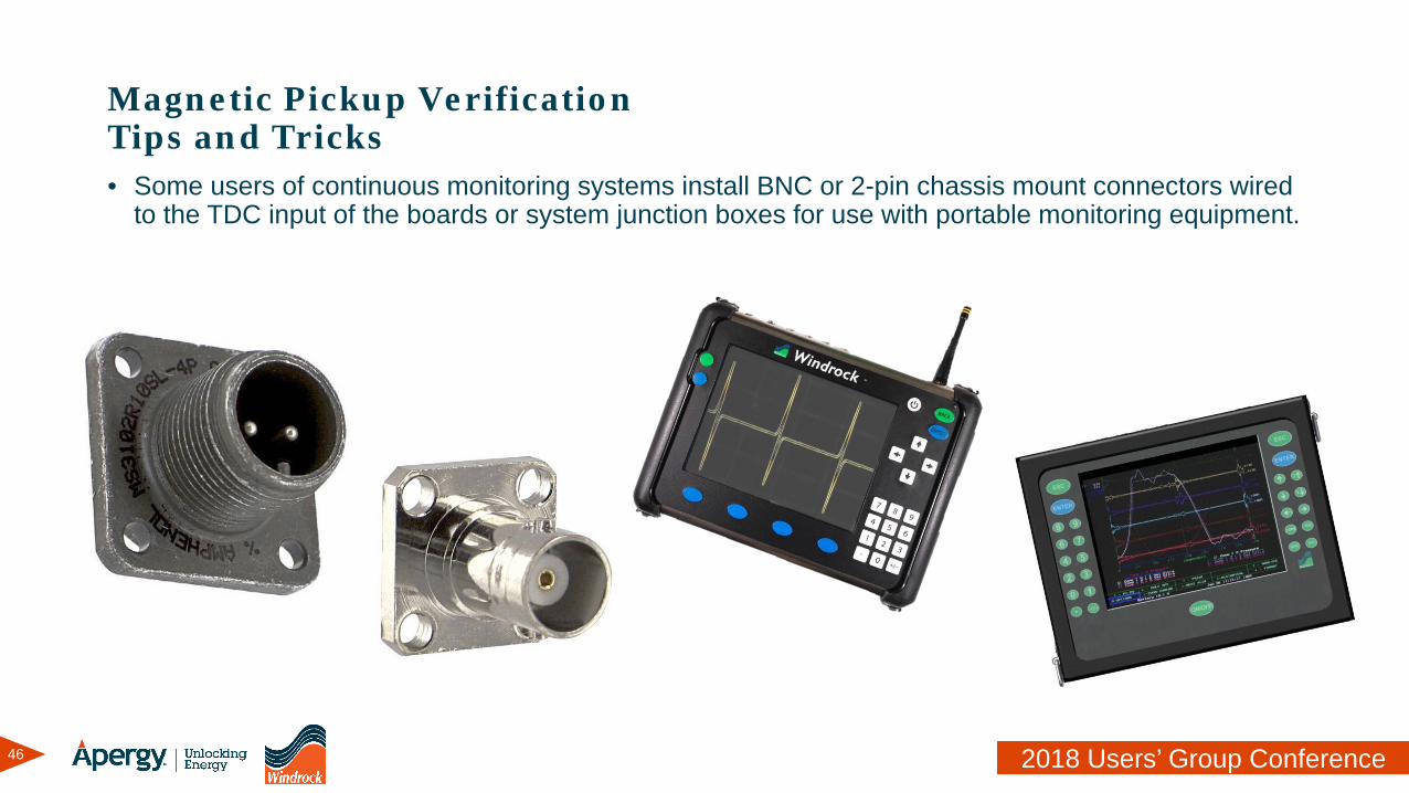
Magnetic Pickup VerificationTips and Tricks• Some users of continuous monitoring systems install BNC or 2-pin chassis mount connectors wired
to the TDC input of the boards or system junction boxes for use with portable monitoring equipment.

47 2018 Users’ Group Conference
Magnetic Pickup Verification• Don’t forget to always stay safe when working around moving and rotating equipment!

48 2018 Users’ Group Conference
Thank You
Related Documents