OVERVIEW & SITE PREPARATION GUIDE Thank you for purchasing the Windrock Spotlight Compressor Monitoring System. This guide is intended to help customers prepare for the install several weeks prior to receiving their order. 1 Overview Windrock Spotlight represents the latest generation of online compressor monitoring. Utilizing technology advancements from Windrock’s decades of experience with online and portable analyzers, Windrock Spotlight provides the best platform available to monitor and assess the health of reciprocating machinery. Spotlight takes measurements relating to vibration, pressure, and temperature for comparing the findings with predicted results to determine where problems may be, or about to be, occurring on a machine. There are two types of assessments: Condition Measurements and Items of Concern: o Leaking Valves and Rings and Packing o Rider Band Wear o Crosshead Wear o Lack of Rod Reversal Performance Measurements and Items of Concern: o Horsepower o Capacity o Efficiency o Valve Dynamics o Gas Pulsations Exclusive Features include: Breakthrough IIOT Platform – Sensor data is captured locally at the machinery and transmitted via WiFi to the Gateway unit. The Gateway then communicates using LTE cellular network to the Cloud. Monitor Machine Status Anywhere – View machine health with Windrock Enterprise Remote Analysis Ready – Designed with remote analysis in mind, whether from within your own enterprise or by Windrock’s Technical Services team. Fresh data can easily be pulled down from the cloud and analyzed using Windrock MD. Regulatory Compliance -- Spotlight systems are suitable for Class 1 Division 2 environments, and ordinary unclassified locations. 1.1 Software Compatibility Windrock Spotlight hardware is designed to work with Windrock’s complement of diagnostic software including: Windrock MD – Providing a common platform for both portable and online systems, Windrock MD is the industry’s flagship diagnostic application. Windrock MD provides the tools for real time interpretation of pressure, vibration, proximity, and ultrasonic data, as well as performance reporting and helpful diagnostic wizards. The ability to compare online data with data collected by a Windrock portable gives the reliability engineer more power than ever to compare and trend machinery health. Windrock Enterprise – Enterprises with distributed assets can optimize operations by enhancing visibility. Existing workflows might rely on schedule based information like weekly reports or even schedule based preventive

Welcome message from author
This document is posted to help you gain knowledge. Please leave a comment to let me know what you think about it! Share it to your friends and learn new things together.
Transcript
OVERVIEW & SITE PREPARATION GUIDE Thank you for purchasing the Windrock Spotlight Compressor Monitoring System. This guide is intended to help customers
prepare for the install several weeks prior to receiving their order.
1 Overview Windrock Spotlight represents the latest generation of online compressor monitoring. Utilizing technology advancements from
Windrock’s decades of experience with online and portable analyzers, Windrock Spotlight provides the best platform available
to monitor and assess the health of reciprocating machinery. Spotlight takes measurements relating to vibration, pressure, and
temperature for comparing the findings with predicted results to determine where problems may be, or about to be, occurring
on a machine. There are two types of assessments:
Condition Measurements and Items of Concern:
o Leaking Valves and Rings and Packing
o Rider Band Wear
o Crosshead Wear
o Lack of Rod Reversal
Performance Measurements and Items of Concern:
o Horsepower
o Capacity
o Efficiency
o Valve Dynamics
o Gas Pulsations
Exclusive Features include:
Breakthrough IIOT Platform – Sensor data is captured locally at the machinery and transmitted via WiFi to the
Gateway unit. The Gateway then communicates using LTE cellular network to the Cloud.
Monitor Machine Status Anywhere – View machine health with Windrock Enterprise
Remote Analysis Ready – Designed with remote analysis in mind, whether from within your own enterprise or by
Windrock’s Technical Services team. Fresh data can easily be pulled down from the cloud and analyzed using
Windrock MD.
Regulatory Compliance -- Spotlight systems are suitable for Class 1 Division 2 environments, and ordinary unclassified
locations.
1.1 Software Compatibility Windrock Spotlight hardware is designed to work with Windrock’s complement of diagnostic software including:
Windrock MD – Providing a common platform for both portable and online systems, Windrock MD is the industry’s
flagship diagnostic application. Windrock MD provides the tools for real time interpretation of pressure, vibration,
proximity, and ultrasonic data, as well as performance reporting and helpful diagnostic wizards. The ability to
compare online data with data collected by a Windrock portable gives the reliability engineer more power than ever
to compare and trend machinery health.
Windrock Enterprise – Enterprises with distributed assets can optimize operations by enhancing visibility. Existing
workflows might rely on schedule based information like weekly reports or even schedule based preventive
operations. Windrock Enterprise provides near real-time asset performance information, shortening the ‘scheduled’
cycle, especially if an asset were trending towards anomalous behavior. Windrock Enterprise allows for the creation
of valuable Key Performance Indicators that are sourced from your operational data. The Key Performance Indicators
can be navigated to understand the underlying details, aiding in decision making.
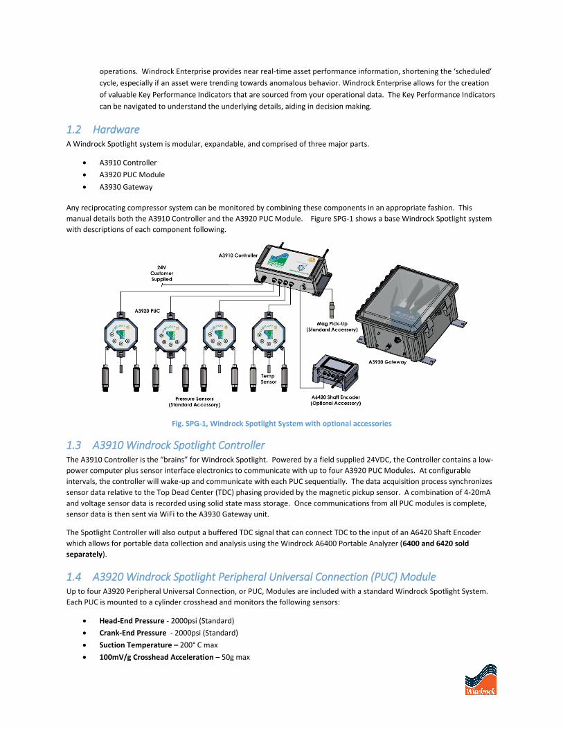
1.2 Hardware A Windrock Spotlight system is modular, expandable, and comprised of three major parts.
A3910 Controller
A3920 PUC Module
A3930 Gateway
Any reciprocating compressor system can be monitored by combining these components in an appropriate fashion. This
manual details both the A3910 Controller and the A3920 PUC Module. Figure SPG-1 shows a base Windrock Spotlight system
with descriptions of each component following.
Fig. SPG-1, Windrock Spotlight System with optional accessories
1.3 A3910 Windrock Spotlight Controller The A3910 Controller is the “brains” for Windrock Spotlight. Powered by a field supplied 24VDC, the Controller contains a low-
power computer plus sensor interface electronics to communicate with up to four A3920 PUC Modules. At configurable
intervals, the controller will wake-up and communicate with each PUC sequentially. The data acquisition process synchronizes
sensor data relative to the Top Dead Center (TDC) phasing provided by the magnetic pickup sensor. A combination of 4-20mA
and voltage sensor data is recorded using solid state mass storage. Once communications from all PUC modules is complete,
sensor data is then sent via WiFi to the A3930 Gateway unit.
The Spotlight Controller will also output a buffered TDC signal that can connect TDC to the input of an A6420 Shaft Encoder
which allows for portable data collection and analysis using the Windrock A6400 Portable Analyzer (6400 and 6420 sold
separately).
1.4 A3920 Windrock Spotlight Peripheral Universal Connection (PUC) Module Up to four A3920 Peripheral Universal Connection, or PUC, Modules are included with a standard Windrock Spotlight System.
Each PUC is mounted to a cylinder crosshead and monitors the following sensors:
Head-End Pressure - 2000psi (Standard)
Crank-End Pressure - 2000psi (Standard)
Suction Temperature – 200° C max
100mV/g Crosshead Acceleration – 50g max
PUCs contain several local status indicators for sensors and power. During the periodic controller polling, sensor indicators light
up to indicate activity. Refer to Figure SPG-2 below for specific pattern identification.
CONTROLLER STATUS INDICATION PATTERNS
Slow clockwise rotation of LEDs on all PUCs: sampling in progress
Brief clockwise rotation on all PUCs, then nothing for 10 seconds at a time: no error, just delay
between samples
Ping pong between outer LEDs on PUC 0: NO TDC SIGNAL. (Note: this display will persist until
the next polling interval even after TDC is restored. Polling interval is initially set to 5 minutes; it
can be changed remotely once the system is brought up.)
Ping pong between inner LEDs on PUC 0: not (yet) connected to WiFi
Fig. SPG-2, Controller Status Indication Patterns
1.5 A3930 Windrock Spotlight Gateway The A3930 Gateway is a commercially available Class 1 Division 2 rated cellular router that has been approved and configured
to work with the Windrock Spotlight System. This router provides a reliable, secure network between multiple A3910
Controllers and the Cloud. The Gateway listens on WiFi for any communication requests from A3910 controllers in the vicinity.
After handshaking, it then records sensor data and then pushes this data from the Gateway to the Cloud. Once in the Cloud,
sensor data can then be accessed from Windrock Enterprise™ or downloaded to Windrock MD™.
2 Locating the Spotlight Controller Care must be taken when choosing the location for the Spotlight Controller. There are four main considerations:
a. Location is within a 50ft (15.2m) unobstructed line-of-sight of Gateway.
b. Location is within 30ft (9.1m) of a 24Vdc Supply.
c. Location is within 16ft (5m) of the magnetic pickup sensor, taking into account cable routing. Longer lengths can be
accommodated by purchasing additional Spotlight Magnetic Pickup (MPU) Extension Cables.
d. Standard Spotlight systems come shipped with six 16ft (5m) trunk cables. It is highly recommended to position the
Controller within 32ft of the furthest PUC module location, otherwise additional trunk cables might be needed to
complete the installation.
3 Mounting the Spotlight Controller Mount the Spotlight Controller vertically on the exterior of any sheet metal enclosure or flat wall surface. For Ariel
applications, a vertical bracket located on the top of the crank plate works well.
Locate Controllers as high as practical and within line-of-sight of the Gateway. The omnidirectional WiFi Antennas
work best in a vertical arrangement.
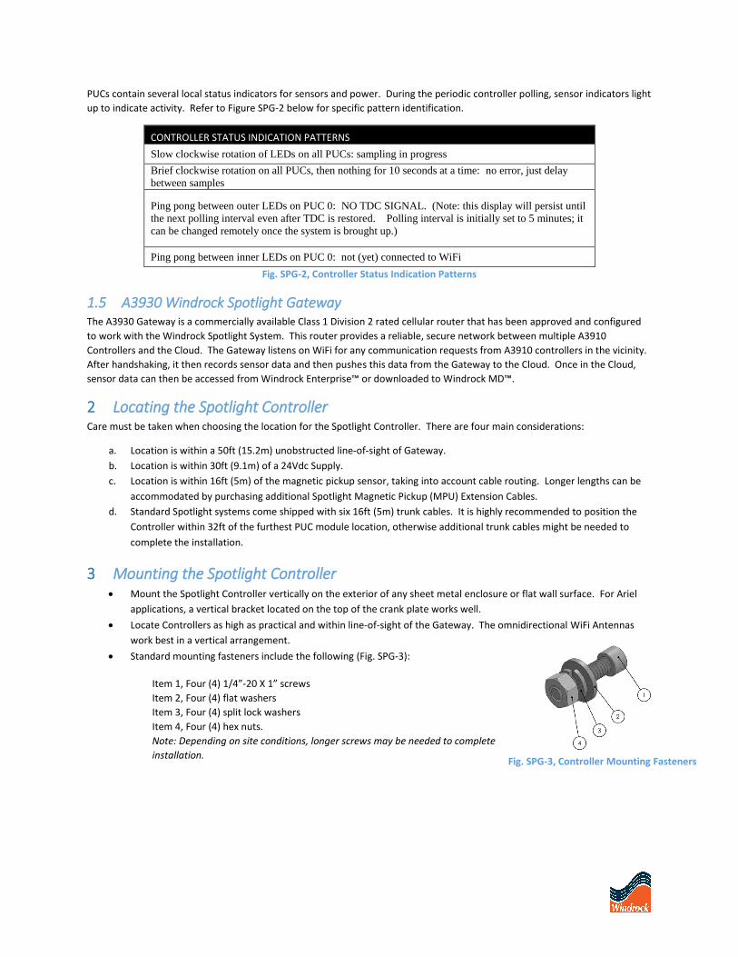
Standard mounting fasteners include the following (Fig. SPG-3):
Item 1, Four (4) 1/4”-20 X 1” screws
Item 2, Four (4) flat washers
Item 3, Four (4) split lock washers
Item 4, Four (4) hex nuts.
Note: Depending on site conditions, longer screws may be needed to complete
installation. Fig. SPG-3, Controller Mounting Fasteners

Mounting dimensions are: 4.213” (107mm) x 10.748” (273mm)
See Fig. SPG-4.
Ensure that all cables exiting the bottom of the Controller have
sufficient slack and are within reach of their intended device.
Possible Cables include:
Six (6) 16’ (5m) Spotlight Trunk Cables
One (1) 30’ (9.1m) integral DC power cable
One (1) 16’ (5m) Spotlight Magnetic Pickup Cable, Sold
Separately
Controller weight is 4lb.
If two or more Spotlight Controllers are used on the same asset,
a Y-Adapter Connector must be used to distribute the mag
pickup signal to all TDC IN Controller connections (Fig. SPG-5).
Parts include:
Description WRI Part Number Qty (for 2 Controllers)
Spotlight Magnetic Pickup Cable A3932-CBL-0-5 1
Y-Adapter Connector 02113040 1
Controller & MPU Extension Cable 02113010 2
Fig. SPG-4, Controller Mounting Dimensions
Fig. SPG-5 Multi Controller Installation Diagram
4 Locating the Windrock Enterprise Gateway When choosing the location for the Windrock Enterprise Gateway, three main
considerations must be taken into account:
a. Location is within a 50ft (15.2m) unobstructed line-of-sight of Controller.
b. Do not position the Gateway so that it is difficult to operate when
disconnecting the device.
c. Gateway requires adequate cellular reception. Check reception using an
approved cellular device. Poor reception may require an external or
directional antenna.
5 Mounting the Gateway (Option 1) The Windrock Enterprise Gateway is intended to be mounted vertically on
the exterior of any sheet metal enclosure or flat wall surface. Windrock
provides the end user with two different mounting options.
Mount the Gateway such that the router indicators are easily visible through
the windowed enclosure.
Gateway weight is 8.5lb.
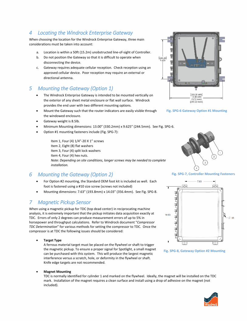
Minimum Mounting dimensions: 13.00” (330.2mm) x 9.625” (244.5mm). See Fig. SPG-6.
Option #1 mounting fasteners include (Fig. SPG-7):
Item 1, Four (4) 1/4”-20 X 1” screws
Item 2, Eight (8) flat washers
Item 3, Four (4) split lock washers
Item 4, Four (4) hex nuts.
Note: Depending on site conditions, longer screws may be needed to complete
installation.
6 Mounting the Gateway (Option 2) For Option #2 mounting, the Standard OEM foot kit is included as well. Each
foot is fastened using a #10 size screw (screws not included)
Mounting dimensions: 7.63” (193.8mm) x 14.03” (356.4mm). See Fig. SPG-8.
7 Magnetic Pickup Sensor When using a magnetic pickup for TDC (top dead center) in reciprocating machine analysis, it is extremely important that the pickup initiates data acquisition exactly at TDC. Errors of only 2 degrees can produce measurement errors of up to 5% in horsepower and throughput calculations. Refer to Windrock document “Compressor TDC Determination” for various methods for setting the compressor to TDC. Once the compressor is at TDC the following issues should be considered:
Target Type A ferrous material target must be placed on the flywheel or shaft to triggerthe magnetic pickup. To ensure a proper signal for Spotlight, a small magnetcan be purchased with this system. This will produce the largest magneticinterference versus a scratch, hole, or deformity in the flywheel or shaft.Knife edge targets are not recommended.
Magnet MountingTDC is normally identified for cylinder 1 and marked on the flywheel. Ideally, the magnet will be installed on the TDCmark. Installation of the magnet requires a clean surface and install using a drop of adhesive on the magnet (notincluded).
Gateway Mounting Dimensions
Fig. SPG-6 Gateway Option #1 Mounting
Fig. SPG-8, Gateway Option #2 Mounting
Fig. SPG-7, Controller Mounting Fasteners
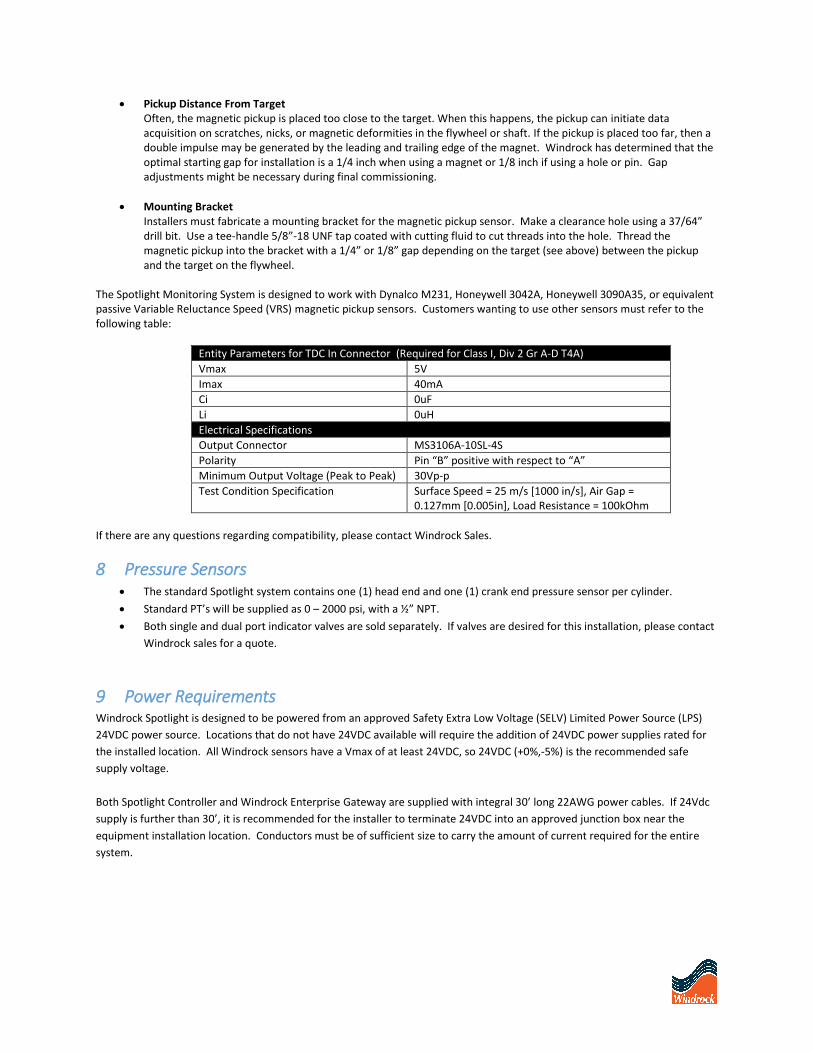
Pickup Distance From TargetOften, the magnetic pickup is placed too close to the target. When this happens, the pickup can initiate dataacquisition on scratches, nicks, or magnetic deformities in the flywheel or shaft. If the pickup is placed too far, then adouble impulse may be generated by the leading and trailing edge of the magnet. Windrock has determined that the optimal starting gap for installation is a 1/4 inch when using a magnet or 1/8 inch if using a hole or pin. Gap adjustments might be necessary during final commissioning.
Mounting BracketInstallers must fabricate a mounting bracket for the magnetic pickup sensor. Make a clearance hole using a 37/64”drill bit. Use a tee-handle 5/8”-18 UNF tap coated with cutting fluid to cut threads into the hole. Thread the magnetic pickup into the bracket with a 1/4” or 1/8” gap depending on the target (see above) between the pickup and the target on the flywheel.
The Spotlight Monitoring System is designed to work with Dynalco M231, Honeywell 3042A, Honeywell 3090A35, or equivalent passive Variable Reluctance Speed (VRS) magnetic pickup sensors. Customers wanting to use other sensors must refer to the following table:
Entity Parameters for TDC In Connector (Required for Class I, Div 2 Gr A-D T4A)
Vmax 5V
Imax 40mA
Ci 0uF
Li 0uH
Electrical Specifications
Output Connector MS3106A-10SL-4S
Polarity Pin “B” positive with respect to “A”
Minimum Output Voltage (Peak to Peak) 30Vp-p
Test Condition Specification Surface Speed = 25 m/s [1000 in/s], Air Gap = 0.127mm [0.005in], Load Resistance = 100kOhm
If there are any questions regarding compatibility, please contact Windrock Sales.
8 Pressure Sensors The standard Spotlight system contains one (1) head end and one (1) crank end pressure sensor per cylinder.
Standard PT’s will be supplied as 0 – 2000 psi, with a ½” NPT.
Both single and dual port indicator valves are sold separately. If valves are desired for this installation, please contact
Windrock sales for a quote.
9 Power Requirements Windrock Spotlight is designed to be powered from an approved Safety Extra Low Voltage (SELV) Limited Power Source (LPS)
24VDC power source. Locations that do not have 24VDC available will require the addition of 24VDC power supplies rated for
the installed location. All Windrock sensors have a Vmax of at least 24VDC, so 24VDC (+0%,-5%) is the recommended safe
supply voltage.
Both Spotlight Controller and Windrock Enterprise Gateway are supplied with integral 30’ long 22AWG power cables. If 24Vdc
supply is further than 30’, it is recommended for the installer to terminate 24VDC into an approved junction box near the
equipment installation location. Conductors must be of sufficient size to carry the amount of current required for the entire
system.

10 Safety Requirements
PERMANENTLY CONNECTED EQUIPMENT must have a customer-provided circuit breaker or switch installed as part of the
final installation. It must be suitably located and easily reached. It must be marked as the disconnecting device for the
equipment. It must be rated for the environment, the voltage, and the amount of power required by the entire system.
Access to disconnect devices must not be obstructed. In short, disconnect devices are not provided as part of the Windrock
system.
ALL WIRING MUST BE IN ACCORDANCE WITH APPROPRIATE SECTIONS OF THE NATIONAL ELECTRICAL CODE AND/OR IN
ACCORDANCE WITH THE CANADIAN ELECTRICAL CODE AND IN ACCORDANCE WITH THE AUTHORITY HAVING JURISDICTION.
Rev 18.23.4
Related Documents