USER Manual USER Manual 1.5.0 Edition 20220523 ECS-9200/9100 Quad Core Intel ® Xeon ® / Core ™ i7/ i5/ i3 Fanless Embedded System High Performance, Rugged, Expandable, -40°C to 75°C Extended Temp

Welcome message from author
This document is posted to help you gain knowledge. Please leave a comment to let me know what you think about it! Share it to your friends and learn new things together.
Transcript
USERManualUSERManual
1.5.0 Edition 20220523
ECS-9200/9100Quad Core Intel® Xeon®/ Core™ i7/ i5/ i3 Fanless Embedded System
High Performance, Rugged, Expandable, -40°C to 75°C Extended Temp
ii
Version Date Page Description Remark1.0 03/24/2017 All Official Release
1.1 05/09/2017 92 Update
1.2 09/19/2017 20 Update
1.3 11/16/2018 All Update
1.4 03/22/2021 3, 5, 7, 10, 12, 14, 26, 27 Update
1.5 05/23/2022 113-115 Update
Record of Revision
iii
This manual is released by Vecow Co., Ltd. for reference purpose only. All product offerings and specifications are subject to change without prior notice. It does not represent commitment of Vecow Co., Ltd. Vecow shall not be liable for direct, indirect, special, incidental, or consequential damages arising out of the use of the product or documentation or any infringements upon the rights of third parties, which may result from such use.
This equipment has been tested and found to comply with the limits for a Class A digital device, pursuant to part 15 of the FCC Rules. These limits are designed to provide reasonable protection against harmful interference when the equipment is operated in a commercial environment. This equipment generates, uses, and can radiate radio frequency energy, and if it is not installed and used in accordance with the instruction manual, it may cause harmful interference to radio communications. Operation of this equipment in a residential area is likely to cause harmful interference in which case the user will be required to correct the interference at his own expense.
FCC
The products described in this manual complies with all applicable European Union (CE) directives if it has a CE marking. For computer systems to remain CE compliant, only CE-compliant parts may be used. Maintaining CE compliance also requires proper cable and cabling techniques.
CE
This document contains proprietary information protected by copyright. No part of this publication may be reproduced in any form or by any means, electric, photocopying, recording or otherwise, without prior written authorization by Vecow Co., Ltd. The rights of all the brand names, product names, and trademarks belong to their respective owners.
Disclaimer
Declaration of Conformity
Copyright and Trademarks
iv
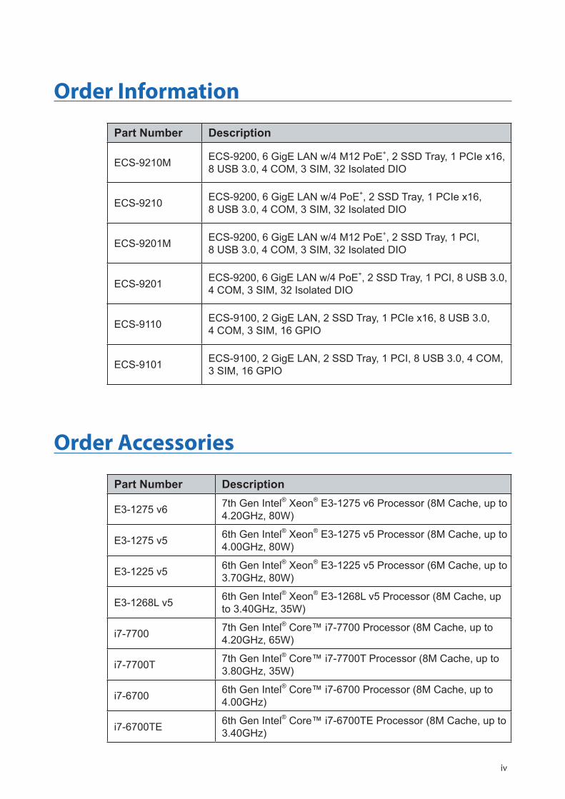
Part Number Description
ECS-9210M ECS-9200, 6 GigE LAN w/4 M12 PoE+, 2 SSD Tray, 1 PCIe x16, 8 USB 3.0, 4 COM, 3 SIM, 32 Isolated DIO
ECS-9210 ECS-9200, 6 GigE LAN w/4 PoE+, 2 SSD Tray, 1 PCIe x16, 8 USB 3.0, 4 COM, 3 SIM, 32 Isolated DIO
ECS-9201M ECS-9200, 6 GigE LAN w/4 M12 PoE+, 2 SSD Tray, 1 PCI, 8 USB 3.0, 4 COM, 3 SIM, 32 Isolated DIO
ECS-9201 ECS-9200, 6 GigE LAN w/4 PoE+, 2 SSD Tray, 1 PCI, 8 USB 3.0, 4 COM, 3 SIM, 32 Isolated DIO
ECS-9110 ECS-9100, 2 GigE LAN, 2 SSD Tray, 1 PCIe x16, 8 USB 3.0, 4 COM, 3 SIM, 16 GPIO
ECS-9101 ECS-9100, 2 GigE LAN, 2 SSD Tray, 1 PCI, 8 USB 3.0, 4 COM, 3 SIM, 16 GPIO
Order Information
Part Number Description
E3-1275 v6 7th Gen Intel® Xeon® E3-1275 v6 Processor (8M Cache, up to 4.20GHz, 80W)
E3-1275 v5 6th Gen Intel® Xeon® E3-1275 v5 Processor (8M Cache, up to 4.00GHz, 80W)
E3-1225 v5 6th Gen Intel® Xeon® E3-1225 v5 Processor (6M Cache, up to 3.70GHz, 80W)
E3-1268L v5 6th Gen Intel® Xeon® E3-1268L v5 Processor (8M Cache, up to 3.40GHz, 35W)
i7-7700 7th Gen Intel® Core™ i7-7700 Processor (8M Cache, up to 4.20GHz, 65W)
i7-7700T 7th Gen Intel® Core™ i7-7700T Processor (8M Cache, up to 3.80GHz, 35W)
i7-6700 6th Gen Intel® Core™ i7-6700 Processor (8M Cache, up to 4.00GHz)
i7-6700TE 6th Gen Intel® Core™ i7-6700TE Processor (8M Cache, up to 3.40GHz)
Order Accessories
v
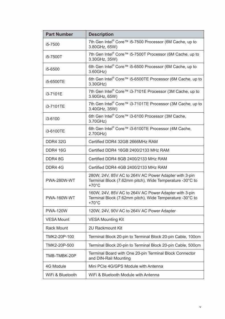
Part Number Description
i5-7500 7th Gen Intel® Core™ i5-7500 Processor (6M Cache, up to 3.80GHz, 65W)
i5-7500T 7th Gen Intel® Core™ i5-7500T Processor (6M Cache, up to 3.30GHz, 35W)
i5-6500 6th Gen Intel® Core™ i5-6500 Processor (6M Cache, up to 3.60GHz)
i5-6500TE 6th Gen Intel® Core™ i5-6500TE Processor (6M Cache, up to 3.30GHz)
i3-7101E 7th Gen Intel® Core™ i3-7101E Processor (3M Cache, up to 3.90GHz, 65W)
i3-7101TE 7th Gen Intel® Core™ i3-7101TE Processor (3M Cache, up to 3.40GHz, 35W)
i3-6100 6th Gen Intel® Core™ i3-6100 Processor (3M Cache, 3.70GHz)
i3-6100TE 6th Gen Intel® Core™ i3-6100TE Processor (4M Cache, 2.70GHz)
DDR4 32G Certified DDR4 32GB 2666MHz RAM
DDR4 16G Certified DDR4 16GB 2400/2133 MHz RAM
DDR4 8G Certified DDR4 8GB 2400/2133 MHz RAM
DDR4 4G Certified DDR4 4GB 2400/2133 MHz RAM
PWA-280W-WT280W, 24V, 85V AC to 264V AC Power Adapter with 3-pin Terminal Block (7.62mm pitch), Wide Temperature -30°C to +70°C
PWA-160W-WT160W, 24V, 85V AC to 264V AC Power Adapter with 3-pin Terminal Block (7.62mm pitch), Wide Temperature -30°C to +70°C
PWA-120W 120W, 24V, 90V AC to 264V AC Power Adapter
VESA Mount VESA Mounting Kit
Rack Mount 2U Rackmount Kit
TMK2-20P-100 Terminal Block 20-pin to Terminal Block 20-pin Cable, 100cm
TMK2-20P-500 Terminal Block 20-pin to Terminal Block 20-pin Cable, 500cm
TMB-TMBK-20P Terminal Board with One 20-pin Terminal Block Connector and DIN-Rail Mounting
4G Module Mini PCIe 4G/GPS Module with Antenna
WiFi & Bluetooth WiFi & Bluetooth Module with Antenna
vi
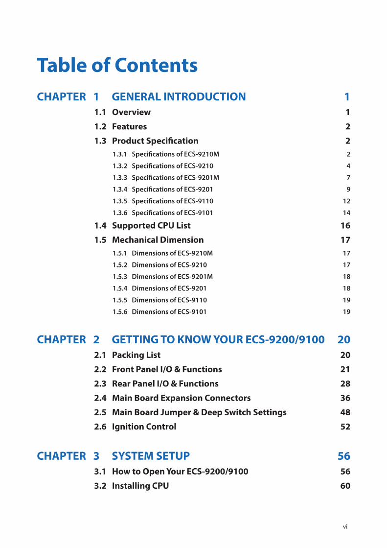
Table of ContentsCHAPTER 1 GENERAL INTRODUCTION 1
1.1 Overview 1
1.2 Features 2
1.3 Product Specification 21.3.1 Specifications of ECS-9210M 2
1.3.2 Specifications of ECS-9210 4
1.3.3 Specifications of ECS-9201M 7
1.3.4 Specifications of ECS-9201 9
1.3.5 Specifications of ECS-9110 12
1.3.6 Specifications of ECS-9101 14
1.4 Supported CPU List 16
1.5 Mechanical Dimension 171.5.1 Dimensions of ECS-9210M 17
1.5.2 Dimensions of ECS-9210 17
1.5.3 Dimensions of ECS-9201M 18
1.5.4 Dimensions of ECS-9201 18
1.5.5 Dimensions of ECS-9110 19
1.5.6 Dimensions of ECS-9101 19
CHAPTER 2 GETTING TO KNOW YOUR ECS-9200/9100 202.1 Packing List 20
2.2 Front Panel I/O & Functions 21
2.3 Rear Panel I/O & Functions 28
2.4 Main Board Expansion Connectors 36
2.5 Main Board Jumper & Deep Switch Settings 48
2.6 Ignition Control 52
CHAPTER 3 SYSTEM SETUP 563.1 How to Open Your ECS-9200/9100 56
3.2 Installing CPU 60
vii
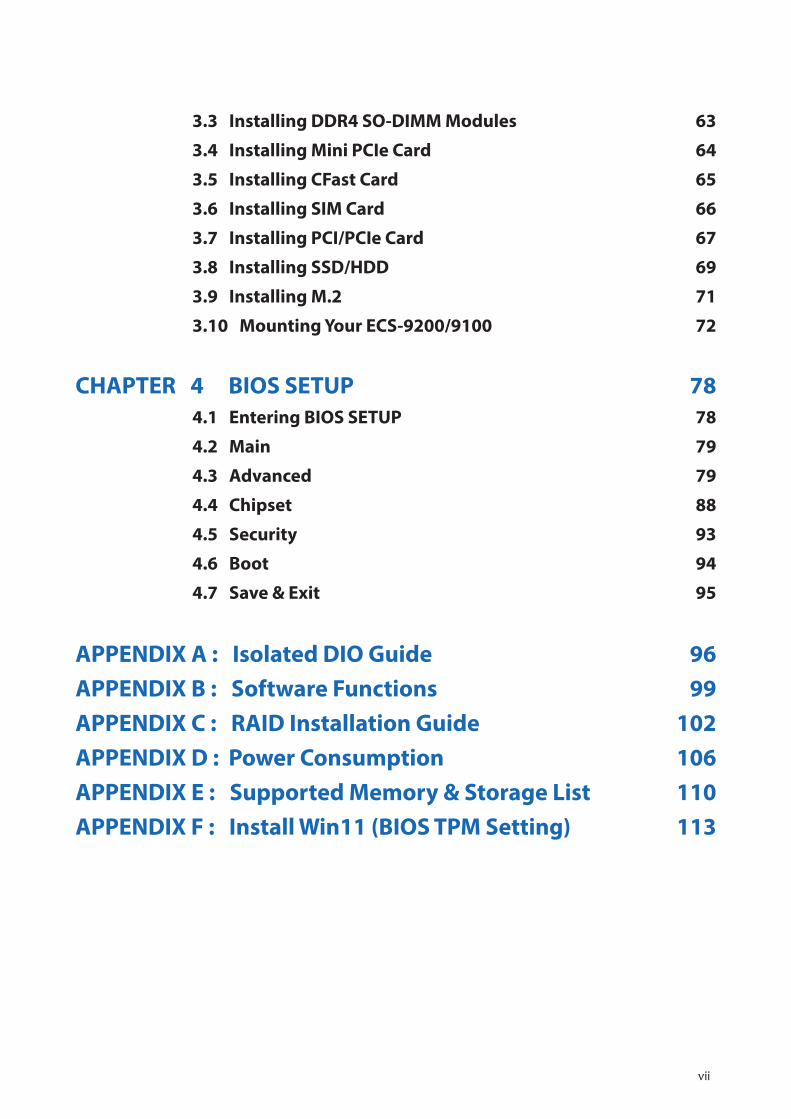
3.3 Installing DDR4 SO-DIMM Modules 63
3.4 Installing Mini PCIe Card 64
3.5 Installing CFast Card 65
3.6 Installing SIM Card 66
3.7 Installing PCI/PCIe Card 67
3.8 Installing SSD/HDD 69
3.9 Installing M.2 71
3.10 Mounting Your ECS-9200/9100 72
CHAPTER 4 BIOS SETUP 784.1 Entering BIOS SETUP 78
4.2 Main 79
4.3 Advanced 79
4.4 Chipset 88
4.5 Security 93
4.6 Boot 94
4.7 Save & Exit 95
APPENDIX A : Isolated DIO Guide 96APPENDIX B : Software Functions 99APPENDIX C : RAID Installation Guide 102APPENDIX D : Power Consumption 106APPENDIX E : Supported Memory & Storage List 110APPENDIX F : Install Win11 (BIOS TPM Setting) 113
1GENERAL INTRODUCTION
1GENERAL INTRODUCTION
Vecow ECS-9200/9100 Series is a high-performance, all-in-one integrated, expandable Fanless Embedded Workstation System. LGA1151 Socket supports Quad Core 7th/6th Generation Intel® Xeon®/Core™ i7/i5/i3 processor (Kaby Lake-S/Skylake-S) running with workstation-grade Intel® C236 chipset, dual channel DDR4 2400MHz up to 64GB ECC memory, advanced Intel® HD Graphics 630/530 supporting DirectX 12, OpenGL 4.4 and OpenCL 2.0 API, onboard DVI-I, DVI-D and DisplayPort display interface for Ultra HD 4K resolution, ECS-9200/9100 offers leading CPU performance, power efficiency, and graphics performance; PCIe 3.0 (8GT/s), Multiple SATA III (6Gbps), USB 3.0 (5Gbps), PoE (1Gbps) LAN and multiple wireless connections make seamless high-speed data conveying possible. Vecow ECS-9200/9100 Series Expandable Fanless Embedded System delivers outstanding system performance, power productivity and flexible manageability for performance-driven embedded computing applications.
All-in-one and cable-less designs, fanless -40°C to 75°C extended operating temperature, 6 GigE LAN ports with 4 IEEE 802.3at (25.5W/48V) PoE+ without additional power connections, 2 Front-access 2.5” SSD/HDD trays, 1 patented easy-swap PCI/PCIe slot, 3 external SIM card sockets for WiFi/4G/3G/LTE/GPRS/UMTS, 1 onboard M.2 socket, 1 front-access CFast socket, 2 SATA III supports software RAID functions, 8 external USB 3.0, 4 COM RS-232/422/485, 32 Isolated DIO, 6V to 36V wide range power input with 80V surge protection, configurable ignition power control, PCIe x16 expansion supports up to 160W power budget, smart remote management features, remote power switch, EN50155 and EN50121-3-2 compliant, Vecow ECS-9200/9100 Series Expandable Rugged Embedded System serves outstanding system performance, versatile I/O functions, flexible expansion features, and rugged reliability for embedded applications.
With outstanding system performance, all-in-one integrated features, smarter manageability, flexible expandability, great mobile availability, 6V to 36V power input with 80V surge protection, ignition power control, intelligent circus protection and more rugged reliability, Vecow ECS-9200/9100 Series Expandable Fanless Embedded System is your superb solution for Machine Vision, Rolling Stock, Intelligent Surveillance, Smart Manufacturing, ITS, Intelligent Automation, Vehicle Computing, and any Industry 4.0 performance-driven real-time embedded computing applications.
1.1 Overview
2GENERAL INTRODUCTION©Vecow ECS-9200/9100 User Manual
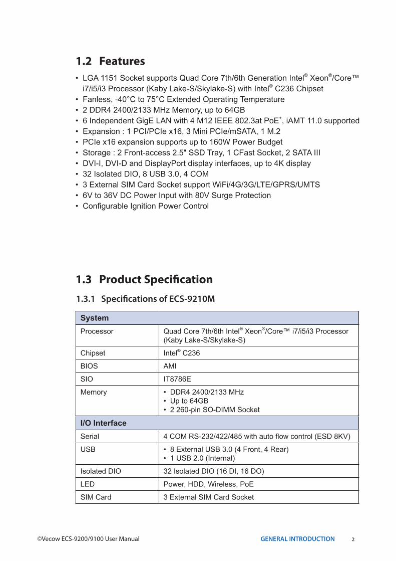
1.2 Features• LGA 1151 Socket supports Quad Core 7th/6th Generation Intel® Xeon®/Core™ i7/i5/i3 Processor (Kaby Lake-S/Skylake-S) with Intel® C236 Chipset
• Fanless, -40°C to 75°C Extended Operating Temperature • 2 DDR4 2400/2133 MHz Memory, up to 64GB • 6 Independent GigE LAN with 4 M12 IEEE 802.3at PoE+, iAMT 11.0 supported • Expansion : 1 PCI/PCIe x16, 3 Mini PCIe/mSATA, 1 M.2• PCIe x16 expansion supports up to 160W Power Budget • Storage : 2 Front-access 2.5" SSD Tray, 1 CFast Socket, 2 SATA III• DVI-I, DVI-D and DisplayPort display interfaces, up to 4K display• 32 Isolated DIO, 8 USB 3.0, 4 COM • 3 External SIM Card Socket support WiFi/4G/3G/LTE/GPRS/UMTS• 6V to 36V DC Power Input with 80V Surge Protection • Configurable Ignition Power Control
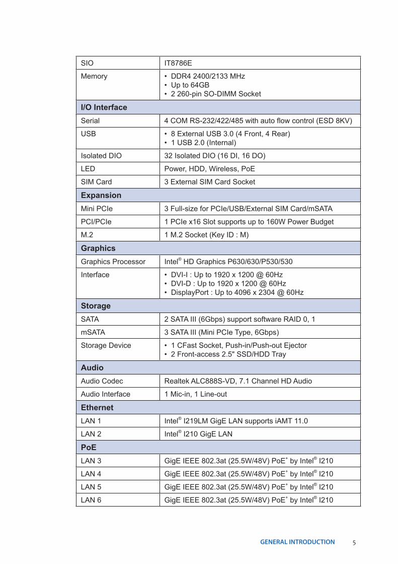
1.3 Product Specification1.3.1 Specifications of ECS-9210M
SystemProcessor Quad Core 7th/6th Intel® Xeon®/Core™ i7/i5/i3 Processor
(Kaby Lake-S/Skylake-S)
Chipset Intel® C236
BIOS AMI
SIO IT8786E
Memory • DDR4 2400/2133 MHz • Up to 64GB• 2 260-pin SO-DIMM Socket
I/O InterfaceSerial 4 COM RS-232/422/485 with auto flow control (ESD 8KV)
USB • 8 External USB 3.0 (4 Front, 4 Rear)• 1 USB 2.0 (Internal)
Isolated DIO 32 Isolated DIO (16 DI, 16 DO)
LED Power, HDD, Wireless, PoE
SIM Card 3 External SIM Card Socket
3GENERAL INTRODUCTION
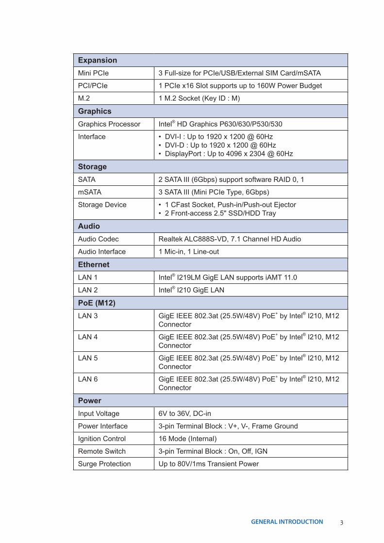
ExpansionMini PCIe 3 Full-size for PCIe/USB/External SIM Card/mSATA
PCI/PCIe 1 PCIe x16 Slot supports up to 160W Power Budget
M.2 1 M.2 Socket (Key ID : M)
GraphicsGraphics Processor Intel® HD Graphics P630/630/P530/530
Interface • DVI-I : Up to 1920 x 1200 @ 60Hz• DVI-D : Up to 1920 x 1200 @ 60Hz• DisplayPort : Up to 4096 x 2304 @ 60Hz
StorageSATA 2 SATA III (6Gbps) support software RAID 0, 1
mSATA 3 SATA III (Mini PCIe Type, 6Gbps)
Storage Device • 1 CFast Socket, Push-in/Push-out Ejector • 2 Front-access 2.5" SSD/HDD Tray
AudioAudio Codec Realtek ALC888S-VD, 7.1 Channel HD Audio
Audio Interface 1 Mic-in, 1 Line-out
EthernetLAN 1 Intel® I219LM GigE LAN supports iAMT 11.0
LAN 2 Intel® I210 GigE LAN
PoE (M12)LAN 3 GigE IEEE 802.3at (25.5W/48V) PoE+ by Intel® I210, M12
Connector
LAN 4 GigE IEEE 802.3at (25.5W/48V) PoE+ by Intel® I210, M12 Connector
LAN 5 GigE IEEE 802.3at (25.5W/48V) PoE+ by Intel® I210, M12 Connector
LAN 6 GigE IEEE 802.3at (25.5W/48V) PoE+ by Intel® I210, M12 Connector
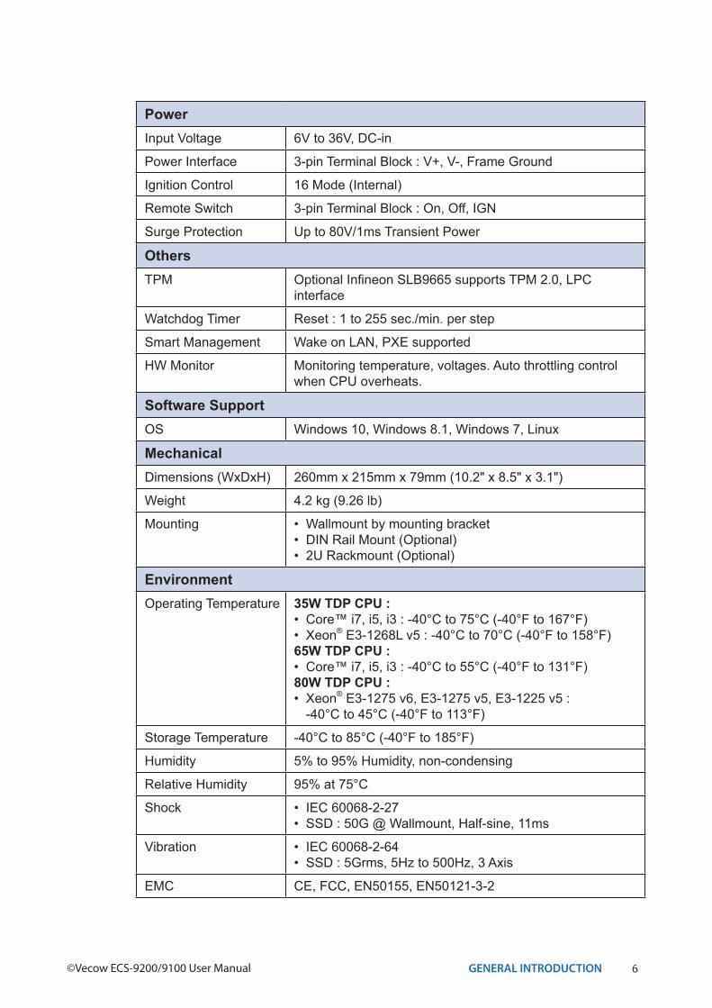
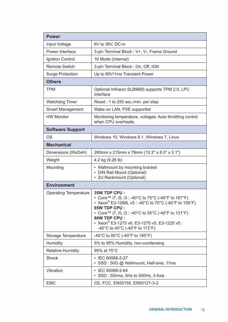
PowerInput Voltage 6V to 36V, DC-in
Power Interface 3-pin Terminal Block : V+, V-, Frame Ground
Ignition Control 16 Mode (Internal)
Remote Switch 3-pin Terminal Block : On, Off, IGN
Surge Protection Up to 80V/1ms Transient Power
4GENERAL INTRODUCTION©Vecow ECS-9200/9100 User Manual
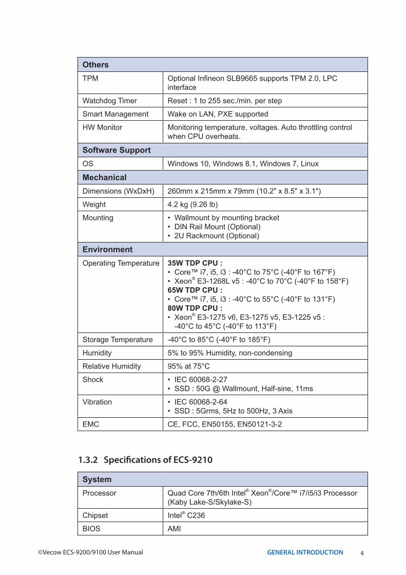
OthersTPM Optional Infineon SLB9665 supports TPM 2.0, LPC
interface
Watchdog Timer Reset : 1 to 255 sec./min. per step
Smart Management Wake on LAN, PXE supported
HW Monitor Monitoring temperature, voltages. Auto throttling control when CPU overheats.
Software SupportOS Windows 10, Windows 8.1, Windows 7, Linux
MechanicalDimensions (WxDxH) 260mm x 215mm x 79mm (10.2" x 8.5" x 3.1")
Weight 4.2 kg (9.26 lb)
Mounting • Wallmount by mounting bracket • DIN Rail Mount (Optional)• 2U Rackmount (Optional)
EnvironmentOperating Temperature 35W TDP CPU :
• Core™ i7, i5, i3 : -40°C to 75°C (-40°F to 167°F) • Xeon® E3-1268L v5 : -40°C to 70°C (-40°F to 158°F)65W TDP CPU :• Core™ i7, i5, i3 : -40°C to 55°C (-40°F to 131°F)80W TDP CPU :• Xeon® E3-1275 v6, E3-1275 v5, E3-1225 v5 :
-40°C to 45°C (-40°F to 113°F)
Storage Temperature -40°C to 85°C (-40°F to 185°F)
Humidity 5% to 95% Humidity, non-condensing
Relative Humidity 95% at 75°C
Shock • IEC 60068-2-27• SSD : 50G @ Wallmount, Half-sine, 11ms
Vibration • IEC 60068-2-64• SSD : 5Grms, 5Hz to 500Hz, 3 Axis
EMC CE, FCC, EN50155, EN50121-3-2
1.3.2 Specifications of ECS-9210
SystemProcessor Quad Core 7th/6th Intel® Xeon®/Core™ i7/i5/i3 Processor
(Kaby Lake-S/Skylake-S)
Chipset Intel® C236
BIOS AMI
5GENERAL INTRODUCTION
SIO IT8786E
Memory • DDR4 2400/2133 MHz • Up to 64GB• 2 260-pin SO-DIMM Socket
I/O InterfaceSerial 4 COM RS-232/422/485 with auto flow control (ESD 8KV)
USB • 8 External USB 3.0 (4 Front, 4 Rear)• 1 USB 2.0 (Internal)
Isolated DIO 32 Isolated DIO (16 DI, 16 DO)
LED Power, HDD, Wireless, PoE
SIM Card 3 External SIM Card Socket
ExpansionMini PCIe 3 Full-size for PCIe/USB/External SIM Card/mSATA
PCI/PCIe 1 PCIe x16 Slot supports up to 160W Power Budget
M.2 1 M.2 Socket (Key ID : M)
GraphicsGraphics Processor Intel® HD Graphics P630/630/P530/530
Interface • DVI-I : Up to 1920 x 1200 @ 60Hz• DVI-D : Up to 1920 x 1200 @ 60Hz• DisplayPort : Up to 4096 x 2304 @ 60Hz
StorageSATA 2 SATA III (6Gbps) support software RAID 0, 1
mSATA 3 SATA III (Mini PCIe Type, 6Gbps)
Storage Device • 1 CFast Socket, Push-in/Push-out Ejector • 2 Front-access 2.5" SSD/HDD Tray
AudioAudio Codec Realtek ALC888S-VD, 7.1 Channel HD Audio
Audio Interface 1 Mic-in, 1 Line-out
EthernetLAN 1 Intel® I219LM GigE LAN supports iAMT 11.0
LAN 2 Intel® I210 GigE LAN
PoELAN 3 GigE IEEE 802.3at (25.5W/48V) PoE+ by Intel® I210
LAN 4 GigE IEEE 802.3at (25.5W/48V) PoE+ by Intel® I210
LAN 5 GigE IEEE 802.3at (25.5W/48V) PoE+ by Intel® I210
LAN 6 GigE IEEE 802.3at (25.5W/48V) PoE+ by Intel® I210
6GENERAL INTRODUCTION©Vecow ECS-9200/9100 User Manual
PowerInput Voltage 6V to 36V, DC-in
Power Interface 3-pin Terminal Block : V+, V-, Frame Ground
Ignition Control 16 Mode (Internal)
Remote Switch 3-pin Terminal Block : On, Off, IGN
Surge Protection Up to 80V/1ms Transient Power
OthersTPM Optional Infineon SLB9665 supports TPM 2.0, LPC
interface
Watchdog Timer Reset : 1 to 255 sec./min. per step
Smart Management Wake on LAN, PXE supported
HW Monitor Monitoring temperature, voltages. Auto throttling control when CPU overheats.
Software SupportOS Windows 10, Windows 8.1, Windows 7, Linux
MechanicalDimensions (WxDxH) 260mm x 215mm x 79mm (10.2" x 8.5" x 3.1")
Weight 4.2 kg (9.26 lb)
Mounting • Wallmount by mounting bracket • DIN Rail Mount (Optional)• 2U Rackmount (Optional)
EnvironmentOperating Temperature 35W TDP CPU :
• Core™ i7, i5, i3 : -40°C to 75°C (-40°F to 167°F) • Xeon® E3-1268L v5 : -40°C to 70°C (-40°F to 158°F)65W TDP CPU :• Core™ i7, i5, i3 : -40°C to 55°C (-40°F to 131°F)80W TDP CPU :• Xeon® E3-1275 v6, E3-1275 v5, E3-1225 v5 :
-40°C to 45°C (-40°F to 113°F)
Storage Temperature -40°C to 85°C (-40°F to 185°F)
Humidity 5% to 95% Humidity, non-condensing
Relative Humidity 95% at 75°C
Shock • IEC 60068-2-27• SSD : 50G @ Wallmount, Half-sine, 11ms
Vibration • IEC 60068-2-64• SSD : 5Grms, 5Hz to 500Hz, 3 Axis
EMC CE, FCC, EN50155, EN50121-3-2
7GENERAL INTRODUCTION
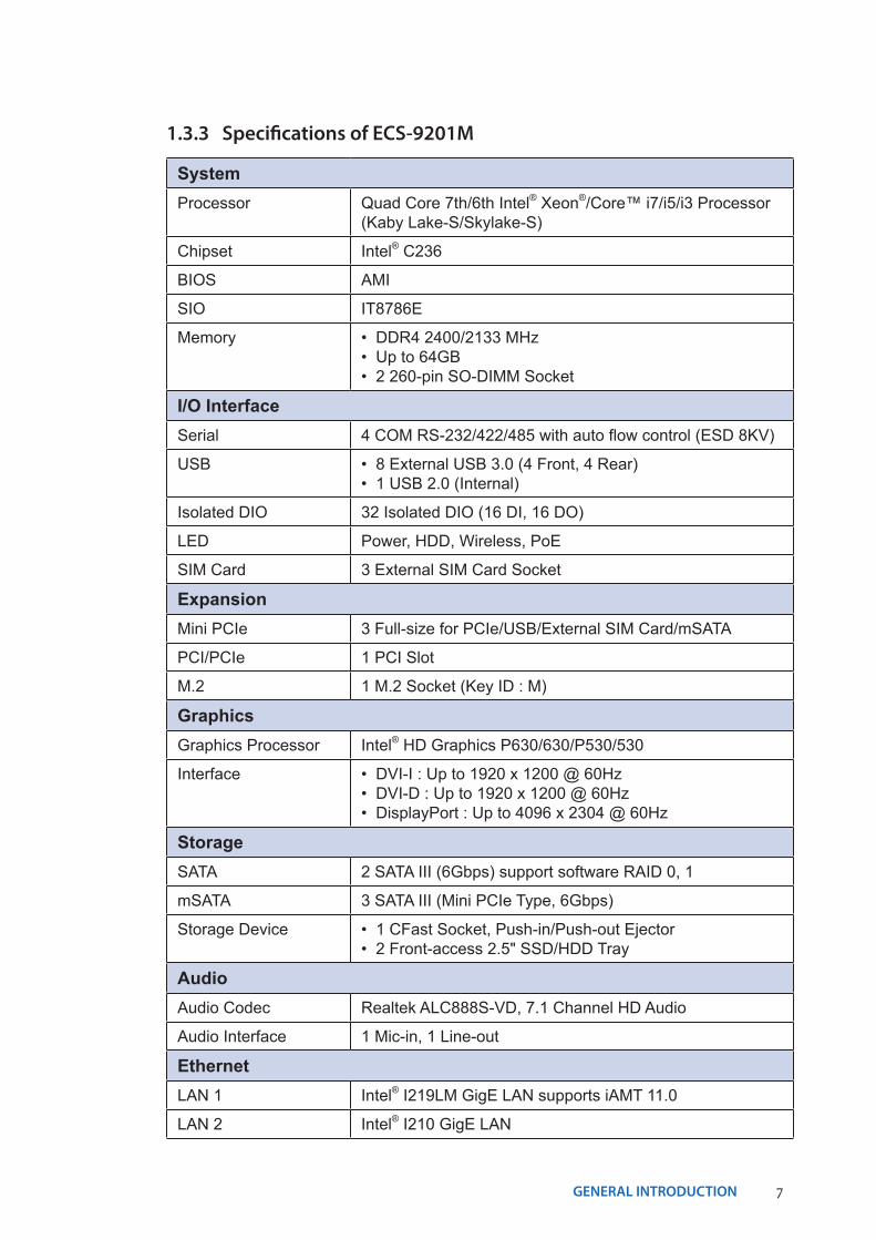
1.3.3 Specifications of ECS-9201M
SystemProcessor Quad Core 7th/6th Intel® Xeon®/Core™ i7/i5/i3 Processor
(Kaby Lake-S/Skylake-S)
Chipset Intel® C236
BIOS AMI
SIO IT8786E
Memory • DDR4 2400/2133 MHz• Up to 64GB• 2 260-pin SO-DIMM Socket
I/O InterfaceSerial 4 COM RS-232/422/485 with auto flow control (ESD 8KV)
USB • 8 External USB 3.0 (4 Front, 4 Rear)• 1 USB 2.0 (Internal)
Isolated DIO 32 Isolated DIO (16 DI, 16 DO)
LED Power, HDD, Wireless, PoE
SIM Card 3 External SIM Card Socket
ExpansionMini PCIe 3 Full-size for PCIe/USB/External SIM Card/mSATA
PCI/PCIe 1 PCI Slot
M.2 1 M.2 Socket (Key ID : M)
GraphicsGraphics Processor Intel® HD Graphics P630/630/P530/530
Interface • DVI-I : Up to 1920 x 1200 @ 60Hz• DVI-D : Up to 1920 x 1200 @ 60Hz• DisplayPort : Up to 4096 x 2304 @ 60Hz
StorageSATA 2 SATA III (6Gbps) support software RAID 0, 1
mSATA 3 SATA III (Mini PCIe Type, 6Gbps)
Storage Device • 1 CFast Socket, Push-in/Push-out Ejector • 2 Front-access 2.5" SSD/HDD Tray
AudioAudio Codec Realtek ALC888S-VD, 7.1 Channel HD Audio
Audio Interface 1 Mic-in, 1 Line-out
EthernetLAN 1 Intel® I219LM GigE LAN supports iAMT 11.0
LAN 2 Intel® I210 GigE LAN
8GENERAL INTRODUCTION©Vecow ECS-9200/9100 User Manual
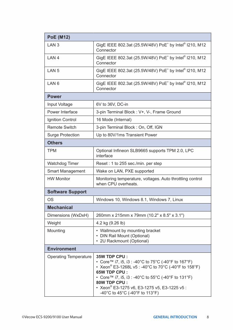
PoE (M12)LAN 3 GigE IEEE 802.3at (25.5W/48V) PoE+ by Intel® I210, M12
Connector
LAN 4 GigE IEEE 802.3at (25.5W/48V) PoE+ by Intel® I210, M12 Connector
LAN 5 GigE IEEE 802.3at (25.5W/48V) PoE+ by Intel® I210, M12 Connector
LAN 6 GigE IEEE 802.3at (25.5W/48V) PoE+ by Intel® I210, M12 Connector
PowerInput Voltage 6V to 36V, DC-in
Power Interface 3-pin Terminal Block : V+, V-, Frame Ground
Ignition Control 16 Mode (Internal)
Remote Switch 3-pin Terminal Block : On, Off, IGN
Surge Protection Up to 80V/1ms Transient Power
OthersTPM Optional Infineon SLB9665 supports TPM 2.0, LPC
interface
Watchdog Timer Reset : 1 to 255 sec./min. per step
Smart Management Wake on LAN, PXE supported
HW Monitor Monitoring temperature, voltages. Auto throttling control when CPU overheats.
Software SupportOS Windows 10, Windows 8.1, Windows 7, Linux
MechanicalDimensions (WxDxH) 260mm x 215mm x 79mm (10.2" x 8.5" x 3.1")
Weight 4.2 kg (9.26 lb)
Mounting • Wallmount by mounting bracket • DIN Rail Mount (Optional)• 2U Rackmount (Optional)
EnvironmentOperating Temperature 35W TDP CPU :
• Core™ i7, i5, i3 : -40°C to 75°C (-40°F to 167°F) • Xeon® E3-1268L v5 : -40°C to 70°C (-40°F to 158°F)65W TDP CPU :• Core™ i7, i5, i3 : -40°C to 55°C (-40°F to 131°F)80W TDP CPU :• Xeon® E3-1275 v6, E3-1275 v5, E3-1225 v5 :
-40°C to 45°C (-40°F to 113°F)
9GENERAL INTRODUCTION
Storage Temperature -40°C to 85°C (-40°F to 185°F)
Humidity 5% to 95% Humidity, non-condensing
Relative Humidity 95% at 75°C
Shock • IEC 60068-2-27• SSD : 50G @ Wallmount, Half-sine, 11ms
Vibration • IEC 60068-2-64• SSD : 5Grms, 5Hz to 500Hz, 3 Axis
EMC CE, FCC, EN50155, EN50121-3-2
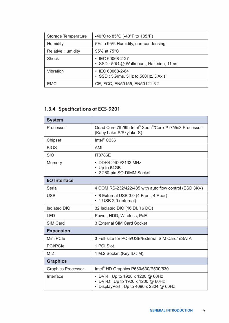
1.3.4 Specifications of ECS-9201
SystemProcessor Quad Core 7th/6th Intel® Xeon®/Core™ i7/i5/i3 Processor
(Kaby Lake-S/Skylake-S)
Chipset Intel® C236
BIOS AMI
SIO IT8786E
Memory • DDR4 2400/2133 MHz • Up to 64GB• 2 260-pin SO-DIMM Socket
I/O InterfaceSerial 4 COM RS-232/422/485 with auto flow control (ESD 8KV)
USB • 8 External USB 3.0 (4 Front, 4 Rear)• 1 USB 2.0 (Internal)
Isolated DIO 32 Isolated DIO (16 DI, 16 DO)
LED Power, HDD, Wireless, PoE
SIM Card 3 External SIM Card Socket
ExpansionMini PCIe 3 Full-size for PCIe/USB/External SIM Card/mSATA
PCI/PCIe 1 PCI Slot
M.2 1 M.2 Socket (Key ID : M)
GraphicsGraphics Processor Intel® HD Graphics P630/630/P530/530
Interface • DVI-I : Up to 1920 x 1200 @ 60Hz• DVI-D : Up to 1920 x 1200 @ 60Hz• DisplayPort : Up to 4096 x 2304 @ 60Hz
10GENERAL INTRODUCTION©Vecow ECS-9200/9100 User Manual
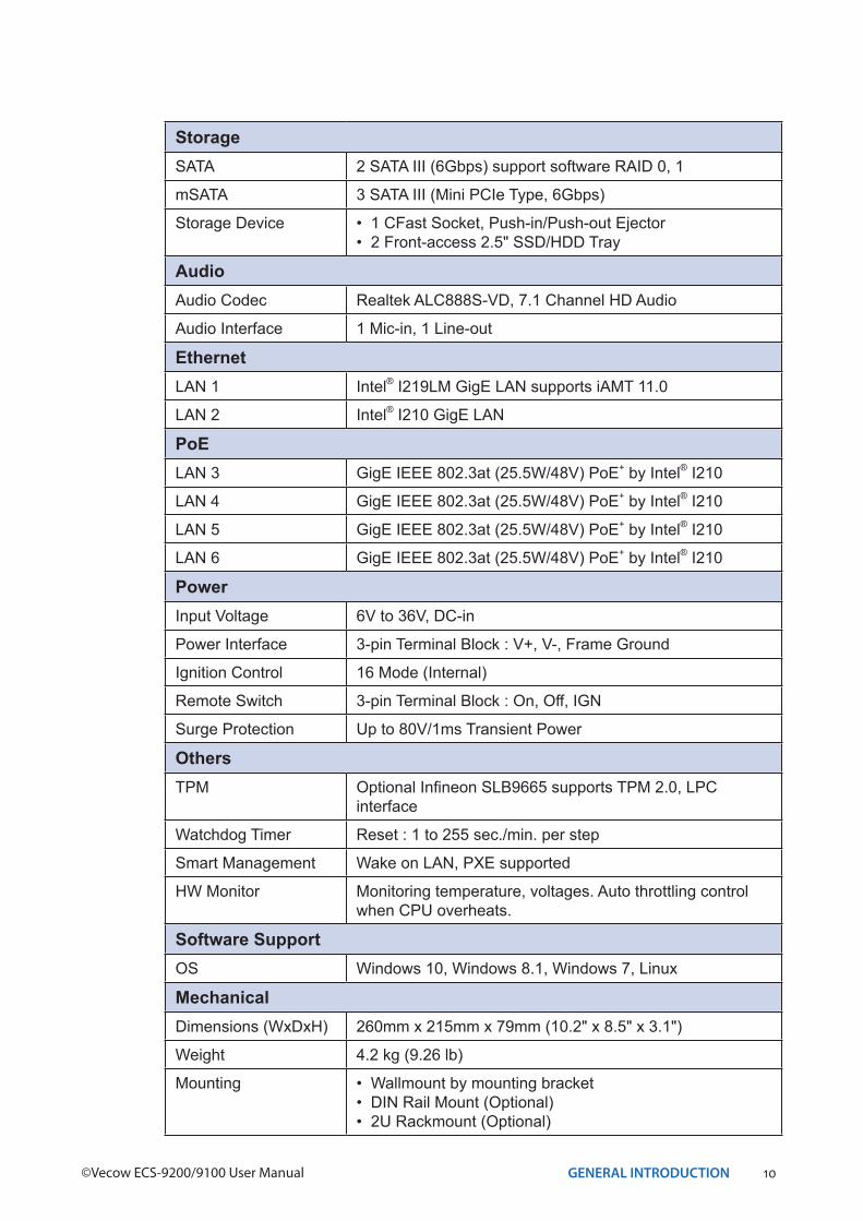
StorageSATA 2 SATA III (6Gbps) support software RAID 0, 1
mSATA 3 SATA III (Mini PCIe Type, 6Gbps)
Storage Device • 1 CFast Socket, Push-in/Push-out Ejector • 2 Front-access 2.5" SSD/HDD Tray
AudioAudio Codec Realtek ALC888S-VD, 7.1 Channel HD Audio
Audio Interface 1 Mic-in, 1 Line-out
EthernetLAN 1 Intel® I219LM GigE LAN supports iAMT 11.0
LAN 2 Intel® I210 GigE LAN
PoELAN 3 GigE IEEE 802.3at (25.5W/48V) PoE+ by Intel® I210
LAN 4 GigE IEEE 802.3at (25.5W/48V) PoE+ by Intel® I210
LAN 5 GigE IEEE 802.3at (25.5W/48V) PoE+ by Intel® I210
LAN 6 GigE IEEE 802.3at (25.5W/48V) PoE+ by Intel® I210
PowerInput Voltage 6V to 36V, DC-in
Power Interface 3-pin Terminal Block : V+, V-, Frame Ground
Ignition Control 16 Mode (Internal)
Remote Switch 3-pin Terminal Block : On, Off, IGN
Surge Protection Up to 80V/1ms Transient Power
OthersTPM Optional Infineon SLB9665 supports TPM 2.0, LPC
interface
Watchdog Timer Reset : 1 to 255 sec./min. per step
Smart Management Wake on LAN, PXE supported
HW Monitor Monitoring temperature, voltages. Auto throttling control when CPU overheats.
Software SupportOS Windows 10, Windows 8.1, Windows 7, Linux
MechanicalDimensions (WxDxH) 260mm x 215mm x 79mm (10.2" x 8.5" x 3.1")
Weight 4.2 kg (9.26 lb)
Mounting • Wallmount by mounting bracket • DIN Rail Mount (Optional)• 2U Rackmount (Optional)
11GENERAL INTRODUCTION
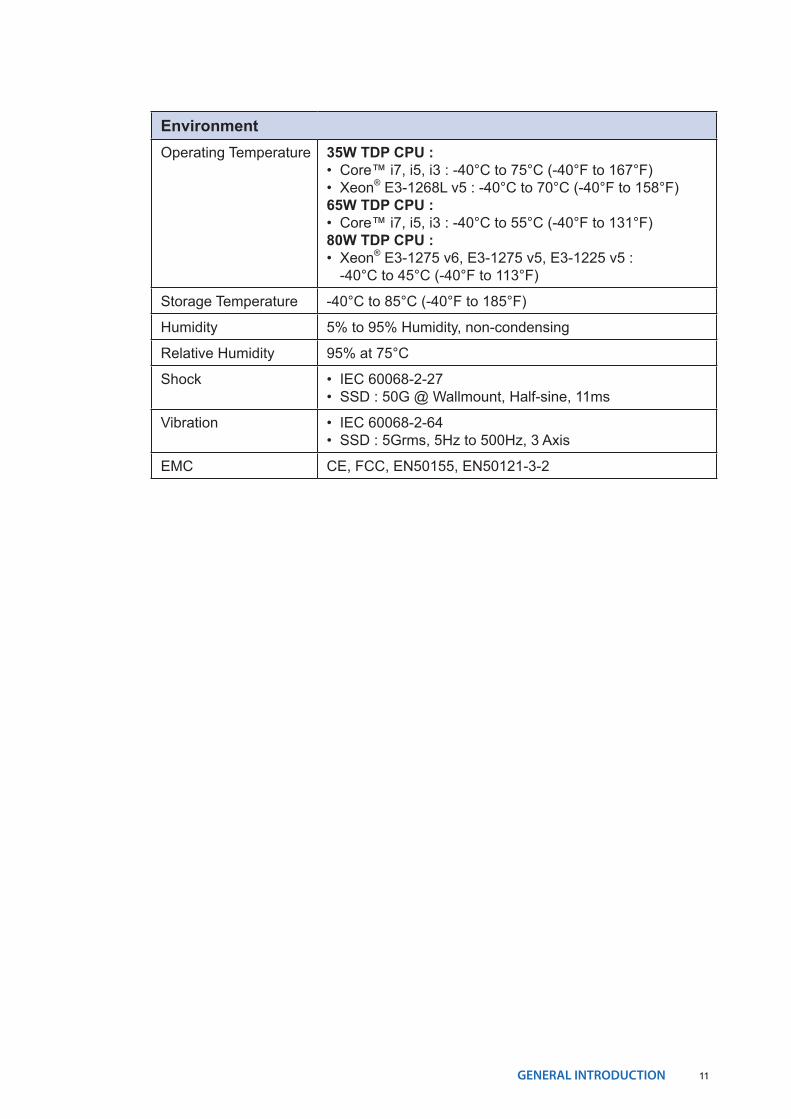
EnvironmentOperating Temperature 35W TDP CPU :
• Core™ i7, i5, i3 : -40°C to 75°C (-40°F to 167°F) • Xeon® E3-1268L v5 : -40°C to 70°C (-40°F to 158°F)65W TDP CPU :• Core™ i7, i5, i3 : -40°C to 55°C (-40°F to 131°F)80W TDP CPU :• Xeon® E3-1275 v6, E3-1275 v5, E3-1225 v5 :
-40°C to 45°C (-40°F to 113°F)
Storage Temperature -40°C to 85°C (-40°F to 185°F)
Humidity 5% to 95% Humidity, non-condensing
Relative Humidity 95% at 75°C
Shock • IEC 60068-2-27• SSD : 50G @ Wallmount, Half-sine, 11ms
Vibration • IEC 60068-2-64• SSD : 5Grms, 5Hz to 500Hz, 3 Axis
EMC CE, FCC, EN50155, EN50121-3-2
12GENERAL INTRODUCTION©Vecow ECS-9200/9100 User Manual
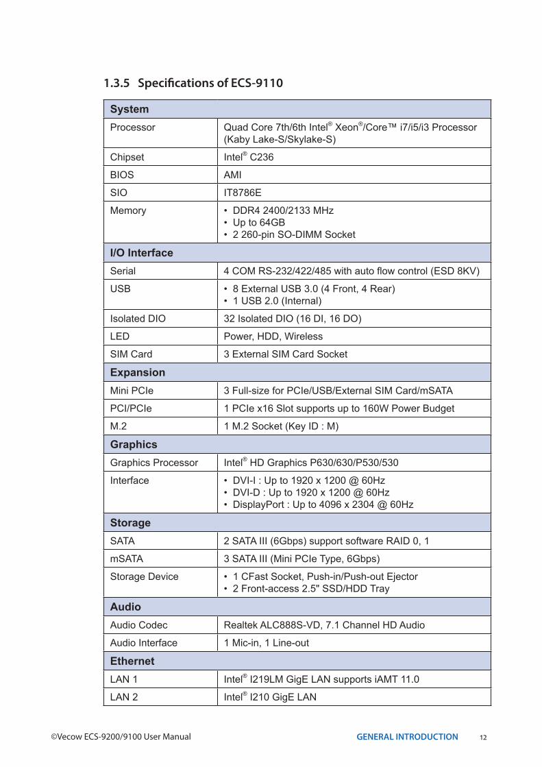
1.3.5 Specifications of ECS-9110
SystemProcessor Quad Core 7th/6th Intel® Xeon®/Core™ i7/i5/i3 Processor
(Kaby Lake-S/Skylake-S)
Chipset Intel® C236
BIOS AMI
SIO IT8786E
Memory • DDR4 2400/2133 MHz • Up to 64GB• 2 260-pin SO-DIMM Socket
I/O InterfaceSerial 4 COM RS-232/422/485 with auto flow control (ESD 8KV)
USB • 8 External USB 3.0 (4 Front, 4 Rear)• 1 USB 2.0 (Internal)
Isolated DIO 32 Isolated DIO (16 DI, 16 DO)
LED Power, HDD, Wireless
SIM Card 3 External SIM Card Socket
ExpansionMini PCIe 3 Full-size for PCIe/USB/External SIM Card/mSATA
PCI/PCIe 1 PCIe x16 Slot supports up to 160W Power Budget
M.2 1 M.2 Socket (Key ID : M)
GraphicsGraphics Processor Intel® HD Graphics P630/630/P530/530
Interface • DVI-I : Up to 1920 x 1200 @ 60Hz• DVI-D : Up to 1920 x 1200 @ 60Hz• DisplayPort : Up to 4096 x 2304 @ 60Hz
StorageSATA 2 SATA III (6Gbps) support software RAID 0, 1
mSATA 3 SATA III (Mini PCIe Type, 6Gbps)
Storage Device • 1 CFast Socket, Push-in/Push-out Ejector • 2 Front-access 2.5" SSD/HDD Tray
AudioAudio Codec Realtek ALC888S-VD, 7.1 Channel HD Audio
Audio Interface 1 Mic-in, 1 Line-out
EthernetLAN 1 Intel® I219LM GigE LAN supports iAMT 11.0
LAN 2 Intel® I210 GigE LAN
13GENERAL INTRODUCTION
PowerInput Voltage 6V to 36V, DC-in
Power Interface 3-pin Terminal Block : V+, V-, Frame Ground
Ignition Control 16 Mode (Internal)
Remote Switch 3-pin Terminal Block : On, Off, IGN
Surge Protection Up to 80V/1ms Transient Power
OthersTPM Optional Infineon SLB9665 supports TPM 2.0, LPC
interface
Watchdog Timer Reset : 1 to 255 sec./min. per step
Smart Management Wake on LAN, PXE supported
HW Monitor Monitoring temperature, voltages. Auto throttling control when CPU overheats.
Software SupportOS Windows 10, Windows 8.1, Windows 7, Linux
MechanicalDimensions (WxDxH) 260mm x 215mm x 79mm (10.2" x 8.5" x 3.1")
Weight 4.2 kg (9.26 lb)
Mounting • Wallmount by mounting bracket • DIN Rail Mount (Optional)• 2U Rackmount (Optional)
EnvironmentOperating Temperature 35W TDP CPU :
• Core™ i7, i5, i3 : -40°C to 75°C (-40°F to 167°F) • Xeon® E3-1268L v5 : -40°C to 70°C (-40°F to 158°F)65W TDP CPU :• Core™ i7, i5, i3 : -40°C to 55°C (-40°F to 131°F)80W TDP CPU :• Xeon® E3-1275 v6, E3-1275 v5, E3-1225 v5 :
-40°C to 45°C (-40°F to 113°F)
Storage Temperature -40°C to 85°C (-40°F to 185°F)
Humidity 5% to 95% Humidity, non-condensing
Relative Humidity 95% at 75°C
Shock • IEC 60068-2-27• SSD : 50G @ Wallmount, Half-sine, 11ms
Vibration • IEC 60068-2-64• SSD : 5Grms, 5Hz to 500Hz, 3 Axis
EMC CE, FCC, EN50155, EN50121-3-2
14GENERAL INTRODUCTION©Vecow ECS-9200/9100 User Manual
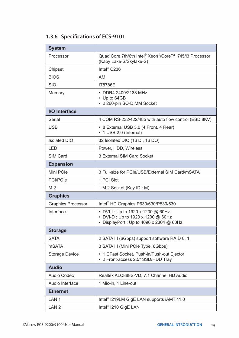
1.3.6 Specifications of ECS-9101
SystemProcessor Quad Core 7th/6th Intel® Xeon®/Core™ i7/i5/i3 Processor
(Kaby Lake-S/Skylake-S)
Chipset Intel® C236
BIOS AMI
SIO IT8786E
Memory • DDR4 2400/2133 MHz • Up to 64GB• 2 260-pin SO-DIMM Socket
I/O InterfaceSerial 4 COM RS-232/422/485 with auto flow control (ESD 8KV)
USB • 8 External USB 3.0 (4 Front, 4 Rear)• 1 USB 2.0 (Internal)
Isolated DIO 32 Isolated DIO (16 DI, 16 DO)
LED Power, HDD, Wireless
SIM Card 3 External SIM Card Socket
ExpansionMini PCIe 3 Full-size for PCIe/USB/External SIM Card/mSATA
PCI/PCIe 1 PCI Slot
M.2 1 M.2 Socket (Key ID : M)
GraphicsGraphics Processor Intel® HD Graphics P630/630/P530/530
Interface • DVI-I : Up to 1920 x 1200 @ 60Hz• DVI-D : Up to 1920 x 1200 @ 60Hz• DisplayPort : Up to 4096 x 2304 @ 60Hz
StorageSATA 2 SATA III (6Gbps) support software RAID 0, 1
mSATA 3 SATA III (Mini PCIe Type, 6Gbps)
Storage Device • 1 CFast Socket, Push-in/Push-out Ejector • 2 Front-access 2.5" SSD/HDD Tray
AudioAudio Codec Realtek ALC888S-VD, 7.1 Channel HD Audio
Audio Interface 1 Mic-in, 1 Line-out
EthernetLAN 1 Intel® I219LM GigE LAN supports iAMT 11.0
LAN 2 Intel® I210 GigE LAN

15GENERAL INTRODUCTION
PowerInput Voltage 6V to 36V, DC-in
Power Interface 3-pin Terminal Block : V+, V-, Frame Ground
Ignition Control 16 Mode (Internal)
Remote Switch 3-pin Terminal Block : On, Off, IGN
Surge Protection Up to 80V/1ms Transient Power
OthersTPM Optional Infineon SLB9665 supports TPM 2.0, LPC
interface
Watchdog Timer Reset : 1 to 255 sec./min. per step
Smart Management Wake on LAN, PXE supported
HW Monitor Monitoring temperature, voltages. Auto throttling control when CPU overheats.
Software SupportOS Windows 10, Windows 8.1, Windows 7, Linux
MechanicalDimensions (WxDxH) 260mm x 215mm x 79mm (10.2" x 8.5" x 3.1")
Weight 4.2 kg (9.26 lb)
Mounting • Wallmount by mounting bracket • DIN Rail Mount (Optional)• 2U Rackmount (Optional)
EnvironmentOperating Temperature 35W TDP CPU :
• Core™ i7, i5, i3 : -40°C to 75°C (-40°F to 167°F) • Xeon® E3-1268L v5 : -40°C to 70°C (-40°F to 158°F)65W TDP CPU :• Core™ i7, i5, i3 : -40°C to 55°C (-40°F to 131°F)80W TDP CPU :• Xeon® E3-1275 v6, E3-1275 v5, E3-1225 v5 :
-40°C to 45°C (-40°F to 113°F)
Storage Temperature -40°C to 85°C (-40°F to 185°F)
Humidity 5% to 95% Humidity, non-condensing
Relative Humidity 95% at 75°C
Shock • IEC 60068-2-27• SSD : 50G @ Wallmount, Half-sine, 11ms
Vibration • IEC 60068-2-64• SSD : 5Grms, 5Hz to 500Hz, 3 Axis
EMC CE, FCC, EN50155, EN50121-3-2
16GENERAL INTRODUCTION©Vecow ECS-9200/9100 User Manual
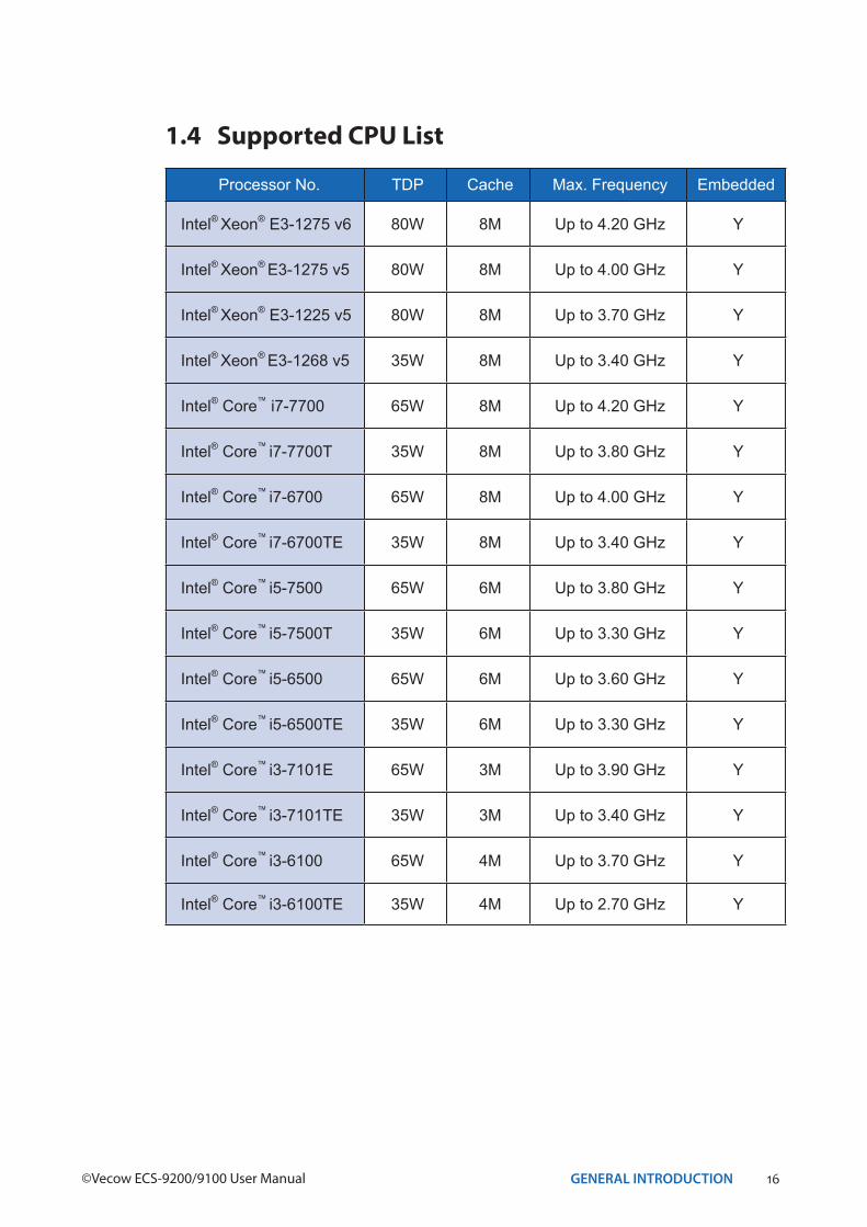
1.4 Supported CPU List
Processor No. TDP Cache Max. Frequency Embedded
Intel® Xeon® E3-1275 v6 80W 8M Up to 4.20 GHz Y
Intel® Xeon® E3-1275 v5 80W 8M Up to 4.00 GHz Y
Intel® Xeon® E3-1225 v5 80W 8M Up to 3.70 GHz Y
Intel® Xeon® E3-1268 v5 35W 8M Up to 3.40 GHz Y
Intel® Core™ i7-7700 65W 8M Up to 4.20 GHz Y
Intel® Core™ i7-7700T 35W 8M Up to 3.80 GHz Y
Intel® Core™ i7-6700 65W 8M Up to 4.00 GHz Y
Intel® Core™ i7-6700TE 35W 8M Up to 3.40 GHz Y
Intel® Core™ i5-7500 65W 6M Up to 3.80 GHz Y
Intel® Core™ i5-7500T 35W 6M Up to 3.30 GHz Y
Intel® Core™ i5-6500 65W 6M Up to 3.60 GHz Y
Intel® Core™ i5-6500TE 35W 6M Up to 3.30 GHz Y
Intel® Core™ i3-7101E 65W 3M Up to 3.90 GHz Y
Intel® Core™ i3-7101TE 35W 3M Up to 3.40 GHz Y
Intel® Core™ i3-6100 65W 4M Up to 3.70 GHz Y
Intel® Core™ i3-6100TE 35W 4M Up to 2.70 GHz Y
17GENERAL INTRODUCTION
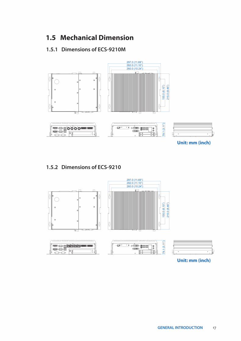
1.5 Mechanical Dimension1.5.1 Dimensions of ECS-9210M
155.
0 (6
.10”
)
215.
0 (8
.46”
)
260.0 (10.24”)282.0 (11.10”)297.0 (11.69”)
79.1
(3.1
1”)
Unit: mm (inch)
1.5.2 Dimensions of ECS-921015
5.0
(6.1
0”)
215.
0 (8
.46”
)
260.0 (10.24”)282.0 (11.10”)297.0 (11.69”)
79.1
(3.1
1”)
Unit: mm (inch)
18GENERAL INTRODUCTION©Vecow ECS-9200/9100 User Manual
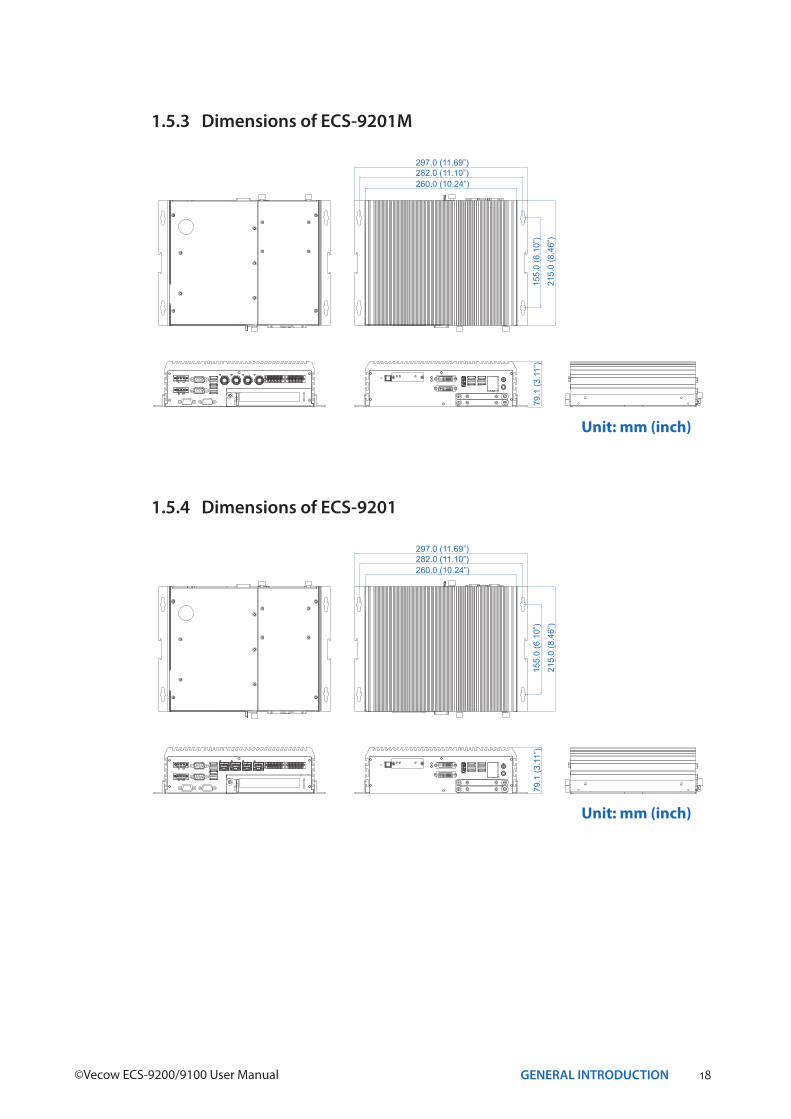
1.5.3 Dimensions of ECS-9201M
155.
0 (6
.10”
)
215.
0 (8
.46”
)
260.0 (10.24”)282.0 (11.10”)297.0 (11.69”)
79.1
(3.1
1”)
Unit: mm (inch)
1.5.4 Dimensions of ECS-920115
5.0
(6.1
0”)
215.
0 (8
.46”
)
260.0 (10.24”)282.0 (11.10”)297.0 (11.69”)
79.1
(3.1
1”)
Unit: mm (inch)
19GENERAL INTRODUCTION
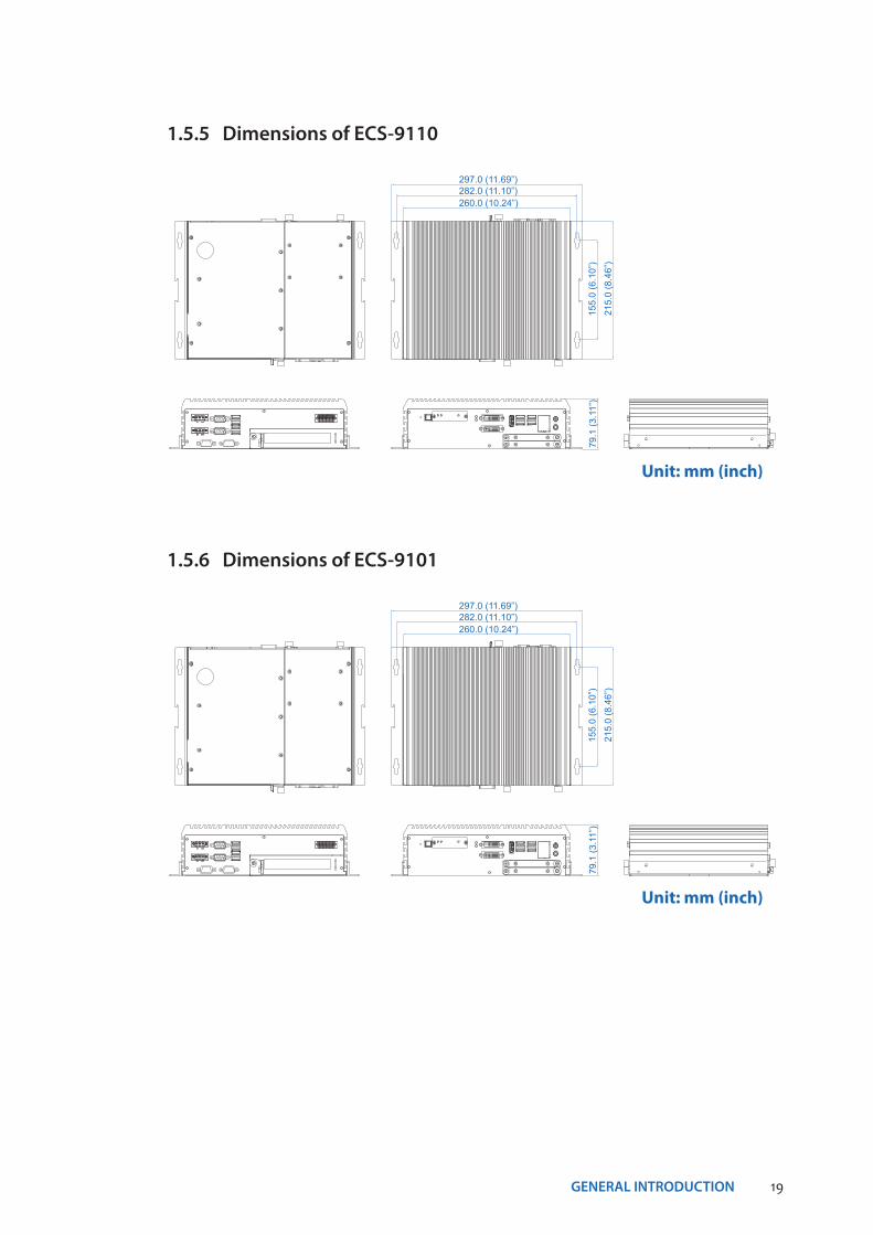
1.5.5 Dimensions of ECS-9110
155.
0 (6
.10”
)
215.
0 (8
.46”
)
260.0 (10.24”)282.0 (11.10”)297.0 (11.69”)
79.1
(3.1
1”)
Unit: mm (inch)
1.5.6 Dimensions of ECS-910115
5.0
(6.1
0”)
215.
0 (8
.46”
)
260.0 (10.24”)282.0 (11.10”)297.0 (11.69”)
79.1
(3.1
1”)
Unit: mm (inch)
20GETTING TO KNOW YOUR ECS-9200/9100©Vecow ECS-9200/9100 User Manual
2GETTING TO KNOW YOUR ECS-9200/9100
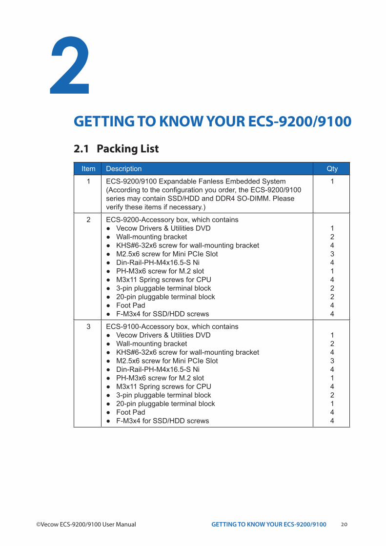
2.1 Packing List
Item Description Qty
1 ECS-9200/9100 Expandable Fanless Embedded System (According to the configuration you order, the ECS-9200/9100 series may contain SSD/HDD and DDR4 SO-DIMM. Please verify these items if necessary.)
1
2 ECS-9200-Accessory box, which contains● Vecow Drivers & Utilities DVD● Wall-mounting bracket● KHS#6-32x6 screw for wall-mounting bracket● M2.5x6 screw for Mini PCIe Slot● Din-Rail-PH-M4x16.5-S Ni● PH-M3x6 screw for M.2 slot● M3x11 Spring screws for CPU● 3-pin pluggable terminal block ● 20-pin pluggable terminal block● Foot Pad● F-M3x4 for SSD/HDD screws
12434142244
3 ECS-9100-Accessory box, which contains● Vecow Drivers & Utilities DVD● Wall-mounting bracket● KHS#6-32x6 screw for wall-mounting bracket● M2.5x6 screw for Mini PCIe Slot● Din-Rail-PH-M4x16.5-S Ni● PH-M3x6 screw for M.2 slot● M3x11 Spring screws for CPU● 3-pin pluggable terminal block ● 20-pin pluggable terminal block● Foot Pad● F-M3x4 for SSD/HDD screws
12434142144
21GETTING TO KNOW YOUR ECS-9200/9100
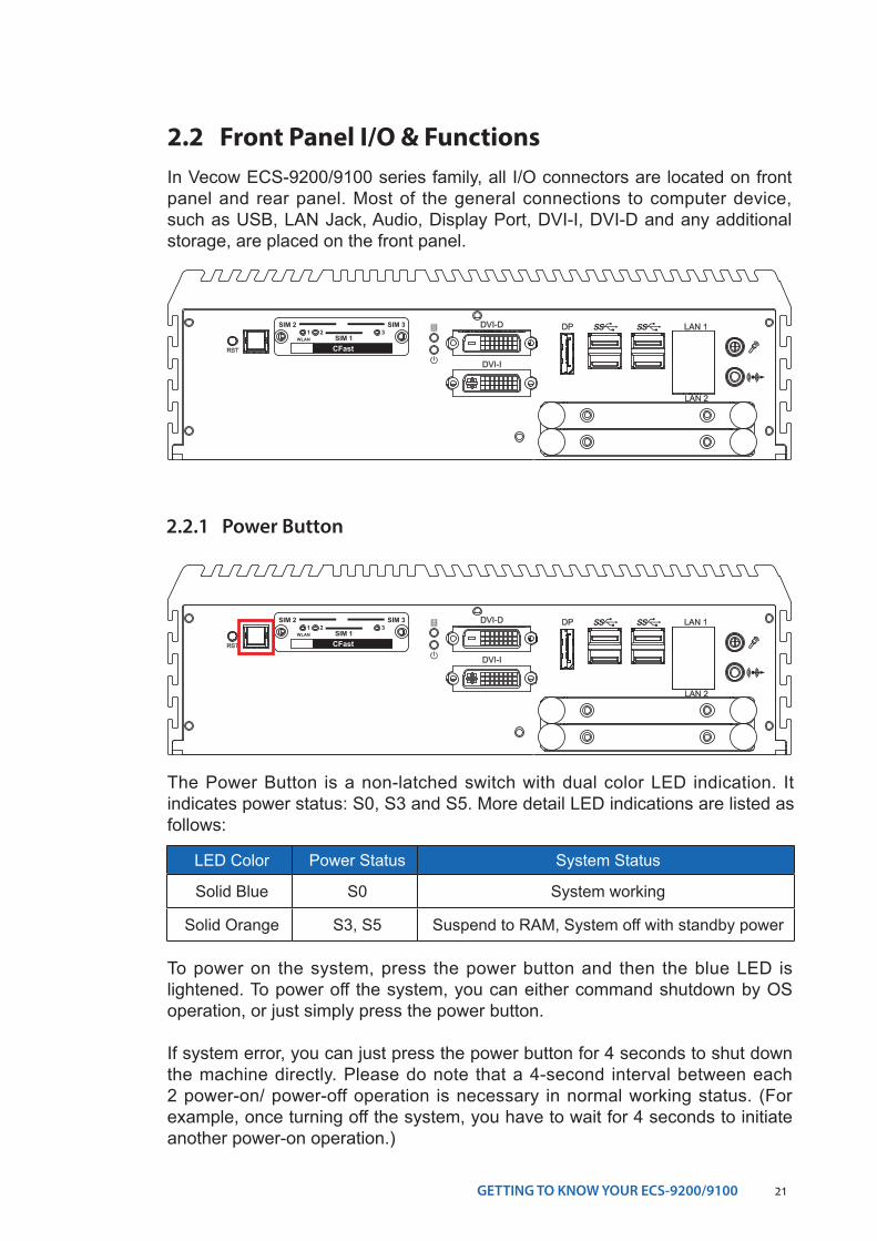
2.2 Front Panel I/O & FunctionsIn Vecow ECS-9200/9100 series family, all I/O connectors are located on front panel and rear panel. Most of the general connections to computer device, such as USB, LAN Jack, Audio, Display Port, DVI-I, DVI-D and any additional storage, are placed on the front panel.
RST
DP LAN 1
LAN 2
DVI-D
DVI-I
CFast
SIM 2 SIM 3
SIM 11 2 3
WLAN
2.2.1 Power Button
The Power Button is a non-latched switch with dual color LED indication. It indicates power status: S0, S3 and S5. More detail LED indications are listed as follows:
To power on the system, press the power button and then the blue LED is lightened. To power off the system, you can either command shutdown by OS operation, or just simply press the power button.
If system error, you can just press the power button for 4 seconds to shut down the machine directly. Please do note that a 4-second interval between each 2 power-on/ power-off operation is necessary in normal working status. (For example, once turning off the system, you have to wait for 4 seconds to initiate another power-on operation.)
LED Color Power Status System Status
Solid Blue S0 System working
Solid Orange S3, S5 Suspend to RAM, System off with standby power
RST
DP LAN 1
LAN 2
DVI-D
DVI-I
CFast
SIM 2 SIM 3
SIM 11 2 3
WLAN
22GETTING TO KNOW YOUR ECS-9200/9100©Vecow ECS-9200/9100 User Manual
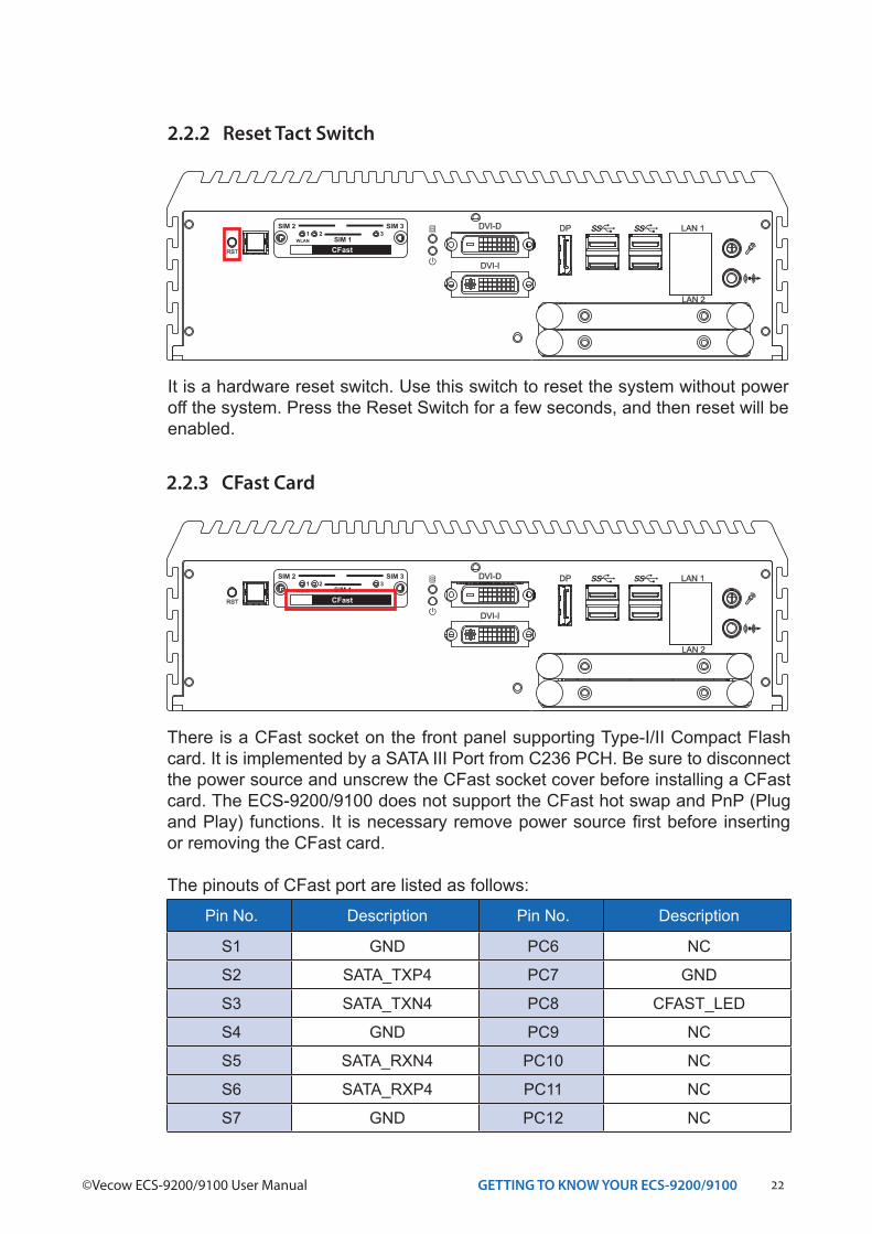
Pin No. Description Pin No. Description
S1 GND PC6 NC
S2 SATA_TXP4 PC7 GND
S3 SATA_TXN4 PC8 CFAST_LED
S4 GND PC9 NC
S5 SATA_RXN4 PC10 NC
S6 SATA_RXP4 PC11 NC
S7 GND PC12 NC
2.2.3 CFast Card
There is a CFast socket on the front panel supporting Type-I/II Compact Flash card. It is implemented by a SATA III Port from C236 PCH. Be sure to disconnect the power source and unscrew the CFast socket cover before installing a CFast card. The ECS-9200/9100 does not support the CFast hot swap and PnP (Plug and Play) functions. It is necessary remove power source first before inserting or removing the CFast card.
The pinouts of CFast port are listed as follows:
RST
DP LAN 1
LAN 2
DVI-D
DVI-I
CFast
SIM 2 SIM 3
SIM 11 2 3
WLAN
2.2.2 Reset Tact Switch
It is a hardware reset switch. Use this switch to reset the system without power off the system. Press the Reset Switch for a few seconds, and then reset will be enabled.
RST
DP LAN 1
LAN 2
DVI-D
DVI-I
CFast
SIM 2 SIM 3
SIM 11 2 3
WLAN
23GETTING TO KNOW YOUR ECS-9200/9100
Pin No. Description Pin No. Description
PC1 GND PC13 +3.3V
PC2 GND PC14 +3.3V
PC3 NC PC15 GND
PC4 NC PC16 GND
PC5 NC PC17 NC
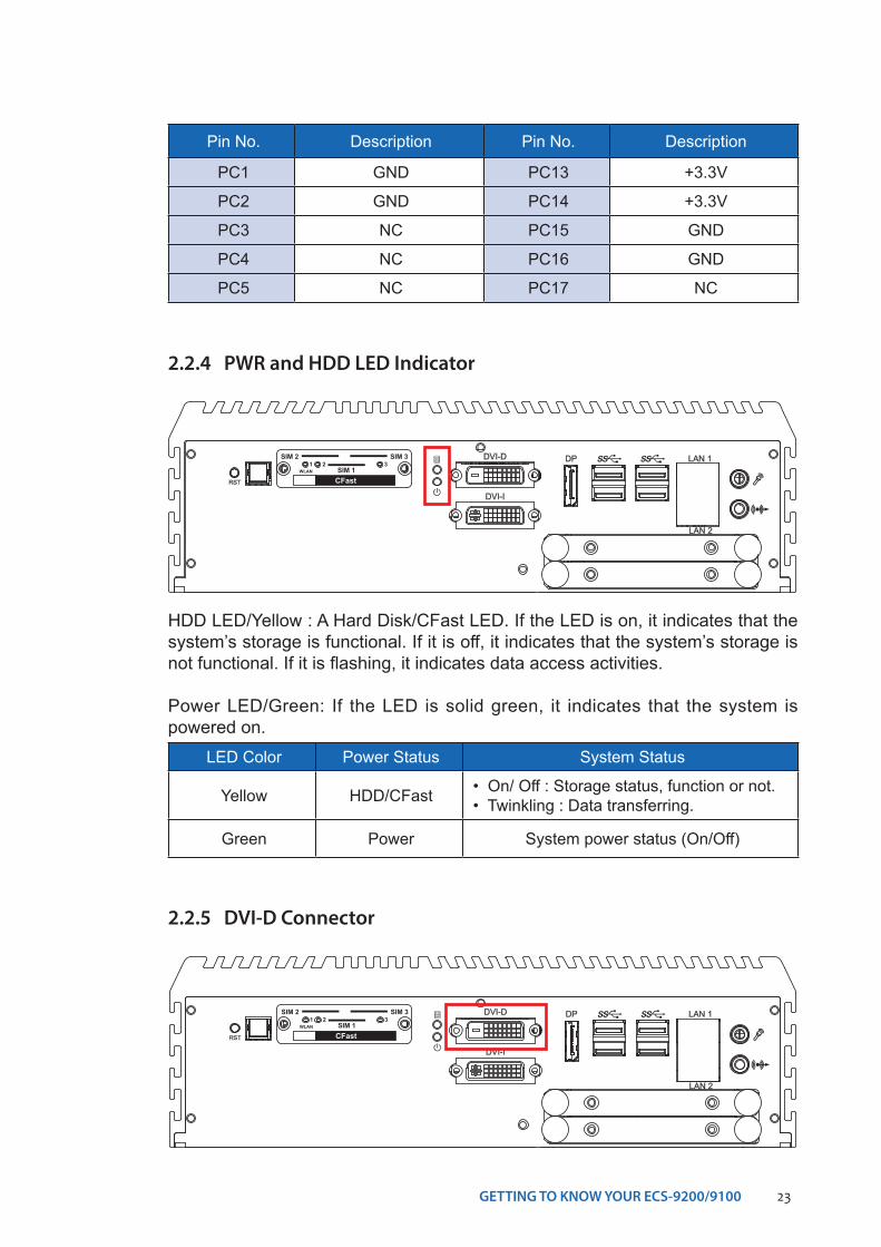
2.2.4 PWR and HDD LED Indicator
HDD LED/Yellow : A Hard Disk/CFast LED. If the LED is on, it indicates that the system’s storage is functional. If it is off, it indicates that the system’s storage is not functional. If it is flashing, it indicates data access activities.
Power LED/Green: If the LED is solid green, it indicates that the system is powered on.
LED Color Power Status System Status
Yellow HDD/CFast • On/ Off : Storage status, function or not.• Twinkling : Data transferring.
Green Power System power status (On/Off)
RST
DP LAN 1
LAN 2
DVI-D
DVI-I
CFast
SIM 2 SIM 3
SIM 11 2 3
WLAN
2.2.5 DVI-D Connector
RST
DP LAN 1
LAN 2
DVI-D
DVI-I
CFast
SIM 2 SIM 3
SIM 11 2 3
WLAN
24GETTING TO KNOW YOUR ECS-9200/9100©Vecow ECS-9200/9100 User Manual
The DVI-D connector on the front panel supports DVI display. This connector can output DVI signal. The DVI output mode supports up to 1920 x 1200 resolution and output mode supports up to 1920 x 1200 resolution. The DVI is automatically selected according to the connected display. You will need a DVI-D cable when connecting to a display device.
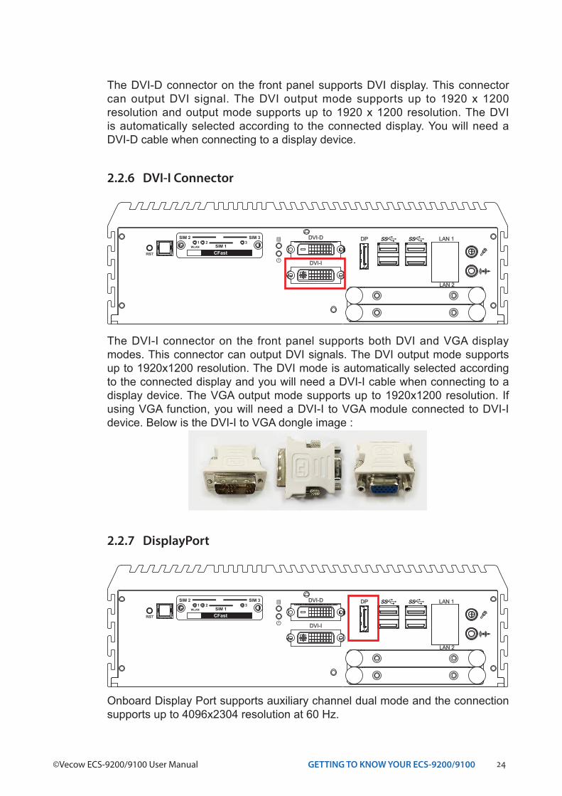
2.2.6 DVI-I Connector
The DVI-I connector on the front panel supports both DVI and VGA display modes. This connector can output DVI signals. The DVI output mode supports up to 1920x1200 resolution. The DVI mode is automatically selected according to the connected display and you will need a DVI-I cable when connecting to a display device. The VGA output mode supports up to 1920x1200 resolution. If using VGA function, you will need a DVI-I to VGA module connected to DVI-I device. Below is the DVI-I to VGA dongle image :
RST
DP LAN 1
LAN 2
DVI-D
DVI-I
CFast
SIM 2 SIM 3
SIM 11 2 3
WLAN
Onboard Display Port supports auxiliary channel dual mode and the connection supports up to 4096x2304 resolution at 60 Hz.
2.2.7 DisplayPort
RST
DP LAN 1
LAN 2
DVI-D
DVI-I
CFast
SIM 2 SIM 3
SIM 11 2 3
WLAN
25GETTING TO KNOW YOUR ECS-9200/9100
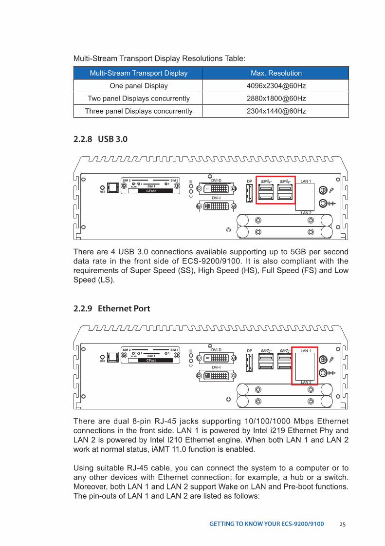
2.2.8 USB 3.0
There are 4 USB 3.0 connections available supporting up to 5GB per second data rate in the front side of ECS-9200/9100. It is also compliant with the requirements of Super Speed (SS), High Speed (HS), Full Speed (FS) and Low Speed (LS).
RST
DP LAN 1
LAN 2
DVI-D
DVI-I
CFast
SIM 2 SIM 3
SIM 11 2 3
WLAN
2.2.9 Ethernet Port
There are dual 8-pin RJ-45 jacks supporting 10/100/1000 Mbps Ethernet connections in the front side. LAN 1 is powered by Intel i219 Ethernet Phy and LAN 2 is powered by Intel I210 Ethernet engine. When both LAN 1 and LAN 2 work at normal status, iAMT 11.0 function is enabled.
Using suitable RJ-45 cable, you can connect the system to a computer or to any other devices with Ethernet connection; for example, a hub or a switch. Moreover, both LAN 1 and LAN 2 support Wake on LAN and Pre-boot functions. The pin-outs of LAN 1 and LAN 2 are listed as follows:
RST
DP LAN 1
LAN 2
DVI-D
DVI-I
CFast
SIM 2 SIM 3
SIM 11 2 3
WLAN
Multi-Stream Transport Display Max. Resolution
One panel Display 4096x2304@60Hz
Two panel Displays concurrently 2880x1800@60Hz
Three panel Displays concurrently 2304x1440@60Hz
Multi-Stream Transport Display Resolutions Table:
26GETTING TO KNOW YOUR ECS-9200/9100©Vecow ECS-9200/9100 User Manual
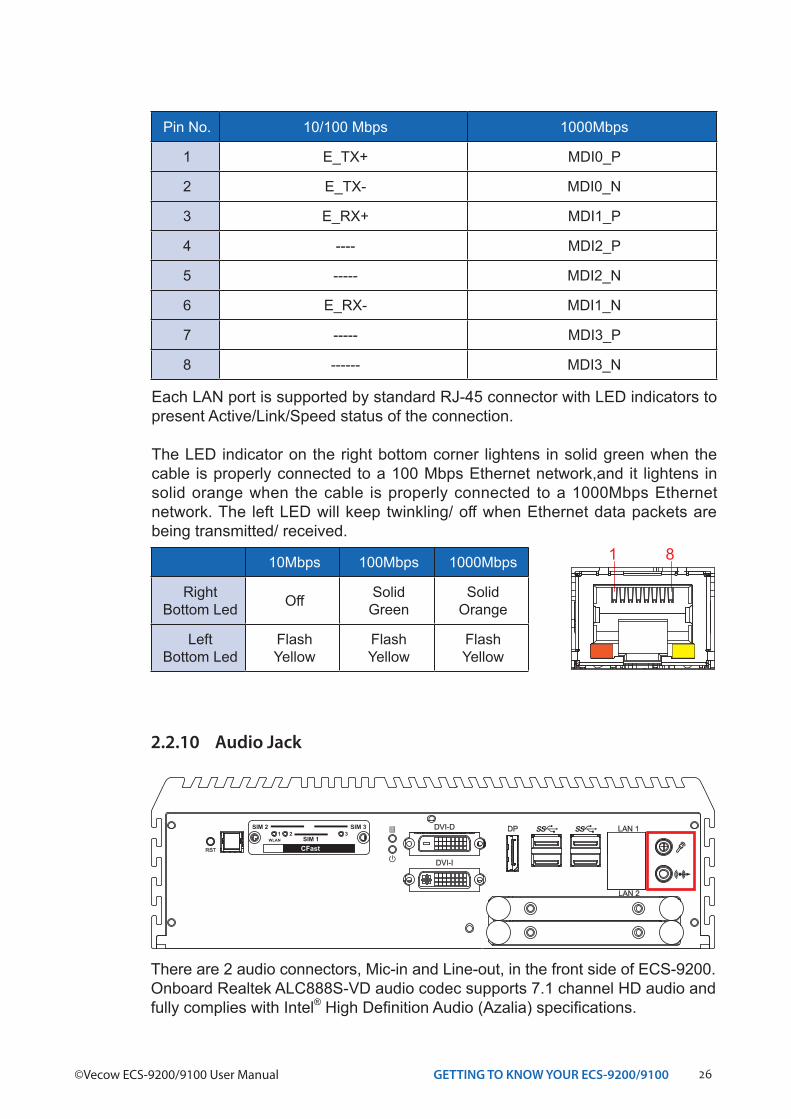
There are 2 audio connectors, Mic-in and Line-out, in the front side of ECS-9200.Onboard Realtek ALC888S-VD audio codec supports 7.1 channel HD audio and fully complies with Intel® High Definition Audio (Azalia) specifications.
2.2.10 Audio Jack
RST
DP LAN 1
LAN 2
DVI-D
DVI-I
CFast
SIM 2 SIM 3
SIM 11 2 3
WLAN
Each LAN port is supported by standard RJ-45 connector with LED indicators to present Active/Link/Speed status of the connection.
The LED indicator on the right bottom corner lightens in solid green when the cable is properly connected to a 100 Mbps Ethernet network,and it lightens in solid orange when the cable is properly connected to a 1000Mbps Ethernet network. The left LED will keep twinkling/ off when Ethernet data packets are being transmitted/ received.
1 810Mbps 100Mbps 1000Mbps
RightBottom Led Off Solid
GreenSolid
Orange
LeftBottom Led
Flash Yellow
Flash Yellow
Flash Yellow
Pin No. 10/100 Mbps 1000Mbps
1 E_TX+ MDI0_P
2 E_TX- MDI0_N
3 E_RX+ MDI1_P
4 ---- MDI2_P
5 ----- MDI2_N
6 E_RX- MDI1_N
7 ----- MDI3_P
8 ------ MDI3_N
27GETTING TO KNOW YOUR ECS-9200/9100
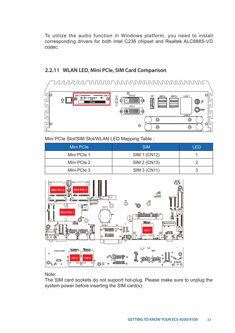
2.2.11 WLAN LED, Mini PCIe, SIM Card Comparison
RST
DP LAN 1
LAN 2
DVI-D
DVI-I
CFast
SIM 2 SIM 3
SIM 11 2 3
WLAN
Mini PCIe SIM LED
Mini PCIe 1 SIM 1 (CN12) 1
Mini PCIe 2 SIM 2 (CN13) 2
Mini PCIe 3 SIM 3 (CN11) 3
Mini PCIe Slot/SIM Slot/WLAN LED Mapping Table :
Note:The SIM card sockets do not support hot-plug. Please make sure to unplug the system power before inserting the SIM card(s).
Mini PCIe 3
CN11
Mini PCIe 2
Mini PCIe 1
CN12 CN13
To utilize the audio function in Windows platform, you need to install corresponding drivers for both Intel C236 chipset and Realtek ALC888S-VD codec.
28GETTING TO KNOW YOUR ECS-9200/9100©Vecow ECS-9200/9100 User Manual
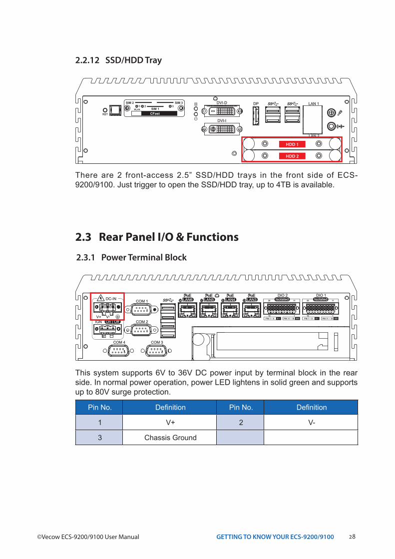
2.2.12 SSD/HDD Tray
There are 2 front-access 2.5” SSD/HDD trays in the front side of ECS-9200/9100. Just trigger to open the SSD/HDD tray, up to 4TB is available.
RST
DP LAN 1
LAN 2
DVI-D
DVI-I
CFast
SIM 2 SIM 3
SIM 11 2 3
WLAN
HDD 1
HDD 2
2.3 Rear Panel I/O & Functions
2.3.1 Power Terminal Block
This system supports 6V to 36V DC power input by terminal block in the rear side. In normal power operation, power LED lightens in solid green and supports up to 80V surge protection.
COM 1
COM 2
COM 3COM 4
V+ V-On | Off
DC-IN
IGN
LAN6PoE
LAN5PoE
LAN4PoE
LAN3PoE
IsolatedDIO 2
D IPIN 1 ~ 8 DOPIN 11 ~ 18
20 11
10 1
IsolatedDIO 1
D IPIN 1 ~ 8 DOPIN 11 ~ 18
20 11
10 1
Pin No. Definition Pin No. Definition
1 V+ 2 V-
3 Chassis Ground
29GETTING TO KNOW YOUR ECS-9200/9100
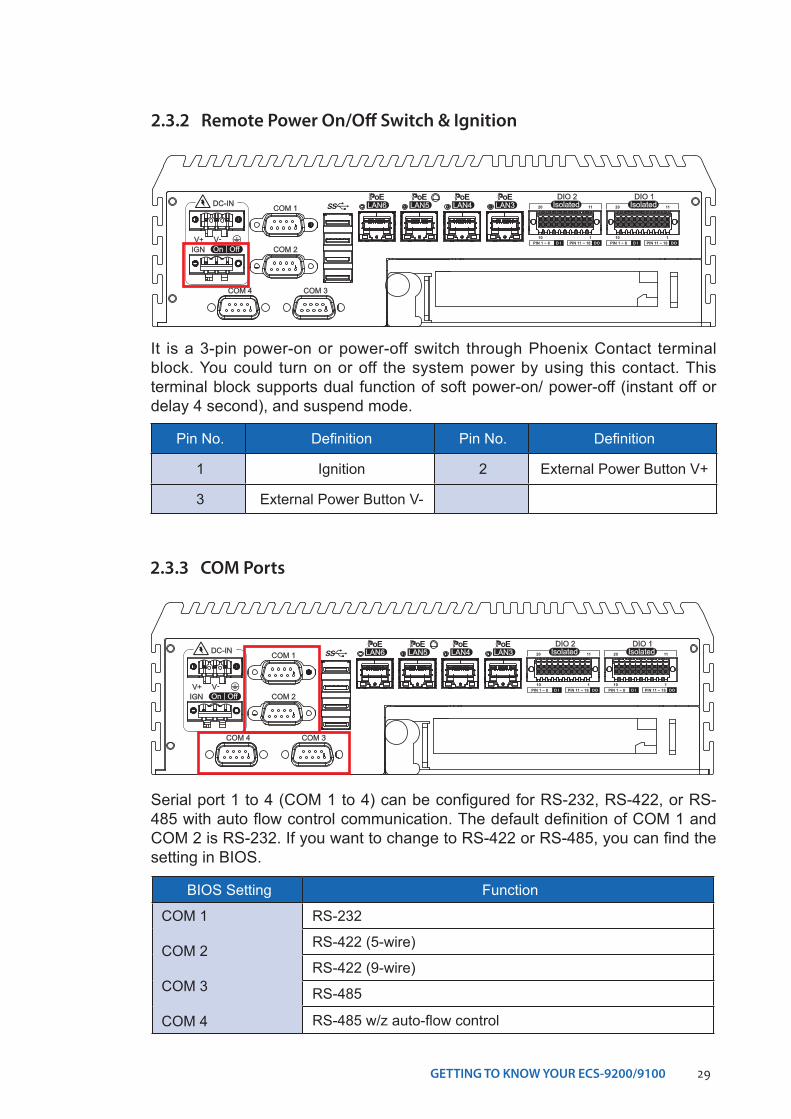
2.3.2 Remote Power On/Off Switch & Ignition
COM 1
COM 2
COM 3COM 4
V+ V-On | Off
DC-IN
IGN
LAN6PoE
LAN5PoE
LAN4PoE
LAN3PoE
IsolatedDIO 2
D IPIN 1 ~ 8 DOPIN 11 ~ 18
20 11
10 1
IsolatedDIO 1
D IPIN 1 ~ 8 DOPIN 11 ~ 18
20 11
10 1
It is a 3-pin power-on or power-off switch through Phoenix Contact terminal block. You could turn on or off the system power by using this contact. This terminal block supports dual function of soft power-on/ power-off (instant off or delay 4 second), and suspend mode.
Pin No. Definition Pin No. Definition
1 Ignition 2 External Power Button V+
3 External Power Button V-
BIOS Setting Function
COM 1
COM 2
COM 3
COM 4
RS-232
RS-422 (5-wire)
RS-422 (9-wire)
RS-485
RS-485 w/z auto-flow control
2.3.3 COM Ports
Serial port 1 to 4 (COM 1 to 4) can be configured for RS-232, RS-422, or RS-485 with auto flow control communication. The default definition of COM 1 and COM 2 is RS-232. If you want to change to RS-422 or RS-485, you can find the setting in BIOS.
COM 1
COM 2
COM 3COM 4
V+ V-On | Off
DC-IN
IGN
LAN6PoE
LAN5PoE
LAN4PoE
LAN3PoE
IsolatedDIO 2
D IPIN 1 ~ 8 DOPIN 11 ~ 18
20 11
10 1
IsolatedDIO 1
D IPIN 1 ~ 8 DOPIN 11 ~ 18
20 11
10 1
30GETTING TO KNOW YOUR ECS-9200/9100©Vecow ECS-9200/9100 User Manual
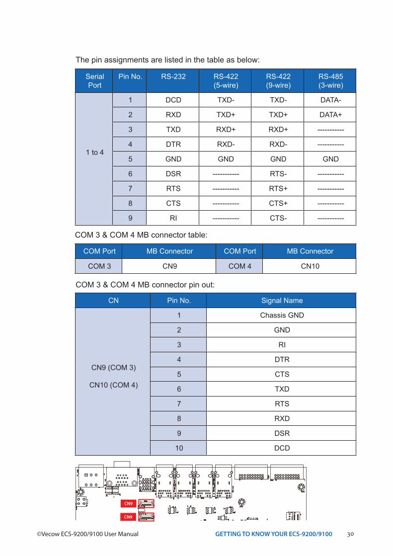
SerialPort
Pin No. RS-232 RS-422(5-wire)
RS-422(9-wire)
RS-485(3-wire)
1 to 4
1 DCD TXD- TXD- DATA-
2 RXD TXD+ TXD+ DATA+
3 TXD RXD+ RXD+ -----------
4 DTR RXD- RXD- -----------
5 GND GND GND GND
6 DSR ----------- RTS- -----------
7 RTS ----------- RTS+ -----------
8 CTS ----------- CTS+ -----------
9 RI ----------- CTS- -----------
The pin assignments are listed in the table as below:
COM 3 & COM 4 MB connector table:
COM Port MB Connector COM Port MB Connector
COM 3 CN9 COM 4 CN10
CN Pin No. Signal Name
CN9 (COM 3)
CN10 (COM 4)
1 Chassis GND
2 GND
3 RI
4 DTR
5 CTS
6 TXD
7 RTS
8 RXD
9 DSR
10 DCD
COM 3 & COM 4 MB connector pin out:
CN9
CN9
31GETTING TO KNOW YOUR ECS-9200/9100
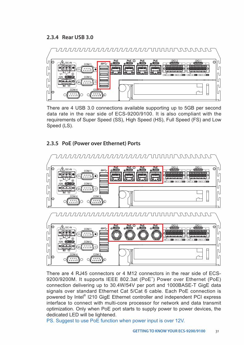
2.3.4 Rear USB 3.0
There are 4 USB 3.0 connections available supporting up to 5GB per second data rate in the rear side of ECS-9200/9100. It is also compliant with the requirements of Super Speed (SS), High Speed (HS), Full Speed (FS) and Low Speed (LS).
COM 1
COM 2
COM 3COM 4
V+ V-On | Off
DC-IN
IGN
LAN6PoE
LAN5PoE
LAN4PoE
LAN3PoE
IsolatedDIO 2
D IPIN 1 ~ 8 DOPIN 11 ~ 18
20 11
10 1
IsolatedDIO 1
D IPIN 1 ~ 8 DOPIN 11 ~ 18
20 11
10 1
2.3.5 PoE (Power over Ethernet) Ports
COM 1
COM 2
COM 3COM 4
V+ V-On | Off
DC-IN
IGN
LAN6PoE
LAN5PoE
LAN4PoE
LAN3PoE
IsolatedDIO 2
D IPIN 1 ~ 8 DOPIN 11 ~ 18
20 11
10 1
IsolatedDIO 1
D IPIN 1 ~ 8 DOPIN 11 ~ 18
20 11
10 1
COM 1
COM 2
COM 3COM 4
V+ V-On | Off
DC-IN
IGN
LAN6PoE
LAN5PoE
LAN4PoE
LAN3PoE
IsolatedDIO 2
D IPIN 1 ~ 8 DOPIN 11 ~ 18
20 11
10 1
IsolatedDIO 1
D IPIN 1 ~ 8 DOPIN 11 ~ 18
20 11
10 1
There are 4 RJ45 connectors or 4 M12 connectors in the rear side of ECS-9200/9200M. It supports IEEE 802.3at (PoE+) Power over Ethernet (PoE) connection delivering up to 30.4W/54V per port and 1000BASE-T GigE data signals over standard Ethernet Cat 5/Cat 6 cable. Each PoE connection is powered by Intel® I210 GigE Ethernet controller and independent PCI express interface to connect with multi-core processor for network and data transmit optimization. Only when PoE port starts to supply power to power devices, the dedicated LED will be lightened.PS. Suggest to use PoE function when power input is over 12V.
32GETTING TO KNOW YOUR ECS-9200/9100©Vecow ECS-9200/9100 User Manual
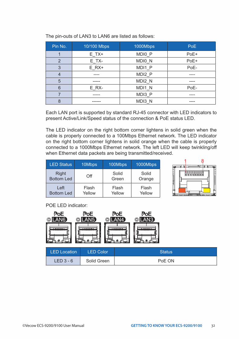
Each LAN port is supported by standard RJ-45 connector with LED indicators to present Active/Link/Speed status of the connection & PoE status LED.
The LED indicator on the right bottom corner lightens in solid green when the cable is properly connected to a 100Mbps Ethernet network. The LED indicator on the right bottom corner lightens in solid orange when the cable is properly connected to a 1000Mbps Ethernet network. The left LED will keep twinkling/off when Ethernet data packets are being transmitted/received.
1 8LED Status 10Mbps 100Mbps 1000Mbps
RightBottom Led Off Solid
GreenSolid
Orange
LeftBottom Led
Flash Yellow
Flash Yellow
Flash Yellow
LED Location LED Color Status
LED 3 - 6 Solid Green PoE ON
POE LED indicator:
Pin No. 10/100 Mbps 1000Mbps PoE
1 E_TX+ MDI0_P PoE+2 E_TX- MDI0_N PoE+3 E_RX+ MDI1_P PoE-4 ---- MDI2_P ----5 ----- MDI2_N ----6 E_RX- MDI1_N PoE-7 ----- MDI3_P ----8 ------ MDI3_N ----
The pin-outs of LAN3 to LAN6 are listed as follows:
33GETTING TO KNOW YOUR ECS-9200/9100
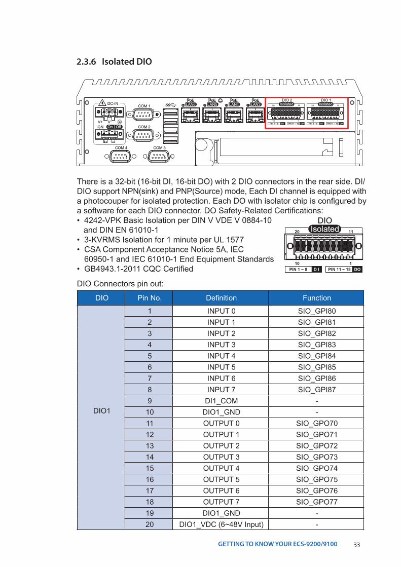
2.3.6 Isolated DIO
COM 1
COM 2
COM 3COM 4
V+ V-On | Off
DC-IN
IGN
LAN6PoE
LAN5PoE
LAN4PoE
LAN3PoE
IsolatedDIO 2
D IPIN 1 ~ 8 DOPIN 11 ~ 18
20 11
10 1
IsolatedDIO 1
D IPIN 1 ~ 8 DOPIN 11 ~ 18
20 11
10 1
There is a 32-bit (16-bit DI, 16-bit DO) with 2 DIO connectors in the rear side. DI/DIO support NPN(sink) and PNP(Source) mode, Each DI channel is equipped with a photocouper for isolated protection. Each DO with isolator chip is configured by a software for each DIO connector. DO Safety-Related Certifications:• 4242-VPK Basic Isolation per DIN V VDE V 0884-10 and DIN EN 61010-1 • 3-KVRMS Isolation for 1 minute per UL 1577• CSA Component Acceptance Notice 5A, IEC
60950-1 and IEC 61010-1 End Equipment Standards• GB4943.1-2011 CQC Certified
IsolatedDIO
D IPIN 1 ~ 8 DOPIN 11 ~ 18
20 11
10 1
DIO Pin No. Definition Function
DIO1
1 INPUT 0 SIO_GPI802 INPUT 1 SIO_GPI813 INPUT 2 SIO_GPI824 INPUT 3 SIO_GPI835 INPUT 4 SIO_GPI846 INPUT 5 SIO_GPI857 INPUT 6 SIO_GPI868 INPUT 7 SIO_GPI879 DI1_COM -
10 DIO1_GND -11 OUTPUT 0 SIO_GPO7012 OUTPUT 1 SIO_GPO7113 OUTPUT 2 SIO_GPO7214 OUTPUT 3 SIO_GPO7315 OUTPUT 4 SIO_GPO7416 OUTPUT 5 SIO_GPO7517 OUTPUT 6 SIO_GPO7618 OUTPUT 7 SIO_GPO7719 DIO1_GND -20 DIO1_VDC (6~48V Input) -
DIO Connectors pin out:
34GETTING TO KNOW YOUR ECS-9200/9100©Vecow ECS-9200/9100 User Manual
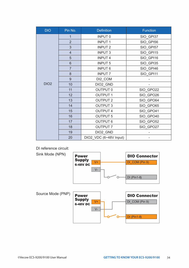
DIO Pin No. Definition Function
DIO2
1 INPUT 0 SIO_GPI372 INPUT 1 SIO_GPI563 INPUT 2 SIO_GPI574 INPUT 3 SIO_GPI155 INPUT 4 SIO_GPI166 INPUT 5 SIO_GPI357 INPUT 6 SIO_GPI468 INPUT 7 SIO_GPI119 DI2_COM -
10 DIO2_GND -11 OUTPUT 0 SIO_GPO2212 OUTPUT 1 SIO_GPO2613 OUTPUT 2 SIO_GPO6414 OUTPUT 3 SIO_GPO6515 OUTPUT 4 SIO_GPO4116 OUTPUT 5 SIO_GPO4017 OUTPUT 6 SIO_GPO5218 OUTPUT 7 SIO_GPO2719 DIO2_GND -20 DIO2_VDC (6~48V Input) -
DI reference circuit:Sink Mode (NPN)
V+
V-
PowerSupply6-48V DC
DI_COM (Pin 9)
DI (Pin1-8)
DIO Connector
Source Mode (PNP)
V+
V-
PowerSupply6-48V DC
DI_COM (Pin 9)
DI (Pin1-8)
DIO Connector
35GETTING TO KNOW YOUR ECS-9200/9100
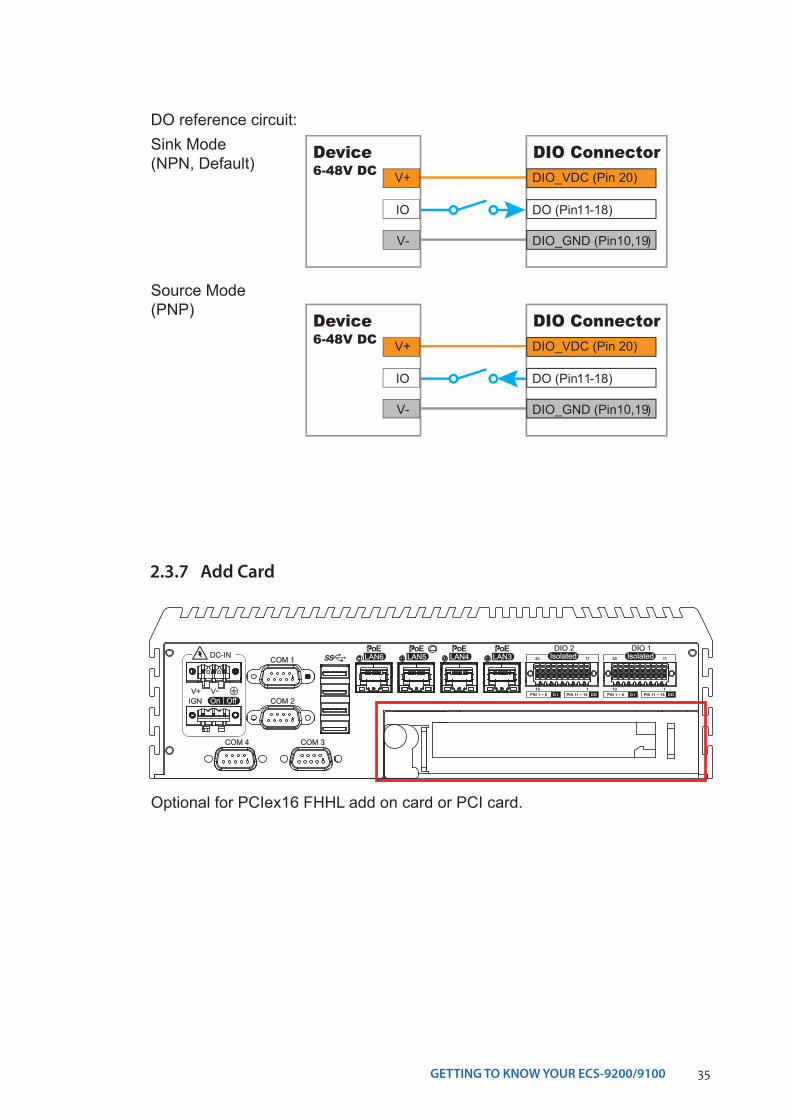
2.3.7 Add Card
Optional for PCIex16 FHHL add on card or PCI card.
COM 1
COM 2
COM 3COM 4
V+ V-On | Off
DC-IN
IGN
LAN6PoE
LAN5PoE
LAN4PoE
LAN3PoE
IsolatedDIO 2
D IPIN 1 ~ 8 DOPIN 11 ~ 18
20 11
10 1
IsolatedDIO 1
D IPIN 1 ~ 8 DOPIN 11 ~ 18
20 11
10 1
DO reference circuit:
V+
IO
V-
Device6-48V DC DIO_VDC (Pin 20)
DO (Pin11-18)
DIO_GND (Pin10,19)
DIO Connector
Source Mode (PNP)
Sink Mode (NPN, Default)
V+
IO
V-
Device6-48V DC DIO_VDC (Pin 20)
DO (Pin11-18)
DIO_GND (Pin10,19)
DIO Connector
36GETTING TO KNOW YOUR ECS-9200/9100©Vecow ECS-9200/9100 User Manual
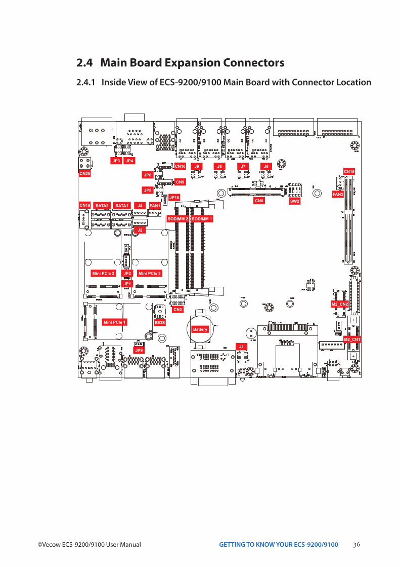
2.4 Main Board Expansion Connectors2.4.1 Inside View of ECS-9200/9100 Main Board with Connector Location
SATA2 SATA1
CN15
FAN2JP10
CN3
CN6CN18
JP1
JP3
BatteryBIOS
CN10
JP5
JP6
JP9
J4
J2
J9 J8 J7 J6JP4
SW2
CN25
CN9
J1
FAN1
JP2 Mini PCIe 3Mini PCIe 2
Mini PCIe 1
SODIMM 2 SODIMM 1
M2_CN2
M2_CN1
37GETTING TO KNOW YOUR ECS-9200/9100
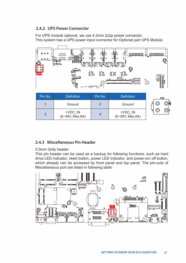
2.4.2 UPS Power Connector
For UPS module optional, we use 4.2mm 2x2p power connector.This system has a UPS power input connector for Optional part UPS Module.
Pin No. Definition Pin No. Definition
1 Ground 2 Ground
3 +VDC_IN(6~36V, Max.8A) 4 +VDC_IN
(6~36V, Max.8A)
CN25
2.4.3 Miscellaneous Pin Header
2.0mm 2x4p headerThis pin header can be used as a backup for following functions, such as hard drive LED indicator, reset button, power LED indicator, and power-on/ off button, which already can be accessed by front panel and top panel. The pin-outs of Miscellaneous port are listed in following table:
J1
38GETTING TO KNOW YOUR ECS-9200/9100©Vecow ECS-9200/9100 User Manual
Group Pin No. Description
HDD LED1 HDD_LED_P
3 HDD_LED_N
RESET BUTTON5 FP_RST_BTN_N
7 Ground
POWER LED2 PWR_LED_P
4 PWR_LED_N
POWER BUTTON6 FP_PWR_BTN_IN
8 Ground
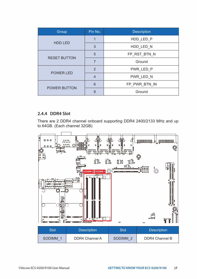
2.4.4 DDR4 Slot
There are 2 DDR4 channel onboard supporting DDR4 2400/2133 MHz and up to 64GB. (Each channel 32GB)
Slot Description Slot Description
SODIMM_1 DDR4 Channel A SODIMM_2 DDR4 Channel B
SODIMM 2 SODIMM 1
39GETTING TO KNOW YOUR ECS-9200/9100
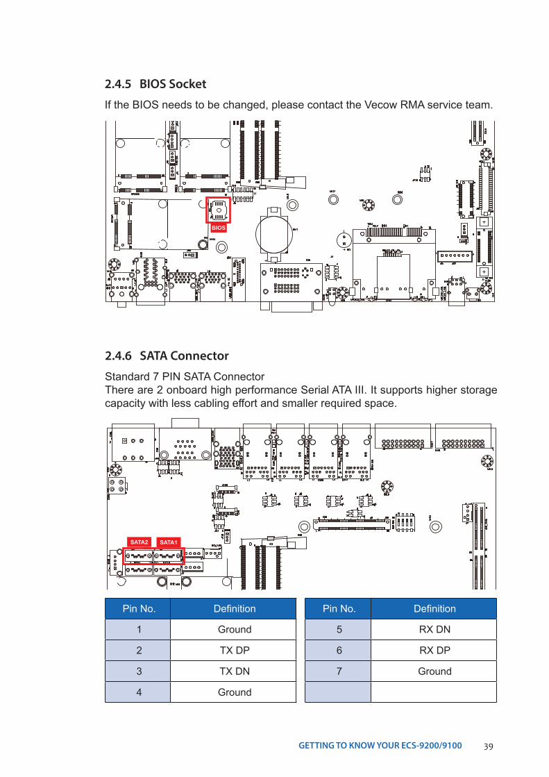
2.4.5 BIOS Socket
If the BIOS needs to be changed, please contact the Vecow RMA service team.
2.4.6 SATA Connector
Standard 7 PIN SATA ConnectorThere are 2 onboard high performance Serial ATA III. It supports higher storage capacity with less cabling effort and smaller required space.
SATA1SATA2
Pin No. Definition
1 Ground
2 TX DP
3 TX DN
4 Ground
Pin No. Definition
5 RX DN
6 RX DP
7 Ground
BIOS
40GETTING TO KNOW YOUR ECS-9200/9100©Vecow ECS-9200/9100 User Manual
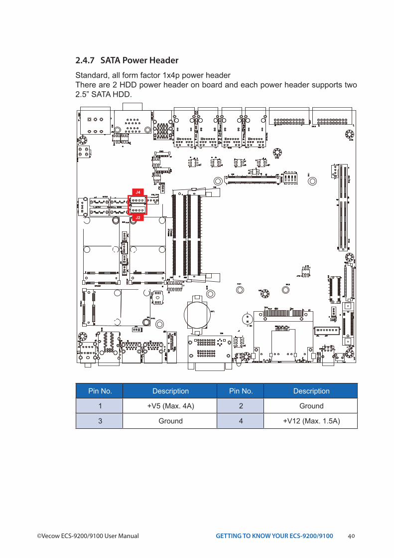
2.4.7 SATA Power Header
Standard, all form factor 1x4p power headerThere are 2 HDD power header on board and each power header supports two 2.5” SATA HDD.
Pin No. Description Pin No. Description
1 +V5 (Max. 4A) 2 Ground
3 Ground 4 +V12 (Max. 1.5A)
J4
J2
41GETTING TO KNOW YOUR ECS-9200/9100
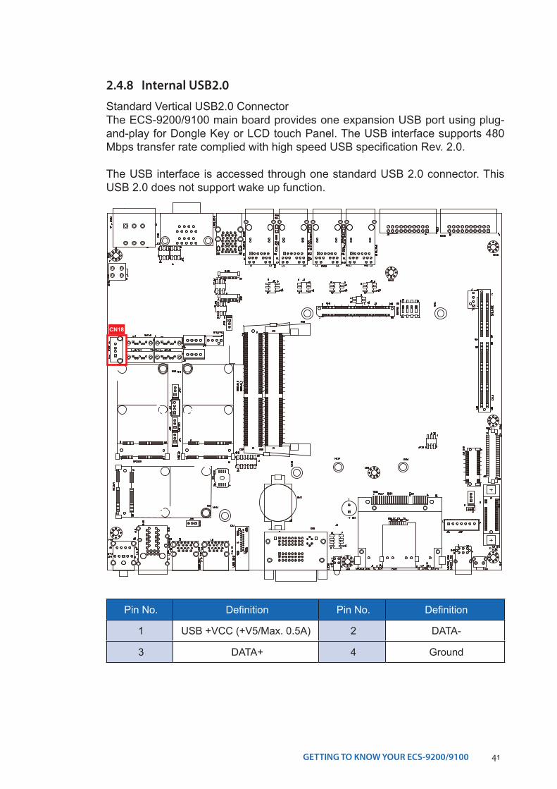
2.4.8 Internal USB2.0
Standard Vertical USB2.0 ConnectorThe ECS-9200/9100 main board provides one expansion USB port using plug-and-play for Dongle Key or LCD touch Panel. The USB interface supports 480 Mbps transfer rate complied with high speed USB specification Rev. 2.0.
The USB interface is accessed through one standard USB 2.0 connector. This USB 2.0 does not support wake up function.
Pin No. Definition Pin No. Definition
1 USB +VCC (+V5/Max. 0.5A) 2 DATA-
3 DATA+ 4 Ground
CN18
42GETTING TO KNOW YOUR ECS-9200/9100©Vecow ECS-9200/9100 User Manual
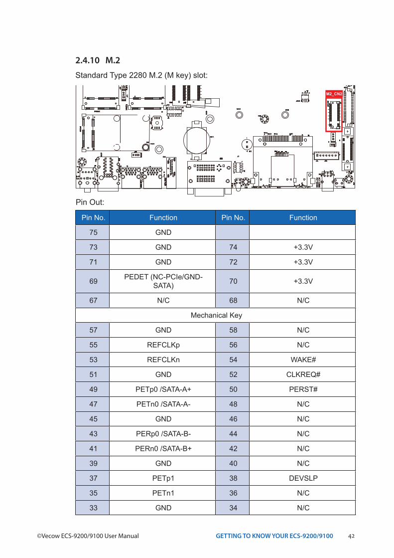
Pin No. Function Pin No. Function
75 GND
73 GND 74 +3.3V
71 GND 72 +3.3V
69 PEDET (NC-PCIe/GND-SATA) 70 +3.3V
67 N/C 68 N/C
Mechanical Key
57 GND 58 N/C
55 REFCLKp 56 N/C
53 REFCLKn 54 WAKE#
51 GND 52 CLKREQ#
49 PETp0 /SATA-A+ 50 PERST#
47 PETn0 /SATA-A- 48 N/C
45 GND 46 N/C
43 PERp0 /SATA-B- 44 N/C
41 PERn0 /SATA-B+ 42 N/C
39 GND 40 N/C
37 PETp1 38 DEVSLP
35 PETn1 36 N/C
33 GND 34 N/C
Pin Out:
2.4.10 M.2
Standard Type 2280 M.2 (M key) slot:
M2_CN2
43GETTING TO KNOW YOUR ECS-9200/9100
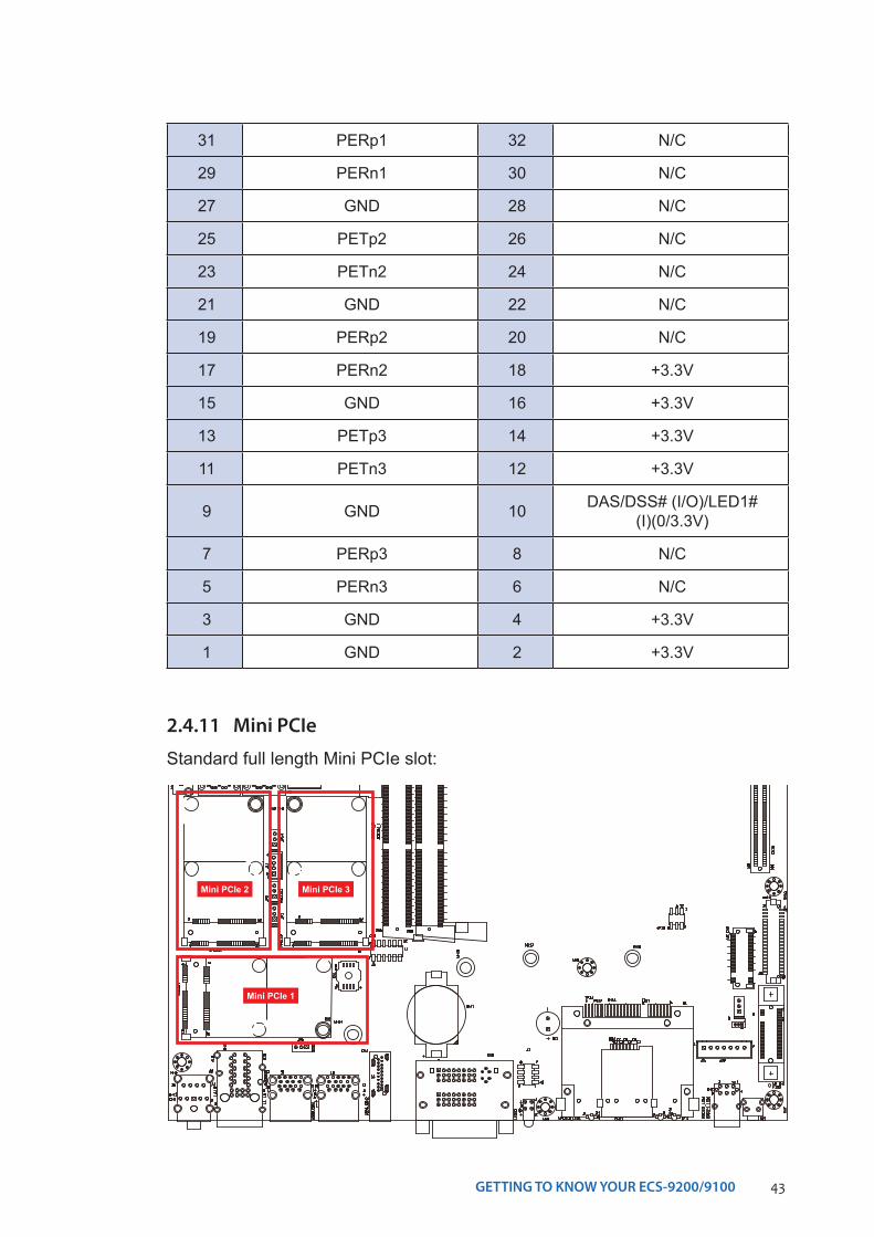
31 PERp1 32 N/C
29 PERn1 30 N/C
27 GND 28 N/C
25 PETp2 26 N/C
23 PETn2 24 N/C
21 GND 22 N/C
19 PERp2 20 N/C
17 PERn2 18 +3.3V
15 GND 16 +3.3V
13 PETp3 14 +3.3V
11 PETn3 12 +3.3V
9 GND 10 DAS/DSS# (I/O)/LED1# (I)(0/3.3V)
7 PERp3 8 N/C
5 PERn3 6 N/C
3 GND 4 +3.3V
1 GND 2 +3.3V
2.4.11 Mini PCIe
Mini PCIe 3Mini PCIe 2
Mini PCIe 1
Standard full length Mini PCIe slot:
44GETTING TO KNOW YOUR ECS-9200/9100©Vecow ECS-9200/9100 User Manual
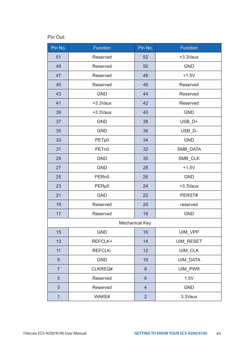
Pin No. Function Pin No. Function
51 Reserved 52 +3.3Vaux
49 Reserved 50 GND
47 Reserved 48 +1.5V
45 Reserved 46 Reserved
43 GND 44 Reserved
41 +3.3Vaux 42 Reserved
39 +3.3Vaux 40 GND
37 GND 38 USB_D+
35 GND 36 USB_D-
33 PETp0 34 GND
31 PETn0 32 SMB_DATA
29 GND 30 SMB_CLK
27 GND 28 +1.5V
25 PERn0 26 GND
23 PERp0 24 +3.3Vaux
21 GND 22 PERST#
19 Reserved 20 reserved
17 Reserved 18 GND
Mechanical Key
15 GND 16 UIM_VPP
13 REFCLK+ 14 UIM_RESET
11 REFCLK- 12 UIM_CLK
9 GND 10 UIM_DATA
7 CLKREQ# 8 UIM_PWR
5 Reserved 6 1.5V
3 Reserved 4 GND
1 WAKE# 2 3.3Vaux
Pin Out:
45GETTING TO KNOW YOUR ECS-9200/9100
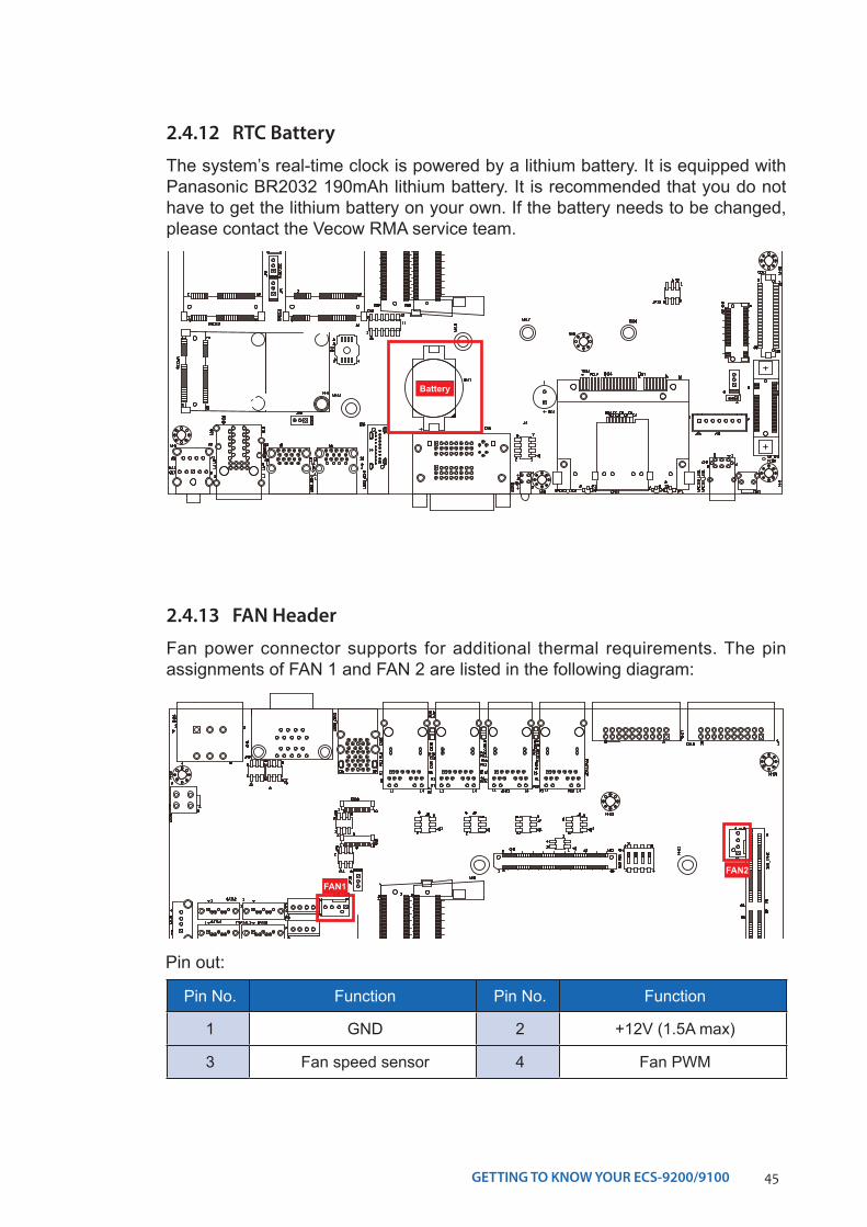
2.4.12 RTC Battery
The system’s real-time clock is powered by a lithium battery. It is equipped with Panasonic BR2032 190mAh lithium battery. It is recommended that you do not have to get the lithium battery on your own. If the battery needs to be changed, please contact the Vecow RMA service team.
Battery
2.4.13 FAN Header
Fan power connector supports for additional thermal requirements. The pin assignments of FAN 1 and FAN 2 are listed in the following diagram:
Pin No. Function Pin No. Function
1 GND 2 +12V (1.5A max)
3 Fan speed sensor 4 Fan PWM
Pin out:
FAN2
FAN1
46GETTING TO KNOW YOUR ECS-9200/9100©Vecow ECS-9200/9100 User Manual
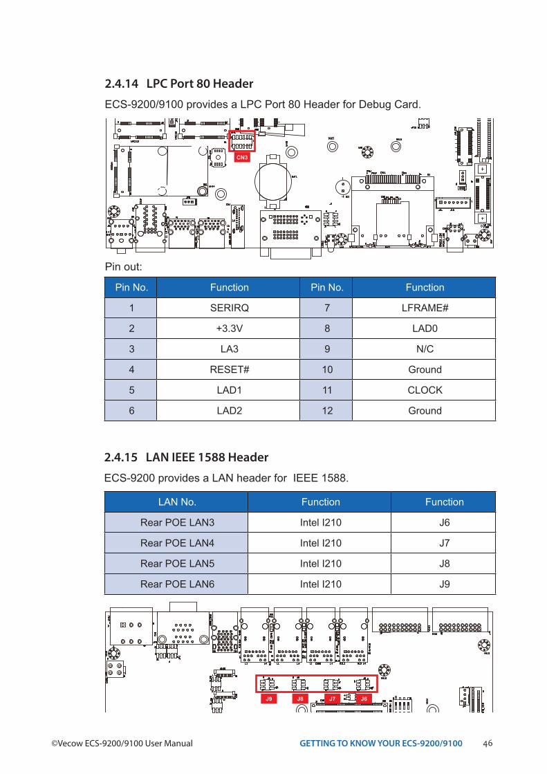
Pin No. Function Pin No. Function
1 SERIRQ 7 LFRAME#
2 +3.3V 8 LAD0
3 LA3 9 N/C
4 RESET# 10 Ground
5 LAD1 11 CLOCK
6 LAD2 12 Ground
Pin out:
2.4.14 LPC Port 80 Header
ECS-9200/9100 provides a LPC Port 80 Header for Debug Card.
CN3
2.4.15 LAN IEEE 1588 Header
ECS-9200 provides a LAN header for IEEE 1588.
LAN No. Function Function
Rear POE LAN3 Intel I210 J6
Rear POE LAN4 Intel I210 J7
Rear POE LAN5 Intel I210 J8
Rear POE LAN6 Intel I210 J9
J9 J8 J7 J6
47GETTING TO KNOW YOUR ECS-9200/9100
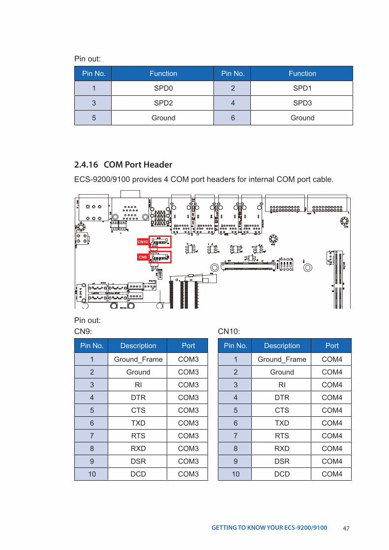
Pin No. Function Pin No. Function
1 SPD0 2 SPD1
3 SPD2 4 SPD3
5 Ground 6 Ground
Pin out:
2.4.16 COM Port Header
ECS-9200/9100 provides 4 COM port headers for internal COM port cable.
Pin No. Description Port
1 Ground_Frame COM3
2 Ground COM3
3 RI COM3
4 DTR COM3
5 CTS COM3
6 TXD COM3
7 RTS COM3
8 RXD COM3
9 DSR COM3
10 DCD COM3
CN9:
Pin No. Description Port
1 Ground_Frame COM4
2 Ground COM4
3 RI COM4
4 DTR COM4
5 CTS COM4
6 TXD COM4
7 RTS COM4
8 RXD COM4
9 DSR COM4
10 DCD COM4
CN10:Pin out:
CN10
CN9
48GETTING TO KNOW YOUR ECS-9200/9100©Vecow ECS-9200/9100 User Manual
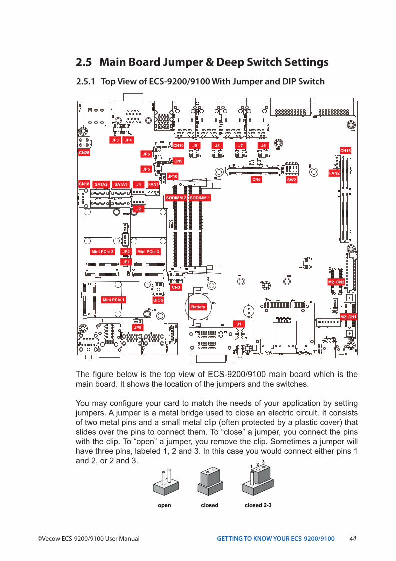
2.5 Main Board Jumper & Deep Switch Settings2.5.1 Top View of ECS-9200/9100 With Jumper and DIP Switch
The figure below is the top view of ECS-9200/9100 main board which is the main board. It shows the location of the jumpers and the switches.
You may configure your card to match the needs of your application by setting jumpers. A jumper is a metal bridge used to close an electric circuit. It consists of two metal pins and a small metal clip (often protected by a plastic cover) that slides over the pins to connect them. To “close” a jumper, you connect the pins with the clip. To “open” a jumper, you remove the clip. Sometimes a jumper will have three pins, labeled 1, 2 and 3. In this case you would connect either pins 1 and 2, or 2 and 3.
SATA2 SATA1
CN15
FAN2JP10
CN3
CN6CN18
JP1
JP3
BatteryBIOS
CN10
JP5
JP6
JP9
J4
J2
J9 J8 J7 J6JP4
SW2
CN25
CN9
J1
FAN1
JP2 Mini PCIe 3Mini PCIe 2
Mini PCIe 1
SODIMM 2 SODIMM 1
M2_CN2
M2_CN1
49GETTING TO KNOW YOUR ECS-9200/9100
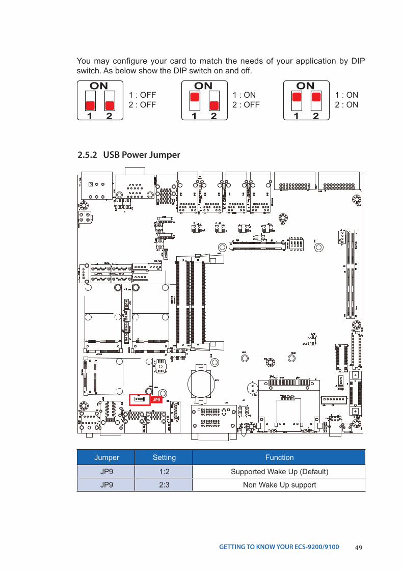
You may configure your card to match the needs of your application by DIP switch. As below show the DIP switch on and off.
ON
1 2
1 : OFF2 : OFF
ON
1 2
1 : ON2 : OFF
ON
1 2
1 : ON2 : ON
2.5.2 USB Power Jumper
Jumper Setting Function
JP9 1:2 Supported Wake Up (Default)
JP9 2:3 Non Wake Up support
JP9
50GETTING TO KNOW YOUR ECS-9200/9100©Vecow ECS-9200/9100 User Manual
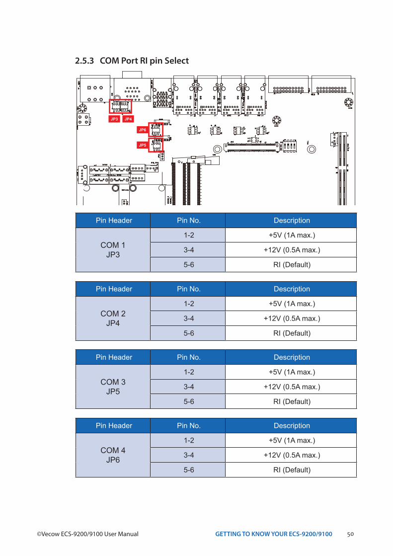
2.5.3 COM Port RI pin Select
Pin Header Pin No. Description
COM 1JP3
1-2 +5V (1A max.)
3-4 +12V (0.5A max.)
5-6 RI (Default)
Pin Header Pin No. Description
COM 2JP4
1-2 +5V (1A max.)
3-4 +12V (0.5A max.)
5-6 RI (Default)
Pin Header Pin No. Description
COM 3JP5
1-2 +5V (1A max.)
3-4 +12V (0.5A max.)
5-6 RI (Default)
Pin Header Pin No. Description
COM 4JP6
1-2 +5V (1A max.)
3-4 +12V (0.5A max.)
5-6 RI (Default)
JP6
JP5
JP3 JP4
51GETTING TO KNOW YOUR ECS-9200/9100
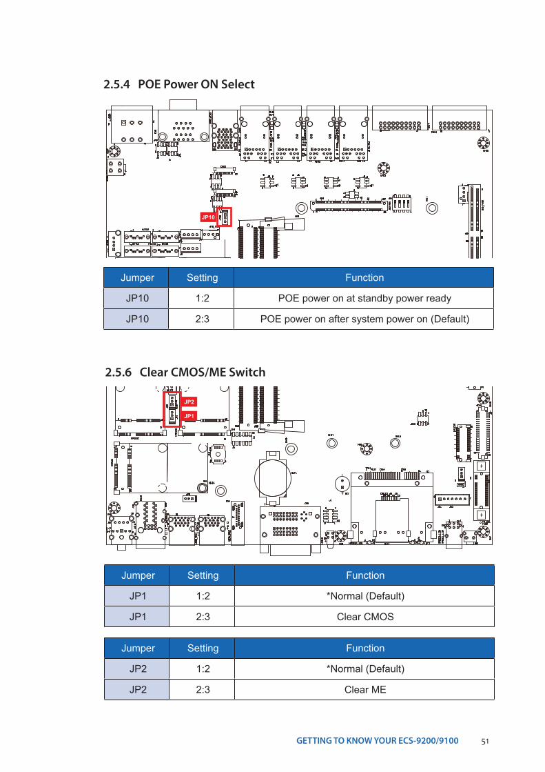
2.5.4 POE Power ON Select
Jumper Setting Function
JP10 1:2 POE power on at standby power ready
JP10 2:3 POE power on after system power on (Default)
JP10
2.5.6 Clear CMOS/ME Switch
Jumper Setting Function
JP1 1:2 *Normal (Default)
JP1 2:3 Clear CMOS
Jumper Setting Function
JP2 1:2 *Normal (Default)
JP2 2:3 Clear ME
JP1
JP2
52GETTING TO KNOW YOUR ECS-9200/9100©Vecow ECS-9200/9100 User Manual
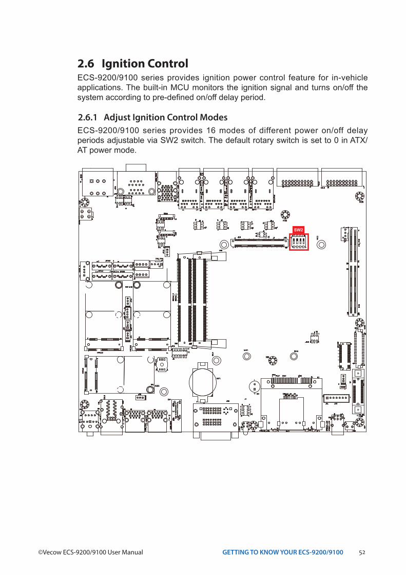
2.6 Ignition Control
2.6.1 Adjust Ignition Control Modes
ECS-9200/9100 series provides ignition power control feature for in-vehicle applications. The built-in MCU monitors the ignition signal and turns on/off the system according to pre-defined on/off delay period.
ECS-9200/9100 series provides 16 modes of different power on/off delay periods adjustable via SW2 switch. The default rotary switch is set to 0 in ATX/ AT power mode.
SW2
53GETTING TO KNOW YOUR ECS-9200/9100
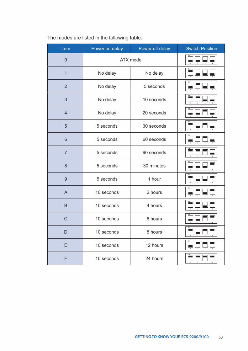
The modes are listed in the following table:
Item Power on delay Power off delay Switch Position
0 ATX mode
1 No delay No delay
2 No delay 5 seconds
3 No delay 10 seconds
4 No delay 20 seconds
5 5 seconds 30 seconds
6 5 seconds 60 seconds
7 5 seconds 90 seconds
8 5 seconds 30 minutes
9 5 seconds 1 hour
A 10 seconds 2 hours
B 10 seconds 4 hours
C 10 seconds 6 hours
D 10 seconds 8 hours
E 10 seconds 12 hours
F 10 seconds 24 hours
ON
1 2 3 4
ON
1 2 3 4
ON
1 2 3 4
ON
1 2 3 4
ON
1 2 3 4
ON
1 2 3 4
ON
1 2 3 4
ON
1 2 3 4
ON
1 2 3 4
ON
1 2 3 4
ON
1 2 3 4
ON
1 2 3 4
ON
1 2 3 4
ON
1 2 3 4
ON
1 2 3 4
ON
1 2 3 4
54GETTING TO KNOW YOUR ECS-9200/9100©Vecow ECS-9200/9100 User Manual
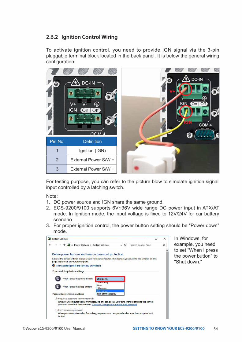
2.6.2 Ignition Control Wiring
To activate ignition control, you need to provide IGN signal via the 3-pin pluggable terminal block located in the back panel. It is below the general wiring configuration.
For testing purpose, you can refer to the picture blow to simulate ignition signal input controlled by a latching switch.
Note:1. DC power source and IGN share the same ground.2. ECS-9200/9100 supports 6V~36V wide range DC power input in ATX/AT
mode. In Ignition mode, the input voltage is fixed to 12V/24V for car battery scenario.
3. For proper ignition control, the power button setting should be “Power down” mode.
In Windows, for example, you need to set “When I press the power button” to "Shut down."
Pin No. Definition
1 Ignition (IGN)
2 External Power S/W +
3 External Power S/W +
IGN
V+
55HARDWARE INSTALLATION
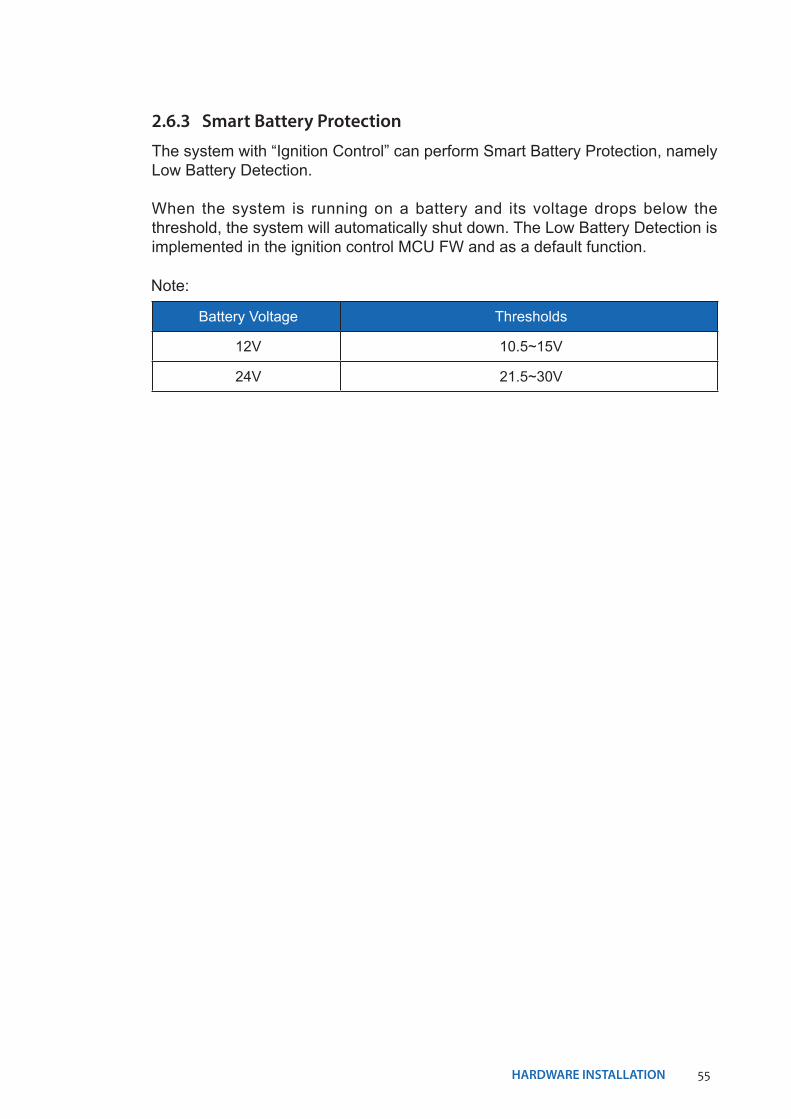
2.6.3 Smart Battery Protection
The system with “Ignition Control” can perform Smart Battery Protection, namely Low Battery Detection.
When the system is running on a battery and its voltage drops below the threshold, the system will automatically shut down. The Low Battery Detection is implemented in the ignition control MCU FW and as a default function.
Battery Voltage Thresholds
12V 10.5~15V
24V 21.5~30V
Note:
56HARDWARE INSTALLATION©Vecow ECS-9200/9100 User Manual
SYSTEM SETUP
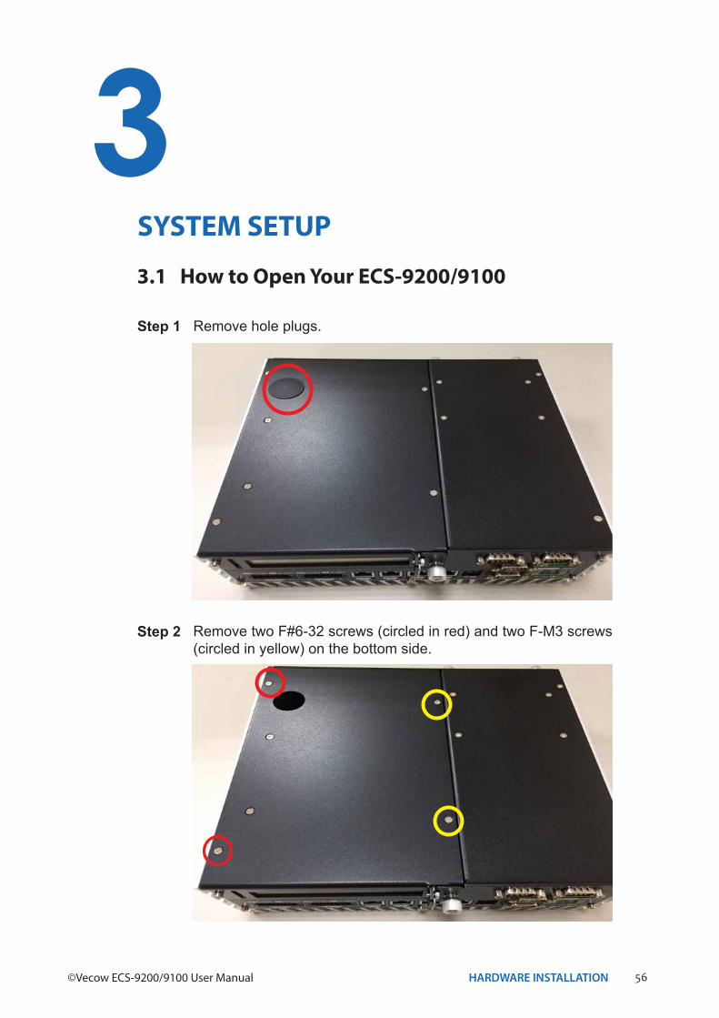
3.1 How to Open Your ECS-9200/9100
3Step 1 Remove hole plugs.
Step 2 Remove two F#6-32 screws (circled in red) and two F-M3 screws (circled in yellow) on the bottom side.
57HARDWARE INSTALLATION
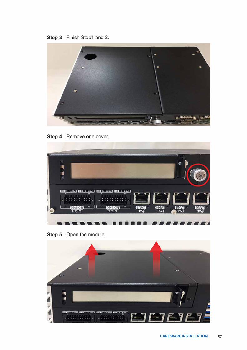
Step 3 Finish Step1 and 2.
Step 4 Remove one cover.
Step 5 Open the module.
58HARDWARE INSTALLATION©Vecow ECS-9200/9100 User Manual
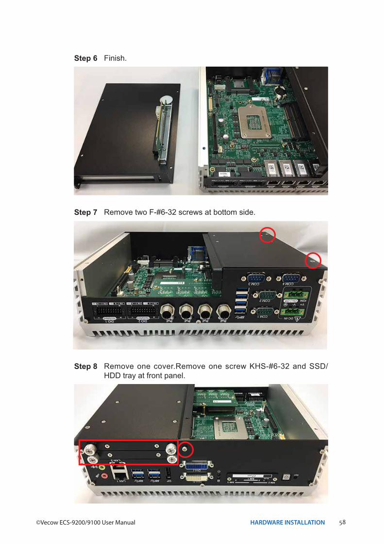
Step 6 Finish.
Step 7 Remove two F-#6-32 screws at bottom side.
Step 8 Remove one cover.Remove one screw KHS-#6-32 and SSD/HDD tray at front panel.
59HARDWARE INSTALLATION
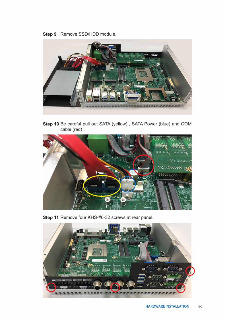
Step 9 Remove SSD/HDD module.
Step 10 Be careful pull out SATA (yellow) , SATA Power (blue) and COM cable (red) .
Step 11 Remove four KHS-#6-32 screws at rear panel.
60HARDWARE INSTALLATION©Vecow ECS-9200/9100 User Manual
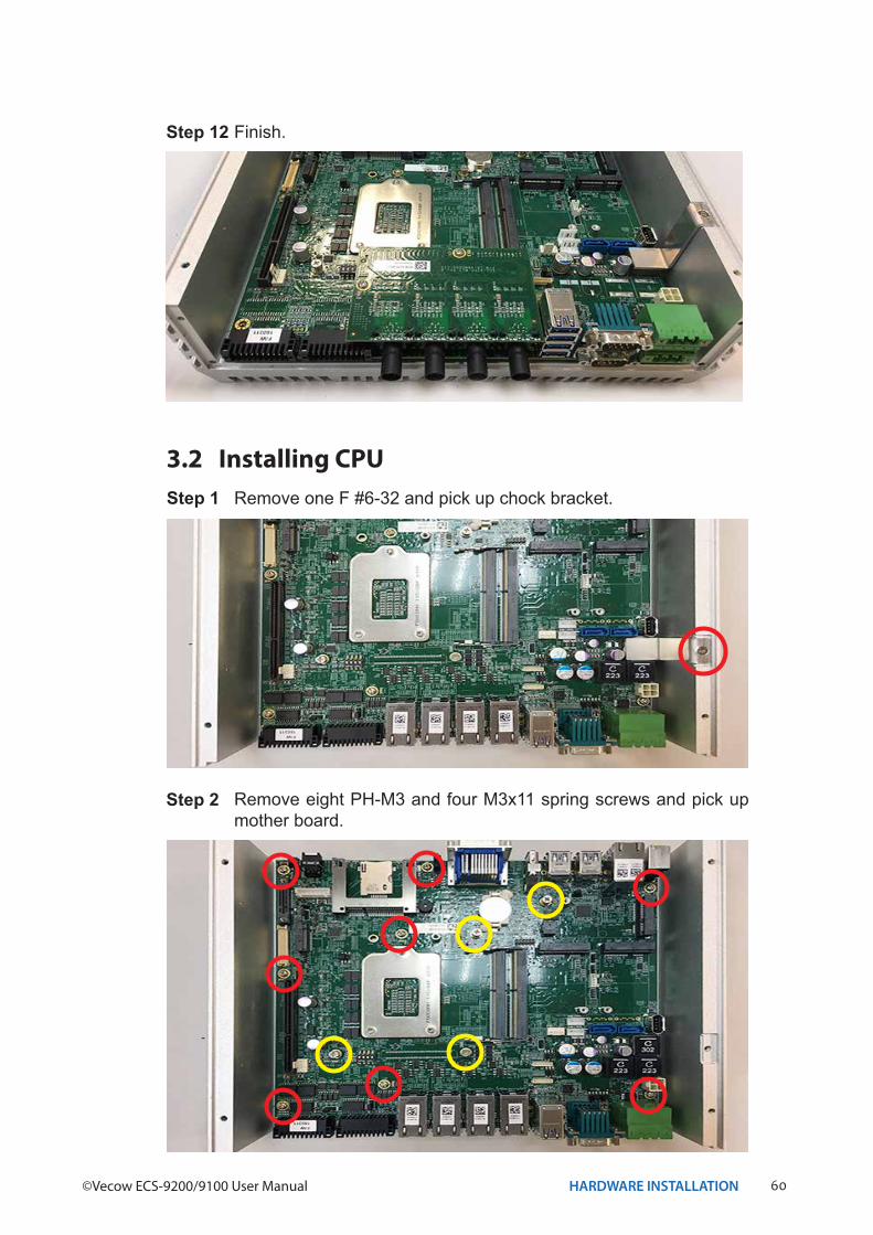
Step 12 Finish.
3.2 Installing CPUStep 1 Remove one F #6-32 and pick up chock bracket.
Step 2 Remove eight PH-M3 and four M3x11 spring screws and pick up mother board.
61HARDWARE INSTALLATION
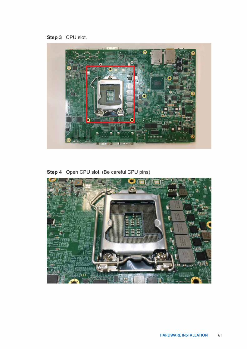
Step 4 Open CPU slot. (Be careful CPU pins)
Step 3 CPU slot.
62HARDWARE INSTALLATION©Vecow ECS-9200/9100 User Manual
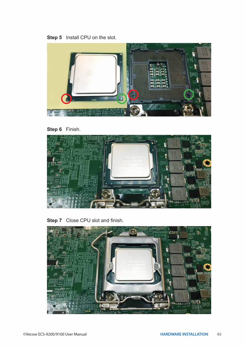
Step 6 Finish.
Step 5 Install CPU on the slot.
Step 7 Close CPU slot and finish.
63HARDWARE INSTALLATION
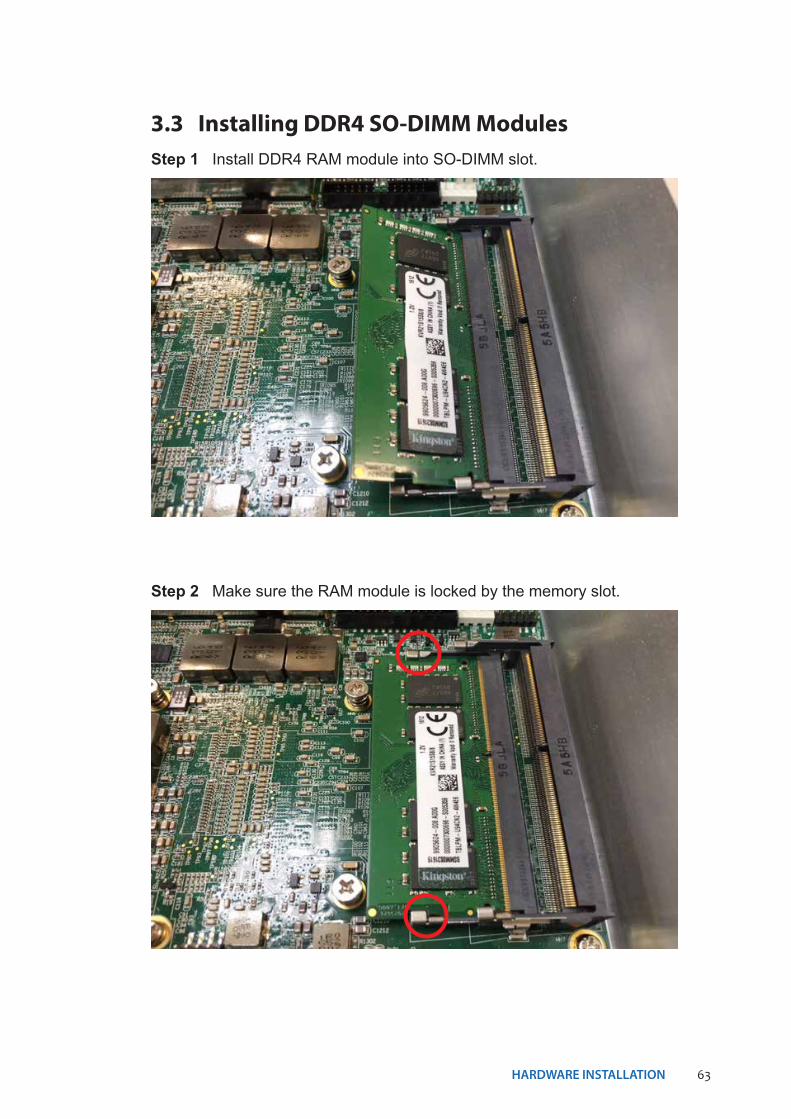
3.3 Installing DDR4 SO-DIMM ModulesStep 1 Install DDR4 RAM module into SO-DIMM slot.
Step 2 Make sure the RAM module is locked by the memory slot.
64HARDWARE INSTALLATION©Vecow ECS-9200/9100 User Manual
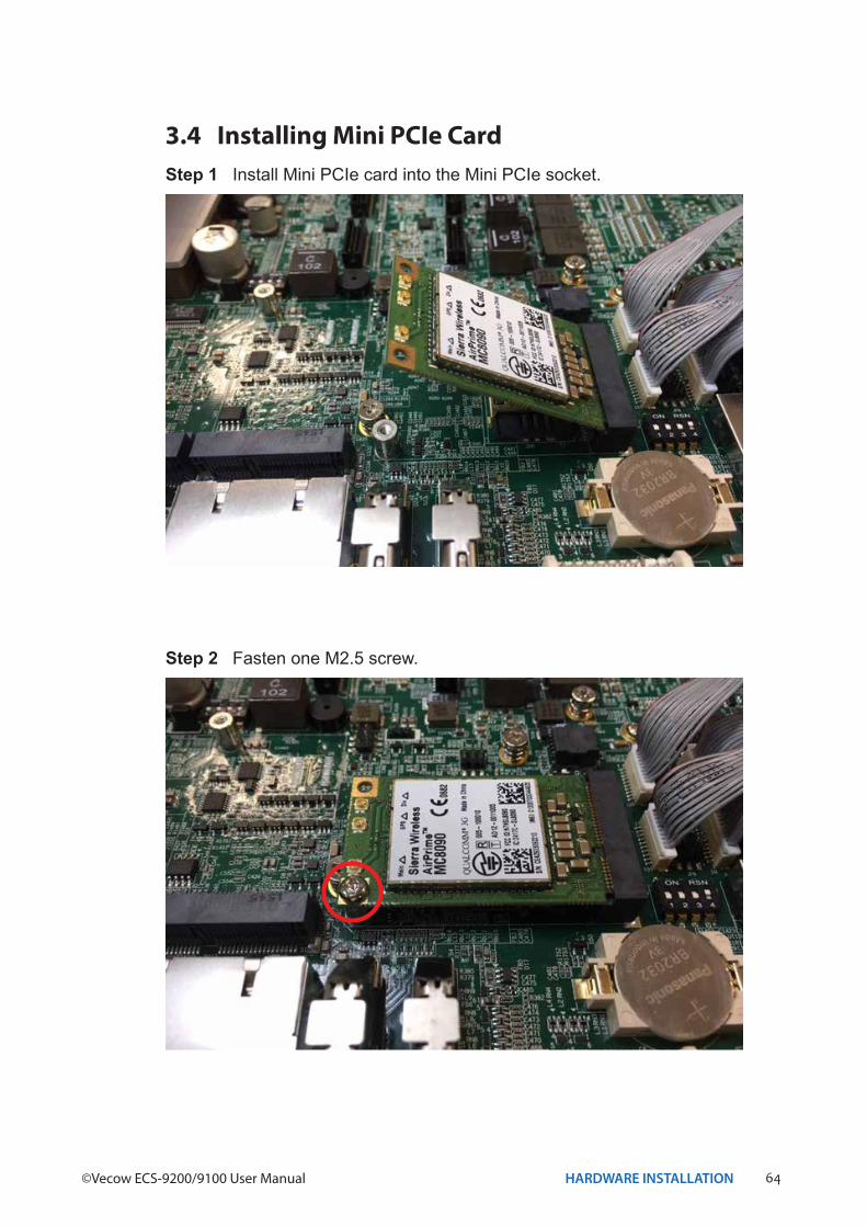
3.4 Installing Mini PCIe CardStep 1 Install Mini PCIe card into the Mini PCIe socket.
Step 2 Fasten one M2.5 screw.
65HARDWARE INSTALLATION
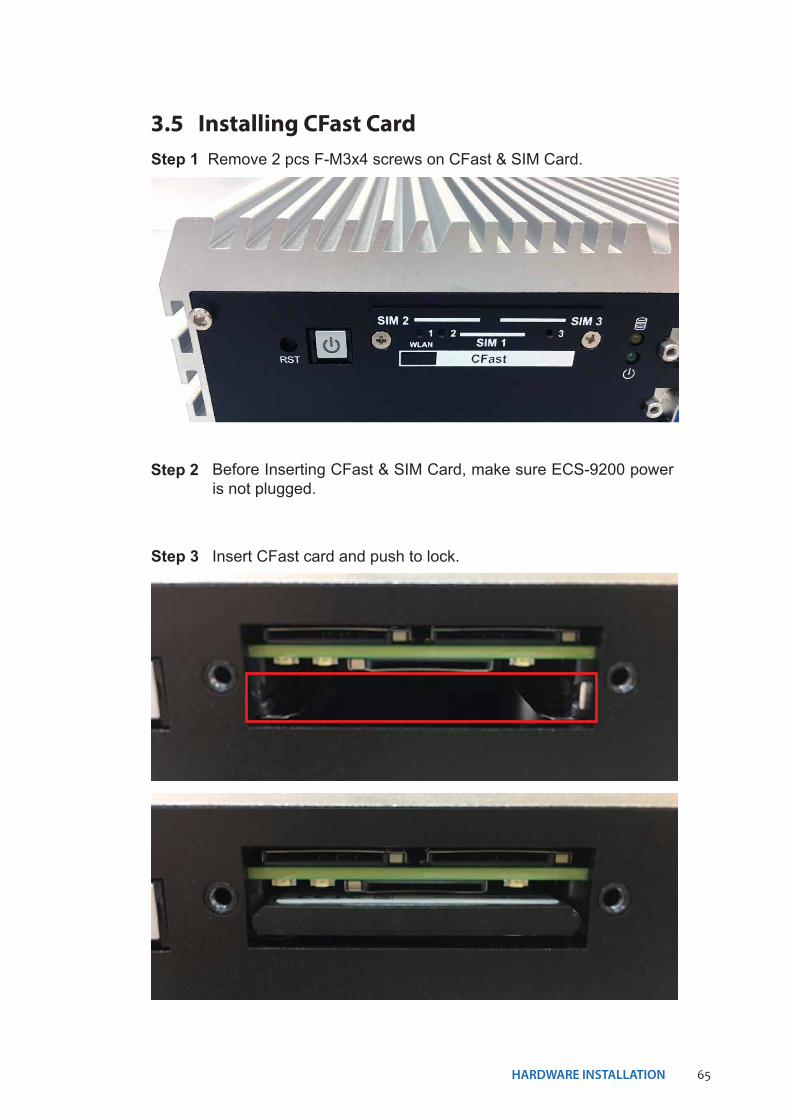
3.5 Installing CFast CardStep 1 Remove 2 pcs F-M3x4 screws on CFast & SIM Card.
Step 2 Before Inserting CFast & SIM Card, make sure ECS-9200 power is not plugged.
Step 3 Insert CFast card and push to lock.
66HARDWARE INSTALLATION©Vecow ECS-9200/9100 User Manual
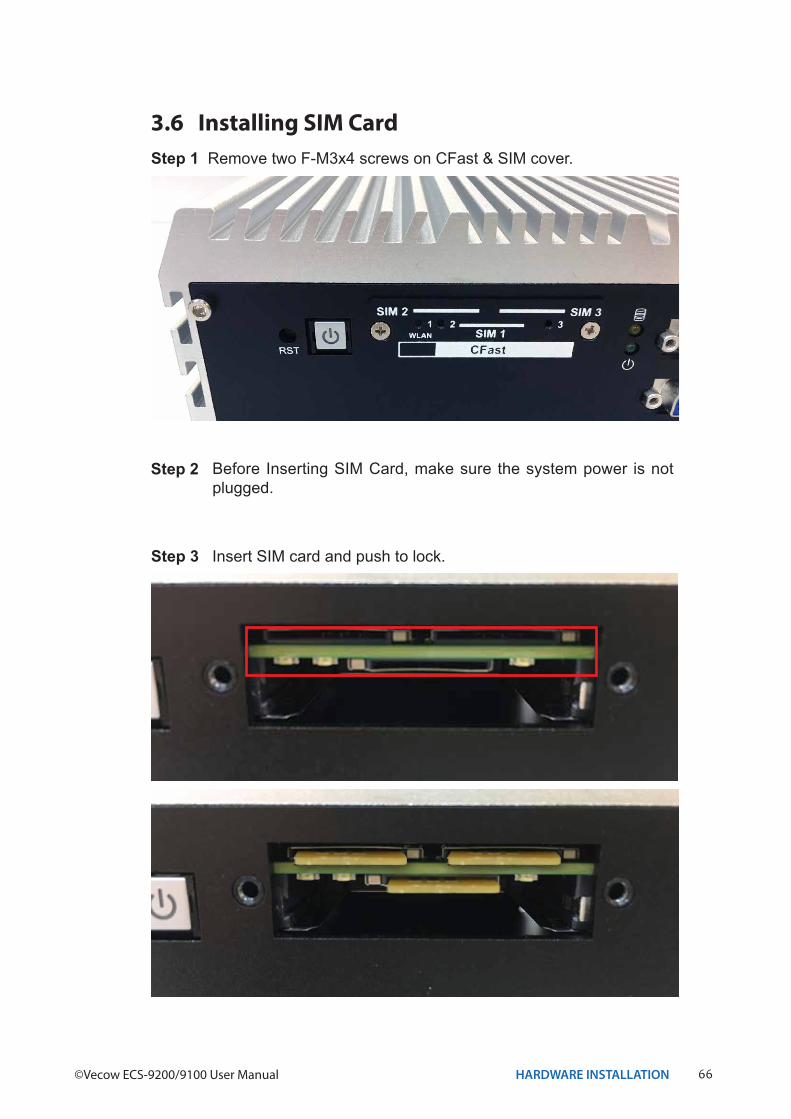
3.6 Installing SIM CardStep 1 Remove two F-M3x4 screws on CFast & SIM cover.
Step 2 Before Inserting SIM Card, make sure the system power is not plugged.
Step 3 Insert SIM card and push to lock.
67HARDWARE INSTALLATION
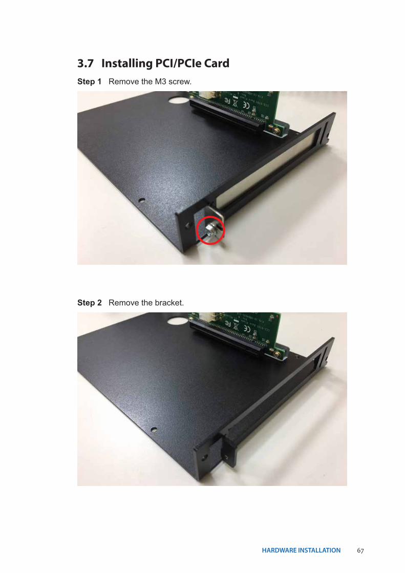
3.7 Installing PCI/PCIe Card
Step 2 Remove the bracket.
Step 1 Remove the M3 screw.
68HARDWARE INSTALLATION©Vecow ECS-9200/9100 User Manual
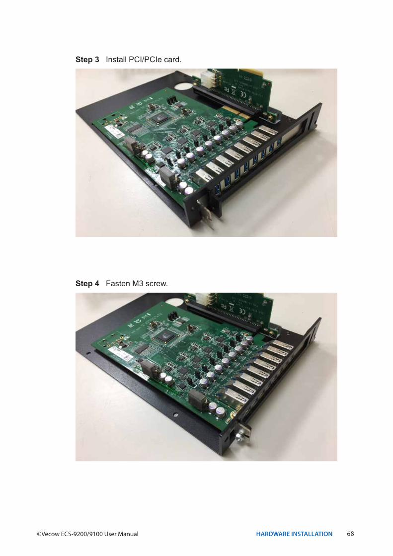
Step 4 Fasten M3 screw.
Step 3 Install PCI/PCIe card.
69HARDWARE INSTALLATION
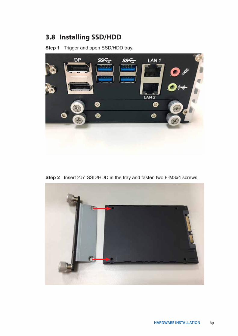
3.8 Installing SSD/HDDStep 1 Trigger and open SSD/HDD tray.
Step 2 Insert 2.5” SSD/HDD in the tray and fasten two F-M3x4 screws.
70HARDWARE INSTALLATION©Vecow ECS-9200/9100 User Manual
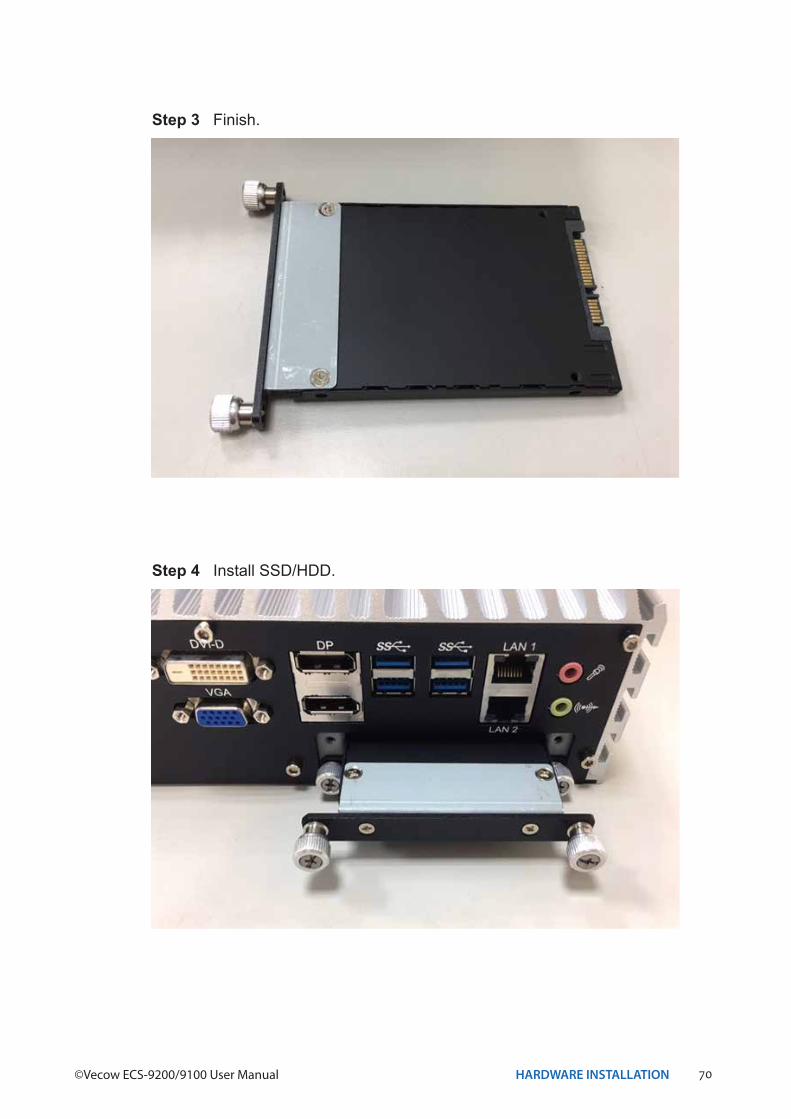
Step 3 Finish.
Step 4 Install SSD/HDD.
71HARDWARE INSTALLATION
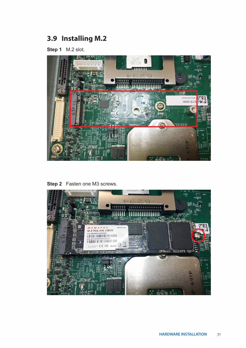
3.9 Installing M.2
Step 2 Fasten one M3 screws.
Step 1 M.2 slot.
72HARDWARE INSTALLATION©Vecow ECS-9200/9100 User Manual
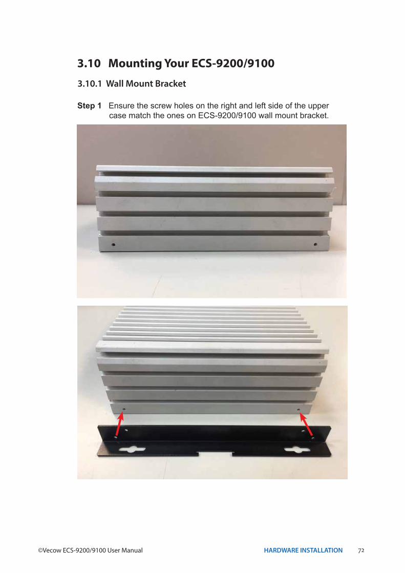
3.10 Mounting Your ECS-9200/9100
Step 1 Ensure the screw holes on the right and left side of the upper case match the ones on ECS-9200/9100 wall mount bracket.
3.10.1 Wall Mount Bracket
73HARDWARE INSTALLATION
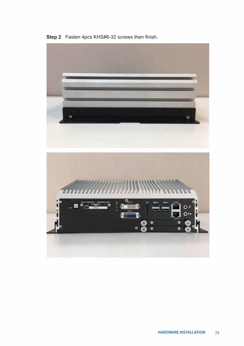
Step 2 Fasten 4pcs KHS#6-32 screws then finish.
74HARDWARE INSTALLATION©Vecow ECS-9200/9100 User Manual
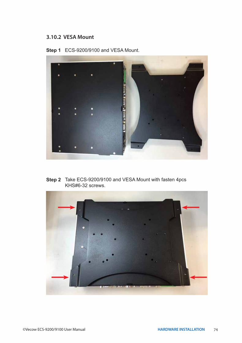
3.10.2 VESA Mount
Step 1 ECS-9200/9100 and VESA Mount.
Step 2 Take ECS-9200/9100 and VESA Mount with fasten 4pcs KHS#6-32 screws.
75HARDWARE INSTALLATION
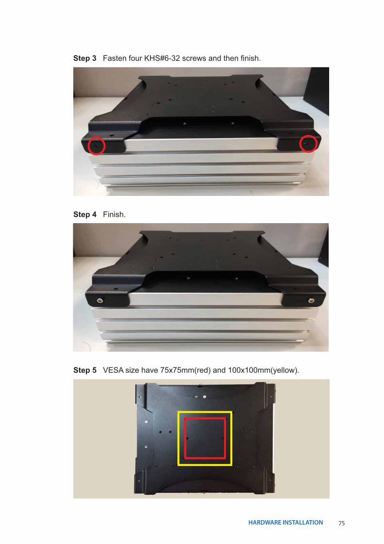
Step 3 Fasten four KHS#6-32 screws and then finish.
Step 4 Finish.
Step 5 VESA size have 75x75mm(red) and 100x100mm(yellow).
76HARDWARE INSTALLATION©Vecow ECS-9200/9100 User Manual
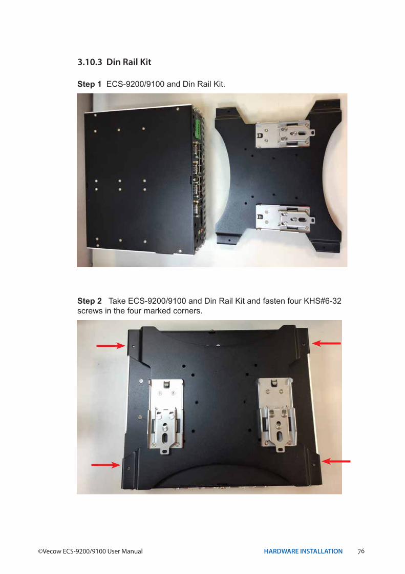
3.10.3 Din Rail Kit
Step 1 ECS-9200/9100 and Din Rail Kit.
Step 2 Take ECS-9200/9100 and Din Rail Kit and fasten four KHS#6-32 screws in the four marked corners.
77HARDWARE INSTALLATION
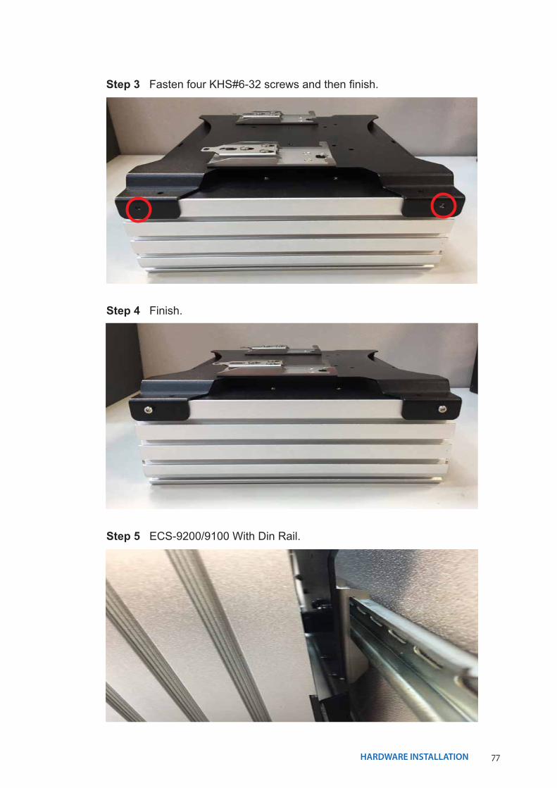
Step 3 Fasten four KHS#6-32 screws and then finish.
Step 4 Finish.
Step 5 ECS-9200/9100 With Din Rail.
78BIOS AND DRIVER SETTING©Vecow ECS-9200/9100 User Manual
4BIOS SETUP
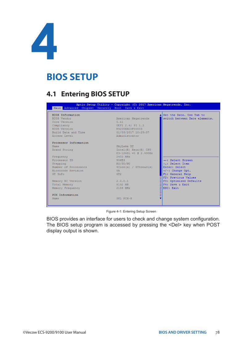
4.1 Entering BIOS SETUP
BIOS provides an interface for users to check and change system configuration. The BIOS setup program is accessed by pressing the <Del> key when POST display output is shown.
Figure 4-1: Entering Setup Screen
79BIOS AND DRIVER SETTING
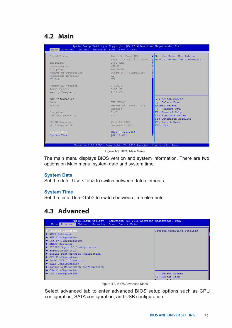
4.2 Main
The main menu displays BIOS version and system information. There are two options on Main menu, system date and system time.
System DateSet the date. Use <Tab> to switch between date elements.
System TimeSet the time. Use <Tab> to switch between time elements.
Figure 4-2: BIOS Main Menu
4.3 Advanced
Figure 4 3: BIOS Advanced Menu
Select advanced tab to enter advanced BIOS setup options such as CPU configuration, SATA configuration, and USB configuration.
80BIOS AND DRIVER SETTING©Vecow ECS-9200/9100 User Manual
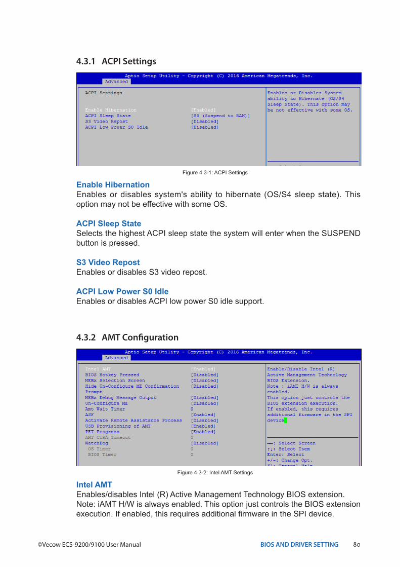
4.3.1 ACPI Settings
Enable HibernationEnables or disables system's ability to hibernate (OS/S4 sleep state). This option may not be effective with some OS.
ACPI Sleep StateSelects the highest ACPI sleep state the system will enter when the SUSPEND button is pressed.
S3 Video RepostEnables or disables S3 video repost.
ACPI Low Power S0 IdleEnables or disables ACPI low power S0 idle support.
Figure 4 3-1: ACPI Settings
4.3.2 AMT Configuration
Intel AMTEnables/disables Intel (R) Active Management Technology BIOS extension.Note: iAMT H/W is always enabled. This option just controls the BIOS extension execution. If enabled, this requires additional firmware in the SPI device.
Figure 4 3-2: Intel AMT Settings
81BIOS AND DRIVER SETTING
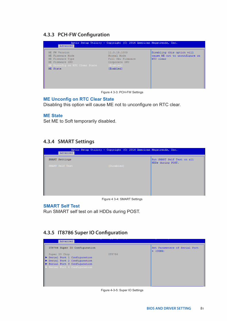
4.3.3 PCH-FW Configuration
ME Unconfig on RTC Clear StateDisabling this option will cause ME not to unconfigure on RTC clear.
ME StateSet ME to Soft temporarily disabled.
Figure 4 3-3: PCH-FW Settings
4.3.4 SMART Settings
SMART Self TestRun SMART self test on all HDDs during POST.
Figure 4 3-4: SMART Settings
4.3.5 IT8786 Super IO Configuration
Figure 4-3-5: Super IO Settings
82BIOS AND DRIVER SETTING©Vecow ECS-9200/9100 User Manual
Serial Port 1 ConfigurationSet parameters of serial port 1 (COM 1).
Serial Port 2 ConfigurationSet parameters of serial port 2 (COM 2).
Serial Port 3 ConfigurationSet parameters of serial port 3 (COM 3).
Serial Port 4 ConfigurationSet parameters of serial port 4 (COM 4).
4.3.7 Serial Port Console Redirection
Console RedirectionConsole redirection enable or disable.
Console Redirection SettingsThe settings specify how the host computer and the remote computer (which the user is using) will exchange data. Both computers should have the same or compatible settings.
Figure 4 3-7: Serial Port Console Redirection Settings
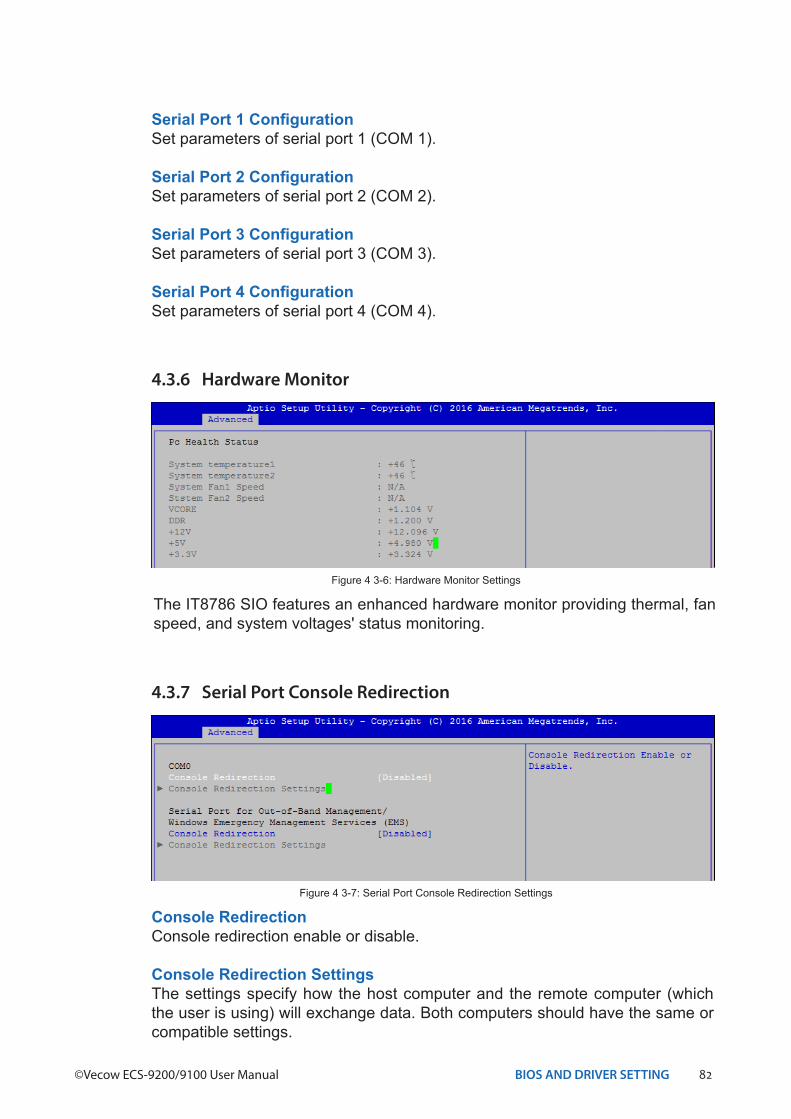
4.3.6 Hardware Monitor
The IT8786 SIO features an enhanced hardware monitor providing thermal, fan speed, and system voltages' status monitoring.
Figure 4 3-6: Hardware Monitor Settings
83BIOS AND DRIVER SETTING
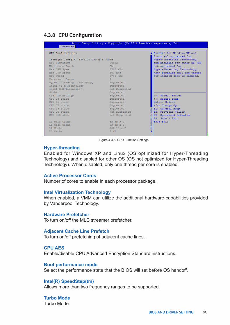
Hyper-threadingEnabled for Windows XP and Linux (OS optimized for Hyper-Threading Technology) and disabled for other OS (OS not optimized for Hyper-Threading Technology). When disabled, only one thread per core is enabled.
Active Processor CoresNumber of cores to enable in each processor package.
Intel Virtualization TechnologyWhen enabled, a VMM can utilize the additional hardware capabilities provided by Vanderpool Technology.
Hardware PrefetcherTo turn on/off the MLC streamer prefetcher.
Adjacent Cache Line PrefetchTo turn on/off prefetching of adjacent cache lines.
CPU AESEnable/disable CPU Advanced Encryption Standard instructions.
Boot performance modeSelect the performance state that the BIOS will set before OS handoff.
Intel(R) SpeedStep(tm)Allows more than two frequency ranges to be supported.
Turbo ModeTurbo Mode.
4.3.8 CPU Configuration
Figure 4 3-8: CPU Function Settings
84BIOS AND DRIVER SETTING©Vecow ECS-9200/9100 User Manual
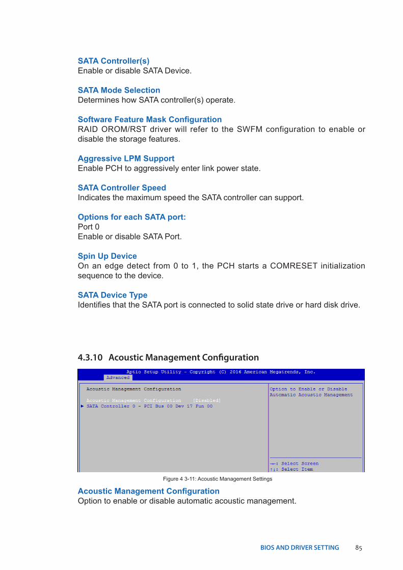
4.3.9 Intel TXT Information
Display Intel TXT information.Figure 4 3-9: Intel TXT Information
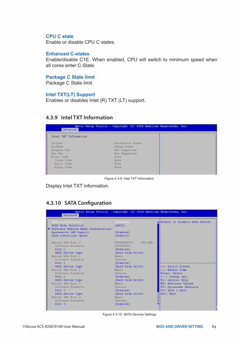
4.3.10 SATA Configuration
Figure 4 3-10: SATA Devices Settings
CPU C stateEnable or disable CPU C states.
Enhanced C-statesEnable/disable C1E. When enabled, CPU will switch to minimum speed when all cores enter C-State.
Package C State limitPackage C State limit.
Intel TXT(LT) SupportEnables or disables Intel (R) TXT (LT) support.
85BIOS AND DRIVER SETTING
SATA Controller(s)Enable or disable SATA Device.
SATA Mode SelectionDetermines how SATA controller(s) operate.
Software Feature Mask ConfigurationRAID OROM/RST driver will refer to the SWFM configuration to enable or disable the storage features.
Aggressive LPM SupportEnable PCH to aggressively enter link power state.
SATA Controller SpeedIndicates the maximum speed the SATA controller can support.
Options for each SATA port:Port 0Enable or disable SATA Port.
Spin Up DeviceOn an edge detect from 0 to 1, the PCH starts a COMRESET initialization sequence to the device.
SATA Device TypeIdentifies that the SATA port is connected to solid state drive or hard disk drive.
4.3.10 Acoustic Management Configuration
Acoustic Management ConfigurationOption to enable or disable automatic acoustic management.
Figure 4 3-11: Acoustic Management Settings
86BIOS AND DRIVER SETTING©Vecow ECS-9200/9100 User Manual
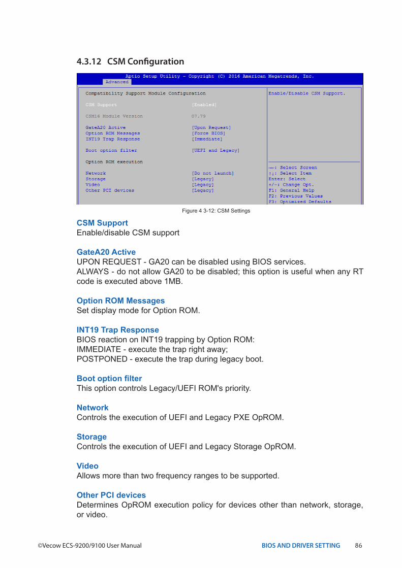
4.3.12 CSM Configuration
CSM SupportEnable/disable CSM support
GateA20 ActiveUPON REQUEST - GA20 can be disabled using BIOS services.ALWAYS - do not allow GA20 to be disabled; this option is useful when any RT code is executed above 1MB.
Option ROM MessagesSet display mode for Option ROM.
INT19 Trap ResponseBIOS reaction on INT19 trapping by Option ROM:IMMEDIATE - execute the trap right away;POSTPONED - execute the trap during legacy boot.
Boot option filterThis option controls Legacy/UEFI ROM's priority.
NetworkControls the execution of UEFI and Legacy PXE OpROM.
StorageControls the execution of UEFI and Legacy Storage OpROM.
VideoAllows more than two frequency ranges to be supported.
Other PCI devicesDetermines OpROM execution policy for devices other than network, storage, or video.
Figure 4 3-12: CSM Settings
87BIOS AND DRIVER SETTING
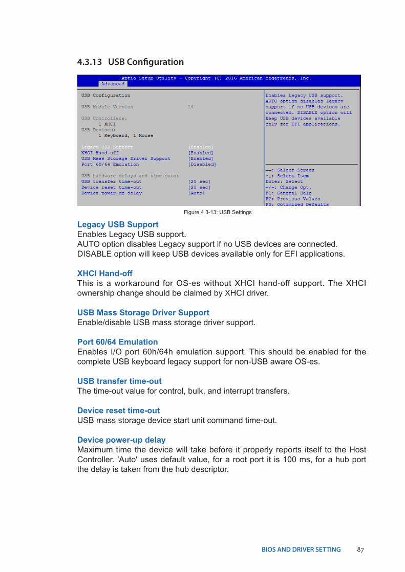
4.3.13 USB Configuration
Legacy USB SupportEnables Legacy USB support.AUTO option disables Legacy support if no USB devices are connected.DISABLE option will keep USB devices available only for EFI applications.
XHCI Hand-offThis is a workaround for OS-es without XHCI hand-off support. The XHCI ownership change should be claimed by XHCI driver.
USB Mass Storage Driver SupportEnable/disable USB mass storage driver support.
Port 60/64 EmulationEnables I/O port 60h/64h emulation support. This should be enabled for the complete USB keyboard legacy support for non-USB aware OS-es.
USB transfer time-outThe time-out value for control, bulk, and interrupt transfers.
Device reset time-outUSB mass storage device start unit command time-out.
Device power-up delayMaximum time the device will take before it properly reports itself to the Host Controller. 'Auto' uses default value, for a root port it is 100 ms, for a hub port the delay is taken from the hub descriptor.
Figure 4 3-13: USB Settings
88BIOS AND DRIVER SETTING©Vecow ECS-9200/9100 User Manual
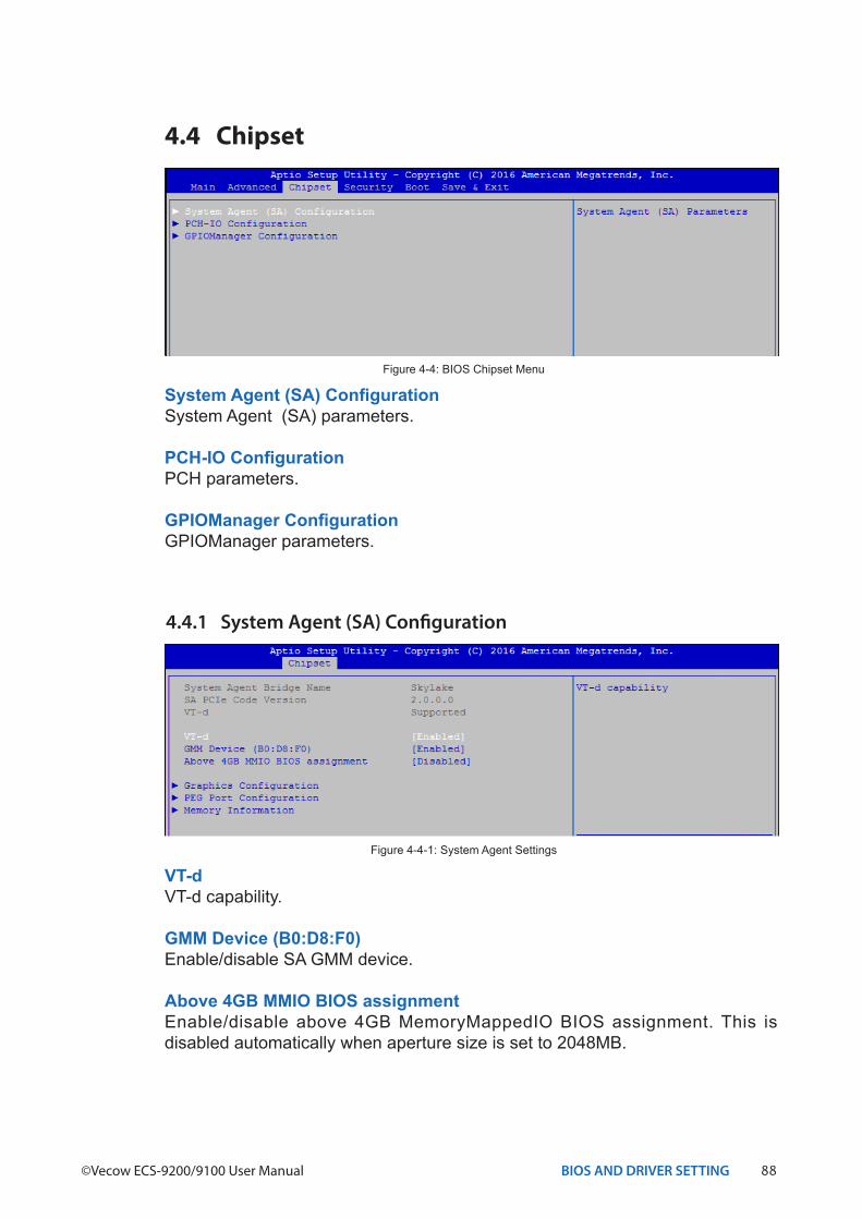
VT-d VT-d capability.
GMM Device (B0:D8:F0)Enable/disable SA GMM device.
Above 4GB MMIO BIOS assignmentEnable/disable above 4GB MemoryMappedIO BIOS assignment. This is disabled automatically when aperture size is set to 2048MB.
4.4.1 System Agent (SA) Configuration
Figure 4-4-1: System Agent Settings
4.4 Chipset
Figure 4-4: BIOS Chipset Menu
System Agent (SA) ConfigurationSystem Agent (SA) parameters.
PCH-IO ConfigurationPCH parameters.
GPIOManager ConfigurationGPIOManager parameters.
89BIOS AND DRIVER SETTING
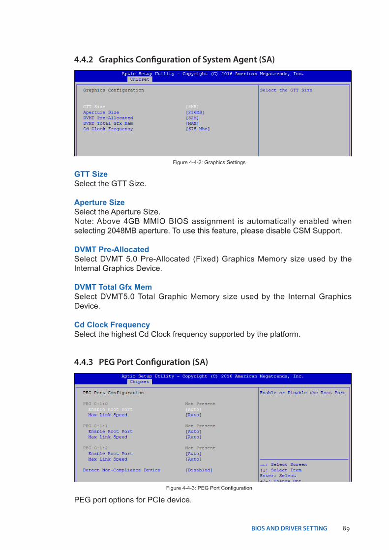
4.4.2 Graphics Configuration of System Agent (SA)
GTT SizeSelect the GTT Size.
Aperture SizeSelect the Aperture Size.Note: Above 4GB MMIO BIOS assignment is automatically enabled when selecting 2048MB aperture. To use this feature, please disable CSM Support.
DVMT Pre-AllocatedSelect DVMT 5.0 Pre-Allocated (Fixed) Graphics Memory size used by the Internal Graphics Device.
DVMT Total Gfx MemSelect DVMT5.0 Total Graphic Memory size used by the Internal Graphics Device.
Cd Clock FrequencySelect the highest Cd Clock frequency supported by the platform.
Figure 4-4-2: Graphics Settings
4.4.3 PEG Port Configuration (SA)
PEG port options for PCIe device.Figure 4-4-3: PEG Port Configuration
90BIOS AND DRIVER SETTING©Vecow ECS-9200/9100 User Manual
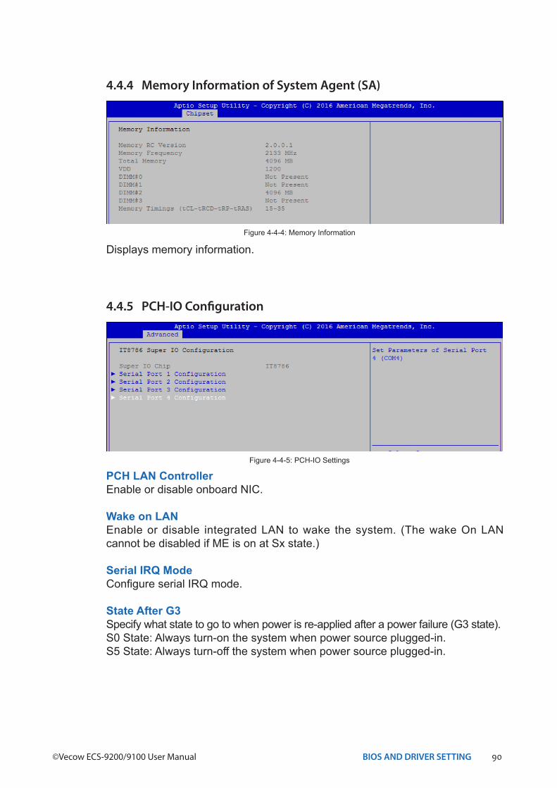
4.4.4 Memory Information of System Agent (SA)
Displays memory information.Figure 4-4-4: Memory Information
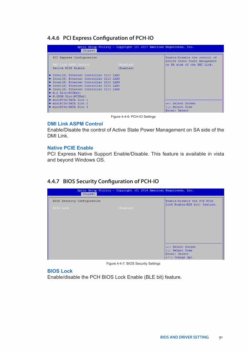
4.4.5 PCH-IO Configuration
Figure 4-4-5: PCH-IO Settings
PCH LAN ControllerEnable or disable onboard NIC.
Wake on LANEnable or disable integrated LAN to wake the system. (The wake On LAN cannot be disabled if ME is on at Sx state.)
Serial IRQ ModeConfigure serial IRQ mode.
State After G3Specify what state to go to when power is re-applied after a power failure (G3 state).S0 State: Always turn-on the system when power source plugged-in.S5 State: Always turn-off the system when power source plugged-in.
91BIOS AND DRIVER SETTING
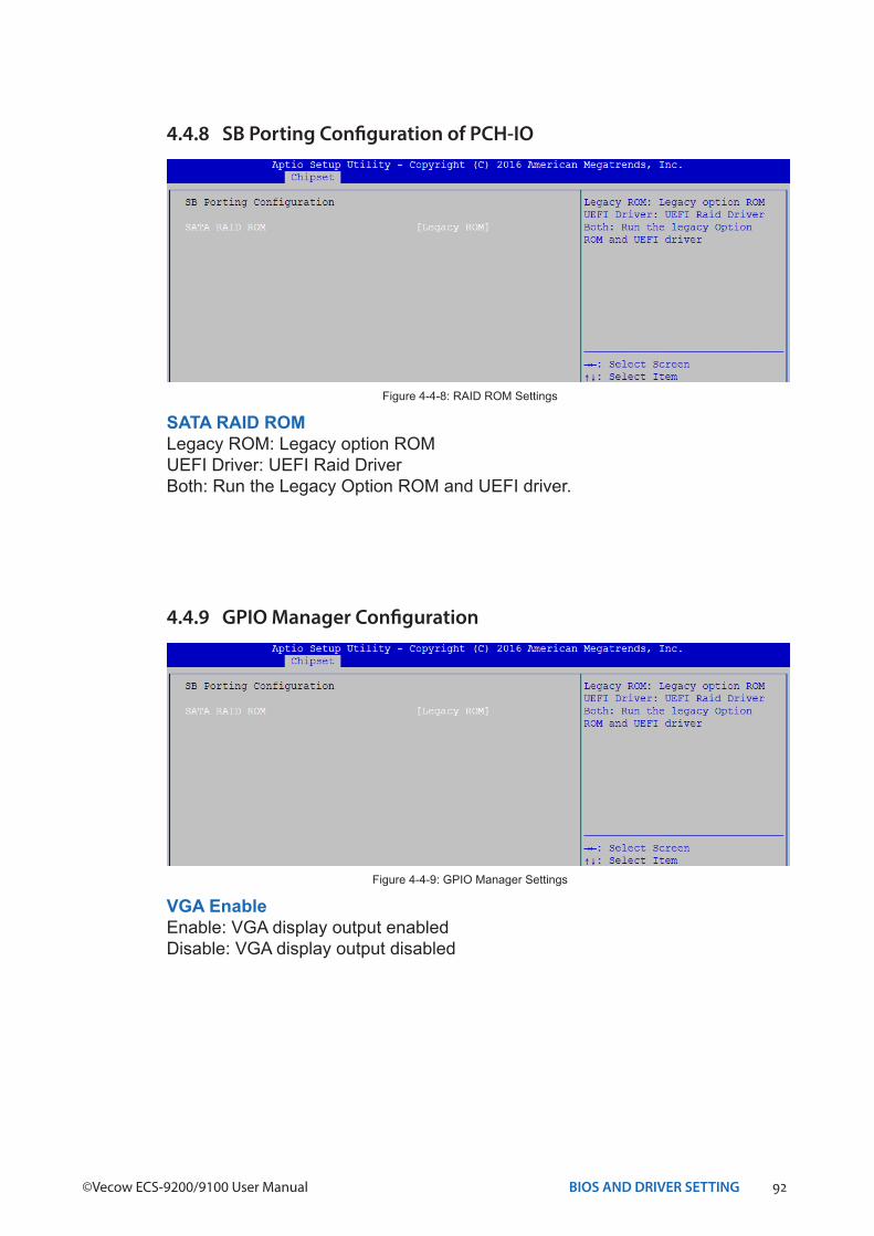
4.4.6 PCI Express Configuration of PCH-IO
Figure 4-4-6: PCH-IO Settings
DMI Link ASPM ControlEnable/Disable the control of Active State Power Management on SA side of the DMI Link.
Native PCIE EnablePCI Express Native Support Enable/Disable. This feature is available in vista and beyond Windows OS.
4.4.7 BIOS Security Configuration of PCH-IO
BIOS LockEnable/disable the PCH BIOS Lock Enable (BLE bit) feature.
Figure 4-4-7: BIOS Security Settings
92BIOS AND DRIVER SETTING©Vecow ECS-9200/9100 User Manual
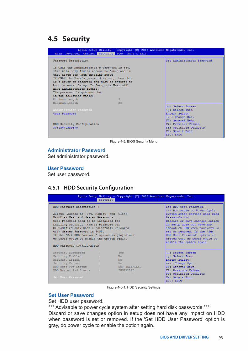
4.4.8 SB Porting Configuration of PCH-IO
SATA RAID ROMLegacy ROM: Legacy option ROMUEFI Driver: UEFI Raid DriverBoth: Run the Legacy Option ROM and UEFI driver.
Figure 4-4-8: RAID ROM Settings
4.4.9 GPIO Manager Configuration
VGA EnableEnable: VGA display output enabledDisable: VGA display output disabled
Figure 4-4-9: GPIO Manager Settings
93BIOS AND DRIVER SETTING
Set User Password Set HDD user password. *** Advisable to power cycle system after setting hard disk passwords ***Discard or save changes option in setup does not have any impact on HDD when password is set or removed. If the 'Set HDD User Password' option is gray, do power cycle to enable the option again.
4.5.1 HDD Security Configuration
Figure 4-5-1: HDD Security Settings
4.5 Security
Figure 4-5: BIOS Security Menu
Administrator PasswordSet administrator password.
User PasswordSet user password.
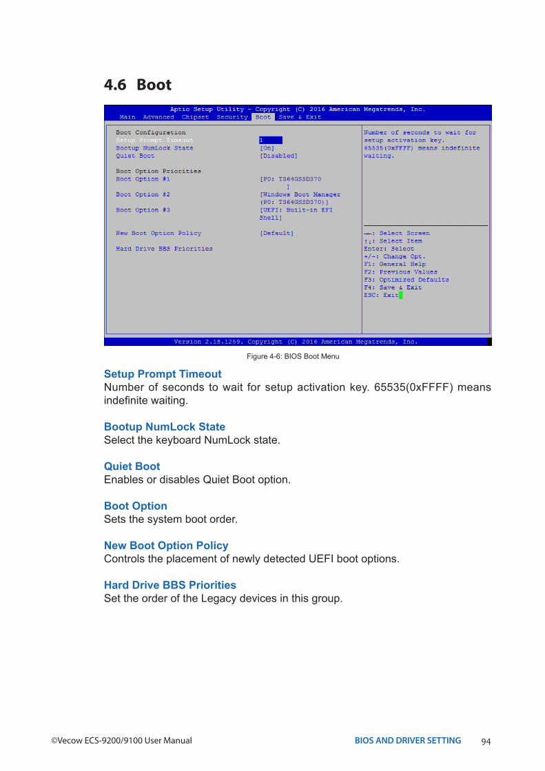
94BIOS AND DRIVER SETTING©Vecow ECS-9200/9100 User Manual
4.6 Boot
Figure 4-6: BIOS Boot Menu
Setup Prompt TimeoutNumber of seconds to wait for setup activation key. 65535(0xFFFF) means indefinite waiting.
Bootup NumLock StateSelect the keyboard NumLock state.
Quiet BootEnables or disables Quiet Boot option.
Boot OptionSets the system boot order.
New Boot Option PolicyControls the placement of newly detected UEFI boot options.
Hard Drive BBS PrioritiesSet the order of the Legacy devices in this group.
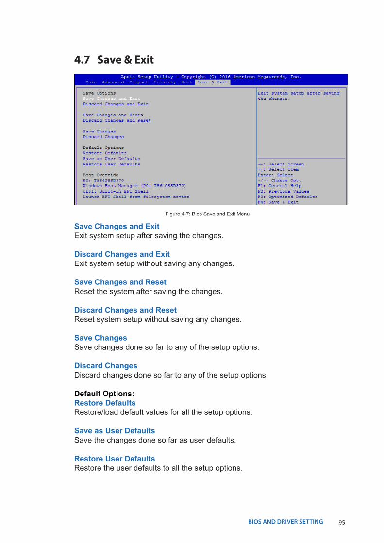
95BIOS AND DRIVER SETTING
4.7 Save & Exit
Figure 4-7: Bios Save and Exit Menu
Save Changes and ExitExit system setup after saving the changes.
Discard Changes and ExitExit system setup without saving any changes.
Save Changes and ResetReset the system after saving the changes.
Discard Changes and ResetReset system setup without saving any changes.
Save ChangesSave changes done so far to any of the setup options.
Discard ChangesDiscard changes done so far to any of the setup options.
Default Options:Restore DefaultsRestore/load default values for all the setup options.
Save as User DefaultsSave the changes done so far as user defaults.
Restore User DefaultsRestore the user defaults to all the setup options.
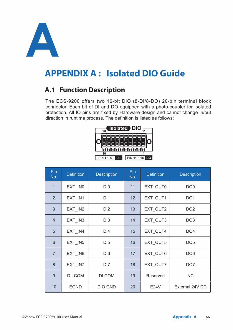
96©Vecow ECS-9200/9100 User Manual Appendix A
AAPPENDIX A : Isolated DIO Guide
Pin No. Definition Description Pin
No. Definition Description
1 EXT_IN0 DI0 11 EXT_OUT0 DO0
2 EXT_IN1 DI1 12 EXT_OUT1 DO1
3 EXT_IN2 DI2 13 EXT_OUT2 DO2
4 EXT_IN3 DI3 14 EXT_OUT3 DO3
5 EXT_IN4 DI4 15 EXT_OUT4 DO4
6 EXT_IN5 DI5 16 EXT_OUT5 DO5
7 EXT_IN6 DI6 17 EXT_OUT6 DO6
8 EXT_IN7 DI7 18 EXT_OUT7 DO7
9 DI_COM DI COM 19 Reserved NC
10 EGND DIO GND 20 E24V External 24V DC
A.1 Function DescriptionThe ECS-9200 offers two 16-bit DIO (8-DI/8-DO) 20-pin terminal block connector. Each bit of DI and DO equipped with a photo-coupler for isolated protection. All IO pins are fixed by Hardware design and cannot change in/out direction in runtime process. The definition is listed as follows:
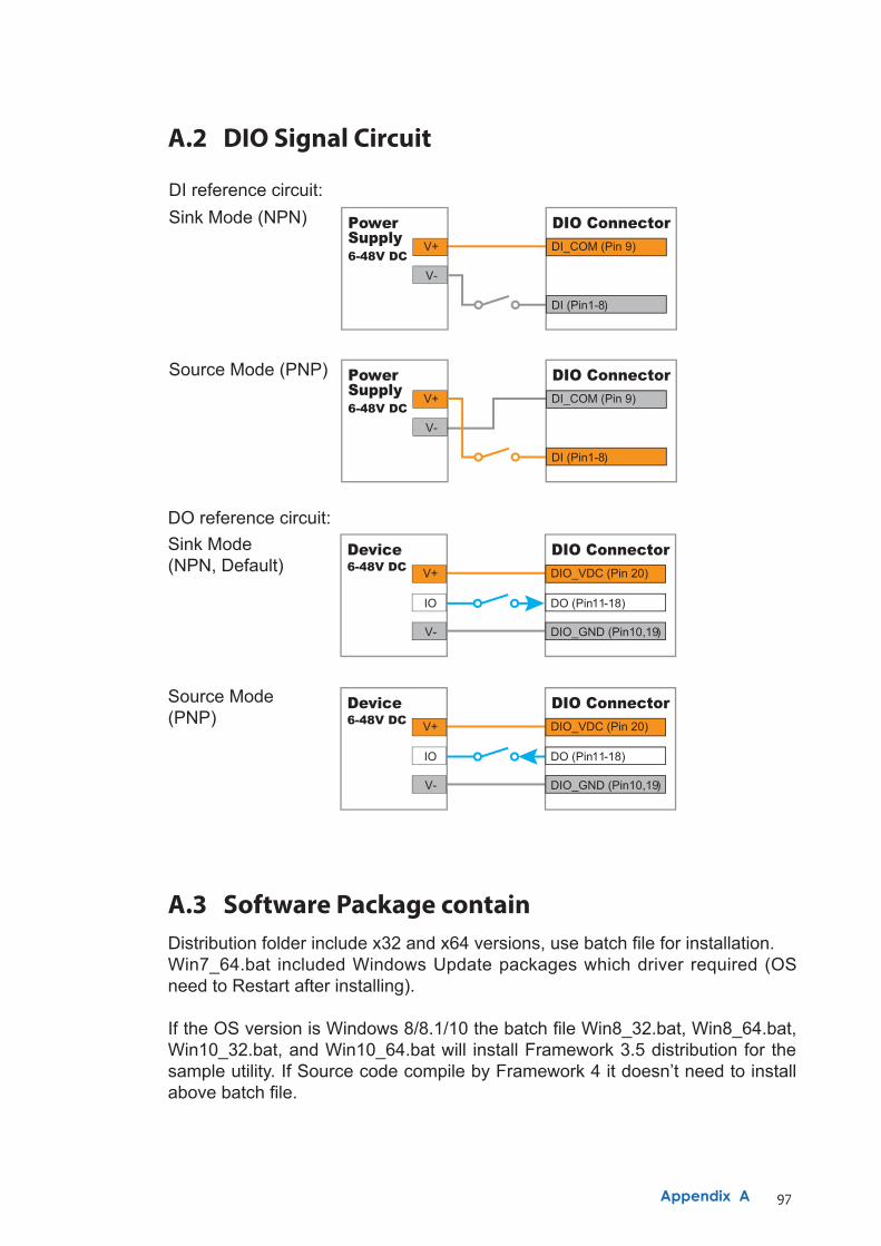
97Appendix A
A.2 DIO Signal Circuit
DI reference circuit:Sink Mode (NPN)
V+
V-
PowerSupply6-48V DC
DI_COM (Pin 9)
DI (Pin1-8)
DIO Connector
Source Mode (PNP)V+
V-
PowerSupply6-48V DC
DI_COM (Pin 9)
DI (Pin1-8)
DIO Connector
DO reference circuit:
V+
IO
V-
Device6-48V DC DIO_VDC (Pin 20)
DO (Pin11-18)
DIO_GND (Pin10,19)
DIO ConnectorSource Mode (PNP)
Sink Mode (NPN, Default) V+
IO
V-
Device6-48V DC DIO_VDC (Pin 20)
DO (Pin11-18)
DIO_GND (Pin10,19)
DIO Connector
A.3 Software Package containDistribution folder include x32 and x64 versions, use batch file for installation.Win7_64.bat included Windows Update packages which driver required (OS need to Restart after installing).
If the OS version is Windows 8/8.1/10 the batch file Win8_32.bat, Win8_64.bat, Win10_32.bat, and Win10_64.bat will install Framework 3.5 distribution for the sample utility. If Source code compile by Framework 4 it doesn’t need to install above batch file.
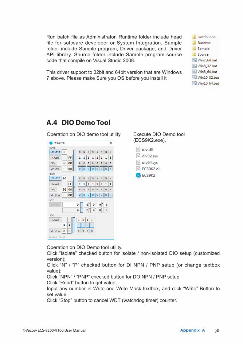
98©Vecow ECS-9200/9100 User Manual Appendix A
Run batch file as Administrator. Runtime folder include head file for software developer or System Integration. Sample folder include Sample program, Driver package, and Driver API library. Source folder include Sample program source code that compile on Visual Studio 2008.
This driver support to 32bit and 64bit version that are Windows 7 above. Please make Sure you OS before you install it
A.4 DIO Demo ToolExecute DIO Demo tool (ECS9K2.exe).
Operation on DIO demo tool utility.
Operation on DIO Demo tool utility.Click “Isolate” checked button for isolate / non-isolated DIO setup (customized version);Click “N” / ”P” checked button for DI NPN / PNP setup (or change textbox value);Click “NPN” / “PNP” checked button for DO NPN / PNP setup;Click “Read” button to get value;Input any number in Write and Write Mask textbox, and click “Write” Button to set value;Click “Stop” button to cancel WDT (watchdog timer) counter.
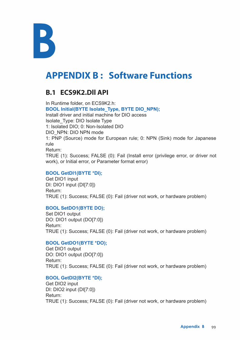
99Appendix B
BAPPENDIX B : Software Functions
B.1 ECS9K2.Dll APIIn Runtime folder, on ECS9K2.h:BOOL Initial(BYTE Isolate_Type, BYTE DIO_NPN);Install driver and initial machine for DIO accessIsolate_Type: DIO Isolate Type1: Isolated DIO; 0: Non-Isolated DIODIO_NPN: DIO NPN mode1: PNP (Source) mode for European rule; 0: NPN (Sink) mode for Japanese ruleReturn:TRUE (1): Success; FALSE (0): Fail (Install error (privilege error, or driver not work), or Initial error, or Parameter format error)
BOOL GetDI1(BYTE *DI);Get DIO1 inputDI: DIO1 input (DI[7:0])Return:TRUE (1): Success; FALSE (0): Fail (driver not work, or hardware problem)
BOOL SetDO1(BYTE DO);Set DIO1 outputDO: DIO1 output (DO[7:0])Return:TRUE (1): Success; FALSE (0): Fail (driver not work, or hardware problem)
BOOL GetDO1(BYTE *DO);Get DIO1 outputDO: DIO1 output (DO[7:0])Return:TRUE (1): Success; FALSE (0): Fail (driver not work, or hardware problem)
BOOL GetDI2(BYTE *DI);Get DIO2 inputDI: DIO2 input (DI[7:0])Return:TRUE (1): Success; FALSE (0): Fail (driver not work, or hardware problem)
100©Vecow ECS-9200/9100 User Manual Appendix B
BOOL SetDO2(BYTE DO);Set DIO2 outputDO: DIO2 output (DO[7:0])Return:TRUE (1): Success; FALSE (0): Fail (driver not work, or hardware problem)
BOOL GetDO2(BYTE *DO);Get DIO2 outputDO: DIO2 output (DO[7:0])Return:TRUE (1): Success; FALSE (0): Fail (driver not work, or hardware problem)
BOOL GetWDT(DWORD *WDT);Get watchdog timerWDT: Watchdog timerReturn:TRUE (1): Success; FALSE (0): Fail (driver not work, or hardware problem)
BOOL SetWDT(DWORD WDT);Set watchdog timerWDT: Watchdog timerReturn:TRUE (1): Success; FALSE (0): Fail (driver not work, or hardware problem, or parameter format error)
BOOL CancelWDT();Cancel watchdog timerWDT: Watchdog timerReturn:TRUE (1): Success; FALSE (0): Fail (driver not work, or hardware problem)
BOOL GetPOEConfig(BYTE *Mask);Get POE enable/disable configurationMask: POE enable mask (Mask[7:0])Return:TRUE (1): Success; FALSE (0): Fail (driver not work, or hardware problem)
BOOL SetPOEConfig(BYTE Mask);Set POE enable/disable configurationMask: POE enable mask (Mask[7:0])Return:TRUE (1): Success; FALSE (0): Fail (driver not work, or hardware problem)
BOOL GetPOE(BYTE *POE);Get POE on/off setupPOE: POE switch (POE[7:0])Return:TRUE (1): Success; FALSE (0): Fail (driver not work, or hardware problem)
101Appendix B
BOOL SetPOE(BYTE POE);Set POE on/off setupPOE: POE switch (POE[7:0])Return:TRUE (1): Success; FALSE (0): Fail (driver not work, or hardware problem)
BOOL GetDIO1Config(BYTE *Isolate_Type, BYTE *DI_NPN, BYTE *DO_NPN);Get DIO1 configurationIsolate_Type: DIO1 Isolate Type1: Isolated DIO; 0: Non-Isolated DIODI_NPN: DIO1 input NPN mode (DI_NPN[7:0])1: PNP (Source) mode for European rule; 0: NPN (Sink) mode for Japanese ruleDO_NPN: DIO1 output NPN mode1: PNP (Source) mode for European rule; 0: NPN (Sink) mode for Japanese ruleReturn:TRUE (1): Success; FALSE (0): Fail (driver not work, or hardware problem)
BOOL Set DIO1Config(BYTE Isolate_Type, BYTE DI_NPN, BYTE DO_NPN);Set DIO1 configurationIsolate_Type: DIO1 Isolate Type1: Isolated DIO; 0: Non-Isolated DIODI_NPN: DIO1 input NPN mode (DI_NPN[7:0])1: PNP (Source) mode for European rule; 0: NPN (Sink) mode for Japanese ruleDO_NPN: DIO1 output NPN mode1: PNP (Source) mode for European rule; 0: NPN (Sink) mode for Japanese ruleReturn:TRUE (1): Success; FALSE (0): Fail (driver not work, or hardware problem)
BOOL GetDIO2Config(BYTE *Isolate_Type, BYTE *DI_NPN, BYTE *DO_NPN);Get DIO2 configurationIsolate_Type: DIO2 Isolate Type1: Isolated DIO; 0: Non-Isolated DIODI_NPN: DIO2 input NPN mode (DI_NPN[7:0])1: PNP (Source) mode for European rule; 0: NPN (Sink) mode for Japanese ruleDO_NPN: DIO2 output NPN mode1: PNP (Source) mode for European rule; 0: NPN (Sink) mode for Japanese ruleReturn:TRUE (1): Success; FALSE (0): Fail (driver not work, or hardware problem)
BOOL Set DIO2Config(BYTE Isolate_Type, BYTE DI_NPN, BYTE DO_NPN);Set DIO2 configurationIsolate_Type: DIO2 Isolate Type1: Isolated DIO; 0: Non-Isolated DIODI_NPN: DIO2 input NPN mode (DI_NPN[7:0])1: PNP (Source) mode for European rule; 0: NPN (Sink) mode for Japanese ruleDO_NPN: DIO2 output NPN mode1: PNP (Source) mode for European rule; 0: NPN (Sink) mode for Japanese ruleReturn:TRUE (1): Success; FALSE (0): Fail (driver not work, or hardware problem)
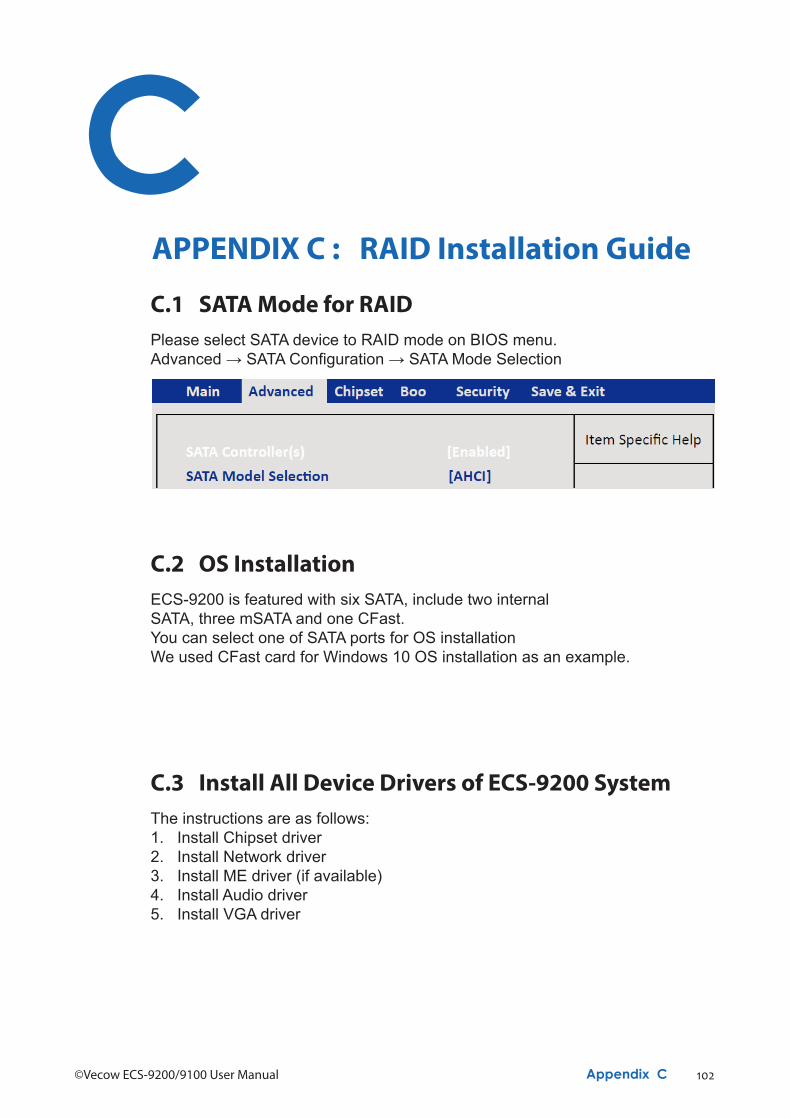
102©Vecow ECS-9200/9100 User Manual Appendix C
CAPPENDIX C : RAID Installation Guide
C.1 SATA Mode for RAIDPlease select SATA device to RAID mode on BIOS menu.Advanced → SATA Configuration → SATA Mode Selection
C.2 OS InstallationECS-9200 is featured with six SATA, include two internalSATA, three mSATA and one CFast.You can select one of SATA ports for OS installationWe used CFast card for Windows 10 OS installation as an example.
C.3 Install All Device Drivers of ECS-9200 SystemThe instructions are as follows:1. Install Chipset driver2. Install Network driver3. Install ME driver (if available)4. Install Audio driver5. Install VGA driver
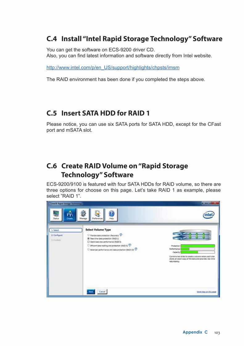
103Appendix C
C.4 Install “Intel Rapid Storage Technology” SoftwareYou can get the software on ECS-9200 driver CD.Also, you can find latest information and software directly from Intel website.
http://www.intel.com/p/en_US/support/highlights/chpsts/imsm
The RAID environment has been done if you completed the steps above.
C.5 Insert SATA HDD for RAID 1Please notice, you can use six SATA ports for SATA HDD, except for the CFast port and mSATA slot.
C.6 Create RAID Volume on “Rapid Storage Technology” SoftwareECS-9200/9100 is featured with four SATA HDDs for RAID volume, so there are three options for choose on this page. Let’s take RAID 1 as example, please select ”RAID 1”.
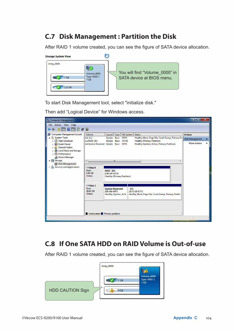
104©Vecow ECS-9200/9100 User Manual Appendix C
Then add “Logical Device” for Windows access.
C.7 Disk Management : Partition the DiskAfter RAID 1 volume created, you can see the figure of SATA device allocation.
To start Disk Management tool, select "initialize disk."
You will find “Volume_0000” in SATA device at BIOS menu.
C.8 If One SATA HDD on RAID Volume is Out-of-useAfter RAID 1 volume created, you can see the figure of SATA device allocation.
HDD CAUTION Sign
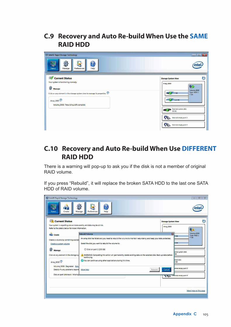
105Appendix C
C.10 Recovery and Auto Re-build When Use DIFFERENT RAID HDDThere is a warning will pop-up to ask you if the disk is not a member of originalRAID volume.
If you press “Rebuild”, it will replace the broken SATA HDD to the last one SATAHDD of RAID volume.
C.9 Recovery and Auto Re-build When Use the SAME RAID HDD
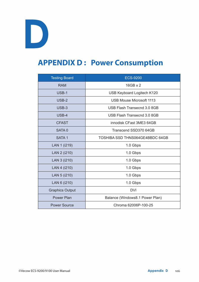
106©Vecow ECS-9200/9100 User Manual Appendix D
DAPPENDIX D : Power Consumption
Testing Board ECS-9200
RAM 16GB x 2
USB-1 USB Keyboard Logitech K120
USB-2 USB Mouse Microsoft 1113
USB-3 USB Flash Transecnd 3.0 8GB
USB-4 USB Flash Transecnd 3.0 8GB
CFAST innodisk CFast 3ME3 64GB
SATA 0 Transcend SSD370 64GB
SATA 1 TOSHIBA SSD THNS064GE4BBDC 64GB
LAN 1 (i219) 1.0 Gbps
LAN 2 (i210) 1.0 Gbps
LAN 3 (i210) 1.0 Gbps
LAN 4 (i210) 1.0 Gbps
LAN 5 (i210) 1.0 Gbps
LAN 6 (i210) 1.0 Gbps
Graphics Output DVI
Power Plan Balance (Windows8.1 Power Plan)
Power Source Chroma 62006P-100-25

107Appendix D
D.1 Intel® Core™ [email protected] (8M Cache, 4.0 GHz)
CPU PowerInput
Sleep Mode Idle Status :CPU usage less 3%
MaxCurrent
Max Consumption
MaxCurrent
Max Consumption
Core™ i7-6700 06V 0.846A 05.08W 3.411A 20.47W
Core™ i7-6700 09V 0.554A 04.99W 2.311A 20.80W
Core™ i7-6700 12V 0.409A 04.91W 1.732A 20.78W
Core™ i7-6700 24V 0.286A 06.86W 0.918A 22.03W
Core™ i7-6700 36V 0.250A 09.00W 0.663A 23.87W
CPU Power Input
Run 100% CPUusage without 3D
Run 100% CPUusage with 3D
MaxCurrent
Max Consumption
MaxCurrent
Max Consumption
Core™ i7-6700 06V 9.940A 59.64W 12.649A 75.89W
Core™ i7-6700 09V 6.389A 57.50W 8.164A 73.48W
Core™ i7-6700 12V 4.778A 57.34W 6.079A 72.95W
Core™ i7-6700 24V 2.424A 58.18W 3.084A 74.02W
Core™ i7-6700 36V 1.676A 60.34W 2.149A 77.36W
Power on and boot to Win8.1 64-bit
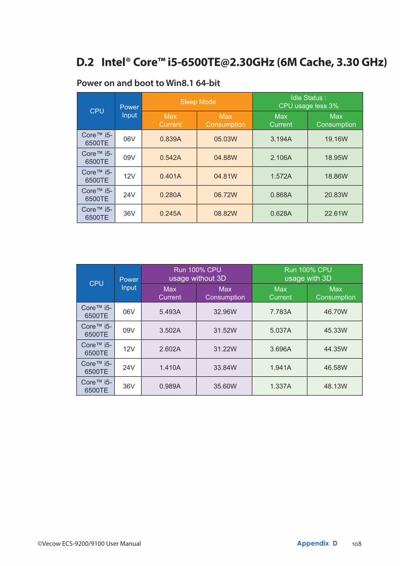
108©Vecow ECS-9200/9100 User Manual Appendix D
D.2 Intel® Core™ [email protected] (6M Cache, 3.30 GHz)
CPU Power Input
Run 100% CPUusage without 3D
Run 100% CPUusage with 3D
MaxCurrent
Max Consumption
MaxCurrent
Max Consumption
Core™ i5-6500TE 06V 5.493A 32.96W 7.783A 46.70W
Core™ i5-6500TE 09V 3.502A 31.52W 5.037A 45.33W
Core™ i5-6500TE 12V 2.602A 31.22W 3.696A 44.35W
Core™ i5-6500TE 24V 1.410A 33.84W 1.941A 46.58W
Core™ i5-6500TE 36V 0.989A 35.60W 1.337A 48.13W
Power on and boot to Win8.1 64-bit
CPU PowerInput
Sleep Mode Idle Status :CPU usage less 3%
MaxCurrent
Max Consumption
MaxCurrent
Max Consumption
Core™ i5-6500TE 06V 0.839A 05.03W 3.194A 19.16W
Core™ i5-6500TE 09V 0.542A 04.88W 2.106A 18.95W
Core™ i5-6500TE 12V 0.401A 04.81W 1.572A 18.86W
Core™ i5-6500TE 24V 0.280A 06.72W 0.868A 20.83W
Core™ i5-6500TE 36V 0.245A 08.82W 0.628A 22.61W
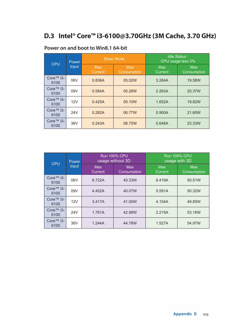
109Appendix D
D.3 Intel® Core™ [email protected] (3M Cache, 3.70 GHz)
CPU PowerInput
Sleep Mode Idle Status :CPU usage less 3%
MaxCurrent
Max Consumption
MaxCurrent
Max Consumption
Core™ i3-6100 06V 0.836A 05.02W 3.264A 19.58W
Core™ i3-6100 09V 0.584A 05.26W 2.263A 20.37W
Core™ i3-6100 12V 0.425A 05.10W 1.652A 19.82W
Core™ i3-6100 24V 0.282A 06.77W 0.900A 21.60W
Core™ i3-6100 36V 0.243A 08.75W 0.648A 23.33W
CPU Power Input
Run 100% CPUusage without 3D
Run 100% CPUusage with 3D
MaxCurrent
Max Consumption
MaxCurrent
Max Consumption
Core™ i3-6100 06V 6.722A 40.33W 8.419A 50.51W
Core™ i3-6100 09V 4.452A 40.07W 5.591A 50.32W
Core™ i3-6100 12V 3.417A 41.00W 4.154A 49.85W
Core™ i3-6100 24V 1.791A 42.98W 2.215A 53.16W
Core™ i3-6100 36V 1.244A 44.78W 1.527A 54.97W
Power on and boot to Win8.1 64-bit
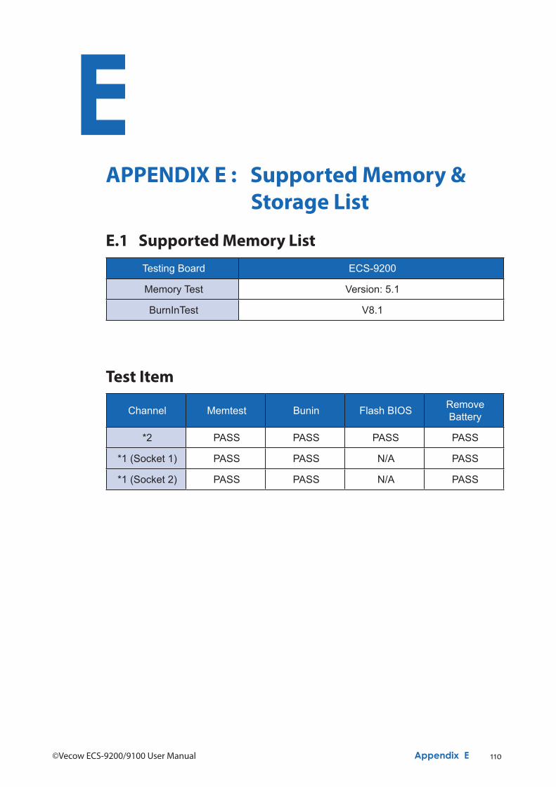
110©Vecow ECS-9200/9100 User Manual Appendix E
EAPPENDIX E : Supported Memory & Storage List
Testing Board ECS-9200
Memory Test Version: 5.1
BurnInTest V8.1
E.1 Supported Memory List
Channel Memtest Bunin Flash BIOS Remove Battery
*2 PASS PASS PASS PASS
*1 (Socket 1) PASS PASS N/A PASS
*1 (Socket 2) PASS PASS N/A PASS
Test Item
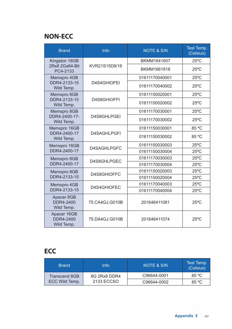
111Appendix E
Brand Info NOTE & S/N Test Temp.(Celsius)
Kingston 16GB2Rx8 2Gx64-Bit
PC4-2133KVR21S15D8/16
BKMM1641607 25ºC
BKMM1661618 25ºC
Memxpro 4GBDDR4-2133-15
Wild Temp.D4S4GHIOFEI
01611170040001 25ºC
01611170040002 25ºC
Memxpro 8GBDDR4-2133-15
Wild Temp.D4S8GHIOFFI
01611150020001 25ºC
01611150020002 25ºC
Memxpro 8GBDDR4-2400-17-
Wild Temp.D4S8GHLPGEI
01611170030001 25ºC
01611170030002 25ºC
Memxpro 16GBDDR4-2400-17
Wild Temp.D4SAGHLPGFI
01611150030001 85 ºC
01611150030002 85 ºC
Memxpro 16GBDDR4-2400-17 D4SAGHLPGFC
01611150030003 25ºC01611150030004 25ºC
Memxpro 8GBDDR4-2400-17 D4S8GHLPGEC
01611170030003 25ºC01611170030004 25ºC
Memxpro 8GBDDR4-2133-15 D4S8GHIOFFC
01611150020003 25ºC01611150020004 25ºC
Memxpro 4GBDDR4-2133-15 D4S4GHIOFEC
01611170040003 25ºC01611170040004 25ºC
Apacer 8GBDDR4-2400 Wild Temp.
75.CA4GJ.G010B 201646411081 25ºC
Apacer 16GBDDR4-2400 Wild Temp.
75.DA4GJ.G010B 201646411074 25ºC
NON-ECC
Brand Info NOTE & S/N Test Temp.(Celsius)
Transcend 8GBECC Wild Temp.
8G 2Rx8 DDR42133 ECCSO
C96644-0001 85 ºCC96644-0002 85 ºC
ECC
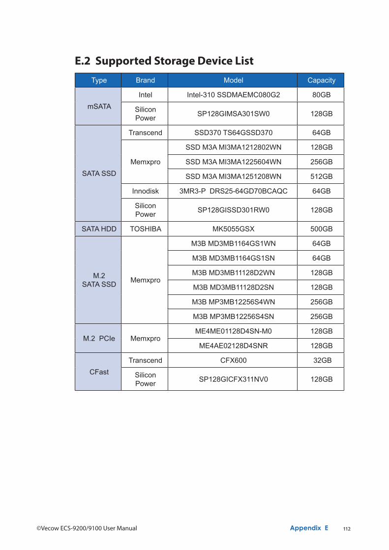
112©Vecow ECS-9200/9100 User Manual Appendix E
Type Brand Model Capacity
mSATAIntel Intel-310 SSDMAEMC080G2 80GB
Silicon Power SP128GIMSA301SW0 128GB
SATA SSD
Transcend SSD370 TS64GSSD370 64GB
Memxpro
SSD M3A MI3MA1212802WN 128GB
SSD M3A MI3MA1225604WN 256GB
SSD M3A MI3MA1251208WN 512GB
Innodisk 3MR3-P DRS25-64GD70BCAQC 64GB
Silicon Power SP128GISSD301RW0 128GB
SATA HDD TOSHIBA MK5055GSX 500GB
M.2SATA SSD Memxpro
M3B MD3MB1164GS1WN 64GB
M3B MD3MB1164GS1SN 64GB
M3B MD3MB11128D2WN 128GB
M3B MD3MB11128D2SN 128GB
M3B MP3MB12256S4WN 256GB
M3B MP3MB12256S4SN 256GB
M.2 PCIe MemxproME4ME01128D4SN-M0 128GB
ME4AE02128D4SNR 128GB
CFastTranscend CFX600 32GB
Silicon Power SP128GICFX311NV0 128GB
E.2 Supported Storage Device List
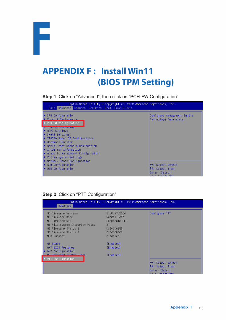
113Appendix F
FAPPENDIX F : Install Win11 (BIOS TPM Setting)Step 1 Click on “Advanced”, then click on “PCH-FW Configuration”
Step 2 Click on “PTT Configuration”
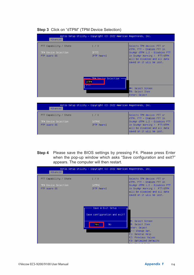
114©Vecow ECS-9200/9100 User Manual Appendix F
Step 3 Click on “dTPM” (TPM Device Selection)
Step 4 Please save the BIOS settings by pressing F4. Please press Enter when the pop-up window which asks “Save configuration and exit?” appears. The computer will then restart.
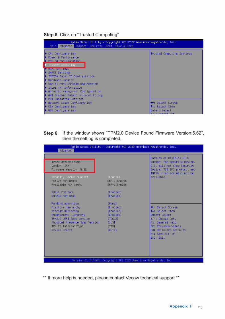
115Appendix F
Step 5 Click on “Trusted Computing”
Step 6 If the window shows “TPM2.0 Device Found Firmware Version:5.62”, then the setting is completed.
** If more help is needed, please contact Vecow technical support **

For further support information, please visit www.vecow.com
This document is released for reference purpose only. All product offerings and specifications are subject to change without prior notice. No part of this publication may be reproduced in any form or by any means, electric, photocopying, or recording, without prior authorization from the publisher.The rights of all the brand names, product names, and trademarks belong to their respective owners. © Vecow Co., Ltd. 2022. All rights reserved.
Related Documents