USER Manual USER Manual 1.3.0 Edition 20220826 Intel ® Xeon ® /Core™ i7/i5/i3 Dual GPU AI Computing System Workstation-grade, NVIDIA ® Tesla ® /Quadro ® /GeForce ® Graphics GPC-1000

Welcome message from author
This document is posted to help you gain knowledge. Please leave a comment to let me know what you think about it! Share it to your friends and learn new things together.
Transcript

USERManualUSERManual
1.3.0 Edition 20220826
Intel® Xeon®/Core™ i7/i5/i3 Dual GPU AI Computing SystemWorkstation-grade, NVIDIA® Tesla®/Quadro®/GeForce® Graphics
GPC-1000

ii©Vecow GPC-1000 User Manual
Version Date Page Description Remark0.10 2020/05/11 All Preliminary Release
1.00 2020/05/19 Official Release
1.10 2020/11/30 1, 2, 62 Update
1.20 2021/03/24 4, 12 Update
1.30 2022/08/26 85-87 Update
Record of Revision
iii©Vecow GPC-1000 User Manual
This manual is released by Vecow Co., Ltd. for reference purpose only. All product offerings and specifications are subject to change without prior notice. Vecow Co., Ltd. is under no legal commitment to the details of this document. Vecow shall not be liable for direct, indirect, special, incidental, or consequential damages arising out of the use of this document, the products, or any third party infringements, which may result from such use.
Disclaimer
This equipment has been tested and found to comply with the limits for a Class A digital device, pursuant to part 15 of the FCC Rules. These limits are designed to provide reasonable protection against harmful interference when the equipment is operated in a commercial environment. This equipment generates, uses, and can radiate radio frequency energy, and if it is not installed and used in accordance with the instruction manual, it may cause harmful interference to radio communications. Operation of this equipment in a residential area is likely to cause harmful interference in which case the user will be required to correct the interference at his own expense.
FCC
The products described in this manual comply with all applicable European Union (CE) directives if it has a CE marking. For computer systems to remain CE compliant, only CE-compliant parts may be used. Maintaining CE compliance also requires proper cable and cabling techniques.
CE
Declaration of Conformity
This document contains proprietary information protected by copyright. No part of this publication may be reproduced in any form or by any means, electric, photocopying, recording or otherwise, without prior written authorization by Vecow Co., Ltd. The rights of all the brand names, product names, and trademarks belong to their respective owners.
Copyright and Trademarks

iv©Vecow GPC-1000 User Manual
Part Number Description
GPC-1000 GPC-1000, 4 GigE LAN, 2 PCIe x8, 1 PCIe x4, 1 PCIe x1, 2 SSD Tray, 4 USB 3.1, 4 COM, 1 SIM, 16 Isolated DIO
Order Information
CPU List
Series CPU Cores GHz TDP (W) CPU Cores GHz TDP
(W)ECC RAM
Intel®Xeon®
E-2176G 6 4.6 80 E-2278GE 8 4.7 80
YesE-2278GEL 8 3.9 35
E-2124G 4 4.5 71E-2226GE 6 4.6 80
Intel®Core™
i7-8700 6 4.6 65 i7-9700E8
4.4 65
N/Ai7-8700T 6 4 35 i7-9700TE 3.8 35
i5-8500 6 4.1 65 i5-9500E6
4.2 65
i5-8500T 6 3.5 35 i5-9500TE 3.6 35
i3-8100 4 3.6 65 i3-9100E4
3.7 65Yes
i3-8100T 4 3.1 35 i3-9100TE 3.2 35

v©Vecow GPC-1000 User Manual
Part Number Description
DDR4 32G Certified DDR4 32GB 2666MHz RAM
DDR4 16G Certified DDR4 16GB 2666/2400/2133 MHz RAM
DDR4 8G Certified DDR4 8GB 2666/2400/2133 MHz RAM
DDR4 4G Certified DDR4 4GB 2666/2400/2133 MHz RAM
PWS-600W 600W, 24V, 90V AC to 305V AC Power Supply
PWS-600W-WT 600W, 28.8V, 90 to 305V AC Power Supply, Wide Temperature -40°C to +70°C
PWS-1000W-24V 1000W, 24V, 90V AC to 264V AC Power Supply
PWS-1500W-24V 1500W, 24V, 90V AC to 264V AC Power Supply
TMK2-20P-100 Terminal Block 20-pin to Terminal Block 20-pin Cable, 100cm
TMK2-20P-500 Terminal Block 20-pin to Terminal Block 20-pin Cable, 500cm
TMB-TMBK-20P Terminal Board with One 20-pin Terminal Block Connector and DIN-Rail Mounting
4G Module Mini PCIe 4G/GPS Module with Antenna
WiFi & Bluetooth WiFi & Bluetooth Module with Antenna
Optional Accessories
vi©Vecow GPC-1000 User Manual
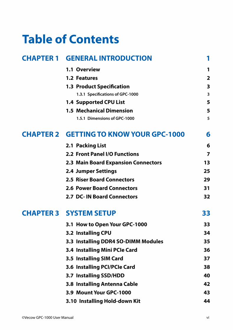
Table of ContentsCHAPTER 1 GENERAL INTRODUCTION 1
1.1 Overview 11.2 Features 21.3 Product Specification 3
1.3.1 Specifications of GPC-1000 3
1.4 Supported CPU List 51.5 Mechanical Dimension 5
1.5.1 Dimensions of GPC-1000 5
CHAPTER 2 GETTING TO KNOW YOUR GPC-1000 62.1 Packing List 62.2 Front Panel I/O Functions 72.3 Main Board Expansion Connectors 132.4 Jumper Settings 252.5 Riser Board Connectors 292.6 Power Board Connectors 312.7 DC- IN Board Connectors 32
CHAPTER 3 SYSTEM SETUP 333.1 How to Open Your GPC-1000 333.2 Installing CPU 343.3 Installing DDR4 SO-DIMM Modules 353.4 Installing Mini PCIe Card 363.5 Installing SIM Card 373.6 Installing PCI/PCIe Card 383.7 Installing SSD/HDD 403.8 Installing Antenna Cable 423.9 Mount Your GPC-1000 433.10 Installing Hold-down Kit 44
vii©Vecow GPC-1000 User Manual
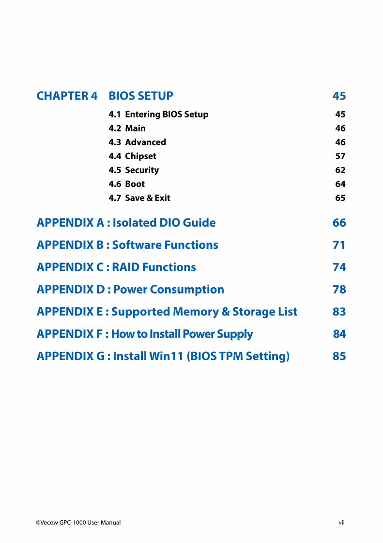
CHAPTER 4 BIOS SETUP 454.1 Entering BIOS Setup 454.2 Main 464.3 Advanced 464.4 Chipset 574.5 Security 624.6 Boot 644.7 Save & Exit 65
APPENDIX A : Isolated DIO Guide 66
APPENDIX B : Software Functions 71
APPENDIX C : RAID Functions 74
APPENDIX D : Power Consumption 78
APPENDIX E : Supported Memory & Storage List 83
APPENDIX F : How to Install Power Supply 84
APPENDIX G : Install Win11 (BIOS TPM Setting) 85

1©Vecow GPC-1000 User Manual GENERAL INTRODUCTION
GENERAL INTRODUCTION
1.1 OverviewVecow GPC-1000 is the industry's first embedded system that offers workstation-grade performance with 9V to 55V DC power input and powered by dual graphics. Vecow GPC-1000 series is powered by 9th Generation Intel® Xeon®/Core™ processor, which offers 37% better performance compared to previous generation Intel® Kaby Lake platform. To address the growing AI applications such as autonomous vehicles, factory automation, public surveillance and traffic vision which requires high performance computing capability, Vecow GPC-1000 Series features dual GPUs with options of NVIDIA® or AMD graphics and brings the power of dual GPU to accelerate AI solutions development and deployment.
Vecow GPC-1000 Series provides highly flexible configuration with 4 PCIe slot including 2 PCIe x8, 1 PCIe x4 and 1 PCIe x1. Additionally, GPC-1000 Series, which runs on NVIDIA® or AMD platform, supports 1500W smart power budget management, with up to 750W for each of dual graphics in edge computing while keeping the system reliable. Designed to operate well in harsh industrial environments, Vecwo GPC-1000 Series supports a wide operating temperature range from -25°C to 60°C, anti-shock, anti-vibration tested EN50155, EN50121-3-2.
Featuring 9V to 55V wide range DC-in with 4 PCIe slots, 4 10G USB 3.1, 4 GigE LAN, 3 COM RS-232/422/485 and optional supporting 5G networks, 10G PoE+, for high-speed data transfer, Vecow GPC-1000 Series Expandable Dual GPU AI Computing System is your powerful embedded engine for Robotic Control, Public Surveillance, Autonomous Vehicles, Deep Learning and AI-oriented computing applications.
1
2©Vecow GPC-1000 User Manual GENERAL INTRODUCTION
1.2 Features• 8 cores 9th Generation Intel® Xeon®/Core™ i7/i5/i3 processor (Coffee Lake Refresh)
with workstation-grade Intel® C246 Chipset
• Single 9V to 55V wide range DC power input
• 4 PCIe slots : 2 PCIe x8, 1 PCIe x4 and 1 PCIe x1, max 2 dual slot PCIe cards supported
• 1500W power budget supports max dual 750W NVIDIA® Tesla®/Quadro®/GeForce® or AMD Radeon™ graphics card for AI computing
• 4 Independent GigE LAN, iAMT 12.0 supported
• 2 DDR4 2666MHz SO-DIMM, up to 64GB
• 4 External USB 3.1 support up to 10Gbps data transfer
• Supports WiFi/4G/3G/LTE/GPRS/UMTS
• 2 SATA III, 4 COM RS-232/422/485, 16 Isolated DIO
• Optional supports 5G Networks, 10G PoE+

3©Vecow GPC-1000 User Manual GENERAL INTRODUCTION
1.3 Product Specification1.3.1 Specifications of GPC-1000
System
Processor 8 Cores 9th/8th Gen Intel® Xeon®/Core™ i7/i5/i3 processor (Coffee Lake Refresh)
Chipset Intel® C246
BIOS AMI
SIO IT8786E
Memory 2 DDR4 2666MHz SO-DIMM, up to 64GB
I/O InterfaceSerial 4 COM RS-232/422/485 (ESD 8kV)
USB 4 USB 3.1
Isolated DIO 16 Isolated DIO : 8 DI, 8 DO
LED Power, HDD
SIM Card 1 External SIM Card Socket
Expansion
Mini PCIe • 1 Full-size for PCIe/USB/External SIM Card• 1 Full-size for PCIe/USB/mSATA
PCIe• 2 PCIe x16 slot with PCIe x8 signal (at third and sixth slot) • 1 PCIe x16 slot with PCIe x4 signal (at first slot) • 1 PCIe x16 slot with PCIe x1 signal (at fourth slot)
SUMIT A, B 2 SUMIT Slot (Optional)
Graphics
Graphics Processor • Intel® UHD graphics 630• Independent Graphics 1 : By request• Independent Graphics 2 : By request
Interface
Up to 11 Display interfaces :• DVI-D : Up to 1920 x 1200 @60Hz • 2 DisplayPort : Up to 4096 x 2304 @60Hz• By requested Graphics Card
StorageSATA 2 SATA III (6Gbps) support S/W RAID 0,1
mSATA 1 SATA III (Mini PCIe Type, 6Gbps)
Storage Device 2 internal 2.5" SSD/HDD bracket
4©Vecow GPC-1000 User Manual GENERAL INTRODUCTION
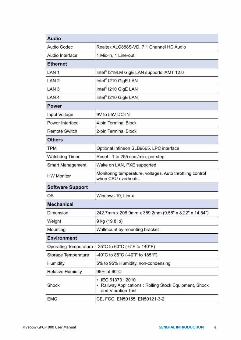
AudioAudio Codec Realtek ALC888S-VD, 7.1 Channel HD Audio
Audio Interface 1 Mic-in, 1 Line-out
EthernetLAN 1 Intel® I219LM GigE LAN supports iAMT 12.0
LAN 2 Intel® I210 GigE LAN
LAN 3 Intel® I210 GigE LAN
LAN 4 Intel® I210 GigE LAN
PowerInput Voltage 9V to 55V DC-IN
Power Interface 4-pin Terminal Block
Remote Switch 2-pin Terminal Block
OthersTPM Optional Infineon SLB9665, LPC interface
Watchdog Timer Reset : 1 to 255 sec./min. per step
Smart Management Wake on LAN, PXE supported
HW Monitor Monitoring temperature, voltages. Auto throttling control when CPU overheats.
Software SupportOS Windows 10, Linux
MechanicalDimension 242.7mm x 208.9mm x 369.2mm (9.56" x 8.22" x 14.54")
Weight 9 kg (19.8 lb)
Mounting Wallmount by mounting bracket
EnvironmentOperating Temperature -25°C to 60°C (-6°F to 140°F)
Storage Temperature -40°C to 85°C (-40°F to 185°F)
Humidity 5% to 95% Humidity, non-condensing
Relative Humidity 95% at 60°C
Shock• IEC 61373 : 2010• Railway Applications : Rolling Stock Equipment, Shock
and Vibration Test
EMC CE, FCC, EN50155, EN50121-3-2
5©Vecow GPC-1000 User Manual GENERAL INTRODUCTION
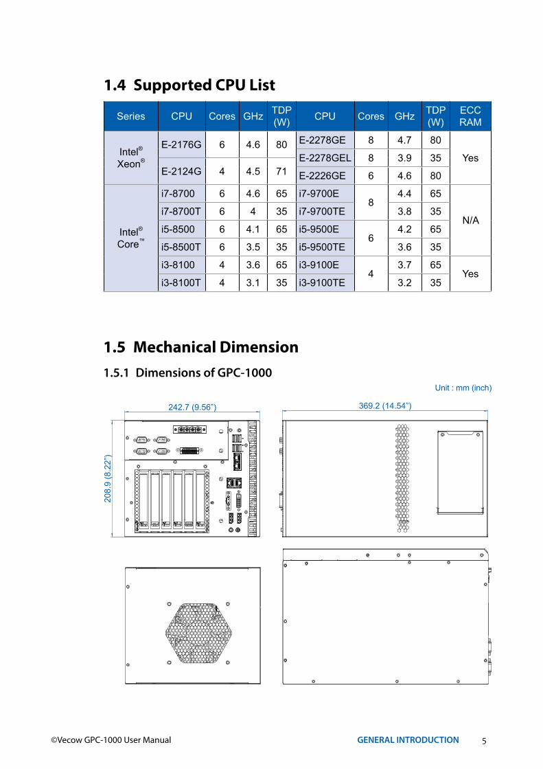
1.4 Supported CPU List
Series CPU Cores GHz TDP (W) CPU Cores GHz TDP
(W)ECC RAM
Intel®Xeon®
E-2176G 6 4.6 80 E-2278GE 8 4.7 80
YesE-2278GEL 8 3.9 35E-2124G 4 4.5 71 E-2226GE 6 4.6 80
Intel®Core™
i7-8700 6 4.6 65 i7-9700E8
4.4 65
N/Ai7-8700T 6 4 35 i7-9700TE 3.8 35
i5-8500 6 4.1 65 i5-9500E6
4.2 65
i5-8500T 6 3.5 35 i5-9500TE 3.6 35
i3-8100 4 3.6 65 i3-9100E4
3.7 65Yes
i3-8100T 4 3.1 35 i3-9100TE 3.2 35
1.5 Mechanical Dimension1.5.1 Dimensions of GPC-1000
242.7 (9.56”)
208.
9 (8
.22”
)
369.2 (14.54”)
Unit : mm (inch)

6©Vecow GPC-1000 User Manual GETTING TO KNOW YOUR GPC-1000
2GETTING TO KNOW YOUR GPC-1000
2.1 Packing List
Item Description Qty
1 GPC-1000 1
2 Vecow Drivers & Utilities DVD 1
Item Description Outlook Usage P/N Qty
1PHILLPIS M4x16L with washer, Ni
Mount 53-24D6416-30B 4
2 PHILLPIS M2.5x6L, Ni
Mini PCIe slot 53-2426906-30B 2
3KHS#6-32x6 screw for wall-mounting
Wall mount bracket 53-I000510-000 4
4 M3 x4 screw HDD/SSD 53-2466204-30B 8
5 Terminal block 2-pin (3.5mm) Switch 51-2411R02-S1B 1
6 4-pin TB Plug Power 51-2711R04-S1Q 1
7Terminal block 20-pin (2.54mm)
Isolated DIO/GPIO 51-2112R20-S1D 1
8 Wall-mounting bracket Mount 62-00P0047-000 2

7©Vecow GPC-1000 User Manual GETTING TO KNOW YOUR GPC-1000
2.2 Front Panel I/O FunctionsIn Vecow GPC-1000 series family, all I/O connectors are located on the front panel. Most of the general connections to computer device, such as USB, LAN Jack, Audio, Display Port, DVI-D and other additional storage, are placed on the front panel.
DVI-D
DP
DP
Switch
On | O
ff
LAN 3
LAN 4
LAN 1
LAN 2
COMRS-232/422/485
V+ V+V
DC-IN
V
Isolated DIO
D IPIN 1 ~ 8 DOPIN 11 ~ 18
1 10
11 20
9-55V 1500W
8©Vecow GPC-1000 User Manual GETTING TO KNOW YOUR GPC-1000
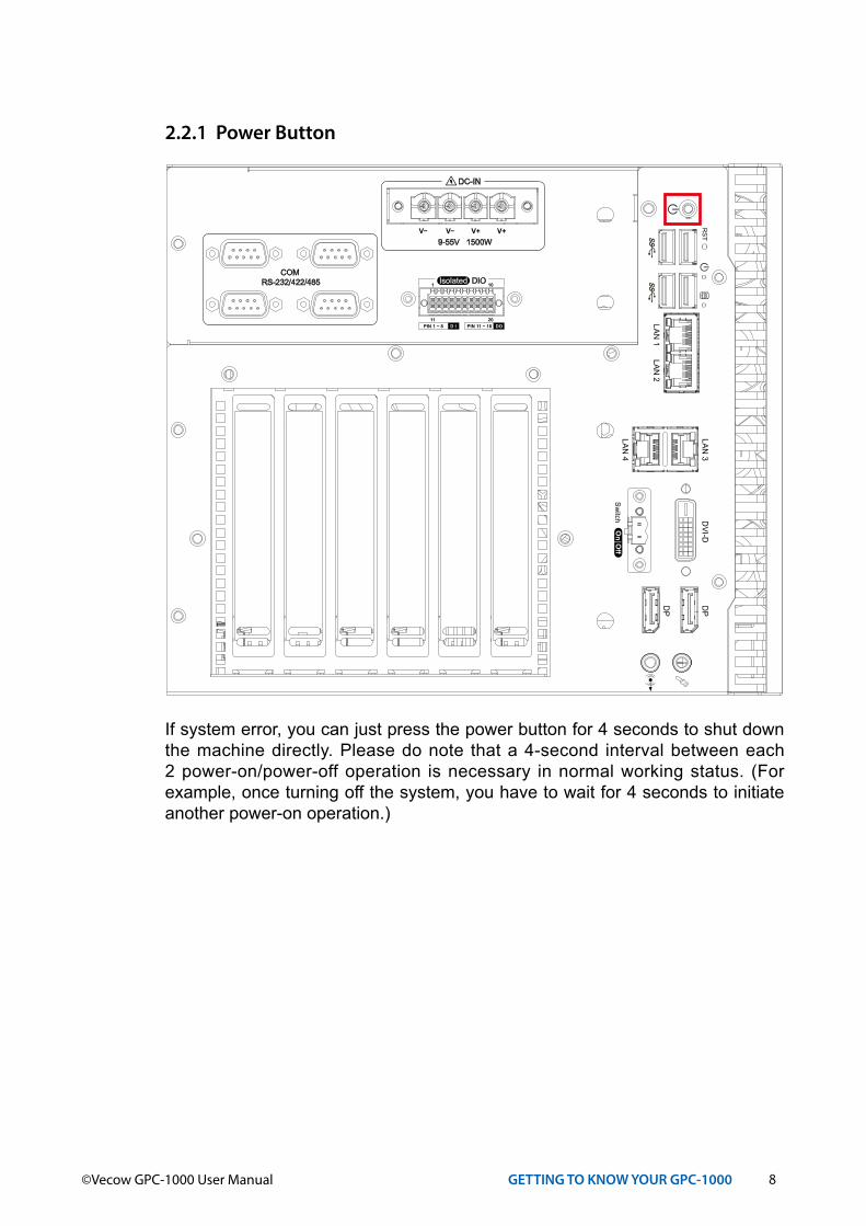
2.2.1 Power Button
If system error, you can just press the power button for 4 seconds to shut down the machine directly. Please do note that a 4-second interval between each 2 power-on/power-off operation is necessary in normal working status. (For example, once turning off the system, you have to wait for 4 seconds to initiate another power-on operation.)
DVI-D
DP
DP
Switch
On | O
ff
LAN 3
LAN 4
LAN 1
LAN 2
COMRS-232/422/485
V+ V+V
DC-IN
V
Isolated DIO
D IPIN 1 ~ 8 DOPIN 11 ~ 18
1 10
11 20
9-55V 1500W
9©Vecow GPC-1000 User Manual GETTING TO KNOW YOUR GPC-1000
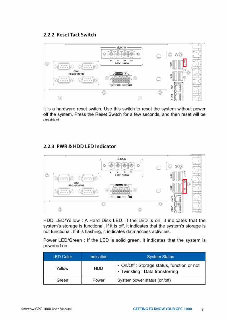
2.2.2 Reset Tact SwitchD
VI-DD
P
DP
Switch
On | O
ff
LAN 3
LAN 4
LAN 1
LAN 2
COMRS-232/422/485
V+ V+V
DC-IN
V
Isolated DIO
D IPIN 1 ~ 8 DOPIN 11 ~ 18
1 10
11 20
9-55V 1500W
It is a hardware reset switch. Use this switch to reset the system without power off the system. Press the Reset Switch for a few seconds, and then reset will be enabled.
2.2.3 PWR & HDD LED Indicator
HDD LED/Yellow : A Hard Disk LED. If the LED is on, it indicates that the system's storage is functional. If it is off, it indicates that the system's storage is not functional. If it is flashing, it indicates data access activities.
Power LED/Green : If the LED is solid green, it indicates that the system is powered on.
LED Color Indication System Status
Yellow HDD• On/Off : Storage status, function or not• Twinkling : Data transferring
Green Power System power status (on/off)
DVI-D
DP
DP
Switch
On | O
ff
LAN 3
LAN 4
LAN 1
LAN 2
COMRS-232/422/485
V+ V+V
DC-IN
V
Isolated DIO
D IPIN 1 ~ 8 DOPIN 11 ~ 18
1 10
11 20
9-55V 1500W
10©Vecow GPC-1000 User Manual GETTING TO KNOW YOUR GPC-1000
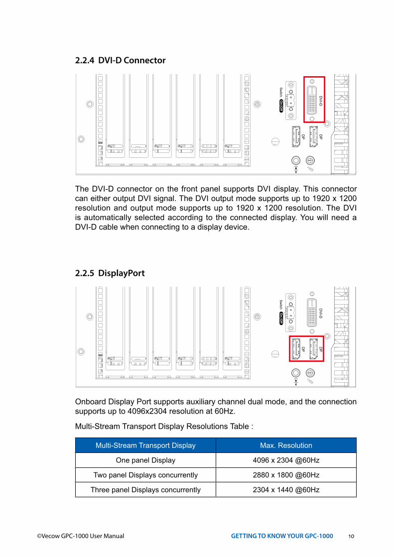
2.2.4 DVI-D Connector
The DVI-D connector on the front panel supports DVI display. This connector can either output DVI signal. The DVI output mode supports up to 1920 x 1200 resolution and output mode supports up to 1920 x 1200 resolution. The DVI is automatically selected according to the connected display. You will need a DVI-D cable when connecting to a display device.
DVI-D
DP
DP
Switch
On | O
ff
LAN 3
LAN 4
LAN 1
LAN 2
COMRS-232/422/485
V+ V+V
DC-IN
V
Isolated DIO
D IPIN 1 ~ 8 DOPIN 11 ~ 18
1 10
11 20
9-55V 1500W
2.2.5 DisplayPort
Onboard Display Port supports auxiliary channel dual mode, and the connection supports up to 4096x2304 resolution at 60Hz.
Multi-Stream Transport Display Resolutions Table :
Multi-Stream Transport Display Max. Resolution
One panel Display 4096 x 2304 @60Hz
Two panel Displays concurrently 2880 x 1800 @60Hz
Three panel Displays concurrently 2304 x 1440 @60Hz
DVI-D
DP
DP
Switch
On | O
ff
LAN 3
LAN 4
LAN 1
LAN 2
COMRS-232/422/485
V+ V+V
DC-IN
V
Isolated DIO
D IPIN 1 ~ 8 DOPIN 11 ~ 18
1 10
11 20
9-55V 1500W

11©Vecow GPC-1000 User Manual GETTING TO KNOW YOUR GPC-1000
2.2.6 USB 3.1
There are 4 USB 3.1 connections available supporting up to 5GB per second data rate in the front side of GPC-1000. It is also compliant with the requirements of Super Speed (SS), High Speed (HS), Full Speed (FS) and Low Speed (LS).
DVI-D
DP
DP
Switch
On | O
ff
LAN 3
LAN 4
LAN 1
LAN 2
COMRS-232/422/485
V+ V+V
DC-IN
V
Isolated DIO
D IPIN 1 ~ 8 DOPIN 11 ~ 18
1 10
11 20
9-55V 1500W
2.2.7 Ethernet Port There are dual 8-pin RJ-45 jacks supporting 10/100/1000 Mbps Ethernet connections in the front side. LAN 1 is powered by Intel® i219 Ethernet Phy and LAN 2 is powered by Intel® I210 Ethernet engine. When both LAN 1 and LAN 2 work at normal status, iAMT 11.0 function is enabled.
Using suitable RJ-45 cable, you can connect the system to a computer or to any other devices with Ethernet connection; for example, a hub or a switch. Moreover, both LAN 1 and LAN 2 support Wake on LAN and Pre-boot functions. The pin-outs of LAN 1 and LAN 2 are listed as follows :
Pin No. 10/100 Mbps 1000Mbps
1 E_TX+ MDI0_P
2 E_TX- MDI0_N
3 E_RX+ MDI1_P
4 ----- MDI2_P
5 ----- MDI2_N
6 E_RX- MDI1_N
7 ----- MDI3_P
8 ----- MDI3_N
Each LAN port is supported by standard RJ-45 connector with LED indicators to present Active/Link/Speed status of the connection.
The LED indicator on the right bottom corner lightens in solid green when the cable is properly connected to a 100Mbps Ethernet network; The LED indicator on the right bottom corner lightens in solid orange when the cable is properly connected to a 1000Mbps Ethernet network; The left LED will keep twinkling/off when Ethernet data packets are being transmitted/received.
12©Vecow GPC-1000 User Manual GETTING TO KNOW YOUR GPC-1000
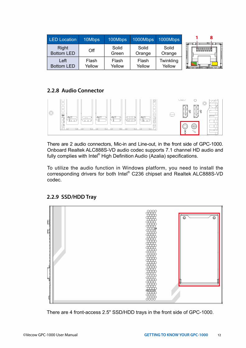
LED Location 10Mbps 100Mbps 1000Mbps 1000Mbps
RightBottom LED Off Solid
GreenSolid
OrangeSolid
OrangeLeft
Bottom LEDFlash Yellow
Flash Yellow
Flash Yellow
Twinkling Yellow
1 8
2.2.8 Audio Connector
There are 2 audio connectors, Mic-in and Line-out, in the front side of GPC-1000. Onboard Realtek ALC888S-VD audio codec supports 7.1 channel HD audio and fully complies with Intel® High Definition Audio (Azalia) specifications.
To utilize the audio function in Windows platform, you need to install the corresponding drivers for both Intel® C236 chipset and Realtek ALC888S-VD codec.
DVI-D
DP
DP
Switch
On | O
ff
LAN 3
LAN 4
LAN 1
LAN 2
COMRS-232/422/485
V+ V+V
DC-IN
V
Isolated DIO
D IPIN 1 ~ 8 DOPIN 11 ~ 18
1 10
11 20
9-55V 1500W
2.2.9 SSD/HDD Tray
There are 4 front-access 2.5" SSD/HDD trays in the front side of GPC-1000.
13©Vecow GPC-1000 User Manual GETTING TO KNOW YOUR GPC-1000
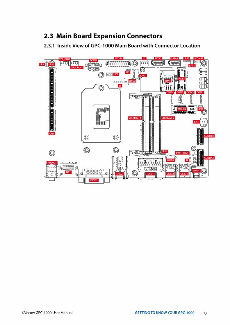
2.3 Main Board Expansion Connectors2.3.1 Inside View of GPC-1000 Main Board with Connector Location
4
8
1
R19 R11
R12R20L1
L4
L5
L8
R1
R2
R9
R10
1
4
1
6
2
1
7
8
119
220
21392240
C1
C5C7
A1A1
0
B1B1
0L1
L4
L5L8
C2
1 4
5
7
1
1 45
91418
1 459
4
3
6
1 2345
2225
179
180
6664
2
1
414
1 4 1 4 1 4
1
1
10
1
10
1
10
110 10
1
10 1
31
3
1
3
1
3 1
1 39
40
7171
1
259
2
260
52 51
2
52
2 1
14 8
71
4
1
3
SYS_FAN1
CPU_FAN1
DCIN1JP9 JP10
CN4
LVDS1
JP3JP2
J6
JDIO2
JDIO1
J2 SATA2 SATA1 JPS2 JCOMS1
BAT1
SIM1PCIE1
COM4 COM3
MPCIE2
COM2 COM1
SODIMM_1 SODIMM_2CN1
SUNITB1
SUNITA1
PWR_BTN1
J4
PWR1USB31USB32
JUSB1
JP11
LAN1LAN2
DVID1
DP1
AUDIO1
JP12
14©Vecow GPC-1000 User Manual GETTING TO KNOW YOUR GPC-1000
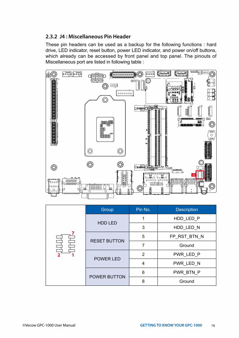
2.3.2 J4 : Miscellaneous Pin HeaderThese pin headers can be used as a backup for the following functions : hard drive, LED indicator, reset button, power LED indicator, and power on/off buttons, which already can be accessed by front panel and top panel. The pinouts of Miscellaneous port are listed in following table :
4
8
1
R19 R11
R12R20L1
L4
L5
L8
R1
R2
R9
R10
1
4
1
6
2
1
7
8
119
220
21392240
C1
C5C7
A1A1
0
B1B1
0L1
L4
L5L8
C2
1 4
5
7
1
1 45
91418
1 459
4
3
6
1 2345
2225
179
180
6664
2
1
414
1 4 1 4 1 4
11
10
1
10
1
10
110 10
1
10 1
31
3
1
3
1
3 1
1 39
40
7171
1
259
2
260
52 51
2
52
2 1
14 8
71
4
1
3
J4
Group Pin No. Description
HDD LED1 HDD_LED_P
3 HDD_LED_N
RESET BUTTON5 FP_RST_BTN_N
7 Ground
POWER LED2 PWR_LED_P
4 PWR_LED_N
POWER BUTTON6 PWR_BTN_P
8 Ground
12
7
15©Vecow GPC-1000 User Manual GETTING TO KNOW YOUR GPC-1000
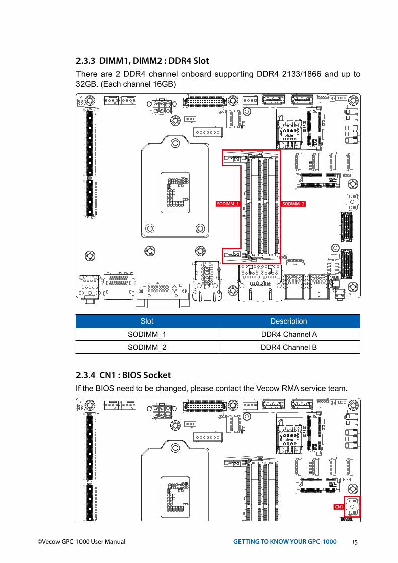
2.3.3 DIMM1, DIMM2 : DDR4 SlotThere are 2 DDR4 channel onboard supporting DDR4 2133/1866 and up to 32GB. (Each channel 16GB)
Slot Description
SODIMM_1 DDR4 Channel A
SODIMM_2 DDR4 Channel B
4
8
1
R19 R11
R12R20L1
L4
L5
L8
R1
R2
R9
R10
1
4
1
6
2
1
7
8
119
220
21392240
C1
C5C7
A1A1
0
B1B1
0L1
L4
L5L8
C2
1 4
5
7
1
1 45
91418
1 459
4
3
6
1 2345
2225
179
180
6664
2
1
414
1 4 1 4 1 4
1
1
10
1
10
1
10
110 10
1
10 1
31
3
1
3
1
3 1
1 39
40
7171
1
259
2
260
52 51
2
52
2 1
14 8
71
4
1
3
SODIMM_1 SODIMM_2
2.3.4 CN1 : BIOS SocketIf the BIOS need to be changed, please contact the Vecow RMA service team.
4
8
1
R19 R11
R12R20L1
L4
L5
L8
R1
R2
R9
R10
1
4
1
6
2
1
7
8
119
220
21392240
C1
C5C7
A1A1
0
B1B1
0L1
L4
L5L8
C2
1 4
5
7
1
1 45
91418
1 459
4
3
6
1 2345
2225
179
180
6664
2
1
414
1 4 1 4 1 4
1
1
10
1
10
1
10
110 10
1
10 1
31
3
1
3
1
3 1
1 39
40
7171
1
259
2
260
52 51
2
52
2 1
14 8
71
4
1
3
CN1

16©Vecow GPC-1000 User Manual GETTING TO KNOW YOUR GPC-1000
2.3.5 SATA1, SATA2 : SATA III Connector
4
8
1
R19 R11
R12R20L1
L4
L5
L8
R1
R2
R9
R10
1
4
1
6
2
1
7
8
119
220
21392240
C1
C5C7
A1A1
0
B1B1
0L1
L4
L5L8
C2
1 4
5
7
1
1 45
91418
1 459
4
3
6
1 2345
2225
179
180
6664
2
1
414
1 4 1 4 1 4
1
1
10
1
10
1
10
110 10
1
10 1
31
3
1
3
1
3 1
1 39
40
7171
1
259
2
260
52 51
2
52
2 1
14 8
71
4
1
3 SATA2 SATA1
Standard 7 PIN SATA ConnectorThere are 2 onboard high performance Serial ATA III. It supports higher storage capacity with less cabling effort and smaller required space.
Pin No. Description Pin No. Description
1 GND 2 TXP
3 TXN 4 GND
5 RXN 6 RXP
7 GND
1 7
2.3.6 J2 : SATA Power Connector
4
8
1
R19 R11
R12R20L1
L4
L5
L8
R1
R2
R9
R10
1
4
1
6
2
1
7
8
119
220
21392240
C1
C5C7
A1A1
0
B1B1
0L1
L4
L5L8
C2
1 4
5
7
1
1 45
91418
1 459
4
3
6
1 2345
2225
179
180
6664
2
1
414
1 4 1 4 1 4
1
1
10
1
10
1
10
110 10
1
10 1
31
3
1
3
1
3 1
1 39
40
7171
1
259
2
260
52 51
2
52
2 1
14 8
71
4
1
3 J2
Standard, all form factor 1x4p power headerThere are 2 HDD power header on board and each power header supports two 2.5" SATA HDD.
Pin No. Description Pin No. Description
1 +12V 2 GND
3 GND 4 +5V
4 1

17©Vecow GPC-1000 User Manual GETTING TO KNOW YOUR GPC-1000
4
8
1
R19 R11
R12R20L1
L4
L5
L8
R1
R2
R9
R10
1
4
1
6
2
1
7
8
119
220
21392240
C1
C5C7
A1A1
0
B1B1
0L1
L4
L5L8
C2
1 4
5
7
1
1 45
91418
1 459
4
3
6
1 2345
2225
179
180
6664
2
1
414
1 4 1 4 1 4
1
1
10
1
10
1
10
110 10
1
10 1
31
3
1
3
1
3 1
1 39
40
7171
1
259
2
260
52 51
2
52
2 1
14 8
71
4
1
3
JUSB1
2.3.7 JUSB1 : Internal USB 2.0 ConnectorStandard Vertical USB 2.0 Connector
GPC-1000 main board provides one expansion USB port using plug-and-play for Dongle Key or LCD touch Panel. The USB interface supports 480Mbps transfer rate complied with high speed USB specification Rev. 2.0.
The USB interface is accessed through one standard USB 2.0 connector. This USB 2.0 does not support wake up function.
Pin No. Definition Pin No. Definition
1 USB_VCC 2 USB_VCC
3 USB_VCC 4 USBD1-
5 USBD1+ 6 USBD2-
7 USBD2+ 8 GND
9 GND 10 GND
110
18©Vecow GPC-1000 User Manual GETTING TO KNOW YOUR GPC-1000
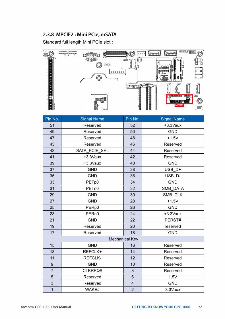
2.3.8 MPCIE2 : Mini PCIe, mSATAStandard full length Mini PCIe slot :
4
8
1
R19 R11
R12R20L1
L4
L5
L8
R1
R2
R9
R10
1
4
1
6
2
1
7
8
119
220
21392240
C1
C5C7
A1A1
0
B1B1
0L1
L4
L5L8
C2
1 4
5
7
1
1 45
91418
1 459
4
3
6
1 2345
2225
179
180
6664
2
1
414
1 4 1 4 1 4
1
1
10
1
10
1
10
110 10
1
10 1
31
3
1
3
1
3 1
1 39
40
7171
1
259
2
260
52 51
2
52
2 1
14 8
71
4
1
3
MPCIE2
Pin No. Signal Name Pin No. Signal Name51 Reserved 52 +3.3Vaux49 Reserved 50 GND47 Reserved 48 +1.5V45 Reserved 46 Reserved43 SATA_PCIE_SEL 44 Reserved41 +3.3Vaux 42 Reserved39 +3.3Vaux 40 GND37 GND 38 USB_D+35 GND 36 USB_D-33 PETp0 34 GND31 PETn0 32 SMB_DATA29 GND 30 SMB_CLK27 GND 28 +1.5V25 PERp0 26 GND23 PERn0 24 +3.3Vaux21 GND 22 PERST#19 Reserved 20 reserved17 Reserved 18 GND
Mechanical Key15 GND 16 Reserved13 REFCLK+ 14 Reserved11 REFCLK- 12 Reserved9 GND 10 Reserved7 CLKREQ# 8 Reserved5 Reserved 6 1.5V3 Reserved 4 GND1 WAKE# 2 3.3Vaux
19©Vecow GPC-1000 User Manual GETTING TO KNOW YOUR GPC-1000
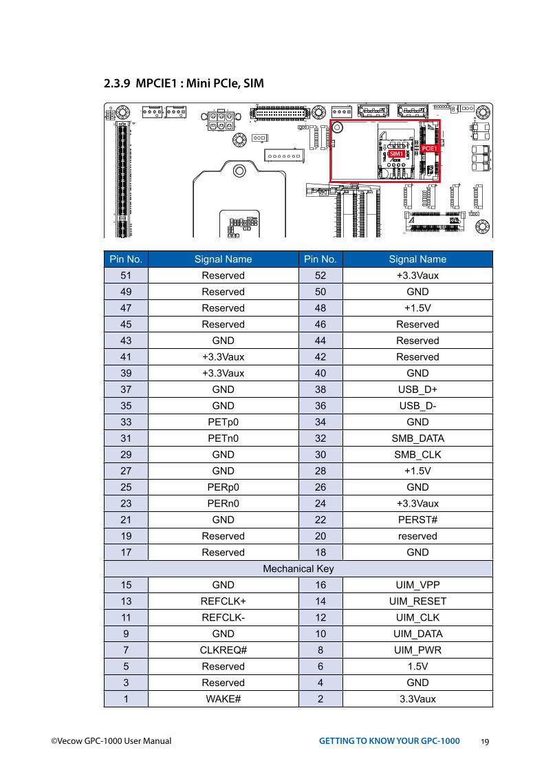
2.3.9 MPCIE1 : Mini PCIe, SIM
4
8
1
R19 R11
R12R20L1
L4
L5
L8
R1
R2
R9
R10
1
4
1
6
2
1
7
8
119
220
21392240
C1
C5C7
A1A1
0
B1B1
0L1
L4
L5L8
C2
1 4
5
7
1
1 45
91418
1 459
4
3
6
1 2345
2225
179
180
6664
2
1
414
1 4 1 4 1 4
1
1
10
1
10
1
10
110 10
1
10 1
31
3
1
3
1
3 1
1 39
40
7171
1
259
2
260
52 51
2
52
2 1
14 8
71
4
1
3
SIM1PCIE1
Pin No. Signal Name Pin No. Signal Name51 Reserved 52 +3.3Vaux49 Reserved 50 GND47 Reserved 48 +1.5V45 Reserved 46 Reserved43 GND 44 Reserved41 +3.3Vaux 42 Reserved39 +3.3Vaux 40 GND37 GND 38 USB_D+35 GND 36 USB_D-33 PETp0 34 GND31 PETn0 32 SMB_DATA29 GND 30 SMB_CLK27 GND 28 +1.5V25 PERp0 26 GND23 PERn0 24 +3.3Vaux21 GND 22 PERST#19 Reserved 20 reserved17 Reserved 18 GND
Mechanical Key15 GND 16 UIM_VPP13 REFCLK+ 14 UIM_RESET11 REFCLK- 12 UIM_CLK9 GND 10 UIM_DATA7 CLKREQ# 8 UIM_PWR5 Reserved 6 1.5V3 Reserved 4 GND1 WAKE# 2 3.3Vaux
20©Vecow GPC-1000 User Manual GETTING TO KNOW YOUR GPC-1000
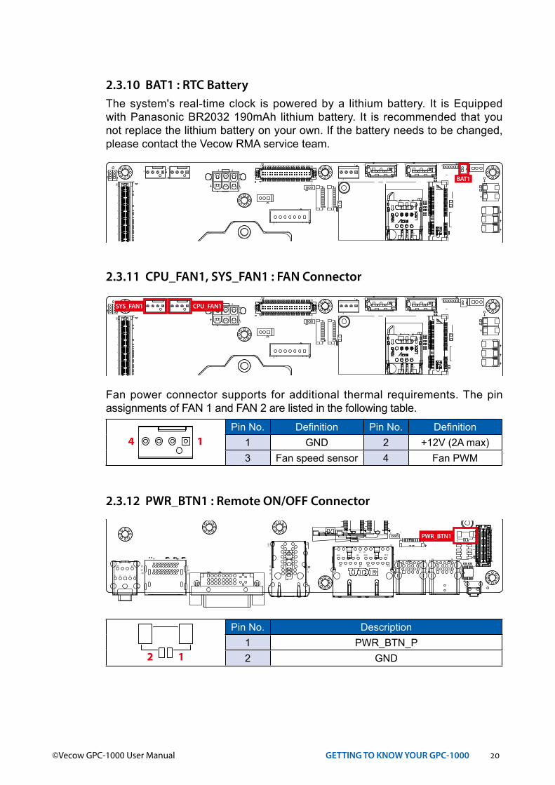
2.3.10 BAT1 : RTC BatteryThe system's real-time clock is powered by a lithium battery. It is Equipped with Panasonic BR2032 190mAh lithium battery. It is recommended that you not replace the lithium battery on your own. If the battery needs to be changed, please contact the Vecow RMA service team.
4
8
1
R19 R11
R12R20L1
L4
L5
L8
R1
R2
R9
R10
1
4
1
6
2
1
7
8
119
220
21392240
C1
C5C7
A1A1
0
B1B1
0L1
L4
L5L8
C2
1 4
5
7
1
1 45
91418
1 459
4
3
6
1 2345
2225
179
180
6664
2
1
414
1 4 1 4 1 4
11
10
1
10
1
10
110 10
1
10 1
31
3
1
3
1
3 1
1 39
40
7171
1
259
2
260
52 51
2
52
2 1
14 8
71
4
1
3
BAT1
2.3.11 CPU_FAN1, SYS_FAN1 : FAN Connector
Fan power connector supports for additional thermal requirements. The pin assignments of FAN 1 and FAN 2 are listed in the following table.
Pin No. Definition Pin No. Definition1 GND 2 +12V (2A max)3 Fan speed sensor 4 Fan PWM
14
4
8
1
R19 R11
R12R20L1
L4
L5
L8
R1
R2
R9
R10
1
4
1
6
2
1
7
8
119
220
21392240
C1
C5C7
A1A1
0
B1B1
0L1
L4
L5L8
C2
1 4
5
7
1
1 45
91418
1 459
4
3
6
1 2345
2225
179
180
6664
2
1
414
1 4 1 4 1 4
1
1
10
1
10
1
10
110 10
1
10 1
31
3
1
3
1
3 1
1 39
40
7171
1
259
2
260
52 51
2
52
2 1
14 8
71
4
1
3
SYS_FAN1 CPU_FAN1
2.3.12 PWR_BTN1 : Remote ON/OFF Connector
Pin No. Description1 PWR_BTN_P2 GND
4
8
1
R19 R11
R12R20L1
L4
L5
L8
R1
R2
R9
R10
1
4
1
6
2
1
7
8
119
220
21392240
C1
C5C7
A1A1
0
B1B1
0L1
L4
L5L8
C2
1 4
5
7
1
1 45
91418
1 459
4
3
6
1 2345
2225
179
180
6664
2
1
414
1 4 1 4 1 4
1
1
10
1
10
1
10
110 10
1
10 1
31
3
1
3
1
3 1
1 39
40
7171
1
259
2
260
52 51
2
522 1
14 8
71
4
1
3
PWR_BTN1
2 1

21©Vecow GPC-1000 User Manual GETTING TO KNOW YOUR GPC-1000
2.3.13 JDIO1~JDIO2 : GPIO Connector There is a 16-bit GPIO connector on the top side. Each GPIO channel can be configuration GPI or GPO. Detail setting see APPENDIX. JDIO1 and JDIO2 Pin define are as below.
4
8
1
R19 R11
R12R20L1
L4
L5
L8
R1
R2
R9
R10
1
4
1
6
2
1
7
8
119
220
21392240
C1
C5C7
A1A1
0
B1B1
0L1
L4
L5L8
C2
1 4
5
7
1
1 45
91418
1 459
4
3
6
1 2345
2225
179
180
6664
2
1
414
1 4 1 4 1 4
1
1
10
1
10
1
10
110 10
1
10 1
31
3
1
3
1
3 1
1 39
40
7171
1
259
2
260
52 51
2
52
2 1
14 8
71
4
1
3
JDIO2 JDIO1
Pin No. JDIO1 Definition JDIO2 Definition
1 SIO_GPO70 SIO_GPI80
2 SIO_GPO71 SIO_GPI81
3 SIO_GPO72 SIO_GPI82
4 SIO_GPO73 SIO_GPI83
5 SIO_GPO74 SIO_GPI84
6 SIO_GPO75 SIO_GPI85
7 SIO_GPO76 SIO_GPI86
8 SIO_GPO77 SIO_GPI87
1
10

22©Vecow GPC-1000 User Manual GETTING TO KNOW YOUR GPC-1000
2.3.14 COM1~COM4 : Serial Port
4
8
1
R19 R11
R12R20L1
L4
L5
L8
R1
R2
R9
R10
1
4
1
6
2
1
7
8
119
220
21392240
C1
C5C7
A1A1
0
B1B1
0L1
L4
L5L8
C2
1 4
5
7
1
1 45
91418
1 459
4
3
6
1 2345
2225
179
180
6664
2
1
414
1 4 1 4 1 4
1
1
10
1
10
1
10
110 10
1
10 1
31
3
1
3
1
3 1
1 39
40
7171
1
259
2
260
52 51
2
52
2 1
14 8
71
4
1
3
COM4 COM3 COM2 COM1
BIOS Setting Function
COM1 COM2 COM3 COM4
RS-232RS-422 (5-wire)RS-422 (9-wire)
RS-485RS-485 w/z auto-flow control
Pin Out :
COM Port MB Connector COM Port MB Connector
COM1 COM1 COM2 COM2
COM3 COM3 COM4 COM4
CN Pin No. Signal Name Pin No. Signal Name
COM1 to 4
1 NC 2 GND
3 RI 4 DTR
5 CTS 6 TXD
7 RTS 8 RXD
9 DSR 10 DCD
23©Vecow GPC-1000 User Manual GETTING TO KNOW YOUR GPC-1000
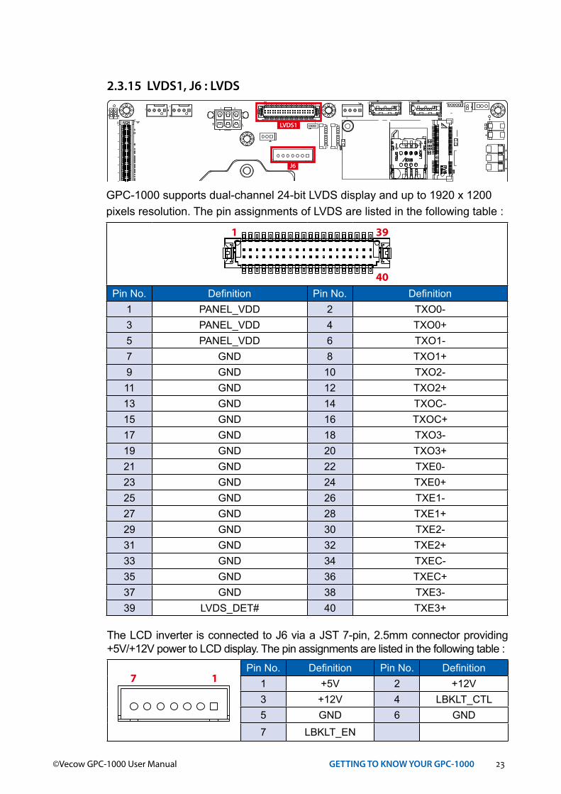
2.3.15 LVDS1, J6 : LVDS
4
8
1
R19 R11
R12R20L1
L4
L5
L8
R1
R2
R9
R10
1
4
1
6
2
1
7
8
119
220
21392240
C1
C5C7
A1A1
0
B1B1
0L1
L4
L5L8
C2
1 4
5
7
1
1 45
91418
1 459
4
3
6
1 2345
2225
179
180
6664
2
1
414
1 4 1 4 1 4
1
1
10
1
10
1
10
110 10
1
10 1
31
3
1
3
1
3 1
1 39
40
7171
1
259
2
260
52 51
2
52
2 1
14 8
71
4
1
3LVDS1
J6
GPC-1000 supports dual-channel 24-bit LVDS display and up to 1920 x 1200pixels resolution. The pin assignments of LVDS are listed in the following table :
Pin No. Definition Pin No. Definition1 PANEL_VDD 2 TXO0-3 PANEL_VDD 4 TXO0+5 PANEL_VDD 6 TXO1-7 GND 8 TXO1+9 GND 10 TXO2-11 GND 12 TXO2+13 GND 14 TXOC-15 GND 16 TXOC+17 GND 18 TXO3-19 GND 20 TXO3+21 GND 22 TXE0-23 GND 24 TXE0+25 GND 26 TXE1-27 GND 28 TXE1+29 GND 30 TXE2-31 GND 32 TXE2+33 GND 34 TXEC-35 GND 36 TXEC+37 GND 38 TXE3-39 LVDS_DET# 40 TXE3+
391
40
The LCD inverter is connected to J6 via a JST 7-pin, 2.5mm connector providing +5V/+12V power to LCD display. The pin assignments are listed in the following table :
Pin No. Definition Pin No. Definition1 +5V 2 +12V3 +12V 4 LBKLT_CTL5 GND 6 GND7 LBKLT_EN
17
24©Vecow GPC-1000 User Manual GETTING TO KNOW YOUR GPC-1000
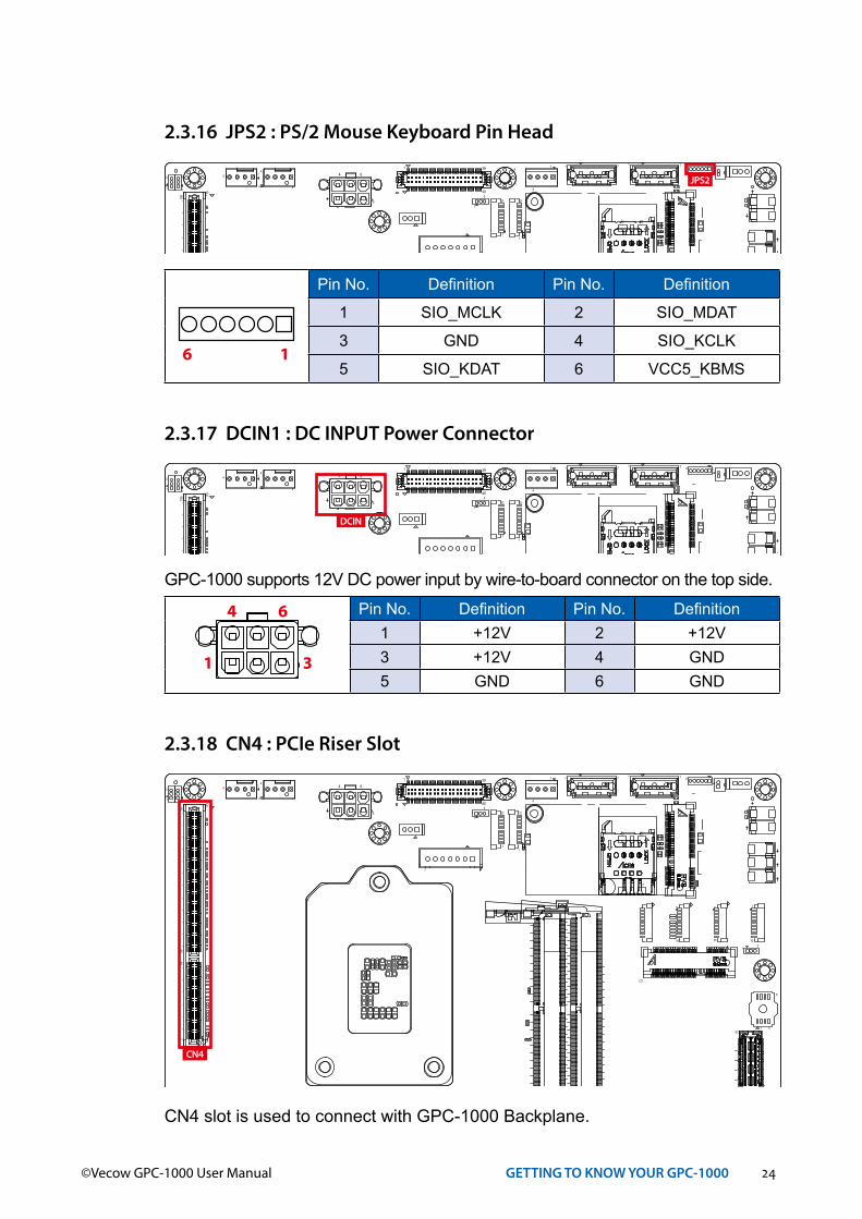
2.3.16 JPS2 : PS/2 Mouse Keyboard Pin Head
4
8
1
R19 R11
R12R20L1
L4
L5
L8
R1
R2
R9
R10
1
4
1
6
2
1
7
8
119
220
21392240
C1
C5C7
A1A1
0
B1B1
0L1
L4
L5L8
C2
1 4
5
7
1
1 45
91418
1 459
4
3
6
1 2345
2225
179
180
6664
2
1
414
1 4 1 4 1 4
1
1
10
1
10
1
10
110 10
1
10 1
31
3
1
3
1
3 1
1 39
40
7171
1
259
2
260
52 51
2
52
2 1
14 8
71
4
1
3
JPS2
Pin No. Definition Pin No. Definition
1 SIO_MCLK 2 SIO_MDAT
3 GND 4 SIO_KCLK
5 SIO_KDAT 6 VCC5_KBMS16
2.3.17 DCIN1 : DC INPUT Power Connector
4
8
1
R19 R11
R12R20L1
L4
L5
L8
R1
R2
R9
R10
1
4
1
6
2
1
7
8
119
220
21392240
C1
C5C7
A1A1
0
B1B1
0L1
L4
L5L8
C2
1 4
5
7
1
1 45
91418
1 459
4
3
6
1 2345
2225
179
180
6664
2
1
414
1 4 1 4 1 4
1
1
10
1
10
1
10
110 10
1
10 1
31
3
1
3
1
3 1
1 39
40
7171
1
259
2
260
52 51
2
52
2 1
14 8
71
4
1
3
DCIN
GPC-1000 supports 12V DC power input by wire-to-board connector on the top side.Pin No. Definition Pin No. Definition
1 +12V 2 +12V3 +12V 4 GND5 GND 6 GND
1 3
4 6
2.3.18 CN4 : PCIe Riser Slot
CN4 slot is used to connect with GPC-1000 Backplane.
4
8
1
R19 R11
R12R20L1
L4
L5
L8
R1
R2
R9
R10
1
4
1
6
2
1
7
8
119
220
21392240
C1
C5C7
A1A1
0
B1B1
0L1
L4
L5L8
C2
1 4
5
7
1
1 45
91418
1 459
4
3
6
1 2345
2225
179
180
6664
2
1
414
1 4 1 4 1 4
1
1
10
1
10
1
10
110 10
1
10 1
31
3
1
3
1
3 1
1 39
40
7171
1
259
2
260
52 51
2
52
2 1
14 8
71
4
1
3
CN4
25©Vecow GPC-1000 User Manual GETTING TO KNOW YOUR GPC-1000
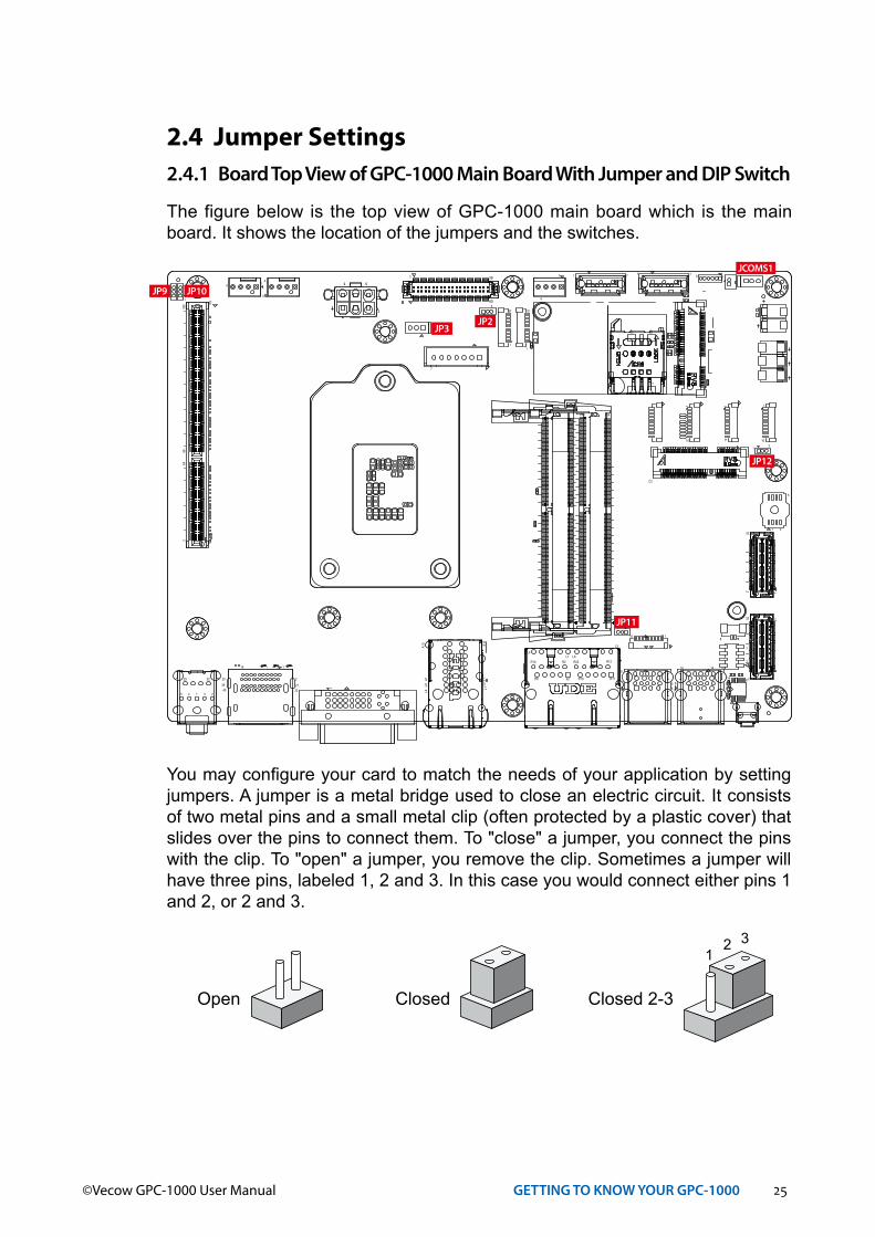
2.4 Jumper Settings2.4.1 Board Top View of GPC-1000 Main Board With Jumper and DIP Switch
The figure below is the top view of GPC-1000 main board which is the main board. It shows the location of the jumpers and the switches.
4
8
1
R19 R11
R12R20L1
L4
L5
L8
R1
R2
R9
R10
1
4
1
6
2
1
7
8
119
220
21392240
C1
C5C7
A1A1
0
B1B1
0L1
L4
L5L8
C2
1 4
5
7
1
1 45
91418
1 459
4
3
6
1 2345
2225
179
180
6664
2
1
414
1 4 1 4 1 4
1
1
10
1
10
1
10
110 10
1
10 1
31
3
1
3
1
3 1
1 39
40
7171
1
259
2
260
52 51
2
52
2 1
14 8
71
4
1
3
JP9 JP10
JP3JP2
JCOMS1
JP11
JP12
You may configure your card to match the needs of your application by setting jumpers. A jumper is a metal bridge used to close an electric circuit. It consists of two metal pins and a small metal clip (often protected by a plastic cover) that slides over the pins to connect them. To "close" a jumper, you connect the pins with the clip. To "open" a jumper, you remove the clip. Sometimes a jumper will have three pins, labeled 1, 2 and 3. In this case you would connect either pins 1 and 2, or 2 and 3.
Open Closed Closed 2-3
12 3

26©Vecow GPC-1000 User Manual GETTING TO KNOW YOUR GPC-1000
2.4.2 JP3 : LVDS Module, Power Selection
JP3 provides LVDS voltage selection function, Closing Pin 1 and Pin 2 is for 3.3V LVDS power input; closing Pin 2 and Pin 3 is for 5V LVDS power input.
Pin No. Definition
1-2 +3.3V (Default)
2-3 +5V
13
4
8
1
R19 R11
R12R20L1
L4
L5
L8
R1
R2
R9
R10
1
4
1
6
2
1
7
8
119
220
21392240
C1
C5C7
A1A1
0
B1B1
0L1
L4
L5L8
C2
1 4
5
7
1
1 45
91418
1 459
4
3
6
1 2345
2225
179
180
6664
2
1
414
1 4 1 4 1 4
1
1
10
1
10
1
10
110 10
1
10 1
31
3
1
3
1
3 1
1 39
40
7171
1
259
2
260
52 51
2
52
2 1
14 8
71
4
1
3
JP3
2.4.3 JCMOS1 : Clear CMOS
CMOS Header
1-2 Normal
2-3 Clear CMOS
31
4
8
1
R19 R11
R12R20L1
L4
L5
L8
R1
R2
R9
R10
1
4
1
6
2
1
7
8
119
220
21392240
C1
C5C7
A1A1
0
B1B1
0L1
L4
L5L8
C2
1 4
5
7
1
1 45
91418
1 459
4
3
6
1 2345
2225
179
180
6664
2
1
414
1 4 1 4 1 4
1
1
10
1
10
1
10
110 10
1
10 1
31
3
1
3
1
3 1
1 39
40
7171
1
259
2
260
52 51
2
52
2 1
14 8
71
4
1
3
JCMOS1
27©Vecow GPC-1000 User Manual GETTING TO KNOW YOUR GPC-1000
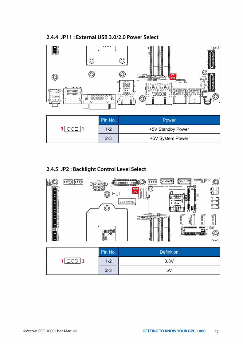
2.4.4 JP11 : External USB 3.0/2.0 Power Select
Pin No. Power
1-2 +5V Standby Power
2-3 +5V System Power
13
4
8
1
R19 R11
R12R20L1
L4
L5
L8
R1
R2
R9
R10
1
4
1
6
2
1
7
8
119
220
21392240
C1
C5C7
A1A1
0
B1B1
0L1
L4
L5L8
C2
1 4
5
7
1
1 45
91418
1 459
4
3
6
1 2345
2225
179
180
6664
2
1
414
1 4 1 4 1 4
1
1
10
1
10
1
10
110 10
1
10 1
31
3
1
3
1
3 1
1 39
40
7171
1
259
2
260
52 51
2
52
2 1
14 8
71
4
1
3
JP11
2.4.5 JP2 : Backlight Control Level Select
Pin No. Definition
1-2 3.3V
2-3 5V
31
4
8
1
R19 R11
R12R20L1
L4
L5
L8
R1
R2
R9
R10
1
4
1
6
2
1
7
8
119
220
21392240
C1
C5C7
A1A1
0
B1B1
0L1
L4
L5L8
C2
1 4
5
7
1
1 45
91418
1 459
4
3
6
1 2345
2225
179
180
6664
2
1
414
1 4 1 4 1 4
1
1
10
1
10
1
10
110 10
1
10 1
31
3
1
3
1
3 1
1 39
40
7171
1
259
2
260
52 51
2
52
2 1
14 8
71
4
1
3
JP2
28©Vecow GPC-1000 User Manual GETTING TO KNOW YOUR GPC-1000
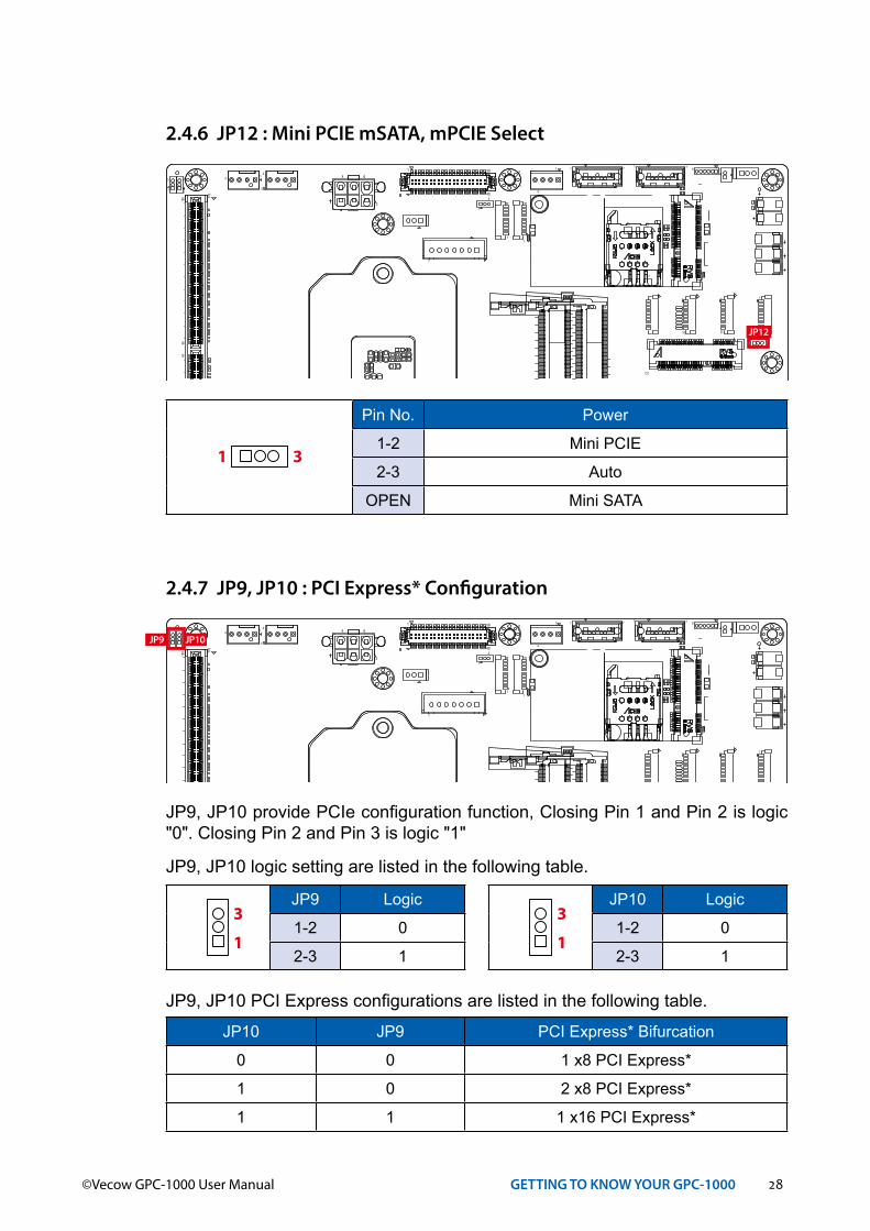
2.4.6 JP12 : Mini PCIE mSATA, mPCIE Select
Pin No. Power
1-2 Mini PCIE
2-3 Auto
OPEN Mini SATA
31
4
8
1
R19 R11
R12R20L1
L4
L5
L8
R1
R2
R9
R10
1
4
1
6
2
1
7
8
119
220
21392240
C1
C5C7
A1A1
0
B1B1
0L1
L4
L5L8
C2
1 4
5
7
1
1 45
91418
1 459
4
3
6
1 2345
2225
179
180
6664
2
1
414
1 4 1 4 1 4
1
1
10
1
10
1
10
110 10
1
10 1
31
3
1
3
1
3 1
1 39
40
7171
1
259
2
260
52 51
2
52
2 1
14 8
71
4
1
3
JP12
2.4.7 JP9, JP10 : PCI Express* Configuration
4
8
1
R19 R11
R12R20L1
L4
L5
L8
R1
R2
R9
R10
1
4
1
6
2
1
7
8
119
220
21392240
C1
C5C7
A1A1
0
B1B1
0L1
L4
L5L8
C2
1 4
5
7
1
1 45
91418
1 459
4
3
6
1 2345
2225
179
180
6664
2
1
414
1 4 1 4 1 4
1
1
10
1
10
1
10
110 10
1
10 1
31
3
1
3
1
3 1
1 39
40
7171
1
259
2
260
52 51
2
52
2 1
14 8
71
4
1
3
JP9 JP10
JP9, JP10 PCI Express configurations are listed in the following table.
JP10 JP9 PCI Express* Bifurcation
0 0 1 x8 PCI Express*
1 0 2 x8 PCI Express*
1 1 1 x16 PCI Express*
JP9, JP10 provide PCIe configuration function, Closing Pin 1 and Pin 2 is logic "0". Closing Pin 2 and Pin 3 is logic "1"
JP9, JP10 logic setting are listed in the following table.
JP9 Logic
1-2 0
2-3 1
JP10 Logic
1-2 0
2-3 11
3
1
3
29©Vecow GPC-1000 User Manual GETTING TO KNOW YOUR GPC-1000
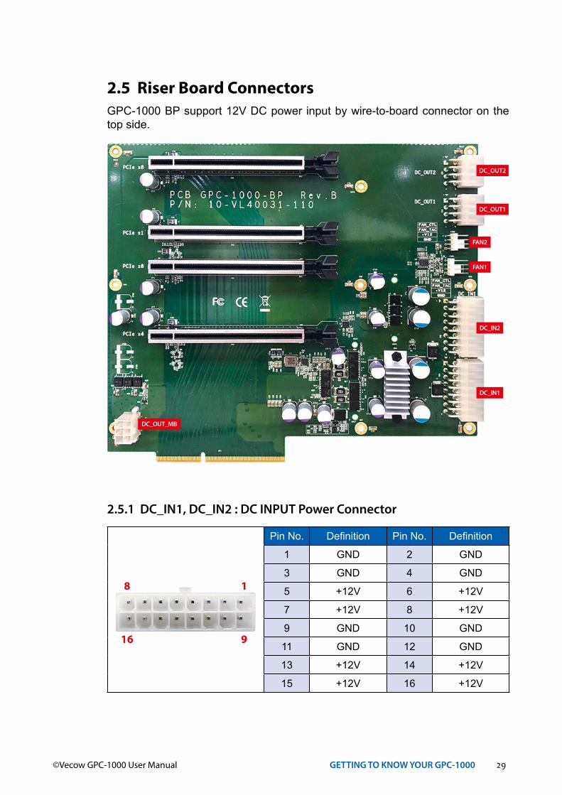
2.5 Riser Board Connectors GPC-1000 BP support 12V DC power input by wire-to-board connector on the top side.
2.5.1 DC_IN1, DC_IN2 : DC INPUT Power Connector
Pin No. Definition Pin No. Definition
1 GND 2 GND
3 GND 4 GND
5 +12V 6 +12V
7 +12V 8 +12V
9 GND 10 GND
11 GND 12 GND
13 +12V 14 +12V
15 +12V 16 +12V
1
9
8
16
DC_OUT_MB
DC_OUT2
DC_OUT1
DC_IN2
DC_IN1
FAN1
FAN2
30©Vecow GPC-1000 User Manual GETTING TO KNOW YOUR GPC-1000
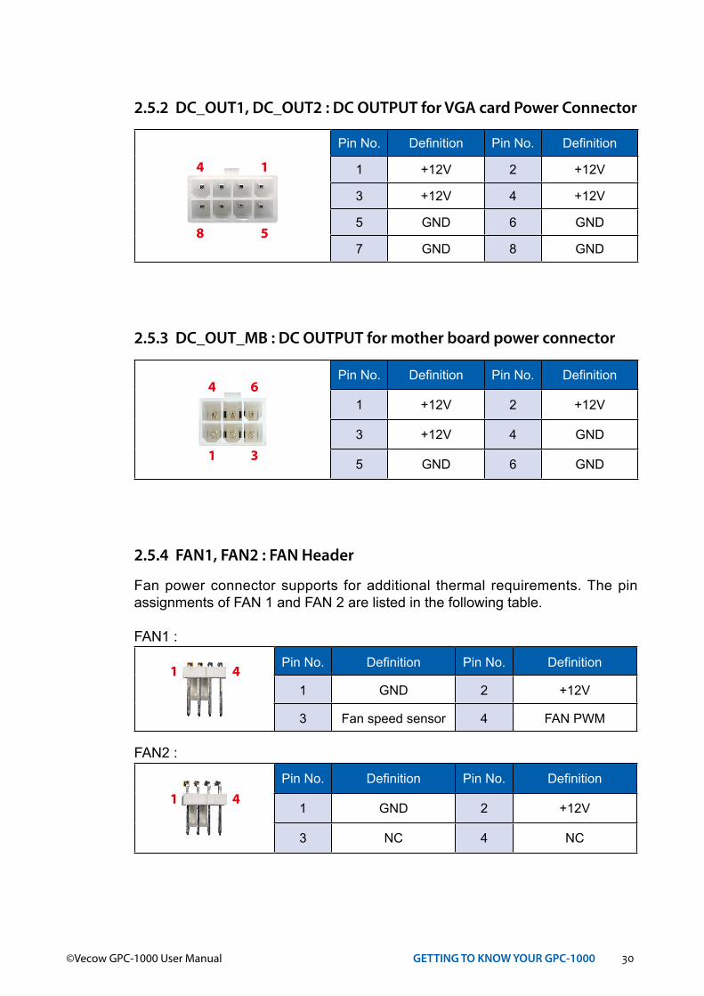
2.5.2 DC_OUT1, DC_OUT2 : DC OUTPUT for VGA card Power Connector
Pin No. Definition Pin No. Definition
1 +12V 2 +12V
3 +12V 4 +12V
5 GND 6 GND
7 GND 8 GND
1
5
4
8
2.5.3 DC_OUT_MB : DC OUTPUT for mother board power connector
Pin No. Definition Pin No. Definition
1 +12V 2 +12V
3 +12V 4 GND
5 GND 6 GND
6
3
4
1
2.5.4 FAN1, FAN2 : FAN Header
Fan power connector supports for additional thermal requirements. The pin assignments of FAN 1 and FAN 2 are listed in the following table.
FAN1 :
Pin No. Definition Pin No. Definition
1 GND 2 +12V
3 Fan speed sensor 4 FAN PWM
FAN2 :
Pin No. Definition Pin No. Definition
1 GND 2 +12V
3 NC 4 NC
1 4
1 4

31©Vecow GPC-1000 User Manual GETTING TO KNOW YOUR GPC-1000
2.6 Power Board ConnectorsWide range power module WPM-120 support 9V~55V DC Input power module, 12V output (750W).
CN1
CN3
SYS FAN1
CN2
2.6.1 CN1, CN3 : DC INPUT POWER CONNECTOR
Connector Description
CN1 VIN +
CN3 VIN -
2.6.2 CN2 : DC OUTPUT Power Connector
Pin No. Definition Pin No. Definition
1 GND 2 GND
3 GND 4 GND
5 +12V 6 +12V
7 +12V 8 +12V
9 GND 10 GND
11 GND 12 GND
13 +12V 14 +12V
15 +12V 16 +12V
1 9
8 16
2.6.3 SYS FAN : Fan Connector
The pin assignments of SYS FAN is listed in the following table.
Pin No. Definition Pin No. Definition
1 GND 2 NC
3 NC 4 +12V
4
1

32©Vecow GPC-1000 User Manual GETTING TO KNOW YOUR GPC-1000
2.7 DC- IN Board ConnectorsGPC-1000-DCB support 9V~55V DC power input by wire-to-board connector on the top side.
CN2 CN4 CN3 CN5
CN1
2.7.1 CN1 : DC INPUT POWER CONNECTOR
Pin No. Definition Pin No. Definition
1 DCIN 2 DCIN
3 GND 4 GND
2.7.2 CN2, CN3, CN4, CN5 : DC OUTPUT POWER CONNECTOR
Pin No. Definition Pin No. Definition
1 DC_OUT 2 GND
3 DC_OUT 4 GND

33©Vecow GPC-1000 User Manual SYSTEM SETUP
3SYSTEM SETUP
3.1 How to Open Your GPC-1000Step 1 Remove bottom eleven F#6-32.
Step 2 Open bottom cover and remove power tray four F#6-32.
Step 3 Finish.

34©Vecow GPC-1000 User Manual SYSTEM SETUP
3.2 Installing CPUStep 1 Open CPU Slot cover.
Step 2 Install CPU into the CPU Slot.
Step 3 Close and lock CPU Slot cover.
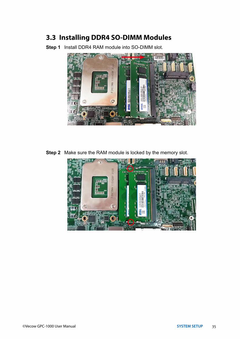
35©Vecow GPC-1000 User Manual SYSTEM SETUP
3.3 Installing DDR4 SO-DIMM ModulesStep 1 Install DDR4 RAM module into SO-DIMM slot.
Step 2 Make sure the RAM module is locked by the memory slot.

36©Vecow GPC-1000 User Manual SYSTEM SETUP
3.4 Installing Mini PCIe CardStep 1 Install Mini PCIe card into the Mini PCIe slot.
Step 2 Fasten one M2.5 screw.
37©Vecow GPC-1000 User Manual SYSTEM SETUP
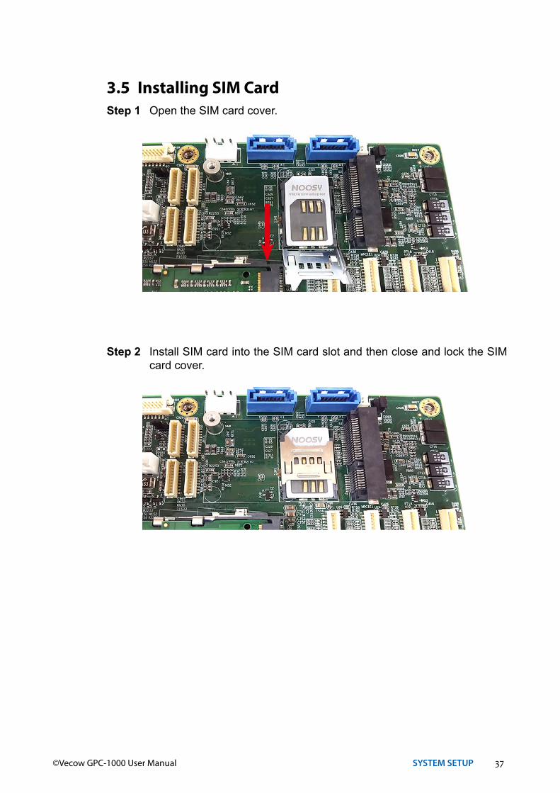
Step 2 Install SIM card into the SIM card slot and then close and lock the SIM card cover.
3.5 Installing SIM CardStep 1 Open the SIM card cover.

38©Vecow GPC-1000 User Manual SYSTEM SETUP
3.6 Installing PCI/PCIe CardStep 1 Please align the gold finger of the PCIE card with the slot.
Step 2 Press down the graphics card.
39©Vecow GPC-1000 User Manual SYSTEM SETUP
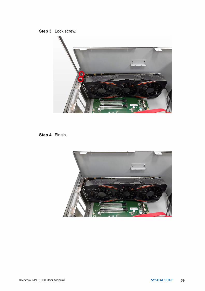
Step 3 Lock screw.
Step 4 Finish.

40©Vecow GPC-1000 User Manual SYSTEM SETUP
3.7 Installing SSD/HDDStep 1 Open HDD/SSD tray.
Step 2 Push the HDD/SSD into the slot.
41©Vecow GPC-1000 User Manual SYSTEM SETUP
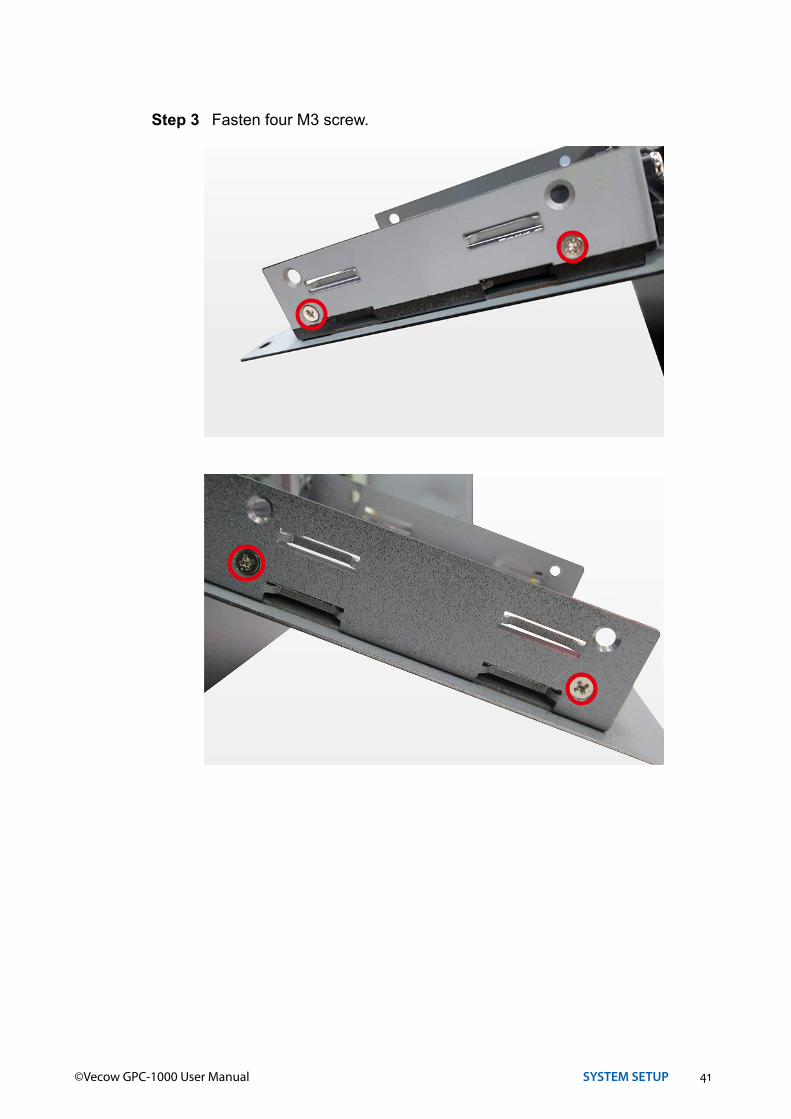
Step 3 Fasten four M3 screw.

42©Vecow GPC-1000 User Manual SYSTEM SETUP
3.8 Installing Antenna CableStep 1 Check Antenna cable and washers.
1 23
Step 2 Put Antenna cable connector into the hole on rear panel and fasten the washer 1, washer 2 and washer 3 on Antenna cable connector.
43©Vecow GPC-1000 User Manual SYSTEM SETUP
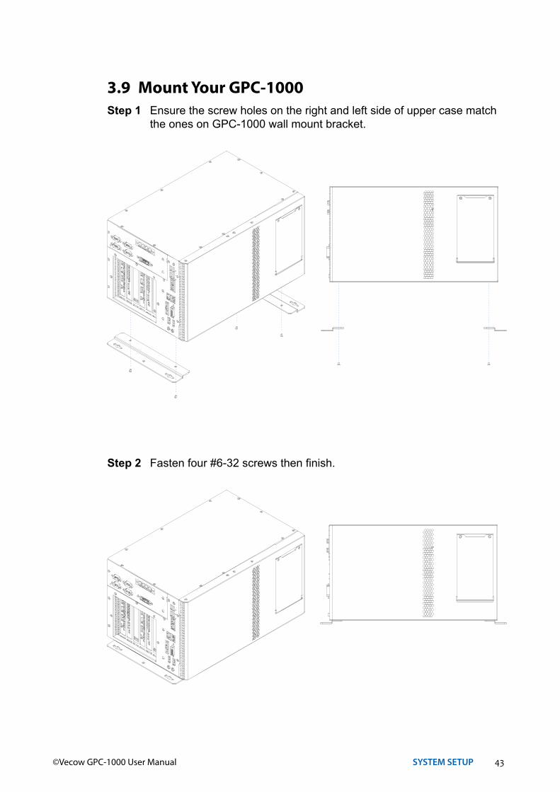
3.9 Mount Your GPC-1000Step 1 Ensure the screw holes on the right and left side of upper case match
the ones on GPC-1000 wall mount bracket.
Step 2 Fasten four #6-32 screws then finish.
44©Vecow GPC-1000 User Manual SYSTEM SETUP
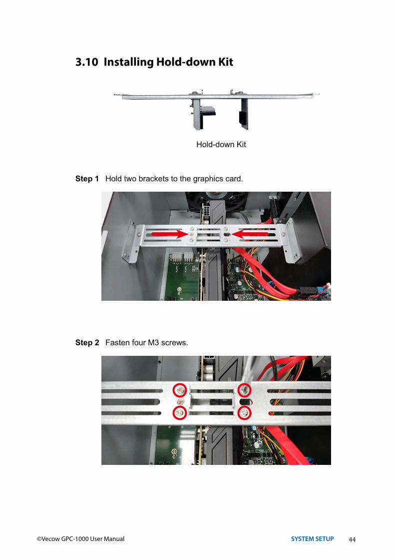
3.10 Installing Hold-down Kit
Step 1 Hold two brackets to the graphics card.
Step 2 Fasten four M3 screws.
Hold-down Kit
45©Vecow GPC-1000 User Manual BIOS SETUP
4BIOS SETUP
4.1 Entering BIOS Setup
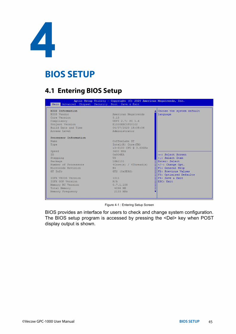
BIOS provides an interface for users to check and change system configuration.The BIOS setup program is accessed by pressing the <Del> key when POST display output is shown.
Figure 4-1 : Entering Setup Screen

46©Vecow GPC-1000 User Manual BIOS SETUP
4.2 Main
The main menu displays BIOS version and system information. There are two options on Main menu.
System DateSet the date. Use <Tab> to switch between date elements.
System TimeSet the time. Use <Tab> to switch between time elements.
Figure 4-2 : BIOS Main Menu
Figure 4-3 : BIOS Advanced Menu
Select advanced tab to enter advanced BIOS setup options, such as CPU configuration, SATA configuration, and USB configuration.
4.3 Advanced

47©Vecow GPC-1000 User Manual BIOS SETUP
4.3.1 CPU Configuration
Figure 4-3-1 : CPU Configuration
Hardware PrefetcherTo turn on/off the MLC streamer prefetcher.
Adjacent Cache Line PrefetchTo turn on/off prefetching of adjacent cache lines.
Intel (VMX) Virtualization TechnologyWhen enabled, a VMM can utilize the additional hardware capabilities provided by Vanderpool Technology.
Active Processor CoresNumber of cores to enable in each processor package.
Hyper-threadingEnabled for Windows XP and Linux (OS optimized for Hyper-Threading Technology) and disabled for other OS (OS not optimized for Hyper-Threading Technology). When disabled only one thread per core is enabled.
AESEnable/disable CPU Advanced Encryption Standard instructions.
Intel Trusted Execution TechnologyEnables utilization of additional hardware capabilities provided by Intel® Trusted Execution Technology.Changes require a full power cycle to take effect.

48©Vecow GPC-1000 User Manual BIOS SETUP
4.3.2 Power & Performance
Figure 4-3-2 : Power & Performance
Boot performance modeSelect the performance state that the BIOS will set before OS handoff.
Intel(R) SpeedStep(tm)Allows more than two frequency ranges to be supported.
Intel(R) Speed shift TechnologyEnable/Disable Intel® Speed Shift Technology support. Enabling will expose the CPPCv2 interface to allow for hardware controlled P-states.
Turbo ModeTurbo Mode.
C statesEnable or disable CPU C states.
Enhanced C-statesEnable/disable C1E. When enabled, CPU will switch to minimum speed when all cores enter C-State.
4.3.2.1 CPU – Power Management Control
Figure 4-3-2-1 : CPU – Power Management Control
49©Vecow GPC-1000 User Manual BIOS SETUP
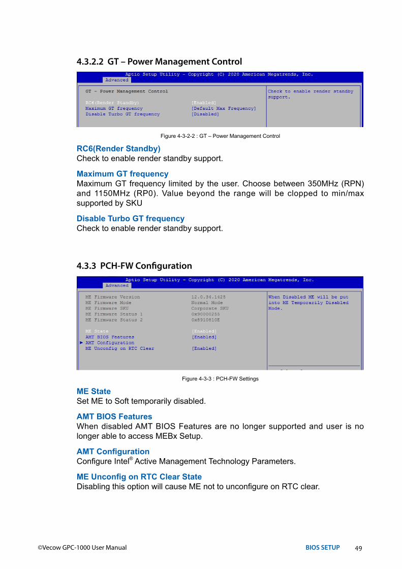
RC6(Render Standby)Check to enable render standby support.
Maximum GT frequencyMaximum GT frequency limited by the user. Choose between 350MHz (RPN) and 1150MHz (RP0). Value beyond the range will be clopped to min/max supported by SKU
Disable Turbo GT frequencyCheck to enable render standby support.
4.3.2.2 GT – Power Management Control
Figure 4-3-2-2 : GT – Power Management Control
ME StateSet ME to Soft temporarily disabled.
AMT BIOS FeaturesWhen disabled AMT BIOS Features are no longer supported and user is no longer able to access MEBx Setup.
AMT ConfigurationConfigure Intel® Active Management Technology Parameters.
ME Unconfig on RTC Clear StateDisabling this option will cause ME not to unconfigure on RTC clear.
4.3.3 PCH-FW Configuration
Figure 4-3-3 : PCH-FW Settings

50©Vecow GPC-1000 User Manual BIOS SETUP
Control the TPM device status and display related information if TPM chip is present.
4.3.4 Trusted Computing
Figure 4-3-4 : Trusted Computing
Enable HibernationEnables or disables system's ability to hibernate (OS/S4 sleep state). This option may not be effective with some OS.
ACPI Sleep StateSelects the highest ACPI sleep state the system will enter when the SUSPEND button is pressed.
S3 Video RepostEnables or disables S3 video repost.
4.3.5 ACPI Settings
Figure 4-3-5 : ACPI Settings
SMART Self TestRun SMART self test on all HDDs during POST.
4.3.6 SMART Settings
Figure 4-3-6 : SMART Settings
4.3.7 IT8786 Super IO Configuration
Figure 4-3-7 : IT8786 Super IO Settings
51©Vecow GPC-1000 User Manual BIOS SETUP
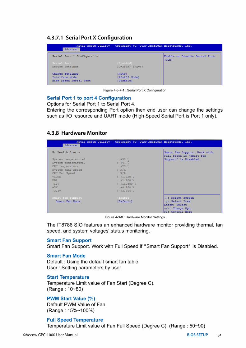
Serial Port 1 to port 4 ConfigurationOptions for Serial Port 1 to Serial Port 4.Entering the corresponding Port option then end user can change the settings such as I/O resource and UART mode (High Speed Serial Port is Port 1 only).
4.3.7.1 Serial Port X Configuration
Figure 4-3-7-1 : Serial Port X Configuration
The IT8786 SIO features an enhanced hardware monitor providing thermal, fan speed, and system voltages' status monitoring.
Smart Fan SupportSmart Fan Support. Work with Full Speed if "Smart Fan Support" is Disabled.
Smart Fan ModeDefault : Using the default smart fan table.User : Setting parameters by user.
Start TemperatureTemperature Limit value of Fan Start (Degree C).(Range : 10~80)
PWM Start Value (%)Default PWM Value of Fan.(Range : 15%~100%)
Full Speed TemperatureTemperature Limit value of Fan Full Speed (Degree C). (Range : 50~90)
4.3.8 Hardware Monitor
Figure 4-3-8 : Hardware Monitor Settings
52©Vecow GPC-1000 User Manual BIOS SETUP
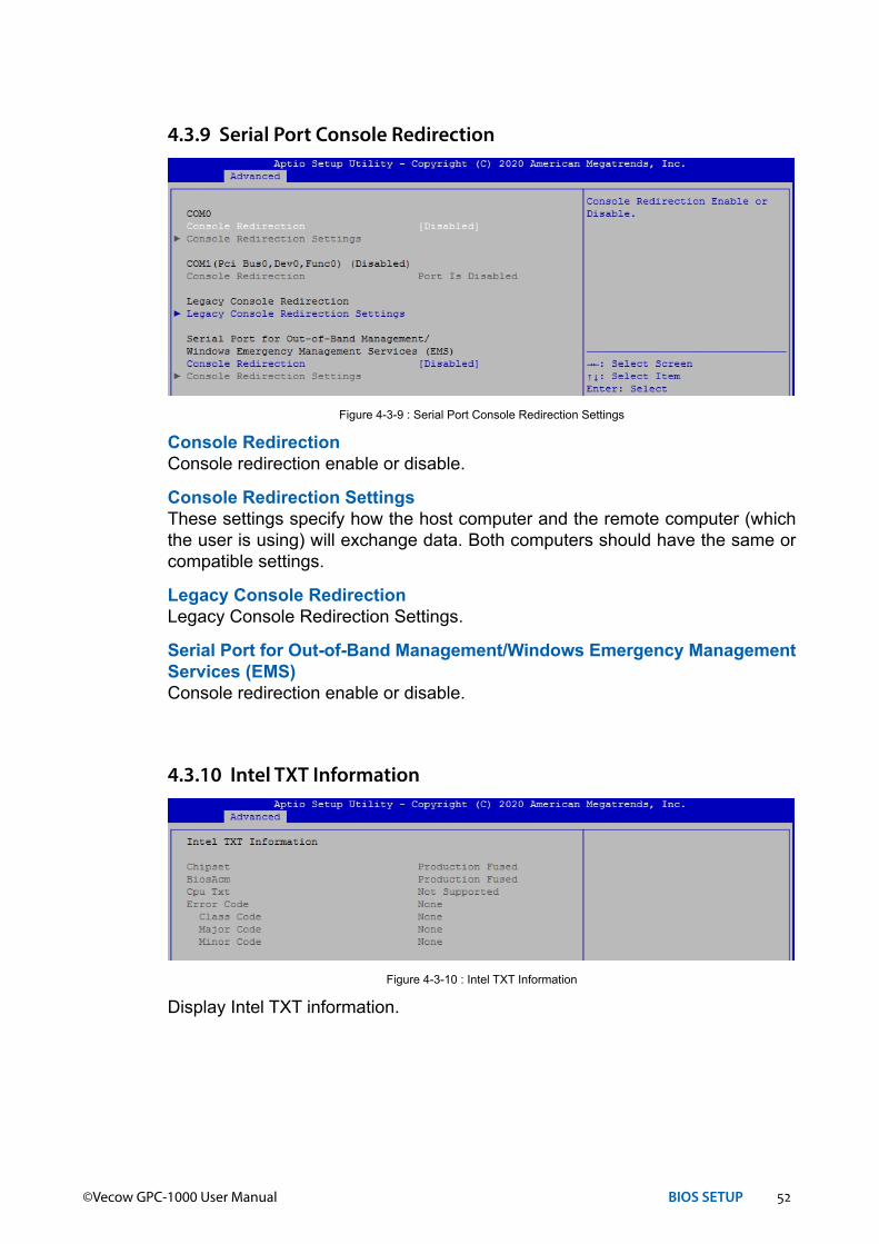
Console RedirectionConsole redirection enable or disable.
Console Redirection SettingsThese settings specify how the host computer and the remote computer (which the user is using) will exchange data. Both computers should have the same or compatible settings.
Legacy Console RedirectionLegacy Console Redirection Settings.
Serial Port for Out-of-Band Management/Windows Emergency Management Services (EMS)Console redirection enable or disable.
4.3.9 Serial Port Console Redirection
Figure 4-3-9 : Serial Port Console Redirection Settings
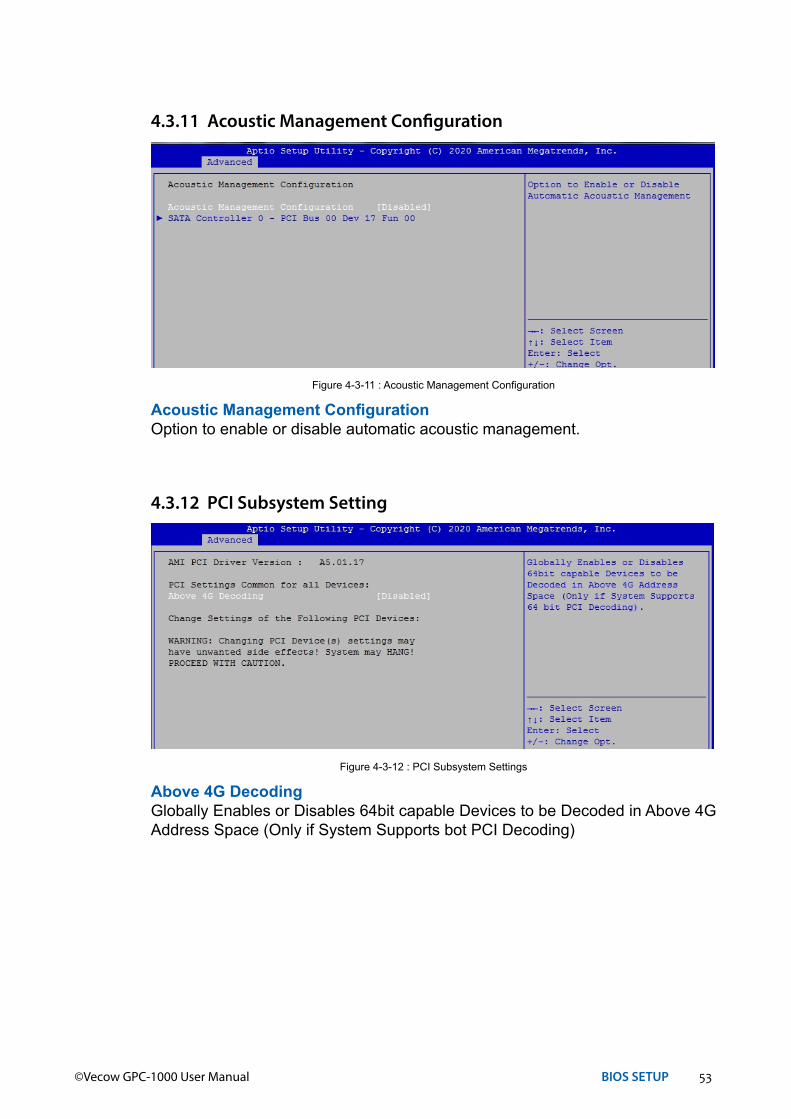
Display Intel TXT information.
4.3.10 Intel TXT Information
Figure 4-3-10 : Intel TXT Information
53©Vecow GPC-1000 User Manual BIOS SETUP
Acoustic Management ConfigurationOption to enable or disable automatic acoustic management.
4.3.11 Acoustic Management Configuration
Figure 4-3-11 : Acoustic Management Configuration
Above 4G DecodingGlobally Enables or Disables 64bit capable Devices to be Decoded in Above 4G Address Space (Only if System Supports bot PCI Decoding)
4.3.12 PCI Subsystem Setting
Figure 4-3-12 : PCI Subsystem Settings

54©Vecow GPC-1000 User Manual BIOS SETUP
Network StackEnable/Disable UEFI Network Stack.
Ipv4 PXE SupportEnable/Disable IPv4 PXE boot support.
Ipv4 HTTP SupportEnable/Disable IPv4 HTTP boot support.
Ipv6 PXE SupportEnable/Disable IPv6 PXE boot support.
Ipv6 HTTP SupportEnable/Disable IPv6 HTTP boot support.
IP6 Configuration PolicySet IP6 Configuration Policy.
PXE boot wait timeWait time to press ESC key to abort the PXE boot.
Media detect countNumber of times presence of media will be checked.
4.3.13 Network Stack Configuration
Figure 4-3-13 : Network Stack Settings
55©Vecow GPC-1000 User Manual BIOS SETUP
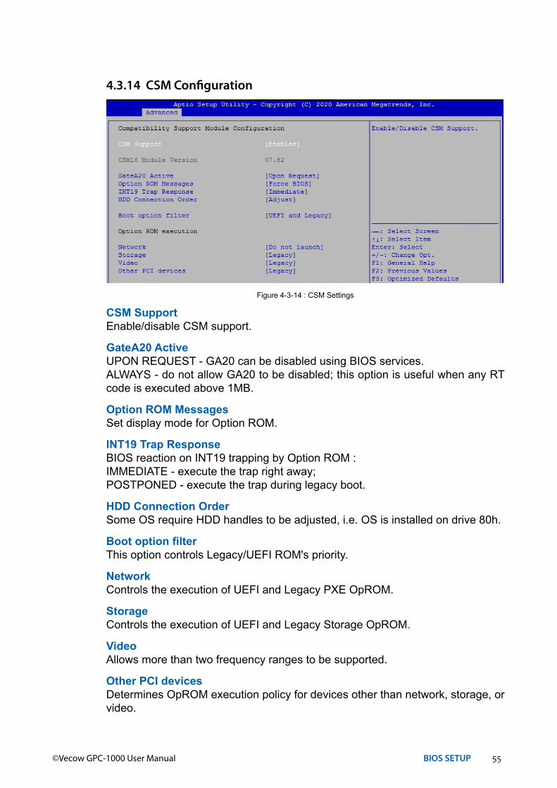
CSM SupportEnable/disable CSM support.
GateA20 ActiveUPON REQUEST - GA20 can be disabled using BIOS services.ALWAYS - do not allow GA20 to be disabled; this option is useful when any RT code is executed above 1MB.
Option ROM MessagesSet display mode for Option ROM.
INT19 Trap ResponseBIOS reaction on INT19 trapping by Option ROM :IMMEDIATE - execute the trap right away;POSTPONED - execute the trap during legacy boot.
HDD Connection OrderSome OS require HDD handles to be adjusted, i.e. OS is installed on drive 80h.
Boot option filterThis option controls Legacy/UEFI ROM's priority.
NetworkControls the execution of UEFI and Legacy PXE OpROM.
StorageControls the execution of UEFI and Legacy Storage OpROM.
VideoAllows more than two frequency ranges to be supported.
Other PCI devicesDetermines OpROM execution policy for devices other than network, storage, or video.
4.3.14 CSM Configuration
Figure 4-3-14 : CSM Settings

56©Vecow GPC-1000 User Manual BIOS SETUP
Display NVMe controller and Drive information.
4.3.15 NVMe Configuration
Figure 4-3-15 : NVMe Settings
Legacy USB SupportEnables Legacy USB support.AUTO option disables Legacy support if no USB devices are connected.DISABLE option will keep USB devices available only for EFI applications.
XHCI Hand-offThis is a workaround for OS-es without XHCI hand-off support. The XHCI ownership change should be claimed by XHCI driver.
USB Mass Storage Driver SupportEnable/disable USB mass storage driver support.
Port 60/64 EmulationEnables I/O port 60h/64h emulation support. This should be enabled for the complete USB keyboard legacy support for non-USB aware OSes.
USB transfer time-outThe time-out value for control, bulk, and interrupt transfers.
Device reset time-outUSB mass storage device start unit command time-out.
Device power-up delayMaximum time the device will take before it properly reports itself to the Host Controller. 'Auto' uses default value, for a root port it is 100 ms, for a hub port the delay is taken from the hub descriptor.
4.3.16 USB Configuration
Figure 4-3-16 : USB Settings
57©Vecow GPC-1000 User Manual BIOS SETUP
The AMC6821 features a hardware monitor providing fan speed monitoring.
FAN1 SpeedThere are three levels for Fan1 control. High/Middle/Low.
4.3.17 AMC6821 Configuration
Figure 4-3-17 : AMC6821 Configuration
4.4 Chipset
System Agent (SA) ConfigurationSystem Agent (SA) parameters.
PCH-IO ConfigurationPCH parameters.
GPIOManager ConfigurationGPIOManager Configuration.
Figure 4-4 : BIOS Chipset Menu
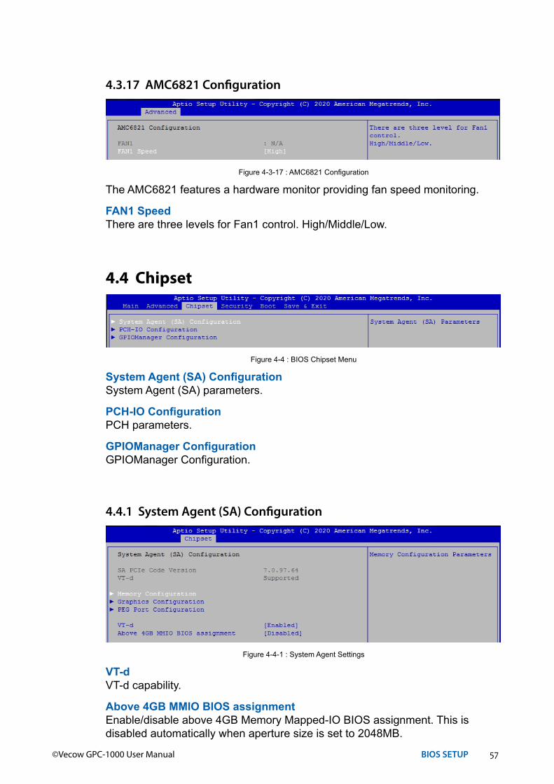
4.4.1 System Agent (SA) Configuration
VT-dVT-d capability.
Above 4GB MMIO BIOS assignmentEnable/disable above 4GB Memory Mapped-IO BIOS assignment. This is disabled automatically when aperture size is set to 2048MB.
Figure 4-4-1 : System Agent Settings

58©Vecow GPC-1000 User Manual BIOS SETUP
4.4.1.1 Memory Configuration
Figure 4-4-1-1 : Memory Information
Displays memory information.
4.4.1.2 Graphics Configuration
Skip Scanning of External Gfx CardIf Enable, it will not scan for External Gfx Card on PEG and PCH PCIE Ports.
Primary DisplaySelect which of IGFX/PEG/PCI Graphics device should be Primary Display or select SG for Switchable Gfx.
Internal graphicsKeep IGFX enabled based on the setup options.
GTT SizeSelect the GTT Size.
Aperture SizeSelect the Aperture Size.Note : Above 4GB MMIO BIOS assignment is automatically enabled when selecting 2048MB aperture. To use this feature, please disable CSM Support.
DVMT Pre-AllocatedSelect DVMT 5.0 Pre-Allocated (Fixed) Graphics Memory size used by the Internal Graphics Device.
DVMT Total Gfx MemSelect DVMT5.0 Total Graphic Memory size used by the Internal Graphics Device.
Figure 4-4-1-2 : Graphics Settings

59©Vecow GPC-1000 User Manual BIOS SETUP
4.4.1.3 PEG Port Configuration
PEG port options for PCIe device.Figure 4-4-1-3 : PEG Port Configuration
4.4.2 PCH-IO Configuration
PCH LAN ControllerEnable or disable onboard NIC.
Wake on LANEnable or disable integrated LAN to wake the system. (The wake On LAN cannot be disabled if ME is on at Sx state.)
Serial IRQ ModeConfigure serial IRQ mode.
State After G3Specify what state to go to when power is re-applied after a power failure (G3 state).S0 State : Always turn-on the system when power source plugged-in.S5 State : Always turn-off the system when power source plugged-in.
Figure 4-4-2 : PCH-IO Settings
60©Vecow GPC-1000 User Manual BIOS SETUP
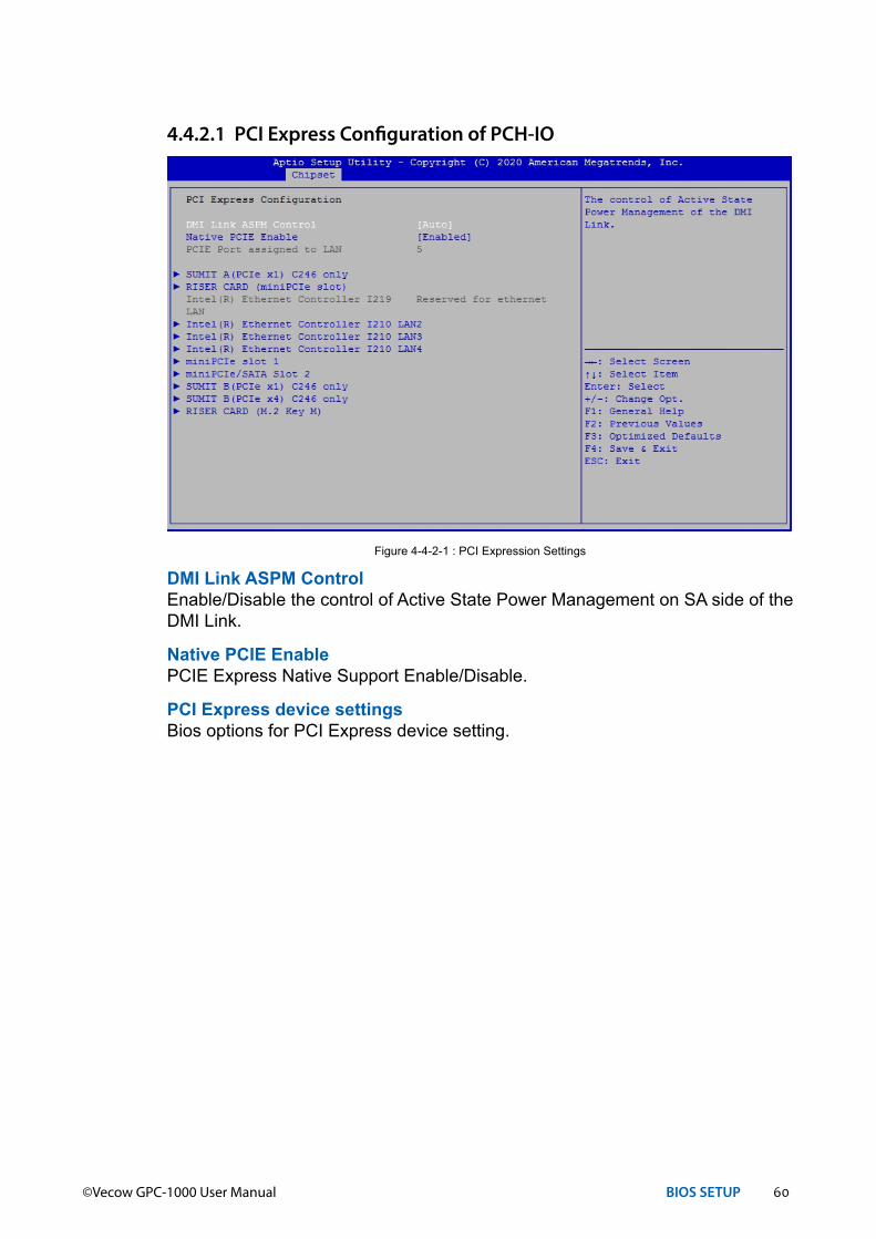
4.4.2.1 PCI Express Configuration of PCH-IO
DMI Link ASPM ControlEnable/Disable the control of Active State Power Management on SA side of the DMI Link.
Native PCIE EnablePCIE Express Native Support Enable/Disable.
PCI Express device settings Bios options for PCI Express device setting.
Figure 4-4-2-1 : PCI Expression Settings
61©Vecow GPC-1000 User Manual BIOS SETUP
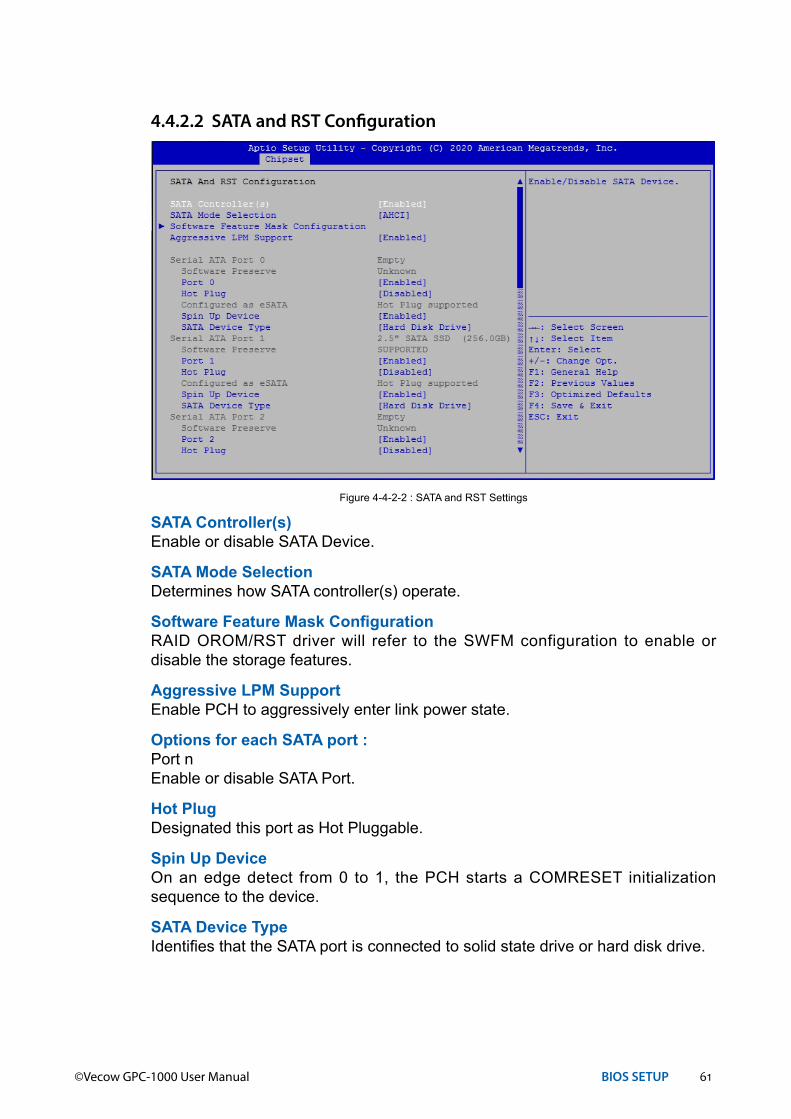
4.4.2.2 SATA and RST Configuration
SATA Controller(s)Enable or disable SATA Device.
SATA Mode SelectionDetermines how SATA controller(s) operate.
Software Feature Mask ConfigurationRAID OROM/RST driver will refer to the SWFM configuration to enable or disable the storage features.
Aggressive LPM SupportEnable PCH to aggressively enter link power state.
Options for each SATA port :Port nEnable or disable SATA Port.
Hot PlugDesignated this port as Hot Pluggable.
Spin Up DeviceOn an edge detect from 0 to 1, the PCH starts a COMRESET initialization sequence to the device.
SATA Device TypeIdentifies that the SATA port is connected to solid state drive or hard disk drive.
Figure 4-4-2-2 : SATA and RST Settings

62©Vecow GPC-1000 User Manual BIOS SETUP
4.4.2.3 Security Configuration
Figure 4-4-2-3 : Security SettingsBIOS LockEnable/disable the PCH BIOS Lock Enable (BLE bit) feature.
Administrator PasswordSet administrator password.User PasswordSet user password.Secure BootCustomizable Secure Boot Settings.
4.5 Security
Figure 4-5 : BIOS Security Menu
4.4.3 GPIO Manager
Figure 4-4-3 : GPIO ManagerSystem Fan 2 SpeedSystem Fan 2 Speed control.
63©Vecow GPC-1000 User Manual BIOS SETUP
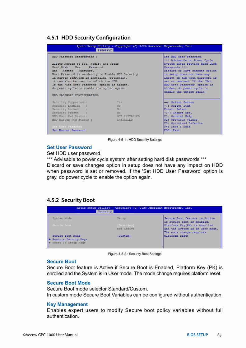
4.5.1 HDD Security Configuration
Figure 4-5-1 : HDD Security Settings
Set User PasswordSet HDD user password.*** Advisable to power cycle system after setting hard disk passwords ***Discard or save changes option in setup does not have any impact on HDD when password is set or removed. If the 'Set HDD User Password' option is gray, do power cycle to enable the option again.
4.5.2 Security Boot
Figure 4-5-2 : Security Boot Settings
Secure BootSecure Boot feature is Active if Secure Boot is Enabled, Platform Key (PK) is enrolled and the System is in User mode. The mode change requires platform reset.
Secure Boot ModeSecure Boot mode selector Standard/Custom.In custom mode Secure Boot Variables can be configured without authentication.
Key ManagementEnables expert users to modify Secure boot policy variables without full authentication.
64©Vecow GPC-1000 User Manual BIOS SETUP
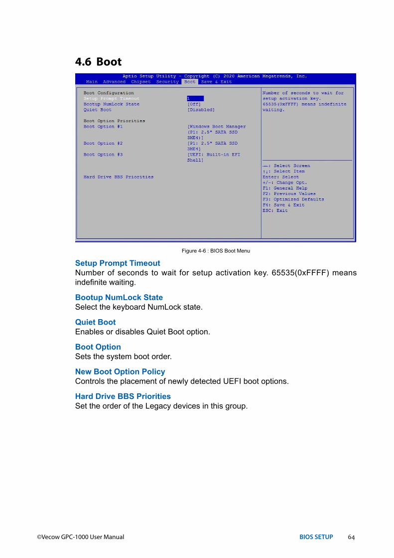
Setup Prompt TimeoutNumber of seconds to wait for setup activation key. 65535(0xFFFF) means indefinite waiting.
Bootup NumLock StateSelect the keyboard NumLock state.
Quiet BootEnables or disables Quiet Boot option.
Boot OptionSets the system boot order.
New Boot Option PolicyControls the placement of newly detected UEFI boot options.
Hard Drive BBS PrioritiesSet the order of the Legacy devices in this group.
4.6 Boot
Figure 4-6 : BIOS Boot Menu
65©Vecow GPC-1000 User Manual BIOS SETUP
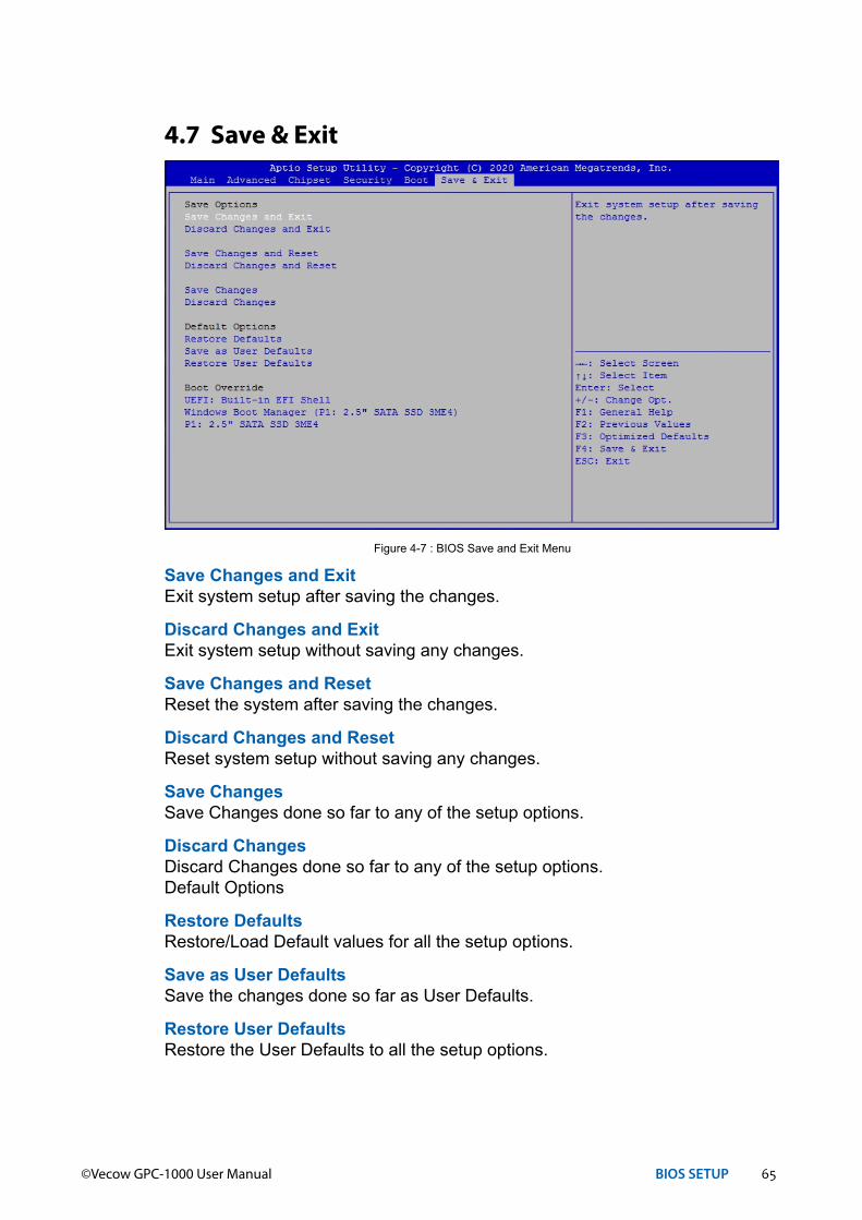
Save Changes and ExitExit system setup after saving the changes.
Discard Changes and ExitExit system setup without saving any changes.
Save Changes and ResetReset the system after saving the changes.
Discard Changes and ResetReset system setup without saving any changes.
Save ChangesSave Changes done so far to any of the setup options.
Discard ChangesDiscard Changes done so far to any of the setup options.Default Options
Restore DefaultsRestore/Load Default values for all the setup options.
Save as User DefaultsSave the changes done so far as User Defaults.
Restore User DefaultsRestore the User Defaults to all the setup options.
4.7 Save & Exit
Figure 4-7 : BIOS Save and Exit Menu

66©Vecow GPC-1000 User Manual Appendix A
AAPPENDIX A : Isolated DIO Guide
A.1 Function DescriptionThe GPC-1000 offers two 16-bit Isolated DIO 20-pin terminal block connector and a watchdog timer.
Isolated DIO pins are fix by Hardware design that cannot change in/out direction in runtime process.
DIO definition is shown below :
Pin No. Isolated DIODefinition
Non-Isolated DIO Definition Pin No. Isolated DIO
DefinitionNon-Isolated DIO Definition
1 DI 0 DIO 0 11 DO 0 DIO 8
2 DI 1 DIO 1 12 DO 1 DIO 9
3 DI 2 DIO 2 13 DO 2 DIO 10
4 DI 3 DIO 3 14 DO 3 DIO 11
5 DI 4 DIO 4 15 DO 4 DIO 12
6 DI 5 DIO 5 16 DO 5 DIO 13
7 DI 6 DIO 6 17 DO 6 DIO 14
8 DI 7 DIO 7 18 DO 7 DIO 15
9 DI COM NC 19 DIO_GND DIO_GND
10 DIO_GND DIO_GND 20 External VDC NC

67©Vecow GPC-1000 User Manual Appendix A
A.2 Isolated DIO Signal CircuitDI reference circuit :
Sink Mode (NPN)
PowerSupply6-48V DC V+
V-
DIO ConnectorDI_COM (Pin 9)
DI (Pin 1-8)
Source Mode (PNP)
PowerSupply6-48V DC V+
V-
DIO ConnectorDI_COM (Pin 9)
DI (Pin 1-8)
DO reference circuit :
Sink Mode (NPN, Default)
Device6-48V DC
V+
V-
DIO ConnectorDIO_VDC (Pin 20)
DIO_GND (Pin 10, 19)
IO DO (Pin 11-18)
Source Mode (PNP)
Device6-48V DC
V+
V-
DIO ConnectorDIO_VDC (Pin 20)
DIO_GND (Pin 10, 19)
IO DO (Pin 11-18)

68©Vecow GPC-1000 User Manual Appendix A
A.4 SampleSample folder includes x32 and x64 versions, as shown right :
Sample GPC1K.exe, as shown below :
A.3 Software Package ContainDistribution folder include x32 and x64 versions, use batch file for installation.
There are included as followed :Win7_32.bat :
Installation for 32-bit driverWin7_64.bat :
Windows update package which driver required (need to restart), and Installation for 64-bit driver
Win8_32.bat, Win8_64.bat :Installation for driver, and guideline to Framework 3.5 distribution for sample
Win10_32.bat, and Win10_64.bat :Installation for driver, and installation to Framework 3.5 distribution for sample
Uninstall_32.bat, and Uninstall_64.bat :Uninstallation for driver
Run batch file as Administrator.Support Windows 7 above.Make sure it is Windows version before installation.
Runtime folder includes head file for software developer or System Integration.Sample folder includes sample program, driver library, and API library. Source folder includes sample program source code that compile on Visual Studio 2008.
69©Vecow GPC-1000 User Manual Appendix A
DIO1 group :Isolate check button :
DIO type of DIO configuration, isolated/non-isolated.Read button :
Set DIO configuration to get DI/DIO input state.DO type check button :
User setting, DO type of DIO configuration to setup 8 pins - Source/Sink.Use for Write (DO) button activation.
Write button :Set DIO configuration to set DO/DIO output state.
DI preference text :User setting, DI type of DIO configuration by hexadecimal bitmask - Source/Sink.Use for Read (DI) button activation.
DO/DIO output text :User setting, DO/DIO output state by hexadecimal bitmask - on/off.Use for Write button activation.
DO/DIO writable text :User setting, DO/DIO writable of DIO configuration by hexadecimal bitmask- yes/no.Use for Read (DIO)/Write button activation.
DI/DIO input text (read only) :DI/DIO input state by hexadecimal bitmask - on/off.Use for Read button activation.
DO/DIO text (read only) :DO/DIO output state with input state (DIO) and configuration.Use for Write button activation.
DO/DIO output text (read only) :DO/DIO output state with configuration.Use for Write button activation.
DI type pin check button(pin 8 ~ pin 1) :User setting, DI pin type of DIO configuration - Source/Sink.
DI/DIO input pin texts (read only, pin 8 ~ pin 1/pin 18 ~ pin 11, pin 8 ~ pin 1):DI/DIO input pin stateUse for Read button activation.
DO/DIO output pin check button(pin 18 ~ pin 11/pin 18 ~ pin 11, pin 8 ~ pin 1) :User setting, DO/DIO output pin stateUse for Write button activation.
DO/DIO pin writable check button(pin 18 ~ pin 11/pin 18 ~ pin 11, pin 8 ~ pin 1) :User setting, DO/DIO pin writable of DIO configuration.Use for Read (DIO)/Write button activation.

70©Vecow GPC-1000 User Manual Appendix A
WDT group :Write button :
Set WDT when WDT setup text is valid.Stop button :
Cancel WDT and counting.Use after Write button action.
WDT setup text :User setting, WDT value, unit : second.Use for Write button activation.
WDT counting text (read only) :WDT counting by program timer after set WDT.Shown after Write button action.
WDT setup day format texts (user setting) :User setting, WDT value, format : day'hour'minute'second.
WDT counting day format text (read only) :WDT counting, format : day'hour'minute'second.

71©Vecow GPC-1000 User Manual Appendix B
BAPPENDIX B : Software Functions
B.1 Driver API GuideIn Runtime folder, on GPC1K.h :
_DLL_IMPORT_ definition is used on LoadLibrary API for GPC1K.dll.GPC1K_EXPORTS definition is used on GPC1K.dll building.
BOOL Initial (BYTE Isolate_Type, BYTE DIO_NPN)Initial machine for DIO, watchdog timer, and POE
Isolate_Type : DIO type1 : Isolated DIO; 0 : Non-Isolated DIO
DIO_NPN : DI/DO type1 : PNP (Source) mode for European rule; 0 : NPN (Sink) mode for Japanese rule
Return :TRUE (1): Success;FALSE (0): Fail (Driver not exists, or initial error (version is too old, or machine not match))
BOOL GetDIO1Config (BYTE *Isolate_Type, BYTE *DI_NPN, BYTE *DO_NPN, WORD *Mask)
Get DIO configuration (by variable)Isolate_Type : DIO type
1 : Isolated DIO;0 : Non-Isolated DIO
DI_NPN ([7:0]) : DI type, pin setting by hexadecimal bitmask1 : PNP (Source) mode for European rule; 0 : NPN (Sink) mode for Japanese rule
DO_NPN : DO type1 : PNP (Source) mode for European rule; 0 : NPN (Sink) mode for Japanese rule
Mask ([15:0]) : In/Out, pin setting by hexadecimal bitmask1 : Output;0 : Input
Return :TRUE (1) : Success;FALSE (0) : Fail (Initial error, or call by pointer error, or hardware problem)
72©Vecow GPC-1000 User Manual Appendix B
BOOL SetDIO1Config (BYTE Isolate_Type, BYTE DI_NPN, BYTE DO_NPN, WORD Mask)
Set DIO configurationIsolate_Type : DIO type
1 : Isolated DIO;0 : Non-Isolated DIO
DI_NPN ([7:0]) : DI type, pin setting by hexadecimal bitmask1 : PNP (Source) mode for European rule; 0 : NPN (Sink) mode for Japanese rule
DO_NPN : DO type1 : PNP (Source) mode for European rule; 0 : NPN (Sink) mode for Japanese rule
Mask ([15:0]) : In/Out, pin setting by hexadecimal bitmask1 : Output;0 : Input
Return :TRUE (1) : Success;FALSE (0) : Fail (Initial error, or hardware problem)
BOOL GetDI1 (BYTE *DI)Get isolated DIO input (DI)
DI ([7:0]) : Input state, pin setting by hexadecimal bitmask1 : High;0 : Low
Return :TRUE (1) : Success;FALSE (0) : Fail (Initial error, or call by pointer error, or hardware problem)
BOOL GetDO1 (BYTE *DO)Get isolated DIO output (DO)
DO ([7:0]) : Output state, pin setting by hexadecimal bitmask1 : High;0 : Low
Return :TRUE (1) : Success;FALSE (0) : Fail (Initial error, or call by pointer error, or hardware problem)
BOOL SetDO1 (BYTE DO)Set isolated DIO output (DO)
DO ([7:0]) : Output state, pin setting by hexadecimal bitmask1 : High;0 : Low
Return :TRUE (1) : Success;FALSE (0) : Fail (Initial error, or hardware problem)

73©Vecow GPC-1000 User Manual Appendix B
BOOL GetDIO1 (WORD *DI)Get non-isolated DIO input (DIO input)DI ([15:0]) : Input state, pin setting by hexadecimal bitmask
1 : High;0 : Low
Return :TRUE (1) : Success;FALSE (0) : Fail (Initial error, or call by pointer error, or hardware problem)
BOOL SetDIO1 (WORD DO)Set non-isolated DIO output (DIO output)
DO ([15:0]) : output state, pin setting by hexadecimal bitmask1 : High;0 : Low
Return :TRUE (1) : Success;FALSE (0) : Fail (Initial error, or hardware problem)
BOOL GetWDT (DWORD *WDT)Get watchdog timer setup
WDT : watchdog timer setupUnit : second. (Range : 0 ~ 65535 sec, 1093 ~ 65535 min (=65580 ~ 3932100 sec))
Return :TRUE (1) : Success;FALSE (0) : Fail (Initial error, or call by pointer error, or hardware problem)
BOOL SetWDT (DWORD WDT)Set watchdog timer setup
WDT : watchdog timer setupUnit : second. (Range : 1 ~ 65535 sec, 1093 ~ 65535 min (=65580 ~ 3932100 sec))
Return :TRUE (1) : Success;FALSE (0) : Fail (Initial error, or setup 0 error, or hardware problem)
BOOL CancelWDT ()Cancel watchdog timer
Return :TRUE (1) : Success;FALSE (0) : Fail (Initial error, or hardware problem)
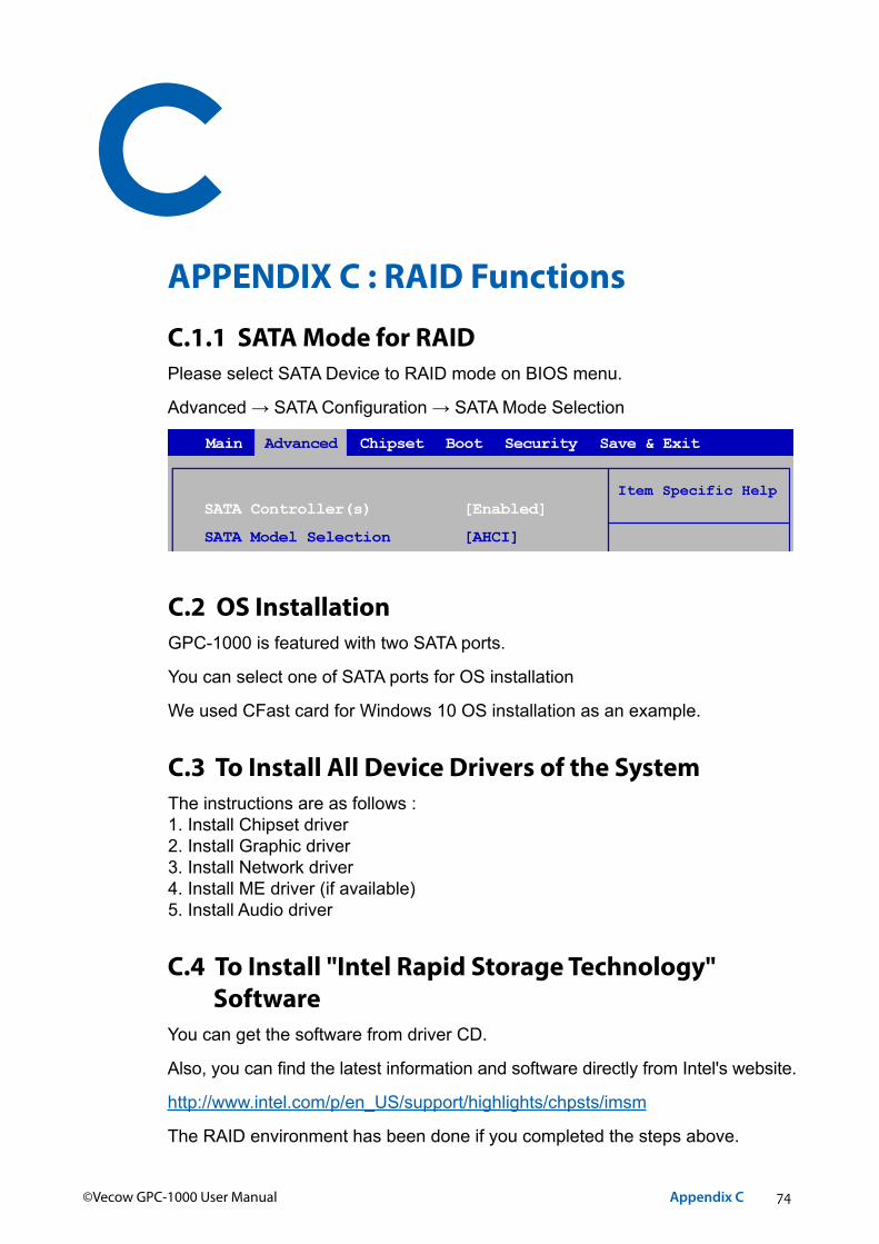
74©Vecow GPC-1000 User Manual Appendix C
CAPPENDIX C : RAID Functions
C.1.1 SATA Mode for RAIDPlease select SATA Device to RAID mode on BIOS menu.
Advanced → SATA Configuration → SATA Mode Selection
C.2 OS InstallationGPC-1000 is featured with two SATA ports.
You can select one of SATA ports for OS installation
We used CFast card for Windows 10 OS installation as an example.
C.3 To Install All Device Drivers of the SystemThe instructions are as follows :1. Install Chipset driver2. Install Graphic driver 3. Install Network driver4. Install ME driver (if available)5. Install Audio driver
C.4 To Install "Intel Rapid Storage Technology" Software
You can get the software from driver CD.
Also, you can find the latest information and software directly from Intel's website.
http://www.intel.com/p/en_US/support/highlights/chpsts/imsm
The RAID environment has been done if you completed the steps above.
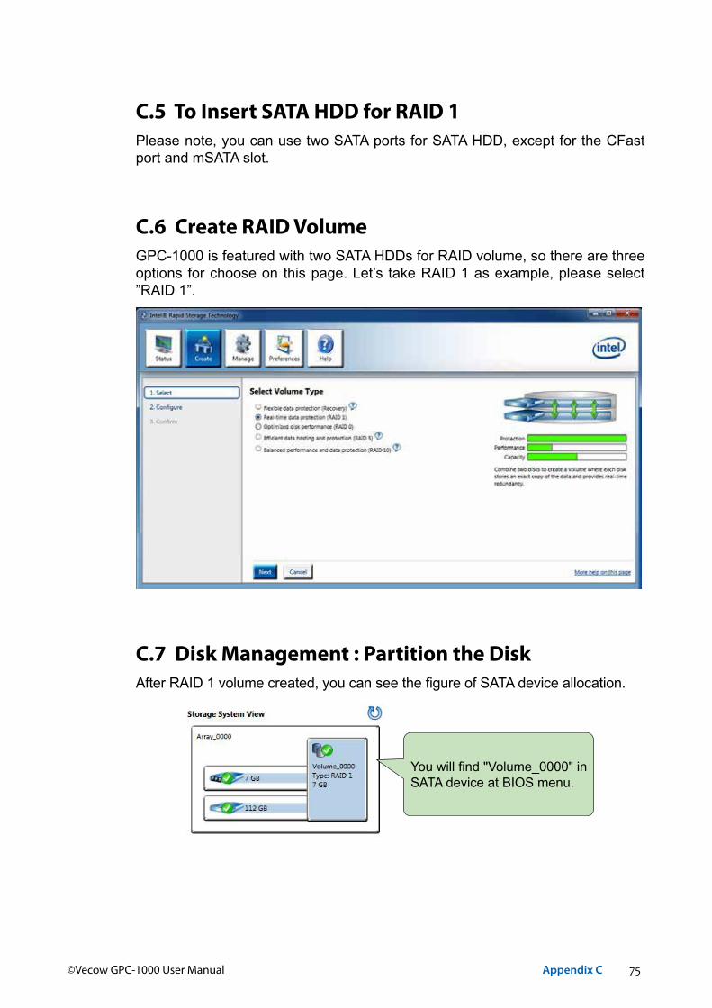
75©Vecow GPC-1000 User Manual Appendix C
C.5 To Insert SATA HDD for RAID 1Please note, you can use two SATA ports for SATA HDD, except for the CFast port and mSATA slot.
C.6 Create RAID VolumeGPC-1000 is featured with two SATA HDDs for RAID volume, so there are three options for choose on this page. Let’s take RAID 1 as example, please select ”RAID 1”.
C.7 Disk Management : Partition the DiskAfter RAID 1 volume created, you can see the figure of SATA device allocation.
You will find "Volume_0000" in SATA device at BIOS menu.

76©Vecow GPC-1000 User Manual Appendix C
To start disk management tool, select "initialize disk".
Then add "Logical Device" for Windows access.
C.8 RAID HDD FailAfter RAID 1 volume is created, you can see the figure of SATA device allocation.
HDD CAUTION Sign
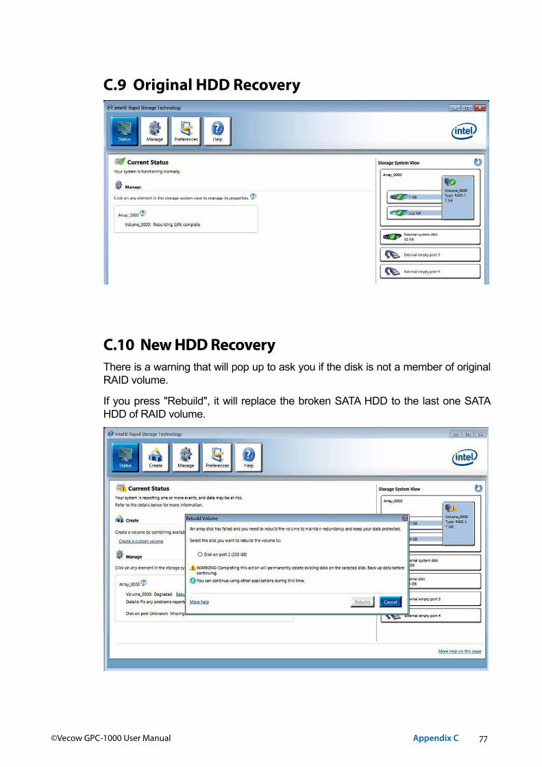
77©Vecow GPC-1000 User Manual Appendix C
C.9 Original HDD Recovery
C.10 New HDD RecoveryThere is a warning that will pop up to ask you if the disk is not a member of original RAID volume.
If you press "Rebuild", it will replace the broken SATA HDD to the last one SATA HDD of RAID volume.

78©Vecow GPC-1000 User Manual Appendix D
DAPPENDIX D : Power Consumption
Testing Board GPC-1000
RAM 16GB X 2
USB-1 USB Microsoft Wired Keyboard 600
USB-2 USB Mouse Logitech M105
USB-3 USB Flash Transecnd 3.0 8GB
USB-4 USB Flash Transcend 3.0 8GB
SATA 0 Transcend SATA SSD420 128GB
SATA 1 WD WD5000BPVT 500GB
LAN 1 (i219) 1.0 Gbps
LAN 2 (i210) 1.0 Gbps
Graphics Output DP
Power Plan Balance (Windows 10 Power plan)
Power Source B&K Precision 9115-AT
Test Program-1 BurnInTest
Test Program-2 FurMark
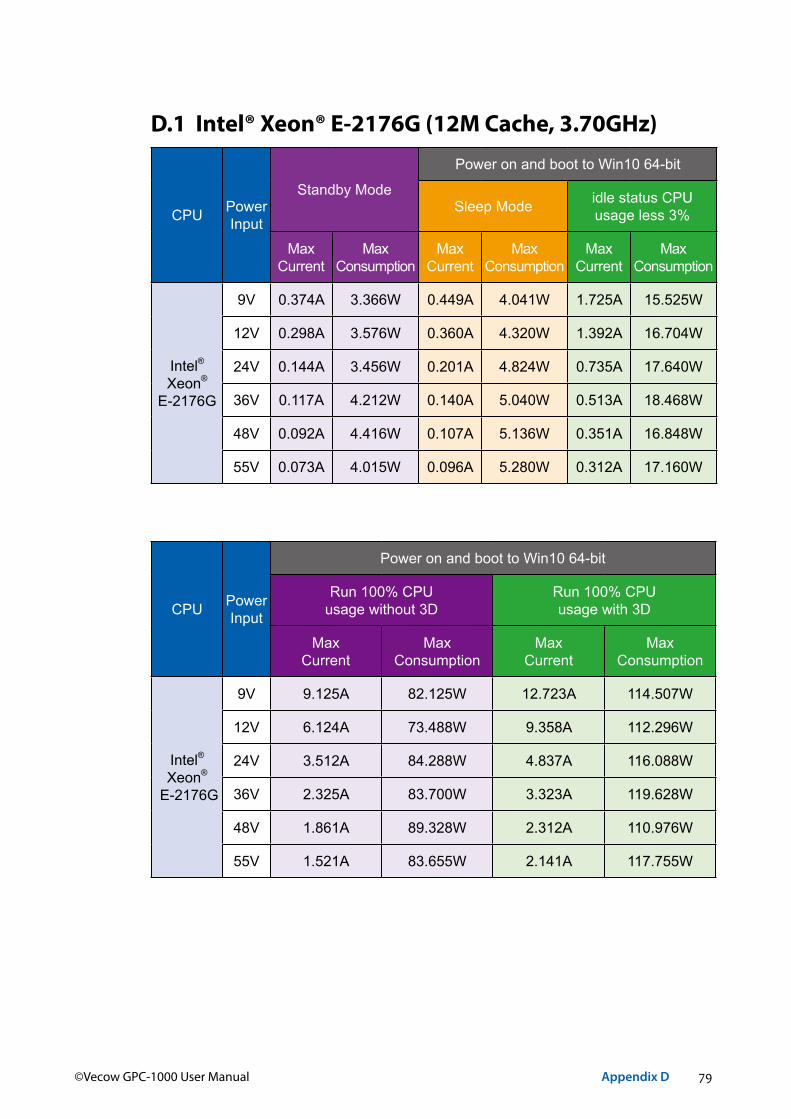
79©Vecow GPC-1000 User Manual Appendix D
D.1 Intel® Xeon® E-2176G (12M Cache, 3.70GHz)
CPU PowerInput
Standby Mode
Power on and boot to Win10 64-bit
Sleep Mode idle status CPUusage less 3%
MaxCurrent
Max Consumption
MaxCurrent
Max Consumption
MaxCurrent
Max Consumption
Intel® Xeon®
E-2176G
9V 0.374A 3.366W 0.449A 4.041W 1.725A 15.525W
12V 0.298A 3.576W 0.360A 4.320W 1.392A 16.704W
24V 0.144A 3.456W 0.201A 4.824W 0.735A 17.640W
36V 0.117A 4.212W 0.140A 5.040W 0.513A 18.468W
48V 0.092A 4.416W 0.107A 5.136W 0.351A 16.848W
55V 0.073A 4.015W 0.096A 5.280W 0.312A 17.160W
CPU PowerInput
Power on and boot to Win10 64-bit
Run 100% CPUusage without 3D
Run 100% CPUusage with 3D
MaxCurrent
MaxConsumption
MaxCurrent
MaxConsumption
Intel® Xeon®
E-2176G
9V 9.125A 82.125W 12.723A 114.507W
12V 6.124A 73.488W 9.358A 112.296W
24V 3.512A 84.288W 4.837A 116.088W
36V 2.325A 83.700W 3.323A 119.628W
48V 1.861A 89.328W 2.312A 110.976W
55V 1.521A 83.655W 2.141A 117.755W

80©Vecow GPC-1000 User Manual Appendix D
D.2 Intel® Core™ i7-8700 (12M Cache, 3.20GHz)
CPU PowerInput
Standby Mode
Power on and boot to Win10 64-bit
Sleep Mode idle status CPUusage less 3%
MaxCurrent
Max Consumption
MaxCurrent
Max Consumption
MaxCurrent
Max Consumption
Intel® Core™ i7-8700
9V 0.340A 3.060W 0.454A 4.086W 1.720A 15.48W
12V 0.252A 3.024W 0.370A 4.440W 1.334A 16.01W
24V 0.142A 3.408W 0.200A 4.800W 0.713A 17.11W
36V 0.114A 4.104W 0.134A 4.824W 0.461A 16.60W
48V 0.092A 4.416W 0.111A 5.328W 0.364A 17.47W
55V 0.073A 4.015W 0.097A 5.335W 0.319A 17.55W
CPU PowerInput
Power on and boot to Win10 64-bit
Run 100% CPUusage without 3D
Run 100% CPUusage with 3D
MaxCurrent
MaxConsumption
MaxCurrent
MaxConsumption
Intel® Core™ i7-8700
9V 6.103A 54.927W 9.303A 83.727W
12V 4.602A 55.224W 7.105A 85.260W
24V 2.305A 55.320W 3.503A 84.072W
36V 1.595A 57.420W 2.604A 93.744W
48V 1.306A 62.688W 2.103A 100.944W
55V 1.125A 61.875W 1.765A 97.075W

81©Vecow GPC-1000 User Manual Appendix D
D.3 Intel® Core™ i7-8700T (12M Cache, 2.40GHz)
CPU PowerInput
Standby Mode
Power on and boot to Win10 64-bit
Sleep Mode idle status CPUusage less 3%
MaxCurrent
Max Consumption
MaxCurrent
Max Consumption
MaxCurrent
Max Consumption
Intel® Core™
i7-8700T
9V 0.374A 3.366W 0.448A 4.032W 2.125A 19.125W
12V 0.294A 3.528W 0.352A 4.224W 1.310A 15.720W
24V 0.146A 3.504W 0.201A 4.824W 0.712A 17.088W
36V 0.118A 4.248W 0.143A 5.148W 0.532A 19.152W
48V 0.093A 4.464W 0.110A 5.280W 0.352A 16.896W
55V 0.082A 4.510W 0.098A 5.390W 0.312A 17.160W
CPU PowerInput
Power on and boot to Win10 64-bit
Run 100% CPUusage without 3D
Run 100% CPUusage with 3D
MaxCurrent
MaxConsumption
MaxCurrent
MaxConsumption
Intel® Core™
i7-8700T
9V 4.310A 38.790W 6.120A 55.080W
12V 3.253A 39.036W 5.745A 68.940W
24V 1.732A 41.568W 2.754A 66.096W
36V 1.201A 43.236W 2.031A 73.116W
48V 0.923A 44.304W 1.452A 69.696W
55V 0.825A 45.375W 1.424A 78.320W
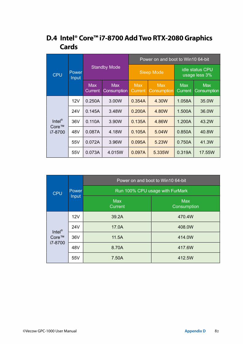
82©Vecow GPC-1000 User Manual Appendix D
D.4 Intel® Core™ i7-8700 Add Two RTX-2080 Graphics Cards
CPU PowerInput
Standby Mode
Power on and boot to Win10 64-bit
Sleep Mode idle status CPUusage less 3%
MaxCurrent
Max Consumption
MaxCurrent
Max Consumption
MaxCurrent
Max Consumption
Intel® Core™ i7-8700
12V 0.250A 3.00W 0.354A 4.30W 1.058A 35.0W
24V 0.145A 3.48W 0.200A 4.80W 1.500A 36.0W
36V 0.110A 3.90W 0.135A 4.86W 1.200A 43.2W
48V 0.087A 4.18W 0.105A 5.04W 0.850A 40.8W
55V 0.072A 3.96W 0.095A 5.23W 0.750A 41.3W
55V 0.073A 4.015W 0.097A 5.335W 0.319A 17.55W
CPU PowerInput
Power on and boot to Win10 64-bit
Run 100% CPU usage with FurMark
MaxCurrent
MaxConsumption
Intel® Core™ i7-8700
12V 39.2A 470.4W
24V 17.0A 408.0W
36V 11.5A 414.0W
48V 8.70A 417.6W
55V 7.50A 412.5W

83©Vecow GPC-1000 User Manual Appendix E
EAPPENDIX E : Supported Memory &
Storage List
E.1 Supported Memory ListTesting Board GPC-1000Memory Test version : 5.1BurnInTest V8.1
E.2 Supported Non-ECC Memory ListBrand Info Test Temp.(Celsius)
Innodisk 4GB DDR4 2666 SODIMM M4S0-4GSSNCIK-H0325ºC25ºC
innodisk 8GB DDR4 2666 SODIMM M4S0-8GSSOCIK-H0325ºC25ºC
Innodisk 8GB DDR4 2666 SODIMM M4S0-8GS1NCIK-H0325ºC25ºC
innodisk 16GB DDR4 2666 SODIMM M4S0-AGS1OCIK-H0325ºC25ºC
Innodisk 16GB DDR4 2666 SODIMM M4S0-AGS1O5IK-H0325ºC25ºC
Innodisk 4GB DDR4 2666 W/T SODIMM M4S0-4GSSN5IK-H0325ºC25ºC
E.3 Supported Storage Device ListType Brand Model Capacity
mSATA Intel Intel-310 SSDMAEMC080G2 80GB
SSD
IntelSSD 530 SSDSC2BW120A4 120GB
SSD E 5400s SSDSC2KR120H6 120GBLITE-ON K8-L1512 512GB
MEMXPRO 2.5" SSD M3A 128GB 128GB
FORESEE2.5" 256GB SSD SATA6.0 S903S256G 256GB2.5" 128GB SSD SATA6.0 S903S128G 128GB
** If more help is needed, please contact Vecow Technical Support.

84©Vecow GPC-1000 User Manual Appendix F
FAPPENDIX F : How to Install Power Supply
F.1 RSP-1500-24 Adapter AC Cable
RSP-1500-24
GREENBLACKWHITE
AC/LAC/N
F.2 RSP-1500-24 Adapter DC Cable
V- V+
RSP-1500-24
V-V+
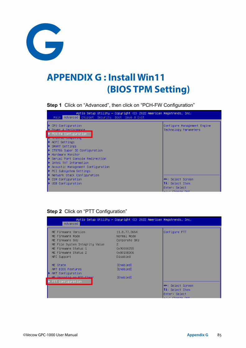
85©Vecow GPC-1000 User Manual Appendix G
GAPPENDIX G : Install Win11 (BIOS TPM Setting)Step 1 Click on “Advanced”, then click on “PCH-FW Configuration”
Step 2 Click on “PTT Configuration”
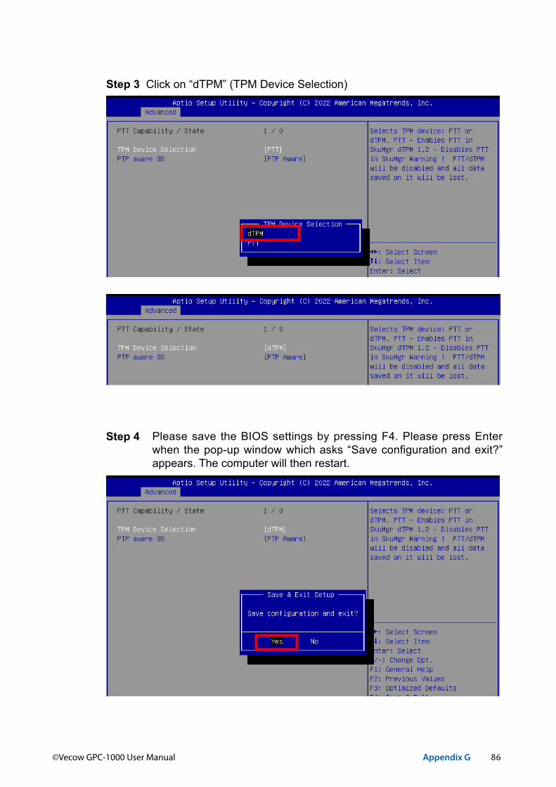
86©Vecow GPC-1000 User Manual Appendix G
Step 3 Click on “dTPM” (TPM Device Selection)
Step 4 Please save the BIOS settings by pressing F4. Please press Enter when the pop-up window which asks “Save configuration and exit?” appears. The computer will then restart.
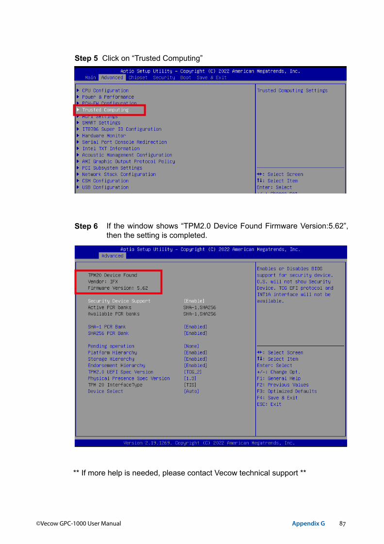
87©Vecow GPC-1000 User Manual Appendix G
Step 5 Click on “Trusted Computing”
Step 6 If the window shows “TPM2.0 Device Found Firmware Version:5.62”, then the setting is completed.
** If more help is needed, please contact Vecow technical support **

For further support information, please visit www.vecow.com
This document is released for reference purpose only. All product offerings and specifications are subject to change without prior notice. No part of this publication may be reproduced in any form or by any means, electric, photocopying, or recording, without prior authorization from the publisher.The rights of all the brand names, product names, and trademarks belong to their respective owners. © Vecow Co., Ltd. 2022. All rights reserved.
Related Documents