September 2019 Version 2.0 User manual Uninterruptible Power Supply SIPB RT 1~3kVA with dry contact interface

Welcome message from author
This document is posted to help you gain knowledge. Please leave a comment to let me know what you think about it! Share it to your friends and learn new things together.
Transcript
September 2019 Version 2.0
User manual
Uninterruptible Power Supply
SIPB RT 1~3kVA
with dry contact interface
All rights reserved. The information in this document is subject to change
without notice.
Publish statement
Thank you for purchasing this series UPS.
This series UPS is an intelligent, single phase, high frequency online UPS
designed by our R&D team who is with years of designing experiences on UPS.
With excellent electrical performance, perfect intelligent monitoring and network
functions, smart appearance, complying with EMC and safety standards this UPS
has become standard product which meets the world’s advanced level.
Read this manual carefully before installation. This manual offers technical
support for equipment operator.
Parus electro LLC
115404, Russia, Moscow 6th Radialnaya str., 9
Tel.: 8(800)301-05-38, +7(495)518-92-92
www.parus-electro.ru
Service support:
Tel.: +7(495)518-92-82
Content
1.Summary. ................................................................................................................ 2
1.1 Introduction .................................................................................................... 2
1.2 functions and characteristics ........................................................................ 2
2.Safety instruction ................................................................................................... 4
2.1 Safety instruction ........................................................................................... 4
2.2 Symbols indication ......................................................................................... 5
3.Product Introduction ............................................................................................. 6
3.1 The appearance of the product ..................................................................... 6
3.2 The principle of the product ......................................................................... 7
3.3 Model ............................................................................................................... 7
4.Installation .............................................................................................................. 8
4.1 Unpacking and inspection ............................................................................. 8
4.2 Notes ................................................................................................................ 8
4.3 UPS input connection .................................................................................... 8
4.4 UPS output connection .................................................................................. 9
4.5 Long backup external battery connection ................................................... 9
4.6 Installation .................................................................................................... 10
5.Faceplate display,operation and running .......................................................... 13
5.1 Faceplate display illumination .................................................................... 13
5.2 Operation ...................................................................................................... 16
5.3 Parameter setting ......................................................................................... 17
5.4 Parameters inquiring ................................................................................... 22
5.5 Run mode ...................................................................................................... 24
6.Maintenance ......................................................................................................... 26
7.Troubleshooting and properties of product ...................................................... 27
7.1 LED indication and warning table ............................................................. 28
7.2 Troubleshooting ........................................................................................... 29
7.3 EMC standard/Safety standard .................................................................. 30
7.4 Product Performance .................................................................................. 30
7.5 Communication interface ............................................................................ 32
2
1. Summary
1.1 Introduction
UPS (uninterruptible power supply) is a kind of power supply equipment
that provides uninterruptible, high quality and efficient and reliable AC power to
the loads, it also has functions of protection and monitoring. The UPS plays a
very important role in power supply of computer and its network, communication,
finance, electricity, transportation, national defense, college, scientific research
institutes and so on.
This series of 1kVA-3kVA products are designed as advanced ON-LINE
UPS that provide the multiple functions and good performance.
1.2 functions and characteristics
1.Advanced IGBT modules are used in our UPS. The electronic components we
used can work normally for more than 300,000 hours.
2.Digital control technology with high efficiency and the most reliable controller
algorithm design are used to optimize the output parameters of the machine.
3.Self-diagnose before start. It can find potential problems of the UPS in time to
avoid any losses.
4.Double conversion on-line topology which makes the output of the UPS a pure
sine wave electricity with constant frequency and voltage, low noise and no
interruption of the main power fluctuation. It provides more comprehensive and
perfect protection for the users’ equipments.
5.No transfer time for the output of the UPS when the main power fails or
restores. It meets the high standard and high request of the precise instruments.
6.The bypass function. When UPS meets a fault, it can transfer to bypass with no
interruption to supply power to loads and provide alarm.
7.Advanced voltage compensation technology. It makes the input voltage range
from 115v to 295v which reduces the battery usage and enhances the adaptive
ability against the bad main power variation.
8.The AC input frequency is 50Hz/60Hz. Advanced wide frequency input
technology makes the input frequency range wider. When the output frequency is
50Hz, the range of the AC input frequency is 45Hz-55Hz, When the output
frequency is 60Hz, the range of the AC input frequency is 55Hz-65Hz.The UPS
has a good compatibility with generator. It is suitable for different types of
single-phase generators.
9.The advanced PFC (power factor correction) technology on the input of the
UPS makes the input power factor more than 0.98. It increases the power
efficiency, removes the harmonic noise from UPS to utility, lowers the UPS
operational cost. It’s really an economic environmental protection power supply.
3
10.Intelligent function without surveillance. When main power is on blackout, the
UPS will start battery mode to supply power to loads.
When battery voltage is low, UPS will protect itself and shut down automatically.
When main power restores, UPS will detect main power to determine whether the
voltage and frequency are normal. If normal, UPS will turn on automatically to
supply power to loads; if abnormal, UPS will start charger to charge the battery.
The UPS will not turn on to supply power to loads until the voltage and
frequency of the main power restore normally.
11.Cold start function. When there is no main power, UPS can be started by
battery pack. It can meet the users’ emergency needs. The cold start function is
quite strong. UPS can be cold started under the full load situation.
12.UPS protection function:
When the main power input/output voltage is too high or too low, overload,
short-circuit, inverter temperature is too high, low voltage
and overcharge of battery, network surge and so on, UPS has a protection
function.
13.Rack-Tower conversion LCD design. No matter what angel to watch the
display, only press the key slightly can meet your perspective needs. The content
displayed on the interface is rich. The capacity of the loads and the battery can be
saw directly and the FLASH pictures and fan rotating icon can be displayed when
charging. So it is easy to know it’s operation. When UPS fails, it can show the
fault code, the machine can be maintained as soon as possible by inquiring fault
code table.
14.The UPS can communicate with the computer with intelligent UPS
monitoring software through the RS232 and USB interfaces. All the parameters
clearly display on the communication interface. Computer can control multiple
functions of the UPS directly.
15.Via internal or external SNMP adapter, UPS can go on internet and provide
the latest information and power messages. You can monitor and manage the UPS
status through all kinds of network management system.
16.Convenient USB communication. You can see the operation of the machine
completely. Even if the RS232 interface is occupied or connected at the same
time, it will automatically switch to USB connection.
17.ECO function can help you save electricity. When the input mains power is in
a fixed range, the loads is supplied with power by mains power directly, the
inverter is on waiting; when input mains power is abnormal, it transfers to
inverter to supply power to loads at once.
18.In order to ensure the power of the important loads can last for a long time,
you can plug the important loads into the second power down socket. When the
battery voltage is below the predetermined value, only the first cut-off power
4
socket is broken off, the second power down can keep on supplying power until
the battery voltage reaches protect point and shut down.
19.Adopt international standard rack-mounted size. Whether you want to put it on
the office desk or in the rack-mount as a system to manage, It can present your
personal style with corresponding components.
2. Safety instruction Abstract
This chapter mainly introduce the safety marks and notes of 1kVA-3kVA series
on-line UPS. Read this chapter carefully before operating on the equipment.
2.1 Safety instruction
There is dangerous voltage and high temperature inside the UPS. During the
installation, operation and maintenance, please abide the local safety instructions
and relative laws, otherwise, it will result in personal injury or equipment damage.
Safety instructions in this manual act as a supplementary for the local safety
instructions.
Our company will not assume the liability that caused by disobey of safety
instructions. Please note the following:
1. Don’t use the UPS when the actual load exceeds the rated load.
2. There are high-capacity batteries in the standard type UPS. You mustn’t open
the enclosure or it will lead to electric shock. If it needs internal maintenance
or battery replacement, please send it to the designated site.
3. Internal short-circuit of the UPS will cause electric shock or fire. So don’t
place the containers equipped with liquid on the top of the UPS so as not to
cause danger of electric shock and so on.
4. Don’t put the UPS in a place with high temperature or humidity as well as the
corrosive gas, much dust.
5. Keep good air circulation between in-vent on front panel and out-vent on back
panel.
6. Avoid direct sunlight or near heat-dispensed objects.
7. In case that the smoke appears on the UPS, please cut off the power as soon as
possible and contact the dealer service site.
5
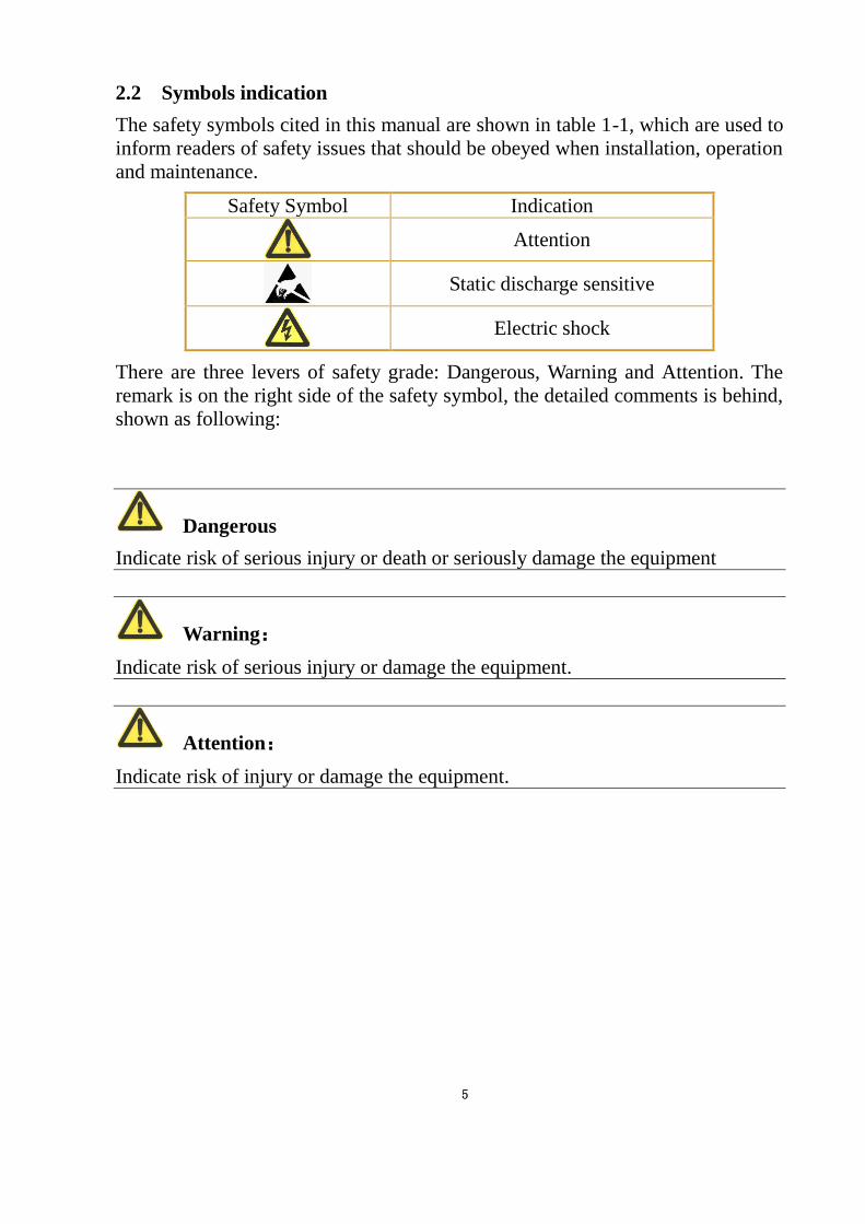
2.2 Symbols indication
The safety symbols cited in this manual are shown in table 1-1, which are used to
inform readers of safety issues that should be obeyed when installation, operation
and maintenance.
Safety Symbol Indication
Attention
Static discharge sensitive
Electric shock
There are three levers of safety grade: Dangerous, Warning and Attention. The
remark is on the right side of the safety symbol, the detailed comments is behind,
shown as following:
Dangerous
Indicate risk of serious injury or death or seriously damage the equipment
Warning:
Indicate risk of serious injury or damage the equipment.
Attention:
Indicate risk of injury or damage the equipment.
6
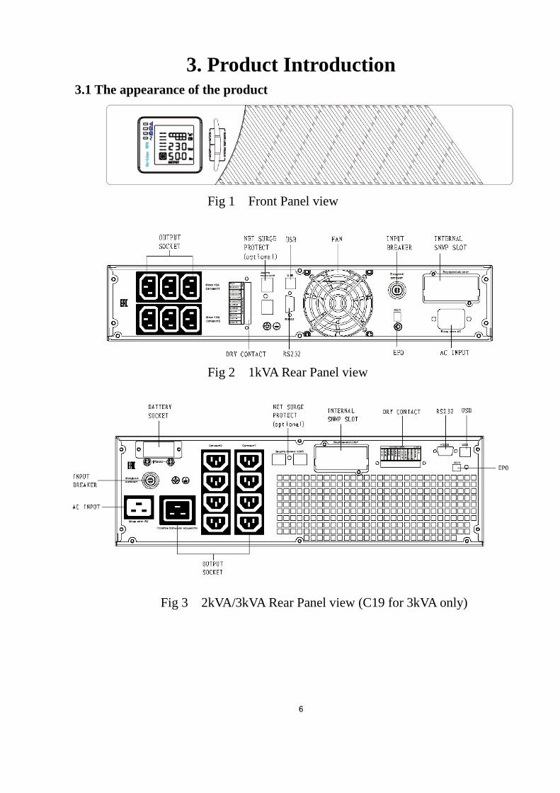
3. Product Introduction 3.1 The appearance of the product
Fig 1 Front Panel view
Fig 2 1kVA Rear Panel view
Fig 3 2kVA/3kVA Rear Panel view (C19 for 3kVA only)
7
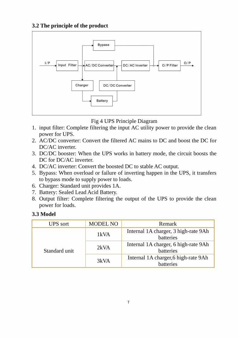
3.2 The principle of the product
Fig 4 UPS Principle Diagram
1. input filter: Complete filtering the input AC utility power to provide the clean
power for UPS.
2. AC/DC converter: Convert the filtered AC mains to DC and boost the DC for
DC/AC inverter.
3. DC/DC booster: When the UPS works in battery mode, the circuit boosts the
DC for DC/AC inverter.
4. DC/AC inverter: Convert the boosted DC to stable AC output.
5. Bypass: When overload or failure of inverting happen in the UPS, it transfers
to bypass mode to supply power to loads.
6. Charger: Standard unit provides 1A.
7. Battery: Sealed Lead Acid Battery.
8. Output filter: Complete filtering the output of the UPS to provide the clean
power for loads.
3.3 Model
UPS sort MODEL NO Remark
Standard unit
1kVA Internal 1A charger, 3 high-rate 9Ah
batteries
2kVA Internal 1A charger, 6 high-rate 9Ah
batteries
3kVA Internal 1A charger,6 high-rate 9Ah
batteries
8
4. Installation 4.1 Unpacking and inspection
1. Unpacking the UPS and check that whether it’s damaged during the
transportation. If damaged or some parts missing, don’t start the machine and
inform the carrier and franchiser.
2. Check the annex (please consult Appendix Table 1).
3. Check if the equipment is just what you wanted to purchase. You can affirm
through inspecting the model number on back panel of the equipment.
4.2 Notes
1. Please place the UPS in a clean, stable environment, avoid the vibration, dust,
too humidity, flammable gas and liquid, corrosive.
2. The ambient temperature around UPS should keep in a range of 0ºC~40ºC. If
UPS works above 40ºC, it is required that the rated value of the largest load
decreases 12% while the temperature increases the 5ºC every time. The highest
temperature cannot be more than 50ºC when UPS works.
3. UPS should be placed in a sufficiently ventilated place.
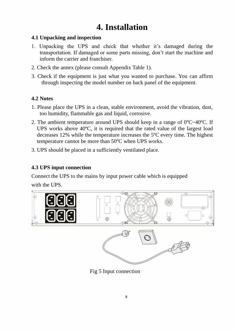
4.3 UPS input connection
Connect the UPS to the mains by input power cable which is equipped
with the UPS.
Fig 5 Input connection
9
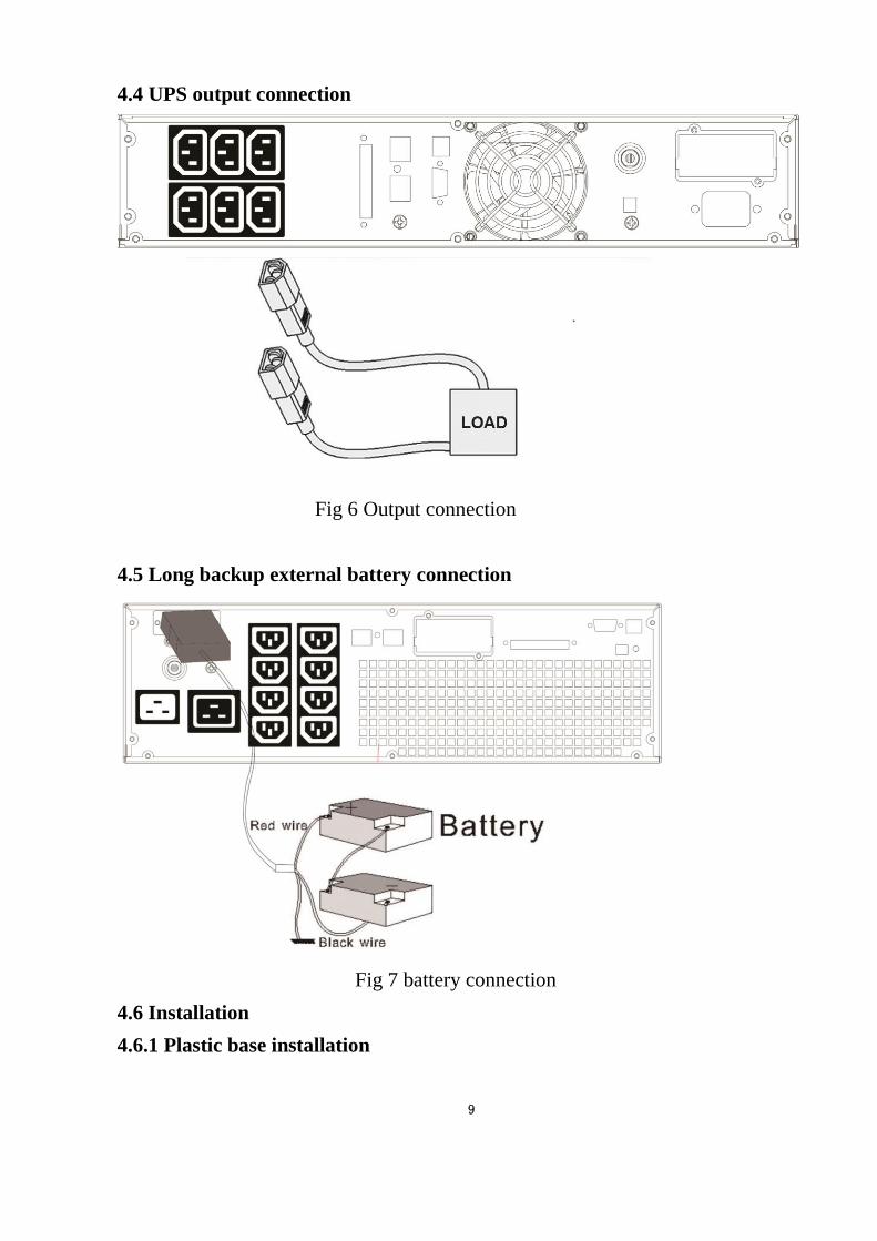
4.4 UPS output connection
Fig 6 Output connection
4.5 Long backup external battery connection
Fig 7 battery connection
4.6 Installation
4.6.1 Plastic base installation
10
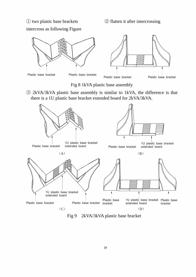
① two plastic base brackets ② flatten it after intercrossing
intercross as following Figure
Fig 8 1kVA plastic base assembly
③ 2kVA/3kVA plastic base assembly is similar to 1kVA, the difference is that
there is a 1U plastic base bracket extended board for 2kVA/3kVA.
(A) (B)
(C) (D)
Fig 9 2kVA/3kVA plastic base bracket
11
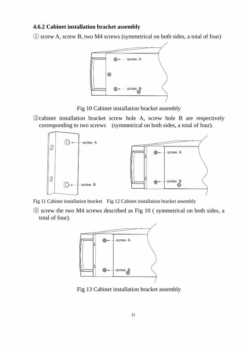
4.6.2 Cabinet installation bracket assembly
① screw A, screw B, two M4 screws (symmetrical on both sides, a total of four)
Fig 10 Cabinet installation bracket assembly
②cabinet installation bracket screw hole A, screw hole B are respectively
corresponding to two screws (symmetrical on both sides, a total of four).
Fig 11 Cabinet installation bracket Fig 12 Cabinet installation bracket assembly
③ screw the two M4 screws described as Fig 10 ( symmetrical on both sides, a
total of four).
Fig 13 Cabinet installation bracket assembly
12
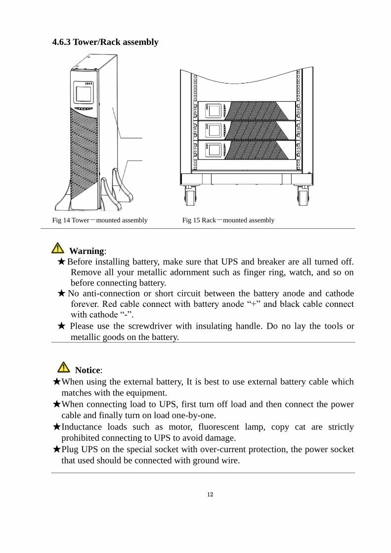
4.6.3 Tower/Rack assembly
Fig 14 Tower-mounted assembly Fig 15 Rack-mounted assembly
Warning:
★ Before installing battery, make sure that UPS and breaker are all turned off.
Remove all your metallic adornment such as finger ring, watch, and so on
before connecting battery.
★ No anti-connection or short circuit between the battery anode and cathode
forever. Red cable connect with battery anode “+” and black cable connect
with cathode “-”.
★ Please use the screwdriver with insulating handle. Do no lay the tools or
metallic goods on the battery.
Notice:
★When using the external battery, It is best to use external battery cable which
matches with the equipment.
★When connecting load to UPS, first turn off load and then connect the power
cable and finally turn on load one-by-one.
★Inductance loads such as motor, fluorescent lamp, copy cat are strictly
prohibited connecting to UPS to avoid damage.
★Plug UPS on the special socket with over-current protection, the power socket
that used should be connected with ground wire.
13
★UPS is likely to have output voltage no matter whether the power input cable is
plugged in mains input socket. If you wish UPS have no output, first break off
the switch and then cancel the mains.
★When connect laser printer, select the capacity of UPS according to the UPS
start power because the startup power is higher.
5. Panel display, operation and running The operation is simple, operators only need to read the manual and follow the
operation instructions listed in this manual without any special training.
5.1 Faceplate display illumination
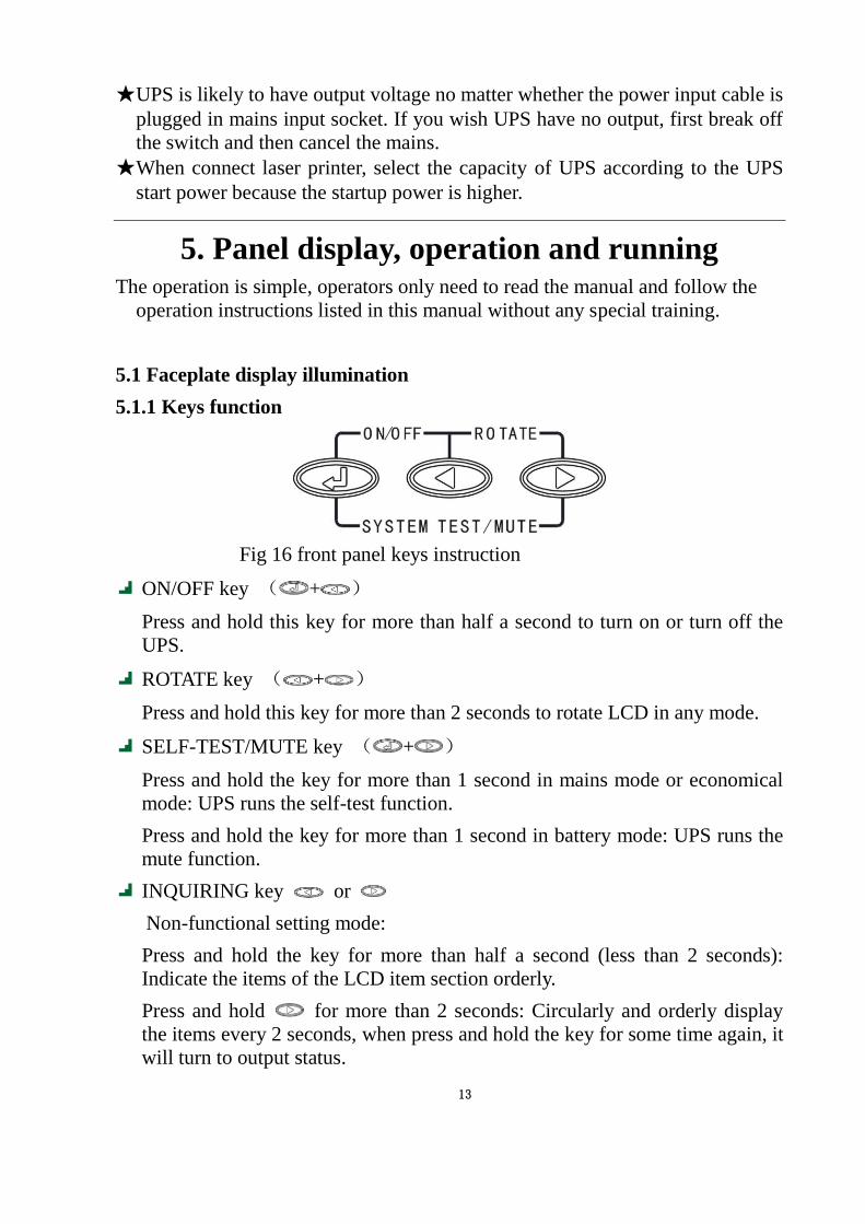
5.1.1 Keys function
Fig 16 front panel keys instruction
ON/OFF key ( + )
Press and hold this key for more than half a second to turn on or turn off the
UPS.
ROTATE key ( + )
Press and hold this key for more than 2 seconds to rotate LCD in any mode.
SELF-TEST/MUTE key ( + )
Press and hold the key for more than 1 second in mains mode or economical
mode: UPS runs the self-test function.
Press and hold the key for more than 1 second in battery mode: UPS runs the
mute function.
INQUIRING key or
Non-functional setting mode:
Press and hold the key for more than half a second (less than 2 seconds):
Indicate the items of the LCD item section orderly.
Press and hold for more than 2 seconds: Circularly and orderly display
the items every 2 seconds, when press and hold the key for some time again, it
will turn to output status.
14
Functional setting mode:
Press and hold the key for more than half a second (less than 2 seconds):
Select the set option.
Function setting key
Non-functional setting mode:
Press and hold the key for more than 2 seconds: Function setting interface.
Functional setting mode:
Press and hold the key for more than half a second (less than 2 seconds):
Affirm the set option.
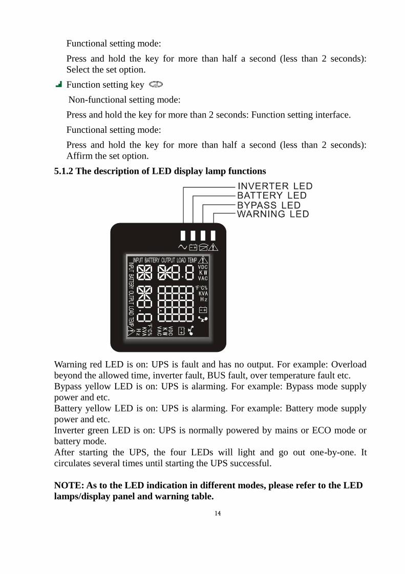
5.1.2 The description of LED display lamp functions
Warning red LED is on: UPS is fault and has no output. For example: Overload
beyond the allowed time, inverter fault, BUS fault, over temperature fault etc.
Bypass yellow LED is on: UPS is alarming. For example: Bypass mode supply
power and etc.
Battery yellow LED is on: UPS is alarming. For example: Battery mode supply
power and etc.
Inverter green LED is on: UPS is normally powered by mains or ECO mode or
battery mode.
After starting the UPS, the four LEDs will light and go out one-by-one. It
circulates several times until starting the UPS successful.
NOTE: As to the LED indication in different modes, please refer to the LED
lamps/display panel and warning table.
15
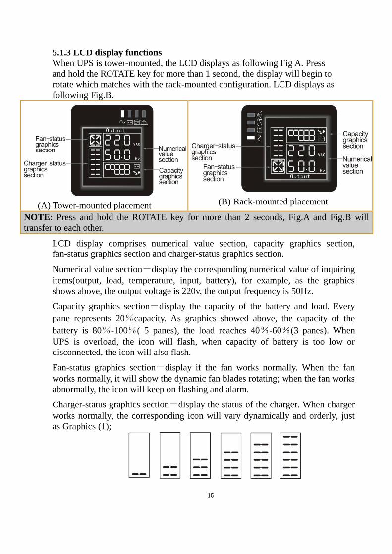
5.1.3 LCD display functions
When UPS is tower-mounted, the LCD displays as following Fig A. Press
and hold the ROTATE key for more than 1 second, the display will begin to
rotate which matches with the rack-mounted configuration. LCD displays as
following Fig.B.
(A) Tower-mounted placement
(B) Rack-mounted placement
NOTE: Press and hold the ROTATE key for more than 2 seconds, Fig.A and Fig.B will
transfer to each other.
LCD display comprises numerical value section, capacity graphics section,
fan-status graphics section and charger-status graphics section.
Numerical value section-display the corresponding numerical value of inquiring
items(output, load, temperature, input, battery), for example, as the graphics
shows above, the output voltage is 220v, the output frequency is 50Hz.
Capacity graphics section-display the capacity of the battery and load. Every
pane represents 20%capacity. As graphics showed above, the capacity of the
battery is 80%-100%( 5 panes), the load reaches 40%-60%(3 panes). When
UPS is overload, the icon will flash, when capacity of battery is too low or
disconnected, the icon will also flash.
Fan-status graphics section-display if the fan works normally. When the fan
works normally, it will show the dynamic fan blades rotating; when the fan works
abnormally, the icon will keep on flashing and alarm.
Charger-status graphics section-display the status of the charger. When charger
works normally, the corresponding icon will vary dynamically and orderly, just
as Graphics (1);
16
(1)
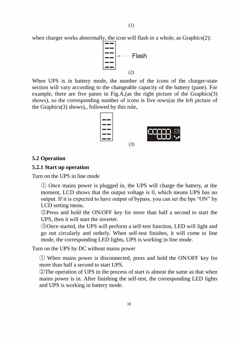
when charger works abnormally, the icon will flash in a whole, as Graphics(2):
(2)
When UPS is in battery mode, the number of the icons of the charger-state
section will vary according to the changeable capacity of the battery (pane). For
example, there are five panes in Fig.A,(as the right picture of the Graphics(3)
shows), so the corresponding number of icons is five rows(as the left picture of
the Graphics(3) shows),, followed by this rule,
(3)
5.2 Operation
5.2.1 Start up operation
Turn on the UPS in line mode
① Once mains power is plugged in, the UPS will charge the battery, at the
moment, LCD shows that the output voltage is 0, which means UPS has no
output. If it is expected to have output of bypass, you can set the bps “ON” by
LCD setting menu.
②Press and hold the ON/OFF key for more than half a second to start the
UPS, then it will start the inverter.
③Once started, the UPS will perform a self-test function, LED will light and
go out circularly and orderly. When self-test finishes, it will come to line
mode, the corresponding LED lights, UPS is working in line mode.
Turn on the UPS by DC without mains power
① When mains power is disconnected, press and hold the ON/OFF key for
more than half a second to start UPS.
②The operation of UPS in the process of start is almost the same as that when
mains power is in. After finishing the self-test, the corresponding LED lights
and UPS is working in battery mode.
17
5.2.2 Turn off operation
Turn off the UPS in line mode
① Press and hold the ON/OFF key for more than half a second to turn off the
UPS and inverter.
②After UPS shutting down, LED go out and there is no output. If output is
needed, you can set bps “ON” by LCD setting menu.
Turn off the UPS by DC without mains power
① Press and hold the ON/OFF key for more than half a second to turn off the
UPS.
②When turning off the UPS, it will do self-testing firstly. LED light and go
out circularly and orderly until there is no display on the panel.
5.2.3 UPS self-test/mute test operation.
① When UPS is in line mode, press and hold the self-test/mute key for more
than 1 second, LED light and go out circularly and orderly. UPS comes to
self-test mode and tests its status. It will exit automatically after finishing
testing, LED resume.
②When UPS is in battery mode, press and hold the self-test/mute key for
more than 1 second, the buzzer stops beeping. If you press and hold the
self-test/mute key for one more second, it will restart to beep again.
5.3 Parameter setting
UPS has setting function. It can run the setting on any mode. After setting, it will
become effective at once when meets some standards. The set information can be
saved only when the battery connected and normally turning off the UPS.
The operation of setting is as following:
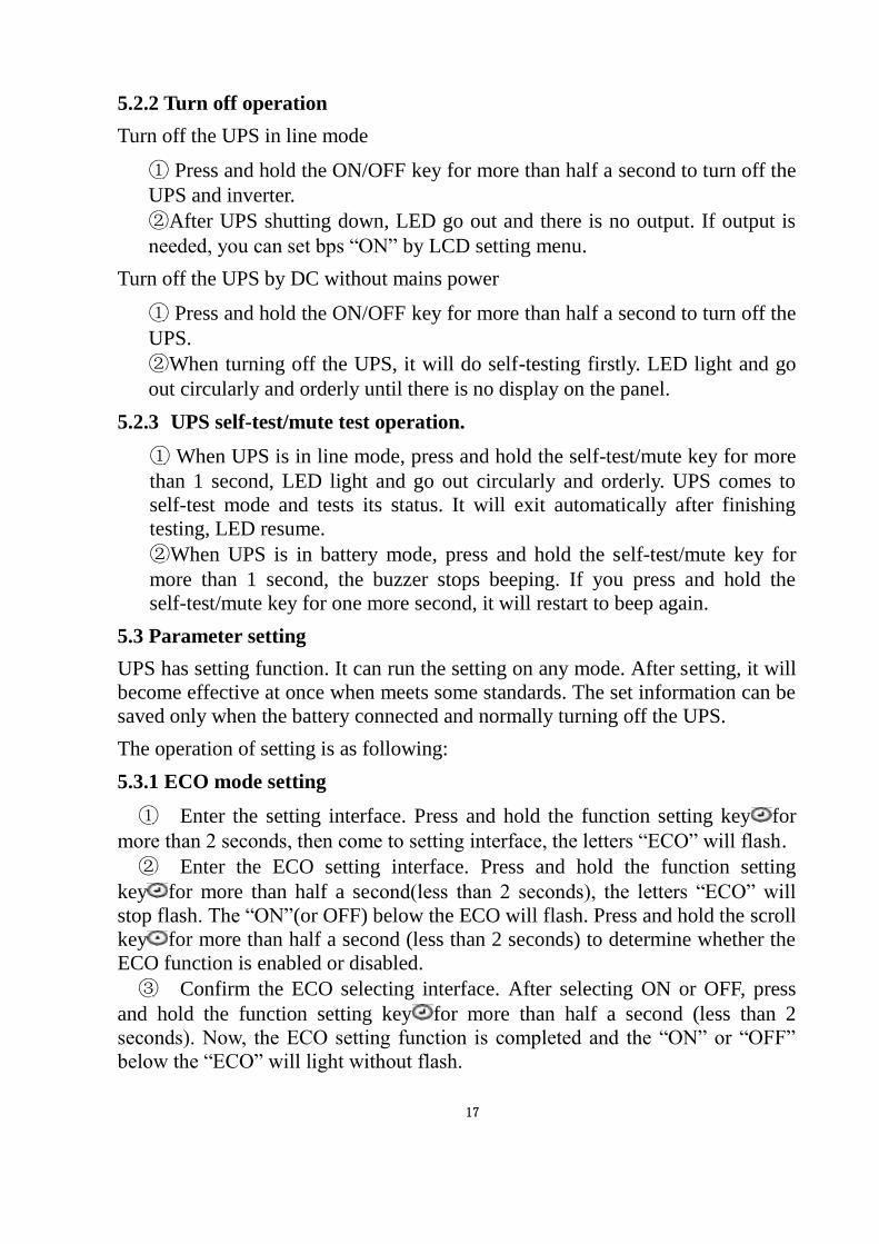
5.3.1 ECO mode setting
① Enter the setting interface. Press and hold the function setting key for
more than 2 seconds, then come to setting interface, the letters “ECO” will flash.
② Enter the ECO setting interface. Press and hold the function setting
key for more than half a second(less than 2 seconds), the letters “ECO” will
stop flash. The “ON”(or OFF) below the ECO will flash. Press and hold the scroll
key for more than half a second (less than 2 seconds) to determine whether the
ECO function is enabled or disabled.
③ Confirm the ECO selecting interface. After selecting ON or OFF, press
and hold the function setting key for more than half a second (less than 2
seconds). Now, the ECO setting function is completed and the “ON” or “OFF”
below the “ECO” will light without flash.
18
④ If you choose “OFF”, then go to step 7, otherwise go ahead to step 5.
⑤ Set the ECO tolerance range. Short press the scroll key or for more than
half a second (shorter than 2 seconds)to select the voltage range in percentage.
+5%,+10%,+15%,+25%(default is +25%),then short press function setting key
for more than half a second (shorter than 2 seconds)to confirm the selection,
then to set the minus range
⑥ To set the minus range in the same way.
⑦ After the minus range is confirmed. Long press function setting key
for more than 2 seconds to exit setting menu.
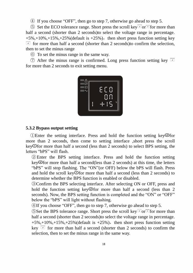
5.3.2 Bypass output setting
①Enter the setting interface. Press and hold the function setting key for
more than 2 seconds, then come to setting interface ,short press the scroll
key for more than half a second (less than 2 seconds) to select BPS setting, the
letters “bPS” will flash.
②Enter the BPS setting interface. Press and hold the function setting
key for more than half a second(less than 2 seconds) at this time, the letters
“bPS” will stop flashing. The “ON”(or OFF) below the bPS will flash. Press
and hold the scroll key for more than half a second (less than 2 seconds) to
determine whether the BPS function is enabled or disabled.
③Confirm the BPS selecting interface. After selecting ON or OFF, press and
hold the function setting key for more than half a second (less than 2
seconds). Now, the BPS setting function is completed and the “ON” or “OFF”
below the “bPS” will light without flashing.
④If you choose “OFF”, then go to step 7, otherwise go ahead to step 5.
⑤Set the BPS tolerance range. Short press the scroll key or for more than
half a second (shorter than 2 seconds)to select the voltage range in percentage.
+5%,+10%,+15%,+25%(default is +25%),then short press function setting
key for more than half a second (shorter than 2 seconds) to confirm the
selection, then to set the minus range in the same way.
19
After the minus range is confirmed. Long press function setting key for
more than 2 seconds to exit setting menu.
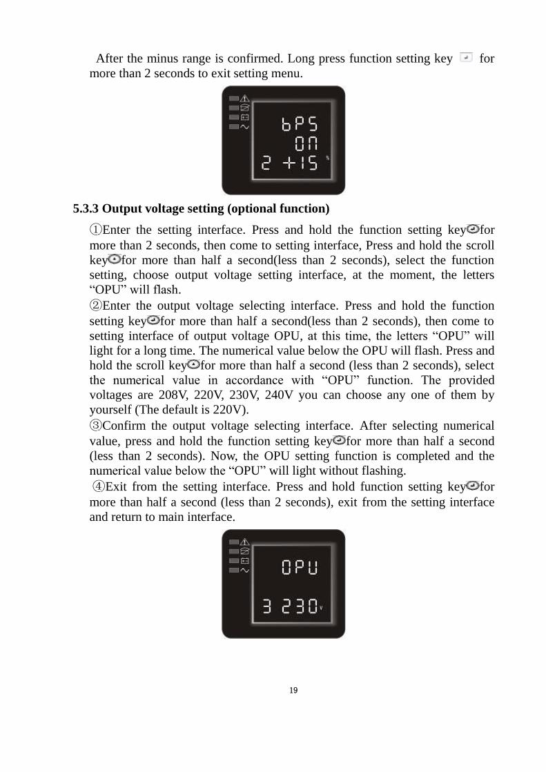
5.3.3 Output voltage setting (optional function)
①Enter the setting interface. Press and hold the function setting key for
more than 2 seconds, then come to setting interface, Press and hold the scroll
key for more than half a second(less than 2 seconds), select the function
setting, choose output voltage setting interface, at the moment, the letters
“OPU” will flash.
②Enter the output voltage selecting interface. Press and hold the function
setting key for more than half a second(less than 2 seconds), then come to
setting interface of output voltage OPU, at this time, the letters “OPU” will
light for a long time. The numerical value below the OPU will flash. Press and
hold the scroll key for more than half a second (less than 2 seconds), select
the numerical value in accordance with “OPU” function. The provided
voltages are 208V, 220V, 230V, 240V you can choose any one of them by
yourself (The default is 220V).
③Confirm the output voltage selecting interface. After selecting numerical
value, press and hold the function setting key for more than half a second
(less than 2 seconds). Now, the OPU setting function is completed and the
numerical value below the “OPU” will light without flashing.
④Exit from the setting interface. Press and hold function setting key for
more than half a second (less than 2 seconds), exit from the setting interface
and return to main interface.
20
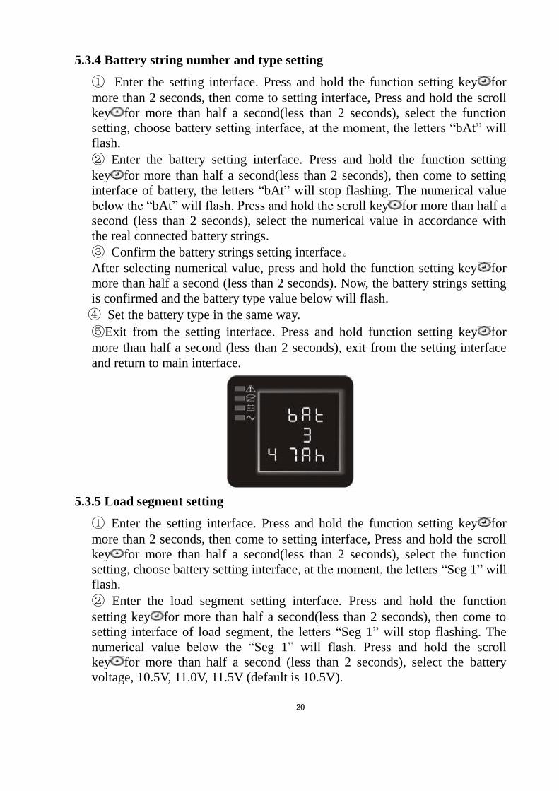
5.3.4 Battery string number and type setting
① Enter the setting interface. Press and hold the function setting key for
more than 2 seconds, then come to setting interface, Press and hold the scroll
key for more than half a second(less than 2 seconds), select the function
setting, choose battery setting interface, at the moment, the letters “bAt” will
flash.
② Enter the battery setting interface. Press and hold the function setting
key for more than half a second(less than 2 seconds), then come to setting
interface of battery, the letters “bAt” will stop flashing. The numerical value
below the “bAt” will flash. Press and hold the scroll key for more than half a
second (less than 2 seconds), select the numerical value in accordance with
the real connected battery strings.
③ Confirm the battery strings setting interface。
After selecting numerical value, press and hold the function setting key for
more than half a second (less than 2 seconds). Now, the battery strings setting
is confirmed and the battery type value below will flash.
④ Set the battery type in the same way.
⑤Exit from the setting interface. Press and hold function setting key for
more than half a second (less than 2 seconds), exit from the setting interface
and return to main interface.
5.3.5 Load segment setting
① Enter the setting interface. Press and hold the function setting key for
more than 2 seconds, then come to setting interface, Press and hold the scroll
key for more than half a second(less than 2 seconds), select the function
setting, choose battery setting interface, at the moment, the letters “Seg 1” will
flash.
② Enter the load segment setting interface. Press and hold the function
setting key for more than half a second(less than 2 seconds), then come to
setting interface of load segment, the letters “Seg 1” will stop flashing. The
numerical value below the “Seg 1” will flash. Press and hold the scroll
key for more than half a second (less than 2 seconds), select the battery
voltage, 10.5V, 11.0V, 11.5V (default is 10.5V).
21
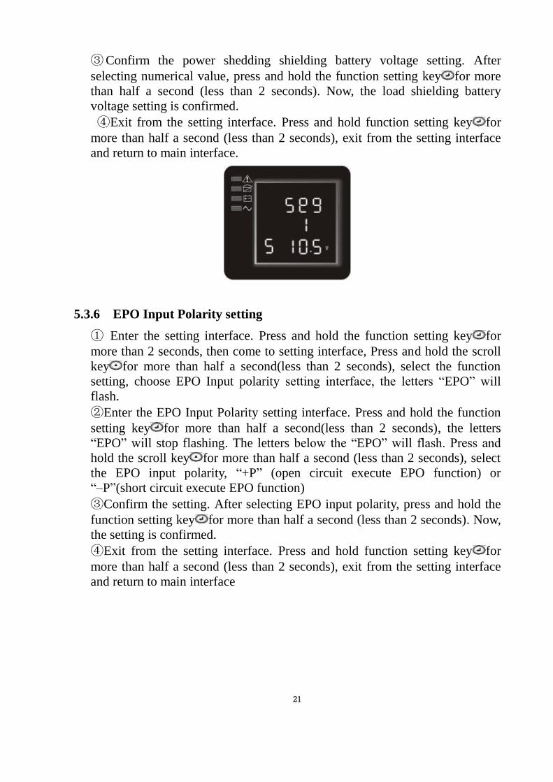
③Confirm the power shedding shielding battery voltage setting. After
selecting numerical value, press and hold the function setting key for more
than half a second (less than 2 seconds). Now, the load shielding battery
voltage setting is confirmed.
④Exit from the setting interface. Press and hold function setting key for
more than half a second (less than 2 seconds), exit from the setting interface
and return to main interface.
5.3.6 EPO Input Polarity setting
① Enter the setting interface. Press and hold the function setting key for
more than 2 seconds, then come to setting interface, Press and hold the scroll
key for more than half a second(less than 2 seconds), select the function
setting, choose EPO Input polarity setting interface, the letters “EPO” will
flash.
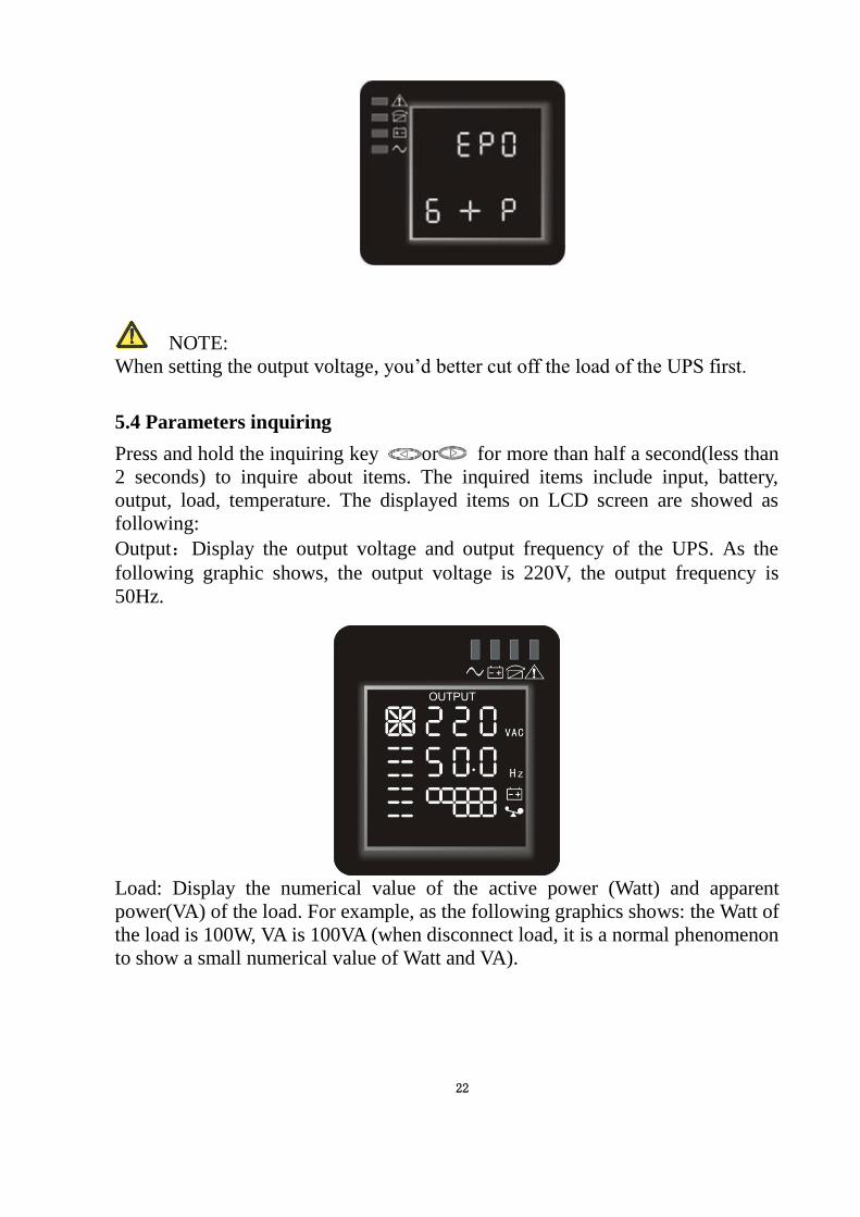
②Enter the EPO Input Polarity setting interface. Press and hold the function
setting key for more than half a second(less than 2 seconds), the letters
“EPO” will stop flashing. The letters below the “EPO” will flash. Press and
hold the scroll key for more than half a second (less than 2 seconds), select
the EPO input polarity, “+P” (open circuit execute EPO function) or
“–P”(short circuit execute EPO function)
③Confirm the setting. After selecting EPO input polarity, press and hold the
function setting key for more than half a second (less than 2 seconds). Now,
the setting is confirmed.
④Exit from the setting interface. Press and hold function setting key for
more than half a second (less than 2 seconds), exit from the setting interface
and return to main interface
22
NOTE:
When setting the output voltage, you’d better cut off the load of the UPS first.
5.4 Parameters inquiring
Press and hold the inquiring key or for more than half a second(less than
2 seconds) to inquire about items. The inquired items include input, battery,
output, load, temperature. The displayed items on LCD screen are showed as
following:
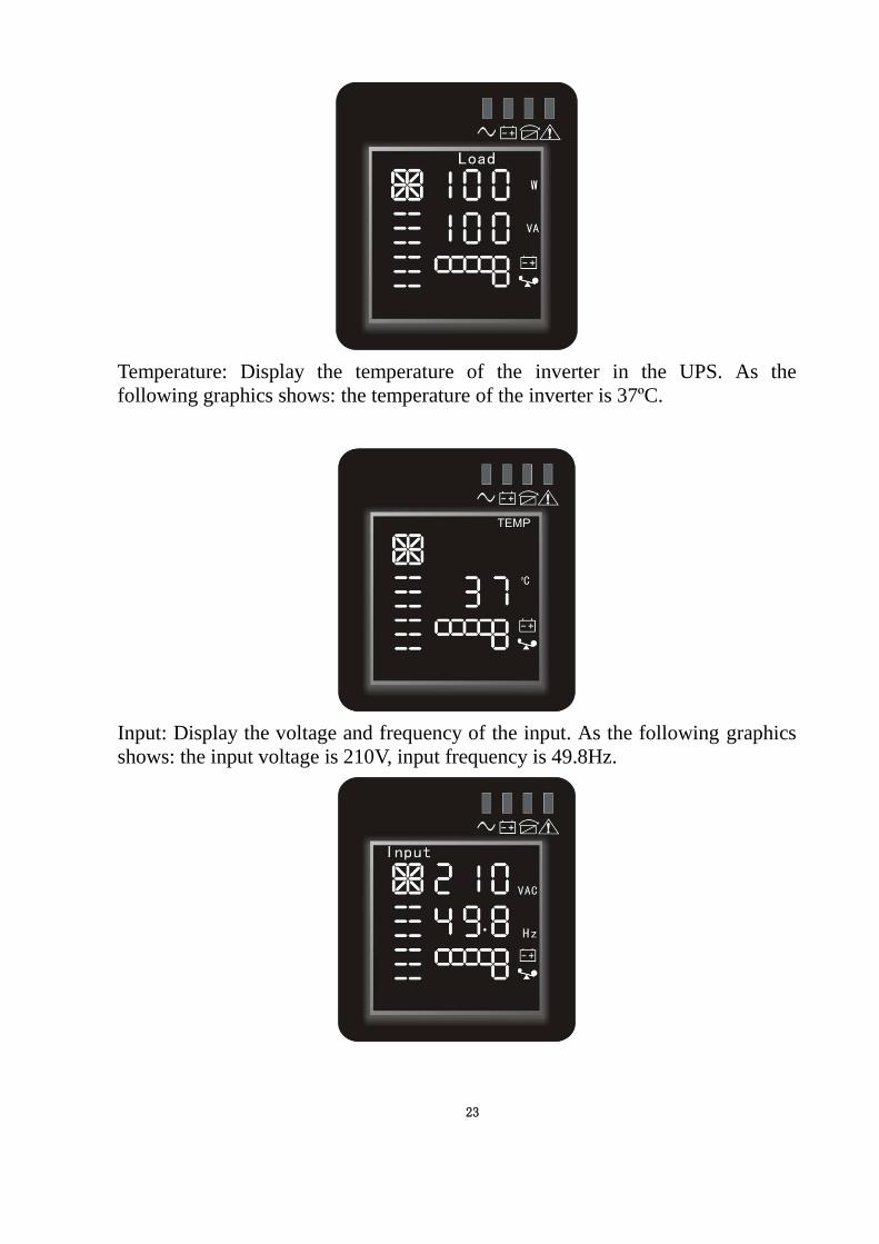
Output:Display the output voltage and output frequency of the UPS. As the
following graphic shows, the output voltage is 220V, the output frequency is
50Hz.
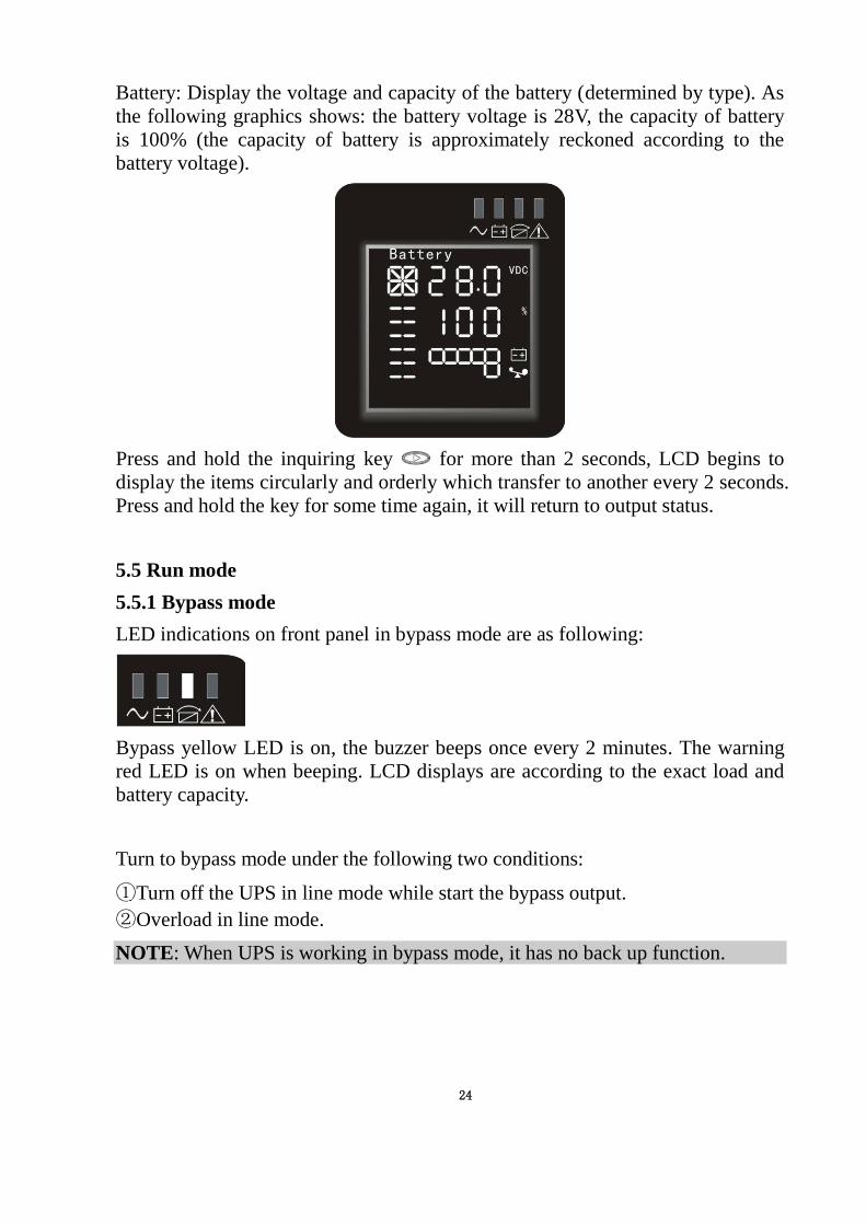
Load: Display the numerical value of the active power (Watt) and apparent
power(VA) of the load. For example, as the following graphics shows: the Watt of
the load is 100W, VA is 100VA (when disconnect load, it is a normal phenomenon
to show a small numerical value of Watt and VA).
23
Temperature: Display the temperature of the inverter in the UPS. As the
following graphics shows: the temperature of the inverter is 37ºC.
Input: Display the voltage and frequency of the input. As the following graphics
shows: the input voltage is 210V, input frequency is 49.8Hz.
24
Battery: Display the voltage and capacity of the battery (determined by type). As
the following graphics shows: the battery voltage is 28V, the capacity of battery
is 100% (the capacity of battery is approximately reckoned according to the
battery voltage).
Press and hold the inquiring key for more than 2 seconds, LCD begins to
display the items circularly and orderly which transfer to another every 2 seconds.
Press and hold the key for some time again, it will return to output status.
5.5 Run mode
5.5.1 Bypass mode
LED indications on front panel in bypass mode are as following:
Bypass yellow LED is on, the buzzer beeps once every 2 minutes. The warning
red LED is on when beeping. LCD displays are according to the exact load and
battery capacity.
Turn to bypass mode under the following two conditions:
①Turn off the UPS in line mode while start the bypass output.
②Overload in line mode.
NOTE: When UPS is working in bypass mode, it has no back up function.
25
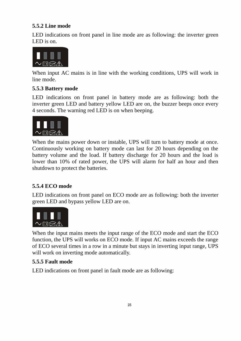
5.5.2 Line mode
LED indications on front panel in line mode are as following: the inverter green
LED is on.
When input AC mains is in line with the working conditions, UPS will work in
line mode.
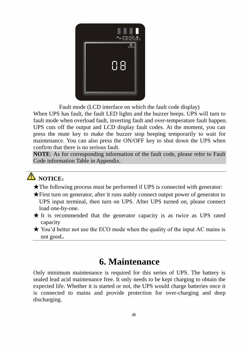
5.5.3 Battery mode
LED indications on front panel in battery mode are as following: both the
inverter green LED and battery yellow LED are on, the buzzer beeps once every
4 seconds. The warning red LED is on when beeping.
When the mains power down or instable, UPS will turn to battery mode at once.
Continuously working on battery mode can last for 20 hours depending on the
battery volume and the load. If battery discharge for 20 hours and the load is
lower than 10% of rated power, the UPS will alarm for half an hour and then
shutdown to protect the batteries.
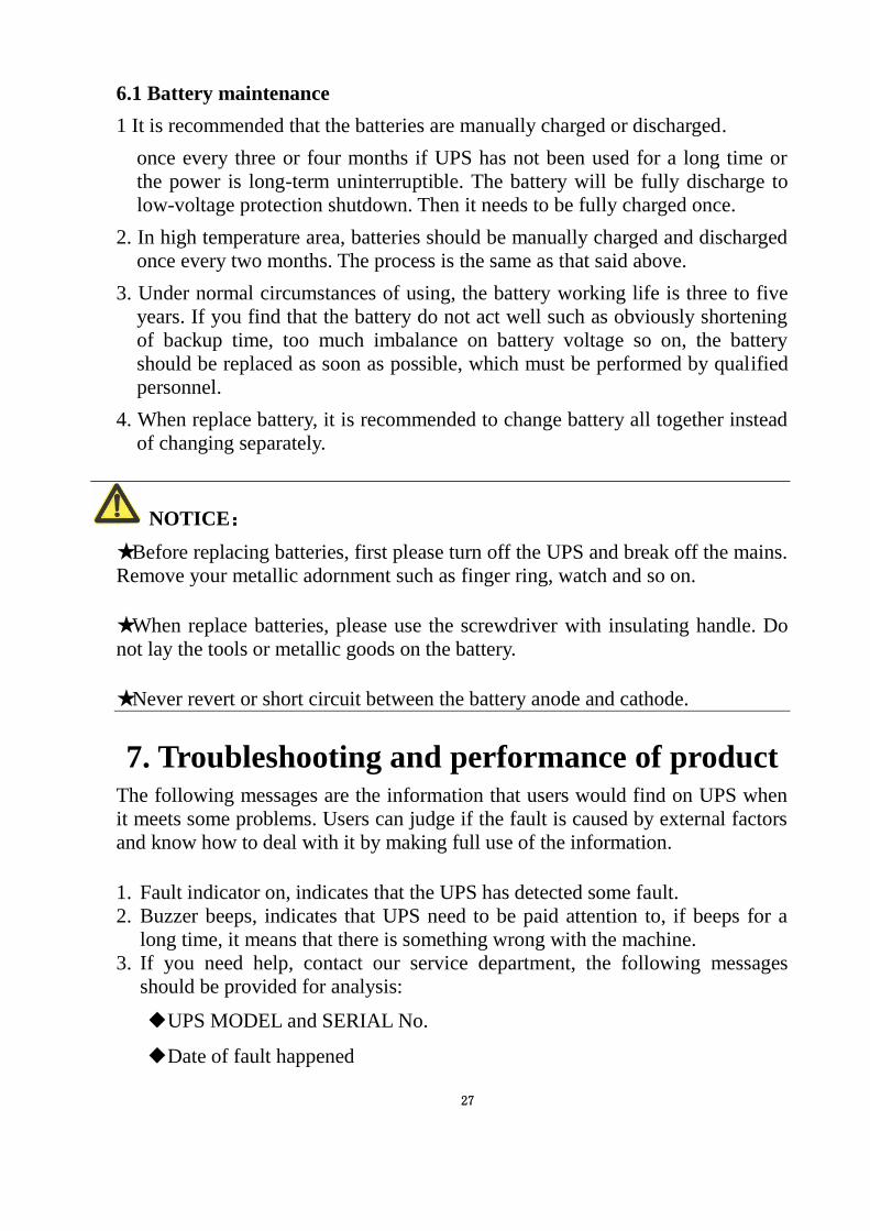
5.5.4 ECO mode
LED indications on front panel on ECO mode are as following: both the inverter
green LED and bypass yellow LED are on.
When the input mains meets the input range of the ECO mode and start the ECO
function, the UPS will works on ECO mode. If input AC mains exceeds the range
of ECO several times in a row in a minute but stays in inverting input range, UPS
will work on inverting mode automatically.
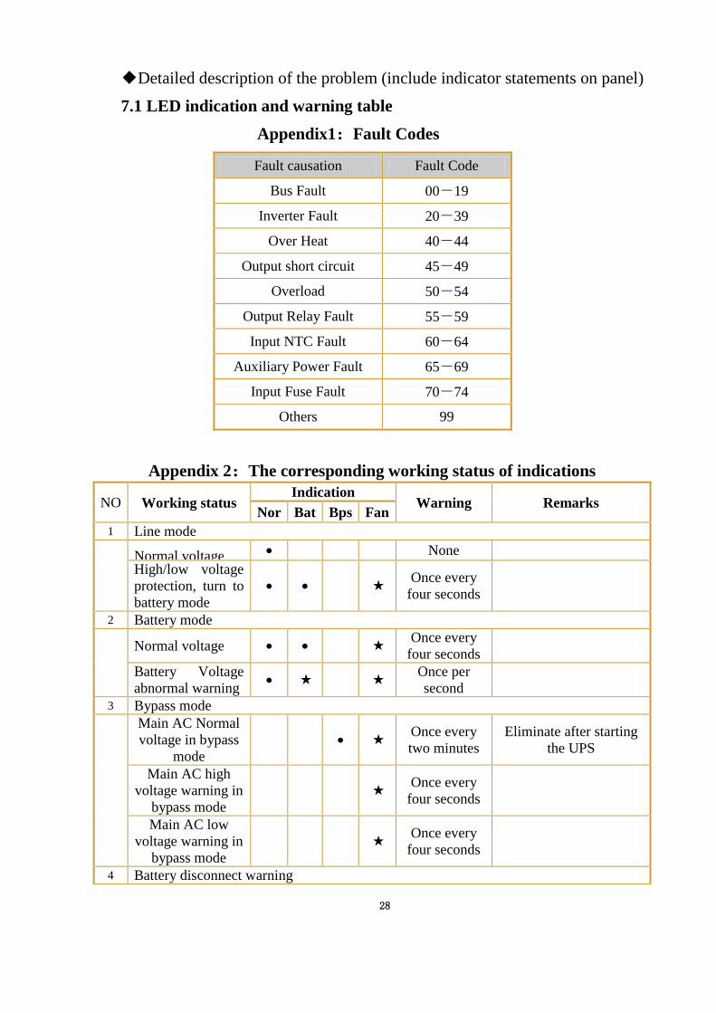
5.5.5 Fault mode
LED indications on front panel in fault mode are as following:
26
Fault mode (LCD interface on which the fault code display)
When UPS has fault, the fault LED lights and the buzzer beeps. UPS will turn to
fault mode when overload fault, inverting fault and over-temperature fault happen.
UPS cuts off the output and LCD display fault codes. At the moment, you can
press the mute key to make the buzzer stop beeping temporarily to wait for
maintenance. You can also press the ON/OFF key to shut down the UPS when
confirm that there is no serious fault.
NOTE: As for corresponding information of the fault code, please refer to Fault
Code information Table in Appendix.
NOTICE:
★The following process must be performed if UPS is connected with generator:
★First turn on generator, after it runs stably connect output power of generator to
UPS input terminal, then turn on UPS. After UPS turned on, please connect
load one-by-one.
★ It is recommended that the generator capacity is as twice as UPS rated
capacity
★ You’d better not use the ECO mode when the quality of the input AC mains is
not good。
6. Maintenance Only minimum maintenance is required for this series of UPS. The battery is
sealed lead acid maintenance free. It only needs to be kept charging to obtain the
expected life. Whether it is started or not, the UPS would charge batteries once it
is connected to mains and provide protection for over-charging and deep
discharging.
27
6.1 Battery maintenance
1 It is recommended that the batteries are manually charged or discharged.
once every three or four months if UPS has not been used for a long time or
the power is long-term uninterruptible. The battery will be fully discharge to
low-voltage protection shutdown. Then it needs to be fully charged once.
2. In high temperature area, batteries should be manually charged and discharged
once every two months. The process is the same as that said above.
3. Under normal circumstances of using, the battery working life is three to five
years. If you find that the battery do not act well such as obviously shortening
of backup time, too much imbalance on battery voltage so on, the battery
should be replaced as soon as possible, which must be performed by qualified
personnel.
4. When replace battery, it is recommended to change battery all together instead
of changing separately.
NOTICE:
★Before replacing batteries, first please turn off the UPS and break off the mains.
Remove your metallic adornment such as finger ring, watch and so on.
★When replace batteries, please use the screwdriver with insulating handle. Do
not lay the tools or metallic goods on the battery.
★Never revert or short circuit between the battery anode and cathode.
7. Troubleshooting and performance of product The following messages are the information that users would find on UPS when
it meets some problems. Users can judge if the fault is caused by external factors
and know how to deal with it by making full use of the information.
1. Fault indicator on, indicates that the UPS has detected some fault.
2. Buzzer beeps, indicates that UPS need to be paid attention to, if beeps for a
long time, it means that there is something wrong with the machine.
3. If you need help, contact our service department, the following messages
should be provided for analysis:
◆UPS MODEL and SERIAL No.
◆Date of fault happened
28
◆Detailed description of the problem (include indicator statements on panel)
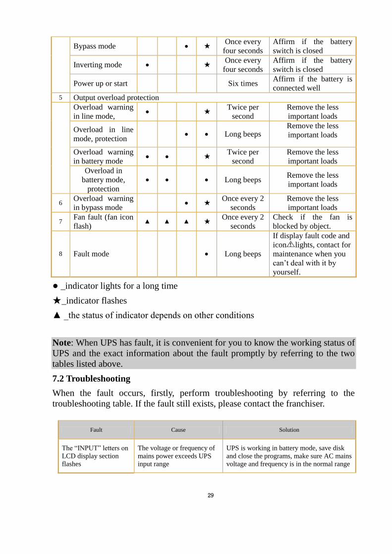
7.1 LED indication and warning table
Appendix1:Fault Codes
Fault causation Fault Code
Bus Fault 00-19
Inverter Fault 20-39
Over Heat 40-44
Output short circuit 45-49
Overload 50-54
Output Relay Fault 55-59
Input NTC Fault 60-64
Auxiliary Power Fault 65-69
Input Fuse Fault 70-74
Others 99
Appendix 2:The corresponding working status of indications
NO Working status Indication
Warning Remarks Nor Bat Bps Fan
1 Line mode
Normal voltage ● None
High/low voltage
protection, turn to
battery mode
● ● ★ Once every
four seconds
2 Battery mode
Normal voltage ● ● ★ Once every
four seconds
Battery Voltage
abnormal warning ● ★
★
Once per
second
3 Bypass mode
Main AC Normal
voltage in bypass
mode
● ★ Once every
two minutes
Eliminate after starting
the UPS
Main AC high
voltage warning in
bypass mode
★ Once every
four seconds
Main AC low
voltage warning in
bypass mode
★ Once every
four seconds
4 Battery disconnect warning
29
Bypass mode ● ★ Once every
four seconds
Affirm if the battery
switch is closed
Inverting mode ● ★ Once every
four seconds
Affirm if the battery
switch is closed
Power up or start Six times Affirm if the battery is
connected well
5 Output overload protection
Overload warning
in line mode, ● ★
Twice per
second
Remove the less
important loads
Overload in line
mode, protection ● ● Long beeps
Remove the less
important loads
Overload warning
in battery mode ● ● ★
Twice per
second
Remove the less
important loads
Overload in
battery mode,
protection
● ● ● Long beeps Remove the less
important loads
6 Overload warning
in bypass mode ● ★
Once every 2
seconds
Remove the less
important loads
7 Fan fault (fan icon
flash) ▲ ▲ ▲ ★
Once every 2
seconds
Check if the fan is
blocked by object.
8 Fault mode ● Long beeps
If display fault code and
icon lights, contact for
maintenance when you
can’t deal with it by
yourself.
● _indicator lights for a long time
★ _indicator flashes
▲ _the status of indicator depends on other conditions
Note: When UPS has fault, it is convenient for you to know the working status of
UPS and the exact information about the fault promptly by referring to the two
tables listed above.
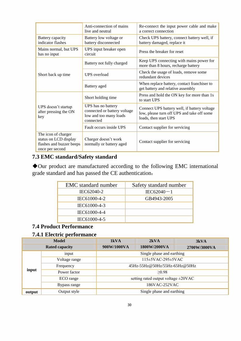
7.2 Troubleshooting
When the fault occurs, firstly, perform troubleshooting by referring to the
troubleshooting table. If the fault still exists, please contact the franchiser.
Fault Cause Solution
The “INPUT” letters on
LCD display section
flashes
The voltage or frequency of
mains power exceeds UPS
input range
UPS is working in battery mode, save disk
and close the programs, make sure AC mains
voltage and frequency is in the normal range
30
Anti-connection of mains
live and neutral
Re-connect the input power cable and make
a correct connection
Battery capacity
indicator flashes
Battery low voltage or
battery disconnected
Check UPS battery, connect battery well, if
battery damaged, replace it
Mains normal, but UPS
has no input
UPS input breaker open
circuit Press the breaker for reset
Short back up time
Battery not fully charged Keep UPS connecting with mains power for
more than 8 hours, recharge battery
UPS overload Check the usage of loads, remove some
redundant devices
Battery aged When replace battery, contact franchiser to
get battery and relative assembly
UPS doesn’t startup
after pressing the ON
key
Short holding time Press and hold the ON key for more than 1s
to start UPS
UPS has no battery
connected or battery voltage
low and too many loads
connected
Connect UPS battery well, if battery voltage
low, please turn off UPS and take off some
loads, then start UPS
Fault occurs inside UPS Contact supplier for servicing
The icon of charger
status on LCD display
flashes and buzzer beeps
once per second
Charger doesn’t work
normally or battery aged Contact supplier for servicing
7.3 EMC standard/Safety standard
◆Our product are manufactured according to the following EMC international
grade standard and has passed the CE authentication:
7.4 Product Performance
7.4.1 Electric performance Model 1kVA 2kVA 3kVA
Rated capacity 900W/1000VA 1800W/2000VA 2700W/3000VA
input
input Single phase and earthing
Voltage range 115±5VAC-295±5VAC
Frequency 45Hz-55Hz@50Hz/55Hz-65Hz@50Hz
Power factor ≥0.98
ECO range setting rated output voltage ±20VAC
Bypass range 186VAC-252VAC
output Output style Single phase and earthing
EMC standard number Safety standard number
IEC62040-2 IEC62040-1
IEC61000-4-2 GB4943-2005
IEC61000-4-3
IEC61000-4-4
IEC61000-4-5
31
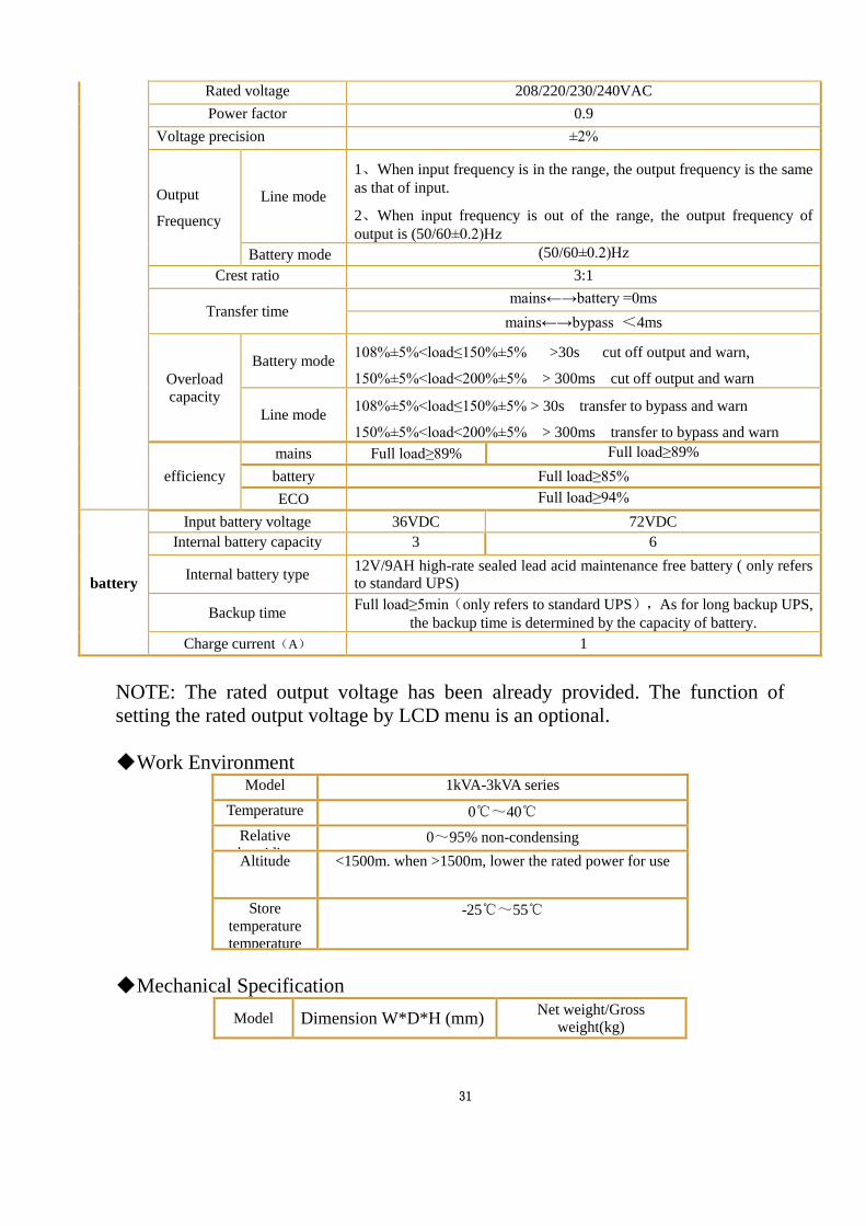
Rated voltage 208/220/230/240VAC
Power factor 0.9
Voltage precision ±2%
Output
Frequency
Line mode
1、When input frequency is in the range, the output frequency is the same
as that of input.
2、When input frequency is out of the range, the output frequency of
output is (50/60±0.2)Hz
Battery mode (50/60±0.2)Hz
Crest ratio 3:1
Transfer time mains←→battery =0ms
mains←→bypass <4ms
Overload
capacity
Battery mode 108%±5%<load≤150%±5% >30s cut off output and warn,
150%±5%<load<200%±5% > 300ms cut off output and warn
Line mode 108%±5%<load≤150%±5% > 30s transfer to bypass and warn
150%±5%<load<200%±5% > 300ms transfer to bypass and warn
efficiency
mains Full load≥89% Full load≥89%
battery Full load≥85%
ECO Full load≥94%
battery
Input battery voltage 36VDC 72VDC
Internal battery capacity 3 6
Internal battery type 12V/9AH high-rate sealed lead acid maintenance free battery ( only refers
to standard UPS)
Backup time Full load≥5min(only refers to standard UPS),As for long backup UPS,
the backup time is determined by the capacity of battery.
Charge current(A) 1
NOTE: The rated output voltage has been already provided. The function of
setting the rated output voltage by LCD menu is an optional.
◆ Work Environment Model 1kVA-3kVA series
Temperature 0℃~40℃
Relative
humidity
humidity
humidityu
humidity
0~95% non-condensing
Altitude <1500m. when >1500m, lower the rated power for use
Store
temperature
temperature
-25℃~55℃
◆ Mechanical Specification
Model Dimension W*D*H (mm) Net weight/Gross
weight(kg)
32
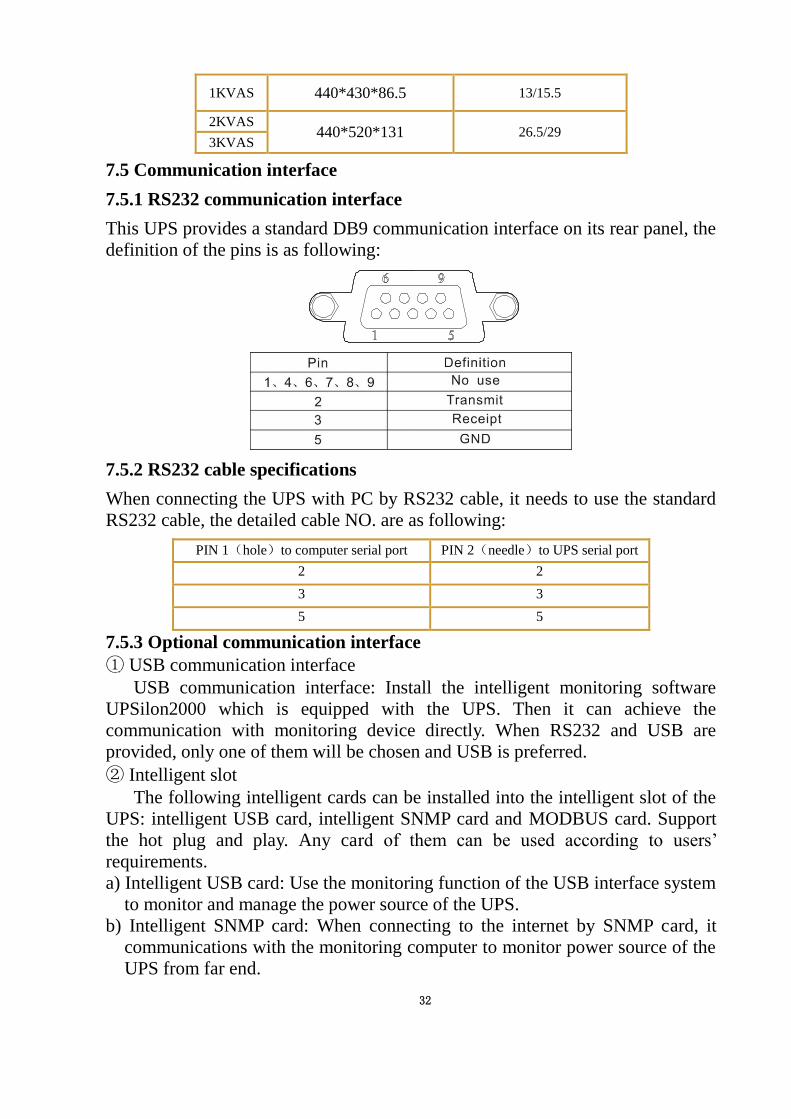
1KVAS 440*430*86.5 13/15.5
2KVAS 440*520*131 26.5/29
3KVAS
7.5 Communication interface
7.5.1 RS232 communication interface
This UPS provides a standard DB9 communication interface on its rear panel, the
definition of the pins is as following:
7.5.2 RS232 cable specifications
When connecting the UPS with PC by RS232 cable, it needs to use the standard
RS232 cable, the detailed cable NO. are as following:
PIN 1(hole)to computer serial port PIN 2(needle)to UPS serial port
2 2
3 3
5 5
7.5.3 Optional communication interface
① USB communication interface
USB communication interface: Install the intelligent monitoring software
UPSilon2000 which is equipped with the UPS. Then it can achieve the
communication with monitoring device directly. When RS232 and USB are
provided, only one of them will be chosen and USB is preferred.
② Intelligent slot
The following intelligent cards can be installed into the intelligent slot of the
UPS: intelligent USB card, intelligent SNMP card and MODBUS card. Support
the hot plug and play. Any card of them can be used according to users’
requirements.
a) Intelligent USB card: Use the monitoring function of the USB interface system
to monitor and manage the power source of the UPS.
b) Intelligent SNMP card: When connecting to the internet by SNMP card, it
communications with the monitoring computer to monitor power source of the
UPS from far end.
33
c) Intelligent MODBUS card: Use the monitoring function of the dry contact
interface system to monitor and manage the power source of the UPS.
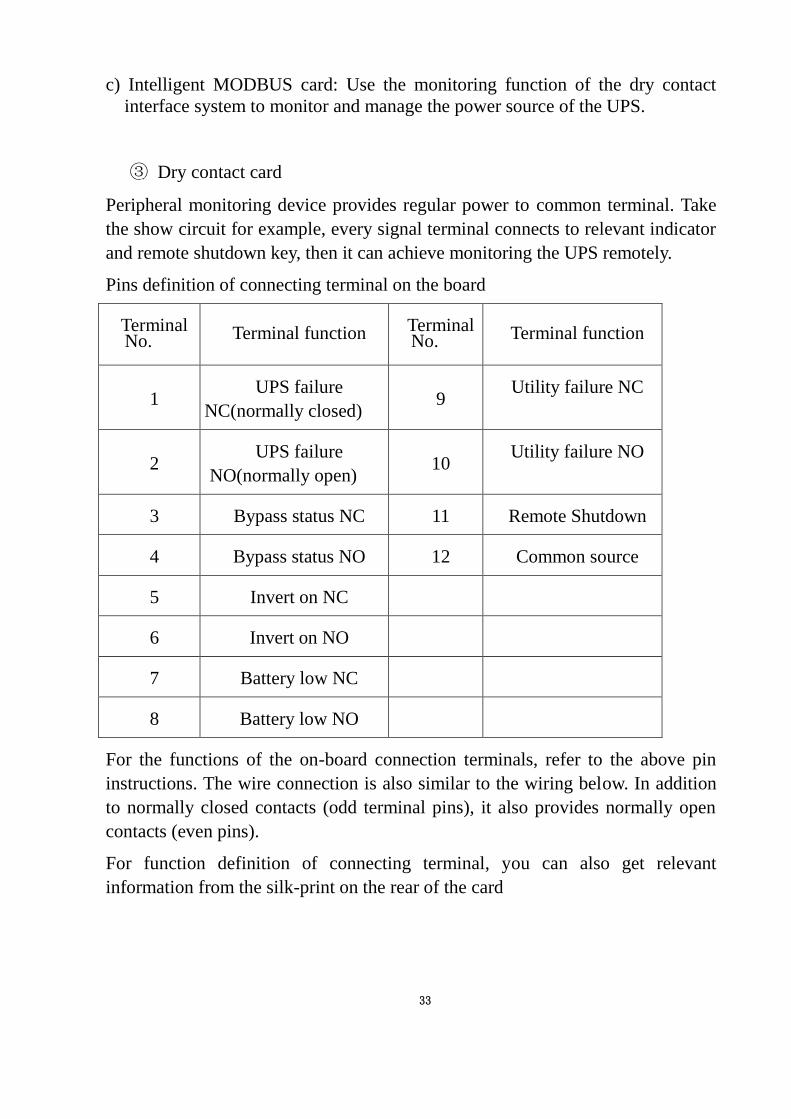
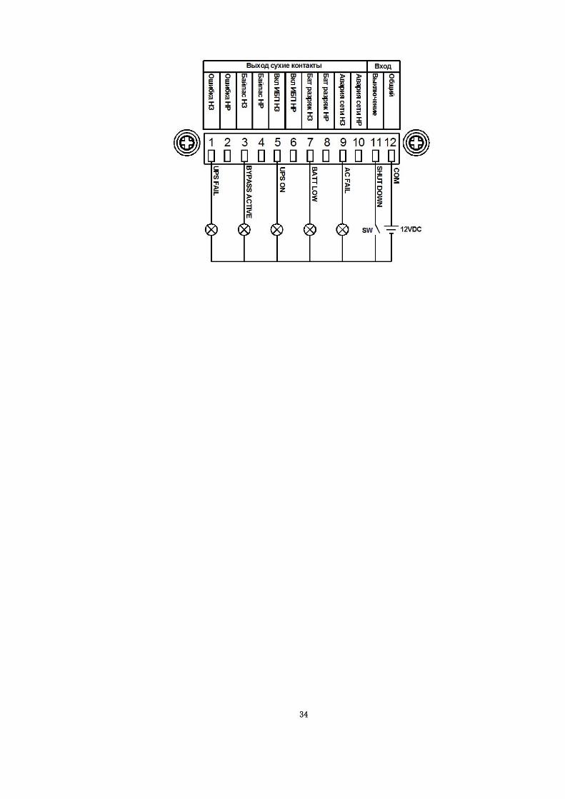
③ Dry contact card
Peripheral monitoring device provides regular power to common terminal. Take
the show circuit for example, every signal terminal connects to relevant indicator
and remote shutdown key, then it can achieve monitoring the UPS remotely.
Pins definition of connecting terminal on the board
Terminal No. Terminal function Terminal
No. Terminal function
1 UPS failure
NC(normally closed) 9
Utility failure NC
2 UPS failure
NO(normally open) 10
Utility failure NO
3 Bypass status NC 11 Remote Shutdown
4 Bypass status NO 12 Common source
5 Invert on NC
6 Invert on NO
7 Battery low NC
8 Battery low NO
For the functions of the on-board connection terminals, refer to the above pin
instructions. The wire connection is also similar to the wiring below. In addition
to normally closed contacts (odd terminal pins), it also provides normally open
contacts (even pins).
For function definition of connecting terminal, you can also get relevant
information from the silk-print on the rear of the card
34
Related Documents