Please visit www.hattelandtechnology.com for the latest electronic version of this manual. USER MANUAL 4-Bay Model 2-Bay Model HTC03 - Compact Computer User Manual HTC03 Updated: 23 Nov 2021 Doc Id: INB100042-6 (Rev 04) Created: 7495/363 Approved: 6987 Models: HTC03-xx-AC yzzzzzz (Single AC power input) HTC03-xx-MP yzzzzzz (Multi-Power AC+DC inputs) where xx=CPU type (i3,i5,i7), y=manufacturing site, zz=configuration

Welcome message from author
This document is posted to help you gain knowledge. Please leave a comment to let me know what you think about it! Share it to your friends and learn new things together.
Transcript

Please visit www.hattelandtechnology.com for the latest electronic version of this manual.
USER MANUAL
4-Bay Model2-Bay Model
HTC03 - Compact Computer
User Manual HTC03Updated: 23 Nov 2021 Doc Id: INB100042-6 (Rev 04)
Created: 7495/363 Approved: 6987
Models: HTC03-xx-AC yzzzzzz (Single AC power input)
HTC03-xx-MP yzzzzzz (Multi-Power AC+DC inputs)
where xx=CPU type (i3,i5,i7), y=manufacturing site, zz=configuration

Copyright © 2021 Hatteland Technology ASEikeskogvegen 52, N-5570 Aksdal, Norway.
All rights are reserved by Hatteland Technology AS. This information may not, in whole or in part, becopied, photocopied, reproduced, translated or reduced to any electronic medium or machine-
readable form without the prior written consent of Hatteland Technology AS. Review also: www.hattelandtechnology.com/hubfs/pdf/misc/doc100703-1_permission_to_create_user_manuals.pdf
The products described, or referenced, herein are copyrighted to the respective owners. The products may not be copied or duplicated in any way. This documentation contains proprietary
information that is not to be disclosed to persons outside the user’s company without prior written consent of Hatteland Technology AS.
The copyright notice appearing above is included to provide statutory protection in the event of unauthorized or unintentional public disclosure.
All other product names or trademarks are properties of their respective owners !
WARNING: This is a class A product. In a domestic environment this product may cause radio interferencein which case the user may be required to take adequate measures.
Statement above last revised 31 Jul. 2019

3IND100206-28
Contents
Contents .................................................................................... 3Contents of package ............................................................................................................... 6
General ...................................................................................... 9IEC62368 policy - Introduction ............................................................................................. 10About this manual ..................................................................................................................11About Hatteland Technology ..................................................................................................11www.hattelandtechnology.com ..............................................................................................11Contact Information ...............................................................................................................11Computers introduction ........................................................................................................ 12Product Labels (Examples) .................................................................................................. 13
Installation ............................................................................... 15Installation and mounting of computers ................................................................................ 16General mounting instructions .............................................................................................. 17Cables .................................................................................................................................. 17Unit Upgrade Precaution Note .............................................................................................. 18Ferrite ................................................................................................................................... 19Housing / Terminal Block Connector Overview .................................................................... 20Cabinet cover removal .......................................................................................................... 22Installing PCIe Card / Rework PCI Bracket Options - Notice ............................................... 23HT 00275OPT-A1 (PCIe Card Bracket, Removal & Replacement) HL/FL/HH ..................... 25Air Filter removal / replacement (H733S30Q20-SP000-0) .................................................. 26Front Fan removal / replacement ......................................................................................... 27Mounting Bracket Kit (Desktop) HTC03 ............................................................................... 28Mounting Brackets for Console Mounting - HT 00226 OPT-A1 ............................................ 2919 inch Rack Kit 4U - HT 00223 OPT-A1 ............................................................................. 30Sliding Rails - HT 00224 OPT-A1 (20”) / HT 00225 OPT-A1 (26”) ....................................... 30Examples of mounting orientations to avoid ......................................................................... 31Replacing Internal CMOS/BIOS Battery ............................................................................... 32User Controls ........................................................................................................................ 34Physical Connections .......................................................................................................... 36Module Expansion Matrix ..................................................................................................... 41Factory Preset COM Port Numbering ................................................................................... 44
Specifications ......................................................................... 45Specifications - HTC03-xx-AC xxxxxxx ................................................................................ 46Specifications - HTC03-xx-MP xxxxxxx ................................................................................ 47
Multi-Power (AC+DC) ...................................................................................................... 47

Contents
4IND100206-28
Specifications Factory Options............................................. 49Specifications - NMEA / IEC COM Module RS-422 / RS-485 .............................................. 50
PCA200828-1 .................................................................................................................. 50Specifications - CAN Module with CO-Processor ................................................................. 54
ZIA0001310-B ................................................................................................................. 54Specifications - CAN Module with CO-Processor ................................................................. 55
ZIA0001310-SLCAN ....................................................................................................... 55Specifications - Isolated Digital Input/Output Module ........................................................... 56
PCA100297-1 .................................................................................................................. 56Specifications - LAN Module ................................................................................................ 58
PCA100298-1 .................................................................................................................. 58Specifications - Isolated COM Module RS-232 .................................................................... 59
PCA100309-1 .................................................................................................................. 59
Specifications Accessories ................................................... 61Specifications - External Modules (USB) .............................................................................. 62Specifications - VSDDPVGA340 / HT DPM2VGAF-A1 ........................................................ 64
DisplayPort to VGA adapter ............................................................................................ 64Specifications - RC3473 / HT DPM2DVI-DF-A1 ................................................................... 65
DisplayPort to DVI adapter .............................................................................................. 65Specifications - JH C01MF A-A ............................................................................................ 66
Technical Drawings ................................................................ 67Technical Drawings - HTC03-xx-AC xxxxxxx ...................................................................... 68Technical Drawings - HTC03-xx-MP xxxxxxx ...................................................................... 69
Multi-Power (AC+DC) ...................................................................................................... 69
Technical Drawings - Accessories ........................................ 71Technical Drawings - HT MBK STD-C1 ................................................................................ 72
Mounting Bracket Kit HTC03/HTC04 - L-Shaped ........................................................... 72Technical Drawings - 19” Rack Kit 4U .................................................................................. 73
HT 00223 OPT-A1 ........................................................................................................... 73Technical Drawings - Mounting Brackets .............................................................................. 75
HT 00226 OPT-A1 ........................................................................................................... 75Technical Drawings - EN60945 PCI/PCIe Support Bracket .................................................. 76
HT 00275 OPT-A1 ........................................................................................................... 76Technical Drawings - External Modules (USB) ..................................................................... 77Technical Drawings - 20” Slide Rails (for 19” Rack) ............................................................. 78
HT 00224 OPT-A1 ........................................................................................................... 78Technical Drawings - 26” Slide Rails (for 19” Rack) ............................................................. 79
HT 00225 OPT-A1 ........................................................................................................... 79
Contents
5IND100206-28
Appendixes ............................................................................. 81SSD Selection Guide ............................................................................................................ 82BIOS - Overview and functions ............................................................................................ 86BIOS - How to create RAID volume ................................................................................... 135BIOS - Hybrid Multi Monitor Configuration ......................................................................... 137WatchDog Timer function ................................................................................................... 138Pinout Assignments ............................................................................................................ 140Trouble-shooting ................................................................................................................. 143Operating System Recovery (tool) .................................................................................... 143How to activate Windows Recovery Environment on OS Drive ........................................ 147IEC62368 policy for Hatteland Technology products .......................................................... 148IEC62368 policy - Appendix ............................................................................................... 150Chassis Thermal / Heat note .............................................................................................. 150Declaration of Conformity ................................................................................................... 151Return Of Goods Information ............................................................................................. 152General Terms and Conditions ........................................................................................... 153Notes .................................................................................................................................. 154Revision History .................................................................................................................. 156

6IND100207-21
Contents of package
Item Description Illustration
702002605
1 x Power Cable European Type F “Schuko” to IEC.Length 1.8m
EUR TYPE FIEC
702002600
1 x Power Cable US Type B plug to IEC.Length 1.8m US TYPE B
IEC
Würth 742 712 21(1212004518-01)(split, 10.5mm)
1 x Würth 742 712 21
This ferrite is required when using 100/110/115V AC voltage on the power supply (not required for 230V AC) to be fully compliant with type approvals.
Review installation chapter for more information.
HT 00226 OPT-A1
Mounting brackets incl. screws (for console mounting)
HT RET STD-A3
Cable Retainer/Relief kit with3 x Screws M3x4 DIN 965-10.9 Torx BLANK
Cable Relief for DP - kit consists of:1 x DP cable tie (1990025128S000)1 x DP cable mounting (1990036354S000)1 x screw M3x5 (1930006255-01)
Test Reports papers:1 x Product Declaration TBD1 x Computer Checklist TBD1 x BurnInTest Certificate TBD
Stratocell packaging foam HTC03 computer Accessories Box (Contains items as listed below) Outer Box

Contents of package
7IND100207-21
Package may also include: (based on accessories/options ordered)Item Description Illustration
Tx- Tx+ COM Rx- Rx+
Terminal Block Connectors
Depending on factory mounted options, connector kit as follows:2 x 4-pin Terminal Block 3.81 for CAN Interface (ZIA0001310-B / ZIA0001310-SLCAN)4 x 5-pin Terminal Block 3.81 for RS-422 / RS-485 NMEA 4 Channel (PCA100828-1)4 x 5-pin Terminal Block 3.81 for Digital Input/Output (PCA100297-1)
PNY NVIDIA Quadro P2200
1 x Installation guide1 x DP to DVI-D (SL) Adapter
Not available for Multi-Power models
PNY NVIDIA Quadro P620
1 x Installation guide1 x DVD with drivers/support software4 x mDP to DP adapter*or 4 x mDP to DVI (SL) adapter**Depends on ordered configuration
Not available for Multi-Power models
CP114EL-I
1 x MOXA Cable with 4 ports

8
This page left intentionally blank

9
General
10IND100078-81
General
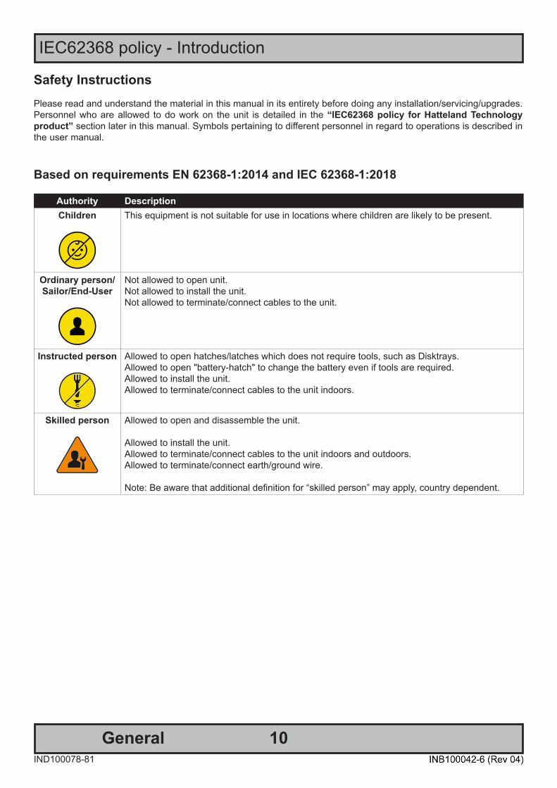
IEC62368 policy - Introduction
Safety InstructionsPlease read and understand the material in this manual in its entirety before doing any installation/servicing/upgrades. Personnel who are allowed to do work on the unit is detailed in the “IEC62368 policy for Hatteland Technology product” section later in this manual. Symbols pertaining to different personnel in regard to operations is described in the user manual.
Based on requirements EN 62368-1:2014 and IEC 62368-1:2018
Authority DescriptionChildren This equipment is not suitable for use in locations where children are likely to be present.
Ordinary person/Sailor/End-User
Not allowed to open unit. Not allowed to install the unit. Not allowed to terminate/connect cables to the unit.
Instructed person Allowed to open hatches/latches which does not require tools, such as Disktrays. Allowed to open "battery-hatch" to change the battery even if tools are required.Allowed to install the unit.Allowed to terminate/connect cables to the unit indoors.
Skilled person Allowed to open and disassemble the unit.
Allowed to install the unit.Allowed to terminate/connect cables to the unit indoors and outdoors.Allowed to terminate/connect earth/ground wire. Note: Be aware that additional definition for “skilled person” may apply, country dependent.

11
Hatteland Technology AS
IND100077-1
General
About this manualThe manual contains electrical, mechanical and input/output signal specifications. All specifications in this manual, due to manufacturing, new revisions and approvals, are subject to change without notice. However, the last updated and revision date of this manual are shown both on the frontpage and also in the “Revision History” chapter. This user manual is a standard/general manual that applies to all variations of its product family, i.e. deviation from actual configuration may exist.
About Hatteland TechnologyHatteland Technology is the leading technology provider of specialized display and computer products, delivering high quality, unique and customized solutions to the international maritime, naval and industrial markets.
The company represents innovation and quality to the system integrators worldwide. Effective quality assurance and investment in sophisticated in-house manufacturing methods and facilities enable us to deliver Type Approved and Mil tested products. Our customer-oriented approach, technical knowledge and dedication to R&D, makes us a trusted and preferred supplier of approved solutions, which are backed up by a strong service network.
www.hattelandtechnology.comYou will find our website full of useful information to help you make an informed choice as to the right product for your needs. You will find detailed product descriptions and specifications for the entire range on Displays, Computers,Panel Computers and Military solutions as well as the range of supporting accessories. The site carries a wealth ofinformation regarding our product testing and approvals in addition to company contact information for our variousoffices around the world, the global service locations and the technical support centre, all ensuring the best possiblesupport wherever you, or your vessel, may be in the world. Contact Information
Head office, Aksdal / Norway:Hatteland Technology AS
Eikeskogvegen 52N-5570 Aksdal, Norway
Switchboard:Tel: +47 4814 2200
Sales office, Frankfurt / Germany:Hatteland Technology GmbHWerner Heisenberg Strasse 2,
D-63263 Neu-Isenburg, Germany
Elke Freisens: Tel: +49 173 6174753
Sales office, Oslo / Norway:Hatteland Technology AS
Strandveien 35 N-1366 Lysaker
Norway
Switchboard:Tel: +47 4814 2200
Sales office, Aix-en-Provence / France:Hatteland Technology SAS
Actimart- 1140, rue Ampère, CS 80544 13594 Aix-en-Provence, Cedex 3
France
Mehdi Bounoua (Sales Director Europe, Middle East & Africa): Tel : +33 6 88 33 64 93
Sales office, Vista / USA:Hatteland Technology Inc450 South Melrose Drive,
Suite #107Vista, CA 92081
USA
Donna Pallonetti: Tel: +1 858-282-0659Fax: +1 858-408-1834
For an up-2-date list, please visit https://www.hattelandtechnology.com/contact
12
Computers
IND101057-28
General
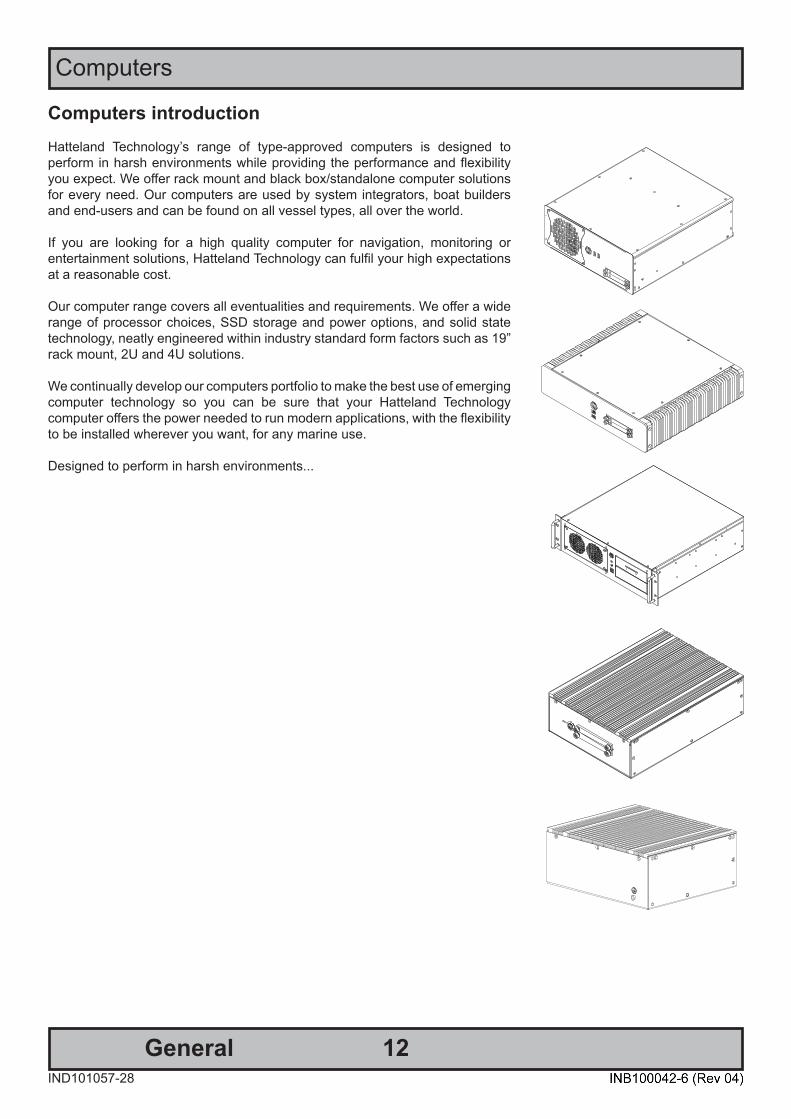
Computers introductionHatteland Technology’s range of type-approved computers is designed to perform in harsh environments while providing the performance and flexibility you expect. We offer rack mount and black box/standalone computer solutions for every need. Our computers are used by system integrators, boat builders and end-users and can be found on all vessel types, all over the world.
If you are looking for a high quality computer for navigation, monitoring or entertainment solutions, Hatteland Technology can fulfil your high expectations at a reasonable cost.
Our computer range covers all eventualities and requirements. We offer a wide range of processor choices, SSD storage and power options, and solid state technology, neatly engineered within industry standard form factors such as 19” rack mount, 2U and 4U solutions.
We continually develop our computers portfolio to make the best use of emerging computer technology so you can be sure that your Hatteland Technology computer offers the power needed to run modern applications, with the flexibility to be installed wherever you want, for any marine use.
Designed to perform in harsh environments...

13
Product Labels (Examples)
GeneralIND100240-16
Product Labels (Examples)
Label Size and Types
ID Label Layout Description SpecificationType : Serial Number LabelName : Label BSize : 60mm wide x 22mm high (rectangle size)Note: Text content of label will match specificationsderived from Data Sheet.
Silver with glue on back, non-tearable and made for thermaltransfer printing.
Barcode type: CODE128 (used extensively world wide in shipping and packagingindustries. The symbology was formerly defined as ISO/IEC 15417:2007.)
Type : Operating System (OS) label. Size : 22mm wide x 9mm high (rectangle size)Note: Label only present if OS was part of factoryoption order. Linux OS does not have any label.
As per delivered from supplier.
Label applies for:Windows® 10 IoT Enterprise
Type : Quality Control (QC) LabelSize : 30mm wide x 23mm high (oval size)
This label indicates that the unit is produced, tested and packed according to the manufacture’s QA specifications. It will include a Personal ID and signature by the personnell responsible for approving the unit inproduction, test and warehouse departments.
FLEXcon®PHARMcal®V 400 F WhiteTC-848V-23 TRACrite™150
Type : Shock Hazard Caution LabelName : Label BSize : 60mm wide x 20mm high (rectangle size)
Silver with glue on back, non-tearable and made for thermaltransfer printing.
Rules specified in IEC62368-1:2018 annex L.8 and F.5. Applies for units with Dual/Multi-Power inputs only (more than 1 Power Input).
Only present if the unit was delivered with factory installed Operating System (OS) such as Microsoft® Windows® Embedded Enterprise. The same Product Key is also printed on the “Product Declaration” sheet that follows the unit, check contents of package. Note: For certain OS, there is no physical Product Key Label required or a Product Key Number that must be entered during installation / usage of the unit.
14
Product Labels (Examples)
GeneralIND100240-16
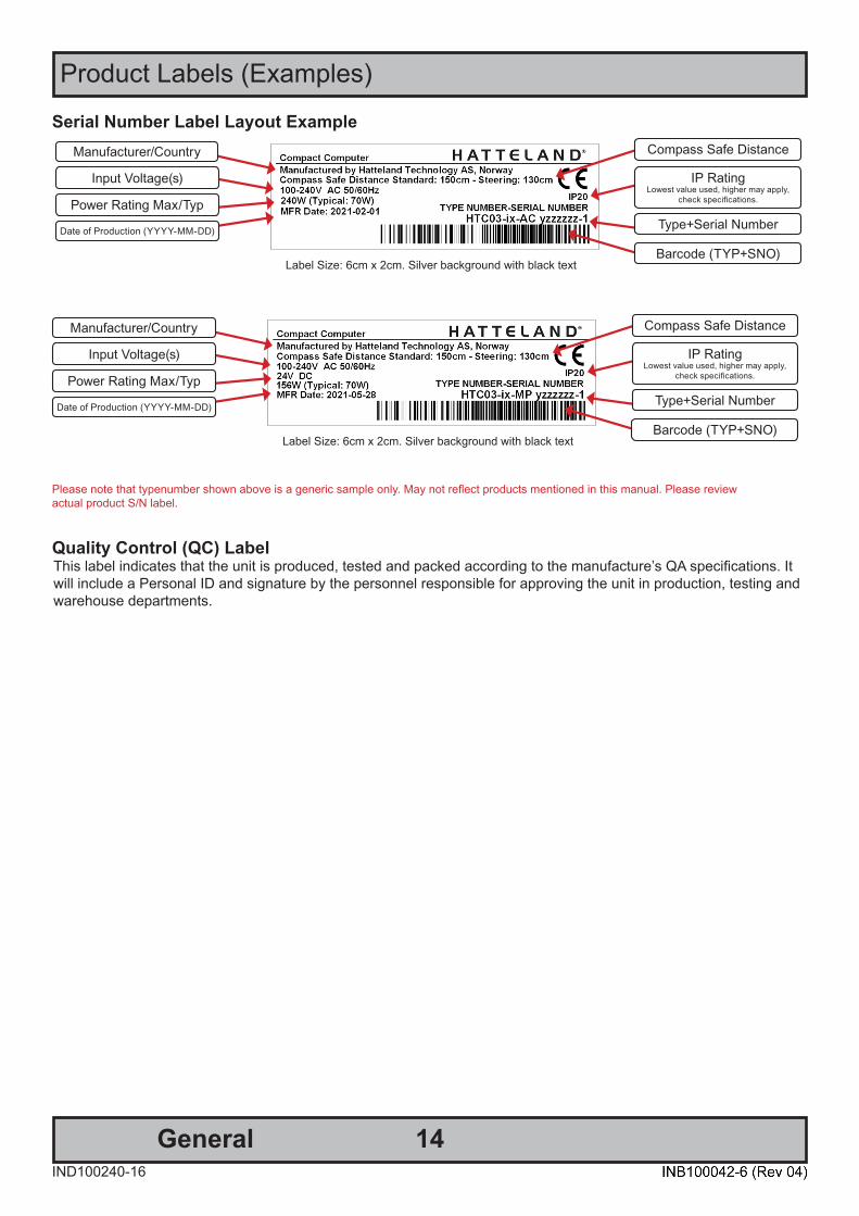
Serial Number Label Layout Example
Please note that typenumber shown above is a generic sample only. May not reflect products mentioned in this manual. Please reviewactual product S/N label.
Label Size: 6cm x 2cm. Silver background with black text
Manufacturer/Country
Input Voltage(s)
Type+Serial Number
Barcode (TYP+SNO)
Power Rating Max/Typ
Date of Production (YYYY-MM-DD)
Compass Safe Distance
IP RatingLowest value used, higher may apply,
check specifications.
Quality Control (QC) LabelThis label indicates that the unit is produced, tested and packed according to the manufacture’s QA specifications. It will include a Personal ID and signature by the personnel responsible for approving the unit in production, testing andwarehouse departments.
Label Size: 6cm x 2cm. Silver background with black text
Manufacturer/Country
Input Voltage(s)
Type+Serial Number
Barcode (TYP+SNO)
Power Rating Max/Typ
Date of Production (YYYY-MM-DD)
Compass Safe Distance
IP RatingLowest value used, higher may apply,
check specifications.

15
Installation

16InstallationIND100210-19
General Installation Recommendations
Installation and mounting of computers1. Units may be intended for various methods of installation or mounting (rack mounting, panel mounting, bracket mounting, ceiling/wall mounting); for details, please see the relevant mechanical drawings.
2. Adequate ventilation is a necessary prerequisite for the life of the unit. The air inlet and outlet openings must definitely be kept clear; coverings which restrict ventilation are not permissible. The product might be without any ventilation aperatures which means pt.2 does not apply.
3. Exposure to direct sunlight can cause a considerable increase in the temperature of the unit, and might under certain circumstances lead to overtemperature. This point should already be taken into consideration when the bridge equipment is being planned (sun shades, distance from the windows, ventilation, etc.)
4. Space necessary for ventilation, for cable inlets, for the operating procedures and for maintenance, must be provided.
5. To further improve the cooling of the unit we recommend installing Cooling Fans underneath blowing upwards into the unit air inlet. This may be required in high temperature applications and also when there is reason to expect temperature problems due to non-optimal way of mounting.
6. Products with AC input shall be grounded to protective Earth (Safety Ground) when necessary via the bolt (usually on terminal plate) available on the product. Products with DC input shall be grounded to protective Earth (Safety Ground) via the bolt (usually on terminal plate) available on the product. A shorter and thicker cable gives better grounding. A 6mm² is recommended, but a 4mm² or even 2.5mm² can be used for this purpose.
7. Expose to heavy vibration and acoustic noise might under certain circumstances affect functionality and expected lifetime. This must be considered during system assembly and installation. Mounting position must be carefully selected to avoid any exposure of amplified vibration.
8. Additional rules may apply to certain procedures where the symbols and are present. For more information, review “IEC62368 policy for Hatteland Technology product” section later in this manual.
17
General Installation Recommendations
InstallationIND100210-19
General mounting instructions1. The useful life of the components of all Electronics Units generally decreases with increasing ambient temperature; it is therefore advisable to install such units in air-conditioned rooms. If there are no such facilities, these rooms must at least be dry, adequately ventilated and kept at a suitable temperature in order to prevent the formation of condensation inside the unit.
2. With most Electronic Units, cooling takes place via the surface of the casing. The cooling must not be impaired by partial covering of the unit or by installation of the unit in a confined cabinet.
3. In the area of the wheel house, the distance of each electronics unit from the magnetic standard compass or the magnetic steering compass must not be less than the permitted magnetic protection distance. This distance is measured from the centre of the magnetic system of the compass to the nearest point on the corresponding unit concerned. The exact distance is often mentioned in the specific product specifications.
4. Transportation damage, even if apparently insignificant at first glance, must immediately be examined and be reported to the freight carrier. The moment of setting-to-work of the equipment is too late, not only for reporting the damage but also for the supply of replacements.
5. The classification is only valid for approved mounting brackets provided by Hatteland Technology. The unit shall be mounted stand-alone without any devices or loose parts placed at or nearby the unit. Any other type of mounting might require test and re-classification.
6. Additional rules may apply to certain procedures where the symbols and are present. For more information, review “IEC62368 policy for Hatteland Technology product” section later in this manual.
CablesUse only high quality shielded signal cables. For RGB/DVI cables use only cables with separate coax for Red, Green and Blue.

18IND100210-4
General Installation Recommendations
Installation
Unit Upgrade Precaution NoteUsers which needs to open the unit to expose and reveal electronics, make sure that prior to touching / removing parts, proper ESD measurements must be taken!
1. Operator should ground himself by using a wrist band.
2. The wrist band should be connected to ground via a ground cord.
3. A one megaohm resistor, installed in the wrist connection end of the ground cord, is a safety requirement.
4. Hatteland Technology recommends to use an Static-dissipative ESD work mat positioned at the workplace. The 3M™ 8501 Portable Field Service Kit is a good choice for this purpose. Make sure that the mat, operator and product is wired/grounded together.
All assisting persons who might come into contact with the endangered boards must also use the ESD equipment.
CAUTIONThis unit contains electrostatic sensitive devices.Observe precautions for handling.
19IND100210-56
General Installation Recommendations
Installation
FerriteThe ferrite prevents high frequency electrical noise (radio frequency interference) from exiting or entering theequipment. This ferrite is required when using 100/110/115V AC voltage on the power supply (not requiredfor 230/240V AC) to be fully compliant with type approvals.
The ferrite should be mounted (clipped in place on the cable) and located as close as possible to the connector piece that connects to the rear of computer.
When ready: Open the ferrite, place the cable inside as shown in FIG1, and then gently close it until a click can be heard (FIG2). You may close and re-open them as many times as required during the installation.
Typenumber Ferrite Type Dimetric View Perferred distance of ferrite. Side view.HTC03 xx-yy-zzzzzzzHT20370 xx-yy-zzzzzzz
1 x Würth 742 712 21 Red Line indicate 5cm [1.97 inch] limit from connector. Do not mount ferrites (orange square) located beyond the red line!
FIG1
To computer
FIG2
To computer
20
General Installation Recommendations
InstallationIND100210-20
Housing / Terminal Block Connector OverviewHousing / Terminal Block connectors are available in different sizes (example 2-pin, 4-pin, 5-pin) which plug into theconnector area of the unit. They are mounted by factory default and delivered with the unit. The housing / terminal block connectors have steering rails, which ensures that it can not be mounted wrong. The color of these connectors may vary between black, green and orange depending on manufacturer. You may use approved equivalents of these connectors, but note that the warranty will be void if any damage would occur to either the unit’s original PCB terminal socket connector or inside the unit (electronic components, boards etc.). The table below is applicable for anySeries X products, such as Display and Panel Computers, including newer type of Stand-Alone Computers.
Illustration Pins Manufacturer Details Connector used for module
If your installation require additional cable fasteners support, please use the provided Cover Hood and Cable Housing shipped with the unit for accessories (contents of package). Illustrations below are approximate, actual Housing and Hood may deviate slightly, but function remains the same.
5-pin Cable Housing - Illustration 4-pin Cover Hood - Illustration
KGG-MC 1,5/ 5 (5-pin) BCZ 3.81 AH04 BK BX (4-pin)
For 5-pin:“https://www.phoenixcontact.com/online/portal/us?uri=pxc-oc-itemdetail:pid=1834372&library=usen&pcck=P-11-02-01&tab=1”
For 4-pin“http://catalog.weidmueller.com/procat/Product.jsp;jsessionid=B040D5EB6832629E567C884809FDF6C1?productId=(%5b1005290000%5d)”
Tx- Tx+ COM Rx- Rx+
5-pin MC 1,5/ 5-STF-3,81Screwdriver: SZS 0,4X2,5mm VDE, slot-headed.
Tightening torque min. 0.22 Nm.Tightening torque max 0.25 Nm.
• RS-422 / RS-485 NMEA (PCA200828-1 / PCA100293-1)• Digital Input/Output (PCA100297-1)
Identifi ed on Hatteland Technology product datasheet as:“Terminal Block 3.81”
4-pin BCZ 3.81/04/180F SN BK BX
Screwdriver: 0.4x2.5mm DIN 5264.Tightening torque min.. 0.2 Nm.Tightening torque max. 0.25 Nm.
• CAN Interface (ZIA0001310-B / ZIA0001310-SLCAN)
Identifi ed on Hatteland Technology product datasheet as:“Terminal Block 3.81”
2-pin MSTB 2,5/ 2-STF-5,08 BK
Screwdriver: SZS 0,6x3,5, slot-headed.Tightening torque min. 0.5 Nm.Tightening torque max 0.6 Nm.
• DC Power IN - Single Input
Identifi ed on Hatteland Technology product datasheet as:“Terminal Block 5.08”

21
General Installation Recommendations
InstallationIND100210-20
Configuring Housing / Terminal Block connectorsBelow is a brief illustration that might be useful during configuration and installation of such connectors. You will need suitable pre-configured cable(s) and tools to configure the connector(s) and cable(s) that are present in yourinstallation environment. Below is a sample procedure for a 2-pin DC power connector. The procedure is the same for other connectors of this type as listed in table above. Unit used as illustration below is for reference only.
FIG 5
FIG 1FIG 4 FIG 6
FIG 2FIG 3
Requires assembly. It is expected that the technician has experience in electronics and assembling cables and connectors.
Warning: Do not connect or disconnect cables/connectors to the unit’s connector while the unit is powered on. Failure to do so may result indamaged electronics.
FIG 1: Unscrew (from top) or make sure that the screw terminal is fully open, so you can secure the inserted cables correctly to the loose housing connector (it may already be plugged into the unit as per factory installation).
FIG 2: Strip carefully the insulation from the cable to expose the wire(s) inside.
FIG 3: Ensure that the wire(s) is without any loose threads to ensure good connection.
FIG 4: Insert cables* (from front) and screw / secure the cables by turning the screw on top of the housing to secure the cables properly. Check that the cables are firmly in place and do not appear loose or fall out when pulling gently.
*Note: Required polarization verification (for instance -/+ for DC power input) should conform with the markings on the connector area of the unit. Ignoring the markings on the unit or its add-on modules might damage the unit and/or external equipment in which end, warranty will be void.
FIG 5: Plug the housing into the appropriate connector area of the unit and check again that the cables securedconform with the markings on the connector area of the unit. Finalize the installation by fastening the screws located in front on each side of the housing connector (FIG 6).
Connector / Function Recommended Cable Thickness2-pin DC Power Input (Terminal Block 5.08) Minimum 20 AWG - Maximum 18 AWG4-pin CAN (Terminal Block 3.81) Minimum 22 AWG - Maximum 20 AWG5-pin NMEA COM (Terminal Block 3.81) Minimum 22 AWG - Maximum 18 AWG5-pin DIO (Terminal Block 3.81) Minimum 22 AWG - Maximum 18 AWG

22IND100210-55
General Installation Recommendations
Installation
Cabinet cover removalNote: Areas of interest are marked in this section with arrows in RED color. Please disconnect ALL cables from the computer unit before proceeding! Procedure applies for all HTC03 models.
1: Unscrew 20 screws (M3x5L S/S) from top of cabinet and 3 screws (M3x5L S/S) in rear. Use a Torx 9screwdriver.
2: Lift the cover up with both hands.
3: The inside of the computer is now revealed.
Repeat the procedure backwards to attach the cover again.

23IND100210-54
General Installation Recommendations
Installation
Installing PCIe Card / Rework PCI Bracket Options - NoticeAll factory options are done in-house by our production facility prior to delivery. If you however need to install your own PCI/PCIe cards later and any of the PCI Bracket Options are already pre-installed, please review:“Physical Connections/ Added functionality through 4 x PCI Sized Metal Brackets” chapter later in this manual.
As this is just a pre-installation notice, please review also the next following page regarding PCI/PCIe cardinstallation. Procedure applies for all HTC03 models.
Note: Areas of interest are marked in this section with RED color. Please disconnect ALL cables from the computer unit before proceeding!
1: Identify if either of the PCI Bracket Options arepresent in any of the slots (as indicated). If yes,proceeed to step 2,3,4. If no, please proceed to next page in this manual.
2: Observe the tie wrap and positioning of cables.You may have to cut the tie-wrap that holds the cable to the inner chassis, in order to insert the new PCIe card and fit the cable again.
3: Either move the PCI Bracket Option into any of the other free slots, or make sure the original cables are routed under the PCIe card when you install the new PCIe card (depending on which slot you have to use).
4: After installing the PCIe card, observe that the PCI Bracket Options cables are not damaged, loose or are subject for getting damaged after long use. Notice also some PCIe card components may get hot. If possible, add a tie wrap to secure the cables further to keep clear of potentional heat.

24IND100210-54
General Installation Recommendations
Installation
PCIe Card removal / replacement - IntroductionNote: Areas of interest are marked in this section with circles and arrows in RED color. Please disconnect ALL cables from the computer unit before proceeding! Procedure applies for all HTC03 models.
1: Unscrew 10 screws on each side of the top brackets. Use a Torx 9 screwdriver.
2: Push each side of the top bracket, one forward and one backwards in a 45 degree rotation clockwise to slide it out of the tracks. Then lift up the top bracket to remove it.
PCIe Card removal / replacement
Note: Areas of interest are marked in this section with circles and arrows in RED color. Please disconnect ALL cables from the computer unit before proceeding! Procedure applies for all HTC03 models.
1: Unscrew 1 screw to loosen the chosen PCIe card bracket from the cabinet and remove or insert thedesired PCIe card into the slot. Use a Pozidriv #2 screwdriver.
2: Attach the internal bracket over the PCIe card andre-mount the 10 x screws to fasten the internal bracket and secure the PCIe card.
Repeat the procedure backwards to finalize operation.
25IND100210-54
General Installation Recommendations
Installation
HT 00275OPT-A1 (PCIe Card Bracket, Removal & Replacement) HL/FL/HHNote: Areas of interest are marked in this section with circles and arrows in RED color. Please disconnect ALL cables from the computer unit before proceeding! Procedure applies for HTC03 models.
For Half Length (HL) + Full Length (FL) / Half Height (HH) - PCIe cardsPlace the EN60945 Tested Bracket as shown on top edge of card and under the top bracket. Mount 2 x M3x6mm Countersunk screws on top to fasten the PCIe bracket securely. Use a Pozidriv #2 screwdriver.

26IND100210-52
General Installation Recommendations
Installation
Air Filter removal / replacement (H733S30Q20-SP000-0) Note: Areas of interest are marked in this section with circles and arrows in RED color. Please disconnect ALLcables from the computer unit and cards before proceeding! Procedure applies for all HTC03 models.
1: Unscrew 4 screws from the fan/filter cover in front of the unit. Use a Torx 9 screwdriver. 2: Gently pull out the fan/filter cover and filter
Filter
Repeat the procedure backwards to finalize operation.

27IND100210-51
General Installation Recommendations
Installation
Front Fan removal / replacementNote: Areas of interest are marked in this section with circles and arrows in RED color. Please disconnect ALLcables from the computer unit before proceeding! Procedure applies for all HTC03 models.
1: Remove cabinet cover then unscrew 1 screw from the back of the fan cover inside the computer to loosen the fan and fan cover.Use a Pozidriv #2 screwdriver.
2: Remove fan/filter cover (see beginning of this chapter)Then unscrew 4 screws from the fan/filter cover location in front of the unit. Use a Torx 9 screwdriver.
3: Unscrew 4 screws from the fan cover and unplug the fan. Use a Pozidriv #2 screwdriver.
Repeat the procedure backwards to finalize operation.
28IND100210-67
General Installation Recommendations
Installation
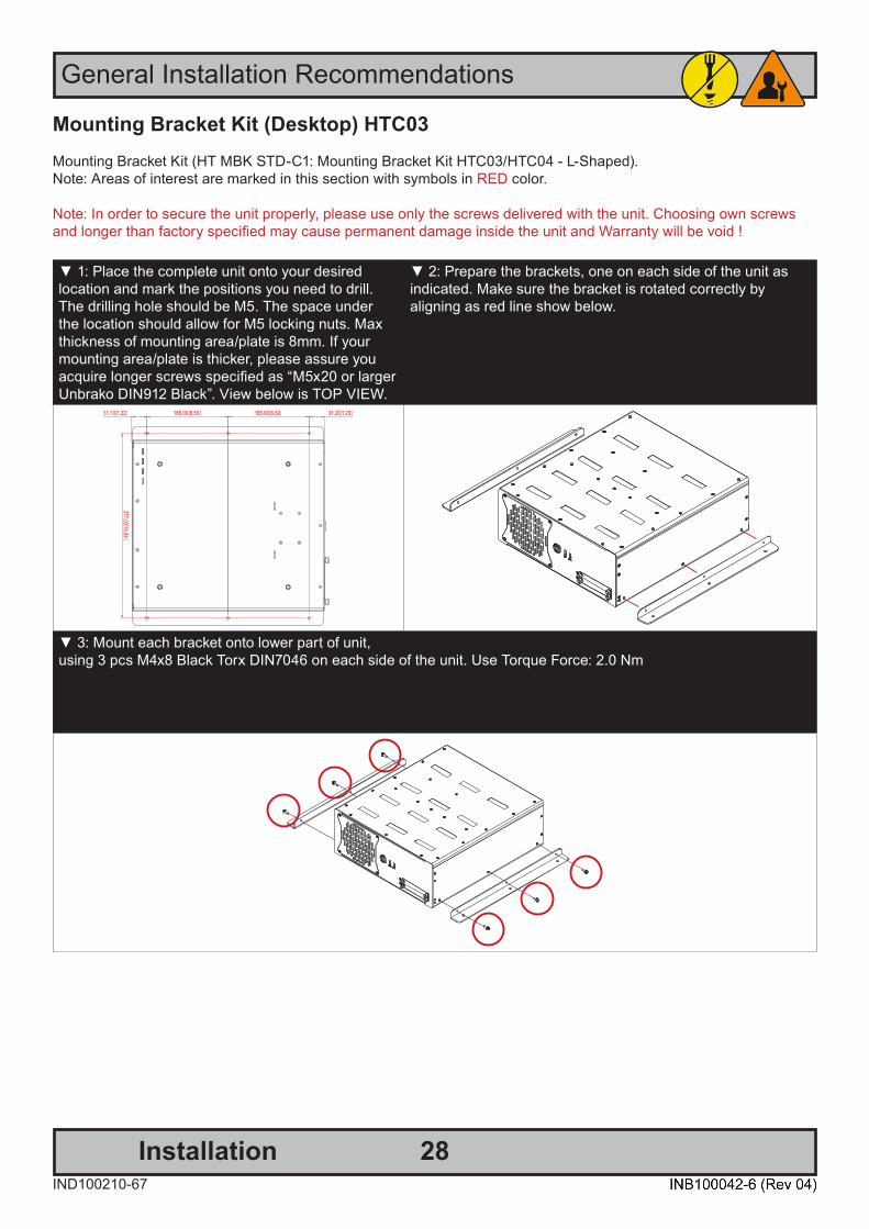
Mounting Bracket Kit (Desktop) HTC03Mounting Bracket Kit (HT MBK STD-C1: Mounting Bracket Kit HTC03/HTC04 - L-Shaped). Note: Areas of interest are marked in this section with symbols in RED color.
Note: In order to secure the unit properly, please use only the screws delivered with the unit. Choosing own screws and longer than factory specified may cause permanent damage inside the unit and Warranty will be void !
▼ 1: Place the complete unit onto your desiredlocation and mark the positions you need to drill. The drilling hole should be M5. The space under the location should allow for M5 locking nuts. Max thickness of mounting area/plate is 8mm. If your mounting area/plate is thicker, please assure you acquire longer screws specified as “M5x20 or larger Unbrako DIN912 Black”. View below is TOP VIEW.
▼ 2: Prepare the brackets, one on each side of the unit as indicated. Make sure the bracket is rotated correctly byaligning as red line show below.
▼ 3: Mount each bracket onto lower part of unit,using 3 pcs M4x8 Black Torx DIN7046 on each side of the unit. Use Torque Force: 2.0 Nm

29IND100210-50
General Installation Recommendations
Installation
Mounting Brackets for Console Mounting - HT 00226 OPT-A1Note: The unit comes with mounting brackets and screws for console mounting in the package. Please reviewspecifications and “Technical Drawings - Accessories” chapter in this user manual for additional information.Procedure applies for all HTC03 models.
Bracket View and Measurements 1: Bottom view showing 4 mounting holes.
Connector Side2: Mount the brackets with 4 x M6x8 (included).Note: Other/longer screws may damage the computer! 3: Bottom view with mounted brackets.
30IND100210-50
General Installation Recommendations
Installation
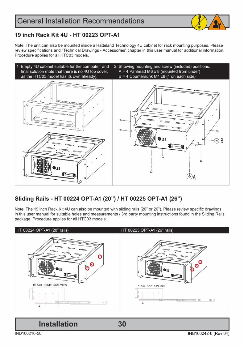
19 inch Rack Kit 4U - HT 00223 OPT-A1Note: The unit can also be mounted inside a Hatteland Technology 4U cabinet for rack mounting purposes. Please review specifications and “Technical Drawings - Accessories” chapter in this user manual for additional information.Procedure applies for all HTC03 models.
1: Empty 4U cabinet suitable for the computer and final solution (note that there is no 4U top cover, as the HTC03 model has its own already).
2: Showing mounting and screw (included) positions. A = 4 Panhead M6 x 8 (mounted from under) B = 4 Countersunk M4 x8 (4 on each side)
Sliding Rails - HT 00224 OPT-A1 (20”) / HT 00225 OPT-A1 (26”)Note: The 19 inch Rack Kit 4U can also be mounted with sliding rails (20” or 26”). Please review specific drawings in this user manual for suitable holes and measurements / 3rd party mounting instructions found in the Sliding Rails package. Procedure applies for all HTC03 models.
HT 00224 OPT-A1 (20” rails) HT 00225 OPT-A1 (26” rails)
31IND100210-50
General Installation Recommendations
Installation
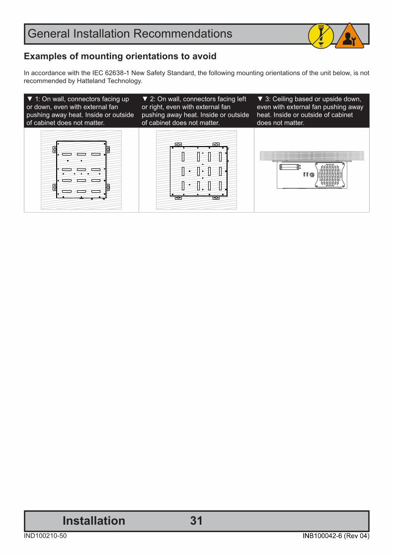
Examples of mounting orientations to avoidIn accordance with the IEC 62638-1 New Safety Standard, the following mounting orientations of the unit below, is notrecommended by Hatteland Technology.
▼ 1: On wall, connectors facing up or down, even with external fanpushing away heat. Inside or outside of cabinet does not matter.
▼ 2: On wall, connectors facing left or right, even with external fan pushing away heat. Inside or outside of cabinet does not matter.
▼ 3: Ceiling based or upside down, even with external fan pushing away heat. Inside or outside of cabinet does not matter.

32IND100210-49
General Installation Recommendations
Installation
Replacing Internal CMOS/BIOS BatteryNote: Areas of interest are marked in this section with arrows in RED color. Please disconnect ALL cables from the computer unit before proceeding! Procedure applies for all HTC03 models.
Please review “Product Storage” recommendations document, ref: https://www.hattelandtechnology.com/hubfs/pdf/misc/ind100350-5_long_term_storage_recommendations.pdf
NOTE: All BIOS settings, Date and Time will be lost if battery is removed from motherboard. If Factory Default BIOSsettings was changed after unit was received from factory, please write down changes (if known) before doing this procedure. Operating System installed will not be affected by a battery replacement. After battery was replaced and unit powered, check BIOS settings and choose to load Factory Default Settings, change time and date. BIOSSettings and its adjustment are outside the scope of this chapter in User Manual. Consult your experienced technician or contact our service / support channels worldwide for further assistance if unit does not operate as intended.
1: Unscrew 20 screws from top of cabinet and 3 screws in rear. Use a Pozidriv #2 screwdriver. 2: Lift the cover up with both hands.
3: Locate CMOS battery as indicated near the smallest PCI-E slot (just above it).
4: With a finger/nail, push the metal clip inwards asindicated (1) and the battery will pop up automatically (2).
1 2
33IND100210-49
General Installation Recommendations
Installation
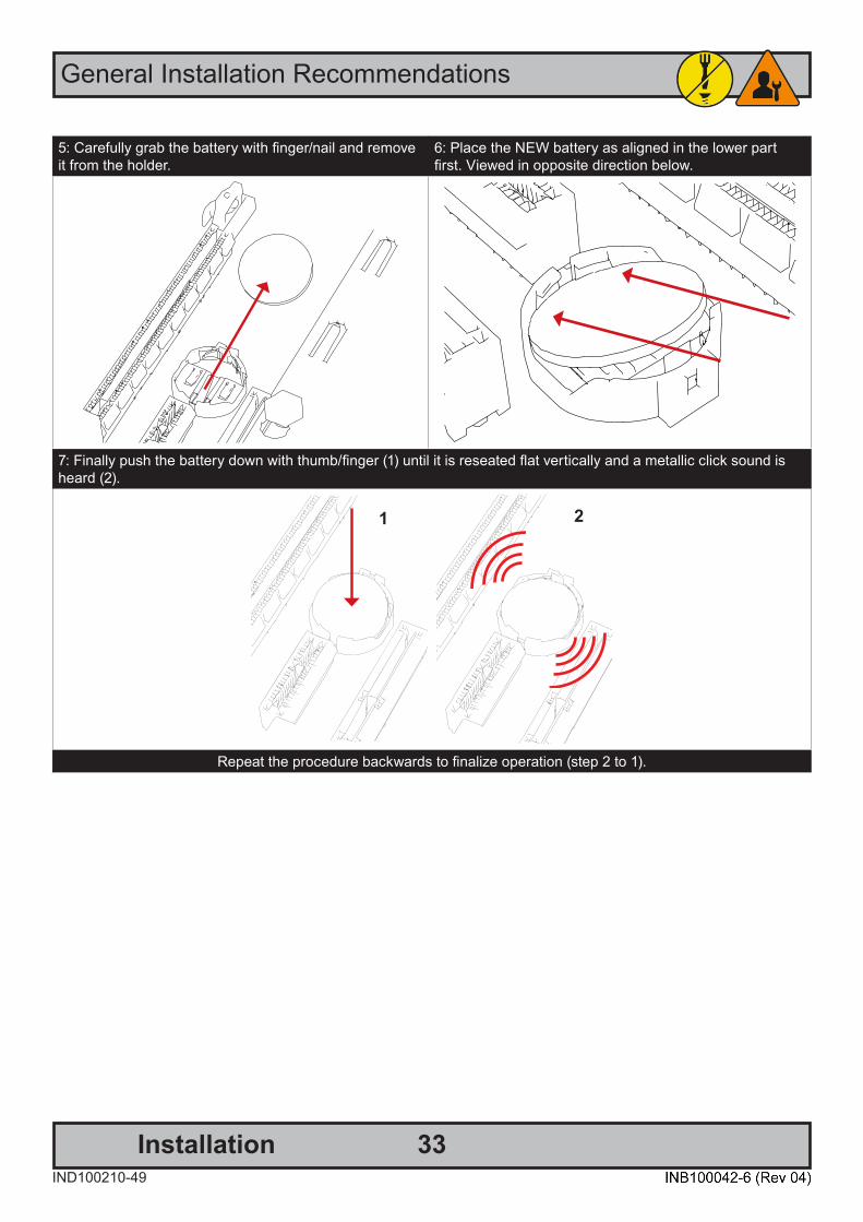
5: Carefully grab the battery with finger/nail and remove it from the holder.
6: Place the NEW battery as aligned in the lower part first. Viewed in opposite direction below.
7: Finally push the battery down with thumb/finger (1) until it is reseated flat vertically and a metallic click sound is heard (2).
1 2
Repeat the procedure backwards to finalize operation (step 2 to 1).

34IND100133-79
AIR FILTER:The computer unit features an cleanable / replaceable air filter (H733S30Q20-SP000-0) located in front behind the metal hatch. Clean the filter regulary or change it (based on environmental factors) to allow the unit to continuously cool properly and to prolong the unit’s lifetime and the components inside. Please review Installation Chapter earlier in this manual for instructions.Spare Part Air Filter can be ordered, check Data Sheet in this manual..
2 x FRONT USB3.1 (<3m) INPUT/OUTPUT:Supports any USB1.1 (12Mbps), USB2.0 (480Mbps) or USB3.1 (10Gbps) compliant peripherals. Drivers for most USB devices are usually included in operating system or on separate installation CD’s delivered with Third Party prod-ucts. USB 1.1 devices will operate in USB 1.1 mode (12 Mbps) and USB 2.0 devices will operate in USB2.0 mode (480Mbps).
Power/Reset Combined Button:To turn ON the computer, press down button and release it immediately. The Power LED indication riing will illuminate green and the operating system will automatically boot. To turn OFF the computer, press down this button and hold it for 3 seconds. The operating system may require additionally tasks to be performed before computer shuts down and turns off the unit.
To reset the computer in case of severe software failure, press this button. This reset button is a hard reset whichmeans the operating system will NOT be warned. Using this reset method may damage files and / or operating systemin worst case scenarios. Precaution should be taken when using this. To perform a safe software reset, press eitherthe power button, or use the operating system own reset functionality if possible.
The Power LED Indication will illuminate static green when powered on. When power is off and the unit is turned off, the LED will also off.
Front area of computer models
2 x USB3.1
12cm FAN intake+filter
Reset ButtonPower Button
User Controls
Power LED
4 x 2.5” Removable SSD Trays.
2-Bay model 4-Bay model
2 x USB3.1
Reset ButtonPower Button
Power LED
2 x 2.5” Removable SSD Trays.

35IND100133-79
User Controls
2 x 2.5” Removable SATA SSD Trays (only Standard model):The unit can utilize 2 x Storage Devices (SSD), 2.5” size. (1 x tray is by factory default occupied, Device #0). The storage devices can be easily be upgraded or replaced by pulling the SSD tray out.
Both trays feature a locking mechanism (using quarter-turn fasteners to lock/unlock) function to prevent accidental removal and to secure the device additionally.
How to Remove or Replace SSD DeviceThe unit must be shut down / powered off before proceeding. After unlocking the tray by unscrewing the thumbscrews (FIG 1) pull out the tray carefully by hand (FIG 2), please proceed as illustrated below.
FIG 2 FIG 3
Pull out the casing gently as indicated. The tray shown here does not have a Storage Devicealready in-place.
Unscrew 4 pcs x M3x4mm Phillips countersunk screws as indicated. Replace or remove the device as needed. Make sure the device connects with the interface connector located in the end of the tray prior to fastening screws.
Screwdriver: Philips PH2Tightening torque 0.4Nm.
Repeat the procedure in reverse (FIG3-2-1) to mount.
Locked/unlocked by quarter-turn fasteners with springs. To unlock, turn 90 degrees anti-clockwise.To lock, push the quarter-turn fastener in and turn 90 degrees clockwise.
FIG 1
Single Front Removable Tray and Pre-mounted StorageDevice are available from Hatteland Technology as accessory.
Typenumber : HD xxxyy SX1-z1Where x = : SizeWhere y = : MB, GB, TBWhere z = : Physical Format / Device Type (Physical Format examples: 2.5”) (Device Type examples: SSD)
Please review datasheet for your model to determine Size, Format and Device Type compatible with your model.
or Empty Front Removable Tray 2.5” (without screws):Typenumber : HD 000TR SX1-A1
or Empty Front Removable Tray 2.5”+ 4 x M3x4mm Phillips Countersunk Screws:Typenumber : HD 000TR SX1-A3
FIG 4 (Optional)Extra locking mechanism inside computer to prevent SSD(s) from being removed unintentionally or by unauthorized personnel. Not mounted by Factory default.
See Cabinet cover removal procedure in General Installation Recommendations chapter for instructions on how to remove the Cabinet cover.
To lock SSD(s) in place, add and mount M3 screw(s) as indicated.Follow SSD manufacturer’s instructions for screw length and torque.

36IND100133-79
Connector area of computer - Single AC power input model
Physical Connections
Power Input AC
Audio AMP
PCIe x16
2 x DisplayPort
PCIe x4PCIe x4(8)PCIe x1
Expansion / Module Area
RS-232/RS-422/RS-4854 x USB3.1USB-CGrounding Screw MIC and Speaker4 x Network
Connector area of computer - Multi-Power (AC+DC) power input modelPower Input AC
Audio AMP
PCIe x16
2 x DisplayPort
PCIe x4PCIe x4(8)PCIe x1
Expansion / Module Area
RS-232/RS-422/RS-4854 x USB3.1USB-CGrounding Screw MIC and Speaker4 x Network
Power Input DC

User Controls / Physical Connections
37IND100133-79
1 x AC Power INPUT (For units supporting AC input): The internal AC power module supports 100-240V AC - 50Hz/60Hz using a standard IEC European power plug. See specifications for more information.
1 x DC Power INPUT (For units supporting AC+DC inputs): Connect your DC power cable to the 2-pin Terminal Block 5.08 connector. The internal DC power module supports 24VDC. For more information, please review “Housing Connector Overview” earlier in this manual.
GROUNDING SCREW: Please review “General Installation Chapter”, pt. 6 for more information.
Note for Grounding Screws:Standard Grounding Screw/Bolt provided by Hatteland Technology is “Pan head screws M4x8mm w/spring and plainwasher”.
Multi-power note: (For units supporting AC & DC input simultaneously) The unit has a dual input power supply which will accept both AC and DC input. If both inputs are connected, the unit will bepowered by AC. If AC is disconnected it will automatically switch over to DC without affecting the operation of the unit. This makes it possible to use AC power as primary power and a 24V battery as secondary power, eliminating the need for expensive UPS systems.
1 x COM (RS-232/422/485) Serial Port INPUT/OUTPUT:Supports RS-232 or RS-485/422 using D-SUB 9P connector (male) connectors. Fasten the cable to the connectorusing the provided screws on the cable housing itself. For configuration, please review the Appendix chapter, section “BIOS - On-board COM Ports Configuration”.
2 x DisplayPort (DP) OUTPUT:Connect your DP (male) cable to the DisplayPort (v1.2) 20P connector (female) on the rear side of the unit. The DP has its own locking mechanism that locks the plug inserted. Make sure the plug “clicks” into place to verify a proper and secure connection. Additionally to add extra security, a Screw Lock in the chassis above the DP port is available if your DP cable supports it. Note: Signal Output can be used together with additional graphics card installed in one of the PCIe slots. Pleasereview Appendix Chapter “BIOS - Hybrid Multi Monitor Configuration”. Both active and passive DP to DVI adapters are supported. For setups requiring three DVI-D outputs, an active DP to DVI adapter must be used. Passive adapter can only be used for setups with max two DVI-D signals.
38IND100133-79
Physical Connections
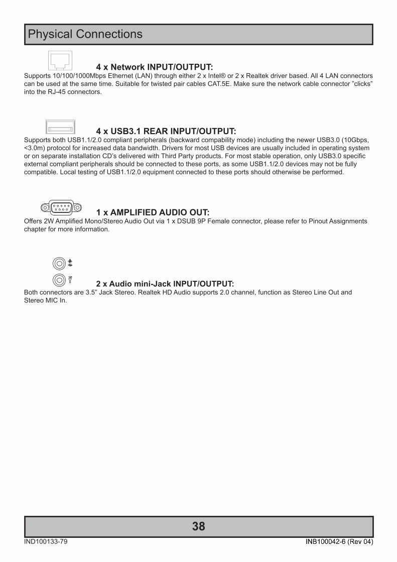
4 x Network INPUT/OUTPUT:Supports 10/100/1000Mbps Ethernet (LAN) through either 2 x Intel® or 2 x Realtek driver based. All 4 LAN connectors can be used at the same time. Suitable for twisted pair cables CAT.5E. Make sure the network cable connector ”clicks” into the RJ-45 connectors.
4 x USB3.1 REAR INPUT/OUTPUT:Supports both USB1.1/2.0 compliant peripherals (backward compability mode) including the newer USB3.0 (10Gbps, <3.0m) protocol for increased data bandwidth. Drivers for most USB devices are usually included in operating system or on separate installation CD’s delivered with Third Party products. For most stable operation, only USB3.0 specificexternal compliant peripherals should be connected to these ports, as some USB1.1/2.0 devices may not be fullycompatible. Local testing of USB1.1/2.0 equipment connected to these ports should otherwise be performed.
1 x AMPLIFIED AUDIO OUT:Offers 2W Amplified Mono/Stereo Audio Out via 1 x DSUB 9P Female connector, please refer to Pinout Assignments chapter for more information.
2 x Audio mini-Jack INPUT/OUTPUT:Both connectors are 3.5” Jack Stereo. Realtek HD Audio supports 2.0 channel, function as Stereo Line Out andStereo MIC In.
39IND100133-79
Physical Connections
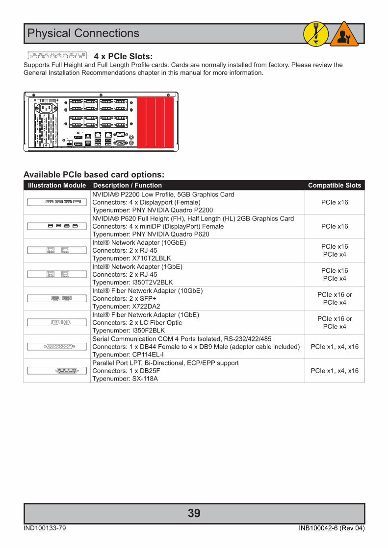
4 x PCIe Slots:Supports Full Height and Full Length Profile cards. Cards are normally installed from factory. Please review theGeneral Installation Recommendations chapter in this manual for more information.
Available PCIe based card options:Illustration Module Description / Function Compatible Slots
NVIDIA® P2200 Low Profile, 5GB Graphics CardConnectors: 4 x Displayport (Female) Typenumber: PNY NVIDIA Quadro P2200
PCIe x16
NVIDIA® P620 Full Height (FH), Half Length (HL) 2GB Graphics CardConnectors: 4 x miniDP (DisplayPort) FemaleTypenumber: PNY NVIDIA Quadro P620
PCIe x16
Intel® Network Adapter (10GbE)Connectors: 2 x RJ-45Typenumber: X710T2LBLK
PCIe x16PCIe x4
Intel® Network Adapter (1GbE)Connectors: 2 x RJ-45Typenumber: I350T2V2BLK
PCIe x16PCIe x4
Intel® Fiber Network Adapter (10GbE)Connectors: 2 x SFP+Typenumber: X722DA2
PCIe x16 orPCIe x4
Intel® Fiber Network Adapter (1GbE)Connectors: 2 x LC Fiber OpticTypenumber: I350F2BLK
PCIe x16 orPCIe x4
Serial Communication COM 4 Ports Isolated, RS-232/422/485Connectors: 1 x DB44 Female to 4 x DB9 Male (adapter cable included)Typenumber: CP114EL-I
PCIe x1, x4, x16
Parallel Port LPT, Bi-Directional, ECP/EPP supportConnectors: 1 x DB25FTypenumber: SX-118A
PCIe x1, x4, x16
40IND100133-79
Physical Connections
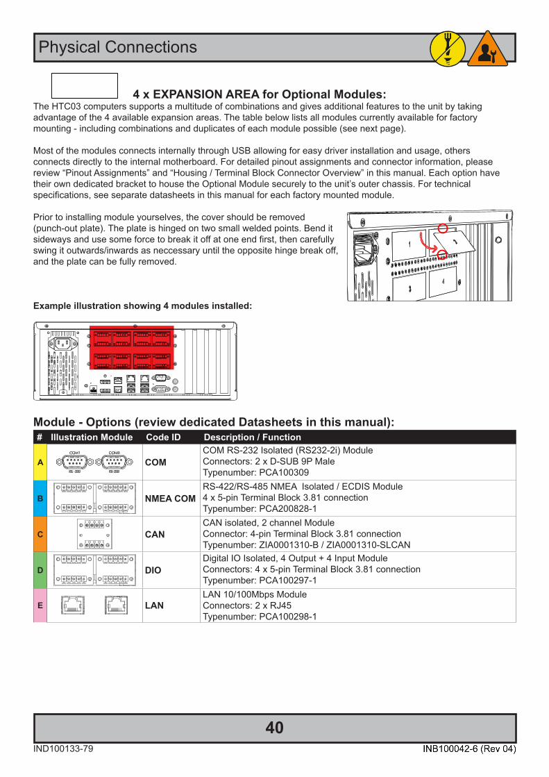
4 x EXPANSION AREA for Optional Modules:The HTC03 computers supports a multitude of combinations and gives additional features to the unit by takingadvantage of the 4 available expansion areas. The table below lists all modules currently available for factorymounting - including combinations and duplicates of each module possible (see next page).
Most of the modules connects internally through USB allowing for easy driver installation and usage, othersconnects directly to the internal motherboard. For detailed pinout assignments and connector information, please review “Pinout Assignments” and “Housing / Terminal Block Connector Overview” in this manual. Each option have their own dedicated bracket to house the Optional Module securely to the unit’s outer chassis. For technicalspecifications, see separate datasheets in this manual for each factory mounted module.
Prior to installing module yourselves, the cover should be removed (punch-out plate). The plate is hinged on two small welded points. Bend it sideways and use some force to break it off at one end first, then carefully swing it outwards/inwards as neccessary until the opposite hinge break off, and the plate can be fully removed.
Example illustration showing 4 modules installed:
Module - Options (review dedicated Datasheets in this manual):# Illustration Module Code ID Description / Function
A COMCOM RS-232 Isolated (RS232-2i) ModuleConnectors: 2 x D-SUB 9P MaleTypenumber: PCA100309
B NMEA COMRS-422/RS-485 NMEA Isolated / ECDIS Module4 x 5-pin Terminal Block 3.81 connectionTypenumber: PCA200828-1
C CANCAN isolated, 2 channel ModuleConnector: 4-pin Terminal Block 3.81 connectionTypenumber: ZIA0001310-B / ZIA0001310-SLCAN
D DIODigital IO Isolated, 4 Output + 4 Input ModuleConnectors: 4 x 5-pin Terminal Block 3.81 connectionTypenumber: PCA100297-1
E LANLAN 10/100Mbps ModuleConnectors: 2 x RJ45Typenumber: PCA100298-1

User Controls / Physical Connections
41IND100133-79
Module Expansion MatrixTable below indicates how many duplicates of the same module can be installed at the same time. Due to limited number of internal connectors and technical limitations some combinations (with duplicates) are naturally not possible to achieve.
Colored Table Cell refers to the “Upper Row” and “Lower Row” tables above from previous page. COMx2 NMEA COM CAN DIO LAN
A B C D E
Factory StandardsThe following illustration indicate mounting locations of the varirty of modules available and how they are numbered to keep a persistent configuration. This is seen from user’s Point-of-View at rear of the computer unit.
Priority Upper Row Priority Lower RowCAN [C] COMx2 [A]
NMEA COM [B] NMEA COM [B]DIO [D] DIO [D]LAN [E] LAN [E]
Priority numbering starts from Upper Row going to right, then Lower Row going to right as illustrated:
1 23 4

User Controls / Physical Connections
42IND100133-79
Table below indicates how many combinations of modules is possible to install (each table row totals upto max 4).Further, as per. factory standards, the unique location and shifting of modules are illustrated in the last column, where the number inside the 2x2 table indicate unique id, starting from 1 to max 4 modules.
COM NMEA COM CAN DIO LAN Default Factory Mounting Position(upper row / lower row)A B C D E
13
23 4
11
21 2
31 23
41 23 4
11
21 2
11
11
1 113
1 113
1 113
1 113
1 1 11 23
1 1 11 23
1 1 11 23
1 21 23
1 2 11 23 4
1 3 11 23 4
1 11 23 4
1 1 1 11 23 4

User Controls / Physical Connections
43IND100133-79
COM NMEA COM CAN DIO LAN Default Factory Mounting Position(upper row / lower row)A B C D E
213 4
2 113 4
2 113 4
2 113 4
2 1 11 23 4
2 1 11 23 4
2 21 23 4
2 1 11 23 4
3 11 23 4
3 11 23 4
2 11 23
2 11 23
2 11 23
2 1 11 23 4
2 1 11 23 4
2 1 11 23 4
1 11 2
1 11 2
1 11 2
1 1 11 23
1 1 11 23
1 1 11 23
1 11 2

User Controls / Physical Connections
44IND100133-79
COM NMEA COM CAN DIO LAN Default Factory Mounting Position(upper row / lower row)A B C D E
1 1 11 23
1 11 2
Factory Preset COM Port NumberingHatteland Technology offer a wealth of options resulting in many Operating System numbered COM ports. The tablebelow lists all known ports that are assigned if a specific factory option (or duplicates of them) were factory mounted prior to manufacturing and delivery of units to customer. Internal on-board, PCI based cards and Modules are listed.
The numbering are only applicable for COM Ports, and not other ports, such as network RJ-45.
COM Port # On-board/factory option Description
1 RS232/RS422/RS485 Onboard, External connector (DB9)
2 RS232 Onboard, Internal connector (DF11-10S-PA66H)
3 Intel ME Onboard, Reserved for Intel ME
5-6 PCA100309 Card #1 COM Dual RS-232 Isolated (RS232-2i) Module
7-8 PCA100309 Card #2 COM Dual RS-232 Isolated (RS232-2i) Module
9-10 PCA100309 Card #3 COM Dual RS-232 Isolated (RS232-2i) Module
11-14 MOXA CP-114, Card #1 PCIe Card, 4x COM Ports, Isolated, RS-232/422/485
15-18 MOXA CP-114, Card #2 PCIe Card, 4x COM Ports, Isolated, RS-232/422/485
19 CAN/SLCAN CAN/SLCAN (ZIA0001310-B/-SLCAN)
20 CAN/SLCAN CAN/SLCAN (ZIA0001310-B/-SLCAN)
41-44 PCA200828-1, Card #1 4 x RS-422/RS-485 NMEA Isolated/ECDIS Module
45-48 PCA200828-1, Card #2 4 x RS-422/RS-485 NMEA Isolated/ECDIS Module
49-52 PCA200828-1, Card #3 4 x RS-422/RS-485 NMEA Isolated/ECDIS Module
53-56 PCA200828-1, Card #4 4 x RS-422/RS-485 NMEA Isolated/ECDIS Module

45
Specifications

46IND100129-261
Note: All specifications are subject to change without prior notice! Please visit www.hattelandtechnology.com for the latest electronic version.
Specifications - HTC03-xx-AC xxxxxxxSPECIFICATIONS Note: All specifi cations are subject to change without prior notice!
Please visit www.hattelandtechnology.com for the latest electronic version.
2/22/2
These products have been tested / type approved by the following classification societies: (*= Pending)IEC 60945 4th (EN 60945:2002) IACS E10 EN61162 EU RO MR - Mutual Recognition by DNVABS - American Bureau of Shipping* CCS - China Classification Society BV - Bureau Veritas* ClassNK - Nippon Kaiji Kyokai*
T E C H N I C A L D E S C R I P T I O N
A P P R O V A L S & C E R T I F I C A T E S
Available Accessories:
• W:345.00 [13.58''] x H:133.00 [5.24''] x D:392.30 [15.44''] mm [inch]• Weight: Approx 9.0kg / 19.8lbs• 2 x Removable SSD tray in front (2.5" size)• Power/Reset/Power LED Combined Function• Easy Removable Front Air Filter (spare part accessory available)• Includes Mounting Brackets (HT 00226 OPT-A1)• 1 x Internal Cooling fan in front (120x120mm)Compass Safe Distance: Standard: 150cm - Steering: 130cm
Physical Specifications: Environmental Considerations:M E C H A N I C A L D E S C R I P T I O N
Factory Mounted Options: * For all Factory Mounted Options, review User Manual for possible HW combinations.
Type Description Size/SpecificationCPU 1 x Intel® Core™ i3-9100E
1 x Intel® Core™ i5-9500E 1 x Intel® Core™ i7-9700E
4-Core 3.10GHz - 3.70GHz, 6MB Cache6-Core 3.00GHz - 4.20GHz, 9MB Cache8-Core 2.60GHz - 4.40GHz, 12MB Cache
Memory DDR4 SO-DIMM 260-pin - Uses 2 slots, Single or Dual Channel (where applicable), available sizes are: Single Channel: 1x8GB (2400MHz) Dual Channel: 2x8GB (2400MHz), 2x16GB (2400MHz), 2x32GB (2666MHz)
Storage 2.5"/M.2 SSD SATA - 240Gb (0.9PBW),480Gb (1.2PBW),960Gb (3.4PBW), 1.92Tb (7.1PWB) OS Option Microsoft® Windows® Server 2016/2019 64bit, Windows® 10 IoT Enterprise 2019 LTSC (64bit). Linux: Kernel 4.1x or later version
Available Computer Configurations:
• CP-114EL-I ELEK KIT: 4xCOM,PCIe x1,1xDB44F to 4xDB9M isolated, RS-232/422/485) • PCA100297-1: Digital IO Isolated, 4 IN + 4 OUT*• PNY NVIDIA Quadro P2200: PCIe 3.0 x16, 4 x DP 1.4, 5GB GDDR5 • PCA100298-1: LAN 10/100Mbps, 2 ports (RJ45) module*• PNY NVIDIA Quadro P620: PCIe 3.0 x16, 4 x mDP 1.4, 2GB GDDR5 • PCA100309-1: Dual Isolated RS-232, 2xDB9 module*• PNY NVIDIA T600: PCIe 3.0 x16, 4 x mDP 1.4, 4GB GDDR6 • PCA200828-1: COM RS-422/485 isolated NMEA 4 channel, 5-pin T. Block 3.81*• PNY NVIDIA RTX A2000: PCIe 4.0 x16, 4 x mDP 1.4, 6GB GDDR6 • SX-118A: Parallel Port LPT, DB25F, Bi-Dir. ECP/EPP, PCIe x1 card• X710T2L / X710T2LBLK: Intel® Network Adapter (10GbE), 2 x RJ45 • ZIA0001310-SLCAN: Socket CAN isolated, 2 channel module*• I350T4V2 / I350T4V2BLK: Intel® Network Adapter (1GbE), 4 x RJ45 • ZIA0001310-B: CAN isolated, 2 channel module*• X710DA2 / X710DA2BLK: Intel® Fiber Network Adapter (10GbE), 2 x SFP+ • VSDxxxxxx-x: Additional USB ports. Pending• X710DA4 / X710DA4BLK: Intel® Fiber Network Adapter (10GbE), 4 x SFP+
• Operating : Temperature -15°C to +55°C - Humidity up to 95%• Storage : Temperature -20°C to +70°C - Humidity up to 95%Lifetime Considerations:Even though the test conditions for bridge units provide for a maximumoperating temperature of 55°C, continuous operation of all electroniccomponents should, if possible, take place at ambient temperatures of only25°C. This is a necessary prerequisite for long life and low service costs.
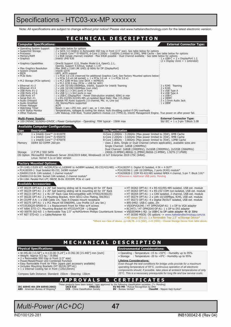
External Connector Type:Computer Specifications:
Power Supply: External Connector Type:• 100-240VAC 50/60Hz Std IECPower Consumption: Operating: 70W typical - 240W max
• Operating System Support : See table below for options• Supported Storage : 2 or 4 x SATA 3.0 (6GB/s) in Removable SSD tray in front (2.5" size). See table below for options• Processor : 1 x Intel® Core™ i5-9500E, 6-Core 4.20Ghz, 9MB Cache - See table below for options• Memory/RAM : 1 x 8GB (single channel) installed - Max 64GB possible - Dual Channel available - See table below for options• Graphics : Intel® UHD 630 1 x USB-C + 2 x DisplayPort 1.2 (2 x Display clone + 1 extended)• Graphics Capabilities : DirectX Support 12.0, Shader Model 6.4, OpenCL 2.1, OpenGL Support 4.5/linux, Vulkan 1.1.97• Max Graphics Resolution : Max 3840 x 2160 (4K UHD) @ 60Hz for DP (DisplayPort)• System Chipset : Intel® Q370 • BIOS : UEFI, ACPI support• PCIe Slots : 1 x PCIe 3.0 x16 (reserved for additional Graphics Card, See Factory Mounted options below) 1 x PCIe 3.0 x4 (x8 socket) + 1 x PCIe 3.0 x4 + 1 x PCIe 3.0 x1• M.2 Storage (PCIe options) : 1 x M.2 2280 M-key (one SATA + NVMEx4) 1 x M.2 2230 E-Key (PCIe + USB for WiFi)• Ethernet #1-2 : 2 x LAN 10/100/1000Mbps, Intel®, Support for Intel® Teaming 2 x RJ45 Teaming • Ethernet #3-4 : 2 x LAN 10/100/1000Mbps (non intel) 2 x RJ45 • USB Ports #1-2 : 2 x USB 3.1 (<3m) ports in front 2 x USB Type A • USB Ports #3-6 : 4 x USB 3.1 (<3m) ports in rear 4 x USB Type A• USB Ports #7 : 1 x USB-C (DisplayPort - Power Distrubution enabled, 60W) in rear 1 x USB-C• Serial Port #1 : 1 x RS-232/RS-422/RS-485 un-isolated Baud Rate: Max 115.2Kbps 1 x DB9M• Audio Onboard : Realtek HD Audio supports 2.0 channel, Mic. in, Line out 2 x 3.5mm Audio Jack• Audio Amplified : 2W, Stereo/Mono supported 1 x DB9F• Power Manager : ACPI• Watchdog Timer : Reset: 1 sec.~255 min. and 1 sec. or 1 min./step• H/W Status Monitor : Temperatures, voltages & cooling fan status. Auto throttling control if CPU overheats• Other Features : LAN Wakeup, USB Boot, Trusted Platform Module 2.0 (TPM2.0), Intel® Management Engine. True power on after power fail.
• HT 00225 OPT-A1: 2 x 26" ball bearing sliding rail & mounting kit for 19" Rack • HT 00262 OPT-A1: 4 x RS-422/RS-485 isolated, USB ext. module• HT 00224 OPT-A1: 2 x 20" ball bearing sliding rail & mounting kit for 19" Rack • HT 00263 OPT-A1: 4 x RS-232 COM non-isolated, USB ext. module• HT 00223 OPT-A1: 1 x 4U 19" Rack Case Kit(compatible with HT00224/00225) • HT 00264 OPT-A1: 1 x CAN isolated, 2 channel, USB ext. module• HT 00226 OPT-A1: 2 x Mounting Bracket, 4mm SECC+Zinc Plating, RAL9011 • HT 00274 OPT-A1: 2 x LAN 10/100Mbps, RJ45, USB ext. module• JH C01MF A-A: 1 x USB Cable 1m, Type A-Chassis mount receptacle • HT 00273 OPT-A1: 4 x Digital IN/OUT isolated, USB ext. module• HT 00275 OPT-A1: 1 x PCI Mount Kit EN60945, Low Profile (LP, any len.) • VSDDPVGA340 / HT DPM2VGAF-A1: 1 x DP to VGA adapter• H733S30Q20-SP000-0: 1 x Replacement Front Air Filter w/4 screws • RC3473 / HT DPM2DVI-DF-A1: 1 x DP to DVI adapter• HT MBK STD-C1: Mounting Bracket Kit HTC03/HTC04 - L-Shaped • DVI-D adapter for P620/T600 Graphics Card: QSP-MINIDP/DVIV2• HD 000TR SX2-A3: 1 x Removable Tray 2.5" w/4xM3x4mm Phillips Countersunk Screws • DP adapter or P620/T600 Graphics Card: QSP-MINIDP/DPV3• HT RET STD-A3: 1 x Cable/Retainer Kit • HDMI adapter or P620/T600 Graphics Card: QSP-MINIDP/HDMIV2• 895-0492: USB-C cable, 2m • VGA adapter or P620/T600 Graphics Card: QSP-MINIDP/VGA• USB-C to DP Adapter PENDING • HT 00300 MSOS: OS options -> www.hattelandtechnology.com/os
• HD xxxyy SX1-z1: 1 x Removable Tray 2.5" w/Storage Device**Where xxx=Size of device. yy=GB,TB. z=S (SSD) - Choose Storage Device from table above.
47IND100129-281
Note: All specifications are subject to change without prior notice! Please visit www.hattelandtechnology.com for the latest electronic version.
Multi-Power (AC+DC)
Specifications - HTC03-xx-MP xxxxxxxSPECIFICATIONS Note: All specifi cations are subject to change without prior notice!
Please visit www.hattelandtechnology.com for the latest electronic version.
2/22/2
T E C H N I C A L D E S C R I P T I O N
A P P R O V A L S & C E R T I F I C A T E S
Available Accessories:
• W:345.00 [13.58''] x H:133.00 [5.24''] x D:392.30 [15.440''] mm [inch]• Weight: Approx 9.0 kg / 19.8lbs• 2 x Removable SSD tray in front (2.5" size)• Power/Reset/Power LED Combined Function• Easy Removable Front Air Filter (spare part accessory available)• Includes Mounting Brackets (HT 00226 OPT-A1)• 1 x Internal Cooling fan in front (120x120mm)
Compass Safe Distance: Standard: 150cm - Steering: 130cm
Physical Specifications: Environmental Considerations:
M E C H A N I C A L D E S C R I P T I O N
Factory Mounted Options:
Type Description Size/SpecificationCPU 1 x Intel® Core™ i3-9100TE
1 x Intel® Core™ i5-9500TE 1 x Intel® Core™ i7-9700TE
4-Core 2.20GHz - 3.20GHz (Max power limited to 35W), 6MB Cache6-Core 2.20GHz - 3.60GHz (Max power limited to 35W), 9MB Cache8-Core 1.80GHz - 3.80GHz (Max power limited to 35W), 12MB Cache
Memory DDR4 SO-DIMM 260-pin - Uses 2 slots, Single or Dual Channel (where applicable), available sizes are: Single Channel: 1x8GB (2400MHz) Dual Channel: 2x8GB (2400MHz), 2x16GB (2400MHz), 2x32GB (2666MHz)
Storage 2.5"/M.2 SSD SATA - 240Gb (0.9PBW),480Gb (1.2PBW),960Gb (3.4PBW), 1.92Tb (7.1PWB) OS Option Microsoft® Windows® Server 2016/2019 64bit, Windows® 10 IoT Enterprise 2019 LTSC (64bit).
Linux: Kernel 4.1x or later version
Available Computer Configurations:
• Operating : Temperature -15 to +55°C - Humidity up to 95%• Storage : Temperature -20 to +0°C - Humidity up to 95%Lifetime Considerations:Even though the test conditions for bridge units provide for a maximumoperating temperature of 55°C, continuous operation of all electroniccomponents should, if possible, take place at ambient temperatures of only25°C. This is a necessary prerequisite for long life and low service costs.
External Connector Type:Computer Specifications:
Multi-Power Supply: External Connector Type:• 100-240VAC 50/60Hz+24VDC : Power Consumption - Operating: 70W typical - 156W max Std IEC + 1 x 2-pin T.Block 5.08
• Operating System Support : See table below for options• Supported Storage : 2 x SATA 3.0 (6GB/s) in Removable SSD tray in front (2.5" size). See table below for options• Processor : 1 x Intel® Core™ i5-9500TE, 6-Core 2.20Ghz - 3.60GHz (Limited to 35W), 9MB Cache - See table below for options• Memory/RAM : 1 x 8GB (single channel) installed - Max 64GB possible - Dual Channel available - See table below for options• Graphics : Intel® UHD 630 1 x USB-C + 2 x DisplayPort 1.2 (2 x Display clone + 1 extended)• Graphics Capabilities : DirectX Support 12.0, Shader Model 6.4, OpenCL 2.1, OpenGL Support 4.5/linux, Vulkan 1.1.97• Max Graphics Resolution : Max 3840 x 2160 (4K UHD) @ 60Hz for DP (DisplayPort)• System Chipset : Intel® Q370 • BIOS : UEFI, ACPI support• PCIe Slots : 1 x PCIe 3.0 x16 (reserved for additional Graphics Card, See Factory Mounted options below) 1 x PCIe 3.0 x4 (x8 socket) + 1 x PCIe 3.0 x4 + 1 x PCIe 3.0 x1• M.2 Storage (PCIe options) : 1 x M.2 2280 M-key (one SATA + NVMEx4) 1 x M.2 2230 E-Key (PCIe + USB for WiFi)• Ethernet #1-2 : 2 x LAN 10/100/1000Mbps, Intel®, Support for Intel® Teaming 2 x RJ45 Teaming • Ethernet #3-4 : 2 x LAN 10/100/1000Mbps (non intel) 2 x RJ45 • USB Ports #1-2 : 2 x USB 3.1 (<3m) ports in front 2 x USB Type A • USB Ports #3-6 : 4 x USB 3.1 (<3m) ports in rear 4 x USB Type A• USB Ports #7 : 1 x USB-C (DisplayPort - Power Distrubution enabled, 60W) in rear 1 x USB-C• Serial Port #1 : 1 x RS-232/RS-422/RS-485 un-isolated Baud Rate: Max 115.2Kbps 1 x DB9M• Audio Onboard : Realtek HD Audio supports 2.0 channel, Mic. in, Line out 2 x 3.5mm Audio Jack• Audio Amplified : 2W, Stereo/Mono supported 1 x DB9F• Power Manager : ACPI• Watchdog Timer : Reset: 1 sec.~255 min. and 1 sec. or 1 min./step• H/W Status Monitor : Temperatures, voltages & cooling fan status. Auto throttling control if CPU overheats• Other Features : LAN Wakeup, USB Boot, Trusted platform module 2.0 (TPM2.0), Intel® Management Engine. True power on after power fail.
*Where xxx=Size of device. yy=GB,TB. z=S (SSD), z=H (HDD) - Choose Storage Device from table above.
• CP-114EL-I ELEK KIT: 4xCOM,PCIe x1,1xDB44F to 4xDB9M isolated, RS-232/422/485) • PCA100297-1: Digital IO Isolated, 4 IN + 4 OUT*• PCA100309-1: Dual Isolated RS-232, 2xDB9 module* • PCA100298-1: LAN 10/100Mbps, 2 ports (RJ45) module*• ZIA0001310-B: CAN isolated, 2 channel module* • PCA200828-1: COM RS-422/485 isolated NMEA 4 channel, 5-pin T. Block 3.81*• ZIA0001310-SLCAN: Socket CAN isolated, 2 channel module* • • VSDxxxxxx-x: Additional USB ports. PendingVSDxxxxxx-x: Additional USB ports. Pending• SX-118A: Parallel Port LPT, DB25F, Bi-Dir. ECP/EPP, PCIe x1 card
• HT 00225 OPT-A1: 2 x 26" ball bearing sliding rail & mounting kit for 19" Rack • HT 00262 OPT-A1: 4 x RS-422/RS-485 isolated, USB ext. module• HT 00224 OPT-A1: 2 x 20" ball bearing sliding rail & mounting kit for 19" Rack • HT 00263 OPT-A1: 4 x RS-232 COM non-isolated, USB ext. module• HT 00223 OPT-A1: 1 x 4U 19" Rack Case Kit(compatible with HT00224/00225) • HT 00264 OPT-A1: 1 x CAN isolated, 2 channel, USB ext. module• HT 00226 OPT-A1: 2 x Mounting Bracket, 4mm SECC+Zinc Plating, RAL9011 • HT 00274 OPT-A1: 2 x LAN 10/100Mbps, RJ45, USB ext. module• JH C01MF A-A: 1 x USB Cable 1m, Type A-Chassis mount receptacle • HT 00273 OPT-A1: 4 x Digital IN/OUT isolated, USB ext. module• HT 00275 OPT-A1: 1 x PCI Mount Kit EN60945, Low Profile (LP, any len.) • 895-0492: USB-C cable, 2m• H733S30Q20-SP000-0: 1 x Replacement Front Air Filter w/4 screws • VSDDPVGA340 / HT DPM2VGAF-A1: 1 x DP to VGA adapter• HT MBK STD-C1: Mounting Bracket Kit HTC03/HTC04 - L-Shaped • RC3473 / HT DPM2DVI-DF-A1: 1 x DP to DVI adapter• HD 000TR SX2-A3: 1 x Removable Tray 2.5" w/4xM3x4mm Phillips Countersunk Screws • VSD203404-1 R2: 1x USB-C to DP cable adapter 4K @ 30Hz• HT RET STD-A3: 1 x Cable/Retainer Kit • HT 00300 MSOS: OS options -> www.hattelandtechnology.com/os
• HD xxxyy SX1-z1: 1 x Removable Tray 2.5" w/Storage Device*
These products have been tested / type approved by the following classification societies: (*= Pending)IEC 60945 4th (EN 60945:2002) IACS E10 EN61162 EU RO MR - Mutual Recognition by DNVABS - American Bureau of Shipping* CCS - China Classification Society BV - Bureau Veritas* ClassNK - Nippon Kaiji Kyokai*

48
This page left intentionally blank

49
Specifications Factory Options
50IND100129-263
PCA200828-1
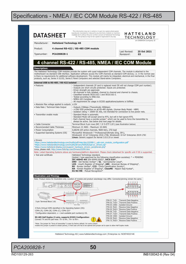
Specifications - NMEA / IEC COM Module RS-422 / RS-485
1/2
This information may not, in whole or in part, be copied, photocopied, reproduced, translated or reduced to any electronic medium or machine-readable form without the prior written consent of Hatteland Technology
AS. The products may not be copied or duplicated in any way.
Dimensions might be shown with or without decimals and indicated as mm [inches]. Tolerance on drawings is +/- 1mm. For accurate measurements, check relevant DWG fi le.
DATASHEET
Hatteland Technology AS | www.hattelandtechnology.com | Enterprise no: NO974533146 1/4
4 channel RS-422 / RS-485, NMEA / IEC COM Module
Manufacturer: Hatteland Technology AS
Product: 4 channel RS-422 / RS-485 COM module
Typenumber: PCA200828-1Last Revised: 25 Oct 2021Revision#: 03
The Hatteland Technology COM modules provide the system with quad independent COM channels. The module is attached to themotherboard via standard USB interface. Application software access the COM channels as standard COM devices, i.e. in the normal case is there no requirements for additional software development. This module will mainly be integrated, electrical and mechanical, in the final products, such as; Series X G1/G2, Series E Panel Computers and selected Stand-alone Computers.
Description:
Internal USB to RS-485 / RS-422 isolated• Features - Independent channels (If card is replaced most OS will not change COM port number).
- Outputs are short circuits protected. Inputs are protected.- Driver strength are approved.- All channels is fully isolated, channel to channel and channel to chassis. - Classified towards IEC61162-1 and IEC61162-2.- Tested according to EN61162.- NMEA-183 Compliant.- All requirement for usage in ECDIS applications/systems is fulfilled.
• Absolute Max voltage applied to outputs ±15V• Data Rate / Technical Data Output - Outputs 230kbps (Theoretically 400kbps).
- ±15kV ESD protection on all RS-485 signals. (Human Body Model - HBM)- Isolation rating = 1000V DC 60s, not intended for connection to live power nets.
• Transmitter enable mode - Standard Mode is automatic.- Standard Mode will accept send by RTS, but will in fact ignore RTS.- Each channel have a overide jumper* which can be used to force the transmitter to always be active. See below and next page for details.
• Cable Connector Terminal Block 5-pin rows (MC 1,5/ 5-STF-3,81) (see illustration below)• Recommended Cable Thickness Minimum 22 AWG - Maximum 18 AWG• Power Consumption 0,6824A @4 active channels, 9600 bit/s, 27Ω load• Supported Operating Systems (OS) Microsoft® Windows® 7 Professional/Ultimate (Eng, SP1),
Windows® 10 IoT Enterprise 2016 LTSB, Windows® 10 IoT Enterprise 2019 LTSCLinux: Generic support for Kernel 3.0.0.19 or newer
• Drivers"https://www.hattelandtechnology.com/hubfs/pdf/misc/doc102080-1_usb-com_module_configuration.pdf""https://www.hattelandtechnology.com/hubfs/drivers/ht00262opt-a1_drivers.zip""https://www.hatteland-display.com/support_hardware_drivers_peripherals.php"Linux, please visit: http://www.ftdichip.com/Drivers/D2XX.htmNote: Listed Operating Systems above are hardware/platform dependent. Please check datasheet for specific unit if OS is supported.• Test and certificate Hatteland Technology standard,
(tested / type approved by the following classification societies): * = PENDINGIEC 60945 4th (EN 60945:2002)*, IACS E10*,DNV - Det Norske Veritas* / GL - Germanischer Lloyd*,LRS - Lloyd’s Register of Shipping*, ABS - American Bureau of Shipping*, BV - Bureau Veritas*, CCS - China Classification Society*,KR - Korean Register of Shipping*, ClassNK - Nippon Kaiji Kyokai*,EU RO MR - Mutual Recognition*
Note: Product below for illustration only. Location of module and product size/design may differ. Connector/pinning remain the same.Illustration and Pinning:
4 Ports (Virtual COM) identified in the Operating System (OS):COMx (A), COMx (B), COMx (C), COMx (D)**Configuration dependent, x = next available port number(s) OS.
RS-485 Half Duplex (2-wire, supports ECHO) Configuration:Connect TX and RX pair-wise: TX- to RX-, TX+ to RX+.
*Note: The jumper for “force of transmitter” is open by factory default. For some custommodels this jumper is preset to closed (active), in that case unit has to be opened and jumper set to open to allow Half Duplex mode.
5-pin Terminal Block 3.81
Pinout Assignments
69IND100241-13
Appendix
5-pin Digital Output Module“Safety Signal Relay”
3 A
DIGOUT
1 2 3 4 5
PIN 01 Out: 011 COM (Common Center Terminal)
PIN 02 N/C Not ConnectedNot in use
PIN 03 Out: 014 NO (Normally Open)
PIN 04 N/C Not Connected Not in use
PIN 05 Out: 012 NC (Normally Closed)
4+4 pin CAN I/O Module, 2 channelsType Number “HT 00254 OPT-A1”
3 A B
CAN1
CAN2
1 2 3 41 2 3 4
Pin 01 Can1 CAN LPin 02 Can1 CAN LPin 03 Can1 CAN HPin 04 Can1 CAN H
Pin 01 Can2 CAN LPin 02 Can2 CAN LPin 03 Can2 CAN HPin 04 Can2 CAN H
8-pin Digital Output / Input Module“Solid State Relay”
3 A
DIGOUT
DIGIN
1 2 3 4
1 2 3 4
Pin 01 Out: 041 Out +Pin 02 Out: 042 Out -
Pin 03 Out: 031 COM (Common Center Terminal) *
Pin 04 Out: 032 NO (Normally Open)** IEC 60950 Compliant, 48VDC
Pin 01 In: 052 +24VDCPin 02 In: 053 GND (Ground)Pin 03 In: 061 +24VDCPin 04 In: 062 +Input
10-pin Digital Output / Input & Serial Module“Mechanical Relay & COM (isolated RS-422/485)”
3 A
XIGOUT
SERI/O
1 2 3 4 51 2 3 4 5
PIN 01 Out: 021 COM (Common Center Terminal)
PIN 02 N/C Not Connected / Not usedPIN 03 Out: 024 NO (Normally Open)PIN 04 N/C Not Connected / Not usedPIN 05 Out: 022 NC (Normally Closed)
PIN 01 In: 71 Rx+ (Receive Data +)PIN 02 In: 72 Rx- (Receive Data -)PIN 03 Out: 73 Tx+ (Transmit Data +)PIN 04 Out: 74 Tx- (Transmit Data -)PIN 05 GND: 75 SGnd (Signal Ground)
10+10 pin RS-422 / RS-485 NMEA ModuleType Number “PCA100293-1”
3 A B
6 7 8 9 101 2 3 4 5
6 7 8 9 101 2 3 4 5
PIN 01 TxD- Transmit Data NegativePIN 02 TxD+ Transmit Data PositivePIN 03 GND Isolated GroundPIN 04 RxD- Receive Data NegativePIN 05 RxD+ Receive Data PositivePIN 06 TxD- Transmit Data NegativePIN 07 TxD+ Transmit Data PositivePIN 08 GND Isolated GroundPIN 09 RxD- Receive Data NegativePIN 10 RxD+ Receive Data Positive
RS-485 Half Duplex (2-wire) Confi guration:Connect TX and RX pair-wise:
TX- to RX-, TX+ to RX+.
*Note: The jumper for “force of transmitter” isopen by factory default. For some custom
models this jumper is preset to closed (active), in that case unit has to be opened and jumper
set to open to allow Half Duplex mode.
10-pin RS-422 / RS-485 Module“RS-422/RS-485 SCOM Buzzer”
1 2 B
2 4 6 8 101 3 5 7 9
PIN 01* RxD+ Receive Data PositivePIN 02 GND GroundPIN 03* RxD- Receive Data NegativePIN 04 +5V +5V OutPIN 05* TxD+ Transmit Data PositivePIN 06 BUZ- Buzzer Control NegativePIN 07* TxD- Transmit Data NegativePIN 08 BUZ+ Buzzer Control PositivePIN 09 GNDR Ground 100ΩPIN 10 GND Ground
*Pin 1,3,5,7 = RS-485 Full Duplex (4-wire)*Pin 5,7 = RS-485 Half Duplex (2-wire)

Specifications - NMEA / IEC COM Module RS-422 / RS-485
PCA200828-1 51IND100129-263
SPECIFICATIONS Note: All specifi cations are subject to change without prior notice!Please visit www.hattelandtechnology.com for the latest electronic version.
2/22/4
Forced TXOn (D)
Forced TXOn (C)
Forced TXOn (B)
Forced TXOn (A)
No Echo(A)No Echo (B)No Echo (C)No Echo (D)
Please note:- By standard factory default, all of the jumpers on all channels are set to open (no jumper), except some customized models as per request.- It is expected that the user has the required knowledge for working with PCB Cards, electronics and setting jumpers.- To avoid voiding warranty, please contact us prior to ordering to ensure safe and correct configuration regarding ECHO in factory.- Incorrect setting of these jumpers can cause strange data losses/corruption which are hard to debug in software.
There are 2 jumpers for each channel (physically they are located as A,B,D,C as indicated below). You will have to provide suitable 2mm jumpers (not part of any delivery)See illustration showing internal PCB card.
Forced TX(x):If this jumper is set it will enable the RS485 transmitter for channel X at all times. It can be useful when the end user need the transmitter to remain on at all times. Note that it is only possible to use one transmitter on the bus when this jumper is set. It will force the bus to a logic high state when there is no traffic. Power consumption is increased if this jumper is set since the termination resistor always see the full output voltage.
No ECHO(x) - NOTE: Required for some MODBUS Compability.Jumper mounted: This setting is only to be used during half duplex communication. When this jumper is set it will disable ability to receive data (Echo of transmitted data) while transmitting is active. Some software libraries are not able to use echo and therefore need this jumper set. Typically example is a very common MODBUS library.
Jumper open (no jumper): Recommended setting. All data sent on the bus is read back and the application/driver on the computer can check that we were able to send the data onto the bus.
Isolation:This only apply to the module in itself, the internally mounted units are most likely lessisolated due to cable/connectors used.
Jumper Configuration:
Users who needs to open the unit set jumper settings will VOID THE WARRANTY!Before opening, proper ESD measurements must be taken!
1. Operator should ground himself by using a wrist band.
2. The wrist band should be connected to ground via a ground cord.
3. A one megaohm resistor, installed in the wrist connection end of the ground cord, is a safety requirement.
4. Hatteland Technology recommend using a Static-dissipative ESD work mat positioned at the workplace. The 3M™ 8501 Portable Field Service Kit is a good choice for this purpose. Make sure that the mat, operator and product are wired/grounded together.
All assisting persons who might come into contact with the endangered boards must also use the ESD equipment.
CAUTIONThis unit contains electrostatic sensitive devices.Observe precautions for handling.
Jumper Locations (top view)
2 x Terminal Block 5-pin rows(MC 1,5/ 5-STF-3,81)

Specifications - NMEA / IEC COM Module RS-422 / RS-485
PCA200828-1 52IND100129-263
SPECIFICATIONS Note: All specifi cations are subject to change without prior notice!Please visit www.hattelandtechnology.com for the latest electronic version.
2/23/4
5-pin Isolated NMEA COM“RS-422/RS-485”
5 4 3 2 1
PIN 01 TxD- Transmit Data NegativePIN 02 TxD+ Transmit Data PositivePIN 03 GND Isolated GroundPIN 04 RxD- Receive Data NegativePIN 05 RxD+ Receive Data Positive
*Pin 1,2,3,4=RS-422/485 Full Duplex (4-wire)*Pin 1+4, 2+5 = RS-485 Half Duplex (2-wire)
Connect TxD and RxD pair-wise: TxD- to RxD-, TxD+ to RxD+.
Note: Confi guration of options for ECHO of transmitted data and to force the transmitter to
always active is available in BIOS.
RS-422 / RS-485 FULL DUPLEX
120Ω
DE (Data Enable)
External Device
Termination Ω at end of cable
External Device
TX
TX RX
RX 120Ω
Termination Ω at end of cable
120Ω 120Ω
Termination Ω at end of cable
Termination Ω at end of cable
TX
External Device
TX
External Device
RX RX
Pin 1: TxD- (Z)
Pin 2: TxD+ (Y)
Pin 5: RxD+ (A)
Pin 4: RxD- (B)
1 112 2 24 4 4
5 55
*
Note: 120Ω termination on TX pins are rarely needed, unless cable is long or enviroment is very noisy.*
COM Ports are identifed in the Operating System(example Microsoft® Windows® 10) as:
COMx (A), COMx (B), COMx (C), COMx (D)*
*COM ports are not reserved nor locked by BIOS. x indicate a numeric number from 1-99. COM Port numbering may differ depending on OS used and customized solutions. Review the dedicated User Manual for actual unit, or use the Operating System functions to determine actual port numbering, if problems arise.
Our units are based on an isolated RS-485 interface with enhancements to meet NMEA standard. It is recommended connecting the ground wire since it will help protect the system in event of fast transient voltage and most likely also help improve signal integrity in the system.
For slow changing or DC offset our system will most likely work without the ground wire. If this wire is not connected, our units are more sensitive to fast transient voltage at the connectors. (The “isolated Ground” wire will help absorb this energy).
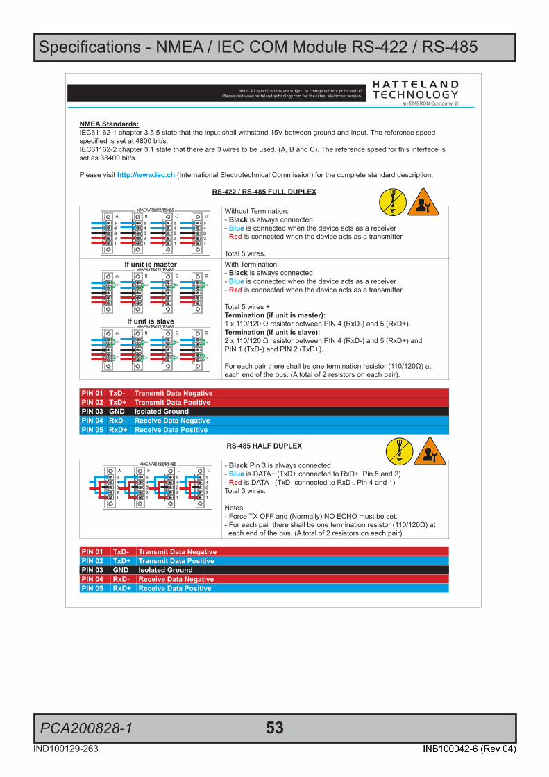
Specifications - NMEA / IEC COM Module RS-422 / RS-485
PCA200828-1 53IND100129-263
SPECIFICATIONS Note: All specifi cations are subject to change without prior notice!Please visit www.hattelandtechnology.com for the latest electronic version.
2/24/4
NMEA Standards:IEC61162-1 chapter 3.5.5 state that the input shall withstand 15V between ground and input. The reference speed specified is set at 4800 bit/s. IEC61162-2 chapter 3.1 state that there are 3 wires to be used. (A, B and C). The reference speed for this interface isset as 38400 bit/s.
Please visit http://www.iec.ch (International Electrotechnical Commission) for the complete standard description.
RS-422 / RS-485 FULL DUPLEX
Without Termination:- Black is always connected- Blue is connected when the device acts as a receiver- Red is connected when the device acts as a transmitter
Total 5 wires.If unit is master
R R R R
If unit is slave
R R R R
R R R R
With Termination:- Black is always connected- Blue is connected when the device acts as a receiver- Red is connected when the device acts as a transmitter
Total 5 wires +Termination (if unit is master):1 x 110/120 Ω resistor between PIN 4 (RxD-) and 5 (RxD+).Termination (if unit is slave):2 x 110/120 Ω resistor between PIN 4 (RxD-) and 5 (RxD+) andPIN 1 (TxD-) and PIN 2 (TxD+).
For each pair there shall be one termination resistor (110/120Ω) at each end of the bus. (A total of 2 resistors on each pair).
PIN 01 TxD- Transmit Data NegativePIN 02 TxD+ Transmit Data PositivePIN 03 GND Isolated GroundPIN 04 RxD- Receive Data NegativePIN 05 RxD+ Receive Data Positive
RS-485 HALF DUPLEX
- Black Pin 3 is always connected- Blue is DATA+ (TxD+ connected to RxD+. Pin 5 and 2)- Red is DATA - (TxD- connected to RxD-. Pin 4 and 1)Total 3 wires.
Notes: - Force TX OFF and (Normally) NO ECHO must be set.- For each pair there shall be one termination resistor (110/120Ω) at each end of the bus. (A total of 2 resistors on each pair).
PIN 01 TxD- Transmit Data NegativePIN 02 TxD+ Transmit Data PositivePIN 03 GND Isolated GroundPIN 04 RxD- Receive Data NegativePIN 05 RxD+ Receive Data Positive
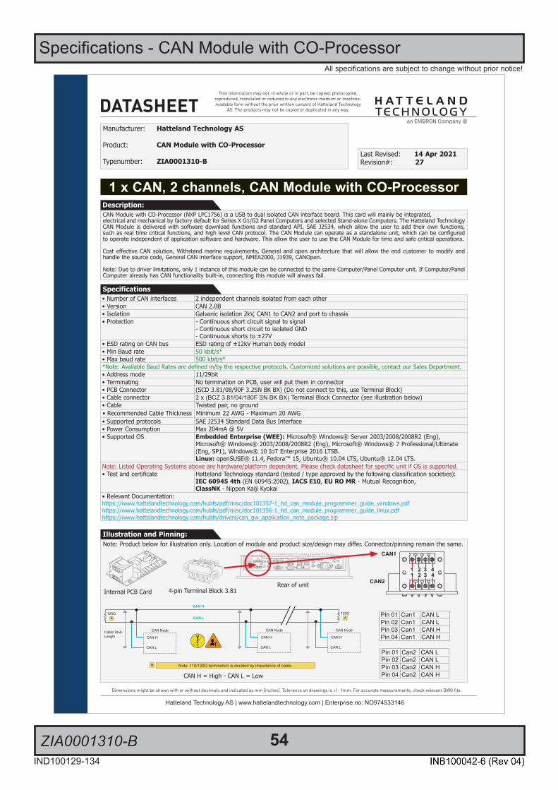
54IND100129-134
All specifications are subject to change without prior notice!
ZIA0001310-B
Specifications - CAN Module with CO-Processor
1/2
This information may not, in whole or in part, be copied, photocopied, reproduced, translated or reduced to any electronic medium or machine-readable form without the prior written consent of Hatteland Technology
AS. The products may not be copied or duplicated in any way.
Dimensions might be shown with or without decimals and indicated as mm [inches]. Tolerance on drawings is +/- 1mm. For accurate measurements, check relevant DWG fi le.
DATASHEET
Hatteland Technology AS | www.hattelandtechnology.com | Enterprise no: NO974533146
1 x CAN, 2 channels, CAN Module with CO-Processor
Manufacturer: Hatteland Technology AS
Product: CAN Module with CO-Processor
Typenumber: ZIA0001310-BLast Revised: 14 Apr 2021Revision#: 27
CAN Module with CO-Processor (NXP LPC1756) is a USB to dual isolated CAN interface board. This card will mainly be integrated,electrical and mechanical by factory default for Series X G1/G2 Panel Computers and selected Stand-alone Computers. The Hatteland Technology CAN Module is delivered with software download functions and standard API, SAE J2534, which allow the user to add their own functions, such as real time critical functions, and high level CAN protocol. The CAN Module can operate as a standalone unit, which can be configured to operate independent of application software and hardware. This allow the user to use the CAN Module for time and safe critical operations.
Cost effective CAN solution, Withstand marine requirements, General and open architecture that will allow the end customer to modify and handle the source code, General CAN interface support, NMEA2000, J1939, CANOpen.
Note: Due to driver limitations, only 1 instance of this module can be connected to the same Computer/Panel Computer unit. If Computer/Panel Computer already has CAN functionality built-in, connecting this module will always fail.
Description:
Specifications
Note: Product below for illustration only. Location of module and product size/design may differ. Connector/pinning remain the same.Illustration and Pinning:
4-pin Terminal Block 3.81
Pinout Assignments
69IND100241-13
Appendix
5-pin Digital Output Module“Safety Signal Relay”
3 A
DIGOUT
1 2 3 4 5
PIN 01 Out: 011 COM (Common Center Terminal)
PIN 02 N/C Not ConnectedNot in use
PIN 03 Out: 014 NO (Normally Open)
PIN 04 N/C Not Connected Not in use
PIN 05 Out: 012 NC (Normally Closed)
4+4 pin CAN I/O Module, 2 channelsType Number “HT 00254 OPT-A1”
3 A B
CAN1
CAN2
1 2 3 41 2 3 4
Pin 01 Can1 CAN LPin 02 Can1 CAN LPin 03 Can1 CAN HPin 04 Can1 CAN H
Pin 01 Can2 CAN LPin 02 Can2 CAN LPin 03 Can2 CAN HPin 04 Can2 CAN H
8-pin Digital Output / Input Module“Solid State Relay”
3 A
DIGOUT
DIGIN
1 2 3 4
1 2 3 4
Pin 01 Out: 041 Out +Pin 02 Out: 042 Out -
Pin 03 Out: 031 COM (Common Center Terminal) *
Pin 04 Out: 032 NO (Normally Open)** IEC 60950 Compliant, 48VDC
Pin 01 In: 052 +24VDCPin 02 In: 053 GND (Ground)Pin 03 In: 061 +24VDCPin 04 In: 062 +Input
10-pin Digital Output / Input & Serial Module“Mechanical Relay & COM (isolated RS-422/485)”
3 A
XIGOUT
SERI/O
1 2 3 4 51 2 3 4 5
PIN 01 Out: 021 COM (Common Center Terminal)
PIN 02 N/C Not Connected / Not usedPIN 03 Out: 024 NO (Normally Open)PIN 04 N/C Not Connected / Not usedPIN 05 Out: 022 NC (Normally Closed)
PIN 01 In: 71 Rx+ (Receive Data +)PIN 02 In: 72 Rx- (Receive Data -)PIN 03 Out: 73 Tx+ (Transmit Data +)PIN 04 Out: 74 Tx- (Transmit Data -)PIN 05 GND: 75 SGnd (Signal Ground)
10+10 pin RS-422 / RS-485 NMEA ModuleType Number “PCA100293-1”
3 A B
6 7 8 9 101 2 3 4 5
6 7 8 9 101 2 3 4 5
PIN 01 TxD- Transmit Data NegativePIN 02 TxD+ Transmit Data PositivePIN 03 GND Isolated GroundPIN 04 RxD- Receive Data NegativePIN 05 RxD+ Receive Data PositivePIN 06 TxD- Transmit Data NegativePIN 07 TxD+ Transmit Data PositivePIN 08 GND Isolated GroundPIN 09 RxD- Receive Data NegativePIN 10 RxD+ Receive Data Positive
RS-485 Half Duplex (2-wire) Confi guration:Connect TX and RX pair-wise:
TX- to RX-, TX+ to RX+.
*Note: The jumper for “force of transmitter” isopen by factory default. For some custom
models this jumper is preset to closed (active), in that case unit has to be opened and jumper
set to open to allow Half Duplex mode.
10-pin RS-422 / RS-485 Module“RS-422/RS-485 SCOM Buzzer”
1 2 B
2 4 6 8 101 3 5 7 9
PIN 01* RxD+ Receive Data PositivePIN 02 GND GroundPIN 03* RxD- Receive Data NegativePIN 04 +5V +5V OutPIN 05* TxD+ Transmit Data PositivePIN 06 BUZ- Buzzer Control NegativePIN 07* TxD- Transmit Data NegativePIN 08 BUZ+ Buzzer Control PositivePIN 09 GNDR Ground 100ΩPIN 10 GND Ground
*Pin 1,3,5,7 = RS-485 Full Duplex (4-wire)*Pin 5,7 = RS-485 Half Duplex (2-wire)
• Number of CAN interfaces 2 independent channels isolated from each other• Version CAN 2.0B• Isolation Galvanic isolation 2kV, CAN1 to CAN2 and port to chassis• Protection - Continuous short circuit signal to signal
- Continuous short circuit to isolated GND- Continuous shorts to ±27V
• ESD rating on CAN bus ESD rating of ±12kV Human body model• Min Baud rate 50 kbit/s*• Max baud rate 500 kbit/s**Note: Available Baud Rates are defined in/by the respective protocols. Customized solutions are possible, contact our Sales Department.• Address mode 11/29bit• Terminating No termination on PCB, user will put them in connector• PCB Connector (SCD 3.81/08/90F 3.2SN BK BX) (Do not connect to this, use Terminal Block)• Cable connector 2 x (BCZ 3.81/04/180F SN BK BX) Terminal Block Connector (see illustration below)• Cable Twisted pair, no ground• Recommended Cable Thickness Minimum 22 AWG - Maximum 20 AWG• Supported protocols SAE J2534 Standard Data Bus Interface• Power Consumption Max 204mA @ 5V• Supported OS Embedded Enterprise (WEE): Microsoft® Windows® Server 2003/2008/2008R2 (Eng),
Microsoft® Windows® 2003/2008/2008R2 (Eng), Microsoft® Windows® 7 Professional/Ultimate (Eng, SP1), Windows® 10 IoT Enterprise 2016 LTSB.Linux: openSUSE® 11.4, Fedora™ 15, Ubuntu® 10.04 LTS, Ubuntu® 12.04 LTS.
Note: Listed Operating Systems above are hardware/platform dependent. Please check datasheet for specific unit if OS is supported.• Test and certificate Hatteland Technology standard (tested / type approved by the following classification societies):
IEC 60945 4th (EN 60945:2002), IACS E10, EU RO MR - Mutual Recognition,ClassNK - Nippon Kaiji Kyokai
• Relevant Documentation:https://www.hattelandtechnology.com/hubfs/pdf/misc/doc101357-1_hd_can_module_programmer_guide_windows.pdfhttps://www.hattelandtechnology.com/hubfs/pdf/misc/doc101356-1_hd_can_module_programmer_guide_linux.pdfhttps://www.hattelandtechnology.com/hubfs/drivers/can_gw_application_note_package.zip
Rear of unitInternal PCB Card
CAN H = High - CAN L = Low
CAN Node
CAN H
CAN L*
Note: 110/120Ω termination is decided by impedance of cable.*
120Ω
*120Ω
Cable StubLength CAN H
CAN L
CAN Node
CAN H
CAN L
CAN Node
CAN H
CAN L
CAN1
CAN2
1 2 3 41 2 3 4

55IND100129-224
All specifications are subject to change without prior notice!
ZIA0001310-SLCAN
Specifications - CAN Module with CO-Processor
1/2
This information may not, in whole or in part, be copied, photocopied, reproduced, translated or reduced to any electronic medium or machine-readable form without the prior written consent of Hatteland Technology
AS. The products may not be copied or duplicated in any way.
Dimensions might be shown with or without decimals and indicated as mm [inches]. Tolerance on drawings is +/- 1mm. For accurate measurements, check relevant DWG fi le.
DATASHEET
Hatteland Technology AS | www.hattelandtechnology.com | Enterprise no: NO974533146
• Number of CAN interfaces 2 independent channels isolated from each other• Version CAN 2.0B• Isolation Galvanic isolation 2kV, CAN1 to CAN2 and port to chassis• Protection - Continuous short circuit signal to signal
- Continuous short circuit to isolated GND- Continuous shorts to ±27V
• ESD rating on CAN bus ESD rating of ±12kV Human body model• Min Baud rate 50k bit/s• Max baud rate 1M bit/s• Address mode 11/29bit• Terminating No termination on PCB, user will put them in connector• Cable connector 2 x (BCZ 3.81/04/180F SN BK BX) Terminal Block Connector (see illustration below)• Cable Twisted pair, no ground• Recommended Cable Thickness Minimum 22 AWG - Maximum 20 AWG• API/Supported Protocols API: SocketCAN
Data Protocol: SLCAN Protocol• Power Consumption Max 204mA @ 5V• Supported OS Embedded Enterprise (WEE): Windows® 10 IoT Enterprise 2016 LTSB. (Periodic message
sending is not supported).Linux: Kernel 2.6.37 or newer with SocketCAN support
• Test and certificate Hatteland Technology standard (tested / type approved by the following classification societies):IEC 60945 4th (EN 60945:2002), IACS E10, EU RO MR - Mutual Recognition,ClassNK - Nippon Kaiji Kyokai
• Relevant Documentation:https://www.hattelandtechnology.com/hubfs/pdf/misc/doc205993-1_usb_slcan_module_user_manual.pdf• Suitable Driver Packages:Windows® Driver: https://www.hattelandtechnology.com/hubfs/drivers/slcan_setup_hd_gw_svc1.5.0.zipLinux: https://www.hattelandtechnology.com/hubfs/drivers/customer_pack_hdcan_linux_180222.zip
1 x CAN, 2 channels, CAN Module with CO-Processor
Manufacturer: Hatteland Technology AS
Product: CAN Module with CO-Processor
Typenumber: ZIA0001310-SLCANLast Revised: 14 Apr 2021Revision#: 09
CAN Module with CO-Processor (NXP LPC1756) is a USB to dual isolated CAN interface board. This card will mainly be integrated,electrical and mechanical by factory default for Series X Panel Computers and selected Stand-alone Computers. The Hatteland Technology CAN Module support socketCAN driver in both Windows and Linux environment, which allow the user to add their own functions, such as real-time critical functions, and high level CAN protocol. The CAN Module can operate as a standalone unit, which can be configured to operate indepen-dent of application software and hardware. This allow the user to use the CAN Module for time and safe critical operations.
Cost effective CAN solution, Withstand marine requirements, General and open architecture that will allow the end customer to modify and handle the source code, General CAN interface support, NMEA2000, J1939, CANOpen.
Note: Due to driver limitations, only 1 instance of this module can be connected to the same Computer/Panel Computer unit. If Computer/Panel Computer already has CAN functionality built-in, connecting thisl module will always fail.
Description:
Specifications
Illustration and Pinning:Note: Product below for illustration only. Location of module and product size/design may differ. Connector/pinning remain the same.
CAN1
CAN2
1 2 3 41 2 3 4
4-pin Terminal Block 3.81
Pinout Assignments
69IND100241-13
Appendix
5-pin Digital Output Module“Safety Signal Relay”
3 A
DIGOUT
1 2 3 4 5
PIN 01 Out: 011 COM (Common Center Terminal)
PIN 02 N/C Not ConnectedNot in use
PIN 03 Out: 014 NO (Normally Open)
PIN 04 N/C Not Connected Not in use
PIN 05 Out: 012 NC (Normally Closed)
4+4 pin CAN I/O Module, 2 channelsType Number “HT 00254 OPT-A1”
3 A B
CAN1
CAN2
1 2 3 41 2 3 4
Pin 01 Can1 CAN LPin 02 Can1 CAN LPin 03 Can1 CAN HPin 04 Can1 CAN H
Pin 01 Can2 CAN LPin 02 Can2 CAN LPin 03 Can2 CAN HPin 04 Can2 CAN H
8-pin Digital Output / Input Module“Solid State Relay”
3 A
DIGOUT
DIGIN
1 2 3 4
1 2 3 4
Pin 01 Out: 041 Out +Pin 02 Out: 042 Out -
Pin 03 Out: 031 COM (Common Center Terminal) *
Pin 04 Out: 032 NO (Normally Open)** IEC 60950 Compliant, 48VDC
Pin 01 In: 052 +24VDCPin 02 In: 053 GND (Ground)Pin 03 In: 061 +24VDCPin 04 In: 062 +Input
10-pin Digital Output / Input & Serial Module“Mechanical Relay & COM (isolated RS-422/485)”
3 A
XIGOUT
SERI/O
1 2 3 4 51 2 3 4 5
PIN 01 Out: 021 COM (Common Center Terminal)
PIN 02 N/C Not Connected / Not usedPIN 03 Out: 024 NO (Normally Open)PIN 04 N/C Not Connected / Not usedPIN 05 Out: 022 NC (Normally Closed)
PIN 01 In: 71 Rx+ (Receive Data +)PIN 02 In: 72 Rx- (Receive Data -)PIN 03 Out: 73 Tx+ (Transmit Data +)PIN 04 Out: 74 Tx- (Transmit Data -)PIN 05 GND: 75 SGnd (Signal Ground)
10+10 pin RS-422 / RS-485 NMEA ModuleType Number “PCA100293-1”
3 A B
6 7 8 9 101 2 3 4 5
6 7 8 9 101 2 3 4 5
PIN 01 TxD- Transmit Data NegativePIN 02 TxD+ Transmit Data PositivePIN 03 GND Isolated GroundPIN 04 RxD- Receive Data NegativePIN 05 RxD+ Receive Data PositivePIN 06 TxD- Transmit Data NegativePIN 07 TxD+ Transmit Data PositivePIN 08 GND Isolated GroundPIN 09 RxD- Receive Data NegativePIN 10 RxD+ Receive Data Positive
RS-485 Half Duplex (2-wire) Confi guration:Connect TX and RX pair-wise:
TX- to RX-, TX+ to RX+.
*Note: The jumper for “force of transmitter” isopen by factory default. For some custom
models this jumper is preset to closed (active), in that case unit has to be opened and jumper
set to open to allow Half Duplex mode.
10-pin RS-422 / RS-485 Module“RS-422/RS-485 SCOM Buzzer”
1 2 B
2 4 6 8 101 3 5 7 9
PIN 01* RxD+ Receive Data PositivePIN 02 GND GroundPIN 03* RxD- Receive Data NegativePIN 04 +5V +5V OutPIN 05* TxD+ Transmit Data PositivePIN 06 BUZ- Buzzer Control NegativePIN 07* TxD- Transmit Data NegativePIN 08 BUZ+ Buzzer Control PositivePIN 09 GNDR Ground 100ΩPIN 10 GND Ground
*Pin 1,3,5,7 = RS-485 Full Duplex (4-wire)*Pin 5,7 = RS-485 Half Duplex (2-wire)
Rear of unitInternal PCB Card
CAN H = High - CAN L = Low
CAN Node
CAN H
CAN L*
Note: 110/120Ω termination is decided by impedance of cable.*
120Ω
*120Ω
Cable StubLength CAN H
CAN L
CAN Node
CAN H
CAN L
CAN Node
CAN H
CAN L
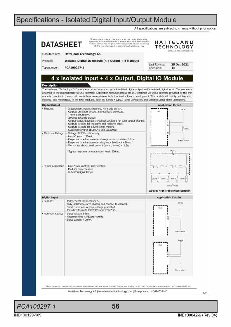
56IND100129-169
All specifications are subject to change without prior notice!
PCA100297-1
Specifications - Isolated Digital Input/Output Module
1/2
This information may not, in whole or in part, be copied, photocopied, reproduced, translated or reduced to any electronic medium or machine-readable form without the prior written consent of Hatteland Technology
AS. The products may not be copied or duplicated in any way.
Dimensions might be shown with or without decimals and indicated as mm [inches]. Tolerance on drawings is +/- 1mm. For accurate measurements, check relevant DWG fi le.
DATASHEET
Hatteland Technology AS | www.hattelandtechnology.com | Enterprise no: NO974533146
4 x Isolated Input + 4 x Output, Digital IO Module
Manufacturer: Hatteland Technology AS
Product: Isolated Digital IO module (4 x Output + 4 x Input)
Typenumber: PCA100297-1Last Revised: 25 Oct 2021Revision#: 18
The Hatteland Technology DIO module provide the system with 4 isolated digital output and 4 isolated digital input. The module is attached to the motherboard via USB interface. Application software access the DIO channels via D2XX interface provided by the chip manufacturer, i.e. in the normal case is there no requirements for low level software development. This module will mainly be integrated, electrical and mechanical, in the final products, such as; Series X G1/G2 Panel Computers and selected Stand-alone Computers.
Description:
Digital Output Application Circuit• Features - Independent output channels, High side switch.
- Outputs are short circuits and overload protected.- Thermal shutdown.- Isolated towards chassis.- Output status/diagnostic feedback available for each output channel.- Outputs is rated for inductive and resistive loads.- Outputs is rated for driving small motors.- Classified towards IEC60945 and IEC60950.
• Maximum Ratings - Voltage: 9-36V continuously.- Load Current: 150mA.- Response time hardware for change of output state <20ms.- Response time hardware for diagnostic feedback <30ms.*- Worst case short circuit current (each channel) < 1.5A.
*Typical response time at system level: 200ms.
Above: High side switch concept
• Typical Application - Low Power control / relay control.- Medium power buzzer.- Indicator/signal lamps.
Digital Input Application Circuits• Features - Independent input channels.
- Fully isolated towards chassis and channel to channel.- Short circuit and reverse voltage protected.- Classified towards IEC60945 and IEC60950.
• Maximum Ratings - Input voltage 8-36V.- Response time hardware <10ms.- Input current < 20mA.

Specifications - Isolated Digital Input/Output Module
PCA100297-1 57IND100129-169
All specifications are subject to change without prior notice!
SPECIFICATIONS Note: All specifi cations are subject to change without prior notice!Please visit www.hattelandtechnology.com for the latest electronic version.
2/2
Supported Operating Systems (OS)Embedded Enterprise (WEE): - Microsoft® Windows® Server 2003/2008/2008R2 (Eng)- Microsoft® Windows® 2003/2008/2008R2 (Eng)- Microsoft® Windows® 7 Professional/Ultimate (Eng, SP1)- Windows® 10 IoT Enterprise 2016 LTSB- Windows® 10 IoT Enterprise 2019 LTSC
Linux:Kernel 3.0.0-19 or above
Note: Listed Operating Systems above are hardware/platform dependent. Please check datasheet for specific unit if OS is supported.
Currently supported D2XX DriversProcessor Architecture
Operating System (OS) Release Date (yyyy-mm-dd) x86 (32-bit) x64 (64-bit) Comments [Footnote]
Microsoft® Windows®* 2013-02-20 2.08.28 2.08.28 2.08.28 WHQL Certified [*1]Release Notes [*2]
Linux 2012-06-29 1.1.12 1.1.12 [*3]
*includes the following versions of the Microsoft® Windows® operating systems:Windows® XP, Windows® Server 2003, Windows® Vista, Windows® Server 2008, Windows® 7, Windows® Server 2008 R2 and Windows® 8.
For updates, please visit: http://www.ftdichip.com/Drivers/D2XX.htm
Footnotes: [*1] = http://www.ftdichip.com/Drivers/CDM/CDM20828_Setup.exe [*2] = http://www.ftdichip.com/Drivers/CDM/CDM%202%2008%2030%20Release%20Info%20for%208.1.rtf [*3] = http://www.ftdichip.com/Drivers/D2XX/Linux/ReadMe-linux.txt
Getting started, documentation and specific Hatteland Technology Library links:http://www.ftdichip.com/Support/Documents/ProgramGuides/D2XX_Programmer%27s_Guide(FT_000071).pdfhttps://www.hattelandtechnology.com/hubfs/pdf/misc/doc101781-1_programmer_guide_ht00273opt-a1.pdfhttps://www.hattelandtechnology.com/hubfs/drivers/dio_pca100297-1_ht00273opt-a1_package.zip
Additional• Cable connector 4 x 5-pin Terminal Block 3.81 connector (MC 1,5/ 5-STF-3,81) - see illustration below• Recommended Cable Thickness Minimum 22 AWG - Maximum 18 AWG• Test and certificate Hatteland Technology standard, (tested / type approved by the following classification societies):
IEC 60945 4th (EN 60945:2002), IACS E10, EU RO MR - Mutual Recognition,ClassNK - Nippon Kaiji Kyokai
• Safety IEC60950 The DIO module is intended to be used in control circuits and does therefore need external fuse to meet safety agency approvals.
Illustration and PinningNote: Product below for illustration only. Location of module and product size/design may differ. Connector/pinning/specifications remain the same.
5-pin Terminal Block 3.81Module A Module B
Pinout Assignments
70IND100241-13
Appendix
25-pin Female Parallel (Optional for selected computers)3 C
13 12 11 10 9 8 7 6 5 4 3 2 1
25 24 23 22 21 20 19 18 17 16 15 14Pin 01 STROBE This signal indicates to the printer that data at PD7..0 are valid.Pin 02 DATA0 Parallel data bus from PC board to printer. The data line are able to operate in PS/2 compatible bi-directional mode. Pin 03 DATA1 Same as Pin 02Pin 04 DATA2 Same as Pin 02Pin 05 DATA3 Same as Pin 02Pin 06 DATA4 Same as Pin 02Pin 07 DATA5 Same as Pin 02Pin 08 DATA6 Same as Pin 02Pin 09 DATA7 Same as Pin 02Pin 10 ACK Signal from printer indicating that the printer has received the data and is ready to accept further data.Pin 11 BUSY Signal from printer indicating that the printer cannot accept further data.Pin 12 PE Signal from printer indicating that the printer is out of paper.Pin 13 SELECT Signal from printer to indicate that the printer is selected.Pin 14 AUTO FEED This active low output causes the printer to add a line feed after each line printed.Pin 15 ERR# Signal from printer indicating that an error has been detected.Pin 16 INIT# This active low output initialises (resets) the printer. Pin 17 SLIN# Signal to select the printer sent from CPU board to printer. Pin 18 GND GroundPin 19 GND GroundPin 20 GND GroundPin 21 GND GroundPin 22 GND GroundPin 23 GND GroundPin 24 GND GroundPin 25 GND Ground
10+10 pin Isolated Digital Input/Output ModuleType Number “HT00268 OPT-A1”
3 C
Module A Module B
Module A Module BA1 External Power + A1 IN+[0]A2 N/C (Not Connected) A2 IN-[0]B1 External Power - (GND1) B1 IN+[1]B2 N/C (Not Connected) B2 IN-[1]O1 HS[0] O1 N/CC1 HS[1] C1 IN+[2]C2 N/C (Not Connected) C2 IN-[2]D1 HS[2] D1 IN+[3]D2 N/C (Not Connected) D2 IN-[3]O2 HS[3] O2 N/C
10-pin DisplayPort (DP) FemaleD
20 18 16 14 12 10 8 6 4 2
19 17 15 13 11 9 7 5 3 1
PIN 01 ML_Lane 0 (p) - Lane 0 (positive)PIN 02 GND - GroundPIN 03 ML_Lane 0 (n) - Lane 0 (negative)PIN 04 ML_Lane 1 (p) - Lane 1 (positive)PIN 05 GND - GroundPIN 06 ML_Lane 1 (n) - Lane 1 (negative)PIN 07 ML_Lane 2 (p) - Lane 2 (positive)PIN 08 GND - GroundPIN 09 ML_Lane 2 (n) - Lane 2 (negative)PIN 10 ML_Lane 3 (p) - Lane 3 (positive)PIN 11 GND - GroundPIN 12 ML_Lane 3 (n) - Lane 3 (negative)PIN 13* CONFIG1 - connected to Ground*PIN 14* CONFIG2 - connected to Ground*PIN 15 AUX CH (p) - Auxiliary Channel (positive)PIN 16 GND - GroundPIN 17 AUX CH (n) - Auxiliary Channel (negative)PIN 18 Hot Plug - Hot Plug DetectPIN 19 Return - Return for PowerPIN 20 DP_PWR - Power for connector (3.3 V 500 mA)
*Pins 13 and 14 may either be directly connected to ground or connected to ground through a pulldown device. This is the pinout for source-side connector, the sink-side connector pinout will have lanes 0–3 reversed in order; i.e., lane 3 will be on pin 1(n) and 3(p) while lane 0 will be on pin 10(n) and 12(p).
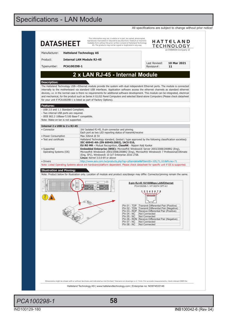
58IND100129-180
All specifications are subject to change without prior notice!
PCA100298-1
Specifications - LAN Module
1/2
This information may not, in whole or in part, be copied, photocopied, reproduced, translated or reduced to any electronic medium or machine-readable form without the prior written consent of Hatteland Technology
AS. The products may not be copied or duplicated in any way.
Dimensions might be shown with or without decimals and indicated as mm [inches]. Tolerance on drawings is +/- 1mm. For accurate measurements, check relevant DWG fi le.
DATASHEET
Hatteland Technology AS | www.hattelandtechnology.com | Enterprise no: NO974533146
Note: Product below for illustration only. Location of module and product size/design may differ. Connector/pinning remain the same.Illustration and Pinning:
2 x LAN RJ-45 - Internal Module
Manufacturer: Hatteland Technology AS
Product: Internal LAN Module RJ-45
Typenumber: PCA100298-1Last Revised: 10 Mar 2021Revision#: 11
Features:
The Hatteland Technology USB->Ethernet module provide the system with dual independent Ethernet ports. The module is connected internally to the motherboard via standard USB interfaces. Application software access the ethernet channels as standard ethernet devices, i.e. in the normal case is there no requirements for additional software development. This module can be integrated, electrical and mechanical, for the product such as Series X G1/G2 Panel Computers and selected Stand-alone Computers (Please check datasheet for your unit if PCA100298-1 is listed as part of Factory Options).
Description:
Internal 2 x USB to 2 x RJ-45• Connector 1kV Isolated RJ-45, 8-pin connector and pinning.
Each port as two LED reporting status of transmit/receive• Power Consumption Max 326mA @ 5V• Test and certificate Hatteland Technology standard, (tested / type approved by the following classification societies):
IEC 60945 4th (EN 60945:2002), IACS E10,EU RO MR - Mutual Recognition, ClassNK - Nippon Kaiji Kyokai
• Supported Operating Systems (OS)
Embedded Enterprise (WEE): Microsoft® Windows® Server 2003/2008/2008R2 (Eng), Microsoft® Windows® 2003/2008/2008R2 (Eng), Microsoft® Windows® 7 Professional/Ultimate (Eng, SP1), Windows® 10 IoT Enterprise 2016 LTSB.Linux: Kernel 3.0.0-64 or above
• Drivers http://www.asix.com.tw/products.php?op=pItemdetail&PItemID=105;71;101&PLine=71Note: Listed Operating Systems above are hardware/platform dependent. Please check datasheet for specific unit if OS is supported.
- USB 2.0 and 1.1 Standard Compliant.- Two internal USB ports are required.- IEEE 802.3 10Base-T/100 Base-T compatible.Note: Wake-on-lan is not supported.
8-pin RJ-45 10/100Mbps LAN/EthernetPCA100298-1 / HT 00274 OPT-A1
1 2 3 4 5 6 7 8
Pin 01 - TDP Transmit Diff erential Pair (Positive)Pin 02 - TDN Transmit Diff erential Pair (Negative)Pin 03 - RDP Receive Diff erential Pair (Positive)Pin 04 - NC Not ConnectedPin 05 - NC Not ConnectedPin 06 - RDN Receive Diff erential Pair (Negative)Pin 07 - NC Not ConnectedPin 08 - NC Not Connected
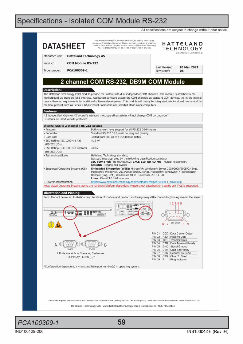
59IND100129-206
All specifications are subject to change without prior notice!
Specifications - Isolated COM Module RS-232
PCA100309-1
1/2
This information may not, in whole or in part, be copied, photocopied, reproduced, translated or reduced to any electronic medium or machine-readable form without the prior written consent of Hatteland Technology
AS. The products may not be copied or duplicated in any way.
Dimensions might be shown with or without decimals and indicated as mm [inches]. Tolerance on drawings is +/- 1mm. For accurate measurements, check relevant DWG fi le.
DATASHEET
Hatteland Technology AS | www.hattelandtechnology.com | Enterprise no: NO974533146
Note: Product below for illustration only. Location of module and product size/design may differ. Connector/pinning remain the same.
*Configuration dependent, x = next available port number(s) in operating system.
Illustration and Pinning:
2 channel COM RS-232, DB9M COM Module
Manufacturer: Hatteland Technology AS
Product: COM Module RS-232
Typenumber: PCA100309-1Last Revised: 10 Mar 2021Revision#: 06
Features:
The Hatteland Technology COM module provide the system with dual independent COM channels. The module is attached to themotherboard via standard USB interface. Application software access the COM channels as standard COM devices, i.e. in the normal case is there no requirements for additional software development. This module will mainly be integrated, electrical and mechanical, in the final product such as Series X G1/G2 Panel Computers and selected stand-alone computers.
Description:
Internal USB to 2 channel x RS-232 isolated• Features Both channels have support for all RS-232 DB-9 signals• Connector Standard RS-232 DB-9 male housing and pinning• Data Rate Tested from 300 up to 115200 Baud Rates• ESD Rating (IEC 1000-4-2 Air) (RS-232 I/Os)
±15 kV
• ESD Rating (IEC 1000-4-2 Contact) (RS-232 I/Os)
±8 kV
• Test and certificate Hatteland Technology standard,(tested / type approved by the following classification societies):IEC 60945 4th (EN 60945:2002), IACS E10, EU RO MR - Mutual Recognition,ClassNK - Nippon Kaiji Kyokai
• Supported Operating Systems (OS) Embedded Enterprise (WEE): Microsoft® Windows® Server 2003/2008/2008R2 (Eng), Microsoft® Windows® 2003/2008/2008R2 (Eng), Microsoft® Windows® 7 Professional/Ultimate (Eng, SP1), Windows® 10 IoT Enterprise 2016 LTSB.Linux: Kernel 3.0.0-64 or above
• Drivers/Documentation https://www.hattelandtechnology.com/hubfs/drivers/pca100390-1_drivers.zipNote: Listed Operating Systems above are hardware/platform dependent. Please check datasheet for specific unit if OS is supported.
- 2 independent channels (If a card is replaced most operating system will not change COM port number)- Outputs are short circuits protected
1 2 3 4 5
6 7 8 9
2 Ports available in Operating System as: COMx (A)*, COMx (B)*
Pinout Assignments
67IND100241-13
Appendix
Analog RGB/VGA, 15-pin DSUB High Density Female1 2 3 A B
5 4 3 2 1
15 14 13 12 11
10 9 8 7 6
PIN 01 RED Red, analogPIN 02 GREEN Green, analogPIN 03 BLUE Blue, analogPIN 04 ID2/RES Reserved for monitor ID bit 2 (grounded)PIN 05 GND Digital groundPIN 06 RED_RTN Analog ground redPIN 07 GREEN_RTN Analog ground greenPIN 08 BLUE_RTN Analog ground bluePIN 09 KEY/PWR +5V power supply for DDC (optional)PIN 10 GND Digital groundPIN 11 ID0/RES Reserved for monitor ID bit 0 (grounded)PIN 12 ID1/SDA DDC serial dataPIN 13 HSYNC. Horizontal sync or composite sync, inputPIN 14 VSYNC. Vertical sync, inputPIN 15 ID3/SCL DDC serial clock
Serial COM RS-232 non-isolated, 9-pin DSUB Female1 2 B
5 4 3 2 1
9 8 7 6
PIN 01 BUZ+ Buzzer Control Positive*PIN 02 TxD Transmit DataPIN 03 RxD Receive DataPIN 04 DTR Data Terminal ReadyPIN 05 GND GroundPIN 06 DSR Data Set ReadyPIN 07 RTS Request To SendPIN 08 CTS Clear To SendPIN 09 BUZ- Buzzer Control Negative*
*Wake On Ring is not enabled
Serial COM RS-485/RS-422, 9-pin DSUB Male“Full Duplex Mode*
3 B
1 2 3 4 5
6 7 8 9PIN 01 TxD- Transmit Data NegativePIN 02 TxD+ Transmit Data PositivePIN 03 RxD+ Receive Data PositivePIN 04 RxD- Receive Data NegativePIN 05 GND Signal GroundPIN 06 N/C No internal connectionPIN 07 N/C No internal connectionPIN 08 N/C No internal connectionPIN 09 N/C No internal connection
*Master only. ECHO not supported.
Serial COM RS-485/RS-422, 9-pin DSUB Male“Half Duplex Mode*
3 B
1 2 3 4 5
6 7 8 9PIN 01 Res. Reserved, do not connectPIN 02 Res. Reserved, do not connectPIN 03 Data+ Data PositivePIN 04 Data- Data NegativePIN 05 GND Signal GroundPIN 06 N/C No internal connectionPIN 07 N/C No internal connectionPIN 08 N/C No internal connectionPIN 09 N/C No internal connection
*ECHO not supported.Half Duplex Confi guration: Via Hatteland Display API.
Flow control: Via RTS signal (controlled by user application).
Serial COM RS-232 non-isolated, 9-pin DSUB Male3 B
1 2 3 4 5
6 7 8 9
PIN 01 DCD Data Carrier DetectPIN 02 RxD Receive DataPIN 03 TxD Transmit DataPIN 04 DTR Data Terminal ReadyPIN 05 GND Signal GroundPIN 06 DSR Data Set ReadyPIN 07 RTS Request To SendPIN 08 CTS Clear To SendPIN 09 RI Ring Indicator
COM Module RS-232 - 4 x ports, 9-pin DSUB MaleType Number “PCA100294-1”
3 A B
B
A
D
C
1 2 3 4 5
6 7 8 9
PIN 01 DCD Data Carrier DetectPIN 02 RxD Receive DataPIN 03 TxD Transmit DataPIN 04 DTR Data Terminal ReadyPIN 05 GND Signal GroundPIN 06 DSR Data Set ReadyPIN 07 RTS Request To SendPIN 08 CTS Clear To SendPIN 09 RI Ring Indicator
A B

60
This page left intentionally blank

61
Specifications Accessories

Specifications - External Modules (USB)
62IND100129-170
All specifications are subject to change without prior notice!
Specifications - External Modules (USB)
1/2
This information may not, in whole or in part, be copied, photocopied, reproduced, translated or reduced to any electronic medium or machine-readable form without the prior written consent of Hatteland Technology
AS. The products may not be copied or duplicated in any way.
Dimensions might be shown with or without decimals and indicated as mm [inches]. Tolerance on drawings is +/- 1mm. For accurate measurements, check relevant DWG fi le.
DATASHEET
Hatteland Technology AS | www.hattelandtechnology.com | Enterprise no: NO974533146
Hatteland Technology IO module series concept for marine applications adds more functionality to your Maritime Multi Computers and Maritime Stand-Alone computers. They are available as regular factory options for the entire range of Series X Maritime Multi Displays, Maritime Multi Computers and as well as the latest Maritime Stand-Alone computers.
In addition, the module concept has been taken further to a self contained and encased external USB module version. This provides flexibility for new installations and easy upgrade of already installed systems. In fact, any Hatteland Technology product that has a USB2.0 port can take advantage of these External Modules for both legacy, obsoleted, current and future products as long as the software and firmware supports the Operating System.
Fully compatible with all Hatteland Technology latest generation products, external cased modules enable system integrators to benefit from the features of these internal options as an external and easy to connect solution. They interface via a standard USB Type A Cable(s) and the chassis comes with its own mounting hinges.
Note for CAN: Due to driver limitations, only 1 instance of this module can be connected to the same Computer/Panel Computer unit. If Computer/Panel Computer already has CAN functionality built-in, connecting this external module will always fail.
External Modules - USB Connectivity
Manufacturer: Hatteland Technology AS
Product: External Modules - USB Connectivity
Typenumber: Based on internal modules, see table on page 2Last Revised: 14 Apr 2021Revision#: 19
Description:
FRONT VIEW SIDE VIEW BACK VIEWSIngle Cable
BOTTOM VIEW
DIMETRIC VIEW BACKSingle Cable
Front plate/silk print indicating type and pinout
BACK VIEWDouble Cable
DIMETRIC VIEW BACKDouble Cable
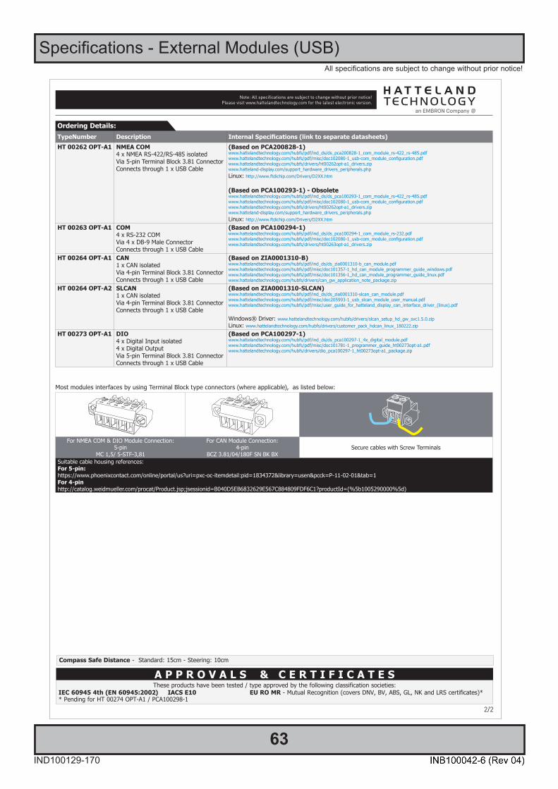
Specifications - External Modules (USB)
63IND100129-170
All specifications are subject to change without prior notice!
SPECIFICATIONS Note: All specifi cations are subject to change without prior notice!Please visit www.hattelandtechnology.com for the latest electronic version.
2/2
TypeNumber Description Internal Specifications (link to separate datasheets)HT 00262 OPT-A1 NMEA COM
4 x NMEA RS-422/RS-485 isolatedVia 5-pin Terminal Block 3.81 ConnectorConnects through 1 x USB Cable
(Based on PCA200828-1)www.hattelandtechnology.com/hubfs/pdf/ind_ds/ds_pca200828-1_com_module_rs-422_rs-485.pdfwww.hattelandtechnology.com/hubfs/pdf/misc/doc102080-1_usb-com_module_configuration.pdfwww.hattelandtechnology.com/hubfs/drivers/ht00262opt-a1_drivers.zipwww.hatteland-display.com/support_hardware_drivers_peripherals.phpLinux: http://www.ftdichip.com/Drivers/D2XX.htm
(Based on PCA100293-1) - Obsoletewww.hattelandtechnology.com/hubfs/pdf/ind_ds/ds_pca100293-1_com_module_rs-422_rs-485.pdfwww.hattelandtechnology.com/hubfs/pdf/misc/doc102080-1_usb-com_module_configuration.pdfwww.hattelandtechnology.com/hubfs/drivers/ht00262opt-a1_drivers.zipwww.hatteland-display.com/support_hardware_drivers_peripherals.phpLinux: http://www.ftdichip.com/Drivers/D2XX.htm
HT 00263 OPT-A1 COM4 x RS-232 COMVia 4 x DB-9 Male ConnectorConnects through 1 x USB Cable
(Based on PCA100294-1)www.hattelandtechnology.com/hubfs/pdf/ind_ds/ds_pca100294-1_com_module_rs-232.pdfwww.hattelandtechnology.com/hubfs/pdf/misc/doc102080-1_usb-com_module_configuration.pdfwww.hattelandtechnology.com/hubfs/drivers/ht00263opt-a1_drivers.zip
HT 00264 OPT-A1 CAN1 x CAN isolatedVia 4-pin Terminal Block 3.81 ConnectorConnects through 1 x USB Cable
(Based on ZIA0001310-B)www.hattelandtechnology.com/hubfs/pdf/ind_ds/ds_zia0001310-b_can_module.pdfwww.hattelandtechnology.com/hubfs/pdf/misc/doc101357-1_hd_can_module_programmer_guide_windows.pdfwww.hattelandtechnology.com/hubfs/pdf/misc/doc101356-1_hd_can_module_programmer_guide_linux.pdfwww.hattelandtechnology.com/hubfs/drivers/can_gw_application_note_package.zip
HT 00264 OPT-A2 SLCAN1 x CAN isolatedVia 4-pin Terminal Block 3.81 ConnectorConnects through 1 x USB Cable
(Based on ZIA0001310-SLCAN)www.hattelandtechnology.com/hubfs/pdf/ind_ds/ds_zia0001310-slcan_can_module.pdfwww.hattelandtechnology.com/hubfs/pdf/misc/doc205993-1_usb_slcan_module_user_manual.pdfwww.hattelandtechnology.com/hubfs/pdf/misc/user_guide_for_hatteland_display_can_interface_driver_(linux).pdf
Windows® Driver: www.hattelandtechnology.com/hubfs/drivers/slcan_setup_hd_gw_svc1.5.0.zipLinux: www.hattelandtechnology.com/hubfs/drivers/customer_pack_hdcan_linux_180222.zip
HT 00273 OPT-A1 DIO4 x Digital Input isolated4 x Digital OutputVia 5-pin Terminal Block 3.81 ConnectorConnects through 1 x USB Cable
(Based on PCA100297-1)www.hattelandtechnology.com/hubfs/pdf/ind_ds/ds_pca100297-1_4x_digital_module.pdfwww.hattelandtechnology.com/hubfs/pdf/misc/doc101781-1_programmer_guide_ht00273opt-a1.pdfwww.hattelandtechnology.com/hubfs/drivers/dio_pca100297-1_ht00273opt-a1_package.zip
Ordering Details:
A P P R O V A L S & C E R T I F I C A T E SThese products have been tested / type approved by the following classification societies:
IEC 60945 4th (EN 60945:2002) IACS E10 EU RO MR - Mutual Recognition (covers DNV, BV, ABS, GL, NK and LRS certificates)** Pending for HT 00274 OPT-A1 / PCA100298-1
Most modules interfaces by using Terminal Block type connectors (where applicable), as listed below:
For NMEA COM & DIO Module Connection:5-pin
MC 1,5/ 5-STF-3,81
For CAN Module Connection:4-pin
BCZ 3.81/04/180F SN BK BXSecure cables with Screw Terminals
Suitable cable housing references:For 5-pin:https://www.phoenixcontact.com/online/portal/us?uri=pxc-oc-itemdetail:pid=1834372&library=usen&pcck=P-11-02-01&tab=1For 4-pinhttp://catalog.weidmueller.com/procat/Product.jsp;jsessionid=B040D5EB6832629E567C884809FDF6C1?productId=(%5b1005290000%5d)
Compass Safe Distance - Standard: 15cm - Steering: 10cm
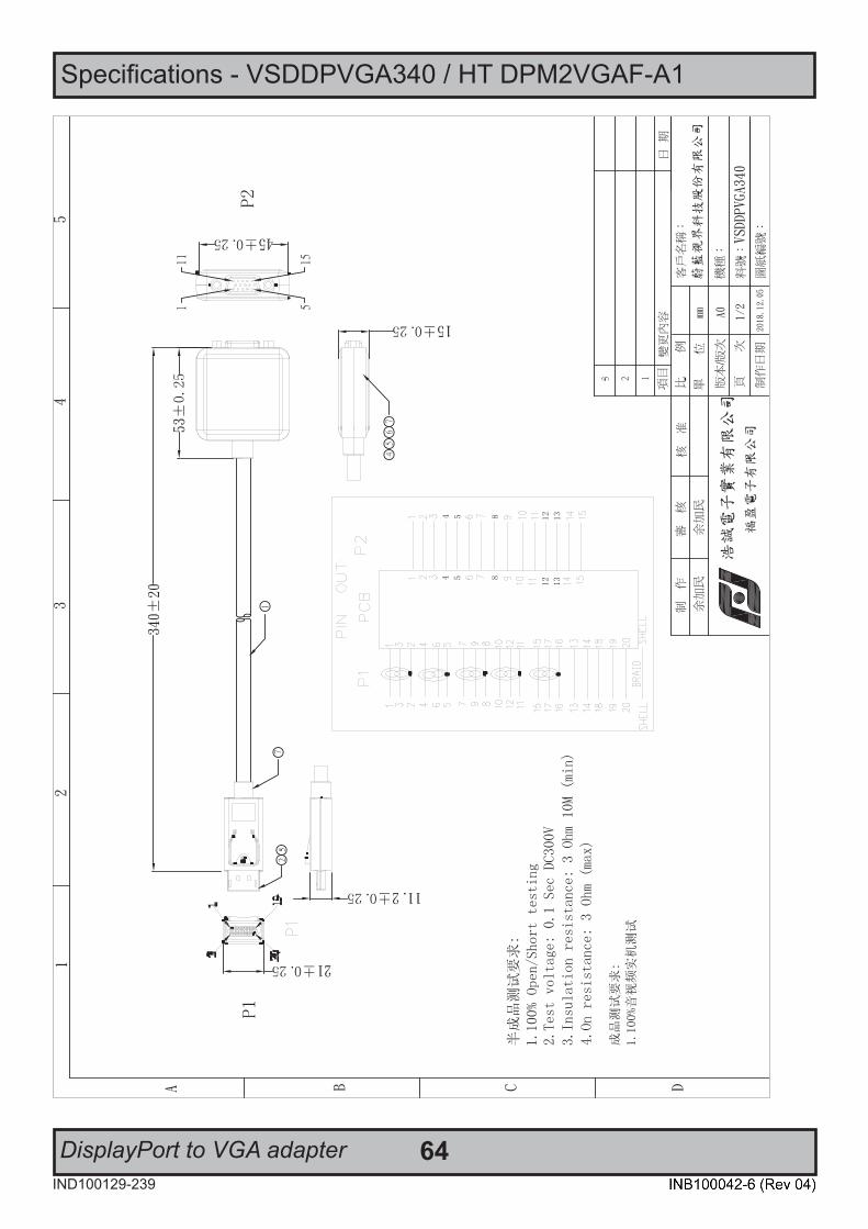
64IND100129-239
Specifications - VSDDPVGA340 / HT DPM2VGAF-A1
DisplayPort to VGA adapter

65IND100129-255
Specifications - RC3473 / HT DPM2DVI-DF-A1
DisplayPort to DVI adapter
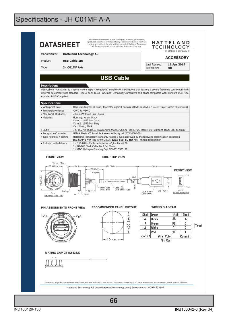
66IND100129-133
Specifications - JH C01MF A-A
1/2
This information may not, in whole or in part, be copied, photocopied, reproduced, translated or reduced to any electronic medium or machine-readable form without the prior written consent of Hatteland Technology
AS. The products may not be copied or duplicated in any way.
Dimensions might be shown with or without decimals and indicated as mm [inches]. Tolerance on drawings is +/- 1mm. For accurate measurements, check relevant DWG fi le.
DATASHEET
Hatteland Technology AS | www.hattelandtechnology.com | Enterprise no: NO974533146
USB Cable
Manufacturer: Hatteland Technology AS
Product: USB Cable 1m
Type: JH C01MF A-ALast Revised: 16 Apr 2019Revision#: 08
USB Cable (Type A plug to Chassis mount Type A receptacle) suitable for installations that feature a secure fastening connection from external equipment with standard Type A ports to all Hatteland Technology computers and panel computers with standard USB Type A ports. RoHS Compliant.
Description:
Specifications• Waterproof Rate : IP67. (No Ingress of dust / Protected against harmful effects caused in 1 meter water within 30 minutes)• Temperature Range : -20°C to +80°C• Max Panel Thickness : 7.0mm (Without Cap Chain)• Materials : Housing: Nylon, Black
: Conn.1: USB2.0-A, Jack: Conn.2: USB2.0-A, Plug: Cap: Nylon, Black
• Cable : 1m, UL2725 USB2.0, 28AWG*1P+24AWG*2C+AL+D+B, PVC Jacket, UV Resistant, Black 0D=ø5.5mm• Receptacle Connector : USB-A Plastic C3 Panel Jack screw with pig tail (GT116300-30)• Type Approval / Testing : Hatteland Technology standard, (tested / type approved by the following classification societies):
IEC 60945 4th (EN 60945:2002), IACS E10, EU RO MR - Mutual Recognition• Included with delivery : 1 x 218-N28 - Cable tie fastener w/glue Panuit 30
: 1 x B2-100 Black Cable tie 2,5x100mm: 1 x GTC Waterproof Mating Cap P/N GT1C533122
ACCESSORY
FRONT VIEW SIDE / TOP VIEW
WIRING DIAGRAM
FRONT VIEW
MATING CAP GT1C533122
PIN ASSIGNMENTS FRONT VIEW RECOMMENDED PANEL CUTOUT

67
Technical Drawings
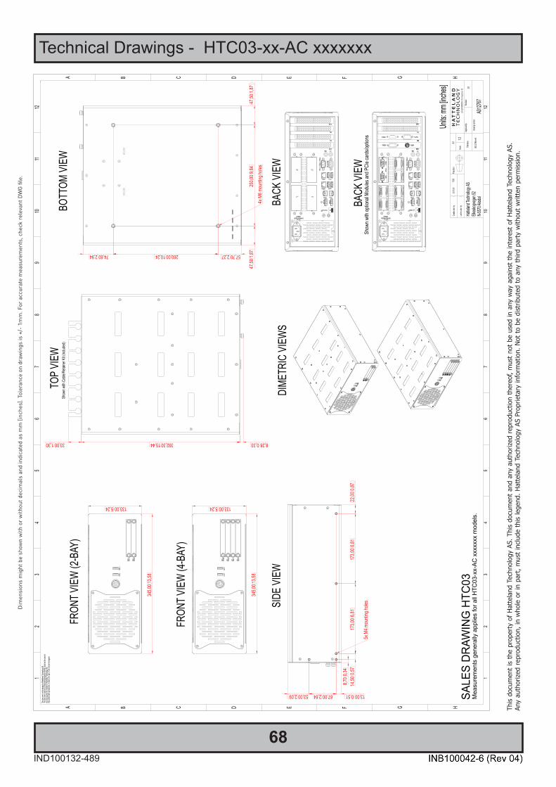
68IND100132-489
This
docu
men
t is
the
prop
erty
of H
atte
land
Tec
hnol
ogy
AS. T
his
docu
men
t and
any
aut
horiz
ed re
prod
uctio
n th
ereo
f, m
ust n
ot b
e us
ed in
any
way
aga
inst
the
inte
rest
of H
atte
land
Tec
hnol
ogy
AS.
Any
auth
orize
d re
prod
uctio
n, in
who
le o
r in
part,
mus
t inc
lude
this
lege
nd. H
atte
land
Tec
hnol
ogy
AS P
ropr
ieta
ry in
form
atio
n. N
ot to
be
dist
ribut
ed to
any
third
par
ty w
ithou
t writ
ten
perm
issio
n.
Dim
ensi
ons
mig
ht b
e sh
own
with
or
with
out d
ecim
als
and
indi
cate
d as
mm
[inc
hes]
. Tol
eran
ce o
n dr
awin
gs is
+/-
1m
m. F
or a
ccur
ate
mea
sure
men
ts, c
heck
rel
evan
t DW
G fi
le.
Technical Drawings - HTC03-xx-AC xxxxxxx

69IND100132-517
This
docu
men
t is
the
prop
erty
of H
atte
land
Tec
hnol
ogy
AS. T
his
docu
men
t and
any
aut
horiz
ed re
prod
uctio
n th
ereo
f, m
ust n
ot b
e us
ed in
any
way
aga
inst
the
inte
rest
of H
atte
land
Tec
hnol
ogy
AS.
Any
auth
orize
d re
prod
uctio
n, in
who
le o
r in
part,
mus
t inc
lude
this
lege
nd. H
atte
land
Tec
hnol
ogy
AS P
ropr
ieta
ry in
form
atio
n. N
ot to
be
dist
ribut
ed to
any
third
par
ty w
ithou
t writ
ten
perm
issio
n.
Dim
ensi
ons
mig
ht b
e sh
own
with
or
with
out d
ecim
als
and
indi
cate
d as
mm
[inc
hes]
. Tol
eran
ce o
n dr
awin
gs is
+/-
1m
m. F
or a
ccur
ate
mea
sure
men
ts, c
heck
rel
evan
t DW
G fi
le.
Multi-Power (AC+DC)
Technical Drawings - HTC03-xx-MP xxxxxxx

70
This page left intentionally blank

71
Technical Drawings - Accessories
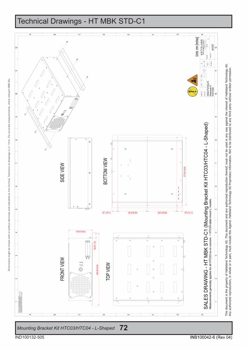
72IND100132-505
This
docu
men
t is
the
prop
erty
of H
atte
land
Tec
hnol
ogy
AS. T
his
docu
men
t and
any
aut
horiz
ed re
prod
uctio
n th
ereo
f, m
ust n
ot b
e us
ed in
any
way
aga
inst
the
inte
rest
of H
atte
land
Tec
hnol
ogy
AS.
Any
auth
orize
d re
prod
uctio
n, in
who
le o
r in
part,
mus
t inc
lude
this
lege
nd. H
atte
land
Tec
hnol
ogy
AS P
ropr
ieta
ry in
form
atio
n. N
ot to
be
dist
ribut
ed to
any
third
par
ty w
ithou
t writ
ten
perm
issio
n.
Dim
ensi
ons
mig
ht b
e sh
own
with
or
with
out d
ecim
als
and
indi
cate
d as
mm
[inc
hes]
. Tol
eran
ce o
n dr
awin
gs is
+/-
1m
m. F
or a
ccur
ate
mea
sure
men
ts, c
heck
rel
evan
t DW
G fi
le.
Mounting Bracket Kit HTC03/HTC04 - L-Shaped
Technical Drawings - HT MBK STD-C1
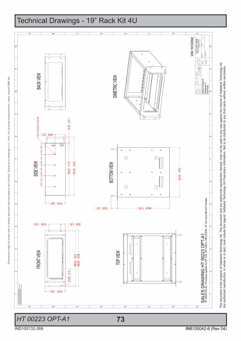
73IND100132-269
This
docu
men
t is
the
prop
erty
of H
atte
land
Tec
hnol
ogy
AS. T
his
docu
men
t and
any
aut
horiz
ed re
prod
uctio
n th
ereo
f, m
ust n
ot b
e us
ed in
any
way
aga
inst
the
inte
rest
of H
atte
land
Tec
hnol
ogy
AS.
Any
auth
orize
d re
prod
uctio
n, in
who
le o
r in
part,
mus
t inc
lude
this
lege
nd. H
atte
land
Tec
hnol
ogy
AS P
ropr
ieta
ry in
form
atio
n. N
ot to
be
dist
ribut
ed to
any
third
par
ty w
ithou
t writ
ten
perm
issio
n.
Dim
ensi
ons
mig
ht b
e sh
own
with
or
with
out d
ecim
als
and
indi
cate
d as
mm
[inc
hes]
. Tol
eran
ce o
n dr
awin
gs is
+/-
1m
m. F
or a
ccur
ate
mea
sure
men
ts, c
heck
rel
evan
t DW
G fi
le.
HT 00223 OPT-A1
Technical Drawings - 19” Rack Kit 4U
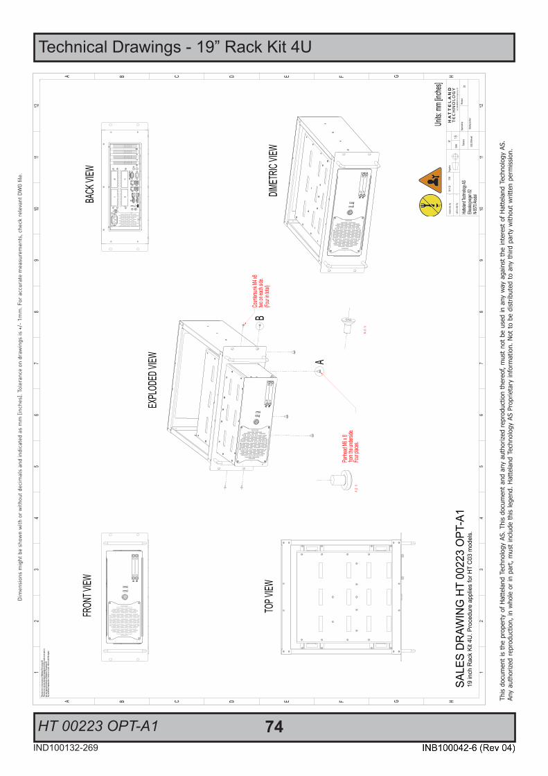
Technical Drawings - 19” Rack Kit 4U
HT 00223 OPT-A1 74IND100132-269
This
docu
men
t is
the
prop
erty
of H
atte
land
Tec
hnol
ogy
AS. T
his
docu
men
t and
any
aut
horiz
ed re
prod
uctio
n th
ereo
f, m
ust n
ot b
e us
ed in
any
way
aga
inst
the
inte
rest
of H
atte
land
Tec
hnol
ogy
AS.
Any
auth
orize
d re
prod
uctio
n, in
who
le o
r in
part,
mus
t inc
lude
this
lege
nd. H
atte
land
Tec
hnol
ogy
AS P
ropr
ieta
ry in
form
atio
n. N
ot to
be
dist
ribut
ed to
any
third
par
ty w
ithou
t writ
ten
perm
issio
n.
Dim
ensi
ons
mig
ht b
e sh
own
with
or
with
out d
ecim
als
and
indi
cate
d as
mm
[inc
hes]
. Tol
eran
ce o
n dr
awin
gs is
+/-
1m
m. F
or a
ccur
ate
mea
sure
men
ts, c
heck
rel
evan
t DW
G fi
le.
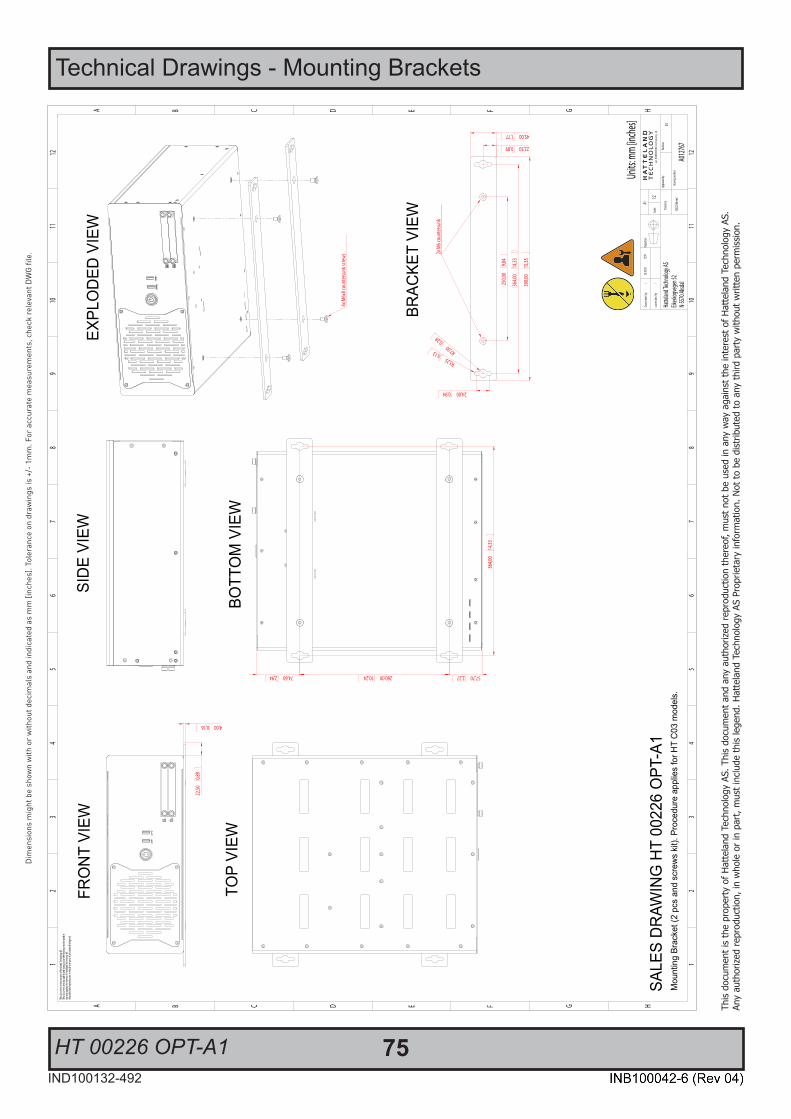
75IND100132-492
This
docu
men
t is
the
prop
erty
of H
atte
land
Tec
hnol
ogy
AS. T
his
docu
men
t and
any
aut
horiz
ed re
prod
uctio
n th
ereo
f, m
ust n
ot b
e us
ed in
any
way
aga
inst
the
inte
rest
of H
atte
land
Tec
hnol
ogy
AS.
Any
auth
orize
d re
prod
uctio
n, in
who
le o
r in
part,
mus
t inc
lude
this
lege
nd. H
atte
land
Tec
hnol
ogy
AS P
ropr
ieta
ry in
form
atio
n. N
ot to
be
dist
ribut
ed to
any
third
par
ty w
ithou
t writ
ten
perm
issio
n.
Dim
ensi
ons
mig
ht b
e sh
own
with
or
with
out d
ecim
als
and
indi
cate
d as
mm
[inc
hes]
. Tol
eran
ce o
n dr
awin
gs is
+/-
1m
m. F
or a
ccur
ate
mea
sure
men
ts, c
heck
rele
vant
DW
G fi
le.
HT 00226 OPT-A1
Technical Drawings - Mounting Brackets

76IND100132-276
This
docu
men
t is
the
prop
erty
of H
atte
land
Tec
hnol
ogy
AS. T
his
docu
men
t and
any
aut
horiz
ed re
prod
uctio
n th
ereo
f, m
ust n
ot b
e us
ed in
any
way
aga
inst
the
inte
rest
of H
atte
land
Tec
hnol
ogy
AS.
Any
auth
orize
d re
prod
uctio
n, in
who
le o
r in
part,
mus
t inc
lude
this
lege
nd. H
atte
land
Tec
hnol
ogy
AS P
ropr
ieta
ry in
form
atio
n. N
ot to
be
dist
ribut
ed to
any
third
par
ty w
ithou
t writ
ten
perm
issio
n.
Dim
ensi
ons
mig
ht b
e sh
own
with
or
with
out d
ecim
als
and
indi
cate
d as
mm
[inc
hes]
. Tol
eran
ce o
n dr
awin
gs is
+/-
1m
m. F
or a
ccur
ate
mea
sure
men
ts, c
heck
rele
vant
DW
G fi
le.
HT 00275 OPT-A1
Technical Drawings - EN60945 PCI/PCIe Support Bracket
Hatte
land T
echn
ology
AS
Eike
skog
vege
n 52
N-55
70 A
ksda
l
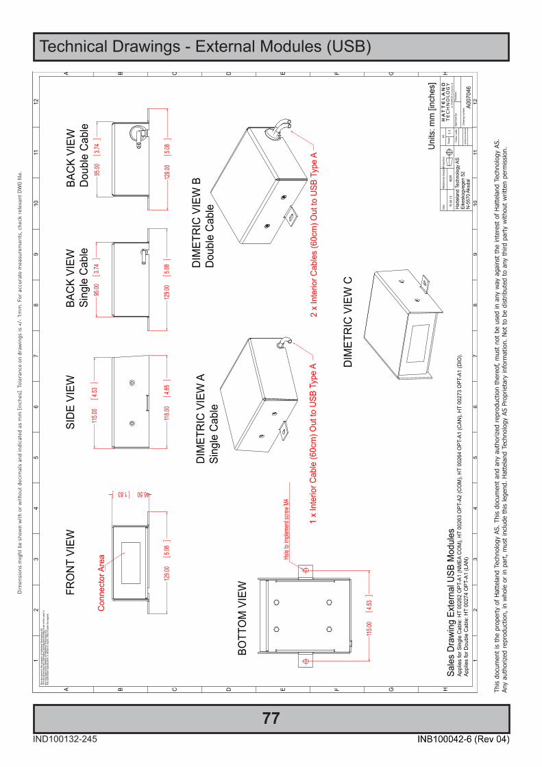
77IND100132-245
This
docu
men
t is
the
prop
erty
of H
atte
land
Tec
hnol
ogy
AS. T
his
docu
men
t and
any
aut
horiz
ed re
prod
uctio
n th
ereo
f, m
ust n
ot b
e us
ed in
any
way
aga
inst
the
inte
rest
of H
atte
land
Tec
hnol
ogy
AS.
Any
auth
orize
d re
prod
uctio
n, in
who
le o
r in
part,
mus
t inc
lude
this
lege
nd. H
atte
land
Tec
hnol
ogy
AS P
ropr
ieta
ry in
form
atio
n. N
ot to
be
dist
ribut
ed to
any
third
par
ty w
ithou
t writ
ten
perm
issio
n.
Dim
ensi
ons
mig
ht b
e sh
own
with
or
with
out d
ecim
als
and
indi
cate
d as
mm
[inc
hes]
. Tol
eran
ce o
n dr
awin
gs is
+/-
1m
m. F
or a
ccur
ate
mea
sure
men
ts, c
heck
rel
evan
t DW
G fi
le.
Hatte
land
Tec
hnol
ogy A
SEi
kesk
ogve
gen
52N-
5570
Aks
dal
Technical Drawings - External Modules (USB)
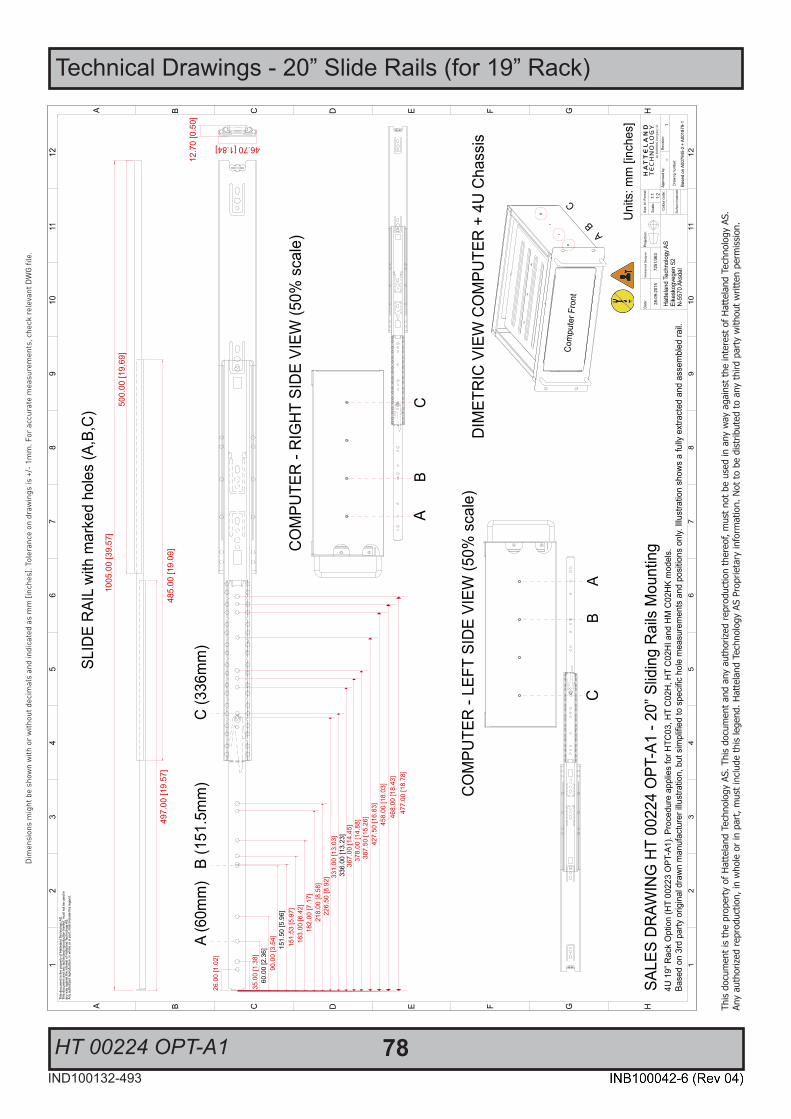
78IND100132-493
This
docu
men
t is
the
prop
erty
of H
atte
land
Tec
hnol
ogy
AS. T
his
docu
men
t and
any
aut
horiz
ed re
prod
uctio
n th
ereo
f, m
ust n
ot b
e us
ed in
any
way
aga
inst
the
inte
rest
of H
atte
land
Tec
hnol
ogy
AS.
Any
auth
orize
d re
prod
uctio
n, in
who
le o
r in
part,
mus
t inc
lude
this
lege
nd. H
atte
land
Tec
hnol
ogy
AS P
ropr
ieta
ry in
form
atio
n. N
ot to
be
dist
ribut
ed to
any
third
par
ty w
ithou
t writ
ten
perm
issio
n.
Dim
ensi
ons
mig
ht b
e sh
own
with
or
with
out d
ecim
als
and
indi
cate
d as
mm
[inc
hes]
. Tol
eran
ce o
n dr
awin
gs is
+/-
1m
m. F
or a
ccur
ate
mea
sure
men
ts, c
heck
rele
vant
DW
G fi
le.
HT 00224 OPT-A1
Technical Drawings - 20” Slide Rails (for 19” Rack)
Hatte
land
Tec
hnol
ogy A
SEi
kesk
ogve
gen
52N-
5570
Aks
dal
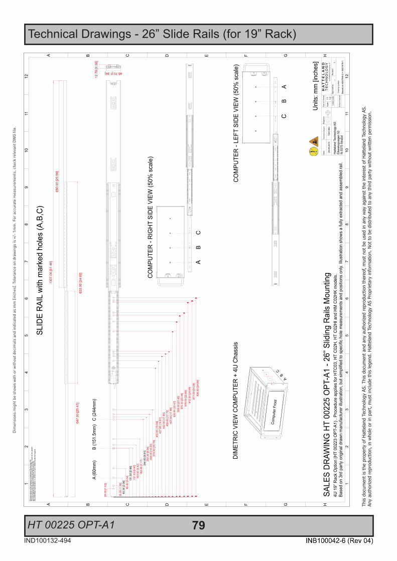
79IND100132-494
This
docu
men
t is
the
prop
erty
of H
atte
land
Tec
hnol
ogy
AS. T
his
docu
men
t and
any
aut
horiz
ed re
prod
uctio
n th
ereo
f, m
ust n
ot b
e us
ed in
any
way
aga
inst
the
inte
rest
of H
atte
land
Tec
hnol
ogy
AS.
Any
auth
orize
d re
prod
uctio
n, in
who
le o
r in
part,
mus
t inc
lude
this
lege
nd. H
atte
land
Tec
hnol
ogy
AS P
ropr
ieta
ry in
form
atio
n. N
ot to
be
dist
ribut
ed to
any
third
par
ty w
ithou
t writ
ten
perm
issio
n.
Dim
ensi
ons
mig
ht b
e sh
own
with
or
with
out d
ecim
als
and
indi
cate
d as
mm
[inc
hes]
. Tol
eran
ce o
n dr
awin
gs is
+/-
1m
m. F
or a
ccur
ate
mea
sure
men
ts, c
heck
rele
vant
DW
G fi
le.
HT 00225 OPT-A1
Technical Drawings - 26” Slide Rails (for 19” Rack)
Hatte
land
Tec
hnol
ogy A
SEi
kesk
ogve
gen
52N-
5570
Aks
dal

80
This page left intentionally blank

81
Appendixes
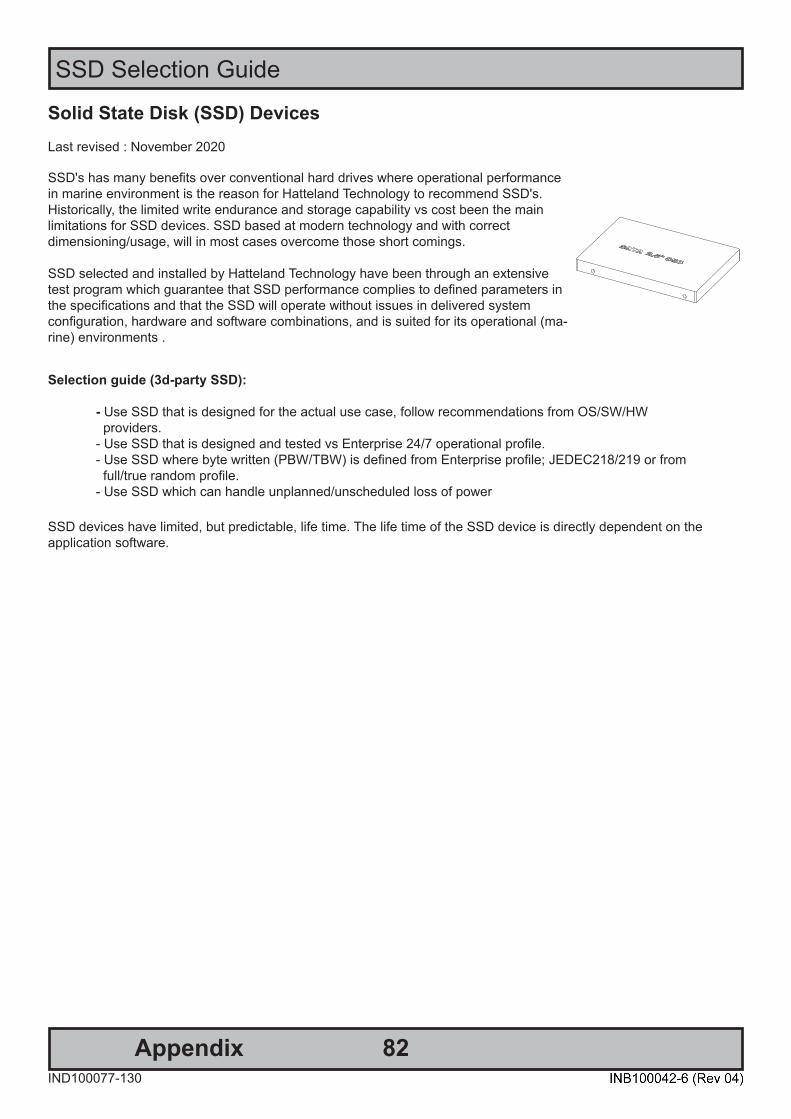
82AppendixIND100077-130
SSD Selection Guide
Solid State Disk (SSD) DevicesLast revised : November 2020
SSD's has many benefits over conventional hard drives where operational performance in marine environment is the reason for Hatteland Technology to recommend SSD's. Historically, the limited write endurance and storage capability vs cost been the mainlimitations for SSD devices. SSD based at modern technology and with correctdimensioning/usage, will in most cases overcome those short comings.
SSD selected and installed by Hatteland Technology have been through an extensive test program which guarantee that SSD performance complies to defined parameters in the specifications and that the SSD will operate without issues in delivered systemconfiguration, hardware and software combinations, and is suited for its operational (ma-rine) environments .
Selection guide (3d-party SSD): - Use SSD that is designed for the actual use case, follow recommendations from OS/SW/HW providers. - Use SSD that is designed and tested vs Enterprise 24/7 operational profile. - Use SSD where byte written (PBW/TBW) is defined from Enterprise profile; JEDEC218/219 or from full/true random profile. - Use SSD which can handle unplanned/unscheduled loss of power SSD devices have limited, but predictable, life time. The life time of the SSD device is directly dependent on theapplication software.
83
SSD Selection Guide
AppendixIND100077-130
Calculation / estimation of operational lifetimeAssumed System with Hatteland Technology provided SSD or selected according to guide above.
1. Measure/estimate/calculate average disk usage per day. For measuring, use SMART data. o Measure the difference in numbers of write cycles at the start and at end of the test (or the difference in remaining lifetime) o Run the test with relevant disk load and during relevant time period Relevant disk load - should correspond to the average disk load during the operational lifetime. Relevant time - time it takes to generate relevant disk load with statically significance. Many SSD manufacturers provide tool for calculating expected operational lifetime.
2. Selection of SSD
Select SSD type/series. Define minimum expected lifetime [Year] Define minimum required SSD capacity [GB]
From datasheet, - check if the endurance is expressed as PBW/TBW or DWPD. - check warranty [year]
PBW - PetaByte Written = 1000 terabyte written = 1000 000 gigabyte written. TBW - Total Byte Written normally expressed in terabyte. DWPD - Disk Write Per Day.
Note relation TBW and DWPD : TBW = DPWD * warranty * 365 * SSD capacity.
Calculate minimum TBW/DPWD. If TBW in datasheet : TBW = Lifetime *365 * average disk load per day. If DPWD in datasheet : DPWD = TBW / (warranty * 365 * SSD capacity).
Use datasheet, Select disk where actual capacity is greater or equal to minimum required capacity and TBW/DPWP in datasheet is greater or equal to calculated minimum TBW/DPWD.
If lifetime is not according to requirements: Select different SSD, size and/or type, or use mechanism such as over provisioning to extend the operational lifetime.

84
SSD Selection Guide
AppendixIND100077-130
Calculation of required size of SSD (Multi-Level Cell - MLC) device The table below details the write endurance of the an enterprise environment. All values are verified by HattelandTechnology during the qualification / selection process. Please review our relevant Product Datasheets for your unit to determine the actual installed device and its TBW values before proceeding with calculations below.
Write Endurance Specifications Previous 2.5” SSD (MLC)
Write Endurance Specifications Current 2.5” SSD (MLC)
Device Size Value in TBW (Terabytes) Device Size Value in TBW (Terabytes)80 GB 45 150 GB 412
120 GB 70 240 GB 599160 GB 100 480 GB 945240 GB 140 800 GB 1663300 GB 225 960 GB 1750600 GB 330 1200 GB 2455
JESD218 standard1 and based on JESD219 workload.
Formula for calculating disk size:z = y * x
Where y = Requested minimum lifetime (with respect to wear out, [year]).Where x = Data rate (GB /per year).Where z = Total amount of data written data to SSD during its whole lifetime.
Step-by-Step Calculation Step 1: Measure (preferred) or estimate data rate y, [GB /per year].Step 2: Define minimum expected lifetime for SSD device x [year].Step 3: Calculate total amount of data written to the SSD during its whole lifetime, z = y * x.Step 4: Use table, column 2, the z value shall be less or equal to the value in the table to achieve requested lifetime.
Write Endurance Specifications Previous 2.5” SSD (MLC)
Write Endurance Specifications Current 2.5” SSD (MLC)
Device Size Value in TBW (Terabytes) Device Size Value in TBW (Terabytes)80 GB 45 150 GB 412
120 GB 70 240 GB 599160 GB 100 480 GB 945240 GB 140 800 GB 1663300 GB 225 960 GB 1750600 GB 330 1200 GB 2455
Step 5: Select the SSD device, column 1, which corresponds to the selected value in column 2.Step 6. Check that the size of the selected SSD is greater than required size of the SSD, if not select the size of the SSD that matches customer requirements.

85
SSD Selection Guide
AppendixIND100077-130
Measure of number of write cycles (Intel® Solid-State Drive Toolbox software)Download Software from: https://downloadcenter.intel.com/download/30162?v=t
Preparation
1: Install "Intel® Memory and Storage Tool" at target system.
2: Install the unit in valid configuration, i.e. the application shall running valid use case, if possible use worst case scenario (with respect to disk activity).
3: Before start of measurement, check and store actual SMART data. - Start "Intel® Solid-Sate Drive toolbol". - Refresh (button at home screen). - Export SMART data, store current data at file (button at home screen).
Measurement
1: Check and save time for start test scenario.
2: Execute the test scenario long enough to cover all valid use cases which may affect disk activity. (Recommended measurement period is at least 1 week without interruption).
3: When the measurement is completed... - Check and save time for completion of the test scenario. - Start Intel® Solid-Sate Drive toolbox. - Refresh (button at home screen). - Export SMART data, store current data at file (button at home screen).
Calculation
1: Calculate number of written bytes during the measurement period, use E1 or F1 parameter (stored log file). Number of written bytes per second = (F1compleation - F1start) / (Timecompletion - Timestart)
2: Convert to bytes per year.
3: Calculate expected life time (see previous time, section "Step-by-Step Calculation").
86AppendixIND100077-227
BIOS - Overview and functions
BQ370-MH3
BIOS Step
Ver. 0.1
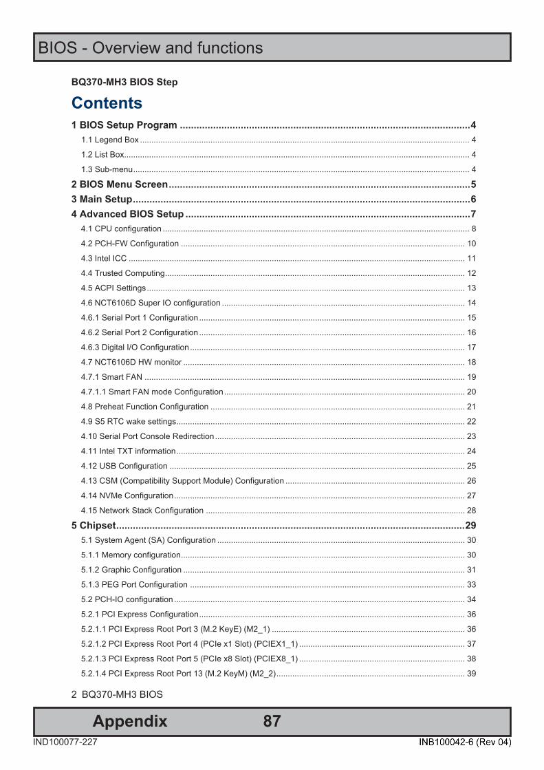
87
BIOS - Overview and functions
AppendixIND100077-227
BQ370-MH3 BIOS Step
2 BQ370-MH3 BIOS
Contents 1 BIOS Setup Program ......................................................................................................... 4
1.1 Legend Box ................................................................................................................................................. 4 1.2 List Box........................................................................................................................................................ 4 1.3 Sub-menu .................................................................................................................................................... 4
2 BIOS Menu Screen ............................................................................................................. 5 3 Main Setup .......................................................................................................................... 6 4 Advanced BIOS Setup ....................................................................................................... 7
4.1 CPU configuration ....................................................................................................................................... 8 4.2 PCH-FW Configuration ............................................................................................................................. 10 4.3 Intel ICC .................................................................................................................................................... 11 4.4 Trusted Computing .................................................................................................................................... 12 4.5 ACPI Settings ............................................................................................................................................ 13 4.6 NCT6106D Super IO configuration ........................................................................................................... 14 4.6.1 Serial Port 1 Configuration ..................................................................................................................... 15 4.6.2 Serial Port 2 Configuration ..................................................................................................................... 16 4.6.3 Digital I/O Configuration ......................................................................................................................... 17 4.7 NCT6106D HW monitor ............................................................................................................................ 18 4.7.1 Smart FAN ............................................................................................................................................. 19 4.7.1.1 Smart FAN mode Configuration .......................................................................................................... 20 4.8 Preheat Function Configuration ................................................................................................................ 21 4.9 S5 RTC wake settings ............................................................................................................................... 22 4.10 Serial Port Console Redirection .............................................................................................................. 23 4.11 Intel TXT information ............................................................................................................................... 24 4.12 USB Configuration .................................................................................................................................. 25 4.13 CSM (Compatibility Support Module) Configuration ............................................................................... 26 4.14 NVMe Configuration ................................................................................................................................ 27 4.15 Network Stack Configuration .................................................................................................................. 28
5 Chipset .............................................................................................................................. 29 5.1 System Agent (SA) Configuration ............................................................................................................. 30 5.1.1 Memory configuration............................................................................................................................. 30 5.1.2 Graphic Configuration ............................................................................................................................ 31 5.1.3 PEG Port Configuration ......................................................................................................................... 33 5.2 PCH-IO configuration ................................................................................................................................ 34 5.2.1 PCI Express Configuration ..................................................................................................................... 36 5.2.1.1 PCI Express Root Port 3 (M.2 KeyE) (M2_1) ..................................................................................... 36 5.2.1.2 PCI Express Root Port 4 (PCIe x1 Slot) (PCIEX1_1) ......................................................................... 37 5.2.1.3 PCI Express Root Port 5 (PCIe x8 Slot) (PCIEX8_1) ......................................................................... 38 5.2.1.4 PCI Express Root Port 13 (M.2 KeyM) (M2_2) ................................................................................... 39
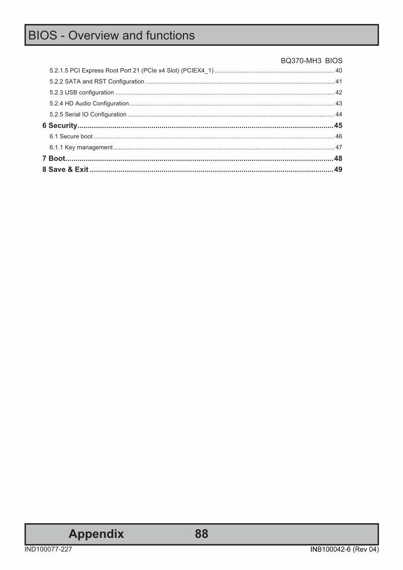
88
BIOS - Overview and functions
AppendixIND100077-227
BQ370-MH3 BIOS
BQ370-MH3 BIOS
3
5.2.1.5 PCI Express Root Port 21 (PCIe x4 Slot) (PCIEX4_1) ....................................................................... 40 5.2.2 SATA and RST Configuration ................................................................................................................ 41 5.2.3 USB configuration .................................................................................................................................. 42 5.2.4 HD Audio Configuration .......................................................................................................................... 43 5.2.5 Serial IO Configuration ........................................................................................................................... 44
6 Security ............................................................................................................................. 45 6.1 Secure boot ............................................................................................................................................... 46 6.1.1 Key management ................................................................................................................................... 47
7 Boot ................................................................................................................................... 48 8 Save & Exit ....................................................................................................................... 49
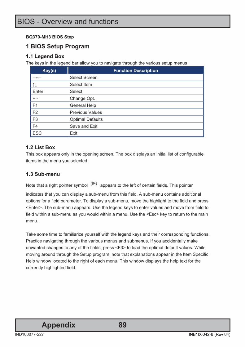
89
BIOS - Overview and functions
AppendixIND100077-227
BQ370-MH3 BIOS Step
4 BQ370-MH3 BIOS
1 BIOS Setup Program 1.1 Legend Box The keys in the legend bar allow you to navigate through the various setup menus
Key(s) Function Description →← Select Screen ↑↓ Select Item Enter Select + - Change Opt. F1 General Help F2 Previous Values F3 Optimal Defaults F4 Save and Exit ESC Exit
1.2 List Box This box appears only in the opening screen. The box displays an initial list of configurable items in the menu you selected. 1.3 Sub-menu
Note that a right pointer symbol appears to the left of certain fields. This pointer
indicates that you can display a sub-menu from this field. A sub-menu contains additional options for a field parameter. To display a sub-menu, move the highlight to the field and press <Enter>. The sub-menu appears. Use the legend keys to enter values and move from field to field within a sub-menu as you would within a menu. Use the <Esc> key to return to the main menu. Take some time to familiarize yourself with the legend keys and their corresponding functions. Practice navigating through the various menus and submenus. If you accidentally make unwanted changes to any of the fields, press <F3> to load the optimal default values. While moving around through the Setup program, note that explanations appear in the Item Specific Help window located to the right of each menu. This window displays the help text for the currently highlighted field.
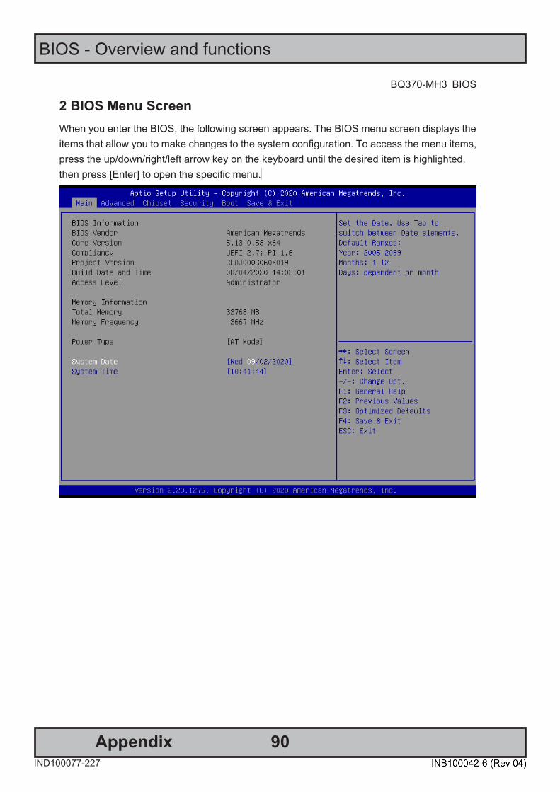
90
BIOS - Overview and functions
AppendixIND100077-227
BQ370-MH3 BIOS
BQ370-MH3 BIOS
5
2 BIOS Menu Screen When you enter the BIOS, the following screen appears. The BIOS menu screen displays the items that allow you to make changes to the system configuration. To access the menu items, press the up/down/right/left arrow key on the keyboard until the desired item is highlighted, then press [Enter] to open the specific menu.
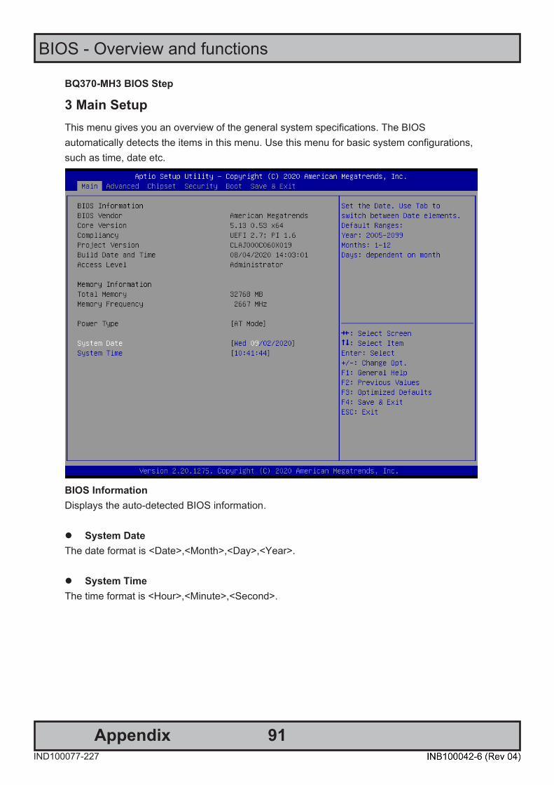
91
BIOS - Overview and functions
AppendixIND100077-227
BQ370-MH3 BIOS Step
6 BQ370-MH3 BIOS
3 Main Setup This menu gives you an overview of the general system specifications. The BIOS automatically detects the items in this menu. Use this menu for basic system configurations, such as time, date etc.
BIOS Information Displays the auto-detected BIOS information. ⚫ System Date The date format is <Date>,<Month>,<Day>,<Year>. ⚫ System Time The time format is <Hour>,<Minute>,<Second>.
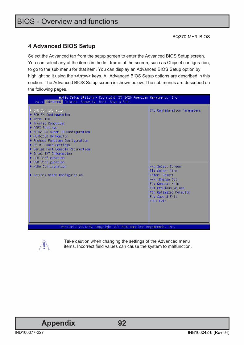
92
BIOS - Overview and functions
AppendixIND100077-227
BQ370-MH3 BIOS
BQ370-MH3 BIOS
7
4 Advanced BIOS Setup Select the Advanced tab from the setup screen to enter the Advanced BIOS Setup screen. You can select any of the items in the left frame of the screen, such as Chipset configuration, to go to the sub menu for that item. You can display an Advanced BIOS Setup option by highlighting it using the <Arrow> keys. All Advanced BIOS Setup options are described in this section. The Advanced BIOS Setup screen is shown below. The sub menus are described on the following pages.
Take caution when changing the settings of the Advanced menu items. Incorrect field values can cause the system to malfunction.

93
BIOS - Overview and functions
AppendixIND100077-227
BQ370-MH3 BIOS Step
8 BQ370-MH3 BIOS
4.1 CPU configuration
These options may differ to each CPU. It depends on the feature and items of each CPU models. This screenshot is for reference only. ⚫ C6DRAM [Enabled]
Enabled or Disabled moving DRAM content to PRM memory when CPU is in C6 state. Configuration options: [Disabled][Enabled] This depends on CPU sku.
⚫ Software Guard Extensions(SGX) [software controlled] Enable or disables Guard Extensions Configuration options:[Disabled][Enabled][Software Controlled]
⚫ Select owner EPOCH input type [No change in owner EPOCHs] After user enters EPOCH values manually, the values will not be visible for security reasons Configuration options:[No Change in Owner EPOCHs][Change to New Random Owner EPOCHs][Manual User Defined Owner EPOCHs]
⚫ Intel Virtualization Technology [Enabled] When enabled, a VWM can utilize the additional hardware capabilities provided by Vandrpool Technology
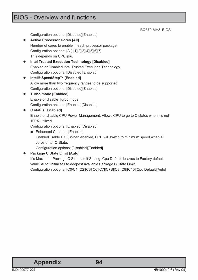
94
BIOS - Overview and functions
AppendixIND100077-227
BQ370-MH3 BIOS
BQ370-MH3 BIOS
9
Configuration options: [Disabled][Enabled] ⚫ Active Processor Cores [All]
Number of cores to enable in each processor package Configuration options: [All] [1][2][3][4][5][6][7] This depends on CPU sku.
⚫ Intel Trusted Execution Technology [Disabled] Enabled or Disabled Intel Trusted Execution Technology. Configuration options: [Disabled][Enabled]
⚫ Intel® SpeedStep™ [Enabled] Allow more than two frequency ranges to be supported. Configuration options: [Disabled][Enabled]
⚫ Turbo mode [Enabled] Enable or disable Turbo mode Configuration options: [Enabled][Disabled]
⚫ C status [Enabled] Enable or disable CPU Power Management. Allows CPU to go to C states when it’s not 100% utilized. Configuration options: [Enabled][Disabled] ◼ Enhanced C-states: [Enabled]
Enable/Disable C1E. When enabled, CPU will switch to minimum speed when all cores enter C-State. Configuration options: [Disabled][Enabled]
⚫ Package C State Limit [Auto] It’s Maximum Package C State Limit Setting. Cpu Default: Leaves to Factory default value. Auto: Initializes to deepest available Package C State Limit. Configuration options: [C0/C1][C2][C3][C6][C7][C7S][C8][C9][C10][Cpu Default][Auto]

95
BIOS - Overview and functions
AppendixIND100077-227
BQ370-MH3 BIOS Step
10 BQ370-MH3 BIOS
4.2 PCH-FW Configuration It shows ME version and ME status.
⚫ ME State [Enable]
Enable or Disable Intel ME. Configuration options: [Enable][Disable]
⚫ ME Unlock Control [Lock] ME unlock switch function. This function will automatically recover setting from Unlock to Lock after power-on system. Configuration options: [Lock][Unlock]
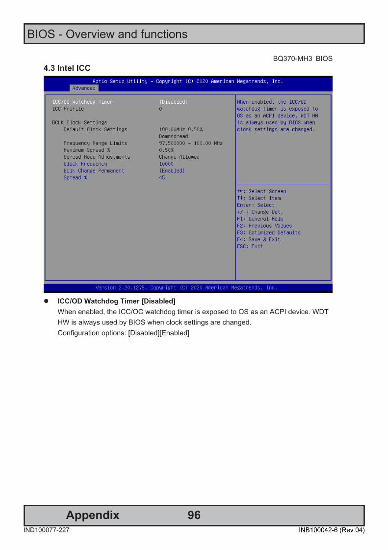
96
BIOS - Overview and functions
AppendixIND100077-227
BQ370-MH3 BIOS
BQ370-MH3 BIOS
11
4.3 Intel ICC
⚫ ICC/OD Watchdog Timer [Disabled]
When enabled, the ICC/OC watchdog timer is exposed to OS as an ACPI device. WDT HW is always used by BIOS when clock settings are changed. Configuration options: [Disabled][Enabled]

97
BIOS - Overview and functions
AppendixIND100077-227
BQ370-MH3 BIOS Step
12 BQ370-MH3 BIOS
4.4 Trusted Computing Security device settings
⚫ Security Device Support [Enable]
Enable or Disable BIOS support for security device. Configuration options: [Disable][Enable]
⚫ SHA-1 PCR Bank [Enabled] Enable or Disable SHA-1 PCR Bank. Configuration options: [Disabled][Enabled]
⚫ SHA256 PCR Bank [Enabled] Enable or Disable SHA256 PCR Bank. Configuration options: [Disabled][Enabled]
⚫ Pending Operation [None] Schedule and operation for the Security Device. Configuration options: [None][TPM clear]

98
BIOS - Overview and functions
AppendixIND100077-227
BQ370-MH3 BIOS
BQ370-MH3 BIOS
13
4.5 ACPI Settings
⚫ Enable Hibernation [Enabled]
Enable or Disable system ability to Hibernation. Configuration options: [Disabled][Enabled]
⚫ ACPI Sleep State [S3 (Suspend to RAM)] Select the highest ACPI sleep state the system will enter the SUSPEND button is press. Configuration options: [Suspend Disabled][S3 (suspend to RAM)]
⚫ S3 Video Repost [Disabled] Enable or disable S3 video repost Configuration options: [Disabled][Enabled]
⚫ PCIE# wake from S5 [Disabled] Enable or disable PCIE wake the system from S5. Configuration options: [Disabled][Enabled]

99
BIOS - Overview and functions
AppendixIND100077-227
BQ370-MH3 BIOS Step
14 BQ370-MH3 BIOS
4.6 NCT6106D Super IO configuration Provide NCT6106D super IO configuration settings
⚫ WatchDog count mode [Second]
WatchDog count mode Selection Configuration options: [Second][Minute]
⚫ WatchDog Timeout value Fill watchdog timeout value, 0 means disables

100
BIOS - Overview and functions
AppendixIND100077-227
BQ370-MH3 BIOS
BQ370-MH3 BIOS
15
4.6.1 Serial Port 1 Configuration
⚫ Serial Port [Enabled]
Enable or Disable serial Port (COM) Configuration options: [Disabled][Enabled]
⚫ Change Settings [Auto] Select an optimal settings for super IO device Configuration options: as below
⚫ COM mode Select [RS232]
Configure the Com port mode Configuration options: [RS232][RS485 Half Duplex][RS485 Full Duplex]
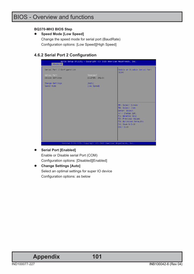
101
BIOS - Overview and functions
AppendixIND100077-227
BQ370-MH3 BIOS Step
16 BQ370-MH3 BIOS
⚫ Speed Mode [Low Speed] Change the speed mode for serial port (BaudRate) Configuration options: [Low Speed][High Speed]
4.6.2 Serial Port 2 Configuration
⚫ Serial Port [Enabled]
Enable or Disable serial Port (COM) Configuration options: [Disabled][Enabled]
⚫ Change Settings [Auto] Select an optimal settings for super IO device Configuration options: as below
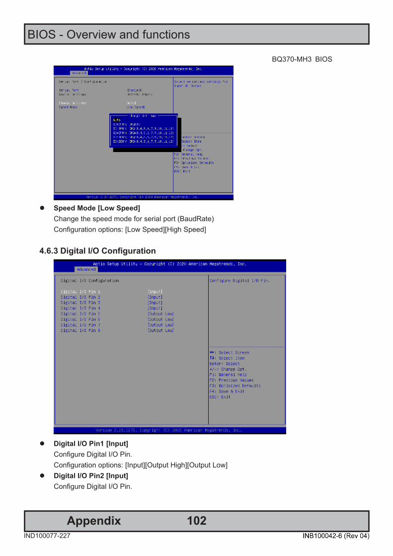
102
BIOS - Overview and functions
AppendixIND100077-227
BQ370-MH3 BIOS
BQ370-MH3 BIOS
17
⚫ Speed Mode [Low Speed]
Change the speed mode for serial port (BaudRate) Configuration options: [Low Speed][High Speed]
4.6.3 Digital I/O Configuration
⚫ Digital I/O Pin1 [Input]
Configure Digital I/O Pin. Configuration options: [Input][Output High][Output Low]
⚫ Digital I/O Pin2 [Input] Configure Digital I/O Pin.

103
BIOS - Overview and functions
AppendixIND100077-227
BQ370-MH3 BIOS Step
18 BQ370-MH3 BIOS
Configuration options: [Input][Output High][Output Low] ⚫ Digital I/O Pin3 [Input]
Configure Digital I/O Pin. Configuration options: [Input][Output High][Output Low]
⚫ Digital I/O Pin4 [Input] Configure Digital I/O Pin. Configuration options: [Input][Output High][Output Low]
⚫ Digital I/O Pin5 [Output Low] Configure Digital I/O Pin. Configuration options: [Input][Output High][Output Low]
⚫ Digital I/O Pin6 [Output Low] Configure Digital I/O Pin. Configuration options: [Input][Output High][Output Low]
⚫ Digital I/O Pin7 [Output Low] Configure Digital I/O Pin. Configuration options: [Input][Output High][Output Low]
⚫ Digital I/O Pin8 [Output Low] Configure Digital I/O Pin. Configuration options: [Input][Output High][Output Low]
4.7 NCT6106D HW monitor Display Hardware monitor information

104
BIOS - Overview and functions
AppendixIND100077-227
BQ370-MH3 BIOS
BQ370-MH3 BIOS
19
4.7.1 Smart FAN
⚫ Smart FAN Function [Enabled]

105
BIOS - Overview and functions
AppendixIND100077-227
BQ370-MH3 BIOS Step
20 BQ370-MH3 BIOS
Smart fan function Enable/Disabled Configuration options: [Disabled][Enabled]
4.7.1.1 Smart FAN mode Configuration
⚫ SYS Smart Fan Mode [Manual Mode]
SYS Smart FAN Mode selection Configuration options: [Manual Mode][Thermal Cruise Mode][SMART FAN IV Mode]
⚫ CPU Smart Fan Mode [Manual Mode] CPU Smart FAN Mode selection Configuration options: [Manual Mode][Thermal Cruise Mode][SMART FAN IV Mode]
⚫ REAR Smart Fan Mode [Manual Mode] CPU Smart FAN Mode selection Configuration options: [Manual Mode][Thermal Cruise Mode][SMART FAN IV Mode]
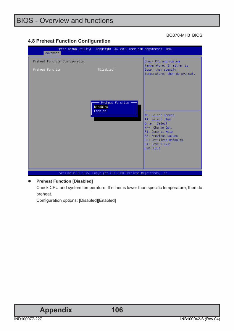
106
BIOS - Overview and functions
AppendixIND100077-227
BQ370-MH3 BIOS
BQ370-MH3 BIOS
21
4.8 Preheat Function Configuration
⚫ Preheat Function [Disabled]
Check CPU and system temperature. If either is lower than specific temperature, then do preheat. Configuration options: [Disabled][Enabled]

107
BIOS - Overview and functions
AppendixIND100077-227
BQ370-MH3 BIOS Step
22 BQ370-MH3 BIOS
4.9 S5 RTC wake settings
⚫ Wake system from S5 [Disabled]
Enabled or Disabled system wake on alarm event Configuration options: [Disabled][Enabled]

108
BIOS - Overview and functions
AppendixIND100077-227
BQ370-MH3 BIOS
BQ370-MH3 BIOS
23
4.10 Serial Port Console Redirection
⚫ Console Redirection [Disabled]
Enabled or Disabled Console Redirection Configuration options: [Disabled][Enabled]
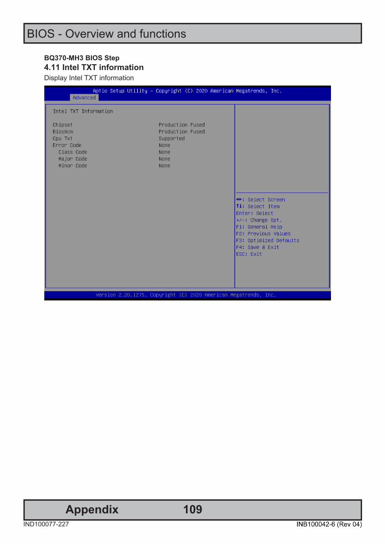
109
BIOS - Overview and functions
AppendixIND100077-227
BQ370-MH3 BIOS Step
24 BQ370-MH3 BIOS
4.11 Intel TXT information Display Intel TXT information
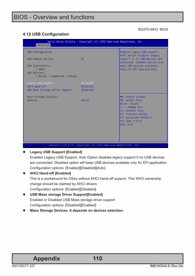
110
BIOS - Overview and functions
AppendixIND100077-227
BQ370-MH3 BIOS
BQ370-MH3 BIOS
25
4.12 USB Configuration
⚫ Legacy USB Support [Enabled]
Enabled Legacy USB Support. Auto Option disables legacy support if no USB devices are connected. Disabled option will keep USB devices available only for EFI application. Configuration options: [Enabled][Disabled][Auto]
⚫ XHCI Hand-off [Enabled] This is a workaround for OSes without XHCI hand-off support. This XHCI ownership change should be claimed by XHCI drivers Configuration options: [Enabled][Disabled]
⚫ USB Mass storage Driver Support[Enabled] Enabled or Disabled USB Mass storage driver support. Configuration options: [Disabled][Enabled]
⚫ Mass Storage Devices: It depends on devices selection.

111
BIOS - Overview and functions
AppendixIND100077-227
BQ370-MH3 BIOS Step
26 BQ370-MH3 BIOS
4.13 CSM (Compatibility Support Module) Configuration
⚫ CSM Support [Enabled]
Enabled or disabled CSM Support Configuration options: [Disabled][Enabled]
⚫ Boot option Filter [UEFI and Legacy] This option controls Legacy/UEFI ROMs Priority Configuration options: [UEFI and Legacy][Legacy Only][UEFI Only]
⚫ Network [UEFI] Control the execution of UEFI and Legacy PXE OpROM Configuration options: [Do not launch][UEFI][Legacy]
⚫ Storage [UEFI] Control the execution of UEFI and Legacy Storage OpROM Configuration options: [Do not launch][UEFI][Legacy]
⚫ Video [UEFI] Control the execution of UEFI and Legacy Video OpROM Configuration options: [Do not launch][UEFI][Legacy]
⚫ Other PCI devices [UEFI] Determine OpROM execution policy for devices other than Network, Storage, or Video. Configuration options: [Do not launch][UEFI][Legacy]
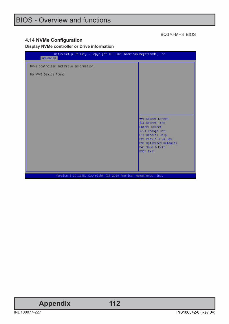
112
BIOS - Overview and functions
AppendixIND100077-227
BQ370-MH3 BIOS
BQ370-MH3 BIOS
27
4.14 NVMe Configuration Display NVMe controller or Drive information
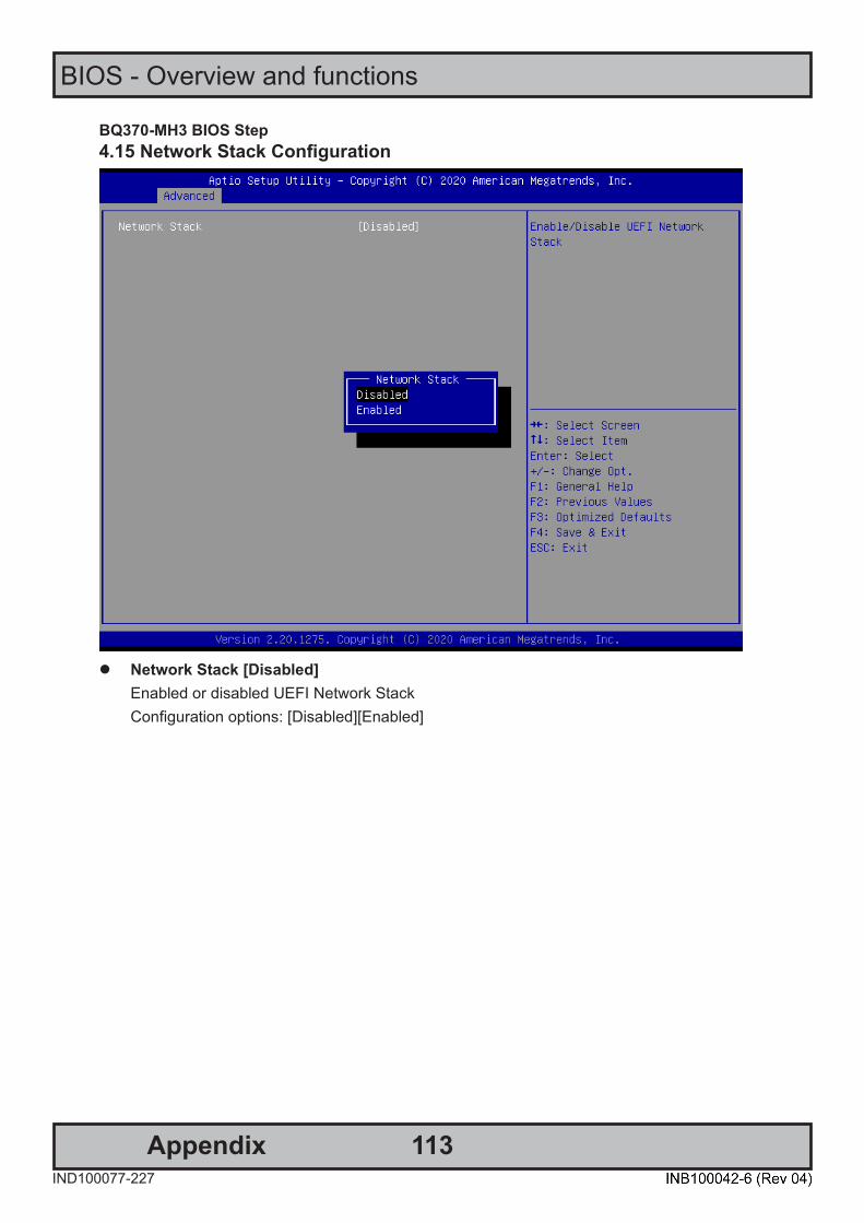
113
BIOS - Overview and functions
AppendixIND100077-227
BQ370-MH3 BIOS Step
28 BQ370-MH3 BIOS
4.15 Network Stack Configuration
⚫ Network Stack [Disabled]
Enabled or disabled UEFI Network Stack Configuration options: [Disabled][Enabled]

114
BIOS - Overview and functions
AppendixIND100077-227
BQ370-MH3 BIOS
BQ370-MH3 BIOS
29
5 Chipset

115
BIOS - Overview and functions
AppendixIND100077-227
BQ370-MH3 BIOS Step
30 BQ370-MH3 BIOS
5.1 System Agent (SA) Configuration
⚫ VT-d [Enabled]
VT-d capability Configuration options: [Disabled][Enabled]
5.1.1 Memory configuration Display memeory information
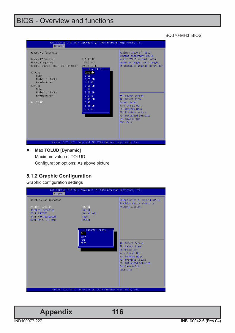
116
BIOS - Overview and functions
AppendixIND100077-227
BQ370-MH3 BIOS
BQ370-MH3 BIOS
31
⚫ Max TOLUD [Dynamic]
Maximum value of TOLUD. Configuration options: As above picture
5.1.2 Graphic Configuration Graphic configuration settings
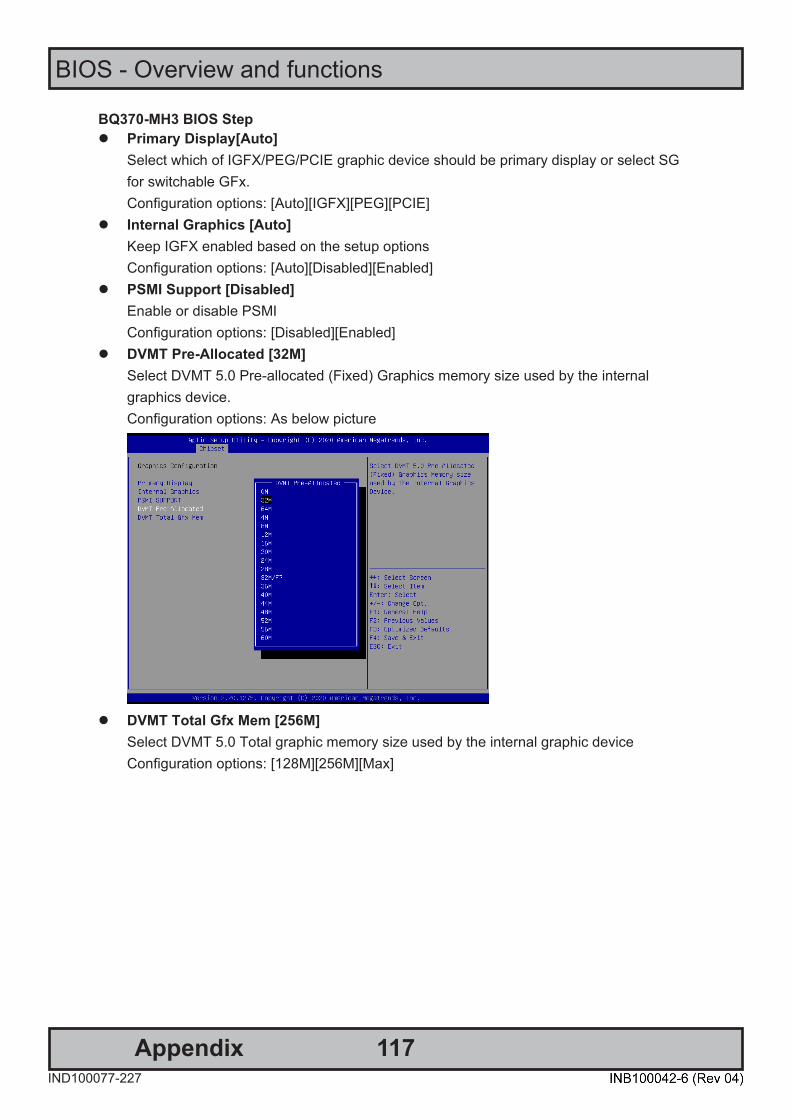
117
BIOS - Overview and functions
AppendixIND100077-227
BQ370-MH3 BIOS Step
32 BQ370-MH3 BIOS
⚫ Primary Display[Auto] Select which of IGFX/PEG/PCIE graphic device should be primary display or select SG for switchable GFx. Configuration options: [Auto][IGFX][PEG][PCIE]
⚫ Internal Graphics [Auto] Keep IGFX enabled based on the setup options Configuration options: [Auto][Disabled][Enabled]
⚫ PSMI Support [Disabled] Enable or disable PSMI Configuration options: [Disabled][Enabled]
⚫ DVMT Pre-Allocated [32M] Select DVMT 5.0 Pre-allocated (Fixed) Graphics memory size used by the internal graphics device. Configuration options: As below picture
⚫ DVMT Total Gfx Mem [256M]
Select DVMT 5.0 Total graphic memory size used by the internal graphic device Configuration options: [128M][256M][Max]
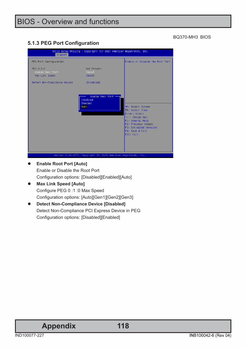
118
BIOS - Overview and functions
AppendixIND100077-227
BQ370-MH3 BIOS
BQ370-MH3 BIOS
33
5.1.3 PEG Port Configuration
⚫ Enable Root Port [Auto]
Enable or Disable the Root Port Configuration options: [Disabled][Enabled][Auto]
⚫ Max Link Speed [Auto] Configure PEG 0 :1 :0 Max Speed Configuration options: [Auto][Gen1][Gen2][Gen3]
⚫ Detect Non-Compliance Device [Disabled] Detect Non-Compliance PCI Express Device in PEG Configuration options: [Disabled][Enabled]
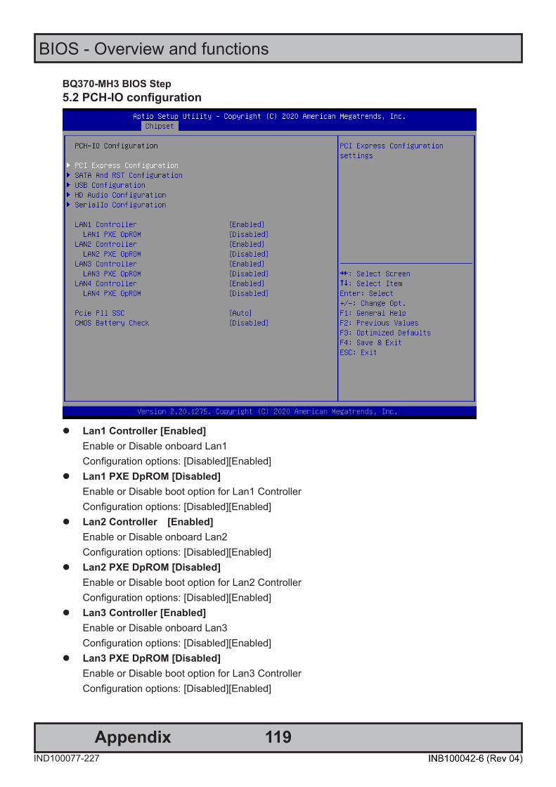
119
BIOS - Overview and functions
AppendixIND100077-227
BQ370-MH3 BIOS Step
34 BQ370-MH3 BIOS
5.2 PCH-IO configuration
⚫ Lan1 Controller [Enabled]
Enable or Disable onboard Lan1 Configuration options: [Disabled][Enabled]
⚫ Lan1 PXE DpROM [Disabled] Enable or Disable boot option for Lan1 Controller Configuration options: [Disabled][Enabled]
⚫ Lan2 Controller [Enabled] Enable or Disable onboard Lan2 Configuration options: [Disabled][Enabled]
⚫ Lan2 PXE DpROM [Disabled] Enable or Disable boot option for Lan2 Controller Configuration options: [Disabled][Enabled]
⚫ Lan3 Controller [Enabled] Enable or Disable onboard Lan3 Configuration options: [Disabled][Enabled]
⚫ Lan3 PXE DpROM [Disabled] Enable or Disable boot option for Lan3 Controller Configuration options: [Disabled][Enabled]
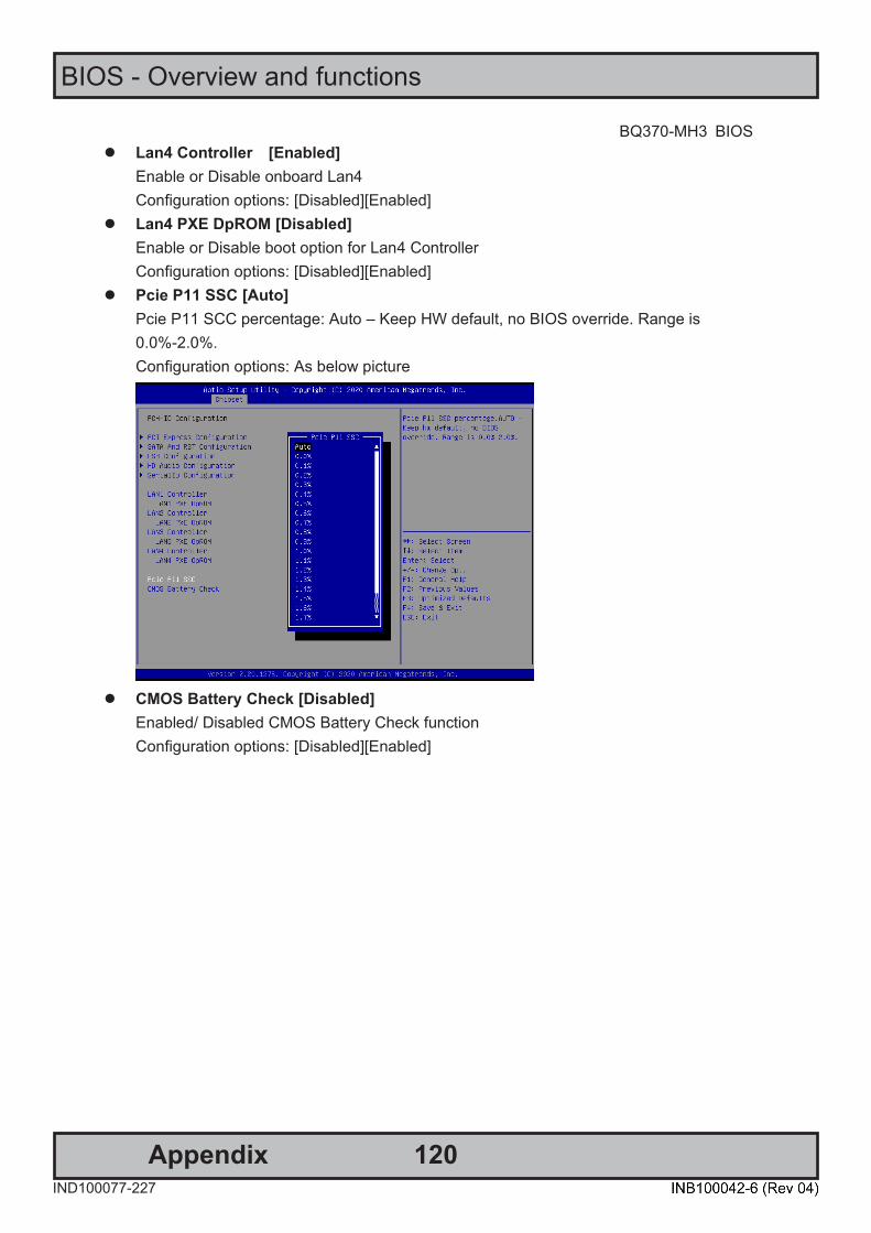
120
BIOS - Overview and functions
AppendixIND100077-227
BQ370-MH3 BIOS
BQ370-MH3 BIOS
35
⚫ Lan4 Controller [Enabled] Enable or Disable onboard Lan4 Configuration options: [Disabled][Enabled]
⚫ Lan4 PXE DpROM [Disabled] Enable or Disable boot option for Lan4 Controller Configuration options: [Disabled][Enabled]
⚫ Pcie P11 SSC [Auto] Pcie P11 SCC percentage: Auto – Keep HW default, no BIOS override. Range is 0.0%-2.0%. Configuration options: As below picture
⚫ CMOS Battery Check [Disabled]
Enabled/ Disabled CMOS Battery Check function Configuration options: [Disabled][Enabled]

121
BIOS - Overview and functions
AppendixIND100077-227
BQ370-MH3 BIOS Step
36 BQ370-MH3 BIOS
5.2.1 PCI Express Configuration 5.2.1.1 PCI Express Root Port 3 (M.2 KeyE) (M2_1)
⚫ PCI Express Root Port 3 [Enabled]
Control the PCI Express Root Port Configuration options: [Disabled][Enabled]
⚫ ASPM 3 [Disabled] Set the ASPM level: Force L0s- Force all links to L0s State; Auto- BIOS auto configure; Disabled- Disables ASPM Configuration options: [Disabled][L0s][L1][L0sL1][Auto]
⚫ PCIe Speed [Auto] Select PCI Express Port speed Configuration options: [Auto][Gen1][Gen2][Gen3]
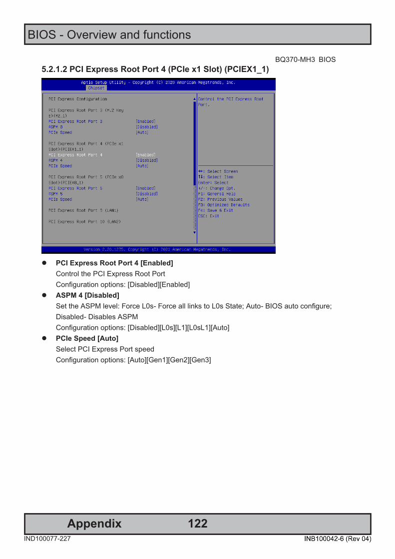
122
BIOS - Overview and functions
AppendixIND100077-227
BQ370-MH3 BIOS
BQ370-MH3 BIOS
37
5.2.1.2 PCI Express Root Port 4 (PCIe x1 Slot) (PCIEX1_1)
⚫ PCI Express Root Port 4 [Enabled]
Control the PCI Express Root Port Configuration options: [Disabled][Enabled]
⚫ ASPM 4 [Disabled] Set the ASPM level: Force L0s- Force all links to L0s State; Auto- BIOS auto configure; Disabled- Disables ASPM Configuration options: [Disabled][L0s][L1][L0sL1][Auto]
⚫ PCIe Speed [Auto] Select PCI Express Port speed Configuration options: [Auto][Gen1][Gen2][Gen3]
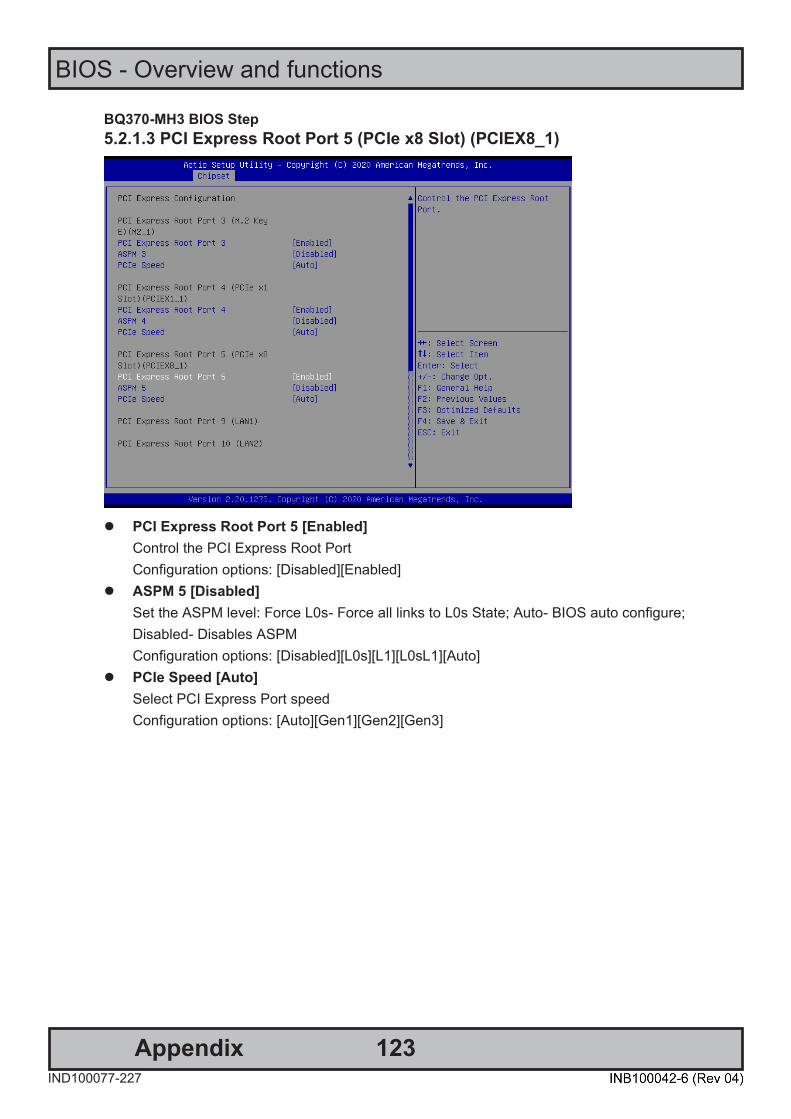
123
BIOS - Overview and functions
AppendixIND100077-227
BQ370-MH3 BIOS Step
38 BQ370-MH3 BIOS
5.2.1.3 PCI Express Root Port 5 (PCIe x8 Slot) (PCIEX8_1)
⚫ PCI Express Root Port 5 [Enabled]
Control the PCI Express Root Port Configuration options: [Disabled][Enabled]
⚫ ASPM 5 [Disabled] Set the ASPM level: Force L0s- Force all links to L0s State; Auto- BIOS auto configure; Disabled- Disables ASPM Configuration options: [Disabled][L0s][L1][L0sL1][Auto]
⚫ PCIe Speed [Auto] Select PCI Express Port speed Configuration options: [Auto][Gen1][Gen2][Gen3]

124
BIOS - Overview and functions
AppendixIND100077-227
BQ370-MH3 BIOS
BQ370-MH3 BIOS
39
5.2.1.4 PCI Express Root Port 13 (M.2 KeyM) (M2_2)
⚫ PCI Express Root Port 13 [Enabled]
Control the PCI Express Root Port Configuration options: [Disabled][Enabled]
⚫ ASPM 13 [Disabled] Set the ASPM level: Force L0s- Force all links to L0s State; Auto- BIOS auto configure; Disabled- Disables ASPM Configuration options: [Disabled][L0s][L1][L0sL1][Auto]
⚫ PCIe Speed [Auto] Select PCI Express Port speed Configuration options: [Auto][Gen1][Gen2][Gen3]
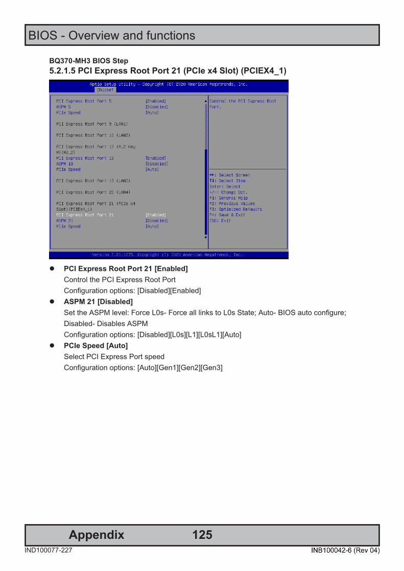
125
BIOS - Overview and functions
AppendixIND100077-227
BQ370-MH3 BIOS Step
40 BQ370-MH3 BIOS
5.2.1.5 PCI Express Root Port 21 (PCIe x4 Slot) (PCIEX4_1)
⚫ PCI Express Root Port 21 [Enabled]
Control the PCI Express Root Port Configuration options: [Disabled][Enabled]
⚫ ASPM 21 [Disabled] Set the ASPM level: Force L0s- Force all links to L0s State; Auto- BIOS auto configure; Disabled- Disables ASPM Configuration options: [Disabled][L0s][L1][L0sL1][Auto]
⚫ PCIe Speed [Auto] Select PCI Express Port speed Configuration options: [Auto][Gen1][Gen2][Gen3]
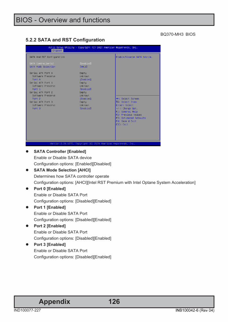
126
BIOS - Overview and functions
AppendixIND100077-227
BQ370-MH3 BIOS
BQ370-MH3 BIOS
41
5.2.2 SATA and RST Configuration
⚫ SATA Controller [Enabled]
Enable or Disable SATA device Configuration options: [Enabled][Disabled]
⚫ SATA Mode Selection [AHCI] Determines how SATA controller operate Configuration options: [AHCI][Intel RST Premium with Intel Optane System Acceleration]
⚫ Port 0 [Enabled] Enable or Disable SATA Port Configuration options: [Disabled][Enabled]
⚫ Port 1 [Enabled] Enable or Disable SATA Port Configuration options: [Disabled][Enabled]
⚫ Port 2 [Enabled] Enable or Disable SATA Port Configuration options: [Disabled][Enabled]
⚫ Port 3 [Enabled] Enable or Disable SATA Port Configuration options: [Disabled][Enabled]
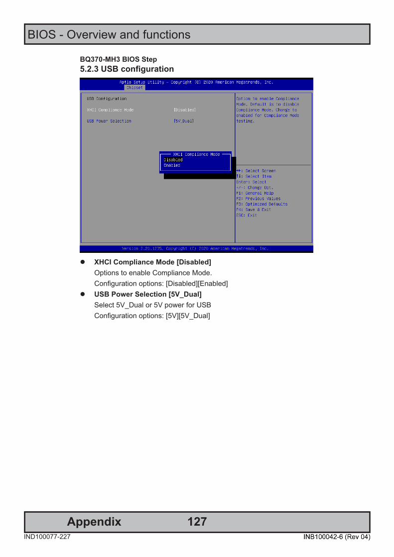
127
BIOS - Overview and functions
AppendixIND100077-227
BQ370-MH3 BIOS Step
42 BQ370-MH3 BIOS
5.2.3 USB configuration
⚫ XHCI Compliance Mode [Disabled]
Options to enable Compliance Mode. Configuration options: [Disabled][Enabled]
⚫ USB Power Selection [5V_Dual] Select 5V_Dual or 5V power for USB Configuration options: [5V][5V_Dual]
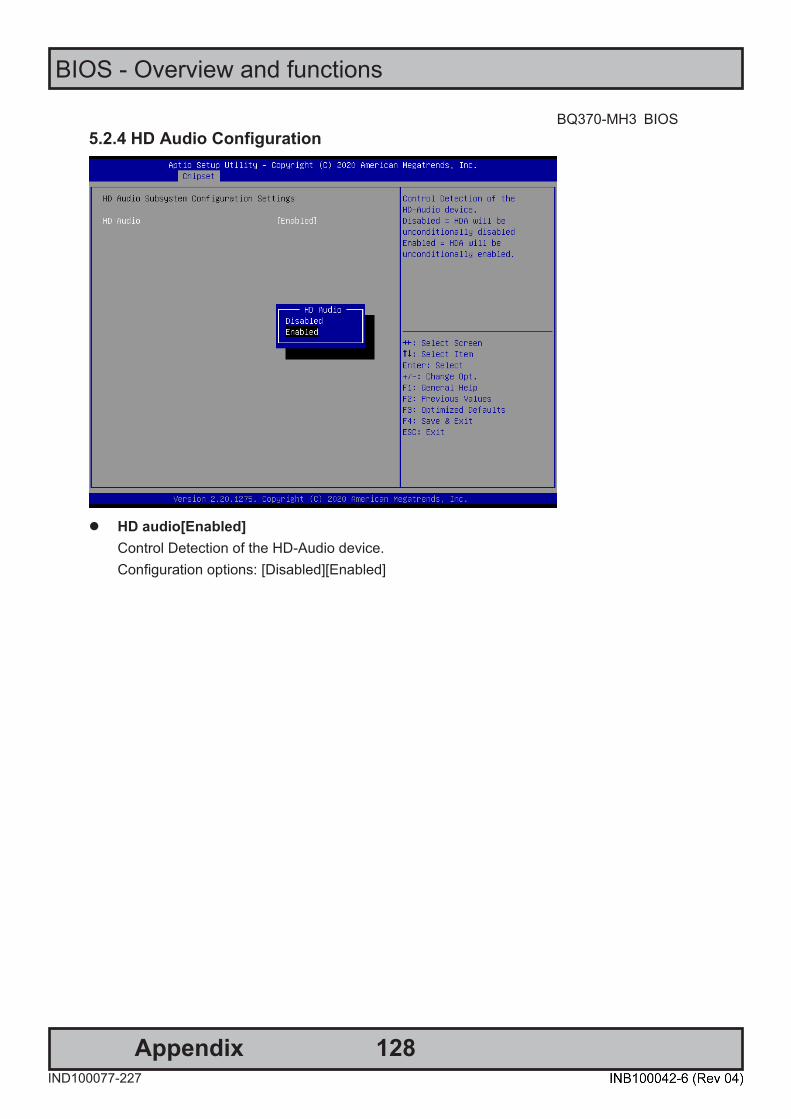
128
BIOS - Overview and functions
AppendixIND100077-227
BQ370-MH3 BIOS
BQ370-MH3 BIOS
43
5.2.4 HD Audio Configuration
⚫ HD audio[Enabled]
Control Detection of the HD-Audio device. Configuration options: [Disabled][Enabled]
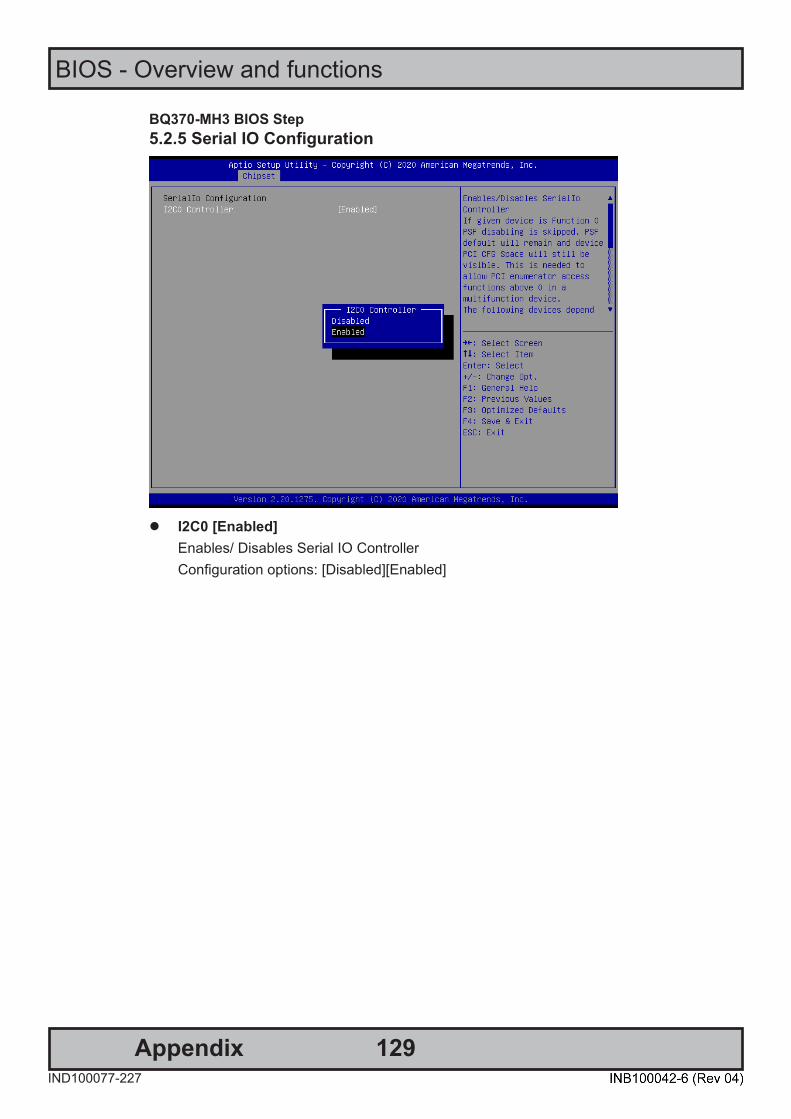
129
BIOS - Overview and functions
AppendixIND100077-227
BQ370-MH3 BIOS Step
44 BQ370-MH3 BIOS
5.2.5 Serial IO Configuration
⚫ I2C0 [Enabled]
Enables/ Disables Serial IO Controller Configuration options: [Disabled][Enabled]
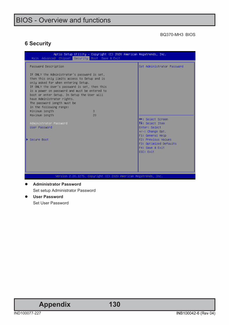
130
BIOS - Overview and functions
AppendixIND100077-227
BQ370-MH3 BIOS
BQ370-MH3 BIOS
45
6 Security
⚫ Administrator Password
Set setup Administrator Password ⚫ User Password
Set User Password
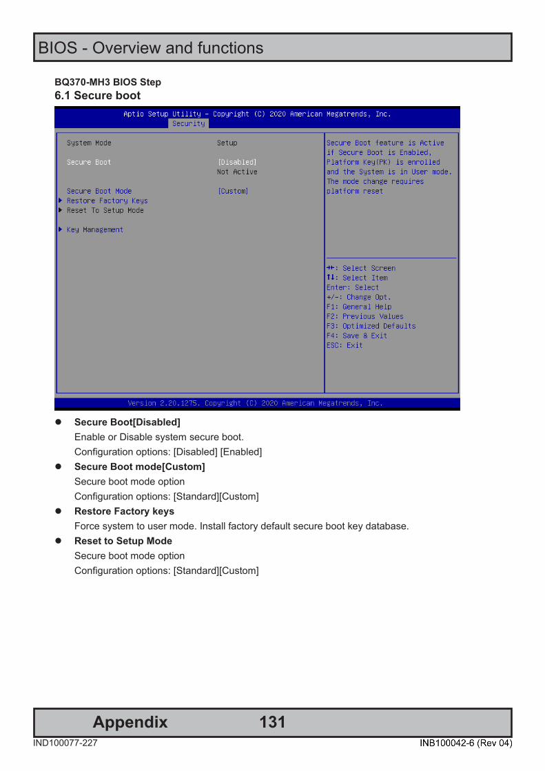
131
BIOS - Overview and functions
AppendixIND100077-227
BQ370-MH3 BIOS Step
46 BQ370-MH3 BIOS
6.1 Secure boot
⚫ Secure Boot[Disabled]
Enable or Disable system secure boot. Configuration options: [Disabled] [Enabled]
⚫ Secure Boot mode[Custom] Secure boot mode option Configuration options: [Standard][Custom]
⚫ Restore Factory keys Force system to user mode. Install factory default secure boot key database.
⚫ Reset to Setup Mode Secure boot mode option Configuration options: [Standard][Custom]
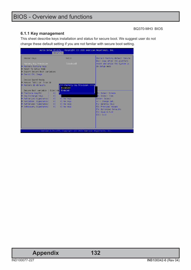
132
BIOS - Overview and functions
AppendixIND100077-227
BQ370-MH3 BIOS
BQ370-MH3 BIOS
47
6.1.1 Key management This sheet describe keys installation and status for secure boot. We suggest user do not change these default setting if you are not familar with secure boot setting.

133
BIOS - Overview and functions
AppendixIND100077-227
BQ370-MH3 BIOS Step
48 BQ370-MH3 BIOS
7 Boot
⚫ Setup Prompt Timeout [1]
Number of seconds to wait for setup activation key. 65535(0xFFFF) means indefinite waiting.
⚫ Bootup NumLock State [On] Select the keyboard NumLock state Configuration options: [On][Off]
⚫ Quick Boot [Disable] Enable or disable Quick Boot option Configuration options: [Disabled][Enabled]
⚫ Boot mode [UEFI] Select boot mode LEGACY/UEFI Configuration options: [LEGACY][UEFI]
⚫ UEFI USB Key Drive BBS Priorities Specifies the boot device priority sequence from available UEFI USB key Drives.

134
BIOS - Overview and functions
AppendixIND100077-227
BQ370-MH3 BIOS
BQ370-MH3 BIOS
49
8 Save & Exit
⚫ Save changes and Exit
Exit system setup after saving the changes. ⚫ Discard changes and Exit
Exit system setup without saving the changes. ⚫ Save changes and Reset
Reset the system after saving the changes. ⚫ Restore Defaults
Restore/Load default values for all the setup options.
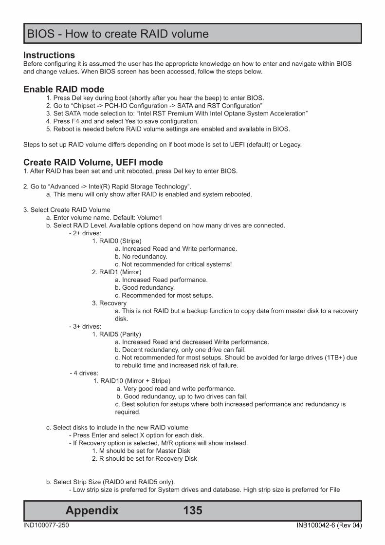
135AppendixIND100077-250
BIOS - How to create RAID volume
InstructionsBefore configuring it is assumed the user has the appropriate knowledge on how to enter and navigate within BIOS and change values. When BIOS screen has been accessed, follow the steps below.
Enable RAID mode1. Press Del key during boot (shortly after you hear the beep) to enter BIOS.2. Go to “Chipset -> PCH-IO Configuration -> SATA and RST Configuration”3. Set SATA mode selection to: “Intel RST Premium With Intel Optane System Acceleration”4. Press F4 and and select Yes to save configuration.5. Reboot is needed before RAID volume settings are enabled and available in BIOS.
Steps to set up RAID volume differs depending on if boot mode is set to UEFI (default) or Legacy.
Create RAID Volume, UEFI mode1. After RAID has been set and unit rebooted, press Del key to enter BIOS.
2. Go to “Advanced -> Intel(R) Rapid Storage Technology”.a. This menu will only show after RAID is enabled and system rebooted.
3. Select Create RAID Volumea. Enter volume name. Default: Volume1b. Select RAID Level. Available options depend on how many drives are connected.
- 2+ drives:1. RAID0 (Stripe)
a. Increased Read and Write performance.b. No redundancy.c. Not recommended for critical systems!
2. RAID1 (Mirror)a. Increased Read performance.b. Good redundancy.c. Recommended for most setups.
3. Recoverya. This is not RAID but a backup function to copy data from master disk to a recovery disk.
- 3+ drives:1. RAID5 (Parity)
a. Increased Read and decreased Write performance.b. Decent redundancy, only one drive can fail.c. Not recommended for most setups. Should be avoided for large drives (1TB+) due to rebuild time and increased risk of failure.
- 4 drives: 1. RAID10 (Mirror + Stripe) a. Very good read and write performance. b. Good redundancy, up to two drives can fail.
c. Best solution for setups where both increased performance and redundancy is required.
c. Select disks to include in the new RAID volume- Press Enter and select X option for each disk.- If Recovery option is selected, M/R options will show instead.
1. M should be set for Master Disk2. R should be set for Recovery Disk
b. Select Strip Size (RAID0 and RAID5 only).- Low strip size is preferred for System drives and database. High strip size is preferred for File
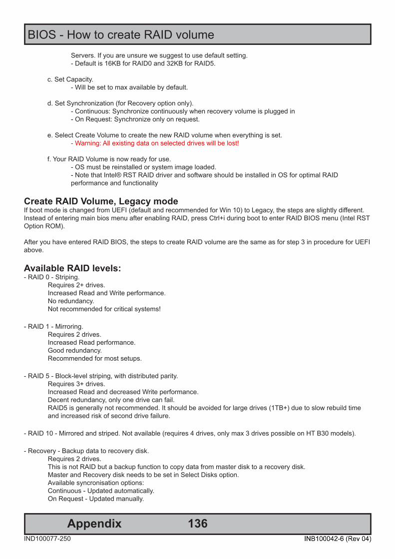
136
BIOS - How to create RAID volume
AppendixIND100077-250
Servers. If you are unsure we suggest to use default setting.- Default is 16KB for RAID0 and 32KB for RAID5.
c. Set Capacity.- Will be set to max available by default.
d. Set Synchronization (for Recovery option only).- Continuous: Synchronize continuously when recovery volume is plugged in- On Request: Synchronize only on request.
e. Select Create Volume to create the new RAID volume when everything is set.- Warning: All existing data on selected drives will be lost!
f. Your RAID Volume is now ready for use.- OS must be reinstalled or system image loaded.- Note that Intel® RST RAID driver and software should be installed in OS for optimal RAID performance and functionality
Create RAID Volume, Legacy modeIf boot mode is changed from UEFI (default and recommended for Win 10) to Legacy, the steps are slightly different. Instead of entering main bios menu after enabling RAID, press Ctrl+i during boot to enter RAID BIOS menu (Intel RST Option ROM).
After you have entered RAID BIOS, the steps to create RAID volume are the same as for step 3 in procedure for UEFI above.
Available RAID levels: - RAID 0 - Striping. Requires 2+ drives. Increased Read and Write performance. No redundancy. Not recommended for critical systems!
- RAID 1 - Mirroring. Requires 2 drives. Increased Read performance. Good redundancy. Recommended for most setups.
- RAID 5 - Block-level striping, with distributed parity. Requires 3+ drives. Increased Read and decreased Write performance. Decent redundancy, only one drive can fail. RAID5 is generally not recommended. It should be avoided for large drives (1TB+) due to slow rebuild time and increased risk of second drive failure.
- RAID 10 - Mirrored and striped. Not available (requires 4 drives, only max 3 drives possible on HT B30 models).
- Recovery - Backup data to recovery disk. Requires 2 drives. This is not RAID but a backup function to copy data from master disk to a recovery disk. Master and Recovery disk needs to be set in Select Disks option. Available syncronisation options: Continuous - Updated automatically. On Request - Updated manually.

137AppendixIND100077-250
BIOS - Hybrid Multi Monitor Configuration
Set up onboard signal output simultaneously with PCIe Graphics CardPCIe cards with 4x additional DP or mDP outputs are available as factory mounted options where higher graphics performance or 4+ display outputs are needed.
Onboard graphics include two DP++ outputs and a USB-C output that can be used as a third DP signal by using a “USB-C to DP adapter”.
When PCIe card is connected, the onboard outputs are disabled by default.BIOS settings can be changed to enable the onboard outputs in addition to PCIe graphics card.
To enable onboard display outputs, when PCIe graphics is present:1: Press Del key during boot to enter BIOS menu.2: From first BIOS menu navigate to "Chipset / System Agent (SA) Configuration" and press enter3: Then navigate to "Graphics Configuration" and press enter4: Select option "Internal Graphics", set to "Enabled" and press enter.5: Press F4 and Enter to save setting and reboot. The Operating System (OS) will now detect the changes made and you will see all your available display outputs.
Note that driver update and reboot may be required in some cases if OS does not already include latest drivers for both onboard controller and PCIe card.
This is tested OK with Windows 10 OS. Linux OS have limited or no support for this feature.

138AppendixIND100077-274
WatchDog Timer function
- 70 - Publication Release Date: Jun 06, 2019
Version 0.71
5. WATCH DOG TIMER The Watchdog Timer of the NCT6102D / NCT6104D / NCT6106D consists of an 8-bit programmable time-out counter and a control and status register. GPIO0, GPIO2, GPIO3, GPIO5, GPIO6, GPIO7 provides an alternative WDT1 function. This function can be configured by the relative GPIO control register. The units of Watchdog Timer counter can be selected at Logical Device 8, CR[F0h], bit[3]. The time-out value is set at Logical Device 8, CR[F1h], default is 4. Writing zero disables the Watchdog Timer function. Writing any non-zero value to this register causes the counter to load this value into the Watchdog Timer counter and start counting down. When Watchdog Timer 1 time-out event is occurring, GPIO0 bit[1], [5], GPIO2, bit[3], [7], GPIO3 bit[1], [5], GPIO5 bit[0], [4], GPIO6 bit[7], GPIO7 bit[0], will trigger a low pluse apporx 100mS. Also the event could go to pin77 WDTO#. In other words, when the value is counted down to zero, the timer stops, and the NCT6102D / NCT6104D / NCT6106D sets the WDT1 status bit in Logical Device 8, CR[F2h], bit[4]. Writing a zero will clear the status bit. It. This bit will also be cleared if LRESET# or PWROK# signal is asserted. The Watchdog Timer 2 of the NCT6102D / NCT6104D / NCT6106D consists of an 8-bit programmable time-out counter register (Logic Device D, CR[E2h]) and status register (Logic Device D, CR[E4h] bit7). The timeout event will trigger PWROK pin to gerenate a low pulse when Logic Device D, CRE3[bit0] is timer count down start bit. When Logic Device D, CRE3[bit0] set to one, the timer will start count down, until this bit is written to zero. Watchdog Timer I related registers are listed below. Watchdog Timer I has four registers in Logic Device 8. When CR30h bit0=1, Watchdog Timer circuit is activated, then CRF5, F6, and F7h are meaningful. Watchdog Timer reset source selection is located at Logic Device A, CRE7h, bit3.
Logical Device Number Register address Register Description
Logical Device 8 CR30h, bit0 Watchdog Timer I circuit enable / disable Logical Device 8 CRF0h Watchdog Timer I Control Mode Register Logical Device 8 CRF1h Watchdog Timer I Counter Register Logical Device 8 CRF2h Watchdog Timer I Control & Status Register
Logical Device A CRE7h, bit3 Watchdog Timer I reset source is LRESET# or PWROK
5.1 Enable Timer (1) CR30h bit0 = 1, enable Watchdog Timer I circuit. (2) Configure CRF0h for time unit or other options. (3) Set time limit into CRF1h then hardware will auto count down. New time limit value overwriting is
acceptable. When CRF1h counts down to 0x0, hardware outputs timeout event on both flag (CRF2h bit4) and pin (via GPIO).
(4) Check then clear CRF2h bit4 (watchdog timeout flag), the timer will restart counting and de-assert pin (via GPIO).
- 71 - Publication Release Date: Jun 06, 2019
Version 0.71
5.2 Disable Timer (1) Set 0x0 to CRF1h, stop Watchdog Timer I counting. (2) CR30h bit0 = 0, disable Watchdog Timer I circuit if no longer use.
5.3 Application Note (1) When Watchdog Timer I is counting, if want to terminate, BIOS or program MUST stop timer (set 0x0 to
CRF1h) first then call platform reset. (2) Watchdog Timer I function is reset by LRESET# or PWROK. Cold reset (front panel reset button), warm
reset (CTRL-ALT-DEL), or any application that drives LRESET# event, Watchdog Timer I would be reset. (3) When Watchdog timeout, the WDTO pin (via GPIO) keeps asserting until flag (CRF2h bit4) is cleared to 0.
6. SMBUS MASTER – MANUAL MODE
6.1 Hardware SIO NCT6106D pin94/96 can be SMBus Master. Please note SIO SMBus Master works at S0 state only.
6.2 Software CR1B bit[1:0] = 01b //set pin.94/96 to be SMBus Master interface SMBus Master Manual Mode Programming Flow (1) Assign a I/O base address for SIO SMBus Master operation Logic Device B, CR62=02h, CR63=A0h //assign I/O base address 0x2A0h for SIO Logic Device B, CR30=01h //enable SIO SMBus Master decode BIOS add I/O address 0x2A0h to chipset generic I/O decoder.
The following extracted section below are available in the full documentation at our website. Please visit:https://www.hattelandtechnology.com/hubfs/pdf/misc/nct6106d_programming_guide_v071.pdf

139
WatchDog Timer function
AppendixIND100077-274
Page 5 of 10 05/20/2021
11. KBRST# and GA20M function application
KBRST# and GA20M pins will be high level after 3VSB supplied by NCT6106D/NCT6104D /NCT6102D push-pull output logic. Please implement an isolation with 3VCC to avoid the leakage before system on.
12. Watch Dog Timer accuracy
When the Watch Dog Timer setting is less than 15 sec, it is suggested that BIOS compensate 1~2 sec for more accuracy. For example, if the target Watch Dog Timer is 10 sec, BIOS needs to set it as 8 sec to compensate for the accuracy. To avoid the unexpected watchdog event, please refer to below items for watchdog timer stop: a. When watchdog timer counter is set, the watchdog could only be stopped after a period of time. This period will be 4 seconds (LDN[8] CR[F5] Bit4=0) or 4 minutes (LDN[8] CR[F5] Bit4=1). If stopping the counter in the period, it will trigger the watchdog timer directly. b. To stop the watchdog timer, please set the timer counter register to 00h first, then clear watch-dog status register.
13. UART RS485 auto flow control and data transit
[For rev. B] NCT6102D / NCT6104D / NCT6106D supports RS485 auto flow control function for all UART. When enabling the RS485 auto control function, it will automatically drive RTS# pin to logic high or low for flow control. To make this RS485 auto flow control function work, please be noted that the parity and stop-bit setting has to be one of the following three settings: (1) 8 data bits + 1 parity bit + 1 stop bit (2) 8 data bits + 1 parity bit + 2 stop bits (3) 8 data bits + 2 stop bits
The following extracted section below are available in the full documentation at our website. Please visit:https://www.hattelandtechnology.com/hubfs/pdf/misc/nct6106d_nct6104d_nct6102d_application_note_v3_6.pdf
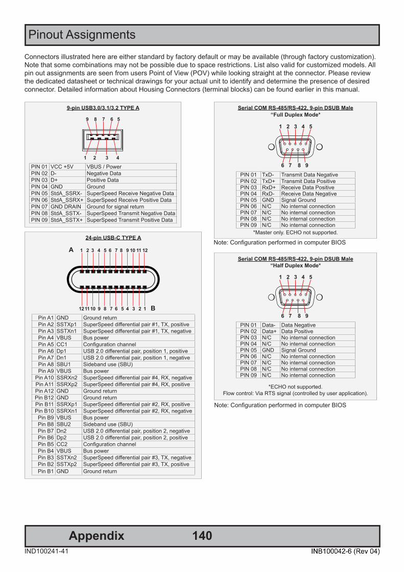
140IND100241-41
Appendix
Pinout AssignmentsConnectors illustrated here are either standard by factory default or may be available (through factory customization).Note that some combinations may not be possible due to space restrictions. List also valid for customized models. All pin out assignments are seen from users Point of View (POV) while looking straight at the connector. Please review the dedicated datasheet or technical drawings for your actual unit to identify and determine the presence of desired connector. Detailed information about Housing Connectors (terminal blocks) can be found earlier in this manual.
Serial COM RS-485/RS-422, 9-pin DSUB Male“Full Duplex Mode*
1 2 3 4 5
6 7 8 9PIN 01 TxD- Transmit Data NegativePIN 02 TxD+ Transmit Data PositivePIN 03 RxD+ Receive Data PositivePIN 04 RxD- Receive Data NegativePIN 05 GND Signal GroundPIN 06 N/C No internal connectionPIN 07 N/C No internal connectionPIN 08 N/C No internal connectionPIN 09 N/C No internal connection
*Master only. ECHO not supported.
Serial COM RS-485/RS-422, 9-pin DSUB Male“Half Duplex Mode*
1 2 3 4 5
6 7 8 9PIN 01 Data- Data NegativePIN 02 Data+ Data PositivePIN 03 N/C No internal connectionPIN 04 N/C No internal connectionPIN 05 GND Signal GroundPIN 06 N/C No internal connectionPIN 07 N/C No internal connectionPIN 08 N/C No internal connectionPIN 09 N/C No internal connection
*ECHO not supported.Flow control: Via RTS signal (controlled by user application).
Note: Configuration performed in computer BIOS
Note: Configuration performed in computer BIOS
9-pin USB3.0/3.1/3.2 TYPE A
1 2 3 4
9 8 7 6 5
PIN 01 VCC +5V VBUS / PowerPIN 02 D- Negative DataPIN 03 D+ Positive DataPIN 04 GND GroundPIN 05 StdA_SSRX- SuperSpeed Receive Negative DataPIN 06 StdA_SSRX+ SuperSpeed Receive Positive DataPIN 07 GND DRAIN Ground for signal returnPIN 08 StdA_SSTX- SuperSpeed Transmit Negative DataPIN 09 StdA_SSTX+ SuperSpeed Transmit Positive Data
24-pin USB-C TYPE A
1 2 3 4 5 6 7 8 9 10 11 12
12 11 10 9 8 7 6 5 4 3 2 1
A
BPin A1 GND Ground returnPin A2 SSTXp1 SuperSpeed diff erential pair #1, TX, positivePin A3 SSTXn1 SuperSpeed diff erential pair #1, TX, negativePin A4 VBUS Bus powerPin A5 CC1 Confi guration channelPin A6 Dp1 USB 2.0 diff erential pair, position 1, positivePin A7 Dn1 USB 2.0 diff erential pair, position 1, negativePin A8 SBU1 Sideband use (SBU)Pin A9 VBUS Bus power
Pin A10 SSRXn2 SuperSpeed diff erential pair #4, RX, negativePin A11 SSRXp2 SuperSpeed diff erential pair #4, RX, positivePin A12 GND Ground returnPin B12 GND Ground returnPin B11 SSRXp1 SuperSpeed diff erential pair #2, RX, positivePin B10 SSRXn1 SuperSpeed diff erential pair #2, RX, negative
Pin B9 VBUS Bus powerPin B8 SBU2 Sideband use (SBU)Pin B7 Dn2 USB 2.0 diff erential pair, position 2, negativePin B6 Dp2 USB 2.0 diff erential pair, position 2, positivePin B5 CC2 Confi guration channelPin B4 VBUS Bus powerPin B3 SSTXn2 SuperSpeed diff erential pair #3, TX, negativePin B2 SSTXp2 SuperSpeed diff erential pair #3, TX, positivePin B1 GND Ground return
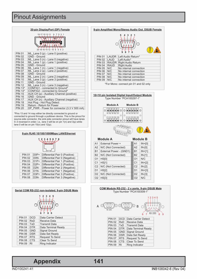
Pinout Assignments
141IND100241-41
Appendix
8-pin RJ45 10/100/1000Mbps LAN/Ethernet
1 2 3 4 5 6 7 8
PIN 01 D0P+ Diff erential Pair 0 (Positive)PIN 02 D0N- Diff erential Pair 0 (Negative)PIN 03 D1P+ Diff erential Pair 1 (Positive)PIN 04 D2P+ Diff erential Pair 2 (Positive)PIN 05 D2N- Diff erential Pair 2 (Negative)PIN 06 D1N- Diff erential Pair 1 (Negative)PIN 07 D3P+ Diff erential Pair 3 (Positive)PIN 08 D3N- Diff erential Pair 3 (Negative)
20-pin DisplayPort (DP) Female
20 18 16 14 12 10 8 6 4 2
19 17 15 13 11 9 7 5 3 1
PIN 01 ML_Lane 0 (p) - Lane 0 (positive)PIN 02 GND - GroundPIN 03 ML_Lane 0 (n) - Lane 0 (negative)PIN 04 ML_Lane 1 (p) - Lane 1 (positive)PIN 05 GND - GroundPIN 06 ML_Lane 1 (n) - Lane 1 (negative)PIN 07 ML_Lane 2 (p) - Lane 2 (positive)PIN 08 GND - GroundPIN 09 ML_Lane 2 (n) - Lane 2 (negative)PIN 10 ML_Lane 3 (p) - Lane 3 (positive)PIN 11 GND - GroundPIN 12 ML_Lane 3 (n) - Lane 3 (negative)PIN 13* CONFIG1 - connected to Ground*PIN 14* CONFIG2 - connected to Ground*PIN 15 AUX CH (p) - Auxiliary Channel (positive)PIN 16 GND - GroundPIN 17 AUX CH (n) - Auxiliary Channel (negative)PIN 18 Hot Plug - Hot Plug DetectPIN 19 Return - Return for PowerPIN 20 DP_PWR - Power for connector (3.3 V 500 mA)
*Pins 13 and 14 may either be directly connected to ground or connected to ground through a pulldown device. This is the pinout for source-side connector, the sink-side connector pinout will have lanes 0–3 reversed in order; i.e., lane 3 will be on pin 1(n) and 3(p) while lane 0 will be on pin 10(n) and 12(p).
9-pin Amplifi ed Mono/Stereo Audio Out, DSUB Female
5 4 3 2 1
9 8 7 6
PIN 01 LAUDR Left Audio Return*PIN 02 LAUD Left Audio*PIN 03 RAUDR Right Audio ReturnPIN 04 RAUD Right AudioPIN 05 N/C No internal connectionPIN 06 N/C No internal connectionPIN 07 N/C No internal connectionPIN 08 N/C No internal connectionPIN 09 N/C No internal connection
*For Mono: connect pin 01 and 02 only
Serial COM RS-232 non-isolated, 9-pin DSUB Male
1 2 3 4 5
6 7 8 9
PIN 01 DCD Data Carrier DetectPIN 02 RxD Receive DataPIN 03 TxD Transmit DataPIN 04 DTR Data Terminal ReadyPIN 05 GND Signal GroundPIN 06 DSR Data Set ReadyPIN 07 RTS Request To SendPIN 08 CTS Clear To SendPIN 09 RI Ring Indicator
COM Module RS-232 - 2 x ports, 9-pin DSUB MaleType Number “PCA100309-1”
A B
1 2 3 4 5
6 7 8 9 PIN 01 DCD Data Carrier DetectPIN 02 RxD Receive DataPIN 03 TxD Transmit DataPIN 04 DTR Data Terminal ReadyPIN 05 GND Signal GroundPIN 06 DSR Data Set ReadyPIN 07 RTS Request To SendPIN 08 CTS Clear To SendPIN 09 RI Ring Indicator
10+10 pin Isolated Digital Input/Output ModuleType Number “PCA100297-1”
Module A Module B
Module A Module BA1 External Power + A1 IN+[0]A2 N/C (Not Connected) A2 IN-[0]B1 External Power - (GND1) B1 IN+[1]B2 N/C (Not Connected) B2 IN-[1]O1 HS[0] O1 N/CC1 HS[1] C1 IN+[2]C2 N/C (Not Connected) C2 IN-[2]D1 HS[2] D1 IN+[3]D2 N/C (Not Connected) D2 IN-[3]O2 HS[3] O2 N/C

Pinout Assignments
142IND100241-41
Appendix
10+10 pin RS-422 / RS-485 NMEA ModuleType Number “PCA200828-1 / PCA100293-1”
6 7 8 9 101 2 3 4 5
6 7 8 9 101 2 3 4 5
PIN 01 TxD- Transmit Data NegativePIN 02 TxD+ Transmit Data PositivePIN 03 GND Isolated GroundPIN 04 RxD- Receive Data NegativePIN 05 RxD+ Receive Data PositivePIN 06 TxD- Transmit Data NegativePIN 07 TxD+ Transmit Data PositivePIN 08 GND Isolated GroundPIN 09 RxD- Receive Data NegativePIN 10 RxD+ Receive Data Positive
RS-485 Half Duplex (2-wire) Confi guration:Connect TX and RX pair-wise:
TX- to RX-, TX+ to RX+.
*Note: The jumper for “force of transmitter (Forced TX(y)” is open by factory default. For
some custom models this jumper is preset to closed (active), in that case unit has to be opened and jumper set to open to allow Half
Duplex mode.
4+4 pin CAN I/O Module, 2 channelsType Number “ZIA0001310-B / ZIA0001310-SLCAN”
CAN1
CAN2
1 2 3 41 2 3 4
Pin 01 Can1 CAN LPin 02 Can1 CAN LPin 03 Can1 CAN HPin 04 Can1 CAN H
Pin 01 Can2 CAN LPin 02 Can2 CAN LPin 03 Can2 CAN HPin 04 Can2 CAN H
CAN Node
CAN H
CAN L*
Note: 110/120Ω termination is decided by impedance of cable.*
120Ω
*120Ω
Cable StubLength CAN H
CAN L
CAN Node
CAN H
CAN L
CAN Node
CAN H
CAN L
2-pin Terminal Block 5.08 - DC Power Input
Pin 2: Negative - Pin 1: Positive +
Only applicable for Multi-Power (AC+DC) models

143IND100077-222
Appendix
Trouble-shooting
Operating System Recovery (tool) Reference: DOC207939-1The tool described in this chapter is available directly from Support at Hatteland Technology. In order to receive a copy of the software (Windows 10 only) and the appropriate matching OS image to your exact product model, please have a complete unit’s Type number and Serial number ready prior to contacting Support at Hatteland Technology (or through dedicated Service Partner channels) via: https://www.hattelandtechnology.com/support/contact
Please note:- At least 30GB of free disk space is needed on the unit in order to create the 16GB USB Memory Stick.- It can take up to 1 hour to create the USB Memory Stick.
DOC207939-1 - Revision 03
Hatteland Technology AS | www.hattelandtechnology.com | Enterprise no: NO974533146 Page 4 of 7
1 How to Use 1.1 Prerequisites To create the Recovery USB-stick, you need to have the following:
- A Windows 10 PC, with Windows version 1703 or newer. - USB Drive. We recommend a size of at least 16GB. - Customer Pack is provided by Hatteland Technology.
Note: This tool can only be used on Hatteland Technology products.
1.2 How to create your Recovery USB-Stick
1. Unpack the customer pack to your PC.
2. Run USB_Setup.exe
3. Select your USB Drive in the dropdown menu.

144IND100077-222
Trouble-shooting
Appendix
DOC207939-1 - Revision 03
Hatteland Technology AS | www.hattelandtechnology.com | Enterprise no: NO974533146 Page 5 of 7
You will be prompted to confirm that the selected USB will be completely wiped of all data. The USB-stick chosen will have all its data deleted.
4. The program will run for a couple of minutes, the speed of the creator depends on the speed of the operating system and the USB-stick.
5. Wait for the “Success” message to appear and a dialog box will appear. Press OK.
6. You have now completed creating the USB Recovery Stick. Please disconnect the USB from the PC using the “Safe Removal” feature.
a.
b.
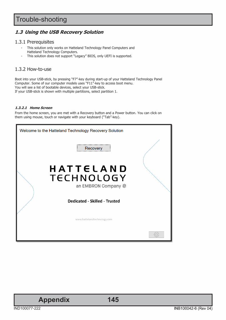
145IND100077-222
Trouble-shooting
Appendix
DOC207939-1 - Revision 03
Hatteland Technology AS | www.hattelandtechnology.com | Enterprise no: NO974533146 Page 6 of 7
1.3 Using the USB Recovery Solution
1.3.1 Prerequisites - This solution only works on Hatteland Technology Panel Computers and
Hatteland Technology Computers. - This solution does not support “Legacy” BIOS, only UEFI is supported.
1.3.2 How-to-use
Boot into your USB-stick, by pressing “F7”-key during start-up of your Hatteland Technology Panel Computer. Some of our computer models uses “F11”-key to access boot menu. You will see a list of bootable devices, select your USB-stick. If your USB-stick is shown with multiple partitions, select partition 1.
1.3.2.1 Home Screen From the home screen, you are met with a Recovery button and a Power button. You can click on them using mouse, touch or navigate with your keyboard (“Tab”-key).

146IND100077-222
Trouble-shooting
Appendix
DOC207939-1 - Revision 03
Hatteland Technology AS | www.hattelandtechnology.com | Enterprise no: NO974533146 Page 7 of 7
1.3.2.2 Recovery The Recovery buttons opens the recovery function. You select the target drive you wish to recover. The description in the large box is the description of the image. When you press “ok”, you will get a final warning that the target drive will be wiped and all data on the drive will be lost. After pressing “yes”, the program will do everything needed for the recovery automatically. When finished, you are asked to restart or shut down your computer. Please disconnect your USB-stick after restarting or shutting down.
DOC207939-1 - Revision 03
Hatteland Technology AS | www.hattelandtechnology.com | Enterprise no: NO974533146 Page 3 of 7
Revision History
Created Approved
Rev Date By Date By Description
1 2020.07.16 Yrjan Rein 2020.07.22 Gunnar Myklebust
Initial Version
2 2021.02.03 Yrjan Rein 2021.02.04 Morten Mæland Updated Pictures. Removed chapter that is not relevant to the function of “recovery only”. Updated name of the USB setup executable.
3

147IND100077-222
Trouble-shooting
Appendix
How to activate Windows Recovery Environment on OS Drive Reference: DOC208258-1Products delivered before Q1-2021 from Hatteland Technology may not have Windows Recovery Environment present.The Windows Recovery Environment must be manually activated before it can be used. Please follow the steps below.
DOC208258-1 - Revision 01
Hatteland Technology AS | www.hattelandtechnology.com | Enterprise no: NO974533146 Page 2 of 2
How to activate WinRE
1. Check if your device has WinRE activated. a. Open Command Line window with Administrator rights b. Run the command: reagentc /info
c. If it looks like the picture above, test the WinRE by typing the following command and restarting your computer: reagentc /boottore
d. If your computer successfully booted into Windows Recovery Environment, press “continue”. You should boot into Windows like normal and the WinRE is verified.
2. If your Windows RE status is “Disabled” or did not boot into Windows Recovery Environment during boot test, do the following steps:
a. Open Command Line window with administrator rights b. Run the following commands in order:
i. attrib -h -s c:\Recovery\WindowsRE\Winre.wim ii. xcopy /h c:\Recovery\WindowsRE\Winre.wim c:\Windows\System32\Recovery iii. reagentc /enable
c. Now test the WinRE by restarting your PC after typing the command: reagentc /boottore
d. If your computer successfully booted into Windows Recovery Environment, press “continue”. You should boot into Windows like normal and the WinRE is verified.
3. If you’re still unable to boot into WinRE or the status is still “disabled”. Please contact Hatteland Technology Customer Support. Contact information available at http://www.hattelandtechnology.com/.
DOC208258-1 - Revision 01
Hatteland Technology AS | www.hattelandtechnology.com | Enterprise no: NO974533146 Page 1 of 2
DOC208258-1
How to activate WinRE on OS drive
Revision History Created Approved
Rev Date By Date By Description
1 27.01.2021 Yrjan Rein 28.01.2021 Gunnar Myklebust
Initial Version
2
3

148IND100078-80
IEC62368 policy for Hatteland Technology products
IntroductionAccording to the requirements of EN 62368-1:2014.
The tables below refers to the policies for opening, servicing and installation of the unit(s) referred to in this manual. This equipment is designed to be used as a fixed installation and to be sold through special sales channels for professional use.
Based on requirements EN 62368-1:2014 and IEC 62368-1:2018
Defenition DescriptionOrdinary person/Sailor/End-User
Ordinary person is the term applied to all persons other than instructed persons and skilled persons. Ordinary persons include not only users of the equipment, but also all persons who may have access to the equipment or who may be in the vicinity of the equipment. Under normal operating conditions or abnormal operating conditions, ordinary persons should not be exposed to parts comprising energy sources capable of causing pain or injury. Under a single fault condition, ordinary persons should not be exposed to parts comprising energy sources capable of causing injury.
Instructed person Instructed person is a term applied to persons who have been instructed and trained by a skilled person, or who are supervised by a skilled person, to identify energy sources that may cause pain and to take precautions to avoid unintentional contact with or exposure to those energy sources. Under normal operating conditions, abnormal operating conditions or single fault conditions, instructed persons should not be exposed to parts comprising energy sources capable of causing injury.
Skilled person Skilled person is a term applied to persons who have training or experience in the equipment technology, particularly in knowing the various energies and energy magnitudes used in the equipment. Skilled persons are expected to use their training and experience to recognize energy sources capable of causing pain or injury and to take action for protection from injury from those energies. Skilled persons should also be protected against unintentional contact or exposure to energy sources capable of causing injury.

149
IEC62368 policy for Hatteland Technology products
IND100078-80
Authority DescriptionChildren This equipment is not suitable for use in locations where children are likely to be present.
Ordinary person/Sailor/End-User
Not allowed to open unit. Not allowed to install the unit. Not allowed to terminate/connect cables to the unit.
Instructed person Allowed to open hatches/latches which does not require tools, such as Disktrays. Allowed to open "battery-hatch" to change the battery even if tools are required.Allowed to install the unit.Allowed to terminate/connect cables to the unit indoors.
Skilled person Allowed to open and disassemble the unit.
Allowed to install the unit.Allowed to terminate/connect cables to the unit indoors and outdoors.Allowed to terminate/connect earth/ground wire. Note: Be aware that additional definition for “skilled person” may apply, country dependent.
Conditions DescriptionAC power net Class Class 1.
Pollution degree 2.Over voltage category 2.
Transient requirement External circuits are considered to be installed wholly within the same building structure.Battery Obligated to use battery specified for the product.Altitude Products are designed for a max operating altitude of 2000m.
Installation DescriptionMounting brackets Only bracket defined/specified for the unit is allowed.
AC power cord When installed it shall be possible to disconnect the unit from the AC power neti.e. possible to reach AC connecter.
Transient requirement External circuits are considered to be installed wholly within the same building structure.Earthing Obligated to use defined earthing material/method specified for the unit.
Minimum protective bonding conductor size of copper conductors:Wire: Minimum 1,5mm2 but Hatteland Technology recommends 2,5mm2 (AWG12)marked yellow/green.
Outdoor Units with IP66/67-rated fronts can be used in outside environments, provided that the console they are fitted in fulfil certain requirements.
- There must be a fully water/dustproof seal between the IP66 front and the console. - Dust/water ingress protection of console. (Unit/product is rated for pollution degree 2). - Humidity/condensation control in console. - Thermal management in console (so units can operate within rated temperature range).
Units with IP20/IP22 shall not be used outdoor.Outdoor Installation Appropriate RCD with ground current rating of 20mA or less shall be used.
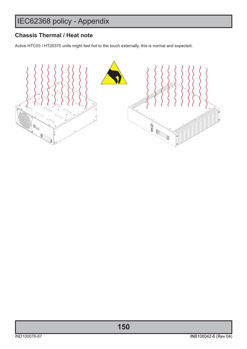
150IND100078-87
IEC62368 policy - Appendix
Chassis Thermal / Heat noteActive HTC03 / HT20370 units might feel hot to the touch externally, this is normal and expected.

IND100237-1
Declaration of ConformityWe, manufacturer, Hatteland Technology AS, Eikeskogvegen 52, N-5570 Aksdal, Norway
declare under our sole responsibility that the JH MMD, JH MMC, JH STD, JH MIL, HM NMD, HM MIL, HM CMD, HT STD, HD MMD, HD MVD, HM MMD, HM XRD, HM RMD, HT MMC, HD MMC, HT/HM (computers) and HN G (Network Switches) product ranges is in
conformity with the following standards in accordance with the EMC Directive.
Low Voltage Directive 2014/35/EU EN 62368-1:2014;A11:2017
EMC Directive 2014/30/EU EN 55032:2015EN 55035:2017
EN 55024:2010+A1:2015EN IEC 63000:2018
Signature:........................................................Frode Grindheim
Vice President Product ManagementAksdal, Norway
CE MARK FIRST AFFIXED DATE (11 March 2010)
Signature:........................................................Arne Kristiansen
Site Manager - Test & Commission Division Oslo, Norway
Declaration of ConformityWe, manufacturer, Hatteland Technology AS, Eikeskogvegen 52, N-5570 Aksdal, Norway
declare under our sole responsibility that the products listed below comply withFCC 47 CFR Part 15, Subpart B, Class A:
JH MMD, JH MMC, JH STD, JH MIL, HM NMD, HM MIL, HM CMD, HT STD, HD MMD, HD MVD, HM MMD, HM XRD,HM RMD, HT MMC, HD MMC, HT/HM (computers) and HN G (Network Switches) product ranges
Note: This equipment has been tested and found to comply with the limits for a Class A digital device, pursuant to part 15 of the FCC Rules.These limits are designed to provide reasonable protection against harmful interference when the equipment is operated in a commercial
environment. This equipment generates, uses, and can radiate radio frequency energy and, if not installed and used in accordance with theinstruction manual, may cause harmful interference to radio communications. Operation of this equipment in a residential area is likely to
cause harmful interference in which case the user will be required to correct the interference at his own expense.
Signature:........................................................Frode Grindheim
Vice President Product ManagementAksdal, Norway
FCC MARK FIRST AFFIXED DATE (16 February 2012)
Signature:........................................................Arne Kristiansen
Site Manager - Test & Commission Division Oslo, Norway
Declaration of ConformityWe, manufacturer, Hatteland Technology AS, Eikeskogvegen 52, N-5570 Aksdal, Norway
declare under our sole responsibility that the JH MMD, JH MMC, JH STD, JH MIL, HM NMD, HM MIL, HM CMD, HT STD,HD MMD, HD MVD, HM MMD, HM XRD, HM RMD, HT MMC, HD MMC, HT/HM (computers) and HN G (Network Switches)
product ranges is in conformity with IEC 60945 4th (EN 60945:2002) and IACS E10 (where applicable)
This document was last approved, reviewed and found valid on 06 Oct 2021 by the signed participants as stated above.

152IND100077-14
Appendix
Return of goods: (Applies not to warranty/normal service/repair of products)
Hatteland Technology referenced as “manufacturer” in this document.
Before returning goods, please contact your system supplier before sending anything directly to manufacturer. When you return products after loan, test, evaluation or products subject for credit, you must ensure that all accessories received from our warehouse are returned. This applies to cables, powermodules and additional equipment except screws or similar, user manual, datasheets or other written paper documents. Furthermore, the product must not have any minor / medium or severe scratches, chemical spills or similar on the backcover, front frame or glass.
This is required in order to credit the invoice 100%. Missing parts will not be subject for credit, and you will not gettotal credit for returned product. You will either be charged separately, or the amount is withdrawn from the credit. If you decide to ship the missing items later on, you will get 100% credit for that particular invoice or items received atmanufacturer incoming goods control. Please contact our Repair Centre if additional questions or review the following links at bottom of page for more information online.
Return Of Goods Information
Make sure you surround the product with the following material (whenever possible):
Use the original packaging from manufacturer, firm foam material, bubble wrap, lots of PadPack paper or foam chips/polyester wrapped in sealed plastic bags. Please make sure that the unit is protected with a surrounding plastic bag to prevent dust accumulation around the unit.
If you do not have the original packaging or are uncertain as to how to secure the unit properly,please consider seeking advice from nearby shipping or transportation offices, if in doubt!
Do not under any circumstances use loose foam chips, expanded polyester, clothes, cardboard with sharp edges/spikes, too little or nothing to secure the unit inside the box. Do not use cardboardboxes that are clearly too weak or not suitable for securing the unit properly during overseas shipment.
Handling and packing units for return/creditTo prevent damage during shipping and transportation, respect the guidelines below.
How to issue a Return merchandise authorization (RMA): Hatteland Technology requires a pre-registered CDV number prior to sending goods for return. If you do not have an pre-registered CDV number, please visit the links below on how to get one.
https://www.hattelandtechnology.com/rma-procedure
Once understood, proceed to registering RMA:http://lcm.hatteland-display.com/CustomerRMA/CustomerRMA.aspx
Additional information:https://www.hattelandtechnology.com/legal-documents
153IND100077-7
Appendix
General Terms and Conditions
INSTRUCTIONS FOR THE CONSIGNEE
1) CONTROLControl the goods immediately by receipt. Examine the quantity against the invoice/packinglist/shipping documents. Look for outward defects on the packing which may indicate damage on or loss of contents. Control the container and the seals for any defects.
2) SECURING EVIDENCEWhen defects on the goods have been found, evidence must be secured, and seller must be informed. Call the transporter and point out the defects. Add a description of the defects on the goods receipt, the forwarder’s copy of the way-bill or on the driving slip.
3) RESCUETry to restrict the damage and the loss. Seller will compensate expenses incurred due to reasonable security efforts in addition to damage and loss.
4) COMPLAINTImmediately write a complaint to the transporter or his agent. Immediately forward the complaint to the transporter or his agent, and hold the transporter responsible for the defects. The complaint must be sent at the latest: - for carriage by sea: within 3 days - for overland / air transportation within 7 days
5) DOCUMENTATIONFor any claims the following documentation is required and must forwarded to the company or their agent: invoice, way-bill and/or bill of landing, and/or statement of arrival, inspection document, besides a copy of the letter of complaint to the transporter.
As of January 2015, Hatteland Technology AS’ “Terms of Sales and Delivery” and “Warranty Terms” have beensubstituted by the updated ”General terms and conditions for sale of goods and performance of additional services” (the “General Terms and Conditions”).
Further, from January 2015 onward, the previous “Terms of Sales and Delivery” and “Warranty Terms”, as well as other standard terms and conditions, policies and instructions issued by Hatteland Technology AS, will be removed from the User Manuals.
Instead, the updated General Terms and Conditions and the other standard terms and conditions, policies andinstructions issued by Hatteland Technology AS will be available via our website only.
Please visit https://www.hattelandtechnology.com/legal-documents#terms-and-conditions to review the latest revision
Long Term Storage RecommendationsFor Minimum storage life for Hatteland Technology products,Storage Conditions, Periodic maintenance - test procedure, please visit: https://www.hattelandtechnology.com/hubfs/pdf/misc/ind100350-5_long_term_storage_recommendations.pdf

154AppendixIND100077-251
Notes
General Notes:- License Terms for the installed OEM Operating System (OS) can be found in the following default factory paths: Note: This is a general listing for a varity of OS’s Hatteland Technology can factory install depending on unit. Please check specification for your unit to verify type of OS installed in order to retrieve the license terms listed below. Microsoft® Windows® 10 IoT Enterprise LTSC 2019: C:\Windows\System32\en-US\Licenses\_Default\EnterpriseS\license.rtf

155AppendixIND100077-24
User Notes

156IND100077-221
Please note that references to page numbers may only be valid for the latest revision.
Rev. By Date Notes00_01 MS 30 Sep 2020 Release for internal reviews
00_02 JESE
31 Dec 2020 Revised after internal reviews
00_03 JEBBSE
08 Jan 2021 Revised after internal reviews
00_04 JESEMS
24 Feb 2021 Revised after internal reviews
00_05 VMSE
10 Mar 2021 Revised after internal reviews
01 ALLSE
12 Apr 202114 Apr 2021
Release for internet
02 SHLSE
28 May 2021 Added new Multi-Power model throughout the entire manual
03 CHSE
17 Aug 202118 Aug 2021
Added Module Matrix overview, page 41-44Added note for chassis heat, page 148
04 VMGMSE
23 Nov 2021 Revised screw/screwdriver details, page 22-27Added Factory Preset COM Port Numbering, page 44Added section for WatchDog function, page 138-139
Revision History

157
Revision History
IND100077-221

Hatteland Technology AS | www.hattelandtechnology.com | Enterprise no: NO974533146
Related Documents