1 FracTex Plug-in for Petrel ® 2020 USER MANUAL Geo5 GmbH

Welcome message from author
This document is posted to help you gain knowledge. Please leave a comment to let me know what you think about it! Share it to your friends and learn new things together.
Transcript
1
FracTex Plug-in for Petrel® 2020
USER MANUAL
Geo5 GmbH
2
ABOUT THIS DOCUMENT
This document provides a guide for the user to the FracTex plug-in for Petrel for the
2020.1 release.
COPYRIGHT NOTICES AND DISCLAIMERS
FracTex, Copyright © 2020 Geo5 GmbH. All rights reserved.
No part of this user documentation may be reproduced, stored in a retrieval system,
or translated in any form or by any means, electronic or mechanical, including
photocopying and recording, without prior written permission of the copyright owner.
3
Contents Introduction ......................................................................................................................................... 4
Directional GLCM-based attributes .......................................................................................... 4
FracTex attributes ........................................................................................................................... 4
User Interface ...................................................................................................................................... 5
Getting started ................................................................................................................................ 5
Directional GLCM-based attributes .......................................................................................... 6
FracTex attributes ........................................................................................................................... 6
Description of parameters ........................................................................................................... 7
Input ............................................................................................................................................... 7
Gray levels .................................................................................................................................... 7
Min/max of input data ............................................................................................................. 7
Number of directions (FracTex only) ..................................................................................... 8
Inline/crossline radius ................................................................................................................. 8
Vertical search window ............................................................................................................ 8
Attribute selection ...................................................................................................................... 8
Output type (FracTex only) ..................................................................................................... 8
Direction of calculation (GLCM only) .................................................................................. 9
Gray level transformation ........................................................................................................ 9
Threshold (FracTex only) ........................................................................................................... 9
Output name ............................................................................................................................... 9
Histogram ....................................................................................................................................... 10
Rose diagrams .............................................................................................................................. 10
Semivariogram .............................................................................................................................. 11
Workflow ............................................................................................................................................. 12
Dialog start ..................................................................................................................................... 12
Parameter settings ....................................................................................................................... 12
Default parameters for GLCM .............................................................................................. 12
Default parameters for FracTex ........................................................................................... 12
Input ............................................................................................................................................. 13
Min/max of input data ........................................................................................................... 13
Create the attribute .................................................................................................................... 13
Settings ........................................................................................................................................ 13
Support ................................................................................................................................................ 13
4
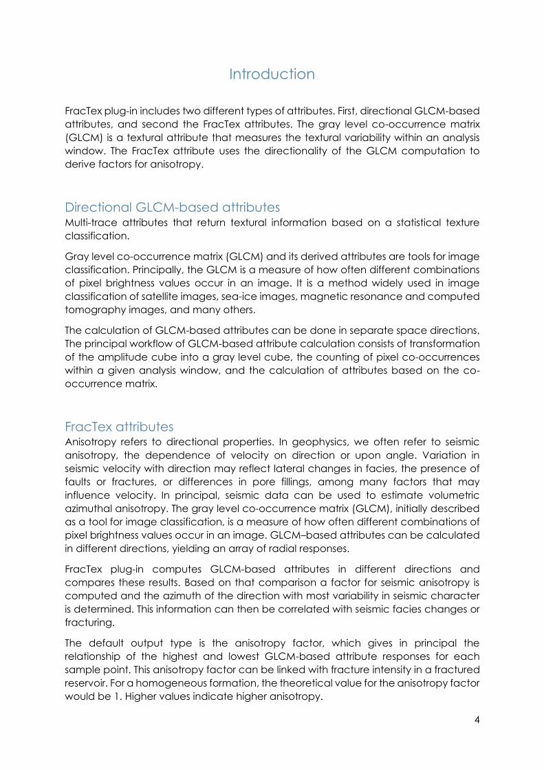
Introduction
FracTex plug-in includes two different types of attributes. First, directional GLCM-based
attributes, and second the FracTex attributes. The gray level co-occurrence matrix
(GLCM) is a textural attribute that measures the textural variability within an analysis
window. The FracTex attribute uses the directionality of the GLCM computation to
derive factors for anisotropy.
Directional GLCM-based attributes Multi-trace attributes that return textural information based on a statistical texture
classification.
Gray level co-occurrence matrix (GLCM) and its derived attributes are tools for image
classification. Principally, the GLCM is a measure of how often different combinations
of pixel brightness values occur in an image. It is a method widely used in image
classification of satellite images, sea-ice images, magnetic resonance and computed
tomography images, and many others.
The calculation of GLCM-based attributes can be done in separate space directions.
The principal workflow of GLCM-based attribute calculation consists of transformation
of the amplitude cube into a gray level cube, the counting of pixel co-occurrences
within a given analysis window, and the calculation of attributes based on the co-
occurrence matrix.
FracTex attributes Anisotropy refers to directional properties. In geophysics, we often refer to seismic
anisotropy, the dependence of velocity on direction or upon angle. Variation in
seismic velocity with direction may reflect lateral changes in facies, the presence of
faults or fractures, or differences in pore fillings, among many factors that may
influence velocity. In principal, seismic data can be used to estimate volumetric
azimuthal anisotropy. The gray level co-occurrence matrix (GLCM), initially described
as a tool for image classification, is a measure of how often different combinations of
pixel brightness values occur in an image. GLCM–based attributes can be calculated
in different directions, yielding an array of radial responses.
FracTex plug-in computes GLCM-based attributes in different directions and
compares these results. Based on that comparison a factor for seismic anisotropy is
computed and the azimuth of the direction with most variability in seismic character
is determined. This information can then be correlated with seismic facies changes or
fracturing.
The default output type is the anisotropy factor, which gives in principal the
relationship of the highest and lowest GLCM-based attribute responses for each
sample point. This anisotropy factor can be linked with fracture intensity in a fractured
reservoir. For a homogeneous formation, the theoretical value for the anisotropy factor
would be 1. Higher values indicate higher anisotropy.
5
The azimuth of fracture dip indicates the azimuth in which the highest variability in data
occurs. For a fractured reservoir this would correspond with the azimuth of fracture dip.
To avoid overestimation of fractures it is advisable to apply a threshold value for the
azimuth of fracture dip calculation. In this case a simultaneous calculation of
anisotropy factor and azimuth of fracture dip is done, and for sample points where the
anisotropy factor is below this threshold value, the azimuth of fracture dip is set to
undefined.
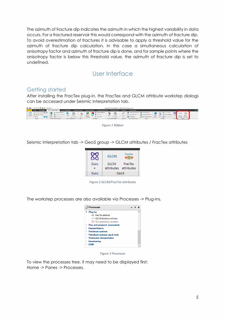
User Interface
Getting started After installing the FracTex plug-in, the FracTex and GLCM attribute workstep dialogs
can be accessed under Seismic Interpretation tab.
Figure 1 Ribbon
Seismic Interpretation tab -> Geo5 group -> GLCM attributes / FracTex attributes
Figure 2 GLCM/FracTex attributes
The workstep processes are also available via Processes -> Plug-ins.
Figure 3 Processes
To view the processes tree, it may need to be displayed first:
Home -> Panes -> Processes.
6
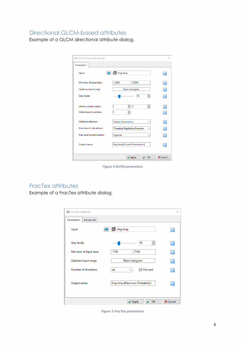
Directional GLCM-based attributes Example of a GLCM directional attribute dialog.
Figure 4 GLCM parameters
FracTex attributes Example of a FracTex attribute dialog.
Figure 5 FracTex parameters
7
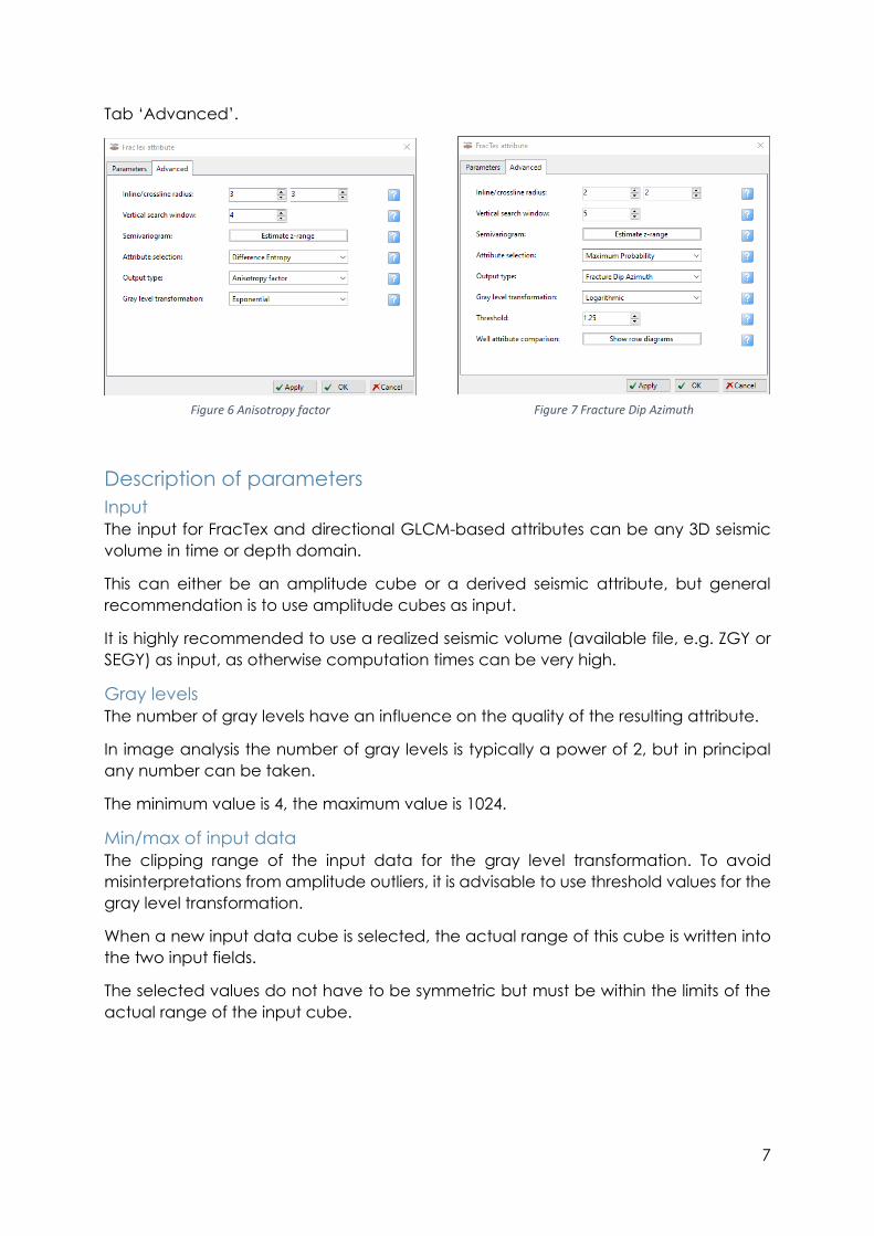
Tab ‘Advanced’.
Description of parameters
Input
The input for FracTex and directional GLCM-based attributes can be any 3D seismic
volume in time or depth domain.
This can either be an amplitude cube or a derived seismic attribute, but general
recommendation is to use amplitude cubes as input.
It is highly recommended to use a realized seismic volume (available file, e.g. ZGY or
SEGY) as input, as otherwise computation times can be very high.
Gray levels
The number of gray levels have an influence on the quality of the resulting attribute.
In image analysis the number of gray levels is typically a power of 2, but in principal
any number can be taken.
The minimum value is 4, the maximum value is 1024.
Min/max of input data
The clipping range of the input data for the gray level transformation. To avoid
misinterpretations from amplitude outliers, it is advisable to use threshold values for the
gray level transformation.
When a new input data cube is selected, the actual range of this cube is written into
the two input fields.
The selected values do not have to be symmetric but must be within the limits of the
actual range of the input cube.
Figure 6 Anisotropy factor Figure 7 Fracture Dip Azimuth
8
Number of directions (FracTex only)
13, 49,109 or 193 spatial directions can be selected.
Please note that 49, 109 and 193 directions require a minimum inline/crossline radius of
2, 3 and 4 respectively and also a significantly higher computation time.
In order to shorten the calculation time, a fast algorithm can be selected for more
than 13 directions. This algorithm first calculates 13 spatial directions. Depending on
this calculation, additional directions are calculated which, based on step one,
represent the highest probability for the resulting output.
Inline/crossline radius
Defines the number of traces used in the computation. The resulting search window
will be 2 * radius + 1.
Minimum value is 1, maximum value is 5, resulting in a search window of 3 up to 11.
Vertical search window
Defines the number of samples used in the computation. The resulting search window
will be 2 * radius + 1.
Minimum value is 3, maximum value is 10, resulting in a search window of 7 up to 21.
Attribute selection
The algorithm used for the attribute.
Directional GLCM-based attributes have 21 options and FracTex attributes have 8
options.
The algorithms can be divided into three categories:
• Contrast group
o Measurements based on the distance from the GLCM diagonal
o e.g. Contrast, Homogeneity, Dissimilarity
• Orderliness group
o Measurements of how organized the GLCM is
o e.g. Energy, Entropy
• Statistics group
o Standard statistical parameters computed from the GLCM
o e.g. Mean, Variance, Correlation
Output type (FracTex only)
The default output type is the anisotropy factor, which gives in principal the
relationship of the highest and lowest GLCM-based attribute responses for each
sample point. This anisotropy factor can be linked with fracture intensity in a fractured
reservoir. For an isotropic formation, the theoretical value for the anisotropy factor
would be 1. Higher values indicate higher anisotropy.
The azimuth of fracture dip indicates the azimuth in which the highest variability in data
occurs. For a fractured reservoir this would correspond with the azimuth of fracture dip.
9
Direction of calculation (GLCM only)
By default, all thirteen spatial directions are calculated. It is also possible to select a
spatial direction of particular interest.
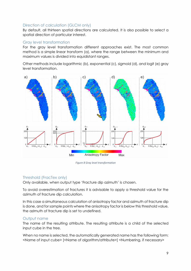
Gray level transformation
For the gray level transformation different approaches exist. The most common
method is a simple linear transform (a), where the range between the minimum and
maximum values is divided into equidistant ranges.
Other methods include logarithmic (b), exponential (c), sigmoid (d), and logit (e) gray
level transformation.
Figure 8 Gray level transformation
Threshold (FracTex only)
Only available, when output type ‘Fracture dip azimuth’ is chosen.
To avoid overestimation of fractures it is advisable to apply a threshold value for the
azimuth of fracture dip calculation.
In this case a simultaneous calculation of anisotropy factor and azimuth of fracture dip
is done, and for sample points where the anisotropy factor is below this threshold value,
the azimuth of fracture dip is set to undefined.
Output name
The name of the resulting attribute. The resulting attribute is a child of the selected
input cube in the tree.
When no name is selected, the automatically generated name has the following form:
<Name of input cube> [<Name of algorithm/attribute>] <Numbering, if necessary>
10
Histogram The ‘Show histogram’ button opens a new window that shows the amplitude
distribution for the input cube. The defined threshold values (min and max) for the gray
level transformation are shown as blue lines in the histogram. The position of the
threshold values can be changed by clicking onto the plus and minus buttons. To
accept the values for the current attribute, click on button 'OK' or 'Apply'.
Figure 9 Histogram
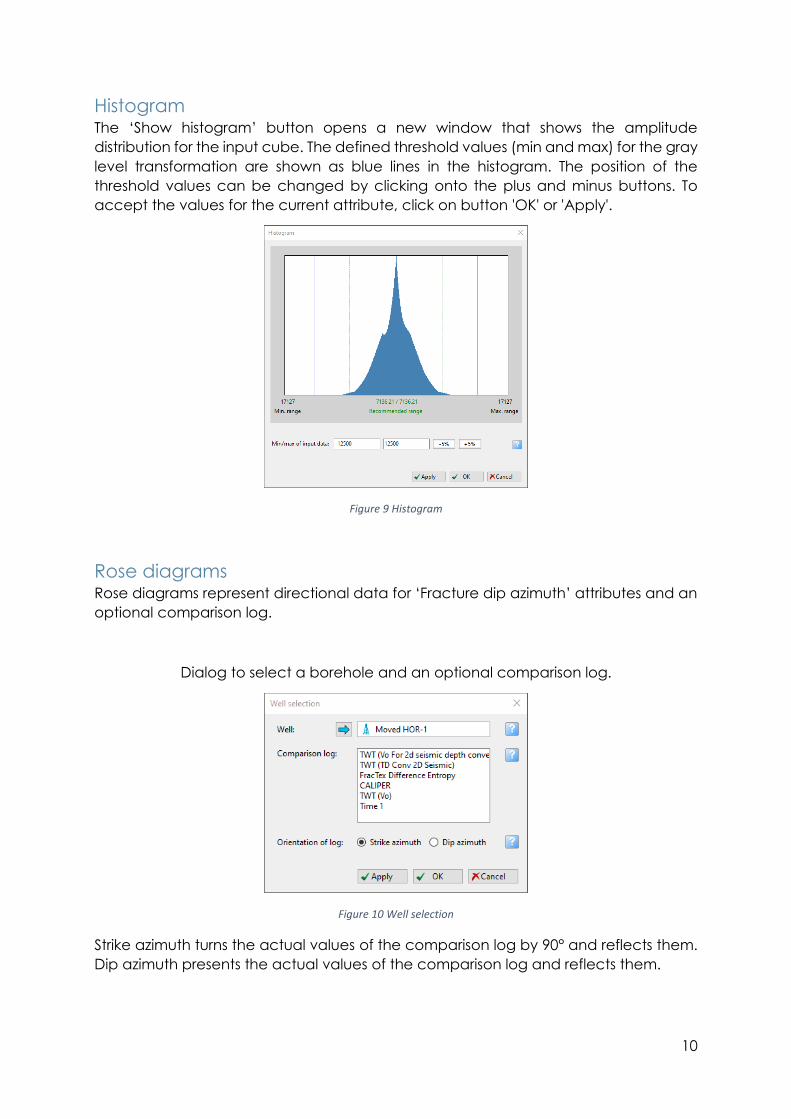
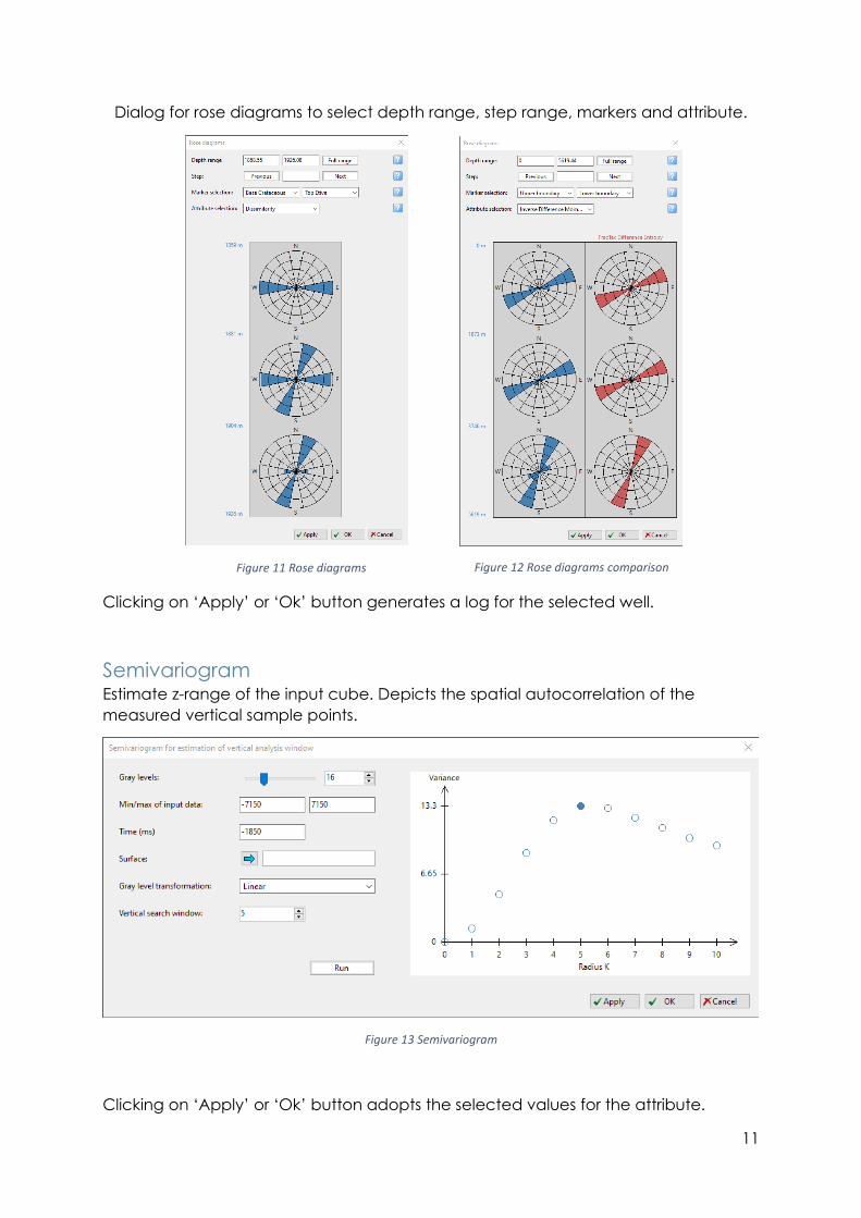
Rose diagrams Rose diagrams represent directional data for ‘Fracture dip azimuth’ attributes and an
optional comparison log.
Dialog to select a borehole and an optional comparison log.
Strike azimuth turns the actual values of the comparison log by 90° and reflects them.
Dip azimuth presents the actual values of the comparison log and reflects them.
Figure 10 Well selection
11
Dialog for rose diagrams to select depth range, step range, markers and attribute.
Clicking on ‘Apply’ or ‘Ok’ button generates a log for the selected well.
Semivariogram Estimate z-range of the input cube. Depicts the spatial autocorrelation of the
measured vertical sample points.
Figure 13 Semivariogram
Clicking on ‘Apply’ or ‘Ok’ button adopts the selected values for the attribute.
Figure 12 Rose diagrams comparison Figure 11 Rose diagrams
12
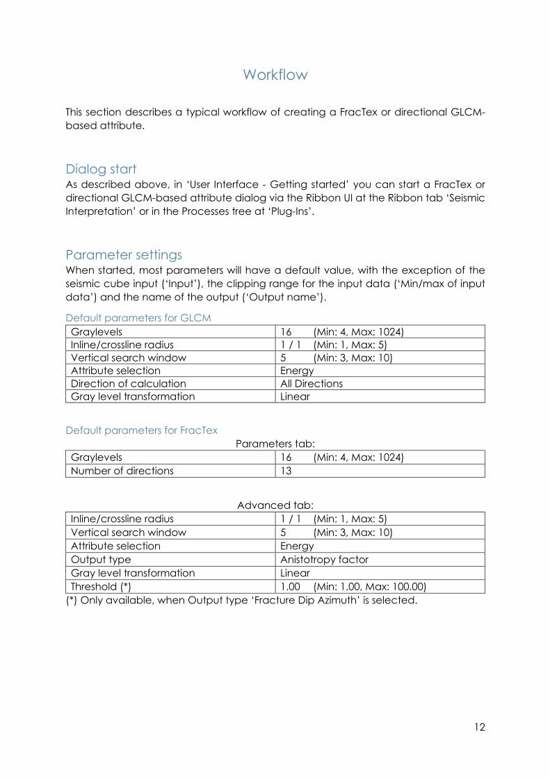
Workflow
This section describes a typical workflow of creating a FracTex or directional GLCM-
based attribute.
Dialog start As described above, in ‘User Interface - Getting started’ you can start a FracTex or
directional GLCM-based attribute dialog via the Ribbon UI at the Ribbon tab ‘Seismic
Interpretation’ or in the Processes tree at ‘Plug-Ins’.
Parameter settings When started, most parameters will have a default value, with the exception of the
seismic cube input (‘Input’), the clipping range for the input data (‘Min/max of input
data’) and the name of the output (‘Output name’).
Default parameters for GLCM
Graylevels 16 (Min: 4, Max: 1024)
Inline/crossline radius 1 / 1 (Min: 1, Max: 5)
Vertical search window 5 (Min: 3, Max: 10)
Attribute selection Energy
Direction of calculation All Directions
Gray level transformation Linear
Default parameters for FracTex
Parameters tab:
Graylevels 16 (Min: 4, Max: 1024)
Number of directions 13
Advanced tab:
Inline/crossline radius 1 / 1 (Min: 1, Max: 5)
Vertical search window 5 (Min: 3, Max: 10)
Attribute selection Energy
Output type Anistotropy factor
Gray level transformation Linear
Threshold (*) 1.00 (Min: 1.00, Max: 100.00)
(*) Only available, when Output type ‘Fracture Dip Azimuth’ is selected.
13
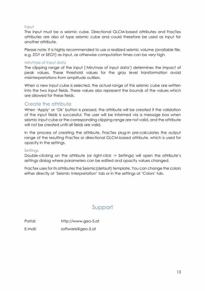
Input
The input must be a seismic cube. Directional GLCM-based attributes and FracTex
attributes are also of type seismic cube and could therefore be used as input for
another attribute.
Please note: It is highly recommended to use a realized seismic volume (available file,
e.g. ZGY or SEGY) as input, as otherwise computation times can be very high.
Min/max of input data
The clipping range of the input (‘Min/max of input data’) determines the impact of
peak values. These threshold values for the gray level transformation avoid
misinterpretations from amplitude outliers.
When a new input cube is selected, the actual range of this seismic cube are written
into the two input fields. These values also represent the bounds of the values which
are allowed for these fields.
Create the attribute When ‘Apply’ or ‘Ok’ button is pressed, the attribute will be created if the validation
of the input fields is successful. The user will be informed via a message box when
seismic input cube or the corresponding clipping range are not valid, and the attribute
will not be created until all fields are valid.
In the process of creating the attribute, FracTex plug-in pre-calculates the output
range of the resulting FracTex or directional GLCM-based attribute, which is used for
opacity in the settings.
Settings
Double-clicking on the attribute (or right-click -> Settings) will open the attribute’s
settings dialog where parameters can be edited and opacity values changed.
FracTex uses for its attributes the Seismic(default) template. You can change the colors
either directly at ‘Seismic Interpretation’ tab or in the settings at ‘Colors’ tab.
Support
Portal: http://www.geo-5.at
E-mail: [email protected]
Related Documents