HELSINKI UNIVERSITY OF TECHNOLOGY Department of Electrical and Communications Engineering Power Systems and High Voltage Engineering Laboratory Jingqiang Li High Voltage Direct Current Transmission Master thesis submitted for approval for the degree of Master of Science, Espoo, January, 2009 Supervisor Professor Matti Lehtonen, D.Sc (Tech.) Instructor Professor Matti Lehtonen

Welcome message from author
This document is posted to help you gain knowledge. Please leave a comment to let me know what you think about it! Share it to your friends and learn new things together.
Transcript

HELSINKI UNIVERSITY OF TECHNOLOGYDepartment of Electrical and Communications EngineeringPower Systems and High Voltage Engineering Laboratory
Jingqiang Li
High Voltage Direct Current Transmission
Master thesis submitted for approval for the degree of Master of Science, Espoo,January, 2009
Supervisor Professor Matti Lehtonen, D.Sc (Tech.)Instructor Professor Matti Lehtonen

HELSINKI UNIVERSITY ABSTRACT OF THEOF TECHNOLOGY MASTER THESIS
Author: Jingqiang LiName of thesis: High Voltage Direct Current TransmissionDate: 14.07.2008 Number of pages: 102Faculty: Department of Electrical and Communications EngineeringChair: Electrical Engineering (Power Systems) Code: S18Supervisor: Prof. Matti LehtonenInstructor: Prof. Matti Lehtonen
This thesis is focused on the application and development of HVDC transmission
technology based on thyristor without turnoff capability. Compared with other
macroelectronics in the power field, thyristor without turnoff capability has
successful operation experience to ensure reliability and high power ratings to transfer
bulk energy.
This thesis covers converter station design and equipments, reactive power
compensation and voltage stability, AC/DC filters design, control strategy and
function, fault analysis, overvoltage and insulation coordination, overhead line and
cable transmission, transmission line environmental effects, earth electrode design
and development.
With the development of new concepts and techniques, the cost of HVDC
transmission will be reduced substantially, thereby extending the area of application.

3
Acknowledge
The work for this thesis has carried out in the Power System Laboratory, Helsinki
University of Technology.
First, I would like to thank my supervisor, Prof. Matti Lehtonen, for the opportunity to
study this subject and for his inspiring guidance.
Again, I would also like to thank Prof. Jorma Kyyrä for his support and continued
encouragement.
I give best thanks to my family. Their love and care were supporting me in a foreign
country.
Helsinki 14. 7. 2008
Jingqiang Li [email protected]

4
ContentsChapter 1 Introduction ................................................................................................... 6
1.1 HVDC Transmission Configurations.................................................................. 61.1.1 TwoTerminal HVDC Transmission........................................................... 61.1.2 Multiterminal HVDC Transmission............................................................ 8
1.2 HVDC Transmission Characteristics ................................................................ 101.2.1 HVDC Transmission Advantages ............................................................. 101.2.2 HVDC Transmission Disadvantages......................................................... 11
1.3 HVDC Transmission Applications ................................................................... 11Chapter 2 Converter Station ......................................................................................... 13
2.1 Station Design.................................................................................................. 132.2 Converter Valve............................................................................................... 152.3 Converter Transformer..................................................................................... 182.4 Smoothing Reactor........................................................................................... 19
Chapter 3 Reactive Power Management ....................................................................... 223.1 Reactive Power Balance................................................................................... 223.2 Voltage Stability .............................................................................................. 233.3 Reactive Power Compensators ......................................................................... 24
Chapter 4 AC Filter Design .......................................................................................... 264.1 AC Harmonics ................................................................................................. 264.2 Design Criteria................................................................................................. 264.3 Passive AC Filters............................................................................................ 27
4.3.1 Tuned Filters ............................................................................................ 284.3.2 Damped Filters......................................................................................... 30
Chapter 5 DC Filter Design .......................................................................................... 335.1 DC Harmonics ................................................................................................. 335.2 Design Criteria................................................................................................. 355.3 Active DC Filter .............................................................................................. 37
Chapter 6 Control System ............................................................................................ 396.1 Multiple Configurations ................................................................................... 396.2 Control System Levels ..................................................................................... 406.3 Converter Firing Phase Control........................................................................ 43
6.3.1 Individual Phase Control .......................................................................... 446.3.2 Equidistant Pulse Control ......................................................................... 44
6.4 Converter Control Mode .................................................................................. 456.5 Control System Functions ................................................................................ 46
Chapter 7 Fault Analysis .............................................................................................. 507.1 Converter Faults............................................................................................... 507.2 ACside Faults ................................................................................................. 547.3 DCLine Fault .................................................................................................. 58
Chapter 8 Overvoltages and Insulation Coordination................................................... 618.1 Overvoltage Protection Devices ....................................................................... 618.2 Overvoltages Studies........................................................................................ 62
8.2.1 ACside Overvoltages .............................................................................. 628.2.2 DCside Overvoltages .............................................................................. 638.2.3 DCLine Overvoltages ............................................................................. 65
8.3 Insulation Coordination .................................................................................. 66Chapter 9 Transmission Lines ...................................................................................... 69
9.1 Overhead Line ................................................................................................. 69

5
9.1.1 Conductor Crosssection .......................................................................... 699.1.2 Insulation Level........................................................................................ 699.1.3 Insulator Types......................................................................................... 719.1.4 Insulator Numbers .................................................................................... 719.1.5 Steel Tower.............................................................................................. 729.1.6 Ground Wire ............................................................................................ 72
9.2 Cable Line ....................................................................................................... 739.2.1 Application and Development .................................................................. 739.2.2 Cable Insulation ....................................................................................... 739.2.3 Cable Types ............................................................................................. 749.2.4 Cable Structures ....................................................................................... 76
9.3 Earth Electrode Line ........................................................................................ 789.3.1 Insulation Level........................................................................................ 789.3.2 Conductor Crosssection .......................................................................... 79
Chapter 10 Transmission Line Environmental Effects ................................................ 8010.1 Corona ............................................................................................................. 8010.2 ElectricField Effect......................................................................................... 8110.3 Radio Interference............................................................................................ 8210.4 Audible Noise .................................................................................................. 84
Chapter 11 Earth Electrode......................................................................................... 8511.1 Earth Electrode Effects .................................................................................... 8511.2 Earth Electrode Operational Features ............................................................... 8511.3 Electrode Site Selection ................................................................................... 8611.4 Earth Electrode Design .................................................................................... 8811.5 Earth Electrode Development........................................................................... 9011.6 Influence of Earth Electrode Current ................................................................ 91
Chapter 12 Conclusion ............................................................................................... 93References....................................................................................................................... 95

6
Chapter 1 Introduction
1.1 HVDC Transmission Configurations
In accordance with operational requirements, flexibility and investment, HVDC
transmission systems can be classified into twoterminal and multiterminal HVDC
transmission systems.
1.1.1 TwoTerminal HVDC Transmission
There are only two converter stations in the pointtopoint HVDC transmission system, one
rectifier station and the other inverter station. The main circuit and primary equipments of
the rectifier station are almost the same as those of the inverter station (sometimes ACside
filter configuration and reactivepower compensation may be different), but the functions
of control and protection systems must be configured respectively. There are three
different configurations, i.e. monopolar link (positive or negative polarity), bipolar link
(positive and negative polarity) and backtoback interconnection (no transmission line),
illustrated in Figure 1.1. [1]
Figure 1.1 Backtoback interconnection (a), monopolar link (b) and bipolar link (c) [1]

7
In accordance with circuit modes, monopolar links can be classified into monopolar link
with ground (or sea) return and monopolar link with metallic return. For a monopolar link
with ground return, earth or sea is used as one conductor line and thereby two converter
stations must be grounded necessarily. Since considerable direct current flows through
earth or sea continuously, it will give rise to transformer magnetism saturation and
underground metalobjects electrochemistry corrosion. Although a monopolar link with
ground return can reduce DCline cost, the reliability and flexibility are relatively less
during operations and earth electrodes must be designed with quite high requirements,
thereby easily increasing the cost of earth electrode. A monopolar link with ground return
is usually employed in the HVDC submarine cable scheme, e.g. KontiSkan, FennoSkan,
Baltic cable and Kontek HVDC links. [2] [3] [4] [5] Instead of earth or sea return, a
monopolar link with metallic return (low insulation) may be used. Although the DCline
investment and operational cost of monopolar link with metallic return are higher than
those of monopolar link with ground return, due to no direct current flowing through earth
during operations, transformer magnetism saturation and electrochemistry corrosion can be
avoided. Initially, SwedenPoland Link was planned as a monopolar link with ground
return. Finally owing to the environmental impact, SwedenPoland Link became the first
monopolar link with metallic return. [6]
According to circuit modes, bipolar links can be classified into bipolar link with two
terminal neutral ground, bipolar link with oneterminal neutral ground and bipolar link
with metallic neutral line. A bipolar link with twoterminal neutral ground was employed
in most HVDC transmission schemes, e.g. Three Gorges – Guangdong, Three Gorges –
Changzhou, Chandrapur – Padghe and Gezhouba – Shanghai. [7] [8] [9] [10] It has two
conductor lines, one positive and the other negative, and earth return can be used as a
backup conductor. If one pole is out of service due to a fault, the other pole can operate
with earth by using the overload capability. For a bipolar link with oneterminal neutral
ground, due to only oneterminal neutral grounded, earth or sea cannot be used as a backup
conductor. If faults occur on one pole, the entire bipolar link must be shut down without
the possibility of monopolar operation. A major advantage is to ensure no earth current
during operations, thereby avoiding some consequences. A bipolar link with oneterminal
neutral ground is rarely used, only in English Channel HVDC submarine scheme
interconnecting England and France. North Sea cannot be used as a return path due to the

8
interference with ship’s magnetic compasses. [11] [12] A bipolar link with metallic neutral
line uses three conductor lines, one lowinsulation neutral line and two DClines. Although
the line structure is relatively complex and the line cost is considerably high, due to no
direct current flowing through earth, a bipolar link with metallic neutral line can prevent
some problems caused by earth current and provide relatively reliable and flexible
operating modes. Usually if direct current is not allowed to flow through earth or the site of
earth electrode is quite difficult to select, the bipolar link with metallic neutral line can be
employed. In London, UK, Kingsnorth underground cable HVDC scheme was built to
reduce the shortcircuit level in areas of high load density. [13] Part of HydroQuebec
(Canada)New England (USA) HVDC scheme employed the bipolar link with metallic
neutral line. The earth electrode for the Sandy Pond converter station is located in
Sherbooke, Quebec and is connected to the converter station by a metallic return. [14]
In a backtoback interconnection, both rectifier and inverter are placed on the same site,
linking via smooth reactor. Due to no transmission line and low loss, the equipments on the
DC side can be designed with relatively low voltage and high current rating, thereby
reducing the price of converter transformer, smooth reactor and converter valve. Because
the rectifier and inverter are installed in the same valve hall and thus DC harmonics do not
interfere with communication, DC filters are not required. [15] [16]
1.1.2 Multiterminal HVDC Transmission
A multiterminal HVDC transmission system is used to connect multiple AC systems or
separate an entire AC system into multiple isolated subsystems. In a multiterminal HVDC
transmission system, converter stations can be connected in series or in parallel, illustrated
in Figure 1.2.

9
Figure 1.2 Parallelconnected (up) and seriesconnected (down) configurations [1]
In the seriesconnected HVDC scheme, the regulation and distribution of active power
among converter stations mainly depend on the directvoltage variation that is achieved by
regulating the converter firingangle or transformer tapchanger. Although the series
connected HVDC scheme can provide advantages, e.g. quick powerflow reversal,
excellent reliability and fast fault recovery, due to permanent faults on one portion of DC
line, the entire multiterminal HVDC system must shut down, thereby necessarily using
double circuits and obviously increasing the line price. In the parallelconnected HVDC
scheme, the regulation and distribution of active power among converter stations mainly
depend on the directcurrent variation that is achieved by regulating the converter firing
angle or transformer tapchanger. For the parallelconnected HVDC scheme, in order to
ensure high converter power factor and less reactive power consumption, the firing angle
must be maintained in the small variation range during operations and due to constant
direct voltage, the load reduction is achieved by lowering direct current, thereby providing
lower loss and excellent economic operation. [17]

10
1.2 HVDC Transmission Characteristics
The development of high rating power electronics strongly influences the development of
HVDC technology. In this book, thyristor valve (without turn off capability and with low
frequency) is mainly discussed.
1.2.1 HVDC Transmission Advantages
(1) A bipolar HVDC overhead line only requires two conductors with positive and
negative polarities, thereby providing simple tower structure, low DCline investment
and less power loss. In comparison with one circuit HVAC overhead line, for the same
transmission capacity, HVDC transmission can save approximately 1/3 steelcore
aluminium line and 1/3 – 1/2 steel. Compared to a double circuit HVAC line with six
conductor bundles, one bipolar HVDC line with two conductor bundles takes much
less the width of transmission routine. [18] Under the effect of direct voltage, the
capacitance of transmission line is never taken into account. Since capacitive current
does not exist, direct voltage maintains the same along the transmission line.
(2) For the AC and DC cables with the same insulation thickness and cross section, the
transmission capability for DC cable is considerably higher than that for AC cable. DC
cable lines only require one cable for monopolar link or two cables for bipolar link and
AC cable lines need three cables, due to threephase AC transmission. Therefore, the
price for DC cable lines is substantially lower than the prices for AC cable lines. Since
there is no the cable capacitance in a DC cable transmission, the transmission distance
for DC cable is unlimited theoretically.
(3) HVDC links can be used to interconnect asynchronous AC systems and the short
circuit current level for each AC system interconnected will not increase. The
interconnected AC systems can be operated with different nominal frequencies (50 and
60 Hz) respectively and the exchange power between interconnected AC systems can
be controlled rapidly and accurately.
(4) Due to the rapid and controllable features, HVDC systems can be used to improve the
performance of AC system, e.g. the stability of frequency and voltage, the power
quality and reliability of interconnected AC systems. For the DC/AC hybrid

11
transmission system, the rapid and controllable features of HVDC system can also be
used to dampen the power oscillations in AC systems, so as to increase AC lines’
transmission capacity.
(5) For an HVDC system, earth can be used as the return path with lower resistance, loss
and operational cost. For a bipolar link, earth is normally used as a backup conductor.
If faults occur on one pole, the bipolar link can be changed into the monopolar link
automatically, thereby improving the reliability of HVDC system.
1.2.2 HVDC Transmission Disadvantages
(1) In a converter station, except for converter transformers and circuit breakers, there are
converter valves, smoothing reactors, AC filters, DC filters and reactive power
compensators. For the same rating, the investment for a converter station is several
times higher than the investment for an AC substation.
(2) A converter acts as not only a load or a source, but also a source of harmonic currents
and voltages, thereby distorting current and voltage waveforms.
(3) In a conventional converter station, the reactive power demand is approximately 60%
of the power transmitted at full load. [19] Since reactive power must balance
instantaneously, reactive power compensators must be installed in the converter
station, in order to improve the stability of commutation and dynamic voltage.
(4) Without current zerocrossing point, DC circuit breakers are difficult to manufacture,
thereby developing multiterminal HVDC systems very slowly. With developing power
semiconductors with high switching frequency, DC circuit breaker can be innovated.
1.3 HVDC Transmission Applications
HVDC schemes mainly serve the following purposes.
• Long Distance and Bulk Capacity Transmission
For the same transmission capacity, above a certain distance, an HVDC transmission offers
more economic benefits than HVAC transmission. As the transmission distance increases,

12
the transmission capacity for HVAC line is restricted by stability limitation, thereby
necessarily increasing additional investment for shortcircuit limitation, voltage support,
etc.
• Power System Interconnection
In order to optimize the resource utilization, several AC systems intend to be
interconnected with the development of power industry, but it will give rise to the
problems in the super system. For example, the interconnection for AC systems always
increases the shortcircuit levels, thereby exceeding the capacity of the existing circuit
breakers. AC systems can also be interconnected by HVDC transmission and thereby it not
only obtains the interconnection benefits but also avoids the serious consequences.
• DC Cable Transmission
For DC cable, without capacitance current, the transmission capacity is not restricted by
transmission distance. Except for the purpose of longdistance and bulkcapacity, DC
cables are also widely used across strait in the world. Due to environmental issue, large
capacity power stations are not allowed to build in the vicinity of city. Moreover, it is very
difficult to select appropriate the overheadline routine, owing to high population and load
density. Therefore, using HVDC underground/submarine cables is an attractive solution to
deliver power from remote power station to urban load center.
13
Chapter 2 Converter Station
2.1 Station Design
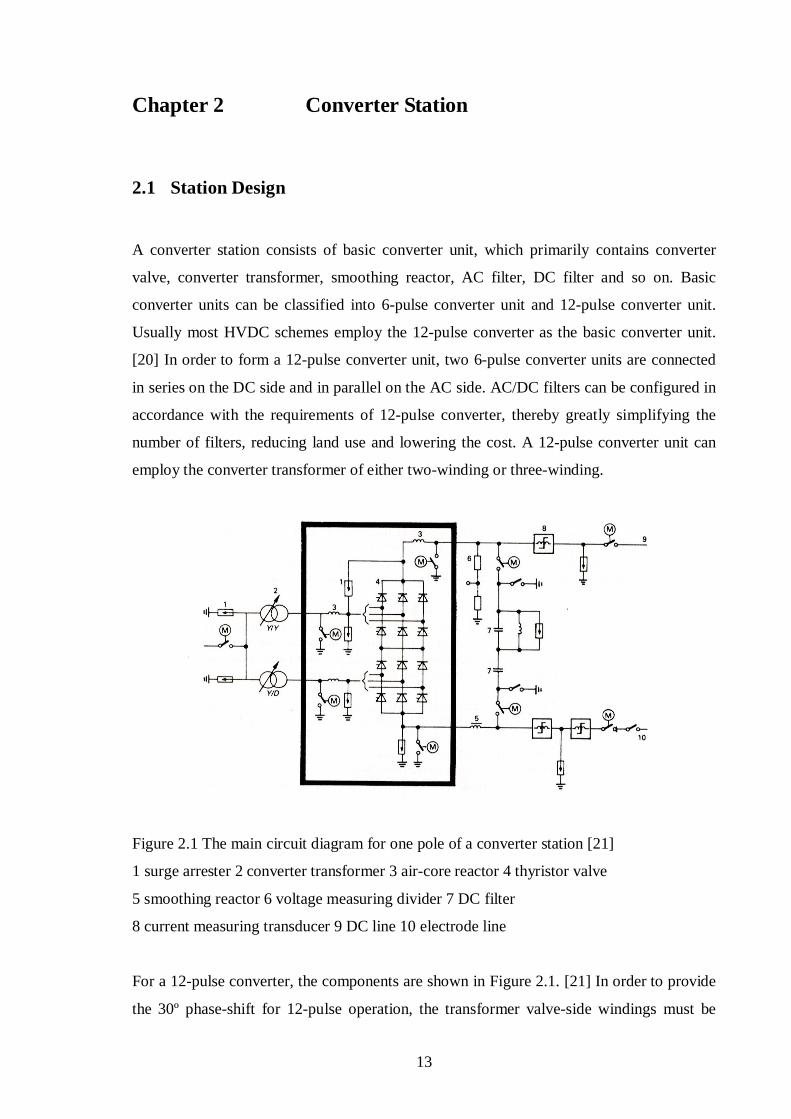
A converter station consists of basic converter unit, which primarily contains converter
valve, converter transformer, smoothing reactor, AC filter, DC filter and so on. Basic
converter units can be classified into 6pulse converter unit and 12pulse converter unit.
Usually most HVDC schemes employ the 12pulse converter as the basic converter unit.
[20] In order to form a 12pulse converter unit, two 6pulse converter units are connected
in series on the DC side and in parallel on the AC side. AC/DC filters can be configured in
accordance with the requirements of 12pulse converter, thereby greatly simplifying the
number of filters, reducing land use and lowering the cost. A 12pulse converter unit can
employ the converter transformer of either twowinding or threewinding.
Figure 2.1 The main circuit diagram for one pole of a converter station [21]
1 surge arrester 2 converter transformer 3 aircore reactor 4 thyristor valve
5 smoothing reactor 6 voltage measuring divider 7 DC filter
8 current measuring transducer 9 DC line 10 electrode line
For a 12pulse converter, the components are shown in Figure 2.1. [21] In order to provide
the 30º phaseshift for 12pulse operation, the transformer valveside windings must be

14
connected in starstar and stardelta respectively. In order to limit any steepfront surges
entering the station, a smoothing reactor is located on the DC side. The measuring
equipments, such as voltage divider and current transducer, can provide the accuracy input
signals for the control and protection systems. The switching components, such as isolators
and circuit breakers, are used for the changeover from monopole metallic return to bipolar
operation.
Figure 2.2 indicates the relative space of the various components for a bipolar converter
station. [22] The areas of shunt capacitor banks and AC filter banks are the major
proportion of the entire area and the valve hall and control room only take a small fraction
of the total station area.
Figure 2.2 The station layout for a bipolar HVDC station [22]
1DC and electrode lines 2DC switchyard 3DC smoothing reactors 4valve hall, pole I
5service building with control room 6valve hall, pole II 7converter transformers
8AC harmonic filters 9highpass filter 10eleventh harmonic filter
11thirteenth harmonic filter 12shunt capacitors 13AC switchyard

15
Figure 2.3 shows a modern compact converter station. [23] In order to reduce the size of a
converter station significantly, using new equipments, such as outdoor valves, gas
insulated bus systems, active AC and DC filters, and the containertype control and
auxiliary integration systems, play an important role. Furthermore, the use of a gas
insulated bus can avoid pollution deposits on exposed portions of a converter station; the
valve building cost can be reduced considerably and all control systems can be tested in the
factory. [24] [25]
Figure 2.3 The compact station layout for a bipolar HVDC station [23]
ACFAC filter DCFDC filter VHvalve hall VYvalve yard SHshunt capacitor
SRsmoothing reactor CCcontrol and auxiliary modules Ttransformer
2.2 Converter Valve
Until today, most HVDC schemes have applied thyristor valves, which are air insulated,
water cooled and suspended indoors. [26]
In order to protect thyristor from overvoltage, excessive rateofrise of voltage and rateof
rise of inrush current, the auxiliary components, such as saturable reactor, voltage dividers,
damping circuits and valve firing electronics are necessarily installed together with local
thyristor to constitute a valve module, shown in Figure 2.4. [27] Owing to the limited
voltage rating for each thyristor, many of them must be connected in series to constitute a
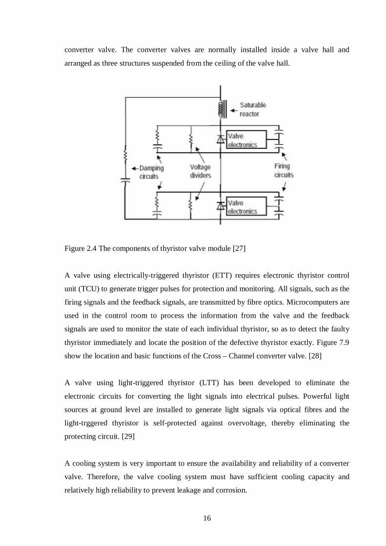
16
converter valve. The converter valves are normally installed inside a valve hall and
arranged as three structures suspended from the ceiling of the valve hall.
Figure 2.4 The components of thyristor valve module [27]
A valve using electricallytriggered thyristor (ETT) requires electronic thyristor control
unit (TCU) to generate trigger pulses for protection and monitoring. All signals, such as the
firing signals and the feedback signals, are transmitted by fibre optics. Microcomputers are
used in the control room to process the information from the valve and the feedback
signals are used to monitor the state of each individual thyristor, so as to detect the faulty
thyristor immediately and locate the position of the defective thyristor exactly. Figure 7.9
show the location and basic functions of the Cross – Channel converter valve. [28]
A valve using lighttriggered thyristor (LTT) has been developed to eliminate the
electronic circuits for converting the light signals into electrical pulses. Powerful light
sources at ground level are installed to generate light signals via optical fibres and the
lighttrggered thyristor is selfprotected against overvoltage, thereby eliminating the
protecting circuit. [29]
A cooling system is very important to ensure the availability and reliability of a converter
valve. Therefore, the valve cooling system must have sufficient cooling capacity and
relatively high reliability to prevent leakage and corrosion.

17
Figure 2.5 Location and basic functions of the CrossChannel valve electronic systems [28]
For indoor valves, a number of disadvantages are the large costly valve buildings, the
complex interface to the electrical equipment, the risk of a valvebuilding fire and the risk
of flashovers across large wall bushings. In order to overcome those disadvantages of
indoor valve design, the outdoor valve design can be an effective alternative. An outdoor
valve is completely assembled in a modular container and fully tested in the factory,
thereby greatly reducing the delivery time and lowering the maintenance cost. In addition,
for the outdoor valve, there is no need to build the valve hall and thus the civil content
(cost and time) of valve hall is greatly reduced.

18
2.3 Converter Transformer
A converter transformer is placed on the core location to link the AC network with the
valve bridge. Owing to expensive component cost and complicated manufacture
technology, the converter transformer is one of most important components.
Usually, modern HVDC systems employ the configuration of one 12pulse converter for
each pole. A converter transformer provides 30º phase shift between two 6pulse
converters to obtain the configuration of 12pulse converter; if the shortcircuit occurs on
the valve arm or DC busbar, the impedance of converter transformer can restrict the fault
current, in order to protect converter valve.
Because the operation of converter transformer is closely related to the nonlinearity caused
by converter commutation, compared with ordinary AC transformer, the converter
transformer is of different characteristics, such as the shortcircuit impedance, test,
harmonics, DCmagnetisation, insulation and onload tap changing. [30]
A converter transformer employs singlephase arrangement or threephase arrangement.
Therefore, for a 12pulse converter, the standard configurations of converter transformer
banks can be: six singlephase twowinding transformers; three singlephase threewinding
transformers; two threephase twowinding transformers and one threephase three
winding transformer.
Figure 2.6 The types of converter transformer [31]

19
In accordance with the voltage requirement, the configuration of converter transformer
depends on transformer ratings, transport conditions and the layout of converter station.
For the converter transformer with medium capacity and voltage, the threephase
transformer can be selected, in order to reduce material consumption, land use and loss,
especially noload loss. For the converter transformer with relatively large capacity and
high voltage, the singlephase transformer groups can be selected, especially without
transport limitations, compared with singlephase twowinding transformer, the single
phase threewinding transformer is of less core, oil tank, bushing and onload tap changer.
Figure 2.7 One large singlephase threewinding converter transformer with its valve side
bushings mounted for entering the valve hall [30]
2.4 Smoothing Reactor
Smoothing reactor can prevent steep impulse waves caused by DC lines or DC switching
yard entering the valve hall, thereby avoiding the damage to the converter valve due to
overvoltage stress.
Excessive inductance likely results in overvoltages during operations, thereby lowering the
response speed. In order to select the suitable reactor inductance, the main considerations
20
are: to limit the rate of rise of the fault current; to smooth the ripples of direct current; to
prevent the intermittent current at lowload condition; to arrange the parameters of DC
filters with the reactor inductance; to prevent the lowfrequency resonance at 50Hz, 100Hz.
Smoothing reactors can be classified into dir/airtype and oiltype. Compared to the oil
type smoothing reactor, the air/drytype smoothing reactor has the following advantages.
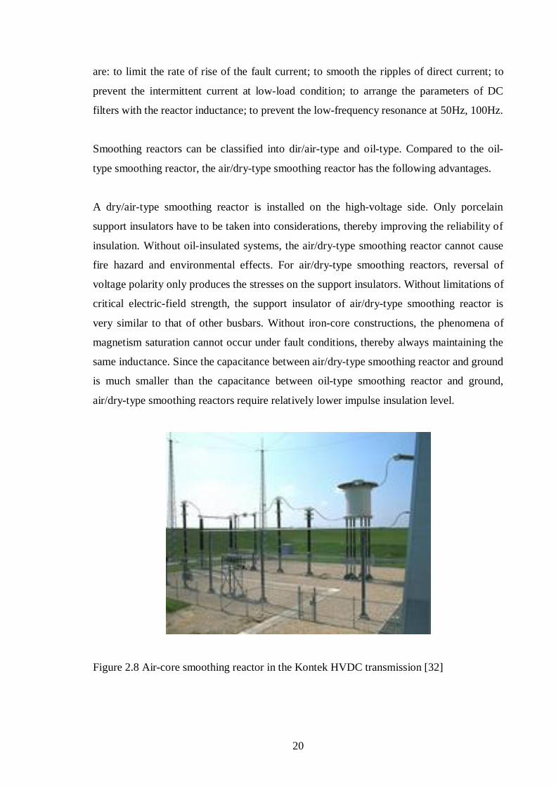
A dry/airtype smoothing reactor is installed on the highvoltage side. Only porcelain
support insulators have to be taken into considerations, thereby improving the reliability of
insulation. Without oilinsulated systems, the air/drytype smoothing reactor cannot cause
fire hazard and environmental effects. For air/drytype smoothing reactors, reversal of
voltage polarity only produces the stresses on the support insulators. Without limitations of
critical electricfield strength, the support insulator of air/drytype smoothing reactor is
very similar to that of other busbars. Without ironcore constructions, the phenomena of
magnetism saturation cannot occur under fault conditions, thereby always maintaining the
same inductance. Since the capacitance between air/drytype smoothing reactor and ground
is much smaller than the capacitance between oiltype smoothing reactor and ground,
air/drytype smoothing reactors require relatively lower impulse insulation level.
Figure 2.8 Aircore smoothing reactor in the Kontek HVDC transmission [32]

21
In contrast to air/drytype smoothing reactor, the oiltype smoothing reactor has the
following advantages.
With ironcore constructions, the oiltype smoothing reactor likely increases the reactor
inductance. The oilpaper insulation system is very feasible and reliable. The oiltype
smoothing reactor is installed on the ground, thus providing the excellent antiseismic
performance.
Figure 2.9 Oilinsulated smoothing reactor in the Rihand – Dehli HVDC transmission [32]

22
Chapter 3 Reactive Power Management
For line commutated converters, no matter at the rectification or inversion state, an HVDC
system need to absorb capacitive reactive power from AC systems. Therefore, the
converter is always the reactivepower load to AC system. The reactive power is expressed
in terms of the active power, i.e.
Q = P tan (3 – 1)
Where;
Q is the reactive power consumed by converters, P is the active power on the DC side of
converters, is the phase difference between the fundamentalfrequency voltage and
current components.
Besides the active power, the reactive power consumed by converters is also related to
some operating parameters very sensitively, such as firing angle and extinction angle. In
the normal operation, when the conversion power is close to the rated power, all possible
control modes are employed to minimize the reactive power consumed by converters;
when the conversion power is much less than the rated power, AC filters must be added to
eliminate harmonics and converters are used to absorb surplus reactive power.
3.1 Reactive Power Balance
For a converter station located close to a power station or power station group, when an
HVDC system operates at high load, generators can provide part of reactive power, in
order to reduce the number of equipments providing capacitive reactivepower; when an
HVDC system operates at low load, generators can absorb part of overcompensation
reactive power, in order to reduce the number of equipments supplying inductive reactive
power. Fully utilizing the reactivepower capability of AC system to balance the reactive
power can reduce the reactivepower compensation capacity provided by the converter
station, save the investment of the reactivepower compensators (capacitor and reactor),
23
reduce the loadrejection overvoltage level at the instant of HVDC system sudden
interruption. [33] [34]
For a converter station located in a load center, the ACbusbar voltage of converter station
is required to maintain basically constant. Under the highload mode, due to inadequate
reactivepower compensation and ACvoltage drop, the converter station is required to
compensate part of reactive power. Under the lowload mode, due to surplus reactive
power and ACvoltage rise, the converter station is required to absorb part of reactive
power.
3.2 Voltage Stability
AC voltage depends on the activepower and reactivepower characteristics of the
converter. In order to minimize ACvoltage variations, the supplied reactivepower must
match the reactivepower consumed by converters. Therefore, a converter station must
install reactivepower compensators, in order to provide reactive power and satisfy filtering
requirements. If generators are close to the sendingend of HVDC system, appropriately
using generators is always more economical and effective to handle most reactive power
demands and maintain AC voltage within an acceptable range. For weak AC systems, it is
necessary to install static var compensators or synchronous compensators. [35]
When the HVDC system deblocks, if the minimum number of AC filters are suddenly
added, the reactive power consumed by converters will be much less than the reactive
power supplied by AC filters, thereby resulting in the reactivepower impact on the AC
system and causing ACvoltage fluctuation. If the HVDC system operates at low load,
adding the minimum number of ACfilters will lead to surplus reactive power and thus it is
very difficult to regulate AC voltage. Furthermore, under the most severe condition, it is
necessary to block the HVDC system. If the HVDC system operates at high load, due to
insufficient reactive power in the sendingend converter station, the local generators must
be regulated immediately to supply reactive power, in order to avoid the reduction of AC
busbar voltage. [36]

24
3.3 Reactive Power Compensators
In the converter station, the reactivepower compensators can be primarily classified into
the following categories. [37]
1. AC Filter and Capacitor Bank
If the connected AC system is not very weak, AC filters and capacitor banks are usually
employed. Besides harmonics elimination, AC filters can also provide fundamental
frequency reactive power. In order to meet reactive power demands, only using capacitor
banks for reactive power compensation can provide much better economic solution rather
than improving the capacity of AC filter.
2. Static Var Compensator
In order to regulate reactive power smoothly and quickly, static var compensators, such as
AC selfsaturated reactors, thyristorcontrolled reactors and thyristorswitched capacitors,
can be employed. In addition, if the receivingend AC system is weak, using static var
compensators can also improve dynamic ACvoltage stability, thereby enhancing the
control stability for HVDC system and increasing the speed of response.
3. Synchronous Compensator
For a very weak AC network relative to the capacity of HVDC system, synchronous
compensators are required to install in the receivingterminal converter station, especially
from a remote power station to a highdensity load centre, and synchronous compensators
are of the slow response characteristic, thereby causing a certain problem especially in the
lack of local generation. However, using synchronous compensators can increase the short
circuit ratio, thereby reducing the sensitivity to transients.
Selecting suitable reactivepower compensatiors mainly depends on the ACDC system
strength, which is generally expressed by the shortcircuit ratio, i.e. the ratio of the AC
system shortcircuit capacity to DClink power. If the shortcircuit ratio is greater than 3,

25
capacitors and reactors are only considered; if the shortcircuit ratio is between 2 and 3,
voltage stability must be calculated and the reactivepower compensatiors with voltage
control capability can be considered; if the shortcircuit ratio is less than 2, when using
conventional conversion technology, installing synchronous compensators is the most
effective method. [38]

26
Chapter 4 AC Filter Design
4.1 AC Harmonics
Line commutated converters discussed in this book generate characteristic harmonics, non
characteristic harmonics (including crossmodulation harmonics) on the AC side.
1. Characteristic Harmonics
Characteristic harmonics are based on the following ideal conversion circumstances: AC
busbar voltage is of the constantfrequency ideal sinusoidal waveform; for a converter
transformer, phaseimpedances or ratios are the same; two convertertransformers are of
the same impedances or ratios; converter firing pulses are of equallyspaced; the current
flowing through DCcircuit is ideal direct current. [39]
2. NonCharacteristic Harmonics
In practice, the operating circumstances are always not ideal. The nonideal factors are: the
ripples exist in direct current; the harmonics exist in AC voltage; AC fundamental
frequency voltages are asymmetrical with negativesequence voltage; for a converter
transformer, phaseimpedances are not identical; two converters are of different firing
angles; due to different convertertransformer ratios, two converters are of different
commutating voltages; two convertertransformers are of different impedances; converter
firing pulses are not of equallyspaced. [40]
4.2 Design Criteria
1. Voltage Distortion
Because the system harmonic impedance is small, the flow of harmonic current cannot
cause the serious problem. Therefore, the reduction of harmonic voltage to an acceptable
27
level at the converter station is a more effective criterion for filter design. In general, the
voltage distortion caused by individual harmonics (Vn) and the total harmonic voltage
distortion are specified factors. The total harmonic voltage distortion is defined as
VTD = ∑∞
=2
2
nnV (4 – 1)
2. Telephone Interference Factor (TIF)
An early telephone system was based on openwire communications disturbed by power
lines likely. Therefore, concerning with filter design, the telephone interference factor must
be taken into account to approximately assess the effect of the distorted voltage or current
waveform of a power line on telephone noise. The TIF is defined as
TIF = ( )2/1
0
21
∑
∞
=ffff VPK
V(4 – 2)
V =2/1
0
2
∑
∞
=ffV (4 – 3)
Where;
Kf = 5000(f/1000) = 5f,
Pf = Cmessage weighting,
Vf = r.m.s. voltage of frequency f on the power line.
4.3 Passive AC Filters
For instance, most HVDC schemes use conventional passive AC filters with successful
experience. Active AC filters and continuously tuned AC filters were rarely installed in
HVDC schemes. [41] Therefore, only passive AC filters are discussed in this book. A
28
passive filter is parallel with the connected AC system and also regarded as bypass path for
harmonics, thereby providing very low impedance under the harmonic frequency.
AC filters are used not only to eliminate harmonic currents, but also to supply part of
fundamentalfrequency reactivepower. In accordance with the frequencyimpedance
characteristics, conventional passive filters are of tuned filters (normally tuned for one or
two frequencies, at most three frequencies), highpass filters (relatively low impedance
over a wide range of frequency) and multituned highpass filters (tuned filters combined
with highpass filters).
4.3.1 Tuned Filters
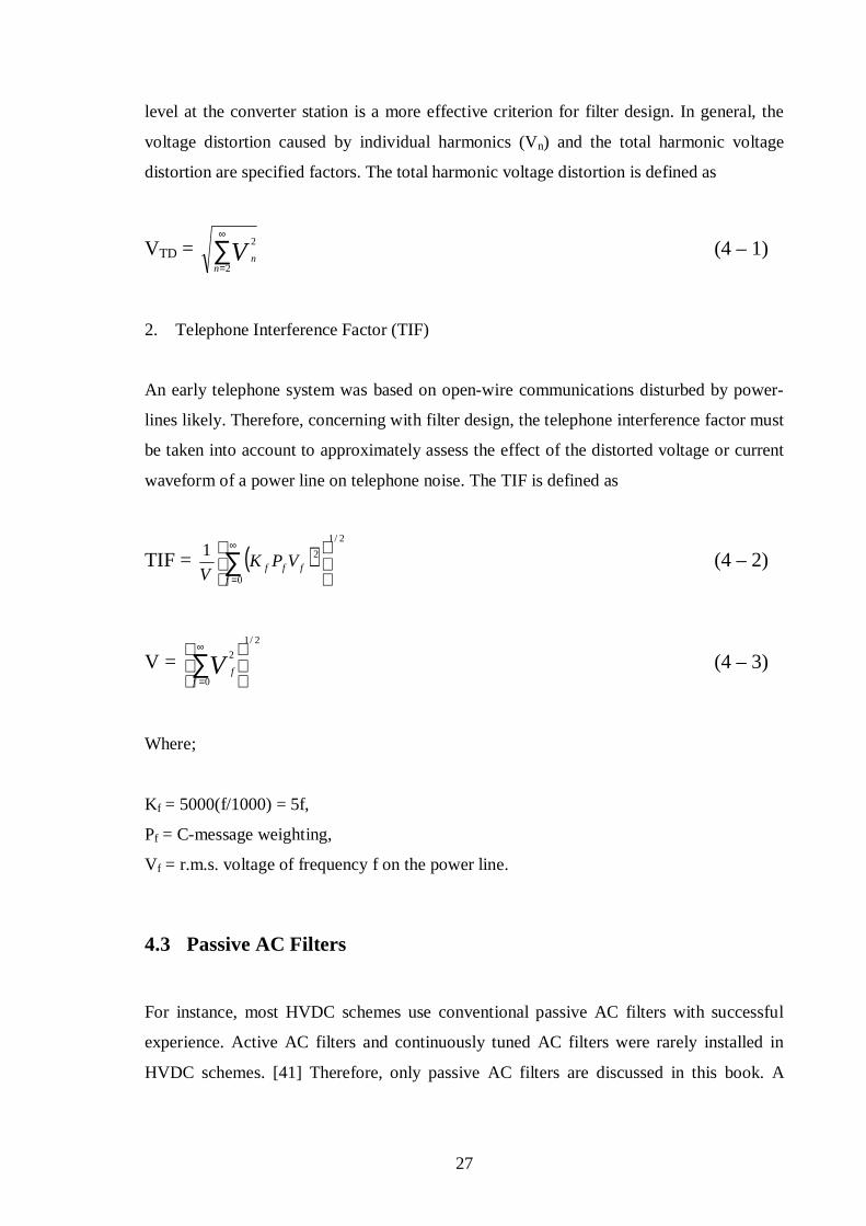
1. SingleTuned Filter
The circuit and impedancefrequency characteristic of singletuned filter are shown in
Figure 4.1.
Figure 4.1 The circuit and impedancefrequency characteristic of singletuned filter [42]
The main conditions to determine filter parameters are fundamentalfrequency reactive
power capacity per single filter under rated voltage, and tuning frequency. A singletuned
filter is more sensitive to the frequency deviation and normally tuned for the characteristic
harmonics, i.e. the 5th, 7th, 11th and 13th. Because 12pulse converters have been used
widely, the singletuned filters are not installed any longer in new HVDC schemes.

29
2. DoubleTuned Filter
The circuit and impedancefrequency characteristic of doubletuned filter are shown in
Figure 4.2.
Figure 4.2 The circuit and impedancefrequency characteristic of doubletuned filter [42]
The main conditions to determine filter parameters are fundamentalfrequency reactive
power capacity per single filter under rated voltage, double tuning frequencies and parallel
circuit tuning frequency. A doubletuned filter can cancel double characteristic harmonics
and produce much lower loss than two singletuned filters together. The doubletuned filter
is the most popular filter in modern HVDC transmission schemes. [43]
3. TripleTuned Filter
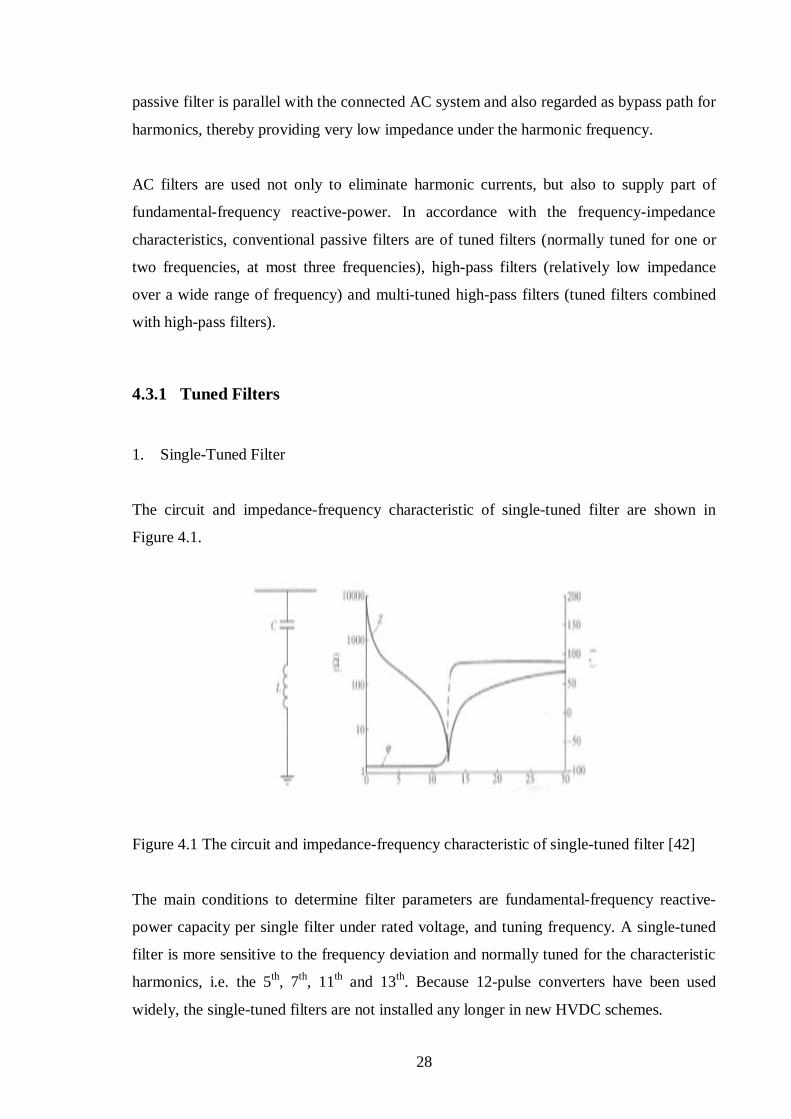
The circuit and impedancefrequency characteristic of tripletuned filter are shown in
Figure 4.3.
30
Figure 4.3 The circuit and impedancefrequency characteristic of tripletuned filter [42]
A tripletuned filter can eliminate three harmonics, thereby substantially reduce the land
use. For the tripletuned filter, the number of highvoltage circuit breakers and capacitors
are less than the doubletuned filter. The most outstanding advantage of tripletuned filter
is the convenient reactivepower balance characteristic at low load. [44]
4.3.2 Damped Filters
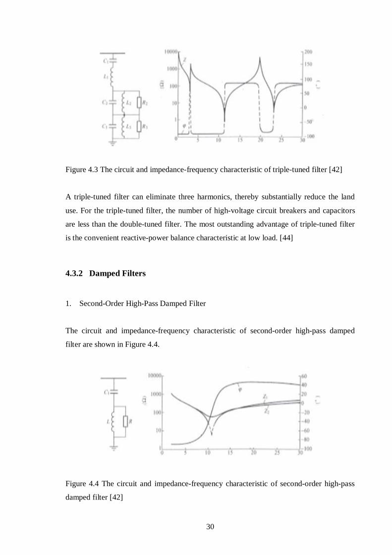
1. SecondOrder HighPass Damped Filter
The circuit and impedancefrequency characteristic of secondorder highpass damped
filter are shown in Figure 4.4.
Figure 4.4 The circuit and impedancefrequency characteristic of secondorder highpass
damped filter [42]

31
Except for selecting suitable damped resistance, the component parameters of secondorder
highpass damped filter are similar to those of singletuned filter. The secondorder high
pass damped filter was used frequently in early HVDC schemes.
2. ThirdOrder HighPass Damped Filter
The circuit and impedancefrequency characteristic of thirdorder highpass damped filter
are shown in Figure 4.5.
Figure 4.5 The circuit and impedancefrequency characteristic of thirdorder highpass
damped filter [42]
Except for selecting suitable damped resistance, the tuning frequency of parallel circuit
must be also selected to determine the component parameters. The fundamentalfrequency
loss of thirdorder highpass damped filter is lower than that of secondorder highpass
damped filter.
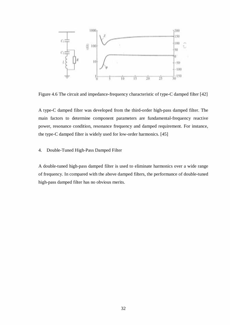
3. TypeC Damped Filter
The circuit and impedancefrequency characteristic of typeC damped filter are shown in
Figure 4.6.
32
Figure 4.6 The circuit and impedancefrequency characteristic of typeC damped filter [42]
A typeC damped filter was developed from the thirdorder highpass damped filter. The
main factors to determine component parameters are fundamentalfrequency reactive
power, resonance condition, resonance frequency and damped requirement. For instance,
the typeC damped filter is widely used for loworder harmonics. [45]
4. DoubleTuned HighPass Damped Filter
A doubletuned highpass damped filter is used to eliminate harmonics over a wide range
of frequency. In compared with the above damped filters, the performance of doubletuned
highpass damped filter has no obvious merits.

33
Chapter 5 DC Filter Design
5.1 DC Harmonics
Line commutated converters generate characteristic and noncharacteristic harmonics on
the DC side.
1. Characteristic Harmonics
Characteristic harmonics are based on the following ideal conversion circumstances: the
ACbusbar voltages of the converter are purely threephase symmetrical sinusoidal waves;
the current flowing through the converter is ripplefree direct current; the parameters of the
converter itself are threephase absolutely symmetry; the control system of the converter
produces perfectly equallyspaced converter firing pulses.
Under above ideal conditions, converters generate direct voltage on the DC side.
According to Fourier analysis, for a 6pulse bridge converter, direct voltage contains
harmonics of order 6n (i.e., 6th, 12th, 18th, etc.) and for a 12pulse bridge converter, direct
voltage contains harmonics of order 12n (i.e., 12th, 24th, 36th, etc.).
In the early 1990s, when built U.S.A Intermountain Power Project HVDC transmission,
owing to DC earth electrode lines and DC lines erected on the same tower, the DCside
harmonics exceeded the normal standards seriously. [46] The capacitance of the DC
neutral point to ground has the important effect on the 18th harmonic, while the stray
capacitance of the converter to ground has the important effect on the distribution of DC
side harmonic currents. Therefore, the equivalent circuit shown in Figure 5.1 was used to
express the 3pulse model of DCside harmonics for a 12pulse converter. [47] In the 3
pulse model of DCside harmonics, for various harmonicvoltage sources, the amplitudes
of harmonic voltages are the same and equal to 1/4 of the values of the 12pulse model’s
harmonic voltages.

34
Figure 5.1 The novel 3pulse model of DCside harmonics for a 12pulse converter [47]
U1 – U4 – 3pulse harmonic voltage source;
Z1 – Z4 – 1/4 12pulse converter internal impedance;
C1, C2 – the stray capacitance of the converter transformer to ground
2. NonCharacteristic Harmonics
The factors, which produce the DCside noncharacteristic harmonics, can be classified
into the following categories.
(1). AC system voltages are never perfectly balanced and undistorted, and the system
impedances are not exactly equal in the three phases. Therefore, the AC busbar
voltages contain the harmonic voltages and generate the noncharacteristic harmonic
voltages on the DC side.
(2). For a 12pulse converter, the transformer turn ratios and transformer reactances are not
identical for the starstar connected converter transformer and the stardelta connected
converter transformer. For a converter transformer, the transformer leakage reactances
are unbalanced in the three phases. As a result, unequal commutation reactances also
cause noncharacteristic voltages on the DC side.

35
(3). In accordance with practical situations, the unequal operating parameters of twopole
converters must be calculated. The amplitudes and phasors of harmonics must be fully
considered respectively.
5.2 Design Criteria
In order to reduce the harmonic hazard, the overheadline HVDC systems usually install
the DC filters, but the backtoback and fullcable HVDC systems are not required to
install the DC filters. Therefore the DC filters are mainly designed to overcome the
interference on the openwire communications. In order to assess the interference level, the
harmonic voltage and current profiles along the HVDC line, especially electromagnetic
induction from harmonic currents, must be carried out comprehensively. Moreover, due to
the disturbances at both ends of the link, the profits from each end must add their effects
necessarily. [48]
There is no unified DCside harmonic indexes defined by the international conferences,
and the DCside harmonic standards must be evaluated in the HVDC system respectively.
The DCside harmonic indexes (DC filter performance) contain induced noise voltage
(INV), equivalent disturbing current (EDC) and DCline harmonic current limit. [49] Until
1970s, in the planning stage of the HVDC transmission system, the induced noise voltage
was no longer used, and the equivalent disturbing current was widely employed to design
the DC filters.
Close to parallel or cross communication lines, the comprehensive interference effect
produced by all the harmonic currents of the DC lines can be expressed by the single
frequency (800 Hz) harmonic current, socalled the equivalent disturbing current. [50]
Ieq(x) = [Ie(x)2S + Ie(x)2
R]1/2 (5 – 1)
Where;

36
Ieq(x) is the 800 Hz equivalent disturbing current at any point along the transmission
corridor, Ie(x)S is the magnitude of the equivalent disturbing current component due to
harmonic voltage sources at the sending end, Ie(x)R is the magnitude of the equivalent
disturbing current component due to harmonic voltage sources at the receiving end, x
denotes the relative location along the transmission corridors.
The equivalent disturbing current, which is caused by harmonic voltages, highly depends
on the harmonic weights. The standard harmonic weighting curves are used to take into
account the sensitivity of the human ear to the harmonic frequencies. Two harmonic
weighting factors are in common use:
The psophometric weighting by the CCITT [51], extensively used in Europe;
The Cmessage weighting by Bell Telephone Systems (BTS) and Edison Electric Institute
(EEI), used in the USA and Canada. [52]
Figure 5.2 shows that the difference between these two harmonic weighting curves is very
slight and that the human ear has a sensitivity to audiofrequencies that peaks at about 1
kHz. [53]
Figure 5.2 Cmessage (realline) and psophometric weighting (dashline) factors [53]
37
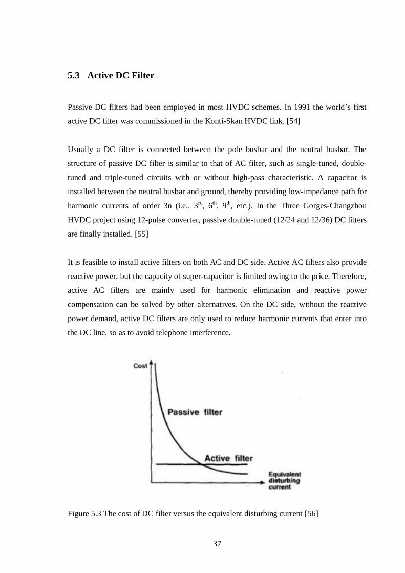
5.3 Active DC Filter
Passive DC filters had been employed in most HVDC schemes. In 1991 the world’s first
active DC filter was commissioned in the KontiSkan HVDC link. [54]
Usually a DC filter is connected between the pole busbar and the neutral busbar. The
structure of passive DC filter is similar to that of AC filter, such as singletuned, double
tuned and tripletuned circuits with or without highpass characteristic. A capacitor is
installed between the neutral busbar and ground, thereby providing lowimpedance path for
harmonic currents of order 3n (i.e., 3rd, 6th, 9th, etc.). In the Three GorgesChangzhou
HVDC project using 12pulse converter, passive doubletuned (12/24 and 12/36) DC filters
are finally installed. [55]
It is feasible to install active filters on both AC and DC side. Active AC filters also provide
reactive power, but the capacity of supercapacitor is limited owing to the price. Therefore,
active AC filters are mainly used for harmonic elimination and reactive power
compensation can be solved by other alternatives. On the DC side, without the reactive
power demand, active DC filters are only used to reduce harmonic currents that enter into
the DC line, so as to avoid telephone interference.
Figure 5.3 The cost of DC filter versus the equivalent disturbing current [56]
38
According to different equivalent disturbing currents, the cost of active DC filters
compared to passive DC filters is shown in Figure 5.5. The cost of passive filter can
increase dramatically when the equivalent disturbing current reduces; however, since
active filter can eliminate all harmonics within the whole range of frequency variation, the
cost of active filter remains constant. [56]
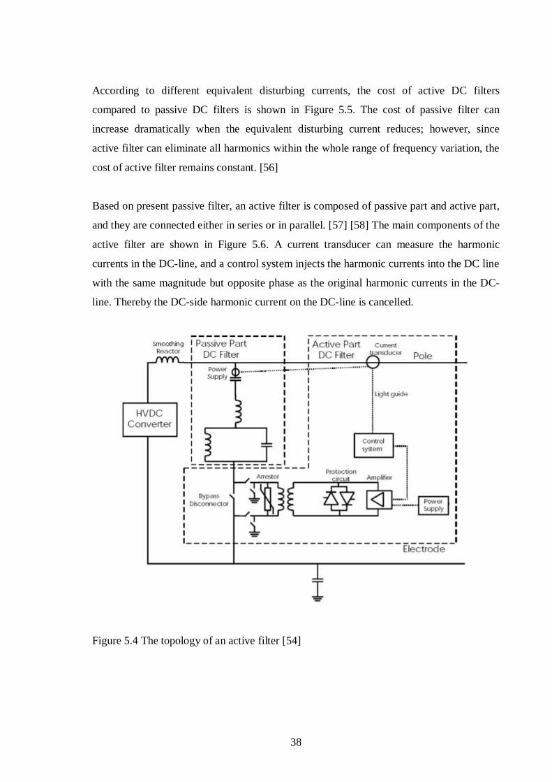
Based on present passive filter, an active filter is composed of passive part and active part,
and they are connected either in series or in parallel. [57] [58] The main components of the
active filter are shown in Figure 5.6. A current transducer can measure the harmonic
currents in the DCline, and a control system injects the harmonic currents into the DC line
with the same magnitude but opposite phase as the original harmonic currents in the DC
line. Thereby the DCside harmonic current on the DCline is cancelled.
Figure 5.4 The topology of an active filter [54]

39
Chapter 6 Control System
In a twoterminal (pointtopoint) HVDC transmission system, the capacity and direction
of power flow can be controlled rapidly, so as to satisfy the operational demands for the
entire AC/DC hybrid systems. In this book, the control system is only designed for the
twoterminal HVDC transmission system, in order to provide the following fundamental
control functions.
1. controlling the starting and stopping sequences of an HVDC transmission system;
2. controlling the capacity and direction of transfer power;
3. controlling the abnormal operations of converters and the disturbances of AC systems
interconnected;
4. when faults occur, protecting the equipments of the converter station;
5. monitoring a variety of operating parameters for converter stations and DC lines, and
supervising the information of the control system itself;
6. enhancing the interface to the equipments of the AC substation and improving the link
with operators.
6.1 Multiple Configurations
In order to meet the indexes of availability and reliability required by HVDC systems, all
the control systems employ the design of multiple configurations, usually using the double
channel design, one channel is active and the other channel is on the hot standby status.
When faults occur in the active channel, the hot standby channel is automatically switched
to the active status and automatic switching actions should not cause the obvious
disturbances to the transfer power. In some cases, the triplechannel design is employed.
For example, Gezhouba – Nanqiao, ThreeGorge – Guangdong HVDC systems and Russia
40
– Finland backtoback HVDC system all employ the triplechannel design. As the channel
number increases, the equipments’ investment and components’ fault will increase
correspondingly. In general, the doublechannel design is a rather better selection.
6.2 Control System Levels
A complicated control system using different levels can improve the reliability and
flexibility of system operation and maintenance, in order to minimize the influence and
hazard extent caused by control faults.
According to the level concept, all the control components are divided into bipole function
(highest level), pole function and valve group function (lowest level) respectively. In order
to reduce the faults’ influence scope, all the control functions must be put into the utmost
low level and especially the number of the control components concerning with bipole
function must minimize.
For reasons of reliability, the control system of a modern HVDC scheme is generally
divided into fourlevel hierarchies from top to down, i.e. system (overall) control
hierarchy, bipole (master) control hierarchy, pole control hierarchy and converter (bridge)
control hierarchy. [59] Figure 6.1 shows the controllevel system of a bipolar HVDC
system.

41
Figure 6.1 The block diagram of level structure for the control system [59]
For only one converter unit in each pole, in order to simplify structures, the pole control
and converter control can group together as one control hierarchy; for only one bipolar
line, the system control and bipole control usually group together as one hierarchy. Among
all converter stations, only one is regarded as the master control station and others as slave
control stations; the system control and bipole control are set in the master control station,
in order to send out control commands via communication systems and coordinate the
operation of the whole system.
1. Converter Control Hierarchy
A converter control hierarchy is used to control the converter’s firing phase. The main
control functions of the converter control hierarchy are: converter firingphase control;
constant current control; constant extinctionangle control; direct voltage control;
maximum and minimum firingangle limit control; maximum and minimum directvoltage
limit control; maximum and minimum directcurrent limit control; converter unit blocking
and deblocking sequence control.
42
2. Pole Control Hierarchy
A pole control hierarchy is used to control one pole. For a bipolar HVDC transmission
system, if one pole is isolated due to a fault, the other pole must operate independently and
complete the main control functions. Therefore, one pole control hierarchy is completely
independent from the other and each pole control hierarchy must configure the utmost
control functions. The main functions of the pole control hierarchy are:
(1) in order to control direct current, the pole control hierarchy provides the current orders
to the converter control hierarchy and the master control station transfers the current
orders to the slave control station through communication systems;
(2) in order to control DC power, direct current orders are determined by power orders
and actual direct voltages, and power orders are defined by the bipole control
hierarchy;
(3) the starting and stopping controls for one pole;
(4) fault process controls, such as phaseshift stopping, automatic restarting and voltage
dependent current limit;
(5) remote controls and communications between converter stations for the same pole.
3. Bipole Control Hierarchy
A bipole control hierarchy is used to control two poles simultaneously for a bipolar HVDC
transmission system, in order to coordinate and control the bipolar operations via the
commands. The main functions of bipole control hierarchy are:
(1) bipolar power orders are determined by the power command, which is ordered by the
system control hierarchy;
(2) the direction control for power transfer;

43
(3) the current balance control for bipolar link;
(4) ACbusbar voltage control and reactive power control of the converter station.
4. System Control Level
A system control hierarchy is the highesthierarchy control level in the HVDC
transmission system. The main functions of system control hierarchy are:
(1) a system control hierarchy communicates with power system dispatch center, in order
to accept the control commands from the dispatch center and to transfer the
corresponding operating information to the communication center;
(2) in according with the transferpower command from dispatch center, the system
control hierarchy distributes the transfer power among all the DC lines;
(3) emergence power support control;
(4) power flow reversal control;
(5) current and power modulation control, damp control for damping AC system
oscillations, AC system frequency or power/frequency control.
6.3 Converter Firing Phase Control
Converter firing phase control is used to change the firing phase of the converter valve. An
ideal control system for a converter must meet perfectly symmetrical and sinusoidal
waveforms with the firing angles occurring at exactly equal intervals and in the appropriate
cyclic sequence. [60] Deviations from such ideal conditions give rise to two basically
different control methods. Two basic types of control methods have been used for the
generation of converter firing pulses:
44
1. Individual phase control (IPC)
2. Equidistant pulse control (EPC)
6.3.1 Individual Phase Control
An individual phase control method was widely used in the early HVDC converter. The
characteristics of individual phase control are: the firingphase control circuit is installed
individually and respectively for each converter valve; the firing pulses are generated
individually for each converter valve and determined by the zero crossing of commutation
voltage in order to determine the firinginstant phase and maintain the identical firing angle
for each valve.
In general the threephase voltagewaveforms are more or less asymmetrical, and although
the firing angles for all the valves are equal, the phase intervals of the cyclic firing pulses
are not equal. The unequal phaseintervals of the firing pulses will give rise to the non
characteristics harmonic currents and voltages on the AC and DC sides respectively. The
loworder noncharacteristics harmonic currents flowing into the AC systems will further
cause ACvoltage distortion and zero crossing spacing, thereby causing more unequal
firingpulse intervals and producing even more considerable noncharacteristic harmonics.
In addition, the unequal firingpulse intervals will produce DC bias magnetisation on the
converter transformers and thereby increase the transformer’s losses and noise. The
harmonic instability is the main disadvantage for individual phase control. [61] [62]
6.3.2 Equidistant Pulse Control
An equidistant pulse control method ensures the equal phaseintervals between the cyclic
firing pulses as a target. Each converter solely installs one phasecontrol circuitry which
generates a series of equalinterval firingpulse signals. In accordance with a specific
sequence, these pulses are in turn transferred to the corresponding valve’s firingpulse
generator to trigger the valve.

45
If the threephase voltagewaveforms are symmetrical, the equidistant pulse control
ensures the identical firing angles for all the valves. If the threephase voltagewaveforms
are asymmetrical, even with the unequal firing angles, the equidistant pulse control method
can effectively suppress the noncharacteristic harmonics in order to avoid the harmonic
instability. [63] [64]
6.4 Converter Control Mode
As electronics technologies have developed rapidly in recent years, the fully
microprocessor control has been employed widely in the world. However, the fundamental
control principle – current margin mode, was used as an effective control method since
Gotland HVDC scheme in 1954. [65]
Figure 6.2 Basic control characteristics schematic diagram [65]
The basic control mode of twoterminal HVDC system is simply shown in Figure 6.2. The
rectifierside characteristic consists of two segments: constant direct current and constant
minimum firing angle. The inverterside characteristic consists of two segments: constant
direct current and constant extinction angle or constant direct voltage (dashline shown in
Figure 6.2). In order to avoid regulation instability caused by twoterminal current
regulators working simultaneously, the setting of the inverterside current regulator is
lower than that of the rectifierside current regulator, termed current margin. According to

46
the current margin control principle, the current margin must be maintained no matter
under the steadystate operation or under the transient situation. In most HVDC systems,
the current margin is set at 10% of the rated direct current.
Under normal operation, usually the rectifier is operated at the constant direct current and
the inverter is operated at the constant extinction angle or the constant direct voltage, and
the normal operating condition is represented by the intersection point N as shown in
Figure 6.2; when considerably reducing the rectifierside ACvoltage or substantially
increasing the inverterside ACvoltage, the rectifier automatically shifts to the constant
minimum firing angle control mode and the inverter automatically shifts to the direct
current control mode, and the operating condition is represented by the intersection point
M as shown in Figure 6.2.
6.5 Control System Functions
1. Starting/Stopping Control
In order to reduce overvoltage and overcurrent, and to decrease the impact on twoterminal
AC systems, the normal starting and stopping procedures for an HVDC transmission
system must be executed strictly by following a prescribed series of steps and sequences.
[66]
• Normal Starting Main Sequences
(1). the convertertransformer networkside’s circuitbreakers are closed respectively in the
twoterminal converter stations, so as to energize the converter transformers and
converter valves.
(2). DCside switches are operated respectively in the twoterminal converter stations, so
as to connect DC circuits.
(3). adding the appropriate ACfilter branches respectively in the twoterminal converter
stations.
47
(4). when the firing angle is equal to 90º (or greater than 90º), the inverter is deblocked
initially, and then the rectifier is deblocked.
(5). according to the directvoltage variation, the inverterside directvoltage regulator (or
extinctionangle regulator) gradually increases direct voltage up to the operating
setting (or extinctionangle setting).
(6). at the same time, according to the directcurrent variation, the rectifierside current
regulator gradually increases direct current up to the operating setting.
(7). when increasing the direct voltage and direct current to the settings, the starting
procedure completes and the HVDC transmission system is on the normal operation.
ACfilter banks are added group by group during the normal starting procedure, so as to
satisfy the requirements of reactivepower compensation and harmonics elimination. The
time of normal starting procedure generally depends on the capabilities of ACsystems at
both ends, taking as short as several seconds or as long as several tends of minutes.
• Normal Stopping Main Sequences
(1). according to the variation of direct current, the rectifierside current regulator
gradually decreases direct current down to the allowable minimum value. As DC
power decreases, ACfilter banks are switched out group by group, so as to satisfy the
requirements of reactivepower balance.
(2). the rectifier firing pulses are blocked and the remaining ACfilter banks are switched
out on the rectifier side.
(3). when direct current reduces to zero, the inverter firing pulses are blocked, and the
remaining ACfilter banks are switched out on the inverter side.
(4). DCside switches are operated respectively in the twoterminal converter stations, so
as to disconnect between DC lines and converter stations.

48
(5). AC switches are operated respectively in the twoterminal converter stations, so as to
trip the circuit breakers on the converter transformer network sides.
2. Power Control
• Constant Power Control
Constant power control is the primary control mode in HVDC schemes. Usually, the
transfer power can be controlled by changing the current order of direct current regulator.
Constantpower control mode can fully exploit the fast response characteristics of direct
current regulation loop. Moverover, under the transient state, due to the extreme variations
of direct voltage, the current order may fluctuate considerably.
• Constant Current Control
Usually the response of constantcurrent controlloop is faster than that of constantpower
controlloop. Therefore, in order to enhance the system stability, constant current control is
used during extreme disturbances.
3. PowerFlow Reversal Control
Using the fast controllability of the HVDC transmission system can automatically reverse
the direction of power flow during operations. The powerflow reversal only depends on
the polarity change of direct voltage and is automatically executed by the prescribed
sequences, and the time of powerflow reversal primarily depends on the requirements of
twoterminal AC systems to DCpower change and the constraints of DCsystem main
circuits. [66]
4. Modulation Functions
The modulation functions are required to fully exploit the controllability of HVDC system,
in order to enhance the ACsystem dynamic performance, and thus the modulation
functions are so called the supplementary controls of HVDC transmission system. Since

49
1976 the power modulator was installed in Pacific Intertie HVDC scheme to damp the
parallel ACline’s oscillations, the HVDC modulation has considerable advantages on grid
interconnection and power system stability.
The modulation functions designed fully depend on the requirements of the connected AC
systems. The modulation functions usually include power runups, power runbacks,
frequency control, reactive power modulation, damping control, power modulation and so
on. [67] [68] [69] [70]
50
Chapter 7 Fault Analysis
The characteristics of internal and external faults are rather different, and must be studied
separately.
7.1 Converter Faults
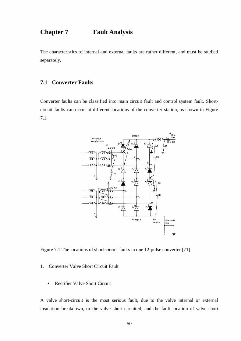
Converter faults can be classified into main circuit fault and control system fault. Short
circuit faults can occur at different locations of the converter station, as shown in Figure
7.1.
Figure 7.1 The locations of shortcircuit faults in one 12pulse converter [71]
1. Converter Valve Short Circuit Fault
• Rectifier Valve Short Circuit
A valve shortcircuit is the most serious fault, due to the valve internal or external
insulation breakdown, or the valve shortcircuited, and the fault location of valve short

51
circuit is shown in Figure 7.1 (a). A rectifier valve must withstand the reverse voltage
during the nonconduction period. If the peak value of the reverse voltage leaps extremely
or the water cooling system leaks considerably, the valve insulation may be damaged,
thereby causing the short circuit across valve.
The characteristics of valve short circuit are: the twophase short circuit and threephase
short circuit occur alternatively on the AC side; the current flows through the fault valve
from the reverse direction and increases dramatically; the ACside current increases
significantly, and thereby the converter valve and converter transformer withstand
considerable current more than the normal current; the DCbusbar voltage and DCside
current of the converter bridge fall down.
• Inverter Valve Short Circuit
An inverter valve withstands the forward voltage during most of nonconduction period.
The excessive high voltage or the rate of rise of voltage is likely to break the valve
insulation, thereby causing the short circuit.
2. Inverter Commutation Failure
A commutation failure is the common fault of the inverter and is caused by the inverter
valve short circuit, the ACsystem frequency spectrum, the inverter firingpulse lost and
the inverterside ACsystem faults. [72] [73]
The characteristics of commutation failure are: the extinction angle is lower than the time
of valve recovery block; the direct voltage of 6pulse inverter reduces to zero during a
certain period; direct current increases temporarily; the fundamental frequency components
penetrate into the DC system; the open circuit occurs temporarily on the AC side and the
current decreases. [74]
3. Converter DCside Terminal Short Circuit
A DCside terminal short circuit is the shortcircuit fault occurred between converter DC
side terminals and the fault locations are shown in Figure 7.1 (b).

52
• Rectifier DCside Terminal Short Circuit
When the rectifier DCside terminal short circuit occurs, the converter valve still maintains
the unidirectional conduction characteristic. The characteristics of the rectifier DCside
terminal short circuit are: the twophase short circuit and threephase short circuit occur
alternatively on the AC side; the conductionvalve current and ACside current increase
dramatically, and the fault value is many times higher than the normal value; the short
circuit causes the DClineside current to fall down; the converter valve maintains the
forwarddirection conduction.
• Inverter DCside Terminal Short Circuit
When the inverter DCside terminal short circuit occurs, the DCline current rises up. Due
to DCside smoothing reactor, the rate of rise of the fault current is quite slow and the
shortcircuit current is relatively small. When the inverter DCside short circuit occurs, the
current flowing through the inverter valve will reduce rapidly to zero and the shortcircuit
fault causes no harm to the inverter and converter transformer. In fact, when each valve is
fired, the momentary charge current still exists. Usually the fault current can be controlled
via the current regulator, but the short circuit cannot be cleared.
4. Converter ACside PhasetoPhase Short Circuit
A converter ACside phasetophase short circuit directly leads to ACsystem twophase
short circuit and the fault location is shown in Figure 7.1 (c).
• Rectifier ACside PhasetoPhase Short Circuit
A rectifier ACside phasetophase short circuit can cause the twophase shortcircuit
current on the AC side. Therefore, the rectifier will loose the twophase commutating
voltage and direct voltage, direct current and transmission power will reduce rapidly.
• Inverter ACside PhasetoPhase Short Circuit
53
An inverter ACside phasetophase short circuit results in the twophase commutating
voltage lost and the abnormal phase on the inverter. Therefore, the inverter commutation
failure occurs and the DCcircuit current rises up and the ACside current falls down.
5. Converter ACside PhasetoGround Short Circuit
For a 6pulse converter, the fault of the converter ACside phasetoground short circuit is
similar to that of the valve short circuit. For a 12pulse converter, the fault location is
shown in Figure 7.1 (e).
• Rectifier ACside PhasetoGround Short Circuit
For a 12pulse rectifier, no matter singlephasetoground short circuit occurs at the high
voltage or lowvoltage terminal’s 6pulse converter, the DC neutral busbar is always one
part of the shortcircuit loop. When the rectifier ACside phasetoground short circuit
occurs, the secondorder harmonic component will penetrate into the DC side. If the
inherent frequency of the DC circuit is close to the secondorder harmonic frequency, it
may lead to the DCcircuit resonance.
• Inverter ACside PhasetoGround Short Circuit
For a 12pulse inverter, the fault 6pulse inverter occurring commutation failure causes
direct current to increase. No matter single phasetoground short circuit occurs at the high
voltage or lowvoltage terminal’s 6pulse converter, the twophase short circuit causes the
ACside current and DCneutralterminal current to increase.
6. Converter DCside to Ground Short Circuit
Ground shortcircuit faults at the DC side contain the ground shortcircuit faults occurring
at the middle point of 12pulse converter, the DC highvoltage terminal and the DC neutral
terminal. The fault locations are shown in Figure 7.1 (d and f).
7. Control System Faults
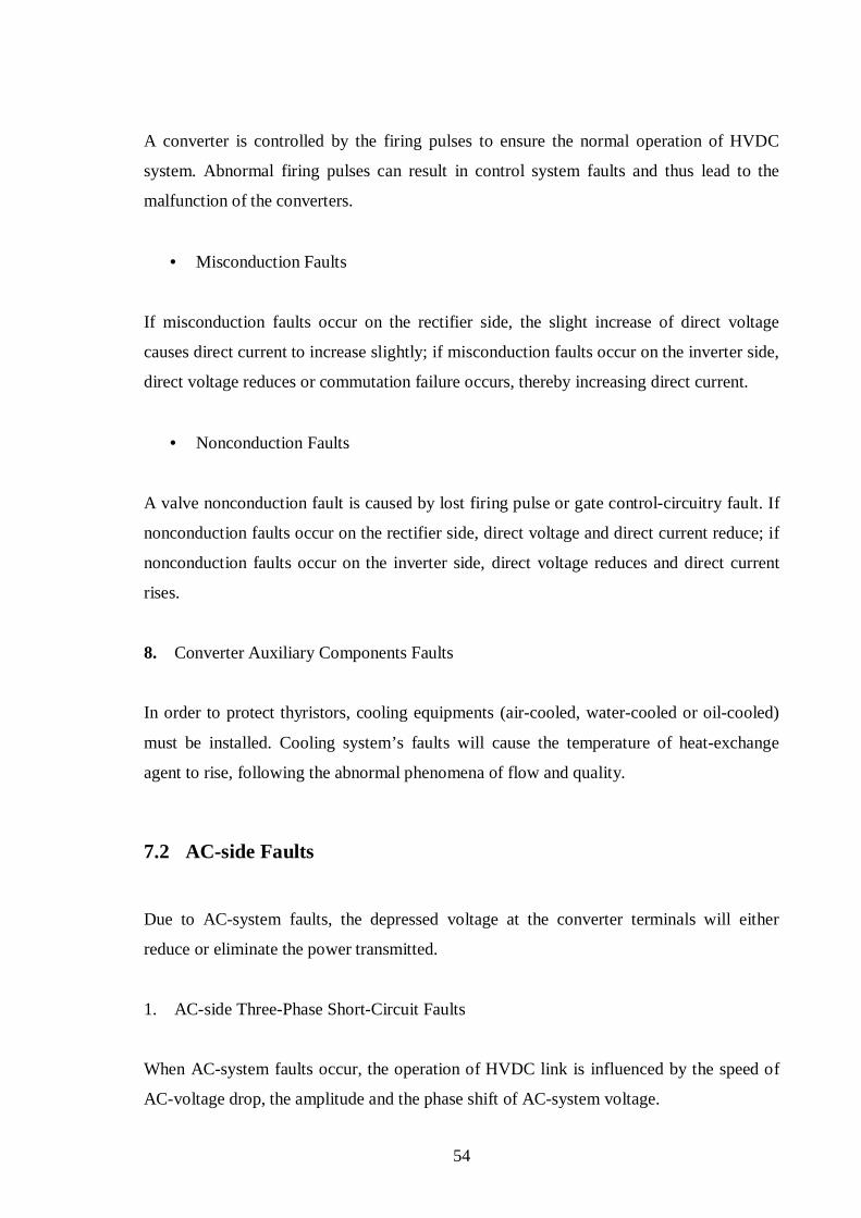
54
A converter is controlled by the firing pulses to ensure the normal operation of HVDC
system. Abnormal firing pulses can result in control system faults and thus lead to the
malfunction of the converters.
• Misconduction Faults
If misconduction faults occur on the rectifier side, the slight increase of direct voltage
causes direct current to increase slightly; if misconduction faults occur on the inverter side,
direct voltage reduces or commutation failure occurs, thereby increasing direct current.
• Nonconduction Faults
A valve nonconduction fault is caused by lost firing pulse or gate controlcircuitry fault. If
nonconduction faults occur on the rectifier side, direct voltage and direct current reduce; if
nonconduction faults occur on the inverter side, direct voltage reduces and direct current
rises.
8. Converter Auxiliary Components Faults
In order to protect thyristors, cooling equipments (aircooled, watercooled or oilcooled)
must be installed. Cooling system’s faults will cause the temperature of heatexchange
agent to rise, following the abnormal phenomena of flow and quality.
7.2 ACside Faults
Due to ACsystem faults, the depressed voltage at the converter terminals will either
reduce or eliminate the power transmitted.
1. ACside ThreePhase ShortCircuit Faults
When ACsystem faults occur, the operation of HVDC link is influenced by the speed of
ACvoltage drop, the amplitude and the phase shift of ACsystem voltage.

55
• Rectifierside AC ThreePhase ShortCircuit Faults
For remote threephase faults, the rectifier commutating voltage drops slightly. For close
in threephase faults, the rectifier commutating voltage drops significantly. Therefore, the
converter is greatly influenced by closein threephase faults until the rectifier
commutating voltage reduces to zero. Since there is no overvoltage and overcurrent
generated on the DC components, it is not necessary to stop the DC system. After AC
system faults are cleared, DCpower recovers very quickly with the recovery of ACsystem
voltage.
• Inverterside AC ThreePhase ShortCircuit Faults
A short circuit occurring at the inverter side causes the reduction of AC busbar voltage at
the inverter station and commutation failures, thus producing large directcurrent peaks.
The rate and amplitude of depressed AC voltage is related to the weak or strong AC system
and the remote or closein threephase fault at the inverter. When a fault occurs sufficiently
close to the inverter end or an AC system is relatively weak, the amplitude of commutating
voltage decreases dramatically and quickly, thereby easily causing commutation failures.
For AC faults close to the inverter, the DCpower transfer is illustrated in Figure 7.2 [75]
Figure 7.2 Converter DC power following a threephase fault at the inverter end [75]
Pi = inverter power waveform Pr = rectifier power waveform

56
2. ACside SinglePhase ShortCircuit Faults
Singlephase faults are ACsystem common faults, usually ground flashover. Singlephase
faults are unsymmetrical faults, which contain components of positive sequence, negative
sequence and zero sequence. Commutating voltage is highly influenced by the circuit
mode of converter transformer.
Because of the lack of symmetry, doublefrequency (second harmonic component)
modulation is introduced on the DC side. For a weak AC system, doublefrequency
modulation will produce heavy oscillations. [76]
When the fault of singlephase to ground occurs near the Haywards converter station in the
New Zealand system, the response to a staged 60 ms AC fault is shown in Figure 7.3. [77]
Figure 7.3 The response to a staged AC fault [77]

57
• Rectifierside AC SinglePhase Faults
As singlephase faults occur on the rectifierside AC system, unbalanced commutating
voltage can produce the secondorder harmonic on the DC system. Like threephase faults,
direct current and voltage relatively decrease during faults period, but the reduction of
power is smaller than that during threephase faults.
• Inverterside AC SinglePhase Faults
In order to ensure sufficient extinction angle, firing angle must be reduced immediately
and commutation failure can recover normal commutation within several tends of
millisecond. Commutation failure cannot occur, following normal sequence commutation;
with considerable second harmonic component, the average value of the inverter direct
voltage is lower than the normal value. The reduced firing angle must be limited by the
inverter minimum firing angle.
3. Converter Transformer and Auxiliary Components Faults
The internal faults of a converter transformer will cause the winding temperature, oil
temperature, oil flow, oil potential, gas and pressure to change. The faults of auxiliary
components (oil pump, fan and motor) cause the converter transformer to malfunction.
Different faults and switching operations will produce the inrush current and harmonic
components during a certain time. ACnetwork switching operations may produce
abnormal overvoltage on the converter and converter transformer.
4. ACFilter Faults
Usually an ACfilter consists of capacitor, inductor, resistor and surge arrester. If ground
faults occur on these components, the highvoltage terminal and ground terminal currents
will appear the differential value and the current flowing through ACfilter will increase
substantially.
5. Station Power System Faults

58
In order to prevent all converter stations from losing power sources simultaneously, an
adjacent AC system usually provides two or three power sources to a converter station. In
order to avoid causing the circulating current, only one power source works effectively and
others are backup power sources. When faults occur in the effective power source, the
backup power sources are automatically switched. If the design of station power system is
not suitable, switching station power systems may cause the operation of HVDC system to
shut down. The faults of station power system lead to the corresponding voltage dip
initially, and this characteristic can be utilized to design the fast switching control and
protection. [78]
7.3 DCLine Fault
Lightning strike, contamination or branch may reduce the DCline insulation level, and
further produce the flashover of DCline to ground. As the short circuit of DCline to
ground occurs, direct voltage falls and direct current rises on the rectifier side, and direct
voltage and direct current fall on the inverter side.
In accordance with the New Zealand link parameters, using a digital model, a typical DC
line fault, is illustrated in Figure 7.4. [79]
Figure 7.4a Direct current waveform during a DCline fault [79]
(i) Rectifier end (ii) Inverter end
59
Figure 7.4b Direct voltage waveform during a DCline fault [79]
(iii) Rectifierline end (iv) Inverterline end
1. Lightning Strike
For a bipolar HVDC link, two poles cannot be stroke simultaneously by lightning at the
same location. Usually DC lines are stroke by lightning very shortly. Lightning strike
causes direct voltage to rise momentarily and then to fall, and discharge current causes
direct current to rise momentarily. If DClines’ insulations cannot withstand momentary
increasing voltage, discharge phenomena will occur. [80]
2. Ground Flashover
Owing to environmental influences (contamination, trees, fog, snow), the insulation of the
DCline tower becomes badly, thereby causing ground flashover. Especially when ground
flashover occurs at the DC lines, the changes of direct voltage and current will propagate
from flashover points to the converter stations. Sudden changing voltage, usually caused
by ground fault, may lead to DCline sudden discharge phenomenon, thereby producing
inrush current. These continued wave reflections produce highfrequency transient voltage
and current on the lines. [81]
3. HighImpedance Ground Fault

60
When highimpedance ground shortcircuit faults (trees touch DC lines) occur in the DC
lines, the variations of direct voltage and current cannot be detected by the traveling wave
protection; partial direct current is shortcircuited, and two directcurrents at both terminals
will appear the differential value. [82]
4. DCLine and ACLine Touch
Longdistance overhead DClines may cross over many AClines of different voltage
levels. AC/DClines touch faults may occur during longterm operations, thereby
appearing fundamental frequency ACcomponents in DClines’ current.
5. DCLines Broken
When serious faults (DClines’ tower collapse) occur, the DC lines may break
simultaneously. The broken DClines cause the DC system to opencircuit; direct current
falls down to zero and the rectifier voltage rises up to the maximum limit value.

61
Chapter 8 Overvoltages and Insulation Coordination
8.1 Overvoltage Protection Devices
Due to lightning strikes, switching, faults, HVDC systems can generate overvoltages with
a variety of waveforms. In order to protect equipment and to limit overvoltage level,
overvoltage protection devices are required to install, thereby improving the system
reliability and reducing the equipment costs.
Due to simple structure, low price, sturdiness, durability and high energy absorption
capability, protectivegaps were used as primary overvoltage protection devices in most
early HVDC schemes, but dischargingvoltage instability and no automatic arcsuppression
capability are main shortcomings. Because an HVDC system provides the perfect control
system, after the protectivegap operates, direct current can automatically drop to zero, in
order to suppress arc.
For AC and DC surge arresters, there are great differences in the operating condition and
working principle. The main differences are:
1. AC surge arresters can cut off the current at natural zerocrossing instant. DC surge
arresters are not of natural zerocrossing points, and it is relatively difficult to suppress
arc;
2. All capacitive components are on the fullcharging state during the normal operation.
Once a certain surge arrester operates, all capacitive components will discharge
through this surge arrester. Therefore, the energyabsorption capacity of DC surge
arrester is much higher than that of conventional AC surge arrester;
3. DC surge arresters can produce substantial heat very seriously under the normal
operation;
4. In some DC surge arresters, two terminals are not grounded;
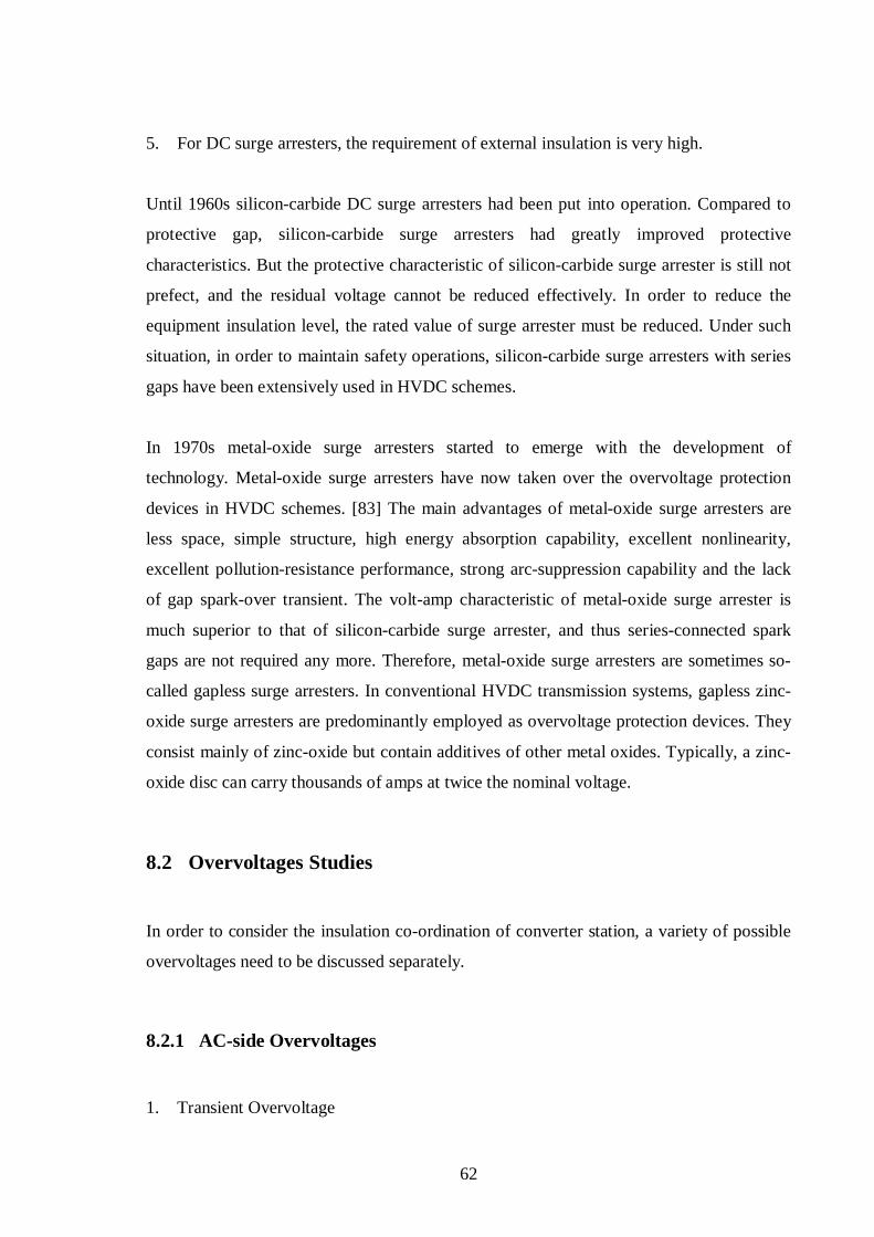
62
5. For DC surge arresters, the requirement of external insulation is very high.
Until 1960s siliconcarbide DC surge arresters had been put into operation. Compared to
protective gap, siliconcarbide surge arresters had greatly improved protective
characteristics. But the protective characteristic of siliconcarbide surge arrester is still not
prefect, and the residual voltage cannot be reduced effectively. In order to reduce the
equipment insulation level, the rated value of surge arrester must be reduced. Under such
situation, in order to maintain safety operations, siliconcarbide surge arresters with series
gaps have been extensively used in HVDC schemes.
In 1970s metaloxide surge arresters started to emerge with the development of
technology. Metaloxide surge arresters have now taken over the overvoltage protection
devices in HVDC schemes. [83] The main advantages of metaloxide surge arresters are
less space, simple structure, high energy absorption capability, excellent nonlinearity,
excellent pollutionresistance performance, strong arcsuppression capability and the lack
of gap sparkover transient. The voltamp characteristic of metaloxide surge arrester is
much superior to that of siliconcarbide surge arrester, and thus seriesconnected spark
gaps are not required any more. Therefore, metaloxide surge arresters are sometimes so
called gapless surge arresters. In conventional HVDC transmission systems, gapless zinc
oxide surge arresters are predominantly employed as overvoltage protection devices. They
consist mainly of zincoxide but contain additives of other metal oxides. Typically, a zinc
oxide disc can carry thousands of amps at twice the nominal voltage.
8.2 Overvoltages Studies
In order to consider the insulation coordination of converter station, a variety of possible
overvoltages need to be discussed separately.
8.2.1 ACside Overvoltages
1. Transient Overvoltage

63
Transient overvoltage is the overvoltage lasting several cycles to hundreds of cycles.
Transient overvoltage can develop directly on the equipment and will cause the switching
overvoltage to rise. The most typical transient overvoltage occurs on the ACbusbar of
converter station and influences the ACbusbar surge arrester directly. This kind of
transient overvoltage is transferred to the valve side via the converter transformer, thereby
influencing the convertervalve surge arrester.
2. Switching Overvoltage
ACbusbar switching overvoltages are caused by the ACside faults and switching.
Normally switching overvoltage with relatively high amplitude maintains only half a cycle.
Switching overvoltages influence the insulation level of ACbusbar equipments and the
energyabsorption capacity of ACside surge arresters. Switching overvoltages can be also
transferred to the converter valve side via the converter transformer, thereby becoming the
initial condition caused by the internal fault of the converter.
3. Lightning Overvoltage
ACline intrusionwaves and the directstrike lightning of the converter station can
generate lightning overvoltages on the ACbusbar of the converter station. Because there
are incoming lines, equipments (AC filters and capacitor banks) which can considerably
damp the lightning wave, ACbusbar surge arrester, in general, the lightning overvoltage of
converter station is less severe than that of conventional substation. Moreover, owing to an
effective shield of converter transformer, lightning waves cannot intrude into the converter
valve side. Therefore, under the normal condition, lightning overvoltages are usually not
regarded as the key to AC overvoltage and insulation coordination in the converter station,
and directly considered in accordance with conventional AC substation rules.
8.2.2 DCside Overvoltages
1. Transient Overvoltage
64
Transient overvoltages generated on the DC side of the converter station mainly include
two categories below.
• ACside Transient Overvoltage
When converters operate, transient overvoltages generated on the AC busbar can propagate
into the DC side of converter station, owing to a variety of origins, thereby mainly causing
considerable energy to pass through surge arresters.
• Converter Faults
When the faults such as partiallymissing pulses, commutation failures, and fullymissing
pulses occur within the converter, internal converter disturbances give rise to AC
fundamental voltages penetrating into the DC side. If the main parameters of the DC side
are not configured correctly, the resonance frequencies close to the fundamental frequency
exist. Due to the enlargement effect caused by resonances, overvoltages can be generated
during a relative longterm on the DC side. An example of fundamentalfrequency
resonance which occurred during early operation of the CahoraBassa scheme is shown in
Figure 8.1. [84]
Figure 8.1 Line current and voltage recorded at the inverter during missing pulse condition
in a rectifier bridge (1980 CIGRE) [84]

65
2. Switching Overvoltage
Switching overvoltages generated within the converter mainly include two categories
below.
• ACside Switching Overvoltage
ACside switching overvoltages can be transferred to the converter via the converter
transformer. Due to the protection effect of ACbusbar surge arresters, the overvoltages
transferred to the DC side usually do not produce considerable stresses on the DC
equipments.
• Short Circuit Fault
When shortcircuit faults occur within converters, due to the inrush ACcurrent and
discharges caused by DC filter capacitors, switching overvoltages are normally generated
on the converter and DC neutral equipments. The most typical shortcircuit location is
between the valveside terminal of the converter transformer and the converter valve.
8.2.3 DCLine Overvoltages
1. Lightning Overvoltage
Directstrike and backstrike lightnings can generate lightning overvoltages on the DC
lines, and lightnings will propagate into the DC switching yard along the DC lines. Direct
strike lightning can generate lightning overvoltages on the DC switching yard as well.
2. Switching Overvoltage
Switching overvoltages generated on the DC lines mainly include two categories below.
When two poles operate, due to monopoletoground short circuit occurrence, switching
overvoltages will induce on the healthy pole. Except for the design of DC line tower head,

66
this kind of switching overvoltage also influences the overvoltage protection and insulation
coordination on the DC switching yards of converter stations at both terminals. The
overvoltage amplitude depends on the parameters of line and the twoterminal circuit
impedances. [85]
When the opposite terminal of the DC lines is opencircuit and the local terminal of the DC
lines is deblocked with the minimum firing angle, excessive high overvoltages are
generated on the opencircuit terminal of the DC lines. [86] This kind of overvoltage can
develop not only on the DC lines, but also possibly on the oppositeterminal DC switching
yard and nonconducting converters. Figure 8.2 shows the overvoltage developed on the
DC line when the rectifier is deblocked with full rectifier voltage against an open inverter
end.
Figure 8.2 Deblocking with full rectifier voltage against an open inverter end [86]
8.3 Insulation Coordination
In accordance with the arrangement of surge arresters, a converter station can be divided
into three zones, i.e. AC zone, converter zone and DCyard zone. The surge arresters of the
AC zone are very similar to that of the conventional AC substation; the surge arresters of
the converter zone are mainly used to protect the thyristor converter valves and the
converter transformers; the surge arresters of the DCyard zone are mainly used to protect
the DCyard equipments. The main principle of surge arrester arrangement is: the
overvoltages generated on the AC side should be limited by ACside surge arresters; the

67
overvoltages generated on the DC side should be limited by DCside surge arresters; the
important equipments are parallel with the surge arresters individually to be protected.
The typical arrangement solution of surge arresters for a 12pulse converter is shown in
Figure 8.3. [87]
Figure 8.3 The typical arrangement solution of surge arresters for a 12pulse converter [87]
The practical arrangement solution of surge arresters may be slightly different with the
above solution. For an airinsulated smoothing reactor, in order to reduce the vertical
insulation level, the surge arrester is directly parallel with the reactor after the economic
and technical comparison; for an oilinsulated smoothing reactor, the reactor is protected
by surge arresters installed on the two ends. The 6pulse converter bridge arrester can be
replaced by seriesconnected valvearresters. In order to reduce the insulation level on the
valveside windings of starstar connected transformer, the 6pulse converter bridge busbar
arrester can be used.
Owing to different structures of AC and DC filters, surge arresters have to be arranged
individually and respectively. Two typical arrangements of surge arresters for AC and DC
filters are shown in Figure 8.4. [87] For the highvoltage capacitors, the dedicated surge
arresters are not required to install. For the lowvoltage reactors and resistors, parallel
connected surge arresters must be installed.
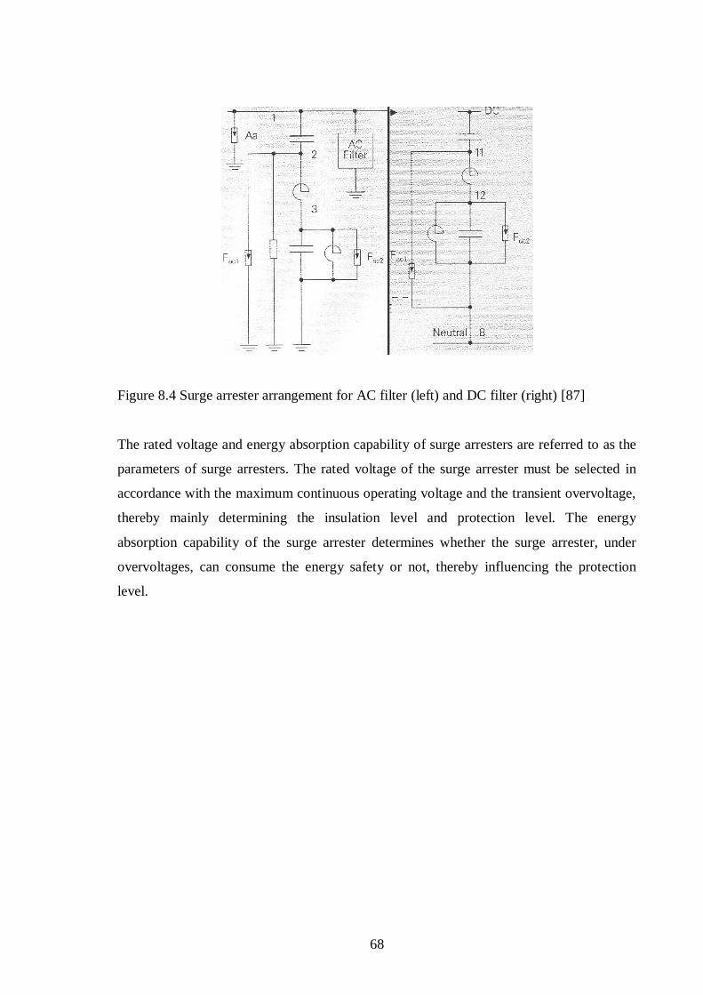
68
Figure 8.4 Surge arrester arrangement for AC filter (left) and DC filter (right) [87]
The rated voltage and energy absorption capability of surge arresters are referred to as the
parameters of surge arresters. The rated voltage of the surge arrester must be selected in
accordance with the maximum continuous operating voltage and the transient overvoltage,
thereby mainly determining the insulation level and protection level. The energy
absorption capability of the surge arrester determines whether the surge arrester, under
overvoltages, can consume the energy safety or not, thereby influencing the protection
level.

69
Chapter 9 Transmission Lines
According to applications, HVDC transmission lines can be classified into overhead line,
cable line and electrode line. During the design of transmission lines, the appropriate
selection depends on the locations of converter stations, the terrains of lines route and the
crowded situations of land use.
9.1 Overhead Line
9.1.1 Conductor Crosssection
In the early design of HVDC overhead lines, thermal limitations were mainly considered
and electricfield effects were much less considered. As the voltage levels increase
gradually, the selection of conductor crosssection depends largely on corona discharges
and electricfield effects. [88]
In accordance with the transfer capacity of HVDC system, several models of conductor
crosssection were initially selected and then analyzed from the result of economical
comparison, thereby finally deciding the most appropriate crosssection. In order to
restraint the influence on the environment, the potential gradient of conductor surface,
audible noise and radio interference must be taken into account.
9.1.2 Insulation Level
In order to design the insulation level of overhead line, all possible flashover paths, e.g.
conductor to earth, tower, ground wire, and positiveconductor to negativeconductor, must
be taken into account. It is very important to appropriately determine insulation levels, for
example, as the distance between two poles increase, the potential gradient of conductor
surface will fall down and the corona loss will reduce. Under reliable operating conditions,
due to the expensive price of DC insulator, selecting the appropriate insulation level
provides considerable economic benefits for overheadlines’ construction.

70
1. TowerHead Air Gap
Airgap breakdown voltage and insulator flashover voltage are related to atmospheric
conditions (pressure, temperature, humidity). In the design of the overheadline external
insulation, the external insulation discharge voltage, under the standard atmospheric
condition, must be corrected according to different atmospheric conditions.
2. DCLine Lightning Protection
Although the hazard caused by lightningstrike overvoltage on the extra highvoltage DC
overhead lines is less severe than that on the AC lines, the ground wires must be erected
along the entire route, so as to improve the reliability of system operation. Owing to the
horizontal arrangement for two poles, two ground (lightning) wires are also arranged
horizontally.
Under the same lightning current and tower height, with the increase of working voltage,
the striking distance factor will obviously decrease. Dealing with the effect of working
voltage, under the circumstance of the same average height (or very slight difference) for
ground wires and conductors, the striking distance will not be approximately equal
between the lead to ground wires and the lead to conductors. With the increase of working
voltage, the rate of lightning shielding failure will increase.
Dealing with the effect of working voltage, under different operating modes, the line
lightningstrike endurances are different in an HVDC transmission line. For an HVDC
overhead line, when towers and ground wires are struke by lightning, on one pole having
polarity opposite to overvoltages, the voltages on the towerhead airgap and insulator
bunch are the sum of lightningimpulse voltage and DC workingvoltage, and for the other
pole, the voltages are the difference. Therefore, a bipolar HVDC overhead line is of natural
imbalance insulation characteristics under lightningstrike. [89]

71
9.1.3 Insulator Types
Porcelain insulators, toughened glass insulators and composite insulators had been
employed in the commissioned HVDC overhead lines. Toughened glass insulators and
porcelain insulators are mostly employed in the world, and composite insulators are mainly
employed in the areas of contamination and inconvenient cleaning.
Composite insulators are of high strength, light weight and excellent pollutionproof
performance. Owing to the hydrophobic status of composite insulators, under the same
creepage distance and pollution degree, the pollution flashover voltage of composite
insulators is 60% 70% higher than that of porcelain or glass insulators. Consequently, for
the flashover voltage, the effect of ununiform pollution distribution (along the top and
bottom surfaces) on the composite insulator is smaller than that on the porcelain or glass
insulator. The DC pollution flashover gradient under hydrophobic status is 153% higher
than that under hydrophilic status according to the research conditions. [90] Owing to
simple shaping technology, under the circumstance of the unchanged insulatorbunch
length, different creepage distances can be obtained easily. Moreover, the price of
composite insulators is cheaper than that of porcelain or glass insulators, composite
insulators are unlikely to damage and are not required to clean or maintain.
9.1.4 Insulator Numbers
For DC overhead lines the number of insulator elements is usually determined by the
normal voltage under contamination circumstances. For example, in places close to the sea
the number of insulator elements was increased to reduce salt pollution problems. If the
pollution levels are very low, the DCvoltage withstand level on switching surge or
impulse flashover performance has to be taken into considerations. In order to suitably
arrange the insulation level of DC overhead lines according to contamination situation, the
materials of contamination tests and the distribution situations of pollution areas must be
collected to carry out the different levels of contamination.

72
9.1.5 Steel Tower
DC overhead lines are classified into monopolar lines and bipolar lines. Most of DC
overhead lines are the bipolar lines erected on the same tower and the positivepolarity and
negativepolarity conductors are arranged on two sides of steel tower. The design
principles used in AC overhead lines also determine the dimension of DC overhead lines
and hence the tower designs of DC overhead lines are very similar to those of AC overhead
lines.
Under normal circumstances, more tower types employed in an HVDC scheme can
consume much less steels, but more tower types can increase the investment of design,
manufacture and installation. Therefore, the tower types employed in HVDC schemes are
required to consider comprehensively in accordance with long route, complicated terrain
and various atmospheres.
9.1.6 Ground Wire
In order to ensure the safety operation and to prevent the trip fault caused by directstrike
lightning, it is necessary to install ground wires. In recent years, in order to satisfy the
requirements of telecommunications, OPGW (optic fibre ground wire) has already
employed. On one hand, OPGW used as ground wires, must take fairly effect as a
safeguard against lightning, so that the characteristic of sag of span of OPGW is very
similar with that of the other ground wire erected on the same tower. On the other hand,
when the shortcircuit faults occur on the transmission lines, the shortcircuit current will
cause the temperatures of OPGW and the other ground wire to increase. When the short
circuit current is extremely high, as the temperature increases dramatically, it may cause
fibre optics to be damaged. In order to avoid the temperature beyond permissible value,
when selecting OPGW, the consideration of thermal stability must be taken into account.

73
9.2 Cable Line
9.2.1 Application and Development
DC cable can transmit bulk power over long distances. DC cable is mainly employed as
submarine cable and underground cable. In twenty years, the application of DC
transmission has made considerable progress, and DC cables have already been used in
many schemes. In 2000, the 2800 MW, ± 500 kV Kiichannel undersea scheme was
commissioned with highest DC voltage in the world. [91] The 600 MW, 450 kV, 250 km
long Baltic cable connecting Sweden and Germany was commissioned in 1994. [92] The
700 MW, ± 450 kV, 580 km long NorNed link is the longest submarine cable transmission
commissioned in 2007. [93]
Owing to thermal limitations, the power of AC cables increases in proportion to the
voltage of AC cables, and the charging current within AC cables increases with the
distance and with the square of the voltage. Therefore, unlike for overhead transmissions,
AC cable transmission only uses relatively low voltages over very short distances. In order
to avoid the conductorcore overheat within AC cables, the power transmitted by AC
cables is much less than the natural power. Consequently, the shunt reactors must be
installed along the route, so as to counteract excessive high voltages at the middle or end of
lines. For relative longdistance submarine cables, it is impossible to employ AC
transmission in practice, and using DC cable lines is rather feasible.
9.2.2 Cable Insulation
When reversing the powerflow direction, the current direction maintains unchanged while
the voltage polarity changes. Therefore, DC cable must withstand fast reversal of voltage
polarity. In addition, due to the transient fault caused by converter, it gives rise to
instantaneous oscillation overvoltage added to DC voltage. Under the most severe
condition, the peak value of transient overvoltages may reach to twice working voltage.

74
Although the structures of DC cables are very similar to those of ordinary AC cables, the
working conditions of DCcable insulation are much excellent than those of ACcable
insulation. For DC cables, the effective value of the voltage is also the peak value of the
voltage, and the losses of DCcable insulation are much less than those of ACcable
insulation under the same voltage. Consequently, for DCcable insulation the thermal
instability has become less important. In addition, the breakdown voltage of ACcable
insulation is related to the working time, but there is no such problem on the DC cable.
9.2.3 Cable Types
The development of DC cable took the successful experience from AC cable, so that the
structure of DC cable is very similar to that of AC cable. There are three types of DC
cable; oil filled, gas pressurized and mass impregnated, often referred to as solid cables.
XLPE is a fourth type, so far studied and employed widely.
1. MassImpregnated Cable
The great bulk of cables are of the massimpregnated type in earlier installations. The
advantages of massimpregnated cable are simple structure, convenient manufacture and
maintenance and low cost. Due to no need for supplying oil and cooling effect of seawater,
the massimpregnated cable is likely to use for longdistance submarine installation. Figure
9.1 shows the development of the maximum power per cable and the maximum operating
voltages of the massimpregnated cables. [94]

75
Figure 9.1 Maximum power per cable and operating voltage of realized HVDC submarine
massimpregnated cables [94]
2. OilFilled Cable
Oilfilled cables were generally installed and developed across land (without intermediate
pressure/feeding stations). Oilfilled cables can provide more excellent technical features
than other types of cables. For example, oilfilled cables can withstand higher insulation
working stresses than massimpregnated cables. As the technical problem for supplying oil
over longdistance settles down, oilfilled cables can be used as submarine cables.
3. GasPressurized Cable
Gaspressurized cables can withstand relatively high insulation working stresses, thereby
likely using for longdistance submarine installation and great depth installation. Due to
extreme high manufacture working stresses and sealing effect, gaspressurized cables have
not been manufactured for DC use since the 1960s.
4. Crosslinked Polyethylene (XLPE) Cable
76
XLPE has become an accepted insulation now as an alternative to oil filled cables. Owing
to simple structure and robustness, XLPE cables are suitably used as submarine cables.
Recently only steelwire armoured XLPE cables are widely paid attention in the world.
9.2.4 Cable Structures
1. Conductor Core
The conductor core of the DC cable is usually made of copper and the crosssectional area
of the conductor core depends on rated current, permissible voltage drop, shortcircuit
capacity and so on. When selecting the structure of conductor core, sea water permeation
after fault must be highly considered.
2. Insulation Layer
The insulation layer thickness of the DC cable must satisfy simultaneously the following
requirements:
(1) For rated DC voltage, at noload condition, the working stress on the conductor’s
surface must be lower than the permissible value.
(2) For rated DC voltage, at fullload condition, the working stress on the outer casing
must be lower than the permissible value.
(3) The insulation layer thickness must withstand the impulse test voltage.
(4) Under rated current, the conductor’s temperature must be lower than the permissible
value.
3. Outer Protective Layer

77
There is no induced voltage on the metallic sheath and armour, and the sheath losses are
not existed in the DC cable. The structure of outer protective layer mainly depends on
environmental corrosion and mechanical damage, especially for submarine cables.
4. Metallic Sheath
In order to ensure the reliability and flexibility of the metallic sheath, until today DC cables
usually employ the galvanized sheath. For oilfilled or gaspressurized cables, several layer
metallic tapes must be added as the reinforcing layer.
5. CorrosionProof Layer
Owing to the effect of the leakage current and other currents (used sea water as return
circuit), the electrolysis corrosion will occur on the metallic sheath and reinforcing layer.
Consequently, the plastic sheath is usually added to prevent electrolysis corrosion.
6. Armour
In order to prevent mechanical damages, steel tapes or armoured steel wires are covered
outside the corrosionproof layer in accordance with specific circumstances. Submarine
cables usually employ steel wires armoured cables. When carrying and laying submarine
cables, owing to the dead weight of submarine cables, considerable mechanical stresses are
generated on the cable, while submarine cables are easily attacked by sea animals.
A typical design is the 250 kV DC cable of the Skagerrak scheme laid at a depth of 550 m,
illustrated in Figure 9.2. [95]
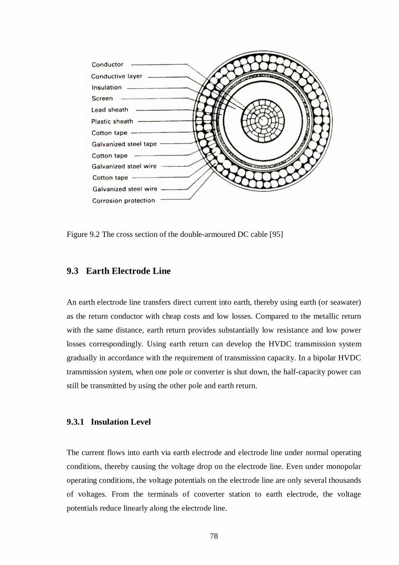
78
Figure 9.2 The cross section of the doublearmoured DC cable [95]
9.3 Earth Electrode Line
An earth electrode line transfers direct current into earth, thereby using earth (or seawater)
as the return conductor with cheap costs and low losses. Compared to the metallic return
with the same distance, earth return provides substantially low resistance and low power
losses correspondingly. Using earth return can develop the HVDC transmission system
gradually in accordance with the requirement of transmission capacity. In a bipolar HVDC
transmission system, when one pole or converter is shut down, the halfcapacity power can
still be transmitted by using the other pole and earth return.
9.3.1 Insulation Level
The current flows into earth via earth electrode and electrode line under normal operating
conditions, thereby causing the voltage drop on the electrode line. Even under monopolar
operating conditions, the voltage potentials on the electrode line are only several thousands
of voltages. From the terminals of converter station to earth electrode, the voltage
potentials reduce linearly along the electrode line.

79
9.3.2 Conductor Crosssection
The earth electrode line has several characteristics below.
1. The current only flows through the conductor and earth electrode, thereby causing the
low voltage drop on the line.
2. The earth electrode line and earth electrode are usually used to fix the neutral potential
of converter station. The current flowing through electrode lines is only 1% at rated
current.
3. The earth electrode line is usually tens of kilometers.
In accordance with the above situations, the conductor crosssection of earth electrode
lines only depends on thermal stability conditions under the most severe operating mode.
Therefore, such conductors can not only save the capital costs, but also satisfy the
transmission requirement.

80
Chapter 10 Transmission Line Environmental Effects
As a significant technology issue, the environmental effects must be taken into
considerations and the electromagnetic environment is directly related to the corona
characteristics of transmission line, i.e. corona loss, DC electricfield effect, radio
interference and audible noise. [96] In order to design the DC lines, corona loss, DC
electricfield effect, radio interference and audible noise must be controlled in the
appropriate extent.
10.1 Corona
If the potential gradient of conductor surface exceeds a specific critical value, atmospheric
ionization following visual discharge, termed DCline corona, will occur in the vicinity of
DCline conductor and the electrically charged ions caused by conductor corona will move
towards the conductor of the opposite polarity or deviate from the conductor of the same
polarity. Therefore, the entire space is fulfilled with electrically charged ions.
The movement of electrically charged ions forms the corona current around the DC
transmission line, thereby producing the energy loss termed corona loss. The electricfield
strength of the conductor surface, which leads to the line corona, is termed the corona
critical electricfield strength or the initial corona electricfield strength. The initial corona
electricfield strength of smalldiameter conductor is higher than that of largediameter
conductor. The critical degree of corona discharge is directly related to the electricfield
strength of the conductor surface, especially the surface maximum electricfield strength.
[97]
According to the testing, the DCline corona is of the following characteristics: [98]
(1) In the rainy days, the increased corona loss in the DC line is much less than that in the
AC line.

81
(2) If the electricfield strength of the conductor surface maintains a certain value, no
matter in the rainy or sunny days, with the increase of the number of bundle conductor,
the DCline corona will increase.
(3) In the specific range (0 – 10 m/s) of wind speed, with increasing the wind speed, the
DCline corona loss usually increases.
(4) Under the specific voltage, for the bipolar lines, the corona loss of each pole is 1.5 –
2.5 times that of the monopolar line.
(5) Under the specific voltage, no matter in the bipolar or monopolar operating mode, the
corona loss of the positive pole is approximately identical to that of the negative pole.
10.2 ElectricField Effect
If the electricfield gradient of the conductor surface exceeds the initial corona electric
field gradient, ionization will occur in the atmosphere close to the conductor surface and
the space charges caused by ionization will move along the electricflux direction.
The electricfield strength under DC line mainly depends on the critical degree of
conductor corona discharge. Figure 10.1 shows the distribution diagram of the electric
field strength under the 450 kV overhead line. The highest electricfield strength occurs
directly under the overhead conductor, both with monopolar and bipolar transmissions, and
the lowest electricfield strength normally occurs at the symmetrical center of bipolar
conductors. The distribution shown in Figure 10.1 is the most ideal circumstances without
wind. In addition, the electricfield may be strengthened further by external factors in
terms of the weather, seasonal variations and relative humidity. [99] The displacement
velocity of positive and negative ions, under the electric field, is at the same scale with the
wind velocity. Therefore, even in the very slow wind velocity (1m/s), the distribution of
the electricfield will be distorted.

82
Figure 10.1 The electric field of monopolar and bipolar 450 kV overhead lines [99]
At the same voltage level, the electricfield strength under DC line is higher than the
electricfield strength under AC line. Under normal operations, without the induced
phenomenon of capacitor coupling, for AC and DC electricfields, the same strengths
produce the different effects.
The electricfield and ionic current density are related to the electricfield strength of the
conductor surface and the corona initial electricfield strength. With the specific geometric
size of lines, higher the electricfield strength of the conductor surface or lower the corona
initial electricfield strength, higher the electricfield and ionic current density. Therefore,
either lowering the electricfield strength of the conductor surface or increasing the corona
initial electricfield strength can reduce the electricfield and ionic current density.
10.3 Radio Interference
Under the normal operating voltage, the DCline conductors always produce a certain
degree of corona discharge with the ionic current in the vast space. Furthermore, it gives
rise to the radio interference in the vicinity of DC lines. The corona discharge process is of
pulsating characteristics, thereby producing the current and voltage pulses on the DCline
conductors.

83
For the conductor of negative polarity, the corona discharge points are generally well
distributed on the entire conductor surface and the repeatedly emerged pulses are of almost
identical amplitudes with low values. Compared with the conductor of positive polarity,
the radio signals are interfered slightly by the corona discharge from the conductor of
negative polarity.
For the conductor of positive polarity, the corona discharge points are randomly distributed
on the entire conductor surface and the continuous discharge points are mostly located on
the drawbacks of the conductor surface. The discharge pulses are of high amplitudes and
irregular distribution. The corona discharge from the conductor of positive polarity is the
principal source of radio interference.
As the distance away from DC line increases, the radio interference caused by conductor
corona gradually attenuates. For bipolar DC lines, the conductor of positive polarity is the
main source and the symmetric center of radio interference, which attenuates transversely
from the symmetric center to both sides. With the increase of frequency, the DCline radio
interference gradually reduces. The spectrum characteristics of the DC line are very similar
to those of the AC line.
With the increase of the humidity, the DCline radio interference tends to reduce, and with
increasing the temperature, the DCline radio interference tends to increase. But the
pressure variations have no obvious influences on the radio interference.
(1) The DCline interference level in rainy days is approximately 3dB lower than that in
sunny days. Compared with the AC line, the DCline interference level is obviously
different under different weather conditions.
(2) Wind causes the DCline radio interference to increase; especially the most severe
consequence is caused by the wind direction flowing from negative polarity to positive
polarity. [100]
(3) In the lateautumn and earlywinter seasons, owing to fairly low temperature and quite
high atmospheric humidity, the DCline radio interference is relatively low. In the

84
winter and earlyautumn seasons, the radio interference is close to the average value.
In the summer season, dust, insect and bird’s droppings always stick on the conductors
and the wind velocity is considerable high, consequently, owing to considerable high
temperature and rather low atmospheric humidity, the DCline radio interference is the
highest level. [100]
10.4 Audible Noise
As voltage levels increase gradually, in order to design DC line properly, audible noise
caused by corona discharge must be considered as an important factor. Since serious
audible noise often makes the residents close to lines annoyed, when designing and
constructing the DC lines, audible noise must be limited within a suitable range.
For DC lines, the corona of the positivepolarity conductor is the main source of audible
noise and the audible noise attenuates transversely towards both sides of DC lines.
However, the symmetry axis of audible noise is not the center of bipolar lines, but the
positivepolarity conductor. With the increase of the distance, the audiblenoise attenuation
is much slow than the radiointerference attenuation. As the distance increases one time,
the audiblenoise attenuation is approximately close to 2.6dB (A). [100]
Audible noise caused by ACline corona is composed of two parts, one part is the wide
frequency band noise (primary part in AC noise) caused by positive polarity injection
discharge and the other part is the pure tone (multiple of fundamental frequency) caused by
the back and forth movement of charged ion in the vicinity of conductor, due to periodic
voltage variation.
In sunny days, ACline audible noise is fairly small. In little rainy, fog and snow days,
dripping water sticks on the conductor surface, thereby causing considerable audible noise.
DCline audible noise in rainy days is less than that in sunny days and the noise in snow
days is slightly different with the noise in sunny days. Therefore, when designing the DC
line, the audible noise in sunny days must be considered primarily. [100]

85
Chapter 11 Earth Electrode
11.1 Earth Electrode Effects
For twoterminal HVDC transmission systems commissioned, the main circuit modes can
be classified into monopole with ground return, monopole with metallic return, bipole with
two terminals grounded, bipole with one terminal grounded and bipole with two terminals
ungrounded. For monopole with metallic return, bipole with two terminals ungrounded and
bipole with one terminal grounded, due to one point grounded or ungrounded, there is no
current in the ground and earth electrodes are only used to clamp the neutralpoint electric
potential. For monopole with ground return and bipole with two terminals grounded, earth
electrodes are used not only to clamp the neutralpoint electricpotential, but also to
provide the path for direct current.
11.2 Earth Electrode Operational Features
Except for obvious merits, using ground return also brings the adverse effects caused by
considerable direct current, i.e. electromagnetic effect, thermodynamic effect and
electrochemical effect.
• Electromagnetic Effect
As considerable direct current injects into earth via earth electrode, a constant direct
current field arises in the soil of electrode site, thereby rising ground potential and
producing surface step voltage and touch potential. Therefore, the electromagnetic effect
may bring the following consequences.
(1) A directcurrent field can change the ground magnetic field nearby earth electrodes,
thereby influencing the magnetic compass.
86
(2) Rising ground potential may give rise to adverse effects on the underground pipelines,
armoured cables and electrical equipments grounded, which are close to electrode site.
(3) Land electrodes create potential differences at the earth surface, termed step voltage,
which can cause shock currents. Surface step voltage and touch potential nearby
electrode site may influence human being and animals. For a humanbody resistance
of 1000 , the maximum safe current flowing through the body is recommended as
the limit value of 5 mA. [101]
• Thermodynamic Effect
Earth electrodes are buried in different soils, thereby obtaining different resistances. Due to
the effect of direct current, the temperature of earth electrode will increase, especially at
the temperature reaching to a certain extent, the moisture in the soil will evaporate, and
thus the conduction performance of the soil will become worse and even loose operational
capability. Therefore, for land electrodes (including coastal electrodes), the soil around
electrode site must have sufficient humidity, considerable heatcapable coefficiency,
excellent electricconduction and heatconduction performances, in order to ensure the
perfect thermal stability performance during the operations. [102]
• Electrochemical Effect
Due to direct current flowing through earth, electrocorrosion occurs not only in earth
electrode, but also in the underground metallic equipments or power system grounded.
11.3 Electrode Site Selection
In accordance with the operational features of earth electrode and the circumstances of
current distribution in the ground, selecting a suitable electrode site must satisfy the
following conditions. [103]
(1) An earth electrode is located a certain distance away from the converter station,
usually 8 – 50 km. If an earth electrode is very close to the converter station, earth

87
current easily injects into the grounding grid of the converter station, thereby
influencing the safety operation of power system equipments and corroding the
grounding grid. If an earth electrode is too far away from the converter station, the
investment of electrode line will increase and the neutralpoint electricpotential in the
converter station will be excessive high. In addition, the electrode site must be
sufficient distance away from some important AC substations, usually larger than 10
km.
(2) Earth electrodes must be placed in the wide terrain with excellent conductivity (low
soil resistivity), especially in the vicinity close to the electrode site, the soil resistivity
is generally under 100 m, in order to reduce the cost of earth electrode, lower the
surface step voltage and ensure the safety and stability operation.
(3) Soil must have sufficient water to maintain humidity, even under the worst situation
that considerable direct current flows through earth electrode over a long period. The
soil of earth surface (close to earth electrode) must be of excellent thermal
characteristics, i.e. high heatconductivity and large heatcapacity, so as to reduce the
size of earth electrode.
(4) There are no important and complicated underground metallic equipments around
electrode site, so as to avoid the corrosion in the underground metallic equipments or
the unnecessary grounding investment for electrical equipments.
(5) Earth surface used to bury earth electrode must be sufficiently large flat area, thereby
providing benefits i.e. convenient installation and operation, and excellent operational
features of earth electrode.
(6) An appropriate electrode site must provide convenient route and cheap investment for
electrode line.
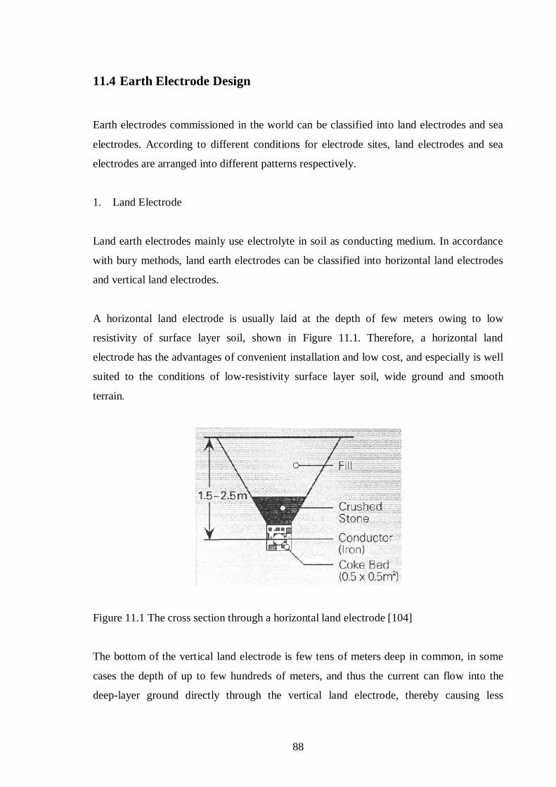
88
11.4 Earth Electrode Design
Earth electrodes commissioned in the world can be classified into land electrodes and sea
electrodes. According to different conditions for electrode sites, land electrodes and sea
electrodes are arranged into different patterns respectively.
1. Land Electrode
Land earth electrodes mainly use electrolyte in soil as conducting medium. In accordance
with bury methods, land earth electrodes can be classified into horizontal land electrodes
and vertical land electrodes.
A horizontal land electrode is usually laid at the depth of few meters owing to low
resistivity of surface layer soil, shown in Figure 11.1. Therefore, a horizontal land
electrode has the advantages of convenient installation and low cost, and especially is well
suited to the conditions of lowresistivity surface layer soil, wide ground and smooth
terrain.
Figure 11.1 The cross section through a horizontal land electrode [104]
The bottom of the vertical land electrode is few tens of meters deep in common, in some
cases the depth of up to few hundreds of meters, and thus the current can flow into the
deeplayer ground directly through the vertical land electrode, thereby causing less
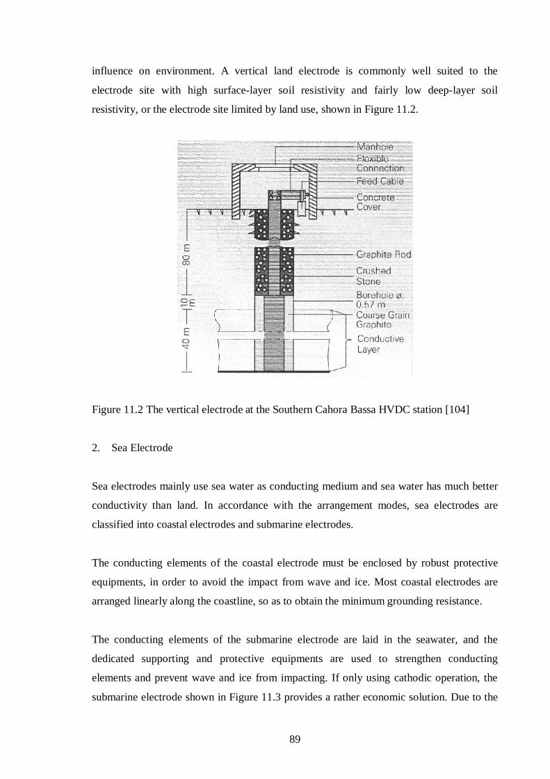
89
influence on environment. A vertical land electrode is commonly well suited to the
electrode site with high surfacelayer soil resistivity and fairly low deeplayer soil
resistivity, or the electrode site limited by land use, shown in Figure 11.2.
Figure 11.2 The vertical electrode at the Southern Cahora Bassa HVDC station [104]
2. Sea Electrode
Sea electrodes mainly use sea water as conducting medium and sea water has much better
conductivity than land. In accordance with the arrangement modes, sea electrodes are
classified into coastal electrodes and submarine electrodes.
The conducting elements of the coastal electrode must be enclosed by robust protective
equipments, in order to avoid the impact from wave and ice. Most coastal electrodes are
arranged linearly along the coastline, so as to obtain the minimum grounding resistance.
The conducting elements of the submarine electrode are laid in the seawater, and the
dedicated supporting and protective equipments are used to strengthen conducting
elements and prevent wave and ice from impacting. If only using cathodic operation, the
submarine electrode shown in Figure 11.3 provides a rather economic solution. Due to the

90
polarity change caused by powerflow reversal, each of earth electrodes must be designed
in accordance with anodic requirements.
Figure 11.3 The submarine electrode (cathodic operation) [104]
11.5 Earth Electrode Development
1. Deep Hole Ground Electrode
In a submarine HVDC transmission or nearby a converter station close to sea, it is feasible
to build a compact seashore or seawater ground electrode. An ordinary ground electrode
requires substantial land areas and must be placed at the location of relatively low soil
resistivity. Under such a condition, a deep hole ground electrode can reach into the earth
layer of quite low soil resistivity, thereby causing relatively low potential and potential
gradient on the earth surface. The first deep hole ground electrode had been installed in the
Baltic cable project.
The advantages of deep hole ground electrode are: the location of ground electrode is fairly
close to the converter station; using relatively short earth electrode line, thereby reducing
loss; reducing interferences and the risk of lightning strike; easily seeking the appropriate
location of earth electrode; improving the feasibility of HVDC monopolar operation.
91
2. Common Earth Electrode
For planning bulk hydropower outgoing transmission schemes, due to complex terrain
especially in a mountainous area, multiple sendingterminal converter stations are located
very closely; for two or more HVDC systems feeding into the same AC network, multiple
receivingterminal converter stations are placed electrically close to each other in the high
density load center; thereby causing the significant difficulties in site selection of earth
electrode. Aiming at such a circumstance, the design scheme of common earth electrode by
multiple HVDC systems is required. This design scheme has obvious advantages in
reducing influences of earth currents on environment; the appropriate electrode site
selection and electrode design can enhance the system safety and reliability; a common
earth electrode not only reduces electrodesite land uses, but also lowers overall cost.
However, both earth electrode resistance and electrode line resistance must be restricted
within a certain range; the electrode site selection and common earth electrode design must
satisfy relatively high requirements; the common earth electrode shared by multiple
converter stations requires reliable and available dispatching and communication.
11.6 Influence of Earth Electrode Current
While considerable direct current injects into ground via earth electrode, a constant direct
current field is formed in the vicinity of electrode site. Meantime, if there are transformers
with neutralpoint grounded, underground metallic pipelines and armoured cables close to
electrode site, owing to these metallic equipments providing much perfect conduction
paths rather than earth soil, partial earth currents flows along and through these metallic
equipments towards remote places, and thus it may cause unfavourable consequences to
system operation and transformer. [105]
In some countries, the transformers (above 110 kV) neutralpoints are mostly grounded
directly. If the substations are located within the vicinity of earth electrodes currentfield,
the electricpotential differences are generated among substations within the currentfield.
Direct current flows into one substation (the transformer neutralpoint) and flows out of the
other substation (the transformer neutralpoint). If considerable direct current flows

92
through the transformers windings, it may give rise to the following harmful effects on
power systems. [106]
(1) Transformercore magnetism saturation. Since transformercore magnetism saturation
occurs, it may cause the temperature, loss, noise of the transformer to increase. [107]
(2) Influence on electromagnetisminduced voltage transformer. While direct current
flows into electromagnetisminduced transformer, owing to inaccuracy measurements,
it may cause the corresponding relay protective devices to maloperation.
(3) Electrocorrosion. While direct ground current flows through the grounding grid (mat)
of power system, it may give rise to electrocorrosion in the grounding grid.
In order to reduce the effect of earth current, the following measurements must be
considered.
(1) The interception measurements from source are: rotationally arranging the HVDC
system operating modes and reducing the circuit modes of monopole groundreturn.
(2) The conduction measurements are: building reliable current path or dedicated line and
reducing the grounding resistance of earth electrode.
(3) The isolation measurements are: rationally configuring the grounding points and
grounding modes of ACsystem transformers.
93
Chapter 12 Conclusion
As some countries are planning to exploit the natural resources (hydro and lowgrade coal
fields), from a technical, economic and environmentally point of view, the HVDC
transmission will be employed with extensive foreground, due to the merits of long
distance (more than 1500 km), large capacity (more than 5 GW), flexible control and
convenient dispatching. In order to compete with the HVAC transmission, the future
development trend for the HVDC transmission is to employ the modular, standard and
duplicated design, so as to significantly lower the cost.
With the development of largerdiameter thyristor, the number of thyristors in series will
reduce substantially, thereby simplifying the design and lowering power loss. Because
considerable components for electrically triggered unit can be cancelled, lighttriggered
thyristor is of the advantages, i.e. higher performance and lower price. In addition, the
functions of overvoltage protection and state monitor can be integrated into lighttriggered
thyristor as well. Each airinsulated valve can be installed inside the outdoor container and
thus there is no need to build large valve hall, thereby enhancing the reliability and
reducing the cost.
Since harmonics must be eliminated in accordance with more strict criteria and the
complicated algorithm can be implemented with the excellent performance of digital signal
processor, active filters will play an important role, especially on the DC side of the
converter station.
The controller based on digital signal processor has been developed dramatically and thus
the control system is of high reliability, fully hot redundancy, numerous control points and
considerable data processing capacity. Due to fully digitalization, the number of control
cubicle installed in the control room has reduced significantly. Moreover, the controller
based on digital signal processor can also provide more advanced control algorithm, lower
maintenance, better fault diagnostic and online monitor function.
Lots of HVDC schemes have been commissioned in the world and the present experience
can be referenced during the construction. However, concerning with different

94
geographical and climatic circumstances (high altitude, heavily polluted contamination,
snow, heavily icing region, rainy), corona characteristics and overvoltage and insulation
coordination must be carried out in each case respectively.
Although the environmental effects of transmission lines can be limited under the
allowable level, the environmental criterion is related to the entire cost. Therefore,
according to the practical arrangement of transmission lines, the environmental effects
must be measured on the specific case.
Due to complex terrain like mountainous area or largescale load center with high
population density, an ordinary earth electrode, which requires substantial land areas, can
be replaced by deep hole ground electrode or common earth electrode.

95
References
[1].Hingorani, N.G.: ‘High voltage DC transmission: a power electronics workhorse’,IEEE Spectr., April 1996, pp.6372
[2].Jos Arrillaga.: ‘High Voltage Direct Current Transmission’, 2nd Edition, The Institutionof Electrical Engineers, 1998, pp.87, KontiSkan (1965)
[3]. FennoSkanhttp://www.abb.com/cawp/gad02181/d6a991f0cba1c22cc1256d8800402514.aspx
[4]. Baltic Cable HVDC project, Sweden and Germanyhttp://www.abb.fi/cawp/gad02181/c1256d71001e0037c12568330063c686.aspx
[5].Jos Arrillaga.: ‘High Voltage Direct Current Transmission’, 2nd Edition, The Institutionof Electrical Engineers, 1998, pp.93, Kontek (1995)
[6].‘SwePol Link HVDC Power Transmission’. ABB Power Technologies AB, PowerSystem, Ludvika, Sweden
[7].‘The Three Gorges – Guangdong HVDC link’. ABB Power Technologies AB,Ludvika, Sweden
[8].‘The Three Gorges – Changzhou HVDC Power Project’. ABB Power TechnologiesAB, Ludvika, Sweden
[9].‘± 500 kV ChandrapurPadghe HVDC bipole project’. ABB Power Technologies AB,Ludvika, Sweden
[10]. GezhoubaShanghaihttp://www.abb.com/cawp/gad02181/de23c98655d5e7b2c1256ee5002467ab.aspx
[11]. English Channel, Great Britain and Francehttp://en.wikipedia.org/wiki/HVDC_CrossChannel
[12]. CrossChannel link, Sellindge SE England and BonningueslesCalaisNorthern France
http://en.wikipedia.org/wiki/HVDC_CrossChannel
[13]. KingsnorthBeddingtonWillesden HVDC scheme, UKhttp://en.wikipedia.org/wiki/HVDC_Kingsnorth
[14]. Donahue, J.A., Fisher, D.A., Railing, B.D. and Tatro, P.J.: “Performancetesting of the Sandy Pond HVDC converter terminal”. IEEE Transactions on PowerDelivery, Vol. 8, No. 1, January 1993
[15]. ‘Vizag II HVDC Backtoback interconnection’. ABB Power TechnologiesAB, Grid System – HVDC, Ludvika, Sweden
96
[16]. ‘Brazil – Argentina Interconnection I & II’. ABB Power Technologies AB,Power Systems/HVDC, Ludvika, Sweden
[17]. J. Reeve: ‘Multiterminal HVDC Power Systems’. IEEE Trans., Vol. PAS99,pp.729737, March/April 1980
[18]. Schmidt, G., Fiegl, B., and Kolbeck, S.: ‘HVDC transmission and theenvironment’. Power Engineering Journal, October 1996, pp.209–210, space relatedconsequences
[19]. Kimbark, E. W.: ‘Direct current transmission’. Wiley Interscience, NewYork, 1971, pp.138146
[20]. J. Arrillaga, Y.H. Liu, N.R. Watson.: ‘Flexible Power Transmission TheHVDC Options’, John Wiley & Sons Ltd, 2007, pp.233235 structure of the HVDClink
[21]. J. Arrillaga, Y.H. Liu, N.R. Watson.: ‘Flexible Power Transmission TheHVDC Options’, John Wiley & Sons Ltd, 2007, pp.226 typical circuit diagram for onepole of a converter station
[22]. J. Arrillaga, Y.H. Liu, N.R. Watson.: ‘Flexible Power Transmission TheHVDC Options’, John Wiley & Sons Ltd, 2007, pp.227 station layout for a bipolarHVDC station
[23]. Carlsson, L., Asplund, G., Bjorklund, H., and Stromberg, H.: ‘Recent andFuture Trends in HVDC Converter Station Design’. IEE 2nd International Conferenceon Advances in Power System Control, Operation and Management, December 1993,Hong Kong
[24]. Jos Arrillaga.: ‘High Voltage Direct Current Transmission’, 2nd edition, TheInstitution of Electrical Engineers, 1998, pp.283284, outdoor valves
[25]. Jos Arrillaga.: ‘High Voltage Direct Current Transmission’, 2nd edition, TheInstitution of Electrical Engineers, 1998, pp.285286, compact converter stations
[26]. Henrik Stomberg, Bernt Abrahamsson and Olaf Saksvik.: ‘Modern HVDCthyristor valves’. ABB Power Systems, Ludvika, Sweden
[27]. Dennis A. Woodford.: ‘HVDC Transmission’. Manitoba HVDC ResearchCentre, Winnipeg, Manitoba, R3T 3Y6, Canada, 18 March 1998
[28]. Woodhouse, M.L., Ballad, J.P., Haddock, J.L., and Rowe, B.A.: ‘The controland protection of thyristors in the English Terminal CrossChannel valves, particularlyduring forward recovery’. IEE Conf. Publ. 205 on ‘Thyristor and variable staticequipment for A.C. and D.C. transmission’, 1981, pp.15863
[29]. ‘ETT vs. LTT for HVDC (A technical comparison between Electricallytriggered thyristor and Light triggered thyristor for HVDC applications.)www.abb.com/hvdc
97
[30]. Ake Carlson.: ‘specific requirements on HVDC converter transformers’.ABB Transformers AB, Ludvika, Sweden
[31]. Siemens Converter Transformers https://www.energyportal.siemens.com/static/hq/de/products_solutions/9110_70515_converter%20transformers.html
[32]. ‘HVDC smoothing reactor’ ABBhttp://www.abb.com/cawp/GAD02181/C1256D71001E0037C125683400432
912.aspx
[33]. Hao, Guo.: “Survey of Three Gorges Power Grid (TGPG)”, IEEE 2000.
[34]. ‘AC Harmonic Filter and Reactive Compensation for HVDC’, CIGRE WG1403, Electra No.63, 1979
[35]. Thorvaldsson, B., Arnlov, B., Saetlire, E., et al.: “Joint operationHVDC/SVC”. IEE Conference on AC and DC Power Transmission Publication,1996:281–284.
[36]. Chen Yiping.: “Analysis of the influence of HVDC reactive power control onthe voltage regulation of AC system”. CSG Power Dispatching and CommunicationCenter, Guangzhou, Guangdong, China (Chinese)
[37]. J. Arrillaga, Y.H. Liu, N.R. Watson.: ‘Flexible Power Transmission TheHVDC Options’, John Wiley & Sons Ltd, 2007, pp.259, dynamic voltage regulation
[38]. Transmission and Distribution Committee of the IEEE Power EngineeringSociety. ‘IEEE Guide for planning DC lines terminating at AC system locations havinglow shortcircuit capacities, Part 1: ACDC interaction phenomena’, Dec 1997
[39]. Kimbark, E.W.: ‘Direct current transmission’. Wiley Interscience, New York,1971, pp.296318
[40]. J. Arrillaga, Y.H. Liu, N.R. Watson.: ‘Flexible Power Transmission TheHVDC Options’, John Wiley & Sons Ltd, 2007, pp.262, harmonic crossmodulationacross the DC link
[41]. Vijay K. Sood.: ‘HVDC and FACTS Controllers Applications of StaticConverters in Power Systems’, Kluwer Power Electronics and Power Systems Series,2004, pp.276, tunable AC filter
[42]. Zhao WanJun.: ‘High Voltage Direct Current Engineering TechnologyReactive Power Compensation and AC side Filtering’. Central China Electric PowerDesign Institution, China (Chinese)
[43]. Peng Baoshu, Rao Hong, Yu Jiangou.: ‘Design and Realization of Tian –Guang HVDC Project’. State Power South Company, Guangzhou, China and SiemensAG PTD, Germany

98
[44]. Bartzsch C, Huang H, Sadek K.: ‘Tripletuned harmonic filters – designprinciple and operating experience’. Proc. 2002 IEEPES/CSEE InternationalConference on Power Systems Conf., 2002
[45]. Stanley, C.H., Price, J.J. and Brewer, G.L.: ‘Design and performance of ACfilters for 12pulse HVDC schemes’. IEE Conf. Publ., 154, 158–61, 1977
[46]. Dickmander, D.L., and Peterson, K.J.: ‘Analysis of DC harmonics using thethreepulse model for the Intermountain Power Project HVDC Transmission’. IEEETransaction on Power Delivery, 1989, 4(2), pp.11951204
[47]. Shore, N.L., Anderson, G., Canelhas, A.P., and Asplund, G.: ‘A threepulsemodel of DC side harmonic flow in HVDC systems’. IEEE Transaction on PowerDelivery, Jul 1989, 4(3), pp.19451954
[48]. Jos Arrillaga and Neville R. Watson.: ‘Power system harmonics’, secondedition, University of Canterbury, Christchurch, New Zealand, 2003, pp.255,
[49]. IEEE STD 11242003.: ‘IEEE Guide for analysis and definition of DC sideharmonic performance of HVDC transmission systems’.
[50]. Bernt Bergdahl and Rebati Dass.: ‘AC – DC Harmonic Filters for ThreeGorges – Changzhou ± 500 kV HVDC Project DC Harmonic Filters’. ABB PowerSystems, Sweden and ABB Limited, India
[51]. Jos Arrillaga and Neville R. Watson.: ‘Power system harmonics’, secondedition, University of Canterbury, Christchurch, New Zealand, 2003, pp.178179,psophometric weighting recommended by Internation Telegraph and TelephoneConsultative Committee (CCITT)
[52]. Jos Arrillaga and Neville R. Watson.: ‘Power system harmonics’, secondedition, University of Canterbury, Christchurch, New Zealand, 2003, pp.179181, Cmessage weighting recommended by the Edison Electric Institute and the BellTelephone System
[53]. Jos Arrillaga and N. R. Watson.: ‘Power System Harmonics’. University ofCanterbury, Christchurch, New Zealand, 2003, pp.178, Cmessage and psophometricweighting factors
[54]. Stefan, Gunnarsson., Lin, Jiang., Anders, Petersson.: “Active filters in HVDCtransmissions”. ABB Power Technologies, Sweden
[55]. Zhou XiaoQian, Huo JiAn, Sun JiaJun, Tao Yu, Liu ZeHong.: ‘Designfeatures of the Three GorgesChangzhou ±500 KV HVDC project’. CIGRE 2000Conference, Paris, France
[56]. Wenyan, Zhang., et al: ‘Active DC filter for HVDC system – a testinstallation in the KontiSkan DC link at Lindome converter station’. IEEE Trans. onPower Delivery, vol. 8, no. 3, July 1993, pp. 15991606

99
[57]. Jos Arrillaga.: ‘High Voltage Direct Current Transmission’, 2nd edition, TheInstitution of Electrical Engineers, 1998, pp.81, DCside active cancellation
[58]. J. Arrillaga, Y.H. Liu, N.R. Watson.: ‘Flexible Power Transmission TheHVDC Options’, John Wiley & Sons Ltd, 2007, pp.281, active DC side filters
[59]. Jos Arrillaga.: ‘High Voltage Direct Current Transmission’, 2nd Edition, TheInstitution of Electrical Engineers, 1998, pp.121,different control levels
[60]. Jos Arrillaga.: ‘High Voltage Direct Current Transmission’, 2nd Edition, TheInstitution of Electrical Engineers, 1998, pp.100, converter control basic philosophy
[61]. Vijay K. Sood.: ‘HVDC and FACTS Controllers Applications of StaticConverters in Power Systems’, Kluwer Power Electronics and Power Systems Series,2004, pp.67, HVDC controls
[62]. Vijay K. Sood.: ‘HVDC and FACTS Controllers Applications of StaticConverters in Power Systems’, Kluwer Power Electronics and Power Systems Series,2004, pp.67, harmonic instability
[63]. Ainsworth, J.D.: ‘The phaselocked oscillator – a new control system forcontrolled static converters’, Trans. IEEE, 1968, PAS87, (3) pp.85965
[64]. Ekstrom, A., and Liss, G.: ‘A refined HVDC control system’, Trans. IEEE,1970, PAS89, pp.723732
[65]. Vijay K. Sood.: ‘HVDC and FACTS Controllers Applications of StaticConverters in Power Systems’, Kluwer Power Electronics and Power Systems Series,2004, pp.7580, current margin control method
[66]. Prabha, Kundur.: ‘Power System Stability and Control’, Chapter 10 HighVoltage DirectCurrent Transmission, pp.521523, starting, stopping, power flowreversal
[67]. IEEE Committee Report, “Dynamic Performance Characteristics of NorthAmerican HVDC Systems for Transient and Dynamic Stability Evaluations,” IEEETrans., Vol. PAS100, pp. 33563364, July 1981.
[68]. IEEE Committee Report, “HVDC Controls for System DynamicPerformance,” IEEE Trans., Vol. PWRS6, No. 2, pp. 743752, May 1991
[69]. Chand, J., Rashwan, M.M., and Tishinski, W.K.: ‘Nelson River HVDCsystemoperating experience’. IEE Conf., Publ. 205 on ‘Thyristor and variable staticequipment for A.C. and D.C. transmission’ (London, 1981), pp.22326
[70]. Jos Arrillaga.: ‘High Voltage Direct Current Transmission’, 2nd Edition, TheInstitution of Electrical Engineers, 1998, pp.124, hierarchical power control at the NewZealand link
100
[71]. Jos Arrillaga.: ‘High Voltage Direct Current Transmission’, 2nd Edition, TheInstitution of Electrical Engineers, 1998, pp.208, possible locations of internal ACDCshortcircuit faults in typical 12pulse thyristor converter
[72]. CIGRE WG 14.02.: ‘Commutation failure in HVDC transmission systemsdue to AC system faults’. Electra, December 1996, (169), pp.5985
[73]. Kristmundsson, G.M. and Carroll, D.P.: ‘The effect of AC system frequencyspectrum on commutation failure in HVDC inverters’. IEEE Transactions on PowerDelivery, 1990, 5(2), pp.121128
[74]. Zou, G., Zheng, J.C., and Chen, X.X.: ‘Study on Commutation Failure in anHVDC Inverter’. International Conference on Power System Technology, August1998, pp.503506
[75]. Jos Arrillaga.: ‘High Voltage Direct Current Transmission’, 2nd Edition, TheInstitution of Electrical Engineers, 1998, pp.215 converter DC power following a threephase fault at the inverter end
[76]. Jos Arrillaga.: ‘High Voltage Direct Current Transmission’, 2nd Edition, TheInstitution of Electrical Engineers, 1998, pp.216, AC system unsymmetrical faults
[77]. Jos Arrillaga.: ‘High Voltage Direct Current Transmission’, 2nd Edition, TheInstitution of Electrical Engineers, 1998, pp.217, staged AC fault of the New ZealandHVDC hybrid link
[78]. Chen, Li.: ‘Analysis of and advice on setting adaptation for the station powersystem of GuiGuang HVDC project’. CSG EHV Power Transmission Company, GZBureau, Guangzhou, Guangdong, China (Chinese)
[79]. Heffernan, M.D., Arrillaga, J., Turner, K.S., and Arnold, C.P.: ‘Recoveryfrom temporary h.v.d.c. line faults’, Trans. IEEE, 1980, PAS100, (4), pp.186470
[80]. Prabha, Kundur.: ‘Power System Stability and Control’, Chapter 10 HighVoltage DirectCurrent Transmission, pp.534535, DC line fault
[81]. Zhang Zhijin, Jiang Xingliang, Sun Caixin.: ‘Present Situation and Prospectof Research on Flashover Characteristics of Polluted Insulators’, ChongqingUniversity, Chongqing, China (Chinese)
[82]. Liu, Dong and Wu, Zehui.: ‘Analysis on the TianGuang DC line protectionagainst highimpedance ground faults’. CSG EHV Transmission Company, GZBureau, Guangzhou, Guangdong, China (Chinese)
[83]. Oyama, M., Ohshima, I., Honda, M., Yamashita, M., Kojima, S.: ‘Lifeperformance of zinc oxide elements under DC voltage’. IEEE Transactions on PowerApparatus and Systems, June 1982, pp.13631368

101
[84]. Jos Arrillaga.: ‘High Voltage Direct Current Transmission’, 2nd Edition, TheInstitution of Electrical Engineers, 1998, pp.233, line current and voltage recorded atthe inverter during missing pulse condition in a rectifier bridge
[85]. Edward W. Kimbark: ‘Transient overvoltages caused by monopolar groundfault on bipolar d.c. lines’. IEEE Transaction on Power Apparatus and System, 1970,pp.584592
[86]. Jos Arrillaga.: ‘High Voltage Direct Current Transmission’, 2nd Edition, TheInstitution of Electrical Engineers, 1998, pp.229230, deblocking with full rectifiervoltage against an open inverter end
[87]. Siemens AG, Power Transmission and Distribution, High Voltage Division.:‘High Voltage Direct Current Transmission – Proven Technology for PowerExchange’. Paper 30
[88]. Jos Arrillaga.: ‘High Voltage Direct Current Transmission’, 2nd Edition,pp.184, the choice of conductors of overhead lines
[89]. YE Huisheng, HE Junjia, LI Hua.: ‘Simulation study on lightningstrikeendurance of HVDC transmission line towers’. College of Electrical and ElectronicEngineering, Huazhong University of Science and Technology, Wuhan, Hubei, China(Chinese)
[90]. LUO Bing, RAO Hong, LI Xiaolin, SU Zhiyi, ZHOU Jun.: ‘The flashovercharacteristic of DC composite insulators in ununiform pollution’. CSG TechnologyResearch Center, Guangzhou, Guangdong, China and China Electric Power ResearchInstitute, Beijing, China (Chinese)
[91]. Taizo, Hasegawa.: ‘Construction and operation experience of large capacityDC transmission system in Japan’. The Kansai Electric Power CO., Inc.
[92]. ‘Submarine Cable Link – The Baltic Cable HVDC ConnectionSweden/Germany’. ABB Power Technologies AB, Ludvika, Sweden
[93]. ‘The NorNed HVDC transmission link – the longest underwater highvoltagecable in the world’. ABB Power Technologies AB, Grid SystemHVDC, Ludvika,Sweden
[94]. Jos Arrillaga.: ‘High Voltage Direct Current Transmission’, The Institutionof Electrical Engineers, 1998, pp.188, maximum power per cable and operating voltageof realised HVDC submarine massimpregnated cables
[95]. Jos Arrillaga.: ‘High Voltage Direct Current Transmission’, The Institutionof Electrical Engineers, 1998, pp.187, cross section of the doublearmoured DC cable
[96]. Jos Arrillaga.: ‘High Voltage Direct Current Transmission’, The Institutionof Electrical Engineers, 1998, pp.188, pp.266, the environmental effects of overheadtransmission lines

102
[97]. Adamson, C., Hingorani, N.G.: ‘High voltage direct current powertransmission’. Garrawy Ltd, London, 1960, pp.200206
[98]. K.R. Padiyar.: ‘HVDC Power Transmission Systems Technology and SystemInteractions’, pp.114115
[99]. Schmidt, G., Fiegl, B., and Kolbeck, S.: ‘HVDC transmission and theenvironment’. Power Engineering Journal, October 1996, pp.205, electric field ofmonopolar and bipolar 450 kV overhead lines
[100]. GuiFang, Wu.: ‘Electromagnetic environment problem brought about by±500kV DC transmission project in China’, China Electric Power Research Institute(Chinese)
[101]. Schmidt, G., Fiegl, B., and Kolbeck, S.: ‘HVDC transmission and theenvironment’. Power Engineering Journal, October 1996, pp.208, electrodes
[102]. Villas, J.E.T. and Portela, C.M.: ‘Soil heating around the ground electrode ofan HVDC system by interaction of electrical thermal and electroosmotic phenomena’.IEEE Transaction on Power Delivery, 2003, 18(3).
[103]. Kimbark, E.W.: ‘Direct current transmission’. Wiley Interscience, New York,1971, pp.443445
[104]. Siemens AG Power Transmission and Distribution.: “High Voltage DirectCurrent Transmission – Proven Technology for Power Exchange”. Paper 3637
[105]. Di zheng, Wan Da, Zou Yun.: ‘The analysis and handling of the impact ofground current in DC transmission on power grid equipment’. IEEE/PES Transmissionand Distribution Conference and Exhibition, Asia and Pacific, Dalian, China, 2005.
[106]. WANG Mingxin and ZHANG Qiang.: ‘Analysis on influence of groundelectrode current in HVDC on AC power network’. China Electric Power ResearchInstitute, Haidian District, Beijing, China and State Grid Corporation of China,Xicheng District, Beijing, China (Chinese)
[107]. CUI Xiuyu.: ‘Analysis of the impact of ground DC on AC transformer’.Guangdong Electric Power Dispatching and Communication Co., Ltd., Guangzhou,Guangdong, China (Chinese)
Related Documents