Saskatchewan Ministry of the Economy Uranium Mining Supply Chain Requirement Guide Date: March 2014 By: AMEC Americas Limited AMEC file: 176123RE006

Welcome message from author
This document is posted to help you gain knowledge. Please leave a comment to let me know what you think about it! Share it to your friends and learn new things together.
Transcript
Saskatchewan Ministry of the Economy Uranium Mining Supply Chain Requirement Guide
Date: March 2014
By: AMEC Americas Limited
AMEC file: 176123RE006
Uranium Mining Supply Chain Requirement Guide
Table of Contents
TABLE OF CONTENTS
1. EXECUTUVE SUMMARY ................................................................................................................ 1
2. INTRODUCTION .............................................................................................................................. 2
3. HISTORY OF URANIUM MINING AND MILLING IN SASKATCHEWAN........................................ 3
4. MINES AND MILL MODELS .......................................................................................................... 13 4.1 Base Data .......................................................................................................................... 13 4.2 Underground Mine Model .................................................................................................. 13 4.3 Open Pit Mine Model ......................................................................................................... 14 4.4 Mill Model........................................................................................................................... 14
5. URANIUM FACILITY LIFE CYCLE STAGES ................................................................................. 16
6. EXPLORATION .............................................................................................................................. 20 6.1 Area Selection ................................................................................................................... 20 6.2 Target Identification ........................................................................................................... 24 6.3 Drill Testing and Resource Evaluation .............................................................................. 26 6.4 Exploration Service Provider Information .......................................................................... 28
7. REGULATORY LICENCES, PERMITS AND APPROVALS .......................................................... 29 7.1 Approval Processes ........................................................................................................... 29 7.2 Licences and Permits Required ........................................................................................ 32 7.3 Types and Values of Services ........................................................................................... 33
8. ENGINEERING, PROCUREMENT, AND CONSTRUCTION MANAGEMENT (EPCM) .............. 36 8.1 Engineering ....................................................................................................................... 36 8.2 Procurement ...................................................................................................................... 38 8.3 Construction Management ................................................................................................ 39 8.4 Estimated EPCM Costs ..................................................................................................... 39
9. MINE AND SURFACE FACILITIES CONSTRUCTION ................................................................. 40 9.1 Underground Mine ............................................................................................................. 40 9.2 Open Pit Mine .................................................................................................................... 58 9.3 Mill ..................................................................................................................................... 69 9.4 General Site ....................................................................................................................... 75
10. COMMISSIONING AND RAMP-UP ............................................................................................... 78
11. OPERATIONS AND MAINTENANCE ............................................................................................ 79 11.1 Underground Mining .......................................................................................................... 79 11.2 Open Pit Mining ................................................................................................................. 85 11.3 Milling ................................................................................................................................. 86
12. CLOSURE AND RECLAMATION................................................................................................... 97
13. LONG TERM SITE MONITORING ................................................................................................. 98
14. INDEX ............................................................................................................................................. 99
15. GLOSSARY OF TERMS .............................................................................................................. 101
Uranium Mining Supply Chain Requirement Guide
Table of Contents
TABLES
Table 3:1 General data for Saskatchewan uranium mills .......................................................................... 3 Table 3:2 Saskatchewan mill feed grade ranges ....................................................................................... 6 Table 3:3 Summary of Saskatchewan uranium mill processes ................................................................. 9 Table 3:4 Summary of Saskatchewan uranium mine types ..................................................................... 12 Table 6:1 Estimated expenditures related to the area selection stage .................................................... 23 Table 6:2 Estimated expenditures related to the target identification stage ............................................ 24 Table 6:3 Estimated expenditures related to the drill testing and resource evaluation stage ................. 26 Table 7:1 Federal regulatory agencies ..................................................................................................... 32 Table 7:2 Mine and surface facilities construction project licensing service requirements...................... 35 Table 7:3 Commissioning and operations project licensing service requirements .................................. 35 Table 8:1 Study estimate classifications and accuracy ........................................................................... 37 Table 8:2 Estimated EPCM costs ............................................................................................................ 39 Table 9:1 Supplies and services for construction .................................................................................... 56 Table 9:2 Key quantities and unit prices for model underground mine ................................................... 57 Table 9:3 Supplies and services for model open pit construction ............................................................ 68 Table 9:4 Unit costs for model open pit construction ............................................................................... 69 Table 9:5 Supplies and services for model mill construction ................................................................... 74 Table 9:6 Supplies and services for general site construction ................................................................. 77 Table 11:1 Supplies and services for model underground mine operations and maintenance ................. 85 Table 11:2 Supplies and services for model open pit mine operations and maintenance......................... 86 Table 11:3 Supplies and services for model mill operation and maintenance ........................................... 94 Table 11:4 Supplies and services for uranium industry operation and maintenance ................................ 95 Table 11:5 Estimated supplies and services for operation & maintenance of Saskatchewan’s
uranium industry ....................................................................................................................... 95 Table 12:1 Closure and reclamation activities ........................................................................................... 97
Uranium Mining Supply Chain Requirement Guide
Table of Contents
FIGURES
Figure 3:1 Beaverlodge site ........................................................................................................................ 4 Figure 3:2 Rabbit Lake mill site, in-pit TMF upper right corner ................................................................... 5 Figure 3:3 Rabbit Lake open pit mine ......................................................................................................... 5 Figure 3:4 Cluff Lake mill site ...................................................................................................................... 7 Figure 3:5 Key Lake mill site, Deilmann in-pit TMF in rear ......................................................................... 8 Figure 3:6 McClean Lake site, JEB in-pit TMF on left, McClean Lake mill on right .................................... 8 Figure 3:7 Raise boring mining machine, McArthur River ........................................................................ 10 Figure 3:8 Jet boring mining machine, Cigar Lake.................................................................................... 11 Figure 5:1 Typical Saskatchewan uranium mine project life cycle ............................................................ 18 Figure 6:1 Athabasca Basin location map ................................................................................................. 22 Figure 6:2 Airborne magnetic survey aircraft ............................................................................................ 23 Figure 6:3 Ground gravity survey .............................................................................................................. 25 Figure 6:4 Diamond drilling rig at the Cameco Millennium deposit ........................................................... 27 Figure 6:5 Athabasca Basin uranium exploration diamond drill core ........................................................ 27 Figure 7:1 Federal licensing and assessment process ............................................................................. 30 Figure 7:2 Provincial assessment process ................................................................................................ 31 Figure 7:3 Project licensing schedule – construction into operation ......................................................... 34 Figure 9:1 3-D View of McArthur River mine showing mineralized zones and mine development .......... 41 Figure 9:2 Shaft sinking in progress .......................................................................................................... 43 Figure 9:3 Twin headframes, hoistroom, ventilation fan facilities ............................................................. 44 Figure 9:4 Typical double drum hoist installation ...................................................................................... 45 Figure 9:5: Drill jumbo working in a drift supported with rockbolts and weld wire mesh ............................ 47 Figure 9:6 Freeze system schematic ........................................................................................................ 48 Figure 9:7 Surface freeze plant ................................................................................................................. 49 Figure 9:8: Geological cross section of the Deilmann orebody .................................................................. 59 Figure 9:9 AREVA’s JEB open pit uranium mine ...................................................................................... 61 Figure 9:10 Excavator loading a haulage truck ........................................................................................... 63 Figure 9:11 Rotary blast hole drill................................................................................................................ 64 Figure 9:12 Open pit uranium ore mining .................................................................................................... 65 Figure 9:13 Exterior view of a typical Saskatchewan uranium mill, Key Lake ............................................ 70 Figure 9:14 Interior view from a typical Saskatchewan uranium mill, ......................................................... 71 Figure 9:15 Interior view from a typical Saskatchewan uranium mill, ......................................................... 72 Figure 9:16 Interior view from a typical Saskatchewan uranium mill, ......................................................... 72 Figure 9:17 A typical Saskatchewan uranium in-pit TMF, at Rabbit Lake .................................................. 73 Figure 9:18: Aerial view of a typical Saskatchewan uranium operations site, Key Lake ............................. 76 Figure 11:1 Raise bore mining method and mining sequence .................................................................... 79 Figure 11:2 Blasthole stoping mining method – cross section schematic .................................................. 80 Figure 11:3 Freeze level .............................................................................................................................. 81 Figure 11:4 Raisebore machine .................................................................................................................. 82 Figure 11:5 Remote controlled LHD located under loading chute at base of production raise bore hole .. 82 Figure 11:6 ITH drill rig used for blast hole drilling ...................................................................................... 83 Figure 11:7 LHD loading ore from a draw drift below a blasthole stope ..................................................... 84
Uranium Mining Supply Chain Requirement Guide
Table of Contents
Figure 11:8 Simplified flowsheet of the uranium milling process .............................................................. 86 Figure 11:9 Uranium ore stockpiles ........................................................................................................... 87 Figure 11:10 SAG mill - ball mill – hydrocyclone grinding circuit for uranium ore ...................................... 87 Figure 11:11 Uranium leach equipment, atmospheric pressure ................................................................ 88 Figure 11:12 CCD thickeners for solid/liquid separation ............................................................................ 89 Figure 11:13 Uranium mixer-settlers .......................................................................................................... 90 Figure 11:14 Uranium yellowcake precipitation tank .................................................................................. 91 Figure 11:15 Uranium yellowcake belt filtration .......................................................................................... 91 Figure 11:16 Uranium yellowcake dryer ..................................................................................................... 92 Figure 11:17 Uranium yellowcake .............................................................................................................. 92 Figure 11:18 Uranium tailings neutralization circuit .................................................................................... 93 Figure 11:19 Uranium in-pit TMF................................................................................................................ 93
Uranium Mining Supply Chain Requirement Guide
Page 1
1. EXECUTUVE SUMMARY
Mining and milling operations in Saskatchewan have produced uranium continuously since
1953. This guide provides a description of the activities throughout the expected 50 plus year
life of a current typical Saskatchewan uranium mining project, and presents order-of-magnitude
estimates of the expenditures for supplies and services in each and every stage of the project.
These expenditures total more than $10 billion.
Saskatchewan uranium mining operators have the following priorities for sourcing supplies and
services, ranked from higher to lower:
Northern Saskatchewan
Saskatchewan
Canada
Others
Note that Northern Saskatchewan provides mainly services.
Expenditure estimates are made for a model project that includes one of an underground or an
open pit mine, a mill, and the site hosting these production plants and the ancillary support
facilities. The model project will produce 12,000,000 lb U3O8 annually as yellowcake from ore
grading 4% U3O8.
This guide discusses eight stages in the model project life cycle:
Exploration
Regulatory licences, permits and approvals
Engineering, procurement and construction management
Mine and surface facilities construction
Commissioning and ramp-up
Operations and maintenance
Closure and reclamation
Long term site monitoring
We estimate a typical duration for each stage, but this duration is a guide only as the actual
duration of each stage has varied between projects.
Uranium Mining Supply Chain Requirement Guide
Page 2
2. INTRODUCTION
Mining and milling operations in Saskatchewan have produced uranium continuously since
1953, with a new mine/mill development approximately every 12 years on average. Over that
period, Saskatchewan has been one of the world’s premier uranium producers, yielding
approximately 786 million lb. of U3O8.
During the anticipated 50 plus year life of a typical Saskatchewan uranium mining project, in
excess of $10 billion will be spent on goods and services to develop, construct, operate,
maintain and eventually decommission the facilities, including the reclamation of all disturbed
lands.
This guide provides information on the quantity, value and scheduling of supplies and services
purchased by typical Saskatchewan uranium mining project owners and/or operators to
discover, develop, operate, maintain, decommission and close out projects.
The intended readers and users of this guide are current supply and service providers to the
industry, potential supply and service providers, and the Government of Saskatchewan to help
guide its programs and support for the industry.
This guide attempts to give a balanced understanding of supplies and services purchased
during both the capital-intensive engineering design and construction stage, and the operations,
maintenance and decommissioning stage. Spending in the earlier stage is relatively rapid, but
total value of purchases is greater through the latter stage.
This document has been prepared by AMEC Americas Limited (AMEC) for Government of
Saskatchewan. This document has been prepared as a general planning guideline intended to
establish an understanding of sector specific supply chain costs. This document is not intended
to serve as a basis for facility or application specific design, cost forecasting, defining regulatory
requirements, or for investment purposes. This document may only be used by its intended
readers in the context and for the express purpose for which it has been prepared. Any other
use or reliance on this document by any user is at that party’s sole risk and responsibility.
Uranium Mining Supply Chain Requirement Guide
Page 3
3. HISTORY OF URANIUM MINING AND MILLING IN SASKATCHEWAN
Mining and milling operations in Saskatchewan have produced uranium continuously since
1953, with a new mine/mill development approximately every 12 years on average. Over that
period Saskatchewan has been one of the world’s premier uranium producers, yielding
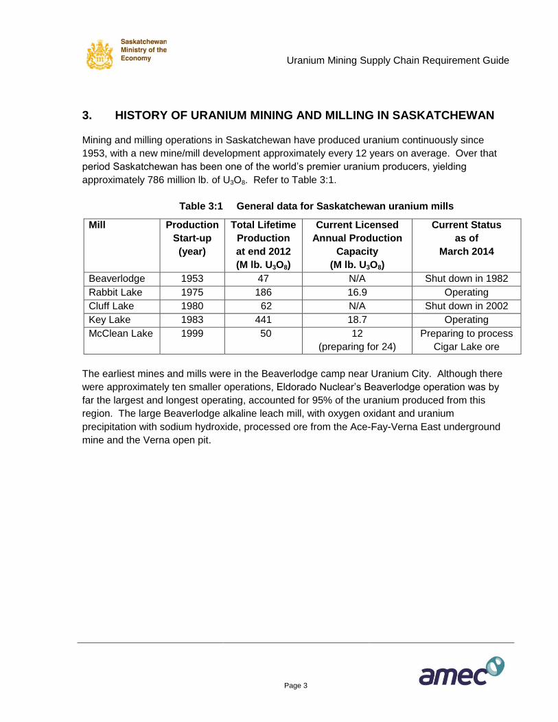
approximately 786 million lb. of U3O8. Refer to Table 3:1.
Table 3:1 General data for Saskatchewan uranium mills
Mill Production
Start-up
(year)
Total Lifetime
Production
at end 2012
(M lb. U3O8)
Current Licensed
Annual Production
Capacity
(M lb. U3O8)
Current Status
as of
March 2014
Beaverlodge 1953 47 N/A Shut down in 1982
Rabbit Lake 1975 186 16.9 Operating
Cluff Lake 1980 62 N/A Shut down in 2002
Key Lake 1983 441 18.7 Operating
McClean Lake 1999 50
12
(preparing for 24)
Preparing to process
Cigar Lake ore
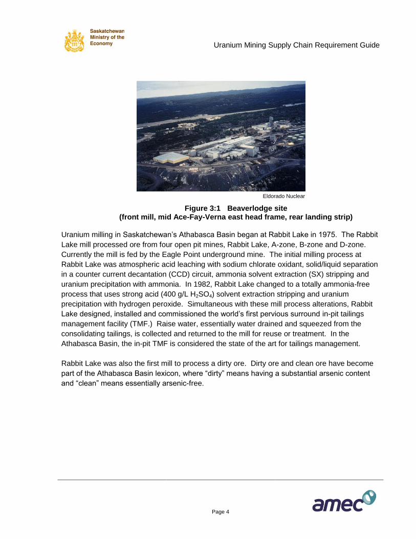
The earliest mines and mills were in the Beaverlodge camp near Uranium City. Although there
were approximately ten smaller operations, Eldorado Nuclear’s Beaverlodge operation was by
far the largest and longest operating, accounted for 95% of the uranium produced from this
region. The large Beaverlodge alkaline leach mill, with oxygen oxidant and uranium
precipitation with sodium hydroxide, processed ore from the Ace-Fay-Verna East underground
mine and the Verna open pit.
Uranium Mining Supply Chain Requirement Guide
Page 4
Eldorado Nuclear
Figure 3:1 Beaverlodge site (front mill, mid Ace-Fay-Verna east head frame, rear landing strip)
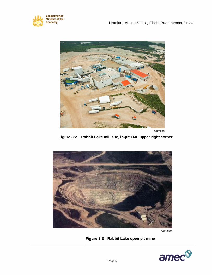
Uranium milling in Saskatchewan’s Athabasca Basin began at Rabbit Lake in 1975. The Rabbit
Lake mill processed ore from four open pit mines, Rabbit Lake, A-zone, B-zone and D-zone.
Currently the mill is fed by the Eagle Point underground mine. The initial milling process at
Rabbit Lake was atmospheric acid leaching with sodium chlorate oxidant, solid/liquid separation
in a counter current decantation (CCD) circuit, ammonia solvent extraction (SX) stripping and
uranium precipitation with ammonia. In 1982, Rabbit Lake changed to a totally ammonia-free
process that uses strong acid (400 g/L H2SO4) solvent extraction stripping and uranium
precipitation with hydrogen peroxide. Simultaneous with these mill process alterations, Rabbit
Lake designed, installed and commissioned the world’s first pervious surround in-pit tailings
management facility (TMF.) Raise water, essentially water drained and squeezed from the
consolidating tailings, is collected and returned to the mill for reuse or treatment. In the
Athabasca Basin, the in-pit TMF is considered the state of the art for tailings management.
Rabbit Lake was also the first mill to process a dirty ore. Dirty ore and clean ore have become
part of the Athabasca Basin lexicon, where “dirty” means having a substantial arsenic content
and “clean” means essentially arsenic-free.
Uranium Mining Supply Chain Requirement Guide
Page 5
Cameco
Figure 3:2 Rabbit Lake mill site, in-pit TMF upper right corner
Cameco
Figure 3:3 Rabbit Lake open pit mine
Uranium Mining Supply Chain Requirement Guide
Page 6
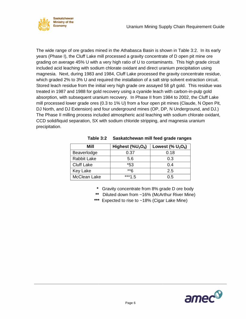
The wide range of ore grades mined in the Athabasca Basin is shown in Table 3:2. In its early
years (Phase I), the Cluff Lake mill processed a gravity concentrate of D open pit mine ore
grading on average 45% U with a very high ratio of U to contaminants. This high grade circuit
included acid leaching with sodium chlorate oxidant and direct uranium precipitation using
magnesia. Next, during 1983 and 1984, Cluff Lake processed the gravity concentrate residue,
which graded 2% to 3% U and required the installation of a salt strip solvent extraction circuit.
Stored leach residue from the initial very high grade ore assayed 58 g/t gold. This residue was
treated in 1987 and 1988 for gold recovery using a cyanide leach with carbon-in-pulp gold
absorption, with subsequent uranium recovery. In Phase II from 1984 to 2002, the Cluff Lake
mill processed lower grade ores (0.3 to 1% U) from a four open pit mines (Claude, N Open Pit,
DJ North, and DJ Extension) and four underground mines (OP, DP, N Underground, and DJ.)
The Phase II milling process included atmospheric acid leaching with sodium chlorate oxidant,
CCD solid/liquid separation, SX with sodium chloride stripping, and magnesia uranium
precipitation.
Table 3:2 Saskatchewan mill feed grade ranges
Mill Highest (%U3O8) Lowest (% U3O8)
Beaverlodge 0.37 0.18
Rabbit Lake 5.6 0.3
Cluff Lake *53 0.4
Key Lake **6 2.5
McClean Lake ***1.5 0.5
* Gravity concentrate from 8% grade D ore body
** Diluted down from ~16% (McArthur River Mine)
*** Expected to rise to ~18% (Cigar Lake Mine)
Uranium Mining Supply Chain Requirement Guide
Page 7
AREVA
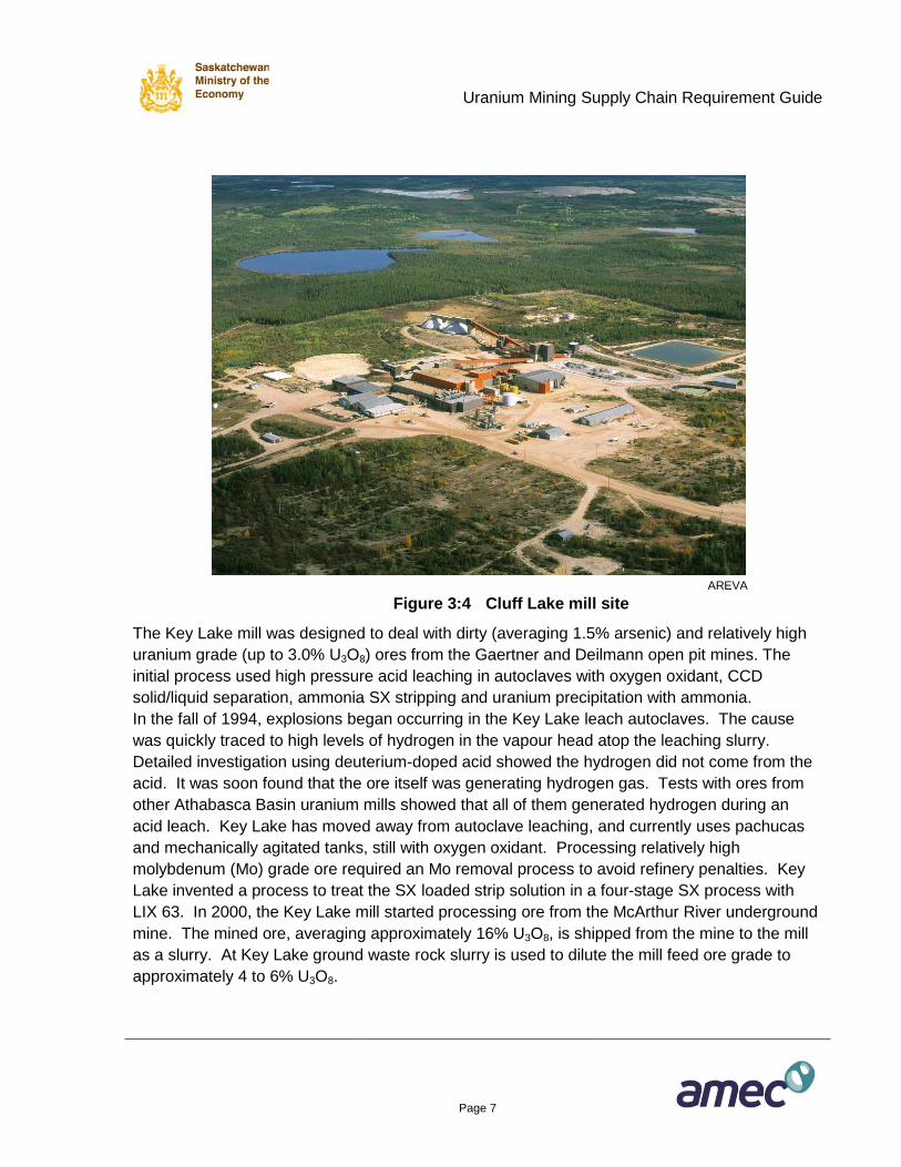
Figure 3:4 Cluff Lake mill site
The Key Lake mill was designed to deal with dirty (averaging 1.5% arsenic) and relatively high
uranium grade (up to 3.0% U3O8) ores from the Gaertner and Deilmann open pit mines. The
initial process used high pressure acid leaching in autoclaves with oxygen oxidant, CCD
solid/liquid separation, ammonia SX stripping and uranium precipitation with ammonia.
In the fall of 1994, explosions began occurring in the Key Lake leach autoclaves. The cause
was quickly traced to high levels of hydrogen in the vapour head atop the leaching slurry.
Detailed investigation using deuterium-doped acid showed the hydrogen did not come from the
acid. It was soon found that the ore itself was generating hydrogen gas. Tests with ores from
other Athabasca Basin uranium mills showed that all of them generated hydrogen during an
acid leach. Key Lake has moved away from autoclave leaching, and currently uses pachucas
and mechanically agitated tanks, still with oxygen oxidant. Processing relatively high
molybdenum (Mo) grade ore required an Mo removal process to avoid refinery penalties. Key
Lake invented a process to treat the SX loaded strip solution in a four-stage SX process with
LIX 63. In 2000, the Key Lake mill started processing ore from the McArthur River underground
mine. The mined ore, averaging approximately 16% U3O8, is shipped from the mine to the mill
as a slurry. At Key Lake ground waste rock slurry is used to dilute the mill feed ore grade to
approximately 4 to 6% U3O8.
Uranium Mining Supply Chain Requirement Guide
Page 8
Cameco
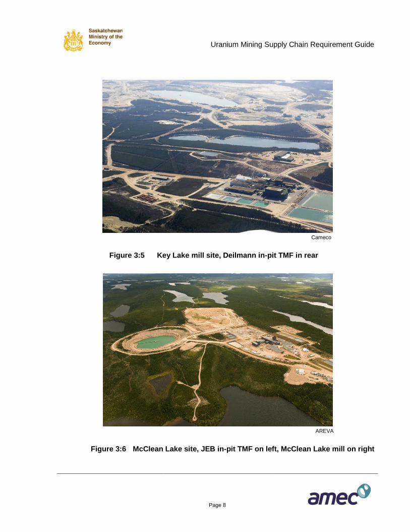
Figure 3:5 Key Lake mill site, Deilmann in-pit TMF in rear
AREVA
Figure 3:6 McClean Lake site, JEB in-pit TMF on left, McClean Lake mill on right
Uranium Mining Supply Chain Requirement Guide
Page 9
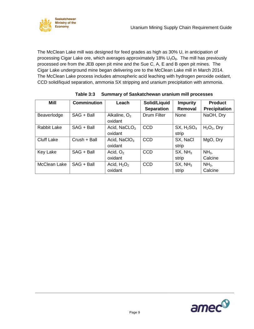
The McClean Lake mill was designed for feed grades as high as 30% U, in anticipation of
processing Cigar Lake ore, which averages approximately 18% U3O8. The mill has previously
processed ore from the JEB open pit mine and the Sue C, A, E and B open pit mines. The
Cigar Lake underground mine began delivering ore to the McClean Lake mill in March 2014.
The McClean Lake process includes atmospheric acid leaching with hydrogen peroxide oxidant,
CCD solid/liquid separation, ammonia SX stripping and uranium precipitation with ammonia.
Table 3:3 Summary of Saskatchewan uranium mill processes
Mill Comminution Leach Solid/Liquid
Separation
Impurity
Removal
Product
Precipitation
Beaverlodge SAG + Ball Alkaline, O2
oxidant
Drum Filter None NaOH, Dry
Rabbit Lake SAG + Ball Acid, NaCLO3
oxidant
CCD SX, H2SO4
strip
H2O2, Dry
Cluff Lake Crush + Ball Acid, NaClO3
oxidant
CCD SX, NaCl
strip
MgO, Dry
Key Lake SAG + Ball Acid, O2
oxidant
CCD SX, NH3
strip
NH3,
Calcine
McClean Lake SAG + Ball Acid, H2O2
oxidant
CCD SX, NH3
strip
NH3,
Calcine
Uranium Mining Supply Chain Requirement Guide
Page 10
Cameco
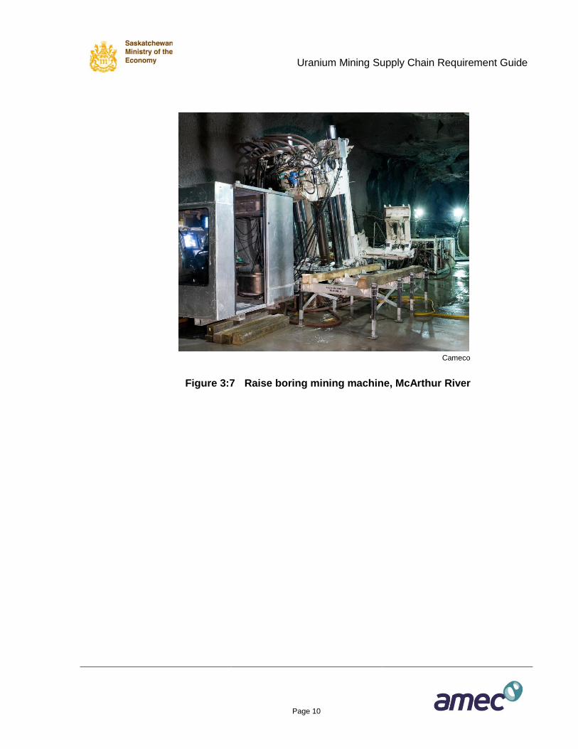
Figure 3:7 Raise boring mining machine, McArthur River
Uranium Mining Supply Chain Requirement Guide
Page 11
Cameco
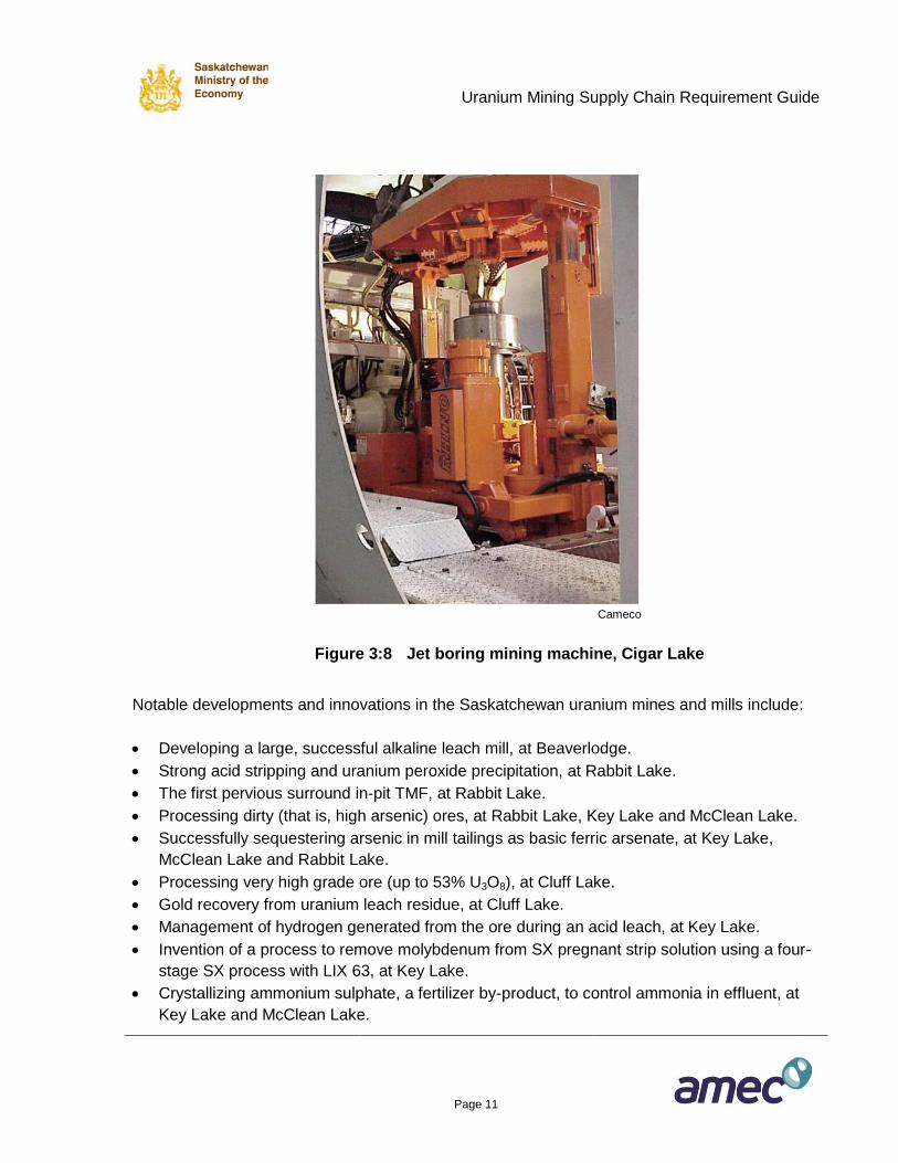
Figure 3:8 Jet boring mining machine, Cigar Lake
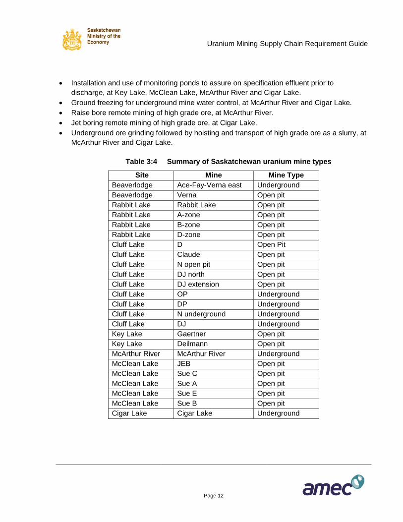
Notable developments and innovations in the Saskatchewan uranium mines and mills include:
Developing a large, successful alkaline leach mill, at Beaverlodge.
Strong acid stripping and uranium peroxide precipitation, at Rabbit Lake.
The first pervious surround in-pit TMF, at Rabbit Lake.
Processing dirty (that is, high arsenic) ores, at Rabbit Lake, Key Lake and McClean Lake.
Successfully sequestering arsenic in mill tailings as basic ferric arsenate, at Key Lake,
McClean Lake and Rabbit Lake.
Processing very high grade ore (up to 53% U3O8), at Cluff Lake.
Gold recovery from uranium leach residue, at Cluff Lake.
Management of hydrogen generated from the ore during an acid leach, at Key Lake.
Invention of a process to remove molybdenum from SX pregnant strip solution using a four-
stage SX process with LIX 63, at Key Lake.
Crystallizing ammonium sulphate, a fertilizer by-product, to control ammonia in effluent, at
Key Lake and McClean Lake.
Uranium Mining Supply Chain Requirement Guide
Page 12
Installation and use of monitoring ponds to assure on specification effluent prior to
discharge, at Key Lake, McClean Lake, McArthur River and Cigar Lake.
Ground freezing for underground mine water control, at McArthur River and Cigar Lake.
Raise bore remote mining of high grade ore, at McArthur River.
Jet boring remote mining of high grade ore, at Cigar Lake.
Underground ore grinding followed by hoisting and transport of high grade ore as a slurry, at
McArthur River and Cigar Lake.
Table 3:4 Summary of Saskatchewan uranium mine types
Site Mine Mine Type
Beaverlodge Ace-Fay-Verna east Underground
Beaverlodge Verna Open pit
Rabbit Lake Rabbit Lake Open pit
Rabbit Lake A-zone Open pit
Rabbit Lake B-zone Open pit
Rabbit Lake D-zone Open pit
Cluff Lake D Open Pit
Cluff Lake Claude Open pit
Cluff Lake N open pit Open pit
Cluff Lake DJ north Open pit
Cluff Lake DJ extension Open pit
Cluff Lake OP Underground
Cluff Lake DP Underground
Cluff Lake N underground Underground
Cluff Lake DJ Underground
Key Lake Gaertner Open pit
Key Lake Deilmann Open pit
McArthur River McArthur River Underground
McClean Lake JEB Open pit
McClean Lake Sue C Open pit
McClean Lake Sue A Open pit
McClean Lake Sue E Open pit
McClean Lake Sue B Open pit
Cigar Lake Cigar Lake Underground
Uranium Mining Supply Chain Requirement Guide
Page 13
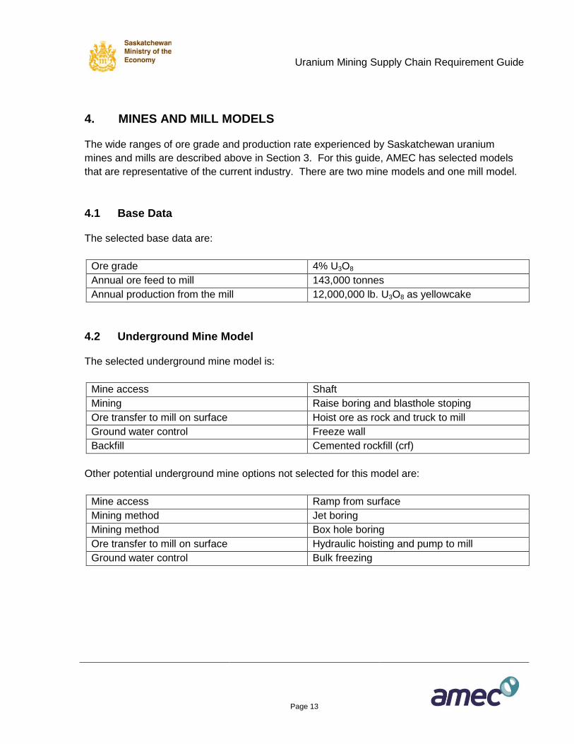
4. MINES AND MILL MODELS
The wide ranges of ore grade and production rate experienced by Saskatchewan uranium
mines and mills are described above in Section 3. For this guide, AMEC has selected models
that are representative of the current industry. There are two mine models and one mill model.
4.1 Base Data
The selected base data are:
Ore grade 4% U3O8
Annual ore feed to mill 143,000 tonnes
Annual production from the mill 12,000,000 lb. U3O8 as yellowcake
4.2 Underground Mine Model
The selected underground mine model is:
Mine access Shaft
Mining Raise boring and blasthole stoping
Ore transfer to mill on surface Hoist ore as rock and truck to mill
Ground water control Freeze wall
Backfill Cemented rockfill (crf)
Other potential underground mine options not selected for this model are:
Mine access Ramp from surface
Mining method Jet boring
Mining method Box hole boring
Ore transfer to mill on surface Hydraulic hoisting and pump to mill
Ground water control Bulk freezing
Uranium Mining Supply Chain Requirement Guide
Page 14
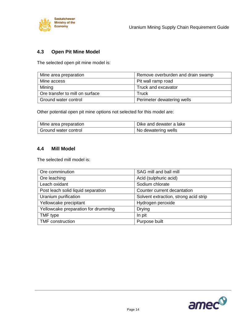
4.3 Open Pit Mine Model
The selected open pit mine model is:
Mine area preparation Remove overburden and drain swamp
Mine access Pit wall ramp road
Mining Truck and excavator
Ore transfer to mill on surface Truck
Ground water control Perimeter dewatering wells
Other potential open pit mine options not selected for this model are:
Mine area preparation Dike and dewater a lake
Ground water control No dewatering wells
4.4 Mill Model
The selected mill model is:
Ore comminution SAG mill and ball mill
Ore leaching Acid (sulphuric acid)
Leach oxidant Sodium chlorate
Post leach solid liquid separation Counter current decantation
Uranium purification Solvent extraction, strong acid strip
Yellowcake precipitant Hydrogen peroxide
Yellowcake preparation for drumming Drying
TMF type In pit
TMF construction Purpose built
Uranium Mining Supply Chain Requirement Guide
Page 15
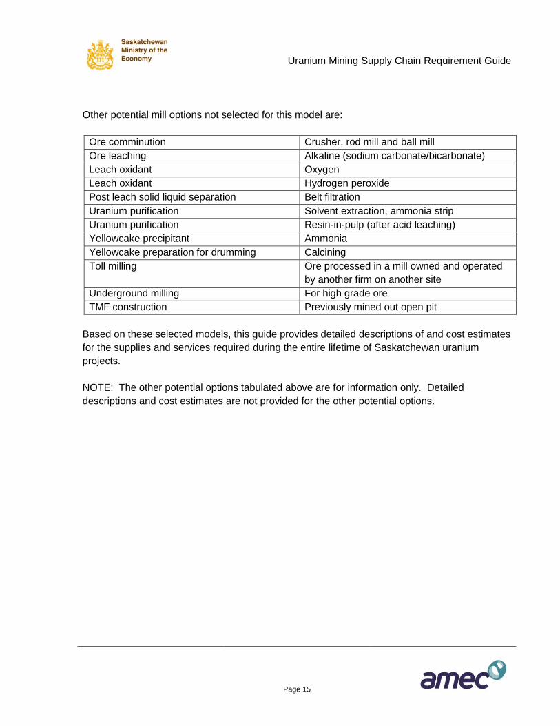
Other potential mill options not selected for this model are:
Ore comminution Crusher, rod mill and ball mill
Ore leaching Alkaline (sodium carbonate/bicarbonate)
Leach oxidant Oxygen
Leach oxidant Hydrogen peroxide
Post leach solid liquid separation Belt filtration
Uranium purification Solvent extraction, ammonia strip
Uranium purification Resin-in-pulp (after acid leaching)
Yellowcake precipitant Ammonia
Yellowcake preparation for drumming Calcining
Toll milling Ore processed in a mill owned and operated
by another firm on another site
Underground milling For high grade ore
TMF construction Previously mined out open pit
Based on these selected models, this guide provides detailed descriptions of and cost estimates
for the supplies and services required during the entire lifetime of Saskatchewan uranium
projects.
NOTE: The other potential options tabulated above are for information only. Detailed
descriptions and cost estimates are not provided for the other potential options.
Uranium Mining Supply Chain Requirement Guide
Page 16
5. URANIUM FACILITY LIFE CYCLE STAGES
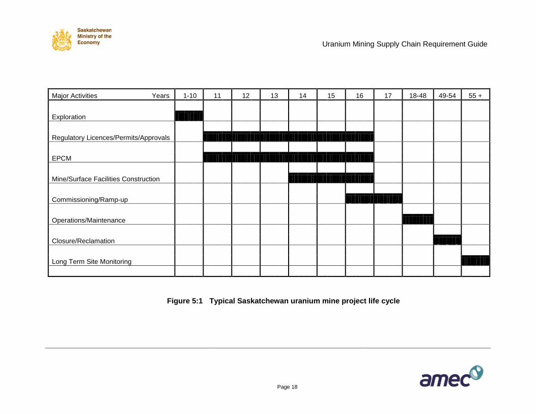
Figure 5:1 provides a high level look at a typical Saskatchewan uranium mining project life cycle
for a conventional mine and milling facility designed to produce 12 million pounds annually of
U3O8 in yellowcake form. The duration of a project may vary substantially, particularly at the
front end during the exploration and regulatory approval stages and at the conclusion of the
operations phase when the site must be decommissioned and monitored for long term
environmental compliance. During the anticipated 50 plus year life of a typical project, in excess
of $10 billion will be spent on goods and services to develop, construct, operate, maintain and
eventually decommission the facilities including the reclamation of all disturbed lands.
A brief description of the major lifecycle stages selected for this guide follows:
Exploration: This initial stage includes a variety of exploration techniques with the objective
of discovering a potentially economic uranium deposit. Typically, airborne geophysical
exploration methods are used to identify promising targets for follow up ground surveys and
diamond core drilling. Following identification of a potential mineral resource, the next
phase is to assess its size and scope in terms of tonnes and ore grade. Additional diamond
drilling is usually required to provide information for modeling the orebody.
Regulatory Licences/Permits/Approvals: This stage of the project encompasses studies,
reports and assessments to obtain the information necessary for the preparation of the
submissions required to obtain the various construction and operating approvals required
from provincial and federal regulatory authorities.
Engineering/Procurement/Construction Management (EPCM): While the environmental
assessment stage is in progress, engineering studies are undertaken to assess the
feasibility of the project. Normally, engineering progresses through a series of stage gates
to arrive at accurate capital and operating costs. Toward the middle of engineering,
procurement activities are initiated to obtain the equipment and services needed to construct
the necessary infrastructure for the project. Construction management services, typically
provided by the engineering company designing the facilities, are required for the duration of
the construction stage.
Mine/Surface Facilities Construction: Typically construction activities are initiated around
the middle of the EPCM stage. A construction period of about three years is anticipated for
a uranium mine/mill of this size.
Uranium Mining Supply Chain Requirement Guide
Page 17
Commissioning/Ramp-up: Commissioning of the new facilities is initiated towards the end
of construction, followed by a period in which capacity is ramped up to achieve production
targets in terms of ore tonnes, ore grade and U3O8 production.
Uranium Mining Supply Chain Requirement Guide
Page 18
Major Activities Years 1-10 11 12 13 14 15 16 17 18-48 49-54 55 +
Exploration
Regulatory Licences/Permits/Approvals
EPCM
Mine/Surface Facilities Construction
Commissioning/Ramp-up
Operations/Maintenance
Closure/Reclamation
Long Term Site Monitoring
Figure 5:1 Typical Saskatchewan uranium mine project life cycle
Uranium Mining Supply Chain Requirement Guide
Page 19
Operations/Maintenance: A lengthy period of regular operations and maintenance will
normally occur once the new facilities meet their production targets. The expected
operating life of a new uranium mining project depends on the size of the ore body and the
selected capacity of the production facilities. A twenty year design life is typical. However,
with good maintenance, lifetimes of forty years or more are achievable.
Closure/Reclamation: An approved closure and site reclamation plan must be implemented
once the original ore body has been exhausted and it has been determined that there is little
or no potential for the discovery of new uranium ore sources in the vicinity of the existing mill
site.
Long Term Site Monitoring: Once the site has been successfully reclaimed, a lengthy
period of environmental monitoring must occur before the property can be returned to the
Crown.
The lifecycle stages are developed in the following sections of this report in terms of the value of
goods and services that are necessary for the successful execution of the model project. In
addition, operating cost estimates are provided encompassing the goods and services currently
required for the total Saskatchewan uranium industry as it exists at the time this guide was
prepared.
Uranium Mining Supply Chain Requirement Guide
Page 20
6. EXPLORATION
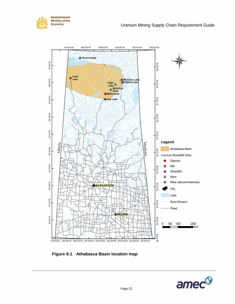
Most of the uranium deposits in Saskatchewan are associated with the Athabasca Basin, an
approximately 100,000 square kilometer sandstone basin that occupies much of the
northernmost one-quarter of the province (Figure 6:1). The style of uranium deposits is known
as unconformity-type deposits, where uranium is constrained to faults in the Archean basement
rocks near the contact with the overlying sandstone of the Athabasca Basin. At its deepest
parts, the Athabasca Basin can be as much as 1.5 kilometers from the surface. The uranium
deposits have some of the highest grades in the world, but are relatively small in size making
them difficult to find. These factors make uranium exploration in Saskatchewan a very
challenging endeavor. In addition, much of the Athabasca Basin remains remote wilderness
with limited road access.
Exploration projects make use of all geoscience disciplines, including geophysics,
geochemistry, surface and subsurface geological mapping and sampling. This work is
supported by various logistical and analytical services. A typical greenfields exploration project
will include the following stages:
Area selection
Target identification
Drill testing and resource evaluation
Details of the type of services involved in these exploration stages, and associated expenditure
estimates are provided in the following sections. The services and related cost estimates are
for the discovery and resource identification development of a uranium deposit that will support
a mine grade of 4% U3O8 with a production of 12 million pounds U3O8 per annum. The cost
estimates are for each stage. The duration of each stage varies according to the effort
expended (that is, the rate of diamond drilling.)
6.1 Area Selection
The first stage of exploration involves identifying the location of faults that are favourable for
containing deposits of uranium. These faults would ideally contain graphite, a naturally
occurring concentration of carbon that promotes the accumulation of uranium in the geological
environment. The faults tend to be located along the edges of rock bodies and the graphite is
electrically conductive. In addition, circulating geothermal water carrying uranium in solution
within the faults causes changes in the rocks that are important to detect.
Uranium Mining Supply Chain Requirement Guide
Page 21
Various geophysical techniques are applied in order to identify those areas that have conditions
favourable for uranium deposition and accumulation. Magnetic and various electro-magnetic
geophysical surveys are undertaken to identify potential graphitic faults and rock body contacts.
Gravity surveys are used to detect changes in rock properties and identify areas where rocks
have been changed by geothermal activity. Radiometric surveys are used to try and detect
concentrations of uranium directly. Many of these geophysical surveys are conducted by air
using fixed wing aircraft or helicopters to overcome the problem of limited road networks.
It is usually during the area selection stage that new mineral claims are staked or existing
mineral claims may be reduced or increased using the Government of Saskatchewan’s Mineral
Administration Registry System (MARS).
Uranium Mining Supply Chain Requirement Guide
Page 22
Figure 6:1 Athabasca Basin location map
Uranium Mining Supply Chain Requirement Guide
Page 23
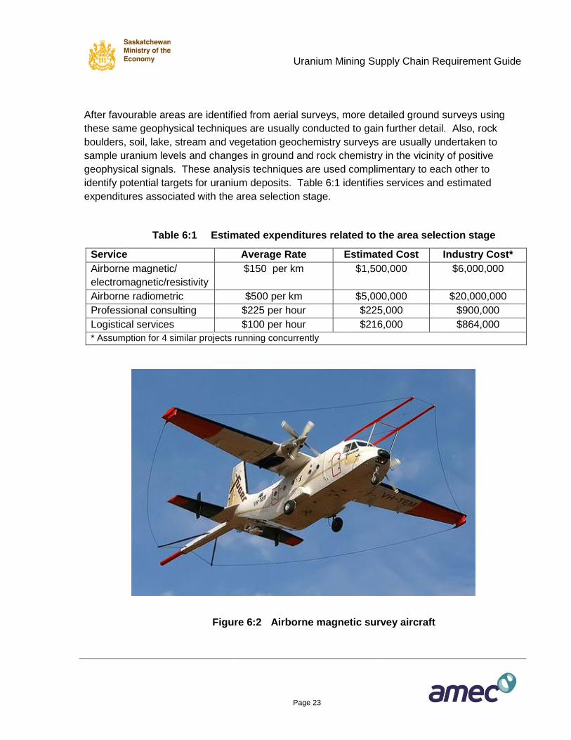
After favourable areas are identified from aerial surveys, more detailed ground surveys using
these same geophysical techniques are usually conducted to gain further detail. Also, rock
boulders, soil, lake, stream and vegetation geochemistry surveys are usually undertaken to
sample uranium levels and changes in ground and rock chemistry in the vicinity of positive
geophysical signals. These analysis techniques are used complimentary to each other to
identify potential targets for uranium deposits. Table 6:1 identifies services and estimated
expenditures associated with the area selection stage.
Table 6:1 Estimated expenditures related to the area selection stage
Service Average Rate Estimated Cost Industry Cost*
Airborne magnetic/
electromagnetic/resistivity
$150 per km $1,500,000 $6,000,000
Airborne radiometric $500 per km $5,000,000 $20,000,000
Professional consulting $225 per hour $225,000 $900,000
Logistical services $100 per hour $216,000 $864,000
* Assumption for 4 similar projects running concurrently
Figure 6:2 Airborne magnetic survey aircraft
Uranium Mining Supply Chain Requirement Guide
Page 24
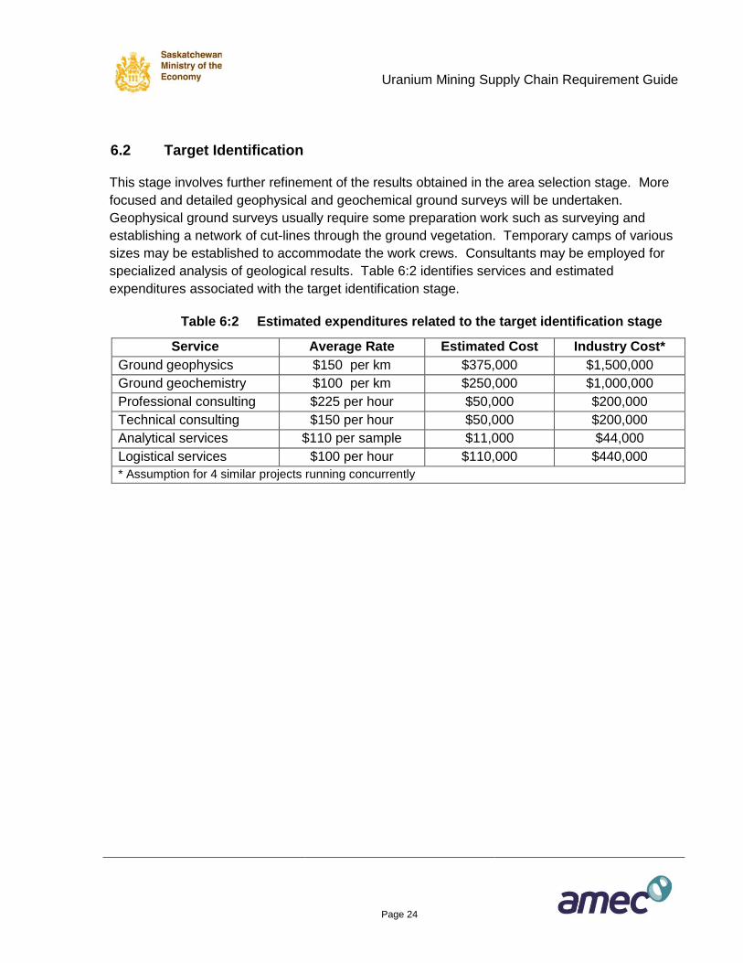
6.2 Target Identification
This stage involves further refinement of the results obtained in the area selection stage. More
focused and detailed geophysical and geochemical ground surveys will be undertaken.
Geophysical ground surveys usually require some preparation work such as surveying and
establishing a network of cut-lines through the ground vegetation. Temporary camps of various
sizes may be established to accommodate the work crews. Consultants may be employed for
specialized analysis of geological results. Table 6:2 identifies services and estimated
expenditures associated with the target identification stage.
Table 6:2 Estimated expenditures related to the target identification stage
Service Average Rate Estimated Cost Industry Cost*
Ground geophysics $150 per km $375,000 $1,500,000
Ground geochemistry $100 per km $250,000 $1,000,000
Professional consulting $225 per hour $50,000 $200,000
Technical consulting $150 per hour $50,000 $200,000
Analytical services $110 per sample $11,000 $44,000
Logistical services $100 per hour $110,000 $440,000
* Assumption for 4 similar projects running concurrently
Uranium Mining Supply Chain Requirement Guide
Page 25
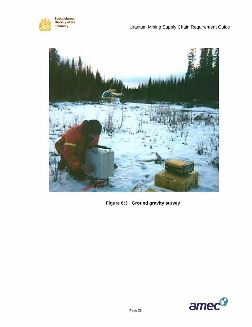
Figure 6:3 Ground gravity survey
Uranium Mining Supply Chain Requirement Guide
Page 26
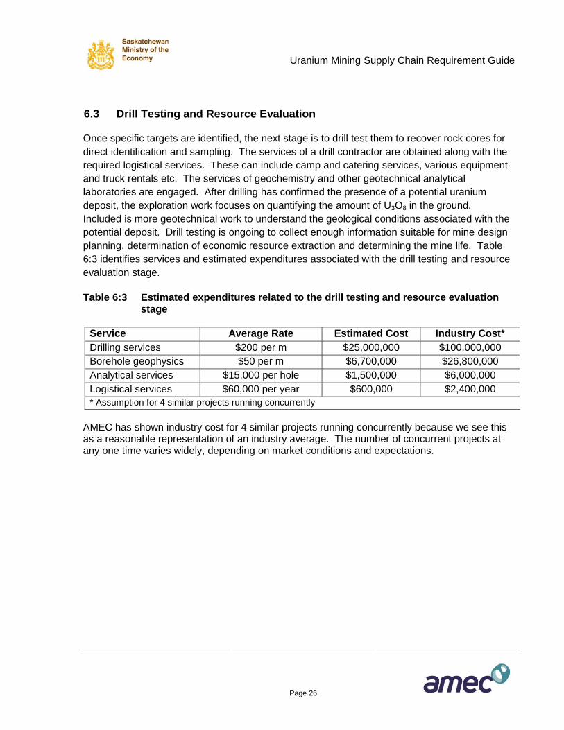
6.3 Drill Testing and Resource Evaluation
Once specific targets are identified, the next stage is to drill test them to recover rock cores for
direct identification and sampling. The services of a drill contractor are obtained along with the
required logistical services. These can include camp and catering services, various equipment
and truck rentals etc. The services of geochemistry and other geotechnical analytical
laboratories are engaged. After drilling has confirmed the presence of a potential uranium
deposit, the exploration work focuses on quantifying the amount of U3O8 in the ground.
Included is more geotechnical work to understand the geological conditions associated with the
potential deposit. Drill testing is ongoing to collect enough information suitable for mine design
planning, determination of economic resource extraction and determining the mine life. Table
6:3 identifies services and estimated expenditures associated with the drill testing and resource
evaluation stage.
Table 6:3 Estimated expenditures related to the drill testing and resource evaluation
stage
Service Average Rate Estimated Cost Industry Cost*
Drilling services $200 per m $25,000,000 $100,000,000
Borehole geophysics $50 per m $6,700,000 $26,800,000
Analytical services $15,000 per hole $1,500,000 $6,000,000
Logistical services $60,000 per year $600,000 $2,400,000
* Assumption for 4 similar projects running concurrently
AMEC has shown industry cost for 4 similar projects running concurrently because we see this as a reasonable representation of an industry average. The number of concurrent projects at any one time varies widely, depending on market conditions and expectations.
Uranium Mining Supply Chain Requirement Guide
Page 27
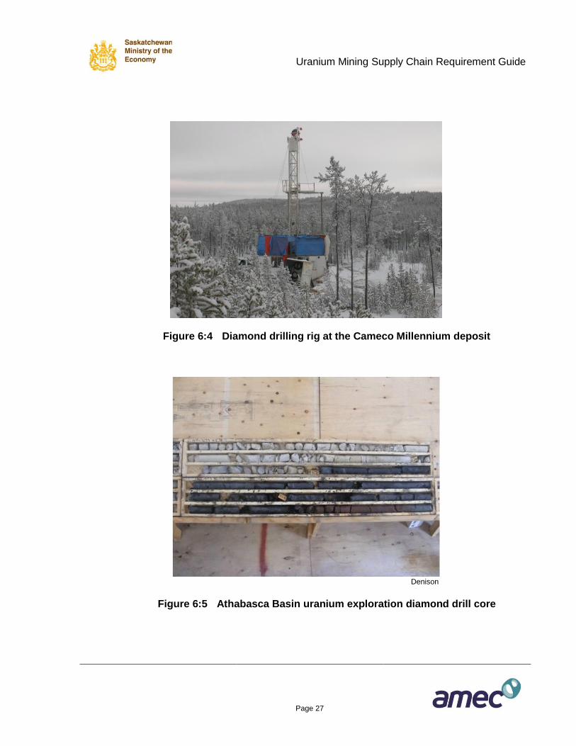
Figure 6:4 Diamond drilling rig at the Cameco Millennium deposit
Denison
Figure 6:5 Athabasca Basin uranium exploration diamond drill core
Uranium Mining Supply Chain Requirement Guide
Page 28
6.4 Exploration Service Provider Information
Further information on service providers to the Saskatchewan uranium exploration industry can
be found on InfoMine (http://www.infomine.com), and the Northern Miner Suppliers Buyers
Guide (http://www.northernminer.com/esource/).
Uranium Mining Supply Chain Requirement Guide
Page 29
7. REGULATORY LICENCES, PERMITS AND APPROVALS
7.1 Approval Processes
Uranium mine and mill facilities in Saskatchewan are regulated both federally and provincially
through comprehensive acts and associated regulations. All phases of uranium mine and mill
operations, from exploration through construction, operation, closure and abandonment require
specific approvals and, with the exception of early phase exploration activities, must also be
supported by comprehensive environmental assessments. Licences issues under federal
jurisdiction must be supported by environmental assessments completed to meet the
requirements of the Canadian Environment Assessment Act, whereas permits issued under
provincial jurisdiction must be supported by assessments that meet the requirements of the
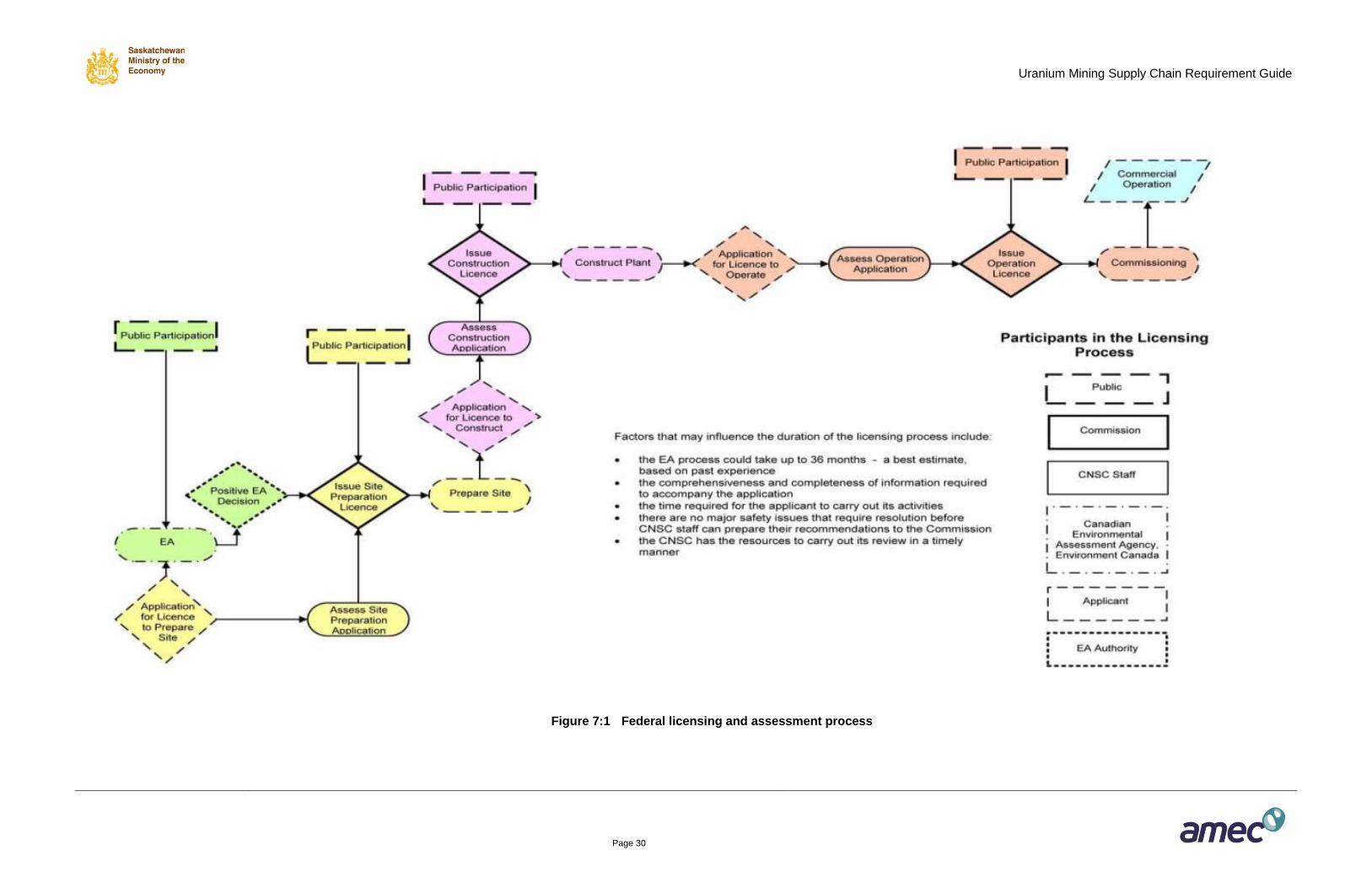
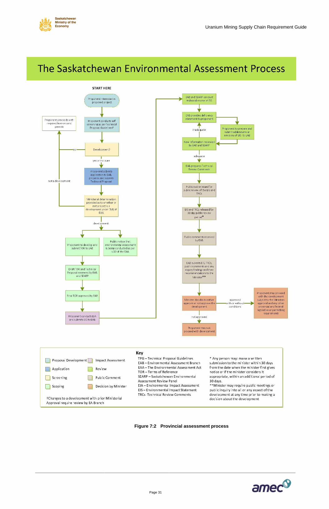
Saskatchewan Environmental Assessment Act. Figure 7:1 demonstrates the federal licensing
and assessment process. Figure 7:2 demonstrates the provincial environmental assessment
process, which in turn supports provincial permitting efforts.
The requirements of the federal and provincial assessment processes are coordinated under
the Canada-Saskatchewan Agreement on Environmental Assessment Cooperation in order to
reduce duplication of effort, while still meeting the specific requirements of both jurisdictions.
Uranium Mining Supply Chain Requirement Guide
Page 30
Figure 7:1 Federal licensing and assessment process
Uranium Mining Supply Chain Requirement Guide
Page 31
Figure 7:2 Provincial assessment process
Uranium Mining Supply Chain Requirement Guide
Page 32
7.2 Licences and Permits Required
7.2.1 Federal Regulation
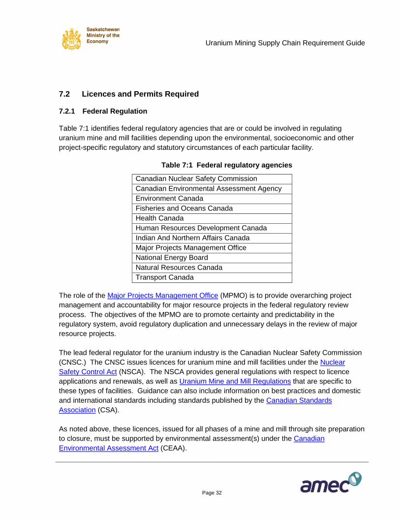
Table 7:1 identifies federal regulatory agencies that are or could be involved in regulating
uranium mine and mill facilities depending upon the environmental, socioeconomic and other
project-specific regulatory and statutory circumstances of each particular facility.
Table 7:1 Federal regulatory agencies
Canadian Nuclear Safety Commission
Canadian Environmental Assessment Agency
Environment Canada
Fisheries and Oceans Canada
Health Canada
Human Resources Development Canada
Indian And Northern Affairs Canada
Major Projects Management Office
National Energy Board
Natural Resources Canada
Transport Canada
The role of the Major Projects Management Office (MPMO) is to provide overarching project
management and accountability for major resource projects in the federal regulatory review
process. The objectives of the MPMO are to promote certainty and predictability in the
regulatory system, avoid regulatory duplication and unnecessary delays in the review of major
resource projects.
The lead federal regulator for the uranium industry is the Canadian Nuclear Safety Commission
(CNSC.) The CNSC issues licences for uranium mine and mill facilities under the Nuclear
Safety Control Act (NSCA). The NSCA provides general regulations with respect to licence
applications and renewals, as well as Uranium Mine and Mill Regulations that are specific to
these types of facilities. Guidance can also include information on best practices and domestic
and international standards including standards published by the Canadian Standards
Association (CSA).
As noted above, these licences, issued for all phases of a mine and mill through site preparation
to closure, must be supported by environmental assessment(s) under the Canadian
Environmental Assessment Act (CEAA).
Uranium Mining Supply Chain Requirement Guide
Page 33
7.2.2 Provincial Regulation
The Saskatchewan uranium industry is regulated at the provincial level by the Saskatchewan
Ministry of the Environment under a number of acts, including the Environmental Management
and Protection Act, the Clean Air Act, the Fisheries Act and through the issuance of surface
leases and construction and operating permits, all with the primary intent of protecting the
environment through the assessment and regulation of pollutant control facilities.
Saskatchewan's Environmental Assessment Act (SEAA) is administered directly by the
Saskatchewan Environmental Assessment Branch. Saskatchewan is in the process of adopting
a new, results-based model for environmental regulation that is intended to improve protection
of the environment, while promoting innovative new tools in environmental management,
including the Saskatchewan Environmental Code.
7.3 Types and Values of Services
The primary licensing/permitting phases of a uranium facility are:
1. Mine and Surface Facilities Construction (Section 9 of this guide).
2. Commissioning and Ramp-Up (Section 10 of this guide), followed by Operations and
Maintenance (Section 11 of this guide).
3. Closure and Reclamation (Section 12 of this guide), followed by Long Term Site
Monitoring (Section 13 of this guide).
Each of these phases must be supported by a formal environmental assessment.
Uranium Mining Supply Chain Requirement Guide
Page 34
7.3.1 Mine and Surface Facilities Construction
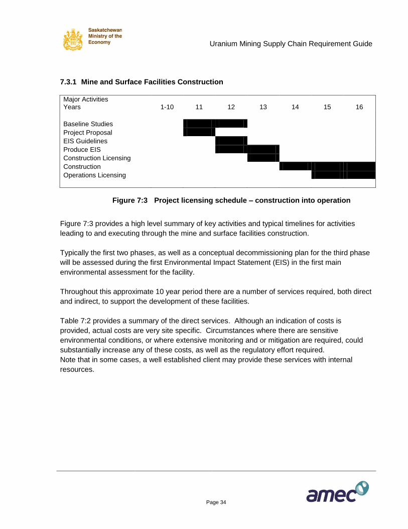
Major Activities Years 1-10 11 12 13 14 15 16
Baseline Studies
Project Proposal
EIS Guidelines
Produce EIS
Construction Licensing
Construction
Operations Licensing
Figure 7:3 Project licensing schedule – construction into operation
Figure 7:3 provides a high level summary of key activities and typical timelines for activities
leading to and executing through the mine and surface facilities construction.
Typically the first two phases, as well as a conceptual decommissioning plan for the third phase
will be assessed during the first Environmental Impact Statement (EIS) in the first main
environmental assessment for the facility.
Throughout this approximate 10 year period there are a number of services required, both direct
and indirect, to support the development of these facilities.
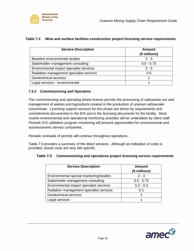
Table 7:2 provides a summary of the direct services. Although an indication of costs is
provided, actual costs are very site specific. Circumstances where there are sensitive
environmental conditions, or where extensive monitoring and or mitigation are required, could
substantially increase any of these costs, as well as the regulatory effort required.
Note that in some cases, a well established client may provide these services with internal
resources.
Uranium Mining Supply Chain Requirement Guide
Page 35
Table 7:2 Mine and surface facilities construction project licensing service requirements
Service Description Amount
($ millions)
Baseline environmental studies 2 - 3
Stakeholder management consulting 0.5 - 0.75
Environmental impact specialist services 3 - 5
Radiation management specialist services 0.5
Geotechnical services 1
Legal services - environmental 1
7.3.2 Commissioning and Operation
The commissioning and operating phase license permits the processing of radioactive ore and
management of wastes and byproducts created in the production of uranium yellowcake
concentrate. Licensing support services for this phase are driven by requirements and
commitments documented in the EIS and in the licensing documents for the facility. Most
routine environmental and operational monitoring activities will be undertaken by client staff.
Periodic EIS validation program monitoring will present opportunities for environmental and
socioeconomic service companies.
Periodic renewals of permits will continue throughout operations. Table 7:3 provides a summary of the direct services. Although an indication of costs is provided, actual costs are very site specific.
Table 7:3 Commissioning and operations project licensing service requirements
Service Description Amount
($ millions)
Environmental special monitoring/studies 2 - 3
Stakeholder management consulting 0.5 - 0.75
Environmental impact specialist services 0.2 - 0.3
Radiation management specialist services 0.1
Geotechnical services 1
Legal services 1
Uranium Mining Supply Chain Requirement Guide
Page 36
8. ENGINEERING, PROCUREMENT, and CONSTRUCTION
MANAGEMENT (EPCM)
EPCM costs typically make up 15 to 20 percent of a project’s total capital cost. For a given
project, EPCM may be carried out by a single general engineering firm or alternatively the
activities may be divided between several specialist firms and possibly the owner. The early
engineering stages are normally carried out in conjunction with the environmental studies.
8.1 Engineering
Engineering and cost estimating for a capital intensive, long lead time project such as a new
green field uranium mine and/or mill will typically progress in stages. Risk adverse mining
companies will proceed through most or all of these stages to ensure the economic viability and
technical success of their major projects. AMEC uses the following stage gate process adapted
from the Association for the Advancement of Cost Engineers (AACE) as summarized below and
in Table 8.1.
Class 5: Assess the preliminary technical and economic viability of the project. The typical
duration for an Order of Magnitude study on a large project will be 3 to 6 months.
Class 4: Determine project configuration through major trade-off studies and develop cost
estimates to justify additional project development. Typically, an ore-feasibility study will
require 6 to 12 months to complete.
Class 3: Optimize project configuration, develop engineering to support a cost estimate used
as the basis for the project production decision and budgeting. A full feasibility study will
usually take 1 to 2 years to complete.
Class 2: Advance engineering to support the purchase of equipment and construction
planning. The basic engineering phase will normally require 1 to 2 years.
Class 1: Advance engineering towards completion. Detailed engineering follows on from the
basic engineering phase and typically will last for an additional 2 to 3 years.
Uranium Mining Supply Chain Requirement Guide
Page 37
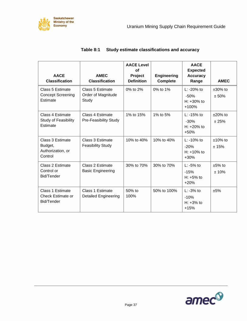
Table 8:1 Study estimate classifications and accuracy
AACE
Classification
AMEC
Classification
AACE Level
of
Project
Definition
Engineering
Complete
AACE
Expected
Accuracy
Range AMEC
Class 5 Estimate
Concept Screening
Estimate
Class 5 Estimate
Order of Magnitude
Study
0% to 2% 0% to 1% L: -20% to
-50%
H: +30% to
+100%
±30% to
± 50%
Class 4 Estimate
Study of Feasibility
Estimate
Class 4 Estimate
Pre-Feasibility Study
1% to 15% 1% to 5% L: -15% to
-30%
H: +20% to
+50%
±20% to
± 25%
Class 3 Estimate
Budget,
Authorization, or
Control
Class 3 Estimate
Feasibility Study
10% to 40% 10% to 40% L: -10% to
-20%
H: +10% to
+30%
±10% to
± 15%
Class 2 Estimate
Control or
Bid/Tender
Class 2 Estimate
Basic Engineering
30% to 70% 30% to 70% L: -5% to
-15%
H: +5% to
+20%
±5% to
± 10%
Class 1 Estimate
Check Estimate or
Bid/Tender
Class 1 Estimate
Detailed Engineering
50% to
100%
50% to 100% L: -3% to
-10%
H: +3% to
+15%
±5%
Uranium Mining Supply Chain Requirement Guide
Page 38
8.2 Procurement
Procurement (supply chain management) encompasses the purchase of all the goods and
services required to complete the construction of a new uranium mining and/or milling facility.
This is split between; procurement of equipment/materials and contracts administration -
construction contracts and services. Typically included under supply chain management is the
preparation of:
Specifications
Work packages
Modularization requirements
Bidders lists
Requests for quotations and proposals
Contracting strategies
Vendor and contractor meetings
Bid analysis and recommendations
Purchase orders/contract negotiations
Purchase orders/conformed contracts
Expediting services
Supplier quality surveillance
Shipping and logistics
Materials management/warehousing
Up-to-date lists of goods and services suppliers to the mining industry are available online and
in print. The Infomine website (www.infomine.com), the Canadian Institute of Mining, Metallurgy
and Petroleum (CIM) website (www.cim.org), the Canadian Association of Mining Equipment
and Services for Export (CAMESE) website (www.camese.org), and the Saskatchewan
Industrial and Mining Suppliers Association (SIMSA) website (www.simsa.ca) are reliable
sources of this type of information. Most engineering consultancy/project management firms
also maintain their own list of suppliers based on recent project experience.
Uranium Mining Supply Chain Requirement Guide
Page 39
8.3 Construction Management
Managing the construction of a major uranium project requires a team of professionals located
at the project site to undertake the following activities:
Work site health and safety
Environmental protection related to construction activities
Planning and scheduling
Cost control and earned value analysis
Contractor management
Materials management
Quality assurance
Commissioning (assistance to owners teams)
8.4 Estimated EPCM Costs
The estimated EPCM costs for a project to develop this report’s model mines, including all
underground and surface facilities are:
Table 8:2 Estimated EPCM costs
Engineering Open Pit Underground
Class 5 $300,000 $300,000
Class 4 $700,000 $700,000
Class 3 $5,000,000 $7,000,000
Class 2 $23,000,000 $30,000,000
Class 1 $52,000,000 $70,000,000
Total engineering $81,000,000 $108,000,000
Procurement $62,000,000 $83,000,000
Construction management $127,000,000 $169,000,000
Total EPCM $270,000,000 $360,000,000
Uranium Mining Supply Chain Requirement Guide
Page 40
9. MINE AND SURFACE FACILITIES CONSTRUCTION
9.1 Underground Mine
9.1.1 General Description of the Underground Mine Model
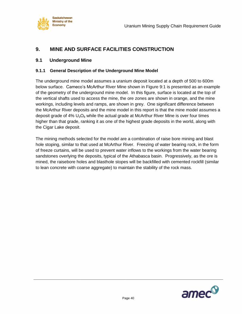
The underground mine model assumes a uranium deposit located at a depth of 500 to 600m
below surface. Cameco’s McArthur River Mine shown in Figure 9:1 is presented as an example
of the geometry of the underground mine model. In this figure, surface is located at the top of
the vertical shafts used to access the mine, the ore zones are shown in orange, and the mine
workings, including levels and ramps, are shown in grey. One significant difference between
the McArthur River deposits and the mine model in this report is that the mine model assumes a
deposit grade of 4% U3O8 while the actual grade at McArthur River Mine is over four times
higher than that grade, ranking it as one of the highest grade deposits in the world, along with
the Cigar Lake deposit.
The mining methods selected for the model are a combination of raise bore mining and blast
hole stoping, similar to that used at McArthur River. Freezing of water bearing rock, in the form
of freeze curtains, will be used to prevent water inflows to the workings from the water bearing
sandstones overlying the deposits, typical of the Athabasca basin. Progressively, as the ore is
mined, the raisebore holes and blasthole stopes will be backfilled with cemented rockfill (similar
to lean concrete with coarse aggregate) to maintain the stability of the rock mass.
Uranium Mining Supply Chain Requirement Guide
Page 41
Cameco
Figure 9:1 3-D View of McArthur River mine showing mineralized zones and
mine development
9.1.2 Shafts and Hoisting
Two shafts will provide access to the underground mine; the main shaft for men and materials
access, ore and waste removal, and fresh air ventilation supply and the service shaft for return
ventilation and emergency egress. Both ore and waste will be hoisted to surface in skips
through the main shaft. Each of the two shafts will be circular in cross section, concrete lined
over their full depth with a finished inside diameter of 7.5m, and developed to a depth of 650m.
Uranium Mining Supply Chain Requirement Guide
Page 42
The permanent headframe at the main shaft will be constructed ahead of sinking and used for
shaft sinking, while a temporary sinking headframe will be used for the service shaft, with that
permanent headframe constructed after sinking. The shafts will be excavated by drill and blast
methods.
The working platform for shaft sinking operations will be a custom built steel Galloway platform
supported by multiple cables, and controlled by individual temporary winches installed near the
shaft collar on surface. The Galloway will be equipped with electric hydraulic drills mounted on
drill booms, excavator boom and bucket, submersible pumps, rock grouting pumps and
accessories, and staging from which to install shaft concrete lining forms and shaft furnishings.
The shaft liner will consist of a 300mm thick monolithic concrete liner with a 7.5m finished inside
diameter.
Shaft furnishings will consist of tubular steel (HSS) sets and guides in combination with wide
flange (WF) steel sections. Shaft services will be mounted on the shaft walls using conventional
rolled channel brackets and inserts to secure all shaft steel and brackets to the shaft walls.
Supplies to support the excavation of the shaft will include explosives and detonators, rockbolts
(typically 2.4m long continuous thread rebar), resin rockbolt grout, 100mm x 100mm weld wire
mesh, grouting materials, drill steel and bits, concrete for shaft lining, plus miscellaneous items.
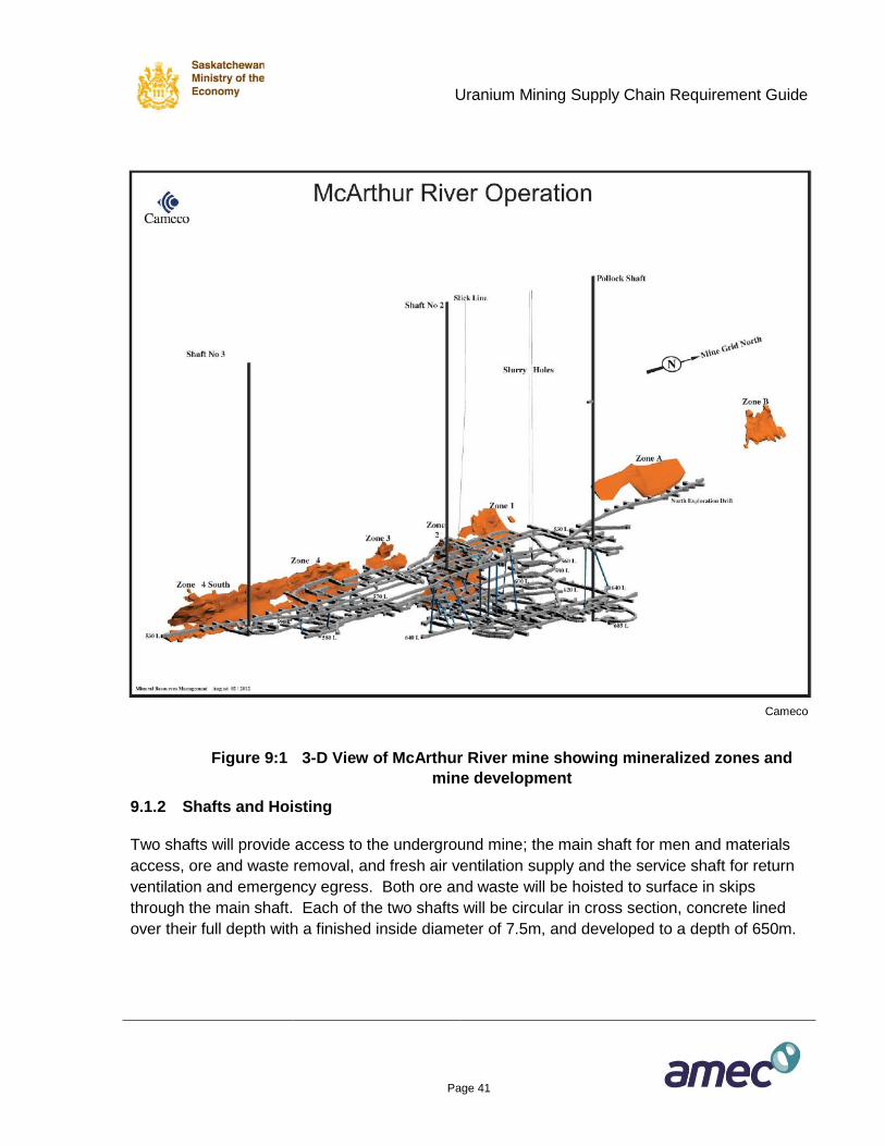
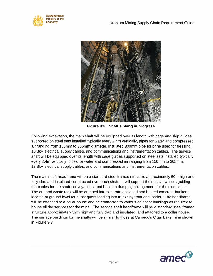
During sinking operations fresh air will be delivered to the working face through rigid ventilation
ducting of between 1.0m and 1.5m in diameter supplied by a temporary axivane fan of
approximately 75kW to 115kW located near the collar on surface. During the winter months the
ventilation air will be heated to +4°C by a temporary propane fired mine air heater. During the
sinking phase, a sinking bucket will be used to transport the blasted waste rock from the shaft
and provide access for men and materials to the working areas. Figure 9:2 shows a typical
picture of shaft sinking in progress.
Uranium Mining Supply Chain Requirement Guide
Page 43
Figure 9:2 Shaft sinking in progress
Following excavation, the main shaft will be equipped over its length with cage and skip guides
supported on steel sets installed typically every 2.4m vertically, pipes for water and compressed
air ranging from 150mm to 305mm diameter, insulated 300mm pipe for brine used for freezing,
13.8kV electrical supply cables, and communications and instrumentation cables. The service
shaft will be equipped over its length with cage guides supported on steel sets installed typically
every 2.4m vertically, pipes for water and compressed air ranging from 150mm to 305mm,
13.8kV electrical supply cables, and communications and instrumentation cables.
The main shaft headframe will be a standard steel framed structure approximately 50m high and
fully clad and insulated constructed over each shaft. It will support the sheave wheels guiding
the cables for the shaft conveyances, and house a dumping arrangement for the rock skips.
The ore and waste rock will be dumped into separate enclosed and heated concrete bunkers
located at ground level for subsequent loading into trucks by front end loader. The headframe
will be attached to a collar house and be connected to various adjacent buildings as required to
house all the services for the mine. The service shaft headframe will be a standard steel framed
structure approximately 32m high and fully clad and insulated, and attached to a collar house.
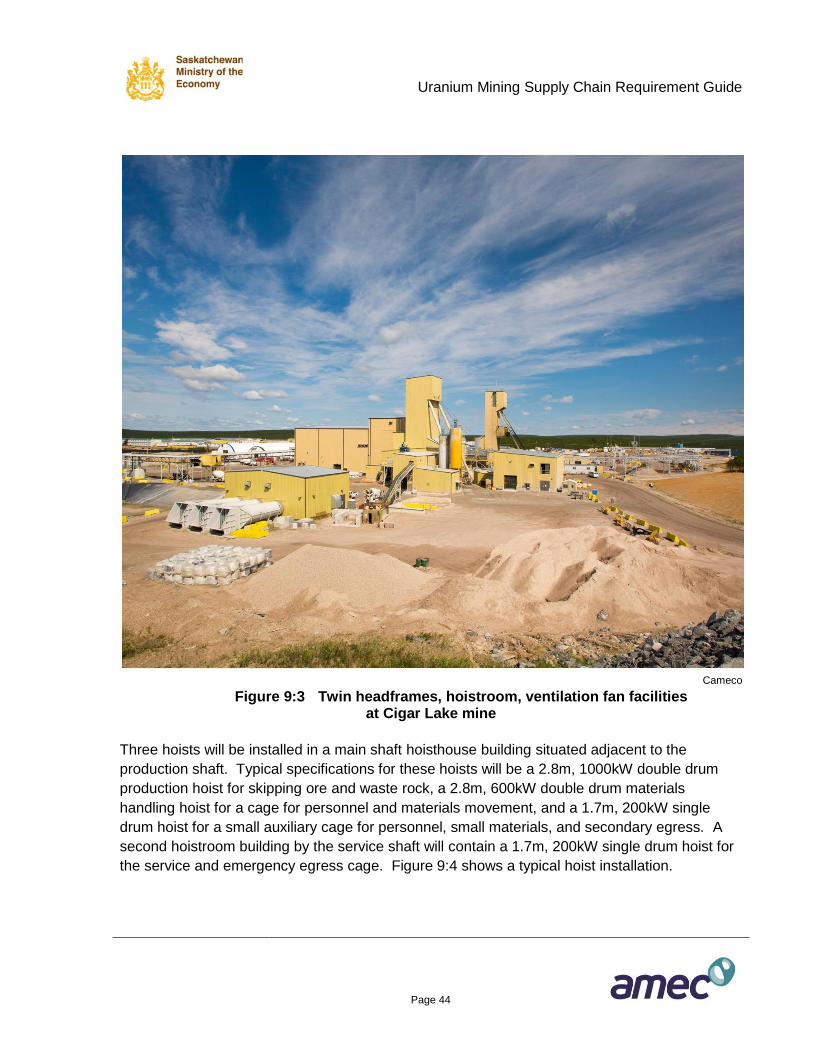
The surface buildings for the shafts will be similar to those at Cameco’s Cigar Lake mine shown
in Figure 9:3.
Uranium Mining Supply Chain Requirement Guide
Page 44
Cameco
Figure 9:3 Twin headframes, hoistroom, ventilation fan facilities at Cigar Lake mine
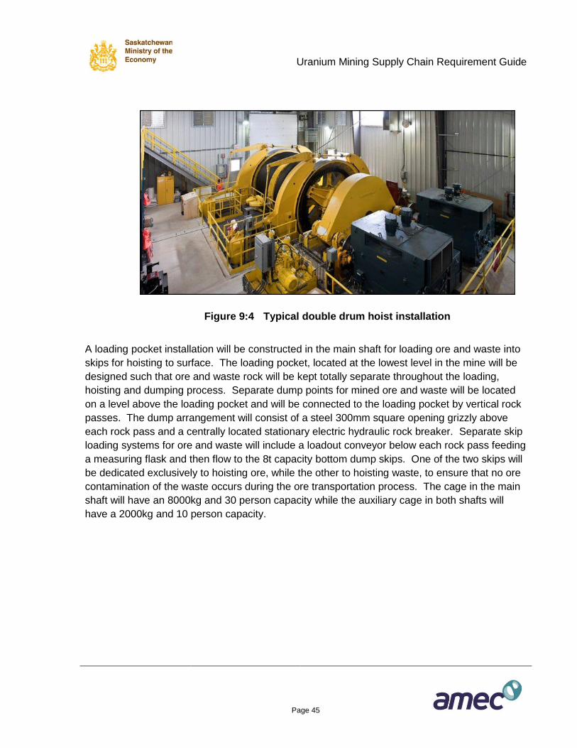
Three hoists will be installed in a main shaft hoisthouse building situated adjacent to the
production shaft. Typical specifications for these hoists will be a 2.8m, 1000kW double drum
production hoist for skipping ore and waste rock, a 2.8m, 600kW double drum materials
handling hoist for a cage for personnel and materials movement, and a 1.7m, 200kW single
drum hoist for a small auxiliary cage for personnel, small materials, and secondary egress. A
second hoistroom building by the service shaft will contain a 1.7m, 200kW single drum hoist for
the service and emergency egress cage. Figure 9:4 shows a typical hoist installation.
Uranium Mining Supply Chain Requirement Guide
Page 45
Figure 9:4 Typical double drum hoist installation
A loading pocket installation will be constructed in the main shaft for loading ore and waste into
skips for hoisting to surface. The loading pocket, located at the lowest level in the mine will be
designed such that ore and waste rock will be kept totally separate throughout the loading,
hoisting and dumping process. Separate dump points for mined ore and waste will be located
on a level above the loading pocket and will be connected to the loading pocket by vertical rock
passes. The dump arrangement will consist of a steel 300mm square opening grizzly above
each rock pass and a centrally located stationary electric hydraulic rock breaker. Separate skip
loading systems for ore and waste will include a loadout conveyor below each rock pass feeding
a measuring flask and then flow to the 8t capacity bottom dump skips. One of the two skips will
be dedicated exclusively to hoisting ore, while the other to hoisting waste, to ensure that no ore
contamination of the waste occurs during the ore transportation process. The cage in the main
shaft will have an 8000kg and 30 person capacity while the auxiliary cage in both shafts will
have a 2000kg and 10 person capacity.
Uranium Mining Supply Chain Requirement Guide
Page 46
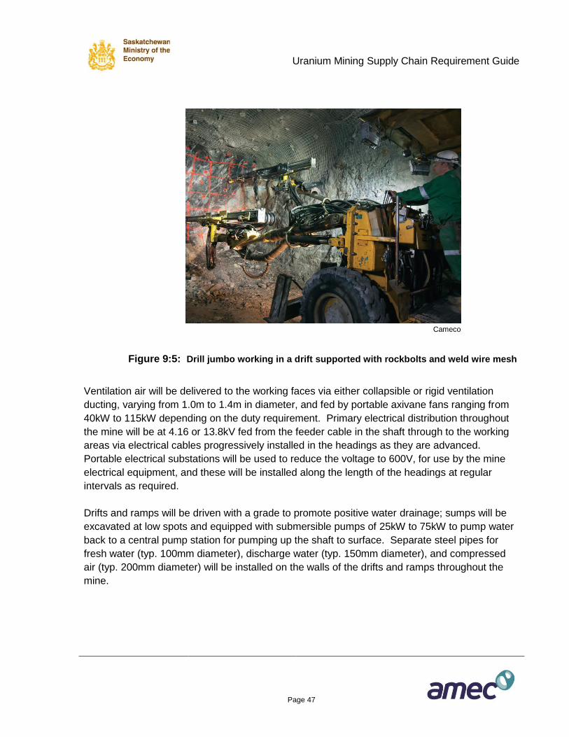
9.1.3 Development of Drifts and Ramps
From the shafts, horizontal tunnels (drifts) and inclined tunnels (ramps) will be excavated by drill
and blast methods to provide access to the deposits and for required infrastructure. Typical
drifts and ramps will be 5m high by 5m wide although the actual size will vary throughout the
mine to suit specific requirements. To excavate these headings, horizontal blast holes,
approximately 4m long (a round), will be drilled by two electric hydraulic drills mounted on a twin
boom drill jumbo vehicle (see Figure 9:5), loaded with explosives with the use of a speciality
explosive loading truck, then blasted. The blasted rock will be loaded by load-haul-dump (LHD)
units and hauled to the grizzly/rockbreaker dump point leading to the shaft loading pocket. If the
haul distances for the LHDs are long, over 300m in length, then the blasted rock will be loaded
by the LHDs into 30t capacity low profile haulage trucks for transport to the rock dump.
Following clearing of the broken rock from the face, the freshly blasted rock will be supported
with the use of a speciality ground support truck capable of drilling holes with an electric
hydraulic drill and then placing 1.8m to 2.4m long rockbolts on a set pattern (typical 1.2m x
1.2m). There are several types of rockbolts that may be used depending on the rock support
specifications including threaded rebar with resin grout, swellex and split sets. Cable bolts will
be used when 3.0m or longer rockbolts are required. As part of the rockbolting procedure
100mm x 100mm weld wire mesh will be installed on the roof and walls and along the full length
of the headings and held in place by the rockbolts. If further support is required, then fibre
reinforced shotcrete will be sprayed on the roof and walls and over the rockbolts and mesh, to a
thickness of 50mm to 150mm depending on the rock support specifications. For the model
mine shotcrete will be applied along 50% of the length of all headings. The shotcrete will be
placed with a speciality shotcrete jumbo with the shotcrete nozzle located on the end of a
hydraulic boom. Shotcrete can be supplied to the jumbo as either wet or dry mix, but for the
model mine it has been assumed that all shotcrete will be wet mix prepared on site at the
concrete batch plant and delivered underground via a concrete slick line in the shaft.
Transmixer trucks of 5m3 to 8m3 capacity will transport the shotcrete mix from a receiving
station at the base of the slick line to the work place.
Uranium Mining Supply Chain Requirement Guide
Page 47
Cameco
Figure 9:5: Drill jumbo working in a drift supported with rockbolts and weld wire mesh
Ventilation air will be delivered to the working faces via either collapsible or rigid ventilation
ducting, varying from 1.0m to 1.4m in diameter, and fed by portable axivane fans ranging from
40kW to 115kW depending on the duty requirement. Primary electrical distribution throughout
the mine will be at 4.16 or 13.8kV fed from the feeder cable in the shaft through to the working
areas via electrical cables progressively installed in the headings as they are advanced.
Portable electrical substations will be used to reduce the voltage to 600V, for use by the mine
electrical equipment, and these will be installed along the length of the headings at regular
intervals as required.
Drifts and ramps will be driven with a grade to promote positive water drainage; sumps will be
excavated at low spots and equipped with submersible pumps of 25kW to 75kW to pump water
back to a central pump station for pumping up the shaft to surface. Separate steel pipes for
fresh water (typ. 100mm diameter), discharge water (typ. 150mm diameter), and compressed
air (typ. 200mm diameter) will be installed on the walls of the drifts and ramps throughout the
mine.
Uranium Mining Supply Chain Requirement Guide
Page 48
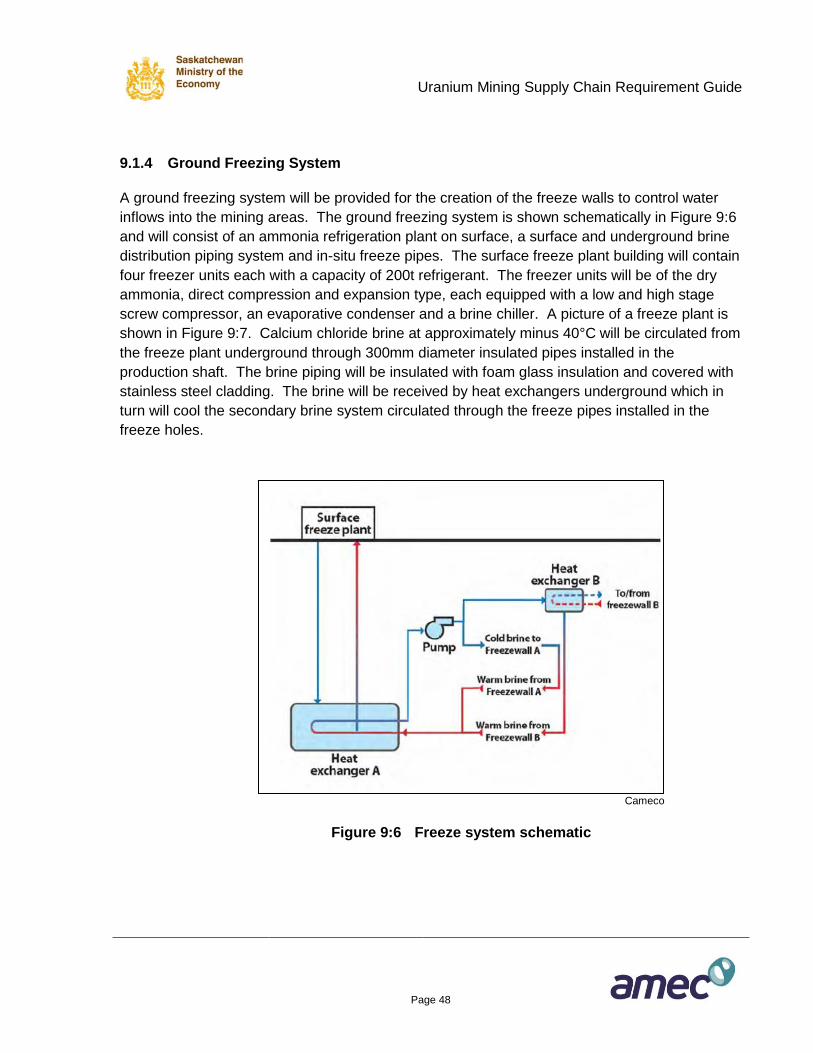
9.1.4 Ground Freezing System
A ground freezing system will be provided for the creation of the freeze walls to control water
inflows into the mining areas. The ground freezing system is shown schematically in Figure 9:6
and will consist of an ammonia refrigeration plant on surface, a surface and underground brine
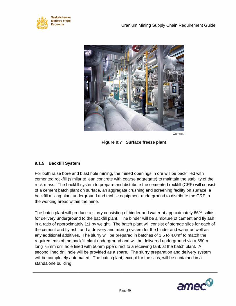
distribution piping system and in-situ freeze pipes. The surface freeze plant building will contain
four freezer units each with a capacity of 200t refrigerant. The freezer units will be of the dry
ammonia, direct compression and expansion type, each equipped with a low and high stage
screw compressor, an evaporative condenser and a brine chiller. A picture of a freeze plant is
shown in Figure 9:7. Calcium chloride brine at approximately minus 40°C will be circulated from
the freeze plant underground through 300mm diameter insulated pipes installed in the
production shaft. The brine piping will be insulated with foam glass insulation and covered with
stainless steel cladding. The brine will be received by heat exchangers underground which in
turn will cool the secondary brine system circulated through the freeze pipes installed in the
freeze holes.
Cameco
Figure 9:6 Freeze system schematic
Uranium Mining Supply Chain Requirement Guide
Page 49
Cameco
Figure 9:7 Surface freeze plant
9.1.5 Backfill System
For both raise bore and blast hole mining, the mined openings in ore will be backfilled with
cemented rockfill (similar to lean concrete with coarse aggregate) to maintain the stability of the
rock mass. The backfill system to prepare and distribute the cemented rockfill (CRF) will consist
of a cement batch plant on surface, an aggregate crushing and screening facility on surface, a
backfill mixing plant underground and mobile equipment underground to distribute the CRF to
the working areas within the mine.
The batch plant will produce a slurry consisting of binder and water at approximately 66% solids
for delivery underground to the backfill plant. The binder will be a mixture of cement and fly ash
in a ratio of approximately 1:1 by weight. The batch plant will consist of storage silos for each of
the cement and fly ash, and a delivery and mixing system for the binder and water as well as
any additional additives. The slurry will be prepared in batches of 3.5 to 4.0m3 to match the
requirements of the backfill plant underground and will be delivered underground via a 550m
long 75mm drill hole lined with 50mm pipe direct to a receiving tank at the batch plant. A
second lined drill hole will be provided as a spare. The slurry preparation and delivery system
will be completely automated. The batch plant, except for the silos, will be contained in a
standalone building.
Uranium Mining Supply Chain Requirement Guide
Page 50
A portable type crushing and screening plant will provide minus 45mm aggregate for the CRF.
Supply of material for the plant will be from a gravel borrow pit or quarry as available and the
crushed and screened aggregate will be stored in a covered stockpile near the delivery point to
the mine. A heated concrete pad will be provided inside the stockpile building for heating the
aggregate during the winter months. The aggregate will be delivered from surface through a
550m long 250mm diameter drill hole direct to a aggregate storage silo adjacent to the
underground backfill plant. The drill hole will be fitted with a 180mm inside diameter replaceable
abrasion resistant steel liner pipe. A second lined drill hole will be provided as a spare. The
aggregate will be loaded into the hole via a front end loader dumping into a hopper and
conveyor to the drill hole.
The underground backfill plant will be located in an underground excavation and will operate as
a batch system which feeds and measures the aggregate and cement slurry into a mixer in the
specified proportions, then feeds the CRF directly into 30t trucks for haulage to the stopes.
Capacity of the plant will be 250m3 of CRF per day. Aggregate will be fed from the underground
storage silo by a rock feeder and onto a conveyor and over a belt scale to the mixer. Cement
slurry will be pumped by a slurry pump, from the slurry receiving tank, to the mixer with the
volume controlled by a magnetic flow meter. The complete backfill system will be automated.
9.1.6 Mining Equipment
The mobile equipment fleet consists of vehicles directly required for development and
production and those used more in a support and maintenance role. The development and
production equipment has already been discussed in the preceding sections and consists of the
following: 4.6m3 and 6.9m3 capacity LHDs, two boom electric-hydraulic drill jumbos, 30t capacity
trucks, electric ITH freeze hole drill rig, electric ITH blasthole drill rig, rockbolt jumbo, raise borer
machine, shotcrete sprayer, shotcrete transmixer, emulsion explosive loading vehicle, and
diamond drill rig.
The support and maintenance fleet will consist of the following equipment:
Scissor lift truck for installation of services and occasional rockbolting.
Boom truck for moving heavier supplies and maintenance.
Grader for maintenance of the roadways.
Fuel/lube truck for fuelling and servicing of certain vehicles such as jumbos.
Specialized service trucks for mechanical and electrical maintenance.
Pick-up trucks (or equivalent) modified for underground use as personnel vehicles,
supervisors vehicles, and materials delivery.
Uranium Mining Supply Chain Requirement Guide
Page 51
Fork lift for materials handling underground around the shaft, warehouse and maintenance shops.
Backhoe (mini style) for maintenance of ditches on drifts and ramps. Surface mobile equipment to support the underground mine will include:
Front end loader (8t capacity) for loading ore and waste at the shaft into trucks and general
use.
Haul trucks (25t capacity) for haulage of ore and waste from the shaft and general
requirements.
Grader for road maintenance and snow clearing.
Fork lift for materials handling on surface around the shaft, warehouse and maintenance
shops.
Mobile crane (20t capacity) for general site duties.
Pick-up trucks for personnel and small supplies.
The mobile mining fleet for the underground mine will include both production and support
equipment and is listed in the capital cost breakdown in Table 9:04.
9.1.7 Infrastructure Facilities
In addition to the freeze and backfill systems described in Sections 9.1.4 and 9.1.5, there are
various infrastructure facilities required to support the mine. These include mine ventilation and
heating, mine dewatering, electrical distribution, compressed air, maintenance, refuge stations,
fuel distribution, and communications and instrumentation.
Mine Ventilation and Heating
The permanent mine ventilation system on surface will consist of main intake fans and mine air
heater at the main shaft and main exhaust fans at the service shaft. Underground there will be
one major booster fan plus secondary fans blowing air to working places as required through
ventilation ducting.
At the main shaft, three horizontally mounted axial vane intake fans, equipped with 260kW
variable frequency drives, and each handling 160m3/sec of air and fitted with intake bells will
blow fresh air through 30MW direct fired propane mine air heaters enclosed in a building, and
then fed into the shaft through a sub-surface airway.
Uranium Mining Supply Chain Requirement Guide
Page 52
The mine air heaters will be used only during the winter to raise the air temperature above 4°C
to prevent freezing. In the centre left of Figure 9:3, a row of three intake fans feeding into a
mine air heating building can be observed and are typical of this type of fan and heater
installation. At the service shaft, three horizontally mounted 560kW axial vane exhaust fans
each handling 160m3/sec and equipped with evases will draw the return air through a sub-
surface airway from the shaft.
Underground a horizontally mounted 110kW axial vane fan handling 75m3/sec will be used as a
booster fan. The use of secondary fans for local ventilation is described in Section 9.1.3 and
consists of portable axial vane fans ranging from 40kW to 110kW.
Mine Dewatering
The mine dewatering system will be designed to handle both normal inflows and emergency
high non-normal inflows. Experience at the existing underground mines has shown that it is
essential that the mine have the capacity to handle emergency high non-normal inflows on a
short term basis to prevent the risk of flooding the mine.
Mine water will be directed to horizontal settlers prior to pumping. The normal condition
dewatering system will consist of two 250m3/h multi stage centrifugal pump (one plus a spare)
operating at 600m static head. The high non-normal condition system (additional 750m3/h) will
consist of three 250m3/h multi stage centrifugal pumps each operating at 600m static head.
Two 250mm pipes will be installed in the shaft to handle the discharge water. For the normal
flow rate mode only one discharge pipe would be used, with two pipes for the higher flow rates.
The pump system will be automated by level switches starting and stopping the pumps, with
manual override.
A number of submersible pumps of 25kW to 75kW will be required for secondary pumping on
the levels.
Electrical Distribution
Electrical power will be provided throughout the mine for drill jumbos, fans, pumps, lighting,
crushing and conveying and other miscellaneous loads. The power will be distributed to the
mine at 13.8kV through two primary feeders, one located in each of the shafts. Both feeders will
be supplied from the power station electrical room. A 2000A substation located in the hoist
house will be fed from the power house electrical room. From there, power will be distributed to
the mine surface facilities including the hoists, collar house, main intake fans, Galloway stage
and winches for shaft sinking.
Uranium Mining Supply Chain Requirement Guide
Page 53
The service shaft hoists and surface fans will be fed from the power station electrical room by
overhead lines.
A shaft electrical station, located adjacent to the shaft, will be provided on each underground
level and station to house 13.8kV switchgear, 13.8kV/0.6kV transformer for services and an
MCC for local services. The shaft electrical station will also provide a location for the network
and communication infrastructure hub for the levels, leaky feeder equipment and automation
equipment such as PLC panels. Additional electrical substations will be excavated throughout
the mine as required and will be equipped with portable substations (mine power centres -
MPC) consisting of a 13.8kV/0.6 kV transformer, cascading 13.8kV fused disconnect, and 600V
starters with GF/GC.
Communications and Instrumentation
A fibre optic system will tie in the underground workings to the site wide network. All
communications, automation, control and monitoring functions will utilize the fibre backbone and
Ethernet network for communication.
A fibre optic trunk cable will be installed from the hoist house network room down the shaft to
the various mine levels.
An IP phone system will be installed underground, as an extension of the surface phone
system. Telephones will be located on the Galloway during shaft sinking, at each of the shaft
stations, and the refuge stations. The system will use the Ethernet network for carrier of the
voice signal.
A backup Wi-Fi based system will also be installed with repeaters installed as required to
provide mine wide coverage.
Refuge Stations
A combination refuge station and lunch room will be excavated and constructed on each of the
main levels in the vicinity of the shaft. This will be designed and equipped according to
approved mine safety standards. Tables and benches, compressed air line, business network
and PC, telephone, potable water, first aid stretcher and kit will be provided. Away from the
shaft and in new developing areas of the mine, commercially available fully equipped refuge
station units will be used. These can be relocated later to suit a mine wide production phase
refuge station location plan.
Uranium Mining Supply Chain Requirement Guide
Page 54
Maintenance Shop
A maintenance shop facility will be excavated and constructed underground. It will consist of
two maintenance bays, equipped with 10t overhead cranes, plus a main service area, tool crib
and lunch room/refuge station. The area will be equipped with a fire suppression system
including fusible linked fir doors. Nearby a bay will be used for the storage of all lubricants and
fluids required to support the equipment fleet. Self contained storage units that include an
automatic fire detection and suppression system, and spill containment will be used. The
system will use steel totes called bladders in standard 1,000L capacity. The stored products
including engine oil, hydraulic oil, transmission fluid, etc. will be pumped from the storage bay to
hose reel banks in the shop.
Diesel Fuel Distribution
During mine construction diesel fuel will be transported underground via the cage in the shaft in
bulk containers of approximately 4m3 capacity. The fuel containers will be delivered to
commercially available totally equipped dispensing stations with a capacity of 2,000L. When the
mine is in production the fuelling system will be upgraded to “dry line” piping system installed
down the shaft and to permanent storage and dispensing stations. The pipe distribution will be
completely automated from the storage tanks on surface to the receiving tanks underground.
Fire suppression equipment, fuel containment and fire doors are major components of these
fuelling stations.
Explosives Storage and Distribution
Emulsion explosives will be used almost exclusively for both development and production
blasting. Most of the emulsion will be supplied as a bulk product with a minor amount as
packaged explosive. The bulk emulsion will be delivered from surface storage to underground
in 1,500kg containers. The containers will be loaded onto the service cage at surface for
transport underground then off-loaded onto speciality trucks for transport to their required
destination.
Explosive and detonator magazines will be provided underground. Separate explosive
magazines will be provided for bulk explosives and packaged explosives. The bulk explosive
magazines will be sized to store 20 containers for a total capacity of 30,000kg of emulsion. The
packaged explosive magazines are designed to hold just over 1,000 cases of explosive for a
capacity of just under 20,000kg. Detonators will be stored in a separate magazine.
Uranium Mining Supply Chain Requirement Guide
Page 55
While the emulsion transport truck and the containers will be owned by the mine operator, the
pumping equipment is highly specialized and can only be leased from an explosive supplier.
Compressed Air Generation and Distribution
Compressed air will be provided for the ITH production drills, shotcrete machines, and small
equipment such as hand-held drills, pumps, etc. The required compressor capacity is estimated
at 2.8m3/sec.
Three air-cooled rotary screw compressors powered by 375kW electric motors each having a
capacity of 1m3/s, will provide the compressed air during production. A vertical air receiver will
be installed. An electronic control system will regulate, control and monitor the operation of the
compressors. Two of these units will be operated during shaft sinking and pre-production
development of the ramps and levels, the third is only required once production operations such
as ITH drilling start.
The compressors will be housed in one end of the hoist building and separated from it by a
firewall. The compressor room will be equipped with an overhead crane and openings will be
provided into one side of the building for individual intake and return air ducts.
Compressed air will be distributed from the compressor house to the shaft and headframe via a
buried pipe connecting to a 254 mm (10”) pipe that will be installed in the shaft. This pipe will be
the compressed air main supply line with tees provided at each shaft station to supply air on the
individual levels and to the general underground development and production areas. A 152mm
(6”) pipe will be installed in the ramps and drifts and this pipe network will be interconnected to
the shaft pipeline system at each shaft station.
9.1.8 Supplies and Service for Underground Mine Construction
The supplies and services purchased for construction of the model underground mine are
tabulated in Table 9:1 following.
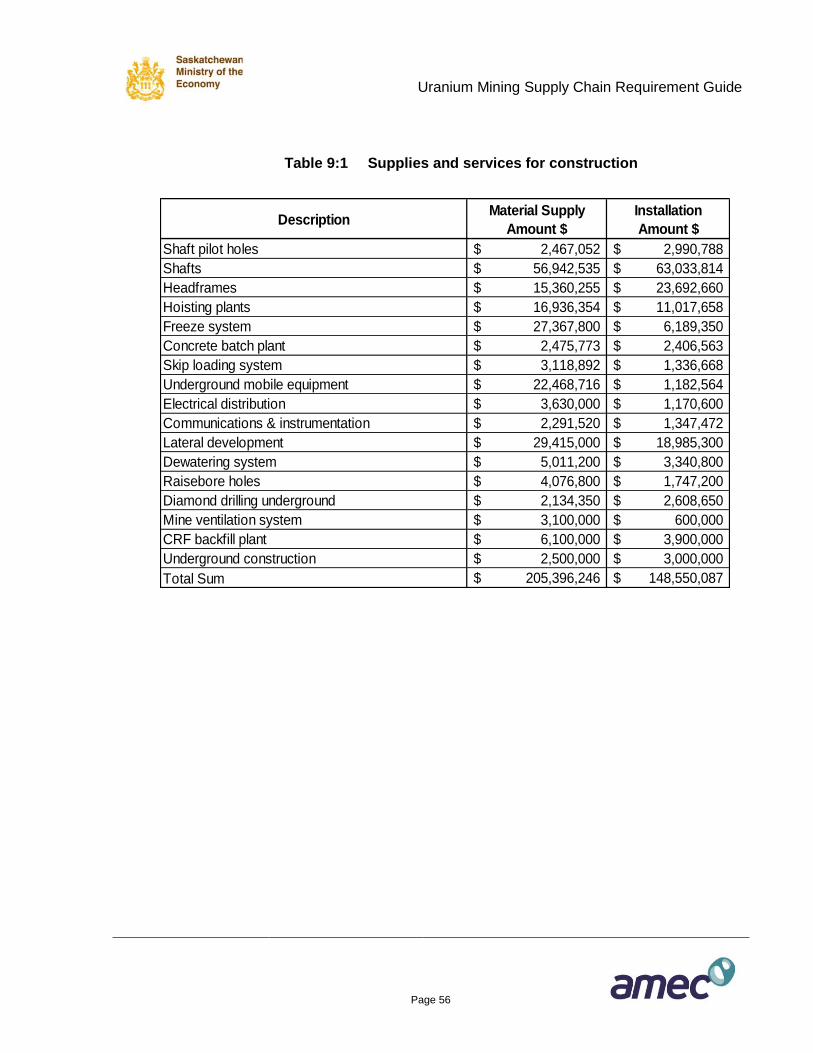
Uranium Mining Supply Chain Requirement Guide
Page 56
Table 9:1 Supplies and services for construction
DescriptionMaterial Supply
Amount $
Installation
Amount $
Shaft pilot holes 2,467,052$ 2,990,788$
Shafts 56,942,535$ 63,033,814$
Headframes 15,360,255$ 23,692,660$
Hoisting plants 16,936,354$ 11,017,658$
Freeze system 27,367,800$ 6,189,350$
Concrete batch plant 2,475,773$ 2,406,563$
Skip loading system 3,118,892$ 1,336,668$
Underground mobile equipment 22,468,716$ 1,182,564$
Electrical distribution 3,630,000$ 1,170,600$
Communications & instrumentation 2,291,520$ 1,347,472$
Lateral development 29,415,000$ 18,985,300$
Dewatering system 5,011,200$ 3,340,800$
Raisebore holes 4,076,800$ 1,747,200$
Diamond drilling underground 2,134,350$ 2,608,650$
Mine ventilation system 3,100,000$ 600,000$
CRF backfill plant 6,100,000$ 3,900,000$
Underground construction 2,500,000$ 3,000,000$
Total Sum 205,396,246$ 148,550,087$
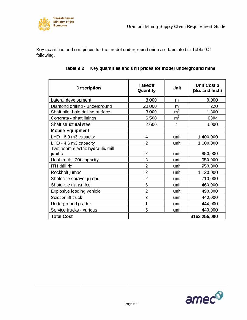
Uranium Mining Supply Chain Requirement Guide
Page 57
Key quantities and unit prices for the model underground mine are tabulated in Table 9:2
following.
Table 9:2 Key quantities and unit prices for model underground mine
Description Takeoff Quantity
Unit Unit Cost $
(Su. and Inst.)
Lateral development 8,000 m 9,000
Diamond drilling - underground 20,000 m 220
Shaft pilot hole drilling surface 3,000 m3 1,800
Concrete - shaft linings 6,500 m3 6394
Shaft structural steel 2,600 t 6000
Mobile Equipment
LHD - 6.9 m3 capacity 4 unit 1,400,000
LHD - 4.6 m3 capacity 2 unit 1,000,000
Two boom electric hydraulic drill jumbo 2 unit 980,000
Haul truck - 30t capacity 3 unit 950,000
ITH drill rig 2 unit 950,000
Rockbolt jumbo 2 unit 1,120,000
Shotcrete sprayer jumbo 2 unit 710,000
Shotcrete transmixer 3 unit 460,000
Explosive loading vehicle 2 unit 490,000
Scissor lift truck 3 unit 440,000
Underground grader 1 unit 444,000
Service trucks - various 5 unit 440,000
Total Cost $163,255,000
Uranium Mining Supply Chain Requirement Guide
Page 58
9.2 Open Pit Mine
9.2.1 General Description of the Open Pit Model Mine
The open pit mine model assumes a uranium deposit located at a depth of 100 to 200m below
surface. The general geology in the Athabasca Basin consists of widespread sandstone rock
which overlies the metasediment basement rocks. The uranium deposits can occur in either
type of rock and also are frequently found at the “unconformity”, or junction of the sandstone
and basement rocks. The Deilmann orebody that was mined (now complete) at Cameco’s Key
Lake operation is a close match for the model open pit mine that has been assumed for this
Guide. A general geological cross section for the Deilmann ore body is shown in Figure 9:8
where the yellow zone, referred to as the Athabasca Group is the sandstone, the brown zone,
called the Paleoproterozic Metasediments are the basement rocks and the uranium orebody
(mineralization) is shown in red.
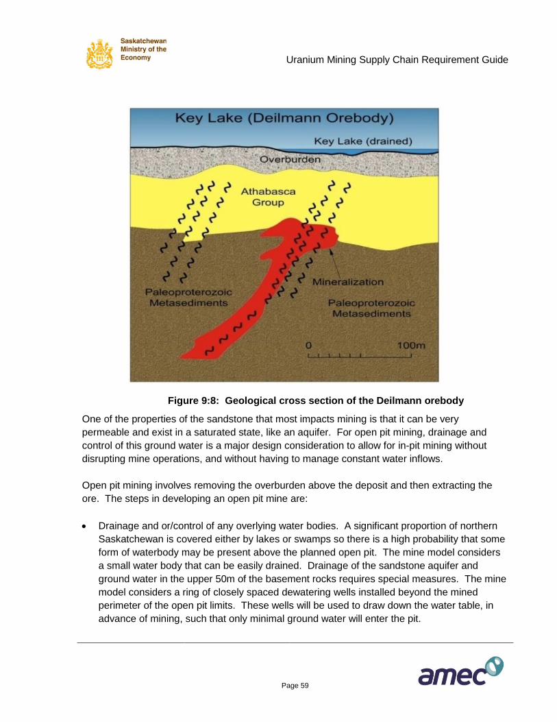
Uranium Mining Supply Chain Requirement Guide
Page 59
Figure 9:8: Geological cross section of the Deilmann orebody
One of the properties of the sandstone that most impacts mining is that it can be very
permeable and exist in a saturated state, like an aquifer. For open pit mining, drainage and
control of this ground water is a major design consideration to allow for in-pit mining without
disrupting mine operations, and without having to manage constant water inflows.
Open pit mining involves removing the overburden above the deposit and then extracting the
ore. The steps in developing an open pit mine are:
Drainage and or/control of any overlying water bodies. A significant proportion of northern
Saskatchewan is covered either by lakes or swamps so there is a high probability that some
form of waterbody may be present above the planned open pit. The mine model considers
a small water body that can be easily drained. Drainage of the sandstone aquifer and
ground water in the upper 50m of the basement rocks requires special measures. The mine
model considers a ring of closely spaced dewatering wells installed beyond the mined
perimeter of the open pit limits. These wells will be used to draw down the water table, in
advance of mining, such that only minimal ground water will enter the pit.
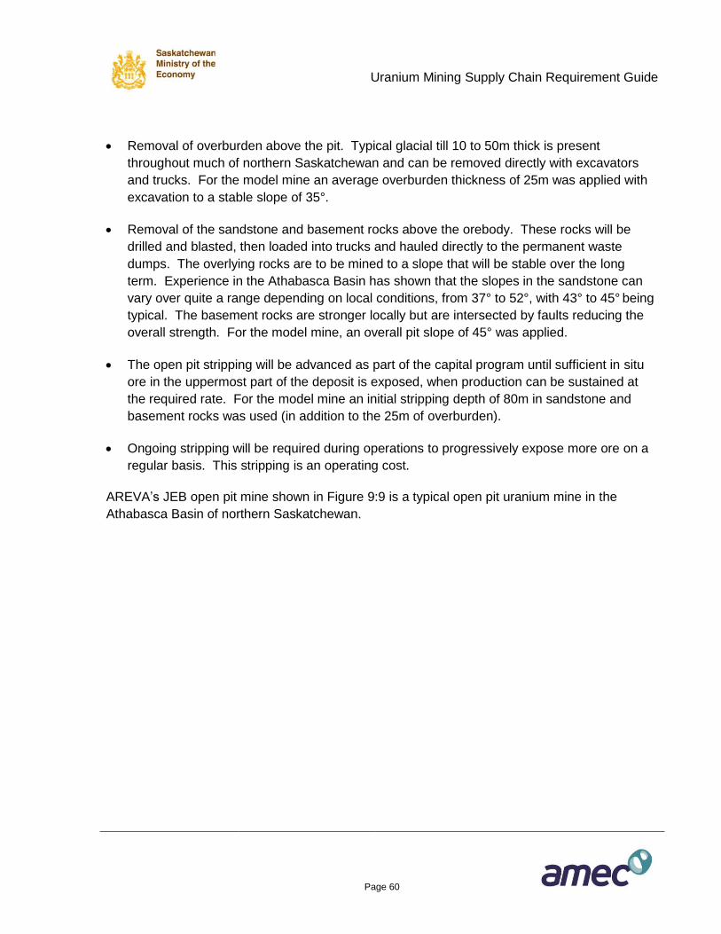
Uranium Mining Supply Chain Requirement Guide
Page 60
Removal of overburden above the pit. Typical glacial till 10 to 50m thick is present
throughout much of northern Saskatchewan and can be removed directly with excavators
and trucks. For the model mine an average overburden thickness of 25m was applied with
excavation to a stable slope of 35°.
Removal of the sandstone and basement rocks above the orebody. These rocks will be
drilled and blasted, then loaded into trucks and hauled directly to the permanent waste
dumps. The overlying rocks are to be mined to a slope that will be stable over the long
term. Experience in the Athabasca Basin has shown that the slopes in the sandstone can
vary over quite a range depending on local conditions, from 37° to 52°, with 43° to 45° being
typical. The basement rocks are stronger locally but are intersected by faults reducing the
overall strength. For the model mine, an overall pit slope of 45° was applied.
The open pit stripping will be advanced as part of the capital program until sufficient in situ
ore in the uppermost part of the deposit is exposed, when production can be sustained at
the required rate. For the model mine an initial stripping depth of 80m in sandstone and
basement rocks was used (in addition to the 25m of overburden).
Ongoing stripping will be required during operations to progressively expose more ore on a
regular basis. This stripping is an operating cost.
AREVA’s JEB open pit mine shown in Figure 9:9 is a typical open pit uranium mine in the
Athabasca Basin of northern Saskatchewan.
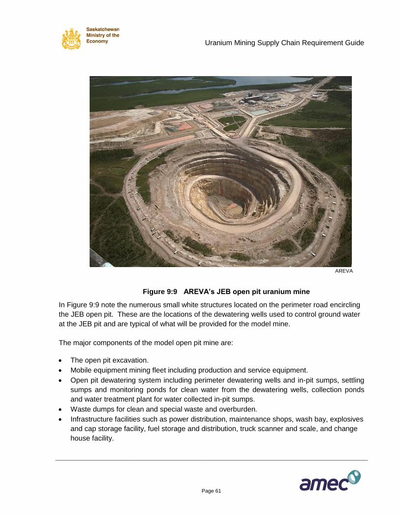
Uranium Mining Supply Chain Requirement Guide
Page 61
AREVA
Figure 9:9 AREVA’s JEB open pit uranium mine
In Figure 9:9 note the numerous small white structures located on the perimeter road encircling
the JEB open pit. These are the locations of the dewatering wells used to control ground water
at the JEB pit and are typical of what will be provided for the model mine.
The major components of the model open pit mine are:
The open pit excavation.
Mobile equipment mining fleet including production and service equipment.
Open pit dewatering system including perimeter dewatering wells and in-pit sumps, settling
sumps and monitoring ponds for clean water from the dewatering wells, collection ponds
and water treatment plant for water collected in-pit sumps.
Waste dumps for clean and special waste and overburden.
Infrastructure facilities such as power distribution, maintenance shops, wash bay, explosives
and cap storage facility, fuel storage and distribution, truck scanner and scale, and change
house facility.
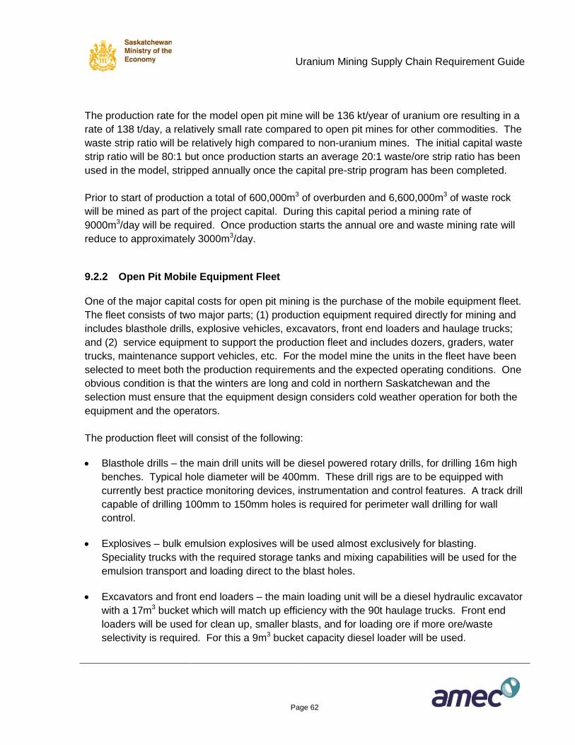
Uranium Mining Supply Chain Requirement Guide
Page 62
The production rate for the model open pit mine will be 136 kt/year of uranium ore resulting in a
rate of 138 t/day, a relatively small rate compared to open pit mines for other commodities. The
waste strip ratio will be relatively high compared to non-uranium mines. The initial capital waste
strip ratio will be 80:1 but once production starts an average 20:1 waste/ore strip ratio has been
used in the model, stripped annually once the capital pre-strip program has been completed.
Prior to start of production a total of 600,000m3 of overburden and 6,600,000m3 of waste rock
will be mined as part of the project capital. During this capital period a mining rate of
9000m3/day will be required. Once production starts the annual ore and waste mining rate will
reduce to approximately 3000m3/day.
9.2.2 Open Pit Mobile Equipment Fleet
One of the major capital costs for open pit mining is the purchase of the mobile equipment fleet.
The fleet consists of two major parts; (1) production equipment required directly for mining and
includes blasthole drills, explosive vehicles, excavators, front end loaders and haulage trucks;
and (2) service equipment to support the production fleet and includes dozers, graders, water
trucks, maintenance support vehicles, etc. For the model mine the units in the fleet have been
selected to meet both the production requirements and the expected operating conditions. One
obvious condition is that the winters are long and cold in northern Saskatchewan and the
selection must ensure that the equipment design considers cold weather operation for both the
equipment and the operators.
The production fleet will consist of the following:
Blasthole drills – the main drill units will be diesel powered rotary drills, for drilling 16m high
benches. Typical hole diameter will be 400mm. These drill rigs are to be equipped with
currently best practice monitoring devices, instrumentation and control features. A track drill
capable of drilling 100mm to 150mm holes is required for perimeter wall drilling for wall
control.
Explosives – bulk emulsion explosives will be used almost exclusively for blasting.
Speciality trucks with the required storage tanks and mixing capabilities will be used for the
emulsion transport and loading direct to the blast holes.
Excavators and front end loaders – the main loading unit will be a diesel hydraulic excavator
with a 17m3 bucket which will match up efficiency with the 90t haulage trucks. Front end
loaders will be used for clean up, smaller blasts, and for loading ore if more ore/waste
selectivity is required. For this a 9m3 bucket capacity diesel loader will be used.
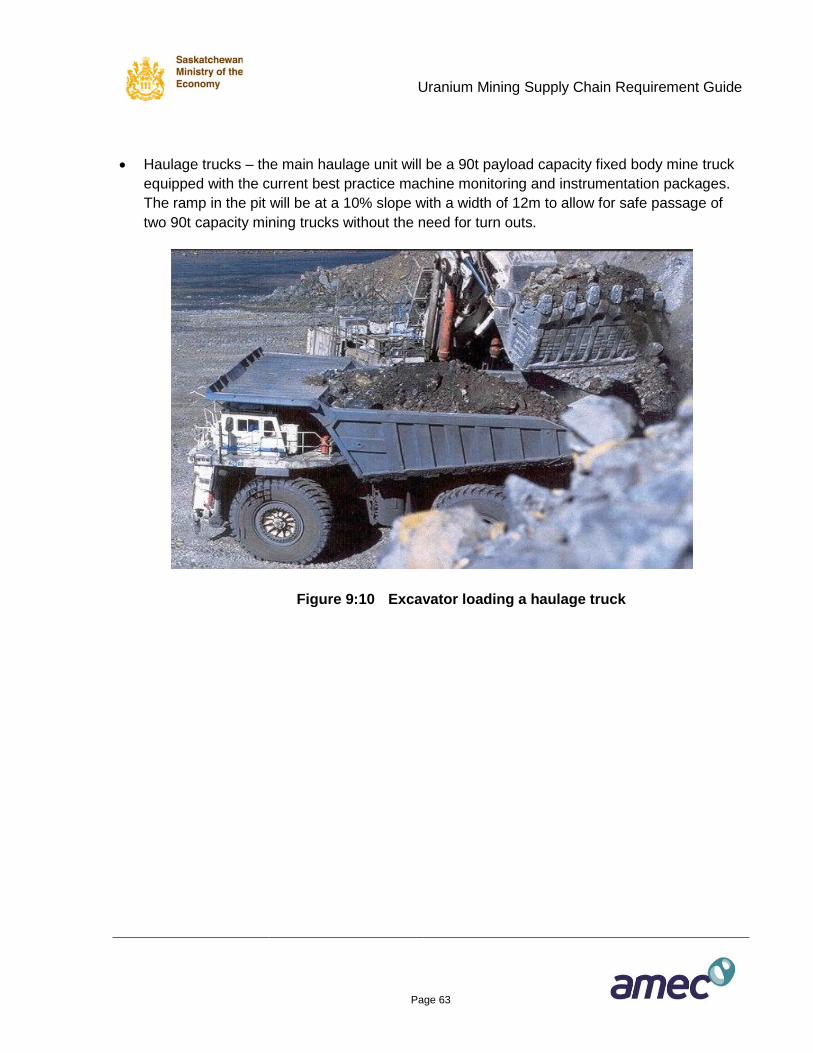
Uranium Mining Supply Chain Requirement Guide
Page 63
Haulage trucks – the main haulage unit will be a 90t payload capacity fixed body mine truck
equipped with the current best practice machine monitoring and instrumentation packages.
The ramp in the pit will be at a 10% slope with a width of 12m to allow for safe passage of
two 90t capacity mining trucks without the need for turn outs.
Figure 9:10 Excavator loading a haulage truck
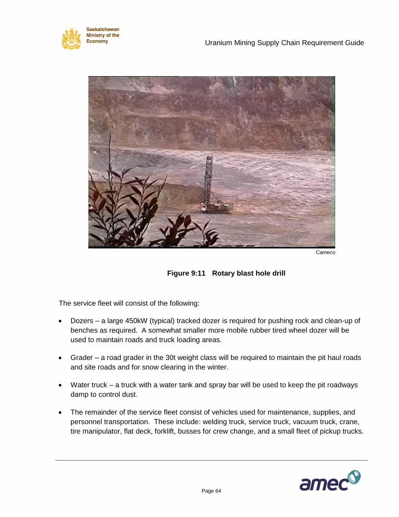
Uranium Mining Supply Chain Requirement Guide
Page 64
Cameco
Figure 9:11 Rotary blast hole drill
The service fleet will consist of the following:
Dozers – a large 450kW (typical) tracked dozer is required for pushing rock and clean-up of
benches as required. A somewhat smaller more mobile rubber tired wheel dozer will be
used to maintain roads and truck loading areas.
Grader – a road grader in the 30t weight class will be required to maintain the pit haul roads
and site roads and for snow clearing in the winter.
Water truck – a truck with a water tank and spray bar will be used to keep the pit roadways
damp to control dust.
The remainder of the service fleet consist of vehicles used for maintenance, supplies, and
personnel transportation. These include: welding truck, service truck, vacuum truck, crane,
tire manipulator, flat deck, forklift, busses for crew change, and a small fleet of pickup trucks.
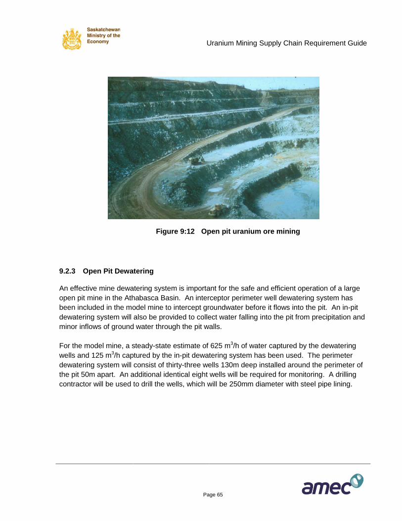
Uranium Mining Supply Chain Requirement Guide
Page 65
Figure 9:12 Open pit uranium ore mining
9.2.3 Open Pit Dewatering
An effective mine dewatering system is important for the safe and efficient operation of a large
open pit mine in the Athabasca Basin. An interceptor perimeter well dewatering system has
been included in the model mine to intercept groundwater before it flows into the pit. An in-pit
dewatering system will also be provided to collect water falling into the pit from precipitation and
minor inflows of ground water through the pit walls.
For the model mine, a steady-state estimate of 625 m3/h of water captured by the dewatering
wells and 125 m3/h captured by the in-pit dewatering system has been used. The perimeter
dewatering system will consist of thirty-three wells 130m deep installed around the perimeter of
the pit 50m apart. An additional identical eight wells will be required for monitoring. A drilling
contractor will be used to drill the wells, which will be 250mm diameter with steel pipe lining.
Uranium Mining Supply Chain Requirement Guide
Page 66
A submersible pump will be installed in each dewatering well to pump groundwater to the
surface; typical pump specifications will be 125m3/h at a static head of 120m.
Discharge piping will run from the submersible pump to an enclosed wellhead located on
surface. Each wellhead will contain a single header with a manual sampling connection and a
flow meter. A three-way valve, located downstream of the manual sampling connection, will
direct groundwater flow into one of two pipelines at any one time. The wellhead piping and
pipelines will be electrically heat traced and insulated.
Two 200mm diameter HDPE pipelines, insulated and heat traced, will run along the surface to
connect to each well. One pipeline will extend 500m to carry clean groundwater to the receiving
pond for clean water. The second pipeline will extend 300m to pump contaminated
groundwater to the receiving pond that feeds the water treatment plant.
An all weather road will run around the perimeter of the dewatering well circle providing access
for vehicles. An overhead distribution power line and communications cable will be installed
around the 1,700m loop complete with all the required electrical and communications
connections.
The in-pit dewatering system will consist of a series of sumps strategically located around the pit
to collect precipitation and water inflows as close to the source as possible. The model mine
includes ten submersible sump pumps of which up to six will be operating. The pump
specifications will be 125m3/h at a static head of up to 100 m. Each sump will be provided with
150mm insulated and heat traced HDPE discharge pipe connecting at the pit rim to the
contaminated dewatering pipeline. An in-pit power line and communications cable will connect
to each of the in-pit sumps.
9.2.4 Open Pit Infrastructure
Infrastructure directly related to open pit operations includes explosive storage and associated
facilities, fuel storage, maintenance shops, clean waste and special waste stockpiles, and haul
road to the mill.
Fuel Storage and Distribution
Fuel storage and distribution for the open pit mining fleet will be established fairly close to the pit
haulage road for efficiency of fuelling. The fuel will be stored in tanks with an appropriate
secondary containment system and high speed dispensing pumps. Used oil will also be stored
in storage tanks with secondary containment.
Uranium Mining Supply Chain Requirement Guide
Page 67
Explosives and Detonator Storage Facility
Emulsion explosives will be used almost exclusively for ore and waste and pit perimeter
blasting. The emulsion will be supplied as a bulk product with a minor amount as packaged
explosive. Ideally, an explosive supplier will establish an emulsion storage and mixing plant at
site and further will contract to complete all the blasthole loading on site. A storage capacity of
at least 200t of explosives will be required. The emulsion loading truck can be owned by the
mine operator but the pumping equipment is highly specialized and can only be leased from an
explosive supplier. Detonators will be stored in an approved facility.
Electrical Distribution
From the main site substation power will be distributed to the pit facilities at either 4.16kV or
13.8kV, depending on final design. An overhead line will circle the pit providing power to the
dewatering pumps while in-pit lines will be supported by simple structures on the pit floor.
Haulage Road to the Mill and Waste Dumps
Haulage roads will be required to transport ore to the mill and waste to the overburden, clean
waste and special waste dumps. The model mine is based on each of the waste roads being
1.5km long and the ore road 2km long. The road width would be 12m which is twice the width
of a common 90t haul truck. Pull outs will be provided along the length for safety when multiple
vehicles are passing.
9.2.5 Supplies and Services for Model Open Pit Construction
The supplies and services purchased for construction of the model open pit mine are tabulated
following in Table 9:3.
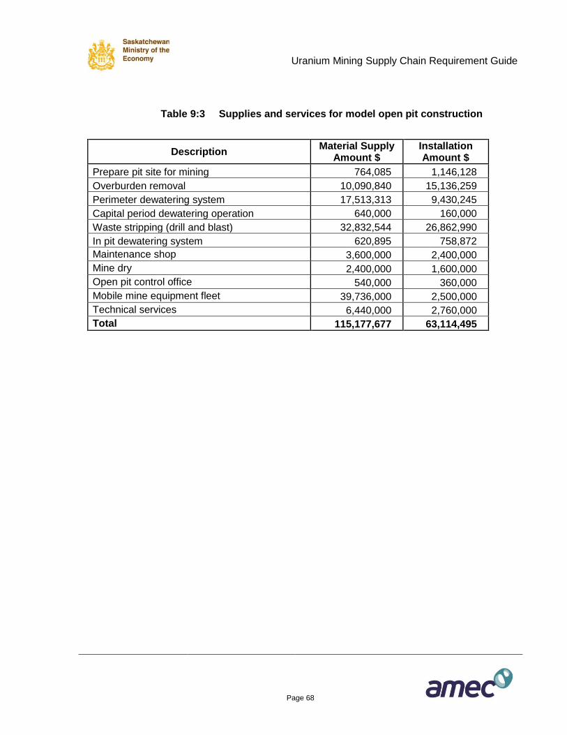
Uranium Mining Supply Chain Requirement Guide
Page 68
Table 9:3 Supplies and services for model open pit construction
Description
Material Supply Amount $
Installation Amount $
Prepare pit site for mining 764,085 1,146,128
Overburden removal 10,090,840 15,136,259
Perimeter dewatering system 17,513,313 9,430,245
Capital period dewatering operation 640,000 160,000
Waste stripping (drill and blast) 32,832,544 26,862,990
In pit dewatering system 620,895 758,872
Maintenance shop 3,600,000 2,400,000
Mine dry 2,400,000 1,600,000
Open pit control office 540,000 360,000
Mobile mine equipment fleet 39,736,000 2,500,000
Technical services 6,440,000 2,760,000
Total 115,177,677 63,114,495
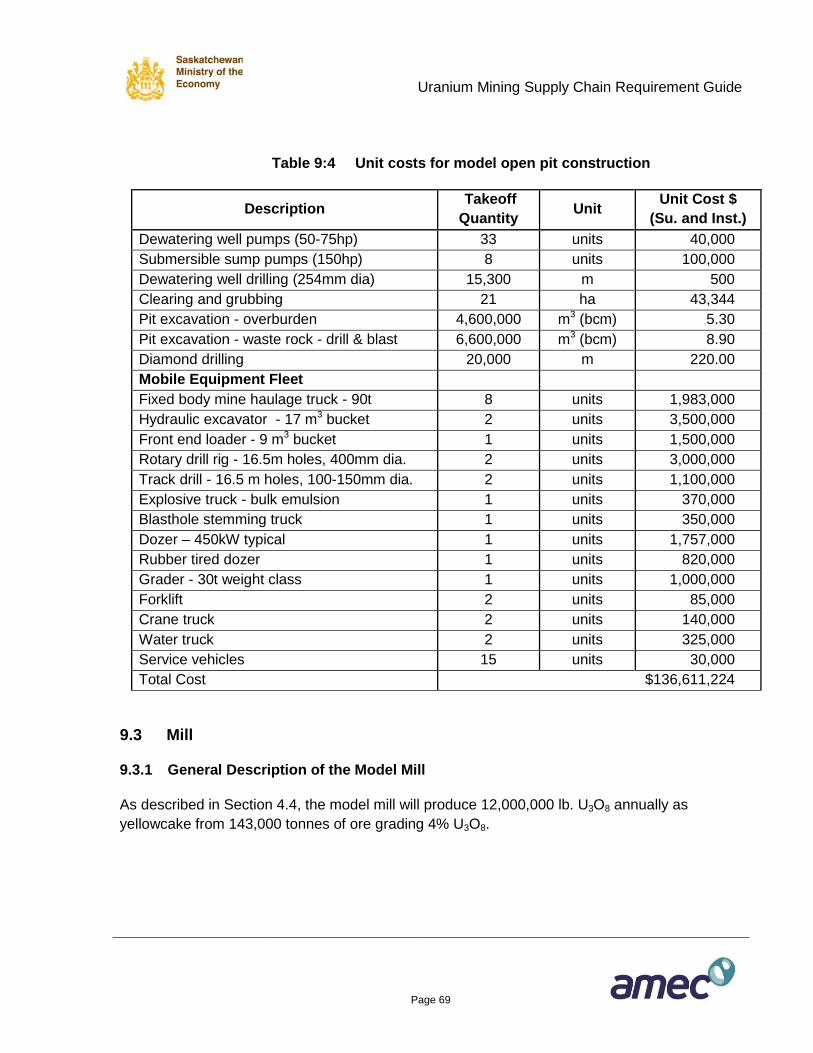
Uranium Mining Supply Chain Requirement Guide
Page 69
Table 9:4 Unit costs for model open pit construction
Description Takeoff
Quantity Unit
Unit Cost $
(Su. and Inst.)
Dewatering well pumps (50-75hp) 33 units 40,000
Submersible sump pumps (150hp) 8 units 100,000
Dewatering well drilling (254mm dia) 15,300 m 500
Clearing and grubbing 21 ha 43,344
Pit excavation - overburden 4,600,000 m3 (bcm) 5.30
Pit excavation - waste rock - drill & blast 6,600,000 m3 (bcm) 8.90
Diamond drilling 20,000 m 220.00
Mobile Equipment Fleet
Fixed body mine haulage truck - 90t 8 units 1,983,000
Hydraulic excavator - 17 m3 bucket 2 units 3,500,000
Front end loader - 9 m3 bucket 1 units 1,500,000
Rotary drill rig - 16.5m holes, 400mm dia. 2 units 3,000,000
Track drill - 16.5 m holes, 100-150mm dia. 2 units 1,100,000
Explosive truck - bulk emulsion 1 units 370,000
Blasthole stemming truck 1 units 350,000
Dozer – 450kW typical 1 units 1,757,000
Rubber tired dozer 1 units 820,000
Grader - 30t weight class 1 units 1,000,000
Forklift 2 units 85,000
Crane truck 2 units 140,000
Water truck 2 units 325,000
Service vehicles 15 units 30,000
Total Cost $136,611,224
9.3 Mill
9.3.1 General Description of the Model Mill
As described in Section 4.4, the model mill will produce 12,000,000 lb. U3O8 annually as
yellowcake from 143,000 tonnes of ore grading 4% U3O8.
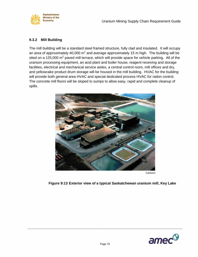
Uranium Mining Supply Chain Requirement Guide
Page 70
9.3.2 Mill Building
The mill building will be a standard steel framed structure, fully clad and insulated. It will occupy
an area of approximately 40,000 m2 and average approximately 15 m high. The building will be
sited on a 125,000 m2 paved mill terrace, which will provide space for vehicle parking. All of the
uranium processing equipment, an acid plant and boiler house, reagent receiving and storage
facilities, electrical and mechanical service aisles, a central control room, mill offices and dry,
and yellowcake product drum storage will be housed in the mill building. HVAC for the building
will provide both general area HVAC and special dedicated process HVAC for radon control.
The concrete mill floors will be sloped to sumps to allow easy, rapid and complete cleanup of
spills.
Cameco
Figure 9:13 Exterior view of a typical Saskatchewan uranium mill, Key Lake
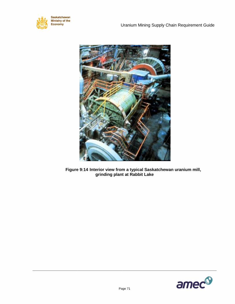
Uranium Mining Supply Chain Requirement Guide
Page 71
Figure 9:14 Interior view from a typical Saskatchewan uranium mill, grinding plant at Rabbit Lake
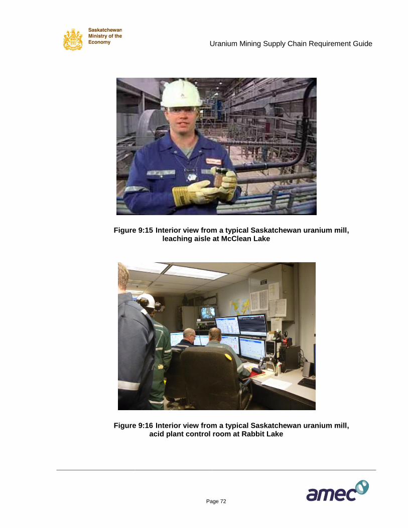
Uranium Mining Supply Chain Requirement Guide
Page 72
Figure 9:15 Interior view from a typical Saskatchewan uranium mill, leaching aisle at McClean Lake
Figure 9:16 Interior view from a typical Saskatchewan uranium mill, acid plant control room at Rabbit Lake
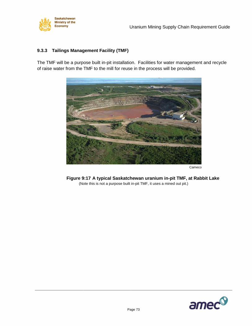
Uranium Mining Supply Chain Requirement Guide
Page 73
9.3.3 Tailings Management Facility (TMF)
The TMF will be a purpose built in-pit installation. Facilities for water management and recycle
of raise water from the TMF to the mill for reuse in the process will be provided.
Cameco
Figure 9:17 A typical Saskatchewan uranium in-pit TMF, at Rabbit Lake (Note this is not a purpose built in-pit TMF, it uses a mined out pit.)
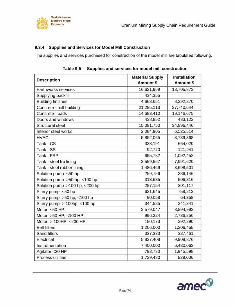
Uranium Mining Supply Chain Requirement Guide
Page 74
9.3.4 Supplies and Services for Model Mill Construction
The supplies and services purchased for construction of the model mill are tabulated following.
Table 9:5 Supplies and services for model mill construction
Description Material Supply
Amount $
Installation
Amount $
Earthworks services 16,621,969 18,705,873
Supplying backfill 434,355
Building finishes 4,663,651 8,292,370
Concrete - mill building 21,285,113 27,740,644
Concrete - pads 14,683,410 19,146,675
Doors and windows 438,852 433,122
Structural steel 15,081,750 34,896,446
Interior steel works 2,084,905 6,525,514
HVAC 5,852,065 3,739,368
Tank - CS 338,191 664,020
Tank - SS 92,720 121,941
Tank - FRP 695,732 1,092,452
Tank - steel frp lining 3,559,567 7,991,620
Tank - steel rubber lining 1,486,469 8,598,501
Solution pump <50 hp 259,756 386,146
Solution pump >50 hp, <100 hp 313,635 506,816
Solution pump >100 hp, <200 hp 287,154 201,117
Slurry pump <50 hp 621,645 758,213
Slurry pump >50 hp, <100 hp 90,058 64,358
Slurry pump > 100hp, <100 hp 344,585 241,341
Motor <50 HP 2,579,047 8,894,993
Motor >50 HP, <100 HP 996,324 2,786,256
Motor > 100HP, <200 HP 180,173 392,290
Belt filters 1,206,000 1,206,455
Sand filters 337,333 337,461
Electrical 5,837,408 9,908,876
Instrumentation 7,400,000 6,480,063
Agitator <20 HP 793,730 1,945,598
Process utilities 1,729,430 829,006
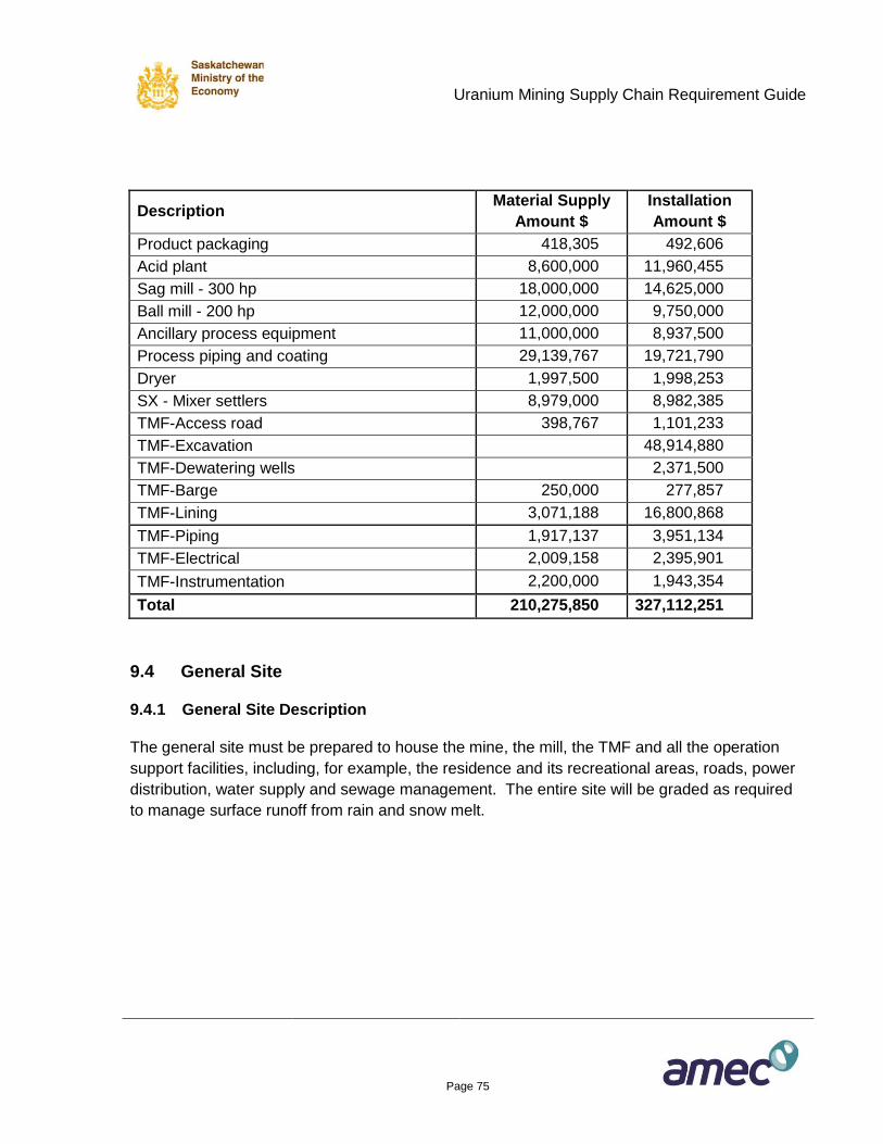
Uranium Mining Supply Chain Requirement Guide
Page 75
Description Material Supply
Amount $
Installation
Amount $
Product packaging 418,305 492,606
Acid plant 8,600,000 11,960,455
Sag mill - 300 hp 18,000,000 14,625,000
Ball mill - 200 hp 12,000,000 9,750,000
Ancillary process equipment 11,000,000 8,937,500
Process piping and coating 29,139,767 19,721,790
Dryer 1,997,500 1,998,253
SX - Mixer settlers 8,979,000 8,982,385
TMF-Access road 398,767 1,101,233
TMF-Excavation 48,914,880
TMF-Dewatering wells 2,371,500
TMF-Barge 250,000 277,857
TMF-Lining 3,071,188 16,800,868
TMF-Piping 1,917,137 3,951,134
TMF-Electrical 2,009,158 2,395,901
TMF-Instrumentation 2,200,000 1,943,354
Total 210,275,850 327,112,251
9.4 General Site
9.4.1 General Site Description
The general site must be prepared to house the mine, the mill, the TMF and all the operation
support facilities, including, for example, the residence and its recreational areas, roads, power
distribution, water supply and sewage management. The entire site will be graded as required
to manage surface runoff from rain and snow melt.
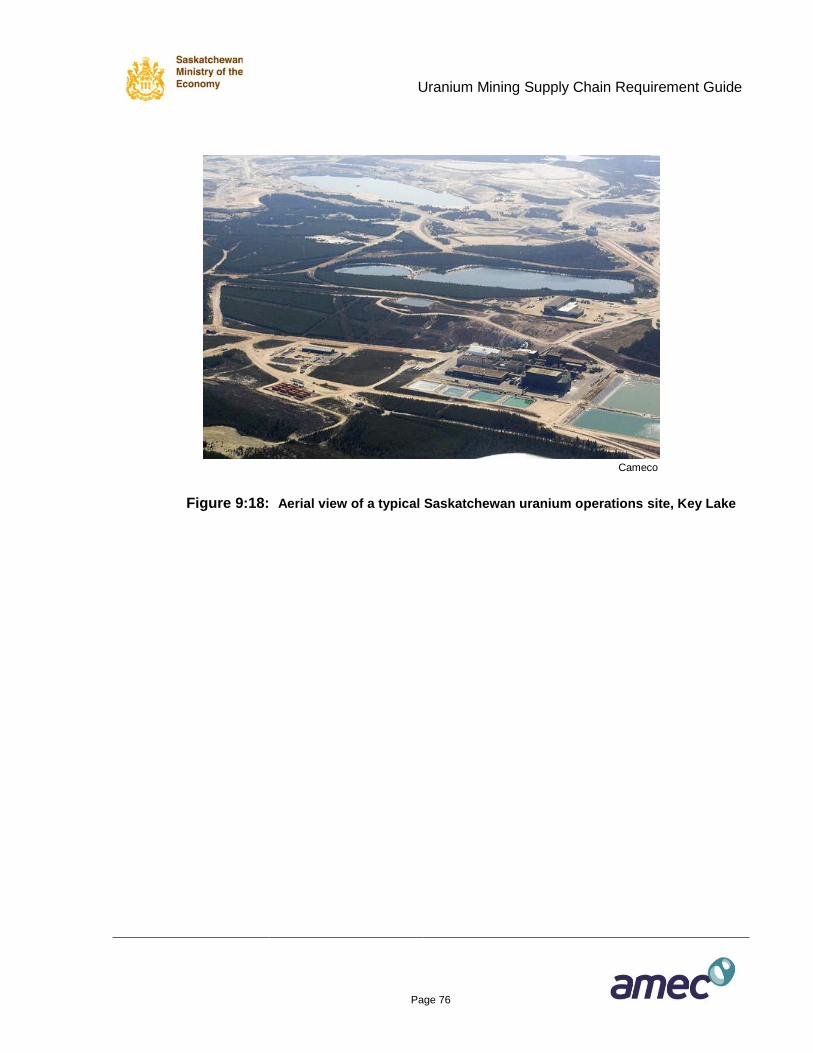
Uranium Mining Supply Chain Requirement Guide
Page 76
Cameco
Figure 9:18: Aerial view of a typical Saskatchewan uranium operations site, Key Lake
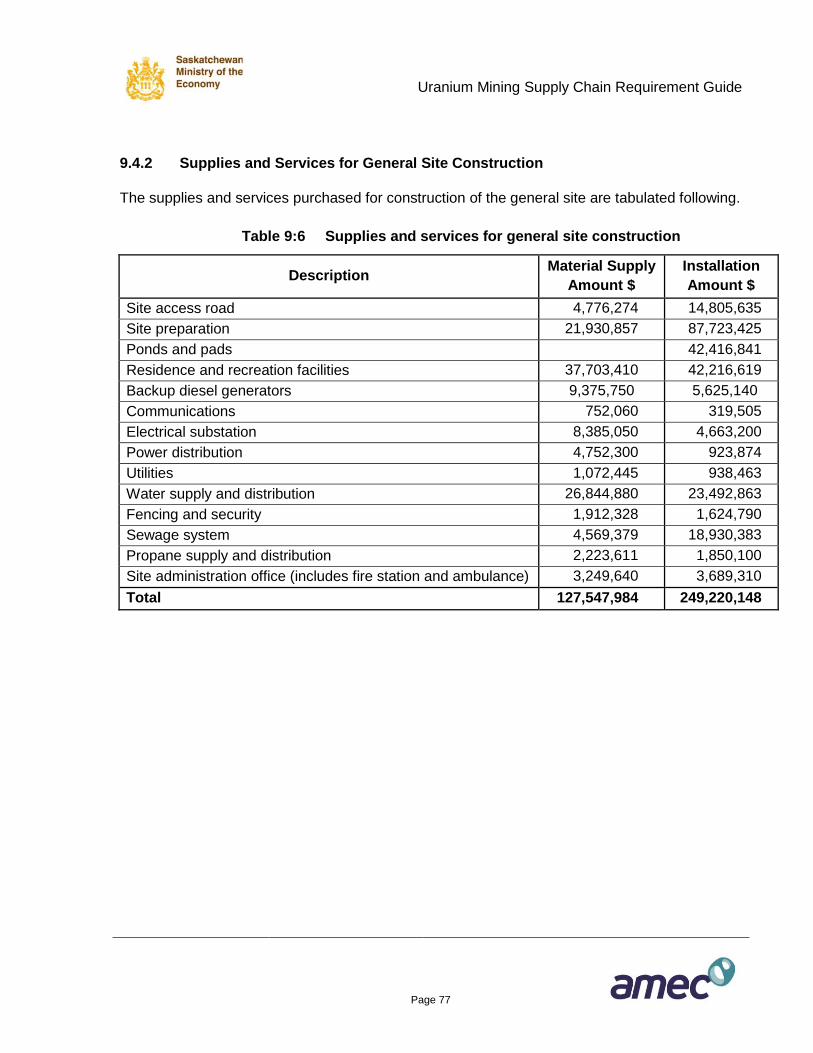
Uranium Mining Supply Chain Requirement Guide
Page 77
9.4.2 Supplies and Services for General Site Construction
The supplies and services purchased for construction of the general site are tabulated following.
Table 9:6 Supplies and services for general site construction
Description Material Supply
Amount $
Installation
Amount $
Site access road 4,776,274 14,805,635
Site preparation 21,930,857 87,723,425
Ponds and pads 42,416,841
Residence and recreation facilities 37,703,410 42,216,619
Backup diesel generators 9,375,750 5,625,140
Communications 752,060 319,505
Electrical substation 8,385,050 4,663,200
Power distribution 4,752,300 923,874
Utilities 1,072,445 938,463
Water supply and distribution 26,844,880 23,492,863
Fencing and security 1,912,328 1,624,790
Sewage system 4,569,379 18,930,383
Propane supply and distribution 2,223,611 1,850,100
Site administration office (includes fire station and ambulance) 3,249,640 3,689,310
Total 127,547,984 249,220,148
Uranium Mining Supply Chain Requirement Guide
Page 78
10. COMMISSIONING AND RAMP-UP
As described previously in Section 5, commissioning of the new facilities is initiated towards the
end of construction, followed by a period in which capacity is ramped up to achieve production
targets in terms of ore tonnes, ore grade and U3O8 yellowcake production. Figure 5:1 shows
that commissioning and ramp-up typically takes two years. However, the commissioning and
ramp-up period may be as short as six months and as long as five years.
Section 8.3 explains that commissioning assistance to the owner’s teams is typically the last
activity for the construction managers, and so is typically the final work in the scope of the
EPCM contractor. The EPCM contractor will appoint a commissioning manager to develop a
comprehensive commissioning plan that will include the establishment of a work schedule that
takes into account the construction mechanical completion dates. The commissioning plan will
also include the schedule for the operation of equipment, and the criteria for system acceptance
and handover to the owner operations personnel. The contractor’s cost for commissioning is
included in the construction management cost; see Section 8.4.
Ramp-up is the period immediately following commissioning in which capacity is ramped up to
achieve production targets in terms of ore tonnes, ore grade and U3O8 yellowcake production.
The ramp-up is carried out by the owner operation personnel. The supplies and services
required during ramp-up are identical to those required on a steady basis during operations; see
Section 11 following. The amounts of these supplies and services begin small, and increase at
a rate commensurate with ramp-up progress. Because the amounts of ramp-up supplies and
services are highly variable, not reliably predictable, and relatively small value compared to the
life-of-operations supplies and services, the amounts and related costs for ramp-up supplies
and services are not estimated in this guide.
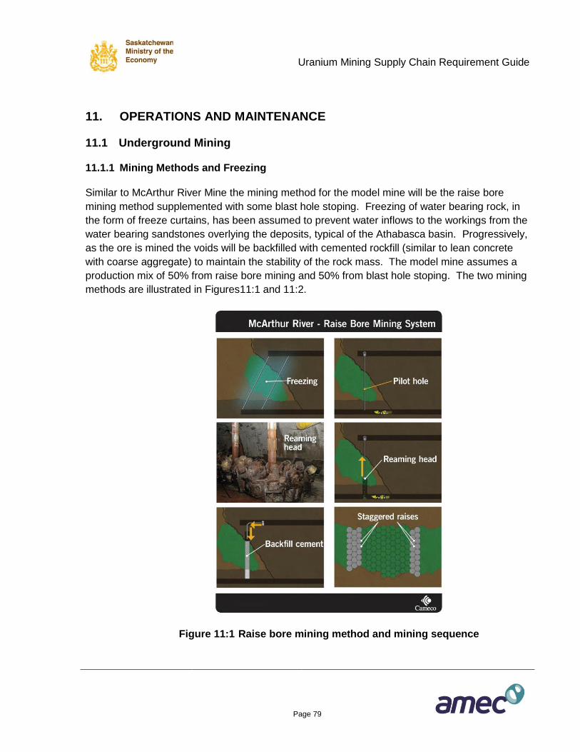
Uranium Mining Supply Chain Requirement Guide
Page 79
11. OPERATIONS AND MAINTENANCE
11.1 Underground Mining
11.1.1 Mining Methods and Freezing
Similar to McArthur River Mine the mining method for the model mine will be the raise bore
mining method supplemented with some blast hole stoping. Freezing of water bearing rock, in
the form of freeze curtains, has been assumed to prevent water inflows to the workings from the
water bearing sandstones overlying the deposits, typical of the Athabasca basin. Progressively,
as the ore is mined the voids will be backfilled with cemented rockfill (similar to lean concrete
with coarse aggregate) to maintain the stability of the rock mass. The model mine assumes a
production mix of 50% from raise bore mining and 50% from blast hole stoping. The two mining
methods are illustrated in Figures11:1 and 11:2.
Figure 11:1 Raise bore mining method and mining sequence
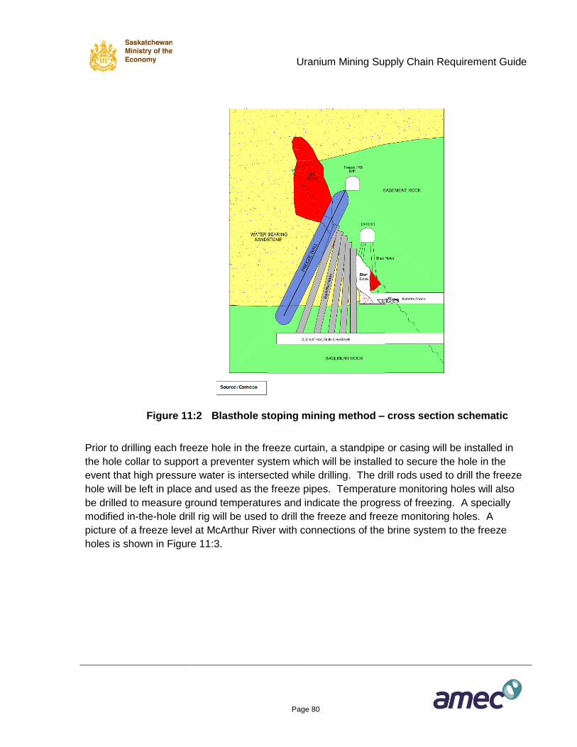
Uranium Mining Supply Chain Requirement Guide
Page 80
Figure 11:2 Blasthole stoping mining method – cross section schematic
Prior to drilling each freeze hole in the freeze curtain, a standpipe or casing will be installed in
the hole collar to support a preventer system which will be installed to secure the hole in the
event that high pressure water is intersected while drilling. The drill rods used to drill the freeze
hole will be left in place and used as the freeze pipes. Temperature monitoring holes will also
be drilled to measure ground temperatures and indicate the progress of freezing. A specially
modified in-the-hole drill rig will be used to drill the freeze and freeze monitoring holes. A
picture of a freeze level at McArthur River with connections of the brine system to the freeze
holes is shown in Figure 11:3.
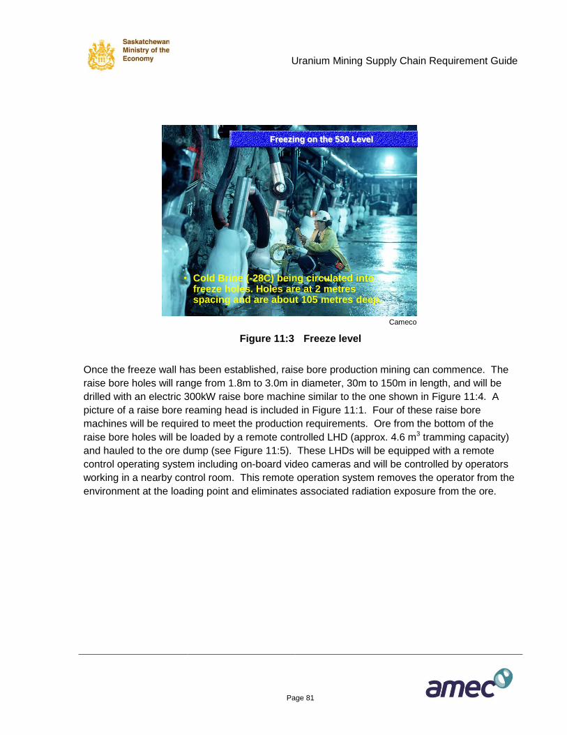
Uranium Mining Supply Chain Requirement Guide
Page 81
Freezing on the 530 Level
• Cold Brine (-28C) being circulated into freeze holes. Holes are at 2 metresspacing and are about 105 metres deep.
Cameco
Figure 11:3 Freeze level
Once the freeze wall has been established, raise bore production mining can commence. The
raise bore holes will range from 1.8m to 3.0m in diameter, 30m to 150m in length, and will be
drilled with an electric 300kW raise bore machine similar to the one shown in Figure 11:4. A
picture of a raise bore reaming head is included in Figure 11:1. Four of these raise bore
machines will be required to meet the production requirements. Ore from the bottom of the
raise bore holes will be loaded by a remote controlled LHD (approx. 4.6 m3 tramming capacity)
and hauled to the ore dump (see Figure 11:5). These LHDs will be equipped with a remote
control operating system including on-board video cameras and will be controlled by operators
working in a nearby control room. This remote operation system removes the operator from the
environment at the loading point and eliminates associated radiation exposure from the ore.
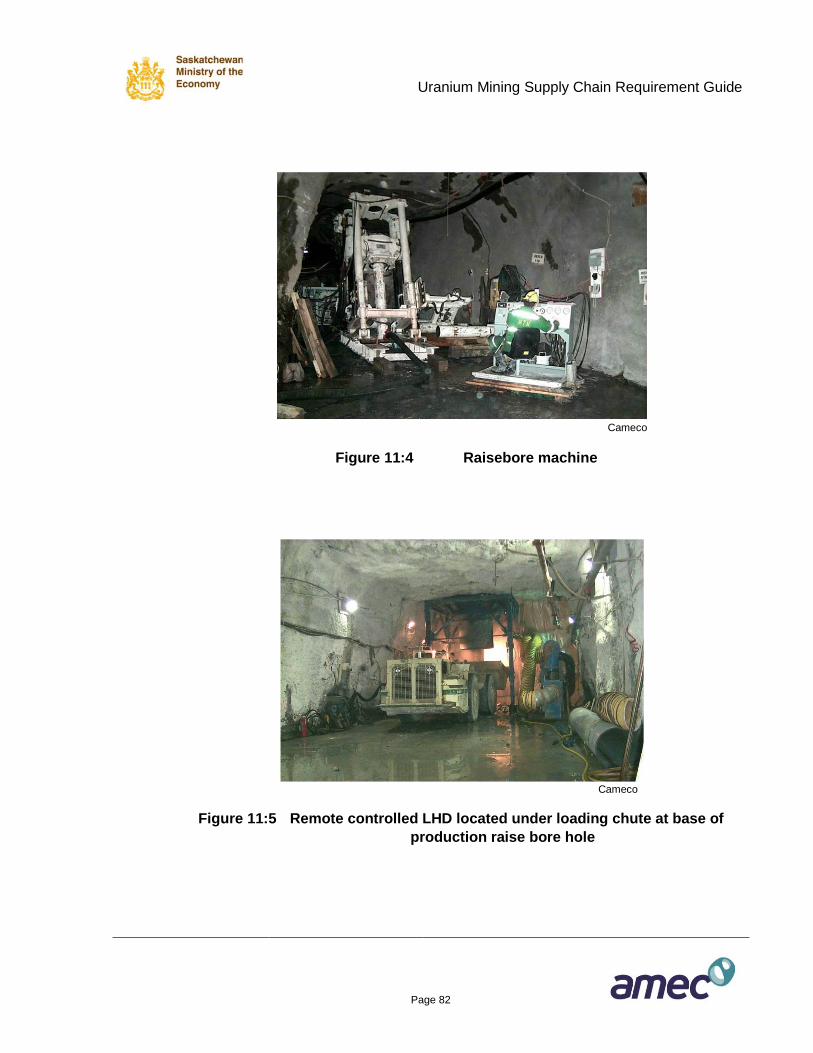
Uranium Mining Supply Chain Requirement Guide
Page 82
Cameco
Figure 11:4 Raisebore machine
Cameco
Figure 11:5 Remote controlled LHD located under loading chute at base of
production raise bore hole
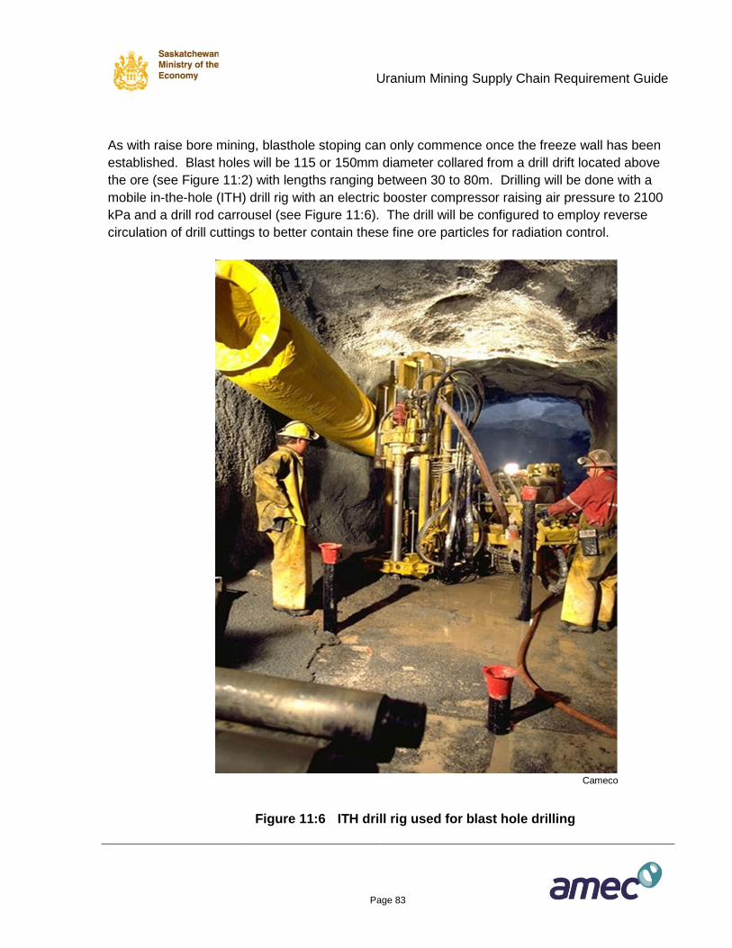
Uranium Mining Supply Chain Requirement Guide
Page 83
As with raise bore mining, blasthole stoping can only commence once the freeze wall has been
established. Blast holes will be 115 or 150mm diameter collared from a drill drift located above
the ore (see Figure 11:2) with lengths ranging between 30 to 80m. Drilling will be done with a
mobile in-the-hole (ITH) drill rig with an electric booster compressor raising air pressure to 2100
kPa and a drill rod carrousel (see Figure 11:6). The drill will be configured to employ reverse
circulation of drill cuttings to better contain these fine ore particles for radiation control.
Cameco
Figure 11:6 ITH drill rig used for blast hole drilling
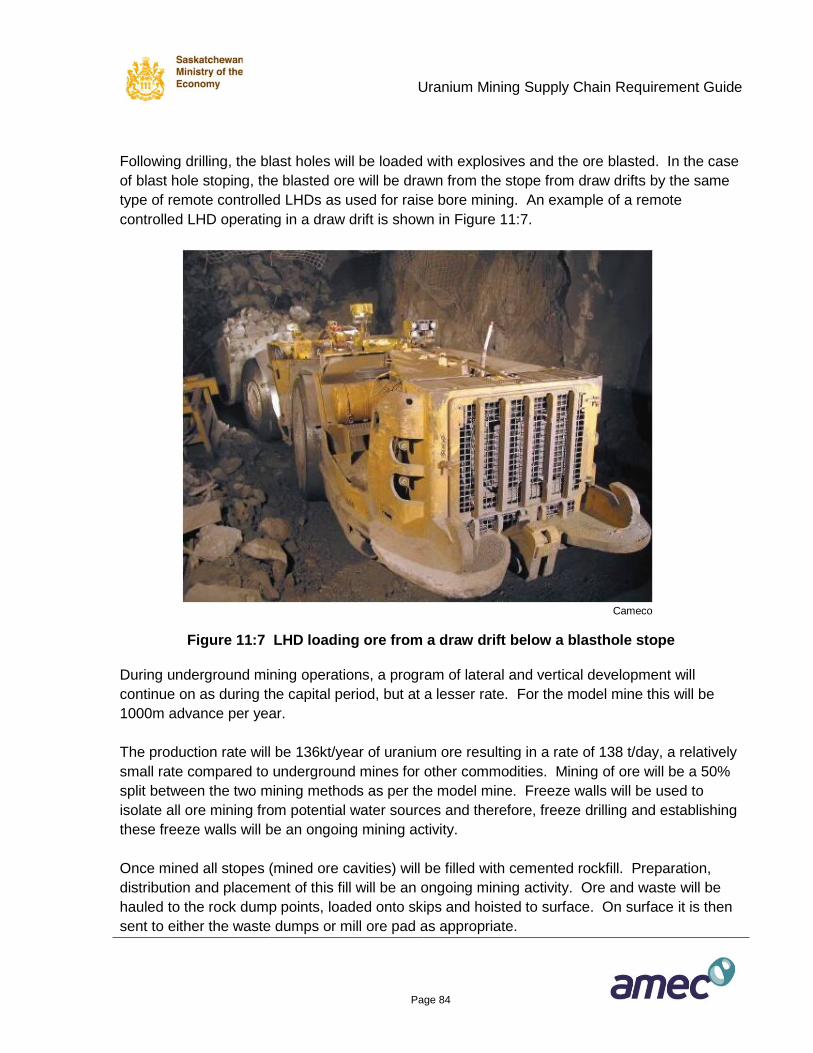
Uranium Mining Supply Chain Requirement Guide
Page 84
Following drilling, the blast holes will be loaded with explosives and the ore blasted. In the case
of blast hole stoping, the blasted ore will be drawn from the stope from draw drifts by the same
type of remote controlled LHDs as used for raise bore mining. An example of a remote
controlled LHD operating in a draw drift is shown in Figure 11:7.
Cameco
Figure 11:7 LHD loading ore from a draw drift below a blasthole stope
During underground mining operations, a program of lateral and vertical development will
continue on as during the capital period, but at a lesser rate. For the model mine this will be
1000m advance per year.
The production rate will be 136kt/year of uranium ore resulting in a rate of 138 t/day, a relatively
small rate compared to underground mines for other commodities. Mining of ore will be a 50%
split between the two mining methods as per the model mine. Freeze walls will be used to
isolate all ore mining from potential water sources and therefore, freeze drilling and establishing
these freeze walls will be an ongoing mining activity.
Once mined all stopes (mined ore cavities) will be filled with cemented rockfill. Preparation,
distribution and placement of this fill will be an ongoing mining activity. Ore and waste will be
hauled to the rock dump points, loaded onto skips and hoisted to surface. On surface it is then
sent to either the waste dumps or mill ore pad as appropriate.
Uranium Mining Supply Chain Requirement Guide
Page 85
11.1.2 Supplies and Services for Model Underground Mine Operations and Maintenance
The supplies and services purchased for operation and maintenance of the model underground
mine are tabulated following.
Table 11:1 Supplies and services for model underground mine operations and
maintenance
Description Quantity per Year Unit Unit Cost $
(Su. and Inst.)
Lateral development 1,000 m 9,000
Diamond drilling - underground 20,000 m 220
Bulk cement 8,000 t 380
Explosives 40,000 kg 2.50
Diesel fuel 800,000 L 1.20
Propane 5,000,000 L 0.80
Electrical consumption 90,000,000 kW/yr 0.15
Annual total cost $35,000,000
11.2 Open Pit Mining
11.2.1 Open Pit Operations
Operations of the model open pit mine will be almost identical to those during the capital
construction period with waste stripping continuing, but with mining of uranium starting and
continuing for the life of the mine. The 16m high waste benches will be reduced to 8m high
benches in the ore for better geological control. Waste rock will be hauled to either the waste
dump or the special waste dump and ore will be hauled direct to the ore pad at the mill. The
perimeter well dewatering system will continue to operate through the full life of the mine.
The production rate for the model mine open pit will be 136kt/year of uranium ore, or 138t/day, a
relatively small rate compared to open pit mines for other commodities. Conversely, the waste
strip ratio will be significantly higher compared to non-uranium mines. The initial capital waste
strip ratio will be 80:1 but once production starts an average 20:1 waste/ore strip ratio has been
used in the model, stripped annually once the capital pre-strip program has been completed.
The annual ore and waste mining rate during operations will be just under 3000m3/day.
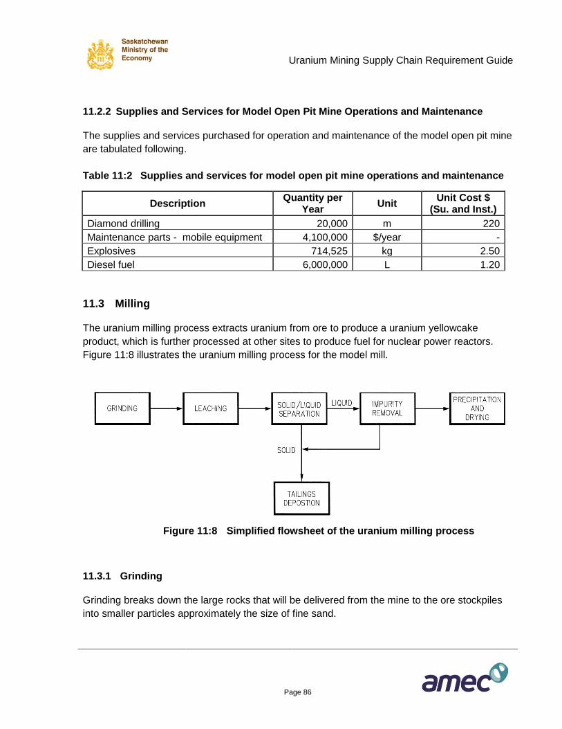
Uranium Mining Supply Chain Requirement Guide
Page 86
11.2.2 Supplies and Services for Model Open Pit Mine Operations and Maintenance
The supplies and services purchased for operation and maintenance of the model open pit mine
are tabulated following.
Table 11:2 Supplies and services for model open pit mine operations and maintenance
Description Quantity per
Year Unit
Unit Cost $ (Su. and Inst.)
Diamond drilling 20,000 m 220
Maintenance parts - mobile equipment 4,100,000 $/year -
Explosives 714,525 kg 2.50
Diesel fuel 6,000,000 L 1.20
11.3 Milling
The uranium milling process extracts uranium from ore to produce a uranium yellowcake
product, which is further processed at other sites to produce fuel for nuclear power reactors.
Figure 11:8 illustrates the uranium milling process for the model mill.
Figure 11:8 Simplified flowsheet of the uranium milling process
11.3.1 Grinding
Grinding breaks down the large rocks that will be delivered from the mine to the ore stockpiles
into smaller particles approximately the size of fine sand.
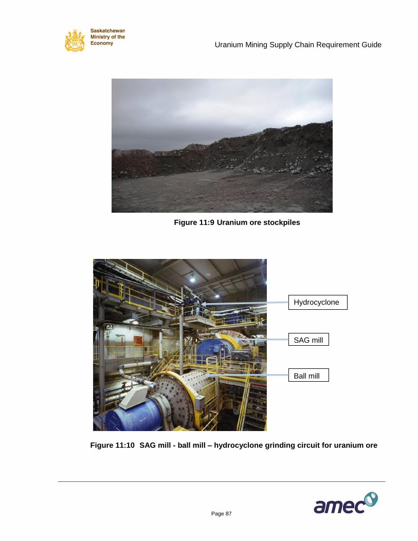
Uranium Mining Supply Chain Requirement Guide
Page 87
Figure 11:9 Uranium ore stockpiles
Figure 11:10 SAG mill - ball mill – hydrocyclone grinding circuit for uranium ore
Hydrocyclone
s
SAG mill
Ball mill
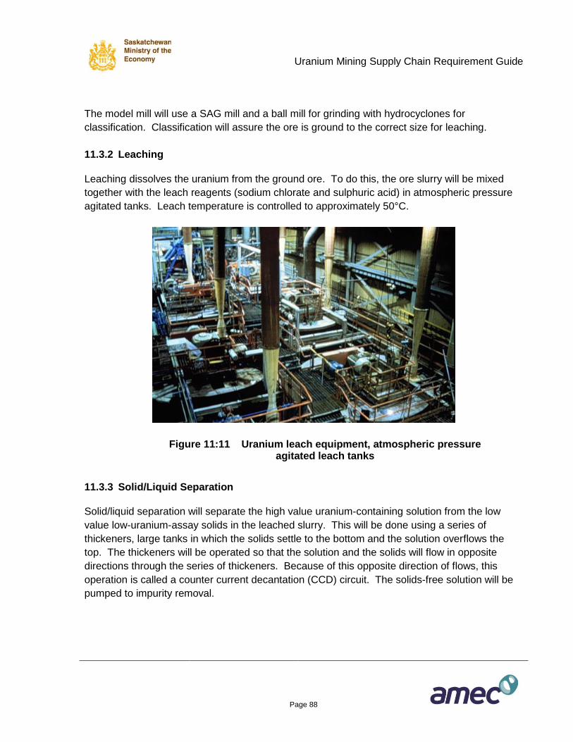
Uranium Mining Supply Chain Requirement Guide
Page 88
The model mill will use a SAG mill and a ball mill for grinding with hydrocyclones for
classification. Classification will assure the ore is ground to the correct size for leaching.
11.3.2 Leaching
Leaching dissolves the uranium from the ground ore. To do this, the ore slurry will be mixed
together with the leach reagents (sodium chlorate and sulphuric acid) in atmospheric pressure
agitated tanks. Leach temperature is controlled to approximately 50°C.
Figure 11:11 Uranium leach equipment, atmospheric pressure agitated leach tanks
11.3.3 Solid/Liquid Separation
Solid/liquid separation will separate the high value uranium-containing solution from the low
value low-uranium-assay solids in the leached slurry. This will be done using a series of
thickeners, large tanks in which the solids settle to the bottom and the solution overflows the
top. The thickeners will be operated so that the solution and the solids will flow in opposite
directions through the series of thickeners. Because of this opposite direction of flows, this
operation is called a counter current decantation (CCD) circuit. The solids-free solution will be
pumped to impurity removal.
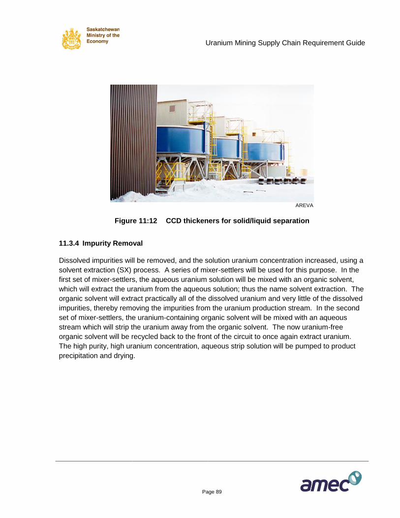
Uranium Mining Supply Chain Requirement Guide
Page 89
AREVA
Figure 11:12 CCD thickeners for solid/liquid separation
11.3.4 Impurity Removal
Dissolved impurities will be removed, and the solution uranium concentration increased, using a
solvent extraction (SX) process. A series of mixer-settlers will be used for this purpose. In the
first set of mixer-settlers, the aqueous uranium solution will be mixed with an organic solvent,
which will extract the uranium from the aqueous solution; thus the name solvent extraction. The
organic solvent will extract practically all of the dissolved uranium and very little of the dissolved
impurities, thereby removing the impurities from the uranium production stream. In the second
set of mixer-settlers, the uranium-containing organic solvent will be mixed with an aqueous
stream which will strip the uranium away from the organic solvent. The now uranium-free
organic solvent will be recycled back to the front of the circuit to once again extract uranium.
The high purity, high uranium concentration, aqueous strip solution will be pumped to product
precipitation and drying.
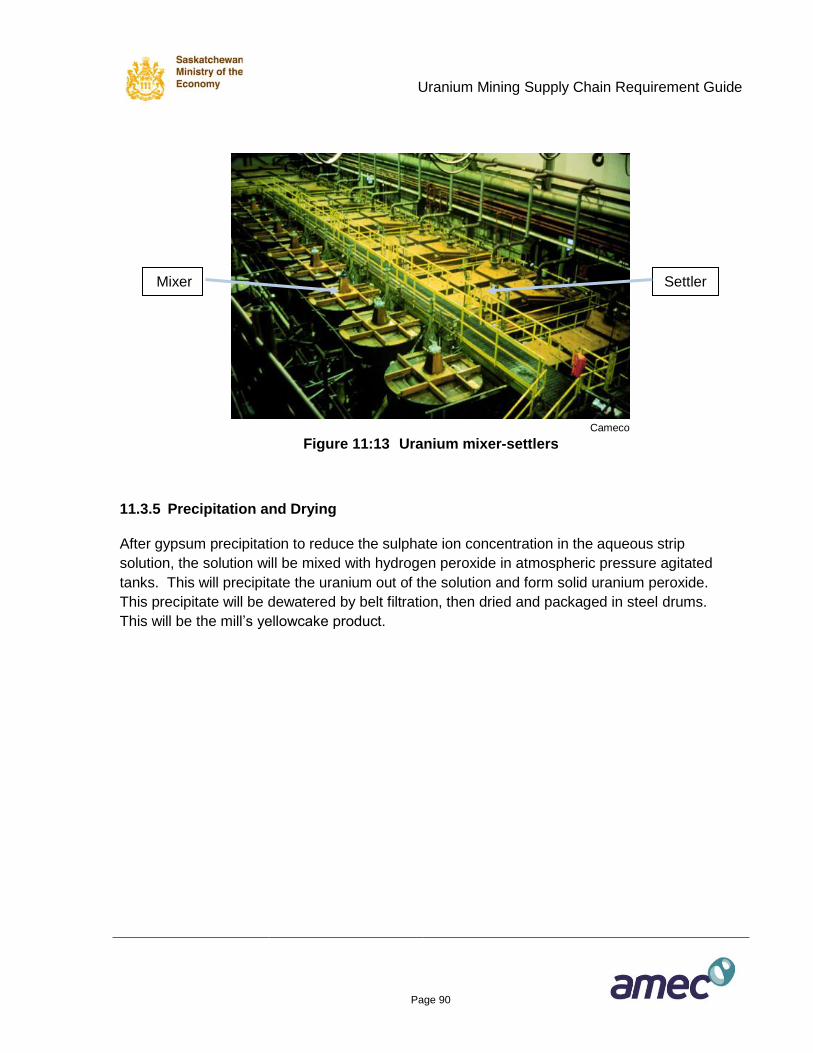
Uranium Mining Supply Chain Requirement Guide
Page 90
Cameco
Figure 11:13 Uranium mixer-settlers
11.3.5 Precipitation and Drying
After gypsum precipitation to reduce the sulphate ion concentration in the aqueous strip
solution, the solution will be mixed with hydrogen peroxide in atmospheric pressure agitated
tanks. This will precipitate the uranium out of the solution and form solid uranium peroxide.
This precipitate will be dewatered by belt filtration, then dried and packaged in steel drums.
This will be the mill’s yellowcake product.
Settler Mixer
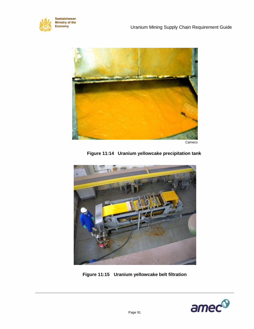
Uranium Mining Supply Chain Requirement Guide
Page 91
Cameco
Figure 11:14 Uranium yellowcake precipitation tank
Figure 11:15 Uranium yellowcake belt filtration
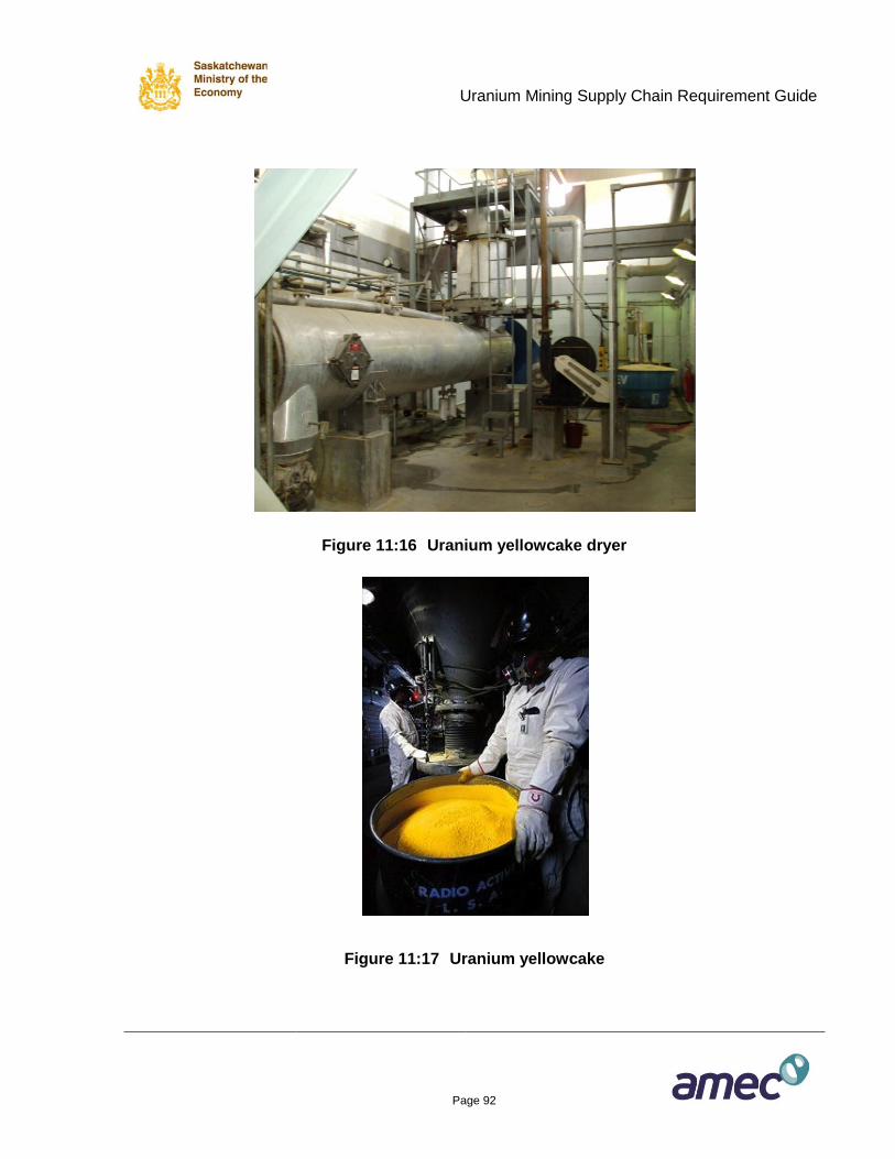
Uranium Mining Supply Chain Requirement Guide
Page 92
Figure 11:16 Uranium yellowcake dryer
Figure 11:17 Uranium yellowcake
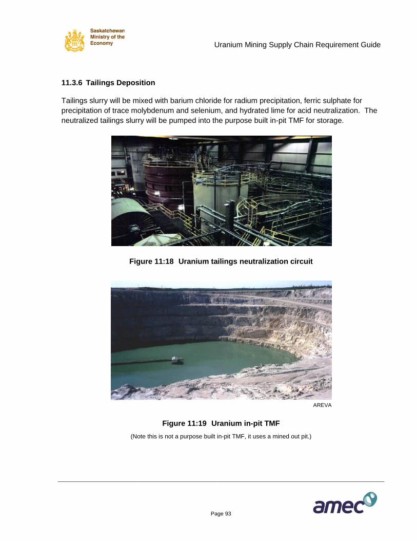
Uranium Mining Supply Chain Requirement Guide
Page 93
11.3.6 Tailings Deposition
Tailings slurry will be mixed with barium chloride for radium precipitation, ferric sulphate for
precipitation of trace molybdenum and selenium, and hydrated lime for acid neutralization. The
neutralized tailings slurry will be pumped into the purpose built in-pit TMF for storage.
Figure 11:18 Uranium tailings neutralization circuit
AREVA
Figure 11:19 Uranium in-pit TMF
(Note this is not a purpose built in-pit TMF, it uses a mined out pit.)
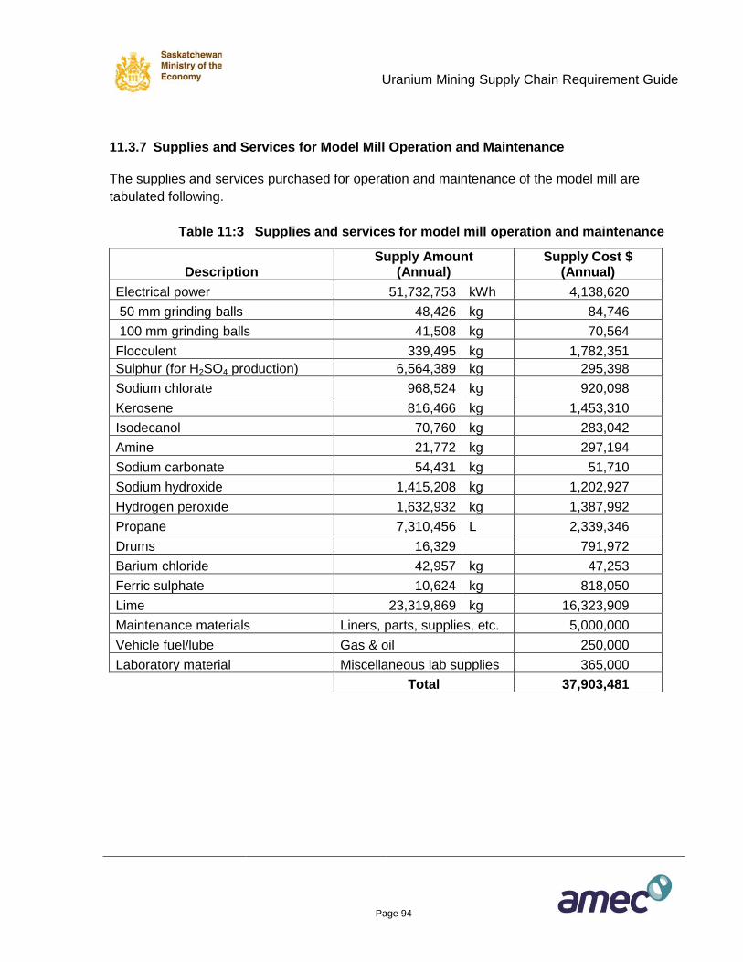
Uranium Mining Supply Chain Requirement Guide
Page 94
11.3.7 Supplies and Services for Model Mill Operation and Maintenance
The supplies and services purchased for operation and maintenance of the model mill are
tabulated following.
Table 11:3 Supplies and services for model mill operation and maintenance
Description Supply Amount
(Annual) Supply Cost $
(Annual)
Electrical power 51,732,753 kWh 4,138,620
50 mm grinding balls 48,426 kg 84,746
100 mm grinding balls 41,508 kg 70,564
Flocculent 339,495 kg 1,782,351
Sulphur (for H2SO4 production) 6,564,389 kg 295,398
Sodium chlorate 968,524 kg 920,098
Kerosene 816,466 kg 1,453,310
Isodecanol 70,760 kg 283,042
Amine 21,772 kg 297,194
Sodium carbonate 54,431 kg 51,710
Sodium hydroxide 1,415,208 kg 1,202,927
Hydrogen peroxide 1,632,932 kg 1,387,992
Propane 7,310,456 L 2,339,346
Drums 16,329
791,972
Barium chloride 42,957 kg 47,253
Ferric sulphate 10,624 kg 818,050
Lime 23,319,869 kg 16,323,909
Maintenance materials Liners, parts, supplies, etc. 5,000,000
Vehicle fuel/lube Gas & oil 250,000
Laboratory material Miscellaneous lab supplies 365,000
Total 37,903,481
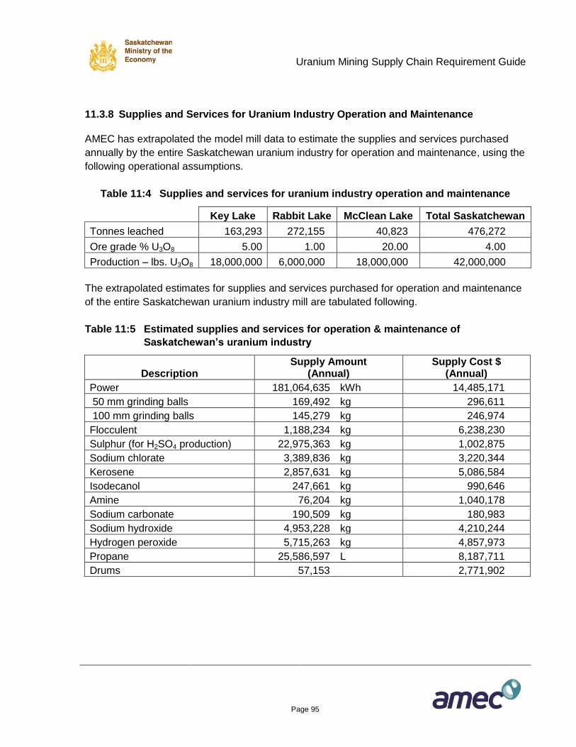
Uranium Mining Supply Chain Requirement Guide
Page 95
11.3.8 Supplies and Services for Uranium Industry Operation and Maintenance
AMEC has extrapolated the model mill data to estimate the supplies and services purchased
annually by the entire Saskatchewan uranium industry for operation and maintenance, using the
following operational assumptions.
Table 11:4 Supplies and services for uranium industry operation and maintenance
Key Lake Rabbit Lake McClean Lake Total Saskatchewan
Tonnes leached 163,293 272,155 40,823 476,272
Ore grade % U3O8 5.00 1.00 20.00 4.00
Production – lbs. U3O8 18,000,000 6,000,000 18,000,000 42,000,000
The extrapolated estimates for supplies and services purchased for operation and maintenance
of the entire Saskatchewan uranium industry mill are tabulated following.
Table 11:5 Estimated supplies and services for operation & maintenance of
Saskatchewan’s uranium industry
Description Supply Amount
(Annual) Supply Cost $
(Annual)
Power 181,064,635 kWh 14,485,171
50 mm grinding balls 169,492 kg 296,611
100 mm grinding balls 145,279 kg 246,974
Flocculent 1,188,234 kg 6,238,230
Sulphur (for H2SO4 production) 22,975,363 kg 1,002,875
Sodium chlorate 3,389,836 kg 3,220,344
Kerosene 2,857,631 kg 5,086,584
Isodecanol 247,661 kg 990,646
Amine 76,204 kg 1,040,178
Sodium carbonate 190,509 kg 180,983
Sodium hydroxide 4,953,228 kg 4,210,244
Hydrogen peroxide 5,715,263 kg 4,857,973
Propane 25,586,597 L 8,187,711
Drums 57,153
2,771,902
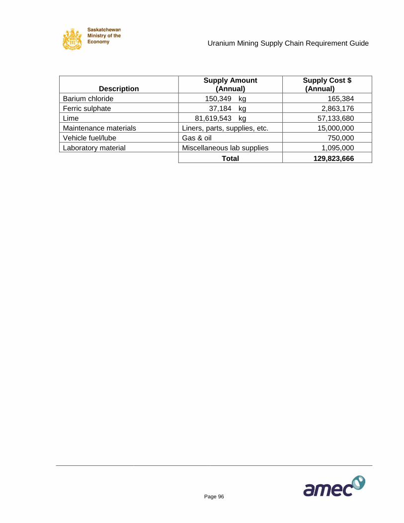
Uranium Mining Supply Chain Requirement Guide
Page 96
Description Supply Amount
(Annual) Supply Cost $ (Annual)
Barium chloride 150,349 kg 165,384
Ferric sulphate 37,184 kg 2,863,176
Lime 81,619,543 kg 57,133,680
Maintenance materials Liners, parts, supplies, etc. 15,000,000
Vehicle fuel/lube Gas & oil 750,000
Laboratory material Miscellaneous lab supplies 1,095,000
Total 129,823,666
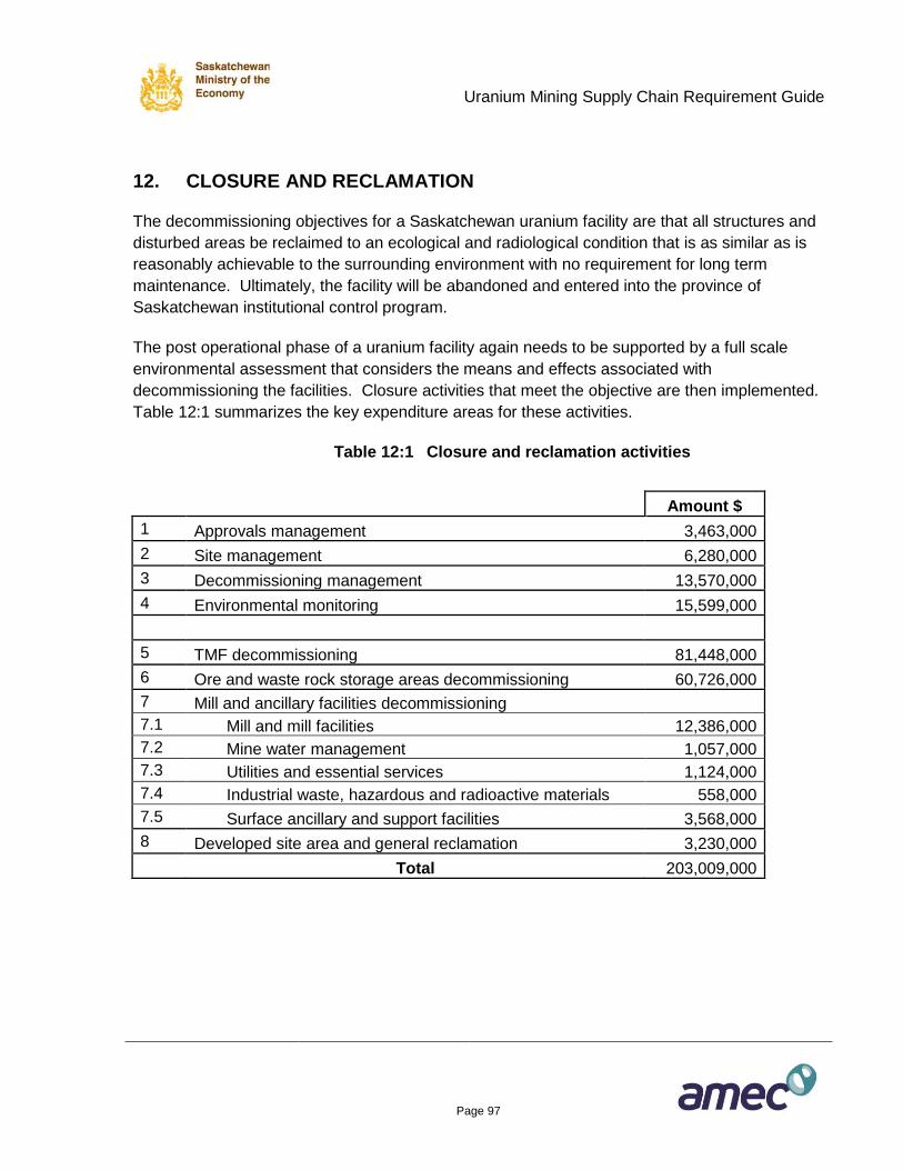
Uranium Mining Supply Chain Requirement Guide
Page 97
12. CLOSURE AND RECLAMATION
The decommissioning objectives for a Saskatchewan uranium facility are that all structures and
disturbed areas be reclaimed to an ecological and radiological condition that is as similar as is
reasonably achievable to the surrounding environment with no requirement for long term
maintenance. Ultimately, the facility will be abandoned and entered into the province of
Saskatchewan institutional control program.
The post operational phase of a uranium facility again needs to be supported by a full scale
environmental assessment that considers the means and effects associated with
decommissioning the facilities. Closure activities that meet the objective are then implemented.
Table 12:1 summarizes the key expenditure areas for these activities.
Table 12:1 Closure and reclamation activities
Amount $
1 Approvals management 3,463,000
2 Site management 6,280,000
3 Decommissioning management 13,570,000
4 Environmental monitoring 15,599,000
5 TMF decommissioning 81,448,000
6 Ore and waste rock storage areas decommissioning 60,726,000
7 Mill and ancillary facilities decommissioning
7.1 Mill and mill facilities 12,386,000
7.2 Mine water management 1,057,000
7.3 Utilities and essential services 1,124,000
7.4 Industrial waste, hazardous and radioactive materials 558,000
7.5 Surface ancillary and support facilities 3,568,000
8 Developed site area and general reclamation 3,230,000
Total 203,009,000
Uranium Mining Supply Chain Requirement Guide
Page 98
13. LONG TERM SITE MONITORING
The long term environmental monitoring program is intended to measure all relevant parameters
of concern that are monitored during operations but at a reduced frequency once the site is
decommissioned and effluent releases and emissions have ceased. The final decommissioning
environmental monitoring program is subject to regulatory approval. Four distinct phases of
environmental monitoring will occur during decommissioning. These phases and approximate
timelines are as follows:
Cessation Period Monitoring (0.5 years)
o Monitoring during the cessation of operations.
Decommissioning Period Monitoring (40.5 years)
o Monitoring during approvals process, care and maintenance, active
decommissioning and pump and treat period.
Transitional Period Monitoring (10 years)
o Monitoring conducted post active decommissioning to confirm decommissioning
criteria is met and the site is in a stable and/or improving condition.
Institutional Control Monitoring
o Covers that period of time after transitional monitoring is completed and the site is
under institutional control.
o Includes periodic assessment of and required repairs to or revisions of impacts
mitigation structures and systems.
Each of these phases will require some degree of environmental monitoring and associated
services directed by the standards of the day. No cost estimate is available for long term site
monitoring as there is no experience to use as the basis of the estimate. Long term site
monitoring of a current best practice designed and operated mine or mill has not yet occurred.
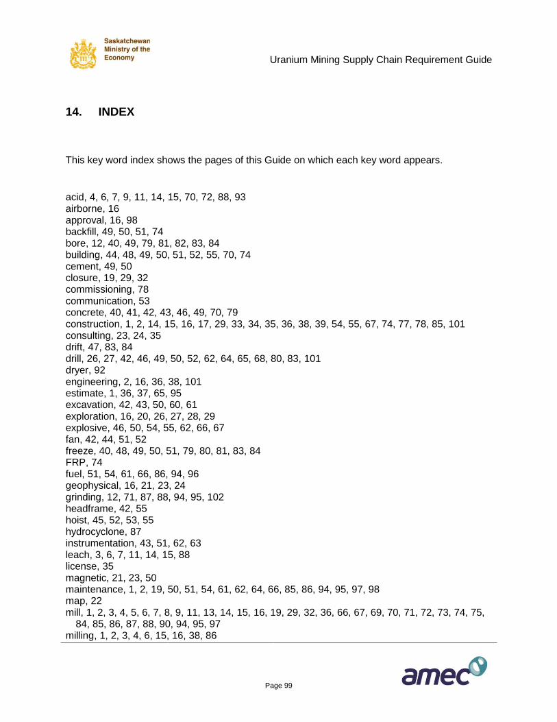
Uranium Mining Supply Chain Requirement Guide
Page 99
14. INDEX
This key word index shows the pages of this Guide on which each key word appears.
acid, 4, 6, 7, 9, 11, 14, 15, 70, 72, 88, 93 airborne, 16 approval, 16, 98 backfill, 49, 50, 51, 74 bore, 12, 40, 49, 79, 81, 82, 83, 84 building, 44, 48, 49, 50, 51, 52, 55, 70, 74 cement, 49, 50 closure, 19, 29, 32 commissioning, 78 communication, 53 concrete, 40, 41, 42, 43, 46, 49, 70, 79 construction, 1, 2, 14, 15, 16, 17, 29, 33, 34, 35, 36, 38, 39, 54, 55, 67, 74, 77, 78, 85, 101 consulting, 23, 24, 35 drift, 47, 83, 84 drill, 26, 27, 42, 46, 49, 50, 52, 62, 64, 65, 68, 80, 83, 101 dryer, 92 engineering, 2, 16, 36, 38, 101 estimate, 1, 36, 37, 65, 95 excavation, 42, 43, 50, 60, 61 exploration, 16, 20, 26, 27, 28, 29 explosive, 46, 50, 54, 55, 62, 66, 67 fan, 42, 44, 51, 52 freeze, 40, 48, 49, 50, 51, 79, 80, 81, 83, 84 FRP, 74 fuel, 51, 54, 61, 66, 86, 94, 96 geophysical, 16, 21, 23, 24 grinding, 12, 71, 87, 88, 94, 95, 102 headframe, 42, 55 hoist, 45, 52, 53, 55 hydrocyclone, 87 instrumentation, 43, 51, 62, 63 leach, 3, 6, 7, 11, 14, 15, 88 license, 35 magnetic, 21, 23, 50 maintenance, 1, 2, 19, 50, 51, 54, 61, 62, 64, 66, 85, 86, 94, 95, 97, 98 map, 22 mill, 1, 2, 3, 4, 5, 6, 7, 8, 9, 11, 13, 14, 15, 16, 19, 29, 32, 36, 66, 67, 69, 70, 71, 72, 73, 74, 75,
84, 85, 86, 87, 88, 90, 94, 95, 97 milling, 1, 2, 3, 4, 6, 15, 16, 38, 86
Uranium Mining Supply Chain Requirement Guide
Page 100
mine, 1, 2, 3, 4, 5, 6, 7, 9, 12, 13, 14, 16, 18, 20, 26, 29, 32, 34, 36, 40, 41, 42, 43, 44, 45, 46, 47, 49, 50, 51, 52, 53, 54, 55, 57, 58, 59, 60, 61, 62, 63, 65, 67, 75, 79, 84, 86, 101
mining, 1, 2, 10, 11, 12, 16, 19, 36, 38, 40, 48, 49, 51, 59, 61, 62, 63, 66, 79, 80, 81, 83, 84, 85 model, 1, 13, 14, 15, 19, 33, 39, 40, 46, 55, 57, 58, 59, 60, 61, 62, 65, 66, 67, 69, 74, 79, 84, 85,
86, 88, 94, 95 monitoring, 1, 12, 19, 34, 35, 53, 61, 62, 63, 65, 80, 97, 98 motor, 101 office, 77 operations, 1, 2, 3, 16, 19, 29, 35, 42, 55, 59, 60, 65, 66, 76, 78, 84, 85, 98 ore, 1, 3, 4, 6, 7, 9, 11, 12, 13, 15, 16, 17, 19, 35, 36, 40, 41, 43, 44, 45, 49, 51, 58, 59, 60, 62,
67, 69, 78, 79, 81, 83, 84, 85, 86, 87, 88 pad, 50, 84, 85 piping, 48, 54, 66, 75 pit, 1, 3, 4, 5, 6, 7, 8, 9, 11, 12, 14, 15, 50, 58, 59, 60, 61, 62, 63, 64, 65, 66, 67, 68, 73, 85, 93 pond, 66 procurement, 1, 16, 38, 101 pump, 13, 47, 50, 52, 66, 74, 98 radiometric, 23 ramp, 1, 14, 63, 78 reclamation, 1, 2, 16, 19, 97 residence, 75 road, 14, 20, 21, 51, 61, 64, 66, 67, 75, 77 rubber, 64, 74 services, 1, 2, 15, 16, 19, 20, 23, 24, 26, 34, 35, 38, 42, 43, 50, 53, 55, 67, 74, 77, 78, 85, 86,
94, 95, 97, 98 sewage, 75 shaft, 41, 42, 43, 44, 45, 46, 47, 48, 51, 52, 53, 54, 55 shotcrete, 46, 50, 55 skip, 43, 45 steel, 42, 43, 45, 47, 48, 50, 54, 65, 70, 74, 90, 102 supplies, 1, 2, 15, 50, 51, 55, 64, 67, 74, 77, 78, 85, 86, 94, 95, 96 tailings, 4, 11, 93, 102 tank, 49, 50, 64, 91 truck, 13, 26, 46, 50, 55, 61, 63, 64, 67 vehicle, 46, 50, 70 ventilation, 41, 42, 44, 47, 51, 52, 101 waste, 7, 41, 42, 43, 44, 45, 51, 60, 61, 62, 66, 67, 84, 85, 97 water, 4, 12, 13, 14, 20, 40, 43, 47, 48, 49, 52, 53, 59, 61, 62, 64, 65, 66, 73, 75, 79, 80, 84, 97 well, 32, 34, 49, 65, 66, 85
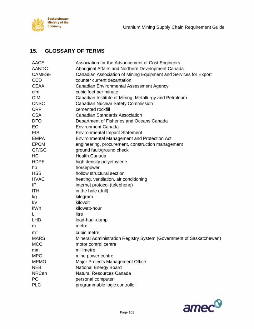
Uranium Mining Supply Chain Requirement Guide
Page 101
15. GLOSSARY OF TERMS
AACE
Association for the Advancement of Cost Engineers AANDC Aboriginal Affairs and Northern Development Canada
CAMESE Canadian Association of Mining Equipment and Services for Export
CCD
counter current decantation CEAA
Canadian Environmental Assessment Agency
cfm
cubic feet per minute CIM
Canadian Institute of Mining, Metallurgy and Petroleum CNSC
Canadian Nuclear Safety Commission
CRF
cemented rockfill CSA
Canadian Standards Association DFO
Department of Fisheries and Oceans Canada
EC
Environment Canada EIS
Environmental Impact Statement EMPA
Environmental Management and Protection Act
EPCM
engineering, procurement, construction management GF/GC
ground fault/ground check HC
Health Canada
HDPE
high density polyethylene hp
horsepower HSS
hollow structural section
HVAC
heating, ventilation, air conditioning IP
internet protocol (telephone) ITH
in the hole (drill)
kg
kilogram kV
kilovolt kWh
kilowatt-hour
L
litre LHD
load-haul-dump m
metre
m3
cubic metre MARS
Mineral Administration Registry System (Government of Saskatchewan)
MCC
motor control centre mm
millimetre MPC
mine power centre
MPMO
Major Projects Management Office NEB
National Energy Board NRCan Natural Resources Canada
PC
personal computer PLC
programmable logic controller
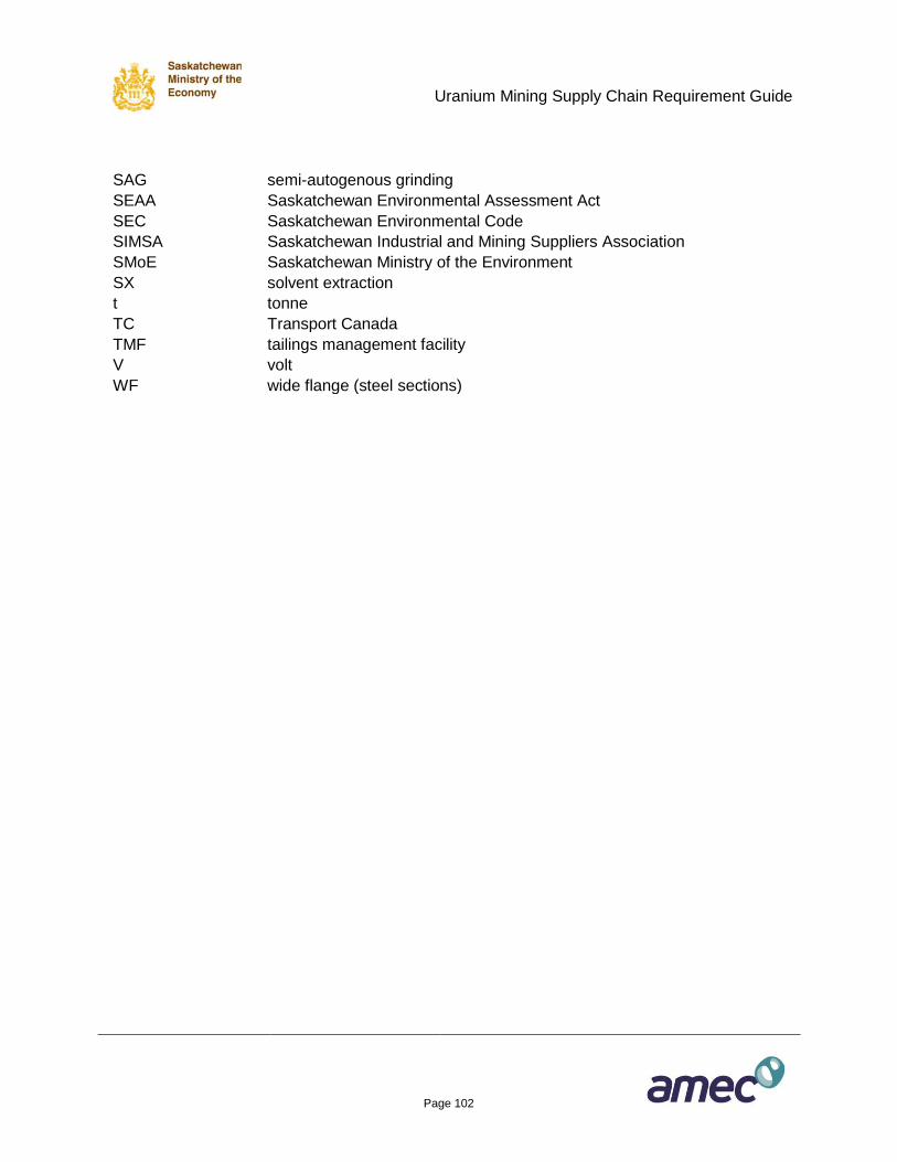
Uranium Mining Supply Chain Requirement Guide
Page 102
SAG
semi-autogenous grinding SEAA
Saskatchewan Environmental Assessment Act
SEC
Saskatchewan Environmental Code SIMSA
Saskatchewan Industrial and Mining Suppliers Association SMoE
Saskatchewan Ministry of the Environment
SX
solvent extraction t
tonne TC
Transport Canada
TMF
tailings management facility V
volt WF
wide flange (steel sections)
Related Documents