Prof. Dr.-Ing. W. Jäger TU Dresden page 1 Dissemination of information for training – Brussels, 2-3 April 2009 EUROCODE 6 Background and applications Unreinforced masonry – shear loading Unreinforced masonry – shear loading 1 Masonry members under shear loading Types • In plane • Out of plane In plane out of plane a) In plane shear b) Out of plane shear Figure 1 Types of shear action In plane shear loading occurs in connection with the transmission of wind loads and stiffening forces of masonry buildings as well as other lateral forces in plane of walls. Out of plane shear has to be verified in case of lateral actions perpendicular to the wall area. Typically examples are the wind action perpendicular to the wall or the pressure of earth or loos stock material. 2 Bracing of buildings The layout of the walls in the ground plan of the building should be foreseen in such a way that the sufficient bracing of a building should be guaranteed. In traditionally buildings the sufficient stiffening can be assumed. The current tendency of economically solutions in residential and office buildings lead to an open ground plan with a minimum of stiffening walls, which makes the verification of stiffening walls often necessary. The principles of bracing are: • an available concrete ceiling or ring beam • more than 3 walls • the axes should not intersect in one point

Welcome message from author
This document is posted to help you gain knowledge. Please leave a comment to let me know what you think about it! Share it to your friends and learn new things together.
Transcript

Prof. Dr.-Ing. W. Jäger TU Dresden page 1
Dissemination of information for training – Brussels, 2-3 April 2009
EUROCODE 6 Background and applications Unreinforced masonry – shear loading
Unreinforced masonry – shear loading
1 Masonry members under shear loading Types
• In plane • Out of plane
In plane
out of plane
a) In plane shear b) Out of plane shear
Figure 1 Types of shear action
In plane shear loading occurs in connection with the transmission of wind loads and stiffening forces of masonry buildings as well as other lateral forces in plane of walls. Out of plane shear has to be verified in case of lateral actions perpendicular to the wall area. Typically examples are the wind action perpendicular to the wall or the pressure of earth or loos stock material.
2 Bracing of buildings The layout of the walls in the ground plan of the building should be foreseen in such a way that the sufficient bracing of a building should be guaranteed. In traditionally buildings the sufficient stiffening can be assumed. The current tendency of economically solutions in residential and office buildings lead to an open ground plan with a minimum of stiffening walls, which makes the verification of stiffening walls often necessary. The principles of bracing are:
• an available concrete ceiling or ring beam • more than 3 walls • the axes should not intersect in one point

Prof. Dr.-Ing. W. Jäger TU Dresden page 2
Dissemination of information for training – Brussels, 2-3 April 2009
EUROCODE 6 Background and applications Unreinforced masonry – shear loading
M0
a) favourable
M0
high excentricity
M0
b) unfavourable
c) instable
Figure 2 Arrangement of stiffening walls
3 Verification format
Table 1 Procedure according to EC 6
EN 1996-1-1 EN 1996-3
General rules Simplified calculation methods
filled head joints:
⎩⎨⎧ ⋅
≤⋅+=vlt
bdvkvk f
fff
065,04,00 σ
unfilled head joints:
⎩⎨⎧ ⋅
≤⋅+⋅=vlt
bdvkvk f
fff
045,04,05,0 0 σ
shell bedded masonry:
⎩⎨⎧ ⋅
≤⋅+⋅=vlt
bdvkvk f
ff
tgf
045,04,00 σ
cvdRd ltfV ⋅⋅=
with: fvk0: adhesive shear strength without load σd: compressive stress, perpendicular with shear load fb: compressive strength of masonry fklt: limit of shear strength g: overall with of mortar strips t: thickness of the wall
vduEdM
EdvdoEdvRd ftelNftelcV ⋅⋅⎥⎦
⎤⎢⎣⎡ −≤⋅+⋅⋅⎥⎦
⎤⎢⎣⎡ −⋅=
234,0
2 γwith:
Ed
EdEd N
Me =
cv = 3 filled head joints cv = 1,5 unfilled head joints eEd: excentricity of load t: thickness of the wall fvd0= fvk0/γM NEd: vertical load l: length of the wall fvdu: ultimate shear strength
verification
RdEd VV ≤

Prof. Dr.-Ing. W. Jäger TU Dresden page 3
Dissemination of information for training – Brussels, 2-3 April 2009
EUROCODE 6 Background and applications Unreinforced masonry – shear loading
3.1 Background – theory Depending on the ratio of shear to the vertical component of compression stress failure initiated differently. The shear fracture failure of masonry is a curve illustration of four modes of failure.
Figure 3 failure modes of a shear wall
The failure of a masonry wall depends on the strength of the unit and mortar. Around the unit exist different areas of compressive stress and shear.
Figure 4 equilibrium of forces at a masonry unit
4 Procedure
4.1 In plane shear loading Schedule A) Actions
1. Determination of wind action 2. Determination of bracing forces 3. Distribution of forces on the stiffening walls (see Figure 5) 4. Determination of normal stresses/forces and compressed area
a. Bending action due to in plane lateral forces and b. determination of the compressed area

Prof. Dr.-Ing. W. Jäger TU Dresden page 4
Dissemination of information for training – Brussels, 2-3 April 2009
EUROCODE 6 Background and applications Unreinforced masonry – shear loading
c. Bending due to deflection of the ceilings B) Resistance
5. Determination of shear strength and/or shear resistance C) Verification
6. Design action ≤ Design resistance
j2
3 nMo
SM2
Mj
M3Mn
mx,o
Hw,i,z
ey
ez
Hw,i,yz
Z y
yMo,j
z zz
y
Yy
Mo
j*
*
*
**
* Mo j
1 M1
conection with shear forceneglect at calculation
0
0
Mo,
j
Figure 5 Determination of the shear centre in the ground plan
4.2 Out of plane shear loading Schedule A) Actions
1. Determination of wind action 2. Determination of normal stresses/forces and compressed area
a. Bending action due to in plane lateral forces and b. determination of the compressed area
B) Resistance 3. Determination of shear strength and/or shear resistance
C) Verification 4. Design action ≤ Design resistance

Prof. Dr.-Ing. W. Jäger TU Dresden page 5
Dissemination of information for training – Brussels, 2-3 April 2009
EUROCODE 6 Background and applications Unreinforced masonry – shear loading
5 Example for in plane shear
5.1 Building
Figure 6 longitudinal section A-A
Figure 7 top floor plan
Staircase

Prof. Dr.-Ing. W. Jäger TU Dresden page 6
Dissemination of information for training – Brussels, 2-3 April 2009
EUROCODE 6 Background and applications Unreinforced masonry – shear loading
Figure 8 first floor plan
Figure 9 basement plan
Staircase
Staircase
Beam
Beam
Prof. Dr.-Ing. W. Jäger TU Dresden page 7
Dissemination of information for training – Brussels, 2-3 April 2009
EUROCODE 6 Background and applications Unreinforced masonry – shear loading
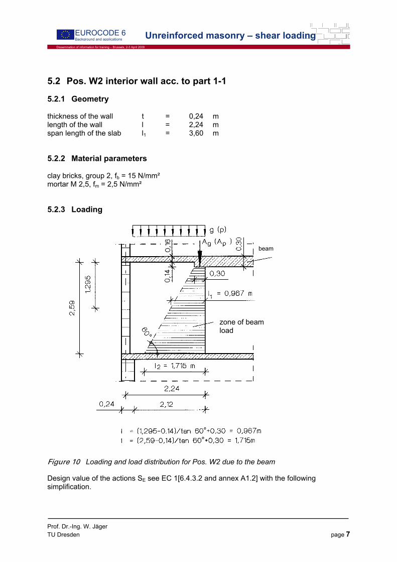
5.2 Pos. W2 interior wall acc. to part 1-1
5.2.1 Geometry thickness of the wall t = 0,24 m length of the wall l = 2,24 m span length of the slab l1 = 3,60 m
5.2.2 Material parameters clay bricks, group 2, fb = 15 N/mm² mortar M 2,5, fm = 2,5 N/mm²
5.2.3 Loading
Figure 10 Loading and load distribution for Pos. W2 due to the beam
Design value of the actions SE see EC 1[6.4.3.2 and annex A1.2] with the following simplification.
zone of beam load
beam

Prof. Dr.-Ing. W. Jäger TU Dresden page 8
Dissemination of information for training – Brussels, 2-3 April 2009
EUROCODE 6 Background and applications Unreinforced masonry – shear loading
Consideration of all unfavourable variable actions: ( ) ∑∑ ⋅+⋅γ i,kkjGj Q5,1G
Load case combinations see Figure 11.
Figure 11 Load case combinations for Pos. W2
Load case combination 1 is verified. The numerical values for load case combination 6 are declared in brackets. - vertical loads
beam Ag=56,6 kN; Ap=16,9 kN angle of load distribution 60° ( Figure 10)
dead load of the wall ²m/kN68,4gwall =
roof loads m/kN96,22N roof,g = , m/kN47,6N roof,q =
LFK 1
1,35g+1,5q
1,35Ng+1,5Nq
LFK 2
1,35g
LFK 3 LFK 4 LFK 5
LFK 6
1,35Ng+1,5Nq 1,35Ng 1,35Ng 1,35Ng
1,0Ng
1,35g+1,5q 1,35g
1,35g+1,5q 1,35g+1,5q
1,0g
1,35g+1,5q
1,0g
1,35g
1,35g 1,35g
LFK 7 LFK 8 LFK 9
1,0Ng 1,0Ng 1,35Ng+1,5Nq
1,0g+1,5q 1,35g+1,5q
1,0g+1,5q 1,35g+1,5q
1,0g
1,0g
1,5H,w
1,5H,w
1,5H,w 1,5H,w
Prof. Dr.-Ing. W. Jäger TU Dresden page 9
Dissemination of information for training – Brussels, 2-3 April 2009
EUROCODE 6 Background and applications Unreinforced masonry – shear loading
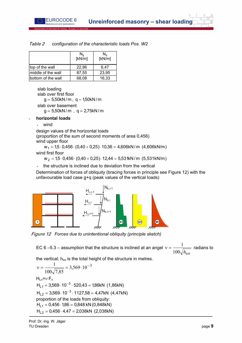
Table 2 configuration of the characteristic loads Pos. W2
Ng [kN/m]
Nq [kN/m]
top of the wall 22,96 6,47 middle of the wall 87,55 23,95 bottom of the wall 68,08 16,33
slab loading slab over first floor
m/kN50,5g = , m/kN50,1q = slab over basement
m/kN50,5g = , m/kN75,2q = - horizontal loads
- wind design values of the horizontal loads (proportion of the sum of second moments of area 0,456) wind upper floor )(4,606kN/m m/kN606,436,10)25,040,0(456,05,1w1 =⋅+⋅⋅= wind first floor )(5,531kN/m m/kN531,544,12)25,040,0(456,05,1w 2 =⋅+⋅⋅= - the structure is inclined due to deviation from the vertical Determination of forces of obliquity (bracing forces in principle see Figure 12) with the unfavourable load case g+q (peak values of the vertical loads)
1 Q1 M1N1
N
N
N
H
H
H
α,i-1
α,i
α,i+1
k,i
k,i+1
k,i-1
Figure 12 Forces due to unintentional obliquity (principle sketch)
EC 6 –5.3 – assumption that the structure is inclined at an angel toth100
1=ν radians to
the vertical; htot is the total height of the structure in metres. 310569,3
85,71001 −⋅==ν
HLn=ν⋅Fn
(1,86kN) kN86,143,52010569,3H 31L =⋅⋅= −
(4,47kN) kN47,458,112710569,3H 32L =⋅⋅= −
proportion of the loads from obliquity: (0,848kN) kN 848,086,1456,0H 1L =⋅= (2,038kN) kN038,247,4456,0H 2L =⋅=

Prof. Dr.-Ing. W. Jäger TU Dresden page 10
Dissemination of information for training – Brussels, 2-3 April 2009
EUROCODE 6 Background and applications Unreinforced masonry – shear loading
Total shear force in longitudinal direction of the wall: (29,61kN) kN61,2975,2531,550,2606,4038,2848,0V =⋅+⋅++=
Figure 13 loads from wind and obliquity
5.2.4 bending moments - moments as a result of vertical loads
- characteristic compressive strength of masonry compressive strength of the unit fb= 15 N/mm² compressive strength of the mortar fm= 2,5 N/mm²
²mm/N94,35,21545,0ffKf 3,07,03,0m
7,0bk =⋅⋅=⋅⋅=
- modulus of elasticity ²m/MN30500EE m0c4 ==
²m/MN39400f1000EE k21 =⋅== - second moment of area
443
B4 m10413,312
16,000,1II −⋅=⋅
==
443
1 m10267,112
115,000,1I −⋅=⋅
=
433
2 m10152,112
24,000,1I −⋅=⋅
=
- stiffness factor 4n = members fixed at both ends 3n = otherwise
HL1=0,848 kN
HL2=2,038 kN
w1=4,606 kN/m
w2=5,531 kN/m
Prof. Dr.-Ing. W. Jäger TU Dresden page 11
Dissemination of information for training – Brussels, 2-3 April 2009
EUROCODE 6 Background and applications Unreinforced masonry – shear loading
- slab loading Load case combination 1 is verified with q5,1g35,1 ⋅+⋅ . The numerical values for load case combination 6 are declared in brackets. slab over first floor
²m/kN675,950,15,150,535,1q4 =⋅+⋅= ²)m/kN500,5( slab over basement
²m/kN425,750,535,1q4 =⋅= ²)m/kN500,5( Bending moment at the top of the wall Simplified frame model
m/kNm449,1012
60,3675,9M2
full −=⋅
−= (-5,94kNm/m)
with 23
M1M1 MNm 5389,410152,13940IE =⋅⋅=⋅ −
24M2M2 MNm 4992,010267,13940IE =⋅⋅=⋅ −
24BB mNM 2390,1010413,330000IE =⋅⋅=⋅ −
)449,10(
60,32390,104
00,34992,03
75,25389,44
75,25389,44
M1 −⋅⋅
+⋅
+⋅
⋅
=
m/kNm733,3)449,10(357,0M1 −=−⋅= (-2,121kNm/m)
0,2602,1
00,34992,03
75,25389,44
60,32390,104
km <=⋅
+⋅
⋅
=
design value
m)(1,273kNm/ m/kNm238,2M)4
k1(M 1
mo =⋅−=
Bending moment at the bottom of the wall
m/kNm019,812
60,3425,7M2
full −=⋅
−=
m/kNm243,2019,8280,0M2 =⋅= (1,663kNm/m)
0,2837,0
75,24992,03
60,25389,44
60,32390,104
km <=⋅
+⋅
⋅
=
Bending moment at the bottom of the wall
m)(1,663kNm/ m/kNm243,2019,8280,0M2 =⋅= 0,2837,0 <=k Reduction factor
m)(1,315kNm/ m/kNm774,1243,2791,0M2 =⋅= moment in the middle of the wall (from the moments at the top and the bottom of the wall)
m)(0,021kNm/ m/kNm232,0238,221)774,1238,2(Mm −=−⋅+=
design value

Prof. Dr.-Ing. W. Jäger TU Dresden page 12
Dissemination of information for training – Brussels, 2-3 April 2009
EUROCODE 6 Background and applications Unreinforced masonry – shear loading
m)(0,021kNm/ m/kNm232,0MM mm == Corresponding normal force in the middle of the wall considering the load propagation of the beam
5.2.5 Design values • Design values of the actions top of the wall )(22,96kN/m m/kN70,4047,65,196,2235,1NN KEd =⋅+⋅== middle of the wall m/kN12,15495,23*5,155,8735,1Nm =+⋅= ( 87,55kN/mNm = ) from wind and obliquity
)(41,547kNm kNm547,41M688,0375,1531,5625,25,2606,4375,1038,2)375,150,2(848,0M
=⋅⋅+⋅⋅+⋅++⋅=
[ ] [ ](122,44kN) kN39,212N
9,1624,247,65,16,5624,2)375,168,496,22(35,1N=
+⋅⋅++⋅⋅+⋅=
624,2m373,0(0,339m) m196,0
39,212547,41e =<==
(section uncracked!)
)49,682kN/m( m/kN682,4924,2
547,416L
M6N22
±±=⋅
=⋅
±=σ
m)(137,23kN/ m/kN80,203682,4912,154NNN mEd =+=+= σ bottom of the wall )(68,08kN/m m/kN40,11633,165,108,6835,1NF =⋅+⋅= from wind and obliquity
)(77,031kNm kNm031,77M375,175,2531,500,45,2606,475,2038,2)75,250,2(848,0M
=⋅⋅+⋅⋅+⋅++⋅=
[ ] [ ]
)(135,182kN kN585,229N9,1624,247,65,16,5624,2)12,1296,22(35,1N
=+⋅⋅++⋅+⋅=
6L
624,2m373,0 m336,0
585,229031,77e ==<== (section uncracked!)
⎟⎟⎟⎟
⎠
⎞
⎜⎜⎜⎜
⎝
⎛
==<
==>
3L
324,2m747,0m570,0
6L
624,2m373,0 m570,0
⇒ (section partial cracked!)
Length of the compressed section for load case combination 6:
m650,1)570,0224,2(3)e
2L(3c3Lc =−⋅=−⋅=⋅=
m/kN113,9224,2
031,776L
M6N22
±=⋅
=⋅
±=σ
( m/kN765,169650,1
031,776L
M6N22
c
±=⋅
=⋅
±=σ )
m)(237,85kN/ m/kN51,208113,9240,116NNN FEd =+=+= σ

Prof. Dr.-Ing. W. Jäger TU Dresden page 13
Dissemination of information for training – Brussels, 2-3 April 2009
EUROCODE 6 Background and applications Unreinforced masonry – shear loading
• Design values of the resistance eccentricity top of the wall
(0,055m) m055,070,40
238,2e0 ==
middle of the wall
(0,0001m) m0011,080,203
232,0em ==
bottom of the wall
(0,0055m) m0085,051,208
774,1eu ==
Initial eccentricity
m00502,0450
26,2450h
e efinit === [EC 6-5.5.1]
with m26,259,2871,0hef =⋅= [EC 6-6.1.4(10)] wall supported on three sides, 24,015m60,3m24,2l ⋅=<= .
0,12 =ρ , load eccentricity at the top of the wall
4t
424,0m06,0(0,031m) m055,0eo ==<=
3,0871,00,1
24,2359,20,11
123 >=⋅
⎟⎠
⎞⎜⎝
⎛⋅⋅
+
=ρ
resultant eccentricity Top of the wall
24,005,0m012,0(0,060m) m060,000502,0055,0ei ⋅=>=+= middle of the wall
24,005,0m012,0(0,0051) m0061,000502,00011,0emk ⋅=<=+= ⇒ t05,0 ⋅ becomes decisive bottom of the wall
24,005,0m012,0 m0135,000502,00085,0ei ⋅=>=+= (0,0105m<0,012m) Reduction factors for slenderness and eccentricity [EC 6-6.1.3]: Top of the wall
(0,5) 5,024,0
060,021K =⋅−=Φ
middle of the wall
2u
1m
2
eA−
⋅=Φ
with (0,350) 350,015,21
417,7
24,0012,03723
224,026,2
u ==⋅−
−=
(0,900) 900,024,0
012,021A1 =⋅−=

Prof. Dr.-Ing. W. Jäger TU Dresden page 14
Dissemination of information for training – Brussels, 2-3 April 2009
EUROCODE 6 Background and applications Unreinforced masonry – shear loading
(0,847) 847,0e900,0 2350,0
m
2
=⋅=Φ−
bottom of the wall
(0,900) 888,024,0
0135,021B =⋅−=Φ
Design values of the resistance [EC 6-6.1.2]: Top of the wall
m)(278,91kN/ m/kN91,2787,1
94,324,05,0NRd =⋅
⋅=
middle of the wall
m)(471,13kN/ m/kN13,4717,1
94,324,0847,0NRd =⋅
⋅=
bottom of the wall
m)(500,61kN/ m/kN94,4937,1
94,324,0888,0NRd =⋅
⋅=
5.2.6 Verification to vertical loading [EC 6-6.1.2]:
RdEd NN ≤ Top of the wall
RdEd Nm/kN91,278m/kN70,40N =<= ( RdEd Nm/kN91,278m/kN96,22N =<= ) middle of the wall
RdEd Nm/kN13,471m/kN80,203N =<= ( RdEd Nm/kN13,471m/kN232,137N =<= ) bottom of the wall
RdEd Nm/kN94,493m/kN51,208N =<= ( RdEd Nm/kN61,500m/kN85,237N =<= )
5.2.7 Verification to shear loading • Design value of the shear resistance
M
cvkRd
ltfV
γ⋅⋅
=
with fvk shear strength t thickness of the wall lc length of the wall γM safety factor
dvkovk 4,0ff σ⋅+= ²m/MN20,0fvko = [EC6-Tab. 3.4] für Mauersteingruppe 2, Mörtel M2,5
Length of the compressed section and design compressive stress for load case combination 1+6:
m24,2L = ( m650,1Lc = )
)m/MN341,0( m/MN427,024,224,0
229585,0ltNminvorh 22
cd =
⋅=
⋅=σ
Prof. Dr.-Ing. W. Jäger TU Dresden page 15
Dissemination of information for training – Brussels, 2-3 April 2009
EUROCODE 6 Background and applications Unreinforced masonry – shear loading
Characteristic value of shear resistance ²m/MN371,0427,04,020,0fvk =⋅+= (0,336MN/m²) ²m/MN975,015065,0f065,0 b =⋅=⋅<
vltf²m/MN0,1 =< limit value for vkf (possibly defined at the National Annex) Design value of the shear resistance:
(106,7kN) kN3,1177,1
24,224,0371,0VRd =⋅⋅
=
• Shear force for load case combination 1 + 6 Q=V=29,61kN (29,61kN) • verification
RdEd VkN17,31 kN61,29 V =<= 106,7kN) kN61,29( < .
5.3 Pos. W2 interior wall – simplified method acc. to part 3
5.3.1 Requirements
• the building has not more than three stores above ground level; • the walls are fixed either through the ceiling or through appropriate constructions,
such as ring beams with sufficient rigidity; • load depth of the ceiling and the roof on the wall is at least 2 / 3 of wall thickness, but
not less than 85 mm; • the floor height is not higher than 3.0 m; • the smallest dimensions in the building floor plan is at least 1 / 3 of building height; • the characteristic values of the variable loads on the ceiling and the roof are not more
than 5.0 kN / m²; • the largest span of the ceiling is 6.0 m;
The conditions are complied with.
5.3.2 Verification to shear loading • Design value of the shear resistance
vduEdM
EdvdoEdvRd fte
2l3
N4,0fte
2lcV ⋅⋅⎥⎦
⎤⎢⎣⎡ −≤
γ⋅+⋅⋅⎥⎦
⎤⎢⎣⎡ −⋅=
with: cv = 3 (filled head joints) Excentricity from wind and obliquity for load case 1
)(77,031kNm kNm031,77M375,175,2531,500,45,2606,475,2038,2)75,250,2(848,0M
=⋅⋅+⋅⋅+⋅++⋅=
[ ] [ ]
)(135,182kN kN585,229N9,1624,247,65,16,5624,2)12,1296,22(35,1N
=+⋅⋅++⋅+⋅=
6L
624,2m373,0 m336,0
585,229031,77eEd ==<== (section uncracked!)
Prof. Dr.-Ing. W. Jäger TU Dresden page 16
Dissemination of information for training – Brussels, 2-3 April 2009
EUROCODE 6 Background and applications Unreinforced masonry – shear loading
7,1371,024,0376,0
224,23
7,1229,04,0
7,12,024,0376,0
224,23VRd ⋅⋅⎥⎦
⎤⎢⎣⎡ −≤⋅+⋅⋅⎥⎦
⎤⎢⎣⎡ −⋅=
kN117kN180VRd ≤=
• verification
RdEd VkN171 kN61,29 V =<= .
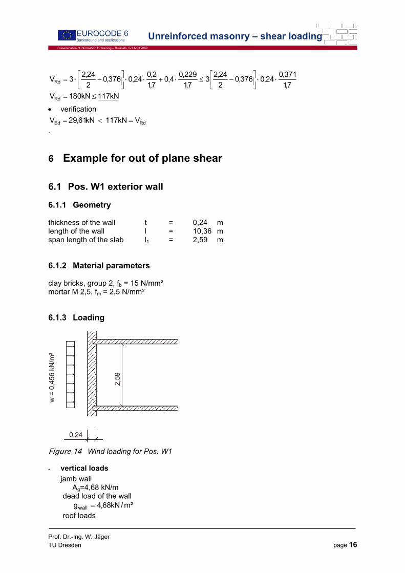
6 Example for out of plane shear
6.1 Pos. W1 exterior wall
6.1.1 Geometry thickness of the wall t = 0,24 m length of the wall l = 10,36 m span length of the slab l1 = 2,59 m
6.1.2 Material parameters clay bricks, group 2, fb = 15 N/mm² mortar M 2,5, fm = 2,5 N/mm²
6.1.3 Loading
w =
0,4
56 k
N/m
²
0,24
2,59
Figure 14 Wind loading for Pos. W1
- vertical loads jamb wall
Ag=4,68 kN/m dead load of the wall
²m/kN68,4gwall = roof loads

Prof. Dr.-Ing. W. Jäger TU Dresden page 17
Dissemination of information for training – Brussels, 2-3 April 2009
EUROCODE 6 Background and applications Unreinforced masonry – shear loading
m/kN29,1N roof,g = , m/kN56,1N roof,q =
- horizontal loads - wind ²m/kN684,0456,05,1w d =⋅=
6.1.4 Shear force as result of wind m/kN89,02/59,2684,0Vd =⋅=
6.1.5 Verification to shear loading • Design value of the shear resistance
M
cvkRd
tlfVγ⋅⋅
=
with fvk shear strength tc thickness of the compression zone of the wall l length of the wall γM safety factor
dvkovk 4,0ff σ⋅+= ²m/MN20,0fvko = [EC6-Tab. 3.4] unit group 2, mortar M2,5
No moments from load on the top of the wall, because support of the ceiling is parallel to its span direction.
m04,06l0,012m24,005,0ee lim =<=⋅== (section uncracked!)
m24,0ttc == kN/m 97,529,168,4Nmin =+=
m/MN025,0124,0
00597,0ltNminvorh 2
d =⋅
=⋅
=σ
Characteristic value of shear resistance
²m/MN21,0025,04,020,0fvk =⋅+= ²m/MN975,015065,0f065,0 b =⋅=⋅< Design value of the shear resistance:
m/kN6,297,1
00,124,021,0VRd =⋅⋅
=
• verification
RdEd VkN9,62 kN,890 V =<=
Related Documents