UNIVERSITY OF OKLAHOMA GRADUATE COLLEGE 3-D FINITE ELEMENT ANALYSIS OVER THE INTERNET USING JAVA AND VRML A THESIS SUBMITTED TO THE GRADUATE FACULTY in partial fulfillment of requirements for the degree of MASTER OF SCIENCE (Mechanical Engineering) By KARTHIK RANGA Norman, Oklahoma 2000

Welcome message from author
This document is posted to help you gain knowledge. Please leave a comment to let me know what you think about it! Share it to your friends and learn new things together.
Transcript

UNIVERSITY OF OKLAHOMA
GRADUATE COLLEGE
3-D FINITE ELEMENT ANALYSIS OVER THE INTERNET
USING JAVA AND VRML
A THESIS
SUBMITTED TO THE GRADUATE FACULTY
in partial fulfillment of requirements for the
degree of
MASTER OF SCIENCE
(Mechanical Engineering)
By
KARTHIK RANGA
Norman, Oklahoma
2000

E
3-D FINITE ELEMENT ANALYSIS OVER THE INTERNET USING JAVA AND VRML
A THESIS APPROVED FOR THE SCHOOL OF AEROSPACE AND MECHANICAL ENGINEERING
BY
_______________________________ Dr. Kurt Gramoll
_______________________________ Dr. Harold Stafford
_______________________________ Dr. Kuang-Hua Chang

Copyright by KARTHIK RANGA 2000
All Rights Reserved.

IV
ACKNOWLEDGEMENTS
I wish to express my sincere gratitude to my advisor, Dr. Kurt Gramoll, for his
guidance, constructive suggestions and encouragement throughout the course of this
research. I wish to thank him for providing all the facilities at his disposal. I am truly
indebted to him for providing me with an assistantship throughout the duration of my
studies at the University of Oklahoma. It was indeed a great pleasure and opportunity to
work under his paragon guidance.
I am grateful to Dr. Harold L. Stalford and Dr. K. H. Chang for serving on my
advisory committee and for reviewing my thesis manuscripts. Special thanks to my friend
Hrishikesh, colleagues at the Engineering Media Lab and well-wishers at the University
of Oklahoma for making my graduate school experience a truly memorable one.
Above all, a heartfelt expression of gratitude to my parents Dr. Geetha Ranga and
Mr. K. K. Ranga for all their support, encouragement and help throughout the course of
my education. Finally I would like to dedicate this thesis to the almighty, Lord Sai Baba
of Shirdi, to whom I owe everything in life.

V
TABLE OF CONTENTS
ACKNOWLEDGEMENTS IV
TABLE OF CONTENTS V
LIST OF FIGURES VIII
ABSTRACT IX
CHAPTER 1
INTRODUCTION
1.1 Definition of the need 1
1.2 Objectives and Overview of the Methodology 3
CHAPTER 2
LITERATURE REVIEW
2.1 Introduction 4
2.2 The Internet 4
2.3 The Internet for Education 6
2.4 Concurrent Engineering 8
2.5 Engineering Design on the Internet 11
CHAPTER 3
TECHNOLOGY BACKGROUND
3.1 Introduction 14

VI
3.2 Hypertext Markup Language 14
3.3 Virtual Reality Modeling Language (VRML) 16
3.3.1 Introduction to VRML 16
3.3.2 Key Concepts of VRML 18
3.3.3 Examples of some VRML Objects and Primitives 26
3.3.4 Dynamic VRML Worlds using Events and Routes 32
3.3.5 Salient Features of VRML 33
3.3.6 VRML Browser (Player) and VRML Authoring Software 34
3.3.7 Limitations of VRML 35
3.4 The Java Programming Language 36
3.4.1 Introduction 36
3.4.2 The Internet and Java 38
3.4.3 Key Features of Java 40
CHAPTER 4
THE FINITE ELEMENT METHOD
4.1 Introduction 44
4.2 History of the Finite Element Method 45
4.3 Applications of the Finite Element Method 46
4.4 Advantages of the Finite Element Method 47
CHAPTER 5
3-D FINITE ELEMENT ANALYSIS OVER THE INTERNET

VII
5.1 Introduction 49
5.2 Description of the hardware and software used 50
5.3 Description of the Model selected for Design and Analysis 51
5.4 Tetrahedral Solid Element for Finite Element Analysis 53
5.5 Preparation of the Finite Element Analysis Mesh 54
5.6 Integrating Java and VRML 58
5.7 Interface of the Application and Operational Procedures 60
5.8 Verification of the Results 68
5.9 Comparison with closed form solution 72
CHAPTER 6
SUMMARY AND CONCLUSIONS
6.1 Introduction 75
6.2 Conclusions 76
6.3 Recommendations for Future Research 77
REFERENCES 78
APPENDIX A: VRML CODE 81
APPENDIX B: JAVA CODES 96

VIII
LIST OF FIGURES
Figure 2.1 Typical Functioning of a Concurrent Design Team 10
Figure 3.1 VRML file using the Cosmo Player plug-in from SGI 21
Figure 3.2 The VRML coordinate system as seen in the SGI Cosmo Player 25
Figure 3.3 VRML Box node as seen in Cosmo Player 27
Figure 3.4 VRML Cone node as seen in Cosmo Player 28
Figure 3.5 VRML Cylinder node as seen in Cosmo Player 30
Figure 3.6 VRML Sphere node as seen in Cosmo Player 32
Figure 5.1 The L-shaped beam chosen for design and analysis 52
Figure 5.2 The tetrahedral family of 3-D elements 54
Figure 5.3 Division of a cube into six tetrahedral elements 56
Figure 5.4 L-beam divided into master cubes of unit dimension 57
Figure 5.5 Java Security Alert Windows 63
Figure 5.6 The Application Interface using Java’s AWT 65
Figure 5.7 A Sample Interface Window with values entered 66
Figure 5.8 Initial View of the Analysis Environment 68
Figure 5.9 L-beam (8x3) analyzed using SDRC I-DEAS 70
Figure 5.10 L-beam (8x3) analyzed in VRML 71
Figure 5.11 L-beam (8x3) analyzed in VRML with transparency turned on 72
Figure 5.12 Closed-form solution approach 74

IX
ABSTRACT
Over the past few years the Internet has gained a prominent role in many fields of
human endeavor such as commerce, entertainment, news, information, communications,
education etc. Many industries have realized the enormous potential of the Internet and
are coming up with newer and better ways of utilizing the Internet for improving their
operations. The Internet can be used as an information backbone for implementing the
concepts of Concurrent Engineering (CE) and Design for Manufacturing (DFM). These
concepts are being stressed in many industries since they can reduce the errors, costs and
time in the design of new products. The ubiquitous and platform independent nature of
the Internet allows geographically dispersed users to view the same data at the same time.
Thus the different departments in a company can coordinate their activities using the
Internet. Also many universities and institutions of higher learning have started adopting
the Internet as a new tool for dissemination of education and information. The
inexpensive access, user-friendly nature, round the clock availability and the ability to
quickly update the outdated information are particularly appealing to the educational
institutions.
This thesis is concerned with creating a virtual design and analysis environment
over the Internet using VRML (Virtual Reality Modeling Language) and Java. The
above-mentioned Internet technologies are used to enhance design education for
engineering students in all courses. Courses in engineering design are an important part

X
of the curriculum for students majoring in mechanical, aerospace and civil engineering.
In design courses students are taught to analyze problems and apply various equations for
computing stresses, strains and displacements. Traditionally these problems are solved by
the student using paper and pencil approach. For more complicated problems with no
closed form solutions finite element techniques are used. Generally the finite element
methods require the use of expensive software codes, which are also difficult to learn.
The students enrolled in the design courses will benefit if they are able to visualize their
designs and the effect of the various parameters on their designs. Although CAD and
analysis programs available in the market today possess good design and visualization
capabilities, they generally require heavy investment of time and money. Also the CAD
and CAE systems currently available do not have built-in Internet capabilities. The
VRML and Java based design and analysis environment developed in this research is a
real time design environment, which allows the creation of 3D models that are viewable
over the Internet using a web browser that has a VRML viewer plug-in. Since the design
environment is in real time, the students can experiment with their design models by
changing the values of the design parameters and receive the feedback immediately as the
model updates quickly on their computer screen. Hence the students can perform
collaborative design over the Internet using the Java and VRML based application. The
VRML and Java based design and analysis environment is also inexpensive compared to
commercial CAD systems and requires only a common text editor along with a Java
complier for development. In order to perform computations on the local machine of the

XI
user rather than the server, this research uses the Java language. The advantage of using
this approach is that the speed of computation is significantly higher than a client-server
based computation using a programming language such as PERL. Since this research
uses an Internet based design and analysis approach, many users can simultaneously log
on to the design environment and this may lead to a bottleneck due to the increased
Internet traffic. However since the Java and VRML application runs on the local machine
of the user, the design and analysis environment is quicker vis-à-vis a client-server based
program. The VRML and Java based design and analysis environment is thus used to
demonstrate the potential for design education over the Internet.

1
CHAPTER 1
INTRODUCTION
1.1 DEFINITION OF THE NEED
The Internet is a universal infrastructure connecting millions of computers around
the world. It provides an abundance of protocols and technologies for cataloging and
exchanging information resources. The commercial popularity of the Internet is due to
the media-rich World Wide Web – a medium capable of conveying textual, graphical,
geometric (3D), audio and video data all at the same time; and all linked together via
“hyperlinks” which are nothing but embedded codes that the system interprets to transfer
access to different points. The Internet has achieved phenomenal growth and acceptance
over the last few years - never before in human history has so much effort been poured
into a single medium of communication. The Internet has already opened a broad new
means of communication and collaboration, and for the most part, there has been very
little resistance to the adoption of these collaborative technologies. Whenever a new
technology has been introduced for the Internet it has generated a lot of interest and
support from organizations who then quickly adopt the technology to streamline their
operations and thereby improve the efficiency of their communication and information
sharing methods.
It is of immense benefit to the product development organizations and learning
institutes such as the universities to explore and exploit the functions, capabilities and
usefulness of the Internet for concurrent and collaborative design and engineering.

2
Although many organizations have been using the Internet for internal communication,
communication with partners and communication with customers or potential customers
few have begun using the Internet for designing products or performing engineering
analyses of those products. The concepts of concurrent engineering and design for
manufacturing are being widely used by many companies since they use the expertise of
employees from different departments who work together in cross-functional teams
involved in the design of a product from the concept stage to the manufacturing stages.
This combined expertise available at the disposal of these teams reduces not only the cost
but also the time to market for the products along with improvement in product quality.
However the different departments are often scattered in different geographical locations,
which then requires a common place for them to access the data at the same time in their
respective locations. Not only do the designers and engineers need to access the data, but
they should also be able to make changes to the product and view the changes in real
time. The ubiquitous nature of the Internet offers a solution to the above-mentioned
factors. Team members in different locations can easily view their designs over the
Internet without being physically present in the same place.
The Internet can also be used in universities and educational institutions to impart
education. However as the student population increases budgets are reduced, universities
face challenges in maintaining the high standards and effectiveness of education. This is
particularly true in the technical, engineering and medical fields, which are resource
intensive. The Internet with its international network of computers, access to vast
databases of knowledge and media-rich content lends itself to be used in the educational
fields.

3
1.2 OBJECTIVES AND OVERVIEW OF THE METHODOLOGY
The objective of this research is to develop an Internet-based interactive design
and finite-element analysis environment. This research examines the feasibility of VRML
(Virtual Reality Modeling Language) for visualizing different designs and the results of
analysis performed on a particular design the Internet. VRML is one of the prominent
standards currently accepted for visualization of three-dimensional objects over the
Internet. A virtual design environment in this work is an electronic design space in which
three-dimensional models can be visualized over the Internet using a web browser and a
VRML plug-in. The user who has an Internet connection to his or her computer can
modify the different attributes of the design model. The user can then perform stress
analysis of the model. The model used for design and analysis in this research is an L-
shaped beam fixed at one end. The stress analysis is performed using the finite element
analysis method since there does not exist a closed form solution for the L-beam model
chosen for this research.

4
CHAPTER 2
LITERATURE REVIEW
2.1 INTRODUCTION
New techniques in information technology are now changing not only our daily
lives, but also the professional practice of engineering development, design,
manufacturing, sales and support. The Internet opens up a new avenue for building future
CAD/CAM/CAE environments that will be global, networked and distributed1. The
evolving Internet infrastructure provides a new way of disseminating knowledge and
higher education. In a relatively short time, the Internet has been able to provide vast
amounts of information in multimedia form2, distribute content in electronic format,
enable commerce and trading facilities etc. Due to the above-mentioned factors, the
Internet holds an enormous opportunity for educational institutions as well as for
industry.
2.2 THE INTERNET
The Internet was originally designed in the early 1960’s through a project
formulated at the Defense Advanced Research Projects Agency (DARPA)3. It was
conceived and designed with the initial objectives of sharing computing resources and
data by connecting the different computers. However till the late 1980’s the Internet was
primarily used for research at universities, defense and government agencies. This was
due to the fact that the Internet did not possess a friendly and easy-to-use interface. In

5
1992, Tim Berners-Lee, a Swiss scientist, created the World Wide Web (WWW) at the
European Laboratory for Particle Physics4. The World Wide Web has quickly become the
graphical user interface to the Internet, and it stands unrivaled by any online service in
terms of both aesthetics and flexibility. WWW is the overall system consisting of ftp
sites, telnet utilities, gopher space etc. The flexible nature of the Web is due to the fact
that the sites on the Web can have media rich content such as graphics, 3-D models,
audio, video apart from regular text. The versatility of the Web is further underscored by
the fact that it allows dynamic text, graphics and simulations compared to static
information available in books. These are some of the reasons why the Internet has
gained mass appeal, especially after the birth of the World Wide Web. In 1983, there
were only about 200 computers that were connected to the Internet, however, since 1988
the number of computers with direct connection to the Internet has doubled every year. In
1998, the number of computers with Internet connection was over 50 million.
To access the Web, a program called a Web browser is used. The browser is
resident on the users’ hard disk and can retrieve information from other computers
connected to the Internet. This browser displays links that allow the user to load another
page of text and graphics. These pages are referred to as Web pages and are simply files
on millions of computers connected to the Internet. These browsers also work with a
special kind of helper application, called a plug-in, that displays unique files inside a
browser window. For this research, a VRML plug-in called Cosmo Player developed by
Silicon Graphics Incorporated is used.
The functionality of the Internet is expanding along with its prolific growth. Thus
with an enormous increase in the number of computers connected to the Internet there

6
have been concerns about Internet traffic and quality of service. In order to address and
resolve these issues, a university-led program called Internet2, (partially sponsored by the
NSF and a federally led program called Next Generation Internet) has been initiated to
propel continuous research in high performance networks5,6.
2.3 THE INTERNET FOR EDUCATION
The Internet is being quickly adopted as a communication means for imparting
education in higher education institutions. The factors responsible for this phenomenon
are the ease of use, increased participation of students in the learning process, flexibility
and relatively inexpensive access of the Internet. The Internet can also be used to deliver
course material to employees in a company to keep the abreast with the latest
developments in their chosen professions, long after they have graduated from the
university. Thus the employees can have a better opportunity for life-long learning7. The
students can learn at their own pace and availability of time. Internet-based education
model allows students to enroll in courses offered in any geographic location8.
The Internet and the World Wide Web can play multiple important roles in higher
education such as improving both the learning and teaching experience, creating
educational communities, improving the creation of instruction and learning materials9. It
can also provide benefits to the end-customer in the educational chain by increasing the
competition among the providers of education. The education market will basically
become a buyers market since the student will no longer be bounded by geographic
locations and can enroll for degrees from anywhere in the world if he/she meets the
eligibility requirements. In many universities, the Web is being used for course

7
administration. The students attend classroom coaching in the conventional student
teacher setting with the course web-site being used to post assignments, project
information, grades, test schedules, etc10.
The Internet has also been used to create virtual laboratories to assist the students
in understanding the concepts taught in the classroom. The ability to present media-rich
content on the World Wide Web is used to set-up such virtual laboratories over the
Internet. Experiments are also underway in many universities to control machinery and
robots over the Internet11. These studies can be used someday to control machines and
robots in hazardous environments. It is generally accepted that interactive simulations
enhance the learning experience of the students. The students can experiment with
various parameters and understand the concepts at their own pace12.
The Web is also being used extensively to deliver online courses for both on-
campus and off-campus students13. The Statics course for engineering students at the
University of Oklahoma is an example of a technical course that is completely offered
over the Internet. The lectures for this course are recorded using a digital camera and
compressed into streaming video format for delivery over the Web. The assignments,
quizzes and tests are also posted online and the students are required to submit their
answers using an HTML form through a web browser. The grading is also done
automatically for this course using a program resident on the Web server14. The Internet
has also been used as a delivery medium for the Fundamentals in Engineering Review
project at the University of Oklahoma. This project aims to provide engineering students,
as well as full-time employed engineers, with up-to-date reference material for the
Professional Certification Examination. The Web site uses multimedia technologies such
8
as graphics, animations, audio, video and simulations to explain and reinforce the
concepts that will be tested in the actual certification examination15.
2.4 CONCURRENT ENGINEERING
The marketplace is seeing an increase in newer and better products from around
the world. Industries are employing various technologies to integrate both product
development and the manufacturing processes used to produce the end product. The
reason for this is that the various companies want to reduce the time to market for a new
product. Customers want high quality products at low prices. They also do not want to
wait to receive the products. Hence the designers and manufacturers of these products are
facing tremendous pressure to satisfy the needs of their customers. Information
technology has become a major contributor to the faster turnaround, the higher quality,
and the low inflation that have characterized business in the last decade. Few industries
illustrate the twin pressures of collapsing time and improving quality better than the
automobile industry. Japanese auto designs in the 1980s appeared fresher and their
quality improvements more frequent than in American cars because Japanese automakers
could take a car from concept to mass production in three years. American automakers
typically took four to six years and their costs were higher. American companies
responded by breaking down the organizational barriers that had cut off design,
manufacturing, and sales divisions from one another and by improving communications
with their external partners16.
The concept of Concurrent Engineering stresses a systematic approach to the
design of products and their manufacturing. The concept of Concurrent Engineering (CE)

9
was introduced to avoid immature designs going into production and to reduce
subsequent design changes, which would ultimately result in losses to the company and
lead to customer dissatisfaction. Various engineering activities in the product and
production development processes are integrated and performed in parallel rather than
sequentially17. Concurrent engineering is founded on eight fundamental principles: early
problem discovery, early decision-making, work structuring, teamwork affinity,
knowledge leveraging, common understanding, ownership, and constancy of purpose.
Since approximately 80% of a product’s life-cycle development cost is driven by
decisions made in the first 20% of the program effort, early supplier involvement and
even inclusion of outside partners are encouraged. Most products in the market are
complex and beyond the ability of a single company to design and produce them.
Meanwhile the international competitiveness is intense and therefore to survive and
prosper in the modern marketplace companies have to coordinate their activities tightly.
The VRML and Java based design and analysis environment will allow the engineers as
well as other members of the product team such as marketing, supply and technical
support personnel to view the model from different locations using the Internet.
The main difference between the concurrent design and the traditional design
engineering is in the designing method. In the CE design stage, a suggested design is
submitted to the CE team. The advantage of the CE team involvement in the design stage
is that the domain experts from the engineering, manufacturing, marketing, sales,
packaging, inspection, service, assembly and environmental departments will improve the
design of the product with implementation of their knowledge while working
simultaneously working with the design team. The important factor to be noted is that by

10
designing the product, the CE team also resolves the manufacturing issues associated
with the product. The CE team makes decisions regarding the kind of equipment, layout
of the machines on the shop floor, assembly layout, inspection method to be used etc.
This greatly reduces the problems that may arise during the manufacturing stage of a
product. Figure 2.1 explains the layout of a typical concurrent engineering team.
Figure 2.1 Typical Functioning of a Concurrent Design Team18
2.5 ENGINEERING DESIGN ON THE INTERNET
One of the most important need in today’s design environment is to involve
personnel from all the related departments so as to make use of their expertise and
Domain Experts :Chemical,Industrial,Mechanical,Electrical, etc
ConcurrentProduct and Process Design Team
Concept &Market & Cost Analysis
Product Realization Phaseswith Concurrent engineering Design
Environment(Recycle/Waste)
ContinuousImprovement
Customer(Service/Maintenance)
Manufacturing fabrication
Manufacturing systemConstruciton and Installation
Selling Price and Production Cost Targets
Human Factors
Cost & Marketing
Reliability &Maintenance
Engineering Analysis
Process Planning
Manufac-turability
Assembla-bility
Compare To goals
MeetGoals?
Testability
redesign
No
Yes

11
experience in different areas. The formation of such cross-functional teams avoids
immature designs going into production and also for the products to make it quicker to
the product marketplace. However, since it is important to keep the total cost of any
product as low as possible to gain a competitive advantage, industries often maintain the
different departments such as design, engineering, production and marketing at different
geographical locations. Hence the integration of various departments involves widespread
locations. The involvement of different teams located at different places requires either
the product information or the teams themselves to be transported from one location to
another. Both these methods involve a lot of time and money, which reduces the overall
competitiveness of the product in the marketplace. Also, this exchange of information
requires all members of the design team to use the same CAD program and tools, which
is quite difficult to achieve and control.
The Internet can serve well as the information backbone for implementing the
concept of concurrent design and engineering. The Internet is interactive and can respond
to user input since it is based on a vast network of computers. The Internet also breaks the
barriers of geography since any person can access the same information from any
physical place in the world. Since the data on the Internet is transmitted electronically it
is fast and easily accessible. The Internet also supports data in text, audio, video,
animation, picture and 3-D formats.
The opportunities available for conducting collaborative design using the Internet
has invoked a lot of interest from both the academia and the industry. Research is being
currently conducted at the University of California at Berkeley to develop a web-based
product design and manufacturing system. This system provides Internet based services

12
such design for manufacturing CAD, Computer Aided Process Planning (CAPP), and
access to an open architecture machine tool for fabrication of parts19.
As the CAD/CAM/CAE technology has matured over the years it has become
very important to manage the large volumes of data generated by these systems
efficiently and effectively. To address this and other issues major CAD vendors have
introduced a software system called Product Development/Data Management (PDM).
These systems also encompass the non-design departments of a company such as
analysis, tool design and development, manufacturing, testing, quality assurance and
control, and sales. The primary goal of developing these PDM systems is to shorten the
overall product development time, costs and streamline product design. Prominent
Product Development Management Systems are Windchill from Parametric Technology
Corporation, MetaPhaseVPDM from SDRC and ENOVIAVPM from IBM20, 21. These
Product Development Management Systems enable the systematic management and
sharing of CAD information among the producers of CAD data such as the design
department and the consumers of CAD data such as manufacturing and quality control
departments. These systems have been designed to exploit the capabilities of the Internet
by using hyperlinks, search engines, applets etc. so that these systems can obtain, share
and generate product information from different geographic locations 22, 23. These Product
Development Systems offer capabilities such as publishing the product information and
viewing this information. They also enable the users to manipulate and mark-up 2-D
drawings and 3-D CAD models for discussion and brainstorming sessions. These features
are important to leverage the expertise of the different members of cross-functional
teams.

13
The VRML and Java based design and analysis environment allows the users to
view the model from any computer with an Internet connection. Also since the
application uses VRML for displaying the 3-D models, this system is cost-effective. The
different personnel in an organization can view the model from different locations. Also
since the computations are performed on the local computer rather the server, the
computations are quicker than a server side calculation. The VRML and Java based
system can be used for developing design environments, which are cost efficient
compared to the commercial CAD-CAM systems available in the market. This makes it
attractive for using in academia where the resources are often scarce in terms of computer
hardware and software. The Java and VRML based design and analysis environment is
also easier to learn and use compared to commercial systems. The user interface can be
designed and extended to specific levels of users.

14
CHAPTER 3
TECHNOLOGY BACKGROUND
3.1 INTRODUCTION
Since this research is concerned with Internet based design and analysis, it is
important to discuss the various technologies used to achieve the same. The Internet
technologies used in this research are Hypertext Markup Language (HTML), Virtual
Reality Modeling Language (VRML) and the Java programming language. This chapter
attempts to give the reader a background and understanding of these technologies.
3.2 HYPERTEXT MARKUP LANGUAGE
The genesis of the Hypertext Markup Language (HTML) can be traced to CERN,
the European Particle Physics Laboratory when some physicists released an authoring
language and distribution system for creating and sharing multimedia-enabled, integrated
electronic documents over the Internet. No longer did Internet content authors have to
distribute their work as collections of pictures, sound and text. HTML unified those
elements. Moreover, the World Wide Web’s systems enabled hypertext linking, whereby
documents automatically reference other documents that are located anywhere in the
world and this makes the Internet more productive.
HTML is a document-layout and hyperlink-specification language. It defines the
syntax and placement of special, embedded tags that aren’t displayed by the browser and
tells it how to display the contents of the document, including text, images, and other

15
support media. The language also has the ability to make a document interactive through
special hypertext links, which connects one document to the other – either on the same
computer or some other computer. The basic syntax and semantics of HTML are defined
in the HTML standard. Browser developers rely upon this standard to program the
software that formats and displays the HTML files. HTML page authors use the standard
to confirm that they are writing effective and correct HTML documents. Members of the
World Wide Web Consortium (W3C) are responsible for drafting, circulating for review
and modifying the HTML standard24.
It is important to realize however that HTML is not a word processing tool, a
desktop publishing software or even a programming language. This is because the
fundamental purpose of HTML is to define the structure and appearance of documents so
that they might be delivered quickly and easily to a user over a network for rendering on
a variety of display devices. HTML is designed to structure documents and make their
content more accessible. However, HTML is not meant for formatting documents for
display purposes. With HTML, content is paramount, particularly since it is less
predictable given the variety of browsers and text-formatting capabilities25. HTML pages
can be created using a simple text editor such as Notepad or WordPad. However
specialized HTML authoring software such as Visual Page from Symantec Corporation
and DreamWeaver from Macromedia are available to automate the HTML page creation
process.

16
3.3 VIRTUAL REALITY MODELING LANGUAGE (VRML)
3.3.1 INTRODUCTION TO VRML
The idea of 3D graphics has gained immense popularity, from video games to
weather simulations that give us the ability to visualize 3D objects on a computer screen.
The World Wide Web has also become a popular medium of information exchange.
Therefore, it is natural that people would want to merge the two technologies of 3D
graphics and the Internet. Virtual Reality Modeling Language (VRML) was conceived to
solve the problem of displaying 3D graphics on the Internet. Also until recently,
displaying 3D images required enormously powerful computers and therefore the use of
3D was limited to a few niche areas such as research and scientific simulations. Over the
past several years computer hardware has become much more powerful and cheaper, so
3D has become affordable for everyone.
The origins of VRML date back to the middle of 1994, to a European Web
conference in which Tim Berners-Lee spoke about the need for a 3D Web standard. He
coined the name VRML (Virtual Reality Markup Language) as an acronym parallel to
HTML. Mark Pesce then picked up on this idea and persuaded Wired Magazine to start a
mailing list known as www-vrml. The VRML mailing list was the seed from which a
thriving community of artists, engineers and application developers grew. The original
name of Virtual Reality Markup Language was changed to Virtual Reality Modeling
Language to emphasize on 3-D worlds rather than text. This group produced the VRML 1
specification through e-mail interactions. The initial VRML specification was based on
the Inventor file format from Silicon Graphics. Inventor is a mature file format used
everywhere from universities doing research to animation houses doing special effects for

17
movies and television. A subset of Inventor was chosen that facilitated implementation
on a wide variety of platforms. However, VRML 1 worlds were static and they contained
only lifeless objects. Hence, in order to infuse interactivity and animation capabilities into
VRML worlds a major overhaul of the standard called VRML 2 was undertaken. The
VRML community conceived of three requirements deemed important for 3D Web
content: composability, scalability and extensibility. Composability allows an author to
create an airplane, scale it down, and place it on a tabletop. This table with the airplane
model can then be placed in the office building of a virtual airline company. This
building can be placed on a city block with other buildings, which, in turn, can be placed
in a city, which can be placed on a planet orbiting the sun. In this composition, each piece
is independent of the rest. At the same time the original full-sized airplane can be placed
in a hangar in the airport of another city. Scalability allows worlds of arbitrary size to be
created. With VRML, it must be possible to see a galaxy, zoom in on a star system, then
to a planet, then a city, a block, a park, a man sitting on a bench, and the pen in his
pocket. However, this may be difficult due to limits in the precision of computer
hardware, but it is important to prevent every world from having arbitrary limits in size or
detail. Extensibility allows an author to extend the capability of the language to serve
special purposes. For instance, multi-user worlds can be created or new geometric objects
can be added to VRML.
The release of the VRML 2 specification was announced at Siggraph ’96, the
preeminent 3D graphics technical conference26. VRML 2.0 has been successful in various
fields such as education, gaming industry, and simulation of models for research. The

18
most interesting characteristics of VRML is that it enables the user to create dynamic
worlds including the ability to:
• Animate objects
• Play sounds and movies
• Allow users to interact in a single multi-user environment
• Control and enhance the worlds with scripts that are written to act within the
VRML worlds
These features of VRML as well as the important fact that it allows 3-D models to be
viewed over the Internet were the key reasons for using it in the development of the web-
based design and analysis environment.
3.3.2 KEY CONCEPTS OF VRML
A VRML file is basically a textual description of the VRML world. It is a file
containing text that is created with the help of any common text editor or word processor.
However, specialized applications such as Cosmo Worlds from Computer Associates are
also available to automate the process of VRML object creation especially for very
complex worlds. The VRML file describes how to build shapes, where to place them in
the virtual world, what color and texture to make them and so on. VRML file names end
with the .wrl extension, which indicates that the file contains a VRML world. Whenever
a web browser with a special utility, called a VRML plug-in, reads a VRML file, it builds
the world described by the file in the browser. As a user navigates around within the
world, the browser draws, or displays, the world. VRML files contain the following four
main types of components:

19
1. The VRML header
2. Prototypes
3. Shapes, interpolators, sensors and scripts
4. Routes
However, not all files have all of these components. The only required item in the VRML
file is the header. The VRML header is required in every VRML file. A VRML file may
also contain the following items:
1. Comments
2. Nodes
3. Fields and field values
4. Defined node names
5. Used node names
Given below is a sample VRML file comprising of a header and a group, which contains
nodes, fields, and comments:
#VRML V2.0 utf8
# A cylinder
Group {
children [
# Draw the cylinder
Shape {
appearance DEF Brown Appearance {
material Material {
diffuseColor 0.6 0.5 0.0
}

20
}
geometry Cylinder
{
height 3.0
radius 2.0
}
},
# Draw the cone
Transform {
translation 0.0 3.0 0.0
children Shape {
appearance USE Brown
geometry Cone {
height 3.0
bottomRadius 3.0
}
}
}
]
}
The output of the above VRML file is shown in Figure 3.1.

21
Figure 3.1 VRML file viewed using the Cosmo Player plug-in from SGI
It should be noted that the VRML header “# VRML V2.0 utf8”, must always be the first
line in any VRML file. The header describes to the web browser that the given file is:
1. A VRML file
2. Compliant with version 2.0 of the VRML specification
3. A file using the international UTF-8 character set
The UTF-8 character set is a standard way of typing characters in many languages
including English. This enables VRML to support English characters, as well as
characters such as those in Korean, Japanese, Chinese and Arabic. VRML comments
allow the user to include extra information in the VRML file that doesn’t directly affect
the appearance of the virtual world. The purpose of comments is to add notes to the file
about its contents. These comments serve a purpose similar to those used in programming
languages such as Fortran, C, and C++. Comments in VRML files begin with the pound

22
sign (#). The nodes in a VRML file describe shapes and their properties in the VRML
worlds. Thus nodes are the building blocks of VRML. Individual nodes describe shapes,
colors, lights, viewpoints, positioning and orientation of shapes, animation timers,
sensors, and interpolators. Nodes generally contain:
1. The type of node
2. A set of curly braces
3. Some number of fields and their values that define attributes of the node within
curly braces
The curly braces group all of the field information within the node. The fields grouped
between the curly braces belong to the node. The shape or property defined by the node
and its related fields are then considered a single entity in the world. It should be noted
that curly braces are required in nodes.
Fields define the attributes of a node. For example, in the Cylinder node shown in
the above example, the height field defines the height of the cylinder, 2.0 units, and the
radius field defines the radius, 2.0 units. Other nodes have fields to set colors, orient
shapes, and set the brightness of lights. The order of fields within a node is not important,
the author of a VRML world can specify fields within a node in any order and the result
is the same. However, fields are optional within nodes because each field has a default
value that is used by the VRML browser if no value is specified. For example, a default
VRML cylinder has a radius of 1.0 unit, and a height of 2.0 units. Field values define
attributes like color, size, or position, and every value is of a specific field type, which
describes the kind of values allowed in the field. These field types have names like
“SFColor” and “SFImage”. Fields are mainly of two types: single-value types and

23
multiple-value types. Single-value types are a single value, like a single color or a single
number, and have names that begin with “SF”. Multiple-values types may have many
values, such as a list of numbers or colors, and have names that begin with “MF”.
It is important to note that VRML units are not bound to any real-world unit of
measurement, such as inches, centimeters etc. They describe a size or distance within the
context of a VRML world. A VRML world author can think of a VRML unit as an inch,
a meter, etc., depending on the design intent.
In VRML it is possible to define a name for any node in the world. The names can
be any sequence of letters and numbers. Once a node has been given a name, it can be
reused later in the VRML file. For instance, the user can specify the name my_desk for a
node or group of nodes that build a desk. Then to put six desks in the VRML world, the
shape my_desk can be reused five more times, without having to retype the whole desk
description each time. The node with the defined name is called the original node, and
each reuse of that node is called an instance. The creator can only set field values when
defining the original node. Each of the instances uses the original’s field values without
any modification. This enables the author to define the node that makes up the desk once,
then later instance the desk multiple times in the world without repeating the nodes and
fields for each desk. Additionally, if a change is made to the original desk, all of the
instances are immediately changed as well. This enables the VRML world author to
rapidly make changes throughout the world by simply changing the field values of the
original world.
To define a node for use in instancing, precede the node with the word “DEF” and
the chosen node name. A VRML file can contain any number of named nodes. However,

24
two nodes with the same name cannot be created in the same file. Node names may
include letters, numbers, and underscores. Once the VRML author has defined a name for
a node, that node can be reused in the same file by preceding the node name with the
word “USE”. A node can be used anywhere in the file where that node can be specified.
The node can even be used as the value of a field that normally requires a full node
description. The same original node can be instanced with USE any number of times in
the same file. All of the instances share the same description of the node, so if the
original node is changed, all the instances of that node also change27.
A VRML shape has a form, or geometry, that defines its 3-D structure, and it has
an appearance based on the material, a color like green or yellow, from which it is made
and its surface texture, like glass or stone. In VRML, these shape attributes of geometry
and appearance are specified by field values within a Shape node. VRML supports
several types of primitive shape geometries, which are predefined in VRML, including
boxes, cylinders, cones, and spheres, as well as several advanced shape geometries, like
extruded shapes and elevation grids. Shapes can be grouped together to build larger, more
complex shapes. The node that groups together the group’s shapes is called the parent
node. The shapes that make up the group are called the group’s children. A group can
have any number of children including other groups as children. When one group is
contained within a larger group, that first group is considered nested within the larger
group. The nodes and fields in a VRML file provide building instructions for creating the
features of a virtual world.
Like real-world building instructions, VRML building instructions must be
precise sizes and distances to control the size and placements of shapes built within

25
VRML’s three-dimensional space. The current VRML specification only supports
polygonal models. The surface of any model is created as a connected series of polygons,
a polygonal mesh. A polygon in turn is composed of vertices, polylines and a face. The
vertices and polylines are used in the construction of the model. Once the basic shape is
created, it can be manipulated by performing one of the three types of transformations
viz. rotation, scaling or translation.
Figure 3.2 depicts the coordinate system used in VRML. The VRML worlds use a
right-handed coordinate for the three axes. The X-axis is horizontal (positive to the right),
the Y-axis is vertical (positive upwards), and the Z-axis is perpendicular to the computer
screen pointing in the direction of the user.
Figure 3.2 The VRML coordinate system as seen in the SGI Cosmo Player

26
3.3.3 EXAMPLES OF SOME VRML OBJECTS AND PRIMITVES
The most basic VRML objects are staple graphics primitives, i.e., shapes that
occur fairly regularly, probably due to their ease of creation. Some examples of VRML
primitives are given in the following sections with their accompanying codes.
3.3.3.1 BOX NODE
The Box node is a cuboid, or, to quote the VRML 97 specification, “a rectangular
parallelepiped box”. The Box node’s dimensions extend from its center, and not from the
bottom left corner. A short example scene that creates a single default-sized Box node of
gray color follows:
#VRML V2.0 utf8
Transform {
children [
Shape {
geometry Box {}
appearance Appearance {
material Material {
diffuseColor 1 1 1
}
}
} ] }

27
Figure 3.3 VRML Box node as seen in Cosmo Player
3.3.3.2 CONE NODE
The Cone node produces a conical object in the scene. The Cone is constructed of
two separate parts, being the “side”, which is the main cone body, and the “bottom”,
which is the base. An example scene containing a Cone node of user specified size
follows:
#VRML V2.0 utf8
Transform {
children [
Shape {
geometry Cone {

28
radius 1.5
height 2
}
appearance Appearance {
material Material {
diffuseColor 1 1 1
} } } ] }
Figure 3.4 VRML Cone node as seen in Cosmo Player
3.3.3.3 CYLINDER NODE
The cylinder is constructed of three discrete parts, the “top” cap, the “bottom” cap
and the “side”, which is the tubing itself. Each part may be switched off by setting the

29
appropriate flag in the node definition to FALSE. An example VRML scene containing a
Cylinder node is shown in figure 3.5.
#VRML V2.0 utf8
Transform {
children [
Shape {
geometry Cylinder {
height 4
radius 1
}
appearance Appearance {
material Material {
diffuse Color 0 0 1
}
}
}
]
}

30
Figure 3.5 VRML Cylinder node as seen in Cosmo Player
3.3.3.4 SPHERE NODE
The sphere node encapsulates a spherical object in a scene with the given radius.
The value of the radius field specifies the radius of a 3-D sphere centered at the origin.
The default radius field value creates a sphere with a radius of 1.0 unit. An example scene
containing a sphere of radius 2 units is shown below
#VRML V2.0 utf8
Transform {
children [

31
Shape {
geometry Sphere {
radius 2
}
appearance Appearance {
material Material {
diffuse Color 1 0 0
}
}
}
]
}

32
Figure 3.6 VRML Sphere node as seen in Cosmo Player
3.3.4 DYNAMIC VRML WORLDS USING EVENTS AND ROUTES
A VRML file provides the building instructions for the creating the 3-D objects.
To make the worlds dynamic, the building instructions can include “wiring” instructions.
Such instructions describe how to wire nodes together so that clicking on shape with the
mouse pointer can turn on a light, trigger a sound, or start up a machine. VRML wiring
involves:
1. A pair of nodes to wire together
33
2. A wiring route, or path, between two nodes
Once a route is built between two nodes, the first node can send messages to the second
node along that route. Such a message, called an event, contains a value, similar to field
values within nodes. Typical event values include floating-point values, color values, or
3-D coordinate values. When a node receives an event, it reacts by turning on a light,
playing a sound, starting an animation, or something else, depending on the features of
that node. By wiring multiple nodes together the VRML developer can create complex
circuits and thereby add complex behavior to the VRML objects.
3.3.5 SALIENT FEATURES OF VRML
This research uses VRML for performing design and analysis over the Internet.
VRML was chosen for displaying the model since it is the standard for displaying 3D
objects over the Internet. VRML allows the users to add sound, backgrounds, shading
control, textures to the 3-D objects. Other powerful capabilities of VRML include
animating the position as well as orientation and model scaling. VRML also allows the
user to define the viewpoint, so that whenever the VRML file is loaded in the browser, it
is automatically positioned to a predefined position. VRML has powerful navigation
capabilities to allow navigating through the 3-D and also allows the user to rotate the
model dynamically. These features allow the user to view all a given object from all
directions. The VRML plug-in also allows the user to vary the navigation speed inside
the world. The users can also change the properties of the VRML objects, which could
then be viewed by people at different physical places at the same time. VRML reuses the
points, which share common edges, faces or vertices. It also reuses those points with

34
common colors, textures and shapes. This results in efficient VRML models with reduced
redundancy. Thus, the VRML file size is small compared to CAD models. One of the
strong points of VRML is that it transmits the instructions for building 3D objects instead
of transmitting entire images, or compressed images. In this way the Internet connection
is used efficiently. The plug-in needed for viewing VRML worlds can be downloaded
from different Internet sites free of cost. Hence, VRML is attractive for conducting
research especially in academic institutions.
3.3.6 VRML BROWSER (PLAYER) AND VRML AUTHORING SOFTWARE
VRML requires special software in order to view VRML worlds. This concept is
similar to other media types, such as sounds and movies, where the Web browser passes
the file to helper applications called plug-ins. Plug-ins are essentially programs that
enable the user to view non-HTML information within the Web window. When the
VRML player reads a VRML file, it builds the world described in the file and places the
model inside an interface in the browser window. A number of VRML plug-ins have
been developed for the two main browsers – Netscape Navigator and Internet Explorer.
Some of the more common VRML players are Silicon Graphics’ Cosmo Player,
Intervista’s World View and Dimension X’s Liquid Reality.
Due to the need for creating complex VRML worlds quickly and efficiently,
software developers have come out with authoring tools designed for this purpose. The
creation of complex worlds with a simple text editor is tedious and time consuming. To
assist and manage the creation of 3-D objects in VRML a number of authoring software
such as Cosmo Worlds, Cosmo Homespace Builder, VR Creator and Sitepad have been

35
developed. Many of these software programs provide powerful tools for creating, editing,
optimizing and packaging VRML content. Also most of the commercial CAD programs
support VRML as an export option due to the increasing importance of displaying 3-D
objects over the Internet. However, the export of CAD files to VRML models results in
the creation of very large VRML files that have too much detail and require a lot more
polygons than the actual requirements. It is important to note that most CAD programs at
the point of this writing cannot read or import VRML files.
3.3.7 LIMITATIONS OF VRML
VRML is designed to work well with both powerful computers and low-end
processors, allowing VRML to trade-off image or animation quality for improved
hardware performance. VRML worlds also scale with network performances, from 14.4K
modems to multi- gigabit connections of the future. However, VRML has its own share
of limitations. One of the limitations of VRML is that the number of polygons in VRML
dictates the rendering time. The more the number of polygons used to create a model, the
more the CPU time needed to render the 3-D object. Therefore VRML worlds are
constrained by the requirement of simplicity. If the VRML developer creates a very large
and complex VRML world with tens and thousands of polygon, the requirements on the
CPU, Internet connection and video graphics card tremendously increase.
As mentioned earlier, there are some tradeoffs in the performance versus the
content of a VRML file. Therefore, optimization is an essential part of creating VRML
worlds. Given the existing limitation on bandwidths and rendering speeds, any world
which isn’t carefully optimized, may be too slow to capture the audience’s interest.

36
Content must be balanced with performance requirements to keep the user from waiting
too long.
In this research VRML was used for generating the design and analysis
environment since it has good display and 3-D visualization characteristics over the
Internet. Also VRML models can be changed and updated in real time using a back-end
application program written in Java. This gives the user the ability to modify the VRML
model and this feature is particularly important in a design and analysis process, which is
based on iterations and step-by-step improvements. VRML models require only a simple
text editor for their creation. However, VRML can only be used for constructing surface
models and not solid models. The VRML models are based on polygonal meshes and
therefore in order to generate new models the program has to keep track of the node order
and numbering. This involves considerable overhead in terms of program development. If
the VRML model is large, complicated and made up of a few thousand nodes, the
program execution time increases.
3.4 THE JAVA PROGRAMMING LANGUAGE
3.4.1 INTRODUCTION
James Gosling, Patrick Naughton, Chris Warth, Ed Frank and Mike Sheridan
conceived Java at Sun Microsystems, Inc. in 1991. It took about one and a half years to
develop the first working version. Java is related to C++, which itself is a direct
descendent of C. Java inherits many of its characters from these two programming
languages. Java derives its syntax from C. Many of Java’s object-oriented features were
influenced by C++. The primary motivation for the development of Java was the need for

37
a platform-independent that is architecture neutral language that could be used to create
software to be embedded in various consumer electric devices, such as microwave ovens
and televisions. The main drawback with other popular programming languages is that
they are designed to be compiled for a specific target. Even though it is possible to
compile a C++ program for just about any type of CPU, to do so requires a full C++
compiler targeted for that CPU which in turn is time-consuming and expensive to create.
Also at about the same time the Internet was emerging as a dominant force in the
computer world. Had the World Wide Web not taken shape at about the same time that
Java was being implemented, Java might have remained a useful language confined to the
realms of programming consumer electronic devices. However, with the genesis of the
World Wide Web, Java was propelled to the forefront of computer language design. The
reason for this was that the Web, too, required cross-platform programs. The members of
the Java development team realized that the problems of portability frequently
encountered when creating code for embedded controllers are also found when
attempting to create code for the Internet. In fact, the same problem that Java was initially
designed to solve on a small scale could also be applied to the Internet on a large scale.
This realization caused the focus of Java to switch from consumer electronics to Internet
programming. Therefore, while it was the desire for a platform-neutral programming
language that provided the initial spark, it was the Internet that ultimately led to Java’s
large-scale success. The Java designers used the familiar syntax of C and the object-
oriented features of C++ intentionally to make it appealing to the legions of experienced
C/C++ programmers.

38
3.4.2 THE INTERNET AND JAVA
The Internet helped launch Java to the forefront of programming, and Java, in
turn, has had a deep impact on the Web. The reason for this is as follows: Java expands
the universe of objects that move freely in cyberspace. In a network, there are two broad
categories of objects that are transmitted between the server and the personal computer:
passive information and dynamic, active programs. For example, e-mail is passive data.
Even programs downloaded from the network are passive until executed. However, there
is a second type of object that can be transmitted to the personal computer: a dynamic,
self-executing program. Such a program would be an active agent on the client computer,
yet the server would initiate it. For example, the server to properly display the data that it
is sending might provide a program. As desirable as dynamic, networked programs are,
they also present serious problems in the areas of security and portability. Java addresses
those concerns and doing so, has opened the door to a new programming paradigm called
applets. Java can be use to create two types of programs: applications and applets. An
application is a program that runs on the computer, under the operating system of that
computer. That is, an application created by Java is more or less like one created using C
or C++. When used to create applications, Java is not much different from any other
computer language. Rather, it is Java’s ability to create applets that makes it important.
An applet is an application designed to be transmitted over the Internet and executed by a
Java-compatible browser. An applet is actually a tiny Java program, dynamically
downloaded across the network, just like an image, sound file, or video clip. The
important difference is that an applet is an intelligent program, not just an animation or
39
media file. In other words, it’s a program that can react to user input and dynamically
change – not just run the same animation or sound over and over.
Also Java addresses the two fundamental problems of security and portability.
Every time a user downloads a program over the network there is a risk of viral infection
associated with the program. Prior to Java, most users did not download executable
programs frequently, and those who did scanned them for viruses prior to execution. In
spite of this, most users still worried about the possibility of infecting their systems with a
virus. In addition to viruses, there is another type of malicious program that must be
guarded against. This type of program can gather private information such as credit card
numbers, bank account balances, and passwords by searching the contents of the
computer’s local file systems. Java answers both of these concerns by providing a
“firewall” between a networked application and the computer. Using a Java-compatible
Web browser, the user can safely download Java applets without fear of viral infection or
malicious intent. Java achieves this by confining a Java program to the Java execution
environment and not allowing it to access other parts of the computer. The ability to
download applets with confidence that no harm will be done and no security breached is
considered by many to be the single most important aspect of Java. Also there are many
types of computers and operating systems in the use throughout the world – and many are
connected to the Internet. For programs to be dynamically downloaded to all of the
various types of platforms connected to the Internet, some means of generating portable
executable code is needed.
The key that allows Java to solve both the security and portability problems is that
the output of a Java compiler is not executable code. Rather it is byte code, which is a

40
highly optimized set of instructions designed to be executed by a virtual machine that the
Java run-time system emulates. In other words, the Java run-time system is an interpreter
for byte code. Most of the modern programming languages are designed to be compiled,
not interpreted because of performance reasons. However, Java was designed to be an
interpreted language in order to solve the major problems associated with downloading
programs over the Internet. Because Java programs are interpreted rather than compiled,
it is much easier to run them in a wide variety of environments. The reason is
straightforward: only the Java run-time needs to be interpreted for each platform. Once
the run-time package exists for a given system, any Java program can run on it. Although
the details of the Java run-time system will differ from platform to platform, all interpret
the same byte code. If Java were a compiled language like C or C++, then different
versions of the same program would have to exist for each type of CPU connected to the
Internet. The fact that Java is interpreted also makes it secure. Because the execution of
every Java program is under the control of run-time system, the run-time system can
contain the program and prevent it from generating side effects outside of the system.
However, interpreted languages pay the penalty by running substantially slower than their
compiled counterparts. However, with Java the differential is not so great because the use
of byte code makes it possible for the Java run-time system to execute the programs
faster.
3.4.3 KEY FEATURES OF JAVA
The following are the key features of the Java programming language as summed
up by the Java design team:

41
1. Simple
2. Secure
3. Portable
4. Obje ct-oriented
5. Robust
6. Multi-threaded
7.Architecture-neutral
8. Interpreted
9. High-performance
10. Distributed
11. Dynamic
Java was designed to be easy for the professional programmer to learn and use
effectively. Since Java inherits the C/C++ syntax and many of the object-oriented
features of C++, most programmers will have little trouble learning Java. Also some of
the more confusing concepts from C++ are either left out of Java, or implemented in a
cleaner, more approachable way. Java has a clean, usable, pragmatic approach to objects.
The object model in Java is simple and easy to extend, while simple types, such as
integers, are kept as high performance nonobjects. The multiplatformed environment of
the Web places extraordinary demands on the program, because it must execute reliably
in a variety of systems. Thus, the ability to create robust programs was given a high
priority in the design of Java. To gain reliability, Java restricts the user in a few key areas
in order to find mistakes early in the program development. Since Java is a strictly typed
language, it checks the code at compile time. However, it also checks the code at run

42
time. Thus many of the hard-to-track-down bugs that often turn-up in run-time situations
are simply impossible to create in Java.
Java was designed to meet the real-world requirement of creating interactive,
networked programs. To achieve this goal, Java employs multithreaded programming
which allows the programmer to create programs that do many things at once. A central
issue for the Java designers was that of code longevity and portability. One of the main
problems facing programmers is that there is no guarantee that a program written today
will run tomorrow – even on the same machine. Operating system upgrades, processor
upgrades, and changes in core system resources can combine to make a program
malfunction. The goal of the Java development team was “write once; run anywhere,
anytime, forever”. Unlike other interpreted systems like BASIC, Tcl, PERL that suffer
from almost insurmountable performance deficits, Java was designed to perform well on
CPUs. While it is true that Java is interpreted, the Java byte code was carefully designed
so that it would be easy to translate directly into native machine code for very high
performance. Java was designed for the distributed environment of the Internet because it
handles TCP/IP protocols. In fact, accessing a resource using a URL is not much different
from accessing a file. Java includes features for intra-address-space messaging that
allows objects on two different computers to execute procedures remotely. This feature is
referred to as remote method invocation (RMI). Java programs carry with them
substantial amounts of run-time type information that is used to verify and resolve
accesses to objects at run time. This makes it possible to dynamically link code in a safe
and expedient manner. This is crucial to the robustness of the applet environment, where
small fragments of byte code may be dynamically updated on a running system28.

43
One of the reasons for using Java in this research is that it tightly integrates with
the VRML model. Since the analysis is conducted using the finite element method which
is computationally intensive, this research uses the local machine for performing the
calculations. This method is advantageous over a client-server program written in a
language such as PERL in terms of speed of program execution. Since many users can
access the VRML based design and analysis environment simultaneously, if the server is
used to perform computations it will lead to slowing down of the server. The Java based
program uses the local machine for performing the design and analysis, thereby
improving the speed of execution.

44
CHAPTER 4
THE FINITE ELEMENT METHOD
4.1 INTRODUCTION
The finite element method is a numerical method for solving problems of
engineering and mathematical physics. The typical problem areas addressed by the finite
element method include structural analysis, heat transfer, fluid flow, mass transport, and
electromagnetic potential. For problems involving complicated geometries, loadings, and
material properties, it is generally not possible to obtain analytical mathematical
solutions. Analytical solutions are those given by a mathematical expression that yields
the values of the desired unknown quantities at any location in a body and are therefore
valid for an infinite number of locations in the body. These analytical solutions generally
require the solution of ordinary or partial differential equations, which, because of the
complicated geometries, loadings and material properties are not usually obtainable.
Hence, the need to rely on numerical methods, such as the finite element method, for
acceptable solutions. The finite element formulation of the problem results in a system of
simultaneous algebraic equations for solution, rather than requiring the solution of
differential equations. However these numerical methods yield approximate values of the
unknowns at discrete number of points in the continuum. Therefore, this process of
modeling a body by dividing it into an equivalent system of smaller bodies or units (finite
elements) interconnected at points common to two or more elements (nodal points or
nodes) and boundary lines and/or surfaces is called discretization. Thus, in the finite

45
element method, instead of solving the problem for the entire body in one operation, one
formulates the equations for each finite element and combines them to obtain the solution
of the whole body.
4.2 HISTORY OF THE FINITE ELEMENT METHOD
The modern development of the finite element method began in the 1940s in the
field of structural engineering with the work of by Hrennikoff in 1941 and McHenry in
1943, who used a lattice of line elements for the solution of stresses in continuous solids.
In a research paper published in the early 1940s, Courant proposed setting up the solution
of stresses in a variational form. Then he introduced piecewise interpolation that is shape
functions over triangular sub regions making up the whole region as a method to obtain
approximate numerical solutions. In the year 1947, Levy developed the flexibility or
force method, and in 1953, his work suggested that another method called the stiffness or
displacement method could be a promising alternative for use in analyzing statically
redundant structures. However since the equations in this method were difficult to solve
by hand, the method became popular only after significant advances in the computing
technologies were achieved. In 1954 Argyris and Kelsey developed the matrix structural
analysis methods using energy principles. Turner, Clough, Martin, and Topp derived
stiffness matrices for truss elements, beam elements, and two-dimensional triangular and
rectangular elements in plane stress. They also developed the procedure commonly
known as the direct stiffness method for obtaining the total structure stiffness method.
The extension of the finite element method to three-dimensional problems with the
development of a tetrahedral stiffness matrix was given by Martin in 1961, by Gallagher,

46
Padlog, and Bijlaard in 1962, and by Melosh in 1963. Argyris studied additional three-
dimensional elements in 1964. A flat, rectangular-plate bending-element stiffness matrix
was developed by Melosh in 1961. This was followed by development of the curved-shell
bending-element stiffness matrix for axisymmetric shells and pressure vessels by Grafton
and Strome in 196329.
4.3 APPLICATIONS OF THE FINITE ELEMENT METHOD
The finite element method can be used as a tool to analyze both structural and
non-structural problems. Typical structural problems include:
1. Stress analysis, including frame and truss analysis, and stress concentration
problems typically associated with holes, fillets, or other changes in geometry of a body.
2. Buckling
3. Vibration analysis
Nonstructural problems include:
1. Heat transfer
2. Fluid flow, including seepage through porous media
3. Distribution of electric or magnetic potential
A relatively new field of application of the finite element method is in the field of
bioengineering. Some biomechanical engineering problems (which may include stress
analysis) typically include analyses of human
1. Spine
2. Skull
3. Hip Joints

47
4. Jaw / gum tooth implants
5. Heart
6. Eye
Thus the finite element method has become a very powerful tool for engineering design
and analysis.
4.4 ADVANTAGES OF THE FINITE ELEMENT METHOD
The finite element method has been applied to both structural and nonstructural
method. This method has a number of advantages that have made it very popular. Some
of the advantages of using the finite element method are as follows:
1. Model irregularly shaped bodies quite easily
2. Handle general load conditions without difficulty
3. Model bodies composed of several different materials because the element
equations are evaluated individually
4. Handle unlimited numbers and kinds of boundary conditions
5. Vary the size of the elements to make it possible to use small elements where
necessary
6. Alter the finite element model easily and quickly
7. Include dynamic effects
8. Handle nonlinear behavior existing with large deformations and nonlinear
materials
The finite element method of structural analysis enables the designer to detect
stress, vibration, and thermal problems during the design process and to evaluate design

48
changes before the construction of a possible prototype. This greatly increases the
confidence in the capabilities of the prototype. Moreover, the method, if used properly,
can reduce the number of prototypes that need to be built.

49
CHAPTER 5
3-D FINITE ELEMENT ANALYSIS OVER THE INTERNET
5.1 INTRODUCTION
This chapter explains the research conducted in order to perform design and
analysis of a simple part over the Internet. The objective of performing design and
analysis over the Internet is achieved by integrating VRML with the Java programming
language. The motivation for developing the Java and VRML based 3-D finite element
analysis over the Internet is to explore the feasibility of using these technologies to impart
education to engineering students. The ubiquitous nature of the Internet can be leveraged
to develop a design and analysis environment in which the participants are not bound by
geographical boundaries. The Internet based design and analysis environment can be
extended into a collaborative design environment in which professionals in the industry
can impart their expertise to students in the university. Also this research could pave the
way for using the Internet for designing and analyzing commercial products. The model
chosen for this research is a simple L-shaped beam fixed at one, with the force applied at
the top free-end. The stress analysis of the beam is performed using the finite element
method, which has become a popular and proven method for performing analysis of
various problems.

50
5.2 DESCRIPTION OF THE HARDWARE AND SOFTWARE USED
The virtual design and analysis environment was developed for a Windows NT
4.0 server and a Windows NT or Windows 9x personal computer. The server is powered
by an Intel Pentium 233 MHz processor, with 128 MB EDO RAM (Random Access
Memory) and a 9 GB (Giga Bytes) hard disk storage space. Microsoft Internet
Information Server 4.0 was used as the World Wide Web server. The recommended CPU
for the personal computer is at least a 200 MHz Intel Pentium processor, with 64 MB
RAM. In order to manipulate the VRML objects in real-time a graphics accelerator card
with at least 2 MB RAM is recommended.
JDK 1.1.8 from Sun Microsystems Inc., is used for developing the back-end finite
element solver and VRML generator. This Java development kit is available for free
download from Sun Microsystems website (http://www.sun.com). A commonly used text
editor such as Notepad is used for writing the source code. This research makes use of the
Java class hierarchy vrml.*, which contains implementations of the classes and methods
defined in the Java Scripting API Specification. These classes are regarded as being
browser-independent, and provide a single unified Java API for VRML scripting.
Netscape Communicator 4.7 was used as the main browser to view the design and
analysis environment. The VRML plug-in used for this research is Cosmo Player from
Silicon Graphics Inc.

51
5.3 DESCRIPTION OF THE MODEL SELECTED FOR DESIGN AND
ANALYSIS
Since the main objective of this research was to investigate the feasibility of
performing design and analysis over the Internet using Java and VRML, the model
chosen was relatively simple. The selected model is an L-shaped beam as shown in
Figure 5.1. The beam is held fixed at one end and is free at the other end. The user can
vary the length and height parameters of the beam. However, the cross-sectional area of
the beam is held fixed and is unity. The user can specify the force applied to the beam in
x, y or z directions. The specifications of the model are:
Poisson’s Ratio ν = 0.3
Type of element = 4-noded tetrahedral element
Number of degrees of freedom (dofs) per node = 3
Number of nodes per element = 4
Degrees of freedom per element = 12
Constrained degrees of freedom = 1 through 12
Type of constraints = Fixed at the left end of the beam
The loads applied at the top two corners of the L-beam are point loads.

52
Figure 5.1 The L-shaped beam chosen for design and analysis
1
FORCE
FORCE
LENGTH
1 unit
X
Y
Z HEIGHT
Front View
Top View

53
5.4 TETRAHEDRAL SOLID ELEMENT FOR FINITE ELEMENT ANALYSIS
Most of the engineering problems are three-dimensional. Hence, in order to
perform finite element analysis of most real world objects with complicated geometries
the elements need to be three-dimensional, or solid element. Even though many of the
three-dimensional analysis problems can be simplified to two-dimensional ones solid
elements are useful for stress analysis of bodies that require more precise analysis than is
possible through two-dimensional analysis. Examples of three-dimensional problems are
arch dams, thick-walled pressure vessels, and solid forging parts. Three-dimensional
solid elements can be broadly grouped under tetrahedral, triangular prism, and hexahedral
family of elements.
The tetrahedron is the basic three-dimensional element, and it is used in the
development of the shape functions, stiffness matrix, and force matrices in terms of a
global coordinate system. There are four types of tetrahedral elements – 4 noded, 8
noded, 10 noded and 20 noded tetrahedral elements as shown in figure 5.2. The simplest
element of the tetrahedral family is a four noded tetrahedron. This research uses the four
noded tetrahedron for the sake of application programming simplicity.
The strain variation is linear within the tetrahedral elements. The main drawback
of the linear tetrahedron is the large number of elements required to produce a good
solution. Also the division of a space volume into individual tetrahedrons sometimes
presents difficulties of visualization and could lead to errors in nodal numbering and
element connectivity in data preparation30.

54
Figure 5.2 The tetrahedral family of 3-dimensional elements.
5.5 PREPARATION OF THE FINITE ELEMENT MESH
While complex three-dimensional regions can be effectively filled by tetrahedral
elements, similar to triangular elements filling a two-dimensional region, it is tedious to
visualize the process. Therefore, in order to overcome this, for simple regions such as the
L-shaped beam chosen in this research, it is easier to divide the regions into eight-node
4 Nodes 10 Nodes
8 Nodes 20 Nodes

55
blocks. Consider the master cube shown in Figure 5.3. This master cube can be divided
into 6 elements with equal volume. The element division of one-half of the cube is also
shown in the same figure. The same division pattern repeats for adjacent elements31. For
the example shown in the figure the element numbers and their respective node numbers
are given below:
Element Number Node Numbers
1 1, 2, 4, 8
2 1, 2, 8, 5
3 2, 8, 5, 6
4 1, 3, 4, 7
5 1, 7, 8, 5
6 1, 8, 4, 7

56
Figure 5.3 Division of a cube into six tetrahedral elements for mesh generation
18
4
3
2
1
4 7
6
1 8
5 2
8
2
6
5
8
2
5
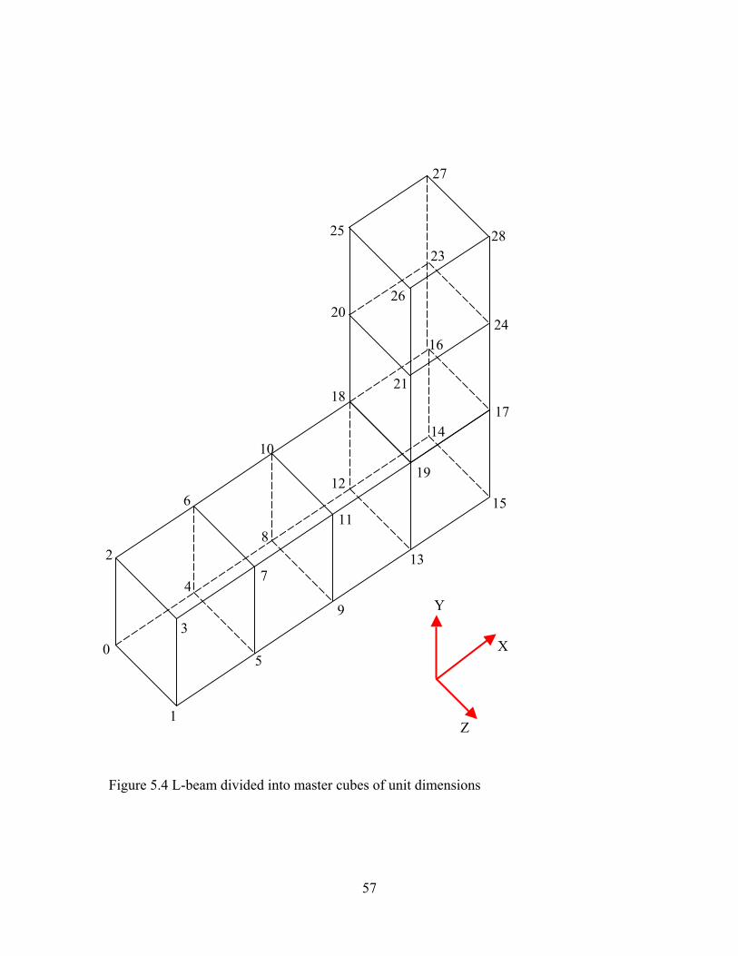
57
Figure 5.4 L-beam divided into master cubes of unit dimensions
28
27
26
25
24
23
21
20
19
1817
16
15
14
13
12
11
10
9
8
7
6
5
4
3
2
1
0
Y
Z
X

58
In figure 5.4 a sample L-beam divided into cubes of unit dimensions with the node
numbering system is depicted. Each of the cubes consists of six tetrahedral elements.
5.6 INTEGRATING JAVA AND VRML
VRML files describe 3D objects and worlds using a hierarchical scene graph.
Entities in the scene graph are called nodes. Nodes store their data in fields, and VRML
defines many types of fields that can store everything from a single value to an array of
values. The VRML nodes can contain other nodes i.e., the nodes can have child nodes.
To allow one node to communicate with the other nodes in the VRML worlds there is an
event or message passing mechanism. Each node type defines the names and types of
events that instances of that type may generate or receive, and Route statements define
event paths between event generators and receivers. Script nodes can be inserted between
event generators and event receivers. Scripts allow the world creators to describe
arbitrary behaviors, defined in either Java or JavaScript languages supported by the
VRML external-authoring interface.
If Java is to be allowed to interact with VRML, it needs a mechanism to access
fields, manipulate their values and return the results to the VRML world. VRML 2.0 does
that by extending its execution model into the Java world by using a special node that
bridges the two worlds. That bridge is called the Script node. The Script node is similar to
any other node in some respects but very powerful in other respects. The similarity is due
to the fact that we can place it anywhere in the scene hierarchies and route events to and
from the Script node like any other node. However, it differs in one key aspect: the fields

59
of a Script node are user-extensible, and events arriving at those fields are automatically
routed to the program associated with the Script node. The URL field in the Script node
provides the link between the node and the program that will implement some behavior
on behalf of this Script node. It enables the scene author to bind code to the Script node.
The field is named URL because it is intended to hold a Uniform Resource Locator and
signifies that this field usually contains a string that points to a file containing the
program that will be used by this Script node. Although VRML 2.0 enables any
programming language to implement its behaviors, the majority of serious VRML
developers use Java – because of its power and tight integration with the Internet. The
Script node also contains user-defined fields that provide the link between the state in the
VRML scene and state in the Java program. There can be any number of these fields, and
they can be any legal VRML 2.0 types. They can also be one of the following: normal
fields, eventIns and eventOuts. They cannot be exposed fields. Any events arriving at an
eventIn field automatically cause the browser to pass the event to the program referred to
the URL field of the Script node. The method used by the browser to do this depends on
the browser implementation and the language being called. This mechanism is specified
for Java and is called event dispatching. It describes the way the event is dispatched to
the piece of code that will handle the event. Any browser that supports Java must
implement this event dispatching mechanism so that code for one browser will work for
the other browsers too. After an event has been dispatched to the program, the program
will handle that event. Eventually, the program will return some result from its
computation. Again, the specification defines a way to enable the program to send
information back to the Script node. Such information is written back to the fields in the

60
Script node. This updates the value of the field in the Script node. Writing an eventIn or
an eventOut has further effects. Writing to an eventIn in a Script node generates an event
that is sent to the Java program. Writing to an eventOut field generates an event that will
be sent to any nodes that are interconnected, via routes, to the eventOut field of the Script
node.
Thus all that is happening in the model is that the Script node is acting as a
messenger for the Script itself. Any events send to the Script node are packaged and
delivered to the Script. Any results written by the Java program update the Script node
fields. Subsequently, the Script node will, if required, generate new events and
automatically send them on. This means that the Script node can be placed anywhere in
the event cascade. Whenever we need to do extra processing as a result of an event, route
the event to a Script node, handle it in the script, and send the results back to the script
node. If we want the results to also affect the other entities in the scene, send the result
back to an eventOut field and have the Script node ROUTE the event to the next node in
the chain.
5.7 INTERFACE OF THE APPLICATION AND OPERATIONAL PROCEDURES
The Java based finite element analysis is designed to work over the Internet and
therefore requires a Web browser to run the application. A Java capable Web browser
with a VRML plug-in is required in order to perform the analysis and view the model.
For best results, a Netscape Communicator 4.7 or above browser with a Silicon Graphics’
Cosmo Player VRML plug-in is recommended.

61
To gain access to the design environment, the Internet site with the URL address,
http://www.eml.ou.edu should be opened. Thereafter, clicking on the “Design Center”
link on the menu of the left side frame will open the home page of the “All Digital
Design (ADD) Center”. Now following the link “Java-Fea” will lead the user to a new
HTML page containing instructions and help regarding the Java and VRML based finite
element analysis application. At the bottom of this web page there is a link to the analysis
environment itself. By clicking on this link the user can access the Java and VRML based
program. However, before the Java program loads itself into the browser of the local
machine, the security feature built into the web browser will alert the user regarding the
possibility of a risk associated with running the Java program on the machine. Figure 5.5
shows the three Java security alert windows. Since this program does not contain any
malicious code the user can safely grant permission to the Web browser for running the
Java program on the local computer. It should be noted, however, that denial of
permission to any one of the three requests might preempt the analysis program from
functioning properly.

62

63
Figure 5.5 Java Security Alert Windows for alerting the user regarding the hazards
associated with downloading Java programs form an Internet Site.
After the user gives permission for loading the Java program on the local computer, the
initial model of the beam appears in the Cosmo Player window that is embedded in a new
HTML page. At the same time a small window, independent of the VRML window also
appears. This smaller window is the interface between the user and the back-end Java
program. This graphical user interface is constructed using the Abstract Window Toolkit
(AWT) provided in the Java programming language. The AWT contains numerous
classes and methods that allow the application developer to create and manage windows.
The AWT classes are contained in the java.awt package. This package must be explicitly
imported in the Java source code in order to be able to use the AWT. The AWT defines

64
windows according to a class hierarchy that adds functionality and specificity with each
level. The window used in this research is derived from Frame, which creates a standard
window. Frame is a sub-class of the Window class and has a title bar, menu bar, borders,
and resizing corners. In order to process the user input, the Frame window uses event
handler functions. The frame window for the VRML based design and analysis
environment uses labels, push buttons, radio buttons, and text fields supported by the
AWT. These components are arranged on the window using the FlowLayout manager of
the AWT. In order to perform the finite element analysis, the user has to enter the values
of various parameters for the L-beam model. The user can vary the geometry of the beam
by entering different values of the length and height parameter. The user can also select
the value for the modulus of elasticity of the beam material. The forces applied to the
beam along the x, y and z directions are specified by entering the values of these forces in
the appropriate text fields. In order to specify the direction of forces either in the positive
(tensile) or negative (compressive) directions the user input window has check boxes for
the selection. The forces can be made tensile or compressive by checking on the desired
radio buttons. The radio buttons allow only one of the two options to be selected at any
time. Thus the user can select either tension or compression for the force in the X-
direction. However, the radio buttons for the X, Y and Z forces are independent of one
another. This allows the user to independently select the directions for the X, Y and Z
forces. Figure 5.6 shows the user interface window of the Java application.

65
Figure 5.6 The Interface of the application created using Java’s AWT.
The application program is designed to compute the average X, Y and Z-stresses
on the L-beam using the finite element method. The user can select the computation of
the X, Y or Z stresses by clicking on the respective radio buttons. It should be noted that
the program is designed to compute only one of the average X, Y or Z stresses at any
given time. In order to better visualize the 3-D model VRML has a transparency feature
built into it. The Java and VRML based design and finite element analysis application
makes use of this VRML feature for enabling the user to see the meshing of the beam
when the finite element analysis is performed. The user can select the transparency
feature by checking the “Transparent” radio button in the user input window. After the
user has entered all the design parameters pressing the “FE Analysis” push button at the
bottom of the interface window performs the finite element analysis. Figure 5.7 shows
sample values entered by a user for analysis.

66
Figure 5.7 A sample interface window with values entered for analysis
When the user presses the “FE Analysis” button, the values entered by the user
are sent to the Java program for performing design and analysis of the L-beam model. As
previously mentioned this Java program is transferred from the server to the local
computer’s memory. Hence, the Java program utilizes the resources of the local
computer. This concept is different from client-server based CGI programs, which run on
the server. The server side execution model uses the server’s CPU for computations and
therefore, the load on the server is high. For engineering applications such as finite
element analysis, which are computationally intensive the server side computation could
lead to bottlenecks and slow down the performance of the server. This is particularly true
if several users log on to the same design site simultaneously. Thus, the Java program
utilizes the local computer’s CPU for increasing the execution speed of the program.
The program automatically generates the finite element mesh for the L-shaped
beam using a master cube element consisting of six tetrahedral solid elements as

67
explained earlier. The user cannot choose the type of element or mesh in order to make
the application easier to use and program. After generating the model and its mesh, the
program computes calculates the X, Y or Z stresses depending upon the user’s choice.
Thereafter it colors the L-beam for visualization of the stresses. The color-coding is as
follows:
Blue indicates the highest tensile stresses.
Green indicates the intermediate stress values.
Red indicates the highest compressive stresses.
This color-coding is also displayed on the left-hand side of the L-beam inside the VRML
window. The program also displays the magnitude of the largest tensile and compressive
stresses at the top and bottom of the color code respectively. Figure 5.8 shows the state of
the VRML design and analysis environment when the application is loaded initially in the
Cosmo Player VRML viewer plug-in in a browser window.

68
Figure 5.8 Initial view of the analysis environment before the application is started.
5.8 VERIFICATION OF RESULTS
This section deals with the verification of results obtained using the VRML and
Java based design and analysis environment. A comparison of the average maximum
stress for a particular configuration of the L-shaped beam is done between the VRML and
Java based finite element analysis application and SDRC-IDEAS Master Simulation
program.

69
In the example configuration, a beam of length 8 units and height of 3 units is
analyzed for stress in the X direction. A load of 300 lbs is applied to the top two nodes of
the L-beam in the positive X-direction. The average maximum X-stress value obtained
from the Java and VRML based Internet application is 5888 lb/in2, whereas the value of
the average maximum X-stress obtained using IDEAS Master Simulation finite element
analysis program is 6140 lb/in2. This verifies that the Java code gives agreeable results.
Screen images of the comparisons are provided in Figures 5.9 through 5.11.

70
Figure 5.9 L-beam of length 8 units and height 3 units, subjected to a load of 300 lbs and
analyzed using IDEAS Master Simulation program.

71
Figure 5.10 L-beam of length 8 units and height 3 units, subjected to a load of 300 lbs
and analyzed using the Java based analysis program.

72
Figure 5.11 L-beam of length 8 units and height 3 units, subjected to a load of 300 lbs
and analyzed using the Java based analysis program with the transparency turned on.
5.9 COMPARISON WITH CLOSED FORM SOLUTION
This section deals with a comparison of the stress obtained using the Java and
VRML based finite element analysis application and a closed form solution. In the
example configuration, a beam of length 7 units and height of 3 units is analyzed for
stress in the X direction. A load of 150 lbs is applied to each of the top two nodes of the
L-beam in the positive X-direction.

73
From an inspection of the L-shaped beam, the stress calculations are conducted at
the base of the beam since the maximum stresses occur at this part of the beam. The load
applied in the positive X-direction at the tip of the L-beam produces both an axial force
and a bending moment in the fixed horizontal portion of the L-beam. The axial force is
tensile and equal to the total load of 300 lb (150 x 2) applied to the beam. The bending
moment is equal to the load applied to the beam multiplied by the length of the vertical
member. The bending moment causes bending in the x-y plane with the z-axis as the
neutral axis. This bending produces a compressive stress at the bottom of the fixed part of
the beam and an equal tensile stress at the top of the fixed part of the beam. The
maximum stress is tensile and occurs at the top portion of the beam.
σmax = F / A + (FL)c / I where
F = Total applied load = 300 lb
A = Cross-sectional area of the beam = 1 in2
L = Moment arm = 3 in.
c = Distance of the top plane of the beam from the neutral axis = 0.5 in.
I = moment of inertia of the cross-section of the beam = bh3 / 12 where b is the
breadth of the cross-section and h is the height of the cross-section. In the case of
the L-beam used in this research, both b and h are 1 in.
Hence, I = 1 / 12 in.4
σmax = 5700 psi.
The maximum stress value obtained from the VRML and Java based analysis program is
5300 psi. Thus, the results from the program are agreeable with the closed form solution.
Figure 5.12 shows the closed form solution approach.

74
Figure 5.12 Closed-form solution approach
Max. Stress
Compression
TensionM = 300(6) = 1800 lb-in.
300 lb
z
y
x
3
7
150 lb
150 lb

75
CHAPTER 6
SUMMARY AND CONCLUSIONS
6.1 INTRODUCTION
The principal objective of this research is to conduct finite element analysis over
the Internet using Java and VRML and to demonstrate the capability of current Internet
technologies for engineering education. The application program was developed using
relatively inexpensive software tools, most of which are available as free download on
their respective Internet sites. The cost factor makes this research very attractive for use
in engineering education. As this research focuses on the creation of a Web based design
and analysis environment, Internet capable software tools were chosen. Since the finite
element analysis method and its associated mesh generation does not lend itself easily for
programming, this research demonstrates that both Java and VRML serve as good tools
for the task. However, in order to keep the application from becoming very complex and
at the same time achieving the original research objective, the number of variables and
the geometry of the model were kept relatively simple. This application was developed
primarily for a Windows NT server and Pentium class personal computer but should also
work with other types of computers.
Java was chosen as the programming language for this project since it is tightly
integrated with the Internet and allows the user to reuse the code for extending the

76
existing program to other applications because of its object-oriented design. VRML was
used to present the data in a 3-D format on the Internet.
6.2 CONCLUSIONS
The following conclusions were drawn as a result of the learning’s during this
research project:
1. The outcome of this research shows that design and analysis on the Internet is possible.
Since design on the Internet requires less expensive tools, it can be used for education.
The advantage of using the Internet for design education is that the students can
collaborate outside the classroom also by logging on to the design environment form a
computer with an Internet connection.
2. The Internet-based analysis does not require the physical presence of a user in a
particular location and is available 24 hours a day. Hence this model is adaptable for use
in distance learning programs.
3. VRML is a good tool for 3-D visualization and is comparatively easy to learn. The
main drawback of VRML is that it is a polygon based surface representation, and does
not allow solid data such as mass, density etc required by modern 3-D CAD systems to
be represented. Also it cannot model complicated geometrical entities accurately.
4. Java is a powerful programming language and integrates well with the Internet and
VRML. However, Java is not an easy language to program in, especially for the novice
users. Hence the initial learning curve of Java is quite steep.
5. This research could pave the way for facilitating the implementation of concurrent
engineering and design for manufacturing in the industry.

77
6.3 RECOMMENDATIONS FOR FUTURE RESEARCH
The model used for this research was a simple L-beam. Since the objective of this
research was to integrate Java and VRML in order to perform design and analysis on the
Internet, a major portion of research time was dedicated for the same. Having achieved
this objective with the L-beam, more emphasis can now be placed on further developing
the Internet-based design and analysis environment for more complex models.
The finite element mesh was generated automatically using tetrahedral elements.
Further improvements can be carried out by giving the user more control over the type of
element, the element size and the meshing. However, it should be noted that this involves
large time and manpower requirements for program development and testing.
Java 3-D is a newer 3-D technology that integrates closely with the Java
programming language and the Internet. The feasibility of using this technology for
developing a Web-based design and analysis environment can be explored and
benchmarked vis-à-vis the current VRML based design and analysis application
developed. The two technologies viz., VRML and Java 3-D could be compared based on
the learning curve, development resources required, visualization of the 3-D models, file
size of the application, real-time speed of execution, security etc.

78
REFERENCES
1. Chung, F., Wang, F., Wright, P., Web-Based Cad Tools for a Networked
Manufacturing Service, Proceedings of DETC’98, 1998 ASME Design
Engineering Technical Conferences, September 13-16, 1998 – Atlanta, Georgia.
2. Arora, S., Kulacki, F.A., Challenges to Exploit the Internet for Engineering
Education, Department of Mechanical Engineering, University of Minnesota –
Twin Cities.
3. Minoli, D., Schmidt, A., Internet Architectures, John Wiley and Sons, 1999.
4. Lemay, L., Teach Yourself Web-Publishing with HTML 3.0 in a Week, Sams Net
Publishing, 1996.
5. http://www.internet2.edu/, January 2000.
6. http://www.ngi.gov/, January 2000.
7. McRight, J.S., Cisco’s Chambers: e-learning will help us control our destinies,
PC Week Online, November 16, 1999.
8. Donstron, D., From the Trenches: Distributed Learning is High Priority, PC
Week, November 14, 1999.
9. McArthur, D.J., Lewis, M.W., Untangling the Web: Applications of the Internet
and other Information Technologies to Higher Learning, 1998.
10. http://www.ecn.ou.edu, December 1999.
11. Hugh, J., Karlesky, M., A Virtual Manufacturing Laboratory, 1999 ASEE Annual
Conference and Exposition, Charlotte, NC, June 20-23, 1999.

79
12. Sun, Q., Gramoll, K.G., Mooney, M., Self-Paced Instruction to Introduce Traffic
Engineering in Virtual City (Sooner City), 1999 ASEE Annual Conference and
Exposition, Charlotte, NC, June 20-23, 1999.
13. Stackpole, B., Online Learning Spans the Vast Lands of Utah, PC Week, March
14, 1999.
14. Gramoll, K., Teaching Statics Online with only Electronic Media on Laptop
Computers, 1999 ASEE Annual Conference and Exposition, Charlotte, NC, June
20-23, 1999.
15. Ng, A., Gramoll, K.G., Online Review and Practice Tests for the Fundamentals of
Engineering Exam, 1999 ASEE Annual Conference and Exposition, Charlotte,
NC, June 20-23, 1999.
16. Gates, W.H., Business @ the Speed of Thought, Penguin Books, 1999.
17. Miller, C.G., Concurrent Engineering Design, First Edition, Society of
Manufacturing Engineers, Michigan, 1993.
18. Miller, C.G., Concurrent Engineering Design, First Edition, Society of
Manufacturing Engineers, Michigan, 1993.
19. Smith, C.S., Wright, P.K., “Cybercut: A Networked Manufacturing Service”,
First International Conference on Managing Enterprises – Stakeholders,
Engineering, Logistics and Achievement, Loughborough University, UK, July
22-24, 1997.
20. http://www.ptc.com, December 1999.
21. http://www.sdrc.com, November 1999.

80
22. Chalmers, R.E., “Windows and the Web: Leveraging CAD Across the
Enterprise”, Integrated Manufacturing Solutions, March 1999.
23. Kempfer, L., “Windchill heats up PDM”, Computer- Aided Engineering, June
1998.
24. http://www.w3.org/, January 2000.
25. Musciano, C., Kennedy, B., HTML – The Definitive Guide, O’Reilly and
Associates, Inc, 1997.
26. Marrin, C., Campbell, B., Teach Yourself VRML 2 in 21 days, Sams.net
Publishing, 1997.
27. Ames, A.L., Nadeau, D.R., Moreland, J.L., VRML 2.0 Sourcebook, John Wiley
and Sons, Inc. 1997.
28. Naughton, P., Schildt, H., Java: The Complete Reference, McGraw-Hill, Inc.,
1997.
29. Logan, D,R., A First Course in the Finite Element Method, PWS Publishing
Company, 1993.
30. Krishnamoorthy, C.S., Finite Element Analysis – Theory and Programming, Tata
McGraw-Hill Publishing Company Limited, 1995.
31. Chandrupatla, T.R., Belegundu, A.D., Introduction to Finite Elements in
Engineering, Prentice-Hall Inc., 1997.

81
APPENDIX A
VRML CODE
#VRML V2.0 utf8
Transform {
children [
Shape {
appearance Appearance {
material DEF MATERIAL Material {
transparency 0.7
}
}
geometry DEF IFS IndexedFaceSet {
coord DEF Face Coordinate {
point [
0.0 0.0 0.0,
0.0 0.0 1.0,
0.0 1.0 0.0,
0.0 1.0 1.0,
1.0 0.0 0.0,

82
1.0 0.0 1.0,
1.0 1.0 0.0,
1.0 1.0 1.0
]
}
coordIndex [
0 1 3 2 -1,
7 6 4 5 -1,
0 , 4 , 5 , 1 , -1,
1 , 5 , 7 , 3 , -1,
2 , 6 , 7 , 3 , -1,
2 , 6 , 4 , 0 , -1
]
color DEF Coll Color {
color [ 1 0 0, 1 0 0, 1 0 0, 1 0 0, 1 0 0, 1 0 0, 1 0 0, 1 0 0 ]
}
#colorIndex [ 0 0 0 0 -1, 0 0 0 0 -1, 0 0 0 0 -1, 0 0 0 0 -1, 0 0 0 0 -1, 0 0 0 0 -1 ]
solid FALSE
}
}

83
Transform {
translation -0.5 0.5 0.5
children Shape {
appearance Appearance {
material Material { }
}
geometry Box {
size 1.0 3.0 5.0
}
}
}
Transform {
# RED + PINK
children Shape {
appearance Appearance {
material Material { }
}
geometry IndexedFaceSet {
coord Coordinate {
point [
-2.0 0.5 0.0,
-2.0 2.5 0.0,

84
-3.0 2.5 0.0,
-3.0 0.5 0.0
]
}
coordIndex [
0 1 2 3 ]
color Color {
color [ 0 1 0 , 1 0 0, 1 0 0, 0 1 0]
}
solid FALSE
}
}
}
Transform {
# YELLOW + BLUE
children Shape {
appearance Appearance {
material Material { }
}
geometry IndexedFaceSet {
coord Coordinate {

85
point [
-2.0 -1.5 0.0,
-2.0 0.5 0.0,
-3.0 0.5 0.0,
-3.0 -1.5 0.0
]
}
coordIndex [
0 1 2 3 ]
color Color {
color [ 0 0 1 , 0 1 0, 0 1 0, 0 0 1]
}
solid FALSE
}
}
}
Transform {
translation -4.75 2.6 0
children Shape {
appearance Appearance {
material Material {
diffuseColor 1.0 0.0 0.0

86
}
}
geometry Text {
string "Avg. Max. Stress"
fontStyle FontStyle {
family "SANS"
style "BOLD"
size 0.4
}
}
}
}
Transform {
translation -4.75 -1.85 0
children Shape {
appearance Appearance {
material Material {
diffuseColor 0.0 0.0 1.0
}
}
geometry Text {
string "Avg. Min. Stress"

87
fontStyle FontStyle {
family "SANS"
style "BOLD"
size 0.4
}
}
}
}
Transform {
translation -4.3 -1.5 0
children Shape {
appearance Appearance {
material Material {
diffuseColor 0.0 0.0 1.0
}
}
geometry DEF MINT Text {
string ["Min"]
fontStyle FontStyle {
family "SANS"
style "BOLD"
size 0.4

88
}
}
}
}
Transform {
translation -4.3 2.15 0
children Shape {
appearance Appearance {
material Material {
diffuseColor 0.0 0.0 1.0
}
}
geometry DEF MAXT Text {
string ["Max"]
fontStyle FontStyle {
family "SANS"
style "BOLD"
size 0.4
}
}
}
}

89
Transform {
# Z-axis
translation -5 0.75 0
children Shape {
appearance Appearance {
material Material { }
}
geometry Cylinder {
radius 0.06
height 1.5
}
}
}
Transform {
#X-axis
translation -4.25 0 0
rotation 0.0 0.0 1.0 1.57
children Shape {
appearance Appearance {
material Material { }
}
geometry Cylinder {

90
radius 0.06
height 1.5
}
}
}
Transform {
#Z-axis
translation -5 0 0.75
rotation 1.0 0.0 0.0 1.57
children Shape {
appearance Appearance {
material Material { }
}
geometry Cylinder {
radius 0.06
height 1.5
}
}
}
Transform {
#Y-axis arrow
translation -5 1.59 0

91
children Shape {
appearance Appearance {
material Material { }
}
geometry Cone {
bottomRadius 0.1
height 0.18
}
}
}
Transform {
#X-axis arrow
translation -3.41 0.0 0
rotation 0.0 0.0 1.0 -1.57
children Shape {
appearance Appearance {
material Material { }
}
geometry Cone {
bottomRadius 0.1
height 0.18
}
}

92
}
Transform {
#Z-axis arrow
translation -5 0.0 1.59
rotation 1.0 0.0 0.0 1.57
children Shape {
appearance Appearance {
material Material { }
}
geometry Cone {
bottomRadius 0.1
height 0.18
}
}
}
Transform {
translation -3.75 0.1 0.0
children Shape {
appearance Appearance {
material Material {
diffuseColor 1.0 1.0 1.0
}
}

93
geometry Text {
string "X"
fontStyle FontStyle {
family "SANS"
style "BOLD"
size 0.4
}
}
}
}
Transform {
translation -4.85 1.3 0.0
children Shape {
appearance Appearance {
material Material {
diffuseColor 1.0 1.0 1.0
}
}
geometry Text {
string "Y"
fontStyle FontStyle {
family "SANS"
style "BOLD"

94
size 0.4
}
}
}
}
Transform {
translation -5.1 0.1 1.4
children Shape {
appearance Appearance {
material Material {
diffuseColor 1.0 1.0 1.0
}
}
geometry Text {
string "Z"
fontStyle FontStyle {
family "SANS"
style "BOLD"
size 0.4
}
}
}
}

95
DEF SCRIPTF Script {
url "editf.class"
eventOut MFVec3f coo
eventOut MFInt32 ind
eventOut MFColor col
eventOut MFString min
eventOut MFString max
eventOut SFFloat trans
}
]
}
ROUTE SCRIPTF.coo TO Face.set_point
ROUTE SCRIPTF.ind TO IFS.set_coordIndex
ROUTE SCRIPTF.col TO Coll.set_color
ROUTE SCRIPTF.min TO MINT.set_string
ROUTE SCRIPTF.max TO MAXT.set_string
ROUTE SCRIPTF.trans TO MATERIAL.set_transparency

96
APPENDIX B
JAVA CODES
import vrml.*;
import vrml.node.*;
import vrml.field.*;
import java.awt.*;
public class editf extends Script {
// The eventOut that carries the coordinates, indices and colour to the L-Beam's nodes
private MFVec3f coo;
private MFInt32 ind;
private MFColor col;
private MFString min;
private MFString max;
private SFFloat trans;
// The Frame in which the interface controls are displayed for the FE analysis
private editFramef f = null;
public void initialize() {

97
// Get the eventOut reference
coo = (MFVec3f)getEventOut( "coo" );
ind = (MFInt32)getEventOut( "ind");
col = (MFColor)getEventOut( "col");
min = (MFString)getEventOut("min");
max = (MFString)getEventOut("max");
trans = (SFFloat)getEventOut("trans");
// Create a new Frame
f = new editFramef( coo , ind , col , min ,max, trans );
}
}

98
import vrml.*;
import vrml.field.*;
import vrml.node.*;
import java.awt.*;
public class editFramef extends Frame {
// The VRML EventOut we wish to set
private MFVec3f coo = null;
private MFInt32 ind = null;
private MFColor col = null;
private MFString min = null;
private MFString max = null;
private SFFloat trans = null;
GridLayout test = new GridLayout (8,4);
Button BT1 = new Button ("FE Analysis");
Label LAB1 = new Label("Length");
Label LAB2 = new Label("Height");
Label LAB3 = new Label("Elasticity");
Label LAB4 = new Label("");
Label LAB44 = new Label("Force Values");

99
Label LAB5 = new Label("X-Force");
Label LAB6 = new Label("Y-Force");
Label LAB7 = new Label("Z-Force");
Label LAB8 = new Label("Avg-Stress");
Label LAB9 = new Label("Transparency");
Label LAB10 = new Label("");
Label LAB11 = new Label("Analyze");
TextField TXF1 = new TextField(02);
TextField TXF2 = new TextField(02);
TextField TXF3 = new TextField(07);
//TextField TXF4 = new TextField(05);
TextField TXF5 = new TextField(07);
TextField TXF6 = new TextField(07);
TextField TXF7 = new TextField(07);
TextField TXF8 = new TextField(07);
CheckboxGroup gxf = new CheckboxGroup();
Checkbox CB1 = new Checkbox("-ve X", gxf, false);
Checkbox CB2 = new Checkbox("+ve X", gxf, true);
CheckboxGroup gyf = new CheckboxGroup();
Checkbox CB3 = new Checkbox("-ve Y", gyf, false);
Checkbox CB4 = new Checkbox("+ve Y", gyf, true);

100
CheckboxGroup gzf = new CheckboxGroup();
Checkbox CB5 = new Checkbox("-ve Z", gzf, false);
Checkbox CB6 = new Checkbox("+ve Z", gzf, true);
CheckboxGroup gs = new CheckboxGroup();
Checkbox CB7 = new Checkbox("X-Stress", gs, true);
Checkbox CB8 = new Checkbox("Y-Stress", gs, false);
Checkbox CB9 = new Checkbox("Z-Stress", gs, false);
CheckboxGroup tra = new CheckboxGroup();
Checkbox CB10 = new Checkbox("Opaque", tra, true);
Checkbox CB11 = new Checkbox("Transparent", tra, false);
// Constructor
public editFramef( MFVec3f coo , MFInt32 ind , MFColor col , MFString min ,
MFString max , SFFloat trans ) {
this.coo = coo;
this.ind = ind;
this.col = col;
this.min = min;
this.max = max;
this.trans = trans;
setLayout(test);
add(LAB1); add(TXF1); add(LAB2); add(TXF2);
add(LAB3); add(TXF3); add(LAB4); add(LAB44);

101
add(LAB5); add(TXF5); add(CB1); add(CB2);
add(LAB6); add(TXF6); add(CB3); add(CB4);
add(LAB7); add(TXF7); add(CB5); add(CB6);
add(LAB8); add(CB7); add(CB8); add(CB9);
add(LAB9);
add(CB10); add(CB11);
add(LAB10); add(LAB11); add(BT1);
pack();
show();
setResizable ( false );
}
// function for bandwidth
int nbw = 0;
int bandwidth (int ne, int nmin, int nmax, int nen, int n, int ndn, int [] noc) {
for (int i = 0; i < ne; i++) {
nmin = noc[nen*i];
nmax = nmin;
for (int j = 1; j < nen; j++) {
n=noc[nen*i+j];
if (nmin > n)

102
nmin = n;
if (nmax < n)
nmax = n;
}
n = ndn * (nmax - nmin + 1);
if (nbw < n)
nbw = n;
}
return nbw;
}
// db[] matrix
void dbmat(int nm,float[][] b,float[][] d,float[][] db,float e,float nu,float [] x,int[]
noc,float dj,float al1)
{
int i,j,k,m,i1,i2,i3,i4;
float c,c1,c2,c3,c4,pnu,al,dj1,dj2,dj3;
float x1,x2,x3,x4,y1,y2,y3,y4,z1,z2,z3,z4;
float x14,x24,x34,y14,y24,y34,z14,z24,z34;
float a11,a21,a31,a12,a22,a32,a13,a23,a33;
// d(), b() and db() matrices
// first the d-matrix

103
// d() matrix
c4 = e / ((1 + nu) * (1 - 2 * nu));
c1 = c4 * (1 - nu);
c2 = c4 * nu;
c3 = (float)0.5 * e / (1 + nu);
for (i = 0; i < 6; i++) {
for (j = 0; j < 6; j++) {
d[i][j] = 0;
}
}
d[0][0] = c1;
d[0][1] = c2;
d[0][2] = c2;
d[1][0] = c2;
d[1][1] = c1;
d[1][2] = c2;
d[2][0] = c2;
d[2][1] = c2;
d[2][2] = c1;
d[3][3] = c3;
d[4][4] = c3;
d[5][5] = c3;
// strain-displacement matrix b()

104
i1 = noc[4*nm];
i2 = noc[4*nm+1];
i3 = noc[4*nm+2];
i4 = noc[4*nm+3];
x14 = x[3*i1] - x[3*i4];
x24 = x[3*i2] - x[3*i4];
x34 = x[3*i3] - x[3*i4];
y14 = x[3*i1+1] - x[3*i4+1];
y24 = x[3*i2+1] - x[3*i4+1];
y34 = x[3*i3+1] - x[3*i4+1];
z14 = x[3*i1+2] - x[3*i4+2];
z24 = x[3*i2+2] - x[3*i4+2];
z34 = x[3*i3+2] - x[3*i4+2];
dj1 = x14 * (y24 * z34 - z24 * y34);
dj2 = y14 * (z24 * x34 - x24 * z34);
dj3 = z14 * (x24 * y34 - y24 * x34);
dj = dj1 + dj2 + dj3; // dj is determinant of jacobian
a11 = (y24 * z34 - z24 * y34) / dj;
a21 = (z24 * x34 - x24 * z34) / dj;
a31 = (x24 * y34 - y24 * x34) / dj;
a12 = (y34 * z14 - z34 * y14) / dj;
a22 = (z34 * x14 - x34 * z14) / dj;
a32 = (x34 * y14 - y34 * x14) / dj;

105
a13 = (y14 * z24 - z14 * y24) / dj;
a23 = (z14 * x24 - x14 * z24) / dj;
a33 = (x14 * y24 - y14 * x24) / dj;
// definition of b() matrix
for (i = 0; i < 6; i++) {
for (j = 0; j < 12; j++) {
b[i][j] = 0;
}
}
b[0][0] = a11;
b[0][3] = a12;
b[0][6] = a13;
b[0][9] = -a11 - a12 - a13;
b[1][1] = a21;
b[1][4] = a22;
b[1][7] = a23;
b[1][10] = -a21 - a22 - a23;
b[2][2] = a31;
b[2][5] = a32;
b[2][8] = a33;
b[2][11] = -a31 - a32 - a33;
b[3][1] = a31;
b[3][2] = a21;

106
b[3][4] = a32;
b[3][5] = a22;
b[3][7] = a33;
b[3][8] = a23;
b[3][10] = b[2][11];
b[3][11] = b[1][10];
b[4][0] = a31;
b[4][2] = a11;
b[4][3] = a32;
b[4][5] = a12;
b[4][6] = a33;
b[4][8] = a13;
b[4][9] = b[2][11];
b[4][11] = b[0][9];
b[5][0] = a21;
b[5][1] = a11;
b[5][3] = a22;
b[5][4] = a12;
b[5][6] = a23;
b[5][7] = a13;
b[5][9] = b[1][10];
b[5][10] = b[0][9];
// db matrix db = d*b

107
for (i = 0; i < 6; i++) {
for (j = 0; j < 12; j++) {
c = 0;
for (k = 0; k < 6; k++) {
c = c + d[i][k] * b[k][j];
}
db[i][j] = c;
}
}
}
// band solver
void bansol(float[] s,float[] f,int nql,int bw)
{
int n1,k,nk,i,i1,j,j1,kk;
float c1;
// band solver
n1 = nql - 1;
// forward elimination
for (k = 1; k <= n1; k++) {
nk = nql - k + 1;
if (nk > bw)
nk = bw;

108
for (i = 2; i <= nk; i++) {
c1 = s[bw*(k-1)+i-1] / s[bw*(k-1)];
i1 = k + i - 1;
for (j = i; j <= nk; j++) {
j1 = j - i + 1;
s[bw*(i1-1)+j1-1] = s[bw*(i1-1)+j1-1] - c1 * s[bw*(k-1)+j-1];
}
f[i1-1] = f[i1-1] - c1 * f[k-1];
}
}
// back-substitution
f[nql-1] = f[nql-1] / s[bw*(nql-1)];
for (kk = 1; kk <= n1;kk++) {
k = nql - kk;
c1 = 1 / s[bw*(k-1)];
f[k-1] = c1 * f[k-1];
nk = nql - k + 1;
if (nk > bw)
nk = bw;
for (j = 2; j <= nk; j++) {
f[k-1] = f[k-1] - c1 * s[bw*(k-1)+j-1] * f[k + j - 2];
}
}

109
}
// stress evaluation
void stress(float[] f,int[] noc,int nm,float[][] d,float[][] db,float[] str)
{ int i,j,in,ii,k;
float c ; float[] q = new float[12];
// stress evaluation (element nodal displacements stored in q()
for (i = 0; i < 4; i++) {
in = 3 * (noc[4*nm + i] );
ii = 3 * i;
for (j = 0; j < 3; j++) {
q[ii + j] = f[in + j];
}
}
for (i = 0; i < 6; i++) {
c = 0;
for (k = 0; k < 12; k++) {
c = c + db[i][k] * q[k];
}
str[i] = c ;
}

110
}
public boolean handleEvent( java.awt.Event evt ) {
try {
switch ( evt.id ) {
case java.awt.Event.ACTION_EVENT: {
if ( evt.arg.toString().equals( "FE Analysis" ) ) {
int var1 = Integer.parseInt(TXF1.getText());
float varl = (float)var1;
int var2 = Integer.parseInt(TXF2.getText());
float varh = (float)var2;
int dim = 3000;
float[] coord = new float[dim];
//Initialise to zero
for ( int a = 0; a < dim; a++) {
coord[a] = 0;
}
coo.setValue ( coord );

111
int dim1 = 12000;
int[] ci = new int[dim1];
for ( int i = 0; i < dim1; i++) {
ci[i] = 0;
}
ind.setValue ( ci );
// Color setting
int cim = 3000;
float[] colo = new float[cim];
//Initialise to zero
for ( int a = 0; a < cim; a++) {
colo[a] = 0;
}
col.setValue ( colo );
// Counter
int count = 0;
for ( int i = 0; i <= var1; i++ ) {
for ( int j = 0; j <= 1; j++ ) {
for ( int k = 0; k <= 1; k++ ) {
coord[count] = (float)i;
count++;

112
coord[count] = (float)j;
count++;
coord[count] = (float)k;
count++;
}
}
}
float xh = (varl - 1);
for ( int i = 0; i < var2; i++ )
{
coord[count] = xh ; count++; coord[count] = 2 + (float)i ; count++; coord[count] = 0;
count++;
coord[count] = xh ; count++; coord[count] = 2 + (float)i; count++; coord[count] = 1;
count++;
coord[count] = xh + 1 ; count++; coord[count] = 2 + (float)i; count++; coord[count] = 0;
count++;
coord[count] = xh + 1 ; count++; coord[count] = 2 + (float)i; count++; coord[count] = 1;
count++;
}
coo.setValue ( coord );
// Creating the Indexed Face Sets for the finite elements in the horizontal portion of the
beam

113
int ct1 = 0;
for ( int i = 0; i < var1; i++)
{
// Tetra 1
ci[ct1] = 0 + 4*i ; ct1++; ci[ct1] = 1 + 4*i ; ct1++; ci[ct1] = 5 + 4*i; ct1++; ci[ct1] = -1;
ct1++;
ci[ct1] = 0 + 4*i ; ct1++; ci[ct1] = 1 + 4*i ; ct1++; ci[ct1] = 7 + 4*i; ct1++; ci[ct1] = -1;
ct1++;
ci[ct1] = 0 + 4*i ; ct1++; ci[ct1] = 5 + 4*i ; ct1++; ci[ct1] = 7 + 4*i; ct1++; ci[ct1] = -1;
ct1++;
ci[ct1] = 1 + 4*i ; ct1++; ci[ct1] = 5+ 4*i ; ct1++; ci[ct1] = 7 + 4*i; ct1++; ci[ct1] = -1;
ct1++;
// Tetra 2
ci[ct1] = 0 + 4*i ; ct1++; ci[ct1] = 1 + 4*i ; ct1++; ci[ct1] = 2 + 4*i; ct1++; ci[ct1] = -1;
ct1++;
ci[ct1] = 0 + 4*i ; ct1++; ci[ct1] = 7 + 4*i ; ct1++; ci[ct1] = 2 + 4*i; ct1++; ci[ct1] = -1;
ct1++;
ci[ct1] = 1 + 4*i ; ct1++; ci[ct1] = 7 + 4*i ; ct1++; ci[ct1] = 2 + 4*i; ct1++; ci[ct1] = -1;
ct1++;
// Tetra 3
ci[ct1] = 1 + 4*i ; ct1++; ci[ct1] = 7+ 4*i ; ct1++; ci[ct1] = 3 + 4*i; ct1++; ci[ct1] = -1;
ct1++;

114
ci[ct1] = 1 + 4*i ; ct1++; ci[ct1] = 2 + 4*i ; ct1++; ci[ct1] = 3 + 4*i; ct1++; ci[ct1] = -1;
ct1++;
ci[ct1] = 7 + 4*i ; ct1++; ci[ct1] = 2 + 4*i ; ct1++; ci[ct1] = 3 + 4*i; ct1++; ci[ct1] = -1;
ct1++;
// Tetra 4
ci[ct1] = 0 + 4*i ; ct1++; ci[ct1] = 4 + 4*i ; ct1++; ci[ct1] = 5 + 4*i; ct1++; ci[ct1] = -1;
ct1++;
ci[ct1] = 0 + 4*i ; ct1++; ci[ct1] = 4+ 4*i ; ct1++; ci[ct1] = 6 + 4*i; ct1++; ci[ct1] = -1;
ct1++;
ci[ct1] = 0 + 4*i ; ct1++; ci[ct1] = 5 + 4*i ; ct1++; ci[ct1] = 6 + 4*i; ct1++; ci[ct1] = -1;
ct1++;
ci[ct1] = 4 + 4*i ; ct1++; ci[ct1] = 5 + 4*i ; ct1++; ci[ct1] = 6 + 4*i; ct1++; ci[ct1] = -1;
ct1++;
// Tetra 5
ci[ct1] = 0 + 4*i ; ct1++; ci[ct1] = 6 + 4*i ; ct1++; ci[ct1] = 7 + 4*i; ct1++; ci[ct1] = -1;
ct1++;
ci[ct1] = 0 + 4*i ; ct1++; ci[ct1] = 6+ 4*i ; ct1++; ci[ct1] = 2 + 4*i; ct1++; ci[ct1] = -1;
ct1++;
ci[ct1] = 6 + 4*i ; ct1++; ci[ct1] = 7 + 4*i ; ct1++; ci[ct1] = 2 + 4*i; ct1++; ci[ct1] = -1;
ct1++;
// Tetra 6
ci[ct1] = 7 + 4*i ; ct1++; ci[ct1] = 5+ 4*i ; ct1++; ci[ct1] = 6 + 4*i; ct1++; ci[ct1] = -1;
ct1++;

115
}
// Creating the finite elements for the vertical part of the beam
int vind = 4*var1 - 2;
// The vertical element with an aberration in numbering
//Tetra 1
ci[ct1]=vind; ct1++; ci[ct1]=vind+1; ct1++; ci[ct1]=vind+5; ct1++; ci[ct1]=-1; ct1++;
ci[ct1]=vind; ct1++; ci[ct1]=vind+1; ct1++; ci[ct1]=vind+9; ct1++; ci[ct1]=-1; ct1++;
ci[ct1]=vind; ct1++; ci[ct1]=vind+5; ct1++; ci[ct1]=vind+9; ct1++; ci[ct1]=-1; ct1++;
ci[ct1]=vind+1; ct1++; ci[ct1]=vind+5; ct1++; ci[ct1]=vind+9; ct1++; ci[ct1]=-1; ct1++;
// Tetra 2
ci[ct1]=vind; ct1++; ci[ct1]=vind+1; ct1++; ci[ct1]=vind+6; ct1++; ci[ct1]=-1; ct1++;
ci[ct1]=vind; ct1++; ci[ct1]=vind+9; ct1++; ci[ct1]=vind+6; ct1++; ci[ct1]=-1; ct1++;
ci[ct1]=vind+1; ct1++; ci[ct1]=vind+9; ct1++; ci[ct1]=vind+6; ct1++; ci[ct1]=-1; ct1++;
// Tetra 3
ci[ct1]=vind+1; ct1++; ci[ct1]=vind+9; ct1++; ci[ct1]=vind+7; ct1++; ci[ct1]=-1; ct1++;
ci[ct1]=vind+1; ct1++; ci[ct1]=vind+6; ct1++; ci[ct1]=vind+7; ct1++; ci[ct1]=-1; ct1++;
ci[ct1]=vind+9; ct1++; ci[ct1]=vind+6; ct1++; ci[ct1]=vind+7; ct1++; ci[ct1]=-1; ct1++;
// Tetra 4
ci[ct1]=vind; ct1++; ci[ct1]=vind+4; ct1++; ci[ct1]=vind+5; ct1++; ci[ct1]=-1; ct1++;
ci[ct1]=vind; ct1++; ci[ct1]=vind+4; ct1++; ci[ct1]=vind+8; ct1++; ci[ct1]=-1; ct1++;
ci[ct1]=vind; ct1++; ci[ct1]=vind+5; ct1++; ci[ct1]=vind+8; ct1++; ci[ct1]=-1; ct1++;
ci[ct1]=vind+4; ct1++; ci[ct1]=vind+5; ct1++; ci[ct1]=vind+8; ct1++; ci[ct1]=-1; ct1++;
// Tetra 5

116
ci[ct1]=vind; ct1++; ci[ct1]=vind+8; ct1++; ci[ct1]=vind+9; ct1++; ci[ct1]=-1; ct1++;
ci[ct1]=vind; ct1++; ci[ct1]=vind+8; ct1++; ci[ct1]=vind+6; ct1++; ci[ct1]=-1; ct1++;
ci[ct1]=vind+8; ct1++; ci[ct1]=vind+9; ct1++; ci[ct1]=vind+6; ct1++; ci[ct1]=-1; ct1++;
// Tetra 6
ci[ct1]=vind+9; ct1++; ci[ct1]=vind+5; ct1++; ci[ct1]=vind+8; ct1++; ci[ct1]=-1; ct1++;
// Creating the indexed face sets for the finite elements in the vertical portion of the beam
if ( var2 > 1) {
int vi = vind + 6;
for (int i = 0; i < (var2-1); i++ )
{
// Tetra 1
ci[ct1] = vi + 4*i ; ct1++; ci[ct1] = (vi+1) + 4*i ; ct1++; ci[ct1] = (vi+3) + 4*i; ct1++;
ci[ct1] = -1; ct1++;
ci[ct1] = vi + 4*i ; ct1++; ci[ct1] = (vi+1) + 4*i ; ct1++; ci[ct1] = (vi+7) + 4*i; ct1++;
ci[ct1] = -1; ct1++;
ci[ct1] = vi + 4*i ; ct1++; ci[ct1] = (vi+3) + 4*i ; ct1++; ci[ct1] = (vi+7) + 4*i; ct1++;
ci[ct1] = -1; ct1++;
ci[ct1] = (vi+1) + 4*i ; ct1++; ci[ct1] = (vi+3)+ 4*i ; ct1++; ci[ct1] = (vi+7) + 4*i; ct1++;
ci[ct1] = -1; ct1++;
// Tetra 2
ci[ct1] = vi + 4*i ; ct1++; ci[ct1] = (vi+1) + 4*i ; ct1++; ci[ct1] = (vi+4) + 4*i; ct1++;
ci[ct1] = -1; ct1++;
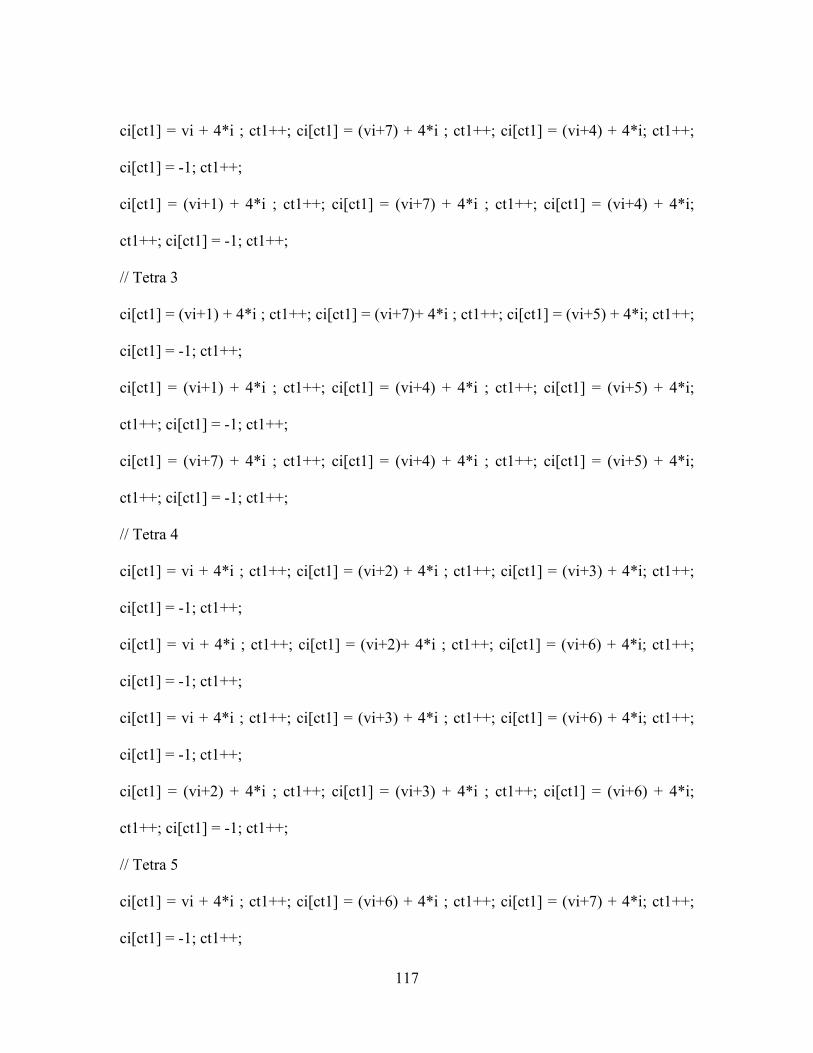
117
ci[ct1] = vi + 4*i ; ct1++; ci[ct1] = (vi+7) + 4*i ; ct1++; ci[ct1] = (vi+4) + 4*i; ct1++;
ci[ct1] = -1; ct1++;
ci[ct1] = (vi+1) + 4*i ; ct1++; ci[ct1] = (vi+7) + 4*i ; ct1++; ci[ct1] = (vi+4) + 4*i;
ct1++; ci[ct1] = -1; ct1++;
// Tetra 3
ci[ct1] = (vi+1) + 4*i ; ct1++; ci[ct1] = (vi+7)+ 4*i ; ct1++; ci[ct1] = (vi+5) + 4*i; ct1++;
ci[ct1] = -1; ct1++;
ci[ct1] = (vi+1) + 4*i ; ct1++; ci[ct1] = (vi+4) + 4*i ; ct1++; ci[ct1] = (vi+5) + 4*i;
ct1++; ci[ct1] = -1; ct1++;
ci[ct1] = (vi+7) + 4*i ; ct1++; ci[ct1] = (vi+4) + 4*i ; ct1++; ci[ct1] = (vi+5) + 4*i;
ct1++; ci[ct1] = -1; ct1++;
// Tetra 4
ci[ct1] = vi + 4*i ; ct1++; ci[ct1] = (vi+2) + 4*i ; ct1++; ci[ct1] = (vi+3) + 4*i; ct1++;
ci[ct1] = -1; ct1++;
ci[ct1] = vi + 4*i ; ct1++; ci[ct1] = (vi+2)+ 4*i ; ct1++; ci[ct1] = (vi+6) + 4*i; ct1++;
ci[ct1] = -1; ct1++;
ci[ct1] = vi + 4*i ; ct1++; ci[ct1] = (vi+3) + 4*i ; ct1++; ci[ct1] = (vi+6) + 4*i; ct1++;
ci[ct1] = -1; ct1++;
ci[ct1] = (vi+2) + 4*i ; ct1++; ci[ct1] = (vi+3) + 4*i ; ct1++; ci[ct1] = (vi+6) + 4*i;
ct1++; ci[ct1] = -1; ct1++;
// Tetra 5
ci[ct1] = vi + 4*i ; ct1++; ci[ct1] = (vi+6) + 4*i ; ct1++; ci[ct1] = (vi+7) + 4*i; ct1++;
ci[ct1] = -1; ct1++;

118
ci[ct1] = vi + 4*i ; ct1++; ci[ct1] = (vi+6)+ 4*i ; ct1++; ci[ct1] = (vi+4) + 4*i; ct1++;
ci[ct1] = -1; ct1++;
ci[ct1] = (vi+6) + 4*i ; ct1++; ci[ct1] = (vi+7) + 4*i ; ct1++; ci[ct1] = (vi+4) + 4*i;
ct1++; ci[ct1] = -1; ct1++;
// Tetra 6
ci[ct1] = (vi+7) + 4*i ; ct1++; ci[ct1] = (vi+3)+ 4*i ; ct1++; ci[ct1] = (vi+6) + 4*i; ct1++;
ci[ct1] = -1; ct1++;
}
}
ind.setValue ( ci );
// Variables required for computation
int ne = (var1 + var2) * 6 ; // Total no of elements
int nen = 4 ; // Nodes / Element
int ndn = 3 ; // DoF / Node
int nn = 4 * ( var1 + var2 - 1 ) + 8 ; // Total no of nodes
int nq = ndn * nn ; // Total DOF of the structure
//*-- -- -- -- -- -- -- -- *//
// Generate the nodal connectivity matrix for the horizontal elements
int [] noc = new int [ne*nen];
int c = 0 ; // Counter
for ( int i = 0; i < var1 ; i++) {
// tetra 1

119
noc[c] = 0 + 4*i ; c++; noc[c] = 1 + 4*i ; c++; noc[c] = 5 + 4*i; c++; noc[c] = 7 + 4*i;
c++;
// tetra 2
noc[c] = 0 + 4*i ; c++; noc[c] = 1 + 4*i ; c++; noc[c] = 7 + 4*i; c++; noc[c] = 2 + 4*i;
c++;
// tetra 3
noc[c] = 1 + 4*i ; c++; noc[c] = 7 + 4*i ; c++; noc[c] = 2 + 4*i; c++; noc[c] = 3 + 4*i;
c++;
// tetra 4
noc[c] = 0 + 4*i ; c++; noc[c] = 4 + 4*i ; c++; noc[c] = 5 + 4*i; c++; noc[c] = 6 + 4*i;
c++;
// tetra 5
noc[c] = 0 + 4*i ; c++; noc[c] = 6 + 4*i ; c++; noc[c] = 7 + 4*i; c++; noc[c] = 2 + 4*i;
c++;
// tetra 6
noc[c] = 0 + 4*i ; c++; noc[c] = 7 + 4*i ; c++; noc[c] = 5 + 4*i; c++; noc[c] = 6 + 4*i;
c++;
}
// Aberration
int va = 4*var1 - 2;
//tetra 1
noc[c] = va; c++; noc[c] = va+1; c++; noc[c] = va+5; c++; noc[c] = va+9; c++;
//tetra 2

120
noc[c] = va; c++; noc[c] = va+1; c++; noc[c] = va+9; c++; noc[c] = va+6; c++;
//tetra 3
noc[c] = va+1; c++; noc[c] = va+9; c++; noc[c] = va+6; c++; noc[c] = va+7; c++;
//tetra 4
noc[c] = va; c++; noc[c] = va+4; c++; noc[c] = va+5; c++; noc[c] = va+8; c++;
//tetra 5
noc[c] = va; c++; noc[c] = va+8; c++; noc[c] = va+9; c++; noc[c] = va+6; c++;
//tetra 6
noc[c] = va; c++; noc[c] = va+9; c++; noc[c] = va+5; c++; noc[c] = va+8; c++;
// Vertical portion of the beam
if ( var2 > 1 ) {
int vi = va + 6 ;
for ( int i = 0; i < (var2 - 1); i++) {
// tetra 1
noc[c] = vi + 4*i; c++; noc[c] = (vi+1) + 4*i; c++; noc[c] = (vi+3) + 4*i; c++; noc[c] =
(vi+7) + 4*i; c++;
// tetra 2
noc[c] = vi + 4*i; c++; noc[c] = (vi+1) + 4*i; c++; noc[c] = (vi+7) + 4*i; c++; noc[c] =
(vi+4) + 4*i; c++;
// tetra 3
noc[c] = (vi+1) + 4*i; c++; noc[c] = (vi+7) + 4*i; c++; noc[c] = (vi+4) + 4*i; c++; noc[c]
= (vi+5) + 4*i; c++;

121
// tetra 4
noc[c] = vi + 4*i; c++; noc[c] = (vi+2) + 4*i; c++; noc[c] = (vi+3) + 4*i; c++; noc[c] =
(vi+6) + 4*i; c++;
// tetra 5
noc[c] = vi + 4*i; c++; noc[c] = (vi+6) + 4*i; c++; noc[c] = (vi+7) + 4*i; c++; noc[c] =
(vi+4) + 4*i; c++;
// tetra 6
noc[c] = vi + 4*i; c++; noc[c] = (vi+7) + 4*i; c++; noc[c] = (vi+3) + 4*i; c++; noc[c] =
(vi+6) + 4*i; c++;
}
}
// Determine the bandwidth
int nmin =0 ; int nmax = 0; int n = 0 ;
int bw = bandwidth(ne,nmin,nmax,nen,n,ndn,noc);
// Stiffness matrix memory
int mem = nq * bw;
float[] s = new float[mem];
//*-- -- -- -- -- -- *//
// Global stiffness matrix
float [][]b = new float[6][12];float[][] d =new float [6][6];float[][] db =new float[6][12];
int E = Integer.parseInt(TXF3.getText()); //int E = 55000;

122
float NU = (float)0.1;
float al = 0; float dj=0 ;
float cl; float[][] se = new float[12][12];
float[] f = new float[nn*ndn];
// X-force
int f1 = Integer.parseInt(TXF5.getText());
if ( CB1.getState() == true ){
f[3*nn-3] = -1*f1;
f[3*nn-6] = -1*f1;
}
else if ( CB2.getState() == true ) {
f[3*nn-3] = f1;
f[3*nn-6] = f1;
}
// Y-force
int f2 = Integer.parseInt(TXF6.getText());
if ( CB3.getState() == true ) {
f[3*nn-2] = -1*f2;
f[3*nn-5] = -1*f2;
}
else if ( CB4.getState() == true ) {

123
f[3*nn-2] = f2;
f[3*nn-5] = f2;
}
// Z-force
int f3 = Integer.parseInt(TXF7.getText());
if ( CB5.getState() == true ) {
f[3*nn-1] = -1*f3;
f[3*nn-4] = -1*f3;
}
else if ( CB6.getState() == true ) {
f[3*nn-1] = f3;
f[3*nn-4] = f3;
}
//float[] f = new float[nn*ndn];
//f[3*nn-3] = 800;
int ii, nrt, it, nr, jj, nct, jt,nc,i,j,k;
int gn = 0 ; // Global stiffness matrix loop counter
for (gn = 0; gn < ne; gn++) {
dbmat(gn,b,d,db,E,NU,coord,noc,dj,al);
// element stiffness
for (i = 0; i < 12; i++) {
for (j = 0; j < 12; j++) {

124
cl = 0;
for (k = 0; k < 6; k++) {
cl = cl + b[k][i] * db[k][j] / 6;
}
se[i][j] = cl;
}
}
// t l v
for (ii = 0; ii < nen; ii++) {
nrt = ndn * (noc[nen*gn + ii] );
for (it = 0; it < ndn; it++) {
nr = nrt + it;
i = ndn * ii + it;
for (jj = 0; jj < nen; jj++) {
nct = ndn * (noc[nen*gn+jj]);
for (jt = 0; jt < ndn; jt++) {
j = ndn * jj + jt;
nc = nct + jt - nr;
if (nc >= 0)
s[bw*nr+nc] = s[bw*nr+nc] + se[i][j];
}
}

125
f[nr] = f[nr];
}
}
}
// Penalty Parameter Constant
float cnst = 0;
for (i = 0; i < nq; i++) {
if (cnst < s[i*bw])
cnst = s[i*bw];
}
cnst = cnst * 10000;
//Displacement Boundary Conditions
int nd = 12; //Initial 12 dof held fixed
int[] nu = new int[nd]; float[] u = new float[nd];
for ( i = 0; i < nd; i++) {
nu[i] = i;
u[i] = 0;
}
// modify for displacement boundary conditions
for (i = 0; i < nd; i++) {
k = nu[i];
s[k*bw] = s[k*bw] + cnst;

126
}
// Banded Matrix Solver
bansol( s, f, nq, bw);
// * -- -- -- -- -- -- *//
// reaction calculation
float reaction;
for (i = 0; i < nd; i++) {
k = nu[i];
reaction = cnst * (u[i] - f[k]);
}
// stress calculations
float[] SigX = new float[ne]; // Each Element's Normal Stress in the X-direction
float[] SigXN = new float[nn]; // Each Node's Normal Stress in the X-direction
float[] SigY = new float[ne]; // Each Element's Normal Stress in the Y-direction
float[] SigYN = new float[nn]; // Each Node's Normal Stress in the Y-direction
float[] SigZ = new float[ne]; // Each Element's Normal Stress in the Z-direction
float[] SigZN = new float[nn]; // Each Node's Normal Stress in the Z-direction
int[] dex = new int[nn];
float[] str = new float[6];
double ai1,ai21,ai22,ai2,ai31,ai32,ai3,c1,c2,c3,th,th2,p1,p2,p3;

127
float pi = (float)3.141593;
for (gn = 0; gn < ne ; gn++) {
dbmat(gn,b,d,db,E,NU,coord,noc,dj,al);
stress(f,noc,gn,d,db,str);
// principal stress calculations
ai1 = str[0] + str[1] + str[2];
ai21 = str[0] * str[1] + str[1] * str[2] + str[2] * str[0];
ai22 = str[3] * str[3] + str[4] * str[4] + str[5] * str[5];
ai2 = ai21 - ai22;
ai31 = str[0] * str[1] * str[2] + 2 * str[3] * str[4] * str[5];
ai32 = str[0]*str[3]*str[3]+str[1]*str[4]*str[4]+str[2]*str[5]*str[5];
ai3 = ai31 - ai32;
c1 = ai2 - ai1 * ai1 / 3;
c2 = -2 * (ai1*ai1*ai1) / 27 + ai1 * ai2 / 3 - ai3;
c3 = 2 * Math.sqrt((double) -c1 / 3);
th = -3 * c2 / (c1 * c3);
th2 = Math.sqrt((double) Math.abs(1 - th * th));
if (th == 0)
th = pi / 2;
if (th > 0)
th = Math.atan((double) th2 / th);
if (th < 0)

128
th = pi - Math.atan((double) th2 / th);
th = th / 3;
// principal stresses
p1 = ai1 / 3 + c3 * Math.cos(th);
p2 = ai1 / 3 + c3 * Math.cos(th + 2 * pi / 3);
p3 = ai1 / 3 + c3 * Math.cos(th + 4 * pi / 3);
// Populate the SigX matrix
SigX[gn] = str[0];
// Populate the SigXN matrix
for ( i = 0; i < 4; i++ ) {
j = noc[4*gn + i];
SigXN[j] += SigX[gn];
}
// Populate the SigY matrix
SigY[gn] = str[1];
// Populate the SigYN matrix
for ( i = 0; i < 4; i++ ) {
j = noc[4*gn + i];
SigYN[j] += SigY[gn];
}
// Populate the SigZ matrix
SigZ[gn] = str[2];
// Populate the SigZN matrix

129
for ( i = 0; i < 4; i++ ) {
j = noc[4*gn + i];
SigZN[j] += SigZ[gn];
}
}
if ( CB7.getState() == true ) {
// Average Stress Calculations for Nodal X-streses
// Fixed end of L-Beam
SigXN[0] = SigXN[0]/5;
SigXN[1] = SigXN[1]/3;
SigXN[2] = SigXN[2]/3;
SigXN[3] = SigXN[3]/1;
// Horizontal part of the beam
for ( i = 4; i < (3*var1+4); i++)
SigXN[i] = SigXN[i]/6;
// Portion with an aberration in numbering
SigXN[3*var1+4] = SigXN[3*var1+4]/11;
SigXN[3*var1+5] = SigXN[3*var1+5]/9;
SigXN[3*var1+6] = SigXN[3*var1+6]/1;
SigXN[3*var1+7] = SigXN[3*var1+7]/3;

130
SigXN[3*var1+8] = SigXN[3*var1+8]/4;
SigXN[3*var1+9] = SigXN[3*var1+9]/8;
// Vertical part of the beam
for ( i=(3*var1+10); i<(nn-5); i+=4) {
SigXN[i] = SigXN[i]/8;
SigXN[i+1] = SigXN[i+1]/4;
SigXN[i+2] = SigXN[i+2]/4;
SigXN[i+3] = SigXN[i+3]/8;
}
// Top side of the L-Beam
SigXN[nn-4] = SigXN[nn-4]/3;
SigXN[nn-3] = SigXN[nn-3]/1;
SigXN[nn-2] = SigXN[nn-2]/3;
SigXN[nn-1] = SigXN[nn-1]/5;
// Generating the node index array
//int[] dex = new int[nn];
for ( i = 0; i < nn ; i++)
dex[i] = i;
float t1;
// Converting all SigXN values to absolute
//for ( i = 0; i < nn; i++)

131
//SigXN[i] = Math.abs( SigXN[i] );
// Sorting the SigXN matrix
for ( i = nn-1; i > 0; i--){
for ( j = 0; j < i; j++){
if (SigXN[j] > SigXN[j+1]) {
t1 = SigXN[j];
SigXN[j] = SigXN[j+1];
SigXN[j+1] = t1;
// Index array
ii = dex[j];
dex[j] = dex[j+1];
dex[j+1] = ii;
}
}
}
int smin = (int)SigXN[0];
String[] s1 = new String[1];
s1[0] = String.valueOf( smin );
min.setValue( s1 );
int smax = (int)SigXN[nn-1];
String[] s2 = new String[1];

132
s2[0] = String.valueOf( smax );
max.setValue( s2 );
}
else if ( CB8.getState() == true ) {
// Average Stress Calculations for Nodal Y-streses
// Fixed end of L-Beam
SigYN[0] = SigYN[0]/5;
SigYN[1] = SigYN[1]/3;
SigYN[2] = SigYN[2]/3;
SigYN[3] = SigYN[3]/1;
// Horizontal part of the beam
for ( i = 4; i < (3*var1+4); i++)
SigYN[i] = SigYN[i]/6;
// Portion with an aberration in numbering
SigYN[3*var1+4] = SigYN[3*var1+4]/11;
SigYN[3*var1+5] = SigYN[3*var1+5]/9;
SigYN[3*var1+6] = SigYN[3*var1+6]/1;
SigYN[3*var1+7] = SigYN[3*var1+7]/3;
SigYN[3*var1+8] = SigYN[3*var1+8]/4;

133
SigYN[3*var1+9] = SigYN[3*var1+9]/8;
// Vertical part of the beam
for ( i=(3*var1+10); i<(nn-5); i+=4) {
SigYN[i] = SigYN[i]/8;
SigYN[i+1] = SigYN[i+1]/4;
SigYN[i+2] = SigYN[i+2]/4;
SigYN[i+3] = SigYN[i+3]/8;
}
// Top side of the L-Beam
SigYN[nn-4] = SigYN[nn-4]/3;
SigYN[nn-3] = SigYN[nn-3]/1;
SigYN[nn-2] = SigYN[nn-2]/3;
SigYN[nn-1] = SigYN[nn-1]/5;
// Generating the node index array
//int[] dex = new int[nn];
for ( i = 0; i < nn ; i++)
dex[i] = i;
float t1;
// Converting all SigYN values to absolute
//for ( i = 0; i < nn; i++)
//SigYN[i] = Math.abs( SigYN[i] );

134
// Sorting the SigYN matrix
for ( i = nn-1; i > 0; i--){
for ( j = 0; j < i; j++){
if (SigYN[j] > SigYN[j+1]) {
t1 = SigYN[j];
SigYN[j] = SigYN[j+1];
SigYN[j+1] = t1;
// Index array
ii = dex[j];
dex[j] = dex[j+1];
dex[j+1] = ii;
}
}
}
int smin = (int)SigYN[0];
String[] s1 = new String[1];
s1[0] = String.valueOf( smin );
min.setValue( s1 );
int smax = (int)SigYN[nn-1];
String[] s2 = new String[1];
s2[0] = String.valueOf( smax );

135
max.setValue( s2 );
}
else if( CB9.getState() == true ) {
// Average Stress Calculations for Nodal Z-streses
// Fixed end of L-Beam
SigZN[0] = SigZN[0]/5;
SigZN[1] = SigZN[1]/3;
SigZN[2] = SigZN[2]/3;
SigZN[3] = SigZN[3]/1;
// Horizontal part of the beam
for ( i = 4; i < (3*var1+4); i++)
SigZN[i] = SigZN[i]/6;
// Portion with an aberration in numbering
SigZN[3*var1+4] = SigZN[3*var1+4]/11;
SigZN[3*var1+5] = SigZN[3*var1+5]/9;
SigZN[3*var1+6] = SigZN[3*var1+6]/1;
SigZN[3*var1+7] = SigZN[3*var1+7]/3;
SigZN[3*var1+8] = SigZN[3*var1+8]/4;
SigZN[3*var1+9] = SigZN[3*var1+9]/8;

136
// Vertical part of the beam
for ( i=(3*var1+10); i<(nn-5); i+=4) {
SigZN[i] = SigZN[i]/8;
SigZN[i+1] = SigZN[i+1]/4;
SigZN[i+2] = SigZN[i+2]/4;
SigZN[i+3] = SigZN[i+3]/8;
}
// Top side of the L-Beam
SigZN[nn-4] = SigZN[nn-4]/3;
SigZN[nn-3] = SigZN[nn-3]/1;
SigZN[nn-2] = SigZN[nn-2]/3;
SigZN[nn-1] = SigZN[nn-1]/5;
// Generating the node index array
//int[] dex = new int[nn];
for ( i = 0; i < nn ; i++)
dex[i] = i;
float t1;
// Converting all SigZN values to absolute
//for ( i = 0; i < nn; i++)
//SigZN[i] = Math.abs( SigZN[i] );

137
// Sorting the SigZN matrix
for ( i = nn-1; i > 0; i--){
for ( j = 0; j < i; j++){
if (SigZN[j] > SigZN[j+1]) {
t1 = SigZN[j];
SigZN[j] = SigZN[j+1];
SigZN[j+1] = t1;
// Index array
ii = dex[j];
dex[j] = dex[j+1];
dex[j+1] = ii;
}
}
}
int smin = (int)SigZN[0];
String[] s1 = new String[1];
s1[0] = String.valueOf( smin );
min.setValue( s1 );
int smax = (int)SigZN[nn-1];
String[] s2 = new String[1];
s2[0] = String.valueOf( smax );
max.setValue( s2 );

138
}
// Make all nodes green
for ( i = 0; i < 3*nn ; i+=3){
colo[i] = 0;
colo[i+1] = 1;
colo[i+2] = 0;
}
col.setValue ( colo );
// Set the low stress nodes to blue
for ( i =0; i < 6; i++){
ii = dex[i];
colo[3*ii] = 0;
colo[3*ii+1] = 0;
colo[3*ii+2] = 1;
}
col.setValue ( colo );
// Set the next lower stress nodes to yellow
//for ( i = 3; i < 6; i++){
//ii = dex[i];
//colo[3*ii] = 1;
//colo[3*ii+1] = 1;

139
//colo[3*ii+2] = 0;
//}
//col.setValue ( colo );
// Set the second highest group of stress nodes to pink
//for ( i = nn-6; i < nn-3 ;i++){
//ii = dex[i];
//colo[3*ii] = 1;
//colo[3*ii+1] = 0;
//colo[3*ii+2] = 1;
//}
//col.setValue ( colo );
// Set the high stress nodes to red
for ( i = nn-6; i < nn; i++){
ii = dex[i];
colo[3*ii] = 1;
colo[3*ii+1] = 0;
colo[3*ii+2] = 0;
}
col.setValue ( colo );
// Code for setting transparency

140
float transp = 0;
if ( CB10.getState() == true ) {
transp = 0;
}
else if ( CB11.getState() == true ) {
transp = (float)0.7;
}
trans.setValue ( transp );
return true;
}
}
}
} catch ( NullPointerException e ) {
System.err.println( "Blah" );
}
return false;
}
}
Related Documents